EP3771419B1 - Measuring method for a micro biosensor - Google Patents
Measuring method for a micro biosensorDownload PDFInfo
- Publication number
- EP3771419B1 EP3771419B1EP20189167.8AEP20189167AEP3771419B1EP 3771419 B1EP3771419 B1EP 3771419B1EP 20189167 AEP20189167 AEP 20189167AEP 3771419 B1EP3771419 B1EP 3771419B1
- Authority
- EP
- European Patent Office
- Prior art keywords
- replenishment
- counter electrode
- measurement
- amount
- electrode
- Prior art date
- Legal status (The legal status is an assumption and is not a legal conclusion. Google has not performed a legal analysis and makes no representation as to the accuracy of the status listed.)
- Active
Links
Images


Classifications
- A—HUMAN NECESSITIES
- A61—MEDICAL OR VETERINARY SCIENCE; HYGIENE
- A61B—DIAGNOSIS; SURGERY; IDENTIFICATION
- A61B5/00—Measuring for diagnostic purposes; Identification of persons
- A61B5/145—Measuring characteristics of blood in vivo, e.g. gas concentration or pH-value ; Measuring characteristics of body fluids or tissues, e.g. interstitial fluid or cerebral tissue
- A61B5/14503—Measuring characteristics of blood in vivo, e.g. gas concentration or pH-value ; Measuring characteristics of body fluids or tissues, e.g. interstitial fluid or cerebral tissue invasive, e.g. introduced into the body by a catheter or needle or using implanted sensors
- G—PHYSICS
- G01—MEASURING; TESTING
- G01N—INVESTIGATING OR ANALYSING MATERIALS BY DETERMINING THEIR CHEMICAL OR PHYSICAL PROPERTIES
- G01N27/00—Investigating or analysing materials by the use of electric, electrochemical, or magnetic means
- G01N27/26—Investigating or analysing materials by the use of electric, electrochemical, or magnetic means by investigating electrochemical variables; by using electrolysis or electrophoresis
- G01N27/28—Electrolytic cell components
- G01N27/30—Electrodes, e.g. test electrodes; Half-cells
- G01N27/327—Biochemical electrodes, e.g. electrical or mechanical details for in vitro measurements
- G01N27/3271—Amperometric enzyme electrodes for analytes in body fluids, e.g. glucose in blood
- A—HUMAN NECESSITIES
- A61—MEDICAL OR VETERINARY SCIENCE; HYGIENE
- A61B—DIAGNOSIS; SURGERY; IDENTIFICATION
- A61B5/00—Measuring for diagnostic purposes; Identification of persons
- A61B5/145—Measuring characteristics of blood in vivo, e.g. gas concentration or pH-value ; Measuring characteristics of body fluids or tissues, e.g. interstitial fluid or cerebral tissue
- A61B5/14532—Measuring characteristics of blood in vivo, e.g. gas concentration or pH-value ; Measuring characteristics of body fluids or tissues, e.g. interstitial fluid or cerebral tissue for measuring glucose, e.g. by tissue impedance measurement
- A—HUMAN NECESSITIES
- A61—MEDICAL OR VETERINARY SCIENCE; HYGIENE
- A61B—DIAGNOSIS; SURGERY; IDENTIFICATION
- A61B5/00—Measuring for diagnostic purposes; Identification of persons
- A61B5/145—Measuring characteristics of blood in vivo, e.g. gas concentration or pH-value ; Measuring characteristics of body fluids or tissues, e.g. interstitial fluid or cerebral tissue
- A61B5/1468—Measuring characteristics of blood in vivo, e.g. gas concentration or pH-value ; Measuring characteristics of body fluids or tissues, e.g. interstitial fluid or cerebral tissue using chemical or electrochemical methods, e.g. by polarographic means
- A61B5/1473—Measuring characteristics of blood in vivo, e.g. gas concentration or pH-value ; Measuring characteristics of body fluids or tissues, e.g. interstitial fluid or cerebral tissue using chemical or electrochemical methods, e.g. by polarographic means invasive, e.g. introduced into the body by a catheter
- A—HUMAN NECESSITIES
- A61—MEDICAL OR VETERINARY SCIENCE; HYGIENE
- A61B—DIAGNOSIS; SURGERY; IDENTIFICATION
- A61B5/00—Measuring for diagnostic purposes; Identification of persons
- A61B5/145—Measuring characteristics of blood in vivo, e.g. gas concentration or pH-value ; Measuring characteristics of body fluids or tissues, e.g. interstitial fluid or cerebral tissue
- A61B5/14507—Measuring characteristics of blood in vivo, e.g. gas concentration or pH-value ; Measuring characteristics of body fluids or tissues, e.g. interstitial fluid or cerebral tissue specially adapted for measuring characteristics of body fluids other than blood
- A61B5/1451—Measuring characteristics of blood in vivo, e.g. gas concentration or pH-value ; Measuring characteristics of body fluids or tissues, e.g. interstitial fluid or cerebral tissue specially adapted for measuring characteristics of body fluids other than blood for interstitial fluid
- A—HUMAN NECESSITIES
- A61—MEDICAL OR VETERINARY SCIENCE; HYGIENE
- A61B—DIAGNOSIS; SURGERY; IDENTIFICATION
- A61B5/00—Measuring for diagnostic purposes; Identification of persons
- A61B5/145—Measuring characteristics of blood in vivo, e.g. gas concentration or pH-value ; Measuring characteristics of body fluids or tissues, e.g. interstitial fluid or cerebral tissue
- A61B5/14546—Measuring characteristics of blood in vivo, e.g. gas concentration or pH-value ; Measuring characteristics of body fluids or tissues, e.g. interstitial fluid or cerebral tissue for measuring analytes not otherwise provided for, e.g. ions, cytochromes
- A—HUMAN NECESSITIES
- A61—MEDICAL OR VETERINARY SCIENCE; HYGIENE
- A61B—DIAGNOSIS; SURGERY; IDENTIFICATION
- A61B5/00—Measuring for diagnostic purposes; Identification of persons
- A61B5/145—Measuring characteristics of blood in vivo, e.g. gas concentration or pH-value ; Measuring characteristics of body fluids or tissues, e.g. interstitial fluid or cerebral tissue
- A61B5/1468—Measuring characteristics of blood in vivo, e.g. gas concentration or pH-value ; Measuring characteristics of body fluids or tissues, e.g. interstitial fluid or cerebral tissue using chemical or electrochemical methods, e.g. by polarographic means
- A61B5/1473—Measuring characteristics of blood in vivo, e.g. gas concentration or pH-value ; Measuring characteristics of body fluids or tissues, e.g. interstitial fluid or cerebral tissue using chemical or electrochemical methods, e.g. by polarographic means invasive, e.g. introduced into the body by a catheter
- A61B5/14735—Measuring characteristics of blood in vivo, e.g. gas concentration or pH-value ; Measuring characteristics of body fluids or tissues, e.g. interstitial fluid or cerebral tissue using chemical or electrochemical methods, e.g. by polarographic means invasive, e.g. introduced into the body by a catheter comprising an immobilised reagent
- A—HUMAN NECESSITIES
- A61—MEDICAL OR VETERINARY SCIENCE; HYGIENE
- A61B—DIAGNOSIS; SURGERY; IDENTIFICATION
- A61B5/00—Measuring for diagnostic purposes; Identification of persons
- A61B5/145—Measuring characteristics of blood in vivo, e.g. gas concentration or pH-value ; Measuring characteristics of body fluids or tissues, e.g. interstitial fluid or cerebral tissue
- A61B5/1468—Measuring characteristics of blood in vivo, e.g. gas concentration or pH-value ; Measuring characteristics of body fluids or tissues, e.g. interstitial fluid or cerebral tissue using chemical or electrochemical methods, e.g. by polarographic means
- A61B5/1486—Measuring characteristics of blood in vivo, e.g. gas concentration or pH-value ; Measuring characteristics of body fluids or tissues, e.g. interstitial fluid or cerebral tissue using chemical or electrochemical methods, e.g. by polarographic means using enzyme electrodes, e.g. with immobilised oxidase
- A61B5/14865—Measuring characteristics of blood in vivo, e.g. gas concentration or pH-value ; Measuring characteristics of body fluids or tissues, e.g. interstitial fluid or cerebral tissue using chemical or electrochemical methods, e.g. by polarographic means using enzyme electrodes, e.g. with immobilised oxidase invasive, e.g. introduced into the body by a catheter or needle or using implanted sensors
- A—HUMAN NECESSITIES
- A61—MEDICAL OR VETERINARY SCIENCE; HYGIENE
- A61B—DIAGNOSIS; SURGERY; IDENTIFICATION
- A61B5/00—Measuring for diagnostic purposes; Identification of persons
- A61B5/68—Arrangements of detecting, measuring or recording means, e.g. sensors, in relation to patient
- A61B5/6846—Arrangements of detecting, measuring or recording means, e.g. sensors, in relation to patient specially adapted to be brought in contact with an internal body part, i.e. invasive
- A61B5/6847—Arrangements of detecting, measuring or recording means, e.g. sensors, in relation to patient specially adapted to be brought in contact with an internal body part, i.e. invasive mounted on an invasive device
- A61B5/686—Permanently implanted devices, e.g. pacemakers, other stimulators, biochips
- G—PHYSICS
- G01—MEASURING; TESTING
- G01N—INVESTIGATING OR ANALYSING MATERIALS BY DETERMINING THEIR CHEMICAL OR PHYSICAL PROPERTIES
- G01N27/00—Investigating or analysing materials by the use of electric, electrochemical, or magnetic means
- G01N27/26—Investigating or analysing materials by the use of electric, electrochemical, or magnetic means by investigating electrochemical variables; by using electrolysis or electrophoresis
- G01N27/28—Electrolytic cell components
- G01N27/30—Electrodes, e.g. test electrodes; Half-cells
- G01N27/327—Biochemical electrodes, e.g. electrical or mechanical details for in vitro measurements
- G01N27/3275—Sensing specific biomolecules, e.g. nucleic acid strands, based on an electrode surface reaction
- G01N27/3278—Sensing specific biomolecules, e.g. nucleic acid strands, based on an electrode surface reaction involving nanosized elements, e.g. nanogaps or nanoparticles
- A—HUMAN NECESSITIES
- A61—MEDICAL OR VETERINARY SCIENCE; HYGIENE
- A61B—DIAGNOSIS; SURGERY; IDENTIFICATION
- A61B2560/00—Constructional details of operational features of apparatus; Accessories for medical measuring apparatus
- A61B2560/02—Operational features
- A61B2560/0223—Operational features of calibration, e.g. protocols for calibrating sensors
- A—HUMAN NECESSITIES
- A61—MEDICAL OR VETERINARY SCIENCE; HYGIENE
- A61B—DIAGNOSIS; SURGERY; IDENTIFICATION
- A61B2560/00—Constructional details of operational features of apparatus; Accessories for medical measuring apparatus
- A61B2560/04—Constructional details of apparatus
- A61B2560/0462—Apparatus with built-in sensors
- A61B2560/0468—Built-in electrodes
- A—HUMAN NECESSITIES
- A61—MEDICAL OR VETERINARY SCIENCE; HYGIENE
- A61B—DIAGNOSIS; SURGERY; IDENTIFICATION
- A61B2562/00—Details of sensors; Constructional details of sensor housings or probes; Accessories for sensors
- A61B2562/02—Details of sensors specially adapted for in-vivo measurements
- A—HUMAN NECESSITIES
- A61—MEDICAL OR VETERINARY SCIENCE; HYGIENE
- A61B—DIAGNOSIS; SURGERY; IDENTIFICATION
- A61B2562/00—Details of sensors; Constructional details of sensor housings or probes; Accessories for sensors
- A61B2562/02—Details of sensors specially adapted for in-vivo measurements
- A61B2562/0209—Special features of electrodes classified in A61B5/24, A61B5/25, A61B5/283, A61B5/291, A61B5/296, A61B5/053
- A61B2562/0215—Silver or silver chloride containing
- A—HUMAN NECESSITIES
- A61—MEDICAL OR VETERINARY SCIENCE; HYGIENE
- A61B—DIAGNOSIS; SURGERY; IDENTIFICATION
- A61B2562/00—Details of sensors; Constructional details of sensor housings or probes; Accessories for sensors
- A61B2562/02—Details of sensors specially adapted for in-vivo measurements
- A61B2562/0209—Special features of electrodes classified in A61B5/24, A61B5/25, A61B5/283, A61B5/291, A61B5/296, A61B5/053
- A61B2562/0217—Electrolyte containing
- A—HUMAN NECESSITIES
- A61—MEDICAL OR VETERINARY SCIENCE; HYGIENE
- A61B—DIAGNOSIS; SURGERY; IDENTIFICATION
- A61B2562/00—Details of sensors; Constructional details of sensor housings or probes; Accessories for sensors
- A61B2562/02—Details of sensors specially adapted for in-vivo measurements
- A61B2562/028—Microscale sensors, e.g. electromechanical sensors [MEMS]
- A—HUMAN NECESSITIES
- A61—MEDICAL OR VETERINARY SCIENCE; HYGIENE
- A61B—DIAGNOSIS; SURGERY; IDENTIFICATION
- A61B2562/00—Details of sensors; Constructional details of sensor housings or probes; Accessories for sensors
- A61B2562/12—Manufacturing methods specially adapted for producing sensors for in-vivo measurements
- A61B2562/125—Manufacturing methods specially adapted for producing sensors for in-vivo measurements characterised by the manufacture of electrodes
- A—HUMAN NECESSITIES
- A61—MEDICAL OR VETERINARY SCIENCE; HYGIENE
- A61B—DIAGNOSIS; SURGERY; IDENTIFICATION
- A61B2562/00—Details of sensors; Constructional details of sensor housings or probes; Accessories for sensors
- A61B2562/16—Details of sensor housings or probes; Details of structural supports for sensors
- A—HUMAN NECESSITIES
- A61—MEDICAL OR VETERINARY SCIENCE; HYGIENE
- A61B—DIAGNOSIS; SURGERY; IDENTIFICATION
- A61B2562/00—Details of sensors; Constructional details of sensor housings or probes; Accessories for sensors
- A61B2562/18—Shielding or protection of sensors from environmental influences, e.g. protection from mechanical damage
- G—PHYSICS
- G01—MEASURING; TESTING
- G01N—INVESTIGATING OR ANALYSING MATERIALS BY DETERMINING THEIR CHEMICAL OR PHYSICAL PROPERTIES
- G01N2800/00—Detection or diagnosis of diseases
- G01N2800/04—Endocrine or metabolic disorders
- G01N2800/042—Disorders of carbohydrate metabolism, e.g. diabetes, glucose metabolism
Definitions
- the present inventionis related to a measuring method using a micro biosensor as defined by independent claim 1.
- CGMcontinuous glucose monitoring
- the reactionis as follows: Glucose + GOx (FAD) ⁇ GOx(FADH 2 ) + Gluconolactone GOx(FADH 2 ) + O 2 ⁇ GOx(FAD) + H 2 O 2 wherein the FAD (which is Flavin Adenine Dinucleotide) is an active center of the GOx.
- FADwhich is Flavin Adenine Dinucleotide
- the basic structure of a CGM systemcomprises: (a) a biosensor, which measures the physiological signals corresponding to the glucose concentration in the human body; and (b) a transmitter for transmitting these physiological signals.
- the biosensormay be a two-electrode system or a three-electrode system.
- the biosensor with a three-electrode systemincludes a working electrode (WE), a counter electrode (CE), and a reference electrode (RE).
- the biosensor with a two-electrode systemincludes a working electrode (WE) and a counter electrode (CE), in which the counter electrode also functions as a reference electrode, and is sometimes called a counter/reference electrode (R/C) accordingly.
- WEworking electrode
- CEcounter electrode
- R/Ccounter/reference electrode
- a suitable material applicable for a stable measurement to the concentration of the glucoseis silver and silver chloride (Ag/AgCI).
- the biosensor implanted into the living bodyis a biosensor with the two or three-electrode system, the depletion of the silver chloride from the reference electrode will occur due to its dissolution in the body fluid, and will cause a drifting problem to the reference voltage.
- US 2013/245412 A1describes an electrochemical sensor, which is mainly with a two-electrode system. The sensor improves the mechanical properties for comfort to the user and minimizes the risk of breakage.
- US 2011/259741 A1discloses a biosensor, which is mainly with a three-electrode system. The biosensor measures a specified ground substance contained in a body fluid of a human being or an animal.
- the consumption on the counter electrodeis about 1.73 millicoulombs (mC) per day at an average sensing current of 20 nanoamperes (nA).
- mCmillicoulombs
- nAnanoamperes
- the length of the counter electrode in the prior artneeds to be up to 15.2 mm. Accordingly, the length of the counter electrode of the biosensor has been extended to be larger than 10 mm in the prior art.
- the biosensorneeds to be implanted at an oblique angle. Therefore, it causes problems such as a larger implantation wound and a higher risk of infection to the patient, and because the implantation length is long, the pain during implantation is also more significant.
- US 8,620,398describes a biosensor, which is mainly with a three-electrode system.
- the reference electrodebasically does not participate in the chemical reaction, the silver chloride is still gradually consumed naturally in the environment in vivo, the consumption rate is slower than that in the counter electrode of the two-electrode system.
- US9,351 ,677proposes a sensor to measure an analyte, which is mainly with a two-electrode system,
- the reference/counter electrode (R/C)participates in the chemical reaction, so the silver chloride is consumed by the electrochemical reaction.
- the patentdisclosed an analyte sensor with an increased AgCl capacity.
- the sensoruses H 2 O 2 to regenerate AgCl on the reference electrode.
- H 2 O 2is easily reduced to H 2 O or oxidized to O 2 , it is not easy to be stably present in the human body.
- the concentration of H 2 O 2 in the human bodymay not be enough to stably replenish a sufficient amount of AgCl, and the biosensor needs to be equipped with a larger AgCl electrode size, and the implantation end is also up to 12 mm long.
- the present disclosureprovides a biosensor, which is capable of achieving the effects of providing uninterrupted measurements by replenishing AgCl after measuring, stably replenishing AgCI, prolonging the usage lifetime of the biosensor, and miniaturizing the implantation end of the biosensor to a compact size, and reducing the manufacturing cost of the product.
- the micro biosensorshave a prolonged usage lifetime and the size of the signal sensing section of the counter electrode in the micro biosensor can be reduced, which can reduce biological toxicity.
- the reduced size of the electrodespecifically refers to the shortened length of the implantation end of the sensor, which would reduce pain for the user during implantation.
- a method of measuring an analyte using a biosensor for prolonging a usage lifetime of the biosensor implanted subcutaneously to measure a physiological signal representative of a physiological parameter associated with the analyte in a biofluidis disclosed.
- the biosensorincludes a working electrode and a counter electrode, the working electrode is at least partially covered by a chemical reagent configured to react with the analyte, and the counter electrode has silver and a silver chloride.
- amountrefers to a capacity of silver halide (AgX) or silver chloride (AgCI) on the counter electrode, and preferably represents in a unit of micro Coulomb ( ⁇ C), milli Coulomb (mC) or Coulomb (C), but is not limited to concentration by weight percentage (wt%), mole number, molar concentration, etc.
- FIG. 1is a schematic diagram of a physiological signal measurement device.
- the physiological signal measurement device 10can be implanted subcutaneously to measure a physiological signal representing a physiological parameter associated with an analyte in a biofluid.
- the physiological signal measurement device 10includes a micro biosensor 100 and a transmitter 200, wherein the transmitter 200 is electrically connected to the micro biosensor 100 and includes a processor 210, a power supply 220, a circuit switching unit 230, a temperature sensing unit 240 and a communicating unit 250.
- the power supply 220provides a voltage to the micro biosensor 100 through the circuit switching unit 230 for measuring the physiological signal, the temperature sensing unit 240 measures the body temperature of the living body, thereby the temperature measuring signal and the measured physiological signal measured by the micro biosensor 100 are transmitted to the processor 210, and the processor 210 operates the measured physiological signal to a physiological parameter.
- the communicating unit 250can communicate with a user device 20 by a wire or wireless transmission.
- the micro biosensor 100includes a substrate 110, a working electrode 120 and a counter electrode 130 disposed on the substrate 110, and a chemical reagent 140 (as shown in FIG. 2C ) covering the working electrode 120 and the counter electrode 130.
- the material of the substrate 110can be any material that is known to be suitable for use in electrode substrates and preferably has flexibility and insulation properties, such as but not limited to: polymer materials such as polyester and polyimide. The aforementioned polymer materials can be used alone or in combination.
- the substrate 110includes a surface 111 (i.e. a first surface), an opposite surface 112 (i.e.
- the substrate 110is separated into three areas respectively - they are a signal output area 115 located close to the first end 113, a sensing area 116 located close to the second end 114, and a connecting area 117 located between the signal output area 115 and the sensing area 116.
- the working electrode 120is disposed on the surface 111 of the substrate 110 and extended from the first end 113 to the second end 114 of the substrate 110.
- the working electrode 120includes a signal output section 121 located in the signal output area 115 of the substrate 110, and a signal sensing section 122 located in the sensing area 116 of the substrate 110.
- a material of the working electrode 120includes but is not limited to: carbon, platinum, aluminum, gallium, gold, indium, iridium, iron, lead, magnesium, nickel, manganese, molybdenum, osmium, palladium, rhodium, silver, tin, titanium, zinc, silicon, zirconium, a mixture thereof, or derivatives thereof (such as alloys, oxides or metal compounds, etc.).
- the material of the working electrode 120is a precious metal, a precious metal derivative or a combination thereof. More preferably, the working electrode 120 is made of platinum-containing material.
- the counter electrode 130is disposed on the opposite surface 112 of the substrate 110 and extended from the first end 113 to the second end 114 of the substrate 110.
- the counter electrode 130includes a signal output section 131 located in the signal output area 115 of the substrate 110, and a signal sensing section 132 located in the sensing area 116 of the substrate 110.
- the material of the surface of the counter electrode 130includes silver and silver halide, preferably silver chloride or silver iodine. Because the electrode material of the counter electrode 130 includes silver and silver halide (Ag/AgX), the counter electrode 130 includes functions of the counter electrode and the reference electrode of the common knowledge in the art.
- the counter electrode 130 of the present inventioncan (1) form an electronic circuit with the working electrode 120 to cause the current between the counter electrode 130 and the working electrode 120 to be conducted to ensure that the electrochemical reaction occurs on the working electrode 120; and (2) provide a stable relative potential as a reference potential. Therefore, the working electrode 120 and the counter electrode 130 form a 2-electrode system.
- the Ag/AgXcan be used with carbon, for example, the Ag/AgX is mixed into carbon paste, and the content of the silver halide can be an amount that allows the counter electrode 130 to stably perform the measurement step.
- the surface of the counter electrode 130can be partially covered by a conductive material to prevent silver halide from the dissolution and to protect the counter electrode 130, wherein the conductive material is selected from the material that does not affect the measuring result of the working electrode.
- the conductive materialis carbon.
- the biosensoris not limited to a wire-type or stacked-type electrode structure.
- the initial amount of the silver halidecan be zero before the biosensor is ready for shipping out of the plant for sale.
- the counter electrode 130 of the biosensorhas no silver halide.
- the initial amount of the silver halidecan be replenished by oxidizing the silver coated on the electrodes 130.
- the chemical reagent 140at least covers on the surface of the signal sensing section 122 of the working electrode 120. In other embodiment, the chemical reagent 140 further covers on the signal sensing section 132 of the counter electrode 130. That is to say, the counter electrode 130 is not covered by the chemical reagent 140.
- the sensing area 116 of the micro biosensor 100can be implanted subcutaneously to cause the signal sensing section 122 of the working electrode 120 to measure the physiological signal of the analyte in the biofluid.
- the physiological signalis transmitted to the processor 210 through the signal output section 121 of the working electrode 120 to obtain the physiological parameter.
- the physiological parametercan also be obtained from the user device 20 through the wire/wireless communication.
- the common user device 20can be a smartphone, a physiological signal receiver or a blood glucose meter.
- FIG. 2Cis a sectional schematic diagram of a cut view of the micro biosensor along the section line A-A in FIG. 2A , wherein the line A-A' is a section line of the sensing area 116 of the micro biosensor 100.
- the working electrode 120is disposed on the surface 111 of the substrate 110
- the counter electrode 130is disposed on the opposite surface 112 of the substrate 110
- the surfaces of the working electrode 120 and the counter electrode 130are covered by the chemical reagent 140.
- the chemical reagent 140covers at least part of the surface of the working electrode 120.
- the micro biosensor 100performs a measurement step during a measurement period, and performs a replenishment (regeneration) step during a replenishment period.
- a voltage level of the working electrode 120is higher than that of the counter electrode 130, causing a current to flow from the working electrode 120 to the counter electrode 130, so that an oxidation reaction occurs on the working electrode 120 having an electrochemical reaction with the chemical reagent 140 and the analyte and the physiological signal is measured, and a reduction reaction occurs on the counter electrode 130, so that silver halide (AgX) in the counter electrode 130 is consumed and dissociated into silver (Ag) and halide ion (X - ). Because the silver halide in the counter electrode 130 is consumed, the silver halide needs to be replenished in the counter electrode 130 to perform the next measurement step.
- the voltage level of the counter electrode 130is higher than that of the working electrode 120, causing a current to flow from the counter electrode 130 to the working electrode 120, so that an oxidation reaction occurs on the counter electrode 130 to cause silver to combine with halide ion in the living body or Cl - oxided (or dissociated) from AgCl to replenish silver halide.
- the detailed measurement step and the detailed replenishment stepare illustrated in FIG. 9 .
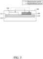
- the working electrode 120 and the counter electrode 130can be disposed on the same surface of the substrate 110. Specifically, both the working electrode 120 and the counter electrode 130 can be disposed on the surface 111 or the opposite surface 112 of the substrate 110, as shown in FIG. 3 .
- a currentflows from the working electrode 120 to the counter electrode 130, so that an oxidation reaction occurs on the working electrode 120 and the physiological signal is measured, and silver halide (AgX) in the counter electrode 130 is consumed and dissociated into silver (Ag) and halide ion (X - ).
- the replenishment stepis performed, a current flows from the counter electrode 130 to the working electrode 120, so that an oxidation reaction occurs on the counter electrode 130 to cause the combination of silver and halide ion to replenish silver halide.
- FIGs. 2C and 3The detailed electrode stacks in FIGs. 2C and 3 are omitted, and only the electrode positions are shown.
- a layer of conductive materialsuch as carbon
- the material of the counter electrode 130 of the present inventionsequentially is the conductive layer, the carbon layer and the silver/silver halide layer from the opposite surface 112 of the substrate 110.
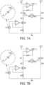
- FIGs. 4A-B and FIGs. 5A-Dshow a constant voltage circuit in a measurement mode and a replenishment mode, respectively, in the present invention
- FIGs. 5A-Drespectively show the current schematic diagrams of the constant voltage circuit running in the measurement mode and the replenishment mode by turns in different ways.
- the measurement modecan be started and stopped by applying a measurement potential difference V1 and removing the measurement potential difference V1, respectively, and the corresponding current is represented by la.
- the measurement potential difference V1is applied across the working electrode W and the counter electrode R/C during the measurement period T1, so that the voltage of the working electrode W is higher than that of the counter electrode R/C.
- the measurement modeas shown in FIG.
- the switches S1 and S4are in the close circuit state, the switches S2 and S3 are in the open circuit state, the working electrode W is +VI, and the counter electrode R/C is grounded, so that at the working electrode W, an oxidation reaction occurs, and the working electrode W electrochemically reacts with chemical reagents and an analyte to output a physiological signal la.
- the AgCl in the counter electrode R/Chas a consumption amount corresponding to the physiological signal la.
- T2is a constant value.
- the replenishment modecan be started and stopped by applying a replenishment potential difference V2 and removing the replenishment potential difference V2, respectively, and the corresponding current is represented by lb.
- V2is a constant value in a range of 0.1V to 0.8V, preferably range of 0.2V to 0.5V.
- the replenishment potential difference V2is applied across the working electrode W and the counter electrode R/C during the replenishment period t2 (t2 is in a range of 0 to T2), so that the voltage of the counter electrode R/C is higher than that of the working electrode W.
- the switches S1 and S4are in the open circuit state, the switches S2 and S3 are in the close circuit state, the working electrode W is grounded, and the counter electrode R/C is +V2, so that on the counter electrode R/C, an oxidation reaction of Ag occurs to replenish the counter electrode R/C with AgCl by a replenishment amount.
- the replenishment potential difference V2is a constant voltage, and the measured output current is lb.
- the amount or value of capacity (with the unit “coulomb” and represented by the symbol “C") of AgClis defined by calculating the area under the current curve, so the consumption amount of AgCl in the measurement mode is la*TI, and the replenishment amount of AgCl in the replenishment mode is Ib*t2.
- the replenishment amount ofAgClcan be controlled by adjusting the period t2 during which the potential difference V2 is applied.
- the replenishment amountcan be equal to or not equal to (including approximately similar, greater than or less than) consumption amount.
- both V2 and T2are constant values, and the period t2 (i.e., the replenishment period) during which V2 is applied is a variable value.
- the replenishment period t2is dynamically adjusted in a range of 0 to T2 according to the physiological signal Ia measured in the measurement mode and during the measurement period T1. As shown in FIG. 5A , t2 can be t2', t2' ', or t2' ' '....
- the replenishment period t2can be changed according to the consumption amount of AgCl.
- the counter electrode R/Ccan be replenished for a longer time to keep the AgCl on the counter electrode R/C within the safe storage range.
- the amount of AgCl replenished during t2"will be greater than the amount of AgCl replenished during t2'.
- t21/2 T2, 2/5 T2, 3/5 T2, etc.
- the replenishment modestarts immediately without any buffer time, and there is a period of time between the end of each replenishment mode and the start of the next measurement mode.
- t2is less than T2, and t2 can be any time period during T2.
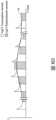
- FIGs. 5E and 5Fshow current-time schematic diagrams of the constant voltage circuit running in the measurement mode and the replenishment mode by turns in different ways.
- the horizontal axisrepresents time
- the vertical axisrepresents current
- the curverepresents the physiological parameter curve calculated from the measured physiological signal la.
- V2 and T2are constant values and the replenishment period t2 is a variable value.
- the white area under the curverepresents the AgCl consumption amount in the measurement mode (la*TI), and the oblique area represents the replenishment amount of AgCl in the replenishment mode (Ib*t2).
- the replenishment period t2is dynamically adjusted in a range of 0 to T2 according to the measured physiological signal Ia and the measurement period T1.
- the front part (as shown in FIG. 5E ) or the back part (as shown in FIG. 5F ) of the period (T2) where the measurement mode is not executedcan be selected to perform the replenishment mode.
- FIGs. 6A-6B and FIGs. 8A-Cshow a segmental constant current circuit in a measurement mode and a replenishment mode, respectively, according to the present invention
- FIGs. 8A-Crespectively show the voltage schematic diagrams of the constant current circuit running in the measurement mode and the replenishment mode by turns in different ways.
- the measurement modecan be started and stopped by applying a measurement potential difference V1 and removing the measurement potential difference V1, respectively, and the corresponding current is represented by la.
- the measurement potential difference V1is applied across the working electrode W and the counter electrode R/C during the measurement period T1.
- the switches S1 and S4are in the close circuit state, the remaining switches are in the open circuit state, the working electrode W is +VI, and the counter electrode R/C is grounded, so that at the working electrode W, an oxidation reaction occurs, and the working electrode W electrochemically reacts with chemical reagents and an analyte to output a physiological signal la.
- the AgCl in the counter electrode R/Chas a consumption amount corresponding to the physiological signal la.
- T2is a constant value.
- the replenishment modecan be started and stopped by applying a replenishment potential difference V2, which is a variable value, and removing the replenishment potential difference V2, respectively, and the corresponding current is represented by lb.
- the replenishment potential difference V2is applied across the working electrode W and the counter electrode R/C during the replenishment period t2 (wherein t2 is in a range of 0 to T2).
- the switches S1 and S4are in the open circuit state
- the switch S2 and at least one of switches corresponding to I_F1 to I_Fnare in the close circuit state (wherein FIG.
- the replenishment modeaccording to the magnitude of the physiological signal Ia and the measurement period T1, at least one of the switches corresponding to I_F1 to I_Fn can be selected to be turned on to output a constant current lb, and the replenishment amount of AgCl can be controlled by adjusting the period t2 during which the potential difference V2 is applied. That is, on the premise that the AgCl on the counter electrode R/C is kept within the safe storage range, the replenishment amount can be equal to or not equal to (including approximately similar, greater than or less than) consumption amount.
- FIGs. 7A-7B and FIGs. 8A-8Cshow a continuous variable constant current circuit in a measurement mode and a replenishment mode, respectively, according to the present invention.
- the measurement mode and the replenishment mode in this embodimentare similar to those in FIGs. 6A and 6B , so they will not be repeated here.
- This embodimentdiffers from that in FIGs. 6A and 6B only in that in the replenishment mode, according to the magnitude of the physiological signal la, a constant current Ib can be output by the control of the digital-to-analog converter (DAC), and the replenishment amount of AgCl can be controlled by adjusting the period t2 during which the potential difference V2 is applied. That is, on the premise that the AgCl on the counter electrode R/C is kept within the safe storage range, the replenishment amount can be equal to or not equal to (including approximately similar, greater than or less than) consumption amount.
- DACdigital-to-analog converter
- T2is a constant value
- V2 and the period t2 (i.e., the replenishment period) during which V2 is appliedare variable values.
- the replenishment period t2is dynamically adjusted in a range of 0 to T2 according to the measurement period T1 and the physiological signal Ia measured in the measurement mode.
- t2can be t2', t2' ', or t2' ' '....
- the replenishment period t2can be changed according to the consumption amount of AgCl.
- the counter electrode R/Ccan be replenished for a longer time to keep the AgCl on the counter electrode R/C within the safe storage range.
- V2is a variable value
- T2 and t2are constant values, wherein t2 is a constant value greater than 0 and less than T2.
- t2can be 1/2 T2, 2/5 T2, 3/5 T2, etc.
- V2is dynamically adjusted according to the consumption amount of AgCl in the step of measuring the physiological signal (i.e., in the measurement mode).
- the dynamic adjustment methodis as follows.
- the segmental constant current circuitis used. The circuit includes n constant current supplies and n switches, and each constant current supply corresponds to a switch.
- the replenishment modeaccording to the consumption amount of AgCl, at least one of the n switches is selected to be turned on (i.e., in the close circuit state) to output a constant current value.
- the replenishment period t2is a constant value
- the replenishment amount of AgClcan be controlled by selecting different constant current outputs.
- V2is a variable value
- the segmental constant current circuitCompared with the continuous variable constant current circuit, in the segmental constant current circuit, multiple current paths can be controlled through multiple switches, and thus the replenishment can be performed by multi-segment constant current according to the amount of current required.
- the multi-segment constant currentin this way, saves electricity and can reduce costs.
- the potential differencecan come from a DC power supply or an AC power supply, preferably from a DC power supply.
- FIGs. 5A to 8Call involve the operation manner of alternately cycling measurement step and replenishment step, which means that there is an AgCl replenishment step between any two measurement steps. Such manner can better ensure that AgCl remains within the safe storage range.
- Y times of AgCl replenishmentcan be optionally performed during N measurements, where Y ⁇ N, in such a way that the accumulated replenishment amount of AgCl can still be kept within the safe storage range.
- the measurement step and the replenishment stepdo not necessarily need to be performed in an alternate cycle.
- a replenishment stepcan also be performed after several measurement steps, or after a predetermined measurement time. For example, a replenishment step can be performed after 10 measurement steps, or after the accumulated measurement time reaches 1 hour.
- FIG. 8Dshows a current-time schematic diagram of the constant current circuit running in the measurement mode and the replenishment mode by turns in a way similar to that of FIG. 8C .
- the curverepresents the physiological parameter curve calculated from the measured physiological signal la, the conditions of T2 and t2 being both constant values and V2 being a variable value are similar to those in FIG. 8C .
- the white area under the curverepresents the AgCl consumption amount in the measurement mode (la*TI), and the oblique area represents the replenishment amount of AgCl in the replenishment mode (Ib*t2). It can be seen from this figure that in order to make Ib*t2 close to la*TI or within a certain range of la*TI, the replenishment potential difference V2 is dynamically adjusted according to the consumption amount of AgCl.
- FIGs 5E, 5F , and 8Ddo not show the output timing of each physiological parameter value after each measurement step for measuring a physiological signal is performed
- the physiological parameter valuemay be output, but is not limited to, when the measurement is completed or during the replenishment period and the AgCl replenishment step may be performed after every physiological parameter is output or after obtaining the physiological signal, but is not limited thereto.
- FIG. 9shows a method of measuring an analyte according to the present invention.
- a usage lifetime of a micro biosensorcan be prolonged by the method.
- the micro biosensorwhich may be, for example, the micro biosensor shown in FIG. 2A to FIG. 3 , is used to be implanted subcutaneously to measure a physiological signal representative of a physiological parameter associated with the analyte in a biofluid (such as tissue fluid).
- a biofluidsuch as tissue fluid
- the analytecan be glucose in the tissue fluid
- the physiological parameteris the glucose level in the human body
- the physiological signalis a current value measured by the micro-biological sensor.
- the method for measuring the analyteincludes repeatedly performing the measurement step (S901) and the replenishment step (S902).
- the measurement step (S901)includes using the aforementioned constant voltage circuit or the constant current circuit to perform the aforementioned measurement mode during the measurement period T1 to output a physiological signal (i.e., a current value), and at the same time, the AgCl on the counter electrode has a consumption amount corresponding to the current value.
- the measurement step (S901)also includes stopping the measurement step by stopping the measurement mode, and the current value is calculated to output a physiological parameter (i.e., glucose level).
- Glucose + Glucose oxidase(Gox, which is an flavin adenine dinucleotide (FAD) enzyme) ⁇ Gluconolactone + FADH 2 FADH 2 + O 2 ⁇ FAD + H 2 O 2 H 2 O 2 ⁇ 2H + + O 2 + 2e -
- the replenishment step (S902)includes using the aforementioned constant voltage circuit or constant current circuit to perform the aforementioned replenishment mode during the replenishment period, such that the AgCl on the counter electrode has a replenishment amount corresponding to consumption amount, and thus the AgCl on the counter electrode has an amount controlled within a safe storage range.
- the potential difference between the working electrode and the counter electrodecan be kept stable, so that the obtained current value can still maintain a stable correlation with the glucose value (if the detected substance is other analytes, the correlation may be proportional or inverse correlation). In other words, it is possible to keep a stable correlation between a next current value obtained in a next measurement step and a next glucose value.
- the replenishment step (S902)also includes a step of stopping the replenishment step by stopping the aforementioned replenishment mode. After the replenishment step (S902) is finished, the method returns to the measurement step (S901) until N measurement steps (S901) and N replenishment steps (S902) are executed.
- the chemical equationsare as follows.
- the following reduction reactionsoccur at the working electrode 120.
- FADflavin adenine dinucleotide
- the positive potential on the counter electrode 130causes the following oxidation reactions occurring at the counter electrode 130. 2Ag ⁇ 2Ag + + 2Cl - ⁇ 2AgCl + 2e -
- the Ag on the counter electrodeis oxidized to Ag + and combined with Cl - from the body or from oxidation (or dissociation) of AgCl to form AgC!, such that part or all of the AgCl consumed during the measurement period T1 is replenished onto the counter electrode.
- Humancan intake chloride ions and iodide ions through iodine-doped salts.
- the available halide ionsinclude at least chloride ions and iodide ions for replenishing the counter electrode with silver halide.
- each measurement potential difference V1is applied during the measurement period T1
- each replenishment potential difference V2is applied during the replenishment period t2
- the measurement period T1is a constant value, which can be a value within 3 seconds, 5 seconds, 10 seconds, 15 seconds, 30 seconds, 1 minute, 2.5 minutes, 5 minutes, or 10 minutes.
- the constant valuemay be a value within 30 seconds.
- the measurement period T1is a constant value, and can be 2.5 seconds, 5 seconds, 15 seconds, 30 seconds, 1 minute, 2.5 minutes, 5 minutes, 10 minutes, or 30 minutes, preferably 30 seconds.
- each measurement period T1 plus each replenishment period t2is a constant value.
- each replenishment potential difference V2has a constant voltage value, and each replenishment period t2 is dynamically adjusted according to each consumption amount of AgCl (as shown in FIG. 5A ).
- each output physiological parameteris obtained through calculation of the physiological signals at a single measurement time point in each measurement period T1.
- each output physiological parameteris obtained through a mathematical operation value of a plurality of physiological signals at a plurality of measurement time points in each measurement period T1.
- the aforementioned mathematical operation valueis, for example, a accumulated value, an average value, a median value, an average value of median, and so on.
- the replenishment amount of AgCl on the counter electrodeis controlled within a safe storage range by controlling each replenishment amount to be equal to or not equal to (including approximately similar, greater than or less than) each consumption amount. As a result, a next physiological signal obtained during a next measurement step maintains a stable proportional correlation with a next physiological parameter.
- the step of removing each measurement potential difference V1is to disconnect the circuit that connects the working electrode and the counter electrode, or set each measurement potential difference V1 to zero.
- the powercan be turned off to make the measurement circuit have an open circuit state; or, a 0 volt voltage can be applied across the working electrode and the counter electrode, wherein the operation time of either of the two operations is 0.01 ⁇ 0.5 seconds.
- the step of removing the measurement potential difference V1can avoid the generation of ⁇ -shaped physiological signals.
- the step of removing each replenishment potential difference V2is to disconnect the circuit configured to connect the working electrode and the counter electrode, or set each replenishment potential difference V2 to zero.
- a warm-up timeis required for the biosensor to be in the condition of equilibrium and stability in the body in order to stably present a physiological signal that is positively correlated with an analyte concentration. Therefore, in the measurement step (S901), the measurement voltage is continuously applied until the end of the measurement period T1, and the measurement period T1 is controlled such that the physiological signal and the physiological parameter of the analyte have a stable proportional correlation.
- the measurement period T1can be a variable value or a combination of a variable value and a constant value (for example, a variable value plus a constant value, in which the variable value may be 1 hour, 2 hours, 3 hours, 6 hours, 12 hours or 24 hours, and the constant value may be, for example, 30 seconds).
- a variable valuefor example, a variable value plus a constant value, in which the variable value may be 1 hour, 2 hours, 3 hours, 6 hours, 12 hours or 24 hours, and the constant value may be, for example, 30 seconds).
- the present inventionuses a voltage applied to the counter electrode R/C during a period to measure a resultant current of the counter electrode, and the initial capacity of AgCl is obtained by mathematical calculation of the resultant current during the period.
- the initial capacity of AgClis defined by calculating area under a curve of the resultant current.
- the initial capacity of AgClis also referred to as the initial amount or initial coulomb amount (C initial ), the following are all described by amount.
- each measurement step (S901)the consumption amount of AgCl (denoted by C consume ) is defined by calculating the area under the current curve of the working electrode W.
- the safe storage rangeis represented by the ratio of Ag to AgCl.
- the present inventionuses the coulomb amount (C) measured at the counter electrode to reflect the ratio of Ag to AgCl.
- the ratio of Ag to AgClis 99.9%:0.1%, 99%:1%, 95%:5%, 90%:10%, 70%:30%, 50%:50%, 40%:60% or 30:70%, which assure of a certain amount of the AgCl on the counter electrode without being exhausted, and thus each measurement step for measuring the physiological signal can be performed stably.
- the remaining amount of AgClis the sum of the replenishment amount and the initial amount minus the consumption amount.
- the remaining amount of AgClmay, within a range, gradually decrease, gradually increase, change steadily, or change arbitrarily but still within the range.
- FIG. 10shows a method for measuring an analyte according to another embodiment of the present invention.
- the micro biosensorwhich may be, for example, the micro biosensor shown in FIG. 2A-FIG. 3 , is used to be implanted subcutaneously to measure a physiological signal representative of a physiological parameter associated with the analyte in a biofluid (such as tissue fluid).
- the electrode material of the counter electrode of the micro biosensorincludes silver and silver halide.
- the analytecan be glucose in tissue fluid
- the physiological parameteris the glucose value in the human body
- the physiological signalis a current value measured by the micro biosensor. Only one cycle of this embodiment is described below.
- the method of this embodimentstarts with the step of applying a measurement voltage to drive a working electrode to measure a physiological signal for obtaining a physiological parameter, wherein a specific amount of silver halide is consumed (hereinafter referred to as "consumption amount") (S1001).
- the step of applying the measurement voltageis stopped (S1002), and the obtained physiological signal is used to obtain a physiological parameter (S1003).
- a replenishment voltageis applied across a counter electrode and a working electrode to drive a counter electrode, such that silver halide is replenished by a replenishment amount (S1004), wherein a value (i.e., the aforementioned "remaining amount") of a sum of the replenishment amount and an initial amount minus the consumption amount is controlled within a range of the initial amount plus or minus a specific value.
- the above control stepis achieved by controlling the replenishment amount to be equal to or not equal to (including approximately similar, greater than or less than) the consumption amount so as to maintain the amount of silver halide within a safe storage range.
- the increase or decrease of the mole number of silver halidecorresponds to the increase or decrease of the mole number of silver. Therefore, for the ease of descriptions, the consumption amount of silver halide corresponds to a simulated increased amount of silver.
- a value of the remaining amountis controlled such that the ratio of the amount of silver halide to the sum of the amount of silver halide plus the amount of silver (AgCI/Ag+AgCI) is greater than 0 and less than 1 (which means that there should be a certain amount of silver halide in the counter electrode), preferably between 0.01-0.99, between 0.1-0.9, between 0.2-0.8, between 0.3-0.7, or between 0.4-0.6.
- the step of applying the replenishment voltageis stopped (S1005). Then the method returns to step S1001 to execute the next loop.
- a specific embodiment of the present inventionwill be described below. Taking a usage lifetime of a biosensor must reach 16 days as an example. To this end, the method to calculate the required size of Ag/AgCI material on a signal sensing section of a electrode is described below.
- the average of the measured current of the analyte for each measurementis 30 nA
- the measurement period (T1)is 30 seconds
- the replenishment period (t2)is 30 seconds.
- the required length of the counter electrodeis at least:
- the length of the counter electrodeneeds to exceed 16 mm in order to make the usage lifetime of the sensor achieve 16 days.
- the signal sensing section of the counter electrodeneeds to be configured with a relatively large size of Ag/AgCI material to achieve the usage lifetime of 16 days.
- the replenishment step for silver halideis performed between two measurement steps. The consumption and replenishment of the silver halide cycles repeated in a short period of time (replenished when used), so the amount of Ag/AgCI material in the sensor can be reduced, and thereby the sensor is miniaturized. Therefore, there is no need to prepare 16 days of AgCl capacity for the signal sensing section material of the electrode for consumption.
- the preparation of the capacity of AgCl for about 1-2 dayscan achieve a usage time of 16 days of the sensor.
- the capacity of AgCl for 1-2 daysalso refers to the initial amount of AgCl in the counter electrode before leaving the factory or before performing the first measurement.
- the initial amount of AgClmay be, for example, between about 1.3 and 2.6 mC, and can be in other smaller range or a larger range.
- different AgCl capacities for 1-5 days, 1-3 days, 6-24 hours, and 6-12 hourscan also be prepared.
- the size of the signal sensing section of the counter electrodecan be configured in such a way that the counter electrode has a capacity which enables stable executions of each measurement step for glucose and the positive correlation between the measurement current and the glucose concentration in the body.
- the prior artincreased the electrode length/area to make the sensor reach the required measurement days without using the silver chloride replenishment technology of the present invention.
- the length of the implantation end of the prior artis about 12 mm. Due to the long implantation length of the prior art, the implantation end needs to be implanted subcutaneous at an oblique angle to avoid the implantation end from implanting deeply into the subcutaneous tissue, which causes a large implantation wound.
- the capacity of AgCl for 1-2 daysis about 1.3 ⁇ 2.6 mC
- the length of the counter electrode for 1-2 daysis 2.5-5 mm after conversion, and thus the length of the counter electrode needs 16 mm without using the replenishment method for silver halide in the present invention.
- the implantation end of the present inventioncan be shortened, for example, to no greater than 10 mm.
- the lower half of the connecting area 117 to the second end 114 of the micro biosensor 100 of the present inventionforms a short implantation end 118, as shown in FIGs. 2A and 2B .
- the implantation depth of the short implantation end 118is at least a depth to the dermis where can measure the glucose concentration in the tissue fluid.
- a length of the longest side of the short implantation end 118is no greater than 6 mm, so that the short implantation end 118 of the micro biosensor 100 can be perpendicularly implanted under the biological epidermis.
- the length of the longest side of the short implantation end 118is no greater than 5 mm, 4.5 mm, 3.5 mm or 2.5 mm.
- the short implantation end 118 of the present inventionincludes the signal sensing section 132 of the counter electrode 130, and a length of the longest side of the signal sensing section 132 of the counter electrode 130 is no greater than 6 mm, preferably 2-6 mm, 2-5 mm, 2-4.5 mm, 2-3.5 mm, 0.5-2 mm or 0.2-1 mm.
- the silver halide replenishment method of the present inventioncan effectively extend the micro sensor's usage lifetime, and can also greatly reduce the use of Ag/AgCI material on the counter electrode, which causes the size of the signal sensing section of the counter electrode to be reduced. Because of the reduced use of the Ag/AgCI material on the counter electrode, the sensor can be miniaturized and biological toxicity can be reduced. In addition, the reduced size of the electrode specifically refers to the shortened length of the implantation end of the sensor, which would reduce pain for the user during implantation.
Landscapes
- Health & Medical Sciences (AREA)
- Life Sciences & Earth Sciences (AREA)
- Physics & Mathematics (AREA)
- Molecular Biology (AREA)
- General Health & Medical Sciences (AREA)
- Pathology (AREA)
- Engineering & Computer Science (AREA)
- Biophysics (AREA)
- Biomedical Technology (AREA)
- Heart & Thoracic Surgery (AREA)
- Medical Informatics (AREA)
- Surgery (AREA)
- Animal Behavior & Ethology (AREA)
- Public Health (AREA)
- Veterinary Medicine (AREA)
- Optics & Photonics (AREA)
- Chemical & Material Sciences (AREA)
- Chemical Kinetics & Catalysis (AREA)
- General Chemical & Material Sciences (AREA)
- Emergency Medicine (AREA)
- Immunology (AREA)
- Analytical Chemistry (AREA)
- Biochemistry (AREA)
- Electrochemistry (AREA)
- General Physics & Mathematics (AREA)
- Spectroscopy & Molecular Physics (AREA)
- Hematology (AREA)
- Nanotechnology (AREA)
- Measurement Of The Respiration, Hearing Ability, Form, And Blood Characteristics Of Living Organisms (AREA)
- Organic Chemistry (AREA)
- Proteomics, Peptides & Aminoacids (AREA)
- Wood Science & Technology (AREA)
- Zoology (AREA)
- Measuring Or Testing Involving Enzymes Or Micro-Organisms (AREA)
- Apparatus Associated With Microorganisms And Enzymes (AREA)
- Investigating Or Analysing Biological Materials (AREA)
- Microbiology (AREA)
- General Engineering & Computer Science (AREA)
- Genetics & Genomics (AREA)
- Bioinformatics & Cheminformatics (AREA)
Description
- The present invention is related to a measuring method using a micro biosensor as defined by
independent claim 1. - The population of diabetic patients is growing rapidly, and there is increasing emphasis on the need to monitor glucose changes in the human body. Therefore, many studies have begun to develop a system that can be implanted in the human body for continuous glucose monitoring (CGM) system to solve the inconvenience to the patient resulting from the repeated blood samplings and detections performed each day.
- In the field of an enzyme-based biosensor of CGM system in which a biochemical reaction signal that depends on the concentration of an analyte is converted into a measurable physical signal, such as an optical or electrochemical signal. In case of a measurement of glucose, the electrochemical reaction occurs so that the glucose oxidase (GOx) catalyzes the glucose to react and produce the gluconolactone and the reduced enzyme. Then, the reduced enzyme transfers electrons to the oxygen in the biofluid in the living body to produce a product hydrogen peroxide (H2O2), and the concentration of the glucose is quantified by oxidizing the product H2O2. The reaction is as follows:
Glucose + GOx (FAD)→ GOx(FADH2) + Gluconolactone
GOx(FADH2) + O2 → GOx(FAD) + H2O2
wherein the FAD (which is Flavin Adenine Dinucleotide) is an active center of the GOx. - A user usually wears the CGM system for a long period of time, for example at least 14 days, thus the miniaturization of its size is a necessary development. The basic structure of a CGM system comprises: (a) a biosensor, which measures the physiological signals corresponding to the glucose concentration in the human body; and (b) a transmitter for transmitting these physiological signals. The biosensor may be a two-electrode system or a three-electrode system. The biosensor with a three-electrode system includes a working electrode (WE), a counter electrode (CE), and a reference electrode (RE). The biosensor with a two-electrode system includes a working electrode (WE) and a counter electrode (CE), in which the counter electrode also functions as a reference electrode, and is sometimes called a counter/reference electrode (R/C) accordingly. For the reference electrode in the biosensor with the three-electrode system and for the counter electrode also functioning as a reference electrode in the biosensor with the two-electrode system, a suitable material applicable for a stable measurement to the concentration of the glucose is silver and silver chloride (Ag/AgCI). However, after the biosensor is implanted into a living body, when an oxidation-reaction occurs on the working electrode to measure the concentration of the glucose, a reduction reaction occurs on the corresponding reference electrode (R) or reference/counter electrode (R/C) to cause the AgCl to be reduced to Ag and the AgCl is consumed. In addition, if the biosensor implanted into the living body is a biosensor with the two or three-electrode system, the depletion of the silver chloride from the reference electrode will occur due to its dissolution in the body fluid, and will cause a drifting problem to the reference voltage. However, due to the reaction of the reference/counter electrode (R/C) of the two-electrode system, the consumption of silver chloride is even higher than that of the three-electrode system. Therefore, the usage lifetime of the biosensor is limited by the content of the silver chloride on the counter electrode and/or the reference electrode. The related prior arts include the patent applications bearing the numbers
US 2009/298104A1 ,US 2013/245412 A1 andUS 2011/259741 A1 .US 2009/298104A1 describes a biosensor, which is mainly with a three-electrode system. The biosensor provides a reference electrode having an extended lifetime that is suitable for long term use in an implantable biosensor.US 2013/245412 A1 describes an electrochemical sensor, which is mainly with a two-electrode system. The sensor improves the mechanical properties for comfort to the user and minimizes the risk of breakage.US 2011/259741 A1 discloses a biosensor, which is mainly with a three-electrode system. The biosensor measures a specified ground substance contained in a body fluid of a human being or an animal. - There are also many inventions proposed to address this problem. Taking a biosensor with a two-electrode system as an example, the consumption on the counter electrode is about 1.73 millicoulombs (mC) per day at an average sensing current of 20 nanoamperes (nA). Assuming that the length, width and height of the counter electrode are 3.3 mm, 0.25 mm and 0.01 mm respectively and the originally designed electrode capacity is only 6 mC, the stable measurement that the biosensor can provide can be maintained for about one day at most. However, if it is necessary to further prolong the usage lifetime of the biosensor so that the subcutaneously implanted biosensor can support continuous glucose monitoring for 16 days, the capacity of the counter electrode must be at least 27.68 mC. Without changing the width and thickness of the counter electrode, the length of the counter electrode in the prior art needs to be up to 15.2 mm. Accordingly, the length of the counter electrode of the biosensor has been extended to be larger than 10 mm in the prior art. However, in order to avoid such a kind of biosensor being implanted deeply into the subcutaneous tissues, the biosensor needs to be implanted at an oblique angle. Therefore, it causes problems such as a larger implantation wound and a higher risk of infection to the patient, and because the implantation length is long, the pain during implantation is also more significant.
US 8,620,398 describes a biosensor, which is mainly with a three-electrode system. Although the reference electrode basically does not participate in the chemical reaction, the silver chloride is still gradually consumed naturally in the environment in vivo, the consumption rate is slower than that in the counter electrode of the two-electrode system. The specification disclosed that the AgCl regenerates when the AgCl is almost totally consumed. That is to say, until the measured signals are unstable, or until the measured signals are all noises, the replenishment process will be activated to recover the AgCl back to having the amount sufficient to perform a plurality of measurements. Then, until next time when the noise occurs again, AgCl needs to be replenished again. It can be understood that, althoughUS 8,620,398 considers that AgCl will be consumed in the measurement and replenishing AgCl when the biosensor fails, the measured value at the time of failure can no longer be trusted. It is necessary to wait for the biosensor to complete the AgCl replenishment procedure so as to obtain the correct measured value, to temporarily perform the measurement by taking a blood sample, or to skip this measurement directly. This problem is always troublesome for the patient or those who need to know the present concentration of the blood glucose. In addition, because the biosensor has to deal with a plurality of measurements of consecutive several measurements or over several days, more AgCl capacity must be prepared. However, it will inevitably result in the problem of a longer implantation length of the biosensor.US 8,620,398 has not proposed anything about the timely AgCl replenishment method that can provide uninterrupted measurements, and a shorter implantation length and a longer usage lifetime of the biosensor.US9,351 ,677 - Therefore, the present disclosure provides a biosensor, which is capable of achieving the effects of providing uninterrupted measurements by replenishing AgCl after measuring, stably replenishing AgCI, prolonging the usage lifetime of the biosensor, and miniaturizing the implantation end of the biosensor to a compact size, and reducing the manufacturing cost of the product. These effects can solve the aforementioned problems that the prior art has found impossible to overcome.
- In view of the above, because of the defect in the prior art, the inventors provide the present invention to effectively overcome the disadvantages of the prior art. The descriptions of the present invention are as follows:
- By the replenishing technique in the present invention, the micro biosensors have a prolonged usage lifetime and the size of the signal sensing section of the counter electrode in the micro biosensor can be reduced, which can reduce biological toxicity. In addition, the reduced size of the electrode specifically refers to the shortened length of the implantation end of the sensor, which would reduce pain for the user during implantation.
- In accordance with another aspect of the present disclosure, a method of measuring an analyte using a biosensor for prolonging a usage lifetime of the biosensor implanted subcutaneously to measure a physiological signal representative of a physiological parameter associated with the analyte in a biofluid is disclosed. The biosensor includes a working electrode and a counter electrode, the working electrode is at least partially covered by a chemical reagent configured to react with the analyte, and the counter electrode has silver and a silver chloride. The method is defined by the
independent claim 1. - The above embodiments and advantages of the present invention will become more readily apparent to those ordinarily skilled in the art after reviewing the following detailed descriptions and accompanying drawings.
FIG. 1 shows a schematic diagram of a physiological signal measurement deviceFIG. 2A shows a front schematic diagram of a micro biosensorFIG. 2B shows a back schematic diagram of a micro biosensorFIG. 2C shows a sectional schematic diagram of a cut view of the micro biosensor along the section line A-A' inFIG. 2A .FIG. 3 shows a sectional schematic diagram of a second embodiment of the micro biosensorFIG. 4A shows a constant voltage circuit in a measurement mode in the present invention.FIG. 4B shows a constant voltage circuit in a replenishment mode in the present invention.FIG. 5A shows a current schematic diagram of the constant voltage circuit running in the measurement mode and the replenishment mode by turns in a first way.FIG. 5B shows a current schematic diagram of the constant voltage circuit running in the measurement mode and the replenishment mode by turns in a second way.FIG. 5C shows a current schematic diagram of the constant voltage circuit running in the measurement mode and the replenishment mode by turns in a third way.FIG. 5D shows a current schematic diagram of the constant voltage circuit running in the measurement mode and the replenishment mode by turns in a fourth way.FIG. 5E shows a current schematic diagram of the constant voltage circuit running in the measurement mode and the replenishment mode by turns in a fifth way.FIG. 5F shows a current schematic diagram of the constant voltage circuit running in the measurement mode and the replenishment mode by turns in a sixth way.FIG. 6A shows a segmental constant current circuit in a measurement mode in the present invention.FIG. 6B shows a segmental constant current circuit in a replenishment mode in the present invention.FIG. 7A shows a continuous variable constant current circuit in a measurement mode in the present invention.FIG. 7B shows a continuous variable constant current circuit in a replenishment mode in the present invention.FIG. 8A shows a voltage schematic diagram of the constant current circuit running in the measurement mode and the replenishment mode by turns in a first way.FIG. 8B shows a voltage schematic diagram of the constant current circuit running in the measurement mode and the replenishment mode by turns in a second way.FIG. 8C shows a voltage schematic diagram of the constant current circuit running in the measurement mode and the replenishment mode by turns in a third way.FIG. 8D shows a schematic diagram of the constant current circuit running in the measurement mode and the replenishment mode by turns in a third way.FIG. 9 shows a method of measuring an analyte according to an embodiment in the present invention.FIG. 10 shows a method of measuring an analyte according to another embodiment in the present invention.- Please refer to all figures of the present invention when reading the following detailed description, wherein all Figures of the present invention demonstrate different embodiments of the present invention by showing examples, and help the skilled person in the art to understand how to implement the present invention.
- Unless there are other restrictions defined in the specific example, the following definitions apply to the terms used throughout the specification.
- The term "amount" refers to a capacity of silver halide (AgX) or silver chloride (AgCI) on the counter electrode, and preferably represents in a unit of micro Coulomb (µC), milli Coulomb (mC) or Coulomb (C), but is not limited to concentration by weight percentage (wt%), mole number, molar concentration, etc.
- Please refer to
FIG. 1 , which is a schematic diagram of a physiological signal measurement device. The physiologicalsignal measurement device 10 can be implanted subcutaneously to measure a physiological signal representing a physiological parameter associated with an analyte in a biofluid. The physiologicalsignal measurement device 10 includes amicro biosensor 100 and atransmitter 200, wherein thetransmitter 200 is electrically connected to themicro biosensor 100 and includes aprocessor 210, apower supply 220, acircuit switching unit 230, atemperature sensing unit 240 and a communicatingunit 250. Thepower supply 220 provides a voltage to themicro biosensor 100 through thecircuit switching unit 230 for measuring the physiological signal, thetemperature sensing unit 240 measures the body temperature of the living body, thereby the temperature measuring signal and the measured physiological signal measured by themicro biosensor 100 are transmitted to theprocessor 210, and theprocessor 210 operates the measured physiological signal to a physiological parameter. The communicatingunit 250 can communicate with auser device 20 by a wire or wireless transmission. - Please refer to
FIGs. 2A and2B , which are front and back schematic diagrams of the micro biosensor. Themicro biosensor 100 includes asubstrate 110, a workingelectrode 120 and acounter electrode 130 disposed on thesubstrate 110, and a chemical reagent 140 (as shown inFIG. 2C ) covering the workingelectrode 120 and thecounter electrode 130. The material of thesubstrate 110 can be any material that is known to be suitable for use in electrode substrates and preferably has flexibility and insulation properties, such as but not limited to: polymer materials such as polyester and polyimide. The aforementioned polymer materials can be used alone or in combination. Thesubstrate 110 includes a surface 111 (i.e. a first surface), an opposite surface 112 (i.e. a second surface) opposite to thesurface 111, afirst end 113 and asecond end 114. Thesubstrate 110 is separated into three areas respectively - they are asignal output area 115 located close to thefirst end 113, asensing area 116 located close to thesecond end 114, and a connectingarea 117 located between thesignal output area 115 and thesensing area 116. The workingelectrode 120 is disposed on thesurface 111 of thesubstrate 110 and extended from thefirst end 113 to thesecond end 114 of thesubstrate 110. The workingelectrode 120 includes asignal output section 121 located in thesignal output area 115 of thesubstrate 110, and asignal sensing section 122 located in thesensing area 116 of thesubstrate 110. A material of the workingelectrode 120 includes but is not limited to: carbon, platinum, aluminum, gallium, gold, indium, iridium, iron, lead, magnesium, nickel, manganese, molybdenum, osmium, palladium, rhodium, silver, tin, titanium, zinc, silicon, zirconium, a mixture thereof, or derivatives thereof (such as alloys, oxides or metal compounds, etc.). Preferably, the material of the workingelectrode 120 is a precious metal, a precious metal derivative or a combination thereof. More preferably, the workingelectrode 120 is made of platinum-containing material. - The
counter electrode 130 is disposed on theopposite surface 112 of thesubstrate 110 and extended from thefirst end 113 to thesecond end 114 of thesubstrate 110. Thecounter electrode 130 includes a signal output section 131 located in thesignal output area 115 of thesubstrate 110, and a signal sensing section 132 located in thesensing area 116 of thesubstrate 110. The material of the surface of thecounter electrode 130 includes silver and silver halide, preferably silver chloride or silver iodine. Because the electrode material of thecounter electrode 130 includes silver and silver halide (Ag/AgX), thecounter electrode 130 includes functions of the counter electrode and the reference electrode of the common knowledge in the art. Specifically, thecounter electrode 130 of the present invention can (1) form an electronic circuit with the workingelectrode 120 to cause the current between thecounter electrode 130 and the workingelectrode 120 to be conducted to ensure that the electrochemical reaction occurs on the workingelectrode 120; and (2) provide a stable relative potential as a reference potential. Therefore, the workingelectrode 120 and thecounter electrode 130 form a 2-electrode system. In order to further reduce the cost and improve the biocompatibility of the biosensor, the Ag/AgX can be used with carbon, for example, the Ag/AgX is mixed into carbon paste, and the content of the silver halide can be an amount that allows thecounter electrode 130 to stably perform the measurement step. The surface of thecounter electrode 130 can be partially covered by a conductive material to prevent silver halide from the dissolution and to protect thecounter electrode 130, wherein the conductive material is selected from the material that does not affect the measuring result of the working electrode. For example, the conductive material is carbon. - Alternatively, the biosensor is not limited to a wire-type or stacked-type electrode structure.
- According to the present disclosure, the initial amount of the silver halide can be zero before the biosensor is ready for shipping out of the plant for sale. In this case the
counter electrode 130 of the biosensor has no silver halide. After the biosensor is subcutaneously implanted in the patient and during the first replenishment period before the first measurement, the initial amount of the silver halide can be replenished by oxidizing the silver coated on theelectrodes 130. - The
chemical reagent 140 at least covers on the surface of thesignal sensing section 122 of the workingelectrode 120. In other embodiment, thechemical reagent 140 further covers on the signal sensing section 132 of thecounter electrode 130. That is to say, thecounter electrode 130 is not covered by thechemical reagent 140. Thesensing area 116 of themicro biosensor 100 can be implanted subcutaneously to cause thesignal sensing section 122 of the workingelectrode 120 to measure the physiological signal of the analyte in the biofluid. The physiological signal is transmitted to theprocessor 210 through thesignal output section 121 of the workingelectrode 120 to obtain the physiological parameter. In addition, apart from thetransmitter 200, the physiological parameter can also be obtained from theuser device 20 through the wire/wireless communication. Thecommon user device 20 can be a smartphone, a physiological signal receiver or a blood glucose meter. - Please refer to
FIG. 2C , which is a sectional schematic diagram of a cut view of the micro biosensor along the section line A-A inFIG. 2A , wherein the line A-A' is a section line of thesensing area 116 of themicro biosensor 100. InFIG. 2C , the workingelectrode 120 is disposed on thesurface 111 of thesubstrate 110, thecounter electrode 130 is disposed on theopposite surface 112 of thesubstrate 110, and the surfaces of the workingelectrode 120 and thecounter electrode 130 are covered by thechemical reagent 140. Basically, thechemical reagent 140 covers at least part of the surface of the workingelectrode 120. Themicro biosensor 100 performs a measurement step during a measurement period, and performs a replenishment (regeneration) step during a replenishment period. When the measurement step is performed, a voltage level of the workingelectrode 120 is higher than that of thecounter electrode 130, causing a current to flow from the workingelectrode 120 to thecounter electrode 130, so that an oxidation reaction occurs on the workingelectrode 120 having an electrochemical reaction with thechemical reagent 140 and the analyte and the physiological signal is measured, and a reduction reaction occurs on thecounter electrode 130, so that silver halide (AgX) in thecounter electrode 130 is consumed and dissociated into silver (Ag) and halide ion (X-). Because the silver halide in thecounter electrode 130 is consumed, the silver halide needs to be replenished in thecounter electrode 130 to perform the next measurement step. When the replenishment step is performed, the voltage level of thecounter electrode 130 is higher than that of the workingelectrode 120, causing a current to flow from thecounter electrode 130 to the workingelectrode 120, so that an oxidation reaction occurs on thecounter electrode 130 to cause silver to combine with halide ion in the living body or Cl- oxided (or dissociated) from AgCl to replenish silver halide. The detailed measurement step and the detailed replenishment step are illustrated inFIG. 9 . - Alternatively, the working
electrode 120 and thecounter electrode 130 can be disposed on the same surface of thesubstrate 110. Specifically, both the workingelectrode 120 and thecounter electrode 130 can be disposed on thesurface 111 or theopposite surface 112 of thesubstrate 110, as shown inFIG. 3 . Similarly, when the measurement step is performed, a current flows from the workingelectrode 120 to thecounter electrode 130, so that an oxidation reaction occurs on the workingelectrode 120 and the physiological signal is measured, and silver halide (AgX) in thecounter electrode 130 is consumed and dissociated into silver (Ag) and halide ion (X-). When the replenishment step is performed, a current flows from thecounter electrode 130 to the workingelectrode 120, so that an oxidation reaction occurs on thecounter electrode 130 to cause the combination of silver and halide ion to replenish silver halide. - The detailed electrode stacks in
FIGs. 2C and3 are omitted, and only the electrode positions are shown. - In any embodiment above, to prevent the silver electrode material from breakage due to over chlorination, a layer of conductive material, such as carbon, can be further disposed between the
opposite surface 112 of thesubstrate 110 and the silver of thecounter electrode 130. However, if the bottom layer of thecounter electrode 130 is carbon, the resistance at a switch position will be too high. A conductive layer, such as silver, can be further disposed between the carbon conductive material and theopposite surface 112 of thesubstrate 110. Therefore, the material of thecounter electrode 130 of the present invention sequentially is the conductive layer, the carbon layer and the silver/silver halide layer from theopposite surface 112 of thesubstrate 110. - Please refer to
FIGs. 4A-B andFIGs. 5A-D , whereinFIGs. 4A and 4B show a constant voltage circuit in a measurement mode and a replenishment mode, respectively, in the present invention, andFIGs. 5A-D respectively show the current schematic diagrams of the constant voltage circuit running in the measurement mode and the replenishment mode by turns in different ways. The measurement mode can be started and stopped by applying a measurement potential difference V1 and removing the measurement potential difference V1, respectively, and the corresponding current is represented by la. In the measurement mode, the measurement potential difference V1 is applied across the working electrode W and the counter electrode R/C during the measurement period T1, so that the voltage of the working electrode W is higher than that of the counter electrode R/C. During the measurement mode, as shown inFIG. 4A , the switches S1 and S4 are in the close circuit state, the switches S2 and S3 are in the open circuit state, the working electrode W is +VI, and the counter electrode R/C is grounded, so that at the working electrode W, an oxidation reaction occurs, and the working electrode W electrochemically reacts with chemical reagents and an analyte to output a physiological signal la. The AgCl in the counter electrode R/C has a consumption amount corresponding to the physiological signal la. As shown inFIGs. 5A-5D , between any two of a plurality of measurement periods T1 is a period T2 during which no measurement is performed. In some preferred embodiments, T2 is a constant value. - The replenishment mode can be started and stopped by applying a replenishment potential difference V2 and removing the replenishment potential difference V2, respectively, and the corresponding current is represented by lb. V2 is a constant value in a range of 0.1V to 0.8V, preferably range of 0.2V to 0.5V. In the replenishment mode, the replenishment potential difference V2 is applied across the working electrode W and the counter electrode R/C during the replenishment period t2 (t2 is in a range of 0 to T2), so that the voltage of the counter electrode R/C is higher than that of the working electrode W. During the replenishment mode, as shown in
FIG. 4B , the switches S1 and S4 are in the open circuit state, the switches S2 and S3 are in the close circuit state, the working electrode W is grounded, and the counter electrode R/C is +V2, so that on the counter electrode R/C, an oxidation reaction of Ag occurs to replenish the counter electrode R/C with AgCl by a replenishment amount. In the constant voltage circuit, the replenishment potential difference V2 is a constant voltage, and the measured output current is lb. In the present invention, the amount or value of capacity (with the unit "coulomb" and represented by the symbol "C") of AgCl is defined by calculating the area under the current curve, so the consumption amount of AgCl in the measurement mode is la*TI, and the replenishment amount of AgCl in the replenishment mode is Ib*t2. In such case, the replenishment amount ofAgCl can be controlled by adjusting the period t2 during which the potential difference V2 is applied. In other words, on the premise that the AgCl on the counter electrode R/C is kept within the safe storage range, the replenishment amount can be equal to or not equal to (including approximately similar, greater than or less than) consumption amount. - In
FIGs. 5A-5D , the horizontal axis represents time, the curve for V1 represents the application and removal of the measurement potential difference V1, and the curve for V2 represents the application and removal of the replenishment potential difference V2. Please refer toFIG. 5A . In a preferred embodiment, both V2 and T2 are constant values, and the period t2 (i.e., the replenishment period) during which V2 is applied is a variable value. The replenishment period t2 is dynamically adjusted in a range of 0 to T2 according to the physiological signal Ia measured in the measurement mode and during the measurement period T1. As shown inFIG. 5A , t2 can be t2', t2' ', or t2' ' '.... In other words, the replenishment period t2 can be changed according to the consumption amount of AgCl. In the condition of a high consumption amount of AgCl, the counter electrode R/C can be replenished for a longer time to keep the AgCl on the counter electrode R/C within the safe storage range. For example, the amount of AgCl replenished during t2" will be greater than the amount of AgCl replenished during t2'. - Please refer to
FIG. 5B , in another preferred embodiment, V2, T2 and t2 are all constant values, wherein t2=T2. That is, the measurement mode and replenishment mode alternate seamlessly, and the period during which no measurement is performed is the replenishment period. Please refer toFIGs. 5C and 5D , in some preferred embodiments, V2, T2, and t2 are constant values, wherein t2 is a constant value greater than 0 and less than T2. For example, t2=1/2 T2, 2/5 T2, 3/5 T2, etc. The difference betweenFIG. 5C and FIG. 5D is that inFIG. 5C , after each measurement mode, a buffer time (buffer time=T2-t2) is passed before the replenishment mode starts; and inFIG. 5D , after each measurement mode, the replenishment mode starts immediately without any buffer time, and there is a period of time between the end of each replenishment mode and the start of the next measurement mode. In some preferred embodiments, t2 is less than T2, and t2 can be any time period during T2. - Please refer to
FIGs. 5E and 5F , which show current-time schematic diagrams of the constant voltage circuit running in the measurement mode and the replenishment mode by turns in different ways. InFIGs. 5E and 5F , the horizontal axis represents time, the vertical axis represents current, and the curve represents the physiological parameter curve calculated from the measured physiological signal la. In the two embodiments, similar to that inFIG. 5A , V2 and T2 are constant values and the replenishment period t2 is a variable value. InFIGs. 5E and 5F , the white area under the curve represents the AgCl consumption amount in the measurement mode (la*TI), and the oblique area represents the replenishment amount of AgCl in the replenishment mode (Ib*t2). It can be seen from the figures that in order to make Ib*t2 close to la*TI or within a certain range of la*TI, the replenishment period t2 is dynamically adjusted in a range of 0 to T2 according to the measured physiological signal Ia and the measurement period T1. According to requirements, the front part (as shown inFIG. 5E ) or the back part (as shown inFIG. 5F ) of the period (T2) where the measurement mode is not executed can be selected to perform the replenishment mode. - Please refer to
FIGs. 6A-6B andFIGs. 8A-C , whereinFIGs. 6A and 6B show a segmental constant current circuit in a measurement mode and a replenishment mode, respectively, according to the present invention, andFIGs. 8A-C respectively show the voltage schematic diagrams of the constant current circuit running in the measurement mode and the replenishment mode by turns in different ways. The measurement mode can be started and stopped by applying a measurement potential difference V1 and removing the measurement potential difference V1, respectively, and the corresponding current is represented by la. In the measurement mode, the measurement potential difference V1 is applied across the working electrode W and the counter electrode R/C during the measurement period T1. During the measurement mode, as shown inFIG. 6A , the switches S1 and S4 are in the close circuit state, the remaining switches are in the open circuit state, the working electrode W is +VI, and the counter electrode R/C is grounded, so that at the working electrode W, an oxidation reaction occurs, and the working electrode W electrochemically reacts with chemical reagents and an analyte to output a physiological signal la. The AgCl in the counter electrode R/C has a consumption amount corresponding to the physiological signal la. As shown inFIGs. 8A-C , between any two of a plurality of measurement periods T1 is a period T2 during which no measurement is performed. In some preferred embodiments, T2 is a constant value. - The replenishment mode can be started and stopped by applying a replenishment potential difference V2, which is a variable value, and removing the replenishment potential difference V2, respectively, and the corresponding current is represented by lb. In the replenishment mode, the replenishment potential difference V2 is applied across the working electrode W and the counter electrode R/C during the replenishment period t2 (wherein t2 is in a range of 0 to T2). During the replenishment mode, as shown in
FIG. 6B , the switches S1 and S4 are in the open circuit state, the switch S2 and at least one of switches corresponding to I_F1 to I_Fn are in the close circuit state (whereinFIG. 6B exemplarily shows that the switches corresponding to I_F1 and I_F3 are in the close circuit state), the working electrode W is grounded, and the counter electrode R/C is +V2, so that on the counter electrode R/C, an oxidation reaction of Ag occurs to replenish the counter electrode R/C with AgCl. In the replenishment mode, according to the magnitude of the physiological signal Ia and the measurement period T1, at least one of the switches corresponding to I_F1 to I_Fn can be selected to be turned on to output a constant current lb, and the replenishment amount of AgCl can be controlled by adjusting the period t2 during which the potential difference V2 is applied. That is, on the premise that the AgCl on the counter electrode R/C is kept within the safe storage range, the replenishment amount can be equal to or not equal to (including approximately similar, greater than or less than) consumption amount. - Please refer to
FIGs. 7A-7B andFIGs. 8A-8C , whereinFIGs. 7A and 7B show a continuous variable constant current circuit in a measurement mode and a replenishment mode, respectively, according to the present invention. The measurement mode and the replenishment mode in this embodiment are similar to those inFIGs. 6A and 6B , so they will not be repeated here. This embodiment differs from that inFIGs. 6A and 6B only in that in the replenishment mode, according to the magnitude of the physiological signal la, a constant current Ib can be output by the control of the digital-to-analog converter (DAC), and the replenishment amount of AgCl can be controlled by adjusting the period t2 during which the potential difference V2 is applied. That is, on the premise that the AgCl on the counter electrode R/C is kept within the safe storage range, the replenishment amount can be equal to or not equal to (including approximately similar, greater than or less than) consumption amount. - In
FIGs. 8A-C , the horizontal axis represents time, the vertical axis represents current, the curve for V1 represents the application and removal of the measurement potential difference V1, and the curve for V2 represents the application and removal of the replenishment potential difference V2. Please refer toFIG. 8A , in a preferred embodiment, T2 is a constant value, V2 and the period t2 (i.e., the replenishment period) during which V2 is applied are variable values. The replenishment period t2 is dynamically adjusted in a range of 0 to T2 according to the measurement period T1 and the physiological signal Ia measured in the measurement mode. As shown inFIG. 8A , t2 can be t2', t2' ', or t2' ' '.... In other words, the replenishment period t2 can be changed according to the consumption amount of AgCl. In the condition of a high consumption amount of AgCl, the counter electrode R/C can be replenished for a longer time to keep the AgCl on the counter electrode R/C within the safe storage range. - Please refer to
FIG. 8B , in another preferred embodiment, V2 is a variable value, and T2 and t2 are constant values, wherein t2 is a constant value greater than 0 and less than T2. For example, t2 can be 1/2 T2, 2/5 T2, 3/5 T2, etc. In this embodiment, V2 is dynamically adjusted according to the consumption amount of AgCl in the step of measuring the physiological signal (i.e., in the measurement mode). One example of the dynamic adjustment method is as follows. For example, the segmental constant current circuit is used. The circuit includes n constant current supplies and n switches, and each constant current supply corresponds to a switch. In the replenishment mode, according to the consumption amount of AgCl, at least one of the n switches is selected to be turned on (i.e., in the close circuit state) to output a constant current value. When the replenishment period t2 is a constant value, the replenishment amount of AgCl can be controlled by selecting different constant current outputs. - Please refer to
FIG. 8C , in another preferred embodiment, V2 is a variable value, T2 and t2 are constant values, wherein t2=T2. That is, the measurement mode and replenishment mode alternate seamlessly, and the period during which no measurement is performed is the replenishment period. - Compared with the continuous variable constant current circuit, in the segmental constant current circuit, multiple current paths can be controlled through multiple switches, and thus the replenishment can be performed by multi-segment constant current according to the amount of current required. The multi-segment constant current, in this way, saves electricity and can reduce costs. In addition, whether it is a constant voltage circuit or a constant current circuit, the potential difference can come from a DC power supply or an AC power supply, preferably from a DC power supply.
- The embodiments of
FIGs. 5A to 8C all involve the operation manner of alternately cycling measurement step and replenishment step, which means that there is an AgCl replenishment step between any two measurement steps. Such manner can better ensure that AgCl remains within the safe storage range. However, in some preferred embodiments, Y times of AgCl replenishment can be optionally performed during N measurements, where Y^N, in such a way that the accumulated replenishment amount of AgCl can still be kept within the safe storage range. The measurement step and the replenishment step do not necessarily need to be performed in an alternate cycle. A replenishment step can also be performed after several measurement steps, or after a predetermined measurement time. For example, a replenishment step can be performed after 10 measurement steps, or after the accumulated measurement time reaches 1 hour. - Please refer to
FIG. 8D , which shows a current-time schematic diagram of the constant current circuit running in the measurement mode and the replenishment mode by turns in a way similar to that ofFIG. 8C . InFIG. 8D , the curve represents the physiological parameter curve calculated from the measured physiological signal la, the conditions of T2 and t2 being both constant values and V2 being a variable value are similar to those inFIG. 8C . InFIG. 8D , the white area under the curve represents the AgCl consumption amount in the measurement mode (la*TI), and the oblique area represents the replenishment amount of AgCl in the replenishment mode (Ib*t2). It can be seen from this figure that in order to make Ib*t2 close to la*TI or within a certain range of la*TI, the replenishment potential difference V2 is dynamically adjusted according to the consumption amount of AgCl. - In addition, although
FIGs 5E, 5F , and8D do not show the output timing of each physiological parameter value after each measurement step for measuring a physiological signal is performed, the physiological parameter value may be output, but is not limited to, when the measurement is completed or during the replenishment period and the AgCl replenishment step may be performed after every physiological parameter is output or after obtaining the physiological signal, but is not limited thereto. - Please refer to
FIG. 9 , which shows a method of measuring an analyte according to the present invention. A usage lifetime of a micro biosensor can be prolonged by the method. The micro biosensor, which may be, for example, the micro biosensor shown inFIG. 2A to FIG. 3 , is used to be implanted subcutaneously to measure a physiological signal representative of a physiological parameter associated with the analyte in a biofluid (such as tissue fluid). In the embodiment ofFIG. 9 , the analyte can be glucose in the tissue fluid, the physiological parameter is the glucose level in the human body, and the physiological signal is a current value measured by the micro-biological sensor. In this embodiment, the method for measuring the analyte includes repeatedly performing the measurement step (S901) and the replenishment step (S902). The measurement step (S901) includes using the aforementioned constant voltage circuit or the constant current circuit to perform the aforementioned measurement mode during the measurement period T1 to output a physiological signal (i.e., a current value), and at the same time, the AgCl on the counter electrode has a consumption amount corresponding to the current value. The measurement step (S901) also includes stopping the measurement step by stopping the measurement mode, and the current value is calculated to output a physiological parameter (i.e., glucose level). - In the measurement step (S901), the chemical equations are as follows.
- The following oxidation reactions occur at the working
electrode 120.
Glucose + Glucose oxidase (Gox, which is an flavin adenine dinucleotide (FAD) enzyme) ⇄ Gluconolactone + FADH2
FADH2 + O2 ⇄ FAD + H2O2
H2O2 ⇄ 2H+ + O2 + 2e- - The following reduction reactions occur at the
counter electrode 130.
2AgCl + 2e- ⇄ 2Ag + 2Cl- - The replenishment step (S902) includes using the aforementioned constant voltage circuit or constant current circuit to perform the aforementioned replenishment mode during the replenishment period, such that the AgCl on the counter electrode has a replenishment amount corresponding to consumption amount, and thus the AgCl on the counter electrode has an amount controlled within a safe storage range. As a result, the potential difference between the working electrode and the counter electrode can be kept stable, so that the obtained current value can still maintain a stable correlation with the glucose value (if the detected substance is other analytes, the correlation may be proportional or inverse correlation). In other words, it is possible to keep a stable correlation between a next current value obtained in a next measurement step and a next glucose value. The replenishment step (S902) also includes a step of stopping the replenishment step by stopping the aforementioned replenishment mode. After the replenishment step (S902) is finished, the method returns to the measurement step (S901) until N measurement steps (S901) and N replenishment steps (S902) are executed.
- In the replenishment step (S902), the chemical equations are as follows. The following reduction reactions occur at the working
electrode 120.
Glucose + Glucose oxidase (Gox, which is an flavin adenine dinucleotide (FAD) enzyme) ⇄ Gluconolactone + FADH2
FADH2 + O2⇄ FAD + H2O2
H2O2 + 2H+ + 2e- ⇄ H2O
O2 + 4H+ + 4e- ⇄ 2H2O - The positive potential on the
counter electrode 130 causes the following oxidation reactions occurring at thecounter electrode 130.
2Ag ⇄ 2Ag+ + 2Cl- ⇄ 2AgCl + 2e- - The Ag on the counter electrode is oxidized to Ag+ and combined with Cl- from the body or from oxidation (or dissociation) of AgCl to form AgC!, such that part or all of the AgCl consumed during the measurement period T1 is replenished onto the counter electrode.
- Human can intake chloride ions and iodide ions through iodine-doped salts. The available halide ions include at least chloride ions and iodide ions for replenishing the counter electrode with silver halide.
- The following embodiments are directed to cycles of N measurement steps (S901) and N replenishment steps (S902). The physiological parameter mentioned is preferably a glucose value, and the physiological signal mentioned is preferably a current value. According to some preferred embodiments, each measurement potential difference V1 is applied during the measurement period T1, each replenishment potential difference V2 is applied during the replenishment period t2, and the measurement period T1 is a constant value, which can be a value within 3 seconds, 5 seconds, 10 seconds, 15 seconds, 30 seconds, 1 minute, 2.5 minutes, 5 minutes, or 10 minutes. According to some preferred embodiments, the constant value may be a value within 30 seconds. The measurement period T1 is a constant value, and can be 2.5 seconds, 5 seconds, 15 seconds, 30 seconds, 1 minute, 2.5 minutes, 5 minutes, 10 minutes, or 30 minutes, preferably 30 seconds. According to some preferred embodiments, each measurement period T1 plus each replenishment period t2 is a constant value. According to some preferred embodiments, each replenishment potential difference V2 has a constant voltage value, and each replenishment period t2 is dynamically adjusted according to each consumption amount of AgCl (as shown in
FIG. 5A ). According to some preferred embodiments, each output physiological parameter is obtained through calculation of the physiological signals at a single measurement time point in each measurement period T1. According to some preferred embodiments, each output physiological parameter is obtained through a mathematical operation value of a plurality of physiological signals at a plurality of measurement time points in each measurement period T1. The aforementioned mathematical operation value is, for example, a accumulated value, an average value, a median value, an average value of median, and so on. According to some preferred embodiments, the replenishment amount of AgCl on the counter electrode is controlled within a safe storage range by controlling each replenishment amount to be equal to or not equal to (including approximately similar, greater than or less than) each consumption amount. As a result, a next physiological signal obtained during a next measurement step maintains a stable proportional correlation with a next physiological parameter. According to some preferred embodiments, the step of removing each measurement potential difference V1 is to disconnect the circuit that connects the working electrode and the counter electrode, or set each measurement potential difference V1 to zero. In other words, the power can be turned off to make the measurement circuit have an open circuit state; or, a 0 volt voltage can be applied across the working electrode and the counter electrode, wherein the operation time of either of the two operations is 0.01~0.5 seconds. The step of removing the measurement potential difference V1 can avoid the generation of Λ-shaped physiological signals. According to some preferred embodiments, the step of removing each replenishment potential difference V2 is to disconnect the circuit configured to connect the working electrode and the counter electrode, or set each replenishment potential difference V2 to zero. - According to some preferred embodiments, after the biosensor is implanted in the human body, a warm-up time is required for the biosensor to be in the condition of equilibrium and stability in the body in order to stably present a physiological signal that is positively correlated with an analyte concentration. Therefore, in the measurement step (S901), the measurement voltage is continuously applied until the end of the measurement period T1, and the measurement period T1 is controlled such that the physiological signal and the physiological parameter of the analyte have a stable proportional correlation. To this end, the measurement period T1 can be a variable value or a combination of a variable value and a constant value (for example, a variable value plus a constant value, in which the variable value may be 1 hour, 2 hours, 3 hours, 6 hours, 12 hours or 24 hours, and the constant value may be, for example, 30 seconds).
- Please refer to
FIGs. 5A-F ,8A-D and9 . The present invention uses a voltage applied to the counter electrode R/C during a period to measure a resultant current of the counter electrode, and the initial capacity of AgCl is obtained by mathematical calculation of the resultant current during the period. For example, the initial capacity of AgCl is defined by calculating area under a curve of the resultant current. The initial capacity of AgCl is also referred to as the initial amount or initial coulomb amount (Cinitial), the following are all described by amount. The counter electrode R/C contains Ag and AgCl. When the amount of AgCl (X% AgCI) is known, the amount of Ag can be calculated (Y% Ag=100%-X% AgCI). In each measurement step (S901), the consumption amount of AgCl (denoted by Cconsume) is defined by calculating the area under the current curve of the working electrode W. The AgCl of the counter electrode R/C has a consumption amount Cconsume corresponding to the physiological signal la, i.e., Cconsume = la*T1. In each replenishment step (S902), each replenishment amount (denoted by Creplenish) of AgCl is defined by calculating the area under the current curve of the counter electrode R/C, i.e., Creplenish =lb*t2, where t2 is a value in a range of 0~T2. - The calculation method of AgCl safe storage amount is described below. In some preferred embodiments, the safe storage range is represented by the ratio of Ag to AgCl. The present invention uses the coulomb amount (C) measured at the counter electrode to reflect the ratio of Ag to AgCl. In some preferred embodiments, the ratio of Ag to AgCl is 99.9%:0.1%, 99%:1%, 95%:5%, 90%:10%, 70%:30%, 50%:50%, 40%:60% or 30:70%, which assure of a certain amount of the AgCl on the counter electrode without being exhausted, and thus each measurement step for measuring the physiological signal can be performed stably. The remaining amount of AgCl is the sum of the replenishment amount and the initial amount minus the consumption amount. In some preferred embodiments, the remaining amount of AgCl varies within a range, that is, the remaining amount of AgCl is controlled within a range of the initial amount plus or minus a specific value (X value). Namely, (Creplenish + Cinitial) - Cconsume = Cinitial ± X, where 0 < X < 100% Cinitial, 10% Cinitial <X= 90% Cinitial, or 0.5% Cinitial <X= 50% Cinitial. In some preferred embodiments, the remaining amount of AgCl may, within a range, gradually decrease, gradually increase, change steadily, or change arbitrarily but still within the range.
- Please refer to
FIG. 10 , which shows a method for measuring an analyte according to another embodiment of the present invention. Through this method, the usage lifetime of the micro biosensor can be prolonged and the amount of silver and silver halide materials of the counter electrode can be reduced. The micro biosensor, which may be, for example, the micro biosensor shown inFIG. 2A-FIG. 3 , is used to be implanted subcutaneously to measure a physiological signal representative of a physiological parameter associated with the analyte in a biofluid (such as tissue fluid). The electrode material of the counter electrode of the micro biosensor includes silver and silver halide. In the embodiment ofFIG. 10 , the analyte can be glucose in tissue fluid, the physiological parameter is the glucose value in the human body, and the physiological signal is a current value measured by the micro biosensor. Only one cycle of this embodiment is described below. The method of this embodiment starts with the step of applying a measurement voltage to drive a working electrode to measure a physiological signal for obtaining a physiological parameter, wherein a specific amount of silver halide is consumed (hereinafter referred to as "consumption amount") (S1001). - Then the step of applying the measurement voltage is stopped (S1002), and the obtained physiological signal is used to obtain a physiological parameter (S1003). After the physiological parameter is obtained, a replenishment voltage is applied across a counter electrode and a working electrode to drive a counter electrode, such that silver halide is replenished by a replenishment amount (S1004), wherein a value (i.e., the aforementioned "remaining amount") of a sum of the replenishment amount and an initial amount minus the consumption amount is controlled within a range of the initial amount plus or minus a specific value. The above control step is achieved by controlling the replenishment amount to be equal to or not equal to (including approximately similar, greater than or less than) the consumption amount so as to maintain the amount of silver halide within a safe storage range. According to the chemical equations, the increase or decrease of the mole number of silver halide corresponds to the increase or decrease of the mole number of silver. Therefore, for the ease of descriptions, the consumption amount of silver halide corresponds to a simulated increased amount of silver. In some preferred embodiments, a value of the remaining amount is controlled such that the ratio of the amount of silver halide to the sum of the amount of silver halide plus the amount of silver (AgCI/Ag+AgCI) is greater than 0 and less than 1 (which means that there should be a certain amount of silver halide in the counter electrode), preferably between 0.01-0.99, between 0.1-0.9, between 0.2-0.8, between 0.3-0.7, or between 0.4-0.6. When the replenishment amount is reached, the step of applying the replenishment voltage is stopped (S1005). Then the method returns to step S1001 to execute the next loop.
- A specific embodiment of the present invention will be described below. Taking a usage lifetime of a biosensor must reach 16 days as an example. To this end, the method to calculate the required size of Ag/AgCI material on a signal sensing section of a electrode is described below. For example, the average of the measured current of the analyte for each measurement is 30 nA, the measurement period (T1) is 30 seconds, and the replenishment period (t2) is 30 seconds. The daily consumption amount of AgCl (Cconsume/day) = 1.3 mC/day. Assuming that the requirement of a usage lifetime of a biosensor is 16 days, the consumption amount of AgCl required for using 16 days is 1.3 x 16 = 20.8 mC.
- For example, the length of the counter electrode is 2.5 mm, which corresponds to the initial amount of AgCl Cintial= 10 mC.
- On a condition that AgCl replenishment is not performed, for the sensor usage lifetime of 16 days, the required length of the counter electrode is at least:
- a. C16day/ Cconsume/day=20.8 mC/1.3 mC/day = 16 mm.
- Therefore, on a condition that the replenishment method for the silver halide in the present application is not performed, the length of the counter electrode needs to exceed 16 mm in order to make the usage lifetime of the sensor achieve 16 days.
- In this embodiment, on a condition that the replenishing technique for silver halide in the present invention is not used, the signal sensing section of the counter electrode needs to be configured with a relatively large size of Ag/AgCI material to achieve the usage lifetime of 16 days. Through the replenishment method for silver halide in the present invention, the replenishment step for silver halide is performed between two measurement steps. The consumption and replenishment of the silver halide cycles repeated in a short period of time (replenished when used), so the amount of Ag/AgCI material in the sensor can be reduced, and thereby the sensor is miniaturized. Therefore, there is no need to prepare 16 days of AgCl capacity for the signal sensing section material of the electrode for consumption. For example, the preparation of the capacity of AgCl for about 1-2 days can achieve a usage time of 16 days of the sensor. Thus, the present invention has the effect of prolonging the usage lifetime of the sensor. The capacity of AgCl for 1-2 days also refers to the initial amount of AgCl in the counter electrode before leaving the factory or before performing the first measurement. The initial amount of AgCl may be, for example, between about 1.3 and 2.6 mC, and can be in other smaller range or a larger range. In other embodiments, different AgCl capacities for 1-5 days, 1-3 days, 6-24 hours, and 6-12 hours can also be prepared. The size of the signal sensing section of the counter electrode can be configured in such a way that the counter electrode has a capacity which enables stable executions of each measurement step for glucose and the positive correlation between the measurement current and the glucose concentration in the body.
- The prior art increased the electrode length/area to make the sensor reach the required measurement days without using the silver chloride replenishment technology of the present invention. For example, the length of the implantation end of the prior art is about 12 mm. Due to the long implantation length of the prior art, the implantation end needs to be implanted subcutaneous at an oblique angle to avoid the implantation end from implanting deeply into the subcutaneous tissue, which causes a large implantation wound. For another example, the capacity of AgCl for 1-2 days is about 1.3~2.6 mC, the length of the counter electrode for 1-2 days is 2.5-5 mm after conversion, and thus the length of the counter electrode needs 16 mm without using the replenishment method for silver halide in the present invention. Comparing to the example above, it is obvious that the present invention has more significant effect on shortening the size of the counter electrode. According to the silver chloride replenishment step of the present invention, the implantation end of the present invention can be shortened, for example, to no greater than 10 mm. Please refer to
FIGs. 2A-2C , the lower half of the connectingarea 117 to thesecond end 114 of themicro biosensor 100 of the present invention forms a short implantation end 118, as shown inFIGs. 2A and2B . The implantation depth of the short implantation end 118 is at least a depth to the dermis where can measure the glucose concentration in the tissue fluid. According to the silver chloride replenishment step of the present invention, a length of the longest side of the short implantation end 118 is no greater than 6 mm, so that the short implantation end 118 of themicro biosensor 100 can be perpendicularly implanted under the biological epidermis. Preferably, the length of the longest side of the short implantation end 118 is no greater than 5 mm, 4.5 mm, 3.5 mm or 2.5 mm. The short implantation end 118 of the present invention includes the signal sensing section 132 of thecounter electrode 130, and a length of the longest side of the signal sensing section 132 of thecounter electrode 130 is no greater than 6 mm, preferably 2-6 mm, 2-5 mm, 2-4.5 mm, 2-3.5 mm, 0.5-2 mm or 0.2-1 mm. - Therefore, compared with the cases where the silver halide replenishment technique of the present invention is not used, the silver halide replenishment method of the present invention can effectively extend the micro sensor's usage lifetime, and can also greatly reduce the use of Ag/AgCI material on the counter electrode, which causes the size of the signal sensing section of the counter electrode to be reduced. Because of the reduced use of the Ag/AgCI material on the counter electrode, the sensor can be miniaturized and biological toxicity can be reduced. In addition, the reduced size of the electrode specifically refers to the shortened length of the implantation end of the sensor, which would reduce pain for the user during implantation.
Claims (6)
- A method of measuring an analyte using a micro biosensor (100) for prolonging a usage lifetime of the micro biosensor (100) implanted subcutaneously to measure a physiological signal representative of a physiological parameter associated with the analyte in a biofluid, the micro biosensor (100) comprising a working electrode (120) and a counter electrode (130), the working electrode (130) being at least partially covered by a chemical reagent (140), the counter electrode (130) including a silver and a silver halide having an initial amount,characterised by that the method comprising cyclic steps of:applying a measurement voltage to drive the working electrode (120) to measure the physiological signal, thereby obtaining the physiological parameter, where the silver halide is consumed by a consumption amount,calculating the consumption amount of the silver halide being consumed from the counter electrode (130) by calculating an area under the current curve of the physiological signal during a measurement period,stopping applying the measurement voltage,whenever the physiological parameter is obtained, applying a replenishment voltage to drive the counter electrode (130) to cause an oxidation reaction thereby the silver halide of a replenishment amount being replenished to the counter electrode,calculating the replenishment amount of the silver halide being replenished to the counter electrode by calculating an area under the current curve of the counter electrode during a replenishment period,wherein a guarding value of a sum of the calculated replenishment amount and the initial amount subtracting the calculated consumption amount is controlled within a range of the initial amount plus or minus a specific value,wherein the replenishment voltage has a constant voltage value and the replenishment time period is dynamically adjusted based on the calculated consumption amount of the silver halide or the replenishment time period has a constant time value and the replenishment voltage has a value dynamically adjusted based on the calculated consumption amount of the silver halide to make the calculated replenishment amount close to the calculated consumption amount or within a certain range of the calculated consumption amount.
- The method according to claim 1,characterised in that a total time period of the measurement time period plus the replenishment time period is a constant.
- The method according to claim 1,characterized in that the constant measurement time period is a time value being no greater than one selected from the group consisting of 15 seconds, 30 seconds, 1 minute, 2 minutes, 5 minutes and 10 minutes.
- The method according to claim 1,characterized in that the guarding value is secured by controlling the replenishment amount of the silver halide at one selected from the group consisting of being close to, equal to, larger than, smaller than, and unequal to the consumption amount of the silver halide to maintain an amount of the silver halide in a safe storage range.
- The method according to claim 1,characterised in that the measurement voltage is a measurement potential difference across the working electrode (120) and the counter electrode (130) so that the working electrode (120) has a higher voltage than that of the counter electrode (130) during the measurement period.
- The method according to claim 1,characterised in that the replenishment voltage is a replenishment potential difference across the counter electrode (130) and the working electrode (120) during the replenishment period so that the counter electrode (130) has a higher voltage than that of the working electrode (120).
Applications Claiming Priority (2)
| Application Number | Priority Date | Filing Date | Title |
|---|---|---|---|
| US201962882162P | 2019-08-02 | 2019-08-02 | |
| US202062988549P | 2020-03-12 | 2020-03-12 |
Publications (2)
| Publication Number | Publication Date |
|---|---|
| EP3771419A1 EP3771419A1 (en) | 2021-02-03 |
| EP3771419B1true EP3771419B1 (en) | 2024-04-10 |
Family
ID=71943924
Family Applications (10)
| Application Number | Title | Priority Date | Filing Date |
|---|---|---|---|
| EP20188965.6APendingEP3771410A1 (en) | 2019-08-02 | 2020-07-31 | Micro biosensor and method for reducing measurement interference using the same |
| EP20188969.8APendingEP3771411A1 (en) | 2019-08-02 | 2020-07-31 | Method for reducing measurement interference of micro biosensor |
| EP20189170.2APendingEP3771430A1 (en) | 2019-08-02 | 2020-08-03 | Biosensor and method for determining dimension of counter electrode and prolonging usage lifetime of the same |
| EP20189169.4AActiveEP3771420B1 (en) | 2019-08-02 | 2020-08-03 | Measuring method for micro biosensor |
| EP20189119.9AActiveEP3771414B1 (en) | 2019-08-02 | 2020-08-03 | Operation procedure of an implantable micro-biosensor |
| EP20189122.3AActiveEP3771415B1 (en) | 2019-08-02 | 2020-08-03 | Implantable micro-biosensor and method for manufacturing the same |
| EP20189167.8AActiveEP3771419B1 (en) | 2019-08-02 | 2020-08-03 | Measuring method for a micro biosensor |
| EP20189125.6ACeasedEP3771416A1 (en) | 2019-08-02 | 2020-08-03 | Implantable micro-biosensor and method for operating the same |
| EP20189172.8AActiveEP3771421B1 (en) | 2019-08-02 | 2020-08-03 | Measuring method of micro biosensor |
| EP23151910.9APendingEP4186423A1 (en) | 2019-08-02 | 2020-08-03 | Implantable micro-biosensor and method for operating the same |
Family Applications Before (6)
| Application Number | Title | Priority Date | Filing Date |
|---|---|---|---|
| EP20188965.6APendingEP3771410A1 (en) | 2019-08-02 | 2020-07-31 | Micro biosensor and method for reducing measurement interference using the same |
| EP20188969.8APendingEP3771411A1 (en) | 2019-08-02 | 2020-07-31 | Method for reducing measurement interference of micro biosensor |
| EP20189170.2APendingEP3771430A1 (en) | 2019-08-02 | 2020-08-03 | Biosensor and method for determining dimension of counter electrode and prolonging usage lifetime of the same |
| EP20189169.4AActiveEP3771420B1 (en) | 2019-08-02 | 2020-08-03 | Measuring method for micro biosensor |
| EP20189119.9AActiveEP3771414B1 (en) | 2019-08-02 | 2020-08-03 | Operation procedure of an implantable micro-biosensor |
| EP20189122.3AActiveEP3771415B1 (en) | 2019-08-02 | 2020-08-03 | Implantable micro-biosensor and method for manufacturing the same |
Family Applications After (3)
| Application Number | Title | Priority Date | Filing Date |
|---|---|---|---|
| EP20189125.6ACeasedEP3771416A1 (en) | 2019-08-02 | 2020-08-03 | Implantable micro-biosensor and method for operating the same |
| EP20189172.8AActiveEP3771421B1 (en) | 2019-08-02 | 2020-08-03 | Measuring method of micro biosensor |
| EP23151910.9APendingEP4186423A1 (en) | 2019-08-02 | 2020-08-03 | Implantable micro-biosensor and method for operating the same |
Country Status (9)
| Country | Link |
|---|---|
| US (11) | US12023150B2 (en) |
| EP (10) | EP3771410A1 (en) |
| JP (6) | JP7143373B2 (en) |
| KR (5) | KR102506277B1 (en) |
| CN (11) | CN112294320B (en) |
| AU (5) | AU2020210303B2 (en) |
| CA (5) | CA3104900A1 (en) |
| TW (11) | TWI755802B (en) |
| WO (4) | WO2021024132A1 (en) |
Families Citing this family (15)
| Publication number | Priority date | Publication date | Assignee | Title |
|---|---|---|---|---|
| KR102506277B1 (en)* | 2019-08-02 | 2023-03-07 | 바이오나임 코포레이션 | Micro biosensor and measuring method thereof |
| TWI770871B (en)* | 2020-03-12 | 2022-07-11 | 華廣生技股份有限公司 | Method for recovering biological sensor and device using same |
| EP3928697A1 (en) | 2020-06-23 | 2021-12-29 | Roche Diabetes Care GmbH | Analyte sensor and a method for producing an analyte sensor |
| US20240182998A1 (en) | 2021-03-08 | 2024-06-06 | Kabushiki Kaisha Kobe Seiko Sho (Kobe Steel, Ltd.) | Method for manufacturing steel sheet |
| CO2021005504A1 (en)* | 2021-04-27 | 2022-10-31 | Pontificia Univ Javeriana | Device for electronic and electrochemical measurement of analyte concentrations in biological samples |
| JP2024526365A (en)* | 2021-07-22 | 2024-07-17 | 華廣生技股▲ふん▼有限公司 | Microbiosensors and their sensing structures |
| US20230112140A1 (en)* | 2021-10-07 | 2023-04-13 | Uxn Co., Ltd. | Electrochemical sensor, continuous analyte meter including electrochemical sensor, and method of fabricating electrochemical sensor |
| KR102813850B1 (en)* | 2021-10-07 | 2025-05-28 | 주식회사 유엑스엔 | Electrochemical biosensor |
| CN114748208B (en)* | 2022-04-15 | 2024-01-12 | 柔脉医疗(深圳)有限公司 | Tissue engineering scaffold capable of in-situ detecting multiple chemical and biological components |
| JP2025524533A (en)* | 2022-07-05 | 2025-07-30 | バイオリンク インコーポレイテッド | Sensor assembly for a microneedle array-based continuous analyte monitoring device |
| CN119604234A (en)* | 2022-07-26 | 2025-03-11 | 豪夫迈·罗氏有限公司 | Method and analyte sensor system for detecting at least one analyte |
| CN115541670B (en)* | 2022-10-09 | 2025-03-14 | 深圳市优维健康科技有限公司 | Preparation method of dynamic blood glucose meter sensor and implantable sensor |
| WO2024144266A2 (en)* | 2022-12-29 | 2024-07-04 | 주식회사 아이센스 | Complex sensor capable of measuring two or more analytes |
| CN116421191B (en)* | 2023-03-08 | 2024-08-06 | 宁波康麦隆医疗器械有限公司 | Flexible integrated bioelectric signal sensor, detection method and device |
| CN116626132A (en)* | 2023-05-15 | 2023-08-22 | 广州达安基因股份有限公司 | Implantable biosensor and preparation method thereof |
Family Cites Families (166)
| Publication number | Priority date | Publication date | Assignee | Title |
|---|---|---|---|---|
| US3719576A (en)* | 1971-01-29 | 1973-03-06 | Gen Electric | Electrode for measuring co2 tension in blood and other liquid and gaseous environments |
| US3957612A (en)* | 1974-07-24 | 1976-05-18 | General Electric Company | In vivo specific ion sensor |
| GB2012435B (en)* | 1978-01-11 | 1982-10-27 | Environmental Sciences Ass | Electrochemical testing system |
| JPS57118152A (en)* | 1981-01-14 | 1982-07-22 | Matsushita Electric Ind Co Ltd | Enzyme electrode |
| JPS6423155A (en)* | 1987-07-17 | 1989-01-25 | Daikin Ind Ltd | Electrode refreshing device for biosensor |
| US5200051A (en)* | 1988-11-14 | 1993-04-06 | I-Stat Corporation | Wholly microfabricated biosensors and process for the manufacture and use thereof |
| US5078854A (en)* | 1990-01-22 | 1992-01-07 | Mallinckrodt Sensor Systems, Inc. | Polarographic chemical sensor with external reference electrode |
| AU7226994A (en)* | 1993-07-28 | 1995-02-28 | Novo Nordisk A/S | Reference electrode |
| AUPN363995A0 (en)* | 1995-06-19 | 1995-07-13 | Memtec Limited | Electrochemical cell |
| US6002954A (en)* | 1995-11-22 | 1999-12-14 | The Regents Of The University Of California | Detection of biological molecules using boronate-based chemical amplification and optical sensors |
| JP3800252B2 (en)* | 1996-01-10 | 2006-07-26 | 王子製紙株式会社 | Concentration measuring method and apparatus |
| DE19605739C1 (en) | 1996-02-16 | 1997-09-04 | Wolfgang Dr Fleckenstein | Brain pO2 measuring device |
| US20050033132A1 (en)* | 1997-03-04 | 2005-02-10 | Shults Mark C. | Analyte measuring device |
| JP2002505008A (en)* | 1997-06-16 | 2002-02-12 | エラン コーポレーション ピーエルシー | Methods for calibrating and testing sensors for in vivo measurement of analytes and devices for use in such methods |
| US6134461A (en)* | 1998-03-04 | 2000-10-17 | E. Heller & Company | Electrochemical analyte |
| CA2265119C (en)* | 1998-03-13 | 2002-12-03 | Cygnus, Inc. | Biosensor, iontophoretic sampling system, and methods of use thereof |
| US8688188B2 (en) | 1998-04-30 | 2014-04-01 | Abbott Diabetes Care Inc. | Analyte monitoring device and methods of use |
| US6175752B1 (en)* | 1998-04-30 | 2001-01-16 | Therasense, Inc. | Analyte monitoring device and methods of use |
| US8974386B2 (en)* | 1998-04-30 | 2015-03-10 | Abbott Diabetes Care Inc. | Analyte monitoring device and methods of use |
| US6338790B1 (en)* | 1998-10-08 | 2002-01-15 | Therasense, Inc. | Small volume in vitro analyte sensor with diffusible or non-leachable redox mediator |
| EP1192269A2 (en)* | 1999-06-18 | 2002-04-03 | Therasense, Inc. | MASS TRANSPORT LIMITED i IN VIVO /i ANALYTE SENSOR |
| US6682649B1 (en)* | 1999-10-01 | 2004-01-27 | Sophion Bioscience A/S | Substrate and a method for determining and/or monitoring electrophysiological properties of ion channels |
| WO2001088534A2 (en)* | 2000-05-16 | 2001-11-22 | Cygnus, Inc. | Methods for improving performance and reliability of biosensors |
| US6872297B2 (en) | 2001-05-31 | 2005-03-29 | Instrumentation Laboratory Company | Analytical instruments, biosensors and methods thereof |
| TWI244550B (en)* | 2001-06-21 | 2005-12-01 | Hmd Biomedical Inc | Electrochemistry test unit, biological sensor, the manufacturing method, and the detector |
| US20030032874A1 (en)* | 2001-07-27 | 2003-02-13 | Dexcom, Inc. | Sensor head for use with implantable devices |
| US6964871B2 (en)* | 2002-04-25 | 2005-11-15 | Home Diagnostics, Inc. | Systems and methods for blood glucose sensing |
| US7736309B2 (en)* | 2002-09-27 | 2010-06-15 | Medtronic Minimed, Inc. | Implantable sensor method and system |
| EP1557662B1 (en)* | 2002-10-31 | 2016-07-13 | Panasonic Healthcare Holdings Co., Ltd. | Determination method for automatically identifying analyte liquid and standard solution for biosensor |
| JP4535741B2 (en)* | 2003-01-30 | 2010-09-01 | 株式会社タニタ | Measuring method using chemical sensor and chemical sensor type measuring device |
| US7132041B2 (en)* | 2003-02-11 | 2006-11-07 | Bayer Healthcare Llc | Methods of determining the concentration of an analyte in a fluid test sample |
| US9763609B2 (en)* | 2003-07-25 | 2017-09-19 | Dexcom, Inc. | Analyte sensors having a signal-to-noise ratio substantially unaffected by non-constant noise |
| US7074307B2 (en) | 2003-07-25 | 2006-07-11 | Dexcom, Inc. | Electrode systems for electrochemical sensors |
| ES2709991T3 (en)* | 2003-08-21 | 2019-04-22 | Agamatrix Inc | Method and apparatus for the analysis of electrochemical properties |
| US20050067277A1 (en)* | 2003-09-30 | 2005-03-31 | Pierce Robin D. | Low volume electrochemical biosensor |
| WO2005040404A1 (en)* | 2003-10-29 | 2005-05-06 | Agency For Science, Technology And Research | Biosensor |
| DE602004021835D1 (en) | 2003-10-31 | 2009-08-13 | Lifescan Scotland Ltd | METHOD FOR REDUCING INTERFERENCE IN AN ELECTROCHEMICAL SENSOR USING TWO DIFFERENT APPROPRIATE POTENTIALS |
| ATE480761T1 (en)* | 2003-12-05 | 2010-09-15 | Dexcom Inc | CALIBRATION METHODS FOR A CONTINUOUSLY WORKING ANALYTICAL SENSOR |
| US8423114B2 (en) | 2006-10-04 | 2013-04-16 | Dexcom, Inc. | Dual electrode system for a continuous analyte sensor |
| US11633133B2 (en)* | 2003-12-05 | 2023-04-25 | Dexcom, Inc. | Dual electrode system for a continuous analyte sensor |
| US7125382B2 (en)* | 2004-05-20 | 2006-10-24 | Digital Angel Corporation | Embedded bio-sensor system |
| JP2008510506A (en)* | 2004-08-20 | 2008-04-10 | ノボ・ノルデイスク・エー/エス | Manufacturing process for forming narrow sensors |
| KR100698961B1 (en)* | 2005-02-04 | 2007-03-26 | 주식회사 아이센스 | Electrochemical Biosensor |
| DE602005002344T2 (en)* | 2005-03-03 | 2008-06-12 | Apex Biotechnology Corporation | Method for reducing the measurement deviation of amperometric biosensors |
| US7695600B2 (en)* | 2005-06-03 | 2010-04-13 | Hypoguard Limited | Test system |
| JP5385607B2 (en) | 2005-07-20 | 2014-01-08 | バイエル・ヘルスケア・エルエルシー | Gated current measuring instrument |
| US7846311B2 (en) | 2005-09-27 | 2010-12-07 | Abbott Diabetes Care Inc. | In vitro analyte sensor and methods of use |
| DE502006004037D1 (en) | 2005-12-19 | 2009-07-30 | Roche Diagnostics Gmbh | SANDWICH SENSOR TO DETERMINE AN ANALYTIC CONCENTRATION |
| JP4394654B2 (en)* | 2006-02-24 | 2010-01-06 | 三菱重工環境・化学エンジニアリング株式会社 | Pyrolysis gas treatment method and apparatus for high water content organic carbonization system |
| US7887682B2 (en)* | 2006-03-29 | 2011-02-15 | Abbott Diabetes Care Inc. | Analyte sensors and methods of use |
| US8346335B2 (en)* | 2008-03-28 | 2013-01-01 | Abbott Diabetes Care Inc. | Analyte sensor calibration management |
| ATE514942T1 (en)* | 2006-04-10 | 2011-07-15 | Bayer Healthcare Llc | CORRECTION OF OXYGEN EFFECTS IN A TEST SENSOR USING REAGENTS |
| GB0607205D0 (en) | 2006-04-10 | 2006-05-17 | Diagnoswiss Sa | Miniaturised biosensor with optimized anperimetric detection |
| BRPI0711433A2 (en)* | 2006-05-08 | 2011-11-16 | Bayer Healthcare Llc | Abnormal output detection system for a biosensor |
| US20070299617A1 (en)* | 2006-06-27 | 2007-12-27 | Willis John P | Biofouling self-compensating biosensor |
| AU2006348994A1 (en)* | 2006-10-04 | 2008-04-10 | Dexcom, Inc. | Dual electrode system for a continuous analyte sensor |
| ES2825036T3 (en)* | 2006-10-24 | 2021-05-14 | Ascensia Diabetes Care Holdings Ag | Transient decay amperometry |
| US20080214912A1 (en)* | 2007-01-10 | 2008-09-04 | Glucose Sensing Technologies, Llc | Blood Glucose Monitoring System And Method |
| US8808515B2 (en)* | 2007-01-31 | 2014-08-19 | Abbott Diabetes Care Inc. | Heterocyclic nitrogen containing polymers coated analyte monitoring device and methods of use |
| US20200037874A1 (en)* | 2007-05-18 | 2020-02-06 | Dexcom, Inc. | Analyte sensors having a signal-to-noise ratio substantially unaffected by non-constant noise |
| EP2179027A4 (en)* | 2007-07-23 | 2013-12-04 | Agamatrix Inc | Electrochemical test strip |
| CN101520428B (en) | 2008-02-25 | 2013-05-01 | 华广生技股份有限公司 | Electrochemical sensing method and test piece |
| WO2009121026A1 (en)* | 2008-03-28 | 2009-10-01 | Dexcom, Inc. | Polymer membranes for continuous analyte sensors |
| US8583204B2 (en)* | 2008-03-28 | 2013-11-12 | Dexcom, Inc. | Polymer membranes for continuous analyte sensors |
| US8280474B2 (en)* | 2008-06-02 | 2012-10-02 | Abbott Diabetes Care Inc. | Reference electrodes having an extended lifetime for use in long term amperometric sensors |
| US8155722B2 (en) | 2008-06-02 | 2012-04-10 | Abbott Diabetes Care Inc. | Reference electrodes having an extended lifetime for use in long term amperometric sensors |
| US8620398B2 (en) | 2008-06-02 | 2013-12-31 | Abbott Diabetes Care Inc. | Reference electrodes having an extended lifetime for use in long term amperometric sensors |
| US8700114B2 (en)* | 2008-07-31 | 2014-04-15 | Medtronic Minmed, Inc. | Analyte sensor apparatuses comprising multiple implantable sensor elements and methods for making and using them |
| US20100025238A1 (en)* | 2008-07-31 | 2010-02-04 | Medtronic Minimed, Inc. | Analyte sensor apparatuses having improved electrode configurations and methods for making and using them |
| JP5228891B2 (en) | 2008-11-21 | 2013-07-03 | 株式会社リコー | Sensor device |
| US20100169035A1 (en)* | 2008-12-29 | 2010-07-01 | Medtronic Minimed, Inc. | Methods and systems for observing sensor parameters |
| US20100204556A1 (en)* | 2009-02-12 | 2010-08-12 | Keimar, Inc. | Physiological parameter sensors |
| EP2416893B1 (en)* | 2009-02-24 | 2013-10-30 | Ultradian Diagnostics LLC | Microsecond response electrochemical sensors and methods thereof |
| CN104825171B (en)* | 2009-02-26 | 2017-08-04 | 雅培糖尿病护理公司 | Improved analyte sensor and production and preparation method thereof |
| LT3912551T (en)* | 2009-02-26 | 2023-12-11 | Abbott Diabetes Care, Inc. | Method of calibrating an analyte sensor |
| US20100219085A1 (en)* | 2009-02-27 | 2010-09-02 | Edwards Lifesciences Corporation | Analyte Sensor Offset Normalization |
| GR1007310B (en)* | 2009-03-09 | 2011-06-10 | Αχιλλεας Τσουκαλης | Implantable biosensor with automatic calibration |
| US8359081B2 (en) | 2009-04-28 | 2013-01-22 | Abbott Diabetes Care Inc. | Service-detectable analyte sensors and methods of using and making same |
| US9351677B2 (en)* | 2009-07-02 | 2016-05-31 | Dexcom, Inc. | Analyte sensor with increased reference capacity |
| US9034172B2 (en)* | 2009-09-08 | 2015-05-19 | Bayer Healthcare Llc | Electrochemical test sensor |
| CN102712946A (en)* | 2009-10-30 | 2012-10-03 | 爱德华兹生命科学公司 | Sensor layers and methods related thereto |
| US8500979B2 (en)* | 2009-12-31 | 2013-08-06 | Intel Corporation | Nanogap chemical and biochemical sensors |
| US10448872B2 (en)* | 2010-03-16 | 2019-10-22 | Medtronic Minimed, Inc. | Analyte sensor apparatuses having improved electrode configurations and methods for making and using them |
| LT3622883T (en)* | 2010-03-24 | 2021-08-25 | Abbott Diabetes Care, Inc. | Medical device inserters and processes of inserting and using medical devices |
| JP5785937B2 (en)* | 2010-04-16 | 2015-09-30 | アークレイ株式会社 | Sensor and interfering substance removal method |
| JP5753720B2 (en)* | 2010-04-22 | 2015-07-22 | アークレイ株式会社 | Biosensor |
| US8476079B2 (en)* | 2010-04-30 | 2013-07-02 | Abbott Point Of Care Inc. | Reagents for reducing leukocyte interference in immunoassays |
| JP2012026910A (en)* | 2010-07-26 | 2012-02-09 | Arkray Inc | Biosensor unit and biosensor system |
| CN107961016B (en)* | 2010-12-09 | 2021-06-15 | 雅培糖尿病护理股份有限公司 | Analyte sensor having a sensing surface comprising a small sensing spot |
| JP4991967B1 (en)* | 2011-02-25 | 2012-08-08 | パナソニック株式会社 | Method for quantifying chemical substances by conversion stripping method and sensor chip used therefor |
| US8399262B2 (en)* | 2011-03-23 | 2013-03-19 | Darrel A. Mazzari | Biosensor |
| US9008744B2 (en)* | 2011-05-06 | 2015-04-14 | Medtronic Minimed, Inc. | Method and apparatus for continuous analyte monitoring |
| WO2013052092A1 (en)* | 2011-10-03 | 2013-04-11 | Cpfilms Inc. | Method of activation of noble metal for measurement of glucose and associated biosensor electrode |
| US9493807B2 (en)* | 2012-05-25 | 2016-11-15 | Medtronic Minimed, Inc. | Foldover sensors and methods for making and using them |
| KR101466222B1 (en) | 2012-06-01 | 2014-12-01 | 주식회사 아이센스 | Electrochemical biosensor with improved accuracy |
| US9632060B2 (en)* | 2012-06-08 | 2017-04-25 | Medtronic Minimed, Inc. | Application of electrochemical impedance spectroscopy in sensor systems, devices, and related methods |
| US10881339B2 (en)* | 2012-06-29 | 2021-01-05 | Dexcom, Inc. | Use of sensor redundancy to detect sensor failures |
| US10598627B2 (en)* | 2012-06-29 | 2020-03-24 | Dexcom, Inc. | Devices, systems, and methods to compensate for effects of temperature on implantable sensors |
| US9201038B2 (en)* | 2012-07-24 | 2015-12-01 | Lifescan Scotland Limited | System and methods to account for interferents in a glucose biosensor |
| JP6282226B2 (en)* | 2012-09-19 | 2018-02-21 | パナソニックヘルスケアホールディングス株式会社 | Biosensor and biosensor manufacturing method |
| US8965478B2 (en)* | 2012-10-12 | 2015-02-24 | Google Inc. | Microelectrodes in an ophthalmic electrochemical sensor |
| US9265455B2 (en)* | 2012-11-13 | 2016-02-23 | Medtronic Minimed, Inc. | Methods and systems for optimizing sensor function by the application of voltage |
| US20140275903A1 (en)* | 2013-03-14 | 2014-09-18 | Lifescan Scotland Limited | System and method for quick-access physiological measurement history |
| CN103462615B (en)* | 2013-09-13 | 2015-12-16 | 上海移宇科技有限公司 | Micrometer-scale glucose sensor microelectrode |
| JP6635789B2 (en)* | 2013-11-27 | 2020-01-29 | Phcホールディングス株式会社 | How to measure blood components |
| US9861747B2 (en)* | 2013-12-05 | 2018-01-09 | Lifescan, Inc. | Method and system for management of diabetes with a glucose monitor and infusion pump to provide feedback on bolus dosing |
| US9603561B2 (en)* | 2013-12-16 | 2017-03-28 | Medtronic Minimed, Inc. | Methods and systems for improving the reliability of orthogonally redundant sensors |
| US20150196224A1 (en)* | 2014-01-16 | 2015-07-16 | Dermal Therapy (Barbados) Inc. | Implantable Sensor and Method for Such Sensor |
| US11259724B2 (en)* | 2014-03-12 | 2022-03-01 | Glucovation, Inc. | Electrochemical sensing system |
| JP6925804B2 (en)* | 2014-04-10 | 2021-08-25 | デックスコム・インコーポレーテッド | A method for making a sensor device for measuring the concentration of an analyte in a host and a sensor device configured to be embedded in the host without using an inserter. |
| US20170042480A1 (en)* | 2014-04-15 | 2017-02-16 | Medella Health Inc. | Functional contact lens and related systems and methods |
| JP2017516548A (en)* | 2014-06-06 | 2017-06-22 | デックスコム・インコーポレーテッド | Fault identification and response processing based on data and context |
| CN105445339B (en) | 2014-07-31 | 2018-07-06 | 天津大学 | A kind of flexibility differential type array electrochemical glucose sensor and application method |
| WO2016033204A2 (en)* | 2014-08-26 | 2016-03-03 | Echo Therapeutics, Inc. | Differential biosensor system |
| DE102014014942A1 (en)* | 2014-10-07 | 2016-04-07 | Neuroloop GmbH | Implantable arrangement |
| KR101703948B1 (en)* | 2014-10-27 | 2017-02-07 | 광운대학교 산학협력단 | Implantable flexible biosensor and method of manufacturing the same |
| US10722160B2 (en)* | 2014-12-03 | 2020-07-28 | The Regents Of The University Of California | Non-invasive and wearable chemical sensors and biosensors |
| JP6410308B2 (en)* | 2014-12-12 | 2018-10-24 | 国立大学法人東北大学 | Sensor chip, detection system, and detection method |
| CN104535627B (en)* | 2014-12-17 | 2017-01-04 | 浙江大学 | glucose sensing system |
| US20160235347A1 (en)* | 2015-02-13 | 2016-08-18 | Maarij Baig | Artificial sensors and methods of manufacture thereof |
| US20160249840A1 (en)* | 2015-02-26 | 2016-09-01 | Medtronic Minimed, Inc. | Ph microsensor for glucose and other analyte sensor fault detection |
| US10575767B2 (en)* | 2015-05-29 | 2020-03-03 | Medtronic Minimed, Inc. | Method for monitoring an analyte, analyte sensor and analyte monitoring apparatus |
| GB2539224A (en)* | 2015-06-09 | 2016-12-14 | Giuseppe Occhipinti Luigi | Method of forming a chemical sensor device and device |
| KR102119301B1 (en) | 2015-06-15 | 2020-06-05 | 에프. 호프만-라 로슈 아게 | Method and test element for electrochemically detecting at least one analyte in a sample of a body fluid |
| GB201510765D0 (en)* | 2015-06-18 | 2015-08-05 | Inside Biometrics Ltd | Method, apparatus and electrochemical test device |
| US20170079568A1 (en)* | 2015-09-17 | 2017-03-23 | Greg GERHARDT | Dual-Sided Biomorphic Bioflex Polymer-based Microelectrode Array and Fabrication Thereof |
| CN105445345B (en)* | 2015-11-12 | 2018-06-05 | 三诺生物传感股份有限公司 | A kind of preparation method of flexibility implant electrode |
| US20170185733A1 (en) | 2015-12-28 | 2017-06-29 | Medtronic Minimed, Inc. | Retrospective sensor systems, devices, and methods |
| EP3397163B1 (en)* | 2015-12-30 | 2023-09-13 | DexCom, Inc. | Diffusion resistance layer for analyte sensors |
| DK3220137T3 (en) | 2016-03-14 | 2019-05-06 | Hoffmann La Roche | METHOD OF DETECTING AN INTERFERENCE CONTRIBUTION IN A BIOS SENSOR |
| JP2017173014A (en) | 2016-03-22 | 2017-09-28 | 大日本印刷株式会社 | Electrode structure manufacturing method, electrochemical sensor manufacturing method, electrode structure, and electrochemical sensor |
| TWM528727U (en)* | 2016-03-25 | 2016-09-21 | Hong Yue Technology Corp | Wearable physiological measuring instrument |
| CN105891297B (en)* | 2016-05-09 | 2018-07-06 | 三诺生物传感股份有限公司 | A kind of electrochemical measuring method |
| US11298059B2 (en)* | 2016-05-13 | 2022-04-12 | PercuSense, Inc. | Analyte sensor |
| HUE071465T2 (en)* | 2016-06-29 | 2025-08-28 | Hoffmann La Roche | Galvanically functionalized sensors |
| JP2018019826A (en)* | 2016-08-02 | 2018-02-08 | セイコーエプソン株式会社 | Detection element, measurement device, agent feeding device, and manufacturing method for detection element |
| TWI589869B (en)* | 2016-08-08 | 2017-07-01 | 友達光電股份有限公司 | Sensing Device and Electrode Strip thereof |
| CN106290530B (en)* | 2016-08-31 | 2018-10-30 | 微泰医疗器械(杭州)有限公司 | It is a kind of can self-correction interference signal electrochemical analyte sensor-based system and method |
| CN107817337B (en) | 2016-09-13 | 2020-09-22 | 华广生技股份有限公司 | Analyte measuring module |
| WO2018057695A1 (en)* | 2016-09-21 | 2018-03-29 | University Of Cincinnati | Accurate enzymatic sensing of sweat analytes |
| TWI631330B (en)* | 2016-10-03 | 2018-08-01 | 國立清華大學 | Non-enzymatic glucose biosensor and manufacturing method thereof and manufacturing method of nanometal catalyst |
| WO2018080637A1 (en)* | 2016-10-24 | 2018-05-03 | Roche Diabetes Care, Inc. | Methods of correcting for uncompensated resistances in the conductive elements of biosensors, as well as devices and systems |
| CN106725470B (en)* | 2016-11-22 | 2023-12-19 | 南通九诺医疗科技有限公司 | A continuous or discontinuous physiological parameter analysis system |
| CN207202871U (en)* | 2016-11-22 | 2018-04-10 | 南通九诺医疗科技有限公司 | A kind of physiologic parameter analysis system continuously or discontinuously |
| CN110418605A (en) | 2017-01-19 | 2019-11-05 | 德克斯康公司 | Flexible Analyte Sensors |
| US20180217079A1 (en)* | 2017-01-31 | 2018-08-02 | Cilag Gmbh International | Determining an analyte concentration of a physiological fluid having an interferent |
| CN107122703B (en)* | 2017-03-15 | 2019-12-17 | 深圳信炜科技有限公司 | Biological information sensing device, electronic apparatus, and common mode interference detection method |
| EP3606599A4 (en)* | 2017-04-03 | 2021-01-13 | Presidio Medical, Inc. | Systems and methods for direct current nerve conduction block |
| US20180306744A1 (en)* | 2017-04-20 | 2018-10-25 | Lifescan Scotland Limited | Analyte measurement system and method |
| CN107064261A (en)* | 2017-05-01 | 2017-08-18 | 台州亿联健医疗科技有限公司 | A kind of biology sensor and detection method based on glucose dehydrogenase |
| EP3399308B1 (en)* | 2017-05-05 | 2023-06-07 | NeoSense Technologies AB | Oxygen sensor |
| TW201903404A (en)* | 2017-06-03 | 2019-01-16 | 暐世生物科技股份有限公司 | Strip with metal electrode and manufacturing method of the same including an insulating substrate, metal electrodes, an insulating pad high sheet and an upper cover sheet |
| CN107064266A (en)* | 2017-06-07 | 2017-08-18 | 杭州暖芯迦电子科技有限公司 | A kind of many working electrode glucose sensors and its manufacture method |
| KR101979257B1 (en) | 2017-06-29 | 2019-05-16 | 주식회사 아이센스 | A method of replenishing level of AgCl on a reference electrode of a electrochemical sensor |
| US11344235B2 (en)* | 2017-09-13 | 2022-05-31 | Medtronic Minimed, Inc. | Methods, systems, and devices for calibration and optimization of glucose sensors and sensor output |
| CN109920922B (en)* | 2017-12-12 | 2020-07-17 | 京东方科技集团股份有限公司 | Organic light-emitting device, preparation method thereof, display substrate and display driving method |
| US20200392473A1 (en)* | 2017-12-22 | 2020-12-17 | The Broad Institute, Inc. | Novel crispr enzymes and systems |
| CN111655147A (en)* | 2018-01-29 | 2020-09-11 | 普和希控股公司 | Protective film materials for biosensor probes |
| ES3036843T3 (en)* | 2018-02-05 | 2025-09-24 | Abbott Diabetes Care Inc | Notes and event log information associated with analyte sensors |
| US11583213B2 (en) | 2018-02-08 | 2023-02-21 | Medtronic Minimed, Inc. | Glucose sensor electrode design |
| US11284816B2 (en)* | 2018-02-13 | 2022-03-29 | PercuSense, Inc. | Multi-analyte continuous glucose monitoring |
| CN109283234A (en)* | 2018-08-15 | 2019-01-29 | 浙江大学 | A kind of anti-interference paper-based electrochemical sensor and its testing method |
| CN109298032A (en)* | 2018-08-15 | 2019-02-01 | 浙江大学 | A kind of anti-interference electrochemical paper-based test piece based on interdigital structure and its test method |
| CN109916980A (en)* | 2019-03-06 | 2019-06-21 | 北京大学 | A wearable sensor for bodily fluid analytes and its sensing method |
| JP7605819B2 (en)* | 2019-07-16 | 2024-12-24 | デックスコム・インコーポレーテッド | Analyte Sensor Electrode Arrangement |
| KR102506277B1 (en)* | 2019-08-02 | 2023-03-07 | 바이오나임 코포레이션 | Micro biosensor and measuring method thereof |
- 2020
- 2020-07-31KRKR1020200096004Apatent/KR102506277B1/enactiveActive
- 2020-07-31CNCN202010758905.0Apatent/CN112294320B/enactiveActive
- 2020-07-31CACA3104900Apatent/CA3104900A1/enactivePending
- 2020-07-31AUAU2020210303Apatent/AU2020210303B2/enactiveActive
- 2020-07-31USUS16/945,620patent/US12023150B2/enactiveActive
- 2020-07-31USUS16/944,458patent/US20210032671A1/enactivePending
- 2020-07-31AUAU2020210301Apatent/AU2020210301B2/enactiveActive
- 2020-07-31CNCN202010758094.4Apatent/CN112305040B/enactiveActive
- 2020-07-31WOPCT/IB2020/057265patent/WO2021024132A1/ennot_activeCeased
- 2020-07-31WOPCT/CN2020/106386patent/WO2021023125A1/ennot_activeCeased
- 2020-07-31KRKR1020200095890Apatent/KR102532761B1/enactiveActive
- 2020-07-31TWTW109125962Apatent/TWI755802B/enactive
- 2020-07-31CACA3127420Apatent/CA3127420C/enactiveActive
- 2020-07-31EPEP20188965.6Apatent/EP3771410A1/enactivePending
- 2020-07-31AUAU2020294358Apatent/AU2020294358B2/enactiveActive
- 2020-07-31TWTW109125968Apatent/TWI799725B/enactive
- 2020-07-31USUS16/944,328patent/US11950902B2/enactiveActive
- 2020-07-31TWTW109125964Apatent/TWI755803B/enactive
- 2020-07-31CNCN202010757984.3Apatent/CN112294318B/enactiveActive
- 2020-07-31USUS16/945,292patent/US11319570B2/enactiveActive
- 2020-07-31AUAU2020327164Apatent/AU2020327164B2/enactiveActive
- 2020-07-31CACA3088582Apatent/CA3088582C/enactiveActive
- 2020-07-31USUS16/945,676patent/US11974842B2/enactiveActive
- 2020-07-31KRKR1020200095893Apatent/KR102497046B1/enactiveActive
- 2020-07-31EPEP20188969.8Apatent/EP3771411A1/enactivePending
- 2020-07-31USUS16/945,216patent/US11506627B2/enactiveActive
- 2020-07-31USUS16/945,239patent/US12097025B2/enactiveActive
- 2020-07-31WOPCT/IB2020/057275patent/WO2021024136A1/ennot_activeCeased
- 2020-07-31CACA3088599Apatent/CA3088599C/enactiveActive
- 2020-08-03JPJP2020131742Apatent/JP7143373B2/enactiveActive
- 2020-08-03EPEP20189170.2Apatent/EP3771430A1/enactivePending
- 2020-08-03CNCN202010767087.0Apatent/CN112294310B/enactiveActive
- 2020-08-03CACA3104769Apatent/CA3104769A1/enactivePending
- 2020-08-03KRKR1020200097055Apatent/KR102446995B1/enactiveActive
- 2020-08-03USUS16/983,055patent/US11766193B2/enactiveActive
- 2020-08-03CNCN202510414864.6Apatent/CN120241055A/enactivePending
- 2020-08-03TWTW109126240Apatent/TWI736383B/enactive
- 2020-08-03CNCN202010769134.5Apatent/CN112294325B/enactiveActive
- 2020-08-03CNCN202010767028.3Apatent/CN112294322B/enactiveActive
- 2020-08-03TWTW109126239Apatent/TWI783250B/enactive
- 2020-08-03TWTW111132568Apatent/TWI788274B/enactive
- 2020-08-03CNCN202010767531.9Apatent/CN112294323B/enactiveActive
- 2020-08-03EPEP20189169.4Apatent/EP3771420B1/enactiveActive
- 2020-08-03EPEP20189119.9Apatent/EP3771414B1/enactiveActive
- 2020-08-03WOPCT/CN2020/106571patent/WO2021023153A1/ennot_activeCeased
- 2020-08-03EPEP20189122.3Apatent/EP3771415B1/enactiveActive
- 2020-08-03CNCN202010767014.1Apatent/CN112294321A/enactivePending
- 2020-08-03AUAU2020324193Apatent/AU2020324193B2/enactiveActive
- 2020-08-03CNCN202411515407.8Apatent/CN119344724A/enactivePending
- 2020-08-03CNCN202010767629.4Apatent/CN112294324B/enactiveActive
- 2020-08-03EPEP20189167.8Apatent/EP3771419B1/enactiveActive
- 2020-08-03EPEP20189125.6Apatent/EP3771416A1/ennot_activeCeased
- 2020-08-03TWTW109126241Apatent/TWI805938B/enactive
- 2020-08-03EPEP20189172.8Apatent/EP3771421B1/enactiveActive
- 2020-08-03JPJP2020131753Apatent/JP7162642B2/enactiveActive
- 2020-08-03JPJP2020131741Apatent/JP7198243B2/enactiveActive
- 2020-08-03JPJP2020131642Apatent/JP7089559B2/enactiveActive
- 2020-08-03EPEP23151910.9Apatent/EP4186423A1/enactivePending
- 2020-08-03TWTW109126238Apatent/TWI783249B/enactive
- 2020-08-03KRKR1020200096992Apatent/KR102417943B1/enactiveActive
- 2020-08-03TWTW109126201Apatent/TWI757811B/enactive
- 2020-08-03TWTW109126213Apatent/TWI770571B/enactive
- 2020-08-03JPJP2020131579Apatent/JP7104109B2/enactiveActive
- 2020-08-03TWTW111132569Apatent/TWI784921B/enactive
- 2020-08-03USUS16/983,148patent/US20210030340A1/enactivePending
- 2022
- 2022-07-07JPJP2022109556Apatent/JP7595045B2/enactiveActive
- 2024
- 2024-01-16USUS18/414,093patent/US20240148280A1/enactivePending
- 2024-03-07USUS18/599,104patent/US20240206771A1/enactivePending
Also Published As
Similar Documents
| Publication | Publication Date | Title |
|---|---|---|
| EP3771419B1 (en) | Measuring method for a micro biosensor | |
| TWI770871B (en) | Method for recovering biological sensor and device using same |
Legal Events
| Date | Code | Title | Description |
|---|---|---|---|
| PUAI | Public reference made under article 153(3) epc to a published international application that has entered the european phase | Free format text:ORIGINAL CODE: 0009012 | |
| STAA | Information on the status of an ep patent application or granted ep patent | Free format text:STATUS: THE APPLICATION HAS BEEN PUBLISHED | |
| AK | Designated contracting states | Kind code of ref document:A1 Designated state(s):AL AT BE BG CH CY CZ DE DK EE ES FI FR GB GR HR HU IE IS IT LI LT LU LV MC MK MT NL NO PL PT RO RS SE SI SK SM TR | |
| AX | Request for extension of the european patent | Extension state:BA ME | |
| STAA | Information on the status of an ep patent application or granted ep patent | Free format text:STATUS: REQUEST FOR EXAMINATION WAS MADE | |
| 17P | Request for examination filed | Effective date:20210730 | |
| RBV | Designated contracting states (corrected) | Designated state(s):AL AT BE BG CH CY CZ DE DK EE ES FI FR GB GR HR HU IE IS IT LI LT LU LV MC MK MT NL NO PL PT RO RS SE SI SK SM TR | |
| STAA | Information on the status of an ep patent application or granted ep patent | Free format text:STATUS: EXAMINATION IS IN PROGRESS | |
| 17Q | First examination report despatched | Effective date:20211126 | |
| GRAP | Despatch of communication of intention to grant a patent | Free format text:ORIGINAL CODE: EPIDOSNIGR1 | |
| STAA | Information on the status of an ep patent application or granted ep patent | Free format text:STATUS: GRANT OF PATENT IS INTENDED | |
| INTG | Intention to grant announced | Effective date:20231106 | |
| GRAS | Grant fee paid | Free format text:ORIGINAL CODE: EPIDOSNIGR3 | |
| GRAA | (expected) grant | Free format text:ORIGINAL CODE: 0009210 | |
| STAA | Information on the status of an ep patent application or granted ep patent | Free format text:STATUS: THE PATENT HAS BEEN GRANTED | |
| AK | Designated contracting states | Kind code of ref document:B1 Designated state(s):AL AT BE BG CH CY CZ DE DK EE ES FI FR GB GR HR HU IE IS IT LI LT LU LV MC MK MT NL NO PL PT RO RS SE SI SK SM TR | |
| REG | Reference to a national code | Ref country code:GB Ref legal event code:FG4D | |
| REG | Reference to a national code | Ref country code:CH Ref legal event code:EP | |
| REG | Reference to a national code | Ref country code:DE Ref legal event code:R096 Ref document number:602020028627 Country of ref document:DE | |
| REG | Reference to a national code | Ref country code:IE Ref legal event code:FG4D | |
| REG | Reference to a national code | Ref country code:LT Ref legal event code:MG9D | |
| REG | Reference to a national code | Ref country code:NL Ref legal event code:MP Effective date:20240410 | |
| REG | Reference to a national code | Ref country code:AT Ref legal event code:MK05 Ref document number:1674037 Country of ref document:AT Kind code of ref document:T Effective date:20240410 | |
| PG25 | Lapsed in a contracting state [announced via postgrant information from national office to epo] | Ref country code:NL Free format text:LAPSE BECAUSE OF FAILURE TO SUBMIT A TRANSLATION OF THE DESCRIPTION OR TO PAY THE FEE WITHIN THE PRESCRIBED TIME-LIMIT Effective date:20240410 | |
| PG25 | Lapsed in a contracting state [announced via postgrant information from national office to epo] | Ref country code:NL Free format text:LAPSE BECAUSE OF FAILURE TO SUBMIT A TRANSLATION OF THE DESCRIPTION OR TO PAY THE FEE WITHIN THE PRESCRIBED TIME-LIMIT Effective date:20240410 | |
| PG25 | Lapsed in a contracting state [announced via postgrant information from national office to epo] | Ref country code:IS Free format text:LAPSE BECAUSE OF FAILURE TO SUBMIT A TRANSLATION OF THE DESCRIPTION OR TO PAY THE FEE WITHIN THE PRESCRIBED TIME-LIMIT Effective date:20240810 | |
| PG25 | Lapsed in a contracting state [announced via postgrant information from national office to epo] | Ref country code:BG Free format text:LAPSE BECAUSE OF FAILURE TO SUBMIT A TRANSLATION OF THE DESCRIPTION OR TO PAY THE FEE WITHIN THE PRESCRIBED TIME-LIMIT Effective date:20240410 | |
| PG25 | Lapsed in a contracting state [announced via postgrant information from national office to epo] | Ref country code:HR Free format text:LAPSE BECAUSE OF FAILURE TO SUBMIT A TRANSLATION OF THE DESCRIPTION OR TO PAY THE FEE WITHIN THE PRESCRIBED TIME-LIMIT Effective date:20240410 Ref country code:FI Free format text:LAPSE BECAUSE OF FAILURE TO SUBMIT A TRANSLATION OF THE DESCRIPTION OR TO PAY THE FEE WITHIN THE PRESCRIBED TIME-LIMIT Effective date:20240410 | |
| PGFP | Annual fee paid to national office [announced via postgrant information from national office to epo] | Ref country code:DE Payment date:20240521 Year of fee payment:5 | |
| PG25 | Lapsed in a contracting state [announced via postgrant information from national office to epo] | Ref country code:GR Free format text:LAPSE BECAUSE OF FAILURE TO SUBMIT A TRANSLATION OF THE DESCRIPTION OR TO PAY THE FEE WITHIN THE PRESCRIBED TIME-LIMIT Effective date:20240711 | |
| PG25 | Lapsed in a contracting state [announced via postgrant information from national office to epo] | Ref country code:PT Free format text:LAPSE BECAUSE OF FAILURE TO SUBMIT A TRANSLATION OF THE DESCRIPTION OR TO PAY THE FEE WITHIN THE PRESCRIBED TIME-LIMIT Effective date:20240812 | |
| PG25 | Lapsed in a contracting state [announced via postgrant information from national office to epo] | Ref country code:ES Free format text:LAPSE BECAUSE OF FAILURE TO SUBMIT A TRANSLATION OF THE DESCRIPTION OR TO PAY THE FEE WITHIN THE PRESCRIBED TIME-LIMIT Effective date:20240410 | |
| PG25 | Lapsed in a contracting state [announced via postgrant information from national office to epo] | Ref country code:AT Free format text:LAPSE BECAUSE OF FAILURE TO SUBMIT A TRANSLATION OF THE DESCRIPTION OR TO PAY THE FEE WITHIN THE PRESCRIBED TIME-LIMIT Effective date:20240410 | |
| PG25 | Lapsed in a contracting state [announced via postgrant information from national office to epo] | Ref country code:PL Free format text:LAPSE BECAUSE OF FAILURE TO SUBMIT A TRANSLATION OF THE DESCRIPTION OR TO PAY THE FEE WITHIN THE PRESCRIBED TIME-LIMIT Effective date:20240410 | |
| PG25 | Lapsed in a contracting state [announced via postgrant information from national office to epo] | Ref country code:LV Free format text:LAPSE BECAUSE OF FAILURE TO SUBMIT A TRANSLATION OF THE DESCRIPTION OR TO PAY THE FEE WITHIN THE PRESCRIBED TIME-LIMIT Effective date:20240410 | |
| PG25 | Lapsed in a contracting state [announced via postgrant information from national office to epo] | Ref country code:PT Free format text:LAPSE BECAUSE OF FAILURE TO SUBMIT A TRANSLATION OF THE DESCRIPTION OR TO PAY THE FEE WITHIN THE PRESCRIBED TIME-LIMIT Effective date:20240812 Ref country code:PL Free format text:LAPSE BECAUSE OF FAILURE TO SUBMIT A TRANSLATION OF THE DESCRIPTION OR TO PAY THE FEE WITHIN THE PRESCRIBED TIME-LIMIT Effective date:20240410 Ref country code:NO Free format text:LAPSE BECAUSE OF FAILURE TO SUBMIT A TRANSLATION OF THE DESCRIPTION OR TO PAY THE FEE WITHIN THE PRESCRIBED TIME-LIMIT Effective date:20240710 Ref country code:LV Free format text:LAPSE BECAUSE OF FAILURE TO SUBMIT A TRANSLATION OF THE DESCRIPTION OR TO PAY THE FEE WITHIN THE PRESCRIBED TIME-LIMIT Effective date:20240410 Ref country code:IS Free format text:LAPSE BECAUSE OF FAILURE TO SUBMIT A TRANSLATION OF THE DESCRIPTION OR TO PAY THE FEE WITHIN THE PRESCRIBED TIME-LIMIT Effective date:20240810 Ref country code:HR Free format text:LAPSE BECAUSE OF FAILURE TO SUBMIT A TRANSLATION OF THE DESCRIPTION OR TO PAY THE FEE WITHIN THE PRESCRIBED TIME-LIMIT Effective date:20240410 Ref country code:GR Free format text:LAPSE BECAUSE OF FAILURE TO SUBMIT A TRANSLATION OF THE DESCRIPTION OR TO PAY THE FEE WITHIN THE PRESCRIBED TIME-LIMIT Effective date:20240711 Ref country code:FI Free format text:LAPSE BECAUSE OF FAILURE TO SUBMIT A TRANSLATION OF THE DESCRIPTION OR TO PAY THE FEE WITHIN THE PRESCRIBED TIME-LIMIT Effective date:20240410 Ref country code:ES Free format text:LAPSE BECAUSE OF FAILURE TO SUBMIT A TRANSLATION OF THE DESCRIPTION OR TO PAY THE FEE WITHIN THE PRESCRIBED TIME-LIMIT Effective date:20240410 Ref country code:BG Free format text:LAPSE BECAUSE OF FAILURE TO SUBMIT A TRANSLATION OF THE DESCRIPTION OR TO PAY THE FEE WITHIN THE PRESCRIBED TIME-LIMIT Effective date:20240410 Ref country code:AT Free format text:LAPSE BECAUSE OF FAILURE TO SUBMIT A TRANSLATION OF THE DESCRIPTION OR TO PAY THE FEE WITHIN THE PRESCRIBED TIME-LIMIT Effective date:20240410 Ref country code:RS Free format text:LAPSE BECAUSE OF FAILURE TO SUBMIT A TRANSLATION OF THE DESCRIPTION OR TO PAY THE FEE WITHIN THE PRESCRIBED TIME-LIMIT Effective date:20240710 | |
| REG | Reference to a national code | Ref country code:DE Ref legal event code:R097 Ref document number:602020028627 Country of ref document:DE | |
| PG25 | Lapsed in a contracting state [announced via postgrant information from national office to epo] | Ref country code:DK Free format text:LAPSE BECAUSE OF FAILURE TO SUBMIT A TRANSLATION OF THE DESCRIPTION OR TO PAY THE FEE WITHIN THE PRESCRIBED TIME-LIMIT Effective date:20240410 | |
| PG25 | Lapsed in a contracting state [announced via postgrant information from national office to epo] | Ref country code:EE Free format text:LAPSE BECAUSE OF FAILURE TO SUBMIT A TRANSLATION OF THE DESCRIPTION OR TO PAY THE FEE WITHIN THE PRESCRIBED TIME-LIMIT Effective date:20240410 | |
| PG25 | Lapsed in a contracting state [announced via postgrant information from national office to epo] | Ref country code:CZ Free format text:LAPSE BECAUSE OF FAILURE TO SUBMIT A TRANSLATION OF THE DESCRIPTION OR TO PAY THE FEE WITHIN THE PRESCRIBED TIME-LIMIT Effective date:20240410 | |
| PG25 | Lapsed in a contracting state [announced via postgrant information from national office to epo] | Ref country code:SK Free format text:LAPSE BECAUSE OF FAILURE TO SUBMIT A TRANSLATION OF THE DESCRIPTION OR TO PAY THE FEE WITHIN THE PRESCRIBED TIME-LIMIT Effective date:20240410 Ref country code:RO Free format text:LAPSE BECAUSE OF FAILURE TO SUBMIT A TRANSLATION OF THE DESCRIPTION OR TO PAY THE FEE WITHIN THE PRESCRIBED TIME-LIMIT Effective date:20240410 | |
| PG25 | Lapsed in a contracting state [announced via postgrant information from national office to epo] | Ref country code:SM Free format text:LAPSE BECAUSE OF FAILURE TO SUBMIT A TRANSLATION OF THE DESCRIPTION OR TO PAY THE FEE WITHIN THE PRESCRIBED TIME-LIMIT Effective date:20240410 | |
| PG25 | Lapsed in a contracting state [announced via postgrant information from national office to epo] | Ref country code:SM Free format text:LAPSE BECAUSE OF FAILURE TO SUBMIT A TRANSLATION OF THE DESCRIPTION OR TO PAY THE FEE WITHIN THE PRESCRIBED TIME-LIMIT Effective date:20240410 Ref country code:SK Free format text:LAPSE BECAUSE OF FAILURE TO SUBMIT A TRANSLATION OF THE DESCRIPTION OR TO PAY THE FEE WITHIN THE PRESCRIBED TIME-LIMIT Effective date:20240410 Ref country code:RO Free format text:LAPSE BECAUSE OF FAILURE TO SUBMIT A TRANSLATION OF THE DESCRIPTION OR TO PAY THE FEE WITHIN THE PRESCRIBED TIME-LIMIT Effective date:20240410 Ref country code:EE Free format text:LAPSE BECAUSE OF FAILURE TO SUBMIT A TRANSLATION OF THE DESCRIPTION OR TO PAY THE FEE WITHIN THE PRESCRIBED TIME-LIMIT Effective date:20240410 Ref country code:DK Free format text:LAPSE BECAUSE OF FAILURE TO SUBMIT A TRANSLATION OF THE DESCRIPTION OR TO PAY THE FEE WITHIN THE PRESCRIBED TIME-LIMIT Effective date:20240410 Ref country code:CZ Free format text:LAPSE BECAUSE OF FAILURE TO SUBMIT A TRANSLATION OF THE DESCRIPTION OR TO PAY THE FEE WITHIN THE PRESCRIBED TIME-LIMIT Effective date:20240410 | |
| PG25 | Lapsed in a contracting state [announced via postgrant information from national office to epo] | Ref country code:IT Free format text:LAPSE BECAUSE OF FAILURE TO SUBMIT A TRANSLATION OF THE DESCRIPTION OR TO PAY THE FEE WITHIN THE PRESCRIBED TIME-LIMIT Effective date:20240410 | |
| PLBE | No opposition filed within time limit | Free format text:ORIGINAL CODE: 0009261 | |
| STAA | Information on the status of an ep patent application or granted ep patent | Free format text:STATUS: NO OPPOSITION FILED WITHIN TIME LIMIT | |
| 26N | No opposition filed | Effective date:20250113 | |
| REG | Reference to a national code | Ref country code:CH Ref legal event code:PL | |
| PG25 | Lapsed in a contracting state [announced via postgrant information from national office to epo] | Ref country code:LU Free format text:LAPSE BECAUSE OF NON-PAYMENT OF DUE FEES Effective date:20240803 | |
| GBPC | Gb: european patent ceased through non-payment of renewal fee | Effective date:20240803 | |
| PG25 | Lapsed in a contracting state [announced via postgrant information from national office to epo] | Ref country code:CH Free format text:LAPSE BECAUSE OF NON-PAYMENT OF DUE FEES Effective date:20240831 Ref country code:MC Free format text:LAPSE BECAUSE OF FAILURE TO SUBMIT A TRANSLATION OF THE DESCRIPTION OR TO PAY THE FEE WITHIN THE PRESCRIBED TIME-LIMIT Effective date:20240410 Ref country code:SI Free format text:LAPSE BECAUSE OF FAILURE TO SUBMIT A TRANSLATION OF THE DESCRIPTION OR TO PAY THE FEE WITHIN THE PRESCRIBED TIME-LIMIT Effective date:20240410 | |
| REG | Reference to a national code | Ref country code:BE Ref legal event code:MM Effective date:20240831 | |
| PG25 | Lapsed in a contracting state [announced via postgrant information from national office to epo] | Ref country code:GB Free format text:LAPSE BECAUSE OF NON-PAYMENT OF DUE FEES Effective date:20240803 | |
| PG25 | Lapsed in a contracting state [announced via postgrant information from national office to epo] | Ref country code:BE Free format text:LAPSE BECAUSE OF NON-PAYMENT OF DUE FEES Effective date:20240831 | |
| PG25 | Lapsed in a contracting state [announced via postgrant information from national office to epo] | Ref country code:FR Free format text:LAPSE BECAUSE OF NON-PAYMENT OF DUE FEES Effective date:20240831 | |
| PG25 | Lapsed in a contracting state [announced via postgrant information from national office to epo] | Ref country code:IE Free format text:LAPSE BECAUSE OF NON-PAYMENT OF DUE FEES Effective date:20240803 | |
| PG25 | Lapsed in a contracting state [announced via postgrant information from national office to epo] | Ref country code:SE Free format text:LAPSE BECAUSE OF FAILURE TO SUBMIT A TRANSLATION OF THE DESCRIPTION OR TO PAY THE FEE WITHIN THE PRESCRIBED TIME-LIMIT Effective date:20240410 |