EP3769187B1 - Electrostatic slide clutch with bidirectional drive circuit - Google Patents
Electrostatic slide clutch with bidirectional drive circuitDownload PDFInfo
- Publication number
- EP3769187B1 EP3769187B1EP19727527.4AEP19727527AEP3769187B1EP 3769187 B1EP3769187 B1EP 3769187B1EP 19727527 AEP19727527 AEP 19727527AEP 3769187 B1EP3769187 B1EP 3769187B1
- Authority
- EP
- European Patent Office
- Prior art keywords
- sheet
- slide clutch
- sheet electrode
- dielectric layer
- electrodes
- Prior art date
- Legal status (The legal status is an assumption and is not a legal conclusion. Google has not performed a legal analysis and makes no representation as to the accuracy of the status listed.)
- Active
Links
Images


Classifications
- G—PHYSICS
- G06—COMPUTING OR CALCULATING; COUNTING
- G06F—ELECTRIC DIGITAL DATA PROCESSING
- G06F3/00—Input arrangements for transferring data to be processed into a form capable of being handled by the computer; Output arrangements for transferring data from processing unit to output unit, e.g. interface arrangements
- G06F3/01—Input arrangements or combined input and output arrangements for interaction between user and computer
- G06F3/016—Input arrangements with force or tactile feedback as computer generated output to the user
- G—PHYSICS
- G06—COMPUTING OR CALCULATING; COUNTING
- G06F—ELECTRIC DIGITAL DATA PROCESSING
- G06F3/00—Input arrangements for transferring data to be processed into a form capable of being handled by the computer; Output arrangements for transferring data from processing unit to output unit, e.g. interface arrangements
- G06F3/01—Input arrangements or combined input and output arrangements for interaction between user and computer
- G06F3/011—Arrangements for interaction with the human body, e.g. for user immersion in virtual reality
- G06F3/014—Hand-worn input/output arrangements, e.g. data gloves
Definitions
- a state-of-the-art virtual reality (VR) or mixed reality (MR) holographic systemmay immerse a user in a convincing alternative reality, where visual and auditory aspects of virtual objects are represented in a true-to-life manner.
- VR and MR systemsmay fail to provide an equally satisfying tactile experience- i . e ., an experience in which virtual objects feel like the real objects they represent.
- True-to-life tactile simulationis also valuable in numerous other application areas besides VR and MR.
- WO2005/089176A2discloses a meta-material with an actively controllable mechanical property.
- the meta-materialincludes a deformable structure and a set of activation elements.
- the activation elementsare controllable between multiple states.
- WO2011/116357A2discloses an electroadhesive device including an outer surface adapted to interface with a surface of a foreign substrate, a plurality of electrodes, and a semi-conductive insulation material disposed adjacent to at least one of the electrodes.
- WO2016/057963A1discloses an electrostatic clutch comprising a plurality of micron-scale thickness electrodes, adjacent electrodes being separated by a thin film of dielectric material.
- One electrostatic slide clutchcomprises first and second sheet electrodes, a dielectric layer between the first and second electrodes, and a drive circuit.
- the drive circuitis coupled electrically to the first sheet electrode and to the second sheet electrode and configured to move a variable amount of charge bidirectionally between the first and second sheet electrodes, to influence a normal force between the first and second sheet electrodes.
- the electrostatic slide clutchincludes a drive circuit being configured to move charge bidirectionally, which may provide realistic resistive force control for various computing device applications, including but not limited to mixed reality and virtual reality applications.
- a body-movement restriction devicemay be incorporated into an electronically functional wearable textile device (e.g ., a glove) that includes sensors to sense motions of a user's finger joints.
- an electronically functional wearable textile devicethen may be used to interact with virtual objects displayed on a computer monitor or other suitable display.
- a usermay use hand and/or finger motions to control the shaping of a spinning virtual pottery object displayed on a computer monitor via joint movement sensors incorporated in a glove for controlling a displayed virtual hand.
- body movement restriction devicesmay be used to provide to the user wearing the glove the sensation that hand motion is restricted by touching the displayed spinning virtual pottery object.
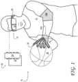
- FIG. 1shows aspects of an example virtual-reality (VR) system 10, configured to present a lifelike VR environment to user 12.
- VR system 10includes a headset 14 and a plurality of electronically functional wearable devices 16.
- the headsetincludes a stereoscopic display 18 configured to display virtual imagery in the field of view of the user.
- the stereoscopic displayis see-through, enabling real-world and virtual imagery to be admixed in the user's field of view. That approach is referred to as augmented or mixed reality (MR).
- MRaugmented or mixed reality
- signal encoding the virtual display imageryis sent to the stereoscopic display via on-board computer 20.
- the on-board computerincludes at least one processor 22 and associated computer memory 24.
- Leveraging communications componentry arranged in headset 14, on-board computer 20may be coupled communicatively to one or more off-board computers on a network.
- the virtual display imagery that user 12 seesmay, in some examples, be composed and/or rendered by an off-board computer. In other examples, the virtual display imagery may be composed and rendered on-board.
- Headset 14includes stereophonic loudspeakers 26 that enable user 12 to experience immersive VR audio.
- Electronically functional wearable devices 16 of VR system 10are configured to further augment the immersive VR experience by providing lifelike physical sensation responsive to user interaction with the virtual environment.
- electronically functional wearable device 16Atakes the form of a glove, which is worn on the hand of the user
- electronically functional wearable device 16Btakes the form of a sleeve worn around the arm.
- a sleeve supporting a haptic devicemay be worn alternatively or additionally on the leg or other body part in some examples.
- Each electronically functional wearable device 16may be configured to provide a resistive physical sensation in response to detection of contact between the body of user 12 and a virtual display object projected into a field of view of the user.
- the resistive physical sensationmay be provided whenever the hand of the user intersects virtual display object 28, for example.
- electronically functional wearable glove device 16Aoptionally includes a skin-pressure simulation portion 30.
- the skin-pressure simulation portionis a component of the haptic device configured to apply touch-simulating pressure to the user's skin in the vicinity of contact with a virtual display object.
- the skin-pressure simulation portionmay include an actuator configured to apply pressure in a direction normal to the surface of the skin.
- the skin-pressure simulation portionmay include a piezoelectric or voice-coil type actuator, for example.
- electronically functional wearable device 16Amay include one or more bodyconfiguration sensors (not shown in FIG. 1 ) and may be coupled operatively to one or more computers of VR system 10, such as on-board computer 20 of headset 14.
- the computermay host a model of the virtual environment and may also track the position of the user's hand with reference to the real-world coordinates of that model.
- the actuatorWhen contact between the hand and a solid virtual object is indicated, the actuator may be energized such that pressure is applied to the skin. The actuator may be de-energized when contact is no longer indicated.
- each haptic device 16includes at least one body-movement restriction portion 32.
- a body-movement restriction portion 32may be used either with or without an associated skin-pressure simulation portion 30, in various implementations.
- a haptic devicemay include a different number of body-movement restriction portions (e.g ., one for each of the thumb, forefinger and ring finger).
- FIG. 2shows aspects of an example body-movement restriction portion 32 of n electronically functional glove device 16A.
- electronically functional glove device 16Ais worn on hand 33 of a user.
- the illustrated body-movement restriction portionincludes an electrostatic slide clutch 34.
- the electrostatic slide clutchis configured to vary the sliding and/or static frictional force between two substrates 36 movable translationally with respect to each other.
- first substrate 36Ais coupled directly to the user's hand on a first side of a skeletomuscular joint 38.
- Second substrate 36Bis coupled indirectly to the opposite side of the skeletomuscular joint, via connector 40.
- the connectormay take the form of a wire or yarn segment, for example.
- the electrostatic slide clutch and connectorare arranged between inner layer 41A and outer layer 41B of a flexible, fabric glove.
- Connector 40connects second substrate 36B to various locations on the inner layer of the fabric glove.
- a single clutch and connectorcontrol motion restriction for all of the skeletomuscular joints of the finger.
- two or more electrostatic slide clutchesmay be provided for a given finger. More particularly, two or more electrostatic slide clutches may be configured to provide independent resistive force at two or more joints of the finger, via independent connectors.
- Electrostatic slide clutch 34optionally includes a tensioner 44. In the illustrated example, the tensioner is coupled between first substrate 36A and second substrate 36B and configured to apply tension to guide wire 40.
- the tensionermay include a spring or elastic band, for example.
- the result of the tension in the guide wireis to provide an unbalanced force that draws grip portion 42 towards the clutch when the clutch is unlocked.
- the frictional force exerted by the clutchbalances the force of the tensioner, so that the grip portion ceases to be drawn towards the clutch.
- both the first and second substrates 36may be coupled directly to the user's body at a location extending over skeletomuscular joint 38.
- both the first and second substratesmay be coupled indirectly to the user's body, via appropriate connectors and grip portions.
- the body-movement restriction portionmay take the form of a tube around the finger that becomes stiffer to restrict movement.
- the substratesmay be arranged as overlapping scales akin to a medieval armor glove.
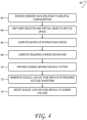
- FIG. 3shows a schematic view of electrostatic slide clutch 34 in one example.
- the electrostatic slide clutchincludes multiple parallel layers of each of a first sheet electrode 46A and a second sheet electrode 46B oriented parallel to the first sheet electrode. In other examples, a single layer of each electrode may be used.
- the first sheet electrodeis formed on or bonded to first substrate 36A
- the second sheet electrodeis formed on or bonded to second substrate 36B.
- each of the first and second substratesmay be secured directly to the body of the user, secured indirectly via a grip portion and/or guide wire, or otherwise closely coupled to an articulable region of the user's body.
- an itself electrodemay be applied directly to the skin, such that no distinct substrate is required for that electrode.
- first sheet electrode 46A and second sheet electrode 46Bmay include an electrically conductive, continuous or discontinuous (e.g ., patterned) film applied to an underlying substrate.
- a filmmay be applied using solution-process methods, for instance.
- electrically conductive filmsinclude ink-jet, screen-printed, gravure printed, or flexographic -printed films.
- Other examplesinclude slot-die coatings and spin coatings of conductive films.
- Graphite, silver, or gold films, for example,may also be used.
- a metal-film electrodemay be formed by vacuum deposition methods such as physical vapor deposition (PVD) of one or more metals-aluminum or copper, etc .-onto a substrate.
- PVDphysical vapor deposition
- Chemical vapor deposition, electroless plating, electroplating, atomic-layer deposition, and/or other forms of material depositionmay also be used.
- Suitable electrode substratesmay be rigid or flexible, depending on the detailed configuration of electrostatic slide clutch 34.
- first and second sheet electrodes 46may be flexible.
- a flexible electrodemay be formed from a woven or non-woven conductive fabric, for instance.
- one or both of the first and second sheet electrodesmay have relatively high sheet resistance, as very little current is drawn through the sheet electrodes during operation of electrostatic slide clutch 34 ( vide infra ) .
- a dielectric layer 48is disposed on first sheet electrode 46A on a face of the first sheet electrode opposing second sheet electrode 46B.
- the dielectric layeris arranged in slidable contact with the second sheet electrode.
- electrostatic slide clutch 34further comprises a second dielectric layer disposed on the second sheet electrode on a face of the second sheet electrode opposing the first sheet electrode.
- the first and second dielectric layersmay be arranged in slidable contact with each other.
- each of first sheet electrode 46A, second sheet electrode 46B, and dielectric layer 48present multiple parallel layers. This configuration may result from folding the first and second sheet electrodes and the dielectric into zig-zag ( i.e. , accordion) shape. Alternatively, multiple discrete sheetelectrode may be used, with connections between equivalent electrodes made externally. Both tactics serve to increase the interfacial electrode area while limiting the form factor of the electrostatic slide clutch.
- electrostatic slide clutch 34may include a guide 50 configured to guide the relative sliding motion of the first and second sheet electrodes.
- the guidemay include a slot for one or both of the first and second sheet electrodes.
- the guideis fixedly coupled to first substrate 36A.
- the guidemay accommodate a plurality of pairs of opposing first and second sheet electrodes, to achieve increased frictional force.
- guide 50accommodates a displacement sensor 52, which provides an output signal responsive to the displacement of the second sheet electrode or substrate relative to the first sheet electrode or substrate.
- a displacement sensor 52which provides an output signal responsive to the displacement of the second sheet electrode or substrate relative to the first sheet electrode or substrate.
- the second sheet electrode or substratemay include a plurality of contrast features detectable by a small photodiode mounted to the first sheet electrode or substrate, so as to generate a digital pulsetrain as the second sheet electrode slides along the first. The relative position of the two electrodes may be revealed, accordingly, by a digital counter clocked by the pulsetrain.
- Analog resistive and capacitive displacement sensorsmay also be used.
- a displacement signalmay be derived from a sensor not located on guide 50, but elsewhere in body-movement restriction portion 32. In each case, output signal from the displacement sensor may facilitate various computations described herein- e.g ., estimating the degree of extension of the user's finger and the area of overlap between the first and second sheet electrodes ( vide infra ) .
- Electrostatic slide clutch 34further includes a drive circuit 54 electrically coupled to first sheet electrode 46A and to second sheet electrode 46B and configured to charge and discharge the first and second sheet electrodes by a controlled, variable amount.
- the effect of the variable charge and dischargeis to influence the normal force between the first and second sheet electrodes.
- Positive voltagemay be applied to the first sheet electrode relative to the second sheet electrode, or vice versa.
- an alternating voltage of suitable frequencymay be used, to facilitate dynamically changing the force applied during sliding operation, as described below.
- haptic device 16may be configured to provide the sensation of physical contact with one or more of the virtual objects.
- drive circuit 54includes a pulse-width modulator 56 and a high-voltage booster 58.
- the drive circuitis coupled operatively to computer 20 and configured to execute an electrostatic clutch-drive process to provide haptic feedback to user in a VR environment.
- FIG. 4illustrates an example electrostatic clutch-drive process 60 in one example embodiment.
- computer 20maintains a mapping of the virtual objects in the user's environment.
- the mappingmay include the position and shape of each virtual object.
- the mappingmay also include certain material properties (e.g ., stress-strain properties) of each virtual object and a matrix of interaction forces among the various virtual objects.
- the computerreceives sensory data relating to the user's skeletal configuration-from displacement sensors 52, image data from the hand, etc.
- the computermaps the user's skeleton and the virtual objects onto the same 3D space.
- the computercomputes a matrix of interaction forces between the virtual objects and the parts of the user's body that are equipped with a body-movement restriction portion 32. More particularly, the computer may be configured to resolve each of the interaction forces into suitable vector components, and thereby compute the required friction force to be realized at each electrostatic slide clutch 34 of the associated body-movement restriction portion. In configurations in which there is the electrostatic slide clutch includes an optional tensioner 44, the restorative force exerted by the tensioner may be included in the calculation.
- the computercomputes the required amount of charge to be separated across sheet electrodes 46. In configurations in which only the overlapping portions of the sheet electrodes can exert a normal force against each other, this calculation may incorporate the overlap area as an input parameter. As noted above, signal responsive to the overlap area is obtained from displacement sensors 52. Additional parameters in the calculation include the amount and polarity of the charge already separated across the sheet electrodes, which may be estimated, stored in computer 20 as a system variable.
- this datais provided to pulse-width modulator (PWM) 56.
- PWMpulse-width modulator
- the PWMcomposes a pulse-modulated a.c. signal (possibly with a d.c. offset voltage) corresponding to ( i.e., having an integral over time which is proportional to) the d.c. control voltage supplied by the computer. More specifically, the PWM generates a scaled, low-voltage replica of a voltage waveform that, when applied across sheet electrodes 46, will cause the desired quantity of charge to flow in the desired direction.
- the waveform generated by the PWMmay be governed by any suitable conditions or parameters. For instance, the applied pulses may be rectangular or sinusoidal.
- the applied pulsesmay have a fixed amplitude and variable period, or a variable amplitude and period.
- the pulse amplitudemay switch between or among discrete voltage values- e.g ., between -5 and +5 volts.
- the PWMmay receive sensory input indicative of the variable area of overlap, and apply the same as an input parameter in determining the appropriate voltage waveform.
- the output of the PWMis fed to high-voltage booster 58, which scales the voltage up to the required level- e.g ., to within a range of -1000 to +1000 volts, depending upon the electrode and dielectric materials and structures used.
- FIG. 5provides a schematic diagram of high-voltage booster 58 in one example.
- the material properties of dielectric layer 48may be selected for suitable resistance to sliding wear and to provide a suitably high coefficient of static and/or sliding friction, so that an increase in the normal force between the dielectric layer and second sheet electrode 46B restricts the relative sliding motion of the first and second sheet electrodes.
- Dielectric layer 48may be of a thickness selected to achieve a suitably strong normal force at a given voltage, and thereby reduce the operating voltage for operation of electrostatic clutch 34. Both the electric field strength and the charge are inversely proportional to the distance between the electrodes, so the normal force is inversely proportional to the square of the distance and directly proportional to the surface area of overlap between the first and second sheet electrodes. In some implementations, roughening, texturing, and/or shaping the electrodes over an appropriate length scale may amplify the effective overlap area.
- dielectric layer 48includes a dielectric material.
- the dielectric materialmay be selected to exhibit a high dielectric strength in order to support a large electric field without suffering breakdown. Moreover, the dielectric material may exhibit a relatively high dielectric constant to achieve a relatively high normal force at a given voltage. Increasing the dielectric constant of the dielectric material increases proportionately the surface charge on first and second sheet electrodes 46, resulting in a proportional increase in the normal force at a given voltage.
- a 10 ⁇ m thick electrically insulating poly(vinylidenefluoride-trifluoroethylene-chlorofluoroethylene)) (P(VDF-TrFE-CFE)) sheetprovides adequate normal force with 150 volts applied between the first and second sheet electrodes.
- the dielectric material of dielectric layer 48may be a homogeneous, sheet-forming material, such as a polymer of suitable dielectric constant and dielectric strength.
- the dielectric layermay be a solid material composite (i.e., a mixture) comprising the dielectric material dispersed and immobilized within a polymer matrix.
- the dielectricmay include finely divided aluminum oxide or barium titanate dispersed in poly(vinylidenefluoride) (PVDF). Table 1 lists physical properties of various example dielectric materials. Table 1.
- Dielectric Materials Materiala VD c Static b Sliding b Dielectric Constant Dielectric Strength d PTFE 0.04 2.1 500 Al 2 O 3 / Sapphire yes 1.05 - 1.13 1.4 9.34 16 SiO 2 yes 3.9 Si 3 N 4 yes 7.5 Dragon Skin Medium 2.7-3 13 P7670 2.7 - 3 30 - 80 Polyimide 0.63 0.48 3.4 303 Polyurethane 7.1 -30 PVC 3.5 - 8 PE 2.5 HTT C1 yes 20 - 25 HTT T1 yes 60 80 SU8-2000 no 4.1 SU8-3000 no 3.2 Plexiglas 1.9 Pyrex no 0.9 - 1 0.4 4.7 Natural rubber no 1 - 4 0.5 - 1 2 - 2.5 BaTiO 3 yes 1200 - 10000 PET 2.9 50 - 100 PFA 2.1 Parylene yes 2.5 - 2.67 ZrO 2 yes 10 - 23 (Pb,La)(Zr,Ti)O 3 (PLZT) yes 440 Ta 2 O 5 yes 25 TiO
- Dielectric layer 42may be formed on or bonded to first sheet electrode 46A in any suitable manner.
- first sheet electrode 46Amay include a conductive fabric.
- the dielectric material of dielectric layer 42may permeate the conductive fabric of the first sheet electrode.
- the dielectric layermay be blade-cast or spin-cast, for example, to a thickness of 1 ⁇ m, or deposited on the first sheet electrode by vapor-phase deposition. Both physical vapor deposition and chemical vapor deposition are envisaged. Table 1 provides non-limiting examples of dielectric materials amenable to vapor-phase deposition.
- dielectric layer 42may be subject to surface treatment.
- a chemical surface treatmentmay be used to modify coefficients of static and/or sliding friction, or to increase the wear resistance or dielectric strength of the dielectric layer.
- Physical surface treatmentsuch as mechanical abrasion may be used to roughen the dielectric layer to increase the frictional coefficients, or to prepare the sheet for chemical surface treatment, for example.
- Second sheet electrode 46Bmay also be subject to chemical and physical surface treatment, for similar advantages.
- the dielectric layermay have a heterogeneous surface structure (which also may be referred to as a composite surface structure) having zones differing in one or more of dielectric composition, matrix composition, surface treatment and/or surface relief.
- the length scale of the heterogeneityi.e., the size of the various zones
- the length scaleis not particularly limited; the length scale may differ from one embodiment to the next and may range from microns to tens of millimeters.
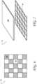
- the heterogeneous surface structure of dielectric layer 48'includes a millimeter- to micrometerscale pattern of such zones 76. As noted above, zones of other dimensions are also envisaged.
- the illustrated exampleshows a checkerboard pattern of alternating zones 76A and 76B, as a non-limiting example of a patterning of zones.
- This approachmay facilitate fine-tuning of the dielectric constant and surface properties, such as the frictional coefficients.
- Strictly or substantially two-dimensional zone patternsmay be used in some examples.
- the zone patternalso may extend normal to the dielectric layer.
- FIG. 7One such example is shown in FIG. 7 .
- the pattern of zones of dielectric layer 48"includes surface features interlocking three-dimensionally with complementary surface features of second sheet electrode 46B". This configuration increases the effective frictional forces between the first and second sheet electrodes.
- zone patternsmay be formed on the dielectric layer 48" and/or second sheet electrode 46B" via a micromolding or embossing procedure. In other examples, the zone patterns may be formed by lithography and/or etching. In the examples provided above, the heterogeneous surface structure of the dielectric layers is on the micrometer-to-millimeter scale.
- a motion restricting apparatusmay comprise a heterogeneous surface structure in the form of macroscopically separate frictional and dielectric surfaces.
- FIG. 8shows an example of such a structure. Separating frictional surface 76B from dielectric surface 76A lessens wear on the dielectric surface with repeated actuation of electrostatic slide clutch 34. This approach also may facilitate subjecting the frictional and dielectric surfaces to different surface treatments. For example, the dielectric surface may be treated with a lubricant to lessen wear, while the frictional surface may remain unlubricated, in order to preserve the high frictional coefficients.
- second sheet electrode 46B'"includes a low-friction zone 78A opposing the dielectric surface of the dielectric layer and a high-friction zone 78B opposing the frictional surface of the dielectric layer.
- the first and second sheet electrodesmay be shaped so as to provide a region of overlap of a predetermined or changing geometry as the electrodes move against each other. For instance, non-rectangular electrodes may provide a changing area of overlap (and normal force, therefore) as one electrode slides over the other.
- haptic device 16may be non-wearable, but instead integrated into a control, such as a dial.
- the electrostatic slide clutch of the haptic devicemay provide variable resistance to the turning of the dial, or give the sensation of a series of detents, for example, pursuant to resistive applied via a drive circuit 54.
- an electrostatic slide clutch as described hereinmay be used to provide controlled resistance between moving parts of a mechanical system of virtually any description.
- an electrostatic slide clutchmay be arranged in a hinge linking the keyboard and display portions of a laptop computer. The clutch may be configured to lock the display portion at various angles relative to the keyboard portion, and to unlock to enable the laptop computer to be closed.
- a body-movement restriction portion in the form of an electrostatic slide clutchmay be used in medical, rather than computer-technology applications. Controllable body-movement restriction may be useful for the patient rehabilitating from a skeletomuscular injury such as back / knee injury, or brain injury such as stroke. In other examples, a body-movement restriction portion may be used as an active restraint for management of seizures or potentially dangerous body movements associated with autism, psychiatric disorders, or acute substance abuse.
- a body-movement restriction portion in the form of an electrostatic slide clutchmay also be amenable to various industrial-safety applications.
- machine vision or other environment-sensing componentrymay be used to assess whether persons are in close proximity to potentially dangerous machinery. Persons wearing an appropriate body-movement restriction portion operatively coupled to the environment-sensing componentry may be protected from drawing too close to the machinery, extending a hand or finger into a cutting device, etc.
- a body-movement restriction portion worn by a workermay be configured for skeletal strain mitigation. When the worker is carrying a heavy object, the body-movement restriction portion may lock into place, providing additional resistance to motion and relieving stress on the worker's fingers, wrists, arms, legs, and other skeletal joints.
- an electrostatic slide clutch as described abovemay be used in a variety of electromechanical applications.
- the clutchmay be used to provide positive braking for a servomechanical (e.g ., a robotic, soft robotic, and/or ball-joint) actuator.
- a servomechanicale.g ., a robotic, soft robotic, and/or ball-joint
- One aspect of this disclosureis directed to an electrostatic slide clutch comprising: a first sheet electrode; a second sheet electrode oriented parallel to first sheet electrode; a dielectric layer between the first and second sheet electrodes; and a drive circuit coupled electrically to the first sheet electrode and to the second sheet electrode, the drive circuit being configured to move a variable amount of charge bidirectionally between the first and second sheet electrodes, to influence a normal force between the first and second sheet electrodes.
- the drive circuitincludes a pulse-width modulator configured to vary an output pulse width in response to a control signal.
- the output pulse widthis of fixed amplitude.
- the control signalis varied depending upon the charge already separated across the first and second sheet electrodes.
- the electrostatic slide clutchfurther comprises a displacement sensor responsive to an area of overlap between the first and second sheet electrodes, wherein the control signal depends upon an output of the displacement sensor.
- the drive circuitincludes high-voltage booster, and wherein the output of the pulse-width modulator is boosted by the high-voltage booster.
- the dielectric layeris a first dielectric layer
- the electrostatic slide clutchfurther comprising a second dielectric layer disposed on the second sheet electrode on a face of the second sheet electrode opposing the first sheet electrode, and wherein the first and second dielectric layers are arranged in slidable contact with each other.
- the dielectric layerincludes a dielectric material dispersed in a polymer matrix.
- the dielectric materialincludes a composite material including barium titanate.
- the dielectric layerincludes a vapor-phase deposited film.
- a haptic devicecomprising a body-movement restriction portion including an electrostatic slide clutch, comprising: a first sheet electrode; a second sheet electrode opposing the first sheet electrode; a dielectric layer disposed on the first sheet electrode opposing the second sheet electrode; and a drive circuit coupled electrically to the first sheet electrode and to the second sheet electrode, the drive circuit being configured to move a variable amount of charge bidirectionally between the first and second sheet electrodes, to influence a normal force between the first and second sheet electrodes.
- the drive circuitincludes a pulse-width modulator and a high-voltage booster.
- the haptic devicefurther comprises a tensioner configured to apply sliding force to the second sheet electrode relative to the first sheet electrode.
- the dielectric layeris arranged in slidable contact with the second sheet electrode, and wherein an increase in the normal force restricts relative sliding motion of the first and second sheet electrodes.
- the haptic devicefurther comprises a displacement sensor configured to provide an output signal responsive to displacement of the second sheet electrode relative to the first sheet electrode.
- one or both of the first and second sheet electrodesis flexible.
- the first and second sheet electrodes and the dielectric layerare arranged in parallel and folded in a zig-zag manner, to achieve increased frictional force for a given applied voltage.
- the first and second sheet electrodesare among a plurality of pairs of parallel sheet electrodes, and wherein a dielectric layer is arranged between the electrodes of each pair.
- the first sheet electrodeis configured to be positioned on a first side of a skeletomuscular joint of the user, and the second sheet electrode is coupled indirectly to a second, opposite side of the skeletomuscular joint.
- a virtual reality systemcomprising: a body-movement restriction portion in the form of an electrostatic slide clutch, comprising: a first electrode; a second electrode oriented parallel to first sheet electrode, the second sheet electrode disposed on a second substrate; a dielectric layer disposed on the first sheet electrode on a face of the first sheet electrode opposing the second sheet electrode; and a drive circuit coupled electrically to the first sheet electrode and to the second sheet electrode, the drive circuit being configured to move a variable amount of charge bidirectionally between the first and second sheet electrodes, to influence a normal force between the first and second sheet electrodes in response to detection of contact between the body of the user and a virtual display object projected into a field of view of the user.
Landscapes
- Engineering & Computer Science (AREA)
- General Engineering & Computer Science (AREA)
- Theoretical Computer Science (AREA)
- Human Computer Interaction (AREA)
- Physics & Mathematics (AREA)
- General Physics & Mathematics (AREA)
- User Interface Of Digital Computer (AREA)
Description
- A state-of-the-art virtual reality (VR) or mixed reality (MR) holographic system may immerse a user in a convincing alternative reality, where visual and auditory aspects of virtual objects are represented in a true-to-life manner. However, VR and MR systems may fail to provide an equally satisfying tactile experience-i.e., an experience in which virtual objectsfeel like the real objects they represent. True-to-life tactile simulation is also valuable in numerous other application areas besides VR and MR.
WO2005/089176A2 discloses a meta-material with an actively controllable mechanical property. The meta-material includes a deformable structure and a set of activation elements. The activation elements are controllable between multiple states.WO2011/116357A2 discloses an electroadhesive device including an outer surface adapted to interface with a surface of a foreign substrate, a plurality of electrodes, and a semi-conductive insulation material disposed adjacent to at least one of the electrodes.WO2016/057963A1 discloses an electrostatic clutch comprising a plurality of micron-scale thickness electrodes, adjacent electrodes being separated by a thin film of dielectric material.- The invention is set out in the independent claim 1 with preferred embodiments being set out in the dependent claims.
- The examples here disclosed relate to an electrostatic slide clutch that may be used for tactile force control in mixed reality and virtual reality settings. One electrostatic slide clutch comprises first and second sheet electrodes, a dielectric layer between the first and second electrodes, and a drive circuit. The drive circuit is coupled electrically to the first sheet electrode and to the second sheet electrode and configured to move a variable amount of charge bidirectionally between the first and second sheet electrodes, to influence a normal force between the first and second sheet electrodes.
- This Summary is provided to introduce a selection of concepts in a simplified form that are further described below in the Detailed Description. This Summary is not intended to identify key features or essential features of the claimed subject matter, nor is it intended to be used to limit the scope of the claimed subject matter. Furthermore, the claimed subject matter is not limited to implementations that solve any or all disadvantages noted in any part of this disclosure.
FIG. 1 shows aspects of an example VR system including a body-movement restriction device.FIG. 2 shows aspects of an example body-movement restriction portion of a haptic device.FIG. 3 show aspects of an example electrostatic slide clutch of a body-movement restriction portion of a haptic device.FIG. 4 illustrates an example electrostatic clutch drive process.FIG. 5 is a schematic diagram of an example boost circuit for an electrostatic slide clutch.FIG. 6 shows aspects of an example dielectric layer of an electrostatic slide clutch.FIGS. 7 and8 show aspects of other example dielectric layers.- This disclosure is presented by way of example, and with reference to the drawing figures listed above. Components, process steps, and other elements that may be substantially the same in one or more of the figures are identified coordinately and described with minimal repetition. It will be noted, however, that elements identified coordinately may also differ to some degree. It will be further noted that the figures are schematic and generally not drawn to scale. Rather, the various drawing scales, aspect ratios, and numbers of components shown in the figures may be purposely distorted to make certain features or relationships easier to see.
- This disclosure relates to a body-movement restriction device based on an electrostatic slide clutch. The electrostatic slide clutch includes a drive circuit being configured to move charge bidirectionally, which may provide realistic resistive force control for various computing device applications, including but not limited to mixed reality and virtual reality applications. For example, a body-movement restriction device may be incorporated into an electronically functional wearable textile device (e.g., a glove) that includes sensors to sense motions of a user's finger joints. Such an electronically functional wearable textile device then may be used to interact with virtual objects displayed on a computer monitor or other suitable display. As a more specific example, a user may use hand and/or finger motions to control the shaping of a spinning virtual pottery object displayed on a computer monitor via joint movement sensors incorporated in a glove for controlling a displayed virtual hand. Here, body movement restriction devices may be used to provide to the user wearing the glove the sensation that hand motion is restricted by touching the displayed spinning virtual pottery object.
FIG. 1 shows aspects of an example virtual-reality (VR)system 10, configured to present a lifelike VR environment touser 12. The VR system as illustrated inFIG. 1 is used to support virtual game play but may be used in numerous other application areas as well.VR system 10 includes aheadset 14 and a plurality of electronically functional wearable devices 16. The headset includes astereoscopic display 18 configured to display virtual imagery in the field of view of the user. In some examples, the stereoscopic display is see-through, enabling real-world and virtual imagery to be admixed in the user's field of view. That approach is referred to as augmented or mixed reality (MR). Inheadset 14, signal encoding the virtual display imagery is sent to the stereoscopic display via on-board computer 20. The on-board computer includes at least oneprocessor 22 and associatedcomputer memory 24.- Leveraging communications componentry arranged in
headset 14, on-board computer 20 may be coupled communicatively to one or more off-board computers on a network. Thus, the virtual display imagery thatuser 12 sees may, in some examples, be composed and/or rendered by an off-board computer. In other examples, the virtual display imagery may be composed and rendered on-board. Headset 14 includesstereophonic loudspeakers 26 that enableuser 12 to experience immersive VR audio. Electronically functional wearable devices 16 ofVR system 10 are configured to further augment the immersive VR experience by providing lifelike physical sensation responsive to user interaction with the virtual environment. In the example shown inFIG. 1 , electronically functionalwearable device 16A takes the form of a glove, which is worn on the hand of the user, and electronically functionalwearable device 16B takes the form of a sleeve worn around the arm. A sleeve supporting a haptic device may be worn alternatively or additionally on the leg or other body part in some examples.- Each electronically functional wearable device 16 may be configured to provide a resistive physical sensation in response to detection of contact between the body of
user 12 and a virtual display object projected into a field of view of the user. The resistive physical sensation may be provided whenever the hand of the user intersects virtual display object 28, for example. - In the example illustrated in
FIG. 1 , electronically functionalwearable glove device 16A optionally includes a skin-pressure simulation portion 30. The skin-pressure simulation portion is a component of the haptic device configured to apply touch-simulating pressure to the user's skin in the vicinity of contact with a virtual display object. The skin-pressure simulation portion may include an actuator configured to apply pressure in a direction normal to the surface of the skin. The skin-pressure simulation portion may include a piezoelectric or voice-coil type actuator, for example. In order to determine when to apply the pressure, electronically functionalwearable device 16A may include one or more bodyconfiguration sensors (not shown inFIG. 1 ) and may be coupled operatively to one or more computers ofVR system 10, such as on-board computer 20 ofheadset 14. More specifically, the computer may host a model of the virtual environment and may also track the position of the user's hand with reference to the real-world coordinates of that model. When contact between the hand and a solid virtual object is indicated, the actuator may be energized such that pressure is applied to the skin. The actuator may be de-energized when contact is no longer indicated. - Although skin-
pressure simulation portion 30 may simulate the sensation of the touch of a virtual object on the user's skin, this aspect alone may not provide a satisfactory contact sensation, as it would not offer a realistic effect of object contact on the user's skeletal joints. Contact with an actual solid object, by comparison, would result in the sensation of kinematic resistance to attempted movement through the object, which would be felt at the joints. In particular, the joints of the fingers, in attempting to move the fingers through a solid object, would experience at least some reactive force from the object. To simulate this sensation, each haptic device 16 includes at least one body-movement restriction portion 32. A body-movement restriction portion 32 may be used either with or without an associated skin-pressure simulation portion 30, in various implementations. In the example of electronicallyfunctional glove device 16A ofFIG. 1 , five separate but substantially equivalent body-movement restriction portions 32 may be provided-one for each finger. In other examples, a haptic device may include a different number of body-movement restriction portions (e.g., one for each of the thumb, forefinger and ring finger). FIG. 2 shows aspects of an example body-movement restriction portion 32 of n electronicallyfunctional glove device 16A. In this example, electronicallyfunctional glove device 16A is worn onhand 33 of a user. The illustrated body-movement restriction portion includes anelectrostatic slide clutch 34. The electrostatic slide clutch is configured to vary the sliding and/or static frictional force between two substrates 36 movable translationally with respect to each other. In the example ofFIG. 2 ,first substrate 36A is coupled directly to the user's hand on a first side of a skeletomuscular joint 38.Second substrate 36B is coupled indirectly to the opposite side of the skeletomuscular joint, viaconnector 40. The connector may take the form of a wire or yarn segment, for example. In the illustrated example, the electrostatic slide clutch and connector are arranged betweeninner layer 41A andouter layer 41B of a flexible, fabric glove.Connector 40 connectssecond substrate 36B to various locations on the inner layer of the fabric glove. In the example illustrated inFIG. 2 , a single clutch and connector control motion restriction for all of the skeletomuscular joints of the finger. In other examples, two or more electrostatic slide clutches may be provided for a given finger. More particularly, two or more electrostatic slide clutches may be configured to provide independent resistive force at two or more joints of the finger, via independent connectors. Electrostatic slide clutch 34 optionally includes atensioner 44. In the illustrated example, the tensioner is coupled betweenfirst substrate 36A andsecond substrate 36B and configured to apply tension to guidewire 40. The tensioner may include a spring or elastic band, for example. The result of the tension in the guide wire is to provide an unbalanced force that draws grip portion 42 towards the clutch when the clutch is unlocked. When the clutch is locked, the frictional force exerted by the clutch balances the force of the tensioner, so that the grip portion ceases to be drawn towards the clutch.- Configurations differing from that of
FIG. 2 are also envisaged. In some examples, both the first and second substrates 36 may be coupled directly to the user's body at a location extending over skeletomuscular joint 38. In some examples, both the first and second substrates may be coupled indirectly to the user's body, via appropriate connectors and grip portions. In other examples, the body-movement restriction portion may take the form of a tube around the finger that becomes stiffer to restrict movement. Alternatively, the substrates may be arranged as overlapping scales akin to a medieval armor glove. FIG. 3 shows a schematic view of electrostatic slide clutch 34 in one example. The electrostatic slide clutch includes multiple parallel layers of each of afirst sheet electrode 46A and asecond sheet electrode 46B oriented parallel to the first sheet electrode. In other examples, a single layer of each electrode may be used. InFIG. 3 , the first sheet electrode is formed on or bonded tofirst substrate 36A, and the second sheet electrode is formed on or bonded tosecond substrate 36B. As noted above, each of the first and second substrates may be secured directly to the body of the user, secured indirectly via a grip portion and/or guide wire, or otherwise closely coupled to an articulable region of the user's body. In other examples, an itself electrode may be applied directly to the skin, such that no distinct substrate is required for that electrode.- In some examples, one or both of
first sheet electrode 46A andsecond sheet electrode 46B may include an electrically conductive, continuous or discontinuous (e.g., patterned) film applied to an underlying substrate. A film may be applied using solution-process methods, for instance. Examples of electrically conductive films include ink-jet, screen-printed, gravure printed, or flexographic -printed films. Other examples include slot-die coatings and spin coatings of conductive films. Graphite, silver, or gold films, for example, may also be used. In still other examples, a metal-film electrode may be formed by vacuum deposition methods such as physical vapor deposition (PVD) of one or more metals-aluminum or copper,etc.-onto a substrate. Chemical vapor deposition, electroless plating, electroplating, atomic-layer deposition, and/or other forms of material deposition may also be used. Suitable electrode substrates may be rigid or flexible, depending on the detailed configuration ofelectrostatic slide clutch 34. - In some examples, one or both of the first and second sheet electrodes 46 may be flexible. A flexible electrode may be formed from a woven or non-woven conductive fabric, for instance. In some examples, one or both of the first and second sheet electrodes may have relatively high sheet resistance, as very little current is drawn through the sheet electrodes during operation of electrostatic slide clutch 34 (vide infra).
- Continuing in
FIG. 3 , adielectric layer 48 is disposed onfirst sheet electrode 46A on a face of the first sheet electrode opposingsecond sheet electrode 46B. In the illustrated example, the dielectric layer is arranged in slidable contact with the second sheet electrode. In other examples, electrostatic slide clutch 34 further comprises a second dielectric layer disposed on the second sheet electrode on a face of the second sheet electrode opposing the first sheet electrode. There, the first and second dielectric layers may be arranged in slidable contact with each other. As mentioned above, in the illustrated example, each offirst sheet electrode 46A,second sheet electrode 46B, anddielectric layer 48 present multiple parallel layers. This configuration may result from folding the first and second sheet electrodes and the dielectric into zig-zag (i.e., accordion) shape. Alternatively, multiple discrete sheetelectrode may be used, with connections between equivalent electrodes made externally. Both tactics serve to increase the interfacial electrode area while limiting the form factor of the electrostatic slide clutch. - Movement of a finger may cause
second sheet electrode 46B to slide alongfist sheet electrode 46A. In some examples,tensioner 44 may exert a sliding force on the second sheet electrode to cause movement relative to the first sheet electrode. Accordingly, electrostatic slide clutch 34 may include aguide 50 configured to guide the relative sliding motion of the first and second sheet electrodes. The guide may include a slot for one or both of the first and second sheet electrodes. In the example ofFIG. 3 , the guide is fixedly coupled tofirst substrate 36A. In some examples, the guide may accommodate a plurality of pairs of opposing first and second sheet electrodes, to achieve increased frictional force. - In the example illustrated in
FIG. 3 , guide 50 accommodates adisplacement sensor 52, which provides an output signal responsive to the displacement of the second sheet electrode or substrate relative to the first sheet electrode or substrate. Numerous displacement-sensor variants are compatible withelectrostatic slide clutch 34. In one example, the second sheet electrode or substrate may include a plurality of contrast features detectable by a small photodiode mounted to the first sheet electrode or substrate, so as to generate a digital pulsetrain as the second sheet electrode slides along the first. The relative position of the two electrodes may be revealed, accordingly, by a digital counter clocked by the pulsetrain. Analog resistive and capacitive displacement sensors may also be used. Among the capacitive sensors envisaged are examples in which the capacitance between a pair of electrodes in the electrostatic slide clutch itself is measured and used to determine the degree of lateral displacement between the electrodes. A transverse arrangement is also possible, where pressure exerted by the user flexing a joint causes the dielectric layer to thin out in the region where the pressure is applied. Such thinning may register as an increase in the capacitance measured between pairs of electrodes. Further, in some examples, a displacement signal may be derived from a sensor not located onguide 50, but elsewhere in body-movement restriction portion 32. In each case, output signal from the displacement sensor may facilitate various computations described herein-e.g., estimating the degree of extension of the user's finger and the area of overlap between the first and second sheet electrodes (vide infra). - Electrostatic slide clutch 34 further includes a
drive circuit 54 electrically coupled tofirst sheet electrode 46A and tosecond sheet electrode 46B and configured to charge and discharge the first and second sheet electrodes by a controlled, variable amount. The effect of the variable charge and discharge is to influence the normal force between the first and second sheet electrodes. Positive voltage may be applied to the first sheet electrode relative to the second sheet electrode, orvice versa. In some examples, an alternating voltage of suitable frequency may be used, to facilitate dynamically changing the force applied during sliding operation, as described below. - Applying voltage of either polarity causes an amount of unbalanced charge to form on the opposing surfaces of electrodes 46, which draws the electrodes together via the Coulomb force. In the illustrated example, the Coulomb force is balanced by a reactive (i.e., third-law) normal force between
dielectric layer 48 andsecond sheet electrode 46B. Increasing normal force brings about a corresponding increase in both static and sliding friction forces between the dielectric layer and the second sheet electrode. By controlling these frictional forces with reference to the disposition of virtual objects in the user's environment, haptic device 16 may be configured to provide the sensation of physical contact with one or more of the virtual objects. - Continuing in
FIG. 3 , drivecircuit 54 includes a pulse-width modulator 56 and a high-voltage booster 58. In a typical VR application, the drive circuit is coupled operatively tocomputer 20 and configured to execute an electrostatic clutch-drive process to provide haptic feedback to user in a VR environment.FIG. 4 illustrates an example electrostatic clutch-drive process 60 in one example embodiment. At the outset ofprocess 60,computer 20 maintains a mapping of the virtual objects in the user's environment. The mapping may include the position and shape of each virtual object. The mapping may also include certain material properties (e.g., stress-strain properties) of each virtual object and a matrix of interaction forces among the various virtual objects. At 62, the computer receives sensory data relating to the user's skeletal configuration-fromdisplacement sensors 52, image data from the hand,etc. At 64, the computer maps the user's skeleton and the virtual objects onto the same 3D space. At 66, the computer computes a matrix of interaction forces between the virtual objects and the parts of the user's body that are equipped with a body-movement restriction portion 32. More particularly, the computer may be configured to resolve each of the interaction forces into suitable vector components, and thereby compute the required friction force to be realized at eachelectrostatic slide clutch 34 of the associated body-movement restriction portion. In configurations in which there is the electrostatic slide clutch includes anoptional tensioner 44, the restorative force exerted by the tensioner may be included in the calculation. - At 68, based upon the required friction force, the computer computes the required amount of charge to be separated across sheet electrodes 46. In configurations in which only the overlapping portions of the sheet electrodes can exert a normal force against each other, this calculation may incorporate the overlap area as an input parameter. As noted above, signal responsive to the overlap area is obtained from
displacement sensors 52. Additional parameters in the calculation include the amount and polarity of the charge already separated across the sheet electrodes, which may be estimated, stored incomputer 20 as a system variable. - After the required amount and direction of charge separation is calculated, this data, at 70, is provided to pulse-width modulator (PWM) 56. At 72, the PWM composes a pulse-modulated a.c. signal (possibly with a d.c. offset voltage) corresponding to (i.e., having an integral over time which is proportional to) the d.c. control voltage supplied by the computer. More specifically, the PWM generates a scaled, low-voltage replica of a voltage waveform that, when applied across sheet electrodes 46, will cause the desired quantity of charge to flow in the desired direction. The waveform generated by the PWM may be governed by any suitable conditions or parameters. For instance, the applied pulses may be rectangular or sinusoidal. The applied pulses may have a fixed amplitude and variable period, or a variable amplitude and period. In some examples, the pulse amplitude may switch between or among discrete voltage values-e.g., between -5 and +5 volts. In configurations in which the area of overlap between the sheet electrodes varies during use, the PWM may receive sensory input indicative of the variable area of overlap, and apply the same as an input parameter in determining the appropriate voltage waveform. At 74, the output of the PWM is fed to high-
voltage booster 58, which scales the voltage up to the required level-e.g., to within a range of -1000 to +1000 volts, depending upon the electrode and dielectric materials and structures used.FIG. 5 provides a schematic diagram of high-voltage booster 58 in one example. - In some examples, the material properties of
dielectric layer 48 may be selected for suitable resistance to sliding wear and to provide a suitably high coefficient of static and/or sliding friction, so that an increase in the normal force between the dielectric layer andsecond sheet electrode 46B restricts the relative sliding motion of the first and second sheet electrodes. Dielectric layer 48 may be of a thickness selected to achieve a suitably strong normal force at a given voltage, and thereby reduce the operating voltage for operation of electrostatic clutch 34. Both the electric field strength and the charge are inversely proportional to the distance between the electrodes, so the normal force is inversely proportional to the square of the distance and directly proportional to the surface area of overlap between the first and second sheet electrodes. In some implementations, roughening, texturing, and/or shaping the electrodes over an appropriate length scale may amplify the effective overlap area.- In the examples envisaged herein,
dielectric layer 48 includes a dielectric material. The dielectric material may be selected to exhibit a high dielectric strength in order to support a large electric field without suffering breakdown. Moreover, the dielectric material may exhibit a relatively high dielectric constant to achieve a relatively high normal force at a given voltage. Increasing the dielectric constant of the dielectric material increases proportionately the surface charge on first and second sheet electrodes 46, resulting in a proportional increase in the normal force at a given voltage. In one non-limiting example, a 10 µm thick electrically insulating poly(vinylidenefluoride-trifluoroethylene-chlorofluoroethylene)) (P(VDF-TrFE-CFE)) sheet provides adequate normal force with 150 volts applied between the first and second sheet electrodes. - In some examples, the dielectric material of
dielectric layer 48 may be a homogeneous, sheet-forming material, such as a polymer of suitable dielectric constant and dielectric strength. In other examples, the dielectric layer may be a solid material composite (i.e., a mixture) comprising the dielectric material dispersed and immobilized within a polymer matrix. For example, the dielectric may include finely divided aluminum oxide or barium titanate dispersed in poly(vinylidenefluoride) (PVDF). Table 1 lists physical properties of various example dielectric materials.Table 1. Dielectric Materials Materiala VDc Staticb Slidingb Dielectric Constant Dielectric Strengthd PTFE 0.04 2.1 500 Al2O3 / Sapphire yes 1.05 - 1.13 1.4 9.34 16 SiO2 yes 3.9 Si3N4 yes 7.5 Dragon Skin Medium 2.7-3 13 P7670 2.7 - 3 30 - 80 Polyimide 0.63 0.48 3.4 303 Polyurethane 7.1 -30 PVC 3.5 - 8 PE 2.5 HTT C1 yes 20 - 25 HTT T1 yes 60 80 SU8-2000 no 4.1 SU8-3000 no 3.2 Plexiglas 1.9 Pyrex no 0.9 - 1 0.4 4.7 Natural rubber no 1 - 4 0.5 - 1 2 - 2.5 BaTiO3 yes 1200 - 10000 PET 2.9 50 - 100 PFA 2.1 Parylene yes 2.5 - 2.67 ZrO2 yes 10 - 23 (Pb,La)(Zr,Ti)O3 (PLZT) yes 440 Ta2O5 yes 25 TiO2 yes 80 - 170 aDragon Skin Medium is a product of Smooth-On, Inc. of Macungie, PA. P7670 is a product of Wacker Chemie AG of München, Germany; Kapton Mylar, Teonex, Tetoron, and HFF are products of Dupont of Wilmington, DE; HTT C1 and HTT T1 are products of Arkema of Colombes, France; SU8-2000 and SU8-3000 are products of Microchem Corp. of Westborough, MA.bCoefficients of static and sliding friction.cYes indicates that the material is amenable to vapor deposition.dDielectric strength in units of volts per micrometer. - Dielectric layer 42 may be formed on or bonded to
first sheet electrode 46A in any suitable manner. In some examples, as noted above,first sheet electrode 46A may include a conductive fabric. Here, the dielectric material of dielectric layer 42 may permeate the conductive fabric of the first sheet electrode. In other examples, the dielectric layer may be blade-cast or spin-cast, for example, to a thickness of 1 µm, or deposited on the first sheet electrode by vapor-phase deposition. Both physical vapor deposition and chemical vapor deposition are envisaged. Table 1 provides non-limiting examples of dielectric materials amenable to vapor-phase deposition. - In some examples, dielectric layer 42 may be subject to surface treatment. For example, a chemical surface treatment may be used to modify coefficients of static and/or sliding friction, or to increase the wear resistance or dielectric strength of the dielectric layer. Physical surface treatment such as mechanical abrasion may be used to roughen the dielectric layer to increase the frictional coefficients, or to prepare the sheet for chemical surface treatment, for example.
Second sheet electrode 46B may also be subject to chemical and physical surface treatment, for similar advantages. - In some examples, the dielectric layer may have a heterogeneous surface structure (which also may be referred to as a composite surface structure) having zones differing in one or more of dielectric composition, matrix composition, surface treatment and/or surface relief. The length scale of the heterogeneity (i.e., the size of the various zones) is not particularly limited; the length scale may differ from one embodiment to the next and may range from microns to tens of millimeters. In the example shown in
FIG. 6 , the heterogeneous surface structure of dielectric layer 48' includes a millimeter- to micrometerscale pattern of such zones 76. As noted above, zones of other dimensions are also envisaged. The illustrated example shows a checkerboard pattern of alternatingzones FIG. 7 . Here, the pattern of zones ofdielectric layer 48" includes surface features interlocking three-dimensionally with complementary surface features ofsecond sheet electrode 46B". This configuration increases the effective frictional forces between the first and second sheet electrodes. In some examples, zone patterns may be formed on thedielectric layer 48" and/orsecond sheet electrode 46B" via a micromolding or embossing procedure. In other examples, the zone patterns may be formed by lithography and/or etching. In the examples provided above, the heterogeneous surface structure of the dielectric layers is on the micrometer-to-millimeter scale. - In some examples, a motion restricting apparatus may comprise a heterogeneous surface structure in the form of macroscopically separate frictional and dielectric surfaces.
FIG. 8 shows an example of such a structure. Separatingfrictional surface 76B fromdielectric surface 76A lessens wear on the dielectric surface with repeated actuation ofelectrostatic slide clutch 34. This approach also may facilitate subjecting the frictional and dielectric surfaces to different surface treatments. For example, the dielectric surface may be treated with a lubricant to lessen wear, while the frictional surface may remain unlubricated, in order to preserve the high frictional coefficients. In the illustrated example,second sheet electrode 46B'" includes a low-friction zone 78A opposing the dielectric surface of the dielectric layer and a high-friction zone 78B opposing the frictional surface of the dielectric layer. In these and other examples, the first and second sheet electrodes may be shaped so as to provide a region of overlap of a predetermined or changing geometry as the electrodes move against each other. For instance, non-rectangular electrodes may provide a changing area of overlap (and normal force, therefore) as one electrode slides over the other. - No aspect of the foregoing description should be understood in a limiting sense, for numerous variations, extensions, and omissions are contemplated as well. In some configurations, for example, haptic device 16 may be non-wearable, but instead integrated into a control, such as a dial. The electrostatic slide clutch of the haptic device may provide variable resistance to the turning of the dial, or give the sensation of a series of detents, for example, pursuant to resistive applied via a
drive circuit 54. More generally, an electrostatic slide clutch as described herein may be used to provide controlled resistance between moving parts of a mechanical system of virtually any description. For instance, an electrostatic slide clutch may be arranged in a hinge linking the keyboard and display portions of a laptop computer. The clutch may be configured to lock the display portion at various angles relative to the keyboard portion, and to unlock to enable the laptop computer to be closed. - In other examples, a body-movement restriction portion in the form of an electrostatic slide clutch may be used in medical, rather than computer-technology applications. Controllable body-movement restriction may be useful for the patient rehabilitating from a skeletomuscular injury such as back / knee injury, or brain injury such as stroke. In other examples, a body-movement restriction portion may be used as an active restraint for management of seizures or potentially dangerous body movements associated with autism, psychiatric disorders, or acute substance abuse.
- A body-movement restriction portion in the form of an electrostatic slide clutch may also be amenable to various industrial-safety applications. In one example, machine vision or other environment-sensing componentry may be used to assess whether persons are in close proximity to potentially dangerous machinery. Persons wearing an appropriate body-movement restriction portion operatively coupled to the environment-sensing componentry may be protected from drawing too close to the machinery, extending a hand or finger into a cutting device,etc. In other examples, a body-movement restriction portion worn by a worker may be configured for skeletal strain mitigation. When the worker is carrying a heavy object, the body-movement restriction portion may lock into place, providing additional resistance to motion and relieving stress on the worker's fingers, wrists, arms, legs, and other skeletal joints.
- In still other examples, an electrostatic slide clutch as described above may be used in a variety of electromechanical applications. The clutch may be used to provide positive braking for a servomechanical (e.g., a robotic, soft robotic, and/or ball-joint) actuator.
- One aspect of this disclosure is directed to an electrostatic slide clutch comprising: a first sheet electrode; a second sheet electrode oriented parallel to first sheet electrode; a dielectric layer between the first and second sheet electrodes; and a drive circuit coupled electrically to the first sheet electrode and to the second sheet electrode, the drive circuit being configured to move a variable amount of charge bidirectionally between the first and second sheet electrodes, to influence a normal force between the first and second sheet electrodes.
- The drive circuit includes a pulse-width modulator configured to vary an output pulse width in response to a control signal. In some implementations, the output pulse width is of fixed amplitude. In some implementations, the control signal is varied depending upon the charge already separated across the first and second sheet electrodes. The electrostatic slide clutch further comprises a displacement sensor responsive to an area of overlap between the first and second sheet electrodes, wherein the control signal depends upon an output of the displacement sensor. In some implementations, the drive circuit includes high-voltage booster, and wherein the output of the pulse-width modulator is boosted by the high-voltage booster. In some implementations, the dielectric layer is a first dielectric layer, the electrostatic slide clutch further comprising a second dielectric layer disposed on the second sheet electrode on a face of the second sheet electrode opposing the first sheet electrode, and wherein the first and second dielectric layers are arranged in slidable contact with each other. In some implementations, the dielectric layer includes a dielectric material dispersed in a polymer matrix. In some implementations, the dielectric material includes a composite material including barium titanate. In some implementations, the dielectric layer includes a vapor-phase deposited film.
- Another aspect of this disclosure is directed to a haptic device comprising a body-movement restriction portion including an electrostatic slide clutch, comprising: a first sheet electrode; a second sheet electrode opposing the first sheet electrode; a dielectric layer disposed on the first sheet electrode opposing the second sheet electrode; and a drive circuit coupled electrically to the first sheet electrode and to the second sheet electrode, the drive circuit being configured to move a variable amount of charge bidirectionally between the first and second sheet electrodes, to influence a normal force between the first and second sheet electrodes.
- In some implementations, the drive circuit includes a pulse-width modulator and a high-voltage booster. In some implementations, the haptic device further comprises a tensioner configured to apply sliding force to the second sheet electrode relative to the first sheet electrode. In some implementations, the dielectric layer is arranged in slidable contact with the second sheet electrode, and wherein an increase in the normal force restricts relative sliding motion of the first and second sheet electrodes. The haptic device further comprises a displacement sensor configured to provide an output signal responsive to displacement of the second sheet electrode relative to the first sheet electrode. In some implementations, one or both of the first and second sheet electrodes is flexible. In some implementations, the first and second sheet electrodes and the dielectric layer are arranged in parallel and folded in a zig-zag manner, to achieve increased frictional force for a given applied voltage. In some implementations, the first and second sheet electrodes are among a plurality of pairs of parallel sheet electrodes, and wherein a dielectric layer is arranged between the electrodes of each pair. In some implementations, the first sheet electrode is configured to be positioned on a first side of a skeletomuscular joint of the user, and the second sheet electrode is coupled indirectly to a second, opposite side of the skeletomuscular joint.
- Another aspect of this disclosure is directed to a virtual reality system comprising: a body-movement restriction portion in the form of an electrostatic slide clutch, comprising: a first electrode; a second electrode oriented parallel to first sheet electrode, the second sheet electrode disposed on a second substrate; a dielectric layer disposed on the first sheet electrode on a face of the first sheet electrode opposing the second sheet electrode; and a drive circuit coupled electrically to the first sheet electrode and to the second sheet electrode, the drive circuit being configured to move a variable amount of charge bidirectionally between the first and second sheet electrodes, to influence a normal force between the first and second sheet electrodes in response to detection of contact between the body of the user and a virtual display object projected into a field of view of the user.
- It will be understood that the configurations and/or approaches described herein are exemplary in nature, and that these specific embodiments or examples are not to be considered in a limiting sense, because numerous variations are possible within the scope of the claims. The specific routines or methods described herein may represent one or more of any number of processing strategies. As such, various acts illustrated and/or described may be performed in the sequence illustrated and/or described, in other sequences, in parallel, or omitted. Likewise, the order of the above-described processes may be changed.
- The subject matter of the present disclosure includes all novel and non-obvious combinations and sub-combinations of the various processes, systems and configurations, and other features, functions, acts, and/or properties disclosed herein.
Claims (7)
- An electrostatic slide clutch (34) comprising:a first sheet electrode (46A);a second sheet electrode (46B) oriented parallel to first sheet electrode (46A);a dielectric layer (48) between the first and second sheet electrodes (46A, 46B); anda drive circuit (54) coupled electrically to the first sheet electrode (46A) and to the second sheet electrode (46B);characterized in that:the drive circuit (54) includes a pulse-width modulator configured to vary an output pulse width in response to a control signal to apply an alternating voltage to move a variable amount of charge bidirectionally between the first and second sheet electrodes (46A, 46B); andthe electrostatic slide clutch (34) includes a displacement sensor (52) responsive to the area of overlap between the first and second sheet electrodes (46A, 46B), wherein the control signal depends upon an output of the displacement sensor and an amount and polarity of charge already separated across the first and second sheet electrodes (46A, 46B), to influence a normal force between the first and second sheet electrodes (46A, 46B), wherein the amount and polarity of the charge already separated across the first and second sheet electrodes (46A, 46B) is stored in a computer coupled operatively to the electrostatic slide clutch (34).
- The electrostatic slide clutch (34) of claim 1 wherein the output pulse width is of fixed amplitude.
- The electrostatic slide clutch (34) of claim 1 wherein the drive circuit (54) includes high-voltage booster, and wherein the output of the pulse-width modulator is boosted by the high-voltage booster.
- The electrostatic slide clutch (34) of claim 1 wherein the dielectric layer (48) is a first dielectric layer, the electrostatic slide clutch (34) further comprising a second dielectric layer disposed on the second sheet electrode (46B) on a face of the second sheet electrode (46B) opposing the first sheet electrode (46A), and wherein the first and second dielectric layers are arranged in slidable contact with each other.
- The electrostatic slide clutch (34) of claim 1 wherein the dielectric layer (48) includes a dielectric material dispersed in a polymer matrix.
- The electrostatic slide clutch (34) of claim 5 wherein the dielectric material includes a composite material including barium titanate.
- The electrostatic slide clutch (34) of claim 1 wherein the dielectric layer (48) includes a vapor-phase deposited film.
Applications Claiming Priority (2)
| Application Number | Priority Date | Filing Date | Title |
|---|---|---|---|
| US15/968,677US11023047B2 (en) | 2018-05-01 | 2018-05-01 | Electrostatic slide clutch with bidirectional drive circuit |
| PCT/US2019/028425WO2019212775A1 (en) | 2018-05-01 | 2019-04-22 | Electrostatic slide clutch with bidirectional drive circuit |
Publications (2)
| Publication Number | Publication Date |
|---|---|
| EP3769187A1 EP3769187A1 (en) | 2021-01-27 |
| EP3769187B1true EP3769187B1 (en) | 2023-10-18 |
Family
ID=66676873
Family Applications (1)
| Application Number | Title | Priority Date | Filing Date |
|---|---|---|---|
| EP19727527.4AActiveEP3769187B1 (en) | 2018-05-01 | 2019-04-22 | Electrostatic slide clutch with bidirectional drive circuit |
Country Status (3)
| Country | Link |
|---|---|
| US (1) | US11023047B2 (en) |
| EP (1) | EP3769187B1 (en) |
| WO (1) | WO2019212775A1 (en) |
Families Citing this family (16)
| Publication number | Priority date | Publication date | Assignee | Title |
|---|---|---|---|---|
| US11036295B2 (en) | 2016-11-23 | 2021-06-15 | Microsoft Technology Licensing, Llc | Electrostatic slide clutch |
| WO2020003177A1 (en) | 2018-06-28 | 2020-01-02 | 3M Innovative Properties Company | Low voltage electrostatic jamming device |
| US11979098B2 (en)* | 2018-06-28 | 2024-05-07 | 3M Innovative Properties Company | Jamming device with jamming sheets |
| US11984823B2 (en)* | 2018-06-28 | 2024-05-14 | 3M Innovative Properties Company | Electrostatic jamming devices and methods of making such devices |
| US10852825B2 (en) | 2018-09-06 | 2020-12-01 | Microsoft Technology Licensing, Llc | Selective restriction of skeletal joint motion |
| US10942572B1 (en)* | 2019-02-12 | 2021-03-09 | Facebook Technologies, Llc | Systems, methods, and articles using polarizable media in haptic-jamming |
| US10860102B2 (en) | 2019-05-08 | 2020-12-08 | Microsoft Technology Licensing, Llc | Guide for supporting flexible articulating structure |
| US11061476B2 (en) | 2019-05-24 | 2021-07-13 | Microsoft Technology Licensing, Llc | Haptic feedback apparatus |
| US11054905B2 (en)* | 2019-05-24 | 2021-07-06 | Microsoft Technology Licensing, Llc | Motion-restricting apparatus with common base electrode |
| KR102702585B1 (en)* | 2019-12-03 | 2024-09-04 | 삼성전자주식회사 | Electronic apparatus and Method for controlling the display apparatus thereof |
| WO2021207330A2 (en)* | 2020-04-08 | 2021-10-14 | Tactual Labs Co. | Non-uniform electrode spacing with a bend sensor |
| KR102330897B1 (en)* | 2020-08-06 | 2021-12-01 | 한국과학기술연구원 | Tensile Force Detecting Device |
| US12407276B2 (en) | 2021-04-30 | 2025-09-02 | Estat Actuation, Inc. | Rotary electroadhesive clutch |
| TWI861614B (en)* | 2022-12-02 | 2024-11-11 | 宏達國際電子股份有限公司 | Glove |
| US11874964B1 (en)* | 2022-12-02 | 2024-01-16 | Htc Corporation | Glove |
| CN119501974A (en)* | 2024-12-24 | 2025-02-25 | 西安交通大学 | Electrostatic adsorption clutch force feedback data gloves based on teleoperation system and design method thereof |
Family Cites Families (170)
| Publication number | Priority date | Publication date | Assignee | Title |
|---|---|---|---|---|
| US2897425A (en) | 1958-10-21 | 1959-07-28 | Robert W Waring | Method of and apparatus for producing electrostatic force |
| US4753442A (en) | 1987-04-20 | 1988-06-28 | Bland Clyde S W | Baseball glove with automatic ball return device |
| JP2958989B2 (en) | 1988-09-30 | 1999-10-06 | ぺんてる株式会社 | Robot hand device and method for mounting a thin work in a mold |
| US5173834A (en) | 1989-06-02 | 1992-12-22 | Roland Dg Corporation | Electrostatic attraction apparatus |
| US5184319A (en) | 1990-02-02 | 1993-02-02 | Kramer James F | Force feedback and textures simulating interface device |
| US5631861A (en) | 1990-02-02 | 1997-05-20 | Virtual Technologies, Inc. | Force feedback and texture simulating interface device |
| JPH06126661A (en) | 1992-10-12 | 1994-05-10 | Mitsubishi Cable Ind Ltd | Handling device of micropart |
| US5429140A (en) | 1993-06-04 | 1995-07-04 | Greenleaf Medical Systems, Inc. | Integrated virtual reality rehabilitation system |
| US5516249A (en) | 1994-05-10 | 1996-05-14 | Technical Research Associates, Inc. | Exoskeleton with kinesthetic feedback and robotic control |
| IT1281584B1 (en) | 1996-01-02 | 1998-02-20 | Benito Ferrati | ORTHOPEDIC EQUIPMENT FOR WALKING AND REHABILITATION OF MOTU-INJURED PEOPLE WITH THE USE OF ELECTRONIC AND REALITY UNITS |
| US6128004A (en) | 1996-03-29 | 2000-10-03 | Fakespace, Inc. | Virtual reality glove system with fabric conductors |
| US6809462B2 (en) | 2000-04-05 | 2004-10-26 | Sri International | Electroactive polymer sensors |
| US6524681B1 (en) | 1997-04-08 | 2003-02-25 | 3M Innovative Properties Company | Patterned surface friction materials, clutch plate members and methods of making and using same |
| US6042555A (en) | 1997-05-12 | 2000-03-28 | Virtual Technologies, Inc. | Force-feedback interface device for the hand |
| EP2345951A3 (en) | 1997-05-12 | 2013-11-06 | Immersion Corporation | Force-feedback interface device for the hand |
| US7166953B2 (en) | 2001-03-02 | 2007-01-23 | Jon Heim | Electroactive polymer rotary clutch motors |
| SG103371A1 (en) | 2001-12-28 | 2004-04-29 | Matsushita Electric Works Ltd | Wearable human motion applicator |
| AU2002951193A0 (en) | 2002-09-04 | 2002-09-19 | Northern Sydney Area Health Service | Movement faciliatation device |
| US20040084261A1 (en) | 2002-11-01 | 2004-05-06 | Performance Friction Corporation | Brake rotor with a surface having a plurality of indentations formed therein |
| US6966882B2 (en) | 2002-11-25 | 2005-11-22 | Tibion Corporation | Active muscle assistance device and method |
| JP2004213350A (en) | 2002-12-27 | 2004-07-29 | Seiko Epson Corp | Force sense presentation device and image correction method |
| US6790308B2 (en) | 2003-01-03 | 2004-09-14 | Borgwarner Inc. | Method and apparatus for making clutch plate with multi segment friction material |
| WO2004086486A1 (en)* | 2003-03-26 | 2004-10-07 | Riken | Process for producing dielectric insulating thin film, and dielectric insulating material |
| US7046151B2 (en) | 2003-07-14 | 2006-05-16 | Michael J. Dundon | Interactive body suit and interactive limb covers |
| JP2005227111A (en) | 2004-02-12 | 2005-08-25 | Masaru Hakoda | Woven-fabric-like electrode, and substance filter unit |
| CN101095277A (en) | 2004-03-12 | 2007-12-26 | 斯里国际 | Mechanical meta-materials |
| US7365463B2 (en) | 2005-01-10 | 2008-04-29 | Tibion Corporation | High-torque motor |
| US20070016265A1 (en) | 2005-02-09 | 2007-01-18 | Alfred E. Mann Institute For Biomedical Engineering At The University Of S. California | Method and system for training adaptive control of limb movement |
| JP4419872B2 (en) | 2005-03-08 | 2010-02-24 | セイコーエプソン株式会社 | Display device and display module |
| US8160743B2 (en) | 2005-08-16 | 2012-04-17 | Brainlab Ag | Anthropomorphic medical robot arm with movement restrictions |
| US8049772B2 (en) | 2005-10-27 | 2011-11-01 | Reald Inc. | Temperature compensation for the differential expansion of an autostereoscopic lenticular array and display screen |
| US20070195482A1 (en) | 2006-02-23 | 2007-08-23 | Varian Semiconductor Equipment Associates, Inc. | Johnsen-Rahbek electrostatic chuck driven with AC voltage |
| US7551419B2 (en) | 2006-06-05 | 2009-06-23 | Sri International | Electroadhesion |
| US7920124B2 (en) | 2006-08-29 | 2011-04-05 | Canon Kabushiki Kaisha | Force sense presentation device, mixed reality system, information processing method, and information processing apparatus |
| ES2652026T3 (en) | 2006-09-01 | 2018-01-31 | Bioservo Technologies Ab | Reinforcement glove |
| JP4769694B2 (en)* | 2006-11-20 | 2011-09-07 | 富士通テン株式会社 | Voltage output circuit, integrated circuit, and electronic equipment |
| US11389171B2 (en) | 2006-11-21 | 2022-07-19 | David S. Goldsmith | Integrated system for the infixion and retrieval of implants |
| TWI434718B (en) | 2006-12-07 | 2014-04-21 | Cel Kom Llc | Tactile wearable gaming device |
| CN100542505C (en) | 2007-01-08 | 2009-09-23 | 张为众 | artificial arm |
| US8138895B2 (en) | 2007-10-19 | 2012-03-20 | Sony Corporation | Force/tactile feedback device |
| WO2009108072A1 (en) | 2008-02-29 | 2009-09-03 | Auckland Uniservices Limited | Dielectric elastomer actuator |
| JP2010086471A (en) | 2008-10-02 | 2010-04-15 | Sony Corp | Operation feeling providing device, and operation feeling feedback method, and program |
| US8362882B2 (en) | 2008-12-10 | 2013-01-29 | Immersion Corporation | Method and apparatus for providing Haptic feedback from Haptic textile |
| EP2399304B1 (en) | 2009-02-19 | 2015-06-03 | Auckland UniServices Limited | System and method for dynamic self-sensing of dielectric elastomer actuators |
| US9403056B2 (en) | 2009-03-20 | 2016-08-02 | Northeastern University | Multiple degree of freedom rehabilitation system having a smart fluid-based, multi-mode actuator |
| JP5472680B2 (en) | 2009-04-09 | 2014-04-16 | 国立大学法人 筑波大学 | Wearable motion assist device |
| US8255079B2 (en) | 2009-09-22 | 2012-08-28 | GM Global Technology Operations LLC | Human grasp assist device and method of use |
| US20110187637A1 (en) | 2010-01-29 | 2011-08-04 | David Scott Nichols | Tactile Input Apparatus |
| US8325458B2 (en) | 2010-02-10 | 2012-12-04 | Sri International | Electroadhesive gripping |
| US8861171B2 (en) | 2010-02-10 | 2014-10-14 | Sri International | Electroadhesive handling and manipulation |
| JP5883430B2 (en) | 2010-03-19 | 2016-03-15 | エスアールアイ インターナショナルSRI International | Materials for electroadhesion and laminating |
| ES2531160T3 (en) | 2010-03-23 | 2015-03-11 | Idrogenet S R L | Hand rehabilitation device |
| US20110234414A1 (en) | 2010-03-26 | 2011-09-29 | Luis Ojeda | Wearable live electrical circuit detection device |
| BR112012026331A2 (en) | 2010-04-16 | 2017-12-12 | Deregallera Holdings Ltd | apparatus for use as engine or generator, wheel mounting motor, vehicle wheel, sensor / detector transducer, use of apparatus and method of connecting an element of apparatus for use as engine or generator |
| KR20140009191A (en) | 2010-10-18 | 2014-01-22 | 오클랜드 유니서비시즈 리미티드 | Dielectric elastomer self-sensing using plane approximation |
| US8831677B2 (en) | 2010-11-17 | 2014-09-09 | Antony-Euclid C. Villa-Real | Customer-controlled instant-response anti-fraud/anti-identity theft devices (with true-personal identity verification), method and systems for secured global applications in personal/business e-banking, e-commerce, e-medical/health insurance checker, e-education/research/invention, e-disaster advisor, e-immigration, e-airport/aircraft security, e-military/e-law enforcement, with or without NFC component and system, with cellular/satellite phone/internet/multi-media functions |
| US20120154974A1 (en) | 2010-12-16 | 2012-06-21 | Applied Materials, Inc. | High efficiency electrostatic chuck assembly for semiconductor wafer processing |
| US8882285B2 (en) | 2011-01-18 | 2014-11-11 | Desmond Walsh | Illuminating safety glove |
| GB2488760A (en) | 2011-03-01 | 2012-09-12 | Angus Everett Strover | Prosthetic hand with digits actuated by muscles via strings |
| JP6092183B2 (en) | 2011-03-21 | 2017-03-08 | エスアールアイ インターナショナルSRI International | Mobile robot manipulator system |
| DE112012005262A5 (en) | 2011-12-14 | 2014-10-16 | Schaeffler Technologies Gmbh & Co. Kg | coupling device |
| WO2013099104A1 (en) | 2011-12-28 | 2013-07-04 | パナソニック株式会社 | Robot arm |
| US9120220B2 (en) | 2012-02-29 | 2015-09-01 | GM Global Technology Operations LLC | Control of a glove-based grasp assist device |
| JP5435116B2 (en) | 2012-03-15 | 2014-03-05 | 株式会社リコー | Powder container, powder replenishing device for replenishing developer from the powder container, and image forming apparatus on which it is mounted |
| CN203911809U (en) | 2012-05-02 | 2014-10-29 | Sri国际公司 | Electric-adhesion grabbing system |
| GB201208798D0 (en) | 2012-05-18 | 2012-07-04 | Jack Sealey Ltd | Lighting device |
| JP2015519870A (en) | 2012-06-14 | 2015-07-09 | オークランド ユニサービシズ リミテッド | Self-detecting dielectric elastomer device |
| US11904101B2 (en) | 2012-06-27 | 2024-02-20 | Vincent John Macri | Digital virtual limb and body interaction |
| US9351900B2 (en) | 2012-09-17 | 2016-05-31 | President And Fellows Of Harvard College | Soft exosuit for assistance with human motion |
| US11826636B2 (en) | 2013-07-12 | 2023-11-28 | Chris Argiro | Depth sensing module and mobile device including the same |
| US9301563B2 (en) | 2013-02-07 | 2016-04-05 | Nova Diagnostics, Llc | Pressure sensing glove |
| CN105143812B (en) | 2013-02-14 | 2017-09-26 | 帝人芳纶有限公司 | Hard impact resistance product and the method for manufacturing the product |
| CN205521410U (en) | 2013-03-15 | 2016-08-31 | Sri国际公司 | Programmable body augmentation system and platform for body augmentation |
| US9441967B2 (en) | 2013-05-31 | 2016-09-13 | Stanley Black & Decker Inc. | Laser level system |
| US20150132974A1 (en) | 2013-11-13 | 2015-05-14 | David W. Kapella | Adapter for using two one-way light bulbs in a three-way light socket |
| EP3099275B1 (en) | 2014-01-31 | 2021-10-13 | Nuada, Lda | Joint assistive and locking device |
| US10248200B2 (en) | 2014-03-02 | 2019-04-02 | Drexel University | Wearable devices, wearable robotic devices, gloves, and systems, methods, and computer program products interacting with the same |
| US9710060B2 (en) | 2014-06-09 | 2017-07-18 | BeBop Senors, Inc. | Sensor system integrated with a glove |
| EP3594039A1 (en) | 2014-06-24 | 2020-01-15 | SRI International | System and method for electrically controllable transmissions |
| US9606624B2 (en)* | 2014-07-02 | 2017-03-28 | Immersion Corporation | Systems and methods for surface elements that provide electrostatic haptic effects |
| US10423227B2 (en) | 2014-07-21 | 2019-09-24 | Dexta Robotics | Hand exoskeleton force feedback system |
| FR3024030B1 (en) | 2014-07-25 | 2016-08-26 | Commissariat Energie Atomique | DEVICE FOR ASSISTING HAND PRINTING OF THE HAND |
| US20160120734A1 (en) | 2014-10-30 | 2016-05-05 | Elwha Llc | Garment system including at least one sensor and at least one actuator responsive to the sensor and related methods |
| KR20250021617A (en) | 2014-09-02 | 2025-02-13 | 애플 인크. | Wearable electronic device |
| US10355624B2 (en)* | 2014-10-09 | 2019-07-16 | Carnegie Mellon University | Electrostatic clutch |
| WO2016057963A1 (en) | 2014-10-09 | 2016-04-14 | Carnegie Mellon University | Electrostatic clutch |
| DE102015206608A1 (en) | 2014-10-20 | 2016-04-21 | Robert Bosch Gmbh | Safety clothing |
| US9661197B2 (en) | 2014-10-22 | 2017-05-23 | Gopro, Inc. | Quick-release ball-and-socket joint camera mount |
| US20160115707A1 (en) | 2014-10-27 | 2016-04-28 | PD2F, Inc. | Accessory mount for a hunting blind |
| WO2016070078A1 (en) | 2014-10-30 | 2016-05-06 | Bebop Sensors, Inc. | Sensor system integrated with a glove |
| US20160124548A1 (en) | 2014-11-03 | 2016-05-05 | Northwestern University | Materials and structures for haptic displays with simultaneous sensing and actuation |
| AU2015362045C1 (en) | 2014-12-08 | 2020-10-15 | Rohit Seth | Wearable wireless HMI device |
| US9931235B2 (en) | 2014-12-12 | 2018-04-03 | Harris Corporation | Passive locking hand exoskeleton |
| DE102014019582B4 (en) | 2014-12-30 | 2017-03-30 | Philip Zeitler | Haptic devices and methods |
| US10082872B2 (en) | 2014-12-30 | 2018-09-25 | Immersion Corporation | Deformable haptic wearables with variable physical properties |
| US9529433B2 (en) | 2014-12-30 | 2016-12-27 | Stmicroelectronics Pte Ltd | Flexible smart glove |
| US20160209448A1 (en) | 2015-01-16 | 2016-07-21 | Robert H. Currie | Voltage Detector Safety Glove |
| JP6489422B2 (en) | 2015-01-28 | 2019-03-27 | パナソニックIpマネジメント株式会社 | Assist wear, assist wear operating method, and control program |
| CN107209571A (en)* | 2015-01-30 | 2017-09-26 | 意美森公司 | Electrostatic tactile actuator and the user interface with electrostatic tactile actuator |
| WO2016160624A1 (en) | 2015-03-27 | 2016-10-06 | Other Lab Llc | Lower-leg exoskeleton system and method |
| CN108883335A (en) | 2015-04-14 | 2018-11-23 | 约翰·詹姆斯·丹尼尔斯 | Wearable electronic multisensory interfaces for man-machine or man-man |
| US9810973B2 (en) | 2015-04-27 | 2017-11-07 | Sage Elmohtaseb | Omnidirectional bracket for cameras and accessories |
| GB2537899B (en) | 2015-04-30 | 2018-02-21 | Hy5Pro As | Control of digits for artificial hand |
| US10055019B2 (en) | 2015-05-20 | 2018-08-21 | Sony Interactive Entertainment Inc. | Electromagnet-laden glove for haptic pressure feedback |
| US10437136B2 (en) | 2015-05-22 | 2019-10-08 | Timothy P. Lajoie | Modular video attachment with vibration dampening |
| WO2016205143A1 (en) | 2015-06-14 | 2016-12-22 | Sony Interactive Entertainment Inc. | Gloves that include haptic feedback for use with hmd systems |
| US20170014111A1 (en)* | 2015-07-17 | 2017-01-19 | Hoowaki, Llc | Microstructured Surface |
| DE102015113827B4 (en) | 2015-08-20 | 2020-04-23 | Jörg Jurkat | Orthosis for the reciprocal coupling of two body joints |
| US10366583B2 (en) | 2015-08-25 | 2019-07-30 | Immersion Corporation | Bistable haptic feedback generator |
| US20170055596A1 (en) | 2015-08-28 | 2017-03-02 | Raquel Smith Colby | Smart Clothing for Simulated Touch and Concussive Force |
| FR3040803B1 (en) | 2015-09-08 | 2017-09-01 | Commissariat Energie Atomique | GLOVE FOR VIRTUAL OR REMOTE HANDLING AND ASSOCIATED VIRTUAL OR REMOTE HANDLING SYSTEM |
| US10528138B2 (en) | 2015-11-06 | 2020-01-07 | Facebook Technologies, Llc | Virtual reality garment capable of jamming user movement |
| US10572014B2 (en) | 2015-11-09 | 2020-02-25 | Facebook Technologies, Llc | Virtual reality garment configured to restrict user movement by repositioning a rigid cuff relative to the user |
| US10564722B2 (en) | 2015-11-20 | 2020-02-18 | Facebook Technologies, Llc | Restricting user movement via connecting tendons in a garment to a jamming mechanism |
| US10025387B2 (en) | 2015-12-08 | 2018-07-17 | Oculus Vr, Llc | Resisting user movement using actuated tendons |
| US20170165567A1 (en)* | 2015-12-10 | 2017-06-15 | Palm Laboratories Inc. | Haptic mechanism for virtual reality and augmented reality interfaces |
| US10197459B2 (en) | 2015-12-17 | 2019-02-05 | Facebook Technologies, Llc | Indexable strain sensor |
| MX391559B (en) | 2016-01-12 | 2025-03-11 | Grabit Inc | METHODS AND SYSTEMS FOR HANDLING BASED ON ELECTROADHESION AND MECHANICAL RELEASE IN MANUFACTURING. |
| US20170210302A1 (en) | 2016-01-27 | 2017-07-27 | Phong Le | Automobile smartphone extended arm and Dash Cam |
| US10509468B2 (en) | 2016-01-27 | 2019-12-17 | Tactai, Inc. | Providing fingertip tactile feedback from virtual objects |
| CN106726027B (en) | 2016-02-24 | 2019-01-22 | 吉林大学 | An underactuated prosthetic hand |
| WO2017165757A1 (en) | 2016-03-24 | 2017-09-28 | Warwick Mills, Inc. | Wearable safety warning and measurement system |
| US10137362B2 (en) | 2016-05-04 | 2018-11-27 | Thomas F Buchanan, IV | Exo-tendon motion capture glove device with haptic grip response |
| US10894204B2 (en) | 2016-05-04 | 2021-01-19 | Contact Control Interfaces, LLC | Exo-tendon motion capture glove device with haptic grip response |
| GB2552450A (en) | 2016-05-18 | 2018-01-31 | Aylesbury Automation Ltd | Electroadhesive gripper |
| US9921609B2 (en) | 2016-08-02 | 2018-03-20 | Immersion Corporation | Systems and methods for deformation and haptic effects |
| US10318005B2 (en) | 2016-08-09 | 2019-06-11 | Google Llc | Haptic feedback mechanism for an interactive garment |
| WO2018039355A1 (en) | 2016-08-23 | 2018-03-01 | Superflex, Inc. | Systems and methods for portable powered stretching exosuit |
| US11020261B2 (en) | 2016-08-23 | 2021-06-01 | Seismic Holdings, Inc. | Patch systems for use with assistive exosuit |
| US10481688B1 (en) | 2016-09-19 | 2019-11-19 | Apple Inc. | Finger beam for generating haptic feedback |
| US10779583B2 (en) | 2016-09-20 | 2020-09-22 | Facebook Technologies, Llc | Actuated tendon pairs in a virtual reality device |
| US10372213B2 (en) | 2016-09-20 | 2019-08-06 | Facebook Technologies, Llc | Composite ribbon in a virtual reality device |
| US10514759B2 (en) | 2016-09-21 | 2019-12-24 | Apple Inc. | Dynamically configurable input structure with tactile overlay |
| IT201600097954A1 (en) | 2016-09-29 | 2018-03-29 | Eric Vezzoli | APTICO DEVICE, PARTICULARLY FOR INTERACTION WITH SYSTEMS OF VIRTUAL REALITY OR INCREASED REALITY |
| US9763285B1 (en) | 2016-10-10 | 2017-09-12 | At&T Intellectual Property I, L.P. | Disengaging movement assistance |
| US20180098583A1 (en) | 2016-10-12 | 2018-04-12 | Oculus Vr, Llc | Force grounding wristband for haptic glove |
| US10281982B2 (en) | 2016-10-17 | 2019-05-07 | Facebook Technologies, Llc | Inflatable actuators in virtual reality |
| US11036295B2 (en) | 2016-11-23 | 2021-06-15 | Microsoft Technology Licensing, Llc | Electrostatic slide clutch |
| US10381143B2 (en) | 2016-11-28 | 2019-08-13 | Immersion Corporation | Magneto-sensitive elastomers for haptic feedback |
| US10732712B2 (en) | 2016-12-27 | 2020-08-04 | Facebook Technologies, Llc | Large scale integration of haptic devices |
| EP3342390A1 (en) | 2016-12-29 | 2018-07-04 | ETH Zurich | Apparatus for supporting a limb of a user against gravity |
| US10055022B2 (en) | 2017-01-11 | 2018-08-21 | International Business Machines Corporation | Simulating obstruction in a virtual environment |
| US10338757B2 (en) | 2017-03-09 | 2019-07-02 | Google Llc | Connector integration for smart clothing |
| WO2018164733A1 (en) | 2017-03-09 | 2018-09-13 | Google Llc | Conductive yarn structure for interactive textiles |
| FI127459B (en) | 2017-05-05 | 2018-06-29 | Pulseon Oy | A strap for a biometric monitor and a biometric monitor connected to the strap |
| US9939468B1 (en) | 2017-05-05 | 2018-04-10 | Michael J. Dyszel | Wearable non contacting AC voltage detection system |
| US20180335841A1 (en) | 2017-05-19 | 2018-11-22 | Axonvr Corporation | Haptic feedback glove |
| KR101917101B1 (en) | 2017-06-05 | 2018-11-09 | 한국과학기술연구원 | Vibrating apparatus, system and method for generating tactile stimulation |
| US10013062B1 (en) | 2017-06-09 | 2018-07-03 | Oculus Vr, Llc | Fluid-actuated haptic feedback jamming device for movement restriction in haptic devices |
| US10595618B2 (en) | 2017-06-21 | 2020-03-24 | Apple Inc. | Electronic devices with input-output devices |
| US10317998B2 (en) | 2017-06-26 | 2019-06-11 | Microsoft Technology Licensing, Llc | Flexible magnetic actuator |
| US10572011B2 (en) | 2017-06-30 | 2020-02-25 | Microsoft Technology Licensing, Llc | Haptic feedback system |
| US10474236B1 (en) | 2017-09-13 | 2019-11-12 | Facebook Technologies, Llc | Haptic device for variable bending resistance |
| US10521947B2 (en) | 2017-09-29 | 2019-12-31 | Sony Interactive Entertainment Inc. | Rendering of virtual hand pose based on detected hand input |
| US10877557B2 (en) | 2017-09-29 | 2020-12-29 | Apple Inc. | IMU-based glove |
| US10663016B2 (en) | 2017-10-09 | 2020-05-26 | Microsoft Technology Licensing, Llc | Electrostatic rotary clutch |
| US10843330B2 (en) | 2017-12-07 | 2020-11-24 | Sarcos Corp. | Resistance-based joint constraint for a master robotic system |
| US10809804B2 (en) | 2017-12-29 | 2020-10-20 | Haptx, Inc. | Haptic feedback glove |
| TWI642421B (en) | 2018-01-05 | 2018-12-01 | 富伯生醫科技股份有限公司 | Finger motion sensing gloves capable of fixing sensors |
| US20190282131A1 (en) | 2018-03-15 | 2019-09-19 | Seismic Holdings, Inc. | Management of biomechanical achievements |
| WO2019216947A1 (en) | 2018-05-09 | 2019-11-14 | Apple Inc. | Finger-mounted device with fabric |
| US20190352808A1 (en) | 2018-05-17 | 2019-11-21 | Microsoft Technology Licensing, Llc | Electronically functional yarn and textile |
| US10884496B2 (en) | 2018-07-05 | 2021-01-05 | Bebop Sensors, Inc. | One-size-fits-all data glove |
| US20200029635A1 (en) | 2018-07-26 | 2020-01-30 | Microsoft Technology Licensing, Llc | Motion-restricting wearable safety device |
| US10852825B2 (en) | 2018-09-06 | 2020-12-01 | Microsoft Technology Licensing, Llc | Selective restriction of skeletal joint motion |
| US20200081533A1 (en) | 2018-09-07 | 2020-03-12 | Microsoft Technology Licensing, Llc | Wearable device having regions of varying stiffnesses |
| US20200170750A1 (en) | 2018-11-29 | 2020-06-04 | Engineered Medical Solutions Co., LLC | Systems, devices and methods for securing cameras and supplemental lighting in surgical environments |
| US10860102B2 (en) | 2019-05-08 | 2020-12-08 | Microsoft Technology Licensing, Llc | Guide for supporting flexible articulating structure |
| US11061476B2 (en) | 2019-05-24 | 2021-07-13 | Microsoft Technology Licensing, Llc | Haptic feedback apparatus |
| US11054905B2 (en) | 2019-05-24 | 2021-07-06 | Microsoft Technology Licensing, Llc | Motion-restricting apparatus with common base electrode |
- 2018
- 2018-05-01USUS15/968,677patent/US11023047B2/enactiveActive
- 2019
- 2019-04-22WOPCT/US2019/028425patent/WO2019212775A1/ennot_activeCeased
- 2019-04-22EPEP19727527.4Apatent/EP3769187B1/enactiveActive
Also Published As
| Publication number | Publication date |
|---|---|
| US11023047B2 (en) | 2021-06-01 |
| US20190339773A1 (en) | 2019-11-07 |
| EP3769187A1 (en) | 2021-01-27 |
| WO2019212775A1 (en) | 2019-11-07 |
Similar Documents
| Publication | Publication Date | Title |
|---|---|---|
| EP3769187B1 (en) | Electrostatic slide clutch with bidirectional drive circuit | |
| US11036295B2 (en) | Electrostatic slide clutch | |
| EP3966663B1 (en) | Guide for supporting flexible articulating structure | |
| EP3847525B1 (en) | Selective restriction of skeletal joint motion | |
| CN110869886A (en) | Haptic feedback system | |
| KR20180077080A (en) | Unitary sensor and haptic actuator | |
| EP2889727B1 (en) | Friction augmented controls and method to convert buttons of touch control panels to friction augmented controls | |
| US7966074B2 (en) | Apparatus and method enhancing muscular movement | |
| Matysek et al. | Dielectric elastomer actuators for tactile displays | |
| US20170371416A1 (en) | Haptic devices and methods | |
| EP3864492B1 (en) | Haptic feedback system having two independent actuators | |
| US20190302889A1 (en) | Static Pattern Electrostatic Haptic Electrodes | |
| KR20180110475A (en) | Apparatus for transparent haptic interface for generating tactile texture | |
| Jungmann et al. | Miniaturised electrostatic tactile display with high structural compliance | |
| Ito et al. | Tactile texture display with vibrotactile and electrostatic friction stimuli mixed at appropriate ratio presents better roughness textures | |
| KR101524906B1 (en) | Apparatus for generating tactile sensation, dielectricpolymer high-perpormance driver, actuator, interfacing apparatus, apparatus for providing tactile feedback using the same | |
| Van Duong et al. | Localized fretting-vibrotactile sensations for large-area displays | |
| Michikawa et al. | A multi-DoF exoskeleton haptic device for the grasping of a compliant object adapting to a user's motion using jamming transitions | |
| Zhang et al. | ELAXO: Rendering Versatile Resistive force feedback for fingers grasping and twisting | |
| Kim et al. | A novel all-in-one manufacturing process for a soft sensor system and its application to a soft sensing glove | |
| Konyo et al. | Tactile feel display for virtual active touch | |
| JP2006173219A (en) | Polymer actuator, driving method thereof, and force-tactile sensation display system using the same | |
| Kimura et al. | Development of a contact width sensor for tactile tele-presentation of softness | |
| EP3900063A1 (en) | Electroactive polymer transducer device and fabrication | |
| Ilhan et al. | Tactile feedback on a fabric surface using electrovibration |
Legal Events
| Date | Code | Title | Description |
|---|---|---|---|
| STAA | Information on the status of an ep patent application or granted ep patent | Free format text:STATUS: UNKNOWN | |
| STAA | Information on the status of an ep patent application or granted ep patent | Free format text:STATUS: THE INTERNATIONAL PUBLICATION HAS BEEN MADE | |
| PUAI | Public reference made under article 153(3) epc to a published international application that has entered the european phase | Free format text:ORIGINAL CODE: 0009012 | |
| STAA | Information on the status of an ep patent application or granted ep patent | Free format text:STATUS: REQUEST FOR EXAMINATION WAS MADE | |
| 17P | Request for examination filed | Effective date:20201019 | |
| AK | Designated contracting states | Kind code of ref document:A1 Designated state(s):AL AT BE BG CH CY CZ DE DK EE ES FI FR GB GR HR HU IE IS IT LI LT LU LV MC MK MT NL NO PL PT RO RS SE SI SK SM TR | |
| AX | Request for extension of the european patent | Extension state:BA ME | |
| DAV | Request for validation of the european patent (deleted) | ||
| DAX | Request for extension of the european patent (deleted) | ||
| RAP3 | Party data changed (applicant data changed or rights of an application transferred) | Owner name:MICROSOFT TECHNOLOGY LICENSING, LLC | |
| STAA | Information on the status of an ep patent application or granted ep patent | Free format text:STATUS: EXAMINATION IS IN PROGRESS | |
| 17Q | First examination report despatched | Effective date:20220401 | |
| GRAP | Despatch of communication of intention to grant a patent | Free format text:ORIGINAL CODE: EPIDOSNIGR1 | |
| STAA | Information on the status of an ep patent application or granted ep patent | Free format text:STATUS: GRANT OF PATENT IS INTENDED | |
| INTG | Intention to grant announced | Effective date:20230522 | |
| P01 | Opt-out of the competence of the unified patent court (upc) registered | Effective date:20230710 | |
| GRAS | Grant fee paid | Free format text:ORIGINAL CODE: EPIDOSNIGR3 | |
| GRAA | (expected) grant | Free format text:ORIGINAL CODE: 0009210 | |
| STAA | Information on the status of an ep patent application or granted ep patent | Free format text:STATUS: THE PATENT HAS BEEN GRANTED | |
| AK | Designated contracting states | Kind code of ref document:B1 Designated state(s):AL AT BE BG CH CY CZ DE DK EE ES FI FR GB GR HR HU IE IS IT LI LT LU LV MC MK MT NL NO PL PT RO RS SE SI SK SM TR | |
| REG | Reference to a national code | Ref country code:GB Ref legal event code:FG4D | |
| REG | Reference to a national code | Ref country code:CH Ref legal event code:EP | |
| REG | Reference to a national code | Ref country code:IE Ref legal event code:FG4D | |
| REG | Reference to a national code | Ref country code:DE Ref legal event code:R096 Ref document number:602019039579 Country of ref document:DE | |
| REG | Reference to a national code | Ref country code:LT Ref legal event code:MG9D | |
| REG | Reference to a national code | Ref country code:NL Ref legal event code:MP Effective date:20231018 | |
| REG | Reference to a national code | Ref country code:AT Ref legal event code:MK05 Ref document number:1623012 Country of ref document:AT Kind code of ref document:T Effective date:20231018 | |
| PG25 | Lapsed in a contracting state [announced via postgrant information from national office to epo] | Ref country code:NL Free format text:LAPSE BECAUSE OF FAILURE TO SUBMIT A TRANSLATION OF THE DESCRIPTION OR TO PAY THE FEE WITHIN THE PRESCRIBED TIME-LIMIT Effective date:20231018 | |
| PG25 | Lapsed in a contracting state [announced via postgrant information from national office to epo] | Ref country code:GR Free format text:LAPSE BECAUSE OF FAILURE TO SUBMIT A TRANSLATION OF THE DESCRIPTION OR TO PAY THE FEE WITHIN THE PRESCRIBED TIME-LIMIT Effective date:20240119 | |
| PG25 | Lapsed in a contracting state [announced via postgrant information from national office to epo] | Ref country code:IS Free format text:LAPSE BECAUSE OF FAILURE TO SUBMIT A TRANSLATION OF THE DESCRIPTION OR TO PAY THE FEE WITHIN THE PRESCRIBED TIME-LIMIT Effective date:20240218 | |
| PG25 | Lapsed in a contracting state [announced via postgrant information from national office to epo] | Ref country code:LT Free format text:LAPSE BECAUSE OF FAILURE TO SUBMIT A TRANSLATION OF THE DESCRIPTION OR TO PAY THE FEE WITHIN THE PRESCRIBED TIME-LIMIT Effective date:20231018 | |
| PG25 | Lapsed in a contracting state [announced via postgrant information from national office to epo] | Ref country code:AT Free format text:LAPSE BECAUSE OF FAILURE TO SUBMIT A TRANSLATION OF THE DESCRIPTION OR TO PAY THE FEE WITHIN THE PRESCRIBED TIME-LIMIT Effective date:20231018 | |
| PG25 | Lapsed in a contracting state [announced via postgrant information from national office to epo] | Ref country code:ES Free format text:LAPSE BECAUSE OF FAILURE TO SUBMIT A TRANSLATION OF THE DESCRIPTION OR TO PAY THE FEE WITHIN THE PRESCRIBED TIME-LIMIT Effective date:20231018 | |
| PG25 | Lapsed in a contracting state [announced via postgrant information from national office to epo] | Ref country code:LT Free format text:LAPSE BECAUSE OF FAILURE TO SUBMIT A TRANSLATION OF THE DESCRIPTION OR TO PAY THE FEE WITHIN THE PRESCRIBED TIME-LIMIT Effective date:20231018 Ref country code:IS Free format text:LAPSE BECAUSE OF FAILURE TO SUBMIT A TRANSLATION OF THE DESCRIPTION OR TO PAY THE FEE WITHIN THE PRESCRIBED TIME-LIMIT Effective date:20240218 Ref country code:GR Free format text:LAPSE BECAUSE OF FAILURE TO SUBMIT A TRANSLATION OF THE DESCRIPTION OR TO PAY THE FEE WITHIN THE PRESCRIBED TIME-LIMIT Effective date:20240119 Ref country code:ES Free format text:LAPSE BECAUSE OF FAILURE TO SUBMIT A TRANSLATION OF THE DESCRIPTION OR TO PAY THE FEE WITHIN THE PRESCRIBED TIME-LIMIT Effective date:20231018 Ref country code:BG Free format text:LAPSE BECAUSE OF FAILURE TO SUBMIT A TRANSLATION OF THE DESCRIPTION OR TO PAY THE FEE WITHIN THE PRESCRIBED TIME-LIMIT Effective date:20240118 Ref country code:AT Free format text:LAPSE BECAUSE OF FAILURE TO SUBMIT A TRANSLATION OF THE DESCRIPTION OR TO PAY THE FEE WITHIN THE PRESCRIBED TIME-LIMIT Effective date:20231018 Ref country code:PT Free format text:LAPSE BECAUSE OF FAILURE TO SUBMIT A TRANSLATION OF THE DESCRIPTION OR TO PAY THE FEE WITHIN THE PRESCRIBED TIME-LIMIT Effective date:20240219 | |
| PG25 | Lapsed in a contracting state [announced via postgrant information from national office to epo] | Ref country code:SE Free format text:LAPSE BECAUSE OF FAILURE TO SUBMIT A TRANSLATION OF THE DESCRIPTION OR TO PAY THE FEE WITHIN THE PRESCRIBED TIME-LIMIT Effective date:20231018 Ref country code:RS Free format text:LAPSE BECAUSE OF FAILURE TO SUBMIT A TRANSLATION OF THE DESCRIPTION OR TO PAY THE FEE WITHIN THE PRESCRIBED TIME-LIMIT Effective date:20231018 Ref country code:PL Free format text:LAPSE BECAUSE OF FAILURE TO SUBMIT A TRANSLATION OF THE DESCRIPTION OR TO PAY THE FEE WITHIN THE PRESCRIBED TIME-LIMIT Effective date:20231018 Ref country code:NO Free format text:LAPSE BECAUSE OF FAILURE TO SUBMIT A TRANSLATION OF THE DESCRIPTION OR TO PAY THE FEE WITHIN THE PRESCRIBED TIME-LIMIT Effective date:20240118 Ref country code:LV Free format text:LAPSE BECAUSE OF FAILURE TO SUBMIT A TRANSLATION OF THE DESCRIPTION OR TO PAY THE FEE WITHIN THE PRESCRIBED TIME-LIMIT Effective date:20231018 Ref country code:HR Free format text:LAPSE BECAUSE OF FAILURE TO SUBMIT A TRANSLATION OF THE DESCRIPTION OR TO PAY THE FEE WITHIN THE PRESCRIBED TIME-LIMIT Effective date:20231018 | |
| PGFP | Annual fee paid to national office [announced via postgrant information from national office to epo] | Ref country code:FR Payment date:20240320 Year of fee payment:6 | |
| PG25 | Lapsed in a contracting state [announced via postgrant information from national office to epo] | Ref country code:DK Free format text:LAPSE BECAUSE OF FAILURE TO SUBMIT A TRANSLATION OF THE DESCRIPTION OR TO PAY THE FEE WITHIN THE PRESCRIBED TIME-LIMIT Effective date:20231018 | |
| REG | Reference to a national code | Ref country code:DE Ref legal event code:R097 Ref document number:602019039579 Country of ref document:DE | |
| PG25 | Lapsed in a contracting state [announced via postgrant information from national office to epo] | Ref country code:CZ Free format text:LAPSE BECAUSE OF FAILURE TO SUBMIT A TRANSLATION OF THE DESCRIPTION OR TO PAY THE FEE WITHIN THE PRESCRIBED TIME-LIMIT Effective date:20231018 | |
| PG25 | Lapsed in a contracting state [announced via postgrant information from national office to epo] | Ref country code:SK Free format text:LAPSE BECAUSE OF FAILURE TO SUBMIT A TRANSLATION OF THE DESCRIPTION OR TO PAY THE FEE WITHIN THE PRESCRIBED TIME-LIMIT Effective date:20231018 | |
| PG25 | Lapsed in a contracting state [announced via postgrant information from national office to epo] | Ref country code:SM Free format text:LAPSE BECAUSE OF FAILURE TO SUBMIT A TRANSLATION OF THE DESCRIPTION OR TO PAY THE FEE WITHIN THE PRESCRIBED TIME-LIMIT Effective date:20231018 Ref country code:SK Free format text:LAPSE BECAUSE OF FAILURE TO SUBMIT A TRANSLATION OF THE DESCRIPTION OR TO PAY THE FEE WITHIN THE PRESCRIBED TIME-LIMIT Effective date:20231018 Ref country code:RO Free format text:LAPSE BECAUSE OF FAILURE TO SUBMIT A TRANSLATION OF THE DESCRIPTION OR TO PAY THE FEE WITHIN THE PRESCRIBED TIME-LIMIT Effective date:20231018 Ref country code:IT Free format text:LAPSE BECAUSE OF FAILURE TO SUBMIT A TRANSLATION OF THE DESCRIPTION OR TO PAY THE FEE WITHIN THE PRESCRIBED TIME-LIMIT Effective date:20231018 Ref country code:EE Free format text:LAPSE BECAUSE OF FAILURE TO SUBMIT A TRANSLATION OF THE DESCRIPTION OR TO PAY THE FEE WITHIN THE PRESCRIBED TIME-LIMIT Effective date:20231018 Ref country code:DK Free format text:LAPSE BECAUSE OF FAILURE TO SUBMIT A TRANSLATION OF THE DESCRIPTION OR TO PAY THE FEE WITHIN THE PRESCRIBED TIME-LIMIT Effective date:20231018 Ref country code:CZ Free format text:LAPSE BECAUSE OF FAILURE TO SUBMIT A TRANSLATION OF THE DESCRIPTION OR TO PAY THE FEE WITHIN THE PRESCRIBED TIME-LIMIT Effective date:20231018 | |
| PLBE | No opposition filed within time limit | Free format text:ORIGINAL CODE: 0009261 | |
| STAA | Information on the status of an ep patent application or granted ep patent | Free format text:STATUS: NO OPPOSITION FILED WITHIN TIME LIMIT | |
| 26N | No opposition filed | Effective date:20240719 | |
| PG25 | Lapsed in a contracting state [announced via postgrant information from national office to epo] | Ref country code:SI Free format text:LAPSE BECAUSE OF FAILURE TO SUBMIT A TRANSLATION OF THE DESCRIPTION OR TO PAY THE FEE WITHIN THE PRESCRIBED TIME-LIMIT Effective date:20231018 | |
| PG25 | Lapsed in a contracting state [announced via postgrant information from national office to epo] | Ref country code:SI Free format text:LAPSE BECAUSE OF FAILURE TO SUBMIT A TRANSLATION OF THE DESCRIPTION OR TO PAY THE FEE WITHIN THE PRESCRIBED TIME-LIMIT Effective date:20231018 | |
| PG25 | Lapsed in a contracting state [announced via postgrant information from national office to epo] | Ref country code:MC Free format text:LAPSE BECAUSE OF FAILURE TO SUBMIT A TRANSLATION OF THE DESCRIPTION OR TO PAY THE FEE WITHIN THE PRESCRIBED TIME-LIMIT Effective date:20231018 | |
| PG25 | Lapsed in a contracting state [announced via postgrant information from national office to epo] | Ref country code:MC Free format text:LAPSE BECAUSE OF FAILURE TO SUBMIT A TRANSLATION OF THE DESCRIPTION OR TO PAY THE FEE WITHIN THE PRESCRIBED TIME-LIMIT Effective date:20231018 | |
| REG | Reference to a national code | Ref country code:CH Ref legal event code:PL | |
| PG25 | Lapsed in a contracting state [announced via postgrant information from national office to epo] | Ref country code:LU Free format text:LAPSE BECAUSE OF NON-PAYMENT OF DUE FEES Effective date:20240422 | |
| REG | Reference to a national code | Ref country code:BE Ref legal event code:MM Effective date:20240430 | |
| PG25 | Lapsed in a contracting state [announced via postgrant information from national office to epo] | Ref country code:LU Free format text:LAPSE BECAUSE OF NON-PAYMENT OF DUE FEES Effective date:20240422 | |
| PG25 | Lapsed in a contracting state [announced via postgrant information from national office to epo] | Ref country code:BE Free format text:LAPSE BECAUSE OF NON-PAYMENT OF DUE FEES Effective date:20240430 | |
| PG25 | Lapsed in a contracting state [announced via postgrant information from national office to epo] | Ref country code:BE Free format text:LAPSE BECAUSE OF NON-PAYMENT OF DUE FEES Effective date:20240430 Ref country code:CH Free format text:LAPSE BECAUSE OF NON-PAYMENT OF DUE FEES Effective date:20240430 | |
| PG25 | Lapsed in a contracting state [announced via postgrant information from national office to epo] | Ref country code:IE Free format text:LAPSE BECAUSE OF NON-PAYMENT OF DUE FEES Effective date:20240422 | |
| PGFP | Annual fee paid to national office [announced via postgrant information from national office to epo] | Ref country code:GB Payment date:20250319 Year of fee payment:7 | |
| PGFP | Annual fee paid to national office [announced via postgrant information from national office to epo] | Ref country code:DE Payment date:20250319 Year of fee payment:7 | |
| PG25 | Lapsed in a contracting state [announced via postgrant information from national office to epo] | Ref country code:CY Free format text:LAPSE BECAUSE OF FAILURE TO SUBMIT A TRANSLATION OF THE DESCRIPTION OR TO PAY THE FEE WITHIN THE PRESCRIBED TIME-LIMIT; INVALID AB INITIO Effective date:20190422 | |
| PG25 | Lapsed in a contracting state [announced via postgrant information from national office to epo] | Ref country code:HU Free format text:LAPSE BECAUSE OF FAILURE TO SUBMIT A TRANSLATION OF THE DESCRIPTION OR TO PAY THE FEE WITHIN THE PRESCRIBED TIME-LIMIT; INVALID AB INITIO Effective date:20190422 | |
| PG25 | Lapsed in a contracting state [announced via postgrant information from national office to epo] | Ref country code:FI Free format text:LAPSE BECAUSE OF FAILURE TO SUBMIT A TRANSLATION OF THE DESCRIPTION OR TO PAY THE FEE WITHIN THE PRESCRIBED TIME-LIMIT Effective date:20231019 |