EP3768160B1 - Vfa cardiac therapy for tachycardia - Google Patents
Vfa cardiac therapy for tachycardiaDownload PDFInfo
- Publication number
- EP3768160B1 EP3768160B1EP19722221.9AEP19722221AEP3768160B1EP 3768160 B1EP3768160 B1EP 3768160B1EP 19722221 AEP19722221 AEP 19722221AEP 3768160 B1EP3768160 B1EP 3768160B1
- Authority
- EP
- European Patent Office
- Prior art keywords
- therapy
- patient
- heart
- electrode
- pacing
- Prior art date
- Legal status (The legal status is an assumption and is not a legal conclusion. Google has not performed a legal analysis and makes no representation as to the accuracy of the status listed.)
- Active
Links
Images


Classifications
- A—HUMAN NECESSITIES
- A61—MEDICAL OR VETERINARY SCIENCE; HYGIENE
- A61N—ELECTROTHERAPY; MAGNETOTHERAPY; RADIATION THERAPY; ULTRASOUND THERAPY
- A61N1/00—Electrotherapy; Circuits therefor
- A61N1/18—Applying electric currents by contact electrodes
- A61N1/32—Applying electric currents by contact electrodes alternating or intermittent currents
- A61N1/36—Applying electric currents by contact electrodes alternating or intermittent currents for stimulation
- A61N1/362—Heart stimulators
- A61N1/3621—Heart stimulators for treating or preventing abnormally high heart rate
- A61N1/3624—Heart stimulators for treating or preventing abnormally high heart rate occurring in the atrium, i.e. atrial tachycardia
- A—HUMAN NECESSITIES
- A61—MEDICAL OR VETERINARY SCIENCE; HYGIENE
- A61B—DIAGNOSIS; SURGERY; IDENTIFICATION
- A61B5/00—Measuring for diagnostic purposes; Identification of persons
- A61B5/24—Detecting, measuring or recording bioelectric or biomagnetic signals of the body or parts thereof
- A61B5/25—Bioelectric electrodes therefor
- A61B5/279—Bioelectric electrodes therefor specially adapted for particular uses
- A61B5/28—Bioelectric electrodes therefor specially adapted for particular uses for electrocardiography [ECG]
- A61B5/283—Invasive
- A61B5/287—Holders for multiple electrodes, e.g. electrode catheters for electrophysiological study [EPS]
- A—HUMAN NECESSITIES
- A61—MEDICAL OR VETERINARY SCIENCE; HYGIENE
- A61B—DIAGNOSIS; SURGERY; IDENTIFICATION
- A61B5/00—Measuring for diagnostic purposes; Identification of persons
- A61B5/24—Detecting, measuring or recording bioelectric or biomagnetic signals of the body or parts thereof
- A61B5/316—Modalities, i.e. specific diagnostic methods
- A61B5/318—Heart-related electrical modalities, e.g. electrocardiography [ECG]
- A61B5/346—Analysis of electrocardiograms
- A61B5/349—Detecting specific parameters of the electrocardiograph cycle
- A61B5/366—Detecting abnormal QRS complex, e.g. widening
- A—HUMAN NECESSITIES
- A61—MEDICAL OR VETERINARY SCIENCE; HYGIENE
- A61N—ELECTROTHERAPY; MAGNETOTHERAPY; RADIATION THERAPY; ULTRASOUND THERAPY
- A61N1/00—Electrotherapy; Circuits therefor
- A61N1/02—Details
- A61N1/04—Electrodes
- A61N1/05—Electrodes for implantation or insertion into the body, e.g. heart electrode
- A61N1/0587—Epicardial electrode systems; Endocardial electrodes piercing the pericardium
- A—HUMAN NECESSITIES
- A61—MEDICAL OR VETERINARY SCIENCE; HYGIENE
- A61N—ELECTROTHERAPY; MAGNETOTHERAPY; RADIATION THERAPY; ULTRASOUND THERAPY
- A61N1/00—Electrotherapy; Circuits therefor
- A61N1/18—Applying electric currents by contact electrodes
- A61N1/32—Applying electric currents by contact electrodes alternating or intermittent currents
- A61N1/36—Applying electric currents by contact electrodes alternating or intermittent currents for stimulation
- A61N1/362—Heart stimulators
- A61N1/365—Heart stimulators controlled by a physiological parameter, e.g. heart potential
- A61N1/36585—Heart stimulators controlled by a physiological parameter, e.g. heart potential controlled by two or more physical parameters
- A—HUMAN NECESSITIES
- A61—MEDICAL OR VETERINARY SCIENCE; HYGIENE
- A61N—ELECTROTHERAPY; MAGNETOTHERAPY; RADIATION THERAPY; ULTRASOUND THERAPY
- A61N1/00—Electrotherapy; Circuits therefor
- A61N1/18—Applying electric currents by contact electrodes
- A61N1/32—Applying electric currents by contact electrodes alternating or intermittent currents
- A61N1/36—Applying electric currents by contact electrodes alternating or intermittent currents for stimulation
- A61N1/362—Heart stimulators
- A61N1/365—Heart stimulators controlled by a physiological parameter, e.g. heart potential
- A61N1/36592—Heart stimulators controlled by a physiological parameter, e.g. heart potential controlled by the heart rate variability
- A—HUMAN NECESSITIES
- A61—MEDICAL OR VETERINARY SCIENCE; HYGIENE
- A61N—ELECTROTHERAPY; MAGNETOTHERAPY; RADIATION THERAPY; ULTRASOUND THERAPY
- A61N1/00—Electrotherapy; Circuits therefor
- A61N1/18—Applying electric currents by contact electrodes
- A61N1/32—Applying electric currents by contact electrodes alternating or intermittent currents
- A61N1/36—Applying electric currents by contact electrodes alternating or intermittent currents for stimulation
- A61N1/372—Arrangements in connection with the implantation of stimulators
- A61N1/375—Constructional arrangements, e.g. casings
- A61N1/37512—Pacemakers
- A—HUMAN NECESSITIES
- A61—MEDICAL OR VETERINARY SCIENCE; HYGIENE
- A61N—ELECTROTHERAPY; MAGNETOTHERAPY; RADIATION THERAPY; ULTRASOUND THERAPY
- A61N1/00—Electrotherapy; Circuits therefor
- A61N1/18—Applying electric currents by contact electrodes
- A61N1/32—Applying electric currents by contact electrodes alternating or intermittent currents
- A61N1/36—Applying electric currents by contact electrodes alternating or intermittent currents for stimulation
- A61N1/372—Arrangements in connection with the implantation of stimulators
- A61N1/375—Constructional arrangements, e.g. casings
- A61N1/37518—Anchoring of the implants, e.g. fixation
- A—HUMAN NECESSITIES
- A61—MEDICAL OR VETERINARY SCIENCE; HYGIENE
- A61N—ELECTROTHERAPY; MAGNETOTHERAPY; RADIATION THERAPY; ULTRASOUND THERAPY
- A61N1/00—Electrotherapy; Circuits therefor
- A61N1/18—Applying electric currents by contact electrodes
- A61N1/32—Applying electric currents by contact electrodes alternating or intermittent currents
- A61N1/36—Applying electric currents by contact electrodes alternating or intermittent currents for stimulation
- A61N1/372—Arrangements in connection with the implantation of stimulators
- A61N1/375—Constructional arrangements, e.g. casings
- A61N1/3752—Details of casing-lead connections
- A61N1/3754—Feedthroughs
- A—HUMAN NECESSITIES
- A61—MEDICAL OR VETERINARY SCIENCE; HYGIENE
- A61N—ELECTROTHERAPY; MAGNETOTHERAPY; RADIATION THERAPY; ULTRASOUND THERAPY
- A61N1/00—Electrotherapy; Circuits therefor
- A61N1/18—Applying electric currents by contact electrodes
- A61N1/32—Applying electric currents by contact electrodes alternating or intermittent currents
- A61N1/38—Applying electric currents by contact electrodes alternating or intermittent currents for producing shock effects
- A61N1/39—Heart defibrillators
- A61N1/3956—Implantable devices for applying electric shocks to the heart, e.g. for cardioversion
- A61N1/3962—Implantable devices for applying electric shocks to the heart, e.g. for cardioversion in combination with another heart therapy
- A61N1/39622—Pacing therapy
- A—HUMAN NECESSITIES
- A61—MEDICAL OR VETERINARY SCIENCE; HYGIENE
- A61N—ELECTROTHERAPY; MAGNETOTHERAPY; RADIATION THERAPY; ULTRASOUND THERAPY
- A61N1/00—Electrotherapy; Circuits therefor
- A61N1/18—Applying electric currents by contact electrodes
- A61N1/32—Applying electric currents by contact electrodes alternating or intermittent currents
- A61N1/36—Applying electric currents by contact electrodes alternating or intermittent currents for stimulation
- A61N1/362—Heart stimulators
- A61N1/3627—Heart stimulators for treating a mechanical deficiency of the heart, e.g. congestive heart failure or cardiomyopathy
- A—HUMAN NECESSITIES
- A61—MEDICAL OR VETERINARY SCIENCE; HYGIENE
- A61N—ELECTROTHERAPY; MAGNETOTHERAPY; RADIATION THERAPY; ULTRASOUND THERAPY
- A61N1/00—Electrotherapy; Circuits therefor
- A61N1/18—Applying electric currents by contact electrodes
- A61N1/32—Applying electric currents by contact electrodes alternating or intermittent currents
- A61N1/36—Applying electric currents by contact electrodes alternating or intermittent currents for stimulation
- A61N1/372—Arrangements in connection with the implantation of stimulators
- A61N1/375—Constructional arrangements, e.g. casings
- A61N1/3756—Casings with electrodes thereon, e.g. leadless stimulators
Definitions
- the present disclosurerelates to implantable medical devices, systems, and methods.
- the present disclosurerelates to implantable medical devices, systems, and methods for ventricle-from-atrium (VfA) cardiac therapy, including single chamber or multiple chamber pacing (e.g., dual or triple chamber pacing), atrioventricular synchronous pacing, asynchronous pacing, triggered pacing, cardiac resynchronization pacing, or tachycardia-related therapy.
- VfAventricle-from-atrium
- the cardiac conduction systemincludes the sinus atrial (SA) node, the atrioventricular (AV) node, the bundle of His, bundle branches and Purkinje fibers.
- SAsinus atrial
- AVatrioventricular
- Purkinje fibersA heart beat is initiated in the SA node, which may be described as the natural "pacemaker" of the heart.
- An electrical impulse arising from the SA nodecauses the atrial myocardium to contract.
- the signalis conducted to the ventricles via the AV node which inherently delays the conduction to allow the atria to stop contracting before the ventricles begin contracting thereby providing proper AV synchrony.
- the electrical impulseis conducted from the AV node to the ventricular myocardium via the bundle of His, bundle branches, and Purkinje fibers.
- IMDimplantable medical device
- a pacemakerimplantable medical device
- ICDsimplantable cardioverter defibrillators
- CRTcardiac resynchronization therapy
- IMDsprovide therapeutic electrical stimulation to a heart of a patient via electrodes on one or more implantable endocardial, epicardial, or coronary venous leads that are positioned in or adjacent to the heart.
- the therapeutic electrical stimulationmay be delivered to the heart in the form of pulses or shocks for pacing, cardioversion, or defibrillation.
- an IMDmay sense intrinsic depolarizations of the heart, and control the delivery of therapeutic stimulation to the heart based on the sensing. sense intrinsic depolarizations of the heart, and control the delivery of therapeutic stimulation to the heart based on the sensing.
- Ventricular dyssynchronymay be described as a lack of synchrony or a difference in the timing of contractions in different ventricles of the heart. Significant differences in timing of contractions can reduce cardiac efficiency.
- CRTdelivered by an IMD to the heart, may enhance cardiac output by resynchronizing the electromechanical activity of the ventricles of the heart. CRT is sometimes referred to as "triple chamber pacing" because of pacing the right atrium, right ventricle, and left ventricle.
- Cardiac arrhythmiasmay be treated by delivering electrical shock therapy for cardioverting or defibrillating the heart in addition to cardiac pacing, for example, from an ICD, which may sense a patient's heart rhythm and classify the rhythm according to an arrhythmia detection scheme in order to detect episodes of tachycardia or fibrillation.
- Arrhythmias detectedmay include ventricular tachycardia (VT), fast ventricular tachycardia (FVT), ventricular fibrillation (VF), atrial tachycardia (AT) and atrial fibrillation (AT).
- Anti-tachycardia pacinga painless therapy, can be used to treat ventricular tachycardia (VT) to substantially terminate many monomorphic fast rhythms. While ATP is painless, ATP may not deliver effective therapy for all types of VTs. For example, ATP may not be as effective for polymorphic VTs, which has variable morphologies. Polymorphic VTs and ventricular fibrillation (VFs) can be more lethal and may require expeditious treatment by shock.
- Dual chamber medical devicesare available that include a transvenous atrial lead carrying electrodes that may be placed in the right atrium and a transvenous ventricular lead carrying electrodes that may be placed in the right ventricle via the right atrium.
- the dual chamber medical deviceitself is generally implanted in a subcutaneous pocket and the transvenous leads are tunneled to the subcutaneous pocket.
- a dual chamber medical devicemay sense atrial electrical signals and ventricular electrical signals and can provide both atrial pacing and ventricular pacing as needed to promote a normal heart rhythm and AV synchrony. Some dual chamber medical devices can treat both atrial and ventricular arrhythmias.
- Intracardiac medical devicessuch as a leadless pacemaker have been introduced or proposed for implantation entirely within a patient's heart, eliminating the need for transvenous leads.
- a leadless pacemakermay include one or more electrodes on its outer housing to deliver therapeutic electrical signals and/or sense intrinsic depolarizations of the heart.
- Intracardiac medical devicesmay provide cardiac therapy functionality, such as sensing and pacing, within a single chamber of the patient's heart. Single chamber intracardiac devices may also treat either atrial or ventricular arrhythmias or fibrillation.
- Some leadless pacemakersare not intracardiac and may be positioned outside of the heart and, in some examples, may be anchored to a wall of the heart via a fixation mechanism.
- single chamber devicesmay adequately address the patient's needs. However, single chamber devices capable of only single chamber sensing and therapy may not fully address cardiac conduction disease or abnormalities in all patients, for example, those with some forms of AV dyssynchrony or tachycardia. Dual chamber sensing and/or pacing functions, in addition to ICD functionality in some cases, may be used to restore more normal heart rhythms.
- US 2014/107723 A1relates to a single-chamber leadless intra-cardiac medical device with dual-chamber functionality.
- Various embodiments of the present disclosurerelate to implantable medical devices, systems, and methods for VfA cardiac therapy, including single or multiple chamber pacing (e.g., dual or triple chamber pacing), atrioventricular synchronous pacing, asynchronous pacing, triggered pacing, cardiac resynchronization pacing, or tachycardia-related therapy.
- a tissue-piercing electrodeis implanted in the basal and/or septal region of the left ventricular myocardium of the patient's heart from the triangle of Koch region of the right atrium through the right atrial endocardium and central fibrous body to facilitate the VfA cardiac therapy.
- the present disclosurerelates to an implantable medical device that includes a plurality of electrodes.
- the plurality of electrodesincludes a tissue-piercing electrode implantable from the triangle of Koch region of the right atrium through the right atrial endocardium and central fibrous body to at least one of deliver cardiac therapy to and sense electrical activity of the left ventricle in the basal and/or septal region of the left ventricular myocardium of a patient's heart.
- the plurality of electrodesalso includes a right atrial electrode positionable within the right atrium to at least one of deliver cardiac therapy and sense electrical activity of the right atrium of the patient's heart.
- the implantable medical devicealso includes a therapy delivery circuit operably coupled to the plurality of electrodes to deliver cardiac therapy to the patient's heart and a sensing circuit operably coupled to the plurality of electrodes to sense electrical activity of the patient's heart.
- the implantable medical devicefurther includes a controller including processing circuitry operably coupled to the therapy delivery circuit and the sensing circuit.
- the controlleris configured to monitor electrical activity of the right atrium using the right atrial electrode and deliver atrioventricular synchronous pacing using at least the tissue-piercing electrode implanted in the basal and/or septal region of the left ventricular myocardium of the patient's heart from the triangle of Koch region of the right atrium through the right atrial endocardium and central fibrous body to pace one or both ventricles based on the monitored electrical activity of the right atrium.
- the present disclosurerelates to a method that includes monitoring activity of the right atrium of a patient's heart using a right atrial electrode or a right atrial motion detector and delivering atrioventricular synchronous pacing using at least a tissue-piercing electrode implanted in the basal and/or septal region of the left ventricular myocardium of the patient's heart from the triangle of Koch region of the right atrium through the right atrial endocardium and central fibrous body including pacing one or both ventricles using at least the tissue-piercing electrode based on the monitored activity of the right atrium.
- the present disclosurerelates to an implantable medical device that includes a housing extending from a proximal end region to a distal end region.
- the devicealso includes a plurality of electrodes.
- the plurality of electrodesincludes a tissue-piercing electrode leadlessly coupled to the distal end region of the housing and implantable from the triangle of Koch region of the right atrium through the right atrial endocardium and central fibrous body to deliver cardiac therapy to or sense electrical activity of the left ventricle in the basal and/or septal region of the left ventricular myocardium of a patient's heart.
- the plurality of electrodesalso includes a right atrial electrode leadlessly coupled to the housing and positionable within the right atrium to deliver cardiac therapy to or sense electrical activity of the right atrium of the patient's heart.
- the implantable medical devicealso includes a therapy delivery circuit within the housing operably coupled to the plurality of electrodes to deliver cardiac therapy to the patient's heart and a sensing circuit within the housing operably coupled to the plurality of electrodes to sense electrical activity of the patient's heart.
- the implantable medical devicefurther includes a controller including processing circuitry within the housing operably coupled to the therapy delivery circuit and the sensing circuit.
- the controlleris configured to monitor electrical activity of the right atrium using the right atrial electrode and deliver atrioventricular synchronous pacing using at least the tissue-piercing electrode implanted in the basal and/or septal region of the left ventricular myocardium of the patient's heart from the triangle of Koch region of the right atrium through the right atrial endocardium and central fibrous body to pace one or both ventricles based on the monitored electrical activity of the right atrium.
- the present disclosurerelates to an implantable medical device that includes a plurality of electrodes.
- the plurality of electrodesincludes a tissue-piercing electrode implantable from the triangle of Koch region of the right atrium through the right atrial endocardium and central fibrous body to at least one of deliver cardiac therapy to and sense electrical activity of the left ventricle in the basal and/or septal region of the left ventricular myocardium of a patient's heart.
- the tissue-piercing electrodealso includes a right atrial motion detector positionable within the right atrium to sense mechanical activity of the right atrium of the patient's heart.
- the implantable medical devicealso includes a therapy delivery circuit operably coupled to the plurality of electrodes to deliver cardiac therapy to the patient's heart and a sensing circuit operably coupled to the plurality of electrodes to sense electrical activity of the patient's heart.
- the implantable medical devicefurther includes a controller including processing circuitry operably coupled to the therapy delivery circuit and the sensing circuit.
- the controlleris configured to monitor mechanical activity of the right atrium using the right atrial motion detector and deliver atrioventricular synchronous pacing using at least the tissue-piercing electrode implanted in the basal and/or septal region of the left ventricular myocardium of the patient's heart from the triangle of Koch region of the right atrium through the right atrial endocardium and central fibrous body to pace one or both ventricles based on the monitored mechanical activity of the right atrium.
- the present disclosurerelates to an implantable medical device that includes a plurality of electrodes.
- the plurality of electrodesincludes a tissue-piercing electrode implantable from the triangle of Koch region of the right atrium through the right atrial endocardium and central fibrous body to at least one of deliver cardiac therapy to or sense electrical activity of the left ventricle in the basal and/or septal region of the left ventricular myocardium of a patient's heart.
- the plurality of electrodesalso includes a right atrial electrode positionable within the right atrium to at least one of deliver cardiac therapy to or sense electrical activity of the right atrium of the patient's heart.
- the implantable medical devicealso includes a therapy delivery circuit operably coupled to the plurality of electrodes to deliver cardiac therapy to the patient's heart and a sensing circuit operably coupled to the plurality of electrodes to sense electrical activity of the patient's heart.
- the implantable medical devicefurther includes a controller including processing circuitry operably coupled to the therapy delivery circuit and the sensing circuit. The controller is configured to monitor at least one of electrical activity of the right atrium using the right atrial electrode and electrical activity of the left ventricle using the tissue-piercing electrode implanted in the basal and/or septal region of the left ventricular myocardium of the patient's heart from the triangle of Koch region of the right atrium through the right atrial endocardium and central fibrous body.
- the controlleris also configured to deliver cardiac resynchronization pacing using at least the tissue-piercing electrode implanted in the basal and/or septal region of the left ventricular myocardium of the patient's heart from the triangle of Koch region of the right atrium through the right atrial endocardium and central fibrous body to pace one or both ventricles based on the monitored electrical activity.
- the present disclosurerelates to a method that includes monitoring at least one of electrical activity of the right atrium of a patient's heart using a right atrial electrode and electrical activity of the left ventricle using a tissue-piercing electrode implanted in the basal and/or septal region of the left ventricular myocardium of the patient's heart from the triangle of Koch region of the right atrium through the right atrial endocardium and central fibrous body.
- the methodalso includes delivering cardiac resynchronization pacing using at least the tissue-piercing electrode implanted in the basal and/or septal region of the left ventricular myocardium of the patient's heart from the triangle of Koch region of the right atrium through the right atrial endocardium and central fibrous body including pacing one or both ventricles based on the monitored electrical activity.
- the present disclosurerelates to an implantable medical device that includes a housing extending from a proximal end region to a distal end region.
- the implantable medical devicealso includes a plurality of electrodes.
- the plurality of electrodesincludes a tissue-piercing electrode leadlessly coupled to the distal end region of the housing and implantable from the triangle of Koch region of the right atrium through the right atrial endocardium and central fibrous body to deliver cardiac therapy to or sense electrical activity of the left ventricle in the basal and/or septal region of the left ventricular myocardium of a patient's heart.
- the plurality of electrodesalso includes a right atrial electrode leadlessly coupled to the housing and positionable within the right atrium to deliver cardiac therapy to or sense electrical activity of the right atrium of the patient's heart.
- the implantable medical devicealso includes a therapy delivery circuit within the housing operably coupled to the plurality of electrodes to deliver cardiac therapy to the patient's heart and a sensing circuit within the housing operably coupled to the plurality of electrodes to sense electrical activity of the patient's heart.
- the implantable medical devicefurther includes a controller including processing circuitry within the housing operably coupled to the therapy delivery circuit and the sensing circuit.
- the controlleris configured to monitor at least one of electrical activity of the right atrium using the right atrial electrode and electrical activity of the left ventricle using the tissue-piercing electrode in the basal and/or septal region of the left ventricular myocardium of the patient's heart from the triangle of Koch region of the right atrium through the right atrial endocardium and central fibrous body.
- the controlleris further configured to deliver cardiac resynchronization pacing using at least the tissue-piercing electrode implanted in the basal and/or septal region of the left ventricular myocardium of the patient's heart from the triangle of Koch region of the right atrium through the right atrial endocardium and central fibrous body to pace one or both ventricles based on the monitored electrical activity.
- the present disclosurerelates to an implantable medical device that includes a plurality of electrodes.
- the plurality of electrodesincludes a tissue-piercing electrode implantable from the triangle of Koch region of the right atrium through the right atrial endocardium and central fibrous body to at least one of deliver cardiac therapy to and sense electrical activity of the left ventricle in the basal and/or septal region of the left ventricular myocardium of a patient's heart.
- the plurality of electrodesalso includes a right atrial motion detector positionable within the right atrium to sense mechanical activity of the right atrium of the patient's heart.
- the implantable medical devicealso includes a therapy delivery circuit operably coupled to the plurality of electrodes to deliver cardiac therapy to the patient's heart and a sensing circuit operably coupled to the plurality of electrodes to sense electrical activity of the patient's heart.
- the implantable medical devicefurther includes a controller including processing circuitry operably coupled to the therapy delivery circuit and the sensing circuit.
- the controlleris configured to monitor mechanical activity of the right atrium using the right atrial motion detector and deliver cardiac resynchronization pacing using at least the tissue-piercing electrode implanted in the basal and/or septal region of the left ventricular myocardium of the patient's heart from the triangle of Koch region of the right atrium through the right atrial endocardium and central fibrous body to pace one or both ventricles based on the monitored mechanical activity of the right atrium.
- the present disclosurerelates to an implantable medical device that includes a plurality of electrodes.
- the plurality of electrodesincludes a tissue-piercing electrode implantable from the triangle of Koch region of the right atrium through the right atrial endocardium and central fibrous body to deliver cardiac therapy to or sense electrical activity of the left ventricle in the basal and/or septal region of the left ventricular myocardium of a patient's heart.
- the plurality of electrodesalso includes a right atrial electrode positionable within the right atrium to deliver cardiac therapy to or sense electrical activity of the right atrium of the patient's heart.
- the implantable medical devicealso includes a therapy delivery circuit operably coupled to the plurality of electrodes to deliver cardiac therapy to the patient's heart and a sensing circuit operably coupled to the plurality of electrodes to sense electrical activity of the patient's heart.
- the implantable medical devicefurther includes a controller including processing circuitry operably coupled to the therapy delivery circuit and the sensing circuit.
- the controlleris configured to: monitor electrical activity of the right atrium using the right atrial electrode; monitor electrical activity of the left ventricle using the tissue-piercing electrode implanted in the basal and/or septal region of the left ventricular myocardium of the patient's heart from the triangle of Koch region of the right atrium through the right atrial endocardium and central fibrous body to sense electrical activity of the left ventricle in the basal and/or septal region of the left ventricular myocardium; and deliver tachycardia therapy based on the monitored electrical activities of the right atrium and the left ventricle.
- the present disclosurerelates to a method that includes monitoring electrical activity of the right atrium of a patient's heart using a right atrial electrode; monitoring electrical activity of the left ventricle of the patient's heart using a tissue-piercing electrode implanted in the basal and/or septal region of the left ventricular myocardium of the patient's heart from the triangle of Koch region of the right atrium through the right atrial endocardium and central fibrous body to sense electrical activity of the left ventricle in the basal and/or septal region of the left ventricular myocardium; and deliver tachycardia therapy based on the monitored electrical activities of the right atrium and the left ventricle.
- the present disclosurerelates to an implantable medical device that includes a plurality of electrodes.
- the plurality of electrodesincludes a tissue-piercing electrode implantable from the triangle of Koch region of the right atrium through the right atrial endocardium and central fibrous body to deliver cardiac therapy to or sense electrical activity of the left ventricle in the basal and/or septal region of the left ventricular myocardium of a patient's heart.
- the plurality of electrodesalso includes a right atrial electrode positionable within the right atrium to deliver cardiac therapy to or sense electrical activity of the right atrium of the patient's heart.
- the implantable medical devicealso includes a therapy delivery circuit operably coupled to the plurality of electrodes to deliver cardiac therapy to the patient's heart and a sensing circuit operably coupled to the plurality of electrodes to sense electrical activity of the patient's heart.
- the implantable medical devicefurther includes a controller including processing circuitry operably coupled to the therapy delivery circuit and the sensing circuit.
- the controlleris configured to: monitor electrical activity of the right atrium using the right atrial electrode; monitor electrical activity of the left ventricle using the tissue-piercing electrode implanted to sense electrical activity of the left ventricle in the basal and/or septal region of the left ventricular myocardium of the patient's heart from the triangle of Koch region of the right atrium through the right atrial endocardium and central fibrous body; and determine tachycardia of the patient's heart based on the monitored electrical activities of the right atrium and the left ventricle.
- the present disclosurerelates to an implantable medical device that includes a plurality of electrodes.
- the plurality of electrodesincludes a tissue-piercing electrode implantable from the triangle of Koch region of the right atrium through the right atrial endocardium and central fibrous body to deliver cardiac therapy to or sense electrical activity of the left ventricle in the basal and/or septal region of the left ventricular myocardium of a patient's heart.
- the plurality of electrodesalso includes a right atrial electrode positionable within the right atrium to deliver cardiac therapy to or sense electrical activity of the right atrium of the patient's heart.
- the implantable medical devicealso includes a therapy delivery circuit operably coupled to the plurality of electrodes to deliver cardiac therapy to the patient's heart and a sensing circuit operably coupled to the plurality of electrodes to sense electrical activity of the patient's heart.
- the implantable medical devicefurther includes a controller including processing circuitry operably coupled to the therapy delivery circuit and the sensing circuit. The controller is configured to deliver at least one of anti-tachycardia pacing therapy using the plurality of electrodes and shock therapy using a separate medical device.
- This disclosurerelates to implantable medical devices, systems, and methods for VfA cardiac therapy, including single or multiple chamber pacing (e.g., dual or triple chamber pacing), atrioventricular synchronous pacing, asynchronous pacing, triggered pacing, cardiac resynchronization pacing, or tachycardia-related therapy.
- single or multiple chamber pacinge.g., dual or triple chamber pacing
- atrioventricular synchronous pacinge.g., asynchronous pacing
- triggered pacinge.g., asynchronous pacing
- cardiac resynchronization pacinge.g., tachycardia-related therapy
- tachycardia-related therapye.g., tachycardia-related therapy.
- an implantable medical devicethat is free of transvenous leads (e.g., a leadless device). It may also be beneficial to provide an implantable medical device capable of being used for various cardiac therapies, such as single or multiple chamber pacing (e.g., dual or triple chamber pacing), atrioventricular synchronous pacing, asynchronous pacing, triggered pacing, cardiac resynchronization pacing, or tachycardia-related therapy. Further, it may be beneficial to provide a system capable of communicating with a separate medical device, for example, to provide triggered pacing or to provide shock therapy in certain cases of tachycardia.
- cardiac therapiessuch as single or multiple chamber pacing (e.g., dual or triple chamber pacing), atrioventricular synchronous pacing, asynchronous pacing, triggered pacing, cardiac resynchronization pacing, or tachycardia-related therapy.
- cardiac therapiessuch as single or multiple chamber pacing (e.g., dual or triple chamber
- the present disclosureprovides an implantable medical device including a tissue-piercing electrode and optionally a right atrial electrode and/or a right atrial motion detector.
- the tissue-piercing electrodemay be implanted in the basal and/or septal region of the left ventricular myocardium of the patient's heart from the triangle of Koch region of the right atrium through the right atrial endocardium and central fibrous body.
- the tissue-piercing electrodemay leadlessly extend from a distal end region of a housing of the device, and the right atrial electrode may be leadlessly coupled to the housing (e.g., part of or positioned on the exterior of).
- the right atrial motion detectormay be within the implantable medical device.
- one or more of the electrodesmay be coupled to the housing using an implantable lead.
- the electrodesWhen the device is implanted, the electrodes may be used to sense electrical activity in one or more atria and/or ventricles of a patient's heart.
- the motion detectormay be used to sense mechanical activity in one or more atria and/or ventricles of the patient's heart. In particular, the activity of the right atrium and the left ventricle may be monitored and, optionally, the activity of the right ventricle may be monitored.
- the electrodesmay be used to deliver cardiac therapy, such as single chamber pacing for atrial fibrillation, atrioventricular synchronous pacing for bradycardia, asynchronous pacing, triggered pacing, cardiac resynchronization pacing for ventricular dyssynchrony, anti-tachycardia pacing, or shock therapy.
- Shock therapymay be initiated by the implantable medical device.
- a separate medical devicesuch as an extravascular ICD, which may also be implanted, may be in operative communication with the implantable medical device and may deliver an electrical shock in response to a trigger, such as a signaling pulse (e.g., triggering, signaling, or distinctive electrical pulse) provided by the device.
- FIG. 1showing a conceptual diagram of a cardiac therapy system 2 including an intracardiac medical device 10 that may be configured for single or dual chamber therapy and implanted in a patient's heart 8.
- the device 10may be configured for single chamber pacing and may, for example, switch between single chamber and multiple chamber pacing (e.g., dual or triple chamber pacing).
- intracardiacrefers to a device configured to be implanted entirely within a patient's heart, for example, to provide cardiac therapy.
- the device 10is shown implanted in the right atrium (RA) of the patient's heart 8 in a target implant region 4.
- RAright atrium
- the device 10may include one or more fixation members 2 0 that anchor a distal end of the device against the atrial endocardium in a target implant region 4.
- the target implant region 4may lie between the Bundle of His 5 and the coronary sinus 3 and may be adjacent the tricuspid valve 6.
- the device 10may be described as a ventricle-from-atrium (VfA) device, which may sense or provide therapy to one or both ventricles (e.g., right ventricle, left ventricle, or both ventricles, depending on the circumstances) while being generally disposed in the right atrium.
- VfAventricle-from-atrium
- the device 10may include a tissue-piercing electrode that may be implanted in the basal and/or septal region of the left ventricular myocardium of the patient's heart from the triangle of Koch region of the right atrium through the right atrial endocardium and central fibrous body.
- the device 10may be described as a leadless implantable medical device.
- leadlessrefers to a device being free of a lead extending out of the patient's heart 8.
- a leadless devicemay have a lead that does not extend from outside of the patient's heart to inside of the patient's heart.
- Some leadless devicesmay be introduced through a vein, but once implanted, the device is free of, or may not include, any transvenous lead and may be configured to provide cardiac therapy without using any transvenous lead.
- a leadless VfA devicein particular, does not use a lead to operably connect to an electrode in the ventricle when a housing of the device is positioned in the atrium.
- a leadless electrodemay be coupled to the housing of the medical device without using a lead between the electrode and the housing.
- the device 10may include one or more dart electrodes 12 having a straight shaft extending from the distal end region of device 10, through the atrial myocardium and the central fibrous body, and into the ventricular myocardium 14 or along the ventricular septum, without perforating entirely through the ventricular endocardial or epicardial surfaces.
- the dart electrode 12may not pierce through the ventricular wall into the blood volume.
- the dart electrode 12may carry an electrode at the distal end region of the shaft for positioning the electrode within the ventricular myocardium for sensing ventricular signals and delivering ventricular pulses (e.g., to depolarize the left ventricle to initiate a contraction of the left ventricle).
- the electrode at the distal end region of the shaftis a cathode electrode provided for use in a bipolar electrode pair for pacing and sensing. While the implant region 4 is shown in FIG. 1 to enable one or more electrodes of the one or more dart electrodes 12 to be positioned in the ventricular myocardium, it is recognized that a device having the aspects disclosed herein may be implanted at other locations for multiple chamber pacing (e.g., dual or triple chamber pacing), single chamber pacing with multiple chamber sensing, single chamber pacing and/or sensing, or other clinical therapy and applications as appropriate.
- multiple chamber pacinge.g., dual or triple chamber pacing
- single chamber pacing with multiple chamber sensingsingle chamber pacing and/or sensing
- other clinical therapy and applicationsas appropriate.
- the cardiac therapy system 2may also include a separate medical device 50 (depicted diagrammatically in FIG. 1 ) , which may be positioned outside the patient's heart 8 (e.g., subcutaneously) and may be operably coupled to the patient's heart 8 to deliver cardiac therapy thereto.
- separate medical device 50may be an extravascular ICD.
- an extravascular ICDmay include a defibrillation lead with a defibrillation electrode.
- a therapy vectormay exist between the defibrillation electrode on the defibrillation lead and a housing electrode of the ICD.
- one or more electrodes of the ICDmay also be used for sensing electrical signals related to the patient's heart 8.
- the ICDmay be configured to deliver shock therapy including one or more defibrillation or cardioversion shocks. For example, if an arrhythmia is sensed, the ICD may send a pulse via the electrical lead wires to shock the heart and restore its normal rhythm. In some examples, the ICD may deliver shock therapy without placing electrical lead wires within the heart or attaching electrical wires directly to the heart (subcutaneous ICDs). Examples of extravascular, subcutaneous ICDs that may be used with the system 2 described herein may be described in U.S. Patent No. 9,278,229 (Reinke et al.), issued 8 March 2016 .
- separate medical device 50may include a control circuit that uses a therapy delivery circuit to generate defibrillation shocks having any of a number of waveform properties, including leading-edge voltage, tilt, delivered energy, pulse phases, and the like.
- the therapy delivery circuitmay, for instance, generate monophasic, biphasic, or multiphasic waveforms.
- the therapy delivery circuitmay generate defibrillation waveforms having different amounts of energy.
- the therapy delivery circuitmay generate defibrillation waveforms that deliver a total of between approximately 60-80 Joules (J) of energy for subcutaneous defibrillation.
- the separate medical device 50may include a sensing circuit.
- the sensing circuitmay be configured to obtain electrical signals sensed via one or more
- the separate medical device 50may include a sensing circuit.
- the sensing circuitmay be configured to obtain electrical signals sensed via one or more combinations of electrodes and process the obtained signals.
- the components of the sensing circuitmay be analog components, digital components, or a combination thereof.
- the sensing circuitmay, for example, include one or more sense amplifiers, filters, rectifiers, threshold detectors, analog-to-digital converters (ADCs) or the like.
- the sensing circuitmay convert the sensed signals to digital form and provide the digital signals to the control circuit for processing or analysis.
- the sensing circuitmay amplify signals from sensing electrodes and convert the amplified signals to multibit digital signals by an ADC.
- the sensing circuitmay also compare processed signals to a threshold to detect the existence of atrial or ventricular depolarizations (e.g., P- or R-waves) and indicate the existence of the atrial depolarization (e.g., P-waves) or ventricular depolarizations (e.g., R-waves) to the control circuit.
- a thresholdto detect the existence of atrial or ventricular depolarizations (e.g., P- or R-waves) and indicate the existence of the atrial depolarization (e.g., P-waves) or ventricular depolarizations (e.g., R-waves) to the control circuit.
- the device 10 and the separate medical device 50may cooperate to provide cardiac therapy to the patient's heart 8.
- the device 10 and the separate medical device 50may be used to detect tachycardia, monitor tachycardia, and/or provide tachycardia-related therapy.
- the device 10may communicate with the separate medical device 50 wirelessly to trigger shock therapy using the separate medical device 50.
- wireless communicationmay use a distinctive, signaling, or triggering electrical pulse provided by the device 10 that conducts through the patient's tissue and is detectable by the separate medical device 50.
- wireless communicationmay use a communication interface (e.g., an antenna) of the device 10 to provide electromagnetic radiation that propagates through patient's tissue and is detectable, for example, using a communication interface (e.g., an antenna) of the separate medical device 50.
- a communication interfacee.g., an antenna
- FIG. 2is an enlarged conceptual diagram of the intracardiac medical device 10 and anatomical structures of the patient's heart 8.
- the intracardiac device 10may include a housing 30.
- the housing 30may define a hermetically sealed internal cavity in which internal components of the device 10 reside, such as a sensing circuit, therapy delivery circuit, control circuit, memory, telemetry circuit, other optional sensors, and a power source as generally described in conjunction with FIG. 4 below.
- the housing 30may be formed from an electrically conductive material including titanium or titanium alloy, stainless steel, MP35N (a non-magnetic nickel-cobalt-chromium-molybdenum alloy), platinum alloy or other bio-compatible metal or metal alloy.
- the housing 30may be formed from a non-conductive material including ceramic, glass, sapphire, silicone, polyurethane, epoxy, acetyl co-polymer plastics, polyether ether ketone (PEEK), a liquid crystal polymer, or other biocompatible polymer.
- a non-conductive materialincluding ceramic, glass, sapphire, silicone, polyurethane, epoxy, acetyl co-polymer plastics, polyether ether ketone (PEEK), a liquid crystal polymer, or other biocompatible polymer.
- the housing 30may be described as extending between a distal end region 32 and a proximal end region 34 in a generally cylindrical shape to facilitate catheter delivery. In other embodiments, the housing 30 may be prismatic or any other shape so as to perform the functionality and utility described herein.
- the housing 30may include a delivery tool interface member 26, e.g., at the proximal end 34, for engaging with a delivery tool during implantation of the device 10.
- All or a portion of the housing 30may function as an electrode during cardiac therapy, for example, in sensing and/or pacing.
- the housing-based electrode 24is shown to circumscribe a proximal portion of the housing 30.
- portions of the housing 30may be electrically insulated by a non-conductive material, such as a coating of parylene, polyurethane, silicone, epoxy, or other biocompatible polymer, leaving one or more discrete areas of conductive material exposed to define the proximal housing-based electrode 24.
- the housing 30When the housing 30 is formed from a non-conductive material, such as a ceramic, glass or polymer material, an electrically-conductive coating or layer, such as a titanium, platinum, stainless steel, or alloys thereof, may be applied to one or more discrete areas of the housing 30 to form the proximal housing-based electrode 24.
- the proximal housing-based electrode 24may be a component, such as a ring electrode, that is mounted or assembled onto the housing 30.
- the proximal housing-based electrode 24may be electrically coupled to internal circuitry of the device 10, e.g., via the electrically-conductive housing 30 or an electrical conductor when the housing 30 is a non-conductive material.
- the proximal housing-based electrode 24is located nearer to the housing proximal end region 34 than the housing distal end region 32 and is therefore referred to as a "proximal housing-based electrode" 24.
- the housing-based electrode 24may be located at other positions along the housing 30, e.g., relatively more distally than the position shown.
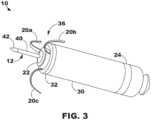
- the device 10may include a distal fixation and electrode assembly 36, which may include one or more fixation members 20, in addition to one or more dart electrodes 12 of equal or unequal length.
- the dart electrode 12may include a shaft 40 extending distally away from the housing distal end region 32 and may include one or more electrode elements, such as a tip electrode 42 at or near the free, distal end region of the shaft 40.
- the tip electrode 42may have a conical or hemispherical distal tip with a relatively narrow tip diameter (e.g., less than about 1 mm) for penetrating into and through tissue layers without using a sharpened tip or needle-like tip having sharpened or beveled edges.
- the shaft 40 of the dart electrode 12may be a normally straight member and may be rigid. In other embodiments, the shaft 40 may be described as being relatively stiff but still possessing limited flexibility in lateral directions. Further, the shaft 40 may be non-rigid to allow some lateral flexing with heart motion. However, in a relaxed state, when not subjected to any external forces, the shaft 40 may maintain a straight position as shown to hold the tip electrode 42 spaced apart from the housing distal end region 32 at least by the height 47 of the shaft 40.
- the dart electrode 12may be configured to pierce through one or more tissue layers to position the tip electrode 42 within a desired tissue layer, e.g., the ventricular myocardium.
- the height 47 of the shaft 40may correspond to the expected pacing site depth, and the shaft may have a relatively high compressive strength along its longitudinal axis to resist bending in a lateral or radial direction when pressed against the implant region 4.
- a second dart electrode 12is employed, its length may be unequal to the expected pacing site depth and may be configured to act as an indifferent electrode for delivering of pacing energy to the tissue.
- a longitudinal axial forcemay be applied against the tip electrode 42, e.g., by applying longitudinal pushing force to the proximal end 34 of the housing 30, to advance the dart electrode 12 into the tissue within target implant region.
- the shaft 40may be e.g., with tissue motion, but may return to its normally straight position when lateral forces diminish. When the shaft 40 is not exposed to any external force, or to only a force along its longitudinal central axis, the shaft 40 may retain a straight, linear position as shown.
- the one or more fixation members 20may be described as one or more "tines" having a normally curved position.
- the tinesmay be held in a distally extended position within a delivery tool.
- the distal tips of tinesmay penetrate the heart tissue to a limited depth before elastically curving back proximally into the normally curved position (shown) upon release from the delivery tool.
- the fixation members 20may include one or more aspects described in, for example, U.S. Patent No. 9,675,579 (Grubac et al.), issued 13 June 2017 , and U.S. Patent No. 9,119,959 (Rys et al.), issued 1 September 2015 .
- the distal fixation and electrode assembly 36includes a distal housing-based electrode 22.
- the tip electrode 42may be used as a cathode electrode paired with the proximal housing-based electrode 24 serving as a return anode electrode.
- the distal housing-based electrode 22may serve as a return anode electrode paired with tip electrode 42 for sensing ventricular signals and delivering ventricular pacing pulses.
- the distal housing-based electrode 22may be a cathode electrode for sensing atrial signals and delivering pacing pulses to the atrial myocardium in the target implant region 4.
- the proximal housing-based electrode 24may serve as the return anode paired with the tip electrode 42 for ventricular pacing and sensing and as the return anode paired with the distal housing-based electrode 22 for atrial pacing and sensing.
- the target implant region 4 in some pacing applicationsis along the atrial endocardium 18, generally inferior to the AV node 15 and the His bundle 5.
- the dart electrode 42may define the height 47 of the shaft 40 for penetrating through the atrial endocardium 18 in the target implant region 4, through the central fibrous body 16, and into the ventricular myocardium 14 without perforating through the ventricular endocardial surface 17.
- the tip electrode 42may rest within the ventricular myocardium 14, and the distal housing-based electrode 22 may be positioned in intimate contact with or close proximity to the atrial endocardium 18.
- the dart electrode 12may have a total combined height 47 of tip electrode 42 and shaft 40 from about 3 mm to about 8 mm in various examples.
- the diameter of the shaft 40may be less than about 2 mm, and may be about 1 mm or less, or even about 0.6 mm or less.
- the device 10may include a motion detector 11 within the housing 30.
- the motion detector 11may be used to monitor mechanical activity, such as atrial mechanical activity (e.g., an atrial contraction) and/or ventricular mechanical activity (e.g., a ventricular contraction).
- the motion detector 11may be used to detect right atrial mechanical activity.
- a non-limiting example of a motion detector 11includes an accelerometer.
- the mechanical activity detected by the motion detector 11may be used to supplement or replace electrical activity detected by one or more of the electrodes of the device 10.
- the motion detector 11may be used in addition to, or as an alternative to, the proximal housing-based electrode 24.
- the motion detector 11may also be used for rate response detection or to provide a rate-responsive IMD.
- rate responsemay be described in U.S. Patent No. 5,154,170 (Bennett et al.), issued October 13, 1992 , entitled “Optimization for rate responsive cardiac pacemaker,” and U.S. Patent No. 5,562,711 (Yerich et al.), issued October 8, 1996 , entitled “Method and apparatus for rate-responsive cardiac pacing".
- FIG. 3is a three-dimensional perspective view of the device 10 capable of cardiac therapy.
- the distal fixation and electrode assembly 36includes the distal housing-based electrode 22 implemented as a ring electrode.
- the distal housing-based electrode 22may be positioned in intimate contact with or operative proximity to atrial tissue when fixation member tines 20a, 20b and 20c of the fixation members 20, engage with the atrial tissue.
- the tines 20a, 20b and 20cwhich may be elastically deformable, may be extended distally during delivery of device 10 to the implant site.
- the tines 20a, 20b, and 20cmay pierce the atrial endocardial surface as the engage with the atrial tissue.
- the tines 20a, 20b and 20cwhich may be elastically deformable, may be extended distally during delivery of device 10 to the implant site.
- the tines 20a, 20b, and 20cmay pierce the atrial endocardial surface as the device 10 is advanced out of the delivery tool and flex back into their normally curved position (as shown) when no longer constrained within the delivery tool.
- the fixation member 20may pull the distal fixation member and electrode assembly 36 toward the atrial endocardial surface.
- the tip electrode 42may be advanced through the atrial myocardium and the central fibrous body and into the ventricular myocardium.
- the distal housing-based electrode 22may then be positioned against the atrial endocardial surface.
- the distal housing-based electrode 22may include a ring formed of an electrically conductive material, such as titanium, platinum, iridium, or alloys thereof.
- the distal housing-based electrode 22may be a single, continuous ring electrode.
- portions of the ringmay be coated with an electrically insulating coating, e.g., parylene, polyurethane, silicone, epoxy, or other insulating coating, to reduce the electrically conductive surface area of the ring electrode.
- an electrically insulating coatinge.g., parylene, polyurethane, silicone, epoxy, or other insulating coating, to reduce the electrically conductive surface area of the ring electrode.
- one or more sectors of the ringmay be coated to separate two or more electrically conductive exposed surface areas of the distal housing-based electrode 22.
- Reducing the electrically conductive surface area of the distal housing-based electrode 22, e.g., by covering portions of the electrically conductive ring with an insulating coating,may increase the electrical impedance of the distal housing-based 22, and thereby, reduce the current delivered during a pacing pulse that captures the myocardium, e.g., the atrial myocardial tissue.
- a lower current drainmay conserve the power source, e.g., one or more rechargeable or non-rechargeable batteries, of the device 10.
- the distal housing-based electrode 22may be configured as an atrial cathode electrode for delivering pacing pulses to the atrial tissue at the implant site in combination with the proximal housing-based electrode 24 as the return anode.
- the electrodes 22 and 24may be used to sense atrial P-waves for use in controlling atrial pacing pulses (delivered in the absence of a sensed P-wave) and for controlling atrial-synchronized ventricular pacing pulses delivered using the tip electrode 42 as a cathode and the proximal housing-based electrode 24 as the return anode.
- the distal housing-based electrode 22may be used as a return anode in conjunction with the cathode tip electrode 42 for ventricular pacing and sensing.
- FIG. 4is a block diagram of circuitry that may be enclosed within the housing 30 ( FIG. 3 ) to provide the functions of cardiac therapy using the device 10 according to one example.
- the separate medical device 50FIG. 1
- the electronic circuitry enclosed within housing 30may include software, firmware, and hardware that cooperatively monitor atrial and ventricular electrical cardiac signals, determine when a cardiac therapy is necessary, and/or deliver electrical pulses to the patient's heart according to programmed therapy mode and pulse control parameters.
- the electronic circuitrymay include a control circuit 80 (e.g., including processing circuitry), a memory 82, a therapy delivery circuit 84, a sensing circuit 86, and/or a telemetry circuit 88.
- the device 10includes one or more sensors 90 for producing a signal that is correlated to a physiological function, state, or condition of the patient, such as a patient activity sensor, for use in determining a need for pacing therapy and/or controlling a pacing rate.
- sensors 90for producing a signal that is correlated to a physiological function, state, or condition of the patient, such as a patient activity sensor, for use in determining a need for pacing therapy and/or controlling a pacing rate.
- the power source 98may provide power to the circuitry of the device 10 including each of the components 80, 82, 84, 86, 88, and 90 as needed.
- the power source 98may include one or more energy storage devices, such as one or more rechargeable or non-rechargeable batteries.
- the connections between the power source 98 and each of the components 80, 82, 84, 86, 88, and 90are to be understood from the general block diagram illustrated but are not shown for the sake of clarity.
- the power source 98may be coupled to one or more charging circuits included in the therapy delivery circuit 84 for providing the power needed to charge holding capacitors included in the therapy delivery circuit 84 that are discharged at appropriate times under the control of the control circuit 80 for delivering pacing pulses, e.g., according to a dual chamber pacing mode such as DDI(R).
- the power source 98may also be coupled to components of the sensing circuit 86, such as sense amplifiers, analog-to-digital converters, switching circuitry, etc., sensors 90, the telemetry circuit 88, and the memory 82 to provide power to the various circuits. charger or programmer, to receive power in situ.
- Various examples of charging a leadless implantable medical deviceare described in U.S. Patent Pub.
- the device 10may also be configured to use various techniques to extend the life of the power source 98, such as a low-power mode.
- the functional blocks shownrepresent functionality included in the device 10 and may include any discrete and/or integrated electronic circuit components that implement analog, and/or digital circuits capable of producing the functions attributed to the medical device 10 herein.
- the various componentsmay include processing circuitry, such as an application specific integrated circuit (ASIC), an electronic circuit, a processor (shared, dedicated, or group), and memory that execute one or more software or firmware programs, a combinational logic circuit, state machine, or other suitable components or combinations of components that provide the described functionality.
- ASICapplication specific integrated circuit
- the particular form of software, hardware, and/or firmware employed to implement the functionality disclosed hereinwill be determined primarily by the particular system architecture employed in the medical device and by the particular detection and therapy delivery methodologies employed by the medical device. Providing software, hardware, and/or firmware to accomplish the described functionality in the context of any modern cardiac medical device system, given the disclosure herein, is within the abilities of one of skill in the art.
- the memory 82may include any volatile, non-volatile, magnetic, or electrical non-transitory computer readable storage media, such as random-access memory (RAM), read-only memory (ROM), non-volatile RAM (NVRAM), electrically-erasable programmable ROM (EEPROM), flash memory, or any other memory device. Furthermore, the memory 82 may include a non-transitory computer readable media
- the memory 82may include any volatile, non-volatile, magnetic, or electrical non-transitory computer readable storage media, such as random-access memory (RAM), read-only memory (ROM), non-volatile RAM (NVRAM), electrically-erasable programmable ROM (EEPROM), flash memory, or any other memory device. Furthermore, the memory 82 may include a non-transitory computer readable media storing instructions that, when executed by one or more processing circuits, cause the control circuit 80 and/or other processing circuitry to perform a single, dual, or triple chamber pacing (e.g., single or multiple chamber pacing) function or other sensing and therapy delivery functions attributed to the device 10.
- the non-transitory computer-readable media storing the instructionsmay include any of the media listed above.
- the control circuit 80may communicate, e.g., via a data bus, with the therapy delivery circuit 84 and the sensing circuit 86 for sensing cardiac electrical signals and controlling delivery of cardiac electrical stimulation therapies in response to sensed cardiac events, e.g., P-waves and R-waves, or the absence thereof.
- the tip electrode 42, the distal housing-based electrode 22, and the proximal housing-based electrode 24may be electrically coupled to the therapy delivery circuit 84 for delivering electrical stimulation pulses to the patient's heart and to the sensing circuit 86 and for sensing cardiac electrical signals.
- the sensing circuit 86may include an atrial (A) sensing channel 87 and a ventricular (V) sensing channel 89.
- the distal housing-based electrode 22 and the proximal housing-based electrode 24may be coupled to the atrial sensing channel 87 for sensing atrial signals, e.g., P-waves attendant to the depolarization of the atrial myocardium.
- the sensing circuit 86may include switching circuitry for selectively coupling one or more of the available distal housing-based electrodes to cardiac event detection circuitry included in the atrial sensing channel 87.
- Switching circuitrymay include a switch array, switch matrix, multiplexer, or any other type of switching device suitable to selectively couple components of the sensing circuit 86 to selected electrodes.
- the tip electrode 42 and the proximal housing-based electrode 24may be coupled to the ventricular sensing channel 89 for sensing ventricular signals, e.g., R-waves attendant to the depolarization of the ventricular myocardium.
- Each of the atrial sensing channel 87 and the ventricular sensing channel 89may include cardiac event detection circuitry for detecting P-waves and R-waves, respectively, from the cardiac electrical signals received by the respective sensing channels.
- the cardiac event detection circuitry included in each of the channels 87 and 89may be configured to amplify, filter, digitize, and rectify the cardiac electrical signal received from the selected electrodes to improve the signal quality for detecting cardiac electrical events.
- the cardiac event detection circuitry within each channel 87 and 89may include one or more sense amplifiers, filters, rectifiers, threshold detectors, comparators, analog-to-digital converters (ADCs), timers, or other analog or digital components.
- a cardiac event sensing thresholde.g., a P-wave sensing threshold and an R-wave sensing threshold
- the sensing circuit 86may produce a sensed event signal that is passed to the control circuit 80.
- the atrial sensing channel 87may produce a P-wave sensed event signal in response to a P-wave sensing threshold crossing.
- the ventricular sensing channel 89may produce an R-wave sensed event signal in response to an R-wave sensing threshold crossing.
- the sensed event signalsmay be used by the control circuit 80 for setting pacing escape interval timers that control the basic time intervals used for scheduling cardiac pacing pulses.
- a sensed event signalmay trigger or inhibit a pacing pulse depending on the particular programmed pacing mode.
- a P-wave sensed event signal received from the atrial sensing channel 87may cause the control circuit 80 to inhibit a scheduled atrial pacing pulse and schedule a ventricular pacing pulse at a programmed atrioventricular (AV) pacing interval. If an R-wave is sensed before the AV pacing interval expires, the ventricular pacing pulse may be inhibited. If the AV pacing interval expires before the control circuit 80 receives an R-wave sensed event signal from the ventricular sensing channel 89, the control circuit 80 may use the therapy delivery circuit 84 to deliver the scheduled ventricular pacing pulse synchronized to the sensed P-wave.
- AVatrioventricular
- the device 10may be configured to deliver a variety of pacing therapies including bradycardia pacing, cardiac resynchronization therapy, post-shock pacing, and/or tachycardia-related therapy, such as ATP, among others.
- the device 10may be configured to detect non-sinus tachycardia and deliver ATP.
- the control circuit 80may determine cardiac event time intervals, e.g., PP intervals between consecutive P-wave sensed event signals received from the atrial sensing channel 87, RR intervals between consecutive R-wave sensed event signals received from the ventricular sensing channel 89, and P-R and/or R-P intervals received between P-wave sensed event signals and R-wave sensed event signals.
- Tachycardiamay be detected in a given heart chamber based on a threshold number of tachycardia detection intervals being detected.
- the therapy delivery circuit 84may include atrial pacing circuit 83 and ventricular pacing circuit 85.
- Each pacing circuit 83 and 85may include charging circuitry, one or more charge storage devices such as one or more low voltage holding capacitors, an output capacitor, and/or switching circuitry that controls when the holding capacitor(s) are charged and discharged across the output capacitor to deliver a pacing pulse to the pacing electrode vector coupled to respective pacing circuits 83 or 85.
- the tip electrode 42 and the proximal housing-based electrode 24may be coupled to the ventricular pacing circuit 85 as a bipolar cathode and anode pair for delivering ventricular pacing pulses, e.g., upon expiration of an AV or VV pacing interval set by the control circuit 80 for providing atrial-synchronized ventricular pacing and a basic lower ventricular pacing rate.
- the atrial pacing circuit 83may be coupled to the distal housing-based electrode 22 and the proximal housing-based electrode 24 to deliver atrial pacing pulses.
- the control circuit 80may set atrial pacing intervals according to a programmed lower pacing rate or a temporary lower rate set according to a rate-responsive sensor indicated pacing rate.
- Atrial pacing circuitmay be controlled to deliver an atrial pacing pulse if the atrial pacing interval expires before a P-wave sensed event signal is received from the atrial sensing channel 87.
- the control circuit 80starts an AV pacing interval in response to a delivered atrial pacing pulse to provide synchronized multiple chamber pacing (e.g., dual or triple chamber pacing).
- Charging of a holding capacitor of the atrial or ventricular pacing circuit 83 or 85 to a programmed pacing voltage amplitude and discharging of the capacitor for a programmed pacing pulse widthmay be performed by the therapy delivery circuit 84 according to control signals received from the control circuit 80.
- a pace timing circuit included in the control circuit 80may include programmable digital counters set by a microprocessor of the control circuit 80 for controlling the basic pacing time intervals associated with various single chamber or multiple chamber pacing (e.g., dual or triple chamber pacing) modes or anti-tachycardia pacing sequences.
- the microprocessor of the control circuit 80may also set the amplitude, pulse width, polarity, or other characteristics of the cardiac pacing pulses, which may be based on programmed values stored in the memory 82.
- the device 10may include other sensors 90 for sensing signals from the patient for use in determining a need for and/or controlling electrical stimulation therapies delivered by the therapy delivery circuit 84.
- a sensor indicative of a need for increased cardiac outputmay include a patient activity sensor, such as an accelerometer.
- An increase in the metabolic demand of the patient due to increased activity as indicated by the patient activity sensormay be determined by the control circuit 80 for use in determining a sensor-indicated pacing rate.
- Control parameters utilized by the control circuit 80 for sensing cardiac events and controlling pacing therapy deliverymay be programmed into the memory 82 via the telemetry circuit 88, which may also be described as a communication interface.
- the telemetry circuit 88includes a transceiver and antenna for communicating with an external device such as a programmer or home monitor, using radio frequency communication or other communication protocols.
- the control circuit 80may use the telemetry circuit 88 to receive downlink telemetry from and send uplink telemetry to the external device. In some cases, the telemetry circuit 88 may be used to transmit and receive communication signals to/from another medical device implanted in the patient.
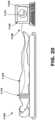
- FIG. 5is a three-dimensional perspective view of another leadless intracardiac medical device 710 that may be configured for single or multiple chamber cardiac therapy (e.g., dual or triple chamber cardiac therapy) according to another example.
- the device 710may include a housing 730 having an outer sidewall 735, shown as a cylindrical outer sidewall, extending from a housing distal end region 732 to a housing proximal end region 734.
- the housing 730may enclose electronic circuitry configured to perform single or multiple chamber cardiac therapy, including atrial and ventricular cardiac electrical signal sensing and pacing the atrial and ventricular chambers.
- Delivery tool interface member 726is shown on the housing proximal end region 734.
- a distal fixation and electrode assembly 736may be coupled to the housing distal end region 732.
- the distal fixation and electrode assembly 736may include an electrically insulative distal member 772 coupled to the housing distal end region 732.
- the tissue piercing electrode 712extends away from the housing distal end region 732, and multiple non-tissue piercing electrodes 722 may be coupled directly to the insulative distal member 772.
- the tissue piercing electrode 712extends in a longitudinal direction away from the housing distal end region 732 and may be coaxial with the longitudinal center axis 731 of the housing 730.
- the tissue piercing distal electrode 712may include an electrically insulated shaft 740 and a tip electrode 742.
- the tissue piercing distal electrode 712is an active fixation member including a helical shaft 740 and a distal cathode tip electrode 742 .
- the helical shaft 740may extend from a shaft distal end region 743 to a shaft proximal end region 741, which may be directly coupled to the insulative distal member 772.
- the helical shaft 740may be coated with an electrically insulating material, e.g., parylene or other examples listed herein, to avoid sensing or stimulation of cardiac tissue along the shaft length.
- the tip electrode 742is at the shaft distal end region 743 and may serve as a cathode electrode for delivering ventricular pacing pulses and sensing ventricular electrical signals using the proximal housing-based electrode 724 as a return anode when the tip electrode 742 is advanced into ventricular tissue.
- the proximal housing-based electrode 724may be a ring electrode circumscribing the housing 730 and may be defined by an uninsulated portion of the longitudinal sidewall 735. Other portions of the housing 730 not serving as an electrode may be coated with an electrically insulating material as described above in conjunction with FIG. 2 .
- tissue-piercing electrodesmay include two or more of a dart-type electrode (e.g., electrode 12 of FIGS. 1-2 ), a helical-type electrode (e.g., electrode 712 )
- a dart-type electrodee.g., electrode 12 of FIGS. 1-2
- a helical-type electrodee.g., electrode 712
- Non-limiting examples of multiple tissue-piercing electrodesinclude two dart electrodes, a helix electrode with a dart electrode extending therethrough (e.g., through the center), or dual intertwined helixes.
- Multiple tissue-piercing electrodesmay also be used for bipolar or multi-polar pacing.
- one or more tissue-piercing electrodesthat penetrate into the LV myocardium may be a multi-polar tissue-piercing electrode.
- a multi-polar tissue-piercing electrodemay include one or more electrically active and electrically separate elements, which may enable bipolar or multi-polar pacing from one or more tissue-piercing electrodes.
- Non-tissue piercing electrodes 722may be provided along a periphery of the insulative distal member 772, peripheral to the tissue piercing electrode 712.
- the insulative distal member 772may define a distal-facing surface 738 of the device 710 and a circumferential surface 739 that circumscribes the device 710 adjacent to the housing longitudinal sidewall 735.
- Non-tissue piercing electrodes 722may be formed of an electrically conductive material, such as titanium, platinum, iridium, or alloys thereof.
- non-tissue piercing electrodes 722are spaced apart radially at equal distances along the outer periphery of insulative distal member 772, however, two or more non-tissue piercing electrodes 722 may be provided.
- Non-tissue piercing electrodes 722may be discrete components each retained within a respective recess 774 in the insulative member 772 sized and shaped to mate with the non-tissue piercing electrode 722.
- the non-tissue piercing electrodes 722may each be an uninsulated, exposed portion of a unitary member mounted within or on the insulative distal member 772 . Intervening portions of the unitary member not functioning as an electrode may be insulated by the insulative distal member 772 or, if exposed to the surrounding environment, may be coated with an electrically insulating coating, e.g., parylene, polyurethane, silicone, epoxy, or other insulating coating.
- an electrically insulating coatinge.g., parylene, polyurethane, silicone, epoxy, or other insulating coating.
- non-tissue piercing electrode 722may be positioned against, in intimate contact with, or in operative proximity to, a cardiac tissue surface for delivering pulses and/or sensing cardiac electrical signals produced by the patient's heart.
- non-tissue piercing electrodes 722may be positioned in contact with right atrial endocardial tissue for pacing and sensing in the atrium when the tissue piercing electrode 712 is advanced into the atrial tissue and through the central fibrous body until the distal tip electrode 742 is positioned in direct contact with ventricular tissue, e.g., ventricular myocardium and/or a portion of the ventricular conduction system.
- Non-tissue piercing electrodes 722may be coupled to the therapy delivery circuit 84 and the sensing circuit 86 (see FIG. 4 ) enclosed by the housing 730 to function collectively as a cathode electrode for delivering atrial pacing pulses and for sensing atrial electrical signals, e.g., P-waves, in combination with the proximal housing-based electrode 724 as a return anode.
- Switching circuitry included in the sensing circuit 86may be activated under the control of the control circuit 80 to couple one or more of the non-tissue piercing electrodes to the atrial sensing channel 87.
- Distal, non-tissue piercing electrodes 722may be electrically isolated from each other so that each individual one of the electrodes 722 may be individually selected by switching circuitry included in the therapy delivery circuit 84 to serve alone or in a combination of two or more of the electrodes 722 as an atrial cathode electrode.
- Switching circuitry included in the therapy delivery circuit 84may be activated under the control of the control circuit 80 to couple one or more of the non-tissue piercing electrodes 722 to the atrial pacing circuit 83. Two or more of the non-tissue piercing electrodes 722 may be selected at a time to operate as a multi-point atrial cathode electrode.
- Certain non-tissue piercing electrodes 722 selected for atrial pacing and/or atrial sensingmay be selected based on atrial capture threshold tests, electrode impedance, P-wave signal strength in the cardiac electrical signal, or other factors. For example, a single one or any combination of two or more individual non-tissue piercing electrodes 722 functioning as a cathode electrode that provides an optimal combination of a low pacing capture threshold amplitude and relatively high electrode impedance may be selected to achieve reliable atrial pacing using minimal current drain from the power source 98.
- the distal-facing surface 738may uniformly contact the atrial endocardial surface when the tissue piercing electrode 712 anchors the housing 730 at the implant site. In that case, all the electrodes 722 may be selected together to form the atrial cathode. Alternatively, every other one of the electrodes 722 may be selected together to form a multi-point atrial cathode having a higher electrical impedance that is still uniformly distributed along the distal-facing surface 738.
- a subset of one or more electrodes 722 along one side of the insulative distal member 772may be selected to provide pacing at a desired site that achieves the lowest pacing capture threshold due to the relative location of the electrodes 722 to the atrial tissue being paced.
- the distal-facing surface 738may be oriented at an angle relative to the adjacent endocardial surface depending on the positioning and orientation at which the tissue piercing electrode 712 enters the cardiac tissue.
- one or more of the non-tissue piercing electrodes 722may be positioned in closer contact with the adjacent endocardial tissue than other non-tissue piercing electrodes 722, which may be angled away from the endocardial surface.
- the angle of the tissue piercing electrode 712 and the housing distal end region 732 relative to the cardiac surfacemay not be required to be substantially parallel.
- Anatomical and positional differencesmay cause the distal-facing surface 738 to be angled or oblique to the endocardial surface, however, multiple non-tissue piercing electrodes 722 distributed along the periphery of the insulative distal member 772 increase the likelihood of good contact between one or more electrodes 722 and the adjacent cardiac tissue to promote acceptable pacing thresholds and reliable cardiac event sensing using at least a subset of multiple electrodes 722. Contact or fixation circumferentially along the entire periphery of the insulative distal member 772 may not be required.
- the non-tissue piercing electrodes 722are shown to each include a first portion 722a extending along the distal-facing surface 738 and a second portion 722b extending along the circumferential surface 739.
- the first portion 722a and the second portion 722bmay be continuous exposed surfaces such that the active electrode surface wraps around a peripheral edge 776 of the insulative distal member 772 that joins the distal facing surface 738 and the circumferential surface 739.
- the non-tissue piercing electrodes 722may include one or more of the electrodes 772 along the distal-facing surface 738, one or more electrodes along the circumferential surface 739, one or more electrodes each extending along both of the distal-facing surface 738 and the circumferential surface 739, or any combination thereof.
- the exposed surface of each of the non-tissue piercing electrodes 722may be flush with respective distal-facing surfaces 738 and/or circumferential surfaces.
- each of the non-tissue piercing electrodes 722may have a raised surface that protrudes from the insulative distal member 772. Any raised surface of the electrodes 722, however, may define a smooth or rounded, non-tissue piercing surface.
- the distal fixation and electrode assembly 736may seal the distal end region of the housing 730 and may provide a foundation on which the electrodes 722 are mounted.
- the electrodes 722may be referred to as housing-based electrodes.
- the electrodes 722may not be not carried by a shaft or other extension that extends the active electrode portion away from the housing 730, like the distal tip electrode 742 residing at the distal tip of the helical shaft 740 extending away from the housing 730.
- Other examples of non-tissue piercing electrodes presented herein that are coupled to a distal-facing surface and/or a circumferential surface of an insulative distal memberinclude the distal housing-based ring electrode 22 ( FIG.
- any non-tissue piercing electrodes directly coupled to a distal insulative member, peripherally to a central tissue-piercing electrode,may be provided to function individually, collectively, or in any combination as a cathode electrode for delivering pacing pulses to adjacent cardiac tissue.
- portions of the ring electrodemay be electrically insulated by a coating to provide multiple distributed non-tissue piercing electrodes along the distal-facing surface and/or the circumferential surface of the insulative distal member.
- the non-tissue piercing electrodes 722 and other examples listed aboveare expected to provide more reliable and effective atrial pacing and sensing than a tissue piercing electrode provided along the distal fixation and electrode assembly 736.
- the atrial chamber wallsare relatively thin compared to ventricular chamber walls.
- a tissue piercing atrial cathode electrodemay extend too deep within the atrial tissue leading to inadvertent sustained or intermittent capture of ventricular tissue.
- a tissue piercing atrial cathode electrodemay lead to interference with sensing atrial signals due to ventricular signals having a larger signal strength in the cardiac electrical signal received via tissue-piercing atrial cathode electrodes that are in closer physical proximity to the ventricular tissue.
- the tissue piercing electrode 712may be securely anchored into ventricular tissue for stabilizing the implant position of the device 710 and providing reasonable certainty that the tip electrode 742 is sensing and pacing in ventricular tissue while the non-tissue piercing electrodes 722 are reliably pacing and sensing in the atrium.
- the tip electrode 742may reach left ventricular tissue for pacing of the left ventricle while the non-tissue piercing electrodes 722 provide pacing and sensing in the right atrium.
- the tissue piercing electrode 712may be in the range of about 4 to about 8 mm in length from the distal-facing surface 738 to reach left ventricular tissue.
- the device 710may achieve four-chamber pacing by delivering atrial pacing pulses from the atrial pacing circuit 83 via the non-tissue piercing electrodes 722 in the target implant region 4 to achieve bi-atrial (right and left atrial) capture and by delivering ventricular pacing pulses from the ventricular pacing circuit 85 via the tip electrode 742 advanced into ventricular tissue from the target implant region 4 to achieve biventricular (right and left ventricular) capture.
- FIGS. 6-14relate to various methods that may be used to position a tissue-piercing electrode of any of the devices described herein, for example, those shown in FIGS. 1-5 and 16-18.
- each of the methodsmay be used when the tissue-piercing electrode is positioned, or implanted, in the basal and/or septal region of the left ventricular myocardium of the patient's heart from the triangle of Koch region of the right atrium through the right atrial endocardium and central fibrous body.
- FIG. 6is a flowchart of a cardiac therapy method 100 for use with, e.g., the system 2 of FIG. 1 .
- the method 100may be used with the intracardiac medical device 10 ( FIGS. 1-2 ) or 710 ( FIG. 5 ).
- the method 100may be used to describe single chamber or multiple chamber pacing (e.g., dual or triple chamber pacing), atrioventricular synchronous pacing, triggered pacing, cardiac resynchronization pacing, or tachycardia-related therapy.
- the method 100may include process 102, in which activity of the right atrium is monitored.
- the medical devicemay use one or more of a plurality of electrodes to monitor the electrical activity of the patient's heart.
- a right atrial electrodee.g., proximal housing-based electrode 24 or distal housing-based electrode 22 of FIG. 2
- the right atrial electrodemay be positioned to sense electrical activity of the right atrium.
- the right atrial electrodemay be positioned in the volume of the right atrium or against the right atrial endocardial surface of the patient's heart.
- the right atrial electrodemay be used to deliver cardiac therapy to the right atrium of the patient's heart.
- the right atrial electrodemay be leadlessly coupled to a housing of the medical device.
- the right atrial electrodemay be positioned at the distal end region of the housing or at a location proximal to the distal end region (e.g., the proximal end region of the housing).
- the medical devicemay use a motion detector to monitor the mechanical activity of the patient's heart.
- a right atrial motion detectormay be positioned to sense mechanical activity of the right atrium.
- the right atrial motion detectormay be positioned within the implantable medical device 10.
- the right atrial motion detectormay be wirelessly coupled, or coupled to the left ventricle, right ventricle, ventricular septum (e.g., higher posterior basal septum region), or other parts of the ventricular myocardium, in response to the monitored activity of the right atrium in process 102.
- the monitored activitymay include electrical activity, mechanical activity, or both electrical and mechanical activity (e.g., using a right atrial electrode and/or a right atrial motion detector).
- the medical devicemay use one or more of the plurality of electrodes to deliver cardiac therapy to the patient's heart.
- a tissue-piercing electrodee.g., tip electrode 42
- the tissue-piercing electrodemay be leadlessly coupled to the housing.
- the tissue-piercing electrodemay be used to sense electrical activity of the left ventricle.
- the tissue-piercing electrodemay extend from a distal end region of the housing.
- the method 100may be used with cardiac resynchronization pacing (e.g., cardiac resynchronization therapy).
- cardiac resynchronization pacinge.g., cardiac resynchronization therapy
- a pacemay be delivered to one or both ventricles in response to a sensed atrial or ventricular event.
- cardiac resynchronization pacinginclude biventricular pacing and monoventricular pacing.
- Monoventricular pacingmay include left ventricular pacing, right ventricular pacing, or fusion pacing.
- Various methods of performing cardiac resynchronization pacingare described in U.S. Patent Application Pub. No. 2017/0340885 (Sambelashvili), filed 31 July 2017 , entitled “Systems and methods for leadless cardiac resynchronization therapy," and U.S. Patent No. 9,789,319 (Sambelashvili), issued 17 October 2017 , entitled “Systems and methods for leadless cardiac resynchronization therapy”.
- Biventricular pacingmay include pacing the right ventricle (RV) with a RV electrode and a left ventricle (LV) with a LV electrode (e.g., the tissue-piercing electrode), which are typically different electrodes.
- RVright ventricle
- LVleft ventricle
- the implantable medical devicecan be configured to automatically switch between biventricular pacing and fusion pacing.
- the primary goalmay be to ensure the ventricles are synchronized with each other.
- Monoventricular pacing, or specifically fusion pacingmay be used instead of biventricular pacing to achieve synchrony.
- a a left ventricle (LV) with a LV electrodee.g., the tissue-piercing electrode
- the implantable medical devicecan be configured to automatically switch between biventricular pacing and fusion pacing.
- the primary goalmay be to ensure the ventricles are synchronized with each other.
- Monoventricular pacing, or specifically fusion pacing,may be used instead of biventricular pacing to achieve synchrony.
- a patient's heartmay be treated using adaptive CRT in which biventricular pacing may be delivered during one period of time (e.g., 1 hour, day, week etc.) and at another time, fusion pacing may be delivered to return the ventricles to synchrony.
- biventricular pacingmay be delivered during one period of time (e.g., 1 hour, day, week etc.) and at another time, fusion pacing may be delivered to return the ventricles to synchrony.
- fusion pacinginvolves pacing the LV.
- the RVmay be solely paced.
- Adaptive LV pacingmay be described as leveraging intrinsic RV conduction by pre-pacing the LV to synchronize with intrinsic RV activation.
- the timing of the LV pacemay be automatically adjusted based on the atrial to intrinsic QRS interval measurement (AV interval).
- One or more embodimentscan set the LV pace to occur at about 70% of the intrinsic AV interval, but at least 40 ms prior to the intrinsic QRS.
- One or more other embodimentscan configure LV pacing in response to, or based on, a moderately lengthened QRS. For example, if the QRS width exceeds 120 ms, but does not exceed 160 ms, then LV pacing with fusion is selected. Otherwise, if the QRS width is greater than 160 ms, then biventricular (BiV) pacing is selected.
- a moderately lengthened QRS thresholdmay benefit heart failure patients. Efficacies of LV-only pacing or biventricular pacing may be predicted by the moderately lengthened QRS duration.
- An illustrative moderately lengthened QRSmay correspond to a QRS width in the range of 130 ms-150 ms.
- Adaptive CRTmay use intrinsic AV conduction to determine whether to use biventricular or fusion pacing.
- the intrinsic AV conductionmay be automatically evaluated.
- the IMDe.g., an ICD
- leadless pacing deviceLPD
- subcutaneous implantable deviceSD
- RVs-LVs interval not exceeding 80 mscorresponds to fusion pacing while greater than 80 ms switches to biventricular pacing.
- RVs-LVsare shorter than the corresponding QRS width. Therefore, it takes about 40 ms to sense the onset of QRS in the RV and the final portion of the QRS in the LV is also sensed prior to the QRS end.
- the IMDmay track the moderately lengthened QRS over time and then relies on trend data to switch between biventricular pacing and fusion pacing.
- the moderately lengthened QRSis 120 ms, 125 ms, 130 ms, 135 m, 140 ms, and 145 ms, respectively for 6 consecutive weeks. The increasing trend could trigger the switch to biventricular pacing before the threshold is met for switching to biventricular pacing.
- the SDcould send a control signal to the LPD to initiate CRT.
- the LPDcould sense a cardiac signal (i.e., a second electrical signal) from the heart of the patient. Based on the cardiac signal, the LPD could determine whether to deliver CRT to the heart from the LPD. For example, the LPD, based on the second electrical signal, could determine that CRT is not necessary.
- the LPDcould consider whether sensed data meets a pre-specified threshold. For instance, if the QRS width does not exceed 120 ms, the LPD may withhold the delivery of CRT therapy (e.g., the LPD could then signal the SD that CRT should not be delivered based upon the cardiac signal).
- the SDcan be configured to perform a more detailed analysis in which at least one or more parameters (such as at least two parameters) are evaluated. The SD could then send another command signal that confirms, denies, or overrides the LPD.
- the LPDcould sense a cardiac signal that indicates a switch between fusion pacing to biventricular pacing should occur and would signal the SD.
- the SDcould be configured to send an override signal to the LPD unless certain conditions are met.
- the LPDcould determine that biventricular pacing is may be used instead of fusion pacing in contravention to the SD communication.
- the LPDcould sense a cardiac signal that indicates a switch between fusion pacing to biventricular pacing should occur and would signal the SD.
- the SDcould be configured to send an override signal to the LPD unless certain conditions are met.
- the LPDcould determine that biventricular pacing is may be used instead of fusion pacing in contravention to the SD communication. In one embodiment, the LPD would deliver biventricular pacing. In one or more other embodiments, the LPD could determine that fusion pacing may be used instead of biventricular pacing in contravention to the SD communication. In this scenario, the LPD could deliver fusion pacing.
- the SDtransmits a control signal to the LPD to initiate CRT.
- the LPDsenses a cardiac signal (i.e., a second electrical signal) from the heart of the patient. Based on the cardiac signal, the LPD could determine whether to deliver CRT or the type of CRT to deliver to the heart from the LPD. In one or more embodiments, the LPD, based on the second electrical signal, could initially determine that CRT should not be used. The initial determination by the LPD could use tests such as a threshold of one or more parameters. In one or more embodiments, the SD could perform a more detailed analysis as to whether CRT should be delivered. Using the sensed data from the LPD and/or SD, the SD could generate another signal to the LPD that either confirms, denies or overrides the LPDs initial determination.
- the LPDcould sense a cardiac signal that indicates a switch should occur between fusion pacing to biventricular pacing. Determining whether to switch between fusion pacing and biventricular pacing could be determined based upon one or more parameters (e.g., moderately lengthened QRS, etc.).
- the LPDcould be configured to either automatically switch between fusion pacing and biventricular pacing or to wait until the SD confirms or denies switching between the CRT pacing mode (i.e., fusion pacing and biventricular pacing).
- the SDcould be configured to send a confirmatory signal or a signal denying the LPD switching the pacing mode.
- the LPDcould determine that biventricular pacing may be used instead of fusion pacing in contravention to the SD communication.
- ICDor have the SD functionality described herein.
- Electrical signalsare then sensed which includes moderately lengthened QRS duration data from the patient's heart.
- a determinationis made as to whether cardiac resynchronization pacing therapy (CRT pacing) is appropriate based upon the moderately lengthened QRS duration in the sensed electrical signals.
- CRT pacingcardiac resynchronization pacing therapy
- the CRT pacing pulsesare delivered to the heart using electrodes.
- the SDcan switch between fusion pacing and biventricular pacing based upon data (e.g., moderately lengthened QRS, etc.) sensed from the heart.
- One or more LPDs carrying one or more electrodesmay be implanted within various chambers of the heart of the patient or otherwise in close proximity of the cardiac muscle. At these locations, an LPD may sense ECG signals with high signal-to-noise ratios to detect arrhythmias. In addition, an LPD may provide cardiac pacing at the location of the implanted LPD.
- one or both of SD and LPDmay share detected signals or physiological information (e.g., R-R intervals, electrogram morphology measurements, and/or electrocardiograms or electrograms) such that the device receiving such information can determine a condition of patient (e.g., determine whether or not patient is experiencing an arrhythmia and or lack of synchrony between ventricles).
- detected signals or physiological informatione.g., R-R intervals, electrogram morphology measurements, and/or electrocardiograms or electrograms
- the device receiving such informationcan determine a condition of patient (e.g., determine whether or not patient is experiencing an arrhythmia and or lack of synchrony between ventricles).
- a condition of patiente.g., determine whether or not patient is experiencing an arrhythmia and or lack of synchrony between ventricles.
- communication between the SICD and an LPDmay be used to initiate therapy and/or confirm that therapy should be delivered.
- the SICDmay also transmit a communication message to the LPD instructing the LPD to change one or more parameters that define the CRT therapy.
- the SICDmay be configured to transmit communications to the LPD and the LPD may be configured to receive the communication from the SICD.
- one-way communicationmay be established such that the LPD may be configured to transmit communications to the SICD (e.g., communication from an LPD).
- two-way communicationmay allow confirmation of a detected of a cardiac condition (e.g., ventricular dyssynchrony, tachyarrhythmia, bradycardia, etc.) prior to delivery of any therapy.
- One or more of the embodiments described hereinmay utilize far-field sensing to carry out cardiac resynchronization pacing.
- one or more of the electrodes of a devicemay be used for far-field sensing of electrical activity in a different chamber.
- a right atrial electrode or a tissue-piercing electrodemay be used to monitor far-field electrical activity of the right ventricle.
- the far-field sensingmay be particularly useful in cardiac resynchronization pacing as described above.
- Ascertaining RV timingmay be used to tailor the timing of the LV pace for an individual patient to allow for fusion pacing (e.g., fusing RV and LV activation).
- FIG. 7is a flowchart of a pacing therapy method 110 for use with, e.g., the method 100 of FIG. 6 .
- the method 110may be used in process 104, which delivers pacing therapy to the ventricle.
- the method 110may be described as an AV resynchronization therapy method.
- the method 110may include process 112, in which an atrial event is sensed.
- the atrial eventmay be a right atrial event in monitored activity of the right atrium, e.g., as mentioned in process 102.
- the right atrial electrodemay be used to sense the right atrial event within monitored electrical activity of the right atrium.
- the right atrial motion detectormay be used to sense the right atrial event within monitored mechanical activity of the right atrium.
- the atrial eventmay be determined by the controller of the medical device using the sensing circuit.
- the method 110may further include process 114, which includes waiting for a selected A-V time period to elapse in response to the detection of the atrial event in process 112.
- process 114which includes waiting for a selected A-V time period to elapse in response to the detection of the atrial event in process 112.
- the controller of the medical devicemay wait the selected A-V time period after detecting the atrial event.
- the method 110may further include process 116, in which a ventricular pace is delivered in response to the atrial event after the selected A-V time period has elapsed in process 114.
- process 116may be performed without process 114. It is contemplated that the ventricular pace may be delivered in response to sensing the atrial event without using the selected A-V time period.
- the A-V time periodis configured to synchronize an atrial event and a ventricular event for atrioventricular synchrony.
- the A-V time periodmay also be configured to, or modified to, improve cardiac resynchronization.
- the A-V time periodmay be used to pace one or both ventricles for ventricular synchrony (e.g., using biventricular pacing or monoventricular pacing, such as fusion pacing) described herein in more detail below.
- FIG. 8is a flowchart of another illustrative pacing therapy method 120 for use with, e.g., the method 100 of FIG. 6 .
- the method 120may be used in process 104, which delivers pacing therapy to the ventricle.
- the method 120may be described as an AV resynchronization therapy method.
- the method 120may include process 122, in which an atrial event is sensed within the monitored activity from process 102 ( FIG. 6 ).
- Process 122may be the same or similar to process 112 of method 110 ( FIG. 7 ).
- the method 120may further include process 124, in which activity of the left ventricle is monitored.
- One or more tissue-piercing electrodesmay be used to sense the activity of the left ventricle. If more than one tissue-piercing electrode has contact with LV myocardium, the tissue-piercing electrodes can be used to both sense and pace the LV.
- the method 120may further include process 126, which starts an A-V time period.
- the method 120may further include process 128, which determines whether a ventricular event is sensed in response to the monitored activities in processes 122 and 124.
- the process 128may determine whether a ventricular event is sensed before the A-V time period elapses.
- the controller of the medical devicemay be used to make the determination. If a ventricular event is not sensed in process 128, the method 120 may branch to process 130. If a ventricular event is sensed, the method 120 may branch to process 132.
- the method 120may further include process 130, in which a ventricular pace is delivered after the selected A-V time period has elapsed.
- Process 130may be the same or similar to process 114 of method 110 ( FIG. 7 ).
- the controller of the medical devicemay initiate or execute the ventricular pace using the therapy delivery circuit.
- the method 120may further include process 132 , which withholds delivering the ventricular pace. Withholding the ventricular pace delivery may be described as inhibiting pacing therapy.
- FIG. 9is a flowchart of a tachycardia-related method 140 for use with, e.g., the system 2 of FIG. 1 .
- the method 140may be used with the intracardiac medical device 10 ( FIGS. 1-2 ) or 710 ( FIG. 5 ).
- the method 140may be described as a tachycardia sensing method.
- the method 140may include process 142 , in which activity of the right atrium is monitored.
- the controller of the medical devicemay use the sensing circuit and right atrial electrode or right atrial motion detector to monitor the activity of the right atrium.
- the method 140may further include process 144, in which activity of the left ventricle is monitored.
- the controller of the medical devicemay use the sensing circuit and tissue-piercing electrode, or a left ventricular motion detector, to monitor the activity of the left ventricle.
- the method 140may further include process 146, in which tachycardia is determined based on the monitored activities in processes 142 and 144.
- the controllermay be used to make the determination.
- FIG. 10is a flowchart of a tachycardia determination method 150 for use with, e.g., the method 140 of FIG. 9 .
- the method 150may be used in process 146, which determines tachycardia based on the monitored activities.
- the method 150may be described as a tachycardia classification method.
- a ventricular tachycardia eventmay be determined if the monitored V-rate exceeds a certain threshold (e.g., 120 bpm) or, additionally or alternatively, if the monitored intervals between successive V-events are less than a certain time-interval threshold (e.g., 500 ms).
- a certain thresholde.g. 120 bpm
- a certain time-interval thresholde.g., 500 ms
- the method 150may include process 152, which determines whether a tachycardia rhythm has a 1:1 AV conduction rhythm or signature.
- a 1:1 AV conduction or rhythmrefers to every V-event being preceded by an A-event with a degree of regularity in terms of the A-V interval.
- the controller of the medical devicemay be used to make the determination. If a 1:1 AV conduction rhythm is determined, the method 150 may continue to process 154. If a 1:1 AV conduction rhythm is not determined by process 152, then the method 150 may continue to process 156.
- the method 150may further include process 154, in which therapy is withheld.
- the controllermay be used to withhold tachycardia-related therapy in response to determining that the detected rhythm is non-treatable.
- the method 150may further include process 156 (e.g., in response to not determining a 1:1 AV conduction rhythm in process 152), in which a type of tachycardia therapy to deliver is determined. For example, a determination may be made that the V-rate is faster than a rate threshold (e.g., 200 bpm) for ventricular fibrillation, in which case the device may initiate shock therapy in process 160. If not, then the device may initiate anti-tachycardia pacing therapy in process 158.
- a rate thresholde.g. 200 bpm
- FIG. 11is a flowchart of a tachycardia therapy determination method 170 for use with, e.g., the method 150 of FIG. 10 .
- the method 170may be used in process 156, which determines a type of tachycardia therapy to deliver.
- the method 170may include process 172, which performs a V-V event interval analysis, which includes determination of parameters like median, range, mode-sum, or other metrics reflective of how fast a tachycardia rhythm is and how regular is the interval between successive V-events.
- the method 170may further include process 174, which performs electrogram morphology analysis. This may include comparing entire morphology or gross morphologic features of different V-events within a tachycardia rhythm and determining a morphologic similarity index. Details of determining morphologic and rate regularity of tachycardia events may be described in U.S. Patent No. 8,594,775 (Ghosh et al )
- the method 170may further include process 176, in which rate and rhythm regularity of tachycardia events are determined based on combination of monitoring of intervals between successive V events (process 172) and corresponding electrogram morphologies (process 174).
- process 172rate and rhythm regularity of tachycardia events are determined based on combination of monitoring of intervals between successive V events
- process 174corresponding electrogram morphologies
- a monomorphic VTmay be determined based on regularity of the successive V-events and/or similarity of electrogram morphologies corresponding to the V-events
- a polymorphic rhythmmay be determined if both rate regularity and morphology similarity criteria are not met.
- Non-limiting examples of tachycardia therapy that may be deliveredinclude anti-tachycardia pacing and shock therapy (e.g., defibrillation therapy).
- shock therapye.g., defibrillation therapy.
- the devicemay initiate anti-tachycardia pacing (ATP). If a polymorphic rhythm is determined the device may initiate shock therapy by signaling the external device to deliver a shock.
- ATPanti-tachycardia pacing
- shock therapyby signaling the external device to deliver a shock.
- tachycardia therapy determination methodsincluding interval analyses and electrogram morphology analyses, that may be used with the methods of the present disclosure may be described in U.S. Patent No. 7,031,711 (Brown et al.), issued 18 April 2016 , and U.S. Patent No. 8,594,775 (Ghosh et al.), issued 26 November 2013 , and U.S. Patent No. 8,750,994 (Ghosh et al.), issued 10 June 2014
- FIG. 12is a flowchart of an anti-tachycardia method 190 for use with, e.g., the system 2 of FIG. 1 .
- the method 190may be used with the intracardiac medical device 10 and the separate medical device 50 ( FIG. 1 ) .
- the method 190may include process 192, which determines that tachycardia is present.
- the controller of the medical devicemay determine that tachycardia is present based on monitored activities generated using the plurality of electrodes and/or one or more motion detectors.
- Process 192may be the same or similar to process 146 of FIG. 9 or process 176 of FIG. 11 .
- the method 190may further include process 194 , which delivers tachycardia-related therapy using the medical device and/or separate medical device based on the determination that tachycardia is present in process 192 .
- the medical devicemay use one or more of the plurality of electrodes to provide anti-tachycardia pacing.
- another devicemay perform process 192 to determine whether tachycardia has been detected and the medical device may be used to perform process 194 to provide the tachycardia-related therapy.
- FIG. 13is a flowchart of a tachycardia therapy delivery method 200 for use with, e.g., the method 190 of FIG. 12 .
- the method 200may be included in process 194 of method 190, which delivers tachycardia-related therapy.
- the method 200may include process 202 , which may be similar to process 176 of FIG. 11 that determines a type of tachycardia to deliver.
- process 202may determine whether the V-V event interval (determined in process 172 of method 170 ) and the electrogram morphology (determined in process 174 of method 170 ) are both regular. If one or both are irregular, the method 200 may continue with process 204 . If both are regular, the method 200 may continue with process 206 .
- the method 200may further include process 204 to deliver shock therapy.
- Shock therapymay be initiated using the medical device.
- the medical devicemay deliver a signaling pulse (e.g., a distinctive single, high-output pacing pulse to the ventricle) or other trigger.
- the pacing signal or other triggermay be detected by the separate medical device, which may provide the electrical shock.
- the method 200may further include process 206 to deliver anti-tachycardia pacing therapy (ATP).
- ATPanti-tachycardia pacing therapy
- the ATPmay be delivered using the plurality of electrodes of the medical device.
- the method 200may continue with process 208 .
- the method 200may include process 208 to determine whether the V rhythm exceeds a threshold after ATP delivery has begun in process 206 .
- a V rhythm thresholdmay be used to distinguish monomorphic VT from other types of tachycardia, in the same or similar manner as process 156 of method 150 ( FIG. 10 ). If the V rhythm exceeds the V rhythm threshold, the method 200 may continue to process 204 described above. If the V rhythm does not exceed the V rhythm threshold, the method may continue with process 210.
- the methodmay further include process 210 to monitor tachycardia.
- process 210may include performing the method 170 of FIG. 11 .
- the method 200may return to process 202. While the V-V event interval and the electrogram morphology are regular, the method 200 may continue to loop, for example, unless shock therapy is delivered in process 204.
- FIG. 14is a flowchart of a shock therapy method 220 for use with, e.g., the method 200 of FIG. 13 .
- the method 220may be included in process 204 , which delivers shock therapy.
- the method 220may be executed by the separate medical device 50 of FIG. 1 .
- the method 220may begin with process 222 , which determines whether a pacing signal has been detected. As described with respect to process 204 of FIG. 13 , the medical device may provide a pacing signal, which may be detected by the separate medical device. If the pacing signal is not detected, the method 220 may continue to process 224. If the pacing signal is detected, the method 220 may continue with process 226.
- the method 220may further include process 224 to withhold therapy.
- process 224may withhold shock therapy from being delivered by the separate medical device (e.g., extravascular ICD).
- the method 220may further include process 226 to deliver a shock to cardiac tissue of the patient's heart.
- the separate medical devicemay be used to provide the shock as, e.g., the medical device may not have a sufficient battery capacity, size, or positioning sufficient to deliver an effective cardioversion or defibrillation shock.
- FIG. 15is a two-dimensional (2D) ventricular map 300 of a patient's heart (e.g., a top-down view) showing the left ventricle 320 in a standard 17 segment view and the right ventricle 322.
- the map 300includes a plurality of areas 326 corresponding to different regions of a human heart. As illustrated, the areas 326 are numerically labeled 1-17 (which, e.g., correspond to a standard 17 segment model of a human heart, correspond to 17 segments of the left ventricle of a human heart, etc.).
- Areas 326 of the map 300may include basal anterior area 1, basal anteroseptal area 2, basal inferoseptal area 3, basal inferior area 4, basal inferolateral area 5, basal anterolateral area 6, mid-anterior area 7, mid-anteroseptal area 8, mid-inferoseptal area 9, mid-inferior area 10, mid-inferolateral area 11, mid-anterolateral area 12, apical anterior area 13, apical septal area 14, apical inferior area 15, apical lateral area 16, and apex area 17.
- the inferoseptal and anteroseptal areas of the right ventricle 322are also illustrated, as well as the right bunch branch (RBB) and left bundle branch (LBB).
- any of the tissue-piercing electrodes of the present disclosuremay be implanted in the basal and/or septal region of the left ventricular myocardium of the patient's heart.
- the tissue-piercing electrodemay be implanted from the triangle of Koch region of the right atrium through the right atrial endocardium and central fibrous body.
- the tissue-piercing electrodemay be positioned in the target implant region 4 ( FIG. 1 ), such as the basal and/or septal region of the left ventricular myocardium.
- the basal regionincludes one or more of the basal anterior area 1, basal anteroseptal area 2, basal inferoseptal area 3, basal inferior area 4, mid-anterior area 7, mid-anteroseptal area 8, mid-inferoseptal area 9, and mid-inferior area 10.
- the septal regionincludes one or more of the basal anteroseptal area 2, basal anteroseptal area 3, mid-anteroseptal area 8, mid-inferoseptal area 9, and apical septal area 14.
- the tissue-piercing electrodemay be positioned in the basal septal region of the left ventricular myocardium when implanted.
- the basal septal regionmay include one or more of the basal anteroseptal area 2, basal inferoseptal area 3, mid-anteroseptal area 8, and mid-inferoseptal area 9.
- the tissue-piercing electrodemay be positioned in the high inferior/posterior basal septal region of the left ventricular myocardium when implanted.
- the high inferior/posterior basal septal region of the left ventricular myocardiummay include a portion of at least one of the basal inferoseptal area 3 and mid-inferoseptal area 9.
- the high inferior/posterior basal septal regionmay include region 324 illustrated generally as a dashed-line boundary. As shown, the dashed line boundary represents an approximation of about where the high inferior/posterior basal septal region and may take somewhat different shape or size depending on the particular application.
- intraventricular synchronous pacing and/or activationmay result from stimulating the high septal ventricular myocardium due to functional electrical coupling between the subendocardial Purkinje fibers and the ventricular myocardium.
- FIGS. 16-18are conceptual diagrams of illustrative cardiac therapy systems 402, 404, 406 including leaded medical devices 408, 418, 428 with electrodes implanted in a patient's heart 8. Many of the structures of cardiac therapy systems 402, 404, 406 may be the same as those in cardiac therapy system 2. Accordingly, many of the structures depicted in FIGS. 16-18 have the same numbering as the structures depicted in FIG. 1 . The description of some reference characters shown in FIGS. 16-18 (e.g., separate medical device 50 ) may be found in the description above, in particular, with respect to FIG. 1 , and is not repeated here with reference to FIGS. 16-18 .
- leaded medical device 408includes one, or a single, implantable lead 410 having a tissue-piercing electrode 12 coupled to a distal end region of the lead and implanted inside the patient's heart 8 .
- the housing 420 of the leaded medical device 408may be implanted and positioned outside of the patient's heart 8.
- the lead 410may include a right atrial electrode, and the device 408 may operate as a dual-channel capable device. In some embodiments, the lead 410 may not include a right atrial electrode.
- the leaded medical device 408may be a single channel device, which may be used for asynchronous, triggered, or other single channel pacing.
- lead 410may sense activity or deliver pacing to the left ventricle (LV) when the tissue-piercing electrode 12 is implanted as described above (e.g., with respect to map 300 of FIG. 15 and with respect to device 10 of FIG. 1 ).
- LVleft ventricle
- leaded medical device 418is like leaded medical device 408 except that device 418 includes two implantable leads 410 , 412 .
- implantable lead 412may include an electrode (e.g., a right atrial electrode) coupled to a distal end region of the lead and may be implanted in a different location than lead 410 .
- lead 412is implanted in a different region of the right atrium.
- each lead 410, 412may contribute one channel of a dual-channel device 418 .
- lead 410may sense activity or deliver pacing to the left ventricle (LV), and lead 412 may sense activity or deliver pacing to the right atrium (RA).
- LVleft ventricle
- RAright atrium
- leaded medical device 428is like leaded medical device 418 except that device 428 includes three implantable leads 410, 412, 414 .
- implantable lead 414may include an electrode (e.g., a right ventricular electrode) coupled to a distal end region of the lead and may be implanted in a different location than leads 410 , 412.
- lead 414is implanted in a region of the right ventricle.
- each lead 410 , 412 , 414may contribute one channel to a multi-channel device 428.
- lead 410may sense activity or deliver pacing to the left ventricle (LV)
- lead 412may sense activity of deliver pacing to the right atrium (RA)
- lead 414may sense activity or deliver pacing to the right ventricle (RV).
- FIG. 19is a state diagram 500 showing different illustrative therapy modes that the implantable medical device and systems described herein may initiate or enter during operation.
- implantable medical devices and systemsmay have a nominal state 502 , in which the device is configured to perform at least one or more of atrioventricular synchronous pacing, cardiac resynchronization pacing, and tachycardia-related therapy.
- the devicemay initiate or switch to a single chamber pacing mode in state 504 in response to detecting atrial fibrillation. Atrial fibrillation may be detected by the device or by a separate device.
- the devicemay return to the nominal state 502 from state 504.
- the devicemay initiate or switch to a triggered pacing mode in state 506, in which the device delivers pacing in response to a trigger (e.g., pacing signal) from a separate device (e.g., an ICD).
- a triggere.g., pacing signal
- the implantable medical devicemay include only electrodes to pace the LV (e.g., tissue-piercing electrode), which is electrode apparatus 1110 , display apparatus 1130 , and computing apparatus 1140 is depicted in FIG. 20 .
- the electrode apparatus 1110 as shownincludes a plurality of electrodes incorporated, or included, within a band wrapped around the chest, or torso, of a patient 1120 .
- the electrode apparatus 1110is operatively coupled to the computing apparatus 1140 (e.g., through one or wired electrical connections, wirelessly, etc.) to provide electrical signals from each of the electrodes to the computing apparatus 1140 for analysis, evaluation, etc.
- Illustrative electrode apparatusmay be described in U.S. Patent No. 9,320,446 entitled “Bioelectric Sensor Device and Methods” and issued on April 26, 2016 . Further, illustrative electrode apparatus 1110 will be described in more detail in reference to FIGS. 21-22 .
- the illustrative system 1100may further include imaging apparatus.
- the imaging apparatusmay be any type of imaging apparatus configured to image, or provide images of, at least a portion of the patient in a noninvasive manner.
- the imaging apparatusmay not use any components or parts that may be located within the patient to provide images of the patient except noninvasive tools such as contrast solution.
- the illustrative systems, methods, and interfaces described hereinmay further use imaging apparatus to provide noninvasive assistance to a user (e.g., a physician) to locate and position a device to deliver VfA cardiac pacing therapy and/or to locate or select a pacing electrode or pacing vector proximate the patient's heart for Ventricle from atrium pacing therapy in conjunction with the evaluation of Ventricle from atrium pacing therapy.
- a usere.g., a physician
- the illustrative systems, methods, and interfacesmay provide image guided navigation that may be used to navigate leads including leadless devices, electrodes, leadless electrodes, wireless electrodes, catheters, etc., within the patient's body while also providing noninvasive cardiac therapy evaluation including determining whether a ventricle from atrium (VfA) paced setting is acceptable or determining whether one or more selected parameters are acceptable, such as selected location information (e.g., location information for the electrodes to target a particular location in the left ventricle).
- VfAventricle from atrium
- selected location informatione.g., location information for the electrodes to target a particular location in the left ventricle.
- Illustrative imaging apparatusmay be configured to capture x-ray images and/or any other alternative imaging modality.
- the imaging apparatusmay be configured to capture images, or image data, using isocentric fluoroscopy, bi-plane fluoroscopy, ultrasound, computed tomography (CT), multi-slice computed tomography (MSCT), magnetic resonance imaging (MRI), high frequency ultrasound (HIFU), optical coherence tomography (OCT), intra-vascular ultrasound (IVUS), two dimensional (2D) ultrasound, three dimensional (3D) ultrasound, four dimensional (4D) ultrasound, intraoperative CT, intraoperative MRI, etc.
- CTcomputed tomography
- MSCTmulti-slice computed tomography
- MRImagnetic resonance imaging
- HIFUhigh frequency ultrasound
- OCToptical coherence tomography
- IVUSintra-vascular ultrasound
- two dimensional (2D) ultrasoundthree dimensional (3D) ultrasound
- 4Dfour dimensional
- a plurality of images taken over time using the imaging apparatusmay provide video frame, or motion picture, data. Additionally, the images may also be obtained and displayed in two, three, or four dimensions. In more advanced forms, four-dimensional surface rendering of the heart or other regions of the body may also be achieved by incorporating heart data or other soft tissue data from a map or from pre-operative image data captured by MRI, CT, or echocardiography modalities.
- Image datasets from hybrid modalitiescould also provide functional image data superimposed onto anatomical data, e.g., to be used to navigate treatment apparatus proximate target locations (e.g., such as locations within the left ventricle, including a selected location within the high posterior basal septal area of the left ventricular cavity) within the heart or other areas of interest.
- target locationse.g., such as locations within the left ventricle, including a selected location within the high posterior basal septal area of the left ventricular cavity
- the display apparatus 1130 and the computing apparatus 1140may be configured to display and analyze data such as, e.g., electrical signals (e.g., electrocardiogram data), cardiac information representative of at least one of mechanical cardiac functionality and electrical cardiac functionality, etc.
- Cardiac informationmay include, e.g., electrical heterogeneity information or electrical dyssynchrony information, surrogate electrical activation information or data, etc. that is generated using electrical signals gathered, monitored, or collected, using the electrode apparatus 1110.
- the computing apparatus 1140may be a server, a personal computer, or a tablet computer.
- the computing apparatus 1140may be configured to receive input from input apparatus 1142 and transmit output to the display apparatus 1130.
- the computing apparatus 1140may include data storage that may allow for access to processing programs or routines and/or one or more other types of data, e.g., for driving a graphical user interface configured to noninvasively assist a user in targeting placement
- the display apparatus 1130 and the computing apparatus 1140may be configured to display and analyze data such as, e.g., electrical signals (e.g., electrocardiogram data), cardiac information representative of at least one of mechanical cardiac functionality and electrical cardiac functionality, etc.
- Cardiac informationmay include, e.g., electrical heterogeneity information or electrical dyssynchrony information, surrogate electrical activation information or data, etc. that is generated using electrical signals gathered, monitored, or collected, using the electrode apparatus 1110.
- the computing apparatus 1140may be a server, a personal computer, or a tablet computer.
- the computing apparatus 1140may be configured to receive input from input apparatus 1142 and transmit output to the display apparatus 1130.
- the computing apparatus 1140may include data storage that may allow for access to processing programs or routines and/or one or more other types of data, e.g., for driving a graphical user interface configured to noninvasively assist a user in targeting placement of a pacing device and/or evaluating pacing therapy at that location (e.g., the location of an implantable electrode used for pacing, the location of pacing therapy delivered by a particular pacing vector, etc.).
- data storagemay allow for access to processing programs or routines and/or one or more other types of data, e.g., for driving a graphical user interface configured to noninvasively assist a user in targeting placement of a pacing device and/or evaluating pacing therapy at that location (e.g., the location of an implantable electrode used for pacing, the location of pacing therapy delivered by a particular pacing vector, etc.).
- the computing apparatus 1140may be operatively coupled to the input apparatus 1142 and the display apparatus 1130 to, e.g., transmit data to and from each of the input apparatus 1142 and the display apparatus 1130.
- the computing apparatus 1140may be electrically coupled to each of the input apparatus 1142 and the display apparatus 1130 using, e.g., analog electrical connections, digital electrical connections, wireless connections, bus-based connections, network-based connections, internet-based connections, etc.
- a usermay provide input to the input apparatus 1142 to manipulate, or modify, one or more graphical depictions displayed on the display apparatus 1130 and to view and/or select one or more pieces of information related to the cardiac therapy.
- the input apparatus 1142is a keyboard, it is to be understood that the input apparatus 1142 may include any apparatus capable of providing input to the computing apparatus 1140 to perform the functionality, methods, and/or logic described herein.
- the input apparatus 1142may include a mouse, a trackball, a touchscreen (e.g., capacitive touchscreen, a resistive touchscreen, a multi-touch touchscreen, etc.), etc.
- the display apparatus 1130may include any apparatus capable of displaying information to a user, such as a graphical user interface 1132 including cardiac information, textual instructions, graphical depictions of electrical activation information, graphical depictions of anatomy of a human heart, images or graphical depictions of the patient's heart, graphical depictions of a leadless and/or leaded pacing device being positioned or placed to provide VfA pacing therapy, graphical depictions of locations of one or more electrodes, graphical depictions of a human torso, images or graphical depictions of the patient's torso, graphical depictions or actual images of implanted electrodes and/or leads, etc.
- the display apparatus 1130may include a liquid crystal display, an organic light-emitting diode screen, a touchscreen, a cathode ray tube display, etc.
- the processing programs or routines stored and/or executed by the computing apparatus 1140may include programs or routines for computational mathematics, matrix mathematics, dispersion determinations (e.g., standard deviations, variances, ranges, interquartile ranges, mean absolute differences, average absolute deviations, etc.), filtering algorithms, maximum value determinations, minimum value determinations, threshold determinations, moving windowing algorithms, decomposition algorithms, compression algorithms (e.g., data compression algorithms), calibration algorithms, image construction algorithms, signal processing algorithms (e.g., various filtering algorithms, Fourier transforms, fast Fourier transforms, etc.), standardization algorithms, comparison algorithms, vector mathematics, or any other processing required to implement one or more illustrative methods and/or processes described herein.
- dispersion determinationse.g., standard deviations, variances, ranges, interquartile ranges, mean absolute differences, average absolute deviations, etc.
- filtering algorithmsmaximum value determinations, minimum value determinations, threshold determinations, moving windowing algorithms
- decomposition algorithmse.g., data
- Data stored and/or used by the computing apparatus 1140may include, for example, electrical signal/waveform data from the electrode apparatus 1110, dispersions signals, windowed dispersions signals, parts or portions of various signals, electrical activation times from the electrode apparatus 1110, graphics (e.g., graphical elements, icons, buttons, windows, dialogs, pull-down menus, graphic areas, graphic regions, 3D graphics, etc.), graphical user interfaces, results from one or more processing programs or routines employed according to the disclosure herein (e.g., electrical signals, cardiac information, etc.), or any other data that may be necessary for carrying out the one and/or more processes or methods described herein.
- graphicse.g., graphical elements, icons, buttons, windows, dialogs, pull-down menus, graphic areas, graphic regions, 3D graphics, etc.
- results from one or more processing programs or routines employed according to the disclosure hereine.g., electrical signals, cardiac information, etc.
- the illustrative systems, methods, and interfacesmay be implemented using one or more computer programs executed on programmable computers, such as computers that include, for example, processing capabilities, data storage (e.g., volatile or non-volatile memory and/or storage elements), input devices, and output devices.
- Program code and/or logic described hereinmay be applied to input data to perform functionality described herein and generate desired output information.
- the output informationmay be applied as input to one or more other devices and/or methods as described herein or as would be applied in a known fashion.
- the one or more programs used to implement the systems, methods, and/or interfaces described hereinmay be provided using any programmable language, e.g., a high-level procedural and/or object orientated programming language that is suitable for communicating with a computer system. Any such programs may, for example, be stored on any suitable device, e.g., a storage media, that is readable by a general or special purpose program running on a computer system (e.g., including processing apparatus) for configuring and operating the computer system when the suitable device is read for performing the procedures described herein.
- a programmable languagee.g., a high-level procedural and/or object orientated programming language that is suitable for communicating with a computer system.
- Any such programsmay, for example, be stored on any suitable device, e.g., a storage media, that is readable by a general or special purpose program running on a computer system (e.g., including processing apparatus) for configuring and operating the computer system when the suitable device is read for performing the
- the illustrative systems, methods, and/or interfacesmay be implemented using a computer readable storage medium, configured with a computer program, where the storage medium so configured causes the computer to operate in a specific and predefined manner to perform functions described herein.
- the illustrative systems, methods, and/or interfacesmay be described as being implemented by logic (e.g., object code) encoded in one or more non-transitory media that includes code for execution and, when executed by a processor, is operable to perform operations such as the methods, processes, and/or functionality described herein.
- the computing apparatus 1140may be, for example, any fixed or mobile computer system (e.g., a controller, a microcontroller, a personal computer, minicomputer, tablet computer, etc.) and may be generally described as including processing circuitry.
- the exact configuration of the computing apparatus 1140is not limiting, and essentially any device capable of providing suitable computing capabilities and control capabilities (e.g., graphics processing, etc.) may be used.
- a digital filemay be any medium (e.g., volatile or non-volatile memory, a CD-ROM, a punch card, magnetic recordable medium such as a disk or tape, etc.) containing digital bits (e.g., encoded in binary, trinary, etc.) that may be readable and/or writeable by computing apparatus 1140 described herein.
- a file in user-readable formatmay be any representation of data (e.g., ASCII text, binary numbers, hexadecimal numbers, decimal numbers, graphically, etc.) presentable on any medium (e.g., paper, a display, etc.) readable and/or understandable by a user.
- Electrode apparatus 1110may be configured to measure body-surface potentials of a patient 1120 and, more particularly, torso-surface potentials of a patient 1120. As shown in FIG. 21 , the illustrative electrode apparatus 1110 may include a set, or array, of electrodes 1112, a strap 1113, and interface/amplifier circuitry 1116.
- a portion of the set of electrodesmay be used wherein the portion corresponds to a particular location on the patient's heart.
- the electrodes 1112may be attached, or coupled, to the strap 1113 and the strap 1113 may be configured to be wrapped around the torso of a patient 1120 such that the electrodes 1112 surround the patient's heart.
- the electrodes 1112may be positioned around the circumference of a patient 1120, including the posterior, lateral, posterolateral, anterolateral, and anterior locations of the torso of a patient 1120.
- the electrodes 1112may be electrically connected to interface/amplifier circuitry 1116 via wired connection 1118.
- the interface/amplifier circuitry 1116may be configured to amplify the signals from the electrodes 1112 and provide the signals to the computing apparatus 1140.
- Other illustrative systemsmay use a wireless connection to transmit the signals sensed by electrodes 1112 to the interface/amplifier circuitry 1116 and, in turn, the computing apparatus 1140, e.g., as channels of data.
- the interface/amplifier circuitry 1116may be electrically coupled to each of the computing apparatus 1140 and the display apparatus 1130 using, e.g., analog electrical connections, digital electrical connections, wireless connections, bus-based connections, network-based connections, internet-based connections, etc.
- the electrode apparatus 1110includes a strap 1113
- any of a variety of mechanismse.g., tape or adhesives, may be employed to aid in the spacing and placement of electrodes 1112.
- the strap 1113may include an elastic band, strip of tape, or cloth.
- the electrodes 1112may be placed individually on the torso of a patient 1120. Further, in other examples, electrodes 1112 (e.g., arranged in an array) may be part of, or located within, patches, vests, and/or other manners of securing the electrodes 1112 to the torso of the patient 1120.
- the electrodes 1112may be configured to surround the heart of the patient 1120 and record, or monitor, the electrical signals associated with the depolarization and repolarization of the heart after the signals have propagated through the torso of a patient 1120. Each of the electrodes 1112 may be used in a unipolar configuration to sense the torso-surface potentials that reflect the cardiac signals.
- the interface/amplifier circuitry 1116may also be coupled to a return or indifferent electrode (not shown) that may be used in combination with each electrode 1112 for unipolar sensing. In some examples, there may be about 12 to about 50 electrodes 1112 spatially distributed around the torso of patient. Other configurations may have more or fewer electrodes 1112.
- the computing apparatus 1140may record and analyze the electrical activity (e.g., torso-surface potential signals) sensed by electrodes 1112 and amplified/conditioned by the interface/amplifier circuitry 1116.
- the computing apparatus 1140may be configured to analyze the signals from the electrodes 1112 to provide as anterior and posterior electrode signals and surrogate cardiac electrical activation times, e.g., representative of actual, or local, electrical activation times of one or more regions of the patient's heart as will be further described herein.
- the computing apparatus 1140may be configured to analyze the signals from the electrodes 1112 to provide as anterior-septal electrode signals and surrogate cardiac electrical activation times, e.g., representative of actual, or local, electrical activation times of one or more anterior-septal regions of the patient's heart, as will be further described herein, e.g., for use in evaluation of VfA pacing therapy.
- the electrical signals measured at the left anterior surface location of a patient's torsomay be representative, or surrogates, of electrical signals of the left anterior left ventricle region of the patient's heart
- electrical signals measured at the left lateral surface location of a patient's torsomay be representative, or surrogates, of electrical signals of the left lateral left ventricle region of the patient's heart
- electrical signals measured at the left posterolateral surface location of a patient's torsomay be representative, or surrogates, of electrical signals of the posterolateral left ventricle region of the patient's heart
- electrical signals measured at the posterior surface location of a patient's torsomay be representative, or surrogates, of electrical signals of the posterior left ventricle region of the patient's heart.
- measurement of activation timescan be performed by measuring the period of time between an onset of cardiac depolarization (e.g., onset of QRS complex) and an appropriate fiducial point such as, e.g., a peak value, a minimum value, a minimum slope, a maximum slope, a zero crossing, a threshold crossing, etc.
- an onset of cardiac depolarizatione.g., onset of QRS complex
- an appropriate fiducial pointsuch as, e.g., a peak value, a minimum value, a minimum slope, a maximum slope, a zero crossing, a threshold crossing, etc.
- the computing apparatus 1140may be configured to provide graphical user interfaces depicting the surrogate electrical activation times obtained using the electrode apparatus 1110.
- Illustrative systems, methods, and/or interfacesmay noninvasively use the electrical information collected using the electrode apparatus 1110 to evaluate a patient's cardiac condition and/or ventricle from atrium pacing therapy being delivered to the patient.
- FIG. 22illustrates another illustrative electrode apparatus 1110 that includes a plurality of electrodes 1112 configured to surround the heart of the patient 1120 and record, or monitor, the electrical signals associated with the depolarization and repolarization of the heart after the signals have propagated through the torso of the patient 1120.
- the electrode apparatus 1110may include a vest 1114 upon which the plurality of electrodes 1112 may be attached, or to which the electrodes 1112 may be coupled.
- the plurality, or array, of electrodes 1112may be used to collect electrical information such as, e.g., surrogate electrical activation times. Similar to the electrode apparatus 1110 of FIG. 21 , the electrode apparatus 1110 of FIG.
- the 22may include interface/amplifier circuitry 1116 electrically coupled to each of the electrodes 1112 through a wired connection 1118 and be configured to transmit signals from the electrodes 1112 to computing apparatus 1140.
- the electrodes 1112may be distributed over the torso of a patient 1120, including, for example, the anterior, lateral, posterolateral, anterolateral, and posterior surfaces of the torso of the patient 1120.
- the vest 1114may be formed of fabric with the electrodes 1112 attached to the fabric.
- the vest 1114may be configured to maintain the position and spacing of electrodes 1112 on the torso of the patient 1120. Further, the vest 1114 may be marked to assist in determining the location of the electrodes 1112 on the surface of the torso of the patient 1120.
- the vest 1114may include 17 or more anterior electrodes positionable proximate the anterior torso of the patient, and 39 or more posterior electrodes positionable proximate the anterior torso of the patient. In some examples, there may be about 25 electrodes 1112 to about 256 electrodes 1112 distributed around the torso of the patient 1120, though other configurations may have more or less electrodes 1112.
- the electrode apparatus 1110may be configured to measure electrical information (e.g., electrical signals) representing different regions of a patient's heart.
- electrical informatione.g., electrical signals
- activation times of different regions of a patient's heartcan be approximated from surface electrocardiogram (ECG) activation times measured using surface electrodes in proximity to surface areas corresponding to the different regions of the patient's heart.
- ECGsurface electrocardiogram
- activation times of the anterior-septal region of a patient's heartcan be approximated from surface ECG activation times measured using surface electrodes in proximity to surface areas corresponding to the anterior-septal region of the patient's heart. That is, a portion of the set of electrodes 1112, and not the entire set, can be used to generate activation times corresponding to a particular location of the patient's heart that the portion of the set of electrodes corresponds to.
- the illustrative systems, methods, and interfacesmay be used to provide noninvasive assistance to a user in the evaluation of a patient's cardiac health or status, and/or the evaluation of cardiac therapy such as ventricle from atrium (VfA) pacing therapy by use of the electrode apparatus 1110 (e.g., cardiac therapy being presently-delivered to a patient during implantation or after implantation). Further, the illustrative systems, methods, and interfaces may be used to assist a user in the configuration of the cardiac therapy, such as VfA pacing therapy, being delivered to a patient.
- VfAventricle from atrium
- VfA pacingcan be described as providing a synchronized homogeneous activation of ventricles of the heart.
- patients with atrial-ventricular (AV) block or prolonged AV timings that can lead to heart failure who have otherwise intact (e.g., normal) QRScan benefit from VfA pacing therapy.
- VfA pacingmay provide beneficial activation for heart failure patients with intrinsic ventricular conduction disorders. Further, proper placement of VfA pacing can provide optimal activation of the ventricles for such patients.
- left ventricular (LV) resynchronization for heart failure patients with left bundle branch block (LBBB)may find that VfA pacing enables easier access to left ventricular endocardium without exposing the leadless device or lead to endocardial blood pool. At the same time, in that example, this can help engage part of the conduction system to potentially correct LBBB and effectively resynchronize the patient.
- LVleft ventricular
- LBBBleft bundle branch block
- FIG. 23shows an illustrative method 600 of detecting atrial activity, for example, using the motion detector 11 of FIG. 2 .
- method 600may include detecting an atrial contraction based on analysis of a motion signal (e.g., provided by the motion detector 11 ) that may be performed by an IMD implanted in the patient's heart.
- the motion signalmay be provided by an IMD implanted within a ventricle, such as the right ventricle, of the patient's heart.
- the method 600may include beginning an atrial contraction detection delay period upon identification of a ventricular activation event 630.
- the method 600may include beginning an atrial contraction detection window upon expiration of the atrial contraction delay period 632.
- the method No. 9,399,140(Cho et al.), issued July 26, 2016 , entitled "Atrial contraction detection by a ventricular leadless pacing device for atrio-synchronous ventricular pacing".
- Coupledrefers to elements being attached to each other either directly (in direct contact with each other) or indirectly (having one or more elements between and attaching the two elements). Either term may be modified by "operatively” and “operably,” which may be used interchangeably, to describe that the coupling or connection is configured to allow the components to interact to carry out at least some functionality (for example, an intracardiac medical device may be operatively or operably coupled to an extravascular ICD to initiate shock therapy).
- references to "one embodiment,” “an embodiment,” “certain embodiments,” or “some embodiments,” etc.means that a particular feature, configuration, composition, or characteristic described in connection with the embodiment is included in at least one embodiment of the disclosure. Thus, the appearances of such phrases in various places throughout are not necessarily referring to the same embodiment of the disclosure. Furthermore, the particular features, configurations, compositions, or characteristics may be combined in any suitable manner in one or more embodiments.
- phrases "at least one of,” “comprises at least one of,” and “one or more of” followed by a listrefers to any one of the items in the list and any combination of two or more items in the list.
Landscapes
- Health & Medical Sciences (AREA)
- Life Sciences & Earth Sciences (AREA)
- Cardiology (AREA)
- Heart & Thoracic Surgery (AREA)
- Animal Behavior & Ethology (AREA)
- General Health & Medical Sciences (AREA)
- Public Health (AREA)
- Veterinary Medicine (AREA)
- Biomedical Technology (AREA)
- Engineering & Computer Science (AREA)
- Radiology & Medical Imaging (AREA)
- Nuclear Medicine, Radiotherapy & Molecular Imaging (AREA)
- Biophysics (AREA)
- Physiology (AREA)
- Physics & Mathematics (AREA)
- Pathology (AREA)
- Medical Informatics (AREA)
- Molecular Biology (AREA)
- Surgery (AREA)
- Electrotherapy Devices (AREA)
- Measurement And Recording Of Electrical Phenomena And Electrical Characteristics Of The Living Body (AREA)
Description
- The present application claims the benefit of
U.S. Provisional Application Serial No. 62/647,414, filed March 23, 2018 - The present disclosure relates to implantable medical devices, systems, and methods. In particular, the present disclosure relates to implantable medical devices, systems, and methods for ventricle-from-atrium (VfA) cardiac therapy, including single chamber or multiple chamber pacing (e.g., dual or triple chamber pacing), atrioventricular synchronous pacing, asynchronous pacing, triggered pacing, cardiac resynchronization pacing, or tachycardia-related therapy.
- The cardiac conduction system includes the sinus atrial (SA) node, the atrioventricular (AV) node, the bundle of His, bundle branches and Purkinje fibers. A heart beat is initiated in the SA node, which may be described as the natural "pacemaker" of the heart. An electrical impulse arising from the SA node causes the atrial myocardium to contract. The signal is conducted to the ventricles via the AV node which inherently delays the conduction to allow the atria to stop contracting before the ventricles begin contracting thereby providing proper AV synchrony. The electrical impulse is conducted from the AV node to the ventricular myocardium via the bundle of His, bundle branches, and Purkinje fibers.
- Patients with a conduction system abnormality, such as poor AV node conduction or poor SA node function, may receive an implantable medical device (IMD), such as a pacemaker, to restore a more normal heart rhythm and AV synchrony. Some types of IMDs, such as cardiac pacemakers, implantable cardioverter defibrillators (ICDs), or cardiac resynchronization therapy (CRT) devices, provide therapeutic electrical stimulation to a heart of a patient via electrodes on one or more implantable endocardial, epicardial, or coronary venous leads that are positioned in or adjacent to the heart. The therapeutic electrical stimulation may be delivered to the heart in the form of pulses or shocks for pacing, cardioversion, or defibrillation. In some cases, an IMD may sense intrinsic depolarizations of the heart, and control the delivery of therapeutic stimulation to the heart based on the sensing.
sense intrinsic depolarizations of the heart, and control the delivery of therapeutic stimulation to the heart based on the sensing. - Delivery of therapeutic electrical stimulation to the heart can be useful in addressing cardiac conditions such as ventricular dyssynchrony that may occur in patients. Ventricular dyssynchrony may be described as a lack of synchrony or a difference in the timing of contractions in different ventricles of the heart. Significant differences in timing of contractions can reduce cardiac efficiency. CRT, delivered by an IMD to the heart, may enhance cardiac output by resynchronizing the electromechanical activity of the ventricles of the heart. CRT is sometimes referred to as "triple chamber pacing" because of pacing the right atrium, right ventricle, and left ventricle.
- Cardiac arrhythmias may be treated by delivering electrical shock therapy for cardioverting or defibrillating the heart in addition to cardiac pacing, for example, from an ICD, which may sense a patient's heart rhythm and classify the rhythm according to an arrhythmia detection scheme in order to detect episodes of tachycardia or fibrillation. Arrhythmias detected may include ventricular tachycardia (VT), fast ventricular tachycardia (FVT), ventricular fibrillation (VF), atrial tachycardia (AT) and atrial fibrillation (AT). Anti-tachycardia pacing (ATP), a painless therapy, can be used to treat ventricular tachycardia (VT) to substantially terminate many monomorphic fast rhythms. While ATP is painless, ATP may not deliver effective therapy for all types of VTs. For example, ATP may not be as effective for polymorphic VTs, which has variable morphologies. Polymorphic VTs and ventricular fibrillation (VFs) can be more lethal and may require expeditious treatment by shock.
- Dual chamber medical devices are available that include a transvenous atrial lead carrying electrodes that may be placed in the right atrium and a transvenous ventricular lead carrying electrodes that may be placed in the right ventricle via the right atrium. The dual chamber medical device itself is generally implanted in a subcutaneous pocket and the transvenous leads are tunneled to the subcutaneous pocket. A dual chamber medical device may sense atrial electrical signals and ventricular electrical signals and can provide both atrial pacing and ventricular pacing as needed to promote a normal heart rhythm and AV synchrony. Some dual chamber medical devices can treat both atrial and ventricular arrhythmias.
- Intracardiac medical devices, such as a leadless pacemaker, have been introduced or proposed for implantation entirely within a patient's heart, eliminating the need for transvenous leads. A leadless pacemaker may include one or more electrodes on its outer housing to deliver therapeutic electrical signals and/or sense intrinsic depolarizations of the heart. Intracardiac medical devices may provide cardiac therapy functionality, such as sensing and pacing, within a single chamber of the patient's heart. Single chamber intracardiac devices may also treat either atrial or ventricular arrhythmias or fibrillation. Some leadless pacemakers are not intracardiac and may be positioned outside of the heart and, in some examples, may be anchored to a wall of the heart via a fixation mechanism.
- In some patients, single chamber devices may adequately address the patient's needs. However, single chamber devices capable of only single chamber sensing and therapy may not fully address cardiac conduction disease or abnormalities in all patients, for example, those with some forms of AV dyssynchrony or tachycardia. Dual chamber sensing and/or pacing functions, in addition to ICD functionality in some cases, may be used to restore more normal heart rhythms.
US 2014/107723 A1 relates to a single-chamber leadless intra-cardiac medical device with dual-chamber functionality. - Various embodiments of the present disclosure relate to implantable medical devices, systems, and methods for VfA cardiac therapy, including single or multiple chamber pacing (e.g., dual or triple chamber pacing), atrioventricular synchronous pacing, asynchronous pacing, triggered pacing, cardiac resynchronization pacing, or tachycardia-related therapy. A tissue-piercing electrode is implanted in the basal and/or septal region of the left ventricular myocardium of the patient's heart from the triangle of Koch region of the right atrium through the right atrial endocardium and central fibrous body to facilitate the VfA cardiac therapy.
- In one aspect, the present disclosure relates to an implantable medical device that includes a plurality of electrodes. The plurality of electrodes includes a tissue-piercing electrode implantable from the triangle of Koch region of the right atrium through the right atrial endocardium and central fibrous body to at least one of deliver cardiac therapy to and sense electrical activity of the left ventricle in the basal and/or septal region of the left ventricular myocardium of a patient's heart. The plurality of electrodes also includes a right atrial electrode positionable within the right atrium to at least one of deliver cardiac therapy and sense electrical activity of the right atrium of the patient's heart. The implantable medical device also includes a therapy delivery circuit operably coupled to the plurality of electrodes to deliver cardiac therapy to the patient's heart and a sensing circuit operably coupled to the plurality of electrodes to sense electrical activity of the patient's heart. The implantable medical device further includes a controller including processing circuitry operably coupled to the therapy delivery circuit and the sensing circuit. The controller is configured to monitor electrical activity of the right atrium using the right atrial electrode and deliver atrioventricular synchronous pacing using at least the tissue-piercing electrode implanted in the basal and/or septal region of the left ventricular myocardium of the patient's heart from the triangle of Koch region of the right atrium through the right atrial endocardium and central fibrous body to pace one or both ventricles based on the monitored electrical activity of the right atrium.
- In another aspect, the present disclosure relates to a method that includes monitoring activity of the right atrium of a patient's heart using a right atrial electrode or a right atrial motion detector and delivering atrioventricular synchronous pacing using at least a tissue-piercing electrode implanted in the basal and/or septal region of the left ventricular myocardium of the patient's heart from the triangle of Koch region of the right atrium through the right atrial endocardium and central fibrous body including pacing one or both ventricles using at least the tissue-piercing electrode based on the monitored activity of the right atrium.
- In another aspect, the present disclosure relates to an implantable medical device that includes a housing extending from a proximal end region to a distal end region. The device also includes a plurality of electrodes. The plurality of electrodes includes a tissue-piercing electrode leadlessly coupled to the distal end region of the housing and implantable from the triangle of Koch region of the right atrium through the right atrial endocardium and central fibrous body to deliver cardiac therapy to or sense electrical activity of the left ventricle in the basal and/or septal region of the left ventricular myocardium of a patient's heart. The plurality of electrodes also includes a right atrial electrode leadlessly coupled to the housing and positionable within the right atrium to deliver cardiac therapy to or sense electrical activity of the right atrium of the patient's heart. The implantable medical device also includes a therapy delivery circuit within the housing operably coupled to the plurality of electrodes to deliver cardiac therapy to the patient's heart and a sensing circuit within the housing operably coupled to the plurality of electrodes to sense electrical activity of the patient's heart. The implantable medical device further includes a controller including processing circuitry within the housing operably coupled to the therapy delivery circuit and the sensing circuit. The controller is configured to monitor electrical activity of the right atrium using the right atrial electrode and deliver atrioventricular synchronous pacing using at least the tissue-piercing electrode implanted in the basal and/or septal region of the left ventricular myocardium of the patient's heart from the triangle of Koch region of the right atrium through the right atrial endocardium and central fibrous body to pace one or both ventricles based on the monitored electrical activity of the right atrium.
- In another aspect, the present disclosure relates to an implantable medical device that includes a plurality of electrodes. The plurality of electrodes includes a tissue-piercing electrode implantable from the triangle of Koch region of the right atrium through the right atrial endocardium and central fibrous body to at least one of deliver cardiac therapy to and sense electrical activity of the left ventricle in the basal and/or septal region of the left ventricular myocardium of a patient's heart. The tissue-piercing electrode also includes a right atrial motion detector positionable within the right atrium to sense mechanical activity of the right atrium of the patient's heart. The implantable medical device also includes a therapy delivery circuit operably coupled to the plurality of electrodes to deliver cardiac therapy to the patient's heart and a sensing circuit operably coupled to the plurality of electrodes to sense electrical activity of the patient's heart. The implantable medical device further includes a controller including processing circuitry operably coupled to the therapy delivery circuit and the sensing circuit. The controller is configured to monitor mechanical activity of the right atrium using the right atrial motion detector and deliver atrioventricular synchronous pacing using at least the tissue-piercing electrode implanted in the basal and/or septal region of the left ventricular myocardium of the patient's heart from the triangle of Koch region of the right atrium through the right atrial endocardium and central fibrous body to pace one or both ventricles based on the monitored mechanical activity of the right atrium.
- In another aspect, the present disclosure relates to an implantable medical device that includes a plurality of electrodes. The plurality of electrodes includes a tissue-piercing electrode implantable from the triangle of Koch region of the right atrium through the right atrial endocardium and central fibrous body to at least one of deliver cardiac therapy to or sense electrical activity of the left ventricle in the basal and/or septal region of the left ventricular myocardium of a patient's heart. The plurality of electrodes also includes a right atrial electrode positionable within the right atrium to at least one of deliver cardiac therapy to or sense electrical activity of the right atrium of the patient's heart. The implantable medical device also includes a therapy delivery circuit operably coupled to the plurality of electrodes to deliver cardiac therapy to the patient's heart and a sensing circuit operably coupled to the plurality of electrodes to sense electrical activity of the patient's heart. The implantable medical device further includes a controller including processing circuitry operably coupled to the therapy delivery circuit and the sensing circuit. The controller is configured to monitor at least one of electrical activity of the right atrium using the right atrial electrode and electrical activity of the left ventricle using the tissue-piercing electrode implanted in the basal and/or septal region of the left ventricular myocardium of the patient's heart from the triangle of Koch region of the right atrium through the right atrial endocardium and central fibrous body. The controller is also configured to deliver cardiac resynchronization pacing using at least the tissue-piercing electrode implanted in the basal and/or septal region of the left ventricular myocardium of the patient's heart from the triangle of Koch region of the right atrium through the right atrial endocardium and central fibrous body to pace one or both ventricles based on the monitored electrical activity.
- In another aspect, the present disclosure relates to a method that includes monitoring at least one of electrical activity of the right atrium of a patient's heart using a right atrial electrode and electrical activity of the left ventricle using a tissue-piercing electrode implanted in the basal and/or septal region of the left ventricular myocardium of the patient's heart from the triangle of Koch region of the right atrium through the right atrial endocardium and central fibrous body. The method also includes delivering cardiac resynchronization pacing using at least the tissue-piercing electrode implanted in the basal and/or septal region of the left ventricular myocardium of the patient's heart from the triangle of Koch region of the right atrium through the right atrial endocardium and central fibrous body including pacing one or both ventricles based on the monitored electrical activity.
- In another aspect, the present disclosure relates to an implantable medical device that includes a housing extending from a proximal end region to a distal end region. The implantable medical device also includes a plurality of electrodes. The plurality of electrodes includes a tissue-piercing electrode leadlessly coupled to the distal end region of the housing and implantable from the triangle of Koch region of the right atrium through the right atrial endocardium and central fibrous body to deliver cardiac therapy to or sense electrical activity of the left ventricle in the basal and/or septal region of the left ventricular myocardium of a patient's heart. The plurality of electrodes also includes a right atrial electrode leadlessly coupled to the housing and positionable within the right atrium to deliver cardiac therapy to or sense electrical activity of the right atrium of the patient's heart. The implantable medical device also includes a therapy delivery circuit within the housing operably coupled to the plurality of electrodes to deliver cardiac therapy to the patient's heart and a sensing circuit within the housing operably coupled to the plurality of electrodes to sense electrical activity of the patient's heart. The implantable medical device further includes a controller including processing circuitry within the housing operably coupled to the therapy delivery circuit and the sensing circuit. The controller is configured to monitor at least one of electrical activity of the right atrium using the right atrial electrode and electrical activity of the left ventricle using the tissue-piercing electrode in the basal and/or septal region of the left ventricular myocardium of the patient's heart from the triangle of Koch region of the right atrium through the right atrial endocardium and central fibrous body. The controller is further configured to deliver cardiac resynchronization pacing using at least the tissue-piercing electrode implanted in the basal and/or septal region of the left ventricular myocardium of the patient's heart from the triangle of Koch region of the right atrium through the right atrial endocardium and central fibrous body to pace one or both ventricles based on the monitored electrical activity.
- In another aspect, the present disclosure relates to an implantable medical device that includes a plurality of electrodes. The plurality of electrodes includes a tissue-piercing electrode implantable from the triangle of Koch region of the right atrium through the right atrial endocardium and central fibrous body to at least one of deliver cardiac therapy to and sense electrical activity of the left ventricle in the basal and/or septal region of the left ventricular myocardium of a patient's heart. The plurality of electrodes also includes a right atrial motion detector positionable within the right atrium to sense mechanical activity of the right atrium of the patient's heart. The implantable medical device also includes a therapy delivery circuit operably coupled to the plurality of electrodes to deliver cardiac therapy to the patient's heart and a sensing circuit operably coupled to the plurality of electrodes to sense electrical activity of the patient's heart. The implantable medical device further includes a controller including processing circuitry operably coupled to the therapy delivery circuit and the sensing circuit. The controller is configured to monitor mechanical activity of the right atrium using the right atrial motion detector and deliver cardiac resynchronization pacing using at least the tissue-piercing electrode implanted in the basal and/or septal region of the left ventricular myocardium of the patient's heart from the triangle of Koch region of the right atrium through the right atrial endocardium and central fibrous body to pace one or both ventricles based on the monitored mechanical activity of the right atrium.
- In another aspect, the present disclosure relates to an implantable medical device that includes a plurality of electrodes. The plurality of electrodes includes a tissue-piercing electrode implantable from the triangle of Koch region of the right atrium through the right atrial endocardium and central fibrous body to deliver cardiac therapy to or sense electrical activity of the left ventricle in the basal and/or septal region of the left ventricular myocardium of a patient's heart. The plurality of electrodes also includes a right atrial electrode positionable within the right atrium to deliver cardiac therapy to or sense electrical activity of the right atrium of the patient's heart. The implantable medical device also includes a therapy delivery circuit operably coupled to the plurality of electrodes to deliver cardiac therapy to the patient's heart and a sensing circuit operably coupled to the plurality of electrodes to sense electrical activity of the patient's heart. The implantable medical device further includes a controller including processing circuitry operably coupled to the therapy delivery circuit and the sensing circuit. The controller is configured to: monitor electrical activity of the right atrium using the right atrial electrode; monitor electrical activity of the left ventricle using the tissue-piercing electrode implanted in the basal and/or septal region of the left ventricular myocardium of the patient's heart from the triangle of Koch region of the right atrium through the right atrial endocardium and central fibrous body to sense electrical activity of the left ventricle in the basal and/or septal region of the left ventricular myocardium; and deliver tachycardia therapy based on the monitored electrical activities of the right atrium and the left ventricle.
- In another aspect, the present disclosure relates to a method that includes monitoring electrical activity of the right atrium of a patient's heart using a right atrial electrode; monitoring electrical activity of the left ventricle of the patient's heart using a tissue-piercing electrode implanted in the basal and/or septal region of the left ventricular myocardium of the patient's heart from the triangle of Koch region of the right atrium through the right atrial endocardium and central fibrous body to sense electrical activity of the left ventricle in the basal and/or septal region of the left ventricular myocardium; and deliver tachycardia therapy based on the monitored electrical activities of the right atrium and the left ventricle.
- In another aspect, the present disclosure relates to an implantable medical device that includes a plurality of electrodes. The plurality of electrodes includes a tissue-piercing electrode implantable from the triangle of Koch region of the right atrium through the right atrial endocardium and central fibrous body to deliver cardiac therapy to or sense electrical activity of the left ventricle in the basal and/or septal region of the left ventricular myocardium of a patient's heart. The plurality of electrodes also includes a right atrial electrode positionable within the right atrium to deliver cardiac therapy to or sense electrical activity of the right atrium of the patient's heart. The implantable medical device also includes a therapy delivery circuit operably coupled to the plurality of electrodes to deliver cardiac therapy to the patient's heart and a sensing circuit operably coupled to the plurality of electrodes to sense electrical activity of the patient's heart. The implantable medical device further includes a controller including processing circuitry operably coupled to the therapy delivery circuit and the sensing circuit. The controller is configured to: monitor electrical activity of the right atrium using the right atrial electrode; monitor electrical activity of the left ventricle using the tissue-piercing electrode implanted to sense electrical activity of the left ventricle in the basal and/or septal region of the left ventricular myocardium of the patient's heart from the triangle of Koch region of the right atrium through the right atrial endocardium and central fibrous body; and determine tachycardia of the patient's heart based on the monitored electrical activities of the right atrium and the left ventricle.
- In another aspect, the present disclosure relates to an implantable medical device that includes a plurality of electrodes. The plurality of electrodes includes a tissue-piercing electrode implantable from the triangle of Koch region of the right atrium through the right atrial endocardium and central fibrous body to deliver cardiac therapy to or sense electrical activity of the left ventricle in the basal and/or septal region of the left ventricular myocardium of a patient's heart. The plurality of electrodes also includes a right atrial electrode positionable within the right atrium to deliver cardiac therapy to or sense electrical activity of the right atrium of the patient's heart. The implantable medical device also includes a therapy delivery circuit operably coupled to the plurality of electrodes to deliver cardiac therapy to the patient's heart and a sensing circuit operably coupled to the plurality of electrodes to sense electrical activity of the patient's heart. The implantable medical device further includes a controller including processing circuitry operably coupled to the therapy delivery circuit and the sensing circuit. The controller is configured to deliver at least one of anti-tachycardia pacing therapy using the plurality of electrodes and shock therapy using a separate medical device.
- The above summary is not intended to describe each embodiment or every implementation of the present disclosure. A more complete understanding will become apparent and appreciated by referring to the following detailed description and claims taken in conjunction with the accompanying drawings. In other words, these and various other features and advantages will be apparent from a reading of the following detailed description.
FIG. 1 is a conceptual diagram of an illustrative cardiac therapy system including an intracardiac medical device implanted in a patient's heart shown in a cross-sectional view and a separate medical device positioned outside of the patient's heart.FIG. 2 is an enlarged conceptual diagram of the intracardiac medical device ofFIG. 1 and anatomical structures of the patient's heart.FIG. 3 is a perspective view of the intracardiac medical device ofFIGS. 1-2 having a distal fixation and electrode assembly that includes a distal housing-based electrode implemented as a ring electrode.FIG. 4 is a block diagram of illustrative circuitry that may be enclosed within a housing of the intracardiac medical device ofFIGS. 1-3 , for example, to provide the functionality and therapy described herein.FIG. 5 is a perspective view of another illustrative intracardiac medical device for use with, e.g., the illustrative system and device ofFIGS. 1-4 .FIG. 6 is a flowchart of an illustrative cardiac therapy method for use with, e.g., the illustrative system and devices ofFIGS. 1-5 .FIG. 7 is a flowchart of an illustrative pacing therapy method for use with, e.g., the illustrative method ofFIG. 6 .FIG. 8 is a flowchart of another illustrative pacing therapy method for use with, e.g., the illustrative method ofFIG. 6 .FIG. 9 is a flowchart of an illustrative tachycardia-related method for use with, e.g., the illustrative system and devices ofFIGS. 1-5 .FIG. 10 is a flowchart of an illustrative tachycardia determination method for use with, e.g., the illustrative method ofFIG. 9 .FIG. 11 is a flowchart of an illustrative tachycardia therapy determination method for use with, e.g., the illustrative method ofFIG. 10 .FIG. 12 is a flowchart of another illustrative anti-tachycardia method for use with, e.g., the illustrative system and devices ofFIGS. 1-5 .FIG. 13 is a flowchart of an illustrative tachycardia therapy delivery method for use with, e.g., the illustrative method ofFIG. 12 .FIG. 14 is a flowchart of an illustrative shock therapy method for use with, e.g., the illustrative method ofFIG. 13 .FIG. 15 is a conceptual diagram of a map of a patient's heart in a standard 17 segment view of the left ventricle showing various electrode implantation locations for use with, e.g., the exemplary system and devices ofFIGS. 1-5 .FIGS. 16-18 are conceptual diagrams of illustrative cardiac therapy systems including medical devices including leads with electrodes implanted in a patient's heart shown in a cross-sectional view for use with, e.g., the illustrative methods ofFIGS. 6-14 or the illustrative system and devices ofFIGS. 1-5 .FIG. 19 is a state diagram showing different illustrative modes for use with, e.g., the illustrative systems and devices ofFIGS. 1-5 andFIGS. 16-18 .FIG. 20 is a diagram of an illustrative system including electrode apparatus, display apparatus, and computing apparatus for use with, e.g., the illustrative systems and devices ofFIGS. 1-5 andFIGS. 16-18 .FIGS. 21-22 are diagrams of illustrative external electrode apparatus for measuring torso-surface potentials for use with, e.g., the illustrative systems and devices ofFIGS. 1-5 andFIGS. 16-18 .FIG. 23 is a flowchart of an illustrative method of detecting atrial activity using an atrial motion detector for use with, e.g., the illustrative systems and devices ofFIGS. 1-5 andFIGS. 16-18 .- This disclosure relates to implantable medical devices, systems, and methods for VfA cardiac therapy, including single or multiple chamber pacing (e.g., dual or triple chamber pacing), atrioventricular synchronous pacing, asynchronous pacing, triggered pacing, cardiac resynchronization pacing, or tachycardia-related therapy. Although reference is made herein to implantable medical devices, such as a pacemaker or ICD, the methods and processes may be used with any medical devices, systems, or methods related to a patient's heart. Various other applications will become apparent to one of skill in the art having the benefit of the present disclosure.
- It may be beneficial to provide an implantable medical device that is free of transvenous leads (e.g., a leadless device). It may also be beneficial to provide an implantable medical device capable of being used for various cardiac therapies, such as single or multiple chamber pacing (e.g., dual or triple chamber pacing), atrioventricular synchronous pacing, asynchronous pacing, triggered pacing, cardiac resynchronization pacing, or tachycardia-related therapy. Further, it may be beneficial to provide a system capable of communicating with a separate medical device, for example, to provide triggered pacing or to provide shock therapy in certain cases of tachycardia.
- The present disclosure provides an implantable medical device including a tissue-piercing electrode and optionally a right atrial electrode and/or a right atrial motion detector. The tissue-piercing electrode may be implanted in the basal and/or septal region of the left ventricular myocardium of the patient's heart from the triangle of Koch region of the right atrium through the right atrial endocardium and central fibrous body. In a leadless implantable medical device, the tissue-piercing electrode may leadlessly extend from a distal end region of a housing of the device, and the right atrial electrode may be leadlessly coupled to the housing (e.g., part of or positioned on the exterior of). The right atrial motion detector may be within the implantable medical device. In a leaded implantable medical device, one or more of the electrodes may be coupled to the housing using an implantable lead. When the device is implanted, the electrodes may be used to sense electrical activity in one or more atria and/or ventricles of a patient's heart. The motion detector may be used to sense mechanical activity in one or more atria and/or ventricles of the patient's heart. In particular, the activity of the right atrium and the left ventricle may be monitored and, optionally, the activity of the right ventricle may be monitored. The electrodes may be used to deliver cardiac therapy, such as single chamber pacing for atrial fibrillation, atrioventricular synchronous pacing for bradycardia, asynchronous pacing, triggered pacing, cardiac resynchronization pacing for ventricular dyssynchrony, anti-tachycardia pacing, or shock therapy. Shock therapy may be initiated by the implantable medical device. A separate medical device, such as an extravascular ICD, which may also be implanted, may be in operative communication with the implantable medical device and may deliver an electrical shock in response to a trigger, such as a signaling pulse (e.g., triggering, signaling, or distinctive electrical pulse) provided by the device.
- Reference will now be made to the drawings, which depict one or more aspects described in this disclosure. However, it will be understood that other aspects not depicted in the drawings fall within the scope of this disclosure. Like numbers used in the figures refer to like components, steps, and the like. However, it will be understood that the use of a reference character to refer to an element in a given figure is not intended to limit the element in another figure labeled with the same reference character. In addition, the use of different reference characters to refer to elements in different figures is not intended to indicate that the differently referenced elements cannot be the same or similar.
- Although the present disclosure describes leadless and leaded implantable medical devices, reference is first made to
FIG. 1 showing a conceptual diagram of acardiac therapy system 2 including an intracardiacmedical device 10 that may be configured for single or dual chamber therapy and implanted in a patient'sheart 8. In some embodiments, thedevice 10 may be configured for single chamber pacing and may, for example, switch between single chamber and multiple chamber pacing (e.g., dual or triple chamber pacing). As used herein, "intracardiac" refers to a device configured to be implanted entirely within a patient's heart, for example, to provide cardiac therapy. Thedevice 10 is shown implanted in the right atrium (RA) of the patient'sheart 8 in atarget implant region 4. Thedevice 10 may include one ormore fixation members 20 that anchor a distal end of the device against the atrial endocardium in atarget implant region 4. Thetarget implant region 4 may lie between the Bundle of His 5 and the coronary sinus 3 and may be adjacent thetricuspid valve 6. Thedevice 10 may be described as a ventricle-from-atrium (VfA) device, which may sense or provide therapy to one or both ventricles (e.g., right ventricle, left ventricle, or both ventricles, depending on the circumstances) while being generally disposed in the right atrium. In particular, thedevice 10 may include a tissue-piercing electrode that may be implanted in the basal and/or septal region of the left ventricular myocardium of the patient's heart from the triangle of Koch region of the right atrium through the right atrial endocardium and central fibrous body. - The
device 10 may be described as a leadless implantable medical device. As used herein, "leadless" refers to a device being free of a lead extending out of the patient'sheart 8. In other words, a leadless device may have a lead that does not extend from outside of the patient's heart to inside of the patient's heart. Some leadless devices may be introduced through a vein, but once implanted, the device is free of, or may not include, any transvenous lead and may be configured to provide cardiac therapy without using any transvenous lead. A leadless VfA device, in particular, does not use a lead to operably connect to an electrode in the ventricle when a housing of the device is positioned in the atrium. A leadless electrode may be coupled to the housing of the medical device without using a lead between the electrode and the housing. - The
device 10 may include one ormore dart electrodes 12 having a straight shaft extending from the distal end region ofdevice 10, through the atrial myocardium and the central fibrous body, and into theventricular myocardium 14 or along the ventricular septum, without perforating entirely through the ventricular endocardial or epicardial surfaces. In other words, thedart electrode 12 may not pierce through the ventricular wall into the blood volume. Thedart electrode 12 may carry an electrode at the distal end region of the shaft for positioning the electrode within the ventricular myocardium for sensing ventricular signals and delivering ventricular pulses (e.g., to depolarize the left ventricle to initiate a contraction of the left ventricle). In some examples, the electrode at the distal end region of the shaft is a cathode electrode provided for use in a bipolar electrode pair for pacing and sensing. While theimplant region 4 is shown inFIG. 1 to enable one or more electrodes of the one ormore dart electrodes 12 to be positioned in the ventricular myocardium, it is recognized that a device having the aspects disclosed herein may be implanted at other locations for multiple chamber pacing (e.g., dual or triple chamber pacing), single chamber pacing with multiple chamber sensing, single chamber pacing and/or sensing, or other clinical therapy and applications as appropriate. - The
cardiac therapy system 2 may also include a separate medical device50 (depicted diagrammatically inFIG. 1 ), which may be positioned outside the patient's heart8 (e.g., subcutaneously) and may be operably coupled to the patient'sheart 8 to deliver cardiac therapy thereto. In one example, separatemedical device 50 may be an extravascular ICD. In some embodiments, an extravascular ICD may include a defibrillation lead with a defibrillation electrode. A therapy vector may exist between the defibrillation electrode on the defibrillation lead and a housing electrode of the ICD. Further, one or more electrodes of the ICD may also be used for sensing electrical signals related to the patient'sheart 8. The ICD may be configured to deliver shock therapy including one or more defibrillation or cardioversion shocks. For example, if an arrhythmia is sensed, the ICD may send a pulse via the electrical lead wires to shock the heart and restore its normal rhythm. In some examples, the ICD may deliver shock therapy without placing electrical lead wires within the heart or attaching electrical wires directly to the heart (subcutaneous ICDs). Examples of extravascular, subcutaneous ICDs that may be used with thesystem 2 described herein may be described inU.S. Patent No. 9,278,229 (Reinke et al.), issued 8 March 2016 - In the case of shock therapy, e.g., the defibrillation shocks provided by the defibrillation electrode of the defibrillation lead, separate medical device50 (e.g., extravascular ICD) may include a control circuit that uses a therapy delivery circuit to generate defibrillation shocks having any of a number of waveform properties, including leading-edge voltage, tilt, delivered energy, pulse phases, and the like. The therapy delivery circuit may, for instance, generate monophasic, biphasic, or multiphasic waveforms. Additionally, the therapy delivery circuit may generate defibrillation waveforms having different amounts of energy. For example, the therapy delivery circuit may generate defibrillation waveforms that deliver a total of between approximately 60-80 Joules (J) of energy for subcutaneous defibrillation.
- The separate
medical device 50 may include a sensing circuit. The sensing circuit may be configured to obtain electrical signals sensed via one or more - The separate
medical device 50 may include a sensing circuit. The sensing circuit may be configured to obtain electrical signals sensed via one or more combinations of electrodes and process the obtained signals. The components of the sensing circuit may be analog components, digital components, or a combination thereof. The sensing circuit may, for example, include one or more sense amplifiers, filters, rectifiers, threshold detectors, analog-to-digital converters (ADCs) or the like. The sensing circuit may convert the sensed signals to digital form and provide the digital signals to the control circuit for processing or analysis. For example, the sensing circuit may amplify signals from sensing electrodes and convert the amplified signals to multibit digital signals by an ADC. The sensing circuit may also compare processed signals to a threshold to detect the existence of atrial or ventricular depolarizations (e.g., P- or R-waves) and indicate the existence of the atrial depolarization (e.g., P-waves) or ventricular depolarizations (e.g., R-waves) to the control circuit. - The
device 10 and the separatemedical device 50 may cooperate to provide cardiac therapy to the patient'sheart 8. For example, thedevice 10 and the separatemedical device 50 may be used to detect tachycardia, monitor tachycardia, and/or provide tachycardia-related therapy. For example, thedevice 10 may communicate with the separatemedical device 50 wirelessly to trigger shock therapy using the separatemedical device 50. As used herein, "wirelessly" refers to an operative coupling or connection without using a metal conductor between thedevice 10 and the separatemedical device 50. In one example, wireless communication may use a distinctive, signaling, or triggering electrical pulse provided by thedevice 10 that conducts through the patient's tissue and is detectable by the separatemedical device 50. In another example, wireless communication may use a communication interface (e.g., an antenna) of thedevice 10 to provide electromagnetic radiation that propagates through patient's tissue and is detectable, for example, using a communication interface (e.g., an antenna) of the separatemedical device 50. FIG. 2 is an enlarged conceptual diagram of the intracardiacmedical device 10 and anatomical structures of the patient'sheart 8. Theintracardiac device 10 may include ahousing 30. Thehousing 30 may define a hermetically sealed internal cavity in which internal components of thedevice 10 reside, such as a sensing circuit, therapy delivery circuit, control circuit, memory, telemetry circuit, other optional sensors, and a power source as generally described in conjunction withFIG. 4 below. Thehousing 30 may be formed from an electrically conductive material including titanium or titanium alloy, stainless steel, MP35N (a non-magnetic nickel-cobalt-chromium-molybdenum alloy), platinum alloy or other bio-compatible metal or metal alloy. In other examples, thehousing 30 may be formed from a non-conductive material including ceramic, glass, sapphire, silicone, polyurethane, epoxy, acetyl co-polymer plastics, polyether ether ketone (PEEK), a liquid crystal polymer, or other biocompatible polymer.- The
housing 30 may be described as extending between adistal end region 32 and aproximal end region 34 in a generally cylindrical shape to facilitate catheter delivery. In other embodiments, thehousing 30 may be prismatic or any other shape so as to perform the functionality and utility described herein. Thehousing 30 may include a deliverytool interface member 26, e.g., at theproximal end 34, for engaging with a delivery tool during implantation of thedevice 10. - All or a portion of the
housing 30 may function as an electrode during cardiac therapy, for example, in sensing and/or pacing. In the example shown, the housing-basedelectrode 24 is shown to circumscribe a proximal portion of thehousing 30. When thehousing 30 is formed from an electrically conductive material, such as a titanium alloy or other examples listed above, portions of thehousing 30 may be electrically insulated by a non-conductive material, such as a coating of parylene, polyurethane, silicone, epoxy, or other biocompatible polymer, leaving one or more discrete areas of conductive material exposed to define the proximal housing-basedelectrode 24. When thehousing 30 is formed from a non-conductive material, such as a ceramic, glass or polymer material, an electrically-conductive coating or layer, such as a titanium, platinum, stainless steel, or alloys thereof, may be applied to one or more discrete areas of thehousing 30 to form the proximal housing-basedelectrode 24. In other examples, the proximal housing-basedelectrode 24 may be a component, such as a ring electrode, that is mounted or assembled onto thehousing 30. The proximal housing-basedelectrode 24 may be electrically coupled to internal circuitry of thedevice 10, e.g., via the electrically-conductive housing 30 or an electrical conductor when thehousing 30 is a non-conductive material. - In the example shown, the proximal housing-based
electrode 24 is located nearer to the housingproximal end region 34 than the housingdistal end region 32 and is therefore referred to as a "proximal housing-based electrode"24. In other examples, however, the housing-basedelectrode 24 may be located at other positions along thehousing 30, e.g., relatively more distally than the position shown. - At the
distal end region 32, thedevice 10 may include a distal fixation andelectrode assembly 36, which may include one ormore fixation members 20, in addition to one ormore dart electrodes 12 of equal or unequal length. Thedart electrode 12 may include ashaft 40 extending distally away from the housingdistal end region 32 and may include one or more electrode elements, such as atip electrode 42 at or near the free, distal end region of theshaft 40. Thetip electrode 42 may have a conical or hemispherical distal tip with a relatively narrow tip diameter (e.g., less than about 1 mm) for penetrating into and through tissue layers without using a sharpened tip or needle-like tip having sharpened or beveled edges. - The
shaft 40 of thedart electrode 12 may be a normally straight member and may be rigid. In other embodiments, theshaft 40 may be described as being relatively stiff but still possessing limited flexibility in lateral directions. Further, theshaft 40 may be non-rigid to allow some lateral flexing with heart motion. However, in a relaxed state, when not subjected to any external forces, theshaft 40 may maintain a straight position as shown to hold thetip electrode 42 spaced apart from the housingdistal end region 32 at least by theheight 47 of theshaft 40. Thedart electrode 12 may be configured to pierce through one or more tissue layers to position thetip electrode 42 within a desired tissue layer, e.g., the ventricular myocardium. As such, theheight 47 of theshaft 40 may correspond to the expected pacing site depth, and the shaft may have a relatively high compressive strength along its longitudinal axis to resist bending in a lateral or radial direction when pressed against theimplant region 4. If asecond dart electrode 12 is employed, its length may be unequal to the expected pacing site depth and may be configured to act as an indifferent electrode for delivering of pacing energy to the tissue. A longitudinal axial force may be applied against thetip electrode 42, e.g., by applying longitudinal pushing force to theproximal end 34 of thehousing 30, to advance thedart electrode 12 into the tissue within target implant region. Theshaft 40 may be e.g., with tissue motion, but may return to its normally straight position when lateral forces diminish. When theshaft 40 is not exposed to any external force, or to only a force along its longitudinal central axis, theshaft 40 may retain a straight, linear position as shown. - The one or
more fixation members 20 may be described as one or more "tines" having a normally curved position. The tines may be held in a distally extended position within a delivery tool. The distal tips of tines may penetrate the heart tissue to a limited depth before elastically curving back proximally into the normally curved position (shown) upon release from the delivery tool. Further, thefixation members 20 may include one or more aspects described in, for example,U.S. Patent No. 9,675,579 (Grubac et al.), issued 13 June 2017 U.S. Patent No. 9,119,959 (Rys et al.), issued 1 September 2015 - In some examples, the distal fixation and
electrode assembly 36 includes a distal housing-basedelectrode 22. In the case of using thedevice 10 as a pacemaker for multiple chamber pacing (e.g., dual or triple chamber pacing) and sensing, thetip electrode 42 may be used as a cathode electrode paired with the proximal housing-basedelectrode 24 serving as a return anode electrode. Alternatively, the distal housing-basedelectrode 22 may serve as a return anode electrode paired withtip electrode 42 for sensing ventricular signals and delivering ventricular pacing pulses. In other examples, the distal housing-basedelectrode 22 may be a cathode electrode for sensing atrial signals and delivering pacing pulses to the atrial myocardium in thetarget implant region 4. When the distal housing-basedelectrode 22 serves as an atrial cathode electrode, the proximal housing-basedelectrode 24 may serve as the return anode paired with thetip electrode 42 for ventricular pacing and sensing and as the return anode paired with the distal housing-basedelectrode 22 for atrial pacing and sensing. - As shown in this illustration, the
target implant region 4 in some pacing applications is along theatrial endocardium 18, generally inferior to theAV node 15 and the Hisbundle 5. Thedart electrode 42 may define theheight 47 of theshaft 40 for penetrating through theatrial endocardium 18 in thetarget implant region 4, through the centralfibrous body 16, and into theventricular myocardium 14 without perforating through the ventricularendocardial surface 17. When theheight 47 of thedart electrode 12 is fully advanced into thetarget implant region 4, thetip electrode 42 may rest within theventricular myocardium 14, and the distal housing-basedelectrode 22 may be positioned in intimate contact with or close proximity to theatrial endocardium 18. Thedart electrode 12 may have a total combinedheight 47 oftip electrode 42 andshaft 40 from about 3 mm to about 8 mm in various examples. The diameter of theshaft 40 may be less than about 2 mm, and may be about 1 mm or less, or even about 0.6 mm or less. - The
device 10 may include amotion detector 11 within thehousing 30. Themotion detector 11 may be used to monitor mechanical activity, such as atrial mechanical activity (e.g., an atrial contraction) and/or ventricular mechanical activity (e.g., a ventricular contraction). In some embodiments, themotion detector 11 may be used to detect right atrial mechanical activity. A non-limiting example of amotion detector 11 includes an accelerometer. In some embodiments, the mechanical activity detected by themotion detector 11 may be used to supplement or replace electrical activity detected by one or more of the electrodes of thedevice 10. For example, themotion detector 11 may be used in addition to, or as an alternative to, the proximal housing-basedelectrode 24. - The
motion detector 11 may also be used for rate response detection or to provide a rate-responsive IMD. Various techniques related to rate response may be described inU.S. Patent No. 5,154,170 (Bennett et al.), issued October 13, 1992 , entitled "Optimization for rate responsive cardiac pacemaker," andU.S. Patent No. 5,562,711 (Yerich et al.), issued October 8, 1996 , entitled "Method and apparatus for rate-responsive cardiac pacing". FIG. 3 is a three-dimensional perspective view of thedevice 10 capable of cardiac therapy. As shown, the distal fixation andelectrode assembly 36 includes the distal housing-basedelectrode 22 implemented as a ring electrode. The distal housing-basedelectrode 22 may be positioned in intimate contact with or operative proximity to atrial tissue whenfixation member tines fixation members 20, engage with the atrial tissue. Thetines device 10 to the implant site. For example, thetines tines device 10 to the implant site. For example, thetines device 10 is advanced out of the delivery tool and flex back into their normally curved position (as shown) when no longer constrained within the delivery tool. As thetines fixation member 20 may pull the distal fixation member andelectrode assembly 36 toward the atrial endocardial surface. As the distal fixation member andelectrode assembly 36 is pulled toward the atrial endocardium, thetip electrode 42 may be advanced through the atrial myocardium and the central fibrous body and into the ventricular myocardium. The distal housing-basedelectrode 22 may then be positioned against the atrial endocardial surface.- The distal housing-based
electrode 22 may include a ring formed of an electrically conductive material, such as titanium, platinum, iridium, or alloys thereof. The distal housing-basedelectrode 22 may be a single, continuous ring electrode. In other examples, portions of the ring may be coated with an electrically insulating coating, e.g., parylene, polyurethane, silicone, epoxy, or other insulating coating, to reduce the electrically conductive surface area of the ring electrode. For instance, one or more sectors of the ring may be coated to separate two or more electrically conductive exposed surface areas of the distal housing-basedelectrode 22. Reducing the electrically conductive surface area of the distal housing-basedelectrode 22, e.g., by covering portions of the electrically conductive ring with an insulating coating, may increase the electrical impedance of the distal housing-based22, and thereby, reduce the current delivered during a pacing pulse that captures the myocardium, e.g., the atrial myocardial tissue. A lower current drain may conserve the power source, e.g., one or more rechargeable or non-rechargeable batteries, of thedevice 10. - As described above, the distal housing-based
electrode 22 may be configured as an atrial cathode electrode for delivering pacing pulses to the atrial tissue at the implant site in combination with the proximal housing-basedelectrode 24 as the return anode. Theelectrodes tip electrode 42 as a cathode and the proximal housing-basedelectrode 24 as the return anode. In other examples, the distal housing-basedelectrode 22 may be used as a return anode in conjunction with thecathode tip electrode 42 for ventricular pacing and sensing. FIG. 4 is a block diagram of circuitry that may be enclosed within the housing30 (FIG. 3 ) to provide the functions of cardiac therapy using thedevice 10 according to one example. The separate medical device50 (FIG. 1 ) may include some or all the same components, which may be configured in a similar manner. The electronic circuitry enclosed withinhousing 30 may include software, firmware, and hardware that cooperatively monitor atrial and ventricular electrical cardiac signals, determine when a cardiac therapy is necessary, and/or deliver electrical pulses to the patient's heart according to programmed therapy mode and pulse control parameters. The electronic circuitry may include a control circuit80 (e.g., including processing circuitry), amemory 82, atherapy delivery circuit 84, asensing circuit 86, and/or atelemetry circuit 88. In some examples, thedevice 10 includes one ormore sensors 90 for producing a signal that is correlated to a physiological function, state, or condition of the patient, such as a patient activity sensor, for use in determining a need for pacing therapy and/or controlling a pacing rate.- The
power source 98 may provide power to the circuitry of thedevice 10 including each of thecomponents power source 98 may include one or more energy storage devices, such as one or more rechargeable or non-rechargeable batteries. The connections between thepower source 98 and each of thecomponents power source 98 may be coupled to one or more charging circuits included in thetherapy delivery circuit 84 for providing the power needed to charge holding capacitors included in thetherapy delivery circuit 84 that are discharged at appropriate times under the control of thecontrol circuit 80 for delivering pacing pulses, e.g., according to a dual chamber pacing mode such as DDI(R). Thepower source 98 may also be coupled to components of thesensing circuit 86, such as sense amplifiers, analog-to-digital converters, switching circuitry, etc.,sensors 90, thetelemetry circuit 88, and thememory 82 to provide power to the various circuits.
charger or programmer, to receive powerin situ. Various examples of charging a leadless implantable medical device are described inU.S. Patent Pub. No. 2018/0212451 (Schmidt et al.), filed January 26, 2017 , entitled "Recharge of Implanted Medical Devices". Thedevice 10 may also be configured to use various techniques to extend the life of thepower source 98, such as a low-power mode. - Various examples of power sources and techniques related to power sources may be used, such as those found in, for example,
U.S. Patent No. 8,383,269 (Scott et al.), granted February 26, 2013 ,U.S. Patent No. 8,105,714 (Schmidt et al.), granted January 31, 2012 , andU.S. Patent No. 7,635,541 (Scott et al.), granted December 22, 2009 . - The functional blocks shown represent functionality included in the
device 10 and may include any discrete and/or integrated electronic circuit components that implement analog, and/or digital circuits capable of producing the functions attributed to themedical device 10 herein. The various components may include processing circuitry, such as an application specific integrated circuit (ASIC), an electronic circuit, a processor (shared, dedicated, or group), and memory that execute one or more software or firmware programs, a combinational logic circuit, state machine, or other suitable components or combinations of components that provide the described functionality. The particular form of software, hardware, and/or firmware employed to implement the functionality disclosed herein will be determined primarily by the particular system architecture employed in the medical device and by the particular detection and therapy delivery methodologies employed by the medical device. Providing software, hardware, and/or firmware to accomplish the described functionality in the context of any modern cardiac medical device system, given the disclosure herein, is within the abilities of one of skill in the art. - The
memory 82 may include any volatile, non-volatile, magnetic, or electrical non-transitory computer readable storage media, such as random-access memory (RAM), read-only memory (ROM), non-volatile RAM (NVRAM), electrically-erasable programmable ROM (EEPROM), flash memory, or any other memory device. Furthermore, thememory 82 may include a non-transitory computer readable media - The
memory 82 may include any volatile, non-volatile, magnetic, or electrical non-transitory computer readable storage media, such as random-access memory (RAM), read-only memory (ROM), non-volatile RAM (NVRAM), electrically-erasable programmable ROM (EEPROM), flash memory, or any other memory device. Furthermore, thememory 82 may include a non-transitory computer readable media storing instructions that, when executed by one or more processing circuits, cause thecontrol circuit 80 and/or other processing circuitry to perform a single, dual, or triple chamber pacing (e.g., single or multiple chamber pacing) function or other sensing and therapy delivery functions attributed to thedevice 10. The non-transitory computer-readable media storing the instructions may include any of the media listed above. - The
control circuit 80 may communicate, e.g., via a data bus, with thetherapy delivery circuit 84 and thesensing circuit 86 for sensing cardiac electrical signals and controlling delivery of cardiac electrical stimulation therapies in response to sensed cardiac events, e.g., P-waves and R-waves, or the absence thereof. Thetip electrode 42, the distal housing-basedelectrode 22, and the proximal housing-basedelectrode 24 may be electrically coupled to thetherapy delivery circuit 84 for delivering electrical stimulation pulses to the patient's heart and to thesensing circuit 86 and for sensing cardiac electrical signals. - The
sensing circuit 86 may include an atrial (A)sensing channel 87 and a ventricular (V) sensingchannel 89. The distal housing-basedelectrode 22 and the proximal housing-basedelectrode 24 may be coupled to theatrial sensing channel 87 for sensing atrial signals, e.g., P-waves attendant to the depolarization of the atrial myocardium. In examples that include two or more selectable distal housing-based electrodes, thesensing circuit 86 may include switching circuitry for selectively coupling one or more of the available distal housing-based electrodes to cardiac event detection circuitry included in theatrial sensing channel 87. Switching circuitry may include a switch array, switch matrix, multiplexer, or any other type of switching device suitable to selectively couple components of thesensing circuit 86 to selected electrodes. Thetip electrode 42 and the proximal housing-basedelectrode 24 may be coupled to theventricular sensing channel 89 for sensing ventricular signals, e.g., R-waves attendant to the depolarization of the ventricular myocardium. - Each of the
atrial sensing channel 87 and theventricular sensing channel 89 may include cardiac event detection circuitry for detecting P-waves and R-waves, respectively, from the cardiac electrical signals received by the respective sensing channels. The cardiac event detection circuitry included in each of thechannels channel respective sensing channel control circuit 80, e.g., based on timing intervals and sensing threshold values determined by thecontrol circuit 80, stored in thememory 82, and/or controlled by hardware, firmware, and/or software of thecontrol circuit 80 and/or thesensing circuit 86. - Upon detecting a cardiac electrical event based on a sensing threshold crossing, the
sensing circuit 86 may produce a sensed event signal that is passed to thecontrol circuit 80. For example, theatrial sensing channel 87 may produce a P-wave sensed event signal in response to a P-wave sensing threshold crossing. Theventricular sensing channel 89 may produce an R-wave sensed event signal in response to an R-wave sensing threshold crossing. The sensed event signals may be used by thecontrol circuit 80 for setting pacing escape interval timers that control the basic time intervals used for scheduling cardiac pacing pulses. A sensed event signal may trigger or inhibit a pacing pulse depending on the particular programmed pacing mode. For example, a P-wave sensed event signal received from theatrial sensing channel 87 may cause thecontrol circuit 80 to inhibit a scheduled atrial pacing pulse and schedule a ventricular pacing pulse at a programmed atrioventricular (AV) pacing interval. If an R-wave is sensed before the AV pacing interval expires, the ventricular pacing pulse may be inhibited. If the AV pacing interval expires before thecontrol circuit 80 receives an R-wave sensed event signal from theventricular sensing channel 89, thecontrol circuit 80 may use thetherapy delivery circuit 84 to deliver the scheduled ventricular pacing pulse synchronized to the sensed P-wave. - In some examples, the
device 10 may be configured to deliver a variety of pacing therapies including bradycardia pacing, cardiac resynchronization therapy, post-shock pacing, and/or tachycardia-related therapy, such as ATP, among others. For example, thedevice 10 may be configured to detect non-sinus tachycardia and deliver ATP. Thecontrol circuit 80 may determine cardiac event time intervals, e.g., PP intervals between consecutive P-wave sensed event signals received from theatrial sensing channel 87, RR intervals between consecutive R-wave sensed event signals received from theventricular sensing channel 89, and P-R and/or R-P intervals received between P-wave sensed event signals and R-wave sensed event signals. These intervals may be compared to tachycardia detection intervals for detecting non-sinus tachycardia. Tachycardia may be detected in a given heart chamber based on a threshold number of tachycardia detection intervals being detected. - The
therapy delivery circuit 84 may includeatrial pacing circuit 83 andventricular pacing circuit 85. Each pacingcircuit respective pacing circuits tip electrode 42 and the proximal housing-basedelectrode 24 may be coupled to theventricular pacing circuit 85 as a bipolar cathode and anode pair for delivering ventricular pacing pulses, e.g., upon expiration of an AV or VV pacing interval set by thecontrol circuit 80 for providing atrial-synchronized ventricular pacing and a basic lower ventricular pacing rate. - The
atrial pacing circuit 83 may be coupled to the distal housing-basedelectrode 22 and the proximal housing-basedelectrode 24 to deliver atrial pacing pulses. Thecontrol circuit 80 may set atrial pacing intervals according to a programmed lower pacing rate or a temporary lower rate set according to a rate-responsive sensor indicated pacing rate. Atrial pacing circuit may be controlled to deliver an atrial pacing pulse if the atrial pacing interval expires before a P-wave sensed event signal is received from theatrial sensing channel 87. Thecontrol circuit 80 starts an AV pacing interval in response to a delivered atrial pacing pulse to provide synchronized multiple chamber pacing (e.g., dual or triple chamber pacing). - Charging of a holding capacitor of the atrial or
ventricular pacing circuit therapy delivery circuit 84 according to control signals received from thecontrol circuit 80. For example, a pace timing circuit included in thecontrol circuit 80 may include programmable digital counters set by a microprocessor of thecontrol circuit 80 for controlling the basic pacing time intervals associated with various single chamber or multiple chamber pacing (e.g., dual or triple chamber pacing) modes or anti-tachycardia pacing sequences. The microprocessor of thecontrol circuit 80 may also set the amplitude, pulse width, polarity, or other characteristics of the cardiac pacing pulses, which may be based on programmed values stored in thememory 82. - The
device 10 may includeother sensors 90 for sensing signals from the patient for use in determining a need for and/or controlling electrical stimulation therapies delivered by thetherapy delivery circuit 84. In some examples, a sensor indicative of a need for increased cardiac output may include a patient activity sensor, such as an accelerometer. An increase in the metabolic demand of the patient due to increased activity as indicated by the patient activity sensor may be determined by thecontrol circuit 80 for use in determining a sensor-indicated pacing rate. - Control parameters utilized by the
control circuit 80 for sensing cardiac events and controlling pacing therapy delivery may be programmed into thememory 82 via thetelemetry circuit 88, which may also be described as a communication interface. Thetelemetry circuit 88 includes a transceiver and antenna for communicating with an external device such as a programmer or home monitor, using radio frequency communication or other communication protocols. Thecontrol circuit 80 may use thetelemetry circuit 88 to receive downlink telemetry from and send uplink telemetry to the external device. In some cases, thetelemetry circuit 88 may be used to transmit and receive communication signals to/from another medical device implanted in the patient. FIG. 5 is a three-dimensional perspective view of another leadless intracardiacmedical device 710 that may be configured for single or multiple chamber cardiac therapy (e.g., dual or triple chamber cardiac therapy) according to another example. Thedevice 710 may include ahousing 730 having anouter sidewall 735, shown as a cylindrical outer sidewall, extending from a housingdistal end region 732 to a housingproximal end region 734. Thehousing 730 may enclose electronic circuitry configured to perform single or multiple chamber cardiac therapy, including atrial and ventricular cardiac electrical signal sensing and pacing the atrial and ventricular chambers. Deliverytool interface member 726 is shown on the housingproximal end region 734.- A distal fixation and
electrode assembly 736 may be coupled to the housingdistal end region 732. The distal fixation andelectrode assembly 736 may include an electrically insulativedistal member 772 coupled to the housingdistal end region 732. Thetissue piercing electrode 712 extends away from the housingdistal end region 732, and multiplenon-tissue piercing electrodes 722 may be coupled directly to the insulativedistal member 772. Thetissue piercing electrode 712 extends in a longitudinal direction away from the housingdistal end region 732 and may be coaxial with thelongitudinal center axis 731 of thehousing 730. - The tissue piercing
distal electrode 712 may include an electricallyinsulated shaft 740 and atip electrode 742. In some examples, the tissue piercingdistal electrode 712 is an active fixation member including ahelical shaft 740 and a distalcathode tip electrode 742. Thehelical shaft 740 may extend from a shaftdistal end region 743 to a shaftproximal end region 741, which may be directly coupled to the insulativedistal member 772. Thehelical shaft 740 may be coated with an electrically insulating material, e.g., parylene or other examples listed herein, to avoid sensing or stimulation of cardiac tissue along the shaft length. Thetip electrode 742 is at the shaftdistal end region 743 and may serve as a cathode electrode for delivering ventricular pacing pulses and sensing ventricular electrical signals using the proximal housing-basedelectrode 724 as a return anode when thetip electrode 742 is advanced into ventricular tissue. The proximal housing-basedelectrode 724 may be a ring electrode circumscribing thehousing 730 and may be defined by an uninsulated portion of thelongitudinal sidewall 735. Other portions of thehousing 730 not serving as an electrode may be coated with an electrically insulating material as described above in conjunction withFIG. 2 . - Using two or more tissue-piercing electrodes (e.g., of any type) penetrating into the LV myocardium may be used for more localized pacing capture and may mitigate ventricular pacing spikes affecting capturing atrial tissue. In some embodiments, multiple tissue-piercing electrodes may include two or more of a dart-type electrode (e.g.,
electrode 12 ofFIGS. 1-2 ), a helical-type electrode (e.g., electrode712) Non-limiting examples of multiple tissue-piercing electrodes include two dart electrodes, a helix electrode with a dart electrode extending therethrough (e.g., through the center), or dual intertwined helixes. Multiple tissue-piercing electrodes may also be used for bipolar or multi-polar pacing. - In some embodiments, one or more tissue-piercing electrodes (e.g., of any type) that penetrate into the LV myocardium may be a multi-polar tissue-piercing electrode. A multi-polar tissue-piercing electrode may include one or more electrically active and electrically separate elements, which may enable bipolar or multi-polar pacing from one or more tissue-piercing electrodes.
- Multiple non-tissue piercing
electrodes 722 may be provided along a periphery of the insulativedistal member 772, peripheral to thetissue piercing electrode 712. The insulativedistal member 772 may define a distal-facingsurface 738 of thedevice 710 and acircumferential surface 739 that circumscribes thedevice 710 adjacent to the housinglongitudinal sidewall 735. Non-tissue piercingelectrodes 722 may be formed of an electrically conductive material, such as titanium, platinum, iridium, or alloys thereof. In the illustrated embodiment, six non-tissue piercingelectrodes 722 are spaced apart radially at equal distances along the outer periphery of insulativedistal member 772, however, two or more non-tissue piercingelectrodes 722 may be provided. - Non-tissue piercing
electrodes 722 may be discrete components each retained within a respective recess774 in theinsulative member 772 sized and shaped to mate with thenon-tissue piercing electrode 722. In other examples, the non-tissue piercingelectrodes 722 may each be an uninsulated, exposed portion of a unitary member mounted within or on the insulativedistal member 772. Intervening portions of the unitary member not functioning as an electrode may be insulated by the insulativedistal member 772 or, if exposed to the surrounding environment, may be coated with an electrically insulating coating, e.g., parylene, polyurethane, silicone, epoxy, or other insulating coating. - When the
tissue piercing electrode 712 is advanced into cardiac tissue, at least onenon-tissue piercing electrode 722 may be positioned against, in intimate contact with, or in operative proximity to, a cardiac tissue surface for delivering pulses and/or sensing cardiac electrical signals produced by the patient's heart. For example, non-tissue piercingelectrodes 722 may be positioned in contact with right atrial endocardial tissue for pacing and sensing in the atrium when thetissue piercing electrode 712 is advanced into the atrial tissue and through the central fibrous body until thedistal tip electrode 742 is positioned in direct contact with ventricular tissue, e.g., ventricular myocardium and/or a portion of the ventricular conduction system. - Non-tissue piercing
electrodes 722 may be coupled to thetherapy delivery circuit 84 and the sensing circuit86 (seeFIG. 4 ) enclosed by thehousing 730 to function collectively as a cathode electrode for delivering atrial pacing pulses and for sensing atrial electrical signals, e.g., P-waves, in combination with the proximal housing-basedelectrode 724 as a return anode. Switching circuitry included in thesensing circuit 86 may be activated under the control of thecontrol circuit 80 to couple one or more of the non-tissue piercing electrodes to theatrial sensing channel 87. Distal, non-tissue piercingelectrodes 722 may be electrically isolated from each other so that each individual one of theelectrodes 722 may be individually selected by switching circuitry included in thetherapy delivery circuit 84 to serve alone or in a combination of two or more of theelectrodes 722 as an atrial cathode electrode. Switching circuitry included in thetherapy delivery circuit 84 may be activated under the control of thecontrol circuit 80 to couple one or more of the non-tissue piercingelectrodes 722 to theatrial pacing circuit 83. Two or more of the non-tissue piercingelectrodes 722 may be selected at a time to operate as a multi-point atrial cathode electrode. - Certain
non-tissue piercing electrodes 722 selected for atrial pacing and/or atrial sensing may be selected based on atrial capture threshold tests, electrode impedance, P-wave signal strength in the cardiac electrical signal, or other factors. For example, a single one or any combination of two or more individualnon-tissue piercing electrodes 722 functioning as a cathode electrode that provides an optimal combination of a low pacing capture threshold amplitude and relatively high electrode impedance may be selected to achieve reliable atrial pacing using minimal current drain from thepower source 98. - In some instances, the distal-facing
surface 738 may uniformly contact the atrial endocardial surface when thetissue piercing electrode 712 anchors thehousing 730 at the implant site. In that case, all theelectrodes 722 may be selected together to form the atrial cathode. Alternatively, every other one of theelectrodes 722 may be selected together to form a multi-point atrial cathode having a higher electrical impedance that is still uniformly distributed along the distal-facingsurface 738. Alternatively, a subset of one ormore electrodes 722 along one side of the insulativedistal member 772 may be selected to provide pacing at a desired site that achieves the lowest pacing capture threshold due to the relative location of theelectrodes 722 to the atrial tissue being paced. - In other instances, the distal-facing
surface 738 may be oriented at an angle relative to the adjacent endocardial surface depending on the positioning and orientation at which thetissue piercing electrode 712 enters the cardiac tissue. In this situation, one or more of the non-tissue piercingelectrodes 722 may be positioned in closer contact with the adjacent endocardial tissue than other non-tissue piercingelectrodes 722, which may be angled away from the endocardial surface. By providing multiple non-tissue piercing electrodes along the periphery of the insulativedistal member 772, the angle of thetissue piercing electrode 712 and the housingdistal end region 732 relative to the cardiac surface, e.g., the right atrial endocardial surface, may not be required to be substantially parallel. Anatomical and positional differences may cause the distal-facingsurface 738 to be angled or oblique to the endocardial surface, however, multiplenon-tissue piercing electrodes 722 distributed along the periphery of the insulativedistal member 772 increase the likelihood of good contact between one ormore electrodes 722 and the adjacent cardiac tissue to promote acceptable pacing thresholds and reliable cardiac event sensing using at least a subset ofmultiple electrodes 722. Contact or fixation circumferentially along the entire periphery of the insulativedistal member 772 may not be required. - The
non-tissue piercing electrodes 722 are shown to each include afirst portion 722a extending along the distal-facingsurface 738 and asecond portion 722b extending along thecircumferential surface 739. Thefirst portion 722a and thesecond portion 722b may be continuous exposed surfaces such that the active electrode surface wraps around aperipheral edge 776 of the insulativedistal member 772 that joins the distal facingsurface 738 and thecircumferential surface 739. Thenon-tissue piercing electrodes 722 may include one or more of theelectrodes 772 along the distal-facingsurface 738, one or more electrodes along thecircumferential surface 739, one or more electrodes each extending along both of the distal-facingsurface 738 and thecircumferential surface 739, or any combination thereof. The exposed surface of each of the non-tissue piercingelectrodes 722 may be flush with respective distal-facingsurfaces 738 and/or circumferential surfaces. In other examples, each of the non-tissue piercingelectrodes 722 may have a raised surface that protrudes from the insulativedistal member 772. Any raised surface of theelectrodes 722, however, may define a smooth or rounded, non-tissue piercing surface. - The distal fixation and
electrode assembly 736 may seal the distal end region of thehousing 730 and may provide a foundation on which theelectrodes 722 are mounted. Theelectrodes 722 may be referred to as housing-based electrodes. Theelectrodes 722 may not be not carried by a shaft or other extension that extends the active electrode portion away from thehousing 730, like thedistal tip electrode 742 residing at the distal tip of thehelical shaft 740 extending away from thehousing 730. Other examples of non-tissue piercing electrodes presented herein that are coupled to a distal-facing surface and/or a circumferential surface of an insulative distal member include the distal housing-based ring electrode22 (FIG. 3 ), the distal housing-based ring electrode extending circumferentially around the assembly36 (FIG. 3 ), button electrodes, other housing-based electrodes, and other circumferential ring electrodes. Any non-tissue piercing electrodes directly coupled to a distal insulative member, peripherally to a central tissue-piercing electrode, may be provided to function individually, collectively, or in any combination as a cathode electrode for delivering pacing pulses to adjacent cardiac tissue. When a ring electrode, such as thedistal ring electrode 22 and/or a circumferential ring electrode, is provided, portions of the ring electrode may be electrically insulated by a coating to provide multiple distributed non-tissue piercing electrodes along the distal-facing surface and/or the circumferential surface of the insulative distal member. - The
non-tissue piercing electrodes 722 and other examples listed above are expected to provide more reliable and effective atrial pacing and sensing than a tissue piercing electrode provided along the distal fixation andelectrode assembly 736. The atrial chamber walls are relatively thin compared to ventricular chamber walls. A tissue piercing atrial cathode electrode may extend too deep within the atrial tissue leading to inadvertent sustained or intermittent capture of ventricular tissue. A tissue piercing atrial cathode electrode may lead to interference with sensing atrial signals due to ventricular signals having a larger signal strength in the cardiac electrical signal received via tissue-piercing atrial cathode electrodes that are in closer physical proximity to the ventricular tissue. Thetissue piercing electrode 712 may be securely anchored into ventricular tissue for stabilizing the implant position of thedevice 710 and providing reasonable certainty that thetip electrode 742 is sensing and pacing in ventricular tissue while the non-tissue piercingelectrodes 722 are reliably pacing and sensing in the atrium. When thedevice 710 is implanted in thetarget implant region 4, e.g., as shown inFIG. 1 the ventricular septum, thetip electrode 742 may reach left ventricular tissue for pacing of the left ventricle while the non-tissue piercingelectrodes 722 provide pacing and sensing in the right atrium. Thetissue piercing electrode 712 may be in the range of about 4 to about 8 mm in length from the distal-facingsurface 738 to reach left ventricular tissue. In some instances, thedevice 710 may achieve four-chamber pacing by delivering atrial pacing pulses from theatrial pacing circuit 83 via thenon-tissue piercing electrodes 722 in thetarget implant region 4 to achieve bi-atrial (right and left atrial) capture and by delivering ventricular pacing pulses from theventricular pacing circuit 85 via thetip electrode 742 advanced into ventricular tissue from thetarget implant region 4 to achieve biventricular (right and left ventricular) capture. FIGS. 6-14 relate to various methods that may be used to position a tissue-piercing electrode of any of the devices described herein, for example, those shown inFIGS. 1-5 and16-18. In particular, each of the methods may be used when the tissue-piercing electrode is positioned, or implanted, in the basal and/or septal region of the left ventricular myocardium of the patient's heart from the triangle of Koch region of the right atrium through the right atrial endocardium and central fibrous body.FIG. 6 is a flowchart of acardiac therapy method 100 for use with, e.g., thesystem 2 ofFIG. 1 . For example, themethod 100 may be used with the intracardiac medical device10 (FIGS. 1-2 ) or710 (FIG. 5 ). Themethod 100 may be used to describe single chamber or multiple chamber pacing (e.g., dual or triple chamber pacing), atrioventricular synchronous pacing, triggered pacing, cardiac resynchronization pacing, or tachycardia-related therapy.- The
method 100 may includeprocess 102, in which activity of the right atrium is monitored. The medical device may use one or more of a plurality of electrodes to monitor the electrical activity of the patient's heart. For example, when implanted, a right atrial electrode (e.g., proximal housing-basedelectrode 24 or distal housing-basedelectrode 22 ofFIG. 2 ) may be positioned to sense electrical activity of the right atrium. In some embodiments, the right atrial electrode may be positioned in the volume of the right atrium or against the right atrial endocardial surface of the patient's heart. In some embodiments, the right atrial electrode may be used to deliver cardiac therapy to the right atrium of the patient's heart. The right atrial electrode may be leadlessly coupled to a housing of the medical device. For example, the right atrial electrode may be positioned at the distal end region of the housing or at a location proximal to the distal end region (e.g., the proximal end region of the housing). - In addition, or as an alternative, to using the right atrial electrode, the medical device may use a motion detector to monitor the mechanical activity of the patient's heart. For example, when implanted, a right atrial motion detector may be positioned to sense mechanical activity of the right atrium. In some embodiments, the right atrial motion detector may be positioned within the implantable
medical device 10. In some embodiments, the right atrial motion detector may be wirelessly coupled, or coupled to the left ventricle, right ventricle, ventricular septum (e.g., higher posterior basal septum region), or other parts of the ventricular myocardium, in response to the monitored activity of the right atrium inprocess 102. The monitored activity may include electrical activity, mechanical activity, or both electrical and mechanical activity (e.g., using a right atrial electrode and/or a right atrial motion detector). The medical device may use one or more of the plurality of electrodes to deliver cardiac therapy to the patient's heart. For example, when implanted, a tissue-piercing electrode (e.g., tip electrode42) may be positioned in the ventricular septum to deliver cardiac therapy to the left ventricle of the patient's heart. The tissue-piercing electrode may be leadlessly coupled to the housing. In some embodiments, the tissue-piercing electrode may be used to sense electrical activity of the left ventricle. The tissue-piercing electrode may extend from a distal end region of the housing. - As mentioned above, the
method 100 may be used with cardiac
resynchronization pacing (e.g., cardiac resynchronization therapy). In some embodiments using cardiac resynchronization pacing, a pace may be delivered to one or both ventricles in response to a sensed atrial or ventricular event. Examples of cardiac resynchronization pacing include biventricular pacing and monoventricular pacing. Monoventricular pacing may include left ventricular pacing, right ventricular pacing, or fusion pacing. Various methods of performing cardiac resynchronization pacing are described inU.S. Patent Application Pub. No. 2017/0340885 (Sambelashvili), filed 31 July 2017 , entitled "Systems and methods for leadless cardiac resynchronization therapy," andU.S. Patent No. 9,789,319 (Sambelashvili), issued 17 October 2017 - One type of cardiac resynchronization pacing is biventricular pacing. Biventricular pacing may include pacing the right ventricle (RV) with a RV electrode and a left ventricle (LV) with a LV electrode (e.g., the tissue-piercing electrode), which are typically different electrodes. In one or more embodiments, the implantable medical device can be configured to automatically switch between biventricular pacing and fusion pacing. In general, the primary goal may be to ensure the ventricles are synchronized with each other. Monoventricular pacing, or specifically fusion pacing, may be used instead of biventricular pacing to achieve synchrony. Skilled artisans appreciate that a a left ventricle (LV) with a LV electrode (e.g., the tissue-piercing electrode), which are typically different electrodes. In one or more embodiments, the implantable medical device can be configured to automatically switch between biventricular pacing and fusion pacing. In general, the primary goal may be to ensure the ventricles are synchronized with each other. Monoventricular pacing, or specifically fusion pacing, may be used instead of biventricular pacing to achieve synchrony. Skilled artisans appreciate that a patient's heart may be treated using adaptive CRT in which biventricular pacing may be delivered during one period of time (e.g., 1 hour, day, week etc.) and at another time, fusion pacing may be delivered to return the ventricles to synchrony. Typically, fusion pacing involves pacing the LV. However, there may be conditions for which the RV may be solely paced.
- One type of adaptive CRT is adaptive LV pacing. Adaptive LV pacing may be described as leveraging intrinsic RV conduction by pre-pacing the LV to synchronize with intrinsic RV activation. The timing of the LV pace may be automatically adjusted based on the atrial to intrinsic QRS interval measurement (AV interval). One or more embodiments can set the LV pace to occur at about 70% of the intrinsic AV interval, but at least 40 ms prior to the intrinsic QRS.
- One or more other embodiments can configure LV pacing in response to, or based on, a moderately lengthened QRS. For example, if the QRS width exceeds 120 ms, but does not exceed 160 ms, then LV pacing with fusion is selected. Otherwise, if the QRS width is greater than 160 ms, then biventricular (BiV) pacing is selected. Implementing a moderately lengthened QRS threshold may benefit heart failure patients. Efficacies of LV-only pacing or biventricular pacing may be predicted by the moderately lengthened QRS duration. An illustrative moderately lengthened QRS may correspond to a QRS width in the range of 130 ms-150 ms.
- Adaptive CRT may use intrinsic AV conduction to determine whether to use biventricular or fusion pacing. In one or more embodiments, the intrinsic AV conduction may be automatically evaluated. In one or more embodiments, the IMD (e.g., an ICD), leadless pacing device (LPD) (e.g., an intracardiac medical device), and/or subcutaneous implantable device (SD) may automatically evaluate intrinsic ventricular conduction pacing, whereas >150 ms could switch the algorithm to biventricular pacing. In one or more other embodiments, RVs-LVs interval not exceeding 80 ms corresponds to fusion pacing while greater than 80 ms switches to biventricular pacing. Typically, RVs-LVs are shorter than the corresponding QRS width. Therefore, it takes about 40 ms to sense the onset of QRS in the RV and the final portion of the QRS in the LV is also sensed prior to the QRS end.
- Various devices may be used to carry out the functionality of adaptive CRT. In one or more other embodiments, the IMD may track the moderately lengthened QRS over time and then relies on trend data to switch between biventricular pacing and fusion pacing. For example, assume that the moderately lengthened QRS is 120 ms, 125 ms, 130 ms, 135 m, 140 ms, and 145 ms, respectively for 6 consecutive weeks. The increasing trend could trigger the switch to biventricular pacing before the threshold is met for switching to biventricular pacing.
- In another embodiment, the SD could send a control signal to the LPD to initiate CRT. The LPD could sense a cardiac signal (i.e., a second electrical signal) from the heart of the patient. Based on the cardiac signal, the LPD could determine whether to deliver CRT to the heart from the LPD. For example, the LPD, based on the second electrical signal, could determine that CRT is not necessary. The LPD could consider whether sensed data meets a pre-specified threshold. For instance, if the QRS width does not exceed 120 ms, the LPD may withhold the delivery of CRT therapy (e.g., the LPD could then signal the SD that CRT should not be delivered based upon the cardiac signal). The SD can be configured to perform a more detailed analysis in which at least one or more parameters (such as at least two parameters) are evaluated. The SD could then send another command signal that confirms, denies, or overrides the LPD.
- In another embodiment, the LPD could sense a cardiac signal that indicates a switch between fusion pacing to biventricular pacing should occur and would signal the SD. The SD could be configured to send an override signal to the LPD unless certain conditions are met.
- In yet another embodiment, the LPD could determine that biventricular pacing is may be used instead of fusion pacing in contravention to the SD communication. In
- In another embodiment, the LPD could sense a cardiac signal that indicates a switch between fusion pacing to biventricular pacing should occur and would signal the SD. The SD could be configured to send an override signal to the LPD unless certain conditions are met.
- In yet another embodiment, the LPD could determine that biventricular pacing is may be used instead of fusion pacing in contravention to the SD communication. In one embodiment, the LPD would deliver biventricular pacing. In one or more other embodiments, the LPD could determine that fusion pacing may be used instead of biventricular pacing in contravention to the SD communication. In this scenario, the LPD could deliver fusion pacing.
- In another embodiment, the SD transmits a control signal to the LPD to initiate CRT. The LPD senses a cardiac signal (i.e., a second electrical signal) from the heart of the patient. Based on the cardiac signal, the LPD could determine whether to deliver CRT or the type of CRT to deliver to the heart from the LPD. In one or more embodiments, the LPD, based on the second electrical signal, could initially determine that CRT should not be used. The initial determination by the LPD could use tests such as a threshold of one or more parameters. In one or more embodiments, the SD could perform a more detailed analysis as to whether CRT should be delivered. Using the sensed data from the LPD and/or SD, the SD could generate another signal to the LPD that either confirms, denies or overrides the LPDs initial determination.
- In another embodiment, the LPD could sense a cardiac signal that indicates a switch should occur between fusion pacing to biventricular pacing. Determining whether to switch between fusion pacing and biventricular pacing could be determined based upon one or more parameters (e.g., moderately lengthened QRS, etc.). The LPD could be configured to either automatically switch between fusion pacing and biventricular pacing or to wait until the SD confirms or denies switching between the CRT pacing mode (i.e., fusion pacing and biventricular pacing). The SD could be configured to send a confirmatory signal or a signal denying the LPD switching the pacing mode.
- In yet another embodiment, the LPD could determine that biventricular pacing may be used instead of fusion pacing in contravention to the SD communication. In one ICD or have the SD functionality described herein. Electrical signals are then sensed which includes moderately lengthened QRS duration data from the patient's heart. A determination is made as to whether cardiac resynchronization pacing therapy (CRT pacing) is appropriate based upon the moderately lengthened QRS duration in the sensed electrical signals. The CRT pacing pulses are delivered to the heart using electrodes. In one or more embodiments, the SD can switch between fusion pacing and biventricular pacing based upon data (e.g., moderately lengthened QRS, etc.) sensed from the heart.
- In addition, there are even further embodiments that may be implemented with the methods described herein. One or more LPDs carrying one or more electrodes may be implanted within various chambers of the heart of the patient or otherwise in close proximity of the cardiac muscle. At these locations, an LPD may sense ECG signals with high signal-to-noise ratios to detect arrhythmias. In addition, an LPD may provide cardiac pacing at the location of the implanted LPD. In some examples, one or both of SD and LPD may share detected signals or physiological information (e.g., R-R intervals, electrogram morphology measurements, and/or electrocardiograms or electrograms) such that the device receiving such information can determine a condition of patient (e.g., determine whether or not patient is experiencing an arrhythmia and or lack of synchrony between ventricles). Communication between an LPD and a subcutaneous ICD (SICD) is described in
U.S. patent application Ser. No. 13/756,085, filed on Jan. 31, 2013 - In some examples, communication between the SICD and an LPD may be used to initiate therapy and/or confirm that therapy should be delivered. The SICD may also transmit a communication message to the LPD instructing the LPD to change one or more parameters that define the CRT therapy. In this one-way communication example, the SICD may be configured to transmit communications to the LPD and the LPD may be configured to receive the communication from the SICD. Alternatively, one-way communication may be established such that the LPD may be configured to transmit communications to the SICD (e.g., communication from an LPD). In other examples, two-way communication may allow confirmation of a detected of a cardiac condition (e.g., ventricular dyssynchrony, tachyarrhythmia, bradycardia, etc.) prior to delivery of any therapy. Communication between the SD and the LPD is described in greater details in
U.S. Patent Application Ser. No. 13/756,085 (Attorney Docket No. C0001726.USU1) filed May 26, 2013 - One or more of the embodiments described herein may utilize far-field sensing to carry out cardiac resynchronization pacing. In some embodiments, one or more of the electrodes of a device may be used for far-field sensing of electrical activity in a different chamber. For example, a right atrial electrode or a tissue-piercing electrode may be used to monitor far-field electrical activity of the right ventricle. The far-field sensing may be particularly useful in cardiac resynchronization pacing as described above. Ascertaining RV timing may be used to tailor the timing of the LV pace for an individual patient to allow for fusion pacing (e.g., fusing RV and LV activation).
FIG. 7 is a flowchart of apacing therapy method 110 for use with, e.g., themethod 100 ofFIG. 6 . For example, themethod 110 may be used inprocess 104, which delivers pacing therapy to the ventricle. Themethod 110 may be described as an AV resynchronization therapy method.- The
method 110 may includeprocess 112, in which an atrial event is sensed. For example, the atrial event may be a right atrial event in monitored activity of the right atrium, e.g., as mentioned inprocess 102. The right atrial electrode may be used to sense the right atrial event within monitored electrical activity of the right atrium. In addition, or alternatively, the right atrial motion detector may be used to sense the right atrial event within monitored mechanical activity of the right atrium. The atrial event may be determined by the controller of the medical device using the sensing circuit. - The
method 110 may further includeprocess 114, which includes waiting for a selected A-V time period to elapse in response to the detection of the atrial event inprocess 112. For example, the controller of the medical device may wait the selected A-V time period after detecting the atrial event. - The
method 110 may further includeprocess 116, in which a ventricular pace is delivered in response to the atrial event after the selected A-V time period has elapsed inprocess 114. In some embodiments,process 116 may be performed withoutprocess 114. It is contemplated that the ventricular pace may be delivered in response to sensing the atrial event without using the selected A-V time period. - The
method 110 may further includeprocess 114, which includes waiting for a selected A-V time period to elapse in response to the detection of the atrial event inprocess 112. For example, the controller of the medical device may wait the selected A-V time period after detecting the atrial event. - The
method 110 may further includeprocess 116, in which a ventricular pace is delivered in response to the atrial event after the selected A-V time period has elapsed inprocess 114. In some embodiments,process 116 may be performed withoutprocess 114. It is contemplated that the ventricular pace may be delivered in response to sensing the atrial event without using the selected A-V time period. - In some embodiments, the A-V time period is configured to synchronize an atrial event and a ventricular event for atrioventricular synchrony. The A-V time period may also be configured to, or modified to, improve cardiac resynchronization. For example, the A-V time period may be used to pace one or both ventricles for ventricular synchrony (e.g., using biventricular pacing or monoventricular pacing, such as fusion pacing) described herein in more detail below.
FIG. 8 is a flowchart of another illustrativepacing therapy method 120 for use with, e.g., themethod 100 ofFIG. 6 . For example, themethod 120 may be used inprocess 104, which delivers pacing therapy to the ventricle. Themethod 120 may be described as an AV resynchronization therapy method.- The
method 120 may includeprocess 122, in which an atrial event is sensed within the monitored activity from process102 (FIG. 6 ).Process 122 may be the same or similar to process112 of method110 (FIG. 7 ). - The
method 120 may further includeprocess 124, in which activity of the left ventricle is monitored. One or more tissue-piercing electrodes may be used to sense the activity of the left ventricle. If more than one tissue-piercing electrode has contact with LV myocardium, the tissue-piercing electrodes can be used to both sense and pace the LV. - The
method 120 may further includeprocess 126, which starts an A-V time period. Themethod 120 may further includeprocess 128, which determines whether a ventricular event is sensed in response to the monitored activities inprocesses process 128 may determine whether a ventricular event is sensed before the A-V time period elapses. The controller of the medical device may be used to make the determination. If a ventricular event is not sensed inprocess 128, themethod 120 may branch to process130. If a ventricular event is sensed, themethod 120 may branch to process132. - The
method 120 may further includeprocess 130, in which a ventricular pace is delivered after the selected A-V time period has elapsed.Process 130 may be the same or similar to process114 of method110 (FIG. 7 ). The controller of the medical device may initiate or execute the ventricular pace using the therapy delivery circuit. - The
method 120 may further includeprocess 132, which withholds delivering the ventricular pace. Withholding the ventricular pace delivery may be described as inhibiting pacing therapy. FIG. 9 is a flowchart of a tachycardia-relatedmethod 140 for use with, e.g., thesystem 2 ofFIG. 1 . For example, themethod 140 may be used with the intracardiac medical device10 (FIGS. 1-2 ) or710 (FIG. 5 ). Themethod 140 may be described as a tachycardia sensing method.- The
method 140 may includeprocess 142, in which activity of the right atrium is monitored. When implanted, the controller of the medical device may use the sensing circuit and right atrial electrode or right atrial motion detector to monitor the activity of the right atrium. - The
method 140 may further includeprocess 144, in which activity of the left ventricle is monitored. When implanted, the controller of the medical device may use the sensing circuit and tissue-piercing electrode, or a left ventricular motion detector, to monitor the activity of the left ventricle. - The
method 140 may further includeprocess 146, in which tachycardia is determined based on the monitored activities inprocesses FIG. 10 is a flowchart of atachycardia determination method 150 for use with, e.g., themethod 140 ofFIG. 9 . For example, themethod 150 may be used inprocess 146, which determines tachycardia based on the monitored activities. Themethod 150 may be described as a tachycardia classification method. A ventricular tachycardia event may be determined if the monitored V-rate exceeds a certain threshold (e.g., 120 bpm) or, additionally or alternatively, if the monitored intervals between successive V-events are less than a certain time-interval threshold (e.g., 500 ms).- The
method 150 may includeprocess 152, which determines whether a tachycardia rhythm has a 1:1 AV conduction rhythm or signature. As used herein, a 1:1 AV conduction or rhythm refers to every V-event being preceded by an A-event with a degree of regularity in terms of the A-V interval. The controller of the medical device may be used to make the determination. If a 1:1 AV conduction rhythm is determined, themethod 150 may continue to process154. If a 1:1 AV conduction rhythm is not determined byprocess 152, then themethod 150 may continue to process156. - The
method 150 may further includeprocess 154, in which therapy is withheld. For example, the controller may be used to withhold tachycardia-related therapy in response to determining that the detected rhythm is non-treatable. - The
method 150 may further include process156 (e.g., in response to not determining a 1:1 AV conduction rhythm in process152), in which a type of tachycardia therapy to deliver is determined. For example, a determination may be made that the V-rate is faster than a rate threshold (e.g., 200 bpm) for ventricular fibrillation, in which case the device may initiate shock therapy inprocess 160. If not, then the device may initiate anti-tachycardia pacing therapy inprocess 158. FIG. 11 is a flowchart of a tachycardiatherapy determination method 170 for use with, e.g., themethod 150 ofFIG. 10 . For example, themethod 170 may be used inprocess 156, which determines a type of tachycardia therapy to deliver.- The
method 170 may includeprocess 172, which performs a V-V event interval analysis, which includes determination of parameters like median, range, mode-sum, or other metrics reflective of how fast a tachycardia rhythm is and how regular is the interval between successive V-events. Themethod 170 may further includeprocess 174, which performs electrogram morphology analysis. This may include comparing entire morphology or gross morphologic features of different V-events within a tachycardia rhythm and determining a morphologic similarity index. Details of determining morphologic and rate regularity of tachycardia events may be described inU.S. Patent No. 8,594,775 (Ghosh et al ) - The
method 170 may further includeprocess 176, in which rate and rhythm regularity of tachycardia events are determined based on combination of monitoring of intervals between successive V events (process172) and corresponding electrogram morphologies (process174). In some embodiments, a monomorphic VT may be determined based on regularity of the successive V-events and/or similarity of electrogram morphologies corresponding to the V-events, whereas a polymorphic rhythm may be determined if both rate regularity and morphology similarity criteria are not met. - Non-limiting examples of tachycardia therapy that may be delivered include anti-tachycardia pacing and shock therapy (e.g., defibrillation therapy). In some embodiments, if a monomorphic VT is determined, the device may initiate anti-tachycardia pacing (ATP). If a polymorphic rhythm is determined the device may initiate shock therapy by signaling the external device to deliver a shock.
- Examples of tachycardia therapy determination methods, including interval analyses and electrogram morphology analyses, that may be used with the methods of the present disclosure may be described in
U.S. Patent No. 7,031,711 (Brown et al.), issued 18 April 2016 , andU.S. Patent No. 8,594,775 (Ghosh et al.), issued 26 November 2013 , andU.S. Patent No. 8,750,994 (Ghosh et al.), issued 10 June 2014 FIG. 12 is a flowchart of ananti-tachycardia method 190 for use with, e.g., thesystem 2 ofFIG. 1 . For example, themethod 190 may be used with the intracardiacmedical device 10 and the separate medical device50 (FIG. 1 ).- The
method 190 may includeprocess 192, which determines that tachycardia is present. For example, the controller of the medical device may determine that tachycardia is present based on monitored activities generated using the plurality of electrodes and/or one or more motion detectors.Process 192 may be the same or similar to process146 ofFIG. 9 orprocess 176 ofFIG. 11 . - The
method 190 may further includeprocess 194, which delivers tachycardia-related therapy using the medical device and/or separate medical device based on the determination that tachycardia is present inprocess 192. For example, the medical device may use one or more of the plurality of electrodes to provide anti-tachycardia pacing. - In some embodiments, another device may perform
process 192 to determine whether tachycardia has been detected and the medical device may be used to performprocess 194 to provide the tachycardia-related therapy. FIG. 13 is a flowchart of a tachycardiatherapy delivery method 200 for use with, e.g., themethod 190 ofFIG. 12 . For example, themethod 200 may be included inprocess 194 ofmethod 190, which delivers tachycardia-related therapy.- The
method 200 may includeprocess 202, which may be similar to process176 ofFIG. 11 that determines a type of tachycardia to deliver. In particular,process 202 may determine whether the V-V event interval (determined inprocess 172 of method170) and the electrogram morphology (determined inprocess 174 of method170) are both regular. If one or both are irregular, themethod 200 may continue withprocess 204. If both are regular, themethod 200 may continue withprocess 206. - The
method 200 may further includeprocess 204 to deliver shock therapy. Shock therapy may be initiated using the medical device. For example, the medical device may deliver a signaling pulse (e.g., a distinctive single, high-output pacing pulse to the ventricle) or other trigger. The pacing signal or other trigger may be detected by the separate medical device, which may provide the electrical shock. - The
method 200 may further includeprocess 206 to deliver anti-tachycardia pacing therapy (ATP). The ATP may be delivered using the plurality of electrodes of the medical device. Afterprocess 206, themethod 200 may continue withprocess 208. - The
method 200 may includeprocess 208 to determine whether the V rhythm exceeds a threshold after ATP delivery has begun inprocess 206. In particular, a V rhythm threshold may be used to distinguish monomorphic VT from other types of tachycardia, in the same or similar manner asprocess 156 of method150 (FIG. 10 ). If the V rhythm exceeds the V rhythm threshold, themethod 200 may continue to process204 described above. If the V rhythm does not exceed the V rhythm threshold, the method may continue withprocess 210. - The method may further include
process 210 to monitor tachycardia. For example,process 210 may include performing themethod 170 ofFIG. 11 . Afterprocess 210, themethod 200 may return toprocess 202. While the V-V event interval and the electrogram morphology are regular, themethod 200 may continue to loop, for example, unless shock therapy is delivered inprocess 204. FIG. 14 is a flowchart of ashock therapy method 220 for use with, e.g., themethod 200 ofFIG. 13 . For example, themethod 220 may be included inprocess 204, which delivers shock therapy. Themethod 220 may be executed by the separatemedical device 50 ofFIG. 1 .- The
method 220 may begin withprocess 222, which determines whether a pacing signal has been detected. As described with respect to process204 ofFIG. 13 , the medical device may provide a pacing signal, which may be detected by the separate medical device. If the pacing signal is not detected, themethod 220 may continue to process224. If the pacing signal is detected, themethod 220 may continue withprocess 226. - The
method 220 may further includeprocess 224 to withhold therapy. In particular,process 224 may withhold shock therapy from being delivered by the separate medical device (e.g., extravascular ICD). - The
method 220 may further includeprocess 226 to deliver a shock to cardiac tissue of the patient's heart. In particular, the separate medical device may be used to provide the shock as, e.g., the medical device may not have a sufficient battery capacity, size, or positioning sufficient to deliver an effective cardioversion or defibrillation shock. FIG. 15 is a two-dimensional (2D)ventricular map 300 of a patient's heart (e.g., a top-down view) showing theleft ventricle 320 in a standard 17 segment view and theright ventricle 322. Themap 300 includes a plurality ofareas 326 corresponding to different regions of a human heart. As illustrated, theareas 326 are numerically labeled 1-17 (which, e.g., correspond to a standard 17 segment model of a human heart, correspond to 17 segments of the left ventricle of a human heart, etc.).Areas 326 of themap 300 may include basalanterior area 1, basalanteroseptal area 2, basal inferoseptal area 3, basalinferior area 4, basalinferolateral area 5, basalanterolateral area 6,mid-anterior area 7,mid-anteroseptal area 8,mid-inferoseptal area 9,mid-inferior area 10,mid-inferolateral area 11,mid-anterolateral area 12, apicalanterior area 13, apicalseptal area 14, apicalinferior area 15,apical lateral area 16, andapex area 17. The inferoseptal and anteroseptal areas of theright ventricle 322 are also illustrated, as well as the right bunch branch (RBB) and left bundle branch (LBB).- In some embodiments, any of the tissue-piercing electrodes of the present disclosure may be implanted in the basal and/or septal region of the left ventricular myocardium of the patient's heart. In particular, the tissue-piercing electrode may be implanted from the triangle of Koch region of the right atrium through the right atrial endocardium and central fibrous body.
- Once implanted, the tissue-piercing electrode may be positioned in the target implant region4 (
FIG. 1 ), such as the basal and/or septal region of the left ventricular myocardium. With reference to map300, the basal region includes one or more of the basalanterior area 1, basalanteroseptal area 2, basal inferoseptal area 3, basalinferior area 4,mid-anterior area 7,mid-anteroseptal area 8,mid-inferoseptal area 9, andmid-inferior area 10. With reference to map300, the septal region includes one or more of the basalanteroseptal area 2, basal anteroseptal area 3,mid-anteroseptal area 8,mid-inferoseptal area 9, and apicalseptal area 14. - In some embodiments, the tissue-piercing electrode may be positioned in the basal septal region of the left ventricular myocardium when implanted. The basal septal region may include one or more of the basal
anteroseptal area 2, basal inferoseptal area 3,mid-anteroseptal area 8, andmid-inferoseptal area 9. - In some embodiments, the tissue-piercing electrode may be positioned in the high inferior/posterior basal septal region of the left ventricular myocardium when implanted. The high inferior/posterior basal septal region of the left ventricular myocardium may include a portion of at least one of the basal inferoseptal area 3 and
mid-inferoseptal area 9. For example, the high inferior/posterior basal septal region may includeregion 324 illustrated generally as a dashed-line boundary. As shown, the dashed line boundary represents an approximation of about where the high inferior/posterior basal septal region and may take somewhat different shape or size depending on the particular application. Without being bound by any particular theory, intraventricular synchronous pacing and/or activation may result from stimulating the high septal ventricular myocardium due to functional electrical coupling between the subendocardial Purkinje fibers and the ventricular myocardium. FIGS. 16-18 are conceptual diagrams of illustrativecardiac therapy systems medical devices heart 8. Many of the structures ofcardiac therapy systems cardiac therapy system 2. Accordingly, many of the structures depicted inFIGS. 16-18 have the same numbering as the structures depicted inFIG. 1 . The description of some reference characters shown inFIGS. 16-18 (e.g., separate medical device50) may be found in the description above, in particular, with respect toFIG. 1 , and is not repeated here with reference toFIGS. 16-18 .- With reference to
FIG. 16 , leadedmedical device 408 includes one, or a single,implantable lead 410 having a tissue-piercingelectrode 12 coupled to a distal end region of the lead and implanted inside the patient'sheart 8. Thehousing 420 of the leadedmedical device 408 may be implanted and positioned outside of the patient'sheart 8. Thelead 410 may include a right atrial electrode, and thedevice 408 may operate as a dual-channel capable device. In some embodiments, thelead 410 may not include a right atrial electrode. In other words, the leadedmedical device 408 may be a single channel device, which may be used for asynchronous, triggered, or other single channel pacing. For example, lead410 may sense activity or deliver pacing to the left ventricle (LV) when the tissue-piercingelectrode 12 is implanted as described above (e.g., with respect to map300 ofFIG. 15 and with respect todevice 10 ofFIG. 1 ). - With reference to
FIG. 17 , leadedmedical device 418 is like leadedmedical device 408 except thatdevice 418 includes twoimplantable leads implantable lead 412 may include an electrode (e.g., a right atrial electrode) coupled to a distal end region of the lead and may be implanted in a different location thanlead 410. In some embodiments, lead412 is implanted in a different region of the right atrium. In some embodiments, each lead410, 412 may contribute one channel of a dual-channel device 418. For example, lead410 may sense activity or deliver pacing to the left ventricle (LV), and lead412 may sense activity or deliver pacing to the right atrium (RA). - With reference to
FIG. 18 , leadedmedical device 428 is like leadedmedical device 418 except thatdevice 428 includes threeimplantable leads implantable lead 414 may include an electrode (e.g., a right ventricular electrode) coupled to a distal end region of the lead and may be implanted in a different location than leads410,412. In some embodiments, lead414 is implanted in a region of the right ventricle. In some embodiments, each lead410,412,414 may contribute one channel to amulti-channel device 428. For example, lead410 may sense activity or deliver pacing to the left ventricle (LV), lead412 may sense activity of deliver pacing to the right atrium (RA), and lead414 may sense activity or deliver pacing to the right ventricle (RV). FIG. 19 is a state diagram500 showing different illustrative therapy modes that the implantable medical device and systems described herein may initiate or enter during operation. Such implantable medical devices and systems may have anominal state 502, in which the device is configured to perform at least one or more of atrioventricular synchronous pacing, cardiac resynchronization pacing, and tachycardia-related therapy. The device may initiate or switch to a single chamber pacing mode instate 504 in response to detecting atrial fibrillation. Atrial fibrillation may be detected by the device or by a separate device. The device may return to thenominal state 502 fromstate 504.- The device may initiate or switch to a triggered pacing mode in
state 506, in which the device delivers pacing in response to a trigger (e.g., pacing signal) from a separate device (e.g., an ICD). In some embodiments, the implantable medical device may include only electrodes to pace the LV (e.g., tissue-piercing electrode), which iselectrode apparatus 1110,display apparatus 1130, andcomputing apparatus 1140 is depicted inFIG. 20 . Theelectrode apparatus 1110 as shown includes a plurality of electrodes incorporated, or included, within a band wrapped around the chest, or torso, of apatient 1120. Theelectrode apparatus 1110 is operatively coupled to the computing apparatus1140 (e.g., through one or wired electrical connections, wirelessly, etc.) to provide electrical signals from each of the electrodes to thecomputing apparatus 1140 for analysis, evaluation, etc. Illustrative electrode apparatus may be described inU.S. Patent No. 9,320,446 entitled "Bioelectric Sensor Device and Methods" and issued on April 26, 2016 illustrative electrode apparatus 1110 will be described in more detail in reference toFIGS. 21-22 . - Although not described herein, the
illustrative system 1100 may further include imaging apparatus. The imaging apparatus may be any type of imaging apparatus configured to image, or provide images of, at least a portion of the patient in a noninvasive manner. For example, the imaging apparatus may not use any components or parts that may be located within the patient to provide images of the patient except noninvasive tools such as contrast solution. It is to be understood that the illustrative systems, methods, and interfaces described herein may further use imaging apparatus to provide noninvasive assistance to a user (e.g., a physician) to locate and position a device to deliver VfA cardiac pacing therapy and/or to locate or select a pacing electrode or pacing vector proximate the patient's heart for Ventricle from atrium pacing therapy in conjunction with the evaluation of Ventricle from atrium pacing therapy. - For example, the illustrative systems, methods, and interfaces may provide image guided navigation that may be used to navigate leads including leadless devices, electrodes, leadless electrodes, wireless electrodes, catheters, etc., within the patient's body while also providing noninvasive cardiac therapy evaluation including determining whether a ventricle from atrium (VfA) paced setting is acceptable or determining whether one or more selected parameters are acceptable, such as selected location information (e.g., location information for the electrodes to target a particular location in the left ventricle). Illustrative systems and methods that use imaging apparatus and/or electrode apparatus may be described in
U.S. Patent Publication No. 2014/0371832 filed on June 12, 2013 and entitled "Implantable Electrode Location Selection,"U.S. Patent Publication No. 2014/0371833 filed on June 12, 2013 and entitled "Implantable Electrode Location Selection,"U.S. Patent Publication No. 2014/0323892 filed on March 27, 2014 and entitled "Systems, Methods, and Interfaces for Identifying Effective Electrodes,"U.S. Patent Publication No. 2014/0323882 filed on March 27, 2014 and entitled "Systems, Methods, and Interfaces for Identifying Optical Electrical Vectors". - Illustrative imaging apparatus may be configured to capture x-ray images and/or any other alternative imaging modality. For example, the imaging apparatus may be configured to capture images, or image data, using isocentric fluoroscopy, bi-plane fluoroscopy, ultrasound, computed tomography (CT), multi-slice computed tomography (MSCT), magnetic resonance imaging (MRI), high frequency ultrasound (HIFU), optical coherence tomography (OCT), intra-vascular ultrasound (IVUS), two dimensional (2D) ultrasound, three dimensional (3D) ultrasound, four dimensional (4D) ultrasound, intraoperative CT, intraoperative MRI, etc. Further, it is to be understood that the imaging apparatus may be configured to capture a plurality of consecutive images (e.g., continuously) to provide video frame data. In other words, a plurality of images taken over time using the imaging apparatus may provide video frame, or motion picture, data. Additionally, the images may also be obtained and displayed in two, three, or four dimensions. In more advanced forms, four-dimensional surface rendering of the heart or other regions of the body may also be achieved by incorporating heart data or other soft tissue data from a map or from pre-operative image data captured by MRI, CT, or echocardiography modalities. Image datasets from hybrid modalities, such as positron emission tomography (PET) combined with CT, or single photon emission computer tomography (SPECT) combined with CT, could also provide functional image data superimposed onto anatomical data, e.g., to be used to navigate treatment apparatus proximate target locations (e.g., such as locations within the left ventricle, including a selected location within the high posterior basal septal area of the left ventricular cavity) within the heart or other areas of interest.
- Systems and/or imaging apparatus that may be used in conjunction with the illustrative systems and method described herein are described in
U.S. Pat. App. Pub. No. 2005/0008210 to Evron et al. published on January 13, 2005 ,U.S. Pat. App. Pub. No. 2006/0074285 to Zarkh et al. published on April 6, 2006 ,U.S. Pat. App. Pub. No. 2011/0112398 to Zarkh et al. published on May 12, 2011 ,U.S. Pat. App. Pub. No. 2013/0116739 to Brada et al. published on May 9, 2013 ,U.S. Pat. No. 6,980,675 to Evron et al. issued on December 27, 2005 ,U.S. Pat. No. 7,286,866 to Okerlund et al. issued on October 23, 2007 ,U.S. Pat. No. 7,308,297 to Reddy et al. issued on December 11, 2011 ,U.S. Pat. No. 7,308,299 to Burrell et al. issued on December 11, 2011 ,U.S. Pat. No. 7,321,677 to Evron et al. issued on January 22, 2008 ,U.S. Pat. No. 7,346,381 to Okerlund et al. issued on March 18, 2008 ,U.S. Pat. No. 7,454,248 to Burrell et al. issued on November 18, 2008 ,U.S. Pat. No. 7,499,743 to Vass et al. issued on March 3, 2009 ,U.S. Pat. No. 7,565,190 to Okerlund et al. issued on July 21, 2009 ,U.S. Pat. No. 7,587,074 to Zarkh et al. issued on September 8, 2009 ,U.S. Pat. No. 7,599,730 to Hunter et al. issued on October 6, 2009 ,U.S. Pat. No. 7,613,500 to Vass et al. issued on November 3, 2009 ,U.S. Pat. No. 7,742,629 to Zarkh et al. issued on June 22, 2010 ,U.S. Pat. No. 7,747,047 to Okerlund et al. issued on June 29, 2010 ,U.S. Pat. No. 7,778,685 to Evron et al. issued on August 17, 2010 ,U.S. Pat. No. 7,778,686 to Vass et al. issued on August 17, 2010 ,U.S. Pat. No. 7,813,785 to Okerlund et al. issued on October 12, 2010 ,U.S. Pat. No. 7,996,063 to Vass et al. issued on August 9, 2011 ,U.S. Pat. No. 8,060,185 to Hunter et al. issued on November 15, 2011 , andU.S. Pat. No. 8,401,616 to Verard et al. issued on March 19, 2013 . - The
display apparatus 1130 and thecomputing apparatus 1140 may be configured to display and analyze data such as, e.g., electrical signals (e.g., electrocardiogram data), cardiac information representative of at least one of mechanical cardiac functionality and electrical cardiac functionality, etc. Cardiac information may include, e.g., electrical heterogeneity information or electrical dyssynchrony information, surrogate electrical activation information or data, etc. that is generated using electrical signals gathered, monitored, or collected, using theelectrode apparatus 1110. In at least one embodiment, thecomputing apparatus 1140 may be a server, a personal computer, or a tablet computer. Thecomputing apparatus 1140 may be configured to receive input frominput apparatus 1142 and transmit output to thedisplay apparatus 1130. Further, thecomputing apparatus 1140 may include data storage that may allow for access to processing programs or routines and/or one or more other types of data, e.g., for driving a graphical user interface configured to noninvasively assist a user in targeting placement - The
display apparatus 1130 and thecomputing apparatus 1140 may be configured to display and analyze data such as, e.g., electrical signals (e.g., electrocardiogram data), cardiac information representative of at least one of mechanical cardiac functionality and electrical cardiac functionality, etc. Cardiac information may include, e.g., electrical heterogeneity information or electrical dyssynchrony information, surrogate electrical activation information or data, etc. that is generated using electrical signals gathered, monitored, or collected, using theelectrode apparatus 1110. In at least one embodiment, thecomputing apparatus 1140 may be a server, a personal computer, or a tablet computer. Thecomputing apparatus 1140 may be configured to receive input frominput apparatus 1142 and transmit output to thedisplay apparatus 1130. Further, thecomputing apparatus 1140 may include data storage that may allow for access to processing programs or routines and/or one or more other types of data, e.g., for driving a graphical user interface configured to noninvasively assist a user in targeting placement of a pacing device and/or evaluating pacing therapy at that location (e.g., the location of an implantable electrode used for pacing, the location of pacing therapy delivered by a particular pacing vector, etc.). - The
computing apparatus 1140 may be operatively coupled to theinput apparatus 1142 and thedisplay apparatus 1130 to, e.g., transmit data to and from each of theinput apparatus 1142 and thedisplay apparatus 1130. For example, thecomputing apparatus 1140 may be electrically coupled to each of theinput apparatus 1142 and thedisplay apparatus 1130 using, e.g., analog electrical connections, digital electrical connections, wireless connections, bus-based connections, network-based connections, internet-based connections, etc. As described further herein, a user may provide input to theinput apparatus 1142 to manipulate, or modify, one or more graphical depictions displayed on thedisplay apparatus 1130 and to view and/or select one or more pieces of information related to the cardiac therapy. - Although as depicted the
input apparatus 1142 is a keyboard, it is to be understood that theinput apparatus 1142 may include any apparatus capable of providing input to thecomputing apparatus 1140 to perform the functionality, methods, and/or logic described herein. For example, theinput apparatus 1142 may include a mouse, a trackball, a touchscreen (e.g., capacitive touchscreen, a resistive touchscreen, a multi-touch touchscreen, etc.), etc. Likewise, thedisplay apparatus 1130 may include any apparatus capable of displaying information to a user, such as agraphical user interface 1132 including cardiac information, textual instructions, graphical depictions of electrical activation information, graphical depictions of anatomy of a human heart, images or graphical depictions of the patient's heart, graphical depictions of a leadless and/or leaded pacing device being positioned or placed to provide VfA pacing therapy, graphical depictions of locations of one or more electrodes, graphical depictions of a human torso, images or graphical depictions of the patient's torso, graphical depictions or actual images of implanted electrodes and/or leads, etc. Further, thedisplay apparatus 1130 may include a liquid crystal display, an organic light-emitting diode screen, a touchscreen, a cathode ray tube display, etc. - The processing programs or routines stored and/or executed by the
computing apparatus 1140 may include programs or routines for computational mathematics, matrix mathematics, dispersion determinations (e.g., standard deviations, variances, ranges, interquartile ranges, mean absolute differences, average absolute deviations, etc.), filtering algorithms, maximum value determinations, minimum value determinations, threshold determinations, moving windowing algorithms, decomposition algorithms, compression algorithms (e.g., data compression algorithms), calibration algorithms, image construction algorithms, signal processing algorithms (e.g., various filtering algorithms, Fourier transforms, fast Fourier transforms, etc.), standardization algorithms, comparison algorithms, vector mathematics, or any other processing required to implement one or more illustrative methods and/or processes described herein. Data stored and/or used by thecomputing apparatus 1140 may include, for example, electrical signal/waveform data from theelectrode apparatus 1110, dispersions signals, windowed dispersions signals, parts or portions of various signals, electrical activation times from theelectrode apparatus 1110, graphics (e.g., graphical elements, icons, buttons, windows, dialogs, pull-down menus, graphic areas, graphic regions, 3D graphics, etc.), graphical user interfaces, results from one or more processing programs or routines employed according to the disclosure herein (e.g., electrical signals, cardiac information, etc.), or any other data that may be necessary for carrying out the one and/or more processes or methods described herein. - In one or more embodiments, the illustrative systems, methods, and interfaces may be implemented using one or more computer programs executed on programmable computers, such as computers that include, for example, processing capabilities, data storage (e.g., volatile or non-volatile memory and/or storage elements), input devices, and output devices. Program code and/or logic described herein may be applied to input data to perform functionality described herein and generate desired output information. The output information may be applied as input to one or more other devices and/or methods as described herein or as would be applied in a known fashion.
- The one or more programs used to implement the systems, methods, and/or interfaces described herein may be provided using any programmable language, e.g., a high-level procedural and/or object orientated programming language that is suitable for communicating with a computer system. Any such programs may, for example, be stored on any suitable device, e.g., a storage media, that is readable by a general or special purpose program running on a computer system (e.g., including processing apparatus) for configuring and operating the computer system when the suitable device is read for performing the procedures described herein. In other words, at least in one embodiment, the illustrative systems, methods, and/or interfaces may be implemented using a computer readable storage medium, configured with a computer program, where the storage medium so configured causes the computer to operate in a specific and predefined manner to perform functions described herein. Further, in at least one embodiment, the illustrative systems, methods, and/or interfaces may be described as being implemented by logic (e.g., object code) encoded in one or more non-transitory media that includes code for execution and, when executed by a processor, is operable to perform operations such as the methods, processes, and/or functionality described herein.
- The
computing apparatus 1140 may be, for example, any fixed or mobile computer system (e.g., a controller, a microcontroller, a personal computer, minicomputer, tablet computer, etc.) and may be generally described as including processing circuitry. The exact configuration of thecomputing apparatus 1140 is not limiting, and essentially any device capable of providing suitable computing capabilities and control capabilities (e.g., graphics processing, etc.) may be used. As described herein, a digital file may be any medium (e.g., volatile or non-volatile memory, a CD-ROM, a punch card, magnetic recordable medium such as a disk or tape, etc.) containing digital bits (e.g., encoded in binary, trinary, etc.) that may be readable and/or writeable bycomputing apparatus 1140 described herein. Also, as described herein, a file in user-readable format may be any representation of data (e.g., ASCII text, binary numbers, hexadecimal numbers, decimal numbers, graphically, etc.) presentable on any medium (e.g., paper, a display, etc.) readable and/or understandable by a user. - In view of the above, it will be readily apparent that the functionality as described in one or more embodiments according to the present disclosure may be implemented in any manner as would be known to one skilled in the art. As such, the computer language, the computer system, or any other software/hardware which is to be used to implement the processes described herein shall not be limiting on the scope of the systems, processes or programs (e.g., the functionality provided by such systems, processes or programs) described herein.
- Electrical activation times of the patient's heart may be useful to evaluate a patient's cardiac condition and/or ventricle from atrium (VfA) cardiac therapy being delivered to a patient. Surrogate electrical activation information or data of one or more regions of a patient's heart may be monitored, or determined, using
electrode apparatus 1110 as shown inFIG. 20 and inFIGS. 21-22 . Theillustrative electrode apparatus 1110 may be configured to measure body-surface potentials of apatient 1120 and, more particularly, torso-surface potentials of apatient 1120. As shown inFIG. 21 , theillustrative electrode apparatus 1110 may include a set, or array, ofelectrodes 1112, astrap 1113, and interface/amplifier circuitry 1116. In at least one embodiment, a portion of the set of electrodes may be used wherein the portion corresponds to a particular location on the patient's heart. Theelectrodes 1112 may be attached, or coupled, to thestrap 1113 and thestrap 1113 may be configured to be wrapped around the torso of apatient 1120 such that theelectrodes 1112 surround the patient's heart. As further illustrated, theelectrodes 1112 may be positioned around the circumference of apatient 1120, including the posterior, lateral, posterolateral, anterolateral, and anterior locations of the torso of apatient 1120. - Further, the
electrodes 1112 may be electrically connected to interface/amplifier circuitry 1116 via wiredconnection 1118. The interface/amplifier circuitry 1116 may be configured to amplify the signals from theelectrodes 1112 and provide the signals to thecomputing apparatus 1140. Other illustrative systems may use a wireless connection to transmit the signals sensed byelectrodes 1112 to the interface/amplifier circuitry 1116 and, in turn, thecomputing apparatus 1140, e.g., as channels of data. For example, the interface/amplifier circuitry 1116 may be electrically coupled to each of thecomputing apparatus 1140 and thedisplay apparatus 1130 using, e.g., analog electrical connections, digital electrical connections, wireless connections, bus-based connections, network-based connections, internet-based connections, etc. - Although in the example of
FIG. 21 theelectrode apparatus 1110 includes astrap 1113, in other examples any of a variety of mechanisms, e.g., tape or adhesives, may be employed to aid in the spacing and placement ofelectrodes 1112. In some examples, thestrap 1113 may include an elastic band, strip of tape, or cloth. In other examples, theelectrodes 1112 may be placed individually on the torso of apatient 1120. Further, in other examples, electrodes1112 (e.g., arranged in an array) may be part of, or located within, patches, vests, and/or other manners of securing theelectrodes 1112 to the torso of thepatient 1120. - The
electrodes 1112 may be configured to surround the heart of thepatient 1120 and record, or monitor, the electrical signals associated with the depolarization and repolarization of the heart after the signals have propagated through the torso of apatient 1120. Each of theelectrodes 1112 may be used in a unipolar configuration to sense the torso-surface potentials that reflect the cardiac signals. The interface/amplifier circuitry 1116 may also be coupled to a return or indifferent electrode (not shown) that may be used in combination with eachelectrode 1112 for unipolar sensing. In some examples, there may be about 12 to about 50electrodes 1112 spatially distributed around the torso of patient. Other configurations may have more orfewer electrodes 1112. - The
computing apparatus 1140 may record and analyze the electrical activity (e.g., torso-surface potential signals) sensed byelectrodes 1112 and amplified/conditioned by the interface/amplifier circuitry 1116. Thecomputing apparatus 1140 may be configured to analyze the signals from theelectrodes 1112 to provide as anterior and posterior electrode signals and surrogate cardiac electrical activation times, e.g., representative of actual, or local, electrical activation times of one or more regions of the patient's heart as will be further described herein. Thecomputing apparatus 1140 may be configured to analyze the signals from theelectrodes 1112 to provide as anterior-septal electrode signals and surrogate cardiac electrical activation times, e.g., representative of actual, or local, electrical activation times of one or more anterior-septal regions of the patient's heart, as will be further described herein, e.g., for use in evaluation of VfA pacing therapy. Further, the electrical signals measured at the left anterior surface location of a patient's torso may be representative, or surrogates, of electrical signals of the left anterior left ventricle region of the patient's heart, electrical signals measured at the left lateral surface location of a patient's torso may be representative, or surrogates, of electrical signals of the left lateral left ventricle region of the patient's heart, electrical signals measured at the left posterolateral surface location of a patient's torso may be representative, or surrogates, of electrical signals of the posterolateral left ventricle region of the patient's heart, and electrical signals measured at the posterior surface location of a patient's torso may be representative, or surrogates, of electrical signals of the posterior left ventricle region of the patient's heart. In one or more embodiments, measurement of activation times can be performed by measuring the period of time between an onset of cardiac depolarization (e.g., onset of QRS complex) and an appropriate fiducial point such as, e.g., a peak value, a minimum value, a minimum slope, a maximum slope, a zero crossing, a threshold crossing, etc. - Additionally, the
computing apparatus 1140 may be configured to provide graphical user interfaces depicting the surrogate electrical activation times obtained using theelectrode apparatus 1110. Illustrative systems, methods, and/or interfaces may noninvasively use the electrical information collected using theelectrode apparatus 1110 to evaluate a patient's cardiac condition and/or ventricle from atrium pacing therapy being delivered to the patient. FIG. 22 illustrates anotherillustrative electrode apparatus 1110 that includes a plurality ofelectrodes 1112 configured to surround the heart of thepatient 1120 and record, or monitor, the electrical signals associated with the depolarization and repolarization of the heart after the signals have propagated through the torso of thepatient 1120. Theelectrode apparatus 1110 may include avest 1114 upon which the plurality ofelectrodes 1112 may be attached, or to which theelectrodes 1112 may be coupled. In at least one embodiment, the plurality, or array, ofelectrodes 1112 may be used to collect electrical information such as, e.g., surrogate electrical activation times. Similar to theelectrode apparatus 1110 ofFIG. 21 , theelectrode apparatus 1110 ofFIG. 22 may include interface/amplifier circuitry 1116 electrically coupled to each of theelectrodes 1112 through awired connection 1118 and be configured to transmit signals from theelectrodes 1112 tocomputing apparatus 1140. As illustrated, theelectrodes 1112 may be distributed over the torso of apatient 1120, including, for example, the anterior, lateral, posterolateral, anterolateral, and posterior surfaces of the torso of thepatient 1120.- The
vest 1114 may be formed of fabric with theelectrodes 1112 attached to the fabric. Thevest 1114 may be configured to maintain the position and spacing ofelectrodes 1112 on the torso of thepatient 1120. Further, thevest 1114 may be marked to assist in determining the location of theelectrodes 1112 on the surface of the torso of thepatient 1120. In one or more embodiments, thevest 1114 may include 17 or more anterior electrodes positionable proximate the anterior torso of the patient, and 39 or more posterior electrodes positionable proximate the anterior torso of the patient. In some examples, there may be about 25electrodes 1112 to about 256electrodes 1112 distributed around the torso of thepatient 1120, though other configurations may have more orless electrodes 1112. - As described herein, the
electrode apparatus 1110 may be configured to measure electrical information (e.g., electrical signals) representing different regions of a patient's heart. For example, activation times of different regions of a patient's heart can be approximated from surface electrocardiogram (ECG) activation times measured using surface electrodes in proximity to surface areas corresponding to the different regions of the patient's heart. In at least one example, activation times of the anterior-septal region of a patient's heart can be approximated from surface ECG activation times measured using surface electrodes in proximity to surface areas corresponding to the anterior-septal region of the patient's heart. That is, a portion of the set ofelectrodes 1112, and not the entire set, can be used to generate activation times corresponding to a particular location of the patient's heart that the portion of the set of electrodes corresponds to. - The illustrative systems, methods, and interfaces may be used to provide noninvasive assistance to a user in the evaluation of a patient's cardiac health or status, and/or the evaluation of cardiac therapy such as ventricle from atrium (VfA) pacing therapy by use of the electrode apparatus1110 (e.g., cardiac therapy being presently-delivered to a patient during implantation or after implantation). Further, the illustrative systems, methods, and interfaces may be used to assist a user in the configuration of the cardiac therapy, such as VfA pacing therapy, being delivered to a patient.
- VfA pacing can be described as providing a synchronized homogeneous activation of ventricles of the heart. As an example, patients with atrial-ventricular (AV) block or prolonged AV timings that can lead to heart failure who have otherwise intact (e.g., normal) QRS can benefit from VfA pacing therapy. In addition, as an example, VfA pacing may provide beneficial activation for heart failure patients with intrinsic ventricular conduction disorders. Further, proper placement of VfA pacing can provide optimal activation of the ventricles for such patients. Further, left ventricular (LV) resynchronization for heart failure patients with left bundle branch block (LBBB) may find that VfA pacing enables easier access to left ventricular endocardium without exposing the leadless device or lead to endocardial blood pool. At the same time, in that example, this can help engage part of the conduction system to potentially correct LBBB and effectively resynchronize the patient.
FIG. 23 shows anillustrative method 600 of detecting atrial activity, for example, using themotion detector 11 ofFIG. 2 . In particular,method 600 may include detecting an atrial contraction based on analysis of a motion signal (e.g., provided by the motion detector11) that may be performed by an IMD implanted in the patient's heart. In some embodiments, the motion signal may be provided by an IMD implanted within a ventricle, such as the right ventricle, of the patient's heart. Themethod 600 may include beginning an atrial contraction detection delay period upon identification of aventricular activation event 630. Themethod 600 may include beginning an atrial contraction detection window upon expiration of the atrialcontraction delay period 632. The method No.9,399,140 (Cho et al.), issued July 26, 2016 - Thus, various embodiments of VFA CARDIAC THERAPY are disclosed. Although reference is made herein to the accompanying set of drawings that form part of this disclosure, one of at least ordinary skill in the art will appreciate that various adaptations and modifications of the embodiments described herein are within, or do not depart from, the scope of this disclosure. For example, aspects of the embodiments described herein may be combined in a variety of ways with each other. Therefore, it is to be understood that, within the scope of the appended claims, the claimed invention may be practiced other than as explicitly described herein.
- It will be understood that each block of the block diagrams and combinations of those blocks can be implemented by means for performing the illustrated function.
- All scientific and technical terms used herein have meanings commonly used in the art unless otherwise specified. The definitions provided herein are to facilitate understanding of certain terms used frequently herein and are not meant to limit the scope of the present disclosure.
- Unless otherwise indicated, all numbers expressing feature sizes, amounts, and physical properties used in the specification and claims may be understood as being modified either by the term "exactly" or "about." Accordingly, unless indicated to the contrary, the numerical parameters set forth in the foregoing specification and attached claims are approximations that can vary depending upon the desired properties sought to be obtained by those skilled in the art utilizing the teachings disclosed herein or, for example, within typical ranges of experimental error.
- The recitation of numerical ranges by endpoints includes all numbers subsumed within that range (e.g., 1 to 5 includes 1, 1.5, 2, 2.75, 3, 3.80, 4, and 5) and any range within that range. Herein, the terms "up to" or "no greater than" a number (e.g., up to 50) includes the number (e.g., 50), and the term "no less than" a number (e.g., no less than 5) includes the number (e.g., 5).
- The terms "coupled" or "connected" refer to elements being attached to each other either directly (in direct contact with each other) or indirectly (having one or more elements between and attaching the two elements). Either term may be modified by "operatively" and "operably," which may be used interchangeably, to describe that the coupling or connection is configured to allow the components to interact to carry out at least some functionality (for example, an intracardiac medical device may be operatively or operably coupled to an extravascular ICD to initiate shock therapy).
- Reference to "one embodiment," "an embodiment," "certain embodiments," or "some embodiments," etc., means that a particular feature, configuration, composition, or characteristic described in connection with the embodiment is included in at least one embodiment of the disclosure. Thus, the appearances of such phrases in various places throughout are not necessarily referring to the same embodiment of the disclosure. Furthermore, the particular features, configurations, compositions, or characteristics may be combined in any suitable manner in one or more embodiments.
- The words "preferred" and "preferably" refer to embodiments of the disclosure that may afford certain benefits, under certain circumstances. However, other embodiments may also be preferred, under the same or other circumstances. Furthermore, the recitation of one or more preferred embodiments does not imply that other embodiments are not useful and is not intended to exclude other embodiments from the scope of the disclosure.
- As used in this specification and the appended claims, the singular forms "a," "an," and "the" encompass embodiments having plural referents, unless the content clearly dictates otherwise. As used in this specification and the appended claims, the term "or" is generally employed in its sense including "and/or" unless the content clearly dictates otherwise.
- As used herein, "have," "having," "include," "including," "comprise," "comprising" or the like are used in their open-ended sense, and generally mean "including, but not limited to." It will be understood that "consisting essentially of," "consisting of," and the like are subsumed in "comprising," and the like.
- The term "and/or" means one or all of the listed elements or a combination of at least two of the listed elements.
- The phrases "at least one of," "comprises at least one of," and "one or more of" followed by a list refers to any one of the items in the list and any combination of two or more items in the list.
Claims (15)
- An implantable medical device comprising:a plurality of electrodes comprising:a tissue-piercing electrode (712) implantable from the triangle of Koch region of the right atrium through the right atrial endocardium and central fibrous body to deliver cardiac therapy to or sense electrical activity of the left ventricle in the basal and/or septal region of the left ventricular myocardium of a patient's heart, anda right atrial electrode (24) positionable within the right atrium to deliver cardiac therapy to or sense electrical activity of the right atrium of the patient's heart;a therapy delivery circuit (84) operably coupled to the plurality of electrodes to deliver cardiac therapy to the patient's heart;a sensing circuit (86) operably coupled to the plurality of electrodes to sense electrical activity of the patient's heart; anda controller (80) comprising processing circuitry operably coupled to the therapy delivery circuit and the sensing circuit, the controller configured to:monitor electrical activity of the right atrium using the right atrial electrode;monitor electrical activity of the left ventricle using the tissue-piercing electrode implanted in the basal and/or septal region of the left ventricular myocardium of the patient's heart from the triangle of Koch region of the right atrium through the right atrial endocardium and central fibrous body to sense electrical activity of the left ventricle in the basal and/or septal region of the left ventricular myocardium; anddeliver tachycardia therapy based on the monitored electrical activities of the right atrium and the left ventricle.
- The device according to claim 1, wherein delivering tachycardia therapy based on the monitored electrical activities of the right atrium and left ventricle comprises delivering at least one of anti-tachycardia pacing therapy using the plurality of electrodes and shock therapy using a separate medical device.
- The device according to claim 1 or 2, wherein controller (80) is further configured to withhold tachycardia therapy in response to a determining that a cardiac rhythm of the patient's heart has 1: 1 atrioventricular conduction.
- The device according to any preceding claim, further comprising a housing (30) extending from a proximal end region to a distal end region, wherein the right atrial electrode is leadlessly coupled to the housing and the tissue-piercing electrode is leadlessly coupled to the distal end region of the housing, wherein the therapy delivery circuit, the sensing circuit, and the controller are enclosed within the housing.
- The device according to any one of claims 1-3, further comprising:a housing (30), wherein the therapy delivery circuit, the sensing circuit, and the controller are located within the housing; anda lead (410) coupled to and extending from the housing to a distal end region, wherein the tissue-piercing electrode and the right atrial electrode are coupled to the distal end region of the lead.
- An implantable medical device comprising:a plurality of electrodes comprising:a tissue-piercing electrode (712) implantable from the triangle of Koch region of the right atrium through the right atrial endocardium and central fibrous body to deliver cardiac therapy to or sense electrical activity of the left ventricle in the basal and/or septal region of the left ventricular myocardium of a patient's heart, anda right atrial electrode (24) positionable within the right atrium to deliver cardiac therapy to or sense electrical activity of the right atrium of the patient's heart;a therapy delivery circuit (84) operably coupled to the plurality of electrodes to deliver cardiac therapy to the patient's heart;a sensing circuit (86) operably coupled to the plurality of electrodes to sense electrical activity of the patient's heart; anda controller (80) comprising processing circuitry operably coupled to the therapy delivery circuit and the sensing circuit, the controller configured to:monitor electrical activity of the right atrium using the right atrial electrode;monitor electrical activity of the left ventricle using the tissue-piercing electrode implanted to sense electrical activity of the left ventricle in the basal and/or septal region of the left ventricular myocardium of the patient's heart from the triangle of Koch region of the right atrium through the right atrial endocardium and central fibrous body; anddetermine tachycardia of the patient's heart based on the monitored electrical activities of the right atrium and the left ventricle.
- The device according to claim 6, wherein the controller is further configured to:determine whether a cardiac rhythm of the patient's heart has 1: 1 atrioventricular conduction; andoptionally determine appropriate tachycardia therapy based on the monitored electrical activities of the right atrium and the left ventricle in response to the cardiac rhythm not having 1:1 atrioventricular conduction.
- The device according to claim 6 or 7, wherein determining tachycardia of the patient's heart based on the monitored electrical activities of the right atrium and the left ventricle comprises determining that an atrial rhythm is regular and that a ventricular rhythm exceeds a selected ventricular rhythm threshold.
- The device according to any one of claims 6-8, wherein the controller is further configured to deliver tachycardia therapy in response to determining tachycardia of the patient's heart.
- The device according to claim 9, wherein the controller is configured to:deliver anti-tachycardia pacing therapy in response to a regular V-V event interval and a regular electrogram morphology; ordeliver shock therapy using a separate medical device in response to at least one of an irregular V-V event interval and an irregular electrogram morphology.
- An implantable medical device comprising:a plurality of electrodes comprising:a tissue-piercing electrode (712) implantable from the triangle of Koch region of the right atrium through the right atrial endocardium and central fibrous body to deliver cardiac therapy to or sense electrical activity of the left ventricle in the basal and/or septal region of the left ventricular myocardium of a patient's heart, anda right atrial electrode (24) positionable within the right atrium to deliver cardiac therapy to or sense electrical activity of the right atrium of the patient's heart;a therapy delivery circuit (84) operably coupled to the plurality of electrodes to deliver cardiac therapy to the patient's heart;a sensing circuit (86) operably coupled to the plurality of electrodes to sense electrical activity of the patient's heart; anda controller (80) comprising processing circuitry operably coupled to the therapy delivery circuit and the sensing circuit, the controller configured to:
deliver at least one of anti-tachycardia pacing therapy using the plurality of electrodes and shock therapy using a separate medical device. - The device according to claim 11, wherein the controller is configured to:detect whether a ventricular rhythm exceeds a selected ventricular rhythm threshold after beginning to deliver anti-tachycardia pacing therapy;optionally monitor for tachycardia in response to detecting a regular ventricular rhythm; andoptionally deliver shock therapy using a separate device therapy in response to detecting a ventricular rhythm that exceeds the selected ventricular rhythm threshold.
- The device according to claim 11 or 12, wherein the shock therapy comprises delivering a signaling pulse to the left ventricle using the tissue-piercing electrode.
- The device according to claim 13, wherein the signaling pulse is configured to be detected by the separate medical device to trigger delivery of a shock from the separate medical device to the cardiac tissue.
- The device according to any one of claims 11-14, wherein the separate medical device is not connected to the implantable medical device by a metal conductor.
Applications Claiming Priority (2)
| Application Number | Priority Date | Filing Date | Title |
|---|---|---|---|
| US201862647414P | 2018-03-23 | 2018-03-23 | |
| PCT/US2019/023645WO2019183514A1 (en) | 2018-03-23 | 2019-03-22 | Vfa cardiac therapy for tachycardia |
Publications (2)
| Publication Number | Publication Date |
|---|---|
| EP3768160A1 EP3768160A1 (en) | 2021-01-27 |
| EP3768160B1true EP3768160B1 (en) | 2023-06-07 |
Family
ID=66429451
Family Applications (1)
| Application Number | Title | Priority Date | Filing Date |
|---|---|---|---|
| EP19722221.9AActiveEP3768160B1 (en) | 2018-03-23 | 2019-03-22 | Vfa cardiac therapy for tachycardia |
Country Status (5)
| Country | Link |
|---|---|
| US (1) | US11058880B2 (en) |
| EP (1) | EP3768160B1 (en) |
| JP (1) | JP2021519117A (en) |
| CN (1) | CN111936046B (en) |
| WO (1) | WO2019183514A1 (en) |
Families Citing this family (19)
| Publication number | Priority date | Publication date | Assignee | Title |
|---|---|---|---|---|
| US11304641B2 (en) | 2018-06-01 | 2022-04-19 | Medtronic, Inc. | Systems, methods, and interfaces for use in cardiac evaluation |
| US11951313B2 (en) | 2018-11-17 | 2024-04-09 | Medtronic, Inc. | VFA delivery systems and methods |
| EP3679985A1 (en)* | 2019-01-11 | 2020-07-15 | BIOTRONIK SE & Co. KG | Analysis device for assisting in the implantation of a device for stimulation of the human or animal heart |
| US11497431B2 (en) | 2019-10-09 | 2022-11-15 | Medtronic, Inc. | Systems and methods for configuring cardiac therapy |
| US12201843B2 (en) | 2019-10-09 | 2025-01-21 | Medtronic, Inc. | Synchronizing external electrical activity |
| US20210154477A1 (en) | 2019-11-26 | 2021-05-27 | Medtronic, Inc. | Implantable medical devices for multi-chamber pacing |
| US11642032B2 (en) | 2019-12-31 | 2023-05-09 | Medtronic, Inc. | Model-based therapy parameters for heart failure |
| US11813466B2 (en) | 2020-01-27 | 2023-11-14 | Medtronic, Inc. | Atrioventricular nodal stimulation |
| EP4117526A4 (en)* | 2020-03-09 | 2024-03-13 | Maxwell Biomedical, Inc. | CARDIAC STIMULATION DEVICE |
| US11911168B2 (en) | 2020-04-03 | 2024-02-27 | Medtronic, Inc. | Cardiac conduction system therapy benefit determination |
| US12023503B2 (en) | 2020-07-30 | 2024-07-02 | Medtronic, Inc. | ECG belt systems to interoperate with IMDs |
| US11813464B2 (en) | 2020-07-31 | 2023-11-14 | Medtronic, Inc. | Cardiac conduction system evaluation |
| US12311183B2 (en) | 2020-09-21 | 2025-05-27 | Medtronic, Inc. | Current steering for cardiac pacing |
| WO2022119880A1 (en)* | 2020-12-02 | 2022-06-09 | Medtronic, Inc. | Evaluation and adjustment of left bundle branch (lbb) pacing therapy |
| US12280260B2 (en) | 2020-12-02 | 2025-04-22 | Medtronic, Inc. | Evaluation and adjustment of left bundle branch (LBB) pacing therapy |
| EP4499209A1 (en)* | 2022-03-28 | 2025-02-05 | Medtronic, Inc. | Detection of ventricular capture from atrial pacing by implantable device |
| WO2024022680A1 (en)* | 2022-07-25 | 2024-02-01 | Biotronik Se & Co. Kg | Supraventricular tachycardia management and anti-tachycardia pacing coordination in an atrially-implanted leadless pacemaker |
| CN119768210A (en)* | 2022-07-29 | 2025-04-04 | 美敦力公司 | Miniaturized leadless rechargeable pacemaker for epicardial pacing design and assembly |
| US11801093B1 (en)* | 2023-01-12 | 2023-10-31 | Mahmood Mirhoseini | System and method for trans myocardial laser revascularization |
Family Cites Families (1020)
| Publication number | Priority date | Publication date | Assignee | Title |
|---|---|---|---|---|
| US3943936A (en) | 1970-09-21 | 1976-03-16 | Rasor Associates, Inc. | Self powered pacers and stimulators |
| USRE30366E (en) | 1970-09-21 | 1980-08-12 | Rasor Associates, Inc. | Organ stimulator |
| US3835864A (en) | 1970-09-21 | 1974-09-17 | Rasor Ass Inc | Intra-cardiac stimulator |
| US3865118A (en) | 1973-12-27 | 1975-02-11 | Univ California | Transvenous coaxial catheter |
| US3949757A (en) | 1974-05-13 | 1976-04-13 | Sabel George H | Catheter for atrio-ventricular pacemaker |
| US4151513A (en) | 1975-03-06 | 1979-04-24 | Medtronic, Inc. | Apparatus for sensing and transmitting a pacemaker's stimulating pulse |
| US4256115A (en) | 1976-12-20 | 1981-03-17 | American Technology, Inc. | Leadless cardiac pacer |
| US4157720A (en) | 1977-09-16 | 1979-06-12 | Greatbatch W | Cardiac pacemaker |
| DE2805681C2 (en) | 1978-02-10 | 1979-11-22 | Siemens Ag, 1000 Berlin Und 8000 Muenchen | Circuit arrangement for suppressing interference signals in a useful signal |
| US4142530A (en) | 1978-03-06 | 1979-03-06 | Vitatron Medical B. V. | Epicardial lead |
| US4250884A (en) | 1978-11-06 | 1981-02-17 | Medtronic, Inc. | Apparatus for and method of programming the minimum energy threshold for pacing pulses to be applied to a patient's heart |
| US4476868A (en) | 1978-11-06 | 1984-10-16 | Medtronic, Inc. | Body stimulator output circuit |
| US4280502A (en) | 1979-08-08 | 1981-07-28 | Intermedics, Inc. | Tachycardia arrester |
| US4332259A (en) | 1979-09-19 | 1982-06-01 | Mccorkle Jr Charles E | Intravenous channel cardiac electrode and lead assembly and method |
| US4263919A (en) | 1979-10-12 | 1981-04-28 | Levin Kenneth M | Heartbeat detection and artifact discrimination method and apparatus |
| US4440173A (en) | 1979-11-08 | 1984-04-03 | Medtronic | Programmable body stimulation system |
| US4289144A (en) | 1980-01-10 | 1981-09-15 | Medtronic, Inc. | A-V Sidearm lead |
| US4310000A (en) | 1980-01-23 | 1982-01-12 | Medtronic, Inc. | Implantable pulse generator having separate passive sensing reference electrode |
| US4312354A (en) | 1980-02-04 | 1982-01-26 | Arco Medical Products Company | Pacemaker with circuit for pulse width modulating stimulus pulses in accordance with programmed parameter control states |
| US4365639A (en) | 1980-02-07 | 1982-12-28 | Applied Cardiac Electrophysiology | Catheter, cardiac pacemaker and method of pacing |
| US4357946A (en) | 1980-03-24 | 1982-11-09 | Medtronic, Inc. | Epicardial pacing lead with stylet controlled helical fixation screw |
| US4323081A (en) | 1980-06-30 | 1982-04-06 | Medtronic, Inc. | Pacing lead |
| US4556063A (en) | 1980-10-07 | 1985-12-03 | Medtronic, Inc. | Telemetry system for a medical device |
| US4393883A (en) | 1980-11-03 | 1983-07-19 | Medtronic, Inc. | Single pass A-V lead |
| US4374382A (en) | 1981-01-16 | 1983-02-15 | Medtronic, Inc. | Marker channel telemetry system for a medical device |
| US4630611A (en) | 1981-02-02 | 1986-12-23 | Medtronic, Inc. | Orthogonally-sensing lead |
| US4546777A (en) | 1981-03-06 | 1985-10-15 | Siemens Gammasonics, Inc. | Heart sound detector and synchronization for diagnostics |
| US4522208A (en) | 1981-04-16 | 1985-06-11 | Cardiofrance Compagnie Francaise D'electrocardiologie | Method for determining parameter values of an implanted programmable pacemaker |
| US4754753A (en) | 1981-05-12 | 1988-07-05 | Medtronic, Inc. | System for sensing electrical depolarization wave signals and their direction |
| US4793353A (en) | 1981-06-30 | 1988-12-27 | Borkan William N | Non-invasive multiprogrammable tissue stimulator and method |
| FR2510390B1 (en) | 1981-07-31 | 1986-06-06 | Cardiofrance Co | SLIDING COAXIAL PROBE FOR HEART STIMULATOR |
| PL133646B1 (en) | 1981-10-22 | 1985-06-29 | Os Bad Rozwojowy Tech Medyc | Non-invasive method of measuring activation of hearth stimuli conducting system between successive stimulations |
| US4562841A (en) | 1982-08-05 | 1986-01-07 | Cardiac Pacemakers, Inc. | Programmable multi-mode cardiac pacemaker |
| US4479500A (en) | 1982-09-16 | 1984-10-30 | Medtronic, Inc. | Pacing lead with A-V distance adapter |
| US4593955A (en) | 1983-06-14 | 1986-06-10 | Robert Bosch Gmbh | Yaw-compensated vehicle anti-skid system |
| US4537200A (en) | 1983-07-07 | 1985-08-27 | The Board Of Trustees Of The Leland Stanford Junior University | ECG enhancement by adaptive cancellation of electrosurgical interference |
| US4635639A (en) | 1985-01-08 | 1987-01-13 | Physio-Control Corporation | Modular physiological instrument |
| US4712554A (en) | 1985-04-08 | 1987-12-15 | Baylor College Of Medicine | Electronic system to distinguish between sinus and nonsinus atrial depolarizations which do not stimulate ventricular depolarizations in response to nonsinus atrial depolarizations |
| US4729376A (en) | 1985-05-28 | 1988-03-08 | Cordis Corporation | Cardiac pacer and method providing means for periodically determining capture threshold and adjusting pulse output level accordingly |
| US4674508A (en) | 1985-05-28 | 1987-06-23 | Cordis Corporation | Low-power consumption cardiac pacer based on automatic verification of evoked contractions |
| EP0236562B2 (en) | 1985-12-11 | 2006-06-07 | Telectronics N.V. | Apparatus for cardiac pacing with detection of cardiac evoked potentials |
| US4759366A (en) | 1986-03-19 | 1988-07-26 | Telectronics N.V. | Rate responsive pacing using the ventricular gradient |
| US4776338A (en) | 1986-06-16 | 1988-10-11 | Siemens Aktiengesellschaft | Cardiac pacer for pacing a human heart and pacing method |
| US4830006B1 (en) | 1986-06-17 | 1997-10-28 | Intermedics Inc | Implantable cardiac stimulator for detection and treatment of ventricular arrhythmias |
| IT1214738B (en) | 1986-11-11 | 1990-01-18 | Sbm Soc Brevetti Medicina | IMPROVEMENT IN CARDIAC STIMULATION SYSTEMS VIA PACEMAKER |
| US4887609A (en) | 1987-05-13 | 1989-12-19 | The Methodist Hospital System | Apparatus and method for filtering electrocardiograph signals |
| US4787389A (en) | 1987-07-16 | 1988-11-29 | Tnc Medical Devices Pte. Ltd. | Using an implantable antitachycardia defibrillator circuit |
| US4819662A (en) | 1987-10-26 | 1989-04-11 | Cardiac Pacemakers, Inc. | Cardiac electrode with drug delivery capabilities |
| US4865037A (en) | 1987-11-13 | 1989-09-12 | Thomas J. Fogarty | Method for implanting automatic implantable defibrillator |
| US4886064A (en) | 1987-11-25 | 1989-12-12 | Siemens Aktiengesellschaft | Body activity controlled heart pacer |
| US5078134A (en) | 1988-04-25 | 1992-01-07 | Lifecor, Inc. | Portable device for sensing cardiac function and automatically delivering electrical therapy |
| DE3831809A1 (en) | 1988-09-19 | 1990-03-22 | Funke Hermann | DEVICE DETERMINED AT LEAST PARTLY IN THE LIVING BODY |
| US4928688A (en) | 1989-01-23 | 1990-05-29 | Mieczyslaw Mirowski | Method and apparatus for treating hemodynamic disfunction |
| US5040534A (en) | 1989-01-25 | 1991-08-20 | Siemens-Pacesetter, Inc. | Microprocessor controlled rate-responsive pacemaker having automatic rate response threshold adjustment |
| US4989602A (en) | 1989-04-12 | 1991-02-05 | Siemens-Pacesetter, Inc. | Programmable automatic implantable cardioverter/defibrillator and pacemaker system |
| US4953564A (en) | 1989-08-23 | 1990-09-04 | Medtronic, Inc. | Screw-in drug eluting lead |
| US4987897A (en) | 1989-09-18 | 1991-01-29 | Medtronic, Inc. | Body bus medical device communication system |
| US4967746A (en) | 1989-10-23 | 1990-11-06 | Intermedics, Inc. | Dual chamber pacemaker with adjustable blanking and V-A extension |
| JPH0659319B2 (en) | 1989-11-17 | 1994-08-10 | 三洋電機株式会社 | Wireless low frequency therapy device |
| US5111812A (en) | 1990-01-23 | 1992-05-12 | Cardiac Pacemakers, Inc. | Defilbrillation electrode having smooth current distribution |
| US5058581A (en) | 1990-02-20 | 1991-10-22 | Siemens-Pacesetter, Inc. | Telemetry apparatus and method for implantable tissue stimulator |
| US5036849A (en) | 1990-04-04 | 1991-08-06 | Cardiac Pacemakers, Inc. | Variable rate cardiac pacer |
| US5284136A (en) | 1990-04-04 | 1994-02-08 | Cardiac Pacemakers, Inc. | Dual indifferent electrode pacemaker |
| US5133353A (en) | 1990-04-25 | 1992-07-28 | Cardiac Pacemakers, Inc. | Implantable intravenous cardiac stimulation system with pulse generator housing serving as optional additional electrode |
| US5203348A (en) | 1990-06-06 | 1993-04-20 | Cardiac Pacemakers, Inc. | Subcutaneous defibrillation electrodes |
| US5241961A (en) | 1990-07-13 | 1993-09-07 | Cook Pacemaker Corporation | Synchronous telemetry receiver and receiving method for an implantable medical device |
| US5154170A (en) | 1990-08-14 | 1992-10-13 | Medtronic, Inc. | Optimization for rate responsive cardiac pacemaker |
| US5113869A (en) | 1990-08-21 | 1992-05-19 | Telectronics Pacing Systems, Inc. | Implantable ambulatory electrocardiogram monitor |
| US5144950A (en) | 1990-08-30 | 1992-09-08 | Vitatron Medical B.V. | Rate controlled pacemaker system using ar interval for rate control |
| US5174289A (en) | 1990-09-07 | 1992-12-29 | Cohen Fred M | Pacing systems and methods for control of the ventricular activation sequence |
| US5107850A (en)* | 1990-11-02 | 1992-04-28 | Cardiac Pacemakers, Inc. | Method and apparatus for classifying and treating cardiac arrhythmias based on atrial and ventricular activity |
| US5127401A (en) | 1990-11-09 | 1992-07-07 | Medtronic, Inc. | Method of and apparatus for multi-vector pacing artifact detection |
| US5117824A (en) | 1990-11-14 | 1992-06-02 | Medtronic, Inc. | Apparatus for monitoring electrical physiologic signals |
| US5170784A (en) | 1990-11-27 | 1992-12-15 | Ceon Ramon | Leadless magnetic cardiac pacemaker |
| US5318594A (en) | 1990-11-30 | 1994-06-07 | Ela Medical | DDD type cardiac pacemaker having automatic operating mode switching |
| US5179945A (en) | 1991-01-17 | 1993-01-19 | Cardiac Pacemakers, Inc. | Defibrillation/cardioversion system with multiple evaluation of heart condition prior to shock delivery |
| WO1992017240A1 (en) | 1991-04-05 | 1992-10-15 | Medtronic, Inc. | Subcutaneous multi-electrode sensing system |
| US5383915A (en) | 1991-04-10 | 1995-01-24 | Angeion Corporation | Wireless programmer/repeater system for an implanted medical device |
| WO1994008657A1 (en) | 1992-10-20 | 1994-04-28 | Noel Desmond Gray | A heart pacemaker |
| US6144879A (en) | 1991-05-17 | 2000-11-07 | Gray; Noel Desmond | Heart pacemaker |
| US6044300A (en) | 1991-05-17 | 2000-03-28 | Gray; Noel Desmond | Heart pacemaker |
| US5954757A (en) | 1991-05-17 | 1999-09-21 | Gray; Noel Desmond | Heart pacemaker |
| US5243977A (en) | 1991-06-26 | 1993-09-14 | Trabucco Hector O | Pacemaker |
| US5259387A (en) | 1991-09-09 | 1993-11-09 | Quinton Instrument Company | ECG muscle artifact filter system |
| US5269326A (en) | 1991-10-24 | 1993-12-14 | Georgetown University | Method for transvenously accessing the pericardial space via the right auricle for medical procedures |
| US5312439A (en) | 1991-12-12 | 1994-05-17 | Loeb Gerald E | Implantable device having an electrolytic storage electrode |
| US5193539A (en) | 1991-12-18 | 1993-03-16 | Alfred E. Mann Foundation For Scientific Research | Implantable microstimulator |
| US5193540A (en) | 1991-12-18 | 1993-03-16 | Alfred E. Mann Foundation For Scientific Research | Structure and method of manufacture of an implantable microstimulator |
| US5313953A (en) | 1992-01-14 | 1994-05-24 | Incontrol, Inc. | Implantable cardiac patient monitor |
| EP0553864B1 (en) | 1992-01-30 | 1999-10-27 | Cardiac Pacemakers, Inc. | Defibrillator waveform generator for generating waveform of long duration |
| US5411525A (en) | 1992-01-30 | 1995-05-02 | Cardiac Pacemakers, Inc. | Dual capacitor biphasic defibrillator waveform generator employing selective connection of capacitors for each phase |
| US5301677A (en) | 1992-02-06 | 1994-04-12 | Cardiac Pacemakers, Inc. | Arrhythmia detector using delta modulated turning point morphology of the ECG wave |
| US5305760A (en) | 1992-02-07 | 1994-04-26 | Interflo Medical Inc. | Method for rejecting electrical interference from physiological measurements |
| JPH05245215A (en) | 1992-03-03 | 1993-09-24 | Terumo Corp | Heart pace maker |
| US5342404A (en) | 1992-04-03 | 1994-08-30 | Intermedics, Inc. | Implantable medical interventional device |
| US5370667A (en) | 1992-04-03 | 1994-12-06 | Intermedics, Inc. | Device and method for automatically adjusting tachycardia recognition criteria based on detected parameter |
| US5255692A (en) | 1992-09-04 | 1993-10-26 | Siemens Aktiengesellschaft | Subcostal patch electrode |
| US5300107A (en) | 1992-10-22 | 1994-04-05 | Medtronic, Inc. | Universal tined myocardial pacing lead |
| US5334222A (en) | 1992-11-03 | 1994-08-02 | Cardiac Pacemakers, Inc. | Cardiac stimulating apparatus and method for heart failure therapy |
| US5342408A (en) | 1993-01-07 | 1994-08-30 | Incontrol, Inc. | Telemetry system for an implantable cardiac device |
| US5318597A (en) | 1993-03-15 | 1994-06-07 | Cardiac Pacemakers, Inc. | Rate adaptive cardiac rhythm management device control algorithm using trans-thoracic ventilation |
| WO1994027670A1 (en)* | 1993-06-02 | 1994-12-08 | Cardiac Pathways Corporation | Catheter having tip with fixation means |
| US5404877A (en) | 1993-06-04 | 1995-04-11 | Telectronics Pacing Systems, Inc. | Leadless implantable sensor assembly and a cardiac emergency warning alarm |
| US5350411A (en) | 1993-06-28 | 1994-09-27 | Medtronic, Inc. | Pacemaker telemetry system |
| US5468254A (en) | 1993-07-26 | 1995-11-21 | Cardiac Pacemakers, Inc. | Method and apparatus for defibrillation using a multiphasic truncated exponential waveform |
| US5372606A (en) | 1993-10-07 | 1994-12-13 | Cardiac Pacemakers, Inc. | Method and apparatus for generating adaptive n-phasic defibrillation waveforms |
| US5376106A (en) | 1993-10-18 | 1994-12-27 | Cardiac Pacemakers, Inc. | Multi-sensor blending in a rate responsive cardiac pacemaker |
| US5456691A (en) | 1993-11-12 | 1995-10-10 | Pacesetter, Inc. | Programming system having multiple program modules |
| US5411031A (en) | 1993-11-24 | 1995-05-02 | Incontrol, Inc. | Implantable cardiac patient monitor |
| US6077236A (en) | 1994-06-07 | 2000-06-20 | Cunningham; David | Apparatus for monitoring cardiac contractility |
| US5466246A (en) | 1994-07-29 | 1995-11-14 | Pacesetter, Inc. | Telemetry receiver for implantable device, incorporating digital signal processing |
| US5522866A (en) | 1994-11-01 | 1996-06-04 | Intermedics, Inc. | Method and apparatus for improving the resolution of pulse position modulated communications between an implantable medical device and an external medical device |
| US5540727A (en) | 1994-11-15 | 1996-07-30 | Cardiac Pacemakers, Inc. | Method and apparatus to automatically optimize the pacing mode and pacing cycle parameters of a dual chamber pacemaker |
| US5562711A (en) | 1994-11-30 | 1996-10-08 | Medtronic, Inc. | Method and apparatus for rate-responsive cardiac pacing |
| US5534016A (en) | 1995-02-21 | 1996-07-09 | Vitatron Medical, B.V. | Dual chamber pacing system and method utilizing detection of ventricular fusion for adjustment of the atrial-ventricular delay as therapy for hypertrophic obstructive cardiomyopathy |
| US5554177A (en) | 1995-03-27 | 1996-09-10 | Medtronic, Inc. | Method and apparatus to optimize pacing based on intensity of acoustic signal |
| US5545186A (en) | 1995-03-30 | 1996-08-13 | Medtronic, Inc. | Prioritized rule based method and apparatus for diagnosis and treatment of arrhythmias |
| EP0824799B1 (en) | 1995-05-08 | 2002-08-21 | Massachusetts Institute Of Technology | System for non-contact sensing and signalling using human body as signal transmission medium |
| US5827216A (en) | 1995-06-07 | 1998-10-27 | Cormedics Corp. | Method and apparatus for accessing the pericardial space |
| US6083248A (en) | 1995-06-23 | 2000-07-04 | Medtronic, Inc. | World wide patient location and data telemetry system for implantable medical devices |
| US5752976A (en) | 1995-06-23 | 1998-05-19 | Medtronic, Inc. | World wide patient location and data telemetry system for implantable medical devices |
| US5842977A (en) | 1995-07-24 | 1998-12-01 | The Johns Hopkins University | Multi-channel pill with integrated optical interface |
| US5759199A (en) | 1995-08-02 | 1998-06-02 | Pacesetter, Inc. | System and method for ambulatory monitoring and programming of an implantable medical device |
| US5662688A (en) | 1995-08-14 | 1997-09-02 | Cardiac Pacemakers, Inc. | Slow gain control |
| US5620466A (en) | 1995-08-14 | 1997-04-15 | Cardiac Pacemakers, Inc. | Digital AGC using separate gain control and threshold templating |
| US5706823A (en) | 1995-08-18 | 1998-01-13 | Quinton Instrument Company | Electrophysiology filtering system |
| US5709215A (en) | 1995-09-06 | 1998-01-20 | Angeion Corporation | R-wave detection method for implantable cardioverter defibrillators |
| US5720770A (en) | 1995-10-06 | 1998-02-24 | Pacesetter, Inc. | Cardiac stimulation system with enhanced communication and control capability |
| AU708422B2 (en) | 1995-10-19 | 1999-08-05 | Cochlear Pty. Limited | Embedded data link and protocol |
| US6076016A (en) | 1995-10-19 | 2000-06-13 | Feierbach; Gary F. | Galvanic transdermal conduction communication system and method |
| US5774501A (en) | 1995-10-24 | 1998-06-30 | Halpern, Deceased; Peter H. | High speed multilevel symbol telemetry system for cardiac pacemakers |
| US5571146A (en) | 1995-10-31 | 1996-11-05 | Pacesetter, Inc. | Technique for welding dissimilar metals |
| US5649968A (en) | 1995-11-14 | 1997-07-22 | Intermedics, Inc. | Accelerometer-based rate-adaptive cardiac pacing with second generation signal processing |
| US5836987A (en) | 1995-11-15 | 1998-11-17 | Cardiac Pacemakers, Inc. | Apparatus and method for optimizing cardiac performance by determining the optimal timing interval from an accelerometer signal |
| US5591214A (en) | 1995-11-20 | 1997-01-07 | Telectronics Pacing Systems, Inc. | Pacemaker with automatic blanking period function |
| AU710236B2 (en) | 1996-01-08 | 1999-09-16 | Biosense, Inc. | Cardiac electro-mechanics |
| US5683432A (en) | 1996-01-11 | 1997-11-04 | Medtronic, Inc. | Adaptive, performance-optimizing communication system for communicating with an implanted medical device |
| US5935078A (en) | 1996-01-30 | 1999-08-10 | Telecom Medical, Inc. | Transdermal communication system and method |
| US5728154A (en) | 1996-02-29 | 1998-03-17 | Minnesota Mining And Manfacturing Company | Communication method for implantable medical device |
| FR2746565B1 (en) | 1996-03-22 | 1998-05-22 | Ela Medical Sa | DEVICE FOR RECEIVING SIGNALS FROM AN IMPLANTED ACTIVE MEDICAL APPARATUS |
| US6016445A (en) | 1996-04-16 | 2000-01-18 | Cardiotronics | Method and apparatus for electrode and transthoracic impedance estimation |
| US5817130A (en) | 1996-05-03 | 1998-10-06 | Sulzer Intermedics Inc. | Implantable cardiac cardioverter/defibrillator with EMI suppression filter with independent ground connection |
| DE69718523T2 (en) | 1996-05-14 | 2003-11-20 | Medtronic, Inc. | Priority device for cardiac arrhythmia diagnosis and treatment |
| US5899928A (en) | 1996-05-14 | 1999-05-04 | Pacesetter, Inc. | Descriptive transtelephonic pacing intervals for use by an emplantable pacemaker |
| FR2749175B1 (en) | 1996-06-04 | 1998-08-14 | Ela Medical Sa | DEVICE FOR FILTERING SIGNALS TRANSMITTED BY A MEDICAL DEVICE, IN PARTICULAR AN IMPLANTED ACTIVE MEDICAL DEVICE |
| US5728140A (en) | 1996-06-17 | 1998-03-17 | Cardiac Pacemakers, Inc. | Method for evoking capture of left ventricle using transeptal pacing lead |
| US5683426A (en) | 1996-08-29 | 1997-11-04 | Pacesetter, Inc. | Apparatus and method for detecting the progression of AV nodal block and atrial capture |
| US5792205A (en) | 1996-10-21 | 1998-08-11 | Intermedics, Inc. | Cardiac pacemaker with bidirectional communication |
| DE19646746C2 (en) | 1996-11-01 | 2003-09-18 | Nanotron Technologies Gmbh | Transmission method for wireless communication with an implanted medical device |
| US5749909A (en) | 1996-11-07 | 1998-05-12 | Sulzer Intermedics Inc. | Transcutaneous energy coupling using piezoelectric device |
| US5792202A (en) | 1996-12-05 | 1998-08-11 | Medtronic, Inc. | System and method for rate encoding of pacing intervals for external transmission of data |
| US8183998B2 (en) | 1996-12-16 | 2012-05-22 | Ip Holdings, Inc. | System for seamless and secure networking of implantable medical devices, electronic patch devices and wearable devices |
| US5792195A (en) | 1996-12-16 | 1998-08-11 | Cardiac Pacemakers, Inc. | Acceleration sensed safe upper rate envelope for calculating the hemodynamic upper rate limit for a rate adaptive cardiac rhythm management device |
| US5999857A (en) | 1996-12-18 | 1999-12-07 | Medtronic, Inc. | Implantable device telemetry system and method |
| US5814089A (en) | 1996-12-18 | 1998-09-29 | Medtronic, Inc. | Leadless multisite implantable stimulus and diagnostic system |
| US6208894B1 (en) | 1997-02-26 | 2001-03-27 | Alfred E. Mann Foundation For Scientific Research And Advanced Bionics | System of implantable devices for monitoring and/or affecting body parameters |
| US6164284A (en) | 1997-02-26 | 2000-12-26 | Schulman; Joseph H. | System of implantable devices for monitoring and/or affecting body parameters |
| EP1702648B1 (en) | 1997-03-27 | 2015-03-18 | The Alfred E Mann Foundation for Scientific Research | System of implantable devices for monitoring and/or affecting body parameters |
| US6029085A (en) | 1997-04-09 | 2000-02-22 | Survivalink Corporation | Charging and safety control for automated external defibrillator and method |
| US5752977A (en) | 1997-04-15 | 1998-05-19 | Medtronic, Inc. | Efficient high data rate telemetry format for implanted medical device |
| US5983127A (en) | 1997-05-21 | 1999-11-09 | Quinton Instruments Company | ECG noise detection system |
| US7231253B2 (en) | 1997-08-01 | 2007-06-12 | Medtronic, Inc. | IMD connector header with grommet retainer |
| US5897586A (en) | 1997-08-15 | 1999-04-27 | Regents Of The University Of Minnesota | Implantable defibrillator lead |
| US5792203A (en) | 1997-08-18 | 1998-08-11 | Sulzer Intermedics Inc. | Universal programmable cardiac stimulation device |
| US5899876A (en) | 1997-08-27 | 1999-05-04 | Becton, Dickinson And Company | Multiple site drug delivery system |
| US5999848A (en) | 1997-09-12 | 1999-12-07 | Alfred E. Mann Foundation | Daisy chainable sensors and stimulators for implantation in living tissue |
| US5991660A (en) | 1997-09-18 | 1999-11-23 | The Regents Of The University Of Michigan | Cardiac pacing methods |
| US5836985A (en) | 1997-09-18 | 1998-11-17 | The Regents Of The University Of Michigan | Method for treating abnormal arial or ventricular activity |
| US20060064135A1 (en) | 1997-10-14 | 2006-03-23 | Transoma Medical, Inc. | Implantable pressure sensor with pacing capability |
| US6409674B1 (en) | 1998-09-24 | 2002-06-25 | Data Sciences International, Inc. | Implantable sensor with wireless communication |
| US5941906A (en) | 1997-10-15 | 1999-08-24 | Medtronic, Inc. | Implantable, modular tissue stimulator |
| US5991661A (en) | 1997-10-17 | 1999-11-23 | Pacesetter, Inc. | System and method for measuring cardiac activity |
| DE19747172C2 (en) | 1997-10-24 | 2000-04-13 | Pulsion Verwaltungs Gmbh & Co | Device for determining a pericardial effusion |
| US6211799B1 (en) | 1997-11-06 | 2001-04-03 | Massachusetts Institute Of Technology | Method and apparatus for transbody transmission of power and information |
| US5919214A (en) | 1997-11-12 | 1999-07-06 | Pacesetter, Inc. | Two-sided telemetry in implantable cardiac therapy devices |
| SE9800126D0 (en) | 1998-01-20 | 1998-01-20 | Pacesetter Ab | Implantable medical device |
| US5978713A (en) | 1998-02-06 | 1999-11-02 | Intermedics Inc. | Implantable device with digital waveform telemetry |
| US5944744A (en) | 1998-02-06 | 1999-08-31 | Sulzer Intermedics Inc. | Implantable cardiac stimulator with automatic electrogram profiling |
| US5873894A (en) | 1998-02-17 | 1999-02-23 | Sulzer Intermedics Inc. | Diagnostic test protocol in an implantable medical device |
| US5928271A (en) | 1998-02-25 | 1999-07-27 | Medtronic, Inc. | Atrial anti-arrhythmia pacemaker and method using high rate atrial and backup ventricular pacing |
| US6141592A (en) | 1998-03-06 | 2000-10-31 | Intermedics Inc. | Data transmission using a varying electric field |
| US6132456A (en) | 1998-03-10 | 2000-10-17 | Medtronic, Inc. | Arrangement for implanting an endocardial cardiac lead |
| US6144880A (en) | 1998-05-08 | 2000-11-07 | Cardiac Pacemakers, Inc. | Cardiac pacing using adjustable atrio-ventricular delays |
| US6307751B1 (en) | 1998-06-01 | 2001-10-23 | Wearlogic, Inc. | Flexible circuit assembly |
| US6026320A (en) | 1998-06-08 | 2000-02-15 | Cardiac Pacemakers, Inc. | Heart rate variability as an indicator of exercise capacity |
| US6285903B1 (en) | 1998-06-30 | 2001-09-04 | Eclipse Surgical Technologies, Inc. | Intracorporeal device with radiopaque marker |
| US6704602B2 (en) | 1998-07-02 | 2004-03-09 | Medtronic, Inc. | Implanted medical device/external medical instrument communication utilizing surface electrodes |
| US6141588A (en) | 1998-07-24 | 2000-10-31 | Intermedics Inc. | Cardiac simulation system having multiple stimulators for anti-arrhythmia therapy |
| US6055454A (en) | 1998-07-27 | 2000-04-25 | Cardiac Pacemakers, Inc. | Cardiac pacemaker with automatic response optimization of a physiologic sensor based on a second sensor |
| US6434428B1 (en) | 1998-07-29 | 2002-08-13 | Pacesetter, Inc. | System and method for optimizing far-field R-wave sensing by switching electrode polarity during atrial capture verification |
| US7548787B2 (en) | 2005-08-03 | 2009-06-16 | Kamilo Feher | Medical diagnostic and communication system |
| US6256534B1 (en) | 1998-08-11 | 2001-07-03 | Angeion Corporation | Implantable defibrillator with countershock synchronized to P-wave |
| US6240316B1 (en) | 1998-08-14 | 2001-05-29 | Advanced Bionics Corporation | Implantable microstimulation system for treatment of sleep apnea |
| US6141584A (en) | 1998-09-30 | 2000-10-31 | Agilent Technologies, Inc. | Defibrillator with wireless communications |
| US6044298A (en) | 1998-10-13 | 2000-03-28 | Cardiac Pacemakers, Inc. | Optimization of pacing parameters based on measurement of integrated acoustic noise |
| US6321090B1 (en) | 1998-11-06 | 2001-11-20 | Samir S. Soliman | Mobile communication system with position detection to facilitate hard handoff |
| US6073050A (en) | 1998-11-10 | 2000-06-06 | Advanced Bionics Corporation | Efficient integrated RF telemetry transmitter for use with implantable device |
| US6361780B1 (en) | 1998-11-12 | 2002-03-26 | Cardiac Pacemakers, Inc. | Microporous drug delivery system |
| US6507755B1 (en) | 1998-12-01 | 2003-01-14 | Neurometrix, Inc. | Apparatus and method for stimulating human tissue |
| US6266558B1 (en) | 1998-12-01 | 2001-07-24 | Neurometrix, Inc. | Apparatus and method for nerve conduction measurements with automatic setting of stimulus intensity |
| US6201993B1 (en) | 1998-12-09 | 2001-03-13 | Medtronic, Inc. | Medical device telemetry receiver having improved noise discrimination |
| US6115636A (en) | 1998-12-22 | 2000-09-05 | Medtronic, Inc. | Telemetry for implantable devices using the body as an antenna |
| US6266554B1 (en) | 1999-02-12 | 2001-07-24 | Cardiac Pacemakers, Inc. | System and method for classifying cardiac complexes |
| US6508771B1 (en) | 1999-03-05 | 2003-01-21 | Medtronic, Inc. | Method and apparatus for monitoring heart rate |
| US6297943B1 (en) | 1999-03-19 | 2001-10-02 | Pacesetter, Inc. | Capacitor with thermosealed polymeric case for implantable medical device |
| US6128526A (en) | 1999-03-29 | 2000-10-03 | Medtronic, Inc. | Method for ischemia detection and apparatus for using same |
| US6167310A (en) | 1999-03-31 | 2000-12-26 | Medtronic, Inc. | Downlink telemetry system and method for implantable medical device |
| US6295473B1 (en) | 1999-04-16 | 2001-09-25 | Medtronic, Inc. | Digital delay line receiver for use with an implantable medical device |
| US6240317B1 (en) | 1999-04-30 | 2001-05-29 | Medtronic, Inc. | Telemetry system for implantable medical devices |
| DE60029776T2 (en) | 1999-05-12 | 2007-08-02 | Medtronic, Inc., Minneapolis | MONITORING DEVICE USING WAVELET TRANSFORMATIONS FOR CARDIAC RATIO ANALYSIS |
| US6285907B1 (en) | 1999-05-21 | 2001-09-04 | Cardiac Pacemakers, Inc. | System providing ventricular pacing and biventricular coordination |
| US6351669B1 (en) | 1999-05-21 | 2002-02-26 | Cardiac Pacemakers, Inc. | Cardiac rhythm management system promoting atrial pacing |
| US6266567B1 (en) | 1999-06-01 | 2001-07-24 | Ball Semiconductor, Inc. | Implantable epicardial electrode |
| US6270457B1 (en) | 1999-06-03 | 2001-08-07 | Cardiac Intelligence Corp. | System and method for automated collection and analysis of regularly retrieved patient information for remote patient care |
| US6312378B1 (en) | 1999-06-03 | 2001-11-06 | Cardiac Intelligence Corporation | System and method for automated collection and analysis of patient information retrieved from an implantable medical device for remote patient care |
| DE19930241A1 (en) | 1999-06-25 | 2000-12-28 | Biotronik Mess & Therapieg | Procedure for data transmission in implant monitoring |
| DE19930256A1 (en) | 1999-06-25 | 2000-12-28 | Biotronik Mess & Therapieg | Near and far field telemetry implant |
| DE19930262A1 (en) | 1999-06-25 | 2000-12-28 | Biotronik Mess & Therapieg | Electromedical implant, especially pacemaker, has telemetry device transmitter containing oscillator with first transistor and resonator, buffer stage, antenna driver with second transistor |
| US7181505B2 (en) | 1999-07-07 | 2007-02-20 | Medtronic, Inc. | System and method for remote programming of an implantable medical device |
| US6804558B2 (en) | 1999-07-07 | 2004-10-12 | Medtronic, Inc. | System and method of communicating between an implantable medical device and a remote computer system or health care provider |
| US6298271B1 (en) | 1999-07-19 | 2001-10-02 | Medtronic, Inc. | Medical system having improved telemetry |
| US6221011B1 (en) | 1999-07-26 | 2001-04-24 | Cardiac Intelligence Corporation | System and method for determining a reference baseline of individual patient status for use in an automated collection and analysis patient care system |
| US20030187460A1 (en) | 1999-08-10 | 2003-10-02 | Chin Albert K. | Methods and apparatus for endoscopic cardiac surgery |
| US7288096B2 (en) | 2003-01-17 | 2007-10-30 | Origin Medsystems, Inc. | Apparatus for placement of cardiac defibrillator and pacer |
| US7526342B2 (en) | 1999-08-10 | 2009-04-28 | Maquet Cardiovascular Llc | Apparatus for endoscopic cardiac mapping and lead placement |
| US20030187461A1 (en) | 1999-08-10 | 2003-10-02 | Chin Albert K. | Releasable guide and method for endoscopic cardiac lead placement |
| NO311746B1 (en) | 1999-08-27 | 2002-01-21 | Laerdal Medical As | System for reducing signal interference in ECG caused by cardiac lung rescue |
| US6272377B1 (en) | 1999-10-01 | 2001-08-07 | Cardiac Pacemakers, Inc. | Cardiac rhythm management system with arrhythmia prediction and prevention |
| US6273856B1 (en) | 1999-10-19 | 2001-08-14 | Cardiac Pacemakers, Inc. | Apparatus and methods for METS measurement by accelerometer and minute ventilation sensors |
| US6628985B2 (en) | 2000-12-18 | 2003-09-30 | Cardiac Pacemakers, Inc. | Data logging system for implantable medical device |
| US6993385B1 (en) | 1999-10-25 | 2006-01-31 | Impulse Dynamics N.V. | Cardiac contractility modulation device having anti-arrhythmic capabilities and a method of operating thereof |
| US6442433B1 (en) | 1999-10-26 | 2002-08-27 | Medtronic, Inc. | Apparatus and method for remote troubleshooting, maintenance and upgrade of implantable device systems |
| US6408208B1 (en) | 1999-10-28 | 2002-06-18 | Cardiac Pacemakers, Inc. | Fully automatic and physiologic rate-adaptive pacing |
| US6613062B1 (en) | 1999-10-29 | 2003-09-02 | Medtronic, Inc. | Method and apparatus for providing intra-pericardial access |
| US7758521B2 (en) | 1999-10-29 | 2010-07-20 | Medtronic, Inc. | Methods and systems for accessing the pericardial space |
| US6459929B1 (en) | 1999-11-04 | 2002-10-01 | Cardiac Pacemakers, Inc. | Implantable cardiac rhythm management device for assessing status of CHF patients |
| US6398728B1 (en) | 1999-11-16 | 2002-06-04 | Cardiac Intelligence Corporation | Automated collection and analysis patient care system and method for diagnosing and monitoring respiratory insufficiency and outcomes thereof |
| US6368284B1 (en) | 1999-11-16 | 2002-04-09 | Cardiac Intelligence Corporation | Automated collection and analysis patient care system and method for diagnosing and monitoring myocardial ischemia and outcomes thereof |
| US6336903B1 (en) | 1999-11-16 | 2002-01-08 | Cardiac Intelligence Corp. | Automated collection and analysis patient care system and method for diagnosing and monitoring congestive heart failure and outcomes thereof |
| US6440066B1 (en) | 1999-11-16 | 2002-08-27 | Cardiac Intelligence Corporation | Automated collection and analysis patient care system and method for ordering and prioritizing multiple health disorders to identify an index disorder |
| US6442426B1 (en) | 1999-12-01 | 2002-08-27 | Pacesetter, Inc. | Implantable ventricular cadioverter-defibrillator employing atrial pacing for preventing a trial fibrillation form ventricular cardioversion and defibrillation shocks |
| US7060031B2 (en) | 1999-12-17 | 2006-06-13 | Medtronic, Inc. | Method and apparatus for remotely programming implantable medical devices |
| US6497655B1 (en) | 1999-12-17 | 2002-12-24 | Medtronic, Inc. | Virtual remote monitor, alert, diagnostics and programming for implantable medical device systems |
| CA2401777A1 (en) | 1999-12-21 | 2001-06-28 | Bozidar Ferek-Petric | System for dynamic remote networking with implantable medical devices |
| US6442432B2 (en) | 1999-12-21 | 2002-08-27 | Medtronic, Inc. | Instrumentation and software for remote monitoring and programming of implantable medical devices (IMDs) |
| US6480745B2 (en) | 1999-12-24 | 2002-11-12 | Medtronic, Inc. | Information network interrogation of an implanted device |
| US6471645B1 (en) | 1999-12-30 | 2002-10-29 | Medtronic, Inc. | Communications system for an implantable device and a drug dispenser |
| US8002700B2 (en) | 1999-12-30 | 2011-08-23 | Medtronic, Inc. | Communications system for an implantable medical device and a delivery device |
| US7483743B2 (en) | 2000-01-11 | 2009-01-27 | Cedars-Sinai Medical Center | System for detecting, diagnosing, and treating cardiovascular disease |
| US6577899B2 (en) | 2000-01-21 | 2003-06-10 | Medtronic Minimed, Inc. | Microprocessor controlled ambulatory medical apparatus with hand held communication device |
| US6400990B1 (en) | 2000-02-18 | 2002-06-04 | Pacesetter, Inc. | Patient activated telemetry control unit using bidirectional asymmetric dual-mode telemetry link to communicate with an implanted device |
| US6922592B2 (en) | 2000-04-04 | 2005-07-26 | Medtronic, Inc. | Implantable medical device controlled by a non-invasive physiological data measurement device |
| US6371922B1 (en) | 2000-04-07 | 2002-04-16 | Cardiac Pacemakers, Inc. | Method for measuring baroreflex sensitivity and therapy optimization in heart failure patients |
| US6400986B1 (en) | 2000-04-10 | 2002-06-04 | Cardiac Pacemakers, Inc. | Adaptive anti-tachycardia therapy apparatus and method |
| US6441747B1 (en) | 2000-04-18 | 2002-08-27 | Motorola, Inc. | Wireless system protocol for telemetry monitoring |
| US6561975B1 (en) | 2000-04-19 | 2003-05-13 | Medtronic, Inc. | Method and apparatus for communicating with medical device systems |
| US20050102003A1 (en) | 2000-05-03 | 2005-05-12 | Grabek James R. | Perficardial pacing lead placement device and method |
| US7321677B2 (en) | 2000-05-09 | 2008-01-22 | Paieon Inc. | System and method for three-dimensional reconstruction of an artery |
| US7206423B1 (en) | 2000-05-10 | 2007-04-17 | Board Of Trustees Of University Of Illinois | Intrabody communication for a hearing aid |
| US20080243217A1 (en) | 2000-05-30 | 2008-10-02 | Michael Peter Wildon | Cardiac stimulation apparatus |
| US7289852B2 (en) | 2000-06-16 | 2007-10-30 | Medtronic. Inc. | Implantable medical device configured for diagnostic emulation through serial communication |
| US6738670B1 (en) | 2000-06-19 | 2004-05-18 | Medtronic, Inc. | Implantable medical device telemetry processor |
| US6424865B1 (en) | 2000-07-13 | 2002-07-23 | Cardiac Pacemakers, Inc. | Ventricular conduction delay trending system and method |
| US20040167558A1 (en) | 2000-07-26 | 2004-08-26 | Igo Stephen R. | Method and apparatus for accessing the pericardial space |
| US6526311B2 (en) | 2000-08-11 | 2003-02-25 | Medtronic, Inc. | System and method for sensing and detecting far-field R-wave |
| US6519495B1 (en) | 2000-08-15 | 2003-02-11 | Cardiac Pacemakers, Inc. | Rate-adaptive therapy with sensor cross-checking |
| US6539253B2 (en) | 2000-08-26 | 2003-03-25 | Medtronic, Inc. | Implantable medical device incorporating integrated circuit notch filters |
| US6690959B2 (en) | 2000-09-01 | 2004-02-10 | Medtronic, Inc. | Skin-mounted electrodes with nano spikes |
| US6823214B1 (en) | 2000-09-08 | 2004-11-23 | Cardiac Pacemakers, Inc. | Self-calibrating rate-adaptive pacemaker |
| WO2002022206A1 (en) | 2000-09-12 | 2002-03-21 | Lee Hongpyo H | A method and apparatus for left ventricular pacing via a right ventricular endocardial approach |
| US6544270B1 (en) | 2000-09-14 | 2003-04-08 | Cardiac Pacemakers, Inc. | Multi-lumen cardiac catheter and system |
| US6856835B2 (en) | 2000-09-18 | 2005-02-15 | Cameron Health, Inc. | Biphasic waveform for anti-tachycardia pacing for a subcutaneous implantable cardioverter-defibrillator |
| US6721597B1 (en) | 2000-09-18 | 2004-04-13 | Cameron Health, Inc. | Subcutaneous only implantable cardioverter defibrillator and optional pacer |
| US6778860B2 (en) | 2001-11-05 | 2004-08-17 | Cameron Health, Inc. | Switched capacitor defibrillation circuit |
| US6754528B2 (en) | 2001-11-21 | 2004-06-22 | Cameraon Health, Inc. | Apparatus and method of arrhythmia detection in a subcutaneous implantable cardioverter/defibrillator |
| US6950705B2 (en) | 2000-09-18 | 2005-09-27 | Cameron Health, Inc. | Canister designs for implantable cardioverter-defibrillators |
| US20020095184A1 (en) | 2000-09-18 | 2002-07-18 | Bardy Gust H. | Monophasic waveform for anti-tachycardia pacing for a subcutaneous implantable cardioverter-defibrillator |
| US6952610B2 (en) | 2000-09-18 | 2005-10-04 | Cameron Health, Inc. | Current waveforms for anti-tachycardia pacing for a subcutaneous implantable cardioverter- defibrillator |
| US6988003B2 (en) | 2000-09-18 | 2006-01-17 | Cameron Health, Inc. | Implantable cardioverter-defibrillator having two spaced apart shocking electrodes on housing |
| US20020035377A1 (en) | 2000-09-18 | 2002-03-21 | Cameron Health, Inc. | Subcutaneous electrode for transthoracic conduction with insertion tool |
| US7039465B2 (en) | 2000-09-18 | 2006-05-02 | Cameron Health, Inc. | Ceramics and/or other material insulated shell for active and non-active S-ICD can |
| US6647292B1 (en) | 2000-09-18 | 2003-11-11 | Cameron Health | Unitary subcutaneous only implantable cardioverter-defibrillator and optional pacer |
| US7146212B2 (en) | 2000-09-18 | 2006-12-05 | Cameron Health, Inc. | Anti-bradycardia pacing for a subcutaneous implantable cardioverter-defibrillator |
| US7069080B2 (en) | 2000-09-18 | 2006-06-27 | Cameron Health, Inc. | Active housing and subcutaneous electrode cardioversion/defibrillating system |
| US20020035378A1 (en) | 2000-09-18 | 2002-03-21 | Cameron Health, Inc. | Subcutaneous electrode for transthoracic conduction with highly maneuverable insertion tool |
| US6937907B2 (en) | 2000-09-18 | 2005-08-30 | Cameron Health, Inc. | Subcutaneous electrode for transthoracic conduction with low-profile installation appendage and method of doing same |
| US20020035379A1 (en) | 2000-09-18 | 2002-03-21 | Bardy Gust H. | Subcutaneous electrode for transthoracic conduction with improved installation characteristics |
| US7120495B2 (en) | 2000-09-18 | 2006-10-10 | Cameron Health, Inc. | Flexible subcutaneous implantable cardioverter-defibrillator |
| US6866044B2 (en) | 2000-09-18 | 2005-03-15 | Cameron Health, Inc. | Method of insertion and implantation of implantable cardioverter-defibrillator canisters |
| US7090682B2 (en) | 2000-09-18 | 2006-08-15 | Cameron Health, Inc. | Method and apparatus for extraction of a subcutaneous electrode |
| US7065407B2 (en) | 2000-09-18 | 2006-06-20 | Cameron Health, Inc. | Duckbill-shaped implantable cardioverter-defibrillator canister and method of use |
| US6788974B2 (en) | 2000-09-18 | 2004-09-07 | Cameron Health, Inc. | Radian curve shaped implantable cardioverter-defibrillator canister |
| US7043299B2 (en) | 2000-09-18 | 2006-05-09 | Cameron Health, Inc. | Subcutaneous implantable cardioverter-defibrillator employing a telescoping lead |
| US20020035381A1 (en) | 2000-09-18 | 2002-03-21 | Cameron Health, Inc. | Subcutaneous electrode with improved contact shape for transthoracic conduction |
| US7194309B2 (en) | 2000-09-18 | 2007-03-20 | Cameron Health, Inc. | Packaging technology for non-transvenous cardioverter/defibrillator devices |
| US7076296B2 (en) | 2000-09-18 | 2006-07-11 | Cameron Health, Inc. | Method of supplying energy to subcutaneous cardioverter-defibrillator and pacer |
| US6443891B1 (en) | 2000-09-20 | 2002-09-03 | Medtronic, Inc. | Telemetry modulation protocol system for medical devices |
| US6498951B1 (en) | 2000-10-13 | 2002-12-24 | Medtronic, Inc. | Implantable medical device employing integral housing for a formable flat battery |
| US7024248B2 (en) | 2000-10-16 | 2006-04-04 | Remon Medical Technologies Ltd | Systems and methods for communicating with implantable devices |
| ATE493070T1 (en) | 2000-10-18 | 2011-01-15 | Paieon Inc | SYSTEM FOR POSITIONING A DEVICE IN A TUBULAR ORGAN |
| US6980675B2 (en) | 2000-10-18 | 2005-12-27 | Paieon, Inc. | Method for processing images of coronary arteries |
| US6522915B1 (en) | 2000-10-26 | 2003-02-18 | Medtronic, Inc. | Surround shroud connector and electrode housings for a subcutaneous electrode array and leadless ECGS |
| US20030004549A1 (en) | 2000-10-26 | 2003-01-02 | Medtronic, Inc. | Method and apparatus to minimize the effects of a cardiac insult |
| US6512940B1 (en) | 2000-10-31 | 2003-01-28 | Medtronic, Inc. | Subcutaneous spiral electrode for sensing electrical signals of the heart |
| US6904315B2 (en) | 2000-12-14 | 2005-06-07 | Medtronic, Inc. | Atrial aware VVI: a method for atrial synchronous ventricular (VDD/R) pacing using the subcutaneous electrode array and a standard pacing lead |
| US6689117B2 (en) | 2000-12-18 | 2004-02-10 | Cardiac Pacemakers, Inc. | Drug delivery system for implantable medical device |
| US6574506B2 (en) | 2000-12-26 | 2003-06-03 | Cardiac Pacemakers, Inc. | System and method for timing synchronized pacing |
| US6512952B2 (en) | 2000-12-26 | 2003-01-28 | Cardiac Pacemakers, Inc. | Method and apparatus for maintaining synchronized pacing |
| US6553258B2 (en) | 2000-12-26 | 2003-04-22 | Cardiac Pacemakers, Inc. | System and method for managing refractory periods in a cardiac rhythm management device with biventricular sensing |
| US6438421B1 (en) | 2000-12-26 | 2002-08-20 | Cardiac Pacemakers, Inc. | Mode transition timing for synchronized pacing |
| US6584352B2 (en) | 2000-12-27 | 2003-06-24 | Medtronic, Inc. | Leadless fully automatic pacemaker follow-up |
| US6556871B2 (en) | 2001-01-04 | 2003-04-29 | Cardiac Pacemakers, Inc. | System and method for receiving telemetry data from an implantable medical device |
| US6786898B2 (en) | 2003-01-15 | 2004-09-07 | Medtronic, Inc. | Methods and tools for accessing an anatomic space |
| US7146225B2 (en) | 2002-10-30 | 2006-12-05 | Medtronic, Inc. | Methods and apparatus for accessing and stabilizing an area of the heart |
| US6445953B1 (en) | 2001-01-16 | 2002-09-03 | Kenergy, Inc. | Wireless cardiac pacing system with vascular electrode-stents |
| US6749566B2 (en) | 2001-02-14 | 2004-06-15 | Draeger Medical Systems, Inc. | Patient monitoring area network |
| EP1381408A4 (en) | 2001-02-22 | 2007-06-13 | Insulet Corp | Modular infusion device and method |
| US6623518B2 (en) | 2001-02-26 | 2003-09-23 | Ev3 Peripheral, Inc. | Implant delivery system with interlock |
| US6990375B2 (en) | 2001-03-02 | 2006-01-24 | Cardiac Pacemakers, Inc. | Adjustment of the breakpoint of the rate response curve based on minute ventilation values |
| US6694189B2 (en) | 2001-03-07 | 2004-02-17 | Medtronic, Inc. | Rate adaptive pacemaker system with dual sensing component and method of using same |
| US6597951B2 (en) | 2001-03-16 | 2003-07-22 | Cardiac Pacemakers, Inc. | Automatic selection from multiple cardiac optimization protocols |
| US6993389B2 (en) | 2001-03-30 | 2006-01-31 | Cardiac Pacemakers, Inc. | Identifying heart failure patients suitable for resynchronization therapy using QRS complex width from an intracardiac electrogram |
| US6584350B2 (en) | 2001-04-06 | 2003-06-24 | Cardiac Pacemakers, Inc. | Apparatus and method for R-wave detection with dual dynamic sensitivities |
| US6622046B2 (en) | 2001-05-07 | 2003-09-16 | Medtronic, Inc. | Subcutaneous sensing feedthrough/electrode assembly |
| US7305266B1 (en) | 2001-05-14 | 2007-12-04 | Pacesetter, Inc. | Cardiac stimulation devices and methods for measuring impedances associated with the heart |
| KR100606307B1 (en) | 2001-05-23 | 2006-07-28 | 안태영 | Contactless power train for human implant |
| CA2449468A1 (en) | 2001-06-04 | 2002-12-12 | Albert Einstein Healthcare Network | Cardiac stimulating apparatus having a blood clot filter and atrial pacer |
| US20030009204A1 (en) | 2001-07-06 | 2003-01-09 | Amundson Mark D. | Adapative telemetry system and method for an implantable medical device |
| AU2002354933A1 (en) | 2001-07-16 | 2003-03-03 | Alto Development Corporation | Clip and method for epicardial placement of temporary heart pacing electrodes |
| US6746797B2 (en) | 2001-07-31 | 2004-06-08 | Delphi Technologies, Inc. | Battery pack having flexible circuit connector |
| US6648823B2 (en) | 2001-07-31 | 2003-11-18 | Medtronic, Inc. | Method and system of follow-up support for a medical device |
| US6721602B2 (en) | 2001-08-21 | 2004-04-13 | Medtronic, Inc. | Implantable medical device assembly and manufacturing method |
| US6937899B2 (en) | 2001-08-30 | 2005-08-30 | Medtronic, Inc. | Ischemia detection |
| US6718212B2 (en) | 2001-10-12 | 2004-04-06 | Medtronic, Inc. | Implantable medical electrical lead with light-activated adhesive fixation |
| US7260436B2 (en) | 2001-10-16 | 2007-08-21 | Case Western Reserve University | Implantable networked neural system |
| US6871096B2 (en) | 2001-10-26 | 2005-03-22 | Medtronic, Inc. | System and method for bi-ventricular fusion pacing |
| US6763269B2 (en) | 2001-11-02 | 2004-07-13 | Pacesetter, Inc. | Frequency agile telemetry system for implantable medical device |
| US7286866B2 (en) | 2001-11-05 | 2007-10-23 | Ge Medical Systems Global Technology Company, Llc | Method, system and computer product for cardiac interventional procedure planning |
| US20030092995A1 (en) | 2001-11-13 | 2003-05-15 | Medtronic, Inc. | System and method of positioning implantable medical devices |
| US20040230283A1 (en) | 2001-11-29 | 2004-11-18 | Medtronic, Inc. | Trans-septal pacing method and apparatus |
| US7546166B2 (en) | 2001-11-29 | 2009-06-09 | Medtronic, Inc. | Medical lead designs for lead placement through tissue |
| US6810287B2 (en) | 2001-12-03 | 2004-10-26 | Cardiac Pacemakers, Inc. | Implantable cardiac disease management device with trigger-stored polysomnogram and phonocardiogram |
| DE60233157D1 (en) | 2001-12-03 | 2009-09-10 | Medtronic Inc | TWO-CHAMBER PACEMAKER SYSTEM FOR THE DIAGNOSIS AND REMEDY OF ARRHYTHMIES |
| US6978176B2 (en) | 2001-12-08 | 2005-12-20 | Lattouf Omar M | Treatment for patient with congestive heart failure |
| US6993393B2 (en) | 2001-12-19 | 2006-01-31 | Cardiac Pacemakers, Inc. | Telemetry duty cycle management system for an implantable medical device |
| DE10162508A1 (en) | 2001-12-19 | 2003-07-03 | Biotronik Mess & Therapieg | Epicardial lead, insertion catheter for such and electrode implantation set |
| US6909916B2 (en) | 2001-12-20 | 2005-06-21 | Cardiac Pacemakers, Inc. | Cardiac rhythm management system with arrhythmia classification and electrode selection |
| US6963778B2 (en) | 2002-01-17 | 2005-11-08 | Cardiac Pacemakers, Inc. | Maximum pacing rate limiter implemented using the evoked response-T-wave interval |
| US7211884B1 (en) | 2002-01-28 | 2007-05-01 | Pacesetter, Inc. | Implantable medical device construction using a flexible substrate |
| US8364278B2 (en) | 2002-01-29 | 2013-01-29 | Boston Scientific Neuromodulation Corporation | Lead assembly for implantable microstimulator |
| US6968226B2 (en) | 2002-01-30 | 2005-11-22 | Medtronic, Inc. | Method and system for terminating an atrial arrhythmia |
| US6985773B2 (en) | 2002-02-07 | 2006-01-10 | Cardiac Pacemakers, Inc. | Methods and apparatuses for implantable medical device telemetry power management |
| US8321036B2 (en) | 2002-02-15 | 2012-11-27 | Data Sciences International, Inc. | Cardiac rhythm management device |
| US20090088813A1 (en)* | 2004-03-12 | 2009-04-02 | Brockway Brian P | Cardiac Rhythm Management Device |
| US7236821B2 (en) | 2002-02-19 | 2007-06-26 | Cardiac Pacemakers, Inc. | Chronically-implanted device for sensing and therapy |
| US6957107B2 (en) | 2002-03-13 | 2005-10-18 | Cardionet, Inc. | Method and apparatus for monitoring and communicating with an implanted medical device |
| US7270669B1 (en) | 2002-03-14 | 2007-09-18 | Medtronic, Inc. | Epicardial lead placement for bi-ventricular pacing using thoracoscopic approach |
| US7499743B2 (en) | 2002-03-15 | 2009-03-03 | General Electric Company | Method and system for registration of 3D images within an interventional system |
| US7346381B2 (en) | 2002-11-01 | 2008-03-18 | Ge Medical Systems Global Technology Company Llc | Method and apparatus for medical intervention procedure planning |
| US7191015B2 (en) | 2002-04-11 | 2007-03-13 | Medtronic Vascular, Inc. | Devices and methods for transluminal or transthoracic interstitial electrode placement |
| US6777623B2 (en) | 2002-04-17 | 2004-08-17 | M. Daniel Ballard | System and method of tracking surgical sponges |
| US7386351B2 (en) | 2002-04-30 | 2008-06-10 | Medtronic, Inc. | Method and apparatus for placing a coronary sinus/cardiac vein pacing and defibriliation lead with adjustable electrode spacing |
| US6892094B2 (en) | 2002-04-30 | 2005-05-10 | Medtronic, Inc. | Combined anti-tachycardia pacing (ATP) and high voltage therapy for treating ventricular arrhythmias |
| US7610104B2 (en) | 2002-05-10 | 2009-10-27 | Cerebral Vascular Applications, Inc. | Methods and apparatus for lead placement on a surface of the heart |
| US6931282B2 (en) | 2002-05-23 | 2005-08-16 | Cardiac Pacemakers, Inc. | Method to create pacemaker timing cycles |
| US7778686B2 (en) | 2002-06-04 | 2010-08-17 | General Electric Company | Method and apparatus for medical intervention procedure planning and location and navigation of an intervention tool |
| US6847844B2 (en) | 2002-06-06 | 2005-01-25 | University Of Pittsburgh Of The Commonwealth System Of Higher Education | Method of data communication with implanted device and associated apparatus |
| US7292890B2 (en) | 2002-06-20 | 2007-11-06 | Advanced Bionics Corporation | Vagus nerve stimulation via unidirectional propagation of action potentials |
| US6934585B1 (en) | 2002-06-21 | 2005-08-23 | Pacesetter, Inc. | System and method for far-field R-wave detection |
| US20040147973A1 (en) | 2002-06-27 | 2004-07-29 | Hauser Robert G. | Intra cardiac pacer and method |
| US7142912B2 (en) | 2002-07-12 | 2006-11-28 | Cardiac Pacemakers, Inc. | Method and apparatus for assessing and treating atrial fibrillation risk |
| TWI231109B (en) | 2002-07-18 | 2005-04-11 | Ntt Docomo Inc | Electric field communication system, electric field communication device and electrode allocation method |
| WO2004011081A1 (en) | 2002-07-25 | 2004-02-05 | Oscor Inc. | Epicardial screw-in lead |
| AU2002323811A1 (en) | 2002-08-05 | 2004-02-23 | Japan As Represented By President Of National Cardiovascular Center | Subminiature integrated heart pace maker and dispersed heart pacing system |
| US7801596B2 (en) | 2002-09-20 | 2010-09-21 | Angel Medical Systems, Inc. | Physician's programmer for implantable devices having cardiac diagnostic and patient alerting capabilities |
| US7013178B2 (en) | 2002-09-25 | 2006-03-14 | Medtronic, Inc. | Implantable medical device communication system |
| US7139613B2 (en) | 2002-09-25 | 2006-11-21 | Medtronic, Inc. | Implantable medical device communication system with pulsed power biasing |
| US7209790B2 (en) | 2002-09-30 | 2007-04-24 | Medtronic, Inc. | Multi-mode programmer for medical device communication |
| US7082335B2 (en) | 2002-09-30 | 2006-07-25 | Medtronic, Inc. | Multipolar pacing method and apparatus |
| US7103418B2 (en) | 2002-10-02 | 2006-09-05 | Medtronic, Inc. | Active fluid delivery catheter |
| US8249710B2 (en) | 2002-10-07 | 2012-08-21 | Medtronic, Inc. | Complex connector in component footprint of implantable medical device |
| US7027871B2 (en) | 2002-10-31 | 2006-04-11 | Medtronic, Inc. | Aggregation of data from external data sources within an implantable medical device |
| US7317950B2 (en) | 2002-11-16 | 2008-01-08 | The Regents Of The University Of California | Cardiac stimulation system with delivery of conductive agent |
| US7697972B2 (en) | 2002-11-19 | 2010-04-13 | Medtronic Navigation, Inc. | Navigation system for cardiac therapies |
| US7599730B2 (en) | 2002-11-19 | 2009-10-06 | Medtronic Navigation, Inc. | Navigation system for cardiac therapies |
| US20040102830A1 (en) | 2002-11-22 | 2004-05-27 | Williams Terrell M. | System for coupling an implanatable medical device to an epicardial site |
| JP2004181068A (en)* | 2002-12-05 | 2004-07-02 | Terumo Corp | Heart treatment equipment |
| US7333853B2 (en) | 2002-11-26 | 2008-02-19 | Cardiac Pacemakers, Inc. | Implantable medical device having a controlled diagnostic function |
| US7242982B2 (en) | 2002-12-09 | 2007-07-10 | Medtronic, Inc. | Overmold for a modular implantable medical device |
| US8509916B2 (en) | 2002-12-16 | 2013-08-13 | Medtronic, Inc. | Bilumen guide catheters for accessing cardiac sites |
| US20040133242A1 (en) | 2003-01-02 | 2004-07-08 | Chapman Fred W. | Medical device communication |
| US7512448B2 (en) | 2003-01-10 | 2009-03-31 | Phonak Ag | Electrode placement for wireless intrabody communication between components of a hearing system |
| US7200439B2 (en) | 2003-01-24 | 2007-04-03 | Proteus Biomedical, Inc. | Method and apparatus for enhancing cardiac pacing |
| KR100873683B1 (en) | 2003-01-25 | 2008-12-12 | 한국과학기술연구원 | Human Body Communication Method, Human Body Communication System and Capsule Endoscope |
| US7013176B2 (en) | 2003-01-28 | 2006-03-14 | Cardiac Pacemakers, Inc. | Method and apparatus for setting pacing parameters in cardiac resynchronization therapy |
| US7149581B2 (en) | 2003-01-31 | 2006-12-12 | Medtronic, Inc. | Patient monitoring device with multi-antenna receiver |
| US7162307B2 (en) | 2003-02-11 | 2007-01-09 | Medtronic, Inc. | Channel occupancy in multi-channel medical device communication |
| US6869404B2 (en) | 2003-02-26 | 2005-03-22 | Medtronic, Inc. | Apparatus and method for chronically monitoring heart sounds for deriving estimated blood pressure |
| US7035684B2 (en) | 2003-02-26 | 2006-04-25 | Medtronic, Inc. | Method and apparatus for monitoring heart function in a subcutaneously implanted device |
| US7269460B2 (en) | 2003-02-28 | 2007-09-11 | Medtronic, Inc. | Method and apparatus for evaluating and optimizing ventricular synchronization |
| US7610088B2 (en) | 2003-02-28 | 2009-10-27 | Medtronic, Inc. | Method and apparatus for assessing left ventricular function and optimizing cardiac pacing intervals based on left ventricular wall motion |
| US6885889B2 (en) | 2003-02-28 | 2005-04-26 | Medtronic, Inc. | Method and apparatus for optimizing cardiac resynchronization therapy based on left ventricular acceleration |
| US20040176830A1 (en) | 2003-03-06 | 2004-09-09 | Fang H. Kenith | Epicardial electrode |
| US7302294B2 (en) | 2003-04-11 | 2007-11-27 | Cardiac Pacemakers, Inc. | Subcutaneous cardiac sensing and stimulation system employing blood sensor |
| US20040220626A1 (en) | 2003-04-11 | 2004-11-04 | Wagner Darrell Orvin | Distributed subcutaneous defibrillation system |
| US7558626B2 (en) | 2003-04-23 | 2009-07-07 | Medtronic, Inc. | Cardiac resynchronization via left ventricular pacing |
| US7130684B2 (en) | 2003-04-30 | 2006-10-31 | Medtronic, Inc. | Method and apparatus for improving ventricular status using the force interval relationship |
| US7536224B2 (en) | 2003-04-30 | 2009-05-19 | Medtronic, Inc. | Method for elimination of ventricular pro-arrhythmic effect caused by atrial therapy |
| CA2777958C (en) | 2003-05-06 | 2015-01-20 | Enpath Medical, Inc. | Rotatable lead introducer |
| US7747047B2 (en) | 2003-05-07 | 2010-06-29 | Ge Medical Systems Global Technology Company, Llc | Cardiac CT system and method for planning left atrial appendage isolation |
| US7565190B2 (en) | 2003-05-09 | 2009-07-21 | Ge Medical Systems Global Technology Company, Llc | Cardiac CT system and method for planning atrial fibrillation intervention |
| US7130681B2 (en) | 2003-05-09 | 2006-10-31 | Medtronic, Inc. | Use of accelerometer signal to augment ventricular arrhythmia detection |
| DE10323016A1 (en) | 2003-05-15 | 2004-12-02 | Biotronik Meß- und Therapiegeräte GmbH & Co. Ingenieurbüro Berlin | Epicardium electrode |
| CA2527909A1 (en) | 2003-06-04 | 2005-01-06 | Synecor Llc | Intravascular electrophysiological system and methods |
| US7082336B2 (en) | 2003-06-04 | 2006-07-25 | Synecor, Llc | Implantable intravascular device for defibrillation and/or pacing |
| US8239045B2 (en) | 2003-06-04 | 2012-08-07 | Synecor Llc | Device and method for retaining a medical device within a vessel |
| US7617007B2 (en) | 2003-06-04 | 2009-11-10 | Synecor Llc | Method and apparatus for retaining medical implants within body vessels |
| US8214043B2 (en) | 2006-08-29 | 2012-07-03 | Matos Jeffrey A | Control of a defibrillator and/or pacemaker |
| US8565882B2 (en) | 2006-08-29 | 2013-10-22 | Jeffrey A. Matos | Control of a defibrillator and/or pacemaker |
| US7346393B2 (en) | 2003-06-12 | 2008-03-18 | Cardiac Pacemakers, Inc. | Implantable cardiac rhythm management system having multiple therapy modalities |
| EP1488735B1 (en) | 2003-06-17 | 2007-06-13 | Raymond Moser | Instrumented retrievable implantable device |
| US7006864B2 (en) | 2003-06-17 | 2006-02-28 | Ebr Systems, Inc. | Methods and systems for vibrational treatment of cardiac arrhythmias |
| US7133718B2 (en) | 2003-06-19 | 2006-11-07 | Medtronic, Inc. | Method and apparatus for temporarily varying a parameter in an implantable medical device |
| US7813785B2 (en) | 2003-07-01 | 2010-10-12 | General Electric Company | Cardiac imaging system and method for planning minimally invasive direct coronary artery bypass surgery |
| US7657313B2 (en) | 2003-07-21 | 2010-02-02 | Ai-Semi Ltd | Adaptive cardiac resynchronization therapy system |
| EP1654704A2 (en) | 2003-07-21 | 2006-05-10 | Paieon Inc. | Method and system for identifying an optimal image within a series of images that depict a moving organ |
| US7184830B2 (en) | 2003-08-18 | 2007-02-27 | Ebr Systems, Inc. | Methods and systems for treating arrhythmias using a combination of vibrational and electrical energy |
| US7591265B2 (en) | 2003-09-18 | 2009-09-22 | Cardiac Pacemakers, Inc. | Coordinated use of respiratory and cardiac therapies for sleep disordered breathing |
| US7289853B1 (en) | 2003-08-28 | 2007-10-30 | David Campbell | High frequency wireless pacemaker |
| WO2005031635A1 (en) | 2003-09-25 | 2005-04-07 | Paieon, Inc. | System and method for three-dimensional reconstruction of a tubular organ |
| US20050070962A1 (en) | 2003-09-30 | 2005-03-31 | Ebr Systems, Inc. | Methods and systems for treating heart failure with vibrational energy |
| US7280872B1 (en) | 2003-10-16 | 2007-10-09 | Transoma Medical, Inc. | Wireless communication with implantable medical device |
| US7308299B2 (en) | 2003-10-22 | 2007-12-11 | General Electric Company | Method, apparatus and product for acquiring cardiac images |
| US7765003B2 (en) | 2003-10-31 | 2010-07-27 | Sunshine Heart Pty Ltd | Synchronization control system |
| US7003350B2 (en) | 2003-11-03 | 2006-02-21 | Kenergy, Inc. | Intravenous cardiac pacing system with wireless power supply |
| US7308297B2 (en) | 2003-11-05 | 2007-12-11 | Ge Medical Systems Global Technology Company, Llc | Cardiac imaging system and method for quantification of desynchrony of ventricles for biventricular pacing |
| US7050849B2 (en) | 2003-11-06 | 2006-05-23 | Ebr Systems, Inc. | Vibrational therapy device used for resynchronization pacing in a treatment for heart failure |
| US7155295B2 (en) | 2003-11-07 | 2006-12-26 | Paracor Medical, Inc. | Cardiac harness for treating congestive heart failure and for defibrillating and/or pacing/sensing |
| US7158839B2 (en) | 2003-11-07 | 2007-01-02 | Paracor Medical, Inc. | Cardiac harness for treating heart disease |
| WO2005046447A2 (en)* | 2003-11-10 | 2005-05-26 | Symphony Medical, Inc. | Method to control ventricular rate in atrial fibrillation patients |
| US20050137629A1 (en) | 2003-12-08 | 2005-06-23 | Dyjach John A. | Trended measurement of cardiac resynchronization therapy |
| EP1701766A2 (en) | 2003-12-12 | 2006-09-20 | Synecor, LLC | Implantable medical device having pre-implant exoskeleton |
| JP4680205B2 (en) | 2003-12-19 | 2011-05-11 | カーディアック ペースメイカーズ, インコーポレイテッド | Sequential adjustment of biventricular pacing parameters |
| EP1711222A4 (en) | 2003-12-19 | 2011-02-09 | Savacor Inc | Digital electrode for cardiac rhythm management |
| US7123960B2 (en) | 2003-12-22 | 2006-10-17 | Cardiac Pacemakers, Inc. | Method and system for delivering cardiac resynchronization therapy with variable atrio-ventricular delay |
| US7203540B2 (en) | 2003-12-22 | 2007-04-10 | Cardiac Pacemakers, Inc. | Method and system for setting cardiac resynchronization therapy parameters |
| US7245973B2 (en) | 2003-12-23 | 2007-07-17 | Cardiac Pacemakers, Inc. | His bundle mapping, pacing, and injection lead |
| US7212871B1 (en) | 2003-12-24 | 2007-05-01 | Pacesetter, Inc. | Epicardial and myocardial leads for implanting in the heart by thoracotomy or port access surgeries with detachable electrode tip |
| US20050149138A1 (en) | 2003-12-24 | 2005-07-07 | Xiaoyi Min | System and method for determining optimal pacing sites based on myocardial activation times |
| US7336994B2 (en) | 2004-01-16 | 2008-02-26 | Medtronic, Inc. | Control of atrial defibrillation therapy based on hemodynamic sensor feedback |
| WO2005070494A1 (en) | 2004-01-22 | 2005-08-04 | Rehabtronics Inc. | Method of routing electrical current to bodily tissues via implanted passive conductors |
| US7454248B2 (en) | 2004-01-30 | 2008-11-18 | Ge Medical Systems Global Technology, Llc | Method, apparatus and product for acquiring cardiac images |
| US7186214B2 (en) | 2004-02-12 | 2007-03-06 | Medtronic, Inc. | Instruments and methods for accessing an anatomic space |
| US20050203410A1 (en) | 2004-02-27 | 2005-09-15 | Ep Medsystems, Inc. | Methods and systems for ultrasound imaging of the heart from the pericardium |
| JP2005245215A (en) | 2004-03-01 | 2005-09-15 | Fu Sheng Industrial Co Ltd | Method for producing reel seat for fishing rod |
| US7406105B2 (en) | 2004-03-03 | 2008-07-29 | Alfred E. Mann Foundation For Scientific Research | System and method for sharing a common communication channel between multiple systems of implantable medical devices |
| US7738963B2 (en) | 2004-03-04 | 2010-06-15 | Advanced Neuromodulation Systems, Inc. | System and method for programming an implantable pulse generator |
| US8099174B1 (en) | 2004-03-05 | 2012-01-17 | Pacesetter, Inc. | Left heart implantable cardiac stimulation system with clot prevention electrode body coating and method |
| US7366572B2 (en) | 2004-03-16 | 2008-04-29 | Medtronic, Inc. | Controlling therapy based on sleep quality |
| US7881798B2 (en) | 2004-03-16 | 2011-02-01 | Medtronic Inc. | Controlling therapy based on sleep quality |
| US7181284B2 (en) | 2004-03-17 | 2007-02-20 | Medtronic, Inc. | Apparatus and methods of energy efficient, atrial-based Bi-ventricular fusion-pacing |
| US7181269B1 (en)* | 2004-04-12 | 2007-02-20 | Pacesetter, Inc. | Implantable device that diagnoses ischemia and myocardial infarction and method |
| WO2005107863A2 (en) | 2004-05-04 | 2005-11-17 | University Of Rochester | Implantable bio-electro-physiologic interface matrix |
| EP1744809A4 (en) | 2004-05-04 | 2008-05-07 | Univ Rochester | WIRELESS IMPLANTABLE INTRAVASCULAR ELECTROPHYSIOLOGICAL DEVICE FOR DETECTION AND NEUROLOGIC / CARDIOVASCULAR STIMULATION |
| EP1753506A4 (en) | 2004-05-04 | 2008-06-11 | Univ Rochester | LINE-FREE IMPLANTABLE CARDIOVERED DEFRIBRILLATOR |
| DE102004023190B3 (en) | 2004-05-11 | 2005-10-20 | Ppa Technologies Ag | Device for epicardial support and / or transfer of cardiac activity |
| US20060106442A1 (en) | 2004-05-19 | 2006-05-18 | The Board Of Trustees Of The Leland Stanford Junior University | Devices and methods for treating cardiac pathologies |
| US9082268B2 (en) | 2004-05-28 | 2015-07-14 | Therasolve Nv | Communication unit for a person's skin |
| US7289855B2 (en) | 2004-06-09 | 2007-10-30 | Medtronic, Inc. | Implantable medical device package antenna |
| US7765001B2 (en) | 2005-08-31 | 2010-07-27 | Ebr Systems, Inc. | Methods and systems for heart failure prevention and treatments using ultrasound and leadless implantable devices |
| US7610092B2 (en) | 2004-12-21 | 2009-10-27 | Ebr Systems, Inc. | Leadless tissue stimulation systems and methods |
| US7519430B2 (en) | 2004-06-17 | 2009-04-14 | Cardiac Pacemakers, Inc. | Dynamic telemetry encoding for an implantable medical device |
| US7457669B2 (en) | 2004-06-17 | 2008-11-25 | Cardiac Pacemakers, Inc. | On-demand retransmission of data with an implantable medical device |
| US7630767B1 (en) | 2004-07-14 | 2009-12-08 | Pacesetter, Inc. | System and method for communicating information using encoded pacing pulses within an implantable medical system |
| US7743151B2 (en) | 2004-08-05 | 2010-06-22 | Cardiac Pacemakers, Inc. | System and method for providing digital data communications over a wireless intra-body network |
| US7406349B2 (en) | 2004-08-09 | 2008-07-29 | Cardiac Pacemakers, Inc. | Dynamic telemetry link selection for an implantable device |
| US7539541B2 (en) | 2004-08-09 | 2009-05-26 | Cardiac Pacemakers, Inc. | Automatic power control for a radio frequency transceiver of an implantable device |
| US20060042830A1 (en) | 2004-08-25 | 2006-03-02 | The Regents Of The University Of California | Flexible multi-level cable |
| US7236829B1 (en) | 2004-08-30 | 2007-06-26 | Pacesetter, Inc. | Implantable leadless cardiac device with flexible flaps for sensing |
| US7515969B2 (en) | 2004-08-31 | 2009-04-07 | Cardiac Pacemakers, Inc. | Sensor guided epicardial lead |
| WO2006029090A2 (en) | 2004-09-02 | 2006-03-16 | Proteus Biomedical, Inc. | Methods and apparatus for tissue activation and monitoring |
| US7277755B1 (en) | 2004-09-08 | 2007-10-02 | Pacesetter, Inc. | Subcutaneous cardiac stimulation device providing anti-tachycardia pacing therapy and method |
| US7386342B1 (en) | 2004-09-08 | 2008-06-10 | Pacesetter, Inc. | Subcutaneous cardiac stimulation device providing anti-tachycardia pacing therapy and method |
| US7493174B2 (en) | 2004-09-23 | 2009-02-17 | Medtronic, Inc. | Implantable medical lead |
| US20060074285A1 (en) | 2004-09-24 | 2006-04-06 | Paieon Inc. | Apparatus and method for fusion and in-operating-room presentation of volumetric data and 3-D angiographic data |
| US7200437B1 (en) | 2004-10-13 | 2007-04-03 | Pacesetter, Inc. | Tissue contact for satellite cardiac pacemaker |
| EP1812104B1 (en) | 2004-10-20 | 2012-11-21 | Boston Scientific Limited | Leadless cardiac stimulation systems |
| US7532933B2 (en) | 2004-10-20 | 2009-05-12 | Boston Scientific Scimed, Inc. | Leadless cardiac stimulation systems |
| US7650186B2 (en) | 2004-10-20 | 2010-01-19 | Boston Scientific Scimed, Inc. | Leadless cardiac stimulation systems |
| US8489189B2 (en) | 2004-10-29 | 2013-07-16 | Medtronic, Inc. | Expandable fixation mechanism |
| US7635541B2 (en) | 2004-10-29 | 2009-12-22 | Medtronic, Inc. | Method for charging lithium-ion battery |
| US8105714B2 (en) | 2004-10-29 | 2012-01-31 | Medtronic, Inc. | Lithium-ion battery |
| US7927742B2 (en) | 2004-10-29 | 2011-04-19 | Medtronic, Inc. | Negative-limited lithium-ion battery |
| US8262578B1 (en) | 2004-11-24 | 2012-09-11 | Pacesetter, Inc. | System and method for detecting physiologic states based on intracardiac electrogram signals while distinguishing cardiac rhythm types |
| US7433739B1 (en) | 2004-11-30 | 2008-10-07 | Pacesetter, Inc. | Passive fixation mechanism for epicardial sensing and stimulation lead placed through pericardial access |
| US7410497B2 (en) | 2004-12-14 | 2008-08-12 | Boston Scientific Scimed, Inc. | Stimulation of cell growth at implant surfaces |
| US8818504B2 (en) | 2004-12-16 | 2014-08-26 | Cardiac Pacemakers Inc | Leadless cardiac stimulation device employing distributed logic |
| US7384403B2 (en) | 2004-12-17 | 2008-06-10 | Depuy Products, Inc. | Wireless communication system for transmitting information from a medical device |
| US8112148B2 (en) | 2004-12-17 | 2012-02-07 | Medtronic, Inc. | System and method for monitoring cardiac signal activity in patients with nervous system disorders |
| US8014861B2 (en) | 2004-12-20 | 2011-09-06 | Cardiac Pacemakers, Inc. | Systems, devices and methods relating to endocardial pacing for resynchronization |
| US8010191B2 (en) | 2004-12-20 | 2011-08-30 | Cardiac Pacemakers, Inc. | Systems, devices and methods for monitoring efficiency of pacing |
| US7558631B2 (en) | 2004-12-21 | 2009-07-07 | Ebr Systems, Inc. | Leadless tissue stimulation systems and methods |
| JP5153343B2 (en) | 2004-12-21 | 2013-02-27 | イービーアール システムズ, インコーポレイテッド | Implantable transducer device |
| US8001975B2 (en) | 2004-12-29 | 2011-08-23 | Depuy Products, Inc. | Medical device communications network |
| US7496410B2 (en) | 2005-01-10 | 2009-02-24 | Cardiac Pacemakers, Inc. | Spring fixation mechanism for epicardial leads |
| US8577455B2 (en) | 2005-01-18 | 2013-11-05 | Medtronic, Inc. | Method and apparatus for arrhythmia detection in a medical device |
| US7289847B1 (en) | 2005-01-18 | 2007-10-30 | Pacesetter, Inc. | Implantable cardiac device and method of treating atrial fibrillation |
| US7226440B2 (en) | 2005-01-31 | 2007-06-05 | G & L Consulting, Llc | Method and device for accessing a pericardial space |
| US20060178586A1 (en) | 2005-02-07 | 2006-08-10 | Dobak John D Iii | Devices and methods for accelerometer-based characterization of cardiac function and identification of LV target pacing zones |
| US20060206151A1 (en) | 2005-02-16 | 2006-09-14 | Fei Lu | Heart rhythm management system |
| EP1858580A4 (en) | 2005-02-28 | 2011-08-03 | A I Medical Semiconductor | Adaptive cardiac resyncronization therapy and vagal stimulation system |
| US8165674B2 (en) | 2005-03-02 | 2012-04-24 | Backbeat Medical, Inc. | Methods and apparatus to increase secretion of endogenous naturetic hormones |
| US7310556B2 (en) | 2005-03-24 | 2007-12-18 | Kenergy, Inc. | Implantable medical stimulation apparatus with intra-conductor capacitive energy storage |
| US7307321B1 (en) | 2005-03-25 | 2007-12-11 | Spansion Llc | Memory device with improved data retention |
| EP1871470A4 (en) | 2005-03-31 | 2011-06-01 | Proteus Biomedical Inc | Automated optimization of multi-electrode pacing for cardiac resynchronization |
| US7321798B2 (en) | 2005-03-31 | 2008-01-22 | Medtronic, Inc. | Trans-septal/trans-myocardial ventricular pacing lead |
| US7565195B1 (en) | 2005-04-11 | 2009-07-21 | Pacesetter, Inc. | Failsafe satellite pacemaker system |
| US7634313B1 (en) | 2005-04-11 | 2009-12-15 | Pacesetter, Inc. | Failsafe satellite pacemaker system |
| US20060235289A1 (en) | 2005-04-19 | 2006-10-19 | Willem Wesselink | Pacemaker lead with motion sensor |
| US8214041B2 (en) | 2005-04-19 | 2012-07-03 | Medtronic, Inc. | Optimization of AV intervals in single ventricle fusion pacing through electrogram morphology |
| DE102005020071A1 (en) | 2005-04-22 | 2006-10-26 | Biotronik Crm Patent Ag | Pacemaker |
| US7640057B2 (en) | 2005-04-25 | 2009-12-29 | Cardiac Pacemakers, Inc. | Methods of providing neural markers for sensed autonomic nervous system activity |
| US7991467B2 (en) | 2005-04-26 | 2011-08-02 | Medtronic, Inc. | Remotely enabled pacemaker and implantable subcutaneous cardioverter/defibrillator system |
| US20060247672A1 (en) | 2005-04-27 | 2006-11-02 | Vidlund Robert M | Devices and methods for pericardial access |
| US7664553B2 (en) | 2005-04-27 | 2010-02-16 | Cardiac Pacemakers, Inc. | System and method for enabling communications with implantable medical devices |
| US8730031B2 (en) | 2005-04-28 | 2014-05-20 | Proteus Digital Health, Inc. | Communication system using an implantable device |
| US7881786B2 (en) | 2005-04-29 | 2011-02-01 | Medtronic, Inc. | Suppression of high rate pacing for reducing myocardial ischemic irritability |
| US20060259088A1 (en) | 2005-05-13 | 2006-11-16 | Pastore Joseph M | Method and apparatus for delivering pacing pulses using a coronary stent |
| US8391990B2 (en) | 2005-05-18 | 2013-03-05 | Cardiac Pacemakers, Inc. | Modular antitachyarrhythmia therapy system |
| US7272448B1 (en) | 2005-05-24 | 2007-09-18 | Pacesetter, Inc. | Medical lead for placement in the pericardial sac |
| US8335564B2 (en) | 2005-05-27 | 2012-12-18 | Rami Rom | Ventricle pacing during atrial fibrillation episodes |
| US8095123B2 (en) | 2005-06-13 | 2012-01-10 | Roche Diagnostics International Ag | Wireless communication system |
| US20090299447A1 (en) | 2005-07-01 | 2009-12-03 | Marc Jensen | Deployable epicardial electrode and sensor array |
| DE102005031116B4 (en) | 2005-07-04 | 2012-04-12 | Siemens Ag | Shockwave system |
| KR100738074B1 (en) | 2005-07-16 | 2007-07-10 | 삼성전자주식회사 | Health care device and method |
| US8634908B2 (en) | 2005-08-01 | 2014-01-21 | Ebr Systems, Inc. | Efficiently delivering acoustic stimulation energy to tissue |
| US7844348B2 (en) | 2005-08-09 | 2010-11-30 | Greatbatch Ltd. | Fiber optic assisted medical lead |
| US7801620B2 (en) | 2005-08-29 | 2010-09-21 | Cardiac Pacemakers, Inc. | RF telemetry link quality assessment system and method |
| US8027727B2 (en) | 2005-08-29 | 2011-09-27 | Cardiac Pacemakers, Inc. | Pacemaker RF telemetry repeater and method |
| US20070049975A1 (en) | 2005-09-01 | 2007-03-01 | Cates Adam W | Active can with dedicated defibrillation and sensing electrodes |
| US8547248B2 (en) | 2005-09-01 | 2013-10-01 | Proteus Digital Health, Inc. | Implantable zero-wire communications system |
| US7890181B2 (en) | 2005-09-12 | 2011-02-15 | Medtronic, Inc. | System and method for unscheduled wireless communication with a medical device |
| US8065018B2 (en) | 2005-09-12 | 2011-11-22 | Medtronic, Inc. | System and method for unscheduled wireless communication with a medical device |
| US8380320B2 (en) | 2005-09-12 | 2013-02-19 | Medtronic, Inc. | Implantable medical device communication system with macro and micro sampling intervals |
| US7702392B2 (en) | 2005-09-12 | 2010-04-20 | Ebr Systems, Inc. | Methods and apparatus for determining cardiac stimulation sites using hemodynamic data |
| US9168383B2 (en) | 2005-10-14 | 2015-10-27 | Pacesetter, Inc. | Leadless cardiac pacemaker with conducted communication |
| EP1948296B2 (en) | 2005-10-14 | 2017-10-11 | Pacesetter, Inc. | Leadless cardiac pacemaker and system |
| KR100723307B1 (en) | 2005-10-25 | 2007-05-30 | 한국전자통신연구원 | Communication device |
| US8160704B2 (en) | 2005-11-02 | 2012-04-17 | Cardiac Pacemakers, Inc. | System and method for enabling relayed communications by implantable medical devices |
| US8233985B2 (en) | 2005-11-04 | 2012-07-31 | Kenergy, Inc. | MRI compatible implanted electronic medical device with power and data communication capability |
| US7761164B2 (en) | 2005-11-30 | 2010-07-20 | Medtronic, Inc. | Communication system for medical devices |
| EP1957147B1 (en) | 2005-12-09 | 2010-12-29 | Boston Scientific Scimed, Inc. | Cardiac stimulation system |
| EP1968698B1 (en) | 2005-12-12 | 2016-11-23 | Peters, Tor | Intra cardiac device |
| US7844331B2 (en) | 2005-12-20 | 2010-11-30 | Cardiac Pacemakers, Inc. | Method and apparatus for controlling anti-tachyarrhythmia pacing using hemodynamic sensor |
| US8050774B2 (en) | 2005-12-22 | 2011-11-01 | Boston Scientific Scimed, Inc. | Electrode apparatus, systems and methods |
| US20080004663A1 (en) | 2005-12-22 | 2008-01-03 | Medtronic Emergency Response Systems, Inc. | Defibrillator with implantable medical device detection |
| US7826897B2 (en) | 2005-12-22 | 2010-11-02 | Cardiac Pacemakers, Inc. | Cardiac pacemaker with pacing rate monitoring |
| WO2007073435A1 (en) | 2005-12-22 | 2007-06-28 | Mayo Foundation For Medical Education And Research | Helical electrodes for intramyocardial pacing and sensing |
| JP2009521276A (en) | 2005-12-22 | 2009-06-04 | プロテウス バイオメディカル インコーポレイテッド | Implantable integrated circuit |
| US8102789B2 (en) | 2005-12-29 | 2012-01-24 | Medtronic, Inc. | System and method for synchronous wireless communication with a medical device |
| US20070156190A1 (en) | 2005-12-30 | 2007-07-05 | Can Cinbis | Subcutaneous ICD with motion artifact noise suppression |
| US8301254B2 (en) | 2006-01-09 | 2012-10-30 | Greatbatch Ltd. | Cross-band communications in an implantable device |
| US8078278B2 (en) | 2006-01-10 | 2011-12-13 | Remon Medical Technologies Ltd. | Body attachable unit in wireless communication with implantable devices |
| EP1971399A1 (en) | 2006-01-13 | 2008-09-24 | Universität Duisburg-Essen | Stimulation system, in particular a cardiac pacemaker |
| US8175703B2 (en) | 2006-01-25 | 2012-05-08 | Cardiac Pacemakers, Inc. | Cardiac resynchronization therapy parameter optimization |
| US8050759B2 (en) | 2006-01-31 | 2011-11-01 | Medtronic, Inc. | Subcutaneous ICD with separate cardiac rhythm sensor |
| US8046065B2 (en) | 2006-02-03 | 2011-10-25 | Medtronic, Inc. | Fusion pacing enhancements |
| US20070191892A1 (en) | 2006-02-03 | 2007-08-16 | Mullen Thomas J | Apparatus and methods for automatic adjustment of av interval to ensure delivery of cardiac resynchronization therapy |
| US7509167B2 (en) | 2006-02-16 | 2009-03-24 | Cardiac Pacemakers, Inc. | MRI detector for implantable medical device |
| US8630710B2 (en) | 2006-03-01 | 2014-01-14 | The Board Of Trustees Of The Leland Stanford Junior University | Implanted cardiac device for defibrillation |
| EP1839566A1 (en) | 2006-03-29 | 2007-10-03 | F. Hoffmann-La Roche AG | Method and assembly for the observation of a medical instrument. |
| US7991471B2 (en) | 2006-03-29 | 2011-08-02 | Medtronic, Inc. | Method and apparatus for detecting arrhythmias in a subcutaneous medical device |
| US7941214B2 (en) | 2006-03-29 | 2011-05-10 | Medtronic, Inc. | Method and apparatus for detecting arrhythmias in a subcutaneous medical device |
| US7742812B2 (en) | 2006-03-29 | 2010-06-22 | Medtronic, Inc. | Method and apparatus for detecting arrhythmias in a medical device |
| US7894894B2 (en) | 2006-03-29 | 2011-02-22 | Medtronic, Inc. | Method and apparatus for detecting arrhythmias in a subcutaneous medical device |
| US7496409B2 (en) | 2006-03-29 | 2009-02-24 | Medtronic, Inc. | Implantable medical device system and method with signal quality monitoring and response |
| US8095205B2 (en) | 2006-03-31 | 2012-01-10 | Medtronic, Inc. | Method and apparatus for verifying a determined cardiac event in a medical device based on detected variation in hemodynamic status |
| US7937161B2 (en) | 2006-03-31 | 2011-05-03 | Boston Scientific Scimed, Inc. | Cardiac stimulation electrodes, delivery devices, and implantation configurations |
| US7742816B2 (en) | 2006-03-31 | 2010-06-22 | Medtronic, Inc. | Multichannel communication for implantable medical device applications |
| US7899555B2 (en) | 2006-04-11 | 2011-03-01 | Pacesetter, Inc. | Intrapericardial lead |
| DE102006018851A1 (en) | 2006-04-22 | 2007-10-25 | Biotronik Crm Patent Ag | Active medical device implant with at least two diagnostic and / or therapeutic functions |
| US8244379B2 (en) | 2006-04-26 | 2012-08-14 | Medtronic, Inc. | Pericardium fixation concepts of epicardium pacing leads and tools |
| US7729783B2 (en) | 2006-04-26 | 2010-06-01 | Medtronic, Inc. | Apparatus and methods for vacuum- and mechanically-assisted fixation of medical electrical leads |
| FR2901146A1 (en) | 2006-05-18 | 2007-11-23 | Ela Medical Soc Par Actions Si | ACTIVE IMPLANTABLE MEDICAL DEVICE FOR CARDIAC STIMULATION, RESYNCHRONIZATION, CARDIOVERSION AND / OR DEFIBRILLATION, COMPRISING MEANS FOR DETECTING VENTRICULAR NOISE ARTEFACTS |
| US20070276444A1 (en) | 2006-05-24 | 2007-11-29 | Daniel Gelbart | Self-powered leadless pacemaker |
| WO2007142562A1 (en) | 2006-06-09 | 2007-12-13 | St Jude Medical Ab | Methods in a medical telemetry system |
| US7565196B2 (en) | 2006-06-15 | 2009-07-21 | Medtronic, Inc. | System and method for promoting intrinsic conduction through atrial timing |
| US7899542B2 (en) | 2006-06-20 | 2011-03-01 | Ebr Systems, Inc. | Systems and methods for implantable leadless spine stimulation |
| US7894907B2 (en) | 2006-06-20 | 2011-02-22 | Ebr Systems, Inc. | Systems and methods for implantable leadless nerve stimulation |
| US7894904B2 (en) | 2006-06-20 | 2011-02-22 | Ebr Systems, Inc. | Systems and methods for implantable leadless brain stimulation |
| US20070293904A1 (en) | 2006-06-20 | 2007-12-20 | Daniel Gelbart | Self-powered resonant leadless pacemaker |
| US8078283B2 (en) | 2006-06-20 | 2011-12-13 | Ebr Systems, Inc. | Systems and methods for implantable leadless bone stimulation |
| US7894910B2 (en) | 2006-06-20 | 2011-02-22 | Ebr Systems, Inc. | Systems and methods for implantable leadless cochlear stimulation |
| US7751881B2 (en) | 2006-06-20 | 2010-07-06 | Ebr Systems, Inc. | Acoustically-powered wireless defibrillator |
| US7899541B2 (en) | 2006-06-20 | 2011-03-01 | Ebr Systems, Inc. | Systems and methods for implantable leadless gastrointestinal tissue stimulation |
| US20100217367A1 (en) | 2006-06-23 | 2010-08-26 | Amir Belson | Transesophageal implantation of cardiac electrodes and delivery of cardiac therapies |
| US7949404B2 (en) | 2006-06-26 | 2011-05-24 | Medtronic, Inc. | Communications network for distributed sensing and therapy in biomedical applications |
| US8682411B2 (en) | 2007-01-22 | 2014-03-25 | Cvdevices, Llc | Devices, systems and methods for epicardial cardiac monitoring system |
| NZ599528A (en) | 2006-06-30 | 2013-11-29 | Cvdevices Llc | Percutaneous intravascular access to cardiac tissue |
| US7877142B2 (en) | 2006-07-05 | 2011-01-25 | Micardia Corporation | Methods and systems for cardiac remodeling via resynchronization |
| US8290600B2 (en) | 2006-07-21 | 2012-10-16 | Boston Scientific Scimed, Inc. | Electrical stimulation of body tissue using interconnected electrode assemblies |
| US7840281B2 (en) | 2006-07-21 | 2010-11-23 | Boston Scientific Scimed, Inc. | Delivery of cardiac stimulation devices |
| US7877144B2 (en) | 2006-07-26 | 2011-01-25 | Medtronic, Inc. | Predicting chronic optimal A-V intervals for biventricular pacing via observed inter-atrial delay |
| US8315708B2 (en) | 2006-08-31 | 2012-11-20 | Biotronik Crm Patent Ag | Patient device for bidirectional data communication with an implant |
| US8036757B2 (en) | 2006-09-10 | 2011-10-11 | Seth Worley | Pacing lead and method for pacing in the pericardial space |
| US8644934B2 (en) | 2006-09-13 | 2014-02-04 | Boston Scientific Scimed Inc. | Cardiac stimulation using leadless electrode assemblies |
| US8209013B2 (en) | 2006-09-14 | 2012-06-26 | Cardiac Pacemakers, Inc. | Therapeutic electrical stimulation that avoids undesirable activation |
| US8068920B2 (en) | 2006-10-03 | 2011-11-29 | Vincent A Gaudiani | Transcoronary sinus pacing system, LV summit pacing, early mitral closure pacing, and methods therefor |
| US7925343B1 (en) | 2006-10-06 | 2011-04-12 | Pacesetter, Inc. | Subcutaneous implantable cardiac device system with low defibrillation thresholds and improved sensing |
| FR2906996B1 (en) | 2006-10-13 | 2009-03-20 | Didier Chatel | DEVICE FOR THE IMPLANTATION OF A THERAPY OR DIAGNOSTIC APPARATUS IN OR ON A MAMMALIAN INTERNAL ORGAN |
| US20080294229A1 (en) | 2006-10-17 | 2008-11-27 | Friedman Paul A | Helical Electrodes for Intramyocardial Pacing and Sensing |
| US7894915B1 (en) | 2006-10-27 | 2011-02-22 | Pacesetter, Inc. | Implantable medical device |
| US7899537B1 (en) | 2006-10-27 | 2011-03-01 | Pacesetter, Inc. | Pericardial cardioverter defibrillator |
| US7797059B1 (en) | 2006-11-15 | 2010-09-14 | Pacesetter, Inc. | System and method for lead implantation in a pericardial space |
| EP2083914A4 (en) | 2006-11-16 | 2014-10-08 | St Jude Medical | METHOD AND MEDICAL SYSTEM FOR DETERMINING A BINDING QUALITY OF A COMMUNICATION LINK IN SUCH A MEDICAL SYSTEM |
| GB0623936D0 (en) | 2006-11-29 | 2007-01-10 | Univ Strathclyde | Polymers with transmission into the ultraviolet |
| US7835277B2 (en) | 2006-12-05 | 2010-11-16 | Samsung Electronics Co., Ltd. | Method and apparatus for managing a buffer in a communication system |
| US8406879B2 (en) | 2006-12-20 | 2013-03-26 | Cardiac Pacemakers, Inc. | Rate adaptive cardiac pacing systems and methods |
| US7613512B2 (en) | 2006-12-22 | 2009-11-03 | Medtronic, Inc. | Gradually synchronized simultaneous atrial and ventricular pacing for cardiac rhythm discrimination |
| US7792588B2 (en) | 2007-01-26 | 2010-09-07 | Medtronic, Inc. | Radio frequency transponder based implantable medical system |
| WO2008094080A1 (en) | 2007-01-31 | 2008-08-07 | St Jude Medical Ab | Method for segmentation in a medical telemetry system |
| US7920928B1 (en) | 2007-01-31 | 2011-04-05 | Pacesetter, Inc. | Passive fixation for epicardial lead |
| US8523771B2 (en) | 2007-02-12 | 2013-09-03 | Cardiac Pacemakers, Inc. | Cardiovascular pressure annotations and logbook |
| WO2008101409A1 (en) | 2007-02-16 | 2008-08-28 | Sun Medical-Scientific (Shanghai) Co., Ltd. | Non-electrode-lead ultra-thin micro multifunctional heart rate adjusting device |
| US7946997B2 (en) | 2007-02-16 | 2011-05-24 | Radi Medical Systems Ab | Measurement system to measure a physiological condition in a body |
| US8046079B2 (en) | 2007-03-13 | 2011-10-25 | Cardiac Pacemakers, Inc. | Implantable medical device telemetry with hop-on-error frequency hopping |
| US8150521B2 (en) | 2007-03-15 | 2012-04-03 | Cvrx, Inc. | Methods and devices for controlling battery life in an implantable pulse generator |
| US9381366B2 (en) | 2007-03-16 | 2016-07-05 | Medtronic, Inc. | Methods and apparatus for improved IPG rate response using subcutaneous electrodes directly coupled to an implantable medical device (IMD) |
| US8738131B2 (en) | 2007-03-20 | 2014-05-27 | Medtronic, Inc. | Mechanical ventricular pacing capture detection for a post extrasystolic potentiation (PESP) pacing therapy using at least one lead-based accelerometer |
| US8060212B1 (en) | 2007-04-17 | 2011-11-15 | Pacesetter, Inc. | External medical device configurations for communicating with implantable medical devices |
| US7912544B1 (en) | 2007-04-20 | 2011-03-22 | Pacesetter, Inc. | CRT responder model using EGM information |
| US7742822B2 (en) | 2007-04-24 | 2010-06-22 | Medtronic, Inc. | Channel selection and mapping for medical device communication |
| US8000788B2 (en) | 2007-04-27 | 2011-08-16 | Medtronic, Inc. | Implantable medical device for treating neurological conditions including ECG sensing |
| JP5174891B2 (en) | 2007-04-27 | 2013-04-03 | シーヴィ デヴァイシズ,エルエルシー | Devices, systems, and methods for accessing the epicardial surface of the heart |
| US7930027B2 (en) | 2007-04-30 | 2011-04-19 | Medtronic, Inc. | Method and apparatus to deliver mechanically fused pacing therapy |
| US7787942B2 (en) | 2007-04-30 | 2010-08-31 | Medtronic, Inc. | Mechanical ventricular pacing non-capture detection for a refractory period stimulation (RPS) pacing therapy using at least one lead-based accelerometer |
| US7706879B2 (en) | 2007-04-30 | 2010-04-27 | Medtronic, Inc. | Apparatus and methods for automatic determination of a fusion pacing pre-excitation interval |
| US7937135B2 (en) | 2007-05-01 | 2011-05-03 | Medtronic, Inc. | Method and apparatus for adjusting a sensing parameter |
| US7774049B2 (en) | 2007-05-01 | 2010-08-10 | Medtronic, Inc. | Method and apparatus for determining oversensing in a medical device |
| US8095206B2 (en) | 2007-05-01 | 2012-01-10 | Medtronic, Inc. | Method and apparatus for detecting arrhythmias in a medical device |
| US7894885B2 (en) | 2007-05-02 | 2011-02-22 | Biosense Webster, Inc. | Coherent signal rejection in ECG |
| US7930022B2 (en) | 2007-05-07 | 2011-04-19 | Cardiac Pacemakers, Inc. | System and method to determine hemodynamic tolerability |
| US8103359B2 (en) | 2007-05-17 | 2012-01-24 | Cardiac Pacemakers, Inc. | Systems and methods for fixating transvenously implanted medical devices |
| US7901360B1 (en) | 2007-05-17 | 2011-03-08 | Pacesetter, Inc. | Implantable sensor for measuring physiologic information |
| US8718773B2 (en) | 2007-05-23 | 2014-05-06 | Ebr Systems, Inc. | Optimizing energy transmission in a leadless tissue stimulation system |
| US7881810B1 (en) | 2007-05-24 | 2011-02-01 | Pacesetter, Inc. | Cardiac access methods and apparatus |
| US8934984B2 (en) | 2007-05-31 | 2015-01-13 | Cochlear Limited | Behind-the-ear (BTE) prosthetic device with antenna |
| WO2008156981A2 (en) | 2007-06-14 | 2008-12-24 | Cardiac Pacemakers, Inc. | Multi-element acoustic recharging system |
| WO2009006531A1 (en) | 2007-07-03 | 2009-01-08 | Ebr Systems, Inc. | Minimization of tissue stimulation energy using a microstimulator |
| DE102007033993A1 (en) | 2007-07-19 | 2009-01-22 | Biotronik Crm Patent Ag | Arrangement and method for the remote programming of a programmable personal device |
| US8340750B2 (en) | 2007-07-19 | 2012-12-25 | Medtronic, Inc. | Mechanical function marker channel for cardiac monitoring and therapy control |
| US7682316B2 (en) | 2007-07-23 | 2010-03-23 | Medtronic, Inc. | Implantable heart sound sensor with noise cancellation |
| US20090025459A1 (en) | 2007-07-23 | 2009-01-29 | Cardiac Pacemakers, Inc. | Implantable viscosity monitoring device and method therefor |
| US8041424B2 (en) | 2007-07-31 | 2011-10-18 | Medtronic, Inc. | Cardiac resynchronization therapy for patients with right bundle branch block |
| DE102007037948A1 (en) | 2007-08-11 | 2009-02-12 | Biotronik Crm Patent Ag | Method for the safe reprogramming of clinically relevant parameters in the context of the remote programming of an electronic implant |
| US7894914B2 (en) | 2007-08-28 | 2011-02-22 | Cardiac Pacemakers, Inc. | Medical device electrodes including nanostructures |
| US8055345B2 (en) | 2007-08-31 | 2011-11-08 | Proteus Biomedical, Inc. | Self-referencing communication in implantable devices |
| DE102007043090A1 (en) | 2007-09-10 | 2009-03-12 | Biotronik Crm Patent Ag | Remote programmable personal device and arrangement and method for remote programming of a personal device |
| JP2010540037A (en) | 2007-09-20 | 2010-12-24 | ナノスティム インコーポレイテッド | Leadless cardiac pacemaker with secondary fixation capability |
| US8019419B1 (en) | 2007-09-25 | 2011-09-13 | Dorin Panescu | Methods and apparatus for leadless, battery-less, wireless stimulation of tissue |
| US20090082827A1 (en) | 2007-09-26 | 2009-03-26 | Cardiac Pacemakers, Inc. | Hinged anchors for wireless pacing electrodes |
| US7877136B1 (en) | 2007-09-28 | 2011-01-25 | Boston Scientific Neuromodulation Corporation | Enhancement of neural signal transmission through damaged neural tissue via hyperpolarizing electrical stimulation current |
| US8352038B2 (en) | 2007-10-01 | 2013-01-08 | Medtronic, Inc. | Medical device function configuration post-manufacturing |
| US8180428B2 (en) | 2007-10-03 | 2012-05-15 | Medtronic, Inc. | Methods and systems for use in selecting cardiac pacing sites |
| US8145306B2 (en) | 2007-10-15 | 2012-03-27 | Lessmeier Timothy J | Method for optimizing CRT therapy |
| DE102007051756A1 (en) | 2007-10-30 | 2009-05-07 | Biotronik Crm Patent Ag | Device for determining a follow-up appointment for the supply of an implantable medical device |
| US20100241185A1 (en) | 2007-11-09 | 2010-09-23 | University Of Virginia Patent Foundation | Steerable epicardial pacing catheter system placed via the subxiphoid process |
| US8229556B2 (en) | 2007-11-21 | 2012-07-24 | Cardiac Pacemakers, Inc. | Tachycardia hemodynamics detection based on cardiac mechanical sensor signal regularity |
| KR101586193B1 (en) | 2007-11-27 | 2016-01-18 | 프로테우스 디지털 헬스, 인코포레이티드 | Transbody communication systems employing communication channels |
| US7979136B2 (en) | 2007-12-07 | 2011-07-12 | Roche Diagnostics Operation, Inc | Method and system for multi-device communication |
| US8509910B2 (en) | 2007-12-14 | 2013-08-13 | Cardiac Pacemakers, Inc. | Telemetry during safety mode operation |
| WO2009086007A1 (en) | 2007-12-21 | 2009-07-09 | St. Jude Medical, Atrial Fibrillation Division, Inc. | Longitudinally incompressible, laterally flexible interior shaft for catheter |
| US7953493B2 (en) | 2007-12-27 | 2011-05-31 | Ebr Systems, Inc. | Optimizing size of implantable medical devices by isolating the power source |
| US20090171414A1 (en) | 2007-12-30 | 2009-07-02 | Cardiac Pacemakers, Inc. | Interrogation of stored data in implantable devices |
| US7974702B1 (en) | 2008-01-10 | 2011-07-05 | Pacesetter, Inc. | Communication device, communication system and communication method for an implantable medical device |
| US8165694B2 (en) | 2008-01-29 | 2012-04-24 | Boston Scientific Neuromodulation Corporation | Thermal management of implantable medical devices |
| JP5153892B2 (en) | 2008-02-07 | 2013-02-27 | カーディアック ペースメイカーズ, インコーポレイテッド | Wireless tissue electrical stimulation |
| WO2009102613A2 (en) | 2008-02-11 | 2009-08-20 | Cardiac Pacemakers, Inc. | Methods of monitoring hemodynamic status for ryhthm discrimination within the heart |
| US8649866B2 (en) | 2008-02-14 | 2014-02-11 | Cardiac Pacemakers, Inc. | Method and apparatus for phrenic stimulation detection |
| WO2009108705A1 (en) | 2008-02-25 | 2009-09-03 | Autonomic Technologies, Inc. | Devices, methods, and systems for harvesting energy in the body |
| ES2605653T3 (en) | 2008-03-07 | 2017-03-15 | Cameron Health, Inc. | Devices to accurately classify cardiac activity |
| WO2009113069A1 (en) | 2008-03-12 | 2009-09-17 | Navotek Medical Ltd. | Combination mri and radiotherapy systems and methods of use |
| US20090234414A1 (en) | 2008-03-13 | 2009-09-17 | Sambelashvili Aleksandre T | Apparatus and methods of optimizing atrioventricular pacing delay intervals |
| US7941218B2 (en) | 2008-03-13 | 2011-05-10 | Medtronic, Inc. | Apparatus and methods of optimizing atrioventricular pacing delay intervals |
| US20090234413A1 (en) | 2008-03-13 | 2009-09-17 | Sambelashvili Aleksandre T | Apparatus and methods of adjusting atrioventricular pacing delay intervals in a rate adaptive pacemaker |
| US8145308B2 (en) | 2008-03-13 | 2012-03-27 | Medtronic, Inc. | Method and apparatus for determining a parameter associated with delivery of therapy in a medical device |
| US9566013B2 (en) | 2008-03-13 | 2017-02-14 | Medtronic, Inc. | Methods and apparatus for monitoring P-wave duration and end and QRS duration with an implantable medical device |
| CN101530649B (en) | 2008-03-13 | 2014-04-16 | 深圳迈瑞生物医疗电子股份有限公司 | Defibrillator and defibrillation electrode with unified electrode interfaces |
| TWI368188B (en) | 2008-03-18 | 2012-07-11 | Univ Nat Taiwan | Intra-body biomedical communication system (ibc) and the method use of |
| US8364276B2 (en) | 2008-03-25 | 2013-01-29 | Ebr Systems, Inc. | Operation and estimation of output voltage of wireless stimulators |
| WO2009120636A1 (en) | 2008-03-25 | 2009-10-01 | Ebr Systems, Inc. | Temporary electrode connection for wireless pacing systems |
| US7881791B2 (en) | 2008-03-25 | 2011-02-01 | Medtronic, Inc. | Apparatus and methods of optimizing ventricle-to-ventricular pacing delay intervals |
| EP2452721B1 (en) | 2008-03-25 | 2013-11-13 | EBR Systems, Inc. | Method of manufacturing implantable wireless acoustic stimulators with high energy conversion efficiency |
| US8588926B2 (en) | 2008-03-25 | 2013-11-19 | Ebr Systems, Inc. | Implantable wireless accoustic stimulators with high energy conversion efficiencies |
| JP5154692B2 (en) | 2008-04-15 | 2013-02-27 | カーディアック ペースメイカーズ, インコーポレイテッド | His bundle stimulation system |
| US8473056B2 (en) | 2008-04-25 | 2013-06-25 | Medtronic, Inc. | Assembly method for implantable medical device |
| US20090275998A1 (en) | 2008-04-30 | 2009-11-05 | Medtronic, Inc. | Extra-cardiac implantable device with fusion pacing capability |
| US20090275999A1 (en) | 2008-04-30 | 2009-11-05 | Burnes John E | Extra-cardiac implantable device with fusion pacing capability |
| EP2291222B1 (en) | 2008-05-07 | 2015-11-25 | Cardiac Pacemakers, Inc. | Apparatus to ensure consistent left ventricular pacing |
| US8103346B2 (en) | 2008-05-22 | 2012-01-24 | Cardiac Pacemakers, Inc. | Regulatory compliant transmission of medical data employing a patient implantable medical device and a generic network access device |
| US20100043462A1 (en) | 2008-06-10 | 2010-02-25 | Oxicool, Inc. | Air Conditioning System |
| US20100016911A1 (en) | 2008-07-16 | 2010-01-21 | Ebr Systems, Inc. | Local Lead To Improve Energy Efficiency In Implantable Wireless Acoustic Stimulators |
| DE102008040502A1 (en) | 2008-07-17 | 2010-01-21 | Biotronik Crm Patent Ag | Medical implant with at least two data communication channels |
| US8554333B2 (en) | 2008-07-24 | 2013-10-08 | Pacesetter, Inc. | Adaptable communication sensitivity for an implantable medical device |
| JP2010029564A (en) | 2008-07-30 | 2010-02-12 | Olympus Corp | Defibrillation electrode, defibrillator and endoscope |
| US20100030061A1 (en) | 2008-07-31 | 2010-02-04 | Canfield Monte R | Navigation system for cardiac therapies using gating |
| US8467871B2 (en) | 2008-10-03 | 2013-06-18 | Cardiac Pacemakers, Inc. | Methods and apparatuses for cardiac resynchronization therapy mode selection based on intrinsic conduction |
| EP2349467B1 (en) | 2008-10-06 | 2017-08-23 | Cardiac Pacemakers, Inc. | Dynamic cardiac resynchronization therapy by tracking intrinsic conduction |
| US20100114209A1 (en) | 2008-10-31 | 2010-05-06 | Medtronic, Inc. | Communication between implantable medical devices |
| US8532777B2 (en) | 2008-10-31 | 2013-09-10 | Medtronic, Inc. | Implantable cardioverter defibrillator capacitor assembly with flex circuit |
| US20100125281A1 (en) | 2008-11-17 | 2010-05-20 | Northwestern University | Cardiac pacing lead and delivery sheath |
| WO2010065465A2 (en) | 2008-12-02 | 2010-06-10 | Proteus Biomedical, Inc. | Analyzer compatible communication protocol |
| US8285387B2 (en) | 2008-12-12 | 2012-10-09 | Microchips, Inc. | Wireless communication with a medical implant |
| WO2010068933A1 (en) | 2008-12-12 | 2010-06-17 | Cameron Health, Inc. | Electrode spacing in a subcutaneous implantable cardiac stimulus device |
| TWI503101B (en) | 2008-12-15 | 2015-10-11 | Proteus Digital Health Inc | Body-associated receiver and method |
| US8457761B2 (en) | 2009-01-14 | 2013-06-04 | Cardiac Pacemakers, Inc. | System and method for promoting diuresis and natriuresis by the application of electric fields to the kidney |
| US8204590B2 (en) | 2009-01-30 | 2012-06-19 | Medtronic, Inc. | Fusion pacing interval determination |
| US8527068B2 (en) | 2009-02-02 | 2013-09-03 | Nanostim, Inc. | Leadless cardiac pacemaker with secondary fixation capability |
| US8571678B2 (en) | 2009-02-03 | 2013-10-29 | Medtronic, Inc. | Adaptation of modulation parameters for communications between an implantable medical device and an external instrument |
| US8290598B2 (en) | 2009-02-11 | 2012-10-16 | Cardiac Pacemakers, Inc. | Method and apparatus for intra-body ultrasound communication |
| JP5072882B2 (en) | 2009-02-25 | 2012-11-14 | 株式会社東芝 | Circuit specification description visualization apparatus and circuit specification description visualization method |
| US20100234906A1 (en) | 2009-03-16 | 2010-09-16 | Pacesetter, Inc. | System and method for controlling rate-adaptive pacing based on a cardiac force-frequency relation detected by an implantable medical device |
| US8805528B2 (en) | 2009-03-31 | 2014-08-12 | Medtronic, Inc. | Channel assessment and selection for wireless communication between medical devices |
| US8706230B2 (en) | 2009-04-23 | 2014-04-22 | Impulse Dynamics Nv | Implantable lead connector |
| US8391964B2 (en) | 2009-05-11 | 2013-03-05 | Medtronic, Inc. | Detecting electrical conduction abnormalities in a heart |
| US8541131B2 (en) | 2009-05-29 | 2013-09-24 | Medtronic, Inc. | Elongate battery for implantable medical device |
| US8359098B2 (en) | 2009-05-29 | 2013-01-22 | Medtronic, Inc. | Implantable medical device with exposed generator |
| WO2010144578A2 (en) | 2009-06-09 | 2010-12-16 | Setpoint Medical Corporation | Nerve cuff with pocket for leadless stimulator |
| US9072890B2 (en) | 2009-09-03 | 2015-07-07 | Mayo Foundation For Medical Education And Research | Pacing, sensing or defibrillator leads for implantation into the myocardium |
| US20110077708A1 (en) | 2009-09-28 | 2011-03-31 | Alan Ostroff | MRI Compatible Leadless Cardiac Pacemaker |
| US8417340B2 (en) | 2009-10-13 | 2013-04-09 | Empire Technology Development Llc | Implant with antenna array |
| US8744555B2 (en) | 2009-10-27 | 2014-06-03 | Cameron Health, Inc. | Adaptive waveform appraisal in an implantable cardiac system |
| WO2011053196A1 (en) | 2009-10-27 | 2011-05-05 | St. Jude Medical Ab | Implantable medical device power saving communication |
| US8731642B2 (en) | 2009-11-08 | 2014-05-20 | Paieon Inc. | Apparatus and method for locating a device tip within a volume |
| US8700153B2 (en) | 2009-12-08 | 2014-04-15 | St. Jude Medical Ab | Cardiac stimulating device |
| JP5519804B2 (en) | 2009-12-17 | 2014-06-11 | カーディアック ペースメイカーズ, インコーポレイテッド | Pacemaker with automatic adaptation of pacing heart rate based on inputs from activity sensor and minute ventilation sensor |
| US20110152970A1 (en) | 2009-12-23 | 2011-06-23 | Medtronic Minimed, Inc. | Location-based ranking and switching of wireless channels in a body area network of medical devices |
| EP2515996B1 (en) | 2009-12-23 | 2019-09-18 | Setpoint Medical Corporation | Neural stimulation devices and systems for treatment of chronic inflammation |
| US8945090B2 (en) | 2009-12-29 | 2015-02-03 | Cardiac Pacemakers, Inc. | Implantable radiopaque marking |
| US8983619B2 (en) | 2009-12-30 | 2015-03-17 | Medtronic, Inc. | Testing communication during implantation |
| US8391992B2 (en) | 2009-12-30 | 2013-03-05 | Cardiac Pacemakers, Inc. | Implantable medical device switching power supply including multiple modes |
| US20110160565A1 (en) | 2009-12-31 | 2011-06-30 | Stubbs Scott R | Detecting proximity to mri scanner |
| EP2527917A4 (en) | 2010-01-19 | 2014-05-21 | Univ Kyushu Nat Univ Corp | BISTABLE ELEMENT |
| US9186519B2 (en) | 2010-01-28 | 2015-11-17 | Medtronic, Inc. | Wireless communication with an implantable medical device |
| US8433409B2 (en) | 2010-01-29 | 2013-04-30 | Medtronic, Inc. | Implantable medical device battery |
| US9033996B1 (en) | 2010-03-01 | 2015-05-19 | Michael B. West | System, method and apparatus for placing therapeutic devices in a heart |
| US8352028B2 (en) | 2010-03-26 | 2013-01-08 | Medtronic, Inc. | Intravascular medical device |
| US8565879B2 (en) | 2010-03-30 | 2013-10-22 | Cardiac Pacemakers, Inc. | Method and apparatus for pacing safety margin |
| CN106570307B (en) | 2010-04-09 | 2020-01-07 | 卓尔医学产品公司 | System and method for streaming patient information from a defibrillator |
| US8478431B2 (en) | 2010-04-13 | 2013-07-02 | Medtronic, Inc. | Slidable fixation device for securing a medical implant |
| US8532790B2 (en) | 2010-04-13 | 2013-09-10 | Medtronic, Inc. | Slidable fixation device for securing a medical implant |
| EP2564417B1 (en) | 2010-04-28 | 2022-04-27 | Medtronic, Inc. | Hermetic wafer-to-wafer bonding with electrical interconnection |
| US20110270340A1 (en) | 2010-04-30 | 2011-11-03 | Medtronic Vascular,Inc. | Two-Stage Delivery Systems and Methods for Fixing a Leadless Implant to Tissue |
| US20110270339A1 (en) | 2010-04-30 | 2011-11-03 | Medtronic Vascular, Inc. | Two-Stage Delivery Systems and Methods for Fixing a Leadless Implant to Tissue |
| US20110276102A1 (en) | 2010-05-05 | 2011-11-10 | Cohen Todd J | Redundant pacing system with leaded and leadless pacing |
| US8525340B2 (en) | 2010-06-11 | 2013-09-03 | Premitec, Inc. | Flexible electronic devices and related methods |
| EP2394695B1 (en) | 2010-06-14 | 2012-09-26 | Sorin CRM SAS | Standalone intracardiac capsule and implantation accessory |
| US8788028B2 (en)* | 2010-07-28 | 2014-07-22 | Medtronic, Inc. | Parasympathetic stimulation to enhance tachyarrhythmia detection |
| US9610450B2 (en) | 2010-07-30 | 2017-04-04 | Medtronics, Inc. | Antenna for an implantable medical device |
| EP2600936B1 (en) | 2010-08-06 | 2018-09-19 | Cardiac Pacemakers, Inc. | User interface system for use with multipolar pacing leads |
| US9669226B2 (en) | 2010-09-07 | 2017-06-06 | Empi, Inc. | Methods and systems for reducing interference in stimulation treatment |
| US20120065500A1 (en) | 2010-09-15 | 2012-03-15 | Medtronic, Inc. | Radiopaque embedded into desiccant for implantable medical device |
| US8903473B2 (en) | 2010-09-15 | 2014-12-02 | Medtronic, Inc. | Radiopaque markers for implantable medical devices |
| EP2433675B1 (en) | 2010-09-24 | 2013-01-09 | Sorin CRM SAS | Active implantable medical device including a means for wireless communication via electric pulses conducted by the interstitial tissue of the body |
| US8543205B2 (en) | 2010-10-12 | 2013-09-24 | Nanostim, Inc. | Temperature sensor for a leadless cardiac pacemaker |
| US9060692B2 (en) | 2010-10-12 | 2015-06-23 | Pacesetter, Inc. | Temperature sensor for a leadless cardiac pacemaker |
| EP2627406A1 (en) | 2010-10-13 | 2013-08-21 | Nanostim, Inc. | Leadless cardiac pacemaker with anti-unscrewing feature |
| US20120095539A1 (en) | 2010-10-13 | 2012-04-19 | Alexander Khairkhahan | Delivery Catheter Systems and Methods |
| EP2441491B1 (en) | 2010-10-18 | 2013-01-09 | Sorin CRM SAS | Standalone active medical implant, with a circuit for awakening the input on receiving pulses transmitted via the interstitial tissue of the body |
| US20120095521A1 (en) | 2010-10-19 | 2012-04-19 | Medtronic, Inc. | Detection of heart rhythm using an accelerometer |
| US8666505B2 (en) | 2010-10-26 | 2014-03-04 | Medtronic, Inc. | Wafer-scale package including power source |
| US20120109235A1 (en) | 2010-10-27 | 2012-05-03 | Medtronic, Inc. | Capture detection in response to lead related conditions |
| US8676319B2 (en) | 2010-10-29 | 2014-03-18 | Medtronic, Inc. | Implantable medical device with compressible fixation member |
| US9504820B2 (en) | 2010-10-29 | 2016-11-29 | Medtronic, Inc. | System and method for implantation of an implantable medical device |
| US10713936B2 (en) | 2010-10-29 | 2020-07-14 | Cochlear Limited | Pairing or associating electronic devices |
| US20120109148A1 (en) | 2010-10-29 | 2012-05-03 | Medtronic, Inc. | System and method for retrieval of an implantable medical device |
| US8825170B2 (en) | 2010-10-29 | 2014-09-02 | Medtronic, Inc. | Low-power system clock calibration based on a high-accuracy reference clock |
| US9072872B2 (en) | 2010-10-29 | 2015-07-07 | Medtronic, Inc. | Telescoping catheter delivery system for left heart endocardial device placement |
| AU2011335129B2 (en) | 2010-11-29 | 2016-04-28 | Stryker European Operations Limited | An external defibrillator |
| US20120303082A1 (en) | 2010-12-02 | 2012-11-29 | Yanting Dong | Adjusting Cardiac Pacing Response Sensing Intervals |
| EP2651502B1 (en) | 2010-12-13 | 2016-11-09 | Pacesetter, Inc. | Pacemaker retrieval systems |
| US8615310B2 (en) | 2010-12-13 | 2013-12-24 | Pacesetter, Inc. | Delivery catheter systems and methods |
| WO2012088118A1 (en) | 2010-12-20 | 2012-06-28 | Nanostim, Inc. | Leadless pacemaker with radial fixation mechanism |
| US9775982B2 (en) | 2010-12-29 | 2017-10-03 | Medtronic, Inc. | Implantable medical device fixation |
| US20120172891A1 (en) | 2010-12-29 | 2012-07-05 | Medtronic, Inc. | Implantable medical device fixation testing |
| US10112045B2 (en) | 2010-12-29 | 2018-10-30 | Medtronic, Inc. | Implantable medical device fixation |
| US8452396B2 (en) | 2010-12-30 | 2013-05-28 | Medtronic, Inc. | Synchronization of electrical stimulation therapy to treat cardiac arrhythmias |
| US8386051B2 (en) | 2010-12-30 | 2013-02-26 | Medtronic, Inc. | Disabling an implantable medical device |
| US8412352B2 (en) | 2011-01-28 | 2013-04-02 | Medtronic, Inc. | Communication dipole for implantable medical device |
| US8515559B2 (en) | 2011-01-28 | 2013-08-20 | Medtronic, Inc. | Communication dipole for implantable medical device |
| US8639335B2 (en) | 2011-01-28 | 2014-01-28 | Medtronic, Inc. | Disabling an implanted medical device with another medical device |
| EP2486953B1 (en) | 2011-02-09 | 2016-06-01 | Sorin CRM SAS | Method for quantifying the desynchronisation between the clocks of two active HBC implants |
| US8983615B2 (en) | 2011-02-21 | 2015-03-17 | Boston Scientific Neuromodulation Corporation | System for communication with implantable medical devices using a bridge device |
| US8652098B2 (en) | 2011-03-08 | 2014-02-18 | Abbott Cardiovascular Systems Inc. | Catheter with radiopaque coil |
| US20120232563A1 (en) | 2011-03-08 | 2012-09-13 | Medtronic, Inc. | Implant catheters for physiological pacing |
| US9314205B2 (en) | 2011-04-28 | 2016-04-19 | Medtronic, Inc. | Measurement of cardiac cycle length and pressure metrics from pulmonary arterial pressure |
| US10010716B2 (en) | 2011-04-28 | 2018-07-03 | Medtronic, Inc. | Implantable medical device with automatic sensing threshold adjustment in noisy environment |
| US8972228B2 (en) | 2011-05-03 | 2015-03-03 | Medtronic, Inc. | Assessing intra-cardiac activation patterns |
| US8827913B2 (en) | 2011-05-03 | 2014-09-09 | Medtronic, Inc. | Verification of pressure metrics |
| EP2520333B1 (en) | 2011-05-04 | 2014-09-03 | Sorin CRM SAS | Energy recovery device for autonomous intracorporeal capsule |
| US9339657B2 (en) | 2011-05-05 | 2016-05-17 | Medtronic, Inc. | Selectively enabling a passive recharge cycle for an implantable cardiac stimulation device |
| WO2012154599A2 (en) | 2011-05-06 | 2012-11-15 | Ndsu Research Foundation | Intelligent self-organizing electrode stimulation delivery system |
| US8594775B2 (en) | 2011-05-10 | 2013-11-26 | Medtronic, Inc. | Techniques for determining morphological stability of cardiac cycles |
| US8521268B2 (en) | 2011-05-10 | 2013-08-27 | Medtronic, Inc. | Techniques for determining cardiac cycle morphology |
| US9592398B2 (en) | 2011-05-12 | 2017-03-14 | Medtronic, Inc. | Leadless implantable medical device with osmotic pump |
| US8617082B2 (en) | 2011-05-19 | 2013-12-31 | Medtronic, Inc. | Heart sounds-based pacing optimization |
| EP2529787B9 (en) | 2011-05-31 | 2014-04-16 | St. Jude Medical AB | System for stimulating a heart of a patient |
| US9849291B2 (en) | 2011-06-09 | 2017-12-26 | Cameron Health, Inc. | Antitachycardia pacing pulse from a subcutaneous defibrillator |
| EP2537555B1 (en) | 2011-06-24 | 2013-05-01 | Sorin CRM SAS | Leadless autonomous intracardiac implant with disengageable attachment element |
| US20130012151A1 (en) | 2011-07-05 | 2013-01-10 | Hankins Mark S | Defibrillator with integrated telecommunications |
| US8989873B2 (en) | 2011-07-20 | 2015-03-24 | Medtronic, Inc. | Intravascular medical device with advancable electrode |
| US8478407B2 (en) | 2011-07-28 | 2013-07-02 | Medtronic, Inc. | Methods for promoting intrinsic activation in single chamber implantable cardiac pacing systems |
| US9643014B2 (en) | 2011-07-29 | 2017-05-09 | Medtronic, Inc. | System and method for pacing parameter optimization using heart sounds |
| US8626294B2 (en) | 2011-07-29 | 2014-01-07 | Medtronic, Inc. | Methods for setting cardiac pacing parameters in relatively high efficiency pacing systems |
| US8768459B2 (en) | 2011-07-31 | 2014-07-01 | Medtronic, Inc. | Morphology-based precursor to template matching comparison |
| US8750994B2 (en) | 2011-07-31 | 2014-06-10 | Medtronic, Inc. | Morphology-based discrimination algorithm based on relative amplitude differences and correlation of imprints of energy distribution |
| US8758365B2 (en) | 2011-08-03 | 2014-06-24 | Medtronic, Inc. | Implant system including guiding accessory and methods of use |
| US8504156B2 (en) | 2011-08-26 | 2013-08-06 | Medtronic, Inc. | Holding members for implantable cardiac stimulation devices |
| EP2564897A1 (en) | 2011-08-31 | 2013-03-06 | St. Jude Medical AB | System for determining pacing settings |
| US8954160B2 (en) | 2011-09-02 | 2015-02-10 | Medtronic, Inc. | Detection of extracardiac stimulation by a cardiac rhythm management device |
| US9248300B2 (en) | 2011-09-09 | 2016-02-02 | Medtronic, Inc. | Controlling wireless communication in an implanted cardiac device |
| US8945145B2 (en) | 2011-09-22 | 2015-02-03 | Medtronic, Inc. | Delivery system assemblies for implantable medical devices |
| US9101281B2 (en) | 2011-09-27 | 2015-08-11 | Medtronic, Inc. | IMD stability monitor |
| US20130085550A1 (en) | 2011-09-30 | 2013-04-04 | Greatbatch, Ltd. | Medical implant range extension bridge apparatus and method |
| US9668668B2 (en) | 2011-09-30 | 2017-06-06 | Medtronic, Inc. | Electrogram summary |
| US8939905B2 (en) | 2011-09-30 | 2015-01-27 | Medtronic, Inc. | Antenna structures for implantable medical devices |
| US8945146B2 (en) | 2011-10-24 | 2015-02-03 | Medtronic, Inc. | Delivery system assemblies and associated methods for implantable medical devices |
| US20130110008A1 (en) | 2011-10-28 | 2013-05-02 | Medtronic, Inc. | Communication between external devices and implantable medical devices |
| US8781605B2 (en) | 2011-10-31 | 2014-07-15 | Pacesetter, Inc. | Unitary dual-chamber leadless intra-cardiac medical device and method of implanting same |
| US9017341B2 (en) | 2011-10-31 | 2015-04-28 | Pacesetter, Inc. | Multi-piece dual-chamber leadless intra-cardiac medical device and method of implanting same |
| US8634912B2 (en) | 2011-11-04 | 2014-01-21 | Pacesetter, Inc. | Dual-chamber leadless intra-cardiac medical device with intra-cardiac extension |
| US8798740B2 (en) | 2011-11-03 | 2014-08-05 | Pacesetter, Inc. | Single chamber leadless intra-cardiac medical device with dual-chamber functionality |
| US8700181B2 (en) | 2011-11-03 | 2014-04-15 | Pacesetter, Inc. | Single-chamber leadless intra-cardiac medical device with dual-chamber functionality and shaped stabilization intra-cardiac extension |
| US20130123872A1 (en)* | 2011-11-03 | 2013-05-16 | Pacesetter, Inc. | Leadless implantable medical device with dual chamber sensing functionality |
| US8996109B2 (en) | 2012-01-17 | 2015-03-31 | Pacesetter, Inc. | Leadless intra-cardiac medical device with dual chamber sensing through electrical and/or mechanical sensing |
| US20130138006A1 (en) | 2011-11-04 | 2013-05-30 | Pacesetter, Inc. | Single chamber leadless intra-cardiac medical device having dual chamber sensing with signal discrimination |
| US9511236B2 (en) | 2011-11-04 | 2016-12-06 | Pacesetter, Inc. | Leadless cardiac pacemaker with integral battery and redundant welds |
| US9265436B2 (en) | 2011-11-04 | 2016-02-23 | Pacesetter, Inc. | Leadless intra-cardiac medical device with built-in telemetry system |
| US8861830B2 (en) | 2011-11-07 | 2014-10-14 | Paieon Inc. | Method and system for detecting and analyzing heart mechanics |
| US8721587B2 (en) | 2011-11-17 | 2014-05-13 | Medtronic, Inc. | Delivery system assemblies and associated methods for implantable medical devices |
| US9216293B2 (en) | 2011-11-17 | 2015-12-22 | Medtronic, Inc. | Delivery system assemblies for implantable medical devices |
| US8639333B2 (en) | 2011-11-21 | 2014-01-28 | Medtronic, Inc. | Method and apparatus for adaptive cardiac resynchronization therapy employing a multipolar left ventricular lead |
| US9199087B2 (en) | 2011-11-21 | 2015-12-01 | Medtronic, Inc. | Apparatus and method for selecting a preferred pacing vector in a cardiac resynchronization device |
| WO2013080038A2 (en) | 2011-11-28 | 2013-06-06 | Sirius Implantable Systems Ltd. | Implantable medical device communications |
| FR2983347B1 (en) | 2011-11-28 | 2014-07-25 | Commissariat Energie Atomique | DIODE ARRAY DEVICE HAVING ACCESS RESISTORS AND IMPROVED STABILITY |
| EP2599523B1 (en) | 2011-11-30 | 2016-02-10 | St. Jude Medical AB | Activity-responsive pacing |
| EP2602001A1 (en) | 2011-12-08 | 2013-06-12 | BIOTRONIK SE & Co. KG | Medical implant and medical arrangement |
| WO2013090118A2 (en) | 2011-12-12 | 2013-06-20 | Cardiac Pacemakers, Inc. | Heart rate variability and heart rate variation |
| US9002454B2 (en) | 2011-12-23 | 2015-04-07 | Medtronic, Inc. | Tracking pacing effectiveness based on waveform features |
| WO2013098644A2 (en) | 2011-12-30 | 2013-07-04 | Sirius Implantable Systems Ltd. | Implantable medical device housing and anchoring |
| US8886311B2 (en) | 2012-01-27 | 2014-11-11 | Medtronic, Inc. | Techniques for mitigating motion artifacts from implantable physiological sensors |
| US8886307B2 (en) | 2012-01-30 | 2014-11-11 | Medtronic, Inc. | Adaptive cardiac resynchronization therapy |
| US20130196703A1 (en) | 2012-02-01 | 2013-08-01 | Medtronic, Inc. | System and communication hub for a plurality of medical devices and method therefore |
| EP2639845B1 (en) | 2012-03-12 | 2014-11-19 | Sorin CRM SAS | Autonomous intracorporeal capsule with piezoelectric energy recovery |
| FR2987747A1 (en) | 2012-03-12 | 2013-09-13 | Sorin Crm Sas | INTRACORPORAL INDEPENDENT CAPSULE WITH DOUBLE RECOVERY OF ENERGY |
| US10485435B2 (en) | 2012-03-26 | 2019-11-26 | Medtronic, Inc. | Pass-through implantable medical device delivery catheter with removeable distal tip |
| US20130253342A1 (en) | 2012-03-26 | 2013-09-26 | Medtronic, Inc. | Pass-through implantable medical device delivery catheter |
| US9339197B2 (en) | 2012-03-26 | 2016-05-17 | Medtronic, Inc. | Intravascular implantable medical device introduction |
| US9833625B2 (en) | 2012-03-26 | 2017-12-05 | Medtronic, Inc. | Implantable medical device delivery with inner and outer sheaths |
| US9717421B2 (en) | 2012-03-26 | 2017-08-01 | Medtronic, Inc. | Implantable medical device delivery catheter with tether |
| US9220906B2 (en) | 2012-03-26 | 2015-12-29 | Medtronic, Inc. | Tethered implantable medical device deployment |
| US9084545B2 (en) | 2012-05-03 | 2015-07-21 | Physio-Control, Inc. | Filter mechanism for removing ECG artifact from mechanical chest compressions |
| US9095718B2 (en) | 2012-04-04 | 2015-08-04 | Medtronic, Inc. | Heart-sounds based adaptive cardiac resynchronization therapy timing parameter optimization system |
| EP2662113B1 (en) | 2012-05-08 | 2016-08-31 | BIOTRONIK SE & Co. KG | Leadless heart stimulation and/or monitoring device |
| WO2013184787A1 (en) | 2012-06-05 | 2013-12-12 | Nanostim, Inc. | Leadless pacemaker with multiple electrodes |
| US9008777B2 (en) | 2012-06-21 | 2015-04-14 | Pacesetter, Inc. | Leadless intra-cardiac medical device with reduced number of feed-thrus |
| CN202776633U (en)* | 2012-07-30 | 2013-03-13 | 上海形状记忆合金材料有限公司 | a heart blocker |
| WO2014031752A1 (en) | 2012-08-21 | 2014-02-27 | Nanostim, Inc. | X-ray identification for active implantable medical device |
| US9351648B2 (en) | 2012-08-24 | 2016-05-31 | Medtronic, Inc. | Implantable medical device electrode assembly |
| WO2014052985A1 (en) | 2012-09-28 | 2014-04-03 | Pare Mike | Systems. devices, and methods for selectively locating implantable devices |
| US20140100627A1 (en) | 2012-10-08 | 2014-04-10 | Pacesetter, Inc. | Leadless intra-cardiac medical device with integrated l-c resonant circuit pressure sensor |
| US20140107723A1 (en)* | 2012-10-16 | 2014-04-17 | Pacesetter, Inc. | Single-chamber leadless intra-cardiac medical device with dual-chamber functionality |
| US10441236B2 (en) | 2012-10-19 | 2019-10-15 | Biosense Webster (Israel) Ltd. | Integration between 3D maps and fluoroscopic images |
| US9808633B2 (en) | 2012-10-31 | 2017-11-07 | Medtronic, Inc. | Leadless pacemaker system |
| US8923963B2 (en) | 2012-10-31 | 2014-12-30 | Medtronic, Inc. | Leadless pacemaker system |
| US9238145B2 (en) | 2012-11-27 | 2016-01-19 | Biotronik Se & Co. Kg | Leadless implantable device delivery apparatus |
| US9308365B2 (en) | 2012-11-27 | 2016-04-12 | Biotronik Se & Co. Kg | Detachable electrode and anchor |
| CN202933393U (en) | 2012-11-30 | 2013-05-15 | 苏州景昱医疗器械有限公司 | Implantable medical equipment and system with wireless communication antenna |
| US8750998B1 (en) | 2012-12-06 | 2014-06-10 | Medtronic, Inc. | Effective capture test |
| US8670842B1 (en) | 2012-12-14 | 2014-03-11 | Pacesetter, Inc. | Intra-cardiac implantable medical device |
| US20140169162A1 (en) | 2012-12-17 | 2014-06-19 | St. Jude Medical Ab | Method and system to manage real-time and non-real-time data transmission over a shared link with an imd |
| US8634919B1 (en) | 2012-12-20 | 2014-01-21 | Pacesetter, Inc. | Intracardiac implantable medical device for biatrial and/or left heart pacing and method of implanting same |
| US8805505B1 (en) | 2013-01-25 | 2014-08-12 | Medtronic, Inc. | Using telemetry downlink for real time clock calibration |
| US8744572B1 (en) | 2013-01-31 | 2014-06-03 | Medronic, Inc. | Systems and methods for leadless pacing and shock therapy |
| US9370663B2 (en) | 2013-02-07 | 2016-06-21 | Biotronik SE & Co., KG | Implantable medical device, medical system and method for data communication |
| US9381365B2 (en) | 2013-02-07 | 2016-07-05 | Biotronik Se & Co. Kg | Implantable medical device, medical system and method for data communication |
| EP2769750B1 (en) | 2013-02-25 | 2020-01-22 | Sorin CRM SAS | System for leadless pacing of the heart |
| JP2016513496A (en) | 2013-03-07 | 2016-05-16 | ゾール メディカル コーポレイションZOLL Medical Corporation | Reduced defibrillation pad contact detection |
| US9168372B2 (en) | 2013-03-07 | 2015-10-27 | Pacesetter, Inc. | Temporary leadless implantable medical device with indwelling retrieval mechanism |
| US20140255298A1 (en) | 2013-03-08 | 2014-09-11 | Medtronic, Inc. | Radiopaque markers for implantable medical leads |
| US20140257444A1 (en) | 2013-03-08 | 2014-09-11 | Medtronic, Inc. | Radiopaque markers for implantable medical leads |
| US9694172B2 (en) | 2013-03-12 | 2017-07-04 | Cardiac Pacemakers, Inc. | Implantable medical devices with separate fixation mechanism |
| US9358387B2 (en) | 2013-04-09 | 2016-06-07 | Biotronik Se & Co Kg | Leadless pacemaker |
| GB2513167B (en) | 2013-04-18 | 2016-03-02 | Otsuka Pharma Co Ltd | Tetrahydrocannabivarin for use in the treatment of nausea and vomiting |
| US8948883B2 (en) | 2013-04-24 | 2015-02-03 | Medtronic, Inc. | Electrode assemblies and associated fixation members for implantable medical devices |
| US10064567B2 (en) | 2013-04-30 | 2018-09-04 | Medtronic, Inc. | Systems, methods, and interfaces for identifying optimal electrical vectors |
| US9931048B2 (en) | 2013-04-30 | 2018-04-03 | Medtronic, Inc. | Systems, methods, and interfaces for identifying effective electrodes |
| US9717923B2 (en) | 2013-05-06 | 2017-08-01 | Medtronic, Inc. | Implantable medical device system having implantable cardioverter-defibrillator (ICD) system and substernal leadless pacing device |
| US20140330287A1 (en) | 2013-05-06 | 2014-11-06 | Medtronic, Inc. | Devices and techniques for anchoring an implantable medical device |
| US10933230B2 (en) | 2013-05-06 | 2021-03-02 | Medtronic, Inc. | Systems and methods for implanting a medical electrical lead |
| US20140358135A1 (en) | 2013-05-29 | 2014-12-04 | Medtronic Cryocath Lp | Method and apparatus for using phonomyography to prevent nerve damage during a medical procedure |
| US10251555B2 (en) | 2013-06-12 | 2019-04-09 | Medtronic, Inc. | Implantable electrode location selection |
| US9877789B2 (en) | 2013-06-12 | 2018-01-30 | Medtronic, Inc. | Implantable electrode location selection |
| US9474457B2 (en) | 2013-06-12 | 2016-10-25 | Medtronic, Inc. | Metrics of electrical dyssynchrony and electrical activation patterns from surface ECG electrodes |
| US9592399B2 (en) | 2013-06-20 | 2017-03-14 | Cardiac Pacemakers, Inc. | Deployable multi-electrode leadless electrostimulator |
| US9333342B2 (en) | 2013-07-22 | 2016-05-10 | Cardiac Pacemakers, Inc. | System and methods for chronic fixation of medical devices |
| US9155882B2 (en) | 2013-07-31 | 2015-10-13 | Medtronic, Inc. | Implantable medical devices including tine fixation component having hook segment |
| US9119959B2 (en) | 2013-07-31 | 2015-09-01 | Medtronic, Inc. | Tine fixation components for implantable medical devices |
| US10842993B2 (en) | 2013-08-16 | 2020-11-24 | Cardiac Pacemakers, Inc. | Leadless cardiac pacing devices |
| US9393427B2 (en) | 2013-08-16 | 2016-07-19 | Cardiac Pacemakers, Inc. | Leadless cardiac pacemaker with delivery and/or retrieval features |
| US10722723B2 (en) | 2013-08-16 | 2020-07-28 | Cardiac Pacemakers, Inc. | Delivery devices and methods for leadless cardiac devices |
| JP6151452B2 (en) | 2013-08-16 | 2017-06-21 | カーディアック ペースメイカーズ, インコーポレイテッド | Delivery device and method for a leadless heart device |
| BR112016003148B1 (en) | 2013-08-16 | 2021-01-12 | Cardiac Pacemakers, Inc. | non-shunt cardiac pacing devices |
| US9492674B2 (en) | 2013-08-16 | 2016-11-15 | Cardiac Pacemakers, Inc. | Leadless cardiac pacemaker with delivery and/or retrieval features |
| US9480850B2 (en) | 2013-08-16 | 2016-11-01 | Cardiac Pacemakers, Inc. | Leadless cardiac pacemaker and retrieval device |
| JP6182675B2 (en) | 2013-08-16 | 2017-08-16 | カーディアック ペースメイカーズ, インコーポレイテッド | Leadless cardiac pacemaker and collection device |
| US20150051614A1 (en) | 2013-08-16 | 2015-02-19 | Cardiac Pacemakers, Inc. | Leadless cardiac pacing devices |
| WO2015026495A1 (en) | 2013-08-20 | 2015-02-26 | Cardiac Pacemakers, Inc. | Fixation mechanism assembly and method for implantable devices |
| CN105492069B (en) | 2013-08-23 | 2018-01-26 | 心脏起搏器股份公司 | With improved conductive electrical communication without lead pacemaker |
| US9433368B2 (en) | 2013-08-23 | 2016-09-06 | Cardiac Pacemakers, Inc. | Leadless pacemaker with tripolar electrode |
| US20150088155A1 (en) | 2013-09-23 | 2015-03-26 | Cardiac Pacemakers, Inc. | Mechanical configurations for a multi-site leadless pacemaker |
| US9526522B2 (en) | 2013-09-27 | 2016-12-27 | Medtronic, Inc. | Interventional medical systems, tools, and assemblies |
| EP2857065B1 (en) | 2013-10-01 | 2016-05-04 | Sorin CRM SAS | Autonomous intracorporeal capsule having energy recovery with frequency conversion |
| EP2674194A3 (en) | 2013-10-08 | 2014-01-08 | BIOTRONIK SE & Co. KG | Implantable cardioverter-defibrillator with means for delivering a pulse train or a shock |
| US8831747B1 (en) | 2013-11-19 | 2014-09-09 | Pacesetter, Inc. | Leadless neurostimulation device and method including the same |
| US9789319B2 (en) | 2013-11-21 | 2017-10-17 | Medtronic, Inc. | Systems and methods for leadless cardiac resynchronization therapy |
| EP3073911B8 (en) | 2013-11-27 | 2025-09-03 | Mozarc Medical US LLC | Precision dialysis monitoring and synchonization system |
| US9320446B2 (en) | 2013-12-09 | 2016-04-26 | Medtronic, Inc. | Bioelectric sensor device and methods |
| US9713717B2 (en) | 2013-12-09 | 2017-07-25 | Boston Scientific Neuromodulation Corporation | Implantable stimulator device having components embedded in a circuit board |
| US10512424B2 (en) | 2013-12-23 | 2019-12-24 | Medtronic, Inc. | Method and apparatus for selecting activity response vector |
| WO2015106015A1 (en) | 2014-01-10 | 2015-07-16 | Cardiac Pacemakers, Inc. | Systems and methods for detecting cardiac arrhythmias |
| WO2015106011A2 (en) | 2014-01-10 | 2015-07-16 | Cardiac Pacemakers, Inc. | Communication of therapy activity of a first implantable medical device to another implantable medical device |
| US10449361B2 (en) | 2014-01-10 | 2019-10-22 | Cardiac Pacemakers, Inc. | Systems and methods for treating cardiac arrhythmias |
| AU2015204693B2 (en) | 2014-01-10 | 2017-03-23 | Cardiac Pacemakers, Inc. | Methods and systems for improved communication between medical devices |
| US9387330B2 (en) | 2014-01-17 | 2016-07-12 | Medtronic, Inc. | Cardiac resynchronization therapy optimization based on intracardiac impedance and heart sounds |
| US9381369B2 (en) | 2014-02-06 | 2016-07-05 | Cardiac Pacemakers, Inc. | Battery for use with medical devices |
| US9814887B2 (en) | 2014-02-06 | 2017-11-14 | Medtronic, Inc. | Selection of optimal accelerometer sensing axis for rate response in leadless pacemaker |
| JP6363216B2 (en) | 2014-02-10 | 2018-07-25 | カーディアック ペースメイカーズ, インコーポレイテッド | Multi-chamber leadless maker system for inter-device communication |
| WO2015120464A1 (en) | 2014-02-10 | 2015-08-13 | Cardiac Pacemakers, Inc. | Multi-chamber leadless pacemaker system with inter-device communication |
| US9283382B2 (en) | 2014-04-01 | 2016-03-15 | Medtronic, Inc. | Interventional medical systems, tools, and associated methods |
| US9808640B2 (en) | 2014-04-10 | 2017-11-07 | Medtronic, Inc. | Method and apparatus for discriminating tachycardia events in a medical device using two sensing vectors |
| US9352165B2 (en) | 2014-04-17 | 2016-05-31 | Medtronic, Inc. | Method and apparatus for verifying discriminating of tachycardia events in a medical device having dual sensing vectors |
| US10278601B2 (en) | 2014-04-24 | 2019-05-07 | Medtronic, Inc. | Method and apparatus for selecting a sensing vector configuration in a medical device |
| US10244957B2 (en) | 2014-04-24 | 2019-04-02 | Medtronic, Inc. | Method and apparatus for selecting a sensing vector configuration in a medical device |
| US9795312B2 (en) | 2014-04-24 | 2017-10-24 | Medtronic, Inc. | Method and apparatus for adjusting a blanking period for selecting a sensing vector configuration in a medical device |
| US10625087B2 (en) | 2014-04-24 | 2020-04-21 | Medtronic, Inc. | Therapy delivery methods and circuits for an implantable medical device |
| US9956422B2 (en) | 2014-04-24 | 2018-05-01 | Medtronic, Inc. | Therapy delivery methods and circuits for an implantable medical device |
| US10252067B2 (en) | 2014-04-24 | 2019-04-09 | Medtronic, Inc. | Method and apparatus for adjusting a blanking period during transitioning between operating states in a medical device |
| US10448855B2 (en) | 2014-04-25 | 2019-10-22 | Medtronic, Inc. | Implantable medical device (IMD) sensing modifications responsive to detected pacing pulses |
| US10154794B2 (en) | 2014-04-25 | 2018-12-18 | Medtronic, Inc. | Implantable cardioverter-defibrillator (ICD) tachyarrhythmia detection modifications responsive to detected pacing |
| US10004467B2 (en) | 2014-04-25 | 2018-06-26 | Medtronic, Inc. | Guidance system for localization and cannulation of the coronary sinus |
| US10226197B2 (en) | 2014-04-25 | 2019-03-12 | Medtronic, Inc. | Pace pulse detector for an implantable medical device |
| US20150306375A1 (en) | 2014-04-25 | 2015-10-29 | Medtronic, Inc. | Implantable extravascular electrical stimulation lead having improved sensing and pacing capability |
| US9981121B2 (en) | 2014-04-28 | 2018-05-29 | Medtronic, Inc. | Implantable medical devices, systems and components thereof |
| US9492671B2 (en) | 2014-05-06 | 2016-11-15 | Medtronic, Inc. | Acoustically triggered therapy delivery |
| US9833624B2 (en) | 2014-05-15 | 2017-12-05 | Pacesetter, Inc. | System and method for rate modulated cardiac therapy utilizing a temperature senor |
| US20150335894A1 (en) | 2014-05-20 | 2015-11-26 | Pacesetter, Inc. | Communications scheme for distributed leadless implantable medical devices enabling mode switching |
| FR3022790A1 (en) | 2014-06-25 | 2016-01-01 | Sorin Crm Sas | IMPLANTABLE FASTENING CAPSULE, IN PARTICULAR AN AUTONOMOUS CARDIAC STIMULATION CAPSULE |
| US10390720B2 (en) | 2014-07-17 | 2019-08-27 | Medtronic, Inc. | Leadless pacing system including sensing extension |
| US9168380B1 (en) | 2014-07-24 | 2015-10-27 | Medtronic, Inc. | System and method for triggered pacing |
| US9399140B2 (en) | 2014-07-25 | 2016-07-26 | Medtronic, Inc. | Atrial contraction detection by a ventricular leadless pacing device for atrio-synchronous ventricular pacing |
| US9586050B2 (en)* | 2014-08-15 | 2017-03-07 | Medtronic, Inc. | Systems and methods for configuration of atrioventricular interval |
| US9675798B2 (en) | 2014-08-26 | 2017-06-13 | Medtronic, Inc. | Interventional medical systems, devices, and components thereof |
| CN107073275B (en) | 2014-08-28 | 2020-09-01 | 心脏起搏器股份公司 | Medical device with triggered blanking period |
| US9393424B2 (en) | 2014-09-08 | 2016-07-19 | Medtronic, Inc. | System and method for dual-chamber pacing |
| US9889303B2 (en) | 2014-09-08 | 2018-02-13 | Medtronic, Inc. | Far-field R-wave detection to control atrial pace timing in a dual-chamber leadless pacemaker |
| US9694186B2 (en) | 2014-09-08 | 2017-07-04 | Medtronic, Inc. | Dual chamber timing for leadless pacemakers using infrequent atrial signals and ventricular contractions |
| US9566012B2 (en) | 2014-10-27 | 2017-02-14 | Medtronic, Inc. | Method and apparatus for selection and use of virtual sensing vectors |
| EP3015132B1 (en) | 2014-10-27 | 2017-11-22 | Sorin CRM SAS | Active implantable stimulator, in particular an autonomous intracardiac capsule, with detection of atrium activity without collecting atrial electrical activity |
| US9561382B2 (en) | 2014-11-03 | 2017-02-07 | Pacesetter, Inc. | System and method for low power communication between implantable devices |
| US9522280B2 (en) | 2014-11-03 | 2016-12-20 | Pacesetter, Inc. | Leadless dual-chamber pacing system and method |
| US9457193B2 (en) | 2014-11-03 | 2016-10-04 | Paceseter, Inc. | Dual chamber leadless pacemaker programmer and method |
| US9492669B2 (en) | 2014-11-11 | 2016-11-15 | Medtronic, Inc. | Mode switching by a ventricular leadless pacing device |
| US9724519B2 (en) | 2014-11-11 | 2017-08-08 | Medtronic, Inc. | Ventricular leadless pacing device mode switching |
| US9492668B2 (en) | 2014-11-11 | 2016-11-15 | Medtronic, Inc. | Mode switching by a ventricular leadless pacing device |
| US9623234B2 (en) | 2014-11-11 | 2017-04-18 | Medtronic, Inc. | Leadless pacing device implantation |
| US9289612B1 (en) | 2014-12-11 | 2016-03-22 | Medtronic Inc. | Coordination of ventricular pacing in a leadless pacing system |
| US9216285B1 (en) | 2014-12-18 | 2015-12-22 | Pacesetter, Inc. | Leadless implantable medical device having removable and fixed components |
| WO2016110856A1 (en)* | 2015-01-08 | 2016-07-14 | The Medical Research, Infrastructure and Health Services Fund of the Tel Aviv Medical Center | Cardiac stimulation of atrial-ventricle pathways and/or associated tissue |
| US9522276B2 (en) | 2015-01-22 | 2016-12-20 | Medtronic, Inc. | Accelerometer integrity alert |
| US9808632B2 (en) | 2015-01-23 | 2017-11-07 | Medtronic, Inc. | Implantable medical device with dual-use communication module |
| EP3056157B1 (en) | 2015-01-23 | 2018-03-14 | BIOTRONIK SE & Co. KG | A medical implant with a proximal rigid fastener for interaction with a coupling element of a catheter |
| US9278229B1 (en) | 2015-01-23 | 2016-03-08 | Medtronic, Inc. | Anti-tachyarrhythmia shock detection |
| US9636511B2 (en) | 2015-01-23 | 2017-05-02 | Medtronic, Inc. | Tissue conduction communication (TCC) transmission |
| US9468392B2 (en) | 2015-02-06 | 2016-10-18 | Medtronic, Inc. | Determining paced cardiac depolarization waveform morphological templates |
| US9533163B2 (en) | 2015-02-27 | 2017-01-03 | Pacesetter, Inc. | Systems and methods for implantable medical device communication |
| US9687654B2 (en) | 2015-04-23 | 2017-06-27 | Medtronic, Inc. | System and method for dual-chamber pacing |
| US10166396B2 (en) | 2015-04-24 | 2019-01-01 | Medtronic, Inc. | Efficient delivery of multi-site pacing |
| US9526891B2 (en) | 2015-04-24 | 2016-12-27 | Medtronic, Inc. | Intracardiac medical device |
| US9427594B1 (en) | 2015-05-26 | 2016-08-30 | Pacesetter, Inc. | Method and system for tracking events of interest between leadless and subcutaneous implantable cardioverter devices |
| US10004906B2 (en) | 2015-07-16 | 2018-06-26 | Medtronic, Inc. | Confirming sensed atrial events for pacing during resynchronization therapy in a cardiac medical device and medical device system |
| US9808637B2 (en) | 2015-08-11 | 2017-11-07 | Medtronic, Inc. | Ventricular tachycardia detection algorithm using only cardiac event intervals |
| US9855430B2 (en) | 2015-10-29 | 2018-01-02 | Medtronic, Inc. | Far-field P-wave sensing in near real-time for timing delivery of pacng therapy in a cardiac medical device and medical device system |
| US10905886B2 (en) | 2015-12-28 | 2021-02-02 | Cardiac Pacemakers, Inc. | Implantable medical device for deployment across the atrioventricular septum |
| US10099050B2 (en) | 2016-01-21 | 2018-10-16 | Medtronic, Inc. | Interventional medical devices, device systems, and fixation components thereof |
| US10780280B2 (en) | 2016-04-26 | 2020-09-22 | Mayo Foundation For Medical Education And Research | Devices and methods for cardiac pacing and resynchronization |
| US20170326369A1 (en)* | 2016-05-10 | 2017-11-16 | Cardiac Pacemakers, Inc. | Trans septal implantable medical device |
| US11207527B2 (en) | 2016-07-06 | 2021-12-28 | Cardiac Pacemakers, Inc. | Method and system for determining an atrial contraction timing fiducial in a leadless cardiac pacemaker system |
| US10874860B2 (en) | 2016-07-20 | 2020-12-29 | Cardiac Pacemakers, Inc. | Method and system for determining a cardiac cycle pace time in accordance with metabolic demand in a leadless cardiac pacemaker system |
| US11147965B2 (en) | 2016-07-20 | 2021-10-19 | Cardiac Pacemakers, Inc. | Method and system for determining pace timing in a leadless cardiac pacemaker system |
| EP3487579B1 (en) | 2016-07-20 | 2020-11-25 | Cardiac Pacemakers, Inc. | System for utilizing an atrial contraction timing fiducial in a leadless cardiac pacemaker system |
| WO2018035343A1 (en) | 2016-08-19 | 2018-02-22 | Cardiac Pacemakers, Inc. | Trans septal implantable medical device |
| US10758737B2 (en) | 2016-09-21 | 2020-09-01 | Cardiac Pacemakers, Inc. | Using sensor data from an intracardially implanted medical device to influence operation of an extracardially implantable cardioverter |
| US20180078773A1 (en) | 2016-09-21 | 2018-03-22 | Cardiac Pacemakers, Inc. | Multi-device cardiac resynchronization therapy with mode switching timing reference |
| US10449364B2 (en) | 2016-10-28 | 2019-10-22 | Medtronic, Inc. | Pacemaker mediated tachycardia detection and intervention |
| WO2018093605A1 (en) | 2016-11-21 | 2018-05-24 | Cardiac Pacemakers, Inc. | Leadless cardiac pacemaker providing cardiac resynchronization therapy |
| US10806931B2 (en) | 2016-12-27 | 2020-10-20 | Cardiac Pacemakers, Inc. | Delivery devices and methods for leadless cardiac devices |
| US10707692B2 (en) | 2017-01-26 | 2020-07-07 | Medtronic, Inc. | Recharge of implanted medical devices |
| US11160989B2 (en) | 2017-03-20 | 2021-11-02 | Cardiac Pacemakers, Inc. | Systems and methods for treating cardiac arrhythmias |
| JP6888112B2 (en) | 2017-03-20 | 2021-06-16 | カーディアック ペースメイカーズ, インコーポレイテッド | Leadless pacing device for treating cardiac arrhythmias |
| US10994148B2 (en) | 2017-03-20 | 2021-05-04 | Cardiac Pacemakers, Inc. | Systems and methods for treating cardiac arrhythmias |
| US11000690B2 (en) | 2017-03-20 | 2021-05-11 | Cardiac Pacemakers, Inc. | Systems and methods for treating cardiac arrhythmias |
| US10737092B2 (en) | 2017-03-30 | 2020-08-11 | Cardiac Pacemakers, Inc. | Delivery devices and methods for leadless cardiac devices |
| US10881862B2 (en) | 2017-05-10 | 2021-01-05 | Medtronic, Inc. | Estimating RV-timings from left ventricular (LV) sensing times for adaptive cardiac resynchronization therapy using DDD/VDD LV pacing without a right ventricular (RV) lead |
| US10583300B2 (en) | 2017-07-27 | 2020-03-10 | Pacesetter, Inc. | Leadless implantable medical device with fixation antenna member |
| US11577085B2 (en) | 2017-08-03 | 2023-02-14 | Cardiac Pacemakers, Inc. | Delivery devices and methods for leadless cardiac devices |
| US11426578B2 (en) | 2017-09-15 | 2022-08-30 | Medtronic, Inc. | Electrodes for intra-cardiac pacemaker |
| US10758733B2 (en) | 2017-09-15 | 2020-09-01 | Medtronic, Inc. | Implantable medical device with retractable fixation sheath |
| US10799703B2 (en) | 2017-12-22 | 2020-10-13 | Medtronic, Inc. | Evaluation of his bundle pacing therapy |
| US10668290B2 (en) | 2018-03-01 | 2020-06-02 | Medtronic, Inc. | Delivery of pacing therapy by a cardiac pacing device |
- 2019
- 2019-03-22EPEP19722221.9Apatent/EP3768160B1/enactiveActive
- 2019-03-22CNCN201980021139.5Apatent/CN111936046B/enactiveActive
- 2019-03-22JPJP2020551322Apatent/JP2021519117A/enactivePending
- 2019-03-22WOPCT/US2019/023645patent/WO2019183514A1/ennot_activeCeased
- 2019-03-22USUS16/362,015patent/US11058880B2/enactiveActive
Also Published As
| Publication number | Publication date |
|---|---|
| WO2019183514A1 (en) | 2019-09-26 |
| US20190290905A1 (en) | 2019-09-26 |
| JP2021519117A (en) | 2021-08-10 |
| US11058880B2 (en) | 2021-07-13 |
| CN111936046B (en) | 2024-06-28 |
| EP3768160A1 (en) | 2021-01-27 |
| CN111936046A (en) | 2020-11-13 |
Similar Documents
| Publication | Publication Date | Title |
|---|---|---|
| EP3768160B1 (en) | Vfa cardiac therapy for tachycardia | |
| EP3768375B1 (en) | Evaluation of ventricle from atrium pacing therapy | |
| US11819699B2 (en) | VfA cardiac resynchronization therapy | |
| EP3843828B1 (en) | Adaptive vfa cardiac therapy | |
| US11400296B2 (en) | AV synchronous VfA cardiac therapy | |
| US12233266B2 (en) | VFA cardiac resynchronization therapy using accelerometer | |
| EP3897815B1 (en) | Implantable medical device delivery for cardiac therapy | |
| US20240238597A1 (en) | Vfa delivery systems and methods | |
| EP4125566B1 (en) | Pacing efficacy determination using a representative morphology of external cardiac signals |
Legal Events
| Date | Code | Title | Description |
|---|---|---|---|
| STAA | Information on the status of an ep patent application or granted ep patent | Free format text:STATUS: UNKNOWN | |
| STAA | Information on the status of an ep patent application or granted ep patent | Free format text:STATUS: THE INTERNATIONAL PUBLICATION HAS BEEN MADE | |
| PUAI | Public reference made under article 153(3) epc to a published international application that has entered the european phase | Free format text:ORIGINAL CODE: 0009012 | |
| STAA | Information on the status of an ep patent application or granted ep patent | Free format text:STATUS: REQUEST FOR EXAMINATION WAS MADE | |
| 17P | Request for examination filed | Effective date:20201023 | |
| AK | Designated contracting states | Kind code of ref document:A1 Designated state(s):AL AT BE BG CH CY CZ DE DK EE ES FI FR GB GR HR HU IE IS IT LI LT LU LV MC MK MT NL NO PL PT RO RS SE SI SK SM TR | |
| AX | Request for extension of the european patent | Extension state:BA ME | |
| DAV | Request for validation of the european patent (deleted) | ||
| DAX | Request for extension of the european patent (deleted) | ||
| STAA | Information on the status of an ep patent application or granted ep patent | Free format text:STATUS: EXAMINATION IS IN PROGRESS | |
| 17Q | First examination report despatched | Effective date:20220502 | |
| REG | Reference to a national code | Ref country code:DE Ref legal event code:R079 Ref document number:602019030196 Country of ref document:DE Free format text:PREVIOUS MAIN CLASS: A61B0005047200 Ipc:A61N0001365000 | |
| RIC1 | Information provided on ipc code assigned before grant | Ipc:A61N 1/375 20060101ALI20221208BHEP Ipc:A61N 1/362 20060101ALI20221208BHEP Ipc:A61N 1/365 20060101AFI20221208BHEP | |
| INTG | Intention to grant announced | Effective date:20230112 | |
| GRAS | Grant fee paid | Free format text:ORIGINAL CODE: EPIDOSNIGR3 | |
| STAA | Information on the status of an ep patent application or granted ep patent | Free format text:STATUS: GRANT OF PATENT IS INTENDED | |
| GRAA | (expected) grant | Free format text:ORIGINAL CODE: 0009210 | |
| STAA | Information on the status of an ep patent application or granted ep patent | Free format text:STATUS: THE PATENT HAS BEEN GRANTED | |
| AK | Designated contracting states | Kind code of ref document:B1 Designated state(s):AL AT BE BG CH CY CZ DE DK EE ES FI FR GB GR HR HU IE IS IT LI LT LU LV MC MK MT NL NO PL PT RO RS SE SI SK SM TR | |
| REG | Reference to a national code | Ref country code:GB Ref legal event code:FG4D | |
| REG | Reference to a national code | Ref country code:CH Ref legal event code:EP Ref country code:AT Ref legal event code:REF Ref document number:1573135 Country of ref document:AT Kind code of ref document:T Effective date:20230615 | |
| REG | Reference to a national code | Ref country code:DE Ref legal event code:R096 Ref document number:602019030196 Country of ref document:DE | |
| REG | Reference to a national code | Ref country code:LT Ref legal event code:MG9D | |
| REG | Reference to a national code | Ref country code:NL Ref legal event code:MP Effective date:20230607 | |
| PG25 | Lapsed in a contracting state [announced via postgrant information from national office to epo] | Ref country code:SE Free format text:LAPSE BECAUSE OF FAILURE TO SUBMIT A TRANSLATION OF THE DESCRIPTION OR TO PAY THE FEE WITHIN THE PRESCRIBED TIME-LIMIT Effective date:20230607 Ref country code:NO Free format text:LAPSE BECAUSE OF FAILURE TO SUBMIT A TRANSLATION OF THE DESCRIPTION OR TO PAY THE FEE WITHIN THE PRESCRIBED TIME-LIMIT Effective date:20230907 Ref country code:ES Free format text:LAPSE BECAUSE OF FAILURE TO SUBMIT A TRANSLATION OF THE DESCRIPTION OR TO PAY THE FEE WITHIN THE PRESCRIBED TIME-LIMIT Effective date:20230607 | |
| REG | Reference to a national code | Ref country code:AT Ref legal event code:MK05 Ref document number:1573135 Country of ref document:AT Kind code of ref document:T Effective date:20230607 | |
| PG25 | Lapsed in a contracting state [announced via postgrant information from national office to epo] | Ref country code:RS Free format text:LAPSE BECAUSE OF FAILURE TO SUBMIT A TRANSLATION OF THE DESCRIPTION OR TO PAY THE FEE WITHIN THE PRESCRIBED TIME-LIMIT Effective date:20230607 Ref country code:NL Free format text:LAPSE BECAUSE OF FAILURE TO SUBMIT A TRANSLATION OF THE DESCRIPTION OR TO PAY THE FEE WITHIN THE PRESCRIBED TIME-LIMIT Effective date:20230607 Ref country code:LV Free format text:LAPSE BECAUSE OF FAILURE TO SUBMIT A TRANSLATION OF THE DESCRIPTION OR TO PAY THE FEE WITHIN THE PRESCRIBED TIME-LIMIT Effective date:20230607 Ref country code:LT Free format text:LAPSE BECAUSE OF FAILURE TO SUBMIT A TRANSLATION OF THE DESCRIPTION OR TO PAY THE FEE WITHIN THE PRESCRIBED TIME-LIMIT Effective date:20230607 Ref country code:HR Free format text:LAPSE BECAUSE OF FAILURE TO SUBMIT A TRANSLATION OF THE DESCRIPTION OR TO PAY THE FEE WITHIN THE PRESCRIBED TIME-LIMIT Effective date:20230607 Ref country code:GR Free format text:LAPSE BECAUSE OF FAILURE TO SUBMIT A TRANSLATION OF THE DESCRIPTION OR TO PAY THE FEE WITHIN THE PRESCRIBED TIME-LIMIT Effective date:20230908 | |
| PG25 | Lapsed in a contracting state [announced via postgrant information from national office to epo] | Ref country code:FI Free format text:LAPSE BECAUSE OF FAILURE TO SUBMIT A TRANSLATION OF THE DESCRIPTION OR TO PAY THE FEE WITHIN THE PRESCRIBED TIME-LIMIT Effective date:20230607 | |
| PG25 | Lapsed in a contracting state [announced via postgrant information from national office to epo] | Ref country code:SK Free format text:LAPSE BECAUSE OF FAILURE TO SUBMIT A TRANSLATION OF THE DESCRIPTION OR TO PAY THE FEE WITHIN THE PRESCRIBED TIME-LIMIT Effective date:20230607 | |
| PG25 | Lapsed in a contracting state [announced via postgrant information from national office to epo] | Ref country code:IS Free format text:LAPSE BECAUSE OF FAILURE TO SUBMIT A TRANSLATION OF THE DESCRIPTION OR TO PAY THE FEE WITHIN THE PRESCRIBED TIME-LIMIT Effective date:20231007 | |
| PG25 | Lapsed in a contracting state [announced via postgrant information from national office to epo] | Ref country code:SM Free format text:LAPSE BECAUSE OF FAILURE TO SUBMIT A TRANSLATION OF THE DESCRIPTION OR TO PAY THE FEE WITHIN THE PRESCRIBED TIME-LIMIT Effective date:20230607 Ref country code:SK Free format text:LAPSE BECAUSE OF FAILURE TO SUBMIT A TRANSLATION OF THE DESCRIPTION OR TO PAY THE FEE WITHIN THE PRESCRIBED TIME-LIMIT Effective date:20230607 Ref country code:RO Free format text:LAPSE BECAUSE OF FAILURE TO SUBMIT A TRANSLATION OF THE DESCRIPTION OR TO PAY THE FEE WITHIN THE PRESCRIBED TIME-LIMIT Effective date:20230607 Ref country code:PT Free format text:LAPSE BECAUSE OF FAILURE TO SUBMIT A TRANSLATION OF THE DESCRIPTION OR TO PAY THE FEE WITHIN THE PRESCRIBED TIME-LIMIT Effective date:20231009 Ref country code:IS Free format text:LAPSE BECAUSE OF FAILURE TO SUBMIT A TRANSLATION OF THE DESCRIPTION OR TO PAY THE FEE WITHIN THE PRESCRIBED TIME-LIMIT Effective date:20231007 Ref country code:EE Free format text:LAPSE BECAUSE OF FAILURE TO SUBMIT A TRANSLATION OF THE DESCRIPTION OR TO PAY THE FEE WITHIN THE PRESCRIBED TIME-LIMIT Effective date:20230607 Ref country code:CZ Free format text:LAPSE BECAUSE OF FAILURE TO SUBMIT A TRANSLATION OF THE DESCRIPTION OR TO PAY THE FEE WITHIN THE PRESCRIBED TIME-LIMIT Effective date:20230607 Ref country code:AT Free format text:LAPSE BECAUSE OF FAILURE TO SUBMIT A TRANSLATION OF THE DESCRIPTION OR TO PAY THE FEE WITHIN THE PRESCRIBED TIME-LIMIT Effective date:20230607 | |
| PG25 | Lapsed in a contracting state [announced via postgrant information from national office to epo] | Ref country code:PL Free format text:LAPSE BECAUSE OF FAILURE TO SUBMIT A TRANSLATION OF THE DESCRIPTION OR TO PAY THE FEE WITHIN THE PRESCRIBED TIME-LIMIT Effective date:20230607 | |
| REG | Reference to a national code | Ref country code:DE Ref legal event code:R097 Ref document number:602019030196 Country of ref document:DE | |
| PLBE | No opposition filed within time limit | Free format text:ORIGINAL CODE: 0009261 | |
| STAA | Information on the status of an ep patent application or granted ep patent | Free format text:STATUS: NO OPPOSITION FILED WITHIN TIME LIMIT | |
| PG25 | Lapsed in a contracting state [announced via postgrant information from national office to epo] | Ref country code:DK Free format text:LAPSE BECAUSE OF FAILURE TO SUBMIT A TRANSLATION OF THE DESCRIPTION OR TO PAY THE FEE WITHIN THE PRESCRIBED TIME-LIMIT Effective date:20230607 | |
| PG25 | Lapsed in a contracting state [announced via postgrant information from national office to epo] | Ref country code:SI Free format text:LAPSE BECAUSE OF FAILURE TO SUBMIT A TRANSLATION OF THE DESCRIPTION OR TO PAY THE FEE WITHIN THE PRESCRIBED TIME-LIMIT Effective date:20230607 | |
| 26N | No opposition filed | Effective date:20240308 | |
| PG25 | Lapsed in a contracting state [announced via postgrant information from national office to epo] | Ref country code:SI Free format text:LAPSE BECAUSE OF FAILURE TO SUBMIT A TRANSLATION OF THE DESCRIPTION OR TO PAY THE FEE WITHIN THE PRESCRIBED TIME-LIMIT Effective date:20230607 Ref country code:IT Free format text:LAPSE BECAUSE OF FAILURE TO SUBMIT A TRANSLATION OF THE DESCRIPTION OR TO PAY THE FEE WITHIN THE PRESCRIBED TIME-LIMIT Effective date:20230607 | |
| REG | Reference to a national code | Ref country code:CH Ref legal event code:PL | |
| PG25 | Lapsed in a contracting state [announced via postgrant information from national office to epo] | Ref country code:BG Free format text:LAPSE BECAUSE OF FAILURE TO SUBMIT A TRANSLATION OF THE DESCRIPTION OR TO PAY THE FEE WITHIN THE PRESCRIBED TIME-LIMIT Effective date:20230607 | |
| PG25 | Lapsed in a contracting state [announced via postgrant information from national office to epo] | Ref country code:LU Free format text:LAPSE BECAUSE OF NON-PAYMENT OF DUE FEES Effective date:20240322 | |
| PG25 | Lapsed in a contracting state [announced via postgrant information from national office to epo] | Ref country code:MC Free format text:LAPSE BECAUSE OF FAILURE TO SUBMIT A TRANSLATION OF THE DESCRIPTION OR TO PAY THE FEE WITHIN THE PRESCRIBED TIME-LIMIT Effective date:20230607 | |
| GBPC | Gb: european patent ceased through non-payment of renewal fee | Effective date:20240322 | |
| PG25 | Lapsed in a contracting state [announced via postgrant information from national office to epo] | Ref country code:MC Free format text:LAPSE BECAUSE OF FAILURE TO SUBMIT A TRANSLATION OF THE DESCRIPTION OR TO PAY THE FEE WITHIN THE PRESCRIBED TIME-LIMIT Effective date:20230607 Ref country code:LU Free format text:LAPSE BECAUSE OF NON-PAYMENT OF DUE FEES Effective date:20240322 Ref country code:BG Free format text:LAPSE BECAUSE OF FAILURE TO SUBMIT A TRANSLATION OF THE DESCRIPTION OR TO PAY THE FEE WITHIN THE PRESCRIBED TIME-LIMIT Effective date:20230607 | |
| REG | Reference to a national code | Ref country code:BE Ref legal event code:MM Effective date:20240331 | |
| PG25 | Lapsed in a contracting state [announced via postgrant information from national office to epo] | Ref country code:BE Free format text:LAPSE BECAUSE OF NON-PAYMENT OF DUE FEES Effective date:20240331 | |
| PG25 | Lapsed in a contracting state [announced via postgrant information from national office to epo] | Ref country code:GB Free format text:LAPSE BECAUSE OF NON-PAYMENT OF DUE FEES Effective date:20240322 | |
| PG25 | Lapsed in a contracting state [announced via postgrant information from national office to epo] | Ref country code:IE Free format text:LAPSE BECAUSE OF NON-PAYMENT OF DUE FEES Effective date:20240322 | |
| PG25 | Lapsed in a contracting state [announced via postgrant information from national office to epo] | Ref country code:IE Free format text:LAPSE BECAUSE OF NON-PAYMENT OF DUE FEES Effective date:20240322 Ref country code:GB Free format text:LAPSE BECAUSE OF NON-PAYMENT OF DUE FEES Effective date:20240322 Ref country code:BE Free format text:LAPSE BECAUSE OF NON-PAYMENT OF DUE FEES Effective date:20240331 Ref country code:CH Free format text:LAPSE BECAUSE OF NON-PAYMENT OF DUE FEES Effective date:20240331 | |
| PGFP | Annual fee paid to national office [announced via postgrant information from national office to epo] | Ref country code:DE Payment date:20250218 Year of fee payment:7 | |
| PGFP | Annual fee paid to national office [announced via postgrant information from national office to epo] | Ref country code:FR Payment date:20250219 Year of fee payment:7 | |
| PG25 | Lapsed in a contracting state [announced via postgrant information from national office to epo] | Ref country code:CY Free format text:LAPSE BECAUSE OF FAILURE TO SUBMIT A TRANSLATION OF THE DESCRIPTION OR TO PAY THE FEE WITHIN THE PRESCRIBED TIME-LIMIT; INVALID AB INITIO Effective date:20190322 | |
| PG25 | Lapsed in a contracting state [announced via postgrant information from national office to epo] | Ref country code:HU Free format text:LAPSE BECAUSE OF FAILURE TO SUBMIT A TRANSLATION OF THE DESCRIPTION OR TO PAY THE FEE WITHIN THE PRESCRIBED TIME-LIMIT; INVALID AB INITIO Effective date:20190322 |