EP3756612A2 - Rfid identification systems for surgical instruments - Google Patents
Rfid identification systems for surgical instrumentsDownload PDFInfo
- Publication number
- EP3756612A2 EP3756612A2EP20182534.6AEP20182534AEP3756612A2EP 3756612 A2EP3756612 A2EP 3756612A2EP 20182534 AEP20182534 AEP 20182534AEP 3756612 A2EP3756612 A2EP 3756612A2
- Authority
- EP
- European Patent Office
- Prior art keywords
- rfid tag
- clip
- rfid
- surgical device
- surgical
- Prior art date
- Legal status (The legal status is an assumption and is not a legal conclusion. Google has not performed a legal analysis and makes no representation as to the accuracy of the status listed.)
- Granted
Links
Images


Classifications
- A—HUMAN NECESSITIES
- A61—MEDICAL OR VETERINARY SCIENCE; HYGIENE
- A61B—DIAGNOSIS; SURGERY; IDENTIFICATION
- A61B90/00—Instruments, implements or accessories specially adapted for surgery or diagnosis and not covered by any of the groups A61B1/00 - A61B50/00, e.g. for luxation treatment or for protecting wound edges
- A61B90/90—Identification means for patients or instruments, e.g. tags
- A61B90/98—Identification means for patients or instruments, e.g. tags using electromagnetic means, e.g. transponders
- G—PHYSICS
- G06—COMPUTING OR CALCULATING; COUNTING
- G06K—GRAPHICAL DATA READING; PRESENTATION OF DATA; RECORD CARRIERS; HANDLING RECORD CARRIERS
- G06K7/00—Methods or arrangements for sensing record carriers, e.g. for reading patterns
- G06K7/10—Methods or arrangements for sensing record carriers, e.g. for reading patterns by electromagnetic radiation, e.g. optical sensing; by corpuscular radiation
- G06K7/10009—Methods or arrangements for sensing record carriers, e.g. for reading patterns by electromagnetic radiation, e.g. optical sensing; by corpuscular radiation sensing by radiation using wavelengths larger than 0.1 mm, e.g. radio-waves or microwaves
- G06K7/10366—Methods or arrangements for sensing record carriers, e.g. for reading patterns by electromagnetic radiation, e.g. optical sensing; by corpuscular radiation sensing by radiation using wavelengths larger than 0.1 mm, e.g. radio-waves or microwaves the interrogation device being adapted for miscellaneous applications
- A—HUMAN NECESSITIES
- A61—MEDICAL OR VETERINARY SCIENCE; HYGIENE
- A61B—DIAGNOSIS; SURGERY; IDENTIFICATION
- A61B17/00—Surgical instruments, devices or methods
- A61B17/12—Surgical instruments, devices or methods for ligaturing or otherwise compressing tubular parts of the body, e.g. blood vessels or umbilical cord
- A61B17/128—Surgical instruments, devices or methods for ligaturing or otherwise compressing tubular parts of the body, e.g. blood vessels or umbilical cord for applying or removing clamps or clips
- A61B17/1285—Surgical instruments, devices or methods for ligaturing or otherwise compressing tubular parts of the body, e.g. blood vessels or umbilical cord for applying or removing clamps or clips for minimally invasive surgery
- A—HUMAN NECESSITIES
- A61—MEDICAL OR VETERINARY SCIENCE; HYGIENE
- A61B—DIAGNOSIS; SURGERY; IDENTIFICATION
- A61B17/00—Surgical instruments, devices or methods
- A61B17/04—Surgical instruments, devices or methods for suturing wounds; Holders or packages for needles or suture materials
- A61B17/0469—Suturing instruments for use in minimally invasive surgery, e.g. endoscopic surgery
- A—HUMAN NECESSITIES
- A61—MEDICAL OR VETERINARY SCIENCE; HYGIENE
- A61B—DIAGNOSIS; SURGERY; IDENTIFICATION
- A61B17/00—Surgical instruments, devices or methods
- A61B17/068—Surgical staplers, e.g. containing multiple staples or clamps
- A61B17/072—Surgical staplers, e.g. containing multiple staples or clamps for applying a row of staples in a single action, e.g. the staples being applied simultaneously
- A61B17/07207—Surgical staplers, e.g. containing multiple staples or clamps for applying a row of staples in a single action, e.g. the staples being applied simultaneously the staples being applied sequentially
- A—HUMAN NECESSITIES
- A61—MEDICAL OR VETERINARY SCIENCE; HYGIENE
- A61B—DIAGNOSIS; SURGERY; IDENTIFICATION
- A61B17/00—Surgical instruments, devices or methods
- A61B17/10—Surgical instruments, devices or methods for applying or removing wound clamps, e.g. containing only one clamp or staple; Wound clamp magazines
- A—HUMAN NECESSITIES
- A61—MEDICAL OR VETERINARY SCIENCE; HYGIENE
- A61B—DIAGNOSIS; SURGERY; IDENTIFICATION
- A61B17/00—Surgical instruments, devices or methods
- A61B17/12—Surgical instruments, devices or methods for ligaturing or otherwise compressing tubular parts of the body, e.g. blood vessels or umbilical cord
- A61B17/122—Clamps or clips, e.g. for the umbilical cord
- A—HUMAN NECESSITIES
- A61—MEDICAL OR VETERINARY SCIENCE; HYGIENE
- A61B—DIAGNOSIS; SURGERY; IDENTIFICATION
- A61B90/00—Instruments, implements or accessories specially adapted for surgery or diagnosis and not covered by any of the groups A61B1/00 - A61B50/00, e.g. for luxation treatment or for protecting wound edges
- A61B90/90—Identification means for patients or instruments, e.g. tags
- G—PHYSICS
- G06—COMPUTING OR CALCULATING; COUNTING
- G06K—GRAPHICAL DATA READING; PRESENTATION OF DATA; RECORD CARRIERS; HANDLING RECORD CARRIERS
- G06K19/00—Record carriers for use with machines and with at least a part designed to carry digital markings
- G06K19/06—Record carriers for use with machines and with at least a part designed to carry digital markings characterised by the kind of the digital marking, e.g. shape, nature, code
- G06K19/067—Record carriers with conductive marks, printed circuits or semiconductor circuit elements, e.g. credit or identity cards also with resonating or responding marks without active components
- G06K19/07—Record carriers with conductive marks, printed circuits or semiconductor circuit elements, e.g. credit or identity cards also with resonating or responding marks without active components with integrated circuit chips
- G06K19/0723—Record carriers with conductive marks, printed circuits or semiconductor circuit elements, e.g. credit or identity cards also with resonating or responding marks without active components with integrated circuit chips the record carrier comprising an arrangement for non-contact communication, e.g. wireless communication circuits on transponder cards, non-contact smart cards or RFIDs
- A—HUMAN NECESSITIES
- A61—MEDICAL OR VETERINARY SCIENCE; HYGIENE
- A61B—DIAGNOSIS; SURGERY; IDENTIFICATION
- A61B17/00—Surgical instruments, devices or methods
- A61B2017/00017—Electrical control of surgical instruments
- A61B2017/00115—Electrical control of surgical instruments with audible or visual output
- A61B2017/00119—Electrical control of surgical instruments with audible or visual output alarm; indicating an abnormal situation
- A—HUMAN NECESSITIES
- A61—MEDICAL OR VETERINARY SCIENCE; HYGIENE
- A61B—DIAGNOSIS; SURGERY; IDENTIFICATION
- A61B17/00—Surgical instruments, devices or methods
- A61B2017/00367—Details of actuation of instruments, e.g. relations between pushing buttons, or the like, and activation of the tool, working tip, or the like
- A61B2017/00398—Details of actuation of instruments, e.g. relations between pushing buttons, or the like, and activation of the tool, working tip, or the like using powered actuators, e.g. stepper motors, solenoids
- A—HUMAN NECESSITIES
- A61—MEDICAL OR VETERINARY SCIENCE; HYGIENE
- A61B—DIAGNOSIS; SURGERY; IDENTIFICATION
- A61B17/00—Surgical instruments, devices or methods
- A61B2017/0046—Surgical instruments, devices or methods with a releasable handle; with handle and operating part separable
- A61B2017/00473—Distal part, e.g. tip or head
- A—HUMAN NECESSITIES
- A61—MEDICAL OR VETERINARY SCIENCE; HYGIENE
- A61B—DIAGNOSIS; SURGERY; IDENTIFICATION
- A61B17/00—Surgical instruments, devices or methods
- A61B17/28—Surgical forceps
- A61B17/29—Forceps for use in minimally invasive surgery
- A61B2017/2946—Locking means
Definitions
- the present inventionrelates to surgical instruments and, in various embodiments, to surgical cutting and stapling instruments and staple cartridges therefor that are designed to cut and staple tissue.
- RFID technologycan be used to identify the components of a surgical instrument, such as staple cartridges, for example. Examples of surgical systems which use RFID technology can be found in the disclosures of U.S. Patent No. 7,959,050 , entitled ELECTRICALLY SELF-POWERED SURGICAL INSTRUMENT WITH MANUAL RELEASE, which issued on June 14, 2011, and U.S. Patent Application No. 2015/0053743 , entitled ERROR DETECTION ARRANGEMENTS FOR SURGICAL INSTRUMENT ASSEMBLIES, which published on February 26, 2015, and both of which are incorporated by reference herein in their entireties.
- a surgical device for applying clipsincludes an elongate shaft extending from a housing, an end effector extending from the elongate shaft, a cartridge, a crimping drive, an RFID tag including stored data, an RFID scanner configured to send an interrogation signal to the RFID tag and receive a first signal from the RFID tag in response to the interrogation signal, and a controller in communication with the RFID scanner.
- the end effectorincludes a first jaw and a second jaw. The first jaw and the second jaw are movable relative to each other between an open position and a closed position.
- the cartridgeincludes a storage chamber and a plurality of clips removably positioned within the storage chamber.
- the crimping driveis configured to move the first jaw and the second jaw to the closed position during a crimping stroke.
- One of the plurality of clipsis crimped around tissue of a patient during the crimping stroke.
- the stored data on the RFID tagrelates to an identifying characteristic of at least one of the plurality of clips within the cartridge.
- the first signalincludes the stored data on the RFID tag.
- the controlleris configured to compare the stored data received by the RFID scanner to a set of compatibility data stored in a memory of the controller and vary an operational parameter of the surgical device based on the stored data received by the RFID scanner.
- a surgical device for applying clipsincludes an elongate shaft extending from a housing, an end effector extending from the elongate shaft, a clip including an RFID tag, a crimping drive, an RFID scanner, and a controller in communication with the RFID scanner.
- the end effectorincludes a first jaw and a second jaw. The first jaw is movable relative to the second jaw between an open position and a closed position.
- the RFID tagincludes stored data. The stored data on the RFID tag is representative of the clip.
- the crimping driveis configured to move the first jaw and the second jaw to the closed position during a crimping stroke.
- the clipis crimped around tissue of a patient during the crimping stroke.
- the RFID scanneris configured to receive the stored data on the RFID tag.
- the controlleris configured to determine if the clip is compatible for use with the surgical device by comparing the stored data received by the RFID scanner to a set of compatibility data, permit the surgical device to perform a function when the controller determines the clip is compatible for use with the surgical device, and prevent the surgical device from performing the function when the controller determines the clip is incompatible for use with the surgical device.
- a surgical device for applying clipsincludes an elongate shaft extending from a housing, an end effector extending from the elongate shaft, a cartridge, a crimping drive, an RFID tag including stored data, an RFID scanner configured to communicate with the RFID tag, and a controller in communication with the RFID scanner.
- the end effectorincludes a first jaw and a second jaw. The first jaw and the second jaw are movable relative to each other between an open position and a closed position.
- the cartridgeincludes a storage chamber and a plurality of clips removably positioned within the storage chamber.
- the crimping driveis configured to move the first jaw and the second jaw to the closed position during a crimping stroke.
- One of the plurality of clipsis crimped around tissue of a patient during the crimping stroke.
- the stored data on the RFID tagrelates to an identifying characteristic of the plurality of clips within the cartridge.
- the RFID scanneris configured to receive the stored data from the RFID tag.
- the controlleris configured to compare the stored data received by the RFID scanner to a set of authenticity data, permit the surgical device to perform the crimping stroke when the controller determines that the plurality of clips are authentic, and prevent the surgical device from performing the crimping stroke when the controller determines that the plurality of clips are inauthentic.
- the surgical systems and/or instrumentscomprise a radio-frequency identification (RFID) system that includes one or more RFID scanners and one or more RFID tags, as will be discussed in greater detail below.
- RFIDradio-frequency identification
- Examples of surgical systems which use RFID technologyare disclosed in U.S. Patent No. 7,959,050 and U.S. Patent Application No. 2015/0053743 , both of which are incorporated by reference herein in their entireties.
- Radio-frequency identificationis used in a variety of industries to track and identify objects.
- RFIDrelies on radio waves to transfer digitally-stored information from a RFID tag to a RFID reader or receiver configured to receive the information.
- RFID technologyuses RFID tags, sometimes referred to as chips, which contain electronically-stored information, and RFID readers, which serve to identify and communicate with the RFID tags.
- RFID systemsThere are two different types of RFID systems - active RFID systems and passive RFID systems. Active RFID systems include RFID tags that comprise an on-board power source to broadcast their signals. Active RFID tags can include a battery within the RFID tag which allows the active RFID tag to function independently from the RFID reader. As such, RFID tags in an active RFID system do not need to wait to receive a signal from a RFID reader before sending out information.
- the active RFID tagsare free to continuously send out a signal, or beacon.
- Many commercially available active RFID systemsoften operate at one of two main frequency ranges - 433 MHz and 915 MHz, but any suitable frequency range can be used.
- a RFID tagmust be within a specific distance or frequency range in order to be identified by its corresponding RFID reader.
- Passive RFID systemsinclude RFID tags which do not comprise an on-board power source but instead receive the energy needed to operate from an RFID reader. Contrary to active RFID tags, RFID tags in a passive RFID system do not actively send out a signal before receiving a prompt. Instead, passive RFID tags wait to receive information from a RFID reader before sending out a signal. Many commercially-available passive RFID systems often operate within three frequency ranges - Low Frequency (“LF”), High Frequency (“HF”) & Near-Field Communication (“NFC”), and Ultra High Frequency (“UHF”).
- LFLow Frequency
- HFHigh Frequency
- NFCNear-Field Communication
- UHFUltra High Frequency
- the LF bandwidthis 125-134 KHz and includes a longer wavelength with a short read range of approximately one to ten centimeters.
- the HF and NFC bandwidthis 13.56 MHz and includes a medium wavelength with a typical read range of one centimeter to one meter.
- the UHF bandwidthis 865-960 MHz and includes a short, high-energy wavelength of one meter which translates into a long read range. The above being said, any suitable frequency can be used.
- Hitachi Chemical Co. Ltd.is a leading manufacturer in the RFID technology field.
- the Ultra Small size UHF RFID tag manufactured by Hitachi Chemical Co. Ltd.is typically no larger than 1.0 to 13 mm and enables communication between a RFID tag and a RFID reader at distances of several centimeters or more. Due to its compact nature, the Hitachi RFID tag is suitable for very small products which need to be identified.
- Each Hitachi RFID tagcomprises an antenna, an IC chip connected to the antenna, and a sealing material that seals the IC chip and the antenna. Because the Hitachi RFID tag incorporates an antenna and an IC chip in a single unit, the Hitachi RFID tag is convenient enough to easily affix to any small object using an adhesive or tape, for example.
- the Hitachi RFID tagcomprises a square stainless steel plate and a metal antenna.
- the antennacomprises a LC resonant circuit or any other suitable circuit and is electrically connected to the plate. After the plate and the antenna are connected to one another, the antenna and plate are sealed together in a single unit with a sealing material.
- the sealing materialis primarily composed of epoxy, carbon, and silica to enhance the heat resistance capabilities of the Hitachi RFID tag. That is, the heat resistance of the RFID tag substantially depends on the heat resistance capabilities of the sealing material.
- the sealing materialhas a high heat resistance withstanding temperatures of up to 250 to 300°C for shorter time periods, such as a few seconds, and is resistant to heat for longer periods of time up to 150°C.
- the Hitachi RFID taghas a higher heat resistance than conventional RFID tags and can still operate normally even at high temperatures. Additional information regarding the Hitachi RFID tag can be found in U.S. Patent No. 9,171,244 , which is incorporated by reference herein in its entirety.
- a surgical instrumentcomprising at least one replaceable component are used. It is important that such replaceable components be replaced with functional and/or compatible components.
- Various identification systems described in greater detail hereinverify, among other things, a component's compatibility with the surgical instrument and/or verify an operating status of the component. For instance, a controller and/or an identification system can serve to, for example, ensure that the packaging containing the replaceable component has not been destroyed and/or tampered with, alert a clinician if a component is compatible or incompatible with the surgical instrument, alert the clinician if the replaceable component is expired, and/or alert the clinician if a recall exists for a particular manufacturing batch and/or type of the replaceable component.
- the identification systems described hereincan either be active systems or passive systems. In various embodiments, a combination of active and passive identification systems are used. Passive systems can include, for example, a barcode, a quick response (QR) code, and/or a radio frequency identification (RFID) tag. Passive systems do not comprise an internal power source, and the passive systems described herein require a reader and/or scanner to send a first signal, such as an interrogation signal, for example.
- a first signalsuch as an interrogation signal
- RFIDradio frequency identification
- RFID systemscommunicate information by using radio frequencies.
- Such passive RFID systemscomprise an RFID scanner and an RFID tag with no internal power source.
- the RFID tagis powered by electromagnetic energy transmitted from the RFID scanner.
- Each RFID tagcomprises a chip, such as a microchip, for example, that stores information about the replaceable component and/or a surgical instrument with which the replaceable component is compatible. While the chip may only contain an identification number, in various instances, the chip can store additional information such as, for example, the manufacturing data, shipping data, and/or maintenance history.
- Each RFID tagcomprises a radio antenna that allows the RFID tag to communicate with the RFID scanner. The radio antenna extends the range in which the RFID tag can receive signals from the RFID scanner and transmit response signals back to the RFID scanner.
- the RFID scannerwhich also comprises its own antenna, transmits radio signals that activate RFID tags that are positioned within a pre-determined range.
- the RFID scanneris configured to receive the response signals that are "bounced back" from RFID tags, allowing the RFID scanner is to capture the identification information representative of the replaceable component.
- the one or more response signalscomprise the same signal as the interrogation signal.
- the one or more response signalscomprise a modified signal from the interrogation signal.
- the RFID scanneris also able to write, or encode, information directly onto the RFID tag. In any event, the RFID scanner is able to pass information about the replaceable component to a controller, such as the control system of a surgical instrument and/or a remote surgical system.
- the RFID scanneris configured to read multiple RFID tags at once, as the RFID tags are activated by radio signals. Additionally, in certain instances, the RFID scanner is able to update, or rewrite, information stored on an RFID tag in signal range with the RFID scanner. The updates can, for example, be transmitted to the RFID scanner from a surgical hub, or any suitable server.
- a surgical hubor any suitable server.
- Various surgical hubsare described in described in U.S. Patent Application Serial No. 16/209,395 , titled METHOD OF HUB COMMUNICATION, and filed 12/4/2018, which is hereby incorporated by reference in its entirety.
- Active radio frequency identification (RFID) systemsalso comprise an RFID tag and an RFID scanner.
- the RFID tag in an active RFID systemcomprises an internal power source.
- Active RFID systemsutilize battery-powered RFID tags that are configured to continuously broadcast their own signal.
- One type of active RFID tagis commonly referred to as a "beacon.”
- Such beacon RFID tagsdo not wait to receive a first signal from an RFID scanner. Instead, the beacon RFID tag continuously transmits its stored information. For example, the beacon can send out its information at an interval of every 3-5 seconds.
- Another type of active RFID tagcomprises a transponder. In such systems, the RFID scanner transmits a signal first. The RFID transponder tag then sends a signal back to the RFID scanner with the relevant information.
- the active RFID tagcomprises an on-board sensor to track an environmental parameter.
- the on-board sensorcan track moisture levels, temperature, and/or other data that might be relevant.
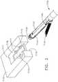
- FIG. 1illustrates various surgical instruments that are configured to receive various supplemental components that can be replaced during a surgical procedure.
- Such surgical instrumentscan benefit from the inclusion of at least one of the identification systems described herein, such as an RFID system.
- a surgical stapling instrument 6100comprises a handle 6110, an elongate shaft 6120 extending from the handle 6110, and an end effector 6130 extending from the elongate shaft 6120.
- the end effector 6130comprises a first jaw 6132 and a second jaw 6134, wherein the second jaw 6134 is configured to receive a replaceable staple cartridge 6140.
- a clinicianmay want to attach various supplemental components to the end effector 6130.
- supplemental components, or adjunct materialsare used to reinforce the staples and/or supplement the function of the staples.
- a buttress, or tissue thickness compensator, 6165may be attached to the first jaw 6132 and/or the second jaw 6134 to accommodate for varying tissue thicknesses.
- the addition of the buttress 6165 to the end effector 6130can assist in forming a uniform staple line on the patient tissue, for example.
- the buttress 6165can be supported on a mounting member 6160.
- the cliniciancan attach a layer of hemostatic agent 6175 to the first jaw 6132 and/or the second jaw 6134 of the end effector 6130 to promote rapid blood coagulation, among other things.
- the layer of hemostatic agent 6175can improve the seal created by the staples, for example.
- the layer of hemostatic agent 6175can be supported on a mounting member 6170.
- the cliniciancan attach a layer of adhesive 6185 to the first jaw 6132 and/or the second jaw 6134 of the end effector 6130 to promote healing of the treated tissue and/or enhance the connection between two layers of tissue, among other things.
- the layer of adhesive 6185can improve the seal created by the staples, for example.
- In an effort to facilitate attachment of the layer of adhesivecan be supported on a mounting member 6180.
- a first RFID tag 6162is positioned on the mounting member 6160.
- the first RFID tag 6162comprises stored information, wherein the stored information comprises data that identifies a characteristic of the buttress 6165 supported on the mounting member 6160.
- a second RFID tag 6172is positioned on the mounting member 6170.
- the second RFID tag 6172comprises stored information, wherein the stored information comprises data that identifies a characteristic of the layer of hemostatic agent 6175 supported on the mounting member 6170.
- a third RFID tag 6182is positioned on the mounting member 6180.
- the third RFID tag 6182comprises stored information, wherein the stored information comprises data that identifies a characteristic of the layer of adhesive 6185 supported on the mounting member 6180.
- the surgical stapling instrument 6100further comprises an RFID scanner 6150.
- the RFID scanner 6150can be positioned in any suitable location on the surgical instrument 6100 that allows the RFID scanner 6150 to communicate with the first RFID tag 6162, the second RFID tag 6172, and/or the third RFID tag 6182 as the supplemental component is being attached and/or after the supplemental component is attached to the end effector 6130.
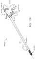
- a surgical clip applier 6200comprises a handle 6210, an elongate shaft 6220 extending from the handle 6210, and an end effector 6230 extending from the elongate shaft 6220.
- the end effector 6230comprises a first jaw 6232 and a second jaw 6234, wherein at least one of the first jaw 6232 and the second jaw 6234 is movable relative to one another during a clip crimping stroke.
- a clinicianmay want to attach various supplemental components to the end effector 6230.
- a clip 6260comprising a first thickness may be loaded into the surgical clip applier 6200.
- the clip 6260may be loaded individually into the surgical clip applier 6200 and/or the clip 6260 may be loaded into the surgical clip applier 6200 as a part of a clip cartridge.
- the attachment of the clip 6260 to the surgical clip applier 6200can be beneficial when the patient tissue is thick and/or dense, for example.
- the cliniciancan attach a clip 6290 comprising a second thickness to the surgical clip applier 6200.
- the second thickness of the clip 6290is smaller than the first thickness of the clip 6260.
- the attachment of the clip 6290 to the surgical clip applier 6200can be beneficial when the patient tissue is thin and/or delicate, for example.
- the cliniciancan attach a clip 6270 comprising a plurality of projections 6275 to the surgical clip applier 6200.
- the projections 6275 of the clip 6270can serve to enhance the grip between the clip 6270 and the patient tissue and/or maintain the position of a crimped clip 6270 on the patient tissue, among other things.
- the projections 6275may be attached to a thin clip. Utilization of the projections 6275 on the thin clip is beneficial when the patient tissue is thin and/or delicate, for example.
- the cliniciancan attach a clip 6280 comprising a plurality of projections 6285 to the surgical clip applier 6200.
- the projections 6285 of the clip 6280can serve to enhance the grip between the clip 6280 and the patient tissue and/or maintain the position of a crimped clip 6280 on the patient tissue, among other things. As shown on clip 6280, the projections 6285 may be attached to a thick clip. Utilization of the projections 6285 on the thick clip is beneficial when the patient tissue is thick and/or dense, for example.
- a first RFID tag 6262is positioned on the first clip 6260.
- the first RFID tag 6162comprises stored information, wherein the stored information comprises data that identifies a characteristic of the clip 6260.
- a second RFID tag 6272is positioned on the second clip 6270.
- the second RFID tag 6272comprises stored information, wherein the stored information comprises data that identifies a characteristic of the second clip 6270.
- a third RFID tag 6282is positioned on the third clip 6280.
- the third RFID tag 6282comprises stored information, wherein the stored information comprises data that identifies a characteristic of the third clip 6280.
- a fourth RFID tag 6292is positioned on the fourth clip 6290.
- the fourth RFID tag 6292comprises stored information, wherein the stored information comprises data that identifies a characteristic of the fourth clip 6290.
- the surgical clip applier 6200further comprises an RFID scanner 6250.
- the RFID scanner 6250can be positioned in any suitable location on the surgical instrument 6200 that allows the RFID scanner 6250 to communicate with the first RFID tag 6262, the second RFID tag 6272, the third RFID tag 6282, and/or the fourth RFID tag 6292 as the supplemental component is being and/or after the supplemental component is attached to the suturing device 6200.
- a surgical suturing device 6300comprises a handle 6310, an elongate shaft 6320 extending from the handle 6310, and an end effector 6330 extending from the elongate shaft 6320.
- the end effector 6330comprises a needle track configured to receive a portion of a replaceable needle.
- a clinicianmay want to attach various supplemental components to the end effector 6330.
- Different knot tying mechanisms and/or different suture termination elementscan be used to finish a line of sutures instead of tying a knot laparoscopically.
- a needle 6360comprising a first thickness may be loaded into the end effector 6330.
- the needle 6360comprises a first end 6364 and a second end 6366.
- the first end 6364comprises a pointed tip that comprises a first degree of sharpness.
- the second end 6366comprises a suturing material 6365 attached thereto.
- the attachment of the shaft needle 6360 to the end effector 6330can be beneficial when the patient tissue is thick and/or dense, for example.
- the cliniciancan attach a needle 6370 comprising a second thickness to the end effector 6330.
- the second thickness of the clip 6370is smaller than the first thickness of the clip 6360.
- the clip 6370further comprises a first end 6374 comprising a pointed tip that comprises a second degree of sharpness.
- the second degree of sharpness of the clip 6370is less than the first degree of sharpness of the clip 6360.
- the second end 6376comprises a suturing material 6375 attached thereto.
- the attachment of the needle 6370 to the end effector 6330can be beneficial when the patient tissue is thin and/or delicate, for example.
- the cliniciancan select a particular suturing material to be attached to the replaceable needle.
- a first suturing material 6385can be made of a first material, comprise a first length, and/or comprise a first thickness.
- the first suturing material 6385can be stored in a first packaging 6380 prior to attachment to a replaceable needle.
- a second suturing material 6395can be made of a second material, comprise a second length, and/or comprise a second thickness.
- the second suturing material 6395can be stored in a second packaging 6390 prior to attachment to a replaceable needle.
- a first RFID tag 6362is positioned on the first replaceable needle 6360.
- the first RFID tag 6362comprises stored information, wherein the stored information comprises data that identifies a characteristic of the replaceable needle 6360 and/or the suturing material 6365 attached thereto.
- a second RFID tag 6372is positioned on the second replaceable needle 6370.
- the second RFID tag 6372comprises stored information, wherein the stored information comprises data that identifies a characteristic of the second replaceable needle 6370 and/or the suturing material 6375 attached thereto.
- a third RFID tag 6382is positioned on the packaging 6380 of the third suturing material 6385.
- the third RFID tag 6382comprises stored information, wherein the stored information comprises data that identifies a characteristic of the third suturing material 6385.
- a fourth RFID tag 6392is positioned on the packaging 6390 of the fourth suturing material 6395.
- the fourth RFID tag 6392comprises stored information, wherein the stored information comprises data that identifies a characteristic of the fourth suturing material 6390.
- the surgical suturing device 6300further comprises an RFID scanner 6350.
- the RFID scanner 6350can be positioned in any suitable location on the surgical instrument 6300 that allows the RFID scanner 6350 to communicate with the first RFID tag 6362 and/or the second RFID tag 6372 as one of the replaceable needles 6360, 6370 is being positioned and/or after the replaceable needle is positioned within the needle track of the end effector 6330 and/or to communicate with the third RFID tag 6382 and/or the fourth RFID tag 6392 when the packaging 6380, 6390 is brought within a pre-defined distance from the RFID scanner 6300.
- Supplemental componentssuch as, for example, the buttress 6165, the hemostatic agent 6175, and/or the adhesive 6185, are contained within a sealed packaging after being manufactured until the packaging in opened in the operating room.
- the supplemental componentis supported on a mounting member within the packaging, for example, to facilitate storage and/or facilitate attachment of the supplemental component to the surgical instrument.
- Various forms of packaginginclude, for example, peel-pouches, woven and/or non-woven material wrappers, and rigid containers.
- FIG. 2depicts an example of a sealed packaging 7000.
- the depicted packaging 7000is a peel-pouch.
- the packaging 7000comprises a first layer 7010 and a second layer 7020.
- the first layer 7010 and the second layer 7020form a protective barrier around a layer of hemostatic agent 7175, which is configured to be attached to a surgical staple cartridge.
- the layer of hemostatic agent 7175is supported on a mounting member 7170 prior to the attachment of the layer of hemostatic agent 7175 to a surgical instrument.
- the mounting member 7170comprises retention members 7171 configured to receive a portion of the layer of hemostatic agent 7175 and to, for example, facilitate alignment of the layer of hemostatic agent 7175.
- An adhesivebonds the first layer 7010 and the second layer 7020 together to form an airtight and/or fluid-tight seal and/or pouch around the layer of hemostatic agent 7175.
- the adhesiveforms a seal without creases, wrinkles, and/or gaps.
- the seal created by the adhesiveprevents contaminants from coming into contact with the layer of hemostatic agent 7175 and/or prevents components of the layer of hemostatic agent 7175 from being misplaced, for example.
- the hemostatic agent 7175is hermetically sealed within the packaging 7000.
- the packaging 7000provides a completely fluid-tight and airtight seal.
- the first layer 7010 and the second layer 7020are comprised of a material such as, for example, paper with a laminated inner surface.
- the laminated inner surfaceprovides a barrier to prevent contaminants from entering the sealed portion of the packaging 7000.
- the first layer 7010 and the second layer 7020are comprised of plastic.
- the first layer 7010 and the second layer 7020can be comprised of a material with a particular degree of transparency to allow a clinician, for example, to observe the contents of the packaging 7000 prior to breaking the seal. The above being said, any suitable material and/or combinations of materials can be used for the first layer 7010 and/or the second layer 7020.
- the first layer 7010comprises a first portion positioned outside of the seal
- the second layer 7020comprises a second portion positioned outside of the seal.
- the cliniciancan expose the sealed layer of hemostatic agent 7175 by holding the first portion and the second portion in separate hands and pulling the first portion in a direction away from the second layer 7020, although any suitable opening method can be used.
- FIG. 2depicts an RFID system 7500 integrated with the packaging 7000.
- the RFID system 7500comprises an RFID tag 7172 and an insulator 7050.
- the RFID tag 7172comprises a chip, such as a microchip, for example, that stores information about the packaging 7000 and/or the contents of the packaging 7000.
- the chipcomprises an identification number. Such an identification number can be assigned to the chip that can communicate the chip's existence to an RFID scanner.
- the chipcomprises additional information such as, for example, manufacturing data, shipping data, and/or compatibility data.
- the RFID tag 7172further comprises a radio antenna 7173 configured to facilitate communication between the RFID tag 7172 and the RFID scanner.
- the insulator 7050is attached to the first layer 7010 of the packaging 7000, while the RFID tag 7172 is attached to a mounting member 7170 supporting the layer of hemostatic agent 7175.
- the insulator 7050is affixed to, or otherwise connected to an integrated battery 7176 of the RFID tag 7172.
- the integrated battery 7176is activated when the packaging 7000 is opened.
- the interface between the insulator 7050 and the integrated battery 7176prevents the integrated battery 7176 from providing power to the RFID tag 7172. In such instances, the RFID tag 7172 is unable to emit a signal.
- the insulator 7050When a clinician breaks the seal of the packaging 7000 by peeling the first layer 7010 away from the second layer 7020, the insulator 7050 is disconnected, or otherwise disassociated, from the integrated battery 7176 of the RFID tag 7172. Upon disassociation of the insulator 7050 from the integrated battery 7176, the circuit between the integrated battery 7176 and the RFID tag 7172 is closed, and the RFID tag 7172 is energized. As shown in FIG. 2 , the RFID tag 7172 begins emitting a signal 7174 upon being energized.
- the RFID tag 7172is configured to emit the signal 7174 at any appropriate frequency and/or for any appropriate duration. For example, the RFID tag 7172 can continuously emit the signal 7174 or the RFID tag 7172 can emit the signal 7174 every 3-5 seconds.
- the signal 7174comprises some, or all, of the information stored on the chip of the RFID tag 7172.
- the signal 7174may serve to alert a surgical instrument that the packaging 7000 has been tampered with during shipping and/or storage or simply that the packaging 7000 has been unsealed, for example.
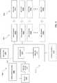
- FIG. 4illustrates a block diagram of an RFID system and/or control system 7400 of the surgical stapling instrument and/or tool 7100; however the control system 7400 can be adapted for use with alternative surgical instruments and/or tools, such as the surgical clip applier 7200 and/or the surgical suturing device 7300 described in greater detail herein.
- the control system 7400includes a control circuit 1210 that can be integrated with the RFID scanner, such as RFID scanner 7408a or can be coupled to, but positioned separately from, the RFID scanner 7408a.
- the control circuit 1210can be configured to receive input from the RFID scanner 7408a indicative of the information stored in the RFID tag 7406a about the supplemental component 7175 and/or information about the packaging 7000 of the supplemental component 7175.
- the RFID system 7400comprises more than one RFID scanner 7408b-h and/or more than one RFID tag 7406b-h.
- the RFID scanners 7408a-hare communicably coupled to that the control circuit 1210 can receive data from the RFID scanners 7408a-h and then take various actions based upon the read data, as are described below.
- the control circuit 1210includes a microcontroller 1213 that has a processor 1214 and a storage medium such as, for example, a memory 1212.
- the memory 1212stores program instructions for performing various processes such as, for example, identity verification.
- the program instructionswhen executed by the processor 1214, cause the processor 1214 to verify the identity of the packaging 7000 and/or the supplemental component 7175 by comparing the identification information received from the RFID tag(s) 7406a-h to identification information stored in the memory 1212 in the form of an identity database or look-up table, for example.
- the memory 1212comprises a local memory of the instrument 7100.
- identity databases or tables and/or compatibility databases or tablescan be downloaded from a remote server.
- the instrument 7100may transmit the information received from RFID tag(s) 7406a-7406h to a remote server that stores the databases or tables for performing the identity and/or compatibility checks remotely.
- the RFID tag 7172is configured to communicate with an RFID scanner. Once the insulator 7050 has been removed, the integrated battery 7176 of the RFID tag 7172 allows the RFID tag 7172 to emit the signal 7174 prior to receiving a first signal, such as an interrogation signal, from the RFID scanner.
- the RFID scannercomprises a scanner antenna configured to transmit and/or receive radio signals 7174 from the RFID tag 7172. In various instances, the RFID scanner comprises reading and writing capabilities.
- the RFID scanneris configured to pass the collected information from the RFID tag 7172 to a controller of the surgical instrument for further interpretation. In various instances, the controller is configured to determine if the supplemental component is compatible with the particular surgical instrument.
- the controlleris configured to activate a lockout assembly 7179 to prevent the surgical instrument from performing a function with the firing drive assembly 1163 such as, for example, a staple firing stroke, a suture firing stroke, and/or a clip crimping stroke if the controller determines that the supplemental component is not compatible with the particular surgical instrument and/or for use during the particular surgical procedure.
- a lockout assembly 7179to prevent the surgical instrument from performing a function with the firing drive assembly 1163 such as, for example, a staple firing stroke, a suture firing stroke, and/or a clip crimping stroke if the controller determines that the supplemental component is not compatible with the particular surgical instrument and/or for use during the particular surgical procedure.
- Various lockout assembliesare described in greater detail in U.S. Patent No. 7,143,923 , entitled SURGICAL STAPLING INSTRUMENT HAVING A FIRING LOCKOUT FOR AN UNCLOSED ANVIL, which issued on December 5, 2006; U.S. Patent No.
- the RFID scanneris positioned within a pre-determined range of the RFID tag 7172 that allows for the RFID scanner to be able to receive the emitted signal 7174 transmitted by the RFID tag 7172.
- the RFID scannercan be positioned on a surgical instrument, on the contents of the packaging, and/or remotely located on a console, such as a remote surgical system in communication with the surgical instrument.
- the controllercan be located in any suitable location, such as, for example, the surgical instrument or on a remote console.
- the tag antenna of the RFID tag 7172is destroyed and/or is otherwise rendered inoperable as the packaging 7000 is opened and/or after the packaging 7000 is opened.
- the RFID tag 7172is unable to transmit and/or receive communication and/or signals from an RFID scanner when the tag antenna is inoperable.
- the RFID scanneris configured to receive a first signal from the RFID tag 7172 before the packaging is opened.
- the controller of the surgical instrumentis configured to authenticate the packaging 7000 and the contents of the packaging 7000. If the RFID scanner does not receive the first signal from the RFID tag 7172, the controller is configured to prevent the surgical instrument from performing a function with the firing drive assembly 1163.
- the failure of the RFID scanner to receive the first signalis indicative of a tampered packaging and/or an inauthentic packaging, among other things.
- the tag antennais still operable after the packaging 7000 is opened; however, the communication range of the tag antenna is diminished. In such instances, the diminished communication range prevents the RFID tag 7172 from receiving and/or transmitting communication to the RFID scanner.
- a switchis positioned between the RFID tag 7172 and the power source.
- the insulator 7050biases the switch open when the packaging 7000 is in a sealed configuration, and the power source is unable to supply power to the RFID tag 7172. In such circumstances, the RFID tag 7172 is unable to communicate with the RFID scanner.
- the insulator 7050is disassociated from the RFID tag 7172, and the switch is closed. In such circumstances, the power source is able to supply power to the RFID tag 7172, and the RFID tag 7172 is able to communicate with the RFID scanner.
- an RFID systemcomprising an RFID tag mounted to the second layer 7020 of the packaging 7000 can be used.
- the RFID tagcomprises an internal power source positioned on the second layer 7020 of the packaging 7000.
- An insulatorsimilar to the insulator 7050, is attached to the packaging 7000 and, when the packaging 7000 is opened, the RFID tag on the second layer 7020 is activated.
- the insulatoris attached to, or otherwise associated with, the first layer 7010 of the packaging 7000.
- the insulator 7050is attached to, or otherwise connected to, the RFID tag on the second layer 7020 of the packaging 7000 and holds open the circuit between the integrated power source and the RFID tag.
- the interface between the insulator 7050 and the RFID tagprevents the power source from activating the RFID tag, and the RFID tag is unable to emit a signal.
- a clinicianbreaks the seal of the packaging 7000 by peeling away the first layer 7010, for example, the insulator 7050 is disconnected, or otherwise disassociated, from the RFID tag and the circuit between the power source and the RFID tag is closed. At such point, the RFID tag is energized and begins to emit a signal.
- the RFID system 7500further comprises a transponder.
- the transponderreceives a first communication from an RFID scanner.
- the first communication from the RFID scannerenergizes the transponder to a degree sufficient for the transponder to communicate with the RFID tag.
- the transponderis energized prior to receiving the first communication from the RFID scanner.
- the transponderis configured to automatically transmit a signal to the RFID tag upon hearing, or otherwise receiving, the first communication from the RFID scanner.
- the power source of the RFID tagenergizes the RFID tag upon receiving the signal from the transponder, and the RFID tag is able to respond to the communication transmitted by the RFID scanner.
- the transponderserves to, among other things, preserve the battery life of the RFID tag until, for example, the RFID tag is within range of the RFID scanner.
- a clinicianit is valuable for a clinician to be able to verify the compatibility of a supplemental component for use with a particular surgical instrument and/or for use during a particular surgical procedure. For various reasons, it can be also be meaningful for a clinician to be able to ensure that the supplemental component has not been previously used and/or tampered with. The clinician may also want to confirm, for example, that the supplemental component is not contaminated, that the supplemental component is intact, and/or that the supplemental component comprises an acceptable composition and/or dimension.
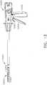
- FIG. 3illustrates a portion of a surgical stapling instrument 7100.
- the surgical stapling instrument 7100comprises an end effector 7130 extending from an elongate shaft 7120 of the surgical stapling instrument 7100.
- the end effector 7130comprises a first jaw 7132, wherein the first jaw 7132 is an anvil.
- the first jaw 7132comprises a plurality of staple forming pockets.
- the end effector 7130further comprises a second jaw 7134 comprising a channel configured to receive a replaceable staple cartridge 7140.
- the replaceable staple cartridge 7140comprises a cartridge body and a plurality of staples removably stored within the cartridge body. The plurality of staples are driven out of the cartridge body during a staple firing stroke 1163.
- the cliniciancan attach a layer of hemostatic agent 7175 to the end effector 7130 prior to performing the staple firing stroke 1163.
- the layer of hemostatic agent 7175is attached to a deck surface of the cartridge body.
- the layer of hemostatic agent 7175is attached to a tissue-supporting surface of the anvil. In any event, the layer of hemostatic agent 7175 is in contact with the patient tissue during and/or after the staple firing stroke 1163.
- the layer of hemostatic agent 7175is sealed within a packaging prior to attachment to the surgical instrument.
- the layer of hemostatic agent 7175is part of a mounting assembly configured to facilitate storage and attachment of the layer of hemostatic agent 7175.
- the mounting assemblycomprises a mounting member 7170.
- the mounting member 7170provides a physical barrier between the layers of the packaging and the hemostatic agent 7175 and prevents the layers of the packaging from coming into contact with the hemostatic agent 7175.
- the mounting member 7170prevents the layer of hemostatic agent 7175 from sticking and/or otherwise adhering to one or both of the layers of the packaging.
- the layer of hemostatic agent 7175is positioned between an opening within the mounting member 7170 defined by sidewalls 7177, 7188 of the mounting member 7170.
- the mounting member 7170comprises retention members 7171 that receive a portion of the layer of hemostatic agent 7175.
- the retention members 7171maintain the alignment of the layer of hemostatic agent 7175 and secure the layer of hemostatic agent 7175 to the mounting member 7170.
- the mounting member 7170also provides a surface for the clinician to hold when aligning the layer of hemostatic agent 7175 for attachment to the end effector 7130 of the surgical instrument.
- the surface provided by the mounting member 7170allows a clinician to attach the layer of hemostatic agent 7175 to the end effector 7130 without having to touch or otherwise contact the layer of hemostatic agent 7175.
- the mounting member 7170further comprises an RFID tag 7172.
- the RFID tag 7172comprises a chip, such as a microchip, for example, that stores information about the mounting member 7170 and/or the layer of hemostatic agent 7175.
- the set of stored information stored on the RFID chipcomprises data that identifies the type of supplemental component the mounting member 7170 is supporting.
- the mounting member 7170is supporting a layer of hemostatic agent 7175.
- the mounting member 7170can support any suitable form of supplemental component such as, for example, a tissue thickness compensator and/or an adhesive.
- the RFID tag 7172is mounted to a sidewall 7178 of the mounting member 7170.
- the RFID tag 7172can be embedded within and/or attached to the mounting member 7170 by any suitable method.
- the RFID tag 7172can be positioned on the layer of hemostatic agent 7175.
- the RFID tag 7172 in the mounting member 7170provides a lockout 7179 for the surgical instrument.
- the surgical instrumentwill not perform a function with the firing drive assembly 1163, such as a staple firing stroke and/or a jaw closure stroke, for example, if the information stored on the RFID tag 7172 is not received by a controller of the surgical instrument. In various instances, the surgical instrument will not perform the function with the firing drive assembly 1163 when the RFID tag 7172 is still in communication with an RFID scanner 7150 after the layer of hemostatic agent 7175 has been attached to the end effector 7130.
- Such a lockout 7179prevents the surgical instrument from performing the function with the firing drive assembly 1163 when the mounting member 7170 is still attached to the layer of hemostatic agent 7175 and/or the layer of hemostatic agent 7175 has been inappropriately attached to the end effector 7130.
- the surgical stapling instrument 7100comprises an RFID scanner 7150 configured to communicate with nearby RFID tags.
- the RFID scanner 7150comprises a scanner antenna configured to transmit radio signals.
- the radio signalsactivate RFID tags that are positioned within a pre-determined range of the RFID scanner 7150.
- the RFID scanner 7150then receives one or more response signals that are "bounced back" from the RFID tag(s).
- the one or more response signalscomprise the same signal as the interrogation signal.
- the one or more response signalscomprise a modified signal from the interrogation signal.
- the RFID scanner 7150comprises reading and writing capabilities. The RFID scanner 7150 is then able to pass the collected information from the RFID tag to a controller for further interpretation.
- the controllercan be positioned in the surgical instrument, the remote console, or in any suitable location.
- the RFID scanner 7150 and/or the controllercan comprise a stored set of information that corresponds to surgical stapling assemblies that are compatible with a particular surgical instrument and/or for use during a particular surgical procedure.
- the surgical systemcomprises an RFID scanner 7150 configured to interact with the RFID tag 7172 attached to the mounting member 7170.
- the RFID scanner 7150can be present in various locations.
- the RFID scanner 7150can be retained by the staple cartridge 7140.
- the RFID scanneris powered by the battery and/or power source of the surgical instrument.
- the RFID scanner 7150is positioned on the second jaw 7134 of the end effector 7130; however, the RFID scanner 7150 can be located in an alternative location within the surgical system and/or any other suitable location that would allow for communication between the RFID tag 7172 and the RFID scanner 7150 when the mounting member 7170 is within a pre-determined range of the end effector 7130.
- the RFID scanner 7150 and/or the RFID tag 7172are powered such that the signal(s) they emit can only be detected within a limited radius. That said, as the mounting member 7170 is removed from the layer of hemostatic agent 7175 after attaching the layer of hemostatic agent 7175 to the end effector 7130, the RFID tag 7172 is unable to communicate with the RFID scanner 7150.
- the end effector 7130comprises an RFID scanner positioned on a distal end of the end effector 7130.
- An RFID tagis retained by a back wall 7177 of the mounting member 7170.
- the distal end of the end effector 7130is brought close to, aligned with, and/or brought into contact with the back wall 7177 of the mounting member 7170.
- the communication range of the RFID scannerspans a distance that only encompasses the RFID tag of the back wall 7177 of the mounting member 7170 when the end effector 7130 is brought close to and/or brought into contact with the back wall 7177.
- Such a communication rangeallows the RFID tag to communicate with the RFID scanner only when the supplemental component 7175 is fully aligned with the end effector 7130.
- the communication between the RFID tag and the RFID scannercan alert a clinician that the supplemental component 7175 is fully aligned with the end effector 7130 and a function with the firing drive assembly 1163 of the surgical instrument can be performed. If the RFID scanner does not receive a communication from the RFID tag, the supplemental component 7175 may be misaligned and/or not fully attached to the end effector 7130, for example, which can lead to the formation of a non-uniform staple line, for example.
- the controller of the surgical instrumentprevents the surgical instrument from performing a function with the firing drive assembly 1163, such as a staple firing stroke, for example.
- the controlleris configured to prevent the function with the firing drive assembly 1163 of the surgical instrument.
- the continued communicationindicates that the mounting member 7170 is still attached to the supplemental component 7175.
- the loss of communicationindicates that the mounting member 7170 has been removed and/or moved out of communication distance from the end effector 7130 and/or the supplemental component 7175.
- the supplemental component verification system of the surgical instrumentwill be unable to permit the surgical instrument to perform a function with the firing drive assembly 1163, such as the staple firing stroke or the jaw closure stroke. If the RFID scanner 7150 receives a response to an interrogation signal that is not found within a stored set of compatible supplemental components, the controller of the surgical instrument is programmed to communicate an error to the clinician. Likewise, if the RFID scanner 7150 does not receive a response to the interrogation signal, the controller of the surgical instrument is programmed to communicate an error to the clinician.
- the detection of an error by the controllercan render the surgical instrument inoperable for use with that particular supplemental component.
- a detected errorcan prevent the surgical instrument from performing a staple firing stroke, jaw closure stroke, and/or tissue cutting stroke.
- the surgical instrumentfurther comprises a manual override that can be activated to allow a clinician to override any system lockout 7179 and utilize operational functions of the surgical instrument in an emergency.
- the controlleris configured to alert the clinician that an error has been detected by way of an indicator 1209. Such an alert can be communicated through various forms of feedback, including, for example, haptic, acoustic, and/or visual feedback.
- the feedbackcomprises audio feedback
- the surgical instrumentcan comprise a speaker which emits a sound, such as a beep, for example, when an error is detected.
- the feedbackcomprises visual feedback and the surgical instrument can comprise a light emitting diode (LED), for example, which flashes when an error is detected.
- the feedbackcomprises haptic feedback and the surgical instrument can comprise an electric motor 1160 comprising an eccentric element which vibrates when an error is detected.
- the alertcan be specific or generic. For example, the alert can specifically state that the RFID tag 7172 on the mounting member 7170 is unable to be detected, or the alert can specifically state that the RFID tag 7172 comprises information representative of an incompatible and/or defective supplemental component 7175.
- the controllercan be configured to select and/or modify various operational parameters based on the identification of the layer of hemostatic agent 7175 using the information stored on the RFID tag 7172.
- an identificationcan include the material the layer of hemostatic agent 7175 is comprised of and/or the thickness of the layer of hemostatic agent 7175, among other things.
- the controlleris configured to permit the surgical instrument to perform the desired function with the firing drive assembly 1163 using the modified operational parameters.
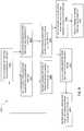
- FIG. 5depicts an exemplary process 6400 of the control circuit 1210.
- the control circuit 1210is configured to receive 6410 the information stored on the RFID tag 7172 corresponding to the supplemental component, such as the layer of hemostatic agent 7175. Using the received information, the control circuit 1210 is configured to identify 6420 a characteristic of the supplemental component 7175 using the received information. The control circuit 1210 is configured to select 6430 one or more appropriate operating parameters that correspond to the identified characteristic of the supplemental component 7175. The control circuit 1210 is configured to direct 6440 the firing assembly to perform a function, such as a staple firing stroke, with the selected operating parameter(s).
- a functionsuch as a staple firing stroke
- the RFID tag 7172can comprise an integrated power source and become activated upon the opening of the packaging 7000. In such instances, the RFID tag 7172 can continuously transmit the stored set of information, and the RFID tag 7172 does not need to wait for an interrogation signal from the RFID scanner 7300 to transmit the stored set of information.
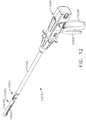
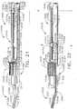
- FIG. 6illustrates a portion of a surgical clip applier 7200.
- the surgical clip applier 7200comprises an end effector 7230.
- the end effector 7230comprises a first jaw 7232 and a second jaw 7234. At least one of the first jaw and the second jaw are movable toward one another during a crimping stroke.
- the surgical clip applier 7200further comprises at least one clip.
- the surgical clip applier 7200is configured to receive a cartridge comprising a plurality of clips.
- the surgical slip applier 7200is configured to receive one clip at a time. Each clip is configured to be crimped around patient tissue T one at a time during the crimping strokes.
- the surgical clip applier 7200is configured to receive a clip cartridge comprising a first clip 7260 and a second clip 7260'.
- the first clip 7260comprises a first RFID tag 7262.
- the first RFID tag 7262comprises a chip, such as a microchip, for example, that stores information about the surgical clip applier 7200, the first clip 7260, and/or the cartridge attached to the surgical clip applier 7200.
- the set of information stored on the RFID chipcomprises data that identifies the type of clip 7260 and/or clip cartridge attached to the surgical instrument 7200.
- the first RFID tag 7262is mounted to an outer surface of the first clip 7260.
- the first RFID tag 7262is positioned on the outer surface of the first clip 7260 so that the first RFID tag 7262 is not in contact with patient tissue T when the first clip 7260 is crimped. Such placement can minimize damage and/or trauma to the patient tissue T, for example.
- the first RFID tag 7262is positioned on a portion of the first clip 7260 that is not bent during the crimping stroke. Such placement avoids damaging the first RFID tag 7262 during the crimping stroke, for example. That said, the first RFID tag 7262 can be embedded within and/or attached to the first clip 7260 by any suitable method and/or at any suitable location.
- the first RFID tag 7262 on the first clip 7260provides a lockout for the surgical instrument, such as lockout 7179, for example.
- the clip applierwill not perform a function with the firing drive assembly 1163, such as the crimping stroke on the first clip 7260, for example, if the information stored on the first RFID tag 7262 is not received by a controller of the surgical instrument.
- the surgical instrumentwill not perform the function with the firing drive assembly 1163 when the first RFID tag 7262 is still in communication with an RFID scanner 7250 after the crimping stroke has been performed on the first clip 7260.
- the continued communication between the first RFID tag 7262 and the RFID scanner 7250 after the crimping stroke has been performed on the first clip 7260indicates, among other things, that the clip applier is positioned too close to the formed first clip 7260.
- the clip appliercan alert a clinician of the detected location of the clip applier with respect to the formed first clip 7260 to prevent the clip applier from applying clips too close together, for example.
- the control circuit 1210is configured to detect 6710 the presence of a first clip after a crimping stroke is performed on the first clip. If the controller, through an RFID scanner, receives 6720 a communication and/or signal from the first RFID tag supported by the first clip, the controller is configured to prevent 6730 the surgical instrument 7200 from performing a crimping stroke on a second clip. If the controller, through the RFID scanner, fails to receive 6740 a communication and/or signal from the first RFID tag supported by the first clip, the controller is configured to permit 6750 the surgical instrument 7200 to perform the crimping stroke on the second clip.
- the control circuit 1210is configured to detect the presence of a first RFID tag supported by a first clip 6610. If the control circuit 1210 fails to receive a communication from the first RFID tag 6620, through an RFID scanner, the controller is configured to prevent the surgical instrument 7200 from performing a function 6630, such as a crimping stroke, on the first clip. The control circuit 1210 continues to detect the presence of the first RFID tag 6610 until the controller receives a communication from the first RFID tag 6640. Upon receiving the communication from the first RFID tag 6640, through the RFID scanner, the control circuit 1210 is configured to permit the surgical instrument 7200 to perform a crimping stroke on the first clip.
- a function 6630such as a crimping stroke
- the controllerAfter the crimping stroke is performed on the first clip, if the controller continues to receive communication from the first RFID tag 6660, the controller is configured to prevent the surgical instrument 7200 from performing a crimping stroke on a second clip 6670. After the crimping stroke is performed on the first clip, if the controller no longer receives communication from the first RFID tag 6680, the controller is configured to permit the surgical instrument 7200 to perform the crimping stroke on the second clip 6690.
- the surgical clip applier 7200comprises an RFID scanner 7250 configured to communicate with nearby RFID tags.
- the RFID scanner 7250comprises a scanner antenna configured to transmit radio signals.
- the radio signalsactivate RFID tags that are positioned within a pre-determined range of the RFID scanner 7250.
- the RFID scanner 7250then receives one or more response signals that are "bounced back" from the RFID tag(s).
- the one or more response signalscomprise the same signal as the interrogation signal.
- the one or more response signalscomprise a modified signal from the interrogation signal.
- the RFID scanner 7250comprises reading and writing capabilities. The RFID scanner 7250 is then able to pass the collected information from the RFID tag to a controller for further interpretation.
- the controllercan be positioned in the surgical instrument 7200, the remote console, or in any suitable location.
- the RFID scanner 7250 and/or the controllercan comprise a stored set of compatibility information that corresponds to clip cartridges and/or clips that are compatible with a particular surgical instrument and/or for use during a particular surgical procedure.
- the surgical system 7200comprises an RFID scanner 7250 configured to interact with the RFID tag 7262 attached to the first clip 7262.
- the RFID scanner 7250can be present in various locations. In the depicted embodiment, the RFID scanner 7250 is positioned on the second jaw 7234 of the end effector 7230; however, the RFID scanner 7250 can be located in an alternative location within the surgical system 7200 and/or any other suitable location that would allow for communication between the first RFID tag 7262 and the RFID scanner 7250.
- the RFID scanner 7250 and/or the first RFID tag 7262are powered such that the signal(s) they emit can only be detected within a communication range 7252 defined by a limited radius.
- the first RFID tag 7262is unable to communicate with the RFID scanner 7250. In such circumstances, the RFID tag 7262 moves outside of the communication range 7252 of the RFID scanner 7250. The RFID tag 7262 is unable to transmit and/or receive signals from the RFID scanner 7250 when the RFID tag 7262 is positioned outside of the communication range 7252.
- the supplemental component verification system of the surgical instrument 7200will be unable to permit the surgical instrument to perform a function with the firing drive assembly 1163, such as the crimping stroke. If the RFID scanner 7250 receives a response to an interrogation signal that is not found within a stored set of compatible supplemental components, the controller of the surgical instrument is programmed to communicate an error to the clinician. Likewise, if the RFID scanner 7250 does not receive a response to the interrogation signal, the controller of the surgical instrument is programmed to communicate an error to the clinician.
- the detection of an error by the controllercan render the surgical instrument inoperable for use with that particular clip cartridge and/or clip 7260.
- a detected errorcan prevent the surgical instrument from performing a clip applying and/or crimping stroke.
- the surgical instrumentfurther comprises a manual override that can be activated to allow a clinician to override any system lockout 7179 and utilize operational functions of the surgical instrument in an emergency.
- the controlleris configured to alert the clinician that an error has been detected through an indicator 1209.
- Such an alertcan be communicated through various forms of feedback, including, for example, haptic, acoustic, and/or visual feedback.
- the alertcan be specific or generic.
- the alertcan specifically state that the first RFID tag 7262 on the first clip 7260 is unable to be detected, or the alert can specifically state that the first RFID tag 7262 comprises information representative of an incompatible and/or defective clip cartridge and/or clip 7260.
- each clipcomprises an RFID tag
- the control circuit 1210is configured to detect the presence of the first RFID tag supported by the first clip 6510 through an RFID scanner. If the RFID scanner fails to receive a communication from the first RFID tag, the RFID scanner is unable to pass along the communication to the control circuit 1210. In such instances, the control circuit 1210 fails to receive the information stored on the first RFID tag 6520, and the control circuit 1210 prevents the surgical instrument 7200 from performing a crimping stroke on the first clip 6530.
- the failure for the RFID scanner to detect the first RFID tagcan arise from various scenarios such as an inauthentic clip, a defective clip, and/or an improperly aligned clip, among other things.
- the RFID scannerreceives a communication from the first RFID tag, the RFID scanner is configured to communicate the received information to the control circuit 1210.
- the control circuit 1210determines if the first clip is compatible 6550 for use with the surgical instrument 7200 and/or during the surgical procedure. If the control circuit 1210 determines that the first clip is compatible for use, the control circuit 1210 permits the surgical instrument 7200 to perform a function 6560, such as a crimping stroke, on the first clip. If the control circuit 1210 determines that the first clip is incompatible for use, the control circuit 1210 prevents the surgical instrument 7200 from performing the function 6570.
- the controllercan modify various operational parameters based on the identification of the clip cartridge and/or clip 7260 using the information stored on the first RFID tag 7262.
- Such an identificationcan include the material the first clip 7260 is comprised of, the number of clips 7260 remaining in the clip cartridge, the size of the clips 7260, and/or the thickness of the first clip 7260, among other things.
- the controlleris configured to permit the surgical instrument to perform the desired function with the firing drive assembly 1163 using the modified operational parameters.
- the RFID scanner 7250comprises a communication range 7252 that spans a distance D from the RFID scanner 7250.
- the RFID scanner 7250is able to transmit signals to and receive signals 7265 from the first RFID tag 7262.
- the surgical clip applier 7200 depicted in FIG. 6further comprises the second clip 7260' comprising a second RFID tag 7260'.
- the second RFID tag 7260'comprises an RFID chip and a tag antenna, and the second RFID tag 7260' is similar in function and structure to the first RFID tag 7260.
- the controller of the surgical clip applier 7200is configured to alert the clinician. Such an alert can notify the clinician that the surgical clip applier 7200 is about to crimp the second clip 7260' in a location that is too close to the first formed clip 7260, for example.
- the controllercan then prevent the clip applier 7200 from performing a crimping stroke on the second clip 7260' until the RFID scanner 7250 is unable to send and/or receive communications and/or signals from the first RFID tag 7262 on the first clip 7260.
- the information stored on the first RFID tag 7262is a first serial number that is specific to the first clip 7260 and the information stored on the second RFID tag 7262' is a second serial number that is specific to the second clip 7260'.
- the controlleris able to monitor each individual clip 7260, 7260' for compatibility with the surgical clip applier 7200 and/or authenticity, for example.
- the controlleris further able to maintain a count of the number of clips remaining in the loaded clip cartridge. In such instances, the controller is configured to alert the clinician of the number of clips remaining in the clip cartridge so that the clinician can prepare a new clip cartridge for attachment to the clip applier 7200.
- the control circuit 1210is configured to identify a characteristic of a clip cartridge 6810 attached to the surgical instrument 7200. Using the identified characteristic, the control circuit 1210 is configured to determine a number 6820 of clips stored and/or remaining in the clip cartridge. The control circuit 1210 is configured to update the count of the number of clips 6830 stored and/or remaining in the clip cartridge after each crimping stroke. The control circuit 1210 is further configured to alert a clinician 6840 when a pre-determined number of clips remain in the clip cartridge. For example, the clinician can be alerted when only one clip remains in the clip cartridge. In various instances, the clinician can be continuously alerted of the clip count.
- individual surgical clip applierssuch as the clip appliers 6200 and 7200, are configured to be interchangeably used with various configurations of clips and/or clip cartridges.
- clipscan comprise different dimensions, different strengths, different harnesses, and/or different material compositions.
- the end effector 6230can be removably attached to the elongate shaft 6220 to allow different end effector configurations to be attached to the clip applier 6200.
- Such modularityrequires the controller of the clip applier to implement different operational parameters for each type of attached clip, attached clip cartridge, and/or attached end effector.
- the surgical clip applier 7200further comprises an electric motor 1160 and a driver 1161 configured to control the operation of the motor 1160 including the flow of electrical energy from a power source.
- the controllervaries and/or modifies parameters of the electric motor 1160 through a motor control program.
- the motor control programis configured to determine the appropriate operational parameters based on the information received by the RFID scanner.
- the motor control programcan compare the information received from the RFID tag to a look-up table and/or database stored within a memory, such as the memory 1212. Such a look-up table and/or database can comprise recommended operational parameters for the motor control program to implement based on the detected attached components.
- Operational parameters that can be adjusted based on the identification of the identified replaceable componentscomprise the overall motor rate, the loading force applied to a clip by the jaws of the end effector during a crimping stroke, the duration of the crimping stroke, the rate of crimping, and/or the duration the jaws of the end effector are held in a closed configuration upon completion of the crimping stroke, for example.
- Such operational parametersshould be changed based on the attached clip to ensure proper clip closing without severing patient tissue, for example.
- the motor control programis configured to set a maximum load threshold based on the information received from the RFID tag positioned on the attached clip and/or clip cartridge. In such instances, the motor control program prevents the clip applier 7200 from performing a crimping stroke by blocking the power source's ability to supply power to the electric motor 1160 when the maximum load threshold is exceeded. In various instances, the motor control program is configured to prevent the clip applier 7200 from performing functions 1163 when other thresholds are exceeded, such as handling loads and/or elongate shaft twist loads, among others. The motor control program can implement prevent the power source from providing power to the electric motor 1160 after the crimping stroke is completed but before the jaws of the end effector are opened.
- the clip applier 7200comprises a locking member that holds the jaw in the closed configuration when power is no longer being supplied to the motor 1160. Such a locking member prevents the jaws from returning to the open configuration when power is no longer being supplied to the motor 1160.
- the motor control programis configured to cause the power source to supply a minimum amount of power to the motor 1160 after the crimping stroke is completed, wherein the minimum amount of power is sufficient to keep the jaws in the closed configuration.
- the ability for the controller of the clip applier 7200 to determine the identification of the clip material and/or size, the clip cartridge side and configuration, and/or the end effector configuration and/or capabilitiesallows the control system to appropriately adapt by setting maximum threshold limits and/or the rates and/or speeds of performing a crimping stroke, among other things.
- FIG. 11illustrates a portion of a surgical suturing device 7300.
- the surgical suturing device 7300comprises an end effector 7330.
- the end effector 7330comprises a needle track 7335 configured to guide a replaceable needle 7360.
- the replaceable needle 7360comprises a first end 7364 comprising a pointed tip configured to pierce through patient tissue.
- the replaceable needle 7360comprises a second end 7366, wherein the second end 7366 comprises suturing material 7365 attached thereto.
- the replaceable needle 7360is guided by the needle track 7335 and actuated by a firing drive through a firing stroke.
- the needle track 7335 of the end effector 7330is configured to receive a replaceable needle 7360.
- the replaceable needle 7360comprises an RFID tag 7362.
- the RFID tag 7362comprises a chip, such as a microchip, for example, that stores information about the surgical suturing device 7300, the replaceable needle 7360, and/or the suturing material 7365 attached to the replaceable needle 7360.
- the set of information stored on the RFID chipcomprises data that identifies the size of the needle 7360 positioned in the needle track 7335, the material the needle 7360 is comprised of, and/or the material the suturing material 7365 is comprised of. As shown in FIG.
- the RFID tag 7362is molded within the replaceable needle 7362.
- the RFID tag 7362is molded within the replaceable needle 7362 to allow the needle 7362 to travel through the needle track 7335 uninterrupted, for example.
- the RFID tag 7362is molded within the replaceable needle 7362 to allow the needle 7362 to travel through the patient tissue T in a smooth path. In other words, the RFID tag 7362 does not get stuck during the firing stroke and/or require an additional force to fire the replaceable needle through the patient tissue and/or the needle track 7335 during the firing stroke. That said, the RFID tag 7362 can be embedded within and/or attached to the replaceable needle 7360 by any suitable method and/or at any suitable location.
- the RFID tag 7362 on the replaceable needle 7360provides a lockout 7179 for the surgical instrument 7300.
- the suturing device 7300will not perform a function with the firing drive assembly 1163, such as the needle firing stroke, for example, if the information stored on the RFID tag 7362 is not received by a controller of the surgical instrument.
- the surgical suturing device 7300comprises an RFID scanner 7350 configured to communicate with nearby RFID tags.
- the RFID scanner 7350comprises a scanner antenna configured to transmit radio signals. The radio signals activate RFID tags that are positioned within a pre-determined range of the RFID scanner 7350.
- the RFID scanner 7350then receives one or more response signals that are "bounced back" from the RFID tag(s).
- the one or more response signalscomprise the same signal as the interrogation signal. In various instances, the one or more response signals comprise a modified signal from the interrogation signal. In various instances, the RFID scanner 7350 comprises reading and writing capabilities. The RFID scanner 7350 is then able to pass the collected information from the RFID tag to a controller for further interpretation.
- the controllercan be positioned in the surgical instrument 7300, the remote console, or in any suitable location.
- the RFID scanner 7350 and/or the controllercan comprise a stored set of compatibility information that corresponds to replaceable needles and/or suturing materials that are compatible with a particular surgical instrument and/or for use during a particular surgical procedure.
- the surgical system 7300comprises an RFID scanner 7350 configured to interact with the RFID tag 7362 attached to the replaceable needle 7360.
- the RFID scanner 7350can be present in various locations. In the depicted embodiment, the RFID scanner 7350 is positioned on a distal end of the of the end effector 7330. More specifically, the RFID scanner 7350 is positioned at a first end of the needle track 7335 adjacent the second end 7366 of the replaceable needle 7360 when the replaceable needle 7360 is appropriately positioned in the needle track 7335; however, the RFID scanner 7350 can be located in an alternative location within the surgical system 7300 and/or any other suitable location that would allow for communication between the RFID tag 7362 and the RFID scanner 7350.
- the RFID scanner 7350 and/or the RFID tag 7362are powered such that the signal(s) they emit can only be detected within a limited radius.
- the replaceable needle 7360does not comprise an RFID tag and/or the RFID tag 7362 comprises information that is not compatible with the surgical instrument 7300
- the supplemental component verification system and/or the controller of the surgical instrument 7300will be prevent the surgical instrument from performing a function with the firing drive assembly 1163, such as the firing stroke.
- the controller of the surgical instrumentis programmed to communicate an error to the clinician.
- the controller of the surgical instrumentis programmed to communicate an error to the clinician.
- the detection of an error by the controllercan render the surgical instrument inoperable for use with that particular replaceable needle 7360.
- a detected errorcan prevent the surgical instrument from performing a firing stroke.
- the surgical instrumentfurther comprises a manual override that can be activated to allow a clinician to override any system lockout 7179 and utilize operational functions of the surgical instrument in an emergency.
- the controlleris configured to alert the clinician that an error has been detected through an indicator 1209. Such an alert can be communicated through various forms of feedback, including, for example, haptic, acoustic, and/or visual feedback. The alert can be specific or generic.
- the alertcan specifically state that the RFID tag 7362 on the replaceable needle 7360 is unable to be detected, or the alert can specifically state that the RFID tag 7362 comprises information representative of an incompatible and/or defective needle 7360 and/or suturing material 7365.
- the controllercan modify various operational parameters based on the identification of the replaceable needle 7360 and/or the suturing material 7365 using the information stored on the RFID tag 7362.
- Such an identificationcan include the material the needle 7360 and/or the suturing material 7365 is comprised of, the length of the suturing material 7365, and/or the thickness of the replaceable needle 7360 and/or the suturing material 7365, among other things.
- the controlleris configured to permit the surgical instrument to perform the desired function with the firing drive assembly 1163 using the modified operational parameters.
- FIGS. 12 and 13depict a motor-driven surgical cutting and fastening instrument 12310.
- This illustrated embodimentdepicts an endoscopic instrument and, in general, the instrument 12310 is described herein as an endoscopic surgical cutting and fastening instrument; however, it should be noted that the invention is not so limited and that, according to other embodiments, any instrument disclosed herein may comprise a non-endoscopic surgical cutting and fastening instrument.
- the surgical instrument 12310 depicted in FIGS. 12 and 13comprises a handle 12306, a shaft 12308, and an end effector 12312 connected to the shaft 12308.
- the end effector 12312can be articulated relative to the shaft 12308 about an articulation joint 12314.
- Various means for articulating the end effector 12312 and/or means for permitting the end effector 12312 to articulate relative to the shaft 12308are disclosed in U.S. Patent No. 7,753,245 , entitled SURGICAL STAPLING INSTRUMENTS, which issued on July 13, 2010, and U.S. Patent No.
- the end effector 12312is configured to act as a surgical stapler for clamping, severing, and/or stapling tissue, although, in other embodiments, different types of end effectors may be used, such as end effectors for other types of surgical devices, graspers, cutters, staplers, clip appliers, access devices, drug/gene therapy devices, ultrasound, RF and/or laser devices, etc.
- the end effector 12312can include, among other things, a staple channel 12322 and a pivotally translatable clamping member, such as an anvil 12324, for example.
- the handle 12306 of the instrument 12310may include a closure trigger 12318 and a firing trigger 12320 for actuating the end effector 12312. It will be appreciated that instruments having end effectors directed to different surgical tasks may have different numbers or types of triggers or other suitable controls for operating the end effector 12312.
- the handle 12306can include a downwardly extending pistol grip 12326 toward which the closure trigger 12318 is pivotally drawn by the clinician to cause clamping or closing of the anvil 12324 toward the staple channel 12322 of the end effector 12312 to thereby clamp tissue positioned between the anvil 12324 and channel 12322.
- the handle 12306can further include a lock which can be configured to releasably hold the closure trigger 12318 in its closed position. More details regarding embodiments of an exemplary closure system for closing (or clamping) the anvil 12324 of the end effector 12312 by retracting the closure trigger 12318 are provided in U.S.
- Patent No. 7,000,818entitled SURGICAL STAPLING INSTRUMENT HAVING SEPARATE DISTINCT CLOSING AND FIRING SYSTEMS, which issued on February 21, 2006
- U.S. Patent No. 7,422,139entitled MOTOR-DRIVEN SURGICAL CUTTING AND FASTENING INSTRUMENT WITH TACTILE POSITION FEEDBACK, which issued on September 9, 2008
- U.S. Patent No. 7,464,849entitled ELECTRO-MECHANICAL SURGICAL INSTRUMENT WITH CLOSURE SYSTEM AND ANVIL ALIGNMENT COMPONENTS, which issued on December 16, 2008, the entire disclosures of which are incorporated by reference herein.
- the clinicianmay draw back the closure trigger 12318 to its fully closed, locked position proximate to the pistol grip 12326.
- the firing trigger 12320may then be actuated, or fired.
- the firing trigger 12320can be farther outboard of the closure trigger 12318 wherein the closure of the closure trigger 12318 can move, or rotate, the firing trigger 12320 toward the pistol grip 12326 so that the firing trigger 12320 can be reached by the operator using one hand.
- the operatormay pivotally draw the firing trigger 12320 toward the pistol grip 12312 to cause the stapling and severing of clamped tissue in the end effector 12312.
- the firing trigger 12320can be returned to its unactuated, or unfired, position after the clinician relaxes or releases the force being applied to the firing trigger 12320.
- a release button on the handle 12306when depressed, may release the locked closure trigger 12318.
- the release buttonmay be implemented in various forms such as, for example, those disclosed in published U.S. Patent Application Publication No. 2007/0175955 , entitled SURGICAL CUTTING AND FASTENING INSTRUMENT WITH CLOSURE TRIGGER LOCKING MECHANISM, which was filed on January 31, 2006, the entire disclosure of which is incorporated herein by reference in its entirety.
- the end effector 12312may include a cutting instrument, such as knife, for example, for cutting tissue clamped in the end effector 12312 when the firing trigger 12320 is retracted by a user. Also further to the above, the end effector 12312 may also comprise means for fastening the tissue severed by the cutting instrument, such as staples, RF electrodes, and/or adhesives, for example.
- a longitudinally movable drive shaft located within the shaft 12308 of the instrument 12310may drive/actuate the cutting instrument and the fastening means in the end effector 12312.
- An electric motor, located in the handle 12306 of the instrument 12310may be used to drive the drive shaft, as described further herein.
- the motormay be a DC brushed driving motor having a maximum rotation of, approximately, 25,000 RPM, for example.
- the motormay include a brushless motor, a cordless motor, a synchronous motor, a stepper motor, or any other suitable electric motor.
- a battery(or "power source” or “power pack"), such as a Li ion battery, for example, may be provided in the pistol grip portion 12326 of the handle 12306 adjacent to the motor wherein the battery can supply electric power to the motor via a motor control circuit.
- a number of battery cells connected in seriesmay be used as the power source to power the motor.
- the power sourcemay be replaceable and/or rechargeable.
- an electric motor 12342can be mounted to and positioned within the pistol grip portion 12326 of the handle 12306.
- the electric motor 12342can include a rotatable shaft operably coupled with a gear reducer assembly 12370 wherein the gear reducer assembly 12370 can include, among other things, a housing 12374 and an output pinion gear 12372.
- the output pinion gear 12372can be directly operably engaged with a longitudinally-movable drive member 12382 or, alternatively, operably engaged with the drive member 12382 via one or more intermediate gears 12386.
- the intermediate gear 12386in at least one such embodiment, can be meshingly engaged with a set, or rack, of drive teeth 12384 defined in the drive member 12382.
- the electric motor 12342can be drive the drive member distally, indicated by an arrow D ( FIG. 9 ), and/or proximally, indicated by an arrow D ( FIG. 10 ), depending on the direction in which the electric motor 12342 rotates the intermediate gear 12386.
- a voltage polarity provided by the batterycan operate the electric motor 12342 in a clockwise direction wherein the voltage polarity applied to the electric motor by the battery can be reversed in order to operate the electric motor 12342 in a counter-clockwise direction.
- the handle 12306can include a switch which can be configured to reverse the polarity applied to the electric motor 12342 by the battery.
- the handle 12306can also include a sensor 12330 configured to detect the position of the drive member 12382 and/or the direction in which the drive member 12382 is being moved.
- a surgical instrumentsuch as a clip applier 13100, for example, can be configured to apply one or more clips to tissue located within a surgical site in the patient.
- a surgical instrumentsuch as a clip applier 13100, for example, can be configured to apply one or more clips to tissue located within a surgical site in the patient.
- the clip applier 13100can be structured and arranged to position a clip 13140 relative to the tissue in order to compress the tissue within the clip 13140.
- the clip applier 13100can be configured to deform the clip 13140 as illustrated in FIGS. 19 and 20 , for example, and as described in greater detail further below.
- Each clip 13140can comprise a base 13142 and opposing legs 13144 extending from the base 13142.
- the base 13142 and the legs 13144can comprise any suitable shape and can define a substantially U-shaped configuration and/or a substantially V-shaped configuration, for example.
- the base 13142can comprise angled portions 13141 which are connected together by a joint 13143.
- the legs 13144 of the clip 13140can be positioned on opposite sides of the tissue wherein the legs 13144 can be pushed toward one another to compress the tissue positioned between the legs 13144.
- the joint 13143can be configured to permit the angled portions 13141 of the base 13142, and the legs 13144 extending therefrom, to deform inwardly.
- the clip 13140can be configured to yield, or deform plastically, when the clip 13140 is sufficiently compressed, although some amount of elastic deformation, or spring-back, may occur within the deformed clip 13140.
- the clip applier 13100can include a shaft 13110, an end effector 13120, and a replaceable clip cartridge, or magazine, 13130.
- the clip cartridge 13130can comprise a housing 13132 and a plurality of clips 13140 positioned within the housing 13132.
- the housing 13132can define a storage chamber 13134 in which the clips 13140 can be stacked.
- the storage chamber 13134can comprise sidewalls which extend around, or at least substantially around, the perimeter of the clips 13140.
- each clip 13140can comprise opposing faces, such as a top face 13145 and a bottom face 13146 on opposite sides of the clip 13140 wherein, when the clips 13140 are stacked in the housing 13132, the top face 13145 of a clip 13140 can be positioned against the bottom face 13146 of an adjacent clip 13140 and wherein the bottom face 13146 of the clip 13140 can be positioned against the top face 13145 of another adjacent clip 13140.
- the bottom faces 13146 of the clips 13140can face downwardly toward one or more support shelves, or platforms, 13135 defined in the housing 13132 while the top faces 13145 of the clips 13140 can face upwardly away from the support shelves 13135.
- the top faces 13145 and the bottom faces 13146 of the clips 13140may be identical, or at least substantially identical, in some cases, while, in other cases, the top faces 13145 and the bottom faces 13146 may be different.
- the stack of clips 13140 depicted in FIGS. 26-28comprises five clips 13140, for example; however, other embodiments are envisioned in which the stack of clips 13140 can include more than five clips 13140 or less than five clips 13140.
- the clip cartridge 13130can further comprise at least one biasing member, such as biasing member 13136, for example, positioned intermediate the housing 13132 and the top clip 13140 in the stack of clips 13140.
- the biasing member 13136can be configured to bias the bottom clip 13140 in the stack of clips 13140 or, more particularly, the bottom face 13146 of the bottom clip 13140, against the support shelves 13135 defined in the housing 13132.
- the biasing member 13136can comprise a spring, and/or any suitable compressed elastic element, for example, which can be configured to apply a biasing force to the clips 13140, or at least apply a biasing force to the top clip 13140 which is transmitted downwardly through the stack of clips 13140.
- the clip 13140When a clip 13140 is positioned against the support shelves 13135 as described above, the clip 13140 can be supported in a firing position in which the clip 13140 can be advanced and ejected from the cartridge 13130.
- the support shelves 13135can define at least a portion of a firing chamber 13149 in which the clips 13140 can be sequentially positioned in the firing position.
- the firing chamber 13149can be entirely defined within the cartridge 13130 or, in other cases, the firing chamber 13149 can be defined within and/or between the shaft 13110 and the cartridge 13130.
- the clip applier 13100can comprise a firing drive which can advance a firing member into the cartridge 13130 and push the clip 13140 from its firing position positioned against the support shelves 13135 to a fired position in which it is received within the end effector 13120 of the clip applier 13100.
- the housing 13132 of the cartridge 13130can comprise a proximal opening, or window, 13133 which can be aligned, or at least substantially aligned, with the support shelves 13135 such that the firing member can enter into the cartridge 13130 through the proximal opening 13133 and advance a clip 13140 distally out of the cartridge 13130.
- the housing 13132can further comprise a distal, or discharge, opening, or window, 13137 which is also aligned with the support shelves 13135 such that the clip 13140 can be advanced, or fired, distally along a firing axis 13139 extending through the proximal opening 13133, the firing chamber 13149, and the distal opening 13137, for example.
- the firing member of the firing drivecan be advanced into to the cartridge housing 13132 and, in various circumstances, into the firing chamber 13149.
- the firing membercan pass entirely through the cartridge 13130 in order to advance the clip 13140 into its fired position within the end effector 13120.
- the firing membercan be retracted sufficiently such that the biasing member 13136 can position another clip 13140 against the support shelves 13135.
- the biasing member 13136can bias a clip 13140 against the firing member while the firing member is positioned within the housing 13132.
- Such a clip 13140can be referred to as a queued clip.
- the biasing member 13136can then bias the clip 13140 against the support shelves 13135 where it is staged for the next stroke of the reciprocating firing member.
- the cartridge 13130can be configured to supply the clips 13140 to the firing chamber 13149 along a predetermined path, such as supply axis 13138, for example.
- the supply axis 13138can be transverse to the firing axis 13139 such that the clips 13140 are fed into the firing chamber 13149 in a direction which is different than the direction in which the firing member passes through the firing chamber 13149.
- the supply axis 13138can be perpendicular, or at least substantially perpendicular, to the firing axis 13139, for example.
- the shaft 13110can comprise a cartridge, or magazine, aperture 13131 which can be sized and configured to receive a clip cartridge 13130, for example, therein.
- the cartridge aperture 13131can be sized and configured such that the housing 13132 of the cartridge 13130 is closely received within the cartridge aperture 13131.
- the sidewalls which define the cartridge aperture 13131can limit, or at least substantially limit, the lateral movement of the cartridge 13130 relative to the shaft 13110.
- the shaft 13110 and/or the cartridge 13130can further comprise one or more locks which can be configured to releasably hold the cartridge 13130 in the cartridge aperture 13131. As illustrated in FIG.
- the cartridge 13130can be loaded into the cartridge aperture 13131 along an axis which is, in at least one embodiment, parallel to or collinear with the supply axis 13138.
- the shaft 13110can further comprise a pad or seat 13118 extending from the sidewall 13111 of the shaft 13110 wherein the pad 13118 can be configured to be received within and/or engaged with the housing 13132 of the cartridge 13130.
- the pad 13118can be sized and configured to be closely received within a recess 13148 defined in the cartridge housing such that the pad 13118 can limit, or at least substantially limit, the lateral movement of the cartridge 13130 relative to the shaft 13110.
- the pad 13118can be sized and configured to align the cartridge 13130 within the shaft 13110 and/or support the cartridge housing 13132.
- a firing drive 13160 of the clip applier 13100can be actuated to advance the clips 13140 from the clip cartridge 13130 as described above.
- the firing drive 13160can comprise a rotary drive input such as a drive screw 13161, for example, and a displaceable firing nut 13163 operably engaged with the drive screw 13161.
- the drive screw 13161can comprise at least one drive thread 13162 which can be threadably engaged with a threaded aperture extending through the firing nut 13163.
- the clip applier 13100can further include an electric motor, for example, operably coupled with the drive screw 13161.
- the drive screw 13161can be operably coupled with the motor of a surgical instrument system comprising a hand-held instrument or a robotic arm, for example.
- the movement of the firing nut 13163 within the shaft 13110can be constrained such that the firing nut 13163 moves along a longitudinal axis 13164 when the drive screw 13161 is rotated about the longitudinal axis 13164 by the motor.
- the drive screw 13161can advance the firing nut 13163 distally toward the end effector 13120, as illustrated in FIG. 22 .
- the shaft 13110can comprise one or more bearings which can be configured to rotatably support the drive screw 13161.
- a bearing 13159can be configured to rotatably support the distal end of the drive screw 13161, for example, as illustrated in FIGS. 21 and 22 .
- the firing drive 13160can further comprise a firing member 13165 extending from the firing nut 13163 which can be advanced distally and retracted proximally with the firing nut 13163, as described in greater detail further below.
- a firing member 13165extending from the firing nut 13163 which can be advanced distally and retracted proximally with the firing nut 13163, as described in greater detail further below.
- the clip cartridge 13130is illustrated as comprising a plurality of clips 13140 stored therein wherein one of the clips 13140 is positioned in a firing position, as described above.
- the firing member 13165can include a distal portion 13166 which can be advanced into the staple cartridge 13130 along a firing axis 13167 and engage the clip 13140 positioned in the firing position when the firing member 13165 and the firing nut 13163 are advanced distally.
- the firing member 13165can comprise a linear member while, in other cases, the distal end 13166 of the firing member 13165 can extend upwardly from the firing member 13165, for example.
- the firing member 13165can advance the clip 13140 distally out of the clip cartridge 13130 along the firing axis 13167 and into a receiving cavity 13122 defined in the end effector 13120.
- the firing member 13165can be attached to and extend distally from the firing nut 13163 while, in other cases, the firing member 13165 and the firing nut 13163 can be operably connected to one another by a firing actuator 13168.
- the firing actuator 13168can be pivotably mounted to the firing member 13165 at a pivot 13169 and can include a distal arm 13170a and a proximal arm 13170b which can be engaged with a longitudinal slot 13113 defined in the housing 13112 of the shaft 13110.
- each of the arms 13170a, 13170bcan include a projection, such as projections 13171 a and 13171b, respectively, extending therefrom which can be configured to slide within the longitudinal slot 13113.
- the firing nut 13163can further include a firing pin 13172 extending therefrom which can be configured to engage the distal arm 13170a in order to advance the actuator 13168 and the firing member 13165 distally, as described above.
- the firing nut 13163can be advanced distally by the drive screw 13161 wherein the firing pin 13172, which is positioned intermediate the distal arm 13170a and the proximal arm 13170b, can contact the distal arm 13170a and drive the actuator 13168 and the firing member 13165 distally.
- the actuator 13168may be prevented from rotating about the pivot pin 13169 as one or both of the projections 13171 a and 13171b sliding in the shaft slot 13113 can be prevented from being moved laterally relative to the longitudinal shaft slot 13113 until the actuator 13168 reaches the position illustrated in FIG. 22 .
- the clip 13140can be deformed by a crimping drive 13180, for example.
- the end effector 13120 of the clip applier 13100can further comprise a first jaw 13123a and a second jaw 13123b wherein the first jaw 13123a and the second jaw 13123b can at least partially define the receiving chamber 13122.
- the first jaw 13123acan comprise a first channel 13124a and the second jaw 13123b can comprise a second channel 13124b which can each be configured to receive and support at least a portion of a clip 13140 therein.
- the first jaw 13123acan be pivotably coupled to a frame 13111 of the shaft 13110 by a pin 13125a and the second jaw 13123b can be pivotably coupled to the frame 13111 by a pin 13125b.
- the crimping drive 13180can be configured to rotate the first jaw 13123a toward the second jaw 13123b and/or rotate the second jaw 13123b toward the first jaw 13123a in order to compress the clip 13140 positioned therebetween.
- the crimping drive 13180can comprise a cam actuator 13181 which can be configured to engage a first cam surface 13126a defined on the first jaw 13123a and a second cam surface 13126b on the second jaw 13123b in order to pivot the first jaw 13123a and the second jaw 13123b toward one another.
- the cam actuator 13181can comprise a collar which at least partially surrounds the first jaw 13123a and the second jaw 13123b.
- the collarcan comprise an inner cam surface 13182 which can be contoured to contact the cam surfaces 13126a, 13126b of the jaws 13123a, 13123b and drive them inwardly toward one another.
- the clip 13140 positioned within the receiving chamber 13122 defined in the end effector 13120can be positioned relative to tissue before the crimping drive 13180 is actuated.
- the crimping drive 13180can be at least partially actuated prior to positioning the clip 13140 relative to the tissue in order to at least partially compress the clip 13140.
- the clip 13140 and the receiving chamber 13122can be sized and configured such that the clip 13140 can be biased or flexed inwardly when the end effector 13120 is in its unactuated state, as illustrated in FIG. 19 .
- the crimping first jaw 13123a and the second jaw 13123bcan be actuated to elastically crimp and/or permanently crimp the clip 13140 positioned therebetween.
- the firing nut 13163can be configured to actuate the crimping drive 13180. More particularly, referring now to FIG. 23 , the crimping drive 13180 can comprise a crimping actuator 13188 operably coupled with the cam actuator 13181 wherein the crimping actuator 13188 can be selectively engaged by the firing nut 13163 as the firing nut 13163 is advanced distally as described above. In at least one such embodiment, the firing nut 13163 can further comprise a second firing pin, such as firing pin 13184, for example, extending therefrom which can be configured to engage the crimping actuator 13188 as the firing nut 13163 is advancing the firing actuator 13168. Referring again to FIG.
- the crimping actuator 13188is positioned in an unactuated position and, when the firing nut 13163 is advanced sufficiently to engage a distal arm 13190a of the crimping actuator 13188, the firing nut 13163 can rotate the crimping actuator 13188 upwardly into an actuated position as illustrated in FIG. 24 .
- the distal arm 13190a and a proximal arm 13190bcan each comprise a projection, such as projections 13191 a and 13191b, respectively, extending therefrom which can be positioned within a second longitudinal slot defined in shaft 13110, such as slot 13115, for example.
- the projections 13191 a and 13191bcan move from the proximal curved end 13116 of the longitudinal slot 13115 into a portion of the longitudinal slot 13115 which is substantially linear.
- the sidewalls of the longitudinal slot 13115can be configured to confine the movement of the crimping actuator 13188 along a longitudinal path and can be configured to limit or prevent the rotation of the crimping actuator 13188 once the crimping actuator 13188 has been rotated upwardly into an at least partially actuated position, as discussed above.
- the firing pin 13172 of the firing drive 13160 and the firing pin 13184 of the crimping drive 13180both extend from the firing nut 13163.
- the firing pins 13172 and 13184are illustrated as extending from the same side of the firing nut 13163; however, it is envisioned that the firing pin 13172 can extend from a first lateral side of the firing nut 13163 while the firing pin 13184 can extend from the other lateral side of the firing nut 13163.
- the firing actuator 13168can be positioned alongside the first lateral side of the drive screw 13161 and the crimping actuator 13188 can be positioned alongside the opposite lateral side of the drive screw 13161.
- the longitudinal slot 13113can be defined in a first lateral side of the shaft housing 13112 while the longitudinal slot 13115 can be defined in the opposite lateral side of the shaft housing 13112.
- the cam actuator 13181can be operably coupled with crimping actuator 13188 such that, when the crimping actuator 13188 is advanced distally by the firing nut 13163, the cam actuator 13181 can be advanced distally, as illustrated in FIG. 24 , until the distal projection 13191a extending from the distal arm 13190a reaches the distal end 13117 of the longitudinal slot 13115. In such a distal position, the cam actuator 13181 may be in a fully advanced position and the clip 13140 positioned within the receiving chamber 13122 can be in a fully deformed or crimped configuration. Thereafter, the cam actuator 13181 can be retracted and the end effector 13120 can be reopened.
- the drive screw 13161can be rotated in an opposite direction in order to move the firing nut 13163 proximally and retract the cam actuator 13181 wherein, in certain instances, the end effector 13120 can further include a biasing member which can be configured to bias the first jaw 13123 and the second jaw 13123b from the closed, or fired, position illustrated in FIG. 20 into the open, or unfired, position illustrated in FIG. 19 .
- these surgical suturing instrumentscomprise, among other things, a shaft, an end effector attached to the shaft, and drive systems positioned within the shaft to transfer motion from a source motion to the end effector.
- the motion sourcecan comprise a manually driven actuator, an electric motor, and/or a robotic surgical system.
- the end effectorcomprises a body portion, a needle track defined within the body portion, and a needle driver configured to drive a needle through a rotational firing stroke.
- the needleis configured to be guided through its rotational firing stroke within the body portion by the needle track.
- the needle driveris similar to that of a ratchet system.
- the needle driveris configured to drive the needle through a first half of the rotational firing stroke which places the needle in a hand-off position - a position where a tissue-puncturing end of the needle has passed through the target tissue and reentered the body portion of the end effector.
- the needle drivercan be returned to its original position to pick up the tissue-puncturing end of the needle and drive the needle through a second half of its rotational firing stroke. Once the needle driver pulls the needle through the second half of its rotational firing stroke, the needle driver is then returned to its original unfired position to grab the needle for another rotational firing stroke.
- the drive systemscan be driven by one or more motors and/or manual drive actuation systems.
- the needlecomprises suturing material, such as thread, for example, attached thereto.
- the suturing materialis configured to be pulled through tissue as the needle is advanced through its rotational firing stroke to seal the tissue and/or attached the tissue to another structure, for example.
- FIGS. 29-33depict a surgical suturing instrument 94000 configured to suture the tissue of a patient.
- the surgical suturing instrument 94000comprises a handle 94100, a shaft 94200 extending distally from the handle 94100, and an end effector 94300 attached to the shaft 94200 by way of an articulation joint 94210.
- the handle 94100comprises a firing trigger 94110 configured to actuate a firing drive of the surgical suturing instrument 94000, a first rotational actuator 94120 configured to articulate the end effector 94300 about an articulation axis AA defined by the articulation joint 94210, and a second rotational actuator 94130 configured to rotate the end effector 94300 about a longitudinal axis LA defined by the end effector 94300.
- the surgical suturing instrument 94000further comprises a flush port 94140. Examples of surgical suturing devices, systems, and methods are disclosed in U.S. Patent Application Serial No. 13/832,786 , now U.S. Patent No.
- FIG. 34depicts a handle assembly 95200 that is operable for use a surgical suturing instrument.
- the handle assembly 95200is connected to a proximal end of a shaft.
- the handle assembly 95200includes a motor 95202 and a transmission assembly 95210.
- the motor 95202is configured to actuate a needle of a surgical suturing end effector by way of a needle driver, articulate the end effector, and rotate the end effector by way of the transmission assembly 95210.
- the transmission assembly 95210is shifted between three states by a double acting solenoid, for example, so as to allow the motor 95202 to be used to actuate a needle of a surgical suturing end effector, articulate the end effector, and/or rotate the end effector.
- the handle assembly 95200could take the form of a robotic interface or a housing comprising gears, pulleys, and/or servomechanisms, for example. Such an arrangement could be used with a robotic surgical system.
- FIG. 35depicts a suturing cartridge 93590 comprising a lower body 93581, an upper body 93582, and a needle cover 93583.
- the cartridge 93590further comprises a drive system comprising a needle driver 93586, a rotary input 93594, and a link 93585 connecting the needle driver 93586 and the rotary input 93594.
- the needle driver 93586, rotary input 93594, and link 93585are captured between the lower body 93581 and the upper body 93582.
- the needle driver 93586, the link 93585, and the rotary input 93594are configured to be actuated to drive a needle 93570 through a needle firing stroke by way of a motor-driven system, a manually-driven handheld system, and/or a robotic system, for example.
- the lower and upper bodies 93581, 93582are attached to one another using any suitable technique, such as, for example, welds, pins, adhesives, and/or the like to form the cartridge body.
- the needle 93570comprises a leading end 93571 configured to puncture tissue, a trailing end 93572, and a length of suture 93573 extending from and attached to the trailing end 93572.
- the needle 93570is configured to rotate in a circular path defined by a needle track 93584.
- the needle track 93584is defined in the cartridge body.
- the needle 93570is configured to exit one of a first arm 95393A and a second arm 95393B of the cartridge body and enter the other of the first arm 95393A and the second arm 95393B during a needle firing stroke.
- Recessed features 93574are provided to so that the needle driver 93586 can engage and drive the needle 93570 through the needle firing stroke in a ratchet-like motion.
- the needle 93570is positioned between the needle track 93584 and the needle cover 93583.
- the suturing cartridge 93590further comprises a cage 93587 that is configured to slide over the cartridge body to attach the needle cover 93583 to the lower body 93581.
- a machine-readable mediummay include any mechanism for storing or transmitting information in a form readable by a machine (e.g., a computer), but is not limited to, floppy diskettes, optical disks, compact disc, read-only memory (CD-ROMs), and magneto-optical disks, read-only memory (ROMs), random access memory (RAM), erasable programmable read-only memory (EPROM), electrically erasable programmable read-only memory (EEPROM), magnetic or optical cards, flash memory, or a tangible, machine-readable storage used in the transmission of information over the Internet via electrical, optical, acoustical or other forms of propagated signals (e.g., carrier waves, infrared signals, digital signals, etc.). Accordingly, the non-
- control circuitmay refer to, for example, hardwired circuitry, programmable circuitry (e.g., a computer processor comprising one or more individual instruction processing cores, processing unit, processor, microcontroller, microcontroller unit, controller, digital signal processor (DSP), programmable logic device (PLD), programmable logic array (PLA), or field programmable gate array (FPGA)), state machine circuitry, firmware that stores instructions executed by programmable circuitry, and any combination thereof.
- programmable circuitrye.g., a computer processor comprising one or more individual instruction processing cores, processing unit, processor, microcontroller, microcontroller unit, controller, digital signal processor (DSP), programmable logic device (PLD), programmable logic array (PLA), or field programmable gate array (FPGA)
- state machine circuitryfirmware that stores instructions executed by programmable circuitry, and any combination thereof.
- the control circuitmay, collectively or individually, be embodied as circuitry that forms part of a larger system, for example, an integrated circuit (IC), an application-specific integrated circuit (ASIC), a system on-chip (SoC), desktop computers, laptop computers, tablet computers, servers, smart phones, etc.
- ICintegrated circuit
- ASICapplication-specific integrated circuit
- SoCsystem on-chip
- control circuitincludes, but is not limited to, electrical circuitry having at least one discrete electrical circuit, electrical circuitry having at least one integrated circuit, electrical circuitry having at least one application specific integrated circuit, electrical circuitry forming a general purpose computing device configured by a computer program (e.g., a general purpose computer configured by a computer program which at least partially carries out processes and/or devices described herein, or a microprocessor configured by a computer program which at least partially carries out processes and/or devices described herein), electrical circuitry forming a memory device (e.g., forms of random access memory), and/or electrical circuitry forming a communications device (e.g., a modem, communications switch, or optical-electrical equipment).
- a computer programe.g., a general purpose computer configured by a computer program which at least partially carries out processes and/or devices described herein, or a microprocessor configured by a computer program which at least partially carries out processes and/or devices described herein
- electrical circuitry forming a memory device
- logicmay refer to an app, software, firmware and/or circuitry configured to perform any of the aforementioned operations.
- Softwaremay be embodied as a software package, code, instructions, instruction sets and/or data recorded on non-transitory computer readable storage medium.
- Firmwaremay be embodied as code, instructions or instruction sets and/or data that are hard-coded (e.g., nonvolatile) in memory devices.
- the terms "component,” “system,” “module” and the likecan refer to a computer-related entity, either hardware, a combination of hardware and software, software, or software in execution.
- an “algorithm”refers to a self-consistent sequence of steps leading to a desired result, where a “step” refers to a manipulation of physical quantities and/or logic states which may, though need not necessarily, take the form of electrical or magnetic signals capable of being stored, transferred, combined, compared, and otherwise manipulated. It is common usage to refer to these signals as bits, values, elements, symbols, characters, terms, numbers, or the like. These and similar terms may be associated with the appropriate physical quantities and are merely convenient labels applied to these quantities and/or states.
- a networkmay include a packet switched network.
- the communication devicesmay be capable of communicating with each other using a selected packet switched network communications protocol.
- One example communications protocolmay include an Ethernet communications protocol which may be capable permitting communication using a Transmission Control Protocol/Internet Protocol (TCP/IP).
- TCP/IPTransmission Control Protocol/Internet Protocol
- the Ethernet protocolmay comply or be compatible with the Ethernet standard published by the Institute of Electrical and Electronics Engineers (IEEE) titled "IEEE 802.3 Standard", published in December, 2008 and/or later versions of this standard.
- the communication devicesmay be capable of communicating with each other using an X.25 communications protocol.
- the X.25 communications protocolmay comply or be compatible with a standard promulgated by the International Telecommunication Union-Telecommunication Standardization Sector (ITU-T).
- the communication devicesmay be capable of communicating with each other using a frame relay communications protocol.
- the frame relay communications protocolmay comply or be compatible with a standard promulgated by Consultative Committee for International Circuit and Telephone (CCITT) and/or the American National Standards Institute (ANSI).
- the transceiversmay be capable of communicating with each other using an Asynchronous Transfer Mode (ATM) communications protocol.
- ATMAsynchronous Transfer Mode
- the ATM communications protocolmay comply or be compatible with an ATM standard published by the ATM Forum titled " ATM-MPLS Network Interworking 2.0" published August 2001 , and/or later versions of this standard.
- ATM-MPLS Network Interworking 2.0published August 2001
- a microcontroller of control circuit in accordance with the present disclosuremay be any single-core or multicore processor such as those known under the trade name ARM Cortex by Texas Instruments.
- the main microcontroller 461may be an LM4F230H5QR ARM Cortex-M4F Processor Core, available from Texas Instruments, for example, comprising an on-chip memory of 256 KB single-cycle flash memory, or other nonvolatile memory, up to 40 MHz, a prefetch buffer to improve performance above 40 MHz, a 32 KB single-cycle SRAM, and internal ROM loaded with StellarisWare® software, a 2 KB EEPROM, one or more PWM modules, one or more QEI analogs, and/or one or more 12-bit ADCs with 12 analog input channels, details of which are available for the product datasheet.
- One or more componentsmay be referred to herein as “configured to,” “configurable to,” “operable/operative to,” “adapted/adaptable,” “able to,” “conformable/conformed to,” etc.
- “configured to”can generally encompass active-state components and/or inactive-state components and/or standby-state components, unless context requires otherwise.
- proximal and distalare used herein with reference to a clinician manipulating the housing portion of the surgical instrument.
- proximalrefers to the portion closest to the clinician and the term “distal” refers to the portion located away from the clinician.
- distalrefers to the portion located away from the clinician.
- spatial termssuch as “vertical”, “horizontal”, “up”, and “down” may be used herein with respect to the drawings.
- surgical instrumentsare used in many orientations and positions, and these terms are not intended to be limiting and/or absolute.
- any reference to “one aspect,” “an aspect,” “an exemplification,” “one exemplification,” and the likemeans that a particular feature, structure, or characteristic described in connection with the aspect is included in at least one aspect.
- appearances of the phrases “in one aspect,” “in an aspect,” “in an exemplification,” and “in one exemplification” in various places throughout the specificationare not necessarily all referring to the same aspect.
- the particular features, structures or characteristicsmay be combined in any suitable manner in one or more aspects.
Landscapes
- Health & Medical Sciences (AREA)
- Surgery (AREA)
- Life Sciences & Earth Sciences (AREA)
- Engineering & Computer Science (AREA)
- General Health & Medical Sciences (AREA)
- Public Health (AREA)
- Animal Behavior & Ethology (AREA)
- Nuclear Medicine, Radiotherapy & Molecular Imaging (AREA)
- Molecular Biology (AREA)
- Biomedical Technology (AREA)
- Heart & Thoracic Surgery (AREA)
- Medical Informatics (AREA)
- Veterinary Medicine (AREA)
- Physics & Mathematics (AREA)
- Electromagnetism (AREA)
- Oral & Maxillofacial Surgery (AREA)
- Pathology (AREA)
- General Physics & Mathematics (AREA)
- Theoretical Computer Science (AREA)
- Toxicology (AREA)
- Reproductive Health (AREA)
- Vascular Medicine (AREA)
- Microelectronics & Electronic Packaging (AREA)
- Computer Hardware Design (AREA)
- Computer Networks & Wireless Communication (AREA)
- Artificial Intelligence (AREA)
- Computer Vision & Pattern Recognition (AREA)
- Surgical Instruments (AREA)
Abstract
Description
- This application is a non-provisional application claiming priority under 35 U.S.C. §119(e) to
U.S. Provisional Patent Application Serial No. 62/868,457 - The present invention relates to surgical instruments and, in various embodiments, to surgical cutting and stapling instruments and staple cartridges therefor that are designed to cut and staple tissue. In various embodiments, RFID technology can be used to identify the components of a surgical instrument, such as staple cartridges, for example. Examples of surgical systems which use RFID technology can be found in the disclosures of
U.S. Patent No. 7,959,050 , entitled ELECTRICALLY SELF-POWERED SURGICAL INSTRUMENT WITH MANUAL RELEASE, which issued on June 14, 2011, andU.S. Patent Application No. 2015/0053743 , entitled ERROR DETECTION ARRANGEMENTS FOR SURGICAL INSTRUMENT ASSEMBLIES, which published on February 26, 2015, and both of which are incorporated by reference herein in their entireties. - In various embodiments, a surgical device for applying clips is disclosed. The surgical device includes an elongate shaft extending from a housing, an end effector extending from the elongate shaft, a cartridge, a crimping drive, an RFID tag including stored data, an RFID scanner configured to send an interrogation signal to the RFID tag and receive a first signal from the RFID tag in response to the interrogation signal, and a controller in communication with the RFID scanner. The end effector includes a first jaw and a second jaw. The first jaw and the second jaw are movable relative to each other between an open position and a closed position. The cartridge includes a storage chamber and a plurality of clips removably positioned within the storage chamber. The crimping drive is configured to move the first jaw and the second jaw to the closed position during a crimping stroke. One of the plurality of clips is crimped around tissue of a patient during the crimping stroke. The stored data on the RFID tag relates to an identifying characteristic of at least one of the plurality of clips within the cartridge. The first signal includes the stored data on the RFID tag. The controller is configured to compare the stored data received by the RFID scanner to a set of compatibility data stored in a memory of the controller and vary an operational parameter of the surgical device based on the stored data received by the RFID scanner.
- In various embodiments, a surgical device for applying clips is disclosed. The surgical device includes an elongate shaft extending from a housing, an end effector extending from the elongate shaft, a clip including an RFID tag, a crimping drive, an RFID scanner, and a controller in communication with the RFID scanner. The end effector includes a first jaw and a second jaw. The first jaw is movable relative to the second jaw between an open position and a closed position. The RFID tag includes stored data. The stored data on the RFID tag is representative of the clip. The crimping drive is configured to move the first jaw and the second jaw to the closed position during a crimping stroke. The clip is crimped around tissue of a patient during the crimping stroke. The RFID scanner is configured to receive the stored data on the RFID tag. The controller is configured to determine if the clip is compatible for use with the surgical device by comparing the stored data received by the RFID scanner to a set of compatibility data, permit the surgical device to perform a function when the controller determines the clip is compatible for use with the surgical device, and prevent the surgical device from performing the function when the controller determines the clip is incompatible for use with the surgical device.
- In various embodiments, a surgical device for applying clips is disclosed. The surgical device includes an elongate shaft extending from a housing, an end effector extending from the elongate shaft, a cartridge, a crimping drive, an RFID tag including stored data, an RFID scanner configured to communicate with the RFID tag, and a controller in communication with the RFID scanner. The end effector includes a first jaw and a second jaw. The first jaw and the second jaw are movable relative to each other between an open position and a closed position. The cartridge includes a storage chamber and a plurality of clips removably positioned within the storage chamber. The crimping drive is configured to move the first jaw and the second jaw to the closed position during a crimping stroke. One of the plurality of clips is crimped around tissue of a patient during the crimping stroke. The stored data on the RFID tag relates to an identifying characteristic of the plurality of clips within the cartridge. The RFID scanner is configured to receive the stored data from the RFID tag. The controller is configured to compare the stored data received by the RFID scanner to a set of authenticity data, permit the surgical device to perform the crimping stroke when the controller determines that the plurality of clips are authentic, and prevent the surgical device from performing the crimping stroke when the controller determines that the plurality of clips are inauthentic.
- Various features of the embodiments described herein, together with advantages thereof, may be understood in accordance with the following description taken in conjunction with the accompanying drawings as follows:
FIG. 1 is a schematic of various surgical instruments and supplemental components for use with the surgical instruments;FIG. 2 is a perspective view of a packaging, wherein the packaging comprises an identifying characteristic of the supplemental component contained therein;FIG. 3 is a partial cross-sectional view of a surgical stapling instrument system comprising a mounting member and a supplemental component, wherein the mounting member comprises an RFID tag;FIG.4 is a representation of an RFID system for use with the surgical instruments disclosed herein;FIG. 5 is a flowchart representative of a process of a controller for modifying at least one operational parameter based on an identified supplemental component;FIG. 6 is a partial perspective view of a surgical clip applier comprising an RFID system;FIG. 7 is a flowchart representative of a process of a controller for controlling the performance of a crimping stroke based on the detection of an RFID tag;FIG. 8 is a flowchart representative of a process of a controller for controlling the performance of a crimping stroke based on the monitoring of multiple RFID tags;FIG. 9 is a flowchart representative of a process of a controller for detecting the compatibility of an attached clip;FIG. 10 is a flowchart representative of a process of a controller for monitoring the number of clips remaining in a clip cartridge;FIG. 11 is a partial perspective view of a surgical suturing device comprising an RFID system;FIG. 12 is a perspective view of a surgical instrument comprising a handle, a shaft, and an articulatable end effector;FIG. 13 is a side view of the surgical instrument ofFIG. 12 ;FIG. 14 is a perspective view of a firing member and a pinion gear positioned within the handle ofFIG. 12 ;FIG. 15 is a perspective view of the firing member and the pinion gear ofFIG. 14 and a gear reducer assembly operably engaged with the pinion gear;FIG. 16 is a perspective view of the handle ofFIG. 12 with portions thereof removed to illustrate the firing member and the pinion gear ofFIG. 14 , the gear reducer assembly ofFIG. 15 , and an electric motor configured to drive the firing member distally and/or proximally depending on the direction in which the electric motor is turned;FIG. 17 is a partial perspective view of a clip applier;FIG. 18 is a cross-sectional view of an end effector of the clip applier ofFIG. 17 comprising a removable clip cartridge, a reciprocating firing drive for sequentially advancing the clips, a receiver for receiving the clips, and a crimping drive for deforming the clips;FIG. 19 is a partial cross-sectional view of the clip applier ofFIG. 17 in an open configuration;FIG. 20 is a partial cross-sectional view of the clip applier ofFIG. 17 in a closed configuration;FIG. 21 is a cross-sectional view of the end effector ofFIG. 18 in an unfired condition;FIG. 22 is a cross-sectional view of the end effector ofFIG. 18 illustrating the firing drive in a partially fired condition in which a firing member of the firing drive has advanced a clip into the receiver;FIG. 23 is a cross-sectional view of the end effector ofFIG. 18 illustrating the firing drive coming into engagement with the crimping drive;FIG. 24 is a cross-sectional view of the end effector ofFIG. 18 illustrating the crimping drive in an at least partially fired condition;FIG. 25 is a perspective view of a clip illustrated inFIG.18 ;FIG. 26 is a front view of a cartridge illustrated inFIG. 18 comprising a plurality of clips with portions of the cartridge removed to illustrate the clips stored in the cartridge;FIG. 27 is a side view of the cartridge ofFIG. 26 illustrated with portions removed to illustrate the clips stored in the cartridge;FIG. 28 is a cross-sectional plan view of the cartridge ofFIG. 26 taken along line 28-28 inFIG. 27 ;FIG. 29 is a perspective view of a surgical suturing instrument comprising a handle, a shaft, and an end effector;FIG. 30 is a partial plan view of the surgical suturing instrument ofFIG. 29 ;FIG. 31 is a partial plan view of the surgical suturing instrument ofFIG. 29 , wherein the end effector is in an articulated state;FIG. 32 is a partial perspective view of the surgical suturing instrument ofFIG. 29 ;FIG. 33 is a partial perspective view of the surgical suturing instrument ofFIG. 29 , wherein the end effector is in an articulated and rotated state;FIG. 34 is a perspective view of a surgical suturing instrument handle comprising a motor; andFIG. 35 is an exploded view of a suturing cartridge for use with a surgical suturing system.- Applicant of the present application owns the following U.S. Patent Applications that were filed on even date herewith and which are each herein incorporated by reference in their respective entireties:
- Attorney Docket No. END9145USNP1/190235-1M, entitled METHOD FOR AUTHENTICATING THE COMPATIBILITY OF A STAPLE CARTRIDGE WITH A SURGICAL INSTRUMENT;
- Attorney Docket No. END9146USNP1/190236, entitled SURGICAL INSTRUMENT SYSTEM COMPRISING AN RFID SYSTEM;
- Attorney Docket No. END9147USNP1/190237, entitled SURGICAL INSTRUMENT COMPRISING AN RFID SYSTEM FOR TRACKING A MOVABLE COMPONENT;
- Attorney Docket No. END9148USNP1/190238, entitled SURGICAL INSTRUMENT COMPRISING AN ALIGNED RFID SENSOR;
- Attorney Docket No. END9123USNP1/190239, entitled SURGICAL STAPLING SYSTEM HAVING AN INFORMATION DECRYPTION PROTOCOL;
- Attorney Docket No. END9124USNP/190240, entitled SURGICAL STAPLING SYSTEM HAVING AN INFORMATION ENCRYPTION PROTOCOL;
- Attorney Docket No. END9125USNP/190241, entitled SURGICAL STAPLING SYSTEM HAVING A LOCKOUT MECHANISM FOR AN INCOMPATIBLE CARTRIDGE;
- Attorney Docket No. END9126USNP/190242, entitled SURGICAL STAPLING SYSTEM HAVING A FRANGIBLE RFID TAG; and
- Attorney Docket No. END9127USNP/190243, entitled PACKAGING FOR A REPLACEABLE COMPONENT OF A SURGICAL STAPLING SYSTEM.
- Applicant of the present application owns the following U.S. Patent Applications that were filed on even date herewith and which are each herein incorporated by reference in their respective entireties:
- Attorney Docket No. END9119USNP1/190245-1M, entitled METHOD OF USING MULTIPLE RFID CHIPS WITH A SURGICAL ASSEMBLY;
- Attorney Docket No. END9120USNP1/190246, entitled MECHANISMS FOR PROPER ANVIL ATTACHMENT SURGICAL STAPLING HEAD ASSEMBLY;
- Attorney Docket No. END9121USNP1/190247, entitled MECHANISMS FOR MOTOR CONTROL ADJUSTMENTS OF A MOTORIZED SURGICAL INSTRUMENT;
- Attorney Docket No. END9122USNP1/190248, entitled SURGICAL INSTRUMENT WITH BATTERY COMPATIBILITY VERIFICATION FUNCTIONALITY;
- Attorney Docket No. END9131 USNP1/190249, entitled SURGICAL SYSTEM WITH RFID TAGS FOR UPDATING MOTOR ASSEMBLY PARAMETERS;
- Attorney Docket No. END9132USNP1/190250, entitled SURGICAL SYSTEMS WITH MULTIPLE RFID TAGS;
- Attorney Docket No. END9150USNP1/190252, entitled RFID IDENTIFICATION SYSTEMS FOR SURGICAL INSTRUMENTS;
- Attorney Docket No. END9151USNP1/190253, entitled SURGICAL RFID ASSEMBLIES FOR DISPLAY AND COMMUNICATION;
- Attorney Docket No. END9152USNP1/190254, entitled SURGICAL RFID ASSEMBLIES FOR COMPATIBILITY DETECTION; and
- Attorney Docket No. END9153USNP1/190255, entitled SURGICAL RFID ASSEMBLIES FOR INSTRUMENT OPERATIONAL SETTING CONTROL.
- Applicant of the present application owns the following U.S. Patent Applications that were filed on May 1, 2018 and which are each herein incorporated by reference in their respective entireties:
U.S. Provisional Patent Application Serial No. 62/665,129 U.S. Provisional Patent Application Serial No. 62/665,139 U.S. Provisional Patent Application Serial No. 62/665,177 U.S. Provisional Patent Application Serial No. 62/665,128 U.S. Provisional Patent Application Serial No. 62/665,192 U.S. Provisional Patent Application Serial No. 62/665,134 - Applicant of the present application owns the following U.S. Patent Applications that were filed on August 24, 2018 which are each herein incorporated by reference in their respective entireties:
U.S. Patent Application Serial No. 16/112,129 U.S. Patent Application Serial No. 16/112,155 U.S. Patent Application Serial No. 16/112,168 U.S. Patent Application Serial No. 16/112,180 U.S. Patent Application Serial No. 16/112,193 U.S. Patent Application Serial No. 16/112,099 U.S. Patent Application Serial No. 16/112,112 U.S. Patent Application Serial No. 16/112,119 U.S. Patent Application Serial No. 16/112,097 U.S. Patent Application Serial No. 16/112,109 U.S. Patent Application Serial No. 16/112,114 U.S. Patent Application Serial No. 16/112,117 U.S. Patent Application Serial No. 16/112,095 U.S. Patent Application Serial No. 16/112,121 U.S. Patent Application Serial No. 16/112,151 U.S. Patent Application Serial No. 16/112,154 U.S. Patent Application Serial No. 16/112,226 U.S. Patent Application Serial No. 16/112,062 U.S. Patent Application Serial No. 16/112,098 U.S. Patent Application Serial No. 16/112,237 U.S. Patent Application Serial No. 16/112,245 U.S. Patent Application Serial No. 16/112,249 U.S. Patent Application Serial No. 16/112,253 U.S. Patent Application Serial No. 16/112,257 - Applicant of the present application owns the following U.S. Patent Applications that were filed on October 26, 2018 which are each herein incorporated by reference in their respective entireties:
U.S. Patent Application Serial No. 16/172,130 U.S. Patent Application Serial No. 16/172,066 U.S. Patent Application Serial No. 16/172,078 U.S. Patent Application Serial NO. 16/172,087 U.S. Patent Application Serial No. 16/172,094 U.S. Patent Application Serial No. 16/172,128 U.S. Patent Application Serial No. 16/172,168 U.S. Patent Application Serial No. 16/172,164 U.S. Patent Application Serial No. 16/172,303 - Applicant of the present application owns the following U.S. Patent Applications, filed on December 4, 2018, the disclosure of each of which is herein incorporated by reference in its entirety:
U.S. Patent Application Serial No. 16/209,385 U.S. Patent Application Serial No. 16/209,395 U.S. Patent Application Serial No. 16/209,403 U.S. Patent Application Serial No. 16/209,407 U.S. Patent Application Serial No. 16/209,416 U.S. Patent Application Serial No. 16/209,423 U.S. Patent Application Serial No. 16/209,427 U.S. Patent Application Serial No. 16/209,433 U.S. Patent Application Serial No. 16/209,447 U.S. Patent Application Serial No. 16/209,453 U.S. Patent Application Serial No. 16/209,458 U.S. Patent Application Serial No. 16/209,465 U.S. Patent Application Serial No. 16/209,478 U.S. Patent Application Serial No. 16/209,490 U.S. Patent Application Serial No. 16/209,491 - Before explaining various aspects of surgical devices and systems in detail, it should be noted that the illustrative examples are not limited in application or use to the details of construction and arrangement of parts illustrated in the accompanying drawings and description. The illustrative examples may be implemented or incorporated in other aspects, variations, and modifications and may be practiced or carried out in various ways. Further, unless otherwise indicated, the terms and expressions employed herein have been chosen for the purpose of describing the illustrative examples for the convenience of the reader and are not for the purpose of limitation thereof. Also, it will be appreciated that one or more of the following-described aspects, expressions of aspects, and/or examples, can be combined with any one or more of the other following-described aspects, expressions of aspects and/or examples.
- Various surgical systems and instruments (e.g. surgical stapling instrument, surgical clip applier, surgical suturing instrument) are described in connection with the present disclosure. The surgical systems and/or instruments comprise a radio-frequency identification (RFID) system that includes one or more RFID scanners and one or more RFID tags, as will be discussed in greater detail below. Examples of surgical systems which use RFID technology are disclosed in
U.S. Patent No. 7,959,050 andU.S. Patent Application No. 2015/0053743 , both of which are incorporated by reference herein in their entireties. - Radio-frequency identification (RFID) is used in a variety of industries to track and identify objects. RFID relies on radio waves to transfer digitally-stored information from a RFID tag to a RFID reader or receiver configured to receive the information. RFID technology uses RFID tags, sometimes referred to as chips, which contain electronically-stored information, and RFID readers, which serve to identify and communicate with the RFID tags. There are two different types of RFID systems - active RFID systems and passive RFID systems. Active RFID systems include RFID tags that comprise an on-board power source to broadcast their signals. Active RFID tags can include a battery within the RFID tag which allows the active RFID tag to function independently from the RFID reader. As such, RFID tags in an active RFID system do not need to wait to receive a signal from a RFID reader before sending out information. Instead, the active RFID tags are free to continuously send out a signal, or beacon. Many commercially available active RFID systems often operate at one of two main frequency ranges - 433 MHz and 915 MHz, but any suitable frequency range can be used. Typically, a RFID tag must be within a specific distance or frequency range in order to be identified by its corresponding RFID reader.
- Passive RFID systems include RFID tags which do not comprise an on-board power source but instead receive the energy needed to operate from an RFID reader. Contrary to active RFID tags, RFID tags in a passive RFID system do not actively send out a signal before receiving a prompt. Instead, passive RFID tags wait to receive information from a RFID reader before sending out a signal. Many commercially-available passive RFID systems often operate within three frequency ranges - Low Frequency ("LF"), High Frequency ("HF") & Near-Field Communication ("NFC"), and Ultra High Frequency ("UHF"). The LF bandwidth is 125-134 KHz and includes a longer wavelength with a short read range of approximately one to ten centimeters. The HF and NFC bandwidth is 13.56 MHz and includes a medium wavelength with a typical read range of one centimeter to one meter. The UHF bandwidth is 865-960 MHz and includes a short, high-energy wavelength of one meter which translates into a long read range. The above being said, any suitable frequency can be used.
- A variety of RFID systems comprising differently-sized RFID tags exist. However, some are better suited for use in technology areas that require the tracking of very small objects. For example, Hitachi Chemical Co. Ltd. is a leading manufacturer in the RFID technology field. The Ultra Small size UHF RFID tag manufactured by Hitachi Chemical Co. Ltd. is typically no larger than 1.0 to 13 mm and enables communication between a RFID tag and a RFID reader at distances of several centimeters or more. Due to its compact nature, the Hitachi RFID tag is suitable for very small products which need to be identified. Each Hitachi RFID tag comprises an antenna, an IC chip connected to the antenna, and a sealing material that seals the IC chip and the antenna. Because the Hitachi RFID tag incorporates an antenna and an IC chip in a single unit, the Hitachi RFID tag is convenient enough to easily affix to any small object using an adhesive or tape, for example.
- The Hitachi RFID tag comprises a square stainless steel plate and a metal antenna. The antenna comprises a LC resonant circuit or any other suitable circuit and is electrically connected to the plate. After the plate and the antenna are connected to one another, the antenna and plate are sealed together in a single unit with a sealing material. The sealing material is primarily composed of epoxy, carbon, and silica to enhance the heat resistance capabilities of the Hitachi RFID tag. That is, the heat resistance of the RFID tag substantially depends on the heat resistance capabilities of the sealing material. The sealing material has a high heat resistance withstanding temperatures of up to 250 to 300°C for shorter time periods, such as a few seconds, and is resistant to heat for longer periods of time up to 150°C. Accordingly, the Hitachi RFID tag has a higher heat resistance than conventional RFID tags and can still operate normally even at high temperatures. Additional information regarding the Hitachi RFID tag can be found in
U.S. Patent No. 9,171,244 - During various surgical procedures, a surgical instrument comprising at least one replaceable component are used. It is important that such replaceable components be replaced with functional and/or compatible components. Various identification systems described in greater detail herein verify, among other things, a component's compatibility with the surgical instrument and/or verify an operating status of the component. For instance, a controller and/or an identification system can serve to, for example, ensure that the packaging containing the replaceable component has not been destroyed and/or tampered with, alert a clinician if a component is compatible or incompatible with the surgical instrument, alert the clinician if the replaceable component is expired, and/or alert the clinician if a recall exists for a particular manufacturing batch and/or type of the replaceable component.
- The identification systems described herein can either be active systems or passive systems. In various embodiments, a combination of active and passive identification systems are used. Passive systems can include, for example, a barcode, a quick response (QR) code, and/or a radio frequency identification (RFID) tag. Passive systems do not comprise an internal power source, and the passive systems described herein require a reader and/or scanner to send a first signal, such as an interrogation signal, for example.
- Passive radio frequency identification (RFID) systems communicate information by using radio frequencies. Such passive RFID systems comprise an RFID scanner and an RFID tag with no internal power source. The RFID tag is powered by electromagnetic energy transmitted from the RFID scanner. Each RFID tag comprises a chip, such as a microchip, for example, that stores information about the replaceable component and/or a surgical instrument with which the replaceable component is compatible. While the chip may only contain an identification number, in various instances, the chip can store additional information such as, for example, the manufacturing data, shipping data, and/or maintenance history. Each RFID tag comprises a radio antenna that allows the RFID tag to communicate with the RFID scanner. The radio antenna extends the range in which the RFID tag can receive signals from the RFID scanner and transmit response signals back to the RFID scanner. In a passive RFID system, the RFID scanner, which also comprises its own antenna, transmits radio signals that activate RFID tags that are positioned within a pre-determined range. The RFID scanner is configured to receive the response signals that are "bounced back" from RFID tags, allowing the RFID scanner is to capture the identification information representative of the replaceable component. In various instances, the one or more response signals comprise the same signal as the interrogation signal. In various instances, the one or more response signals comprise a modified signal from the interrogation signal. In various instances, the RFID scanner is also able to write, or encode, information directly onto the RFID tag. In any event, the RFID scanner is able to pass information about the replaceable component to a controller, such as the control system of a surgical instrument and/or a remote surgical system. The RFID scanner is configured to read multiple RFID tags at once, as the RFID tags are activated by radio signals. Additionally, in certain instances, the RFID scanner is able to update, or rewrite, information stored on an RFID tag in signal range with the RFID scanner. The updates can, for example, be transmitted to the RFID scanner from a surgical hub, or any suitable server. Various surgical hubs are described in described in
U.S. Patent Application Serial No. 16/209,395 - Active radio frequency identification (RFID) systems also comprise an RFID tag and an RFID scanner. However, the RFID tag in an active RFID system comprises an internal power source. Active RFID systems utilize battery-powered RFID tags that are configured to continuously broadcast their own signal. One type of active RFID tag is commonly referred to as a "beacon." Such beacon RFID tags do not wait to receive a first signal from an RFID scanner. Instead, the beacon RFID tag continuously transmits its stored information. For example, the beacon can send out its information at an interval of every 3-5 seconds. Another type of active RFID tag comprises a transponder. In such systems, the RFID scanner transmits a signal first. The RFID transponder tag then sends a signal back to the RFID scanner with the relevant information. Such RFID transponder tag systems are efficient, as they conserve battery life when, for example, the RFID tag is out of range of the RFID scanner. In various instances, the active RFID tag comprises an on-board sensor to track an environmental parameter. For example, the on-board sensor can track moisture levels, temperature, and/or other data that might be relevant.
FIG. 1 illustrates various surgical instruments that are configured to receive various supplemental components that can be replaced during a surgical procedure. Such surgical instruments can benefit from the inclusion of at least one of the identification systems described herein, such as an RFID system. For example, asurgical stapling instrument 6100 comprises ahandle 6110, anelongate shaft 6120 extending from thehandle 6110, and anend effector 6130 extending from theelongate shaft 6120. Theend effector 6130 comprises afirst jaw 6132 and asecond jaw 6134, wherein thesecond jaw 6134 is configured to receive areplaceable staple cartridge 6140. During a particular surgical procedure, a clinician may want to attach various supplemental components to theend effector 6130. Such supplemental components, or adjunct materials, are used to reinforce the staples and/or supplement the function of the staples. For example, a buttress, or tissue thickness compensator, 6165 may be attached to thefirst jaw 6132 and/or thesecond jaw 6134 to accommodate for varying tissue thicknesses. The addition of thebuttress 6165 to theend effector 6130 can assist in forming a uniform staple line on the patient tissue, for example. In an effort to facilitate attachment of thebuttress 6165 to theend effector 6130 and/or for storage, thebuttress 6165 can be supported on a mountingmember 6160. In various instances, the clinician can attach a layer ofhemostatic agent 6175 to thefirst jaw 6132 and/or thesecond jaw 6134 of theend effector 6130 to promote rapid blood coagulation, among other things. The layer ofhemostatic agent 6175 can improve the seal created by the staples, for example. In an effort to facilitate attachment of the layer ofhemostatic agent 6175 to theend effector 6130 and/or for storage, the layer ofhemostatic agent 6175 can be supported on a mountingmember 6170. In various instances, the clinician can attach a layer of adhesive 6185 to thefirst jaw 6132 and/or thesecond jaw 6134 of theend effector 6130 to promote healing of the treated tissue and/or enhance the connection between two layers of tissue, among other things. The layer of adhesive 6185 can improve the seal created by the staples, for example. In an effort to facilitate attachment of the layer of adhesive can be supported on a mountingmember 6180.- As described in greater detail herein, a
first RFID tag 6162 is positioned on the mountingmember 6160. Thefirst RFID tag 6162 comprises stored information, wherein the stored information comprises data that identifies a characteristic of thebuttress 6165 supported on the mountingmember 6160. Asecond RFID tag 6172 is positioned on the mountingmember 6170. Thesecond RFID tag 6172 comprises stored information, wherein the stored information comprises data that identifies a characteristic of the layer ofhemostatic agent 6175 supported on the mountingmember 6170. Athird RFID tag 6182 is positioned on the mountingmember 6180. Thethird RFID tag 6182 comprises stored information, wherein the stored information comprises data that identifies a characteristic of the layer of adhesive 6185 supported on the mountingmember 6180. Thesurgical stapling instrument 6100 further comprises anRFID scanner 6150. As discussed in greater detail herein, theRFID scanner 6150 can be positioned in any suitable location on thesurgical instrument 6100 that allows theRFID scanner 6150 to communicate with thefirst RFID tag 6162, thesecond RFID tag 6172, and/or thethird RFID tag 6182 as the supplemental component is being attached and/or after the supplemental component is attached to theend effector 6130. - A
surgical clip applier 6200 comprises ahandle 6210, anelongate shaft 6220 extending from thehandle 6210, and anend effector 6230 extending from theelongate shaft 6220. Theend effector 6230 comprises afirst jaw 6232 and asecond jaw 6234, wherein at least one of thefirst jaw 6232 and thesecond jaw 6234 is movable relative to one another during a clip crimping stroke. During a particular surgical procedure, a clinician may want to attach various supplemental components to theend effector 6230. For example, aclip 6260 comprising a first thickness may be loaded into thesurgical clip applier 6200. Theclip 6260 may be loaded individually into thesurgical clip applier 6200 and/or theclip 6260 may be loaded into thesurgical clip applier 6200 as a part of a clip cartridge. The attachment of theclip 6260 to thesurgical clip applier 6200 can be beneficial when the patient tissue is thick and/or dense, for example. In various instances, the clinician can attach aclip 6290 comprising a second thickness to thesurgical clip applier 6200. In various instances, the second thickness of theclip 6290 is smaller than the first thickness of theclip 6260. The attachment of theclip 6290 to thesurgical clip applier 6200 can be beneficial when the patient tissue is thin and/or delicate, for example. In various instances, the clinician can attach aclip 6270 comprising a plurality ofprojections 6275 to thesurgical clip applier 6200. Theprojections 6275 of theclip 6270 can serve to enhance the grip between theclip 6270 and the patient tissue and/or maintain the position of a crimpedclip 6270 on the patient tissue, among other things. As shown onclip 6270, theprojections 6275 may be attached to a thin clip. Utilization of theprojections 6275 on the thin clip is beneficial when the patient tissue is thin and/or delicate, for example. In various instances, the clinician can attach aclip 6280 comprising a plurality ofprojections 6285 to thesurgical clip applier 6200. Theprojections 6285 of theclip 6280 can serve to enhance the grip between theclip 6280 and the patient tissue and/or maintain the position of a crimpedclip 6280 on the patient tissue, among other things. As shown onclip 6280, theprojections 6285 may be attached to a thick clip. Utilization of theprojections 6285 on the thick clip is beneficial when the patient tissue is thick and/or dense, for example. - As described in greater detail herein, a
first RFID tag 6262 is positioned on thefirst clip 6260. Thefirst RFID tag 6162 comprises stored information, wherein the stored information comprises data that identifies a characteristic of theclip 6260. Asecond RFID tag 6272 is positioned on thesecond clip 6270. Thesecond RFID tag 6272 comprises stored information, wherein the stored information comprises data that identifies a characteristic of thesecond clip 6270. Athird RFID tag 6282 is positioned on thethird clip 6280. Thethird RFID tag 6282 comprises stored information, wherein the stored information comprises data that identifies a characteristic of thethird clip 6280. Afourth RFID tag 6292 is positioned on thefourth clip 6290. Thefourth RFID tag 6292 comprises stored information, wherein the stored information comprises data that identifies a characteristic of thefourth clip 6290. Thesurgical clip applier 6200 further comprises anRFID scanner 6250. As discussed in greater detail herein, theRFID scanner 6250 can be positioned in any suitable location on thesurgical instrument 6200 that allows theRFID scanner 6250 to communicate with thefirst RFID tag 6262, thesecond RFID tag 6272, thethird RFID tag 6282, and/or thefourth RFID tag 6292 as the supplemental component is being and/or after the supplemental component is attached to thesuturing device 6200. - A
surgical suturing device 6300 comprises ahandle 6310, anelongate shaft 6320 extending from thehandle 6310, and anend effector 6330 extending from theelongate shaft 6320. Theend effector 6330 comprises a needle track configured to receive a portion of a replaceable needle. During a particular surgical procedure, a clinician may want to attach various supplemental components to theend effector 6330. Different knot tying mechanisms and/or different suture termination elements can be used to finish a line of sutures instead of tying a knot laparoscopically. For example, aneedle 6360 comprising a first thickness may be loaded into theend effector 6330. Theneedle 6360 comprises afirst end 6364 and asecond end 6366. Thefirst end 6364 comprises a pointed tip that comprises a first degree of sharpness. Thesecond end 6366 comprises asuturing material 6365 attached thereto. The attachment of theshaft needle 6360 to theend effector 6330 can be beneficial when the patient tissue is thick and/or dense, for example. In various instances, the clinician can attach aneedle 6370 comprising a second thickness to theend effector 6330. In various instances, the second thickness of theclip 6370 is smaller than the first thickness of theclip 6360. Theclip 6370 further comprises afirst end 6374 comprising a pointed tip that comprises a second degree of sharpness. In various instances, the second degree of sharpness of theclip 6370 is less than the first degree of sharpness of theclip 6360. Thesecond end 6376 comprises asuturing material 6375 attached thereto. The attachment of theneedle 6370 to theend effector 6330 can be beneficial when the patient tissue is thin and/or delicate, for example. In various instances, the clinician can select a particular suturing material to be attached to the replaceable needle. For example, afirst suturing material 6385 can be made of a first material, comprise a first length, and/or comprise a first thickness. Thefirst suturing material 6385 can be stored in afirst packaging 6380 prior to attachment to a replaceable needle. Asecond suturing material 6395 can be made of a second material, comprise a second length, and/or comprise a second thickness. Thesecond suturing material 6395 can be stored in asecond packaging 6390 prior to attachment to a replaceable needle. - As described in greater detail herein, a
first RFID tag 6362 is positioned on the firstreplaceable needle 6360. Thefirst RFID tag 6362 comprises stored information, wherein the stored information comprises data that identifies a characteristic of thereplaceable needle 6360 and/or thesuturing material 6365 attached thereto. Asecond RFID tag 6372 is positioned on the secondreplaceable needle 6370. Thesecond RFID tag 6372 comprises stored information, wherein the stored information comprises data that identifies a characteristic of the secondreplaceable needle 6370 and/or thesuturing material 6375 attached thereto. Athird RFID tag 6382 is positioned on thepackaging 6380 of thethird suturing material 6385. Thethird RFID tag 6382 comprises stored information, wherein the stored information comprises data that identifies a characteristic of thethird suturing material 6385. Afourth RFID tag 6392 is positioned on thepackaging 6390 of thefourth suturing material 6395. Thefourth RFID tag 6392 comprises stored information, wherein the stored information comprises data that identifies a characteristic of thefourth suturing material 6390. Thesurgical suturing device 6300 further comprises anRFID scanner 6350. As discussed in greater detail herein, theRFID scanner 6350 can be positioned in any suitable location on thesurgical instrument 6300 that allows theRFID scanner 6350 to communicate with thefirst RFID tag 6362 and/or thesecond RFID tag 6372 as one of thereplaceable needles end effector 6330 and/or to communicate with thethird RFID tag 6382 and/or thefourth RFID tag 6392 when thepackaging RFID scanner 6300. - Supplemental components, such as, for example, the
buttress 6165, thehemostatic agent 6175, and/or the adhesive 6185, are contained within a sealed packaging after being manufactured until the packaging in opened in the operating room. In various instances, the supplemental component is supported on a mounting member within the packaging, for example, to facilitate storage and/or facilitate attachment of the supplemental component to the surgical instrument. Various forms of packaging include, for example, peel-pouches, woven and/or non-woven material wrappers, and rigid containers. FIG. 2 depicts an example of a sealedpackaging 7000. The depictedpackaging 7000 is a peel-pouch. Thepackaging 7000 comprises afirst layer 7010 and asecond layer 7020. Thefirst layer 7010 and thesecond layer 7020 form a protective barrier around a layer ofhemostatic agent 7175, which is configured to be attached to a surgical staple cartridge. The layer ofhemostatic agent 7175 is supported on a mountingmember 7170 prior to the attachment of the layer ofhemostatic agent 7175 to a surgical instrument. The mountingmember 7170 comprisesretention members 7171 configured to receive a portion of the layer ofhemostatic agent 7175 and to, for example, facilitate alignment of the layer ofhemostatic agent 7175. An adhesive bonds thefirst layer 7010 and thesecond layer 7020 together to form an airtight and/or fluid-tight seal and/or pouch around the layer ofhemostatic agent 7175. The adhesive forms a seal without creases, wrinkles, and/or gaps. The seal created by the adhesive prevents contaminants from coming into contact with the layer ofhemostatic agent 7175 and/or prevents components of the layer ofhemostatic agent 7175 from being misplaced, for example. In various instances, thehemostatic agent 7175 is hermetically sealed within thepackaging 7000. In various instances, thepackaging 7000 provides a completely fluid-tight and airtight seal.- The
first layer 7010 and thesecond layer 7020 are comprised of a material such as, for example, paper with a laminated inner surface. The laminated inner surface provides a barrier to prevent contaminants from entering the sealed portion of thepackaging 7000. In various instances, thefirst layer 7010 and thesecond layer 7020 are comprised of plastic. Thefirst layer 7010 and thesecond layer 7020 can be comprised of a material with a particular degree of transparency to allow a clinician, for example, to observe the contents of thepackaging 7000 prior to breaking the seal. The above being said, any suitable material and/or combinations of materials can be used for thefirst layer 7010 and/or thesecond layer 7020. Thefirst layer 7010 comprises a first portion positioned outside of the seal, and thesecond layer 7020 comprises a second portion positioned outside of the seal. The clinician can expose the sealed layer ofhemostatic agent 7175 by holding the first portion and the second portion in separate hands and pulling the first portion in a direction away from thesecond layer 7020, although any suitable opening method can be used. FIG. 2 depicts an RFID system 7500 integrated with thepackaging 7000. The RFID system 7500 comprises anRFID tag 7172 and aninsulator 7050. TheRFID tag 7172 comprises a chip, such as a microchip, for example, that stores information about thepackaging 7000 and/or the contents of thepackaging 7000. In various instances, the chip comprises an identification number. Such an identification number can be assigned to the chip that can communicate the chip's existence to an RFID scanner. In various instances, the chip comprises additional information such as, for example, manufacturing data, shipping data, and/or compatibility data. TheRFID tag 7172 further comprises a radio antenna 7173 configured to facilitate communication between theRFID tag 7172 and the RFID scanner.- The
insulator 7050 is attached to thefirst layer 7010 of thepackaging 7000, while theRFID tag 7172 is attached to a mountingmember 7170 supporting the layer ofhemostatic agent 7175. When thepackaging 7000 is in a sealed configuration, theinsulator 7050 is affixed to, or otherwise connected to anintegrated battery 7176 of theRFID tag 7172. The integratedbattery 7176 is activated when thepackaging 7000 is opened. Prior to thepackaging 7000 being opened, the interface between theinsulator 7050 and the integratedbattery 7176 prevents the integratedbattery 7176 from providing power to theRFID tag 7172. In such instances, theRFID tag 7172 is unable to emit a signal. When a clinician breaks the seal of thepackaging 7000 by peeling thefirst layer 7010 away from thesecond layer 7020, theinsulator 7050 is disconnected, or otherwise disassociated, from the integratedbattery 7176 of theRFID tag 7172. Upon disassociation of theinsulator 7050 from the integratedbattery 7176, the circuit between theintegrated battery 7176 and theRFID tag 7172 is closed, and theRFID tag 7172 is energized. As shown inFIG. 2 , theRFID tag 7172 begins emitting asignal 7174 upon being energized. TheRFID tag 7172 is configured to emit thesignal 7174 at any appropriate frequency and/or for any appropriate duration. For example, theRFID tag 7172 can continuously emit thesignal 7174 or theRFID tag 7172 can emit thesignal 7174 every 3-5 seconds. Thesignal 7174 comprises some, or all, of the information stored on the chip of theRFID tag 7172. In various instances, thesignal 7174 may serve to alert a surgical instrument that thepackaging 7000 has been tampered with during shipping and/or storage or simply that thepackaging 7000 has been unsealed, for example. FIG. 4 illustrates a block diagram of an RFID system and/orcontrol system 7400 of the surgical stapling instrument and/ortool 7100; however thecontrol system 7400 can be adapted for use with alternative surgical instruments and/or tools, such as thesurgical clip applier 7200 and/or thesurgical suturing device 7300 described in greater detail herein. Thecontrol system 7400 includes acontrol circuit 1210 that can be integrated with the RFID scanner, such asRFID scanner 7408a or can be coupled to, but positioned separately from, theRFID scanner 7408a. Thecontrol circuit 1210 can be configured to receive input from theRFID scanner 7408a indicative of the information stored in the RFID tag 7406a about thesupplemental component 7175 and/or information about thepackaging 7000 of thesupplemental component 7175. In various instances, theRFID system 7400 comprises more than oneRFID scanner 7408b-h and/or more than oneRFID tag 7406b-h. TheRFID scanners 7408a-h are communicably coupled to that thecontrol circuit 1210 can receive data from theRFID scanners 7408a-h and then take various actions based upon the read data, as are described below.- In at least one example, the
control circuit 1210 includes amicrocontroller 1213 that has aprocessor 1214 and a storage medium such as, for example, amemory 1212. Thememory 1212 stores program instructions for performing various processes such as, for example, identity verification. The program instructions, when executed by theprocessor 1214, cause theprocessor 1214 to verify the identity of thepackaging 7000 and/or thesupplemental component 7175 by comparing the identification information received from the RFID tag(s) 7406a-h to identification information stored in thememory 1212 in the form of an identity database or look-up table, for example. In various examples, thememory 1212 comprises a local memory of theinstrument 7100. In other examples, identity databases or tables and/or compatibility databases or tables can be downloaded from a remote server. In various aspects, theinstrument 7100 may transmit the information received from RFID tag(s) 7406a-7406h to a remote server that stores the databases or tables for performing the identity and/or compatibility checks remotely. - The
RFID tag 7172 is configured to communicate with an RFID scanner. Once theinsulator 7050 has been removed, the integratedbattery 7176 of theRFID tag 7172 allows theRFID tag 7172 to emit thesignal 7174 prior to receiving a first signal, such as an interrogation signal, from the RFID scanner. The RFID scanner comprises a scanner antenna configured to transmit and/or receiveradio signals 7174 from theRFID tag 7172. In various instances, the RFID scanner comprises reading and writing capabilities. The RFID scanner is configured to pass the collected information from theRFID tag 7172 to a controller of the surgical instrument for further interpretation. In various instances, the controller is configured to determine if the supplemental component is compatible with the particular surgical instrument. In various instances, the controller is configured to activate alockout assembly 7179 to prevent the surgical instrument from performing a function with the firingdrive assembly 1163 such as, for example, a staple firing stroke, a suture firing stroke, and/or a clip crimping stroke if the controller determines that the supplemental component is not compatible with the particular surgical instrument and/or for use during the particular surgical procedure. Various lockout assemblies are described in greater detail inU.S. Patent No. 7,143,923 , entitled SURGICAL STAPLING INSTRUMENT HAVING A FIRING LOCKOUT FOR AN UNCLOSED ANVIL, which issued on December 5, 2006;U.S. Patent No. 7,044,352 , SURGICAL STAPLING INSTRUMENT HAVING A SINGLE LOCKOUT MECHANISM FOR PREVENTION OF FIRING, which issued on May 16, 2006;U.S. Patent No. 7,000,818 , SURGICAL STAPLING INSTRUMENT HAVING SEPARATE DISTINCT CLOSING AND FIRING SYSTEMS, which issued on February 21, 2006;U.S. Patent No. 6,988,649 , SURGICAL STAPLING INSTRUMENT HAVING A SPENT CARTRIDGE LOCKOUT, which issued on January 24, 2006; andU.S. Patent No. 6,978,921 , SURGICAL STAPLING INSTRUMENT INCORPORATING AN E-BEAM FIRING MECHANISM, which issued on December 27, 2005, the disclosures of which are incorporated by reference herein in their entireties. The RFID scanner is positioned within a pre-determined range of theRFID tag 7172 that allows for the RFID scanner to be able to receive the emittedsignal 7174 transmitted by theRFID tag 7172. Depending on the application, the RFID scanner can be positioned on a surgical instrument, on the contents of the packaging, and/or remotely located on a console, such as a remote surgical system in communication with the surgical instrument. Additionally, the controller can be located in any suitable location, such as, for example, the surgical instrument or on a remote console. - In various instances, the tag antenna of the
RFID tag 7172 is destroyed and/or is otherwise rendered inoperable as thepackaging 7000 is opened and/or after thepackaging 7000 is opened. TheRFID tag 7172 is unable to transmit and/or receive communication and/or signals from an RFID scanner when the tag antenna is inoperable. In such instances, the RFID scanner is configured to receive a first signal from theRFID tag 7172 before the packaging is opened. Once the RFID scanner receives the first signal, the controller of the surgical instrument is configured to authenticate thepackaging 7000 and the contents of thepackaging 7000. If the RFID scanner does not receive the first signal from theRFID tag 7172, the controller is configured to prevent the surgical instrument from performing a function with the firingdrive assembly 1163. The failure of the RFID scanner to receive the first signal is indicative of a tampered packaging and/or an inauthentic packaging, among other things. In various instances, the tag antenna is still operable after thepackaging 7000 is opened; however, the communication range of the tag antenna is diminished. In such instances, the diminished communication range prevents theRFID tag 7172 from receiving and/or transmitting communication to the RFID scanner. - In various instances, a switch is positioned between the
RFID tag 7172 and the power source. Theinsulator 7050 biases the switch open when thepackaging 7000 is in a sealed configuration, and the power source is unable to supply power to theRFID tag 7172. In such circumstances, theRFID tag 7172 is unable to communicate with the RFID scanner. When thepackaging 7000 in an unsealed configuration, theinsulator 7050 is disassociated from theRFID tag 7172, and the switch is closed. In such circumstances, the power source is able to supply power to theRFID tag 7172, and theRFID tag 7172 is able to communicate with the RFID scanner. - In various instances, an RFID system comprising an RFID tag mounted to the
second layer 7020 of thepackaging 7000 can be used. Further to the above, the RFID tag comprises an internal power source positioned on thesecond layer 7020 of thepackaging 7000. An insulator, similar to theinsulator 7050, is attached to thepackaging 7000 and, when thepackaging 7000 is opened, the RFID tag on thesecond layer 7020 is activated. The insulator is attached to, or otherwise associated with, thefirst layer 7010 of thepackaging 7000. When thepackaging 7000 is in a sealed configuration, theinsulator 7050 is attached to, or otherwise connected to, the RFID tag on thesecond layer 7020 of thepackaging 7000 and holds open the circuit between the integrated power source and the RFID tag. The interface between theinsulator 7050 and the RFID tag prevents the power source from activating the RFID tag, and the RFID tag is unable to emit a signal. When a clinician breaks the seal of thepackaging 7000 by peeling away thefirst layer 7010, for example, theinsulator 7050 is disconnected, or otherwise disassociated, from the RFID tag and the circuit between the power source and the RFID tag is closed. At such point, the RFID tag is energized and begins to emit a signal. - In various instances, the RFID system 7500 further comprises a transponder. The transponder receives a first communication from an RFID scanner. In various instances, the first communication from the RFID scanner energizes the transponder to a degree sufficient for the transponder to communicate with the RFID tag. In various instances, the transponder is energized prior to receiving the first communication from the RFID scanner. In any event, the transponder is configured to automatically transmit a signal to the RFID tag upon hearing, or otherwise receiving, the first communication from the RFID scanner. The power source of the RFID tag energizes the RFID tag upon receiving the signal from the transponder, and the RFID tag is able to respond to the communication transmitted by the RFID scanner. The transponder serves to, among other things, preserve the battery life of the RFID tag until, for example, the RFID tag is within range of the RFID scanner.
- As described in greater detail herein, it is valuable for a clinician to be able to verify the compatibility of a supplemental component for use with a particular surgical instrument and/or for use during a particular surgical procedure. For various reasons, it can be also be meaningful for a clinician to be able to ensure that the supplemental component has not been previously used and/or tampered with. The clinician may also want to confirm, for example, that the supplemental component is not contaminated, that the supplemental component is intact, and/or that the supplemental component comprises an acceptable composition and/or dimension.
FIG. 3 illustrates a portion of asurgical stapling instrument 7100. As discussed in greater detail elsewhere herein, thesurgical stapling instrument 7100 comprises an end effector 7130 extending from an elongate shaft 7120 of thesurgical stapling instrument 7100. The end effector 7130 comprises afirst jaw 7132, wherein thefirst jaw 7132 is an anvil. Thefirst jaw 7132 comprises a plurality of staple forming pockets. The end effector 7130 further comprises asecond jaw 7134 comprising a channel configured to receive areplaceable staple cartridge 7140. Thereplaceable staple cartridge 7140 comprises a cartridge body and a plurality of staples removably stored within the cartridge body. The plurality of staples are driven out of the cartridge body during astaple firing stroke 1163. In an effort to, for example, promote rapid blood coagulation, of patient tissue affected during the staple firing andtissue cutting stroke 1163, the clinician can attach a layer ofhemostatic agent 7175 to the end effector 7130 prior to performing thestaple firing stroke 1163. In various instances, the layer ofhemostatic agent 7175 is attached to a deck surface of the cartridge body. In various instances, the layer ofhemostatic agent 7175 is attached to a tissue-supporting surface of the anvil. In any event, the layer ofhemostatic agent 7175 is in contact with the patient tissue during and/or after thestaple firing stroke 1163.- As discussed above, the layer of
hemostatic agent 7175 is sealed within a packaging prior to attachment to the surgical instrument. Within the packaging, the layer ofhemostatic agent 7175 is part of a mounting assembly configured to facilitate storage and attachment of the layer ofhemostatic agent 7175. The mounting assembly comprises a mountingmember 7170. In various instances, the mountingmember 7170 provides a physical barrier between the layers of the packaging and thehemostatic agent 7175 and prevents the layers of the packaging from coming into contact with thehemostatic agent 7175. For example, the mountingmember 7170 prevents the layer ofhemostatic agent 7175 from sticking and/or otherwise adhering to one or both of the layers of the packaging. The layer ofhemostatic agent 7175 is positioned between an opening within the mountingmember 7170 defined by sidewalls 7177, 7188 of the mountingmember 7170. The mountingmember 7170 comprisesretention members 7171 that receive a portion of the layer ofhemostatic agent 7175. Theretention members 7171 maintain the alignment of the layer ofhemostatic agent 7175 and secure the layer ofhemostatic agent 7175 to the mountingmember 7170. The mountingmember 7170 also provides a surface for the clinician to hold when aligning the layer ofhemostatic agent 7175 for attachment to the end effector 7130 of the surgical instrument. The surface provided by the mountingmember 7170 allows a clinician to attach the layer ofhemostatic agent 7175 to the end effector 7130 without having to touch or otherwise contact the layer ofhemostatic agent 7175. - The mounting
member 7170 further comprises anRFID tag 7172. TheRFID tag 7172 comprises a chip, such as a microchip, for example, that stores information about the mountingmember 7170 and/or the layer ofhemostatic agent 7175. In various instances, the set of stored information stored on the RFID chip comprises data that identifies the type of supplemental component the mountingmember 7170 is supporting. In the depicted embodiment, the mountingmember 7170 is supporting a layer ofhemostatic agent 7175. However, the mountingmember 7170 can support any suitable form of supplemental component such as, for example, a tissue thickness compensator and/or an adhesive. As shown inFIG. 3 , theRFID tag 7172 is mounted to asidewall 7178 of the mountingmember 7170. However, theRFID tag 7172 can be embedded within and/or attached to the mountingmember 7170 by any suitable method. In various instances, theRFID tag 7172 can be positioned on the layer ofhemostatic agent 7175. - The
RFID tag 7172 in the mountingmember 7170 provides alockout 7179 for the surgical instrument. The surgical instrument will not perform a function with the firingdrive assembly 1163, such as a staple firing stroke and/or a jaw closure stroke, for example, if the information stored on theRFID tag 7172 is not received by a controller of the surgical instrument. In various instances, the surgical instrument will not perform the function with the firingdrive assembly 1163 when theRFID tag 7172 is still in communication with anRFID scanner 7150 after the layer ofhemostatic agent 7175 has been attached to the end effector 7130. Such alockout 7179 prevents the surgical instrument from performing the function with the firingdrive assembly 1163 when the mountingmember 7170 is still attached to the layer ofhemostatic agent 7175 and/or the layer ofhemostatic agent 7175 has been inappropriately attached to the end effector 7130. - As mentioned in greater detail herein, the
surgical stapling instrument 7100 comprises anRFID scanner 7150 configured to communicate with nearby RFID tags. TheRFID scanner 7150 comprises a scanner antenna configured to transmit radio signals. The radio signals activate RFID tags that are positioned within a pre-determined range of theRFID scanner 7150. TheRFID scanner 7150 then receives one or more response signals that are "bounced back" from the RFID tag(s). In various instances, the one or more response signals comprise the same signal as the interrogation signal. In various instances, the one or more response signals comprise a modified signal from the interrogation signal. In various instances, theRFID scanner 7150 comprises reading and writing capabilities. TheRFID scanner 7150 is then able to pass the collected information from the RFID tag to a controller for further interpretation. The controller can be positioned in the surgical instrument, the remote console, or in any suitable location. TheRFID scanner 7150 and/or the controller can comprise a stored set of information that corresponds to surgical stapling assemblies that are compatible with a particular surgical instrument and/or for use during a particular surgical procedure. - More specifically, the surgical system comprises an
RFID scanner 7150 configured to interact with theRFID tag 7172 attached to the mountingmember 7170. TheRFID scanner 7150 can be present in various locations. For example, theRFID scanner 7150 can be retained by thestaple cartridge 7140. In various instances, the RFID scanner is powered by the battery and/or power source of the surgical instrument. In the depicted embodiment, theRFID scanner 7150 is positioned on thesecond jaw 7134 of the end effector 7130; however, theRFID scanner 7150 can be located in an alternative location within the surgical system and/or any other suitable location that would allow for communication between theRFID tag 7172 and theRFID scanner 7150 when the mountingmember 7170 is within a pre-determined range of the end effector 7130. TheRFID scanner 7150 and/or theRFID tag 7172 are powered such that the signal(s) they emit can only be detected within a limited radius. That said, as the mountingmember 7170 is removed from the layer ofhemostatic agent 7175 after attaching the layer ofhemostatic agent 7175 to the end effector 7130, theRFID tag 7172 is unable to communicate with theRFID scanner 7150. - In various instances, the end effector 7130 comprises an RFID scanner positioned on a distal end of the end effector 7130. An RFID tag is retained by a
back wall 7177 of the mountingmember 7170. During proper attachment of thesupplemental component 7175 to the end effector 7130, the distal end of the end effector 7130 is brought close to, aligned with, and/or brought into contact with theback wall 7177 of the mountingmember 7170. In various instances, the communication range of the RFID scanner spans a distance that only encompasses the RFID tag of theback wall 7177 of the mountingmember 7170 when the end effector 7130 is brought close to and/or brought into contact with theback wall 7177. Such a communication range allows the RFID tag to communicate with the RFID scanner only when thesupplemental component 7175 is fully aligned with the end effector 7130. The communication between the RFID tag and the RFID scanner can alert a clinician that thesupplemental component 7175 is fully aligned with the end effector 7130 and a function with the firingdrive assembly 1163 of the surgical instrument can be performed. If the RFID scanner does not receive a communication from the RFID tag, thesupplemental component 7175 may be misaligned and/or not fully attached to the end effector 7130, for example, which can lead to the formation of a non-uniform staple line, for example. In various instances, the controller of the surgical instrument prevents the surgical instrument from performing a function with the firingdrive assembly 1163, such as a staple firing stroke, for example. In various instances, if the RFID scanner continues to receive communication from the RFID tag when the clinician believes thesupplemental component 7175 is attached to the end effector, the controller is configured to prevent the function with the firingdrive assembly 1163 of the surgical instrument. The continued communication indicates that the mountingmember 7170 is still attached to thesupplemental component 7175. In such circumstances, the loss of communication indicates that the mountingmember 7170 has been removed and/or moved out of communication distance from the end effector 7130 and/or thesupplemental component 7175. - If the mounting
member 7170 does not comprise an RFID tag and/or theRFID tag 7172 comprises information that is not compatible with the surgical instrument, the supplemental component verification system of the surgical instrument will be unable to permit the surgical instrument to perform a function with the firingdrive assembly 1163, such as the staple firing stroke or the jaw closure stroke. If theRFID scanner 7150 receives a response to an interrogation signal that is not found within a stored set of compatible supplemental components, the controller of the surgical instrument is programmed to communicate an error to the clinician. Likewise, if theRFID scanner 7150 does not receive a response to the interrogation signal, the controller of the surgical instrument is programmed to communicate an error to the clinician. In various instances, the detection of an error by the controller can render the surgical instrument inoperable for use with that particular supplemental component. In various instances, a detected error can prevent the surgical instrument from performing a staple firing stroke, jaw closure stroke, and/or tissue cutting stroke. In various instances, the surgical instrument further comprises a manual override that can be activated to allow a clinician to override anysystem lockout 7179 and utilize operational functions of the surgical instrument in an emergency. As discussed above, the controller is configured to alert the clinician that an error has been detected by way of anindicator 1209. Such an alert can be communicated through various forms of feedback, including, for example, haptic, acoustic, and/or visual feedback. In at least one instance, the feedback comprises audio feedback, and the surgical instrument can comprise a speaker which emits a sound, such as a beep, for example, when an error is detected. In certain instances, the feedback comprises visual feedback and the surgical instrument can comprise a light emitting diode (LED), for example, which flashes when an error is detected. In various instances, the feedback comprises haptic feedback and the surgical instrument can comprise anelectric motor 1160 comprising an eccentric element which vibrates when an error is detected. The alert can be specific or generic. For example, the alert can specifically state that theRFID tag 7172 on the mountingmember 7170 is unable to be detected, or the alert can specifically state that theRFID tag 7172 comprises information representative of an incompatible and/or defectivesupplemental component 7175. - In various instances, the controller can be configured to select and/or modify various operational parameters based on the identification of the layer of
hemostatic agent 7175 using the information stored on theRFID tag 7172. Such an identification can include the material the layer ofhemostatic agent 7175 is comprised of and/or the thickness of the layer ofhemostatic agent 7175, among other things. After identification of the layer ofhemostatic agent 7175, the controller is configured to permit the surgical instrument to perform the desired function with the firingdrive assembly 1163 using the modified operational parameters. - For example,
FIG. 5 depicts anexemplary process 6400 of thecontrol circuit 1210. As discussed above, thecontrol circuit 1210 is configured to receive 6410 the information stored on theRFID tag 7172 corresponding to the supplemental component, such as the layer ofhemostatic agent 7175. Using the received information, thecontrol circuit 1210 is configured to identify 6420 a characteristic of thesupplemental component 7175 using the received information. Thecontrol circuit 1210 is configured to select 6430 one or more appropriate operating parameters that correspond to the identified characteristic of thesupplemental component 7175. Thecontrol circuit 1210 is configured to direct 6440 the firing assembly to perform a function, such as a staple firing stroke, with the selected operating parameter(s). - In various instances, and as discussed above, the
RFID tag 7172 can comprise an integrated power source and become activated upon the opening of thepackaging 7000. In such instances, theRFID tag 7172 can continuously transmit the stored set of information, and theRFID tag 7172 does not need to wait for an interrogation signal from theRFID scanner 7300 to transmit the stored set of information. FIG. 6 illustrates a portion of asurgical clip applier 7200. As discussed in greater detail herein, thesurgical clip applier 7200 comprises anend effector 7230. Theend effector 7230 comprises afirst jaw 7232 and asecond jaw 7234. At least one of the first jaw and the second jaw are movable toward one another during a crimping stroke. Thesurgical clip applier 7200 further comprises at least one clip. In various instances, thesurgical clip applier 7200 is configured to receive a cartridge comprising a plurality of clips. In other instances, thesurgical slip applier 7200 is configured to receive one clip at a time. Each clip is configured to be crimped around patient tissue T one at a time during the crimping strokes.- The
surgical clip applier 7200 is configured to receive a clip cartridge comprising afirst clip 7260 and a second clip 7260'. Thefirst clip 7260 comprises afirst RFID tag 7262. Thefirst RFID tag 7262 comprises a chip, such as a microchip, for example, that stores information about thesurgical clip applier 7200, thefirst clip 7260, and/or the cartridge attached to thesurgical clip applier 7200. In various instances, the set of information stored on the RFID chip comprises data that identifies the type ofclip 7260 and/or clip cartridge attached to thesurgical instrument 7200. As shown inFIG. 6 , thefirst RFID tag 7262 is mounted to an outer surface of thefirst clip 7260. Thefirst RFID tag 7262 is positioned on the outer surface of thefirst clip 7260 so that thefirst RFID tag 7262 is not in contact with patient tissue T when thefirst clip 7260 is crimped. Such placement can minimize damage and/or trauma to the patient tissue T, for example. Thefirst RFID tag 7262 is positioned on a portion of thefirst clip 7260 that is not bent during the crimping stroke. Such placement avoids damaging thefirst RFID tag 7262 during the crimping stroke, for example. That said, thefirst RFID tag 7262 can be embedded within and/or attached to thefirst clip 7260 by any suitable method and/or at any suitable location. - The
first RFID tag 7262 on thefirst clip 7260 provides a lockout for the surgical instrument, such aslockout 7179, for example. The clip applier will not perform a function with the firingdrive assembly 1163, such as the crimping stroke on thefirst clip 7260, for example, if the information stored on thefirst RFID tag 7262 is not received by a controller of the surgical instrument. In various instances, the surgical instrument will not perform the function with the firingdrive assembly 1163 when thefirst RFID tag 7262 is still in communication with anRFID scanner 7250 after the crimping stroke has been performed on thefirst clip 7260. As described in greater detail herein, the continued communication between thefirst RFID tag 7262 and theRFID scanner 7250 after the crimping stroke has been performed on thefirst clip 7260 indicates, among other things, that the clip applier is positioned too close to the formedfirst clip 7260. In various instances, the clip applier can alert a clinician of the detected location of the clip applier with respect to the formedfirst clip 7260 to prevent the clip applier from applying clips too close together, for example. - For example, a
process 6700 of thecontrol circuit 1210 is depicted inFIG. 7 . Thecontrol circuit 1210 is configured to detect 6710 the presence of a first clip after a crimping stroke is performed on the first clip. If the controller, through an RFID scanner, receives 6720 a communication and/or signal from the first RFID tag supported by the first clip, the controller is configured to prevent 6730 thesurgical instrument 7200 from performing a crimping stroke on a second clip. If the controller, through the RFID scanner, fails to receive 6740 a communication and/or signal from the first RFID tag supported by the first clip, the controller is configured to permit 6750 thesurgical instrument 7200 to perform the crimping stroke on the second clip. - An
additional process 6600 of thecontrol circuit 1210 is depicted inFIG. 8 . Thecontrol circuit 1210 is configured to detect the presence of a first RFID tag supported by a first clip 6610. If thecontrol circuit 1210 fails to receive a communication from thefirst RFID tag 6620, through an RFID scanner, the controller is configured to prevent thesurgical instrument 7200 from performing afunction 6630, such as a crimping stroke, on the first clip. Thecontrol circuit 1210 continues to detect the presence of the first RFID tag 6610 until the controller receives a communication from thefirst RFID tag 6640. Upon receiving the communication from thefirst RFID tag 6640, through the RFID scanner, thecontrol circuit 1210 is configured to permit thesurgical instrument 7200 to perform a crimping stroke on the first clip. After the crimping stroke is performed on the first clip, if the controller continues to receive communication from thefirst RFID tag 6660, the controller is configured to prevent thesurgical instrument 7200 from performing a crimping stroke on asecond clip 6670. After the crimping stroke is performed on the first clip, if the controller no longer receives communication from thefirst RFID tag 6680, the controller is configured to permit thesurgical instrument 7200 to perform the crimping stroke on thesecond clip 6690. - As mentioned in greater detail herein, the
surgical clip applier 7200 comprises anRFID scanner 7250 configured to communicate with nearby RFID tags. TheRFID scanner 7250 comprises a scanner antenna configured to transmit radio signals. The radio signals activate RFID tags that are positioned within a pre-determined range of theRFID scanner 7250. TheRFID scanner 7250 then receives one or more response signals that are "bounced back" from the RFID tag(s). In various instances, the one or more response signals comprise the same signal as the interrogation signal. In various instances, the one or more response signals comprise a modified signal from the interrogation signal. In various instances, theRFID scanner 7250 comprises reading and writing capabilities. TheRFID scanner 7250 is then able to pass the collected information from the RFID tag to a controller for further interpretation. The controller can be positioned in thesurgical instrument 7200, the remote console, or in any suitable location. TheRFID scanner 7250 and/or the controller can comprise a stored set of compatibility information that corresponds to clip cartridges and/or clips that are compatible with a particular surgical instrument and/or for use during a particular surgical procedure. - More specifically, the
surgical system 7200 comprises anRFID scanner 7250 configured to interact with theRFID tag 7262 attached to thefirst clip 7262. TheRFID scanner 7250 can be present in various locations. In the depicted embodiment, theRFID scanner 7250 is positioned on thesecond jaw 7234 of theend effector 7230; however, theRFID scanner 7250 can be located in an alternative location within thesurgical system 7200 and/or any other suitable location that would allow for communication between thefirst RFID tag 7262 and theRFID scanner 7250. TheRFID scanner 7250 and/or thefirst RFID tag 7262 are powered such that the signal(s) they emit can only be detected within acommunication range 7252 defined by a limited radius. That said, as thesurgical clip applier 7200 is moved away from the patient tissue T where thefirst clip 7260 was applied, thefirst RFID tag 7262 is unable to communicate with theRFID scanner 7250. In such circumstances, theRFID tag 7262 moves outside of thecommunication range 7252 of theRFID scanner 7250. TheRFID tag 7262 is unable to transmit and/or receive signals from theRFID scanner 7250 when theRFID tag 7262 is positioned outside of thecommunication range 7252. - If the
first clip 7260 does not comprise an RFID tag and/or thefirst RFID tag 7262 comprises information that is not compatible with thesurgical instrument 7200, the supplemental component verification system of thesurgical instrument 7200 will be unable to permit the surgical instrument to perform a function with the firingdrive assembly 1163, such as the crimping stroke. If theRFID scanner 7250 receives a response to an interrogation signal that is not found within a stored set of compatible supplemental components, the controller of the surgical instrument is programmed to communicate an error to the clinician. Likewise, if theRFID scanner 7250 does not receive a response to the interrogation signal, the controller of the surgical instrument is programmed to communicate an error to the clinician. In various instances, the detection of an error by the controller can render the surgical instrument inoperable for use with that particular clip cartridge and/orclip 7260. In various instances, a detected error can prevent the surgical instrument from performing a clip applying and/or crimping stroke. In various instances, the surgical instrument further comprises a manual override that can be activated to allow a clinician to override anysystem lockout 7179 and utilize operational functions of the surgical instrument in an emergency. As discussed above, the controller is configured to alert the clinician that an error has been detected through anindicator 1209. Such an alert can be communicated through various forms of feedback, including, for example, haptic, acoustic, and/or visual feedback. The alert can be specific or generic. For example, the alert can specifically state that thefirst RFID tag 7262 on thefirst clip 7260 is unable to be detected, or the alert can specifically state that thefirst RFID tag 7262 comprises information representative of an incompatible and/or defective clip cartridge and/orclip 7260. - For example, a
process 6500 of thecontrol circuit 1210 to determine authenticity and/or compatibility of the clips and/or the clip cartridge attached to thesurgical instrument 7200 is depicted inFIG. 9 . In instances where each clip comprises an RFID tag, thecontrol circuit 1210 is configured to detect the presence of the first RFID tag supported by thefirst clip 6510 through an RFID scanner. If the RFID scanner fails to receive a communication from the first RFID tag, the RFID scanner is unable to pass along the communication to thecontrol circuit 1210. In such instances, thecontrol circuit 1210 fails to receive the information stored on thefirst RFID tag 6520, and thecontrol circuit 1210 prevents thesurgical instrument 7200 from performing a crimping stroke on thefirst clip 6530. The failure for the RFID scanner to detect the first RFID tag can arise from various scenarios such as an inauthentic clip, a defective clip, and/or an improperly aligned clip, among other things. If the RFID scanner receives a communication from the first RFID tag, the RFID scanner is configured to communicate the received information to thecontrol circuit 1210. Thecontrol circuit 1210 determines if the first clip is compatible 6550 for use with thesurgical instrument 7200 and/or during the surgical procedure. If thecontrol circuit 1210 determines that the first clip is compatible for use, thecontrol circuit 1210 permits thesurgical instrument 7200 to perform afunction 6560, such as a crimping stroke, on the first clip. If thecontrol circuit 1210 determines that the first clip is incompatible for use, thecontrol circuit 1210 prevents thesurgical instrument 7200 from performing thefunction 6570. - In various instances, the controller can modify various operational parameters based on the identification of the clip cartridge and/or
clip 7260 using the information stored on thefirst RFID tag 7262. Such an identification can include the material thefirst clip 7260 is comprised of, the number ofclips 7260 remaining in the clip cartridge, the size of theclips 7260, and/or the thickness of thefirst clip 7260, among other things. After identification of thefirst clip 7260, the controller is configured to permit the surgical instrument to perform the desired function with the firingdrive assembly 1163 using the modified operational parameters. - As discussed above, the
RFID scanner 7250 comprises acommunication range 7252 that spans a distance D from theRFID scanner 7250. When thefirst RFID tag 7262 on thefirst clip 7260 is located a distance away from theRFID scanner 7250 that is less than the distance D, theRFID scanner 7250 is able to transmit signals to and receivesignals 7265 from thefirst RFID tag 7262. As discussed above, thesurgical clip applier 7200 depicted inFIG. 6 further comprises the second clip 7260' comprising a second RFID tag 7260'. The second RFID tag 7260' comprises an RFID chip and a tag antenna, and the second RFID tag 7260' is similar in function and structure to thefirst RFID tag 7260. When theRFID scanner 7250 receives signals from both thefirst RFID tag 7260 and the second RFID tag 7260', the controller of thesurgical clip applier 7200 is configured to alert the clinician. Such an alert can notify the clinician that thesurgical clip applier 7200 is about to crimp the second clip 7260' in a location that is too close to the first formedclip 7260, for example. The controller can then prevent theclip applier 7200 from performing a crimping stroke on the second clip 7260' until theRFID scanner 7250 is unable to send and/or receive communications and/or signals from thefirst RFID tag 7262 on thefirst clip 7260. - In various instances, the information stored on the
first RFID tag 7262 is a first serial number that is specific to thefirst clip 7260 and the information stored on the second RFID tag 7262' is a second serial number that is specific to the second clip 7260'. Based on the information received by theRFID scanner 7250, the controller is able to monitor eachindividual clip 7260, 7260' for compatibility with thesurgical clip applier 7200 and/or authenticity, for example. In various instances, the controller is further able to maintain a count of the number of clips remaining in the loaded clip cartridge. In such instances, the controller is configured to alert the clinician of the number of clips remaining in the clip cartridge so that the clinician can prepare a new clip cartridge for attachment to theclip applier 7200. - For example, a
process 6800 of thecontrol circuit 1210 is depicted inFIG. 10 . Thecontrol circuit 1210 is configured to identify a characteristic of aclip cartridge 6810 attached to thesurgical instrument 7200. Using the identified characteristic, thecontrol circuit 1210 is configured to determine a number 6820 of clips stored and/or remaining in the clip cartridge. Thecontrol circuit 1210 is configured to update the count of the number ofclips 6830 stored and/or remaining in the clip cartridge after each crimping stroke. Thecontrol circuit 1210 is further configured to alert aclinician 6840 when a pre-determined number of clips remain in the clip cartridge. For example, the clinician can be alerted when only one clip remains in the clip cartridge. In various instances, the clinician can be continuously alerted of the clip count. - In various instances, individual surgical clip appliers, such as the
clip appliers end effector 6230 can be removably attached to theelongate shaft 6220 to allow different end effector configurations to be attached to theclip applier 6200. Such modularity requires the controller of the clip applier to implement different operational parameters for each type of attached clip, attached clip cartridge, and/or attached end effector. - The
surgical clip applier 7200 further comprises anelectric motor 1160 and adriver 1161 configured to control the operation of themotor 1160 including the flow of electrical energy from a power source. The controller varies and/or modifies parameters of theelectric motor 1160 through a motor control program. The motor control program is configured to determine the appropriate operational parameters based on the information received by the RFID scanner. The motor control program can compare the information received from the RFID tag to a look-up table and/or database stored within a memory, such as thememory 1212. Such a look-up table and/or database can comprise recommended operational parameters for the motor control program to implement based on the detected attached components. Operational parameters that can be adjusted based on the identification of the identified replaceable components comprise the overall motor rate, the loading force applied to a clip by the jaws of the end effector during a crimping stroke, the duration of the crimping stroke, the rate of crimping, and/or the duration the jaws of the end effector are held in a closed configuration upon completion of the crimping stroke, for example. Such operational parameters should be changed based on the attached clip to ensure proper clip closing without severing patient tissue, for example. - In various instances, the motor control program is configured to set a maximum load threshold based on the information received from the RFID tag positioned on the attached clip and/or clip cartridge. In such instances, the motor control program prevents the
clip applier 7200 from performing a crimping stroke by blocking the power source's ability to supply power to theelectric motor 1160 when the maximum load threshold is exceeded. In various instances, the motor control program is configured to prevent theclip applier 7200 from performingfunctions 1163 when other thresholds are exceeded, such as handling loads and/or elongate shaft twist loads, among others. The motor control program can implement prevent the power source from providing power to theelectric motor 1160 after the crimping stroke is completed but before the jaws of the end effector are opened. Such a pause in suppling power to themotor 1160 allows the jaws to hold the crimped clip in place for a predetermined amount of time. In various instances, theclip applier 7200 comprises a locking member that holds the jaw in the closed configuration when power is no longer being supplied to themotor 1160. Such a locking member prevents the jaws from returning to the open configuration when power is no longer being supplied to themotor 1160. In various instances, the motor control program is configured to cause the power source to supply a minimum amount of power to themotor 1160 after the crimping stroke is completed, wherein the minimum amount of power is sufficient to keep the jaws in the closed configuration. - The ability for the
end effector 7230 to be interchangeably attached to the elongate shaft of theclip applier 7200 requires the instrument controller to vary and/or otherwise adjust the length an advancing member must be translated to separate an individual clip from the clips stored within a clip cartridge to a crimping position, for example. The controller is configured to account for the differences in distance between the first jaw and the second jaw of themodular end effector 7330 to appropriately crimp the clips. The operational parameters should also be modified based on the attached clip to compensate for the spring back and/or other responses of the clip based on the material composition of the clip and the patient tissue, for example. The ability for the controller of theclip applier 7200 to determine the identification of the clip material and/or size, the clip cartridge side and configuration, and/or the end effector configuration and/or capabilities allows the control system to appropriately adapt by setting maximum threshold limits and/or the rates and/or speeds of performing a crimping stroke, among other things. FIG. 11 illustrates a portion of asurgical suturing device 7300. As discussed in greater detail herein, thesurgical suturing device 7300 comprises anend effector 7330. Theend effector 7330 comprises aneedle track 7335 configured to guide areplaceable needle 7360. Thereplaceable needle 7360 comprises afirst end 7364 comprising a pointed tip configured to pierce through patient tissue. Thereplaceable needle 7360 comprises asecond end 7366, wherein thesecond end 7366 comprisessuturing material 7365 attached thereto. Thereplaceable needle 7360 is guided by theneedle track 7335 and actuated by a firing drive through a firing stroke.- As discussed above, the
needle track 7335 of theend effector 7330 is configured to receive areplaceable needle 7360. Thereplaceable needle 7360 comprises anRFID tag 7362. TheRFID tag 7362 comprises a chip, such as a microchip, for example, that stores information about thesurgical suturing device 7300, thereplaceable needle 7360, and/or thesuturing material 7365 attached to thereplaceable needle 7360. In various instances, the set of information stored on the RFID chip comprises data that identifies the size of theneedle 7360 positioned in theneedle track 7335, the material theneedle 7360 is comprised of, and/or the material thesuturing material 7365 is comprised of. As shown inFIG. 11 , theRFID tag 7362 is molded within thereplaceable needle 7362. TheRFID tag 7362 is molded within thereplaceable needle 7362 to allow theneedle 7362 to travel through theneedle track 7335 uninterrupted, for example. Furthermore, theRFID tag 7362 is molded within thereplaceable needle 7362 to allow theneedle 7362 to travel through the patient tissue T in a smooth path. In other words, theRFID tag 7362 does not get stuck during the firing stroke and/or require an additional force to fire the replaceable needle through the patient tissue and/or theneedle track 7335 during the firing stroke. That said, theRFID tag 7362 can be embedded within and/or attached to thereplaceable needle 7360 by any suitable method and/or at any suitable location. - The
RFID tag 7362 on thereplaceable needle 7360 provides alockout 7179 for thesurgical instrument 7300. Thesuturing device 7300 will not perform a function with the firingdrive assembly 1163, such as the needle firing stroke, for example, if the information stored on theRFID tag 7362 is not received by a controller of the surgical instrument. As mentioned in greater detail herein, thesurgical suturing device 7300 comprises anRFID scanner 7350 configured to communicate with nearby RFID tags. TheRFID scanner 7350 comprises a scanner antenna configured to transmit radio signals. The radio signals activate RFID tags that are positioned within a pre-determined range of theRFID scanner 7350. TheRFID scanner 7350 then receives one or more response signals that are "bounced back" from the RFID tag(s). In various instances, the one or more response signals comprise the same signal as the interrogation signal. In various instances, the one or more response signals comprise a modified signal from the interrogation signal. In various instances, theRFID scanner 7350 comprises reading and writing capabilities. TheRFID scanner 7350 is then able to pass the collected information from the RFID tag to a controller for further interpretation. The controller can be positioned in thesurgical instrument 7300, the remote console, or in any suitable location. TheRFID scanner 7350 and/or the controller can comprise a stored set of compatibility information that corresponds to replaceable needles and/or suturing materials that are compatible with a particular surgical instrument and/or for use during a particular surgical procedure. - More specifically, the
surgical system 7300 comprises anRFID scanner 7350 configured to interact with theRFID tag 7362 attached to thereplaceable needle 7360. TheRFID scanner 7350 can be present in various locations. In the depicted embodiment, theRFID scanner 7350 is positioned on a distal end of the of theend effector 7330. More specifically, theRFID scanner 7350 is positioned at a first end of theneedle track 7335 adjacent thesecond end 7366 of thereplaceable needle 7360 when thereplaceable needle 7360 is appropriately positioned in theneedle track 7335; however, theRFID scanner 7350 can be located in an alternative location within thesurgical system 7300 and/or any other suitable location that would allow for communication between theRFID tag 7362 and theRFID scanner 7350. TheRFID scanner 7350 and/or theRFID tag 7362 are powered such that the signal(s) they emit can only be detected within a limited radius. - If the
replaceable needle 7360 does not comprise an RFID tag and/or theRFID tag 7362 comprises information that is not compatible with thesurgical instrument 7300, the supplemental component verification system and/or the controller of thesurgical instrument 7300 will be prevent the surgical instrument from performing a function with the firingdrive assembly 1163, such as the firing stroke. If theRFID scanner 7350 receives a response to an interrogation signal that is not found within a stored set of compatible supplemental components, the controller of the surgical instrument is programmed to communicate an error to the clinician. Likewise, if theRFID scanner 7350 does not receive a response to the interrogation signal, the controller of the surgical instrument is programmed to communicate an error to the clinician. In various instances, the detection of an error by the controller can render the surgical instrument inoperable for use with that particularreplaceable needle 7360. In various instances, a detected error can prevent the surgical instrument from performing a firing stroke. In various instances, the surgical instrument further comprises a manual override that can be activated to allow a clinician to override anysystem lockout 7179 and utilize operational functions of the surgical instrument in an emergency. As discussed above, the controller is configured to alert the clinician that an error has been detected through anindicator 1209. Such an alert can be communicated through various forms of feedback, including, for example, haptic, acoustic, and/or visual feedback. The alert can be specific or generic. For example, the alert can specifically state that theRFID tag 7362 on thereplaceable needle 7360 is unable to be detected, or the alert can specifically state that theRFID tag 7362 comprises information representative of an incompatible and/ordefective needle 7360 and/orsuturing material 7365. - In various instances, the controller can modify various operational parameters based on the identification of the
replaceable needle 7360 and/or thesuturing material 7365 using the information stored on theRFID tag 7362. Such an identification can include the material theneedle 7360 and/or thesuturing material 7365 is comprised of, the length of thesuturing material 7365, and/or the thickness of thereplaceable needle 7360 and/or thesuturing material 7365, among other things. After identification of a characteristic of thereplaceable needle 7360, the controller is configured to permit the surgical instrument to perform the desired function with the firingdrive assembly 1163 using the modified operational parameters. - The embodiments disclosed herein are configured for use with surgical clip appliers and systems such as those disclosed in
U.S. Patent Application Serial No. 14/200,111 , nowU.S. Patent No. 9,629,629 FIGS. 12 and13 depict a motor-driven surgical cutting andfastening instrument 12310. This illustrated embodiment depicts an endoscopic instrument and, in general, theinstrument 12310 is described herein as an endoscopic surgical cutting and fastening instrument; however, it should be noted that the invention is not so limited and that, according to other embodiments, any instrument disclosed herein may comprise a non-endoscopic surgical cutting and fastening instrument. Thesurgical instrument 12310 depicted inFIGS. 12 and13 comprises ahandle 12306, ashaft 12308, and anend effector 12312 connected to theshaft 12308. In various embodiments, theend effector 12312 can be articulated relative to theshaft 12308 about anarticulation joint 12314. Various means for articulating theend effector 12312 and/or means for permitting theend effector 12312 to articulate relative to theshaft 12308 are disclosed inU.S. Patent No. 7,753,245 , entitled SURGICAL STAPLING INSTRUMENTS, which issued on July 13, 2010, andU.S. Patent No. 7,670,334 , entitled SURGICAL INSTRUMENT HAVING AN ARTICULATING END EFFECTOR, which issued on March 2, 2010, the entire disclosures of which are incorporated by reference herein. Various other means for articulating theend effector 12312 are discussed in greater detail below. Similar to the above, theend effector 12312 is configured to act as a surgical stapler for clamping, severing, and/or stapling tissue, although, in other embodiments, different types of end effectors may be used, such as end effectors for other types of surgical devices, graspers, cutters, staplers, clip appliers, access devices, drug/gene therapy devices, ultrasound, RF and/or laser devices, etc. Several RF devices may be found inU.S. Patent No. 5,403,312 , entitled ELECTROSURGICAL HEMOSTATIC DEVICE, which issued on April 4, 1995, andU.S. Patent Application Serial No. 12/031,573 , entitled SURGICAL CUTTING AND FASTENING INSTRUMENT HAVING RF ELECTRODES, filed February 14, 2008, the entire disclosures of which are incorporated by reference in their entireties. - The
end effector 12312 can include, among other things, astaple channel 12322 and a pivotally translatable clamping member, such as ananvil 12324, for example. Thehandle 12306 of theinstrument 12310 may include aclosure trigger 12318 and afiring trigger 12320 for actuating theend effector 12312. It will be appreciated that instruments having end effectors directed to different surgical tasks may have different numbers or types of triggers or other suitable controls for operating theend effector 12312. Thehandle 12306 can include a downwardly extendingpistol grip 12326 toward which theclosure trigger 12318 is pivotally drawn by the clinician to cause clamping or closing of theanvil 12324 toward thestaple channel 12322 of theend effector 12312 to thereby clamp tissue positioned between theanvil 12324 andchannel 12322. In other embodiments, different types of clamping members in addition to or lieu of theanvil 12324 could be used. Thehandle 12306 can further include a lock which can be configured to releasably hold theclosure trigger 12318 in its closed position. More details regarding embodiments of an exemplary closure system for closing (or clamping) theanvil 12324 of theend effector 12312 by retracting theclosure trigger 12318 are provided inU.S. Patent No. 7,000,818 , entitled SURGICAL STAPLING INSTRUMENT HAVING SEPARATE DISTINCT CLOSING AND FIRING SYSTEMS, which issued on February 21, 2006,U.S. Patent No. 7,422,139 , entitled MOTOR-DRIVEN SURGICAL CUTTING AND FASTENING INSTRUMENT WITH TACTILE POSITION FEEDBACK, which issued on September 9, 2008, andU.S. Patent No. 7,464,849 , entitled ELECTRO-MECHANICAL SURGICAL INSTRUMENT WITH CLOSURE SYSTEM AND ANVIL ALIGNMENT COMPONENTS, which issued on December 16, 2008, the entire disclosures of which are incorporated by reference herein. - Once the clinician is satisfied with the positioning of the
end effector 12312, the clinician may draw back theclosure trigger 12318 to its fully closed, locked position proximate to thepistol grip 12326. The firingtrigger 12320 may then be actuated, or fired. In at least one such embodiment, the firingtrigger 12320 can be farther outboard of theclosure trigger 12318 wherein the closure of theclosure trigger 12318 can move, or rotate, the firingtrigger 12320 toward thepistol grip 12326 so that the firingtrigger 12320 can be reached by the operator using one hand. Thereafter, the operator may pivotally draw the firingtrigger 12320 toward thepistol grip 12312 to cause the stapling and severing of clamped tissue in theend effector 12312. Thereafter, the firingtrigger 12320 can be returned to its unactuated, or unfired, position after the clinician relaxes or releases the force being applied to thefiring trigger 12320. A release button on thehandle 12306, when depressed, may release the lockedclosure trigger 12318. The release button may be implemented in various forms such as, for example, those disclosed in publishedU.S. Patent Application Publication No. 2007/0175955 , entitled SURGICAL CUTTING AND FASTENING INSTRUMENT WITH CLOSURE TRIGGER LOCKING MECHANISM, which was filed on January 31, 2006, the entire disclosure of which is incorporated herein by reference in its entirety. - Further to the above, the
end effector 12312 may include a cutting instrument, such as knife, for example, for cutting tissue clamped in theend effector 12312 when the firingtrigger 12320 is retracted by a user. Also further to the above, theend effector 12312 may also comprise means for fastening the tissue severed by the cutting instrument, such as staples, RF electrodes, and/or adhesives, for example. A longitudinally movable drive shaft located within theshaft 12308 of theinstrument 12310 may drive/actuate the cutting instrument and the fastening means in theend effector 12312. An electric motor, located in thehandle 12306 of theinstrument 12310 may be used to drive the drive shaft, as described further herein. In various embodiments, the motor may be a DC brushed driving motor having a maximum rotation of, approximately, 25,000 RPM, for example. In other embodiments, the motor may include a brushless motor, a cordless motor, a synchronous motor, a stepper motor, or any other suitable electric motor. A battery (or "power source" or "power pack"), such as a Li ion battery, for example, may be provided in thepistol grip portion 12326 of thehandle 12306 adjacent to the motor wherein the battery can supply electric power to the motor via a motor control circuit. According to various embodiments, a number of battery cells connected in series may be used as the power source to power the motor. In addition, the power source may be replaceable and/or rechargeable. - As outlined above, the electric motor in the
handle 12306 of theinstrument 12310 can be operably engaged with the longitudinally-movable drive member positioned within theshaft 12308. Referring now toFIGS. 14-16 , anelectric motor 12342 can be mounted to and positioned within thepistol grip portion 12326 of thehandle 12306. Theelectric motor 12342 can include a rotatable shaft operably coupled with agear reducer assembly 12370 wherein thegear reducer assembly 12370 can include, among other things, ahousing 12374 and anoutput pinion gear 12372. In certain embodiments, theoutput pinion gear 12372 can be directly operably engaged with a longitudinally-movable drive member 12382 or, alternatively, operably engaged with thedrive member 12382 via one or moreintermediate gears 12386. Theintermediate gear 12386, in at least one such embodiment, can be meshingly engaged with a set, or rack, ofdrive teeth 12384 defined in thedrive member 12382. In use, theelectric motor 12342 can be drive the drive member distally, indicated by an arrow D (FIG. 9 ), and/or proximally, indicated by an arrow D (FIG. 10 ), depending on the direction in which theelectric motor 12342 rotates theintermediate gear 12386. In use, a voltage polarity provided by the battery can operate theelectric motor 12342 in a clockwise direction wherein the voltage polarity applied to the electric motor by the battery can be reversed in order to operate theelectric motor 12342 in a counter-clockwise direction. Thehandle 12306 can include a switch which can be configured to reverse the polarity applied to theelectric motor 12342 by the battery. Thehandle 12306 can also include asensor 12330 configured to detect the position of thedrive member 12382 and/or the direction in which thedrive member 12382 is being moved. - The embodiments disclosed herein are configured for use with surgical clip appliers and systems such as those disclosed in
U.S. Patent Application Serial No. 16/112,237, filed on August 24, 2018 U.S. Patent Application Publication No. 2019/0125347 , entitled SURGICAL CLIP APPLIER CONFIGURED TO STORE CLIPS IN A STORED STATE, which is incorporated in its entirety herein. Referring toFIG. 17 , a surgical instrument, such as aclip applier 13100, for example, can be configured to apply one or more clips to tissue located within a surgical site in the patient. Generally, referring now toFIG. 25 , theclip applier 13100 can be structured and arranged to position aclip 13140 relative to the tissue in order to compress the tissue within theclip 13140. Theclip applier 13100 can be configured to deform theclip 13140 as illustrated inFIGS. 19 and 20 , for example, and as described in greater detail further below. Eachclip 13140 can comprise abase 13142 and opposinglegs 13144 extending from thebase 13142. Thebase 13142 and thelegs 13144 can comprise any suitable shape and can define a substantially U-shaped configuration and/or a substantially V-shaped configuration, for example. Thebase 13142 can compriseangled portions 13141 which are connected together by a joint 13143. In use, thelegs 13144 of theclip 13140 can be positioned on opposite sides of the tissue wherein thelegs 13144 can be pushed toward one another to compress the tissue positioned between thelegs 13144. The joint 13143 can be configured to permit theangled portions 13141 of thebase 13142, and thelegs 13144 extending therefrom, to deform inwardly. In various circumstances, theclip 13140 can be configured to yield, or deform plastically, when theclip 13140 is sufficiently compressed, although some amount of elastic deformation, or spring-back, may occur within thedeformed clip 13140. - Referring now to
FIGS. 17 and 18 , theclip applier 13100 can include ashaft 13110, anend effector 13120, and a replaceable clip cartridge, or magazine, 13130. Referring toFIGS. 26-28 , theclip cartridge 13130 can comprise ahousing 13132 and a plurality ofclips 13140 positioned within thehousing 13132. Thehousing 13132 can define astorage chamber 13134 in which theclips 13140 can be stacked. Thestorage chamber 13134 can comprise sidewalls which extend around, or at least substantially around, the perimeter of theclips 13140. Referring again toFIG. 25 , eachclip 13140 can comprise opposing faces, such as atop face 13145 and abottom face 13146 on opposite sides of theclip 13140 wherein, when theclips 13140 are stacked in thehousing 13132, thetop face 13145 of aclip 13140 can be positioned against thebottom face 13146 of anadjacent clip 13140 and wherein thebottom face 13146 of theclip 13140 can be positioned against thetop face 13145 of anotheradjacent clip 13140. In various circumstances, the bottom faces 13146 of theclips 13140 can face downwardly toward one or more support shelves, or platforms, 13135 defined in thehousing 13132 while the top faces 13145 of theclips 13140 can face upwardly away from thesupport shelves 13135. The top faces 13145 and the bottom faces 13146 of theclips 13140 may be identical, or at least substantially identical, in some cases, while, in other cases, the top faces 13145 and the bottom faces 13146 may be different. The stack ofclips 13140 depicted inFIGS. 26-28 comprises fiveclips 13140, for example; however, other embodiments are envisioned in which the stack ofclips 13140 can include more than fiveclips 13140 or less than fiveclips 13140. In any event, theclip cartridge 13130 can further comprise at least one biasing member, such as biasingmember 13136, for example, positioned intermediate thehousing 13132 and thetop clip 13140 in the stack ofclips 13140. As described in greater detail below, the biasingmember 13136 can be configured to bias thebottom clip 13140 in the stack ofclips 13140 or, more particularly, thebottom face 13146 of thebottom clip 13140, against thesupport shelves 13135 defined in thehousing 13132. The biasingmember 13136 can comprise a spring, and/or any suitable compressed elastic element, for example, which can be configured to apply a biasing force to theclips 13140, or at least apply a biasing force to thetop clip 13140 which is transmitted downwardly through the stack ofclips 13140. - When a
clip 13140 is positioned against thesupport shelves 13135 as described above, theclip 13140 can be supported in a firing position in which theclip 13140 can be advanced and ejected from thecartridge 13130. In various circumstances, thesupport shelves 13135 can define at least a portion of afiring chamber 13149 in which theclips 13140 can be sequentially positioned in the firing position. In some cases, thefiring chamber 13149 can be entirely defined within thecartridge 13130 or, in other cases, thefiring chamber 13149 can be defined within and/or between theshaft 13110 and thecartridge 13130. In any event, as described in greater detail further below, theclip applier 13100 can comprise a firing drive which can advance a firing member into thecartridge 13130 and push theclip 13140 from its firing position positioned against thesupport shelves 13135 to a fired position in which it is received within theend effector 13120 of theclip applier 13100. Referring primarily toFIGS. 26-28 , thehousing 13132 of thecartridge 13130 can comprise a proximal opening, or window, 13133 which can be aligned, or at least substantially aligned, with thesupport shelves 13135 such that the firing member can enter into thecartridge 13130 through theproximal opening 13133 and advance aclip 13140 distally out of thecartridge 13130. In at least one such embodiment, thehousing 13132 can further comprise a distal, or discharge, opening, or window, 13137 which is also aligned with thesupport shelves 13135 such that theclip 13140 can be advanced, or fired, distally along a firingaxis 13139 extending through theproximal opening 13133, thefiring chamber 13149, and thedistal opening 13137, for example. - In order to advance a
clip 13140 out of thecartridge 13130, further to the above, the firing member of the firing drive can be advanced into to thecartridge housing 13132 and, in various circumstances, into thefiring chamber 13149. As disclosed in greater detail further below, the firing member can pass entirely through thecartridge 13130 in order to advance theclip 13140 into its fired position within theend effector 13120. After theclip 13140 positioned in thefiring chamber 13149 has been advanced distally by the firing member, as outlined above, the firing member can be retracted sufficiently such that the biasingmember 13136 can position anotherclip 13140 against thesupport shelves 13135. In various circumstances, the biasingmember 13136 can bias aclip 13140 against the firing member while the firing member is positioned within thehousing 13132. Such aclip 13140 can be referred to as a queued clip. After the firing member has been sufficiently retracted and slid out from underneath the queuedclip 13140, the biasingmember 13136 can then bias theclip 13140 against thesupport shelves 13135 where it is staged for the next stroke of the reciprocating firing member. Referring primarily toFIGS. 18 and 26-28 , thecartridge 13130 can be configured to supply theclips 13140 to thefiring chamber 13149 along a predetermined path, such assupply axis 13138, for example. Thesupply axis 13138 can be transverse to the firingaxis 13139 such that theclips 13140 are fed into thefiring chamber 13149 in a direction which is different than the direction in which the firing member passes through thefiring chamber 13149. In at least one such embodiment, thesupply axis 13138 can be perpendicular, or at least substantially perpendicular, to the firingaxis 13139, for example. - Referring again to
FIG. 18 , theshaft 13110 can comprise a cartridge, or magazine,aperture 13131 which can be sized and configured to receive aclip cartridge 13130, for example, therein. Thecartridge aperture 13131 can be sized and configured such that thehousing 13132 of thecartridge 13130 is closely received within thecartridge aperture 13131. The sidewalls which define thecartridge aperture 13131 can limit, or at least substantially limit, the lateral movement of thecartridge 13130 relative to theshaft 13110. Theshaft 13110 and/or thecartridge 13130 can further comprise one or more locks which can be configured to releasably hold thecartridge 13130 in thecartridge aperture 13131. As illustrated inFIG. 18 , thecartridge 13130 can be loaded into thecartridge aperture 13131 along an axis which is, in at least one embodiment, parallel to or collinear with thesupply axis 13138. As also illustrated inFIG. 18 , theshaft 13110 can further comprise a pad orseat 13118 extending from thesidewall 13111 of theshaft 13110 wherein thepad 13118 can be configured to be received within and/or engaged with thehousing 13132 of thecartridge 13130. Thepad 13118 can be sized and configured to be closely received within arecess 13148 defined in the cartridge housing such that thepad 13118 can limit, or at least substantially limit, the lateral movement of thecartridge 13130 relative to theshaft 13110. Thepad 13118 can be sized and configured to align thecartridge 13130 within theshaft 13110 and/or support thecartridge housing 13132. - Once the
clip cartridge 13130 has been positioned and seated within theshaft aperture 13131, referring now toFIGS. 21 and 22 , afiring drive 13160 of theclip applier 13100 can be actuated to advance theclips 13140 from theclip cartridge 13130 as described above. The firingdrive 13160 can comprise a rotary drive input such as adrive screw 13161, for example, and adisplaceable firing nut 13163 operably engaged with thedrive screw 13161. Thedrive screw 13161 can comprise at least onedrive thread 13162 which can be threadably engaged with a threaded aperture extending through the firingnut 13163. In various embodiments, theclip applier 13100 can further include an electric motor, for example, operably coupled with thedrive screw 13161. In various instances, thedrive screw 13161 can be operably coupled with the motor of a surgical instrument system comprising a hand-held instrument or a robotic arm, for example. In any event, the movement of the firingnut 13163 within theshaft 13110 can be constrained such that the firingnut 13163 moves along alongitudinal axis 13164 when thedrive screw 13161 is rotated about thelongitudinal axis 13164 by the motor. For instance, when thedrive screw 13161 is rotated in a first direction by the motor, thedrive screw 13161 can advance the firingnut 13163 distally toward theend effector 13120, as illustrated inFIG. 22 . When thedrive screw 13161 is rotated in a direction opposite the first direction by the motor, thedrive screw 13161 can retract thefiring nut 13163 proximally away from theend effector 13120. Theshaft 13110 can comprise one or more bearings which can be configured to rotatably support thedrive screw 13161. For instance, abearing 13159 can be configured to rotatably support the distal end of thedrive screw 13161, for example, as illustrated inFIGS. 21 and 22 . - The firing
drive 13160 can further comprise a firingmember 13165 extending from the firingnut 13163 which can be advanced distally and retracted proximally with the firingnut 13163, as described in greater detail further below. Upon comparingFIGS. 21 and 22 , the reader will note that the firingnut 13163 and the firingmember 13165 have been advanced from a proximal, unfired position, illustrated inFIG. 21 , to a distal, fired position, illustrated inFIG. 22 , in which the firingmember 13165 has advanced aclip 13140 from theclip cartridge 13130 into theend effector 13120. Referring primarily toFIG. 21 , theclip cartridge 13130 is illustrated as comprising a plurality ofclips 13140 stored therein wherein one of theclips 13140 is positioned in a firing position, as described above. As illustrated inFIGS. 21 and 22 , the firingmember 13165 can include adistal portion 13166 which can be advanced into thestaple cartridge 13130 along a firingaxis 13167 and engage theclip 13140 positioned in the firing position when the firingmember 13165 and the firingnut 13163 are advanced distally. In some cases, the firingmember 13165 can comprise a linear member while, in other cases, thedistal end 13166 of the firingmember 13165 can extend upwardly from the firingmember 13165, for example. Further to the above, the firingmember 13165 can advance theclip 13140 distally out of theclip cartridge 13130 along the firingaxis 13167 and into a receivingcavity 13122 defined in theend effector 13120. - In various cases, the firing
member 13165 can be attached to and extend distally from the firingnut 13163 while, in other cases, the firingmember 13165 and the firingnut 13163 can be operably connected to one another by a firingactuator 13168. The firingactuator 13168 can be pivotably mounted to the firingmember 13165 at apivot 13169 and can include adistal arm 13170a and aproximal arm 13170b which can be engaged with alongitudinal slot 13113 defined in thehousing 13112 of theshaft 13110. In at least one such embodiment, each of thearms projections longitudinal slot 13113. Further to the above, the firingnut 13163 can further include afiring pin 13172 extending therefrom which can be configured to engage thedistal arm 13170a in order to advance theactuator 13168 and the firingmember 13165 distally, as described above. In use, referring again to the progression illustrated inFIGS. 21 and 22 , the firingnut 13163 can be advanced distally by thedrive screw 13161 wherein thefiring pin 13172, which is positioned intermediate thedistal arm 13170a and theproximal arm 13170b, can contact thedistal arm 13170a and drive theactuator 13168 and the firingmember 13165 distally. As theactuator 13168 is advanced distally, theactuator 13168 may be prevented from rotating about thepivot pin 13169 as one or both of theprojections shaft slot 13113 can be prevented from being moved laterally relative to thelongitudinal shaft slot 13113 until theactuator 13168 reaches the position illustrated inFIG. 22 . - Once a
clip 13140 has been positioned within the receivingcavity 13122, further to the above, theclip 13140 can be deformed by a crimpingdrive 13180, for example. Referring now toFIGS. 19 and 20 , theend effector 13120 of theclip applier 13100 can further comprise afirst jaw 13123a and asecond jaw 13123b wherein thefirst jaw 13123a and thesecond jaw 13123b can at least partially define the receivingchamber 13122. As illustrated inFIGS. 19 and 20 , thefirst jaw 13123a can comprise afirst channel 13124a and thesecond jaw 13123b can comprise asecond channel 13124b which can each be configured to receive and support at least a portion of aclip 13140 therein. Thefirst jaw 13123a can be pivotably coupled to aframe 13111 of theshaft 13110 by apin 13125a and thesecond jaw 13123b can be pivotably coupled to theframe 13111 by apin 13125b. In use, the crimpingdrive 13180 can be configured to rotate thefirst jaw 13123a toward thesecond jaw 13123b and/or rotate thesecond jaw 13123b toward thefirst jaw 13123a in order to compress theclip 13140 positioned therebetween. In at least one such embodiment, the crimpingdrive 13180 can comprise acam actuator 13181 which can be configured to engage afirst cam surface 13126a defined on thefirst jaw 13123a and asecond cam surface 13126b on thesecond jaw 13123b in order to pivot thefirst jaw 13123a and thesecond jaw 13123b toward one another. Thecam actuator 13181 can comprise a collar which at least partially surrounds thefirst jaw 13123a and thesecond jaw 13123b. In at least one such embodiment, the collar can comprise aninner cam surface 13182 which can be contoured to contact the cam surfaces 13126a, 13126b of thejaws clip 13140 positioned within the receivingchamber 13122 defined in theend effector 13120 can be positioned relative to tissue before the crimpingdrive 13180 is actuated. In some circumstances, the crimpingdrive 13180 can be at least partially actuated prior to positioning theclip 13140 relative to the tissue in order to at least partially compress theclip 13140. In certain instances, theclip 13140 and the receivingchamber 13122 can be sized and configured such that theclip 13140 can be biased or flexed inwardly when theend effector 13120 is in its unactuated state, as illustrated inFIG. 19 . In various instances, the crimpingfirst jaw 13123a and thesecond jaw 13123b can be actuated to elastically crimp and/or permanently crimp theclip 13140 positioned therebetween. - Further to the above, the firing
nut 13163 can be configured to actuate the crimpingdrive 13180. More particularly, referring now toFIG. 23 , the crimpingdrive 13180 can comprise a crimpingactuator 13188 operably coupled with thecam actuator 13181 wherein the crimpingactuator 13188 can be selectively engaged by the firingnut 13163 as the firingnut 13163 is advanced distally as described above. In at least one such embodiment, the firingnut 13163 can further comprise a second firing pin, such asfiring pin 13184, for example, extending therefrom which can be configured to engage the crimpingactuator 13188 as the firingnut 13163 is advancing the firingactuator 13168. Referring again toFIG. 23 , the crimpingactuator 13188 is positioned in an unactuated position and, when the firingnut 13163 is advanced sufficiently to engage adistal arm 13190a of the crimpingactuator 13188, the firingnut 13163 can rotate the crimpingactuator 13188 upwardly into an actuated position as illustrated inFIG. 24 . As also illustrated inFIG. 24 , thedistal arm 13190a and aproximal arm 13190b can each comprise a projection, such asprojections shaft 13110, such as slot 13115, for example. As the crimpingactuator 13188 is rotated upwardly from its unactuated position about apivot 13189, theprojections curved end 13116 of the longitudinal slot 13115 into a portion of the longitudinal slot 13115 which is substantially linear. Similar to the above, the sidewalls of the longitudinal slot 13115 can be configured to confine the movement of the crimpingactuator 13188 along a longitudinal path and can be configured to limit or prevent the rotation of the crimpingactuator 13188 once the crimpingactuator 13188 has been rotated upwardly into an at least partially actuated position, as discussed above. As the reader will understand, thefiring pin 13172 of thefiring drive 13160 and thefiring pin 13184 of the crimpingdrive 13180 both extend from the firingnut 13163. For the sake of expediency and demonstration, thefiring pins nut 13163; however, it is envisioned that thefiring pin 13172 can extend from a first lateral side of the firingnut 13163 while thefiring pin 13184 can extend from the other lateral side of the firingnut 13163. In such circumstances, the firingactuator 13168 can be positioned alongside the first lateral side of thedrive screw 13161 and the crimpingactuator 13188 can be positioned alongside the opposite lateral side of thedrive screw 13161. Correspondingly, thelongitudinal slot 13113 can be defined in a first lateral side of theshaft housing 13112 while the longitudinal slot 13115 can be defined in the opposite lateral side of theshaft housing 13112. - Further to the above, the
cam actuator 13181 can be operably coupled with crimpingactuator 13188 such that, when the crimpingactuator 13188 is advanced distally by the firingnut 13163, thecam actuator 13181 can be advanced distally, as illustrated inFIG. 24 , until thedistal projection 13191a extending from thedistal arm 13190a reaches the distal end 13117 of the longitudinal slot 13115. In such a distal position, thecam actuator 13181 may be in a fully advanced position and theclip 13140 positioned within the receivingchamber 13122 can be in a fully deformed or crimped configuration. Thereafter, thecam actuator 13181 can be retracted and theend effector 13120 can be reopened. More particularly, thedrive screw 13161 can be rotated in an opposite direction in order to move thefiring nut 13163 proximally and retract thecam actuator 13181 wherein, in certain instances, theend effector 13120 can further include a biasing member which can be configured to bias the first jaw 13123 and thesecond jaw 13123b from the closed, or fired, position illustrated inFIG. 20 into the open, or unfired, position illustrated inFIG. 19 . - The embodiments disclosed herein are configured for use with surgical suturing instruments and systems such as those disclosed in
U.S. Patent Application Serial No. 16/112,168, filed on August 24, 2018 U.S. Patent Application Publication No. 2019/0125336 , entitled SURGICAL SUTURING INSTRUMENT COMPRISING A NON-CIRCULAR NEEDLE,U.S. Patent Application Serial No. 13/832,786 , nowU.S. Patent No. 9,398,905 U.S. Patent Application Serial No. 14/721,244 , nowU.S. Patent Application Publication No. 2016/0345958 , entitled SURGICAL NEEDLE WITH RECESSED FEATURES; andU.S. Patent Application Serial No. 14/740,724 , nowU.S. Patent Application Publication No. 2016/0367243 , entitled SUTURING INSTRUMENT WITH MOTORIZED NEEDLE DRIVE, which are incorporated by reference in their entireties herein. The embodiments discussed herein are also usable with the instruments, systems, and methods disclosed inU.S. Patent Application Serial No. 15/908,021 U.S. Patent Application Serial No. 15/908,012 U.S. Patent Application Serial No. 15/908,040 U.S. Patent Application Serial No. 15/908,057 U.S. Patent Application Serial No. 15/908,058 U.S. Patent Application Serial No. 15/908,143 FIGS. 29-33 depict asurgical suturing instrument 94000 configured to suture the tissue of a patient. Thesurgical suturing instrument 94000 comprises ahandle 94100, ashaft 94200 extending distally from thehandle 94100, and anend effector 94300 attached to theshaft 94200 by way of anarticulation joint 94210. Thehandle 94100 comprises afiring trigger 94110 configured to actuate a firing drive of thesurgical suturing instrument 94000, a firstrotational actuator 94120 configured to articulate theend effector 94300 about an articulation axis AA defined by the articulation joint 94210, and a secondrotational actuator 94130 configured to rotate theend effector 94300 about a longitudinal axis LA defined by theend effector 94300. Thesurgical suturing instrument 94000 further comprises aflush port 94140. Examples of surgical suturing devices, systems, and methods are disclosed inU.S. Patent Application Serial No. 13/832,786 , nowU.S. Patent No. 9,398,905 U.S. Patent Application Serial No. 14/721,244 , nowU.S. Patent Application Publication No. 2016/0345958 , entitled SURGICAL NEEDLE WITH RECESSED FEATURES; andU.S. Patent Application Serial No. 14/740,724 , nowU.S. Patent Application Publication No. 2016/0367243 , entitled SUTURING INSTRUMENT WITH MOTORIZED NEEDLE DRIVE, which are incorporated by reference in their entireties herein.FIG. 34 depicts ahandle assembly 95200 that is operable for use a surgical suturing instrument. Thehandle assembly 95200 is connected to a proximal end of a shaft. Thehandle assembly 95200 includes amotor 95202 and atransmission assembly 95210. Themotor 95202 is configured to actuate a needle of a surgical suturing end effector by way of a needle driver, articulate the end effector, and rotate the end effector by way of thetransmission assembly 95210. Thetransmission assembly 95210 is shifted between three states by a double acting solenoid, for example, so as to allow themotor 95202 to be used to actuate a needle of a surgical suturing end effector, articulate the end effector, and/or rotate the end effector. In at least one embodiment, thehandle assembly 95200 could take the form of a robotic interface or a housing comprising gears, pulleys, and/or servomechanisms, for example. Such an arrangement could be used with a robotic surgical system.FIG. 35 depicts a suturing cartridge 93590 comprising a lower body 93581, an upper body 93582, and a needle cover 93583. The cartridge 93590 further comprises a drive system comprising a needle driver 93586, a rotary input 93594, and a link 93585 connecting the needle driver 93586 and the rotary input 93594. The needle driver 93586, rotary input 93594, and link 93585 are captured between the lower body 93581 and the upper body 93582. The needle driver 93586, the link 93585, and the rotary input 93594 are configured to be actuated to drive a needle 93570 through a needle firing stroke by way of a motor-driven system, a manually-driven handheld system, and/or a robotic system, for example. The lower and upper bodies 93581, 93582 are attached to one another using any suitable technique, such as, for example, welds, pins, adhesives, and/or the like to form the cartridge body. The needle 93570 comprises a leading end 93571 configured to puncture tissue, a trailing end 93572, and a length of suture 93573 extending from and attached to the trailing end 93572. The needle 93570 is configured to rotate in a circular path defined by a needle track 93584. The needle track 93584 is defined in the cartridge body. The needle 93570 is configured to exit one of afirst arm 95393A and asecond arm 95393B of the cartridge body and enter the other of thefirst arm 95393A and thesecond arm 95393B during a needle firing stroke. Recessed features 93574 are provided to so that the needle driver 93586 can engage and drive the needle 93570 through the needle firing stroke in a ratchet-like motion. The needle 93570 is positioned between the needle track 93584 and the needle cover 93583. The suturing cartridge 93590 further comprises a cage 93587 that is configured to slide over the cartridge body to attach the needle cover 93583 to the lower body 93581.- Various aspects of the subject matter described herein are set out in the following examples.
- Example 1. A surgical device for applying clips, wherein the surgical device comprises an elongate shaft extending from a housing, an end effector extending from the elongate shaft, a cartridge, a crimping drive, an RFID tag comprising stored data, an RFID scanner configured to send an interrogation signal to the RFID tag and receive a first signal from the RFID tag in response to the interrogation signal, and a controller in communication with the RFID scanner. The end effector comprises a first jaw and a second jaw, wherein the first jaw and the second jaw are movable relative to each other between an open position and a closed position. The cartridge comprises a storage chamber and a plurality of clips removably positioned within the storage chamber. The crimping drive is configured to move the first jaw and the second jaw to the closed position during a crimping stroke, wherein one of the plurality of clips is crimped around tissue of a patient during the crimping stroke. The stored data on the RFID tag relates to an identifying characteristic of at least one of the plurality of clips within the cartridge. The first signal comprises the stored data on the RFID tag. The controller is configured to compare the stored data received by the RFID scanner to a set of compatibility data stored in a memory of the controller and vary an operational parameter of the surgical device based on the stored data received by the RFID scanner.
- Example 2. The surgical device of Example 1, wherein the controller is further configured to permit the surgical device to perform the crimping stroke using the varied operational parameter when the controller determines the cartridge is compatible for use with the surgical device.
- Example 3. The surgical device of Example 1 or 2, wherein the controller is further configured to prevent the surgical device from performing the crimping stroke when the controller is unable to recognize the cartridge as compatible for use with the surgical device.
- Example 4. The surgical device of any one of Examples 1-3, wherein the controller is configured to vary the operational parameter of the surgical device based on the stored data received by the RFID scanner and the set of compatibility data stored in the memory.
- Example 5. The surgical device of any one of Examples 1-4, wherein the stored data on the RFID tag comprises a number of clips contained within the cartridge.
- Example 6. The surgical device of any one of Examples 1-5, wherein the stored data on the RFID tag comprises a type of material of which the plurality of clips within the cartridge are comprised.
- Example 7. The surgical device of any one of Examples 1-6, wherein the stored data on the RFID tag comprises a size of the plurality of clips positioned within the cartridge.
- Example 8. The surgical device of any one of Examples 1-7, wherein the operating parameter is a maximum load threshold.
- Example 9. The surgical device of any one of Examples 1-7, wherein the operating parameter is a lockout load threshold, wherein the controller prevents the surgical device from performing the crimping stroke if the lockout load threshold is exceeded.
- Example 10. The surgical device of any one of Examples 1-9, further comprising an electric motor and a power source, wherein the power source supplies power to the electric motor, and wherein the controller is configured to vary the power suppled to the electric motor based on the stored data received by the RFID scanner.
- Example 11. The surgical device of any one of Examples 1-10, wherein the RFID tag is positioned on the cartridge.
- Example 12. The surgical device of any one of Examples 1-10, wherein the RFID tag is positioned on one of the plurality of clips.
- Example 13. The surgical device of Example 12, wherein the RFID tag is positioned on a portion of the clip that does not bend during the crimping stroke.
- Example 14. A surgical device for applying clips, wherein the surgical device comprises an elongate shaft extending from a housing, an end effector extending from the elongate shaft, a clip comprising an RFID tag, a crimping drive, an RFID scanner, and a controller in communication with the RFID scanner. The end effector comprises a first jaw and a second jaw, wherein the first jaw is movable relative to the second jaw between an open position and a closed position. The RFID tag comprises stored data, wherein the stored data on the RFID tag is representative of the clip. The crimping drive is configured to move the first jaw and the second jaw to the closed position during a crimping stroke, wherein the clip is crimped around tissue of a patient during the crimping stroke. The RFID scanner is configured to receive the stored data on the RFID tag. The controller is configured to determine if the clip is compatible for use with the surgical device by comparing the stored data received by the RFID scanner to a set of compatibility data, permit the surgical device to perform a function when the controller determines the clip is compatible for use with the surgical device, and prevent the surgical device from performing the function when the controller determines the clip is incompatible for use with the surgical device.
- Example 15. The surgical device of Example 14, wherein the controller determines the clip is incompatible for use with the surgical device when the stored data received by the RFID scanner is not found within the set of compatibility data.
- Example 16. The surgical device of Examples 14 or 15, wherein the controller determines the clip is incompatible for use with the surgical device when the RFID scanner fails to receive the stored data the RFID tag.
- Example 17. The surgical device of any one of Examples 14-16, further comprising an electric motor and a power source, wherein the power source is configured to supply power to the electric motor, and wherein the controller is configured to vary an operating condition of the electric motor based on the stored data received from the RFID tag.
- Example 18. The surgical device of any one of Examples 14-17, wherein the RFID tag is positioned on a portion of the clip that is not bent during the crimping stroke.
- Example 19. The surgical device of any one of Examples 14-17, wherein the clip comprises an inner surface and an outer surface, wherein the inner surface is in contact with the tissue of the patient after the crimping stroke, and wherein the RFID tag is positioned on the outer surface of the clip.
- Example 20. A surgical device for applying clips, wherein the surgical device comprises an elongate shaft extending from a housing, an end effector extending from the elongate shaft, a cartridge, a crimping drive, an RFID tag comprising stored data, an RFID scanner configured to communicate with the RFID tag, and a controller in communication with the RFID scanner. The end effector comprises a first jaw and a second jaw, wherein the first jaw and the second jaw are movable relative to each other between an open position and a closed position. The cartridge comprises a storage chamber and a plurality of clips removably positioned within the storage chamber. The crimping drive is configured to move the first jaw and the second jaw to the closed position during a crimping stroke, wherein one of the plurality of clips is crimped around tissue of a patient during the crimping stroke. The stored data on the RFID tag relates to an identifying characteristic of the plurality of clips within the cartridge. The RFID scanner is configured to receive the stored data from the RFID tag. The controller is configured to compare the stored data received by the RFID scanner to a set of authenticity data, permit the surgical device to perform the crimping stroke when the controller determines that the plurality of clips are authentic, and prevent the surgical device from performing the crimping stroke when the controller determines that the plurality of clips are inauthentic.
- Example 1. A surgical suturing system comprising an elongate shaft, a firing drive, an end effector extending distally from the elongate shaft, wherein the end effector comprises a needle track and a replaceable needle guided by the needle track and actuated by the firing drive through a firing stroke, wherein the replaceable needle comprises suturing material attached thereto and an RFID tag comprising stored data. The surgical suturing system further comprises an RFID scanner, wherein the RFID scanner receives a signal from the RFID tag comprising the stored data, and wherein the signal is indicative of the stored data. The surgical suturing system further comprises a controller in communication with the RFID scanner, wherein the controller is configured to determine compatibility between the replaceable needle and the surgical suturing system based on the stored data received by the RFID scanner and prevent the surgical suturing system from performing the firing stroke when the replaceable needle is incompatible with the surgical suturing system.
- Example 2. The surgical suturing system of Example 1, wherein the controller is further configured to prevent the surgical suturing system from performing the firing stroke when the RFID scanner fails to receive the signal from the RFID tag.
- Example 3. The surgical suturing system of Examples 1 or 2, wherein the RFID scanner comprises reading capabilities and writing capabilities.
- Example 4. The surgical suturing system of any one of Examples 1-3, wherein the RFID tag is positioned on the replaceable needle.
- Example 5. The surgical suturing system of any one of Examples 1-3, wherein the RFID tag is positioned on the suturing material.
- Example 6. The surgical suturing system of any one of Examples 1-5, wherein the RFID tag comprises an integrated battery.
- Example 7. The surgical suturing system of Example 6, wherein the replaceable needle is stored in a packaging prior to being attached to the surgical suturing system, wherein the packaging comprises a first layer and a second layer, wherein the first layer and the second layer form a seal around the replaceable needle, and wherein the RFID tag is positioned on the packaging.
- Example 8. The surgical suturing system of Example 7, further comprising an insulator attached to the second layer which electrically decouples the integrated battery from the RFID tag, wherein the RFID tag is attached to the first layer of the packaging, wherein the insulator detaches from the integrated battery when the first layer is removed from the second layer, and wherein the RFID tag becomes active and transmits the stored data when the insulator is detached from the integrated battery.
- Example 9. A surgical device for applying clips, wherein the surgical device comprises an elongate shaft extending from a housing, an end effector extending from the elongate shaft, a cartridge, a crimping drive, an RFID tag comprising a first set of information, an RFID scanner configured to receive a first signal from the RFID tag, and a controller in communication with the RFID scanner. The end effector comprises a first jaw and a second jaw, wherein the first jaw and the second jaw are movable relative to each other between an open position and a closed position. The cartridge comprises a storage chamber and a plurality of clips removably positioned within the storage chamber. The crimping drive is configured to move the first jaw and the second jaw to the closed position during a crimping stroke, wherein one of the plurality of clips is crimped around tissue of a patient during the crimping stroke. The first set of information corresponds to the cartridge. The first signal comprises the first set of information. The controller is configured to determine if the cartridge is compatible with the surgical device by comparing the first set of information received by the RFID scanner to a set of compatibility data stored in a memory of the controller, permit the surgical device to perform the crimping stroke when the controller determines the cartridge is compatible for use with the surgical device, prevent the surgical device from performing the crimping stroke when the controller is unable to recognize the cartridge as compatible for use with the surgical device, and prevent the surgical device from performing the crimping stroke when the RFID scanner does not receive the first signal.
- Example 10. The surgical device of Example 9, wherein the RFID tag is positioned on the cartridge.
- Example 11. The surgical device of Example 9, wherein the RFID tag is positioned on a first clip from the plurality of clips and a second RFID tag is positioned on a second clip from the plurality of clips, and wherein the second RFID tag comprises a second set of information.
- Example 12. The surgical device of Example 11, wherein the controller is configured to prevent the crimping stroke when the RFID scanner receives the first signal from the RFID tag and a second signal from the second RFID tag.
- Example 13. The surgical device of Example 11, wherein the RFID scanner comprises a communication range, wherein the RFID scanner can only communicate with RFID tags positioned within the communication range, and wherein the controller is configured to prevent the crimping stroke if the RFID scanner receives signals from more than one RFID tag.
- Example 14. The surgical device of any one of Examples 9-13, further comprising an electric motor and a power source, wherein the power source is configured to supply power to the electric motor, and wherein the controller is configured to vary an operating parameter of the electric motor based on the first set of information received by the RFID scanner.
- Example 15. A surgical stapling system comprising a surgical instrument, a replaceable component assembly, an RFID scanner comprising a communication range, and a controller in communication with the RFID scanner. The surgical instrument comprises an elongate shaft, an end effector extending from the elongate shaft, wherein the end effector comprises a first jaw and a second jaw, and a staple cartridge replaceably seated in the second jaw, wherein the staple cartridge comprises a cartridge body comprising a cartridge deck and staples removably positioned in the cartridge body. The replaceable component assembly comprises a mounting member, a replaceable component configured to be positioned on the cartridge deck of the staple cartridge, wherein the replaceable component is supported on the mounting member as the replaceable component is being attached to the cartridge deck, and an RFID tag comprising a first set of data. The RFID scanner is configured to transmit a first signal to the RFID tag and receive a second signal from the RFID tag as the replaceable component is brought within the communication range, wherein the second signal comprises the first set of data. The controller comprises a memory comprising a second set of data, wherein the controller is configured to determine if the replaceable component is compatible with the surgical instrument by comparing the first set of data received by the RFID scanner to the second set of data stored in the memory of the controller, permit the surgical instrument to perform a function when the controller determines the replaceable component is compatible for use with the surgical instrument, prevent the surgical instrument from performing the function when the controller is unable to recognize the replaceable component as compatible for use with the surgical instrument, and prevent the surgical instrument from performing the function when the RFID scanner does not receive the second signal in response to the first signal.
- Example 16. The surgical stapling system of Example 15, wherein the mounting member comprises a back wall, wherein the RFID tag is positioned on the back wall, and wherein the RFID scanner is positioned on a distal end of the end effector.
- Example 17. The surgical stapling system of Example 16, wherein the RFID tag is in the communication range of the RFID scanner when the end effector and the replaceable component are aligned.
- Example 18. The surgical stapling system of any one of Examples 15-17, wherein the function comprises a staple firing stroke.
- Example 19. The surgical stapling system of any one of Examples 15-18, wherein the replaceable component comprises a tissue thickness compensator.
- Example 20. The surgical stapling system of any one of Examples 15-19, further comprising an electric motor and a power source configured to supply power to the electric motor, wherein the controller is configured to vary an operating parameter of the electric motor based on the first set of data received by the RFID scanner.
- While several forms have been illustrated and described, it is not the intention of the applicant to restrict or limit the scope of the appended claims to such detail. Numerous modifications, variations, changes, substitutions, combinations, and equivalents to those forms may be implemented and will occur to those skilled in the art without departing from the scope of the present disclosure. Moreover, the structure of each element associated with the described forms can be alternatively described as a means for providing the function performed by the element. Also, where materials are disclosed for certain components, other materials may be used. It is therefore to be understood that the foregoing description and the appended claims are intended to cover all such modifications, combinations, and variations as falling within the scope of the disclosed forms. The appended claims are intended to cover all such modifications, variations, changes, substitutions, modifications, and equivalents.
- The foregoing detailed description has set forth various forms of the devices and/or processes via the use of block diagrams, flowcharts, and/or examples. Insofar as such block diagrams, flowcharts, and/or examples contain one or more functions and/or operations, it will be understood by those within the art that each function and/or operation within such block diagrams, flowcharts, and/or examples can be implemented, individually and/or collectively, by a wide range of hardware, software, firmware, or virtually any combination thereof. Those skilled in the art will recognize that some aspects of the forms disclosed herein, in whole or in part, can be equivalently implemented in integrated circuits, as one or more computer programs running on one or more computers (e.g., as one or more programs running on one or more computer systems), as one or more programs running on one or more processors (e.g., as one or more programs running on one or more microprocessors), as firmware, or as virtually any combination thereof, and that designing the circuitry and/or writing the code for the software and or firmware would be well within the skill of one of skill in the art in light of this disclosure. In addition, those skilled in the art will appreciate that the mechanisms of the subject matter described herein are capable of being distributed as one or more program products in a variety of forms, and that an illustrative form of the subject matter described herein applies regardless of the particular type of signal bearing medium used to actually carry out the distribution.
- Instructions used to program logic to perform various disclosed aspects can be stored within a memory in the system, such as dynamic random access memory (DRAM), cache, flash memory, or other storage. Furthermore, the instructions can be distributed via a network or by way of other computer readable media. Thus a machine-readable medium may include any mechanism for storing or transmitting information in a form readable by a machine (e.g., a computer), but is not limited to, floppy diskettes, optical disks, compact disc, read-only memory (CD-ROMs), and magneto-optical disks, read-only memory (ROMs), random access memory (RAM), erasable programmable read-only memory (EPROM), electrically erasable programmable read-only memory (EEPROM), magnetic or optical cards, flash memory, or a tangible, machine-readable storage used in the transmission of information over the Internet via electrical, optical, acoustical or other forms of propagated signals (e.g., carrier waves, infrared signals, digital signals, etc.). Accordingly, the non-transitory computer-readable medium includes any type of tangible machine-readable medium suitable for storing or transmitting electronic instructions or information in a form readable by a machine (e.g., a computer).
- As used in any aspect herein, the term "control circuit" may refer to, for example, hardwired circuitry, programmable circuitry (e.g., a computer processor comprising one or more individual instruction processing cores, processing unit, processor, microcontroller, microcontroller unit, controller, digital signal processor (DSP), programmable logic device (PLD), programmable logic array (PLA), or field programmable gate array (FPGA)), state machine circuitry, firmware that stores instructions executed by programmable circuitry, and any combination thereof. The control circuit may, collectively or individually, be embodied as circuitry that forms part of a larger system, for example, an integrated circuit (IC), an application-specific integrated circuit (ASIC), a system on-chip (SoC), desktop computers, laptop computers, tablet computers, servers, smart phones, etc. Accordingly, as used herein "control circuit" includes, but is not limited to, electrical circuitry having at least one discrete electrical circuit, electrical circuitry having at least one integrated circuit, electrical circuitry having at least one application specific integrated circuit, electrical circuitry forming a general purpose computing device configured by a computer program (e.g., a general purpose computer configured by a computer program which at least partially carries out processes and/or devices described herein, or a microprocessor configured by a computer program which at least partially carries out processes and/or devices described herein), electrical circuitry forming a memory device (e.g., forms of random access memory), and/or electrical circuitry forming a communications device (e.g., a modem, communications switch, or optical-electrical equipment). Those having skill in the art will recognize that the subject matter described herein may be implemented in an analog or digital fashion or some combination thereof.
- As used in any aspect herein, the term "logic" may refer to an app, software, firmware and/or circuitry configured to perform any of the aforementioned operations. Software may be embodied as a software package, code, instructions, instruction sets and/or data recorded on non-transitory computer readable storage medium. Firmware may be embodied as code, instructions or instruction sets and/or data that are hard-coded (e.g., nonvolatile) in memory devices.
- As used in any aspect herein, the terms "component," "system," "module" and the like can refer to a computer-related entity, either hardware, a combination of hardware and software, software, or software in execution.
- As used in any aspect herein, an "algorithm" refers to a self-consistent sequence of steps leading to a desired result, where a "step" refers to a manipulation of physical quantities and/or logic states which may, though need not necessarily, take the form of electrical or magnetic signals capable of being stored, transferred, combined, compared, and otherwise manipulated. It is common usage to refer to these signals as bits, values, elements, symbols, characters, terms, numbers, or the like. These and similar terms may be associated with the appropriate physical quantities and are merely convenient labels applied to these quantities and/or states.
- A network may include a packet switched network. The communication devices may be capable of communicating with each other using a selected packet switched network communications protocol. One example communications protocol may include an Ethernet communications protocol which may be capable permitting communication using a Transmission Control Protocol/Internet Protocol (TCP/IP). The Ethernet protocol may comply or be compatible with the Ethernet standard published by theInstitute of Electrical and Electronics Engineers (IEEE) titled "IEEE 802.3 Standard", published in December, 2008 and/or later versions of this standard. Alternatively or additionally, the communication devices may be capable of communicating with each other using an X.25 communications protocol. The X.25 communications protocol may comply or be compatible with a standard promulgated by the International Telecommunication Union-Telecommunication Standardization Sector (ITU-T). Alternatively or additionally, the communication devices may be capable of communicating with each other using a frame relay communications protocol. The frame relay communications protocol may comply or be compatible with a standard promulgated by Consultative Committee for International Telegraph and Telephone (CCITT) and/or the American National Standards Institute (ANSI). Alternatively or additionally, the transceivers may be capable of communicating with each other using an Asynchronous Transfer Mode (ATM) communications protocol. The ATM communications protocol may comply or be compatible with an ATM standard published by the ATM Forum titled "ATM-MPLS Network Interworking 2.0" published August 2001, and/or later versions of this standard. Of course, different and/or after-developed connection-oriented network communication protocols are equally contemplated herein.
- In various aspects, a microcontroller of control circuit in accordance with the present disclosure may be any single-core or multicore processor such as those known under the trade name ARM Cortex by Texas Instruments. In one aspect, the main microcontroller 461 may be an LM4F230H5QR ARM Cortex-M4F Processor Core, available from Texas Instruments, for example, comprising an on-chip memory of 256 KB single-cycle flash memory, or other nonvolatile memory, up to 40 MHz, a prefetch buffer to improve performance above 40 MHz, a 32 KB single-cycle SRAM, and internal ROM loaded with StellarisWare® software, a 2 KB EEPROM, one or more PWM modules, one or more QEI analogs, and/or one or more 12-bit ADCs with 12 analog input channels, details of which are available for the product datasheet.
- Unless specifically stated otherwise as apparent from the foregoing disclosure, it is appreciated that, throughout the foregoing disclosure, discussions using terms such as "processing," "computing," "calculating," "determining," "displaying," or the like, refer to the action and processes of a computer system, or similar electronic computing device, that manipulates and transforms data represented as physical (electronic) quantities within the computer system's registers and memories into other data similarly represented as physical quantities within the computer system memories or registers or other such information storage, transmission or display devices.
- One or more components may be referred to herein as "configured to," "configurable to," "operable/operative to," "adapted/adaptable," "able to," "conformable/conformed to," etc. Those skilled in the art will recognize that "configured to" can generally encompass active-state components and/or inactive-state components and/or standby-state components, unless context requires otherwise.
- The terms "proximal" and "distal" are used herein with reference to a clinician manipulating the housing portion of the surgical instrument. The term "proximal" refers to the portion closest to the clinician and the term "distal" refers to the portion located away from the clinician. It will be further appreciated that, for convenience and clarity, spatial terms such as "vertical", "horizontal", "up", and "down" may be used herein with respect to the drawings. However, surgical instruments are used in many orientations and positions, and these terms are not intended to be limiting and/or absolute.
- Those skilled in the art will recognize that, in general, terms used herein, and especially in the appended claims (e.g., bodies of the appended claims) are generally intended as "open" terms (e.g., the term "including" should be interpreted as "including but not limited to," the term "having" should be interpreted as "having at least," the term "includes" should be interpreted as "includes but is not limited to," etc.). It will be further understood by those within the art that if a specific number of an introduced claim recitation is intended, such an intent will be explicitly recited in the claim, and in the absence of such recitation no such intent is present. For example, as an aid to understanding, the following appended claims may contain usage of the introductory phrases "at least one" and "one or more" to introduce claim recitations. However, the use of such phrases should not be construed to imply that the introduction of a claim recitation by the indefinite articles "a" or "an" limits any particular claim containing such introduced claim recitation to claims containing only one such recitation, even when the same claim includes the introductory phrases "one or more" or "at least one" and indefinite articles such as "a" or "an" (e.g., "a" and/or "an" should typically be interpreted to mean "at least one" or "one or more"); the same holds true for the use of definite articles used to introduce claim recitations.
- In addition, even if a specific number of an introduced claim recitation is explicitly recited, those skilled in the art will recognize that such recitation should typically be interpreted to mean at least the recited number (e.g., the bare recitation of "two recitations," without other modifiers, typically means at least two recitations, or two or more recitations). Furthermore, in those instances where a convention analogous to "at least one of A, B, and C, etc." is used, in general such a construction is intended in the sense one having skill in the art would understand the convention (e.g., "a system having at least one of A, B, and C" would include but not be limited to systems that have A alone, B alone, C alone, A and B together, A and C together, B and C together, and/or A, B, and C together, etc.). In those instances where a convention analogous to "at least one of A, B, or C, etc." is used, in general such a construction is intended in the sense one having skill in the art would understand the convention (e.g., "a system having at least one of A, B, or C" would include but not be limited to systems that have A alone, B alone, C alone, A and B together, A and C together, B and C together, and/or A, B, and C together, etc.). It will be further understood by those within the art that typically a disjunctive word and/or phrase presenting two or more alternative terms, whether in the description, claims, or drawings, should be understood to contemplate the possibilities of including one of the terms, either of the terms, or both terms unless context dictates otherwise. For example, the phrase "A or B" will be typically understood to include the possibilities of "A" or "B" or "A and B."
- With respect to the appended claims, those skilled in the art will appreciate that recited operations therein may generally be performed in any order. Also, although various operational flow diagrams are presented in a sequence(s), it should be understood that the various operations may be performed in other orders than those which are illustrated, or may be performed concurrently. Examples of such alternate orderings may include overlapping, interleaved, interrupted, reordered, incremental, preparatory, supplemental, simultaneous, reverse, or other variant orderings, unless context dictates otherwise. Furthermore, terms like "responsive to," "related to," or other past-tense adjectives are generally not intended to exclude such variants, unless context dictates otherwise.
- It is worthy to note that any reference to "one aspect," "an aspect," "an exemplification," "one exemplification," and the like means that a particular feature, structure, or characteristic described in connection with the aspect is included in at least one aspect. Thus, appearances of the phrases "in one aspect," "in an aspect," "in an exemplification," and "in one exemplification" in various places throughout the specification are not necessarily all referring to the same aspect. Furthermore, the particular features, structures or characteristics may be combined in any suitable manner in one or more aspects.
- Any patent application, patent, non-patent publication, or other disclosure material referred to in this specification and/or listed in any Application Data Sheet is incorporated by reference herein, to the extent that the incorporated materials is not inconsistent herewith. As such, and to the extent necessary, the disclosure as explicitly set forth herein supersedes any conflicting material incorporated herein by reference. Any material, or portion thereof, that is said to be incorporated by reference herein, but which conflicts with existing definitions, statements, or other disclosure material set forth herein will only be incorporated to the extent that no conflict arises between that incorporated material and the existing disclosure material.
- In summary, numerous benefits have been described which result from employing the concepts described herein. The foregoing description of the one or more forms has been presented for purposes of illustration and description. It is not intended to be exhaustive or limiting to the precise form disclosed. Modifications or variations are possible in light of the above teachings. The one or more forms were chosen and described in order to illustrate principles and practical application to thereby enable one of ordinary skill in the art to utilize the various forms and with various modifications as are suited to the particular use contemplated. It is intended that the claims submitted herewith define the overall scope.
Claims (15)
- A surgical device for applying clips, wherein said surgical device comprises:an elongate shaft extending from a housing;an end effector extending from said elongate shaft, wherein said end effector comprises:a first jaw; anda second jaw, wherein said first jaw and said second jaw are movable relative to each other between an open position and a closed position;a cartridge, comprising:a storage chamber; anda plurality of clips removably positioned within said storage chamber;a crimping drive configured to move said first jaw and said second jaw to said closed position during a crimping stroke, wherein one of said plurality of clips is crimped around tissue of a patient during the crimping stroke;an RFID tag comprising stored data, wherein said stored data on said RFID tag relates to an identifying characteristic of at least one of said plurality of clips within said cartridge;an RFID scanner configured to send an interrogation signal to said RFID tag and receive a first signal from said RFID tag in response to said interrogation signal, wherein said first signal comprises said stored data on said RFID tag; anda controller in communication with said RFID scanner, wherein said controller is configured to:compare said stored data received by said RFID scanner to a set of compatibility data stored in a memory of said controller; andvary an operational parameter of said surgical device based on said stored data received by said RFID scanner.
- The surgical device of Claim 1, wherein said controller is further configured to permit said surgical device to perform the crimping stroke using said varied operational parameter when said controller determines said cartridge is compatible for use with said surgical device.
- The surgical device of Claim 1 or 2, wherein said controller is further configured to prevent said surgical device from performing the crimping stroke when said controller is unable to recognize said cartridge as compatible for use with said surgical device.
- The surgical device of any one of Claims 1-3, wherein said controller is configured to vary said operational parameter of said surgical device based on said stored data received by said RFID scanner and said set of compatibility data stored in said memory.
- The surgical device of any one of Claims 1-4, wherein said stored data on said RFID tag comprises: a number of clips contained within said cartridge, a type of material of which said plurality of clips within said cartridge are comprised, and/or a size of said plurality of clips positioned within said cartridge.
- The surgical device of any one of Claims 1-5, wherein said operating parameter is a maximum load threshold.
- The surgical device of any one of Claims 1-5, wherein said operating parameter is a lockout load threshold, wherein said controller prevents said surgical device from performing the crimping stroke if said lockout load threshold is exceeded.
- The surgical device of any one of Claims 1-7, further comprising an electric motor and a power source, wherein said power source supplies power to said electric motor, and wherein said controller is configured to vary said power suppled to said electric motor based on said stored data received by said RFID scanner.
- The surgical device of any one of Claims 1-8, wherein said RFID tag is positioned on said cartridge, or said RFID tag is positioned on one of said plurality of clips.
- The surgical device of Claim 9, wherein when said RFID tag is positioned on one of said plurality of clips, said RFID tag is positioned on a portion of said clip that does not bend during the crimping stroke.
- A surgical device for applying clips, wherein said surgical device comprises:an elongate shaft extending from a housing;an end effector extending from said elongate shaft, wherein said end effector comprises:a first jaw; anda second jaw, wherein said first jaw is movable relative to said second jaw between an open position and a closed position;a clip comprising an RFID tag, wherein said RFID tag comprises stored data, and wherein said stored data on said RFID tag is representative of said clip;a crimping drive configured to move said first jaw and said second jaw to said closed position during a crimping stroke, wherein said clip is crimped around tissue of a patient during the crimping stroke;an RFID scanner configured to receive said stored data on said RFID tag; anda controller in communication with said RFID scanner, wherein said controller is configured to:determine if said clip is compatible for use with said surgical device by comparing said stored data received by said RFID scanner to a set of compatibility data;permit said surgical device to perform a function when said controller determines said clip is compatible for use with said surgical device; andprevent said surgical device from performing said function when said controller determines said clip is incompatible for use with said surgical device.
- The surgical device of Claim 11, wherein said controller determines said clip is incompatible for use with said surgical device when said stored data received by said RFID scanner is not found within said set of compatibility data, or when said RFID scanner fails to receive said stored data said RFID tag.
- The surgical device of Claim 11 or 12, further comprising an electric motor and a power source, wherein said power source is configured to supply power to said electric motor, and wherein said controller is configured to vary an operating condition of said electric motor based on said stored data received from said RFID tag.
- The surgical device of any one of Claims 11-13, wherein said RFID tag is positioned on a portion of said clip that is not bent during the crimping stroke; or wherein said clip comprises an inner surface and an outer surface, said inner surface being in contact with the tissue of the patient after the crimping stroke, and said RFID tag being positioned on said outer surface of said clip.
- A surgical device for applying clips, wherein said surgical device comprises:an elongate shaft extending from a housing;an end effector extending from said elongate shaft, wherein said end effector comprises:a first jaw; anda second jaw, wherein said first jaw and said second jaw are movable relative to each other between an open position and a closed position;a cartridge, comprising:a storage chamber; anda plurality of clips removably positioned within said storage chamber;a crimping drive configured to move said first jaw and said second jaw to said closed position during a crimping stroke, wherein one of said plurality of clips is crimped around tissue of a patient during the crimping stroke;an RFID tag comprising stored data, wherein said stored data on said RFID tag relates to an identifying characteristic of said plurality of clips within said cartridge;an RFID scanner configured to communicate with said RFID tag, wherein said RFID scanner is configured to receive said stored data from said RFID tag; anda controller in communication with said RFID scanner, wherein said controller is configured to:compare said stored data received by said RFID scanner to a set of authenticity data;permit said surgical device to perform the crimping stroke when said controller determines that said plurality of clips are authentic; andprevent said surgical device from performing the crimping stroke when said controller determines that said plurality of clips are inauthentic.
Applications Claiming Priority (2)
| Application Number | Priority Date | Filing Date | Title |
|---|---|---|---|
| US201962868457P | 2019-06-28 | 2019-06-28 | |
| US16/458,122US11853835B2 (en) | 2019-06-28 | 2019-06-30 | RFID identification systems for surgical instruments |
Publications (4)
| Publication Number | Publication Date |
|---|---|
| EP3756612A2true EP3756612A2 (en) | 2020-12-30 |
| EP3756612A3 EP3756612A3 (en) | 2021-05-26 |
| EP3756612B1 EP3756612B1 (en) | 2024-08-28 |
| EP3756612C0 EP3756612C0 (en) | 2024-08-28 |
Family
ID=71170455
Family Applications (1)
| Application Number | Title | Priority Date | Filing Date |
|---|---|---|---|
| EP20182534.6AActiveEP3756612B1 (en) | 2019-06-28 | 2020-06-26 | Rfid identification systems for surgical instruments for applying clips |
Country Status (6)
| Country | Link |
|---|---|
| US (2) | US11853835B2 (en) |
| EP (1) | EP3756612B1 (en) |
| JP (1) | JP7589417B2 (en) |
| CN (1) | CN114025702A (en) |
| BR (1) | BR112021026460A2 (en) |
| WO (1) | WO2020261068A2 (en) |
Cited By (11)
| Publication number | Priority date | Publication date | Assignee | Title |
|---|---|---|---|---|
| WO2022208294A1 (en)* | 2021-03-30 | 2022-10-06 | Cilag Gmbh International | Smart packaging for tissue adjuncts |
| US11504125B2 (en) | 2021-03-30 | 2022-11-22 | Cilag Gmbh International | Tissue thickness compensating adjuncts having regions of differential expansion |
| US11602341B2 (en) | 2021-03-30 | 2023-03-14 | Cilag Gmbh International | Compressible adjuncts with drug release features |
| US11627961B2 (en) | 2021-03-30 | 2023-04-18 | Cilag Gmbh International | Compressible adjuncts with different behavioral zones |
| US11786240B2 (en) | 2021-03-30 | 2023-10-17 | Cilag Gmbh International | Using smart packaging in adjusting use of tissue adjuncts |
| US11839374B2 (en) | 2021-03-30 | 2023-12-12 | Cilag Gmbh International | Compressible adjuncts with drug release features |
| US11849950B2 (en) | 2021-03-30 | 2023-12-26 | Cilag Gmbh International | Compressible adjuncts with drug dosage control features |
| US11850332B2 (en) | 2021-03-30 | 2023-12-26 | Cilag Gmbh International | Method for treating tissue |
| US11864765B2 (en) | 2021-03-30 | 2024-01-09 | Cilag Gmbh International | Compressible adjuncts with fluid control features |
| US11896226B2 (en) | 2021-03-30 | 2024-02-13 | Cilag Gmbh International | Compressible adjuncts with healing-dependent degradation profile |
| US12059153B2 (en) | 2021-03-30 | 2024-08-13 | Cilag Gmbh International | Implantable adjuncts having adjustable degradation profile |
Families Citing this family (371)
| Publication number | Priority date | Publication date | Assignee | Title |
|---|---|---|---|---|
| US9060770B2 (en) | 2003-05-20 | 2015-06-23 | Ethicon Endo-Surgery, Inc. | Robotically-driven surgical instrument with E-beam driver |
| US20070084897A1 (en) | 2003-05-20 | 2007-04-19 | Shelton Frederick E Iv | Articulating surgical stapling instrument incorporating a two-piece e-beam firing mechanism |
| US8215531B2 (en) | 2004-07-28 | 2012-07-10 | Ethicon Endo-Surgery, Inc. | Surgical stapling instrument having a medical substance dispenser |
| US11890012B2 (en) | 2004-07-28 | 2024-02-06 | Cilag Gmbh International | Staple cartridge comprising cartridge body and attached support |
| US9072535B2 (en) | 2011-05-27 | 2015-07-07 | Ethicon Endo-Surgery, Inc. | Surgical stapling instruments with rotatable staple deployment arrangements |
| US11998198B2 (en) | 2004-07-28 | 2024-06-04 | Cilag Gmbh International | Surgical stapling instrument incorporating a two-piece E-beam firing mechanism |
| US11484312B2 (en) | 2005-08-31 | 2022-11-01 | Cilag Gmbh International | Staple cartridge comprising a staple driver arrangement |
| US11246590B2 (en) | 2005-08-31 | 2022-02-15 | Cilag Gmbh International | Staple cartridge including staple drivers having different unfired heights |
| US9237891B2 (en) | 2005-08-31 | 2016-01-19 | Ethicon Endo-Surgery, Inc. | Robotically-controlled surgical stapling devices that produce formed staples having different lengths |
| US10159482B2 (en) | 2005-08-31 | 2018-12-25 | Ethicon Llc | Fastener cartridge assembly comprising a fixed anvil and different staple heights |
| US7669746B2 (en) | 2005-08-31 | 2010-03-02 | Ethicon Endo-Surgery, Inc. | Staple cartridges for forming staples having differing formed staple heights |
| US7934630B2 (en) | 2005-08-31 | 2011-05-03 | Ethicon Endo-Surgery, Inc. | Staple cartridges for forming staples having differing formed staple heights |
| US20070106317A1 (en) | 2005-11-09 | 2007-05-10 | Shelton Frederick E Iv | Hydraulically and electrically actuated articulation joints for surgical instruments |
| US11793518B2 (en) | 2006-01-31 | 2023-10-24 | Cilag Gmbh International | Powered surgical instruments with firing system lockout arrangements |
| US11224427B2 (en) | 2006-01-31 | 2022-01-18 | Cilag Gmbh International | Surgical stapling system including a console and retraction assembly |
| US20120292367A1 (en) | 2006-01-31 | 2012-11-22 | Ethicon Endo-Surgery, Inc. | Robotically-controlled end effector |
| US8186555B2 (en) | 2006-01-31 | 2012-05-29 | Ethicon Endo-Surgery, Inc. | Motor-driven surgical cutting and fastening instrument with mechanical closure system |
| US20110295295A1 (en) | 2006-01-31 | 2011-12-01 | Ethicon Endo-Surgery, Inc. | Robotically-controlled surgical instrument having recording capabilities |
| US11278279B2 (en) | 2006-01-31 | 2022-03-22 | Cilag Gmbh International | Surgical instrument assembly |
| US8708213B2 (en) | 2006-01-31 | 2014-04-29 | Ethicon Endo-Surgery, Inc. | Surgical instrument having a feedback system |
| US8820603B2 (en) | 2006-01-31 | 2014-09-02 | Ethicon Endo-Surgery, Inc. | Accessing data stored in a memory of a surgical instrument |
| US7845537B2 (en) | 2006-01-31 | 2010-12-07 | Ethicon Endo-Surgery, Inc. | Surgical instrument having recording capabilities |
| US7753904B2 (en) | 2006-01-31 | 2010-07-13 | Ethicon Endo-Surgery, Inc. | Endoscopic surgical instrument with a handle that can articulate with respect to the shaft |
| US8992422B2 (en) | 2006-03-23 | 2015-03-31 | Ethicon Endo-Surgery, Inc. | Robotically-controlled endoscopic accessory channel |
| US8322455B2 (en) | 2006-06-27 | 2012-12-04 | Ethicon Endo-Surgery, Inc. | Manually driven surgical cutting and fastening instrument |
| US10568652B2 (en) | 2006-09-29 | 2020-02-25 | Ethicon Llc | Surgical staples having attached drivers of different heights and stapling instruments for deploying the same |
| US11980366B2 (en) | 2006-10-03 | 2024-05-14 | Cilag Gmbh International | Surgical instrument |
| US11291441B2 (en) | 2007-01-10 | 2022-04-05 | Cilag Gmbh International | Surgical instrument with wireless communication between control unit and remote sensor |
| US8632535B2 (en) | 2007-01-10 | 2014-01-21 | Ethicon Endo-Surgery, Inc. | Interlock and surgical instrument including same |
| US8684253B2 (en) | 2007-01-10 | 2014-04-01 | Ethicon Endo-Surgery, Inc. | Surgical instrument with wireless communication between a control unit of a robotic system and remote sensor |
| US20080169333A1 (en) | 2007-01-11 | 2008-07-17 | Shelton Frederick E | Surgical stapler end effector with tapered distal end |
| US7673782B2 (en) | 2007-03-15 | 2010-03-09 | Ethicon Endo-Surgery, Inc. | Surgical stapling instrument having a releasable buttress material |
| US11564682B2 (en) | 2007-06-04 | 2023-01-31 | Cilag Gmbh International | Surgical stapler device |
| US8931682B2 (en) | 2007-06-04 | 2015-01-13 | Ethicon Endo-Surgery, Inc. | Robotically-controlled shaft based rotary drive systems for surgical instruments |
| US7753245B2 (en) | 2007-06-22 | 2010-07-13 | Ethicon Endo-Surgery, Inc. | Surgical stapling instruments |
| US11849941B2 (en) | 2007-06-29 | 2023-12-26 | Cilag Gmbh International | Staple cartridge having staple cavities extending at a transverse angle relative to a longitudinal cartridge axis |
| JP5410110B2 (en) | 2008-02-14 | 2014-02-05 | エシコン・エンド−サージェリィ・インコーポレイテッド | Surgical cutting / fixing instrument with RF electrode |
| US9179912B2 (en) | 2008-02-14 | 2015-11-10 | Ethicon Endo-Surgery, Inc. | Robotically-controlled motorized surgical cutting and fastening instrument |
| US7866527B2 (en) | 2008-02-14 | 2011-01-11 | Ethicon Endo-Surgery, Inc. | Surgical stapling apparatus with interlockable firing system |
| US8573465B2 (en) | 2008-02-14 | 2013-11-05 | Ethicon Endo-Surgery, Inc. | Robotically-controlled surgical end effector system with rotary actuated closure systems |
| US8636736B2 (en) | 2008-02-14 | 2014-01-28 | Ethicon Endo-Surgery, Inc. | Motorized surgical cutting and fastening instrument |
| US7819298B2 (en) | 2008-02-14 | 2010-10-26 | Ethicon Endo-Surgery, Inc. | Surgical stapling apparatus with control features operable with one hand |
| US11986183B2 (en) | 2008-02-14 | 2024-05-21 | Cilag Gmbh International | Surgical cutting and fastening instrument comprising a plurality of sensors to measure an electrical parameter |
| US9585657B2 (en) | 2008-02-15 | 2017-03-07 | Ethicon Endo-Surgery, Llc | Actuator for releasing a layer of material from a surgical end effector |
| US11648005B2 (en) | 2008-09-23 | 2023-05-16 | Cilag Gmbh International | Robotically-controlled motorized surgical instrument with an end effector |
| US9386983B2 (en) | 2008-09-23 | 2016-07-12 | Ethicon Endo-Surgery, Llc | Robotically-controlled motorized surgical instrument |
| US9005230B2 (en) | 2008-09-23 | 2015-04-14 | Ethicon Endo-Surgery, Inc. | Motorized surgical instrument |
| US8210411B2 (en) | 2008-09-23 | 2012-07-03 | Ethicon Endo-Surgery, Inc. | Motor-driven surgical cutting instrument |
| US8608045B2 (en) | 2008-10-10 | 2013-12-17 | Ethicon Endo-Sugery, Inc. | Powered surgical cutting and stapling apparatus with manually retractable firing system |
| US8517239B2 (en) | 2009-02-05 | 2013-08-27 | Ethicon Endo-Surgery, Inc. | Surgical stapling instrument comprising a magnetic element driver |
| RU2525225C2 (en) | 2009-02-06 | 2014-08-10 | Этикон Эндо-Серджери, Инк. | Improvement of drive surgical suturing instrument |
| US8663220B2 (en) | 2009-07-15 | 2014-03-04 | Ethicon Endo-Surgery, Inc. | Ultrasonic surgical instruments |
| US11090104B2 (en) | 2009-10-09 | 2021-08-17 | Cilag Gmbh International | Surgical generator for ultrasonic and electrosurgical devices |
| US8851354B2 (en) | 2009-12-24 | 2014-10-07 | Ethicon Endo-Surgery, Inc. | Surgical cutting instrument that analyzes tissue thickness |
| US8220688B2 (en) | 2009-12-24 | 2012-07-17 | Ethicon Endo-Surgery, Inc. | Motor-driven surgical cutting instrument with electric actuator directional control assembly |
| US8783543B2 (en) | 2010-07-30 | 2014-07-22 | Ethicon Endo-Surgery, Inc. | Tissue acquisition arrangements and methods for surgical stapling devices |
| US9351730B2 (en) | 2011-04-29 | 2016-05-31 | Ethicon Endo-Surgery, Llc | Tissue thickness compensator comprising channels |
| US9386988B2 (en) | 2010-09-30 | 2016-07-12 | Ethicon End-Surgery, LLC | Retainer assembly including a tissue thickness compensator |
| US9016542B2 (en) | 2010-09-30 | 2015-04-28 | Ethicon Endo-Surgery, Inc. | Staple cartridge comprising compressible distortion resistant components |
| US11298125B2 (en) | 2010-09-30 | 2022-04-12 | Cilag Gmbh International | Tissue stapler having a thickness compensator |
| US10945731B2 (en) | 2010-09-30 | 2021-03-16 | Ethicon Llc | Tissue thickness compensator comprising controlled release and expansion |
| US11812965B2 (en) | 2010-09-30 | 2023-11-14 | Cilag Gmbh International | Layer of material for a surgical end effector |
| US12213666B2 (en) | 2010-09-30 | 2025-02-04 | Cilag Gmbh International | Tissue thickness compensator comprising layers |
| US9788834B2 (en) | 2010-09-30 | 2017-10-17 | Ethicon Llc | Layer comprising deployable attachment members |
| US11925354B2 (en) | 2010-09-30 | 2024-03-12 | Cilag Gmbh International | Staple cartridge comprising staples positioned within a compressible portion thereof |
| US9629814B2 (en) | 2010-09-30 | 2017-04-25 | Ethicon Endo-Surgery, Llc | Tissue thickness compensator configured to redistribute compressive forces |
| US8695866B2 (en) | 2010-10-01 | 2014-04-15 | Ethicon Endo-Surgery, Inc. | Surgical instrument having a power control circuit |
| AU2012250197B2 (en) | 2011-04-29 | 2017-08-10 | Ethicon Endo-Surgery, Inc. | Staple cartridge comprising staples positioned within a compressible portion thereof |
| US11207064B2 (en) | 2011-05-27 | 2021-12-28 | Cilag Gmbh International | Automated end effector component reloading system for use with a robotic system |
| BR112014024098B1 (en) | 2012-03-28 | 2021-05-25 | Ethicon Endo-Surgery, Inc. | staple cartridge |
| MX358135B (en) | 2012-03-28 | 2018-08-06 | Ethicon Endo Surgery Inc | Tissue thickness compensator comprising a plurality of layers. |
| US9439668B2 (en) | 2012-04-09 | 2016-09-13 | Ethicon Endo-Surgery, Llc | Switch arrangements for ultrasonic surgical instruments |
| US9101358B2 (en) | 2012-06-15 | 2015-08-11 | Ethicon Endo-Surgery, Inc. | Articulatable surgical instrument comprising a firing drive |
| US11278284B2 (en) | 2012-06-28 | 2022-03-22 | Cilag Gmbh International | Rotary drive arrangements for surgical instruments |
| JP6290201B2 (en) | 2012-06-28 | 2018-03-07 | エシコン・エンド−サージェリィ・インコーポレイテッドEthicon Endo−Surgery,Inc. | Lockout for empty clip cartridge |
| BR112014032776B1 (en) | 2012-06-28 | 2021-09-08 | Ethicon Endo-Surgery, Inc | SURGICAL INSTRUMENT SYSTEM AND SURGICAL KIT FOR USE WITH A SURGICAL INSTRUMENT SYSTEM |
| US20140005705A1 (en) | 2012-06-29 | 2014-01-02 | Ethicon Endo-Surgery, Inc. | Surgical instruments with articulating shafts |
| US9289256B2 (en) | 2012-06-28 | 2016-03-22 | Ethicon Endo-Surgery, Llc | Surgical end effectors having angled tissue-contacting surfaces |
| US20140001231A1 (en) | 2012-06-28 | 2014-01-02 | Ethicon Endo-Surgery, Inc. | Firing system lockout arrangements for surgical instruments |
| US9408606B2 (en) | 2012-06-28 | 2016-08-09 | Ethicon Endo-Surgery, Llc | Robotically powered surgical device with manually-actuatable reversing system |
| US12383267B2 (en) | 2012-06-28 | 2025-08-12 | Cilag Gmbh International | Robotically powered surgical device with manually-actuatable reversing system |
| US9282974B2 (en) | 2012-06-28 | 2016-03-15 | Ethicon Endo-Surgery, Llc | Empty clip cartridge lockout |
| US9408622B2 (en) | 2012-06-29 | 2016-08-09 | Ethicon Endo-Surgery, Llc | Surgical instruments with articulating shafts |
| US9393037B2 (en) | 2012-06-29 | 2016-07-19 | Ethicon Endo-Surgery, Llc | Surgical instruments with articulating shafts |
| BR112015021082B1 (en) | 2013-03-01 | 2022-05-10 | Ethicon Endo-Surgery, Inc | surgical instrument |
| RU2672520C2 (en) | 2013-03-01 | 2018-11-15 | Этикон Эндо-Серджери, Инк. | Hingedly turnable surgical instruments with conducting ways for signal transfer |
| US9629629B2 (en) | 2013-03-14 | 2017-04-25 | Ethicon Endo-Surgey, LLC | Control systems for surgical instruments |
| BR112015026109B1 (en) | 2013-04-16 | 2022-02-22 | Ethicon Endo-Surgery, Inc | surgical instrument |
| US9826976B2 (en) | 2013-04-16 | 2017-11-28 | Ethicon Llc | Motor driven surgical instruments with lockable dual drive shafts |
| MX369362B (en) | 2013-08-23 | 2019-11-06 | Ethicon Endo Surgery Llc | Firing member retraction devices for powered surgical instruments. |
| US9775609B2 (en) | 2013-08-23 | 2017-10-03 | Ethicon Llc | Tamper proof circuit for surgical instrument battery pack |
| US10013049B2 (en) | 2014-03-26 | 2018-07-03 | Ethicon Llc | Power management through sleep options of segmented circuit and wake up control |
| US20150272580A1 (en) | 2014-03-26 | 2015-10-01 | Ethicon Endo-Surgery, Inc. | Verification of number of battery exchanges/procedure count |
| US12232723B2 (en) | 2014-03-26 | 2025-02-25 | Cilag Gmbh International | Systems and methods for controlling a segmented circuit |
| BR112016021943B1 (en) | 2014-03-26 | 2022-06-14 | Ethicon Endo-Surgery, Llc | SURGICAL INSTRUMENT FOR USE BY AN OPERATOR IN A SURGICAL PROCEDURE |
| US9737355B2 (en) | 2014-03-31 | 2017-08-22 | Ethicon Llc | Controlling impedance rise in electrosurgical medical devices |
| US10327764B2 (en) | 2014-09-26 | 2019-06-25 | Ethicon Llc | Method for creating a flexible staple line |
| BR112016023825B1 (en) | 2014-04-16 | 2022-08-02 | Ethicon Endo-Surgery, Llc | STAPLE CARTRIDGE FOR USE WITH A SURGICAL STAPLER AND STAPLE CARTRIDGE FOR USE WITH A SURGICAL INSTRUMENT |
| US20150297225A1 (en) | 2014-04-16 | 2015-10-22 | Ethicon Endo-Surgery, Inc. | Fastener cartridges including extensions having different configurations |
| CN106456159B (en) | 2014-04-16 | 2019-03-08 | 伊西康内外科有限责任公司 | Fastener Cartridge Assembly and Nail Retainer Cover Arrangement |
| CN106456176B (en) | 2014-04-16 | 2019-06-28 | 伊西康内外科有限责任公司 | Fastener Cartridge Including Extensions With Different Configurations |
| BR112017004361B1 (en) | 2014-09-05 | 2023-04-11 | Ethicon Llc | ELECTRONIC SYSTEM FOR A SURGICAL INSTRUMENT |
| US11311294B2 (en) | 2014-09-05 | 2022-04-26 | Cilag Gmbh International | Powered medical device including measurement of closure state of jaws |
| US10135242B2 (en) | 2014-09-05 | 2018-11-20 | Ethicon Llc | Smart cartridge wake up operation and data retention |
| US10105142B2 (en) | 2014-09-18 | 2018-10-23 | Ethicon Llc | Surgical stapler with plurality of cutting elements |
| CN107427300B (en) | 2014-09-26 | 2020-12-04 | 伊西康有限责任公司 | Surgical suture buttresses and auxiliary materials |
| US11523821B2 (en) | 2014-09-26 | 2022-12-13 | Cilag Gmbh International | Method for creating a flexible staple line |
| US9924944B2 (en) | 2014-10-16 | 2018-03-27 | Ethicon Llc | Staple cartridge comprising an adjunct material |
| US11141153B2 (en) | 2014-10-29 | 2021-10-12 | Cilag Gmbh International | Staple cartridges comprising driver arrangements |
| US10517594B2 (en) | 2014-10-29 | 2019-12-31 | Ethicon Llc | Cartridge assemblies for surgical staplers |
| US9844376B2 (en) | 2014-11-06 | 2017-12-19 | Ethicon Llc | Staple cartridge comprising a releasable adjunct material |
| US10736636B2 (en) | 2014-12-10 | 2020-08-11 | Ethicon Llc | Articulatable surgical instrument system |
| US9844374B2 (en) | 2014-12-18 | 2017-12-19 | Ethicon Llc | Surgical instrument systems comprising an articulatable end effector and means for adjusting the firing stroke of a firing member |
| US9943309B2 (en) | 2014-12-18 | 2018-04-17 | Ethicon Llc | Surgical instruments with articulatable end effectors and movable firing beam support arrangements |
| US10085748B2 (en) | 2014-12-18 | 2018-10-02 | Ethicon Llc | Locking arrangements for detachable shaft assemblies with articulatable surgical end effectors |
| US9844375B2 (en) | 2014-12-18 | 2017-12-19 | Ethicon Llc | Drive arrangements for articulatable surgical instruments |
| US9987000B2 (en) | 2014-12-18 | 2018-06-05 | Ethicon Llc | Surgical instrument assembly comprising a flexible articulation system |
| MX389118B (en) | 2014-12-18 | 2025-03-20 | Ethicon Llc | SURGICAL INSTRUMENT WITH AN ANVIL THAT CAN BE SELECTIVELY MOVED ON A DISCRETE, NON-MOBILE AXIS RELATIVE TO A STAPLE CARTRIDGE. |
| US11154301B2 (en) | 2015-02-27 | 2021-10-26 | Cilag Gmbh International | Modular stapling assembly |
| JP2020121162A (en) | 2015-03-06 | 2020-08-13 | エシコン エルエルシーEthicon LLC | Time dependent evaluation of sensor data to determine stability element, creep element and viscoelastic element of measurement |
| US10441279B2 (en) | 2015-03-06 | 2019-10-15 | Ethicon Llc | Multiple level thresholds to modify operation of powered surgical instruments |
| US9993248B2 (en) | 2015-03-06 | 2018-06-12 | Ethicon Endo-Surgery, Llc | Smart sensors with local signal processing |
| US10245033B2 (en) | 2015-03-06 | 2019-04-02 | Ethicon Llc | Surgical instrument comprising a lockable battery housing |
| US10548504B2 (en) | 2015-03-06 | 2020-02-04 | Ethicon Llc | Overlaid multi sensor radio frequency (RF) electrode system to measure tissue compression |
| US10433844B2 (en) | 2015-03-31 | 2019-10-08 | Ethicon Llc | Surgical instrument with selectively disengageable threaded drive systems |
| US10238386B2 (en) | 2015-09-23 | 2019-03-26 | Ethicon Llc | Surgical stapler having motor control based on an electrical parameter related to a motor current |
| US10105139B2 (en) | 2015-09-23 | 2018-10-23 | Ethicon Llc | Surgical stapler having downstream current-based motor control |
| US10299878B2 (en) | 2015-09-25 | 2019-05-28 | Ethicon Llc | Implantable adjunct systems for determining adjunct skew |
| US10194973B2 (en) | 2015-09-30 | 2019-02-05 | Ethicon Llc | Generator for digitally generating electrical signal waveforms for electrosurgical and ultrasonic surgical instruments |
| US10478188B2 (en) | 2015-09-30 | 2019-11-19 | Ethicon Llc | Implantable layer comprising a constricted configuration |
| US11890015B2 (en) | 2015-09-30 | 2024-02-06 | Cilag Gmbh International | Compressible adjunct with crossing spacer fibers |
| US10433846B2 (en) | 2015-09-30 | 2019-10-08 | Ethicon Llc | Compressible adjunct with crossing spacer fibers |
| US10595930B2 (en) | 2015-10-16 | 2020-03-24 | Ethicon Llc | Electrode wiping surgical device |
| US10265068B2 (en) | 2015-12-30 | 2019-04-23 | Ethicon Llc | Surgical instruments with separable motors and motor control circuits |
| US10368865B2 (en) | 2015-12-30 | 2019-08-06 | Ethicon Llc | Mechanisms for compensating for drivetrain failure in powered surgical instruments |
| US10292704B2 (en) | 2015-12-30 | 2019-05-21 | Ethicon Llc | Mechanisms for compensating for battery pack failure in powered surgical instruments |
| US11051840B2 (en) | 2016-01-15 | 2021-07-06 | Ethicon Llc | Modular battery powered handheld surgical instrument with reusable asymmetric handle housing |
| US12193698B2 (en) | 2016-01-15 | 2025-01-14 | Cilag Gmbh International | Method for self-diagnosing operation of a control switch in a surgical instrument system |
| US11229471B2 (en) | 2016-01-15 | 2022-01-25 | Cilag Gmbh International | Modular battery powered handheld surgical instrument with selective application of energy based on tissue characterization |
| US11129670B2 (en) | 2016-01-15 | 2021-09-28 | Cilag Gmbh International | Modular battery powered handheld surgical instrument with selective application of energy based on button displacement, intensity, or local tissue characterization |
| BR112018016098B1 (en) | 2016-02-09 | 2023-02-23 | Ethicon Llc | SURGICAL INSTRUMENT |
| US11213293B2 (en) | 2016-02-09 | 2022-01-04 | Cilag Gmbh International | Articulatable surgical instruments with single articulation link arrangements |
| US11224426B2 (en) | 2016-02-12 | 2022-01-18 | Cilag Gmbh International | Mechanisms for compensating for drivetrain failure in powered surgical instruments |
| US10448948B2 (en) | 2016-02-12 | 2019-10-22 | Ethicon Llc | Mechanisms for compensating for drivetrain failure in powered surgical instruments |
| US10426467B2 (en) | 2016-04-15 | 2019-10-01 | Ethicon Llc | Surgical instrument with detection sensors |
| US10456137B2 (en) | 2016-04-15 | 2019-10-29 | Ethicon Llc | Staple formation detection mechanisms |
| US10492783B2 (en) | 2016-04-15 | 2019-12-03 | Ethicon, Llc | Surgical instrument with improved stop/start control during a firing motion |
| US10357247B2 (en) | 2016-04-15 | 2019-07-23 | Ethicon Llc | Surgical instrument with multiple program responses during a firing motion |
| US11607239B2 (en) | 2016-04-15 | 2023-03-21 | Cilag Gmbh International | Systems and methods for controlling a surgical stapling and cutting instrument |
| US10335145B2 (en) | 2016-04-15 | 2019-07-02 | Ethicon Llc | Modular surgical instrument with configurable operating mode |
| US10828028B2 (en) | 2016-04-15 | 2020-11-10 | Ethicon Llc | Surgical instrument with multiple program responses during a firing motion |
| US11179150B2 (en) | 2016-04-15 | 2021-11-23 | Cilag Gmbh International | Systems and methods for controlling a surgical stapling and cutting instrument |
| US10363037B2 (en) | 2016-04-18 | 2019-07-30 | Ethicon Llc | Surgical instrument system comprising a magnetic lockout |
| US20170296173A1 (en) | 2016-04-18 | 2017-10-19 | Ethicon Endo-Surgery, Llc | Method for operating a surgical instrument |
| US11317917B2 (en) | 2016-04-18 | 2022-05-03 | Cilag Gmbh International | Surgical stapling system comprising a lockable firing assembly |
| US10456193B2 (en) | 2016-05-03 | 2019-10-29 | Ethicon Llc | Medical device with a bilateral jaw configuration for nerve stimulation |
| US10376305B2 (en) | 2016-08-05 | 2019-08-13 | Ethicon Llc | Methods and systems for advanced harmonic energy |
| US10500000B2 (en) | 2016-08-16 | 2019-12-10 | Ethicon Llc | Surgical tool with manual control of end effector jaws |
| US11266430B2 (en) | 2016-11-29 | 2022-03-08 | Cilag Gmbh International | End effector control and calibration |
| US10542982B2 (en) | 2016-12-21 | 2020-01-28 | Ethicon Llc | Shaft assembly comprising first and second articulation lockouts |
| US11090048B2 (en) | 2016-12-21 | 2021-08-17 | Cilag Gmbh International | Method for resetting a fuse of a surgical instrument shaft |
| US11419606B2 (en) | 2016-12-21 | 2022-08-23 | Cilag Gmbh International | Shaft assembly comprising a clutch configured to adapt the output of a rotary firing member to two different systems |
| JP2020501815A (en) | 2016-12-21 | 2020-01-23 | エシコン エルエルシーEthicon LLC | Surgical stapling system |
| US20180168615A1 (en) | 2016-12-21 | 2018-06-21 | Ethicon Endo-Surgery, Llc | Method of deforming staples from two different types of staple cartridges with the same surgical stapling instrument |
| CN110087565A (en) | 2016-12-21 | 2019-08-02 | 爱惜康有限责任公司 | Surgical stapling system |
| US10973516B2 (en) | 2016-12-21 | 2021-04-13 | Ethicon Llc | Surgical end effectors and adaptable firing members therefor |
| US10582928B2 (en) | 2016-12-21 | 2020-03-10 | Ethicon Llc | Articulation lock arrangements for locking an end effector in an articulated position in response to actuation of a jaw closure system |
| JP7010957B2 (en) | 2016-12-21 | 2022-01-26 | エシコン エルエルシー | Shaft assembly with lockout |
| US20180168625A1 (en) | 2016-12-21 | 2018-06-21 | Ethicon Endo-Surgery, Llc | Surgical stapling instruments with smart staple cartridges |
| JP6983893B2 (en) | 2016-12-21 | 2021-12-17 | エシコン エルエルシーEthicon LLC | Lockout configuration for surgical end effectors and replaceable tool assemblies |
| US10813638B2 (en) | 2016-12-21 | 2020-10-27 | Ethicon Llc | Surgical end effectors with expandable tissue stop arrangements |
| JP7010956B2 (en) | 2016-12-21 | 2022-01-26 | エシコン エルエルシー | How to staple tissue |
| US10980536B2 (en) | 2016-12-21 | 2021-04-20 | Ethicon Llc | No-cartridge and spent cartridge lockout arrangements for surgical staplers |
| MX2019007295A (en) | 2016-12-21 | 2019-10-15 | Ethicon Llc | Surgical instrument system comprising an end effector lockout and a firing assembly lockout. |
| US11517325B2 (en) | 2017-06-20 | 2022-12-06 | Cilag Gmbh International | Closed loop feedback control of motor velocity of a surgical stapling and cutting instrument based on measured displacement distance traveled over a specified time interval |
| US11071554B2 (en) | 2017-06-20 | 2021-07-27 | Cilag Gmbh International | Closed loop feedback control of motor velocity of a surgical stapling and cutting instrument based on magnitude of velocity error measurements |
| US11653914B2 (en) | 2017-06-20 | 2023-05-23 | Cilag Gmbh International | Systems and methods for controlling motor velocity of a surgical stapling and cutting instrument according to articulation angle of end effector |
| US11382638B2 (en) | 2017-06-20 | 2022-07-12 | Cilag Gmbh International | Closed loop feedback control of motor velocity of a surgical stapling and cutting instrument based on measured time over a specified displacement distance |
| US10307170B2 (en) | 2017-06-20 | 2019-06-04 | Ethicon Llc | Method for closed loop control of motor velocity of a surgical stapling and cutting instrument |
| US11090046B2 (en) | 2017-06-20 | 2021-08-17 | Cilag Gmbh International | Systems and methods for controlling displacement member motion of a surgical stapling and cutting instrument |
| US10779820B2 (en) | 2017-06-20 | 2020-09-22 | Ethicon Llc | Systems and methods for controlling motor speed according to user input for a surgical instrument |
| US10881399B2 (en) | 2017-06-20 | 2021-01-05 | Ethicon Llc | Techniques for adaptive control of motor velocity of a surgical stapling and cutting instrument |
| US11324503B2 (en) | 2017-06-27 | 2022-05-10 | Cilag Gmbh International | Surgical firing member arrangements |
| US11090049B2 (en) | 2017-06-27 | 2021-08-17 | Cilag Gmbh International | Staple forming pocket arrangements |
| US10993716B2 (en) | 2017-06-27 | 2021-05-04 | Ethicon Llc | Surgical anvil arrangements |
| US11266405B2 (en) | 2017-06-27 | 2022-03-08 | Cilag Gmbh International | Surgical anvil manufacturing methods |
| US11564686B2 (en) | 2017-06-28 | 2023-01-31 | Cilag Gmbh International | Surgical shaft assemblies with flexible interfaces |
| US10758232B2 (en) | 2017-06-28 | 2020-09-01 | Ethicon Llc | Surgical instrument with positive jaw opening features |
| EP3420947B1 (en) | 2017-06-28 | 2022-05-25 | Cilag GmbH International | Surgical instrument comprising selectively actuatable rotatable couplers |
| US10765427B2 (en) | 2017-06-28 | 2020-09-08 | Ethicon Llc | Method for articulating a surgical instrument |
| US11259805B2 (en) | 2017-06-28 | 2022-03-01 | Cilag Gmbh International | Surgical instrument comprising firing member supports |
| US11246592B2 (en) | 2017-06-28 | 2022-02-15 | Cilag Gmbh International | Surgical instrument comprising an articulation system lockable to a frame |
| USD906355S1 (en) | 2017-06-28 | 2020-12-29 | Ethicon Llc | Display screen or portion thereof with a graphical user interface for a surgical instrument |
| US11484310B2 (en) | 2017-06-28 | 2022-11-01 | Cilag Gmbh International | Surgical instrument comprising a shaft including a closure tube profile |
| US10932772B2 (en) | 2017-06-29 | 2021-03-02 | Ethicon Llc | Methods for closed loop velocity control for robotic surgical instrument |
| US11304695B2 (en) | 2017-08-03 | 2022-04-19 | Cilag Gmbh International | Surgical system shaft interconnection |
| US11944300B2 (en) | 2017-08-03 | 2024-04-02 | Cilag Gmbh International | Method for operating a surgical system bailout |
| US11974742B2 (en) | 2017-08-03 | 2024-05-07 | Cilag Gmbh International | Surgical system comprising an articulation bailout |
| US11471155B2 (en) | 2017-08-03 | 2022-10-18 | Cilag Gmbh International | Surgical system bailout |
| US10743872B2 (en) | 2017-09-29 | 2020-08-18 | Ethicon Llc | System and methods for controlling a display of a surgical instrument |
| US11399829B2 (en) | 2017-09-29 | 2022-08-02 | Cilag Gmbh International | Systems and methods of initiating a power shutdown mode for a surgical instrument |
| US11090075B2 (en) | 2017-10-30 | 2021-08-17 | Cilag Gmbh International | Articulation features for surgical end effector |
| US11134944B2 (en) | 2017-10-30 | 2021-10-05 | Cilag Gmbh International | Surgical stapler knife motion controls |
| US10842490B2 (en) | 2017-10-31 | 2020-11-24 | Ethicon Llc | Cartridge body design with force reduction based on firing completion |
| US10779826B2 (en) | 2017-12-15 | 2020-09-22 | Ethicon Llc | Methods of operating surgical end effectors |
| US11197670B2 (en) | 2017-12-15 | 2021-12-14 | Cilag Gmbh International | Surgical end effectors with pivotal jaws configured to touch at their respective distal ends when fully closed |
| US11071543B2 (en) | 2017-12-15 | 2021-07-27 | Cilag Gmbh International | Surgical end effectors with clamping assemblies configured to increase jaw aperture ranges |
| US10835330B2 (en) | 2017-12-19 | 2020-11-17 | Ethicon Llc | Method for determining the position of a rotatable jaw of a surgical instrument attachment assembly |
| US11076853B2 (en) | 2017-12-21 | 2021-08-03 | Cilag Gmbh International | Systems and methods of displaying a knife position during transection for a surgical instrument |
| US12336705B2 (en) | 2017-12-21 | 2025-06-24 | Cilag Gmbh International | Continuous use self-propelled stapling instrument |
| US11311290B2 (en) | 2017-12-21 | 2022-04-26 | Cilag Gmbh International | Surgical instrument comprising an end effector dampener |
| US11179151B2 (en) | 2017-12-21 | 2021-11-23 | Cilag Gmbh International | Surgical instrument comprising a display |
| US11291440B2 (en) | 2018-08-20 | 2022-04-05 | Cilag Gmbh International | Method for operating a powered articulatable surgical instrument |
| US11207065B2 (en) | 2018-08-20 | 2021-12-28 | Cilag Gmbh International | Method for fabricating surgical stapler anvils |
| US20200054321A1 (en) | 2018-08-20 | 2020-02-20 | Ethicon Llc | Surgical instruments with progressive jaw closure arrangements |
| US11324501B2 (en) | 2018-08-20 | 2022-05-10 | Cilag Gmbh International | Surgical stapling devices with improved closure members |
| US11253256B2 (en) | 2018-08-20 | 2022-02-22 | Cilag Gmbh International | Articulatable motor powered surgical instruments with dedicated articulation motor arrangements |
| US11172929B2 (en) | 2019-03-25 | 2021-11-16 | Cilag Gmbh International | Articulation drive arrangements for surgical systems |
| US11147553B2 (en) | 2019-03-25 | 2021-10-19 | Cilag Gmbh International | Firing drive arrangements for surgical systems |
| US11147551B2 (en) | 2019-03-25 | 2021-10-19 | Cilag Gmbh International | Firing drive arrangements for surgical systems |
| US11696761B2 (en) | 2019-03-25 | 2023-07-11 | Cilag Gmbh International | Firing drive arrangements for surgical systems |
| US11648009B2 (en) | 2019-04-30 | 2023-05-16 | Cilag Gmbh International | Rotatable jaw tip for a surgical instrument |
| US11253254B2 (en) | 2019-04-30 | 2022-02-22 | Cilag Gmbh International | Shaft rotation actuator on a surgical instrument |
| US11426251B2 (en) | 2019-04-30 | 2022-08-30 | Cilag Gmbh International | Articulation directional lights on a surgical instrument |
| US11432816B2 (en) | 2019-04-30 | 2022-09-06 | Cilag Gmbh International | Articulation pin for a surgical instrument |
| US11903581B2 (en) | 2019-04-30 | 2024-02-20 | Cilag Gmbh International | Methods for stapling tissue using a surgical instrument |
| US11471157B2 (en) | 2019-04-30 | 2022-10-18 | Cilag Gmbh International | Articulation control mapping for a surgical instrument |
| US11452528B2 (en) | 2019-04-30 | 2022-09-27 | Cilag Gmbh International | Articulation actuators for a surgical instrument |
| US11627959B2 (en) | 2019-06-28 | 2023-04-18 | Cilag Gmbh International | Surgical instruments including manual and powered system lockouts |
| US11291451B2 (en) | 2019-06-28 | 2022-04-05 | Cilag Gmbh International | Surgical instrument with battery compatibility verification functionality |
| US11224497B2 (en) | 2019-06-28 | 2022-01-18 | Cilag Gmbh International | Surgical systems with multiple RFID tags |
| US11246678B2 (en) | 2019-06-28 | 2022-02-15 | Cilag Gmbh International | Surgical stapling system having a frangible RFID tag |
| US11464601B2 (en) | 2019-06-28 | 2022-10-11 | Cilag Gmbh International | Surgical instrument comprising an RFID system for tracking a movable component |
| US11219455B2 (en) | 2019-06-28 | 2022-01-11 | Cilag Gmbh International | Surgical instrument including a lockout key |
| US11051807B2 (en) | 2019-06-28 | 2021-07-06 | Cilag Gmbh International | Packaging assembly including a particulate trap |
| US11259803B2 (en) | 2019-06-28 | 2022-03-01 | Cilag Gmbh International | Surgical stapling system having an information encryption protocol |
| US11241235B2 (en) | 2019-06-28 | 2022-02-08 | Cilag Gmbh International | Method of using multiple RFID chips with a surgical assembly |
| US12004740B2 (en) | 2019-06-28 | 2024-06-11 | Cilag Gmbh International | Surgical stapling system having an information decryption protocol |
| US11478241B2 (en) | 2019-06-28 | 2022-10-25 | Cilag Gmbh International | Staple cartridge including projections |
| US11426167B2 (en) | 2019-06-28 | 2022-08-30 | Cilag Gmbh International | Mechanisms for proper anvil attachment surgical stapling head assembly |
| US11684434B2 (en) | 2019-06-28 | 2023-06-27 | Cilag Gmbh International | Surgical RFID assemblies for instrument operational setting control |
| US11660163B2 (en) | 2019-06-28 | 2023-05-30 | Cilag Gmbh International | Surgical system with RFID tags for updating motor assembly parameters |
| US11771419B2 (en) | 2019-06-28 | 2023-10-03 | Cilag Gmbh International | Packaging for a replaceable component of a surgical stapling system |
| US11553971B2 (en) | 2019-06-28 | 2023-01-17 | Cilag Gmbh International | Surgical RFID assemblies for display and communication |
| US11298127B2 (en) | 2019-06-28 | 2022-04-12 | Cilag GmbH Interational | Surgical stapling system having a lockout mechanism for an incompatible cartridge |
| US11298132B2 (en) | 2019-06-28 | 2022-04-12 | Cilag GmbH Inlernational | Staple cartridge including a honeycomb extension |
| US11523822B2 (en) | 2019-06-28 | 2022-12-13 | Cilag Gmbh International | Battery pack including a circuit interrupter |
| US11399837B2 (en) | 2019-06-28 | 2022-08-02 | Cilag Gmbh International | Mechanisms for motor control adjustments of a motorized surgical instrument |
| US11638587B2 (en) | 2019-06-28 | 2023-05-02 | Cilag Gmbh International | RFID identification systems for surgical instruments |
| US11497492B2 (en) | 2019-06-28 | 2022-11-15 | Cilag Gmbh International | Surgical instrument including an articulation lock |
| US11376098B2 (en) | 2019-06-28 | 2022-07-05 | Cilag Gmbh International | Surgical instrument system comprising an RFID system |
| US11853835B2 (en)* | 2019-06-28 | 2023-12-26 | Cilag Gmbh International | RFID identification systems for surgical instruments |
| US11701111B2 (en) | 2019-12-19 | 2023-07-18 | Cilag Gmbh International | Method for operating a surgical stapling instrument |
| US11576672B2 (en) | 2019-12-19 | 2023-02-14 | Cilag Gmbh International | Surgical instrument comprising a closure system including a closure member and an opening member driven by a drive screw |
| US11529137B2 (en) | 2019-12-19 | 2022-12-20 | Cilag Gmbh International | Staple cartridge comprising driver retention members |
| US11931033B2 (en) | 2019-12-19 | 2024-03-19 | Cilag Gmbh International | Staple cartridge comprising a latch lockout |
| US11446029B2 (en) | 2019-12-19 | 2022-09-20 | Cilag Gmbh International | Staple cartridge comprising projections extending from a curved deck surface |
| US11559304B2 (en) | 2019-12-19 | 2023-01-24 | Cilag Gmbh International | Surgical instrument comprising a rapid closure mechanism |
| US11529139B2 (en) | 2019-12-19 | 2022-12-20 | Cilag Gmbh International | Motor driven surgical instrument |
| US11234698B2 (en) | 2019-12-19 | 2022-02-01 | Cilag Gmbh International | Stapling system comprising a clamp lockout and a firing lockout |
| US11304696B2 (en) | 2019-12-19 | 2022-04-19 | Cilag Gmbh International | Surgical instrument comprising a powered articulation system |
| US11911032B2 (en) | 2019-12-19 | 2024-02-27 | Cilag Gmbh International | Staple cartridge comprising a seating cam |
| US11464512B2 (en) | 2019-12-19 | 2022-10-11 | Cilag Gmbh International | Staple cartridge comprising a curved deck surface |
| US11607219B2 (en) | 2019-12-19 | 2023-03-21 | Cilag Gmbh International | Staple cartridge comprising a detachable tissue cutting knife |
| US11504122B2 (en) | 2019-12-19 | 2022-11-22 | Cilag Gmbh International | Surgical instrument comprising a nested firing member |
| US12035913B2 (en) | 2019-12-19 | 2024-07-16 | Cilag Gmbh International | Staple cartridge comprising a deployable knife |
| US11844520B2 (en) | 2019-12-19 | 2023-12-19 | Cilag Gmbh International | Staple cartridge comprising driver retention members |
| US11291447B2 (en) | 2019-12-19 | 2022-04-05 | Cilag Gmbh International | Stapling instrument comprising independent jaw closing and staple firing systems |
| US12336747B2 (en) | 2019-12-30 | 2025-06-24 | Cilag Gmbh International | Method of operating a combination ultrasonic / bipolar RF surgical device with a combination energy modality end-effector |
| US20210196357A1 (en) | 2019-12-30 | 2021-07-01 | Ethicon Llc | Electrosurgical instrument with asynchronous energizing electrodes |
| US12343063B2 (en) | 2019-12-30 | 2025-07-01 | Cilag Gmbh International | Multi-layer clamp arm pad for enhanced versatility and performance of a surgical device |
| US11696776B2 (en) | 2019-12-30 | 2023-07-11 | Cilag Gmbh International | Articulatable surgical instrument |
| US11937863B2 (en) | 2019-12-30 | 2024-03-26 | Cilag Gmbh International | Deflectable electrode with variable compression bias along the length of the deflectable electrode |
| US20210196362A1 (en) | 2019-12-30 | 2021-07-01 | Ethicon Llc | Electrosurgical end effectors with thermally insulative and thermally conductive portions |
| US11452525B2 (en) | 2019-12-30 | 2022-09-27 | Cilag Gmbh International | Surgical instrument comprising an adjustment system |
| US11779387B2 (en) | 2019-12-30 | 2023-10-10 | Cilag Gmbh International | Clamp arm jaw to minimize tissue sticking and improve tissue control |
| US12076006B2 (en) | 2019-12-30 | 2024-09-03 | Cilag Gmbh International | Surgical instrument comprising an orientation detection system |
| US11786291B2 (en) | 2019-12-30 | 2023-10-17 | Cilag Gmbh International | Deflectable support of RF energy electrode with respect to opposing ultrasonic blade |
| US12053224B2 (en) | 2019-12-30 | 2024-08-06 | Cilag Gmbh International | Variation in electrode parameters and deflectable electrode to modify energy density and tissue interaction |
| US11812957B2 (en) | 2019-12-30 | 2023-11-14 | Cilag Gmbh International | Surgical instrument comprising a signal interference resolution system |
| US11660089B2 (en) | 2019-12-30 | 2023-05-30 | Cilag Gmbh International | Surgical instrument comprising a sensing system |
| US12064109B2 (en) | 2019-12-30 | 2024-08-20 | Cilag Gmbh International | Surgical instrument comprising a feedback control circuit |
| US11911063B2 (en) | 2019-12-30 | 2024-02-27 | Cilag Gmbh International | Techniques for detecting ultrasonic blade to electrode contact and reducing power to ultrasonic blade |
| US12082808B2 (en) | 2019-12-30 | 2024-09-10 | Cilag Gmbh International | Surgical instrument comprising a control system responsive to software configurations |
| US12114912B2 (en) | 2019-12-30 | 2024-10-15 | Cilag Gmbh International | Non-biased deflectable electrode to minimize contact between ultrasonic blade and electrode |
| US11944366B2 (en) | 2019-12-30 | 2024-04-02 | Cilag Gmbh International | Asymmetric segmented ultrasonic support pad for cooperative engagement with a movable RF electrode |
| US11937866B2 (en) | 2019-12-30 | 2024-03-26 | Cilag Gmbh International | Method for an electrosurgical procedure |
| US12262937B2 (en) | 2019-12-30 | 2025-04-01 | Cilag Gmbh International | User interface for surgical instrument with combination energy modality end-effector |
| US11684412B2 (en) | 2019-12-30 | 2023-06-27 | Cilag Gmbh International | Surgical instrument with rotatable and articulatable surgical end effector |
| US11779329B2 (en) | 2019-12-30 | 2023-10-10 | Cilag Gmbh International | Surgical instrument comprising a flex circuit including a sensor system |
| US12023086B2 (en) | 2019-12-30 | 2024-07-02 | Cilag Gmbh International | Electrosurgical instrument for delivering blended energy modalities to tissue |
| US11950797B2 (en) | 2019-12-30 | 2024-04-09 | Cilag Gmbh International | Deflectable electrode with higher distal bias relative to proximal bias |
| US11786294B2 (en) | 2019-12-30 | 2023-10-17 | Cilag Gmbh International | Control program for modular combination energy device |
| US11986201B2 (en) | 2019-12-30 | 2024-05-21 | Cilag Gmbh International | Method for operating a surgical instrument |
| USD975278S1 (en) | 2020-06-02 | 2023-01-10 | Cilag Gmbh International | Staple cartridge |
| USD974560S1 (en) | 2020-06-02 | 2023-01-03 | Cilag Gmbh International | Staple cartridge |
| USD976401S1 (en) | 2020-06-02 | 2023-01-24 | Cilag Gmbh International | Staple cartridge |
| USD975850S1 (en) | 2020-06-02 | 2023-01-17 | Cilag Gmbh International | Staple cartridge |
| USD975851S1 (en) | 2020-06-02 | 2023-01-17 | Cilag Gmbh International | Staple cartridge |
| USD967421S1 (en) | 2020-06-02 | 2022-10-18 | Cilag Gmbh International | Staple cartridge |
| USD966512S1 (en) | 2020-06-02 | 2022-10-11 | Cilag Gmbh International | Staple cartridge |
| US11871925B2 (en) | 2020-07-28 | 2024-01-16 | Cilag Gmbh International | Surgical instruments with dual spherical articulation joint arrangements |
| US11238246B1 (en)* | 2020-09-18 | 2022-02-01 | Baker Hughes Oilfield Operations Llc | Omni-directional RFID system for downhole and surface equipment |
| US12053175B2 (en) | 2020-10-29 | 2024-08-06 | Cilag Gmbh International | Surgical instrument comprising a stowed closure actuator stop |
| USD980425S1 (en) | 2020-10-29 | 2023-03-07 | Cilag Gmbh International | Surgical instrument assembly |
| US11517390B2 (en) | 2020-10-29 | 2022-12-06 | Cilag Gmbh International | Surgical instrument comprising a limited travel switch |
| USD1013170S1 (en) | 2020-10-29 | 2024-01-30 | Cilag Gmbh International | Surgical instrument assembly |
| US11779330B2 (en) | 2020-10-29 | 2023-10-10 | Cilag Gmbh International | Surgical instrument comprising a jaw alignment system |
| US11534259B2 (en) | 2020-10-29 | 2022-12-27 | Cilag Gmbh International | Surgical instrument comprising an articulation indicator |
| US11617577B2 (en) | 2020-10-29 | 2023-04-04 | Cilag Gmbh International | Surgical instrument comprising a sensor configured to sense whether an articulation drive of the surgical instrument is actuatable |
| US11717289B2 (en) | 2020-10-29 | 2023-08-08 | Cilag Gmbh International | Surgical instrument comprising an indicator which indicates that an articulation drive is actuatable |
| US11844518B2 (en) | 2020-10-29 | 2023-12-19 | Cilag Gmbh International | Method for operating a surgical instrument |
| US11896217B2 (en) | 2020-10-29 | 2024-02-13 | Cilag Gmbh International | Surgical instrument comprising an articulation lock |
| US11931025B2 (en) | 2020-10-29 | 2024-03-19 | Cilag Gmbh International | Surgical instrument comprising a releasable closure drive lock |
| US11452526B2 (en) | 2020-10-29 | 2022-09-27 | Cilag Gmbh International | Surgical instrument comprising a staged voltage regulation start-up system |
| US11744581B2 (en) | 2020-12-02 | 2023-09-05 | Cilag Gmbh International | Powered surgical instruments with multi-phase tissue treatment |
| US11653920B2 (en) | 2020-12-02 | 2023-05-23 | Cilag Gmbh International | Powered surgical instruments with communication interfaces through sterile barrier |
| US11678882B2 (en) | 2020-12-02 | 2023-06-20 | Cilag Gmbh International | Surgical instruments with interactive features to remedy incidental sled movements |
| US11737751B2 (en) | 2020-12-02 | 2023-08-29 | Cilag Gmbh International | Devices and methods of managing energy dissipated within sterile barriers of surgical instrument housings |
| US11944296B2 (en) | 2020-12-02 | 2024-04-02 | Cilag Gmbh International | Powered surgical instruments with external connectors |
| US11890010B2 (en) | 2020-12-02 | 2024-02-06 | Cllag GmbH International | Dual-sided reinforced reload for surgical instruments |
| US11653915B2 (en) | 2020-12-02 | 2023-05-23 | Cilag Gmbh International | Surgical instruments with sled location detection and adjustment features |
| US11849943B2 (en) | 2020-12-02 | 2023-12-26 | Cilag Gmbh International | Surgical instrument with cartridge release mechanisms |
| US11627960B2 (en) | 2020-12-02 | 2023-04-18 | Cilag Gmbh International | Powered surgical instruments with smart reload with separately attachable exteriorly mounted wiring connections |
| US11696757B2 (en) | 2021-02-26 | 2023-07-11 | Cilag Gmbh International | Monitoring of internal systems to detect and track cartridge motion status |
| US11744583B2 (en) | 2021-02-26 | 2023-09-05 | Cilag Gmbh International | Distal communication array to tune frequency of RF systems |
| US11730473B2 (en) | 2021-02-26 | 2023-08-22 | Cilag Gmbh International | Monitoring of manufacturing life-cycle |
| US12324580B2 (en) | 2021-02-26 | 2025-06-10 | Cilag Gmbh International | Method of powering and communicating with a staple cartridge |
| US11812964B2 (en) | 2021-02-26 | 2023-11-14 | Cilag Gmbh International | Staple cartridge comprising a power management circuit |
| US11701113B2 (en) | 2021-02-26 | 2023-07-18 | Cilag Gmbh International | Stapling instrument comprising a separate power antenna and a data transfer antenna |
| US12108951B2 (en) | 2021-02-26 | 2024-10-08 | Cilag Gmbh International | Staple cartridge comprising a sensing array and a temperature control system |
| US11925349B2 (en) | 2021-02-26 | 2024-03-12 | Cilag Gmbh International | Adjustment to transfer parameters to improve available power |
| US11723657B2 (en) | 2021-02-26 | 2023-08-15 | Cilag Gmbh International | Adjustable communication based on available bandwidth and power capacity |
| US11950779B2 (en) | 2021-02-26 | 2024-04-09 | Cilag Gmbh International | Method of powering and communicating with a staple cartridge |
| US11950777B2 (en) | 2021-02-26 | 2024-04-09 | Cilag Gmbh International | Staple cartridge comprising an information access control system |
| US11793514B2 (en) | 2021-02-26 | 2023-10-24 | Cilag Gmbh International | Staple cartridge comprising sensor array which may be embedded in cartridge body |
| US11751869B2 (en) | 2021-02-26 | 2023-09-12 | Cilag Gmbh International | Monitoring of multiple sensors over time to detect moving characteristics of tissue |
| US11980362B2 (en) | 2021-02-26 | 2024-05-14 | Cilag Gmbh International | Surgical instrument system comprising a power transfer coil |
| US11749877B2 (en) | 2021-02-26 | 2023-09-05 | Cilag Gmbh International | Stapling instrument comprising a signal antenna |
| US11826012B2 (en) | 2021-03-22 | 2023-11-28 | Cilag Gmbh International | Stapling instrument comprising a pulsed motor-driven firing rack |
| US11806011B2 (en) | 2021-03-22 | 2023-11-07 | Cilag Gmbh International | Stapling instrument comprising tissue compression systems |
| US11737749B2 (en) | 2021-03-22 | 2023-08-29 | Cilag Gmbh International | Surgical stapling instrument comprising a retraction system |
| US11723658B2 (en) | 2021-03-22 | 2023-08-15 | Cilag Gmbh International | Staple cartridge comprising a firing lockout |
| US11826042B2 (en) | 2021-03-22 | 2023-11-28 | Cilag Gmbh International | Surgical instrument comprising a firing drive including a selectable leverage mechanism |
| US11717291B2 (en) | 2021-03-22 | 2023-08-08 | Cilag Gmbh International | Staple cartridge comprising staples configured to apply different tissue compression |
| US11759202B2 (en) | 2021-03-22 | 2023-09-19 | Cilag Gmbh International | Staple cartridge comprising an implantable layer |
| US11786243B2 (en) | 2021-03-24 | 2023-10-17 | Cilag Gmbh International | Firing members having flexible portions for adapting to a load during a surgical firing stroke |
| US11944336B2 (en) | 2021-03-24 | 2024-04-02 | Cilag Gmbh International | Joint arrangements for multi-planar alignment and support of operational drive shafts in articulatable surgical instruments |
| US11849945B2 (en) | 2021-03-24 | 2023-12-26 | Cilag Gmbh International | Rotary-driven surgical stapling assembly comprising eccentrically driven firing member |
| US11793516B2 (en) | 2021-03-24 | 2023-10-24 | Cilag Gmbh International | Surgical staple cartridge comprising longitudinal support beam |
| US11896218B2 (en) | 2021-03-24 | 2024-02-13 | Cilag Gmbh International | Method of using a powered stapling device |
| US11903582B2 (en) | 2021-03-24 | 2024-02-20 | Cilag Gmbh International | Leveraging surfaces for cartridge installation |
| US12102323B2 (en) | 2021-03-24 | 2024-10-01 | Cilag Gmbh International | Rotary-driven surgical stapling assembly comprising a floatable component |
| US11857183B2 (en) | 2021-03-24 | 2024-01-02 | Cilag Gmbh International | Stapling assembly components having metal substrates and plastic bodies |
| US11786239B2 (en) | 2021-03-24 | 2023-10-17 | Cilag Gmbh International | Surgical instrument articulation joint arrangements comprising multiple moving linkage features |
| US11896219B2 (en) | 2021-03-24 | 2024-02-13 | Cilag Gmbh International | Mating features between drivers and underside of a cartridge deck |
| US11832816B2 (en) | 2021-03-24 | 2023-12-05 | Cilag Gmbh International | Surgical stapling assembly comprising nonplanar staples and planar staples |
| US11744603B2 (en) | 2021-03-24 | 2023-09-05 | Cilag Gmbh International | Multi-axis pivot joints for surgical instruments and methods for manufacturing same |
| US11849944B2 (en) | 2021-03-24 | 2023-12-26 | Cilag Gmbh International | Drivers for fastener cartridge assemblies having rotary drive screws |
| US11826047B2 (en) | 2021-05-28 | 2023-11-28 | Cilag Gmbh International | Stapling instrument comprising jaw mounts |
| KR20240034821A (en)* | 2021-09-17 | 2024-03-14 | 각코우호우진 지치 이카다이가쿠 | An auxiliary device to facilitate placement of the ligation device into the target organ. |
| US11980363B2 (en) | 2021-10-18 | 2024-05-14 | Cilag Gmbh International | Row-to-row staple array variations |
| US11877745B2 (en) | 2021-10-18 | 2024-01-23 | Cilag Gmbh International | Surgical stapling assembly having longitudinally-repeating staple leg clusters |
| US11957337B2 (en) | 2021-10-18 | 2024-04-16 | Cilag Gmbh International | Surgical stapling assembly with offset ramped drive surfaces |
| US12239317B2 (en) | 2021-10-18 | 2025-03-04 | Cilag Gmbh International | Anvil comprising an arrangement of forming pockets proximal to tissue stop |
| US11937816B2 (en) | 2021-10-28 | 2024-03-26 | Cilag Gmbh International | Electrical lead arrangements for surgical instruments |
| US12432790B2 (en) | 2021-10-28 | 2025-09-30 | Cilag Gmbh International | Method and device for transmitting UART communications over a security short range wireless communication |
| US12089841B2 (en) | 2021-10-28 | 2024-09-17 | Cilag CmbH International | Staple cartridge identification systems |
| US20230135811A1 (en) | 2021-10-28 | 2023-05-04 | Cilag Gmbh International | Surgical instrument cartridge with unique resistor for surgical instrument identification |
| CN116269606A (en)* | 2023-03-21 | 2023-06-23 | 苏州英途康医疗科技有限公司 | Clip Applier |
| US20250013972A1 (en)* | 2023-07-07 | 2025-01-09 | Cilag Gmbh International | System and method for selectively adjustable data exchange between a smart package and a requesting system |
Citations (19)
| Publication number | Priority date | Publication date | Assignee | Title |
|---|---|---|---|---|
| US3157308A (en) | 1961-09-05 | 1964-11-17 | Clark Mfg Co J L | Canister type container and method of making the same |
| US5403312A (en) | 1993-07-22 | 1995-04-04 | Ethicon, Inc. | Electrosurgical hemostatic device |
| US6978921B2 (en) | 2003-05-20 | 2005-12-27 | Ethicon Endo-Surgery, Inc. | Surgical stapling instrument incorporating an E-beam firing mechanism |
| US6988649B2 (en) | 2003-05-20 | 2006-01-24 | Ethicon Endo-Surgery, Inc. | Surgical stapling instrument having a spent cartridge lockout |
| US7044352B2 (en) | 2003-05-20 | 2006-05-16 | Ethicon Endo-Surgery, Inc. | Surgical stapling instrument having a single lockout mechanism for prevention of firing |
| US7143923B2 (en) | 2003-05-20 | 2006-12-05 | Ethicon Endo-Surgery, Inc. | Surgical stapling instrument having a firing lockout for an unclosed anvil |
| US20070175955A1 (en) | 2006-01-31 | 2007-08-02 | Shelton Frederick E Iv | Surgical cutting and fastening instrument with closure trigger locking mechanism |
| US7422139B2 (en) | 2006-01-31 | 2008-09-09 | Ethicon Endo-Surgery, Inc. | Motor-driven surgical cutting fastening instrument with tactile position feedback |
| US7464849B2 (en) | 2006-01-31 | 2008-12-16 | Ethicon Endo-Surgery, Inc. | Electro-mechanical surgical instrument with closure system and anvil alignment components |
| US7670334B2 (en) | 2006-01-10 | 2010-03-02 | Ethicon Endo-Surgery, Inc. | Surgical instrument having an articulating end effector |
| US7753245B2 (en) | 2007-06-22 | 2010-07-13 | Ethicon Endo-Surgery, Inc. | Surgical stapling instruments |
| US7959050B2 (en) | 2005-07-26 | 2011-06-14 | Ethicon Endo-Surgery, Inc | Electrically self-powered surgical instrument with manual release |
| US20150053743A1 (en) | 2013-08-23 | 2015-02-26 | Ethicon Endo-Surgery, Inc. | Error detection arrangements for surgical instrument assemblies |
| US9171244B2 (en) | 2011-09-30 | 2015-10-27 | Hitachi Chemical Company, Ltd. | RFID tag |
| US9398905B2 (en) | 2012-12-13 | 2016-07-26 | Ethicon Endo-Surgery, Llc | Circular needle applier with offset needle and carrier tracks |
| US20160345958A1 (en) | 2015-05-26 | 2016-12-01 | Ethicon Endo-Surgery, Llc | Surgical Needle with Recessed Features |
| US20160367243A1 (en) | 2015-06-16 | 2016-12-22 | Ethicon Endo-Surgery, Llc | Suturing instrument with motorized needle drive |
| US9629629B2 (en) | 2013-03-14 | 2017-04-25 | Ethicon Endo-Surgey, LLC | Control systems for surgical instruments |
| US20190125336A1 (en) | 2017-10-30 | 2019-05-02 | Ethicon Llc | Surgical suturing instrument comprising a non-circular needle |
Family Cites Families (773)
| Publication number | Priority date | Publication date | Assignee | Title |
|---|---|---|---|---|
| US2120951A (en) | 1938-06-14 | Steering repeater compass | ||
| US903739A (en) | 1908-07-30 | 1908-11-10 | William Lesemann | Gearing. |
| US1082105A (en) | 1912-10-17 | 1913-12-23 | George A Anderson | Releasable driving mechanism. |
| US1075556A (en) | 1913-05-12 | 1913-10-14 | American Carbon & Battery Company | Battery. |
| US1466128A (en) | 1921-11-28 | 1923-08-28 | Baker Bros | Drill-press control |
| US2224108A (en) | 1939-04-15 | 1940-12-03 | Ingersoll Milling Machine Co | Machine tool |
| US2420552A (en) | 1942-12-05 | 1947-05-13 | Gen Electric | Driving mechanism |
| US2491872A (en) | 1946-06-15 | 1949-12-20 | Int Resistance Co | Liquid cooled resistor |
| US2724289A (en) | 1954-04-27 | 1955-11-22 | Janette Electric Mfg Co | Coupling apparatus |
| US2825178A (en) | 1955-10-07 | 1958-03-04 | Havilah S Hawkins | Articulated toy set of building blocks |
| US3035256A (en) | 1960-02-02 | 1962-05-15 | Thompson Ramo Wooldridge Inc | Remote frequency indicator |
| US3026744A (en) | 1960-07-14 | 1962-03-27 | Cutler Hammer Inc | Motor operated and overriding manual drive for rotatable shaft operated devices |
| US3315863A (en) | 1965-07-06 | 1967-04-25 | United States Surgical Corp | Medical instrument |
| US3661339A (en) | 1969-03-27 | 1972-05-09 | Nippon Kogaku Kk | Film rewinding mechanism for cameras |
| US3635394A (en) | 1969-07-30 | 1972-01-18 | Rohe Scientific Corp | Automated clinical laboratory |
| US3604561A (en) | 1969-08-07 | 1971-09-14 | Codman & Shurtleff | Multiple stapler cartridge |
| US3685250A (en) | 1970-07-09 | 1972-08-22 | Woodman Co | Cam interrupted sealing jaws for product stripping |
| US3724237A (en) | 1971-06-07 | 1973-04-03 | Black & Decker Mfg Co | Attachment coupling for power tool |
| US3887393A (en) | 1972-12-15 | 1975-06-03 | Bell & Howell Co | Battery holder assembly |
| US3973179A (en) | 1974-08-23 | 1976-08-03 | The Black And Decker Manufacturing Company | Modular cordless tools |
| US3999110A (en) | 1975-02-06 | 1976-12-21 | The Black And Decker Manufacturing Company | Battery pack and latch |
| DE2649052C2 (en) | 1976-10-28 | 1979-01-25 | Roland Offsetmaschinenfabrik Faber & Schleicher Ag, 6050 Offenbach | Device for switching off the bearing play on printing cylinders of printing machines, in particular rotary offset printing machines |
| US4203444A (en) | 1977-11-07 | 1980-05-20 | Dyonics, Inc. | Surgical instrument suitable for closed surgery such as of the knee |
| US4160857A (en) | 1978-02-16 | 1979-07-10 | Codman & Shurtleff, Inc. | Canister and removable battery pack unit therefor |
| SU1042742A1 (en) | 1980-02-08 | 1983-09-23 | Всесоюзный Научно-Исследовательский Институт Клинической И Экспериментальной Хирургии | Surgical suturing apparatus for application of linear suture |
| US4389963A (en) | 1981-03-26 | 1983-06-28 | Pearson Richard W | Apparatus and method for monitoring periodic dispensation of pills |
| US4421264A (en) | 1981-06-26 | 1983-12-20 | International Business Machines Corporation | Variable thickness set compensation for stapler |
| US4425915A (en) | 1982-02-26 | 1984-01-17 | Ethicon, Inc. | Surgical clip applier with in-line cartridge and interruptable biased feeder |
| JPS5949356U (en) | 1982-09-25 | 1984-04-02 | 新正工業株式会社 | Cassette type battery case |
| US4476864A (en) | 1982-09-29 | 1984-10-16 | Jirayr Tezel | Combined multiple punch and single punch hair transplant cutting device |
| US4481458A (en) | 1983-04-11 | 1984-11-06 | Levitt-Safety Limited | Miners lamp power pack |
| US4608980A (en) | 1984-04-13 | 1986-09-02 | Osada Electric Co., Ltd. | Laser hand piece |
| DE3426173A1 (en) | 1984-07-16 | 1986-01-23 | Hilti Ag, Schaan | DRIVING DEVICE FOR FASTENING ELEMENTS, LIKE NAILS, CLIPS AND THE LIKE |
| JPH0663165B2 (en) | 1985-11-20 | 1994-08-17 | ユニ・チヤ−ム株式会社 | Nonwoven fabric manufacturing method and apparatus |
| IL74405A0 (en) | 1985-02-21 | 1985-05-31 | Moshe Meller | Illuminated dental drill |
| US5217478A (en) | 1987-02-18 | 1993-06-08 | Linvatec Corporation | Arthroscopic surgical instrument drive system |
| GB8704265D0 (en) | 1987-02-24 | 1987-04-01 | Yang T H | Manual electric tools(1) |
| GB2212433B (en) | 1987-11-16 | 1992-07-29 | Canon Kk | A sheet stapler |
| US4827552A (en) | 1988-03-14 | 1989-05-09 | Better Health Concepts, Inc. | Rotary electric toothbrush |
| FR2631396B1 (en) | 1988-05-11 | 1991-01-04 | Marot Jacques | ASSEMBLY DEVICE FOR REMOVABLE OR MODULAR ELEMENTS |
| JP2625176B2 (en) | 1988-10-14 | 1997-07-02 | 株式会社テック | Rechargeable electric razor |
| US4962681A (en) | 1988-11-09 | 1990-10-16 | Yang Tai Her | Modular manual electric appliance |
| US5164652A (en) | 1989-04-21 | 1992-11-17 | Motorola, Inc. | Method and apparatus for determining battery type and modifying operating characteristics |
| US5100422A (en) | 1989-05-26 | 1992-03-31 | Impra, Inc. | Blood vessel patch |
| US5009222A (en) | 1989-07-24 | 1991-04-23 | Her Ming Long | Diving case massager |
| US5431645A (en) | 1990-05-10 | 1995-07-11 | Symbiosis Corporation | Remotely activated endoscopic tools such as endoscopic biopsy forceps |
| US5033552A (en) | 1990-07-24 | 1991-07-23 | Hu Cheng Te | Multi-function electric tool |
| US5324489A (en) | 1991-03-04 | 1994-06-28 | Johnson & Johnson Medical, Inc. | Medical instrument sterilization container with a contaminant plug |
| US5302148A (en) | 1991-08-16 | 1994-04-12 | Ted Heinz | Rotatable demountable blocks of several shapes on a central elastic anchor |
| US5350104A (en) | 1991-08-23 | 1994-09-27 | Ethicon, Inc. | Sealing means for endoscopic surgical anastomosis stapling instrument |
| WO1993008754A1 (en) | 1991-11-01 | 1993-05-13 | Medical Scientific, Inc. | Electrosurgical cutting tool |
| US5389072A (en) | 1992-06-05 | 1995-02-14 | Mircor Biomedical, Inc. | Mechanism for manipulating a tool and flexible elongate device using the same |
| US5330486A (en) | 1992-07-29 | 1994-07-19 | Wilk Peter J | Laparoscopic or endoscopic anastomosis technique and associated instruments |
| US5762458A (en) | 1996-02-20 | 1998-06-09 | Computer Motion, Inc. | Method and apparatus for performing minimally invasive cardiac procedures |
| US5524180A (en) | 1992-08-10 | 1996-06-04 | Computer Motion, Inc. | Automated endoscope system for optimal positioning |
| US5291133A (en) | 1992-08-24 | 1994-03-01 | General Motors Corporation | Multi-bit encoder signal conditioning circuit having common mode disturbance compensation |
| US5308358A (en) | 1992-08-25 | 1994-05-03 | Bond Albert L | Rigid-shaft surgical instruments that can be disassembled for improved cleaning |
| US5308353A (en) | 1992-08-31 | 1994-05-03 | Merrimac Industries, Inc. | Surgical suturing device |
| US5281400A (en) | 1992-09-30 | 1994-01-25 | Carr Metal Products | Plastic autoclave tray and lid combination |
| US5769640A (en) | 1992-12-02 | 1998-06-23 | Cybernet Systems Corporation | Method and system for simulating medical procedures including virtual reality and control method and system for use therein |
| DE4304571A1 (en) | 1993-02-16 | 1994-08-18 | Mdc Med Diagnostic Computing | Procedures for planning and controlling a surgical procedure |
| US5303606A (en) | 1993-04-15 | 1994-04-19 | Kokinda Mark A | Anti-backlash nut having a free floating insert for applying an axial force to a lead screw |
| JPH06304176A (en) | 1993-04-27 | 1994-11-01 | Olympus Optical Co Ltd | Suturing and ligating device |
| US5509918A (en) | 1993-05-11 | 1996-04-23 | David Romano | Method and apparatus for drilling a curved bore in an object |
| US5607436A (en) | 1993-10-08 | 1997-03-04 | United States Surgical Corporation | Apparatus for applying surgical clips |
| US5487377A (en) | 1993-11-05 | 1996-01-30 | Clinical Innovation Associates, Inc. | Uterine manipulator and manipulator tip assembly |
| US5507773A (en) | 1994-02-18 | 1996-04-16 | Ethicon Endo-Surgery | Cable-actuated jaw assembly for surgical instruments |
| US5626979A (en) | 1994-04-08 | 1997-05-06 | Sony Corporation | Battery device and electronic equipment employing the battery device as power source |
| US5881943A (en) | 1994-06-17 | 1999-03-16 | Heartport, Inc. | Surgical anastomosis apparatus and method thereof |
| US5807376A (en) | 1994-06-24 | 1998-09-15 | United States Surgical Corporation | Apparatus and method for performing surgical tasks during laparoscopic procedures |
| US5637110A (en) | 1995-01-31 | 1997-06-10 | Stryker Corporation | Electrocautery surgical tool with relatively pivoted tissue engaging jaws |
| US5664404A (en) | 1995-08-31 | 1997-09-09 | Ethicon, Inc. | Automatic zipper package winding and packaging machine |
| DE19535179A1 (en) | 1995-09-22 | 1997-03-27 | Wolf Gmbh Richard | Angled pipe and process for its manufacture |
| US5656917A (en) | 1995-12-14 | 1997-08-12 | Motorola, Inc. | Battery identification apparatus and associated method |
| US5868664A (en) | 1996-02-23 | 1999-02-09 | Envision Medical Corporation | Electrically isolated sterilizable endoscopic video camera head |
| US6402780B2 (en) | 1996-02-23 | 2002-06-11 | Cardiovascular Technologies, L.L.C. | Means and method of replacing a heart valve in a minimally invasive manner |
| US5747953A (en) | 1996-03-29 | 1998-05-05 | Stryker Corporation | Cordless, battery operated surical tool |
| US5772099A (en) | 1996-04-01 | 1998-06-30 | United States Surgical Corporation | Surgical fastening apparatus with alignment pin |
| US5736271A (en) | 1996-06-28 | 1998-04-07 | Telxon Corporation | Battery pack for portable electronic device |
| US5732712A (en) | 1996-07-12 | 1998-03-31 | Adair; Edwin L. | Sterile encapsulated operating room video monitor and video monitor support device |
| US6017354A (en) | 1996-08-15 | 2000-01-25 | Stryker Corporation | Integrated system for powered surgical tools |
| US5766186A (en) | 1996-12-03 | 1998-06-16 | Simon Fraser University | Suturing device |
| US6019780A (en) | 1996-12-17 | 2000-02-01 | Tnco, Inc. | Dual pin and groove pivot for micro-instrument |
| US6554844B2 (en) | 1998-02-24 | 2003-04-29 | Endovia Medical, Inc. | Surgical instrument |
| US6626938B1 (en) | 2000-11-16 | 2003-09-30 | Cordis Corporation | Stent graft having a pleated graft member |
| US6039126A (en) | 1998-05-15 | 2000-03-21 | Hsieh; An-Fu | Multi-usage electric tool with angle-changeable grip |
| US6402748B1 (en) | 1998-09-23 | 2002-06-11 | Sherwood Services Ag | Electrosurgical device having a dielectrical seal |
| JP2000210299A (en) | 1999-01-20 | 2000-08-02 | Olympus Optical Co Ltd | Surgical operation instrument |
| JP3034508B1 (en) | 1998-11-12 | 2000-04-17 | 本田技研工業株式会社 | Motor drive |
| US6887244B1 (en) | 1998-12-16 | 2005-05-03 | Medtronic, Inc. | Cordless surgical handpiece with disposable battery; and method |
| ES2153313B1 (en) | 1999-01-21 | 2001-11-16 | Biomed S A | APPARATUS FOR THE GUIDED APPLICATION OF A RETRACTABLE CLAMP FOR THE PRECUTE CLOSURE OF ORIFICES, INCISIONS OR LACERATIONS IN VESSELS, DUCTS OR ANATOMICAL STRUCTURES, HUMAN RETRACTABLE AND PROCEDURE FOR APPLICATION. |
| US7226467B2 (en) | 1999-04-09 | 2007-06-05 | Evalve, Inc. | Fixation device delivery catheter, systems and methods of use |
| DE59900101D1 (en) | 1999-04-29 | 2001-06-28 | Storz Karl Gmbh & Co Kg | Medical instrument for tissue preparation |
| US6793652B1 (en) | 1999-06-02 | 2004-09-21 | Power Medical Interventions, Inc. | Electro-mechanical surgical device |
| US7951071B2 (en) | 1999-06-02 | 2011-05-31 | Tyco Healthcare Group Lp | Moisture-detecting shaft for use with an electro-mechanical surgical device |
| JP2001069758A (en) | 1999-08-26 | 2001-03-16 | Asahi Optical Co Ltd | Power supply for endoscope |
| US6317616B1 (en) | 1999-09-15 | 2001-11-13 | Neil David Glossop | Method and system to facilitate image guided surgery |
| EP1092487A3 (en) | 1999-10-15 | 2004-08-25 | Gustav Klauke GmbH | Pressing tool with pressure jaws |
| US6482063B1 (en) | 1999-11-18 | 2002-11-19 | Charles Raymond Frigard | Articulating blocks toy |
| US6364828B1 (en) | 2000-01-06 | 2002-04-02 | Hubert K. Yeung | Elongated flexible inspection neck |
| JP2001208655A (en) | 2000-01-28 | 2001-08-03 | Rion Co Ltd | Failure diagnosis method and device |
| GB0005897D0 (en) | 2000-03-10 | 2000-05-03 | Black & Decker Inc | Power tool |
| IL138632A (en) | 2000-09-21 | 2008-06-05 | Minelu Zonnenschein | Multiple view endoscopes |
| JP2001275941A (en) | 2000-03-31 | 2001-10-09 | Olympus Optical Co Ltd | Motor-driven bending endoscopic apparatus |
| US6361542B1 (en) | 2000-05-17 | 2002-03-26 | Prism Enterprises, Inc. | Obstetrical vacuum extractor cup with force measuring capabilities |
| US20020023126A1 (en) | 2000-06-01 | 2002-02-21 | Flavin James D. | Systems and methods for application service provision |
| US6306423B1 (en) | 2000-06-02 | 2001-10-23 | Allergan Sales, Inc. | Neurotoxin implant |
| GB0014120D0 (en) | 2000-06-10 | 2000-08-02 | Sinton Richard T | Hand instrument |
| US6572629B2 (en) | 2000-08-17 | 2003-06-03 | Johns Hopkins University | Gastric reduction endoscopy |
| US7334717B2 (en) | 2001-10-05 | 2008-02-26 | Tyco Healthcare Group Lp | Surgical fastener applying apparatus |
| US20020138086A1 (en) | 2000-12-06 | 2002-09-26 | Robert Sixto | Surgical clips particularly useful in the endoluminal treatment of gastroesophageal reflux disease (GERD) |
| US7605826B2 (en) | 2001-03-27 | 2009-10-20 | Siemens Corporate Research, Inc. | Augmented reality guided instrument positioning with depth determining graphics |
| US7367973B2 (en) | 2003-06-30 | 2008-05-06 | Intuitive Surgical, Inc. | Electro-surgical instrument with replaceable end-effectors and inhibited surface conduction |
| NZ511444A (en) | 2001-05-01 | 2004-01-30 | Deep Video Imaging Ltd | Information display |
| US20020177848A1 (en) | 2001-05-24 | 2002-11-28 | Csaba Truckai | Electrosurgical working end for sealing tissue |
| US20060199999A1 (en) | 2001-06-29 | 2006-09-07 | Intuitive Surgical Inc. | Cardiac tissue ablation instrument with flexible wrist |
| KR100431690B1 (en) | 2001-09-12 | 2004-05-17 | 김중한 | Apparatus for binding wire |
| US6955864B1 (en) | 2001-09-21 | 2005-10-18 | Defibtech, Llc | Medical device battery pack with active status indication |
| US7464847B2 (en) | 2005-06-03 | 2008-12-16 | Tyco Healthcare Group Lp | Surgical stapler with timer and feedback display |
| US6869435B2 (en)* | 2002-01-17 | 2005-03-22 | Blake, Iii John W | Repeating multi-clip applier |
| US20050120836A1 (en) | 2003-03-04 | 2005-06-09 | Anderson Steven P. | Hinged socket wrench speed handle |
| US7197965B1 (en) | 2002-02-25 | 2007-04-03 | Anderson Steven P | Hinged socket wrench speed handle |
| JP4316491B2 (en) | 2002-05-10 | 2009-08-19 | タイコ ヘルスケア グループ エルピー | Wound closure material applicator and stapler |
| WO2003097111A2 (en) | 2002-05-16 | 2003-11-27 | Scott Laboratories, Inc. | System and method for permitting sterile operation of a sedation and analgesia system |
| US6726705B2 (en) | 2002-06-25 | 2004-04-27 | Incisive Surgical, Inc. | Mechanical method and apparatus for bilateral tissue fastening |
| KR100450086B1 (en) | 2002-09-18 | 2004-09-30 | 삼성테크윈 주식회사 | Means for containing batteries |
| ES2730694T3 (en) | 2002-10-04 | 2019-11-12 | Covidien Lp | Surgical stapler with universal joint and prior tissue support |
| AU2012268848B2 (en) | 2002-10-04 | 2016-01-28 | Covidien Lp | Surgical stapler with universal articulation and tissue pre-clamp |
| US6801009B2 (en) | 2002-11-27 | 2004-10-05 | Siemens Vdo Automotive Inc. | Current limitation process of brush and brushless DC motors during severe voltage changes |
| EP1572259A2 (en) | 2002-12-05 | 2005-09-14 | Cardio Incorporated | Layered bioresorbable implant |
| US20070084897A1 (en) | 2003-05-20 | 2007-04-19 | Shelton Frederick E Iv | Articulating surgical stapling instrument incorporating a two-piece e-beam firing mechanism |
| US9060770B2 (en) | 2003-05-20 | 2015-06-23 | Ethicon Endo-Surgery, Inc. | Robotically-driven surgical instrument with E-beam driver |
| US7038421B2 (en) | 2003-06-17 | 2006-05-02 | International Business Machines Corporation | Method and system for multiple servo motor control |
| US9002518B2 (en) | 2003-06-30 | 2015-04-07 | Intuitive Surgical Operations, Inc. | Maximum torque driving of robotic surgical tools in robotic surgical systems |
| DE102004034444A1 (en) | 2003-07-18 | 2005-02-03 | Pentax Corp. | Endoscope capsule for digestive tract investigations has power coupling coils at different angles to provide stable output and orientation information |
| US6949196B2 (en) | 2003-07-28 | 2005-09-27 | Fkos, Llc | Methods and systems for improved dosing of a chemical treatment, such as chlorine dioxide, into a fluid stream, such as a wastewater stream |
| US7205959B2 (en) | 2003-09-09 | 2007-04-17 | Sony Ericsson Mobile Communications Ab | Multi-layered displays providing different focal lengths with optically shiftable viewing formats and terminals incorporating the same |
| US10588629B2 (en)* | 2009-11-20 | 2020-03-17 | Covidien Lp | Surgical console and hand-held surgical device |
| US20090090763A1 (en)* | 2007-10-05 | 2009-04-09 | Tyco Healthcare Group Lp | Powered surgical stapling device |
| US10022123B2 (en) | 2012-07-09 | 2018-07-17 | Covidien Lp | Surgical adapter assemblies for use between surgical handle assembly and surgical end effectors |
| JP4460890B2 (en) | 2003-12-15 | 2010-05-12 | 衛 光石 | Multi-DOF manipulator |
| US7618427B2 (en) | 2003-12-29 | 2009-11-17 | Ethicon Endo-Surgery, Inc. | Device and method for intralumenal anastomosis |
| US20050191936A1 (en) | 2004-01-07 | 2005-09-01 | Marine Jon C. | Doll |
| US7336183B2 (en) | 2004-04-30 | 2008-02-26 | Kimberly-Clark Worldwide, Inc. | Decommissioning an electronic data tag |
| US7151455B2 (en) | 2004-04-30 | 2006-12-19 | Kimberly-Clark Worldwide, Inc. | Activating a data tag by load or orientation or user control |
| US7948381B2 (en) | 2004-04-30 | 2011-05-24 | Binforma Group Limited Liability Company | Reversibly deactivating a radio frequency identification data tag |
| US7158032B2 (en) | 2004-05-20 | 2007-01-02 | Xerox Corporation | Diagnosis of programmable modules |
| US20060020167A1 (en) | 2004-06-30 | 2006-01-26 | James Sitzmann | Medical devices for minimally invasive surgeries and other internal procedures |
| JP4596844B2 (en) | 2004-07-23 | 2010-12-15 | テルモ株式会社 | Medical article and ordering system for medical article |
| US9072535B2 (en) | 2011-05-27 | 2015-07-07 | Ethicon Endo-Surgery, Inc. | Surgical stapling instruments with rotatable staple deployment arrangements |
| DE102004041871B4 (en) | 2004-08-27 | 2014-01-30 | W.O.M. World Of Medicine Ag | Method for producing an autoclavable remote control and autoclavable remote control |
| BRPI0419120B8 (en) | 2004-09-30 | 2021-06-22 | Ethicon Endo Surgery Inc | surgical stapling instrument |
| US10646292B2 (en) | 2004-09-30 | 2020-05-12 | Intuitive Surgical Operations, Inc. | Electro-mechanical strap stack in robotic arms |
| US7845536B2 (en) | 2004-10-18 | 2010-12-07 | Tyco Healthcare Group Lp | Annular adhesive structure |
| US9070068B2 (en) | 2004-10-19 | 2015-06-30 | Michael E. Coveley | Passive tamper-resistant seal and applications therefor |
| US9463012B2 (en) | 2004-10-26 | 2016-10-11 | P Tech, Llc | Apparatus for guiding and positioning an implant |
| US20060226957A1 (en) | 2004-11-15 | 2006-10-12 | Miller Ronald H | Health care operating system with radio frequency information transfer |
| US7492261B2 (en) | 2004-11-22 | 2009-02-17 | Warsaw Orthopedic, Inc. | Control system for an RFID-based system for assembling and verifying outbound surgical equipment corresponding to a particular surgery |
| US9700334B2 (en) | 2004-11-23 | 2017-07-11 | Intuitive Surgical Operations, Inc. | Articulating mechanisms and link systems with torque transmission in remote manipulation of instruments and tools |
| WO2006086223A2 (en) | 2005-02-08 | 2006-08-17 | Blue Belt Technologies, Inc. | Augmented reality device and method |
| US7706853B2 (en) | 2005-02-10 | 2010-04-27 | Terumo Cardiovascular Systems Corporation | Near infrared spectroscopy device with reusable portion |
| US7878981B2 (en) | 2005-03-01 | 2011-02-01 | Checkpoint Surgical, Llc | Systems and methods for intra-operative stimulation |
| JP5484674B2 (en) | 2005-03-04 | 2014-05-07 | シー・アール・バード・インコーポレーテッド | Access port and identification method |
| CN2785249Y (en) | 2005-03-16 | 2006-05-31 | 刘文辉 | H bridge power module bypassing circuit in H bridge series connection voltage type inverter |
| US8523882B2 (en) | 2005-04-14 | 2013-09-03 | Ethicon Endo-Surgery, Inc. | Clip advancer mechanism with alignment features |
| WO2006122167A2 (en) | 2005-05-10 | 2006-11-16 | Cardinal Health 303, Inc | Medication safety system featuring a multiplexed rfid interrogator panel |
| US20060276726A1 (en) | 2005-06-03 | 2006-12-07 | Holsten Henry E | Tissue tension detection system |
| US11291443B2 (en) | 2005-06-03 | 2022-04-05 | Covidien Lp | Surgical stapler with timer and feedback display |
| EP1901884B1 (en) | 2005-06-30 | 2019-02-13 | Intuitive Surgical Operations Inc. | Indicator for tool state communication in multi-arm telesurgery |
| US7709136B2 (en) | 2005-07-01 | 2010-05-04 | Perimeter Technologies Incorporated | Battery pack assembly |
| JP4756943B2 (en) | 2005-07-22 | 2011-08-24 | オリンパス株式会社 | Endoscopic suturing device |
| US9554803B2 (en) | 2005-07-26 | 2017-01-31 | Ethicon Endo-Surgery, Llc | Electrically self-powered surgical instrument with manual release |
| US8573462B2 (en) | 2006-05-19 | 2013-11-05 | Ethicon Endo-Surgery, Inc. | Electrical surgical instrument with optimized power supply and drive |
| CA2620196A1 (en) | 2005-08-24 | 2007-03-01 | Traxtal Inc. | System, method and devices for navigated flexible endoscopy |
| US7934630B2 (en) | 2005-08-31 | 2011-05-03 | Ethicon Endo-Surgery, Inc. | Staple cartridges for forming staples having differing formed staple heights |
| US10159482B2 (en) | 2005-08-31 | 2018-12-25 | Ethicon Llc | Fastener cartridge assembly comprising a fixed anvil and different staple heights |
| US7669746B2 (en) | 2005-08-31 | 2010-03-02 | Ethicon Endo-Surgery, Inc. | Staple cartridges for forming staples having differing formed staple heights |
| JP4190530B2 (en) | 2005-09-26 | 2008-12-03 | オリンパスメディカルシステムズ株式会社 | Ultrasonic diagnostic equipment |
| JP2007097252A (en) | 2005-09-27 | 2007-04-12 | Nayuta:Kk | Power unit and its bidirectional step-up/step-down converter |
| US20070106317A1 (en) | 2005-11-09 | 2007-05-10 | Shelton Frederick E Iv | Hydraulically and electrically actuated articulation joints for surgical instruments |
| EP1785703B1 (en) | 2005-11-15 | 2011-12-21 | Mettler-Toledo AG | Method for monitoring and/or determining the condition of a force measuring device and force measuring device |
| WO2007061890A2 (en) | 2005-11-17 | 2007-05-31 | Calypso Medical Technologies, Inc. | Apparatus and methods for using an electromagnetic transponder in orthopedic procedures |
| US20070118115A1 (en) | 2005-11-22 | 2007-05-24 | Sherwood Services Ag | Bipolar electrosurgical sealing instrument having an improved tissue gripping device |
| DE102005058107A1 (en) | 2005-12-05 | 2007-07-26 | Müller, Erich Johann, Dr. med. | Surgical processing tool |
| JP4597871B2 (en) | 2006-01-05 | 2010-12-15 | 富士フイルム株式会社 | Digital camera |
| US8202535B2 (en)* | 2006-01-06 | 2012-06-19 | Acelrx Pharmaceuticals, Inc. | Small-volume oral transmucosal dosage forms |
| WO2007080783A1 (en) | 2006-01-13 | 2007-07-19 | Olympus Medical Systems Corp. | Rotary self-running endoscope system, program, and method of driving rotary self-running endoscope system |
| US7705559B2 (en) | 2006-01-27 | 2010-04-27 | Stryker Corporation | Aseptic battery with a removal cell cluster, the cell cluster configured for charging in a socket that receives a sterilizable battery |
| US7753904B2 (en) | 2006-01-31 | 2010-07-13 | Ethicon Endo-Surgery, Inc. | Endoscopic surgical instrument with a handle that can articulate with respect to the shaft |
| US20110295295A1 (en) | 2006-01-31 | 2011-12-01 | Ethicon Endo-Surgery, Inc. | Robotically-controlled surgical instrument having recording capabilities |
| US20110024477A1 (en) | 2009-02-06 | 2011-02-03 | Hall Steven G | Driven Surgical Stapler Improvements |
| US11793518B2 (en) | 2006-01-31 | 2023-10-24 | Cilag Gmbh International | Powered surgical instruments with firing system lockout arrangements |
| US20120292367A1 (en) | 2006-01-31 | 2012-11-22 | Ethicon Endo-Surgery, Inc. | Robotically-controlled end effector |
| GB2435214B (en) | 2006-01-31 | 2010-01-20 | Michael John Radley Young | Ultrasonic Cutting Tool |
| US20070270660A1 (en) | 2006-03-29 | 2007-11-22 | Caylor Edward J Iii | System and method for determining a location of an orthopaedic medical device |
| US8915842B2 (en) | 2008-07-14 | 2014-12-23 | Ethicon Endo-Surgery, Inc. | Methods and devices for maintaining visibility and providing irrigation and/or suction during surgical procedures |
| KR100739165B1 (en) | 2006-04-13 | 2007-07-13 | 엘지전자 주식회사 | Operation control device and method of linear compressor |
| US20070260132A1 (en) | 2006-05-04 | 2007-11-08 | Sterling Bernhard B | Method and apparatus for processing signals reflecting physiological characteristics from multiple sensors |
| JP2007306710A (en) | 2006-05-11 | 2007-11-22 | Mitsubishi Electric Corp | Electric power steering device |
| JP4584186B2 (en) | 2006-05-15 | 2010-11-17 | トヨタ自動車株式会社 | Failure diagnosis method and failure diagnosis apparatus |
| EP2486862B1 (en) | 2006-05-19 | 2019-03-27 | Ethicon Endo-Surgery, Inc. | Electrical surgical instrument |
| DE602006017990D1 (en) | 2006-07-07 | 2010-12-16 | Ethicon Endo Surgery Inc | Surgical stapling applicator and stapling cartridge and staple for such a device |
| ATE440549T1 (en) | 2006-09-08 | 2009-09-15 | Ethicon Endo Surgery Inc | SURGICAL INSTRUMENT AND ACTUATING DEVICE FOR TRANSMITTING MOTION THEREFOR |
| US20080064920A1 (en) | 2006-09-08 | 2008-03-13 | Ethicon Endo-Surgery, Inc. | Medical drive system for providing motion to at least a portion of a medical apparatus |
| US8403196B2 (en) | 2006-09-08 | 2013-03-26 | Covidien Lp | Dissection tip and introducer for surgical instrument |
| EP2068743B1 (en) | 2006-09-12 | 2017-03-15 | Vidacare LLC | Medical procedures trays, kits and related methods |
| DE502006007177D1 (en) | 2006-09-15 | 2010-07-22 | Brainlab Ag | Apparatus and method for measuring geometric properties of medical treatment devices, in particular for the automatic verification, calibration and measurement of instruments for computer-assisted surgery |
| US7887755B2 (en) | 2006-09-20 | 2011-02-15 | Binforma Group Limited Liability Company | Packaging closures integrated with disposable RFID devices |
| US20200038018A1 (en) | 2006-09-29 | 2020-02-06 | Ethicon Llc | End effector for use with a surgical fastening instrument |
| US10568652B2 (en) | 2006-09-29 | 2020-02-25 | Ethicon Llc | Surgical staples having attached drivers of different heights and stapling instruments for deploying the same |
| US20080081948A1 (en) | 2006-10-03 | 2008-04-03 | Ethicon Endo-Surgery, Inc. | Apparatus for cleaning a distal scope end of a medical viewing scope |
| US8226667B2 (en) | 2006-10-05 | 2012-07-24 | Tyco Healthcare Group Lp | Axial stitching device |
| CN101273908A (en) | 2006-10-06 | 2008-10-01 | 伊西康内外科公司 | Devices for reduction of post operative ileus |
| US7481348B2 (en) | 2006-10-06 | 2009-01-27 | Tyco Healthcare Group Lp | Surgical instrument with articulating tool assembly |
| US8584921B2 (en) | 2006-10-06 | 2013-11-19 | Covidien Lp | Surgical instrument with articulating tool assembly |
| US7862502B2 (en) | 2006-10-20 | 2011-01-04 | Ellipse Technologies, Inc. | Method and apparatus for adjusting a gastrointestinal restriction device |
| SE0602364L (en) | 2006-11-08 | 2008-04-15 | Atlas Copco Tools Ab | Power tool with interchangeable gear unit |
| JP2008154804A (en) | 2006-12-25 | 2008-07-10 | Cyber Firm Inc | Device for discriminating living body condition, and laser blood flowmeter |
| ES1070456Y (en) | 2007-01-02 | 2009-11-25 | La Torre Martinez Ruben De | CLAMP CLAMP WITH SECURITY AND IDENTIFICATION SYSTEM |
| US8684253B2 (en)* | 2007-01-10 | 2014-04-01 | Ethicon Endo-Surgery, Inc. | Surgical instrument with wireless communication between a control unit of a robotic system and remote sensor |
| US7681725B2 (en) | 2007-02-23 | 2010-03-23 | The Procter And Gamble Company | Container with ability to transfer a material to container content |
| US7673782B2 (en) | 2007-03-15 | 2010-03-09 | Ethicon Endo-Surgery, Inc. | Surgical stapling instrument having a releasable buttress material |
| JP4916011B2 (en) | 2007-03-20 | 2012-04-11 | 株式会社日立製作所 | Master / slave manipulator system |
| US20080243088A1 (en) | 2007-03-28 | 2008-10-02 | Docusys, Inc. | Radio frequency identification drug delivery device and monitoring system |
| US20080255420A1 (en) | 2007-04-10 | 2008-10-16 | Cambridge Endoscopic Devices, Inc. | Surgical instrument |
| US7950560B2 (en) | 2007-04-13 | 2011-05-31 | Tyco Healthcare Group Lp | Powered surgical instrument |
| US8486047B2 (en) | 2007-05-03 | 2013-07-16 | Covidien Lp | Packaged medical device |
| DE102007023585B4 (en)* | 2007-05-16 | 2009-08-20 | Esab Cutting Systems Gmbh | Device and method for calibrating swivel units, in particular on cutting machines |
| US7971414B1 (en) | 2007-05-30 | 2011-07-05 | Walgreen Co. | Multi-dose filling machine |
| US8931682B2 (en) | 2007-06-04 | 2015-01-13 | Ethicon Endo-Surgery, Inc. | Robotically-controlled shaft based rotary drive systems for surgical instruments |
| US8620473B2 (en) | 2007-06-13 | 2013-12-31 | Intuitive Surgical Operations, Inc. | Medical robotic system with coupled control modes |
| US8062330B2 (en) | 2007-06-27 | 2011-11-22 | Tyco Healthcare Group Lp | Buttress and surgical stapling apparatus |
| US7829416B2 (en) | 2007-08-07 | 2010-11-09 | Panasonic Corporation | Silicon carbide semiconductor device and method for producing the same |
| US7556185B2 (en) | 2007-08-15 | 2009-07-07 | Tyco Healthcare Group Lp | Surgical instrument with flexible drive mechanism |
| US8165663B2 (en) | 2007-10-03 | 2012-04-24 | The Invention Science Fund I, Llc | Vasculature and lymphatic system imaging and ablation |
| US8061576B2 (en) | 2007-08-31 | 2011-11-22 | Tyco Healthcare Group Lp | Surgical instrument |
| GB2452720A (en) | 2007-09-11 | 2009-03-18 | Ethicon Inc | Wound dressing with an antimicrobial absorbent layer and an apertured cover sheet |
| AU2008302043B2 (en) | 2007-09-21 | 2013-06-27 | Covidien Lp | Surgical device |
| CN101188900B (en) | 2007-10-17 | 2011-07-20 | 廖云峰 | Medical diagnosis X ray high-frequency and high-voltage generator based on dual-bed and dual-tube |
| EP2052678A1 (en) | 2007-10-24 | 2009-04-29 | F. Hoffmann-Roche AG | Medical system with monitoring of consumables |
| CN101203085B (en) | 2007-10-30 | 2011-08-10 | 杨扬 | X ray high frequency high voltage generator for medical use diagnose |
| JP5011067B2 (en) | 2007-10-31 | 2012-08-29 | 株式会社東芝 | Manipulator system |
| KR100877721B1 (en) | 2007-11-05 | 2009-01-07 | (주)건양트루넷 | Riveting device |
| US7791009B2 (en) | 2007-11-27 | 2010-09-07 | University Of Washington | Eliminating illumination crosstalk while using multiple imaging devices with plural scanning devices, each coupled to an optical fiber |
| US8377059B2 (en) | 2007-11-28 | 2013-02-19 | Covidien Ag | Cordless medical cauterization and cutting device |
| WO2009073577A2 (en) | 2007-11-29 | 2009-06-11 | Surgiquest, Inc. | Surgical instruments with improved dexterity for use in minimally invasive surgical procedures |
| US9314261B2 (en) | 2007-12-03 | 2016-04-19 | Covidien Ag | Battery-powered hand-held ultrasonic surgical cautery cutting device |
| US9192376B2 (en) | 2008-01-04 | 2015-11-24 | Luis Jose Almodovar | Rotational driver |
| MX2010008003A (en) | 2008-01-29 | 2010-09-24 | Milux Holding Sa | Apparatus for treating obesity. |
| JP4672031B2 (en) | 2008-01-31 | 2011-04-20 | オリンパスメディカルシステムズ株式会社 | Medical instruments |
| US8114345B2 (en) | 2008-02-08 | 2012-02-14 | Ethicon Endo-Surgery, Inc. | System and method of sterilizing an implantable medical device |
| US7866527B2 (en) | 2008-02-14 | 2011-01-11 | Ethicon Endo-Surgery, Inc. | Surgical stapling apparatus with interlockable firing system |
| US8657174B2 (en)* | 2008-02-14 | 2014-02-25 | Ethicon Endo-Surgery, Inc. | Motorized surgical cutting and fastening instrument having handle based power source |
| US9179912B2 (en) | 2008-02-14 | 2015-11-10 | Ethicon Endo-Surgery, Inc. | Robotically-controlled motorized surgical cutting and fastening instrument |
| US8758391B2 (en) | 2008-02-14 | 2014-06-24 | Ethicon Endo-Surgery, Inc. | Interchangeable tools for surgical instruments |
| US7819298B2 (en) | 2008-02-14 | 2010-10-26 | Ethicon Endo-Surgery, Inc. | Surgical stapling apparatus with control features operable with one hand |
| JP5410110B2 (en) | 2008-02-14 | 2014-02-05 | エシコン・エンド−サージェリィ・インコーポレイテッド | Surgical cutting / fixing instrument with RF electrode |
| US8636736B2 (en) | 2008-02-14 | 2014-01-28 | Ethicon Endo-Surgery, Inc. | Motorized surgical cutting and fastening instrument |
| US8573465B2 (en) | 2008-02-14 | 2013-11-05 | Ethicon Endo-Surgery, Inc. | Robotically-controlled surgical end effector system with rotary actuated closure systems |
| US9585657B2 (en) | 2008-02-15 | 2017-03-07 | Ethicon Endo-Surgery, Llc | Actuator for releasing a layer of material from a surgical end effector |
| WO2009146089A2 (en) | 2008-04-01 | 2009-12-03 | Cardiomems, Inc. | System and apparatus for in-vivo assessment of relative position of an implant |
| FR2929544B1 (en) | 2008-04-02 | 2010-09-03 | Facom | AUTONOMOUS PORTABLE ELECTRICAL APPARATUS WITH ELECTRIC POWER SUPPLY BLOCK LOCKING. |
| US8640940B2 (en) | 2008-04-30 | 2014-02-04 | Educational Foundation Jichi Medical University | Surgical system and surgical method for natural orifice transluminal endoscopic surgery (NOTES) |
| WO2009137410A1 (en) | 2008-05-06 | 2009-11-12 | Corindus Ltd. | Catheter system |
| US8006577B2 (en) | 2008-05-09 | 2011-08-30 | The Schnipke Family, LLC | Method and apparatus for testing for the presence of excess drivers in a surgical cartridge |
| DE102008024438A1 (en) | 2008-05-14 | 2009-11-19 | Aesculap Ag | Surgical drive unit, surgical instrument and surgical drive system |
| US7789283B2 (en) | 2008-06-06 | 2010-09-07 | Tyco Healthcare Group Lp | Knife/firing rod connection for surgical instrument |
| US9179832B2 (en) | 2008-06-27 | 2015-11-10 | Intuitive Surgical Operations, Inc. | Medical robotic system with image referenced camera control using partitionable orientational and translational modes |
| US8206482B2 (en) | 2008-07-04 | 2012-06-26 | Emerson Electric Co. | Vacuum appliance filter assemblies and associated vacuum systems |
| DE102008040341A1 (en) | 2008-07-11 | 2010-01-14 | Robert Bosch Gmbh | Accumulator with several accumulator cells |
| US8771270B2 (en) | 2008-07-16 | 2014-07-08 | Intuitive Surgical Operations, Inc. | Bipolar cautery instrument |
| US8465475B2 (en) | 2008-08-18 | 2013-06-18 | Intuitive Surgical Operations, Inc. | Instrument with multiple articulation locks |
| JP5089537B2 (en) | 2008-09-10 | 2012-12-05 | 三菱電機株式会社 | Failure diagnosis device for electric blower and electric device equipped with the same |
| US8210411B2 (en) | 2008-09-23 | 2012-07-03 | Ethicon Endo-Surgery, Inc. | Motor-driven surgical cutting instrument |
| US9386983B2 (en) | 2008-09-23 | 2016-07-12 | Ethicon Endo-Surgery, Llc | Robotically-controlled motorized surgical instrument |
| US9339342B2 (en) | 2008-09-30 | 2016-05-17 | Intuitive Surgical Operations, Inc. | Instrument interface |
| US8608045B2 (en) | 2008-10-10 | 2013-12-17 | Ethicon Endo-Sugery, Inc. | Powered surgical cutting and stapling apparatus with manually retractable firing system |
| US20110009694A1 (en) | 2009-07-10 | 2011-01-13 | Schultz Eric E | Hand-held minimally dimensioned diagnostic device having integrated distal end visualization |
| US8157834B2 (en) | 2008-11-25 | 2012-04-17 | Ethicon Endo-Surgery, Inc. | Rotational coupling device for surgical instrument with flexible actuators |
| CN101756727A (en) | 2008-11-27 | 2010-06-30 | 苏州天臣国际医疗科技有限公司 | Nail barn of linear type cutting closer |
| US20130268062A1 (en) | 2012-04-05 | 2013-10-10 | Zeus Industrial Products, Inc. | Composite prosthetic devices |
| US8690776B2 (en) | 2009-02-17 | 2014-04-08 | Inneroptic Technology, Inc. | Systems, methods, apparatuses, and computer-readable media for image guided surgery |
| DE102009012175A1 (en) | 2009-02-27 | 2010-09-02 | Andreas Stihl Ag & Co. Kg | Electrical appliance with a battery pack |
| US8858547B2 (en) | 2009-03-05 | 2014-10-14 | Intuitive Surgical Operations, Inc. | Cut and seal instrument |
| US8423182B2 (en) | 2009-03-09 | 2013-04-16 | Intuitive Surgical Operations, Inc. | Adaptable integrated energy control system for electrosurgical tools in robotic surgical systems |
| CN102421384B (en) | 2009-03-27 | 2014-11-12 | 内球外科股份有限公司 | Cannula with integrated camera and illumination |
| US9486215B2 (en) | 2009-03-31 | 2016-11-08 | Covidien Lp | Surgical stapling apparatus |
| PL2424458T3 (en) | 2009-04-29 | 2019-09-30 | Erbe Elektromedizin Gmbh | Hf surgery generator and method for operating an hf surgery generator |
| SG176213A1 (en) | 2009-05-29 | 2011-12-29 | Univ Nanyang Tech | Robotic system for flexible endoscopy |
| CA2770743C (en) | 2009-08-14 | 2018-05-01 | Ethicon Endo-Surgery, Inc. | Ultrasonic surgical apparatus and silicon waveguide and methods for use thereof |
| US8733612B2 (en) | 2009-08-17 | 2014-05-27 | Covidien Lp | Safety method for powered surgical instruments |
| US10172669B2 (en) | 2009-10-09 | 2019-01-08 | Ethicon Llc | Surgical instrument comprising an energy trigger lockout |
| US20110118708A1 (en) | 2009-11-13 | 2011-05-19 | Intuitive Surgical Operations, Inc. | Double universal joint |
| DE102009060987A1 (en) | 2009-12-07 | 2011-06-09 | Deutsches Zentrum für Luft- und Raumfahrt e.V. | Surgical manipulation instrument |
| CN101716090A (en) | 2009-12-15 | 2010-06-02 | 李东瑞 | Nut cap of tubular anastomat |
| DE102009059196A1 (en) | 2009-12-17 | 2011-06-22 | Aesculap AG, 78532 | Surgical system for connecting body tissue |
| DE102009060495A1 (en) | 2009-12-23 | 2011-06-30 | Karl Storz GmbH & Co. KG, 78532 | Holding device for medical instruments |
| US8261958B1 (en) | 2010-01-06 | 2012-09-11 | Cardica, Inc. | Stapler cartridge with staples frangibly affixed thereto |
| JP5461221B2 (en) | 2010-02-12 | 2014-04-02 | 株式会社マキタ | Electric tool powered by multiple battery packs |
| US8403945B2 (en)* | 2010-02-25 | 2013-03-26 | Covidien Lp | Articulating endoscopic surgical clip applier |
| US8672209B2 (en) | 2010-02-25 | 2014-03-18 | Design Standards Corporation | Laproscopic stapler |
| US9610412B2 (en) | 2010-03-02 | 2017-04-04 | Covidien Lp | Internally pressurized medical devices |
| DE102010002702A1 (en) | 2010-03-09 | 2011-09-15 | Robert Bosch Gmbh | Electrical appliance, in particular electric hand tool |
| US8864761B2 (en) | 2010-03-10 | 2014-10-21 | Covidien Lp | System and method for determining proximity relative to a critical structure |
| DE102010003339B4 (en) | 2010-03-26 | 2012-02-02 | Leica Microsystems (Schweiz) Ag | Sterile control unit with touch screen |
| US8597295B2 (en) | 2010-04-12 | 2013-12-03 | Covidien Lp | Surgical instrument with non-contact electrical coupling |
| IT1399603B1 (en) | 2010-04-26 | 2013-04-26 | Scuola Superiore Di Studi Universitari E Di Perfez | ROBOTIC SYSTEM FOR MINIMUM INVASIVE SURGERY INTERVENTIONS |
| US9226760B2 (en) | 2010-05-07 | 2016-01-05 | Ethicon Endo-Surgery, Inc. | Laparoscopic devices with flexible actuation mechanisms |
| US20110285507A1 (en) | 2010-05-21 | 2011-11-24 | Nelson Erik T | Tamper Detection RFID Tape |
| US20110292258A1 (en) | 2010-05-28 | 2011-12-01 | C2Cure, Inc. | Two sensor imaging systems |
| CN101856250B (en) | 2010-06-07 | 2011-08-31 | 常州威克医疗器械有限公司 | Disposable automatic safety circular anastomat |
| US9226799B2 (en) | 2010-06-23 | 2016-01-05 | Mako Surgical Corp. | Inertially tracked objects |
| US20120008880A1 (en) | 2010-07-06 | 2012-01-12 | Landy Toth | Isolation system for a mobile computing device |
| US8439246B1 (en) | 2010-07-20 | 2013-05-14 | Cardica, Inc. | Surgical stapler with cartridge-adjustable clamp gap |
| US8403946B2 (en) | 2010-07-28 | 2013-03-26 | Covidien Lp | Articulating clip applier cartridge |
| CN103140226B (en) | 2010-08-06 | 2015-07-08 | 大日本住友制药株式会社 | Preparation for treatment of spinal cord injury |
| WO2012036296A1 (en) | 2010-09-17 | 2012-03-22 | ユニバーサル・バイオ・リサーチ株式会社 | Cartridge and automatic analysis device |
| US20120078244A1 (en) | 2010-09-24 | 2012-03-29 | Worrell Barry C | Control features for articulating surgical device |
| RU2586246C2 (en) | 2010-09-30 | 2016-06-10 | Этикон Эндо-Серджери, Инк. | Compressible fastener cartridge |
| US10945731B2 (en) | 2010-09-30 | 2021-03-16 | Ethicon Llc | Tissue thickness compensator comprising controlled release and expansion |
| US9629814B2 (en) | 2010-09-30 | 2017-04-25 | Ethicon Endo-Surgery, Llc | Tissue thickness compensator configured to redistribute compressive forces |
| US9301753B2 (en) | 2010-09-30 | 2016-04-05 | Ethicon Endo-Surgery, Llc | Expandable tissue thickness compensator |
| US9788834B2 (en) | 2010-09-30 | 2017-10-17 | Ethicon Llc | Layer comprising deployable attachment members |
| US9016542B2 (en) | 2010-09-30 | 2015-04-28 | Ethicon Endo-Surgery, Inc. | Staple cartridge comprising compressible distortion resistant components |
| US9351730B2 (en) | 2011-04-29 | 2016-05-31 | Ethicon Endo-Surgery, Llc | Tissue thickness compensator comprising channels |
| US11812965B2 (en) | 2010-09-30 | 2023-11-14 | Cilag Gmbh International | Layer of material for a surgical end effector |
| US9232941B2 (en) | 2010-09-30 | 2016-01-12 | Ethicon Endo-Surgery, Inc. | Tissue thickness compensator comprising a reservoir |
| JP5902177B2 (en) | 2010-09-30 | 2016-04-13 | エシコン・エンド−サージェリィ・インコーポレイテッドEthicon Endo−Surgery,Inc. | Implantable fastener cartridge including support retainer |
| US8695866B2 (en) | 2010-10-01 | 2014-04-15 | Ethicon Endo-Surgery, Inc. | Surgical instrument having a power control circuit |
| US8828046B2 (en) | 2010-10-14 | 2014-09-09 | Ethicon Endo-Surgery, Inc. | Laparoscopic device with distal handle |
| US9017849B2 (en) | 2010-11-05 | 2015-04-28 | Ethicon Endo-Surgery, Inc. | Power source management for medical device |
| US9017851B2 (en) | 2010-11-05 | 2015-04-28 | Ethicon Endo-Surgery, Inc. | Sterile housing for non-sterile medical device component |
| US9526921B2 (en) | 2010-11-05 | 2016-12-27 | Ethicon Endo-Surgery, Llc | User feedback through end effector of surgical instrument |
| CN102068290B (en) | 2010-12-16 | 2013-06-05 | 苏州天臣国际医疗科技有限公司 | Linear cutting stapler |
| KR102143818B1 (en) | 2011-02-15 | 2020-08-13 | 인튜어티브 서지컬 오퍼레이션즈 인코포레이티드 | Indicator for knife location in a stapling or vessel sealing instrument |
| DE102011011497A1 (en) | 2011-02-17 | 2012-08-23 | Kuka Roboter Gmbh | Surgical instrument |
| US9949754B2 (en) | 2011-03-28 | 2018-04-24 | Avinger, Inc. | Occlusion-crossing devices |
| CN103402414B (en) | 2011-04-08 | 2016-05-11 | 奥林巴斯株式会社 | Endoscope |
| CN102743201B (en) | 2011-04-20 | 2014-03-12 | 苏州天臣国际医疗科技有限公司 | Linear cutting suturing device |
| US10603044B2 (en) | 2011-04-27 | 2020-03-31 | Covidien Lp | Surgical instruments for use with diagnostic scanning devices |
| CN102247182A (en) | 2011-04-29 | 2011-11-23 | 常州市康迪医用吻合器有限公司 | Electric anastomat for surgical department |
| RU2606316C2 (en) | 2011-04-29 | 2017-01-10 | Этикон Эндо-Серджери, Инк. | Staple cartridge with implanted compressed part and cap for introduction |
| AU2012250197B2 (en) | 2011-04-29 | 2017-08-10 | Ethicon Endo-Surgery, Inc. | Staple cartridge comprising staples positioned within a compressible portion thereof |
| US8733615B2 (en) | 2011-05-19 | 2014-05-27 | Ethicon Endo-Surgery, Inc. | Circular stapler with frictional reducing member |
| JP5159918B2 (en) | 2011-05-20 | 2013-03-13 | 浩平 窪田 | Medical implantable staples |
| US9358065B2 (en) | 2011-06-23 | 2016-06-07 | Covidien Lp | Shaped electrode bipolar resection apparatus, system and methods of use |
| US9050089B2 (en) | 2011-05-31 | 2015-06-09 | Covidien Lp | Electrosurgical apparatus with tissue site sensing and feedback control |
| CN102243850B (en) | 2011-06-27 | 2013-03-06 | 青岛海信电器股份有限公司 | Backlight source driving circuit, driving method thereof as well as liquid crystal television |
| US9474513B2 (en) | 2011-06-30 | 2016-10-25 | Karl Storz Gmbh & Co. Kg | Medical manipulator |
| CN103648414A (en) | 2011-07-11 | 2014-03-19 | 意昂外科手术有限公司 | Laparoscopic graspers |
| US9421682B2 (en) | 2011-07-18 | 2016-08-23 | Black & Decker Inc. | Multi-head power tool with reverse lock-out capability |
| US8931692B2 (en) | 2011-08-05 | 2015-01-13 | Murat Sancak | Multi-communication featured, touch-operated or keyboard cash register with contact and non-contact credit card reader |
| US9004799B1 (en) | 2011-08-31 | 2015-04-14 | Skylar Tibbits | Transformable linked self-assembly system |
| JP5330627B2 (en) | 2011-09-08 | 2013-10-30 | オリンパスメディカルシステムズ株式会社 | Multi-DOF forceps |
| US9101359B2 (en) | 2011-09-13 | 2015-08-11 | Ethicon Endo-Surgery, Inc. | Surgical staple cartridge with self-dispensing staple buttress |
| US20130075447A1 (en) | 2011-09-22 | 2013-03-28 | II William B. Weisenburgh | Adjunct therapy device for applying hemostatic agent |
| CN104105957B (en) | 2011-09-30 | 2018-06-19 | 生命科技公司 | For the optical system and method for bioanalysis |
| US8672206B2 (en) | 2011-10-25 | 2014-03-18 | Covidien Lp | Apparatus for endoscopic procedures |
| KR102019754B1 (en) | 2011-10-26 | 2019-09-10 | 인튜어티브 서지컬 오퍼레이션즈 인코포레이티드 | Surgical instrument with integral knife blade |
| US9393354B2 (en) | 2011-11-01 | 2016-07-19 | J&M Shuler Medical, Inc. | Mechanical wound therapy for sub-atmospheric wound care system |
| CN103083053A (en) | 2011-11-07 | 2013-05-08 | 苏州天臣国际医疗科技有限公司 | Nail head assembly of stitching device and sewing cutting device |
| CN111281457B (en) | 2011-11-15 | 2023-10-20 | 直观外科手术操作公司 | Surgical instrument with retracting blade |
| JP5591213B2 (en) | 2011-11-25 | 2014-09-17 | 三菱電機株式会社 | Inverter device and air conditioner equipped with the same |
| WO2013137942A1 (en) | 2012-03-13 | 2013-09-19 | Eca Medical Instruments | Bidirectional ramped disposable torque limiting device |
| US9402555B2 (en) | 2011-12-29 | 2016-08-02 | St. Jude Medical, Atrial Fibrillation Division, Inc. | Drive assembly for use in a robotic control and guidance system |
| US9265510B2 (en) | 2012-02-06 | 2016-02-23 | Zimmer, Inc. | Cone lock quick connect mechanism |
| US9044230B2 (en)* | 2012-02-13 | 2015-06-02 | Ethicon Endo-Surgery, Inc. | Surgical cutting and fastening instrument with apparatus for determining cartridge and firing motion status |
| JP5620932B2 (en) | 2012-02-14 | 2014-11-05 | 富士フイルム株式会社 | Endoscope system, processor device for endoscope system, and method for operating endoscope system |
| KR101400981B1 (en) | 2012-03-27 | 2014-05-30 | 주식회사 루트로닉 | Radio-frequency surgical electrode, radio-frequency surgical devices and method for controlling thereof |
| BR112014024098B1 (en) | 2012-03-28 | 2021-05-25 | Ethicon Endo-Surgery, Inc. | staple cartridge |
| BR112014024153B1 (en) | 2012-03-28 | 2021-09-14 | Ethicon Endo-Surgery, Inc | CLAMP ATTACHED TO AN ANGEL OF A HOLDING INSTRUMENT |
| MX358135B (en) | 2012-03-28 | 2018-08-06 | Ethicon Endo Surgery Inc | Tissue thickness compensator comprising a plurality of layers. |
| US9044238B2 (en) | 2012-04-10 | 2015-06-02 | Covidien Lp | Electrosurgical monopolar apparatus with arc energy vascular coagulation control |
| JP5883343B2 (en) | 2012-04-12 | 2016-03-15 | 株式会社スズキプレシオン | Medical manipulator |
| US9507399B2 (en) | 2012-04-24 | 2016-11-29 | Analog Devices, Inc. | Accelerometer-controlled master power switch for electronic devices |
| US20130284792A1 (en) | 2012-04-26 | 2013-10-31 | Covidien Lp | Surgical Stapling Device Including A Camera |
| US9204920B2 (en) | 2012-05-02 | 2015-12-08 | Covidien Lp | External reader for device management |
| US10575716B2 (en) | 2012-05-11 | 2020-03-03 | Ethicon Llc | Applicator instruments with imaging systems for dispensing surgical fasteners during open repair procedures |
| US11871901B2 (en) | 2012-05-20 | 2024-01-16 | Cilag Gmbh International | Method for situational awareness for surgical network or surgical network connected device capable of adjusting function based on a sensed situation or usage |
| US9101358B2 (en) | 2012-06-15 | 2015-08-11 | Ethicon Endo-Surgery, Inc. | Articulatable surgical instrument comprising a firing drive |
| US20140107697A1 (en) | 2012-06-25 | 2014-04-17 | Castle Surgical, Inc. | Clamping Forceps and Associated Methods |
| US20140001231A1 (en) | 2012-06-28 | 2014-01-02 | Ethicon Endo-Surgery, Inc. | Firing system lockout arrangements for surgical instruments |
| US9289256B2 (en) | 2012-06-28 | 2016-03-22 | Ethicon Endo-Surgery, Llc | Surgical end effectors having angled tissue-contacting surfaces |
| US9561038B2 (en)* | 2012-06-28 | 2017-02-07 | Ethicon Endo-Surgery, Llc | Interchangeable clip applier |
| DE102012211886A1 (en) | 2012-07-06 | 2014-01-09 | Technische Universität Berlin | Medical instrument and method for pivoting such a medical instrument |
| US9408605B1 (en) | 2012-07-12 | 2016-08-09 | Cardica, Inc. | Single-trigger clamping and firing of surgical stapler |
| US10194907B2 (en)* | 2012-07-18 | 2019-02-05 | Covidien Lp | Multi-fire stapler with electronic counter, lockout, and visual indicator |
| US20140022283A1 (en) | 2012-07-20 | 2014-01-23 | University Health Network | Augmented reality apparatus |
| CN104640514B (en) | 2012-09-17 | 2019-05-07 | 直观外科手术操作公司 | Method and system for assigning input devices to teleoperated surgical instrument functionality |
| US9610397B2 (en) | 2012-11-20 | 2017-04-04 | Medimop Medical Projects Ltd. | System and method to distribute power to both an inertial device and a voltage sensitive device from a single current limited power source |
| US9681936B2 (en) | 2012-11-30 | 2017-06-20 | Covidien Lp | Multi-layer porous film material |
| CN103860221B (en) | 2012-12-18 | 2016-08-17 | 苏州天臣国际医疗科技有限公司 | Linear stapling cutter nail-head component |
| US9099922B2 (en) | 2012-12-21 | 2015-08-04 | Silicon Laboratories Inc. | System and method for adaptive current limit of a switching regulator |
| JP6297060B2 (en) | 2012-12-31 | 2018-03-20 | インテュイティブ サージカル オペレーションズ, インコーポレイテッド | Surgical staple cartridge with enhanced knife clearance |
| US9241758B2 (en) | 2013-01-25 | 2016-01-26 | Ethicon Endo-Surgery, Inc. | Surgical instrument with blade compliant along vertical cutting edge plane |
| US9610114B2 (en) | 2013-01-29 | 2017-04-04 | Ethicon Endo-Surgery, Llc | Bipolar electrosurgical hand shears |
| JP6033698B2 (en) | 2013-02-01 | 2016-11-30 | 株式会社マキタ | Electric tool |
| DE102013101158A1 (en) | 2013-02-06 | 2014-08-07 | Karl Storz Gmbh & Co. Kg | Medical device e.g. endoscope, for forming medical system to perform diagnostic or therapeutic surgeries for patient, has signaling device producing viewable, audible or instruction signal to medical elements with coupling mode |
| MX360430B (en) | 2013-02-08 | 2018-10-31 | Ethicon Endo Surgery Inc | Staple cartridge comprising a releasable cover. |
| US10231728B2 (en) | 2013-02-15 | 2019-03-19 | Surgimatix, Inc. | Medical fastening device |
| US9216013B2 (en) | 2013-02-18 | 2015-12-22 | Covidien Lp | Apparatus for endoscopic procedures |
| US9186142B2 (en) | 2013-02-28 | 2015-11-17 | Ethicon Endo-Surgery, Inc. | Surgical instrument end effector articulation drive with pinion and opposing racks |
| US9517065B2 (en) | 2013-02-28 | 2016-12-13 | Ethicon Endo-Surgery, Llc | Integrated tissue positioning and jaw alignment features for surgical stapler |
| US9468438B2 (en)* | 2013-03-01 | 2016-10-18 | Eticon Endo-Surgery, LLC | Sensor straightened end effector during removal through trocar |
| AU2014200501B2 (en) | 2013-03-07 | 2017-08-24 | Covidien Lp | Powered surgical stapling device |
| US9839481B2 (en) | 2013-03-07 | 2017-12-12 | Intuitive Surgical Operations, Inc. | Hybrid manual and robotic interventional instruments and methods of use |
| US9352071B2 (en) | 2013-03-14 | 2016-05-31 | Ethicon, Inc. | Method of forming an implantable device |
| US9615816B2 (en) | 2013-03-15 | 2017-04-11 | Vidacare LLC | Drivers and drive systems |
| US10105149B2 (en) | 2013-03-15 | 2018-10-23 | Board Of Regents Of The University Of Nebraska | On-board tool tracking system and methods of computer assisted surgery |
| AU2014228789A1 (en) | 2013-03-15 | 2015-10-29 | Board Of Regents Of The University Of Nebraska | On-board tool tracking system and methods of computer assisted surgery |
| CN105228443B (en) | 2013-03-15 | 2019-05-03 | 索迈克创新公司 | The equipment, system and method for microelectronics animal identification |
| US10303851B2 (en) | 2013-03-15 | 2019-05-28 | Md24 Patent Technology, Llc | Physician-centric health care delivery platform |
| US9700318B2 (en) | 2013-04-09 | 2017-07-11 | Covidien Lp | Apparatus for endoscopic procedures |
| US9826976B2 (en) | 2013-04-16 | 2017-11-28 | Ethicon Llc | Motor driven surgical instruments with lockable dual drive shafts |
| ITMI20130666A1 (en) | 2013-04-23 | 2014-10-24 | Valuebiotech S R L | ROBOT STRUCTURE, PARTICULARLY FOR MINI-INVASIVE SURGERY THROUGH SINGLE PARIETAL ENGRAVING OR NATURAL ORIFICE. |
| WO2014175894A1 (en) | 2013-04-25 | 2014-10-30 | Cardica, Inc. | Active wedge and i-beam for surgical stapler |
| KR20140129702A (en) | 2013-04-30 | 2014-11-07 | 삼성전자주식회사 | Surgical robot system and method for controlling the same |
| US9956677B2 (en) | 2013-05-08 | 2018-05-01 | Black & Decker Inc. | Power tool with interchangeable power heads |
| US11020016B2 (en) | 2013-05-30 | 2021-06-01 | Auris Health, Inc. | System and method for displaying anatomy and devices on a movable display |
| US9504520B2 (en) | 2013-06-06 | 2016-11-29 | Ethicon Endo-Surgery, Llc | Surgical instrument with modular motor |
| CN203328751U (en) | 2013-06-20 | 2013-12-11 | 瑞奇外科器械(中国)有限公司 | Surgical operating instrument and driving device thereof |
| US9668730B2 (en) | 2013-06-28 | 2017-06-06 | Covidien Lp | Articulating apparatus for endoscopic procedures with timing system |
| EP3014394B1 (en) | 2013-07-05 | 2022-06-22 | Rubin, Jacob A. | Whole-body human-computer interface |
| US9750503B2 (en) | 2013-07-11 | 2017-09-05 | Covidien Lp | Methods and devices for performing a surgical anastomosis |
| CN103391037B (en) | 2013-08-13 | 2016-01-20 | 山东大学 | Based on the chaos mixing control system that ARM single-chip microcomputer chaotic maps controls |
| US9636112B2 (en) | 2013-08-16 | 2017-05-02 | Covidien Lp | Chip assembly for reusable surgical instruments |
| BR112016003537B1 (en) | 2013-08-23 | 2023-01-17 | Ethicon Endo-Surgery, Llc | SURGICAL INSTRUMENT, EQUIPPED WITH A MOTOR, WITH SECONDARY BATTERY PROVISIONS |
| MX369362B (en) | 2013-08-23 | 2019-11-06 | Ethicon Endo Surgery Llc | Firing member retraction devices for powered surgical instruments. |
| CN104422849A (en) | 2013-09-09 | 2015-03-18 | 南京南瑞继保电气有限公司 | Short circuit simulation test circuit and test method thereof |
| US9962157B2 (en) | 2013-09-18 | 2018-05-08 | Covidien Lp | Apparatus and method for differentiating between tissue and mechanical obstruction in a surgical instrument |
| CN103505264B (en) | 2013-09-18 | 2015-06-24 | 大连理工大学 | Minimally invasive surgical instrument for treating thoracolumbar spine burst fracture through vertebral pedicle tunnel |
| US9642642B2 (en) | 2013-09-20 | 2017-05-09 | Kok Hoo LIM | Guide tip introducer and method to create thereof |
| US9907552B2 (en) | 2013-09-23 | 2018-03-06 | Ethicon Llc | Control features for motorized surgical stapling instrument |
| US20180132849A1 (en) | 2016-11-14 | 2018-05-17 | Ethicon Endo-Surgery, Llc | Staple forming pocket configurations for circular surgical stapler anvil |
| US20150082624A1 (en) | 2013-09-24 | 2015-03-26 | Covidien Lp | Aseptic bag to encapsulate an energy source of a surgical instrument |
| US20150087952A1 (en) | 2013-09-24 | 2015-03-26 | Alivecor, Inc. | Smartphone and ecg device microbial shield |
| US9392885B2 (en) | 2013-09-24 | 2016-07-19 | Marketing Impact Limited | Modular manual lift dispenser security systems and methods for assembling, manufacturing and/or utilizing said security systems |
| DE102013018499B3 (en) | 2013-11-04 | 2014-12-24 | Wagner GmbH Fabrik für medizinische Geräte | Ventilation valve arrangement for a vacuum sterilizing container |
| USD746459S1 (en) | 2013-11-14 | 2015-12-29 | Karl Storz Gmbh & Co. Kg | Laparoscopic vacuum grasper |
| WO2015076780A1 (en) | 2013-11-19 | 2015-05-28 | Perfecseal, Inc | A vented rigid gas sterilization packaging tray |
| CN104682792B (en) | 2013-11-27 | 2020-01-31 | 德昌电机(深圳)有限公司 | Direct current motor control circuit |
| EP2878274A1 (en) | 2013-12-02 | 2015-06-03 | Ethicon Endo-Surgery, Inc. | Electrically self-powered surgical instrument with cryptographic identification of interchangeable part |
| MX2016007236A (en) | 2013-12-04 | 2016-08-04 | Obalon Therapeutics Inc | Systems and methods for locating and/or characterizing intragastric devices. |
| US9936952B2 (en) | 2014-02-03 | 2018-04-10 | Covidien Lp | Introducer assembly for a surgical fastener applying apparatus |
| US10213266B2 (en) | 2014-02-07 | 2019-02-26 | Covidien Lp | Robotic surgical assemblies and adapter assemblies thereof |
| JP6218634B2 (en) | 2014-02-20 | 2017-10-25 | オリンパス株式会社 | ENDOSCOPE SYSTEM AND ENDOSCOPE OPERATING METHOD |
| WO2015137040A1 (en) | 2014-03-14 | 2015-09-17 | ソニー株式会社 | Robot arm device, robot arm control method and program |
| US10595836B2 (en) | 2014-03-17 | 2020-03-24 | Intuitive Surgical Operations, Inc. | Systems and methods for confirming disc engagement |
| JP2017508590A (en) | 2014-03-20 | 2017-03-30 | ステップワイズ エルティーディーStepwise Ltd | Convertible surgical tissue stapler and application method thereof |
| US20150272580A1 (en) | 2014-03-26 | 2015-10-01 | Ethicon Endo-Surgery, Inc. | Verification of number of battery exchanges/procedure count |
| US10013049B2 (en) | 2014-03-26 | 2018-07-03 | Ethicon Llc | Power management through sleep options of segmented circuit and wake up control |
| CN106413578B (en) | 2014-03-26 | 2019-09-06 | 伊西康内外科有限责任公司 | Surgery suturing appliance system |
| US10130382B2 (en)* | 2014-03-27 | 2018-11-20 | Medtronic Xomed, Inc. | Powered surgical handpiece having a surgical tool with an RFID tag |
| US9549750B2 (en) | 2014-03-31 | 2017-01-24 | Ethicon Endo-Surgery, Llc | Surgical devices with articulating end effectors and methods of using surgical devices with articulating end effectors |
| JP6654623B2 (en) | 2014-04-08 | 2020-02-26 | アキュイティバイオ コーポレーション | Delivery system for placing and gluing a surgical mesh or surgical buttress over a resection edge |
| US10105126B2 (en) | 2014-04-09 | 2018-10-23 | Lsi Solutions, Inc. | Self-articulating joint for a minimally invasive surgical apparatus |
| US10327764B2 (en) | 2014-09-26 | 2019-06-25 | Ethicon Llc | Method for creating a flexible staple line |
| US20150297225A1 (en) | 2014-04-16 | 2015-10-22 | Ethicon Endo-Surgery, Inc. | Fastener cartridges including extensions having different configurations |
| US10164466B2 (en) | 2014-04-17 | 2018-12-25 | Covidien Lp | Non-contact surgical adapter electrical interface |
| US10080552B2 (en) | 2014-04-21 | 2018-09-25 | Covidien Lp | Adapter assembly with gimbal for interconnecting electromechanical surgical devices and surgical loading units, and surgical systems thereof |
| CN105358072B (en) | 2014-04-22 | 2018-11-09 | 香港生物医学工程有限公司 | Single access channel surgical robotic devices and systems and methods of configuring single access channel surgical robotic devices and systems |
| US9855108B2 (en) | 2014-04-22 | 2018-01-02 | Bio-Medical Engineering (HK) Limited | Robotic devices and systems for performing single incision procedures and natural orifice translumenal endoscopic surgical procedures, and methods of configuring robotic devices and systems |
| CN104027145B (en) | 2014-06-06 | 2016-07-06 | 山东威瑞外科医用制品有限公司 | Anti-misoperation type Endo-GIA |
| US9693774B2 (en) | 2014-06-25 | 2017-07-04 | Ethicon Llc | Pivotable articulation joint unlocking feature for surgical stapler |
| JP2016007800A (en) | 2014-06-25 | 2016-01-18 | 株式会社リコー | Abnormality detection system, electronic apparatus, abnormality detection method, and program |
| US9629631B2 (en) | 2014-07-01 | 2017-04-25 | Covidien Lp | Composite drive beam for surgical stapling |
| CN112862775A (en) | 2014-07-25 | 2021-05-28 | 柯惠Lp公司 | Augmenting surgical reality environment |
| US10542976B2 (en) | 2014-07-31 | 2020-01-28 | Covidien Lp | Powered surgical instrument with pressure sensitive motor speed control |
| CA2959162C (en) | 2014-08-28 | 2023-02-28 | Unitract Syringe Pty Ltd | Sensor systems for drug delivery devices |
| US9877722B2 (en) | 2014-09-02 | 2018-01-30 | Ethicon Llc | Devices and methods for guiding surgical fasteners |
| BR112017004361B1 (en) | 2014-09-05 | 2023-04-11 | Ethicon Llc | ELECTRONIC SYSTEM FOR A SURGICAL INSTRUMENT |
| US10105142B2 (en) | 2014-09-18 | 2018-10-23 | Ethicon Llc | Surgical stapler with plurality of cutting elements |
| CN107427300B (en) | 2014-09-26 | 2020-12-04 | 伊西康有限责任公司 | Surgical suture buttresses and auxiliary materials |
| US9953193B2 (en)* | 2014-09-30 | 2018-04-24 | Tego, Inc. | Operating systems for an RFID tag |
| US9924943B2 (en) | 2014-10-01 | 2018-03-27 | Covidien Lp | Method of manufacturing jaw members for surgical stapling instrument |
| US10076325B2 (en) | 2014-10-13 | 2018-09-18 | Ethicon Llc | Surgical stapling apparatus comprising a tissue stop |
| GB2531994B (en) | 2014-10-15 | 2020-06-24 | Cmr Surgical Ltd | Surgical articulation |
| US9924944B2 (en) | 2014-10-16 | 2018-03-27 | Ethicon Llc | Staple cartridge comprising an adjunct material |
| US11504192B2 (en) | 2014-10-30 | 2022-11-22 | Cilag Gmbh International | Method of hub communication with surgical instrument systems |
| US9844376B2 (en) | 2014-11-06 | 2017-12-19 | Ethicon Llc | Staple cartridge comprising a releasable adjunct material |
| ES2907269T3 (en) | 2014-11-07 | 2022-04-22 | Corium Inc | Medical device container. |
| EP3220797A1 (en) | 2014-11-17 | 2017-09-27 | Lina Medical ApS | A device for use in hysteroscopy |
| US10736636B2 (en) | 2014-12-10 | 2020-08-11 | Ethicon Llc | Articulatable surgical instrument system |
| US10085748B2 (en) | 2014-12-18 | 2018-10-02 | Ethicon Llc | Locking arrangements for detachable shaft assemblies with articulatable surgical end effectors |
| US9844374B2 (en) | 2014-12-18 | 2017-12-19 | Ethicon Llc | Surgical instrument systems comprising an articulatable end effector and means for adjusting the firing stroke of a firing member |
| US9987000B2 (en) | 2014-12-18 | 2018-06-05 | Ethicon Llc | Surgical instrument assembly comprising a flexible articulation system |
| US9844375B2 (en) | 2014-12-18 | 2017-12-19 | Ethicon Llc | Drive arrangements for articulatable surgical instruments |
| US9943309B2 (en) | 2014-12-18 | 2018-04-17 | Ethicon Llc | Surgical instruments with articulatable end effectors and movable firing beam support arrangements |
| US9993284B2 (en) | 2014-12-19 | 2018-06-12 | Ethicon Llc | Electrosurgical instrument with jaw cleaning mode |
| CN104434250B (en) | 2014-12-30 | 2017-01-18 | 苏州天臣国际医疗科技有限公司 | Reload unit and medical stapler using same |
| US20170106302A1 (en) | 2015-01-16 | 2017-04-20 | Kma Concepts Limited | Toy Figure with Articulating Limbs and Body |
| US11026750B2 (en) | 2015-01-23 | 2021-06-08 | Queen's University At Kingston | Real-time surgical navigation |
| US9396369B1 (en) | 2015-02-03 | 2016-07-19 | Apple Inc. | Electronic tag transmissions corresponding to physical disturbance of tag |
| US10111658B2 (en) | 2015-02-12 | 2018-10-30 | Covidien Lp | Display screens for medical devices |
| CN204520822U (en) | 2015-02-15 | 2015-08-05 | 王超航 | A kind of interchangeable cartridge device for surgical stapling device |
| US10111665B2 (en) | 2015-02-19 | 2018-10-30 | Covidien Lp | Electromechanical surgical systems |
| US11154301B2 (en) | 2015-02-27 | 2021-10-26 | Cilag Gmbh International | Modular stapling assembly |
| US20160256221A1 (en) | 2015-03-05 | 2016-09-08 | Donald L. Smith | Anesthesia cover system |
| JP2020121162A (en) | 2015-03-06 | 2020-08-13 | エシコン エルエルシーEthicon LLC | Time dependent evaluation of sensor data to determine stability element, creep element and viscoelastic element of measurement |
| US9808246B2 (en) | 2015-03-06 | 2017-11-07 | Ethicon Endo-Surgery, Llc | Method of operating a powered surgical instrument |
| US10190888B2 (en) | 2015-03-11 | 2019-01-29 | Covidien Lp | Surgical stapling instruments with linear position assembly |
| US10478187B2 (en) | 2015-03-25 | 2019-11-19 | Ethicon Llc | Biologically derived extracellular matrix with infused viscous absorbable copolymer for releasably attaching a staple buttress to a surgical stapler |
| US10172618B2 (en) | 2015-03-25 | 2019-01-08 | Ethicon Llc | Low glass transition temperature bioabsorbable polymer adhesive for releasably attaching a staple buttress to a surgical stapler |
| US10548593B2 (en) | 2015-03-25 | 2020-02-04 | Ethicon Llc | Flowable bioabsorbable polymer adhesive for releasably attaching a staple buttress to a surgical stapler |
| US10433844B2 (en) | 2015-03-31 | 2019-10-08 | Ethicon Llc | Surgical instrument with selectively disengageable threaded drive systems |
| US10342567B2 (en) | 2015-04-16 | 2019-07-09 | Ethicon Llc | Ultrasonic surgical instrument with opposing thread drive for end effector articulation |
| US20160314717A1 (en) | 2015-04-27 | 2016-10-27 | KindHeart, Inc. | Telerobotic surgery system for remote surgeon training using robotic surgery station coupled to remote surgeon trainee and instructor stations and associated methods |
| CN107635481B (en) | 2015-05-25 | 2021-01-05 | 柯惠有限合伙公司 | Minor diameter surgical suturing device |
| US10426555B2 (en) | 2015-06-03 | 2019-10-01 | Covidien Lp | Medical instrument with sensor for use in a system and method for electromagnetic navigation |
| US10154841B2 (en) | 2015-06-18 | 2018-12-18 | Ethicon Llc | Surgical stapling instruments with lockout arrangements for preventing firing system actuation when a cartridge is spent or missing |
| US10905415B2 (en) | 2015-06-26 | 2021-02-02 | Ethicon Llc | Surgical stapler with electromechanical lockout |
| US10226276B2 (en) | 2015-06-26 | 2019-03-12 | Covidien Lp | Tissue-removing catheter including operational control mechanism |
| US11051873B2 (en) | 2015-06-30 | 2021-07-06 | Cilag Gmbh International | Surgical system with user adaptable techniques employing multiple energy modalities based on tissue parameters |
| GB2540757B (en) | 2015-07-22 | 2021-03-31 | Cmr Surgical Ltd | Torque sensors |
| GB201512964D0 (en) | 2015-07-22 | 2015-09-02 | Cambridge Medical Robotics Ltd | Communication paths for robot arms |
| US10314580B2 (en) | 2015-07-28 | 2019-06-11 | Ethicon Llc | Surgical staple cartridge with compression feature at knife slot |
| US10064622B2 (en) | 2015-07-29 | 2018-09-04 | Covidien Lp | Surgical stapling loading unit with stroke counter and lockout |
| US10166023B2 (en)* | 2015-08-24 | 2019-01-01 | Ethicon Llc | Method of applying a buttress to a surgical stapler end effector |
| US10188389B2 (en) | 2015-08-31 | 2019-01-29 | Ethicon Llc | Adjunct material for delivery to colon tissue |
| US20170066054A1 (en) | 2015-09-08 | 2017-03-09 | Caterpillar Inc. | Powdered metal compacting |
| US10238386B2 (en) | 2015-09-23 | 2019-03-26 | Ethicon Llc | Surgical stapler having motor control based on an electrical parameter related to a motor current |
| US10105139B2 (en) | 2015-09-23 | 2018-10-23 | Ethicon Llc | Surgical stapler having downstream current-based motor control |
| US10327769B2 (en) | 2015-09-23 | 2019-06-25 | Ethicon Llc | Surgical stapler having motor control based on a drive system component |
| US10299878B2 (en) | 2015-09-25 | 2019-05-28 | Ethicon Llc | Implantable adjunct systems for determining adjunct skew |
| US10314578B2 (en) | 2015-09-29 | 2019-06-11 | Ethicon Llc | Battery drain circuit for surgical instrument |
| US10433846B2 (en) | 2015-09-30 | 2019-10-08 | Ethicon Llc | Compressible adjunct with crossing spacer fibers |
| US10213204B2 (en) | 2015-10-02 | 2019-02-26 | Covidien Lp | Micro surgical instrument and loading unit for use therewith |
| US9987097B2 (en)* | 2015-10-02 | 2018-06-05 | Elucent Medical, Inc. | Signal tag detection components, devices, and systems |
| WO2017062516A1 (en) | 2015-10-05 | 2017-04-13 | Flexdex, Inc. | Medical devices having smoothly articulating multi-cluster joints |
| US10404136B2 (en) | 2015-10-14 | 2019-09-03 | Black & Decker Inc. | Power tool with separate motor case compartment |
| JP6810950B2 (en)* | 2015-10-15 | 2021-01-13 | 地方独立行政法人 大阪府立病院機構 | RF tag markers, luminescence markers and their detectors |
| US10499917B2 (en) | 2015-10-15 | 2019-12-10 | Ethicon Llc | Surgical stapler end effector with knife position indicators |
| US10307204B2 (en) | 2015-11-13 | 2019-06-04 | Ethicon Llc | Integrated bailout for motorized RF device |
| US10143514B2 (en) | 2015-11-13 | 2018-12-04 | Ethicon Llc | Electronic bailout for motorized RF device |
| US10709495B2 (en) | 2015-11-13 | 2020-07-14 | Ethicon Llc | Dual step bailout for motorized RF device |
| AU2016262637B2 (en)* | 2015-12-17 | 2020-12-10 | Covidien Lp | Multi-fire stapler with electronic counter, lockout, and visual indicator |
| US10420554B2 (en)* | 2015-12-22 | 2019-09-24 | Covidien Lp | Personalization of powered surgical devices |
| JP6180692B1 (en) | 2015-12-28 | 2017-08-16 | オリンパス株式会社 | Medical manipulator system |
| US10292704B2 (en) | 2015-12-30 | 2019-05-21 | Ethicon Llc | Mechanisms for compensating for battery pack failure in powered surgical instruments |
| US10265068B2 (en) | 2015-12-30 | 2019-04-23 | Ethicon Llc | Surgical instruments with separable motors and motor control circuits |
| US10508720B2 (en) | 2016-01-21 | 2019-12-17 | Covidien Lp | Adapter assembly with planetary gear drive for interconnecting electromechanical surgical devices and surgical loading units, and surgical systems thereof |
| BR112018016098B1 (en) | 2016-02-09 | 2023-02-23 | Ethicon Llc | SURGICAL INSTRUMENT |
| US10349937B2 (en) | 2016-02-10 | 2019-07-16 | Covidien Lp | Surgical stapler with articulation locking mechanism |
| US20170242455A1 (en) | 2016-02-24 | 2017-08-24 | Shavena Dickens | Sterile Screen Protector |
| US9824251B2 (en) | 2016-03-04 | 2017-11-21 | Motorola Mobility Llc | Automating device testing using RFID |
| US10625062B2 (en) | 2016-03-08 | 2020-04-21 | Acclarent, Inc. | Dilation catheter assembly with rapid change components |
| US10631858B2 (en) | 2016-03-17 | 2020-04-28 | Intuitive Surgical Operations, Inc. | Stapler with cable-driven advanceable clamping element and distal pulley |
| US20190110779A1 (en) | 2016-03-31 | 2019-04-18 | Snpshot Trustee Limited | Biological sampler, collector and storage container |
| US10420552B2 (en) | 2016-04-01 | 2019-09-24 | Ethicon Llc | Surgical stapling system configured to provide selective cutting of tissue |
| US20170297106A1 (en) | 2016-04-14 | 2017-10-19 | Desktop Metal, Inc. | System for fabricating an interface layer to separate binder jetted objects from support structures |
| US10828028B2 (en) | 2016-04-15 | 2020-11-10 | Ethicon Llc | Surgical instrument with multiple program responses during a firing motion |
| US10426467B2 (en) | 2016-04-15 | 2019-10-01 | Ethicon Llc | Surgical instrument with detection sensors |
| US20170296173A1 (en)* | 2016-04-18 | 2017-10-19 | Ethicon Endo-Surgery, Llc | Method for operating a surgical instrument |
| EP4104775A1 (en) | 2016-04-18 | 2022-12-21 | Ethicon LLC | Surgical instrument comprising a lockout |
| US10285700B2 (en) | 2016-04-20 | 2019-05-14 | Ethicon Llc | Surgical staple cartridge with hydraulic staple deployment |
| US10561419B2 (en) | 2016-05-04 | 2020-02-18 | Covidien Lp | Powered end effector assembly with pivotable channel |
| CN114588435A (en) | 2016-05-19 | 2022-06-07 | 曼金德公司 | Devices, systems and methods for detecting and monitoring inhalation |
| CN105919642A (en) | 2016-06-30 | 2016-09-07 | 江苏风和医疗器材有限公司 | Nail cabin for surgical instrument and surgical instrument |
| CN105997173A (en) | 2016-06-30 | 2016-10-12 | 江苏风和医疗器材有限公司 | Nail cartridge for surgical instrument and surgical instrument |
| US10993760B2 (en) | 2016-08-16 | 2021-05-04 | Ethicon, Llc | Modular surgical robotic tool |
| US10500000B2 (en) | 2016-08-16 | 2019-12-10 | Ethicon Llc | Surgical tool with manual control of end effector jaws |
| US10849698B2 (en) | 2016-08-16 | 2020-12-01 | Ethicon Llc | Robotics tool bailouts |
| CN109996490B (en) | 2016-09-28 | 2023-01-10 | 项目莫里股份有限公司 | Base station, charging station and/or server for robotic catheter systems and other uses, and improved articulation apparatus and systems |
| US20180092710A1 (en) | 2016-09-30 | 2018-04-05 | Kerr Corporation | Electronic tool recognition system for dental devices |
| US10482292B2 (en) | 2016-10-03 | 2019-11-19 | Gary L. Sharpe | RFID scanning device |
| KR20240129097A (en) | 2016-10-11 | 2024-08-27 | 인튜어티브 서지컬 오퍼레이션즈 인코포레이티드 | Stapler cartridge with an integral knife |
| KR20180053811A (en)* | 2016-11-14 | 2018-05-24 | 재단법인 오송첨단의료산업진흥재단 | Distance detecting system for real-time detection of tumor location and method for detecting tumor location using the same |
| US10603041B2 (en) | 2016-11-14 | 2020-03-31 | Ethicon Llc | Circular surgical stapler with angularly asymmetric deck features |
| USD833608S1 (en) | 2016-11-14 | 2018-11-13 | Ethicon Llc | Stapling head feature for surgical stapler |
| USD830550S1 (en) | 2016-11-14 | 2018-10-09 | Ethicon Llc | Surgical stapler |
| US11382649B2 (en) | 2016-11-17 | 2022-07-12 | Covidien Lp | Rotation control systems for surgical instruments |
| US10463371B2 (en) | 2016-11-29 | 2019-11-05 | Covidien Lp | Reload assembly with spent reload indicator |
| US10251716B2 (en) | 2016-12-19 | 2019-04-09 | Ethicon Llc | Robotic surgical system with selective motion control decoupling |
| US10813638B2 (en) | 2016-12-21 | 2020-10-27 | Ethicon Llc | Surgical end effectors with expandable tissue stop arrangements |
| US11090048B2 (en) | 2016-12-21 | 2021-08-17 | Cilag Gmbh International | Method for resetting a fuse of a surgical instrument shaft |
| US20180168625A1 (en) | 2016-12-21 | 2018-06-21 | Ethicon Endo-Surgery, Llc | Surgical stapling instruments with smart staple cartridges |
| US10973516B2 (en) | 2016-12-21 | 2021-04-13 | Ethicon Llc | Surgical end effectors and adaptable firing members therefor |
| US20180168615A1 (en) | 2016-12-21 | 2018-06-21 | Ethicon Endo-Surgery, Llc | Method of deforming staples from two different types of staple cartridges with the same surgical stapling instrument |
| US11134942B2 (en) | 2016-12-21 | 2021-10-05 | Cilag Gmbh International | Surgical stapling instruments and staple-forming anvils |
| US11564687B2 (en) | 2017-02-17 | 2023-01-31 | Cilag Gmbh International | Method of surgical stapling with end effector component having a curved tip |
| US10806451B2 (en) | 2017-02-17 | 2020-10-20 | Ethicon Llc | Surgical stapler with cooperating distal tip features on anvil and staple cartridge |
| US10828031B2 (en) | 2017-02-17 | 2020-11-10 | Ethicon Llc | Surgical stapler with elastically deformable tip |
| US10849621B2 (en) | 2017-02-23 | 2020-12-01 | Covidien Lp | Surgical stapler with small diameter endoscopic portion |
| US20180242970A1 (en) | 2017-02-28 | 2018-08-30 | Covidien Lp | Reusable powered surgical devices having improved durability |
| WO2018159338A1 (en) | 2017-02-28 | 2018-09-07 | ソニー株式会社 | Medical support arm system and control device |
| US10667408B2 (en) | 2017-05-18 | 2020-05-26 | Covidien Lp | Fully encapsulated electronics and printed circuit boards |
| US10588231B2 (en) | 2017-05-18 | 2020-03-10 | Covidien Lp | Hermetically sealed printed circuit boards |
| US10420551B2 (en) | 2017-05-30 | 2019-09-24 | Covidien Lp | Authentication and information system for reusable surgical instruments |
| US10478185B2 (en) | 2017-06-02 | 2019-11-19 | Covidien Lp | Tool assembly with minimal dead space |
| CA3064576A1 (en) | 2017-06-09 | 2018-12-13 | Stryker Corporation | Surgical systems with twist-lock battery connection |
| US10425894B2 (en) | 2017-06-16 | 2019-09-24 | Stryker Corporation | System and method for providing power from a battery to a medical device |
| US10779820B2 (en) | 2017-06-20 | 2020-09-22 | Ethicon Llc | Systems and methods for controlling motor speed according to user input for a surgical instrument |
| US10881399B2 (en) | 2017-06-20 | 2021-01-05 | Ethicon Llc | Techniques for adaptive control of motor velocity of a surgical stapling and cutting instrument |
| US10677853B2 (en) | 2017-06-22 | 2020-06-09 | Stryker Corporation | System and method for determining an amount of degradation of a medical device battery |
| USD865174S1 (en) | 2017-06-27 | 2019-10-29 | Ethicon Llc | Shaft assembly for surgical stapler |
| US10828029B2 (en) | 2017-06-27 | 2020-11-10 | Ethicon Llc | Surgical stapler with independently actuated drivers to provide varying staple heights |
| US10993716B2 (en) | 2017-06-27 | 2021-05-04 | Ethicon Llc | Surgical anvil arrangements |
| US10765427B2 (en) | 2017-06-28 | 2020-09-08 | Ethicon Llc | Method for articulating a surgical instrument |
| USD893717S1 (en) | 2017-06-28 | 2020-08-18 | Ethicon Llc | Staple cartridge for surgical instrument |
| BR112019027065B1 (en) | 2017-06-28 | 2023-12-26 | Ethicon Llc | SURGICAL INSTRUMENT AND SURGICAL SYSTEM |
| USD906355S1 (en) | 2017-06-28 | 2020-12-29 | Ethicon Llc | Display screen or portion thereof with a graphical user interface for a surgical instrument |
| USD908216S1 (en) | 2017-06-28 | 2021-01-19 | Ethicon Llc | Surgical instrument |
| USD865175S1 (en) | 2017-06-28 | 2019-10-29 | Ethicon Llc | Staple cartridge for surgical instrument |
| US10932772B2 (en) | 2017-06-29 | 2021-03-02 | Ethicon Llc | Methods for closed loop velocity control for robotic surgical instrument |
| US10849625B2 (en) | 2017-08-07 | 2020-12-01 | Covidien Lp | Surgical buttress retention systems for surgical stapling apparatus |
| USD858767S1 (en) | 2017-08-10 | 2019-09-03 | Ethicon Llc | Surgical clip applier device |
| US10912562B2 (en) | 2017-08-14 | 2021-02-09 | Standard Bariatrics, Inc. | End effectors, surgical stapling devices, and methods of using same |
| US10163065B1 (en)* | 2017-08-16 | 2018-12-25 | Nmetric, Llc | Systems and methods of ensuring and maintaining equipment viability for a task |
| US10966720B2 (en) | 2017-09-01 | 2021-04-06 | RevMedica, Inc. | Surgical stapler with removable power pack |
| AU2018342093B2 (en) | 2017-09-26 | 2023-09-07 | Stryker Corporation | System and method for wirelessly charging a medical device battery |
| USD907647S1 (en) | 2017-09-29 | 2021-01-12 | Ethicon Llc | Display screen or portion thereof with animated graphical user interface |
| USD917500S1 (en) | 2017-09-29 | 2021-04-27 | Ethicon Llc | Display screen or portion thereof with graphical user interface |
| US10743872B2 (en) | 2017-09-29 | 2020-08-18 | Ethicon Llc | System and methods for controlling a display of a surgical instrument |
| USD907648S1 (en) | 2017-09-29 | 2021-01-12 | Ethicon Llc | Display screen or portion thereof with animated graphical user interface |
| NL2019672B1 (en) | 2017-10-05 | 2019-04-15 | N V Nederlandsche Apparatenfabriek Nedap | System of RFID reader units transmitting synchronized modulation using asynchronous carrier waves |
| US10624709B2 (en) | 2017-10-26 | 2020-04-21 | Ethicon Llc | Robotic surgical tool with manual release lever |
| US10932804B2 (en) | 2017-10-30 | 2021-03-02 | Ethicon Llc | Surgical instrument with sensor and/or control systems |
| US11510741B2 (en) | 2017-10-30 | 2022-11-29 | Cilag Gmbh International | Method for producing a surgical instrument comprising a smart electrical system |
| US11801098B2 (en) | 2017-10-30 | 2023-10-31 | Cilag Gmbh International | Method of hub communication with surgical instrument systems |
| US11564756B2 (en) | 2017-10-30 | 2023-01-31 | Cilag Gmbh International | Method of hub communication with surgical instrument systems |
| US11317919B2 (en) | 2017-10-30 | 2022-05-03 | Cilag Gmbh International | Clip applier comprising a clip crimping system |
| US10736616B2 (en) | 2017-10-30 | 2020-08-11 | Ethicon Llc | Surgical instrument with remote release |
| US11911045B2 (en) | 2017-10-30 | 2024-02-27 | Cllag GmbH International | Method for operating a powered articulating multi-clip applier |
| US10987104B2 (en) | 2017-10-30 | 2021-04-27 | Covidien Lp | Apparatus for endoscopic procedures |
| US11026687B2 (en) | 2017-10-30 | 2021-06-08 | Cilag Gmbh International | Clip applier comprising clip advancing systems |
| US11129634B2 (en) | 2017-10-30 | 2021-09-28 | Cilag Gmbh International | Surgical instrument with rotary drive selectively actuating multiple end effector functions |
| EP3476339A3 (en) | 2017-10-30 | 2019-07-31 | Ethicon LLC | Surgical clip applier comprising an empty clip cartridge lockout |
| US11291510B2 (en) | 2017-10-30 | 2022-04-05 | Cilag Gmbh International | Method of hub communication with surgical instrument systems |
| US11311342B2 (en) | 2017-10-30 | 2022-04-26 | Cilag Gmbh International | Method for communicating with surgical instrument systems |
| US11229436B2 (en) | 2017-10-30 | 2022-01-25 | Cilag Gmbh International | Surgical system comprising a surgical tool and a surgical hub |
| US10842490B2 (en) | 2017-10-31 | 2020-11-24 | Ethicon Llc | Cartridge body design with force reduction based on firing completion |
| US10779826B2 (en) | 2017-12-15 | 2020-09-22 | Ethicon Llc | Methods of operating surgical end effectors |
| USD910847S1 (en) | 2017-12-19 | 2021-02-16 | Ethicon Llc | Surgical instrument assembly |
| US10835330B2 (en) | 2017-12-19 | 2020-11-17 | Ethicon Llc | Method for determining the position of a rotatable jaw of a surgical instrument attachment assembly |
| US11179151B2 (en) | 2017-12-21 | 2021-11-23 | Cilag Gmbh International | Surgical instrument comprising a display |
| US11013563B2 (en) | 2017-12-28 | 2021-05-25 | Ethicon Llc | Drive arrangements for robot-assisted surgical platforms |
| US11132462B2 (en) | 2017-12-28 | 2021-09-28 | Cilag Gmbh International | Data stripping method to interrogate patient records and create anonymized record |
| US11559308B2 (en) | 2017-12-28 | 2023-01-24 | Cilag Gmbh International | Method for smart energy device infrastructure |
| US20190206555A1 (en) | 2017-12-28 | 2019-07-04 | Ethicon Llc | Cloud-based medical analytics for customization and recommendations to a user |
| US11998193B2 (en) | 2017-12-28 | 2024-06-04 | Cilag Gmbh International | Method for usage of the shroud as an aspect of sensing or controlling a powered surgical device, and a control algorithm to adjust its default operation |
| US11589888B2 (en) | 2017-12-28 | 2023-02-28 | Cilag Gmbh International | Method for controlling smart energy devices |
| US11857152B2 (en) | 2017-12-28 | 2024-01-02 | Cilag Gmbh International | Surgical hub spatial awareness to determine devices in operating theater |
| US20190200906A1 (en) | 2017-12-28 | 2019-07-04 | Ethicon Llc | Dual cmos array imaging |
| US10849697B2 (en) | 2017-12-28 | 2020-12-01 | Ethicon Llc | Cloud interface for coupled surgical devices |
| US11266468B2 (en) | 2017-12-28 | 2022-03-08 | Cilag Gmbh International | Cooperative utilization of data derived from secondary sources by intelligent surgical hubs |
| US11389164B2 (en) | 2017-12-28 | 2022-07-19 | Cilag Gmbh International | Method of using reinforced flexible circuits with multiple sensors to optimize performance of radio frequency devices |
| US11678881B2 (en) | 2017-12-28 | 2023-06-20 | Cilag Gmbh International | Spatial awareness of surgical hubs in operating rooms |
| US11109866B2 (en) | 2017-12-28 | 2021-09-07 | Cilag Gmbh International | Method for circular stapler control algorithm adjustment based on situational awareness |
| US11304699B2 (en) | 2017-12-28 | 2022-04-19 | Cilag Gmbh International | Method for adaptive control schemes for surgical network control and interaction |
| US11026751B2 (en) | 2017-12-28 | 2021-06-08 | Cilag Gmbh International | Display of alignment of staple cartridge to prior linear staple line |
| US10932872B2 (en) | 2017-12-28 | 2021-03-02 | Ethicon Llc | Cloud-based medical analytics for linking of local usage trends with the resource acquisition behaviors of larger data set |
| US20190201142A1 (en) | 2017-12-28 | 2019-07-04 | Ethicon Llc | Automatic tool adjustments for robot-assisted surgical platforms |
| US11969142B2 (en)* | 2017-12-28 | 2024-04-30 | Cilag Gmbh International | Method of compressing tissue within a stapling device and simultaneously displaying the location of the tissue within the jaws |
| US11432885B2 (en) | 2017-12-28 | 2022-09-06 | Cilag Gmbh International | Sensing arrangements for robot-assisted surgical platforms |
| US11937769B2 (en) | 2017-12-28 | 2024-03-26 | Cilag Gmbh International | Method of hub communication, processing, storage and display |
| US10987178B2 (en) | 2017-12-28 | 2021-04-27 | Ethicon Llc | Surgical hub control arrangements |
| CN208625784U (en) | 2017-12-28 | 2019-03-22 | 重庆西山科技股份有限公司 | Sealing structure of stapler power handle |
| US11424027B2 (en) | 2017-12-28 | 2022-08-23 | Cilag Gmbh International | Method for operating surgical instrument systems |
| US11166772B2 (en) | 2017-12-28 | 2021-11-09 | Cilag Gmbh International | Surgical hub coordination of control and communication of operating room devices |
| US11202570B2 (en) | 2017-12-28 | 2021-12-21 | Cilag Gmbh International | Communication hub and storage device for storing parameters and status of a surgical device to be shared with cloud based analytics systems |
| US20190201112A1 (en) | 2017-12-28 | 2019-07-04 | Ethicon Llc | Computer implemented interactive surgical systems |
| US11659023B2 (en) | 2017-12-28 | 2023-05-23 | Cilag Gmbh International | Method of hub communication |
| US11903601B2 (en) | 2017-12-28 | 2024-02-20 | Cilag Gmbh International | Surgical instrument comprising a plurality of drive systems |
| US20190201027A1 (en) | 2017-12-28 | 2019-07-04 | Ethicon Llc | Surgical instrument with acoustic-based motor control |
| US11324557B2 (en) | 2017-12-28 | 2022-05-10 | Cilag Gmbh International | Surgical instrument with a sensing array |
| US11419630B2 (en) | 2017-12-28 | 2022-08-23 | Cilag Gmbh International | Surgical system distributed processing |
| US11559307B2 (en) | 2017-12-28 | 2023-01-24 | Cilag Gmbh International | Method of robotic hub communication, detection, and control |
| US20190205567A1 (en) | 2017-12-28 | 2019-07-04 | Ethicon Llc | Data pairing to interconnect a device measured parameter with an outcome |
| US20190201115A1 (en) | 2017-12-28 | 2019-07-04 | Ethicon Llc | Aggregation and reporting of surgical hub data |
| US11864728B2 (en) | 2017-12-28 | 2024-01-09 | Cilag Gmbh International | Characterization of tissue irregularities through the use of mono-chromatic light refractivity |
| US12096916B2 (en) | 2017-12-28 | 2024-09-24 | Cilag Gmbh International | Method of sensing particulate from smoke evacuated from a patient, adjusting the pump speed based on the sensed information, and communicating the functional parameters of the system to the hub |
| US10944728B2 (en) | 2017-12-28 | 2021-03-09 | Ethicon Llc | Interactive surgical systems with encrypted communication capabilities |
| US11410259B2 (en) | 2017-12-28 | 2022-08-09 | Cilag Gmbh International | Adaptive control program updates for surgical devices |
| US20190201140A1 (en) | 2017-12-28 | 2019-07-04 | Ethicon Llc | Surgical hub situational awareness |
| US11069012B2 (en) | 2017-12-28 | 2021-07-20 | Cilag Gmbh International | Interactive surgical systems with condition handling of devices and data capabilities |
| US12127729B2 (en) | 2017-12-28 | 2024-10-29 | Cilag Gmbh International | Method for smoke evacuation for surgical hub |
| US11179208B2 (en) | 2017-12-28 | 2021-11-23 | Cilag Gmbh International | Cloud-based medical analytics for security and authentication trends and reactive measures |
| US10966791B2 (en) | 2017-12-28 | 2021-04-06 | Ethicon Llc | Cloud-based medical analytics for medical facility segmented individualization of instrument function |
| US11076921B2 (en) | 2017-12-28 | 2021-08-03 | Cilag Gmbh International | Adaptive control program updates for surgical hubs |
| US20190206561A1 (en) | 2017-12-28 | 2019-07-04 | Ethicon Llc | Data handling and prioritization in a cloud analytics network |
| US20190206564A1 (en) | 2017-12-28 | 2019-07-04 | Ethicon Llc | Method for facility data collection and interpretation |
| US20190201034A1 (en) | 2017-12-28 | 2019-07-04 | Ethicon Llc | Powered stapling device configured to adjust force, advancement speed, and overall stroke of cutting member based on sensed parameter of firing or clamping |
| US10892899B2 (en) | 2017-12-28 | 2021-01-12 | Ethicon Llc | Self describing data packets generated at an issuing instrument |
| US20190206569A1 (en) | 2017-12-28 | 2019-07-04 | Ethicon Llc | Method of cloud based data analytics for use with the hub |
| US11100631B2 (en) | 2017-12-28 | 2021-08-24 | Cilag Gmbh International | Use of laser light and red-green-blue coloration to determine properties of back scattered light |
| US10687819B2 (en) | 2018-02-06 | 2020-06-23 | Ethicon Llc | Clamping mechanism for linear surgical stapler |
| US10667818B2 (en) | 2018-02-06 | 2020-06-02 | Ethicon Llc | Lockout assembly for linear surgical stapler |
| US11134946B2 (en) | 2018-02-27 | 2021-10-05 | Bolder Surgical, Llc | Staple cartridge and methods for surgical staplers |
| US10631860B2 (en) | 2018-03-23 | 2020-04-28 | Ethicon Llc | Surgical instrument with electrical contact under membrane |
| US11219453B2 (en) | 2018-03-28 | 2022-01-11 | Cilag Gmbh International | Surgical stapling devices with cartridge compatible closure and firing lockout arrangements |
| US11207067B2 (en) | 2018-03-28 | 2021-12-28 | Cilag Gmbh International | Surgical stapling device with separate rotary driven closure and firing systems and firing member that engages both jaws while firing |
| US20190298353A1 (en) | 2018-03-28 | 2019-10-03 | Ethicon Llc | Surgical stapling devices with asymmetric closure features |
| US11090047B2 (en) | 2018-03-28 | 2021-08-17 | Cilag Gmbh International | Surgical instrument comprising an adaptive control system |
| US11096688B2 (en) | 2018-03-28 | 2021-08-24 | Cilag Gmbh International | Rotary driven firing members with different anvil and channel engagement features |
| US11278280B2 (en) | 2018-03-28 | 2022-03-22 | Cilag Gmbh International | Surgical instrument comprising a jaw closure lockout |
| US11471156B2 (en) | 2018-03-28 | 2022-10-18 | Cilag Gmbh International | Surgical stapling devices with improved rotary driven closure systems |
| US10973520B2 (en) | 2018-03-28 | 2021-04-13 | Ethicon Llc | Surgical staple cartridge with firing member driven camming assembly that has an onboard tissue cutting feature |
| US11213294B2 (en) | 2018-03-28 | 2022-01-04 | Cilag Gmbh International | Surgical instrument comprising co-operating lockout features |
| US11589865B2 (en) | 2018-03-28 | 2023-02-28 | Cilag Gmbh International | Methods for controlling a powered surgical stapler that has separate rotary closure and firing systems |
| USD904612S1 (en) | 2018-08-13 | 2020-12-08 | Ethicon Llc | Cartridge for linear surgical stapler |
| USD914878S1 (en) | 2018-08-20 | 2021-03-30 | Ethicon Llc | Surgical instrument anvil |
| CN111134849B (en) | 2018-11-02 | 2024-05-31 | 威博外科公司 | Surgical robot system |
| US11369377B2 (en) | 2019-02-19 | 2022-06-28 | Cilag Gmbh International | Surgical stapling assembly with cartridge based retainer configured to unlock a firing lockout |
| US11357503B2 (en) | 2019-02-19 | 2022-06-14 | Cilag Gmbh International | Staple cartridge retainers with frangible retention features and methods of using same |
| US11464511B2 (en) | 2019-02-19 | 2022-10-11 | Cilag Gmbh International | Surgical staple cartridges with movable authentication key arrangements |
| US11331100B2 (en) | 2019-02-19 | 2022-05-17 | Cilag Gmbh International | Staple cartridge retainer system with authentication keys |
| US11317915B2 (en) | 2019-02-19 | 2022-05-03 | Cilag Gmbh International | Universal cartridge based key feature that unlocks multiple lockout arrangements in different surgical staplers |
| US11376000B2 (en) | 2019-03-13 | 2022-07-05 | Covidien Lp | Surgical stapler anvil with directionally biased staple pockets |
| US11696761B2 (en) | 2019-03-25 | 2023-07-11 | Cilag Gmbh International | Firing drive arrangements for surgical systems |
| US11147553B2 (en) | 2019-03-25 | 2021-10-19 | Cilag Gmbh International | Firing drive arrangements for surgical systems |
| US11147551B2 (en) | 2019-03-25 | 2021-10-19 | Cilag Gmbh International | Firing drive arrangements for surgical systems |
| US11172929B2 (en) | 2019-03-25 | 2021-11-16 | Cilag Gmbh International | Articulation drive arrangements for surgical systems |
| KR20210145248A (en) | 2019-03-29 | 2021-12-01 | 어플라이드 메디컬 리소시스 코포레이션 | Reload cover for surgical stapling system |
| US11076933B2 (en) | 2019-04-19 | 2021-08-03 | Elt Sight, Inc. | Authentication systems and methods for an excimer laser system |
| US20200345359A1 (en) | 2019-04-30 | 2020-11-05 | Ethicon Llc | Tissue stop for a surgical instrument |
| US11471157B2 (en) | 2019-04-30 | 2022-10-18 | Cilag Gmbh International | Articulation control mapping for a surgical instrument |
| US11253254B2 (en) | 2019-04-30 | 2022-02-22 | Cilag Gmbh International | Shaft rotation actuator on a surgical instrument |
| US11452528B2 (en) | 2019-04-30 | 2022-09-27 | Cilag Gmbh International | Articulation actuators for a surgical instrument |
| US11432816B2 (en) | 2019-04-30 | 2022-09-06 | Cilag Gmbh International | Articulation pin for a surgical instrument |
| US20200345356A1 (en) | 2019-04-30 | 2020-11-05 | Ethicon Llc | Intelligent firing associated with a surgical instrument |
| US11648009B2 (en) | 2019-04-30 | 2023-05-16 | Cilag Gmbh International | Rotatable jaw tip for a surgical instrument |
| US11426251B2 (en) | 2019-04-30 | 2022-08-30 | Cilag Gmbh International | Articulation directional lights on a surgical instrument |
| US20200345357A1 (en) | 2019-04-30 | 2020-11-05 | Ethicon Llc | Intelligent firing associated with a surgical instrument |
| US11903581B2 (en) | 2019-04-30 | 2024-02-20 | Cilag Gmbh International | Methods for stapling tissue using a surgical instrument |
| US11413102B2 (en) | 2019-06-27 | 2022-08-16 | Cilag Gmbh International | Multi-access port for surgical robotic systems |
| US11207146B2 (en) | 2019-06-27 | 2021-12-28 | Cilag Gmbh International | Surgical instrument drive systems with cable-tightening system |
| US11426167B2 (en) | 2019-06-28 | 2022-08-30 | Cilag Gmbh International | Mechanisms for proper anvil attachment surgical stapling head assembly |
| US11853835B2 (en)* | 2019-06-28 | 2023-12-26 | Cilag Gmbh International | RFID identification systems for surgical instruments |
| US11298132B2 (en) | 2019-06-28 | 2022-04-12 | Cilag GmbH Inlernational | Staple cartridge including a honeycomb extension |
| US12004740B2 (en) | 2019-06-28 | 2024-06-11 | Cilag Gmbh International | Surgical stapling system having an information decryption protocol |
| US11298127B2 (en) | 2019-06-28 | 2022-04-12 | Cilag GmbH Interational | Surgical stapling system having a lockout mechanism for an incompatible cartridge |
| US11684434B2 (en) | 2019-06-28 | 2023-06-27 | Cilag Gmbh International | Surgical RFID assemblies for instrument operational setting control |
| US11464601B2 (en) | 2019-06-28 | 2022-10-11 | Cilag Gmbh International | Surgical instrument comprising an RFID system for tracking a movable component |
| US11497492B2 (en) | 2019-06-28 | 2022-11-15 | Cilag Gmbh International | Surgical instrument including an articulation lock |
| US11241235B2 (en) | 2019-06-28 | 2022-02-08 | Cilag Gmbh International | Method of using multiple RFID chips with a surgical assembly |
| US20200405306A1 (en) | 2019-06-28 | 2020-12-31 | Ethicon Llc | Surgical instrument including a firing system bailout |
| US11399837B2 (en) | 2019-06-28 | 2022-08-02 | Cilag Gmbh International | Mechanisms for motor control adjustments of a motorized surgical instrument |
| US11219455B2 (en) | 2019-06-28 | 2022-01-11 | Cilag Gmbh International | Surgical instrument including a lockout key |
| US11771419B2 (en) | 2019-06-28 | 2023-10-03 | Cilag Gmbh International | Packaging for a replaceable component of a surgical stapling system |
| US20200405292A1 (en) | 2019-06-28 | 2020-12-31 | Ethicon Llc | Surgical instrument including a battery unit |
| US11051807B2 (en) | 2019-06-28 | 2021-07-06 | Cilag Gmbh International | Packaging assembly including a particulate trap |
| US11627959B2 (en) | 2019-06-28 | 2023-04-18 | Cilag Gmbh International | Surgical instruments including manual and powered system lockouts |
| US11523822B2 (en) | 2019-06-28 | 2022-12-13 | Cilag Gmbh International | Battery pack including a circuit interrupter |
| US11553971B2 (en) | 2019-06-28 | 2023-01-17 | Cilag Gmbh International | Surgical RFID assemblies for display and communication |
| US11224497B2 (en) | 2019-06-28 | 2022-01-18 | Cilag Gmbh International | Surgical systems with multiple RFID tags |
| US11660163B2 (en) | 2019-06-28 | 2023-05-30 | Cilag Gmbh International | Surgical system with RFID tags for updating motor assembly parameters |
| US20200405307A1 (en) | 2019-06-28 | 2020-12-31 | Ethicon Llc | Control circuit comprising a coating |
| US11246678B2 (en) | 2019-06-28 | 2022-02-15 | Cilag Gmbh International | Surgical stapling system having a frangible RFID tag |
| US11361176B2 (en) | 2019-06-28 | 2022-06-14 | Cilag Gmbh International | Surgical RFID assemblies for compatibility detection |
| US11259803B2 (en) | 2019-06-28 | 2022-03-01 | Cilag Gmbh International | Surgical stapling system having an information encryption protocol |
| US11291451B2 (en) | 2019-06-28 | 2022-04-05 | Cilag Gmbh International | Surgical instrument with battery compatibility verification functionality |
| US11478241B2 (en) | 2019-06-28 | 2022-10-25 | Cilag Gmbh International | Staple cartridge including projections |
| US20200405308A1 (en) | 2019-06-28 | 2020-12-31 | Ethicon Llc | Surgical instrument including a firing lockout |
| US11376098B2 (en) | 2019-06-28 | 2022-07-05 | Cilag Gmbh International | Surgical instrument system comprising an RFID system |
| US11638587B2 (en) | 2019-06-28 | 2023-05-02 | Cilag Gmbh International | RFID identification systems for surgical instruments |
| US11642130B2 (en) | 2019-09-16 | 2023-05-09 | Cilag Gmbh International | Compressible non-fibrous adjuncts |
| US11446029B2 (en) | 2019-12-19 | 2022-09-20 | Cilag Gmbh International | Staple cartridge comprising projections extending from a curved deck surface |
| US11304696B2 (en) | 2019-12-19 | 2022-04-19 | Cilag Gmbh International | Surgical instrument comprising a powered articulation system |
| US11931033B2 (en) | 2019-12-19 | 2024-03-19 | Cilag Gmbh International | Staple cartridge comprising a latch lockout |
| US11464512B2 (en) | 2019-12-19 | 2022-10-11 | Cilag Gmbh International | Staple cartridge comprising a curved deck surface |
| US11234698B2 (en) | 2019-12-19 | 2022-02-01 | Cilag Gmbh International | Stapling system comprising a clamp lockout and a firing lockout |
| US11576672B2 (en) | 2019-12-19 | 2023-02-14 | Cilag Gmbh International | Surgical instrument comprising a closure system including a closure member and an opening member driven by a drive screw |
| US11911032B2 (en) | 2019-12-19 | 2024-02-27 | Cilag Gmbh International | Staple cartridge comprising a seating cam |
| US11844520B2 (en) | 2019-12-19 | 2023-12-19 | Cilag Gmbh International | Staple cartridge comprising driver retention members |
| US11607219B2 (en) | 2019-12-19 | 2023-03-21 | Cilag Gmbh International | Staple cartridge comprising a detachable tissue cutting knife |
| US11701111B2 (en) | 2019-12-19 | 2023-07-18 | Cilag Gmbh International | Method for operating a surgical stapling instrument |
| US11529137B2 (en) | 2019-12-19 | 2022-12-20 | Cilag Gmbh International | Staple cartridge comprising driver retention members |
| US11559304B2 (en) | 2019-12-19 | 2023-01-24 | Cilag Gmbh International | Surgical instrument comprising a rapid closure mechanism |
| US11529139B2 (en) | 2019-12-19 | 2022-12-20 | Cilag Gmbh International | Motor driven surgical instrument |
| US12035913B2 (en) | 2019-12-19 | 2024-07-16 | Cilag Gmbh International | Staple cartridge comprising a deployable knife |
| US11291447B2 (en) | 2019-12-19 | 2022-04-05 | Cilag Gmbh International | Stapling instrument comprising independent jaw closing and staple firing systems |
| US11504122B2 (en) | 2019-12-19 | 2022-11-22 | Cilag Gmbh International | Surgical instrument comprising a nested firing member |
| US12303217B2 (en) | 2019-12-20 | 2025-05-20 | Auris Health, Inc. | Functional indicators for robotic medical systems |
- 2019
- 2019-06-30USUS16/458,122patent/US11853835B2/enactiveActive
- 2020
- 2020-06-18JPJP2021577552Apatent/JP7589417B2/enactiveActive
- 2020-06-18BRBR112021026460Apatent/BR112021026460A2/enunknown
- 2020-06-18CNCN202080047319.3Apatent/CN114025702A/enactivePending
- 2020-06-18WOPCT/IB2020/055740patent/WO2020261068A2/ennot_activeCeased
- 2020-06-26EPEP20182534.6Apatent/EP3756612B1/enactiveActive
- 2023
- 2023-11-09USUS18/388,314patent/US20240070411A1/enactivePending
Patent Citations (21)
| Publication number | Priority date | Publication date | Assignee | Title |
|---|---|---|---|---|
| US3157308A (en) | 1961-09-05 | 1964-11-17 | Clark Mfg Co J L | Canister type container and method of making the same |
| US5403312A (en) | 1993-07-22 | 1995-04-04 | Ethicon, Inc. | Electrosurgical hemostatic device |
| US6978921B2 (en) | 2003-05-20 | 2005-12-27 | Ethicon Endo-Surgery, Inc. | Surgical stapling instrument incorporating an E-beam firing mechanism |
| US6988649B2 (en) | 2003-05-20 | 2006-01-24 | Ethicon Endo-Surgery, Inc. | Surgical stapling instrument having a spent cartridge lockout |
| US7000818B2 (en) | 2003-05-20 | 2006-02-21 | Ethicon, Endo-Surger, Inc. | Surgical stapling instrument having separate distinct closing and firing systems |
| US7044352B2 (en) | 2003-05-20 | 2006-05-16 | Ethicon Endo-Surgery, Inc. | Surgical stapling instrument having a single lockout mechanism for prevention of firing |
| US7143923B2 (en) | 2003-05-20 | 2006-12-05 | Ethicon Endo-Surgery, Inc. | Surgical stapling instrument having a firing lockout for an unclosed anvil |
| US7959050B2 (en) | 2005-07-26 | 2011-06-14 | Ethicon Endo-Surgery, Inc | Electrically self-powered surgical instrument with manual release |
| US7670334B2 (en) | 2006-01-10 | 2010-03-02 | Ethicon Endo-Surgery, Inc. | Surgical instrument having an articulating end effector |
| US7464849B2 (en) | 2006-01-31 | 2008-12-16 | Ethicon Endo-Surgery, Inc. | Electro-mechanical surgical instrument with closure system and anvil alignment components |
| US7422139B2 (en) | 2006-01-31 | 2008-09-09 | Ethicon Endo-Surgery, Inc. | Motor-driven surgical cutting fastening instrument with tactile position feedback |
| US20070175955A1 (en) | 2006-01-31 | 2007-08-02 | Shelton Frederick E Iv | Surgical cutting and fastening instrument with closure trigger locking mechanism |
| US7753245B2 (en) | 2007-06-22 | 2010-07-13 | Ethicon Endo-Surgery, Inc. | Surgical stapling instruments |
| US9171244B2 (en) | 2011-09-30 | 2015-10-27 | Hitachi Chemical Company, Ltd. | RFID tag |
| US9398905B2 (en) | 2012-12-13 | 2016-07-26 | Ethicon Endo-Surgery, Llc | Circular needle applier with offset needle and carrier tracks |
| US9629629B2 (en) | 2013-03-14 | 2017-04-25 | Ethicon Endo-Surgey, LLC | Control systems for surgical instruments |
| US20150053743A1 (en) | 2013-08-23 | 2015-02-26 | Ethicon Endo-Surgery, Inc. | Error detection arrangements for surgical instrument assemblies |
| US20160345958A1 (en) | 2015-05-26 | 2016-12-01 | Ethicon Endo-Surgery, Llc | Surgical Needle with Recessed Features |
| US20160367243A1 (en) | 2015-06-16 | 2016-12-22 | Ethicon Endo-Surgery, Llc | Suturing instrument with motorized needle drive |
| US20190125336A1 (en) | 2017-10-30 | 2019-05-02 | Ethicon Llc | Surgical suturing instrument comprising a non-circular needle |
| US20190125347A1 (en) | 2017-10-30 | 2019-05-02 | Ethicon Llc | Surgical clip applier configured to store clips in a stored state |
Cited By (11)
| Publication number | Priority date | Publication date | Assignee | Title |
|---|---|---|---|---|
| WO2022208294A1 (en)* | 2021-03-30 | 2022-10-06 | Cilag Gmbh International | Smart packaging for tissue adjuncts |
| US11504125B2 (en) | 2021-03-30 | 2022-11-22 | Cilag Gmbh International | Tissue thickness compensating adjuncts having regions of differential expansion |
| US11602341B2 (en) | 2021-03-30 | 2023-03-14 | Cilag Gmbh International | Compressible adjuncts with drug release features |
| US11627961B2 (en) | 2021-03-30 | 2023-04-18 | Cilag Gmbh International | Compressible adjuncts with different behavioral zones |
| US11786240B2 (en) | 2021-03-30 | 2023-10-17 | Cilag Gmbh International | Using smart packaging in adjusting use of tissue adjuncts |
| US11839374B2 (en) | 2021-03-30 | 2023-12-12 | Cilag Gmbh International | Compressible adjuncts with drug release features |
| US11849950B2 (en) | 2021-03-30 | 2023-12-26 | Cilag Gmbh International | Compressible adjuncts with drug dosage control features |
| US11850332B2 (en) | 2021-03-30 | 2023-12-26 | Cilag Gmbh International | Method for treating tissue |
| US11864765B2 (en) | 2021-03-30 | 2024-01-09 | Cilag Gmbh International | Compressible adjuncts with fluid control features |
| US11896226B2 (en) | 2021-03-30 | 2024-02-13 | Cilag Gmbh International | Compressible adjuncts with healing-dependent degradation profile |
| US12059153B2 (en) | 2021-03-30 | 2024-08-13 | Cilag Gmbh International | Implantable adjuncts having adjustable degradation profile |
Also Published As
| Publication number | Publication date |
|---|---|
| JP7589417B2 (en) | 2024-11-26 |
| EP3756612B1 (en) | 2024-08-28 |
| WO2020261068A3 (en) | 2021-02-04 |
| CN114025702A (en) | 2022-02-08 |
| WO2020261068A2 (en) | 2020-12-30 |
| US20200410177A1 (en) | 2020-12-31 |
| JP2022538631A (en) | 2022-09-05 |
| US11853835B2 (en) | 2023-12-26 |
| EP3756612A3 (en) | 2021-05-26 |
| BR112021026460A2 (en) | 2022-02-15 |
| US20240070411A1 (en) | 2024-02-29 |
| EP3756612C0 (en) | 2024-08-28 |
Similar Documents
| Publication | Publication Date | Title |
|---|---|---|
| US20240070411A1 (en) | Rfid identification systems for surgical instruments | |
| US11638587B2 (en) | RFID identification systems for surgical instruments | |
| EP3756579B1 (en) | Surgical instrument system comprising an rfid system | |
| EP3756613B1 (en) | Packaging for a replaceable component of a surgical stapling system | |
| US11684369B2 (en) | Method of using multiple RFID chips with a surgical assembly | |
| US11246678B2 (en) | Surgical stapling system having a frangible RFID tag | |
| US11298127B2 (en) | Surgical stapling system having a lockout mechanism for an incompatible cartridge | |
| US11464601B2 (en) | Surgical instrument comprising an RFID system for tracking a movable component | |
| US11259803B2 (en) | Surgical stapling system having an information encryption protocol | |
| EP3756582A1 (en) | Surgical stapling system having an information decryption protocol |
Legal Events
| Date | Code | Title | Description |
|---|---|---|---|
| PUAI | Public reference made under article 153(3) epc to a published international application that has entered the european phase | Free format text:ORIGINAL CODE: 0009012 | |
| STAA | Information on the status of an ep patent application or granted ep patent | Free format text:STATUS: THE APPLICATION HAS BEEN PUBLISHED | |
| AK | Designated contracting states | Kind code of ref document:A2 Designated state(s):AL AT BE BG CH CY CZ DE DK EE ES FI FR GB GR HR HU IE IS IT LI LT LU LV MC MK MT NL NO PL PT RO RS SE SI SK SM TR | |
| AX | Request for extension of the european patent | Extension state:BA ME | |
| PUAL | Search report despatched | Free format text:ORIGINAL CODE: 0009013 | |
| AK | Designated contracting states | Kind code of ref document:A3 Designated state(s):AL AT BE BG CH CY CZ DE DK EE ES FI FR GB GR HR HU IE IS IT LI LT LU LV MC MK MT NL NO PL PT RO RS SE SI SK SM TR | |
| RIC1 | Information provided on ipc code assigned before grant | Ipc:A61B 90/98 20160101AFI20210420BHEP Ipc:A61B 17/04 20060101ALI20210420BHEP Ipc:A61B 17/072 20060101ALI20210420BHEP Ipc:A61B 17/122 20060101ALI20210420BHEP Ipc:A61B 17/128 20060101ALI20210420BHEP Ipc:A61B 90/90 20160101ALI20210420BHEP | |
| STAA | Information on the status of an ep patent application or granted ep patent | Free format text:STATUS: REQUEST FOR EXAMINATION WAS MADE | |
| 17P | Request for examination filed | Effective date:20210628 | |
| RBV | Designated contracting states (corrected) | Designated state(s):AL AT BE BG CH CY CZ DE DK EE ES FI FR GB GR HR HU IE IS IT LI LT LU LV MC MK MT NL NO PL PT RO RS SE SI SK SM TR | |
| GRAP | Despatch of communication of intention to grant a patent | Free format text:ORIGINAL CODE: EPIDOSNIGR1 | |
| STAA | Information on the status of an ep patent application or granted ep patent | Free format text:STATUS: GRANT OF PATENT IS INTENDED | |
| INTG | Intention to grant announced | Effective date:20240418 | |
| GRAS | Grant fee paid | Free format text:ORIGINAL CODE: EPIDOSNIGR3 | |
| GRAA | (expected) grant | Free format text:ORIGINAL CODE: 0009210 | |
| STAA | Information on the status of an ep patent application or granted ep patent | Free format text:STATUS: THE PATENT HAS BEEN GRANTED | |
| AK | Designated contracting states | Kind code of ref document:B1 Designated state(s):AL AT BE BG CH CY CZ DE DK EE ES FI FR GB GR HR HU IE IS IT LI LT LU LV MC MK MT NL NO PL PT RO RS SE SI SK SM TR | |
| REG | Reference to a national code | Ref country code:CH Ref legal event code:EP | |
| REG | Reference to a national code | Ref country code:DE Ref legal event code:R096 Ref document number:602020036528 Country of ref document:DE | |
| REG | Reference to a national code | Ref country code:IE Ref legal event code:FG4D | |
| U01 | Request for unitary effect filed | Effective date:20240927 | |
| U07 | Unitary effect registered | Designated state(s):AT BE BG DE DK EE FI FR IT LT LU LV MT NL PT RO SE SI Effective date:20241023 | |
| PG25 | Lapsed in a contracting state [announced via postgrant information from national office to epo] | Ref country code:NO Free format text:LAPSE BECAUSE OF FAILURE TO SUBMIT A TRANSLATION OF THE DESCRIPTION OR TO PAY THE FEE WITHIN THE PRESCRIBED TIME-LIMIT Effective date:20241128 | |
| PG25 | Lapsed in a contracting state [announced via postgrant information from national office to epo] | Ref country code:GR Free format text:LAPSE BECAUSE OF FAILURE TO SUBMIT A TRANSLATION OF THE DESCRIPTION OR TO PAY THE FEE WITHIN THE PRESCRIBED TIME-LIMIT Effective date:20241129 Ref country code:PL Free format text:LAPSE BECAUSE OF FAILURE TO SUBMIT A TRANSLATION OF THE DESCRIPTION OR TO PAY THE FEE WITHIN THE PRESCRIBED TIME-LIMIT Effective date:20240828 | |
| PG25 | Lapsed in a contracting state [announced via postgrant information from national office to epo] | Ref country code:IS Free format text:LAPSE BECAUSE OF FAILURE TO SUBMIT A TRANSLATION OF THE DESCRIPTION OR TO PAY THE FEE WITHIN THE PRESCRIBED TIME-LIMIT Effective date:20241228 | |
| PG25 | Lapsed in a contracting state [announced via postgrant information from national office to epo] | Ref country code:HR Free format text:LAPSE BECAUSE OF FAILURE TO SUBMIT A TRANSLATION OF THE DESCRIPTION OR TO PAY THE FEE WITHIN THE PRESCRIBED TIME-LIMIT Effective date:20240828 | |
| PG25 | Lapsed in a contracting state [announced via postgrant information from national office to epo] | Ref country code:ES Free format text:LAPSE BECAUSE OF FAILURE TO SUBMIT A TRANSLATION OF THE DESCRIPTION OR TO PAY THE FEE WITHIN THE PRESCRIBED TIME-LIMIT Effective date:20240828 Ref country code:RS Free format text:LAPSE BECAUSE OF FAILURE TO SUBMIT A TRANSLATION OF THE DESCRIPTION OR TO PAY THE FEE WITHIN THE PRESCRIBED TIME-LIMIT Effective date:20241128 | |
| PG25 | Lapsed in a contracting state [announced via postgrant information from national office to epo] | Ref country code:RS Free format text:LAPSE BECAUSE OF FAILURE TO SUBMIT A TRANSLATION OF THE DESCRIPTION OR TO PAY THE FEE WITHIN THE PRESCRIBED TIME-LIMIT Effective date:20241128 Ref country code:PL Free format text:LAPSE BECAUSE OF FAILURE TO SUBMIT A TRANSLATION OF THE DESCRIPTION OR TO PAY THE FEE WITHIN THE PRESCRIBED TIME-LIMIT Effective date:20240828 Ref country code:NO Free format text:LAPSE BECAUSE OF FAILURE TO SUBMIT A TRANSLATION OF THE DESCRIPTION OR TO PAY THE FEE WITHIN THE PRESCRIBED TIME-LIMIT Effective date:20241128 Ref country code:IS Free format text:LAPSE BECAUSE OF FAILURE TO SUBMIT A TRANSLATION OF THE DESCRIPTION OR TO PAY THE FEE WITHIN THE PRESCRIBED TIME-LIMIT Effective date:20241228 Ref country code:HR Free format text:LAPSE BECAUSE OF FAILURE TO SUBMIT A TRANSLATION OF THE DESCRIPTION OR TO PAY THE FEE WITHIN THE PRESCRIBED TIME-LIMIT Effective date:20240828 Ref country code:GR Free format text:LAPSE BECAUSE OF FAILURE TO SUBMIT A TRANSLATION OF THE DESCRIPTION OR TO PAY THE FEE WITHIN THE PRESCRIBED TIME-LIMIT Effective date:20241129 Ref country code:ES Free format text:LAPSE BECAUSE OF FAILURE TO SUBMIT A TRANSLATION OF THE DESCRIPTION OR TO PAY THE FEE WITHIN THE PRESCRIBED TIME-LIMIT Effective date:20240828 | |
| PG25 | Lapsed in a contracting state [announced via postgrant information from national office to epo] | Ref country code:SM Free format text:LAPSE BECAUSE OF FAILURE TO SUBMIT A TRANSLATION OF THE DESCRIPTION OR TO PAY THE FEE WITHIN THE PRESCRIBED TIME-LIMIT Effective date:20240828 | |
| PG25 | Lapsed in a contracting state [announced via postgrant information from national office to epo] | Ref country code:CZ Free format text:LAPSE BECAUSE OF FAILURE TO SUBMIT A TRANSLATION OF THE DESCRIPTION OR TO PAY THE FEE WITHIN THE PRESCRIBED TIME-LIMIT Effective date:20240828 | |
| PG25 | Lapsed in a contracting state [announced via postgrant information from national office to epo] | Ref country code:SK Free format text:LAPSE BECAUSE OF FAILURE TO SUBMIT A TRANSLATION OF THE DESCRIPTION OR TO PAY THE FEE WITHIN THE PRESCRIBED TIME-LIMIT Effective date:20240828 | |
| U20 | Renewal fee for the european patent with unitary effect paid | Year of fee payment:6 Effective date:20250509 | |
| PLBE | No opposition filed within time limit | Free format text:ORIGINAL CODE: 0009261 | |
| STAA | Information on the status of an ep patent application or granted ep patent | Free format text:STATUS: NO OPPOSITION FILED WITHIN TIME LIMIT | |
| PGFP | Annual fee paid to national office [announced via postgrant information from national office to epo] | Ref country code:GB Payment date:20250508 Year of fee payment:6 | |
| 26N | No opposition filed | Effective date:20250530 |