EP3756557A1 - Surgical staple cartridges with movable authentication key arrangements - Google Patents
Surgical staple cartridges with movable authentication key arrangementsDownload PDFInfo
- Publication number
- EP3756557A1 EP3756557A1EP20181881.2AEP20181881AEP3756557A1EP 3756557 A1EP3756557 A1EP 3756557A1EP 20181881 AEP20181881 AEP 20181881AEP 3756557 A1EP3756557 A1EP 3756557A1
- Authority
- EP
- European Patent Office
- Prior art keywords
- retainer
- staple cartridge
- surgical stapling
- authentication key
- cartridge
- Prior art date
- Legal status (The legal status is an assumption and is not a legal conclusion. Google has not performed a legal analysis and makes no representation as to the accuracy of the status listed.)
- Withdrawn
Links
Images


Classifications
- A—HUMAN NECESSITIES
- A61—MEDICAL OR VETERINARY SCIENCE; HYGIENE
- A61B—DIAGNOSIS; SURGERY; IDENTIFICATION
- A61B17/00—Surgical instruments, devices or methods
- A61B17/068—Surgical staplers, e.g. containing multiple staples or clamps
- A61B17/072—Surgical staplers, e.g. containing multiple staples or clamps for applying a row of staples in a single action, e.g. the staples being applied simultaneously
- A61B17/07207—Surgical staplers, e.g. containing multiple staples or clamps for applying a row of staples in a single action, e.g. the staples being applied simultaneously the staples being applied sequentially
- A—HUMAN NECESSITIES
- A61—MEDICAL OR VETERINARY SCIENCE; HYGIENE
- A61B—DIAGNOSIS; SURGERY; IDENTIFICATION
- A61B17/00—Surgical instruments, devices or methods
- A61B17/068—Surgical staplers, e.g. containing multiple staples or clamps
- A—HUMAN NECESSITIES
- A61—MEDICAL OR VETERINARY SCIENCE; HYGIENE
- A61B—DIAGNOSIS; SURGERY; IDENTIFICATION
- A61B17/00—Surgical instruments, devices or methods
- A61B17/068—Surgical staplers, e.g. containing multiple staples or clamps
- A61B17/0682—Surgical staplers, e.g. containing multiple staples or clamps for applying U-shaped staples or clamps, e.g. without a forming anvil
- A61B17/0684—Surgical staplers, e.g. containing multiple staples or clamps for applying U-shaped staples or clamps, e.g. without a forming anvil having a forming anvil staying above the tissue during stapling
- A—HUMAN NECESSITIES
- A61—MEDICAL OR VETERINARY SCIENCE; HYGIENE
- A61B—DIAGNOSIS; SURGERY; IDENTIFICATION
- A61B17/00—Surgical instruments, devices or methods
- A61B17/068—Surgical staplers, e.g. containing multiple staples or clamps
- A61B17/072—Surgical staplers, e.g. containing multiple staples or clamps for applying a row of staples in a single action, e.g. the staples being applied simultaneously
- A—HUMAN NECESSITIES
- A61—MEDICAL OR VETERINARY SCIENCE; HYGIENE
- A61B—DIAGNOSIS; SURGERY; IDENTIFICATION
- A61B17/00—Surgical instruments, devices or methods
- A61B17/28—Surgical forceps
- A61B17/29—Forceps for use in minimally invasive surgery
- A—HUMAN NECESSITIES
- A61—MEDICAL OR VETERINARY SCIENCE; HYGIENE
- A61B—DIAGNOSIS; SURGERY; IDENTIFICATION
- A61B34/00—Computer-aided surgery; Manipulators or robots specially adapted for use in surgery
- A61B34/30—Surgical robots
- A—HUMAN NECESSITIES
- A61—MEDICAL OR VETERINARY SCIENCE; HYGIENE
- A61B—DIAGNOSIS; SURGERY; IDENTIFICATION
- A61B50/00—Containers, covers, furniture or holders specially adapted for surgical or diagnostic appliances or instruments, e.g. sterile covers
- A—HUMAN NECESSITIES
- A61—MEDICAL OR VETERINARY SCIENCE; HYGIENE
- A61B—DIAGNOSIS; SURGERY; IDENTIFICATION
- A61B50/00—Containers, covers, furniture or holders specially adapted for surgical or diagnostic appliances or instruments, e.g. sterile covers
- A61B50/20—Holders specially adapted for surgical or diagnostic appliances or instruments
- A—HUMAN NECESSITIES
- A61—MEDICAL OR VETERINARY SCIENCE; HYGIENE
- A61B—DIAGNOSIS; SURGERY; IDENTIFICATION
- A61B90/00—Instruments, implements or accessories specially adapted for surgery or diagnosis and not covered by any of the groups A61B1/00 - A61B50/00, e.g. for luxation treatment or for protecting wound edges
- A61B90/03—Automatic limiting or abutting means, e.g. for safety
- A—HUMAN NECESSITIES
- A61—MEDICAL OR VETERINARY SCIENCE; HYGIENE
- A61B—DIAGNOSIS; SURGERY; IDENTIFICATION
- A61B90/00—Instruments, implements or accessories specially adapted for surgery or diagnosis and not covered by any of the groups A61B1/00 - A61B50/00, e.g. for luxation treatment or for protecting wound edges
- A61B90/06—Measuring instruments not otherwise provided for
- A—HUMAN NECESSITIES
- A61—MEDICAL OR VETERINARY SCIENCE; HYGIENE
- A61B—DIAGNOSIS; SURGERY; IDENTIFICATION
- A61B90/00—Instruments, implements or accessories specially adapted for surgery or diagnosis and not covered by any of the groups A61B1/00 - A61B50/00, e.g. for luxation treatment or for protecting wound edges
- A61B90/08—Accessories or related features not otherwise provided for
- A—HUMAN NECESSITIES
- A61—MEDICAL OR VETERINARY SCIENCE; HYGIENE
- A61B—DIAGNOSIS; SURGERY; IDENTIFICATION
- A61B90/00—Instruments, implements or accessories specially adapted for surgery or diagnosis and not covered by any of the groups A61B1/00 - A61B50/00, e.g. for luxation treatment or for protecting wound edges
- A61B90/90—Identification means for patients or instruments, e.g. tags
- A—HUMAN NECESSITIES
- A61—MEDICAL OR VETERINARY SCIENCE; HYGIENE
- A61B—DIAGNOSIS; SURGERY; IDENTIFICATION
- A61B17/00—Surgical instruments, devices or methods
- A61B2017/00004—(bio)absorbable, (bio)resorbable or resorptive
- A—HUMAN NECESSITIES
- A61—MEDICAL OR VETERINARY SCIENCE; HYGIENE
- A61B—DIAGNOSIS; SURGERY; IDENTIFICATION
- A61B17/00—Surgical instruments, devices or methods
- A61B2017/00017—Electrical control of surgical instruments
- A—HUMAN NECESSITIES
- A61—MEDICAL OR VETERINARY SCIENCE; HYGIENE
- A61B—DIAGNOSIS; SURGERY; IDENTIFICATION
- A61B17/00—Surgical instruments, devices or methods
- A61B2017/00017—Electrical control of surgical instruments
- A61B2017/00022—Sensing or detecting at the treatment site
- A61B2017/00039—Electric or electromagnetic phenomena other than conductivity, e.g. capacity, inductivity, Hall effect
- A—HUMAN NECESSITIES
- A61—MEDICAL OR VETERINARY SCIENCE; HYGIENE
- A61B—DIAGNOSIS; SURGERY; IDENTIFICATION
- A61B17/00—Surgical instruments, devices or methods
- A61B2017/00367—Details of actuation of instruments, e.g. relations between pushing buttons, or the like, and activation of the tool, working tip, or the like
- A61B2017/00389—Button or wheel for performing multiple functions, e.g. rotation of shaft and end effector
- A—HUMAN NECESSITIES
- A61—MEDICAL OR VETERINARY SCIENCE; HYGIENE
- A61B—DIAGNOSIS; SURGERY; IDENTIFICATION
- A61B17/00—Surgical instruments, devices or methods
- A61B2017/00367—Details of actuation of instruments, e.g. relations between pushing buttons, or the like, and activation of the tool, working tip, or the like
- A61B2017/00398—Details of actuation of instruments, e.g. relations between pushing buttons, or the like, and activation of the tool, working tip, or the like using powered actuators, e.g. stepper motors, solenoids
- A—HUMAN NECESSITIES
- A61—MEDICAL OR VETERINARY SCIENCE; HYGIENE
- A61B—DIAGNOSIS; SURGERY; IDENTIFICATION
- A61B17/00—Surgical instruments, devices or methods
- A61B2017/0046—Surgical instruments, devices or methods with a releasable handle; with handle and operating part separable
- A—HUMAN NECESSITIES
- A61—MEDICAL OR VETERINARY SCIENCE; HYGIENE
- A61B—DIAGNOSIS; SURGERY; IDENTIFICATION
- A61B17/00—Surgical instruments, devices or methods
- A61B2017/0046—Surgical instruments, devices or methods with a releasable handle; with handle and operating part separable
- A61B2017/00473—Distal part, e.g. tip or head
- A—HUMAN NECESSITIES
- A61—MEDICAL OR VETERINARY SCIENCE; HYGIENE
- A61B—DIAGNOSIS; SURGERY; IDENTIFICATION
- A61B17/00—Surgical instruments, devices or methods
- A61B2017/00477—Coupling
- A—HUMAN NECESSITIES
- A61—MEDICAL OR VETERINARY SCIENCE; HYGIENE
- A61B—DIAGNOSIS; SURGERY; IDENTIFICATION
- A61B17/00—Surgical instruments, devices or methods
- A61B2017/00477—Coupling
- A61B2017/00482—Coupling with a code
- A—HUMAN NECESSITIES
- A61—MEDICAL OR VETERINARY SCIENCE; HYGIENE
- A61B—DIAGNOSIS; SURGERY; IDENTIFICATION
- A61B17/00—Surgical instruments, devices or methods
- A61B2017/00526—Methods of manufacturing
- A61B2017/0053—Loading magazines or sutures into applying tools
- A—HUMAN NECESSITIES
- A61—MEDICAL OR VETERINARY SCIENCE; HYGIENE
- A61B—DIAGNOSIS; SURGERY; IDENTIFICATION
- A61B17/00—Surgical instruments, devices or methods
- A61B2017/00681—Aspects not otherwise provided for
- A61B2017/00734—Aspects not otherwise provided for battery operated
- A—HUMAN NECESSITIES
- A61—MEDICAL OR VETERINARY SCIENCE; HYGIENE
- A61B—DIAGNOSIS; SURGERY; IDENTIFICATION
- A61B17/00—Surgical instruments, devices or methods
- A61B2017/00831—Material properties
- A61B2017/00876—Material properties magnetic
- A—HUMAN NECESSITIES
- A61—MEDICAL OR VETERINARY SCIENCE; HYGIENE
- A61B—DIAGNOSIS; SURGERY; IDENTIFICATION
- A61B17/00—Surgical instruments, devices or methods
- A61B2017/00982—General structural features
- A—HUMAN NECESSITIES
- A61—MEDICAL OR VETERINARY SCIENCE; HYGIENE
- A61B—DIAGNOSIS; SURGERY; IDENTIFICATION
- A61B17/00—Surgical instruments, devices or methods
- A61B17/068—Surgical staplers, e.g. containing multiple staples or clamps
- A61B17/072—Surgical staplers, e.g. containing multiple staples or clamps for applying a row of staples in a single action, e.g. the staples being applied simultaneously
- A61B2017/07214—Stapler heads
- A61B2017/07257—Stapler heads characterised by its anvil
- A61B2017/07264—Stapler heads characterised by its anvil characterised by its staple forming cavities, e.g. geometry or material
- A—HUMAN NECESSITIES
- A61—MEDICAL OR VETERINARY SCIENCE; HYGIENE
- A61B—DIAGNOSIS; SURGERY; IDENTIFICATION
- A61B17/00—Surgical instruments, devices or methods
- A61B17/068—Surgical staplers, e.g. containing multiple staples or clamps
- A61B17/072—Surgical staplers, e.g. containing multiple staples or clamps for applying a row of staples in a single action, e.g. the staples being applied simultaneously
- A61B2017/07214—Stapler heads
- A61B2017/07271—Stapler heads characterised by its cartridge
- A—HUMAN NECESSITIES
- A61—MEDICAL OR VETERINARY SCIENCE; HYGIENE
- A61B—DIAGNOSIS; SURGERY; IDENTIFICATION
- A61B17/00—Surgical instruments, devices or methods
- A61B17/068—Surgical staplers, e.g. containing multiple staples or clamps
- A61B17/072—Surgical staplers, e.g. containing multiple staples or clamps for applying a row of staples in a single action, e.g. the staples being applied simultaneously
- A61B2017/07214—Stapler heads
- A61B2017/07278—Stapler heads characterised by its sled or its staple holder
- A—HUMAN NECESSITIES
- A61—MEDICAL OR VETERINARY SCIENCE; HYGIENE
- A61B—DIAGNOSIS; SURGERY; IDENTIFICATION
- A61B17/00—Surgical instruments, devices or methods
- A61B17/068—Surgical staplers, e.g. containing multiple staples or clamps
- A61B17/072—Surgical staplers, e.g. containing multiple staples or clamps for applying a row of staples in a single action, e.g. the staples being applied simultaneously
- A61B2017/07214—Stapler heads
- A61B2017/07285—Stapler heads characterised by its cutter
- A—HUMAN NECESSITIES
- A61—MEDICAL OR VETERINARY SCIENCE; HYGIENE
- A61B—DIAGNOSIS; SURGERY; IDENTIFICATION
- A61B17/00—Surgical instruments, devices or methods
- A61B17/28—Surgical forceps
- A61B17/29—Forceps for use in minimally invasive surgery
- A61B2017/2926—Details of heads or jaws
- A—HUMAN NECESSITIES
- A61—MEDICAL OR VETERINARY SCIENCE; HYGIENE
- A61B—DIAGNOSIS; SURGERY; IDENTIFICATION
- A61B17/00—Surgical instruments, devices or methods
- A61B17/28—Surgical forceps
- A61B17/29—Forceps for use in minimally invasive surgery
- A61B2017/2926—Details of heads or jaws
- A61B2017/2932—Transmission of forces to jaw members
- A61B2017/2933—Transmission of forces to jaw members camming or guiding means
- A61B2017/2936—Pins in guiding slots
- A—HUMAN NECESSITIES
- A61—MEDICAL OR VETERINARY SCIENCE; HYGIENE
- A61B—DIAGNOSIS; SURGERY; IDENTIFICATION
- A61B17/00—Surgical instruments, devices or methods
- A61B17/28—Surgical forceps
- A61B17/29—Forceps for use in minimally invasive surgery
- A61B2017/2946—Locking means
- A—HUMAN NECESSITIES
- A61—MEDICAL OR VETERINARY SCIENCE; HYGIENE
- A61B—DIAGNOSIS; SURGERY; IDENTIFICATION
- A61B50/00—Containers, covers, furniture or holders specially adapted for surgical or diagnostic appliances or instruments, e.g. sterile covers
- A61B2050/005—Containers, covers, furniture or holders specially adapted for surgical or diagnostic appliances or instruments, e.g. sterile covers with a lid or cover
- A61B2050/0067—Types of closures or fasteners
- A61B2050/007—Locking clamps
- A—HUMAN NECESSITIES
- A61—MEDICAL OR VETERINARY SCIENCE; HYGIENE
- A61B—DIAGNOSIS; SURGERY; IDENTIFICATION
- A61B90/00—Instruments, implements or accessories specially adapted for surgery or diagnosis and not covered by any of the groups A61B1/00 - A61B50/00, e.g. for luxation treatment or for protecting wound edges
- A61B90/03—Automatic limiting or abutting means, e.g. for safety
- A61B2090/033—Abutting means, stops, e.g. abutting on tissue or skin
- A61B2090/034—Abutting means, stops, e.g. abutting on tissue or skin abutting on parts of the device itself
- A—HUMAN NECESSITIES
- A61—MEDICAL OR VETERINARY SCIENCE; HYGIENE
- A61B—DIAGNOSIS; SURGERY; IDENTIFICATION
- A61B90/00—Instruments, implements or accessories specially adapted for surgery or diagnosis and not covered by any of the groups A61B1/00 - A61B50/00, e.g. for luxation treatment or for protecting wound edges
- A61B90/03—Automatic limiting or abutting means, e.g. for safety
- A61B2090/037—Automatic limiting or abutting means, e.g. for safety with a frangible part, e.g. by reduced diameter
- A—HUMAN NECESSITIES
- A61—MEDICAL OR VETERINARY SCIENCE; HYGIENE
- A61B—DIAGNOSIS; SURGERY; IDENTIFICATION
- A61B90/00—Instruments, implements or accessories specially adapted for surgery or diagnosis and not covered by any of the groups A61B1/00 - A61B50/00, e.g. for luxation treatment or for protecting wound edges
- A61B90/03—Automatic limiting or abutting means, e.g. for safety
- A61B2090/038—Automatic limiting or abutting means, e.g. for safety during shipment
- A—HUMAN NECESSITIES
- A61—MEDICAL OR VETERINARY SCIENCE; HYGIENE
- A61B—DIAGNOSIS; SURGERY; IDENTIFICATION
- A61B90/00—Instruments, implements or accessories specially adapted for surgery or diagnosis and not covered by any of the groups A61B1/00 - A61B50/00, e.g. for luxation treatment or for protecting wound edges
- A61B90/06—Measuring instruments not otherwise provided for
- A61B2090/067—Measuring instruments not otherwise provided for for measuring angles
- A—HUMAN NECESSITIES
- A61—MEDICAL OR VETERINARY SCIENCE; HYGIENE
- A61B—DIAGNOSIS; SURGERY; IDENTIFICATION
- A61B90/00—Instruments, implements or accessories specially adapted for surgery or diagnosis and not covered by any of the groups A61B1/00 - A61B50/00, e.g. for luxation treatment or for protecting wound edges
- A61B90/08—Accessories or related features not otherwise provided for
- A61B2090/0803—Counting the number of times an instrument is used
- A—HUMAN NECESSITIES
- A61—MEDICAL OR VETERINARY SCIENCE; HYGIENE
- A61B—DIAGNOSIS; SURGERY; IDENTIFICATION
- A61B90/00—Instruments, implements or accessories specially adapted for surgery or diagnosis and not covered by any of the groups A61B1/00 - A61B50/00, e.g. for luxation treatment or for protecting wound edges
- A61B90/08—Accessories or related features not otherwise provided for
- A61B2090/0807—Indication means
- A61B2090/0808—Indication means for indicating correct assembly of components, e.g. of the surgical apparatus
- A—HUMAN NECESSITIES
- A61—MEDICAL OR VETERINARY SCIENCE; HYGIENE
- A61B—DIAGNOSIS; SURGERY; IDENTIFICATION
- A61B90/00—Instruments, implements or accessories specially adapted for surgery or diagnosis and not covered by any of the groups A61B1/00 - A61B50/00, e.g. for luxation treatment or for protecting wound edges
- A61B90/08—Accessories or related features not otherwise provided for
- A61B2090/0807—Indication means
- A61B2090/0811—Indication means for the position of a particular part of an instrument with respect to the rest of the instrument, e.g. position of the anvil of a stapling instrument
- A—HUMAN NECESSITIES
- A61—MEDICAL OR VETERINARY SCIENCE; HYGIENE
- A61B—DIAGNOSIS; SURGERY; IDENTIFICATION
- A61B90/00—Instruments, implements or accessories specially adapted for surgery or diagnosis and not covered by any of the groups A61B1/00 - A61B50/00, e.g. for luxation treatment or for protecting wound edges
- A61B90/08—Accessories or related features not otherwise provided for
- A61B2090/0814—Preventing re-use
- A—HUMAN NECESSITIES
- A61—MEDICAL OR VETERINARY SCIENCE; HYGIENE
- A61B—DIAGNOSIS; SURGERY; IDENTIFICATION
- A61B90/00—Instruments, implements or accessories specially adapted for surgery or diagnosis and not covered by any of the groups A61B1/00 - A61B50/00, e.g. for luxation treatment or for protecting wound edges
- A61B90/90—Identification means for patients or instruments, e.g. tags
- A61B90/92—Identification means for patients or instruments, e.g. tags coded with colour
- A—HUMAN NECESSITIES
- A61—MEDICAL OR VETERINARY SCIENCE; HYGIENE
- A61B—DIAGNOSIS; SURGERY; IDENTIFICATION
- A61B90/00—Instruments, implements or accessories specially adapted for surgery or diagnosis and not covered by any of the groups A61B1/00 - A61B50/00, e.g. for luxation treatment or for protecting wound edges
- A61B90/90—Identification means for patients or instruments, e.g. tags
- A61B90/94—Identification means for patients or instruments, e.g. tags coded with symbols, e.g. text
Definitions
- the present inventionrelates to surgical instruments and, in various arrangements, to surgical stapling and cutting instruments and staple cartridges for use therewith that are designed to staple and cut tissue.
- a staple cartridgecomprising a deformable authentication key, wherein said authentication key is movable between a first state and a second state and is configured to operably engage a lockout of a surgical stapling device when said staple cartridge is inserted into the surgical stapling device in an initial insertion position and said authentication key is in said first state, and wherein said authentication key is deformed into said second state and moves the lockout from a locked position to an unlocked position when said staple cartridge is longitudinally moved from said initial insertion position to a final insertion position within the surgical stapling device.
- a staple cartridge assemblyconfigured to be seated in a surgical stapling device comprising a lockout for preventing operation of the surgical stapling device
- said staple cartridge assemblycomprises a movable authentication key, wherein said authentication key is movable from a first state to a second state upon contact with a portion of the surgical stapling device when said staple cartridge assembly is seated in the surgical stapling device, and wherein said authentication key moves the lockout from a locked position to an unlocked position when said movable authentication key moves from said first state to said second state.
- a surgical stapling assemblycomprising: a surgical stapling device, comprising:
- proximal and distalare used herein with reference to a clinician manipulating the handle portion of the surgical instrument.
- proximalrefers to the portion closest to the clinician and the term “distal” refers to the portion located away from the clinician.
- distalrefers to the portion located away from the clinician.
- spatial termssuch as “vertical”, “horizontal”, “up”, and “down” may be used herein with respect to the drawings.
- surgical instrumentsare used in many orientations and positions, and these terms are not intended to be limiting and/or absolute.
- Various exemplary devices and methodsare provided for performing laparoscopic and minimally invasive surgical procedures.
- the various methods and devices disclosed hereincan be used in numerous surgical procedures and applications including, for example, in connection with open surgical procedures.
- the various instruments disclosed hereincan be inserted into a body in any way, such as through a natural orifice, through an incision or puncture hole formed in tissue, etc.
- the working portions or end effector portions of the instrumentscan be inserted directly into a patient's body or can be inserted through an access device that has a working frame through which the end effector and elongate shaft of a surgical instrument can be advanced.
- a surgical stapling systemcan comprise a shaft and an end effector extending from the shaft.
- the end effectorcomprises a first jaw and a second jaw.
- the first jawcomprises a staple cartridge.
- the staple cartridgeis insertable into and removable from the first jaw; however, other embodiments are envisioned in which a staple cartridge is not removable from, or at least readily replaceable from, the first jaw.
- the second jawcomprises an anvil configured to deform staples ejected from the staple cartridge.
- the second jawis pivotable relative to the first jaw about a closure axis; however, other embodiments are envisioned in which the first jaw is pivotable relative to the second jaw.
- the surgical stapling systemfurther comprises an articulation joint configured to permit the end effector to be rotated, or articulated, relative to the shaft.
- the end effectoris rotatable about an articulation axis extending through the articulation joint. Other embodiments are envisioned which do not include an articulation joint.
- the staple cartridgecomprises a cartridge body.
- the cartridge bodyincludes a proximal end, a distal end, and a deck extending between the proximal end and the distal end.
- the staple cartridgeis positioned on a first side of the tissue to be stapled and the anvil is positioned on a second side of the tissue.
- the anvilis moved toward the staple cartridge to compress and clamp the tissue against the deck.
- staples removably stored in the cartridge bodycan be deployed into the tissue.
- the cartridge bodyincludes staple cavities defined therein wherein staples are removably stored in the staple cavities.
- the staple cavitiesare arranged in six longitudinal rows. Three rows of staple cavities are positioned on a first side of a longitudinal slot and three rows of staple cavities are positioned on a second side of the longitudinal slot. Other arrangements of staple cavities and staples may be possible.
- the staplesare supported by staple drivers in the cartridge body.
- the driversare movable between a first, or unfired position, and a second, or fired, position to eject the staples from the staple cavities.
- the driversare retained in the cartridge body by a retainer which extends around the bottom of the cartridge body and includes resilient members configured to grip the cartridge body and hold the retainer to the cartridge body.
- the driversare movable between their unfired positions and their fired positions by a sled.
- the sledis movable between a proximal position adjacent the proximal end and a distal position adjacent the distal end.
- the sledcomprises a plurality of ramped surfaces configured to slide under the drivers and lift the drivers, and the staples supported thereon, toward the anvil.
- the sledis moved distally by a firing member.
- the firing memberis configured to contact the sled and push the sled toward the distal end.
- the longitudinal slot defined in the cartridge bodyis configured to receive the firing member.
- the anvilalso includes a slot configured to receive the firing member.
- the firing memberfurther comprises a first cam which engages the first jaw and a second cam which engages the second jaw. As the firing member is advanced distally, the first cam and the second cam can control the distance, or tissue gap, between the deck of the staple cartridge and the anvil.
- the firing memberalso comprises a knife configured to incise the tissue captured intermediate the staple cartridge and the anvil. It is desirable for the knife to be positioned at least partially proximal to the ramped surfaces such that the staples are ejected ahead of the knife.
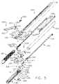
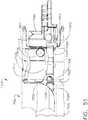
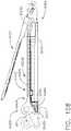
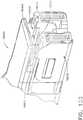
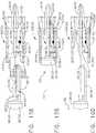
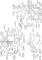
- FIG. 1illustrates the surgical instrument 1010 that includes an interchangeable shaft assembly 1200 operably coupled to a housing 1012.
- FIG. 2illustrates the interchangeable shaft assembly 1200 detached from the housing 1012 or handle 1014.
- the handle 1014may comprise a pair of interconnectable handle housing segments 1016 and 1018 that may be interconnected by screws, snap features, adhesive, etc.
- the handle housing segments 1016, 1018cooperate to form a pistol grip portion 1019.
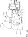
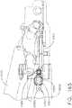
- FIGS. 1 and 3depict a motor-driven surgical cutting and fastening instrument 1010 that may or may not be reused.
- the instrument 1010includes a previous housing 1012 that comprises a handle 1014 that is configured to be grasped, manipulated and actuated by the clinician.
- the housing 1012is configured for operable attachment to an interchangeable shaft assembly 1200 that has a surgical end effector 1300 operably coupled thereto that is configured to perform one or more surgical tasks or procedures.
- an interchangeable shaft assembly 1200that has a surgical end effector 1300 operably coupled thereto that is configured to perform one or more surgical tasks or procedures.
- housingmay also encompass a housing or similar portion of a robotic system that houses or otherwise operably supports at least one drive system that is configured to generate and apply at least one control motion which could be used to actuate the interchangeable shaft assemblies disclosed herein and their respective equivalents.
- various componentsmay be “housed” or contained in the housing or various components may be “associated with” a housing. In such instances, the components may not be contained within the housing or supported directly by the housing.
- the term “frame”may refer to a portion of a handheld surgical instrument.
- the term “frame”may also represent a portion of a robotically controlled surgical instrument and/or a portion of the robotic system that may be used to operably control a surgical instrument.
- interchangeable shaft assemblies disclosed hereinmay be employed with various robotic systems, instruments, components and methods disclosed in U.S. Patent No. 9,072,535 , entitled SURGICAL STAPLING INSTRUMENTS WITH ROTATABLE STAPLE DEPLOYMENT ARRANGEMENTS, that is incorporated by reference herein in its entirety.
- the previous housing 1012 depicted in FIG. 1is shown in connection with an interchangeable shaft assembly 1200 ( FIGS. 2 , 4 and 5 ) that includes an end effector 1300 that comprises a surgical cutting and fastening device that is configured to operably support a surgical staple cartridge 1350 therein.
- the housing 1012may be configured for use in connection with interchangeable shaft assemblies that include end effectors that are adapted to support different sizes and types of staple cartridges, have different shaft lengths, sizes, and types, etc.
- the housing 1012may also be effectively employed with a variety of other interchangeable shaft assemblies including those assemblies that are configured to apply other motions and forms of energy such as, for example, radio frequency (RF) energy, ultrasonic energy and/or motion to end effector arrangements adapted for use in connection with various surgical applications and procedures.
- RFradio frequency
- the end effectors, shaft assemblies, handles, surgical instruments, and/or surgical instrument systemscan utilize any suitable fastener, that can be gripped and manipulated by the clinician.
- the handle 1014operably supports a plurality of drive systems therein that are configured to generate and apply various control motions to corresponding portions of the interchangeable shaft assembly that is operably attached thereto.
- the handle 1014may further include a frame 1020 that operably supports a plurality of drive systems.
- the frame 1020can operably support a "first" or closure drive system, generally designated as 1030, which may be employed to apply closing and opening motions to the interchangeable shaft assembly 1200 that is operably attached or coupled thereto.
- the closure drive system 1030may include an actuator in the form of a closure trigger 1032 that is pivotally supported by the frame 1020. More specifically, as illustrated in FIG. 3 , the closure trigger 1032 is pivotally coupled to the handle 1014 by a pin 1033.
- the closure drive system 1030further includes a closure linkage assembly 1034 that is pivotally coupled to the closure trigger 1032.
- the closure linkage assembly 1034may include a first closure link 1036 and a second closure link 1038 that are pivotally coupled to the closure trigger 1032 by a pin 1035.
- the second closure link 1038may also be referred to herein as an "attachment member” and include a transverse attachment pin 1037.
- the first closure link 1036may have a locking wall or end 1039 thereon that is configured to cooperate with a closure release assembly 1060 that is pivotally coupled to the frame 1020.
- the closure release assembly 1060may comprise a release button assembly 1062 that has a distally protruding locking pawl 1064 formed thereon.
- the release button assembly 1062may be pivoted in a counterclockwise direction by a release spring (not shown).
- the closure release assembly 1060serves to lock the closure trigger 1032 in the fully actuated position.
- the cliniciansimply pivots the release button assembly 1062 such that the locking pawl 1064 is moved out of engagement with the locking wall 1039 on the first closure link 1036.
- the closure trigger 1032may pivot back to the unactuated position.
- Other closure trigger locking and release arrangementsmay also be employed.
- An arm 1061may extend from the release button assembly 1062.
- a magnetic element 1063such as a permanent magnet, for example, may be mounted to the arm 1061.
- the circuit board 1100can include at least one sensor that is configured to detect the movement of the magnetic element 1063.
- a "Hall Effect" sensor(not shown) can be mounted to the bottom surface of the circuit board 1100.
- the Hall Effect sensorcan be configured to detect changes in a magnetic field surrounding the Hall Effect sensor caused by the movement of the magnetic element 1063.
- the Hall Effect sensorcan be in signal communication with a microcontroller, for example, which can determine whether the release button assembly 1062 is in its first position, which is associated with the unactuated position of the closure trigger 1032 and the open configuration of the end effector, its second position, which is associated with the actuated position of the closure trigger 1032 and the closed configuration of the end effector, and/or any position between the first position and the second position.
- a microcontrollerfor example, which can determine whether the release button assembly 1062 is in its first position, which is associated with the unactuated position of the closure trigger 1032 and the open configuration of the end effector, its second position, which is associated with the actuated position of the closure trigger 1032 and the closed configuration of the end effector, and/or any position between the first position and the second position.
- the handle 1014 and the frame 1020may operably support another drive system referred to herein as a firing drive system 1080 that is configured to apply firing motions to corresponding portions of the interchangeable shaft assembly attached thereto.
- the firing drive system 1080may also be referred to herein as a "second drive system”.
- the firing drive system 1080may employ an electric motor 1082 that is located in the pistol grip portion 1019 of the handle 1014.
- the motor 1082may be a DC brushed driving motor having a maximum rotation of, approximately, 25,000 RPM, for example.
- the motormay include a brushless motor, a cordless motor, a synchronous motor, a stepper motor, or any other suitable electric motor.
- the motor 1082may be powered by a power source 1090 that in one form may comprise a removable power pack 1092.
- the power pack 1092may comprise a proximal housing portion 1094 that is configured for attachment to a distal housing portion 1096.
- the proximal housing portion 1094 and the distal housing portion 1096are configured to operably support a plurality of batteries 1098 therein.
- Batteries 1098may each comprise, for example, a Lithium Ion ("LI”) or other suitable battery.
- the distal housing portion 1096is configured for removable operable attachment to the circuit board 1100 which is also operably coupled to the motor 1082.
- a number of batteries 1098may be connected in series may be used as the power source for the surgical instrument 1010.
- the power source 1090may be replaceable and/or rechargeable.
- the electric motor 1082can include a rotatable shaft (not shown) that operably interfaces with a gear reducer assembly 1084 that is mounted in meshing engagement with a with a set, or rack, of drive teeth 1122 on a longitudinally-movable drive member 1120.
- a voltage polarity provided by the power source 1090can operate the electric motor 1082 in a clockwise direction wherein the voltage polarity applied to the electric motor by the battery can be reversed in order to operate the electric motor 1082 in a counter-clockwise direction.
- the drive member 1120will be axially driven in the distal direction "DD".
- the handle 1014can include a switch which can be configured to reverse the polarity applied to the electric motor 1082 by the power source 1090. As with the other forms described herein, the handle 1014 can also include a sensor that is configured to detect the position of the drive member 1120 and/or the direction in which the drive member 1120 is being moved.
- Actuation of the motor 1082can be controlled by a firing trigger 1130 that is pivotally supported on the handle 1014.
- the firing trigger 1130may be pivoted between an unactuated position and an actuated position.
- the firing trigger 1130may be biased into the unactuated position by a spring 1132 or other biasing arrangement such that when the clinician releases the firing trigger 1130, it may be pivoted or otherwise returned to the unactuated position by the spring 1132 or biasing arrangement.
- the firing trigger 1130can be positioned "outboard" of the closure trigger 1032 as was discussed above.
- a firing trigger safety button 1134may be pivotally mounted to the closure trigger 1032 by the pin 1035.
- the safety button 1134may be positioned between the firing trigger 1130 and the closure trigger 1032 and have a pivot arm 1136 protruding therefrom. See FIG. 3 .
- the safety button 1134When the closure trigger 1032 is in the unactuated position, the safety button 1134 is contained in the handle 1014 where the clinician cannot readily access it and move it between a safety position preventing actuation of the firing trigger 1130 and a firing position wherein the firing trigger 1130 may be fired. As the clinician depresses the closure trigger 1032, the safety button 1134 and the firing trigger 1130 pivot down wherein they can then be manipulated by the clinician.
- the longitudinally movable drive member 1120has a rack of teeth 1122 formed thereon for meshing engagement with a corresponding drive gear 1086 of the gear reducer assembly 1084.
- At least one formalso includes a manually-actuatable "bailout” assembly 1140 that is configured to enable the clinician to manually retract the longitudinally movable drive member 1120 should the motor 1082 become disabled.
- the bailout assembly 1140may include a lever or bailout handle assembly 1142 that is configured to be manually pivoted into ratcheting engagement with the rack of teeth 1122 also provided in the drive member 1120.
- U.S. Patent No. 8,608,045entitled POWERED SURGICAL CUTTING AND STAPLING APPARATUS WITH MANUALLY RETRACTABLE FIRING SYSTEM, discloses bailout arrangements and other components, arrangements and systems that may also be employed with the various instruments disclosed herein.
- U.S. Patent No. 8,608,045is hereby incorporated by reference herein in its entirety.
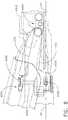
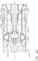
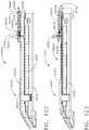
- the interchangeable shaft assembly 1200includes a surgical end effector 1300 that comprises an elongate frame 1310 that is configured to operably support a staple cartridge 1350 therein.
- the end effector 1300may further include an anvil 2000 that is pivotally supported relative to the elongate frame 1310.
- the interchangeable shaft assembly 1200may further include an articulation joint 3020 and an articulation lock 2140 which can be configured to releasably hold the end effector 1300 in a desired position relative to a shaft axis SA. Examples of various features of at least one form of the end effector 1300, the articulation joint 3020 and articulation locks may be found in U.S. Patent Application Serial No.
- the interchangeable shaft assembly 1200can further include a proximal housing or nozzle 1201 comprised of nozzle portions 1202 and 1203.
- the interchangeable shaft assembly 1200can further include a closure system or closure member assembly 3000 which can be utilized to close and/or open the anvil 2000 of the end effector 1300.
- the shaft assembly 1200can include a spine 1210 that is configured to, one, slidably support a firing member therein and, two, slidably support the closure member assembly 3000 which extends around the spine 1210.
- a distal end 1212 of spine 1210terminates in an upper lug mount feature 1270 and in a lower lug mount feature 1280.
- the upper lug mount feature 1270is formed with a lug slot 1272 therein that is adapted to mountingly support an upper mounting link 1274 therein.
- the lower lug mount feature 1280is formed with a lug slot 1282 therein that is adapted to mountingly support a lower mounting link 1284 therein.
- the upper mounting link 1274includes a pivot socket 1276 therein that is adapted to rotatably receive therein a pivot pin 1292 that is formed on a frame cap or anvil retainer 1290 that is attached to a proximal end portion 1312 of the elongate frame 1310.
- the lower mounting link 1284includes lower pivot pin 1286 that adapted to be received within a pivot hole 1314 formed in the proximal end portion 1312 of the elongate frame 1310. See FIG. 5 .
- the lower pivot pin 1286is vertically aligned with the pivot socket 1276 to define an articulation axis AA about which the surgical end effector 1300 may articulate relative to the shaft axis SA. See FIG. 2 .
- the surgical end effector 1300is selectively articulatable about the articulation axis AA by an articulation system 2100.
- the articulation system 2100includes proximal articulation driver 2102 that is pivotally coupled to an articulation link 2120.
- an offset attachment lug 2114is formed on a distal end 2110 of the proximal articulation driver 2102.
- a pivot hole 2116is formed in the offset attachment lug 2114 and is configured to pivotally receive therein a proximal link pin 2124 formed on the proximal end 2122 of the articulation link 2120.
- a distal end 2126 of the articulation link 2120includes a pivot hole 2128 that is configured to pivotally receive therein a frame pin 1317 formed on the proximal end portion 1312 of the elongate frame 1310.
- proximal articulation driver 2102will thereby apply articulation motions to the elongate frame 1310 to thereby cause the surgical end effector 1300 to articulate about the articulation axis AA relative to the spine 1210.
- proximal articulation driver 2102can be held in position by an articulation lock 2140 when the proximal articulation driver 2102 is not being moved in the proximal or distal directions. Additional details regarding an example of an articulation lock 2140 may be found in U.S. Patent Application Serial No. 15/635,631 , now U.S. Patent Application Publication No. 2019/0000464 , as well as in other references incorporated by reference herein.
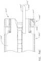
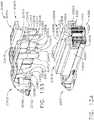
- the spine 1210can comprise a proximal end 1211 which is rotatably supported in a chassis 1240.
- the proximal end 1211 of the spine 1210has a thread 1214 formed thereon for threaded attachment to a spine bearing 1216 configured to be supported within the chassis 1240. See FIG. 4 .
- Such an arrangementfacilitates rotatable attachment of the spine 1210 to the chassis 1240 such that the spine 1210 may be selectively rotated about a shaft axis SA relative to the chassis 1240.
- the interchangeable shaft assembly 1200includes a closure shuttle 1250 that is slidably supported within the chassis 1240 such that it may be axially moved relative thereto.
- the closure shuttle 1250includes a pair of proximally-protruding hooks 1252 that are configured for attachment to the attachment pin 1037 ( FIG. 3 ) that is attached to the second closure link 1038 as will be discussed in further detail below.
- the closure member assembly 3000comprises a proximal closure member segment 3010 that has a proximal end 3012 that is coupled to the closure shuttle 1250 for relative rotation thereto.
- a U shaped connector 1263is inserted into an annular slot 3014 in the proximal end 3012 of the proximal closure member segment 3010 and is retained within vertical slots 1253 in the closure shuttle 1250.
- Such an arrangementserves to attach the proximal closure member segment 3010 to the closure shuttle 1250 for axial travel therewith while enabling the proximal closure member segment 3010 to rotate relative to the closure shuttle 1250 about the shaft axis SA.
- a closure spring 1268is journaled on the proximal closure member segment 3010 and serves to bias the proximal closure member segment 3010 in the proximal direction "PD" which can serve to pivot the closure trigger 1032 into the unactuated position when the shaft assembly is operably coupled to the handle 1014.
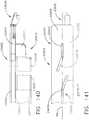
- the interchangeable shaft assembly 1200may further include an articulation joint 3020.
- Other interchangeable shaft assembliesmay not be capable of articulation.
- a distal closure member or distal closure tube segment 3030is coupled to the distal end of the proximal closure member segment 3010.
- the articulation joint 3020includes a double pivot closure sleeve assembly 3022.
- the double pivot closure sleeve assembly 3022includes an end effector closure tube 3050 having upper and lower proximally projecting tangs 3052, 3054.
- An upper double pivot link 3056includes upwardly projecting distal and proximal pivot pins that engage respectively an upper distal pin hole in the upper proximally projecting tang 3052 and an upper proximal pin hole 3032 in an upper distally projecting tang 3031 on the distal closure tube segment 3030.
- a lower double pivot link 3058includes upwardly projecting distal and proximal pivot pins that engage respectively a lower distal pin hole in the lower proximally projecting tang 3054 and a lower proximal pin hole in the lower distally projecting tang 3034. See FIGS. 4 and 5 .
- the closure member assembly 3000is translated distally (direction "DD") to close the anvil 2000, for example, in response to the actuation of the closure trigger 1032.
- the anvil 2000is opened by proximally translating the closure member assembly 3000 which causes the end effector closure tube 3050 to interact with the anvil 2000 and pivot it to an open position.
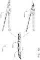
- the interchangeable shaft assembly 1200further includes a firing member 1900 that is supported for axial travel within the spine 1210.
- the firing member 1900includes an intermediate firing shaft portion 1222 that is configured for attachment to a distal cutting portion or knife bar 1910.
- the intermediate firing shaft portion 1222may include a longitudinal slot 1223 in the distal end thereof which can be configured to receive a tab 1912 on the proximal end of the distal knife bar 1910.
- the longitudinal slot 1223 and the proximal end tab 1912can be sized and configured to permit relative movement therebetween and can comprise a slip joint 1914.
- the slip joint 1914can permit the intermediate firing shaft portion 1222 of the firing member 1900 to be moved to articulate the end effector 1300 without moving, or at least substantially moving, the knife bar 1910.
- the intermediate firing shaft portion 1222can be advanced distally until a proximal sidewall of the longitudinal slot 1223 comes into contact with the tab 1912 in order to advance the knife bar 1910 and fire the staple cartridge 1350 positioned within the frame 1310.
- the knife bar 1910includes a knife portion 1920 that includes a blade or tissue cutting edge 1922 and includes an upper anvil engagement tab 1924 and lower frame engagement tabs 1926.
- Various firing member configurations and operationsare disclosed in various other references incorporated herein by reference.
- the shaft assembly 1200further includes a switch drum 1500 that is rotatably received on proximal closure member segment 3010.
- the switch drum 1500comprises a hollow shaft segment 1502 that has a shaft boss formed thereon for receive an outwardly protruding actuation pin therein.
- the actuation pinextends through a longitudinal slot provided in the lock sleeve to facilitate axial movement of the lock sleeve when it is engaged with the articulation driver.
- a rotary torsion spring 1420is configured to engage the boss on the switch drum 1500 and a portion of the nozzle 1201 to apply a biasing force to the switch drum 1500.
- the switch drum 1500can further comprise at least partially circumferential openings 1506 defined therein which can be configured to receive circumferential mounts extending from the nozzle portions 1202, 1203 and permit relative rotation, but not translation, between the switch drum 1500 and the nozzle 1201.
- the mountsalso extend through openings 3011 in the proximal closure member segment 3010 to be seated in recesses 1219 in the spine 1210. Rotation of the switch drum 1500 about the shaft axis SA will ultimately result in the rotation of the actuation pin and the lock sleeve between its engaged and disengaged positions.
- the rotation of the switch drum 1500may be linked to the axial advancement of the closure tube or closure member.
- actuation of the closure systemmay operably engage and disengage the articulation drive system with the firing drive system in the various manners described in further detail in U.S. Patent Application Serial No. 13/803,086 , now U.S. Patent Application Publication No. 2014/0263541 , entitled ARTICULATABLE SURGICAL INSTRUMENT COMPRISING AN ARTICULATION LOCK and U.S. Patent No. 9,913,642 , entitled SURGICAL INSTRUMENT COMPRISING A SENSOR SYSTEM, the entire disclosures of each being hereby incorporated by reference herein.
- the closure member segment 3010when the closure member segment 3010 is in its proximal-most position corresponding to a "jaws open” position, the closure member segment 3010 will have positioned the switch drum 1500 so as to link the articulation system with the firing drive system.
- the closure tubehas been moved to its distal position corresponding to a "jaws closed” position, the closure tube has rotated the switch drum 1500 to a position wherein the articulation system is delinked from the firing drive system.
- the shaft assembly 1200can comprise a slip ring assembly 1600 which can be configured to conduct electrical power to and/or from the end effector 1300 and/or communicate signals to and/or from the end effector 1300, for example.
- the slip ring assembly 1600can comprise a proximal connector flange 1604 that is mounted to a chassis flange 1242 that extends from the chassis 1240 and a distal connector flange that is positioned within a slot defined in the shaft housings.
- the proximal connector flange 1604can comprise a first face and the distal connector flange can comprise a second face which is positioned adjacent to and movable relative to the first face.
- the distal connector flangecan rotate relative to the proximal connector flange 1604 about the shaft axis SA.
- the proximal connector flange 1604can comprise a plurality of concentric, or at least substantially concentric, conductors defined in the first face thereof.
- a connectorcan be mounted on the proximal side of the connector flange and may have a plurality of contacts wherein each contact corresponds to and is in electrical contact with one of the conductors. Such an arrangement permits relative rotation between the proximal connector flange 1604 and the distal connector flange while maintaining electrical contact therebetween.
- the proximal connector flange 1604can include an electrical connector 1606 which can place the conductors in signal communication with a shaft circuit board 1610 mounted to the shaft chassis 1240, for example.
- a wiring harnesscomprising a plurality of conductors can extend between the electrical connector 1606 and the shaft circuit board 1610.
- the electrical connector 1606may extend proximally through a connector opening 1243 defined in the chassis flange 1242. See FIG. 4 . Further details regarding slip ring assembly 1600 may be found in U.S. Patent Application Serial No. 13/803,086 , entitled ARTICULATABLE SURGICAL INSTRUMENT COMPRISING AN ARTICULATION LOCK, now U.S. Patent Application Publication No.
- the shaft assembly 1200can include a proximal portion which is fixably mounted to the handle 1014 and a distal portion which is rotatable about a longitudinal axis.
- the rotatable distal shaft portioncan be rotated relative to the proximal portion about the slip ring assembly 1600, as discussed above.
- the distal connector flange of the slip ring assembly 1600can be positioned within the rotatable distal shaft portion.
- the switch drum 1500can also be positioned within the rotatable distal shaft portion. When the rotatable distal shaft portion is rotated, the distal connector flange and the switch drum 1500 can be rotated synchronously with one another.
- the switch drum 1500can be rotated between a first position and a second position relative to the distal connector flange.
- the articulation drive systemWhen the switch drum 1500 is in its first position, the articulation drive system may be operably disengaged from the firing drive system and, thus, the operation of the firing drive system may not articulate the end effector 1300 of the shaft assembly 1200.
- the switch drum 1500When the switch drum 1500 is in its second position, the articulation drive system may be operably engaged with the firing drive system and, thus, the operation of the firing drive system may articulate the end effector 1300 of the shaft assembly 1200.
- the switch drum 1500When the switch drum 1500 is moved between its first position and its second position, the switch drum 1500 is moved relative to distal connector flange.
- the shaft assembly 1200can comprise at least one sensor configured to detect the position of the switch drum 1500.
- the chassis 1240includes at least one, and preferably two, tapered attachment portions 1244 formed thereon that are adapted to be received within corresponding dovetail slots 1702 formed within a distal attachment flange portion 1700 of the frame 1020. See FIG. 3 .
- Each dovetail slot 1702may be tapered or, stated another way, be somewhat V-shaped to seatingly receive the attachment portions 1244 therein.
- a shaft attachment lug 1226is formed on the proximal end of the intermediate firing shaft portion 1222.
- the shaft attachment lug 1226is received in a firing shaft attachment cradle 1126 formed in a distal end 1125 of the longitudinal drive member 1120. See FIG. 3 .
- the latch system 1710includes a lock member or lock yoke 1712 that is movably coupled to the chassis 1240.
- the lock yoke 1712has a U-shape with two spaced downwardly extending legs 1714.
- the legs 1714each have a pivot lug 1715 formed thereon that are adapted to be received in corresponding holes 1245 formed in the chassis 1240.
- Such arrangementfacilitates pivotal attachment of the lock yoke 1712 to the chassis 1240.
- the lock yoke 1712may include two proximally protruding lock lugs 1716 that are configured for releasable engagement with corresponding lock detents or grooves 1704 in the distal attachment flange portion 1700 of the frame 1020. See FIG. 3 .
- the lock yoke 1712is biased in the proximal direction by spring or biasing member (not shown). Actuation of the lock yoke 1712 may be accomplished by a latch button 1722 that is slidably mounted on a latch actuator assembly 1720 that is mounted to the chassis 1240.
- the latch button 1722may be biased in a proximal direction relative to the lock yoke 1712.
- the lock yoke 1712may be moved to an unlocked position by biasing the latch button in the distal direction which also causes the lock yoke 1712 to pivot out of retaining engagement with the distal attachment flange portion 1700 of the frame 1020.
- the lock lugs 1716are retainingly seated within the corresponding lock detents or grooves 1704 in the distal attachment flange portion 1700.
- an interchangeable shaft assemblythat includes an end effector of the type described herein that is adapted to cut and fasten tissue, as well as other types of end effectors
- the clinicianmay actuate the closure trigger 1032 to grasp and manipulate the target tissue into a desired position. Once the target tissue is positioned within the end effector 1300 in a desired orientation, the clinician may then fully actuate the closure trigger 1032 to close the anvil 2000 and clamp the target tissue in position for cutting and stapling. In that instance, the first drive system 1030 has been fully actuated.
- One form of the latch system 1710is configured to prevent such inadvertent detachment.
- the lock yoke 1712includes at least one and preferably two lock hooks 1718 that are adapted to contact corresponding lock lug portions 1256 that are formed on the closure shuttle 1250.
- the lock yoke 1712may be pivoted in a distal direction to unlock the interchangeable shaft assembly 1200 from the housing 1012.
- the lock hooks 1718do not contact the lock lug portions 1256 on the closure shuttle 1250.
- the lock yoke 1712is prevented from being pivoted to an unlocked position.
- the clinicianwere to attempt to pivot the lock yoke 1712 to an unlocked position or, for example, the lock yoke 1712 was inadvertently bumped or contacted in a manner that might otherwise cause it to pivot distally, the lock hooks 1718 on the lock yoke 1712 will contact the lock lug portions 1256 on the closure shuttle 1250 and prevent movement of the lock yoke 1712 to an unlocked position.
- the clinicianmay position the chassis 1240 of the interchangeable shaft assembly 1200 above or adjacent to the distal attachment flange portion 1700 of the frame 1020 such that the tapered attachment portions 1244 formed on the chassis 1240 are aligned with the dovetail slots 1702 in the frame 1020.
- the clinicianmay then move the shaft assembly 1200 along an installation axis that is perpendicular to the shaft axis SA to seat the attachment portions 1244 in "operable engagement" with the corresponding dovetail receiving slots 1702.
- the shaft attachment lug 1226 on the intermediate firing shaft portion 1222will also be seated in the cradle 1126 in the longitudinally movable drive member 1120 and the portions of the pin 1037 on the second closure link 1038 will be seated in the corresponding hooks 1252 in the closure shuttle 1250.
- operble engagementin the context of two components means that the two components are sufficiently engaged with each other so that upon application of an actuation motion thereto, the components may carry out their intended action, function and/or procedure.
- At least five systems of the interchangeable shaft assembly 1200can be operably coupled with at least five corresponding systems of the handle 1014.
- a first systemcan comprise a frame system which couples and/or aligns the frame or spine of the shaft assembly 1200 with the frame 1020 of the handle 1014.
- Another systemcan comprise a closure drive system 1030 which can operably connect the closure trigger 1032 of the handle 1014 and the closure tube 3050 and the anvil 2000 of the shaft assembly 1200.
- the closure shuttle 1250 of the shaft assembly 1200can be engaged with the pin 1037 on the second closure link 1038.
- Another systemcan comprise the firing drive system 1080 which can operably connect the firing trigger 1130 of the handle 1014 with the intermediate firing shaft portion 1222 of the shaft assembly 1200.
- the shaft attachment lug 1226can be operably connected with the cradle 1126 of the longitudinal drive member 1120.
- Another systemcan comprise an electrical system which can signal to a controller in the handle 1014, such as microcontroller, for example, that a shaft assembly, such as shaft assembly 1200, for example, has been operably engaged with the handle 1014 and/or, two, conduct power and/or communication signals between the shaft assembly 1200 and the handle 1014.
- the shaft assembly 1200can include an electrical connector 1810 that is operably mounted to the shaft circuit board 1610.
- the electrical connector 1810is configured for mating engagement with a corresponding electrical connector 1800 on the control circuit board 1100. Further details regaining the circuitry and control systems may be found in U.S. Patent Application Serial No.
- the fifth systemmay consist of the latching system for releasably locking the shaft assembly 1200 to the handle 1014.
- the anvil 2000 in the illustrated exampleincludes an anvil body 2002 that terminates in an anvil mounting portion 2010.
- the anvil mounting portion 2010is movably or pivotably supported on the elongate frame 1310 for selective pivotal travel relative thereto about a fixed anvil pivot axis PA that is transverse to the shaft axis SA.
- a pivot member or anvil trunnion 2012extends laterally out of each lateral side of the anvil mounting portion 2010 to be received in a corresponding trunnion cradle 1316 formed in the upstanding walls 1315 of the proximal end portion 1312 of the elongate frame 1310.
- the anvil trunnions 2012are pivotally retained in their corresponding trunnion cradle 1316 by the frame cap or anvil retainer 1290.
- the frame cap or anvil retainer 1290includes a pair of attachment lugs that are configured to be retainingly received within corresponding lug grooves or notches formed in the upstanding walls 1315 of the proximal end portion 1312 of the elongate frame 1310. See FIG. 5 .
- the distal closure member or end effector closure tube 3050employs two axially offset, proximal and distal positive jaw opening features 3060 and 3062.
- the positive jaw opening features 3060, 3062are configured to interact with corresponding relieved areas and stepped portions formed on the anvil mounting portion 2010 as described in further detail in U.S. Patent Application Serial No. 15/635,631 , entitled SURGICAL INSTRUMENT WITH AXIALLY MOVABLE CLOSURE MEMBER, now U.S. Patent Application Publication No. 2019/0000464 , the entire disclosure which has been herein incorporated by reference.
- Other jaw opening arrangementsmay be employed.
- 2004/0232196entitled SURGICAL STAPLING INSTRUMENT HAVING SEPARATE DISTINCT CLOSING AND FIRING SYSTEMS, filed on May 20, 2003
- U.S. Patent Application Publication No. 2004/0232195entitled SURGICAL STAPLING INSTRUMENT HAVING A SINGLE LOCKOUT MECHANISM FOR PREVENTION OF FIRING, filed on May 20, 3003
- U.S. Patent Application Publication No. 2018/0085123entitled ARTICULATING SURGICAL STAPLING INSTRUMENT INCORPORATING A TWO-PIECE E-BEAM FIRING MECHANISM, filed on August 17, 2017 are incorporated by reference in their entireties.
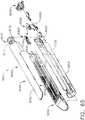
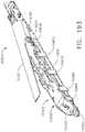
- the surgical stapling assembly 4000may be employed in connection with the surgical instrument 1010 described above or in connection with a variety of other surgical instruments described in various disclosures that have been incorporated by reference herein.
- the surgical stapling assembly 4000may be employed in connection with electrically controlled, battery powered, manually powered, and/or robotically-controlled surgical instruments in the various forms disclosed in the aforementioned incorporated disclosures, for example.
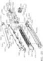
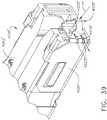
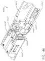
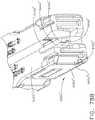
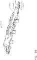
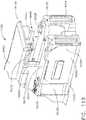
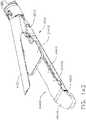
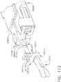
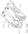
- the surgical stapling assembly 4000comprises a surgical stapling device generally designated as 4002 that comprises a first jaw, or frame 4010 that is configured to operably support a staple cartridge 4200 therein.
- the first jaw 4010may be attached to a spine of the shaft assembly of a surgical instrument or robot in the various manners described herein as well as in the various disclosures which have been herein incorporated by reference.
- the first jaw 4010is attached to the spine portion of the shaft assembly (not shown in FIG. 6 ), by a shaft mount flange 4030 that is pinned by a pin 4032 or otherwise attached to a proximal end 4014 of the first jaw 4010.
- pin 4032is configured to pass through aligned holes 4021 in upstanding sidewalls 4020 of the first jaw 4010 as well as through hole 4031 in the shaft mount flange 4030.
- the shaft mount flange 4030is configured to interface with an articulation joint arrangement (not shown) that is configured to facilitate articulation of the first jaw 4010 relative to the shaft assembly in various known configurations.
- Other methods of attaching and operably interfacing the surgical device 4002 with a shaft of a surgical instrumentmay also be employed.
- the stapling device 4002may be attached to the shaft assembly such that the stapling device (sometimes also referred to as an "end effector") is not capable of articulating relative to the shaft assembly.
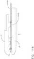
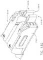
- the surgical stapling device 4002further comprises a firing member assembly 4040 that comprises a knife bar 4042 that is attached to a knife member or "firing member" 4050.
- the knife bar 4042also interfaces with corresponding components and firing systems in the surgical instrument to receive firing motions which can distally advance the knife bar 4042 and firing member 4050 through a staple firing stroke from a starting position to an ending position and also retract the knife bar 4042 and firing member 4050 proximally to a starting position.
- the firing member 4050comprises a firing member body 4052 that supports a cutting edge or knife edge 4053.
- the firing member 4050further comprises a foot 4054 that is formed on the bottom of the firing member body 4052 and extends laterally from each side of the firing member body 4052.
- the firing member 4050further comprises a pair of top pins or tabs 4056 that extend laterally from the firing member body 4052 that are adapted to engage ledges on an anvil as will be discussed further herein.
- the firing member 4050comprises a pair of central pins or tabs 4058 that protrude laterally from each side of the firing member body 4052.
- the firing member 4050may also be referred to as an "E-Beam" firing member or cutting member.
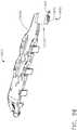
- the surgical stapling device 4002comprises a second jaw or anvil 4100 that is movable relative to the first jaw or frame 4010.
- the anvil 4100comprises an anvil body 4102 and an anvil mounting portion 4110.
- the anvil body 4102comprises a staple forming undersurface or tissue contacting surface 4104 that has a series of staple forming pockets formed therein (not shown) that are arranged to form corresponding staples as they are driven into forming contact therewith.
- the anvil mounting portion 4110comprises a pair of laterally extending anvil pins or trunnion pins 4112 that are configured to be received in corresponding trunnion slots 4022 in the upstanding sidewalls 4020 of the first jaw 4010.
- the trunnion slots 4022are somewhat "kidney-shaped" and facilitate pivotal as well as axial travel of the corresponding trunnion pins 4112 therein. Such pivotal and axial movement of the anvil 4100 may be referred to as “translation" of the anvil during an anvil closure sequence.
- the anvil 4100may be movable from an open position wherein a used or spent surgical staple cartridge may either be removed from the first jaw or frame 4010 or an unfired surgical staple cartridge may be operably seated therein to a closed position.
- the anvil 4100may be movable between the open and closed positions by an axially movable closure member which may comprise an end effector closure tube (not shown) that is part of the shaft assembly of the surgical instrument to which the surgical device 4002 is operably attached.
- the closure membermay operably engage a cam surface on the anvil mounting portion 4110.
- Such interaction between the closure member and the anvil mounting portion 4110causes the anvil mounting portion 4110 and the anvil trunnion pins 4112 to pivot and translate up the trunnion slots 4022 until the closure member moves the anvil 4100 to a fully closed position.
- the staple-forming pockets in the anvil 4100are properly aligned with the staples in a corresponding compatible surgical staple cartridge that has been operably seated in the first jaw or frame 4010.
- the closure memberinterfaces with an upstanding tab 4114 on the anvil mounting portion 4110 to return the anvil 4100 to the open position.
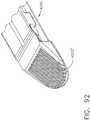
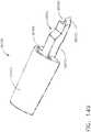
- One form of surgical staple cartridge 4200that may be compatible with the surgical stapling device 4002 comprises a cartridge body 4202 that defines a cartridge deck surface or tissue contacting surface 4204.
- the cartridge body 4202further comprises a longitudinal slot 4206 that bisects the cartridge deck surface 4204 and is configured to accommodate axial passage of the firing member 4050 therein between its starting position and an ending position within the cartridge body 4202 during a staple firing stroke.
- the longitudinal slot 4206lies along a center axis CA of the cartridge 4200.
- the surgical staple cartridge 4200further comprises a series of staple pockets 4208 that are formed in the cartridge body 4202.
- the staple pockets 4208may be formed in offset "lines" located on each side of the longitudinal slot 4206.
- Each staple pocket 4208may have a staple driver (not shown) associated therewith that supports a surgical staple or fastener (not shown) thereon.
- the cartridge body 4202is molded from a polymer material with the staple pockets 4208 molded or machined therein.
- the staple pockets 4208also open through a bottom of the cartridge body 4202 to facilitate installation of the drivers and fasteners into their respective staple pockets 4208.
- a cartridge pan 4220is attached to the cartridge body 4202.
- the cartridge pan 4220is fabricated from a metal material and includes a bottom 4222 that spans across the bottom of the cartridge body 4202.
- the cartridge pan 4220also includes two upstanding sidewalls 4224 that correspond to each side of the cartridge body 4202.
- the cartridge pan 4220may be removably affixed to the cartridge body 4202 by hooks 4226 that are formed on the sidewalls 4224 and configured to hookingly engage corresponding portions of the cartridge body 4202.
- the cartridge body 4202may also have lugs or attachment formations protruding therefrom that are configured to retainingly engage corresponding portions of the cartridge pan 4220.
- the cartridge pan 4220may, among other things, prevent the drivers and fasteners from falling out of the bottom of the cartridge body 4202 during handling and installation of the staple cartridge into the first jaw or frame 4010.
- Each surgical stapleoperably support a single surgical staple thereon and other staple drivers support more than one surgical staple thereon depending upon the particular cartridge design.
- Each surgical staplecomprises a staple crown and two upstanding staple legs.
- the staple crownis typically supported on a cradle arrangement formed in a corresponding staple driver such that the legs are vertically oriented toward the anvil when the cartridge is operably seated in the frame 4010.
- surgical stapleshave a somewhat V-shape, wherein the ends of the legs flare slightly outward. Such arrangement may serve to retain the staple in its corresponding staple pocket due to frictional engagement between the legs and the sides of the staple pocket should the cartridge be inadvertently inverted or turned upside down during use.
- Other surgical staplesare roughly U-shaped (the ends of the legs do not flare outward) and may be more susceptible to falling out of the staple pocket should the cartridge be inverted prior to use.
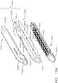
- the surgical staple cartridge 4200further comprises a sled or camming member 4230 that is configured to be axially advanced through the cartridge body 4202 during a staple firing stroke.
- the sled 4230In a "new”, “fresh” or “unfired” surgical staple cartridge, the sled 4230 is in its proximal-most, "unfired” position.
- the sled 4230comprises a plurality of wedges or cam members 4232 that are configured to drivingly engage the corresponding lines of staple drivers in the cartridge body.
- the firing member 4050abuts and pushes the sled 4230 distally into camming contact with the staple drivers thereby sequentially driving the staple drivers upward toward the anvil 4100 as the sled 4230 is driven from its unfired position to its distal-most fully fired position within the cartridge body 4202.
- the staple driversare driven upwardly, the staples are driven through the tissue that is clamped between the deck surface 4204 of the staple cartridge 4200 and the anvil 4100 and into forming contact with the staple-forming undersurface 4104 of the anvil 4100.
- the tissue-cutting knife 4053 on the firing member 4050cuts through the stapled tissue as the firing member 4050 is driven distally.
- the firing member 4050is retracted proximally.
- the sled 4230is not retracted proximally with the firing member 4050. Instead, the sled 4230 is left behind at the distal-most position in which it was pushed by the firing member 4050.
- a staple cartridgeAfter a staple cartridge has been fired, or at least partially fired, it is removed from the frame and then replaced with another replaceable staple cartridge, if desired. At such point, the stapling device can be re-used to continue stapling and incising the patient tissue. In some instances, however, a previously-fired staple cartridge can be accidentally loaded into the frame. If the firing member were to be advanced distally within such a previously-fired staple cartridge, the stapling instrument would cut the patient tissue without stapling it. The stapling instrument would similarly cut the patient tissue without stapling it if the firing member were advanced distally through a staple firing stroke without a staple cartridge positioned in the cartridge jaw at all.
- various surgical staple cartridgesmay have different arrays of and/or orientations of staples/fasteners therein.
- the sizes of the staples or fasteners, as well as the number of fastenersmay vary from cartridge type to cartridge type depending upon a particular surgical procedure or application.
- the surgical staple cartridgesmust be used in connection with corresponding, compatible anvils that have the proper array of staple-forming pockets therein as well as the proper cutting and firing components.
- the surgical stapling assembly 4000comprises one or more lockouts which prevents this from happening, as discussed in greater detail below.
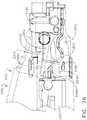
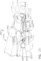
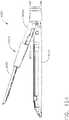
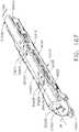
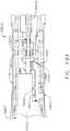
- the surgical stapling device 4002comprises a first lockout 4300 that is configured to prevent the firing member 4050 from moving distally from its proximal-most, starting position unless an authorized or compatible staple cartridge is operably seated in the first jaw or frame 4010.
- the first lockout 4300may also be referred to herein as an "authentication" lockout.
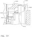
- the first lockout 4300comprises a single, bi-lateral first lockout spring 4310 that is supported in the proximal end 4014 of the frame 4010 and attached to the shaft mount flange 4030.
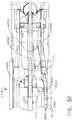
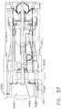
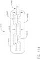
- the first lockout spring 4310comprises a first lockout arm 4312 that is located on one side of the cartridge axis CA and a second lockout arm 4314 that is located on an opposite side of the cartridge axis CA.
- the first and second lockout arms 4312, 4314are attached to a central body portion 4316. See FIG. 7 .
- the spring 4310is supported in the first jaw or frame 4010 and affixed to the shaft mount flange 4030 by a pin 4034 that extends through holes 4036 in the shaft mount flange 4030 and through holes 4318 in the first lockout arm 4312 and the second lockout arm 4314.
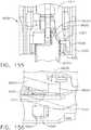
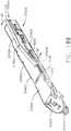
- the first lockout arm 4312 and the second lockout arm 4314each further comprise a lockout window or opening 4320.
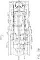
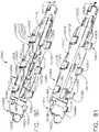
- the lockout windows 4320are each adapted to receive therein a corresponding central pin 4058 protruding from the adjacent first or second lateral side of the firing member 4050 when the firing member 4050 is in its proximal-most or starting position. See FIGS. 8 and 9 .
- FIGS. 8-10illustrate the first lockout 4300 in the locked position wherein the central pins 4058 are received within the lockout windows 4320 in the first and second lockout arms 4312, 4314.
- those staple cartridges that are compatible with the surgical stapling device 4002 or, stated another way, those staple cartridges that have the proper number, size, and arrangement of staplesmay have one or more unlocking or "authorization" keys directly formed on the cartridge body and/or on the cartridge pan that are configured to defeat the first lockout when the compatible staple cartridge is operably seated in the first jaw or frame.
- Various staple cartridges that have unlocking keys protruding therefromare disclosed below as well as in various disclosures which have been herein incorporated by reference.
- the surgical stapling device 4002includes features designed to facilitate use of such compatible staple cartridges that otherwise lack unlocking key features.
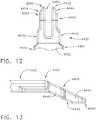
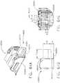
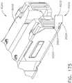
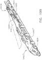
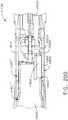
- the stapling assembly 4000further comprises a retainer 4400 that is configured to be removably coupled to the staple cartridge 4200 which is otherwise compatible with the surgical stapling device 4002.
- the retainer 4400comprises a top portion 4402 that is coextensive with, and configured to be received on, the deck surface 4204 of the cartridge body 4202.
- the retainer 4400covers all of the staple pockets 4208 in the cartridge body 4202.
- the retainer 4400may prevent the surgical staples stored within the staple pockets 4208 from falling out should the staple cartridge 4200 be inverted or turned upside down prior to use.
- the retainer 4400also protects the deck surface from being contaminated during shipping and storage.
- the retainer 4400may be molded from a polymer material and include a plurality of retainer lugs 4410 that are configured to latchingly engage outwardly extending deck ledge portions 4205 that are formed on the cartridge body 4202.
- the retainer 4400may further comprise an angled nose portion 4420 and distal latch tab 4422 that that is configured to latching engage a distal nose 4203 of the cartridge body 4202.
- the retainer 4400may be removably coupled to the surgical staple cartridge 4200 by engaging the distal latch tab 4422 with an end of the distal nose 4203 and aligning the retainer 4400 such that the underside of the top portion 4402 confronts the cartridge deck surface 4204 and the retainer lugs 4410 are located above the deck ledge portions 4205 on each side of the cartridge body 4202. Thereafter, the retainer 4400 may be pressed toward the staple cartridge 4200 causing the retainer lugs 4410 to flex laterally outward and snap into latching engagement with the corresponding deck ledge portions 4205.
- Other retainer latching arrangements disclosed hereinmay also be employed to removably affix the retainer 4400 to the staple cartridge 4200.
- the retainer 4400may be removed from the staple cartridge 4200 by applying a prying motion to the distal latch tab 4422 until the retainer lugs 4410 disengage the deck ledge portions 4205.
- the term "LIFT"is molded, embossed, imprinted or otherwise provided on the nose portion 4420 to provide removal instructions to the user.
- the retainer 4400further comprises an authentication key 4430 that is configured to defeat, deactivate or unlatch the first lockout 4300 when the retainer 4400 is attached to the staple cartridge 4200 to form a cartridge assembly 4500 and the cartridge assembly 4500 has been operably seated in the first jaw or frame 4010.
- the authentication key 4430protrudes proximally from a proximal end 4401 of the top portion 4402 of the retainer 4400 and comprises a right ramp feature 4440 and a left ramp feature 4450 that are separated by a space 4460 that is sized to receive the firing member body 4052 therebetween.
- the right ramp feature 4440angles downward from the top portion 4402 of the retainer 4400 and comprises a proximal right tip 4442.
- the proximal right tip 4442defines a first right cam surface 4444 that angles inward at the tip and extends distally to a second right cam surface 4446.
- the second right cam surface 4446extends from the first right cam surface 4444 to the top portion 4402. See FIG. 12 .
- the left ramp feature 4450angles downward from the top portion 4402 of the retainer 4400 and comprises a proximal left tip 4452.
- the proximal left tip 4452angles inward at the tip and extends distally to a second left cam surface 4456.
- the second left cam surface 4456extends from the first left cam surface 4454 to the top portion 4402.
- the retainer 4400additionally comprises a retainer keel 4470 that protrudes from the bottom surface of the top portion 4402 and is oriented to be received within the longitudinal slot 4206 in the surgical staple cartridge 4200.
- Retainer keel 4470may serve to properly orient the retainer 4400 on the staple cartridge 4200 so that the right and left ramp features 4440 and 4450 extend on each side of the firing member 4050.
- the retainer keel 4470may be configured to engage the sled 4230 in the staple cartridge 4200 and retain the sled 4230 in the unfired position while the retainer 4400 is attached to the staple cartridge 4200.
- the retainer keel 4470may be sized relative to the longitudinal slot 4206 to establish a frictional fit therewith to retain the retainer 4400 on the staple cartridge 4200.
- the cartridge assembly 4500may be longitudinally inserted into the first jaw or frame 4010 so as to bring the right tip 4442 of the right ramp feature 4440 of the authentication key 4430 into contact with an upstanding unlocking tab 4322 on the first lockout arm 4312 and the left tip 4452 of the left ramp 4450 into contact with an upstanding unlocking tab 4324 on the second lockout arm 4314 of the first lockout spring 4310.
- the first right cam surface 4444biases the first lockout arm 4312 of the first lockout spring 4310 laterally outward (arrow RL in FIG. 14 ) and the first left cam surface 4454 biases the second lockout arm 4314 laterally outward (arrow LL).
- first lockout arm 4312disengages the corresponding central pin 4058 on the firing member 4050 and also causes the second lockout arm 4314 to attain a second intermediate position wherein the second lockout arm 4314 disengages the corresponding central pin 4058 on the firing member 4050.
- a distal second retention tab 4328 formed on the second lockout arm 4314engages another corresponding side of the staple cartridge 4200 to retain the second lockout arm 4314 in that unlocked position.
- the first lockout 4300is in the unlocked position or, stated another way, is "defeated”.
- the right and left ramps 4440, 4450may be reinforced by the firing member 4050 in applications wherein the locking forces generated from the first spring 4310 are high.
- the usermay then remove the retainer 4400 from the staple cartridge 4200 by prying the up the distal latch tab 4422 and lifting the retainer 4400 upward until the retainer lugs 4410 disengage the deck ledge portions 4205 on the cartridge body 4202.
- the firing member 4050may be distally advanced from the starting position and is in a "ready state”.
- the firing member 4050is retracted back to the starting position and the second jaw or anvil 4100 is pivoted back to the open position.
- the spent staple cartridgemay then be removed from the first jaw or frame 4010.
- the first and second lockout arms 4312, 4314spring back into engagement with the corresponding central pins 4058 on the firing member 4050 to once again retain the firing member 4050 in the starting position.
- first lockout spring arrangementsare contemplated.
- a first lockout springmay only comprise one lateral lockout arm and engage only one side of the firing member.
- an authentication keycomprising only one ramp may be needed to unlock the lockout arm.
- the first lockout 4300is defeated or unlocked to permit the firing member 4050 to be distally advanced from that ready state during a staple firing stroke.
- the retainer 4400covers the cartridge deck surface 4204 and prevents staples from falling out of the staple pockets 4208 as well as prevents any debris or contamination from entering the longitudinal slot 4206 or staple pockets 4208 which could damage the staple cartridge or prevent it from operating properly.
- Other variations of the retainer 4400are contemplated wherein only a portion of the cartridge deck surface 4204 is covered by the retainer. Other configurations may not cover any of staple pockets and/or any of the deck surface.
- a staple cartridgeAs was also discussed above, after a staple cartridge has been fired, or at least partially fired, it is removed from the first jaw or frame and then replaced with another compatible staple cartridge, if desired. At such point, the stapling device can be re-used to continue stapling and incising the patient tissue. In some instances, however, a previously-fired staple cartridge can be accidentally loaded into the frame. If the firing member were to be advanced distally within such a previously-fired staple cartridge (sometimes referred to herein as a "spent" cartridge), the stapling instrument would cut the patient tissue without stapling it.
- the surgical stapling device 4002further comprises a second lockout 4600 that is configured to prevent the firing member 4050 from distally advancing through the staple firing stroke when a spent staple cartridge is seated in the first jaw or frame 4010.
- the knife bar 4042which may comprise a solid or laminated structure, comprises a spring tab 4044 that is configured to operably interface with a spring plate 4070 that is mounted or grounded in the bottom of the first jaw or frame 4010.
- the spring plate 4070is provided with a hole 4072 that is configured to receive the spring tab 4044 therein when the firing member 4050 is in its proximal-most, "starting" position. When in that position, the spring tab 4044 extends into the hole 4072 and may serve to prevent any inadvertent distal movement of the firing member 4050 until desired by the operator.
- the second lockout 4600further comprises blocking features or ledges 4602 that are formed in the bottom of the frame 4010.
- the spring tab 4044in cooperation with the spring plate 4070 will cause the firing member 4050 to dive downward bringing the central pins 4058 on the firing member 4050 into contact with the blocking features 4602 in the frame and thereby prevent the firing member 4050 from advancing distally.
- FIGS. 16 and 17illustrate operation of the second lockout 4600 when a spent staple cartridge 4200S has been seated into the frame 4010.
- the term "spent" staple cartridgemay refer to a staple cartridge that has been previously fully fired or partially fired. In either case, the sled 4230 will have been distally advanced from its proximal-most, unfired position.
- FIG. 16depicts the firing member 4050 in the proximal-most, starting position with the spent staple cartridge 4200S seated in the frame 4010.
- FIG. 17illustrates the second lockout 4600 preventing the firing member 4050 from being distally advanced into the spent cartridge 4200S. As can be seen in FIG.
- the spring tab 4044in cooperation with the spring plate 4070 has caused the firing member 4050 to dive downward bringing the central pins 4058 on the firing member 4050 into contact with the blocking features 4602 in the frame to thereby prevent the firing member 4050 from advancing distally.
- FIGS. 18 and 19illustrate operation of the second lockout 4600 when an unfired staple cartridge 4200 has been seated into the first jaw or frame 4010.
- the sled 4230is in its proximal-most, unfired position.
- the sled 4230comprises an unlocking ledge 4234 that is configured to be engaged by an unlocking feature 4055 that is formed on the firing member body 4052.
- FIG. 18illustrates the firing member 4050 in the proximal-most, starting position with the unfired staple cartridge 4200 seated in the first jaw or frame 4010.
- the unlocking feature 4055 on the firing member 4050engages the unlocking ledge 4234 on the sled 4230 which causes the firing member 4050 to be lifted upward so that the central pins 4058 on the firing member 4050 clear the blocking features 4060 in the first jaw or frame 4010.
- the firing member 4050is now free to continue its distal advancement into the staple cartridge 4200 to complete the staple firing stroke.
- the foot 4054may engage corresponding surfaces on the bottom of the first jaw or frame 4010 and the top pins 4056 may engage a cam surface on the anvil 4100 of the surgical stapling device 4002 which co-operate to position the anvil 4100 and the staple cartridge 4200 relative to one another. That said, embodiments are envisioned without one or both of the foot 4054 and top pins 4056.
- the first lockout 5300is proximal to the second lockout 4600.
- the first lockout 5300is positioned within the surgical stapling device 4002 such that the first lockout 5300 is proximal to the sled 4230 of an unfired staple cartridge 4200 that has been seated in the first jaw or frame 4010.
- the first lockout 5300is configured to move laterally between engaged positions wherein the first lock prevents distal advancement of the firing member 4050 from a starting position and disengaged positions wherein the firing member 4050 may be distally advanced therefrom (sometimes referred to herein as a "ready state").
- first and second lockout arms 4312 and 4314are configured to move in a first horizontal plane FP between engaged and disengaged positions. See FIG. 8 .
- the firing member 4050moves vertically between the unlocked and locked positions along a second plane SP. See FIG. 9 .
- the second plane SPis orthogonal to the first plane FP.
- FIGS. 20-23illustrate another surgical stapling assembly 5000 that is similar in many aspects to surgical stapling assembly 4000 discussed above.
- the surgical stapling assembly 5000comprises a surgical stapling device 5002 that may be employed in connection with the surgical instrument 1010 described above or in connection with a variety of other surgical instruments described in various disclosures that have been incorporated by reference herein.
- the surgical stapling device 5002comprises a first jaw or frame 5010 that is configured to operably support a compatible staple cartridge 4200 therein.
- the first jaw or frame 5010may be attached to a spine of a shaft assembly of a surgical instrument or robot in the various manners described herein and/or described in the various disclosures which have been incorporated by reference herein.
- the first jaw or frame 5010is attached to the spine of a shaft assembly (not shown in FIG. 20 ), by a shaft mount flange 5030 that is pinned by a pin 5032 or otherwise attached to a proximal end 5014 of the first jaw 5010.
- pin 5032is configured to pass through aligned holes 5021 in upstanding sidewalls 5020 of the first jaw or frame 5010 as well as through hole 5031 in the shaft mount flange 5030.
- the shaft mount flange 5030is configured to interface with an articulation joint arrangement (not shown) that is configured to facilitate articulation of the first jaw 5010 relative to the shaft assembly in various known configurations.
- the surgical stapling device 5002may also be used in connection with shaft assemblies that do not facilitate articulation of the surgical stapling device 5002.
- the surgical stapling device 5002further comprises a firing member assembly 5040 that comprises a knife bar 5042 that is attached to a knife member or firing member 5050.
- the knife bar 5042also interfaces with corresponding components and firing systems in the surgical instrument or robot to receive firing motions which can distally advance the knife bar 5042 and firing member 5050 through a staple firing stroke from a starting position to an ending position and also retract the knife bar 5042 and firing member 5050 proximally to the starting position.
- the firing member 5050comprises a firing member body 5052 that supports a cutting edge or knife edge 5053.
- the firing member 5050further comprises a foot 5054 that is formed on the bottom of the firing member body 5052 and extends laterally from each side thereof.
- the firing member 5050further comprises a pair of top pins or tabs 5056 that extend laterally from the firing member body 5052 that are adapted to engage ledges on a second jaw or anvil as will be discussed further herein.
- the firing member 5050comprises a pair of central pins or tabs 5058 that protrude laterally from each side of the firing member body 5052.
- the firing member 5050may also be referred to as an "E-Beam" firing member or cutting member.
- the surgical stapling device 5002further comprises a second jaw or anvil 5100 that is movable relative to the first jaw or frame 5010.
- the anvil 5100comprises an anvil body 5102 and an anvil mounting portion 5110.
- the anvil body 5102comprises a staple forming undersurface or tissue contacting surface 5104 that has a series of staple forming pockets (not shown) formed therein that are arranged to form corresponding staples as they are driven into forming contact therewith.
- the anvil mounting portion 5110comprises a pair of laterally extending anvil pins or trunnion pins 5112 that are configured to be received in corresponding trunnion holes 5022 provided in the upstanding sidewalls 5020 of the first jaw or frame 5010.
- the anvil 5100is pivotally pinned to the frame 5010 for pivotal travel relative thereto about a fixed pivot axis. Stated another way, unlike anvil 4100, anvil 5100 does not materially move axially or translate during the anvil closure process.
- the trunnion holes 5022may be sized relative to the trunnion pins 5112 to facilitate installation therein and free pivotal travel of the trunnion pins such that the trunnion pins may have some slight axial movement therein, but any of such axial motion is much less than the axial translation of the anvil 4100.
- the anvil 5100may be movable from an open position wherein a used or spent staple cartridge may either be removed from the first jaw or frame 5010 or an unfired staple cartridge may be operably seated therein to a closed position by an axially movable closure member or end effector closure tube (not shown).
- a closure membermay operably engage a cam surface on the anvil mounting portion 5110.
- Such interaction between the closure member and the anvil mounting portion 5110causes the anvil mounting portion 5110 and the anvil trunnion pins 5112 to pivot until the closure member moves the anvil 5100 to a fully closed position.
- the staple-forming pockets in the anvil 5100are properly aligned with the staples in a corresponding compatible surgical staple cartridge that has been operably seated in the first jaw or frame 5010.
- the closure membercauses the anvil 5100 to pivot back to the open position.
- the surgical stapling device 5002comprises a first lockout 5300 that is configured to prevent the firing member 5050 from moving distally from its proximal-most, starting position when an authorized or compatible staple cartridge is not operably seated in the frame 5010.
- the first lockout 5300may also be referred to herein as an "authentication" lockout.
- the first lockout 5300comprises a single, a pivotal first spring assembly 5310 that is supported in a proximal end 5014 of the first jaw or frame 5010 and is attached to the shaft mount flange 5030.
- the first spring assembly 5310comprises a first lockout arm 5312 and a second lockout arm 5314 that are attached to a central body portion 5316.
- the first spring assembly 5310is attached to the shaft mount flange 5030 by a pin 5034 that extends through holes 5036 in the shaft mount flange 5030 and through holes 5318 in the first lockout arm 5312 and the second lockout arm 5314.
- the first lockout arm 5312 and the second lockout arm 5314each further comprise a lockout latch feature 5320.
- Each lockout latch feature 5320is adapted to releasably capture therein a corresponding central pin 5058 on the firing member 5050 when the firing member 5050 is in its proximal-most or starting position. See FIG. 21 .
- the first lockout spring assembly 5310further comprises a pivot spring or springs 5330 that serve to bias or pivot the first spring assembly 5310 downwardly about the pin 5034 to bring the latch features 5320 into latching or locking engagement with the corresponding central pins 5058.
- the surgical stapling assembly 5000may further comprise a retainer 5400 that is similar to retainer 4400 described above.
- the retainer 5400comprises a top portion 5402 that is coextensive with and configured to be received on the deck surface 4204 of the staple cartridge 4200 such that when the retainer 5400 is attached to the cartridge body 4202, the retainer 5400 covers all of the staple pockets 4208 in the cartridge body 4202.
- the retainer 5400may prevent the surgical staples stored within the staple pockets 4208 from falling out should the surgical staple cartridge 4200 be inverted or turned upside down prior to use.
- Other retainer configurationsare contemplated wherein the retainer top does not cover all or any of the staple pockets.
- the retainer 5400may be molded from a polymer material and include a plurality of retainer lugs 5410 that are configured to latchingly engage outwardly extending deck ledge portions 4205 on the staple cartridge body 4202.
- the retainer 5400may further comprise an angled nose portion 5420 and a distal latch tab 5422 that that is configured to latchingly engage the distal nose 4203 of the cartridge body 4202.
- the retainer 5400may be removably coupled to the staple cartridge 4200 by engaging the distal latch tab 5422 with the end of the staple cartridge distal nose 4203 and aligning the retainer 5400 such that the underside of the top portion 5402 confronts the cartridge deck surface 4204 and the retainer lugs 5410 are located above the deck ledge portions 4205 on each side of the staple cartridge body 4202. Thereafter, the retainer 5400 may be pressed toward the staple cartridge 4200 causing the retainer lugs 5410 to flex laterally outward and snap into latching engagement with the corresponding deck ledge portions 4205.
- Other retainer latching arrangements disclosed hereinmay also be employed to removably affix the retainer 5400 to the staple cartridge 4200.
- the retainer 5400further comprises an authentication key 5430 that is adapted to engage key pockets 5322 that are formed in the first lockout arm 5312 and the second lockout arm 5314.
- the authentication key 5430protrudes proximally from a proximal end 5401 of the top portion 5402 of the retainer 5400 and comprises a right ramp feature 5440 and a left ramp feature 5450 that are separated by a space that is sized to receive the firing member body 5052 therebetween.
- the ramps 5440 and 5450angle downward from the top portion 5402 of the retainer 5400 and are configured to enter the key pockets 5322 in the first and second lockout arms 5312, 5314.
- the retainer 5400is removably attached to the staple cartridge 4200 to form a cartridge assembly 5500.
- the cartridge assemblyis initially inserted into the first jaw or frame 5010 so as to insert the ramps 5440 and 5450 of the authentication key 5430 into the key pockets 5322 in the first and second lockout arms 5312, 5314. See FIG. 21 .
- Further longitudinal advancement of the cartridge assembly 5500 into the first jaw or frame 5010 in a proximal directioncauses the ramps 5440 and 5450 to pivot the first spring 5310 upward into a disengaged or unlocked position wherein the latch features 5320 have disengaged the corresponding central pins 5058. See FIG. 22 .
- a distally facing detent 5326that is formed on each of the first and second lockout arms 5312, 5314 retainingly engage a proximal end of the staple cartridge 4200 as shown in FIG. 22 .
- Such arrangementserves to retain the first spring 5310 in the disengaged position.
- the first lockout 5300is in the unlocked position or stated another way is "defeated”, unlocked or unlatched.
- the usermay then remove the retainer 5400 from the staple cartridge 4200 by prying the up the distal latch tab 5422 and lifting the retainer 5400 upward until the retainer lugs 5410 disengage the deck ledge portions 4205.
- the term "LIFT"is molded, embossed, imprinted or otherwise provided on the nose portion 5420 to provide removal instructions to the user.
- the surgical staple cartridge 5200 remaining in the frame 5010is ready to be fired. See FIG. 23 .
- the surgical stapling device 5002also includes a second lockout 5600 that is very similar to the second lockout 4600 described above.
- the knife bar 5042which may comprise a solid or laminated structure, comprises a spring tab 5044 that is configured to operably interface with a spring plate 5070 that is mounted in the bottom of the first jaw 5010.
- the spring plate 5070serves to pivot the firing member 5050 downward such that the central pins 5038 thereon contact the frame blocking or abutment features (not shown) in the bottom of the frame 5010 unless an unlocking feature 5055 on the firing member 5050 engages an unlocking ledge 4234 on the sled 4230 causing the firing member 5050 to be lifted upward so that the central pins 5058 on the firing member 5050 clear the blocking features in the frame 5010 was discussed above.
- FIGS. 24-26illustrate an alternative compatible surgical staple cartridge 4200' that is configured to actuate the first lockout 5300 in the manner described above.
- the authentication key 5030'is formed on the cartridge pan 4220'.
- the authentication key 5030'comprises a right ramp feature 5440' and a left ramp feature 5450' that are bent into the cartridge pan 4220' to protrude proximally therefrom.
- a reinforcement rib 5441'may be embossed into each joint where the ramps 5440' and 5450' are formed to provide additional support and rigidity to each of the ramps 5440', 5450'.
- the ramp 5440'has an angled proximal tip 5442' and the ramp 5450' contains an angled proximal tip 5452.
- the tips 5442', 5452'are each configured to enter the key pockets 5322 in the first and second lockout arms 5312, 5314 to pivot the first lockout 5300 in the above described manner.
- the first lockout 5300otherwise operates in the manner described above.
- the surgical stapling assembly 6000comprises a surgical stapling device 6002 that may be employed in connection with the surgical instrument 1010 described above or in connection with a variety of other surgical instruments or robots described in various disclosures that have been incorporated by reference herein.
- the surgical stapling device 6002comprises a first jaw, or frame 6010 that is configured to operably support a staple cartridge 4200 therein.
- the first jaw or frame 6010is attached to a spine of the shaft assembly (not shown) by a shaft mount flange 4030 ( FIG. 6 ) in the various manners described herein.
- the surgical stapling device 6002further comprises a firing member assembly that comprises a knife bar that is attached to a knife member or firing member 4050 as was described above.
- the surgical stapling device 6002comprises a second jaw or anvil 6100 that is movable relative to the first jaw or frame 6010.
- the anvil 6100is similar to anvil 4100 described above and comprises an anvil body 6102 and an anvil mounting portion 6110.
- the anvil body 6102comprises a staple forming undersurface or tissue contacting surface 6104 that has a series of staple forming pockets (not shown) formed therein that are arranged to form corresponding staples as they are driven into forming contact therewith.
- the anvil mounting portion 6110comprises a pair of laterally extending anvil pins or trunnion assemblies 6112.
- Each trunnion assembly 6112comprises an outwardly and downwardly protruding lock lug portion 6120 that has a trunnion pin 6122 extending therefrom.
- Each trunnion pin 6122is configured to be received in corresponding trunnion slots 6022 in the upstanding sidewalls 6020 of the first jaw 6010.
- the trunnion slots 6022are somewhat "kidney-shaped' and facilitate pivotal as well as axial travel of the corresponding trunnion pins 6122 therein.
- the anvil 6100may be movable from an open position wherein a used or spent surgical staple cartridge may either be removed from the frame 6010 or a fresh, new staple cartridge may be operably seated therein to a closed position by an axially movable closure member or end effector closure tube (not shown).
- a used or spent surgical staple cartridgemay either be removed from the frame 6010 or a fresh, new staple cartridge may be operably seated therein to a closed position by an axially movable closure member or end effector closure tube (not shown).
- the closure membermay operably engage a cam surface on the anvil mounting portion 6110.
- Such interaction between the closure member and the anvil mounting portion 6110causes the anvil mounting portion 6110 and the anvil trunnion pins 6122 to pivot and translate up the trunnion slots 6022 until the closure member moves the anvil 6100 to a closed position.
- the staple-forming pockets in the anvil 6100are properly aligned with the staples in a corresponding compatible staple cartridge that has been operably seated in the frame 6010.
- the closure memberinterfaces with an upstanding tab 6114 on the anvil mounting portion 6110 to return the anvil 6100 to the open position.
- the surgical stapling device 6002comprises a first lockout 6300 that is configured to prevent the second jaw or anvil 6100 from being movable from the open position to the closed position by the closure member.
- the first lockout 6300may also be referred to herein as an "authentication" lockout.
- the first lockout 6300comprises a first lockout arm 6310 that is pivotally supported in the frame 6010 by a lockout pin 6312 that is attached thereto.
- the first lockout arm 6310is fabricated from stainless steel or the like and the lockout pin 6312 is welded or otherwise attached thereto.
- the lockout pin 6312is pivotally seated in a pivot hole 6013 in the frame 6010 to facilitate pivotal travel of the first lockout arm 6310 between a locked position and an unlocked position. See FIG. 28 .
- a lockout feature 6316is formed on the proximal end 6314 of the first lockout arm 6310 and is configured to blockingly engage the lock lug portion 6120 on the corresponding trunnion assembly 6112 when the first lockout arm 6310 is in an engaged position.
- the lockout feature 6316prevents the trunnion assembly 6112 from traveling within the corresponding trunnion slot 6022 in the first jaw or frame 6010 which effectively prevents the second jaw or anvil 6100 from moving from the open position to the closed position should a closure motion be applied thereto.
- This position of the first lockout arm 6310may be referred to herein as a "jaw locking position”. It will be appreciated that the lockout feature 6316, as well as the lock lug portion 6120, may be sufficiently robust so as to resist substantial closure motions that applied to the anvil 6100 to prevent closure of the anvil 6100.
- a first lockout spring 6330is supported in a corresponding sidewall 6020 of the first jaw or frame 6010 to bias the first lockout arm 6310 in a locking direction LD to the engaged, locked or "jaw locking" position wherein the first lockout arm 6310 prevents the anvil 6100 from moving from the open position to the closed position.
- a travel limiting plate or mounting plate 6070is supported within the frame 6010 and attached to the shaft mounting assembly. The travel limiting plate 6070 also provides lateral support to the first lockout arm 6310 when in the jaw locking position. See FIG. 29 . As can be seen in FIGS.
- the first lockout arm 6310further comprises an upstanding actuator cam arm 6322 that is formed on a distal end 6320 of the first lockout arm 6310.
- the actuator cam arm 6322comprises an actuator cam surface 6324.
- the first lockout arm 6310further comprises a retention tab 6326 that is configured to be received within a corresponding opening or tab window 6024 that is provided in a frame sidewall 6020.
- the stapling assembly 6000further comprises a retainer 6400 that is configured to be removably coupled to the surgical staple cartridge 4200.
- the retainer 6400is substantially similar to the retainer 4400 described above except for the authentication key 6430.
- the retainer 6400comprises a top portion 6402 that is coextensive with and configured to be received on the deck surface 4204 such that when the retainer 6400 is attached to the cartridge body 4202, the retainer 6400 covers all of the staple pockets 4208 in the cartridge body 4202.
- the retainer topmay only cover some of the staple pockets or none at all.
- the retainer 6400may be molded from a polymer material and include a plurality of retainer lugs 6410 that are configured to latchingly engage outwardly extending deck ledge portions 4205 that are formed on the staple cartridge body 4202.
- the retainer 6400may further comprise an angled nose portion 6420 and a distal latch tab 6422 that that is configured to latching engage the distal nose 4203 of the staple cartridge body 4202.
- the retainer 6400may be removably coupled to the surgical staple cartridge 4200 by engaging the latch tab 6422 with the end of the distal nose 4203 and aligning the retainer 6400 such that the underside of the top portion 6402 of the retainer 6400 confronts the cartridge deck surface 4204 and the retainer lugs 6410 are located above the deck ledge portions 4205 on each side of the cartridge body 4202. Thereafter, the retainer 6400 may be pressed toward the staple cartridge 4200 causing the retainer lugs 6410 to flex laterally outward and snap into latching engagement with the corresponding deck ledge portions 4205.
- Other retainer latching arrangements disclosed hereinmay also be employed to removably affix the retainer 6400 to the staple cartridge 4200.
- the retainer 6400may be removed from the staple cartridge 4200 by applying a prying motion to the distal latch tab 6422 and lifting upward until the retainer lugs 6410 disengage the deck ledge portions 4205.
- the term "LIFT"is molded or embossed into the nose portion 6420 to provide removal instructions to the user.
- the retainer 6400further comprises an authentication key 6430 that is configured to defeat, unlock or unlatch the first lockout 6300 when the retainer 6400 is attached to the surgical staple cartridge 4200 and the surgical staple cartridge 4200 has been operably seated in the first jaw or frame 6010.
- the authentication key 6430protrudes proximally from a proximal end 6401 of the top portion 6402 of the retainer 6400 and comprises an angled ramp feature 6440 that is positioned on one side of the cartridge axis CA when the retainer 6400 is attached to the staple cartridge 4200.
- the ramp 6440angles downward from the top portion 6402 of the retainer 6400 and comprises a proximal tip 6442 that defines a first or proximal cam surface 6444 that angles inward at the tip.
- a second or distal cam surface 6446is located below the first cam surface 6444.
- These dual sequential cam surfaces 6444, 6446are configured to interface with the actuator cam surface 6324 on the actuator cam arm 6322 to move the first lockout arm 6310 from the locked or jaw locking position to the unlocked or jaw closure position.
- Such arrangementaffords little room for the authentication key 6430 to unlockingly actuate the actuator cam arm 6322 when the staple cartridge supporting the retainer 6400 is operably seated in the first jaw or frame 6010.
- the dual cam surface arrangementfacilitates pivotal actuation of the first lockout arm 6310 a sufficient pivotal distance required to place the first lockout arm 6310 in the disengaged or jaw closure position. This amount of pivotal travel may be more than twice the width of the ramp 6440, for example.
- FIG. 29illustrates the first lockout 6300 in the locked or jaw locking position wherein the first lockout arm 6310 is pivoted into position wherein the lockout feature 6316 is in blocking engagement with the lock lug portion 6120 on the trunnion assembly 6112 on the anvil 6100.
- the cartridge assembly 6500may be inserted into the first jaw or frame 6010 such that the first cam surface 6444 engages the actuator cam surface 6324 on the actuator cam arm 6322 and begins to pivot the first lockout arm 6310 out of the locked or jaw locking position to an intermediate position.
- first cam surface 6444disengages the actuator cam surface 6324 and the lower, second cam surface 6446 to engage the actuator cam surface 6324 to move the first lockout arm 6310 from the intermediate position to the jaw closure position. See FIG. 37 .
- the actuator cam arm 6322is located distal to the firing member 6050.
- the lower second cam surface 6446completes the pivotal travel of the first lockout arm 6310 so that the actuator cam arm 6322 does not interfere with the operation of the firing member 6050 while allowing the anvil 6100 to move to a closed position.
- the retention tab 6326is received within the tab window 6024 in the frame sidewall 6020 and is retained therein by the staple cartridge 4200.
- the first lockout 6300is in the jaw closure position or stated another way is "defeated”, unlocked or unlatched. The user may then remove the retainer 6400 from the surgical staple cartridge 4200 by prying the up the distal latch tab 6422 and lifting the retainer 6400 upward until the retainer lugs 6410 disengage the deck ledge portions 4205.
- the space required to interface with the first lockout 6300is available when the anvil 6100 is open, but is not available when the anvil 6100 is closed.
- the retainer 6400is present on the cartridge 4200 only when the anvil 6100 is open during the cartridge insertion process. Thereafter, the retainer 6400 is removed from the staple cartridge 4200.
- the anvil 6100cannot be closed when the retainer 6400 is in place. When closed, the anvil 6100 occupies the space that was occupied by the retainer 6400.
- This arrangementis very different from a cartridge-based authentication key arrangement that remains resident in the stapling device during the closing and firing of the device. Dual sequential ramps/camming surfaces are employed in this arrangement to move the first lockout arm 6310 laterally through a distance that is approximately at least twice as wide as the authentication key 6430. This may be an important aspect to this design.
- the proximal high ramp or camming surfacebegins the unlocking movement and engages the upstaging actuator cam arm 6322 that is distal to the firing member 4050. It will be appreciated that a stationary locking feature that is unable to be moved or removed would not be able to reach this area without affecting the ability to move the firing member 4050 through the staple firing stroke.
- the second lower ramp/camming surfacecompletes the unlocking movement of the first unlocking arm 6310 so that it is completely clear for the anvil 6100 to close.
- the second ramp/camming surfaceis sequentially spaced behind the first ramp/camming surface so that it can only engage the distal end of the first lockout arm 6310 after the first ramp/camming surface has pivoted it to that intermediate position.
- FIG. 38illustrates the staple cartridge 4200 operably seated in the frame 6010 with the first lockout 6300 defeated and the retainer 6400 removed from the staple cartridge 4200.
- the anvil 6100is now movable between the open and closed position and the surgical staple cartridge 4200 is otherwise capable of being fired.
- the surgical stapling device 6002may also include a second lockout 4600 that is configured to prevent the firing member 4050 from distally advancing through the staple firing stroke when a spent staple cartridge is seated in the first jaw or frame 6010 in the various manners discussed above.
- the firing member 4050is retracted back to the starting position and the second jaw or anvil 6100 is pivoted back to the open position.
- the spent staple cartridgemay then be removed from the first jaw or frame 6010.
- the first lockout springbiases the first lockout arm 6310 back to the jaw locking position wherein second jaw or anvil 6100 is prevented from moving from the open to closed position.
- FIG. 38Ais another top view of the surgical stapling device 6002 with a cartridge assembly 6500' seated therein that comprises a retainer 6400' that is attached to a staple cartridge 4200.
- the retainer 6400'is similar to retainer 6400 described above, except that the authentication key 6430' and ramp 6440' are blended into a side wall 6403' of the retainer 6400'.
- the retainer 6400'may otherwise operate in the same manner as retainer 6400 discussed above.
- FIG. 39is a perspective view of a proximal end of a staple cartridge 4200" that is identical to staple cartridge 4200 described above, except that an authentication key 4228" is folded into a cartridge pan 4220" that is attached to a cartridge body 4202" as shown.
- the staple cartridge 4200"is configured to be used in connection with a surgical stapling assembly 6000' that comprises a surgical stapling device 6002' that comprises a first lockout 6300'.
- Surgical stapling device 6002'is substantially identical to surgical stapling device 6002 except for a distal end of 6311' of a first lockout arm 6310' that is pivotally supported in a frame 6010' by a lockout pin 6312' that is attached thereto.
- a proximal end 6314' of the first lockout arm 6310'is identical to the proximal end 6314 of the first lockout arm 6310 and is configured to blockingly engage a lock lug portion on the corresponding trunnion assembly 6112' of an anvil 6100' in the manner described in detail above.
- a lockout spring 6330'serves to pivot the first lockout arm 6310' to the locked position in the manner described above.
- FIG. 40illustrates insertion of the staple cartridge 4200" into the frame 6010'.
- the first lockout arm 6310'is in a locked or jaw locking position wherein the proximal end 6314' ( FIG. 41 ) is in blocking engagement with the lock lug on the trunnion assembly 6112' to prevent closure of the anvil 6100'.
- FIGS. 41 and 42illustrate the staple cartridge 4200" fully seated in the frame 6010'.
- the authentication key 4228"has pivoted the first lockout arm 6310' into a jaw closure position and retains the first lockout arm 6310' in that position.
- the authentication key 4228"comprises a portion of the staple cartridge and is not mounted to a removable retainer.
- the authentication key 4228"retains the first lockout arm 6310' in the jaw closure position while the staple cartridge remains seated in the frame 6010' throughout the stapling procedure.
- the userAfter the staple cartridge 4200' has been fired, the user returns a firing member of the surgical stapling device 6002' back to a starting position and the anvil 6100' is pivoted to the open position allowing the spent staple cartridge to be removed from the frame 6010'.
- the lockout spring 6330'pivots the first lockout arm 6310' back to the jaw locking position.
- the spent staple cartridgemay be "reprocessed" for reuse in another stapling procedure and/or another stapling device.
- the authentication key 4228"may be irretrievably flattened. For example, as can be seen in FIG.
- the authentication key 4228"is formed with a pair of lugs 4229" that are slidably received in slots 4223" provided in the cartridge pan 4220".
- a flattening force FFto the tip of the authentication key 4228” the key may be flattened against the proximal end 4225" of the cartridge pan 4220" rendering the authentication key 4228" inoperable for future use.
- FIG. 43is a perspective view of a proximal end of a staple cartridge 4200"' that is identical to staple cartridge 4200 described above, except that an authentication key 4228'" is folded into a cartridge pan 4220'" that is attached to a cartridge body 4202'" as shown.
- the authentication key 4228"'protrudes from a top flap 4225"' of the cartridge pan 4220"' that is folded over a portion of a cartridge deck 4204"' which may serve to enhance the strength of the authentication key 4228'".
- the authentication key 4228"'may further comprise a folded stiffener wall portion 4227"' and have an angled actuation or cam surface 4229A" and a latch surface 4229B"'.
- the staple cartridge 4200"'is configured to be used in connection with a surgical stapling assembly 6000" that comprises a surgical stapling device 6002" that comprises a first lockout 6300".
- surgical stapling device 6002"is substantially identical to surgical stapling device 6002 and includes a first lockout arm 6310" that is pivotally supported in a frame 6010" by a lockout pin 6312" that is attached thereto.
- a proximal end 6314" of the first lockout arm 6310”may be identical to the proximal end 6314 of the first lockout arm 6310 and is configured to blockingly engage a lock lug portion on the corresponding trunnion assembly 6112" of an anvil 6100" in the manner described in detail above.
- a lockout spring 6330"serves to pivot the first lockout arm 6310" to the locked or jaw locking position in the manner described above.
- a distal end of the first lockout arm 6310"comprises an upstanding actuator cam arm 6322" that is configured to be engaged by the authentication key 4228"' on the staple cartridge 4200'".
- FIG. 46illustrates insertion of the staple cartridge 4200"' into the frame 6010".
- the first lockout arm 6310"is in a jaw locking position wherein the proximal end 6314" is in blocking engagement with the lock lug on the trunnion assembly 6112' to prevent closure of the anvil 6100".
- the angled actuation or cam surface 4229A"'has contacted the upstanding actuator cam arm 6322" to begin to pivot the first lockout arm 6310" out of the jaw locking position.
- the authentication key 4228"'pivots the first lockout arm 6310" to the unlocked or jaw closure position wherein the actuator cam arm 6322" has disengaged the angled cam surface 4229A"' and is retained in that unlocked or jaw closure position by the latch surface 4229B"' on the authentication key 4228"'. See FIGS. 44 and 45 .
- the anvil 6100"is free to be pivoted closed.
- the authentication key 4228"'comprises a portion of the staple cartridge and is not mounted to a removable retainer. The authentication key 4228'" retains the first lockout arm 6310" in the jaw closure position while the staple cartridge 4200"' remains seated in the frame 6010" throughout the stapling procedure.
- FIG. 47is a perspective view of a proximal end of a staple cartridge 4700 that, for the most part, is identical to staple cartridge 4200 described above, except that an authentication key 4728 is folded into a cartridge pan 4720 that is attached to a cartridge body 4702 as shown.
- the authentication key 4728protrudes from a top flap 4725 of the cartridge pan 4720 that is folded over a portion of a cartridge deck 4704 which may serve to enhance the strength of the authentication key 4728.
- the authentication key 4728comprises an angled actuation or cam surface 4729A and a latch surface 4729B.
- the authentication key 4728is folded to extend below a plane defined by the cartridge deck 4704 and may be employed, for example, with surgical stapling device 6002" in the above described manner or other surgical stapling devices with slightly shorter actuator cam arms.
- FIGS. 48-51illustrate another surgical stapling assembly 7000 that is similar in many aspects to surgical stapling assembly 6000 discussed above.
- the surgical stapling assembly 7000comprises a surgical stapling device 7002 that may be employed in connection with the surgical instrument 1010 described above or in connection with a variety of other surgical instruments or robots described in various disclosures that have been incorporated by reference herein.
- the surgical stapling device 7002comprises a first jaw, or frame, 7010 that is configured to operably support a staple cartridge 4200 therein.
- the first jaw or frame 7010is attached to a spine of the shaft assembly in the various manners described herein.
- the first jaw or frame 7010is attached to the spine of a shaft assembly (not shown in FIG. 48 ), by a shaft mount flange 7030 that is pinned by a pin 7032 or otherwise attached to a proximal end 7014 of the first jaw 7010.
- pin 7032is configured to pass through aligned holes 7021 in upstanding sidewalls 7020 of the first jaw or frame 7010 as well as through hole 7031 in the shaft mount flange 7030.
- the shaft mount flange 7030is configured to interface with an articulation joint arrangement (not shown) that is configured to facilitate articulation of the first jaw 7010 relative to the shaft assembly in various known configurations.
- the surgical stapling device 7002may also be used in connection with shaft assemblies that do not facilitate articulation of the surgical stapling device 7002.
- the surgical stapling device 7002further comprises a firing member assembly 4040 that comprises a knife bar 4042 that is attached to a knife member or firing member 4050. Operation of the firing member 4050 and the knife bar 4042 were discussed in detail above. Further to the above, the surgical stapling device 7002 further comprises a second jaw or anvil 7100 that is movable relative to the first jaw or frame 7010.
- the anvil 7100comprises an anvil body 7102 and an anvil mounting portion 7110.
- the anvil body 7102comprises a staple forming undersurface or tissue contacting surface 7104 that has a series of staple forming pockets formed therein (not shown) that are arranged to form corresponding staples as they are driven into forming contact therewith.
- the anvil mounting portion 7110comprises a pair of laterally extending anvil pins or trunnion pins 7112 that are configured to be received in corresponding trunnion holes 7022 in the upstanding sidewalls 7020 of the first jaw or frame 7010.
- the anvil 7100is pivotally pinned to the frame 7010 for pivotal travel relative thereto about a fixed pivot axis. Stated another way, unlike anvil 6100, anvil 7100 does not materially move axially or translate during the anvil closure process.
- the anvil 7100may be movable from an open position wherein a used or spent staple cartridge may either be removed from the first jaw or frame 7010 or an unfired staple cartridge may be operably seated therein to a closed position by an axially movable closure member or end effector closure tube 7600.
- a used or spent staple cartridgemay either be removed from the first jaw or frame 7010 or an unfired staple cartridge may be operably seated therein to a closed position by an axially movable closure member or end effector closure tube 7600.
- the closure tube 7600may operably engage a cam surface 7113 on the anvil mounting portion 7110.
- Such interaction between the closure tube 7600 and the anvil mounting portion 7110causes the anvil mounting portion 7110 and the trunnion pins 7112 to pivot until the closure member moves the anvil 7100 to a fully closed position.
- the staple-forming pockets in the anvil 7100are properly aligned with the staples in a corresponding compatible staple cartridge 4200 that has been operably seated in the first jaw or frame 7010.
- a tab 7602 on the closure tube 7600interfaces with a tab 7114 on the anvil mounting portion 7110 to cause the anvil 7100 to pivot back to the open position.
- the surgical stapling device 7002comprises a first lockout 7300 that is configured to prevent the second jaw or anvil 7100 from being movable from the open position to the closed position by the closure member 7600.
- the first lockout 7300may also be referred to herein as an "authentication" lockout.
- the first lockout 7300comprises a first lockout arm 7310 that is pivotally supported in the first jaw or frame 7010 by a lockout pin 7312 that is attached thereto.
- the first lockout arm 7310is fabricated from stainless steel or the like and the lockout pin 7312 may be machined into the proximal end thereof.
- the lockout pin 7312is pivotally seated in a pivot hole 7013 in the frame 7010 to facilitate pivotal travel of the first lockout arm 7310 in a locking direction LD between a jaw locking position and a jaw closure position. See FIG. 50 .
- the first lockout arm 7310is configured to blockingly engage a lock lug portion 7120 protruding downward from the anvil mounting portion 7110 when the first lockout arm 7310 is the jaw locking position.
- pivotal travel of the anvil 7100is prevented when the lock lug portion 7120 contacts the first lockout arm 7310.
- the first lockout arm 7310, as well as the lock lug portion 7120are each sufficiently robust so as to resist substantial closure motions that applied to the anvil 7100 to prevent closure of the anvil 7100.
- a first lockout spring 7330is supported in a corresponding sidewall 7020 of the first jaw or frame 7010 to bias the first lockout arm 7310 in the locking direction LD to the locked or jaw locking position wherein the first lockout arm 7310 prevents the anvil 7100 from moving from the open position to the closed position.
- the first lockout arm 7310further comprises an upstanding actuator cam arm 7322 that is formed on a distal end 7320 of the first lockout arm 7310.
- the actuator cam arm 7322comprises an actuator cam surface 7324 thereon.
- the first lockout arm 7310further comprises a retention tab 7326 that is configured to be received within a corresponding opening or tab window 7024 provided in a frame sidewall 7020.
- the stapling assembly 7000further comprises a retainer 7400 that is configured to be removably coupled to the surgical staple cartridge 4200.
- the retainer 7400is substantially similar to the retainer 4400 described above.
- the retainer 7400comprises a top portion 7402 that is coextensive with and configured to be received on the deck surface 4204 of the staple cartridge body 4202.
- the retainer 7400covers all of the staple pockets 4208 in the cartridge body 4202. In other versions only some or none of the staple pockets are covered.
- the retainer 7400may be molded from a polymer material and include a plurality of retainer lugs 7410 that are configured to latchingly engage outwardly extending deck ledge portions 4205.
- the retainer 7400may further comprise an angled nose portion 7420 and a distal latch tab 7422 that that is configured to latching engage the distal nose 4203 of the cartridge body 4202.
- the retainer 7400may be removably coupled to the surgical staple cartridge 4200 by engaging the distal latch tab 7422 with the end of the distal nose 4203 and aligning the retainer 7400 such that the underside of the top portion 7402 confronts the cartridge deck surface 4204 and the retainer lugs 7410 are located above the deck ledge portions 4205 on each side of the cartridge body 4202. Thereafter, the retainer 7400 may be pressed toward the staple cartridge 4200 causing the retainer lugs 7410 to flex laterally outward and snap into latching engagement with the corresponding deck ledge portions 4205.
- Other retainer latching arrangements disclosed hereinmay also be employed to removably affix the retainer 7400 to the staple cartridge 4200.
- the retainer 7400may be removed from the staple cartridge 4200 by applying a prying motion to the distal latch tab 7422 and lifting upward until the retainer lugs 7410 disengage the deck ledge portions 4205.
- the term "LIFT"is molded or embossed into the nose portion 7420 to provide removal instructions to the user.
- the retainer 7400further comprises an authentication key 7430 that is configured to defeat the first lockout 7300 when the retainer 7400 is attached to the surgical staple cartridge 4200 and the surgical staple cartridge 4200 has been operably seated in the first jaw or frame 7010.
- the authentication key 7430protrudes proximally from a proximal end 7401 of the top portion 7402 of the retainer 7400 and comprises a right ramp feature 7440 and a left ramp feature 7450 that are separated by a space 7460 that is sized to receive the firing member body 4052 therebetween.
- the right ramp 7440angles downward from the top portion 7402 of the retainer 7400 and comprises a proximal right tip 7442 that comprises a first right or proximal right cam surface 7444 that angles inward at the tip.
- a second right or distal right cam surface 7446is located below the first right cam surface 7444.
- the left ramp 7450angles downward from the top portion 7402 of the retainer 7400 and comprises a proximal left tip 7452 that comprises a first left or proximal left cam surface 7454 that angles inward at the tip.
- a second left or distal left cam surface 7456is located below the first right cam surface 7444.
- the retainer 7400additionally comprises a retainer keel 7470 that protrudes from the bottom surface of the top portion 7402 and is oriented to be received within the longitudinal slot 4206 in the surgical staple cartridge 4200.
- Retainer keel 7470may serve to properly orient the retainer 7400 on the surgical staple cartridge 4200 so that the right and left ramps 7440 and 7450 extend on each side of the firing member 4050.
- the retainer keel 7470may also be sized relative to the longitudinal slot 4206 to create a frictional retaining engagement therewith when the retainer 7400 is attached to the staple cartridge 4200 and also retain the sled 4230 in the unfired position with the staple cartridge 4200.
- the retainer 7400is attached to the staple cartridge 4200 in the various manners disclosed herein to form a cartridge assembly 7500.
- the cartridge assembly 7500may then be inserted into the first jaw or frame 7010 so as to bring the right ramp 7440 of the authentication key 7430 into engagement with the actuator cam surface 7324 on the actuator cam arm 7322.
- the first right cam surface 7444biases the actuator cam arm 7322 laterally outward to an intermediate position.
- first cam surface 7444to disengage the actuator cam surface 7324 and the second right cam surface 7446 to engage the actuator cam surface 7324 to move the first lockout arm 7310 from the intermediate position into the fully disengaged or jaw closure position.
- the retention tab 7326is received within the tab window 7024 in the frame sidewall 7020 and is retained therein by the staple cartridge 4200.
- the first lockout 7300is in the unlocked or jaw closure position or stated another way is "defeated", unlocked or unlatched.
- the surgical stapling device 7002may include a second lockout 4600 that is configured to prevent the firing member 4050 from distally advancing through the staple firing stroke when a spent staple cartridge is seated in the first jaw or frame 7010 in the various manners discussed above.
- the firing member 4050is retracted back to the starting position and the second jaw or anvil 7100 is pivoted back to the open position.
- the spent staple cartridgemay then be removed from the first jaw or frame 7010.
- the first lockout springbiases the first lockout arm 7310 back to an engaged or jaw locking position wherein second jaw or anvil is prevented from moving from the open to closed position.
- the surgical stapling device 7002employs a first lockout 7300 that is positioned within the first jaw or frame 7010 on a first side 7005 of a frame axis FA that lies on a common plane with the cartridge axis CA when a staple cartridge is operably seated in the frame 7010.
- FIG. 56illustrates a second surgical stapling device 7002' that is identical to surgical stapling device 7002, except that the first lockout 7300' is positioned within the first jaw or frame 7010' on a second or opposite side 7007 of the center frame axis FA.
- the left ramp 7450 of the authentication key 7430serves to move the first lockout arm 7310' from the engaged or locked position to the disengaged or unlocked position when the cartridge assembly 7500' is seated into the first jaw of frame 7010' of the surgical stapling device 7002'.
- a 45mm surgical stapling devicemay have the first lockout on a right side of the cartridge axis and a 60mm surgical stapler may have the first lockout on a left side of the cartridge axis and visa versa.
- a certain specialty stapling devicesuch as a vascular stapler or a thoracic staple may have the lockout on a different side than a multipurpose stapler.
- FIG. 57an example of a surgical stapling assembly 8000 is shown.
- the surgical stapling assembly 8000may be employed in connection with the surgical instrument 1010 described above or in connection with a variety of other surgical instruments or robots described in various disclosures that have been incorporated by reference herein.
- the surgical stapling assembly 8000may be employed in connection with electrically controlled, battery powered manually powered and/or robotic controlled surgical instruments in the various forms disclosed in the aforementioned incorporated disclosures.
- the surgical stapling assembly 8000comprises a surgical stapling device generally designated as 8002 that comprises first jaw or frame 8010 that is configured to operably support a staple cartridge 4200 therein.
- the first jaw 8010is attached to a spine of the shaft assembly of the surgical instrument or robot in the various manners described herein.
- the first jaw 8010is attached to the spine portion of the shaft assembly (not shown in FIG. 57 ), by a shaft mount flange 8030 that is pinned by a pin or otherwise attached to a proximal end 8014 of the first jaw 8010.
- Other methods of attaching and operably interfacing the surgical device 8002 with a shaft of a surgical instrumentmay also be employed.
- the stapling device 8002may be attached to the shaft assembly such that the stapling device (sometimes also referred to as an "end effector") is not capable of articulating relative to the shaft assembly.
- the surgical stapling assembly 8000further comprises a firing member assembly 5040 that comprises a knife bar 5042 that is attached to a knife member 5050 or "firing member".
- the knife bar 5042also interfaces with corresponding components and firing systems in the surgical instrument or robot to receive firing motions which can distally advance the knife bar 5042 and firing member 5050 through a staple firing stroke from a starting position to an ending position and also retract the knife bar 5042 and firing member 5050 proximally to return the firing member 5050 to the starting position.
- the firing member 5050comprises a firing member body 5052 that supports a cutting edge or knife edge 5053.
- the firing member 5050further comprises a foot 5054 that is formed on the bottom of the firing member body 5052 and extends laterally from each side thereof.
- the firing member 5050further comprises a pair of top pins or tabs 5056 that extend laterally from the firing member body 5052 that are adapted to engage ledges on an anvil as will be discussed further herein. Additionally, the firing member 5050 comprises a pair of central pins or tabs 5058 that protrude laterally from each side of the firing member body 5052.
- the firing member 5050may also be referred to as an "E-Beam" firing member or cutting member.
- the surgical stapling device 8002further comprises a second jaw or anvil 8100 that is movable relative to the first jaw or frame 8010.
- the anvil 8100comprises an anvil body 8102 and an anvil mounting portion 8110.
- the anvil body 8102comprises a staple forming undersurface or tissue contacting surface 8104 that has a series of staple forming pockets (not shown) formed therein that are arranged to form corresponding staples as they are driven into forming contact therewith.
- the anvil mounting portion 8110comprises a pair of laterally extending anvil pins or trunnion pins 8112 that are configured to be received in corresponding trunnion holes 8022 in the upstanding sidewalls 8020 of the first jaw or frame 8010.
- anvil 8100is pivotally pinned to the frame 8010 for pivotal travel relative thereto about a fixed pivot axis. Stated another way, unlike anvil 4100, anvil 8100 does not materially move axially or translate during the anvil closure process.
- the anvil 8100may be movable from an open position wherein a used or spent staple cartridge may either be removed from the first jaw or frame 8010 or an unfired staple cartridge may be operably seated therein to a closed position by an axially movable closure member or end effector closure tube (not shown).
- an axially movable closure member or end effector closure tube(not shown).
- the closure membermay be moved distally from a proximal position, the closure tube may operably engage a cam surface on the anvil mounting portion 8110.
- Such interaction between the closure member and the anvil mounting portion 8110causes the anvil mounting portion 8110 and the trunnion pins 8112 to pivot until the closure member moves the anvil 8100 to a fully closed position.
- the staple-forming pockets in the anvil 8100are properly aligned with the staples in a corresponding compatible surgical staple cartridge that has been operably seated in the first jaw or frame 8010.
- the closure membercauses the anvil 8100 to pivot back to the open position.
- the surgical stapling assembly 8000further comprises a first lockout 8300 that is configured to prevent the firing member 5050 from moving distally from its proximal-most starting position when an authorized or compatible staple cartridge is not operably seated in the first jaw or frame 8010.
- the first lockout 8300may also be referred to herein as an "authentication" lockout.
- the first lockout 8300comprises a single, bi-lateral first spring 8310 that is supported in the proximal end 8014 of the frame 8010 and attached to the shaft mount flange 8030.
- the first spring 8310comprises a first lockout arm 8312 that is located on one side of the cartridge axis CA and a second lockout arm 8314 that is located on an opposite side of the cartridge axis CA from the first lockout arm 8312.
- the first and second lockout arms 8312, 8314are attached to a central body portion 8316. See FIG. 58 .
- the spring 8310is mounted in the first jaw or frame 8010 and affixed to the shaft mount flange 8030 by a pin 8034 that extends through holes 8036 in the shaft mount flange 8030 and through holes 8318 in the first lockout arm 8312 and the second lockout arm 8314.
- the first lockout arm 8312 and the second lockout arm 8314each further comprise a lockout window or opening 8320 therein that are each adapted to receive therein the corresponding central pin 5058 protruding from the first and second sides of the firing member 5050 when the firing member 5050 is in its proximal-most or starting position. See FIGS. 59 and 61 .
- FIGS. 59-61illustrate the first lockout 8300 in the locked position wherein the central pins 5058 are received within the lockout windows 8320 in the first and second lockout arms 8312, 8314.
- those staple cartridges that are compatible with the surgical stapling device 8002 or, stated another way, those staple cartridges that have the proper number, size and arrangement of staplesmay have one or more unlocking keys directly formed on the cartridge body and/or cartridge pan that are configured to defeat the first lockout when the compatible cartridge is operably seated in the first jaw or frame.
- Various cartridges that have unlocking keys protruding therefromare disclosed in various disclosures which have been herein incorporated by reference.
- the surgical stapling assembly 8000includes features designed to facilitate use of such compatible staple cartridges that otherwise lack unlocking key features.
- the stapling assembly 8000further comprises a retainer 4400 that is configured to be removably coupled to the staple cartridge 4200. Specific details concerning the retainer 4400 were discussed above and will not be repeated here. As indicated above, the retainer 4400 further comprises an authentication key 4430 that is configured to defeat the first lockout 4300 when the retainer 4400 is attached to the staple cartridge 4200 and the staple cartridge 4200 has been operably seated in the first jaw or frame 8010. As can be seen in FIG.
- the authentication key 4430protrudes proximally from a proximal end 4401 of the top portion 4402 of the retainer 4400 and comprises a right ramp feature 4440 and a left ramp feature 4450 that are separated by a space 4460 that is sized to receive the firing member body 4052 therebetween.
- the right ramp 4440angles downward from the top portion 4402 of the retainer 4400 and comprises a proximal right tip 4442.
- the proximal right tip 4442defines a first right cam surface 4444 that angles inward at the tip and extends distally to a second right cam surface 4446.
- the second right cam surface 4446extends from the first right cam surface 4444 to the top portion 4402. See FIG. 12 .
- the left ramp 4450angles downward from the top portion 4402 of the retainer 4400 and comprises a proximal left tip 4452.
- the proximal left tip 4452angles inward at the tip and extends distally to a second left cam surface 4456.
- the second left cam surfaceextends from the first left cam surface 4454 to the top portion 4402.
- the retainer 4400is removably attached to the staple cartridge 4200 to form a cartridge assembly 4500.
- the cartridge assembly 4500is then inserted into the first jaw or frame 8010 so as to bring the right tip 4442 of the authentication key into contact with an upstanding unlocking tab 8322 on the first lockout arm 8312 and the left tip 4452 into contact with an upstanding unlocking tab 8324 on the second lockout arm 8314.
- the first right cam surface 4444biases the first lockout arm 8312 laterally outward (arrow RL in FIG.
- a distal first retention tab 8326 on the first lockout arm 8312engages a corresponding side of the staple cartridge 4200 to retain the first lockout arm 8312 in that unlocked position.
- a clearance pocket 8021Ris provided in the sidewall 8020 to accommodate the first retention tab 8326 in that position.
- a distal second retention tab 8328 formed on the second lockout arm 8314engages another corresponding side of the staple cartridge 4200 to retain the second lockout arm 8314 in that unlocked position.
- a clearance pocket 8021Lis provided in the sidewall 8020 to accommodate the second retention tab 8328 in that position.
- the first lockout 8300When in that position, the first lockout 8300 is in the unlocked position or, stated another way, is "defeated”. The user may then remove the retainer 4400 from the staple cartridge 4200 in the above-described manner. With the first lockout 8300 defeated or unlocked, the firing member 5050 may be distally advanced from the starting position and is in a "ready state”.
- the firing member 5050is retracted back to the starting position and the second jaw or anvil 8100 is pivoted back to the open position.
- the spent staple cartridgemay then be removed from the first jaw or frame 8010.
- the first and second lockout arms 8312, 8314spring back into engagement with the corresponding central pins 5058 on the firing member 5050 to once again retain the firing member 5050 in the starting position.
- the surgical stapling device 8002also includes a second lockout 5600 that is configured to prevent the firing member 5050 from distally advancing through the staple firing stroke when a spent staple cartridge is seated in the first jaw or frame 8010. Details concerning the operation of the second lockout were provided above and will not be repeated here.
- FIG. 64illustrates a surgical stapling system generally designated as 8600 which comprises a first stapling device 4002 and at least a second stapling device 8002.
- the retainer 4400may be coupled to surgical staple cartridges 4200 to form a cartridge assembly 4500 that is compatible with one of both of the surgical stapling devices 4002, 8002.
- the assembled cartridge arrangementmay be used in either of the devices 4002, 8002.
- the staple cartridge 4200may also be used in either of the stapling devices 4002, 8002.
- Surgical stapling device 4002employs a translating anvil 4100; stapling device 8002 employs a pivoting anvil 8100.
- the various authentication keys and authentication ramps disclosed hereinmay be mixed and matched with retainer body configurations disclosed herein such that one retainer/authentication key/ramp configuration may be employed with staple cartridges that can be used in a plurality of stapling devices disclosed herein. Such retainer authentication key/ramp configurations may be used to defeat a plurality of the lockout systems in those various stapling devices. Stated another way, one retainer/authentication key/authentication ramp configuration may be employed to unlock the jaw blocking lockouts and/or the firing member lockouts on several of the stapling devices disclosed herein.
- the authentication key arrangementmay be provided on a detachable retainer, on the cartridge pan, on the cartridge body, on the sled or on another ancillary attached part.
- These authentication keysmay be fashioned such that they could defeat the various first lockout systems of those surgical stapling devices disclosed herein that employ a translating jaw arrangement as well as the first lockout systems of those surgical stapling devices that employ a jaw arrangement that is pivotable about a fixed pivot axis.
- the design of such "universal" authentication keysmay be limited and dictated by the amount of available space in such devices when the movable jaw or anvil is in the closed position (for those keys designed to be resident in the device throughout the stapling firing operation) as well as in the open position.
- FIGS. 64A-Cillustrate an example of an amount of space that is available to accommodate an authentication key 4228A of a staple cartridge 4200A, wherein the authentication key feature 4228A formed on a bottom portion of the cartridge pan 4220A and when the staple cartridge 4200A is seated in, for example, a surgical stapling device 4002 that has a translating anvil 4100 that is in the closed position.
- a "closed" space envelop 4800has a vertical leg 4800V and a horizontal leg 4800H, wherein when used in connection with one surgical stapling device: a is approximately 0.16 inches, b is approximately 0.14 inches, c is approximately 0.047 inches, d is approximately 0.025 inches, e is approximately 0.04 inches, f is approximately 0.035 inches, and g is approximately 0.05 inches, for example.
- FIGS. 1is approximately 0.16 inches
- bis approximately 0.14 inches
- cis approximately 0.047 inches
- dis approximately 0.025 inches
- eis approximately 0.04 inches
- fis approximately 0.035 inches
- gis approximately 0.05 inches, for example.
- 64D-64Gillustrate an "open" space envelope 4802 for the staple cartridge 4200A when the jaws of the surgical stapling device are open, wherein: h is approximately 0.14 inches, i is approximately 0.26 inches, j is approximately 0.17 inches, k is approximately 0.04 inches, L is approximately 0.0.07 inches, and M is approximately 0.03 inches, for example.
- FIGS. 64H-Jillustrate an example of an amount of space that is available to accommodate an authentication key 4228B of another staple cartridge 4200B, wherein the authentication key feature 4228B formed on a bottom portion of the cartridge pan 4220B and when the staple cartridge 4200B is seated in, for example, a surgical stapling device 4002 that has a translating anvil 4100 that is in the closed position.
- a "closed" space envelop 4804has a vertical leg 4804V and a horizontal leg 4804H, wherein when used in connection with one surgical stapling device: n is approximately 0.16 inches, o is approximately 0.16 inches, p is approximately 0.14 inches, q is approximately 0.025 inches, r is approximately 0.04 inches, s is approximately 0.095 inches, t is approximately 0.05 inches, for example.
- FIGS. 64K-Millustrate an example of an amount of space that is available to accommodate an authentication key 4228C of a staple cartridge 4200C, wherein the authentication key feature 4228C formed on a bottom portion of the cartridge pan 4220C and when the staple cartridge 4200C is seated in, for example, a surgical stapling device 4002 that has a translating anvil 4100 that is in the closed position.
- a "closed" space envelop 4806has a vertical leg 4806V and a horizontal leg 4806H, wherein when used in connection with one surgical stapling device: u is approximately 0.16 inches, v is approximately 0.15 inches, w is approximately 0.037 inches, x is approximately 0.025 inches, y is approximately 0.04 inches, z is approximately 0.095 inches, and aa is approximately 0.06 inches, for example.
- 64N-Qillustrate an "open" space envelope 4808 for the staple cartridge 4200C when the jaws of the surgical stapling device are open, wherein: bb is approximately 0.26 inches, cc is approximately 0.23 inches, dd is approximately 0.12 inches, ee is approximately 0.12 inches, ff is approximately 0.08 inches, and gg is approximately 0.04 inches, for example.
- FIGS. 64R-Tillustrate an example of an amount of space that is available to accommodate an authentication key 4228D of a staple cartridge 4200D, wherein the authentication key feature 4228D formed on a bottom portion of the cartridge pan 4220D and when the staple cartridge 4200D is seated in, for example, a surgical stapling device 8002 that has an anvil 8100 that movable between an open and closed position about a fixed pivot axis.
- a "closed" space envelop 4810has a vertical leg 4810V and a horizontal leg 4810H, wherein when used in connection with one surgical stapling device: hh is approximately 0.16 inches, ii is approximately 0.20 inches, jj is approximately 0.047 inches, kk is approximately 0.025 inches, 11 is approximately 0.05 inches, mm is approximately 0.025 inches, and nn is approximately 0.09 inches, for example.
- hhis approximately 0.16 inches
- iiis approximately 0.20 inches
- jjis approximately 0.047 inches
- kkis approximately 0.025 inches
- 11is approximately 0.05 inches
- mmis approximately 0.025 inches
- nnis approximately 0.09 inches, for example.
- 64U-64Xillustrate an "open" space envelope 4812 for the staple cartridge 4200D when the jaws of the surgical stapling device are open, wherein: oo is approximately 0.09 inches, pp is approximately 0.08 inches, qq is approximately 0.05 inches, rr is approximately 0.06 inches, ss is approximately 0.10 inches, and tt is approximately 0.03 inches, and uu is approximately 0.09inches, for example.
- FIGS. 64Y- 64ZZillustrate an example of an amount of space that is available to accommodate an authentication key 4228E of a staple cartridge 4200E, wherein the authentication key feature 4228E formed on a bottom portion of the cartridge pan 4220E and when the staple cartridge 4200E is seated in, for example, a surgical stapling device 8002 that has an anvil 8100 that movable between an open and closed position about a fixed pivot axis.
- a "closed" space envelop 4814has a vertical leg 4814V and a horizontal leg 4814H, wherein when used in connection with one surgical stapling device: vv is approximately 0.16 inches, ww is approximately 0.20 inches, xx is approximately 0.047 inches, yy is approximately 0.025 inches, zz is approximately 0.05 inches, aaa is approximately 0.085 inches, and bbb is approximately 0.09 inches, for example.
- FIGS. 65-71illustrate another surgical stapling assembly 9000 that is similar in many aspects to surgical stapling assembly 7000 discussed above.
- the surgical stapling assembly 9000comprises a surgical stapling device 9002 that may be employed in connection with the surgical instrument 1010 described above or in connection with a variety of other surgical instruments and robots described in various disclosures that have been incorporated by reference herein.
- the surgical stapling device 9002comprises a first jaw or frame 9010 that is configured to operably support a staple cartridge 9200 therein.
- the first jaw or frame 9010is attached to a spine of the shaft assembly in the various manners described herein.
- the first jaw or frame 9010is attached to the spine of a shaft assembly (not shown in FIG. 65 ), by a shaft mount flange 9030.
- the surgical stapling device 9002may also be used in connection with shaft assemblies that do not facilitate articulation of the surgical stapling device 9002.
- the surgical stapling device 9002further comprises a firing member assembly 4040 that comprises a knife bar (not shown) that is attached to a knife member 4050 or "firing member". Operation of the firing member 4050 and the knife bar were discussed in detail above and will not be repeated here.
- the surgical stapling device 9002further comprises a second jaw or anvil 9100 that is movable relative to the first jaw or frame 9010.
- the anvil 9100comprises an anvil body 9102 and an anvil mounting portion 9110.
- the anvil body 9102comprises a staple forming undersurface or tissue contacting surface 9104 that has a series of staple forming pockets (not shown) formed therein that are arranged to form corresponding staples as they are driven into forming contact therewith.
- the anvil mounting portion 9110comprises a pair of laterally extending anvil pins or trunnion pins 9112 that are configured to be received in corresponding trunnion holes 9022 in the upstanding sidewalls 9020 of the first jaw or frame 9010.
- the anvil 9100is pivotally pinned to the frame 9010 for pivotal travel relative thereto about a fixed pivot axis. Stated another way, unlike anvil 6100, anvil 9100 does not materially move axially or translate during the anvil closure process.
- the anvil 9100may be movable from an open position wherein a used or spent staple cartridge may either be removed from the first jaw or frame 9010 or an unfired staple cartridge may be operably seated therein to a closed position by an axially movable closure member or end effector closure tube 9600 ( FIG. 69 ).
- a used or spent staple cartridgemay either be removed from the first jaw or frame 9010 or an unfired staple cartridge may be operably seated therein to a closed position by an axially movable closure member or end effector closure tube 9600 ( FIG. 69 ).
- the closure tube 9600may operably engage a cam surface 9113 on the anvil mounting portion 9110.
- closure tube 9600 and the anvil mounting portion 9110Such interaction between the closure tube 9600 and the anvil mounting portion 9110 causes the anvil mounting portion 9110 and the anvil trunnion pins 9112 to pivot until the closure member moves the anvil 9100 to a fully closed position.
- the staple-forming pockets in the anvil 9100are properly aligned with the staples in a corresponding compatible staple cartridge 9200 that has been operably seated in the first jaw or frame 9010.
- the axially movable closure tube 9600is thereafter moved in a proximal direction, features on the closure tube 9600 interface with the anvil mounting portion 9110 to cause the anvil 9100 to pivot back to the open position.
- the surgical stapling device 9002comprises a first lockout 9300 that is configured to prevent the second jaw or anvil 9100 from being movable from the open position to the closed position by the closure tube 9600.
- the first lockout 9300may also be referred to herein as an "authentication" lockout.
- the first lockout 9300comprises a first lockout arm 9310 that is pivotally supported in the first jaw or frame 9010 by a lockout pin 9312 that is attached thereto. See FIG. 66 .
- the first lockout arm 9310is fabricated from stainless steel or the like and the lockout pin 9312 may be machined into the proximal end thereof.
- the lockout pin 9312is pivotally seated in a pivot hole 9013 in the frame 9010 to facilitate pivotal travel of the first lockout arm 9310 between a jaw locking position and a jaw closure position. See FIG. 68 .
- the first lockout arm 9310is configured to blockingly engage a lock lug portion 9120 protruding downward from the anvil mounting portion 9110 when the first lockout arm 9310 is the locked or jaw locking position. See FIG. 69 .
- pivotal travel of the anvil 9100is prevented when the lock lug portion 9120 contacts the first lockout arm 9310.
- the first lockout arm 9310, as well as the lock lug portion 9120are each sufficiently robust so as to resist substantial closure motions that applied to the anvil 9100 to prevent closure of the anvil 9100.
- a first lockout spring 9330is supported in a corresponding sidewall 9020 of the first jaw or frame 9010 to apply a lateral biasing force to the first lockout arm 9310 to bias the first lockout arm 9310 in the locked direction LD ( FIG. 68 ) to the locked or jaw locking position wherein the first lockout arm 9310 prevents the anvil 9100 from moving from the open position to the closed position.
- the first lockout arm 9310further comprises an upstanding cam actuator tab 9322 that is formed on a distal end 9320 of the first lockout arm 9310.
- the cam actuator tab 9322comprises an upper actuator cam surface 9324.
- a lower actuator cam member 9326is formed on the distal end 9320 of the first lockout arm 9310.
- the stapling assembly 9000comprises a staple cartridge 9200 that is identical to staple cartridge 4200 described above except that an authentication key 9430 is formed into a cartridge pan 9220. See FIG. 72 .
- the authentication key 9430is configured to defeat, unlock or unlatch the first lockout 9300 when the staple cartridge 9200 is operably seated in the frame 9010.
- the authentication key 9430protrudes proximally from a proximal end 9221 of the cartridge pan 9220 and comprises an upper ramp feature 9440 and a lower ramp feature 9450 that is vertically displaced from the upper ramp feature 9440.
- the authentication key 9430is bent in a generally right angle from a portion 9223 of the cartridge pan 9220 that extends across a portion of a distal end of the cartridge body 9202.
- the upper ramp feature 9440comprises an upper ramp tab 9441 that is bent into the authentication key 9430 and the lower ramp feature 9450 comprises a lower ramp tab 9451 that is bent into the authentication key 9430.
- both the upper ramp feature 9440 and the lower ramp feature 9450are located on a same side of a cartridge axis CA that is defined by the cartridge body 9202.
- the upper ramp feature 9440is formed so that is its also proximal to the lower ramp feature 9450.
- the upper and lower ramp features 9440, 9450are bent out of the cartridge pan 9220. Stated another way, the upper and lower ramp features 9440, 9450 are integrally formed in the cartridge pan 9220.
- the upper ramp feature 9440comprises a first upper cam surface 9442 and a second upper cam surface 9444.
- the first upper cam surface 9442is proximal to the second upper cam surface and is also angled relative to the second upper cam surface 9444.
- the lower ramp feature 9450comprises a first lower cam surface 9452 and a second lower cam surface 9454.
- the first lower cam surface 9452is proximal to the second lower cam surface 9454 and is also angled relative to the first lower cam surface 9452.
- FIGS. 73-77illustrate the interaction between the upper and lower ramp features 9440, 9450 of the authentication key 9430 and the upper actuator cam surface 9324 on the cam actuator tab 9322 and the lower actuator cam member 9326.
- FIG. 73illustrates the position of the authentication key 9430 relative to the cam actuator tab 9322 when the staple cartridge 9200 is initially longitudinally inserted (direction PD) into the frame 9010.
- the first upper cam surface 9442 of the upper ramp feature 9440is in camming engagement with the upper actuator cam surface 9324 on the cam actuator tab 9322 and begins to bias the cam actuator tab 9322, as well as the first lockout arm 9310 laterally.
- a lockout pocket 9021is provided in the adjacent upstanding side wall 9020 of the frame 9010 to accommodate the cam actuator tab 9322 as the first lockout arm 9310 is moved from the locked or jaw locking position to the unlocked or jaw closure position.
- FIG. 74illustrates the continued longitudinal insertion of the staple cartridge 9200 into the frame 9010 in a proximal direction.
- the staple cartridge 9200has been inserted to a point wherein the first upper cam surface 9442 has proceeded past the upper actuator cam surface 9324 allowing a tip 9325 of the cam actuator tab 9322 to engage the second upper cam surface 9444 on the upper ramp feature 9440 of the authentication key 9430.
- Such sequential interactioncontinues to move the cam actuator tab 9322 and the first lockout arm 9310 laterally to an intermediate position between the locked or jaw locking position and the unlocked or jaw closure position.
- FIG. 75illustrates a position of the staple cartridge 9200 as it continues to be longitudinally inserted into the frame 9010 in the proximal direction PD.
- the tip 9325 of the cam actuator tab 9322remains in engagement with the second upper cam surface 9444 on the upper ramp feature 9440 and the lower actuator cam member 9326 has now engaged the first lower cam surface 9452 on the lower ramp feature 9450.
- This sequential interactioncontinues to move the cam actuator tab 9322 as well as the first lockout arm 9310 laterally.
- FIG. 76illustrates the position of the actuator tab 9322 after the staple cartridge 9200 has been operably (fully) seated in the frame 9010.
- the lower actuator cam member 9326remains engaged with the second lower cam surface 9454 on the lower ramp feature 9450 and has moved the cam actuator tab 9322 laterally to be seated in the lockout pocket 9021 in the upstanding side wall 9020 of the frame 9010.
- the anvil 9100may be pivoted from the open position to the closed position without being blocked by the first lockout arm 9310.
- FIGS. 77 and 78illustrate position of the first lockout arm 6310 relative to a portion of the anvil 9100 after the anvil 9100 has been pivoted to the closed position.
- the surgical stapling device 9002may further comprise a second lockout similar to second lockout 4600 for preventing the firing member 4050 from advancing through the firing stroke when a spent staple cartridge is seated in the first jaw of frame 9010.
- the second lockout 4600was described in detail above and will not be repeated here.
- FIG. 78Aillustrates an alternative cartridge assembly 9500 that may be used in connection with the surgical stapling device 9002 in the above-described manner.
- the cartridge assembly 9500comprises a staple cartridge 9200' that has a retainer a 6400" attached thereto.
- Retainer 6400"is similar to retainer 6400 described above, except for the shape and configuration of the authentication key 6430" and ramp 6440".
- the retainer 6400"may in many aspects be identical to retainer 6400 discussed above.
- the cartridge assembly 9500comprises a staple cartridge 9200' that is similar to staple cartridge 4200 described above except that a second authentication ramp 9450' is formed into a cartridge pan 9220' that is attached to the cartridge body 9202'.
- the ramp 6440"comprises a "first” ramp that comprises a first upper cam surface 6442" and a second upper cam surface 6444".
- the first upper cam surface 6442"is proximal to the second upper cam surface 6444" and is also angled relative to the second upper cam surface 6444".
- the second authentication ramp 9450'which is located on the cartridge pan 9220' comprises a first lower cam surface 9452' and a second lower cam surface 9454'.
- the second ramp 9450'is positioned below the first ramp 6440" on the retainer 6400" and is positioned distal to the first upper cam surface 6442".
- the second ramp 9450'retains the first lockout arm 9310 in that position.
- the usermay then remove the retainer 6400" from the staple cartridge 9200' and the anvil 9100 may be pivoted from the open position to the closed position.
- FIGS. 78B-78Cillustrate an alternative staple cartridge 9200" that is similar to staple cartridge 9200 described above except that a first authentication key 9430" is formed or molded into the cartridge body 9202".
- the first authentication key 9430"comprises a first ramp 9440" that has a first upper cam surface 9442" and a second upper cam surface 9444” formed thereon.
- the first upper cam surface 9442"is proximal to the second upper cam surface 9444" and is also angled relative to the second upper cam surface 9444".
- the second authentication ramp 9450"which comprises a portion of the cartridge pan 9220” comprises a first lower cam surface 9452" and a second lower cam surface 9454".
- the second authentication ramp 9450"is located below the first ramp 9440" and is positioned distal to the first upper cam surface 9442".
- FIGS. 79-81depict one form of a retainer 10400 that is configured to be removably coupled to a staple cartridge 4200 of the type, for example, depicted in FIG. 6 .
- the retainer 10400comprises a top portion 10402 that is coextensive with and configured to be received on the deck surface 4204 of the staple cartridge 4200 such that when the retainer 10400 is attached to the cartridge body 4202, the retainer 10400 covers all of the staple pockets 4208 in the cartridge body 4202.
- the retainer 10400may be molded from a polymer material and include a plurality of lateral retention features that protrude downward from each lateral side of the retainer 10400.
- each lateral retention lug assembly 10410is molded into a corresponding lateral side portion of the retainer 10400 such that a retention arm 10412 extends downwardly below a bottom surface 10403 of the retainer 10400.
- each retention arm 10412extends from a corresponding side boss portion 10414 that extends above the top surface 10402.
- Such arrangementserves to provide the retainer lug assembly 10410 with sufficient strength while affording each of the retention arms 10412 the ability to flex slightly outward during attachment of the retainer 10400 to the staple cartridge 4200 and removal of the retainer 10400 therefrom.
- Each retention arm 10412corresponds to a notch 10405 in the bottom surface 10403 of the retainer and comprises a catch feature 10416 that is molded on the end thereof.
- the catch features 10416are configured to latchingly engage a corresponding portion of the deck ledge portion 4205 that is formed on the cartridge body 4202 or other portion of the staple cartridge 4200.
- the retainer 10400may comprise additional lateral retention features in the form of lateral retainer arms 10480 and 10484 that extend downward from each lateral side of the retainer 10400 and are distal to the lateral retainer lug assemblies 10410.
- Each lateral retainer arm 10480comprises a catch feature 10482 that is formed on an end thereof.
- Each lateral retainer arm 10484comprises a tab that includes an angled end portion 10486 that is configured to engage a corresponding side of the staple cartridge 4200.
- the retainer 10400further comprises an angled nose portion 10420 and distal latch tab 10422.
- the distal latch tab 10422comprises an inwardly extending lip 10424 that is configured to latching engage the distal nose 4203 of the cartridge body 4202.
- the retainer 10400additionally comprises a proximal keel feature 10470, a central keel feature 10472 and a distal keel feature 10474 that are axially aligned with each other and protrude from the bottom surface 10403 of the retainer body.
- the proximal keel feature 10470, the central keel feature 10472 and the distal keel feature 10474are configured to be inserted into the longitudinal slot 4206 in the staple cartridge 4200.
- the proximal keel feature 10470, the central keel feature 10472 and the distal keel feature 10474serve to ensure that the retainer is properly aligned on the staple cartridge 4200 to facilitate attachment and detachment of the retainer as well to ensure that the retainer authentication key 10430 is properly positioned for engagement with unlocking features of a stapling device in which the cartridge and retainer assembly are seated.
- the proximal keel feature 10470, the central keel feature 10472 and the distal keel feature 10474may be sized relative to the longitudinal slot 4206 in the cartridge body 42020 to create a frictional fit therewith.
- the proximal keel feature 10472may serve to retain a sled in the staple cartridge in the unfired position.
- a series of frangible retainer tabsare molded onto the bottom surface of the retainer 10400 between the proximal keel 10470 and the central keel 10472 and between the central keel 10472 and the distal keel 10474. More specifically and with reference to FIG. 80 , four frangible retention tabs are employed between the proximal keel 10470 and the central keel 10472 and four frangible retention tabs are employed between the central keel 10472 and the distal keel 10474. However, other numbers of frangible retention tabs may be employed.
- each series of frangible retention tabscomprises two right retention tabs 10490R and two left retention tabs 10490L.
- Each right retention tab 10490R and each left retention tab 10490Lis attached to the bottom surface 10403 of the retainer 10400 by a corresponding frangible joint 10492 that facilitates selective removal of the retention tab 10490R, 10490L from the retainer 10400.
- Each right retention tab 10490Ris oriented to be inserted into the longitudinal slot 4206 of the staple cartridge 4200 and has leftwardly angled bias to frictionally engage a left sidewall of the longitudinal slot 4206.
- Each left retention tab 10490Lis oriented to be inserted into the longitudinal slot 4206 of the staple cartridge 4200 and has a rightwardly angled bias to frictionally engage a right sidewall of the longitudinal slot 4206.
- the right retention tabs 10490R and left retention tabs 10490Langle downward in opposite directions.
- frangible jointmeans a joint that is configured to facilitate detachment of a tab from the body of the retainer. Such joint may comprise an area of reduced cross-section as compared to the remaining cross-section of the tab/body portion to which it is attached.
- a frangible jointmay be fabricated from material that has different properties from the properties of the retainer body material. Such properties may result in the joint being easily broken by the user. In all of such cases, once the frangible joint has been broken and the tab detached from the retainer body, the tab cannot be reattached to the body for reuse by the user.
- frangible joint/attachment feature arrangementsare distinguishable from other retainer arrangements that employ removable clips or other features that may be reattached to the retainer to facilitate its reuse.
- the retainer 10400may be removably coupled to the surgical staple cartridge 4200 by engaging the inwardly extending lip 10424 on the distal latch tab 10422 with the end of the distal nose 4203 and aligning the retainer 10400 such that the underside of the retainer top 10402 confronts the cartridge deck surface 4204 and the proximal keel feature 10470, the central keel feature 10472, the distal keel feature 10474, and the frangible retention tabs 10490R, 10490L are aligned with the longitudinal slot 4206 in the staple cartridge 4200.
- the retainer 10400may be pressed toward the staple cartridge 4200 causing the retainer arms 10412, 10480, 10484 to flex laterally outward and snap into latching engagement with the corresponding portions of the staple cartridge body 4202.
- the angled frangible retention tabs 10490R, 10490Lfrictionally engage the sidewalls of the longitudinal slot 4206.
- the retention tabs 10490R, 10490L as well as the retainer arms 10412, 10480, 10484affix the retainer 10400 to the staple cartridge 4200.
- the retainer 10400may be removed from the staple cartridge 4200 by applying a prying motion to the distal latch tab 10422 and lifting the retainer 10400 upward until the retention tabs 10490R, 10490L and the retainer arms 10412, 10480, 10484 disengage from the cartridge 4200.
- the term "LIFT"is molded or embossed into the nose portion 10420 to provide removal instructions to the user.
- the retainer 10400may be reused on another staple cartridge after being cleaned and re-sterilized using conventional cleaning and sterilization methods that are compatible with the retainer material.
- the attachment and removal of the retainer as well as the re-sterilizationmay tend to degrade the retainer over time to point wherein the retainer 10400 may become unreliable. At that point, the retainer 10400 may be discarded for a new retainer.
- the usermay remove one or more of the frangible retention tabs 10490R, 10490L after each use until all of the frangible retention tabs 10490R, 10490L have been removed at which point the retainer 10400 should be discarded. See FIG. 81 .
- the retainer 10400comprises an authentication key 10430 that is similar in construction and operation as authentication key 6430.
- the construction and operation of authentication key 6430is described in detail above and will not be repeated here.
- the retainer 10400may be formed with any one of the various authentication key/authentication ramp arrangements disclosed herein, however.
- some retainersare designed to be easily installed onto a compatible staple cartridge as well as removed therefrom. Many retainers are typically installed by the cartridge manufacturer, wherein the manufacturer can ensure that the retainer is matched with a particular staple cartridge that is compatible for use with a particular stapling device. Once the retainer has been removed from the staple cartridge and the staple cartridge has been used, the retainer, as well as the spent staple cartridge, may be discarded. In some instances, however, the staple cartridge as well as the retainer may be "reprocessed" for reuse in another stapling procedure and/or another stapling device.
- a reprocessed retainerit is important that the retainer is attached to a staple cartridge that is compatible or matched with the particular stapling device. If, for example, a reprocessed retainer is inadvertently attached to a staple cartridge that is incompatible with a particular stapling device and that cartridge assembly is seated into the device to defeat the various lockouts therein, the user may then unwittingly fire the device with the improper cartridge installed.
- some of the retainers disclosed hereinare designed to be used once or a limited number of times to reduce the chances of their reuse on incompatible or improper staple cartridges.
- FIGS. 82-85depict one form of a retainer 11400 that is configured to be removably coupled to a staple cartridge 4200 of the type, for example, depicted in FIG. 6 .
- the retainer 11400comprises a top portion 11402 that is coextensive with and configured to be received on the deck surface 4204 of a staple cartridge 4200 such that when the retainer 11400 is attached to the cartridge body 4202, the retainer 11400 covers all of the staple pockets 4208 in the cartridge body 4202.
- the retainer 11400may be molded from a polymer material and include a plurality of lateral retention features that protrude downward from each lateral side of the retainer 11400.
- each lateral retention lug assembly 11410is molded into a corresponding lateral side portion of the retainer 11400 such that a retention arm 11412 extends downwardly below a bottom surface 11403 of the retainer 11400.
- each retention arm 11412extends from a corresponding side boss portion 11414.
- Such arrangementserves to provide the retainer lug assembly 11410 with sufficient strength while affording each of the retention arms 11412 the ability to flex slightly outward during attachment of the retainer 11400 to the staple cartridge 4200 and removal of the retainer 11400 therefrom.
- Each retention arm 11412corresponds to a notch in the bottom surface 11403 and has a catch feature 11416 molded on the end thereof.
- the catch features 11416are configured to latchingly engage a corresponding portion of the ledge 4205 that is formed on the cartridge body 4202.
- the cartridge body 4202may be formed with angled surfaces 4011 to facilitate latching of the catch features under the ledge 4205 as shown in FIG. 84 .
- the catch features 11416may also be configured to engage other portions of the cartridge body 4202.
- the retainer 11400additionally comprises a proximal keel feature 11470 and a distal keel feature 11474 that are axially aligned with each other and protrude from the bottom surface 11403 of the retainer body.
- the proximal keel feature 11470 and distal keel feature 11474are configured to be inserted into the longitudinal slot 4206 in the staple cartridge 4200.
- the proximal keel feature 11470 and distal keel feature 11474serve to ensure that the retainer 11400 is properly aligned on the staple cartridge 4200 to facilitate attachment and detachment of the retainer 11400 as well to ensure that the retainer authentication key 11430 is properly positioned for engagement with unlocking features of a stapling device in which the cartridge assembly is seated.
- the proximal keel feature 11470 and the distal keel features 11474may be sized relative to the cartridge slot 4206 to establish a frictional fit therewith.
- the proximal keel feature 11470may also be configured to retain a sled in the staple cartridge in an unfired position while the retainer 11400 is coupled to the staple cartridge 4200.
- a series of releasable retention membersare molded onto the bottom surface between the proximal keel 11470 and the distal keel 11474.
- two pairs of right and left releasable retention membersare positioned between the proximal keel 11470 and the distal keel 11474. Each pair comprises a right releasable retention member 11480R and a left releasable retention member 11480L.
- Each right releasable retention member 11480Ris molded with a leftwardly angled bias (when viewed from the distal end of the retainer) and each left releasable retention member 11480L is molded with a rightwardly angled bias. See FIG. 83 .
- Each right releasable retention member 11480Ris molded with a right bottom latch feature 11481R that has a "right" angled surface 11482R that terminates in a relatively blunt pointed right end 11483R.
- a right central lug 11484Ris molded relative to each right bottom latch feature 11481R to define a space 11485R therebetween that is sized to receive a portion of the cartridge pan 4220 therebetween.
- each left releasable retention member 11480Lis molded with a left bottom latch feature 11481L that has a "left" angled surface 11482L that terminates in a relatively blunt pointed left end 11483L.
- a left central lug 11484Lis molded relative to each left bottom latch feature 11481L to define a space 11485L therebetween that is sized to receive a portion of a cartridge pan 4220 therebetween.
- the retainer 11400further comprises two pairs of retention tabs that are oriented between the pairs of right and left releasable retention members.
- Each paircomprises a right retention tab 11490R and a left retention tab 11490L.
- Each right retention tab 11490Ris oriented to be inserted into the longitudinal slot 4206 of the staple cartridge 4200 and has a leftwardly angled bias to enable the right retention tab 11490R to frictionally engage a left sidewall of the longitudinal slot 4206.
- Each left retention tab 11490Lis oriented to be inserted into the longitudinal slot 4206 of the staple cartridge 4200 and has a rightwardly angled bias to enable the left retention tab 11490L to frictionally engage a right sidewall of the longitudinal slot 4206.
- the right retention tabs 11490R and left retention tabs 11490Langle downward in opposite directions.
- the right retention tabs 11490R and left retention tabs 11490Lare inserted into the longitudinal slot 4206, they frictionally engage the opposing sidewalls of the cartridge slot 4206 to further retainingly affix the retainer 11400 to the staple cartridge 4200.
- the retainer 11400may be removably coupled to the staple cartridge 4200 by engaging the inwardly extending lip (not shown) that is associated with the distal latch tab 11422 with the end of the distal nose 4203 and aligning the retainer 11400 such that the underside of the top 11402 confronts the cartridge deck surface 4204 and the pointed ends 11483R, 11483L of the right and left releasable retention members 11480R, 11480L are inserted into the longitudinal slot 4206 in the staple cartridge 4200. An installation force "IF" is then applied to the retainer 11400 to press the retainer downward onto the staple cartridge 4200.
- each of the catch features 11416include an angled surface 11417 configured to contact the ledge 4205 on the cartridge 4200 and pivot catch feature 11416 laterally outward to snap into engagement with the ledge 4205.
- the retainer 11400continues downward advancement of the retainer 11400 causes the pointed ends 11483R, 11483L of the right releasable retention members 11480R and left releasable retention members 11480L, respectively to enter a slot 4221 in the cartridge pan 4220 and snap into engagement therewith such that the cartridge pan 4220 is received in the spaces 11485R, 11485L.
- the assemblycomprises a "cartridge assembly" 11500.
- FIGS. 84 and 85illustrate installation of the cartridge assembly 11500 into the first jaw or frame 4010 of a stapling device 4002.
- the angled surfaces 11417 on the catch features 11416slidably contact angled surfaces 11417 on the frame 4010 and bias the catch features 11416 laterally outward (arrows L in FIG. 84 ) to disengage the catch features 11416 from the ledge 4205 on the staple cartridge 4200.
- the angled surfaces 11482R, 11482L on the right releasable retention members 11480R and left releasable retention members 11480Lrespectively contact the edges of a channel slot 4209 in the bottom of the frame 4010 which causes the right releasable retention members 11480R and left releasable retention members 11480L to disengage the cartridge pan 4220.
- the usercan then apply a prying force to the distal latch tab 11422 on the distal end of the retainer 11400 and pry the retainer 11400 off of the cartridge 4200 which is now seated in the channel 4010.
- the distal latch tab 11422extends distally from an angled nose portion 11420 of the retainer 11400.
- the right releasable retention members 11480R and left releasable retention members 11480Lare molded with a relatively strong angled bias which makes the retainer 11400 difficult to reinstall on another staple cartridge.
- the retainer 11400comprises an authentication key 11430 that is configured to defeat a lockout of the surgical stapling device 4002.
- the retainer 11400may also be configured for use on other staple cartridges that are compatible with any of the surgical staple cartridges disclosed herein. In such instances, the retainer 11400 would be provided with an authentication key 11430 that is compatible with the lockout of the particular surgical stapling device with which it is to be used.
- the userit is desirable for the user to ensure that the staple cartridge that is being employed in a particular surgical stapling device is authentic or compatible with the surgical stapling device.
- those cartridges that are manufactured by the same manufacturer of the surgical stapling deviceare generally compatible with those stapling devices.
- the manufacturer's logo 4260 or source indicator markingmay be provided, for example, on the nose 4203 or other portion of the cartridge 4200. Such source indicator markings may be applied to each of the components of the surgical stapling device as well as each of the components of the staple cartridge and retainer. In the example depicted in FIG.
- FIGS. 88 and 89illustrate another logo or source indicator marking 4262 that is provided on a distal portion of the cartridge deck 4204.
- the logo 4262is embossed onto the deck 4204.
- the logo 4262is indented into the deck 4204.
- FIG. 90illustrates a nose 4203 of a staple cartridge 4200 that has no source indicator markings thereon.
- FIG. 91illustrates a nose 4203' of a staple cartridge 4200 that is provided with a unique shape (that may be associated with the manufacturer or with a particular type of cartridge) and also has a logo/source indicator 4264 provided on the cartridge deck 4204.
- FIG. 92illustrates another nose configuration 4203" of a staple cartridge 4200 that is provided with a unique shape to provide the user with an indication as to the source of the cartridge.
- the underside of the nose portions of the compatible retainersmay be formed with features that mate or match with the nose configurations 4203', 4203" so that when the retainer is attached to those cartridges, the user is provided with an indication as to whether the retainer matches with or, stated another way, is compatible with those staple cartridges.
- FIG. 93Another example is depicted in FIG. 93 , wherein a frame 11010 of a surgical stapling device 11002 has a bottom portion 11262 of a logo or source marking 11260 printed or embossed thereon.
- the compatible staple cartridge 11200has a middle portion 11264 of the logo 11260 printed on a side of a deck ledge 11205 of the cartridge 11200.
- the compatible retainer 11400'has a top portion 11266 of the logo 11260 printed or formed thereon.
- FIG. 94illustrates use of a staple cartridge 11200' and a retainer 11400" that may not be compatible with each other and are not compatible with the stapling device 11202.
- the retainer 11400" and staple cartridge 11200'do not have the markings thereon to form the complete logo 11260.
- the various markings described abovecould be molded into (plastic) components, pad printed laser etched, chemically marked or mechanically machined into the components/parts.
- the markingsmay be recessed into or protrude from the surfaces on which they are located. Such marking may be employed to increment distance or show a length, for example.
- FIGS. 95 and 96illustrate a retainer 12400 that in many aspects is identical to retainer 4400 discussed above.
- the retainer 12400includes an authentication key assembly 12430 that is removably coupled to the retainer body 12402.
- the authentication key assembly 12430comprises a key body portion 12432 and a key ramp 12440 that protrudes proximally from the key body portion 12432.
- the authentication key assembly 12430may comprise any of the authentication key/ramp arrangements disclosed herein.
- the authentication key assembly 12430is attached to the retainer body 12402 by a frangible joint 12435 that enables the user to detach the authentication key assembly 12430 from the retainer body 12402 after use.
- the retainer 12400is removed from the staple cartridge and the user then detaches the authentication key assembly 12430 from the retainer body thus making the retainer 12400 a "single-use" retainer.
- a tether 12437attaches the detached authentication key assembly 12430 to the retainer body 12402 to prevent the detached authentication key assembly 12430 from becoming lost. See FIG. 87 .
- Any of the various retainer body configurations disclosed hereinmay be equipped with an authentication key assembly that is removably coupled thereto by a frangible or otherwise separable joint making the retainer a "single-use" retainer.
- Such retainer arrangementsmay or may not otherwise employ frangible retention members/tabs/arms configured to attach the retainer to a staple cartridge and thereafter be removed therefrom after use.
- FIG. 97illustrates another single use retainer 13400 that, in many aspects is very similar to retainer 10400 described above.
- one or more slits 13405are provided in a bottom surface 13403 of the retainer body 13402.
- FIG. 98illustrates a cross-sectional view of a portion of the retainer 13400 (the retention features have been omitted) at the locations indicated in FIG. 97 , for example, showing slits 13405.
- the slits 13405only extend partially upward into the retainer body 13402 such that, during installation of the retainer onto a staple cartridge in the manners disclosed herein to form a cartridge assembly, the retainer body 13402 retains the cross-sectional configuration that is sufficiently rigid to ensure that the authentication key 13430 is properly oriented so as to defeat the lockout of the stapling device in which the cartridge assembly is seated.
- the slits 13405may sufficiently weaken the retainer body 13402 such that the retainer body 13402 assumes a non-planar configuration illustrated in FIG. 99 or similar non-usable configuration which prevents reuse of the retainer 13400 on another staple cartridge.
- Any of the various retainer body configurations disclosed hereinmay be provided with at least one slit in the above-described manner to make the retainer a single-use retainer. Further, any of the authentication key arrangements disclosed herein may be employed on the retainer 13400.
- FIGS. 100-104illustrate another retainer assembly 14400 that may be used in connection with a surgical staple cartridge 4200 or other suitable staple cartridge arrangements.
- the retainer assembly 14400comprises an retainer base 14500 that is configured to be removably mounted within a retainer cover 14600.
- the retainer base 14500comprises an internal body 14502 that comprises two sidewalls 14504 that protrude from a retainer nose feature 14503 that is configured to be inserted over a nose 4203 of the staple cartridge 4200.
- the sidewalls 14504are connected by a proximal bridge 14506 that is configured to be seated on a proximal portion of the cartridge deck 4204.
- an authentication key 14530extends proximally from an end of the proximal bridge 14506.
- the authentication key 14530may comprise any of the authentication key arrangements disclosed herein depending upon the particular surgical stapling device with which it is to be employed.
- the retainer cover 14600comprises a cover top 14602 and two cover sidewalls 14604 that have a series of cover attachment features or attachment lugs 14606 formed therein to releasably engage the sidewalls 14504 of the retainer base 14500.
- a distal latch tab 14608is formed on a distal end of the retainer cover 14600 for assisting with the removal of the retainer cover 14600.
- the retainer cover 14600may be snapped over the retainer base 14500 such that the attachment lugs 14606 latchingly engage an underside of the sidewalls 14504 as shown in FIG. 100 .
- the assemblymay be referred to as a "retainer assembly" 14700.
- the retainer assembly 14700is installed onto the staple cartridge 4200 by inserting the retainer nose feature 14503 over the nose 4203 of the staple cartridge 4200.
- a keel 14610is formed on the underside of the cover top 14602. Keel 14610 is oriented and sized to be received within the longitudinal slot 4206 in the staple cartridge 4200 when assembled. The keel 14610 may be sized relative to the longitudinal slot 4206 to create frictional engagement therewith. In addition, the keel 14610 may serve to retain the sled in the unfired position when the retainer assembly 14700 is attached to the staple cartridge 4200.
- the retainer cover 14600When assembled, the retainer cover 14600 completely covers the staple cartridge 4200 and forms a cartridge assembly 14702. See FIG. 104 .
- the cartridge body 4202 of a staple cartridge 4200is molded in a particular color to designate a type or size of cartridge.
- one or more windows 14505are provided in the retainer base 14500. Windows 14505 are configured to coincide with cooperating windows 14612 in the retainer cover 14600 to enable the user to view the staple cartridge body 4202 when the retainer assembly 14700 is attached to a staple cartridge 4200 or other compatible staple cartridge.
- the cartridge assembly 14702may then be inserted into the channel of a surgical stapling device such that contact between the sidewalls of the channel and the attachment lugs 14606 in the cover sidewalls 14604 causes the cover attachment features or attachment lugs 14606 to disengage from the retainer base 14500.
- the retainer cover 14600may be removed from the retainer assembly 14700 prior to installation of the cartridge assembly 14702 in the channel of the surgical stapling device by applying a prying motion to the distal latch tab 14608.
- the cartridge assembly 14702 minus the retainer cover 14600continues to be inserted into the channel in the various manners described herein until the authentication key feature 14530 has defeated, unlocked or unlatched a lockout of the surgical stapling device and the cartridge assembly 14702 is seated in the channel.
- the sidewalls 14504 of the retainer base 14500do not extend to the bottom of the staple cartridge 4200 such that when the cartridge assembly 14702 is seated in the channel, portions of the staple cartridge sides are exposed to engage portions of the lockout arm of the lockout.
- the usermay then pull the retainer base 14500 off of the staple cartridge 4200 by pulling the retainer base 14500 in a distal direction leaving the staple cartridge 4200 operably seated in the frame to retain the lockout in an unlocked or jaw closure position, whichever the case may be.
- FIGS. 105-107illustrate another retainer assembly 15400 that may be used in connection with a surgical staple cartridge 4200 or other staple cartridge configurations.
- the retainer assembly 15400comprises a retainer base 15410 that comprises two bottom sidewalls 15412 that protrude from a retainer nose feature 15414.
- the retainer nose feature 15414is configured to be inserted over a nose 4203 of the staple cartridge 4200.
- the bottom sidewalls 15412are connected by a proximal bridge 15416 that is configured to be seated on a proximal portion of the staple cartridge deck 4204.
- an authentication key 15530extends proximally from an end of the proximal bridge 15416.
- the authentication key 15530may comprise any of the authentication key arrangements disclosed herein.
- the retainer base 15410is configured to be inserted over the nose 4203 of the staple cartridge 4200.
- one or more latch lugs 15413may be formed on each sidewall 15412 to engage a ledge 4205 on the cartridge body 4202.
- the retainer assembly 15400further comprises a retainer cover 15600 that is removably coupled to the retainer base 15410 by a series of frangible attachment joints 15604.
- the retainer cover 15600comprises a distal latch tab 15602 and a window 15606.
- the window 15606is configured to enable the user to view the cartridge body 4202 when the retainer assembly 15400 is attached thereto.
- the retainer assembly 15400covers the entire staple cartridge 4200 and forms a cartridge assembly 15700.
- the cartridge assembly 15700may then be inserted into a frame of a surgical stapling device such that contact between a proximal end portion 15608 or other portions of the retainer cover 15600 and the sidewalls or other portions of the channel causes the frangible attachment joints 15604 to rupture to permit the retainer cover 15600 to be detached from the retainer base 15410.
- the usermay apply a prying motion to the distal latch tab 15602 to cause the frangible attachment joints 15604 to rupture to permit the retainer cover 15600 to be removed from the retainer base 15410. See FIG. 107 .
- the cartridge/retainer base assemblycontinues to be inserted into the channel in the various manners described herein until the authentication key feature 15530 has defeated a lockout of the surgical stapling device 4002 (or other surgical stapling device), for example, and the cartridge assembly 15700 is seated in the frame 4010.
- the usermay then pull the retainer base 15410 off of the staple cartridge 4200 by pulling the retainer base 15410 in a distal direction leaving the staple cartridge 4200 operably seated in the frame 4010 to retain the lockout in an unlocked or jaw closure position, whichever the case may be.
- Such retainer assembly 15400may be referred to as a "single-use" retainer.
- FIG. 108illustrates another cartridge assembly 16500 that comprises a retainer 16400 that is attached to a staple cartridge 4200.
- the retainer 16400comprises a retainer body 16402 that is configured to extend over and cover the cartridge deck 4204.
- An authentication key 16530is formed on the proximal end of the retainer body 16402.
- the authentication key 16530may comprise any of the authentication key arrangements disclosed herein depending upon the particular surgical stapling device to be employed.
- a detachment member 16406is formed on a distal end 16404 of the retainer body.
- the distal end 16404comprises a nose attachment portion 16408 that hooks over a nose 4203 of the staple cartridge 4200.
- the retainer 16400is inserted over the staple cartridge 4200 in the manner illustrated in FIG. 108 and a lower attachment feature 16410 on the nose attachment portion 16408 is temporarily attached to the cartridge nose 4203 to form the cartridge assembly 16500.
- the lower attachment feature 16410may be "heat staked" or plastic welded to the cartridge nose 4203.
- the attachment feature 16410may be temporarily attached to the cartridge nose or cartridge body 4202 by an appropriate adhesive that would permit detachment of the retainer 16400 when desired.
- the usermay grasp the detachment member 16406 and pull the retainer 16400 in a longitudinally distal direction DD which causes the joint between the attachment feature 16410 and the nose 4203 to sheer or otherwise break to permit the retainer 16400 to be removed from the staple cartridge 4200.
- the various authentication keys disclosed hereinmay also be attached to the respective retainer body portion with a joint arrangement that permits the authentication key to be unrepairably broken or deformed or repositioned from a first or proper actuation position to a position rendering the authentication key unusable to defeat a lockout in a surgical stapling device and without completely detaching the authentication key from the remaining portion of the retainer.
- FIG. 1For example, FIG. 1
- 109illustrates a retainer 17400 that includes a retainer body portion 17402 and an authentication key 17430 that is attached to a proximal end 17401 of the retainer body portion 17402 by a reconfigurable hinge or joint arrangement 17480.
- the retainer body 17402may be identical to any of the various retainer body portions disclosed herein and be removably attachable to a staple cartridge 4200 by any of the various arrangements disclosed herein.
- the authentication key 17430may comprise any of the authentication key arrangements disclosed herein depending upon the particular surgical stapling device to be employed.
- FIGS. 110A-110Billustrate a reconfigurable joint or hinge arrangement 17480 that comprises slits 17482 that are cut into the bottom of the authentication key 17430.
- the slits 17482are of sufficient depth so as to weaken the joint arrangement 17480 to enable the authentication key 17430 to be reconfigured to a non-usable position after the retainer 17400 has been removed from the staple cartridge 4200 without being completely detached from the retainer body 17402.
- FIG. 111illustrates another reconfigurable joint arrangement that comprises a reconfigurable hinge or joint 17480' that is fabricated from a rapidly degrading polymer material that, after a period of time, would enable to the authentication key 17430 to be reconfigured to a non-usable configuration after initial use.
- the retainer body 17402may be fabricated from a first polymer material.
- the reconfigurable joint 17480'may be fabricated from a second polymer material such as a hydrolytically-degradable material such as polyglycolic acid that degrades at a fastener rate from the first polymer material.
- the second materialmay comprise carboxyphennoxy-based polyanhydrides that, when exposed to moisture during package opening and use, will begin rapid degradation to sufficiently weaken the authentication key joint to prevent reuse.
- the material propertiescan be "tuned” based on the initial strength and degradation speed desired.
- the geometry and amount of degradable polymer materialcan be altered to increase the degradation effects (e.g., regions of increased degradable polymer that will permit the fracturing, but not complete breakage) of the authentication key should a reprocessing entity or other user attempt to reuse it.
- the entire retainermay be fabricated from such second polymer materials.
- Such material compositionsmay also be employed in connection with the various frangible joint arrangements described in connection with other frangible joint arrangements disclosed herein.
- FIG. 112illustrates an authentication key 17430' wherein a portion 17430A of the key 17430' is fabricated from an increased concentration of degradable polymer material.
- FIG. 113illustrates a cross-section through an authentication key 17430" that is fabricated from degradable polymer material and comprises a hollow truss element 17431" that aids in weakening of the authentication key 17430" during degradation.
- FIGS. 114 and 115illustrate in diagrammatic form, another retainer 15400 and authentication key arrangement 15430 that may be reconfigured to an unusable condition after its initial use.
- the retainer body 15402 and the authentication key 15430comprises a composite structure that comprises a weak center dwelling part 15403 that is supported on both sides by stronger thicker pieces 15405.
- the center dwelling part 15403is configured with a tortuous path that allows thin webs 15407 of the stronger material to connect during manufacturing to provide structural integrity to the retainer 15400.
- Those webs 15407are low strength and are connected with features that could hold the retainer 15400 on the staple cartridge during initial use, but thereafter rupture during removal of the retainer 15400.
- closing of the stapling device jaws JA, JBcould be used to assist with the removal of the retainer 15400. See FIG. 116 .
- the closing jawsmay apply sufficient load/forces to the retainer 15400 to cause the retainer to break or deform.
- the retainer 15400may further comprise an embedded wire 15409 that serves to attach the authentication key 15430 to the retainer body 15402 so that should the authentication key 15430 be broken from the retainer body 15402, it will remain attached thereto by the wire 15409. See FIG. 115 .
- any of the retainer arrangements disclosed hereinmay be temporarily affixed to an unfired staple cartridge by an appropriate adhesive.
- the adhesivewill affix the retainer to the cartridge body for example, but fracture and permit the retainer to be removed from the cartridge body by the user.
- a retainer 18400is shown.
- Retainer 18400is configured to be removably coupled to a staple cartridge 18200 or other staple cartridge that is compatible with a particular surgical stapling device that comprises a lockout of the various types disclosed herein that prevent the stapling device from operating unless defeated, unlocked or unlatched by an authentication key on the retainer or staple cartridge.
- the retainer 18400may be used with a staple cartridge 18200 that is compatible with a surgical stapling device 6002.
- the staple cartridge 18200comprises a cartridge body 18204 that includes a longitudinal slot 18206 that is configured to accommodate a firing member of the surgical stapling device.
- the staple cartridge 18200further comprises a series of staple pockets 18208 that are formed in the cartridge body 18202.
- the staple pockets 18208may be formed in offset "lines" located on each side of the longitudinal slot 18206.
- Each staple pocket 18208may have a staple driver (not shown) associated therewith that supports a surgical staple or fastener (not shown) thereon.
- the cartridge body 18202is molded from a polymer material with the staple pockets 18208 molded or machined therein.
- the staple pockets 18208also open through a bottom of the cartridge body 18202 to facilitate installation of the drivers and fasteners into their respective staple pockets 18208. Once the drivers and fasteners are inserted into their respective staple pockets 18208, a cartridge pan 18220 is attached to the cartridge body 18202.
- the cartridge pan 18220is fabricated from a metal material and includes a bottom 18222 that spans across the bottom of the cartridge body 18202.
- the cartridge pan 18220also includes two upstanding sidewalls 18224 that correspond to each side of the cartridge body 18202.
- the cartridge pan 18220may be removably affixed to the cartridge body 18202 by hooks 18226 that are formed on the sidewalls 18224 and configured to hookingly engage corresponding portions of the cartridge body 18202.
- the retainer 18400comprises a top portion 18403 that is coextensive with, and configured to be received on, the deck surface 18204 of the cartridge body 18202.
- the retainer 18400covers all of the staple pockets 18208 in the cartridge body 4202.
- the retainer 18400may prevent the surgical staples stored within the staple pockets 18208 from falling out should the staple cartridge 18200 be inverted or turned upside down prior to use.
- the retainer body 18402may comprise any of the retainer body arrangements disclosed herein so that the retainer 18400 is removably attachable to the staple cartridge 18200.
- the retainer 18400may be molded from a polymer material and include a plurality of retainer lugs 18410 that are configured to latchingly engage outwardly extending deck ledge portions 18205 form on the cartridge body 4202. See FIG. 121 .
- the retainer 18400additionally comprises a retainer keel 18470 that protrudes from the bottom surface of the retainer body portion 18402 and is oriented to be received within the longitudinal slot 18206 in the surgical staple cartridge 18200.
- Retainer keel 18470may sized relative to the longitudinal slot 18206 so as to establish a frictional fit therewith.
- the retainer keel 18470may also be configured to retain the sled in the cartridge in an unfired position while the retainer 18400 is attached to the cartridge 18200.
- the retainer 18400comprises an authentication key 18430 that is movably supported on the retainer body 18402 such that it is movable between a first actuation position and a retracted position.
- the authentication key 18430is L-shaped with one leg 18440 pivotally pinned to the retainer body 18402 and another leg 18442 that comprises a ramp feature 18446.
- the authentication key 18430is supported within a key housing 18450 that is molded or otherwise attached to a proximal end 18405 of the retainer body 18402.
- the leg 18442protrudes proximally out of the key housing 18450 and when the authentication key 18430 is in the retracted position, the authentication key 18430 is completely contained within the key housing 18450.
- at least the leg 18442is inoperably received within the key housing 18450.
- a torsion spring or other biasing member 18452is mounted within the key housing 18450 to bias the authentication key 18430 into the retracted position.
- FIG. 119illustrates initial installation of the retainer 18400 onto the staple cartridge 18200 by the original manufacturer.
- the authentication key 18430is retained in the actuation position while the retainer is removably attached to the staple cartridge 18200.
- An actuation hole 18448is provided through leg 18442 of the actuation key 18430 and is adapted to receive therein a retainer peg 18209 that protrudes upward from the deck surface 18204.
- the retainer peg 18209is received in the hole 18448 in the leg 18442 to retain the authentication key 18430 in the actuation position. See FIG. 120 .
- the resulting cartridge assembly 18500may be seated into a frame 6010 of a surgical stapling device 6002 in the various manners disclosed herein such that the leg 18442 of the authentication key 18430 defeats, unlocks, unlatches the lockout of the surgical stapling device 6002.
- the usermay then remove the retainer 18400 from the staple cartridge 18200 in the various manners disclosed herein. Such action causes the leg 18442 to disengage from the retention peg 18209.
- the torsion spring 18452causes the authentication key 18430 to spring into the key housing 18450 to the retracted position wherein the authentication key 18430 may not be re-actuated to the actuated position.
- the retainer 18400is a single-use retainer and cannot be reused again on another staple cartridge.
- FIGS. 122-126illustrate another retainer 19400 that is configured to be removably coupled to a staple cartridge 4200 or other staple cartridge that is compatible with a particular surgical stapling device that comprises a lockout of the various types disclosed herein.
- the retainer 19400comprises a top portion 19403 that is coextensive with, and configured to be received on, the deck surface 4204 of the cartridge body 4202.
- the retainer 19400covers all of the staple pockets in the cartridge body 4202.
- the retainer 19400may prevent the surgical staples stored within the staple pockets from falling out should the staple cartridge 4200 be inverted or turned upside down prior to use.
- the retainer body 19402may comprise any of the retainer body arrangements disclosed herein so that the retainer 19400 is removably attachable to the staple cartridge 4200.
- the retainer 19400comprises retention tabs or features 19480 that are configured to removably engage the staple cartridge 4200.
- the retainer 19400comprises an authentication key 19430 that is movably supported on the retainer body 19402 such that it is movable between a first actuation position and a retracted position.
- the authentication key 19430is supported for axial movement within a key housing 19450 that is molded or otherwise attached to a proximal end 19405 of the retainer body 19402.
- the authentication key 19400slidably extends through a housing wall 19452 and has a flange 19431 formed thereon.
- a retraction spring 19454is journaled on the authentication key 19430 between the housing wall 19452 and the flange 19431 to bias the authentication key 19430 distally (direction DD) into the retracted position.
- a proximal end 19440that may have action cam surface(s) 19442 thereon protrudes out of the key housing 19450.
- the retainer 19400further comprises a plunger actuator 19500 that is configured to interface with the authentication key 19430.
- the plunger actuator 19500comprises an actuator rod 19502 that extends transversely through the key housing 19450 and is axially movable between an installed position and a removal position.
- a plunger pad 19504is attached to a bottom end of the actuator rod 19502 that is configured to engage the deck surface 4204 of the staple cartridge 4200.
- a plunger button 19506is attached to a top end of the actuator rod 19502 as shown.
- the actuator rod 19502further comprises a vertical notch 19508 that corresponds with a distal end 19435 of the authentication key 19430.
- the vertical notch 19508intersects a through hole 19510 that extends through the actuator rod 19502.
- the retainer 19400is installed on the staple cartridge 4200 to form a cartridge assembly 19600 that can be seated in a surgical stapling device of the various types disclosed herein.
- the distal end 19435 of the authentication key 19430is received in the vertical notch 19508 and the proximal end 19440 protrudes proximally out of the key housing 19450.
- the proximal end portion 19440is positioned to interact with a lockout arm of a lockout of a surgical stapling device in which the cartridge assembly 19600 is seated.
- the userdepresses the plunger actuator 19500 toward the staple cartridge 4200.
- the plunger actuatorcauses the retainer 19400 to detach from the staple cartridge 4200 and the distal end 19435 of the authentication key to ride up the vertical slot 19508 until the distal end 19435 enters the through hole 19510 in the actuator rod 19502 which allows the authentication key 19430 to move distally to the retracted position. See FIG. 125 .
- the authentication key 14430 and, more particularly, the proximal end 19440 of the authentication key 19430is unable to defeat the lockout of the surgical stapling device.
- the amount of force required to detach the retainer 19400 from the staple cartridge 4200is significant enough to result in the permanent deformation of the actuator rod which may prevent the reuse of the retainer 19400.
- FIGS. 127-129illustrate another retainer 20400 that is configured to be removably coupled to a staple cartridge 4200 or other staple cartridge that is compatible with a particular surgical stapling device that comprises a lockout of the various types disclosed herein.
- the retainer 20400comprises a retainer body 20402 that includes a top portion 20403 that is coextensive with, and configured to be received on, the deck surface 4204 of the cartridge body 4202.
- the retainer 20400covers all of the staple pockets in the cartridge body 4202.
- the retainer 20400may prevent the surgical staples stored within the staple pockets from falling out should the staple cartridge 4200 be inverted or turned upside down prior to use.
- the retainer body 20402is removably attachable to the staple cartridge 4200.
- the retainer 20400comprises retention tabs or features 20480 that are configured to removably engage the staple cartridge 4200 in the various manners described herein.
- the surgical staple cartridge 4200comprises a sled or camming member 4230 that is configured to be axially advanced through the cartridge body 4202 during a staple firing stroke.
- the sled 4230In a "new”, “fresh” or “unfired” surgical staple cartridge, the sled 4230 is in its proximal-most, "unfired” position.
- the sled 4230comprises a central body portion 4231 that coincides with a longitudinal slot 4206 in the cartridge body 4202.
- the sled 4230further comprises a plurality of wedges or cam members 4232 that are configured to drivingly engage the corresponding lines of staple drivers in the cartridge body 4202.
- the firing member of a surgical stapling deviceabuts the central body portion 4231 of the sled 4230 and pushes the sled 4230 distally into camming contact with the staple drivers thereby sequentially driving the staple drivers upward toward the anvil as the sled 4230 is driven from its unfired position to its distal-most, fully fired position within the cartridge body 4202.
- the retainer 20400comprises an authentication key assembly 20430 that comprises a first authentication key portion 20440 and a second authentication key portion 20450 that are axially movable relative to each other.
- the first authentication key portion 20440 and the second authentication key portion 20450are slidably supported in a longitudinal pocket 20405 formed in the retainer body 20402.
- the first authentication key portion 20440comprises a first authentication ramp portion 20444 on a proximal end 20442 thereof.
- the second authentication key portion 20450comprises a second authentication ramp portion 20454 that is formed on a proximal end 20452 thereof.
- the first authentication ramp portion 20444 and the second authentication ramp portion 20454cooperate to form an authentication key ramp assembly 20700 that is configured to defeat a lockout of an associated surgical stapling device in the various manners described herein.
- the first authentication key portion 20440further comprises first sled engagement features 20446 that are configured to engage the central body portion 4231 of the sled 4230 when the retainer 20400 is attached to the staple cartridge 4200 and the sled 4230 is in the unfired position.
- the second authentication key portion 20450further comprises second sled engagement features 20456 that are configured to engage the central body portion 4231 of the sled 4230 when the retainer 20400 is attached to the staple cartridge 4200 and the sled 4230 is in the unfired position.
- one or more biasing members(not shown) are supported in the retainer body 20402 to bias the first and second authentication key portions 20440, 20450 out of the actuation position unless the first and second sled engagement features 20446, 20456 are in engagement with the central body portion 4231 of an unfired sled 4230 in the staple cartridge 4200 to which the retainer 20400 is attached.
- the first and second authentication key portions 20440, 20450are axially misaligned such that the first and second ramp portions 20444, 20454 are misaligned and do not form the authentication key ramp assembly 20700. See FIG. 127 .
- Other arrangementsdo not employ the biasing members.
- the authentication key portion 20440comprises a travel limiter 20448 that is received within a cavity 20409 in the top portion 20403 of the retainer 20400.
- the authentication key portion 20450comprises a travel limiter 20458 that is also received within the cavity 20409.
- Such arrangementserves to limit the authentication key portions 20440, 20450 to a limited amount of axial travel.
- the retainer 20400is aligned above the unfired staple cartridge 4200 such that the first and second sled engagement features 20446, 20456 are aligned with the longitudinal slot 4206 in the staple cartridge 4200.
- the retainer 20400is thereafter pressed onto the staple cartridge 4200 in the manners described herein to form a cartridge assembly 20800.
- the first and second sled engagement features 20446, 20456engage the central body portion 4231 of the unfired sled 4230 and move the first and second authentication key portions 20440, 20450 into the actuated position.
- the authentication key ramp assembly 20700defeats the lockout of the surgical stapling device in the various manners disclosed herein.
- the first and second sled engagement features 20446, 20456disengage the central body portion 4231 of the sled 4230 and the first and second authentication key portions 20440, 20450 are moved to a misaligned position.
- FIGS. 130 and 131illustrate another retainer 21400 that comprises a retainer body 21402 that is configured to be removably coupled to a staple cartridge 4200 or other staple cartridge that is compatible with a particular surgical stapling device that comprises a lockout of the various types disclosed herein.
- the retainer body 21402comprises a top portion 21403 that is coextensive with, and configured to be received on, the deck surface 4204 of a cartridge body 4202 of the staple cartridge 4200.
- the retainer 21400covers all of the staple pockets in the cartridge body 4202.
- the retainer 21400may prevent surgical staples that are stored within the staple pockets from falling out should the staple cartridge 4200 be inverted or turned upside down prior to use.
- the retainer body 21402is removably attachable to the staple cartridge 4200 to form a cartridge assembly that is configured to be seated in a frame of a surgical stapling device.
- the retainer 21400comprises retention tabs or features (not shown) that are configured to removably engage the staple cartridge 4200 in the various manners described herein.
- the retainer 21400comprises an authentication key assembly 21430 that is movably supported in the retainer body 21402 such that it is movable between an actuation position and a deactivated or retracted position.
- the authentication key assembly 21430comprises a key body 21432 that is slidably supported within the retainer body 21402.
- a proximal end 21440protrudes proximally out of the retainer body 21402.
- the proximal end 21440may comprise cam surface(s) 21442 that are configured to interface with an upstanding cam actuator arm or actuation tab on a lockout arm of a lockout of a surgical stapling device in which the cartridge assembly is seated.
- the key body 21432further comprises a series of locking teeth 21434 that are configured to lockingly interface with pawl teeth 21405 formed in the retainer body 21402.
- a removal feature 21436is formed on a distal end of the key body 21432 as shown.
- the authentication key assembly 21430Prior to installation on the staple cartridge 4200, the authentication key assembly 21430 is axially moved into the actuation position wherein the proximal end portion 21440 is in position to defeat, unlock or unlatch the lockout of the surgical stapling device in which the cartridge assembly is seated. This may be done by the manufacturer who installs the retainer assembly 21400 onto the staple cartridge. The retainer assembly 21400 is then pressed onto or otherwise removably attached to the staple cartridge in the various manners disclosed herein. The end user may then seat the cartridge assembly into a frame of a surgical stapling device such that the proximal end 21440 of the authentication key assembly 21430 defeats, unlocks, unlatches a lockout of the surgical stapling device in the various manner s disclosed herein.
- the usermay then remove the retainer assembly 21400 from the staple cartridge by pulling on the removal feature 21436 and axially pulling the retainer assembly 21400 in a distal direction.
- such actionretracts the authentication key assembly 21430 to a retracted position wherein the authentication key assembly 21430 is unable to defeat a lockout if the retainer 21400 were to be reattached to another staple cartridge and reseated into a stapling device.
- the removal featurecomprises a hole 21438 through which an adjustable wire tie, sometimes referred to as a "zip-tie" may be inserted through and thereafter pulled on.
- a zip-tiemay be threaded between one of the retention tabs and the cartridge body to enable a pulling force to be applied thereto.
- the manufacturer of the retainer assembly 21400initially sets the authentication key assembly 21430 in the actuation position.
- the series of locking teeth 21434 and the pawl teeth 21405are "one-way" teeth and only permit the authentication key assembly 21430 to be retracted in the distal direction to the retracted position.
- the teeth 21434, 21405do not permit the authentication key assembly 21430 to be moved proximally from the retracted position to the actuation position.
- the series of teethmay also be referred to as a "one-way latch".
- FIGS. 132-136illustrate a staple cartridge retainer system, generally designed as 22000.
- the system 22000comprises a retainer 22400 that is similar in design to various other retainers disclosed herein.
- the retainer 22400comprises a retainer body 22402 that comprises a top portion 22403 that is coextensive with and configured to be received on the deck surface 4204 of a staple cartridge 4200 such that when the retainer 22400 is attached to the cartridge body 4202, the retainer 22400 covers all of the staple pockets 4208 in the cartridge body 4202.
- the retainer 22400may be molded from a polymer material and include a plurality of lateral retention members that protrude downward from each lateral side of the retainer 22400.
- each lateral retention lug assembly 22410is molded into a corresponding lateral side portion of the retainer 22400 such that a retention member 22412 extends downwardly below a bottom surface 22405 of the retainer 22400.
- each retention member 22412extends from a corresponding side boss portion 22414.
- Such arrangementserves to provide the retainer lug assembly 22410 with sufficient strength while affording each of the retention arms 22412 the ability to flex slightly outward during attachment of the retainer 22400 to the staple cartridge 4200 and removal of the retainer 22400 therefrom.
- Each retention member 22412comprises a catch feature 22416 that is molded on the end thereof.
- the catch features 22416each comprise an angled surface 22417 and are configured to latchingly engage a corresponding portion of a ledge 4205 formed on the cartridge body 4202 of the staple cartridge 4200.
- the retainer 22400may comprise additional lateral retention features in the form of lateral retention members 22480 and 22484 that extend downward from each lateral side of the retainer 22400 and are distal to the lateral retainer lug assemblies 22410.
- Each lateral retention member 22480comprises a latch end 22482 configured to engage a corresponding portion of the staple cartridge 4200.
- Each lateral retention member 22484includes an angled end portion 22486 that is configured to engage a corresponding side of the staple cartridge 4200.
- the retainer 22400further comprises an angled nose portion 22420 and distal latch tab 22422.
- the retainer 22400additionally comprises a proximal keel feature 22470 and a distal keel feature 22474. Also in at least one arrangement, a series of central retention tabs are molded onto the bottom surface 22405 of the retainer 22400 between the proximal keel 22740 and the distal keel 22474.
- the central retention tabscomprise alternating right retention tabs 22490R and left retention tabs 22490L.
- Each right retention tab 22490Rcomprises a pair of catch features 22492R that are configured to extend into a slot 4221 in a cartridge pan 4220 that is attached to the staple cartridge 4200 and snap into engagement therewith. See FIG. 134 .
- each right retention tab 22490RPrior to installation, each right retention tab 22490R is in a "first state" with a leftwardly angled bias that prevents the right retention tab 22490R from being insertable into the longitudinal slot 4206. Each right retention tab 22490R must be straightened into a "second state” to be insertable into the longitudinal slot 4206.
- Each left retention tab 22490Lcomprises a pair of catch features 22492L that are configured to extend through the slot 4221 in the cartridge pan 4220 and snap into engagement therewith.
- each left retention tab 22490LPrior to installation, each left retention tab 22490L is oriented in a first state with a rightwardly angled bias that prevents the left retention tab 22490L from being inserted into the longitudinal slot 4206 of the staple cartridge 4200.
- the right retention tabs 22490R and left retention tabs 22490Langle downward in opposite directions when in their respective first states.
- the right and left retention tabs 22490R, 22490Lare molded with a significantly strong angled bias into the first state which prevents their insertion into a longitudinal slot 4206 of the staple cartridge 4200 unless they are sufficiently straightened to the second state during the assembly process.
- the retainer system 22000comprises a retainer tool 22800 that is configured to be used to straighten the right and left retention tabs 22490R, 22490L (or move the right and left retention tabs 22490R, 22490L from the first state to the second state) during the attachment of the retainer 22400 to the staple cartridge 4200.
- the retainer tool 22800comprises an elongated body 22802 that comprises a top portion 22810 and two downwardly depending sidewalls 22820.
- the sidewalls 22820are spaced from each other to accommodate the staple cartridge deck 4204 therebetween. See FIG. 134 .
- the top portion 22810comprises a raised central portion 22812 that has a tool slot 22814.
- the raised central portion 22812coincides with the bottom surface 22405 of the retainer body 22402.
- the tool slot 22814comprises a wider top portion 22816 that is sized to receive the ends of the right and left retention tabs 22490R, 22490L therein and a narrower bottom portion 22818 that has a width that is similar to or slightly smaller than a width of the longitudinal slot 4206 in the staple cartridge 4200.
- the retainer tool 22800is removably supported on the staple cartridge deck 4204, the tool slot 22814 coincides with the longitudinal slot 4206 in the staple cartridge 4200.
- a small ledge feature 22820is formed on one side of the top portion 22816 of the slot 22814 to accommodate initial positioning of the right and left retention tabs 22490R, 22490L during the installation process. See FIG. 134 .
- the retainer 22400is installed onto the staple cartridge 4200 by initially placing the retainer tool 22800 onto the deck 4204 of the staple cartridge 4200 as shown so that the tool slot 22814 is aligned with the longitudinal slot 4206 in the staple cartridge 4200.
- the retainer 22400is then placed onto the retainer tool 22800 so that the bottom surface 22405 is oriented above the raised central portion 22812 and the ends of the right and left retention tabs 22490R, 22490L (while in their respective first states) are received in the wide portion 22816 of the tool slot 22814. Thereafter, the retainer 22400 is pressed downward onto the tool 22800.
- each retention member 22412engages a corresponding tool sidewall 22820 and is flexed outward so that the catch features 22416 clear the ledge 4205 on the cartridge body 4202.
- Each of the right and left retention tabs 22490R, 22490Lare flexed inward to enter the bottom portion 22818 of the tool slot 22814 and ultimately enter the longitudinal slot 4206 in the staple cartridge 4200 (assume their respective second states).
- the retainer tool 22800may be slid longitudinally out from between the retainer 22400 and the staple cartridge 4200 by grasping a proximal end of the retainer tool 22800 and pulling the tool in a proximal longitudinal direction PD. See FIG. 136 . Thereafter, the retainer 22400 may continue to be pressed downward into a fully seated position on the cartridge. When in the fully seated position, the catch features 22492R, 22492L extend into the slot 4221 in the cartridge pan 4220 and snap into engagement therewith. Each retention member 22412 is in engagement with the ledge 4205 on the cartridge body 4202 and each of the lateral retainer arms 22480 and 22484 are in retaining engagement with corresponding portion so of the staple cartridge 4200.
- the cartridge assembly 22500may then be inserted into the frame of a surgical stapling device in the various manners disclosed herein.
- the retainer 22400further comprises an authentication key 22430 that is configured to defeat a lockout in the surgical stapling device into which the cartridge assembly 22500 is seated.
- the angled surfaces 22417 on the catch features 22416 of the retention arms 22412, as well as the angled surface 22483 on each lateral retention member 22482contact sidewalls of the frame which serve to bias the catch features 22416, 22482 laterally outward out of engagement with the ledge 4205 on the cartridge body 4202.
- catch features 22492R, 22492L on the right and left retention tabs 22490R, 22490Lcontact the corresponding sidewalls of a slot in the frame of the surgical stapling device, the catch features 22492R, 22492L are biased out of engagement with the cartridge pan 4220.
- the retainer 22400may then be removed by applying a prying motion to the distal latch tab 22422 and pulling the retainer 22400 upward off of the staple cartridge 4200.
- the left and right retention tabs 22490R, 22490L, as well as the retention arms 22412are sufficiently rigid such that when the retainer 22400 has not been attached to the cartridge, it may be very difficult if not impossible to install the retainer 22400 on a staple cartridge 4200 without using the retainer tool 22800.
- the retainermay practically comprise a single-use retainer.
- FIGS. 137-139illustrates another staple cartridge retainer system, generally designed as 22000' that is similar to system 22000, except for the retainer tool 22800'.
- the retainer tool 22800'comprises a tool body 22802' that has a downwardly extending straightening arm that corresponds to each of the left and right retention tabs 22490R, 22490L.
- the retainer 22400comprises three right retention tabs 22490R and two left retention tabs 22490L.
- the retainer tool 22800'comprises three right straightening arms 22810R' and two left straightening arms 22810L'. Each of the straightening arms 22810R', 22810L' correspond to a hole 22407 in the top portion 22403 of the retainer 22400. See FIG. 138 .
- the straightening arms 22810R', 22810L'are inserted into the corresponding holes 22407 in the top portion 22403 of the retainer 22400 and into engagement with the corresponding left and right retention tabs 22490R, 22490L.
- the straightening arms 22810R'engage the corresponding right retention tabs 22490R and bias them into a relatively straight insertion position wherein they are insertable into the slot 4206 in the staple cartridge 4200.
- the straightening arms 22810L'engage the corresponding left retention tabs 22490L and bias them into a relatively straight insertion position in which they are insertable into the slot 4206 in the staple cartridge 4200.
- the retainer tool 22800'may then be pressed onto the staple cartridge 4200. Thereafter the tool 22800' may be removed from the retainer by pulling it in an upward direction off of the retainer 22400 to thereby permit the catch features on the left and right retention tabs 22490L, 22490R to engage the edges of the slot 4221 in the cartridge pan 4220.
- FIGS. 140 and 141depict a portion of another retainer 23400 that may be identical to or similar to any of the retainers disclosed herein, except for the following differences.
- the retainer 23400comprises a retainer body 23402 that comprises a top portion 23403.
- a central keel assembly 23470extends from an underside 23405 of the top portion and configured to be received within a longitudinal slot in a cartridge body of a staple cartridge.
- the keel assembly 23470comprises two axially aligned primary keel portions 23472, 23474 and two movable retention flaps 23476, 23478 that are biased out of plane or axial alignment with the primary keel portions 23472, 23474.
- the primary keel portions 23472, 23474are axially aligned on a retainer axis RA.
- the movable retention flaps 23476, 23478are biased to a first state wherein they lie on opposites sides of the retainer axis RA. See FIG. 141 .
- the keel assembly 23470is aligned with the slot in the staple cartridge and the two movable retention flaps 23476, 23478 are biased into plane (second state) as the keel assembly 23470 is pressed into the slot 4206 of the staple cartridge 4200.
- the retainer 23400also includes an authentication key assembly 23430 that may comprise any of the various authentication key arrangements disclosed herein.
- FIGS. 142-147depict another single use retainer 24400 that may be employed in connection with a staple cartridge 4200 that is compatible with use with a surgical stapling device 6002.
- the retainer 24400comprises a retainer body 24402 that comprises a planar top portion 24410.
- a nose pocket 24414is formed on a distal end 24412 of the top portion 24410.
- the nose pocket 24414is configured to be hooked over a distal nose 4203 of a staple cartridge 4200.
- the top portion 24410is sized relative to the staple cartridge 4200 such that the top portion 24410 is coextensive with and configured to be received on a deck surface 4204 of the staple cartridge 4200 or other suitable staple cartridge such that when the retainer 24400 is attached to the cartridge body 4202, the retainer 24400 covers all of the staple pockets 4208 in the cartridge body 4202.
- the retainer 24400may be molded from a polymer material and include a lateral retention feature 24420 that protrudes downward from each lateral side of the retainer top portion 24410. Each lateral retention feature 24420 is configured to retainingly engage a ledge portion 4205 of the staple cartridge body 4202. See FIG. 144 .
- the retainer 24400further includes a retainer detachment member 24430 that is attached to a proximal end 22416 of the top portion 24410 by a living hinge 24432.
- An authentication key 24440is formed on the retainer detachment member 24430 and is configured to defeat a lockout 6300 of a surgical stapling device 6002 or other lockouts of other surgical stapling devices disclosed herein.
- the retainer detachment member 24430further comprises at least one ejector post or one-way tab feature 24434 that protrudes from a bottom surface of the retainer actuator 24430.
- an ejector post or one-way tab feature 24434is formed adjacent each lateral side of the retainer actuator 24430. Each ejector post or one-way tab feature 24434 corresponds with a hole 24418 in the retainer top portion 24410.
- the retainer 22400may be installed onto the staple cartridge 4200 with the retainer detachment member 24430 in a first unactuated position.
- the retainer 24400is installed by hooking the nose pocket 24414 over the nose 4203 of the staple cartridge 4200 and pressing the top portion 24410 downward onto a deck surface 4204 of the staple cartridge 4200 until the lateral retention features 24420 retainingly engage the ledges 4205 of the cartridge body 4202.
- the retainer 24400 and the staple cartridge 4200now form a cartridge assembly 24500.
- the cartridge assembly 24500may then be inserted into the frame 6010 of the surgical stapling device 6002 such that the authentication key 24440 of the retainer engages the actuator cam arm 6322 of the first lockout arm 6310 in the surgical stapling device 6002 to defeat the lockout 6300 while the retainer detachment member 24430 is in the first unactuated position.
- FIG. 145illustrates the retainer detachment member 24430 (in solid lines) in the first unactuated position.
- the authentication key 24440has engaged the actuator cam arm 6322.
- FIG. 146also illustrates the authentication key 24440 in engagement with the actuator cam arm 6322 during the initial insertion of the cartridge assembly 24500 into the frame 6010.
- the cartridge assembly 24500operably seated into the frame 6010 wherein the authentication key 24440 has pivoted the first lockout arm 6310 into the jaw closure position to thereby defeat the lockout 6300 of the stapling device 6002. Thereafter, the user may press the retainer detachment member 24430 toward the retainer top portion 24410 to a second actuated position wherein the one-way tab features 24434 pass through the holes 24418 in the retainer top portion 24410. When the one-way tab features 24434 pass through the holes 24418, they engage the deck surface 4204 of the staple cartridge 4200 and cause the lateral retention features 24420 to disengage from the deck ledge portions 4205.
- the authentication key 24440disengages from the actuator cam arm 6322 of the first lockout arm 6310 of the surgical stapling device 6002, but the staple cartridge 4200 retains the lockout 6300 in the defeated or unlocked position.
- the retainer 24400may now be removed from the staple cartridge 4200 that is seated in the frame 6010. In the illustrated arrangement, once the one-way tab features 24434 are pressed through the corresponding holes 24418 in the top portion 24410 they cannot pass back through the holes 24418 and thereby retain the retainer detachment member 24430 in the second or actuated position.
- the retainer 24400cannot be used again on another staple cartridge.
- a usermay sever the living hinge 24432 after initial use of the retainer 24400.
- FIG. 148illustrates another retainer 25400 that may be employed with a staple cartridge 4200.
- the retainer 24500may be similar to any of the various retainers disclosed herein and comprise a cartridge removal feature 25600 on a distal end thereof. Stated another way, any of the various retainer arrangements disclosed herein may additionally be formed with a cartridge removal feature 25600.
- the cartridge removal feature 25600comprises a pry bar portion 25602 that is integrally formed on a distal end of a top portion 25403 of the retainer 25400.
- the pry bar portion 25602extends distally beyond the angled nose portion 25420 of the retainer to form a nose pocket 25610 therebetween.
- a downwardly extending pry arm 25604is formed on a distal end of the pry bar portion 25602.
- the retainer 25400is attached to a staple cartridge 4200 in the various manners disclosed herein to form a cartridge assembly.
- the cartridge assemblyis then seated in a frame of a surgical stapling device such that the authentication key 25430 of the retainer 25400 defeats a lockout thereof in any of the various manners disclosed herein.
- the retainer 25400is then detached from the staple cartridge 4200 and the stapling device is used to fire the staples in the staple cartridge 4200.
- the usermay employ the cartridge removal features 25600 to remove the spent staple cartridge 4200S from the frame 25010 of the stapling device.
- the nose 4203 of the spent staple cartridge 4200Sprotrudes distally out of the frame 25010.
- the usermanipulates the retainer 25400 to engage the nose 4203 of the spent staple cartridge in the nose pocket 25610 and the pry arm 25604 is inserted into a distal portion of a longitudinal slot in the spent staple cartridge 4200S. Thereafter the user applies a removal force RF to a proximal end of the retainer 25400 to apply a prying force to the cartridge nose 4203 and cause the spent staple cartridge 4200S to pop out of the frame 25010.
- Such arrangementprovides an improved mechanical advantage for removing a spent cartridge from a surgical stapling device and may be sued to remove spent cartridges from any of the surgical stapling devices disclosed herein.
- FIGS. 149-156illustrate a deactivator tool 26000 that may be used to defeat a lockout of a surgical stapling device.
- the deactivator 26000may be configured to be used with any of the various surgical stapling devices disclosed herein to defeat the first lockout thereof, whether it be a lockout that prevents the closure of one of the jaws or a lockout that prevents the distal movement of a firing member from a starting position within the surgical stapling device.
- FIGS. 150-156illustrate use of the deactivator tool 26000 in connection with a surgical device 6002 that was described in detail above.
- the deactivator tool 26000comprises a tool body 26002 that is designed to removably mate with one of the first and second jaws of the surgical stapling device 6002.
- the tool body 26002comprises a passage 26004 that is sized to receive one of the jaws therethrough.
- the passage 26004is sized and shaped to slidably receive the anvil 6100 of the stapling device 6002 therethrough.
- Tool 26000further comprises a proximally extending authentication key arm 26010 that has an authentication key ramp 26020 formed on a proximal end thereof.
- the authentication key ramp 26020has a single angled cam surface 26022 formed thereon.
- Other tool arrangementsmay have different ramp arrangements and cam surface(s) that are specifically configured to actuate features/cam surface(s) on the lockouts of other surgical stapling devices.
- the authentication key arm 26010has a stepped portion 26012 that facilitates alignment of the authentication key ramp 26020 with the actuator cam arm 6322 of the lockout arm 6310 of the lockout 6300.
- Other versions of the tool 26000may have multiple steps/offsets and other versions may have no steps/offsets.
- FIG. 150illustrates an initial installation of the tool 26000 onto an anvil 6100 that is in an open position and before the user has seated an unfired staple cartridge into the frame 6010.
- the lockout 6300When in this state, the lockout 6300 is in a locked position.
- the locked positionmay also be referred to herein as the "jaw locking position”.
- the tool 26000is moved proximally on the anvil 6100 to bring the cam surface 26022 on the key ramp 26020 into contact with the upstanding actuator cam arm 6322 on the first lockout arm 6310 of the device 6002. See FIGS. 151 and 152 .
- FIG. 151 and 152See FIGS. 151 and 152 .
- FIGS. 154-156illustrates a position of the tool 26000 in a proximal-most "deactivation" position wherein the cam surface 26022 has proceeded proximally past the actuator cam arm 6322 and the actuator cam arm 6322 and the first lockout arm 6310 have now been moved into an unlocked position or, in this example, the "jaw closure” position.
- the staple cartridge 4200may be seated into the frame 6010 so that the proximal end of the staple cartridge 4200, when seated in the frame 6010, retains the first lockout arm 6310 in the locked or jaw closure position. See FIGS. 154-156 .
- the retention tab 6326 on the first lockout arm 6310is received within the tab window 6024 that is provided in a frame sidewall 6020.
- the deactivator tool 26000may be removed from the anvil 6100.
- FIG. 157illustrates use of a deactivator insert 26100 that may be employed to defeat a lockout of a surgical stapling device.
- the deactivator insert 26100may be configured to be used with any of the various surgical stapling devices disclosed herein to defeat the first lockout thereof, whether it be a lockout that prevents the closure of one of the jaws or a lockout that prevents the distal movement of a firing member from a starting position within the surgical stapling device.
- FIG. 157illustrates use of the deactivator insert 26100 in connection with a surgical device 6002A that is substantially identical to surgical device 6002 that was described in detail above.
- stapling device 6002Aemploys a spring plate 4070 of the type employed in surgical stapling device 4002 described above in place of the travel limiting or mounting plate 6070 that is employed in stapling device 6002.
- a distal end 6311A of a first lockout arm 6310Ais slightly different from the distal end 6311 of the first lockout arm 6310 in surgical stapling device 6002.
- the distal end 6311A the first lockout arm 6310Acomprises an angled member 6317A that is attached to the first lockout arm 6310A.
- An actuator cam member 6322Aextends upward from the angle member 6317A.
- One leg 6319Aextends inwardly past the actuator cam member 6322A and another leg of the angled member comprises a retention tab 6326A.
- device 6002Aoperates in a similar manner as device 6002. Details concerning the specific construction and operation of surgical stapling device 6002 were provided above and will not be repeated here beyond what is necessary to understand the use of the deactivator insert 26100.
- surgical stapling device 6002Acomprises a firing member 4050 of the type described above that is attached to a knife bar 4042.
- the knife bar 4042which may comprise a solid or laminated structure, comprises a spring tab 4044 that is configured to operably interface with the spring plate 4070 that is mounted in the bottom of the first jaw or frame 6010.
- the spring plate 4070is provided with a hole 4072 that is configured to receive the spring tab 4044 therein when the firing member 4050 is in its proximal-most, "starting" position.
- the spring tab 4044 and the spring plate 4070cooperate to cause the firing member 4050 to dive downward into abutting contact with a blocking feature in the frame (not shown) unless the firing member 4050 is in engagement with a sled in a staple cartridge that is in an unfired state.
- Such arrangementwas discussed in detail above and comprises a second lockout to prevent the firing member from being distally movable through a staple firing stroke when a spent cartridge is loaded in the device 6002A.
- the deactivator insert 26100comprises a locking tail 26102 that has a proximal catch 26104 formed thereon that is configured to hookingly engage an edge of the hole 4072 in the spring plate 4070 as shown.
- the insert 26100may be fabricated from metal and comprise a lockout arm blocking feature 26106 that is bent into a distal end of the insert 26100 such that an insert passage 26108 extends therethrough.
- the lockout arm blocking feature 26106biases the first lockout arm 6310A into the unlocked or jaw closure position to defeat the lockout 6300.
- FIGS. 158-160illustrate use of an installation tool 26120 that may be used to install the insert 26100 into the deactivation position when the anvil is in the open position and the first lockout arm 6310A is in the locked or jaw locking position.
- the installation tool 26120comprises a tool body 26122 that may be held in the hand and manually manipulated.
- the tool 26120may be configured to mate with one of the jaws or other portion of the surgical stapling device.
- the tool 26120further includes a mounting feature 26124 that protrudes from the body 26122 and is configured to slidably extend into the passage 26108 in the lockout arm blocking feature 26106 of the insert 26100.
- two mounting features 26124are shown.
- the second mounting feature 26124may be employed to install an insert 26100 on an opposing side of a frame axis FA, when the first lockout arm 6310A of the surgical stapling device is mounted on an opposing side of the frame axis.
- the installation tool 26120further comprises a proximal support arm 26126 that has a catch feature 26128 that is configured to releasably support the proximal catch 26104 on the insert locking tail 26102.
- FIG. 158illustrates the deactivator insert 26100 mounted on the installation tool 26120. With the jaws of the device 6002A in an open position, the tool 26120 and deactivator insert 26100 are proximally advanced into the device 6002A until the proximal catch 26104 on the locking tail 26102 is dropped into engagement with the hole 4072 in the spring plate 4070.
- the tool and the insertpass between the leg 6139A of the angled member 6317A and the firing member 4050 and serve to bias the first lockout arm 6310A into the unlocked or jaw closure position.
- the deactivator insert 26100Once the deactivator insert 26100 is in the deactivation position wherein the catch 26104 is in the hole 4072 in the spring plate 4070, the user can then retract the tool 26120 in a distal direction leaving the insert in position to retain the first lockout arm 6310 in the unlocked or jaw closure position wherein the anvil or second jaw may be moved from an open to a closed position.
- Other deactivator insertsmay be employed in similar manners to defeat lockouts of the types disclosed herein that prevent the firing member from moving from a starting position.
- FIG. 161illustrates another form of deactivator insert 26200 that may be used to retain the lockout arm 6310 in the unlocked or jaw closure position.
- deactivator insert 26200is pressed into the opening 6024 in the sidewall 6020 of the frame 6010 to frictionally engage the retention tab 6326 and or the actuator cam arm 6322 of the first lockout arm 6310 to retain the lockout arm 6310 in the unlocked or jaw closure position.
- the opening 6024may need to be enlarged somewhat to accommodate the deactivator insert 26200 between the retention tab 6326 and the edge of the enlarged opening 6024.
- 162depicts a handheld installation tool 26220 that may be manually inserted into contact with the actuator cam arm 6322 to bias the lockout arm 6310 into the unlocked or jaw closure position, so that the deactivator insert 26200 may be wedged or otherwise installed in position. See also FIG. 163 .
- FIG. 164illustrates another installation tool 26400 for installing a deactivator insert 26300 in a position wherein the insert 26300 biases the lockout arm 6310 into the unlocked or jaw closure position.
- the installation tool 26400comprises a magazine leg 26410 and an injector leg 26420 that are pivotally coupled together.
- the tool 26400is configured to be inserted into the frame 6010 from a distal end thereof to bring the magazine leg 26410 into a deactivation position wherein a proximal end 26412 of the magazine leg 26410 has biased the lockout arm 6310A into the unlocked or jaw closure position.
- the magazine leg 26410comprises a spring-loaded magazine 26414 that contains a plurality of deactivator inserts 26300 therein.
- the injector leg 26420is pivoted toward the magazine leg 26410 to inject the proximal-most insert 26300 into a deactivation position within the frame.
- the spring-loaded magazine 26414than advances a next insert 26300 in line into an injection position for installation in another surgical stapling device.
- the deactivator insert 26300biases the distal end 6311A of the lockout arm 6310A in the unlocked position or jaw closure position and may be retained in that position between a portion of the frame and/or the firing member. Once the deactivator insert 26300 has been installed, the user may then withdraw the installation tool 26400 and install a staple cartridge into the frame 6010.
- the useruses the installation tool 26400 to manually bias the first lockout arm 6310 into the unlocked or jaw closure position in the above-described manner.
- the retention tab 6326 on the first lockout arm 6310is received in the opening 6024 in the sidewall 6020 of the frame 6010.
- a deactivator member 26500 in the form of a piece of adhesive tape 26502is placed over the retention tab 6326 and onto the adjacent portions of the sidewall 6020 to retain the retention tab 6326 in the opening 6024 and the first lockout arm 6310 in the unlocked or jaw closure position.
- a deactivator member 26510comprises a piece of adhesive tape 26512 that is attached to a magnet member 26514 that is configured to magnetically engage the retention tab 6326 and retain the retention tab 6326 in the opening 6024 when the adhesive tape 26512 is attached onto the adjacent portions of the sidewall 6020. See FIG. 166 . In both instances, the deactivator members 26500, 26510 may not interfere with the closing of the anvil 6100.
- FIG. 167illustrates a deactivator tool 26600 that may be used to temporarily bias the first lockout arm 6310 into the unlocked or jaw closure position and retain the first lockout arm 6310 in that position until a staple cartridge is inserted into the frame 6010 to retain the lockout arm 6310 in the unlocked or jaw closure position.
- the deactivator tool 26600comprises a C-shaped body portion 26602 that has two spaced legs 26604, 26606 that are configured to receive a portion of the frame 6010 therebetween as shown.
- the deactivator tool 26600further comprises a spring-biased plunger assembly 26610 that is operably attached to the leg 26606 and is biased into the lateral position L by spring 26612.
- a magnet 26614is attached to the spring-biased plunger assembly 26610 and is adapted to magnetically engage the retention tab 6326 and retain the retention tab 6326 in the window 6024 in the frame 6010 until the staple cartridge is inserted into the frame 6010 to retain the first lockout arm 6310 in the unlocked or jaw closure position. Thereafter, the tool 26600 may be removed from the frame 6010.
- an end of the spring biased plunger assembly 26610may be attachable to the retention tab 6326 with adhesive, wax, surface tension, suction, etc.
- FIG. 168depicts a channel ledge 27000 that may be provided on both sidewalls of the various frames 4010, 5010, 6010, 7010, 8010, 9010 disclosed herein of the devices disclosed herein to limit the cartridge/cartridge assembly insertion ranges and to properly align the cartridge/cartridge assembly in frame.
- channel ledges 27000may be provided on the top portions of each frame sidewall and be formed or machined therein or otherwise attached thereto. To accommodate such channel ledges 27000, a relief area 27002 may need to be provided in the corresponding anvils 4100, 5100, 6100, 7100, 8100, 9100. See FIG. 169 .
- FIGS. 170-172depict portions of surgical stapling device 6002A that was described above.
- the device 6002Acomprises a first lockout arm 6310A that is pivotally supported in a frame 6010 of the device 6002A and is movable between a locked or jaw locking position ( FIG. 170 ) to an unlocked or jaw closure position in the various manners disclosed herein.
- the first lockout arm 6310Ais in the unlocked or jaw closure position
- the second jaw or anvil of the device 6002is movable from an open position to a close position.
- FIG. 170the locked or jaw locking position
- a distal end 6311A the first lockout arm 6310Acomprises an angled member 6317A that is attached to the first lockout arm 6310A.
- An actuator cam member 6322Aextends upward from the angle member 6317A.
- One leg 6319Aextends inwardly past the actuator cam member 6322A and another leg of the angled member comprises a retention tab 6326A.
- the actuator cam member 6322Amay also be referred to herein as a primary lockout feature 6322A and retention tab 6326A may also be referred to herein as a secondary lockout feature 6326A that is configured to be received within a corresponding tab window 6024 in a frame sidewall 6020 when the first lockout arm 6310A is in the unlocked or jaw closure position.
- the primary lockout feature 6326Amay also be referred to as a 'first portion" of the first lockout arm 6310A and the secondary lockout feature 6026A may also be referred to herein as a "second portion" of the first lockout arm 6310A.
- the device 6002Afurther includes a firing member 4050 that is configured to be distally advanced along a cartridge axis CA between a starting position and an ending position with a staple cartridge 28200 in the various manners disclosed herein.
- a firing member 4050that is configured to be distally advanced along a cartridge axis CA between a starting position and an ending position with a staple cartridge 28200 in the various manners disclosed herein.
- the leg 6319A of angle member 6317Ais in very close proximity to the firing member 4050.
- the leg 6319A or lower feature of the primary lockout feature 6322Ais in a path 4051 of the firing member 4050.
- an actuation key on a staple cartridge that is seated in the stapling device 6002Amust be configured to initially engage the actuator cam arm 6322A when in the locked position and pivot the actuator cam arm 6322A to the unlocked position while providing sufficient clearance for the firing member 4050 to operate.
- FIGS. 170-172further depict portions of a staple cartridge 28200 that comprises an authentication key 28230 that is configured to actuate the actuator cam arm 6322A from the locked or jaw locking position to an unlocked or jaw closure position and provide sufficient clearance for the firing member 4050 to operate while the cartridge 28200 remains seated in the device.
- the staple cartridge 28200comprises a cartridge body 28202 that has the authentication key 28230 integrally formed therewith.
- the authentication key 28230comprises a proximally extending authentication ramp 28232 that angles inward toward the cartridge axis, but stops just short of the firing member 4050 when the firing member 4050 is in the starting position.
- the authentication ramp 28232is sufficiently long enough such that a first cam surface 28234 formed thereon can camming engage the actuator cam arm 6322A as the cartridge 28200 is initially longitudinally inserted into the frame 6010 and move the actuator cam arm 6322A laterally.
- a second cam surface 28236 on a side of the cartridge body 282020contacts the secondary lockout feature 6326A to finish pivoting the first lockout arm 6310A laterally into the unlocked or jaw closing position. See FIG. 171 .
- the authentication ramp 28232protrudes from one of the sidewall potions 28203 of the cartridge body 28202 and utilizes two camming surfaces to completely pivot the first lockout arm 6310A into the unlocked or jaw closure position.
- FIG. 173depicts a sled 4230' that may be used in connection with a staple cartridge 29200 that is compatible with, for example, a surgical stapling device 6002'.
- the surgical stapling device 6002'comprises a lockout arm 6310' that is pivotally mounted in a frame 6010' and is movable between a locked or jaw locking position and an unlocked or jaw closure position. Specific details concerning the operation of surgical stapling device 6002' were provided above and will not be repeated here.
- the sled 4230'is similar in construction to sled 4230 described above, but sled 4230' additionally comprises an authentication key 4270' that protrudes therefrom.
- the authentication key 4270'comprises a relatively pointed authentication ramp 4272' that comprises a first angled camming surface 4274'.
- the first angled camming surface 4274'angles distally to intersect with a longitudinal second camming surface 4276' that is approximately parallel with the wedges or camming features 4232' of the sled 4230'.
- sled 4230'comprises an unlocking ledge 4234' that is configured to be engaged by an unlocking feature 4055 that is formed on the firing member body 4052 when the sled 4230' is in a proximal-most, unfired position to defeat a second lockout configured to lockout the firing member when a spent staple cartridge or no cartridge at all is seated in the frame 6010'.
- FIG. 174illustrates the unlocking interaction between the authentication key 4270' of the sled 4230' and a distal end of 6311' of the first lockout arm 6310'.
- FIG. 174illustrates the sled 4230' in an unfired position within the staple cartridge 29200.
- the authentication key 4270'protrudes proximally from the staple cartridge 29200.
- the first angled camming surface 4276'contacts a camming surface 6313' on a distal end 6311' of the first lockout arm 6310' and pivots the first lockout arm 6310' laterally from the locked or jaw locking position.
- the cartridge 29200is longitudinally moved in the proximal direction PD to bring the authentication ramp 4272' into contact with a camming surface 6313' on a distal end of the first lockout arm 6310', the resulting resistive force RF that is experienced by the authentication ramp 4272' is applied at an angle relative to a cartridge axis CA as shown in FIG. 174 .
- the orientation of such resistive force RFmay serve to apply a slight angled bias to the sled 4230' to prevent the sled 4230' from being pushed distally out of the unfired position.
- FIG. 174illustrates the position of the cartridge 29200 just prior to being completely operably seated in the device.
- a camming surface 6313' on the distal end 6311' of the first lockout arm 6310'is ready to disengage the first angled camming surface 4276' on the authentication ramp 4272'.
- Further longitudinal travel of the staple cartridge 29200 in the proximal directionwill cause the camming surface 6313' to contact the secondary camming surface 4276' on the authentication ramp 4272' to finish pivoting the first lockout arm 6310' into the unlocked position.
- the staple cartridge 29200may be fully seated when it attains the position illustrated in FIG. 174 .
- a biasing force BF established by the spring 6330' that is urging the first lockout arm 6310' in an opposite locking directionwill be laterally applied to the sled 4230'.
- This lateral biasing force BFmay also assist in retaining the sled 4230' in the unfired position until distally advanced by the firing member.
- a retainer that has a proximal keel featuremay be attached to the staple cartridge 29200 to further retain the sled 4230' in the unfired position while the staple cartridge 29200 is seated in the stapling device.
- the keel featurewill prevent the sled 4230' from being urged distally out of the unfired position during the above-described unlocking procedure.
- the retainermay be similar to any of the various retainers disclosed herein, but lack an authentication key. In such instances, once the cartridge assembly (retainer and cartridge) has been operably seated in the device so that the first and second lockouts are defeated, unlocked or unlatched, the user may then remove the retainer.
- FIGS. 175 and 176illustrate another staple cartridge 30200 that has an authentication key 30230 that is formed into a cartridge pan 30220 that is attached to a cartridge body portion 30202 of the cartridge 30200.
- the authentication key 30230comprises a flap portion 30232 of the cartridge pan 30220 that extends at an angle from a corner 30203 of the cartridge body 30202.
- the flap portion 30232is reinforced by a bottom extension 30234 of the cartridge pan 30220.
- staple cartridge 30200is configured for use with (compatible with) a surgical stapling device 6002B that is similar to surgical stapling device 6002A, except for a shape of a distal end 6311B of a first lockout arm 6310B. Other details concerning the construction and operation of surgical stapling device 6002A were described above and will not be repeated here.
- FIG. 177illustrates an initial longitudinal insertion of the staple cartridge 30200 into a frame 6010B of the surgical stapling device 6002B.
- the flap portion 30232 of the authentication key 30230has initially contacted a top 6315B of the distal end 6311B of the first lockout arm 6310B.
- the authentication key 30230causes the authentication key 30230 to pivot the distal end 6311B of the first lockout arm 6310B into the unlocked or jaw closure position.
- the flap portion 30232 of the authentication keyinteracts with the camming surface 6313B
- the first lockout arm 6310Bis pivoted to the unlocked or jaw closure position and the distal end 6311B is wedged between the authentication key 30230 and the sidewall 6020B of the frame 6010B.
- a proximal end 30207 of the cartridge body 30202is distal to the distal end 6311B of the first lockout arm 6310B.
- the authentication key 30230is formed on a right side of the staple cartridge pan 30220.
- the authentication key 30230is formed on a left side of the cartridge pan 30220 when the first lockout arm is positioned on that side of the surgical stapling device.
- other arrangements of the staple cartridge 30200comprise authentication keys 30230 that are formed on both sides of the cartridge pan 30200 making the cartridge functional for both forms of surgical stapling devices.
- FIGS. 179 and 180depict a staple cartridge 31200 that may be employed with the surgical stapling device 6002A that was described above.
- the staple cartridge 31200comprises a cartridge body 31202 that has an authentication key 31270 attached thereto by a "deformable", “bendable” or “rotatable” tab portion or living hinge 31272.
- the tab portion 31272, as well as the authentication key 31270,may be integrally formed with the cartridge body 31202.
- the tab portion 31272 and authentication key 31270may be separately fabricated from the cartridge body 31202 and attached thereto by adhesive, welding, etc.
- the tab portion 31272 and the authentication key 31270may be fabricated from the same material comprising the cartridge body 31202 or the tab portion 31272 and the authentication key 31270 may be fabricated from a different material. In still other arrangements, the tab portion 31272 and the authentication key 31270 are fabricated from different materials.
- the authentication key 31270comprises an authentication ramp 31274 that comprises a first angled camming surface 31276 and a second camming surface 31278.
- FIG. 179illustrates the authentication key 31270 in a first state wherein a proximal end or tip 31279 of the authentication ramp 31274 is configured to contact an actuator cam arm of a first lockout arm of a surgical stapling device when the staple cartridge 31200 is initially longitudinally inserted into the surgical stapling device.
- FIG. 180illustrates the authentication key 31270 in a "second" state wherein the authentication key 31270 is deformed, bent or rotated state wherein the authentication ramp 31274 has been deflected against a proximal end 31209 of the cartridge body 31202.
- FIG. 181illustrates an initial longitudinal insertion of the staple cartridge 31200 into a frame 6010 of a surgical stapling device 6002A.
- the tip 31279 of the authentication key 31270has initially contacted leg 6319A of the angled member 6317A on a distal end 6311A of the first lockout arm 6310A.
- the tip 31279rotates on the leg 6319A while the tab portion 31272 deforms, bends or rotates to the position shown in FIG. 182 while biasing the first lockout arm 6310A into the unlocked or jaw closure position.
- FIG. 181illustrates an initial longitudinal insertion of the staple cartridge 31200 into a frame 6010 of a surgical stapling device 6002A.
- the tip 31279 of the authentication key 31270has initially contacted leg 6319A of the angled member 6317A on a distal end 6311A of the first lockout arm 6310A.
- the tip 31279rotates on the leg 6319A while
- the tip 31279is in contact with the retention tab 6326A of the angled member 6317A and serves to retain the retention tab 6326A within the window 6024 in the sidewall 6020 of the frame 6010.
- the leg 6319A of angle member 6317Ais in very close proximity to the firing member 4050.
- an actuation key on a staple cartridge that is seated in the stapling device 6002Amust be configured to initially engage the distal end 6311A of the first lockout arm 6310A when in the locked position and pivot the actuator cam arm 6322A to the unlocked position while providing sufficient clearance for the firing member 4050 to operate.
- the tab portion 31272is fabricated from material that prevents the authentication key 31270 from being returned to an operable or functional first state when in the second state thus making the staple cartridge 31200 a single-use cartridge.
- the tab portion 31272may be fabricated from a resilient material that allows the tab portion to return the authentication key 31270 to a functional first state.
- the tab portion 31272may be molded to or otherwise attached to a retainer body of the various types disclosed herein. In such arrangements, the tab portion may be configured to be permanently deformed into the second state or it may be configured to return to a functional first state after use.
- initial operation of the firing member 4050may cause the first lockout arm 6310A to start to pivot laterally to a point wherein the firing member action causes the authentication key to rotate from the first state to the second state.
- the authentication key 31270is formed on a right side of a longitudinal slot 31206 in the cartridge body 31202. In alternative arrangements, the authentication key 31270 is formed on a left side of the longitudinal slot 31206 when the first lockout arm is positioned on that side of the surgical stapling device.
- other arrangements of the staple cartridge 31200comprise authentication keys 31270 that are formed on both sides of the slot 31206 making the cartridge functional for both forms of surgical stapling devices.
- FIGS. 183 and 184depict a staple cartridge 32200 that may be employed with various surgical stapling devices disclosed herein.
- the staple cartridge 32200comprises a cartridge body 32202 that has a cartridge pan 32220 attached thereto.
- an authentication key 32270comprises a portion of the cartridge pan 32220 and is bent into a first state ( FIG. 183 ) wherein when the staple cartridge is initially inserted into a frame of the staple device, the authentication key actuates the first lockout arm of the device.
- the authentication key 32270may pivot the first lock out arm of the device from the locked position to the unlocked position as it is forced into a second state shown in FIG. 184 , for example.
- the authentication key 32270remains in the first state during the complete insertion of the staple cartridge 32200 into the frame and moves the first lockout arm from the locked position to the unlocked position and retains the first lockout arm in the unlocked position while the authentication key 32270 remains in that first state.
- the usermay move the authentication key 32270 to the second state making the cartridge 32200 a single-use cartridge.
- the authentication key 32270is formed on a right side of the cartridge pan 32220. In alternative arrangements, the authentication key 32270 is formed on a left side of the cartridge pan 32220 when the first lockout arm is positioned on that side of the surgical stapling device. Also, depending upon an amount of space available in particular surgical stapling devices, other arrangements of the staple cartridge 32200 comprise authentication keys 32270 that are formed on both sides of the cartridge pan 32220 making the cartridge functional for both forms of surgical stapling devices.
- FIG. 185is a perspective view of a proximal end of a staple cartridge 33200 comprises a cartridge body 33202 that has a cartridge pan 33220 attached thereto.
- an authentication key 33270that comprises a right authentication ramp portion 33272R and a left authentication ramp portion 33272L is formed into the cartridge pan 33220.
- Each of the right and left authentication ramp portions 33272R, 33272Lare bent into a first state shown in FIG. 185 and are formed with lugs 33273 that are slidably received in slots 33275 provided in the cartridge pan 33220.
- each of the ramps 33272R, 33272Lmay be flattened against a proximal end 33225 of the cartridge pan 33220 rendering the authentication key 33270 inoperable for future use.
- the staple cartridge 33200may be used, for example, in connection with surgical stapling devices 4002 and 8002 described above as well as others.
- FIG. 186depicts a retainer 34400 that is configure to be removably coupled to a staple cartridge 4200 to form a cartridge assembly 34500 that may be operably seated in various surgical stapling devices disclosed herein.
- the retainer 34400comprises an elongate distal retainer body 34402 that is configured to cover a cartridge deck surface of the staple cartridge 4200 when the retainer 34400 is attached thereto.
- retainer 34400further comprises an angled nose portion 34420 that is configured to extend over a nose of the staple cartridge 4200 and be latched thereto by a distal latch tab 34422 in the various manners disclosed herein.
- the retainerfurther comprises a pair of retention arms 34412 that are configured to releasable engage a ledge 4205 that is formed on the cartridge body 4202.
- Other various forms of retention features disclosed hereinmay be employed to couple the retainer 34400 to staple cartridge 4200.
- the retainer 34400further comprises a proximal end portion 34460 that is connected to the distal retainer body 34402 by a resilient or spring section 34450.
- An authentication key 34430is formed on the proximal end portion 34460 and is shown in a first state in FIG. 186 .
- the authentication key 34430may comprise any of the various authentication key arrangements disclosed herein that are configured to move a first lockout arm of a surgical stapling device in which the cartridge assembly 34500 is seated from a locked position to an unlocked position when the authentication key 34430 is moved into a second state.
- the retainer 34400is coupled to the staple cartridge 4200 to form the cartridge assembly 34500 and then the cartridge assembly 34500 is inserted into the stapling device with the authentication key 34400 in the first state.
- the first lockout arm of the stapling devicemay still be in the locked position.
- the usermay then apply an actuation force AF to an actuator tab 34462 formed on the proximal portion 34460 in a distal direction DD (or a proximal direction PD, depending upon the configuration of the lockout).
- Such action forcecauses the spring portion 34450 to flex and move the proximal portion 34460 which causes the authentication key 34430 to move in an actuation direction AD to a second state wherein the first lockout arm is biased into the unlocked position by the authentication key.
- This actuation stepmay be undertaken before the cartridge assembly is completely operably seated in the device, so that once the first lockout arm is moved to the unlocked position the cartridge may be fully seated to retain the first lockout arm in that unlocked positon. The user may then remove the retainer from the seated staple cartridge and commence operation of the surgical stapling device.
- FIG. 187depicts a retainer 35400 that is configure to be removably coupled to a staple cartridge 4200 to form a cartridge assembly 35500 that may be operably seated in various surgical stapling devices disclosed herein.
- the retainer 35400comprises an elongate retainer body 35402 that is configured to cover a cartridge deck surface of the staple cartridge 4200 when the retainer 35400 is attached thereto.
- retainer 35400further comprises an angled nose portion 35420 that is configured to extend over a nose of the staple cartridge 4200 and be latched thereto by a distal latch tab 35422 in the various manners disclosed herein.
- the retainer 35400further comprises a pair of retention arms 35412 that are configured to releasably engage a ledge 4205 that is formed on the cartridge body 4202.
- Other various forms of retention features disclosed hereinmay be employed to couple the retainer 35400 to staple cartridge 4200.
- the retainer 35400further comprises an actuator member 35424 that is movably coupled to the retainer body 35402.
- the actuator member 35424is attached to the top portion 35403 of the retainer body 35402 by a pair of upstanding attachment pins 35405 that are received in angled slots 35426 in the actuator member 35424.
- An authentication key 35530is formed on a proximal end 35428 of the actuator member 35424 and an actuator tab 35429 is formed in a distal end thereof.
- the authentication key 34530is shown in a first state in FIG. 186 .
- the authentication key 35430may comprise any of the various authentication key arrangements disclosed herein that are configured to move a first lockout arm of a surgical stapling device in which the cartridge assembly 35500 is seated from a locked position to an unlocked position when the authentication key 35430 is moved into a second state.
- the retainer 35400is coupled to the staple cartridge 4200 to form the cartridge assembly 35500 and then the cartridge assembly 35500 is inserted into the stapling device with the authentication key 35400 in the first state.
- the first lockout arm of the stapling devicemay still be in the locked position.
- the usermay then apply an actuation force AF to the actuator tab 35429 which moves the authentication key 35430 in the actuation direction AD to a second state wherein the first lockout arm is biased into the unlocked position by the authentication key 35430.
- This actuation stepmay be undertaken before the cartridge assembly 35500 is completely operably seated in the device, so that once the first lockout arm is moved to the unlocked position the cartridge may be fully seated to retain the first lockout arm in that unlocked positon.
- the usermay then remove the retainer 35400 from the seated staple cartridge 4200 and commence operation of the surgical stapling device.
- FIG. 188depicts a retainer 36400 that is configure to be removably coupled to a staple cartridge 4200 to form a cartridge assembly 36500 that may be operably seated in various surgical stapling devices disclosed herein.
- the retainer 36400comprises an elongate retainer body 36402 that is configured to cover a cartridge deck surface of the staple cartridge 4200 when the retainer 36400 is attached thereto.
- retainer 36400further comprises an angled nose portion 36420 that is configured to extend over a nose of the staple cartridge 4200 and be latched thereto by a distal latch tab 36422 in the various manners disclosed herein.
- the retainer 36400further comprises a pair of retention arms 36412 that are configured to releasably engage a ledge 4205 that is formed on the cartridge body 4202.
- Other various forms of retention features disclosed hereinmay be employed to couple the retainer 36400 to staple cartridge 4200.
- the retainer 36400further comprises an actuator member 36424 that is movably coupled to the retainer body 36402.
- the actuator member 36424is attached to the top portion 36403 of the retainer body 36402 by a pair of upstanding attachment pins 36405 that are received in slots 36426 in the actuator member 36424 that are transverse to the cartridge axis CA.
- An authentication key 36530is formed on a proximal end 36428 of the actuator member 36424 and an actuator tab 36429 is formed in a lateral end thereof. The authentication key 36530 is shown in a first state in FIG. 188 .
- the authentication key 36430may comprise any of the various authentication key arrangements disclosed herein that are configured to move a first lockout arm of a surgical stapling device in which the cartridge assembly 36500 is seated from a locked position to an unlocked position when the authentication key 36430 is moved into a second state.
- the retainer 36400is coupled to the staple cartridge 4200 to form the cartridge assembly 36500 and then the cartridge assembly 36500 is inserted into the stapling device with the authentication key 36400 in the first state.
- the first lockout arm of the stapling devicemay still be in the locked position.
- the usermay then apply an actuation force AF to the actuator tab 36429 which moves the authentication key 36430 laterally in an actuation direction AD to a second state wherein the first lockout arm is biased into the unlocked position by the authentication key 36430.
- This actuation stepmay be undertaken before the cartridge assembly 36500 is completely operably seated in the device, so that once the first lockout arm is moved to the unlocked position the cartridge may be fully seated to retain the first lockout arm in that unlocked positon.
- the usermay then remove the retainer 36400 from the seated staple cartridge 4200 and commence operation of the surgical stapling device.
- FIG. 189depicts a retainer 37400 that is configure to be removably coupled to a staple cartridge 4200 to form a cartridge assembly 37500 that may be operably seated in various surgical stapling devices disclosed herein.
- the retainer 37400comprises an elongate retainer body 37402 that is configured to cover a cartridge deck surface of the staple cartridge 4200 when the retainer 37400 is attached thereto.
- retainer 37400further comprises an angled nose portion 37420 that is configured to extend over a nose of the staple cartridge 4200 and be latched thereto by a distal latch tab 37422 in the various manners disclosed herein.
- the retainer 37400further comprises a pair of retention arms 37412 that are configured to releasable engage a ledge 4205 that is formed on the cartridge body 4202.
- Other various forms of retention features disclosed hereinmay be employed to couple the retainer 37400 to staple cartridge 4200.
- the retainer 37400further comprises an actuator member 37424 that is movably coupled to the retainer body 37402.
- the actuator member 37424is pivotally attached to the top portion 37403 of the retainer body 37402 by an attachment pin 37405.
- An authentication key 37430is formed on a proximal end 37428 of the actuator member 37424 and an actuator tab 37429 is formed in a lateral end thereof. The authentication key 37430 is shown in a first state in FIG. 189 .
- the authentication key 37430may comprise any of the various authentication key arrangements disclosed herein that are configured to move a first lockout arm of a surgical stapling device in which the cartridge assembly 37500 is seated from a locked position to an unlocked position when the authentication key 37430 is moved into a second state.
- the retainer 37400is coupled to the staple cartridge 4200 to form the cartridge assembly 37500 and then the cartridge assembly 37500 is inserted into the stapling device with the authentication key 37400 in the first state.
- the first lockout arm of the stapling devicemay still be in the locked position.
- the usermay then apply an actuation force AF to the actuator tab 37429 which moves the authentication key 37430 in an actuation direction AD to a second state wherein the first lockout arm is biased into the unlocked position by the authentication key 37430.
- This actuation stepmay be undertaken before the cartridge assembly 37500 is completely operably seated in the device, so that once the first lockout arm is moved to the unlocked position the cartridge may be fully seated to retain the first lockout arm in that unlocked positon.
- the usermay then remove the retainer 37400 from the seated staple cartridge 4200 and commence operation of the surgical stapling device.
- FIG. 190depicts a retainer 38400 that is configure to be removably coupled to a staple cartridge 4200 to form a cartridge assembly 38500 that may be operably seated in various surgical stapling devices disclosed herein.
- the retainer 38400comprises an elongate retainer body 38402 that is configured to cover a cartridge deck surface of the staple cartridge 4200 when the retainer 38400 is attached thereto.
- retainer 38400further comprises an angled nose portion 38420 that is configured to extend over a nose of the staple cartridge 4200 and be latched thereto by a distal latch tab 38422 in the various manners disclosed herein.
- the retainer 38400further comprises a pair of retention arms 38412 that are configured to releasable engage a ledge 4205 that is formed on the cartridge body 4202.
- Other various forms of retention features disclosed hereinmay be employed to couple the retainer 38400 to staple cartridge 4200.
- the retainer 38400further comprises an actuator member 38424 that is movably coupled to the retainer body 38402.
- the actuator member 38424is rotatably attached to the top portion 38403 of the retainer body 38402 by a pair of catches 38405.
- An authentication key 38430is formed on a proximal end 38428 of the actuator member 38424 and an actuator tab 38429 is attached thereto. The authentication key 38430 is shown in a first state in FIG. 189 .
- the authentication key 38430may be fabricated as shown or may comprise any of the various authentication key arrangements disclosed herein that are configured to move a first lockout arm of a surgical stapling device in which the cartridge assembly 38500 is seated from a locked position to an unlocked position when the authentication key 38430 is moved into a second state.
- the retainer 38400is coupled to the staple cartridge 4200 to form the cartridge assembly 38500 and then the cartridge assembly 38500 is inserted into the stapling device with the authentication key 38400 in the first state.
- the first lockout arm of the stapling devicemay still be in the locked position.
- the usermay then apply an actuation force AF to the actuator tab 38429 which rotates the authentication key 38430 in an actuation direction AD to a second state wherein the first lockout arm is biased into the unlocked position by the authentication key 38430.
- This actuation stepmay be undertaken before the cartridge assembly 38500 is completely operably seated in the device, so that once the first lockout arm is moved to the unlocked position the cartridge may be fully seated to retain the first lockout arm in that unlocked positon.
- the usermay then remove the retainer 38400 from the seated staple cartridge 4200 and commence operation of the surgical stapling device.
- FIG. 191depicts a retainer 39400 that is configure to be removably coupled to a staple cartridge 4200 to form a cartridge assembly 39500 that may be operably seated in various surgical stapling devices disclosed herein.
- the retainer 39400comprises an elongate retainer body 39402 that is configured to cover a cartridge deck surface of the staple cartridge 4200 when the retainer 39400 is attached thereto.
- retainer 39400further comprises an angled nose portion 38420 that is configured to extend over a nose of the staple cartridge 4200 and be latched thereto by a distal latch tab 38422 in the various manners disclosed herein.
- the retainer 39400further comprises a pair of retention arms 38412 that are configured to releasable engage a ledge 4205 that is formed on the cartridge body 4202.
- Other various forms of retention features disclosed hereinmay be employed to couple the retainer 39400 to staple cartridge 4200.
- an authentication key 4230is formed into cartridge pan 4220 that is attached to the cartridge body 4202.
- the authentication key 4230comprises a spring member that is movable from a first state to a second state.
- an actuator lug 39424is formed on a bottom surface of a proximal end of the retainer 39400.
- the retainer 39400is coupled to the staple cartridge 4200 to form the cartridge assembly 39500 and then the cartridge assembly 39500 is inserted into the stapling device with the authentication key 39400 in the second state.
- the authentication key 4230biases the first lockout arm into the unlocked position.
- the usermay then remove the retainer 39400 from the seated staple cartridge 4200.
- the authentication key 4230is permitted to spring to the first state wherein it is out of the road of the firing member of the stapling device.
- the retainer 39400when the retainer 39400 is removed, the authentication key moves the first lockout arm from the locked position to the unlocked position as the authentication key 4230 springs back to the first position.
- FIG. 192depicts a retainer 40400 that is configure to be removably coupled to a staple cartridge 4200 to form a cartridge assembly 40500 that may be operably seated in various surgical stapling devices disclosed herein.
- the retainer 40400comprises an elongate retainer body 40402 that is configured to cover a cartridge deck surface of the staple cartridge 4200 when the retainer 40400 is attached thereto.
- retainer 40400further comprises an angled nose portion 40420 that is configured to extend over a nose of the staple cartridge 4200 and be latched thereto by a distal latch tab 40422 in the various manners disclosed herein.
- the retainer 40400further comprises a pair of retention arms 40412 that are configured to releasable engage a ledge 4205 that is formed on the cartridge body 4202.
- Other various forms of retention features disclosed hereinmay be employed to couple the retainer 40400 to staple cartridge 4200.
- an authentication key 40430 that comprises a crushable memberis located at a proximal end 40460 of the retainer body 40402.
- the authentication key 40430may be incorporated into (molded) to the retainer body 40402 or attached thereto.
- the authentication key 40430may be fabricated from flexible packaging material, Polyethylene terephthalate (PET), cardboard, etc. and be attached to the body portion 40202by appropriate adhesive.
- FIG. 192illustrates the authentication key 40430 in a first state. In use, the retainer 40400 is coupled to the staple cartridge 4200 to form the cartridge assembly 40500 and then the cartridge assembly 40500 is inserted into the stapling device with the authentication key 40400 in the first state.
- the authentication key 40430is crushed into the second state while biasing the first lockout arm into the unlocked position.
- the usermay then remove the retainer 40400 from the seated staple cartridge 4200 and commence operation of the surgical stapling device.
- the crushed authentication key 40430may be removed from the retainer body 40402 and new authentication key 40430 (in a first state) may be attached to the retainer body 40402 to enable the retainer 40400 to be reused.
- FIGS. 193-195depict a retainer 10400' that is configure to be removably coupled to a staple cartridge 4200 to form a cartridge assembly 10500' that may be operably seated in various surgical stapling devices such as surgical stapling device 6002A.
- retainer 10400'is similar to retainer 10400 described above, except for the following differences.
- the retainer 10400'further comprises an actuator member 10600 that is movably coupled to the retainer body 10402.
- the actuator member 10600is movably coupled to the retainer body 10402 by a tab 10602 that, in one arrangement, is integrally formed (molded) with the retainer body 10402 and the actuator member 10600.
- An authentication key 10630is formed on a proximal end 10604 of the actuator member 10600 and an actuator tab 10608 is formed in a distal end 10606 end thereof.
- the authentication key 10630is shown in a first state in FIG. 194 .
- the retainer 10400'is coupled to the staple cartridge 4200 to form the cartridge assembly 10500' and then the cartridge assembly 10500' is inserted into the stapling device 6002A with the authentication key 10630 in the first state.
- FIG. 194illustrates the position of the actuator member 10600 and the authentication key 10630 when the cartridge assembly 10500' is initially inserted into the frame 6010 of the stapling device 6002A.
- FIGS. 193 and 195illustrate a further insertion of the cartridge assembly 10500' into the frame 6010 to a final seated position therein.
- the actuator tab 10608contacts a portion of the surgical stapling device 6002A and is moved into the second state.
- the actuator tab 10608contacts a corresponding downwardly extending tissue stop 6109 that is formed on the anvil 6100.
- FIG. 195Adepicts the retainer 10400' that has a different actuator tab 10608' that may otherwise operate in the same manner as the actuator tab 10608.
- FIGS. 196-198depict a retainer 10400" that is configure to be removably coupled to a staple cartridge 4200 to form a cartridge assembly 10500" that may be operably seated in various surgical stapling devices such as surgical stapling device 6002A.
- retainer 10400"is similar to retainer 10400' described above, except that an actuator member 10700 is movably coupled to the retainer body 10402 for axial and pivotal travel relative thereto in response to contact with a portion of the surgical stapling device 6002A.
- the actuator member 10700comprises an actuator body portion 10701 that comprises a pin 10702 that is received on a longitudinal slot 10605 provided in the retainer body 10402.
- An authentication key arrangement 10730is formed on a proximal end 10704 of the actuator body portion 10700 and an actuator tab 10708 is formed in a distal end 10706 end thereof.
- the authentication key 10730is shown in a first state in FIG. 197 .
- the retainer 10400"is coupled to the staple cartridge 4200 to form the cartridge assembly 10500” and then the cartridge assembly 10500" is inserted into the stapling device 6002A with the authentication key 10730 in the first state.
- the first lockout arm 6310A of the stapling device 6002Ais biased into the locked position.
- FIG. 197illustrates the position of the actuator member 10700 and the authentication key 10730 when the cartridge assembly 10500" is initially inserted into the frame 6010 of the stapling device 6002A.
- FIGS. 196 and 198illustrate a further insertion of the cartridge assembly 10500" into the frame 6010 to a final seated position therein.
- the actuator tab 10708contacts a portion of the surgical stapling device 6002A and is moved into the second state.
- the actuator tab 10708contacts a corresponding downwardly extending tissue stop 6109 that is formed on the anvil 6100.
- Such movementpivots the authentication key 10730 into the second state wherein the authentication key 10730 cammingly engages an actuator cam member 6322A on the first lockout arm 6310A and pivots the first lockout arm 6310A from the locked position to the unlocked position.
- the usermay then remove the retainer 10400" from the seated staple cartridge 4200 and commence operation of the surgical stapling device 6002A.
- FIGS. 199-201depict a retainer 10400'" that is configure to be removably coupled to a staple cartridge 4200 to form a cartridge assembly 10500'" that may be operably seated in various surgical stapling devices such as surgical stapling device 6002A.
- retainer 10400'"is similar to retainer 10400" described above, except that an actuator member 10800 is movably coupled to the retainer body 10402 for pivotal vertical travel relative thereto in response to contact with a portion of the surgical stapling device 6002A.
- the actuator member 10800comprises an actuator body portion 10801 that is attached to the retainer body 10402 by a living hinge 10802.
- An authentication key arrangement 10830is formed on a proximal end 10804 of the actuator body portion 10801.
- the authentication key 10830is shown in a first state in FIG. 200 .
- the retainer 10400"'is coupled to the staple cartridge 4200 to form the cartridge assembly 10500"' and then the cartridge assembly 10500'" is inserted into the stapling device 6002A with the authentication key 10830 in the first state.
- the first lockout arm 6310A of the stapling device 6002Ais biased into the locked position.
- FIGS. 199 and 200illustrate the position of the actuator member 10800 and the authentication key 10830 when the cartridge assembly 10500'" is initially inserted into the frame 6010 of the stapling device 6002A.
- FIG. 201illustrates a further insertion of the cartridge assembly 10500'" into the frame 6010 to a final seated position therein.
- the actuator member 10800contacts a portion of the surgical stapling device 6002A and is moved into the second state.
- the actuator member 10800contacts a portion of the anvil 6100 which pivots the actuator member 10800 downward into a second state wherein the authentication key 10830 is aligned to cammingly engage an actuator cam member 6322A on the first lockout arm 6310A when the cartridge assembly 10500'" is moved proximally into the final seated position.
- the authentication key 10830causes the first lockout arm 6310A to pivot into the unlocked position. The user may then remove the retainer 10400'" from the seated staple cartridge 4200 and commence operation of the surgical stapling device 6002A.
- FIGS. 202-205illustrate a deactivator element 41100 that may be used in connection with various staple cartridge and retainer configurations disclosed herein to defeat a first lockout of various surgical stapling devices disclosed herein.
- a deactivator element 41100comprises a deactivator body 41102 that has an authentication key feature 41130 formed on a proximal end 41104 thereof.
- a removal tab 41110also extends from a distal end 41408 at a right angle to the body 41102.
- the authentication key 41130comprises an authentication ramp 41132 that has a cam surface 41134 thereon.
- FIG. 204illustrates the cartridge assembly 5500' seated in surgical stapling device 7002.
- Cartridge assembly 5500'comprises a retainer 5400' that is similar to retainer 5400 described above except that a retainer body 5402' of the retainer 5400' stops short of a proximal end 4201 of a staple cartridge 4200 on which it is attached and retainer 5400' lacks a dedicated authentication key.
- the retainer 5500'is sized to cover a portion of a cartridge deck surface 4204 that has staple pockets (not shown) therein.
- a step 41103is formed in the body 41102 to accommodate the retainer body 5402' as shown in FIG. 203 .
- An element locator or detent 5409'protrudes from the retainer body 5402' and is configured to be received within a locator cavity 41105 in the deactivator body 41102 to properly locate the deactivator element on the cartridge assembly 5500'.
- the proximal end portion 41104is supported on the cartridge deck surface 4204 and the authentication key 41130 protrudes proximally from the proximal end 4201 of the staple cartridge 4200.
- Such arrangementserves to accommodate the retainer 5400' as well as the deactivator element 41100 between the staple cartridge 4200 and an underside of the anvil 7100 of the surgical stapling device 7002.
- the retainer 5400'may be attached to an unfired staple cartridge 4200 in the above described manner to form a cartridge assembly 5500'.
- the deactivator element 41100may be installed on the retainer 5400' as was described above.
- the cartridge assembly 5500' with the deactivator element 41100 attachedis then inserted into the frame 7010.
- the authentication ramp 41132initially contacts an upstanding actuator cam arm 7322 that is formed on a distal end 7320 of the first lockout arm 7310. See FIG. 48 .
- the removal tab 41110protrudes laterally beyond a side of the frame 7010 making it easy for the user to remove the deactivator element 41100 from the stapling device.
- the proximal end 4202 of the staple cartridge 4200retains the first lockout arm 7310 in the unlocked or jaw closure position in the manner described above.
- the surgical stapling device 7002may now be actuated.
- the deactivator element 41100may have a handle, tab, string, tether or other user accessible feature that allows removal of the deactivator element 41100 from the surgical stapling device without falling into sensitive areas within the operating room, for example.
- the deactivator element 41100is attached to the retainer 5400' by a tether 41150.
- the deactivator element 41100may directly attached to the staple cartridge 4200 as opposed to the retainer 5400'. In such instances, the deactivator element 41100 may not have the step 41103 formed therein and the element locator or detent 5409' may be formed on the cartridge deck surface 4204. In other arrangements, however, the deactivator element 41100 may have locator features/tabs, holes, detents thereon that interface with other portions of the staple cartridge 4200, such as the longitudinal slot 4206, cartridge body 4202, cartridge pan 4220, etc.
- FIGS. 206-210depict an alternative staple cartridge 42200 that may be used in connection with various surgical stapling devices disclosed herein to defeat a lockout thereof.
- the staple cartridge 42200comprises a cartridge body 42202 that comprises a proximal end 42204 and a distal end portion (not shown).
- a centrally disposed longitudinal slot 42222extends from the proximal end 42204 to the distal end portion and defines a cartridge axis CA.
- the longitudinal slot 4222is configured to accommodate the axial passage of a firing member of the device therethrough.
- the cartridge 42200is shown in connection with surgical stapling device 6002A.
- the longitudinal slot 42222is configured to accommodate passage of firing member 4050 as it is actuated during a staple firing stroke from a starting to an ending position within the cartridge body 42202.
- the longitudinal slot 42222divides the cartridge body 42202 into a right body portion 42224 and a left body portion 42230.
- the right body portion 42224for example, extends between a right slot wall 42226 and a right side 42228 of the cartridge body 42202.
- the left body portion 422230extends between a left slot wall 42227 and a left side 42232 of the cartridge body 42202.
- the right body portion 42224comprises a pair of right longitudinal cam slots 42240 and the left body portion 42230 comprises a pair of left longitudinal cam slots 42242.
- the right longitudinal cam slots 42240extend from the proximal end 42204 to the distal end portion and are configured to accommodate corresponding right wedges or cam members 42440 that are formed on a sled 42430 that is slidably supported within the staple cartridge 42200.
- the left longitudinal cam slots 42242extend from the proximal end 42204 to the distal end portion and are configured to accommodate corresponding left wedges or cam members 42442 on the sled 42430.
- the right cam members 42440 and the left cam members 42442are configured to drivingly engage corresponding lines of staple drivers (not shown) in the cartridge body 42202.
- the sled 42430further comprises a central body portion 42432 that may include an unlocking ledge (not shown) that is configured to be engaged by an unlocking feature that is formed on the firing member 4050 in the above described manners to defeat a second lockout in the surgical stapling device 6002A.
- a central body portion 42432may include an unlocking ledge (not shown) that is configured to be engaged by an unlocking feature that is formed on the firing member 4050 in the above described manners to defeat a second lockout in the surgical stapling device 6002A.
- the longitudinal slot and each of the longitudinal cam slotsare open in a bottom portion 42221 of the cartridge body 42202 to form a sled opening 42223 into which the sled 42430 may be inserted.
- a cartridge pan 42250is attached to the cartridge body to facilitate installation of staple drivers and staples (not shown) into staple pockets formed in the cartridge body 42202 and prevent the staples and staple drivers from falling out of the staple pockets through the open bottom of the cartridge body 42202 thereafter.
- the cartridge pan 42250further comprises a notch 42252 in a distal end portion thereof to facilitate installation of the sled 42430 into the bottom of the staple cartridge 42200. As can be further seen in FIGS.
- the longitudinal slot 42222extends from a longitudinal slot opening 42225 in the proximal end 42204 of the cartridge body 42204 and each of the longitudinal cam slots 42242 extend from a cam slot opening 42227 in the proximal end of the cartridge body 42204.
- a proximal end 42433 of the sled 42430lies on a cartridge body plane CP that is defined by a proximal end 42204 of the cartridge body 42202.
- one of the right longitudinal cam slotsis bridged or blocked by an authentication key assembly 42260.
- the authentication key assembly 42260protrudes proximally from the right body portion 42224 of the cartridge body 42202.
- the authentication key assembly 42260is integrally formed with the proximal end 42204 of the cartridge body 42202.
- the authentication key assembly 42260comprises a top portion 42280 that cantilevers out from the proximal end 42204 of the cartridge body 42202 in a proximal direction.
- the top portioncomprises a top surface 42280 that is coplanar with a cartridge deck surface 42205 defined on the cartridge body 42202.
- the top portion 42280has a side surface 42284 that is coplanar with the right slot wall 42226.
- the authentication key 42260further comprises a bottom portion 42261 that extends downwardly from the top portion 42280 to define an authentication ramp 42262. As can be seen in FIG. 208 , the authentication ramp 42262 tapers to a rounded proximal tip 42264 that defines a first cam surface 42266. The authentication ramp 42262 further comprises a notch 42270 that defines an angled second lower cam surface 42272.
- the staple cartridge 42200comprises a cartridge width W and the authentication ramp 42262 has a ramp length X that is measured from the proximal end 42204 of the cartridge body 42202 or plane CP which also coincides with the proximal end 42433 of the sled 42430.
- the dimensions of the authentication key 42260 relative to a width of the staple cartridgemay be critical. In at least one example, (.3)W ⁇ X ⁇ (.5)W.
- the authentication ramp 42262protrudes proximally beyond the proximal end 42433 of the sled 42430 a distance of between 30% and 50% of the overall cartridge width.
- the authentication key 42260is integrally formed in (molded) the cartridge body 42202 on one side of the longitudinal slot 42222.
- the authentication ramp 42262defines a ramp surface 42263 that generally lies along a ramp axis RA that is transverse to a cartridge axis CA. Because the authentication ramp 42262 is aligned with one of the right cam slots 42240, the authentication ramp 42262 prevents the sled 42430 from falling out of the back of the cartridge body 42202.
- FIG. 209illustrates an initial alignment of the staple cartridge 42200 with the frame 6010 of the surgical stapling device 6002A.
- the first cam surface 42266 on the authentication ramp 42262is aligned with an upstanding actuator cam member 6322A that is formed on a distal end 6311A of a first lockout arm 6310A of the surgical stapling device 6002A.
- the first cam surface 42266 on the authentication ramp 42262contacts the actuator cam member 6322A on the first lockout arm 6310A and begins to pivot the first lockout arm 6310A laterally out of a locking position or jaw locking position.
- the first cam surface 42266moves the first lockout arm 6310A in a direction away from the cartridge axis CA. Further proximal advancement of the staple cartridge 42200 into the frame 6010 causes the second cam surface 42272 on the authentication ramp 42262 to engage a leg 6319A on a distal end 6311A of the first lockout arm 6310 and further pivot the first lockout arm 6310A into the unlocked or jaw closure position. The second cam surface 42272 retains the first lockout arm 6310A in the unlocked or jaw closure position.
- the authentication key 42260 of the staple cartridge 42200is configured to defeat a first lockout 6300A of the surgical stapling device 6002A when the staple cartridge 42200 is operably seated in the surgical stapling device.
- an end effector in accordance with various embodimentscan comprise electrodes configured to heat and seal the tissue.
- an end effector in accordance with certain embodimentscan apply vibrational energy to seal the tissue.
- the devices disclosed hereincan be designed to be disposed of after a single use, or they can be designed to be used multiple times. In either case, however, a device can be reconditioned for reuse after at least one use. Reconditioning can include any combination of the steps including, but not limited to, the disassembly of the device, followed by cleaning or replacement of particular pieces of the device, and subsequent reassembly of the device. In particular, a reconditioning facility and/or surgical team can disassemble a device and, after cleaning and/or replacing particular parts of the device, the device can be reassembled for subsequent use.
- reconditioning of a devicecan utilize a variety of techniques for disassembly, cleaning/replacement, and reassembly. Use of such techniques, and the resulting reconditioned device, are all within the scope of the present application.
- the devices disclosed hereinmay be processed before surgery.
- a new or used instrumentmay be obtained and, when necessary, cleaned.
- the instrumentmay then be sterilized.
- the instrumentis placed in a closed and sealed container, such as a plastic or TYVEK bag.
- the container and instrumentmay then be placed in a field of radiation that can penetrate the container, such as gamma radiation, x-rays, and/or high-energy electrons.
- the radiationmay kill bacteria on the instrument and in the container.
- the sterilized instrumentmay then be stored in the sterile container.
- the sealed containermay keep the instrument sterile until it is opened in a medical facility.
- a devicemay also be sterilized using any other technique known in the art, including but not limited to beta radiation, gamma radiation, ethylene oxide, plasma peroxide, and/or steam.
Landscapes
- Health & Medical Sciences (AREA)
- Surgery (AREA)
- Life Sciences & Earth Sciences (AREA)
- Engineering & Computer Science (AREA)
- Molecular Biology (AREA)
- Public Health (AREA)
- Heart & Thoracic Surgery (AREA)
- Medical Informatics (AREA)
- Nuclear Medicine, Radiotherapy & Molecular Imaging (AREA)
- Animal Behavior & Ethology (AREA)
- General Health & Medical Sciences (AREA)
- Biomedical Technology (AREA)
- Veterinary Medicine (AREA)
- Oral & Maxillofacial Surgery (AREA)
- Pathology (AREA)
- Robotics (AREA)
- Ophthalmology & Optometry (AREA)
- Surgical Instruments (AREA)
Abstract
Description
- This application claims the benefit of
U.S. Provisional Patent Application Serial No. 62/866,208 U.S. Provisional Patent Application Serial No. 62/807,310 U.S. Provisional Patent Application Serial No. 62/807,319 U.S. Provisional Patent Application Serial No. 62/807,309 - The present invention relates to surgical instruments and, in various arrangements, to surgical stapling and cutting instruments and staple cartridges for use therewith that are designed to staple and cut tissue.
- According to a first aspect of the present invention there is provided a staple cartridge comprising a deformable authentication key, wherein said authentication key is movable between a first state and a second state and is configured to operably engage a lockout of a surgical stapling device when said staple cartridge is inserted into the surgical stapling device in an initial insertion position and said authentication key is in said first state, and wherein said authentication key is deformed into said second state and moves the lockout from a locked position to an unlocked position when said staple cartridge is longitudinally moved from said initial insertion position to a final insertion position within the surgical stapling device.
There is further provided a staple cartridge assembly configured to be seated in a surgical stapling device comprising a lockout for preventing operation of the surgical stapling device, wherein said staple cartridge assembly comprises a movable authentication key, wherein said authentication key is movable from a first state to a second state upon contact with a portion of the surgical stapling device when said staple cartridge assembly is seated in the surgical stapling device, and wherein said authentication key moves the lockout from a locked position to an unlocked position when said movable authentication key moves from said first state to said second state.
Also provided is a surgical stapling assembly, comprising:
a surgical stapling device, comprising: - a first jaw;
- a second jaw supported relative to said first jaw, wherein said second jaw is movable relative to said first jaw between an open position and a closed position;
- a firing member movable between a starting position and an ending position during a staple firing stroke; and
- a lockout movable between a locked position wherein said lockout prevents operation of said surgical stapling device and an unlocked position wherein said surgical stapling device is operable, and wherein said surgical stapling assembly further comprises:
a staple cartridge assembly configured to be seated in said first jaw, wherein said staple cartridge assembly comprises a movable authentication key, wherein said authentication key is movable from a first state to a second state upon contact with a portion of said surgical stapling device when said staple cartridge assembly is seated in said surgical stapling device, and wherein said authentication key moves said lockout from said locked position to said unlocked position when said authentication key moves from said first state to said second state. - Various features of the embodiments described herein, together with advantages thereof, may be understood in accordance with the following description taken in conjunction with the accompanying drawings as follows:
FIG. 1 is a perspective view of a powered surgical stapling system;FIG. 2 is a perspective view of an interchangeable surgical shaft assembly of the powered surgical stapling system ofFIG. 1 ;FIG. 3 is an exploded assembly view of portions of a handle assembly of the powered surgical stapling system ofFIG. 1 ;FIG. 4 is an exploded assembly view of the interchangeable surgical shaft assembly ofFIG. 2 ;FIG. 5 is another partial exploded assembly view of a portion of the interchangeable surgical shaft assembly ofFIG. 4 ;FIG. 6 is an exploded perspective assembly view of a surgical stapling device and staple cartridge of a surgical stapling assembly;FIG. 7 is a perspective view of a first lockout spring of the surgical stapling device ofFIG. 6 ;FIG. 8 is a partial side elevational view of a portion of the surgical stapling device ofFIG. 6 showing the first lockout spring in retaining engagement with a firing member thereof and prior to insertion of a surgical staple cartridge into a first jaw of the surgical stapling device;FIG. 9 is a top view of the portion of the surgical stapling device ofFIG. 8 ;FIG. 10 is an exploded view of portions of the surgical stapling device ofFIG. 8 showing an initial insertion of a cartridge assembly that comprises a retainer that is attached to a staple cartridge wherein an authentication key on the retainer is engaging the first lockout spring of the surgical stapling device;FIG. 11 is a perspective view of the authentication key of the retainer ofFIG. 10 ;FIG. 12 is a top view of the authentication key of the retainer ofFIG. 11 ;FIG. 13 is a side view of the authentication key of the retainer ofFIG. 11 ;FIG. 14 is another top view of a portion of the surgical stapling device ofFIG. 8 illustrating an initial insertion of the cartridge assembly ofFIG. 8 into the first jaw of the surgical stapling device;FIG. 15 is another top view of the portion of the surgical stapling device ofFIG. 14 after the retainer has been removed from the staple cartridge that is operably seated in the first jaw of the surgical stapling device;FIG. 16 is a side elevational view of a portion of the surgical stapling device ofFIG. 6 with a spent staple cartridge seated in the first jaw and the firing member in a starting position;FIG. 17 is another side elevational view of the surgical stapling device and spent staple cartridge ofFIG. 16 showing a second firing member lockout in a locked position, wherein the firing member is prevented from moving distally during a staple firing stroke;FIG. 18 is a side elevational view of a portion of the surgical stapling device ofFIG. 6 with an unfired staple cartridge seated in the first jaw and the firing member in a starting position;FIG. 19 is another side elevational view of the surgical stapling device and unfired staple cartridge ofFIG. 18 showing the second firing member lockout in an unlocked position, wherein a sled in the staple cartridge is in unlocking engagement with the firing member;FIG. 20 is an exploded perspective assembly view of a surgical stapling device and staple cartridge of another surgical stapling assembly;FIG. 21 is a partial side elevational view of a portion of the surgical stapling device ofFIG. 20 during an initial insertion of a cartridge assembly comprising a retainer attached to a staple cartridge into the surgical stapling device;FIG. 22 is another partial side view of the surgical stapling device ofFIG. 21 after the cartridge assembly has been seated in a first jaw of the surgical stapling device and prior to removal of the retainer from the staple cartridge;FIG. 23 is another partial side view of the surgical stapling assembly ofFIG. 22 after the retainer has been removed from the staple cartridge;FIG. 24 is a perspective view of a proximal end of another staple cartridge;FIG. 25 is a partial side elevational view showing an initial insertion of the staple cartridge ofFIG. 24 into a surgical stapling device with a first firing member lockout thereof in an engaged or locked position;FIG. 26 is another partial side view of the surgical stapling device ofFIG. 25 , with the staple cartridge ofFIG. 24 operably seated therein and the first firing member lockout in a disengaged or unlocked position;FIG. 27 is an exploded perspective assembly view of a surgical stapling device and staple cartridge of another surgical stapling assembly;FIG. 28 is a partial side elevational view of a portion of the surgical stapling device ofFIG. 27 illustrating a first lockout arm of a first lockout in a jaw locking position;FIG. 29 is a top view of portions of the surgical stapling device ofFIG. 28 with the first lockout arm in the jaw locking position;FIG. 30 is another top view of portions of the surgical stapling device ofFIG. 29 with the first lockout arm in a jaw closure position;FIG. 31 is a partial bottom perspective view of the surgical stapling device ofFIG. 29 with the first lockout arm in the jaw locking position;FIG. 32 is a partial perspective view of a proximal end of a cartridge assembly comprising another retainer attached to a staple cartridge;FIG. 33 is a bottom perspective view of a proximal end portion of the retainer ofFIG. 32 ;FIG. 34 is a top view of the proximal end of the retainer ofFIG. 33 ;FIG. 35 is a side view of the proximal end of the retainer ofFIG. 34 ;FIG. 36 is another top view of portions of the surgical stapling device ofFIG. 29 during an initial insertion of the cartridge assembly ofFIG. 32 therein;FIG. 37 is another top view of portions of the surgical stapling device ofFIG. 36 after the cartridge assembly has been seated therein;FIG. 38 is another top view of portions of the surgical stapling device ofFIG. 37 after the retainer has been removed from the staple cartridge seated therein;FIG. 38A is a top view of portions of the surgical stapling device ofFIG. 37 with another cartridge assembly seated therein;FIG. 39 is a partial perspective view of another staple cartridge with an authentication key folded into a cartridge pan of the staple cartridge;FIG. 40 is a top view of another surgical stapling device illustrating an initial insertion of the staple cartridge ofFIG. 39 therein;FIG. 41 is a side elevational view of the surgical stapling device and staple cartridge ofFIG. 40 ;FIG. 42 is another top view of the surgical stapling device ofFIG. 40 with the surgical staple cartridge ofFIG. 39 operably seated therein;FIG. 43 is a partial perspective view of another staple cartridge with an authentication key folded into a cartridge pan of the staple cartridge;FIG. 44 is a partial perspective view showing the staple cartridge ofFIG. 43 operably seated in another surgical stapling device;FIG. 45 is a side elevational view of the surgical stapling device and staple cartridge ofFIG. 44 with a first lockout arm of the stapling device retained in a jaw closure position;FIG. 46 is another perspective view of the surgical stapling device and staple cartridge ofFIG. 44 , during an initial insertion of the staple cartridge into the surgical stapling device;FIG. 47 is a partial perspective view of another staple cartridge with an authentication key folded into a cartridge pan of the staple cartridge;FIG. 48 is an exploded perspective assembly view of a surgical stapling device and staple cartridge of another surgical stapling assembly;FIG. 49 is a side elevational view of the surgical stapling device ofFIG. 48 with a first lockout arm of the surgical stapling device retained in a jaw locking position;FIG. 50 is a top view of the surgical stapling device ofFIG. 49 , with the first lockout arm in the jaw locking position;FIG. 51 is a side elevational view of the surgical stapling device ofFIG. 49 with the first lockout arm in a jaw closure position and an anvil thereof in a closed position;FIG. 52 is another top view of the surgical stapling device ofFIG. 49 illustrating an initial insertion of a cartridge assembly comprising a retainer attached to a staple cartridge into the surgical stapling device;FIG. 53 is a partial perspective view of a proximal end of the retainer of the cartridge assembly ofFIG. 52 ;FIG. 54 is a top view of the proximal end of the retainer ofFIG. 53 ;FIG. 55 is a side view of the proximal end of the retainer ofFIG. 54 ;FIG. 56 is a top view of another surgical stapling device wherein a first lockout arm is supported in an opposite side of the surgical stapling device and during an initial insertion of the cartridge assembly ofFIG. 52 therein;FIG. 57 is an exploded perspective assembly view of a surgical stapling device and staple cartridge of another surgical stapling assembly;FIG. 58 is a perspective view of a first lockout spring of the surgical stapling device ofFIG. 57 ;FIG. 59 is a partial side elevational view of the surgical stapling device ofFIG. 57 with a first lockout spring thereof in locking engagement with a firing member of the surgical stapling device;FIG. 60 is a top view of the surgical stapling device ofFIG. 59 with the first lockout spring in the engaged or locked position;FIG. 61 is an exploded view of portions of the surgical stapling device ofFIG. 60 showing an initial insertion of a cartridge assembly that comprises a retainer attached to a staple cartridge, wherein an authentication key on the retainer is engaging the first lockout spring of the surgical stapling device;FIG. 62 is a top view of the surgical stapling device ofFIG. 60 illustrating an initial insertion of the cartridge assembly ofFIG. 61 therein;FIG. 63 is another top view of the surgical stapling device ofFIG. 62 after the retainer has been removed from the staple cartridge seated in the surgical stapling device;FIG. 64 is an exploded view of a surgical system;FIGS. 64A-64ZZ illustrate examples of various amounts of spaces that are available for authentication key arrangements of various staple cartridges as used in connection with different surgical stapling devices;FIG. 65 is an exploded perspective assembly view of a surgical stapling device and staple cartridge of another surgical stapling assembly;FIG. 66 is a partial perspective view of portions of the surgical stapling device ofFIG. 65 ;FIG. 67 is a perspective view of a proximal end portion of a first jaw of the surgical stapling device ofFIG. 65 ;FIG. 68 is a top view of the surgical stapling device ofFIG. 65 with a first lockout arm thereof in a jaw locking position;FIG. 69 is a side elevational view of the surgical stapling device ofFIG. 68 with the first lockout arm in the jaw locking position;FIG. 70 is another side elevational view of the surgical stapling device ofFIG. 69 with the first lockout arm in a jaw closure position and an anvil thereof in a closed position;FIG. 71 is an end elevational view of a portion of the surgical stapling device with the first lockout arm thereof in the jaw locking position;FIG. 72 is a perspective view of a staple cartridge that may be employed in connection with the surgical stapling device ofFIG. 65 ;FIG. 73 is a top view of a portion of the first lockout arm of the surgical stapling device ofFIG. 65 illustrating an initial insertion of the staple cartridge ofFIG. 72 therein;FIG. 74 is another top view of the first lockout arm in engagement with an upper ramp feature of an authentication key of the staple cartridge;FIG. 75 is another top view of the first lockout arm of the surgical stapling device ofFIG. 65 during further insertion of the staple cartridge ofFIG. 72 therein;FIG. 76 is another top view of the first lockout arm of the surgical stapling device ofFIG. 65 in the jaw closure position after the staple cartridge has been operably seated in the surgical stapling device;FIG. 77 is a partial perspective view of a portion of the first lockout arm ofFIG. 76 during closure of an anvil of the surgical stapling device ofFIG. 65 ;FIG. 78 is a partial top view of the surgical stapling device ofFIG. 77 with a portion of the anvil shown in cross-section;FIG. 78A is a perspective view of another retainer embodiment attached to another staple cartridge embodiment;FIG. 78B is a perspective view of another staple cartridge embodiment;FIG. 78C is a top view of the staple cartridge embodiment ofFIG. 78B ;FIG. 79 is a perspective view of another retainer embodiment;FIG. 80 is a bottom perspective view of the retainer embodiment ofFIG. 79 ;FIG. 81 is another bottom perspective view of the retainer embodiment ofFIG. 79 with the frangible retention tabs removed therefrom;FIG. 82 is a perspective assembly view of another retainer embodiment and a staple cartridge;FIG. 83 is an exploded cross-sectional assembly view of the retainer and staple cartridge ofFIG. 82 ;FIG. 84 is a cross-sectional end view of the retainer and staple cartridge ofFIG. 82 coupled together to form a cartridge assembly that is seated in a frame of a surgical stapling device;FIG. 85 is a partial cross-sectional perspective view of the cartridge assembly ofFIG. 84 being seated in the frame ofFIG. 84 ;FIG. 86 is a partial perspective view of a nose portion of a staple cartridge;FIG. 87 is a partial perspective view of a nose portion of another staple cartridge;FIG. 88 is a partial perspective view of a nose portion of another staple cartridge;FIG. 89 is a partial perspective view of a nose portion of another staple cartridge;FIG. 90 is a partial perspective view of a nose portion of another staple cartridge;FIG. 91 is a partial perspective view of a nose portion of another staple cartridge;FIG. 92 is a partial perspective view of a nose portion of another staple cartridge;FIG. 93 is a side view of a portion of a surgical stapling device showing a compatible staple cartridge and compatible retainer seated in a frame of the surgical stapling device;FIG. 94 is another side view of the surgical stapling device ofFIG. 93 with an incompatible staple cartridge and incompatible retainer seated in the frame of the device;FIG. 95 is a perspective view of another retainer embodiment with a detachable authentication key;FIG. 96 is another perspective view of the retainer ofFIG. 95 with the detachable authentication key detached from a body portion of the retainer and tethered thereto;FIG. 97 is a bottom view of another retainer embodiment;FIG. 98 is a cross-sectional view of a portion of the retainer ofFIG. 97 prior to use;FIG. 99 is another cross-sectional view of the portion of the retainer ofFIG. 97 after the retainer has been used and removed from a staple cartridge;FIG. 100 is a proximal perspective view of a retainer assembly embodiment;FIG. 101 is an exploded assembly view of the retainer assembly ofFIG. 100 and a staple cartridge;FIG. 102 is another proximal perspective view of the retainer assembly ofFIG. 100 ;FIG. 103 is a bottom view of the retainer assembly ofFIG. 100 ;FIG. 104 is a perspective view of the retainer assembly ofFIG. 100 mounted to a staple cartridge to form a cartridge assembly;FIG. 105 is a perspective view of another retainer assembly embodiment mounted to a staple cartridge to form a cartridge assembly;FIG. 106 is an exploded perspective assembly view of the cartridge assembly ofFIG. 105 ;FIG. 107 is a partial perspective view of a portion of a surgical stapling device supporting the cartridge assembly ofFIG. 105 showing removal of a retainer cover from the cartridge assembly;FIG. 108 is a side view of a cartridge assembly seated in a frame of a surgical stapling device, wherein the cartridge assembly comprises another retainer removably coupled to a staple cartridge;FIG. 109 is a bottom view of a proximal end of another retainer embodiment;FIG. 110A is a top view of a proximal end of another retainer embodiment with an authentication key thereof in a first position;FIG. 110B in another top view of the retainer ofFIG. 110A with the authentication key in a second position making the retainer un-reusable;FIG. 111 is a bottom view of a proximal end of another retainer embodiment;FIG. 112 is a bottom view of proximal end of another retainer embodiment;FIG. 113 is a cross-sectional view of an authentication key of the retainer ofFIG. 112 taken along line 113-113 inFIG. 112 ;FIG. 114 is a diagrammatic view of another retainer embodiment composition;FIG. 115 is another view of the retainer embodiment ofFIG. 114 ;FIG. 116 is a diagrammatic view of the retainer embodiment ofFIG. 114 being clamped between jaws of a stapling device;FIG. 117 is a top view of another retainer embodiment;FIG. 118 is another top view of the retainer ofFIG. 117 showing some portions in cross-section;FIG. 119 is a partial perspective assembly view showing initial installation of the retainer ofFIG. 117 onto a staple cartridge;FIG. 120 is another partial perspective view showing the retainer ofFIG. 117 installed on the staple cartridge ofFIG. 119 ;FIG. 121 is a proximal end view of the retainer and staple cartridge assembly ofFIG. 120 ;FIG. 122 is a side elevational view of another retainer embodiment installed on a staple cartridge with portion of the retainer shown in cross-section and an authentication key thereof in a retracted position;FIG. 123 is another side elevational view of the retainer and staple cartridge ofFIG. 122 with the authentication key of the retainer protruding proximally out of a key housing on the retainer;FIG. 124 is an enlarged view of a portion of the retainer and staple cartridge ofFIG. 123 ;FIG. 125 is an enlarged cross-sectional view of portion of the retainer and staple cartridge ofFIG. 124 with a plunger actuator in a depressed position to detach the retainer from the staple cartridge;FIG. 126 is an enlarged view of the plunger actuator ofFIG. 125 ;FIG. 127 is a perspective view of a proximal end of another retainer embodiment;FIG. 128 is a perspective view showing the retainer ofFIG. 127 coupled to an unfired staple cartridge;FIG. 129 is an exploded assembly view of a portion of the retainer ofFIG. 128 in relation to a sled of the unfired staple cartridge ofFIG. 128 ;FIG. 130 is a top view of another retainer embodiment with an authentication key thereof in an extended actuated position, with some of the features of the retainer omitted for clarity;FIG. 131 is a side view of the retainer ofFIG. 130 with the authentication key thereof in a retracted position;FIG. 132 is an exploded assembly view of a retainer system;FIG. 133 is a partial cross-sectional view of a retainer of the retainer system ofFIG. 132 ;FIG. 134 is a cross-sectional assembly view of a retainer tool of the retainer system ofFIG. 132 supported on a staple cartridge;FIG. 135 is another exploded assembly view of retainer system ofFIG. 132 showing the retainer tool being used to initially install the retainer onto the staple cartridge;FIG. 136 is another exploded assembly view showing the retainer initially installed on the staple cartridge ofFIG. 135 , with the retainer tool being withdrawn from between the retainer and the staple cartridge;FIG. 137 is an exploded assembly view of another retainer system;FIG. 138 is a bottom perspective assembly view showing a tool of the system ofFIG. 137 inserted into a retainer of the system ofFIG. 137 prior to installation on a staple cartridge;FIG. 139 is a cross-sectional view of the tool ofFIG. 138 inserted into the retainer ofFIG. 138 with the retainer seated on the staple cartridge;FIG. 140 is a side elevational view of a portion of another retainer embodiment;FIG. 141 is a bottom view of a portion of the retainer embodiment ofFIG. 140 ;FIG. 142 is an exploded assembly view of another retainer embodiment and a surgical stapling device;FIG. 143 is a perspective view showing the retainer ofFIG. 142 attached to a staple cartridge seated in a frame of the stapling device ofFIG. 143 ;FIG. 144 is a side elevational view of the retainer and stapling device ofFIG. 143 with a motion of a detachment member of the retainer shown in broken lines;FIG. 145 is a partial side elevational view showing positions of an authentication key of the retainer ofFIG. 144 mounted in the stapling device ofFIG. 144 ;FIG. 146 is a partial top view of the retainer and stapling device ofFIG. 145 showing the initial insertion of the staple cartridge/retainer assembly into the stapling device;FIG. 147 is another partial top view of the staple cartridge/retainer assembly ofFIG. 146 seated in the stapling device ofFIG. 146 and with an authentication key of the retainer defeating the lockout of the stapling device;FIG. 148 is a side view of another retainer embodiment being used to apply a prying motion to a nose of a spent staple cartridge mounted in a frame of a surgical stapling device;FIG. 149 is a perspective view of a deactivator tool embodiment;FIG. 150 is a side elevational view of a surgical stapling device with the deactivator tool ofFIG. 149 installed thereon;FIG. 151 is a partial top view of an authentication key of the deactivator tool initially contacting an actuator cam arm of a lockout of the surgical stapling device ofFIG. 150 ;FIG. 152 is a partial side elevational view of the authentication key and actuator cam arm ofFIG. 151 ;FIG. 153 is another side elevational view of the surgical stapling device ofFIG. 150 with the deactivator tool biasing the lockout arm of the surgical stapling device into a jaw closure position;FIG. 154 is another side elevational view of the surgical stapling device ofFIG. 153 with the deactivator tool biasing the lockout arm of the surgical stapling device into a jaw closure position and with a staple cartridge installed in the frame of the surgical stapling device;FIG. 155 is a partial top view of the authentication key of the deactivator tool biasing the actuator cam arm of the surgical stapling device ofFIG. 153 into the jaw closure position;FIG. 156 is a partial side elevational view of the authentication key and actuator cam arm ofFIG. 155 ;FIG. 157 is a partial perspective view of portions of a surgical stapling device with a deactivator insert embodiment retaining a first lockout arm of the surgical stapling device in a jaw closure position;FIG. 158 is a partial cross-sectional top view of an installation tool embodiment supporting the deactivator insert ofFIG. 157 thereon prior to installation in the surgical stapling device ofFIG. 157 ;FIG. 159 is another partial cross-sectional top view of the installation tool ofFIG. 158 installing the deactivator insert ofFIG. 157 into the surgical stapling device ofFIG. 158 ;FIG. 160 is another partial cross-sectional top view he surgical stapling device ofFIG. 159 after the deactivator insert has been installed therein and the installation tool being withdrawn therefrom;FIG. 161 is a partial perspective view of portions of another surgical stapling device with another deactivator insert installed therein to retain a first lockout of the surgical stapling device in a jaw closure position;FIG. 162 is a perspective view of another installation tool embodiment;FIG. 163 is a side elevational view of a surgical stapling device illustrating use of the installation tool ofFIG. 162 to bias a first lockout arm of the device into a jaw closure position;FIG. 164 is a top view of another installation tool embodiment for installing deactivator inserts into a channel of a surgical stapling device;FIG. 165 is a side elevational view of the surgical stapling device ofFIG. 163 illustrating use of a deactivator embodiment to retain a lockout arm of the surgical stapling device in a jaw closure position;FIG. 166 is another side elevational view of the surgical stapling device ofFIG. 163 illustrating use of another deactivator embodiment to retain a lockout arm of the surgical stapling device in a jaw closure position;FIG. 167 is a partial top view of a portion of a surgical stapling device with a deactivator tool embodiment attached thereto to retain a lockout arm of the surgical stapling device in a jaw closure position or lockout position until a staple cartridge is inserted into a frame of the device;FIG. 168 is a partial perspective view of a frame of various surgical stapling devices with a channel ledge formed thereon for cartridge alignment purposes;FIG. 169 is a partial perspective view of a portion of an anvil of various surgical stapling devices showing a relief area therein for accommodating the channel ledges ofFIG. 168 when the anvil is moved to a closed position;FIG. 170 is a top cross-sectional view of a portion of a surgical stapling device with a portion of a staple cartridge being initially longitudinally seated therein;FIG. 171 is another top cross-sectional view of the surgical stapling device and cartridge ofFIG. 170 , with the staple cartridge operably seated in the surgical stapling device;FIG. 172 is a partial perspective view of the staple cartridge ofFIG. 171 and a first lockout arm of the surgical stapling device ofFIG. 171 ;FIG. 173 is a perspective view of a sled embodiment that comprises an authentication key arrangement;FIG. 174 is a partial top view of a staple cartridge housing the sled ofFIG. 173 therein in an unfired position and interacting with a first lockout arm of a surgical stapling device;FIG. 175 is a perspective view of a proximal end of another staple cartridge wherein an authentication key is formed into a cartridge pan of the cartridge;FIG. 176 is another perspective view of the proximal end of the staple cartridge ofFIG. 175 ;FIG. 177 is a top view of a portion of the staple cartridge ofFIG. 175 inserted into a portion of another surgical stapling device;FIG. 178 is another top view of the staple cartridge ofFIG. 175 fully inserted into the surgical stapling device ofFIG. 177 with a first lockout thereof in an unlocked or jaw closure position;FIG. 179 is a perspective view of a proximal end of another staple cartridge embodiment with an authentication key thereof in a first state;FIG. 180 is another perspective view of the proximal end of the staple cartridge ofFIG. 179 with the authentication key in a second state;FIG. 181 is a partial top cross-sectional view of the staple cartridge ofFIG. 179 during an initial insertion thereof into a surgical stapling device;FIG. 182 is another partial top cross-sectional view of the staple cartridge and surgical stapling device ofFIG. 181 with the staple cartridge operably seated in the device and a lockout arm of the device in an unlocked position;FIG. 183 is a perspective view of a proximal end of another staple cartridge embodiment with an authentication key formed into a cartridge pan and in a first state;FIG. 184 is another perspective view of the proximal end of the staple cartridge ofFIG. 183 with the authentication key in a second state;FIG. 185 is a perspective view of a proximal end of another staple cartridge embodiment with an authentication key formed into a cartridge pan and in a first state;FIG. 186 is a perspective view of another retainer embodiment with a movable authentication key arrangement attached to a staple cartridge;FIG. 187 is a perspective view of another retainer embodiment with a movable authentication key arrangement attached to a staple cartridge;FIG. 188 is a perspective view of another retainer embodiment with a movable authentication key arrangement attached to a staple cartridge;FIG. 189 is a perspective view of another retainer embodiment with a movable authentication key arrangement attached to a staple cartridge;FIG. 190 is a perspective view of another retainer embodiment with a movable authentication key arrangement attached to a staple cartridge;FIG. 191 is a perspective view of another retainer embodiment attached to a staple cartridge with a movable authentication key arrangement formed in a cartridge pan of the staple cartridge;FIG. 192 is a perspective view of another retainer embodiment with a crushable authentication key arrangement attached thereto attached to a staple cartridge;FIG. 193 is a partial perspective view of a portion of a surgical stapling device with a cartridge assembly seated therein that comprises a retainer with a movable authentication key that is movable when contacted by a portion of the surgical stapling device;FIG. 194 is a partial top view of the surgical stapling device ofFIG. 193 with the cartridge assembly ofFIG. 193 initially inserted into the stapling device;FIG. 195 is another partial top view of the surgical stapling device ofFIG. 194 with the cartridge assembly seated in a final position wherein the movable authentication key thereof has moved a first lockout arm of the surgical stapling device into an unlocked position;FIG. 195A is another partial top view of the surgical stapling device ofFIG. 194 with a cartridge assembly that comprises an alternative retainer seated on the staple cartridge that is seated in a final position, wherein the movable authentication key thereof has moved a first lockout arm of the device into an unlocked position;FIG. 196 is a partial perspective view of a portion of a surgical stapling device with another cartridge assembly seated therein that comprises another retainer with a movable authentication key that is movable when contacted by a portion of the surgical stapling device;FIG. 197 is a partial top view of the surgical stapling device ofFIG. 196 with the cartridge assembly ofFIG. 196 initially inserted into the stapling device;FIG. 198 is another partial top view of the surgical stapling device ofFIG. 196 with the cartridge assembly seated in a final position wherein the movable authentication key thereof has moved a first lockout arm of the device into an unlocked position;FIG. 199 is a partial perspective view of a portion of a surgical stapling device with another cartridge assembly seated therein that comprises another retainer with a movable authentication key that is movable when contacted by a portion of the surgical stapling device;FIG. 200 is a partial top view of the surgical stapling device ofFIG. 199 with the cartridge assembly ofFIG. 196 initially inserted into the surgical stapling device;FIG. 201 is another partial top view of the surgical stapling device ofFIG. 196 with the cartridge assembly seated in a final position wherein the movable authentication key thereof has moved a first lockout arm of the surgical stapling device into an unlocked position;FIG. 202 is a perspective view of a deactivator element embodiment;FIG. 203 is a partial perspective view of the deactivator element installed on a cartridge assembly comprising a staple cartridge and a retainer;FIG. 204 is a perspective view of the cartridge assembly and deactivator installed in a surgical stapling device;FIG. 205 is another perspective view of the cartridge assembly and surgical stapling device ofFIG. 204 with the retainer being detached from the staple cartridge while the deactivator element remains in the surgical stapling device;FIG. 206 is a bottom perspective view of a proximal end of a staple cartridge embodiment with an authentication key integrally formed thereon;FIG. 207 is a bottom view of a sled embodiment of the staple cartridge ofFIG. 206 ;FIG. 208 is a top perspective view of the proximal end of the staple cartridge ofFIG. 206 ;FIG. 209 is a partial top cross-sectional view of the staple cartridge ofFIG. 206 aligned with a surgical stapling device prior to insertion therein; andFIG. 210 is another partial top cross-sectional view of the staple cartridge and surgical stapling device ofFIG. 209 with the staple cartridge operably seated in the device and a lockout arm of the device in an unlocked position.- Corresponding reference characters indicate corresponding parts throughout the several views. The exemplifications set out herein illustrate various embodiments of the invention, in one form, and such exemplifications are not to be construed as limiting the scope of the invention in any manner.
- Applicant of the present application owns the following U.S. Patent Applications that were filed on even date herewith and which are each herein incorporated by reference in their respective entireties:
- U.S. Patent Application entitled METHOD FOR PROVIDING AN AUTHENTICATION LOCKOUT IN A SURGICAL STAPLER WITH A REPLACEABLE CARTRIDGE, Attorney Docket No. END9170USNP1/190162-1M;
- U.S. Patent Application entitled SURGICAL STAPLING ASSEMBLY WITH CARTRIDGE BASED RETAINER CONFIGURED TO UNLOCK A FIRING LOCKOUT; Attorney Docket No. END9170USNP2/190162-2;
- U.S. Patent Application entitled SURGICAL STAPLING ASSEMBLY WITH CARTRIDGE BASED RETAINER CONFIGURED TO UNLOCK A CLOSURE LOCKOUT, Attorney Docket No. END9170USNP3/190162-3;
- U.S. Patent Application entitled UNIVERSAL CARTRIDGE BASED KEY FEATURE THAT UNLOCKS MULTIPLE LOCKOUT ARRANGEMENTS IN DIFFERENT SURGICAL STAPLERS, Attorney Docket No. END9170USNP4/190162-4;
- U.S. Patent Application entitled STAPLE CARTRIDGE RETAINERS WITH FRANGIBLE RETENTION FEATURES AND METHODS OF USING SAME, Attorney Docket No. END9170USNP5/190162-5;
- U.S. Patent Application entitled STAPLE CARTRIDGE RETAINER WITH FRANGIBLE AUTHENTICATION KEY, Attorney Docket No. END9170USNP6/190162-6;
- U.S. Patent Application entitled STAPLE CARTRIDGE RETAINER WITH RETRACTABLE AUTHENTICATION KEY, Attorney Docket No. END9170USNP7/190162-7;
- U.S. Patent Application entitled STAPLE CARTRIDGE RETAINER SYSTEM WITH AUTHENTICATION KEYS, Attorney Docket No. END9170USNP8/190162-8;
- U.S. Patent Application entitled INSERT ABLE DEACTIVATOR ELEMENT FOR SURGICAL STAPLER LOCKOUTS, Attorney Docket No. END9170USNP9/190162-9;
- U.S. Patent Application entitled DUAL CAM CARTRIDGE BASED FEATURE FOR UNLOCKING A SURGICAL STAPLER LOCKOUT, Attorney Docket No. END9170USNP10/190162-10;
- U.S. Patent Application entitled STAPLE CARTRIDGES WITH CAM SURFACES CONFIGURED TO ENGAGE PRIMARY AND SECONDARY PORTIONS OF A LOCKOUT OF A SURGICAL STAPLING DEVICE, Attorney Docket No. END9170USNP11/190162-11;
- U.S. Patent Application entitled DEACTIVATOR ELEMENT FOR DEFEATING SURGICAL STAPLING DEVICE LOCKOUTS, Attorney Docket No. END9170USNP13/190162-13; and
- U.S. Patent Application entitled SURGICAL STAPLE CARTRIDGES WITH INTEGRAL AUTHENTICATION KEYS, Attorney Docket No. END9170USNP14/190162-14.
- Applicant of the present application owns the following U.S. Design Patent Applications that were filed on June 25, 2019 which are each herein incorporated by reference in their respective entireties:
- U.S. Design Patent Application Serial No.
29/696,066 - U.S. Design Patent Application Serial No.
29/696,067 - U.S. Design Patent Application Serial No.
29/696,072 - Applicant of the present application owns the following U.S. Patent Applications that were filed on February 21, 2019 which are each herein incorporated by reference in their respective entireties:
U.S. Patent Application Serial No. 16/281,658 U.S. Patent Application Serial No. 16/281,670 U.S. Patent Application Serial No. 16/281,675 U.S. Patent Application Serial No. 16/281,685 U.S. Patent Application Serial No. 16/281,693 U.S. Patent Application Serial No. 16/281,704 U.S. Patent Application Serial No. 16/281,707 U.S. Patent Application Serial No. 16/281,741 U.S. Patent Application Serial No. 16/281,762 U.S. Patent Application Serial No. 16/281,660 U.S. Patent Application Serial No. 16/281,666 U.S. Patent Application Serial No. 16/281,660 U.S. Patent Application Serial No. 16/281,678 - U.S. Patent Application e Serial No.
16/281,682 - Numerous specific details are set forth to provide a thorough understanding of the overall structure, function, manufacture, and use of the embodiments as described in the specification and illustrated in the accompanying drawings. Well-known operations, components, and elements have not been described in detail so as not to obscure the embodiments described in the specification. The reader will understand that the embodiments described and illustrated herein are non-limiting examples, and thus it can be appreciated that the specific structural and functional details disclosed herein may be representative and illustrative. Variations and changes thereto may be made without departing from the scope of the claims.
- The terms "comprise" (and any form of comprise, such as "comprises" and "comprising"), "have" (and any form of have, such as "has" and "having"), "include" (and any form of include, such as "includes" and "including") and "contain" (and any form of contain, such as "contains" and "containing") are open-ended linking verbs. As a result, a surgical system, device, or apparatus that "comprises," "has," "includes" or "contains" one or more elements possesses those one or more elements, but is not limited to possessing only those one or more elements. Likewise, an element of a system, device, or apparatus that "comprises," "has," "includes" or "contains" one or more features possesses those one or more features, but is not limited to possessing only those one or more features.
- The terms "proximal" and "distal" are used herein with reference to a clinician manipulating the handle portion of the surgical instrument. The term "proximal" refers to the portion closest to the clinician and the term "distal" refers to the portion located away from the clinician. It will be further appreciated that, for convenience and clarity, spatial terms such as "vertical", "horizontal", "up", and "down" may be used herein with respect to the drawings. However, surgical instruments are used in many orientations and positions, and these terms are not intended to be limiting and/or absolute.
- Various exemplary devices and methods are provided for performing laparoscopic and minimally invasive surgical procedures. However, the reader will readily appreciate that the various methods and devices disclosed herein can be used in numerous surgical procedures and applications including, for example, in connection with open surgical procedures. As the present Detailed Description proceeds, the reader will further appreciate that the various instruments disclosed herein can be inserted into a body in any way, such as through a natural orifice, through an incision or puncture hole formed in tissue, etc. The working portions or end effector portions of the instruments can be inserted directly into a patient's body or can be inserted through an access device that has a working frame through which the end effector and elongate shaft of a surgical instrument can be advanced.
- A surgical stapling system can comprise a shaft and an end effector extending from the shaft. The end effector comprises a first jaw and a second jaw. The first jaw comprises a staple cartridge. The staple cartridge is insertable into and removable from the first jaw; however, other embodiments are envisioned in which a staple cartridge is not removable from, or at least readily replaceable from, the first jaw. The second jaw comprises an anvil configured to deform staples ejected from the staple cartridge. The second jaw is pivotable relative to the first jaw about a closure axis; however, other embodiments are envisioned in which the first jaw is pivotable relative to the second jaw. The surgical stapling system further comprises an articulation joint configured to permit the end effector to be rotated, or articulated, relative to the shaft. The end effector is rotatable about an articulation axis extending through the articulation joint. Other embodiments are envisioned which do not include an articulation joint.
- The staple cartridge comprises a cartridge body. The cartridge body includes a proximal end, a distal end, and a deck extending between the proximal end and the distal end. In use, the staple cartridge is positioned on a first side of the tissue to be stapled and the anvil is positioned on a second side of the tissue. The anvil is moved toward the staple cartridge to compress and clamp the tissue against the deck. Thereafter, staples removably stored in the cartridge body can be deployed into the tissue. The cartridge body includes staple cavities defined therein wherein staples are removably stored in the staple cavities. The staple cavities are arranged in six longitudinal rows. Three rows of staple cavities are positioned on a first side of a longitudinal slot and three rows of staple cavities are positioned on a second side of the longitudinal slot. Other arrangements of staple cavities and staples may be possible.
- The staples are supported by staple drivers in the cartridge body. The drivers are movable between a first, or unfired position, and a second, or fired, position to eject the staples from the staple cavities. The drivers are retained in the cartridge body by a retainer which extends around the bottom of the cartridge body and includes resilient members configured to grip the cartridge body and hold the retainer to the cartridge body. The drivers are movable between their unfired positions and their fired positions by a sled. The sled is movable between a proximal position adjacent the proximal end and a distal position adjacent the distal end. The sled comprises a plurality of ramped surfaces configured to slide under the drivers and lift the drivers, and the staples supported thereon, toward the anvil.
- Further to the above, the sled is moved distally by a firing member. The firing member is configured to contact the sled and push the sled toward the distal end. The longitudinal slot defined in the cartridge body is configured to receive the firing member. The anvil also includes a slot configured to receive the firing member. The firing member further comprises a first cam which engages the first jaw and a second cam which engages the second jaw. As the firing member is advanced distally, the first cam and the second cam can control the distance, or tissue gap, between the deck of the staple cartridge and the anvil. The firing member also comprises a knife configured to incise the tissue captured intermediate the staple cartridge and the anvil. It is desirable for the knife to be positioned at least partially proximal to the ramped surfaces such that the staples are ejected ahead of the knife.
FIG. 1 illustrates thesurgical instrument 1010 that includes aninterchangeable shaft assembly 1200 operably coupled to ahousing 1012.FIG. 2 illustrates theinterchangeable shaft assembly 1200 detached from thehousing 1012 or handle 1014. As can be seen inFIG. 3 , thehandle 1014 may comprise a pair of interconnectable handlehousing segments handle housing segments pistol grip portion 1019.FIGS. 1 and3 depict a motor-driven surgical cutting andfastening instrument 1010 that may or may not be reused. In the illustrated embodiment, theinstrument 1010 includes aprevious housing 1012 that comprises ahandle 1014 that is configured to be grasped, manipulated and actuated by the clinician. Thehousing 1012 is configured for operable attachment to aninterchangeable shaft assembly 1200 that has asurgical end effector 1300 operably coupled thereto that is configured to perform one or more surgical tasks or procedures. As the present Detailed Description proceeds, it will be understood that the various forms of interchangeable shaft assemblies disclosed herein may also be effectively employed in connection with robotically-controlled surgical systems. Thus, the term "housing" may also encompass a housing or similar portion of a robotic system that houses or otherwise operably supports at least one drive system that is configured to generate and apply at least one control motion which could be used to actuate the interchangeable shaft assemblies disclosed herein and their respective equivalents. In addition, various components may be "housed" or contained in the housing or various components may be "associated with" a housing. In such instances, the components may not be contained within the housing or supported directly by the housing. The term "frame" may refer to a portion of a handheld surgical instrument. The term "frame" may also represent a portion of a robotically controlled surgical instrument and/or a portion of the robotic system that may be used to operably control a surgical instrument. For example, the interchangeable shaft assemblies disclosed herein may be employed with various robotic systems, instruments, components and methods disclosed inU.S. Patent No. 9,072,535 - The
previous housing 1012 depicted inFIG. 1 is shown in connection with an interchangeable shaft assembly 1200 (FIGS. 2 ,4 and5 ) that includes anend effector 1300 that comprises a surgical cutting and fastening device that is configured to operably support asurgical staple cartridge 1350 therein. Thehousing 1012 may be configured for use in connection with interchangeable shaft assemblies that include end effectors that are adapted to support different sizes and types of staple cartridges, have different shaft lengths, sizes, and types, etc. In addition, thehousing 1012 may also be effectively employed with a variety of other interchangeable shaft assemblies including those assemblies that are configured to apply other motions and forms of energy such as, for example, radio frequency (RF) energy, ultrasonic energy and/or motion to end effector arrangements adapted for use in connection with various surgical applications and procedures. Furthermore, the end effectors, shaft assemblies, handles, surgical instruments, and/or surgical instrument systems can utilize any suitable fastener, that can be gripped and manipulated by the clinician. As will be discussed in further detail below, thehandle 1014 operably supports a plurality of drive systems therein that are configured to generate and apply various control motions to corresponding portions of the interchangeable shaft assembly that is operably attached thereto. - Referring now to
FIG. 3 , thehandle 1014 may further include aframe 1020 that operably supports a plurality of drive systems. For example, theframe 1020 can operably support a "first" or closure drive system, generally designated as 1030, which may be employed to apply closing and opening motions to theinterchangeable shaft assembly 1200 that is operably attached or coupled thereto. In at least one form, theclosure drive system 1030 may include an actuator in the form of aclosure trigger 1032 that is pivotally supported by theframe 1020. More specifically, as illustrated inFIG. 3 , theclosure trigger 1032 is pivotally coupled to thehandle 1014 by apin 1033. Such arrangement enables theclosure trigger 1032 to be manipulated by a clinician such that when the clinician grips thepistol grip portion 1019 of thehandle 1014, theclosure trigger 1032 may be easily pivoted from a starting or "unactuated" position to an "actuated" position and more particularly to a fully compressed or fully actuated position. Theclosure trigger 1032 may be biased into the unactuated position by spring or other biasing arrangement (not shown). In various forms, theclosure drive system 1030 further includes aclosure linkage assembly 1034 that is pivotally coupled to theclosure trigger 1032. As can be seen inFIG. 3 , theclosure linkage assembly 1034 may include afirst closure link 1036 and asecond closure link 1038 that are pivotally coupled to theclosure trigger 1032 by apin 1035. Thesecond closure link 1038 may also be referred to herein as an "attachment member" and include a transverse attachment pin 1037. - Still referring to
FIG. 3 , it can be observed that thefirst closure link 1036 may have a locking wall or end 1039 thereon that is configured to cooperate with aclosure release assembly 1060 that is pivotally coupled to theframe 1020. In at least one form, theclosure release assembly 1060 may comprise arelease button assembly 1062 that has a distally protruding lockingpawl 1064 formed thereon. Therelease button assembly 1062 may be pivoted in a counterclockwise direction by a release spring (not shown). As the clinician depresses theclosure trigger 1032 from its unactuated position towards thepistol grip portion 1019 of thehandle 1014, thefirst closure link 1036 pivots upward to a point wherein thelocking pawl 1064 drops into retaining engagement with thelocking wall 1039 on thefirst closure link 1036 thereby preventing theclosure trigger 1032 from returning to the unactuated position. Thus, theclosure release assembly 1060 serves to lock theclosure trigger 1032 in the fully actuated position. When the clinician desires to unlock theclosure trigger 1032 to permit it to be biased to the unactuated position, the clinician simply pivots therelease button assembly 1062 such that the lockingpawl 1064 is moved out of engagement with thelocking wall 1039 on thefirst closure link 1036. When thelocking pawl 1064 has been moved out of engagement with thefirst closure link 1036, theclosure trigger 1032 may pivot back to the unactuated position. Other closure trigger locking and release arrangements may also be employed. - An
arm 1061 may extend from therelease button assembly 1062. Amagnetic element 1063, such as a permanent magnet, for example, may be mounted to thearm 1061. When therelease button assembly 1062 is rotated from its first position to its second position, themagnetic element 1063 can move toward acircuit board 1100. Thecircuit board 1100 can include at least one sensor that is configured to detect the movement of themagnetic element 1063. In at least one embodiment, for example, a "Hall Effect" sensor (not shown) can be mounted to the bottom surface of thecircuit board 1100. The Hall Effect sensor can be configured to detect changes in a magnetic field surrounding the Hall Effect sensor caused by the movement of themagnetic element 1063. The Hall Effect sensor can be in signal communication with a microcontroller, for example, which can determine whether therelease button assembly 1062 is in its first position, which is associated with the unactuated position of theclosure trigger 1032 and the open configuration of the end effector, its second position, which is associated with the actuated position of theclosure trigger 1032 and the closed configuration of the end effector, and/or any position between the first position and the second position. - In at least one form, the
handle 1014 and theframe 1020 may operably support another drive system referred to herein as afiring drive system 1080 that is configured to apply firing motions to corresponding portions of the interchangeable shaft assembly attached thereto. The firingdrive system 1080 may also be referred to herein as a "second drive system". The firingdrive system 1080 may employ anelectric motor 1082 that is located in thepistol grip portion 1019 of thehandle 1014. In various forms, themotor 1082 may be a DC brushed driving motor having a maximum rotation of, approximately, 25,000 RPM, for example. In other arrangements, the motor may include a brushless motor, a cordless motor, a synchronous motor, a stepper motor, or any other suitable electric motor. Themotor 1082 may be powered by apower source 1090 that in one form may comprise aremovable power pack 1092. As can be seen inFIG. 3 , for example, thepower pack 1092 may comprise aproximal housing portion 1094 that is configured for attachment to adistal housing portion 1096. Theproximal housing portion 1094 and thedistal housing portion 1096 are configured to operably support a plurality ofbatteries 1098 therein.Batteries 1098 may each comprise, for example, a Lithium Ion ("LI") or other suitable battery. Thedistal housing portion 1096 is configured for removable operable attachment to thecircuit board 1100 which is also operably coupled to themotor 1082. A number ofbatteries 1098 may be connected in series may be used as the power source for thesurgical instrument 1010. In addition, thepower source 1090 may be replaceable and/or rechargeable. - As outlined above with respect to other various forms, the
electric motor 1082 can include a rotatable shaft (not shown) that operably interfaces with agear reducer assembly 1084 that is mounted in meshing engagement with a with a set, or rack, of drive teeth 1122 on a longitudinally-movable drive member 1120. In use, a voltage polarity provided by thepower source 1090 can operate theelectric motor 1082 in a clockwise direction wherein the voltage polarity applied to the electric motor by the battery can be reversed in order to operate theelectric motor 1082 in a counter-clockwise direction. When theelectric motor 1082 is rotated in one direction, thedrive member 1120 will be axially driven in the distal direction "DD". When the motor 82 is driven in the opposite rotary direction, thedrive member 1120 will be axially driven in a proximal direction "PD". Thehandle 1014 can include a switch which can be configured to reverse the polarity applied to theelectric motor 1082 by thepower source 1090. As with the other forms described herein, thehandle 1014 can also include a sensor that is configured to detect the position of thedrive member 1120 and/or the direction in which thedrive member 1120 is being moved. - Actuation of the
motor 1082 can be controlled by afiring trigger 1130 that is pivotally supported on thehandle 1014. Thefiring trigger 1130 may be pivoted between an unactuated position and an actuated position. Thefiring trigger 1130 may be biased into the unactuated position by aspring 1132 or other biasing arrangement such that when the clinician releases thefiring trigger 1130, it may be pivoted or otherwise returned to the unactuated position by thespring 1132 or biasing arrangement. In at least one form, thefiring trigger 1130 can be positioned "outboard" of theclosure trigger 1032 as was discussed above. In at least one form, a firingtrigger safety button 1134 may be pivotally mounted to theclosure trigger 1032 by thepin 1035. Thesafety button 1134 may be positioned between the firingtrigger 1130 and theclosure trigger 1032 and have apivot arm 1136 protruding therefrom. SeeFIG. 3 . When theclosure trigger 1032 is in the unactuated position, thesafety button 1134 is contained in thehandle 1014 where the clinician cannot readily access it and move it between a safety position preventing actuation of thefiring trigger 1130 and a firing position wherein thefiring trigger 1130 may be fired. As the clinician depresses theclosure trigger 1032, thesafety button 1134 and thefiring trigger 1130 pivot down wherein they can then be manipulated by the clinician. - As indicated above, in at least one form, the longitudinally
movable drive member 1120 has a rack of teeth 1122 formed thereon for meshing engagement with acorresponding drive gear 1086 of thegear reducer assembly 1084. At least one form also includes a manually-actuatable "bailout"assembly 1140 that is configured to enable the clinician to manually retract the longitudinallymovable drive member 1120 should themotor 1082 become disabled. Thebailout assembly 1140 may include a lever or bailout handle assembly 1142 that is configured to be manually pivoted into ratcheting engagement with the rack of teeth 1122 also provided in thedrive member 1120. Thus, the clinician can manually retract thedrive member 1120 by using the bailout handle assembly 1142 to ratchet thedrive member 1120 in the proximal direction "PD"U.S. Patent No. 8,608,045 , entitled POWERED SURGICAL CUTTING AND STAPLING APPARATUS WITH MANUALLY RETRACTABLE FIRING SYSTEM, discloses bailout arrangements and other components, arrangements and systems that may also be employed with the various instruments disclosed herein.U.S. Patent No. 8,608,045 , is hereby incorporated by reference herein in its entirety. - Turning now to
FIGS. 2 and5 , theinterchangeable shaft assembly 1200 includes asurgical end effector 1300 that comprises anelongate frame 1310 that is configured to operably support astaple cartridge 1350 therein. Theend effector 1300 may further include ananvil 2000 that is pivotally supported relative to theelongate frame 1310. Theinterchangeable shaft assembly 1200 may further include an articulation joint 3020 and anarticulation lock 2140 which can be configured to releasably hold theend effector 1300 in a desired position relative to a shaft axis SA. Examples of various features of at least one form of theend effector 1300, the articulation joint 3020 and articulation locks may be found inU.S. Patent Application Serial No. 13/803,086, filed March 14, 2013 U.S. Patent Application Publication No. 2014/0263541 . The entire disclosure ofU.S. Patent Application Serial No. 13/803,086, filed March 14, 2013 U.S. Patent Application Publication No. 2014/0263541 , is hereby incorporated by reference herein. As can be seen inFIG. 4 , theinterchangeable shaft assembly 1200 can further include a proximal housing ornozzle 1201 comprised ofnozzle portions - The
interchangeable shaft assembly 1200 can further include a closure system orclosure member assembly 3000 which can be utilized to close and/or open theanvil 2000 of theend effector 1300. Theshaft assembly 1200 can include aspine 1210 that is configured to, one, slidably support a firing member therein and, two, slidably support theclosure member assembly 3000 which extends around thespine 1210. As can be seen inFIG. 5 , a distal end 1212 ofspine 1210 terminates in an upper lug mount feature 1270 and in a lowerlug mount feature 1280. The upper lug mount feature 1270 is formed with alug slot 1272 therein that is adapted to mountingly support an upper mounting link 1274 therein. Similarly, the lowerlug mount feature 1280 is formed with alug slot 1282 therein that is adapted to mountingly support a lower mounting link 1284 therein. The upper mounting link 1274 includes apivot socket 1276 therein that is adapted to rotatably receive therein apivot pin 1292 that is formed on a frame cap oranvil retainer 1290 that is attached to aproximal end portion 1312 of theelongate frame 1310. The lower mounting link 1284 includeslower pivot pin 1286 that adapted to be received within apivot hole 1314 formed in theproximal end portion 1312 of theelongate frame 1310. SeeFIG. 5 . Thelower pivot pin 1286 is vertically aligned with thepivot socket 1276 to define an articulation axis AA about which thesurgical end effector 1300 may articulate relative to the shaft axis SA. SeeFIG. 2 . - In the illustrated example, the
surgical end effector 1300 is selectively articulatable about the articulation axis AA by anarticulation system 2100. In one form, thearticulation system 2100 includesproximal articulation driver 2102 that is pivotally coupled to anarticulation link 2120. As can be most particularly seen inFIG. 5 , an offsetattachment lug 2114 is formed on adistal end 2110 of theproximal articulation driver 2102. A pivot hole 2116 is formed in the offsetattachment lug 2114 and is configured to pivotally receive therein aproximal link pin 2124 formed on theproximal end 2122 of thearticulation link 2120. Adistal end 2126 of thearticulation link 2120 includes apivot hole 2128 that is configured to pivotally receive therein aframe pin 1317 formed on theproximal end portion 1312 of theelongate frame 1310. Thus, axial movement ofproximal articulation driver 2102 will thereby apply articulation motions to theelongate frame 1310 to thereby cause thesurgical end effector 1300 to articulate about the articulation axis AA relative to thespine 1210. Further details concerning the construction and operation of thearticulation system 2100 may be found in various references incorporated by reference herein includingU.S. Patent Application Serial No. 15/635,631, filed June 28, 2017 U.S. Patent Application Publication No. 2019/0000464 , the entire disclosure of which is hereby incorporated by reference herein. In various circumstances, theproximal articulation driver 2102 can be held in position by anarticulation lock 2140 when theproximal articulation driver 2102 is not being moved in the proximal or distal directions. Additional details regarding an example of anarticulation lock 2140 may be found inU.S. Patent Application Serial No. 15/635,631 , nowU.S. Patent Application Publication No. 2019/0000464 , as well as in other references incorporated by reference herein. - In various circumstances, the
spine 1210 can comprise aproximal end 1211 which is rotatably supported in achassis 1240. In one arrangement, for example, theproximal end 1211 of thespine 1210 has athread 1214 formed thereon for threaded attachment to a spine bearing 1216 configured to be supported within thechassis 1240. SeeFIG. 4 . Such an arrangement facilitates rotatable attachment of thespine 1210 to thechassis 1240 such that thespine 1210 may be selectively rotated about a shaft axis SA relative to thechassis 1240. - Referring primarily to
FIG. 4 , theinterchangeable shaft assembly 1200 includes aclosure shuttle 1250 that is slidably supported within thechassis 1240 such that it may be axially moved relative thereto. Theclosure shuttle 1250 includes a pair of proximally-protrudinghooks 1252 that are configured for attachment to the attachment pin 1037 (FIG. 3 ) that is attached to thesecond closure link 1038 as will be discussed in further detail below. In at least one example, theclosure member assembly 3000 comprises a proximalclosure member segment 3010 that has aproximal end 3012 that is coupled to theclosure shuttle 1250 for relative rotation thereto. For example, a U shapedconnector 1263 is inserted into anannular slot 3014 in theproximal end 3012 of the proximalclosure member segment 3010 and is retained withinvertical slots 1253 in theclosure shuttle 1250. Such an arrangement serves to attach the proximalclosure member segment 3010 to theclosure shuttle 1250 for axial travel therewith while enabling the proximalclosure member segment 3010 to rotate relative to theclosure shuttle 1250 about the shaft axis SA. Aclosure spring 1268 is journaled on the proximalclosure member segment 3010 and serves to bias the proximalclosure member segment 3010 in the proximal direction "PD" which can serve to pivot theclosure trigger 1032 into the unactuated position when the shaft assembly is operably coupled to thehandle 1014. - In at least one form, the
interchangeable shaft assembly 1200 may further include an articulation joint 3020. Other interchangeable shaft assemblies, however, may not be capable of articulation. As can be seen inFIG. 5 , for example, a distal closure member or distalclosure tube segment 3030 is coupled to the distal end of the proximalclosure member segment 3010. The articulation joint 3020 includes a double pivot closure sleeve assembly 3022. According to various forms, the double pivot closure sleeve assembly 3022 includes an endeffector closure tube 3050 having upper and lower proximally projectingtangs double pivot link 3056 includes upwardly projecting distal and proximal pivot pins that engage respectively an upper distal pin hole in the upperproximally projecting tang 3052 and an upperproximal pin hole 3032 in an upperdistally projecting tang 3031 on the distalclosure tube segment 3030. A lowerdouble pivot link 3058 includes upwardly projecting distal and proximal pivot pins that engage respectively a lower distal pin hole in the lower proximally projectingtang 3054 and a lower proximal pin hole in the lower distally projectingtang 3034. SeeFIGS. 4 and5 . As will be discussed in further detail below, theclosure member assembly 3000 is translated distally (direction "DD") to close theanvil 2000, for example, in response to the actuation of theclosure trigger 1032. Theanvil 2000 is opened by proximally translating theclosure member assembly 3000 which causes the endeffector closure tube 3050 to interact with theanvil 2000 and pivot it to an open position. - As was also indicated above, the
interchangeable shaft assembly 1200 further includes a firingmember 1900 that is supported for axial travel within thespine 1210. The firingmember 1900 includes an intermediatefiring shaft portion 1222 that is configured for attachment to a distal cutting portion or knife bar 1910. The intermediatefiring shaft portion 1222 may include alongitudinal slot 1223 in the distal end thereof which can be configured to receive a tab 1912 on the proximal end of the distal knife bar 1910. Thelongitudinal slot 1223 and the proximal end tab 1912 can be sized and configured to permit relative movement therebetween and can comprise a slip joint 1914. The slip joint 1914 can permit the intermediatefiring shaft portion 1222 of the firingmember 1900 to be moved to articulate theend effector 1300 without moving, or at least substantially moving, the knife bar 1910. Once theend effector 1300 has been suitably oriented, the intermediatefiring shaft portion 1222 can be advanced distally until a proximal sidewall of thelongitudinal slot 1223 comes into contact with the tab 1912 in order to advance the knife bar 1910 and fire thestaple cartridge 1350 positioned within theframe 1310. The knife bar 1910 includes aknife portion 1920 that includes a blade ortissue cutting edge 1922 and includes an upperanvil engagement tab 1924 and lowerframe engagement tabs 1926. Various firing member configurations and operations are disclosed in various other references incorporated herein by reference. - As can be seen in
FIG. 4 , theshaft assembly 1200 further includes aswitch drum 1500 that is rotatably received on proximalclosure member segment 3010. Theswitch drum 1500 comprises ahollow shaft segment 1502 that has a shaft boss formed thereon for receive an outwardly protruding actuation pin therein. In various circumstances, the actuation pin extends through a longitudinal slot provided in the lock sleeve to facilitate axial movement of the lock sleeve when it is engaged with the articulation driver. Arotary torsion spring 1420 is configured to engage the boss on theswitch drum 1500 and a portion of thenozzle 1201 to apply a biasing force to theswitch drum 1500. Theswitch drum 1500 can further comprise at least partiallycircumferential openings 1506 defined therein which can be configured to receive circumferential mounts extending from thenozzle portions switch drum 1500 and thenozzle 1201. The mounts also extend throughopenings 3011 in the proximalclosure member segment 3010 to be seated inrecesses 1219 in thespine 1210. Rotation of theswitch drum 1500 about the shaft axis SA will ultimately result in the rotation of the actuation pin and the lock sleeve between its engaged and disengaged positions. In one arrangement, the rotation of theswitch drum 1500 may be linked to the axial advancement of the closure tube or closure member. Thus, in essence, actuation of the closure system may operably engage and disengage the articulation drive system with the firing drive system in the various manners described in further detail inU.S. Patent Application Serial No. 13/803,086 , nowU.S. Patent Application Publication No. 2014/0263541 , entitled ARTICULATABLE SURGICAL INSTRUMENT COMPRISING AN ARTICULATION LOCK andU.S. Patent No. 9,913,642 closure member segment 3010 is in its proximal-most position corresponding to a "jaws open" position, theclosure member segment 3010 will have positioned theswitch drum 1500 so as to link the articulation system with the firing drive system. When, the closure tube has been moved to its distal position corresponding to a "jaws closed" position, the closure tube has rotated theswitch drum 1500 to a position wherein the articulation system is delinked from the firing drive system. - As also illustrated in
FIG. 4 , theshaft assembly 1200 can comprise aslip ring assembly 1600 which can be configured to conduct electrical power to and/or from theend effector 1300 and/or communicate signals to and/or from theend effector 1300, for example. Theslip ring assembly 1600 can comprise aproximal connector flange 1604 that is mounted to achassis flange 1242 that extends from thechassis 1240 and a distal connector flange that is positioned within a slot defined in the shaft housings. Theproximal connector flange 1604 can comprise a first face and the distal connector flange can comprise a second face which is positioned adjacent to and movable relative to the first face. The distal connector flange can rotate relative to theproximal connector flange 1604 about the shaft axis SA. Theproximal connector flange 1604 can comprise a plurality of concentric, or at least substantially concentric, conductors defined in the first face thereof. A connector can be mounted on the proximal side of the connector flange and may have a plurality of contacts wherein each contact corresponds to and is in electrical contact with one of the conductors. Such an arrangement permits relative rotation between theproximal connector flange 1604 and the distal connector flange while maintaining electrical contact therebetween. Theproximal connector flange 1604 can include anelectrical connector 1606 which can place the conductors in signal communication with ashaft circuit board 1610 mounted to theshaft chassis 1240, for example. In at least one instance, a wiring harness comprising a plurality of conductors can extend between theelectrical connector 1606 and theshaft circuit board 1610. Theelectrical connector 1606 may extend proximally through a connector opening 1243 defined in thechassis flange 1242. SeeFIG. 4 . Further details regardingslip ring assembly 1600 may be found inU.S. Patent Application Serial No. 13/803,086 , entitled ARTICULATABLE SURGICAL INSTRUMENT COMPRISING AN ARTICULATION LOCK, nowU.S. Patent Application Publication No. 2014/0263541 ,U.S. Patent Application Serial No. 13/800,067 U.S. Patent Application Publication No. 2014/0263552 , andU.S. Patent No. 9,345,481 U.S. Patent Application Serial No. 13/803,086 , nowU.S. Patent Application Publication No. 2014/0263541 ,U.S. Patent Application Serial No. 13/800,067 , nowU.S. Patent Application Publication No. 2014/0263552 , andU.S. Patent No. 9,345,481 - As discussed above, the
shaft assembly 1200 can include a proximal portion which is fixably mounted to thehandle 1014 and a distal portion which is rotatable about a longitudinal axis. The rotatable distal shaft portion can be rotated relative to the proximal portion about theslip ring assembly 1600, as discussed above. The distal connector flange of theslip ring assembly 1600 can be positioned within the rotatable distal shaft portion. Moreover, further to the above, theswitch drum 1500 can also be positioned within the rotatable distal shaft portion. When the rotatable distal shaft portion is rotated, the distal connector flange and theswitch drum 1500 can be rotated synchronously with one another. In addition, theswitch drum 1500 can be rotated between a first position and a second position relative to the distal connector flange. When theswitch drum 1500 is in its first position, the articulation drive system may be operably disengaged from the firing drive system and, thus, the operation of the firing drive system may not articulate theend effector 1300 of theshaft assembly 1200. When theswitch drum 1500 is in its second position, the articulation drive system may be operably engaged with the firing drive system and, thus, the operation of the firing drive system may articulate theend effector 1300 of theshaft assembly 1200. When theswitch drum 1500 is moved between its first position and its second position, theswitch drum 1500 is moved relative to distal connector flange. In various instances, theshaft assembly 1200 can comprise at least one sensor configured to detect the position of theswitch drum 1500. - Referring again to
FIG. 4 , thechassis 1240 includes at least one, and preferably two, taperedattachment portions 1244 formed thereon that are adapted to be received within correspondingdovetail slots 1702 formed within a distalattachment flange portion 1700 of theframe 1020. SeeFIG. 3 . Eachdovetail slot 1702 may be tapered or, stated another way, be somewhat V-shaped to seatingly receive theattachment portions 1244 therein. As can be further seen inFIG. 4 , ashaft attachment lug 1226 is formed on the proximal end of the intermediatefiring shaft portion 1222. As will be discussed in further detail below, when theinterchangeable shaft assembly 1200 is coupled to thehandle 1014, theshaft attachment lug 1226 is received in a firingshaft attachment cradle 1126 formed in adistal end 1125 of thelongitudinal drive member 1120. SeeFIG. 3 . - Various shaft assembly embodiments employ a
latch system 1710 for removably coupling theshaft assembly 1200 to thehousing 1012 and more specifically to theframe 1020. As can be seen inFIG. 4 , for example, in at least one form, thelatch system 1710 includes a lock member orlock yoke 1712 that is movably coupled to thechassis 1240. In the illustrated embodiment, for example, thelock yoke 1712 has a U-shape with two spaced downwardly extendinglegs 1714. Thelegs 1714 each have apivot lug 1715 formed thereon that are adapted to be received in correspondingholes 1245 formed in thechassis 1240. Such arrangement facilitates pivotal attachment of thelock yoke 1712 to thechassis 1240. Thelock yoke 1712 may include two proximally protruding lock lugs 1716 that are configured for releasable engagement with corresponding lock detents orgrooves 1704 in the distalattachment flange portion 1700 of theframe 1020. SeeFIG. 3 . In various forms, thelock yoke 1712 is biased in the proximal direction by spring or biasing member (not shown). Actuation of thelock yoke 1712 may be accomplished by alatch button 1722 that is slidably mounted on alatch actuator assembly 1720 that is mounted to thechassis 1240. Thelatch button 1722 may be biased in a proximal direction relative to thelock yoke 1712. As will be discussed in further detail below, thelock yoke 1712 may be moved to an unlocked position by biasing the latch button in the distal direction which also causes thelock yoke 1712 to pivot out of retaining engagement with the distalattachment flange portion 1700 of theframe 1020. When thelock yoke 1712 is in "retaining engagement" with the distalattachment flange portion 1700 of theframe 1020, the lock lugs 1716 are retainingly seated within the corresponding lock detents orgrooves 1704 in the distalattachment flange portion 1700. - When employing an interchangeable shaft assembly that includes an end effector of the type described herein that is adapted to cut and fasten tissue, as well as other types of end effectors, it may be desirable to prevent inadvertent detachment of the interchangeable shaft assembly from the housing during actuation of the end effector. For example, in use the clinician may actuate the
closure trigger 1032 to grasp and manipulate the target tissue into a desired position. Once the target tissue is positioned within theend effector 1300 in a desired orientation, the clinician may then fully actuate theclosure trigger 1032 to close theanvil 2000 and clamp the target tissue in position for cutting and stapling. In that instance, thefirst drive system 1030 has been fully actuated. After the target tissue has been clamped in theend effector 1300, it may be desirable to prevent the inadvertent detachment of theshaft assembly 1200 from thehousing 1012. One form of thelatch system 1710 is configured to prevent such inadvertent detachment. - As can be most particularly seen in
FIG. 4 , thelock yoke 1712 includes at least one and preferably twolock hooks 1718 that are adapted to contact correspondinglock lug portions 1256 that are formed on theclosure shuttle 1250. When theclosure shuttle 1250 is in an unactuated position (i.e., thefirst drive system 1030 is unactuated and theanvil 2000 is open), thelock yoke 1712 may be pivoted in a distal direction to unlock theinterchangeable shaft assembly 1200 from thehousing 1012. When in that position, the lock hooks 1718 do not contact thelock lug portions 1256 on theclosure shuttle 1250. However, when theclosure shuttle 1250 is moved to an actuated position (i.e., thefirst drive system 1030 is actuated and theanvil 2000 is in the closed position), thelock yoke 1712 is prevented from being pivoted to an unlocked position. Stated another way, if the clinician were to attempt to pivot thelock yoke 1712 to an unlocked position or, for example, thelock yoke 1712 was inadvertently bumped or contacted in a manner that might otherwise cause it to pivot distally, the lock hooks 1718 on thelock yoke 1712 will contact thelock lug portions 1256 on theclosure shuttle 1250 and prevent movement of thelock yoke 1712 to an unlocked position. - Attachment of the
interchangeable shaft assembly 1200 to thehandle 1014 will now be described. To commence the coupling process, the clinician may position thechassis 1240 of theinterchangeable shaft assembly 1200 above or adjacent to the distalattachment flange portion 1700 of theframe 1020 such that the taperedattachment portions 1244 formed on thechassis 1240 are aligned with thedovetail slots 1702 in theframe 1020. The clinician may then move theshaft assembly 1200 along an installation axis that is perpendicular to the shaft axis SA to seat theattachment portions 1244 in "operable engagement" with the correspondingdovetail receiving slots 1702. In doing so, theshaft attachment lug 1226 on the intermediatefiring shaft portion 1222 will also be seated in thecradle 1126 in the longitudinallymovable drive member 1120 and the portions of the pin 1037 on thesecond closure link 1038 will be seated in the correspondinghooks 1252 in theclosure shuttle 1250. As used herein, the term "operable engagement" in the context of two components means that the two components are sufficiently engaged with each other so that upon application of an actuation motion thereto, the components may carry out their intended action, function and/or procedure. - At least five systems of the
interchangeable shaft assembly 1200 can be operably coupled with at least five corresponding systems of thehandle 1014. A first system can comprise a frame system which couples and/or aligns the frame or spine of theshaft assembly 1200 with theframe 1020 of thehandle 1014. Another system can comprise aclosure drive system 1030 which can operably connect theclosure trigger 1032 of thehandle 1014 and theclosure tube 3050 and theanvil 2000 of theshaft assembly 1200. As outlined above, theclosure shuttle 1250 of theshaft assembly 1200 can be engaged with the pin 1037 on thesecond closure link 1038. Another system can comprise thefiring drive system 1080 which can operably connect thefiring trigger 1130 of thehandle 1014 with the intermediatefiring shaft portion 1222 of theshaft assembly 1200. As outlined above, theshaft attachment lug 1226 can be operably connected with thecradle 1126 of thelongitudinal drive member 1120. Another system can comprise an electrical system which can signal to a controller in thehandle 1014, such as microcontroller, for example, that a shaft assembly, such asshaft assembly 1200, for example, has been operably engaged with thehandle 1014 and/or, two, conduct power and/or communication signals between theshaft assembly 1200 and thehandle 1014. For instance, theshaft assembly 1200 can include anelectrical connector 1810 that is operably mounted to theshaft circuit board 1610. Theelectrical connector 1810 is configured for mating engagement with a correspondingelectrical connector 1800 on thecontrol circuit board 1100. Further details regaining the circuitry and control systems may be found inU.S. Patent Application Serial No. 13/803,086 , nowU.S. Patent Application Publication No. 2014/0263541 , andU.S. Patent Application Serial No. 14/226,142 , nowU.S. Patent No. 9,913,642 shaft assembly 1200 to thehandle 1014. - The
anvil 2000 in the illustrated example includes ananvil body 2002 that terminates in ananvil mounting portion 2010. Theanvil mounting portion 2010 is movably or pivotably supported on theelongate frame 1310 for selective pivotal travel relative thereto about a fixed anvil pivot axis PA that is transverse to the shaft axis SA. In the illustrated arrangement, a pivot member oranvil trunnion 2012 extends laterally out of each lateral side of theanvil mounting portion 2010 to be received in acorresponding trunnion cradle 1316 formed in theupstanding walls 1315 of theproximal end portion 1312 of theelongate frame 1310. Theanvil trunnions 2012 are pivotally retained in theircorresponding trunnion cradle 1316 by the frame cap oranvil retainer 1290. The frame cap oranvil retainer 1290 includes a pair of attachment lugs that are configured to be retainingly received within corresponding lug grooves or notches formed in theupstanding walls 1315 of theproximal end portion 1312 of theelongate frame 1310. SeeFIG. 5 . - Still referring to
FIG. 5 , in at least one arrangement, the distal closure member or endeffector closure tube 3050 employs two axially offset, proximal and distal positive jaw opening features 3060 and 3062. The positive jaw opening features 3060, 3062 are configured to interact with corresponding relieved areas and stepped portions formed on theanvil mounting portion 2010 as described in further detail inU.S. Patent Application Serial No. 15/635,631 , entitled SURGICAL INSTRUMENT WITH AXIALLY MOVABLE CLOSURE MEMBER, nowU.S. Patent Application Publication No. 2019/0000464 , the entire disclosure which has been herein incorporated by reference. Other jaw opening arrangements may be employed. - The disclosures of
U.S. Patent Application Publication No. 2004/0232200 , entitled SURGICAL STAPLING INSTRUMENT HAVING A SPENT CARTRIDGE LOCKOUT, filed on May 20, 2003,U.S. Patent Application Publication No. 2004/0232199 , entitled SURGICAL STAPLING INSTRUMENT HAVING A FIRING LOCKOUT FOR AN UNCLOSED ANVIL,U.S. Patent Application Publication No. 2004/0232197 , entitled SURGICAL STAPLING INSTRUMENT INCORPORATING AN E-BEAM FIRING MECHANISM, filed on May 20, 2003,U.S. Patent Application Publication No. 2004/0232196 , entitled SURGICAL STAPLING INSTRUMENT HAVING SEPARATE DISTINCT CLOSING AND FIRING SYSTEMS, filed on May 20, 2003,U.S. Patent Application Publication No. 2004/0232195 , entitled SURGICAL STAPLING INSTRUMENT HAVING A SINGLE LOCKOUT MECHANISM FOR PREVENTION OF FIRING, filed on May 20, 3003, andU.S. Patent Application Publication No. 2018/0085123 , entitled ARTICULATING SURGICAL STAPLING INSTRUMENT INCORPORATING A TWO-PIECE E-BEAM FIRING MECHANISM, filed on August 17, 2017 are incorporated by reference in their entireties. - Referring to
FIG. 6 , an example of asurgical stapling assembly 4000 is shown. Thesurgical stapling assembly 4000 may be employed in connection with thesurgical instrument 1010 described above or in connection with a variety of other surgical instruments described in various disclosures that have been incorporated by reference herein. Thesurgical stapling assembly 4000 may be employed in connection with electrically controlled, battery powered, manually powered, and/or robotically-controlled surgical instruments in the various forms disclosed in the aforementioned incorporated disclosures, for example. As can be seen inFIG. 6 , thesurgical stapling assembly 4000 comprises a surgical stapling device generally designated as 4002 that comprises a first jaw, orframe 4010 that is configured to operably support astaple cartridge 4200 therein. Thefirst jaw 4010 may be attached to a spine of the shaft assembly of a surgical instrument or robot in the various manners described herein as well as in the various disclosures which have been herein incorporated by reference. In the illustrated example, thefirst jaw 4010 is attached to the spine portion of the shaft assembly (not shown inFIG. 6 ), by ashaft mount flange 4030 that is pinned by apin 4032 or otherwise attached to aproximal end 4014 of thefirst jaw 4010. In particular,pin 4032 is configured to pass through alignedholes 4021 in upstanding sidewalls 4020 of thefirst jaw 4010 as well as throughhole 4031 in theshaft mount flange 4030. Theshaft mount flange 4030 is configured to interface with an articulation joint arrangement (not shown) that is configured to facilitate articulation of thefirst jaw 4010 relative to the shaft assembly in various known configurations. Other methods of attaching and operably interfacing thesurgical device 4002 with a shaft of a surgical instrument may also be employed. For example, thestapling device 4002 may be attached to the shaft assembly such that the stapling device (sometimes also referred to as an "end effector") is not capable of articulating relative to the shaft assembly. - Still referring to
FIG. 6 , thesurgical stapling device 4002 further comprises a firingmember assembly 4040 that comprises aknife bar 4042 that is attached to a knife member or "firing member" 4050. Theknife bar 4042 also interfaces with corresponding components and firing systems in the surgical instrument to receive firing motions which can distally advance theknife bar 4042 and firingmember 4050 through a staple firing stroke from a starting position to an ending position and also retract theknife bar 4042 and firingmember 4050 proximally to a starting position. In the illustrated arrangement, the firingmember 4050 comprises a firingmember body 4052 that supports a cutting edge orknife edge 4053. The firingmember 4050 further comprises afoot 4054 that is formed on the bottom of the firingmember body 4052 and extends laterally from each side of the firingmember body 4052. The firingmember 4050 further comprises a pair of top pins ortabs 4056 that extend laterally from the firingmember body 4052 that are adapted to engage ledges on an anvil as will be discussed further herein. Additionally, the firingmember 4050 comprises a pair of central pins ortabs 4058 that protrude laterally from each side of the firingmember body 4052. In some of the disclosures incorporated by reference herein, the firingmember 4050 may also be referred to as an "E-Beam" firing member or cutting member. - Further to the above, the
surgical stapling device 4002 comprises a second jaw oranvil 4100 that is movable relative to the first jaw orframe 4010. Theanvil 4100 comprises ananvil body 4102 and ananvil mounting portion 4110. Theanvil body 4102 comprises a staple forming undersurface ortissue contacting surface 4104 that has a series of staple forming pockets formed therein (not shown) that are arranged to form corresponding staples as they are driven into forming contact therewith. Theanvil mounting portion 4110 comprises a pair of laterally extending anvil pins ortrunnion pins 4112 that are configured to be received incorresponding trunnion slots 4022 in the upstanding sidewalls 4020 of thefirst jaw 4010. In the illustrated arrangement, thetrunnion slots 4022 are somewhat "kidney-shaped" and facilitate pivotal as well as axial travel of thecorresponding trunnion pins 4112 therein. Such pivotal and axial movement of theanvil 4100 may be referred to as "translation" of the anvil during an anvil closure sequence. - As discussed above, as well as in several of the disclosures which have been incorporated by reference herein, the
anvil 4100 may be movable from an open position wherein a used or spent surgical staple cartridge may either be removed from the first jaw orframe 4010 or an unfired surgical staple cartridge may be operably seated therein to a closed position. Theanvil 4100 may be movable between the open and closed positions by an axially movable closure member which may comprise an end effector closure tube (not shown) that is part of the shaft assembly of the surgical instrument to which thesurgical device 4002 is operably attached. For example, as the closure member is moved distally from a proximal position by actuating a closure control system in the surgical instrument, the closure member may operably engage a cam surface on theanvil mounting portion 4110. Such interaction between the closure member and theanvil mounting portion 4110 causes theanvil mounting portion 4110 and the anvil trunnion pins 4112 to pivot and translate up thetrunnion slots 4022 until the closure member moves theanvil 4100 to a fully closed position. When in the fully closed position, the staple-forming pockets in theanvil 4100 are properly aligned with the staples in a corresponding compatible surgical staple cartridge that has been operably seated in the first jaw orframe 4010. When the axially movable closure member is thereafter moved in a proximal direction, the closure member interfaces with anupstanding tab 4114 on theanvil mounting portion 4110 to return theanvil 4100 to the open position. - One form of
surgical staple cartridge 4200 that may be compatible with thesurgical stapling device 4002 comprises acartridge body 4202 that defines a cartridge deck surface ortissue contacting surface 4204. Thecartridge body 4202 further comprises alongitudinal slot 4206 that bisects thecartridge deck surface 4204 and is configured to accommodate axial passage of the firingmember 4050 therein between its starting position and an ending position within thecartridge body 4202 during a staple firing stroke. Thelongitudinal slot 4206 lies along a center axis CA of thecartridge 4200. Thesurgical staple cartridge 4200 further comprises a series ofstaple pockets 4208 that are formed in thecartridge body 4202. The staple pockets 4208 may be formed in offset "lines" located on each side of thelongitudinal slot 4206. Eachstaple pocket 4208 may have a staple driver (not shown) associated therewith that supports a surgical staple or fastener (not shown) thereon. In at least one example, thecartridge body 4202 is molded from a polymer material with thestaple pockets 4208 molded or machined therein. In one arrangement, the staple pockets 4208 also open through a bottom of thecartridge body 4202 to facilitate installation of the drivers and fasteners into their respective staple pockets 4208. Once the drivers and fasteners are inserted into their respectivestaple pockets 4208, acartridge pan 4220 is attached to thecartridge body 4202. In one form, thecartridge pan 4220 is fabricated from a metal material and includes a bottom 4222 that spans across the bottom of thecartridge body 4202. Thecartridge pan 4220 also includes twoupstanding sidewalls 4224 that correspond to each side of thecartridge body 4202. Thecartridge pan 4220 may be removably affixed to thecartridge body 4202 byhooks 4226 that are formed on thesidewalls 4224 and configured to hookingly engage corresponding portions of thecartridge body 4202. In addition, thecartridge body 4202 may also have lugs or attachment formations protruding therefrom that are configured to retainingly engage corresponding portions of thecartridge pan 4220. When installed, thecartridge pan 4220 may, among other things, prevent the drivers and fasteners from falling out of the bottom of thecartridge body 4202 during handling and installation of the staple cartridge into the first jaw orframe 4010. - Some of the staple drivers operably support a single surgical staple thereon and other staple drivers support more than one surgical staple thereon depending upon the particular cartridge design. Each surgical staple comprises a staple crown and two upstanding staple legs. The staple crown is typically supported on a cradle arrangement formed in a corresponding staple driver such that the legs are vertically oriented toward the anvil when the cartridge is operably seated in the
frame 4010. In some arrangements, surgical staples have a somewhat V-shape, wherein the ends of the legs flare slightly outward. Such arrangement may serve to retain the staple in its corresponding staple pocket due to frictional engagement between the legs and the sides of the staple pocket should the cartridge be inadvertently inverted or turned upside down during use. Other surgical staples are roughly U-shaped (the ends of the legs do not flare outward) and may be more susceptible to falling out of the staple pocket should the cartridge be inverted prior to use. - The
surgical staple cartridge 4200 further comprises a sled orcamming member 4230 that is configured to be axially advanced through thecartridge body 4202 during a staple firing stroke. In a "new", "fresh" or "unfired" surgical staple cartridge, thesled 4230 is in its proximal-most, "unfired" position. Thesled 4230 comprises a plurality of wedges orcam members 4232 that are configured to drivingly engage the corresponding lines of staple drivers in the cartridge body. During the staple firing stroke, the firingmember 4050 abuts and pushes thesled 4230 distally into camming contact with the staple drivers thereby sequentially driving the staple drivers upward toward theanvil 4100 as thesled 4230 is driven from its unfired position to its distal-most fully fired position within thecartridge body 4202. As the staple drivers are driven upwardly, the staples are driven through the tissue that is clamped between thedeck surface 4204 of thestaple cartridge 4200 and theanvil 4100 and into forming contact with the staple-formingundersurface 4104 of theanvil 4100. The tissue-cuttingknife 4053 on the firingmember 4050 cuts through the stapled tissue as the firingmember 4050 is driven distally. After the staple firing stroke has been completed, and/or after a sufficient length of the staple firing stroke has been completed, the firingmember 4050 is retracted proximally. However, thesled 4230 is not retracted proximally with the firingmember 4050. Instead, thesled 4230 is left behind at the distal-most position in which it was pushed by the firingmember 4050. - After a staple cartridge has been fired, or at least partially fired, it is removed from the frame and then replaced with another replaceable staple cartridge, if desired. At such point, the stapling device can be re-used to continue stapling and incising the patient tissue. In some instances, however, a previously-fired staple cartridge can be accidentally loaded into the frame. If the firing member were to be advanced distally within such a previously-fired staple cartridge, the stapling instrument would cut the patient tissue without stapling it. The stapling instrument would similarly cut the patient tissue without stapling it if the firing member were advanced distally through a staple firing stroke without a staple cartridge positioned in the cartridge jaw at all. In addition, various surgical staple cartridges may have different arrays of and/or orientations of staples/fasteners therein. The sizes of the staples or fasteners, as well as the number of fasteners may vary from cartridge type to cartridge type depending upon a particular surgical procedure or application. To ensure that the staples are properly crimped or formed, the surgical staple cartridges must be used in connection with corresponding, compatible anvils that have the proper array of staple-forming pockets therein as well as the proper cutting and firing components. Should a "non-compatible" cartridge be loaded into a surgical stapling device that has an anvil that is mismatched to the staple cartridge, the staples may not be properly formed during the firing process which could lead to catastrophic results. To this end, the
surgical stapling assembly 4000 comprises one or more lockouts which prevents this from happening, as discussed in greater detail below. - Further to the above, the
surgical stapling device 4002 comprises afirst lockout 4300 that is configured to prevent thefiring member 4050 from moving distally from its proximal-most, starting position unless an authorized or compatible staple cartridge is operably seated in the first jaw orframe 4010. Thefirst lockout 4300 may also be referred to herein as an "authentication" lockout. In the illustrated arrangement, thefirst lockout 4300 comprises a single, bi-lateralfirst lockout spring 4310 that is supported in theproximal end 4014 of theframe 4010 and attached to theshaft mount flange 4030. In one arrangement for example, thefirst lockout spring 4310 comprises afirst lockout arm 4312 that is located on one side of the cartridge axis CA and asecond lockout arm 4314 that is located on an opposite side of the cartridge axis CA. The first andsecond lockout arms central body portion 4316. SeeFIG. 7 . Thespring 4310 is supported in the first jaw orframe 4010 and affixed to theshaft mount flange 4030 by apin 4034 that extends throughholes 4036 in theshaft mount flange 4030 and throughholes 4318 in thefirst lockout arm 4312 and thesecond lockout arm 4314. Thefirst lockout arm 4312 and thesecond lockout arm 4314 each further comprise a lockout window oropening 4320. Thelockout windows 4320 are each adapted to receive therein a correspondingcentral pin 4058 protruding from the adjacent first or second lateral side of the firingmember 4050 when the firingmember 4050 is in its proximal-most or starting position. SeeFIGS. 8 and9 . FIGS. 8-10 illustrate thefirst lockout 4300 in the locked position wherein thecentral pins 4058 are received within thelockout windows 4320 in the first andsecond lockout arms surgical stapling device 4002 or, stated another way, those staple cartridges that have the proper number, size, and arrangement of staples, may have one or more unlocking or "authorization" keys directly formed on the cartridge body and/or on the cartridge pan that are configured to defeat the first lockout when the compatible staple cartridge is operably seated in the first jaw or frame. Various staple cartridges that have unlocking keys protruding therefrom are disclosed below as well as in various disclosures which have been herein incorporated by reference. In certain instances, however, the clinician may wish to use staple cartridges that are compatible with the surgical stapling device, but otherwise lack the unlocking keys. In such instances, the clinician would be unable to otherwise use those compatible staple cartridges in the surgical stapling device. Thesurgical stapling device 4002 includes features designed to facilitate use of such compatible staple cartridges that otherwise lack unlocking key features.- Turning now to
FIGS. 6 and10 , thestapling assembly 4000 further comprises aretainer 4400 that is configured to be removably coupled to thestaple cartridge 4200 which is otherwise compatible with thesurgical stapling device 4002. In the illustrated arrangement, theretainer 4400 comprises atop portion 4402 that is coextensive with, and configured to be received on, thedeck surface 4204 of thecartridge body 4202. Thus, in at least one configuration, when theretainer 4400 is attached to thecartridge body 4202, theretainer 4400 covers all of thestaple pockets 4208 in thecartridge body 4202. As such, when theretainer 4400 is attached to thestaple cartridge 4200, theretainer 4400 may prevent the surgical staples stored within the staple pockets 4208 from falling out should thestaple cartridge 4200 be inverted or turned upside down prior to use. Theretainer 4400 also protects the deck surface from being contaminated during shipping and storage. - In one arrangement, the
retainer 4400 may be molded from a polymer material and include a plurality ofretainer lugs 4410 that are configured to latchingly engage outwardly extendingdeck ledge portions 4205 that are formed on thecartridge body 4202. Theretainer 4400 may further comprise anangled nose portion 4420 anddistal latch tab 4422 that that is configured to latching engage adistal nose 4203 of thecartridge body 4202. Theretainer 4400 may be removably coupled to thesurgical staple cartridge 4200 by engaging thedistal latch tab 4422 with an end of thedistal nose 4203 and aligning theretainer 4400 such that the underside of thetop portion 4402 confronts thecartridge deck surface 4204 and the retainer lugs 4410 are located above thedeck ledge portions 4205 on each side of thecartridge body 4202. Thereafter, theretainer 4400 may be pressed toward thestaple cartridge 4200 causing the retainer lugs 4410 to flex laterally outward and snap into latching engagement with the correspondingdeck ledge portions 4205. Other retainer latching arrangements disclosed herein may also be employed to removably affix theretainer 4400 to thestaple cartridge 4200. Theretainer 4400 may be removed from thestaple cartridge 4200 by applying a prying motion to thedistal latch tab 4422 until the retainer lugs 4410 disengage thedeck ledge portions 4205. In the illustrated example, the term "LIFT" is molded, embossed, imprinted or otherwise provided on thenose portion 4420 to provide removal instructions to the user. - Referring now to
FIGS. 10-13 , theretainer 4400 further comprises anauthentication key 4430 that is configured to defeat, deactivate or unlatch thefirst lockout 4300 when theretainer 4400 is attached to thestaple cartridge 4200 to form acartridge assembly 4500 and thecartridge assembly 4500 has been operably seated in the first jaw orframe 4010. As can be seen inFIG. 11 , theauthentication key 4430 protrudes proximally from aproximal end 4401 of thetop portion 4402 of theretainer 4400 and comprises aright ramp feature 4440 and aleft ramp feature 4450 that are separated by aspace 4460 that is sized to receive the firingmember body 4052 therebetween. In the illustrated example, theright ramp feature 4440 angles downward from thetop portion 4402 of theretainer 4400 and comprises a proximalright tip 4442. The proximalright tip 4442 defines a firstright cam surface 4444 that angles inward at the tip and extends distally to a secondright cam surface 4446. The secondright cam surface 4446 extends from the firstright cam surface 4444 to thetop portion 4402. SeeFIG. 12 . Similarly, theleft ramp feature 4450 angles downward from thetop portion 4402 of theretainer 4400 and comprises a proximalleft tip 4452. The proximalleft tip 4452 angles inward at the tip and extends distally to a secondleft cam surface 4456. The secondleft cam surface 4456 extends from the firstleft cam surface 4454 to thetop portion 4402. Theretainer 4400 additionally comprises aretainer keel 4470 that protrudes from the bottom surface of thetop portion 4402 and is oriented to be received within thelongitudinal slot 4206 in thesurgical staple cartridge 4200.Retainer keel 4470 may serve to properly orient theretainer 4400 on thestaple cartridge 4200 so that the right and left ramp features 4440 and 4450 extend on each side of the firingmember 4050. In addition, theretainer keel 4470 may be configured to engage thesled 4230 in thestaple cartridge 4200 and retain thesled 4230 in the unfired position while theretainer 4400 is attached to thestaple cartridge 4200. Theretainer keel 4470 may be sized relative to thelongitudinal slot 4206 to establish a frictional fit therewith to retain theretainer 4400 on thestaple cartridge 4200. - Referring now to
FIGS. 10 ,14 , and15 , after theretainer 4400 has been attached to thestaple cartridge 4200 to form thecartridge assembly 4500, thecartridge assembly 4500 may be longitudinally inserted into the first jaw orframe 4010 so as to bring theright tip 4442 of theright ramp feature 4440 of theauthentication key 4430 into contact with an upstanding unlockingtab 4322 on thefirst lockout arm 4312 and theleft tip 4452 of theleft ramp 4450 into contact with an upstanding unlockingtab 4324 on thesecond lockout arm 4314 of thefirst lockout spring 4310. During the initial longitudinal insertion of the assembledcartridge arrangement 4500 in a proximal direction into theframe 4010, the firstright cam surface 4444 biases thefirst lockout arm 4312 of thefirst lockout spring 4310 laterally outward (arrow RL inFIG. 14 ) and the firstleft cam surface 4454 biases thesecond lockout arm 4314 laterally outward (arrow LL). Further proximal advancement of thecartridge assembly 4500 into the first jaw orframe 4010 causes thefirst lockout arm 4312 to attain a first intermediate position wherein thefirst lockout arm 4312 disengages the correspondingcentral pin 4058 on the firingmember 4050 and also causes thesecond lockout arm 4314 to attain a second intermediate position wherein thesecond lockout arm 4314 disengages the correspondingcentral pin 4058 on the firingmember 4050. Continued longitudinal insertion of the assembledcartridge arrangement 4500 in a proximal direction into the first jaw orframe 4010 causes the secondright cam surface 4446 to further bias thefirst lockout arm 4312 laterally outward and the secondleft cam surface 4456 to further bias thesecond lockout arm 4314 laterally outward until thecartridge assembly 4500 is completely operably seated in the first jaw orframe 4010. SeeFIG. 15 . When thecartridge assembly 4500 has been operably seated in the first jaw orframe 4010, a distalfirst retention tab 4326 on thefirst lockout arm 4312 engages a corresponding side of thestaple cartridge 4200 to retain thefirst lockout arm 4312 in that unlocked position. Likewise a distalsecond retention tab 4328 formed on thesecond lockout arm 4314 engages another corresponding side of thestaple cartridge 4200 to retain thesecond lockout arm 4314 in that unlocked position. When in that position, thefirst lockout 4300 is in the unlocked position or, stated another way, is "defeated". During the unlocking process, the right and leftramps member 4050 in applications wherein the locking forces generated from thefirst spring 4310 are high. - The user may then remove the
retainer 4400 from thestaple cartridge 4200 by prying the up thedistal latch tab 4422 and lifting theretainer 4400 upward until the retainer lugs 4410 disengage thedeck ledge portions 4205 on thecartridge body 4202. With thefirst lockout 4300 defeated or unlocked, the firingmember 4050 may be distally advanced from the starting position and is in a "ready state". After thestaple cartridge 4200 has been fired, the firingmember 4050 is retracted back to the starting position and the second jaw oranvil 4100 is pivoted back to the open position. The spent staple cartridge may then be removed from the first jaw orframe 4010. Once the spentstaple cartridge 4200 has been removed from the first jaw orframe 4010, the first andsecond lockout arms central pins 4058 on the firingmember 4050 to once again retain the firingmember 4050 in the starting position. - Other first lockout spring arrangements are contemplated. For example, a first lockout spring may only comprise one lateral lockout arm and engage only one side of the firing member. In such arrangements, an authentication key comprising only one ramp may be needed to unlock the lockout arm.
- As discussed above, when the
cartridge assembly 4500 is operably seated in theframe 4010, thefirst lockout 4300 is defeated or unlocked to permit thefiring member 4050 to be distally advanced from that ready state during a staple firing stroke. When attached to thestaple cartridge 4200, theretainer 4400 covers thecartridge deck surface 4204 and prevents staples from falling out of thestaple pockets 4208 as well as prevents any debris or contamination from entering thelongitudinal slot 4206 orstaple pockets 4208 which could damage the staple cartridge or prevent it from operating properly. Other variations of theretainer 4400 are contemplated wherein only a portion of thecartridge deck surface 4204 is covered by the retainer. Other configurations may not cover any of staple pockets and/or any of the deck surface. - As was also discussed above, after a staple cartridge has been fired, or at least partially fired, it is removed from the first jaw or frame and then replaced with another compatible staple cartridge, if desired. At such point, the stapling device can be re-used to continue stapling and incising the patient tissue. In some instances, however, a previously-fired staple cartridge can be accidentally loaded into the frame. If the firing member were to be advanced distally within such a previously-fired staple cartridge (sometimes referred to herein as a "spent" cartridge), the stapling instrument would cut the patient tissue without stapling it. This could conceivably happen even if the
retainer 4400 were inadvertently accidentally attached to the spent cartridge and the resulting cartridge assembly is then seated into the frame so as to defeat the first lockout. The surgical stapling device would similarly cut the patient tissue without stapling it if the firing member were advanced distally through a staple firing stroke without a staple cartridge positioned in the cartridge jaw at all. To prevent these occurrences from happening, thesurgical stapling device 4002 further comprises asecond lockout 4600 that is configured to prevent thefiring member 4050 from distally advancing through the staple firing stroke when a spent staple cartridge is seated in the first jaw orframe 4010. - Referring now to
FIGS. 6 , and16-19 , theknife bar 4042, which may comprise a solid or laminated structure, comprises aspring tab 4044 that is configured to operably interface with aspring plate 4070 that is mounted or grounded in the bottom of the first jaw orframe 4010. Thespring plate 4070 is provided with ahole 4072 that is configured to receive thespring tab 4044 therein when the firingmember 4050 is in its proximal-most, "starting" position. When in that position, thespring tab 4044 extends into thehole 4072 and may serve to prevent any inadvertent distal movement of the firingmember 4050 until desired by the operator. In the illustrated example, thesecond lockout 4600 further comprises blocking features orledges 4602 that are formed in the bottom of theframe 4010. If the user were to attempt to distally advance the firingmember 4050 before a cartridge has been operably seated into theframe 4010, thespring tab 4044 in cooperation with thespring plate 4070 will cause thefiring member 4050 to dive downward bringing thecentral pins 4058 on the firingmember 4050 into contact with the blocking features 4602 in the frame and thereby prevent thefiring member 4050 from advancing distally. FIGS. 16 and 17 illustrate operation of thesecond lockout 4600 when a spentstaple cartridge 4200S has been seated into theframe 4010. As used in this context, the term "spent" staple cartridge may refer to a staple cartridge that has been previously fully fired or partially fired. In either case, thesled 4230 will have been distally advanced from its proximal-most, unfired position.FIG. 16 depicts the firingmember 4050 in the proximal-most, starting position with the spentstaple cartridge 4200S seated in theframe 4010.FIG. 17 illustrates thesecond lockout 4600 preventing the firingmember 4050 from being distally advanced into the spentcartridge 4200S. As can be seen inFIG. 17 , thespring tab 4044 in cooperation with thespring plate 4070 has caused thefiring member 4050 to dive downward bringing thecentral pins 4058 on the firingmember 4050 into contact with the blocking features 4602 in the frame to thereby prevent thefiring member 4050 from advancing distally.FIGS. 18 and 19 illustrate operation of thesecond lockout 4600 when anunfired staple cartridge 4200 has been seated into the first jaw orframe 4010. As can be seen inFIGS. 18 and 19 , thesled 4230 is in its proximal-most, unfired position. Thesled 4230 comprises an unlockingledge 4234 that is configured to be engaged by an unlockingfeature 4055 that is formed on the firingmember body 4052.FIG. 18 illustrates the firingmember 4050 in the proximal-most, starting position with theunfired staple cartridge 4200 seated in the first jaw orframe 4010. When the firingmember 4050 is advanced distally, the unlockingfeature 4055 on the firingmember 4050 engages the unlockingledge 4234 on thesled 4230 which causes the firingmember 4050 to be lifted upward so that thecentral pins 4058 on the firingmember 4050 clear the blocking features 4060 in the first jaw orframe 4010. The firingmember 4050 is now free to continue its distal advancement into thestaple cartridge 4200 to complete the staple firing stroke. As the firingmember 4050 is distally advanced, thefoot 4054 may engage corresponding surfaces on the bottom of the first jaw orframe 4010 and thetop pins 4056 may engage a cam surface on theanvil 4100 of thesurgical stapling device 4002 which co-operate to position theanvil 4100 and thestaple cartridge 4200 relative to one another. That said, embodiments are envisioned without one or both of thefoot 4054 andtop pins 4056.- As can be appreciated from the foregoing, the
first lockout 5300 is proximal to thesecond lockout 4600. Thefirst lockout 5300 is positioned within thesurgical stapling device 4002 such that thefirst lockout 5300 is proximal to thesled 4230 of anunfired staple cartridge 4200 that has been seated in the first jaw orframe 4010. Thefirst lockout 5300 is configured to move laterally between engaged positions wherein the first lock prevents distal advancement of the firingmember 4050 from a starting position and disengaged positions wherein the firingmember 4050 may be distally advanced therefrom (sometimes referred to herein as a "ready state"). For example, the first andsecond lockout arms FIG. 8 . With regard to thesecond lockout 4600, the firingmember 4050 moves vertically between the unlocked and locked positions along a second plane SP. SeeFIG. 9 . In the illustrated example, the second plane SP is orthogonal to the first plane FP. When the firingmember 4050 is in the ready state, if firing motions are applied thereto, the firingmember 4050 may move distally. However, unless a compatible staple cartridge that has a sled located in an unfired position therein is seated in the frame to unlock the second lockout, the firing member will be prevented from distally advancing through the staple firing stroke. FIGS. 20-23 illustrate anothersurgical stapling assembly 5000 that is similar in many aspects tosurgical stapling assembly 4000 discussed above. Thesurgical stapling assembly 5000 comprises asurgical stapling device 5002 that may be employed in connection with thesurgical instrument 1010 described above or in connection with a variety of other surgical instruments described in various disclosures that have been incorporated by reference herein. As can be seen inFIG. 20 , thesurgical stapling device 5002 comprises a first jaw orframe 5010 that is configured to operably support acompatible staple cartridge 4200 therein. The first jaw orframe 5010 may be attached to a spine of a shaft assembly of a surgical instrument or robot in the various manners described herein and/or described in the various disclosures which have been incorporated by reference herein. In the illustrated example, the first jaw orframe 5010 is attached to the spine of a shaft assembly (not shown inFIG. 20 ), by ashaft mount flange 5030 that is pinned by apin 5032 or otherwise attached to aproximal end 5014 of thefirst jaw 5010. In particular,pin 5032 is configured to pass through alignedholes 5021 in upstanding sidewalls 5020 of the first jaw orframe 5010 as well as throughhole 5031 in theshaft mount flange 5030. Theshaft mount flange 5030 is configured to interface with an articulation joint arrangement (not shown) that is configured to facilitate articulation of thefirst jaw 5010 relative to the shaft assembly in various known configurations. Thesurgical stapling device 5002 may also be used in connection with shaft assemblies that do not facilitate articulation of thesurgical stapling device 5002.- Still referring to
FIG. 20 , thesurgical stapling device 5002 further comprises a firingmember assembly 5040 that comprises aknife bar 5042 that is attached to a knife member or firingmember 5050. Theknife bar 5042 also interfaces with corresponding components and firing systems in the surgical instrument or robot to receive firing motions which can distally advance theknife bar 5042 and firingmember 5050 through a staple firing stroke from a starting position to an ending position and also retract theknife bar 5042 and firingmember 5050 proximally to the starting position. In the illustrated arrangement, the firingmember 5050 comprises a firingmember body 5052 that supports a cutting edge orknife edge 5053. The firingmember 5050 further comprises afoot 5054 that is formed on the bottom of the firingmember body 5052 and extends laterally from each side thereof. The firingmember 5050 further comprises a pair of top pins ortabs 5056 that extend laterally from the firingmember body 5052 that are adapted to engage ledges on a second jaw or anvil as will be discussed further herein. Additionally, the firingmember 5050 comprises a pair of central pins ortabs 5058 that protrude laterally from each side of the firingmember body 5052. In some of the disclosures incorporated by reference herein, the firingmember 5050 may also be referred to as an "E-Beam" firing member or cutting member. - Further to the above, the
surgical stapling device 5002 further comprises a second jaw oranvil 5100 that is movable relative to the first jaw orframe 5010. Theanvil 5100 comprises ananvil body 5102 and ananvil mounting portion 5110. Theanvil body 5102 comprises a staple forming undersurface ortissue contacting surface 5104 that has a series of staple forming pockets (not shown) formed therein that are arranged to form corresponding staples as they are driven into forming contact therewith. Theanvil mounting portion 5110 comprises a pair of laterally extending anvil pins ortrunnion pins 5112 that are configured to be received incorresponding trunnion holes 5022 provided in the upstanding sidewalls 5020 of the first jaw orframe 5010. Unlike theanvil 4100 described above, theanvil 5100 is pivotally pinned to theframe 5010 for pivotal travel relative thereto about a fixed pivot axis. Stated another way, unlikeanvil 4100,anvil 5100 does not materially move axially or translate during the anvil closure process. In various arrangements, the trunnion holes 5022 may be sized relative to the trunnion pins 5112 to facilitate installation therein and free pivotal travel of the trunnion pins such that the trunnion pins may have some slight axial movement therein, but any of such axial motion is much less than the axial translation of theanvil 4100. - As discussed above, as well as in several of the disclosures which have been incorporated by reference herein, the
anvil 5100 may be movable from an open position wherein a used or spent staple cartridge may either be removed from the first jaw orframe 5010 or an unfired staple cartridge may be operably seated therein to a closed position by an axially movable closure member or end effector closure tube (not shown). For example, as the closure member is moved distally from a proximal position, the closure tube may operably engage a cam surface on theanvil mounting portion 5110. Such interaction between the closure member and theanvil mounting portion 5110 causes theanvil mounting portion 5110 and the anvil trunnion pins 5112 to pivot until the closure member moves theanvil 5100 to a fully closed position. When in the fully closed position, the staple-forming pockets in theanvil 5100 are properly aligned with the staples in a corresponding compatible surgical staple cartridge that has been operably seated in the first jaw orframe 5010. When the axially movable closure member is thereafter moved in a proximal direction, the closure member causes theanvil 5100 to pivot back to the open position. - Further to the above, the
surgical stapling device 5002 comprises afirst lockout 5300 that is configured to prevent thefiring member 5050 from moving distally from its proximal-most, starting position when an authorized or compatible staple cartridge is not operably seated in theframe 5010. Thefirst lockout 5300 may also be referred to herein as an "authentication" lockout. In the illustrated arrangement, thefirst lockout 5300 comprises a single, a pivotalfirst spring assembly 5310 that is supported in aproximal end 5014 of the first jaw orframe 5010 and is attached to theshaft mount flange 5030. In one arrangement for example, thefirst spring assembly 5310 comprises afirst lockout arm 5312 and asecond lockout arm 5314 that are attached to acentral body portion 5316. Thefirst spring assembly 5310 is attached to theshaft mount flange 5030 by apin 5034 that extends through holes 5036 in theshaft mount flange 5030 and throughholes 5318 in thefirst lockout arm 5312 and thesecond lockout arm 5314. Thefirst lockout arm 5312 and thesecond lockout arm 5314 each further comprise alockout latch feature 5320. Eachlockout latch feature 5320 is adapted to releasably capture therein a correspondingcentral pin 5058 on the firingmember 5050 when the firingmember 5050 is in its proximal-most or starting position. SeeFIG. 21 . Additionally, the firstlockout spring assembly 5310 further comprises a pivot spring or springs 5330 that serve to bias or pivot thefirst spring assembly 5310 downwardly about thepin 5034 to bring the latch features 5320 into latching or locking engagement with the correspondingcentral pins 5058. - The
surgical stapling assembly 5000 may further comprise aretainer 5400 that is similar toretainer 4400 described above. Theretainer 5400 comprises atop portion 5402 that is coextensive with and configured to be received on thedeck surface 4204 of thestaple cartridge 4200 such that when theretainer 5400 is attached to thecartridge body 4202, theretainer 5400 covers all of thestaple pockets 4208 in thecartridge body 4202. Thus, when theretainer 5400 is attached to thestaple cartridge 4200, theretainer 5400 may prevent the surgical staples stored within the staple pockets 4208 from falling out should thesurgical staple cartridge 4200 be inverted or turned upside down prior to use. Other retainer configurations are contemplated wherein the retainer top does not cover all or any of the staple pockets. In the illustrated arrangement, theretainer 5400 may be molded from a polymer material and include a plurality ofretainer lugs 5410 that are configured to latchingly engage outwardly extendingdeck ledge portions 4205 on thestaple cartridge body 4202. Theretainer 5400 may further comprise anangled nose portion 5420 and adistal latch tab 5422 that that is configured to latchingly engage thedistal nose 4203 of thecartridge body 4202. Theretainer 5400 may be removably coupled to thestaple cartridge 4200 by engaging thedistal latch tab 5422 with the end of the staple cartridgedistal nose 4203 and aligning theretainer 5400 such that the underside of thetop portion 5402 confronts thecartridge deck surface 4204 and the retainer lugs 5410 are located above thedeck ledge portions 4205 on each side of thestaple cartridge body 4202. Thereafter, theretainer 5400 may be pressed toward thestaple cartridge 4200 causing the retainer lugs 5410 to flex laterally outward and snap into latching engagement with the correspondingdeck ledge portions 4205. Other retainer latching arrangements disclosed herein may also be employed to removably affix theretainer 5400 to thestaple cartridge 4200. - The
retainer 5400 further comprises anauthentication key 5430 that is adapted to engagekey pockets 5322 that are formed in thefirst lockout arm 5312 and thesecond lockout arm 5314. As can be seen inFIG. 20 , theauthentication key 5430 protrudes proximally from aproximal end 5401 of thetop portion 5402 of theretainer 5400 and comprises aright ramp feature 5440 and aleft ramp feature 5450 that are separated by a space that is sized to receive the firingmember body 5052 therebetween. In the illustrated example, theramps top portion 5402 of theretainer 5400 and are configured to enter thekey pockets 5322 in the first andsecond lockout arms - In use, the
retainer 5400 is removably attached to thestaple cartridge 4200 to form acartridge assembly 5500. Thereafter, the cartridge assembly is initially inserted into the first jaw orframe 5010 so as to insert theramps authentication key 5430 into thekey pockets 5322 in the first andsecond lockout arms FIG. 21 . Further longitudinal advancement of thecartridge assembly 5500 into the first jaw orframe 5010 in a proximal direction causes theramps first spring 5310 upward into a disengaged or unlocked position wherein the latch features 5320 have disengaged the correspondingcentral pins 5058. SeeFIG. 22 . When thecartridge assembly 5500 has been operably seated in the first jaw orframe 5010, a distally facing detent 5326 that is formed on each of the first andsecond lockout arms staple cartridge 4200 as shown inFIG. 22 . Such arrangement serves to retain thefirst spring 5310 in the disengaged position. When in that position, thefirst lockout 5300 is in the unlocked position or stated another way is "defeated", unlocked or unlatched. The user may then remove theretainer 5400 from thestaple cartridge 4200 by prying the up thedistal latch tab 5422 and lifting theretainer 5400 upward until the retainer lugs 5410 disengage thedeck ledge portions 4205. In the illustrated example, the term "LIFT" is molded, embossed, imprinted or otherwise provided on thenose portion 5420 to provide removal instructions to the user. The surgical staple cartridge 5200 remaining in theframe 5010 is ready to be fired. SeeFIG. 23 . - The
surgical stapling device 5002 also includes a second lockout 5600 that is very similar to thesecond lockout 4600 described above. Referring now toFIGS. 20 and21 , theknife bar 5042, which may comprise a solid or laminated structure, comprises aspring tab 5044 that is configured to operably interface with aspring plate 5070 that is mounted in the bottom of thefirst jaw 5010. Thespring plate 5070 serves to pivot the firingmember 5050 downward such that thecentral pins 5038 thereon contact the frame blocking or abutment features (not shown) in the bottom of theframe 5010 unless an unlockingfeature 5055 on the firingmember 5050 engages an unlockingledge 4234 on thesled 4230 causing the firingmember 5050 to be lifted upward so that thecentral pins 5058 on the firingmember 5050 clear the blocking features in theframe 5010 was discussed above. FIGS. 24-26 illustrate an alternative compatible surgical staple cartridge 4200' that is configured to actuate thefirst lockout 5300 in the manner described above. In this arrangement, however, the authentication key 5030' is formed on the cartridge pan 4220'. As can be seen inFIG. 24 , the authentication key 5030' comprises a right ramp feature 5440' and a left ramp feature 5450' that are bent into the cartridge pan 4220' to protrude proximally therefrom. A reinforcement rib 5441' may be embossed into each joint where the ramps 5440' and 5450' are formed to provide additional support and rigidity to each of the ramps 5440', 5450'. In the illustrated example, the ramp 5440' has an angledproximal tip 5442' and the ramp 5450' contains an angled proximal tip 5452. Thetips key pockets 5322 in the first andsecond lockout arms first lockout 5300 in the above described manner. Thefirst lockout 5300 otherwise operates in the manner described above.- Referring to
FIG. 27 , an example of asurgical stapling assembly 6000 is shown. Thesurgical stapling assembly 6000 comprises asurgical stapling device 6002 that may be employed in connection with thesurgical instrument 1010 described above or in connection with a variety of other surgical instruments or robots described in various disclosures that have been incorporated by reference herein. As can be seen inFIG. 27 , thesurgical stapling device 6002 comprises a first jaw, orframe 6010 that is configured to operably support astaple cartridge 4200 therein. The first jaw orframe 6010 is attached to a spine of the shaft assembly (not shown) by a shaft mount flange 4030 (FIG. 6 ) in the various manners described herein. Thesurgical stapling device 6002 further comprises a firing member assembly that comprises a knife bar that is attached to a knife member or firingmember 4050 as was described above. - Further to the above, the
surgical stapling device 6002 comprises a second jaw oranvil 6100 that is movable relative to the first jaw orframe 6010. Theanvil 6100 is similar toanvil 4100 described above and comprises ananvil body 6102 and ananvil mounting portion 6110. Theanvil body 6102 comprises a staple forming undersurface ortissue contacting surface 6104 that has a series of staple forming pockets (not shown) formed therein that are arranged to form corresponding staples as they are driven into forming contact therewith. Theanvil mounting portion 6110 comprises a pair of laterally extending anvil pins ortrunnion assemblies 6112. Eachtrunnion assembly 6112 comprises an outwardly and downwardly protrudinglock lug portion 6120 that has atrunnion pin 6122 extending therefrom. Eachtrunnion pin 6122 is configured to be received incorresponding trunnion slots 6022 in the upstanding sidewalls 6020 of thefirst jaw 6010. In the illustrated arrangement, thetrunnion slots 6022 are somewhat "kidney-shaped' and facilitate pivotal as well as axial travel of thecorresponding trunnion pins 6122 therein. - As discussed above, as well as in several of the disclosures which have been incorporated by reference herein, the
anvil 6100 may be movable from an open position wherein a used or spent surgical staple cartridge may either be removed from theframe 6010 or a fresh, new staple cartridge may be operably seated therein to a closed position by an axially movable closure member or end effector closure tube (not shown). For example, as the closure member is moved distally from a proximal position, the closure member may operably engage a cam surface on theanvil mounting portion 6110. Such interaction between the closure member and theanvil mounting portion 6110 causes theanvil mounting portion 6110 and the anvil trunnion pins 6122 to pivot and translate up thetrunnion slots 6022 until the closure member moves theanvil 6100 to a closed position. When in the fully closed position, the staple-forming pockets in theanvil 6100 are properly aligned with the staples in a corresponding compatible staple cartridge that has been operably seated in theframe 6010. When the axially movable closure member is thereafter moved in a proximal direction, the closure member interfaces with anupstanding tab 6114 on theanvil mounting portion 6110 to return theanvil 6100 to the open position. - Further to the above, the
surgical stapling device 6002 comprises afirst lockout 6300 that is configured to prevent the second jaw oranvil 6100 from being movable from the open position to the closed position by the closure member. Thefirst lockout 6300 may also be referred to herein as an "authentication" lockout. In the illustrated arrangement, thefirst lockout 6300 comprises afirst lockout arm 6310 that is pivotally supported in theframe 6010 by alockout pin 6312 that is attached thereto. In one example, thefirst lockout arm 6310 is fabricated from stainless steel or the like and thelockout pin 6312 is welded or otherwise attached thereto. Thelockout pin 6312 is pivotally seated in apivot hole 6013 in theframe 6010 to facilitate pivotal travel of thefirst lockout arm 6310 between a locked position and an unlocked position. SeeFIG. 28 . In the illustrated example, alockout feature 6316 is formed on theproximal end 6314 of thefirst lockout arm 6310 and is configured to blockingly engage thelock lug portion 6120 on the correspondingtrunnion assembly 6112 when thefirst lockout arm 6310 is in an engaged position. When thelockout feature 6316 blockingly engages thelock lug portion 6120 on thetrunnion assembly 6112, thelockout feature 6316 prevents thetrunnion assembly 6112 from traveling within the correspondingtrunnion slot 6022 in the first jaw orframe 6010 which effectively prevents the second jaw oranvil 6100 from moving from the open position to the closed position should a closure motion be applied thereto. This position of thefirst lockout arm 6310 may be referred to herein as a "jaw locking position". It will be appreciated that thelockout feature 6316, as well as thelock lug portion 6120, may be sufficiently robust so as to resist substantial closure motions that applied to theanvil 6100 to prevent closure of theanvil 6100. - Still referring to
FIG. 28 , afirst lockout spring 6330 is supported in acorresponding sidewall 6020 of the first jaw orframe 6010 to bias thefirst lockout arm 6310 in a locking direction LD to the engaged, locked or "jaw locking" position wherein thefirst lockout arm 6310 prevents theanvil 6100 from moving from the open position to the closed position. A travel limiting plate or mountingplate 6070 is supported within theframe 6010 and attached to the shaft mounting assembly. Thetravel limiting plate 6070 also provides lateral support to thefirst lockout arm 6310 when in the jaw locking position. SeeFIG. 29 . As can be seen inFIGS. 28 and29 , thefirst lockout arm 6310 further comprises an upstandingactuator cam arm 6322 that is formed on adistal end 6320 of thefirst lockout arm 6310. Theactuator cam arm 6322 comprises anactuator cam surface 6324. Thefirst lockout arm 6310 further comprises aretention tab 6326 that is configured to be received within a corresponding opening ortab window 6024 that is provided in aframe sidewall 6020. - Turning now to
FIG. 27 , thestapling assembly 6000 further comprises aretainer 6400 that is configured to be removably coupled to thesurgical staple cartridge 4200. In various embodiments, theretainer 6400 is substantially similar to theretainer 4400 described above except for theauthentication key 6430. In the illustrated arrangement, theretainer 6400 comprises atop portion 6402 that is coextensive with and configured to be received on thedeck surface 4204 such that when theretainer 6400 is attached to thecartridge body 4202, theretainer 6400 covers all of thestaple pockets 4208 in thecartridge body 4202. In alternative versions the retainer top may only cover some of the staple pockets or none at all. Theretainer 6400 may be molded from a polymer material and include a plurality ofretainer lugs 6410 that are configured to latchingly engage outwardly extendingdeck ledge portions 4205 that are formed on thestaple cartridge body 4202. Theretainer 6400 may further comprise anangled nose portion 6420 and adistal latch tab 6422 that that is configured to latching engage thedistal nose 4203 of thestaple cartridge body 4202. Theretainer 6400 may be removably coupled to thesurgical staple cartridge 4200 by engaging thelatch tab 6422 with the end of thedistal nose 4203 and aligning theretainer 6400 such that the underside of thetop portion 6402 of theretainer 6400 confronts thecartridge deck surface 4204 and the retainer lugs 6410 are located above thedeck ledge portions 4205 on each side of thecartridge body 4202. Thereafter, theretainer 6400 may be pressed toward thestaple cartridge 4200 causing the retainer lugs 6410 to flex laterally outward and snap into latching engagement with the correspondingdeck ledge portions 4205. Other retainer latching arrangements disclosed herein may also be employed to removably affix theretainer 6400 to thestaple cartridge 4200. Theretainer 6400 may be removed from thestaple cartridge 4200 by applying a prying motion to thedistal latch tab 6422 and lifting upward until the retainer lugs 6410 disengage thedeck ledge portions 4205. In the illustrated example, the term "LIFT" is molded or embossed into thenose portion 6420 to provide removal instructions to the user. - Referring now to
FIGS. 32-35 , theretainer 6400 further comprises anauthentication key 6430 that is configured to defeat, unlock or unlatch thefirst lockout 6300 when theretainer 6400 is attached to thesurgical staple cartridge 4200 and thesurgical staple cartridge 4200 has been operably seated in the first jaw orframe 6010. As can be seen inFIG. 32 , theauthentication key 6430 protrudes proximally from aproximal end 6401 of thetop portion 6402 of theretainer 6400 and comprises anangled ramp feature 6440 that is positioned on one side of the cartridge axis CA when theretainer 6400 is attached to thestaple cartridge 4200. In the illustrated example, theramp 6440 angles downward from thetop portion 6402 of theretainer 6400 and comprises aproximal tip 6442 that defines a first orproximal cam surface 6444 that angles inward at the tip. A second ordistal cam surface 6446 is located below thefirst cam surface 6444. These dualsequential cam surfaces actuator cam surface 6324 on theactuator cam arm 6322 to move thefirst lockout arm 6310 from the locked or jaw locking position to the unlocked or jaw closure position. Such arrangement affords little room for theauthentication key 6430 to unlockingly actuate theactuator cam arm 6322 when the staple cartridge supporting theretainer 6400 is operably seated in the first jaw orframe 6010. The dual cam surface arrangement facilitates pivotal actuation of the first lockout arm 6310 a sufficient pivotal distance required to place thefirst lockout arm 6310 in the disengaged or jaw closure position. This amount of pivotal travel may be more than twice the width of theramp 6440, for example. FIG. 29 illustrates thefirst lockout 6300 in the locked or jaw locking position wherein thefirst lockout arm 6310 is pivoted into position wherein thelockout feature 6316 is in blocking engagement with thelock lug portion 6120 on thetrunnion assembly 6112 on theanvil 6100. Referring now toFIG. 36 , after theretainer 6400 has been attached to thesurgical staple cartridge 4200 to form acartridge assembly 6500, thecartridge assembly 6500 may be inserted into the first jaw orframe 6010 such that thefirst cam surface 6444 engages theactuator cam surface 6324 on theactuator cam arm 6322 and begins to pivot thefirst lockout arm 6310 out of the locked or jaw locking position to an intermediate position. Continued longitudinal insertion of the assembledcartridge arrangement 6500 into theframe 6010 in a proximal direction causes thefirst cam surface 6444 to disengage theactuator cam surface 6324 and the lower,second cam surface 6446 to engage theactuator cam surface 6324 to move thefirst lockout arm 6310 from the intermediate position to the jaw closure position. SeeFIG. 37 . When thefirst lockout arm 6310 is in the locked or jaw locking position, theactuator cam arm 6322 is located distal to the firing member 6050. The lowersecond cam surface 6446 completes the pivotal travel of thefirst lockout arm 6310 so that theactuator cam arm 6322 does not interfere with the operation of the firing member 6050 while allowing theanvil 6100 to move to a closed position. When thefirst lockout arm 6310 is in the unlocked or jaw closure position, theretention tab 6326 is received within thetab window 6024 in theframe sidewall 6020 and is retained therein by thestaple cartridge 4200. When in that position, thefirst lockout 6300 is in the jaw closure position or stated another way is "defeated", unlocked or unlatched. The user may then remove theretainer 6400 from thesurgical staple cartridge 4200 by prying the up thedistal latch tab 6422 and lifting theretainer 6400 upward until the retainer lugs 6410 disengage thedeck ledge portions 4205.- As can be appreciated from the foregoing, the space required to interface with the
first lockout 6300 is available when theanvil 6100 is open, but is not available when theanvil 6100 is closed. Theretainer 6400 is present on thecartridge 4200 only when theanvil 6100 is open during the cartridge insertion process. Thereafter, theretainer 6400 is removed from thestaple cartridge 4200. Theanvil 6100 cannot be closed when theretainer 6400 is in place. When closed, theanvil 6100 occupies the space that was occupied by theretainer 6400. This arrangement is very different from a cartridge-based authentication key arrangement that remains resident in the stapling device during the closing and firing of the device. Dual sequential ramps/camming surfaces are employed in this arrangement to move thefirst lockout arm 6310 laterally through a distance that is approximately at least twice as wide as theauthentication key 6430. This may be an important aspect to this design. - The proximal high ramp or camming surface begins the unlocking movement and engages the upstaging
actuator cam arm 6322 that is distal to the firingmember 4050. It will be appreciated that a stationary locking feature that is unable to be moved or removed would not be able to reach this area without affecting the ability to move the firingmember 4050 through the staple firing stroke. The second lower ramp/camming surface completes the unlocking movement of the first unlockingarm 6310 so that it is completely clear for theanvil 6100 to close. The second ramp/camming surface is sequentially spaced behind the first ramp/camming surface so that it can only engage the distal end of thefirst lockout arm 6310 after the first ramp/camming surface has pivoted it to that intermediate position. FIG. 38 illustrates thestaple cartridge 4200 operably seated in theframe 6010 with thefirst lockout 6300 defeated and theretainer 6400 removed from thestaple cartridge 4200. Theanvil 6100 is now movable between the open and closed position and thesurgical staple cartridge 4200 is otherwise capable of being fired. In at least one form, thesurgical stapling device 6002 may also include asecond lockout 4600 that is configured to prevent thefiring member 4050 from distally advancing through the staple firing stroke when a spent staple cartridge is seated in the first jaw orframe 6010 in the various manners discussed above. After thestaple cartridge 4200 has been fired, the firingmember 4050 is retracted back to the starting position and the second jaw oranvil 6100 is pivoted back to the open position. The spent staple cartridge may then be removed from the first jaw orframe 6010. Once the spentstaple cartridge 4200 has been removed from the first jaw orframe 6010, the first lockout spring biases thefirst lockout arm 6310 back to the jaw locking position wherein second jaw oranvil 6100 is prevented from moving from the open to closed position.FIG. 38A is another top view of thesurgical stapling device 6002 with a cartridge assembly 6500' seated therein that comprises a retainer 6400' that is attached to astaple cartridge 4200. The retainer 6400' is similar toretainer 6400 described above, except that the authentication key 6430' and ramp 6440' are blended into a side wall 6403' of the retainer 6400'. The retainer 6400' may otherwise operate in the same manner asretainer 6400 discussed above.FIG. 39 is a perspective view of a proximal end of astaple cartridge 4200" that is identical tostaple cartridge 4200 described above, except that anauthentication key 4228" is folded into acartridge pan 4220" that is attached to acartridge body 4202" as shown. As shown inFIGS. 40-42 , thestaple cartridge 4200" is configured to be used in connection with a surgical stapling assembly 6000' that comprises a surgical stapling device 6002' that comprises a first lockout 6300'. Surgical stapling device 6002' is substantially identical tosurgical stapling device 6002 except for a distal end of 6311' of a first lockout arm 6310' that is pivotally supported in a frame 6010' by a lockout pin 6312' that is attached thereto. A proximal end 6314' of the first lockout arm 6310' is identical to theproximal end 6314 of thefirst lockout arm 6310 and is configured to blockingly engage a lock lug portion on the corresponding trunnion assembly 6112' of an anvil 6100' in the manner described in detail above. A lockout spring 6330' serves to pivot the first lockout arm 6310' to the locked position in the manner described above.FIG. 40 illustrates insertion of thestaple cartridge 4200" into the frame 6010'. As can be seen inFIG. 40 , the first lockout arm 6310' is in a locked or jaw locking position wherein the proximal end 6314' (FIG. 41 ) is in blocking engagement with the lock lug on the trunnion assembly 6112' to prevent closure of the anvil 6100'.FIGS. 41 and42 illustrate thestaple cartridge 4200" fully seated in the frame 6010'. As can be seen inFIGS. 41 and42 , theauthentication key 4228" has pivoted the first lockout arm 6310' into a jaw closure position and retains the first lockout arm 6310' in that position. When in the jaw closure position, theanvil 6100 is free to be pivoted closed as illustrated inFIG. 41 . In this arrangement, theauthentication key 4228" comprises a portion of the staple cartridge and is not mounted to a removable retainer. Theauthentication key 4228" retains the first lockout arm 6310' in the jaw closure position while the staple cartridge remains seated in the frame 6010' throughout the stapling procedure.- After the staple cartridge 4200' has been fired, the user returns a firing member of the surgical stapling device 6002' back to a starting position and the anvil 6100' is pivoted to the open position allowing the spent staple cartridge to be removed from the frame 6010'. When the spent staple cartridge 4200' is removed from the frame 6010', the lockout spring 6330' pivots the first lockout arm 6310' back to the jaw locking position. In some instances, the spent staple cartridge may be "reprocessed" for reuse in another stapling procedure and/or another stapling device. It is important for those reprocessing entities to install the proper surgical staples as well as the proper number of surgical staples into the reprocessed staple cartridge required to make that cartridge compatible with a particular stapling device to ensure the desired results during use. Unfortunately, some reprocessing entities at times fail to properly reprocess the spent cartridge, yet still offer the reprocessed spent cartridge as a new cartridge manufactured by the original manufacturer. The end user may unwittingly obtain the defective cartridge and use it in a surgical stapling device. In an effort to prevent such instances from occurring, once the spent cartridge has been removed from the surgical stapling device 6002', the
authentication key 4228" may be irretrievably flattened. For example, as can be seen inFIG. 39 , theauthentication key 4228" is formed with a pair oflugs 4229" that are slidably received inslots 4223" provided in thecartridge pan 4220". By a applying a flattening force FF to the tip of theauthentication key 4228" the key may be flattened against theproximal end 4225" of thecartridge pan 4220" rendering theauthentication key 4228" inoperable for future use. FIG. 43 is a perspective view of a proximal end of astaple cartridge 4200"' that is identical tostaple cartridge 4200 described above, except that an authentication key 4228'" is folded into a cartridge pan 4220'" that is attached to a cartridge body 4202'" as shown. In this embodiment, theauthentication key 4228"' protrudes from atop flap 4225"' of thecartridge pan 4220"' that is folded over a portion of acartridge deck 4204"' which may serve to enhance the strength of the authentication key 4228'". Theauthentication key 4228"' may further comprise a foldedstiffener wall portion 4227"' and have an angled actuation orcam surface 4229A" and alatch surface 4229B"'. As shown inFIGS. 44-46 , thestaple cartridge 4200"' is configured to be used in connection with asurgical stapling assembly 6000" that comprises asurgical stapling device 6002" that comprises afirst lockout 6300".- In many aspects,
surgical stapling device 6002" is substantially identical tosurgical stapling device 6002 and includes afirst lockout arm 6310" that is pivotally supported in aframe 6010" by alockout pin 6312" that is attached thereto. Aproximal end 6314" of thefirst lockout arm 6310" may be identical to theproximal end 6314 of thefirst lockout arm 6310 and is configured to blockingly engage a lock lug portion on the correspondingtrunnion assembly 6112" of ananvil 6100" in the manner described in detail above. Alockout spring 6330" serves to pivot thefirst lockout arm 6310" to the locked or jaw locking position in the manner described above. A distal end of thefirst lockout arm 6310" comprises an upstandingactuator cam arm 6322" that is configured to be engaged by theauthentication key 4228"' on the staple cartridge 4200'". FIG. 46 illustrates insertion of thestaple cartridge 4200"' into theframe 6010". Thefirst lockout arm 6310" is in a jaw locking position wherein theproximal end 6314" is in blocking engagement with the lock lug on the trunnion assembly 6112' to prevent closure of theanvil 6100". During the initial insertion of thestaple cartridge 4200"' into theframe 6010", the angled actuation orcam surface 4229A"' has contacted the upstandingactuator cam arm 6322" to begin to pivot thefirst lockout arm 6310" out of the jaw locking position. Continued insertion of thestaple cartridge 4200"' into theframe 6010" causes theauthentication key 4228"' to pivot thefirst lockout arm 6310" to the unlocked or jaw closure position wherein theactuator cam arm 6322" has disengaged theangled cam surface 4229A"' and is retained in that unlocked or jaw closure position by thelatch surface 4229B"' on theauthentication key 4228"'. SeeFIGS. 44 and45 . When in the unlocked or jaw closure position, theanvil 6100" is free to be pivoted closed. In this arrangement, theauthentication key 4228"' comprises a portion of the staple cartridge and is not mounted to a removable retainer. The authentication key 4228'" retains thefirst lockout arm 6310" in the jaw closure position while thestaple cartridge 4200"' remains seated in theframe 6010" throughout the stapling procedure.FIG. 47 is a perspective view of a proximal end of astaple cartridge 4700 that, for the most part, is identical tostaple cartridge 4200 described above, except that anauthentication key 4728 is folded into acartridge pan 4720 that is attached to acartridge body 4702 as shown. In this embodiment, theauthentication key 4728 protrudes from atop flap 4725 of thecartridge pan 4720 that is folded over a portion of acartridge deck 4704 which may serve to enhance the strength of theauthentication key 4728. Theauthentication key 4728 comprises an angled actuation orcam surface 4729A and alatch surface 4729B. Theauthentication key 4728 is folded to extend below a plane defined by thecartridge deck 4704 and may be employed, for example, withsurgical stapling device 6002" in the above described manner or other surgical stapling devices with slightly shorter actuator cam arms.FIGS. 48-51 illustrate anothersurgical stapling assembly 7000 that is similar in many aspects tosurgical stapling assembly 6000 discussed above. Thesurgical stapling assembly 7000 comprises asurgical stapling device 7002 that may be employed in connection with thesurgical instrument 1010 described above or in connection with a variety of other surgical instruments or robots described in various disclosures that have been incorporated by reference herein. As can be seen inFIG. 48 , thesurgical stapling device 7002 comprises a first jaw, or frame, 7010 that is configured to operably support astaple cartridge 4200 therein. The first jaw orframe 7010 is attached to a spine of the shaft assembly in the various manners described herein. In the illustrated example, the first jaw orframe 7010 is attached to the spine of a shaft assembly (not shown inFIG. 48 ), by ashaft mount flange 7030 that is pinned by apin 7032 or otherwise attached to aproximal end 7014 of thefirst jaw 7010. In particular,pin 7032 is configured to pass through alignedholes 7021 in upstanding sidewalls 7020 of the first jaw orframe 7010 as well as throughhole 7031 in theshaft mount flange 7030. Theshaft mount flange 7030 is configured to interface with an articulation joint arrangement (not shown) that is configured to facilitate articulation of thefirst jaw 7010 relative to the shaft assembly in various known configurations. Thesurgical stapling device 7002 may also be used in connection with shaft assemblies that do not facilitate articulation of thesurgical stapling device 7002.- Still referring to
FIG. 48 , thesurgical stapling device 7002 further comprises a firingmember assembly 4040 that comprises aknife bar 4042 that is attached to a knife member or firingmember 4050. Operation of the firingmember 4050 and theknife bar 4042 were discussed in detail above. Further to the above, thesurgical stapling device 7002 further comprises a second jaw oranvil 7100 that is movable relative to the first jaw orframe 7010. Theanvil 7100 comprises ananvil body 7102 and ananvil mounting portion 7110. Theanvil body 7102 comprises a staple forming undersurface ortissue contacting surface 7104 that has a series of staple forming pockets formed therein (not shown) that are arranged to form corresponding staples as they are driven into forming contact therewith. Theanvil mounting portion 7110 comprises a pair of laterally extending anvil pins ortrunnion pins 7112 that are configured to be received incorresponding trunnion holes 7022 in the upstanding sidewalls 7020 of the first jaw orframe 7010. Unlike theanvil 6100 described above, theanvil 7100 is pivotally pinned to theframe 7010 for pivotal travel relative thereto about a fixed pivot axis. Stated another way, unlikeanvil 6100,anvil 7100 does not materially move axially or translate during the anvil closure process. - As discussed above, as well as in several of the disclosures which have been incorporated by reference herein, the
anvil 7100 may be movable from an open position wherein a used or spent staple cartridge may either be removed from the first jaw orframe 7010 or an unfired staple cartridge may be operably seated therein to a closed position by an axially movable closure member or endeffector closure tube 7600. For example, as theclosure tube 7600 is moved distally from a proximal position, theclosure tube 7600 may operably engage acam surface 7113 on theanvil mounting portion 7110. Such interaction between theclosure tube 7600 and theanvil mounting portion 7110 causes theanvil mounting portion 7110 and the trunnion pins 7112 to pivot until the closure member moves theanvil 7100 to a fully closed position. When in the fully closed position, the staple-forming pockets in theanvil 7100 are properly aligned with the staples in a correspondingcompatible staple cartridge 4200 that has been operably seated in the first jaw orframe 7010. When the axiallymovable closure tube 7600 is thereafter moved in a proximal direction, atab 7602 on theclosure tube 7600 interfaces with atab 7114 on theanvil mounting portion 7110 to cause theanvil 7100 to pivot back to the open position. - Further to the above, the
surgical stapling device 7002 comprises afirst lockout 7300 that is configured to prevent the second jaw oranvil 7100 from being movable from the open position to the closed position by theclosure member 7600. Thefirst lockout 7300 may also be referred to herein as an "authentication" lockout. In the illustrated arrangement, thefirst lockout 7300 comprises afirst lockout arm 7310 that is pivotally supported in the first jaw orframe 7010 by alockout pin 7312 that is attached thereto. In one example, thefirst lockout arm 7310 is fabricated from stainless steel or the like and thelockout pin 7312 may be machined into the proximal end thereof. Thelockout pin 7312 is pivotally seated in apivot hole 7013 in theframe 7010 to facilitate pivotal travel of thefirst lockout arm 7310 in a locking direction LD between a jaw locking position and a jaw closure position. SeeFIG. 50 . In the illustrated example, thefirst lockout arm 7310 is configured to blockingly engage alock lug portion 7120 protruding downward from theanvil mounting portion 7110 when thefirst lockout arm 7310 is the jaw locking position. When thefirst lockout arm 7310 is in that locked or engaged position, pivotal travel of theanvil 7100 is prevented when thelock lug portion 7120 contacts thefirst lockout arm 7310. It will be appreciated that thefirst lockout arm 7310, as well as thelock lug portion 7120, are each sufficiently robust so as to resist substantial closure motions that applied to theanvil 7100 to prevent closure of theanvil 7100. - Referring now to
FIG. 50 , afirst lockout spring 7330 is supported in acorresponding sidewall 7020 of the first jaw orframe 7010 to bias thefirst lockout arm 7310 in the locking direction LD to the locked or jaw locking position wherein thefirst lockout arm 7310 prevents theanvil 7100 from moving from the open position to the closed position. As can be seen inFIG. 50 , thefirst lockout arm 7310 further comprises an upstandingactuator cam arm 7322 that is formed on adistal end 7320 of thefirst lockout arm 7310. Theactuator cam arm 7322 comprises anactuator cam surface 7324 thereon. Thefirst lockout arm 7310 further comprises aretention tab 7326 that is configured to be received within a corresponding opening ortab window 7024 provided in aframe sidewall 7020. - Turning again to
FIG. 48 , thestapling assembly 7000 further comprises aretainer 7400 that is configured to be removably coupled to thesurgical staple cartridge 4200. In many aspects, theretainer 7400 is substantially similar to theretainer 4400 described above. In the illustrated arrangement, theretainer 7400 comprises atop portion 7402 that is coextensive with and configured to be received on thedeck surface 4204 of thestaple cartridge body 4202. When theretainer 7400 is attached to thecartridge body 4202, theretainer 7400 covers all of thestaple pockets 4208 in thecartridge body 4202. In other versions only some or none of the staple pockets are covered. Theretainer 7400 may be molded from a polymer material and include a plurality ofretainer lugs 7410 that are configured to latchingly engage outwardly extendingdeck ledge portions 4205. Theretainer 7400 may further comprise anangled nose portion 7420 and adistal latch tab 7422 that that is configured to latching engage thedistal nose 4203 of thecartridge body 4202. - The
retainer 7400 may be removably coupled to thesurgical staple cartridge 4200 by engaging thedistal latch tab 7422 with the end of thedistal nose 4203 and aligning theretainer 7400 such that the underside of thetop portion 7402 confronts thecartridge deck surface 4204 and the retainer lugs 7410 are located above thedeck ledge portions 4205 on each side of thecartridge body 4202. Thereafter, theretainer 7400 may be pressed toward thestaple cartridge 4200 causing the retainer lugs 7410 to flex laterally outward and snap into latching engagement with the correspondingdeck ledge portions 4205. Other retainer latching arrangements disclosed herein may also be employed to removably affix theretainer 7400 to thestaple cartridge 4200. Theretainer 7400 may be removed from thestaple cartridge 4200 by applying a prying motion to thedistal latch tab 7422 and lifting upward until the retainer lugs 7410 disengage thedeck ledge portions 4205. In the illustrated example, the term "LIFT" is molded or embossed into thenose portion 7420 to provide removal instructions to the user. - Referring now to
FIGS. 53-56 , theretainer 7400 further comprises anauthentication key 7430 that is configured to defeat thefirst lockout 7300 when theretainer 7400 is attached to thesurgical staple cartridge 4200 and thesurgical staple cartridge 4200 has been operably seated in the first jaw orframe 7010. As can be seen inFIG. 53 , theauthentication key 7430 protrudes proximally from aproximal end 7401 of thetop portion 7402 of theretainer 7400 and comprises aright ramp feature 7440 and aleft ramp feature 7450 that are separated by aspace 7460 that is sized to receive the firingmember body 4052 therebetween. In the illustrated example, theright ramp 7440 angles downward from thetop portion 7402 of theretainer 7400 and comprises a proximalright tip 7442 that comprises a first right or proximalright cam surface 7444 that angles inward at the tip. A second right or distalright cam surface 7446 is located below the firstright cam surface 7444. These dualsequential cam surfaces actuator cam surface 7324 on theactuator cam arm 7322 to move thefirst lockout arm 7310 from the jaw locking position to a "jaw closure position" in the various manners described above. Similarly, theleft ramp 7450 angles downward from thetop portion 7402 of theretainer 7400 and comprises a proximalleft tip 7452 that comprises a first left or proximalleft cam surface 7454 that angles inward at the tip. A second left or distalleft cam surface 7456 is located below the firstright cam surface 7444. These dualsequential cam surfaces actuator cam surface 7324 on theactuator cam arm 7322 of afirst lockout arm 7310 that is mounted on the left or opposite side of a frame axis FA. Theretainer 7400 additionally comprises aretainer keel 7470 that protrudes from the bottom surface of thetop portion 7402 and is oriented to be received within thelongitudinal slot 4206 in thesurgical staple cartridge 4200.Retainer keel 7470 may serve to properly orient theretainer 7400 on thesurgical staple cartridge 4200 so that the right and leftramps member 4050. Theretainer keel 7470 may also be sized relative to thelongitudinal slot 4206 to create a frictional retaining engagement therewith when theretainer 7400 is attached to thestaple cartridge 4200 and also retain thesled 4230 in the unfired position with thestaple cartridge 4200. - In use, the
retainer 7400 is attached to thestaple cartridge 4200 in the various manners disclosed herein to form acartridge assembly 7500. Thecartridge assembly 7500 may then be inserted into the first jaw orframe 7010 so as to bring theright ramp 7440 of theauthentication key 7430 into engagement with theactuator cam surface 7324 on theactuator cam arm 7322. During the initial proximal insertion of thecartridge assembly 7500, the firstright cam surface 7444 biases theactuator cam arm 7322 laterally outward to an intermediate position. Further longitudinal advancement of thecartridge assembly 7500 into the first jaw orframe 7010 in a proximal direction causes thefirst cam surface 7444 to disengage theactuator cam surface 7324 and the secondright cam surface 7446 to engage theactuator cam surface 7324 to move thefirst lockout arm 7310 from the intermediate position into the fully disengaged or jaw closure position. When thefirst lockout arm 7310 is in the unlocked or jaw closure position, theretention tab 7326 is received within thetab window 7024 in theframe sidewall 7020 and is retained therein by thestaple cartridge 4200. When in that position, thefirst lockout 7300 is in the unlocked or jaw closure position or stated another way is "defeated", unlocked or unlatched. The user may then remove theretainer 7400 from thesurgical staple cartridge 4200 by prying the up thedistal latch tab 7422 and lifting theretainer 7400 upward until the retainer lugs 7410 disengage thedeck ledge portions 4205. Theanvil 7100 is now movable between the open and closed position and thesurgical staple cartridge 4200 is otherwise capable of being fired. In at least one version, thesurgical stapling device 7002 may include asecond lockout 4600 that is configured to prevent thefiring member 4050 from distally advancing through the staple firing stroke when a spent staple cartridge is seated in the first jaw orframe 7010 in the various manners discussed above. After thestaple cartridge 4200 has been fired, the firingmember 4050 is retracted back to the starting position and the second jaw oranvil 7100 is pivoted back to the open position. The spent staple cartridge may then be removed from the first jaw orframe 7010. Once the spentstaple cartridge 4200 has been removed from the first jaw orframe 7010, the first lockout spring biases thefirst lockout arm 7310 back to an engaged or jaw locking position wherein second jaw or anvil is prevented from moving from the open to closed position. - As can be seen in
FIG. 52 , thesurgical stapling device 7002 employs afirst lockout 7300 that is positioned within the first jaw orframe 7010 on afirst side 7005 of a frame axis FA that lies on a common plane with the cartridge axis CA when a staple cartridge is operably seated in theframe 7010.FIG. 56 illustrates a second surgical stapling device 7002' that is identical tosurgical stapling device 7002, except that the first lockout 7300' is positioned within the first jaw or frame 7010' on a second oropposite side 7007 of the center frame axis FA. In such instances, theleft ramp 7450 of theauthentication key 7430 serves to move the first lockout arm 7310' from the engaged or locked position to the disengaged or unlocked position when the cartridge assembly 7500' is seated into the first jaw of frame 7010' of the surgical stapling device 7002'. A 45mm surgical stapling device may have the first lockout on a right side of the cartridge axis and a 60mm surgical stapler may have the first lockout on a left side of the cartridge axis and visa versa. Or a certain specialty stapling device such as a vascular stapler or a thoracic staple may have the lockout on a different side than a multipurpose stapler. - Referring to
FIG. 57 , an example of asurgical stapling assembly 8000 is shown. Thesurgical stapling assembly 8000 may be employed in connection with thesurgical instrument 1010 described above or in connection with a variety of other surgical instruments or robots described in various disclosures that have been incorporated by reference herein. Thesurgical stapling assembly 8000 may be employed in connection with electrically controlled, battery powered manually powered and/or robotic controlled surgical instruments in the various forms disclosed in the aforementioned incorporated disclosures. As can be seen inFIG. 57 , thesurgical stapling assembly 8000 comprises a surgical stapling device generally designated as 8002 that comprises first jaw orframe 8010 that is configured to operably support astaple cartridge 4200 therein. Thefirst jaw 8010 is attached to a spine of the shaft assembly of the surgical instrument or robot in the various manners described herein. In the illustrated example, thefirst jaw 8010 is attached to the spine portion of the shaft assembly (not shown inFIG. 57 ), by ashaft mount flange 8030 that is pinned by a pin or otherwise attached to aproximal end 8014 of thefirst jaw 8010. Other methods of attaching and operably interfacing thesurgical device 8002 with a shaft of a surgical instrument may also be employed. For example, thestapling device 8002 may be attached to the shaft assembly such that the stapling device (sometimes also referred to as an "end effector") is not capable of articulating relative to the shaft assembly. - Still referring to
FIG. 57 , thesurgical stapling assembly 8000 further comprises a firingmember assembly 5040 that comprises aknife bar 5042 that is attached to aknife member 5050 or "firing member". Theknife bar 5042 also interfaces with corresponding components and firing systems in the surgical instrument or robot to receive firing motions which can distally advance theknife bar 5042 and firingmember 5050 through a staple firing stroke from a starting position to an ending position and also retract theknife bar 5042 and firingmember 5050 proximally to return thefiring member 5050 to the starting position. In the illustrated arrangement, the firingmember 5050 comprises a firingmember body 5052 that supports a cutting edge orknife edge 5053. The firingmember 5050 further comprises afoot 5054 that is formed on the bottom of the firingmember body 5052 and extends laterally from each side thereof. The firingmember 5050 further comprises a pair of top pins ortabs 5056 that extend laterally from the firingmember body 5052 that are adapted to engage ledges on an anvil as will be discussed further herein. Additionally, the firingmember 5050 comprises a pair of central pins ortabs 5058 that protrude laterally from each side of the firingmember body 5052. In some of the disclosures incorporated by reference herein, the firingmember 5050 may also be referred to as an "E-Beam" firing member or cutting member. - Further to the above, the
surgical stapling device 8002 further comprises a second jaw oranvil 8100 that is movable relative to the first jaw orframe 8010. Theanvil 8100 comprises ananvil body 8102 and ananvil mounting portion 8110. Theanvil body 8102 comprises a staple forming undersurface ortissue contacting surface 8104 that has a series of staple forming pockets (not shown) formed therein that are arranged to form corresponding staples as they are driven into forming contact therewith. Theanvil mounting portion 8110 comprises a pair of laterally extending anvil pins ortrunnion pins 8112 that are configured to be received incorresponding trunnion holes 8022 in the upstanding sidewalls 8020 of the first jaw orframe 8010. Unlike theanvil 4100 described above, theanvil 8100 is pivotally pinned to theframe 8010 for pivotal travel relative thereto about a fixed pivot axis. Stated another way, unlikeanvil 4100,anvil 8100 does not materially move axially or translate during the anvil closure process. - As discussed above, as well as in several of the disclosures which have been incorporated by reference herein, the
anvil 8100 may be movable from an open position wherein a used or spent staple cartridge may either be removed from the first jaw orframe 8010 or an unfired staple cartridge may be operably seated therein to a closed position by an axially movable closure member or end effector closure tube (not shown). For example, as the closure member is moved distally from a proximal position, the closure tube may operably engage a cam surface on theanvil mounting portion 8110. Such interaction between the closure member and theanvil mounting portion 8110 causes theanvil mounting portion 8110 and the trunnion pins 8112 to pivot until the closure member moves theanvil 8100 to a fully closed position. When in the fully closed position, the staple-forming pockets in theanvil 8100 are properly aligned with the staples in a corresponding compatible surgical staple cartridge that has been operably seated in the first jaw orframe 8010. When the axially movable closure member is thereafter moved in a proximal direction, the closure member causes theanvil 8100 to pivot back to the open position. - Further to the above, the
surgical stapling assembly 8000 further comprises afirst lockout 8300 that is configured to prevent thefiring member 5050 from moving distally from its proximal-most starting position when an authorized or compatible staple cartridge is not operably seated in the first jaw orframe 8010. Thefirst lockout 8300 may also be referred to herein as an "authentication" lockout. In the illustrated arrangement, thefirst lockout 8300 comprises a single, bi-lateralfirst spring 8310 that is supported in theproximal end 8014 of theframe 8010 and attached to theshaft mount flange 8030. In one arrangement for example, thefirst spring 8310 comprises afirst lockout arm 8312 that is located on one side of the cartridge axis CA and asecond lockout arm 8314 that is located on an opposite side of the cartridge axis CA from thefirst lockout arm 8312. The first andsecond lockout arms central body portion 8316. SeeFIG. 58 . Thespring 8310 is mounted in the first jaw orframe 8010 and affixed to theshaft mount flange 8030 by a pin 8034 that extends through holes 8036 in theshaft mount flange 8030 and through holes 8318 in thefirst lockout arm 8312 and thesecond lockout arm 8314. Thefirst lockout arm 8312 and thesecond lockout arm 8314 each further comprise a lockout window oropening 8320 therein that are each adapted to receive therein the correspondingcentral pin 5058 protruding from the first and second sides of the firingmember 5050 when the firingmember 5050 is in its proximal-most or starting position. SeeFIGS. 59 and61 . FIGS. 59-61 illustrate thefirst lockout 8300 in the locked position wherein thecentral pins 5058 are received within thelockout windows 8320 in the first andsecond lockout arms surgical stapling device 8002 or, stated another way, those staple cartridges that have the proper number, size and arrangement of staples, may have one or more unlocking keys directly formed on the cartridge body and/or cartridge pan that are configured to defeat the first lockout when the compatible cartridge is operably seated in the first jaw or frame. Various cartridges that have unlocking keys protruding therefrom are disclosed in various disclosures which have been herein incorporated by reference. In other instances, however, the clinician may wish to use staple cartridges that are otherwise compatible with the surgical stapling assembly, but otherwise lack the unlocking keys. In such instances, the clinician would be unable to otherwise use those compatible staple cartridges in the surgical stapling device. Thesurgical stapling assembly 8000 includes features designed to facilitate use of such compatible staple cartridges that otherwise lack unlocking key features.- Turning now to
FIGS. 51 and55 , thestapling assembly 8000 further comprises aretainer 4400 that is configured to be removably coupled to thestaple cartridge 4200. Specific details concerning theretainer 4400 were discussed above and will not be repeated here. As indicated above, theretainer 4400 further comprises anauthentication key 4430 that is configured to defeat thefirst lockout 4300 when theretainer 4400 is attached to thestaple cartridge 4200 and thestaple cartridge 4200 has been operably seated in the first jaw orframe 8010. As can be seen inFIG. 11 , theauthentication key 4430 protrudes proximally from aproximal end 4401 of thetop portion 4402 of theretainer 4400 and comprises aright ramp feature 4440 and aleft ramp feature 4450 that are separated by aspace 4460 that is sized to receive the firingmember body 4052 therebetween. In the illustrated example, theright ramp 4440 angles downward from thetop portion 4402 of theretainer 4400 and comprises a proximalright tip 4442. The proximalright tip 4442 defines a firstright cam surface 4444 that angles inward at the tip and extends distally to a secondright cam surface 4446. The secondright cam surface 4446 extends from the firstright cam surface 4444 to thetop portion 4402. SeeFIG. 12 . Similarly, theleft ramp 4450 angles downward from thetop portion 4402 of theretainer 4400 and comprises a proximalleft tip 4452. The proximalleft tip 4452 angles inward at the tip and extends distally to a secondleft cam surface 4456. The second left cam surface extends from the firstleft cam surface 4454 to thetop portion 4402. - Referring now to
FIGS. 61 and62 , in use theretainer 4400 is removably attached to thestaple cartridge 4200 to form acartridge assembly 4500. Thecartridge assembly 4500 is then inserted into the first jaw orframe 8010 so as to bring theright tip 4442 of the authentication key into contact with an upstanding unlockingtab 8322 on thefirst lockout arm 8312 and theleft tip 4452 into contact with an upstanding unlockingtab 8324 on thesecond lockout arm 8314. During the initial proximal insertion of thecartridge assembly 4500, the firstright cam surface 4444 biases thefirst lockout arm 8312 laterally outward (arrow RL inFIG. 62 ) and the firstleft cam surface 4454 biases thesecond lockout arm 8314 laterally outward (arrow LL). Further longitudinal advancement of thecartridge assembly 4500 into the first jaw orframe 8010 in a proximal direction causes thefirst lockout arm 8312 to attain a first intermediate position wherein thefirst lockout arm 8312 disengages the correspondingcentral pin 5058 on the firingmember 5050 and also causes thesecond lockout arm 8314 to attain a second intermediate position wherein thesecond lockout arm 8314 disengages the correspondingcentral pin 5058 on the firingmember 5050. Continued longitudinal insertion of thecartridge assembly 4500 into the first jaw orframe 8010 in a proximal direction causes the secondright cam surface 4446 to further bias thefirst lockout arm 8312 laterally outward and the secondleft cam surface 4456 to further bias thesecond lockout arm 8314 laterally outward until thecartridge assembly 4500 is completely operably seated in the first jaw orframe 8010. SeeFIG. 63 . - When the
cartridge assembly 4500 has been operably seated in the first jaw orframe 5010, a distalfirst retention tab 8326 on thefirst lockout arm 8312 engages a corresponding side of thestaple cartridge 4200 to retain thefirst lockout arm 8312 in that unlocked position. As can be seen inFIG. 62 , aclearance pocket 8021R is provided in thesidewall 8020 to accommodate thefirst retention tab 8326 in that position. Likewise a distalsecond retention tab 8328 formed on thesecond lockout arm 8314 engages another corresponding side of thestaple cartridge 4200 to retain thesecond lockout arm 8314 in that unlocked position. Aclearance pocket 8021L is provided in thesidewall 8020 to accommodate thesecond retention tab 8328 in that position. When in that position, thefirst lockout 8300 is in the unlocked position or, stated another way, is "defeated". The user may then remove theretainer 4400 from thestaple cartridge 4200 in the above-described manner. With thefirst lockout 8300 defeated or unlocked, the firingmember 5050 may be distally advanced from the starting position and is in a "ready state". - After the
staple cartridge 4200 has been fired, the firingmember 5050 is retracted back to the starting position and the second jaw oranvil 8100 is pivoted back to the open position. The spent staple cartridge may then be removed from the first jaw orframe 8010. Once the spentstaple cartridge 4200 has been removed from the first jaw orframe 8010, the first andsecond lockout arms central pins 5058 on the firingmember 5050 to once again retain the firingmember 5050 in the starting position. Also, in at least one version, thesurgical stapling device 8002 also includes a second lockout 5600 that is configured to prevent thefiring member 5050 from distally advancing through the staple firing stroke when a spent staple cartridge is seated in the first jaw orframe 8010. Details concerning the operation of the second lockout were provided above and will not be repeated here. - Further to the above, at least one form of the
retainer 4400 may be attached to various staple cartridges that are adapted to be used with (compatible with) different forms of surgical stapling devices. Stated another way, theretainer 4400 may be used on staple cartridges that can be seated in different stapling devices to defeat the various lockout mechanisms of those stapling devices. Staple cartridge 8200 may similarly be used with different stapling devices that have different forms of lockouts. For example,FIG. 64 illustrates a surgical stapling system generally designated as 8600 which comprises afirst stapling device 4002 and at least asecond stapling device 8002. Theretainer 4400 may be coupled tosurgical staple cartridges 4200 to form acartridge assembly 4500 that is compatible with one of both of thesurgical stapling devices retainer 4400 is attached to acompatible staple cartridge 4200 to form an assembledcartridge arrangement 4500, the assembled cartridge arrangement may be used in either of thedevices staple cartridge 4200 may also be used in either of thestapling devices Surgical stapling device 4002 employs a translatinganvil 4100; staplingdevice 8002 employs a pivotinganvil 8100. These device offer very different amounts of space for the authentication key arrangements to operate due to the different amounts of space required for the anvils of each device to move between the open and closed positions. Thus, in various applications, the authentication ramp features may need to be rather narrow and employ staged and vertically displaced camming surfaces in order to actuate the lockout configurations of both types of stapling devices. - In connection with another general aspect, the various authentication keys and authentication ramps disclosed herein may be mixed and matched with retainer body configurations disclosed herein such that one retainer/authentication key/ramp configuration may be employed with staple cartridges that can be used in a plurality of stapling devices disclosed herein. Such retainer authentication key/ramp configurations may be used to defeat a plurality of the lockout systems in those various stapling devices. Stated another way, one retainer/authentication key/authentication ramp configuration may be employed to unlock the jaw blocking lockouts and/or the firing member lockouts on several of the stapling devices disclosed herein.
- As discussed herein, the authentication key arrangement may be provided on a detachable retainer, on the cartridge pan, on the cartridge body, on the sled or on another ancillary attached part. These authentication keys may be fashioned such that they could defeat the various first lockout systems of those surgical stapling devices disclosed herein that employ a translating jaw arrangement as well as the first lockout systems of those surgical stapling devices that employ a jaw arrangement that is pivotable about a fixed pivot axis. The design of such "universal" authentication keys may be limited and dictated by the amount of available space in such devices when the movable jaw or anvil is in the closed position (for those keys designed to be resident in the device throughout the stapling firing operation) as well as in the open position.
- When designing authentication key configurations that may be employed to defeat lockouts in surgical stapling devices that employ a translating jaw as well lockouts in surgical stapling devices that employ a movable jaw that pivots about a fixed axis, the amount of available space that is available in each surgical stapling device will necessarily dictate a particular shape of a "universal" authentication key. Because the jaw shapes and travel paths are different in these types of surgical stapling devices, the amount of available space for the authentication keys when the jaws are open and closed differ.
FIGS. 64A-C illustrate an example of an amount of space that is available to accommodate an authentication key 4228A of astaple cartridge 4200A, wherein the authenticationkey feature 4228A formed on a bottom portion of thecartridge pan 4220A and when thestaple cartridge 4200A is seated in, for example, asurgical stapling device 4002 that has a translatinganvil 4100 that is in the closed position. As can be seen in those Figures, a "closed"space envelop 4800 has avertical leg 4800V and ahorizontal leg 4800H, wherein when used in connection with one surgical stapling device: a is approximately 0.16 inches, b is approximately 0.14 inches, c is approximately 0.047 inches, d is approximately 0.025 inches, e is approximately 0.04 inches, f is approximately 0.035 inches, and g is approximately 0.05 inches, for example.FIGS. 64D-64G illustrate an "open"space envelope 4802 for thestaple cartridge 4200A when the jaws of the surgical stapling device are open, wherein: h is approximately 0.14 inches, i is approximately 0.26 inches, j is approximately 0.17 inches, k is approximately 0.04 inches, L is approximately 0.0.07 inches, and M is approximately 0.03 inches, for example.FIGS. 64H-J illustrate an example of an amount of space that is available to accommodate an authentication key 4228B of anotherstaple cartridge 4200B, wherein the authenticationkey feature 4228B formed on a bottom portion of thecartridge pan 4220B and when thestaple cartridge 4200B is seated in, for example, asurgical stapling device 4002 that has a translatinganvil 4100 that is in the closed position. As can be seen in those Figures, a "closed"space envelop 4804 has avertical leg 4804V and ahorizontal leg 4804H, wherein when used in connection with one surgical stapling device: n is approximately 0.16 inches, o is approximately 0.16 inches, p is approximately 0.14 inches, q is approximately 0.025 inches, r is approximately 0.04 inches, s is approximately 0.095 inches, t is approximately 0.05 inches, for example.FIGS. 64K-M illustrate an example of an amount of space that is available to accommodate an authentication key 4228C of astaple cartridge 4200C, wherein the authenticationkey feature 4228C formed on a bottom portion of thecartridge pan 4220C and when thestaple cartridge 4200C is seated in, for example, asurgical stapling device 4002 that has a translatinganvil 4100 that is in the closed position. As can be seen in those Figures, a "closed"space envelop 4806 has avertical leg 4806V and ahorizontal leg 4806H, wherein when used in connection with one surgical stapling device: u is approximately 0.16 inches, v is approximately 0.15 inches, w is approximately 0.037 inches, x is approximately 0.025 inches, y is approximately 0.04 inches, z is approximately 0.095 inches, and aa is approximately 0.06 inches, for example.FIGS. 64N-Q illustrate an "open"space envelope 4808 for thestaple cartridge 4200C when the jaws of the surgical stapling device are open, wherein: bb is approximately 0.26 inches, cc is approximately 0.23 inches, dd is approximately 0.12 inches, ee is approximately 0.12 inches, ff is approximately 0.08 inches, and gg is approximately 0.04 inches, for example.FIGS. 64R-T illustrate an example of an amount of space that is available to accommodate an authentication key 4228D of astaple cartridge 4200D, wherein the authenticationkey feature 4228D formed on a bottom portion of thecartridge pan 4220D and when thestaple cartridge 4200D is seated in, for example, asurgical stapling device 8002 that has ananvil 8100 that movable between an open and closed position about a fixed pivot axis. As can be seen in those Figures, a "closed"space envelop 4810 has avertical leg 4810V and ahorizontal leg 4810H, wherein when used in connection with one surgical stapling device: hh is approximately 0.16 inches, ii is approximately 0.20 inches, jj is approximately 0.047 inches, kk is approximately 0.025 inches, 11 is approximately 0.05 inches, mm is approximately 0.025 inches, and nn is approximately 0.09 inches, for example.FIGS. 64U-64X illustrate an "open"space envelope 4812 for thestaple cartridge 4200D when the jaws of the surgical stapling device are open, wherein: oo is approximately 0.09 inches, pp is approximately 0.08 inches, qq is approximately 0.05 inches, rr is approximately 0.06 inches, ss is approximately 0.10 inches, and tt is approximately 0.03 inches, and uu is approximately 0.09inches, for example.FIGS. 64Y- 64ZZ illustrate an example of an amount of space that is available to accommodate an authentication key 4228E of astaple cartridge 4200E, wherein the authenticationkey feature 4228E formed on a bottom portion of thecartridge pan 4220E and when thestaple cartridge 4200E is seated in, for example, asurgical stapling device 8002 that has ananvil 8100 that movable between an open and closed position about a fixed pivot axis. As can be seen in those Figures, a "closed" space envelop 4814 has avertical leg 4814V and ahorizontal leg 4814H, wherein when used in connection with one surgical stapling device: vv is approximately 0.16 inches, ww is approximately 0.20 inches, xx is approximately 0.047 inches, yy is approximately 0.025 inches, zz is approximately 0.05 inches, aaa is approximately 0.085 inches, and bbb is approximately 0.09 inches, for example.FIGS. 65-71 illustrate anothersurgical stapling assembly 9000 that is similar in many aspects tosurgical stapling assembly 7000 discussed above. Thesurgical stapling assembly 9000 comprises asurgical stapling device 9002 that may be employed in connection with thesurgical instrument 1010 described above or in connection with a variety of other surgical instruments and robots described in various disclosures that have been incorporated by reference herein. As can be seen inFIG. 65 , thesurgical stapling device 9002 comprises a first jaw orframe 9010 that is configured to operably support astaple cartridge 9200 therein. The first jaw orframe 9010 is attached to a spine of the shaft assembly in the various manners described herein. In the illustrated example, the first jaw orframe 9010 is attached to the spine of a shaft assembly (not shown inFIG. 65 ), by ashaft mount flange 9030. Thesurgical stapling device 9002 may also be used in connection with shaft assemblies that do not facilitate articulation of thesurgical stapling device 9002.- Still referring to
FIG. 65 , thesurgical stapling device 9002 further comprises a firingmember assembly 4040 that comprises a knife bar (not shown) that is attached to aknife member 4050 or "firing member". Operation of the firingmember 4050 and the knife bar were discussed in detail above and will not be repeated here. Thesurgical stapling device 9002 further comprises a second jaw oranvil 9100 that is movable relative to the first jaw orframe 9010. Theanvil 9100 comprises ananvil body 9102 and ananvil mounting portion 9110. Theanvil body 9102 comprises a staple forming undersurface ortissue contacting surface 9104 that has a series of staple forming pockets (not shown) formed therein that are arranged to form corresponding staples as they are driven into forming contact therewith. Theanvil mounting portion 9110 comprises a pair of laterally extending anvil pins ortrunnion pins 9112 that are configured to be received incorresponding trunnion holes 9022 in the upstanding sidewalls 9020 of the first jaw orframe 9010. Unlike theanvil 6100 described above, theanvil 9100 is pivotally pinned to theframe 9010 for pivotal travel relative thereto about a fixed pivot axis. Stated another way, unlikeanvil 6100,anvil 9100 does not materially move axially or translate during the anvil closure process. - As discussed above, as well as in several of the disclosures which have been incorporated by reference herein, the
anvil 9100 may be movable from an open position wherein a used or spent staple cartridge may either be removed from the first jaw orframe 9010 or an unfired staple cartridge may be operably seated therein to a closed position by an axially movable closure member or end effector closure tube 9600 (FIG. 69 ). For example, as theclosure tube 9600 is moved distally from a proximal position, theclosure tube 9600 may operably engage acam surface 9113 on theanvil mounting portion 9110. Such interaction between theclosure tube 9600 and theanvil mounting portion 9110 causes theanvil mounting portion 9110 and the anvil trunnion pins 9112 to pivot until the closure member moves theanvil 9100 to a fully closed position. When in the fully closed position, the staple-forming pockets in theanvil 9100 are properly aligned with the staples in a correspondingcompatible staple cartridge 9200 that has been operably seated in the first jaw orframe 9010. When the axiallymovable closure tube 9600 is thereafter moved in a proximal direction, features on theclosure tube 9600 interface with theanvil mounting portion 9110 to cause theanvil 9100 to pivot back to the open position. - Further to the above, the
surgical stapling device 9002 comprises afirst lockout 9300 that is configured to prevent the second jaw oranvil 9100 from being movable from the open position to the closed position by theclosure tube 9600. Thefirst lockout 9300 may also be referred to herein as an "authentication" lockout. In the illustrated arrangement, thefirst lockout 9300 comprises afirst lockout arm 9310 that is pivotally supported in the first jaw orframe 9010 by alockout pin 9312 that is attached thereto. SeeFIG. 66 . In one example, thefirst lockout arm 9310 is fabricated from stainless steel or the like and thelockout pin 9312 may be machined into the proximal end thereof. Thelockout pin 9312 is pivotally seated in apivot hole 9013 in theframe 9010 to facilitate pivotal travel of thefirst lockout arm 9310 between a jaw locking position and a jaw closure position. SeeFIG. 68 . In the illustrated example, thefirst lockout arm 9310 is configured to blockingly engage alock lug portion 9120 protruding downward from theanvil mounting portion 9110 when thefirst lockout arm 9310 is the locked or jaw locking position. SeeFIG. 69 . When thefirst lockout arm 9310 is in that locked or engaged position, pivotal travel of theanvil 9100 is prevented when thelock lug portion 9120 contacts thefirst lockout arm 9310. It will be appreciated that thefirst lockout arm 9310, as well as thelock lug portion 9120, are each sufficiently robust so as to resist substantial closure motions that applied to theanvil 9100 to prevent closure of theanvil 9100. - Referring now to
FIG. 66 , afirst lockout spring 9330 is supported in acorresponding sidewall 9020 of the first jaw orframe 9010 to apply a lateral biasing force to thefirst lockout arm 9310 to bias thefirst lockout arm 9310 in the locked direction LD (FIG. 68 ) to the locked or jaw locking position wherein thefirst lockout arm 9310 prevents theanvil 9100 from moving from the open position to the closed position. As can be seen inFIG. 66 , thefirst lockout arm 9310 further comprises an upstandingcam actuator tab 9322 that is formed on adistal end 9320 of thefirst lockout arm 9310. As can be seen inFIG. 71 , thecam actuator tab 9322 comprises an upperactuator cam surface 9324. In addition, a loweractuator cam member 9326 is formed on thedistal end 9320 of thefirst lockout arm 9310. - In at least one example, the
stapling assembly 9000 comprises astaple cartridge 9200 that is identical tostaple cartridge 4200 described above except that anauthentication key 9430 is formed into acartridge pan 9220. SeeFIG. 72 . Theauthentication key 9430 is configured to defeat, unlock or unlatch thefirst lockout 9300 when thestaple cartridge 9200 is operably seated in theframe 9010. As can be seen inFIG. 72 , theauthentication key 9430 protrudes proximally from aproximal end 9221 of thecartridge pan 9220 and comprises anupper ramp feature 9440 and alower ramp feature 9450 that is vertically displaced from theupper ramp feature 9440. Theauthentication key 9430 is bent in a generally right angle from aportion 9223 of thecartridge pan 9220 that extends across a portion of a distal end of thecartridge body 9202. Theupper ramp feature 9440 comprises an upper ramp tab 9441 that is bent into theauthentication key 9430 and thelower ramp feature 9450 comprises a lower ramp tab 9451 that is bent into theauthentication key 9430. As can be seen inFIG. 72 , both theupper ramp feature 9440 and thelower ramp feature 9450 are located on a same side of a cartridge axis CA that is defined by thecartridge body 9202. Theupper ramp feature 9440 is formed so that is its also proximal to thelower ramp feature 9450. As indicated above, the upper and lower ramp features 9440, 9450 are bent out of thecartridge pan 9220. Stated another way, the upper and lower ramp features 9440, 9450 are integrally formed in thecartridge pan 9220. In the illustrated example, theupper ramp feature 9440 comprises a firstupper cam surface 9442 and a secondupper cam surface 9444. The firstupper cam surface 9442 is proximal to the second upper cam surface and is also angled relative to the secondupper cam surface 9444. Thelower ramp feature 9450 comprises a firstlower cam surface 9452 and a secondlower cam surface 9454. The firstlower cam surface 9452 is proximal to the secondlower cam surface 9454 and is also angled relative to the firstlower cam surface 9452. FIGS. 73-77 illustrate the interaction between the upper and lower ramp features 9440, 9450 of theauthentication key 9430 and the upperactuator cam surface 9324 on thecam actuator tab 9322 and the loweractuator cam member 9326.FIG. 73 illustrates the position of theauthentication key 9430 relative to thecam actuator tab 9322 when thestaple cartridge 9200 is initially longitudinally inserted (direction PD) into theframe 9010. As can be seen inFIG. 73 , the firstupper cam surface 9442 of theupper ramp feature 9440 is in camming engagement with the upperactuator cam surface 9324 on thecam actuator tab 9322 and begins to bias thecam actuator tab 9322, as well as thefirst lockout arm 9310 laterally. As can be further seen inFIG. 73 , alockout pocket 9021 is provided in the adjacentupstanding side wall 9020 of theframe 9010 to accommodate thecam actuator tab 9322 as thefirst lockout arm 9310 is moved from the locked or jaw locking position to the unlocked or jaw closure position.FIG. 74 illustrates the continued longitudinal insertion of thestaple cartridge 9200 into theframe 9010 in a proximal direction. As can be seen inFIG. 74 , thestaple cartridge 9200 has been inserted to a point wherein the firstupper cam surface 9442 has proceeded past the upperactuator cam surface 9324 allowing atip 9325 of thecam actuator tab 9322 to engage the secondupper cam surface 9444 on theupper ramp feature 9440 of theauthentication key 9430. Such sequential interaction continues to move thecam actuator tab 9322 and thefirst lockout arm 9310 laterally to an intermediate position between the locked or jaw locking position and the unlocked or jaw closure position.FIG. 75 illustrates a position of thestaple cartridge 9200 as it continues to be longitudinally inserted into theframe 9010 in the proximal direction PD. As can be seen inFIG. 75 , thetip 9325 of thecam actuator tab 9322 remains in engagement with the secondupper cam surface 9444 on theupper ramp feature 9440 and the loweractuator cam member 9326 has now engaged the firstlower cam surface 9452 on thelower ramp feature 9450. This sequential interaction continues to move thecam actuator tab 9322 as well as thefirst lockout arm 9310 laterally.FIG. 76 illustrates the position of theactuator tab 9322 after thestaple cartridge 9200 has been operably (fully) seated in theframe 9010. As can be seen inFIG. 76 , the loweractuator cam member 9326 remains engaged with the secondlower cam surface 9454 on thelower ramp feature 9450 and has moved thecam actuator tab 9322 laterally to be seated in thelockout pocket 9021 in theupstanding side wall 9020 of theframe 9010. When thefirst lockout arm 9310 is in that unlocked or jaw closure position shown inFIG. 76 , theanvil 9100 may be pivoted from the open position to the closed position without being blocked by thefirst lockout arm 9310. When thefirst lockout arm 9310 is in the locked or jaw locking position, the loweractuator cam member 9326 is located in front of the firingmember body 4052 so that the jaw unlocking procedure cannot be commenced by distally advancing the firing member. The loweractuator cam member 9326 is positioned above thecentral pins 4058 of the firingmember 4050 to provide adequate clearance therebetween during the unlocking procedure.FIGS. 77 and78 illustrate position of thefirst lockout arm 6310 relative to a portion of theanvil 9100 after theanvil 9100 has been pivoted to the closed position.- The
surgical stapling device 9002 may further comprise a second lockout similar tosecond lockout 4600 for preventing the firingmember 4050 from advancing through the firing stroke when a spent staple cartridge is seated in the first jaw offrame 9010. Thesecond lockout 4600 was described in detail above and will not be repeated here. FIG. 78A illustrates analternative cartridge assembly 9500 that may be used in connection with thesurgical stapling device 9002 in the above-described manner. In the illustrated example, thecartridge assembly 9500 comprises a staple cartridge 9200' that has a retainer a 6400" attached thereto.Retainer 6400" is similar toretainer 6400 described above, except for the shape and configuration of theauthentication key 6430" andramp 6440". Theretainer 6400" may in many aspects be identical toretainer 6400 discussed above.- Still referring to
FIG. 78A , thecartridge assembly 9500 comprises a staple cartridge 9200' that is similar tostaple cartridge 4200 described above except that a second authentication ramp 9450' is formed into a cartridge pan 9220' that is attached to the cartridge body 9202'. When theretainer 6400" is attached to the staple cartridge 9200' as shown, theramp 6440" comprises a "first" ramp that comprises a firstupper cam surface 6442" and a secondupper cam surface 6444". The firstupper cam surface 6442" is proximal to the secondupper cam surface 6444" and is also angled relative to the secondupper cam surface 6444". The second authentication ramp 9450' which is located on the cartridge pan 9220' comprises a first lower cam surface 9452' and a second lower cam surface 9454'. The second ramp 9450' is positioned below thefirst ramp 6440" on theretainer 6400" and is positioned distal to the firstupper cam surface 6442". When thecartridge assembly 9500 is operably seated into theframe 9010 of thesurgical stapling device 9002, the combination of thefirst ramp 6440" on theretainer 6400" and thesecond ramp 9450" on the cartridge pan 9220' operates in the same manner as theupper ramp feature 9440 and thesecond ramp feature 9450 oncartridge 9200 to sequentially defeat, unlock or unlatch thefirst lockout 9300 in the manner described in detail above. Once thefirst lockout arm 9310 has been moved to the unlocked or "jaw closure position", the second ramp 9450' retains thefirst lockout arm 9310 in that position. The user may then remove theretainer 6400" from the staple cartridge 9200' and theanvil 9100 may be pivoted from the open position to the closed position. FIGS. 78B-78C illustrate analternative staple cartridge 9200" that is similar tostaple cartridge 9200 described above except that afirst authentication key 9430" is formed or molded into thecartridge body 9202". Thefirst authentication key 9430" comprises afirst ramp 9440" that has a firstupper cam surface 9442" and a secondupper cam surface 9444" formed thereon. The firstupper cam surface 9442" is proximal to the secondupper cam surface 9444" and is also angled relative to the secondupper cam surface 9444". Thesecond authentication ramp 9450" which comprises a portion of thecartridge pan 9220" comprises a firstlower cam surface 9452" and a secondlower cam surface 9454". Thesecond authentication ramp 9450" is located below thefirst ramp 9440" and is positioned distal to the firstupper cam surface 9442". When thecartridge assembly 9200" is operably seated into theframe 9010 of thesurgical stapling device 9002, the combination of thefirst ramp 9440" and thesecond ramp 9450" operate in the same manner as theupper ramp feature 9440 and the lower ramp features 9450 oncartridge 9200 to defeat thefirst lockout 9300 in the manner described in detail above.FIGS. 79-81 depict one form of aretainer 10400 that is configured to be removably coupled to astaple cartridge 4200 of the type, for example, depicted inFIG. 6 . In various embodiments, theretainer 10400 comprises atop portion 10402 that is coextensive with and configured to be received on thedeck surface 4204 of thestaple cartridge 4200 such that when theretainer 10400 is attached to thecartridge body 4202, theretainer 10400 covers all of thestaple pockets 4208 in thecartridge body 4202. Theretainer 10400 may be molded from a polymer material and include a plurality of lateral retention features that protrude downward from each lateral side of theretainer 10400. In the illustrated example, two lateralretainer lug assemblies 10410 are associated with the general central portion of theretainer 10400. Each lateralretention lug assembly 10410 is molded into a corresponding lateral side portion of theretainer 10400 such that aretention arm 10412 extends downwardly below abottom surface 10403 of theretainer 10400. In the illustrated example, eachretention arm 10412 extends from a correspondingside boss portion 10414 that extends above thetop surface 10402. Such arrangement serves to provide theretainer lug assembly 10410 with sufficient strength while affording each of theretention arms 10412 the ability to flex slightly outward during attachment of theretainer 10400 to thestaple cartridge 4200 and removal of theretainer 10400 therefrom. Eachretention arm 10412 corresponds to anotch 10405 in thebottom surface 10403 of the retainer and comprises acatch feature 10416 that is molded on the end thereof. The catch features 10416 are configured to latchingly engage a corresponding portion of thedeck ledge portion 4205 that is formed on thecartridge body 4202 or other portion of thestaple cartridge 4200.- Still referring to
FIGS. 79-81 , theretainer 10400 may comprise additional lateral retention features in the form oflateral retainer arms retainer 10400 and are distal to the lateralretainer lug assemblies 10410. Eachlateral retainer arm 10480 comprises acatch feature 10482 that is formed on an end thereof. Eachlateral retainer arm 10484 comprises a tab that includes anangled end portion 10486 that is configured to engage a corresponding side of thestaple cartridge 4200. Theretainer 10400 further comprises anangled nose portion 10420 anddistal latch tab 10422. Thedistal latch tab 10422 comprises an inwardly extendinglip 10424 that is configured to latching engage thedistal nose 4203 of thecartridge body 4202. - As can be seen in
FIGS. 80 and 81 , theretainer 10400 additionally comprises aproximal keel feature 10470, acentral keel feature 10472 and adistal keel feature 10474 that are axially aligned with each other and protrude from thebottom surface 10403 of the retainer body. Theproximal keel feature 10470, thecentral keel feature 10472 and thedistal keel feature 10474 are configured to be inserted into thelongitudinal slot 4206 in thestaple cartridge 4200. Theproximal keel feature 10470, thecentral keel feature 10472 and thedistal keel feature 10474 serve to ensure that the retainer is properly aligned on thestaple cartridge 4200 to facilitate attachment and detachment of the retainer as well to ensure that theretainer authentication key 10430 is properly positioned for engagement with unlocking features of a stapling device in which the cartridge and retainer assembly are seated. Theproximal keel feature 10470, thecentral keel feature 10472 and thedistal keel feature 10474 may be sized relative to thelongitudinal slot 4206 in the cartridge body 42020 to create a frictional fit therewith. In addition, theproximal keel feature 10472 may serve to retain a sled in the staple cartridge in the unfired position. - Also in at least one arrangement, a series of frangible retainer tabs are molded onto the bottom surface of the
retainer 10400 between theproximal keel 10470 and thecentral keel 10472 and between thecentral keel 10472 and thedistal keel 10474. More specifically and with reference toFIG. 80 , four frangible retention tabs are employed between theproximal keel 10470 and thecentral keel 10472 and four frangible retention tabs are employed between thecentral keel 10472 and thedistal keel 10474. However, other numbers of frangible retention tabs may be employed. In illustrated example, each series of frangible retention tabs comprises tworight retention tabs 10490R and twoleft retention tabs 10490L. Eachright retention tab 10490R and eachleft retention tab 10490L is attached to thebottom surface 10403 of theretainer 10400 by a corresponding frangible joint 10492 that facilitates selective removal of theretention tab retainer 10400. Eachright retention tab 10490R is oriented to be inserted into thelongitudinal slot 4206 of thestaple cartridge 4200 and has leftwardly angled bias to frictionally engage a left sidewall of thelongitudinal slot 4206. Eachleft retention tab 10490L is oriented to be inserted into thelongitudinal slot 4206 of thestaple cartridge 4200 and has a rightwardly angled bias to frictionally engage a right sidewall of thelongitudinal slot 4206. Thus, theright retention tabs 10490R andleft retention tabs 10490L angle downward in opposite directions. When theright retention tabs 10490R andleft retention tabs 10490L are inserted into thelongitudinal slot 4206, they frictionally engage the opposing sidewalls of theslot 4206 to further retainingly affix theretainer 10400 to thestaple cartridge 4200. - As used in this context, the term "frangible joint" means a joint that is configured to facilitate detachment of a tab from the body of the retainer. Such joint may comprise an area of reduced cross-section as compared to the remaining cross-section of the tab/body portion to which it is attached. In other arrangements, a frangible joint may be fabricated from material that has different properties from the properties of the retainer body material. Such properties may result in the joint being easily broken by the user. In all of such cases, once the frangible joint has been broken and the tab detached from the retainer body, the tab cannot be reattached to the body for reuse by the user. Such frangible joint/attachment feature arrangements are distinguishable from other retainer arrangements that employ removable clips or other features that may be reattached to the retainer to facilitate its reuse.
- The
retainer 10400 may be removably coupled to thesurgical staple cartridge 4200 by engaging the inwardly extendinglip 10424 on thedistal latch tab 10422 with the end of thedistal nose 4203 and aligning theretainer 10400 such that the underside of theretainer top 10402 confronts thecartridge deck surface 4204 and theproximal keel feature 10470, thecentral keel feature 10472, thedistal keel feature 10474, and thefrangible retention tabs longitudinal slot 4206 in thestaple cartridge 4200. Thereafter, theretainer 10400 may be pressed toward thestaple cartridge 4200 causing theretainer arms staple cartridge body 4202. As theretainer 10400 is pressed downward, the angledfrangible retention tabs longitudinal slot 4206. Theretention tabs retainer arms retainer 10400 to thestaple cartridge 4200. - The
retainer 10400 may be removed from thestaple cartridge 4200 by applying a prying motion to thedistal latch tab 10422 and lifting theretainer 10400 upward until theretention tabs retainer arms cartridge 4200. In the illustrated example, the term "LIFT" is molded or embossed into thenose portion 10420 to provide removal instructions to the user. In various instances, theretainer 10400 may be reused on another staple cartridge after being cleaned and re-sterilized using conventional cleaning and sterilization methods that are compatible with the retainer material. The attachment and removal of the retainer as well as the re-sterilization may tend to degrade the retainer over time to point wherein theretainer 10400 may become unreliable. At that point, theretainer 10400 may be discarded for a new retainer. In keeping with such process, the user may remove one or more of thefrangible retention tabs frangible retention tabs retainer 10400 should be discarded. SeeFIG. 81 . - In the illustrated example, the
retainer 10400 comprises anauthentication key 10430 that is similar in construction and operation asauthentication key 6430. The construction and operation ofauthentication key 6430 is described in detail above and will not be repeated here. In alternative configurations, theretainer 10400 may be formed with any one of the various authentication key/authentication ramp arrangements disclosed herein, however. - In certain situations, some retainers are designed to be easily installed onto a compatible staple cartridge as well as removed therefrom. Many retainers are typically installed by the cartridge manufacturer, wherein the manufacturer can ensure that the retainer is matched with a particular staple cartridge that is compatible for use with a particular stapling device. Once the retainer has been removed from the staple cartridge and the staple cartridge has been used, the retainer, as well as the spent staple cartridge, may be discarded. In some instances, however, the staple cartridge as well as the retainer may be "reprocessed" for reuse in another stapling procedure and/or another stapling device. It is important for those reprocessing entities to install the proper surgical staples as well as the proper number of surgical staples into the reprocessed staple cartridge that make that cartridge compatible with a particular stapling device to ensure the desired results during use. Further, when using a reprocessed retainer, it is important that the retainer is attached to a staple cartridge that is compatible or matched with the particular stapling device. If, for example, a reprocessed retainer is inadvertently attached to a staple cartridge that is incompatible with a particular stapling device and that cartridge assembly is seated into the device to defeat the various lockouts therein, the user may then unwittingly fire the device with the improper cartridge installed. Thus, some of the retainers disclosed herein are designed to be used once or a limited number of times to reduce the chances of their reuse on incompatible or improper staple cartridges.
FIGS. 82-85 depict one form of aretainer 11400 that is configured to be removably coupled to astaple cartridge 4200 of the type, for example, depicted inFIG. 6 . In various embodiments, theretainer 11400 comprises atop portion 11402 that is coextensive with and configured to be received on thedeck surface 4204 of astaple cartridge 4200 such that when theretainer 11400 is attached to thecartridge body 4202, theretainer 11400 covers all of thestaple pockets 4208 in thecartridge body 4202. Theretainer 11400 may be molded from a polymer material and include a plurality of lateral retention features that protrude downward from each lateral side of theretainer 11400. In the illustrated example, three lateralretainer lug assemblies 11410 are associated with a central portion of theretainer 11400. Each lateralretention lug assembly 11410 is molded into a corresponding lateral side portion of theretainer 11400 such that aretention arm 11412 extends downwardly below abottom surface 11403 of theretainer 11400. In the illustrated example, eachretention arm 11412 extends from a correspondingside boss portion 11414. Such arrangement serves to provide theretainer lug assembly 11410 with sufficient strength while affording each of theretention arms 11412 the ability to flex slightly outward during attachment of theretainer 11400 to thestaple cartridge 4200 and removal of theretainer 11400 therefrom. Eachretention arm 11412 corresponds to a notch in thebottom surface 11403 and has acatch feature 11416 molded on the end thereof. The catch features 11416 are configured to latchingly engage a corresponding portion of theledge 4205 that is formed on thecartridge body 4202. Thecartridge body 4202 may be formed withangled surfaces 4011 to facilitate latching of the catch features under theledge 4205 as shown inFIG. 84 . The catch features 11416 may also be configured to engage other portions of thecartridge body 4202.- Still referring to
FIG. 82 , theretainer 11400 additionally comprises aproximal keel feature 11470 and adistal keel feature 11474 that are axially aligned with each other and protrude from thebottom surface 11403 of the retainer body. Theproximal keel feature 11470 anddistal keel feature 11474 are configured to be inserted into thelongitudinal slot 4206 in thestaple cartridge 4200. Theproximal keel feature 11470 anddistal keel feature 11474 serve to ensure that theretainer 11400 is properly aligned on thestaple cartridge 4200 to facilitate attachment and detachment of theretainer 11400 as well to ensure that theretainer authentication key 11430 is properly positioned for engagement with unlocking features of a stapling device in which the cartridge assembly is seated. Theproximal keel feature 11470 and the distal keel features 11474 may be sized relative to thecartridge slot 4206 to establish a frictional fit therewith. Theproximal keel feature 11470 may also be configured to retain a sled in the staple cartridge in an unfired position while theretainer 11400 is coupled to thestaple cartridge 4200. - Also in at least one arrangement, a series of releasable retention members are molded onto the bottom surface between the
proximal keel 11470 and thedistal keel 11474. In the illustrated arrangement, two pairs of right and left releasable retention members are positioned between theproximal keel 11470 and thedistal keel 11474. Each pair comprises a rightreleasable retention member 11480R and a leftreleasable retention member 11480L. Each rightreleasable retention member 11480R is molded with a leftwardly angled bias (when viewed from the distal end of the retainer) and each leftreleasable retention member 11480L is molded with a rightwardly angled bias. SeeFIG. 83 . Each rightreleasable retention member 11480R is molded with a rightbottom latch feature 11481R that has a "right" angledsurface 11482R that terminates in a relatively blunt pointedright end 11483R. A rightcentral lug 11484R is molded relative to each right bottom latch feature 11481R to define aspace 11485R therebetween that is sized to receive a portion of thecartridge pan 4220 therebetween. Similarly, each leftreleasable retention member 11480L is molded with a leftbottom latch feature 11481L that has a "left" angledsurface 11482L that terminates in a relatively blunt pointedleft end 11483L. A leftcentral lug 11484L is molded relative to each leftbottom latch feature 11481L to define aspace 11485L therebetween that is sized to receive a portion of acartridge pan 4220 therebetween. - As can also be seen in
FIG. 82 , theretainer 11400 further comprises two pairs of retention tabs that are oriented between the pairs of right and left releasable retention members. Each pair comprises aright retention tab 11490R and aleft retention tab 11490L. Eachright retention tab 11490R is oriented to be inserted into thelongitudinal slot 4206 of thestaple cartridge 4200 and has a leftwardly angled bias to enable theright retention tab 11490R to frictionally engage a left sidewall of thelongitudinal slot 4206. Eachleft retention tab 11490L is oriented to be inserted into thelongitudinal slot 4206 of thestaple cartridge 4200 and has a rightwardly angled bias to enable theleft retention tab 11490L to frictionally engage a right sidewall of thelongitudinal slot 4206. Thus, like the right and left releasable retention members, theright retention tabs 11490R andleft retention tabs 11490L angle downward in opposite directions. When theright retention tabs 11490R andleft retention tabs 11490L are inserted into thelongitudinal slot 4206, they frictionally engage the opposing sidewalls of thecartridge slot 4206 to further retainingly affix theretainer 11400 to thestaple cartridge 4200. - Referring now to
FIGS. 82-84 , theretainer 11400 may be removably coupled to thestaple cartridge 4200 by engaging the inwardly extending lip (not shown) that is associated with thedistal latch tab 11422 with the end of thedistal nose 4203 and aligning theretainer 11400 such that the underside of the top 11402 confronts thecartridge deck surface 4204 and the pointed ends 11483R, 11483L of the right and leftreleasable retention members longitudinal slot 4206 in thestaple cartridge 4200. An installation force "IF" is then applied to theretainer 11400 to press the retainer downward onto thestaple cartridge 4200. The rightreleasable retention members 11480R and leftreleasable retention members 11480L, as well as theright retention tabs 11490R andleft retention tabs 11490L slidably engage the opposingwalls slot 4206 as theretainer 11400 is advanced downwardly onto thecartridge 4200. As illustrated inFIG. 83 , each of the catch features 11416 include anangled surface 11417 configured to contact theledge 4205 on thecartridge 4200 andpivot catch feature 11416 laterally outward to snap into engagement with theledge 4205. Continued downward advancement of theretainer 11400 causes the pointed ends 11483R, 11483L of the rightreleasable retention members 11480R and leftreleasable retention members 11480L, respectively to enter aslot 4221 in thecartridge pan 4220 and snap into engagement therewith such that thecartridge pan 4220 is received in thespaces retainer 11400 is attached to thestaple cartridge 4200, the assembly comprises a "cartridge assembly" 11500. FIGS. 84 and85 illustrate installation of thecartridge assembly 11500 into the first jaw orframe 4010 of astapling device 4002. As can be seen inFIGS. 83 and85 , as thecartridge assembly 11500 is inserted into theframe 4010 and pushed downwardly therein (arrow IF), theangled surfaces 11417 on the catch features 11416 slidably contact angled surfaces 11417 on theframe 4010 and bias the catch features 11416 laterally outward (arrows L inFIG. 84 ) to disengage the catch features 11416 from theledge 4205 on thestaple cartridge 4200. Further, theangled surfaces releasable retention members 11480R and leftreleasable retention members 11480L, respectively contact the edges of achannel slot 4209 in the bottom of theframe 4010 which causes the rightreleasable retention members 11480R and leftreleasable retention members 11480L to disengage thecartridge pan 4220. The user can then apply a prying force to thedistal latch tab 11422 on the distal end of theretainer 11400 and pry theretainer 11400 off of thecartridge 4200 which is now seated in thechannel 4010. Thedistal latch tab 11422 extends distally from anangled nose portion 11420 of theretainer 11400. In various arrangements, the rightreleasable retention members 11480R and leftreleasable retention members 11480L are molded with a relatively strong angled bias which makes theretainer 11400 difficult to reinstall on another staple cartridge. In the illustrated example, theretainer 11400 comprises anauthentication key 11430 that is configured to defeat a lockout of thesurgical stapling device 4002. Theretainer 11400 may also be configured for use on other staple cartridges that are compatible with any of the surgical staple cartridges disclosed herein. In such instances, theretainer 11400 would be provided with anauthentication key 11430 that is compatible with the lockout of the particular surgical stapling device with which it is to be used.- In various instances, it is desirable for the user to ensure that the staple cartridge that is being employed in a particular surgical stapling device is authentic or compatible with the surgical stapling device. For example, in many instances those cartridges that are manufactured by the same manufacturer of the surgical stapling device are generally compatible with those stapling devices. To provide the user with and indication as to the identity of the manufacturer of a
staple cartridge 4200, for example, the manufacturer'slogo 4260 or source indicator marking may be provided, for example, on thenose 4203 or other portion of thecartridge 4200. Such source indicator markings may be applied to each of the components of the surgical stapling device as well as each of the components of the staple cartridge and retainer. In the example depicted inFIG. 86 , thelogo 4260 is embossed onto thenose 4203. In the example depicted inFIG. 87 , thelogo 4260 is indented in a portion of thedistal nose 4203.FIGS. 88 and 89 illustrate another logo or source indicator marking 4262 that is provided on a distal portion of thecartridge deck 4204. In the example depicted inFIG. 88 , thelogo 4262 is embossed onto thedeck 4204. In the example depicted inFIG. 89 , thelogo 4262 is indented into thedeck 4204.FIG. 90 illustrates anose 4203 of astaple cartridge 4200 that has no source indicator markings thereon.FIG. 91 illustrates a nose 4203' of astaple cartridge 4200 that is provided with a unique shape (that may be associated with the manufacturer or with a particular type of cartridge) and also has a logo/source indicator 4264 provided on thecartridge deck 4204.FIG. 92 illustrates anothernose configuration 4203" of astaple cartridge 4200 that is provided with a unique shape to provide the user with an indication as to the source of the cartridge. - In various instances, it is also desirable to ensure that the retainer that is being used in connection with a staple cartridge is authentic or compatible with that cartridge and surgical stapling device. In the examples of
FIGS. 91 and92 , the underside of the nose portions of the compatible retainers may be formed with features that mate or match with thenose configurations 4203', 4203" so that when the retainer is attached to those cartridges, the user is provided with an indication as to whether the retainer matches with or, stated another way, is compatible with those staple cartridges. Another example is depicted inFIG. 93 , wherein aframe 11010 of asurgical stapling device 11002 has abottom portion 11262 of a logo or source marking 11260 printed or embossed thereon. The compatiblestaple cartridge 11200 has amiddle portion 11264 of thelogo 11260 printed on a side of adeck ledge 11205 of thecartridge 11200. Thecompatible retainer 11400' has atop portion 11266 of thelogo 11260 printed or formed thereon. Thus, when assembled together as shown inFIG. 93 , themarkings 11262 on theframe 11010, themarkings 11264 on thestaple cartridge 11200, and themarkings 11266 on theretainer 11400' cooperate to form thecomplete logo 11260 "ETHICON" or other name or logo to provide the user with confirmation that all three components came from the same source and are compatible with each other.FIG. 94 illustrates use of a staple cartridge 11200' and aretainer 11400" that may not be compatible with each other and are not compatible with the stapling device 11202. As can be seen inFIG. 94 , theretainer 11400" and staple cartridge 11200' do not have the markings thereon to form thecomplete logo 11260. The various markings described above could be molded into (plastic) components, pad printed laser etched, chemically marked or mechanically machined into the components/parts. The markings may be recessed into or protrude from the surfaces on which they are located. Such marking may be employed to increment distance or show a length, for example. FIGS. 95 and96 illustrate aretainer 12400 that in many aspects is identical toretainer 4400 discussed above. Theretainer 12400 includes an authenticationkey assembly 12430 that is removably coupled to theretainer body 12402. The authenticationkey assembly 12430 comprises akey body portion 12432 and akey ramp 12440 that protrudes proximally from thekey body portion 12432. The authenticationkey assembly 12430 may comprise any of the authentication key/ramp arrangements disclosed herein. In at least one arrangement, the authenticationkey assembly 12430 is attached to theretainer body 12402 by a frangible joint 12435 that enables the user to detach the authenticationkey assembly 12430 from theretainer body 12402 after use. Thus, once theretainer 12400 has been used in the various manners disclosed herein, theretainer 12400 is removed from the staple cartridge and the user then detaches the authenticationkey assembly 12430 from the retainer body thus making the retainer 12400 a "single-use" retainer. In at least one arrangement, atether 12437 attaches the detached authenticationkey assembly 12430 to theretainer body 12402 to prevent the detached authenticationkey assembly 12430 from becoming lost. SeeFIG. 87 . Any of the various retainer body configurations disclosed herein may be equipped with an authentication key assembly that is removably coupled thereto by a frangible or otherwise separable joint making the retainer a "single-use" retainer. Such retainer arrangements may or may not otherwise employ frangible retention members/tabs/arms configured to attach the retainer to a staple cartridge and thereafter be removed therefrom after use.FIG. 97 illustrates anothersingle use retainer 13400 that, in many aspects is very similar toretainer 10400 described above. In one or more locations along a central cross-section of theretainer body 13402, one ormore slits 13405 are provided in abottom surface 13403 of theretainer body 13402.FIG. 98 illustrates a cross-sectional view of a portion of the retainer 13400 (the retention features have been omitted) at the locations indicated inFIG. 97 , for example, showing slits 13405. Theslits 13405 only extend partially upward into theretainer body 13402 such that, during installation of the retainer onto a staple cartridge in the manners disclosed herein to form a cartridge assembly, theretainer body 13402 retains the cross-sectional configuration that is sufficiently rigid to ensure that theauthentication key 13430 is properly oriented so as to defeat the lockout of the stapling device in which the cartridge assembly is seated. However, during the removal of theretainer 13400 in the various manners disclosed herein, theslits 13405 may sufficiently weaken theretainer body 13402 such that theretainer body 13402 assumes a non-planar configuration illustrated inFIG. 99 or similar non-usable configuration which prevents reuse of theretainer 13400 on another staple cartridge. Any of the various retainer body configurations disclosed herein may be provided with at least one slit in the above-described manner to make the retainer a single-use retainer. Further, any of the authentication key arrangements disclosed herein may be employed on theretainer 13400.FIGS. 100-104 illustrate anotherretainer assembly 14400 that may be used in connection with asurgical staple cartridge 4200 or other suitable staple cartridge arrangements. As can be seen inFIG. 101 , theretainer assembly 14400 comprises anretainer base 14500 that is configured to be removably mounted within aretainer cover 14600. Theretainer base 14500 comprises aninternal body 14502 that comprises twosidewalls 14504 that protrude from aretainer nose feature 14503 that is configured to be inserted over anose 4203 of thestaple cartridge 4200. Thesidewalls 14504 are connected by aproximal bridge 14506 that is configured to be seated on a proximal portion of thecartridge deck 4204. In addition, anauthentication key 14530 extends proximally from an end of theproximal bridge 14506. Theauthentication key 14530 may comprise any of the authentication key arrangements disclosed herein depending upon the particular surgical stapling device with which it is to be employed.- The
retainer cover 14600 comprises acover top 14602 and twocover sidewalls 14604 that have a series of cover attachment features or attachment lugs 14606 formed therein to releasably engage thesidewalls 14504 of theretainer base 14500. Adistal latch tab 14608 is formed on a distal end of theretainer cover 14600 for assisting with the removal of theretainer cover 14600. In use, theretainer cover 14600 may be snapped over theretainer base 14500 such that the attachment lugs 14606 latchingly engage an underside of thesidewalls 14504 as shown inFIG. 100 . When theretainer cover 14600 andretainer base 14500 are coupled together, the assembly may be referred to as a "retainer assembly" 14700. Theretainer assembly 14700 is installed onto thestaple cartridge 4200 by inserting theretainer nose feature 14503 over thenose 4203 of thestaple cartridge 4200. As can be seen inFIG. 100 , akeel 14610 is formed on the underside of thecover top 14602.Keel 14610 is oriented and sized to be received within thelongitudinal slot 4206 in thestaple cartridge 4200 when assembled. Thekeel 14610 may be sized relative to thelongitudinal slot 4206 to create frictional engagement therewith. In addition, thekeel 14610 may serve to retain the sled in the unfired position when theretainer assembly 14700 is attached to thestaple cartridge 4200. - When assembled, the
retainer cover 14600 completely covers thestaple cartridge 4200 and forms acartridge assembly 14702. SeeFIG. 104 . In some instances, thecartridge body 4202 of astaple cartridge 4200 is molded in a particular color to designate a type or size of cartridge. In at least one arrangement, one ormore windows 14505 are provided in theretainer base 14500.Windows 14505 are configured to coincide with cooperatingwindows 14612 in theretainer cover 14600 to enable the user to view thestaple cartridge body 4202 when theretainer assembly 14700 is attached to astaple cartridge 4200 or other compatible staple cartridge. - Once the
retainer assembly 14700 has been inserted onto thestaple cartridge 4200 to form thecartridge assembly 14702, thecartridge assembly 14702 may then be inserted into the channel of a surgical stapling device such that contact between the sidewalls of the channel and the attachment lugs 14606 in the cover sidewalls 14604 causes the cover attachment features or attachment lugs 14606 to disengage from theretainer base 14500. Alternatively, theretainer cover 14600 may be removed from theretainer assembly 14700 prior to installation of thecartridge assembly 14702 in the channel of the surgical stapling device by applying a prying motion to thedistal latch tab 14608. In either event, after theretainer cover 14600 has been detached, thecartridge assembly 14702 minus theretainer cover 14600 continues to be inserted into the channel in the various manners described herein until the authenticationkey feature 14530 has defeated, unlocked or unlatched a lockout of the surgical stapling device and thecartridge assembly 14702 is seated in the channel. As can be seen inFIG. 101 , thesidewalls 14504 of theretainer base 14500 do not extend to the bottom of thestaple cartridge 4200 such that when thecartridge assembly 14702 is seated in the channel, portions of the staple cartridge sides are exposed to engage portions of the lockout arm of the lockout. The user may then pull theretainer base 14500 off of thestaple cartridge 4200 by pulling theretainer base 14500 in a distal direction leaving thestaple cartridge 4200 operably seated in the frame to retain the lockout in an unlocked or jaw closure position, whichever the case may be. FIGS. 105-107 illustrate anotherretainer assembly 15400 that may be used in connection with asurgical staple cartridge 4200 or other staple cartridge configurations. As can be seen inFIG. 106 , theretainer assembly 15400 comprises aretainer base 15410 that comprises twobottom sidewalls 15412 that protrude from aretainer nose feature 15414. Theretainer nose feature 15414 is configured to be inserted over anose 4203 of thestaple cartridge 4200. Thebottom sidewalls 15412 are connected by aproximal bridge 15416 that is configured to be seated on a proximal portion of thestaple cartridge deck 4204. In addition, anauthentication key 15530 extends proximally from an end of theproximal bridge 15416. Theauthentication key 15530 may comprise any of the authentication key arrangements disclosed herein. Theretainer base 15410 is configured to be inserted over thenose 4203 of thestaple cartridge 4200. In at least one arrangement, one or more latch lugs 15413 may be formed on eachsidewall 15412 to engage aledge 4205 on thecartridge body 4202.- The
retainer assembly 15400 further comprises aretainer cover 15600 that is removably coupled to theretainer base 15410 by a series of frangible attachment joints 15604. In the illustrated arrangement, theretainer cover 15600 comprises adistal latch tab 15602 and awindow 15606. Thewindow 15606 is configured to enable the user to view thecartridge body 4202 when theretainer assembly 15400 is attached thereto. When theretainer assembly 15400 is attached to thestaple cartridge 4200, theretainer assembly 15400 covers theentire staple cartridge 4200 and forms acartridge assembly 15700. Thecartridge assembly 15700 may then be inserted into a frame of a surgical stapling device such that contact between aproximal end portion 15608 or other portions of theretainer cover 15600 and the sidewalls or other portions of the channel causes the frangible attachment joints 15604 to rupture to permit theretainer cover 15600 to be detached from theretainer base 15410. Alternatively, once thecartridge assembly 15700 has been seated in the channel of the surgical stapling device, the user may apply a prying motion to thedistal latch tab 15602 to cause the frangible attachment joints 15604 to rupture to permit theretainer cover 15600 to be removed from theretainer base 15410. SeeFIG. 107 . In either event, after theretainer cover 15600 has been detached, the cartridge/retainer base assembly continues to be inserted into the channel in the various manners described herein until the authenticationkey feature 15530 has defeated a lockout of the surgical stapling device 4002 (or other surgical stapling device), for example, and thecartridge assembly 15700 is seated in theframe 4010. The user may then pull theretainer base 15410 off of thestaple cartridge 4200 by pulling theretainer base 15410 in a distal direction leaving thestaple cartridge 4200 operably seated in theframe 4010 to retain the lockout in an unlocked or jaw closure position, whichever the case may be.Such retainer assembly 15400 may be referred to as a "single-use" retainer. FIG. 108 illustrates anothercartridge assembly 16500 that comprises aretainer 16400 that is attached to astaple cartridge 4200. As can be seen inFIG. 108 , theretainer 16400 comprises a retainer body 16402 that is configured to extend over and cover thecartridge deck 4204. Anauthentication key 16530 is formed on the proximal end of the retainer body 16402. Theauthentication key 16530 may comprise any of the authentication key arrangements disclosed herein depending upon the particular surgical stapling device to be employed. As can be further seen inFIG. 108 , adetachment member 16406 is formed on adistal end 16404 of the retainer body. Thedistal end 16404 comprises anose attachment portion 16408 that hooks over anose 4203 of thestaple cartridge 4200.- In at least one arrangement, after the staples have been loaded into the
staple cartridge 4200 by the manufacturer, theretainer 16400 is inserted over thestaple cartridge 4200 in the manner illustrated inFIG. 108 and alower attachment feature 16410 on thenose attachment portion 16408 is temporarily attached to thecartridge nose 4203 to form thecartridge assembly 16500. For example, thelower attachment feature 16410 may be "heat staked" or plastic welded to thecartridge nose 4203. In another arrangement, theattachment feature 16410 may be temporarily attached to the cartridge nose orcartridge body 4202 by an appropriate adhesive that would permit detachment of theretainer 16400 when desired. In use, after thecartridge assembly 16500 has been seated in aframe 4010 of asurgical stapling device 4002 and theauthentication key 16530 has defeated a lockout thereof, the user may grasp thedetachment member 16406 and pull theretainer 16400 in a longitudinally distal direction DD which causes the joint between theattachment feature 16410 and thenose 4203 to sheer or otherwise break to permit theretainer 16400 to be removed from thestaple cartridge 4200. - In various instances wherein it may be desirable to prevent any of the various retainers disclosed herein from being reprocessed/reused, the various authentication keys disclosed herein may also be attached to the respective retainer body portion with a joint arrangement that permits the authentication key to be unrepairably broken or deformed or repositioned from a first or proper actuation position to a position rendering the authentication key unusable to defeat a lockout in a surgical stapling device and without completely detaching the authentication key from the remaining portion of the retainer. For example,
FIG. 109 illustrates aretainer 17400 that includes aretainer body portion 17402 and anauthentication key 17430 that is attached to aproximal end 17401 of theretainer body portion 17402 by a reconfigurable hinge orjoint arrangement 17480. Theretainer body 17402 may be identical to any of the various retainer body portions disclosed herein and be removably attachable to astaple cartridge 4200 by any of the various arrangements disclosed herein. Theauthentication key 17430 may comprise any of the authentication key arrangements disclosed herein depending upon the particular surgical stapling device to be employed. FIGS. 110A-110B illustrate a reconfigurable joint orhinge arrangement 17480 that comprisesslits 17482 that are cut into the bottom of theauthentication key 17430. Theslits 17482 are of sufficient depth so as to weaken thejoint arrangement 17480 to enable theauthentication key 17430 to be reconfigured to a non-usable position after theretainer 17400 has been removed from thestaple cartridge 4200 without being completely detached from theretainer body 17402.FIG. 111 illustrates another reconfigurable joint arrangement that comprises a reconfigurable hinge or joint 17480' that is fabricated from a rapidly degrading polymer material that, after a period of time, would enable to theauthentication key 17430 to be reconfigured to a non-usable configuration after initial use. In such arrangements, theretainer body 17402 may be fabricated from a first polymer material. The reconfigurable joint 17480' may be fabricated from a second polymer material such as a hydrolytically-degradable material such as polyglycolic acid that degrades at a fastener rate from the first polymer material. In other arrangements, the second material may comprise carboxyphennoxy-based polyanhydrides that, when exposed to moisture during package opening and use, will begin rapid degradation to sufficiently weaken the authentication key joint to prevent reuse. The material properties can be "tuned" based on the initial strength and degradation speed desired. Further, the geometry and amount of degradable polymer material can be altered to increase the degradation effects (e.g., regions of increased degradable polymer that will permit the fracturing, but not complete breakage) of the authentication key should a reprocessing entity or other user attempt to reuse it. In alternative arrangements the entire retainer may be fabricated from such second polymer materials. Such material compositions may also be employed in connection with the various frangible joint arrangements described in connection with other frangible joint arrangements disclosed herein.FIG. 112 illustrates an authentication key 17430' wherein aportion 17430A of the key 17430' is fabricated from an increased concentration of degradable polymer material.FIG. 113 illustrates a cross-section through anauthentication key 17430" that is fabricated from degradable polymer material and comprises ahollow truss element 17431" that aids in weakening of theauthentication key 17430" during degradation.FIGS. 114 and115 illustrate in diagrammatic form, anotherretainer 15400 and authenticationkey arrangement 15430 that may be reconfigured to an unusable condition after its initial use. As can be seen inFIG. 114 , theretainer body 15402 and theauthentication key 15430 comprises a composite structure that comprises a weakcenter dwelling part 15403 that is supported on both sides by strongerthicker pieces 15405. Thecenter dwelling part 15403 is configured with a tortuous path that allowsthin webs 15407 of the stronger material to connect during manufacturing to provide structural integrity to theretainer 15400. Thosewebs 15407 are low strength and are connected with features that could hold theretainer 15400 on the staple cartridge during initial use, but thereafter rupture during removal of theretainer 15400. In such instance, closing of the stapling device jaws JA, JB, for example, could be used to assist with the removal of theretainer 15400. SeeFIG. 116 . The closing jaws may apply sufficient load/forces to theretainer 15400 to cause the retainer to break or deform. Theretainer 15400 may further comprise an embeddedwire 15409 that serves to attach theauthentication key 15430 to theretainer body 15402 so that should theauthentication key 15430 be broken from theretainer body 15402, it will remain attached thereto by thewire 15409. SeeFIG. 115 .- In still other arrangements, any of the retainer arrangements disclosed herein may be temporarily affixed to an unfired staple cartridge by an appropriate adhesive. The adhesive will affix the retainer to the cartridge body for example, but fracture and permit the retainer to be removed from the cartridge body by the user.
- Turning next to
FIGS. 117-121 , aretainer 18400 is shown.Retainer 18400 is configured to be removably coupled to astaple cartridge 18200 or other staple cartridge that is compatible with a particular surgical stapling device that comprises a lockout of the various types disclosed herein that prevent the stapling device from operating unless defeated, unlocked or unlatched by an authentication key on the retainer or staple cartridge. In one arrangement, for example, theretainer 18400 may be used with astaple cartridge 18200 that is compatible with asurgical stapling device 6002. Thestaple cartridge 18200 comprises acartridge body 18204 that includes a longitudinal slot 18206 that is configured to accommodate a firing member of the surgical stapling device. Thestaple cartridge 18200 further comprises a series ofstaple pockets 18208 that are formed in the cartridge body 18202. The staple pockets 18208 may be formed in offset "lines" located on each side of the longitudinal slot 18206. Eachstaple pocket 18208 may have a staple driver (not shown) associated therewith that supports a surgical staple or fastener (not shown) thereon. In at least one example, the cartridge body 18202 is molded from a polymer material with the staple pockets 18208 molded or machined therein. In one arrangement, the staple pockets 18208 also open through a bottom of the cartridge body 18202 to facilitate installation of the drivers and fasteners into their respective staple pockets 18208. Once the drivers and fasteners are inserted into their respectivestaple pockets 18208, acartridge pan 18220 is attached to the cartridge body 18202. In one form, thecartridge pan 18220 is fabricated from a metal material and includes a bottom 18222 that spans across the bottom of the cartridge body 18202. Thecartridge pan 18220 also includes twoupstanding sidewalls 18224 that correspond to each side of the cartridge body 18202. Thecartridge pan 18220 may be removably affixed to the cartridge body 18202 byhooks 18226 that are formed on thesidewalls 18224 and configured to hookingly engage corresponding portions of the cartridge body 18202. - The
retainer 18400 comprises atop portion 18403 that is coextensive with, and configured to be received on, thedeck surface 18204 of the cartridge body 18202. Thus, in at least one configuration, when theretainer 18400 is attached to the cartridge body 18202, theretainer 18400 covers all of the staple pockets 18208 in thecartridge body 4202. As such, when theretainer 18400 is attached to thestaple cartridge 18200, theretainer 18400 may prevent the surgical staples stored within the staple pockets 18208 from falling out should thestaple cartridge 18200 be inverted or turned upside down prior to use. The retainer body 18402 may comprise any of the retainer body arrangements disclosed herein so that theretainer 18400 is removably attachable to thestaple cartridge 18200. In one arrangement, theretainer 18400 may be molded from a polymer material and include a plurality of retainer lugs 18410 that are configured to latchingly engage outwardly extendingdeck ledge portions 18205 form on thecartridge body 4202. SeeFIG. 121 . Theretainer 18400 additionally comprises aretainer keel 18470 that protrudes from the bottom surface of the retainer body portion 18402 and is oriented to be received within the longitudinal slot 18206 in the surgicalstaple cartridge 18200.Retainer keel 18470 may sized relative to the longitudinal slot 18206 so as to establish a frictional fit therewith. Theretainer keel 18470 may also be configured to retain the sled in the cartridge in an unfired position while theretainer 18400 is attached to thecartridge 18200. - In the illustrated example, the
retainer 18400 comprises anauthentication key 18430 that is movably supported on the retainer body 18402 such that it is movable between a first actuation position and a retracted position. Theauthentication key 18430 is L-shaped with oneleg 18440 pivotally pinned to the retainer body 18402 and anotherleg 18442 that comprises aramp feature 18446. Theauthentication key 18430 is supported within akey housing 18450 that is molded or otherwise attached to aproximal end 18405 of the retainer body 18402. When theauthentication key 18430 is in the actuation position, theleg 18442 protrudes proximally out of thekey housing 18450 and when theauthentication key 18430 is in the retracted position, theauthentication key 18430 is completely contained within thekey housing 18450. In another arrangement, when theauthentication key 18430 is in the retracted position, at least theleg 18442 is inoperably received within thekey housing 18450. As can be seen inFIGS. 117 and 118 , a torsion spring or other biasingmember 18452 is mounted within thekey housing 18450 to bias theauthentication key 18430 into the retracted position. FIG. 119 illustrates initial installation of theretainer 18400 onto thestaple cartridge 18200 by the original manufacturer. During installation, theauthentication key 18430 is retained in the actuation position while the retainer is removably attached to thestaple cartridge 18200. Anactuation hole 18448 is provided throughleg 18442 of theactuation key 18430 and is adapted to receive therein aretainer peg 18209 that protrudes upward from thedeck surface 18204. When the new,unused retainer 18400 is seated onto theunfired cartridge 18200 by the manufacturer, theretainer peg 18209 is received in thehole 18448 in theleg 18442 to retain theauthentication key 18430 in the actuation position. SeeFIG. 120 . When thenew retainer 18400 is attached to theunfired staple cartridge 18400, the resulting cartridge assembly 18500 may be seated into aframe 6010 of asurgical stapling device 6002 in the various manners disclosed herein such that theleg 18442 of theauthentication key 18430 defeats, unlocks, unlatches the lockout of thesurgical stapling device 6002. Once the cartridge assembly 18500 has been seated in theframe 6010 of thesurgical stapling device 6002 and the lockout thereof has been defeated, unlocked, unlatched, the user may then remove theretainer 18400 from thestaple cartridge 18200 in the various manners disclosed herein. Such action causes theleg 18442 to disengage from theretention peg 18209. When theleg 18442 is removed from theretention peg 18209, thetorsion spring 18452 causes theauthentication key 18430 to spring into thekey housing 18450 to the retracted position wherein theauthentication key 18430 may not be re-actuated to the actuated position. Thus, theretainer 18400 is a single-use retainer and cannot be reused again on another staple cartridge.FIGS. 122-126 illustrate anotherretainer 19400 that is configured to be removably coupled to astaple cartridge 4200 or other staple cartridge that is compatible with a particular surgical stapling device that comprises a lockout of the various types disclosed herein. Theretainer 19400 comprises atop portion 19403 that is coextensive with, and configured to be received on, thedeck surface 4204 of thecartridge body 4202. Thus, in at least one configuration, when theretainer 19400 is attached to thecartridge body 4202, theretainer 19400 covers all of the staple pockets in thecartridge body 4202. As such, when theretainer 19400 is attached to thestaple cartridge 4200, theretainer 19400 may prevent the surgical staples stored within the staple pockets from falling out should thestaple cartridge 4200 be inverted or turned upside down prior to use. Theretainer body 19402 may comprise any of the retainer body arrangements disclosed herein so that theretainer 19400 is removably attachable to thestaple cartridge 4200. In one arrangement, theretainer 19400 comprises retention tabs or features 19480 that are configured to removably engage thestaple cartridge 4200.- In the illustrated example, the
retainer 19400 comprises anauthentication key 19430 that is movably supported on theretainer body 19402 such that it is movable between a first actuation position and a retracted position. Theauthentication key 19430 is supported for axial movement within akey housing 19450 that is molded or otherwise attached to aproximal end 19405 of theretainer body 19402. Theauthentication key 19400 slidably extends through ahousing wall 19452 and has aflange 19431 formed thereon. Aretraction spring 19454 is journaled on theauthentication key 19430 between thehousing wall 19452 and theflange 19431 to bias theauthentication key 19430 distally (direction DD) into the retracted position. When theauthentication key 19400 is in the actuation position, aproximal end 19440 that may have action cam surface(s) 19442 thereon protrudes out of thekey housing 19450. - As can be seen in
FIGS. 125 and 126 , theretainer 19400 further comprises aplunger actuator 19500 that is configured to interface with theauthentication key 19430. In the illustrated arrangement, theplunger actuator 19500 comprises anactuator rod 19502 that extends transversely through thekey housing 19450 and is axially movable between an installed position and a removal position. Aplunger pad 19504 is attached to a bottom end of theactuator rod 19502 that is configured to engage thedeck surface 4204 of thestaple cartridge 4200. Aplunger button 19506 is attached to a top end of theactuator rod 19502 as shown. Theactuator rod 19502 further comprises avertical notch 19508 that corresponds with adistal end 19435 of theauthentication key 19430. Thevertical notch 19508 intersects a throughhole 19510 that extends through theactuator rod 19502. - In use, the
retainer 19400 is installed on thestaple cartridge 4200 to form acartridge assembly 19600 that can be seated in a surgical stapling device of the various types disclosed herein. As can be seen inFIGS. 123 and124 , thedistal end 19435 of theauthentication key 19430 is received in thevertical notch 19508 and theproximal end 19440 protrudes proximally out of thekey housing 19450. When theauthentication key 19430 is in that actuation position, theproximal end portion 19440 is positioned to interact with a lockout arm of a lockout of a surgical stapling device in which thecartridge assembly 19600 is seated. Once thecartridge assembly 19600 has been seated in the frame of the surgical stapling device and theauthentication key 19430 has defeated, unlocked or unlatched the lockout, the user depresses theplunger actuator 19500 toward thestaple cartridge 4200. By depressing theplunger actuator 19500, the plunger actuator causes theretainer 19400 to detach from thestaple cartridge 4200 and thedistal end 19435 of the authentication key to ride up thevertical slot 19508 until thedistal end 19435 enters the throughhole 19510 in theactuator rod 19502 which allows theauthentication key 19430 to move distally to the retracted position. SeeFIG. 125 . When in the retracted position, the authentication key 14430 and, more particularly, theproximal end 19440 of theauthentication key 19430 is unable to defeat the lockout of the surgical stapling device. In at least one arrangement, the amount of force required to detach theretainer 19400 from thestaple cartridge 4200 is significant enough to result in the permanent deformation of the actuator rod which may prevent the reuse of theretainer 19400. FIGS. 127-129 illustrate anotherretainer 20400 that is configured to be removably coupled to astaple cartridge 4200 or other staple cartridge that is compatible with a particular surgical stapling device that comprises a lockout of the various types disclosed herein. Theretainer 20400 comprises aretainer body 20402 that includes atop portion 20403 that is coextensive with, and configured to be received on, thedeck surface 4204 of thecartridge body 4202. Thus, in at least one configuration, when theretainer 20400 is attached to thecartridge body 4202, theretainer 20400 covers all of the staple pockets in thecartridge body 4202. As such, when theretainer 20400 is attached to thestaple cartridge 4200, theretainer 20400 may prevent the surgical staples stored within the staple pockets from falling out should thestaple cartridge 4200 be inverted or turned upside down prior to use. Theretainer body 20402 is removably attachable to thestaple cartridge 4200. In one arrangement, theretainer 20400 comprises retention tabs or features 20480 that are configured to removably engage thestaple cartridge 4200 in the various manners described herein.- As was discussed above, the
surgical staple cartridge 4200 comprises a sled orcamming member 4230 that is configured to be axially advanced through thecartridge body 4202 during a staple firing stroke. In a "new", "fresh" or "unfired" surgical staple cartridge, thesled 4230 is in its proximal-most, "unfired" position. Thesled 4230 comprises acentral body portion 4231 that coincides with alongitudinal slot 4206 in thecartridge body 4202. Thesled 4230 further comprises a plurality of wedges orcam members 4232 that are configured to drivingly engage the corresponding lines of staple drivers in thecartridge body 4202. During the staple firing stroke, the firing member of a surgical stapling device abuts thecentral body portion 4231 of thesled 4230 and pushes thesled 4230 distally into camming contact with the staple drivers thereby sequentially driving the staple drivers upward toward the anvil as thesled 4230 is driven from its unfired position to its distal-most, fully fired position within thecartridge body 4202. - As can be seen in
FIGS. 127-129 , theretainer 20400 comprises an authenticationkey assembly 20430 that comprises a first authenticationkey portion 20440 and a second authenticationkey portion 20450 that are axially movable relative to each other. The first authenticationkey portion 20440 and the second authenticationkey portion 20450 are slidably supported in alongitudinal pocket 20405 formed in theretainer body 20402. The first authenticationkey portion 20440 comprises a firstauthentication ramp portion 20444 on aproximal end 20442 thereof. Similarly, the second authenticationkey portion 20450 comprises a secondauthentication ramp portion 20454 that is formed on aproximal end 20452 thereof. - When the first and second authentication
key portions authentication ramp portion 20444 and the secondauthentication ramp portion 20454 cooperate to form an authenticationkey ramp assembly 20700 that is configured to defeat a lockout of an associated surgical stapling device in the various manners described herein. In at least one arrangement, the first authenticationkey portion 20440 further comprises first sled engagement features 20446 that are configured to engage thecentral body portion 4231 of thesled 4230 when theretainer 20400 is attached to thestaple cartridge 4200 and thesled 4230 is in the unfired position. Similarly, the second authenticationkey portion 20450 further comprises second sled engagement features 20456 that are configured to engage thecentral body portion 4231 of thesled 4230 when theretainer 20400 is attached to thestaple cartridge 4200 and thesled 4230 is in the unfired position. In one arrangement, one or more biasing members (not shown) are supported in theretainer body 20402 to bias the first and second authenticationkey portions central body portion 4231 of anunfired sled 4230 in thestaple cartridge 4200 to which theretainer 20400 is attached. Stated another way, the first and second authenticationkey portions second ramp portions key ramp assembly 20700. SeeFIG. 127 . Other arrangements do not employ the biasing members. As can also be seen inFIGS. 127 and 128 , the authenticationkey portion 20440 comprises atravel limiter 20448 that is received within acavity 20409 in thetop portion 20403 of theretainer 20400. Similarly, the authenticationkey portion 20450 comprises atravel limiter 20458 that is also received within thecavity 20409. Such arrangement serves to limit the authenticationkey portions - In use, the
retainer 20400 is aligned above theunfired staple cartridge 4200 such that the first and second sled engagement features 20446, 20456 are aligned with thelongitudinal slot 4206 in thestaple cartridge 4200. Theretainer 20400 is thereafter pressed onto thestaple cartridge 4200 in the manners described herein to form acartridge assembly 20800. As theretainer 20400 is attached to thestaple cartridge 4200, the first and second sled engagement features 20446, 20456 engage thecentral body portion 4231 of theunfired sled 4230 and move the first and second authenticationkey portions cartridge assembly 20800 has been seated in a frame of a surgical staple cartridge that theretainer 20400 is associated with, the authenticationkey ramp assembly 20700 defeats the lockout of the surgical stapling device in the various manners disclosed herein. Once theretainer 20400 is removed from thestaple cartridge 4200, the first and second sled engagement features 20446, 20456 disengage thecentral body portion 4231 of thesled 4230 and the first and second authenticationkey portions FIGS. 130 and 131 illustrate anotherretainer 21400 that comprises aretainer body 21402 that is configured to be removably coupled to astaple cartridge 4200 or other staple cartridge that is compatible with a particular surgical stapling device that comprises a lockout of the various types disclosed herein. Theretainer body 21402 comprises atop portion 21403 that is coextensive with, and configured to be received on, thedeck surface 4204 of acartridge body 4202 of thestaple cartridge 4200. Thus, in at least one configuration, when theretainer 21400 is attached to thecartridge body 4202, theretainer 21400 covers all of the staple pockets in thecartridge body 4202. As such, when theretainer 21400 is attached to thestaple cartridge 4200, theretainer 21400 may prevent surgical staples that are stored within the staple pockets from falling out should thestaple cartridge 4200 be inverted or turned upside down prior to use. Theretainer body 21402 is removably attachable to thestaple cartridge 4200 to form a cartridge assembly that is configured to be seated in a frame of a surgical stapling device. In one arrangement, theretainer 21400 comprises retention tabs or features (not shown) that are configured to removably engage thestaple cartridge 4200 in the various manners described herein.- As can be seen in
FIGS. 130-131 , theretainer 21400 comprises an authenticationkey assembly 21430 that is movably supported in theretainer body 21402 such that it is movable between an actuation position and a deactivated or retracted position. In the illustrated arrangement, the authenticationkey assembly 21430 comprises akey body 21432 that is slidably supported within theretainer body 21402. Aproximal end 21440 protrudes proximally out of theretainer body 21402. Theproximal end 21440 may comprise cam surface(s) 21442 that are configured to interface with an upstanding cam actuator arm or actuation tab on a lockout arm of a lockout of a surgical stapling device in which the cartridge assembly is seated. As can also be seen inFIG. 130 , thekey body 21432 further comprises a series of locking teeth 21434 that are configured to lockingly interface withpawl teeth 21405 formed in theretainer body 21402. Aremoval feature 21436 is formed on a distal end of thekey body 21432 as shown. - Prior to installation on the
staple cartridge 4200, the authenticationkey assembly 21430 is axially moved into the actuation position wherein theproximal end portion 21440 is in position to defeat, unlock or unlatch the lockout of the surgical stapling device in which the cartridge assembly is seated. This may be done by the manufacturer who installs theretainer assembly 21400 onto the staple cartridge. Theretainer assembly 21400 is then pressed onto or otherwise removably attached to the staple cartridge in the various manners disclosed herein. The end user may then seat the cartridge assembly into a frame of a surgical stapling device such that theproximal end 21440 of the authenticationkey assembly 21430 defeats, unlocks, unlatches a lockout of the surgical stapling device in the various manner s disclosed herein. Thereafter, the user may then remove theretainer assembly 21400 from the staple cartridge by pulling on theremoval feature 21436 and axially pulling theretainer assembly 21400 in a distal direction. In addition to detaching theretainer assembly 21400 from thestaple cartridge 4200, such action retracts the authenticationkey assembly 21430 to a retracted position wherein the authenticationkey assembly 21430 is unable to defeat a lockout if theretainer 21400 were to be reattached to another staple cartridge and reseated into a stapling device. - In at least one arrangement, the removal feature comprises a
hole 21438 through which an adjustable wire tie, sometimes referred to as a "zip-tie" may be inserted through and thereafter pulled on. In addition or in an alternative arrangement, a zip-tie may be threaded between one of the retention tabs and the cartridge body to enable a pulling force to be applied thereto. Also, in at least one example, the manufacturer of theretainer assembly 21400 initially sets the authenticationkey assembly 21430 in the actuation position. The series of locking teeth 21434 and thepawl teeth 21405 are "one-way" teeth and only permit the authenticationkey assembly 21430 to be retracted in the distal direction to the retracted position. Theteeth 21434, 21405 do not permit the authenticationkey assembly 21430 to be moved proximally from the retracted position to the actuation position. The series of teeth may also be referred to as a "one-way latch". Once the authenticationkey assembly 21430 is in the retracted position, it cannot be used to defeat a lockout of a surgical stapling device. Thus, theretainer assembly 21400 is configured to only be used a single time. FIGS. 132-136 illustrate a staple cartridge retainer system, generally designed as 22000. In one form, thesystem 22000 comprises aretainer 22400 that is similar in design to various other retainers disclosed herein. In one example, theretainer 22400, comprises aretainer body 22402 that comprises atop portion 22403 that is coextensive with and configured to be received on thedeck surface 4204 of astaple cartridge 4200 such that when theretainer 22400 is attached to thecartridge body 4202, theretainer 22400 covers all of thestaple pockets 4208 in thecartridge body 4202. Theretainer 22400 may be molded from a polymer material and include a plurality of lateral retention members that protrude downward from each lateral side of theretainer 22400. In the illustrated example, two lateralretainer lug assemblies 22410 are associated with the general central portion of theretainer 22400. Each lateralretention lug assembly 22410 is molded into a corresponding lateral side portion of theretainer 22400 such that aretention member 22412 extends downwardly below abottom surface 22405 of theretainer 22400. In the illustrated example, eachretention member 22412 extends from a correspondingside boss portion 22414. Such arrangement serves to provide theretainer lug assembly 22410 with sufficient strength while affording each of theretention arms 22412 the ability to flex slightly outward during attachment of theretainer 22400 to thestaple cartridge 4200 and removal of theretainer 22400 therefrom. Eachretention member 22412 comprises acatch feature 22416 that is molded on the end thereof. The catch features 22416 each comprise anangled surface 22417 and are configured to latchingly engage a corresponding portion of aledge 4205 formed on thecartridge body 4202 of thestaple cartridge 4200.- The
retainer 22400 may comprise additional lateral retention features in the form oflateral retention members retainer 22400 and are distal to the lateralretainer lug assemblies 22410. Eachlateral retention member 22480 comprises alatch end 22482 configured to engage a corresponding portion of thestaple cartridge 4200. Eachlateral retention member 22484 includes anangled end portion 22486 that is configured to engage a corresponding side of thestaple cartridge 4200. Theretainer 22400 further comprises anangled nose portion 22420 anddistal latch tab 22422. - As can be seen in
FIG. 135 , theretainer 22400 additionally comprises aproximal keel feature 22470 and adistal keel feature 22474. Also in at least one arrangement, a series of central retention tabs are molded onto thebottom surface 22405 of theretainer 22400 between the proximal keel 22740 and thedistal keel 22474. The central retention tabs comprise alternatingright retention tabs 22490R andleft retention tabs 22490L. Eachright retention tab 22490R comprises a pair of catch features 22492R that are configured to extend into aslot 4221 in acartridge pan 4220 that is attached to thestaple cartridge 4200 and snap into engagement therewith. SeeFIG. 134 . Prior to installation, eachright retention tab 22490R is in a "first state" with a leftwardly angled bias that prevents theright retention tab 22490R from being insertable into thelongitudinal slot 4206. Eachright retention tab 22490R must be straightened into a "second state" to be insertable into thelongitudinal slot 4206. Eachleft retention tab 22490L comprises a pair of catch features 22492L that are configured to extend through theslot 4221 in thecartridge pan 4220 and snap into engagement therewith. Prior to installation, eachleft retention tab 22490L is oriented in a first state with a rightwardly angled bias that prevents theleft retention tab 22490L from being inserted into thelongitudinal slot 4206 of thestaple cartridge 4200. Thus, theright retention tabs 22490R andleft retention tabs 22490L angle downward in opposite directions when in their respective first states. - In the illustrated example, the right and
left retention tabs longitudinal slot 4206 of thestaple cartridge 4200 unless they are sufficiently straightened to the second state during the assembly process. In at least one instance, theretainer system 22000 comprises aretainer tool 22800 that is configured to be used to straighten the right andleft retention tabs left retention tabs retainer 22400 to thestaple cartridge 4200. In one form, theretainer tool 22800 comprises anelongated body 22802 that comprises atop portion 22810 and two downwardly dependingsidewalls 22820. Thesidewalls 22820 are spaced from each other to accommodate thestaple cartridge deck 4204 therebetween. SeeFIG. 134 . Thetop portion 22810 comprises a raisedcentral portion 22812 that has atool slot 22814. The raisedcentral portion 22812 coincides with thebottom surface 22405 of theretainer body 22402. Thetool slot 22814 comprises a widertop portion 22816 that is sized to receive the ends of the right andleft retention tabs narrower bottom portion 22818 that has a width that is similar to or slightly smaller than a width of thelongitudinal slot 4206 in thestaple cartridge 4200. When theretainer tool 22800 is removably supported on thestaple cartridge deck 4204, thetool slot 22814 coincides with thelongitudinal slot 4206 in thestaple cartridge 4200. In one arrangement, asmall ledge feature 22820 is formed on one side of thetop portion 22816 of theslot 22814 to accommodate initial positioning of the right andleft retention tabs FIG. 134 . - Referring now to
FIG. 132 , theretainer 22400 is installed onto thestaple cartridge 4200 by initially placing theretainer tool 22800 onto thedeck 4204 of thestaple cartridge 4200 as shown so that thetool slot 22814 is aligned with thelongitudinal slot 4206 in thestaple cartridge 4200. Theretainer 22400 is then placed onto theretainer tool 22800 so that thebottom surface 22405 is oriented above the raisedcentral portion 22812 and the ends of the right andleft retention tabs wide portion 22816 of thetool slot 22814. Thereafter, theretainer 22400 is pressed downward onto thetool 22800. As theretainer 22400 is pressed downward, anangled surface 22417 on eachretention member 22412 engages acorresponding tool sidewall 22820 and is flexed outward so that the catch features 22416 clear theledge 4205 on thecartridge body 4202. Each of the right andleft retention tabs bottom portion 22818 of thetool slot 22814 and ultimately enter thelongitudinal slot 4206 in the staple cartridge 4200 (assume their respective second states). Once theretainer 22400 is in that intermediate installation position, theretainer tool 22800 may be slid longitudinally out from between theretainer 22400 and thestaple cartridge 4200 by grasping a proximal end of theretainer tool 22800 and pulling the tool in a proximal longitudinal direction PD. SeeFIG. 136 . Thereafter, theretainer 22400 may continue to be pressed downward into a fully seated position on the cartridge. When in the fully seated position, the catch features 22492R, 22492L extend into theslot 4221 in thecartridge pan 4220 and snap into engagement therewith. Eachretention member 22412 is in engagement with theledge 4205 on thecartridge body 4202 and each of thelateral retainer arms staple cartridge 4200. - Once the
retainer 22400 has been attached to thestaple cartridge 4200 to form acartridge assembly 22500, thecartridge assembly 22500 may then be inserted into the frame of a surgical stapling device in the various manners disclosed herein. Theretainer 22400 further comprises anauthentication key 22430 that is configured to defeat a lockout in the surgical stapling device into which thecartridge assembly 22500 is seated. As thecartridge assembly 22500 is seated into the frame, theangled surfaces 22417 on the catch features 22416 of theretention arms 22412, as well as theangled surface 22483 on eachlateral retention member 22482 contact sidewalls of the frame which serve to bias the catch features 22416, 22482 laterally outward out of engagement with theledge 4205 on thecartridge body 4202. Likewise when the catch features 22492R, 22492L on the right andleft retention tabs cartridge pan 4220. Theretainer 22400 may then be removed by applying a prying motion to thedistal latch tab 22422 and pulling theretainer 22400 upward off of thestaple cartridge 4200. In at least some arrangements, the left andright retention tabs retention arms 22412, are sufficiently rigid such that when theretainer 22400 has not been attached to the cartridge, it may be very difficult if not impossible to install theretainer 22400 on astaple cartridge 4200 without using theretainer tool 22800. In such instances, the retainer may practically comprise a single-use retainer. FIGS. 137-139 illustrates another staple cartridge retainer system, generally designed as 22000' that is similar tosystem 22000, except for the retainer tool 22800'. In this arrangement, the retainer tool 22800' comprises a tool body 22802' that has a downwardly extending straightening arm that corresponds to each of the left andright retention tabs retainer 22400 comprises threeright retention tabs 22490R and twoleft retention tabs 22490L. Thus, the retainer tool 22800' comprises three right straighteningarms 22810R' and two left straighteningarms 22810L'. Each of the straighteningarms 22810R', 22810L' correspond to ahole 22407 in thetop portion 22403 of theretainer 22400. SeeFIG. 138 .- To install the
retainer 22400 onto thestaple cartridge 4200, the straighteningarms 22810R', 22810L' are inserted into the correspondingholes 22407 in thetop portion 22403 of theretainer 22400 and into engagement with the corresponding left andright retention tabs arms 22810R' engage the correspondingright retention tabs 22490R and bias them into a relatively straight insertion position wherein they are insertable into theslot 4206 in thestaple cartridge 4200. Likewise the straighteningarms 22810L' engage the correspondingleft retention tabs 22490L and bias them into a relatively straight insertion position in which they are insertable into theslot 4206 in thestaple cartridge 4200. Once the retainer tool 22800' has been inserted into theretainer 22400, the retainer may then be pressed onto thestaple cartridge 4200. Thereafter the tool 22800' may be removed from the retainer by pulling it in an upward direction off of theretainer 22400 to thereby permit the catch features on the left andright retention tabs slot 4221 in thecartridge pan 4220. FIGS. 140 and 141 depict a portion of anotherretainer 23400 that may be identical to or similar to any of the retainers disclosed herein, except for the following differences. In particular, theretainer 23400 comprises aretainer body 23402 that comprises atop portion 23403. Acentral keel assembly 23470 extends from anunderside 23405 of the top portion and configured to be received within a longitudinal slot in a cartridge body of a staple cartridge. In the illustrated arrangement, thekeel assembly 23470 comprises two axially alignedprimary keel portions primary keel portions primary keel portions FIG. 141 . To install theretainer 23400 onto thestaple cartridge 4200, thekeel assembly 23470 is aligned with the slot in the staple cartridge and the two movable retention flaps 23476, 23478 are biased into plane (second state) as thekeel assembly 23470 is pressed into theslot 4206 of thestaple cartridge 4200. Theretainer 23400 also includes an authenticationkey assembly 23430 that may comprise any of the various authentication key arrangements disclosed herein.FIGS. 142-147 depict anothersingle use retainer 24400 that may be employed in connection with astaple cartridge 4200 that is compatible with use with asurgical stapling device 6002.Surgical stapling device 6002 was described in detail above. In the illustrated example, theretainer 24400 comprises aretainer body 24402 that comprises a planartop portion 24410. Anose pocket 24414 is formed on a distal end 24412 of thetop portion 24410. Thenose pocket 24414 is configured to be hooked over adistal nose 4203 of astaple cartridge 4200. Thetop portion 24410 is sized relative to thestaple cartridge 4200 such that thetop portion 24410 is coextensive with and configured to be received on adeck surface 4204 of thestaple cartridge 4200 or other suitable staple cartridge such that when theretainer 24400 is attached to thecartridge body 4202, theretainer 24400 covers all of thestaple pockets 4208 in thecartridge body 4202. Theretainer 24400 may be molded from a polymer material and include alateral retention feature 24420 that protrudes downward from each lateral side of theretainer top portion 24410. Eachlateral retention feature 24420 is configured to retainingly engage aledge portion 4205 of thestaple cartridge body 4202. SeeFIG. 144 .- In the illustrated arrangement, the
retainer 24400 further includes aretainer detachment member 24430 that is attached to aproximal end 22416 of thetop portion 24410 by aliving hinge 24432. Anauthentication key 24440 is formed on theretainer detachment member 24430 and is configured to defeat alockout 6300 of asurgical stapling device 6002 or other lockouts of other surgical stapling devices disclosed herein. Theretainer detachment member 24430 further comprises at least one ejector post or one-way tab feature 24434 that protrudes from a bottom surface of theretainer actuator 24430. In at least one arrangement, an ejector post or one-way tab feature 24434 is formed adjacent each lateral side of theretainer actuator 24430. Each ejector post or one-way tab feature 24434 corresponds with ahole 24418 in theretainer top portion 24410. - The
retainer 22400 may be installed onto thestaple cartridge 4200 with theretainer detachment member 24430 in a first unactuated position. Theretainer 24400 is installed by hooking thenose pocket 24414 over thenose 4203 of thestaple cartridge 4200 and pressing thetop portion 24410 downward onto adeck surface 4204 of thestaple cartridge 4200 until the lateral retention features 24420 retainingly engage theledges 4205 of thecartridge body 4202. Theretainer 24400 and thestaple cartridge 4200 now form acartridge assembly 24500. Thecartridge assembly 24500 may then be inserted into theframe 6010 of thesurgical stapling device 6002 such that theauthentication key 24440 of the retainer engages theactuator cam arm 6322 of thefirst lockout arm 6310 in thesurgical stapling device 6002 to defeat thelockout 6300 while theretainer detachment member 24430 is in the first unactuated position.FIG. 145 illustrates the retainer detachment member 24430 (in solid lines) in the first unactuated position. As can be seen inFIG. 145 , theauthentication key 24440 has engaged theactuator cam arm 6322.FIG. 146 also illustrates theauthentication key 24440 in engagement with theactuator cam arm 6322 during the initial insertion of thecartridge assembly 24500 into theframe 6010.FIG. 147 illustrates thecartridge assembly 24500 operably seated into theframe 6010 wherein theauthentication key 24440 has pivoted thefirst lockout arm 6310 into the jaw closure position to thereby defeat thelockout 6300 of thestapling device 6002. Thereafter, the user may press theretainer detachment member 24430 toward theretainer top portion 24410 to a second actuated position wherein the one-way tab features 24434 pass through theholes 24418 in theretainer top portion 24410. When the one-way tab features 24434 pass through theholes 24418, they engage thedeck surface 4204 of thestaple cartridge 4200 and cause the lateral retention features 24420 to disengage from thedeck ledge portions 4205. When theretainer detachment member 24430 is pivoted to the second or actuated position, theauthentication key 24440 disengages from theactuator cam arm 6322 of thefirst lockout arm 6310 of thesurgical stapling device 6002, but thestaple cartridge 4200 retains thelockout 6300 in the defeated or unlocked position. Theretainer 24400 may now be removed from thestaple cartridge 4200 that is seated in theframe 6010. In the illustrated arrangement, once the one-way tab features 24434 are pressed through the correspondingholes 24418 in thetop portion 24410 they cannot pass back through theholes 24418 and thereby retain theretainer detachment member 24430 in the second or actuated position. Because theauthentication key 24440 is unable to defeat a lockout of a surgical stapling device when theretainer detachment member 24430 is in the second or actuated position (shown in broken lines inFIG. 145 ) and because theretainer detachment member 24430 is retained in the second or actuated position by the one-way tab features 24434, theretainer 24400 cannot be used again on another staple cartridge. To further render theretainer 24400 un-reusable, a user may sever theliving hinge 24432 after initial use of theretainer 24400. FIG. 148 illustrates anotherretainer 25400 that may be employed with astaple cartridge 4200. Theretainer 24500 may be similar to any of the various retainers disclosed herein and comprise acartridge removal feature 25600 on a distal end thereof. Stated another way, any of the various retainer arrangements disclosed herein may additionally be formed with acartridge removal feature 25600. In one example, thecartridge removal feature 25600 comprises apry bar portion 25602 that is integrally formed on a distal end of atop portion 25403 of theretainer 25400. Thepry bar portion 25602 extends distally beyond theangled nose portion 25420 of the retainer to form anose pocket 25610 therebetween. A downwardly extendingpry arm 25604 is formed on a distal end of thepry bar portion 25602.- The
retainer 25400 is attached to astaple cartridge 4200 in the various manners disclosed herein to form a cartridge assembly. The cartridge assembly is then seated in a frame of a surgical stapling device such that theauthentication key 25430 of theretainer 25400 defeats a lockout thereof in any of the various manners disclosed herein. Theretainer 25400 is then detached from thestaple cartridge 4200 and the stapling device is used to fire the staples in thestaple cartridge 4200. Once the staple cartridge has been fired, the user may employ the cartridge removal features 25600 to remove the spentstaple cartridge 4200S from theframe 25010 of the stapling device. As can be seen inFIG. 148 , thenose 4203 of the spentstaple cartridge 4200S protrudes distally out of theframe 25010. The user manipulates theretainer 25400 to engage thenose 4203 of the spent staple cartridge in thenose pocket 25610 and thepry arm 25604 is inserted into a distal portion of a longitudinal slot in the spentstaple cartridge 4200S. Thereafter the user applies a removal force RF to a proximal end of theretainer 25400 to apply a prying force to thecartridge nose 4203 and cause the spentstaple cartridge 4200S to pop out of theframe 25010. Such arrangement provides an improved mechanical advantage for removing a spent cartridge from a surgical stapling device and may be sued to remove spent cartridges from any of the surgical stapling devices disclosed herein. FIGS. 149-156 illustrate adeactivator tool 26000 that may be used to defeat a lockout of a surgical stapling device. Thedeactivator 26000 may be configured to be used with any of the various surgical stapling devices disclosed herein to defeat the first lockout thereof, whether it be a lockout that prevents the closure of one of the jaws or a lockout that prevents the distal movement of a firing member from a starting position within the surgical stapling device.FIGS. 150-156 illustrate use of thedeactivator tool 26000 in connection with asurgical device 6002 that was described in detail above. Details concerning the specific construction and operation ofsurgical stapling device 6002 were provided above and will not be repeated here beyond what is necessary to understand the use of thedeactivator tool 26000. As can be seen inFIG. 149 , in one form, thedeactivator tool 26000 comprises atool body 26002 that is designed to removably mate with one of the first and second jaws of thesurgical stapling device 6002. In the illustrated example, thetool body 26002 comprises apassage 26004 that is sized to receive one of the jaws therethrough. In the illustrated arrangement, thepassage 26004 is sized and shaped to slidably receive theanvil 6100 of thestapling device 6002 therethrough.Tool 26000 further comprises a proximally extending authenticationkey arm 26010 that has an authenticationkey ramp 26020 formed on a proximal end thereof. In this arrangement, the authenticationkey ramp 26020 has a singleangled cam surface 26022 formed thereon. Other tool arrangements may have different ramp arrangements and cam surface(s) that are specifically configured to actuate features/cam surface(s) on the lockouts of other surgical stapling devices. Also in the illustrated arrangement, the authenticationkey arm 26010 has a steppedportion 26012 that facilitates alignment of the authenticationkey ramp 26020 with theactuator cam arm 6322 of thelockout arm 6310 of thelockout 6300. Other versions of thetool 26000 may have multiple steps/offsets and other versions may have no steps/offsets.FIG. 150 illustrates an initial installation of thetool 26000 onto ananvil 6100 that is in an open position and before the user has seated an unfired staple cartridge into theframe 6010. When in this state, thelockout 6300 is in a locked position. In this case, wherein thelockout 6300 is designed to prevent theanvil 6100 from moving from the open position to a closed position, the locked position may also be referred to herein as the "jaw locking position". In use, thetool 26000 is moved proximally on theanvil 6100 to bring thecam surface 26022 on thekey ramp 26020 into contact with the upstandingactuator cam arm 6322 on thefirst lockout arm 6310 of thedevice 6002. SeeFIGS. 151 and 152 .FIG. 153 illustrates a position of thetool 26000 in a proximal-most "deactivation" position wherein thecam surface 26022 has proceeded proximally past theactuator cam arm 6322 and theactuator cam arm 6322 and thefirst lockout arm 6310 have now been moved into an unlocked position or, in this example, the "jaw closure" position. At this point, thestaple cartridge 4200 may be seated into theframe 6010 so that the proximal end of thestaple cartridge 4200, when seated in theframe 6010, retains thefirst lockout arm 6310 in the locked or jaw closure position. SeeFIGS. 154-156 . As was discussed above, when thefirst lockout arm 6310 is in the unlocked or jaw closure position, theretention tab 6326 on thefirst lockout arm 6310 is received within thetab window 6024 that is provided in aframe sidewall 6020. Once thestaple cartridge 4200 has been seated in theframe 6010, thedeactivator tool 26000 may be removed from theanvil 6100.FIG. 157 illustrates use of adeactivator insert 26100 that may be employed to defeat a lockout of a surgical stapling device. Thedeactivator insert 26100 may be configured to be used with any of the various surgical stapling devices disclosed herein to defeat the first lockout thereof, whether it be a lockout that prevents the closure of one of the jaws or a lockout that prevents the distal movement of a firing member from a starting position within the surgical stapling device.FIG. 157 illustrates use of thedeactivator insert 26100 in connection with asurgical device 6002A that is substantially identical tosurgical device 6002 that was described in detail above. The only significant difference betweenstapling device device 6002A employs aspring plate 4070 of the type employed insurgical stapling device 4002 described above in place of the travel limiting or mountingplate 6070 that is employed instapling device 6002. In addition, adistal end 6311A of afirst lockout arm 6310A is slightly different from thedistal end 6311 of thefirst lockout arm 6310 insurgical stapling device 6002. For example, as can be seen inFIG. 157 , thedistal end 6311A thefirst lockout arm 6310A comprises anangled member 6317A that is attached to thefirst lockout arm 6310A. Anactuator cam member 6322A extends upward from theangle member 6317A. Oneleg 6319A extends inwardly past theactuator cam member 6322A and another leg of the angled member comprises aretention tab 6326A. Otherwise,device 6002A operates in a similar manner asdevice 6002. Details concerning the specific construction and operation ofsurgical stapling device 6002 were provided above and will not be repeated here beyond what is necessary to understand the use of thedeactivator insert 26100.- As shown in
FIG. 157 ,surgical stapling device 6002A comprises a firingmember 4050 of the type described above that is attached to aknife bar 4042. Theknife bar 4042, which may comprise a solid or laminated structure, comprises aspring tab 4044 that is configured to operably interface with thespring plate 4070 that is mounted in the bottom of the first jaw orframe 6010. Thespring plate 4070 is provided with ahole 4072 that is configured to receive thespring tab 4044 therein when the firingmember 4050 is in its proximal-most, "starting" position. Thespring tab 4044 and thespring plate 4070 cooperate to cause thefiring member 4050 to dive downward into abutting contact with a blocking feature in the frame (not shown) unless the firingmember 4050 is in engagement with a sled in a staple cartridge that is in an unfired state. Such arrangement was discussed in detail above and comprises a second lockout to prevent the firing member from being distally movable through a staple firing stroke when a spent cartridge is loaded in thedevice 6002A. - As can be seen in
FIG. 157 , thedeactivator insert 26100 comprises a lockingtail 26102 that has aproximal catch 26104 formed thereon that is configured to hookingly engage an edge of thehole 4072 in thespring plate 4070 as shown. Theinsert 26100 may be fabricated from metal and comprise a lockoutarm blocking feature 26106 that is bent into a distal end of theinsert 26100 such that aninsert passage 26108 extends therethrough. When theinsert 26100 is mounted in a deactivation position shown inFIG. 157 , the lockoutarm blocking feature 26106 biases thefirst lockout arm 6310A into the unlocked or jaw closure position to defeat thelockout 6300. FIGS. 158-160 illustrate use of aninstallation tool 26120 that may be used to install theinsert 26100 into the deactivation position when the anvil is in the open position and thefirst lockout arm 6310A is in the locked or jaw locking position. In one arrangement, theinstallation tool 26120 comprises atool body 26122 that may be held in the hand and manually manipulated. In other arrangements, thetool 26120 may be configured to mate with one of the jaws or other portion of the surgical stapling device. Thetool 26120 further includes a mountingfeature 26124 that protrudes from thebody 26122 and is configured to slidably extend into thepassage 26108 in the lockoutarm blocking feature 26106 of theinsert 26100. In the illustrated example, two mountingfeatures 26124 are shown. Thesecond mounting feature 26124 may be employed to install aninsert 26100 on an opposing side of a frame axis FA, when thefirst lockout arm 6310A of the surgical stapling device is mounted on an opposing side of the frame axis.- Still referring to
FIGS. 158-160 , theinstallation tool 26120 further comprises aproximal support arm 26126 that has acatch feature 26128 that is configured to releasably support theproximal catch 26104 on theinsert locking tail 26102.FIG. 158 illustrates thedeactivator insert 26100 mounted on theinstallation tool 26120. With the jaws of thedevice 6002A in an open position, thetool 26120 anddeactivator insert 26100 are proximally advanced into thedevice 6002A until theproximal catch 26104 on the lockingtail 26102 is dropped into engagement with thehole 4072 in thespring plate 4070. During the installation process, the tool and the insert pass between the leg 6139A of theangled member 6317A and the firingmember 4050 and serve to bias thefirst lockout arm 6310A into the unlocked or jaw closure position. Once thedeactivator insert 26100 is in the deactivation position wherein thecatch 26104 is in thehole 4072 in thespring plate 4070, the user can then retract thetool 26120 in a distal direction leaving the insert in position to retain thefirst lockout arm 6310 in the unlocked or jaw closure position wherein the anvil or second jaw may be moved from an open to a closed position. Other deactivator inserts may be employed in similar manners to defeat lockouts of the types disclosed herein that prevent the firing member from moving from a starting position. FIG. 161 illustrates another form ofdeactivator insert 26200 that may be used to retain thelockout arm 6310 in the unlocked or jaw closure position. In one arrangement,deactivator insert 26200 is pressed into theopening 6024 in thesidewall 6020 of theframe 6010 to frictionally engage theretention tab 6326 and or theactuator cam arm 6322 of thefirst lockout arm 6310 to retain thelockout arm 6310 in the unlocked or jaw closure position. In at least some applications, theopening 6024 may need to be enlarged somewhat to accommodate thedeactivator insert 26200 between theretention tab 6326 and the edge of theenlarged opening 6024.FIG. 162 depicts ahandheld installation tool 26220 that may be manually inserted into contact with theactuator cam arm 6322 to bias thelockout arm 6310 into the unlocked or jaw closure position, so that thedeactivator insert 26200 may be wedged or otherwise installed in position. See alsoFIG. 163 .FIG. 164 illustrates anotherinstallation tool 26400 for installing adeactivator insert 26300 in a position wherein theinsert 26300 biases thelockout arm 6310 into the unlocked or jaw closure position. In the illustrated arrangement, theinstallation tool 26400 comprises amagazine leg 26410 and aninjector leg 26420 that are pivotally coupled together. Thetool 26400 is configured to be inserted into theframe 6010 from a distal end thereof to bring themagazine leg 26410 into a deactivation position wherein aproximal end 26412 of themagazine leg 26410 has biased thelockout arm 6310A into the unlocked or jaw closure position. Themagazine leg 26410 comprises a spring-loadedmagazine 26414 that contains a plurality of deactivator inserts 26300 therein. Once the user has maneuvered theproximal end 26412 of themagazine leg 26410 into position, theinjector leg 26420 is pivoted toward themagazine leg 26410 to inject theproximal-most insert 26300 into a deactivation position within the frame. The spring-loadedmagazine 26414 than advances anext insert 26300 in line into an injection position for installation in another surgical stapling device. Thedeactivator insert 26300 biases thedistal end 6311A of thelockout arm 6310A in the unlocked position or jaw closure position and may be retained in that position between a portion of the frame and/or the firing member. Once thedeactivator insert 26300 has been installed, the user may then withdraw theinstallation tool 26400 and install a staple cartridge into theframe 6010. In an alternative arrangement, the user uses theinstallation tool 26400 to manually bias thefirst lockout arm 6310 into the unlocked or jaw closure position in the above-described manner. When in the unlocked or jaw closure position, theretention tab 6326 on thefirst lockout arm 6310 is received in theopening 6024 in thesidewall 6020 of theframe 6010. In the arrangement depicted inFIG. 165 , adeactivator member 26500 in the form of a piece ofadhesive tape 26502 is placed over theretention tab 6326 and onto the adjacent portions of thesidewall 6020 to retain theretention tab 6326 in theopening 6024 and thefirst lockout arm 6310 in the unlocked or jaw closure position. In another arrangement, adeactivator member 26510 comprises a piece ofadhesive tape 26512 that is attached to amagnet member 26514 that is configured to magnetically engage theretention tab 6326 and retain theretention tab 6326 in theopening 6024 when theadhesive tape 26512 is attached onto the adjacent portions of thesidewall 6020. SeeFIG. 166 . In both instances, thedeactivator members anvil 6100.FIG. 167 illustrates adeactivator tool 26600 that may be used to temporarily bias thefirst lockout arm 6310 into the unlocked or jaw closure position and retain thefirst lockout arm 6310 in that position until a staple cartridge is inserted into theframe 6010 to retain thelockout arm 6310 in the unlocked or jaw closure position. In the illustrated arrangement, thedeactivator tool 26600 comprises a C-shapedbody portion 26602 that has two spacedlegs frame 6010 therebetween as shown. Thedeactivator tool 26600 further comprises a spring-biasedplunger assembly 26610 that is operably attached to theleg 26606 and is biased into the lateral position L byspring 26612. Amagnet 26614 is attached to the spring-biasedplunger assembly 26610 and is adapted to magnetically engage theretention tab 6326 and retain theretention tab 6326 in thewindow 6024 in theframe 6010 until the staple cartridge is inserted into theframe 6010 to retain thefirst lockout arm 6310 in the unlocked or jaw closure position. Thereafter, thetool 26600 may be removed from theframe 6010. In alternative arrangements, an end of the springbiased plunger assembly 26610 may be attachable to theretention tab 6326 with adhesive, wax, surface tension, suction, etc.- To ensure that the cartridge configurations of the types disclosed herein that have authentication keys integrally formed thereon as well as those cartridge assemblies that have a retainer attached thereto that includes an authentication key feature thereon, are properly aligned with the various lockout components in a stapling device, various stapling device embodiments may be equipped with alignment features to aid in the proper mating of the cartridge or cartridge assembly to the device. For example,
FIG. 168 depicts achannel ledge 27000 that may be provided on both sidewalls of thevarious frames channel ledges 27000 may be provided on the top portions of each frame sidewall and be formed or machined therein or otherwise attached thereto. To accommodatesuch channel ledges 27000, arelief area 27002 may need to be provided in the correspondinganvils FIG. 169 . FIGS. 170-172 depict portions ofsurgical stapling device 6002A that was described above. As can be seen inFIGS. 170 and 171 , thedevice 6002A comprises afirst lockout arm 6310A that is pivotally supported in aframe 6010 of thedevice 6002A and is movable between a locked or jaw locking position (FIG. 170 ) to an unlocked or jaw closure position in the various manners disclosed herein. When thefirst lockout arm 6310A is in the unlocked or jaw closure position, the second jaw or anvil of thedevice 6002 is movable from an open position to a close position. As can be seen inFIG. 172 , adistal end 6311A thefirst lockout arm 6310A comprises anangled member 6317A that is attached to thefirst lockout arm 6310A. Anactuator cam member 6322A extends upward from theangle member 6317A. Oneleg 6319A extends inwardly past theactuator cam member 6322A and another leg of the angled member comprises aretention tab 6326A. Theactuator cam member 6322A may also be referred to herein as aprimary lockout feature 6322A andretention tab 6326A may also be referred to herein as asecondary lockout feature 6326A that is configured to be received within a correspondingtab window 6024 in aframe sidewall 6020 when thefirst lockout arm 6310A is in the unlocked or jaw closure position. Theprimary lockout feature 6326A may also be referred to as a 'first portion" of thefirst lockout arm 6310A and the secondary lockout feature 6026A may also be referred to herein as a "second portion" of thefirst lockout arm 6310A.- The
device 6002A further includes a firingmember 4050 that is configured to be distally advanced along a cartridge axis CA between a starting position and an ending position with astaple cartridge 28200 in the various manners disclosed herein. As can be see inFIG. 170 , when thefirst lockout arm 6310A is in the locked or jaw locking position, theleg 6319A ofangle member 6317A is in very close proximity to the firingmember 4050. Stated another way, theleg 6319A or lower feature of theprimary lockout feature 6322A is in apath 4051 of the firingmember 4050. Thus, an actuation key on a staple cartridge that is seated in thestapling device 6002A must be configured to initially engage theactuator cam arm 6322A when in the locked position and pivot theactuator cam arm 6322A to the unlocked position while providing sufficient clearance for the firingmember 4050 to operate. FIGS. 170-172 further depict portions of astaple cartridge 28200 that comprises anauthentication key 28230 that is configured to actuate theactuator cam arm 6322A from the locked or jaw locking position to an unlocked or jaw closure position and provide sufficient clearance for the firingmember 4050 to operate while thecartridge 28200 remains seated in the device. As can be seen inFIGS. 170-172 , thestaple cartridge 28200 comprises acartridge body 28202 that has theauthentication key 28230 integrally formed therewith. Theauthentication key 28230 comprises a proximally extending authentication ramp 28232 that angles inward toward the cartridge axis, but stops just short of the firingmember 4050 when the firingmember 4050 is in the starting position. However, the authentication ramp 28232 is sufficiently long enough such that afirst cam surface 28234 formed thereon can camming engage theactuator cam arm 6322A as thecartridge 28200 is initially longitudinally inserted into theframe 6010 and move theactuator cam arm 6322A laterally. In this example, when thecartridge 28200 is fully seated (or "operably seated") into theframe 6010, asecond cam surface 28236 on a side of the cartridge body 282020 contacts thesecondary lockout feature 6326A to finish pivoting thefirst lockout arm 6310A laterally into the unlocked or jaw closing position. SeeFIG. 171 . Thus, in this arrangement the authentication ramp 28232 protrudes from one of the sidewall potions 28203 of thecartridge body 28202 and utilizes two camming surfaces to completely pivot thefirst lockout arm 6310A into the unlocked or jaw closure position.FIG. 173 depicts a sled 4230' that may be used in connection with astaple cartridge 29200 that is compatible with, for example, a surgical stapling device 6002'. The surgical stapling device 6002' comprises a lockout arm 6310' that is pivotally mounted in a frame 6010' and is movable between a locked or jaw locking position and an unlocked or jaw closure position. Specific details concerning the operation of surgical stapling device 6002' were provided above and will not be repeated here. The sled 4230' is similar in construction tosled 4230 described above, but sled 4230' additionally comprises an authentication key 4270' that protrudes therefrom. The authentication key 4270' comprises a relatively pointed authentication ramp 4272' that comprises a first angled camming surface 4274'. The first angled camming surface 4274' angles distally to intersect with a longitudinal second camming surface 4276' that is approximately parallel with the wedges or camming features 4232' of the sled 4230'. Likesled 4230, sled 4230' comprises an unlocking ledge 4234' that is configured to be engaged by an unlockingfeature 4055 that is formed on the firingmember body 4052 when the sled 4230' is in a proximal-most, unfired position to defeat a second lockout configured to lockout the firing member when a spent staple cartridge or no cartridge at all is seated in the frame 6010'. Complete details concerning the use of a sled to unlock a second lockout were discussed above and will not be repeated here.FIG. 174 illustrates the unlocking interaction between the authentication key 4270' of the sled 4230' and a distal end of 6311' of the first lockout arm 6310'.FIG. 174 illustrates the sled 4230' in an unfired position within thestaple cartridge 29200. As can be seen inFIG. 174 , the authentication key 4270' protrudes proximally from thestaple cartridge 29200. Thus, as thecartridge 29200 is initially longitudinally seated in the frame of the stapling device 6002', the first angled camming surface 4276' contacts a camming surface 6313' on a distal end 6311' of the first lockout arm 6310' and pivots the first lockout arm 6310' laterally from the locked or jaw locking position. As thecartridge 29200 is longitudinally moved in the proximal direction PD to bring the authentication ramp 4272' into contact with a camming surface 6313' on a distal end of the first lockout arm 6310', the resulting resistive force RF that is experienced by the authentication ramp 4272' is applied at an angle relative to a cartridge axis CA as shown inFIG. 174 . The orientation of such resistive force RF may serve to apply a slight angled bias to the sled 4230' to prevent the sled 4230' from being pushed distally out of the unfired position.FIG. 174 illustrates the position of thecartridge 29200 just prior to being completely operably seated in the device. As can be seen inFIG. 174 , a camming surface 6313' on the distal end 6311' of the first lockout arm 6310' is ready to disengage the first angled camming surface 4276' on the authentication ramp 4272'. Further longitudinal travel of thestaple cartridge 29200 in the proximal direction will cause the camming surface 6313' to contact the secondary camming surface 4276' on the authentication ramp 4272' to finish pivoting the first lockout arm 6310' into the unlocked position. In alternative arrangements, thestaple cartridge 29200 may be fully seated when it attains the position illustrated inFIG. 174 . In either case, a biasing force BF established by the spring 6330' that is urging the first lockout arm 6310' in an opposite locking direction will be laterally applied to the sled 4230'. This lateral biasing force BF may also assist in retaining the sled 4230' in the unfired position until distally advanced by the firing member. After the first lockout arm 6310' has been moved to the unlocked or jaw closure position, the user may pivot the anvil to the closed position. The firing member may then be distally advanced through a staple firing stroke. In alternative arrangements, a retainer that has a proximal keel feature may be attached to thestaple cartridge 29200 to further retain the sled 4230' in the unfired position while thestaple cartridge 29200 is seated in the stapling device. The keel feature will prevent the sled 4230' from being urged distally out of the unfired position during the above-described unlocking procedure. In such instance, the retainer may be similar to any of the various retainers disclosed herein, but lack an authentication key. In such instances, once the cartridge assembly (retainer and cartridge) has been operably seated in the device so that the first and second lockouts are defeated, unlocked or unlatched, the user may then remove the retainer.FIGS. 175 and176 illustrate anotherstaple cartridge 30200 that has anauthentication key 30230 that is formed into acartridge pan 30220 that is attached to acartridge body portion 30202 of thecartridge 30200. As can be seen inFIGS. 175 and176 , theauthentication key 30230 comprises aflap portion 30232 of thecartridge pan 30220 that extends at an angle from acorner 30203 of thecartridge body 30202. Theflap portion 30232 is reinforced by abottom extension 30234 of thecartridge pan 30220. In one example,staple cartridge 30200 is configured for use with (compatible with) asurgical stapling device 6002B that is similar tosurgical stapling device 6002A, except for a shape of adistal end 6311B of afirst lockout arm 6310B. Other details concerning the construction and operation ofsurgical stapling device 6002A were described above and will not be repeated here.- As can be seen in
FIGS. 177 and178 , thedistal end 6311B of thefirst lockout arm 6310B comprises acamming surface 6313B and is somewhat wedge-shaped.FIG. 177 illustrates an initial longitudinal insertion of thestaple cartridge 30200 into aframe 6010B of thesurgical stapling device 6002B. As can be seen inFIG. 177 , theflap portion 30232 of theauthentication key 30230 has initially contacted a top 6315B of thedistal end 6311B of thefirst lockout arm 6310B. Continued longitudinal insertion of thestaple cartridge 30200 in the proximal direction in theframe 6010B into the seated position illustrated inFIG. 178 causes theauthentication key 30230 to pivot thedistal end 6311B of thefirst lockout arm 6310B into the unlocked or jaw closure position. As theflap portion 30232 of the authentication key interacts with thecamming surface 6313B, thefirst lockout arm 6310B is pivoted to the unlocked or jaw closure position and thedistal end 6311B is wedged between theauthentication key 30230 and thesidewall 6020B of theframe 6010B. As can also be seen inFIG. 178 , aproximal end 30207 of thecartridge body 30202 is distal to thedistal end 6311B of thefirst lockout arm 6310B. In the illustrated example, theauthentication key 30230 is formed on a right side of thestaple cartridge pan 30220. In alternative arrangements, theauthentication key 30230 is formed on a left side of thecartridge pan 30220 when the first lockout arm is positioned on that side of the surgical stapling device. Also, depending upon an amount of space available in particular surgical stapling devices, other arrangements of thestaple cartridge 30200 compriseauthentication keys 30230 that are formed on both sides of thecartridge pan 30200 making the cartridge functional for both forms of surgical stapling devices. FIGS. 179 and 180 depict astaple cartridge 31200 that may be employed with thesurgical stapling device 6002A that was described above. As can be seen inFIGS. 179 and 180 , thestaple cartridge 31200 comprises acartridge body 31202 that has anauthentication key 31270 attached thereto by a "deformable", "bendable" or "rotatable" tab portion or livinghinge 31272. Thetab portion 31272, as well as theauthentication key 31270, may be integrally formed with thecartridge body 31202. In other arrangements, thetab portion 31272 andauthentication key 31270 may be separately fabricated from thecartridge body 31202 and attached thereto by adhesive, welding, etc. In such arrangements, thetab portion 31272 and theauthentication key 31270 may be fabricated from the same material comprising thecartridge body 31202 or thetab portion 31272 and theauthentication key 31270 may be fabricated from a different material. In still other arrangements, thetab portion 31272 and theauthentication key 31270 are fabricated from different materials.- In the illustrated arrangement, the
authentication key 31270 comprises anauthentication ramp 31274 that comprises a firstangled camming surface 31276 and asecond camming surface 31278.FIG. 179 illustrates theauthentication key 31270 in a first state wherein a proximal end ortip 31279 of theauthentication ramp 31274 is configured to contact an actuator cam arm of a first lockout arm of a surgical stapling device when thestaple cartridge 31200 is initially longitudinally inserted into the surgical stapling device.FIG. 180 illustrates theauthentication key 31270 in a "second" state wherein theauthentication key 31270 is deformed, bent or rotated state wherein theauthentication ramp 31274 has been deflected against aproximal end 31209 of thecartridge body 31202. FIG. 181 illustrates an initial longitudinal insertion of thestaple cartridge 31200 into aframe 6010 of asurgical stapling device 6002A. As can be seen inFIG. 181 , thetip 31279 of theauthentication key 31270 has initially contactedleg 6319A of theangled member 6317A on adistal end 6311A of thefirst lockout arm 6310A. As thestaple cartridge 31200 continues to be longitudinally inserted into theframe 6010 in a proximal direction, thetip 31279 rotates on theleg 6319A while thetab portion 31272 deforms, bends or rotates to the position shown inFIG. 182 while biasing thefirst lockout arm 6310A into the unlocked or jaw closure position. As can be seen inFIG. 182 , thetip 31279 is in contact with theretention tab 6326A of theangled member 6317A and serves to retain theretention tab 6326A within thewindow 6024 in thesidewall 6020 of theframe 6010. As can be see inFIG. 181 , when thefirst lockout arm 6310A is in the locked or jaw locking position, theleg 6319A ofangle member 6317A is in very close proximity to the firingmember 4050. Thus, an actuation key on a staple cartridge that is seated in thestapling device 6002A must be configured to initially engage thedistal end 6311A of thefirst lockout arm 6310A when in the locked position and pivot theactuator cam arm 6322A to the unlocked position while providing sufficient clearance for the firingmember 4050 to operate.- In one arrangement, the
tab portion 31272 is fabricated from material that prevents theauthentication key 31270 from being returned to an operable or functional first state when in the second state thus making the staple cartridge 31200 a single-use cartridge. In other arrangements, however, once the cartridge has been fired and removed from theframe 6010, thetab portion 31272 may be fabricated from a resilient material that allows the tab portion to return theauthentication key 31270 to a functional first state. In other arrangements, thetab portion 31272 may be molded to or otherwise attached to a retainer body of the various types disclosed herein. In such arrangements, the tab portion may be configured to be permanently deformed into the second state or it may be configured to return to a functional first state after use. In still other arrangements, initial operation of the firingmember 4050 may cause thefirst lockout arm 6310A to start to pivot laterally to a point wherein the firing member action causes the authentication key to rotate from the first state to the second state. In the illustrated example, theauthentication key 31270 is formed on a right side of alongitudinal slot 31206 in thecartridge body 31202. In alternative arrangements, theauthentication key 31270 is formed on a left side of thelongitudinal slot 31206 when the first lockout arm is positioned on that side of the surgical stapling device. Also, depending upon an amount of space available in particular surgical stapling devices, other arrangements of thestaple cartridge 31200 compriseauthentication keys 31270 that are formed on both sides of theslot 31206 making the cartridge functional for both forms of surgical stapling devices. FIGS. 183 and184 depict astaple cartridge 32200 that may be employed with various surgical stapling devices disclosed herein. As can be seen inFIGS. 183 and184 , thestaple cartridge 32200 comprises acartridge body 32202 that has acartridge pan 32220 attached thereto. In the illustrated example, anauthentication key 32270 comprises a portion of thecartridge pan 32220 and is bent into a first state (FIG. 183 ) wherein when the staple cartridge is initially inserted into a frame of the staple device, the authentication key actuates the first lockout arm of the device. Depending upon the particular design of the first lockout arm of the device, as the staple cartridge continues to be inserted into the frame, theauthentication key 32270 may pivot the first lock out arm of the device from the locked position to the unlocked position as it is forced into a second state shown inFIG. 184 , for example. In other arrangements, theauthentication key 32270 remains in the first state during the complete insertion of thestaple cartridge 32200 into the frame and moves the first lockout arm from the locked position to the unlocked position and retains the first lockout arm in the unlocked position while theauthentication key 32270 remains in that first state. Once thecartridge 32200 is fired and removed from the frame, the user may move theauthentication key 32270 to the second state making the cartridge 32200 a single-use cartridge.- In the illustrated example, the
authentication key 32270 is formed on a right side of thecartridge pan 32220. In alternative arrangements, theauthentication key 32270 is formed on a left side of thecartridge pan 32220 when the first lockout arm is positioned on that side of the surgical stapling device. Also, depending upon an amount of space available in particular surgical stapling devices, other arrangements of thestaple cartridge 32200 compriseauthentication keys 32270 that are formed on both sides of thecartridge pan 32220 making the cartridge functional for both forms of surgical stapling devices. FIG. 185 is a perspective view of a proximal end of astaple cartridge 33200 comprises a cartridge body 33202 that has acartridge pan 33220 attached thereto. In the illustrated example, anauthentication key 33270 that comprises a rightauthentication ramp portion 33272R and a leftauthentication ramp portion 33272L is formed into thecartridge pan 33220. Each of the right and leftauthentication ramp portions FIG. 185 and are formed with lugs 33273 that are slidably received in slots 33275 provided in thecartridge pan 33220. By a applying a flattening force FF to a tip of eachauthentication ramp ramps cartridge pan 33220 rendering theauthentication key 33270 inoperable for future use. Thestaple cartridge 33200 may be used, for example, in connection withsurgical stapling devices FIG. 186 depicts aretainer 34400 that is configure to be removably coupled to astaple cartridge 4200 to form a cartridge assembly 34500 that may be operably seated in various surgical stapling devices disclosed herein. In the illustrated example, theretainer 34400 comprises an elongatedistal retainer body 34402 that is configured to cover a cartridge deck surface of thestaple cartridge 4200 when theretainer 34400 is attached thereto. In one example,retainer 34400 further comprises anangled nose portion 34420 that is configured to extend over a nose of thestaple cartridge 4200 and be latched thereto by adistal latch tab 34422 in the various manners disclosed herein. The retainer further comprises a pair ofretention arms 34412 that are configured to releasable engage aledge 4205 that is formed on thecartridge body 4202. Other various forms of retention features disclosed herein may be employed to couple theretainer 34400 tostaple cartridge 4200.- As can be seen in
FIG. 186 , theretainer 34400 further comprises aproximal end portion 34460 that is connected to thedistal retainer body 34402 by a resilient orspring section 34450. Anauthentication key 34430 is formed on theproximal end portion 34460 and is shown in a first state inFIG. 186 . Theauthentication key 34430 may comprise any of the various authentication key arrangements disclosed herein that are configured to move a first lockout arm of a surgical stapling device in which the cartridge assembly 34500 is seated from a locked position to an unlocked position when theauthentication key 34430 is moved into a second state. In use, theretainer 34400 is coupled to thestaple cartridge 4200 to form the cartridge assembly 34500 and then the cartridge assembly 34500 is inserted into the stapling device with theauthentication key 34400 in the first state. At this point, the first lockout arm of the stapling device may still be in the locked position. The user may then apply an actuation force AF to anactuator tab 34462 formed on theproximal portion 34460 in a distal direction DD (or a proximal direction PD, depending upon the configuration of the lockout). Such action force causes thespring portion 34450 to flex and move theproximal portion 34460 which causes theauthentication key 34430 to move in an actuation direction AD to a second state wherein the first lockout arm is biased into the unlocked position by the authentication key. This actuation step may be undertaken before the cartridge assembly is completely operably seated in the device, so that once the first lockout arm is moved to the unlocked position the cartridge may be fully seated to retain the first lockout arm in that unlocked positon. The user may then remove the retainer from the seated staple cartridge and commence operation of the surgical stapling device. FIG. 187 depicts aretainer 35400 that is configure to be removably coupled to astaple cartridge 4200 to form acartridge assembly 35500 that may be operably seated in various surgical stapling devices disclosed herein. In the illustrated example, theretainer 35400 comprises anelongate retainer body 35402 that is configured to cover a cartridge deck surface of thestaple cartridge 4200 when theretainer 35400 is attached thereto. In one example,retainer 35400 further comprises anangled nose portion 35420 that is configured to extend over a nose of thestaple cartridge 4200 and be latched thereto by adistal latch tab 35422 in the various manners disclosed herein. Theretainer 35400 further comprises a pair ofretention arms 35412 that are configured to releasably engage aledge 4205 that is formed on thecartridge body 4202. Other various forms of retention features disclosed herein may be employed to couple theretainer 35400 tostaple cartridge 4200.- As can be seen in
FIG. 187 , theretainer 35400 further comprises anactuator member 35424 that is movably coupled to theretainer body 35402. In the illustrated example, theactuator member 35424 is attached to the top portion 35403 of theretainer body 35402 by a pair of upstanding attachment pins 35405 that are received inangled slots 35426 in theactuator member 35424. An authentication key 35530 is formed on aproximal end 35428 of theactuator member 35424 and anactuator tab 35429 is formed in a distal end thereof. The authentication key 34530 is shown in a first state inFIG. 186 . Theauthentication key 35430 may comprise any of the various authentication key arrangements disclosed herein that are configured to move a first lockout arm of a surgical stapling device in which thecartridge assembly 35500 is seated from a locked position to an unlocked position when theauthentication key 35430 is moved into a second state. In use, theretainer 35400 is coupled to thestaple cartridge 4200 to form thecartridge assembly 35500 and then thecartridge assembly 35500 is inserted into the stapling device with theauthentication key 35400 in the first state. At this point, the first lockout arm of the stapling device may still be in the locked position. The user may then apply an actuation force AF to theactuator tab 35429 which moves theauthentication key 35430 in the actuation direction AD to a second state wherein the first lockout arm is biased into the unlocked position by theauthentication key 35430. This actuation step may be undertaken before thecartridge assembly 35500 is completely operably seated in the device, so that once the first lockout arm is moved to the unlocked position the cartridge may be fully seated to retain the first lockout arm in that unlocked positon. The user may then remove theretainer 35400 from the seatedstaple cartridge 4200 and commence operation of the surgical stapling device. FIG. 188 depicts aretainer 36400 that is configure to be removably coupled to astaple cartridge 4200 to form acartridge assembly 36500 that may be operably seated in various surgical stapling devices disclosed herein. In the illustrated example, theretainer 36400 comprises anelongate retainer body 36402 that is configured to cover a cartridge deck surface of thestaple cartridge 4200 when theretainer 36400 is attached thereto. In one example,retainer 36400 further comprises anangled nose portion 36420 that is configured to extend over a nose of thestaple cartridge 4200 and be latched thereto by adistal latch tab 36422 in the various manners disclosed herein. Theretainer 36400 further comprises a pair ofretention arms 36412 that are configured to releasably engage aledge 4205 that is formed on thecartridge body 4202. Other various forms of retention features disclosed herein may be employed to couple theretainer 36400 tostaple cartridge 4200.- As can be seen in
FIG. 188 , theretainer 36400 further comprises anactuator member 36424 that is movably coupled to theretainer body 36402. In the illustrated example, theactuator member 36424 is attached to thetop portion 36403 of theretainer body 36402 by a pair of upstanding attachment pins 36405 that are received inslots 36426 in theactuator member 36424 that are transverse to the cartridge axis CA. An authentication key 36530 is formed on aproximal end 36428 of theactuator member 36424 and anactuator tab 36429 is formed in a lateral end thereof. The authentication key 36530 is shown in a first state inFIG. 188 . Theauthentication key 36430 may comprise any of the various authentication key arrangements disclosed herein that are configured to move a first lockout arm of a surgical stapling device in which thecartridge assembly 36500 is seated from a locked position to an unlocked position when theauthentication key 36430 is moved into a second state. In use, theretainer 36400 is coupled to thestaple cartridge 4200 to form thecartridge assembly 36500 and then thecartridge assembly 36500 is inserted into the stapling device with theauthentication key 36400 in the first state. At this point, the first lockout arm of the stapling device may still be in the locked position. The user may then apply an actuation force AF to theactuator tab 36429 which moves theauthentication key 36430 laterally in an actuation direction AD to a second state wherein the first lockout arm is biased into the unlocked position by theauthentication key 36430. This actuation step may be undertaken before thecartridge assembly 36500 is completely operably seated in the device, so that once the first lockout arm is moved to the unlocked position the cartridge may be fully seated to retain the first lockout arm in that unlocked positon. The user may then remove theretainer 36400 from the seatedstaple cartridge 4200 and commence operation of the surgical stapling device. FIG. 189 depicts aretainer 37400 that is configure to be removably coupled to astaple cartridge 4200 to form acartridge assembly 37500 that may be operably seated in various surgical stapling devices disclosed herein. In the illustrated example, theretainer 37400 comprises anelongate retainer body 37402 that is configured to cover a cartridge deck surface of thestaple cartridge 4200 when theretainer 37400 is attached thereto. In one example,retainer 37400 further comprises anangled nose portion 37420 that is configured to extend over a nose of thestaple cartridge 4200 and be latched thereto by adistal latch tab 37422 in the various manners disclosed herein. Theretainer 37400 further comprises a pair ofretention arms 37412 that are configured to releasable engage aledge 4205 that is formed on thecartridge body 4202. Other various forms of retention features disclosed herein may be employed to couple theretainer 37400 tostaple cartridge 4200.- As can be seen in
FIG. 189 , theretainer 37400 further comprises anactuator member 37424 that is movably coupled to theretainer body 37402. In the illustrated example, theactuator member 37424 is pivotally attached to thetop portion 37403 of theretainer body 37402 by anattachment pin 37405. Anauthentication key 37430 is formed on aproximal end 37428 of theactuator member 37424 and anactuator tab 37429 is formed in a lateral end thereof. Theauthentication key 37430 is shown in a first state inFIG. 189 . Theauthentication key 37430 may comprise any of the various authentication key arrangements disclosed herein that are configured to move a first lockout arm of a surgical stapling device in which thecartridge assembly 37500 is seated from a locked position to an unlocked position when theauthentication key 37430 is moved into a second state. In use, theretainer 37400 is coupled to thestaple cartridge 4200 to form thecartridge assembly 37500 and then thecartridge assembly 37500 is inserted into the stapling device with theauthentication key 37400 in the first state. At this point, the first lockout arm of the stapling device may still be in the locked position. The user may then apply an actuation force AF to theactuator tab 37429 which moves theauthentication key 37430 in an actuation direction AD to a second state wherein the first lockout arm is biased into the unlocked position by theauthentication key 37430. This actuation step may be undertaken before thecartridge assembly 37500 is completely operably seated in the device, so that once the first lockout arm is moved to the unlocked position the cartridge may be fully seated to retain the first lockout arm in that unlocked positon. The user may then remove theretainer 37400 from the seatedstaple cartridge 4200 and commence operation of the surgical stapling device. FIG. 190 depicts aretainer 38400 that is configure to be removably coupled to astaple cartridge 4200 to form acartridge assembly 38500 that may be operably seated in various surgical stapling devices disclosed herein. In the illustrated example, theretainer 38400 comprises anelongate retainer body 38402 that is configured to cover a cartridge deck surface of thestaple cartridge 4200 when theretainer 38400 is attached thereto. In one example,retainer 38400 further comprises anangled nose portion 38420 that is configured to extend over a nose of thestaple cartridge 4200 and be latched thereto by adistal latch tab 38422 in the various manners disclosed herein. Theretainer 38400 further comprises a pair ofretention arms 38412 that are configured to releasable engage aledge 4205 that is formed on thecartridge body 4202. Other various forms of retention features disclosed herein may be employed to couple theretainer 38400 tostaple cartridge 4200.- As can be seen in
FIG. 190 , theretainer 38400 further comprises anactuator member 38424 that is movably coupled to theretainer body 38402. In the illustrated example, theactuator member 38424 is rotatably attached to thetop portion 38403 of theretainer body 38402 by a pair ofcatches 38405. Anauthentication key 38430 is formed on aproximal end 38428 of theactuator member 38424 and anactuator tab 38429 is attached thereto. Theauthentication key 38430 is shown in a first state inFIG. 189 . Theauthentication key 38430 may be fabricated as shown or may comprise any of the various authentication key arrangements disclosed herein that are configured to move a first lockout arm of a surgical stapling device in which thecartridge assembly 38500 is seated from a locked position to an unlocked position when theauthentication key 38430 is moved into a second state. In use, theretainer 38400 is coupled to thestaple cartridge 4200 to form thecartridge assembly 38500 and then thecartridge assembly 38500 is inserted into the stapling device with theauthentication key 38400 in the first state. At this point, the first lockout arm of the stapling device may still be in the locked position. The user may then apply an actuation force AF to theactuator tab 38429 which rotates theauthentication key 38430 in an actuation direction AD to a second state wherein the first lockout arm is biased into the unlocked position by theauthentication key 38430. This actuation step may be undertaken before thecartridge assembly 38500 is completely operably seated in the device, so that once the first lockout arm is moved to the unlocked position the cartridge may be fully seated to retain the first lockout arm in that unlocked positon. The user may then remove theretainer 38400 from the seatedstaple cartridge 4200 and commence operation of the surgical stapling device. FIG. 191 depicts aretainer 39400 that is configure to be removably coupled to astaple cartridge 4200 to form acartridge assembly 39500 that may be operably seated in various surgical stapling devices disclosed herein. In the illustrated example, theretainer 39400 comprises anelongate retainer body 39402 that is configured to cover a cartridge deck surface of thestaple cartridge 4200 when theretainer 39400 is attached thereto. In one example,retainer 39400 further comprises anangled nose portion 38420 that is configured to extend over a nose of thestaple cartridge 4200 and be latched thereto by adistal latch tab 38422 in the various manners disclosed herein. Theretainer 39400 further comprises a pair ofretention arms 38412 that are configured to releasable engage aledge 4205 that is formed on thecartridge body 4202. Other various forms of retention features disclosed herein may be employed to couple theretainer 39400 tostaple cartridge 4200.- As can be seen in
FIG. 191 , anauthentication key 4230 is formed intocartridge pan 4220 that is attached to thecartridge body 4202. In the illustrated example, theauthentication key 4230 comprises a spring member that is movable from a first state to a second state. In this embodiment, anactuator lug 39424 is formed on a bottom surface of a proximal end of theretainer 39400. When theretainer 39400 is attached to thestaple cartridge 4200 as shown, theactuator lug 39424 retains the authentication key in a second state. When theretainer 39400 is detached from thestaple cartridge 4200, theauthentication key 4230 spring back to a first state. In use, theretainer 39400 is coupled to thestaple cartridge 4200 to form thecartridge assembly 39500 and then thecartridge assembly 39500 is inserted into the stapling device with theauthentication key 39400 in the second state. As thecartridge assembly 39500 is seated in the stapling device, the authentication key 4230 biases the first lockout arm into the unlocked position. The user may then remove theretainer 39400 from the seatedstaple cartridge 4200. When theretainer 39400 is removed form thestaple cartridge 4200, theauthentication key 4230 is permitted to spring to the first state wherein it is out of the road of the firing member of the stapling device. In other arrangements, when theretainer 39400 is removed, the authentication key moves the first lockout arm from the locked position to the unlocked position as theauthentication key 4230 springs back to the first position. FIG. 192 depicts aretainer 40400 that is configure to be removably coupled to astaple cartridge 4200 to form acartridge assembly 40500 that may be operably seated in various surgical stapling devices disclosed herein. In the illustrated example, theretainer 40400 comprises anelongate retainer body 40402 that is configured to cover a cartridge deck surface of thestaple cartridge 4200 when theretainer 40400 is attached thereto. In one example,retainer 40400 further comprises anangled nose portion 40420 that is configured to extend over a nose of thestaple cartridge 4200 and be latched thereto by adistal latch tab 40422 in the various manners disclosed herein. Theretainer 40400 further comprises a pair ofretention arms 40412 that are configured to releasable engage aledge 4205 that is formed on thecartridge body 4202. Other various forms of retention features disclosed herein may be employed to couple theretainer 40400 tostaple cartridge 4200.- As can be seen in
FIG. 192 , anauthentication key 40430 that comprises a crushable member is located at aproximal end 40460 of theretainer body 40402. In one form, theauthentication key 40430 may be incorporated into (molded) to theretainer body 40402 or attached thereto. Theauthentication key 40430 may be fabricated from flexible packaging material, Polyethylene terephthalate (PET), cardboard, etc. and be attached to the body portion 40202by appropriate adhesive.FIG. 192 illustrates theauthentication key 40430 in a first state. In use, theretainer 40400 is coupled to thestaple cartridge 4200 to form thecartridge assembly 40500 and then thecartridge assembly 40500 is inserted into the stapling device with theauthentication key 40400 in the first state. As thecartridge assembly 40500 is seated in the stapling device, theauthentication key 40430 is crushed into the second state while biasing the first lockout arm into the unlocked position. The user may then remove theretainer 40400 from the seatedstaple cartridge 4200 and commence operation of the surgical stapling device. The crushedauthentication key 40430 may be removed from theretainer body 40402 and new authentication key 40430 (in a first state) may be attached to theretainer body 40402 to enable theretainer 40400 to be reused. FIGS. 193-195 depict aretainer 10400' that is configure to be removably coupled to astaple cartridge 4200 to form a cartridge assembly 10500' that may be operably seated in various surgical stapling devices such assurgical stapling device 6002A. In the illustrated example,retainer 10400' is similar toretainer 10400 described above, except for the following differences. As can be seen inFIGS. 193-195 , theretainer 10400' further comprises anactuator member 10600 that is movably coupled to theretainer body 10402. In the illustrated example, theactuator member 10600 is movably coupled to theretainer body 10402 by atab 10602 that, in one arrangement, is integrally formed (molded) with theretainer body 10402 and theactuator member 10600. Anauthentication key 10630 is formed on aproximal end 10604 of theactuator member 10600 and anactuator tab 10608 is formed in adistal end 10606 end thereof. Theauthentication key 10630 is shown in a first state inFIG. 194 . In use, theretainer 10400' is coupled to thestaple cartridge 4200 to form the cartridge assembly 10500' and then the cartridge assembly 10500' is inserted into thestapling device 6002A with theauthentication key 10630 in the first state. At this point, thefirst lockout arm 6310A of the stapling device is biased into the locked position.FIG. 194 illustrates the position of theactuator member 10600 and theauthentication key 10630 when the cartridge assembly 10500' is initially inserted into theframe 6010 of thestapling device 6002A.FIGS. 193 and195 illustrate a further insertion of the cartridge assembly 10500' into theframe 6010 to a final seated position therein. As the user moves the cartridge assembly 10500' proximally from the initial insertion position depicted inFIG. 194 , theactuator tab 10608 contacts a portion of thesurgical stapling device 6002A and is moved into the second state. In the illustrated example, theactuator tab 10608 contacts a corresponding downwardly extendingtissue stop 6109 that is formed on theanvil 6100. Such movement pivots theauthentication key 10630 into the second state wherein theauthentication key 10630 cammingly engages anactuator cam member 6322A on thefirst lockout arm 6310A and pivots thefirst lockout arm 6310A from the locked position to the unlocked position. The user may then remove theretainer 10400' from the seatedstaple cartridge 4200 and commence operation of thesurgical stapling device 6002A.FIG. 195A depicts theretainer 10400' that has a different actuator tab 10608' that may otherwise operate in the same manner as theactuator tab 10608.FIGS. 196-198 depict aretainer 10400" that is configure to be removably coupled to astaple cartridge 4200 to form acartridge assembly 10500" that may be operably seated in various surgical stapling devices such assurgical stapling device 6002A. In the illustrated example,retainer 10400" is similar toretainer 10400' described above, except that anactuator member 10700 is movably coupled to theretainer body 10402 for axial and pivotal travel relative thereto in response to contact with a portion of thesurgical stapling device 6002A. In the illustrated example, theactuator member 10700 comprises anactuator body portion 10701 that comprises apin 10702 that is received on alongitudinal slot 10605 provided in theretainer body 10402. An authenticationkey arrangement 10730 is formed on aproximal end 10704 of theactuator body portion 10700 and anactuator tab 10708 is formed in adistal end 10706 end thereof. Theauthentication key 10730 is shown in a first state inFIG. 197 . In use, theretainer 10400" is coupled to thestaple cartridge 4200 to form thecartridge assembly 10500" and then thecartridge assembly 10500" is inserted into thestapling device 6002A with theauthentication key 10730 in the first state. At this point, thefirst lockout arm 6310A of thestapling device 6002A is biased into the locked position.FIG. 197 illustrates the position of theactuator member 10700 and theauthentication key 10730 when thecartridge assembly 10500" is initially inserted into theframe 6010 of thestapling device 6002A.FIGS. 196 and198 illustrate a further insertion of thecartridge assembly 10500" into theframe 6010 to a final seated position therein. As the user moves thecartridge assembly 10500" proximally from the initial insertion position depicted inFIG. 197 , theactuator tab 10708 contacts a portion of thesurgical stapling device 6002A and is moved into the second state. In the illustrated example, theactuator tab 10708 contacts a corresponding downwardly extendingtissue stop 6109 that is formed on theanvil 6100. Such movement pivots theauthentication key 10730 into the second state wherein theauthentication key 10730 cammingly engages anactuator cam member 6322A on thefirst lockout arm 6310A and pivots thefirst lockout arm 6310A from the locked position to the unlocked position. The user may then remove theretainer 10400" from the seatedstaple cartridge 4200 and commence operation of thesurgical stapling device 6002A.FIGS. 199-201 depict aretainer 10400'" that is configure to be removably coupled to astaple cartridge 4200 to form a cartridge assembly 10500'" that may be operably seated in various surgical stapling devices such assurgical stapling device 6002A. In the illustrated example,retainer 10400'" is similar toretainer 10400" described above, except that anactuator member 10800 is movably coupled to theretainer body 10402 for pivotal vertical travel relative thereto in response to contact with a portion of thesurgical stapling device 6002A. In the illustrated example, theactuator member 10800 comprises anactuator body portion 10801 that is attached to theretainer body 10402 by aliving hinge 10802. An authenticationkey arrangement 10830 is formed on aproximal end 10804 of theactuator body portion 10801. Theauthentication key 10830 is shown in a first state inFIG. 200 . In use, theretainer 10400"' is coupled to thestaple cartridge 4200 to form thecartridge assembly 10500"' and then the cartridge assembly 10500'" is inserted into thestapling device 6002A with theauthentication key 10830 in the first state. At this point, thefirst lockout arm 6310A of thestapling device 6002A is biased into the locked position.FIGS. 199 and200 illustrate the position of theactuator member 10800 and theauthentication key 10830 when the cartridge assembly 10500'" is initially inserted into theframe 6010 of thestapling device 6002A.FIG. 201 illustrates a further insertion of the cartridge assembly 10500'" into theframe 6010 to a final seated position therein. As the user moves the cartridge assembly 10500'" proximally from the initial insertion position depicted inFIG. 200 , theactuator member 10800 contacts a portion of thesurgical stapling device 6002A and is moved into the second state. In the illustrated example, theactuator member 10800 contacts a portion of theanvil 6100 which pivots theactuator member 10800 downward into a second state wherein theauthentication key 10830 is aligned to cammingly engage anactuator cam member 6322A on thefirst lockout arm 6310A when the cartridge assembly 10500'" is moved proximally into the final seated position. As thecartridge assembly 10500"' is moved into that position, theauthentication key 10830 causes thefirst lockout arm 6310A to pivot into the unlocked position. The user may then remove theretainer 10400'" from the seatedstaple cartridge 4200 and commence operation of thesurgical stapling device 6002A.FIGS. 202-205 illustrate adeactivator element 41100 that may be used in connection with various staple cartridge and retainer configurations disclosed herein to defeat a first lockout of various surgical stapling devices disclosed herein. As can be seen inFIG. 204 , in one form, adeactivator element 41100 comprises adeactivator body 41102 that has an authenticationkey feature 41130 formed on aproximal end 41104 thereof. Aremoval tab 41110 also extends from a distal end 41408 at a right angle to thebody 41102. Theauthentication key 41130 comprises anauthentication ramp 41132 that has acam surface 41134 thereon.- In the arrangement depicted in
FIGS. 203 and204 , thedeactivator insert 41100 is configured to be used with a cartridge assembly 5500' that is configured to be used with any of the various surgical stapling devices disclosed herein.FIG. 204 illustrates the cartridge assembly 5500' seated insurgical stapling device 7002. Cartridge assembly 5500' comprises a retainer 5400' that is similar toretainer 5400 described above except that a retainer body 5402' of the retainer 5400' stops short of aproximal end 4201 of astaple cartridge 4200 on which it is attached and retainer 5400' lacks a dedicated authentication key. The retainer 5500' is sized to cover a portion of acartridge deck surface 4204 that has staple pockets (not shown) therein. In the illustrated arrangement, astep 41103 is formed in thebody 41102 to accommodate the retainer body 5402' as shown inFIG. 203 . An element locator or detent 5409' protrudes from the retainer body 5402' and is configured to be received within alocator cavity 41105 in thedeactivator body 41102 to properly locate the deactivator element on the cartridge assembly 5500'. When thedeactivator element 41100 is installed on the retainer 5400' in a deactivator position as shown inFIG. 203 , theproximal end portion 41104 is supported on thecartridge deck surface 4204 and theauthentication key 41130 protrudes proximally from theproximal end 4201 of thestaple cartridge 4200. Such arrangement serves to accommodate the retainer 5400' as well as thedeactivator element 41100 between thestaple cartridge 4200 and an underside of theanvil 7100 of thesurgical stapling device 7002. - In use, the retainer 5400' may be attached to an
unfired staple cartridge 4200 in the above described manner to form a cartridge assembly 5500'. Thereafter, thedeactivator element 41100 may be installed on the retainer 5400' as was described above. The cartridge assembly 5500' with thedeactivator element 41100 attached is then inserted into theframe 7010. As the cartridge assembly 5500' is initially inserted into theframe 7010, theauthentication ramp 41132 initially contacts an upstandingactuator cam arm 7322 that is formed on adistal end 7320 of thefirst lockout arm 7310. SeeFIG. 48 . Continued movement of the cartridge assembly 5500' in the proximal direction within theframe 7010 causes thecam surface 41134 on theauthentication ramp 41132 to cam theactuator cam arm 7322 and thefirst lockout arm 7310 to an unlocked or jaw closure position. When in that position, theproximal end portion 41104 of thedeactivator element 41100 is retained in position by an underside of theanvil 7100. The user may then remove the retainer 5400' from thestaple cartridge 4200 while thedeactivator element 41100 remains in place. The element locator or detent 5409' on the retainer 5400' is configured to permit the retainer 5400' to longitudinally disengage thelocator cavity 41105 in thedeactivator body 41102 without pulling the deactivator out of position. When in that position, theremoval tab 41110 protrudes laterally beyond a side of theframe 7010 making it easy for the user to remove thedeactivator element 41100 from the stapling device. After thedeactivator 41100 has been removed from thesurgical stapling device 7002, theproximal end 4202 of thestaple cartridge 4200 retains thefirst lockout arm 7310 in the unlocked or jaw closure position in the manner described above. Thesurgical stapling device 7002 may now be actuated. Thedeactivator element 41100 may have a handle, tab, string, tether or other user accessible feature that allows removal of thedeactivator element 41100 from the surgical stapling device without falling into sensitive areas within the operating room, for example. In one arrangement, thedeactivator element 41100 is attached to the retainer 5400' by atether 41150. - In alternative arrangements, the
deactivator element 41100 may directly attached to thestaple cartridge 4200 as opposed to the retainer 5400'. In such instances, thedeactivator element 41100 may not have thestep 41103 formed therein and the element locator or detent 5409' may be formed on thecartridge deck surface 4204. In other arrangements, however, thedeactivator element 41100 may have locator features/tabs, holes, detents thereon that interface with other portions of thestaple cartridge 4200, such as thelongitudinal slot 4206,cartridge body 4202,cartridge pan 4220, etc. FIGS. 206-210 depict analternative staple cartridge 42200 that may be used in connection with various surgical stapling devices disclosed herein to defeat a lockout thereof. As can be seen inFIG. 206 , in one form, thestaple cartridge 42200 comprises acartridge body 42202 that comprises aproximal end 42204 and a distal end portion (not shown). A centrally disposedlongitudinal slot 42222 extends from theproximal end 42204 to the distal end portion and defines a cartridge axis CA. Thelongitudinal slot 4222 is configured to accommodate the axial passage of a firing member of the device therethrough. In the example illustrated inFIGS. 208 and209 , thecartridge 42200 is shown in connection withsurgical stapling device 6002A. Thus, in this illustrated example, thelongitudinal slot 42222 is configured to accommodate passage of firingmember 4050 as it is actuated during a staple firing stroke from a starting to an ending position within thecartridge body 42202. Thelongitudinal slot 42222 divides thecartridge body 42202 into aright body portion 42224 and aleft body portion 42230. Theright body portion 42224, for example, extends between aright slot wall 42226 and aright side 42228 of thecartridge body 42202. The left body portion 422230 extends between aleft slot wall 42227 and aleft side 42232 of thecartridge body 42202.- The
right body portion 42224 comprises a pair of rightlongitudinal cam slots 42240 and theleft body portion 42230 comprises a pair of leftlongitudinal cam slots 42242. The rightlongitudinal cam slots 42240 extend from theproximal end 42204 to the distal end portion and are configured to accommodate corresponding right wedges orcam members 42440 that are formed on asled 42430 that is slidably supported within thestaple cartridge 42200. Similarly, the leftlongitudinal cam slots 42242 extend from theproximal end 42204 to the distal end portion and are configured to accommodate corresponding left wedges orcam members 42442 on thesled 42430. Theright cam members 42440 and theleft cam members 42442 are configured to drivingly engage corresponding lines of staple drivers (not shown) in thecartridge body 42202. Thesled 42430 further comprises acentral body portion 42432 that may include an unlocking ledge (not shown) that is configured to be engaged by an unlocking feature that is formed on the firingmember 4050 in the above described manners to defeat a second lockout in thesurgical stapling device 6002A. - In the illustrated arrangement, the longitudinal slot and each of the longitudinal cam slots are open in a bottom portion 42221 of the
cartridge body 42202 to form asled opening 42223 into which thesled 42430 may be inserted. Acartridge pan 42250 is attached to the cartridge body to facilitate installation of staple drivers and staples (not shown) into staple pockets formed in thecartridge body 42202 and prevent the staples and staple drivers from falling out of the staple pockets through the open bottom of thecartridge body 42202 thereafter. Thecartridge pan 42250 further comprises anotch 42252 in a distal end portion thereof to facilitate installation of thesled 42430 into the bottom of thestaple cartridge 42200. As can be further seen inFIGS. 206 and 208 , thelongitudinal slot 42222 extends from alongitudinal slot opening 42225 in theproximal end 42204 of thecartridge body 42204 and each of thelongitudinal cam slots 42242 extend from acam slot opening 42227 in the proximal end of thecartridge body 42204. When thesled 42430 is in an unfired position within thecartridge 42200, aproximal end 42433 of thesled 42430 lies on a cartridge body plane CP that is defined by aproximal end 42204 of thecartridge body 42202. In alternative arrangements, one of the right longitudinal cam slots is bridged or blocked by an authenticationkey assembly 42260. - The authentication
key assembly 42260 protrudes proximally from theright body portion 42224 of thecartridge body 42202. In the illustrated arrangement, the authenticationkey assembly 42260 is integrally formed with theproximal end 42204 of thecartridge body 42202. The authenticationkey assembly 42260 comprises atop portion 42280 that cantilevers out from theproximal end 42204 of thecartridge body 42202 in a proximal direction. The top portion comprises atop surface 42280 that is coplanar with a cartridge deck surface 42205 defined on thecartridge body 42202. In addition, thetop portion 42280 has aside surface 42284 that is coplanar with theright slot wall 42226. Theauthentication key 42260 further comprises abottom portion 42261 that extends downwardly from thetop portion 42280 to define anauthentication ramp 42262. As can be seen inFIG. 208 , theauthentication ramp 42262 tapers to a roundedproximal tip 42264 that defines afirst cam surface 42266. Theauthentication ramp 42262 further comprises anotch 42270 that defines an angled secondlower cam surface 42272. - Turning to
FIG. 209 , in one arrangement, thestaple cartridge 42200 comprises a cartridge width W and theauthentication ramp 42262 has a ramp length X that is measured from theproximal end 42204 of thecartridge body 42202 or plane CP which also coincides with theproximal end 42433 of thesled 42430. In one arrangement to facilitate proper actuation of alockout 6310A of asurgical staling device 6002A in the very limited amount of available space for theauthentication key 42260 to reside within theframe 6010 of the device throughout the entire stapling process, the dimensions of theauthentication key 42260 relative to a width of the staple cartridge may be critical. In at least one example, (.3)W < X < (.5)W. Thus, stated another way, theauthentication ramp 42262 protrudes proximally beyond theproximal end 42433 of the sled 42430 a distance of between 30% and 50% of the overall cartridge width. Further to the above, theauthentication key 42260 is integrally formed in (molded) thecartridge body 42202 on one side of thelongitudinal slot 42222. Theauthentication ramp 42262 defines aramp surface 42263 that generally lies along a ramp axis RA that is transverse to a cartridge axis CA. Because theauthentication ramp 42262 is aligned with one of theright cam slots 42240, theauthentication ramp 42262 prevents thesled 42430 from falling out of the back of thecartridge body 42202. FIG. 209 illustrates an initial alignment of thestaple cartridge 42200 with theframe 6010 of thesurgical stapling device 6002A. When in that initial insertion position, thefirst cam surface 42266 on theauthentication ramp 42262 is aligned with an upstandingactuator cam member 6322A that is formed on adistal end 6311A of afirst lockout arm 6310A of thesurgical stapling device 6002A. During the insertion of thestaple cartridge 42200 into theframe 6010, thefirst cam surface 42266 on theauthentication ramp 42262 contacts theactuator cam member 6322A on thefirst lockout arm 6310A and begins to pivot thefirst lockout arm 6310A laterally out of a locking position or jaw locking position. Stated another way, thefirst cam surface 42266 moves thefirst lockout arm 6310A in a direction away from the cartridge axis CA. Further proximal advancement of thestaple cartridge 42200 into theframe 6010 causes thesecond cam surface 42272 on theauthentication ramp 42262 to engage aleg 6319A on adistal end 6311A of thefirst lockout arm 6310 and further pivot thefirst lockout arm 6310A into the unlocked or jaw closure position. Thesecond cam surface 42272 retains thefirst lockout arm 6310A in the unlocked or jaw closure position. Thus, theauthentication key 42260 of thestaple cartridge 42200 is configured to defeat afirst lockout 6300A of thesurgical stapling device 6002A when thestaple cartridge 42200 is operably seated in the surgical stapling device.- Various aspects of the subject matter described herein are set out in the following examples.
- Example 1 - A staple cartridge comprising a deformable authentication key movable between a first state and a second state. The authentication key is configured to operably engage a lockout of a surgical stapling device when the staple cartridge is inserted into the surgical stapling device in an initial insertion position and the authentication key is in the first state. The authentication key is deformed into the second state and moves the lockout from a locked position to an unlocked position when the staple cartridge is longitudinally moved from the initial insertion position to a final insertion position within the surgical stapling device.
- Example 2 - The staple cartridge of Example 1, further comprising a cartridge body, wherein the authentication key protrudes from the cartridge body.
- Example 3 - The staple cartridge of Example 2, wherein the authentication key comprises an authentication ramp, and wherein the authentication ramp is coupled to the cartridge body by a deformable tab.
- Example 4 - The staple cartridge of Example 3, wherein the authentication ramp comprises a ramp tip configured to engage the lockout when the staple cartridge is in the initial insertion position, a first angled cam surface extending from the ramp tip, and a second cam surface.
- Example 5 - The staple cartridge of Example 4, wherein the first angled cam surface operably engages the lockout as the authentication key is moved from the first state to the second state and biases the lockout laterally toward the unlocked position.
- Example 6 - The staple cartridge of Example 1, wherein the staple cartridge comprises a cartridge body and a cartridge pan coupled to the cartridge body. The authentication key comprises a portion of the cartridge pan.
- Example 7 - The staple cartridge of Examples 1, 2, 3, 4, 5, or 6, wherein the authentication key rotates between the first state and the second state.
- Example 8 - The staple cartridge of Examples 1, 2, 3, 4, 5, 6, or 7, wherein the surgical stapling device further comprises a firing member that is movable between a starting position and an ending position during a staple firing stroke, and wherein the authentication key is positioned in a path of the firing member when the staple cartridge is in the initial insertion position and the authentication key is in the first state.
- Example 9 - A staple cartridge assembly configured to be seated in a surgical stapling device comprising a lockout for preventing operation of the surgical stapling device. The staple cartridge assembly comprises a movable authentication key. The authentication key is movable from a first state to a second state upon contact with a portion of the surgical stapling device when the staple cartridge assembly is seated in the surgical stapling device. The authentication key moves the lockout from a locked position to an unlocked position when the movable authentication key moves from the first state to the second state.
- Example 10 - The staple cartridge assembly of Example 9, further comprising a staple cartridge comprising a cartridge body, wherein the authentication key comprises a portion of the cartridge body.
- Example 11 - The staple cartridge assembly of Examples 9 or 10, wherein the authentication key is rotatable between the first state and the second state.
- Example 12 - The staple cartridge assembly of Examples 9, 10, or 11, wherein the authentication key is permanently deformed when in the second state.
- Example 13 - The staple cartridge assembly of Examples 9, 10, 11, or 12, further comprising a staple cartridge and a retainer removably coupled to the staple cartridge. The authentication key is formed on the retainer.
- Example 14 - The staple cartridge assembly of Example 13, wherein the retainer comprises an actuator configured to move the authentication key from the first state to the second state.
- Example 15 - The staple cartridge assembly of Examples 9, 10, 11, 12, 13, or 14, further comprising a releasable latch for retaining the authentication key in the first state.
- Example 16 - The staple cartridge assembly of Example 13, further comprising a releasable latch in the retainer for retaining the authentication key in the first state.
- Example 17 - A surgical stapling assembly comprising a surgical stapling device comprising a first jaw, a second jaw, a firing member, and a lockout. The second jaw is supported relative to the first jaw. The second jaw is movable relative to the first jaw between an open position and a closed position. The firing member is movable between a starting position and an ending position during a staple firing stroke. The lockout is movable between a locked position wherein the lockout prevents operation of the surgical stapling device and an unlocked position wherein the surgical stapling device is operable. The surgical stapling assembly further comprises a staple cartridge assembly configured to be seated in the first jaw. The staple cartridge assembly comprises a movable authentication key. The authentication key is movable from a first state to a second state upon contact with a portion of the surgical stapling device when the staple cartridge assembly is seated in the surgical stapling device. The authentication key moves the lockout from the locked position to the unlocked position when the authentication key moves from the first state to the second state.
- Example 18 - The surgical stapling assembly of Example 17, wherein the authentication key is positioned in a path of the firing member when the authentication key is in the first state and the surgical stapling assembly is initially positioned in the first jaw.
- Example 19 - The surgical stapling assembly of Examples 17 or 18, wherein the second jaw moves the authentication key from the first state to the second state when the second jaw is moved from the open position to the closed position.
- Example 20 - The surgical stapling assembly of Examples 17 or 18, wherein the firing member moves the authentication key from the first state to the second state when the firing member is moved from the starting position toward the ending position.
- Many of the surgical instrument systems described herein are motivated by an electric motor; however, the surgical instrument systems described herein can be motivated in any suitable manner. In various instances, the surgical instrument systems described herein can be motivated by a manually-operated trigger, for example. In certain instances, the motors disclosed herein may comprise a portion or portions of a robotically controlled system. Moreover, any of the end effectors and/or tool assemblies disclosed herein can be utilized with a robotic surgical instrument system.
U.S. Patent Application Serial No. 13/118,241 , entitled SURGICAL STAPLING INSTRUMENTS WITH ROTATABLE STAPLE DEPLOYMENT ARRANGEMENTS, nowU.S. Patent No. 9,072,535 - The surgical instrument systems described herein have been described in connection with the deployment and deformation of staples; however, the embodiments described herein are not so limited. Various embodiments are envisioned which deploy fasteners other than staples, such as clamps or tacks, for example. Moreover, various embodiments are envisioned which utilize any suitable means for sealing tissue. For instance, an end effector in accordance with various embodiments can comprise electrodes configured to heat and seal the tissue. Also, for instance, an end effector in accordance with certain embodiments can apply vibrational energy to seal the tissue.
- The entire disclosures of:
U.S. Patent No. 5,403,312 , entitled ELECTROSURGICAL HEMOSTATIC DEVICE, which issued on April 4, 1995;U.S. Patent No. 7,000,818 , entitled SURGICAL STAPLING INSTRUMENT HAVING SEPARATE DISTINCT CLOSING AND FIRING SYSTEMS, which issued on February 21, 2006;U.S. Patent No. 7,422,139 , entitled MOTOR-DRIVEN SURGICAL CUTTING AND FASTENING INSTRUMENT WITH TACTILE POSITION FEEDBACK, which issued on September 9, 2008;U.S. Patent No. 7,464,849 , entitled ELECTRO-MECHANICAL SURGICAL INSTRUMENT WITH CLOSURE SYSTEM AND ANVIL ALIGNMENT COMPONENTS, which issued on December 16, 2008;U.S. Patent No. 7,670,334 , entitled SURGICAL INSTRUMENT HAVING AN ARTICULATING END EFFECTOR, which issued on March 2, 2010;U.S. Patent No. 7,753,245 , entitled SURGICAL STAPLING INSTRUMENTS, which issued on July 13, 2010;U.S. Patent No. 8,393,514 , entitled SELECTIVELY ORIENTABLE IMPLANTABLE FASTENER CARTRIDGE, which issued on March 12, 2013;U.S. Patent Application Serial No. 11/343,803 , entitled SURGICAL INSTRUMENT HAVING RECORDING CAPABILITIES, nowU.S. Patent No. 7,845,537 ;U.S. Patent Application Serial No. 12/031,573 , entitled SURGICAL CUTTING AND FASTENING INSTRUMENT HAVING RF ELECTRODES, filed February 14, 2008;U.S. Patent Application Serial No. 12/031,873 , entitled END EFFECTORS FOR A SURGICAL CUTTING AND STAPLING INSTRUMENT, filed February 15, 2008, nowU.S. Patent No. 7,980,443 ;U.S. Patent Application Serial No. 12/235,782 , entitled MOTOR-DRIVEN SURGICAL CUTTING INSTRUMENT, nowU.S. Patent No. 8,210,411 ;U.S. Patent Application Serial No. 12/235,972 , entitled MOTORIZED SURGICAL INSTRUMENT, nowU.S. Patent No. 9,050,083 U.S. Patent Application Serial No. 12/249,117 , entitled POWERED SURGICAL CUTTING AND STAPLING APPARATUS WITH MANUALLY RETRACTABLE FIRING SYSTEM, nowU.S. Patent No. 8,608,045 ;U.S. Patent Application Serial No. 12/647,100 U.S. Patent No. 8,220,688 ;U.S. Patent Application Serial No. 12/893,461 U.S. Patent No. 8,733,613 ;U.S. Patent Application Serial No. 13/036,647 , entitled SURGICAL STAPLING INSTRUMENT, filed February 28, 2011, nowU.S. Patent No. 8,561,870 ;U.S. Patent Application Serial No. 13/118,241 , entitled SURGICAL STAPLING INSTRUMENTS WITH ROTATABLE STAPLE DEPLOYMENT ARRANGEMENTS, nowU.S. Patent No. 9,072,535 U.S. Patent Application Serial No. 13/524,049 U.S. Patent No. 9,101,358 U.S. Patent Application Serial No. 13/800,025 U.S. Patent No. 9,345,481 U.S. Patent Application Serial No. 13/800,067 U.S. Patent Application Publication No. 2014/0263552 ;U.S. Patent Application Publication No. 2007/0175955 , entitled SURGICAL CUTTING AND FASTENING INSTRUMENT WITH CLOSURE TRIGGER LOCKING MECHANISM, filed January 31, 2006; andU.S. Patent Application Publication No. 2010/0264194 , entitled SURGICAL STAPLING INSTRUMENT WITH AN ARTICULATABLE END EFFECTOR, filed April 22, 2010, nowU.S. Patent No. 8,308,040 , are hereby incorporated by reference herein.- Although various devices have been described herein in connection with certain embodiments, modifications and variations to those embodiments may be implemented. Particular features, structures, or characteristics may be combined in any suitable manner in one or more embodiments. Thus, the particular features, structures, or characteristics illustrated or described in connection with one embodiment may be combined in whole or in part, with the features, structures or characteristics of one ore more other embodiments without limitation. Also, where materials are disclosed for certain components, other materials may be used. Furthermore, according to various embodiments, a single component may be replaced by multiple components, and multiple components may be replaced by a single component, to perform a given function or functions. The foregoing description and following claims are intended to cover all such modification and variations.
- The devices disclosed herein can be designed to be disposed of after a single use, or they can be designed to be used multiple times. In either case, however, a device can be reconditioned for reuse after at least one use. Reconditioning can include any combination of the steps including, but not limited to, the disassembly of the device, followed by cleaning or replacement of particular pieces of the device, and subsequent reassembly of the device. In particular, a reconditioning facility and/or surgical team can disassemble a device and, after cleaning and/or replacing particular parts of the device, the device can be reassembled for subsequent use. Those skilled in the art will appreciate that reconditioning of a device can utilize a variety of techniques for disassembly, cleaning/replacement, and reassembly. Use of such techniques, and the resulting reconditioned device, are all within the scope of the present application.
- The devices disclosed herein may be processed before surgery. First, a new or used instrument may be obtained and, when necessary, cleaned. The instrument may then be sterilized. In one sterilization technique, the instrument is placed in a closed and sealed container, such as a plastic or TYVEK bag. The container and instrument may then be placed in a field of radiation that can penetrate the container, such as gamma radiation, x-rays, and/or high-energy electrons. The radiation may kill bacteria on the instrument and in the container. The sterilized instrument may then be stored in the sterile container. The sealed container may keep the instrument sterile until it is opened in a medical facility. A device may also be sterilized using any other technique known in the art, including but not limited to beta radiation, gamma radiation, ethylene oxide, plasma peroxide, and/or steam.
- While this invention has been described as having exemplary designs, the present invention may be further modified within the spirit and scope of the disclosure. This application is therefore intended to cover any variations, uses, or adaptations of the invention using its general principles.
Claims (15)
- A staple cartridge comprising a deformable authentication key, wherein said authentication key is movable between a first state and a second state and is configured to operably engage a lockout of a surgical stapling device when said staple cartridge is inserted into the surgical stapling device in an initial insertion position and said authentication key is in said first state, and wherein said authentication key is deformed into said second state and moves the lockout from a locked position to an unlocked position when said staple cartridge is longitudinally moved from said initial insertion position to a final insertion position within the surgical stapling device.
- The staple cartridge of Claim 1, further comprising a cartridge body, wherein said authentication key protrudes from said cartridge body.
- The staple cartridge of Claim 2, wherein said authentication key comprises an authentication ramp, and wherein said authentication ramp is coupled to said cartridge body by a deformable tab.
- The staple cartridge of Claim 3, wherein said authentication ramp comprises:a ramp tip configured to engage the lockout when said staple cartridge is in said initial insertion position;a first angled cam surface extending from said ramp tip; anda second cam surface,and optionally,wherein said first angled cam surface operably engages the lockout as said authentication key is moved from said first state to said second state and biases the lockout laterally toward said unlocked position.
- The staple cartridge of any preceding Claim, wherein said staple cartridge comprises;
a cartridge body; and
a cartridge pan coupled to said cartridge body, wherein said authentication key comprises a portion of said cartridge pan. - The staple cartridge of any preceding Claim, wherein said authentication key rotates between said first state and said second state.
- The staple cartridge of any preceding Claim, wherein the surgical stapling device further comprises a firing member that is movable between a starting position and an ending position during a staple firing stroke, and wherein said authentication key is positioned in a path of said firing member when said staple cartridge is in said initial insertion position and said authentication key is in said first state.
- A staple cartridge assembly configured to be seated in a surgical stapling device comprising a lockout for preventing operation of the surgical stapling device, wherein said staple cartridge assembly comprises a movable authentication key, wherein said authentication key is movable from a first state to a second state upon contact with a portion of the surgical stapling device when said staple cartridge assembly is seated in the surgical stapling device, and wherein said authentication key moves the lockout from a locked position to an unlocked position when said movable authentication key moves from said first state to said second state.
- The staple cartridge assembly of Claim 8, further comprising a staple cartridge comprising a cartridge body, wherein said authentication key comprises a portion of said cartridge body.
- The staple cartridge assembly of Claim 8 or Claim 9, wherein said authentication key is at least one of:rotatable between said first state and said second state; orpermanently deformed when in said second state
- The staple cartridge assembly of Claim 8 or of Claim 10 when dependent on Claim 8, further comprising:a staple cartridge; anda retainer removably coupled to said staple cartridge, wherein said authentication key is formed on said retainer, and optionally,further comprising a releasable latch in said retainer for retaining said authentication key in said first state; orwherein said retainer comprises an actuator configured to move said authentication key from said first state to said second state
- The staple cartridge assembly of one of Claims 8 to 11, further comprising a releasable latch for retaining said authentication key in said first state.
- A surgical stapling assembly, comprising:a surgical stapling device, comprising:a first jaw;a second jaw supported relative to said first jaw, wherein said second jaw is movable relative to said first jaw between an open position and a closed position;a firing member movable between a starting position and an ending position during a staple firing stroke; anda lockout movable between a locked position wherein said lockout prevents operation of said surgical stapling device and an unlocked position wherein said surgical stapling device is operable, and wherein said surgical stapling assembly further comprises:a staple cartridge assembly configured to be seated in said first jaw, wherein said staple cartridge assembly comprises a movable authentication key, wherein said authentication key is movable from a first state to a second state upon contact with a portion of said surgical stapling device when said staple cartridge assembly is seated in said surgical stapling device, and wherein said authentication key moves said lockout from said locked position to said unlocked position when said authentication key moves from said first state to said second state.
- The surgical stapling assembly of Claim 13, wherein said authentication key is positioned in a path of said firing member when said authentication key is in said first state and said surgical stapling assembly is initially positioned in said first jaw.
- The surgical stapling assembly of Claim 13 or Claim 14,
wherein said second jaw moves said authentication key from said first state to said second state when said second jaw is moved from said open position to said closed position; or,
wherein said firing member moves said authentication key from said first state to said second state when said firing member is moved from said starting position toward said ending position; or
both.
Applications Claiming Priority (2)
| Application Number | Priority Date | Filing Date | Title |
|---|---|---|---|
| US201962866208P | 2019-06-25 | 2019-06-25 | |
| US16/453,413US11464511B2 (en) | 2019-02-19 | 2019-06-26 | Surgical staple cartridges with movable authentication key arrangements |
Publications (1)
| Publication Number | Publication Date |
|---|---|
| EP3756557A1true EP3756557A1 (en) | 2020-12-30 |
Family
ID=71078557
Family Applications (14)
| Application Number | Title | Priority Date | Filing Date |
|---|---|---|---|
| EP20181937.2AWithdrawnEP3756561A1 (en) | 2019-06-25 | 2020-06-24 | Insertable deactivator element for surgical stapler lockouts |
| EP20181957.0AWithdrawnEP3756563A1 (en) | 2019-06-25 | 2020-06-24 | Surgical stapling assembly with cartridge based retainer configured to unlock a firing lockout |
| EP20181881.2AWithdrawnEP3756557A1 (en) | 2019-06-25 | 2020-06-24 | Surgical staple cartridges with movable authentication key arrangements |
| EP20182075.0AWithdrawnEP3756568A3 (en) | 2019-06-25 | 2020-06-24 | Staple cartridges with cam surfaces configured to engage primary and secondary portions of a lockout of a surgical stapling device |
| EP20182018.0AWithdrawnEP3756564A3 (en) | 2019-06-25 | 2020-06-24 | Surgical stapling assembly with cartridge based retainer configured to unlock a closure lockout |
| EP21193515.0AWithdrawnEP3973890A3 (en) | 2019-06-25 | 2020-06-24 | Surgical staple cartridges with authentication keys |
| EP21193523.4AWithdrawnEP3988033A3 (en) | 2019-06-25 | 2020-06-24 | Dual cam cartridge based feature for unlocking a surgical stapler lockout |
| EP20182100.6AActiveEP3756569B1 (en) | 2019-06-25 | 2020-06-24 | Surgical staple cartridges with integral authentication keys |
| EP20182050.3AWithdrawnEP3756566A3 (en) | 2019-06-25 | 2020-06-24 | Deactivator element for defeating surgical stapling device lockouts |
| EP20181956.2AActiveEP3756562B1 (en) | 2019-06-25 | 2020-06-24 | Dual cam cartridge based feature for unlocking a surgical stapler lockout |
| EP21193524.2AWithdrawnEP3988034A3 (en) | 2019-06-25 | 2020-06-24 | Surgical staple cartridges with integral authentication keys |
| EP20181903.4AWithdrawnEP3756558A3 (en) | 2019-06-25 | 2020-06-24 | Staple cartridge retainer with authentication key |
| EP20181904.2AWithdrawnEP3756559A1 (en) | 2019-06-25 | 2020-06-24 | Staple cartridge retainer with retractable authentication key |
| EP20182049.5AWithdrawnEP3756565A1 (en) | 2019-06-25 | 2020-06-24 | Staple cartridge retainer system with authentication keys |
Family Applications Before (2)
| Application Number | Title | Priority Date | Filing Date |
|---|---|---|---|
| EP20181937.2AWithdrawnEP3756561A1 (en) | 2019-06-25 | 2020-06-24 | Insertable deactivator element for surgical stapler lockouts |
| EP20181957.0AWithdrawnEP3756563A1 (en) | 2019-06-25 | 2020-06-24 | Surgical stapling assembly with cartridge based retainer configured to unlock a firing lockout |
Family Applications After (11)
| Application Number | Title | Priority Date | Filing Date |
|---|---|---|---|
| EP20182075.0AWithdrawnEP3756568A3 (en) | 2019-06-25 | 2020-06-24 | Staple cartridges with cam surfaces configured to engage primary and secondary portions of a lockout of a surgical stapling device |
| EP20182018.0AWithdrawnEP3756564A3 (en) | 2019-06-25 | 2020-06-24 | Surgical stapling assembly with cartridge based retainer configured to unlock a closure lockout |
| EP21193515.0AWithdrawnEP3973890A3 (en) | 2019-06-25 | 2020-06-24 | Surgical staple cartridges with authentication keys |
| EP21193523.4AWithdrawnEP3988033A3 (en) | 2019-06-25 | 2020-06-24 | Dual cam cartridge based feature for unlocking a surgical stapler lockout |
| EP20182100.6AActiveEP3756569B1 (en) | 2019-06-25 | 2020-06-24 | Surgical staple cartridges with integral authentication keys |
| EP20182050.3AWithdrawnEP3756566A3 (en) | 2019-06-25 | 2020-06-24 | Deactivator element for defeating surgical stapling device lockouts |
| EP20181956.2AActiveEP3756562B1 (en) | 2019-06-25 | 2020-06-24 | Dual cam cartridge based feature for unlocking a surgical stapler lockout |
| EP21193524.2AWithdrawnEP3988034A3 (en) | 2019-06-25 | 2020-06-24 | Surgical staple cartridges with integral authentication keys |
| EP20181903.4AWithdrawnEP3756558A3 (en) | 2019-06-25 | 2020-06-24 | Staple cartridge retainer with authentication key |
| EP20181904.2AWithdrawnEP3756559A1 (en) | 2019-06-25 | 2020-06-24 | Staple cartridge retainer with retractable authentication key |
| EP20182049.5AWithdrawnEP3756565A1 (en) | 2019-06-25 | 2020-06-24 | Staple cartridge retainer system with authentication keys |
Country Status (6)
| Country | Link |
|---|---|
| US (2) | US11464511B2 (en) |
| EP (14) | EP3756561A1 (en) |
| JP (11) | JP2022539531A (en) |
| CN (11) | CN114025687A (en) |
| BR (11) | BR112021026305A2 (en) |
| WO (11) | WO2020260990A1 (en) |
Families Citing this family (480)
| Publication number | Priority date | Publication date | Assignee | Title |
|---|---|---|---|---|
| US20070084897A1 (en) | 2003-05-20 | 2007-04-19 | Shelton Frederick E Iv | Articulating surgical stapling instrument incorporating a two-piece e-beam firing mechanism |
| US9060770B2 (en) | 2003-05-20 | 2015-06-23 | Ethicon Endo-Surgery, Inc. | Robotically-driven surgical instrument with E-beam driver |
| US11890012B2 (en) | 2004-07-28 | 2024-02-06 | Cilag Gmbh International | Staple cartridge comprising cartridge body and attached support |
| US9072535B2 (en) | 2011-05-27 | 2015-07-07 | Ethicon Endo-Surgery, Inc. | Surgical stapling instruments with rotatable staple deployment arrangements |
| US11998198B2 (en) | 2004-07-28 | 2024-06-04 | Cilag Gmbh International | Surgical stapling instrument incorporating a two-piece E-beam firing mechanism |
| US11246590B2 (en) | 2005-08-31 | 2022-02-15 | Cilag Gmbh International | Staple cartridge including staple drivers having different unfired heights |
| US7669746B2 (en) | 2005-08-31 | 2010-03-02 | Ethicon Endo-Surgery, Inc. | Staple cartridges for forming staples having differing formed staple heights |
| US11484312B2 (en) | 2005-08-31 | 2022-11-01 | Cilag Gmbh International | Staple cartridge comprising a staple driver arrangement |
| US10159482B2 (en) | 2005-08-31 | 2018-12-25 | Ethicon Llc | Fastener cartridge assembly comprising a fixed anvil and different staple heights |
| US7934630B2 (en) | 2005-08-31 | 2011-05-03 | Ethicon Endo-Surgery, Inc. | Staple cartridges for forming staples having differing formed staple heights |
| US20070106317A1 (en) | 2005-11-09 | 2007-05-10 | Shelton Frederick E Iv | Hydraulically and electrically actuated articulation joints for surgical instruments |
| US8186555B2 (en) | 2006-01-31 | 2012-05-29 | Ethicon Endo-Surgery, Inc. | Motor-driven surgical cutting and fastening instrument with mechanical closure system |
| US11278279B2 (en) | 2006-01-31 | 2022-03-22 | Cilag Gmbh International | Surgical instrument assembly |
| US7753904B2 (en) | 2006-01-31 | 2010-07-13 | Ethicon Endo-Surgery, Inc. | Endoscopic surgical instrument with a handle that can articulate with respect to the shaft |
| US11793518B2 (en) | 2006-01-31 | 2023-10-24 | Cilag Gmbh International | Powered surgical instruments with firing system lockout arrangements |
| US20110295295A1 (en) | 2006-01-31 | 2011-12-01 | Ethicon Endo-Surgery, Inc. | Robotically-controlled surgical instrument having recording capabilities |
| US20120292367A1 (en) | 2006-01-31 | 2012-11-22 | Ethicon Endo-Surgery, Inc. | Robotically-controlled end effector |
| US11224427B2 (en) | 2006-01-31 | 2022-01-18 | Cilag Gmbh International | Surgical stapling system including a console and retraction assembly |
| US8820603B2 (en) | 2006-01-31 | 2014-09-02 | Ethicon Endo-Surgery, Inc. | Accessing data stored in a memory of a surgical instrument |
| US7845537B2 (en) | 2006-01-31 | 2010-12-07 | Ethicon Endo-Surgery, Inc. | Surgical instrument having recording capabilities |
| US8708213B2 (en) | 2006-01-31 | 2014-04-29 | Ethicon Endo-Surgery, Inc. | Surgical instrument having a feedback system |
| US8992422B2 (en) | 2006-03-23 | 2015-03-31 | Ethicon Endo-Surgery, Inc. | Robotically-controlled endoscopic accessory channel |
| US8322455B2 (en) | 2006-06-27 | 2012-12-04 | Ethicon Endo-Surgery, Inc. | Manually driven surgical cutting and fastening instrument |
| US10568652B2 (en) | 2006-09-29 | 2020-02-25 | Ethicon Llc | Surgical staples having attached drivers of different heights and stapling instruments for deploying the same |
| US11980366B2 (en) | 2006-10-03 | 2024-05-14 | Cilag Gmbh International | Surgical instrument |
| US11291441B2 (en) | 2007-01-10 | 2022-04-05 | Cilag Gmbh International | Surgical instrument with wireless communication between control unit and remote sensor |
| US8632535B2 (en) | 2007-01-10 | 2014-01-21 | Ethicon Endo-Surgery, Inc. | Interlock and surgical instrument including same |
| US8684253B2 (en) | 2007-01-10 | 2014-04-01 | Ethicon Endo-Surgery, Inc. | Surgical instrument with wireless communication between a control unit of a robotic system and remote sensor |
| US20080169333A1 (en) | 2007-01-11 | 2008-07-17 | Shelton Frederick E | Surgical stapler end effector with tapered distal end |
| US7673782B2 (en) | 2007-03-15 | 2010-03-09 | Ethicon Endo-Surgery, Inc. | Surgical stapling instrument having a releasable buttress material |
| US8931682B2 (en) | 2007-06-04 | 2015-01-13 | Ethicon Endo-Surgery, Inc. | Robotically-controlled shaft based rotary drive systems for surgical instruments |
| US11564682B2 (en) | 2007-06-04 | 2023-01-31 | Cilag Gmbh International | Surgical stapler device |
| US7753245B2 (en) | 2007-06-22 | 2010-07-13 | Ethicon Endo-Surgery, Inc. | Surgical stapling instruments |
| US11849941B2 (en) | 2007-06-29 | 2023-12-26 | Cilag Gmbh International | Staple cartridge having staple cavities extending at a transverse angle relative to a longitudinal cartridge axis |
| US9179912B2 (en) | 2008-02-14 | 2015-11-10 | Ethicon Endo-Surgery, Inc. | Robotically-controlled motorized surgical cutting and fastening instrument |
| US11986183B2 (en) | 2008-02-14 | 2024-05-21 | Cilag Gmbh International | Surgical cutting and fastening instrument comprising a plurality of sensors to measure an electrical parameter |
| US7819298B2 (en) | 2008-02-14 | 2010-10-26 | Ethicon Endo-Surgery, Inc. | Surgical stapling apparatus with control features operable with one hand |
| JP5410110B2 (en) | 2008-02-14 | 2014-02-05 | エシコン・エンド−サージェリィ・インコーポレイテッド | Surgical cutting / fixing instrument with RF electrode |
| US8573465B2 (en) | 2008-02-14 | 2013-11-05 | Ethicon Endo-Surgery, Inc. | Robotically-controlled surgical end effector system with rotary actuated closure systems |
| US8636736B2 (en) | 2008-02-14 | 2014-01-28 | Ethicon Endo-Surgery, Inc. | Motorized surgical cutting and fastening instrument |
| US7866527B2 (en) | 2008-02-14 | 2011-01-11 | Ethicon Endo-Surgery, Inc. | Surgical stapling apparatus with interlockable firing system |
| US9585657B2 (en) | 2008-02-15 | 2017-03-07 | Ethicon Endo-Surgery, Llc | Actuator for releasing a layer of material from a surgical end effector |
| US9005230B2 (en) | 2008-09-23 | 2015-04-14 | Ethicon Endo-Surgery, Inc. | Motorized surgical instrument |
| US9386983B2 (en) | 2008-09-23 | 2016-07-12 | Ethicon Endo-Surgery, Llc | Robotically-controlled motorized surgical instrument |
| US11648005B2 (en) | 2008-09-23 | 2023-05-16 | Cilag Gmbh International | Robotically-controlled motorized surgical instrument with an end effector |
| US8210411B2 (en) | 2008-09-23 | 2012-07-03 | Ethicon Endo-Surgery, Inc. | Motor-driven surgical cutting instrument |
| US8608045B2 (en) | 2008-10-10 | 2013-12-17 | Ethicon Endo-Sugery, Inc. | Powered surgical cutting and stapling apparatus with manually retractable firing system |
| US8663220B2 (en) | 2009-07-15 | 2014-03-04 | Ethicon Endo-Surgery, Inc. | Ultrasonic surgical instruments |
| US11090104B2 (en) | 2009-10-09 | 2021-08-17 | Cilag Gmbh International | Surgical generator for ultrasonic and electrosurgical devices |
| US8220688B2 (en) | 2009-12-24 | 2012-07-17 | Ethicon Endo-Surgery, Inc. | Motor-driven surgical cutting instrument with electric actuator directional control assembly |
| US8851354B2 (en) | 2009-12-24 | 2014-10-07 | Ethicon Endo-Surgery, Inc. | Surgical cutting instrument that analyzes tissue thickness |
| US8783543B2 (en) | 2010-07-30 | 2014-07-22 | Ethicon Endo-Surgery, Inc. | Tissue acquisition arrangements and methods for surgical stapling devices |
| US11812965B2 (en) | 2010-09-30 | 2023-11-14 | Cilag Gmbh International | Layer of material for a surgical end effector |
| US9629814B2 (en) | 2010-09-30 | 2017-04-25 | Ethicon Endo-Surgery, Llc | Tissue thickness compensator configured to redistribute compressive forces |
| US9788834B2 (en) | 2010-09-30 | 2017-10-17 | Ethicon Llc | Layer comprising deployable attachment members |
| US11925354B2 (en) | 2010-09-30 | 2024-03-12 | Cilag Gmbh International | Staple cartridge comprising staples positioned within a compressible portion thereof |
| US10945731B2 (en) | 2010-09-30 | 2021-03-16 | Ethicon Llc | Tissue thickness compensator comprising controlled release and expansion |
| US11298125B2 (en) | 2010-09-30 | 2022-04-12 | Cilag Gmbh International | Tissue stapler having a thickness compensator |
| US9386988B2 (en) | 2010-09-30 | 2016-07-12 | Ethicon End-Surgery, LLC | Retainer assembly including a tissue thickness compensator |
| US9351730B2 (en) | 2011-04-29 | 2016-05-31 | Ethicon Endo-Surgery, Llc | Tissue thickness compensator comprising channels |
| US12213666B2 (en) | 2010-09-30 | 2025-02-04 | Cilag Gmbh International | Tissue thickness compensator comprising layers |
| US9016542B2 (en) | 2010-09-30 | 2015-04-28 | Ethicon Endo-Surgery, Inc. | Staple cartridge comprising compressible distortion resistant components |
| US8695866B2 (en) | 2010-10-01 | 2014-04-15 | Ethicon Endo-Surgery, Inc. | Surgical instrument having a power control circuit |
| AU2012250197B2 (en) | 2011-04-29 | 2017-08-10 | Ethicon Endo-Surgery, Inc. | Staple cartridge comprising staples positioned within a compressible portion thereof |
| US11207064B2 (en) | 2011-05-27 | 2021-12-28 | Cilag Gmbh International | Automated end effector component reloading system for use with a robotic system |
| BR112014024098B1 (en) | 2012-03-28 | 2021-05-25 | Ethicon Endo-Surgery, Inc. | staple cartridge |
| MX358135B (en) | 2012-03-28 | 2018-08-06 | Ethicon Endo Surgery Inc | Tissue thickness compensator comprising a plurality of layers. |
| US9439668B2 (en) | 2012-04-09 | 2016-09-13 | Ethicon Endo-Surgery, Llc | Switch arrangements for ultrasonic surgical instruments |
| US11871901B2 (en) | 2012-05-20 | 2024-01-16 | Cilag Gmbh International | Method for situational awareness for surgical network or surgical network connected device capable of adjusting function based on a sensed situation or usage |
| US9101358B2 (en) | 2012-06-15 | 2015-08-11 | Ethicon Endo-Surgery, Inc. | Articulatable surgical instrument comprising a firing drive |
| US9289256B2 (en) | 2012-06-28 | 2016-03-22 | Ethicon Endo-Surgery, Llc | Surgical end effectors having angled tissue-contacting surfaces |
| JP6290201B2 (en) | 2012-06-28 | 2018-03-07 | エシコン・エンド−サージェリィ・インコーポレイテッドEthicon Endo−Surgery,Inc. | Lockout for empty clip cartridge |
| US9408606B2 (en) | 2012-06-28 | 2016-08-09 | Ethicon Endo-Surgery, Llc | Robotically powered surgical device with manually-actuatable reversing system |
| BR112014032776B1 (en) | 2012-06-28 | 2021-09-08 | Ethicon Endo-Surgery, Inc | SURGICAL INSTRUMENT SYSTEM AND SURGICAL KIT FOR USE WITH A SURGICAL INSTRUMENT SYSTEM |
| US20140001231A1 (en) | 2012-06-28 | 2014-01-02 | Ethicon Endo-Surgery, Inc. | Firing system lockout arrangements for surgical instruments |
| US20140005705A1 (en) | 2012-06-29 | 2014-01-02 | Ethicon Endo-Surgery, Inc. | Surgical instruments with articulating shafts |
| US9282974B2 (en) | 2012-06-28 | 2016-03-15 | Ethicon Endo-Surgery, Llc | Empty clip cartridge lockout |
| US12383267B2 (en) | 2012-06-28 | 2025-08-12 | Cilag Gmbh International | Robotically powered surgical device with manually-actuatable reversing system |
| US11278284B2 (en) | 2012-06-28 | 2022-03-22 | Cilag Gmbh International | Rotary drive arrangements for surgical instruments |
| US9393037B2 (en) | 2012-06-29 | 2016-07-19 | Ethicon Endo-Surgery, Llc | Surgical instruments with articulating shafts |
| US9408622B2 (en) | 2012-06-29 | 2016-08-09 | Ethicon Endo-Surgery, Llc | Surgical instruments with articulating shafts |
| BR112015021082B1 (en) | 2013-03-01 | 2022-05-10 | Ethicon Endo-Surgery, Inc | surgical instrument |
| RU2672520C2 (en) | 2013-03-01 | 2018-11-15 | Этикон Эндо-Серджери, Инк. | Hingedly turnable surgical instruments with conducting ways for signal transfer |
| US9629629B2 (en) | 2013-03-14 | 2017-04-25 | Ethicon Endo-Surgey, LLC | Control systems for surgical instruments |
| BR112015026109B1 (en) | 2013-04-16 | 2022-02-22 | Ethicon Endo-Surgery, Inc | surgical instrument |
| US9826976B2 (en) | 2013-04-16 | 2017-11-28 | Ethicon Llc | Motor driven surgical instruments with lockable dual drive shafts |
| US9775609B2 (en) | 2013-08-23 | 2017-10-03 | Ethicon Llc | Tamper proof circuit for surgical instrument battery pack |
| MX369362B (en) | 2013-08-23 | 2019-11-06 | Ethicon Endo Surgery Llc | Firing member retraction devices for powered surgical instruments. |
| US20150272580A1 (en) | 2014-03-26 | 2015-10-01 | Ethicon Endo-Surgery, Inc. | Verification of number of battery exchanges/procedure count |
| US12232723B2 (en) | 2014-03-26 | 2025-02-25 | Cilag Gmbh International | Systems and methods for controlling a segmented circuit |
| BR112016021943B1 (en) | 2014-03-26 | 2022-06-14 | Ethicon Endo-Surgery, Llc | SURGICAL INSTRUMENT FOR USE BY AN OPERATOR IN A SURGICAL PROCEDURE |
| US10013049B2 (en) | 2014-03-26 | 2018-07-03 | Ethicon Llc | Power management through sleep options of segmented circuit and wake up control |
| US9737355B2 (en) | 2014-03-31 | 2017-08-22 | Ethicon Llc | Controlling impedance rise in electrosurgical medical devices |
| CN106456159B (en) | 2014-04-16 | 2019-03-08 | 伊西康内外科有限责任公司 | Fastener Cartridge Assembly and Nail Retainer Cover Arrangement |
| US20150297225A1 (en) | 2014-04-16 | 2015-10-22 | Ethicon Endo-Surgery, Inc. | Fastener cartridges including extensions having different configurations |
| US10327764B2 (en) | 2014-09-26 | 2019-06-25 | Ethicon Llc | Method for creating a flexible staple line |
| CN106456176B (en) | 2014-04-16 | 2019-06-28 | 伊西康内外科有限责任公司 | Fastener Cartridge Including Extensions With Different Configurations |
| BR112016023825B1 (en) | 2014-04-16 | 2022-08-02 | Ethicon Endo-Surgery, Llc | STAPLE CARTRIDGE FOR USE WITH A SURGICAL STAPLER AND STAPLE CARTRIDGE FOR USE WITH A SURGICAL INSTRUMENT |
| US10135242B2 (en) | 2014-09-05 | 2018-11-20 | Ethicon Llc | Smart cartridge wake up operation and data retention |
| US11311294B2 (en) | 2014-09-05 | 2022-04-26 | Cilag Gmbh International | Powered medical device including measurement of closure state of jaws |
| BR112017004361B1 (en) | 2014-09-05 | 2023-04-11 | Ethicon Llc | ELECTRONIC SYSTEM FOR A SURGICAL INSTRUMENT |
| US10105142B2 (en) | 2014-09-18 | 2018-10-23 | Ethicon Llc | Surgical stapler with plurality of cutting elements |
| US11523821B2 (en) | 2014-09-26 | 2022-12-13 | Cilag Gmbh International | Method for creating a flexible staple line |
| CN107427300B (en) | 2014-09-26 | 2020-12-04 | 伊西康有限责任公司 | Surgical suture buttresses and auxiliary materials |
| US9924944B2 (en) | 2014-10-16 | 2018-03-27 | Ethicon Llc | Staple cartridge comprising an adjunct material |
| US11141153B2 (en) | 2014-10-29 | 2021-10-12 | Cilag Gmbh International | Staple cartridges comprising driver arrangements |
| US10517594B2 (en) | 2014-10-29 | 2019-12-31 | Ethicon Llc | Cartridge assemblies for surgical staplers |
| US11504192B2 (en) | 2014-10-30 | 2022-11-22 | Cilag Gmbh International | Method of hub communication with surgical instrument systems |
| US9844376B2 (en) | 2014-11-06 | 2017-12-19 | Ethicon Llc | Staple cartridge comprising a releasable adjunct material |
| US10736636B2 (en) | 2014-12-10 | 2020-08-11 | Ethicon Llc | Articulatable surgical instrument system |
| US9844374B2 (en) | 2014-12-18 | 2017-12-19 | Ethicon Llc | Surgical instrument systems comprising an articulatable end effector and means for adjusting the firing stroke of a firing member |
| US9987000B2 (en) | 2014-12-18 | 2018-06-05 | Ethicon Llc | Surgical instrument assembly comprising a flexible articulation system |
| US9844375B2 (en) | 2014-12-18 | 2017-12-19 | Ethicon Llc | Drive arrangements for articulatable surgical instruments |
| US9943309B2 (en) | 2014-12-18 | 2018-04-17 | Ethicon Llc | Surgical instruments with articulatable end effectors and movable firing beam support arrangements |
| US10085748B2 (en) | 2014-12-18 | 2018-10-02 | Ethicon Llc | Locking arrangements for detachable shaft assemblies with articulatable surgical end effectors |
| MX389118B (en) | 2014-12-18 | 2025-03-20 | Ethicon Llc | SURGICAL INSTRUMENT WITH AN ANVIL THAT CAN BE SELECTIVELY MOVED ON A DISCRETE, NON-MOBILE AXIS RELATIVE TO A STAPLE CARTRIDGE. |
| US11154301B2 (en) | 2015-02-27 | 2021-10-26 | Cilag Gmbh International | Modular stapling assembly |
| US9993248B2 (en) | 2015-03-06 | 2018-06-12 | Ethicon Endo-Surgery, Llc | Smart sensors with local signal processing |
| US10548504B2 (en) | 2015-03-06 | 2020-02-04 | Ethicon Llc | Overlaid multi sensor radio frequency (RF) electrode system to measure tissue compression |
| JP2020121162A (en) | 2015-03-06 | 2020-08-13 | エシコン エルエルシーEthicon LLC | Time dependent evaluation of sensor data to determine stability element, creep element and viscoelastic element of measurement |
| US10441279B2 (en) | 2015-03-06 | 2019-10-15 | Ethicon Llc | Multiple level thresholds to modify operation of powered surgical instruments |
| US10433844B2 (en) | 2015-03-31 | 2019-10-08 | Ethicon Llc | Surgical instrument with selectively disengageable threaded drive systems |
| US10238386B2 (en) | 2015-09-23 | 2019-03-26 | Ethicon Llc | Surgical stapler having motor control based on an electrical parameter related to a motor current |
| US10105139B2 (en) | 2015-09-23 | 2018-10-23 | Ethicon Llc | Surgical stapler having downstream current-based motor control |
| US10299878B2 (en) | 2015-09-25 | 2019-05-28 | Ethicon Llc | Implantable adjunct systems for determining adjunct skew |
| US10433846B2 (en) | 2015-09-30 | 2019-10-08 | Ethicon Llc | Compressible adjunct with crossing spacer fibers |
| US10478188B2 (en) | 2015-09-30 | 2019-11-19 | Ethicon Llc | Implantable layer comprising a constricted configuration |
| US11890015B2 (en) | 2015-09-30 | 2024-02-06 | Cilag Gmbh International | Compressible adjunct with crossing spacer fibers |
| US10194973B2 (en) | 2015-09-30 | 2019-02-05 | Ethicon Llc | Generator for digitally generating electrical signal waveforms for electrosurgical and ultrasonic surgical instruments |
| US10595930B2 (en) | 2015-10-16 | 2020-03-24 | Ethicon Llc | Electrode wiping surgical device |
| US10265068B2 (en) | 2015-12-30 | 2019-04-23 | Ethicon Llc | Surgical instruments with separable motors and motor control circuits |
| US10292704B2 (en) | 2015-12-30 | 2019-05-21 | Ethicon Llc | Mechanisms for compensating for battery pack failure in powered surgical instruments |
| US11051840B2 (en) | 2016-01-15 | 2021-07-06 | Ethicon Llc | Modular battery powered handheld surgical instrument with reusable asymmetric handle housing |
| US11229471B2 (en) | 2016-01-15 | 2022-01-25 | Cilag Gmbh International | Modular battery powered handheld surgical instrument with selective application of energy based on tissue characterization |
| US12193698B2 (en) | 2016-01-15 | 2025-01-14 | Cilag Gmbh International | Method for self-diagnosing operation of a control switch in a surgical instrument system |
| US11129670B2 (en) | 2016-01-15 | 2021-09-28 | Cilag Gmbh International | Modular battery powered handheld surgical instrument with selective application of energy based on button displacement, intensity, or local tissue characterization |
| US11213293B2 (en) | 2016-02-09 | 2022-01-04 | Cilag Gmbh International | Articulatable surgical instruments with single articulation link arrangements |
| BR112018016098B1 (en) | 2016-02-09 | 2023-02-23 | Ethicon Llc | SURGICAL INSTRUMENT |
| US10448948B2 (en) | 2016-02-12 | 2019-10-22 | Ethicon Llc | Mechanisms for compensating for drivetrain failure in powered surgical instruments |
| US11224426B2 (en) | 2016-02-12 | 2022-01-18 | Cilag Gmbh International | Mechanisms for compensating for drivetrain failure in powered surgical instruments |
| US10426467B2 (en) | 2016-04-15 | 2019-10-01 | Ethicon Llc | Surgical instrument with detection sensors |
| US11179150B2 (en) | 2016-04-15 | 2021-11-23 | Cilag Gmbh International | Systems and methods for controlling a surgical stapling and cutting instrument |
| US10828028B2 (en) | 2016-04-15 | 2020-11-10 | Ethicon Llc | Surgical instrument with multiple program responses during a firing motion |
| US10456137B2 (en) | 2016-04-15 | 2019-10-29 | Ethicon Llc | Staple formation detection mechanisms |
| US10357247B2 (en) | 2016-04-15 | 2019-07-23 | Ethicon Llc | Surgical instrument with multiple program responses during a firing motion |
| US11607239B2 (en) | 2016-04-15 | 2023-03-21 | Cilag Gmbh International | Systems and methods for controlling a surgical stapling and cutting instrument |
| US10492783B2 (en) | 2016-04-15 | 2019-12-03 | Ethicon, Llc | Surgical instrument with improved stop/start control during a firing motion |
| US10363037B2 (en) | 2016-04-18 | 2019-07-30 | Ethicon Llc | Surgical instrument system comprising a magnetic lockout |
| US11317917B2 (en) | 2016-04-18 | 2022-05-03 | Cilag Gmbh International | Surgical stapling system comprising a lockable firing assembly |
| US20170296173A1 (en) | 2016-04-18 | 2017-10-19 | Ethicon Endo-Surgery, Llc | Method for operating a surgical instrument |
| US10456193B2 (en) | 2016-05-03 | 2019-10-29 | Ethicon Llc | Medical device with a bilateral jaw configuration for nerve stimulation |
| US10376305B2 (en) | 2016-08-05 | 2019-08-13 | Ethicon Llc | Methods and systems for advanced harmonic energy |
| US10500000B2 (en) | 2016-08-16 | 2019-12-10 | Ethicon Llc | Surgical tool with manual control of end effector jaws |
| US11266430B2 (en) | 2016-11-29 | 2022-03-08 | Cilag Gmbh International | End effector control and calibration |
| JP6983893B2 (en) | 2016-12-21 | 2021-12-17 | エシコン エルエルシーEthicon LLC | Lockout configuration for surgical end effectors and replaceable tool assemblies |
| CN110087565A (en) | 2016-12-21 | 2019-08-02 | 爱惜康有限责任公司 | Surgical stapling system |
| US20180168615A1 (en) | 2016-12-21 | 2018-06-21 | Ethicon Endo-Surgery, Llc | Method of deforming staples from two different types of staple cartridges with the same surgical stapling instrument |
| US11090048B2 (en) | 2016-12-21 | 2021-08-17 | Cilag Gmbh International | Method for resetting a fuse of a surgical instrument shaft |
| JP7010956B2 (en) | 2016-12-21 | 2022-01-26 | エシコン エルエルシー | How to staple tissue |
| US20180168625A1 (en) | 2016-12-21 | 2018-06-21 | Ethicon Endo-Surgery, Llc | Surgical stapling instruments with smart staple cartridges |
| MX2019007295A (en) | 2016-12-21 | 2019-10-15 | Ethicon Llc | Surgical instrument system comprising an end effector lockout and a firing assembly lockout. |
| US11419606B2 (en) | 2016-12-21 | 2022-08-23 | Cilag Gmbh International | Shaft assembly comprising a clutch configured to adapt the output of a rotary firing member to two different systems |
| US10973516B2 (en) | 2016-12-21 | 2021-04-13 | Ethicon Llc | Surgical end effectors and adaptable firing members therefor |
| US10582928B2 (en) | 2016-12-21 | 2020-03-10 | Ethicon Llc | Articulation lock arrangements for locking an end effector in an articulated position in response to actuation of a jaw closure system |
| US10980536B2 (en) | 2016-12-21 | 2021-04-20 | Ethicon Llc | No-cartridge and spent cartridge lockout arrangements for surgical staplers |
| JP2020501815A (en) | 2016-12-21 | 2020-01-23 | エシコン エルエルシーEthicon LLC | Surgical stapling system |
| US10813638B2 (en) | 2016-12-21 | 2020-10-27 | Ethicon Llc | Surgical end effectors with expandable tissue stop arrangements |
| US10542982B2 (en) | 2016-12-21 | 2020-01-28 | Ethicon Llc | Shaft assembly comprising first and second articulation lockouts |
| JP7010957B2 (en) | 2016-12-21 | 2022-01-26 | エシコン エルエルシー | Shaft assembly with lockout |
| US11517325B2 (en) | 2017-06-20 | 2022-12-06 | Cilag Gmbh International | Closed loop feedback control of motor velocity of a surgical stapling and cutting instrument based on measured displacement distance traveled over a specified time interval |
| US11382638B2 (en) | 2017-06-20 | 2022-07-12 | Cilag Gmbh International | Closed loop feedback control of motor velocity of a surgical stapling and cutting instrument based on measured time over a specified displacement distance |
| US10779820B2 (en) | 2017-06-20 | 2020-09-22 | Ethicon Llc | Systems and methods for controlling motor speed according to user input for a surgical instrument |
| US11653914B2 (en) | 2017-06-20 | 2023-05-23 | Cilag Gmbh International | Systems and methods for controlling motor velocity of a surgical stapling and cutting instrument according to articulation angle of end effector |
| US10881399B2 (en) | 2017-06-20 | 2021-01-05 | Ethicon Llc | Techniques for adaptive control of motor velocity of a surgical stapling and cutting instrument |
| US10307170B2 (en) | 2017-06-20 | 2019-06-04 | Ethicon Llc | Method for closed loop control of motor velocity of a surgical stapling and cutting instrument |
| US10993716B2 (en) | 2017-06-27 | 2021-05-04 | Ethicon Llc | Surgical anvil arrangements |
| US11324503B2 (en) | 2017-06-27 | 2022-05-10 | Cilag Gmbh International | Surgical firing member arrangements |
| US11266405B2 (en) | 2017-06-27 | 2022-03-08 | Cilag Gmbh International | Surgical anvil manufacturing methods |
| US11564686B2 (en) | 2017-06-28 | 2023-01-31 | Cilag Gmbh International | Surgical shaft assemblies with flexible interfaces |
| US11246592B2 (en) | 2017-06-28 | 2022-02-15 | Cilag Gmbh International | Surgical instrument comprising an articulation system lockable to a frame |
| US11484310B2 (en) | 2017-06-28 | 2022-11-01 | Cilag Gmbh International | Surgical instrument comprising a shaft including a closure tube profile |
| US10758232B2 (en) | 2017-06-28 | 2020-09-01 | Ethicon Llc | Surgical instrument with positive jaw opening features |
| US10765427B2 (en) | 2017-06-28 | 2020-09-08 | Ethicon Llc | Method for articulating a surgical instrument |
| USD906355S1 (en) | 2017-06-28 | 2020-12-29 | Ethicon Llc | Display screen or portion thereof with a graphical user interface for a surgical instrument |
| EP3420947B1 (en) | 2017-06-28 | 2022-05-25 | Cilag GmbH International | Surgical instrument comprising selectively actuatable rotatable couplers |
| US10932772B2 (en) | 2017-06-29 | 2021-03-02 | Ethicon Llc | Methods for closed loop velocity control for robotic surgical instrument |
| US11471155B2 (en) | 2017-08-03 | 2022-10-18 | Cilag Gmbh International | Surgical system bailout |
| US11304695B2 (en) | 2017-08-03 | 2022-04-19 | Cilag Gmbh International | Surgical system shaft interconnection |
| US11974742B2 (en) | 2017-08-03 | 2024-05-07 | Cilag Gmbh International | Surgical system comprising an articulation bailout |
| US11944300B2 (en) | 2017-08-03 | 2024-04-02 | Cilag Gmbh International | Method for operating a surgical system bailout |
| US10743872B2 (en) | 2017-09-29 | 2020-08-18 | Ethicon Llc | System and methods for controlling a display of a surgical instrument |
| US11399829B2 (en) | 2017-09-29 | 2022-08-02 | Cilag Gmbh International | Systems and methods of initiating a power shutdown mode for a surgical instrument |
| US11311342B2 (en) | 2017-10-30 | 2022-04-26 | Cilag Gmbh International | Method for communicating with surgical instrument systems |
| US11229436B2 (en) | 2017-10-30 | 2022-01-25 | Cilag Gmbh International | Surgical system comprising a surgical tool and a surgical hub |
| US11564756B2 (en) | 2017-10-30 | 2023-01-31 | Cilag Gmbh International | Method of hub communication with surgical instrument systems |
| US11317919B2 (en) | 2017-10-30 | 2022-05-03 | Cilag Gmbh International | Clip applier comprising a clip crimping system |
| US11026687B2 (en) | 2017-10-30 | 2021-06-08 | Cilag Gmbh International | Clip applier comprising clip advancing systems |
| US11510741B2 (en) | 2017-10-30 | 2022-11-29 | Cilag Gmbh International | Method for producing a surgical instrument comprising a smart electrical system |
| US11925373B2 (en) | 2017-10-30 | 2024-03-12 | Cilag Gmbh International | Surgical suturing instrument comprising a non-circular needle |
| US11911045B2 (en) | 2017-10-30 | 2024-02-27 | Cllag GmbH International | Method for operating a powered articulating multi-clip applier |
| US11291510B2 (en) | 2017-10-30 | 2022-04-05 | Cilag Gmbh International | Method of hub communication with surgical instrument systems |
| US11134944B2 (en) | 2017-10-30 | 2021-10-05 | Cilag Gmbh International | Surgical stapler knife motion controls |
| US11801098B2 (en) | 2017-10-30 | 2023-10-31 | Cilag Gmbh International | Method of hub communication with surgical instrument systems |
| US10842490B2 (en) | 2017-10-31 | 2020-11-24 | Ethicon Llc | Cartridge body design with force reduction based on firing completion |
| US10779826B2 (en) | 2017-12-15 | 2020-09-22 | Ethicon Llc | Methods of operating surgical end effectors |
| US10835330B2 (en) | 2017-12-19 | 2020-11-17 | Ethicon Llc | Method for determining the position of a rotatable jaw of a surgical instrument attachment assembly |
| US12336705B2 (en) | 2017-12-21 | 2025-06-24 | Cilag Gmbh International | Continuous use self-propelled stapling instrument |
| US11179151B2 (en) | 2017-12-21 | 2021-11-23 | Cilag Gmbh International | Surgical instrument comprising a display |
| US11311290B2 (en) | 2017-12-21 | 2022-04-26 | Cilag Gmbh International | Surgical instrument comprising an end effector dampener |
| US11969142B2 (en) | 2017-12-28 | 2024-04-30 | Cilag Gmbh International | Method of compressing tissue within a stapling device and simultaneously displaying the location of the tissue within the jaws |
| US11464535B2 (en) | 2017-12-28 | 2022-10-11 | Cilag Gmbh International | Detection of end effector emersion in liquid |
| US11109866B2 (en) | 2017-12-28 | 2021-09-07 | Cilag Gmbh International | Method for circular stapler control algorithm adjustment based on situational awareness |
| US11304720B2 (en) | 2017-12-28 | 2022-04-19 | Cilag Gmbh International | Activation of energy devices |
| US11832899B2 (en) | 2017-12-28 | 2023-12-05 | Cilag Gmbh International | Surgical systems with autonomously adjustable control programs |
| US11257589B2 (en) | 2017-12-28 | 2022-02-22 | Cilag Gmbh International | Real-time analysis of comprehensive cost of all instrumentation used in surgery utilizing data fluidity to track instruments through stocking and in-house processes |
| US11602393B2 (en) | 2017-12-28 | 2023-03-14 | Cilag Gmbh International | Surgical evacuation sensing and generator control |
| US11304763B2 (en) | 2017-12-28 | 2022-04-19 | Cilag Gmbh International | Image capturing of the areas outside the abdomen to improve placement and control of a surgical device in use |
| US11786245B2 (en) | 2017-12-28 | 2023-10-17 | Cilag Gmbh International | Surgical systems with prioritized data transmission capabilities |
| US11529187B2 (en) | 2017-12-28 | 2022-12-20 | Cilag Gmbh International | Surgical evacuation sensor arrangements |
| US20190201142A1 (en) | 2017-12-28 | 2019-07-04 | Ethicon Llc | Automatic tool adjustments for robot-assisted surgical platforms |
| US12127729B2 (en) | 2017-12-28 | 2024-10-29 | Cilag Gmbh International | Method for smoke evacuation for surgical hub |
| US12396806B2 (en) | 2017-12-28 | 2025-08-26 | Cilag Gmbh International | Adjustment of a surgical device function based on situational awareness |
| US11903601B2 (en) | 2017-12-28 | 2024-02-20 | Cilag Gmbh International | Surgical instrument comprising a plurality of drive systems |
| US11069012B2 (en) | 2017-12-28 | 2021-07-20 | Cilag Gmbh International | Interactive surgical systems with condition handling of devices and data capabilities |
| US11832840B2 (en) | 2017-12-28 | 2023-12-05 | Cilag Gmbh International | Surgical instrument having a flexible circuit |
| US11446052B2 (en) | 2017-12-28 | 2022-09-20 | Cilag Gmbh International | Variation of radio frequency and ultrasonic power level in cooperation with varying clamp arm pressure to achieve predefined heat flux or power applied to tissue |
| US10892995B2 (en) | 2017-12-28 | 2021-01-12 | Ethicon Llc | Surgical network determination of prioritization of communication, interaction, or processing based on system or device needs |
| US20190206569A1 (en) | 2017-12-28 | 2019-07-04 | Ethicon Llc | Method of cloud based data analytics for use with the hub |
| US11284936B2 (en) | 2017-12-28 | 2022-03-29 | Cilag Gmbh International | Surgical instrument having a flexible electrode |
| US11304745B2 (en) | 2017-12-28 | 2022-04-19 | Cilag Gmbh International | Surgical evacuation sensing and display |
| US11464559B2 (en) | 2017-12-28 | 2022-10-11 | Cilag Gmbh International | Estimating state of ultrasonic end effector and control system therefor |
| US11051876B2 (en) | 2017-12-28 | 2021-07-06 | Cilag Gmbh International | Surgical evacuation flow paths |
| US11432885B2 (en) | 2017-12-28 | 2022-09-06 | Cilag Gmbh International | Sensing arrangements for robot-assisted surgical platforms |
| US11376002B2 (en) | 2017-12-28 | 2022-07-05 | Cilag Gmbh International | Surgical instrument cartridge sensor assemblies |
| US11666331B2 (en) | 2017-12-28 | 2023-06-06 | Cilag Gmbh International | Systems for detecting proximity of surgical end effector to cancerous tissue |
| US11311306B2 (en) | 2017-12-28 | 2022-04-26 | Cilag Gmbh International | Surgical systems for detecting end effector tissue distribution irregularities |
| US11308075B2 (en) | 2017-12-28 | 2022-04-19 | Cilag Gmbh International | Surgical network, instrument, and cloud responses based on validation of received dataset and authentication of its source and integrity |
| US12376855B2 (en) | 2017-12-28 | 2025-08-05 | Cilag Gmbh International | Safety systems for smart powered surgical stapling |
| US11013563B2 (en) | 2017-12-28 | 2021-05-25 | Ethicon Llc | Drive arrangements for robot-assisted surgical platforms |
| US11786251B2 (en) | 2017-12-28 | 2023-10-17 | Cilag Gmbh International | Method for adaptive control schemes for surgical network control and interaction |
| US11291495B2 (en) | 2017-12-28 | 2022-04-05 | Cilag Gmbh International | Interruption of energy due to inadvertent capacitive coupling |
| US11179175B2 (en) | 2017-12-28 | 2021-11-23 | Cilag Gmbh International | Controlling an ultrasonic surgical instrument according to tissue location |
| US11896322B2 (en) | 2017-12-28 | 2024-02-13 | Cilag Gmbh International | Sensing the patient position and contact utilizing the mono-polar return pad electrode to provide situational awareness to the hub |
| US11304699B2 (en) | 2017-12-28 | 2022-04-19 | Cilag Gmbh International | Method for adaptive control schemes for surgical network control and interaction |
| US11132462B2 (en) | 2017-12-28 | 2021-09-28 | Cilag Gmbh International | Data stripping method to interrogate patient records and create anonymized record |
| US10898622B2 (en) | 2017-12-28 | 2021-01-26 | Ethicon Llc | Surgical evacuation system with a communication circuit for communication between a filter and a smoke evacuation device |
| US12062442B2 (en) | 2017-12-28 | 2024-08-13 | Cilag Gmbh International | Method for operating surgical instrument systems |
| US11696760B2 (en) | 2017-12-28 | 2023-07-11 | Cilag Gmbh International | Safety systems for smart powered surgical stapling |
| US11253315B2 (en) | 2017-12-28 | 2022-02-22 | Cilag Gmbh International | Increasing radio frequency to create pad-less monopolar loop |
| US11160605B2 (en) | 2017-12-28 | 2021-11-02 | Cilag Gmbh International | Surgical evacuation sensing and motor control |
| US11419630B2 (en) | 2017-12-28 | 2022-08-23 | Cilag Gmbh International | Surgical system distributed processing |
| US11026751B2 (en) | 2017-12-28 | 2021-06-08 | Cilag Gmbh International | Display of alignment of staple cartridge to prior linear staple line |
| US11612444B2 (en) | 2017-12-28 | 2023-03-28 | Cilag Gmbh International | Adjustment of a surgical device function based on situational awareness |
| US11266468B2 (en) | 2017-12-28 | 2022-03-08 | Cilag Gmbh International | Cooperative utilization of data derived from secondary sources by intelligent surgical hubs |
| US11278281B2 (en) | 2017-12-28 | 2022-03-22 | Cilag Gmbh International | Interactive surgical system |
| US11559308B2 (en) | 2017-12-28 | 2023-01-24 | Cilag Gmbh International | Method for smart energy device infrastructure |
| US11969216B2 (en) | 2017-12-28 | 2024-04-30 | Cilag Gmbh International | Surgical network recommendations from real time analysis of procedure variables against a baseline highlighting differences from the optimal solution |
| US11324557B2 (en) | 2017-12-28 | 2022-05-10 | Cilag Gmbh International | Surgical instrument with a sensing array |
| US10758310B2 (en) | 2017-12-28 | 2020-09-01 | Ethicon Llc | Wireless pairing of a surgical device with another device within a sterile surgical field based on the usage and situational awareness of devices |
| US11389164B2 (en) | 2017-12-28 | 2022-07-19 | Cilag Gmbh International | Method of using reinforced flexible circuits with multiple sensors to optimize performance of radio frequency devices |
| US11744604B2 (en) | 2017-12-28 | 2023-09-05 | Cilag Gmbh International | Surgical instrument with a hardware-only control circuit |
| US11571234B2 (en) | 2017-12-28 | 2023-02-07 | Cilag Gmbh International | Temperature control of ultrasonic end effector and control system therefor |
| US20190201112A1 (en) | 2017-12-28 | 2019-07-04 | Ethicon Llc | Computer implemented interactive surgical systems |
| US11864728B2 (en) | 2017-12-28 | 2024-01-09 | Cilag Gmbh International | Characterization of tissue irregularities through the use of mono-chromatic light refractivity |
| US10918310B2 (en) | 2018-01-03 | 2021-02-16 | Biosense Webster (Israel) Ltd. | Fast anatomical mapping (FAM) using volume filling |
| US12096916B2 (en) | 2017-12-28 | 2024-09-24 | Cilag Gmbh International | Method of sensing particulate from smoke evacuated from a patient, adjusting the pump speed based on the sensed information, and communicating the functional parameters of the system to the hub |
| US11424027B2 (en) | 2017-12-28 | 2022-08-23 | Cilag Gmbh International | Method for operating surgical instrument systems |
| US10987178B2 (en) | 2017-12-28 | 2021-04-27 | Ethicon Llc | Surgical hub control arrangements |
| US11937769B2 (en) | 2017-12-28 | 2024-03-26 | Cilag Gmbh International | Method of hub communication, processing, storage and display |
| US11633237B2 (en) | 2017-12-28 | 2023-04-25 | Cilag Gmbh International | Usage and technique analysis of surgeon / staff performance against a baseline to optimize device utilization and performance for both current and future procedures |
| US11273001B2 (en) | 2017-12-28 | 2022-03-15 | Cilag Gmbh International | Surgical hub and modular device response adjustment based on situational awareness |
| US11678881B2 (en) | 2017-12-28 | 2023-06-20 | Cilag Gmbh International | Spatial awareness of surgical hubs in operating rooms |
| WO2019133144A1 (en) | 2017-12-28 | 2019-07-04 | Ethicon Llc | Detection and escalation of security responses of surgical instruments to increasing severity threats |
| US11659023B2 (en) | 2017-12-28 | 2023-05-23 | Cilag Gmbh International | Method of hub communication |
| US11179208B2 (en) | 2017-12-28 | 2021-11-23 | Cilag Gmbh International | Cloud-based medical analytics for security and authentication trends and reactive measures |
| US11410259B2 (en) | 2017-12-28 | 2022-08-09 | Cilag Gmbh International | Adaptive control program updates for surgical devices |
| US11540855B2 (en) | 2017-12-28 | 2023-01-03 | Cilag Gmbh International | Controlling activation of an ultrasonic surgical instrument according to the presence of tissue |
| US10966791B2 (en) | 2017-12-28 | 2021-04-06 | Ethicon Llc | Cloud-based medical analytics for medical facility segmented individualization of instrument function |
| US11589888B2 (en) | 2017-12-28 | 2023-02-28 | Cilag Gmbh International | Method for controlling smart energy devices |
| US11998193B2 (en) | 2017-12-28 | 2024-06-04 | Cilag Gmbh International | Method for usage of the shroud as an aspect of sensing or controlling a powered surgical device, and a control algorithm to adjust its default operation |
| US11364075B2 (en) | 2017-12-28 | 2022-06-21 | Cilag Gmbh International | Radio frequency energy device for delivering combined electrical signals |
| US11818052B2 (en) | 2017-12-28 | 2023-11-14 | Cilag Gmbh International | Surgical network determination of prioritization of communication, interaction, or processing based on system or device needs |
| US11423007B2 (en) | 2017-12-28 | 2022-08-23 | Cilag Gmbh International | Adjustment of device control programs based on stratified contextual data in addition to the data |
| US11896443B2 (en) | 2017-12-28 | 2024-02-13 | Cilag Gmbh International | Control of a surgical system through a surgical barrier |
| US11076921B2 (en) | 2017-12-28 | 2021-08-03 | Cilag Gmbh International | Adaptive control program updates for surgical hubs |
| US11100631B2 (en) | 2017-12-28 | 2021-08-24 | Cilag Gmbh International | Use of laser light and red-green-blue coloration to determine properties of back scattered light |
| US11559307B2 (en) | 2017-12-28 | 2023-01-24 | Cilag Gmbh International | Method of robotic hub communication, detection, and control |
| US11147607B2 (en) | 2017-12-28 | 2021-10-19 | Cilag Gmbh International | Bipolar combination device that automatically adjusts pressure based on energy modality |
| US10944728B2 (en) | 2017-12-28 | 2021-03-09 | Ethicon Llc | Interactive surgical systems with encrypted communication capabilities |
| US11419667B2 (en) | 2017-12-28 | 2022-08-23 | Cilag Gmbh International | Ultrasonic energy device which varies pressure applied by clamp arm to provide threshold control pressure at a cut progression location |
| US11056244B2 (en) | 2017-12-28 | 2021-07-06 | Cilag Gmbh International | Automated data scaling, alignment, and organizing based on predefined parameters within surgical networks |
| US11166772B2 (en) | 2017-12-28 | 2021-11-09 | Cilag Gmbh International | Surgical hub coordination of control and communication of operating room devices |
| US20190201090A1 (en) | 2017-12-28 | 2019-07-04 | Ethicon Llc | Capacitive coupled return path pad with separable array elements |
| US11202570B2 (en) | 2017-12-28 | 2021-12-21 | Cilag Gmbh International | Communication hub and storage device for storing parameters and status of a surgical device to be shared with cloud based analytics systems |
| US20190201039A1 (en) | 2017-12-28 | 2019-07-04 | Ethicon Llc | Situational awareness of electrosurgical systems |
| US10943454B2 (en) | 2017-12-28 | 2021-03-09 | Ethicon Llc | Detection and escalation of security responses of surgical instruments to increasing severity threats |
| US11096693B2 (en) | 2017-12-28 | 2021-08-24 | Cilag Gmbh International | Adjustment of staple height of at least one row of staples based on the sensed tissue thickness or force in closing |
| US11317937B2 (en) | 2018-03-08 | 2022-05-03 | Cilag Gmbh International | Determining the state of an ultrasonic end effector |
| US11234756B2 (en) | 2017-12-28 | 2022-02-01 | Cilag Gmbh International | Powered surgical tool with predefined adjustable control algorithm for controlling end effector parameter |
| US11857152B2 (en) | 2017-12-28 | 2024-01-02 | Cilag Gmbh International | Surgical hub spatial awareness to determine devices in operating theater |
| US11576677B2 (en) | 2017-12-28 | 2023-02-14 | Cilag Gmbh International | Method of hub communication, processing, display, and cloud analytics |
| US10932872B2 (en) | 2017-12-28 | 2021-03-02 | Ethicon Llc | Cloud-based medical analytics for linking of local usage trends with the resource acquisition behaviors of larger data set |
| US11534196B2 (en) | 2018-03-08 | 2022-12-27 | Cilag Gmbh International | Using spectroscopy to determine device use state in combo instrument |
| US12303159B2 (en) | 2018-03-08 | 2025-05-20 | Cilag Gmbh International | Methods for estimating and controlling state of ultrasonic end effector |
| US11259830B2 (en) | 2018-03-08 | 2022-03-01 | Cilag Gmbh International | Methods for controlling temperature in ultrasonic device |
| US11986233B2 (en) | 2018-03-08 | 2024-05-21 | Cilag Gmbh International | Adjustment of complex impedance to compensate for lost power in an articulating ultrasonic device |
| US11207067B2 (en) | 2018-03-28 | 2021-12-28 | Cilag Gmbh International | Surgical stapling device with separate rotary driven closure and firing systems and firing member that engages both jaws while firing |
| US11278280B2 (en) | 2018-03-28 | 2022-03-22 | Cilag Gmbh International | Surgical instrument comprising a jaw closure lockout |
| US11096688B2 (en) | 2018-03-28 | 2021-08-24 | Cilag Gmbh International | Rotary driven firing members with different anvil and channel engagement features |
| US11589865B2 (en) | 2018-03-28 | 2023-02-28 | Cilag Gmbh International | Methods for controlling a powered surgical stapler that has separate rotary closure and firing systems |
| US11213294B2 (en) | 2018-03-28 | 2022-01-04 | Cilag Gmbh International | Surgical instrument comprising co-operating lockout features |
| US10973520B2 (en) | 2018-03-28 | 2021-04-13 | Ethicon Llc | Surgical staple cartridge with firing member driven camming assembly that has an onboard tissue cutting feature |
| US11219453B2 (en) | 2018-03-28 | 2022-01-11 | Cilag Gmbh International | Surgical stapling devices with cartridge compatible closure and firing lockout arrangements |
| US11090047B2 (en) | 2018-03-28 | 2021-08-17 | Cilag Gmbh International | Surgical instrument comprising an adaptive control system |
| US11471156B2 (en) | 2018-03-28 | 2022-10-18 | Cilag Gmbh International | Surgical stapling devices with improved rotary driven closure systems |
| US20200054321A1 (en) | 2018-08-20 | 2020-02-20 | Ethicon Llc | Surgical instruments with progressive jaw closure arrangements |
| US11324501B2 (en) | 2018-08-20 | 2022-05-10 | Cilag Gmbh International | Surgical stapling devices with improved closure members |
| US11291440B2 (en) | 2018-08-20 | 2022-04-05 | Cilag Gmbh International | Method for operating a powered articulatable surgical instrument |
| US11207065B2 (en) | 2018-08-20 | 2021-12-28 | Cilag Gmbh International | Method for fabricating surgical stapler anvils |
| US11317915B2 (en) | 2019-02-19 | 2022-05-03 | Cilag Gmbh International | Universal cartridge based key feature that unlocks multiple lockout arrangements in different surgical staplers |
| US11369377B2 (en) | 2019-02-19 | 2022-06-28 | Cilag Gmbh International | Surgical stapling assembly with cartridge based retainer configured to unlock a firing lockout |
| US11331100B2 (en) | 2019-02-19 | 2022-05-17 | Cilag Gmbh International | Staple cartridge retainer system with authentication keys |
| US11464511B2 (en) | 2019-02-19 | 2022-10-11 | Cilag Gmbh International | Surgical staple cartridges with movable authentication key arrangements |
| US11357503B2 (en) | 2019-02-19 | 2022-06-14 | Cilag Gmbh International | Staple cartridge retainers with frangible retention features and methods of using same |
| US11172929B2 (en) | 2019-03-25 | 2021-11-16 | Cilag Gmbh International | Articulation drive arrangements for surgical systems |
| US11696761B2 (en) | 2019-03-25 | 2023-07-11 | Cilag Gmbh International | Firing drive arrangements for surgical systems |
| US11648009B2 (en) | 2019-04-30 | 2023-05-16 | Cilag Gmbh International | Rotatable jaw tip for a surgical instrument |
| US11426251B2 (en) | 2019-04-30 | 2022-08-30 | Cilag Gmbh International | Articulation directional lights on a surgical instrument |
| US11253254B2 (en) | 2019-04-30 | 2022-02-22 | Cilag Gmbh International | Shaft rotation actuator on a surgical instrument |
| US11452528B2 (en) | 2019-04-30 | 2022-09-27 | Cilag Gmbh International | Articulation actuators for a surgical instrument |
| US11432816B2 (en) | 2019-04-30 | 2022-09-06 | Cilag Gmbh International | Articulation pin for a surgical instrument |
| US11471157B2 (en) | 2019-04-30 | 2022-10-18 | Cilag Gmbh International | Articulation control mapping for a surgical instrument |
| US11903581B2 (en) | 2019-04-30 | 2024-02-20 | Cilag Gmbh International | Methods for stapling tissue using a surgical instrument |
| USD952144S1 (en) | 2019-06-25 | 2022-05-17 | Cilag Gmbh International | Surgical staple cartridge retainer with firing system authentication key |
| USD950728S1 (en) | 2019-06-25 | 2022-05-03 | Cilag Gmbh International | Surgical staple cartridge |
| USD964564S1 (en)* | 2019-06-25 | 2022-09-20 | Cilag Gmbh International | Surgical staple cartridge retainer with a closure system authentication key |
| US11660163B2 (en) | 2019-06-28 | 2023-05-30 | Cilag Gmbh International | Surgical system with RFID tags for updating motor assembly parameters |
| US11426167B2 (en) | 2019-06-28 | 2022-08-30 | Cilag Gmbh International | Mechanisms for proper anvil attachment surgical stapling head assembly |
| US11627959B2 (en) | 2019-06-28 | 2023-04-18 | Cilag Gmbh International | Surgical instruments including manual and powered system lockouts |
| US11553971B2 (en) | 2019-06-28 | 2023-01-17 | Cilag Gmbh International | Surgical RFID assemblies for display and communication |
| US11241235B2 (en) | 2019-06-28 | 2022-02-08 | Cilag Gmbh International | Method of using multiple RFID chips with a surgical assembly |
| US11478241B2 (en) | 2019-06-28 | 2022-10-25 | Cilag Gmbh International | Staple cartridge including projections |
| US11376098B2 (en) | 2019-06-28 | 2022-07-05 | Cilag Gmbh International | Surgical instrument system comprising an RFID system |
| US11684434B2 (en) | 2019-06-28 | 2023-06-27 | Cilag Gmbh International | Surgical RFID assemblies for instrument operational setting control |
| US11298127B2 (en) | 2019-06-28 | 2022-04-12 | Cilag GmbH Interational | Surgical stapling system having a lockout mechanism for an incompatible cartridge |
| US11298132B2 (en) | 2019-06-28 | 2022-04-12 | Cilag GmbH Inlernational | Staple cartridge including a honeycomb extension |
| US11497492B2 (en) | 2019-06-28 | 2022-11-15 | Cilag Gmbh International | Surgical instrument including an articulation lock |
| US11638587B2 (en) | 2019-06-28 | 2023-05-02 | Cilag Gmbh International | RFID identification systems for surgical instruments |
| US11399837B2 (en) | 2019-06-28 | 2022-08-02 | Cilag Gmbh International | Mechanisms for motor control adjustments of a motorized surgical instrument |
| US11246678B2 (en) | 2019-06-28 | 2022-02-15 | Cilag Gmbh International | Surgical stapling system having a frangible RFID tag |
| US11464601B2 (en) | 2019-06-28 | 2022-10-11 | Cilag Gmbh International | Surgical instrument comprising an RFID system for tracking a movable component |
| US11771419B2 (en) | 2019-06-28 | 2023-10-03 | Cilag Gmbh International | Packaging for a replaceable component of a surgical stapling system |
| US11291451B2 (en) | 2019-06-28 | 2022-04-05 | Cilag Gmbh International | Surgical instrument with battery compatibility verification functionality |
| US11523822B2 (en) | 2019-06-28 | 2022-12-13 | Cilag Gmbh International | Battery pack including a circuit interrupter |
| US11853835B2 (en) | 2019-06-28 | 2023-12-26 | Cilag Gmbh International | RFID identification systems for surgical instruments |
| US11224497B2 (en) | 2019-06-28 | 2022-01-18 | Cilag Gmbh International | Surgical systems with multiple RFID tags |
| US12004740B2 (en) | 2019-06-28 | 2024-06-11 | Cilag Gmbh International | Surgical stapling system having an information decryption protocol |
| US11361176B2 (en) | 2019-06-28 | 2022-06-14 | Cilag Gmbh International | Surgical RFID assemblies for compatibility detection |
| US11259803B2 (en) | 2019-06-28 | 2022-03-01 | Cilag Gmbh International | Surgical stapling system having an information encryption protocol |
| US11844520B2 (en) | 2019-12-19 | 2023-12-19 | Cilag Gmbh International | Staple cartridge comprising driver retention members |
| US11931033B2 (en) | 2019-12-19 | 2024-03-19 | Cilag Gmbh International | Staple cartridge comprising a latch lockout |
| US12035913B2 (en) | 2019-12-19 | 2024-07-16 | Cilag Gmbh International | Staple cartridge comprising a deployable knife |
| US11504122B2 (en) | 2019-12-19 | 2022-11-22 | Cilag Gmbh International | Surgical instrument comprising a nested firing member |
| US11607219B2 (en) | 2019-12-19 | 2023-03-21 | Cilag Gmbh International | Staple cartridge comprising a detachable tissue cutting knife |
| US11304696B2 (en) | 2019-12-19 | 2022-04-19 | Cilag Gmbh International | Surgical instrument comprising a powered articulation system |
| US11234698B2 (en) | 2019-12-19 | 2022-02-01 | Cilag Gmbh International | Stapling system comprising a clamp lockout and a firing lockout |
| US11576672B2 (en) | 2019-12-19 | 2023-02-14 | Cilag Gmbh International | Surgical instrument comprising a closure system including a closure member and an opening member driven by a drive screw |
| US11529137B2 (en) | 2019-12-19 | 2022-12-20 | Cilag Gmbh International | Staple cartridge comprising driver retention members |
| US11291447B2 (en) | 2019-12-19 | 2022-04-05 | Cilag Gmbh International | Stapling instrument comprising independent jaw closing and staple firing systems |
| US11464512B2 (en) | 2019-12-19 | 2022-10-11 | Cilag Gmbh International | Staple cartridge comprising a curved deck surface |
| US11529139B2 (en) | 2019-12-19 | 2022-12-20 | Cilag Gmbh International | Motor driven surgical instrument |
| US11701111B2 (en) | 2019-12-19 | 2023-07-18 | Cilag Gmbh International | Method for operating a surgical stapling instrument |
| US11446029B2 (en) | 2019-12-19 | 2022-09-20 | Cilag Gmbh International | Staple cartridge comprising projections extending from a curved deck surface |
| US11559304B2 (en) | 2019-12-19 | 2023-01-24 | Cilag Gmbh International | Surgical instrument comprising a rapid closure mechanism |
| US11911032B2 (en) | 2019-12-19 | 2024-02-27 | Cilag Gmbh International | Staple cartridge comprising a seating cam |
| US20210196357A1 (en) | 2019-12-30 | 2021-07-01 | Ethicon Llc | Electrosurgical instrument with asynchronous energizing electrodes |
| US11660089B2 (en) | 2019-12-30 | 2023-05-30 | Cilag Gmbh International | Surgical instrument comprising a sensing system |
| US12053224B2 (en) | 2019-12-30 | 2024-08-06 | Cilag Gmbh International | Variation in electrode parameters and deflectable electrode to modify energy density and tissue interaction |
| US11950797B2 (en) | 2019-12-30 | 2024-04-09 | Cilag Gmbh International | Deflectable electrode with higher distal bias relative to proximal bias |
| US12076006B2 (en) | 2019-12-30 | 2024-09-03 | Cilag Gmbh International | Surgical instrument comprising an orientation detection system |
| US11937863B2 (en) | 2019-12-30 | 2024-03-26 | Cilag Gmbh International | Deflectable electrode with variable compression bias along the length of the deflectable electrode |
| US12262937B2 (en) | 2019-12-30 | 2025-04-01 | Cilag Gmbh International | User interface for surgical instrument with combination energy modality end-effector |
| US11696776B2 (en) | 2019-12-30 | 2023-07-11 | Cilag Gmbh International | Articulatable surgical instrument |
| US11944366B2 (en) | 2019-12-30 | 2024-04-02 | Cilag Gmbh International | Asymmetric segmented ultrasonic support pad for cooperative engagement with a movable RF electrode |
| US11986201B2 (en) | 2019-12-30 | 2024-05-21 | Cilag Gmbh International | Method for operating a surgical instrument |
| US11786294B2 (en) | 2019-12-30 | 2023-10-17 | Cilag Gmbh International | Control program for modular combination energy device |
| US11779387B2 (en) | 2019-12-30 | 2023-10-10 | Cilag Gmbh International | Clamp arm jaw to minimize tissue sticking and improve tissue control |
| US11786291B2 (en) | 2019-12-30 | 2023-10-17 | Cilag Gmbh International | Deflectable support of RF energy electrode with respect to opposing ultrasonic blade |
| US12336747B2 (en) | 2019-12-30 | 2025-06-24 | Cilag Gmbh International | Method of operating a combination ultrasonic / bipolar RF surgical device with a combination energy modality end-effector |
| US11911063B2 (en) | 2019-12-30 | 2024-02-27 | Cilag Gmbh International | Techniques for detecting ultrasonic blade to electrode contact and reducing power to ultrasonic blade |
| US11937866B2 (en) | 2019-12-30 | 2024-03-26 | Cilag Gmbh International | Method for an electrosurgical procedure |
| US12343063B2 (en) | 2019-12-30 | 2025-07-01 | Cilag Gmbh International | Multi-layer clamp arm pad for enhanced versatility and performance of a surgical device |
| US12082808B2 (en) | 2019-12-30 | 2024-09-10 | Cilag Gmbh International | Surgical instrument comprising a control system responsive to software configurations |
| US11812957B2 (en) | 2019-12-30 | 2023-11-14 | Cilag Gmbh International | Surgical instrument comprising a signal interference resolution system |
| US11779329B2 (en) | 2019-12-30 | 2023-10-10 | Cilag Gmbh International | Surgical instrument comprising a flex circuit including a sensor system |
| US11684412B2 (en) | 2019-12-30 | 2023-06-27 | Cilag Gmbh International | Surgical instrument with rotatable and articulatable surgical end effector |
| US11452525B2 (en) | 2019-12-30 | 2022-09-27 | Cilag Gmbh International | Surgical instrument comprising an adjustment system |
| US12064109B2 (en) | 2019-12-30 | 2024-08-20 | Cilag Gmbh International | Surgical instrument comprising a feedback control circuit |
| US12114912B2 (en) | 2019-12-30 | 2024-10-15 | Cilag Gmbh International | Non-biased deflectable electrode to minimize contact between ultrasonic blade and electrode |
| US20210196362A1 (en) | 2019-12-30 | 2021-07-01 | Ethicon Llc | Electrosurgical end effectors with thermally insulative and thermally conductive portions |
| US12023086B2 (en) | 2019-12-30 | 2024-07-02 | Cilag Gmbh International | Electrosurgical instrument for delivering blended energy modalities to tissue |
| USD975278S1 (en) | 2020-06-02 | 2023-01-10 | Cilag Gmbh International | Staple cartridge |
| USD966512S1 (en) | 2020-06-02 | 2022-10-11 | Cilag Gmbh International | Staple cartridge |
| USD974560S1 (en) | 2020-06-02 | 2023-01-03 | Cilag Gmbh International | Staple cartridge |
| USD975851S1 (en) | 2020-06-02 | 2023-01-17 | Cilag Gmbh International | Staple cartridge |
| USD967421S1 (en) | 2020-06-02 | 2022-10-18 | Cilag Gmbh International | Staple cartridge |
| USD976401S1 (en) | 2020-06-02 | 2023-01-24 | Cilag Gmbh International | Staple cartridge |
| USD975850S1 (en) | 2020-06-02 | 2023-01-17 | Cilag Gmbh International | Staple cartridge |
| US11497494B2 (en)* | 2020-06-30 | 2022-11-15 | Cilag Gmbh International | Surgical stapler cartridge retainer with ejector feature |
| US11871925B2 (en) | 2020-07-28 | 2024-01-16 | Cilag Gmbh International | Surgical instruments with dual spherical articulation joint arrangements |
| US11660093B2 (en)* | 2020-09-16 | 2023-05-30 | Cilag Gmbh International | Method of applying buttress to end effector of surgical stapler |
| US11517390B2 (en) | 2020-10-29 | 2022-12-06 | Cilag Gmbh International | Surgical instrument comprising a limited travel switch |
| US11617577B2 (en) | 2020-10-29 | 2023-04-04 | Cilag Gmbh International | Surgical instrument comprising a sensor configured to sense whether an articulation drive of the surgical instrument is actuatable |
| US11896217B2 (en) | 2020-10-29 | 2024-02-13 | Cilag Gmbh International | Surgical instrument comprising an articulation lock |
| US11844518B2 (en) | 2020-10-29 | 2023-12-19 | Cilag Gmbh International | Method for operating a surgical instrument |
| US11779330B2 (en) | 2020-10-29 | 2023-10-10 | Cilag Gmbh International | Surgical instrument comprising a jaw alignment system |
| US12053175B2 (en) | 2020-10-29 | 2024-08-06 | Cilag Gmbh International | Surgical instrument comprising a stowed closure actuator stop |
| US11717289B2 (en) | 2020-10-29 | 2023-08-08 | Cilag Gmbh International | Surgical instrument comprising an indicator which indicates that an articulation drive is actuatable |
| US11931025B2 (en) | 2020-10-29 | 2024-03-19 | Cilag Gmbh International | Surgical instrument comprising a releasable closure drive lock |
| US11452526B2 (en) | 2020-10-29 | 2022-09-27 | Cilag Gmbh International | Surgical instrument comprising a staged voltage regulation start-up system |
| USD980425S1 (en) | 2020-10-29 | 2023-03-07 | Cilag Gmbh International | Surgical instrument assembly |
| USD1013170S1 (en) | 2020-10-29 | 2024-01-30 | Cilag Gmbh International | Surgical instrument assembly |
| US11534259B2 (en) | 2020-10-29 | 2022-12-27 | Cilag Gmbh International | Surgical instrument comprising an articulation indicator |
| US11653920B2 (en) | 2020-12-02 | 2023-05-23 | Cilag Gmbh International | Powered surgical instruments with communication interfaces through sterile barrier |
| US11890010B2 (en) | 2020-12-02 | 2024-02-06 | Cllag GmbH International | Dual-sided reinforced reload for surgical instruments |
| US11627960B2 (en) | 2020-12-02 | 2023-04-18 | Cilag Gmbh International | Powered surgical instruments with smart reload with separately attachable exteriorly mounted wiring connections |
| WO2022118168A2 (en)* | 2020-12-02 | 2022-06-09 | Cilag Gmbh International | Surgical instrument with cartridge release mechanisms |
| US11849943B2 (en) | 2020-12-02 | 2023-12-26 | Cilag Gmbh International | Surgical instrument with cartridge release mechanisms |
| US11744581B2 (en) | 2020-12-02 | 2023-09-05 | Cilag Gmbh International | Powered surgical instruments with multi-phase tissue treatment |
| US11678882B2 (en) | 2020-12-02 | 2023-06-20 | Cilag Gmbh International | Surgical instruments with interactive features to remedy incidental sled movements |
| US11653915B2 (en) | 2020-12-02 | 2023-05-23 | Cilag Gmbh International | Surgical instruments with sled location detection and adjustment features |
| US11944296B2 (en) | 2020-12-02 | 2024-04-02 | Cilag Gmbh International | Powered surgical instruments with external connectors |
| US11737751B2 (en) | 2020-12-02 | 2023-08-29 | Cilag Gmbh International | Devices and methods of managing energy dissipated within sterile barriers of surgical instrument housings |
| US11980362B2 (en) | 2021-02-26 | 2024-05-14 | Cilag Gmbh International | Surgical instrument system comprising a power transfer coil |
| US11696757B2 (en) | 2021-02-26 | 2023-07-11 | Cilag Gmbh International | Monitoring of internal systems to detect and track cartridge motion status |
| US11751869B2 (en) | 2021-02-26 | 2023-09-12 | Cilag Gmbh International | Monitoring of multiple sensors over time to detect moving characteristics of tissue |
| US11744583B2 (en) | 2021-02-26 | 2023-09-05 | Cilag Gmbh International | Distal communication array to tune frequency of RF systems |
| US11950777B2 (en) | 2021-02-26 | 2024-04-09 | Cilag Gmbh International | Staple cartridge comprising an information access control system |
| US11950779B2 (en) | 2021-02-26 | 2024-04-09 | Cilag Gmbh International | Method of powering and communicating with a staple cartridge |
| US11730473B2 (en) | 2021-02-26 | 2023-08-22 | Cilag Gmbh International | Monitoring of manufacturing life-cycle |
| US11812964B2 (en) | 2021-02-26 | 2023-11-14 | Cilag Gmbh International | Staple cartridge comprising a power management circuit |
| US12324580B2 (en) | 2021-02-26 | 2025-06-10 | Cilag Gmbh International | Method of powering and communicating with a staple cartridge |
| US12108951B2 (en) | 2021-02-26 | 2024-10-08 | Cilag Gmbh International | Staple cartridge comprising a sensing array and a temperature control system |
| US11723657B2 (en) | 2021-02-26 | 2023-08-15 | Cilag Gmbh International | Adjustable communication based on available bandwidth and power capacity |
| US11925349B2 (en) | 2021-02-26 | 2024-03-12 | Cilag Gmbh International | Adjustment to transfer parameters to improve available power |
| US11749877B2 (en) | 2021-02-26 | 2023-09-05 | Cilag Gmbh International | Stapling instrument comprising a signal antenna |
| US11793514B2 (en) | 2021-02-26 | 2023-10-24 | Cilag Gmbh International | Staple cartridge comprising sensor array which may be embedded in cartridge body |
| US11701113B2 (en) | 2021-02-26 | 2023-07-18 | Cilag Gmbh International | Stapling instrument comprising a separate power antenna and a data transfer antenna |
| US11737749B2 (en) | 2021-03-22 | 2023-08-29 | Cilag Gmbh International | Surgical stapling instrument comprising a retraction system |
| US11759202B2 (en) | 2021-03-22 | 2023-09-19 | Cilag Gmbh International | Staple cartridge comprising an implantable layer |
| US11826012B2 (en) | 2021-03-22 | 2023-11-28 | Cilag Gmbh International | Stapling instrument comprising a pulsed motor-driven firing rack |
| US11826042B2 (en) | 2021-03-22 | 2023-11-28 | Cilag Gmbh International | Surgical instrument comprising a firing drive including a selectable leverage mechanism |
| US11717291B2 (en) | 2021-03-22 | 2023-08-08 | Cilag Gmbh International | Staple cartridge comprising staples configured to apply different tissue compression |
| US11723658B2 (en) | 2021-03-22 | 2023-08-15 | Cilag Gmbh International | Staple cartridge comprising a firing lockout |
| US11806011B2 (en) | 2021-03-22 | 2023-11-07 | Cilag Gmbh International | Stapling instrument comprising tissue compression systems |
| US11786243B2 (en) | 2021-03-24 | 2023-10-17 | Cilag Gmbh International | Firing members having flexible portions for adapting to a load during a surgical firing stroke |
| US11793516B2 (en) | 2021-03-24 | 2023-10-24 | Cilag Gmbh International | Surgical staple cartridge comprising longitudinal support beam |
| US11744603B2 (en) | 2021-03-24 | 2023-09-05 | Cilag Gmbh International | Multi-axis pivot joints for surgical instruments and methods for manufacturing same |
| US11896219B2 (en) | 2021-03-24 | 2024-02-13 | Cilag Gmbh International | Mating features between drivers and underside of a cartridge deck |
| US11786239B2 (en) | 2021-03-24 | 2023-10-17 | Cilag Gmbh International | Surgical instrument articulation joint arrangements comprising multiple moving linkage features |
| US11896218B2 (en) | 2021-03-24 | 2024-02-13 | Cilag Gmbh International | Method of using a powered stapling device |
| US11903582B2 (en) | 2021-03-24 | 2024-02-20 | Cilag Gmbh International | Leveraging surfaces for cartridge installation |
| US11857183B2 (en) | 2021-03-24 | 2024-01-02 | Cilag Gmbh International | Stapling assembly components having metal substrates and plastic bodies |
| US12102323B2 (en) | 2021-03-24 | 2024-10-01 | Cilag Gmbh International | Rotary-driven surgical stapling assembly comprising a floatable component |
| US11832816B2 (en) | 2021-03-24 | 2023-12-05 | Cilag Gmbh International | Surgical stapling assembly comprising nonplanar staples and planar staples |
| US11849945B2 (en) | 2021-03-24 | 2023-12-26 | Cilag Gmbh International | Rotary-driven surgical stapling assembly comprising eccentrically driven firing member |
| US11849944B2 (en) | 2021-03-24 | 2023-12-26 | Cilag Gmbh International | Drivers for fastener cartridge assemblies having rotary drive screws |
| US11944336B2 (en) | 2021-03-24 | 2024-04-02 | Cilag Gmbh International | Joint arrangements for multi-planar alignment and support of operational drive shafts in articulatable surgical instruments |
| US11826047B2 (en) | 2021-05-28 | 2023-11-28 | Cilag Gmbh International | Stapling instrument comprising jaw mounts |
| US11986182B2 (en)* | 2021-08-16 | 2024-05-21 | Cilag Gmbh International | Multi-position restraining member for sled movement |
| US11576671B1 (en)* | 2021-08-20 | 2023-02-14 | Covidien Lp | Small diameter linear surgical stapling apparatus |
| US11877745B2 (en) | 2021-10-18 | 2024-01-23 | Cilag Gmbh International | Surgical stapling assembly having longitudinally-repeating staple leg clusters |
| US11957337B2 (en) | 2021-10-18 | 2024-04-16 | Cilag Gmbh International | Surgical stapling assembly with offset ramped drive surfaces |
| US11980363B2 (en) | 2021-10-18 | 2024-05-14 | Cilag Gmbh International | Row-to-row staple array variations |
| US12239317B2 (en) | 2021-10-18 | 2025-03-04 | Cilag Gmbh International | Anvil comprising an arrangement of forming pockets proximal to tissue stop |
| US11937816B2 (en) | 2021-10-28 | 2024-03-26 | Cilag Gmbh International | Electrical lead arrangements for surgical instruments |
| US12089841B2 (en) | 2021-10-28 | 2024-09-17 | Cilag CmbH International | Staple cartridge identification systems |
| US12432790B2 (en) | 2021-10-28 | 2025-09-30 | Cilag Gmbh International | Method and device for transmitting UART communications over a security short range wireless communication |
| US12254977B2 (en)* | 2022-12-30 | 2025-03-18 | Cilag Gmbh International | Detection of knock-off or counterfeit surgical devices |
| US20250120714A1 (en)* | 2023-10-13 | 2025-04-17 | Cilag Gmbh International | Dual independent keyed locking members acting on the same drive member |
Citations (31)
| Publication number | Priority date | Publication date | Assignee | Title |
|---|---|---|---|---|
| US3157308A (en) | 1961-09-05 | 1964-11-17 | Clark Mfg Co J L | Canister type container and method of making the same |
| US3187308A (en) | 1961-07-03 | 1965-06-01 | Gen Electric | Information storage system for microwave computer |
| US5403312A (en) | 1993-07-22 | 1995-04-04 | Ethicon, Inc. | Electrosurgical hemostatic device |
| EP1479345A1 (en)* | 2003-05-20 | 2004-11-24 | Ethicon Endo-Surgery | Surgical stapling instrument having a spent cartridge lockout |
| US20040232195A1 (en) | 2003-05-20 | 2004-11-25 | Shelton Frederick E. | Surgical stapling instrument having a single lockout mechanism for prevention of firing |
| US20040232199A1 (en) | 2003-05-20 | 2004-11-25 | Shelton Frederick E. | Surgical stapling instrument having a firing lockout for an unclosed anvil |
| US20040232196A1 (en) | 2003-05-20 | 2004-11-25 | Shelton Frederick E. | Surgical stapling instrument having separate distinct closing and firing systems |
| US20070175955A1 (en) | 2006-01-31 | 2007-08-02 | Shelton Frederick E Iv | Surgical cutting and fastening instrument with closure trigger locking mechanism |
| US7422139B2 (en) | 2006-01-31 | 2008-09-09 | Ethicon Endo-Surgery, Inc. | Motor-driven surgical cutting fastening instrument with tactile position feedback |
| US7464849B2 (en) | 2006-01-31 | 2008-12-16 | Ethicon Endo-Surgery, Inc. | Electro-mechanical surgical instrument with closure system and anvil alignment components |
| US7670334B2 (en) | 2006-01-10 | 2010-03-02 | Ethicon Endo-Surgery, Inc. | Surgical instrument having an articulating end effector |
| US7753245B2 (en) | 2007-06-22 | 2010-07-13 | Ethicon Endo-Surgery, Inc. | Surgical stapling instruments |
| US20100264194A1 (en) | 2007-06-22 | 2010-10-21 | Ethicon Endo-Surgery, Inc. | Surgical stapling instrument with an articulatable end effector |
| US7845537B2 (en) | 2006-01-31 | 2010-12-07 | Ethicon Endo-Surgery, Inc. | Surgical instrument having recording capabilities |
| US7980443B2 (en) | 2008-02-15 | 2011-07-19 | Ethicon Endo-Surgery, Inc. | End effectors for a surgical cutting and stapling instrument |
| US8210411B2 (en) | 2008-09-23 | 2012-07-03 | Ethicon Endo-Surgery, Inc. | Motor-driven surgical cutting instrument |
| US8220688B2 (en) | 2009-12-24 | 2012-07-17 | Ethicon Endo-Surgery, Inc. | Motor-driven surgical cutting instrument with electric actuator directional control assembly |
| US8393514B2 (en) | 2010-09-30 | 2013-03-12 | Ethicon Endo-Surgery, Inc. | Selectively orientable implantable fastener cartridge |
| US8561870B2 (en) | 2008-02-13 | 2013-10-22 | Ethicon Endo-Surgery, Inc. | Surgical stapling instrument |
| US8608045B2 (en) | 2008-10-10 | 2013-12-17 | Ethicon Endo-Sugery, Inc. | Powered surgical cutting and stapling apparatus with manually retractable firing system |
| US8733613B2 (en) | 2010-09-29 | 2014-05-27 | Ethicon Endo-Surgery, Inc. | Staple cartridge |
| EP2764833A2 (en)* | 2013-02-08 | 2014-08-13 | Ethicon Endo-Surgery, Inc. | Adhesive film laminate |
| US20140263552A1 (en) | 2013-03-13 | 2014-09-18 | Ethicon Endo-Surgery, Inc. | Staple cartridge tissue thickness sensor system |
| US20140263541A1 (en) | 2013-03-14 | 2014-09-18 | Ethicon Endo-Surgery, Inc. | Articulatable surgical instrument comprising an articulation lock |
| US9050083B2 (en) | 2008-09-23 | 2015-06-09 | Ethicon Endo-Surgery, Inc. | Motorized surgical instrument |
| US9072535B2 (en) | 2011-05-27 | 2015-07-07 | Ethicon Endo-Surgery, Inc. | Surgical stapling instruments with rotatable staple deployment arrangements |
| US9101358B2 (en) | 2012-06-15 | 2015-08-11 | Ethicon Endo-Surgery, Inc. | Articulatable surgical instrument comprising a firing drive |
| EP3135225A2 (en)* | 2013-03-13 | 2017-03-01 | Covidien LP | Surgical stapling apparatus |
| US9913642B2 (en) | 2014-03-26 | 2018-03-13 | Ethicon Llc | Surgical instrument comprising a sensor system |
| US20180085123A1 (en) | 2004-07-28 | 2018-03-29 | Ethicon Llc | Articulating surgical stapling instrument incorporating a two-piece e-beam firing mechanism |
| US20190000464A1 (en) | 2017-06-28 | 2019-01-03 | Ethicon Llc | Surgical instrument with axially movable closure member |
Family Cites Families (2131)
| Publication number | Priority date | Publication date | Assignee | Title |
|---|---|---|---|---|
| US1853416A (en) | 1931-01-24 | 1932-04-12 | Ada P Hall | Tattoo marker |
| US2222125A (en) | 1940-03-19 | 1940-11-19 | Rudolph J Stehlik | Nail driver |
| US3082426A (en) | 1960-06-17 | 1963-03-26 | George Oliver Halsted | Surgical stapling device |
| US3503396A (en) | 1967-09-21 | 1970-03-31 | American Hospital Supply Corp | Atraumatic surgical clamp |
| US3584628A (en) | 1968-10-11 | 1971-06-15 | United States Surgical Corp | Wire suture wrapping instrument |
| US3633584A (en) | 1969-06-10 | 1972-01-11 | Research Corp | Method and means for marking animals for identification |
| US4041362A (en) | 1970-01-23 | 1977-08-09 | Canon Kabushiki Kaisha | Motor control system |
| US3626457A (en) | 1970-03-05 | 1971-12-07 | Koppers Co Inc | Sentinel control for cutoff apparatus |
| US3759017A (en) | 1971-10-22 | 1973-09-18 | American Air Filter Co | Latch for a filter apparatus |
| US3863118A (en) | 1973-01-26 | 1975-01-28 | Warner Electric Brake & Clutch | Closed-loop speed control for step motors |
| US3898545A (en) | 1973-05-25 | 1975-08-05 | Mohawk Data Sciences Corp | Motor control circuit |
| US3932812A (en) | 1974-03-20 | 1976-01-13 | Peripheral Equipment Corporation | Motor speed indicator |
| US3912121A (en) | 1974-08-14 | 1975-10-14 | Dickey John Corp | Controlled population monitor |
| US3915271A (en) | 1974-09-25 | 1975-10-28 | Koppers Co Inc | Method and apparatus for electronically controlling the engagement of coacting propulsion systems |
| US4052649A (en) | 1975-06-18 | 1977-10-04 | Lear Motors Corporation | Hand held variable speed drill motor and control system therefor |
| AT340039B (en) | 1975-09-18 | 1977-11-25 | Viennatone Gmbh | MYOELECTRIC CONTROL CIRCUIT |
| US4096006A (en) | 1976-09-22 | 1978-06-20 | Spectra-Strip Corporation | Method and apparatus for making twisted pair multi-conductor ribbon cable with intermittent straight sections |
| US4412539A (en) | 1976-10-08 | 1983-11-01 | United States Surgical Corporation | Repeating hemostatic clip applying instruments and multi-clip cartridges therefor |
| US4171700A (en) | 1976-10-13 | 1979-10-23 | Erbe Elektromedizin Gmbh & Co. Kg | High-frequency surgical apparatus |
| JPS6056394B2 (en) | 1976-12-10 | 1985-12-10 | ソニー株式会社 | Motor control device |
| US4157859A (en) | 1977-05-26 | 1979-06-12 | Clifford Terry | Surgical microscope system |
| CA1124605A (en) | 1977-08-05 | 1982-06-01 | Charles H. Klieman | Surgical stapler |
| DE2944730A1 (en) | 1978-11-16 | 1980-05-29 | Corning Glass Works | SURGICAL INSTRUMENT |
| DE3016131A1 (en) | 1980-04-23 | 1981-10-29 | Siemens AG, 1000 Berlin und 8000 München | Telecommunications cable with humidity detector - comprising one bare conductor and one conductor insulated with water-soluble material |
| DE3204522A1 (en) | 1982-02-10 | 1983-08-25 | B. Braun Melsungen Ag, 3508 Melsungen | SURGICAL SKIN CLIP DEVICE |
| US4448193A (en) | 1982-02-26 | 1984-05-15 | Ethicon, Inc. | Surgical clip applier with circular clip magazine |
| US5385544A (en) | 1992-08-12 | 1995-01-31 | Vidamed, Inc. | BPH ablation method and apparatus |
| US4614366A (en) | 1983-11-18 | 1986-09-30 | Exactident, Inc. | Nail identification wafer |
| US4633874A (en) | 1984-10-19 | 1987-01-06 | Senmed, Inc. | Surgical stapling instrument with jaw latching mechanism and disposable staple cartridge |
| US4608160A (en) | 1984-11-05 | 1986-08-26 | Nelson Industries, Inc. | System for separating liquids |
| DE3523871C3 (en) | 1985-07-04 | 1994-07-28 | Erbe Elektromedizin | High frequency surgical device |
| US4701193A (en) | 1985-09-11 | 1987-10-20 | Xanar, Inc. | Smoke evacuator system for use in laser surgery |
| GB2180972A (en) | 1985-09-27 | 1987-04-08 | Philips Electronic Associated | Generating addresses for circuit units |
| US5047043A (en) | 1986-03-11 | 1991-09-10 | Olympus Optical Co., Ltd. | Resecting device for living organism tissue utilizing ultrasonic vibrations |
| US4735603A (en) | 1986-09-10 | 1988-04-05 | James H. Goodson | Laser smoke evacuation system and method |
| USD303787S (en) | 1986-10-31 | 1989-10-03 | Messenger Ronald L | Connector strain relieving back shell |
| GB8704265D0 (en) | 1987-02-24 | 1987-04-01 | Yang T H | Manual electric tools(1) |
| US5084057A (en) | 1989-07-18 | 1992-01-28 | United States Surgical Corporation | Apparatus and method for applying surgical clips in laparoscopic or endoscopic procedures |
| US5158585A (en) | 1988-04-13 | 1992-10-27 | Hitachi, Ltd. | Compressor unit and separator therefor |
| DE3824913A1 (en) | 1988-07-22 | 1990-02-01 | Thomas Hill | Device for monitoring high-frequency (radio-frequency) electric leakage currents |
| JPH071130Y2 (en) | 1988-10-25 | 1995-01-18 | オリンパス光学工業株式会社 | Ultrasonic treatment device |
| US4892244A (en) | 1988-11-07 | 1990-01-09 | Ethicon, Inc. | Surgical stapler cartridge lockout device |
| US4955959A (en) | 1989-05-26 | 1990-09-11 | United States Surgical Corporation | Locking mechanism for a surgical fastening apparatus |
| FR2647683B1 (en) | 1989-05-31 | 1993-02-12 | Kyocera Corp | BLOOD WATERPROOFING / COAGULATION DEVICE OUTSIDE BLOOD VESSELS |
| JPH0341943A (en) | 1989-07-10 | 1991-02-22 | Topcon Corp | Laser surgical operation device |
| US5010341A (en) | 1989-10-04 | 1991-04-23 | The United States Of America As Represented By The Secretary Of The Navy | High pulse repetition frequency radar early warning receiver |
| DE4002843C1 (en) | 1990-02-01 | 1991-04-18 | Gesellschaft Fuer Geraetebau Mbh, 4600 Dortmund, De | Protective breathing mask with filter - having gas sensors in-front and behind with difference in their signals providing signal for change of filter |
| US5035692A (en) | 1990-02-13 | 1991-07-30 | Nicholas Herbert | Hemostasis clip applicator |
| US5026387A (en) | 1990-03-12 | 1991-06-25 | Ultracision Inc. | Method and apparatus for ultrasonic surgical cutting and hemostatis |
| US5318516A (en) | 1990-05-23 | 1994-06-07 | Ioan Cosmescu | Radio frequency sensor for automatic smoke evacuator system for a surgical laser and/or electrical apparatus and method therefor |
| DE4026452C2 (en) | 1990-08-21 | 1993-12-02 | Schott Glaswerke | Device for recognizing and distinguishing medical disposable applicators that can be connected to a laser under a plug connection |
| US5204669A (en) | 1990-08-30 | 1993-04-20 | Datacard Corporation | Automatic station identification where function modules automatically initialize |
| US5156315A (en) | 1990-09-17 | 1992-10-20 | United States Surgical Corporation | Arcuate apparatus for applying two-part surgical fasteners |
| US5253793A (en) | 1990-09-17 | 1993-10-19 | United States Surgical Corporation | Apparatus for applying two-part surgical fasteners |
| US5100402A (en) | 1990-10-05 | 1992-03-31 | Megadyne Medical Products, Inc. | Electrosurgical laparoscopic cauterization electrode |
| US5129570A (en) | 1990-11-30 | 1992-07-14 | Ethicon, Inc. | Surgical stapler |
| BR9107241A (en) | 1990-12-18 | 1994-02-16 | Minnesota Mining & Mfg | CLAMP CARTRIDGE SET ADAPTED FOR USE IN A SURGICAL STAPLER |
| USD399561S (en) | 1991-01-24 | 1998-10-13 | Megadyne Medical Products, Inc. | Electrical surgical forceps handle |
| US5217003A (en) | 1991-03-18 | 1993-06-08 | Wilk Peter J | Automated surgical system and apparatus |
| US5423192A (en) | 1993-08-18 | 1995-06-13 | General Electric Company | Electronically commutated motor for driving a compressor |
| US5396900A (en) | 1991-04-04 | 1995-03-14 | Symbiosis Corporation | Endoscopic end effectors constructed from a combination of conductive and non-conductive materials and useful for selective endoscopic cautery |
| US5171247A (en) | 1991-04-04 | 1992-12-15 | Ethicon, Inc. | Endoscopic multiple ligating clip applier with rotating shaft |
| US5189277A (en) | 1991-04-08 | 1993-02-23 | Thermal Dynamics Corporation | Modular, stackable plasma cutting apparatus |
| US5413267A (en) | 1991-05-14 | 1995-05-09 | United States Surgical Corporation | Surgical stapler with spent cartridge sensing and lockout means |
| US5197962A (en) | 1991-06-05 | 1993-03-30 | Megadyne Medical Products, Inc. | Composite electrosurgical medical instrument |
| US5417210A (en) | 1992-05-27 | 1995-05-23 | International Business Machines Corporation | System and method for augmentation of endoscopic surgery |
| USD327061S (en) | 1991-07-29 | 1992-06-16 | Motorola, Inc. | Radio telephone controller or similar article |
| US5397046A (en) | 1991-10-18 | 1995-03-14 | United States Surgical Corporation | Lockout mechanism for surgical apparatus |
| US5307976A (en) | 1991-10-18 | 1994-05-03 | Ethicon, Inc. | Linear stapling mechanism with cutting means |
| US6250532B1 (en) | 1991-10-18 | 2001-06-26 | United States Surgical Corporation | Surgical stapling apparatus |
| EP0642376A4 (en) | 1991-11-01 | 1995-04-12 | Sorenson Laboratories, Inc. | Dual mode laser smoke evacuation system with sequential filter monitor and vacuum compensation. |
| US7497828B1 (en) | 1992-01-10 | 2009-03-03 | Wilk Ultrasound Of Canada, Inc. | Ultrasonic medical device and associated method |
| US5383880A (en) | 1992-01-17 | 1995-01-24 | Ethicon, Inc. | Endoscopic surgical system with sensing means |
| US5271543A (en) | 1992-02-07 | 1993-12-21 | Ethicon, Inc. | Surgical anastomosis stapling instrument with flexible support shaft and anvil adjusting mechanism |
| US5906625A (en) | 1992-06-04 | 1999-05-25 | Olympus Optical Co., Ltd. | Tissue-fixing surgical instrument, tissue-fixing device, and method of fixing tissue |
| US5318563A (en) | 1992-06-04 | 1994-06-07 | Valley Forge Scientific Corporation | Bipolar RF generator |
| US5762458A (en) | 1996-02-20 | 1998-06-09 | Computer Motion, Inc. | Method and apparatus for performing minimally invasive cardiac procedures |
| US5772597A (en) | 1992-09-14 | 1998-06-30 | Sextant Medical Corporation | Surgical tool end effector |
| FR2696089B1 (en) | 1992-09-25 | 1994-11-25 | Gen Electric Cgr | Device for handling a radiology device. |
| US5626587A (en) | 1992-10-09 | 1997-05-06 | Ethicon Endo-Surgery, Inc. | Method for operating a surgical instrument |
| DE4304353A1 (en) | 1992-10-24 | 1994-04-28 | Helmut Dipl Ing Wurster | Suturing device used in endoscopic surgical operations - has helical needle with fixed non-traumatic thread held and rotated by rollers attached to instrument head extended into patients body. |
| US5610811A (en) | 1992-11-09 | 1997-03-11 | Niti-On Medical Supply Co., Ltd. | Surgical instrument file system |
| US5417699A (en) | 1992-12-10 | 1995-05-23 | Perclose Incorporated | Device and method for the percutaneous suturing of a vascular puncture site |
| US5697926A (en) | 1992-12-17 | 1997-12-16 | Megadyne Medical Products, Inc. | Cautery medical instrument |
| US5403327A (en) | 1992-12-31 | 1995-04-04 | Pilling Weck Incorporated | Surgical clip applier |
| US5322055B1 (en) | 1993-01-27 | 1997-10-14 | Ultracision Inc | Clamp coagulator/cutting system for ultrasonic surgical instruments |
| US5987346A (en) | 1993-02-26 | 1999-11-16 | Benaron; David A. | Device and method for classification of tissue |
| US5467911A (en) | 1993-04-27 | 1995-11-21 | Olympus Optical Co., Ltd. | Surgical device for stapling and fastening body tissues |
| ES2122282T3 (en) | 1993-04-30 | 1998-12-16 | United States Surgical Corp | SURGICAL INSTRUMENT THAT HAS AN ARTICULATED JAW STRUCTURE. |
| GB9309142D0 (en) | 1993-05-04 | 1993-06-16 | Gyrus Medical Ltd | Laparoscopic instrument |
| US5364003A (en) | 1993-05-05 | 1994-11-15 | Ethicon Endo-Surgery | Staple cartridge for a surgical stapler |
| US5439468A (en) | 1993-05-07 | 1995-08-08 | Ethicon Endo-Surgery | Surgical clip applier |
| EP0706345B1 (en) | 1993-07-01 | 2003-02-19 | Boston Scientific Limited | Imaging, electrical potential sensing, and ablation catheters |
| US5817093A (en) | 1993-07-22 | 1998-10-06 | Ethicon Endo-Surgery, Inc. | Impedance feedback monitor with query electrode for electrosurgical instrument |
| GR940100335A (en) | 1993-07-22 | 1996-05-22 | Ethicon Inc. | Electrosurgical device for placing staples. |
| JPH07132122A (en) | 1993-11-09 | 1995-05-23 | Olympus Optical Co Ltd | Control system for medical treatment |
| US5342349A (en) | 1993-08-18 | 1994-08-30 | Sorenson Laboratories, Inc. | Apparatus and system for coordinating a surgical plume evacuator and power generator |
| US5503320A (en) | 1993-08-19 | 1996-04-02 | United States Surgical Corporation | Surgical apparatus with indicator |
| ZA948393B (en) | 1993-11-01 | 1995-06-26 | Polartechnics Ltd | Method and apparatus for tissue type recognition |
| US5462545A (en) | 1994-01-31 | 1995-10-31 | New England Medical Center Hospitals, Inc. | Catheter electrodes |
| US5560372A (en) | 1994-02-02 | 1996-10-01 | Cory; Philip C. | Non-invasive, peripheral nerve mapping device and method of use |
| US5465895A (en) | 1994-02-03 | 1995-11-14 | Ethicon Endo-Surgery, Inc. | Surgical stapler instrument |
| US5415335A (en) | 1994-04-07 | 1995-05-16 | Ethicon Endo-Surgery | Surgical stapler cartridge containing lockout mechanism |
| US5529235A (en) | 1994-04-28 | 1996-06-25 | Ethicon Endo-Surgery, Inc. | Identification device for surgical instrument |
| US5474566A (en) | 1994-05-05 | 1995-12-12 | United States Surgical Corporation | Self-contained powered surgical apparatus |
| DE69530642T2 (en) | 1994-07-29 | 2004-04-01 | Olympus Optical Co., Ltd. | Medical instrument for use in combination with endoscopes |
| US5496315A (en) | 1994-08-26 | 1996-03-05 | Megadyne Medical Products, Inc. | Medical electrode insulating system |
| US7053752B2 (en) | 1996-08-06 | 2006-05-30 | Intuitive Surgical | General purpose distributed operating room control system |
| US6646541B1 (en) | 1996-06-24 | 2003-11-11 | Computer Motion, Inc. | General purpose distributed operating room control system |
| DE4434864C2 (en) | 1994-09-29 | 1997-06-19 | United States Surgical Corp | Surgical staple applicator with interchangeable staple magazine |
| US6678552B2 (en) | 1994-10-24 | 2004-01-13 | Transscan Medical Ltd. | Tissue characterization based on impedance images and on impedance measurements |
| US5846237A (en) | 1994-11-18 | 1998-12-08 | Megadyne Medical Products, Inc. | Insulated implement |
| US5531743A (en) | 1994-11-18 | 1996-07-02 | Megadyne Medical Products, Inc. | Resposable electrode |
| JP3506809B2 (en) | 1995-06-08 | 2004-03-15 | オリンパス株式会社 | Body cavity observation device |
| US5836869A (en) | 1994-12-13 | 1998-11-17 | Olympus Optical Co., Ltd. | Image tracking endoscope system |
| JPH08164148A (en) | 1994-12-13 | 1996-06-25 | Olympus Optical Co Ltd | Surgical operation device under endoscope |
| US5632432A (en) | 1994-12-19 | 1997-05-27 | Ethicon Endo-Surgery, Inc. | Surgical instrument |
| US5613966A (en) | 1994-12-21 | 1997-03-25 | Valleylab Inc | System and method for accessory rate control |
| DE19503702B4 (en) | 1995-02-04 | 2005-10-27 | Nicolay Verwaltungs-Gmbh | Liquid and gas-tight encapsulated switch, in particular for electrosurgical instruments |
| US5654750A (en) | 1995-02-23 | 1997-08-05 | Videorec Technologies, Inc. | Automatic recording system |
| US5735445A (en) | 1995-03-07 | 1998-04-07 | United States Surgical Corporation | Surgical stapler |
| US5695505A (en) | 1995-03-09 | 1997-12-09 | Yoon; Inbae | Multifunctional spring clips and cartridges and applicators therefor |
| US5942333A (en) | 1995-03-27 | 1999-08-24 | Texas Research Institute | Non-conductive coatings for underwater connector backshells |
| US5624452A (en) | 1995-04-07 | 1997-04-29 | Ethicon Endo-Surgery, Inc. | Hemostatic surgical cutting or stapling instrument |
| US5775331A (en) | 1995-06-07 | 1998-07-07 | Uromed Corporation | Apparatus and method for locating a nerve |
| US5752644A (en) | 1995-07-11 | 1998-05-19 | United States Surgical Corporation | Disposable loading unit for surgical stapler |
| US5706998A (en) | 1995-07-17 | 1998-01-13 | United States Surgical Corporation | Surgical stapler with alignment pin locking mechanism |
| US5718359A (en) | 1995-08-14 | 1998-02-17 | United States Of America Surgical Corporation | Surgical stapler with lockout mechanism |
| US5693052A (en) | 1995-09-01 | 1997-12-02 | Megadyne Medical Products, Inc. | Coated bipolar electrocautery |
| USD379346S (en) | 1995-09-05 | 1997-05-20 | International Business Machines Corporation | Battery charger |
| US6283960B1 (en) | 1995-10-24 | 2001-09-04 | Oratec Interventions, Inc. | Apparatus for delivery of energy to a surgical site |
| GB9521772D0 (en) | 1995-10-24 | 1996-01-03 | Gyrus Medical Ltd | An electrosurgical instrument |
| DE19546707A1 (en) | 1995-12-14 | 1997-06-19 | Bayerische Motoren Werke Ag | Drive device for a motor vehicle |
| US5746209A (en) | 1996-01-26 | 1998-05-05 | The United States Of America As Represented By The Administrator Of The National Aeronautics And Space Administration | Method of and apparatus for histological human tissue characterizationusing ultrasound |
| US5762255A (en) | 1996-02-20 | 1998-06-09 | Richard-Allan Medical Industries, Inc. | Surgical instrument with improvement safety lockout mechanisms |
| US5820009A (en) | 1996-02-20 | 1998-10-13 | Richard-Allan Medical Industries, Inc. | Articulated surgical instrument with improved jaw closure mechanism |
| US6010054A (en) | 1996-02-20 | 2000-01-04 | Imagyn Medical Technologies | Linear stapling instrument with improved staple cartridge |
| US5725536A (en) | 1996-02-20 | 1998-03-10 | Richard-Allen Medical Industries, Inc. | Articulated surgical instrument with improved articulation control mechanism |
| US5797537A (en) | 1996-02-20 | 1998-08-25 | Richard-Allan Medical Industries, Inc. | Articulated surgical instrument with improved firing mechanism |
| US6099537A (en) | 1996-02-26 | 2000-08-08 | Olympus Optical Co., Ltd. | Medical treatment instrument |
| US5673842A (en) | 1996-03-05 | 1997-10-07 | Ethicon Endo-Surgery | Surgical stapler with locking mechanism |
| IL117607A0 (en) | 1996-03-21 | 1996-07-23 | Dev Of Advanced Medical Produc | Surgical stapler and method of surgical fastening |
| WO1997038634A1 (en) | 1996-04-18 | 1997-10-23 | Applied Medical Resources Corporation | Malleable clip applier and method |
| US6911916B1 (en) | 1996-06-24 | 2005-06-28 | The Cleveland Clinic Foundation | Method and apparatus for accessing medical data over a network |
| US6017354A (en) | 1996-08-15 | 2000-01-25 | Stryker Corporation | Integrated system for powered surgical tools |
| US5997528A (en) | 1996-08-29 | 1999-12-07 | Bausch & Lomb Surgical, Inc. | Surgical system providing automatic reconfiguration |
| DE69728793T2 (en) | 1996-08-29 | 2004-09-23 | Bausch & Lomb Surgical, Inc. | FREQUENCY AND POWER CONTROL ARRANGEMENT WITH DOUBLE CIRCLE |
| US5724468A (en) | 1996-09-09 | 1998-03-03 | Lucent Technologies Inc. | Electronic backplane device for a fiber distribution shelf in an optical fiber administration system |
| US7030146B2 (en) | 1996-09-10 | 2006-04-18 | University Of South Carolina | Methods for treating diabetic neuropathy |
| US5836909A (en) | 1996-09-13 | 1998-11-17 | Cosmescu; Ioan | Automatic fluid control system for use in open and laparoscopic laser surgery and electrosurgery and method therefor |
| US6109500A (en) | 1996-10-04 | 2000-08-29 | United States Surgical Corporation | Lockout mechanism for a surgical stapler |
| US5843080A (en) | 1996-10-16 | 1998-12-01 | Megadyne Medical Products, Inc. | Bipolar instrument with multi-coated electrodes |
| US6582424B2 (en) | 1996-10-30 | 2003-06-24 | Megadyne Medical Products, Inc. | Capacitive reusable electrosurgical return electrode |
| US6053910A (en) | 1996-10-30 | 2000-04-25 | Megadyne Medical Products, Inc. | Capacitive reusable electrosurgical return electrode |
| US7054674B2 (en) | 1996-11-19 | 2006-05-30 | Astron Clinica Limited | Method of and apparatus for investigating tissue histology |
| US5766186A (en) | 1996-12-03 | 1998-06-16 | Simon Fraser University | Suturing device |
| US6331181B1 (en) | 1998-12-08 | 2001-12-18 | Intuitive Surgical, Inc. | Surgical robotic tools, data architecture, and use |
| US9050119B2 (en) | 2005-12-20 | 2015-06-09 | Intuitive Surgical Operations, Inc. | Cable tensioning in a robotic surgical system |
| US8183998B2 (en) | 1996-12-16 | 2012-05-22 | Ip Holdings, Inc. | System for seamless and secure networking of implantable medical devices, electronic patch devices and wearable devices |
| EP0864348A1 (en) | 1997-03-11 | 1998-09-16 | Philips Electronics N.V. | Gas purifier |
| US6699187B2 (en) | 1997-03-27 | 2004-03-02 | Medtronic, Inc. | System and method for providing remote expert communications and video capabilities for use during a medical procedure |
| US7041941B2 (en) | 1997-04-07 | 2006-05-09 | Patented Medical Solutions, Llc | Medical item thermal treatment systems and method of monitoring medical items for compliance with prescribed requirements |
| US5947996A (en) | 1997-06-23 | 1999-09-07 | Medicor Corporation | Yoke for surgical instrument |
| DE19731894C1 (en) | 1997-07-24 | 1999-05-12 | Storz Karl Gmbh & Co | Endoscopic instrument for performing endoscopic interventions or examinations and endoscopic instruments containing such an endoscopic instrument |
| US5878938A (en) | 1997-08-11 | 1999-03-09 | Ethicon Endo-Surgery, Inc. | Surgical stapler with improved locking mechanism |
| US6102907A (en) | 1997-08-15 | 2000-08-15 | Somnus Medical Technologies, Inc. | Apparatus and device for use therein and method for ablation of tissue |
| US5865361A (en) | 1997-09-23 | 1999-02-02 | United States Surgical Corporation | Surgical stapling apparatus |
| US6039735A (en) | 1997-10-03 | 2000-03-21 | Megadyne Medical Products, Inc. | Electric field concentrated electrosurgical electrode |
| US5980510A (en) | 1997-10-10 | 1999-11-09 | Ethicon Endo-Surgery, Inc. | Ultrasonic clamp coagulator apparatus having improved clamp arm pivot mount |
| US5873873A (en) | 1997-10-10 | 1999-02-23 | Ethicon Endo-Surgery, Inc. | Ultrasonic clamp coagulator apparatus having improved clamp mechanism |
| US6068627A (en) | 1997-12-10 | 2000-05-30 | Valleylab, Inc. | Smart recognition apparatus and method |
| US6273887B1 (en) | 1998-01-23 | 2001-08-14 | Olympus Optical Co., Ltd. | High-frequency treatment tool |
| US6457625B1 (en) | 1998-02-17 | 2002-10-01 | Bionx Implants, Oy | Device for installing a tissue fastener |
| AU2769399A (en) | 1998-02-17 | 1999-08-30 | James A. Baker Jr. | Radiofrequency medical instrument for vessel welding |
| US6126658A (en) | 1998-02-19 | 2000-10-03 | Baker; James A. | Radiofrequency medical instrument and methods for vessel welding |
| JPH11267133A (en) | 1998-03-25 | 1999-10-05 | Olympus Optical Co Ltd | Therapeutic apparatus |
| US5968032A (en) | 1998-03-30 | 1999-10-19 | Sleister; Dennis R. | Smoke evacuator for a surgical laser or cautery plume |
| US8688188B2 (en) | 1998-04-30 | 2014-04-01 | Abbott Diabetes Care Inc. | Analyte monitoring device and methods of use |
| US6059799A (en) | 1998-06-25 | 2000-05-09 | United States Surgical Corporation | Apparatus for applying surgical clips |
| US6341164B1 (en) | 1998-07-22 | 2002-01-22 | Entrust Technologies Limited | Method and apparatus for correcting improper encryption and/or for reducing memory storage |
| US6126592A (en) | 1998-09-12 | 2000-10-03 | Smith & Nephew, Inc. | Endoscope cleaning and irrigation sheath |
| US6090107A (en) | 1998-10-20 | 2000-07-18 | Megadyne Medical Products, Inc. | Resposable electrosurgical instrument |
| US20100042093A9 (en) | 1998-10-23 | 2010-02-18 | Wham Robert H | System and method for terminating treatment in impedance feedback algorithm |
| US7137980B2 (en) | 1998-10-23 | 2006-11-21 | Sherwood Services Ag | Method and system for controlling output of RF medical generator |
| US7901400B2 (en) | 1998-10-23 | 2011-03-08 | Covidien Ag | Method and system for controlling output of RF medical generator |
| WO2000024322A1 (en) | 1998-10-23 | 2000-05-04 | Applied Medical Resources Corporation | Surgical grasper with inserts and method of using same |
| JP4101951B2 (en) | 1998-11-10 | 2008-06-18 | オリンパス株式会社 | Surgical microscope |
| US6451015B1 (en) | 1998-11-18 | 2002-09-17 | Sherwood Services Ag | Method and system for menu-driven two-dimensional display lesion generator |
| US6659939B2 (en) | 1998-11-20 | 2003-12-09 | Intuitive Surgical, Inc. | Cooperative minimally invasive telesurgical system |
| US6325808B1 (en) | 1998-12-08 | 2001-12-04 | Advanced Realtime Control Systems, Inc. | Robotic system, docking station, and surgical tool for collaborative control in minimally invasive surgery |
| US6522906B1 (en) | 1998-12-08 | 2003-02-18 | Intuitive Surgical, Inc. | Devices and methods for presenting and regulating auxiliary information on an image display of a telesurgical system to assist an operator in performing a surgical procedure |
| DE19860689C2 (en) | 1998-12-29 | 2001-07-05 | Erbe Elektromedizin | Method for controlling a device for removing smoke and device for carrying out the method |
| CA2358387C (en) | 1998-12-31 | 2007-11-13 | Jeffrey E. Yeung | Tissue fastening devices and delivery means |
| US6423057B1 (en) | 1999-01-25 | 2002-07-23 | The Arizona Board Of Regents On Behalf Of The University Of Arizona | Method and apparatus for monitoring and controlling tissue temperature and lesion formation in radio-frequency ablation procedures |
| GB2351884B (en) | 1999-04-10 | 2002-07-31 | Peter Strong | Data transmission method |
| US6308089B1 (en) | 1999-04-14 | 2001-10-23 | O.B. Scientific, Inc. | Limited use medical probe |
| US6301495B1 (en) | 1999-04-27 | 2001-10-09 | International Business Machines Corporation | System and method for intra-operative, image-based, interactive verification of a pre-operative surgical plan |
| US6461352B2 (en) | 1999-05-11 | 2002-10-08 | Stryker Corporation | Surgical handpiece with self-sealing switch assembly |
| US6454781B1 (en) | 1999-05-26 | 2002-09-24 | Ethicon Endo-Surgery, Inc. | Feedback control in an ultrasonic surgical instrument for improved tissue effects |
| US7032798B2 (en) | 1999-06-02 | 2006-04-25 | Power Medical Interventions, Inc. | Electro-mechanical surgical device |
| US8241322B2 (en) | 2005-07-27 | 2012-08-14 | Tyco Healthcare Group Lp | Surgical device |
| US6793652B1 (en) | 1999-06-02 | 2004-09-21 | Power Medical Interventions, Inc. | Electro-mechanical surgical device |
| US6264087B1 (en) | 1999-07-12 | 2001-07-24 | Powermed, Inc. | Expanding parallel jaw device for use with an electromechanical driver device |
| US6443973B1 (en) | 1999-06-02 | 2002-09-03 | Power Medical Interventions, Inc. | Electromechanical driver device for use with anastomosing, stapling, and resecting instruments |
| US8229549B2 (en) | 2004-07-09 | 2012-07-24 | Tyco Healthcare Group Lp | Surgical imaging device |
| US6716233B1 (en) | 1999-06-02 | 2004-04-06 | Power Medical Interventions, Inc. | Electromechanical driver and remote surgical instrument attachment having computer assisted control capabilities |
| US8025199B2 (en) | 2004-02-23 | 2011-09-27 | Tyco Healthcare Group Lp | Surgical cutting and stapling device |
| US6619406B1 (en) | 1999-07-14 | 2003-09-16 | Cyra Technologies, Inc. | Advanced applications for 3-D autoscanning LIDAR system |
| JP2001029353A (en) | 1999-07-21 | 2001-02-06 | Olympus Optical Co Ltd | Ultrasonic treating device |
| WO2001008578A1 (en) | 1999-07-30 | 2001-02-08 | Vivant Medical, Inc. | Device and method for safe location and marking of a cavity and sentinel lymph nodes |
| DE19935904C1 (en) | 1999-07-30 | 2001-07-12 | Karlsruhe Forschzent | Applicator tip of a surgical applicator for placing clips / clips for the connection of tissue |
| US6269411B1 (en) | 1999-08-12 | 2001-07-31 | Hewlett-Packard Company | System for enabling stacking of autochanger modules |
| AU7880600A (en) | 1999-08-12 | 2001-03-13 | Somnus Medical Technologies, Inc. | Nerve stimulation and tissue ablation apparatus and method |
| US6611793B1 (en) | 1999-09-07 | 2003-08-26 | Scimed Life Systems, Inc. | Systems and methods to identify and disable re-use single use devices based on detecting environmental changes |
| WO2001020892A2 (en) | 1999-09-13 | 2001-03-22 | Fernway Limited | A method for transmitting data between respective first and second modems in a telecommunications system, and a telecommunications system |
| US8004229B2 (en) | 2005-05-19 | 2011-08-23 | Intuitive Surgical Operations, Inc. | Software center and highly configurable robotic systems for surgery and other uses |
| US6325811B1 (en) | 1999-10-05 | 2001-12-04 | Ethicon Endo-Surgery, Inc. | Blades with functional balance asymmetries for use with ultrasonic surgical instruments |
| US20040078236A1 (en) | 1999-10-30 | 2004-04-22 | Medtamic Holdings | Storage and access of aggregate patient data for analysis |
| US6466817B1 (en) | 1999-11-24 | 2002-10-15 | Nuvasive, Inc. | Nerve proximity and status detection system and method |
| DK1246665T3 (en) | 2000-01-07 | 2006-01-09 | Biowave Corp | Electromagnetic Therapy Device |
| US6569109B2 (en) | 2000-02-04 | 2003-05-27 | Olympus Optical Co., Ltd. | Ultrasonic operation apparatus for performing follow-up control of resonance frequency drive of ultrasonic oscillator by digital PLL system using DDS (direct digital synthesizer) |
| US6911033B2 (en) | 2001-08-21 | 2005-06-28 | Microline Pentax Inc. | Medical clip applying device |
| US8016855B2 (en) | 2002-01-08 | 2011-09-13 | Tyco Healthcare Group Lp | Surgical device |
| US7770773B2 (en) | 2005-07-27 | 2010-08-10 | Power Medical Interventions, Llc | Surgical device |
| AUPQ600100A0 (en) | 2000-03-03 | 2000-03-23 | Macropace Products Pty. Ltd. | Animation technology |
| US6689131B2 (en) | 2001-03-08 | 2004-02-10 | Tissuelink Medical, Inc. | Electrosurgical device having a tissue reduction sensor |
| US6391102B1 (en) | 2000-03-21 | 2002-05-21 | Stackhouse, Inc. | Air filtration system with filter efficiency management |
| JP3875841B2 (en) | 2000-03-28 | 2007-01-31 | アロカ株式会社 | Medical system |
| US6778846B1 (en) | 2000-03-30 | 2004-08-17 | Medtronic, Inc. | Method of guiding a medical device and system regarding same |
| JP4723156B2 (en) | 2000-03-31 | 2011-07-13 | アンジオ ダイナミクス インコーポレイテッド | Tissue biopsy and treatment equipment |
| US6905498B2 (en) | 2000-04-27 | 2005-06-14 | Atricure Inc. | Transmural ablation device with EKG sensor and pacing electrode |
| US7252664B2 (en) | 2000-05-12 | 2007-08-07 | Cardima, Inc. | System and method for multi-channel RF energy delivery with coagulum reduction |
| EP1289415A4 (en) | 2000-05-18 | 2008-12-03 | Nuvasive Inc | Tissue discrimination and applications in medical procedures |
| DE10025285A1 (en) | 2000-05-22 | 2001-12-06 | Siemens Ag | Fully automatic, robot-assisted camera guidance using position sensors for laparoscopic interventions |
| US6742895B2 (en) | 2000-07-06 | 2004-06-01 | Alan L. Robin | Internet-based glaucoma diagnostic system |
| JP2004520865A (en) | 2000-07-25 | 2004-07-15 | リタ メディカル システムズ インコーポレイテッド | Apparatus for tumor detection and treatment using localized impedance measurements |
| ATE369800T1 (en) | 2000-09-24 | 2007-09-15 | Medtronic Inc | MOTOR CONTROL SYSTEM FOR A SURGICAL HANDPIECE |
| US7055730B2 (en) | 2000-10-13 | 2006-06-06 | Tyco Healthcare Group Lp | Surgical fastener applying apparatus |
| WO2003079909A2 (en) | 2002-03-19 | 2003-10-02 | Tyco Healthcare Group, Lp | Surgical fastener applying apparatus |
| US7334717B2 (en) | 2001-10-05 | 2008-02-26 | Tyco Healthcare Group Lp | Surgical fastener applying apparatus |
| US6679899B2 (en) | 2000-10-20 | 2004-01-20 | Ethicon Endo-Surgery, Inc. | Method for detecting transverse vibrations in an ultrasonic hand piece |
| US7077853B2 (en) | 2000-10-20 | 2006-07-18 | Ethicon Endo-Surgery, Inc. | Method for calculating transducer capacitance to determine transducer temperature |
| US6945981B2 (en) | 2000-10-20 | 2005-09-20 | Ethicon-Endo Surgery, Inc. | Finger operated switch for controlling a surgical handpiece |
| US6633234B2 (en) | 2000-10-20 | 2003-10-14 | Ethicon Endo-Surgery, Inc. | Method for detecting blade breakage using rate and/or impedance information |
| US6480796B2 (en) | 2000-10-20 | 2002-11-12 | Ethicon Endo-Surgery, Inc. | Method for improving the start up of an ultrasonic system under zero load conditions |
| CA2702198C (en) | 2000-10-20 | 2013-12-17 | Ethicon Endo-Surgery, Inc. | Detection circuitry for surgical handpiece system |
| US20020049551A1 (en) | 2000-10-20 | 2002-04-25 | Ethicon Endo-Surgery, Inc. | Method for differentiating between burdened and cracked ultrasonically tuned blades |
| ATE326802T1 (en) | 2000-11-28 | 2006-06-15 | Flash Networks Ltd | SYSTEM AND METHOD FOR TRANSMISSION RATE CONTROL |
| US7232445B2 (en) | 2000-12-06 | 2007-06-19 | Id, Llc | Apparatus for the endoluminal treatment of gastroesophageal reflux disease (GERD) |
| US6558380B2 (en) | 2000-12-08 | 2003-05-06 | Gfd Gesellschaft Fur Diamantprodukte Mbh | Instrument for surgical purposes and method of cleaning same |
| EP1216651A1 (en) | 2000-12-21 | 2002-06-26 | BrainLAB AG | Wireless medical acquisition and treatment system |
| US20050004559A1 (en) | 2003-06-03 | 2005-01-06 | Senorx, Inc. | Universal medical device control console |
| US6618626B2 (en) | 2001-01-16 | 2003-09-09 | Hs West Investments, Llc | Apparatus and methods for protecting the axillary nerve during thermal capsullorhaphy |
| US6551243B2 (en) | 2001-01-24 | 2003-04-22 | Siemens Medical Solutions Health Services Corporation | System and user interface for use in providing medical information and health care delivery support |
| WO2002067798A1 (en) | 2001-02-26 | 2002-09-06 | Ntero Surgical, Inc. | System and method for reducing post-surgical complications |
| DE60232315D1 (en) | 2001-02-27 | 2009-06-25 | Smith & Nephew Inc | SURGICAL NAVIGATION SYSTEM FOR PARTIAL KNEE JOINT CONSTRUCTION |
| EP1235471A1 (en) | 2001-02-27 | 2002-08-28 | STMicroelectronics Limited | A stackable module |
| EP1367958B1 (en) | 2001-03-14 | 2007-11-07 | Braun GmbH | Device for cleaning teeth |
| JP3660887B2 (en) | 2001-03-19 | 2005-06-15 | 株式会社日立製作所 | Surgery support device |
| JP2002288105A (en) | 2001-03-26 | 2002-10-04 | Hitachi Ltd | Storage area network system, operation method thereof, storage, data transfer amount monitoring device |
| US6783524B2 (en) | 2001-04-19 | 2004-08-31 | Intuitive Surgical, Inc. | Robotic surgical tool with ultrasound cauterizing and cutting instrument |
| ATE551955T1 (en) | 2001-04-20 | 2012-04-15 | Tyco Healthcare | SURGICAL DEVICE HAVING BIPOLAR OR ULTRASONIC FEATURES |
| JP4617059B2 (en) | 2001-04-20 | 2011-01-19 | パワー メディカル インターベンションズ, エルエルシー | Imaging device |
| US20020169584A1 (en) | 2001-05-14 | 2002-11-14 | Zhongsu Fu | Mobile monitoring system |
| US11229472B2 (en) | 2001-06-12 | 2022-01-25 | Cilag Gmbh International | Modular battery powered handheld surgical instrument with multiple magnetic position sensors |
| WO2002100247A2 (en) | 2001-06-13 | 2002-12-19 | Ckm Diagnostics, Inc. | Non-invasive method and apparatus for tissue detection |
| US7044911B2 (en) | 2001-06-29 | 2006-05-16 | Philometron, Inc. | Gateway platform for biological monitoring and delivery of therapeutic compounds |
| US20040243147A1 (en) | 2001-07-03 | 2004-12-02 | Lipow Kenneth I. | Surgical robot and robotic controller |
| WO2003013374A1 (en) | 2001-08-06 | 2003-02-20 | Penn State Research Foundation | Multifunctional tool and method for minimally invasive surgery |
| EP2314233B1 (en) | 2001-08-08 | 2013-06-12 | Stryker Corporation | A surgical tool system with an intermediate attachment located between the handpiece and an accessory or an implant, the attachment able to transmit energy from the handpiece to the accessory or the implant and the transmission of data signals from the accessory or implant to the handpiece |
| US7344532B2 (en) | 2001-08-27 | 2008-03-18 | Gyrus Medical Limited | Electrosurgical generator and system |
| US20030046109A1 (en) | 2001-08-30 | 2003-03-06 | Olympus Optical Co., Ltd. | Medical information system for improving efficiency of clinical record creating operations |
| US7104949B2 (en) | 2001-08-31 | 2006-09-12 | Ams Research Corporation | Surgical articles for placing an implant about a tubular tissue structure and methods |
| US20030093503A1 (en) | 2001-09-05 | 2003-05-15 | Olympus Optical Co., Ltd. | System for controling medical instruments |
| CN1561244A (en) | 2001-09-28 | 2005-01-05 | 密根医药公司 | Method and apparatus for securing and/or identifying a link to a percutaneous probe |
| JP4450622B2 (en) | 2001-09-28 | 2010-04-14 | アンジオ ダイナミクス インコーポレイテッド | Impedance-controlled tissue peeling device and method |
| US6524307B1 (en) | 2001-10-05 | 2003-02-25 | Medtek Devices, Inc. | Smoke evacuation apparatus |
| US6635056B2 (en) | 2001-10-09 | 2003-10-21 | Cardiac Pacemakers, Inc. | RF ablation apparatus and method using amplitude control |
| DE10151269B4 (en) | 2001-10-17 | 2005-08-25 | Sartorius Ag | Method for monitoring the integrity of filtration plants |
| US7464847B2 (en) | 2005-06-03 | 2008-12-16 | Tyco Healthcare Group Lp | Surgical stapler with timer and feedback display |
| US10285694B2 (en) | 2001-10-20 | 2019-05-14 | Covidien Lp | Surgical stapler with timer and feedback display |
| US6770072B1 (en) | 2001-10-22 | 2004-08-03 | Surgrx, Inc. | Electrosurgical jaw structure for controlled energy delivery |
| US8075558B2 (en) | 2002-04-30 | 2011-12-13 | Surgrx, Inc. | Electrosurgical instrument and method |
| WO2003038566A2 (en) | 2001-11-01 | 2003-05-08 | Scott Laboratories, Inc. | User interface for sedation and analgesia delivery systems and methods |
| US7383088B2 (en) | 2001-11-07 | 2008-06-03 | Cardiac Pacemakers, Inc. | Centralized management system for programmable medical devices |
| US7409354B2 (en) | 2001-11-29 | 2008-08-05 | Medison Online Inc. | Method and apparatus for operative event documentation and related data management |
| EP1453432B1 (en) | 2001-12-04 | 2012-08-01 | Tyco Healthcare Group LP | System and method for calibrating a surgical instrument |
| US6783525B2 (en) | 2001-12-12 | 2004-08-31 | Megadyne Medical Products, Inc. | Application and utilization of a water-soluble polymer on a surface |
| US20030114851A1 (en) | 2001-12-13 | 2003-06-19 | Csaba Truckai | Electrosurgical jaws for controlled application of clamping pressure |
| US6869435B2 (en) | 2002-01-17 | 2005-03-22 | Blake, Iii John W | Repeating multi-clip applier |
| US8775196B2 (en) | 2002-01-29 | 2014-07-08 | Baxter International Inc. | System and method for notification and escalation of medical data |
| US6585791B1 (en) | 2002-01-29 | 2003-07-01 | Jon C. Garito | Smoke plume evacuation filtration system |
| EP1334699A1 (en) | 2002-02-11 | 2003-08-13 | Led S.p.A. | Apparatus for electrosurgery |
| US6685704B2 (en) | 2002-02-26 | 2004-02-03 | Megadyne Medical Products, Inc. | Utilization of an active catalyst in a surface coating of an electrosurgical instrument |
| US20030210812A1 (en) | 2002-02-26 | 2003-11-13 | Ali Khamene | Apparatus and method for surgical navigation |
| US8010180B2 (en) | 2002-03-06 | 2011-08-30 | Mako Surgical Corp. | Haptic guidance system and method |
| US7527590B2 (en) | 2002-03-19 | 2009-05-05 | Olympus Corporation | Anastomosis system |
| US7343565B2 (en) | 2002-03-20 | 2008-03-11 | Mercurymd, Inc. | Handheld device graphical user interfaces for displaying patient medical records |
| US6641039B2 (en) | 2002-03-21 | 2003-11-04 | Alcon, Inc. | Surgical procedure identification system |
| FR2838234A1 (en) | 2002-04-03 | 2003-10-10 | Sylea | Flat electric cable, uses two layers with alternating wave layout for flattened conductors to provide electromagnetic cancellation |
| US7258688B1 (en) | 2002-04-16 | 2007-08-21 | Baylis Medical Company Inc. | Computerized electrical signal generator |
| WO2003090630A2 (en) | 2002-04-25 | 2003-11-06 | Tyco Healthcare Group, Lp | Surgical instruments including micro-electromechanical systems (mems) |
| EP2292151B1 (en) | 2002-05-10 | 2014-08-27 | Covidien LP | Surgical stapling apparatus having a wound closure material applicator assembly |
| US7457804B2 (en) | 2002-05-10 | 2008-11-25 | Medrad, Inc. | System and method for automated benchmarking for the recognition of best medical practices and products and for establishing standards for medical procedures |
| US20030223877A1 (en) | 2002-06-04 | 2003-12-04 | Ametek, Inc. | Blower assembly with closed-loop feedback |
| US7442198B2 (en) | 2002-06-12 | 2008-10-28 | Boston Scientific Scimed, Inc. | Suturing instrument with multi-load cartridge |
| CA2489727C (en) | 2002-06-14 | 2011-04-26 | Power Medical Interventions, Inc. | Surgical device |
| US6849074B2 (en) | 2002-06-17 | 2005-02-01 | Medconx, Inc. | Disposable surgical devices |
| US6951559B1 (en) | 2002-06-21 | 2005-10-04 | Megadyne Medical Products, Inc. | Utilization of a hybrid material in a surface coating of an electrosurgical instrument |
| WO2004001569A2 (en) | 2002-06-21 | 2003-12-31 | Cedara Software Corp. | Computer assisted system and method for minimal invasive hip, uni knee and total knee replacement |
| US7121460B1 (en) | 2002-07-16 | 2006-10-17 | Diebold Self-Service Systems Division Of Diebold, Incorporated | Automated banking machine component authentication system and method |
| US6852219B2 (en) | 2002-07-22 | 2005-02-08 | John M. Hammond | Fluid separation and delivery apparatus and method |
| US20060116908A1 (en) | 2002-07-30 | 2006-06-01 | Dew Douglas K | Web-based data entry system and method for generating medical records |
| US6824539B2 (en) | 2002-08-02 | 2004-11-30 | Storz Endoskop Produktions Gmbh | Touchscreen controlling medical equipment from multiple manufacturers |
| US9271753B2 (en) | 2002-08-08 | 2016-03-01 | Atropos Limited | Surgical device |
| AU2003257309A1 (en) | 2002-08-13 | 2004-02-25 | Microbotics Corporation | Microsurgical robot system |
| JP4217215B2 (en) | 2002-10-02 | 2009-01-28 | オリンパス株式会社 | Surgery system |
| ES2730694T3 (en) | 2002-10-04 | 2019-11-12 | Covidien Lp | Surgical stapler with universal joint and prior tissue support |
| EP1561299B1 (en) | 2002-10-28 | 2009-09-16 | Nokia Corporation | Device keys |
| US6913471B2 (en) | 2002-11-12 | 2005-07-05 | Gateway Inc. | Offset stackable pass-through signal connector |
| US7073765B2 (en) | 2002-11-13 | 2006-07-11 | Hill-Rom Services, Inc. | Apparatus for carrying medical equipment |
| KR100486596B1 (en) | 2002-12-06 | 2005-05-03 | 엘지전자 주식회사 | Apparatus and control method for driving of reciprocating compressor |
| US7009511B2 (en) | 2002-12-17 | 2006-03-07 | Cardiac Pacemakers, Inc. | Repeater device for communications with an implantable medical device |
| JP3769752B2 (en) | 2002-12-24 | 2006-04-26 | ソニー株式会社 | Information processing apparatus and information processing method, data communication system, and program |
| EP1590447B1 (en) | 2003-01-03 | 2012-03-14 | The Texas A & M University System | Stem-regulated, plant defense promoter and uses thereof in tissue-specific expression in monocots |
| US7081096B2 (en) | 2003-01-24 | 2006-07-25 | Medtronic Vascular, Inc. | Temperature mapping balloon |
| US7230529B2 (en) | 2003-02-07 | 2007-06-12 | Theradoc, Inc. | System, method, and computer program for interfacing an expert system to a clinical information system |
| US7104834B2 (en) | 2003-02-20 | 2006-09-12 | Sherwood Services Ag | System and method for connecting an electrosurgical instrument to a generator |
| US7182775B2 (en) | 2003-02-27 | 2007-02-27 | Microline Pentax, Inc. | Super atraumatic grasper apparatus |
| US20080114212A1 (en) | 2006-10-10 | 2008-05-15 | General Electric Company | Detecting surgical phases and/or interventions |
| JP2004267461A (en) | 2003-03-07 | 2004-09-30 | Olympus Corp | Endoscopic surgery system |
| US8882657B2 (en) | 2003-03-07 | 2014-11-11 | Intuitive Surgical Operations, Inc. | Instrument having radio frequency identification systems and methods for use |
| US20040206365A1 (en) | 2003-03-31 | 2004-10-21 | Knowlton Edward Wells | Method for treatment of tissue |
| US9149322B2 (en) | 2003-03-31 | 2015-10-06 | Edward Wells Knowlton | Method for treatment of tissue |
| US20040199180A1 (en) | 2003-04-02 | 2004-10-07 | Knodel Bryan D. | Method of using surgical device for anastomosis |
| WO2004091419A2 (en) | 2003-04-08 | 2004-10-28 | Wasielewski Ray C | Use of micro-and miniature position sensing devices for use in tka and tha |
| US20070192139A1 (en) | 2003-04-22 | 2007-08-16 | Ammon Cookson | Systems and methods for patient re-identification |
| CA2523675C (en) | 2003-05-01 | 2016-04-26 | Sherwood Services Ag | Electrosurgical instrument which reduces thermal damage to adjacent tissue |
| JP5137230B2 (en) | 2003-05-15 | 2013-02-06 | コヴィディエン・アクチェンゲゼルシャフト | Tissue sealer with non-conductive variable stop member and method for sealing tissue |
| US7380695B2 (en) | 2003-05-20 | 2008-06-03 | Ethicon Endo-Surgery, Inc. | Surgical stapling instrument having a single lockout mechanism for prevention of firing |
| US7140528B2 (en) | 2003-05-20 | 2006-11-28 | Ethicon Endo-Surgery, Inc. | Surgical stapling instrument having an electroactive polymer actuated single lockout mechanism for prevention of firing |
| US20070010838A1 (en) | 2003-05-20 | 2007-01-11 | Shelton Frederick E Iv | Surgical stapling instrument having a firing lockout for an unclosed anvil |
| US9060770B2 (en) | 2003-05-20 | 2015-06-23 | Ethicon Endo-Surgery, Inc. | Robotically-driven surgical instrument with E-beam driver |
| US20040243435A1 (en) | 2003-05-29 | 2004-12-02 | Med-Sched, Inc. | Medical information management system |
| SE0301718L (en) | 2003-06-13 | 2005-02-11 | Atos Medical Ab | Method and device for determining body condition |
| US9035741B2 (en) | 2003-06-27 | 2015-05-19 | Stryker Corporation | Foot-operated control console for wirelessly controlling medical devices |
| US9002518B2 (en) | 2003-06-30 | 2015-04-07 | Intuitive Surgical Operations, Inc. | Maximum torque driving of robotic surgical tools in robotic surgical systems |
| US20050020909A1 (en) | 2003-07-10 | 2005-01-27 | Moctezuma De La Barrera Jose Luis | Display device for surgery and method for using the same |
| US8200775B2 (en) | 2005-02-01 | 2012-06-12 | Newsilike Media Group, Inc | Enhanced syndication |
| JP2005058616A (en) | 2003-08-19 | 2005-03-10 | Olympus Corp | Control device for medical system and method of control for medical system |
| KR100724837B1 (en) | 2003-08-25 | 2007-06-04 | 엘지전자 주식회사 | How to manage audio level information recording and adjust audio output level in digital audio equipment |
| US20050182655A1 (en) | 2003-09-02 | 2005-08-18 | Qcmetrix, Inc. | System and methods to collect, store, analyze, report, and present data |
| US20050065438A1 (en) | 2003-09-08 | 2005-03-24 | Miller Landon C.G. | System and method of capturing and managing information during a medical diagnostic imaging procedure |
| AU2004273890A1 (en) | 2003-09-15 | 2005-03-31 | Robert O. Dean | Operating room smoke evacuator with integrated vacuum motor and filter |
| EP1517117A1 (en) | 2003-09-22 | 2005-03-23 | Leica Geosystems AG | Method and system for the determination of the actual position of a positioning apparatus |
| US8147486B2 (en) | 2003-09-22 | 2012-04-03 | St. Jude Medical, Atrial Fibrillation Division, Inc. | Medical device with flexible printed circuit |
| US20050063575A1 (en) | 2003-09-22 | 2005-03-24 | Ge Medical Systems Global Technology, Llc | System and method for enabling a software developer to introduce informational attributes for selective inclusion within image headers for medical imaging apparatus applications |
| JP4129217B2 (en) | 2003-09-29 | 2008-08-06 | オリンパス株式会社 | Ultrasonic surgery system, abnormality detection method and abnormality detection program thereof |
| JP2005111085A (en) | 2003-10-09 | 2005-04-28 | Olympus Corp | Operation supporting system |
| US9113880B2 (en) | 2007-10-05 | 2015-08-25 | Covidien Lp | Internal backbone structural chassis for a surgical device |
| US10588629B2 (en) | 2009-11-20 | 2020-03-17 | Covidien Lp | Surgical console and hand-held surgical device |
| US9055943B2 (en) | 2007-09-21 | 2015-06-16 | Covidien Lp | Hand held surgical handle assembly, surgical adapters for use between surgical handle assembly and surgical end effectors, and methods of use |
| US10105140B2 (en) | 2009-11-20 | 2018-10-23 | Covidien Lp | Surgical console and hand-held surgical device |
| US8968276B2 (en) | 2007-09-21 | 2015-03-03 | Covidien Lp | Hand held surgical handle assembly, surgical adapters for use between surgical handle assembly and surgical end effectors, and methods of use |
| US10041822B2 (en) | 2007-10-05 | 2018-08-07 | Covidien Lp | Methods to shorten calibration times for powered devices |
| US20090090763A1 (en) | 2007-10-05 | 2009-04-09 | Tyco Healthcare Group Lp | Powered surgical stapling device |
| CA2543613A1 (en) | 2003-10-28 | 2005-05-12 | Uab Research Foundation | Electrosurgical control system |
| US7169145B2 (en) | 2003-11-21 | 2007-01-30 | Megadyne Medical Products, Inc. | Tuned return electrode with matching inductor |
| US7118564B2 (en) | 2003-11-26 | 2006-10-10 | Ethicon Endo-Surgery, Inc. | Medical treatment system with energy delivery device for limiting reuse |
| US7317955B2 (en) | 2003-12-12 | 2008-01-08 | Conmed Corporation | Virtual operating room integration |
| JP2005205184A (en) | 2003-12-22 | 2005-08-04 | Pentax Corp | Diagnosis support device |
| US7766207B2 (en) | 2003-12-30 | 2010-08-03 | Ethicon Endo-Surgery, Inc. | Articulating curved cutter stapler |
| US7207472B2 (en) | 2003-12-30 | 2007-04-24 | Ethicon Endo-Surgery, Inc. | Cartridge with locking knife for a curved cutter stapler |
| US20050143759A1 (en) | 2003-12-30 | 2005-06-30 | Kelly William D. | Curved cutter stapler shaped for male pelvis |
| US7147139B2 (en) | 2003-12-30 | 2006-12-12 | Ethicon Endo-Surgery, Inc | Closure plate lockout for a curved cutter stapler |
| US6988650B2 (en) | 2003-12-30 | 2006-01-24 | Ethicon Endo-Surgery, Inc. | Retaining pin lever advancement mechanism for a curved cutter stapler |
| US20050149356A1 (en) | 2004-01-02 | 2005-07-07 | Cyr Keneth K. | System and method for management of clinical supply operations |
| CN100490750C (en) | 2004-01-23 | 2009-05-27 | Ams研究公司 | Tissue Binding and Cutting Tools |
| US7766905B2 (en) | 2004-02-12 | 2010-08-03 | Covidien Ag | Method and system for continuity testing of medical electrodes |
| ES2285586T3 (en) | 2004-02-17 | 2007-11-16 | Tyco Healthcare Group Lp | SURGICAL ENGRAVING DEVICE WITH LOCKING MECHANISM. |
| US7774044B2 (en) | 2004-02-17 | 2010-08-10 | Siemens Medical Solutions Usa, Inc. | System and method for augmented reality navigation in a medical intervention procedure |
| US20050192610A1 (en) | 2004-02-27 | 2005-09-01 | Houser Kevin L. | Ultrasonic surgical shears and tissue pad for same |
| US7625388B2 (en) | 2004-03-22 | 2009-12-01 | Alcon, Inc. | Method of controlling a surgical system based on a load on the cutting tip of a handpiece |
| JP2007531124A (en) | 2004-03-26 | 2007-11-01 | コンヴァージェンス シーティー | System and method for controlling access and use of patient medical data records |
| US20050222631A1 (en) | 2004-04-06 | 2005-10-06 | Nirav Dalal | Hierarchical data storage and analysis system for implantable medical devices |
| US7248909B2 (en) | 2004-04-13 | 2007-07-24 | The Regents Of The University Of California | Method and apparatus for dynamically monitoring multiple in vivo tissue chromophores |
| US7379790B2 (en) | 2004-05-04 | 2008-05-27 | Intuitive Surgical, Inc. | Tool memory-based software upgrades for robotic surgery |
| US20050251233A1 (en) | 2004-05-07 | 2005-11-10 | John Kanzius | System and method for RF-induced hyperthermia |
| US7945065B2 (en) | 2004-05-07 | 2011-05-17 | Phonak Ag | Method for deploying hearing instrument fitting software, and hearing instrument adapted therefor |
| US20070179482A1 (en) | 2004-05-07 | 2007-08-02 | Anderson Robert S | Apparatuses and methods to treat biological external tissue |
| EP1753357B1 (en) | 2004-05-11 | 2014-11-26 | Wisconsin Alumni Research Foundation | Radiofrequency ablation with independently controllable ground pad conductors |
| US20050277913A1 (en) | 2004-06-09 | 2005-12-15 | Mccary Brian D | Heads-up display for displaying surgical parameters in a surgical microscope |
| US20050283148A1 (en) | 2004-06-17 | 2005-12-22 | Janssen William M | Ablation apparatus and system to limit nerve conduction |
| KR20070039065A (en) | 2004-06-24 | 2007-04-11 | 필립 엘. 길덴버그 | Anti-robot sealing device |
| US7818041B2 (en) | 2004-07-07 | 2010-10-19 | Young Kim | System and method for efficient diagnostic analysis of ophthalmic examinations |
| CA2513202C (en) | 2004-07-23 | 2015-03-31 | Mehran Anvari | Multi-purpose robotic operating system and method |
| US7879070B2 (en) | 2004-07-28 | 2011-02-01 | Ethicon Endo-Surgery, Inc. | Electroactive polymer-based actuation mechanism for grasper |
| US7147138B2 (en) | 2004-07-28 | 2006-12-12 | Ethicon Endo-Surgery, Inc. | Surgical stapling instrument having an electroactive polymer actuated buttress deployment mechanism |
| US7143925B2 (en) | 2004-07-28 | 2006-12-05 | Ethicon Endo-Surgery, Inc. | Surgical instrument incorporating EAP blocking lockout mechanism |
| US7407074B2 (en) | 2004-07-28 | 2008-08-05 | Ethicon Endo-Surgery, Inc. | Electroactive polymer-based actuation mechanism for multi-fire surgical fastening instrument |
| US8905977B2 (en) | 2004-07-28 | 2014-12-09 | Ethicon Endo-Surgery, Inc. | Surgical stapling instrument having an electroactive polymer actuated medical substance dispenser |
| JP4873384B2 (en) | 2004-09-16 | 2012-02-08 | オリンパス株式会社 | Medical practice management method, management server and medical practice management system using the same |
| US8123764B2 (en) | 2004-09-20 | 2012-02-28 | Endoevolution, Llc | Apparatus and method for minimally invasive suturing |
| WO2008147555A2 (en) | 2007-05-24 | 2008-12-04 | Suturtek Incorporated | Apparatus and method for minimally invasive suturing |
| US7993354B1 (en) | 2010-10-01 | 2011-08-09 | Endoevolution, Llc | Devices and methods for minimally invasive suturing |
| US7782789B2 (en) | 2004-09-23 | 2010-08-24 | Harris Corporation | Adaptive bandwidth utilization for telemetered data |
| US20080015664A1 (en) | 2004-10-06 | 2008-01-17 | Podhajsky Ronald J | Systems and methods for thermally profiling radiofrequency electrodes |
| US20060079872A1 (en) | 2004-10-08 | 2006-04-13 | Eggleston Jeffrey L | Devices for detecting heating under a patient return electrode |
| US20060079879A1 (en) | 2004-10-08 | 2006-04-13 | Faller Craig N | Actuation mechanism for use with an ultrasonic surgical instrument |
| US7865236B2 (en) | 2004-10-20 | 2011-01-04 | Nervonix, Inc. | Active electrode, bio-impedance based, tissue discrimination system and methods of use |
| US8641738B1 (en) | 2004-10-28 | 2014-02-04 | James W. Ogilvie | Method of treating scoliosis using a biological implant |
| JP2006158525A (en) | 2004-12-03 | 2006-06-22 | Olympus Medical Systems Corp | Ultrasonic surgical apparatus and driving method of ultrasonic treatment instrument |
| US7371227B2 (en) | 2004-12-17 | 2008-05-13 | Ethicon Endo-Surgery, Inc. | Trocar seal assembly |
| US20060136622A1 (en) | 2004-12-21 | 2006-06-22 | Spx Corporation | Modular controller apparatus and method |
| US7294116B1 (en) | 2005-01-03 | 2007-11-13 | Ellman Alan G | Surgical smoke plume evacuation system |
| USD521936S1 (en) | 2005-01-07 | 2006-05-30 | Apple Computer, Inc. | Connector system |
| US8027710B1 (en) | 2005-01-28 | 2011-09-27 | Patrick Dannan | Imaging system for endoscopic surgery |
| US20070168461A1 (en) | 2005-02-01 | 2007-07-19 | Moore James F | Syndicating surgical data in a healthcare environment |
| US20080040151A1 (en) | 2005-02-01 | 2008-02-14 | Moore James F | Uses of managed health care data |
| EP1848332A4 (en) | 2005-02-03 | 2011-11-02 | Christopher Sakezles | Models and methods of using same for testing medical devices |
| US20060241399A1 (en) | 2005-02-10 | 2006-10-26 | Fabian Carl E | Multiplex system for the detection of surgical implements within the wound cavity |
| US7884735B2 (en) | 2005-02-11 | 2011-02-08 | Hill-Rom Services, Inc. | Transferable patient care equipment support |
| JP4681908B2 (en) | 2005-02-14 | 2011-05-11 | オリンパス株式会社 | Surgical device controller and surgical system using the same |
| JP2006223375A (en) | 2005-02-15 | 2006-08-31 | Olympus Corp | Surgery data recorder, surgery data display device and surgery data recording and displaying method |
| WO2006093807A2 (en) | 2005-02-28 | 2006-09-08 | Michael Rothman | A system and method for improving hospital patient care by providing a continual measurement of health |
| US8206345B2 (en) | 2005-03-07 | 2012-06-26 | Medtronic Cryocath Lp | Fluid control system for a medical device |
| US7784663B2 (en) | 2005-03-17 | 2010-08-31 | Ethicon Endo-Surgery, Inc. | Surgical stapling instrument having load sensing control circuitry |
| US8945095B2 (en) | 2005-03-30 | 2015-02-03 | Intuitive Surgical Operations, Inc. | Force and torque sensing for surgical instruments |
| US7699860B2 (en) | 2005-04-14 | 2010-04-20 | Ethicon Endo-Surgery, Inc. | Surgical clip |
| US7297149B2 (en) | 2005-04-14 | 2007-11-20 | Ethicon Endo-Surgery, Inc. | Surgical clip applier methods |
| US8038686B2 (en) | 2005-04-14 | 2011-10-18 | Ethicon Endo-Surgery, Inc. | Clip applier configured to prevent clip fallout |
| US9204830B2 (en) | 2005-04-15 | 2015-12-08 | Surgisense Corporation | Surgical instruments with sensors for detecting tissue properties, and system using such instruments |
| US7362228B2 (en) | 2005-04-28 | 2008-04-22 | Warsaw Orthepedic, Inc. | Smart instrument tray RFID reader |
| US7515961B2 (en) | 2005-04-29 | 2009-04-07 | Medtronic, Inc. | Method and apparatus for dynamically monitoring, detecting and diagnosing lead conditions |
| US9526587B2 (en) | 2008-12-31 | 2016-12-27 | Intuitive Surgical Operations, Inc. | Fiducial marker design and detection for locating surgical instrument in images |
| US7717312B2 (en) | 2005-06-03 | 2010-05-18 | Tyco Healthcare Group Lp | Surgical instruments employing sensors |
| US8398541B2 (en) | 2006-06-06 | 2013-03-19 | Intuitive Surgical Operations, Inc. | Interactive user interfaces for robotic minimally invasive surgical systems |
| US20060282097A1 (en) | 2005-06-13 | 2006-12-14 | Ortiz Mark S | Surgical suturing apparatus with a non-visible spectrum sensing member |
| US8468030B2 (en) | 2005-06-27 | 2013-06-18 | Children's Mercy Hospital | System and method for collecting, organizing, and presenting date-oriented medical information |
| US20160374747A9 (en) | 2005-07-15 | 2016-12-29 | Atricure, Inc. | Ablation Device with Sensor |
| US8603083B2 (en) | 2005-07-15 | 2013-12-10 | Atricure, Inc. | Matrix router for surgical ablation |
| US7554343B2 (en) | 2005-07-25 | 2009-06-30 | Piezoinnovations | Ultrasonic transducer control method and system |
| US8627993B2 (en) | 2007-02-12 | 2014-01-14 | Ethicon Endo-Surgery, Inc. | Active braking electrical surgical instrument and method for braking such an instrument |
| US8627995B2 (en) | 2006-05-19 | 2014-01-14 | Ethicon Endo-Sugery, Inc. | Electrically self-powered surgical instrument with cryptographic identification of interchangeable part |
| US9662116B2 (en) | 2006-05-19 | 2017-05-30 | Ethicon, Llc | Electrically self-powered surgical instrument with cryptographic identification of interchangeable part |
| US8573462B2 (en) | 2006-05-19 | 2013-11-05 | Ethicon Endo-Surgery, Inc. | Electrical surgical instrument with optimized power supply and drive |
| CN101495046B (en) | 2005-07-27 | 2012-12-12 | Tyco医疗健康集团 | e.g. shafts for electromechanical surgical equipment |
| US7621192B2 (en) | 2005-07-29 | 2009-11-24 | Dynatek Laboratories, Inc. | Medical device durability test apparatus having an integrated particle counter and method of use |
| KR20080045165A (en) | 2005-07-29 | 2008-05-22 | 알콘, 인코퍼레이티드 | Method and system for configuring a surgical device and entering data |
| US7641092B2 (en) | 2005-08-05 | 2010-01-05 | Ethicon Endo - Surgery, Inc. | Swing gate for device lockout in a curved cutter stapler |
| US7407075B2 (en) | 2005-08-15 | 2008-08-05 | Tyco Healthcare Group Lp | Staple cartridge having multiple staple sizes for a surgical stapling instrument |
| US20070049947A1 (en) | 2005-08-25 | 2007-03-01 | Microline Pentax Inc. | Cinch control device |
| US7720306B2 (en) | 2005-08-29 | 2010-05-18 | Photomed Technologies, Inc. | Systems and methods for displaying changes in biological responses to therapy |
| US8800838B2 (en) | 2005-08-31 | 2014-08-12 | Ethicon Endo-Surgery, Inc. | Robotically-controlled cable-based surgical end effectors |
| US9237891B2 (en) | 2005-08-31 | 2016-01-19 | Ethicon Endo-Surgery, Inc. | Robotically-controlled surgical stapling devices that produce formed staples having different lengths |
| US20070066970A1 (en) | 2005-09-16 | 2007-03-22 | Leonard Ineson | Integrated electrosurgical cart and surgical smoke evacuator unit |
| US20070078678A1 (en) | 2005-09-30 | 2007-04-05 | Disilvestro Mark R | System and method for performing a computer assisted orthopaedic surgical procedure |
| CA2625359A1 (en) | 2005-10-11 | 2007-04-19 | Blake Podaima | Smart medical compliance method and system |
| US8096459B2 (en) | 2005-10-11 | 2012-01-17 | Ethicon Endo-Surgery, Inc. | Surgical stapler with an end effector support |
| US20070191713A1 (en) | 2005-10-14 | 2007-08-16 | Eichmann Stephen E | Ultrasonic device for cutting and coagulating |
| US8000772B2 (en) | 2005-10-19 | 2011-08-16 | Biosense Webster, Inc. | Metal immunity in a reverse magnetic system |
| US7966269B2 (en) | 2005-10-20 | 2011-06-21 | Bauer James D | Intelligent human-machine interface |
| DE202005021068U1 (en) | 2005-10-25 | 2007-02-15 | Olympus Winter & Ibe Gmbh | Surgical gripping or cutting tool, comprises gripping or cutting elements and joint area separately made of different material |
| JP4676864B2 (en) | 2005-10-26 | 2011-04-27 | 株式会社フジクラ | Circuit structure using flexible wiring board |
| US7328828B2 (en) | 2005-11-04 | 2008-02-12 | Ethicon Endo-Surgery, Inc, | Lockout mechanisms and surgical instruments including same |
| CN1964187B (en) | 2005-11-11 | 2011-09-28 | 鸿富锦精密工业(深圳)有限公司 | A system, device and method to manage sound volume |
| US8411034B2 (en) | 2009-03-12 | 2013-04-02 | Marc Boillot | Sterile networked interface for medical systems |
| US7761164B2 (en) | 2005-11-30 | 2010-07-20 | Medtronic, Inc. | Communication system for medical devices |
| US7246734B2 (en) | 2005-12-05 | 2007-07-24 | Ethicon Endo-Surgery, Inc. | Rotary hydraulic pump actuated multi-stroke surgical instrument |
| JP2009519104A (en) | 2005-12-12 | 2009-05-14 | クック クリティカル ケア インコーポレーテッド | High intensity echo stimulation block needle |
| CA2867838C (en) | 2005-12-14 | 2016-08-02 | Stryker Corporation | Medical surgical waste collection and disposal system including a rover and a docker, the docker having features facilitating the alignment of the docker with the rover |
| US7757028B2 (en) | 2005-12-22 | 2010-07-13 | Intuitive Surgical Operations, Inc. | Multi-priority messaging |
| US8054752B2 (en) | 2005-12-22 | 2011-11-08 | Intuitive Surgical Operations, Inc. | Synchronous data communication |
| JP2007175231A (en) | 2005-12-27 | 2007-07-12 | Olympus Medical Systems Corp | Medical system |
| WO2007075091A2 (en) | 2005-12-29 | 2007-07-05 | Rikshospitalet - Radiumhospitalet Hf | Method and apparatus for determining local tissue impedance for positioning of a needle |
| US8628518B2 (en) | 2005-12-30 | 2014-01-14 | Intuitive Surgical Operations, Inc. | Wireless force sensor on a distal portion of a surgical instrument and method |
| US7907166B2 (en) | 2005-12-30 | 2011-03-15 | Intuitive Surgical Operations, Inc. | Stereo telestration for robotic surgery |
| US7930065B2 (en) | 2005-12-30 | 2011-04-19 | Intuitive Surgical Operations, Inc. | Robotic surgery system including position sensors using fiber bragg gratings |
| US20070167702A1 (en) | 2005-12-30 | 2007-07-19 | Intuitive Surgical Inc. | Medical robotic system providing three-dimensional telestration |
| CA2574935A1 (en) | 2006-01-24 | 2007-07-24 | Sherwood Services Ag | A method and system for controlling an output of a radio-frequency medical generator having an impedance based control algorithm |
| CA2854625C (en) | 2006-01-27 | 2017-01-24 | Suturtek Incorporated | Apparatus and method for tissue closure |
| US8161977B2 (en) | 2006-01-31 | 2012-04-24 | Ethicon Endo-Surgery, Inc. | Accessing data stored in a memory of a surgical instrument |
| US7568603B2 (en) | 2006-01-31 | 2009-08-04 | Ethicon Endo-Surgery, Inc. | Motor-driven surgical cutting and fastening instrument with articulatable end effector |
| US8820603B2 (en) | 2006-01-31 | 2014-09-02 | Ethicon Endo-Surgery, Inc. | Accessing data stored in a memory of a surgical instrument |
| US20120292367A1 (en) | 2006-01-31 | 2012-11-22 | Ethicon Endo-Surgery, Inc. | Robotically-controlled end effector |
| US9861359B2 (en) | 2006-01-31 | 2018-01-09 | Ethicon Llc | Powered surgical instruments with firing system lockout arrangements |
| US7644848B2 (en) | 2006-01-31 | 2010-01-12 | Ethicon Endo-Surgery, Inc. | Electronic lockouts and surgical instrument including same |
| US7575144B2 (en) | 2006-01-31 | 2009-08-18 | Ethicon Endo-Surgery, Inc. | Surgical fastener and cutter with single cable actuator |
| US8763879B2 (en) | 2006-01-31 | 2014-07-01 | Ethicon Endo-Surgery, Inc. | Accessing data stored in a memory of surgical instrument |
| US10357184B2 (en) | 2012-06-21 | 2019-07-23 | Globus Medical, Inc. | Surgical tool systems and method |
| US20070203744A1 (en) | 2006-02-28 | 2007-08-30 | Stefan Scholl | Clinical workflow simulation tool and method |
| CA2644983C (en) | 2006-03-16 | 2015-09-29 | Boston Scientific Limited | System and method for treating tissue wall prolapse |
| US20070225556A1 (en) | 2006-03-23 | 2007-09-27 | Ethicon Endo-Surgery, Inc. | Disposable endoscope devices |
| US8992422B2 (en) | 2006-03-23 | 2015-03-31 | Ethicon Endo-Surgery, Inc. | Robotically-controlled endoscopic accessory channel |
| US9636188B2 (en) | 2006-03-24 | 2017-05-02 | Stryker Corporation | System and method for 3-D tracking of surgical instrument in relation to patient body |
| US9675375B2 (en) | 2006-03-29 | 2017-06-13 | Ethicon Llc | Ultrasonic surgical system and method |
| US20070270660A1 (en) | 2006-03-29 | 2007-11-22 | Caylor Edward J Iii | System and method for determining a location of an orthopaedic medical device |
| US7667839B2 (en) | 2006-03-30 | 2010-02-23 | Particle Measuring Systems, Inc. | Aerosol particle sensor with axial fan |
| US20080015912A1 (en) | 2006-03-30 | 2008-01-17 | Meryl Rosenthal | Systems and methods for workforce management |
| FR2899932A1 (en) | 2006-04-14 | 2007-10-19 | Renault Sas | METHOD AND DEVICE FOR CONTROLLING THE REGENERATION OF A DEPOLLUTION SYSTEM |
| US20070244478A1 (en) | 2006-04-18 | 2007-10-18 | Sherwood Services Ag | System and method for reducing patient return electrode current concentrations |
| US20070249990A1 (en) | 2006-04-20 | 2007-10-25 | Ioan Cosmescu | Automatic smoke evacuator and insufflation system for surgical procedures |
| CN101060315B (en) | 2006-04-21 | 2010-09-29 | 鸿富锦精密工业(深圳)有限公司 | Volume management system and method |
| US7278563B1 (en) | 2006-04-25 | 2007-10-09 | Green David T | Surgical instrument for progressively stapling and incising tissue |
| US8007494B1 (en) | 2006-04-27 | 2011-08-30 | Encision, Inc. | Device and method to prevent surgical burns |
| US8574229B2 (en) | 2006-05-02 | 2013-11-05 | Aesculap Ag | Surgical tool |
| US7841980B2 (en) | 2006-05-11 | 2010-11-30 | Olympus Medical Systems Corp. | Treatment system, trocar, treatment method and calibration method |
| US7920162B2 (en) | 2006-05-16 | 2011-04-05 | Stryker Leibinger Gmbh & Co. Kg | Display method and system for surgical procedures |
| WO2007136769A2 (en) | 2006-05-19 | 2007-11-29 | Mako Surgical Corp. | Method and apparatus for controlling a haptic device |
| EP2486862B1 (en)* | 2006-05-19 | 2019-03-27 | Ethicon Endo-Surgery, Inc. | Electrical surgical instrument |
| US20070293218A1 (en) | 2006-05-22 | 2007-12-20 | Qualcomm Incorporated | Collision avoidance for traffic in a wireless network |
| US8366727B2 (en) | 2006-06-01 | 2013-02-05 | Ethicon Endo-Surgery, Inc. | Tissue pad ultrasonic surgical instrument |
| JP4504332B2 (en) | 2006-06-12 | 2010-07-14 | オリンパスメディカルシステムズ株式会社 | Surgical system and system operation information notification method |
| US9561045B2 (en) | 2006-06-13 | 2017-02-07 | Intuitive Surgical Operations, Inc. | Tool with rotation lock |
| US8560047B2 (en) | 2006-06-16 | 2013-10-15 | Board Of Regents Of The University Of Nebraska | Method and apparatus for computer aided surgery |
| WO2007149559A2 (en) | 2006-06-22 | 2007-12-27 | Board Of Regents Of The University Of Nebraska | Magnetically coupleable robotic devices and related methods |
| CN103222894B (en) | 2006-06-28 | 2015-07-01 | 美敦力Af卢森堡公司 | Methods and systems for thermally-induced renal neuromodulation |
| US10258425B2 (en) | 2008-06-27 | 2019-04-16 | Intuitive Surgical Operations, Inc. | Medical robotic system providing an auxiliary view of articulatable instruments extending out of a distal end of an entry guide |
| US20080059658A1 (en) | 2006-06-29 | 2008-03-06 | Nokia Corporation | Controlling the feeding of data from a feed buffer |
| US7391173B2 (en) | 2006-06-30 | 2008-06-24 | Intuitive Surgical, Inc | Mechanically decoupled capstan drive |
| JP2009543299A (en) | 2006-06-30 | 2009-12-03 | モレックス インコーポレイテド | Compliant pin control module and manufacturing method thereof |
| CA2692368C (en) | 2006-07-03 | 2016-09-20 | Beth Israel Deaconess Medical Center | Multi-channel medical imaging systems |
| US7776037B2 (en) | 2006-07-07 | 2010-08-17 | Covidien Ag | System and method for controlling electrode gap during tissue sealing |
| US20080013460A1 (en) | 2006-07-17 | 2008-01-17 | Geoffrey Benjamin Allen | Coordinated upload of content from multimedia capture devices based on a transmission rule |
| JP4643510B2 (en) | 2006-07-18 | 2011-03-02 | オリンパスメディカルシステムズ株式会社 | Surgical system control device and surgical device timeout value setting method |
| JP2008026051A (en) | 2006-07-19 | 2008-02-07 | Furuno Electric Co Ltd | Biochemical autoanalyzer |
| US7740159B2 (en) | 2006-08-02 | 2010-06-22 | Ethicon Endo-Surgery, Inc. | Pneumatically powered surgical cutting and fastening instrument with a variable control of the actuating rate of firing with mechanical power assist |
| US20080033404A1 (en) | 2006-08-03 | 2008-02-07 | Romoda Laszlo O | Surgical machine with removable display |
| US9757142B2 (en) | 2006-08-09 | 2017-09-12 | Olympus Corporation | Relay device and ultrasonic-surgical and electrosurgical system |
| EP2054852B1 (en) | 2006-08-21 | 2010-06-23 | STI Medical Systems, LLC | Computer aided analysis using video from endoscopes |
| US7771429B2 (en) | 2006-08-25 | 2010-08-10 | Warsaw Orthopedic, Inc. | Surgical tool for holding and inserting fasteners |
| ATE440549T1 (en) | 2006-09-08 | 2009-09-15 | Ethicon Endo Surgery Inc | SURGICAL INSTRUMENT AND ACTUATING DEVICE FOR TRANSMITTING MOTION THEREFOR |
| US8652086B2 (en) | 2006-09-08 | 2014-02-18 | Abbott Medical Optics Inc. | Systems and methods for power and flow rate control |
| US7637907B2 (en) | 2006-09-19 | 2009-12-29 | Covidien Ag | System and method for return electrode monitoring |
| USD584688S1 (en) | 2006-09-26 | 2009-01-13 | Hosiden Corporation | Photoelectric-transfer connector for optical fiber |
| US7506791B2 (en) | 2006-09-29 | 2009-03-24 | Ethicon Endo-Surgery, Inc. | Surgical stapling instrument with mechanical mechanism for limiting maximum tissue compression |
| US10130359B2 (en) | 2006-09-29 | 2018-11-20 | Ethicon Llc | Method for forming a staple |
| US8584921B2 (en) | 2006-10-06 | 2013-11-19 | Covidien Lp | Surgical instrument with articulating tool assembly |
| US8733614B2 (en) | 2006-10-06 | 2014-05-27 | Covidien Lp | End effector identification by mechanical features |
| EP1911391B1 (en) | 2006-10-11 | 2012-08-08 | Alka Kumar | System for evacuating detached tissue in continuous flow irrigation endoscopic procedures |
| CA2605135C (en) | 2006-10-17 | 2014-12-30 | Tyco Healthcare Group Lp | Apparatus for applying surgical clips |
| US8229767B2 (en) | 2006-10-18 | 2012-07-24 | Hartford Fire Insurance Company | System and method for salvage calculation, fraud prevention and insurance adjustment |
| EP2455036B1 (en) | 2006-10-18 | 2015-07-15 | Vessix Vascular, Inc. | Tuned RF energy and electrical tissue characterization for selective treatment of target tissues |
| US8126728B2 (en) | 2006-10-24 | 2012-02-28 | Medapps, Inc. | Systems and methods for processing and transmittal of medical data through an intermediary device |
| JP5085996B2 (en) | 2006-10-25 | 2012-11-28 | テルモ株式会社 | Manipulator system |
| US8214007B2 (en) | 2006-11-01 | 2012-07-03 | Welch Allyn, Inc. | Body worn physiological sensor device having a disposable electrode module |
| IL179051A0 (en) | 2006-11-05 | 2007-03-08 | Gyrus Group Plc | Modular surgical workstation |
| WO2008056618A2 (en) | 2006-11-06 | 2008-05-15 | Johnson & Johnson Kabushiki Kaisha | Stapling instrument |
| WO2008069816A1 (en) | 2006-12-06 | 2008-06-12 | Ryan Timothy J | Apparatus and methods for delivering sutures |
| US8062306B2 (en) | 2006-12-14 | 2011-11-22 | Ethicon Endo-Surgery, Inc. | Manually articulating devices |
| US8571598B2 (en) | 2006-12-18 | 2013-10-29 | Intel Corporation | Method and apparatus for location-based wireless connection and pairing |
| WO2008097407A2 (en) | 2006-12-18 | 2008-08-14 | Trillium Precision Surgical, Inc. | Intraoperative tissue mapping and dissection systems, devices, methods, and kits |
| US7617137B2 (en) | 2006-12-19 | 2009-11-10 | At&T Intellectual Property I, L.P. | Surgical suite radio frequency identification methods and systems |
| US7900805B2 (en) | 2007-01-10 | 2011-03-08 | Ethicon Endo-Surgery, Inc. | Surgical instrument with enhanced battery performance |
| US7954682B2 (en) | 2007-01-10 | 2011-06-07 | Ethicon Endo-Surgery, Inc. | Surgical instrument with elements to communicate between control unit and end effector |
| US8632535B2 (en) | 2007-01-10 | 2014-01-21 | Ethicon Endo-Surgery, Inc. | Interlock and surgical instrument including same |
| US11291441B2 (en) | 2007-01-10 | 2022-04-05 | Cilag Gmbh International | Surgical instrument with wireless communication between control unit and remote sensor |
| US8684253B2 (en) | 2007-01-10 | 2014-04-01 | Ethicon Endo-Surgery, Inc. | Surgical instrument with wireless communication between a control unit of a robotic system and remote sensor |
| US7721936B2 (en) | 2007-01-10 | 2010-05-25 | Ethicon Endo-Surgery, Inc. | Interlock and surgical instrument including same |
| JP5165696B2 (en) | 2007-01-16 | 2013-03-21 | エシコン・エンド−サージェリィ・インコーポレイテッド | Ultrasonic device for cutting and coagulation |
| US20080177362A1 (en) | 2007-01-18 | 2008-07-24 | Medtronic, Inc. | Screening device and lead delivery system |
| US20080177258A1 (en) | 2007-01-18 | 2008-07-24 | Assaf Govari | Catheter with microphone |
| US20090017910A1 (en) | 2007-06-22 | 2009-01-15 | Broadcom Corporation | Position and motion tracking of an object |
| US7836085B2 (en) | 2007-02-05 | 2010-11-16 | Google Inc. | Searching structured geographical data |
| US20110125149A1 (en) | 2007-02-06 | 2011-05-26 | Rizk El-Galley | Universal surgical function control system |
| US20080306759A1 (en) | 2007-02-09 | 2008-12-11 | Hakan Mehmel Ilkin | Patient workflow process messaging notification apparatus, system, and method |
| US8930203B2 (en) | 2007-02-18 | 2015-01-06 | Abbott Diabetes Care Inc. | Multi-function analyte test device and methods therefor |
| DK2117621T3 (en) | 2007-03-01 | 2013-12-09 | Buffalo Filter Llc | Weights and relief valve for laparoscopic disposable smoke evacuation system |
| EP3087929B1 (en) | 2007-03-06 | 2020-04-29 | Covidien LP | Surgical stapling apparatus |
| US8690864B2 (en) | 2007-03-09 | 2014-04-08 | Covidien Lp | System and method for controlling tissue treatment |
| US7422136B1 (en) | 2007-03-15 | 2008-09-09 | Tyco Healthcare Group Lp | Powered surgical stapling device |
| US7673782B2 (en) | 2007-03-15 | 2010-03-09 | Ethicon Endo-Surgery, Inc. | Surgical stapling instrument having a releasable buttress material |
| US20080235052A1 (en) | 2007-03-19 | 2008-09-25 | General Electric Company | System and method for sharing medical information between image-guided surgery systems |
| US8057498B2 (en) | 2007-11-30 | 2011-11-15 | Ethicon Endo-Surgery, Inc. | Ultrasonic surgical instrument blades |
| US8142461B2 (en) | 2007-03-22 | 2012-03-27 | Ethicon Endo-Surgery, Inc. | Surgical instruments |
| US7862560B2 (en) | 2007-03-23 | 2011-01-04 | Arthrocare Corporation | Ablation apparatus having reduced nerve stimulation and related methods |
| WO2008124079A1 (en) | 2007-04-03 | 2008-10-16 | Nuvasive, Inc. | Neurophysiologic monitoring system |
| EP2156718B1 (en) | 2007-04-03 | 2015-06-03 | Optis Wireless Technology, LLC | Backplane to mate boards with different widths |
| CN102327136B (en) | 2007-04-11 | 2014-04-23 | 柯惠Lp公司 | Surgical clip applier |
| US7995045B2 (en) | 2007-04-13 | 2011-08-09 | Ethicon Endo-Surgery, Inc. | Combined SBI and conventional image processor |
| US20080255413A1 (en) | 2007-04-13 | 2008-10-16 | Michael Zemlok | Powered surgical instrument |
| US7950560B2 (en) | 2007-04-13 | 2011-05-31 | Tyco Healthcare Group Lp | Powered surgical instrument |
| WO2009040677A2 (en) | 2007-04-16 | 2009-04-02 | The Governors Of The University Of Calgary | Methods, devices, and systems useful in registration |
| US8170396B2 (en) | 2007-04-16 | 2012-05-01 | Adobe Systems Incorporated | Changing video playback rate |
| US20080281301A1 (en) | 2007-04-20 | 2008-11-13 | Deboer Charles | Personal Surgical Center |
| US7823760B2 (en) | 2007-05-01 | 2010-11-02 | Tyco Healthcare Group Lp | Powered surgical stapling device platform |
| DE102007021185B4 (en) | 2007-05-05 | 2012-09-20 | Ziehm Imaging Gmbh | X-ray diagnostic device with a plurality of coded marks and a method for determining the position of device parts of the X-ray diagnostic device |
| US8083685B2 (en) | 2007-05-08 | 2011-12-27 | Propep, Llc | System and method for laparoscopic nerve detection |
| US20080281678A1 (en) | 2007-05-09 | 2008-11-13 | Mclagan Partners, Inc. | Practice management analysis tool for financial advisors |
| US9042978B2 (en) | 2007-05-11 | 2015-05-26 | Neurometrix, Inc. | Method and apparatus for quantitative nerve localization |
| US8768251B2 (en) | 2007-05-17 | 2014-07-01 | Abbott Medical Optics Inc. | Exclusive pairing technique for Bluetooth compliant medical devices |
| US7518502B2 (en) | 2007-05-24 | 2009-04-14 | Smith & Nephew, Inc. | System and method for tracking surgical assets |
| WO2008147567A1 (en) | 2007-05-25 | 2008-12-04 | The Charles Stark Draper Laboratory, Inc. | Integration and control of medical devices in a clinical environment |
| US8157145B2 (en) | 2007-05-31 | 2012-04-17 | Ethicon Endo-Surgery, Inc. | Pneumatically powered surgical cutting and fastening instrument with electrical feedback |
| US20080296346A1 (en) | 2007-05-31 | 2008-12-04 | Shelton Iv Frederick E | Pneumatically powered surgical cutting and fastening instrument with electrical control and recording mechanisms |
| US8931682B2 (en) | 2007-06-04 | 2015-01-13 | Ethicon Endo-Surgery, Inc. | Robotically-controlled shaft based rotary drive systems for surgical instruments |
| US8620473B2 (en) | 2007-06-13 | 2013-12-31 | Intuitive Surgical Operations, Inc. | Medical robotic system with coupled control modes |
| US9138129B2 (en) | 2007-06-13 | 2015-09-22 | Intuitive Surgical Operations, Inc. | Method and system for moving a plurality of articulated instruments in tandem back towards an entry guide |
| US20080312953A1 (en) | 2007-06-14 | 2008-12-18 | Advanced Medical Optics, Inc. | Database design for collection of medical instrument parameters |
| US8160690B2 (en) | 2007-06-14 | 2012-04-17 | Hansen Medical, Inc. | System and method for determining electrode-tissue contact based on amplitude modulation of sensed signal |
| US8062330B2 (en) | 2007-06-27 | 2011-11-22 | Tyco Healthcare Group Lp | Buttress and surgical stapling apparatus |
| GB0715211D0 (en) | 2007-08-06 | 2007-09-12 | Smith & Nephew | Apparatus |
| US9861354B2 (en) | 2011-05-06 | 2018-01-09 | Ceterix Orthopaedics, Inc. | Meniscus repair |
| US20160184054A1 (en) | 2007-07-05 | 2016-06-30 | Orthoaccel Technologies, Inc. | Pulsatile orthodontic device and methods |
| US7982776B2 (en) | 2007-07-13 | 2011-07-19 | Ethicon Endo-Surgery, Inc. | SBI motion artifact removal apparatus and method |
| JP5435532B2 (en) | 2007-07-17 | 2014-03-05 | 富士フイルム株式会社 | Image processing system |
| US8808319B2 (en) | 2007-07-27 | 2014-08-19 | Ethicon Endo-Surgery, Inc. | Surgical instruments |
| US8035685B2 (en) | 2007-07-30 | 2011-10-11 | General Electric Company | Systems and methods for communicating video data between a mobile imaging system and a fixed monitor system |
| US8604709B2 (en) | 2007-07-31 | 2013-12-10 | Lsi Industries, Inc. | Methods and systems for controlling electrical power to DC loads |
| US9044261B2 (en) | 2007-07-31 | 2015-06-02 | Ethicon Endo-Surgery, Inc. | Temperature controlled ultrasonic surgical instruments |
| US8512365B2 (en) | 2007-07-31 | 2013-08-20 | Ethicon Endo-Surgery, Inc. | Surgical instruments |
| US8801703B2 (en) | 2007-08-01 | 2014-08-12 | Covidien Lp | System and method for return electrode monitoring |
| US9020240B2 (en) | 2007-08-10 | 2015-04-28 | Leica Geosystems Ag | Method and surveying system for noncontact coordinate measurement on an object surface |
| WO2009023634A2 (en) | 2007-08-10 | 2009-02-19 | Smiths Medical Md, Inc. | System for controlling medical devices |
| US20090046146A1 (en) | 2007-08-13 | 2009-02-19 | Jonathan Hoyt | Surgical communication and control system |
| US20090048589A1 (en) | 2007-08-14 | 2009-02-19 | Tomoyuki Takashino | Treatment device and treatment method for living tissue |
| FR2920086A1 (en) | 2007-08-24 | 2009-02-27 | Univ Grenoble 1 | ANALYSIS SYSTEM AND METHOD FOR ENDOSCOPY SURGICAL OPERATION |
| US9848058B2 (en) | 2007-08-31 | 2017-12-19 | Cardiac Pacemakers, Inc. | Medical data transport over wireless life critical network employing dynamic communication link mapping |
| GB0718291D0 (en) | 2007-09-19 | 2007-10-31 | King S College London | Imaging apparatus and method |
| CN102793571B (en) | 2007-09-21 | 2014-12-17 | 柯惠Lp公司 | Surgical device |
| AU2008302043B2 (en) | 2007-09-21 | 2013-06-27 | Covidien Lp | Surgical device |
| US9050120B2 (en) | 2007-09-30 | 2015-06-09 | Intuitive Surgical Operations, Inc. | Apparatus and method of user interface with alternate tool mode for robotic surgical tools |
| US20090112618A1 (en) | 2007-10-01 | 2009-04-30 | Johnson Christopher D | Systems and methods for viewing biometrical information and dynamically adapting schedule and process interdependencies with clinical process decisioning |
| US10271844B2 (en) | 2009-04-27 | 2019-04-30 | Covidien Lp | Surgical stapling apparatus employing a predictive stapling algorithm |
| US10498269B2 (en)* | 2007-10-05 | 2019-12-03 | Covidien Lp | Powered surgical stapling device |
| US8967443B2 (en) | 2007-10-05 | 2015-03-03 | Covidien Lp | Method and apparatus for determining parameters of linear motion in a surgical instrument |
| US8960520B2 (en) | 2007-10-05 | 2015-02-24 | Covidien Lp | Method and apparatus for determining parameters of linear motion in a surgical instrument |
| US8012170B2 (en) | 2009-04-27 | 2011-09-06 | Tyco Healthcare Group Lp | Device and method for controlling compression of tissue |
| US20110022032A1 (en) | 2007-10-05 | 2011-01-27 | Tyco Healthcare Group Lp | Battery ejection design for a surgical device |
| EP2217157A2 (en) | 2007-10-05 | 2010-08-18 | Ethicon Endo-Surgery, Inc. | Ergonomic surgical instruments |
| US10779818B2 (en) | 2007-10-05 | 2020-09-22 | Covidien Lp | Powered surgical stapling device |
| US20130214025A1 (en) | 2007-10-05 | 2013-08-22 | Covidien Lp | Powered surgical stapling device |
| US8343065B2 (en) | 2007-10-18 | 2013-01-01 | Innovative Surgical Solutions, Llc | Neural event detection |
| US8321581B2 (en) | 2007-10-19 | 2012-11-27 | Voxer Ip Llc | Telecommunication and multimedia management method and apparatus |
| DE102007050232B4 (en) | 2007-10-20 | 2024-05-02 | Deutsches Zentrum für Luft- und Raumfahrt e.V. | Handling robot and method for controlling a handling robot |
| EP2053353A1 (en) | 2007-10-26 | 2009-04-29 | Leica Geosystems AG | Distance measuring method and corresponding device |
| US7954685B2 (en) | 2007-11-06 | 2011-06-07 | Tyco Healthcare Group Lp | Articulation and firing force mechanisms |
| US7954687B2 (en) | 2007-11-06 | 2011-06-07 | Tyco Healthcare Group Lp | Coated surgical staples and an illuminated staple cartridge for a surgical stapling instrument |
| EP2060986B1 (en) | 2007-11-13 | 2019-01-02 | Karl Storz SE & Co. KG | System and method for management of processes in a hospital and/or in an operating room |
| US8125168B2 (en) | 2007-11-19 | 2012-02-28 | Honeywell International Inc. | Motor having controllable torque |
| DE102007057033A1 (en) | 2007-11-27 | 2009-05-28 | Robert Bosch Gmbh | Electrically drivable hand tool machine |
| US9314261B2 (en) | 2007-12-03 | 2016-04-19 | Covidien Ag | Battery-powered hand-held ultrasonic surgical cautery cutting device |
| JP5278854B2 (en) | 2007-12-10 | 2013-09-04 | 富士フイルム株式会社 | Image processing system and program |
| DE102008061418A1 (en) | 2007-12-12 | 2009-06-18 | Erbe Elektromedizin Gmbh | Apparatus for contactless communication and use of a memory device |
| FR2924917B1 (en) | 2007-12-13 | 2011-02-11 | Microval | APPARATUS FOR INSTALLING SUTURE SPIERS RESULTING FROM A SHAPE MEMORY METAL WIRE. |
| EP2075096A1 (en) | 2007-12-27 | 2009-07-01 | Leica Geosystems AG | Method and system for extremely precise positioning of at least one object in the end position of a space |
| US20110264000A1 (en) | 2007-12-28 | 2011-10-27 | Saurav Paul | System and method for determining tissue type and mapping tissue morphology |
| US20090182577A1 (en) | 2008-01-15 | 2009-07-16 | Carestream Health, Inc. | Automated information management process |
| US8740840B2 (en) | 2008-01-16 | 2014-06-03 | Catheter Robotics Inc. | Remotely controlled catheter insertion system |
| JP5154961B2 (en) | 2008-01-29 | 2013-02-27 | テルモ株式会社 | Surgery system |
| US9336385B1 (en) | 2008-02-11 | 2016-05-10 | Adaptive Cyber Security Instruments, Inc. | System for real-time threat detection and management |
| US9179912B2 (en) | 2008-02-14 | 2015-11-10 | Ethicon Endo-Surgery, Inc. | Robotically-controlled motorized surgical cutting and fastening instrument |
| US7810692B2 (en) | 2008-02-14 | 2010-10-12 | Ethicon Endo-Surgery, Inc. | Disposable loading unit with firing indicator |
| US7857185B2 (en) | 2008-02-14 | 2010-12-28 | Ethicon Endo-Surgery, Inc. | Disposable loading unit for surgical stapling apparatus |
| US7913891B2 (en)* | 2008-02-14 | 2011-03-29 | Ethicon Endo-Surgery, Inc. | Disposable loading unit with user feedback features and surgical instrument for use therewith |
| US8573465B2 (en) | 2008-02-14 | 2013-11-05 | Ethicon Endo-Surgery, Inc. | Robotically-controlled surgical end effector system with rotary actuated closure systems |
| US7819298B2 (en) | 2008-02-14 | 2010-10-26 | Ethicon Endo-Surgery, Inc. | Surgical stapling apparatus with control features operable with one hand |
| US8752749B2 (en) | 2008-02-14 | 2014-06-17 | Ethicon Endo-Surgery, Inc. | Robotically-controlled disposable motor-driven loading unit |
| US8636736B2 (en) | 2008-02-14 | 2014-01-28 | Ethicon Endo-Surgery, Inc. | Motorized surgical cutting and fastening instrument |
| US20090206131A1 (en) | 2008-02-15 | 2009-08-20 | Ethicon Endo-Surgery, Inc. | End effector coupling arrangements for a surgical cutting and stapling instrument |
| US9585657B2 (en) | 2008-02-15 | 2017-03-07 | Ethicon Endo-Surgery, Llc | Actuator for releasing a layer of material from a surgical end effector |
| US8608044B2 (en) | 2008-02-15 | 2013-12-17 | Ethicon Endo-Surgery, Inc. | Feedback and lockout mechanism for surgical instrument |
| US20090217932A1 (en) | 2008-03-03 | 2009-09-03 | Ethicon Endo-Surgery, Inc. | Intraluminal tissue markers |
| US8118206B2 (en) | 2008-03-15 | 2012-02-21 | Surgisense Corporation | Sensing adjunct for surgical staplers |
| US9987072B2 (en) | 2008-03-17 | 2018-06-05 | Covidien Lp | System and method for detecting a fault in a capacitive return electrode for use in electrosurgery |
| US20090234352A1 (en) | 2008-03-17 | 2009-09-17 | Tyco Healthcare Group Lp | Variable Capacitive Electrode Pad |
| US8343096B2 (en) | 2008-03-27 | 2013-01-01 | St. Jude Medical, Atrial Fibrillation Division, Inc. | Robotic catheter system |
| WO2009120953A2 (en) | 2008-03-27 | 2009-10-01 | Mayo Foundation For Medical Education And Research | Navigation and tissue capture systems and methods |
| US8155479B2 (en) | 2008-03-28 | 2012-04-10 | Intuitive Surgical Operations Inc. | Automated panning and digital zooming for robotic surgical systems |
| ES2442241T3 (en) | 2008-03-31 | 2014-02-10 | Applied Medical Resources Corporation | Electrosurgical system with a switching mechanism |
| USD583328S1 (en) | 2008-04-01 | 2008-12-23 | Cheng Uei Precision Industry Co., Ltd. | Receptacle connector |
| WO2009126553A2 (en) | 2008-04-08 | 2009-10-15 | The Quantum Group, Inc. | Dynamic integration of disparate health-related processes and data |
| US20090259221A1 (en) | 2008-04-15 | 2009-10-15 | Naoko Tahara | Power supply apparatus for operation |
| US20090259149A1 (en) | 2008-04-15 | 2009-10-15 | Naoko Tahara | Power supply apparatus for operation |
| US9526407B2 (en) | 2008-04-25 | 2016-12-27 | Karl Storz Imaging, Inc. | Wirelessly powered medical devices and instruments |
| WO2009140092A1 (en) | 2008-05-13 | 2009-11-19 | The Medicines Company | Maintenance of platelet inhibition during antiplatelet therapy |
| EP2793154B1 (en) | 2008-05-27 | 2021-03-31 | Stryker Corporation | Wireless medical room control arrangement for control of a plurality of medical devices |
| DE602009001103D1 (en) | 2008-06-04 | 2011-06-01 | Fujifilm Corp | Lighting device for use in endoscopes |
| EP2304555A2 (en) | 2008-06-05 | 2011-04-06 | Alcon Research, Ltd. | Wireless network and methods of wireless communication for ophthalmic surgical consoles |
| US7942303B2 (en) | 2008-06-06 | 2011-05-17 | Tyco Healthcare Group Lp | Knife lockout mechanisms for surgical instrument |
| US7789283B2 (en) | 2008-06-06 | 2010-09-07 | Tyco Healthcare Group Lp | Knife/firing rod connection for surgical instrument |
| US8622951B2 (en) | 2008-06-09 | 2014-01-07 | Abbott Medical Optics Inc. | Controlling a phacoemulsification system based on real-time analysis of image data |
| US8007513B2 (en) | 2008-06-12 | 2011-08-30 | Ethicon Endo-Surgery, Inc. | Partially reusable surgical stapler |
| US7932826B2 (en) | 2008-06-12 | 2011-04-26 | Abbott Laboratories Inc. | System for tracking the location of components, assemblies, and subassemblies in an automated diagnostic analyzer |
| JP5216429B2 (en) | 2008-06-13 | 2013-06-19 | 富士フイルム株式会社 | Light source device and endoscope device |
| US8628545B2 (en) | 2008-06-13 | 2014-01-14 | Covidien Lp | Endoscopic stitching devices |
| US20090326321A1 (en) | 2008-06-18 | 2009-12-31 | Jacobsen Stephen C | Miniaturized Imaging Device Including Multiple GRIN Lenses Optically Coupled to Multiple SSIDs |
| US9168104B2 (en) | 2008-06-23 | 2015-10-27 | John Richard Dein | Intra-operative system for identifying and tracking surgical sharp objects, instruments, and sponges |
| US20090326336A1 (en) | 2008-06-25 | 2009-12-31 | Heinz Ulrich Lemke | Process for comprehensive surgical assist system by means of a therapy imaging and model management system (TIMMS) |
| CN101617950A (en) | 2008-07-01 | 2010-01-06 | 王爱娣 | Repeating titanium clamp pincers |
| US8771270B2 (en) | 2008-07-16 | 2014-07-08 | Intuitive Surgical Operations, Inc. | Bipolar cautery instrument |
| US8054184B2 (en) | 2008-07-31 | 2011-11-08 | Intuitive Surgical Operations, Inc. | Identification of surgical instrument attached to surgical robot |
| US8058771B2 (en) | 2008-08-06 | 2011-11-15 | Ethicon Endo-Surgery, Inc. | Ultrasonic device for cutting and coagulating with stepped output |
| US9089360B2 (en) | 2008-08-06 | 2015-07-28 | Ethicon Endo-Surgery, Inc. | Devices and techniques for cutting and coagulating tissue |
| US8406859B2 (en) | 2008-08-10 | 2013-03-26 | Board Of Regents, The University Of Texas System | Digital light processing hyperspectral imaging apparatus |
| US8172836B2 (en) | 2008-08-11 | 2012-05-08 | Tyco Healthcare Group Lp | Electrosurgical system having a sensor for monitoring smoke or aerosols |
| US20100217991A1 (en) | 2008-08-14 | 2010-08-26 | Seung Wook Choi | Surgery robot system of server and client type |
| US8257387B2 (en) | 2008-08-15 | 2012-09-04 | Tyco Healthcare Group Lp | Method of transferring pressure in an articulating surgical instrument |
| US8500728B2 (en) | 2008-08-18 | 2013-08-06 | Encision, Inc. | Enhanced control systems including flexible shielding and support systems for electrosurgical applications |
| US8409223B2 (en) | 2008-08-29 | 2013-04-02 | Covidien Lp | Endoscopic surgical clip applier with clip retention |
| JP5231902B2 (en) | 2008-09-02 | 2013-07-10 | 株式会社ニデック | Vitreous surgery device |
| US8208707B2 (en) | 2008-09-02 | 2012-06-26 | General Electric Company | Tissue classification in medical images |
| CN101672648A (en) | 2008-09-12 | 2010-03-17 | 富士通天株式会社 | Information processing device and image processing device |
| US9107688B2 (en) | 2008-09-12 | 2015-08-18 | Ethicon Endo-Surgery, Inc. | Activation feature for surgical instrument with pencil grip |
| WO2010030850A2 (en) | 2008-09-12 | 2010-03-18 | Ethicon Endo-Surgery, Inc. | Ultrasonic device for fingertip control |
| US20100070417A1 (en) | 2008-09-12 | 2010-03-18 | At&T Mobility Ii Llc | Network registration for content transactions |
| EP2163209A1 (en) | 2008-09-15 | 2010-03-17 | Zhiqiang Weng | Lockout mechanism for a surgical stapler |
| US20100069939A1 (en) | 2008-09-15 | 2010-03-18 | Olympus Medical Systems Corp. | Operation system |
| US20100069942A1 (en) | 2008-09-18 | 2010-03-18 | Ethicon Endo-Surgery, Inc. | Surgical instrument with apparatus for measuring elapsed time between actions |
| US7954686B2 (en) | 2008-09-19 | 2011-06-07 | Ethicon Endo-Surgery, Inc. | Surgical stapler with apparatus for adjusting staple height |
| US8005947B2 (en) | 2008-09-22 | 2011-08-23 | Abbott Medical Optics Inc. | Systems and methods for providing remote diagnostics and support for surgical systems |
| US9005230B2 (en) | 2008-09-23 | 2015-04-14 | Ethicon Endo-Surgery, Inc. | Motorized surgical instrument |
| US9386983B2 (en) | 2008-09-23 | 2016-07-12 | Ethicon Endo-Surgery, Llc | Robotically-controlled motorized surgical instrument |
| US7988028B2 (en) | 2008-09-23 | 2011-08-02 | Tyco Healthcare Group Lp | Surgical instrument having an asymmetric dynamic clamping member |
| CN102216430B (en) | 2008-10-01 | 2014-07-09 | 雪佛龙美国公司 | A process to manufacture a base stock and a base oil manufacturing plant |
| US8808308B2 (en) | 2008-10-13 | 2014-08-19 | Alcon Research, Ltd. | Automated intraocular lens injector device |
| US7918377B2 (en) | 2008-10-16 | 2011-04-05 | Ethicon Endo-Surgery, Inc. | Surgical stapling instrument with apparatus for providing anvil position feedback |
| US8239066B2 (en) | 2008-10-27 | 2012-08-07 | Lennox Industries Inc. | System and method of use for a user interface dashboard of a heating, ventilation and air conditioning network |
| US8021890B2 (en) | 2008-11-03 | 2011-09-20 | Petty Jon A | Colorimetric test for brake system corrosion |
| US8231042B2 (en)* | 2008-11-06 | 2012-07-31 | Tyco Healthcare Group Lp | Surgical stapler |
| US8295902B2 (en) | 2008-11-11 | 2012-10-23 | Shifamed Holdings, Llc | Low profile electrode assembly |
| US20100137845A1 (en) | 2008-12-03 | 2010-06-03 | Immersion Corporation | Tool Having Multiple Feedback Devices |
| JP5282343B2 (en) | 2008-12-05 | 2013-09-04 | 富士フイルム株式会社 | Imaging apparatus and program |
| US8515520B2 (en) | 2008-12-08 | 2013-08-20 | Medtronic Xomed, Inc. | Nerve electrode |
| US10080578B2 (en) | 2008-12-16 | 2018-09-25 | Nico Corporation | Tissue removal device with adjustable delivery sleeve for neurosurgical and spinal surgery applications |
| US8627483B2 (en) | 2008-12-18 | 2014-01-07 | Accenture Global Services Limited | Data anonymization based on guessing anonymity |
| US8335590B2 (en) | 2008-12-23 | 2012-12-18 | Intuitive Surgical Operations, Inc. | System and method for adjusting an image capturing device attribute using an unused degree-of-freedom of a master control device |
| US8160098B1 (en) | 2009-01-14 | 2012-04-17 | Cisco Technology, Inc. | Dynamically allocating channel bandwidth between interfaces |
| US11075754B2 (en) | 2009-01-15 | 2021-07-27 | International Business Machines Corporation | Universal personal medical database access control |
| US20100191100A1 (en) | 2009-01-23 | 2010-07-29 | Warsaw Orthopedic, Inc. | Methods and systems for diagnosing, treating, or tracking spinal disorders |
| US20110278343A1 (en) | 2009-01-29 | 2011-11-17 | Cardica, Inc. | Clamping of Hybrid Surgical Instrument |
| BRPI1007522A2 (en) | 2009-01-30 | 2016-02-16 | Univ Columbia | controllable magnetic source for intracorporeal device fixation |
| US20100198200A1 (en) | 2009-01-30 | 2010-08-05 | Christopher Horvath | Smart Illumination for Surgical Devices |
| CN102300516B (en) | 2009-01-30 | 2014-07-23 | 皇家飞利浦电子股份有限公司 | Check device |
| US20100198248A1 (en) | 2009-02-02 | 2010-08-05 | Ethicon Endo-Surgery, Inc. | Surgical dissector |
| US8799009B2 (en) | 2009-02-02 | 2014-08-05 | Mckesson Financial Holdings | Systems, methods and apparatuses for predicting capacity of resources in an institution |
| EP2215980B1 (en) | 2009-02-04 | 2012-12-19 | Stryker Leibinger GmbH & Co. KG | Surgical electric tool and actuation components for same |
| US8517239B2 (en) | 2009-02-05 | 2013-08-27 | Ethicon Endo-Surgery, Inc. | Surgical stapling instrument comprising a magnetic element driver |
| US20100204717A1 (en) | 2009-02-12 | 2010-08-12 | Cardica, Inc. | Surgical Device for Multiple Clip Application |
| US8641621B2 (en) | 2009-02-17 | 2014-02-04 | Inneroptic Technology, Inc. | Systems, methods, apparatuses, and computer-readable media for image management in image-guided medical procedures |
| US8858547B2 (en) | 2009-03-05 | 2014-10-14 | Intuitive Surgical Operations, Inc. | Cut and seal instrument |
| TW201129129A (en) | 2009-03-06 | 2011-08-16 | Interdigital Patent Holdings | Platform validation and management of wireless devices |
| US9848904B2 (en) | 2009-03-06 | 2017-12-26 | Procept Biorobotics Corporation | Tissue resection and treatment with shedding pulses |
| US8892191B2 (en) | 2009-03-08 | 2014-11-18 | Oprobe, Llc | Methods of determining motion and distance during medical and veterinary procedures |
| US8918207B2 (en) | 2009-03-09 | 2014-12-23 | Intuitive Surgical Operations, Inc. | Operator input device for a robotic surgical system |
| US8418073B2 (en) | 2009-03-09 | 2013-04-09 | Intuitive Surgical Operations, Inc. | User interfaces for electrosurgical tools in robotic surgical systems |
| US8120301B2 (en) | 2009-03-09 | 2012-02-21 | Intuitive Surgical Operations, Inc. | Ergonomic surgeon control console in robotic surgical systems |
| US8423182B2 (en) | 2009-03-09 | 2013-04-16 | Intuitive Surgical Operations, Inc. | Adaptable integrated energy control system for electrosurgical tools in robotic surgical systems |
| US9226689B2 (en) | 2009-03-10 | 2016-01-05 | Medtronic Xomed, Inc. | Flexible circuit sheet |
| US20100235689A1 (en) | 2009-03-16 | 2010-09-16 | Qualcomm Incorporated | Apparatus and method for employing codes for telecommunications |
| US20100250276A1 (en) | 2009-03-26 | 2010-09-30 | Jay Pierce | System and method for an orthopedic dynamic data repository and registry for clinical |
| CN102422552B (en) | 2009-03-26 | 2016-05-04 | Xped控股股份有限公司 | Arrangement for managing wireless communication between devices |
| US8945163B2 (en) | 2009-04-01 | 2015-02-03 | Ethicon Endo-Surgery, Inc. | Methods and devices for cutting and fastening tissue |
| US9277969B2 (en) | 2009-04-01 | 2016-03-08 | Covidien Lp | Microwave ablation system with user-controlled ablation size and method of use |
| US8277446B2 (en) | 2009-04-24 | 2012-10-02 | Tyco Healthcare Group Lp | Electrosurgical tissue sealer and cutter |
| US8365975B1 (en) | 2009-05-05 | 2013-02-05 | Cardica, Inc. | Cam-controlled knife for surgical instrument |
| AU2010245667B2 (en) | 2009-05-08 | 2015-03-12 | Johnson & Johnson Surgical Vision, Inc. | Self-learning engine for the refinement and optimization of surgical settings |
| GB2470189B (en) | 2009-05-11 | 2013-10-16 | Gyrus Medical Ltd | Electrosurgical generator |
| US9656092B2 (en) | 2009-05-12 | 2017-05-23 | Chronicmobile, Inc. | Methods and systems for managing, controlling and monitoring medical devices via one or more software applications functioning in a secure environment |
| GB0908368D0 (en) | 2009-05-15 | 2009-06-24 | Univ Leuven Kath | Adjustable remote center of motion positioner |
| US20100292684A1 (en) | 2009-05-15 | 2010-11-18 | Cybulski James S | Tissue modification devices and methods of the same |
| US20100292535A1 (en) | 2009-05-18 | 2010-11-18 | Larry Paskar | Endoscope with multiple fields of view |
| WO2010141922A1 (en) | 2009-06-04 | 2010-12-09 | Abbott Diabetes Care Inc. | Method and system for updating a medical device |
| US9226791B2 (en) | 2012-03-12 | 2016-01-05 | Advanced Cardiac Therapeutics, Inc. | Systems for temperature-controlled ablation using radiometric feedback |
| US9277961B2 (en) | 2009-06-12 | 2016-03-08 | Advanced Cardiac Therapeutics, Inc. | Systems and methods of radiometrically determining a hot-spot temperature of tissue being treated |
| US20110077512A1 (en) | 2009-06-16 | 2011-03-31 | Dept. Of Veterans Affairs | Biopsy marker composition and method of use |
| US9532827B2 (en) | 2009-06-17 | 2017-01-03 | Nuortho Surgical Inc. | Connection of a bipolar electrosurgical hand piece to a monopolar output of an electrosurgical generator |
| WO2010146587A1 (en) | 2009-06-18 | 2010-12-23 | Peer Medical Ltd. | Multi-camera endoscope |
| US9872609B2 (en) | 2009-06-18 | 2018-01-23 | Endochoice Innovation Center Ltd. | Multi-camera endoscope |
| US8827134B2 (en) | 2009-06-19 | 2014-09-09 | Covidien Lp | Flexible surgical stapler with motor in the head |
| US8473066B2 (en) | 2009-07-06 | 2013-06-25 | Boston Scientific Neuromodulation Company | External charger for a medical implantable device using field sensing coils to improve coupling |
| US8461744B2 (en) | 2009-07-15 | 2013-06-11 | Ethicon Endo-Surgery, Inc. | Rotating transducer mount for ultrasonic surgical instruments |
| WO2011007271A1 (en) | 2009-07-15 | 2011-01-20 | Koninklijke Philips Electronics N.V. | Method for automatic setting time varying parameter alert and alarm limits |
| US8663220B2 (en) | 2009-07-15 | 2014-03-04 | Ethicon Endo-Surgery, Inc. | Ultrasonic surgical instruments |
| US9017326B2 (en) | 2009-07-15 | 2015-04-28 | Ethicon Endo-Surgery, Inc. | Impedance monitoring apparatus, system, and method for ultrasonic surgical instruments |
| US9439736B2 (en) | 2009-07-22 | 2016-09-13 | St. Jude Medical, Atrial Fibrillation Division, Inc. | System and method for controlling a remote medical device guidance system in three-dimensions using gestures |
| US8934684B2 (en) | 2009-07-31 | 2015-01-13 | Siemens Aktiengesellschaft | Method and system for facilitating an image guided medical procedure |
| FR2948594B1 (en) | 2009-07-31 | 2012-07-20 | Dexterite Surgical | ERGONOMIC AND SEMI-AUTOMATIC MANIPULATOR AND INSTRUMENT APPLICATIONS FOR MINI-INVASIVE SURGERY |
| US20110046618A1 (en) | 2009-08-04 | 2011-02-24 | Minar Christopher D | Methods and systems for treating occluded blood vessels and other body cannula |
| US8968358B2 (en) | 2009-08-05 | 2015-03-03 | Covidien Lp | Blunt tissue dissection surgical instrument jaw designs |
| GB0913930D0 (en) | 2009-08-07 | 2009-09-16 | Ucl Business Plc | Apparatus and method for registering two medical images |
| US8360299B2 (en) | 2009-08-11 | 2013-01-29 | Covidien Lp | Surgical stapling apparatus |
| US8955732B2 (en) | 2009-08-11 | 2015-02-17 | Covidien Lp | Surgical stapling apparatus |
| US7956620B2 (en) | 2009-08-12 | 2011-06-07 | Tyco Healthcare Group Lp | System and method for augmented impedance sensing |
| US8733612B2 (en) | 2009-08-17 | 2014-05-27 | Covidien Lp | Safety method for powered surgical instruments |
| US20140148729A1 (en) | 2012-11-29 | 2014-05-29 | Gregory P. Schmitz | Micro-mechanical devices and methods for brain tumor removal |
| US8886790B2 (en) | 2009-08-19 | 2014-11-11 | Opanga Networks, Inc. | Systems and methods for optimizing channel resources by coordinating data transfers based on data type and traffic |
| US9636239B2 (en) | 2009-08-20 | 2017-05-02 | Case Western Reserve University | System and method for mapping activity in peripheral nerves |
| US20110166883A1 (en) | 2009-09-01 | 2011-07-07 | Palmer Robert D | Systems and Methods for Modeling Healthcare Costs, Predicting Same, and Targeting Improved Healthcare Quality and Profitability |
| SE0901166A1 (en) | 2009-09-10 | 2011-03-11 | Cathprint Ab | Flexible catheter lead carrier provided with such lead carrier |
| US9265429B2 (en) | 2009-09-18 | 2016-02-23 | Welch Allyn, Inc. | Physiological parameter measuring platform device supporting multiple workflows |
| US10386990B2 (en) | 2009-09-22 | 2019-08-20 | Mederi Rf, Llc | Systems and methods for treating tissue with radiofrequency energy |
| US9750563B2 (en) | 2009-09-22 | 2017-09-05 | Mederi Therapeutics, Inc. | Systems and methods for treating tissue with radiofrequency energy |
| US9474565B2 (en) | 2009-09-22 | 2016-10-25 | Mederi Therapeutics, Inc. | Systems and methods for treating tissue with radiofrequency energy |
| WO2011035816A1 (en) | 2009-09-28 | 2011-03-31 | Johnson & Johnson Medical S.P.A. | Method and system for monitoring the flow and usage of medical devices |
| WO2011035817A1 (en) | 2009-09-28 | 2011-03-31 | Johnson & Johnson Medical S.P.A. | Method and system for monitoring the flow and usage of medical devices |
| EP2329786A2 (en) | 2009-10-01 | 2011-06-08 | Navotek Medical Ltd. | Guided surgery |
| US20110125519A1 (en) | 2009-10-02 | 2011-05-26 | Rabin Chandra Kemp Dhoble | Apparatuses, methods and systems for a mobile healthcare manager-based patient feedback driven prescription optimizer |
| US9050093B2 (en) | 2009-10-09 | 2015-06-09 | Ethicon Endo-Surgery, Inc. | Surgical generator for ultrasonic and electrosurgical devices |
| US10441345B2 (en) | 2009-10-09 | 2019-10-15 | Ethicon Llc | Surgical generator for ultrasonic and electrosurgical devices |
| US9168054B2 (en) | 2009-10-09 | 2015-10-27 | Ethicon Endo-Surgery, Inc. | Surgical generator for ultrasonic and electrosurgical devices |
| US20140074076A1 (en) | 2009-10-12 | 2014-03-13 | Kona Medical, Inc. | Non-invasive autonomic nervous system modulation |
| US8635088B2 (en) | 2009-10-14 | 2014-01-21 | Cincinnati Children's Hospital Medical Center | Medical facility bed availability |
| US8157151B2 (en) | 2009-10-15 | 2012-04-17 | Tyco Healthcare Group Lp | Staple line reinforcement for anvil and cartridge |
| AU2010306622A1 (en) | 2009-10-16 | 2012-05-24 | Nanomedapps Llc | Item and user tracking |
| US8038693B2 (en) | 2009-10-21 | 2011-10-18 | Tyco Healthcare Group Ip | Methods for ultrasonic tissue sensing and feedback |
| US8322590B2 (en)* | 2009-10-28 | 2012-12-04 | Covidien Lp | Surgical stapling instrument |
| WO2011052390A1 (en) | 2009-10-28 | 2011-05-05 | オリンパスメディカルシステムズ株式会社 | Medical device |
| US8398633B2 (en) | 2009-10-30 | 2013-03-19 | Covidien Lp | Jaw roll joint |
| US8225979B2 (en) | 2009-10-30 | 2012-07-24 | Tyco Healthcare Group Lp | Locking shipping wedge |
| WO2011053921A2 (en) | 2009-10-30 | 2011-05-05 | The Johns Hopkins University | Visual tracking and annotation of clinically important anatomical landmarks for surgical interventions |
| DK2320621T3 (en) | 2009-11-06 | 2016-12-19 | Hoffmann La Roche | A method of establishing a cryptographic communication between a remote device and a medical device and system for carrying out this method |
| US8521331B2 (en) | 2009-11-13 | 2013-08-27 | Intuitive Surgical Operations, Inc. | Patient-side surgeon interface for a minimally invasive, teleoperated surgical instrument |
| US20110118708A1 (en) | 2009-11-13 | 2011-05-19 | Intuitive Surgical Operations, Inc. | Double universal joint |
| EP2467065B1 (en) | 2009-11-13 | 2020-01-08 | Intuitive Surgical Operations, Inc. | End effector with redundant closing mechanisms |
| KR102152042B1 (en) | 2009-11-13 | 2020-09-04 | 인튜어티브 서지컬 오퍼레이션즈 인코포레이티드 | Surgical tool with a compact wrist |
| US8682489B2 (en) | 2009-11-13 | 2014-03-25 | Intuitive Sugical Operations, Inc. | Method and system for hand control of a teleoperated minimally invasive slave surgical instrument |
| US20110114697A1 (en)* | 2009-11-19 | 2011-05-19 | Ethicon Endo-Surgery, Inc. | Circular stapler introducer with multi-lumen sheath |
| US9241730B2 (en) | 2009-11-25 | 2016-01-26 | Eliaz Babaev | Ultrasound surgical saw |
| US8540709B2 (en) | 2009-12-07 | 2013-09-24 | Covidien Lp | Removable ink for surgical instrument |
| US8136712B2 (en) | 2009-12-10 | 2012-03-20 | Ethicon Endo-Surgery, Inc. | Surgical stapler with discrete staple height adjustment and tactile feedback |
| US20110152712A1 (en) | 2009-12-21 | 2011-06-23 | Hong Cao | Impedance Measurement Tissue Identification in Blood Vessels |
| US8851354B2 (en) | 2009-12-24 | 2014-10-07 | Ethicon Endo-Surgery, Inc. | Surgical cutting instrument that analyzes tissue thickness |
| US20110162048A1 (en) | 2009-12-31 | 2011-06-30 | Apple Inc. | Local device awareness |
| USD657368S1 (en) | 2009-12-31 | 2012-04-10 | Welch Allyn, Inc. | Patient monitoring device with graphical user interface |
| US8608046B2 (en)* | 2010-01-07 | 2013-12-17 | Ethicon Endo-Surgery, Inc. | Test device for a surgical tool |
| WO2011089606A1 (en) | 2010-01-20 | 2011-07-28 | Creative Team Instruments Ltd. | Orientation dector for use with a hand-held surgical or dental tool |
| US11881307B2 (en) | 2012-05-24 | 2024-01-23 | Deka Products Limited Partnership | System, method, and apparatus for electronic patient care |
| US8439910B2 (en) | 2010-01-22 | 2013-05-14 | Megadyne Medical Products Inc. | Electrosurgical electrode with electric field concentrating flash edge |
| US8476227B2 (en) | 2010-01-22 | 2013-07-02 | Ethicon Endo-Surgery, Inc. | Methods of activating a melanocortin-4 receptor pathway in obese subjects |
| WO2011089718A1 (en) | 2010-01-22 | 2011-07-28 | オリンパスメディカルシステムズ株式会社 | Treatment tool, treatment device, and treatment method |
| US8556929B2 (en) | 2010-01-29 | 2013-10-15 | Covidien Lp | Surgical forceps capable of adjusting seal plate width based on vessel size |
| GB2477515B (en) | 2010-02-03 | 2012-09-26 | Orbital Multi Media Holdings Corp | Data flow control method and apparatus |
| ES2436516T3 (en) | 2010-02-04 | 2014-01-02 | Aesculap Ag | Laparoscopic radiofrequency surgical device |
| US8951272B2 (en) | 2010-02-11 | 2015-02-10 | Ethicon Endo-Surgery, Inc. | Seal arrangements for ultrasonically powered surgical instruments |
| US8486096B2 (en) | 2010-02-11 | 2013-07-16 | Ethicon Endo-Surgery, Inc. | Dual purpose surgical instrument for cutting and coagulating tissue |
| US8403945B2 (en) | 2010-02-25 | 2013-03-26 | Covidien Lp | Articulating endoscopic surgical clip applier |
| US8512325B2 (en) | 2010-02-26 | 2013-08-20 | Covidien Lp | Frequency shifting multi mode ultrasonic dissector |
| US9610412B2 (en) | 2010-03-02 | 2017-04-04 | Covidien Lp | Internally pressurized medical devices |
| US9107684B2 (en) | 2010-03-05 | 2015-08-18 | Covidien Lp | System and method for transferring power to intrabody instruments |
| USD673117S1 (en) | 2010-03-09 | 2012-12-25 | Wago Verwaltungsgesellschaft Mbh | Electrical connectors |
| US8864761B2 (en) | 2010-03-10 | 2014-10-21 | Covidien Lp | System and method for determining proximity relative to a critical structure |
| WO2011112931A1 (en) | 2010-03-12 | 2011-09-15 | The Board Of Trustees Of The University Of Illinois | Waterproof stretchable optoelectronics |
| US9888864B2 (en) | 2010-03-12 | 2018-02-13 | Inspire Medical Systems, Inc. | Method and system for identifying a location for nerve stimulation |
| WO2011119840A1 (en) | 2010-03-25 | 2011-09-29 | The Research Foundation Of State University Of New York | Method and system for guided, efficient treatment |
| US9023032B2 (en) | 2010-03-25 | 2015-05-05 | Covidien Lp | Shaped circuit boards suitable for use in electrosurgical devices and rotatable assemblies including same |
| JP5405373B2 (en) | 2010-03-26 | 2014-02-05 | 富士フイルム株式会社 | Electronic endoscope system |
| JP5606120B2 (en) | 2010-03-29 | 2014-10-15 | 富士フイルム株式会社 | Endoscope device |
| USD678304S1 (en) | 2010-03-31 | 2013-03-19 | Spintso International Ab | Display screen or portion thereof with graphical user interface |
| US8834518B2 (en) | 2010-04-12 | 2014-09-16 | Ethicon Endo-Surgery, Inc. | Electrosurgical cutting and sealing instruments with cam-actuated jaws |
| WO2011128766A2 (en) | 2010-04-13 | 2011-10-20 | Picard Frederic | Methods and systems for object tracking |
| WO2011128796A1 (en) | 2010-04-13 | 2011-10-20 | Koninklijke Philips Electronics N.V. | Medical body area network (mban) with key-based control of spectrum usage |
| US9498298B2 (en) | 2010-04-23 | 2016-11-22 | Kenneth I. Lipow | Ring form surgical effector |
| US10631912B2 (en) | 2010-04-30 | 2020-04-28 | Medtronic Xomed, Inc. | Interface module for use with nerve monitoring and electrosurgery |
| USD631252S1 (en) | 2010-05-26 | 2011-01-25 | Leslie Henry E | Glove holder for engaging a garment |
| US9052809B2 (en) | 2010-05-26 | 2015-06-09 | General Electric Company | Systems and methods for situational application development and deployment with patient event monitoring |
| US9091588B2 (en) | 2010-05-28 | 2015-07-28 | Prognost Systems Gmbh | System and method of mechanical fault detection based on signature detection |
| AU2015201140B2 (en) | 2010-06-11 | 2017-02-09 | Ethicon, Llc | Suture delivery tools for endoscopic and robot-assisted surgery and methods |
| US20120130217A1 (en) | 2010-11-23 | 2012-05-24 | Kauphusman James V | Medical devices having electrodes mounted thereon and methods of manufacturing therefor |
| US8596515B2 (en) | 2010-06-18 | 2013-12-03 | Covidien Lp | Staple position sensor system |
| RU2579737C2 (en) | 2010-06-24 | 2016-04-10 | Конинклейке Филипс Электроникс Н.В. | Real-time hifu therapy monitoring and control in set of measurements |
| US8429153B2 (en) | 2010-06-25 | 2013-04-23 | The United States Of America As Represented By The Secretary Of The Army | Method and apparatus for classifying known specimens and media using spectral properties and identifying unknown specimens and media |
| US8453906B2 (en) | 2010-07-14 | 2013-06-04 | Ethicon Endo-Surgery, Inc. | Surgical instruments with electrodes |
| FR2963148A1 (en) | 2010-07-20 | 2012-01-27 | Maquet S A | EQUIPMENT MANAGEMENT SYSTEM OF AN OPERATIVE BLOCK AND USE THEREOF |
| US20120022519A1 (en) | 2010-07-22 | 2012-01-26 | Ethicon Endo-Surgery, Inc. | Surgical cutting and sealing instrument with controlled energy delivery |
| US8968337B2 (en) | 2010-07-28 | 2015-03-03 | Covidien Lp | Articulating clip applier |
| US8403946B2 (en) | 2010-07-28 | 2013-03-26 | Covidien Lp | Articulating clip applier cartridge |
| US8827136B2 (en) | 2010-08-11 | 2014-09-09 | Covidien Lp | Endoscopic purse string surgical device |
| US10137245B2 (en) | 2010-08-17 | 2018-11-27 | University Of Florida Research Foundation, Inc. | Central site photoplethysmography, medication administration, and safety |
| US8814864B2 (en) | 2010-08-23 | 2014-08-26 | Covidien Lp | Method of manufacturing tissue sealing electrodes |
| US11544652B2 (en) | 2010-09-01 | 2023-01-03 | Apixio, Inc. | Systems and methods for enhancing workflow efficiency in a healthcare management system |
| US20120059684A1 (en) | 2010-09-02 | 2012-03-08 | International Business Machines Corporation | Spatial-Temporal Optimization of Physical Asset Maintenance |
| US8360296B2 (en) | 2010-09-09 | 2013-01-29 | Ethicon Endo-Surgery, Inc. | Surgical stapling head assembly with firing lockout for a surgical stapler |
| US8632525B2 (en) | 2010-09-17 | 2014-01-21 | Ethicon Endo-Surgery, Inc. | Power control arrangements for surgical instruments and batteries |
| US9289212B2 (en) | 2010-09-17 | 2016-03-22 | Ethicon Endo-Surgery, Inc. | Surgical instruments and batteries for surgical instruments |
| WO2012044410A2 (en) | 2010-09-20 | 2012-04-05 | Surgiquest, Inc. | Multi-flow filtration system |
| JP2012065698A (en) | 2010-09-21 | 2012-04-05 | Fujifilm Corp | Operation support system, and operation support method using the same |
| US9220559B2 (en) | 2010-09-24 | 2015-12-29 | Ethicon Endo-Surgery, Inc. | Articulation joint features for articulating surgical device |
| US8893949B2 (en) | 2010-09-30 | 2014-11-25 | Ethicon Endo-Surgery, Inc. | Surgical stapler with floating anvil |
| US9314246B2 (en) | 2010-09-30 | 2016-04-19 | Ethicon Endo-Surgery, Llc | Tissue stapler having a thickness compensator incorporating an anti-inflammatory agent |
| EP3120781B1 (en) | 2010-09-30 | 2018-03-21 | Ethicon LLC | Surgical stapling instrument with interchangeable staple cartridge arrangements |
| US9351730B2 (en) | 2011-04-29 | 2016-05-31 | Ethicon Endo-Surgery, Llc | Tissue thickness compensator comprising channels |
| US9301753B2 (en) | 2010-09-30 | 2016-04-05 | Ethicon Endo-Surgery, Llc | Expandable tissue thickness compensator |
| JP5902179B2 (en)* | 2010-09-30 | 2016-04-13 | エシコン・エンド−サージェリィ・インコーポレイテッドEthicon Endo−Surgery,Inc. | Surgical stapling instrument having a releasable support structure and a surgical stapling instrument having a system that prevents actuation movement when no cartridge is present |
| US20120100517A1 (en) | 2010-09-30 | 2012-04-26 | Andrew Bowditch | Real-time, interactive, three-dimensional virtual surgery system and method thereof |
| RU2013119928A (en) | 2010-09-30 | 2014-11-10 | Этикон Эндо-Серджери, Инк. | A STAPLING SYSTEM CONTAINING A RETAINING MATRIX AND A LEVELING MATRIX |
| US9016542B2 (en) | 2010-09-30 | 2015-04-28 | Ethicon Endo-Surgery, Inc. | Staple cartridge comprising compressible distortion resistant components |
| US9788834B2 (en)* | 2010-09-30 | 2017-10-17 | Ethicon Llc | Layer comprising deployable attachment members |
| US9386988B2 (en) | 2010-09-30 | 2016-07-12 | Ethicon End-Surgery, LLC | Retainer assembly including a tissue thickness compensator |
| AU2011308509B8 (en) | 2010-10-01 | 2015-04-02 | Applied Medical Resources Corporation | Electrosurgical instrument |
| US8979890B2 (en) | 2010-10-01 | 2015-03-17 | Ethicon Endo-Surgery, Inc. | Surgical instrument with jaw member |
| US9655672B2 (en) | 2010-10-04 | 2017-05-23 | Covidien Lp | Vessel sealing instrument |
| BR112013008763B1 (en) | 2010-10-11 | 2021-02-17 | Cook Medical Technologies LLC. | medical device for engaging a tissue |
| TWI513451B (en) | 2010-10-25 | 2015-12-21 | Medtronic Ardian Luxembourg | Devices, systems and methods for evaluation and feedback of neuromodulation treatment |
| US8628529B2 (en) | 2010-10-26 | 2014-01-14 | Ethicon Endo-Surgery, Inc. | Surgical instrument with magnetic clamping force |
| US9155503B2 (en) | 2010-10-27 | 2015-10-13 | Cadwell Labs | Apparatus, system, and method for mapping the location of a nerve |
| US20140287393A1 (en) | 2010-11-04 | 2014-09-25 | The Johns Hopkins University | System and method for the evaluation of or improvement of minimally invasive surgery skills |
| US10959769B2 (en) | 2010-11-05 | 2021-03-30 | Ethicon Llc | Surgical instrument with slip ring assembly to power ultrasonic transducer |
| US9381058B2 (en) | 2010-11-05 | 2016-07-05 | Ethicon Endo-Surgery, Llc | Recharge system for medical devices |
| US9782214B2 (en) | 2010-11-05 | 2017-10-10 | Ethicon Llc | Surgical instrument with sensor and powered control |
| US9072523B2 (en) | 2010-11-05 | 2015-07-07 | Ethicon Endo-Surgery, Inc. | Medical device with feature for sterile acceptance of non-sterile reusable component |
| US9011471B2 (en) | 2010-11-05 | 2015-04-21 | Ethicon Endo-Surgery, Inc. | Surgical instrument with pivoting coupling to modular shaft and end effector |
| US20120116265A1 (en) | 2010-11-05 | 2012-05-10 | Houser Kevin L | Surgical instrument with charging devices |
| US20120116381A1 (en) | 2010-11-05 | 2012-05-10 | Houser Kevin L | Surgical instrument with charging station and wireless communication |
| US9161803B2 (en) | 2010-11-05 | 2015-10-20 | Ethicon Endo-Surgery, Inc. | Motor driven electrosurgical device with mechanical and electrical feedback |
| CA140107S (en) | 2010-11-11 | 2011-11-30 | Hosiden Corp | Electrical connector |
| EP2640301B1 (en) | 2010-11-15 | 2016-03-30 | Intuitive Surgical Operations, Inc. | Decoupling instrument shaft roll and end effector actuation in a surgical instrument |
| EP2458328B1 (en) | 2010-11-24 | 2016-01-27 | Leica Geosystems AG | Construction measuring device with an automatic plumbing point finding function |
| US8814996B2 (en) | 2010-12-01 | 2014-08-26 | University Of South Carolina | Methods and sensors for the detection of active carbon filters degradation with EMIS-ECIS PWAS |
| US8523043B2 (en) | 2010-12-07 | 2013-09-03 | Immersion Corporation | Surgical stapler having haptic feedback |
| US8714352B2 (en) | 2010-12-10 | 2014-05-06 | Covidien Lp | Cartridge shipping aid |
| US9044244B2 (en) | 2010-12-10 | 2015-06-02 | Biosense Webster (Israel), Ltd. | System and method for detection of metal disturbance based on mutual inductance measurement |
| US9364171B2 (en) | 2010-12-22 | 2016-06-14 | Veebot Systems, Inc. | Systems and methods for autonomous intravenous needle insertion |
| DE112011104539T5 (en) | 2010-12-22 | 2013-09-26 | Cooper Technologies Company | Pre-filtering and maintenance detection for explosion-proof enclosures |
| US9119655B2 (en) | 2012-08-03 | 2015-09-01 | Stryker Corporation | Surgical manipulator capable of controlling a surgical instrument in multiple modes |
| US8936614B2 (en) | 2010-12-30 | 2015-01-20 | Covidien Lp | Combined unilateral/bilateral jaws on a surgical instrument |
| USD678196S1 (en) | 2011-01-07 | 2013-03-19 | Seiko Epson Corporation | Input signal selector for projector |
| EP3113692B1 (en) | 2011-01-11 | 2025-09-10 | Amsel Medical Corporation | Apparatus for occluding a blood vessel and/or other tubular structures |
| US8818556B2 (en) | 2011-01-13 | 2014-08-26 | Microsoft Corporation | Multi-state model for robot and user interaction |
| US8798527B2 (en) | 2011-01-14 | 2014-08-05 | Covidien Lp | Wireless relay module for remote monitoring systems |
| US20120191162A1 (en) | 2011-01-20 | 2012-07-26 | Cristiano Villa | System of Remote Controlling a Medical Laser Generator Unit with a Portable Computing Device |
| US20120191091A1 (en) | 2011-01-24 | 2012-07-26 | Tyco Healthcare Group Lp | Reusable Medical Device with Advanced Counting Capability |
| US9875339B2 (en) | 2011-01-27 | 2018-01-23 | Simbionix Ltd. | System and method for generating a patient-specific digital image-based model of an anatomical structure |
| WO2012106310A1 (en) | 2011-02-04 | 2012-08-09 | The Penn State Research Foundation | Method and device for determining the location of an endoscope |
| US9990856B2 (en) | 2011-02-08 | 2018-06-05 | The Trustees Of The University Of Pennsylvania | Systems and methods for providing vibration feedback in robotic systems |
| CA2827044A1 (en) | 2011-02-10 | 2012-08-16 | Actuated Medical, Inc. | Medical tool with electromechanical control and feedback |
| WO2012112251A1 (en) | 2011-02-15 | 2012-08-23 | Intuitive Surgical Operations, Inc. | Systems for indicating a clamping prediction |
| KR102359695B1 (en) | 2011-02-15 | 2022-02-09 | 인튜어티브 서지컬 오퍼레이션즈 인코포레이티드 | Systems for detecting clamping or firing failure |
| US9393017B2 (en) | 2011-02-15 | 2016-07-19 | Intuitive Surgical Operations, Inc. | Methods and systems for detecting staple cartridge misfire or failure |
| US9216062B2 (en) | 2011-02-15 | 2015-12-22 | Intuitive Surgical Operations, Inc. | Seals and sealing methods for a surgical instrument having an articulated end effector actuated by a drive shaft |
| US20120211542A1 (en) | 2011-02-23 | 2012-08-23 | Tyco Healthcare Group I.P | Controlled tissue compression systems and methods |
| USD687146S1 (en) | 2011-03-02 | 2013-07-30 | Baylis Medical Company Inc. | Electrosurgical generator |
| AU2012225668A1 (en) | 2011-03-07 | 2013-10-10 | Passer Stitch, Llc | Suture passing devices and methods |
| US8397972B2 (en) | 2011-03-18 | 2013-03-19 | Covidien Lp | Shipping wedge with lockout |
| US20120245958A1 (en) | 2011-03-25 | 2012-09-27 | Surgichart, Llc | Case-Centric Medical Records System with Social Networking |
| US10729458B2 (en) | 2011-03-30 | 2020-08-04 | Covidien Lp | Ultrasonic surgical instruments |
| US20120253847A1 (en) | 2011-03-31 | 2012-10-04 | General Electric Company | Health information telecommunications system and method |
| EP2509276B1 (en) | 2011-04-05 | 2013-11-20 | F. Hoffmann-La Roche AG | Method for secure transmission of electronic data over a data communication connection between one device and another |
| BR112013026603A8 (en) | 2011-04-15 | 2018-03-06 | Infobionic Inc | multi-layer analysis remote data collection and monitoring system |
| US20150051452A1 (en) | 2011-04-26 | 2015-02-19 | The Trustees Of Columbia University In The City Of New York | Apparatus, method and computer-accessible medium for transform analysis of biomedical data |
| US9649113B2 (en) | 2011-04-27 | 2017-05-16 | Covidien Lp | Device for monitoring physiological parameters in vivo |
| AU2012250197B2 (en) | 2011-04-29 | 2017-08-10 | Ethicon Endo-Surgery, Inc. | Staple cartridge comprising staples positioned within a compressible portion thereof |
| US9561316B2 (en) | 2011-04-29 | 2017-02-07 | Medtronic, Inc. | Intersession monitoring for blood fluid removal therapy |
| AU2012201645B2 (en)* | 2011-04-29 | 2015-04-16 | Covidien Lp | Surgical stapling apparatus |
| JP5816457B2 (en) | 2011-05-12 | 2015-11-18 | オリンパス株式会社 | Surgical device |
| US9820741B2 (en) | 2011-05-12 | 2017-11-21 | Covidien Lp | Replaceable staple cartridge |
| JP5865606B2 (en) | 2011-05-27 | 2016-02-17 | オリンパス株式会社 | Endoscope apparatus and method for operating endoscope apparatus |
| US9202078B2 (en) | 2011-05-27 | 2015-12-01 | International Business Machines Corporation | Data perturbation and anonymization using one way hash |
| US10542978B2 (en) | 2011-05-27 | 2020-01-28 | Covidien Lp | Method of internally potting or sealing a handheld medical device |
| KR102109615B1 (en) | 2011-05-31 | 2020-05-12 | 인튜어티브 서지컬 오퍼레이션즈 인코포레이티드 | Positive control of robotic surgical instrument end effector |
| US9615877B2 (en) | 2011-06-17 | 2017-04-11 | Covidien Lp | Tissue sealing forceps |
| WO2012174539A1 (en) | 2011-06-17 | 2012-12-20 | Parallax Enterprises | Consolidated healthcare and resource management system |
| US9498231B2 (en) | 2011-06-27 | 2016-11-22 | Board Of Regents Of The University Of Nebraska | On-board tool tracking system and methods of computer assisted surgery |
| JP6093761B2 (en) | 2011-06-28 | 2017-03-08 | コーニンクレッカ フィリップス エヌ ヴェKoninklijke Philips N.V. | Apparatus for optical analysis of relevant tissue samples |
| US20130001121A1 (en) | 2011-07-01 | 2013-01-03 | Biomet Manufacturing Corp. | Backup kit for a patient-specific arthroplasty kit assembly |
| JP5623348B2 (en) | 2011-07-06 | 2014-11-12 | 富士フイルム株式会社 | Endoscope system, processor device for endoscope system, and method for operating endoscope system |
| US20130008677A1 (en) | 2011-07-08 | 2013-01-10 | Chen Huifu | Multi-head power tool |
| US9652655B2 (en) | 2011-07-09 | 2017-05-16 | Gauss Surgical, Inc. | System and method for estimating extracorporeal blood volume in a physical sample |
| JP5502812B2 (en) | 2011-07-14 | 2014-05-28 | 富士フイルム株式会社 | Biological information acquisition system and method of operating biological information acquisition system |
| JP5936914B2 (en) | 2011-08-04 | 2016-06-22 | オリンパス株式会社 | Operation input device and manipulator system including the same |
| JP6021353B2 (en) | 2011-08-04 | 2016-11-09 | オリンパス株式会社 | Surgery support device |
| US9724095B2 (en) | 2011-08-08 | 2017-08-08 | Covidien Lp | Surgical fastener applying apparatus |
| US9539007B2 (en) | 2011-08-08 | 2017-01-10 | Covidien Lp | Surgical fastener applying aparatus |
| US20130112618A1 (en) | 2011-08-08 | 2013-05-09 | Mamadou S. Diallo | Filtration membranes, related nano and/or micro fibers, composites methods and systems |
| US9312618B2 (en) | 2011-08-08 | 2016-04-12 | Molex, Llc | Connector with tuned channel |
| US9123155B2 (en) | 2011-08-09 | 2015-09-01 | Covidien Lp | Apparatus and method for using augmented reality vision system in surgical procedures |
| US9125644B2 (en) | 2011-08-14 | 2015-09-08 | SafePath Medical, Inc. | Apparatus and method for suturing tissue |
| US20130046279A1 (en) | 2011-08-16 | 2013-02-21 | Paul J. Niklewski | User interface feature for drug delivery system |
| US20130046182A1 (en) | 2011-08-16 | 2013-02-21 | Elwha LLC, a limited liability company of the State of Delaware | Devices and Methods for Recording Information on a Subject's Body |
| US9028492B2 (en) | 2011-08-18 | 2015-05-12 | Covidien Lp | Surgical instruments with removable components |
| US8685056B2 (en) | 2011-08-18 | 2014-04-01 | Covidien Lp | Surgical forceps |
| WO2013027202A2 (en) | 2011-08-21 | 2013-02-28 | M.S.T. Medical Surgery Technologies Ltd. | Device and method for asissting laparoscopic surgery - rule based approach |
| US9099863B2 (en) | 2011-09-09 | 2015-08-04 | Covidien Lp | Surgical generator and related method for mitigating overcurrent conditions |
| WO2013036496A1 (en) | 2011-09-09 | 2013-03-14 | Depuy Spine, Inc. | Systems and methods for surgical support and management |
| US9101359B2 (en) | 2011-09-13 | 2015-08-11 | Ethicon Endo-Surgery, Inc. | Surgical staple cartridge with self-dispensing staple buttress |
| US9414940B2 (en) | 2011-09-23 | 2016-08-16 | Orthosensor Inc. | Sensored head for a measurement tool for the muscular-skeletal system |
| WO2013049386A1 (en) | 2011-09-27 | 2013-04-04 | Allied Minds Devices Llc | Instruct-or |
| US11154559B2 (en) | 2011-09-29 | 2021-10-26 | Ethicon Endo-Surgery, Inc. | Methods and compositions of bile acids |
| US9579503B2 (en) | 2011-10-05 | 2017-02-28 | Medtronic Xomed, Inc. | Interface module allowing delivery of tissue stimulation and electrosurgery through a common surgical instrument |
| US9463646B2 (en) | 2011-10-07 | 2016-10-11 | Transact Technologies Incorporated | Tilting touch screen for printer and printer with tilting touch screen |
| US8856936B2 (en) | 2011-10-14 | 2014-10-07 | Albeado Inc. | Pervasive, domain and situational-aware, adaptive, automated, and coordinated analysis and control of enterprise-wide computers, networks, and applications for mitigation of business and operational risks and enhancement of cyber security |
| US8931679B2 (en) | 2011-10-17 | 2015-01-13 | Covidien Lp | Surgical stapling apparatus |
| US8585631B2 (en) | 2011-10-18 | 2013-11-19 | Alcon Research, Ltd. | Active bimodal valve system for real-time IOP control |
| EP2768418B1 (en) | 2011-10-19 | 2017-07-19 | Ethicon Endo-Surgery, Inc. | Clip applier adapted for use with a surgical robot |
| US9492146B2 (en) | 2011-10-25 | 2016-11-15 | Covidien Lp | Apparatus for endoscopic procedures |
| US9016539B2 (en) | 2011-10-25 | 2015-04-28 | Covidien Lp | Multi-use loading unit |
| US9480492B2 (en) | 2011-10-25 | 2016-11-01 | Covidien Lp | Apparatus for endoscopic procedures |
| US8657177B2 (en) | 2011-10-25 | 2014-02-25 | Covidien Lp | Surgical apparatus and method for endoscopic surgery |
| KR102019754B1 (en) | 2011-10-26 | 2019-09-10 | 인튜어티브 서지컬 오퍼레이션즈 인코포레이티드 | Surgical instrument with integral knife blade |
| US8912746B2 (en) | 2011-10-26 | 2014-12-16 | Intuitive Surgical Operations, Inc. | Surgical instrument motor pack latch |
| EP2770937B1 (en) | 2011-10-26 | 2016-10-05 | Intuitive Surgical Operations, Inc. | Cartridge status and presence detection |
| US9364231B2 (en) | 2011-10-27 | 2016-06-14 | Covidien Lp | System and method of using simulation reload to optimize staple formation |
| US10404801B2 (en) | 2011-11-08 | 2019-09-03 | DISH Technologies L.L.C. | Reconfiguring remote controls for different devices in a network |
| US9277956B2 (en) | 2011-11-09 | 2016-03-08 | Siemens Medical Solutions Usa, Inc. | System for automatic medical ablation control |
| US8968309B2 (en) | 2011-11-10 | 2015-03-03 | Covidien Lp | Surgical forceps |
| CN111281457B (en) | 2011-11-15 | 2023-10-20 | 直观外科手术操作公司 | Surgical instrument with retracting blade |
| EP2781195B1 (en) | 2011-11-16 | 2016-10-26 | Olympus Corporation | Medical instrument |
| US8968312B2 (en) | 2011-11-16 | 2015-03-03 | Covidien Lp | Surgical device with powered articulation wrist rotation |
| WO2013076714A1 (en) | 2011-11-24 | 2013-05-30 | Synerom Medical Ltd | A safe skin treatment apparatus for personal use and method for its use |
| WO2013086036A1 (en) | 2011-12-05 | 2013-06-13 | Qualcomm Incorporated | Telehealth wireless communication hub device and service platform system |
| US9259268B2 (en) | 2011-12-06 | 2016-02-16 | Covidien Lp | Vessel sealing using microwave energy |
| US8968336B2 (en) | 2011-12-07 | 2015-03-03 | Edwards Lifesciences Corporation | Self-cinching surgical clips and delivery system |
| US9010608B2 (en)* | 2011-12-14 | 2015-04-21 | Covidien Lp | Releasable buttress retention on a surgical stapler |
| US9237892B2 (en)* | 2011-12-14 | 2016-01-19 | Covidien Lp | Buttress attachment to the cartridge surface |
| US20130165776A1 (en) | 2011-12-22 | 2013-06-27 | Andreas Blomqvist | Contraction status assessment |
| JP5859849B2 (en) | 2011-12-28 | 2016-02-16 | タイコエレクトロニクスジャパン合同会社 | Electrical connector |
| US9220502B2 (en) | 2011-12-28 | 2015-12-29 | Covidien Lp | Staple formation recognition for a surgical device |
| US20130178853A1 (en) | 2012-01-05 | 2013-07-11 | International Business Machines Corporation | Surgical tool management |
| US9867914B2 (en) | 2012-01-10 | 2018-01-16 | Buffalo Filter Llc | Fluid filtration device and system |
| US8962062B2 (en) | 2012-01-10 | 2015-02-24 | Covidien Lp | Methods of manufacturing end effectors for energy-based surgical instruments |
| CN103841910B (en) | 2012-01-19 | 2017-02-15 | 奥林巴斯株式会社 | Medical system |
| US20130191154A1 (en) | 2012-01-22 | 2013-07-25 | Dobkin William R. | Medical data system generating automated surgical reports |
| US20130191647A1 (en) | 2012-01-23 | 2013-07-25 | Michael N. Ferrara, JR. | Secure Wireless Access to Medical Data |
| JP5815426B2 (en) | 2012-01-25 | 2015-11-17 | 富士フイルム株式会社 | Endoscope system, processor device for endoscope system, and image processing method |
| WO2013111244A1 (en) | 2012-01-25 | 2013-08-01 | パナソニック株式会社 | Consumer electronic appliance information management device, consumer electronic appliance information sharing method and consumer electronic appliance information sharing system |
| US9649064B2 (en) | 2012-01-26 | 2017-05-16 | Autonomix Medical, Inc. | Controlled sympathectomy and micro-ablation systems and methods |
| US9183723B2 (en) | 2012-01-31 | 2015-11-10 | Cleanalert, Llc | Filter clog detection and notification system |
| US9710644B2 (en) | 2012-02-01 | 2017-07-18 | Servicenow, Inc. | Techniques for sharing network security event information |
| US9038882B2 (en) | 2012-02-03 | 2015-05-26 | Covidien Lp | Circular stapling instrument |
| US20140066700A1 (en) | 2012-02-06 | 2014-03-06 | Vantage Surgical Systems Inc. | Stereoscopic System for Minimally Invasive Surgery Visualization |
| US8682049B2 (en) | 2012-02-14 | 2014-03-25 | Terarecon, Inc. | Cloud-based medical image processing system with access control |
| US20130206813A1 (en) | 2012-02-14 | 2013-08-15 | Ethicon Endo-Surgery, Inc. | Linear stapler |
| US9192375B2 (en) | 2012-02-29 | 2015-11-24 | Marker Medical, Llc | Surgical apparatus and method |
| US9486271B2 (en) | 2012-03-05 | 2016-11-08 | Covidien Lp | Method and apparatus for identification using capacitive elements |
| US11399898B2 (en) | 2012-03-06 | 2022-08-02 | Briteseed, Llc | User interface for a system used to determine tissue or artifact characteristics |
| US20150066000A1 (en) | 2012-03-06 | 2015-03-05 | Briteseed Llc | Surgical Tool With Integrated Sensor |
| US9864839B2 (en) | 2012-03-14 | 2018-01-09 | El Wha Llc. | Systems, devices, and method for determining treatment compliance including tracking, registering, etc. of medical staff, patients, instrumentation, events, etc. according to a treatment staging plan |
| US9119617B2 (en) | 2012-03-16 | 2015-09-01 | Ethicon, Inc. | Clamping devices for dispensing surgical fasteners into soft media |
| US9364249B2 (en) | 2012-03-22 | 2016-06-14 | Ethicon Endo-Surgery, Llc | Method and apparatus for programming modular surgical instrument |
| US20130253480A1 (en) | 2012-03-22 | 2013-09-26 | Cory G. Kimball | Surgical instrument usage data management |
| US9198711B2 (en) | 2012-03-22 | 2015-12-01 | Covidien Lp | Electrosurgical system for communicating information embedded in an audio tone |
| US9381003B2 (en) | 2012-03-23 | 2016-07-05 | Integrated Medical Systems International, Inc. | Digital controller for surgical handpiece |
| US9375282B2 (en) | 2012-03-26 | 2016-06-28 | Covidien Lp | Light energy sealing, cutting and sensing surgical device |
| US9078653B2 (en) | 2012-03-26 | 2015-07-14 | Ethicon Endo-Surgery, Inc. | Surgical stapling device with lockout system for preventing actuation in the absence of an installed staple cartridge |
| WO2013143573A1 (en) | 2012-03-26 | 2013-10-03 | Brainlab Ag | Pairing medical devices within a working environment |
| US20130256373A1 (en) | 2012-03-28 | 2013-10-03 | Ethicon Endo-Surgery, Inc. | Devices and methods for attaching tissue thickness compensating materials to surgical stapling instruments |
| MX358135B (en) | 2012-03-28 | 2018-08-06 | Ethicon Endo Surgery Inc | Tissue thickness compensator comprising a plurality of layers. |
| JP2013202313A (en) | 2012-03-29 | 2013-10-07 | Panasonic Corp | Surgery support device and surgery support program |
| CN103619233B (en) | 2012-03-30 | 2016-08-17 | 奥林巴斯株式会社 | endoscopic device |
| US9050063B2 (en) | 2012-03-30 | 2015-06-09 | Sandance Technology Llc | Systems and methods for determining suitability of a mechanical implant for a medical procedure |
| KR101365357B1 (en) | 2012-04-02 | 2014-02-20 | 주식회사 모바수 | Instrument for Minimally Invasive Surgery Having Articulation Fixing Structure |
| US9055870B2 (en) | 2012-04-05 | 2015-06-16 | Welch Allyn, Inc. | Physiological parameter measuring platform device supporting multiple workflows |
| USD772252S1 (en) | 2012-04-05 | 2016-11-22 | Welch Allyn, Inc. | Patient monitoring device with a graphical user interface |
| US20130268283A1 (en) | 2012-04-05 | 2013-10-10 | Welch Allyn, Inc. | Process to Streamline Workflow for Continuous Monitoring of a Patient |
| US9724118B2 (en) | 2012-04-09 | 2017-08-08 | Ethicon Endo-Surgery, Llc | Techniques for cutting and coagulating tissue for ultrasonic surgical instruments |
| US9439668B2 (en) | 2012-04-09 | 2016-09-13 | Ethicon Endo-Surgery, Llc | Switch arrangements for ultrasonic surgical instruments |
| US9226766B2 (en) | 2012-04-09 | 2016-01-05 | Ethicon Endo-Surgery, Inc. | Serial communication protocol for medical device |
| US9237921B2 (en) | 2012-04-09 | 2016-01-19 | Ethicon Endo-Surgery, Inc. | Devices and techniques for cutting and coagulating tissue |
| US20130267874A1 (en) | 2012-04-09 | 2013-10-10 | Amy L. Marcotte | Surgical instrument with nerve detection feature |
| US9241731B2 (en) | 2012-04-09 | 2016-01-26 | Ethicon Endo-Surgery, Inc. | Rotatable electrical connection for ultrasonic surgical instruments |
| US9814457B2 (en) | 2012-04-10 | 2017-11-14 | Ethicon Llc | Control interface for laparoscopic suturing instrument |
| US9186141B2 (en) | 2012-04-12 | 2015-11-17 | Covidien Lp | Circular anastomosis stapling apparatus utilizing a two stroke firing sequence |
| JP5940864B2 (en) | 2012-04-12 | 2016-06-29 | カール シュトルツ ゲゼルシャフト ミット ベシュレンクテル ハフツング ウント コンパニー コマンディートゲゼルシャフト | Medical manipulator |
| JP5997365B2 (en) | 2012-04-18 | 2016-09-28 | カーディカ インコーポレイテッド | Safety lockout for surgical staplers |
| US10357304B2 (en) | 2012-04-18 | 2019-07-23 | CardioSonic Ltd. | Tissue treatment |
| US9788851B2 (en) | 2012-04-18 | 2017-10-17 | Ethicon Llc | Surgical instrument with tissue density sensing |
| US20150133945A1 (en) | 2012-05-02 | 2015-05-14 | Stryker Global Technology Center | Handheld tracking system and devices for aligning implant systems during surgery |
| US11871901B2 (en) | 2012-05-20 | 2024-01-16 | Cilag Gmbh International | Method for situational awareness for surgical network or surgical network connected device capable of adjusting function based on a sensed situation or usage |
| US9439622B2 (en) | 2012-05-22 | 2016-09-13 | Covidien Lp | Surgical navigation system |
| US9498182B2 (en) | 2012-05-22 | 2016-11-22 | Covidien Lp | Systems and methods for planning and navigation |
| US9493807B2 (en) | 2012-05-25 | 2016-11-15 | Medtronic Minimed, Inc. | Foldover sensors and methods for making and using them |
| US9572592B2 (en) | 2012-05-31 | 2017-02-21 | Ethicon Endo-Surgery, Llc | Surgical instrument with orientation sensing |
| US9084606B2 (en) | 2012-06-01 | 2015-07-21 | Megadyne Medical Products, Inc. | Electrosurgical scissors |
| KR20130136184A (en) | 2012-06-04 | 2013-12-12 | 삼성전자주식회사 | Method for contents backup and an electronic device thereof |
| US10453573B2 (en) | 2012-06-05 | 2019-10-22 | Dexcom, Inc. | Dynamic report building |
| US11076880B2 (en) | 2012-06-11 | 2021-08-03 | Covidien Lp | Temperature estimation and tissue detection of an ultrasonic dissector from frequency response monitoring |
| US10677764B2 (en) | 2012-06-11 | 2020-06-09 | Covidien Lp | Temperature estimation and tissue detection of an ultrasonic dissector from frequency response monitoring |
| US20130331875A1 (en) | 2012-06-11 | 2013-12-12 | Covidien Lp | Temperature estimation and tissue detection of an ultrasonic dissector from frequency response monitoring |
| US20190000569A1 (en) | 2012-06-21 | 2019-01-03 | Globus Medical, Inc. | Controlling a surgical robot to avoid robotic arm collision |
| US10136954B2 (en) | 2012-06-21 | 2018-11-27 | Globus Medical, Inc. | Surgical tool systems and method |
| US10799298B2 (en) | 2012-06-21 | 2020-10-13 | Globus Medical Inc. | Robotic fluoroscopic navigation |
| US9483618B2 (en) | 2012-06-22 | 2016-11-01 | Exco Intouch Limited | Systems, methods and computer program products for providing disease and/or condition specific adaptive mobile health content, applications and/or solutions |
| US20140107697A1 (en) | 2012-06-25 | 2014-04-17 | Castle Surgical, Inc. | Clamping Forceps and Associated Methods |
| US8968296B2 (en) | 2012-06-26 | 2015-03-03 | Covidien Lp | Energy-harvesting system, apparatus and methods |
| US9615728B2 (en) | 2012-06-27 | 2017-04-11 | Camplex, Inc. | Surgical visualization system with camera tracking |
| US9642606B2 (en) | 2012-06-27 | 2017-05-09 | Camplex, Inc. | Surgical visualization system |
| US20140001231A1 (en) | 2012-06-28 | 2014-01-02 | Ethicon Endo-Surgery, Inc. | Firing system lockout arrangements for surgical instruments |
| US9408606B2 (en) | 2012-06-28 | 2016-08-09 | Ethicon Endo-Surgery, Llc | Robotically powered surgical device with manually-actuatable reversing system |
| US20140006132A1 (en) | 2012-06-28 | 2014-01-02 | Jason W. Barker | Systems and methods for managing promotional offers |
| US9119657B2 (en) | 2012-06-28 | 2015-09-01 | Ethicon Endo-Surgery, Inc. | Rotary actuatable closure arrangement for surgical end effector |
| US9028494B2 (en) | 2012-06-28 | 2015-05-12 | Ethicon Endo-Surgery, Inc. | Interchangeable end effector coupling arrangement |
| US8747238B2 (en) | 2012-06-28 | 2014-06-10 | Ethicon Endo-Surgery, Inc. | Rotary drive shaft assemblies for surgical instruments with articulatable end effectors |
| US10930400B2 (en) | 2012-06-28 | 2021-02-23 | LiveData, Inc. | Operating room checklist system |
| JP6290201B2 (en) | 2012-06-28 | 2018-03-07 | エシコン・エンド−サージェリィ・インコーポレイテッドEthicon Endo−Surgery,Inc. | Lockout for empty clip cartridge |
| US9282974B2 (en) | 2012-06-28 | 2016-03-15 | Ethicon Endo-Surgery, Llc | Empty clip cartridge lockout |
| US9561038B2 (en) | 2012-06-28 | 2017-02-07 | Ethicon Endo-Surgery, Llc | Interchangeable clip applier |
| BR112014032776B1 (en) | 2012-06-28 | 2021-09-08 | Ethicon Endo-Surgery, Inc | SURGICAL INSTRUMENT SYSTEM AND SURGICAL KIT FOR USE WITH A SURGICAL INSTRUMENT SYSTEM |
| US9072536B2 (en) | 2012-06-28 | 2015-07-07 | Ethicon Endo-Surgery, Inc. | Differential locking arrangements for rotary powered surgical instruments |
| US20140005718A1 (en) | 2012-06-28 | 2014-01-02 | Ethicon Endo-Surgery, Inc. | Multi-functional powered surgical device with external dissection features |
| US20140005640A1 (en) | 2012-06-28 | 2014-01-02 | Ethicon Endo-Surgery, Inc. | Surgical end effector jaw and electrode configurations |
| US9820768B2 (en) | 2012-06-29 | 2017-11-21 | Ethicon Llc | Ultrasonic surgical instruments with control mechanisms |
| DE102012220116A1 (en) | 2012-06-29 | 2014-01-02 | Fraunhofer-Gesellschaft zur Förderung der angewandten Forschung e.V. | Mobile device, in particular for processing or observation of a body, and method for handling, in particular calibration, of a device |
| US9283045B2 (en) | 2012-06-29 | 2016-03-15 | Ethicon Endo-Surgery, Llc | Surgical instruments with fluid management system |
| US9226767B2 (en) | 2012-06-29 | 2016-01-05 | Ethicon Endo-Surgery, Inc. | Closed feedback control for electrosurgical device |
| US9393037B2 (en) | 2012-06-29 | 2016-07-19 | Ethicon Endo-Surgery, Llc | Surgical instruments with articulating shafts |
| TWM444669U (en) | 2012-07-03 | 2013-01-01 | Sercomm Corp | Multi-module combination communication device |
| CN104755010A (en) | 2012-07-04 | 2015-07-01 | 西比姆公司 | Devices and systems for carotid body ablation |
| KR101806195B1 (en) | 2012-07-10 | 2018-01-11 | 큐렉소 주식회사 | Surgical Robot System and Method for Controlling Surgical Robot |
| US20140013565A1 (en) | 2012-07-10 | 2014-01-16 | Eileen B. MacDonald | Customized process for facilitating successful total knee arthroplasty with outcomes analysis |
| US10194907B2 (en) | 2012-07-18 | 2019-02-05 | Covidien Lp | Multi-fire stapler with electronic counter, lockout, and visual indicator |
| MX346174B (en) | 2012-07-26 | 2017-03-10 | Depuy Synthes Products Inc | YCBCR PULSED LIGHTING SCHEME IN A DEFICIENT LIGHT ENVIRONMENT. |
| US20140029411A1 (en) | 2012-07-27 | 2014-01-30 | Samsung Electronics Co., Ltd. | Method and system to provide seamless data transmission |
| US8917513B1 (en) | 2012-07-30 | 2014-12-23 | Methode Electronics, Inc. | Data center equipment cabinet information center and updateable asset tracking system |
| US20140033926A1 (en) | 2012-08-03 | 2014-02-06 | Robert Scott Fassel | Filtration System |
| CA2880277A1 (en) | 2012-08-03 | 2014-02-06 | Applied Medical Resources Corporation | Simulated stapling and energy based ligation for surgical training |
| EP2883510B1 (en) | 2012-08-07 | 2017-09-27 | Olympus Corporation | Medical control system |
| US8761717B1 (en) | 2012-08-07 | 2014-06-24 | Brian K. Buchheit | Safety feature to disable an electronic device when a wireless implantable medical device (IMD) is proximate |
| JP6257930B2 (en) | 2012-08-07 | 2018-01-10 | 東芝メディカルシステムズ株式会社 | Ultrasonic diagnostic apparatus and ultrasonic probe |
| US9101374B1 (en) | 2012-08-07 | 2015-08-11 | David Harris Hoch | Method for guiding an ablation catheter based on real time intracardiac electrical signals and apparatus for performing the method |
| EP4218647A1 (en) | 2012-08-08 | 2023-08-02 | Ortoma AB | System for computer assisted surgery |
| US8795001B1 (en) | 2012-08-10 | 2014-08-05 | Cisco Technology, Inc. | Connector for providing pass-through power |
| EP2698602A1 (en) | 2012-08-16 | 2014-02-19 | Leica Geosystems AG | Hand-held distance measuring device with angle calculation unit |
| WO2014031800A1 (en) | 2012-08-22 | 2014-02-27 | Energize Medical Llc | Therapeutic energy systems |
| AU2012388657B2 (en) | 2012-08-28 | 2017-09-07 | Covidien Lp | Adjustable electrosurgical pencil |
| USD729267S1 (en) | 2012-08-28 | 2015-05-12 | Samsung Electronics Co., Ltd. | Oven display screen with a graphical user interface |
| US20140073893A1 (en) | 2012-09-12 | 2014-03-13 | Boston Scientific Scimed Inc. | Open irrigated-mapping linear ablation catheter |
| US10496788B2 (en) | 2012-09-13 | 2019-12-03 | Parkland Center For Clinical Innovation | Holistic hospital patient care and management system and method for automated patient monitoring |
| CN202875416U (en) | 2012-09-14 | 2013-04-17 | 苏州天臣国际医疗科技有限公司 | Staple chamber of linear stitching and cutting device |
| US20140081659A1 (en) | 2012-09-17 | 2014-03-20 | Depuy Orthopaedics, Inc. | Systems and methods for surgical and interventional planning, support, post-operative follow-up, and functional recovery tracking |
| US9250172B2 (en) | 2012-09-21 | 2016-02-02 | Ethicon Endo-Surgery, Inc. | Systems and methods for predicting metabolic and bariatric surgery outcomes |
| US20140087999A1 (en) | 2012-09-21 | 2014-03-27 | The General Hospital Corporation D/B/A Massachusetts General Hospital | Clinical predictors of weight loss |
| US20140084949A1 (en) | 2012-09-24 | 2014-03-27 | Access Business Group International Llc | Surface impedance systems and methods |
| JP5719819B2 (en) | 2012-09-28 | 2015-05-20 | 日本光電工業株式会社 | Surgery support system |
| US9106270B2 (en) | 2012-10-02 | 2015-08-11 | Covidien Lp | Transmitting data across a patient isolation barrier using an electric-field capacitive coupler module |
| DE102012109459A1 (en) | 2012-10-04 | 2014-04-10 | Aesculap Ag | Adjustable blade for transapical aortic valve resection |
| US20140108035A1 (en) | 2012-10-11 | 2014-04-17 | Kunter Seref Akbay | System and method to automatically assign resources in a network of healthcare enterprises |
| US9107573B2 (en) | 2012-10-17 | 2015-08-18 | Karl Storz Endovision, Inc. | Detachable shaft flexible endoscope |
| US9421014B2 (en) | 2012-10-18 | 2016-08-23 | Covidien Lp | Loading unit velocity and position feedback |
| US10201365B2 (en) | 2012-10-22 | 2019-02-12 | Ethicon Llc | Surgeon feedback sensing and display methods |
| US9095367B2 (en) | 2012-10-22 | 2015-08-04 | Ethicon Endo-Surgery, Inc. | Flexible harmonic waveguides/blades for surgical instruments |
| US9265585B2 (en) | 2012-10-23 | 2016-02-23 | Covidien Lp | Surgical instrument with rapid post event detection |
| EP4257159A3 (en) | 2012-10-24 | 2023-10-25 | Stryker Corporation | Mobile cart of a waste collection system |
| US9918788B2 (en) | 2012-10-31 | 2018-03-20 | St. Jude Medical, Atrial Fibrillation Division, Inc. | Electrogram-based ablation control |
| US9572529B2 (en) | 2012-10-31 | 2017-02-21 | Covidien Lp | Surgical devices and methods utilizing optical coherence tomography (OCT) to monitor and control tissue sealing |
| US9686306B2 (en) | 2012-11-02 | 2017-06-20 | University Of Washington Through Its Center For Commercialization | Using supplemental encrypted signals to mitigate man-in-the-middle attacks on teleoperated systems |
| KR102359702B1 (en) | 2012-11-02 | 2022-02-09 | 인튜어티브 서지컬 오퍼레이션즈 인코포레이티드 | Flux transmission connectors and systems, flux disambiguation, and systems and methods for mapping flux supply paths |
| US10631939B2 (en) | 2012-11-02 | 2020-04-28 | Intuitive Surgical Operations, Inc. | Systems and methods for mapping flux supply paths |
| CN104902836B (en) | 2012-11-05 | 2017-08-08 | 毕达哥拉斯医疗有限公司 | controlled tissue ablation |
| CA2795323C (en) | 2012-11-09 | 2019-09-24 | Covidien Lp | Multi-use loading unit |
| ES2736004T3 (en) | 2012-11-14 | 2019-12-23 | Covidien Lp | Multipurpose Charging Unit |
| WO2014081783A1 (en) | 2012-11-20 | 2014-05-30 | Surgiquest, Inc. | Systems and methods for conducting smoke evacuation during laparoscopic surgical procedures |
| US9546662B2 (en) | 2012-11-20 | 2017-01-17 | Smith & Nephew, Inc. | Medical pump |
| US20140148803A1 (en) | 2012-11-28 | 2014-05-29 | Covidien Lp | External actuator for an electrosurgical instrument |
| US9724100B2 (en)* | 2012-12-04 | 2017-08-08 | Ethicon Llc | Circular anvil introduction system with alignment feature |
| US9743016B2 (en) | 2012-12-10 | 2017-08-22 | Intel Corporation | Techniques for improved focusing of camera arrays |
| US9398905B2 (en) | 2012-12-13 | 2016-07-26 | Ethicon Endo-Surgery, Llc | Circular needle applier with offset needle and carrier tracks |
| FR2999757A1 (en) | 2012-12-13 | 2014-06-20 | Patrick Coudert | METHOD FOR SECURE ACCESS TO CONFIDENTIAL MEDICAL DATA, AND STORAGE MEDIUM FOR SAID METHOD |
| US9320534B2 (en) | 2012-12-13 | 2016-04-26 | Alcon Research, Ltd. | Fine membrane forceps with integral scraping feature |
| JP2014134530A (en) | 2012-12-14 | 2014-07-24 | Panasonic Corp | Force measurement device, force measurement method, force measurement program, force measurement integrated electronic circuit and master-slave device |
| US10722222B2 (en) | 2012-12-14 | 2020-07-28 | Covidien Lp | Surgical system including a plurality of handle assemblies |
| CN202953237U (en) | 2012-12-14 | 2013-05-29 | 纬创资通股份有限公司 | carton structure |
| US9463022B2 (en) | 2012-12-17 | 2016-10-11 | Ethicon Endo-Surgery, Llc | Motor driven rotary input circular stapler with lockable flexible shaft |
| US9597081B2 (en) | 2012-12-17 | 2017-03-21 | Ethicon Endo-Surgery, Llc | Motor driven rotary input circular stapler with modular end effector |
| AU2013266989A1 (en)* | 2012-12-19 | 2014-07-03 | Covidien Lp | Buttress attachment to the cartridge surface |
| DE102012025102A1 (en) | 2012-12-20 | 2014-06-26 | avateramedical GmBH | Endoscope with a multi-camera system for minimally invasive surgery |
| MX365363B (en) | 2012-12-21 | 2019-05-30 | Deka Products Lp | System, method, and apparatus for communicating data. |
| US20140187856A1 (en) | 2012-12-31 | 2014-07-03 | Lee D. Holoien | Control System For Modular Imaging Device |
| JP6297060B2 (en) | 2012-12-31 | 2018-03-20 | インテュイティブ サージカル オペレーションズ, インコーポレイテッド | Surgical staple cartridge with enhanced knife clearance |
| US10588597B2 (en) | 2012-12-31 | 2020-03-17 | Intuitive Surgical Operations, Inc. | Systems and methods for interventional procedure planning |
| US10028788B2 (en) | 2012-12-31 | 2018-07-24 | Mako Surgical Corp. | System for image-based robotic surgery |
| US9717141B1 (en) | 2013-01-03 | 2017-07-25 | St. Jude Medical, Atrial Fibrillation Division, Inc. | Flexible printed circuit with removable testing portion |
| WO2014107548A1 (en) | 2013-01-05 | 2014-07-10 | Foundation Medicine, Inc. | System and method for outcome tracking and analysis |
| GB2509523A (en) | 2013-01-07 | 2014-07-09 | Anish Kumar Mampetta | Surgical instrument with flexible members and a motor |
| JP6112300B2 (en) | 2013-01-10 | 2017-04-12 | パナソニックIpマネジメント株式会社 | Master-slave robot control device and control method, master-slave robot, and control program |
| US9675354B2 (en) | 2013-01-14 | 2017-06-13 | Intuitive Surgical Operations, Inc. | Torque compensation |
| US9522003B2 (en) | 2013-01-14 | 2016-12-20 | Intuitive Surgical Operations, Inc. | Clamping instrument |
| US10265090B2 (en) | 2013-01-16 | 2019-04-23 | Covidien Lp | Hand held electromechanical surgical system including battery compartment diagnostic display |
| US9750500B2 (en) | 2013-01-18 | 2017-09-05 | Covidien Lp | Surgical clip applier |
| USD716333S1 (en) | 2013-01-24 | 2014-10-28 | Broadbandtv, Corp. | Display screen or portion thereof with a graphical user interface |
| US9610114B2 (en) | 2013-01-29 | 2017-04-04 | Ethicon Endo-Surgery, Llc | Bipolar electrosurgical hand shears |
| US9370248B2 (en) | 2013-01-31 | 2016-06-21 | Enrique Ramirez Magaña | Theater seating system with reclining seats and comfort divider |
| CN105358070B (en) | 2013-02-08 | 2018-03-23 | 阿库图森医疗有限公司 | Expandable catheter assembly with flexible printed circuit board |
| BR112015018762B1 (en)* | 2013-02-08 | 2021-11-09 | Ethicon Endo-Surgery, Inc | SURGICAL STAPLER |
| MX360430B (en)* | 2013-02-08 | 2018-10-31 | Ethicon Endo Surgery Inc | Staple cartridge comprising a releasable cover. |
| JP6306058B2 (en)* | 2013-02-08 | 2018-04-04 | エシコン・エンド−サージェリィ・インコーポレイテッドEthicon Endo−Surgery,Inc. | Releasable tissue thickness compensator and fastener cartridge having the same |
| US20140226572A1 (en) | 2013-02-13 | 2014-08-14 | Qualcomm Incorporated | Smart WiFi Access Point That Selects The Best Channel For WiFi Clients Having Multi-Radio Co-Existence Problems |
| JP6299067B2 (en) | 2013-02-14 | 2018-03-28 | セイコーエプソン株式会社 | Head-mounted display device and method for controlling head-mounted display device |
| KR101451970B1 (en) | 2013-02-19 | 2014-10-23 | 주식회사 루트로닉 | An ophthalmic surgical apparatus and an method for controlling that |
| US20140243809A1 (en) | 2013-02-22 | 2014-08-28 | Mark Gelfand | Endovascular catheters for trans-superficial temporal artery transmural carotid body modulation |
| WO2014134196A1 (en) | 2013-02-26 | 2014-09-04 | Eastern Virginia Medical School | Augmented shared situational awareness system |
| US9375262B2 (en) | 2013-02-27 | 2016-06-28 | Covidien Lp | Limited use medical devices |
| US10098527B2 (en) | 2013-02-27 | 2018-10-16 | Ethidcon Endo-Surgery, Inc. | System for performing a minimally invasive surgical procedure |
| US20140243799A1 (en) | 2013-02-27 | 2014-08-28 | Ethicon Endo-Surgery, Inc. | Percutaneous Instrument with Tapered Shaft |
| US9808248B2 (en) | 2013-02-28 | 2017-11-07 | Ethicon Llc | Installation features for surgical instrument end effector cartridge |
| US9717497B2 (en) | 2013-02-28 | 2017-08-01 | Ethicon Llc | Lockout feature for movable cutting member of surgical instrument |
| BR112015021082B1 (en) | 2013-03-01 | 2022-05-10 | Ethicon Endo-Surgery, Inc | surgical instrument |
| RU2672520C2 (en) | 2013-03-01 | 2018-11-15 | Этикон Эндо-Серджери, Инк. | Hingedly turnable surgical instruments with conducting ways for signal transfer |
| US9468438B2 (en) | 2013-03-01 | 2016-10-18 | Eticon Endo-Surgery, LLC | Sensor straightened end effector during removal through trocar |
| US20140252064A1 (en) | 2013-03-05 | 2014-09-11 | Covidien Lp | Surgical stapling device including adjustable fastener crimping |
| KR102117270B1 (en) | 2013-03-06 | 2020-06-01 | 삼성전자주식회사 | Surgical robot system and method for controlling the same |
| US9414776B2 (en) | 2013-03-06 | 2016-08-16 | Navigated Technologies, LLC | Patient permission-based mobile health-linked information collection and exchange systems and methods |
| US9706993B2 (en) | 2013-03-08 | 2017-07-18 | Covidien Lp | Staple cartridge with shipping wedge |
| WO2014164819A1 (en) | 2013-03-12 | 2014-10-09 | Dmitri Boutoussov | Dental laser unit with communication link to assistance center |
| US9204995B2 (en) | 2013-03-12 | 2015-12-08 | Katalyst Surgical, Llc | Membrane removing forceps |
| US9717498B2 (en) | 2013-03-13 | 2017-08-01 | Covidien Lp | Surgical stapling apparatus |
| US9314308B2 (en) | 2013-03-13 | 2016-04-19 | Ethicon Endo-Surgery, Llc | Robotic ultrasonic surgical device with articulating end effector |
| US9814463B2 (en)* | 2013-03-13 | 2017-11-14 | Covidien Lp | Surgical stapling apparatus |
| US9668729B2 (en) | 2013-03-13 | 2017-06-06 | Covidien Lp | Surgical stapling apparatus |
| US9629628B2 (en) | 2013-03-13 | 2017-04-25 | Covidien Lp | Surgical stapling apparatus |
| KR20140112207A (en) | 2013-03-13 | 2014-09-23 | 삼성전자주식회사 | Augmented reality imaging display system and surgical robot system comprising the same |
| US9114494B1 (en) | 2013-03-14 | 2015-08-25 | Kenneth Jack Mah | Electronic drill guide |
| US9629629B2 (en) | 2013-03-14 | 2017-04-25 | Ethicon Endo-Surgey, LLC | Control systems for surgical instruments |
| WO2014142925A1 (en) | 2013-03-14 | 2014-09-18 | Empire Technology Development Llc | Identification of surgical smoke |
| WO2014142926A1 (en) | 2013-03-14 | 2014-09-18 | Empire Technology Development Llc | Identification of surgical smoke |
| EP2967564B1 (en) | 2013-03-14 | 2018-09-12 | Applied Medical Resources Corporation | Surgical stapler with partial pockets |
| US9668765B2 (en) | 2013-03-15 | 2017-06-06 | The Spectranetics Corporation | Retractable blade for lead removal device |
| US9241728B2 (en) | 2013-03-15 | 2016-01-26 | Ethicon Endo-Surgery, Inc. | Surgical instrument with multiple clamping mechanisms |
| WO2014144946A2 (en) | 2013-03-15 | 2014-09-18 | John Alberti | Force responsive power tool |
| WO2014145249A1 (en) | 2013-03-15 | 2014-09-18 | Olive Medical Corporation | Controlling the integral light energy of a laser pulse |
| US9788906B2 (en) | 2013-03-15 | 2017-10-17 | Synaptive Medical (Barbados) Inc. | Context aware surgical systems for intraoperatively configuring imaging devices |
| JP6396987B2 (en) | 2013-03-15 | 2018-09-26 | エスアールアイ インターナショナルSRI International | Super elaborate surgical system |
| US9283028B2 (en) | 2013-03-15 | 2016-03-15 | Covidien Lp | Crest-factor control of phase-shifted inverter |
| KR102526549B1 (en) | 2013-03-15 | 2023-04-27 | 어플라이드 메디컬 리소시스 코포레이션 | Surgical stapler having actuation mechanism with rotatable shaft |
| EP2967347B1 (en) | 2013-03-15 | 2023-09-06 | Synaptive Medical Inc. | Intramodal synchronization of surgical data |
| WO2014145661A1 (en) | 2013-03-15 | 2014-09-18 | Pentair Water Pool And Spa, Inc. | Dissolved oxygen control system for aquaculture |
| MY177299A (en) | 2013-03-15 | 2020-09-11 | Synaptive Medical Inc | Surgical imaging systems |
| US10105149B2 (en) | 2013-03-15 | 2018-10-23 | Board Of Regents Of The University Of Nebraska | On-board tool tracking system and methods of computer assisted surgery |
| US9485475B2 (en) | 2013-03-15 | 2016-11-01 | Arthrex, Inc. | Surgical imaging system and method for processing surgical images |
| US11278353B2 (en) | 2016-03-16 | 2022-03-22 | Synaptive Medical Inc. | Trajectory alignment system and methods |
| WO2014145695A1 (en) | 2013-03-15 | 2014-09-18 | Peerbridge Health, Inc. | System and method for monitoring and diagnosing patient condition based on wireless sensor monitoring data |
| CN105050527B (en) | 2013-03-15 | 2018-03-27 | 圣纳普医疗(巴巴多斯)公司 | Intelligent positioning system and method therefor |
| US10929939B2 (en) | 2013-03-15 | 2021-02-23 | Breg, Inc. | Business intelligence portal |
| WO2014144947A1 (en) | 2013-03-15 | 2014-09-18 | Olive Medical Corporation | Super resolution and color motion artifact correction in a pulsed color imaging system |
| US9116597B1 (en) | 2013-03-15 | 2015-08-25 | Ca, Inc. | Information management software |
| US9600138B2 (en) | 2013-03-15 | 2017-03-21 | Synaptive Medical (Barbados) Inc. | Planning, navigation and simulation systems and methods for minimally invasive therapy |
| US20160038253A1 (en) | 2013-03-15 | 2016-02-11 | Cameron Anthony Piron | Method, system and apparatus for controlling a surgical navigation system |
| US9420967B2 (en) | 2013-03-19 | 2016-08-23 | Surgisense Corporation | Apparatus, systems and methods for determining tissue oxygenation |
| US20140364691A1 (en) | 2013-03-28 | 2014-12-11 | Endochoice, Inc. | Circuit Board Assembly of A Multiple Viewing Elements Endoscope |
| US20140296694A1 (en) | 2013-04-02 | 2014-10-02 | General Electric Company | Method and system for ultrasound needle guidance |
| US20140303660A1 (en) | 2013-04-04 | 2014-10-09 | Elwha Llc | Active tremor control in surgical instruments |
| US20140303990A1 (en) | 2013-04-05 | 2014-10-09 | Biomet Manufacturing Corp. | Integrated orthopedic planning and management process |
| US10349824B2 (en) | 2013-04-08 | 2019-07-16 | Apama Medical, Inc. | Tissue mapping and visualization systems |
| US9826976B2 (en) | 2013-04-16 | 2017-11-28 | Ethicon Llc | Motor driven surgical instruments with lockable dual drive shafts |
| US9561982B2 (en) | 2013-04-30 | 2017-02-07 | Corning Incorporated | Method of cleaning glass substrates |
| US9592095B2 (en) | 2013-05-16 | 2017-03-14 | Intuitive Surgical Operations, Inc. | Systems and methods for robotic medical system integration with external imaging |
| US9111548B2 (en) | 2013-05-23 | 2015-08-18 | Knowles Electronics, Llc | Synchronization of buffered data in multiple microphones |
| US10722292B2 (en) | 2013-05-31 | 2020-07-28 | Covidien Lp | Surgical device with an end-effector assembly and system for monitoring of tissue during a surgical procedure |
| JP6599317B2 (en) | 2013-06-05 | 2019-10-30 | ザ アリゾナ ボード オブ リージェンツ オン ビハーフ オブ ザ ユニバーシティー オブ アリゾナ | Imaging probe |
| AU2014288938B2 (en) | 2013-06-17 | 2019-03-14 | Nyxoah SA | Dynamic modification of modulation throughout a therapy period |
| US9820699B2 (en) | 2013-06-18 | 2017-11-21 | Koninklijke Philips N.V. | Processing status information of a medical device |
| EP2639580B1 (en) | 2013-06-20 | 2017-08-16 | Siemens Schweiz AG | Monitoring the function of an electrolytic gas sensor with three electrodes and a hazard warning device and gas measuring device |
| US9797486B2 (en) | 2013-06-20 | 2017-10-24 | Covidien Lp | Adapter direct drive with manual retraction, lockout and connection mechanisms |
| WO2014205254A2 (en) | 2013-06-21 | 2014-12-24 | Virtual Radiologic Corporation | Radiology data processing and standardization techniques |
| US11195598B2 (en) | 2013-06-28 | 2021-12-07 | Carefusion 303, Inc. | System for providing aggregated patient data |
| US9910963B2 (en) | 2013-07-02 | 2018-03-06 | Quintiles Ims Incorporated | Market measures and outcomes for app prescribing |
| US9750503B2 (en) | 2013-07-11 | 2017-09-05 | Covidien Lp | Methods and devices for performing a surgical anastomosis |
| EP2827099A1 (en) | 2013-07-16 | 2015-01-21 | Leica Geosystems AG | Laser tracker with target searching functionality |
| US10097578B2 (en) | 2013-07-23 | 2018-10-09 | Oasis Technology, Inc. | Anti-cyber hacking defense system |
| CN105431093B (en) | 2013-08-06 | 2019-03-29 | 奥林巴斯株式会社 | Pneumoperitoneum device |
| WO2015021333A1 (en) | 2013-08-07 | 2015-02-12 | Cornell Universty | Semiconductor tweezers and instrumentation for tissue detection and characterization |
| AU2014304991B2 (en) | 2013-08-08 | 2019-03-21 | Bloom Technologies NV | Wireless pregnancy monitor |
| US9439717B2 (en) | 2013-08-13 | 2016-09-13 | Covidien Lp | Surgical forceps including thermal spread control |
| US9750522B2 (en) | 2013-08-15 | 2017-09-05 | Ethicon Llc | Surgical instrument with clips having transecting blades |
| US9636112B2 (en)* | 2013-08-16 | 2017-05-02 | Covidien Lp | Chip assembly for reusable surgical instruments |
| KR102299245B1 (en) | 2013-08-16 | 2021-09-08 | 인튜어티브 서지컬 오퍼레이션즈 인코포레이티드 | System and method for coordinated motion among heterogeneous devices |
| GB201314774D0 (en) | 2013-08-19 | 2013-10-02 | Fish Engineering Ltd | Distributor apparatus |
| US9675419B2 (en) | 2013-08-21 | 2017-06-13 | Brachium, Inc. | System and method for automating medical procedures |
| US9775609B2 (en) | 2013-08-23 | 2017-10-03 | Ethicon Llc | Tamper proof circuit for surgical instrument battery pack |
| US9539006B2 (en) | 2013-08-27 | 2017-01-10 | Covidien Lp | Hand held electromechanical surgical handle assembly for use with surgical end effectors, and methods of use |
| US9326816B2 (en) | 2013-08-30 | 2016-05-03 | Medtronic Ardian Luxembourg S.A.R.L. | Neuromodulation systems having nerve monitoring assemblies and associated devices, systems, and methods |
| US9295514B2 (en) | 2013-08-30 | 2016-03-29 | Ethicon Endo-Surgery, Llc | Surgical devices with close quarter articulation features |
| EP3041427B1 (en) | 2013-09-06 | 2024-11-06 | Brigham and Women's Hospital, Inc. | System for a tissue resection margin measurement device |
| US9916942B2 (en) | 2013-09-10 | 2018-03-13 | Apple Inc. | Sealed button for an electronic device |
| US9861428B2 (en) | 2013-09-16 | 2018-01-09 | Ethicon Llc | Integrated systems for electrosurgical steam or smoke control |
| US9830424B2 (en) | 2013-09-18 | 2017-11-28 | Hill-Rom Services, Inc. | Bed/room/patient association systems and methods |
| US9962157B2 (en) | 2013-09-18 | 2018-05-08 | Covidien Lp | Apparatus and method for differentiating between tissue and mechanical obstruction in a surgical instrument |
| US10073515B2 (en) | 2013-09-18 | 2018-09-11 | Nanophthalmos, Llc | Surgical navigation system and method |
| US9622684B2 (en) | 2013-09-20 | 2017-04-18 | Innovative Surgical Solutions, Llc | Neural locating system |
| US10478189B2 (en) | 2015-06-26 | 2019-11-19 | Ethicon Llc | Method of applying an annular array of staples to tissue |
| US9907552B2 (en) | 2013-09-23 | 2018-03-06 | Ethicon Llc | Control features for motorized surgical stapling instrument |
| US9513861B2 (en) | 2013-09-24 | 2016-12-06 | Intel Corporation | Systems and methods for discovering wireless display devices using inaudible audio signals |
| US9717548B2 (en) | 2013-09-24 | 2017-08-01 | Covidien Lp | Electrode for use in a bipolar electrosurgical instrument |
| US9867651B2 (en) | 2013-09-26 | 2018-01-16 | Covidien Lp | Systems and methods for estimating tissue parameters using surgical devices |
| US9936942B2 (en) | 2013-09-26 | 2018-04-10 | Surgimatix, Inc. | Laparoscopic suture device with release mechanism |
| DE102013016063A1 (en) | 2013-09-27 | 2015-04-02 | W. O. M. World of Medicine GmbH | Pressure-retaining smoke evacuation in an insufflator |
| US20140035762A1 (en) | 2013-10-01 | 2014-02-06 | Ethicon Endo-Surgery, Inc. | Providing Near Real Time Feedback To A User Of A Surgical Instrument |
| US20160235303A1 (en) | 2013-10-11 | 2016-08-18 | The Trustees Of Columbia University In The City Of New York | System, method and computer-accessible medium for characterization of tissue |
| US10037715B2 (en) | 2013-10-16 | 2018-07-31 | Simulab Corporation | Detecting insertion of needle into simulated vessel using a conductive fluid |
| US10463365B2 (en) | 2013-10-17 | 2019-11-05 | Covidien Lp | Chip assembly for surgical instruments |
| US20150108198A1 (en) | 2013-10-17 | 2015-04-23 | Covidien Lp | Surgical instrument, loading unit and fasteners for use therewith |
| US10022090B2 (en) | 2013-10-18 | 2018-07-17 | Atlantic Health System, Inc. | Nerve protecting dissection device |
| EP3060157B1 (en) | 2013-10-24 | 2019-12-11 | Auris Health, Inc. | System for robotic-assisted endolumenal surgery |
| WO2015066565A1 (en) | 2013-10-31 | 2015-05-07 | Health Research, Inc. | System and method for a situation and awareness-based intelligent surgical system |
| EP3063684B1 (en) | 2013-11-01 | 2019-08-28 | Koninklijke Philips N.V. | Patient feedback for use of therapeutic device |
| CN105682568B (en)* | 2013-11-04 | 2018-10-23 | 柯惠Lp公司 | Surgical fasteners bringing device |
| EP3065824A4 (en) | 2013-11-04 | 2017-07-05 | Guided Interventions, Inc. | Method and apparatus for performance of thermal bronchiplasty with unfocused ultrasound |
| US9922304B2 (en) | 2013-11-05 | 2018-03-20 | Deroyal Industries, Inc. | System for sensing and recording consumption of medical items during medical procedure |
| US9544744B2 (en) | 2013-11-15 | 2017-01-10 | Richard Postrel | Method and system for pre and post processing of beacon ID signals |
| USD783675S1 (en) | 2013-11-18 | 2017-04-11 | Mitsubishi Electric Corporation | Information display for an automotive vehicle with a computer generated icon |
| US9949785B2 (en) | 2013-11-21 | 2018-04-24 | Ethicon Llc | Ultrasonic surgical instrument with electrosurgical feature |
| EP2876885A1 (en) | 2013-11-21 | 2015-05-27 | Axis AB | Method and apparatus in a motion video capturing system |
| US10368892B2 (en) | 2013-11-22 | 2019-08-06 | Ethicon Llc | Features for coupling surgical instrument shaft assembly with instrument body |
| US10552574B2 (en) | 2013-11-22 | 2020-02-04 | Spinal Generations, Llc | System and method for identifying a medical device |
| US9105174B2 (en) | 2013-11-25 | 2015-08-11 | Mark Matthew Harris | System and methods for nonverbally communicating patient comfort data |
| WO2015081038A1 (en) | 2013-11-26 | 2015-06-04 | Ethicon Endo-Surgery, Inc. | Features to apply fluid to an ultrasonic blade of a surgical instrument |
| US9943325B2 (en) | 2013-11-26 | 2018-04-17 | Ethicon Llc | Handpiece and blade configurations for ultrasonic surgical instrument |
| WO2015081086A1 (en) | 2013-11-27 | 2015-06-04 | The Johns Hopkins University | System and method for medical data analysis and sharing |
| US9713503B2 (en) | 2013-12-04 | 2017-07-25 | Novartis Ag | Surgical utility connector |
| FR3014636A1 (en) | 2013-12-05 | 2015-06-12 | Sagemcom Broadband Sas | ELECTRIC MODULE |
| US10159044B2 (en) | 2013-12-09 | 2018-12-18 | GM Global Technology Operations LLC | Method and apparatus for controlling operating states of bluetooth interfaces of a bluetooth module |
| KR101527176B1 (en) | 2013-12-09 | 2015-06-09 | (주)미래컴퍼니 | Surgical Robot Apparatus and Method for Controlling Surgical Robot Apparatus |
| CN105813582B (en) | 2013-12-11 | 2019-05-28 | 柯惠Lp公司 | Wrist and jaw assemblies for robotic surgical systems |
| CN110448377A (en) | 2013-12-12 | 2019-11-15 | 柯惠Lp公司 | Gear train for robotic surgical system |
| US9808245B2 (en) | 2013-12-13 | 2017-11-07 | Covidien Lp | Coupling assembly for interconnecting an adapter assembly and a surgical device, and surgical systems thereof |
| GB2521228A (en) | 2013-12-16 | 2015-06-17 | Ethicon Endo Surgery Inc | Medical device |
| US9743946B2 (en) | 2013-12-17 | 2017-08-29 | Ethicon Llc | Rotation features for ultrasonic surgical instrument |
| WO2015095715A1 (en) | 2013-12-20 | 2015-06-25 | Intuitive Surgical Operations, Inc. | Simulator system for medical procedure training |
| US9839428B2 (en) | 2013-12-23 | 2017-12-12 | Ethicon Llc | Surgical cutting and stapling instruments with independent jaw control features |
| US20150297311A1 (en) | 2013-12-23 | 2015-10-22 | Camplex, Inc. | Surgical visualization systems |
| US20150173756A1 (en) | 2013-12-23 | 2015-06-25 | Ethicon Endo-Surgery, Inc. | Surgical cutting and stapling methods |
| US9681870B2 (en) | 2013-12-23 | 2017-06-20 | Ethicon Llc | Articulatable surgical instruments with separate and distinct closing and firing systems |
| US9642620B2 (en) | 2013-12-23 | 2017-05-09 | Ethicon Endo-Surgery, Llc | Surgical cutting and stapling instruments with articulatable end effectors |
| US10039546B2 (en)* | 2013-12-23 | 2018-08-07 | Covidien Lp | Loading unit including shipping member |
| US9539020B2 (en) | 2013-12-27 | 2017-01-10 | Ethicon Endo-Surgery, Llc | Coupling features for ultrasonic surgical instrument |
| TWI548388B (en) | 2013-12-30 | 2016-09-11 | 國立臺灣大學 | A handheld robot for orthopedic surgery and a control method thereof |
| US9795436B2 (en) | 2014-01-07 | 2017-10-24 | Ethicon Llc | Harvesting energy from a surgical generator |
| US9579099B2 (en) | 2014-01-07 | 2017-02-28 | Covidien Lp | Shipping member for loading unit |
| KR20150085251A (en) | 2014-01-15 | 2015-07-23 | 엘지전자 주식회사 | Display device and method for controlling the same |
| US9839424B2 (en) | 2014-01-17 | 2017-12-12 | Covidien Lp | Electromechanical surgical assembly |
| US9655616B2 (en) | 2014-01-22 | 2017-05-23 | Covidien Lp | Apparatus for endoscopic procedures |
| US20150208934A1 (en) | 2014-01-24 | 2015-07-30 | Genevieve Sztrubel | Method And Apparatus For The Detection Of Neural Tissue |
| US9907550B2 (en) | 2014-01-27 | 2018-03-06 | Covidien Lp | Stitching device with long needle delivery |
| WO2015116687A1 (en) | 2014-01-28 | 2015-08-06 | St. Jude Medical, Cardiology Division, Inc. | Elongate medical devices incorporating a flexible substrate, a sensor, and electrically-conductive traces |
| US9700312B2 (en) | 2014-01-28 | 2017-07-11 | Covidien Lp | Surgical apparatus |
| US9468454B2 (en) | 2014-01-28 | 2016-10-18 | Ethicon Endo-Surgery, Inc. | Motor control and feedback in powered surgical devices |
| US9802033B2 (en) | 2014-01-28 | 2017-10-31 | Ethicon Llc | Surgical devices having controlled tissue cutting and sealing |
| US9801679B2 (en) | 2014-01-28 | 2017-10-31 | Ethicon Llc | Methods and devices for controlling motorized surgical devices |
| US9358685B2 (en) | 2014-02-03 | 2016-06-07 | Brain Corporation | Apparatus and methods for control of robot actions based on corrective user inputs |
| US9706674B2 (en) | 2014-02-04 | 2017-07-11 | Covidien Lp | Authentication system for reusable surgical instruments |
| US10213266B2 (en) | 2014-02-07 | 2019-02-26 | Covidien Lp | Robotic surgical assemblies and adapter assemblies thereof |
| US11090109B2 (en) | 2014-02-11 | 2021-08-17 | Covidien Lp | Temperature-sensing electrically-conductive tissue-contacting plate configured for use in an electrosurgical jaw member, electrosurgical system including same, and methods of controlling vessel sealing using same |
| JP5942045B2 (en) | 2014-02-17 | 2016-06-29 | オリンパス株式会社 | Ultrasonic treatment device |
| US9301691B2 (en) | 2014-02-21 | 2016-04-05 | Covidien Lp | Instrument for optically detecting tissue attributes |
| JP6462004B2 (en) | 2014-02-24 | 2019-01-30 | エシコン エルエルシー | Fastening system with launcher lockout |
| US10973682B2 (en) | 2014-02-24 | 2021-04-13 | Alcon Inc. | Surgical instrument with adhesion optimized edge condition |
| US20140166724A1 (en) | 2014-02-24 | 2014-06-19 | Ethicon Endo-Surgery, Inc. | Staple cartridge including a barbed staple |
| US10499994B2 (en) | 2014-02-27 | 2019-12-10 | University Surgical Associates, Inc. | Interactive display for surgery with mother and daughter video feeds |
| JP2015163172A (en) | 2014-02-28 | 2015-09-10 | オリンパス株式会社 | Exclusion device and robot system |
| US9603277B2 (en) | 2014-03-06 | 2017-03-21 | Adtran, Inc. | Field-reconfigurable backplane system |
| WO2015134749A2 (en) | 2014-03-06 | 2015-09-11 | Stryker Corporation | Medical/surgical waste collection unit with a light assembly separate from the primary display, the light assembly presenting informatin about the operation of the system by selectively outputting light |
| GB2523831B (en) | 2014-03-07 | 2020-09-30 | Cmr Surgical Ltd | Surgical arm |
| US10342623B2 (en) | 2014-03-12 | 2019-07-09 | Proximed, Llc | Surgical guidance systems, devices, and methods |
| US20160374710A1 (en) | 2014-03-12 | 2016-12-29 | Yegor D. Sinelnikov | Carotid body ablation with a transvenous ultrasound imaging and ablation catheter |
| KR20170035831A (en) | 2014-03-14 | 2017-03-31 | 시냅티브 메디컬 (바베이도스) 아이엔씨. | Intelligent positioning system and methods therefore |
| KR102395425B1 (en) | 2014-03-17 | 2022-05-09 | 인튜어티브 서지컬 오퍼레이션즈 인코포레이티드 | Alignment and engagement for teleoperated actuated surgical instruments |
| WO2015142953A1 (en) | 2014-03-17 | 2015-09-24 | Intuitive Surgical Operations, Inc. | System and method for recentering imaging devices and input controls |
| KR102553082B1 (en) | 2014-03-17 | 2023-07-10 | 인튜어티브 서지컬 오퍼레이션즈 인코포레이티드 | Surgical cannula mounts and related systems and methods |
| US10166061B2 (en) | 2014-03-17 | 2019-01-01 | Intuitive Surgical Operations, Inc. | Teleoperated surgical system equipment with user interface |
| KR102360482B1 (en) | 2014-03-17 | 2022-02-10 | 인튜어티브 서지컬 오퍼레이션즈 인코포레이티드 | Methods and devices for tele-surgical table registration |
| KR102536576B1 (en) | 2014-03-17 | 2023-05-26 | 인튜어티브 서지컬 오퍼레이션즈 인코포레이티드 | Surgical cannulas and related systems and methods of identifying surgical cannulas |
| US9554854B2 (en) | 2014-03-18 | 2017-01-31 | Ethicon Endo-Surgery, Llc | Detecting short circuits in electrosurgical medical devices |
| JP2017508590A (en) | 2014-03-20 | 2017-03-30 | ステップワイズ エルティーディーStepwise Ltd | Convertible surgical tissue stapler and application method thereof |
| US20150272580A1 (en) | 2014-03-26 | 2015-10-01 | Ethicon Endo-Surgery, Inc. | Verification of number of battery exchanges/procedure count |
| US10004497B2 (en) | 2014-03-26 | 2018-06-26 | Ethicon Llc | Interface systems for use with surgical instruments |
| US10013049B2 (en) | 2014-03-26 | 2018-07-03 | Ethicon Llc | Power management through sleep options of segmented circuit and wake up control |
| US10159140B2 (en) | 2014-03-27 | 2018-12-18 | Fagerhults Belysning Ab | Lighting system for providing light in a room |
| US10197803B2 (en) | 2014-03-28 | 2019-02-05 | Alma Mater Studiorum—Universita' di Bologna | Augmented reality glasses for medical applications and corresponding augmented reality system |
| CN106163445B (en) | 2014-03-31 | 2019-11-29 | 直观外科手术操作公司 | Surgical instruments with switchable drives |
| US9737355B2 (en) | 2014-03-31 | 2017-08-22 | Ethicon Llc | Controlling impedance rise in electrosurgical medical devices |
| US9757126B2 (en) | 2014-03-31 | 2017-09-12 | Covidien Lp | Surgical stapling apparatus with firing lockout mechanism |
| CN106163444B (en) | 2014-04-01 | 2019-06-28 | 直观外科手术操作公司 | Control Input Accuracy of Teleoperated Surgical Instruments |
| US9987068B2 (en) | 2014-04-04 | 2018-06-05 | Covidien Lp | Systems and methods for optimizing emissions from simultaneous activation of electrosurgery generators |
| US9974595B2 (en) | 2014-04-04 | 2018-05-22 | Covidien Lp | Systems and methods for optimizing emissions from simultaneous activation of electrosurgery generators |
| US20170027603A1 (en) | 2014-04-08 | 2017-02-02 | Ams Research Corporation | Flexible devices for blunt dissection and related methods |
| US9980769B2 (en) | 2014-04-08 | 2018-05-29 | Ethicon Llc | Methods and devices for controlling motorized surgical devices |
| US9433427B2 (en) | 2014-04-08 | 2016-09-06 | Incuvate, Llc | Systems and methods for management of thrombosis |
| US9918730B2 (en) | 2014-04-08 | 2018-03-20 | Ethicon Llc | Methods and devices for controlling motorized surgical devices |
| EP3128941B1 (en) | 2014-04-09 | 2020-11-18 | Gyrus ACMI, Inc. (D.B.A. Olympus Surgical Technologies America) | Enforcement device for limited usage product |
| US10765376B2 (en) | 2014-04-09 | 2020-09-08 | University Of Rochester | Method and apparatus to diagnose the metastatic or progressive potential of cancer, fibrosis and other diseases |
| US20150297225A1 (en) | 2014-04-16 | 2015-10-22 | Ethicon Endo-Surgery, Inc. | Fastener cartridges including extensions having different configurations |
| BR112016023825B1 (en) | 2014-04-16 | 2022-08-02 | Ethicon Endo-Surgery, Llc | STAPLE CARTRIDGE FOR USE WITH A SURGICAL STAPLER AND STAPLE CARTRIDGE FOR USE WITH A SURGICAL INSTRUMENT |
| US10470768B2 (en)* | 2014-04-16 | 2019-11-12 | Ethicon Llc | Fastener cartridge including a layer attached thereto |
| US10327764B2 (en) | 2014-09-26 | 2019-06-25 | Ethicon Llc | Method for creating a flexible staple line |
| JP6648034B2 (en)* | 2014-04-16 | 2020-02-14 | エシコン エルエルシーEthicon LLC | Fastener cartridge with tissue control features |
| US20150297200A1 (en) | 2014-04-17 | 2015-10-22 | Covidien Lp | End of life transmission system for surgical instruments |
| US10164466B2 (en) | 2014-04-17 | 2018-12-25 | Covidien Lp | Non-contact surgical adapter electrical interface |
| US20150302157A1 (en) | 2014-04-17 | 2015-10-22 | Ryan Mitchell Collar | Apparatus, Method, and System for Counting Packaged, Consumable, Medical Items Such as Surgical Suture Cartridges |
| US10258363B2 (en) | 2014-04-22 | 2019-04-16 | Ethicon Llc | Method of operating an articulating ultrasonic surgical instrument |
| EP3134038A4 (en) | 2014-04-25 | 2017-11-29 | The Trustees of Columbia University in the City of New York | Spinal treatment devices, methods, and systems |
| AU2015249277B2 (en) | 2014-04-25 | 2020-01-30 | Sharp Fluidics Inc. | Systems and methods for increased operating room efficiency |
| US10133248B2 (en) | 2014-04-28 | 2018-11-20 | Covidien Lp | Systems and methods for determining an end of life state for surgical devices |
| US20150317899A1 (en) | 2014-05-01 | 2015-11-05 | Covidien Lp | System and method for using rfid tags to determine sterilization of devices |
| US10175127B2 (en) | 2014-05-05 | 2019-01-08 | Covidien Lp | End-effector force measurement drive circuit |
| US10342606B2 (en) | 2014-05-06 | 2019-07-09 | Cosman Instruments, Llc | Electrosurgical generator |
| US20150324114A1 (en) | 2014-05-06 | 2015-11-12 | Conceptualiz Inc. | System and method for interactive 3d surgical planning and modelling of surgical implants |
| US9861366B2 (en) | 2014-05-06 | 2018-01-09 | Covidien Lp | Ejecting assembly for a surgical stapler |
| WO2015175570A1 (en) | 2014-05-12 | 2015-11-19 | Virginia Tech Intellectual Properties, Inc. | Selective modulation of intracellular effects of cells using pulsed electric fields |
| CN106456257B (en) | 2014-05-13 | 2019-11-05 | 柯惠Lp公司 | Robot arm for operation support system and application method |
| US9770541B2 (en) | 2014-05-15 | 2017-09-26 | Thermedx, Llc | Fluid management system with pass-through fluid volume measurement |
| US9753568B2 (en) | 2014-05-15 | 2017-09-05 | Bebop Sensors, Inc. | Flexible sensors and applications |
| US11977998B2 (en) | 2014-05-15 | 2024-05-07 | Storz Endoskop Produktions Gmbh | Surgical workflow support system |
| EP3142569B1 (en) | 2014-05-15 | 2023-12-27 | Covidien LP | Surgical fastener applying apparatus |
| US9943918B2 (en) | 2014-05-16 | 2018-04-17 | Powdermet, Inc. | Heterogeneous composite bodies with isolated cermet regions formed by high temperature, rapid consolidation |
| US20150332003A1 (en) | 2014-05-19 | 2015-11-19 | Unitedhealth Group Incorporated | Computer readable storage media for utilizing derived medical records and methods and systems for same |
| SG10201912585TA (en) | 2014-05-30 | 2020-02-27 | Semiconductor Energy Lab | Semiconductor device and method for manufacturing the same |
| JP6735272B2 (en) | 2014-05-30 | 2020-08-05 | アプライド メディカル リソーシーズ コーポレイション | Electrosurgical sealing and incision system |
| US9549781B2 (en) | 2014-05-30 | 2017-01-24 | The Johns Hopkins University | Multi-force sensing surgical instrument and method of use for robotic surgical systems |
| WO2015184146A1 (en) | 2014-05-30 | 2015-12-03 | Sameh Mesallum | Systems for automated biomechanical computerized surgery |
| US9325732B1 (en) | 2014-06-02 | 2016-04-26 | Amazon Technologies, Inc. | Computer security threat sharing |
| WO2015191562A1 (en) | 2014-06-09 | 2015-12-17 | Revon Systems, Llc | Systems and methods for health tracking and management |
| US10251725B2 (en) | 2014-06-09 | 2019-04-09 | Covidien Lp | Authentication and information system for reusable surgical instruments |
| US9331422B2 (en) | 2014-06-09 | 2016-05-03 | Apple Inc. | Electronic device with hidden connector |
| WO2015191718A1 (en) | 2014-06-11 | 2015-12-17 | University Of Houston | Systems and methods for medical procedure monitoring |
| ES2861258T3 (en) | 2014-06-11 | 2021-10-06 | Applied Med Resources | Circumferential Shot Surgical Stapler |
| US10045781B2 (en)* | 2014-06-13 | 2018-08-14 | Ethicon Llc | Closure lockout systems for surgical instruments |
| US11437125B2 (en) | 2014-06-13 | 2022-09-06 | University Hospitals Cleveland Medical Center | Artificial-intelligence-based facilitation of healthcare delivery |
| KR101587721B1 (en) | 2014-06-17 | 2016-01-22 | 에스엔유 프리시젼 주식회사 | Apparatus and method for controlling surgical burr cutter |
| US10314577B2 (en) | 2014-06-25 | 2019-06-11 | Ethicon Llc | Lockout engagement features for surgical stapler |
| US10335147B2 (en) | 2014-06-25 | 2019-07-02 | Ethicon Llc | Method of using lockout features for surgical stapler cartridge |
| US9636825B2 (en) | 2014-06-26 | 2017-05-02 | Robotex Inc. | Robotic logistics system |
| CN112862775A (en) | 2014-07-25 | 2021-05-28 | 柯惠Lp公司 | Augmenting surgical reality environment |
| US20160034648A1 (en) | 2014-07-30 | 2016-02-04 | Verras Healthcare International, LLC | System and method for reducing clinical variation |
| US10748115B2 (en) | 2014-08-01 | 2020-08-18 | Smith & Nephew, Inc. | Providing implants for surgical procedures |
| US10422727B2 (en) | 2014-08-10 | 2019-09-24 | Harry Leon Pliskin | Contaminant monitoring and air filtration system |
| US10478243B2 (en) | 2014-08-11 | 2019-11-19 | Covidien Lp | Surgical instruments and methods for performing tonsillectomy and adenoidectomy procedures |
| EP3179952B1 (en) | 2014-08-13 | 2019-03-20 | Covidien LP | Robotically controlled mechanical advantage gripper |
| CN105449719B (en) | 2014-08-26 | 2019-01-04 | 珠海格力电器股份有限公司 | distributed energy power supply control method, device and system |
| KR20170045286A (en) | 2014-08-26 | 2017-04-26 | 아벤트, 인크. | Method and system for identification of source of chronic pain and treatment |
| US10194972B2 (en) | 2014-08-26 | 2019-02-05 | Ethicon Llc | Managing tissue treatment |
| US9943312B2 (en)* | 2014-09-02 | 2018-04-17 | Ethicon Llc | Methods and devices for locking a surgical device based on loading of a fastener cartridge in the surgical device |
| US9795380B2 (en) | 2014-09-02 | 2017-10-24 | Ethicon Llc | Devices and methods for facilitating closing and clamping of an end effector of a surgical device |
| US10004500B2 (en) | 2014-09-02 | 2018-06-26 | Ethicon Llc | Devices and methods for manually retracting a drive shaft, drive beam, and associated components of a surgical fastening device |
| US9788835B2 (en) | 2014-09-02 | 2017-10-17 | Ethicon Llc | Devices and methods for facilitating ejection of surgical fasteners from cartridges |
| US9700320B2 (en)* | 2014-09-02 | 2017-07-11 | Ethicon Llc | Devices and methods for removably coupling a cartridge to an end effector of a surgical device |
| US9848877B2 (en) | 2014-09-02 | 2017-12-26 | Ethicon Llc | Methods and devices for adjusting a tissue gap of an end effector of a surgical device |
| US9280884B1 (en) | 2014-09-03 | 2016-03-08 | Oberon, Inc. | Environmental sensor device with alarms |
| BR112017004282A2 (en) | 2014-09-05 | 2017-12-05 | Ethicon Llc | adjunct with integrated sensors to quantify tissue compression |
| US10135242B2 (en) | 2014-09-05 | 2018-11-20 | Ethicon Llc | Smart cartridge wake up operation and data retention |
| US11311294B2 (en) | 2014-09-05 | 2022-04-26 | Cilag Gmbh International | Powered medical device including measurement of closure state of jaws |
| CA2957091C (en) | 2014-09-15 | 2021-08-10 | Synaptive Medical (Barbados) Inc. | System and method for collection, storage and management of medical data |
| KR102773368B1 (en)* | 2014-09-15 | 2025-02-27 | 어플라이드 메디컬 리소시스 코포레이션 | Surgical stapler with self-adjusting staple height |
| EP3193767B1 (en) | 2014-09-15 | 2022-04-20 | Covidien LP | Robotically controlling surgical assemblies |
| US10105142B2 (en) | 2014-09-18 | 2018-10-23 | Ethicon Llc | Surgical stapler with plurality of cutting elements |
| WO2016149794A1 (en) | 2015-03-26 | 2016-09-29 | Surgical Safety Technologies Inc. | Operating room black-box device, system, method and computer readable medium |
| US12114986B2 (en) | 2014-09-23 | 2024-10-15 | SST Canada Inc. | System and method for biometric data capture for event prediction |
| WO2016044920A1 (en) | 2014-09-23 | 2016-03-31 | Surgical Safety Technologies Inc. | Operating room black-box device, system, method and computer readable medium |
| EP3626279A1 (en) | 2014-09-25 | 2020-03-25 | NxStage Medical Inc. | Medicament preparation and treatment devices, methods, and systems |
| US9936961B2 (en) | 2014-09-26 | 2018-04-10 | DePuy Synthes Products, Inc. | Surgical tool with feedback |
| CN106714722A (en) | 2014-09-29 | 2017-05-24 | 柯惠Lp公司 | Dynamic Input Scaling for Controlling Robotic Surgical Systems |
| US10039564B2 (en) | 2014-09-30 | 2018-08-07 | Ethicon Llc | Surgical devices having power-assisted jaw closure and methods for compressing and sensing tissue |
| US9901406B2 (en) | 2014-10-02 | 2018-02-27 | Inneroptic Technology, Inc. | Affected region display associated with a medical device |
| US9630318B2 (en) | 2014-10-02 | 2017-04-25 | Brain Corporation | Feature detection apparatus and methods for training of robotic navigation |
| US9833254B1 (en) | 2014-10-03 | 2017-12-05 | Verily Life Sciences Llc | Controlled dissection of biological tissue |
| US10603128B2 (en) | 2014-10-07 | 2020-03-31 | Covidien Lp | Handheld electromechanical surgical system |
| US10292758B2 (en) | 2014-10-10 | 2019-05-21 | Ethicon Llc | Methods and devices for articulating laparoscopic energy device |
| GB201417963D0 (en) | 2014-10-10 | 2014-11-26 | Univ Oslo Hf | Measurement of impedance of body tissue |
| US10076325B2 (en)* | 2014-10-13 | 2018-09-18 | Ethicon Llc | Surgical stapling apparatus comprising a tissue stop |
| US10102926B1 (en) | 2014-10-14 | 2018-10-16 | Sentry Data Systems, Inc. | Detecting, analyzing and impacting improvement opportunities related to total cost of care, clinical quality and revenue integrity |
| US9924944B2 (en) | 2014-10-16 | 2018-03-27 | Ethicon Llc | Staple cartridge comprising an adjunct material |
| US10226254B2 (en) | 2014-10-21 | 2019-03-12 | Covidien Lp | Adapter, extension, and connector assemblies for surgical devices |
| WO2016064632A1 (en) | 2014-10-24 | 2016-04-28 | Covidien Lp | Sensorizing robotic surgical system access ports |
| CN110236853B (en) | 2014-10-27 | 2021-06-04 | 直观外科手术操作公司 | System and method for registration to an operating table |
| US9717417B2 (en) | 2014-10-29 | 2017-08-01 | Spectral Md, Inc. | Reflective mode multi-spectral time-resolved optical imaging methods and apparatuses for tissue classification |
| US11504192B2 (en) | 2014-10-30 | 2022-11-22 | Cilag Gmbh International | Method of hub communication with surgical instrument systems |
| DE112014006992T5 (en) | 2014-10-31 | 2017-06-14 | Olympus Corporation | Medical treatment device |
| CN104436911A (en) | 2014-11-03 | 2015-03-25 | 佛山市顺德区阿波罗环保器材有限公司 | Air purifier capable of preventing faking based on filter element recognition |
| US9844376B2 (en) | 2014-11-06 | 2017-12-19 | Ethicon Llc | Staple cartridge comprising a releasable adjunct material |
| JP2016087248A (en) | 2014-11-07 | 2016-05-23 | ソニー株式会社 | Observation device and observation system |
| US10792422B2 (en) | 2014-11-10 | 2020-10-06 | White Bear Medical LLC | Dynamically controlled treatment protocols for autonomous treatment systems |
| JP6614456B2 (en) | 2014-11-19 | 2019-12-04 | 国立大学法人九州大学 | High frequency forceps |
| US10092355B1 (en) | 2014-11-21 | 2018-10-09 | Verily Life Sciences Llc | Biophotonic surgical probe |
| US9782212B2 (en) | 2014-12-02 | 2017-10-10 | Covidien Lp | High level algorithms |
| CA2969129A1 (en) | 2014-12-03 | 2016-06-09 | Metavention, Inc. | Systems and methods for modulating nerves or other tissue |
| US9247996B1 (en) | 2014-12-10 | 2016-02-02 | F21, Llc | System, method, and apparatus for refurbishment of robotic surgical arms |
| US10736636B2 (en)* | 2014-12-10 | 2020-08-11 | Ethicon Llc | Articulatable surgical instrument system |
| US10188467B2 (en) | 2014-12-12 | 2019-01-29 | Inneroptic Technology, Inc. | Surgical guidance intersection display |
| US10095942B2 (en) | 2014-12-15 | 2018-10-09 | Reflex Robotics, Inc | Vision based real-time object tracking system for robotic gimbal control |
| WO2016100214A1 (en) | 2014-12-16 | 2016-06-23 | Intuitive Surgical Operations, Inc. | Ureter detection using waveband-selective imaging |
| US9160853B1 (en) | 2014-12-17 | 2015-10-13 | Noble Systems Corporation | Dynamic display of real time speech analytics agent alert indications in a contact center |
| WO2016100719A1 (en) | 2014-12-17 | 2016-06-23 | Maquet Cardiovascular Llc | Surgical device |
| CN104490448B (en) | 2014-12-17 | 2017-03-15 | 徐保利 | Surgical ligation clip applier |
| US10010366B2 (en) | 2014-12-17 | 2018-07-03 | Ethicon Llc | Surgical devices and methods for tissue cutting and sealing |
| US10117649B2 (en) | 2014-12-18 | 2018-11-06 | Ethicon Llc | Surgical instrument assembly comprising a lockable articulation system |
| US9844374B2 (en) | 2014-12-18 | 2017-12-19 | Ethicon Llc | Surgical instrument systems comprising an articulatable end effector and means for adjusting the firing stroke of a firing member |
| US9943309B2 (en) | 2014-12-18 | 2018-04-17 | Ethicon Llc | Surgical instruments with articulatable end effectors and movable firing beam support arrangements |
| US10188385B2 (en) | 2014-12-18 | 2019-01-29 | Ethicon Llc | Surgical instrument system comprising lockable systems |
| US10085748B2 (en) | 2014-12-18 | 2018-10-02 | Ethicon Llc | Locking arrangements for detachable shaft assemblies with articulatable surgical end effectors |
| US9844375B2 (en) | 2014-12-18 | 2017-12-19 | Ethicon Llc | Drive arrangements for articulatable surgical instruments |
| US9987000B2 (en) | 2014-12-18 | 2018-06-05 | Ethicon Llc | Surgical instrument assembly comprising a flexible articulation system |
| US20160180045A1 (en) | 2014-12-19 | 2016-06-23 | Ebay Inc. | Wireless beacon devices used to track medical information at a hospital |
| US20160224760A1 (en) | 2014-12-24 | 2016-08-04 | Oncompass Gmbh | System and method for adaptive medical decision support |
| ES2971142T3 (en) | 2014-12-30 | 2024-06-03 | Touchstone International Medical Science Co Ltd | Stapling head and suturing and cutting apparatus set for endoscopic surgery |
| EP3241166A4 (en) | 2014-12-31 | 2018-10-03 | Vector Medical, LLC | Process and apparatus for managing medical device selection and implantation |
| US9775611B2 (en)* | 2015-01-06 | 2017-10-03 | Covidien Lp | Clam shell surgical stapling loading unit |
| US9931124B2 (en) | 2015-01-07 | 2018-04-03 | Covidien Lp | Reposable clip applier |
| US10362179B2 (en) | 2015-01-09 | 2019-07-23 | Tracfone Wireless, Inc. | Peel and stick activation code for activating service for a wireless device |
| WO2016115409A1 (en) | 2015-01-14 | 2016-07-21 | Datto, Inc. | Remotely configurable routers with failover features, and methods and apparatus for reliable web-based administration of same |
| GB2535627B (en) | 2015-01-14 | 2017-06-28 | Gyrus Medical Ltd | Electrosurgical system |
| US9931040B2 (en) | 2015-01-14 | 2018-04-03 | Verily Life Sciences Llc | Applications of hyperspectral laser speckle imaging |
| CN107205747B (en) | 2015-01-15 | 2020-09-08 | 柯惠有限合伙公司 | Reusable endoscopic surgical clip applier |
| US10656720B1 (en) | 2015-01-16 | 2020-05-19 | Ultrahaptics IP Two Limited | Mode switching for integrated gestural interaction and multi-user collaboration in immersive virtual reality environments |
| AU2016200084B2 (en) | 2015-01-16 | 2020-01-16 | Covidien Lp | Powered surgical stapling device |
| GB2534558B (en) | 2015-01-21 | 2020-12-30 | Cmr Surgical Ltd | Robot tool retraction |
| US20160206362A1 (en) | 2015-01-21 | 2016-07-21 | Serene Medical, Inc. | Systems and devices to identify and limit nerve conduction |
| EP3247298A4 (en) | 2015-01-21 | 2018-12-26 | Serene Medical, Inc. | Systems and devices to identify and limit nerve conduction |
| US10159809B2 (en) | 2015-01-30 | 2018-12-25 | Surgiquest, Inc. | Multipath filter assembly with integrated gaseous seal for multimodal surgical gas delivery system |
| US9387295B1 (en) | 2015-01-30 | 2016-07-12 | SurgiQues, Inc. | Filter cartridge with internal gaseous seal for multimodal surgical gas delivery system having a smoke evacuation mode |
| CN107209805A (en) | 2015-02-02 | 2017-09-26 | 思想外科有限公司 | Method and system for managed care data |
| EP3254640A4 (en) | 2015-02-05 | 2018-08-08 | Olympus Corporation | Manipulator |
| US9713424B2 (en) | 2015-02-06 | 2017-07-25 | Richard F. Spaide | Volume analysis and display of information in optical coherence tomography angiography |
| JP6389774B2 (en) | 2015-02-10 | 2018-09-12 | 東芝テック株式会社 | Product sales data processing device |
| US20160228061A1 (en) | 2015-02-10 | 2016-08-11 | Cathprint Ab | Low profile medical device with integrated flexible circuit and methods of making the same |
| US10111658B2 (en) | 2015-02-12 | 2018-10-30 | Covidien Lp | Display screens for medical devices |
| EP3872525A1 (en) | 2015-02-13 | 2021-09-01 | Zoller & Fröhlich GmbH | Scanning assembly and method for scanning an object |
| US9805472B2 (en) | 2015-02-18 | 2017-10-31 | Sony Corporation | System and method for smoke detection during anatomical surgery |
| US10111665B2 (en) | 2015-02-19 | 2018-10-30 | Covidien Lp | Electromechanical surgical systems |
| US9905000B2 (en) | 2015-02-19 | 2018-02-27 | Sony Corporation | Method and system for surgical tool localization during anatomical surgery |
| US20160242836A1 (en) | 2015-02-23 | 2016-08-25 | Hemostatix Medical Technologies, LLC | Apparatus, System and Method for Excision of Soft Tissue |
| US10085749B2 (en) | 2015-02-26 | 2018-10-02 | Covidien Lp | Surgical apparatus with conductor strain relief |
| US10285698B2 (en)* | 2015-02-26 | 2019-05-14 | Covidien Lp | Surgical apparatus |
| JP6440816B2 (en) | 2015-02-27 | 2018-12-19 | オリンパス株式会社 | MEDICAL TREATMENT DEVICE AND METHOD OF OPERATING MEDICAL TREATMENT DEVICE |
| US10733267B2 (en) | 2015-02-27 | 2020-08-04 | Surgical Black Box Llc | Surgical data control system |
| US9993258B2 (en) | 2015-02-27 | 2018-06-12 | Ethicon Llc | Adaptable surgical instrument handle |
| US10180463B2 (en) | 2015-02-27 | 2019-01-15 | Ethicon Llc | Surgical apparatus configured to assess whether a performance parameter of the surgical apparatus is within an acceptable performance band |
| US10159483B2 (en) | 2015-02-27 | 2018-12-25 | Ethicon Llc | Surgical apparatus configured to track an end-of-life parameter |
| US10687806B2 (en)* | 2015-03-06 | 2020-06-23 | Ethicon Llc | Adaptive tissue compression techniques to adjust closure rates for multiple tissue types |
| US9993248B2 (en) | 2015-03-06 | 2018-06-12 | Ethicon Endo-Surgery, Llc | Smart sensors with local signal processing |
| US9808246B2 (en) | 2015-03-06 | 2017-11-07 | Ethicon Endo-Surgery, Llc | Method of operating a powered surgical instrument |
| KR101956496B1 (en) | 2015-03-06 | 2019-03-08 | 마이크로매스 유케이 리미티드 | Liquid trap or separator for electrosurgical applications |
| US10441279B2 (en) | 2015-03-06 | 2019-10-15 | Ethicon Llc | Multiple level thresholds to modify operation of powered surgical instruments |
| US9924961B2 (en) | 2015-03-06 | 2018-03-27 | Ethicon Endo-Surgery, Llc | Interactive feedback system for powered surgical instruments |
| US9901342B2 (en) | 2015-03-06 | 2018-02-27 | Ethicon Endo-Surgery, Llc | Signal and power communication system positioned on a rotatable shaft |
| US10617412B2 (en) | 2015-03-06 | 2020-04-14 | Ethicon Llc | System for detecting the mis-insertion of a staple cartridge into a surgical stapler |
| US10245033B2 (en) | 2015-03-06 | 2019-04-02 | Ethicon Llc | Surgical instrument comprising a lockable battery housing |
| US9895148B2 (en) | 2015-03-06 | 2018-02-20 | Ethicon Endo-Surgery, Llc | Monitoring speed control and precision incrementing of motor for powered surgical instruments |
| US10045776B2 (en) | 2015-03-06 | 2018-08-14 | Ethicon Llc | Control techniques and sub-processor contained within modular shaft with select control processing from handle |
| US10548504B2 (en) | 2015-03-06 | 2020-02-04 | Ethicon Llc | Overlaid multi sensor radio frequency (RF) electrode system to measure tissue compression |
| JP6360803B2 (en) | 2015-03-10 | 2018-07-18 | 富士フイルム株式会社 | Medical data management apparatus, its operating method and operating program |
| ES2779523T3 (en) | 2015-03-10 | 2020-08-18 | Covidien Lp | Robotic Surgical Systems, Instrument Drive Units, and Drive Assemblies |
| WO2016144937A1 (en) | 2015-03-10 | 2016-09-15 | Covidien Lp | Measuring health of a connector member of a robotic surgical system |
| US10190888B2 (en) | 2015-03-11 | 2019-01-29 | Covidien Lp | Surgical stapling instruments with linear position assembly |
| US10653476B2 (en) | 2015-03-12 | 2020-05-19 | Covidien Lp | Mapping vessels for resecting body tissue |
| US10342602B2 (en) | 2015-03-17 | 2019-07-09 | Ethicon Llc | Managing tissue treatment |
| US9717525B2 (en) | 2015-03-17 | 2017-08-01 | Prabhat Kumar Ahluwalia | Uterine manipulator |
| JP6285383B2 (en) | 2015-03-20 | 2018-02-28 | 富士フイルム株式会社 | Image processing apparatus, endoscope system, operation method of image processing apparatus, and operation method of endoscope system |
| US10390718B2 (en) | 2015-03-20 | 2019-08-27 | East Carolina University | Multi-spectral physiologic visualization (MSPV) using laser imaging methods and systems for blood flow and perfusion imaging and quantification in an endoscopic design |
| US10568621B2 (en) | 2015-03-25 | 2020-02-25 | Ethicon Llc | Surgical staple buttress with integral adhesive for releasably attaching to a surgical stapler |
| US10349939B2 (en) | 2015-03-25 | 2019-07-16 | Ethicon Llc | Method of applying a buttress to a surgical stapler |
| US10172618B2 (en)* | 2015-03-25 | 2019-01-08 | Ethicon Llc | Low glass transition temperature bioabsorbable polymer adhesive for releasably attaching a staple buttress to a surgical stapler |
| US9636164B2 (en) | 2015-03-25 | 2017-05-02 | Advanced Cardiac Therapeutics, Inc. | Contact sensing systems and methods |
| US10136891B2 (en)* | 2015-03-25 | 2018-11-27 | Ethicon Llc | Naturally derived bioabsorbable polymer gel adhesive for releasably attaching a staple buttress to a surgical stapler |
| US10863984B2 (en) | 2015-03-25 | 2020-12-15 | Ethicon Llc | Low inherent viscosity bioabsorbable polymer adhesive for releasably attaching a staple buttress to a surgical stapler |
| JP6485694B2 (en) | 2015-03-26 | 2019-03-20 | ソニー株式会社 | Information processing apparatus and method |
| US10813684B2 (en) | 2015-03-30 | 2020-10-27 | Ethicon Llc | Control of cutting and sealing based on tissue mapped by segmented electrode |
| EP3278256A4 (en) | 2015-03-30 | 2018-11-21 | Zoll Medical Corporation | Clinical data handoff in device management and data sharing |
| EP3777745B1 (en) | 2015-03-31 | 2024-06-05 | St. Jude Medical, Cardiology Division, Inc. | Device for delivering pulsed rf energy during catheter ablation |
| US10433844B2 (en) | 2015-03-31 | 2019-10-08 | Ethicon Llc | Surgical instrument with selectively disengageable threaded drive systems |
| US10383518B2 (en) | 2015-03-31 | 2019-08-20 | Midmark Corporation | Electronic ecosystem for medical examination room |
| US20160292456A1 (en) | 2015-04-01 | 2016-10-06 | Abbvie Inc. | Systems and methods for generating longitudinal data profiles from multiple data sources |
| EP3280315B1 (en) | 2015-04-06 | 2020-11-18 | Thomas Jefferson University | Implantable vital sign sensor |
| US10327779B2 (en)* | 2015-04-10 | 2019-06-25 | Covidien Lp | Adapter, extension, and connector assemblies for surgical devices |
| EP3280345B1 (en) | 2015-04-10 | 2024-08-07 | MAKO Surgical Corp. | System of controlling a surgical tool during autonomous movement of the surgical tool |
| US10117702B2 (en) | 2015-04-10 | 2018-11-06 | Ethicon Llc | Surgical generator systems and related methods |
| US20160299213A1 (en) | 2015-04-10 | 2016-10-13 | Enovate Medical, Llc | Asset tags |
| US20160296246A1 (en) | 2015-04-13 | 2016-10-13 | Novartis Ag | Forceps with metal and polymeric arms |
| JP2018512967A (en) | 2015-04-20 | 2018-05-24 | メドロボティクス コーポレイション | Articulated robotic probe, system and method for incorporating a probe, and method for performing a surgical procedure |
| US10806506B2 (en) | 2015-04-21 | 2020-10-20 | Smith & Nephew, Inc. | Vessel sealing algorithm and modes |
| EP3202315A4 (en) | 2015-04-21 | 2018-06-20 | Olympus Corporation | Medical device and operating method for medical device |
| EP3741309A1 (en) | 2015-04-22 | 2020-11-25 | Covidien LP | Handheld electromechanical surgical system |
| CN107708595B (en) | 2015-04-23 | 2020-08-04 | Sri国际公司 | Ultra-dexterous surgical system user interface device |
| US10617463B2 (en) | 2015-04-23 | 2020-04-14 | Covidien Lp | Systems and methods for controlling power in an electrosurgical generator |
| US20160342753A1 (en) | 2015-04-24 | 2016-11-24 | Starslide | Method and apparatus for healthcare predictive decision technology platform |
| US20160314712A1 (en) | 2015-04-27 | 2016-10-27 | KindHeart, Inc. | Telerobotic surgery system for remote surgeon training using robotic surgery station and remote surgeon station and associated methods |
| US20160314717A1 (en) | 2015-04-27 | 2016-10-27 | KindHeart, Inc. | Telerobotic surgery system for remote surgeon training using robotic surgery station coupled to remote surgeon trainee and instructor stations and associated methods |
| US20160323283A1 (en) | 2015-04-30 | 2016-11-03 | Samsung Electronics Co., Ltd. | Semiconductor device for controlling access right to resource based on pairing technique and method thereof |
| JP6501915B2 (en) | 2015-05-07 | 2019-04-17 | ノバダック テクノロジーズ ユーエルシー | Method and system for laser speckle imaging of tissue using color image sensor |
| US10235737B2 (en) | 2015-05-11 | 2019-03-19 | Elwha Llc | Interactive surgical drape, system, and related methods |
| CN107735044B (en) | 2015-05-11 | 2021-02-05 | 柯惠Lp公司 | Coupling instrument drive unit and robotic surgical instrument |
| JP6930062B2 (en) | 2015-05-12 | 2021-09-01 | レビー、エイブラハム | Dynamic field endoscope |
| US9566708B2 (en) | 2015-05-14 | 2017-02-14 | Daniel Kurnianto | Control mechanism for end-effector maneuver |
| GB2538497B (en) | 2015-05-14 | 2020-10-28 | Cmr Surgical Ltd | Torque sensing in a surgical robotic wrist |
| US10555675B2 (en) | 2015-05-15 | 2020-02-11 | Gauss Surgical, Inc. | Method for projecting blood loss of a patient during a surgery |
| EP4434690A3 (en) | 2015-05-15 | 2024-12-18 | Mako Surgical Corp. | Systems for providing guidance for a robotic medical procedure |
| US20160342916A1 (en) | 2015-05-20 | 2016-11-24 | Schlumberger Technology Corporation | Downhole tool management system |
| CA3029355A1 (en) | 2015-05-22 | 2016-11-22 | Covidien Lp | Surgical instruments and methods for performing tonsillectomy, adenoidectomy, and other surgical procedures |
| US9519753B1 (en) | 2015-05-26 | 2016-12-13 | Virtual Radiologic Corporation | Radiology workflow coordination techniques |
| US10022120B2 (en) | 2015-05-26 | 2018-07-17 | Ethicon Llc | Surgical needle with recessed features |
| US10349941B2 (en) | 2015-05-27 | 2019-07-16 | Covidien Lp | Multi-fire lead screw stapling device |
| US9918326B2 (en) | 2015-05-27 | 2018-03-13 | Comcast Cable Communications, Llc | Optimizing resources in data transmission |
| US20160354162A1 (en) | 2015-06-02 | 2016-12-08 | National Taiwan University | Drilling control system and drilling control method |
| US10426555B2 (en) | 2015-06-03 | 2019-10-01 | Covidien Lp | Medical instrument with sensor for use in a system and method for electromagnetic navigation |
| US10959788B2 (en) | 2015-06-03 | 2021-03-30 | Covidien Lp | Offset instrument drive unit |
| CN107666859A (en) | 2015-06-03 | 2018-02-06 | 圣犹达医疗用品国际控股有限公司 | Active magnetic position sensor |
| EP4179997A3 (en) | 2015-06-08 | 2023-08-30 | Covidien LP | Mounting device for surgical systems and method of use |
| US10118119B2 (en) | 2015-06-08 | 2018-11-06 | Cts Corporation | Radio frequency process sensing, control, and diagnostics network and system |
| CN114376733B (en) | 2015-06-09 | 2025-01-10 | 直观外科手术操作公司 | Configuring surgical systems using surgical procedure atlases |
| EP3307197B1 (en) | 2015-06-10 | 2024-06-26 | Intuitive Surgical Operations, Inc. | System for patient-side instrument control |
| US20160361070A1 (en) | 2015-06-10 | 2016-12-15 | OrthoDrill Medical Ltd. | Sensor technologies with alignment to body movements |
| US10004491B2 (en) | 2015-06-15 | 2018-06-26 | Ethicon Llc | Suturing instrument with needle motion indicator |
| CN107921618B (en) | 2015-06-15 | 2022-10-28 | 米沃奇电动工具公司 | Electric tool communication system |
| US9782164B2 (en) | 2015-06-16 | 2017-10-10 | Ethicon Endo-Surgery, Llc | Suturing instrument with multi-mode cartridges |
| US9888914B2 (en) | 2015-06-16 | 2018-02-13 | Ethicon Endo-Surgery, Llc | Suturing instrument with motorized needle drive |
| CA2987637C (en) | 2015-06-16 | 2023-10-03 | Covidien Lp | Robotic surgical system torque transduction sensing |
| US9839419B2 (en) | 2015-06-16 | 2017-12-12 | Ethicon Endo-Surgery, Llc | Suturing instrument with jaw having integral cartridge component |
| US9861422B2 (en) | 2015-06-17 | 2018-01-09 | Medtronic, Inc. | Catheter breach loop feedback fault detection with active and inactive driver system |
| JP6808655B2 (en)* | 2015-06-18 | 2021-01-06 | エシコン エルエルシーEthicon LLC | Surgical end effector with double cam actuated jaw closure mechanism |
| US10154841B2 (en) | 2015-06-18 | 2018-12-18 | Ethicon Llc | Surgical stapling instruments with lockout arrangements for preventing firing system actuation when a cartridge is spent or missing |
| US10512499B2 (en) | 2015-06-19 | 2019-12-24 | Covidien Lp | Systems and methods for detecting opening of the jaws of a vessel sealer mid-seal |
| JP6771494B2 (en) | 2015-06-19 | 2020-10-21 | コヴィディエン リミテッド パートナーシップ | Control method for robotic surgical instruments with bidirectional connections |
| JP6697487B2 (en) | 2015-06-19 | 2020-05-20 | コヴィディエン リミテッド パートナーシップ | Robotic surgery assembly |
| US10792118B2 (en) | 2015-06-23 | 2020-10-06 | Matrix It Medical Tracking Systems, Inc. | Sterile implant tracking device, system and method of use |
| EP3313315B1 (en) | 2015-06-23 | 2024-04-10 | Covidien LP | Robotic surgical assemblies |
| WO2016206015A1 (en) | 2015-06-24 | 2016-12-29 | Covidien Lp | Surgical clip applier with multiple clip feeding mechanism |
| US10528840B2 (en) | 2015-06-24 | 2020-01-07 | Stryker Corporation | Method and system for surgical instrumentation setup and user preferences |
| US10905415B2 (en) | 2015-06-26 | 2021-02-02 | Ethicon Llc | Surgical stapler with electromechanical lockout |
| US10265066B2 (en)* | 2015-06-26 | 2019-04-23 | Ethicon Llc | Surgical stapler with incomplete firing indicator |
| US10034704B2 (en) | 2015-06-30 | 2018-07-31 | Ethicon Llc | Surgical instrument with user adaptable algorithms |
| US11051873B2 (en) | 2015-06-30 | 2021-07-06 | Cilag Gmbh International | Surgical system with user adaptable techniques employing multiple energy modalities based on tissue parameters |
| US11141213B2 (en) | 2015-06-30 | 2021-10-12 | Cilag Gmbh International | Surgical instrument with user adaptable techniques |
| US11129669B2 (en) | 2015-06-30 | 2021-09-28 | Cilag Gmbh International | Surgical system with user adaptable techniques based on tissue type |
| US9839470B2 (en) | 2015-06-30 | 2017-12-12 | Covidien Lp | Electrosurgical generator for minimizing neuromuscular stimulation |
| US10898256B2 (en) | 2015-06-30 | 2021-01-26 | Ethicon Llc | Surgical system with user adaptable techniques based on tissue impedance |
| KR101726054B1 (en) | 2015-07-08 | 2017-04-12 | 성균관대학교산학협력단 | Apparatus and method for discriminating biological tissue, surgical apparatus using the apparatus |
| WO2017011382A1 (en) | 2015-07-13 | 2017-01-19 | Surgimatix, Inc. | Laparoscopic suture device with release mechanism |
| WO2017011576A2 (en) | 2015-07-13 | 2017-01-19 | Mako Surgical Corp. | Lower extremities leg length calculation method |
| WO2017011646A1 (en) | 2015-07-14 | 2017-01-19 | Smith & Nephew, Inc. | Instrumentation identification and re-ordering system |
| GB2540756B (en) | 2015-07-22 | 2021-03-31 | Cmr Surgical Ltd | Gear packaging for robot arms |
| GB2541369B (en) | 2015-07-22 | 2021-03-31 | Cmr Surgical Ltd | Drive mechanisms for robot arms |
| US10194913B2 (en) | 2015-07-30 | 2019-02-05 | Ethicon Llc | Surgical instrument comprising systems for assuring the proper sequential operation of the surgical instrument |
| US10045782B2 (en) | 2015-07-30 | 2018-08-14 | Covidien Lp | Surgical stapling loading unit with stroke counter and lockout |
| CN107920853A (en) | 2015-08-05 | 2018-04-17 | 奥林巴斯株式会社 | Treatment apparatus |
| US10679758B2 (en) | 2015-08-07 | 2020-06-09 | Abbott Cardiovascular Systems Inc. | System and method for supporting decisions during a catheterization procedure |
| US9532845B1 (en) | 2015-08-11 | 2017-01-03 | ITKR Software LLC | Methods for facilitating individualized kinematically aligned total knee replacements and devices thereof |
| EP3334510B1 (en) | 2015-08-14 | 2020-02-12 | 3M Innovative Properties Company | Identification of filter media within a filtration system |
| US10136949B2 (en) | 2015-08-17 | 2018-11-27 | Ethicon Llc | Gathering and analyzing data for robotic surgical systems |
| US11351001B2 (en) | 2015-08-17 | 2022-06-07 | Intuitive Surgical Operations, Inc. | Ungrounded master control devices and methods of use |
| US10205708B1 (en) | 2015-08-21 | 2019-02-12 | Teletracking Technologies, Inc. | Systems and methods for digital content protection and security in multi-computer networks |
| US10639039B2 (en) | 2015-08-24 | 2020-05-05 | Ethicon Llc | Surgical stapler buttress applicator with multi-zone platform for pressure focused release |
| WO2017033365A1 (en) | 2015-08-25 | 2017-03-02 | 川崎重工業株式会社 | Remote control robot system |
| US10980538B2 (en) | 2015-08-26 | 2021-04-20 | Ethicon Llc | Surgical stapling configurations for curved and circular stapling instruments |
| MX2018002387A (en)* | 2015-08-26 | 2018-08-01 | Ethicon Llc | Staple cartridge assembly without a bottom cover. |
| WO2017037705A1 (en) | 2015-08-30 | 2017-03-09 | M.S.T. Medical Surgery Technologies Ltd | An intelligent surgical tool control system for laparoscopic surgeries |
| JP6894431B2 (en) | 2015-08-31 | 2021-06-30 | ケービー メディカル エスアー | Robotic surgical system and method |
| US10238390B2 (en)* | 2015-09-02 | 2019-03-26 | Ethicon Llc | Surgical staple cartridges with driver arrangements for establishing herringbone staple patterns |
| JP5989877B1 (en) | 2015-09-03 | 2016-09-07 | 株式会社メディカルプラットフォーム | Information processing apparatus, information processing method, and information processing program |
| US20170068792A1 (en) | 2015-09-03 | 2017-03-09 | Bruce Reiner | System and method for medical device security, data tracking and outcomes analysis |
| JP7041052B6 (en) | 2015-09-09 | 2022-05-30 | コーニンクレッカ フィリップス エヌ ヴェ | Systems and methods for planning and executing repetitive intervention procedures |
| EP3141181B1 (en) | 2015-09-11 | 2018-06-20 | Bernard Boon Chye Lim | Ablation catheter apparatus with a basket comprising electrodes, an optical emitting element and an optical receiving element |
| EP3346940B1 (en) | 2015-09-11 | 2021-08-18 | Covidien LP | Robotic surgical system control scheme for manipulating robotic end effctors |
| DE102015115559A1 (en) | 2015-09-15 | 2017-03-16 | Karl Storz Gmbh & Co. Kg | Manipulation system and handling device for surgical instruments |
| US10076326B2 (en) | 2015-09-23 | 2018-09-18 | Ethicon Llc | Surgical stapler having current mirror-based motor control |
| CN108289713B (en) | 2015-09-25 | 2021-07-27 | 柯惠Lp公司 | Robotic surgical components and their electromechanical instruments |
| US10639111B2 (en) | 2015-09-25 | 2020-05-05 | Covidien Lp | Surgical robotic assemblies and instrument adapters thereof |
| CN108024834A (en) | 2015-09-25 | 2018-05-11 | 柯惠Lp公司 | Elastic Surgical Interfaces for Robotic Surgical Systems |
| US10130432B2 (en) | 2015-09-25 | 2018-11-20 | Ethicon Llc | Hybrid robotic surgery with locking mode |
| US11076909B2 (en) | 2015-09-25 | 2021-08-03 | Gyrus Acmi, Inc. | Multifunctional medical device |
| AU2016326371B2 (en) | 2015-09-25 | 2020-07-23 | Covidien Lp | Robotic surgical assemblies and instrument drive connectors thereof |
| US10194973B2 (en) | 2015-09-30 | 2019-02-05 | Ethicon Llc | Generator for digitally generating electrical signal waveforms for electrosurgical and ultrasonic surgical instruments |
| US9900787B2 (en) | 2015-09-30 | 2018-02-20 | George Ou | Multicomputer data transferring system with a base station |
| JP7123791B2 (en) | 2015-09-30 | 2022-08-23 | エシコン エルエルシー | Circuit topology for compound generator |
| EP3355816B1 (en) | 2015-09-30 | 2022-06-15 | Ethicon LLC | Generator for digitally generating combined electrical signal waveforms for ultrasonic surgical instruments |
| US10433846B2 (en) | 2015-09-30 | 2019-10-08 | Ethicon Llc | Compressible adjunct with crossing spacer fibers |
| US11083399B2 (en) | 2015-10-05 | 2021-08-10 | Infobionic, Inc. | Electrode patch for health monitoring |
| CN107613897B (en) | 2015-10-14 | 2021-12-17 | 外科手术室公司 | Augmented reality surgical navigation |
| US10595930B2 (en) | 2015-10-16 | 2020-03-24 | Ethicon Llc | Electrode wiping surgical device |
| US11020200B2 (en) | 2015-10-19 | 2021-06-01 | Ethicon Llc | Surgical instrument with dual mode end effector and compound lever with detents |
| US10058393B2 (en) | 2015-10-21 | 2018-08-28 | P Tech, Llc | Systems and methods for navigation and visualization |
| EP3364904A4 (en) | 2015-10-22 | 2019-06-19 | Covidien LP | VARIABLE SCAN FOR INPUT DEVICES |
| US20170116873A1 (en) | 2015-10-26 | 2017-04-27 | C-SATS, Inc. | Crowd-sourced assessment of performance of an activity |
| US10639027B2 (en) | 2015-10-27 | 2020-05-05 | Ethicon Llc | Suturing instrument cartridge with torque limiting features |
| WO2017075541A1 (en) | 2015-10-29 | 2017-05-04 | Sharp Fluidics Llc | Systems and methods for data capture in an operating room |
| CN108348303B (en) | 2015-10-30 | 2021-03-05 | 柯惠Lp公司 | Input handle for robotic surgical system with visual feedback |
| EP3367948B1 (en) | 2015-10-30 | 2024-04-24 | Covidien LP | Haptic fedback controls for a robotic surgical system interface |
| US10818383B2 (en) | 2015-10-30 | 2020-10-27 | Koninklijke Philips N.V. | Hospital matching of de-identified healthcare databases without obvious quasi-identifiers |
| WO2017075176A1 (en) | 2015-10-30 | 2017-05-04 | Cedars-Sinai Medical Center | Methods and systems for performing tissue classification using multi-channel tr-lifs and multivariate analysis |
| WO2017079044A1 (en) | 2015-11-06 | 2017-05-11 | Intuitive Surgical Operations, Inc. | Knife with mechanical fuse |
| US10084833B2 (en) | 2015-11-09 | 2018-09-25 | Cisco Technology, Inc. | Initiating a collaboration session between devices using an audible message |
| US20170132785A1 (en) | 2015-11-09 | 2017-05-11 | Xerox Corporation | Method and system for evaluating the quality of a surgical procedure from in-vivo video |
| EP3373811A4 (en) | 2015-11-10 | 2019-09-04 | Novanta Inc. | Cordless and wireless surgical display system |
| US10390831B2 (en) | 2015-11-10 | 2019-08-27 | Covidien Lp | Endoscopic reposable surgical clip applier |
| US20170132374A1 (en) | 2015-11-11 | 2017-05-11 | Zyno Medical, Llc | System for Collecting Medical Data Using Proxy Inputs |
| AU2016354489A1 (en) | 2015-11-11 | 2018-06-07 | Johnson & Johnson Surgical Vision, Inc. | Systems and methods for providing virtual access to a surgical console |
| EP3373834A4 (en) | 2015-11-12 | 2019-07-31 | Intuitive Surgical Operations Inc. | Surgical system with training or assist functions |
| EP3373831B1 (en) | 2015-11-13 | 2024-01-03 | Intuitive Surgical Operations, Inc. | Push-pull stapler with two degree of freedom wrist |
| US10772630B2 (en) | 2015-11-13 | 2020-09-15 | Intuitive Surgical Operations, Inc. | Staple pusher with lost motion between ramps |
| US10973517B2 (en) | 2015-11-13 | 2021-04-13 | Intuitive Surgical Operations, Inc. | Stapler with composite cardan and screw drive |
| US20170143284A1 (en) | 2015-11-25 | 2017-05-25 | Carestream Health, Inc. | Method to detect a retained surgical object |
| WO2017091704A1 (en) | 2015-11-25 | 2017-06-01 | Camplex, Inc. | Surgical visualization systems and displays |
| KR102374677B1 (en) | 2015-11-27 | 2022-03-15 | 삼성전자 주식회사 | Method and apparatus for managing terminal using wireless communication |
| US10143526B2 (en) | 2015-11-30 | 2018-12-04 | Auris Health, Inc. | Robot-assisted driving systems and methods |
| US9888975B2 (en) | 2015-12-04 | 2018-02-13 | Ethicon Endo-Surgery, Llc | Methods, systems, and devices for control of surgical tools in a robotic surgical system |
| KR102535081B1 (en) | 2015-12-09 | 2023-05-22 | 삼성전자주식회사 | Watch-type wearable device |
| US10311036B1 (en) | 2015-12-09 | 2019-06-04 | Universal Research Solutions, Llc | Database management for a logical registry |
| US20170164997A1 (en) | 2015-12-10 | 2017-06-15 | Ethicon Endo-Surgery, Llc | Method of treating tissue using end effector with ultrasonic and electrosurgical features |
| GB201521805D0 (en) | 2015-12-10 | 2016-01-27 | Cambridge Medical Robotics Ltd | Guiding engagement of a robot arm and surgical instrument |
| GB201521804D0 (en) | 2015-12-10 | 2016-01-27 | Cambridge Medical Robotics Ltd | Pulley arrangement for articulating a surgical instrument |
| US10265130B2 (en) | 2015-12-11 | 2019-04-23 | Ethicon Llc | Systems, devices, and methods for coupling end effectors to surgical devices and loading devices |
| US11045223B2 (en) | 2015-12-11 | 2021-06-29 | Reach Surgical, Inc. | Modular signal interface system and powered trocar |
| AU2016367922B2 (en) | 2015-12-11 | 2019-08-08 | Servicenow, Inc. | Computer network threat assessment |
| JP6876065B2 (en) | 2015-12-14 | 2021-05-26 | ニューヴェイジヴ,インコーポレイテッド | 3D visualization during surgery with reduced radiation |
| CA3005094C (en) | 2015-12-14 | 2021-05-25 | Buffalo Filter Llc | Method and apparatus for attachment and evacuation |
| US10238413B2 (en) | 2015-12-16 | 2019-03-26 | Ethicon Llc | Surgical instrument with multi-function button |
| US20170172614A1 (en) | 2015-12-17 | 2017-06-22 | Ethicon Endo-Surgery, Llc | Surgical instrument with multi-functioning trigger |
| US10624616B2 (en) | 2015-12-18 | 2020-04-21 | Covidien Lp | Surgical instruments including sensors |
| US10368894B2 (en) | 2015-12-21 | 2019-08-06 | Ethicon Llc | Surgical instrument with variable clamping force |
| US20170177806A1 (en) | 2015-12-21 | 2017-06-22 | Gavin Fabian | System and method for optimizing surgical team composition and surgical team procedure resource management |
| WO2017111890A1 (en) | 2015-12-21 | 2017-06-29 | GYRUS ACMI, INC. (d/b/a OLYMPUS SURGICAL TECHNOLOGIES AMERICA) | High surface energy portion on a medical instrument |
| JP6657933B2 (en) | 2015-12-25 | 2020-03-04 | ソニー株式会社 | Medical imaging device and surgical navigation system |
| US10779900B2 (en) | 2015-12-29 | 2020-09-22 | Covidien Lp | Robotic surgical systems and instrument drive assemblies |
| US10470791B2 (en) | 2015-12-30 | 2019-11-12 | Ethicon Llc | Surgical instrument with staged application of electrosurgical and ultrasonic energy |
| US10292704B2 (en) | 2015-12-30 | 2019-05-21 | Ethicon Llc | Mechanisms for compensating for battery pack failure in powered surgical instruments |
| US10265068B2 (en) | 2015-12-30 | 2019-04-23 | Ethicon Llc | Surgical instruments with separable motors and motor control circuits |
| US10368865B2 (en) | 2015-12-30 | 2019-08-06 | Ethicon Llc | Mechanisms for compensating for drivetrain failure in powered surgical instruments |
| US20210275129A1 (en) | 2016-01-11 | 2021-09-09 | Kambiz Behzadi | In situ system and method for sensing or monitoring |
| US11129670B2 (en) | 2016-01-15 | 2021-09-28 | Cilag Gmbh International | Modular battery powered handheld surgical instrument with selective application of energy based on button displacement, intensity, or local tissue characterization |
| US20170202595A1 (en) | 2016-01-15 | 2017-07-20 | Ethicon Endo-Surgery, Llc | Modular battery powered handheld surgical instrument with a plurality of control programs |
| US10716615B2 (en) | 2016-01-15 | 2020-07-21 | Ethicon Llc | Modular battery powered handheld surgical instrument with curved end effectors having asymmetric engagement between jaw and blade |
| US11051840B2 (en) | 2016-01-15 | 2021-07-06 | Ethicon Llc | Modular battery powered handheld surgical instrument with reusable asymmetric handle housing |
| US11229471B2 (en) | 2016-01-15 | 2022-01-25 | Cilag Gmbh International | Modular battery powered handheld surgical instrument with selective application of energy based on tissue characterization |
| US11022421B2 (en) | 2016-01-20 | 2021-06-01 | Lucent Medical Systems, Inc. | Low-frequency electromagnetic tracking |
| CN108601623B (en) | 2016-01-29 | 2021-11-02 | 波士顿科学医学有限公司 | Medical User Interface |
| KR102760033B1 (en) | 2016-01-29 | 2025-02-03 | 인튜어티브 서지컬 오퍼레이션즈 인코포레이티드 | Systems and methods for variable speed surgical devices |
| US20170215944A1 (en) | 2016-01-29 | 2017-08-03 | Covidien Lp | Jaw aperture position sensor for electrosurgical forceps |
| US11273006B2 (en) | 2016-01-29 | 2022-03-15 | Millennium Healthcare Technologies, Inc. | Laser-assisted periodontics |
| JP6864011B2 (en) | 2016-02-02 | 2021-04-21 | インテュイティブ サージカル オペレーションズ, インコーポレイテッド | Instrument force sensor using strain gauge on Faraday cage |
| USD784270S1 (en) | 2016-02-08 | 2017-04-18 | Vivint, Inc. | Control panel |
| US11213293B2 (en) | 2016-02-09 | 2022-01-04 | Cilag Gmbh International | Articulatable surgical instruments with single articulation link arrangements |
| US10413291B2 (en) | 2016-02-09 | 2019-09-17 | Ethicon Llc | Surgical instrument articulation mechanism with slotted secondary constraint |
| US10420559B2 (en) | 2016-02-11 | 2019-09-24 | Covidien Lp | Surgical stapler with small diameter endoscopic portion |
| US9980140B1 (en) | 2016-02-11 | 2018-05-22 | Bigfoot Biomedical, Inc. | Secure communication architecture for medical devices |
| US10448948B2 (en) | 2016-02-12 | 2019-10-22 | Ethicon Llc | Mechanisms for compensating for drivetrain failure in powered surgical instruments |
| US10258331B2 (en) | 2016-02-12 | 2019-04-16 | Ethicon Llc | Mechanisms for compensating for drivetrain failure in powered surgical instruments |
| US20170231628A1 (en) | 2016-02-12 | 2017-08-17 | Ethicon Endo-Surgery, Llc | Mechanisms for compensating for drivetrain failure in powered surgical instruments |
| US11224426B2 (en) | 2016-02-12 | 2022-01-18 | Cilag Gmbh International | Mechanisms for compensating for drivetrain failure in powered surgical instruments |
| US10555769B2 (en) | 2016-02-22 | 2020-02-11 | Ethicon Llc | Flexible circuits for electrosurgical instrument |
| CA2958160A1 (en) | 2016-02-24 | 2017-08-24 | Covidien Lp | Endoscopic reposable surgical clip applier |
| US10717194B2 (en) | 2016-02-26 | 2020-07-21 | Intuitive Surgical Operations, Inc. | System and method for collision avoidance using virtual boundaries |
| AU2017224228B2 (en) | 2016-02-26 | 2022-03-24 | Think Surgical, Inc. | Method and system for guiding user positioning of a robot |
| CN108697468B (en) | 2016-02-26 | 2021-06-08 | 柯惠Lp公司 | Robotic surgical system and its robotic arm |
| US10786298B2 (en) | 2016-03-01 | 2020-09-29 | Covidien Lp | Surgical instruments and systems incorporating machine learning based tissue identification and methods thereof |
| US10561753B2 (en) | 2016-03-02 | 2020-02-18 | Asp Global Manufacturing Gmbh | Method of sterilizing medical devices, analyzing biological indicators, and linking medical device sterilization equipment |
| EP3422990A4 (en) | 2016-03-04 | 2019-11-13 | Covidien LP | REVERSE KINEMATIC CONTROL SYSTEMS FOR SURGICAL ROBOTIC SYSTEM |
| AU2017225996B2 (en) | 2016-03-04 | 2021-05-20 | Covidien Lp | Electromechanical surgical systems and robotic surgical instruments thereof |
| EP3422983B1 (en) | 2016-03-04 | 2021-09-22 | Covidien LP | Ultrasonic instruments for robotic surgical systems |
| WO2017155999A1 (en) | 2016-03-07 | 2017-09-14 | Hansa Medical Products, Inc. | Apparatus and method for forming an opening in patient's tissue |
| JP6488249B2 (en) | 2016-03-08 | 2019-03-20 | 富士フイルム株式会社 | Blood vessel information acquisition apparatus, endoscope system, and blood vessel information acquisition method |
| CA2960535C (en) | 2016-03-11 | 2019-08-20 | The Toronto-Dominion Bank | Application platform security enforcement in cross device and ownership structures |
| WO2017160808A1 (en) | 2016-03-15 | 2017-09-21 | Advanced Cardiac Therapeutics, Inc. | Improved devices, systems and methods for irrigated ablation |
| US10350016B2 (en) | 2016-03-17 | 2019-07-16 | Intuitive Surgical Operations, Inc. | Stapler with cable-driven advanceable clamping element and dual distal pulleys |
| US10631858B2 (en) | 2016-03-17 | 2020-04-28 | Intuitive Surgical Operations, Inc. | Stapler with cable-driven advanceable clamping element and distal pulley |
| CN108601670B (en) | 2016-03-30 | 2021-03-23 | 索尼公司 | Image processing device and method, surgical system, and surgical member |
| JP2017176611A (en) | 2016-03-31 | 2017-10-05 | ソニー株式会社 | Tool holding device and medical observation device |
| US10413297B2 (en) | 2016-04-01 | 2019-09-17 | Ethicon Llc | Surgical stapling system configured to apply annular rows of staples having different heights |
| US11284890B2 (en) | 2016-04-01 | 2022-03-29 | Cilag Gmbh International | Circular stapling system comprising an incisable tissue support |
| US10420552B2 (en) | 2016-04-01 | 2019-09-24 | Ethicon Llc | Surgical stapling system configured to provide selective cutting of tissue |
| US10175096B2 (en) | 2016-04-01 | 2019-01-08 | Ethicon Llc | System and method to enable re-use of surgical instrument |
| CN109414267B (en)* | 2016-04-01 | 2021-07-09 | 伊西康有限责任公司 | Surgical suturing system including jaw closure latch |
| JP7010839B2 (en)* | 2016-04-01 | 2022-01-26 | エシコン エルエルシー | Staple cartridge with non-invasive features |
| US10531874B2 (en) | 2016-04-01 | 2020-01-14 | Ethicon Llc | Surgical cutting and stapling end effector with anvil concentric drive member |
| BR112018070087B1 (en)* | 2016-04-01 | 2023-01-24 | Ethicon Llc | SURGICAL STAPPING INSTRUMENT COMPRISING MULTIPLE LOCKS |
| US10722233B2 (en) | 2016-04-07 | 2020-07-28 | Intuitive Surgical Operations, Inc. | Stapling cartridge |
| KR102388183B1 (en) | 2016-04-12 | 2022-04-19 | 어플라이드 메디컬 리소시스 코포레이션 | Reload Shaft Assembly for Surgical Stapler |
| US10828028B2 (en) | 2016-04-15 | 2020-11-10 | Ethicon Llc | Surgical instrument with multiple program responses during a firing motion |
| US11179150B2 (en) | 2016-04-15 | 2021-11-23 | Cilag Gmbh International | Systems and methods for controlling a surgical stapling and cutting instrument |
| US10492783B2 (en) | 2016-04-15 | 2019-12-03 | Ethicon, Llc | Surgical instrument with improved stop/start control during a firing motion |
| US11607239B2 (en) | 2016-04-15 | 2023-03-21 | Cilag Gmbh International | Systems and methods for controlling a surgical stapling and cutting instrument |
| US10456137B2 (en) | 2016-04-15 | 2019-10-29 | Ethicon Llc | Staple formation detection mechanisms |
| US10357247B2 (en) | 2016-04-15 | 2019-07-23 | Ethicon Llc | Surgical instrument with multiple program responses during a firing motion |
| US10426467B2 (en) | 2016-04-15 | 2019-10-01 | Ethicon Llc | Surgical instrument with detection sensors |
| US10363037B2 (en) | 2016-04-18 | 2019-07-30 | Ethicon Llc | Surgical instrument system comprising a magnetic lockout |
| EP4104775A1 (en)* | 2016-04-18 | 2022-12-21 | Ethicon LLC | Surgical instrument comprising a lockout |
| US20170296173A1 (en)* | 2016-04-18 | 2017-10-19 | Ethicon Endo-Surgery, Llc | Method for operating a surgical instrument |
| EP3445978B1 (en) | 2016-04-19 | 2021-03-10 | Clearmotion, Inc. | Active hydraulec ripple cancellation methods and systems |
| JP6355875B2 (en) | 2016-04-19 | 2018-07-11 | オリンパス株式会社 | Endoscope system |
| US20170304020A1 (en) | 2016-04-20 | 2017-10-26 | Samson Ng | Navigation arm system and methods |
| US10363032B2 (en) | 2016-04-20 | 2019-07-30 | Ethicon Llc | Surgical stapler with hydraulic deck control |
| US10285700B2 (en) | 2016-04-20 | 2019-05-14 | Ethicon Llc | Surgical staple cartridge with hydraulic staple deployment |
| WO2017189317A1 (en) | 2016-04-26 | 2017-11-02 | KindHeart, Inc. | Telerobotic surgery system for remote surgeon training using robotic surgery station and remote surgeon station and an animating device |
| US20170312456A1 (en) | 2016-04-27 | 2017-11-02 | David Bruce PHILLIPS | Skin Desensitizing Device |
| US10772673B2 (en) | 2016-05-02 | 2020-09-15 | Covidien Lp | Surgical energy system with universal connection features |
| DE102016207666B4 (en) | 2016-05-03 | 2023-03-02 | Olympus Winter & Ibe Gmbh | Medical smoke evacuation apparatus and method of operating the same |
| US10456193B2 (en) | 2016-05-03 | 2019-10-29 | Ethicon Llc | Medical device with a bilateral jaw configuration for nerve stimulation |
| CN105785611A (en) | 2016-05-04 | 2016-07-20 | 深圳市华星光电技术有限公司 | Backboard and mould used for manufacturing backboard brackets |
| US10505756B2 (en) | 2017-02-10 | 2019-12-10 | Johnson Controls Technology Company | Building management system with space graphs |
| US20200348662A1 (en) | 2016-05-09 | 2020-11-05 | Strong Force Iot Portfolio 2016, Llc | Platform for facilitating development of intelligence in an industrial internet of things system |
| US20170325878A1 (en) | 2016-05-11 | 2017-11-16 | Ethicon Llc | Suction and irrigation sealing grasper |
| CA3024623A1 (en) | 2016-05-18 | 2017-11-23 | Virtual Incision Corporation | Robotic surgical devices, systems and related methods |
| US10624667B2 (en) | 2016-05-20 | 2020-04-21 | Ethicon Llc | System and method to track usage of surgical instrument |
| US10555748B2 (en) | 2016-05-25 | 2020-02-11 | Ethicon Llc | Features and methods to control delivery of cooling fluid to end effector of ultrasonic surgical instrument |
| WO2017205481A1 (en) | 2016-05-26 | 2017-11-30 | Covidien Lp | Robotic surgical assemblies and instrument drive units thereof |
| EP3463143A4 (en) | 2016-05-26 | 2020-01-22 | Covidien LP | ROBOTIC SURGICAL ARRANGEMENTS |
| EP3463159B1 (en) | 2016-05-26 | 2024-01-03 | Covidien LP | Instrument drive units |
| EP3463158B1 (en) | 2016-05-26 | 2023-08-30 | Covidien LP | Cannula assemblies for use with robotic surgical systems |
| GB201609467D0 (en) | 2016-05-30 | 2016-07-13 | Givaudan Sa | Improvements in or relating to organic compounds |
| DE102016209576B4 (en) | 2016-06-01 | 2024-06-13 | Siemens Healthineers Ag | Motion control for a mobile medical device |
| US11090125B2 (en) | 2016-06-03 | 2021-08-17 | Covidien Lp | Passive axis system for robotic surgical systems |
| CN107735040B (en) | 2016-06-03 | 2021-06-18 | 柯惠Lp公司 | Control Arms for Robotic Surgical Systems |
| US11272992B2 (en) | 2016-06-03 | 2022-03-15 | Covidien Lp | Robotic surgical assemblies and instrument drive units thereof |
| CA3023266A1 (en) | 2016-06-03 | 2017-12-07 | Covidien Lp | Systems, methods, and computer-readable storage media for controlling aspects of a robotic surgical device and viewer adaptive stereoscopic display |
| CN107708594B (en) | 2016-06-03 | 2021-03-05 | 柯惠Lp公司 | Control arm assembly for robotic surgical system |
| US11056219B2 (en) | 2016-06-08 | 2021-07-06 | Health Value Analytics, Inc. | System and method for determining and indicating value of healthcare |
| US10561360B2 (en) | 2016-06-15 | 2020-02-18 | Biomet Manufacturing, Llc | Implants, systems and methods for surgical planning and assessment |
| US11617611B2 (en) | 2016-06-17 | 2023-04-04 | Megadayne Medical Products, Inc. | Hand-held instrument with dual zone fluid removal |
| US11515030B2 (en) | 2016-06-23 | 2022-11-29 | Siemens Healthcare Gmbh | System and method for artificial agent based cognitive operating rooms |
| USD826405S1 (en) | 2016-06-24 | 2018-08-21 | Ethicon Llc | Surgical fastener |
| US11125553B2 (en) | 2016-06-24 | 2021-09-21 | Syracuse University | Motion sensor assisted room shape reconstruction and self-localization using first-order acoustic echoes |
| USD822206S1 (en) | 2016-06-24 | 2018-07-03 | Ethicon Llc | Surgical fastener |
| USD847989S1 (en) | 2016-06-24 | 2019-05-07 | Ethicon Llc | Surgical fastener cartridge |
| US10893863B2 (en) | 2016-06-24 | 2021-01-19 | Ethicon Llc | Staple cartridge comprising offset longitudinal staple rows |
| USD850617S1 (en) | 2016-06-24 | 2019-06-04 | Ethicon Llc | Surgical fastener cartridge |
| CN113425344A (en) | 2016-06-30 | 2021-09-24 | 直观外科手术操作公司 | System and method for fault reaction mechanism for medical robotic system |
| US10313137B2 (en) | 2016-07-05 | 2019-06-04 | General Electric Company | Method for authenticating devices in a medical network |
| CN206097107U (en) | 2016-07-08 | 2017-04-12 | 山东威瑞外科医用制品有限公司 | Ultrasonic knife frequency tracking device |
| US10258362B2 (en) | 2016-07-12 | 2019-04-16 | Ethicon Llc | Ultrasonic surgical instrument with AD HOC formed blade |
| US10842522B2 (en) | 2016-07-15 | 2020-11-24 | Ethicon Llc | Ultrasonic surgical instruments having offset blades |
| WO2018020553A1 (en) | 2016-07-25 | 2018-02-01 | オリンパス株式会社 | Energy control device and treatment system |
| JP6665299B2 (en) | 2016-07-26 | 2020-03-13 | オリンパス株式会社 | Energy control device, treatment system, and method of operating energy control device |
| US10378893B2 (en) | 2016-07-29 | 2019-08-13 | Ca, Inc. | Location detection sensors for physical devices |
| US9844321B1 (en) | 2016-08-04 | 2017-12-19 | Novartis Ag | Enhanced ophthalmic surgical experience using a virtual reality head-mounted display |
| US10376305B2 (en) | 2016-08-05 | 2019-08-13 | Ethicon Llc | Methods and systems for advanced harmonic energy |
| US11006997B2 (en) | 2016-08-09 | 2021-05-18 | Covidien Lp | Ultrasonic and radiofrequency energy production and control from a single power converter |
| US10037641B2 (en) | 2016-08-10 | 2018-07-31 | Elwha Llc | Systems and methods for individual identification and authorization utilizing conformable electronics |
| EP3497544B1 (en) | 2016-08-12 | 2021-09-22 | Boston Scientific Scimed, Inc. | Distributed interactive medical visualization system with primary/secondary interaction features |
| US10231775B2 (en) | 2016-08-16 | 2019-03-19 | Ethicon Llc | Robotic surgical system with tool lift control |
| US9943377B2 (en) | 2016-08-16 | 2018-04-17 | Ethicon Endo-Surgery, Llc | Methods, systems, and devices for causing end effector motion with a robotic surgical system |
| US10500000B2 (en) | 2016-08-16 | 2019-12-10 | Ethicon Llc | Surgical tool with manual control of end effector jaws |
| US10398517B2 (en) | 2016-08-16 | 2019-09-03 | Ethicon Llc | Surgical tool positioning based on sensed parameters |
| US10813703B2 (en) | 2016-08-16 | 2020-10-27 | Ethicon Llc | Robotic surgical system with energy application controls |
| US10531929B2 (en) | 2016-08-16 | 2020-01-14 | Ethicon Llc | Control of robotic arm motion based on sensed load on cutting tool |
| US10390895B2 (en) | 2016-08-16 | 2019-08-27 | Ethicon Llc | Control of advancement rate and application force based on measured forces |
| US11285314B2 (en) | 2016-08-19 | 2022-03-29 | Cochlear Limited | Advanced electrode array insertion |
| US10861605B2 (en) | 2016-08-22 | 2020-12-08 | Aic Innovations Group, Inc. | Method and apparatus for determining health status |
| US10695134B2 (en) | 2016-08-25 | 2020-06-30 | Verily Life Sciences Llc | Motion execution of a robotic system |
| US10736649B2 (en) | 2016-08-25 | 2020-08-11 | Ethicon Llc | Electrical and thermal connections for ultrasonic transducer |
| US10555750B2 (en) | 2016-08-25 | 2020-02-11 | Ethicon Llc | Ultrasonic surgical instrument with replaceable blade having identification feature |
| KR102299132B1 (en) | 2016-08-30 | 2021-09-08 | 마코 서지컬 코포레이션 | Intraoperative pelvic registration systems and methods |
| US11370113B2 (en) | 2016-09-06 | 2022-06-28 | Verily Life Sciences Llc | Systems and methods for prevention of surgical mistakes |
| US11291384B2 (en) | 2016-09-09 | 2022-04-05 | Sunnybrook Research Institute | System and method for magnetic occult lesion localization and imaging |
| US10568703B2 (en) | 2016-09-21 | 2020-02-25 | Verb Surgical Inc. | User arm support for use in a robotic surgical system |
| US10069633B2 (en) | 2016-09-30 | 2018-09-04 | Data I/O Corporation | Unified programming environment for programmable devices |
| KR102265060B1 (en) | 2016-10-03 | 2021-06-16 | 버브 서지컬 인크. | Immersive 3D display for robotic surgery |
| US20180098816A1 (en) | 2016-10-06 | 2018-04-12 | Biosense Webster (Israel) Ltd. | Pre-Operative Registration of Anatomical Images with a Position-Tracking System Using Ultrasound |
| US10278778B2 (en) | 2016-10-27 | 2019-05-07 | Inneroptic Technology, Inc. | Medical device navigation using a virtual 3D space |
| EP3534817A4 (en) | 2016-11-04 | 2020-07-29 | Intuitive Surgical Operations Inc. | RECONFIGURABLE DISPLAY IN COMPUTER-BASED REMOTE-CONTROLLED SURGERY |
| US10492784B2 (en) | 2016-11-08 | 2019-12-03 | Covidien Lp | Surgical tool assembly with compact firing assembly |
| WO2018089812A1 (en) | 2016-11-11 | 2018-05-17 | Intuitive Surgical Operations, Inc. | Teleoperated surgical system with patient health records based instrument control |
| WO2018089986A2 (en) | 2016-11-14 | 2018-05-17 | Conmed Corporation | Multimodal surgical gas delivery system having continuous pressure monitoring of a continuous flow of gas to a body cavity |
| US11147935B2 (en) | 2016-11-14 | 2021-10-19 | Conmed Corporation | Smoke evacuation system for continuously removing gas from a body cavity |
| US11003988B2 (en) | 2016-11-23 | 2021-05-11 | General Electric Company | Hardware system design improvement using deep learning algorithms |
| US10463371B2 (en) | 2016-11-29 | 2019-11-05 | Covidien Lp | Reload assembly with spent reload indicator |
| DE112017006128T5 (en) | 2016-12-01 | 2019-08-14 | Kinze Manufacturing, Inc. | A system, method and / or apparatus for providing a display unit and an interface for use with an agricultural implement |
| WO2018106809A2 (en) | 2016-12-06 | 2018-06-14 | Fellowes, Inc. | Air purifier with intelligent sensors and airflow |
| US10881446B2 (en) | 2016-12-19 | 2021-01-05 | Ethicon Llc | Visual displays of electrical pathways |
| US10318763B2 (en) | 2016-12-20 | 2019-06-11 | Privacy Analytics Inc. | Smart de-identification using date jittering |
| BR112019010623B1 (en) | 2016-12-20 | 2023-01-24 | Verb Surgical Inc | SYSTEM FOR USE IN A ROBOTIC SURGICAL SYSTEM AND METHOD OF OPERATING A ROBOTIC SURGICAL SYSTEM |
| US10782114B2 (en) | 2016-12-20 | 2020-09-22 | Boston Scientific Scimed Inc. | Hybrid navigation sensor |
| US11134942B2 (en) | 2016-12-21 | 2021-10-05 | Cilag Gmbh International | Surgical stapling instruments and staple-forming anvils |
| US20180168648A1 (en)* | 2016-12-21 | 2018-06-21 | Ethicon Endo-Surgery, Llc | Durability features for end effectors and firing assemblies of surgical stapling instruments |
| US10973516B2 (en) | 2016-12-21 | 2021-04-13 | Ethicon Llc | Surgical end effectors and adaptable firing members therefor |
| US10485543B2 (en) | 2016-12-21 | 2019-11-26 | Ethicon Llc | Anvil having a knife slot width |
| US10993715B2 (en) | 2016-12-21 | 2021-05-04 | Ethicon Llc | Staple cartridge comprising staples with different clamping breadths |
| US20180168625A1 (en) | 2016-12-21 | 2018-06-21 | Ethicon Endo-Surgery, Llc | Surgical stapling instruments with smart staple cartridges |
| US10542982B2 (en) | 2016-12-21 | 2020-01-28 | Ethicon Llc | Shaft assembly comprising first and second articulation lockouts |
| US10582928B2 (en) | 2016-12-21 | 2020-03-10 | Ethicon Llc | Articulation lock arrangements for locking an end effector in an articulated position in response to actuation of a jaw closure system |
| US10687810B2 (en)* | 2016-12-21 | 2020-06-23 | Ethicon Llc | Stepped staple cartridge with tissue retention and gap setting features |
| US10980536B2 (en) | 2016-12-21 | 2021-04-20 | Ethicon Llc | No-cartridge and spent cartridge lockout arrangements for surgical staplers |
| US11419606B2 (en) | 2016-12-21 | 2022-08-23 | Cilag Gmbh International | Shaft assembly comprising a clutch configured to adapt the output of a rotary firing member to two different systems |
| US10945727B2 (en) | 2016-12-21 | 2021-03-16 | Ethicon Llc | Staple cartridge with deformable driver retention features |
| US10695055B2 (en) | 2016-12-21 | 2020-06-30 | Ethicon Llc | Firing assembly comprising a lockout |
| US10568625B2 (en) | 2016-12-21 | 2020-02-25 | Ethicon Llc | Staple cartridges and arrangements of staples and staple cavities therein |
| US10813638B2 (en)* | 2016-12-21 | 2020-10-27 | Ethicon Llc | Surgical end effectors with expandable tissue stop arrangements |
| US11090048B2 (en) | 2016-12-21 | 2021-08-17 | Cilag Gmbh International | Method for resetting a fuse of a surgical instrument shaft |
| US10758229B2 (en) | 2016-12-21 | 2020-09-01 | Ethicon Llc | Surgical instrument comprising improved jaw control |
| US10426471B2 (en) | 2016-12-21 | 2019-10-01 | Ethicon Llc | Surgical instrument with multiple failure response modes |
| US10898186B2 (en) | 2016-12-21 | 2021-01-26 | Ethicon Llc | Staple forming pocket arrangements comprising primary sidewalls and pocket sidewalls |
| US20180168615A1 (en) | 2016-12-21 | 2018-06-21 | Ethicon Endo-Surgery, Llc | Method of deforming staples from two different types of staple cartridges with the same surgical stapling instrument |
| US11523857B2 (en) | 2016-12-22 | 2022-12-13 | Medtronic, Inc. | Multiplexing algorithm with power allocation |
| US10244926B2 (en) | 2016-12-28 | 2019-04-02 | Auris Health, Inc. | Detecting endolumenal buckling of flexible instruments |
| US10610654B2 (en) | 2017-01-10 | 2020-04-07 | General Electric Company | Lung protective ventilation control |
| US10842897B2 (en) | 2017-01-20 | 2020-11-24 | Éclair Medical Systems, Inc. | Disinfecting articles with ozone |
| US20180211013A1 (en) | 2017-01-25 | 2018-07-26 | International Business Machines Corporation | Patient Communication Priority By Compliance Dates, Risk Scores, and Organizational Goals |
| CN110139619A (en) | 2017-02-15 | 2019-08-16 | 柯惠Lp公司 | Anti-Crush Systems and Devices for Medical Robotics Applications |
| US11158415B2 (en) | 2017-02-16 | 2021-10-26 | Mako Surgical Corporation | Surgical procedure planning system with multiple feedback loops |
| KR102471422B1 (en) | 2017-02-17 | 2022-11-30 | 엔제트 테크놀러지스 인크. | Method and system for non-contact control in surgical environment |
| US20180242967A1 (en) | 2017-02-26 | 2018-08-30 | Endoevolution, Llc | Apparatus and method for minimally invasive suturing |
| WO2018156928A1 (en) | 2017-02-27 | 2018-08-30 | Applied Logic, Inc. | System and method for managing the use of surgical instruments |
| US9922172B1 (en) | 2017-02-28 | 2018-03-20 | Digital Surgery Limited | Surgical guidance system based on a pre-coded surgical procedural map |
| US20170173262A1 (en) | 2017-03-01 | 2017-06-22 | François Paul VELTZ | Medical systems, devices and methods |
| US10813710B2 (en) | 2017-03-02 | 2020-10-27 | KindHeart, Inc. | Telerobotic surgery system using minimally invasive surgical tool with variable force scaling and feedback and relayed communications between remote surgeon and surgery station |
| US10675100B2 (en) | 2017-03-06 | 2020-06-09 | Covidien Lp | Systems and methods for improving medical instruments and devices |
| US10497472B1 (en) | 2017-03-08 | 2019-12-03 | Deborah T. Bullington | Directional signal fencing for medical appointment progress tracking |
| EP4252697A3 (en) | 2017-03-14 | 2024-03-27 | Stephen B. Murphy | Systems and methods for determining leg length change during hip surgery |
| WO2018167878A1 (en) | 2017-03-15 | 2018-09-20 | オリンパス株式会社 | Energy source device |
| CN110402111A (en)* | 2017-03-17 | 2019-11-01 | 柯惠有限合伙公司 | Cutting boards for surgical stapling instruments |
| US11017906B2 (en) | 2017-03-20 | 2021-05-25 | Amino, Inc. | Machine learning models in location based episode prediction |
| US10028402B1 (en) | 2017-03-22 | 2018-07-17 | Seagate Technology Llc | Planar expansion card assembly |
| CN108652695B (en) | 2017-03-31 | 2020-02-14 | 江苏风和医疗器材股份有限公司 | Surgical instrument |
| WO2018176414A1 (en) | 2017-03-31 | 2018-10-04 | Fengh Medical Co., Ltd. | Staple cartridge assembly and surgical instrument with the same |
| US20180294060A1 (en) | 2017-04-10 | 2018-10-11 | Ghassan S. Kassab | Technological devices and systems and methods to use the same to obtain biological information |
| EP3609424A1 (en) | 2017-04-14 | 2020-02-19 | Stryker Corporation | Surgical systems and methods for facilitating ad-hoc intraoperative planning of surgical procedures |
| JP2018176387A (en) | 2017-04-19 | 2018-11-15 | 富士ゼロックス株式会社 | Robot device and program |
| EP3612122B1 (en) | 2017-04-21 | 2023-12-20 | Medicrea International | A system for developing one or more patient-specific spinal implants |
| US20180315492A1 (en) | 2017-04-26 | 2018-11-01 | Darroch Medical Solutions, Inc. | Communication devices and systems and methods of analyzing, authenticating, and transmitting medical information |
| CN117373636A (en) | 2017-05-08 | 2024-01-09 | 梅西莫股份有限公司 | System for pairing a medical system with a network controller using an adapter |
| US11065062B2 (en) | 2017-05-17 | 2021-07-20 | Covidien Lp | Systems and methods of tracking and analyzing use of medical instruments |
| USD834541S1 (en) | 2017-05-19 | 2018-11-27 | Universal Remote Control, Inc. | Remote control |
| CN110650675B (en) | 2017-05-22 | 2022-12-06 | 贝克顿·迪金森公司 | System, apparatus and method for secure wireless pairing between two devices using embedded out-of-band key generation |
| US11266455B2 (en) | 2017-05-22 | 2022-03-08 | Cilag Gmbh International | Combination ultrasonic and electrosurgical instrument with a production clamp force based ultrasonic seal process and related methods |
| US10806532B2 (en) | 2017-05-24 | 2020-10-20 | KindHeart, Inc. | Surgical simulation system using force sensing and optical tracking and robotic surgery system |
| US10478185B2 (en) | 2017-06-02 | 2019-11-19 | Covidien Lp | Tool assembly with minimal dead space |
| US10992698B2 (en) | 2017-06-05 | 2021-04-27 | Meditechsafe, Inc. | Device vulnerability management |
| US20180357383A1 (en) | 2017-06-07 | 2018-12-13 | International Business Machines Corporation | Sorting Medical Concepts According to Priority |
| US10932784B2 (en) | 2017-06-09 | 2021-03-02 | Covidien Lp | Handheld electromechanical surgical system |
| CA3064576A1 (en) | 2017-06-09 | 2018-12-13 | Stryker Corporation | Surgical systems with twist-lock battery connection |
| US11596400B2 (en) | 2017-06-09 | 2023-03-07 | Covidien Lp | Handheld electromechanical surgical system |
| US11045199B2 (en) | 2017-06-09 | 2021-06-29 | Covidien Lp | Handheld electromechanical surgical system |
| US20180360456A1 (en) | 2017-06-20 | 2018-12-20 | Ethicon Llc | Surgical instrument having controllable articulation velocity |
| US10307170B2 (en) | 2017-06-20 | 2019-06-04 | Ethicon Llc | Method for closed loop control of motor velocity of a surgical stapling and cutting instrument |
| US10980537B2 (en) | 2017-06-20 | 2021-04-20 | Ethicon Llc | Closed loop feedback control of motor velocity of a surgical stapling and cutting instrument based on measured time over a specified number of shaft rotations |
| US10888321B2 (en) | 2017-06-20 | 2021-01-12 | Ethicon Llc | Systems and methods for controlling velocity of a displacement member of a surgical stapling and cutting instrument |
| US10881399B2 (en) | 2017-06-20 | 2021-01-05 | Ethicon Llc | Techniques for adaptive control of motor velocity of a surgical stapling and cutting instrument |
| US11229496B2 (en) | 2017-06-22 | 2022-01-25 | Navlab Holdings Ii, Llc | Systems and methods of providing assistance to a surgeon for minimizing errors during a surgical procedure |
| USD893717S1 (en) | 2017-06-28 | 2020-08-18 | Ethicon Llc | Staple cartridge for surgical instrument |
| US10765427B2 (en) | 2017-06-28 | 2020-09-08 | Ethicon Llc | Method for articulating a surgical instrument |
| US10903685B2 (en) | 2017-06-28 | 2021-01-26 | Ethicon Llc | Surgical shaft assemblies with slip ring assemblies forming capacitive channels |
| US10299870B2 (en) | 2017-06-28 | 2019-05-28 | Auris Health, Inc. | Instrument insertion compensation |
| US11298128B2 (en) | 2017-06-28 | 2022-04-12 | Cilag Gmbh International | Surgical system couplable with staple cartridge and radio frequency cartridge, and method of using same |
| US11007022B2 (en) | 2017-06-29 | 2021-05-18 | Ethicon Llc | Closed loop velocity control techniques based on sensed tissue parameters for robotic surgical instrument |
| US10932772B2 (en) | 2017-06-29 | 2021-03-02 | Ethicon Llc | Methods for closed loop velocity control for robotic surgical instrument |
| US10258418B2 (en) | 2017-06-29 | 2019-04-16 | Ethicon Llc | System for controlling articulation forces |
| US10398434B2 (en) | 2017-06-29 | 2019-09-03 | Ethicon Llc | Closed loop velocity control of closure member for robotic surgical instrument |
| US10898183B2 (en) | 2017-06-29 | 2021-01-26 | Ethicon Llc | Robotic surgical instrument with closed loop feedback techniques for advancement of closure member during firing |
| US11153076B2 (en) | 2017-07-17 | 2021-10-19 | Thirdwayv, Inc. | Secure communication for medical devices |
| JP6901342B2 (en) | 2017-07-21 | 2021-07-14 | 東芝テック株式会社 | Information processing device |
| US10959732B2 (en) | 2017-08-10 | 2021-03-30 | Ethicon Llc | Jaw for clip applier |
| US10751052B2 (en) | 2017-08-10 | 2020-08-25 | Ethicon Llc | Surgical device with overload mechanism |
| US10912567B2 (en) | 2017-08-29 | 2021-02-09 | Ethicon Llc | Circular stapler |
| US20190059986A1 (en) | 2017-08-29 | 2019-02-28 | Ethicon Llc | Methods, systems, and devices for controlling electrosurgical tools |
| EP3662810A4 (en) | 2017-08-31 | 2020-07-08 | Sony Corporation | DEVICE FOR PROCESSING MEDICAL IMAGES, SYSTEM FOR PROCESSING MEDICAL IMAGES AND CONTROL METHOD OF A DEVICE FOR PROCESSING MEDICAL IMAGES |
| US11027432B2 (en) | 2017-09-06 | 2021-06-08 | Stryker Corporation | Techniques for controlling position of an end effector of a robotic device relative to a virtual constraint |
| USD831209S1 (en) | 2017-09-14 | 2018-10-16 | Ethicon Llc | Surgical stapler cartridge |
| US10624707B2 (en) | 2017-09-18 | 2020-04-21 | Verb Surgical Inc. | Robotic surgical system and method for communicating synchronous and asynchronous information to and from nodes of a robotic arm |
| US20190087544A1 (en) | 2017-09-21 | 2019-03-21 | General Electric Company | Surgery Digital Twin |
| US10743872B2 (en) | 2017-09-29 | 2020-08-18 | Ethicon Llc | System and methods for controlling a display of a surgical instrument |
| US10874460B2 (en) | 2017-09-29 | 2020-12-29 | K2M, Inc. | Systems and methods for modeling spines and treating spines based on spine models |
| JP6861604B2 (en) | 2017-10-02 | 2021-04-21 | 株式会社オカムラ | Management system and control method |
| WO2019074722A2 (en) | 2017-10-10 | 2019-04-18 | Miki Roberto Augusto | Universal orthopedic clamp |
| WO2019079179A1 (en) | 2017-10-16 | 2019-04-25 | Cryterion Medical, Inc. | Fluid detection assembly for a medical device |
| EP3697356B1 (en) | 2017-10-17 | 2023-02-15 | Alcon Inc. | Customized ophthalmic surgical profiles |
| WO2019079126A1 (en) | 2017-10-17 | 2019-04-25 | Verily Life Sciences Llc | Display of preoperative and intraoperative images |
| US10398348B2 (en) | 2017-10-19 | 2019-09-03 | Biosense Webster (Israel) Ltd. | Baseline impedance maps for tissue proximity indications |
| US11090075B2 (en) | 2017-10-30 | 2021-08-17 | Cilag Gmbh International | Articulation features for surgical end effector |
| US11026687B2 (en) | 2017-10-30 | 2021-06-08 | Cilag Gmbh International | Clip applier comprising clip advancing systems |
| US11564756B2 (en) | 2017-10-30 | 2023-01-31 | Cilag Gmbh International | Method of hub communication with surgical instrument systems |
| US11801098B2 (en) | 2017-10-30 | 2023-10-31 | Cilag Gmbh International | Method of hub communication with surgical instrument systems |
| US10932804B2 (en) | 2017-10-30 | 2021-03-02 | Ethicon Llc | Surgical instrument with sensor and/or control systems |
| US11925373B2 (en) | 2017-10-30 | 2024-03-12 | Cilag Gmbh International | Surgical suturing instrument comprising a non-circular needle |
| US11311342B2 (en) | 2017-10-30 | 2022-04-26 | Cilag Gmbh International | Method for communicating with surgical instrument systems |
| US10736616B2 (en) | 2017-10-30 | 2020-08-11 | Ethicon Llc | Surgical instrument with remote release |
| US11229436B2 (en) | 2017-10-30 | 2022-01-25 | Cilag Gmbh International | Surgical system comprising a surgical tool and a surgical hub |
| US11291510B2 (en) | 2017-10-30 | 2022-04-05 | Cilag Gmbh International | Method of hub communication with surgical instrument systems |
| US11911045B2 (en) | 2017-10-30 | 2024-02-27 | Cllag GmbH International | Method for operating a powered articulating multi-clip applier |
| US11510741B2 (en) | 2017-10-30 | 2022-11-29 | Cilag Gmbh International | Method for producing a surgical instrument comprising a smart electrical system |
| US11317919B2 (en) | 2017-10-30 | 2022-05-03 | Cilag Gmbh International | Clip applier comprising a clip crimping system |
| US11129634B2 (en) | 2017-10-30 | 2021-09-28 | Cilag Gmbh International | Surgical instrument with rotary drive selectively actuating multiple end effector functions |
| US10842490B2 (en) | 2017-10-31 | 2020-11-24 | Ethicon Llc | Cartridge body design with force reduction based on firing completion |
| US10783634B2 (en) | 2017-11-22 | 2020-09-22 | General Electric Company | Systems and methods to deliver point of care alerts for radiological findings |
| US10937551B2 (en) | 2017-11-27 | 2021-03-02 | International Business Machines Corporation | Medical concept sorting based on machine learning of attribute value differentiation |
| US10631916B2 (en) | 2017-11-29 | 2020-04-28 | Megadyne Medical Products, Inc. | Filter connection for a smoke evacuation device |
| US10786317B2 (en) | 2017-12-11 | 2020-09-29 | Verb Surgical Inc. | Active backdriving for a robotic arm |
| US11071595B2 (en) | 2017-12-14 | 2021-07-27 | Verb Surgical Inc. | Multi-panel graphical user interface for a robotic surgical system |
| US10966718B2 (en)* | 2017-12-15 | 2021-04-06 | Ethicon Llc | Dynamic clamping assemblies with improved wear characteristics for use in connection with electromechanical surgical instruments |
| US10729509B2 (en) | 2017-12-19 | 2020-08-04 | Ethicon Llc | Surgical instrument comprising closure and firing locking mechanism |
| US11179151B2 (en) | 2017-12-21 | 2021-11-23 | Cilag Gmbh International | Surgical instrument comprising a display |
| US12127729B2 (en) | 2017-12-28 | 2024-10-29 | Cilag Gmbh International | Method for smoke evacuation for surgical hub |
| US10987178B2 (en) | 2017-12-28 | 2021-04-27 | Ethicon Llc | Surgical hub control arrangements |
| US11273001B2 (en) | 2017-12-28 | 2022-03-15 | Cilag Gmbh International | Surgical hub and modular device response adjustment based on situational awareness |
| US11202570B2 (en) | 2017-12-28 | 2021-12-21 | Cilag Gmbh International | Communication hub and storage device for storing parameters and status of a surgical device to be shared with cloud based analytics systems |
| US11364075B2 (en) | 2017-12-28 | 2022-06-21 | Cilag Gmbh International | Radio frequency energy device for delivering combined electrical signals |
| US11266468B2 (en) | 2017-12-28 | 2022-03-08 | Cilag Gmbh International | Cooperative utilization of data derived from secondary sources by intelligent surgical hubs |
| US11308075B2 (en) | 2017-12-28 | 2022-04-19 | Cilag Gmbh International | Surgical network, instrument, and cloud responses based on validation of received dataset and authentication of its source and integrity |
| US11013563B2 (en) | 2017-12-28 | 2021-05-25 | Ethicon Llc | Drive arrangements for robot-assisted surgical platforms |
| US11540855B2 (en) | 2017-12-28 | 2023-01-03 | Cilag Gmbh International | Controlling activation of an ultrasonic surgical instrument according to the presence of tissue |
| US11166772B2 (en) | 2017-12-28 | 2021-11-09 | Cilag Gmbh International | Surgical hub coordination of control and communication of operating room devices |
| US20190200980A1 (en) | 2017-12-28 | 2019-07-04 | Ethicon Llc | Surgical system for presenting information interpreted from external data |
| US20190200906A1 (en) | 2017-12-28 | 2019-07-04 | Ethicon Llc | Dual cmos array imaging |
| US20190200997A1 (en) | 2017-12-28 | 2019-07-04 | Ethicon Llc | Stapling device with both compulsory and discretionary lockouts based on sensed parameters |
| US11998193B2 (en) | 2017-12-28 | 2024-06-04 | Cilag Gmbh International | Method for usage of the shroud as an aspect of sensing or controlling a powered surgical device, and a control algorithm to adjust its default operation |
| US11304699B2 (en) | 2017-12-28 | 2022-04-19 | Cilag Gmbh International | Method for adaptive control schemes for surgical network control and interaction |
| US11559307B2 (en) | 2017-12-28 | 2023-01-24 | Cilag Gmbh International | Method of robotic hub communication, detection, and control |
| US11969216B2 (en) | 2017-12-28 | 2024-04-30 | Cilag Gmbh International | Surgical network recommendations from real time analysis of procedure variables against a baseline highlighting differences from the optimal solution |
| US20190200987A1 (en) | 2017-12-28 | 2019-07-04 | Ethicon Llc | Variable output cartridge sensor assembly |
| US20190201039A1 (en) | 2017-12-28 | 2019-07-04 | Ethicon Llc | Situational awareness of electrosurgical systems |
| US11419630B2 (en) | 2017-12-28 | 2022-08-23 | Cilag Gmbh International | Surgical system distributed processing |
| US10695081B2 (en) | 2017-12-28 | 2020-06-30 | Ethicon Llc | Controlling a surgical instrument according to sensed closure parameters |
| US20190201140A1 (en) | 2017-12-28 | 2019-07-04 | Ethicon Llc | Surgical hub situational awareness |
| US11026751B2 (en) | 2017-12-28 | 2021-06-08 | Cilag Gmbh International | Display of alignment of staple cartridge to prior linear staple line |
| US20190206555A1 (en) | 2017-12-28 | 2019-07-04 | Ethicon Llc | Cloud-based medical analytics for customization and recommendations to a user |
| US11147607B2 (en) | 2017-12-28 | 2021-10-19 | Cilag Gmbh International | Bipolar combination device that automatically adjusts pressure based on energy modality |
| US11311306B2 (en) | 2017-12-28 | 2022-04-26 | Cilag Gmbh International | Surgical systems for detecting end effector tissue distribution irregularities |
| US11234756B2 (en) | 2017-12-28 | 2022-02-01 | Cilag Gmbh International | Powered surgical tool with predefined adjustable control algorithm for controlling end effector parameter |
| US11832899B2 (en) | 2017-12-28 | 2023-12-05 | Cilag Gmbh International | Surgical systems with autonomously adjustable control programs |
| US11317937B2 (en) | 2018-03-08 | 2022-05-03 | Cilag Gmbh International | Determining the state of an ultrasonic end effector |
| US11432885B2 (en) | 2017-12-28 | 2022-09-06 | Cilag Gmbh International | Sensing arrangements for robot-assisted surgical platforms |
| US10758310B2 (en) | 2017-12-28 | 2020-09-01 | Ethicon Llc | Wireless pairing of a surgical device with another device within a sterile surgical field based on the usage and situational awareness of devices |
| US11969142B2 (en) | 2017-12-28 | 2024-04-30 | Cilag Gmbh International | Method of compressing tissue within a stapling device and simultaneously displaying the location of the tissue within the jaws |
| US11291495B2 (en) | 2017-12-28 | 2022-04-05 | Cilag Gmbh International | Interruption of energy due to inadvertent capacitive coupling |
| US11857152B2 (en) | 2017-12-28 | 2024-01-02 | Cilag Gmbh International | Surgical hub spatial awareness to determine devices in operating theater |
| US11304763B2 (en) | 2017-12-28 | 2022-04-19 | Cilag Gmbh International | Image capturing of the areas outside the abdomen to improve placement and control of a surgical device in use |
| US11786245B2 (en) | 2017-12-28 | 2023-10-17 | Cilag Gmbh International | Surgical systems with prioritized data transmission capabilities |
| US11160605B2 (en) | 2017-12-28 | 2021-11-02 | Cilag Gmbh International | Surgical evacuation sensing and motor control |
| US11109866B2 (en) | 2017-12-28 | 2021-09-07 | Cilag Gmbh International | Method for circular stapler control algorithm adjustment based on situational awareness |
| US20190201142A1 (en) | 2017-12-28 | 2019-07-04 | Ethicon Llc | Automatic tool adjustments for robot-assisted surgical platforms |
| US11571234B2 (en) | 2017-12-28 | 2023-02-07 | Cilag Gmbh International | Temperature control of ultrasonic end effector and control system therefor |
| US11132462B2 (en) | 2017-12-28 | 2021-09-28 | Cilag Gmbh International | Data stripping method to interrogate patient records and create anonymized record |
| US11056244B2 (en) | 2017-12-28 | 2021-07-06 | Cilag Gmbh International | Automated data scaling, alignment, and organizing based on predefined parameters within surgical networks |
| US20190201034A1 (en) | 2017-12-28 | 2019-07-04 | Ethicon Llc | Powered stapling device configured to adjust force, advancement speed, and overall stroke of cutting member based on sensed parameter of firing or clamping |
| US11253315B2 (en) | 2017-12-28 | 2022-02-22 | Cilag Gmbh International | Increasing radio frequency to create pad-less monopolar loop |
| US10932872B2 (en) | 2017-12-28 | 2021-03-02 | Ethicon Llc | Cloud-based medical analytics for linking of local usage trends with the resource acquisition behaviors of larger data set |
| US11602393B2 (en) | 2017-12-28 | 2023-03-14 | Cilag Gmbh International | Surgical evacuation sensing and generator control |
| US11076921B2 (en) | 2017-12-28 | 2021-08-03 | Cilag Gmbh International | Adaptive control program updates for surgical hubs |
| US11179175B2 (en) | 2017-12-28 | 2021-11-23 | Cilag Gmbh International | Controlling an ultrasonic surgical instrument according to tissue location |
| US11896322B2 (en) | 2017-12-28 | 2024-02-13 | Cilag Gmbh International | Sensing the patient position and contact utilizing the mono-polar return pad electrode to provide situational awareness to the hub |
| US11559308B2 (en) | 2017-12-28 | 2023-01-24 | Cilag Gmbh International | Method for smart energy device infrastructure |
| US20190206564A1 (en) | 2017-12-28 | 2019-07-04 | Ethicon Llc | Method for facility data collection and interpretation |
| US10966791B2 (en) | 2017-12-28 | 2021-04-06 | Ethicon Llc | Cloud-based medical analytics for medical facility segmented individualization of instrument function |
| US11389164B2 (en) | 2017-12-28 | 2022-07-19 | Cilag Gmbh International | Method of using reinforced flexible circuits with multiple sensors to optimize performance of radio frequency devices |
| US11576677B2 (en) | 2017-12-28 | 2023-02-14 | Cilag Gmbh International | Method of hub communication, processing, display, and cloud analytics |
| US20190201090A1 (en) | 2017-12-28 | 2019-07-04 | Ethicon Llc | Capacitive coupled return path pad with separable array elements |
| US11096693B2 (en) | 2017-12-28 | 2021-08-24 | Cilag Gmbh International | Adjustment of staple height of at least one row of staples based on the sensed tissue thickness or force in closing |
| US11419667B2 (en) | 2017-12-28 | 2022-08-23 | Cilag Gmbh International | Ultrasonic energy device which varies pressure applied by clamp arm to provide threshold control pressure at a cut progression location |
| US11100631B2 (en) | 2017-12-28 | 2021-08-24 | Cilag Gmbh International | Use of laser light and red-green-blue coloration to determine properties of back scattered light |
| US10943454B2 (en) | 2017-12-28 | 2021-03-09 | Ethicon Llc | Detection and escalation of security responses of surgical instruments to increasing severity threats |
| US11896443B2 (en) | 2017-12-28 | 2024-02-13 | Cilag Gmbh International | Control of a surgical system through a surgical barrier |
| US20190205567A1 (en) | 2017-12-28 | 2019-07-04 | Ethicon Llc | Data pairing to interconnect a device measured parameter with an outcome |
| US11304720B2 (en) | 2017-12-28 | 2022-04-19 | Cilag Gmbh International | Activation of energy devices |
| US12096916B2 (en) | 2017-12-28 | 2024-09-24 | Cilag Gmbh International | Method of sensing particulate from smoke evacuated from a patient, adjusting the pump speed based on the sensed information, and communicating the functional parameters of the system to the hub |
| US11257589B2 (en) | 2017-12-28 | 2022-02-22 | Cilag Gmbh International | Real-time analysis of comprehensive cost of all instrumentation used in surgery utilizing data fluidity to track instruments through stocking and in-house processes |
| US20190201027A1 (en) | 2017-12-28 | 2019-07-04 | Ethicon Llc | Surgical instrument with acoustic-based motor control |
| US11423007B2 (en) | 2017-12-28 | 2022-08-23 | Cilag Gmbh International | Adjustment of device control programs based on stratified contextual data in addition to the data |
| US11424027B2 (en) | 2017-12-28 | 2022-08-23 | Cilag Gmbh International | Method for operating surgical instrument systems |
| US11446052B2 (en) | 2017-12-28 | 2022-09-20 | Cilag Gmbh International | Variation of radio frequency and ultrasonic power level in cooperation with varying clamp arm pressure to achieve predefined heat flux or power applied to tissue |
| US10944728B2 (en) | 2017-12-28 | 2021-03-09 | Ethicon Llc | Interactive surgical systems with encrypted communication capabilities |
| US11324557B2 (en) | 2017-12-28 | 2022-05-10 | Cilag Gmbh International | Surgical instrument with a sensing array |
| WO2019133144A1 (en) | 2017-12-28 | 2019-07-04 | Ethicon Llc | Detection and escalation of security responses of surgical instruments to increasing severity threats |
| US11589888B2 (en) | 2017-12-28 | 2023-02-28 | Cilag Gmbh International | Method for controlling smart energy devices |
| US11832840B2 (en) | 2017-12-28 | 2023-12-05 | Cilag Gmbh International | Surgical instrument having a flexible circuit |
| US11696760B2 (en) | 2017-12-28 | 2023-07-11 | Cilag Gmbh International | Safety systems for smart powered surgical stapling |
| US11633237B2 (en) | 2017-12-28 | 2023-04-25 | Cilag Gmbh International | Usage and technique analysis of surgeon / staff performance against a baseline to optimize device utilization and performance for both current and future procedures |
| US11051876B2 (en) | 2017-12-28 | 2021-07-06 | Cilag Gmbh International | Surgical evacuation flow paths |
| US10849697B2 (en) | 2017-12-28 | 2020-12-01 | Ethicon Llc | Cloud interface for coupled surgical devices |
| US11744604B2 (en) | 2017-12-28 | 2023-09-05 | Cilag Gmbh International | Surgical instrument with a hardware-only control circuit |
| US11678881B2 (en) | 2017-12-28 | 2023-06-20 | Cilag Gmbh International | Spatial awareness of surgical hubs in operating rooms |
| US11864728B2 (en) | 2017-12-28 | 2024-01-09 | Cilag Gmbh International | Characterization of tissue irregularities through the use of mono-chromatic light refractivity |
| US11376002B2 (en) | 2017-12-28 | 2022-07-05 | Cilag Gmbh International | Surgical instrument cartridge sensor assemblies |
| US10898622B2 (en) | 2017-12-28 | 2021-01-26 | Ethicon Llc | Surgical evacuation system with a communication circuit for communication between a filter and a smoke evacuation device |
| US11529187B2 (en) | 2017-12-28 | 2022-12-20 | Cilag Gmbh International | Surgical evacuation sensor arrangements |
| US10892995B2 (en) | 2017-12-28 | 2021-01-12 | Ethicon Llc | Surgical network determination of prioritization of communication, interaction, or processing based on system or device needs |
| US11464535B2 (en) | 2017-12-28 | 2022-10-11 | Cilag Gmbh International | Detection of end effector emersion in liquid |
| US20190201130A1 (en) | 2017-12-28 | 2019-07-04 | Ethicon Llc | Communication of data where a surgical network is using context of the data and requirements of a receiving system / user to influence inclusion or linkage of data and metadata to establish continuity |
| US10892899B2 (en) | 2017-12-28 | 2021-01-12 | Ethicon Llc | Self describing data packets generated at an issuing instrument |
| US20190201115A1 (en) | 2017-12-28 | 2019-07-04 | Ethicon Llc | Aggregation and reporting of surgical hub data |
| US11612444B2 (en) | 2017-12-28 | 2023-03-28 | Cilag Gmbh International | Adjustment of a surgical device function based on situational awareness |
| US11284936B2 (en) | 2017-12-28 | 2022-03-29 | Cilag Gmbh International | Surgical instrument having a flexible electrode |
| US11410259B2 (en) | 2017-12-28 | 2022-08-09 | Cilag Gmbh International | Adaptive control program updates for surgical devices |
| US11179208B2 (en) | 2017-12-28 | 2021-11-23 | Cilag Gmbh International | Cloud-based medical analytics for security and authentication trends and reactive measures |
| US11464559B2 (en) | 2017-12-28 | 2022-10-11 | Cilag Gmbh International | Estimating state of ultrasonic end effector and control system therefor |
| US11659023B2 (en) | 2017-12-28 | 2023-05-23 | Cilag Gmbh International | Method of hub communication |
| US20190206569A1 (en) | 2017-12-28 | 2019-07-04 | Ethicon Llc | Method of cloud based data analytics for use with the hub |
| US11666331B2 (en) | 2017-12-28 | 2023-06-06 | Cilag Gmbh International | Systems for detecting proximity of surgical end effector to cancerous tissue |
| US10755813B2 (en) | 2017-12-28 | 2020-08-25 | Ethicon Llc | Communication of smoke evacuation system parameters to hub or cloud in smoke evacuation module for interactive surgical platform |
| US11278281B2 (en) | 2017-12-28 | 2022-03-22 | Cilag Gmbh International | Interactive surgical system |
| US11937769B2 (en) | 2017-12-28 | 2024-03-26 | Cilag Gmbh International | Method of hub communication, processing, storage and display |
| US11304745B2 (en) | 2017-12-28 | 2022-04-19 | Cilag Gmbh International | Surgical evacuation sensing and display |
| US11903601B2 (en) | 2017-12-28 | 2024-02-20 | Cilag Gmbh International | Surgical instrument comprising a plurality of drive systems |
| US11069012B2 (en) | 2017-12-28 | 2021-07-20 | Cilag Gmbh International | Interactive surgical systems with condition handling of devices and data capabilities |
| US20190206561A1 (en) | 2017-12-28 | 2019-07-04 | Ethicon Llc | Data handling and prioritization in a cloud analytics network |
| US20190201112A1 (en) | 2017-12-28 | 2019-07-04 | Ethicon Llc | Computer implemented interactive surgical systems |
| WO2019143856A2 (en) | 2018-01-17 | 2019-07-25 | Zoll Medical Corporation | Systems and methods for assisting patient airway management |
| US10856768B2 (en) | 2018-01-25 | 2020-12-08 | Biosense Webster (Israel) Ltd. | Intra-cardiac scar tissue identification using impedance sensing and contact measurement |
| WO2019152898A1 (en) | 2018-02-03 | 2019-08-08 | Caze Technologies | Surgical systems with sensing and machine learning capabilities and methods thereof |
| US10682139B2 (en) | 2018-02-11 | 2020-06-16 | Chul Hi Park | Device and method for assisting selection of surgical staple height |
| KR20250038836A (en) | 2018-02-27 | 2025-03-19 | 어플라이드 메디컬 리소시스 코포레이션 | Surgical stapler having a powered handle |
| US11967422B2 (en) | 2018-03-05 | 2024-04-23 | Medtech S.A. | Robotically-assisted surgical procedure feedback techniques |
| US11986233B2 (en) | 2018-03-08 | 2024-05-21 | Cilag Gmbh International | Adjustment of complex impedance to compensate for lost power in an articulating ultrasonic device |
| US11259830B2 (en) | 2018-03-08 | 2022-03-01 | Cilag Gmbh International | Methods for controlling temperature in ultrasonic device |
| US11534196B2 (en) | 2018-03-08 | 2022-12-27 | Cilag Gmbh International | Using spectroscopy to determine device use state in combo instrument |
| US11278280B2 (en) | 2018-03-28 | 2022-03-22 | Cilag Gmbh International | Surgical instrument comprising a jaw closure lockout |
| US11213294B2 (en) | 2018-03-28 | 2022-01-04 | Cilag Gmbh International | Surgical instrument comprising co-operating lockout features |
| US11096688B2 (en) | 2018-03-28 | 2021-08-24 | Cilag Gmbh International | Rotary driven firing members with different anvil and channel engagement features |
| US11207067B2 (en) | 2018-03-28 | 2021-12-28 | Cilag Gmbh International | Surgical stapling device with separate rotary driven closure and firing systems and firing member that engages both jaws while firing |
| US11219453B2 (en) | 2018-03-28 | 2022-01-11 | Cilag Gmbh International | Surgical stapling devices with cartridge compatible closure and firing lockout arrangements |
| US11090047B2 (en) | 2018-03-28 | 2021-08-17 | Cilag Gmbh International | Surgical instrument comprising an adaptive control system |
| US11471156B2 (en) | 2018-03-28 | 2022-10-18 | Cilag Gmbh International | Surgical stapling devices with improved rotary driven closure systems |
| US11589865B2 (en) | 2018-03-28 | 2023-02-28 | Cilag Gmbh International | Methods for controlling a powered surgical stapler that has separate rotary closure and firing systems |
| US10973520B2 (en) | 2018-03-28 | 2021-04-13 | Ethicon Llc | Surgical staple cartridge with firing member driven camming assembly that has an onboard tissue cutting feature |
| US20190298353A1 (en) | 2018-03-28 | 2019-10-03 | Ethicon Llc | Surgical stapling devices with asymmetric closure features |
| USD876466S1 (en) | 2018-03-29 | 2020-02-25 | Mitsubishi Electric Corporation | Display screen with graphical user interface |
| US11141232B2 (en) | 2018-03-29 | 2021-10-12 | Intuitive Surgical Operations, Inc. | Teleoperated surgical instruments |
| JP7108449B2 (en) | 2018-04-10 | 2022-07-28 | Dgshape株式会社 | Surgical instrument management system |
| US11278274B2 (en) | 2018-05-04 | 2022-03-22 | Arch Day Design, Llc | Suture passing device |
| US11642183B2 (en) | 2018-06-06 | 2023-05-09 | Verily Life Sciences Llc | Systems and methods for fleet management of robotic surgical systems |
| US12119110B2 (en) | 2018-06-06 | 2024-10-15 | Verily Life Sciences Llc | Robotic surgery using multi-user authentication without credentials |
| WO2019236847A1 (en) | 2018-06-08 | 2019-12-12 | East Carolina University | Determining peripheral oxygen saturation (spo2) and hemoglobin concentration using multi-spectral laser imaging (msli) methods and systems |
| US10292769B1 (en) | 2018-08-07 | 2019-05-21 | Sony Corporation | Surgical assistive device and method for providing assistance in surgery of anatomical portions of internal organ affected by intraoperative shift |
| US11278285B2 (en) | 2018-08-13 | 2022-03-22 | Cilag GbmH International | Clamping assembly for linear surgical stapler |
| USD904612S1 (en) | 2018-08-13 | 2020-12-08 | Ethicon Llc | Cartridge for linear surgical stapler |
| US11207065B2 (en) | 2018-08-20 | 2021-12-28 | Cilag Gmbh International | Method for fabricating surgical stapler anvils |
| US10856870B2 (en) | 2018-08-20 | 2020-12-08 | Ethicon Llc | Switching arrangements for motor powered articulatable surgical instruments |
| USD914878S1 (en) | 2018-08-20 | 2021-03-30 | Ethicon Llc | Surgical instrument anvil |
| US10912559B2 (en) | 2018-08-20 | 2021-02-09 | Ethicon Llc | Reinforced deformable anvil tip for surgical stapler anvil |
| US11253256B2 (en) | 2018-08-20 | 2022-02-22 | Cilag Gmbh International | Articulatable motor powered surgical instruments with dedicated articulation motor arrangements |
| US11045192B2 (en) | 2018-08-20 | 2021-06-29 | Cilag Gmbh International | Fabricating techniques for surgical stapler anvils |
| US11291440B2 (en) | 2018-08-20 | 2022-04-05 | Cilag Gmbh International | Method for operating a powered articulatable surgical instrument |
| US20200054321A1 (en) | 2018-08-20 | 2020-02-20 | Ethicon Llc | Surgical instruments with progressive jaw closure arrangements |
| US10779821B2 (en) | 2018-08-20 | 2020-09-22 | Ethicon Llc | Surgical stapler anvils with tissue stop features configured to avoid tissue pinch |
| US11083458B2 (en) | 2018-08-20 | 2021-08-10 | Cilag Gmbh International | Powered surgical instruments with clutching arrangements to convert linear drive motions to rotary drive motions |
| US11039834B2 (en) | 2018-08-20 | 2021-06-22 | Cilag Gmbh International | Surgical stapler anvils with staple directing protrusions and tissue stability features |
| US10842492B2 (en) | 2018-08-20 | 2020-11-24 | Ethicon Llc | Powered articulatable surgical instruments with clutching and locking arrangements for linking an articulation drive system to a firing drive system |
| US12144136B2 (en) | 2018-09-07 | 2024-11-12 | Cilag Gmbh International | Modular surgical energy system with module positional awareness with digital logic |
| US11804679B2 (en) | 2018-09-07 | 2023-10-31 | Cilag Gmbh International | Flexible hand-switch circuit |
| US20200078113A1 (en) | 2018-09-07 | 2020-03-12 | Ethicon Llc | Port presence detection system for modular energy system |
| US11923084B2 (en) | 2018-09-07 | 2024-03-05 | Cilag Gmbh International | First and second communication protocol arrangement for driving primary and secondary devices through a single port |
| US11510720B2 (en) | 2018-09-07 | 2022-11-29 | Cilag Gmbh International | Managing simultaneous monopolar outputs using duty cycle and synchronization |
| US11514576B2 (en) | 2018-12-14 | 2022-11-29 | Acclarent, Inc. | Surgical system with combination of sensor-based navigation and endoscopy |
| US11605455B2 (en) | 2018-12-22 | 2023-03-14 | GE Precision Healthcare LLC | Systems and methods for predicting outcomes using raw data |
| US11605161B2 (en) | 2019-01-10 | 2023-03-14 | Verily Life Sciences Llc | Surgical workflow and activity detection based on surgical videos |
| US11331100B2 (en) | 2019-02-19 | 2022-05-17 | Cilag Gmbh International | Staple cartridge retainer system with authentication keys |
| US11357503B2 (en) | 2019-02-19 | 2022-06-14 | Cilag Gmbh International | Staple cartridge retainers with frangible retention features and methods of using same |
| US11464511B2 (en) | 2019-02-19 | 2022-10-11 | Cilag Gmbh International | Surgical staple cartridges with movable authentication key arrangements |
| US11369377B2 (en) | 2019-02-19 | 2022-06-28 | Cilag Gmbh International | Surgical stapling assembly with cartridge based retainer configured to unlock a firing lockout |
| US11317915B2 (en) | 2019-02-19 | 2022-05-03 | Cilag Gmbh International | Universal cartridge based key feature that unlocks multiple lockout arrangements in different surgical staplers |
| US11218822B2 (en) | 2019-03-29 | 2022-01-04 | Cilag Gmbh International | Audio tone construction for an energy module of a modular energy system |
| US20200305924A1 (en) | 2019-03-29 | 2020-10-01 | Ethicon Llc | Automatic ultrasonic energy activation circuit design for modular surgical systems |
| USD952144S1 (en) | 2019-06-25 | 2022-05-17 | Cilag Gmbh International | Surgical staple cartridge retainer with firing system authentication key |
| USD964564S1 (en) | 2019-06-25 | 2022-09-20 | Cilag Gmbh International | Surgical staple cartridge retainer with a closure system authentication key |
| USD950728S1 (en) | 2019-06-25 | 2022-05-03 | Cilag Gmbh International | Surgical staple cartridge |
| US11547468B2 (en) | 2019-06-27 | 2023-01-10 | Cilag Gmbh International | Robotic surgical system with safety and cooperative sensing control |
| US11253255B2 (en) | 2019-07-26 | 2022-02-22 | Covidien Lp | Knife lockout wedge |
| US20210128149A1 (en) | 2019-11-01 | 2021-05-06 | Covidien Lp | Surgical staple cartridge |
| US10902944B1 (en) | 2020-01-06 | 2021-01-26 | Carlsmed, Inc. | Patient-specific medical procedures and devices, and associated systems and methods |
- 2019
- 2019-06-26USUS16/453,413patent/US11464511B2/enactiveActive
- 2019-06-26USUS16/453,355patent/US11751872B2/enactiveActive
- 2020
- 2020-06-01BRBR112021026305Apatent/BR112021026305A2/ennot_activeIP Right Cessation
- 2020-06-01WOPCT/IB2020/055180patent/WO2020260990A1/ennot_activeCeased
- 2020-06-01WOPCT/IB2020/055173patent/WO2020260988A1/ennot_activeCeased
- 2020-06-01JPJP2021576968Apatent/JP2022539531A/enactivePending
- 2020-06-01CNCN202080047405.4Apatent/CN114025687A/enactivePending
- 2020-06-01CNCN202080047297.0Apatent/CN114072075A/enactivePending
- 2020-06-01JPJP2021576963Apatent/JP2022539348A/enactivePending
- 2020-06-01BRBR112021026396Apatent/BR112021026396A2/ennot_activeIP Right Cessation
- 2020-06-01CNCN202080046788.3Apatent/CN114025678A/enactivePending
- 2020-06-01BRBR112021026321Apatent/BR112021026321A2/ennot_activeIP Right Cessation
- 2020-06-01CNCN202080047403.5Apatent/CN114025686A/enactivePending
- 2020-06-01WOPCT/IB2020/055170patent/WO2020260985A1/ennot_activeCeased
- 2020-06-01BRBR112021026347Apatent/BR112021026347A2/ennot_activeIP Right Cessation
- 2020-06-01JPJP2021576969Apatent/JP2022539532A/ennot_activeCeased
- 2020-06-01WOPCT/IB2020/055175patent/WO2020260989A1/ennot_activeCeased
- 2020-06-01JPJP2021576964Apatent/JP2022538144A/enactivePending
- 2020-06-02WOPCT/IB2020/055209patent/WO2020260994A1/ennot_activeCeased
- 2020-06-02JPJP2021576965Apatent/JP2022538145A/ennot_activeCeased
- 2020-06-02CNCN202080046758.2Apatent/CN114007522A/enactivePending
- 2020-06-02BRBR112021026210Apatent/BR112021026210A2/ennot_activeIP Right Cessation
- 2020-06-03CNCN202080047326.3Apatent/CN114025682A/enactivePending
- 2020-06-03WOPCT/IB2020/055238patent/WO2020260995A1/ennot_activeCeased
- 2020-06-03BRBR112021026158Apatent/BR112021026158A2/ennot_activeIP Right Cessation
- 2020-06-03JPJP2021576971Apatent/JP2022538149A/enactivePending
- 2020-06-03JPJP2021576973Apatent/JP2022538150A/enactivePending
- 2020-06-03BRBR112021026287Apatent/BR112021026287A2/ennot_activeIP Right Cessation
- 2020-06-03CNCN202080047429.XApatent/CN114025688A/enactivePending
- 2020-06-03WOPCT/IB2020/055246patent/WO2020260997A1/ennot_activeCeased
- 2020-06-03WOPCT/IB2020/055243patent/WO2020260996A1/ennot_activeCeased
- 2020-06-03CNCN202080047226.0Apatent/CN114051393A/enactivePending
- 2020-06-03BRBR112021026301Apatent/BR112021026301A2/ennot_activeIP Right Cessation
- 2020-06-03JPJP2021576975Apatent/JP2022539533A/enactivePending
- 2020-06-08WOPCT/IB2020/055379patent/WO2020261005A1/ennot_activeCeased
- 2020-06-08WOPCT/IB2020/055378patent/WO2020261004A1/ennot_activeCeased
- 2020-06-08CNCN202080047424.7Apatent/CN114072077B/enactiveActive
- 2020-06-08WOPCT/IB2020/055380patent/WO2020261006A1/ennot_activeCeased
- 2020-06-08BRBR112021026328Apatent/BR112021026328A2/enunknown
- 2020-06-08BRBR112021026200Apatent/BR112021026200A2/ennot_activeIP Right Cessation
- 2020-06-08JPJP2021576974Apatent/JP2022538151A/enactivePending
- 2020-06-08BRBR112021026354Apatent/BR112021026354A2/ennot_activeIP Right Cessation
- 2020-06-08JPJP2021576976Apatent/JP2022539534A/enactivePending
- 2020-06-08CNCN202080046874.4Apatent/CN114144124A/enactivePending
- 2020-06-08JPJP2021576978Apatent/JP7672996B2/enactiveActive
- 2020-06-08CNCN202080046846.2Apatent/CN114096203A/enactivePending
- 2020-06-24EPEP20181937.2Apatent/EP3756561A1/ennot_activeWithdrawn
- 2020-06-24EPEP20181957.0Apatent/EP3756563A1/ennot_activeWithdrawn
- 2020-06-24EPEP20181881.2Apatent/EP3756557A1/ennot_activeWithdrawn
- 2020-06-24EPEP20182075.0Apatent/EP3756568A3/ennot_activeWithdrawn
- 2020-06-24EPEP20182018.0Apatent/EP3756564A3/ennot_activeWithdrawn
- 2020-06-24EPEP21193515.0Apatent/EP3973890A3/ennot_activeWithdrawn
- 2020-06-24EPEP21193523.4Apatent/EP3988033A3/ennot_activeWithdrawn
- 2020-06-24EPEP20182100.6Apatent/EP3756569B1/enactiveActive
- 2020-06-24EPEP20182050.3Apatent/EP3756566A3/ennot_activeWithdrawn
- 2020-06-24EPEP20181956.2Apatent/EP3756562B1/enactiveActive
- 2020-06-24EPEP21193524.2Apatent/EP3988034A3/ennot_activeWithdrawn
- 2020-06-24EPEP20181903.4Apatent/EP3756558A3/ennot_activeWithdrawn
- 2020-06-24EPEP20181904.2Apatent/EP3756559A1/ennot_activeWithdrawn
- 2020-06-24EPEP20182049.5Apatent/EP3756565A1/ennot_activeWithdrawn
Patent Citations (36)
| Publication number | Priority date | Publication date | Assignee | Title |
|---|---|---|---|---|
| US3187308A (en) | 1961-07-03 | 1965-06-01 | Gen Electric | Information storage system for microwave computer |
| US3157308A (en) | 1961-09-05 | 1964-11-17 | Clark Mfg Co J L | Canister type container and method of making the same |
| US5403312A (en) | 1993-07-22 | 1995-04-04 | Ethicon, Inc. | Electrosurgical hemostatic device |
| EP1479345A1 (en)* | 2003-05-20 | 2004-11-24 | Ethicon Endo-Surgery | Surgical stapling instrument having a spent cartridge lockout |
| US20040232195A1 (en) | 2003-05-20 | 2004-11-25 | Shelton Frederick E. | Surgical stapling instrument having a single lockout mechanism for prevention of firing |
| US20040232199A1 (en) | 2003-05-20 | 2004-11-25 | Shelton Frederick E. | Surgical stapling instrument having a firing lockout for an unclosed anvil |
| US20040232196A1 (en) | 2003-05-20 | 2004-11-25 | Shelton Frederick E. | Surgical stapling instrument having separate distinct closing and firing systems |
| US20040232200A1 (en) | 2003-05-20 | 2004-11-25 | Shelton Frederick E. | Surgical stapling instrument having a spent cartridge lockout |
| US20040232197A1 (en) | 2003-05-20 | 2004-11-25 | Shelton Frederick E. | Surgical stapling instrument incorporating an e-beam firing mechanism |
| US7000818B2 (en) | 2003-05-20 | 2006-02-21 | Ethicon, Endo-Surger, Inc. | Surgical stapling instrument having separate distinct closing and firing systems |
| US20180085123A1 (en) | 2004-07-28 | 2018-03-29 | Ethicon Llc | Articulating surgical stapling instrument incorporating a two-piece e-beam firing mechanism |
| US7670334B2 (en) | 2006-01-10 | 2010-03-02 | Ethicon Endo-Surgery, Inc. | Surgical instrument having an articulating end effector |
| US20070175955A1 (en) | 2006-01-31 | 2007-08-02 | Shelton Frederick E Iv | Surgical cutting and fastening instrument with closure trigger locking mechanism |
| US7464849B2 (en) | 2006-01-31 | 2008-12-16 | Ethicon Endo-Surgery, Inc. | Electro-mechanical surgical instrument with closure system and anvil alignment components |
| US7845537B2 (en) | 2006-01-31 | 2010-12-07 | Ethicon Endo-Surgery, Inc. | Surgical instrument having recording capabilities |
| US7422139B2 (en) | 2006-01-31 | 2008-09-09 | Ethicon Endo-Surgery, Inc. | Motor-driven surgical cutting fastening instrument with tactile position feedback |
| US7753245B2 (en) | 2007-06-22 | 2010-07-13 | Ethicon Endo-Surgery, Inc. | Surgical stapling instruments |
| US20100264194A1 (en) | 2007-06-22 | 2010-10-21 | Ethicon Endo-Surgery, Inc. | Surgical stapling instrument with an articulatable end effector |
| US8308040B2 (en) | 2007-06-22 | 2012-11-13 | Ethicon Endo-Surgery, Inc. | Surgical stapling instrument with an articulatable end effector |
| US8561870B2 (en) | 2008-02-13 | 2013-10-22 | Ethicon Endo-Surgery, Inc. | Surgical stapling instrument |
| US7980443B2 (en) | 2008-02-15 | 2011-07-19 | Ethicon Endo-Surgery, Inc. | End effectors for a surgical cutting and stapling instrument |
| US8210411B2 (en) | 2008-09-23 | 2012-07-03 | Ethicon Endo-Surgery, Inc. | Motor-driven surgical cutting instrument |
| US9050083B2 (en) | 2008-09-23 | 2015-06-09 | Ethicon Endo-Surgery, Inc. | Motorized surgical instrument |
| US8608045B2 (en) | 2008-10-10 | 2013-12-17 | Ethicon Endo-Sugery, Inc. | Powered surgical cutting and stapling apparatus with manually retractable firing system |
| US8220688B2 (en) | 2009-12-24 | 2012-07-17 | Ethicon Endo-Surgery, Inc. | Motor-driven surgical cutting instrument with electric actuator directional control assembly |
| US8733613B2 (en) | 2010-09-29 | 2014-05-27 | Ethicon Endo-Surgery, Inc. | Staple cartridge |
| US8393514B2 (en) | 2010-09-30 | 2013-03-12 | Ethicon Endo-Surgery, Inc. | Selectively orientable implantable fastener cartridge |
| US9072535B2 (en) | 2011-05-27 | 2015-07-07 | Ethicon Endo-Surgery, Inc. | Surgical stapling instruments with rotatable staple deployment arrangements |
| US9101358B2 (en) | 2012-06-15 | 2015-08-11 | Ethicon Endo-Surgery, Inc. | Articulatable surgical instrument comprising a firing drive |
| EP2764833A2 (en)* | 2013-02-08 | 2014-08-13 | Ethicon Endo-Surgery, Inc. | Adhesive film laminate |
| US9345481B2 (en) | 2013-03-13 | 2016-05-24 | Ethicon Endo-Surgery, Llc | Staple cartridge tissue thickness sensor system |
| EP3135225A2 (en)* | 2013-03-13 | 2017-03-01 | Covidien LP | Surgical stapling apparatus |
| US20140263552A1 (en) | 2013-03-13 | 2014-09-18 | Ethicon Endo-Surgery, Inc. | Staple cartridge tissue thickness sensor system |
| US20140263541A1 (en) | 2013-03-14 | 2014-09-18 | Ethicon Endo-Surgery, Inc. | Articulatable surgical instrument comprising an articulation lock |
| US9913642B2 (en) | 2014-03-26 | 2018-03-13 | Ethicon Llc | Surgical instrument comprising a sensor system |
| US20190000464A1 (en) | 2017-06-28 | 2019-01-03 | Ethicon Llc | Surgical instrument with axially movable closure member |
Also Published As
Similar Documents
| Publication | Publication Date | Title |
|---|---|---|
| EP3756562B1 (en) | Dual cam cartridge based feature for unlocking a surgical stapler lockout | |
| US11331101B2 (en) | Deactivator element for defeating surgical stapling device lockouts | |
| US11357503B2 (en) | Staple cartridge retainers with frangible retention features and methods of using same |
Legal Events
| Date | Code | Title | Description |
|---|---|---|---|
| PUAI | Public reference made under article 153(3) epc to a published international application that has entered the european phase | Free format text:ORIGINAL CODE: 0009012 | |
| STAA | Information on the status of an ep patent application or granted ep patent | Free format text:STATUS: THE APPLICATION HAS BEEN PUBLISHED | |
| AK | Designated contracting states | Kind code of ref document:A1 Designated state(s):AL AT BE BG CH CY CZ DE DK EE ES FI FR GB GR HR HU IE IS IT LI LT LU LV MC MK MT NL NO PL PT RO RS SE SI SK SM TR | |
| AX | Request for extension of the european patent | Extension state:BA ME | |
| STAA | Information on the status of an ep patent application or granted ep patent | Free format text:STATUS: REQUEST FOR EXAMINATION WAS MADE | |
| 17P | Request for examination filed | Effective date:20210618 | |
| RBV | Designated contracting states (corrected) | Designated state(s):AL AT BE BG CH CY CZ DE DK EE ES FI FR GB GR HR HU IE IS IT LI LT LU LV MC MK MT NL NO PL PT RO RS SE SI SK SM TR | |
| STAA | Information on the status of an ep patent application or granted ep patent | Free format text:STATUS: EXAMINATION IS IN PROGRESS | |
| 17Q | First examination report despatched | Effective date:20230620 | |
| STAA | Information on the status of an ep patent application or granted ep patent | Free format text:STATUS: THE APPLICATION IS DEEMED TO BE WITHDRAWN | |
| 18D | Application deemed to be withdrawn | Effective date:20250103 |