EP3754231B1 - Pneumatic controllers, pneumatically controlled inline valves, and methods of cooling pneumatic controllers - Google Patents
Pneumatic controllers, pneumatically controlled inline valves, and methods of cooling pneumatic controllersDownload PDFInfo
- Publication number
- EP3754231B1 EP3754231B1EP19212831.2AEP19212831AEP3754231B1EP 3754231 B1EP3754231 B1EP 3754231B1EP 19212831 AEP19212831 AEP 19212831AEP 3754231 B1EP3754231 B1EP 3754231B1
- Authority
- EP
- European Patent Office
- Prior art keywords
- selector
- low pressure
- port
- manifold
- seat
- Prior art date
- Legal status (The legal status is an assumption and is not a legal conclusion. Google has not performed a legal analysis and makes no representation as to the accuracy of the status listed.)
- Active
Links
- 238000001816coolingMethods0.000titleclaimsdescription15
- 238000000034methodMethods0.000titleclaimsdescription14
- 239000012530fluidSubstances0.000claimsdescription128
- 238000004891communicationMethods0.000claimsdescription31
- 229910010293ceramic materialInorganic materials0.000claimsdescription7
- 230000008878couplingEffects0.000claimsdescription4
- 238000010168coupling processMethods0.000claimsdescription4
- 238000005859coupling reactionMethods0.000claimsdescription4
- 238000011144upstream manufacturingMethods0.000claimsdescription3
- 230000001419dependent effectEffects0.000claims1
- 230000000694effectsEffects0.000description3
- 239000000463materialSubstances0.000description3
- 239000007858starting materialSubstances0.000description3
- 238000002485combustion reactionMethods0.000description2
- 229910052581Si3N4Inorganic materials0.000description1
- 230000008901benefitEffects0.000description1
- 230000008859changeEffects0.000description1
- 239000011248coating agentSubstances0.000description1
- 238000000576coating methodMethods0.000description1
- 239000002826coolantSubstances0.000description1
- 238000010586diagramMethods0.000description1
- 238000011065in-situ storageMethods0.000description1
- 238000009434installationMethods0.000description1
- 238000011068loading methodMethods0.000description1
- 238000005259measurementMethods0.000description1
- 230000007246mechanismEffects0.000description1
- 238000012986modificationMethods0.000description1
- 230000004048modificationEffects0.000description1
- 210000003205muscleAnatomy0.000description1
- 230000000737periodic effectEffects0.000description1
- 230000002028prematureEffects0.000description1
- 230000000135prohibitive effectEffects0.000description1
- HQVNEWCFYHHQES-UHFFFAOYSA-Nsilicon nitrideChemical compoundN12[Si]34N5[Si]62N3[Si]51N64HQVNEWCFYHHQES-UHFFFAOYSA-N0.000description1
- 238000013022ventingMethods0.000description1
Images


Classifications
- F—MECHANICAL ENGINEERING; LIGHTING; HEATING; WEAPONS; BLASTING
- F16—ENGINEERING ELEMENTS AND UNITS; GENERAL MEASURES FOR PRODUCING AND MAINTAINING EFFECTIVE FUNCTIONING OF MACHINES OR INSTALLATIONS; THERMAL INSULATION IN GENERAL
- F16K—VALVES; TAPS; COCKS; ACTUATING-FLOATS; DEVICES FOR VENTING OR AERATING
- F16K11/00—Multiple-way valves, e.g. mixing valves; Pipe fittings incorporating such valves
- F16K11/02—Multiple-way valves, e.g. mixing valves; Pipe fittings incorporating such valves with all movable sealing faces moving as one unit
- F16K11/04—Multiple-way valves, e.g. mixing valves; Pipe fittings incorporating such valves with all movable sealing faces moving as one unit comprising only lift valves
- F16K11/056—Multiple-way valves, e.g. mixing valves; Pipe fittings incorporating such valves with all movable sealing faces moving as one unit comprising only lift valves with ball-shaped valve members
- F—MECHANICAL ENGINEERING; LIGHTING; HEATING; WEAPONS; BLASTING
- F16—ENGINEERING ELEMENTS AND UNITS; GENERAL MEASURES FOR PRODUCING AND MAINTAINING EFFECTIVE FUNCTIONING OF MACHINES OR INSTALLATIONS; THERMAL INSULATION IN GENERAL
- F16K—VALVES; TAPS; COCKS; ACTUATING-FLOATS; DEVICES FOR VENTING OR AERATING
- F16K31/00—Actuating devices; Operating means; Releasing devices
- F16K31/12—Actuating devices; Operating means; Releasing devices actuated by fluid
- F16K31/122—Actuating devices; Operating means; Releasing devices actuated by fluid the fluid acting on a piston
- F16K31/1223—Actuating devices; Operating means; Releasing devices actuated by fluid the fluid acting on a piston one side of the piston being acted upon by the circulating fluid
- F—MECHANICAL ENGINEERING; LIGHTING; HEATING; WEAPONS; BLASTING
- F02—COMBUSTION ENGINES; HOT-GAS OR COMBUSTION-PRODUCT ENGINE PLANTS
- F02C—GAS-TURBINE PLANTS; AIR INTAKES FOR JET-PROPULSION PLANTS; CONTROLLING FUEL SUPPLY IN AIR-BREATHING JET-PROPULSION PLANTS
- F02C9/00—Controlling gas-turbine plants; Controlling fuel supply in air- breathing jet-propulsion plants
- F02C9/48—Control of fuel supply conjointly with another control of the plant
- F02C9/50—Control of fuel supply conjointly with another control of the plant with control of working fluid flow
- F02C9/52—Control of fuel supply conjointly with another control of the plant with control of working fluid flow by bleeding or by-passing the working fluid
- F—MECHANICAL ENGINEERING; LIGHTING; HEATING; WEAPONS; BLASTING
- F04—POSITIVE - DISPLACEMENT MACHINES FOR LIQUIDS; PUMPS FOR LIQUIDS OR ELASTIC FLUIDS
- F04D—NON-POSITIVE-DISPLACEMENT PUMPS
- F04D27/00—Control, e.g. regulation, of pumps, pumping installations or pumping systems specially adapted for elastic fluids
- F04D27/02—Surge control
- F04D27/0207—Surge control by bleeding, bypassing or recycling fluids
- F04D27/0215—Arrangements therefor, e.g. bleed or by-pass valves
- F—MECHANICAL ENGINEERING; LIGHTING; HEATING; WEAPONS; BLASTING
- F16—ENGINEERING ELEMENTS AND UNITS; GENERAL MEASURES FOR PRODUCING AND MAINTAINING EFFECTIVE FUNCTIONING OF MACHINES OR INSTALLATIONS; THERMAL INSULATION IN GENERAL
- F16K—VALVES; TAPS; COCKS; ACTUATING-FLOATS; DEVICES FOR VENTING OR AERATING
- F16K1/00—Lift valves or globe valves, i.e. cut-off apparatus with closure members having at least a component of their opening and closing motion perpendicular to the closing faces
- F16K1/12—Lift valves or globe valves, i.e. cut-off apparatus with closure members having at least a component of their opening and closing motion perpendicular to the closing faces with streamlined valve member around which the fluid flows when the valve is opened
- F16K1/126—Lift valves or globe valves, i.e. cut-off apparatus with closure members having at least a component of their opening and closing motion perpendicular to the closing faces with streamlined valve member around which the fluid flows when the valve is opened actuated by fluid
- F—MECHANICAL ENGINEERING; LIGHTING; HEATING; WEAPONS; BLASTING
- F16—ENGINEERING ELEMENTS AND UNITS; GENERAL MEASURES FOR PRODUCING AND MAINTAINING EFFECTIVE FUNCTIONING OF MACHINES OR INSTALLATIONS; THERMAL INSULATION IN GENERAL
- F16K—VALVES; TAPS; COCKS; ACTUATING-FLOATS; DEVICES FOR VENTING OR AERATING
- F16K11/00—Multiple-way valves, e.g. mixing valves; Pipe fittings incorporating such valves
- F16K11/02—Multiple-way valves, e.g. mixing valves; Pipe fittings incorporating such valves with all movable sealing faces moving as one unit
- F16K11/04—Multiple-way valves, e.g. mixing valves; Pipe fittings incorporating such valves with all movable sealing faces moving as one unit comprising only lift valves
- F16K11/044—Multiple-way valves, e.g. mixing valves; Pipe fittings incorporating such valves with all movable sealing faces moving as one unit comprising only lift valves with movable valve members positioned between valve seats
- F—MECHANICAL ENGINEERING; LIGHTING; HEATING; WEAPONS; BLASTING
- F16—ENGINEERING ELEMENTS AND UNITS; GENERAL MEASURES FOR PRODUCING AND MAINTAINING EFFECTIVE FUNCTIONING OF MACHINES OR INSTALLATIONS; THERMAL INSULATION IN GENERAL
- F16K—VALVES; TAPS; COCKS; ACTUATING-FLOATS; DEVICES FOR VENTING OR AERATING
- F16K31/00—Actuating devices; Operating means; Releasing devices
- F16K31/12—Actuating devices; Operating means; Releasing devices actuated by fluid
- F16K31/122—Actuating devices; Operating means; Releasing devices actuated by fluid the fluid acting on a piston
- F16K31/1226—Actuating devices; Operating means; Releasing devices actuated by fluid the fluid acting on a piston the fluid circulating through the piston
- F—MECHANICAL ENGINEERING; LIGHTING; HEATING; WEAPONS; BLASTING
- F16—ENGINEERING ELEMENTS AND UNITS; GENERAL MEASURES FOR PRODUCING AND MAINTAINING EFFECTIVE FUNCTIONING OF MACHINES OR INSTALLATIONS; THERMAL INSULATION IN GENERAL
- F16K—VALVES; TAPS; COCKS; ACTUATING-FLOATS; DEVICES FOR VENTING OR AERATING
- F16K49/00—Means in or on valves for heating or cooling
- F—MECHANICAL ENGINEERING; LIGHTING; HEATING; WEAPONS; BLASTING
- F05—INDEXING SCHEMES RELATING TO ENGINES OR PUMPS IN VARIOUS SUBCLASSES OF CLASSES F01-F04
- F05D—INDEXING SCHEME FOR ASPECTS RELATING TO NON-POSITIVE-DISPLACEMENT MACHINES OR ENGINES, GAS-TURBINES OR JET-PROPULSION PLANTS
- F05D2220/00—Application
- F05D2220/30—Application in turbines
- F05D2220/32—Application in turbines in gas turbines
- F05D2220/321—Application in turbines in gas turbines for a special turbine stage
- F05D2220/3216—Application in turbines in gas turbines for a special turbine stage for a special compressor stage
- F05D2220/3218—Application in turbines in gas turbines for a special turbine stage for a special compressor stage for an intermediate stage of a compressor
- Y—GENERAL TAGGING OF NEW TECHNOLOGICAL DEVELOPMENTS; GENERAL TAGGING OF CROSS-SECTIONAL TECHNOLOGIES SPANNING OVER SEVERAL SECTIONS OF THE IPC; TECHNICAL SUBJECTS COVERED BY FORMER USPC CROSS-REFERENCE ART COLLECTIONS [XRACs] AND DIGESTS
- Y10—TECHNICAL SUBJECTS COVERED BY FORMER USPC
- Y10T—TECHNICAL SUBJECTS COVERED BY FORMER US CLASSIFICATION
- Y10T137/00—Fluid handling
- Y10T137/3367—Larner-Johnson type valves; i.e., telescoping internal valve in expanded flow line section
- Y10T137/3421—Line condition change responsive
- Y—GENERAL TAGGING OF NEW TECHNOLOGICAL DEVELOPMENTS; GENERAL TAGGING OF CROSS-SECTIONAL TECHNOLOGIES SPANNING OVER SEVERAL SECTIONS OF THE IPC; TECHNICAL SUBJECTS COVERED BY FORMER USPC CROSS-REFERENCE ART COLLECTIONS [XRACs] AND DIGESTS
- Y10—TECHNICAL SUBJECTS COVERED BY FORMER USPC
- Y10T—TECHNICAL SUBJECTS COVERED BY FORMER US CLASSIFICATION
- Y10T137/00—Fluid handling
- Y10T137/3367—Larner-Johnson type valves; i.e., telescoping internal valve in expanded flow line section
- Y10T137/3476—Internal servo-motor with internal pilot valve
Definitions
- the present disclosuregenerally relates to fluid systems, and more particularly to controlling fluid flow in fluid systems with inline valves.
- Valvessuch as pneumatically actuated valves, are commonly used to control the fluid flow in fluid systems.
- Such valvesgenerally house an actuator with air conduits to allow the valve to open and close according to pressure at the valve inlet.
- an air conduit charged with low pressure airis connected to the actuator, which allows the low pressure air at the inlet to open the valve.
- a conduit charged with high pressure airis connected to the actuator, which causes the valve to close when the pressure of the air at the inlet rises above a predetermined pressure. Since the air provided to the valve may be relatively hot the actuator may require cooling and/or periodic service in order to function reliably during operation.
- a conventional pneumatic controller for an inline valve according to the preamble of claim 1is known from EP3056739A1 .
- a pneumatic controller for an inline valveincludes a manifold, a selector, and a biasing member.
- the manifoldhas a low pressure port, a high pressure port, an actuator port, and a vent.
- the selectoris movable within the manifold between a first position and a second position, the low pressure port in fluid communication with the actuator port in the first position, the high pressure port in fluid communication with the actuator port in the second position.
- the biasing memberis supported within the manifold urges the selector towards the first position.
- the low pressure portis in fluid communication with the vent in both the first position and the second position to cool the biasing member with low pressure fluid received at the low pressure port.
- further embodimentsmay include the manifold has a first selector seat fixed between the high pressure port and the actuator port and a second selector seat fixed between the first selector seat and the vent, the selector is disposed between the first selector seat and the second selector seat.
- further embodimentsmay include that the biasing member is supported within the manifold between the second selector seat and the low pressure port.
- further embodimentsmay include that the biasing member is supported within the manifold between the vent and the low pressure port.
- further embodimentsmay include a plunger supported within the manifold, the plunger coupling the biasing member to the selector.
- further embodimentsmay include that the plunger overlaps the vent along its length.
- further embodimentsmay include that the manifold has a plunger guide fixed between the selector and the low pressure port, wherein the plunger is slidably disposed within the plunger guide.
- further embodimentsmay include a seat member supported within the manifold, the seat member arranged between the biasing member and the low pressure port.
- further embodimentsmay include that the seat member has a seat member flange portion, the biasing member fixed to the seat member flange portion.
- further embodimentsmay include a plunger with a plunger flange portion, the plunger flange portion arranged on an end of the plunger opposite the selector, wherein the biasing member is fixed to the plunger flange portion.
- further embodimentsmay include that the manifold has a fluid channel connecting the vent with each of the low pressure port, the high pressure port, and the actuator port, wherein the selector is disposed within the fluid channel between the high pressure port and the vent.
- further embodimentsmay include a pneumatic conduit fixed to the actuator port, and a valve body having an exterior and an actuator chamber, the actuator chamber connected to the pneumatic conduit, the manifold fixed to the exterior of the valve body to provide low pressure fluid or high pressure fluid to the actuation chamber according to position of the selector.
- selectorhas a spherical shape, wherein the selector includes a ceramic material.
- further embodimentsmay include that the manifold has a mount portion, the pneumatic controller having a valve body with an exterior, the mount portion connecting the manifold to the valve body.
- further embodimentsmay include that the manifold has a mount portion, wherein the vent and the mount portion are on a common side of the manifold.
- An inline valveincludes a pneumatic controller as described above, a valve body, and a poppet.
- the manifoldhas a mount portion, the valve body has an exterior, an inlet, and an outlet, the mount portion of the manifold connecting the manifold to the exterior of the valve body.
- the poppetis supported within the valve body and is operably associated with the selector, wherein the poppet is movable between an actuator poppet seat and valve body poppet seat within the valve body, the inlet of the valve body in fluid communication with the outlet of the valve body when the poppet is against the actuator poppet seat, the poppet fluidly separating the inlet from the outlet when the poppet is against the valve body poppet seat.
- further embodimentsmay include that the vent opposes the valve body to issue low pressure fluid received at the low pressure port toward the exterior of the valve body.
- further embodimentsmay include the pneumatic controller comprises a first selector seat arranged between the high pressure port and the actuator port, a second selector seat arranged between the first selector seat and the vent, wherein the selector is arranged between the first selector seat and the second selector seat, a plunger supported within the manifold, the plunger coupling the biasing member to the selector, and a seat member supported within the manifold, the seat member arranged between the biasing member and the low pressure port.
- the pneumatic controllercomprises a first selector seat arranged between the high pressure port and the actuator port, a second selector seat arranged between the first selector seat and the vent, wherein the selector is arranged between the first selector seat and the second selector seat, a plunger supported within the manifold, the plunger coupling the biasing member to the selector, and a seat member supported within the manifold, the seat member arranged between the biasing member and the low pressure port.
- a gas turbine engineincludes a compressor having a bleed port, a high pressure stage downstream of the bleed port, and a low pressure stage upstream of the bleed port; a pneumatic controller as described above, wherein the high pressure stage is connected to the high pressure port, wherein the low pressure stage is connected to the low pressure port; and an inline valve with a valve body with an inlet and an outlet, wherein the inlet is in fluid communication with the bleed port of the compressor, wherein the pneumatic controller is mounted to an exterior of the valve body.
- a method of controlling flow through an inline valveincludes, at a pneumatic controller as described above, receiving a high pressure fluid at the high pressure port, receiving a low pressure fluid at the low pressure port, communicating one of the low pressure fluid and the high pressure fluid to the actuator port according to position of the selector, and cooling the biasing member by flowing the low pressure fluid across the biasing member and through the vent.
- Technical effects of the present disclosureinclude the capability to provide passive control of inline valves without remotely-mounted, active control mechanisms such as solenoids. In embodiments described herein no external signals are required for active control of the inline valve.
- Technical effectsalso include valve bodies having relatively large flow area in comparison to inline valves having controllers located within the valve body of the inline valve.
- Technical effectsadditionally include controller active cooling, limiting (or eliminating entirely) the tendency of hot control fluid provided to inline valves altering valve performance.
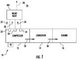
- FIG. 1a partial view of an exemplary embodiment of a controller for an inline valve in accordance with the disclosure is shown in FIG. 1 and is designated generally by reference character 100.
- controllers, inline valves, gas turbine engines and methods of controlling flow through inline valves in accordance with the present disclosure, or aspects thereof,are provided in Figs. 2-6 , as will be described.
- the systems and methods described hereincan be used for pneumatically controlling passively actuated inline valves, such as bleed valves in gas turbine engines, though the present disclosure is not limited to controlling bleed flows in gas turbine engines or to gas turbine engines in general.
- the gas turbine engine 10includes a compressor 12, a combustor 14, and a turbine 16.
- the gas turbine engine 10also includes a starter 18 and the inline valve 100.
- the compressor 12has a bleed port 20, a low pressure stage 22, and a high pressure stage 24.
- the low pressure stage 22is arranged upstream (relative to a direction of fluid flow through the compressor 12) of the bleed port 20, the high pressure stage 24 is arranged downstream of the of the bleed port 20, and the compressor 12 is arranged to ingest and compress fluid from the external environment 26 to generate a working fluid flow 28, e.g., a compressed air flow.
- the combustor 14is in fluid communication with the compressor 12 to receive the working fluid flow 28, and is arranged to generate therefrom a flow of high pressure combustion products 30.
- the turbine 16is in fluid communication with the combustor 14 to extract energy from the flow of high pressure combustion products 30 to power the compressor 12.
- the starter 18is operably connected to the gas turbine engine 10 for starting the gas turbine engine 10. More specifically, the starter 18 is arranged to provide mechanical rotation to the compressor 12 during startup of the gas turbine engine 10 when power is unavailable from the turbine 16. To limit the power required during startup the inline valve 100 is connected to the bleed port 20. In this respect the inline valve 100 is arranged to provide fluid communication between the compressor 12 and the external environment 26 for passive actuation according to pressure within the compressor 12, as will be described.
- the inline valve 100is connected to the bleed port 20, the low pressure stage 22, and the high pressure stage 24.
- the low pressure stage 22provides a flow of low pressure fluid 32, e.g., low pressure compressed air, to the inline valve 100.
- the high pressure stage 24provides a flow of high pressure fluid 34, e.g., high pressure compressed air, to the inline valve 100.
- the bleed port 20is in fluid communication with the inline valve 100 for selective fluid communication of a portion of the working fluid flow 28 with the external environment 26 according to operation of the bleed valve 100. It is contemplated that that the low pressure fluid 32 be relatively cool in comparison to the high pressure fluid 34.
- the flow of high pressure fluid 34be of relatively high pressure and temperature in comparison to the flow of low pressure fluid 32, as will also be described. It is understood that this is for illustration purposes only and is non-limiting, and that other arrangements are possible and remain within the scope of the present disclosure.
- the inline valve 100includes a pneumatic controller 102, valve body 104, and a poppet 106.
- the inline valve 100also includes an actuator 108, a pneumatic conduit 110, a guide 112, and a fairing 114.
- the pneumatic controller 102generally includes a manifold 116, a selector 118, and a biasing member 120.
- the manifold 116has a low pressure port 122, a high pressure port 124, an actuator port 126, and a vent 128.
- the selector 118is movable within the manifold 116 between a first position 130 and a second position 132, the low pressure port 122 in fluid communication with the actuator port 126 in the first position 130, the high pressure port 124 in fluid communication with the actuator port 126 in the second position 132.
- the biasing member 120is supported within the manifold 116 and urges the selector 118 towards the first position 130, the low pressure port 122 being in fluid communication with the vent 128 in both the first position 130 and the second position 132 to cool the biasing member 120 with low pressure fluid, e.g., the low pressure fluid 32 (shown in FIG. 1 ), received at the low pressure port 122.
- low pressure fluide.g., the low pressure fluid 32 (shown in FIG. 1 )
- the valve body 104has an inlet 134, an outlet 136, and an interior 138.
- the valve body 104also has a valve body poppet seat 140 and a valve body exterior 142.
- the poppet 106, the actuator 108, the guide 112, and the fairing 114are arranged within the interior 138 of the valve body 104.
- the pneumatic controller 102is connected to the valve body exterior 142.
- the pneumatic conduit 110fluidly connects the actuator 108 to the pneumatic controller 102, the pneumatic conduit 110 extending through the valve body exterior 142 and seating in the actuator port 126 of the pneumatic controller 102.
- the actuator 108has an open end 144, a closed end 146, and defines an actuator chamber 148 and actuator poppet seat 150.
- the closed end 146 of the actuator 108opposes the outlet 136 of the valve body 104.
- the open end 144 of the actuator 108opposes the inlet 134 of the valve body 104.
- the actuator poppet seat 150extends about the open end 144 of the actuator 108.
- the guide 112is fixed to the actuator 108 and is arranged within the actuator chamber 148.
- the poppet 106is slidably received within the actuator 108 and on the guide 112, the poppet 106 and the actuator 108 thereby bounding the actuator chamber 148.
- the pneumatic conduit 110is fixed to the actuator 108 and provides fluid communication between the pneumatic controller 102 and the actuator chamber 148.
- the poppet 106has a face portion 152, a guide portion 154, and a skirt portion 156.
- the face portion 152opposes the inlet 134 of the valve body 104.
- the guide portion 154 of the poppet 106extends from the face portion 152, towards the outlet 136 of the valve body 104, and is slidably received on the guide 112.
- the skirt portion 156 of the poppet 106extends from the face portion 152 of the poppet 106 at a location radially outward of the guide portion 154 of the poppet 106, extends towards the outlet 136 of the valve body 104, and is slidably received within the actuator 108.
- the fairing 114extends about the pneumatic conduit 110 and couples the actuator 108 to the valve body 104.
- the fairing 114has a leading edge 158, a trailing edge 160, and a fairing body 162.
- the leading edge 158 of the fairing 114opposes the inlet 134 of the valve body 104 and extends between an interior surface 164 of the valve body 104 and the actuator 108.
- the trailing edge 160 of the fairing 114extends between the interior surface 164 of the valve body 104 and the actuator 108 at a location downstream of the leading edge 158 of the fairing 114, and opposes the outlet 136 of the valve body 104.
- the fairing body 162extends between the leading edge 158 and the trailing edge 160 of the fairing 114.
- the pneumatic controller 102includes the manifold 116, the selector 118, and a plunger 166.
- the pneumatic controlleralso includes the biasing member 120, a seat member 168, and a bias-set screw 170.
- the manifold 116has a mount portion 172, a bias-set screw port 174, and a manifold exterior 190, and defines within its interior a fluid channel 176.
- the mount portion 172connects the manifold 116 to the valve body 104 and extends between the manifold 116 the valve body exterior 142, the pneumatic controller 102 and the valve body 104 form a unitary assembly or end item.
- the fluid channel 176connects the bias-set screw port 174 with the low pressure port 122, the high pressure port 124, and the actuator port 126.
- a plunger guide 178is fixed between the selector 118 and the low pressure port 122.
- a first selector seat 180 and a second selector seat 182are arranged within the fluid channel 176. More specifically, the first selector seat 180 is arranged within the fluid channel 176 between high pressure port 124 and the actuator port 126. The second selector seat 182 is arranged within the fluid channel 176 between the first selector seat 180 and the vent 128.
- the selector 118, the plunger 166, the biasing member 120, and the seat member 168are each disposed within the fluid channel 176. In this respect the selector 118 is disposed between the first selector seat 180 and the second selector seat 182.
- the plunger 166is disposed between the selector 118 and the biasing member 120.
- the biasing member 120is disposed between the vent 128 and the low pressure port 122, and is also disposed between the second selector seat 182 and the low pressure port 122.
- the seat member 168is disposed between the bias-set screw 170 and the seat member 168. It is contemplated that the biasing member 120 can include a spring and/or a flexure, as suitable for an intended application.
- the bias-set screw 170has a threaded segment 184, a tool engagement feature 186, and a smooth segment 188.
- the threaded segment 184is threadedly disposed within the seat member 168.
- the tool engagement feature 186is adjacent to the threaded segment 184, e.g., on a side of the threaded segment 184 opposite the seat member 168, and is disposed on the manifold exterior 190.
- the smooth segment 188is adjacent to the threaded segment 184, e.g., on a side of the threaded segment 184 opposite the tool engagement feature 186 and within the fluid channel 176, and is rotatably received within the seat member 168.
- the seat member 168is supported within the manifold 116 between the biasing member 120 and the bias-set screw port 174, defines a set screw socket 192, and has a seat member flange portion 194.
- the set screw socket 192is defined on a side of the seat member 168 opposite the biasing member 120 and the bias-set screw 170 is slidably received within the set screw socket 192. More specifically, the smooth segment 188 of the bias-set screw 170 is slidably received within the set screw socket 192 for rotation relative to the seat member 168.
- the seat member flange portion 194extends about the seat member 168 and biasing member 120, e.g., an end of the biasing member 120 opposite the plunger 166, is seated of the seat member flange portion 194.
- the plunger 166is supported within the manifold 116 and couples the biasing member 120 to the selector 118. More specifically, the plunger 166 is slidably received within the plunger guide 178, overlaps the vent 128 along its length, and has a selector face 196 and a plunger flange portion 198.
- the plunger flange portion 198extends circumferentially about the plunger 166 and the biasing member 120, e.g., at an end of the biasing member 120 opposite the seat member 168, and is seated on the plunger flange portion 198.
- the selector face 196opposes the selector 118 and is tangent to the selector 118.
- the selector 118have a spherical shape.
- the selector 118can additionally include a ceramic material 101. It is contemplated the ceramic material 101 can be disposed on the selector as a coating, reducing wear of the selector 118 and the internal structure of the manifold 116. It is also contemplated that selector 118 can be formed entirely from the ceramic material 101. Forming the selector 118 entirely of the ceramic material 101 has the further benefit of reducing weight of the pneumatic controller 102. Examples of suitable ceramic materials include silicon nitride.
- the biasing member 120is compressively supported between the selector 118 and the bias-set screw 170. In this respect the biasing member 120 urges the selector 118 towards the first selector seat 180 with a biasing force 36.
- the biasing force 36in turn has a magnitude that depends, at least in part, upon the advancement (or retraction) of the bias-set screw 170 within the bias-set screw port 174. For example, advancing the bias-set screw 170 within the bias-set screw port 174 increases magnitude of the biasing force 36.
- Increase of the biasing force 36in turn increases the pressure differential required across the high pressure port 124 and the low pressure port 122 required to move the selector 118 from the first position 130 (shown in FIG. 4 ) to the second position 132 (shown in FIG.
- retracting the bias-set screw 170 from the bias-set screw port 174reduces the magnitude of the biasing force 36 and reduces the pressure differential required across the high pressure port 124 and the low pressure port 122 required to move the selector 118 from the first position 130 to the second position 132.
- the pressure differentialcan be adjusted with the inline valve in-situ, e.g., while installed in the gas turbine engine 10 (shown in FIG. 1 ), simplifying installation and service of the inline valve 100 and the gas turbine engine 10.
- the working fluid flow 28(shown in FIG. 1 ) can be of temperature in excess of the maximum operating temperature of the biasing member 120. This can potentially cause the biasing member 120 to shift in performance and/or fail over time. To prevent performance shift and/or failure the manifold 116 includes the vent 128.
- the vent 128is in fluid communication with the low pressure port 122, is arranged on a side of the biasing member 120 opposite the low pressure port 122, and is open to the external environment 26. So located the flow of low pressure fluid 32 received at the low pressure port 122 to traverse the biasing member 120 and issue to the external environment 26, thermally insulating (and/or cooling) the biasing member 120 from structures of the inline valve 100 heated by the working fluid flow 28. It is contemplated that the vent 128 be positioned such that the selector 118 is disposed within the fluid channel 176 between the high pressure port 124 and the vent 128, the flow of low pressure fluid 32 thereby flowing from the low pressure port 122 to the vent 128 when the selector is in both the first position 130 (shown in FIG.
- the biasing member 120thereby being thermally insulated (and/or cooled) irrespective of the position of the selector 118.
- the vent 128 and the mount portion 172are located on a common side of the manifold 116 such that the vent opposes the valve body 104. This causes the flow of low pressure fluid 32 issuing from the vent 128 to flow across the valve body 104, cooling the valve body 104 and limiting (or eliminating entirely) the need to provide additional coolant to the valve body 104.
- the inline valve 100is shown with the selector 118 in the first position 130.
- the selector 118moves to the first position 130 when the sum of the biasing force 36 (shown in FIG. 3 ) and force exerted on the selector 118 by the flow of low pressure fluid 32 exceeds the force exerted on the selector 118 by the flow of high pressure fluid 34.
- the selector 118moves to the first position 130, wherein the selector 118 abuts the first selector seat 180. Abutment of the selector 118 with the first selector seat 180 places the low pressure port 122 in fluid communication with the actuator chamber 148. Fluid communication between the low pressure port 122 and the actuator chamber 148 in turn pressurizes the actuator chamber 148 according to the pressure of the flow of low pressure fluid 32.
- the inline valve 100passively opens 38, i.e., the poppet 106 moves from the valve body poppet seat 140 to the actuator poppet seat 150. Once the poppet 106 is against the actuator poppet seat 150 the inlet 134 of the valve body 104 is in fluid communication with the outlet 136 of the valve body 104, the compressor 12 (shown in FIG. 1 ) thereby being in fluid communication with the external environment 26 through the valve body 104.
- the compressor 12is thereby able to increase pressure of the working fluid flow 28 without having to fully pressurize the working fluid flow 28 due to the venting provided through the inline valve 100 to the external environment 26, reducing the input energy required to start the gas turbine engine 10 (shown in FIG. 1 ).
- the flow of low pressure fluid 32 received at the low pressure port 122traverses the biasing member 120, insulating (and/or cooling) the biasing member 120, and thereafter issues from the pneumatic controller 102 through the vent 128 while the selector is in the first position 130.
- the inline valve 100is shown with the selector 118 in the second position 132.
- the selector 118moves to the second position 132 when the sum of the biasing force 36 (shown in FIG. 3 ) and force exerted on the selector 118 by the flow of low pressure fluid 32 falls below the force exerted on the selector 118 by the flow of high pressure fluid 34.
- the selector 118moves to the second position 132, wherein the selector 118 abuts the second selector seat 182. Abutment of the selector 118 with the second selector seat 182 places the high pressure port 124 in fluid communication with the actuator chamber 148.
- Fluid communication between the high pressure port 124 and the actuator chamber 148in turn pressurizes the actuator chamber 148 according to the pressure of the flow of high pressure fluid 34.
- the flow of low pressure fluid 32 received at the low pressure port 122traverses the biasing member 120, insulating (and/or cooling) the biasing member 120, and thereafter issues from the pneumatic controller 102 through the vent 128 while the selector is in the second position 132.
- the inline valve 100passively closes 40, i.e., the poppet 106 moves from the actuator poppet seat 150 and against the valve body poppet seat 140. Once against the valve body poppet seat 140 the poppet 106 fluidly separates the outlet 136 of the valve body 104 from the inlet 134 of the valve body 104. This ceases fluid communication between the compressor 12 (shown in FIG. 1 ) and the external environment 26 through the inline valve 100.
- Method 200includes receiving a working fluid flow, e.g., the working fluid flow 28 (shown in FIG. 1 ), at the inline valve, as shown with box 210.
- Method 200also includes receiving a flow of high pressure fluid, e.g. the flow of high pressure fluid 34 (shown in FIG. 1 ) at the inline valve, as shown with box 220.
- the method 200additionally includes receiving a flow of low pressure fluid, e.g., the low pressure fluid 32 (shown in FIG. 1 ), at the inline valve, as shown with box 230.
- the flow of low pressure fluidbe received at a low pressure port of the inline valve, e.g., the low pressure port 122 (shown in FIG. 2 )
- the flow of high pressure fluidbe received at a high pressure port of the inline valve, e.g., the high pressure port 124 (shown in FIG. 2 )
- the working fluid flowbe received at an inlet of the inline valve, e.g., the inlet 134 (shown in FIG. 2 ), as shown by boxes 212, 222, and 232.
- a portion of the low pressure fluidflows through a pneumatic controller of the inline valve, e.g., the controller 102 (shown in FIG. 2 ), cooling the pneumatic controller.
- the portion of the low pressure fluidflows across a biasing member supported within the pneumatic controller, e.g., the biasing member 120 (shown in FIG. 2 ), as shown with box 242, and out a vent port of the pneumatic controller, e.g., the vent port 128 (shown in FIG. 2 ) and into the ambient environment, as shown with box 244.
- the portion of the flow of low pressure fluidis directed by the vent port to a valve body of the inline valve, e.g., the valve body 104 (shown in FIG. 2 ).
- the portion of the low pressure fluidflows through the vent and cools the biasing member while low pressure fluid is communicated to the valve body of the inline valve.
- low pressure fluidflows through the vent and cools the biasing member while high pressure fluid communicated to the valve body of the inline valve.
- the biasing membercan be cooled while switching between communication of the flow of low pressure fluid and the flow of high pressure fluid to the valve body.
- Inline valvescan be operated by selectively applying muscle pressure for actuation of the inline valve using pneumatic controllers.
- controllers employing springsthe air being controlled can be above the temperature at which the mechanical properties of the material forming the spring changes, potentially causing the spring performance to change and/or causing premature failure of the spring.
- pneumatic controllershaving a high pressure port, a low pressure port, an actuator port, and a vent.
- the pneumatic controllerconnects the low pressure port or the high pressure port to the actuator port according to relative pressures of fluids received at the ports and the spring constant of a resilient member supported within the pneumatic controller, and cools the resilient member by flowing low pressure fluid received at the low pressure port across the resilient member and out the vent.
- Thisensures that the resilient member remains insulated from heat by flow of low pressure fluid irrespective of the state of the valve, the resilient member remaining at a known temperature and within the temperature range of the material forming the resilient member, the resilient member thereby having more predictable spring characteristics than were ambient convective cooling employed.
- the present disclosureenables resilient members to be employed in environments which would otherwise be prohibitive due to the associated loadings and temperatures of the application. Further, cooling the resilient member with forced convection from a low pressure fluid source flowing across the resilient member and into the external environment allows temperature of the resilient member to be accurately predicted, reducing the tendency of such inaccuracy to result in resilient member performance and/or failures.
Landscapes
- Engineering & Computer Science (AREA)
- General Engineering & Computer Science (AREA)
- Mechanical Engineering (AREA)
- Physics & Mathematics (AREA)
- Fluid Mechanics (AREA)
- Chemical & Material Sciences (AREA)
- Combustion & Propulsion (AREA)
- Life Sciences & Earth Sciences (AREA)
- Sustainable Development (AREA)
- Fluid-Driven Valves (AREA)
Description
- This invention was made with Government support under Contract No. FA8626-16-C-2139 awarded by the United States Air Force. The Government has certain rights in the invention.
- The present disclosure generally relates to fluid systems, and more particularly to controlling fluid flow in fluid systems with inline valves.
- Valves, such as pneumatically actuated valves, are commonly used to control the fluid flow in fluid systems. Such valves generally house an actuator with air conduits to allow the valve to open and close according to pressure at the valve inlet. When the inlet pressure is low an air conduit charged with low pressure air is connected to the actuator, which allows the low pressure air at the inlet to open the valve. As the inlet pressure rises a conduit charged with high pressure air is connected to the actuator, which causes the valve to close when the pressure of the air at the inlet rises above a predetermined pressure. Since the air provided to the valve may be relatively hot the actuator may require cooling and/or periodic service in order to function reliably during operation.
- Such systems and methods valves have generally been acceptable for their intended purpose. However, there remains a need in the art for improved pneumatic controllers, inline valves, and methods of cooling pneumatic actuators in inline valves. The present disclosure provides a solution to this need. A conventional pneumatic controller for an inline valve according to the preamble of claim 1 is known from
EP3056739A1 . - A pneumatic controller for an inline valve includes a manifold, a selector, and a biasing member. The manifold has a low pressure port, a high pressure port, an actuator port, and a vent. The selector is movable within the manifold between a first position and a second position, the low pressure port in fluid communication with the actuator port in the first position, the high pressure port in fluid communication with the actuator port in the second position. The biasing member is supported within the manifold urges the selector towards the first position. The low pressure port is in fluid communication with the vent in both the first position and the second position to cool the biasing member with low pressure fluid received at the low pressure port.
- In addition to one or more of the features described above, or as an alternative, further embodiments may include the manifold has a first selector seat fixed between the high pressure port and the actuator port and a second selector seat fixed between the first selector seat and the vent, the selector is disposed between the first selector seat and the second selector seat.
- In addition to one or more of the features described above, or as an alternative, further embodiments may include that the biasing member is supported within the manifold between the second selector seat and the low pressure port.
- In addition to one or more of the features described above, or as an alternative, further embodiments may include that the biasing member is supported within the manifold between the vent and the low pressure port.
- In addition to one or more of the features described above, or as an alternative, further embodiments may include a plunger supported within the manifold, the plunger coupling the biasing member to the selector.
- In addition to one or more of the features described above, or as an alternative, further embodiments may include that the plunger overlaps the vent along its length.
- In addition to one or more of the features described above, or as an alternative, further embodiments may include that the manifold has a plunger guide fixed between the selector and the low pressure port, wherein the plunger is slidably disposed within the plunger guide.
- In addition to one or more of the features described above, or as an alternative, further embodiments may include a seat member supported within the manifold, the seat member arranged between the biasing member and the low pressure port.
- In addition to one or more of the features described above, or as an alternative, further embodiments may include that the seat member has a seat member flange portion, the biasing member fixed to the seat member flange portion.
- In addition to one or more of the features described above, or as an alternative, further embodiments may include a plunger with a plunger flange portion, the plunger flange portion arranged on an end of the plunger opposite the selector, wherein the biasing member is fixed to the plunger flange portion.
- In addition to one or more of the features described above, or as an alternative, further embodiments may include that the manifold has a fluid channel connecting the vent with each of the low pressure port, the high pressure port, and the actuator port, wherein the selector is disposed within the fluid channel between the high pressure port and the vent.
- In addition to one or more of the features described above, or as an alternative, further embodiments may include a pneumatic conduit fixed to the actuator port, and a valve body having an exterior and an actuator chamber, the actuator chamber connected to the pneumatic conduit, the manifold fixed to the exterior of the valve body to provide low pressure fluid or high pressure fluid to the actuation chamber according to position of the selector.
- In addition to one or more of the features described above, or as an alternative, further embodiments may include that the selector has a spherical shape, wherein the selector includes a ceramic material.
- In addition to one or more of the features described above, or as an alternative, further embodiments may include that the manifold has a mount portion, the pneumatic controller having a valve body with an exterior, the mount portion connecting the manifold to the valve body.
- In addition to one or more of the features described above, or as an alternative, further embodiments may include that the manifold has a mount portion, wherein the vent and the mount portion are on a common side of the manifold.
- An inline valve includes a pneumatic controller as described above, a valve body, and a poppet. The manifold has a mount portion, the valve body has an exterior, an inlet, and an outlet, the mount portion of the manifold connecting the manifold to the exterior of the valve body. The poppet is supported within the valve body and is operably associated with the selector, wherein the poppet is movable between an actuator poppet seat and valve body poppet seat within the valve body, the inlet of the valve body in fluid communication with the outlet of the valve body when the poppet is against the actuator poppet seat, the poppet fluidly separating the inlet from the outlet when the poppet is against the valve body poppet seat.
- In addition to one or more of the features described above, or as an alternative, further embodiments may include that the vent opposes the valve body to issue low pressure fluid received at the low pressure port toward the exterior of the valve body.
- In addition to one or more of the features described above, or as an alternative, further embodiments may include the pneumatic controller comprises a first selector seat arranged between the high pressure port and the actuator port, a second selector seat arranged between the first selector seat and the vent, wherein the selector is arranged between the first selector seat and the second selector seat, a plunger supported within the manifold, the plunger coupling the biasing member to the selector, and a seat member supported within the manifold, the seat member arranged between the biasing member and the low pressure port.
- A gas turbine engine includes a compressor having a bleed port, a high pressure stage downstream of the bleed port, and a low pressure stage upstream of the bleed port; a pneumatic controller as described above, wherein the high pressure stage is connected to the high pressure port, wherein the low pressure stage is connected to the low pressure port; and an inline valve with a valve body with an inlet and an outlet, wherein the inlet is in fluid communication with the bleed port of the compressor, wherein the pneumatic controller is mounted to an exterior of the valve body.
- A method of controlling flow through an inline valve includes, at a pneumatic controller as described above, receiving a high pressure fluid at the high pressure port, receiving a low pressure fluid at the low pressure port, communicating one of the low pressure fluid and the high pressure fluid to the actuator port according to position of the selector, and cooling the biasing member by flowing the low pressure fluid across the biasing member and through the vent.
- Technical effects of the present disclosure include the capability to provide passive control of inline valves without remotely-mounted, active control mechanisms such as solenoids. In embodiments described herein no external signals are required for active control of the inline valve. Technical effects also include valve bodies having relatively large flow area in comparison to inline valves having controllers located within the valve body of the inline valve. Technical effects additionally include controller active cooling, limiting (or eliminating entirely) the tendency of hot control fluid provided to inline valves altering valve performance.
- The following descriptions should not be considered limiting in any way. With reference to the accompanying drawings, like elements are numbered alike:
FIG. 1 is a schematic view of an inline valve constructed in accordance with the present disclosure, showing gas turbine engine compressor having a bleed port with the inline valve connected to the bleed port;FIG. 2 is cross-sectional view of the inline valve ofFIG. 1 , showing a valve body with a poppet and an externally mounted controller for remotely communicating either a pressure of reference fluid or pressure of control fluid to the poppet;FIG. 3 is a cross-sectional view of a portion of the inline valve ofFIG. 1 including the pneumatic controller, showing a vent defined between the pneumatic controller low pressure port and the pneumatic controller high pressure port to cool a biasing member supported within the pneumatic controller;FIG. 4 is a cross-sectional view of the inline valve ofFIG. 1 , showing the selector in a first position and controller thereby communicating a flow of low pressure fluid to the poppet while cooling the biasing member with low pressure fluid;FIG. 5 is a cross-sectional view of the inline valve ofFIG. 1 , showing the selector in a second position and the pneumatic controller thereby communicating a flow of high pressure fluid to the poppet while cooling the biasing member with low pressure fluid; andFIG. 6 is a block diagram of a method of controlling fluid flow through an inline valve, showing steps of the method according to an illustrative and non-limiting embodiment of the method.- Reference will now be made to the drawings wherein like reference numerals identify similar structural features or aspects of the subject disclosure. For purposes of explanation and illustration, and not limitation, a partial view of an exemplary embodiment of a controller for an inline valve in accordance with the disclosure is shown in
FIG. 1 and is designated generally byreference character 100. Other embodiments of controllers, inline valves, gas turbine engines and methods of controlling flow through inline valves in accordance with the present disclosure, or aspects thereof, are provided inFigs. 2-6 , as will be described. The systems and methods described herein can be used for pneumatically controlling passively actuated inline valves, such as bleed valves in gas turbine engines, though the present disclosure is not limited to controlling bleed flows in gas turbine engines or to gas turbine engines in general. - Referring to
FIG. 1 , agas turbine engine 10 is shown. Thegas turbine engine 10 includes acompressor 12, acombustor 14, and aturbine 16. Thegas turbine engine 10 also includes astarter 18 and theinline valve 100. - The
compressor 12 has ableed port 20, alow pressure stage 22, and ahigh pressure stage 24. Thelow pressure stage 22 is arranged upstream (relative to a direction of fluid flow through the compressor 12) of thebleed port 20, thehigh pressure stage 24 is arranged downstream of the of thebleed port 20, and thecompressor 12 is arranged to ingest and compress fluid from theexternal environment 26 to generate a workingfluid flow 28, e.g., a compressed air flow. Thecombustor 14 is in fluid communication with thecompressor 12 to receive the workingfluid flow 28, and is arranged to generate therefrom a flow of highpressure combustion products 30. Theturbine 16 is in fluid communication with thecombustor 14 to extract energy from the flow of highpressure combustion products 30 to power thecompressor 12. - The
starter 18 is operably connected to thegas turbine engine 10 for starting thegas turbine engine 10. More specifically, thestarter 18 is arranged to provide mechanical rotation to thecompressor 12 during startup of thegas turbine engine 10 when power is unavailable from theturbine 16. To limit the power required during startup theinline valve 100 is connected to thebleed port 20. In this respect theinline valve 100 is arranged to provide fluid communication between thecompressor 12 and theexternal environment 26 for passive actuation according to pressure within thecompressor 12, as will be described. - In the illustrated embodiment the
inline valve 100 is connected to thebleed port 20, thelow pressure stage 22, and thehigh pressure stage 24. Thelow pressure stage 22 provides a flow oflow pressure fluid 32, e.g., low pressure compressed air, to theinline valve 100. Thehigh pressure stage 24 provides a flow ofhigh pressure fluid 34, e.g., high pressure compressed air, to theinline valve 100. Thebleed port 20 is in fluid communication with theinline valve 100 for selective fluid communication of a portion of the workingfluid flow 28 with theexternal environment 26 according to operation of thebleed valve 100. It is contemplated that that thelow pressure fluid 32 be relatively cool in comparison to thehigh pressure fluid 34. It is also contemplated that the flow ofhigh pressure fluid 34 be of relatively high pressure and temperature in comparison to the flow oflow pressure fluid 32, as will also be described. It is understood that this is for illustration purposes only and is non-limiting, and that other arrangements are possible and remain within the scope of the present disclosure. - With reference to
FIG. 2 , theinline valve 100 is shown. Theinline valve 100 includes apneumatic controller 102,valve body 104, and apoppet 106. Theinline valve 100 also includes anactuator 108, apneumatic conduit 110, aguide 112, and afairing 114. - The
pneumatic controller 102 generally includes a manifold 116, aselector 118, and a biasingmember 120. The manifold 116 has alow pressure port 122, ahigh pressure port 124, anactuator port 126, and avent 128. Theselector 118 is movable within the manifold 116 between afirst position 130 and asecond position 132, thelow pressure port 122 in fluid communication with theactuator port 126 in thefirst position 130, thehigh pressure port 124 in fluid communication with theactuator port 126 in thesecond position 132. The biasingmember 120 is supported within themanifold 116 and urges theselector 118 towards thefirst position 130, thelow pressure port 122 being in fluid communication with thevent 128 in both thefirst position 130 and thesecond position 132 to cool the biasingmember 120 with low pressure fluid, e.g., the low pressure fluid 32 (shown inFIG. 1 ), received at thelow pressure port 122. - The
valve body 104 has aninlet 134, anoutlet 136, and an interior 138. Thevalve body 104 also has a valvebody poppet seat 140 and avalve body exterior 142. Thepoppet 106, theactuator 108, theguide 112, and the fairing 114 are arranged within theinterior 138 of thevalve body 104. Thepneumatic controller 102 is connected to thevalve body exterior 142. Thepneumatic conduit 110 fluidly connects theactuator 108 to thepneumatic controller 102, thepneumatic conduit 110 extending through thevalve body exterior 142 and seating in theactuator port 126 of thepneumatic controller 102. - The
actuator 108 has anopen end 144, aclosed end 146, and defines anactuator chamber 148 andactuator poppet seat 150. Theclosed end 146 of theactuator 108 opposes theoutlet 136 of thevalve body 104. Theopen end 144 of theactuator 108 opposes theinlet 134 of thevalve body 104. Theactuator poppet seat 150 extends about theopen end 144 of theactuator 108. Theguide 112 is fixed to theactuator 108 and is arranged within theactuator chamber 148. Thepoppet 106 is slidably received within theactuator 108 and on theguide 112, thepoppet 106 and theactuator 108 thereby bounding theactuator chamber 148. Thepneumatic conduit 110 is fixed to theactuator 108 and provides fluid communication between thepneumatic controller 102 and theactuator chamber 148. - The
poppet 106 has aface portion 152, aguide portion 154, and askirt portion 156. Theface portion 152 opposes theinlet 134 of thevalve body 104. Theguide portion 154 of thepoppet 106 extends from theface portion 152, towards theoutlet 136 of thevalve body 104, and is slidably received on theguide 112. Theskirt portion 156 of thepoppet 106 extends from theface portion 152 of thepoppet 106 at a location radially outward of theguide portion 154 of thepoppet 106, extends towards theoutlet 136 of thevalve body 104, and is slidably received within theactuator 108. - The fairing 114 extends about the
pneumatic conduit 110 and couples theactuator 108 to thevalve body 104. In this respect the fairing 114 has aleading edge 158, a trailingedge 160, and afairing body 162. Theleading edge 158 of the fairing 114 opposes theinlet 134 of thevalve body 104 and extends between aninterior surface 164 of thevalve body 104 and theactuator 108. The trailingedge 160 of the fairing 114 extends between theinterior surface 164 of thevalve body 104 and theactuator 108 at a location downstream of theleading edge 158 of the fairing 114, and opposes theoutlet 136 of thevalve body 104. Thefairing body 162 extends between theleading edge 158 and the trailingedge 160 of thefairing 114. - With reference to
FIG. 3 , thepneumatic controller 102 is shown. Thepneumatic controller 102 includes the manifold 116, theselector 118, and aplunger 166. The pneumatic controller also includes the biasingmember 120, aseat member 168, and a bias-set screw 170. - The manifold 116 has a
mount portion 172, a bias-set screw port 174, and amanifold exterior 190, and defines within its interior afluid channel 176. Themount portion 172 connects the manifold 116 to thevalve body 104 and extends between the manifold 116 thevalve body exterior 142, thepneumatic controller 102 and thevalve body 104 form a unitary assembly or end item. Thefluid channel 176 connects the bias-set screw port 174 with thelow pressure port 122, thehigh pressure port 124, and theactuator port 126. Aplunger guide 178 is fixed between theselector 118 and thelow pressure port 122. - A
first selector seat 180 and asecond selector seat 182 are arranged within thefluid channel 176. More specifically, thefirst selector seat 180 is arranged within thefluid channel 176 betweenhigh pressure port 124 and theactuator port 126. Thesecond selector seat 182 is arranged within thefluid channel 176 between thefirst selector seat 180 and thevent 128. Theselector 118, theplunger 166, the biasingmember 120, and theseat member 168 are each disposed within thefluid channel 176. In this respect theselector 118 is disposed between thefirst selector seat 180 and thesecond selector seat 182. Theplunger 166 is disposed between theselector 118 and the biasingmember 120. The biasingmember 120 is disposed between thevent 128 and thelow pressure port 122, and is also disposed between thesecond selector seat 182 and thelow pressure port 122. Theseat member 168 is disposed between the bias-set screw 170 and theseat member 168. It is contemplated that the biasingmember 120 can include a spring and/or a flexure, as suitable for an intended application. - The bias-
set screw 170 has a threadedsegment 184, atool engagement feature 186, and asmooth segment 188. The threadedsegment 184 is threadedly disposed within theseat member 168. Thetool engagement feature 186 is adjacent to the threadedsegment 184, e.g., on a side of the threadedsegment 184 opposite theseat member 168, and is disposed on themanifold exterior 190. Thesmooth segment 188 is adjacent to the threadedsegment 184, e.g., on a side of the threadedsegment 184 opposite thetool engagement feature 186 and within thefluid channel 176, and is rotatably received within theseat member 168. - The
seat member 168 is supported within the manifold 116 between the biasingmember 120 and the bias-set screw port 174, defines aset screw socket 192, and has a seatmember flange portion 194. Theset screw socket 192 is defined on a side of theseat member 168 opposite the biasingmember 120 and the bias-set screw 170 is slidably received within theset screw socket 192. More specifically, thesmooth segment 188 of the bias-set screw 170 is slidably received within theset screw socket 192 for rotation relative to theseat member 168. The seatmember flange portion 194 extends about theseat member 168 and biasingmember 120, e.g., an end of the biasingmember 120 opposite theplunger 166, is seated of the seatmember flange portion 194. - The
plunger 166 is supported within themanifold 116 and couples the biasingmember 120 to theselector 118. More specifically, theplunger 166 is slidably received within theplunger guide 178, overlaps thevent 128 along its length, and has aselector face 196 and aplunger flange portion 198. Theplunger flange portion 198 extends circumferentially about theplunger 166 and the biasingmember 120, e.g., at an end of the biasingmember 120 opposite theseat member 168, and is seated on theplunger flange portion 198. Theselector face 196 opposes theselector 118 and is tangent to theselector 118. In this respect it is contemplated that theselector 118 have a spherical shape. In certain embodiments theselector 118 can additionally include aceramic material 101. It is contemplated theceramic material 101 can be disposed on the selector as a coating, reducing wear of theselector 118 and the internal structure of themanifold 116. It is also contemplated thatselector 118 can be formed entirely from theceramic material 101. Forming theselector 118 entirely of theceramic material 101 has the further benefit of reducing weight of thepneumatic controller 102. Examples of suitable ceramic materials include silicon nitride. - The biasing
member 120 is compressively supported between theselector 118 and the bias-set screw 170. In this respect the biasingmember 120 urges theselector 118 towards thefirst selector seat 180 with a biasingforce 36. The biasingforce 36 in turn has a magnitude that depends, at least in part, upon the advancement (or retraction) of the bias-set screw 170 within the bias-set screw port 174. For example, advancing the bias-set screw 170 within the bias-set screw port 174 increases magnitude of the biasingforce 36. Increase of the biasingforce 36 in turn increases the pressure differential required across thehigh pressure port 124 and thelow pressure port 122 required to move theselector 118 from the first position 130 (shown inFIG. 4 ) to the second position 132 (shown inFIG. 5 ). Oppositely, retracting the bias-set screw 170 from the bias-set screw port 174 reduces the magnitude of the biasingforce 36 and reduces the pressure differential required across thehigh pressure port 124 and thelow pressure port 122 required to move theselector 118 from thefirst position 130 to thesecond position 132. As thetool engagement feature 186 is located outside of thepneumatic controller 102 and thevalve body 104, the pressure differential can be adjusted with the inline valve in-situ, e.g., while installed in the gas turbine engine 10 (shown inFIG. 1 ), simplifying installation and service of theinline valve 100 and thegas turbine engine 10. - As will be appreciated by those of skill in the art in view of the present disclosure, the working fluid flow 28 (shown in
FIG. 1 ) can be of temperature in excess of the maximum operating temperature of the biasingmember 120. This can potentially cause the biasingmember 120 to shift in performance and/or fail over time. To prevent performance shift and/or failure the manifold 116 includes thevent 128. - The
vent 128 is in fluid communication with thelow pressure port 122, is arranged on a side of the biasingmember 120 opposite thelow pressure port 122, and is open to theexternal environment 26. So located the flow oflow pressure fluid 32 received at thelow pressure port 122 to traverse the biasingmember 120 and issue to theexternal environment 26, thermally insulating (and/or cooling) the biasingmember 120 from structures of theinline valve 100 heated by the workingfluid flow 28. It is contemplated that thevent 128 be positioned such that theselector 118 is disposed within thefluid channel 176 between thehigh pressure port 124 and thevent 128, the flow oflow pressure fluid 32 thereby flowing from thelow pressure port 122 to thevent 128 when the selector is in both the first position 130 (shown inFIG. 4 ) and the second position 132 (shown inFIG. 5 ), the biasingmember 120 thereby being thermally insulated (and/or cooled) irrespective of the position of theselector 118. As shown inFIG. 3 thevent 128 and themount portion 172 are located on a common side of the manifold 116 such that the vent opposes thevalve body 104. This causes the flow oflow pressure fluid 32 issuing from thevent 128 to flow across thevalve body 104, cooling thevalve body 104 and limiting (or eliminating entirely) the need to provide additional coolant to thevalve body 104. - With reference to
FIG. 4 , theinline valve 100 is shown with theselector 118 in thefirst position 130. Theselector 118 moves to thefirst position 130 when the sum of the biasing force 36 (shown inFIG. 3 ) and force exerted on theselector 118 by the flow oflow pressure fluid 32 exceeds the force exerted on theselector 118 by the flow ofhigh pressure fluid 34. When this condition exists theselector 118 moves to thefirst position 130, wherein theselector 118 abuts thefirst selector seat 180. Abutment of theselector 118 with thefirst selector seat 180 places thelow pressure port 122 in fluid communication with theactuator chamber 148. Fluid communication between thelow pressure port 122 and theactuator chamber 148 in turn pressurizes theactuator chamber 148 according to the pressure of the flow oflow pressure fluid 32. - When pressure of the working
fluid flow 28 reaches pressure sufficient to overcome pressure of the flow oflow pressure fluid 32 within theactuator chamber 148, theinline valve 100 passively opens 38, i.e., thepoppet 106 moves from the valvebody poppet seat 140 to theactuator poppet seat 150. Once thepoppet 106 is against theactuator poppet seat 150 theinlet 134 of thevalve body 104 is in fluid communication with theoutlet 136 of thevalve body 104, the compressor 12 (shown inFIG. 1 ) thereby being in fluid communication with theexternal environment 26 through thevalve body 104. Thecompressor 12 is thereby able to increase pressure of the workingfluid flow 28 without having to fully pressurize the workingfluid flow 28 due to the venting provided through theinline valve 100 to theexternal environment 26, reducing the input energy required to start the gas turbine engine 10 (shown inFIG. 1 ). Notably, the flow oflow pressure fluid 32 received at thelow pressure port 122 traverses the biasingmember 120, insulating (and/or cooling) the biasingmember 120, and thereafter issues from thepneumatic controller 102 through thevent 128 while the selector is in thefirst position 130. - With reference to
FIG. 5 , theinline valve 100 is shown with theselector 118 in thesecond position 132. Theselector 118 moves to thesecond position 132 when the sum of the biasing force 36 (shown inFIG. 3 ) and force exerted on theselector 118 by the flow oflow pressure fluid 32 falls below the force exerted on theselector 118 by the flow ofhigh pressure fluid 34. When this condition exists theselector 118 moves to thesecond position 132, wherein theselector 118 abuts thesecond selector seat 182. Abutment of theselector 118 with thesecond selector seat 182 places thehigh pressure port 124 in fluid communication with theactuator chamber 148. Fluid communication between thehigh pressure port 124 and theactuator chamber 148 in turn pressurizes theactuator chamber 148 according to the pressure of the flow ofhigh pressure fluid 34. Notably, the flow oflow pressure fluid 32 received at thelow pressure port 122 traverses the biasingmember 120, insulating (and/or cooling) the biasingmember 120, and thereafter issues from thepneumatic controller 102 through thevent 128 while the selector is in thesecond position 132. - When pressure of the flow of
high pressure fluid 34 reaches pressure sufficient to overcome force exerted on thepoppet 106 by the workingfluid flow 28, theinline valve 100 passively closes 40, i.e., thepoppet 106 moves from theactuator poppet seat 150 and against the valvebody poppet seat 140. Once against the valvebody poppet seat 140 thepoppet 106 fluidly separates theoutlet 136 of thevalve body 104 from theinlet 134 of thevalve body 104. This ceases fluid communication between the compressor 12 (shown inFIG. 1 ) and theexternal environment 26 through theinline valve 100. - With reference to
FIG. 6 , amethod 200 of controlling flow through an inline valve, e.g., theinline valve 100, is shown.Method 200 includes receiving a working fluid flow, e.g., the working fluid flow 28 (shown inFIG. 1 ), at the inline valve, as shown withbox 210.Method 200 also includes receiving a flow of high pressure fluid, e.g. the flow of high pressure fluid 34 (shown inFIG. 1 ) at the inline valve, as shown withbox 220. Themethod 200 additionally includes receiving a flow of low pressure fluid, e.g., the low pressure fluid 32 (shown inFIG. 1 ), at the inline valve, as shown withbox 230. It is contemplated that the flow of low pressure fluid be received at a low pressure port of the inline valve, e.g., the low pressure port 122 (shown inFIG. 2 ), the flow of high pressure fluid be received at a high pressure port of the inline valve, e.g., the high pressure port 124 (shown inFIG. 2 ), and that the working fluid flow be received at an inlet of the inline valve, e.g., the inlet 134 (shown inFIG. 2 ), as shown byboxes - As shown with
box 240, a portion of the low pressure fluid flows through a pneumatic controller of the inline valve, e.g., the controller 102 (shown inFIG. 2 ), cooling the pneumatic controller. In this respect the portion of the low pressure fluid flows across a biasing member supported within the pneumatic controller, e.g., the biasing member 120 (shown inFIG. 2 ), as shown withbox 242, and out a vent port of the pneumatic controller, e.g., the vent port 128 (shown inFIG. 2 ) and into the ambient environment, as shown withbox 244. As shown withbox 246, the portion of the flow of low pressure fluid is directed by the vent port to a valve body of the inline valve, e.g., the valve body 104 (shown inFIG. 2 ). - As shown with
box 250, the portion of the low pressure fluid flows through the vent and cools the biasing member while low pressure fluid is communicated to the valve body of the inline valve. As shown withbox 260, low pressure fluid flows through the vent and cools the biasing member while high pressure fluid communicated to the valve body of the inline valve. As shownbox 270, the biasing member can be cooled while switching between communication of the flow of low pressure fluid and the flow of high pressure fluid to the valve body. - Inline valves can be operated by selectively applying muscle pressure for actuation of the inline valve using pneumatic controllers. In controllers employing springs the air being controlled can be above the temperature at which the mechanical properties of the material forming the spring changes, potentially causing the spring performance to change and/or causing premature failure of the spring.
- In embodiments described herein pneumatic controllers are employed having a high pressure port, a low pressure port, an actuator port, and a vent. The pneumatic controller connects the low pressure port or the high pressure port to the actuator port according to relative pressures of fluids received at the ports and the spring constant of a resilient member supported within the pneumatic controller, and cools the resilient member by flowing low pressure fluid received at the low pressure port across the resilient member and out the vent. This ensures that the resilient member remains insulated from heat by flow of low pressure fluid irrespective of the state of the valve, the resilient member remaining at a known temperature and within the temperature range of the material forming the resilient member, the resilient member thereby having more predictable spring characteristics than were ambient convective cooling employed.
- In certain embodiments the present disclosure enables resilient members to be employed in environments which would otherwise be prohibitive due to the associated loadings and temperatures of the application. Further, cooling the resilient member with forced convection from a low pressure fluid source flowing across the resilient member and into the external environment allows temperature of the resilient member to be accurately predicted, reducing the tendency of such inaccuracy to result in resilient member performance and/or failures.
- The term "about" is intended to include the degree of error associated with measurement of the particular quantity based upon the equipment available at the time of filing the application.
- The terminology used herein is for the purpose of describing particular embodiments only and is not intended to be limiting of the present disclosure. As used herein, the singular forms "a", "an" and "the" are intended to include the plural forms as well, unless the context clearly indicates otherwise. It will be further understood that the terms "comprises" and/or "comprising," when used in this specification, specify the presence of stated features, integers, steps, operations, elements, and/or components, but do not preclude the presence or addition of one or more other features, integers, steps, operations, element components, and/or groups thereof.
- While the present disclosure has been described with reference to an exemplary embodiment or embodiments, it will be understood by those skilled in the art that various changes may be made and equivalents may be substituted for elements thereof without departing from the scope of the present disclosure. In addition, many modifications may be made to adapt a particular situation or material to the teachings of the present disclosure without departing from the essential scope thereof. Therefore, it is intended that the present disclosure not be limited to the particular embodiment disclosed as the best mode contemplated for carrying out this present disclosure, but that the present disclosure will include all embodiments falling within the scope of the claims.
Claims (15)
- A pneumatic controller for an inline valve, comprising:a manifold (116) having a low pressure port (122), a high pressure port (124), an actuator port (126), and a vent (128);a selector (118) movable within the manifold between a first position and a second position, the low pressure port in fluid communication with the actuator port in the first position, the high pressure port in fluid communication with the actuator port in the second position; anda biasing member (120) supported within the manifold and urging the selector towards the first position,characterised in that the low pressure port is in fluid communication with the vent in both the first position and the second position to cool the biasing member with low pressure fluid received at the low pressure port.
- The pneumatic controller of claim 1, wherein the manifold comprises:a first selector seat (180) fixed between the high pressure port and the actuator port; anda second selector seat (182) fixed between the first selector seat and the vent, wherein the selector is disposed between the first selector seat and the second selector seat.
- The pneumatic controller of claim 2, wherein the biasing member is supported within the manifold between the second selector seat and the low pressure port; or
wherein the biasing member is supported within the manifold between the vent and the low pressure port. - The pneumatic controller of any preceding claim, further comprising a plunger (166)
supported within the manifold, the plunger coupling the biasing member to the selector. - The pneumatic controller of claim 4, wherein the plunger overlaps the vent along its length; and/or
wherein the manifold has a plunger guide (178) fixed between the selector and the low pressure port, wherein the plunger is slidably disposed within the plunger guide. - The pneumatic controller of any preceding claim, further comprising a seat member (168)
supported within the manifold, the seat member arranged between the biasing member and the low pressure port. - The pneumatic controller of claim 6 when dependent on claim 4 or claim 5 , wherein the seat member has a seat member flange portion, wherein the biasing member is fixed to the seat member flange portion; and/or
further comprising the plunger with a plunger flange portion (198), the plunger flange portion arranged on an end of the plunger opposite the selector, wherein the biasing member is fixed to the plunger flange portion. - The pneumatic controller of any preceding claim, wherein the manifold has a fluid channel connecting the vent with each of the low pressure port, the high pressure port, and the actuator port, wherein the selector is disposed within the fluid channel between the high pressure port and the vent.
- The pneumatic controller of any preceding claim, further comprising:a pneumatic conduit fixed to the actuator port; anda valve body having an exterior and an actuator chamber, the actuator chamber connected to the pneumatic conduit, wherein the manifold is fixed to the exterior of the valve body to provide low pressure fluid or high pressure fluid to the actuation chamber according to position of the selector.
- The pneumatic controller of any preceding claim, wherein the selector has a spherical shape, wherein the selector includes a ceramic material.
- The pneumatic controller of any preceding claim, wherein the manifold has a mount portion, and further comprising a valve body with an exterior, the mount portion connecting the manifold to the valve body; or
wherein the manifold has a mount portion, wherein the vent and the mount portion are on a common side of the manifold. - An inline valve, comprising:a pneumatic controller as recited in claim 1, wherein the manifold has a mount portion;a valve body with an exterior, an inlet, and an outlet, wherein the mount portion of the manifold connects the manifold to the exterior of the valve body; anda poppet (106) supported within the valve body and operably associated with the selector, wherein the poppet is movable between an actuator poppet seat and valve body poppet seat within the valve body, the inlet of the valve body in fluid communication with the outlet of the valve body when the poppet is against the actuator poppet seat, the poppet fluidly separating the inlet from the outlet when the poppet is against the valve body poppet seat.
- The inline valve of claim 12, wherein the vent opposes the valve body to issue low pressure fluid received at the low pressure port toward the exterior of the valve body; and/or
wherein the pneumatic controller comprises:a first selector seat arranged between the high pressure port and the actuator port;a second selector seat arranged between the first selector seat and the vent, wherein the selector is arranged between the first selector seat and the second selector seat;a plunger supported within the manifold, the plunger coupling the biasing member to the selector; anda seat member supported within the manifold, the seat member arranged between the biasing member and the low pressure port. - As gas turbine engine, comprising:a compressor having a bleed port, a high pressure stage downstream of the bleed port, and a low pressure stage upstream of the bleed port;a pneumatic controller as recited in claim 1, wherein the high pressure stage is connected to the high pressure port, wherein the low pressure stage is connected to the low pressure port; andan inline valve with a valve body with an inlet and an outlet, wherein the inlet is in fluid communication with the bleed port of the compressor, wherein the pneumatic controller is mounted to an exterior of the valve body.
- A method of controlling flow through an inline valve, comprising:at a pneumatic controller including a manifold having a low pressure port (122), a high pressure port (124), an actuator port (126), and a vent (128); a selector (118) movable within the manifold between a first position and a second position, the low pressure port in fluid communication with the actuator port in the first position, the high pressure port in fluid communication with the actuator port in the second position; and a biasing member (120) supported within the manifold and urges the selector towards the first position, wherein the low pressure port is in fluid communication with the vent in both the first position and the second position to cool the biasing member with low pressure fluid received at the low pressure port;receiving a high pressure fluid at the high pressure port;receiving a low pressure fluid at the low pressure port;communicating one of the low pressure fluid and the high pressure fluid to the actuator port according to position of the selector; andcooling the biasing member by flowing the low pressure fluid across the biasing member and through the vent.
Applications Claiming Priority (1)
| Application Number | Priority Date | Filing Date | Title |
|---|---|---|---|
| US16/447,786US10830372B1 (en) | 2019-06-20 | 2019-06-20 | Pneumatic controllers, pneumatically controlled inline valves, and methods of cooling pneumatic controllers |
Publications (2)
| Publication Number | Publication Date |
|---|---|
| EP3754231A1 EP3754231A1 (en) | 2020-12-23 |
| EP3754231B1true EP3754231B1 (en) | 2022-04-27 |
Family
ID=68762573
Family Applications (1)
| Application Number | Title | Priority Date | Filing Date |
|---|---|---|---|
| EP19212831.2AActiveEP3754231B1 (en) | 2019-06-20 | 2019-12-02 | Pneumatic controllers, pneumatically controlled inline valves, and methods of cooling pneumatic controllers |
Country Status (2)
| Country | Link |
|---|---|
| US (1) | US10830372B1 (en) |
| EP (1) | EP3754231B1 (en) |
Families Citing this family (1)
| Publication number | Priority date | Publication date | Assignee | Title |
|---|---|---|---|---|
| FR3085709B1 (en)* | 2018-09-06 | 2020-08-14 | Liebherr-Aerospace Toulouse Sas | COOLING DEVICE FOR CONTROL UNITS SENSITIVE TO THE HEAT OF A PNEUMATIC OR ELECTROPNEUMATIC VALVE AND VALVE EQUIPPED WITH SUCH A COOLING DEVICE |
Family Cites Families (118)
| Publication number | Priority date | Publication date | Assignee | Title |
|---|---|---|---|---|
| US1362331A (en)* | 1919-03-06 | 1920-12-14 | Chester W Larner | Means for controlling valves |
| US1387446A (en)* | 1919-03-19 | 1921-08-16 | Astier Antoine Joseph | Valve for pipes for water and other fluids |
| US1829703A (en)* | 1919-07-22 | 1931-10-27 | Chester W Larner | Valve |
| US1441784A (en)* | 1920-06-03 | 1923-01-09 | Clayton James | Valve |
| US1448717A (en)* | 1921-02-09 | 1923-03-13 | Wellman Seaver Morgan Co | Valve |
| US1723736A (en)* | 1921-05-24 | 1929-08-06 | I P Morris Corp | Valve |
| US1841608A (en)* | 1925-12-07 | 1932-01-19 | I P Morris Corp | Check valve |
| US1824916A (en)* | 1926-11-17 | 1931-09-29 | Lewis F Moody | Valve |
| US1842146A (en)* | 1927-03-02 | 1932-01-19 | I P Morris & De La Vergne Inc | Valve for regulating the flow of fluids |
| US1777060A (en)* | 1927-03-12 | 1930-09-30 | Franklin G Neal | Valve |
| US1856222A (en)* | 1929-01-18 | 1932-05-03 | Universal Hydraulic Corp | Combined flow control and check valve |
| US1838723A (en)* | 1929-09-09 | 1931-12-29 | Franklin G Neal | Valve |
| US1941357A (en)* | 1930-03-18 | 1933-12-26 | I P Morris And De La Vergne In | Fluid control system |
| US2095410A (en)* | 1934-05-28 | 1937-10-12 | M L R Diescher | Combination stop and check valve |
| US2133983A (en)* | 1936-08-26 | 1938-10-25 | Audley D Gaston | Valve |
| US2085893A (en)* | 1936-12-11 | 1937-07-06 | Jerome A Boland | Valve |
| US2269671A (en)* | 1939-05-31 | 1942-01-13 | Phillip A Kinzie | Tube valve |
| US2442625A (en)* | 1943-12-16 | 1948-06-01 | Atomic Energy Commission | Packless valve |
| US2608204A (en)* | 1945-08-13 | 1952-08-26 | Stephen M Dunn | Valve |
| US2996074A (en)* | 1954-03-01 | 1961-08-15 | John S Page | Fluid pressure actuated shut-off valve |
| US2914079A (en)* | 1954-04-06 | 1959-11-24 | Western States Machine Co | Quick acting control valve for water driven centrifugal machines |
| US2931378A (en)* | 1955-01-14 | 1960-04-05 | Parker Hannifin Corp | Vented chamber, fluid pressure actuated valve |
| US2938533A (en)* | 1956-12-04 | 1960-05-31 | Garrett Corp | Shutoff valve |
| US3003516A (en)* | 1957-04-08 | 1961-10-10 | Granberg Corp | Flow control valve assembly |
| US2943636A (en)* | 1957-12-16 | 1960-07-05 | Phillips Petroleum Co | Fluid handling structure |
| US2919714A (en)* | 1958-01-03 | 1960-01-05 | United Aircraft Corp | Pressure balanced regulating and shut-off valve |
| US2950732A (en)* | 1958-09-11 | 1960-08-30 | Rotax Ltd | Compressed air or other gas control valves |
| US3076471A (en)* | 1959-05-25 | 1963-02-05 | Vapor Heating Corp | Modulating in-line valve |
| US3074685A (en)* | 1959-09-01 | 1963-01-22 | North American Aviation Inc | Anti-vibrating fluid control valve |
| US3092133A (en)* | 1959-11-09 | 1963-06-04 | Arkla Ind | Fluid regulating valve |
| GB1007138A (en)* | 1961-01-10 | 1965-10-13 | Plessey Co Ltd | Improvements in or relating to fluid flow control valves |
| US3092132A (en)* | 1961-05-15 | 1963-06-04 | Rotax Ltd | Compressed air or other gas control valves |
| US3172420A (en)* | 1961-05-18 | 1965-03-09 | Schulz Tool & Mfg Co | Liquid flow control system and by-pass valve |
| US3119405A (en)* | 1961-06-12 | 1964-01-28 | Rotax Ltd | Compressed air or other gas control valves |
| US3156253A (en)* | 1961-11-24 | 1964-11-10 | Gen Electric | Pressure regulating valve and combination on-off valve |
| US3177889A (en)* | 1961-12-04 | 1965-04-13 | Schulz Tool & Mfg Co | Float-operated surge relief shutoff valve |
| US3134394A (en)* | 1962-05-29 | 1964-05-26 | Ohta Tsunetaro | Check valves |
| US3194255A (en)* | 1962-07-09 | 1965-07-13 | Westinghouse Electric Corp | Check valve |
| US3192940A (en)* | 1963-01-07 | 1965-07-06 | Heil Co | Fluid control valves |
| US3338259A (en)* | 1964-01-24 | 1967-08-29 | Plessey Uk Ltd | Automatic regulating valves |
| US3297047A (en)* | 1964-03-17 | 1967-01-10 | Vapor Corp | Valve assembly |
| US3359998A (en)* | 1964-10-01 | 1967-12-26 | Donald G Griswold | Pressure control valves for fuel lines |
| US3380469A (en)* | 1965-07-16 | 1968-04-30 | Vapor Corp | Valve assembly |
| US3399689A (en)* | 1965-10-18 | 1968-09-03 | Victor Equipment Co | Control valve including independently operable pilot valves |
| US3490484A (en)* | 1968-03-07 | 1970-01-20 | Leslie A Runton | Valve for high pressure pipe lines |
| US3534769A (en)* | 1968-09-03 | 1970-10-20 | Treffle J Leveque | Valve for controlling speed and working pressure of air motors |
| US3489165A (en)* | 1968-10-30 | 1970-01-13 | Vapor Corp | Inline pressure regulator |
| US3583440A (en)* | 1968-11-26 | 1971-06-08 | Sven E Andersson | Automatic metering valve |
| US3566907A (en)* | 1969-04-25 | 1971-03-02 | Vapor Corp | Inline valve position indicator |
| US3586033A (en)* | 1969-07-07 | 1971-06-22 | Schulz Tool & Mfg Co | Combined aerial refueling coupling and pressure regulator |
| US3617151A (en)* | 1969-08-18 | 1971-11-02 | Drilling Well Control Inc | Fluid flow controlling valve and system |
| US3643707A (en)* | 1970-09-08 | 1972-02-22 | Cla Val Co | Static-reducing and vapor-reducing loading valve with low-pressure drop |
| US3643685A (en)* | 1970-11-04 | 1972-02-22 | Schaub Engineering Co | Flow regulator |
| US3945393A (en)* | 1972-02-29 | 1976-03-23 | Giuseppe Teatini | Regulating valve |
| GB1445081A (en)* | 1972-08-17 | 1976-08-04 | Lucas Industries Ltd | Pressure control valves |
| US3865128A (en)* | 1972-09-08 | 1975-02-11 | Vijay K Zadoo | Pressure regulating and shut-off valve |
| US3963044A (en)* | 1973-03-26 | 1976-06-15 | International Telephone And Telegraph Corporation | Pilot valve operated pressure regulator |
| US3792713A (en)* | 1973-05-21 | 1974-02-19 | Vapor Corp | Pressure regulator with flow limiter |
| US3825026A (en)* | 1973-06-01 | 1974-07-23 | Vapor Corp | Inline valve |
| US3792716A (en)* | 1973-06-13 | 1974-02-19 | Vapor Corp | Inline valve with reverse pressure closing means |
| US4077425A (en)* | 1973-06-14 | 1978-03-07 | Mordeki Drori | Fluid flow control devices |
| DE2428519A1 (en)* | 1974-06-12 | 1976-01-02 | Mokveld Mach Bv | CHECK VALVE |
| US3987812A (en)* | 1975-11-10 | 1976-10-26 | Enterprise Brass Works | Adapter valve |
| US4052035A (en)* | 1975-11-20 | 1977-10-04 | Conservocon, Inc. | Remotely-controlled valve |
| DE2712307C2 (en)* | 1977-03-21 | 1982-04-22 | Klinger AG, 6301 Zug | Device for shutting off two coaxial pipelines |
| US4094334A (en)* | 1977-06-23 | 1978-06-13 | Taylor Julian S | Ocean thermal energy conversion valve |
| US4285495A (en)* | 1977-12-12 | 1981-08-25 | King Ottis W | Safety valve |
| US4226259A (en)* | 1978-11-13 | 1980-10-07 | Clemar Manufacturing Corp. | Regulator module |
| US4373544A (en)* | 1980-09-25 | 1983-02-15 | United Technologies Corporation | Check valve |
| US4479507A (en)* | 1981-06-29 | 1984-10-30 | Emerson Electric Co. | Fluid pressure operated valve |
| US4429709A (en)* | 1981-10-30 | 1984-02-07 | Niskanen Erkki J | Cascade-based method and device for fluid handling and measurement |
| US4565210A (en)* | 1984-09-11 | 1986-01-21 | R&H Technology, Inc. | Throttling and shut-off valve for slurry pipelines and the like |
| US4610265A (en)* | 1984-12-12 | 1986-09-09 | Sundstrand Corporation | Turbine compressor stall recovery valve |
| US4577654A (en)* | 1985-06-10 | 1986-03-25 | Camco, Incorporated | Fluid actuated pipeline valve |
| US4693268A (en)* | 1985-12-24 | 1987-09-15 | Dover Corporation | Poppet valve assembly and method of making same |
| US5005602A (en)* | 1985-12-24 | 1991-04-09 | Dover Corporation | Poppet valve assembly |
| US4732189A (en)* | 1986-05-06 | 1988-03-22 | The Secretary Of State For Defence In Her Britannic Majesty's Government Of The United Kingdom Of Great Britain And Northern Ireland | Fast opening valve |
| US5249599A (en)* | 1987-01-31 | 1993-10-05 | Haynes Joel E | Fluid flow regulator |
| DE58901996D1 (en) | 1988-12-24 | 1992-09-10 | Barmag Barmer Maschf | HYDRAULIC SAFETY VALVE. |
| US4911196A (en)* | 1989-01-03 | 1990-03-27 | Kemp Development Corporation | Inline check valve |
| WO1992014083A1 (en) | 1991-01-30 | 1992-08-20 | Memry Corp. | Emergency valve |
| DE4236896A1 (en)* | 1992-10-31 | 1994-05-05 | Maury Hans Dietmar | Air cannon to remove bulk build-up and build-up |
| US5826613A (en)* | 1993-05-19 | 1998-10-27 | Georg Fischer Rohrleitungssysteme Ag | Flow control valve |
| US5540252A (en)* | 1994-07-21 | 1996-07-30 | United Technologies Corporation | Pneumatically stabilized inline valve |
| US5603352A (en)* | 1994-11-21 | 1997-02-18 | C. Valves Ltd. | Fluid flow control device including multiple valve units |
| US5921276A (en)* | 1995-10-17 | 1999-07-13 | Stream-Flo Industries, Ltd. | Piston-type check valve with diffuser |
| DE69636679T2 (en)* | 1995-10-19 | 2007-08-30 | C Valves Ltd. | Inline control valve |
| US5803356A (en)* | 1997-05-05 | 1998-09-08 | University Of British Columbia | Thermostat bypass system |
| IL128242A (en)* | 1999-01-26 | 2003-01-12 | Bermad Fa | Axial control valve |
| RU2159377C1 (en)* | 1999-02-23 | 2000-11-20 | Открытое акционерное общество НПО Энергомаш им. акад. В.П. Глушко | Flowmeter |
| US6742539B2 (en)* | 2000-05-24 | 2004-06-01 | Innovative Controls | Co-axial control valve |
| US6446657B1 (en)* | 2000-12-15 | 2002-09-10 | Fairchild Controls Corporation | Aircraft air control valve apparatus |
| DE102004044818A1 (en)* | 2004-09-16 | 2006-03-23 | Robert Bosch Gmbh | Compressor bypass valve for multi-stage charging |
| US7493912B2 (en)* | 2006-06-09 | 2009-02-24 | Hartman Brian T | Fixed cone sleeve valve having cone supported by means downstream of the gate in its closed position |
| US7775233B2 (en)* | 2007-03-15 | 2010-08-17 | Baker Hughes Incorporated | Choke or inline valve |
| JP5189399B2 (en)* | 2008-04-07 | 2013-04-24 | 国立大学法人信州大学 | Check valve |
| US8672289B2 (en)* | 2008-04-21 | 2014-03-18 | Pride Technologies International Pty Ltd | Domestic water tap or faucet with floating buoyant ball valve and activation rod |
| US8312893B2 (en)* | 2008-05-02 | 2012-11-20 | Control Components, Inc. | Axial drag valve with internal hub actuator |
| CN100554831C (en) | 2008-07-17 | 2009-10-28 | 上海交通大学 | High pressure control valve for transcritical carbon dioxide refrigeration system |
| DE102008051759B3 (en)* | 2008-10-15 | 2010-04-29 | Karl Dungs Gmbh & Co. Kg | Tubular valve device |
| US8136543B2 (en)* | 2009-01-27 | 2012-03-20 | Fisher Controls International, Llc | Axial flow control valves having an internal actuator |
| WO2010133902A2 (en)* | 2009-05-20 | 2010-11-25 | Hydromat-Inzenjering D.O.O. | Hydraulic axial piston regulating valve and its application |
| US8656941B1 (en)* | 2010-01-11 | 2014-02-25 | Jansen's Aircraft System Controls, Inc. | Flow control valve |
| US9033306B2 (en)* | 2011-03-18 | 2015-05-19 | Gaither Tool Company, Inc. | Rapid opening gas valve |
| US20150008348A1 (en)* | 2012-02-22 | 2015-01-08 | Magna Powertrain Of America, Inc. | Bullet valve for controlled fluid flows |
| US8910653B2 (en)* | 2012-11-08 | 2014-12-16 | Hamilton Sundstrand Corporation | Valve assembly |
| US9080832B2 (en)* | 2013-05-09 | 2015-07-14 | Gaither Tool Company, Inc. | Quick-release valve air gun |
| US9689315B2 (en) | 2015-02-13 | 2017-06-27 | Hamilton Sundstrand Corporation | Full-area bleed valves |
| US20160376913A1 (en)* | 2015-06-29 | 2016-12-29 | Hamilton Sundstrand Corporation | Pressure limiters |
| CN205534367U (en) | 2016-02-02 | 2016-08-31 | 成都欧迅科技股份有限公司 | High stable state of production tree valves high pressure shuttle valve under deep sea water |
| US10001026B2 (en)* | 2016-05-19 | 2018-06-19 | Hamilton Sunstrand Corporation | In-line shutoff valves |
| US10619569B2 (en)* | 2016-06-17 | 2020-04-14 | United Technologies Corporation | Gas turbine engine and method to cool a gas turbine engine case assembly |
| US10359123B2 (en)* | 2016-06-28 | 2019-07-23 | Eaton Intelligent Power Limited | Fluid pressure regulator with reverse flow capability |
| US10203040B2 (en)* | 2016-09-01 | 2019-02-12 | Raycon Industries, Inc. | Hydrant valve with internal shut-off valve |
| BR112020009959B1 (en) | 2017-11-21 | 2022-10-04 | Dukes Aerospace, Inc | VALVE SYSTEM; VALVE PROCESS AND SYSTEM TO PROVIDE A REGULATED FLUID FLOW |
| US10253901B1 (en)* | 2018-08-05 | 2019-04-09 | Electronics Inc. | Flow control valve with eddy current dampening |
| US10578215B2 (en)* | 2018-08-06 | 2020-03-03 | Hans D. Baumann | Inline high-recovery flow control valve |
| US10626802B2 (en)* | 2018-09-21 | 2020-04-21 | United Technologies Corporation | Ducted gas turbine engine stability bleed valve with passive and active shutoff |
- 2019
- 2019-06-20USUS16/447,786patent/US10830372B1/enactiveActive
- 2019-12-02EPEP19212831.2Apatent/EP3754231B1/enactiveActive
Also Published As
| Publication number | Publication date |
|---|---|
| US10830372B1 (en) | 2020-11-10 |
| EP3754231A1 (en) | 2020-12-23 |
Similar Documents
| Publication | Publication Date | Title |
|---|---|---|
| US7784487B2 (en) | Fuel metering valve assembly including thermal compensation mechanism | |
| US10227929B2 (en) | Flow limiting duct vent valves and gas turbine engine bleed air systems including the same | |
| EP2423488A2 (en) | Fuel actuated bleed air system | |
| EP3045699B1 (en) | Anti-icing systems | |
| EP3246607B1 (en) | In-line shutoff valves | |
| EP3133297B1 (en) | Gas turbine engine with actuator control | |
| US10180106B2 (en) | Solenoids for gas turbine engine bleed valves | |
| EP3118436B1 (en) | Bleed valves for gas turbine engines | |
| EP3623583B1 (en) | System for adjusting a variable position vane in an aircraft engine | |
| US10824172B1 (en) | Pneumatic controllers, pneumatically controlled inline valves, and methods of actuating inline valves | |
| CN112020622B (en) | Damping check valve with multi-pressure operation | |
| US11060454B2 (en) | Method of regulating air pressure in anti-icing system | |
| EP3754231B1 (en) | Pneumatic controllers, pneumatically controlled inline valves, and methods of cooling pneumatic controllers | |
| US7669830B2 (en) | Three position shutoff valve | |
| EP3433519A1 (en) | Inlet pressure compensation for a valve system | |
| US10823087B1 (en) | Inline valves, gas turbine engines with inline bleed valves, and methods controlling flow through inline valves | |
| US11346356B2 (en) | Passive bleed valves with adjustable pressure threshold | |
| US11035372B2 (en) | Pneumatic controller for controlling a bleed valve | |
| US10823308B1 (en) | Controllers for inline valves, inline valves, and methods of controlling flow through inline valves | |
| EP3604744B1 (en) | Passively controlled inline bleed valves | |
| US4391093A (en) | Temperature-responsive actuator | |
| US11448139B2 (en) | Fueldraulic air valve | |
| EP4589123A1 (en) | Multi-function fluid control valve |
Legal Events
| Date | Code | Title | Description |
|---|---|---|---|
| PUAI | Public reference made under article 153(3) epc to a published international application that has entered the european phase | Free format text:ORIGINAL CODE: 0009012 | |
| STAA | Information on the status of an ep patent application or granted ep patent | Free format text:STATUS: THE APPLICATION HAS BEEN PUBLISHED | |
| AK | Designated contracting states | Kind code of ref document:A1 Designated state(s):AL AT BE BG CH CY CZ DE DK EE ES FI FR GB GR HR HU IE IS IT LI LT LU LV MC MK MT NL NO PL PT RO RS SE SI SK SM TR | |
| AX | Request for extension of the european patent | Extension state:BA ME | |
| STAA | Information on the status of an ep patent application or granted ep patent | Free format text:STATUS: REQUEST FOR EXAMINATION WAS MADE | |
| 17P | Request for examination filed | Effective date:20210623 | |
| RBV | Designated contracting states (corrected) | Designated state(s):AL AT BE BG CH CY CZ DE DK EE ES FI FR GB GR HR HU IE IS IT LI LT LU LV MC MK MT NL NO PL PT RO RS SE SI SK SM TR | |
| GRAP | Despatch of communication of intention to grant a patent | Free format text:ORIGINAL CODE: EPIDOSNIGR1 | |
| STAA | Information on the status of an ep patent application or granted ep patent | Free format text:STATUS: GRANT OF PATENT IS INTENDED | |
| RIC1 | Information provided on ipc code assigned before grant | Ipc:F02C 9/52 20060101ALI20211029BHEP Ipc:F16K 49/00 20060101ALI20211029BHEP Ipc:F16K 11/056 20060101ALI20211029BHEP Ipc:F04D 27/02 20060101ALI20211029BHEP Ipc:F16K 11/044 20060101AFI20211029BHEP | |
| INTG | Intention to grant announced | Effective date:20211124 | |
| GRAS | Grant fee paid | Free format text:ORIGINAL CODE: EPIDOSNIGR3 | |
| GRAA | (expected) grant | Free format text:ORIGINAL CODE: 0009210 | |
| STAA | Information on the status of an ep patent application or granted ep patent | Free format text:STATUS: THE PATENT HAS BEEN GRANTED | |
| AK | Designated contracting states | Kind code of ref document:B1 Designated state(s):AL AT BE BG CH CY CZ DE DK EE ES FI FR GB GR HR HU IE IS IT LI LT LU LV MC MK MT NL NO PL PT RO RS SE SI SK SM TR | |
| REG | Reference to a national code | Ref country code:GB Ref legal event code:FG4D | |
| REG | Reference to a national code | Ref country code:CH Ref legal event code:EP | |
| REG | Reference to a national code | Ref country code:AT Ref legal event code:REF Ref document number:1487158 Country of ref document:AT Kind code of ref document:T Effective date:20220515 | |
| REG | Reference to a national code | Ref country code:DE Ref legal event code:R096 Ref document number:602019014109 Country of ref document:DE | |
| REG | Reference to a national code | Ref country code:IE Ref legal event code:FG4D | |
| REG | Reference to a national code | Ref country code:LT Ref legal event code:MG9D | |
| REG | Reference to a national code | Ref country code:NL Ref legal event code:MP Effective date:20220427 | |
| REG | Reference to a national code | Ref country code:AT Ref legal event code:MK05 Ref document number:1487158 Country of ref document:AT Kind code of ref document:T Effective date:20220427 | |
| PG25 | Lapsed in a contracting state [announced via postgrant information from national office to epo] | Ref country code:NL Free format text:LAPSE BECAUSE OF FAILURE TO SUBMIT A TRANSLATION OF THE DESCRIPTION OR TO PAY THE FEE WITHIN THE PRESCRIBED TIME-LIMIT Effective date:20220427 | |
| PG25 | Lapsed in a contracting state [announced via postgrant information from national office to epo] | Ref country code:SE Free format text:LAPSE BECAUSE OF FAILURE TO SUBMIT A TRANSLATION OF THE DESCRIPTION OR TO PAY THE FEE WITHIN THE PRESCRIBED TIME-LIMIT Effective date:20220427 Ref country code:PT Free format text:LAPSE BECAUSE OF FAILURE TO SUBMIT A TRANSLATION OF THE DESCRIPTION OR TO PAY THE FEE WITHIN THE PRESCRIBED TIME-LIMIT Effective date:20220829 Ref country code:NO Free format text:LAPSE BECAUSE OF FAILURE TO SUBMIT A TRANSLATION OF THE DESCRIPTION OR TO PAY THE FEE WITHIN THE PRESCRIBED TIME-LIMIT Effective date:20220727 Ref country code:LT Free format text:LAPSE BECAUSE OF FAILURE TO SUBMIT A TRANSLATION OF THE DESCRIPTION OR TO PAY THE FEE WITHIN THE PRESCRIBED TIME-LIMIT Effective date:20220427 Ref country code:HR Free format text:LAPSE BECAUSE OF FAILURE TO SUBMIT A TRANSLATION OF THE DESCRIPTION OR TO PAY THE FEE WITHIN THE PRESCRIBED TIME-LIMIT Effective date:20220427 Ref country code:GR Free format text:LAPSE BECAUSE OF FAILURE TO SUBMIT A TRANSLATION OF THE DESCRIPTION OR TO PAY THE FEE WITHIN THE PRESCRIBED TIME-LIMIT Effective date:20220728 Ref country code:FI Free format text:LAPSE BECAUSE OF FAILURE TO SUBMIT A TRANSLATION OF THE DESCRIPTION OR TO PAY THE FEE WITHIN THE PRESCRIBED TIME-LIMIT Effective date:20220427 Ref country code:BG Free format text:LAPSE BECAUSE OF FAILURE TO SUBMIT A TRANSLATION OF THE DESCRIPTION OR TO PAY THE FEE WITHIN THE PRESCRIBED TIME-LIMIT Effective date:20220727 Ref country code:AT Free format text:LAPSE BECAUSE OF FAILURE TO SUBMIT A TRANSLATION OF THE DESCRIPTION OR TO PAY THE FEE WITHIN THE PRESCRIBED TIME-LIMIT Effective date:20220427 | |
| PG25 | Lapsed in a contracting state [announced via postgrant information from national office to epo] | Ref country code:RS Free format text:LAPSE BECAUSE OF FAILURE TO SUBMIT A TRANSLATION OF THE DESCRIPTION OR TO PAY THE FEE WITHIN THE PRESCRIBED TIME-LIMIT Effective date:20220427 Ref country code:PL Free format text:LAPSE BECAUSE OF FAILURE TO SUBMIT A TRANSLATION OF THE DESCRIPTION OR TO PAY THE FEE WITHIN THE PRESCRIBED TIME-LIMIT Effective date:20220427 Ref country code:LV Free format text:LAPSE BECAUSE OF FAILURE TO SUBMIT A TRANSLATION OF THE DESCRIPTION OR TO PAY THE FEE WITHIN THE PRESCRIBED TIME-LIMIT Effective date:20220427 Ref country code:IS Free format text:LAPSE BECAUSE OF FAILURE TO SUBMIT A TRANSLATION OF THE DESCRIPTION OR TO PAY THE FEE WITHIN THE PRESCRIBED TIME-LIMIT Effective date:20220827 | |
| REG | Reference to a national code | Ref country code:DE Ref legal event code:R097 Ref document number:602019014109 Country of ref document:DE | |
| PG25 | Lapsed in a contracting state [announced via postgrant information from national office to epo] | Ref country code:SM Free format text:LAPSE BECAUSE OF FAILURE TO SUBMIT A TRANSLATION OF THE DESCRIPTION OR TO PAY THE FEE WITHIN THE PRESCRIBED TIME-LIMIT Effective date:20220427 Ref country code:SK Free format text:LAPSE BECAUSE OF FAILURE TO SUBMIT A TRANSLATION OF THE DESCRIPTION OR TO PAY THE FEE WITHIN THE PRESCRIBED TIME-LIMIT Effective date:20220427 Ref country code:RO Free format text:LAPSE BECAUSE OF FAILURE TO SUBMIT A TRANSLATION OF THE DESCRIPTION OR TO PAY THE FEE WITHIN THE PRESCRIBED TIME-LIMIT Effective date:20220427 Ref country code:ES Free format text:LAPSE BECAUSE OF FAILURE TO SUBMIT A TRANSLATION OF THE DESCRIPTION OR TO PAY THE FEE WITHIN THE PRESCRIBED TIME-LIMIT Effective date:20220427 Ref country code:EE Free format text:LAPSE BECAUSE OF FAILURE TO SUBMIT A TRANSLATION OF THE DESCRIPTION OR TO PAY THE FEE WITHIN THE PRESCRIBED TIME-LIMIT Effective date:20220427 Ref country code:DK Free format text:LAPSE BECAUSE OF FAILURE TO SUBMIT A TRANSLATION OF THE DESCRIPTION OR TO PAY THE FEE WITHIN THE PRESCRIBED TIME-LIMIT Effective date:20220427 Ref country code:CZ Free format text:LAPSE BECAUSE OF FAILURE TO SUBMIT A TRANSLATION OF THE DESCRIPTION OR TO PAY THE FEE WITHIN THE PRESCRIBED TIME-LIMIT Effective date:20220427 | |
| PLBE | No opposition filed within time limit | Free format text:ORIGINAL CODE: 0009261 | |
| STAA | Information on the status of an ep patent application or granted ep patent | Free format text:STATUS: NO OPPOSITION FILED WITHIN TIME LIMIT | |
| PG25 | Lapsed in a contracting state [announced via postgrant information from national office to epo] | Ref country code:AL Free format text:LAPSE BECAUSE OF FAILURE TO SUBMIT A TRANSLATION OF THE DESCRIPTION OR TO PAY THE FEE WITHIN THE PRESCRIBED TIME-LIMIT Effective date:20220427 | |
| 26N | No opposition filed | Effective date:20230130 | |
| PG25 | Lapsed in a contracting state [announced via postgrant information from national office to epo] | Ref country code:SI Free format text:LAPSE BECAUSE OF FAILURE TO SUBMIT A TRANSLATION OF THE DESCRIPTION OR TO PAY THE FEE WITHIN THE PRESCRIBED TIME-LIMIT Effective date:20220427 | |
| P01 | Opt-out of the competence of the unified patent court (upc) registered | Effective date:20230603 | |
| REG | Reference to a national code | Ref country code:CH Ref legal event code:PL | |
| REG | Reference to a national code | Ref country code:BE Ref legal event code:MM Effective date:20221231 | |
| PG25 | Lapsed in a contracting state [announced via postgrant information from national office to epo] | Ref country code:LU Free format text:LAPSE BECAUSE OF NON-PAYMENT OF DUE FEES Effective date:20221202 | |
| PG25 | Lapsed in a contracting state [announced via postgrant information from national office to epo] | Ref country code:LI Free format text:LAPSE BECAUSE OF NON-PAYMENT OF DUE FEES Effective date:20221231 Ref country code:IE Free format text:LAPSE BECAUSE OF NON-PAYMENT OF DUE FEES Effective date:20221202 Ref country code:CH Free format text:LAPSE BECAUSE OF NON-PAYMENT OF DUE FEES Effective date:20221231 | |
| PG25 | Lapsed in a contracting state [announced via postgrant information from national office to epo] | Ref country code:BE Free format text:LAPSE BECAUSE OF NON-PAYMENT OF DUE FEES Effective date:20221231 | |
| PG25 | Lapsed in a contracting state [announced via postgrant information from national office to epo] | Ref country code:IT Free format text:LAPSE BECAUSE OF FAILURE TO SUBMIT A TRANSLATION OF THE DESCRIPTION OR TO PAY THE FEE WITHIN THE PRESCRIBED TIME-LIMIT Effective date:20220427 | |
| PG25 | Lapsed in a contracting state [announced via postgrant information from national office to epo] | Ref country code:CY Free format text:LAPSE BECAUSE OF FAILURE TO SUBMIT A TRANSLATION OF THE DESCRIPTION OR TO PAY THE FEE WITHIN THE PRESCRIBED TIME-LIMIT Effective date:20220427 | |
| PG25 | Lapsed in a contracting state [announced via postgrant information from national office to epo] | Ref country code:MK Free format text:LAPSE BECAUSE OF FAILURE TO SUBMIT A TRANSLATION OF THE DESCRIPTION OR TO PAY THE FEE WITHIN THE PRESCRIBED TIME-LIMIT Effective date:20220427 Ref country code:HU Free format text:LAPSE BECAUSE OF FAILURE TO SUBMIT A TRANSLATION OF THE DESCRIPTION OR TO PAY THE FEE WITHIN THE PRESCRIBED TIME-LIMIT; INVALID AB INITIO Effective date:20191202 | |
| PG25 | Lapsed in a contracting state [announced via postgrant information from national office to epo] | Ref country code:MC Free format text:LAPSE BECAUSE OF FAILURE TO SUBMIT A TRANSLATION OF THE DESCRIPTION OR TO PAY THE FEE WITHIN THE PRESCRIBED TIME-LIMIT Effective date:20220427 | |
| PG25 | Lapsed in a contracting state [announced via postgrant information from national office to epo] | Ref country code:MC Free format text:LAPSE BECAUSE OF FAILURE TO SUBMIT A TRANSLATION OF THE DESCRIPTION OR TO PAY THE FEE WITHIN THE PRESCRIBED TIME-LIMIT Effective date:20220427 | |
| PG25 | Lapsed in a contracting state [announced via postgrant information from national office to epo] | Ref country code:MT Free format text:LAPSE BECAUSE OF FAILURE TO SUBMIT A TRANSLATION OF THE DESCRIPTION OR TO PAY THE FEE WITHIN THE PRESCRIBED TIME-LIMIT Effective date:20220427 | |
| PG25 | Lapsed in a contracting state [announced via postgrant information from national office to epo] | Ref country code:BG Free format text:LAPSE BECAUSE OF FAILURE TO SUBMIT A TRANSLATION OF THE DESCRIPTION OR TO PAY THE FEE WITHIN THE PRESCRIBED TIME-LIMIT Effective date:20220427 | |
| PG25 | Lapsed in a contracting state [announced via postgrant information from national office to epo] | Ref country code:BG Free format text:LAPSE BECAUSE OF FAILURE TO SUBMIT A TRANSLATION OF THE DESCRIPTION OR TO PAY THE FEE WITHIN THE PRESCRIBED TIME-LIMIT Effective date:20220427 | |
| PGFP | Annual fee paid to national office [announced via postgrant information from national office to epo] | Ref country code:DE Payment date:20241121 Year of fee payment:6 | |
| PGFP | Annual fee paid to national office [announced via postgrant information from national office to epo] | Ref country code:GB Payment date:20241122 Year of fee payment:6 | |
| PGFP | Annual fee paid to national office [announced via postgrant information from national office to epo] | Ref country code:FR Payment date:20241121 Year of fee payment:6 |