EP3751370B1 - Additive manufacturing-coupled digital twin ecosystem based on multi-variant distribution model of performance - Google Patents
Additive manufacturing-coupled digital twin ecosystem based on multi-variant distribution model of performanceDownload PDFInfo
- Publication number
- EP3751370B1 EP3751370B1EP20179853.5AEP20179853AEP3751370B1EP 3751370 B1EP3751370 B1EP 3751370B1EP 20179853 AEP20179853 AEP 20179853AEP 3751370 B1EP3751370 B1EP 3751370B1
- Authority
- EP
- European Patent Office
- Prior art keywords
- specified part
- performance
- set forth
- manufacturing process
- data
- Prior art date
- Legal status (The legal status is an assumption and is not a legal conclusion. Google has not performed a legal analysis and makes no representation as to the accuracy of the status listed.)
- Active
Links
Images


Classifications
- G—PHYSICS
- G06—COMPUTING OR CALCULATING; COUNTING
- G06F—ELECTRIC DIGITAL DATA PROCESSING
- G06F30/00—Computer-aided design [CAD]
- G06F30/10—Geometric CAD
- G06F30/15—Vehicle, aircraft or watercraft design
- G—PHYSICS
- G05—CONTROLLING; REGULATING
- G05B—CONTROL OR REGULATING SYSTEMS IN GENERAL; FUNCTIONAL ELEMENTS OF SUCH SYSTEMS; MONITORING OR TESTING ARRANGEMENTS FOR SUCH SYSTEMS OR ELEMENTS
- G05B19/00—Programme-control systems
- G05B19/02—Programme-control systems electric
- G05B19/18—Numerical control [NC], i.e. automatically operating machines, in particular machine tools, e.g. in a manufacturing environment, so as to execute positioning, movement or co-ordinated operations by means of programme data in numerical form
- G05B19/4097—Numerical control [NC], i.e. automatically operating machines, in particular machine tools, e.g. in a manufacturing environment, so as to execute positioning, movement or co-ordinated operations by means of programme data in numerical form characterised by using design data to control NC machines, e.g. CAD/CAM
- G05B19/4099—Surface or curve machining, making 3D objects, e.g. desktop manufacturing
- G—PHYSICS
- G05—CONTROLLING; REGULATING
- G05B—CONTROL OR REGULATING SYSTEMS IN GENERAL; FUNCTIONAL ELEMENTS OF SUCH SYSTEMS; MONITORING OR TESTING ARRANGEMENTS FOR SUCH SYSTEMS OR ELEMENTS
- G05B19/00—Programme-control systems
- G05B19/02—Programme-control systems electric
- G05B19/418—Total factory control, i.e. centrally controlling a plurality of machines, e.g. direct or distributed numerical control [DNC], flexible manufacturing systems [FMS], integrated manufacturing systems [IMS] or computer integrated manufacturing [CIM]
- G05B19/41865—Total factory control, i.e. centrally controlling a plurality of machines, e.g. direct or distributed numerical control [DNC], flexible manufacturing systems [FMS], integrated manufacturing systems [IMS] or computer integrated manufacturing [CIM] characterised by job scheduling, process planning, material flow
- B—PERFORMING OPERATIONS; TRANSPORTING
- B33—ADDITIVE MANUFACTURING TECHNOLOGY
- B33Y—ADDITIVE MANUFACTURING, i.e. MANUFACTURING OF THREE-DIMENSIONAL [3-D] OBJECTS BY ADDITIVE DEPOSITION, ADDITIVE AGGLOMERATION OR ADDITIVE LAYERING, e.g. BY 3-D PRINTING, STEREOLITHOGRAPHY OR SELECTIVE LASER SINTERING
- B33Y50/00—Data acquisition or data processing for additive manufacturing
- B33Y50/02—Data acquisition or data processing for additive manufacturing for controlling or regulating additive manufacturing processes
- G—PHYSICS
- G06—COMPUTING OR CALCULATING; COUNTING
- G06F—ELECTRIC DIGITAL DATA PROCESSING
- G06F30/00—Computer-aided design [CAD]
- G06F30/20—Design optimisation, verification or simulation
- G—PHYSICS
- G05—CONTROLLING; REGULATING
- G05B—CONTROL OR REGULATING SYSTEMS IN GENERAL; FUNCTIONAL ELEMENTS OF SUCH SYSTEMS; MONITORING OR TESTING ARRANGEMENTS FOR SUCH SYSTEMS OR ELEMENTS
- G05B2219/00—Program-control systems
- G05B2219/30—Nc systems
- G05B2219/32—Operator till task planning
- G05B2219/32015—Optimize, process management, optimize production line
- G—PHYSICS
- G05—CONTROLLING; REGULATING
- G05B—CONTROL OR REGULATING SYSTEMS IN GENERAL; FUNCTIONAL ELEMENTS OF SUCH SYSTEMS; MONITORING OR TESTING ARRANGEMENTS FOR SUCH SYSTEMS OR ELEMENTS
- G05B2219/00—Program-control systems
- G05B2219/30—Nc systems
- G05B2219/32—Operator till task planning
- G05B2219/32342—Real time simulation
- G—PHYSICS
- G05—CONTROLLING; REGULATING
- G05B—CONTROL OR REGULATING SYSTEMS IN GENERAL; FUNCTIONAL ELEMENTS OF SUCH SYSTEMS; MONITORING OR TESTING ARRANGEMENTS FOR SUCH SYSTEMS OR ELEMENTS
- G05B2219/00—Program-control systems
- G05B2219/30—Nc systems
- G05B2219/49—Nc machine tool, till multiple
- G05B2219/49007—Making, forming 3-D object, model, surface
- G—PHYSICS
- G05—CONTROLLING; REGULATING
- G05B—CONTROL OR REGULATING SYSTEMS IN GENERAL; FUNCTIONAL ELEMENTS OF SUCH SYSTEMS; MONITORING OR TESTING ARRANGEMENTS FOR SUCH SYSTEMS OR ELEMENTS
- G05B2219/00—Program-control systems
- G05B2219/30—Nc systems
- G05B2219/49—Nc machine tool, till multiple
- G05B2219/49008—Making 3-D object with model in computer memory
- Y—GENERAL TAGGING OF NEW TECHNOLOGICAL DEVELOPMENTS; GENERAL TAGGING OF CROSS-SECTIONAL TECHNOLOGIES SPANNING OVER SEVERAL SECTIONS OF THE IPC; TECHNICAL SUBJECTS COVERED BY FORMER USPC CROSS-REFERENCE ART COLLECTIONS [XRACs] AND DIGESTS
- Y02—TECHNOLOGIES OR APPLICATIONS FOR MITIGATION OR ADAPTATION AGAINST CLIMATE CHANGE
- Y02P—CLIMATE CHANGE MITIGATION TECHNOLOGIES IN THE PRODUCTION OR PROCESSING OF GOODS
- Y02P80/00—Climate change mitigation technologies for sector-wide applications
- Y02P80/40—Minimising material used in manufacturing processes
- Y—GENERAL TAGGING OF NEW TECHNOLOGICAL DEVELOPMENTS; GENERAL TAGGING OF CROSS-SECTIONAL TECHNOLOGIES SPANNING OVER SEVERAL SECTIONS OF THE IPC; TECHNICAL SUBJECTS COVERED BY FORMER USPC CROSS-REFERENCE ART COLLECTIONS [XRACs] AND DIGESTS
- Y02—TECHNOLOGIES OR APPLICATIONS FOR MITIGATION OR ADAPTATION AGAINST CLIMATE CHANGE
- Y02P—CLIMATE CHANGE MITIGATION TECHNOLOGIES IN THE PRODUCTION OR PROCESSING OF GOODS
- Y02P90/00—Enabling technologies with a potential contribution to greenhouse gas [GHG] emissions mitigation
- Y02P90/02—Total factory control, e.g. smart factories, flexible manufacturing systems [FMS] or integrated manufacturing systems [IMS]
Definitions
- the production of a componentoften includes considering the manufacturing process at the design stage.
- the design and the manufacturing processesare closely related, meaning that design decisions may be influenced by manufacturing constraints or that manufacturing choices may result directly from aspects of the design.
- operational characteristicsmay be influenced by the manufacturing process' capabilities. For instance, in typical industrial manufacturing processes, parts are produced according to predetermined tolerances because the as-manufactured parts that are deployed in the field may differ from their design specifications (i.e., from the as-designed parts) due to variations inherent to the manufacturing processes.
- the additive processmay use layers of materials by addition to form the component and pre/post treatment steps such as heating and curing of the layers.
- Optimizing and validating the additive processrequires quantifying and validating the variances in the manufactured components by destructive testing that produces significant quantities of scrap material dependent of the number of tolerances tested.
- Destructive testing alonemay validate that a manufactured component meets a specific design tolerance but not consider how the influences of multiple within tolerance variances aggregately affect performance of the component in operation or replicate the range of operating regime that components are exposed to in operation and therefore quantify the fitness of components manufactured by a process for operation.
- a further riskis that manufactured components with a useful and serviceable life are scrapped as the influence of variances occurring during the manufacturing cycle and the fitness of a component for operation is not quantifiable.
- US 2019/049929 A1describes systems and methods for selecting and distributing process parameters within a fleet of additive manufacturing machines based on sensor data received during manufacturing processes.
- EP 3 210 697 A1describes multivariate statistical process control of laser powder bed additive manufacturing.
- the embodiments featured hereinhelp solve or mitigate the above-noted issues as well as other issues known in the art.
- the embodiments featured hereinintegrate operational characteristics, as they are measured and analyzed during a component's life cycle, with design and manufacturing, including specific aspects of additive manufacturing processes, to create models capable of mitigating performance and manufacturing variances.
- the embodimentsprovide the ability to link as-built, as-manufactured/assembled, as-designed and as-simulated, as-tested, as-operated and as-serviced components directly through a unique digital integrated process.
- This digital integrated processincludes specific aspects of additive manufacturing processes used at any point during a component's life cycle.
- any hardware componenthas the capability to reference to its design goal and derive multiple analysis outcomes based on its hardware specifications and operational data.
- the novel processalso provides abstraction of data types from multiple analyses to form an integrated digital twin of hardware components.
- the novel processprovides a framework to increase fidelity and accuracy of a system level digital twin by aggregating sub-system component level digital twin predictions.
- the embodiments featured hereinprovide a technological infrastructure that yield automated, quantitative, and qualitative assessments of the variability in additive manufacturing processes during the useful life of a part.
- the embodimentspurposefully and effectively allow the optimization of a manufacture or repair process to make or repair components to a useful lifetime specified by the application's constraints while optimizing the quantity of material needed and destructive testing required for producing or repairing the part using one or more additive manufacturing processes.
- an embodiment as set forth hereincan provide a quantitative assessment of the amount of coating material needed to be added onto the component in order to match the performance of the component during repair or manufacturing; the amount of material identified can be optimized against cost constraints.
- the embodiments featured hereinhave several advantages. For example, they can allow one to make accurate assessments on the quality of new make parts relative to their design intent. They provide the ability to mix and match different manufactured components in an engine assembly to achieve a desired integrated engine performance. Furthermore, they improve time-on-wing assessments of every part and sub-assembly based on manufacturing variations, operational conditions, and as-serviced conditions. The embodiments help leverage the sub-system assembly performance using high fidelity design knowledge, and they improve prediction accuracy as required. Furthermore, they enable feedback loops that help improve subsequent designs.
- FIG. 1illustrates an exemplary process 100 in accordance with an exemplary embodiment.
- the process 100may be an example process associated with the lifecycle of a part and/or a general manufacturing cycle. While the process 100 is described in the context of air plane or jet engine parts, it may extend to the manufacture or in general to the lifecycle of any manufactured component.
- the process 100includes a module 102 that is a product environment spectrum. In other words, the module 102 can be a database that stores information about instances of the same product as they are used in the field.
- the module 102may include information about the reliability or failure of a plurality of turbine blades as they are commissioned in a fleet of engines (i.e., in two or more engines).
- the module 102may be configured to organize, or present upon request from a device communicatively coupled thereto, a product environment spectrum which sorts all of the products of interest in a predetermined order.
- the productsmay be sorted based on their robustness.
- the productsmay be sorted from more robust (102a) to least robust (102n).
- one or more performance criteriamay be used to sort these products according to the aforementioned spectrum.
- the productsmay be sorted according to their thermal robustness performance, which may be measured using one or more field inspection methods.
- the product environment spectrummay be driven by constraints from customers, which may be collected and functionalized (i.e., put in the form of computer instructions) in the module 104. In other words, the robustness criteria may be dictated by application-specific parameters derived from customers.
- the product environment spectrummay be driven by commercial constraints, which may be functionalized in the module 106. These constraints (for both the modules 104 and 106) may be updated as the manufacturing process is updated in view of the various sources of information, as shall be further described below.
- the customer constraints of the module 104may also drive the manufacturing functions of the module 108, which in turn drive the engineering decisions, as functionalized in the module 112.
- the engineering decisionsmay be used to establish a digital thread that is configured for design.
- the digital design threadmay also be updated from the constraints of the customers (module 104).
- This threadthus forms a digital twin which can be formed from multiple data sources representing multiple use case. In other words, the digital twin integrates multiple use cases to ensure that manufactured parts are produced according to specific performance data rather than merely producing parts according to predetermined dimensional constraints, as is done in typical manufacturing processes.
- the digital twinallows for engineering re-design based on fielded part performance. As such, the digital twin allows the optimization of a given manufacturing process in order to differentiate quality of as-manufactured parts to drive targeted performance and business outcomes.
- the digital design twinmay be constructed from a plurality of sources that include new make manufacturing data from the engineering model, a network and an already existing manufacturing model of the part (module 108).
- Data streams from the networkmay include, for example and not by limitation, borescope inspection data from field inspections (either partial or full, or in some implementations, functional or dimensional inspections), on-wing probes that measure data from an engine during flight.
- the digital twin of a componentmay include at least one of as-manufactured data, as-tested data, as-designed and as-simulated, as-operated data, and as-serviced data of the component.
- the digital twin of the componentmay be based on operational data or nominal operating conditions of the component.
- the process 100allows data to be collected continuously. Specifically, the digital design thread is continuously updated to provide a model reflecting actual conditions. This is done with the explicit feedback loops of the process 100, which ensure that new designs can be manufactured based the wide variety of sources of information mentioned above. As such, the process 100 provides the ability to better predict the durability of a part, as any manufactured part would have been manufactured based on conditions reflecting design, usage, servicing, etc.
- the process 100integrates and automates the various aspect of the lifecycle of the part to provide an optimized manufacturing process at an enterprise level.
- the process 100further includes a score inspection module, which may be updated with field inspection analytics, in order to further augment the engineering model.
- the process 100can be further understood in the context of FIG. 2 , which depicts the digital twin ecosystem 200 featuring exemplary relationships between the as-designed, as manufactured, as-tested, as-serviced, and as-operated aspects of a specified part during its life cycle.
- the digital twin ecosystem 200includes aspects which accounts for additive manufacturing process variance, as shall be described in further detail below.
- FIG. 3illustrates an exemplary process including an as-designed, as-manufactured, as-tested, as-operated and as-serviced additive manufacturing-coupled digital twin ecosystem.
- FIG. 3depicts an operating spectrum and an environmental spectrum. These spectra form the ⁇ operational regime', which denotes a gradation in operation (e.g. from light to hard of the specified part) as well as an environment in which the specified part operates (e.g., from benign to harsh).
- An operational regimeis a factor of the environment and the operation.
- the performance of a componentis thus quantifiable and comparable with similar components within similar operating regimes.
- the performance of a partis an indicator of remaining useful life within a range of operating regimes.
- an inference modelmay include by example and without limitation, a machine-learning framework such as classifier ensemble, or a neural network. This inference model may be used to build multi-variant distributions of component performance relative to expected performance by leveraging the various data sources from the surrogate model described in the context of the process 100.
- FIG. 4illustrates an exemplary process including an as-designed, as-manufactured, as-tested, as-operated and as-serviced additive manufacturing-coupled digital twin ecosystem.
- the exemplary systemcan determine that a similar shift was observed during manufacture of parts with serial number (S/N) 1..3 and the operational and environmental regimes they experienced and the performance of those components.
- the exemplary systemmay be configured to determine the thermal performance and predict the range of useful life based on expected performance of the new component X.
- the exemplary systemmay then suggest a suitable operating regime for that component, X1,2,3 to achieve best in production performance; this reduces scrappage and warranty claim as we do not base scrappage on meeting an ⁇ as designed' or ⁇ as process designed' specification and warranty or price the component as per it's expected useful life or for a particular operating regime.
- the in-service performance and operational regime, Xmay be determined by operational experience of components in production and/or simulation e.g. using computational fluid dynamics.
- the exemplary systemcan then kit a manufactured component with parts that are predicted to achieve a similar in-service performance and remaining useful life within a similar operating regime.
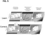
- the exemplary systemcan provide a multi-variant model of performance that is based on additive manufacturing variance.
- the multi-variant modelcan be used to first learn based on the surrogate model and then predict the performance for a given expected operational regime.
- the systemcan look a the sources of manufacturing variance, ⁇ Process X', in the manufacturing process for S/N 1..99 that impacted in-service performance and correct the sources of defect in the process or improve process design, e.g. reduce tolerance.
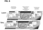
- FIG. 6illustrates an exemplary process including an as-designed, as-manufactured, as-tested, as-operated and as-serviced additive manufacturing-coupled digital twin ecosystem.
- the exemplary systemcan determine a shift in the manufacturing process, ⁇ process X'. This shift may be manifested as a change in flow rate from a nozzle, which may imply that less of a thermal barrier has been applied to a part, resulting in a range of in-production performance, e.g. thermal performance X, depending on operating regime, X1,2,3.
- the exemplary systemcan then match components manufactured with a similar shift in ⁇ Process X', that will have a similar performance to S/N 0000001, X when operated within the operating regime X1.
- the multi-variant modelmay learn and optimize manufacturing accounting for additive manufacturing process variance. For example, the system can determine know the performance of S/N 100..299 operating within a same/similar operating regime is similar and where manufactured within normal 'as process designed' range for process 1..X. We also know S/N 1..99 where manufactured where process 1..2 where within normal 'as process designed' range and 'Process X' had observed a within tolerance shift, e.g. flow rate from a nozzle that may imply less thermal barrier has been applied.
- the systemcan infer that as performance of S/N 1..99, e.g. thermal performance, where same/similar to S/N 100..299 for the same/similar operating regime that the shift in 'Process X' did not influence the performance of S/N 1... 99 within that operating regime and optimize the normal ⁇ as process designed' range to be closer to the shift in ⁇ Process X', e.g. reduce normal range of flow rate at nozzle, with the benefit of reducing manufacturing process or material and improving in service efficiency, e.g. reducing weight.
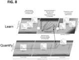
- FIG. 8illustrates an exemplary process including an as-designed, as-manufactured, as-tested, as-operated and as-serviced additive manufacturing-coupled digital twin ecosystem.
- the exemplary systemcan determine a shift in the manufacturing process, ⁇ process X'. This shift may be manifested as a change in flow rate from a nozzle, which may imply that less of a thermal barrier has been applied to a part, resulting in a range of in-production performance, e.g. thermal performance and performance degradation, X, depending on operating regime, X1,2,3.
- the exemplary systemcan then predict the range of useful life, based on predicted in production performance, of components being manufactured by a particular process as the process shift in 'Process X' occurs and use remaining useful life as a quantification of the manufacturing process performance in real time.
- the in-service performance and operational regime, Xmay be determined by operational experience of components in production and/or simulation, e.g. using computational fluid dynamics. This prevents manufacturing stoppage as the system can decide if acceptable production performance or remaining useful life of components are achieved rather than making a decision on meeting ⁇ as process designed' performance.
- Parts that don't meet ⁇ as designed' or ⁇ as process designed' performance'may be applied to specific operating regimes or kitted with components that have a similar remaining useful life or applied to an asset that has a similar remaining operational life to scrappage.
- FIG. 9illustrates an exemplary process including an as-designed, as-manufactured, as-tested, as-operated and as-serviced additive manufacturing-coupled digital twin ecosystem.
- the exemplary systemcan determine a shift in the manufacturing process, 'process X'. This shift may be manifested as a change in flow rate from a nozzle, which may imply that less of a thermal barrier has been applied to a part, resulting in a range of in-production performance, e.g. thermal performance and performance degradation, X, depending on operating regime, X1,2,3.
- the exemplary systemcan infer an in-production performance, e.g. thermal performance, in the range of X.
- a shift in ⁇ Process Y'e.g. a post treatment step such as heat treatment of the thermal barrier, may also result independently in a performance, Y, within acceptable range.
- Creating a model of a manufactured part that quantifies quality as a factor of predicted in production performance, e.g. thermal performance,has the advantage of allowing the prediction of the impact of multiple process influencers, X & Y, on end component performance.
- the in-service performance and operational regime, X & Ymay be determined by operational experience of components in production and/or simulation e.g. using computational fluid dynamics. This has an advantage over destructive testing methods where destructive tests do not independently correlate the aggregate influence of multiple process influencers and cannot reasonably replicate the range of operating regime as can be observed in service and/or simulated. Providing an alternative or parallel qualification process to destructive testing has the benefits of improving safety, reducing warranty claim and reducing scrappage.
- FIG. 10depicts a system 1000 that executes the various operations described above in the context of the exemplary digital twin ecosystem described in the processes described in regards to FIGs. 1-9 .
- the system 1000includes an application-specific processor 1014 configured to perform tasks specific to optimizing a manufacturing process according to the 100.
- the processor 1014has a specific structure imparted by instructions stored in a memory 1002 and/or by instructions 1018 that can be fetched by the processor 1014 from a storage 1020.
- the storage 1020may be co-located with the processor 1014, or it may be located elsewhere and be communicatively coupled to the processor 1014 via a communication interface 1016, for example.
- the system 1000can be a stand-alone programmable system, or it can be a programmable module located in a much larger system.
- the system 1000be part of a distributed system configured to handle the various modules of the process 100 described above.
- the processor 1014may include one or more hardware and/or software components configured to fetch, decode, execute, store, analyze, distribute, evaluate, and/or categorize information.
- the processor 1014can include an input/output module (I/O module 1012) that can be configured to ingest data pertaining to single assets or fleets of assets.
- the processor 1014may include one or more processing devices or cores (not shown). In some embodiments, the processor 1014 may be a plurality of processors, each having either one or more cores.
- the processor 1014can be configured to execute instructions fetched from the memory 1002, i. e. from one of memory block 1004, memory block 1006, memory block 1008, and memory block 1010.
- the storage 1020 and/or the memory 1002may include a volatile or non-volatile, magnetic, semiconductor, tape, optical, removable, non-removable, read-only, random-access, or any type of non-transitory computer-readable computer medium.
- the storage 1020may be configured to log data processed, recorded, or collected during the operation of the processor 1014.
- the datamay be time-stamped, location-stamped, cataloged, indexed, or organized in a variety of ways consistent with data storage practice.
- the storage 1020 and/or the memory 1002may include programs and/or other information that may be used by the processor 1014 to perform tasks consistent with those described herein.
- the processor 1014may be configured by instructions from the memory block 1006, the memory block 1008, and the memory block 1010, to perform real-time updates of a model for a part based on a variety of input sources (e.g. a network and/or a field data module 108).
- the processor 1014may execute the aforementioned instructions from memory blocks, 1006, 1008, and 1010, and output a twin digital model that is based on data from the wide variety of sources described above. Stated generally, from the continuous updates, the processor 1014 may continuously alter the strategy deployment module 110 that includes the model for the part based on the prognostic deployment or degradation models described in the context of FIG. 2-9 .
- the embodimentsprovide the capability to improve time on wing assessments of every part and its sub-assembly based on manufacturing variations, operational conditions and as-serviced data. Furthermore, the embodiments help leverage the sub-system assembly performance using high fidelity design knowledge and improve prediction accuracy as required, and they enable feedback loop that help improve subsequent designs.
Landscapes
- Engineering & Computer Science (AREA)
- Physics & Mathematics (AREA)
- Manufacturing & Machinery (AREA)
- General Physics & Mathematics (AREA)
- Geometry (AREA)
- Theoretical Computer Science (AREA)
- Automation & Control Theory (AREA)
- General Engineering & Computer Science (AREA)
- Computer Hardware Design (AREA)
- Evolutionary Computation (AREA)
- Chemical & Material Sciences (AREA)
- Materials Engineering (AREA)
- Quality & Reliability (AREA)
- Pure & Applied Mathematics (AREA)
- Mathematical Optimization (AREA)
- Mathematical Analysis (AREA)
- Computational Mathematics (AREA)
- Aviation & Aerospace Engineering (AREA)
- Human Computer Interaction (AREA)
- Management, Administration, Business Operations System, And Electronic Commerce (AREA)
- General Factory Administration (AREA)
Description
- In industrial applications the production of a component often includes considering the manufacturing process at the design stage. In such cases, the design and the manufacturing processes are closely related, meaning that design decisions may be influenced by manufacturing constraints or that manufacturing choices may result directly from aspects of the design. Moreover, operational characteristics may be influenced by the manufacturing process' capabilities. For instance, in typical industrial manufacturing processes, parts are produced according to predetermined tolerances because the as-manufactured parts that are deployed in the field may differ from their design specifications (i.e., from the as-designed parts) due to variations inherent to the manufacturing processes.
- With the advent of additive manufacturing technology, another layer of complexity is introduced in the above-noted manufacturing/design/operation ecosystem because of the inherent aspects of additive processes. For example, the additive process may use layers of materials by addition to form the component and pre/post treatment steps such as heating and curing of the layers. Optimizing and validating the additive process requires quantifying and validating the variances in the manufactured components by destructive testing that produces significant quantities of scrap material dependent of the number of tolerances tested.
- Destructive testing alone may validate that a manufactured component meets a specific design tolerance but not consider how the influences of multiple within tolerance variances aggregately affect performance of the component in operation or replicate the range of operating regime that components are exposed to in operation and therefore quantify the fitness of components manufactured by a process for operation. A further risk is that manufactured components with a useful and serviceable life are scrapped as the influence of variances occurring during the manufacturing cycle and the fitness of a component for operation is not quantifiable.
US 2019/049929 A1 describes systems and methods for selecting and distributing process parameters within a fleet of additive manufacturing machines based on sensor data received during manufacturing processes.EP 3 210 697 A1 describes multivariate statistical process control of laser powder bed additive manufacturing.- The embodiments featured herein help solve or mitigate the above-noted issues as well as other issues known in the art. The embodiments featured herein integrate operational characteristics, as they are measured and analyzed during a component's life cycle, with design and manufacturing, including specific aspects of additive manufacturing processes, to create models capable of mitigating performance and manufacturing variances.
- For example, the embodiments provide the ability to link as-built, as-manufactured/assembled, as-designed and as-simulated, as-tested, as-operated and as-serviced components directly through a unique digital integrated process. This digital integrated process includes specific aspects of additive manufacturing processes used at any point during a component's life cycle. In the embodiments featured herein, any hardware component has the capability to reference to its design goal and derive multiple analysis outcomes based on its hardware specifications and operational data. The novel process also provides abstraction of data types from multiple analyses to form an integrated digital twin of hardware components. Furthermore, the novel process provides a framework to increase fidelity and accuracy of a system level digital twin by aggregating sub-system component level digital twin predictions.
- The embodiments featured herein provide a technological infrastructure that yield automated, quantitative, and qualitative assessments of the variability in additive manufacturing processes during the useful life of a part. Thus, in their implementation, the embodiments purposefully and effectively allow the optimization of a manufacture or repair process to make or repair components to a useful lifetime specified by the application's constraints while optimizing the quantity of material needed and destructive testing required for producing or repairing the part using one or more additive manufacturing processes. For example, and not by limitation, in the case of a component requiring a coating, an embodiment as set forth herein can provide a quantitative assessment of the amount of coating material needed to be added onto the component in order to match the performance of the component during repair or manufacturing; the amount of material identified can be optimized against cost constraints.
- Additional features, modes of operations, advantages, and other aspects of various embodiments are described below with reference to the accompanying drawings. It is noted that the present disclosure is not limited to the specific embodiments described herein. These embodiments are presented for illustrative purposes only. Additional embodiments, or modifications of the embodiments disclosed, will be readily apparent to persons skilled in the relevant art(s) based on the teachings provided.
- Illustrative embodiments may take form in various components and arrangements of components. Illustrative embodiments are shown in the accompanying drawings, throughout which like reference numerals may indicate corresponding or similar parts in the various drawings. The drawings are only for purposes of illustrating the embodiments and are not to be construed as limiting the disclosure. Given the following enabling description of the drawings, the novel aspects of the present disclosure should become evident to a person of ordinary skill in the relevant art(s).
FIG. 1 illustrates a process according to an embodiment.FIG. 2 illustrates a digital twin ecosystem according to an embodiment.FIG. 3 illustrates an exemplary process according to an aspect of an embodiment.FIG. 4 illustrates an exemplary process according to an aspect of an embodiment.FIG. 5 illustrates an exemplary process according to an aspect of an embodiment.FIG. 6 illustrates an exemplary process according to an aspect of an embodiment.FIG. 7 illustrates an exemplary process according to an aspect of an embodiment.FIG. 8 illustrates an exemplary process according to an aspect of an embodiment.FIG. 9 illustrates an exemplary process according to an aspect of an embodiment.FIG. 10 illustrates an exemplary system configured to execute one or more aspects of the exemplary processes presented herein.- While the illustrative embodiments are described herein for particular applications, it should be understood that the present disclosure is not limited thereto. Those skilled in the art and with access to the teachings provided herein will recognize additional applications, modifications, and embodiments within the scope thereof and additional fields in which the present disclosure would be of significant utility.
- The embodiments featured herein have several advantages. For example, they can allow one to make accurate assessments on the quality of new make parts relative to their design intent. They provide the ability to mix and match different manufactured components in an engine assembly to achieve a desired integrated engine performance. Furthermore, they improve time-on-wing assessments of every part and sub-assembly based on manufacturing variations, operational conditions, and as-serviced conditions. The embodiments help leverage the sub-system assembly performance using high fidelity design knowledge, and they improve prediction accuracy as required. Furthermore, they enable feedback loops that help improve subsequent designs.
FIG. 1 illustrates anexemplary process 100 in accordance with an exemplary embodiment. Theprocess 100 may be an example process associated with the lifecycle of a part and/or a general manufacturing cycle. While theprocess 100 is described in the context of air plane or jet engine parts, it may extend to the manufacture or in general to the lifecycle of any manufactured component. Theprocess 100 includes amodule 102 that is a product environment spectrum. In other words, themodule 102 can be a database that stores information about instances of the same product as they are used in the field.- For example, the
module 102 may include information about the reliability or failure of a plurality of turbine blades as they are commissioned in a fleet of engines (i.e., in two or more engines). Themodule 102 may be configured to organize, or present upon request from a device communicatively coupled thereto, a product environment spectrum which sorts all of the products of interest in a predetermined order. - For example, the products may be sorted based on their robustness. In one use case, the products may be sorted from more robust (102a) to least robust (102n). Generally, one or more performance criteria may be used to sort these products according to the aforementioned spectrum. In the case of a turbine blade, the products may be sorted according to their thermal robustness performance, which may be measured using one or more field inspection methods.
- The product environment spectrum may be driven by constraints from customers, which may be collected and functionalized (i.e., put in the form of computer instructions) in the
module 104. In other words, the robustness criteria may be dictated by application-specific parameters derived from customers. Similarly, the product environment spectrum may be driven by commercial constraints, which may be functionalized in themodule 106. These constraints (for both themodules 104 and 106) may be updated as the manufacturing process is updated in view of the various sources of information, as shall be further described below. - The customer constraints of the
module 104 may also drive the manufacturing functions of themodule 108, which in turn drive the engineering decisions, as functionalized in themodule 112. Once the engineering decisions are functionalized, they may be used to establish a digital thread that is configured for design. The digital design thread may also be updated from the constraints of the customers (module 104). This thread thus forms a digital twin which can be formed from multiple data sources representing multiple use case. In other words, the digital twin integrates multiple use cases to ensure that manufactured parts are produced according to specific performance data rather than merely producing parts according to predetermined dimensional constraints, as is done in typical manufacturing processes. - Therefore, the digital twin allows for engineering re-design based on fielded part performance. As such, the digital twin allows the optimization of a given manufacturing process in order to differentiate quality of as-manufactured parts to drive targeted performance and business outcomes.
- Generally, the digital design twin may be constructed from a plurality of sources that include new make manufacturing data from the engineering model, a network and an already existing manufacturing model of the part (module 108). Data streams from the network, may include, for example and not by limitation, borescope inspection data from field inspections (either partial or full, or in some implementations, functional or dimensional inspections), on-wing probes that measure data from an engine during flight. Furthermore, generally, the digital twin of a component may include at least one of as-manufactured data, as-tested data, as-designed and as-simulated, as-operated data, and as-serviced data of the component. Furthermore, the digital twin of the component may be based on operational data or nominal operating conditions of the component.
- The
process 100 allows data to be collected continuously. Specifically, the digital design thread is continuously updated to provide a model reflecting actual conditions. This is done with the explicit feedback loops of theprocess 100, which ensure that new designs can be manufactured based the wide variety of sources of information mentioned above. As such, theprocess 100 provides the ability to better predict the durability of a part, as any manufactured part would have been manufactured based on conditions reflecting design, usage, servicing, etc. - In sum, the
process 100 integrates and automates the various aspect of the lifecycle of the part to provide an optimized manufacturing process at an enterprise level. Theprocess 100 further includes a score inspection module, which may be updated with field inspection analytics, in order to further augment the engineering model. Theprocess 100 can be further understood in the context ofFIG. 2 , which depicts thedigital twin ecosystem 200 featuring exemplary relationships between the as-designed, as manufactured, as-tested, as-serviced, and as-operated aspects of a specified part during its life cycle. Thedigital twin ecosystem 200 includes aspects which accounts for additive manufacturing process variance, as shall be described in further detail below. FIG. 3 illustrates an exemplary process including an as-designed, as-manufactured, as-tested, as-operated and as-serviced additive manufacturing-coupled digital twin ecosystem.FIG. 3 depicts an operating spectrum and an environmental spectrum. These spectra form the `operational regime', which denotes a gradation in operation (e.g. from light to hard of the specified part) as well as an environment in which the specified part operates (e.g., from benign to harsh). An operational regime is a factor of the environment and the operation. The performance of a component is thus quantifiable and comparable with similar components within similar operating regimes. The performance of a part is an indicator of remaining useful life within a range of operating regimes.- The process performance is a spectrum from 'As process designed' performance and tolerance to out of tolerance. Thus, outside of the `as process designed' performance may imply more or less processing or material applied to a component, e.g. flow rate and nozzle indicating minimum thickness of coating applied to component. In the embodiment, of
FIG. 3 , an inference model may include by example and without limitation, a machine-learning framework such as classifier ensemble, or a neural network. This inference model may be used to build multi-variant distributions of component performance relative to expected performance by leveraging the various data sources from the surrogate model described in the context of theprocess 100. FIG. 4 illustrates an exemplary process including an as-designed, as-manufactured, as-tested, as-operated and as-serviced additive manufacturing-coupled digital twin ecosystem. InFIG. 4 , when a shift is observed in a manufacturing process by an exemplary system (seeFIG. 10 ) in 'Process X', the exemplary system can determine that a similar shift was observed during manufacture of parts with serial number (S/N) 1..3 and the operational and environmental regimes they experienced and the performance of those components. For instance, the exemplary system may be configured to determine the thermal performance and predict the range of useful life based on expected performance of the new component X.- The exemplary system may then suggest a suitable operating regime for that component, X1,2,3 to achieve best in production performance; this reduces scrappage and warranty claim as we do not base scrappage on meeting an `as designed' or `as process designed' specification and warranty or price the component as per it's expected useful life or for a particular operating regime. The in-service performance and operational regime, X, may be determined by operational experience of components in production and/or simulation e.g. using computational fluid dynamics.
- The exemplary system can then kit a manufactured component with parts that are predicted to achieve a similar in-service performance and remaining useful life within a similar operating regime. As such, the exemplary system can provide a multi-variant model of performance that is based on additive manufacturing variance. As shown in
FIG. 5 , the multi-variant model can be used to first learn based on the surrogate model and then predict the performance for a given expected operational regime. Specifically, if we know the performance of S/N 100..299 operating within a same/similar operating regime is similar and S/N 1..99 operating under the same/similar operating regime are different, the system can look a the sources of manufacturing variance, `Process X', in the manufacturing process for S/N 1..99 that impacted in-service performance and correct the sources of defect in the process or improve process design, e.g. reduce tolerance. FIG. 6 illustrates an exemplary process including an as-designed, as-manufactured, as-tested, as-operated and as-serviced additive manufacturing-coupled digital twin ecosystem. For instance, the exemplary system can determine a shift in the manufacturing process, `process X'. This shift may be manifested as a change in flow rate from a nozzle, which may imply that less of a thermal barrier has been applied to a part, resulting in a range of in-production performance, e.g. thermal performance X, depending on operating regime, X1,2,3.- The exemplary system can then match components manufactured with a similar shift in `Process X', that will have a similar performance to S/N 0000001, X when operated within the operating regime X1. As such, as shown in
FIG. 7 , the multi-variant model may learn and optimize manufacturing accounting for additive manufacturing process variance. For example, the system can determine know the performance of S/N 100..299 operating within a same/similar operating regime is similar and where manufactured within normal 'as process designed' range forprocess 1..X. We also know S/N 1..99 where manufactured whereprocess 1..2 where within normal 'as process designed' range and 'Process X' had observed a within tolerance shift, e.g. flow rate from a nozzle that may imply less thermal barrier has been applied. - The system can infer that as performance of S/
N 1..99, e.g. thermal performance, where same/similar to S/N 100..299 for the same/similar operating regime that the shift in 'Process X' did not influence the performance of S/N 1... 99 within that operating regime and optimize the normal `as process designed' range to be closer to the shift in `Process X', e.g. reduce normal range of flow rate at nozzle, with the benefit of reducing manufacturing process or material and improving in service efficiency, e.g. reducing weight. FIG. 8 illustrates an exemplary process including an as-designed, as-manufactured, as-tested, as-operated and as-serviced additive manufacturing-coupled digital twin ecosystem. InFIG. 8 , the exemplary system can determine a shift in the manufacturing process, `process X'. This shift may be manifested as a change in flow rate from a nozzle, which may imply that less of a thermal barrier has been applied to a part, resulting in a range of in-production performance, e.g. thermal performance and performance degradation, X, depending on operating regime, X1,2,3.- The exemplary system can then predict the range of useful life, based on predicted in production performance, of components being manufactured by a particular process as the process shift in 'Process X' occurs and use remaining useful life as a quantification of the manufacturing process performance in real time. The in-service performance and operational regime, X, may be determined by operational experience of components in production and/or simulation, e.g. using computational fluid dynamics. This prevents manufacturing stoppage as the system can decide if acceptable production performance or remaining useful life of components are achieved rather than making a decision on meeting `as process designed' performance.
- Parts that don't meet `as designed' or `as process designed' performance' may be applied to specific operating regimes or kitted with components that have a similar remaining useful life or applied to an asset that has a similar remaining operational life to scrappage.
FIG. 9 illustrates an exemplary process including an as-designed, as-manufactured, as-tested, as-operated and as-serviced additive manufacturing-coupled digital twin ecosystem. InFIG. 9 , the exemplary system can determine a shift in the manufacturing process, 'process X'. This shift may be manifested as a change in flow rate from a nozzle, which may imply that less of a thermal barrier has been applied to a part, resulting in a range of in-production performance, e.g. thermal performance and performance degradation, X, depending on operating regime, X1,2,3.- The exemplary system can infer an in-production performance, e.g. thermal performance, in the range of X. A shift in `Process Y', e.g. a post treatment step such as heat treatment of the thermal barrier, may also result independently in a performance, Y, within acceptable range. However, the combined influence of X + Y may be greater than the influence of X and Y independently where the resulting performance of X + Y = Z in the range of X1Y1, X2Y2, X3Y3.
- Creating a model of a manufactured part that quantifies quality as a factor of predicted in production performance, e.g. thermal performance, has the advantage of allowing the prediction of the impact of multiple process influencers, X & Y, on end component performance.
- The in-service performance and operational regime, X & Y, may be determined by operational experience of components in production and/or simulation e.g. using computational fluid dynamics. This has an advantage over destructive testing methods where destructive tests do not independently correlate the aggregate influence of multiple process influencers and cannot reasonably replicate the range of operating regime as can be observed in service and/or simulated. Providing an alternative or parallel qualification process to destructive testing has the benefits of improving safety, reducing warranty claim and reducing scrappage.
FIG. 10 depicts asystem 1000 that executes the various operations described above in the context of the exemplary digital twin ecosystem described in the processes described in regards toFIGs. 1-9 . Thesystem 1000 includes an application-specific processor 1014 configured to perform tasks specific to optimizing a manufacturing process according to the 100. Theprocessor 1014 has a specific structure imparted by instructions stored in amemory 1002 and/or byinstructions 1018 that can be fetched by theprocessor 1014 from astorage 1020. Thestorage 1020 may be co-located with theprocessor 1014, or it may be located elsewhere and be communicatively coupled to theprocessor 1014 via acommunication interface 1016, for example.- The
system 1000 can be a stand-alone programmable system, or it can be a programmable module located in a much larger system. For example, thesystem 1000 be part of a distributed system configured to handle the various modules of theprocess 100 described above. Theprocessor 1014 may include one or more hardware and/or software components configured to fetch, decode, execute, store, analyze, distribute, evaluate, and/or categorize information. - The
processor 1014 can include an input/output module (I/O module 1012) that can be configured to ingest data pertaining to single assets or fleets of assets. Theprocessor 1014 may include one or more processing devices or cores (not shown). In some embodiments, theprocessor 1014 may be a plurality of processors, each having either one or more cores. Theprocessor 1014 can be configured to execute instructions fetched from thememory 1002, i. e. from one ofmemory block 1004,memory block 1006,memory block 1008, andmemory block 1010. - Furthermore, without loss of generality, the
storage 1020 and/or thememory 1002 may include a volatile or non-volatile, magnetic, semiconductor, tape, optical, removable, non-removable, read-only, random-access, or any type of non-transitory computer-readable computer medium. Thestorage 1020 may be configured to log data processed, recorded, or collected during the operation of theprocessor 1014. The data may be time-stamped, location-stamped, cataloged, indexed, or organized in a variety of ways consistent with data storage practice. Thestorage 1020 and/or thememory 1002 may include programs and/or other information that may be used by theprocessor 1014 to perform tasks consistent with those described herein. - For example, the
processor 1014 may be configured by instructions from thememory block 1006, thememory block 1008, and thememory block 1010, to perform real-time updates of a model for a part based on a variety of input sources (e.g. a network and/or a field data module 108). Theprocessor 1014 may execute the aforementioned instructions from memory blocks, 1006, 1008, and 1010, and output a twin digital model that is based on data from the wide variety of sources described above. Stated generally, from the continuous updates, theprocessor 1014 may continuously alter thestrategy deployment module 110 that includes the model for the part based on the prognostic deployment or degradation models described in the context ofFIG. 2-9 . - The embodiments provide the capability to improve time on wing assessments of every part and its sub-assembly based on manufacturing variations, operational conditions and as-serviced data. Furthermore, the embodiments help leverage the sub-system assembly performance using high fidelity design knowledge and improve prediction accuracy as required, and they enable feedback loop that help improve subsequent designs.
- Those skilled in the relevant art(s) will appreciate that various adaptations and modifications of the embodiments described above can be configured without departing from the scope of the disclosure. Therefore, it is to be understood that, within the scope of the appended claims, the disclosure may be practiced other than as specifically described herein.
Claims (15)
- A method for making or repairing a specified part, the method including:
creating an optimized process to make or repair the specified part, the creating including:receiving data from a plurality of sources, the data including as-designed, as-manufactured, as-simulated, as-operated, as-inspected, and as-tested data relative to one or more parts similar to the specified part;updating, in real time, a surrogate model (102) corresponding with a physics-based model of the specified part, wherein the surrogate model forms a digital twin of the specified part;generating a multi-variant distribution including component performance and manufacturing variance, the manufacturing variance being associated with at least one of an additive manufacturing process step and a reductive manufacturing process step and the component performance comprising in-service performance and operational regime determined based on operational experience or simulation of the one or more parts similar to the specified part;comparing a performance from the multi-variant distribution with an expected performance of the specified part based on the surrogate model; andexecuting, based on the digital twin, the optimized process to either repair or make the specified part. - The method as set forth in Claim 1, wherein the comparing is based on data including at least one of component design data, additive or reductive process design data or test data.
- The method as set forth in Claim 1 or 2, further including determining a useful life of the specified part based on the multi-variant distribution.
- The method as set forth in any of Claims 1 to 3, further including optimizing the expected performance of the specified part based on the multi-variant distribution, the optimizing including reducing one or more sources of variance in the optimized manufacturing process.
- The method as set forth in Claim 4, wherein the one or more sources of variance are from additive or reductive manufacturing process operations.
- The method as set forth in any of Claims 1 to 5, further including optimizing at least one of an additive and a reductive manufacturing process operation to achieve a desired operational performance of the specified part.
- The method as set forth in any of Claims 1 to 6, further including reducing material utilization based on the multi-variant distribution and a targeted performance for the specified part.
- The method as set forth in any of Claims 1 to 7, further including determining one or more criteria for operability or durability of the specified part based on the comparing.
- The method as set forth in Claim 8, wherein the one or more criteria includes a forecast of a useful life of the specified part.
- The method as set forth in any of Claims 1 to 9, wherein the at least one of the additive manufacturing process step and the reductive manufacturing process step include multiple additive/reductive process steps and/or post treatments steps.
- A system configured to either manufacture or repair a specified part, the system comprising:a processor;a memory including instructions that, when executed by the processor, cause the processor to perform operations including:
creating an optimized process to make or repair the specified part, the creating including:receiving data from a plurality of sources, the data including as-designed, as-manufactured, as-simulated, as-operated, as-inspected, and as-tested data relative to one or more parts similar to the specified part;updating, in real time, a surrogate model (102) corresponding with a physics-based model of the specified part, wherein the surrogate model forms a digital twin of the specified part;generating a multi-variant distribution including component performance and manufacturing variance, the manufacturing variance being associated with at least one of an additive manufacturing process step and a reductive manufacturing process step and the component performance comprising in-service performance and operational regime determined based on operational experience or simulation of the one or more parts similar to the specified part;comparing a performance from the multi-variant distribution with an expected performance of the specified part based on the surrogate model; andexecuting, based on the digital twin, the optimized process to either repair or make the specified part. - The system as set forth in Claim 11, wherein the comparing is based on data including at least one of component design data, additive or reductive process design data or test data.
- The system as set forth in Claim 11 or 12, wherein the operations further include determining a useful life of the specified part based on the multi-variant distribution.
- The system as set forth in any of Claims 11 to 13, wherein the operations further include optimizing the expected performance of the specified part based on the multi-variant distribution, the optimizing including reducing one or more sources of variance in the optimized manufacturing process.
- The system as set forth in any of Claims 11 to 14, wherein the operations further include optimizing at least one of an additive and a reductive manufacturing process operation to achieve a desired operational performance of the specified part.
Applications Claiming Priority (2)
| Application Number | Priority Date | Filing Date | Title |
|---|---|---|---|
| US201962862014P | 2019-06-14 | 2019-06-14 | |
| US201962862016P | 2019-06-14 | 2019-06-14 |
Publications (2)
| Publication Number | Publication Date |
|---|---|
| EP3751370A1 EP3751370A1 (en) | 2020-12-16 |
| EP3751370B1true EP3751370B1 (en) | 2024-07-24 |
Family
ID=71094250
Family Applications (1)
| Application Number | Title | Priority Date | Filing Date |
|---|---|---|---|
| EP20179853.5AActiveEP3751370B1 (en) | 2019-06-14 | 2020-06-12 | Additive manufacturing-coupled digital twin ecosystem based on multi-variant distribution model of performance |
Country Status (3)
| Country | Link |
|---|---|
| US (1) | US11567481B2 (en) |
| EP (1) | EP3751370B1 (en) |
| CN (1) | CN112084569B (en) |
Families Citing this family (13)
| Publication number | Priority date | Publication date | Assignee | Title |
|---|---|---|---|---|
| EP3827316A1 (en)* | 2018-08-23 | 2021-06-02 | Siemens Aktiengesellschaft | Automatic setup of digital twins for industrial controllers |
| EP3751368B1 (en) | 2019-06-14 | 2023-09-27 | General Electric Company | Additive manufacturing-coupled digital twin ecosystem based on a surrogate model of measurement |
| EP3751370B1 (en) | 2019-06-14 | 2024-07-24 | General Electric Company | Additive manufacturing-coupled digital twin ecosystem based on multi-variant distribution model of performance |
| US11339643B2 (en)* | 2020-08-13 | 2022-05-24 | Weatherford Technology Holdings, Llc | Pumping unit inspection sensor assembly, system and method |
| US20230297904A1 (en) | 2020-12-18 | 2023-09-21 | Strong Force Vcn Portfolio 2019, Llc | Clustering-Based Intelligence Service Layer for Robotic Fleet Maintenance |
| US12045739B2 (en)* | 2020-12-28 | 2024-07-23 | EMC IP Holding Company LLC | Best outcome AIOps modeling with data confidence fabrics |
| EP4094867A1 (en)* | 2021-05-26 | 2022-11-30 | Siemens Aktiengesellschaft | Method for additive manufacture of a component |
| US12130608B2 (en)* | 2021-12-10 | 2024-10-29 | International Business Machines Corporation | Determining optimal of additive manufacturing and/or three dimensional printing processes |
| CN114564880B (en)* | 2022-01-26 | 2022-11-25 | 南京理工大学 | A digital twin module construction method for additive manufacturing process |
| EP4273651A1 (en) | 2022-05-05 | 2023-11-08 | Seepex GmbH | Method for providing a replacement part |
| US20240095684A1 (en)* | 2022-09-16 | 2024-03-21 | Dell Products L.P. | Information Technology Ecosystem Environment for Performing an IT Component Sustainability Servicing Operation |
| CN115755796B (en)* | 2022-11-08 | 2025-05-16 | 东风柳州汽车有限公司 | Method, device, equipment and storage medium for improving the painting topcoat rhythm |
| CN115544819B (en)* | 2022-12-06 | 2023-04-18 | 网思科技股份有限公司 | Digital twin modeling method, system and readable storage medium for maintenance station |
Citations (1)
| Publication number | Priority date | Publication date | Assignee | Title |
|---|---|---|---|---|
| US20190004079A1 (en)* | 2017-06-30 | 2019-01-03 | General Electric Company | Systems and method for advanced additive manufacturing |
Family Cites Families (91)
| Publication number | Priority date | Publication date | Assignee | Title |
|---|---|---|---|---|
| US6067486A (en) | 1999-02-01 | 2000-05-23 | General Electric Company | Method and system for planning repair of an aircraft engine |
| US6394646B1 (en) | 1999-04-16 | 2002-05-28 | General Electric Company | Method and apparatus for quantitative nondestructive evaluation of metal airfoils using high resolution transient thermography |
| US6775647B1 (en) | 2000-03-02 | 2004-08-10 | American Technology & Services, Inc. | Method and system for estimating manufacturing costs |
| JP4743944B2 (en) | 2000-08-25 | 2011-08-10 | 鎮男 角田 | Simulation model creation method and system and storage medium |
| US7457762B2 (en) | 2001-09-04 | 2008-11-25 | Accenture Global Services Gmbh | Optimization of management of maintenance, repair and overhaul of equipment in a specified time window |
| US7016825B1 (en) | 2000-10-26 | 2006-03-21 | Vextec Corporation | Method and apparatus for predicting the failure of a component |
| US8266066B1 (en) | 2001-09-04 | 2012-09-11 | Accenture Global Services Limited | Maintenance, repair and overhaul management |
| US6745153B2 (en) | 2001-11-27 | 2004-06-01 | General Motors Corporation | Data collection and manipulation apparatus and method |
| GB0209543D0 (en) | 2002-04-26 | 2002-06-05 | Rolls Royce Plc | The automation and optimisation of the design of a component |
| US10618168B2 (en) | 2016-05-13 | 2020-04-14 | General Electric Company | Robot system path planning for asset health management |
| US7725206B2 (en) | 2003-11-12 | 2010-05-25 | The Boeing Company | System and method for manufacturing and after-market support using as-built data |
| US7063991B1 (en) | 2004-07-28 | 2006-06-20 | Advanced Micro Devices, Inc. | Methods of determining characteristics of doped regions on device wafers, and system for accomplishing same |
| US20060129301A1 (en) | 2004-12-14 | 2006-06-15 | General Electric Company | Method and apparatus for assessing gas turbine acceleration capability |
| JP4652042B2 (en) | 2004-12-24 | 2011-03-16 | ヒタチグローバルストレージテクノロジーズネザーランドビーブイ | Production planning method and production planning system in a production line having a rework process |
| US8423430B2 (en) | 2005-11-16 | 2013-04-16 | The Boeing Company | Integrated materials management for commercial aircraft fleets including access to real-time on-board systems information |
| US7761200B2 (en) | 2005-11-16 | 2010-07-20 | The Boeing Company | Centralized management of maintenance and materials for commercial aircraft fleets with access to real-time information |
| US20080103788A1 (en) | 2006-10-31 | 2008-05-01 | The Boeing Company | System, method and program product for predicting commercial off-the-shelf equipment reliability |
| US8209839B1 (en) | 2006-11-28 | 2012-07-03 | Florida Turbine Technologies, Inc. | Process for re-designing a distressed component used under thermal and structural loading |
| US7966883B2 (en) | 2006-12-06 | 2011-06-28 | Lockheed Martin Corporation | Non-destructive inspection using laser-ultrasound and infrared thermography |
| US8340854B2 (en) | 2006-12-19 | 2012-12-25 | The Boeing Company | Methods and systems for centrally managed maintenance program for aircraft fleets |
| US7549789B2 (en) | 2007-06-20 | 2009-06-23 | General Electric Company | Method and apparatus for thermographic nondestructive evaluation of an object |
| JP2009015460A (en) | 2007-07-02 | 2009-01-22 | Toyota Motor Corp | Model transmission apparatus and model transmission method |
| US20090030752A1 (en) | 2007-07-27 | 2009-01-29 | General Electric Company | Fleet anomaly detection method |
| US20090297336A1 (en) | 2007-08-21 | 2009-12-03 | General Electric Company | Online systems and methods for thermal inspection of parts |
| US8116990B2 (en) | 2007-10-19 | 2012-02-14 | Ashok Koul | Method and system for real-time prognosis analysis and usage based residual life assessment of turbine engine components and display |
| FR2945136A1 (en) | 2009-05-04 | 2010-11-05 | Turbomeca | DATA STRUCTURE OF A NOMENCLATURE |
| US8306791B2 (en) | 2009-12-21 | 2012-11-06 | United Technologies Corporation | Method and system for modeling the performance of a gas turbine engine |
| US8606557B2 (en) | 2010-02-02 | 2013-12-10 | International Business Machines Corporation | Table lookup method for physics based models for SPICE-like simulators |
| KR20110094987A (en) | 2010-02-18 | 2011-08-24 | 삼성전자주식회사 | Product screening method based on quantitative assessment of potential defects |
| US9122821B2 (en) | 2010-05-25 | 2015-09-01 | Siemens Products Lifecycle Management Software Inc. | Method and system for simulation of automated processes |
| US8692887B2 (en) | 2010-08-27 | 2014-04-08 | General Electric Company | Thermal imaging method and apparatus for evaluating coatings |
| US9146652B1 (en) | 2011-08-31 | 2015-09-29 | Comsol Ab | System and method for creating user interfaces in a multiphysics modeling system |
| CA2848384A1 (en) | 2011-09-13 | 2013-03-21 | Rolls-Royce Corporation | Development tool |
| US9575487B2 (en) | 2012-11-12 | 2017-02-21 | Wasber Industries LLC | Computer program, method, and system for optimized kit nesting |
| US10860013B2 (en) | 2012-11-19 | 2020-12-08 | Abb Power Grids Switzerland Ag | Power system equipment design flaw identification |
| US9817452B2 (en) | 2013-01-11 | 2017-11-14 | The Boeing Company | System and method for thermal management guidance |
| GB2541575B (en) | 2014-06-04 | 2021-06-09 | Mitsubishi Power Ltd | Additive manufacturing system, modeling-data providing apparatus and providing method |
| US10466681B1 (en) | 2014-09-02 | 2019-11-05 | Machine Research Corporation | Systems and methods for machining knowledge reuse |
| US10139311B2 (en) | 2014-09-26 | 2018-11-27 | Palo Alto Research Center Incorporated | Computer-implemented method and system for machine tool damage assessment, prediction, and planning in manufacturing shop floor |
| EP3292519A1 (en) | 2015-05-07 | 2018-03-14 | Siemens Corporation | Data-feedback loop from product lifecycle into design and manufacturing |
| US10060824B2 (en) | 2015-10-13 | 2018-08-28 | Hyperloop Technologies, Inc. | Adjustable variable atmospheric condition testing apparatus and method |
| US20170124448A1 (en) | 2015-10-30 | 2017-05-04 | Northrop Grumman Systems Corporation | Concurrent uncertainty management system |
| US9962956B2 (en)* | 2015-11-05 | 2018-05-08 | Northrop Grumman Systems Corporation | System and method for onboard data tracking |
| CA3008667A1 (en) | 2015-12-16 | 2017-06-22 | Desktop Metal, Inc. | Methods and systems for additive manufacturing |
| US10831180B2 (en)* | 2016-02-25 | 2020-11-10 | General Electric Company | Multivariate statistical process control of laser powder bed additive manufacturing |
| KR20180118692A (en)* | 2016-03-03 | 2018-10-31 | 데스크탑 메탈, 인크. | Lamination of metal build materials |
| US20170286572A1 (en) | 2016-03-31 | 2017-10-05 | General Electric Company | Digital twin of twinned physical system |
| US10318903B2 (en) | 2016-05-06 | 2019-06-11 | General Electric Company | Constrained cash computing system to optimally schedule aircraft repair capacity with closed loop dynamic physical state and asset utilization attainment control |
| US20190196449A1 (en) | 2016-05-06 | 2019-06-27 | Yunbo ZHANG | Determining manufacturable models |
| US10417614B2 (en) | 2016-05-06 | 2019-09-17 | General Electric Company | Controlling aircraft operations and aircraft engine components assignment |
| EP3244353A1 (en) | 2016-05-10 | 2017-11-15 | Siemens Aktiengesellschaft | Production module for performing a production function for a product |
| CN109313440A (en) | 2016-05-16 | 2019-02-05 | 伟尔矿物澳大利亚私人有限公司 | Machine monitors |
| JP7107852B2 (en) | 2016-05-24 | 2022-07-27 | ダイバージェント テクノロジーズ, インコーポレイテッド | Systems and methods for additive manufacturing of transportation structures |
| US10152784B2 (en) | 2016-06-30 | 2018-12-11 | General Electric Company | System and method for detecting defects in a component |
| US20180027190A1 (en) | 2016-07-21 | 2018-01-25 | General Electric Company | Infrared non-destructive evaluation of cooling holes using evaporative membrane |
| US10404569B2 (en) | 2016-08-22 | 2019-09-03 | General Electric Company | Internet of things associate |
| US10268182B2 (en) | 2016-09-28 | 2019-04-23 | Mrl Materials Resources Llc | Detection of the integrity of additively manufactured parts |
| US10223846B2 (en) | 2016-10-10 | 2019-03-05 | General Electric Company | Aerial vehicle engine health prediction |
| EP3529675B1 (en) | 2016-10-21 | 2022-12-14 | Trumpf Werkzeugmaschinen GmbH + Co. KG | Interior person-tracking-based control of manufacturing in the metalworking industry |
| US20180137219A1 (en) | 2016-11-14 | 2018-05-17 | General Electric Company | Feature selection and feature synthesis methods for predictive modeling in a twinned physical system |
| WO2018183275A1 (en) | 2017-03-27 | 2018-10-04 | Siemens Aktiengesellschaft | System for automated generative design synthesis using data from design tools and knowledge from a digital twin graph |
| US20180292815A1 (en) | 2017-04-05 | 2018-10-11 | General Electric Company | Systems and methods for checking computer-aided design models |
| EP3615245A1 (en)* | 2017-04-24 | 2020-03-04 | Desktop Metal, Inc. | Three-dimensional (3d) printing using measured processing effects with feedback to processing parameters |
| US11027535B2 (en) | 2017-06-30 | 2021-06-08 | General Electric Company | Systems and method for advanced additive manufacturing |
| US20190001658A1 (en)* | 2017-06-30 | 2019-01-03 | General Electric Company | Systems and method for advanced additive manufacturing |
| US10747202B2 (en)* | 2017-06-30 | 2020-08-18 | General Electric Company | Systems and method for advanced additive manufacturing |
| US10725459B2 (en)* | 2017-08-08 | 2020-07-28 | General Electric Company | Identifying and distributing optimal machine parameters within a fleet of additive manufacturing machines |
| WO2019055576A1 (en) | 2017-09-12 | 2019-03-21 | Arconic Inc. | Systems and methods for performing calibration in additive manufacture |
| WO2019055538A1 (en) | 2017-09-12 | 2019-03-21 | Arconic Inc. | Systems and methods for additive manufacture |
| WO2019067471A2 (en)* | 2017-09-27 | 2019-04-04 | Arconic Inc. | Systems and methods for conducting in-situ monitoring in additive manufacture |
| WO2019070644A2 (en) | 2017-10-02 | 2019-04-11 | Arconic Inc. | Systems and methods for utilizing multicriteria optimization in additive manufacture |
| CN107638279A (en) | 2017-10-23 | 2018-01-30 | 杭州哈慈实业有限公司 | A kind of automatic pyromagnetic moxibustion pot and its control method |
| WO2019103773A1 (en)* | 2017-11-27 | 2019-05-31 | Siemens Aktiengesellschaft | Automatically identifying alternative functional capabilities of designed artifacts |
| US12019963B2 (en)* | 2018-02-07 | 2024-06-25 | Incucomm, Inc. | Operations and maintenance systems and methods employing sensor-less digital twins |
| US11364684B2 (en) | 2018-02-13 | 2022-06-21 | Hewlett-Packard Development Company, L.P. | Part identifier for use at manufacturing facility |
| CN108919760B (en)* | 2018-07-05 | 2020-01-24 | 长安大学 | A dynamic linkage control method for autonomous production process of intelligent workshop based on digital twin |
| EP3599080A1 (en) | 2018-07-27 | 2020-01-29 | Concept Laser GmbH | Apparatus for additively manufacturing three-dimensional objects |
| US11783099B2 (en) | 2018-08-01 | 2023-10-10 | General Electric Company | Autonomous surrogate model creation platform |
| CN109270899B (en)* | 2018-09-03 | 2020-12-25 | 江苏科技大学 | Digital twin-based marine diesel engine heavy part manufacturing process control method |
| CN109615113B (en)* | 2018-11-19 | 2022-12-30 | 江苏科技大学 | Digital twin-based marine diesel engine heavy part machining quality prediction method |
| US10728536B2 (en) | 2018-11-21 | 2020-07-28 | Ubicquia Iq Llc | System and method for camera commissioning beacons |
| US10935964B2 (en)* | 2018-12-04 | 2021-03-02 | General Electric Company | Method and system for optimizing a manufacturing process based on a surrogate model of a part |
| US10928809B2 (en)* | 2018-12-04 | 2021-02-23 | General Electric Company | As-designed, as-manufactured, as-tested, as-operated and as-serviced coupled digital twin ecosystem |
| US20200175438A1 (en) | 2018-12-04 | 2020-06-04 | General Electric Company | Method and system for strategic deployment of components |
| US11280751B2 (en)* | 2018-12-04 | 2022-03-22 | General Electric Company | System and method for optimizing a manufacturing process based on an inspection of a component |
| CN109340062B (en)* | 2018-12-18 | 2020-01-31 | 国电联合动力技术有限公司 | digital twin type fatigue damage prediction method for low wind speed wind turbine generator |
| US11209345B1 (en) | 2019-05-29 | 2021-12-28 | Northrop Grumman Systems Corporation | Automatic prognostic qualification of manufacturing products |
| EP3751369B1 (en)* | 2019-06-14 | 2024-07-24 | General Electric Company | Additive manufacturing-coupled digital twin ecosystem |
| EP3751370B1 (en) | 2019-06-14 | 2024-07-24 | General Electric Company | Additive manufacturing-coupled digital twin ecosystem based on multi-variant distribution model of performance |
| EP3751368B1 (en)* | 2019-06-14 | 2023-09-27 | General Electric Company | Additive manufacturing-coupled digital twin ecosystem based on a surrogate model of measurement |
| DE102020115571A1 (en)* | 2019-06-14 | 2020-12-17 | General Electric Company | Digital double eco-system coupled with additive manufacturing as designed, as manufactured, as tested, as operated, as checked and as maintained |
- 2020
- 2020-06-12EPEP20179853.5Apatent/EP3751370B1/enactiveActive
- 2020-06-15CNCN202010543203.0Apatent/CN112084569B/enactiveActive
- 2020-06-15USUS16/901,205patent/US11567481B2/enactiveActive
Patent Citations (1)
| Publication number | Priority date | Publication date | Assignee | Title |
|---|---|---|---|---|
| US20190004079A1 (en)* | 2017-06-30 | 2019-01-03 | General Electric Company | Systems and method for advanced additive manufacturing |
Also Published As
| Publication number | Publication date |
|---|---|
| CN112084569B (en) | 2024-05-10 |
| US11567481B2 (en) | 2023-01-31 |
| CN112084569A (en) | 2020-12-15 |
| US20200393822A1 (en) | 2020-12-17 |
| EP3751370A1 (en) | 2020-12-16 |
Similar Documents
| Publication | Publication Date | Title |
|---|---|---|
| EP3751370B1 (en) | Additive manufacturing-coupled digital twin ecosystem based on multi-variant distribution model of performance | |
| EP3751368B1 (en) | Additive manufacturing-coupled digital twin ecosystem based on a surrogate model of measurement | |
| US20230038395A1 (en) | Systems and methods for part deployment | |
| EP3751369B1 (en) | Additive manufacturing-coupled digital twin ecosystem | |
| Westerweel et al. | Traditional or additive manufacturing? Assessing component design options through lifecycle cost analysis | |
| CN111274652B (en) | Method and system for manufacturing new parts according to optimized manufacturing process | |
| EP3483798A1 (en) | Methods and apparatus to generate an optimized workscope | |
| US11280751B2 (en) | System and method for optimizing a manufacturing process based on an inspection of a component | |
| US20170176985A1 (en) | Method for predicting end of line quality of assembled product | |
| Amer et al. | Optimizing order fulfillment using design for six sigma and fuzzy logic | |
| Friederich et al. | A framework for validating data-driven discrete-event simulation models of cyber-physical production systems | |
| Zio et al. | A snapshot on maintenance modeling and applications | |
| Lamoureux et al. | Improving aircraft engines prognostics and health management via anticipated model-based validation of health indicators | |
| Engelhardt et al. | Uncertainty-mode-and effects-analysis–an approach to analyze and estimate uncertainty in the product life cycle | |
| Kabashkin et al. | Decision-Making Model for Life Cycle Management of Aircraft Components. | |
| Elia et al. | Sustainable maintenance and digital twin technology: a test case for evaluating integration potentialities | |
| Lawand et al. | A lifecycle cost-driven system dynamics approach for considering additive re-manufacturing or repair in aero-engine component design | |
| Hilton | Visualization techniques for simulation-based dependent failure analysis | |
| Thomsen et al. | Component lifing decisions and maintenance strategies in the context of aeroengine product-service systems design | |
| Krehmer et al. | Avoidance of unnecessary design iterations by monitoring the product s degree of maturity | |
| Koch et al. | Capacitated multi-item lot sizing problem with client prioritization in tire industry | |
| Nakashima et al. | Studies on project management models for embedded software development projects | |
| Nurmi | Mechanical availability and costs analysis of a Screw Conveyor using Run-to-Failure and Preventive Maintenance models | |
| Peritore | Requirements for a web-based tool for operational risk management | |
| Jiang | Engineering activities in product life cycle |
Legal Events
| Date | Code | Title | Description |
|---|---|---|---|
| PUAI | Public reference made under article 153(3) epc to a published international application that has entered the european phase | Free format text:ORIGINAL CODE: 0009012 | |
| STAA | Information on the status of an ep patent application or granted ep patent | Free format text:STATUS: THE APPLICATION HAS BEEN PUBLISHED | |
| AK | Designated contracting states | Kind code of ref document:A1 Designated state(s):AL AT BE BG CH CY CZ DE DK EE ES FI FR GB GR HR HU IE IS IT LI LT LU LV MC MK MT NL NO PL PT RO RS SE SI SK SM TR | |
| AX | Request for extension of the european patent | Extension state:BA ME | |
| STAA | Information on the status of an ep patent application or granted ep patent | Free format text:STATUS: REQUEST FOR EXAMINATION WAS MADE | |
| 17P | Request for examination filed | Effective date:20210325 | |
| RBV | Designated contracting states (corrected) | Designated state(s):AL AT BE BG CH CY CZ DE DK EE ES FI FR GB GR HR HU IE IS IT LI LT LU LV MC MK MT NL NO PL PT RO RS SE SI SK SM TR | |
| STAA | Information on the status of an ep patent application or granted ep patent | Free format text:STATUS: EXAMINATION IS IN PROGRESS | |
| 17Q | First examination report despatched | Effective date:20220223 | |
| GRAP | Despatch of communication of intention to grant a patent | Free format text:ORIGINAL CODE: EPIDOSNIGR1 | |
| STAA | Information on the status of an ep patent application or granted ep patent | Free format text:STATUS: GRANT OF PATENT IS INTENDED | |
| INTG | Intention to grant announced | Effective date:20240201 | |
| GRAS | Grant fee paid | Free format text:ORIGINAL CODE: EPIDOSNIGR3 | |
| GRAA | (expected) grant | Free format text:ORIGINAL CODE: 0009210 | |
| STAA | Information on the status of an ep patent application or granted ep patent | Free format text:STATUS: THE PATENT HAS BEEN GRANTED | |
| AK | Designated contracting states | Kind code of ref document:B1 Designated state(s):AL AT BE BG CH CY CZ DE DK EE ES FI FR GB GR HR HU IE IS IT LI LT LU LV MC MK MT NL NO PL PT RO RS SE SI SK SM TR | |
| REG | Reference to a national code | Ref country code:GB Ref legal event code:FG4D | |
| P01 | Opt-out of the competence of the unified patent court (upc) registered | Free format text:CASE NUMBER: APP_37739/2024 Effective date:20240625 | |
| REG | Reference to a national code | Ref country code:CH Ref legal event code:EP | |
| REG | Reference to a national code | Ref country code:DE Ref legal event code:R096 Ref document number:602020034374 Country of ref document:DE | |
| REG | Reference to a national code | Ref country code:IE Ref legal event code:FG4D | |
| REG | Reference to a national code | Ref country code:LT Ref legal event code:MG9D | |
| REG | Reference to a national code | Ref country code:NL Ref legal event code:MP Effective date:20240724 | |
| PG25 | Lapsed in a contracting state [announced via postgrant information from national office to epo] | Ref country code:PT Free format text:LAPSE BECAUSE OF FAILURE TO SUBMIT A TRANSLATION OF THE DESCRIPTION OR TO PAY THE FEE WITHIN THE PRESCRIBED TIME-LIMIT Effective date:20241125 | |
| REG | Reference to a national code | Ref country code:AT Ref legal event code:MK05 Ref document number:1706879 Country of ref document:AT Kind code of ref document:T Effective date:20240724 | |
| PG25 | Lapsed in a contracting state [announced via postgrant information from national office to epo] | Ref country code:NL Free format text:LAPSE BECAUSE OF FAILURE TO SUBMIT A TRANSLATION OF THE DESCRIPTION OR TO PAY THE FEE WITHIN THE PRESCRIBED TIME-LIMIT Effective date:20240724 | |
| PG25 | Lapsed in a contracting state [announced via postgrant information from national office to epo] | Ref country code:PT Free format text:LAPSE BECAUSE OF FAILURE TO SUBMIT A TRANSLATION OF THE DESCRIPTION OR TO PAY THE FEE WITHIN THE PRESCRIBED TIME-LIMIT Effective date:20241125 Ref country code:NL Free format text:LAPSE BECAUSE OF FAILURE TO SUBMIT A TRANSLATION OF THE DESCRIPTION OR TO PAY THE FEE WITHIN THE PRESCRIBED TIME-LIMIT Effective date:20240724 | |
| PG25 | Lapsed in a contracting state [announced via postgrant information from national office to epo] | Ref country code:NO Free format text:LAPSE BECAUSE OF FAILURE TO SUBMIT A TRANSLATION OF THE DESCRIPTION OR TO PAY THE FEE WITHIN THE PRESCRIBED TIME-LIMIT Effective date:20241024 | |
| PG25 | Lapsed in a contracting state [announced via postgrant information from national office to epo] | Ref country code:FI Free format text:LAPSE BECAUSE OF FAILURE TO SUBMIT A TRANSLATION OF THE DESCRIPTION OR TO PAY THE FEE WITHIN THE PRESCRIBED TIME-LIMIT Effective date:20240724 Ref country code:GR Free format text:LAPSE BECAUSE OF FAILURE TO SUBMIT A TRANSLATION OF THE DESCRIPTION OR TO PAY THE FEE WITHIN THE PRESCRIBED TIME-LIMIT Effective date:20241025 Ref country code:PL Free format text:LAPSE BECAUSE OF FAILURE TO SUBMIT A TRANSLATION OF THE DESCRIPTION OR TO PAY THE FEE WITHIN THE PRESCRIBED TIME-LIMIT Effective date:20240724 | |
| PG25 | Lapsed in a contracting state [announced via postgrant information from national office to epo] | Ref country code:BG Free format text:LAPSE BECAUSE OF FAILURE TO SUBMIT A TRANSLATION OF THE DESCRIPTION OR TO PAY THE FEE WITHIN THE PRESCRIBED TIME-LIMIT Effective date:20240724 | |
| PG25 | Lapsed in a contracting state [announced via postgrant information from national office to epo] | Ref country code:LV Free format text:LAPSE BECAUSE OF FAILURE TO SUBMIT A TRANSLATION OF THE DESCRIPTION OR TO PAY THE FEE WITHIN THE PRESCRIBED TIME-LIMIT Effective date:20240724 | |
| PG25 | Lapsed in a contracting state [announced via postgrant information from national office to epo] | Ref country code:IS Free format text:LAPSE BECAUSE OF FAILURE TO SUBMIT A TRANSLATION OF THE DESCRIPTION OR TO PAY THE FEE WITHIN THE PRESCRIBED TIME-LIMIT Effective date:20241124 Ref country code:AT Free format text:LAPSE BECAUSE OF FAILURE TO SUBMIT A TRANSLATION OF THE DESCRIPTION OR TO PAY THE FEE WITHIN THE PRESCRIBED TIME-LIMIT Effective date:20240724 | |
| PG25 | Lapsed in a contracting state [announced via postgrant information from national office to epo] | Ref country code:HR Free format text:LAPSE BECAUSE OF FAILURE TO SUBMIT A TRANSLATION OF THE DESCRIPTION OR TO PAY THE FEE WITHIN THE PRESCRIBED TIME-LIMIT Effective date:20240724 | |
| PG25 | Lapsed in a contracting state [announced via postgrant information from national office to epo] | Ref country code:RS Free format text:LAPSE BECAUSE OF FAILURE TO SUBMIT A TRANSLATION OF THE DESCRIPTION OR TO PAY THE FEE WITHIN THE PRESCRIBED TIME-LIMIT Effective date:20241024 Ref country code:ES Free format text:LAPSE BECAUSE OF FAILURE TO SUBMIT A TRANSLATION OF THE DESCRIPTION OR TO PAY THE FEE WITHIN THE PRESCRIBED TIME-LIMIT Effective date:20240724 | |
| PG25 | Lapsed in a contracting state [announced via postgrant information from national office to epo] | Ref country code:RS Free format text:LAPSE BECAUSE OF FAILURE TO SUBMIT A TRANSLATION OF THE DESCRIPTION OR TO PAY THE FEE WITHIN THE PRESCRIBED TIME-LIMIT Effective date:20241024 Ref country code:PL Free format text:LAPSE BECAUSE OF FAILURE TO SUBMIT A TRANSLATION OF THE DESCRIPTION OR TO PAY THE FEE WITHIN THE PRESCRIBED TIME-LIMIT Effective date:20240724 Ref country code:NO Free format text:LAPSE BECAUSE OF FAILURE TO SUBMIT A TRANSLATION OF THE DESCRIPTION OR TO PAY THE FEE WITHIN THE PRESCRIBED TIME-LIMIT Effective date:20241024 Ref country code:LV Free format text:LAPSE BECAUSE OF FAILURE TO SUBMIT A TRANSLATION OF THE DESCRIPTION OR TO PAY THE FEE WITHIN THE PRESCRIBED TIME-LIMIT Effective date:20240724 Ref country code:IS Free format text:LAPSE BECAUSE OF FAILURE TO SUBMIT A TRANSLATION OF THE DESCRIPTION OR TO PAY THE FEE WITHIN THE PRESCRIBED TIME-LIMIT Effective date:20241124 Ref country code:HR Free format text:LAPSE BECAUSE OF FAILURE TO SUBMIT A TRANSLATION OF THE DESCRIPTION OR TO PAY THE FEE WITHIN THE PRESCRIBED TIME-LIMIT Effective date:20240724 Ref country code:GR Free format text:LAPSE BECAUSE OF FAILURE TO SUBMIT A TRANSLATION OF THE DESCRIPTION OR TO PAY THE FEE WITHIN THE PRESCRIBED TIME-LIMIT Effective date:20241025 Ref country code:FI Free format text:LAPSE BECAUSE OF FAILURE TO SUBMIT A TRANSLATION OF THE DESCRIPTION OR TO PAY THE FEE WITHIN THE PRESCRIBED TIME-LIMIT Effective date:20240724 Ref country code:ES Free format text:LAPSE BECAUSE OF FAILURE TO SUBMIT A TRANSLATION OF THE DESCRIPTION OR TO PAY THE FEE WITHIN THE PRESCRIBED TIME-LIMIT Effective date:20240724 Ref country code:BG Free format text:LAPSE BECAUSE OF FAILURE TO SUBMIT A TRANSLATION OF THE DESCRIPTION OR TO PAY THE FEE WITHIN THE PRESCRIBED TIME-LIMIT Effective date:20240724 Ref country code:AT Free format text:LAPSE BECAUSE OF FAILURE TO SUBMIT A TRANSLATION OF THE DESCRIPTION OR TO PAY THE FEE WITHIN THE PRESCRIBED TIME-LIMIT Effective date:20240724 | |
| PG25 | Lapsed in a contracting state [announced via postgrant information from national office to epo] | Ref country code:DK Free format text:LAPSE BECAUSE OF FAILURE TO SUBMIT A TRANSLATION OF THE DESCRIPTION OR TO PAY THE FEE WITHIN THE PRESCRIBED TIME-LIMIT Effective date:20240724 Ref country code:RO Free format text:LAPSE BECAUSE OF FAILURE TO SUBMIT A TRANSLATION OF THE DESCRIPTION OR TO PAY THE FEE WITHIN THE PRESCRIBED TIME-LIMIT Effective date:20240724 Ref country code:SM Free format text:LAPSE BECAUSE OF FAILURE TO SUBMIT A TRANSLATION OF THE DESCRIPTION OR TO PAY THE FEE WITHIN THE PRESCRIBED TIME-LIMIT Effective date:20240724 | |
| PG25 | Lapsed in a contracting state [announced via postgrant information from national office to epo] | Ref country code:EE Free format text:LAPSE BECAUSE OF FAILURE TO SUBMIT A TRANSLATION OF THE DESCRIPTION OR TO PAY THE FEE WITHIN THE PRESCRIBED TIME-LIMIT Effective date:20240724 | |
| PG25 | Lapsed in a contracting state [announced via postgrant information from national office to epo] | Ref country code:CZ Free format text:LAPSE BECAUSE OF FAILURE TO SUBMIT A TRANSLATION OF THE DESCRIPTION OR TO PAY THE FEE WITHIN THE PRESCRIBED TIME-LIMIT Effective date:20240724 | |
| REG | Reference to a national code | Ref country code:DE Ref legal event code:R097 Ref document number:602020034374 Country of ref document:DE | |
| PG25 | Lapsed in a contracting state [announced via postgrant information from national office to epo] | Ref country code:SK Free format text:LAPSE BECAUSE OF FAILURE TO SUBMIT A TRANSLATION OF THE DESCRIPTION OR TO PAY THE FEE WITHIN THE PRESCRIBED TIME-LIMIT Effective date:20240724 Ref country code:IT Free format text:LAPSE BECAUSE OF FAILURE TO SUBMIT A TRANSLATION OF THE DESCRIPTION OR TO PAY THE FEE WITHIN THE PRESCRIBED TIME-LIMIT Effective date:20240724 | |
| PLBE | No opposition filed within time limit | Free format text:ORIGINAL CODE: 0009261 | |
| STAA | Information on the status of an ep patent application or granted ep patent | Free format text:STATUS: NO OPPOSITION FILED WITHIN TIME LIMIT | |
| 26N | No opposition filed | Effective date:20250425 | |
| PGFP | Annual fee paid to national office [announced via postgrant information from national office to epo] | Ref country code:DE Payment date:20250520 Year of fee payment:6 | |
| PGFP | Annual fee paid to national office [announced via postgrant information from national office to epo] | Ref country code:GB Payment date:20250520 Year of fee payment:6 | |
| PGFP | Annual fee paid to national office [announced via postgrant information from national office to epo] | Ref country code:FR Payment date:20250520 Year of fee payment:6 | |
| PG25 | Lapsed in a contracting state [announced via postgrant information from national office to epo] | Ref country code:SE Free format text:LAPSE BECAUSE OF FAILURE TO SUBMIT A TRANSLATION OF THE DESCRIPTION OR TO PAY THE FEE WITHIN THE PRESCRIBED TIME-LIMIT Effective date:20240724 |