EP3750511A1 - Spinal implant system - Google Patents
Spinal implant systemDownload PDFInfo
- Publication number
- EP3750511A1 EP3750511A1EP20188415.2AEP20188415AEP3750511A1EP 3750511 A1EP3750511 A1EP 3750511A1EP 20188415 AEP20188415 AEP 20188415AEP 3750511 A1EP3750511 A1EP 3750511A1
- Authority
- EP
- European Patent Office
- Prior art keywords
- plate
- oblique
- spinal implant
- recited
- implant
- Prior art date
- Legal status (The legal status is an assumption and is not a legal conclusion. Google has not performed a legal analysis and makes no representation as to the accuracy of the status listed.)
- Granted
Links
Images


Classifications
- A—HUMAN NECESSITIES
- A61—MEDICAL OR VETERINARY SCIENCE; HYGIENE
- A61F—FILTERS IMPLANTABLE INTO BLOOD VESSELS; PROSTHESES; DEVICES PROVIDING PATENCY TO, OR PREVENTING COLLAPSING OF, TUBULAR STRUCTURES OF THE BODY, e.g. STENTS; ORTHOPAEDIC, NURSING OR CONTRACEPTIVE DEVICES; FOMENTATION; TREATMENT OR PROTECTION OF EYES OR EARS; BANDAGES, DRESSINGS OR ABSORBENT PADS; FIRST-AID KITS
- A61F2/00—Filters implantable into blood vessels; Prostheses, i.e. artificial substitutes or replacements for parts of the body; Appliances for connecting them with the body; Devices providing patency to, or preventing collapsing of, tubular structures of the body, e.g. stents
- A61F2/02—Prostheses implantable into the body
- A61F2/30—Joints
- A61F2/46—Special tools for implanting artificial joints
- A61F2/4603—Special tools for implanting artificial joints for insertion or extraction of endoprosthetic joints or of accessories thereof
- A61F2/4611—Special tools for implanting artificial joints for insertion or extraction of endoprosthetic joints or of accessories thereof of spinal prostheses
- A—HUMAN NECESSITIES
- A61—MEDICAL OR VETERINARY SCIENCE; HYGIENE
- A61B—DIAGNOSIS; SURGERY; IDENTIFICATION
- A61B17/00—Surgical instruments, devices or methods
- A61B17/56—Surgical instruments or methods for treatment of bones or joints; Devices specially adapted therefor
- A61B17/58—Surgical instruments or methods for treatment of bones or joints; Devices specially adapted therefor for osteosynthesis, e.g. bone plates, screws or setting implements
- A61B17/68—Internal fixation devices, including fasteners and spinal fixators, even if a part thereof projects from the skin
- A61B17/70—Spinal positioners or stabilisers, e.g. stabilisers comprising fluid filler in an implant
- A61B17/7059—Cortical plates
- A—HUMAN NECESSITIES
- A61—MEDICAL OR VETERINARY SCIENCE; HYGIENE
- A61B—DIAGNOSIS; SURGERY; IDENTIFICATION
- A61B17/00—Surgical instruments, devices or methods
- A61B17/56—Surgical instruments or methods for treatment of bones or joints; Devices specially adapted therefor
- A61B17/58—Surgical instruments or methods for treatment of bones or joints; Devices specially adapted therefor for osteosynthesis, e.g. bone plates, screws or setting implements
- A61B17/68—Internal fixation devices, including fasteners and spinal fixators, even if a part thereof projects from the skin
- A61B17/80—Cortical plates, i.e. bone plates; Instruments for holding or positioning cortical plates, or for compressing bones attached to cortical plates
- A61B17/8033—Cortical plates, i.e. bone plates; Instruments for holding or positioning cortical plates, or for compressing bones attached to cortical plates having indirect contact with screw heads, or having contact with screw heads maintained with the aid of additional components, e.g. nuts, wedges or head covers
- A61B17/8042—Cortical plates, i.e. bone plates; Instruments for holding or positioning cortical plates, or for compressing bones attached to cortical plates having indirect contact with screw heads, or having contact with screw heads maintained with the aid of additional components, e.g. nuts, wedges or head covers the additional component being a cover over the screw head
- A—HUMAN NECESSITIES
- A61—MEDICAL OR VETERINARY SCIENCE; HYGIENE
- A61F—FILTERS IMPLANTABLE INTO BLOOD VESSELS; PROSTHESES; DEVICES PROVIDING PATENCY TO, OR PREVENTING COLLAPSING OF, TUBULAR STRUCTURES OF THE BODY, e.g. STENTS; ORTHOPAEDIC, NURSING OR CONTRACEPTIVE DEVICES; FOMENTATION; TREATMENT OR PROTECTION OF EYES OR EARS; BANDAGES, DRESSINGS OR ABSORBENT PADS; FIRST-AID KITS
- A61F2/00—Filters implantable into blood vessels; Prostheses, i.e. artificial substitutes or replacements for parts of the body; Appliances for connecting them with the body; Devices providing patency to, or preventing collapsing of, tubular structures of the body, e.g. stents
- A61F2/02—Prostheses implantable into the body
- A61F2/30—Joints
- A61F2/44—Joints for the spine, e.g. vertebrae, spinal discs
- A61F2/442—Intervertebral or spinal discs, e.g. resilient
- A—HUMAN NECESSITIES
- A61—MEDICAL OR VETERINARY SCIENCE; HYGIENE
- A61F—FILTERS IMPLANTABLE INTO BLOOD VESSELS; PROSTHESES; DEVICES PROVIDING PATENCY TO, OR PREVENTING COLLAPSING OF, TUBULAR STRUCTURES OF THE BODY, e.g. STENTS; ORTHOPAEDIC, NURSING OR CONTRACEPTIVE DEVICES; FOMENTATION; TREATMENT OR PROTECTION OF EYES OR EARS; BANDAGES, DRESSINGS OR ABSORBENT PADS; FIRST-AID KITS
- A61F2/00—Filters implantable into blood vessels; Prostheses, i.e. artificial substitutes or replacements for parts of the body; Appliances for connecting them with the body; Devices providing patency to, or preventing collapsing of, tubular structures of the body, e.g. stents
- A61F2/02—Prostheses implantable into the body
- A61F2/30—Joints
- A61F2/44—Joints for the spine, e.g. vertebrae, spinal discs
- A61F2/4455—Joints for the spine, e.g. vertebrae, spinal discs for the fusion of spinal bodies, e.g. intervertebral fusion of adjacent spinal bodies, e.g. fusion cages
- A61F2/4465—Joints for the spine, e.g. vertebrae, spinal discs for the fusion of spinal bodies, e.g. intervertebral fusion of adjacent spinal bodies, e.g. fusion cages having a circular or kidney shaped cross-section substantially perpendicular to the axis of the spine
- A—HUMAN NECESSITIES
- A61—MEDICAL OR VETERINARY SCIENCE; HYGIENE
- A61F—FILTERS IMPLANTABLE INTO BLOOD VESSELS; PROSTHESES; DEVICES PROVIDING PATENCY TO, OR PREVENTING COLLAPSING OF, TUBULAR STRUCTURES OF THE BODY, e.g. STENTS; ORTHOPAEDIC, NURSING OR CONTRACEPTIVE DEVICES; FOMENTATION; TREATMENT OR PROTECTION OF EYES OR EARS; BANDAGES, DRESSINGS OR ABSORBENT PADS; FIRST-AID KITS
- A61F2/00—Filters implantable into blood vessels; Prostheses, i.e. artificial substitutes or replacements for parts of the body; Appliances for connecting them with the body; Devices providing patency to, or preventing collapsing of, tubular structures of the body, e.g. stents
- A61F2/02—Prostheses implantable into the body
- A61F2/30—Joints
- A61F2002/30001—Additional features of subject-matter classified in A61F2/28, A61F2/30 and subgroups thereof
- A61F2002/30316—The prosthesis having different structural features at different locations within the same prosthesis; Connections between prosthetic parts; Special structural features of bone or joint prostheses not otherwise provided for
- A61F2002/30329—Connections or couplings between prosthetic parts, e.g. between modular parts; Connecting elements
- A61F2002/30383—Connections or couplings between prosthetic parts, e.g. between modular parts; Connecting elements made by laterally inserting a protrusion, e.g. a rib into a complementarily-shaped groove
- A61F2002/30387—Dovetail connection
- A—HUMAN NECESSITIES
- A61—MEDICAL OR VETERINARY SCIENCE; HYGIENE
- A61F—FILTERS IMPLANTABLE INTO BLOOD VESSELS; PROSTHESES; DEVICES PROVIDING PATENCY TO, OR PREVENTING COLLAPSING OF, TUBULAR STRUCTURES OF THE BODY, e.g. STENTS; ORTHOPAEDIC, NURSING OR CONTRACEPTIVE DEVICES; FOMENTATION; TREATMENT OR PROTECTION OF EYES OR EARS; BANDAGES, DRESSINGS OR ABSORBENT PADS; FIRST-AID KITS
- A61F2/00—Filters implantable into blood vessels; Prostheses, i.e. artificial substitutes or replacements for parts of the body; Appliances for connecting them with the body; Devices providing patency to, or preventing collapsing of, tubular structures of the body, e.g. stents
- A61F2/02—Prostheses implantable into the body
- A61F2/30—Joints
- A61F2002/30001—Additional features of subject-matter classified in A61F2/28, A61F2/30 and subgroups thereof
- A61F2002/30316—The prosthesis having different structural features at different locations within the same prosthesis; Connections between prosthetic parts; Special structural features of bone or joint prostheses not otherwise provided for
- A61F2002/30329—Connections or couplings between prosthetic parts, e.g. between modular parts; Connecting elements
- A61F2002/30476—Connections or couplings between prosthetic parts, e.g. between modular parts; Connecting elements locked by an additional locking mechanism
- A61F2002/30507—Connections or couplings between prosthetic parts, e.g. between modular parts; Connecting elements locked by an additional locking mechanism using a threaded locking member, e.g. a locking screw or a set screw
- A—HUMAN NECESSITIES
- A61—MEDICAL OR VETERINARY SCIENCE; HYGIENE
- A61F—FILTERS IMPLANTABLE INTO BLOOD VESSELS; PROSTHESES; DEVICES PROVIDING PATENCY TO, OR PREVENTING COLLAPSING OF, TUBULAR STRUCTURES OF THE BODY, e.g. STENTS; ORTHOPAEDIC, NURSING OR CONTRACEPTIVE DEVICES; FOMENTATION; TREATMENT OR PROTECTION OF EYES OR EARS; BANDAGES, DRESSINGS OR ABSORBENT PADS; FIRST-AID KITS
- A61F2/00—Filters implantable into blood vessels; Prostheses, i.e. artificial substitutes or replacements for parts of the body; Appliances for connecting them with the body; Devices providing patency to, or preventing collapsing of, tubular structures of the body, e.g. stents
- A61F2/02—Prostheses implantable into the body
- A61F2/30—Joints
- A61F2002/30001—Additional features of subject-matter classified in A61F2/28, A61F2/30 and subgroups thereof
- A61F2002/30316—The prosthesis having different structural features at different locations within the same prosthesis; Connections between prosthetic parts; Special structural features of bone or joint prostheses not otherwise provided for
- A61F2002/30535—Special structural features of bone or joint prostheses not otherwise provided for
- A61F2002/30537—Special structural features of bone or joint prostheses not otherwise provided for adjustable
- A61F2002/30553—Special structural features of bone or joint prostheses not otherwise provided for adjustable for adjusting a position by translation along an axis
- A—HUMAN NECESSITIES
- A61—MEDICAL OR VETERINARY SCIENCE; HYGIENE
- A61F—FILTERS IMPLANTABLE INTO BLOOD VESSELS; PROSTHESES; DEVICES PROVIDING PATENCY TO, OR PREVENTING COLLAPSING OF, TUBULAR STRUCTURES OF THE BODY, e.g. STENTS; ORTHOPAEDIC, NURSING OR CONTRACEPTIVE DEVICES; FOMENTATION; TREATMENT OR PROTECTION OF EYES OR EARS; BANDAGES, DRESSINGS OR ABSORBENT PADS; FIRST-AID KITS
- A61F2/00—Filters implantable into blood vessels; Prostheses, i.e. artificial substitutes or replacements for parts of the body; Appliances for connecting them with the body; Devices providing patency to, or preventing collapsing of, tubular structures of the body, e.g. stents
- A61F2/02—Prostheses implantable into the body
- A61F2/30—Joints
- A61F2002/30001—Additional features of subject-matter classified in A61F2/28, A61F2/30 and subgroups thereof
- A61F2002/30316—The prosthesis having different structural features at different locations within the same prosthesis; Connections between prosthetic parts; Special structural features of bone or joint prostheses not otherwise provided for
- A61F2002/30535—Special structural features of bone or joint prostheses not otherwise provided for
- A61F2002/30576—Special structural features of bone or joint prostheses not otherwise provided for with extending fixation tabs
- A61F2002/30578—Special structural features of bone or joint prostheses not otherwise provided for with extending fixation tabs having apertures, e.g. for receiving fixation screws
- A—HUMAN NECESSITIES
- A61—MEDICAL OR VETERINARY SCIENCE; HYGIENE
- A61F—FILTERS IMPLANTABLE INTO BLOOD VESSELS; PROSTHESES; DEVICES PROVIDING PATENCY TO, OR PREVENTING COLLAPSING OF, TUBULAR STRUCTURES OF THE BODY, e.g. STENTS; ORTHOPAEDIC, NURSING OR CONTRACEPTIVE DEVICES; FOMENTATION; TREATMENT OR PROTECTION OF EYES OR EARS; BANDAGES, DRESSINGS OR ABSORBENT PADS; FIRST-AID KITS
- A61F2/00—Filters implantable into blood vessels; Prostheses, i.e. artificial substitutes or replacements for parts of the body; Appliances for connecting them with the body; Devices providing patency to, or preventing collapsing of, tubular structures of the body, e.g. stents
- A61F2/02—Prostheses implantable into the body
- A61F2/30—Joints
- A61F2002/30001—Additional features of subject-matter classified in A61F2/28, A61F2/30 and subgroups thereof
- A61F2002/30316—The prosthesis having different structural features at different locations within the same prosthesis; Connections between prosthetic parts; Special structural features of bone or joint prostheses not otherwise provided for
- A61F2002/30535—Special structural features of bone or joint prostheses not otherwise provided for
- A61F2002/30579—Special structural features of bone or joint prostheses not otherwise provided for with mechanically expandable devices, e.g. fixation devices
- A—HUMAN NECESSITIES
- A61—MEDICAL OR VETERINARY SCIENCE; HYGIENE
- A61F—FILTERS IMPLANTABLE INTO BLOOD VESSELS; PROSTHESES; DEVICES PROVIDING PATENCY TO, OR PREVENTING COLLAPSING OF, TUBULAR STRUCTURES OF THE BODY, e.g. STENTS; ORTHOPAEDIC, NURSING OR CONTRACEPTIVE DEVICES; FOMENTATION; TREATMENT OR PROTECTION OF EYES OR EARS; BANDAGES, DRESSINGS OR ABSORBENT PADS; FIRST-AID KITS
- A61F2/00—Filters implantable into blood vessels; Prostheses, i.e. artificial substitutes or replacements for parts of the body; Appliances for connecting them with the body; Devices providing patency to, or preventing collapsing of, tubular structures of the body, e.g. stents
- A61F2/02—Prostheses implantable into the body
- A61F2/30—Joints
- A61F2002/30001—Additional features of subject-matter classified in A61F2/28, A61F2/30 and subgroups thereof
- A61F2002/30316—The prosthesis having different structural features at different locations within the same prosthesis; Connections between prosthetic parts; Special structural features of bone or joint prostheses not otherwise provided for
- A61F2002/30535—Special structural features of bone or joint prostheses not otherwise provided for
- A61F2002/30593—Special structural features of bone or joint prostheses not otherwise provided for hollow
- A—HUMAN NECESSITIES
- A61—MEDICAL OR VETERINARY SCIENCE; HYGIENE
- A61F—FILTERS IMPLANTABLE INTO BLOOD VESSELS; PROSTHESES; DEVICES PROVIDING PATENCY TO, OR PREVENTING COLLAPSING OF, TUBULAR STRUCTURES OF THE BODY, e.g. STENTS; ORTHOPAEDIC, NURSING OR CONTRACEPTIVE DEVICES; FOMENTATION; TREATMENT OR PROTECTION OF EYES OR EARS; BANDAGES, DRESSINGS OR ABSORBENT PADS; FIRST-AID KITS
- A61F2220/00—Fixations or connections for prostheses classified in groups A61F2/00 - A61F2/26 or A61F2/82 or A61F9/00 or A61F11/00 or subgroups thereof
- A61F2220/0008—Fixation appliances for connecting prostheses to the body
- A61F2220/0016—Fixation appliances for connecting prostheses to the body with sharp anchoring protrusions, e.g. barbs, pins, spikes
Definitions
- the present disclosuregenerally relates to medical devices for the treatment of musculoskeletal disorders, and more particularly to a spinal implant system for treating a spine.
- Spinal pathologies and disorderssuch as scoliosis and other curvature abnormalities, kyphosis, degenerative disc disease, disc herniation, osteoporosis, spondylolisthesis, stenosis, tumor, and fracture may result from factors including trauma, disease and degenerative conditions caused by injury and aging.
- Spinal disorderstypically result in symptoms including deformity, pain, nerve damage, and partial or complete loss of mobility.
- Non-surgical treatmentssuch as medication, rehabilitation and exercise can be effective, however, may fail to relieve the symptoms associated with these disorders.
- Surgical treatment of these spinal disordersincludes fusion, fixation, correction, discectomy, laminectomy and implantable prosthetics.
- spinal constructssuch as, for example, bone fasteners, spinal rods and interbody devices can be used to provide stability to a treated region.
- surgical instrumentscan be used to deliver components of the spinal constructs to the surgical site for fixation with bone to immobilize a joint.
- Certain spinal surgery approachesutilize a direct lateral approach to access intervertebral spaces, however, these techniques present certain challenges due to the location of musculature and neural structures embedded therein.
- This disclosuredescribes an improvement over these prior art technologies with the provision of specialized instrumentation, implants and techniques to allow for an oblique lateral surgical pathway to the intervertebral spaces.
- a spinal implantcomprises an implant body extending between an anterior surface and a posterior surface.
- the implant bodyincludes a first vertebral engaging surface and a second vertebral engaging surface.
- the implant bodyincludes an outer surface that defines an oblique surface.
- a wall or plateis connectable with the implant body and translatable relative to the oblique surface.
- the exemplary embodiments of the surgical system and related methods of use disclosedare discussed in terms of medical devices for the treatment of musculoskeletal disorders and more particularly, in terms of a surgical system for implant delivery to a surgical site and a method for treating a spine, which employ an oblique surgical pathway, which may include an oblique-lateral surgical pathway. That is, although in the following medical methods are described, said methods do not form part of the invention itself but are helpful in understanding the invention.
- the systems of the present disclosureare employed with a spinal joint and fusion, for example, with a cervical, thoracic, lumbar and/or sacral region of a spine.
- the surgical systemincludes an interbody implant having an integral floating plate utilized with oblique lateral interbody fusion (OLIF) and direct lateral interbody fusion (DLIF) procedures.
- the surgical systemincludes a standalone interbody implant and a standalone plate configured for connection with each other.
- the interbody implantis inserted and moved off oblique into a lateral position and the plate is maintained in the oblique surgical pathway facilitating engagement of screws with vertebrae.
- the surgical systemincludes an interbody implant having a track disposed along an oblique surface of the interbody implant.
- the surgical systemincludes a plate configured for rotation relative to the interbody implant such that a flush or low profile configuration is maintained during insertion.
- the plateis configured for rotation in two or more planes such that the plate rotates about a longitudinal axis of the interbody implant. In one embodiment, the plate is configured for rotation about an axis defined by a proximal end of the interbody implant such that the plate rotates into the implant to reduce the profile of the surgical system upon insertion.
- the surgical systemincludes an interbody implant having a plate freely translatable relative to the interbody implant along an elongated opening, such as, for example, a track.
- the surgical systemincludes an interbody implant having a plate configured to be locked with the interbody implant.
- the plateincludes a plurality of openings configured to receive fasteners.
- the surgical systemincludes bolts and/or nuts to facilitate translation of the plate relative to the interbody implant.
- the surgical systemincludes fasteners configured to engage the plate in a straight and/or angled configuration.
- the surgical systemincludes an interbody implant having a plate attached along an oblique surface of the interbody implant. In one embodiment, the surgical system includes an interbody implant having a plate attached along an anterior surface of the interbody implant. In one embodiment, the surgical system includes an interbody implant having a multi-level plate configuration such that single level plates are linked together via an additional plate and locked together. In one embodiment, the surgical system includes an interbody implant having an x-shaped plate configuration such that two separate plates can be inserted in a stacked configuration and rotated and fixed with vertebrae in an x-shaped configuration. In one embodiment, each plate includes a threaded post configured to facilitate attachment of the plates. In some embodiments, the plates are configured to nest within one another to reduce the plate profile. In one embodiment, the plates can be inserted individually into the surgical site.
- the surgical systemincludes an interbody implant including a track having a constant radii configured to receive a plate. In one embodiment, the surgical system includes an interbody implant including a track having a variable radii configured to receive a plate.
- Rangesmay be expressed herein as from “about” or “approximately” one particular value and/or to “about” or “approximately” another particular value. When such a range is expressed, another embodiment includes from the one particular value and/or to the other particular value. Similarly, when values are expressed as approximations, by use of the antecedent "about,” it will be understood that the particular value forms another embodiment. It is also understood that all spatial references, such as, for example, horizontal, vertical, top, upper, lower, bottom, left and right, are for illustrative purposes only and can be varied within the scope of the disclosure. For example, the references “upper” and “lower” are relative and used only in the context to the other, and are not necessarily “superior” and “inferior”.
- treatingor “treatment” of a disease or condition refers to performing a procedure that may include administering one or more drugs to a patient (human, normal or otherwise or other mammal), employing implantable devices, and/or employing instruments that treat the disease, such as, for example, microdiscectomy instruments used to remove portions bulging or herniated discs and/or bone spurs, in an effort to alleviate signs or symptoms of the disease or condition. Alleviation can occur prior to signs or symptoms of the disease or condition appearing, as well as after their appearance.
- treating or treatmentincludes preventing or prevention of disease or undesirable condition (e.g., preventing the disease from occurring in a patient, who may be predisposed to the disease but has not yet been diagnosed as having it).
- treating or treatmentdoes not require complete alleviation of signs or symptoms, does not require a cure, and specifically includes procedures that have only a marginal effect on the patient.
- Treatmentcan include inhibiting the disease, e.g., arresting its development, or relieving the disease, e.g., causing regression of the disease.
- treatmentcan include reducing acute or chronic inflammation; alleviating pain and mitigating and inducing re-growth of new ligament, bone and other tissues; as an adjunct in surgery; and/or any repair procedure.
- tissueincludes soft tissue, ligaments, tendons, cartilage and/or bone unless specifically referred to otherwise.
- FIGS. 1-22there are illustrated components of a surgical system, such as, for example, a spinal implant system 10.
- the components of spinal implant system 10can be fabricated from biologically acceptable materials suitable for medical applications, including metals, synthetic polymers, ceramics and bone material and/or their composites, depending on the particular application and/or preference of a medical practitioner.
- the components of spinal implant system 10individually or collectively, can be fabricated from materials such as stainless steel alloys, commercially pure titanium, titanium alloys, Grade 5 titanium, super-elastic titanium alloys, cobalt-chrome alloys, stainless steel alloys, superelastic metallic alloys (e.g., Nitinol, super elasto-plastic metals, such as GUM METAL® manufactured by Toyota Material Incorporated of Japan), ceramics and composites thereof such as calcium phosphate (e.g., SKELITETM manufactured by Biologix Inc.), thermoplastics such as polyaryletherketone (PAEK) including polyetheretherketone (PEEK), polyetherketoneketone (PEKK) and polyetherketone (PEK), carbon-PEEK composites, PEEK-
- Various components of spinal implant system 10may have material composites, including the above materials, to achieve various desired characteristics such as strength, rigidity, elasticity, compliance, biomechanical performance, durability and radiolucency or imaging preference.
- the components of spinal implant system 10, individually or collectively,may also be fabricated from a heterogeneous material such as a combination of two or more of the above-described materials.
- the components of spinal implant system 10may be monolithically formed, integrally connected or include fastening elements and/or instruments, as described herein.
- Spinal implant system 10is employed, for example, with a fully open surgical procedure, a minimally invasive procedure, including percutaneous techniques, and mini-open surgical techniques to deliver and introduce instrumentation and/or an implant, such as, for example, an interbody implant, at a surgical site of a patient, which includes, for example, a spine having vertebrae V, as shown in FIGS. 11-22 .
- an implantsuch as, for example, an interbody implant
- a surgical pathway P to a surgical siteis formed via an OLIF or DLIF procedure.
- the implantcan include spinal constructs, such as, for example, bone fasteners, spinal rods, connectors and/or plates.
- Spinal implant system 10includes an implant body, such as, for example, an interbody cage 12, as shown in FIG. 1 .
- Cage 12extends between a posterior surface 14 and an anterior surface 16 and defines a longitudinal axis L1.
- Posterior surface 14is configured to face a posterior side of a patient body and be disposed adjacent an anterior portion of vertebrae, such as, for example a posterior portion P1 of one or more intervertebral spaces of vertebrae V, as shown in FIG. 11 .
- Anterior surface 16is configured to face an anterior side of the patient body and be disposed adjacent an anterior portion of vertebrae, such as, for example an anterior portion A1 of one or more intervertebral spaces of vertebrae V, as shown in FIG. 11 .
- cage 12(and analogous cages described with respect to the various figures) may be provided with a convex distal end 11 (see FIG. 1 , showing a "bullet nose") for ease of insertion by the surgeon.
- cage 12may also be provided with chamfers or cut outs 13a, 13b on the distal end such that the cage 12 may be placed in an intervertebral space to avoid impinging on various structures in or near the vertebral body (such as the spinal foramina).
- Cage 12may also be provided with a curved end 15 of the posterior surface 14 (immediately opposite the oblique extension 17 described further herein).
- the curved end 15may also serve as a cut out to avoid impingement on the spinal foramina or other structures as the cage 12 is placed and/or as the surgeon manipulates the cage 12 along or outside of the surgical pathway P (see FIGS. 12 and 13 , for example).
- the cage 12 embodiments described hereinmay also comprise any number and configurations of radiopaque markers (such as tantalum pins, not shown) for visualizing a position of the cage 12 using fluoroscopy during insertion, manipulation and implantation.
- markersmay be placed obliquely in the distal end 11, in sidewalls of the cage adjacent the anterior and posterior surfaces (16, 14, respectively), in a proximal end of the implant.
- Such markersmay be placed parallel, oblique to and/or perpendicular to the anterior and posterior surfaces as required to properly visualize the position of the cage 12 relative to the surgical pathway P and/or relative to a preferred oblique axis O to facilitate preferred placement of plate 60 as described further herein.
- Cage 12includes a first vertebral engaging surface 18 and a second vertebral engaging surface 20.
- Surfaces 18may be substantially planar and configured to engage endplate tissue of a vertebral body, such as, for example, an endplate E1 of a V1 vertebral level, as shown in FIG. 13 .
- Surface 20may be substantially planar and configured to engage endplate tissue of a vertebral body, such as, for example, an endplate E2 of a V2 vertebral level, as shown in FIG. 14 .
- surfaces 18, 20may be rough, textured, porous, semi-porous, dimpled, knurled, toothed, grooved and/or polished such that it facilitates engagement with tissue.
- Surfaces 18, 20may also be at least partially convex along the longitudinal axis L1 and/or at least partially convex in a direction substantially perpendicular to the longitudinal axis L2 (i.e. from the anterior surface 16 to the posterior surface 14.
- surfaces 18, 20may be angled along the longitudinal axis L1 or angled perpendicular to the longitudinal axis L1 such that anterior surface 16 is taller than posterior surface 14 such that the cage 12 may be capable of creating and/or augmenting lateral or lordotic curvature in a human spine when implanted.
- the vertebral tissuemay include intervertebral tissue, endplate surfaces and/or cortical bone.
- surfaces 18, 20may be coated with materials suitable for facilitating or encouraging bony ongrowth or fusion including but not limited to titanium and hydroxyapatite (HA) coatings.
- HAhydroxyapatite
- the titaniummay be applied in a porous layer using plasma spray technology.
- Cage 12may have a substantially rectangular configuration when viewed from above, and includes an inner surface 22 and an outer surface 25.
- Surface 22defines an opening 23 configured to receive an agent, which may include bone graft (not shown) and/or other materials, as described herein, for employment in a fixation or fusion treatment.
- the plan geometry of cage 12may have various configurations, such as, for example, oval, round, cylindrical, oblong, triangular, rectangular, polygonal having planar or arcuate side portions, irregular, uniform, non-uniform, consistent, variable, horseshoe shape, U-shape or kidney bean shape (see FIG. 25 for example).
- the cage 12may comprise a corner extension 17 such that the overall configuration of the cage when viewed from above is substantially asymmetrical about the longitudinal axis L1. Therefore, outer surface 25 at the corner extension 17 (i.e. an extension sidewall 44a, as shown in FIG. 2 ), may define at least part of an oblique surface 44.
- the oblique surface 44defines an elongated opening, such as, for example, a track pathway 48. Oblique surface 44 may extend along the corner extension 17 and proximal end of the cage 12 such that at least a portion of the oblique surface may be in substantial alignment with surgical pathway P, as shown in FIGS. 1 and 2 .
- Track pathway 48is defined in oblique surface 44 and is in communication with track 46 such that head 92 of connection mechanism 90 may reside substantially in the track 46, and the post 94 of connection mechanism 90 may extend outward through the track pathway 48 to facilitate translation and/or rotation of a wall and/or plate, as discussed further herein.
- Track pathway 48In one embodiment, as shown in FIG. 1 , pathway 48 extends along an arc that is substantially parallel to the track 46 and to the oblique surface 44.
- the track 46, surface 44 and/or track pathway 48may be arcuate with a single radius defining the arcs. In other embodiments, the track 46, surface 44 and/or track pathway 44 may be arcuate with multiple radii defining one or more of the individual arcs.
- oblique surface 44, track 46extends along a varying radius of curvature.
- Track pathway 48includes a first limit, such as, for example, a lateral axis limit 50, as shown in FIG. 1 , and a second limit, such as, for example, an oblique axis limit 52, as shown in FIG. 1 .
- Limits 50, 52provide a range of translation relative to cage 12 along pathway 48, as discussed herein.
- oblique axis O of the cage 12 bodymay include any axis extending outward from the oblique surface of the cage 12 implant anywhere between the lateral axis limit 50 and the oblique axis limit 52, including but not limited to axes that are co-axial with longitudinal axis L1 and/or the axis defined by surgical pathway P. As shown in FIGS. 14 and 15 , at least one of the various oblique axes O defined by the system 10 may be substantially co-axial with the longitudinal axis L1 of cage 12.
- oblique surface 44, track 46 and track pathway 48may extend along a pathway having various configurations corresponding to the overall shape of the cage 12, such as, for example, round, cylindrical, oblong, triangular, rectangular, polygonal having planar or arcuate side portions, irregular, uniform, non-uniform, consistent, variable, horseshoe shape, U-shape or kidney bean shape.
- surface 44may be rough, textured, porous, semi-porous, dimpled, knurled, toothed, grooved and/or polished such that it facilitates translation.
- oblique surface 44is configured for mating engagement with a surgical instrument, such as, for example, an inserter, which delivers cage 12 adjacent a surgical site via surgical pathway P, as described herein.
- System 10includes a wall, such as, for example, a plate 60 having a substantially rectangular configuration.
- plate 60can be variously configured, such as, for example, tubular, oval, oblong, triangular, square, polygonal, irregular, uniform, non-uniform, variable, hollow and/or tapered.
- Plate 60includes a portion 62 configured to engage a vertebral level V1 and a portion 64 configured to engage a vertebral level V2, as shown in FIG. 17 .
- plate 60may be attached with cage 12 prior to implantation or in situ.
- Plate 60includes a track engagement surface 66 and an instrument engagement surface 68.
- Surface 66defines an opening 67 configured to engage a connection mechanism to facilitate translation along pathway 48.
- Surface 68is configured to engage an instrument, such as, for example, an inserter I to facilitate insertion of system 10.
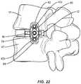
- Plate 60includes an inner surface 70 that defines openings 72 configured to receive fasteners 42, described herein. Openings 72 extend between surface 66 and surface 68. As shown generally in FIG. 25 , fasteners 42a are configured for fixation with vertebral level V1 and fasteners 42b are configured for fixation with vertebral level V2. In some embodiments, plate 60 includes a back out prevention element 74, as shown in FIG. 21 .
- Plate 60includes a first surface 76 and a second surface 78.
- Surfaces 76, 78extend between an end 80 and an end 82.
- Surfaces 76, 78may include substantially planar portions that may be initially oriented in a first orientation such that surfaces 76, 78 are substantially in alignment with surfaces 18, 20 along axis L1 in a zero profile alignment with cage 12, as shown generally in FIG. 14 .
- Surfaces 76, 78may be manipulated to a second orientation, as shown in FIG. 17 , such that surfaces 76, 78 are transverse to surfaces 18,20 and axis L1.
- FIGS. 14-17show an exemplary transition of the plate 60 from the first orientation to the second orientation.
- Plate 60may also be translatable along track 46 and track pathway 48 about axis L2 of the patient body (defmed generally, for example, by a longitudinal axis of the spinal column) and is also rotatable about an oblique axis O of cage 12, as shown in FIG. 15 (with the understanding that the oblique axis O may be, in some configurations substantially co-axial with the longitudinal axis L1).
- Surface 44facilitates translation of plate 60 relative to cage 12. This configuration provides selective positioning of plate 60 with respect to a patient's body for adapting to the configuration of the tissue surfaces of vertebrae, as well as provide range of motion limits 50, 52 for plate 60.
- Surgical system 10includes a connection mechanism 90 configured to connect plate 60 with track 46.
- mechanism 90includes a connecting member, such as, for example, ahead 92 having an elongated post 94.
- Head 92is configured for engagement with and translation along track 46.
- Post 94is configured for disposal in opening 67 of plate 60.
- a nut 96is configured to lock the head 92 (which may comprise the distal end of a bolt) with plate 60 such that translation of head 92 along track 46 causes plate 60 to translate along surface 44 of cage 12.
- a dovetail or t-slot sliding attachment mechanismcan be utilized.
- plate 60can be freely translatable in situ within the patient body such that plate 60 is configured for dynamic translation.
- plate 60can be positioned within the patient body and locked into a fixed position.
- Spinal implant system 10includes one or more fasteners 42, such as, for example, as shown in FIG. 21 , for attaching plate 60 to bone, as described herein.
- fasteners 42a and 42bmay be engaged with tissue, such as, for example, the bony structures of a vertebral body in various orientations, such as, for example, series, parallel, offset, staggered and/or alternate vertebral levels.
- one or more of fasteners 42may comprise multi-axial screws, sagittal angulation screws, pedicle screws, mono-axial screws, uni-planar screws, facet screws, fixed screws, tissue penetrating screws, conventional screws, expanding screws, wedges, anchors, buttons, clips, snaps, friction fittings, compressive fittings, expanding rivets, staples, nails, adhesives, posts, fixation plates and/or posts.
- Fastener 42comprises a first portion, such as, for example, a head 43 and a second portion, such as, for example, an elongated shaft 45 configured for penetrating tissue.
- Head 43includes an engagement portion configured for engagement with a surgical instrument.
- Shaft 45has a cylindrical cross section configuration and includes an outer surface having an external thread form.
- the external thread formmay include a single thread turn or a plurality of discrete threads.
- other engaging structuresmay be located on shaft 45, such as, for example, nail configuration, barbs, expanding elements, raised elements and/or spikes to facilitate engagement of shaft 45 with tissue, such as, for example, vertebrae.
- all or only a portion of shaft 45may have alternate cross section configurations, such as, for example, oval, oblong, triangular, square, polygonal, irregular, uniform, non-uniform, offset, staggered, undulating, arcuate, variable and/or tapered.
- the outer surface of shaft 45may include one or a plurality of openings.
- all or only a portion of the outer surface of shaft 45may have alternate surface configurations, such as, for example, smooth and/or surface configurations to enhance fixation with tissue, such as, for example, rough, arcuate, undulating, porous, semi-porous, dimpled, polished and/or textured.
- all or only a portion of shaft 45may be cannulated.
- system 10may comprise various surgical instruments, such as, for example, drivers, extenders, reducers, spreaders, distractors, blades, clamps, forceps, elevators and drills, which may be alternately sized and dimensioned, and arranged as a kit.
- system 10may comprise the use of microsurgical and image guided technologies, such as, for example, surgical navigation components employing emitters and sensors, which may be employed to track introduction and/or delivery of the components of system 10 including the surgical instruments to a surgical site. See, for example, the surgical navigation components and their use as described in US Patent Nos. 6021343 , 6725080 , and 6796988 .
- system 10comprises a spinal construct including cage 12, described above, and a plate 160, similar to plate 60 described with regard to FIGS. 1-3 .
- Outer surface 125 (or sidewall) of cage 12includes an oblique surface 144 that defines an elongated opening, such as, for example, a track pathway 148.
- Oblique surface 144is oriented with cage 12 and in substantial alignment with surgical pathway P.
- Track 146is in open communication with surface 144 to define a track pathway 148 that facilitates engagement with and translation of plate 160.
- Pathway 148extends about a longitudinal axis L2 of the patient body (wherein L2 is defined generally by the length of the patient's spine), shown as a point L2 in FIG. 4 .
- Pathway 148includes a lateral axis limit 150, as shown in FIG.5 , and an oblique axis limit 152, as shown in FIG. 5 .
- Limits 150, 152provide a range of translation relative to cage 12 along pathway 148, as discussed herein.
- Plate 160includes a portion 162 configured to engage a vertebral level and a portion 164 configured to engage a second vertebral level.
- Plate 160includes a track engagement surface 166 and an instrument engagement surface 168.
- Surface 166defines an opening 167 configured to engage a connection mechanism to facilitate translation along pathway 148.
- Surface 168is configured to engage an instrument to facilitate insertion of system 10.
- Surface 144provides range of motion limits 150, 152 for plate 160 for selective positioning of plate 160 to adapt to vertebrae.
- Plate 160includes an inner surface 170 that defines openings 172 configured to receive fasteners 42, described herein. Openings 172 extend between surface 166 and surface 168.
- a connection mechanism 190is configured to connect plate 160 with track 146.
- Mechanism 190includes a spheroidal joint, such as, for example, a ball screw 192 having an elongated post 194.
- Screw 192is configured to provide freedom of movement and/or toggle of plate 160 relative to cage 112. Screw 192 is configured for engagement with and translation along track 146.
- Post 194is configured for disposal with opening 167 of plate 160.
- a nut 196is configured to lock screw 192 with plate 160 such that translation of screw 192 along track 146 causes plate 160 to translate along surface 144 of cage 12.
- Screw 192provides translation and rotation of plate 160 relative to cage 112 in a plurality of axial orientations and in multiple planes. As shown in FIGS. 4 and 6 , complementary surfaces 144 and 166 may be arcuate in multiple planes such that the plate 160 may be articulated polyaxially relative to the cage 12.
- spinal implant system 10is employed with a surgical procedure for treatment of a spinal disorder, such as those described herein, affecting a section of a spine of a patient.
- System 10may also be employed with other surgical procedures.
- system 10may include retractors such that no further probe is required.
- system 10may include retractors constrained via frame or semi-constrained using elastic or partial frame.
- a surgical instrumentsuch as, for example, a retractor T2 is disposed in communication with surgical pathway P for spacing tissue, as shown in FIG. 10 .
- Retractor blades b1, b2are inserted simultaneously as part of a unitary retractor instrument around one or more intervertebral spaces to protect vessels.
- the various embodiments of the cage 12 and plate 60 disclosed hereinmay allow a surgeon to more effectively manipulate the plate 60 and cage 12 construct relative to the retractor T2. For example, as shown in FIGS.
- the inserter I, cage 12, and plate 60may be inserted along the surgical pathway P substantially between the blades b1, b2 of the retractor T2 with the plate 60 oriented in a low or zero-profile configuration (see FIG. 14 , for example).
- the surgeonmay be free to rotate the inserter I (and consequently the cage 12) into position relative to the vertebrae V1 and V2 and outside the extents of the blades b1, b2 (see FIG. 13 ) with the plate 60 in the low-profile configuration.
- the surgeonmay then utilize the inserter to rotate the plate 60 into position about the oblique axis O defined by the position of the plate 60 relative to the cage 12 in order to obtain a preferred position of the plate 60 relative to vertebrae V1, V2.
- an annulotomy and/or discectomyis performed with a surgical instrument with x-ray confirmation of the starting point that is central on one or more intervertebral spaces.
- system 10includes a semi-constrained retractor that facilitates minimal tissue pressures on surrounding abdominal structures and provides flexibility such that its blades rotate on a fixed pin allowing greater degrees of freedom of movement and working angles for a practitioner.
- a probeis passed into the disc space to secure its location.
- the oblique angle and lordotic angle of the probe as it enters the disc spaceis assessed preoperatively and measured intraoperative using image guidance or using a mechanical or digital protractor. Fluoroscopy, image guidance and/or surgical navigation, as described herein, are used to confirm proper probe alignment into the disc space.
- a guide wireis placed through a cannula into the disc space and positioning is confirmed with fluoroscopy.
- Instrumentssuch as, for example, a Cobb, mallet, shaver, serrated curettes, rasp, a ring curette, a uterine curette and/or combo tools are utilized to perform a discectomy of the disc space. The instruments enter the patient body obliquely through the retractor and can be turned orthogonally to allow the surgeon to work orthogonally across the disc space. The disc space is distracted until adequate disc space height is obtained.
- a discectomyis performed via surgical pathway P.
- trial implantsare delivered along surgical pathway P and used to distract one or more intervertebral spaces and apply appropriate tension in the intervertebral space allowing for indirect decompression.
- a direct decompression of the disc spaceis performed by removing a portion of a herniated disc.
- the size of cage 12is selected after trialing, cage 12 is visualized by fluoroscopy and oriented before malleting into intervertebral space. Trialing is utilized to establish a starting point for cage 12 insertion.
- an anterior longitudinal ligament (ALL) release procedurecan be performed using an OLIF or a DLIF approach post-discectomy. For example, loosening the ALL can be performed by placing holes or partial cuts in the ALL such that the OLIF surgical pathway is immediately closer to the ALL.
- Pilot holes or the likeare made in selected vertebra V1, V2 of vertebrae V adjacent the intervertebral space, via surgical pathway P, for receiving bone fasteners 42a, 42b.
- inserter Iis attached with cage 12 and/or plate 60. Inserter I delivers cage 12 and plate 60 along surgical pathway P adjacent to a surgical site for implantation adjacent the intervertebral space between V1 and V2.
- inserter Iincludes a navigation components to facilitate placement of cage 12 and plate 60 between vertebrae V1, V2.
- system 10may comprise various surgical instruments, such as, for example, drivers, extenders, reducers, spreaders, distractors, blades, clamps, forceps, elevators and drills, which may be alternately sized and dimensioned, and arranged as a kit.
- system 10may comprise various surgical instruments, such as, for example, drivers, extenders, reducers, spreaders, distractors, blades, clamps, forceps, elevators and drills, which may be alternately sized and dimensioned, and arranged as a kit.
- system 10may comprise the use of microsurgical and image guided technologies, such as, for example, surgical navigation components employing emitters and sensors, which may be employed to track introduction and/or delivery of the components of system 10 including the surgical instruments to a surgical site. See, for example, the surgical navigation components and their use as described in US Patent Nos. 6021343 , 6725080 and 6796988 .
- plate 60can be disposed such that surfaces 76, 78 are substantially perpendicular to surface 44 ( FIG. 7 ) or surfaces 76, 78 are substantially aligned with surfaces 18,20 forming a zero profile implant ( FIG. 8 ).
- a pivot bolt 98is utilized to provisionally fix plate 60 and cage 12 with inserter I. Tightening of bolt 98 causes cage 12, plate 60 and inserter I to be drawn together and held in a fixed orientation during insertion. Cage 12 and plate 60 are inserted through retractor T2 adjacent the surgical site.
- Anterior surface 16faces an anterior side of the patient body adjacent anterior portion A1 and posterior surface 14 faces a posterior side of the patient body adjacent posterior portion P1, as described herein with respect to FIGS. 11 and 12 .
- Inserter Iis an adaptable instrument configured to perform multiple applications during a surgical procedure.
- inserter Ican prepare and/or create a cavity in tissue, such as, for example, bone.
- Inserter Iguides a surgical instrument, such as, for example, a drill, tap and/or an awl, as well as guiding fasteners to penetrate tissue.
- inserter Iis a guide that holds plate 60 and cage 12 together. Surgical instruments including an awl, a tap and screws are passed through inserter I.
- inserter Iis utilized to apply a force to plate 60 such that plate 60 is translatable along track 46, as shown by arrows C in FIGS. 2 and 3 .
- plate 60is positioned at an oblique angle relative to cage 12, prior to rotation of plate 60.
- plate 60is translated along track 46 to a position laterally disposed relative to cage 12, prior to rotation and positioning of plate 60.
- Plate 60is translated between lateral axis limit 50 and oblique axis limit 52 to facilitate proper positioning of plate 60 relative to cage 12.
- plate 60is rotated into position such that portion 62 is oriented to engage vertebra V1 and portion 64 is configured to engage vertebra V2.
- Rotation of plate 60 in situfacilitates insertion due to a low profile configuration of cage 12 and plate 60 during insertion.
- Translation and rotation of plate 60allows selective manipulation of plate 60 to facilitate plate 60 adapting with vertebrae.
- Fasteners 42a, 42bare inserted along inserter I via a driver D through openings 72 such that fastener 42a engages vertebra V1 and fastener 42b engages vertebra V2.
- Driver Dis disposed adjacent the intervertebral space and is manipulated to drive, torque, insert or otherwise connect bone fasteners 42a, 42b adjacent the intervertebral space.
- the drivermay include surgical navigation components, as described herein, to establish a screw pathway that is substantially concurrent with and/or parallel to the surgical approach angle.
- plate 60is fixed with fasteners 42a, 42b at an oblique angle relative to cage 12.
- plate 60is fixed with fasteners 42a, 42b laterally to cage 12.
- plate 60includes a back out prevention element 74 that is rotated to prevent fasteners 42, 42b from disengaging from vertebrae V1, V2.
- spinal implant system 10Upon completion of a procedure, as described herein, the surgical instruments, assemblies and non-implanted components of spinal implant system 10 are removed and the incision(s) are closed.
- One or more of the components of spinal implant system 10can be made of radiolucent materials such as polymers. Radiopaque markers may be included for identification under x-ray, fluoroscopy, CT or other imaging techniques.
- the use of surgical navigation, microsurgical and image guided technologiesmay be employed to access, view and repair spinal deterioration or damage, with the aid of spinal implant system 10.
- spinal implant system 10may include one or a plurality of plates, connectors and/or bone fasteners for use with a single vertebral level or a plurality of vertebral levels.
- spinal implant system 10includes an agent, which may be disposed, packed, coated or layered within, on or about the components and/or surfaces of spinal implant system 10.
- the agentmay include bone growth promoting material, such as, for example, bone graft to enhance fixation of the components and/or surfaces of spinal implant system 10 with vertebrae.
- the agentmay include one or a plurality of therapeutic agents and/or pharmacological agents for release, including sustained release, to treat, for example, pain, inflammation and degeneration.
- system 10comprises a spinal construct including cage 212, similar to cage 12, described above, and a plate 260, similar to plate 60 described above.
- Cage 212extends between a posterior surface 214 and an anterior surface 216.
- Cage 212includes a first vertebral engaging surface 218 and a second vertebral engaging surface 220.
- Surface 218may be substantially planar and configured to engage endplate tissue of a vertebral body, such as, for example, an endplate of a vertebral level (not shown, but may be immediately caudal to the vertebral body V2 shown in FIG. 25 ).
- Surface 220may be substantially planar and configured to engage endplate tissue of a vertebral body, such as, for example, an endplate E2 of a V2 vertebral level, as shown in FIG. 25 .
- the surfaces 218, 220may also be provided with convex portions and/or inclined portions to provide for lordotic correction and/or to better conform to the anatomy of particular vertebral endplates.
- cage 212has a substantially kidney bean shaped cross section configuration (such as that which may be used in an anterior and/or anterior-oblique spinal approach) and includes an inner surface 222 and an outer surface 225.
- Surface 222defines an opening 223 configured to receive an agent, which may include bone graft (not shown) and/or other materials, as described herein, for employment in a fixation or fusion treatment.
- Outer surface 225includes an elliptical oblique surface 244 that defines a track 246. Track 246 is in open communication with surface 244 to define a track pathway 248 that facilitates connection with and translation of plate 260.
- pathway 248is arcuate in shape.
- Pathway 248includes a lateral axis limit 250 and an oblique axis limit 252.
- Limits 250, 252provide a range of translation relative to cage 212, as discussed herein.
- System 10includes plate 260 having a substantially rectangular configuration.
- Plate 260includes a portion 262 configured to engage a vertebral level V1 and a portion 264 configured to engage a vertebral level V2.
- Plate 260includes a track engagement surface 266 and an instrument engagement surface 268.
- Surface 266defines an opening 267 configured to engage a connection mechanism 290 to facilitate translation along pathway 248.
- Surface 268is configured to engage an inserter (not shown) to facilitate insertion of system 10.
- surfaces 266, 268may be arcuate in shape such that plate 260 conforms to edge 244 of cage 212.
- Plate 260includes an inner surface 270 that defines openings 272 configured to receive fasteners 42, described herein. Openings 272 extend between surface 266 and surface 268.
- Fasteners 42a(not shown) are configured for fixation with vertebral level V1 and fasteners 42b are configured for fixation with vertebral level V2.
- fasteners 42are aligned to engage vertebrae in a straight orientation. In some embodiments, fasteners 42 are configured to engage vertebrae at an angled orientation.
- Plate 260includes a first surface 276 and a second surface 278. Surfaces 276,278 extend between an end 280 and an end 282. Plate 260 is translatable, as shown by arrows D in FIG. 23 , about pathway 248 about an axis L2 of the patient body and rotatable about surface 244 about an oblique axis O2 of cage 212.
- the term "oblique axis" O2(see element O2 in FIG. 23 , for example) as used herein may include any axis extending outward from the oblique surface anywhere between the lateral axis limit 250 and the oblique axis limit 252.
- connection mechanism 290includes a bolt 292 having an elongated post 294.
- Bolt 292is configured for translation along track 246.
- Post 294is configured to engage opening 267 of plate 260.
- a nut 296is configured to lock bolt 292 with plate 260 such that translation of bolt 292 along track 246 causes plate 260 to translate along surface 244 of cage 212. It should be understood that the positioning of the nut 296 and bolt 292 may be reversed in various embodiments as necessary.
- plate 260is translated along track 246 to a position relative to cage 212, prior to rotation and positioning of plate 260.
- Plate 260is translated between lateral axis limit 250 and oblique axis limit 252 to facilitate proper positioning of plate 260 relative to cage 212.
- Plate 260is rotated into position as shown by arrows E in FIG. 24 , such that portion 262 is oriented to engage vertebra V1 and portion 264 is configured to engage vertebra V2.
- Rotation of plate 260 in situfacilitates insertion due to a low profile configuration of cage 212 and plate 260 during insertion.
- Translation and rotation of plate 260allows selective manipulation of plate 260 to facilitate a proper fit with vertebrae.
- system 10comprises a spinal construct including cage 312, similar to cage 12, described above, and a plate 360, similar to plate 60 described above.
- Cage 312includes a first vertebral engaging surface 318 and a second vertebral engaging surface 320.
- Surface 318is substantially planar and configured to engage endplate tissue E1 of a V1 vertebral level, as shown in FIG. 27 .
- Surface 320is configured to engage endplate tissue E2 of a V2 vertebral level, as shown in FIG. 27 .
- FIGS. 26-27may be especially useful in lumbo-sacral fusion of the L5-S1 level (wherein V2 is FIG. 27 refers to the sacrum).
- Cage 312may have a substantially rectangular cross section configuration and an outer surface 325.
- Outer surface 325includes an arcuate oblique surface 344 that defines a track 346.
- Track 346is in open communication with surface 344 to define a track pathway 348 that facilitates engagement with and translation of plate 360.
- plate 360includes a substantially triangular configuration.
- Plate 360includes a portion 362 configured to engage a vertebral level V1 and a portion 364 configured to engage a vertebral level V2.
- Plate 360includes a track engagement surface 366 and an instrument engagement surface 368.
- Cage 312 and plate 360are configured to connect with a connection mechanism 390, as discussed herein.
- Plate 360includes an inner surface 370 that defines openings 372 configured to receive fasteners 42, not shown. In one embodiment, openings 372 are disposed at angles of approximately 30 degrees relative to plate 360 to facilitate engagement with vertebrae.
- plate 360is translated along track 346 to a position relative to cage 312, prior to rotation and positioning of plate 360.
- Plate 360is translated between lateral axis limit 350 and oblique axis limit 352 to facilitate selective positioning of plate 360 relative to cage 312.
- Plate 360is rotated into position as shown by arrows F in FIG. 24 , such that portion 362 is oriented to engage vertebra V1 and portion 364 is configured to engage vertebra V2.
- Rotation of plate 360 in situfacilitates insertion due to a low profile configuration of cage 312 and plate 360 during insertion.
- Translation and rotation of plate 360allows for selective manipulation of plate 360 to facilitate adaption of plate 360 with vertebrae.
- system 10comprises a spinal construct including cage 412, similar to cage 12, described above, and a plate 460, similar to plate 60 described above.
- system 10includes a multilevel system having cages 412, 412' and plates 460, 460'.
- Cage 412, 412'extends between a posterior surface 414, 414' and an anterior surface 416, 416'.
- Cage 412, 412'includes a first vertebral engaging surface 418, 418' and a second vertebral engaging surface 420, 420'.
- Surface 418, 418'is substantially planar and configured to engage endplates E1, E3.
- Surface 420,420'is configured to engage endplates E2, E4.
- Cage 412, 412'includes an outer surface 425, 425' having and oblique surface 444, 444' that defines a track 446, 446'.
- Track 446, 446'is in open communication with surface 444, 444' to define a track pathway 448, 448' that facilitates engagement with and translation of plate 460, 460'.
- plate 460, 460'includes a portion 462, 462' configured to engage a vertebral level V1, V2 and a portion 464, 464' configured to engage a second vertebral level V2, V3.
- Plate 460, 460'includes a track engagement surface 466, 466' and an instrument engagement surface 468, 468'.
- Surface 466, 466'defines an opening 467, 467' configured to engage connection mechanism 490, 490' to facilitate translation and rotation of plate 460, 460' along pathway 448, 448'.
- Plate 460, 460'includes an inner surface 470, 470' that defines openings 472, 474' configured to receive fasteners 42, described herein.
- Fasteners 42a(not shown) are configured for fixation with a vertebral level V1, V2 and fasteners 42b are configured for fixation with vertebral level V2, V3.
- plate 460, 460'is translated along track 446 to a position relative to cage 412, prior to rotation and positioning of plate 460, 460'.
- Plate 460, 460'is translated between lateral axis limit 450,450' and oblique axis limit 452, 452' to facilitate selective positioning of plate 460, 460' relative to cage 412, 412'.
- Plate 460, 460'is rotated into position to engage vertebrae. Rotation of plate 460, 460' in situ facilitates insertion due to a low profile configuration of cage 412,412' and plate 460, 460' during insertion. Translation and rotation of plate 460, 460' allows for selective manipulation of plate 460, 460' to facilitate adaption of plate 460, 460' with vertebrae.
- plate 460, 460'includes a threaded post 502,502' configured to receive a plate 504.
- posts 502, 502'have multi-axial pivoting to facilitate engagement with plate 504.
- Plate 504includes an engagement surface 506 and an inner surface 508.
- Surface 506is configured to engage plates 460, 460'.
- all or only a portion of the surface 506may have alternate surface configurations, such as, for example, smooth and/or surface configurations to enhance fixation with tissue, such as, for example, rough, arcuate, undulating, porous, semi-porous, dimpled, polished and/or textured to enhance engagement.
- Openings 510configured to receive posts 502, 502'.
- openings 510are elongated to facilitate positioning of plate 504 over posts 502, 502'.
- Locking nuts 512, 512'are provided to lock plate 504 in a fixed position with plates 460, 460'.
- Plate 504is configured to provide stability to system 10 when engaged with vertebrae V.
- system 10comprises a spinal construct including cage 612, similar to cage 12, described above, and a plate 660, similar to plate 60 described above.
- system 10includes two plates 660, 660'.
- Cage 612extends between a posterior surface 614 and an anterior surface 616.
- Cage 612includes a first vertebral engaging surface 618 and a second vertebral engaging surface 620.
- Surface 618is substantially planar and configured to engage endplate tissue of a vertebral body, such as, for example, an endplate E1 of a V1 vertebral level, as shown in FIG. 30 .
- Surface 620is configured to engage endplate tissue of a vertebral body, such as, for example, an endplate E2 of a V2 vertebral level, as shown in FIG. 30 .
- Cage 612may have a substantially rectangular cross section configuration and includes an outer surface 625.
- Outer surface 625includes an arcuate oblique surface 644 that defines a track 646.
- Track 646is in open communication with surface 644 to define a track pathway 648 that facilitates translation and rotation of plates 660, 660'.
- Pathway 648includes a lateral axis limit 650 and an oblique axis limit 652.
- Limits 650, 652provide a range of translation.
- system 10includes a first plate 660 and a second plate 660' each having a substantially rectangular configuration.
- Plate 660, 660'includes a portion 662, 662' configured to engage a vertebral level V1 and a portion 664, 664' configured to engage a vertebral level V2.
- Plate 660, 660'includes a track engagement surface 666, 666' and an instrument engagement surface 668, 668'.
- Surface 666, 666'defines an opening 667, 667' configured to engage connection mechanism 690 (hidden) to facilitate translation along pathway 648.
- Surface 666, 666'define an indent 700, 700' configured to engage each other such that plates 660, 660' are in a nesting configuration upon a cruciate positioning with vertebrae.
- Plate 660, 660'includes an inner surface 670, 670' that defines openings 672, 672' configured to receive fasteners 42, described herein.
- Fasteners 42aare configured for fixation with vertebral level V1 and fasteners 42b are configured for fixation with vertebral level V2.
- Plate 660, 660'includes a first surface 676, 676' and a second surface 678, 678'.
- plates 660. 660'are collapsed, as shown in FIGS. 31A, 31B and 32A, 32B such that surfaces 676, 676' and 678, 678' are in a parallel orientation forming a low or zero profile plate configuration.
- plates 660, 660'are rotated such that surfaces 676, 676' and 678, 678' are positioned in a transverse orientation to engage vertebrae V1, V2.
- the surfaces 676, 676'may define locking channels 700, 700' that may interact and/or be nested to lock in place when the surfaces 676, 676' and 678, 678' are positioned in a transverse orientation to engage vertebrae V1, V2 (as shown, for example in FIGS. 32A-32B ).
- plate 660, 660'is translated along track 646 to a position relative to cage 612, prior to rotation and positioning of plate 660, 660'.
- Plate 660, 660'is translated between lateral axis limit 650, 650' and oblique axis limit 652, 652' to facilitate selective positioning of plate 660, 660' relative to cage 612.
- Plate 660, 660'is rotated into position to engage vertebrae. Rotation of plate 660, 660' in situ facilitates insertion due to a low profile configuration of cage 612' and plate 660, 660' during insertion.
- Translation and rotation of plate 660, 660'allows for selective manipulation of plate 660, 660' to facilitate adaption of plate 660, 660' with vertebrae.
- a spinal implantcomprises an implant body extending between an anterior surface and a posterior surface, and including a first vertebral engaging surface and a second vertebral engaging surface, the implant body further including an outer surface that defines an oblique surface; and a wall connectable with the implant body and translatable relative to the oblique surface.
- the oblique surfacedefines an elongated opening configured for disposal of the wall.
- the openingdefines a pathway for translation of the wall along the oblique surface.
- the pathwayhas an arcuate configuration.
- the wallis connected to the implant body via a spheroidal joint such that the wall is translatable relative to the implant body in a plurality of axial orientations.
- the wallis translatable along the oblique surface and rotatable about an oblique axis of the implant body.
- the wallis translatable along an arcuate pathway and pivotable about the oblique surface.
- the wallis rotatable about an oblique axis of the implant body into a zero profile alignment with the implant body.
- the oblique surfacedefines a range of movement of the wall between a lateral axis and an oblique axis of the implant body.
- the spinal implantfurther comprising an oblique extension extending from an end of the anterior surface, the oblique extension having an extension sidewall forming at least a portion of the oblique surface.
- the wallincludes a plate having a first portion engageable with a first vertebra and a second portion engageable with a second vertebra.
- the wallincludes a triangle configuration.
- the oblique surfaceincludes an elliptical configuration.
- the wallincludes a first plate and a second plate disposed in a cruciate orientation, the plates being engageable with vertebrae.
- the wallis connected to the implant body via a first plate having a spheroidal joint, the joint including a shaft connectable to a second plate extending along a plurality of vertebra.
- a further spinal implantcomprises an implant body extending between an anterior surface and a posterior surface, and including a first vertebral engaging surface and a second vertebral engaging surface, the implant body further including an oblique surface that defines a track including a lateral axis limit and an oblique axis limit; and a plate connectable with the spinal implant and translatable between the limits of the implant body relative to the oblique surface along a pathway, the plate including a first portion engageable with a first vertebra and a second portion engageable with a second vertebra.
- the plateis translatable along the oblique surface and rotatable about an oblique axis of the implant body.
- the spinal implantfurther comprising an oblique extension extending from an end of the anterior surface, the oblique extension having an extension sidewall forming at least a portion of the oblique surface.
Landscapes
- Health & Medical Sciences (AREA)
- Orthopedic Medicine & Surgery (AREA)
- Biomedical Technology (AREA)
- Engineering & Computer Science (AREA)
- Neurology (AREA)
- Life Sciences & Earth Sciences (AREA)
- Transplantation (AREA)
- General Health & Medical Sciences (AREA)
- Heart & Thoracic Surgery (AREA)
- Animal Behavior & Ethology (AREA)
- Public Health (AREA)
- Veterinary Medicine (AREA)
- Oral & Maxillofacial Surgery (AREA)
- Cardiology (AREA)
- Vascular Medicine (AREA)
- Surgery (AREA)
- Physical Education & Sports Medicine (AREA)
- Molecular Biology (AREA)
- Medical Informatics (AREA)
- Nuclear Medicine, Radiotherapy & Molecular Imaging (AREA)
- Prostheses (AREA)
- Surgical Instruments (AREA)
Abstract

Description
- The present disclosure generally relates to medical devices for the treatment of musculoskeletal disorders, and more particularly to a spinal implant system for treating a spine.
- Spinal pathologies and disorders such as scoliosis and other curvature abnormalities, kyphosis, degenerative disc disease, disc herniation, osteoporosis, spondylolisthesis, stenosis, tumor, and fracture may result from factors including trauma, disease and degenerative conditions caused by injury and aging. Spinal disorders typically result in symptoms including deformity, pain, nerve damage, and partial or complete loss of mobility.
- Non-surgical treatments, such as medication, rehabilitation and exercise can be effective, however, may fail to relieve the symptoms associated with these disorders. Surgical treatment of these spinal disorders includes fusion, fixation, correction, discectomy, laminectomy and implantable prosthetics. As part of these surgical treatments, spinal constructs, such as, for example, bone fasteners, spinal rods and interbody devices can be used to provide stability to a treated region. For example, during surgical treatment, surgical instruments can be used to deliver components of the spinal constructs to the surgical site for fixation with bone to immobilize a joint. Certain spinal surgery approaches utilize a direct lateral approach to access intervertebral spaces, however, these techniques present certain challenges due to the location of musculature and neural structures embedded therein.
- This disclosure describes an improvement over these prior art technologies with the provision of specialized instrumentation, implants and techniques to allow for an oblique lateral surgical pathway to the intervertebral spaces.
- A spinal implant comprises an implant body extending between an anterior surface and a posterior surface. The implant body includes a first vertebral engaging surface and a second vertebral engaging surface. The implant body includes an outer surface that defines an oblique surface. A wall or plate is connectable with the implant body and translatable relative to the oblique surface.
- The present disclosure will become more readily apparent from the specific description accompanied by the following drawings, in which:
FIG. 1 is a perspective view of components of one embodiment of a system in accordance with the principles of the present disclosure;FIG. 2 is a cross section view of the components of the system shown inFIG. 1 ;FIG. 3 is an end view of components of the system shown in inFIG. 2 ;FIG. 4 is a cross section view of components of one embodiment of a system in accordance with the principles of the present disclosure;FIG. 5 is an end view taken along lines A-A of components shown inFIG. 4 ;FIG. 6 is a side cross section view taken along lines B-B of components shown inFIG. 5 ;FIG. 7 is a perspective view of components of one embodiment of a system in accordance with the principles of the present disclosure;FIG. 8 is a perspective view of the components shown inFIG. 7 ;FIG. 9 is a perspective view of the components shown inFIG. 7 ;FIG. 10 is a perspective view of components of one embodiment of a system in accordance with the principles of the present disclosure disposed with vertebrae;FIG. 11 is a plan view of the components and vertebrae shown inFIG. 10 ;FIG. 12 is a plan view of the components and vertebrae shown inFIG. 10 ;FIG. 13 is a plan view of the components and vertebrae shown inFIG. 10 ;FIG. 14 is a perspective view of components and vertebrae shown inFIG. 10 ;FIG. 15 is a perspective view of the components and vertebrae shown inFIG. 14 ;FIG. 16 is a perspective view of the components and vertebrae shown inFIG. 14 ;FIG. 17 is a perspective view of components of one embodiment of a system in accordance with the principles of the present disclosure disposed with vertebrae;FIG. 18 is a perspective view of the components and vertebrae shown inFIG. 17 ;FIG. 19 is a plan view of the components and vertebrae shown inFIG. 17 ;FIG. 20 is a perspective view of the components and vertebrae shown inFIG. 17 ;FIG. 21 is a plan view of components and vertebrae shown inFIG. 17 ;FIG. 22 is a plan view of the components and vertebrae shown inFIG. 17 ;FIG. 23 is a plan view of components of one embodiment of a system in accordance with the principles of the present disclosure;FIG. 24 is a side view of the components shown inFIG. 23 ;FIG. 25 is a plan view of components of one embodiment of a system in accordance with the principles of the present disclosure;FIG. 26 is a side view of components of one embodiment of a system in accordance with the principles of the present disclosure;FIG. 27 is a plan view of components shown inFIG. 26 disposed with vertebrae;FIGS. 28A - 28D are views of components of one embodiment of a multi-level and connectable system in accordance with the principles of the present disclosure disposed with vertebrae;FIG. 29 is a side view of components of one embodiment of a system in accordance with the principles of the present disclosure disposed with vertebrae;FIG. 30 is a side view of the components and vertebrae shown inFIG. 29 ;FIGS. 31A-31B are views of components of one embodiment of a system in accordance with the principles of the present disclosure in an unlocked low or zero-profile position; andFIG. 32A-32B are views of components shown inFIGS. 31A-31B in a locked transverse position.- The exemplary embodiments of the surgical system and related methods of use disclosed are discussed in terms of medical devices for the treatment of musculoskeletal disorders and more particularly, in terms of a surgical system for implant delivery to a surgical site and a method for treating a spine, which employ an oblique surgical pathway, which may include an oblique-lateral surgical pathway. That is, although in the following medical methods are described, said methods do not form part of the invention itself but are helpful in understanding the invention. In one embodiment, the systems of the present disclosure are employed with a spinal joint and fusion, for example, with a cervical, thoracic, lumbar and/or sacral region of a spine.
- In one embodiment, the surgical system includes an interbody implant having an integral floating plate utilized with oblique lateral interbody fusion (OLIF) and direct lateral interbody fusion (DLIF) procedures. In one embodiment, the surgical system includes a standalone interbody implant and a standalone plate configured for connection with each other. In some embodiments, the interbody implant is inserted and moved off oblique into a lateral position and the plate is maintained in the oblique surgical pathway facilitating engagement of screws with vertebrae. In one embodiment, the surgical system includes an interbody implant having a track disposed along an oblique surface of the interbody implant. In one embodiment, the surgical system includes a plate configured for rotation relative to the interbody implant such that a flush or low profile configuration is maintained during insertion. In some embodiments, the plate is configured for rotation in two or more planes such that the plate rotates about a longitudinal axis of the interbody implant. In one embodiment, the plate is configured for rotation about an axis defined by a proximal end of the interbody implant such that the plate rotates into the implant to reduce the profile of the surgical system upon insertion.
- In one embodiment, the surgical system includes an interbody implant having a plate freely translatable relative to the interbody implant along an elongated opening, such as, for example, a track. In one embodiment, the surgical system includes an interbody implant having a plate configured to be locked with the interbody implant. In one embodiment, the plate includes a plurality of openings configured to receive fasteners. In one embodiment, the surgical system includes bolts and/or nuts to facilitate translation of the plate relative to the interbody implant. In one embodiment, the surgical system includes fasteners configured to engage the plate in a straight and/or angled configuration.
- In one embodiment, the surgical system includes an interbody implant having a plate attached along an oblique surface of the interbody implant. In one embodiment, the surgical system includes an interbody implant having a plate attached along an anterior surface of the interbody implant. In one embodiment, the surgical system includes an interbody implant having a multi-level plate configuration such that single level plates are linked together via an additional plate and locked together. In one embodiment, the surgical system includes an interbody implant having an x-shaped plate configuration such that two separate plates can be inserted in a stacked configuration and rotated and fixed with vertebrae in an x-shaped configuration. In one embodiment, each plate includes a threaded post configured to facilitate attachment of the plates. In some embodiments, the plates are configured to nest within one another to reduce the plate profile. In one embodiment, the plates can be inserted individually into the surgical site.
- In one embodiment, the surgical system includes an interbody implant including a track having a constant radii configured to receive a plate. In one embodiment, the surgical system includes an interbody implant including a track having a variable radii configured to receive a plate.
- The present disclosure may be understood more readily by reference to the following detailed description of the embodiments taken in connection with the accompanying drawing figures, which form a part of this disclosure. It is to be understood that this application is not limited to the specific devices, methods, conditions or parameters described and/or shown herein, and that the terminology used herein is for the purpose of describing particular embodiments by way of example only and is not intended to be limiting. Also, as used in the specification and including the appended claims, the singular forms "a," "an," and "the" include the plural, and reference to a particular numerical value includes at least that particular value, unless the context clearly dictates otherwise. Ranges may be expressed herein as from "about" or "approximately" one particular value and/or to "about" or "approximately" another particular value. When such a range is expressed, another embodiment includes from the one particular value and/or to the other particular value. Similarly, when values are expressed as approximations, by use of the antecedent "about," it will be understood that the particular value forms another embodiment. It is also understood that all spatial references, such as, for example, horizontal, vertical, top, upper, lower, bottom, left and right, are for illustrative purposes only and can be varied within the scope of the disclosure. For example, the references "upper" and "lower" are relative and used only in the context to the other, and are not necessarily "superior" and "inferior".
- Further, as used in the specification and including the appended claims, "treating" or "treatment" of a disease or condition refers to performing a procedure that may include administering one or more drugs to a patient (human, normal or otherwise or other mammal), employing implantable devices, and/or employing instruments that treat the disease, such as, for example, microdiscectomy instruments used to remove portions bulging or herniated discs and/or bone spurs, in an effort to alleviate signs or symptoms of the disease or condition. Alleviation can occur prior to signs or symptoms of the disease or condition appearing, as well as after their appearance. Thus, treating or treatment includes preventing or prevention of disease or undesirable condition (e.g., preventing the disease from occurring in a patient, who may be predisposed to the disease but has not yet been diagnosed as having it). In addition, treating or treatment does not require complete alleviation of signs or symptoms, does not require a cure, and specifically includes procedures that have only a marginal effect on the patient. Treatment can include inhibiting the disease, e.g., arresting its development, or relieving the disease, e.g., causing regression of the disease. For example, treatment can include reducing acute or chronic inflammation; alleviating pain and mitigating and inducing re-growth of new ligament, bone and other tissues; as an adjunct in surgery; and/or any repair procedure. Also, as used in the specification and including the appended claims, the term "tissue" includes soft tissue, ligaments, tendons, cartilage and/or bone unless specifically referred to otherwise.
- The following discussion includes a description of a surgical system and related methods of employing the surgical system in accordance with the principles of the present disclosure. Alternate embodiments are also disclosed. Reference is made in detail to the exemplary embodiments of the present disclosure, which are illustrated in the accompanying figures. Turning to
FIGS. 1-22 , there are illustrated components of a surgical system, such as, for example, aspinal implant system 10. - The components of
spinal implant system 10 can be fabricated from biologically acceptable materials suitable for medical applications, including metals, synthetic polymers, ceramics and bone material and/or their composites, depending on the particular application and/or preference of a medical practitioner. For example, the components of spinal implant system 10, individually or collectively, can be fabricated from materials such as stainless steel alloys, commercially pure titanium, titanium alloys, Grade 5 titanium, super-elastic titanium alloys, cobalt-chrome alloys, stainless steel alloys, superelastic metallic alloys (e.g., Nitinol, super elasto-plastic metals, such as GUM METAL® manufactured by Toyota Material Incorporated of Japan), ceramics and composites thereof such as calcium phosphate (e.g., SKELITE™ manufactured by Biologix Inc.), thermoplastics such as polyaryletherketone (PAEK) including polyetheretherketone (PEEK), polyetherketoneketone (PEKK) and polyetherketone (PEK), carbon-PEEK composites, PEEK-BaSO4 polymeric rubbers, polyethylene terephthalate (PET), fabric, silicone, polyurethane, silicone-polyurethane copolymers, polymeric rubbers, polyolefin rubbers, hydrogels, semi-rigid and rigid materials, elastomers, rubbers, thermoplastic elastomers, thermoset elastomers, elastomeric composites, rigid polymers including polyphenylene, polyamide, polyimide, polyetherimide, polyethylene, epoxy, bone material including autograft, allograft, xenograft or transgenic cortical and/or corticocancellous bone, and tissue growth or differentiation factors, partially resorbable materials, such as, for example, composites of metals and calcium-based ceramics, composites of PEEK and calcium based ceramics, composites of PEEK with resorbable polymers, totally resorbable materials, such as, for example, calcium based ceramics such as calcium phosphate such as hydroxyapatite (HA), corraline HA, biphasic calcium phosphate, tricalcium phosphate, or fluorapatite, tri-calcium phosphate (TCP), HA-TCP, calcium sulfate, or other resorbable polymers such as polyaetide, polyglycolide, polytyrosine carbonate, polycaroplaetohe and their combinations, biocompatible ceramics, mineralized collagen, bioactive glasses, porous metals, bone particles, bone fibers, morselized bone chips, bone morphogenetic proteins (BMP), such as BMP-2, BMP-4, BMP-7, rhBMP-2, or rhBMP-7, demineralized bone matrix (DBM), transforming growth factors (TGF, e.g., TGF-β), osteoblast cells, growth and differentiation factor (GDF), insulin-like growth factor 1, platelet-derived growth factor, fibroblast growth factor, or any combination thereof. - Various components of
spinal implant system 10 may have material composites, including the above materials, to achieve various desired characteristics such as strength, rigidity, elasticity, compliance, biomechanical performance, durability and radiolucency or imaging preference. The components ofspinal implant system 10, individually or collectively, may also be fabricated from a heterogeneous material such as a combination of two or more of the above-described materials. The components ofspinal implant system 10 may be monolithically formed, integrally connected or include fastening elements and/or instruments, as described herein. Spinal implant system 10 is employed, for example, with a fully open surgical procedure, a minimally invasive procedure, including percutaneous techniques, and mini-open surgical techniques to deliver and introduce instrumentation and/or an implant, such as, for example, an interbody implant, at a surgical site of a patient, which includes, for example, a spine having vertebrae V, as shown inFIGS. 11-22 . In some embodiments, a surgical pathway P to a surgical site is formed via an OLIF or DLIF procedure. In some embodiments, the implant can include spinal constructs, such as, for example, bone fasteners, spinal rods, connectors and/or plates.Spinal implant system 10 includes an implant body, such as, for example, aninterbody cage 12, as shown inFIG. 1 .Cage 12 extends between aposterior surface 14 and ananterior surface 16 and defines a longitudinal axis L1.Posterior surface 14 is configured to face a posterior side of a patient body and be disposed adjacent an anterior portion of vertebrae, such as, for example a posterior portion P1 of one or more intervertebral spaces of vertebrae V, as shown inFIG. 11 .Anterior surface 16 is configured to face an anterior side of the patient body and be disposed adjacent an anterior portion of vertebrae, such as, for example an anterior portion A1 of one or more intervertebral spaces of vertebrae V, as shown inFIG. 11 .- In the various embodiments described herein, cage 12 (and analogous cages described with respect to the various figures) may be provided with a convex distal end 11 (see
FIG. 1 , showing a "bullet nose") for ease of insertion by the surgeon. Furthermore, as viewed in plan view inFIG. 2 ,cage 12 may also be provided with chamfers or cutouts cage 12 may be placed in an intervertebral space to avoid impinging on various structures in or near the vertebral body (such as the spinal foramina).Cage 12 may also be provided with acurved end 15 of the posterior surface 14 (immediately opposite theoblique extension 17 described further herein). Thecurved end 15 may also serve as a cut out to avoid impingement on the spinal foramina or other structures as thecage 12 is placed and/or as the surgeon manipulates thecage 12 along or outside of the surgical pathway P (seeFIGS. 12 and13 , for example). - The
cage 12 embodiments described herein may also comprise any number and configurations of radiopaque markers (such as tantalum pins, not shown) for visualizing a position of thecage 12 using fluoroscopy during insertion, manipulation and implantation. Such markers may be placed obliquely in thedistal end 11, in sidewalls of the cage adjacent the anterior and posterior surfaces (16, 14, respectively), in a proximal end of the implant. Such markers may be placed parallel, oblique to and/or perpendicular to the anterior and posterior surfaces as required to properly visualize the position of thecage 12 relative to the surgical pathway P and/or relative to a preferred oblique axis O to facilitate preferred placement ofplate 60 as described further herein. Cage 12 includes a firstvertebral engaging surface 18 and a secondvertebral engaging surface 20.Surfaces 18 may be substantially planar and configured to engage endplate tissue of a vertebral body, such as, for example, an endplate E1 of a V1 vertebral level, as shown inFIG. 13 .Surface 20 may be substantially planar and configured to engage endplate tissue of a vertebral body, such as, for example, an endplate E2 of a V2 vertebral level, as shown inFIG. 14 . In some embodiments, surfaces 18, 20 may be rough, textured, porous, semi-porous, dimpled, knurled, toothed, grooved and/or polished such that it facilitates engagement with tissue.Surfaces anterior surface 16 to theposterior surface 14. In some embodiments, surfaces 18, 20 may be angled along the longitudinal axis L1 or angled perpendicular to the longitudinal axis L1 such thatanterior surface 16 is taller thanposterior surface 14 such that thecage 12 may be capable of creating and/or augmenting lateral or lordotic curvature in a human spine when implanted. In some embodiments, the vertebral tissue may include intervertebral tissue, endplate surfaces and/or cortical bone. In some embodiments, surfaces 18, 20 may be coated with materials suitable for facilitating or encouraging bony ongrowth or fusion including but not limited to titanium and hydroxyapatite (HA) coatings. In embodiments where titanium coatings are applied tosurfaces - As shown in
FIG. 2 ,Cage 12 may have a substantially rectangular configuration when viewed from above, and includes aninner surface 22 and anouter surface 25.Surface 22 defines anopening 23 configured to receive an agent, which may include bone graft (not shown) and/or other materials, as described herein, for employment in a fixation or fusion treatment. In some embodiments, the plan geometry ofcage 12 may have various configurations, such as, for example, oval, round, cylindrical, oblong, triangular, rectangular, polygonal having planar or arcuate side portions, irregular, uniform, non-uniform, consistent, variable, horseshoe shape, U-shape or kidney bean shape (seeFIG. 25 for example). - As shown in
FIGS. 1 and2 , thecage 12 may comprise acorner extension 17 such that the overall configuration of the cage when viewed from above is substantially asymmetrical about the longitudinal axis L1. Therefore,outer surface 25 at the corner extension 17 (i.e. anextension sidewall 44a, as shown inFIG. 2 ), may define at least part of anoblique surface 44. Theoblique surface 44 defines an elongated opening, such as, for example, atrack pathway 48.Oblique surface 44 may extend along thecorner extension 17 and proximal end of thecage 12 such that at least a portion of the oblique surface may be in substantial alignment with surgical pathway P, as shown inFIGS. 1 and2 .Track pathway 48 is defined inoblique surface 44 and is in communication withtrack 46 such thathead 92 ofconnection mechanism 90 may reside substantially in thetrack 46, and thepost 94 ofconnection mechanism 90 may extend outward through thetrack pathway 48 to facilitate translation and/or rotation of a wall and/or plate, as discussed further herein.Track pathway 48 In one embodiment, as shown inFIG. 1 ,pathway 48 extends along an arc that is substantially parallel to thetrack 46 and to theoblique surface 44. In some embodiments, thetrack 46,surface 44 and/ortrack pathway 48 may be arcuate with a single radius defining the arcs. In other embodiments, thetrack 46,surface 44 and/ortrack pathway 44 may be arcuate with multiple radii defining one or more of the individual arcs. In one embodiment,oblique surface 44, track 46 (and the accompanyingtrack pathway 48 in communication with track 46) extends along a varying radius of curvature.Track pathway 48 includes a first limit, such as, for example, a lateral axis limit 50, as shown inFIG. 1 , and a second limit, such as, for example, anoblique axis limit 52, as shown inFIG. 1 .Limits 50, 52 provide a range of translation relative tocage 12 alongpathway 48, as discussed herein. - The term "oblique axis" O of the
cage 12 body (see element O inFIGS. 1 ,11, 12 , for example) as used herein may include any axis extending outward from the oblique surface of thecage 12 implant anywhere between the lateral axis limit 50 and theoblique axis limit 52, including but not limited to axes that are co-axial with longitudinal axis L1 and/or the axis defined by surgical pathway P. As shown inFIGS. 14 and 15 , at least one of the various oblique axes O defined by thesystem 10 may be substantially co-axial with the longitudinal axis L1 ofcage 12. - In some embodiments,
oblique surface 44,track 46 andtrack pathway 48 may extend along a pathway having various configurations corresponding to the overall shape of thecage 12, such as, for example, round, cylindrical, oblong, triangular, rectangular, polygonal having planar or arcuate side portions, irregular, uniform, non-uniform, consistent, variable, horseshoe shape, U-shape or kidney bean shape. In some embodiments,surface 44 may be rough, textured, porous, semi-porous, dimpled, knurled, toothed, grooved and/or polished such that it facilitates translation. In some embodiments,oblique surface 44 is configured for mating engagement with a surgical instrument, such as, for example, an inserter, which deliverscage 12 adjacent a surgical site via surgical pathway P, as described herein. System 10 includes a wall, such as, for example, aplate 60 having a substantially rectangular configuration. In some embodiments,plate 60 can be variously configured, such as, for example, tubular, oval, oblong, triangular, square, polygonal, irregular, uniform, non-uniform, variable, hollow and/or tapered.Plate 60 includes aportion 62 configured to engage a vertebral level V1 and aportion 64 configured to engage a vertebral level V2, as shown inFIG. 17 . In one embodiment,plate 60 may be attached withcage 12 prior to implantation or in situ.Plate 60 includes atrack engagement surface 66 and aninstrument engagement surface 68.Surface 66 defines anopening 67 configured to engage a connection mechanism to facilitate translation alongpathway 48.Surface 68 is configured to engage an instrument, such as, for example, an inserter I to facilitate insertion ofsystem 10.Plate 60 includes an inner surface 70 that definesopenings 72 configured to receivefasteners 42, described herein.Openings 72 extend betweensurface 66 andsurface 68. As shown generally inFIG. 25 ,fasteners 42a are configured for fixation with vertebral level V1 andfasteners 42b are configured for fixation with vertebral level V2. In some embodiments,plate 60 includes a back outprevention element 74, as shown inFIG. 21 .Plate 60 includes afirst surface 76 and asecond surface 78.Surfaces end 80 and anend 82.Surfaces surfaces cage 12, as shown generally inFIG. 14 .Surfaces FIG. 17 , such thatsurfaces surfaces FIGS. 14-17 show an exemplary transition of theplate 60 from the first orientation to the second orientation.Plate 60 may also be translatable alongtrack 46 andtrack pathway 48 about axis L2 of the patient body (defmed generally, for example, by a longitudinal axis of the spinal column) and is also rotatable about an oblique axis O ofcage 12, as shown inFIG. 15 (with the understanding that the oblique axis O may be, in some configurations substantially co-axial with the longitudinal axis L1).Surface 44 facilitates translation ofplate 60 relative tocage 12. This configuration provides selective positioning ofplate 60 with respect to a patient's body for adapting to the configuration of the tissue surfaces of vertebrae, as well as provide range of motion limits 50, 52 forplate 60.Surgical system 10 includes aconnection mechanism 90 configured to connectplate 60 withtrack 46. In one embodiment, as shown inFIGS. 2 and 3 ,mechanism 90 includes a connecting member, such as, for example, ahead 92 having anelongated post 94.Head 92 is configured for engagement with and translation alongtrack 46.Post 94 is configured for disposal in opening 67 ofplate 60. Anut 96 is configured to lock the head 92 (which may comprise the distal end of a bolt) withplate 60 such that translation ofhead 92 alongtrack 46 causesplate 60 to translate alongsurface 44 ofcage 12. In some embodiments, a dovetail or t-slot sliding attachment mechanism can be utilized. In some embodiments,plate 60 can be freely translatablein situ within the patient body such thatplate 60 is configured for dynamic translation. In some embodiments,plate 60 can be positioned within the patient body and locked into a fixed position.Spinal implant system 10 includes one ormore fasteners 42, such as, for example, as shown inFIG. 21 , for attachingplate 60 to bone, as described herein. In some embodiments,fasteners fasteners 42 may comprise multi-axial screws, sagittal angulation screws, pedicle screws, mono-axial screws, uni-planar screws, facet screws, fixed screws, tissue penetrating screws, conventional screws, expanding screws, wedges, anchors, buttons, clips, snaps, friction fittings, compressive fittings, expanding rivets, staples, nails, adhesives, posts, fixation plates and/or posts.Fastener 42 comprises a first portion, such as, for example, ahead 43 and a second portion, such as, for example, anelongated shaft 45 configured for penetrating tissue.Head 43 includes an engagement portion configured for engagement with a surgical instrument.Shaft 45 has a cylindrical cross section configuration and includes an outer surface having an external thread form. In some embodiments, the external thread form may include a single thread turn or a plurality of discrete threads. In some embodiments, other engaging structures may be located onshaft 45, such as, for example, nail configuration, barbs, expanding elements, raised elements and/or spikes to facilitate engagement ofshaft 45 with tissue, such as, for example, vertebrae.- In some embodiments, all or only a portion of
shaft 45 may have alternate cross section configurations, such as, for example, oval, oblong, triangular, square, polygonal, irregular, uniform, non-uniform, offset, staggered, undulating, arcuate, variable and/or tapered. In some embodiments, the outer surface ofshaft 45 may include one or a plurality of openings. In some embodiments, all or only a portion of the outer surface ofshaft 45 may have alternate surface configurations, such as, for example, smooth and/or surface configurations to enhance fixation with tissue, such as, for example, rough, arcuate, undulating, porous, semi-porous, dimpled, polished and/or textured. In some embodiments, all or only a portion ofshaft 45 may be cannulated. - In some embodiments,
system 10 may comprise various surgical instruments, such as, for example, drivers, extenders, reducers, spreaders, distractors, blades, clamps, forceps, elevators and drills, which may be alternately sized and dimensioned, and arranged as a kit. In some embodiments,system 10 may comprise the use of microsurgical and image guided technologies, such as, for example, surgical navigation components employing emitters and sensors, which may be employed to track introduction and/or delivery of the components ofsystem 10 including the surgical instruments to a surgical site. See, for example, the surgical navigation components and their use as described inUS Patent Nos. 6021343 ,6725080 , and6796988 . - In one embodiment, as shown in in
FIGS. 4-6 ,system 10, similar to the systems and methods described herein, comprises a spinalconstruct including cage 12, described above, and aplate 160, similar toplate 60 described with regard toFIGS. 1-3 . Outer surface 125 (or sidewall) ofcage 12 includes anoblique surface 144 that defines an elongated opening, such as, for example, atrack pathway 148.Oblique surface 144 is oriented withcage 12 and in substantial alignment with surgicalpathway P. Track 146 is in open communication withsurface 144 to define atrack pathway 148 that facilitates engagement with and translation ofplate 160.Pathway 148 extends about a longitudinal axis L2 of the patient body (wherein L2 is defined generally by the length of the patient's spine), shown as a point L2 inFIG. 4 .Pathway 148 includes alateral axis limit 150, as shown inFIG.5 , and anoblique axis limit 152, as shown inFIG. 5 .Limits cage 12 alongpathway 148, as discussed herein. Plate 160 includes aportion 162 configured to engage a vertebral level and aportion 164 configured to engage a second vertebral level.Plate 160 includes atrack engagement surface 166 and aninstrument engagement surface 168.Surface 166 defines anopening 167 configured to engage a connection mechanism to facilitate translation alongpathway 148.Surface 168 is configured to engage an instrument to facilitate insertion ofsystem 10.Surface 144 provides range ofmotion limits plate 160 for selective positioning ofplate 160 to adapt to vertebrae.Plate 160 includes aninner surface 170 that definesopenings 172 configured to receivefasteners 42, described herein.Openings 172 extend betweensurface 166 andsurface 168. Aconnection mechanism 190 is configured to connectplate 160 withtrack 146.Mechanism 190 includes a spheroidal joint, such as, for example, aball screw 192 having anelongated post 194.Screw 192 is configured to provide freedom of movement and/or toggle ofplate 160 relative to cage 112.Screw 192 is configured for engagement with and translation alongtrack 146.Post 194 is configured for disposal withopening 167 ofplate 160. Anut 196 is configured to lockscrew 192 withplate 160 such that translation ofscrew 192 alongtrack 146 causesplate 160 to translate alongsurface 144 ofcage 12.Screw 192 provides translation and rotation ofplate 160 relative to cage 112 in a plurality of axial orientations and in multiple planes. As shown inFIGS. 4 and6 ,complementary surfaces plate 160 may be articulated polyaxially relative to thecage 12.- In assembly, operation and use, as shown in
FIGS. 7-22 ,spinal implant system 10, similar to the systems described herein, is employed with a surgical procedure for treatment of a spinal disorder, such as those described herein, affecting a section of a spine of a patient.System 10 may also be employed with other surgical procedures. To treat the affected section of vertebrae V of a patient utilizing an OLIF and DLIF procedure. In some embodiments,system 10 may include retractors such that no further probe is required. In some embodiments,system 10 may include retractors constrained via frame or semi-constrained using elastic or partial frame. - In some embodiments, as shown in
FIGS. 10-13 , a surgical instrument, such as, for example, a retractor T2 is disposed in communication with surgical pathway P for spacing tissue, as shown inFIG. 10 . Retractor blades b1, b2 are inserted simultaneously as part of a unitary retractor instrument around one or more intervertebral spaces to protect vessels. The various embodiments of thecage 12 andplate 60 disclosed herein may allow a surgeon to more effectively manipulate theplate 60 andcage 12 construct relative to the retractor T2. For example, as shown inFIGS. 10-13 , the inserter I,cage 12, andplate 60 may be inserted along the surgical pathway P substantially between the blades b1, b2 of the retractor T2 with theplate 60 oriented in a low or zero-profile configuration (seeFIG. 14 , for example). The surgeon may be free to rotate the inserter I (and consequently the cage 12) into position relative to the vertebrae V1 and V2 and outside the extents of the blades b1, b2 (seeFIG. 13 ) with theplate 60 in the low-profile configuration. After positioning thecage 12, the surgeon may then utilize the inserter to rotate theplate 60 into position about the oblique axis O defined by the position of theplate 60 relative to thecage 12 in order to obtain a preferred position of theplate 60 relative to vertebrae V1, V2. - In some embodiments, an annulotomy and/or discectomy is performed with a surgical instrument with x-ray confirmation of the starting point that is central on one or more intervertebral spaces. In some embodiments,
system 10 includes a semi-constrained retractor that facilitates minimal tissue pressures on surrounding abdominal structures and provides flexibility such that its blades rotate on a fixed pin allowing greater degrees of freedom of movement and working angles for a practitioner. - A probe is passed into the disc space to secure its location. In one embodiment, the oblique angle and lordotic angle of the probe as it enters the disc space is assessed preoperatively and measured intraoperative using image guidance or using a mechanical or digital protractor. Fluoroscopy, image guidance and/or surgical navigation, as described herein, are used to confirm proper probe alignment into the disc space. In some embodiments, a guide wire is placed through a cannula into the disc space and positioning is confirmed with fluoroscopy. Instruments, such as, for example, a Cobb, mallet, shaver, serrated curettes, rasp, a ring curette, a uterine curette and/or combo tools are utilized to perform a discectomy of the disc space. The instruments enter the patient body obliquely through the retractor and can be turned orthogonally to allow the surgeon to work orthogonally across the disc space. The disc space is distracted until adequate disc space height is obtained.
- In some embodiments, a discectomy is performed via surgical pathway P. In some embodiments, trial implants are delivered along surgical pathway P and used to distract one or more intervertebral spaces and apply appropriate tension in the intervertebral space allowing for indirect decompression. In one embodiment, a direct decompression of the disc space is performed by removing a portion of a herniated disc. In some embodiments, the size of
cage 12 is selected after trialing,cage 12 is visualized by fluoroscopy and oriented before malleting into intervertebral space. Trialing is utilized to establish a starting point forcage 12 insertion. In some embodiments, an anterior longitudinal ligament (ALL) release procedure can be performed using an OLIF or a DLIF approach post-discectomy. For example, loosening the ALL can be performed by placing holes or partial cuts in the ALL such that the OLIF surgical pathway is immediately closer to the ALL. - Pilot holes or the like are made in selected vertebra V1, V2 of vertebrae V adjacent the intervertebral space, via surgical pathway P, for receiving
bone fasteners FIGS. 7 and 8 , inserter I is attached withcage 12 and/orplate 60. Inserter I deliverscage 12 andplate 60 along surgical pathway P adjacent to a surgical site for implantation adjacent the intervertebral space between V1 and V2. In one embodiment, inserter I includes a navigation components to facilitate placement ofcage 12 andplate 60 between vertebrae V1, V2. In some embodiments,system 10 may comprise various surgical instruments, such as, for example, drivers, extenders, reducers, spreaders, distractors, blades, clamps, forceps, elevators and drills, which may be alternately sized and dimensioned, and arranged as a kit. In some embodiments,system 10 may comprise various surgical instruments, such as, for example, drivers, extenders, reducers, spreaders, distractors, blades, clamps, forceps, elevators and drills, which may be alternately sized and dimensioned, and arranged as a kit. In some embodiments,system 10 may comprise the use of microsurgical and image guided technologies, such as, for example, surgical navigation components employing emitters and sensors, which may be employed to track introduction and/or delivery of the components ofsystem 10 including the surgical instruments to a surgical site. See, for example, the surgical navigation components and their use as described inUS Patent Nos. 6021343 ,6725080 and6796988 . - During insertion,
plate 60 can be disposed such that surfaces 76, 78 are substantially perpendicular to surface 44 (FIG. 7 ) or surfaces 76, 78 are substantially aligned withsurfaces FIG. 8 ). Apivot bolt 98 is utilized to provisionally fixplate 60 andcage 12 with inserter I. Tightening ofbolt 98causes cage 12,plate 60 and inserter I to be drawn together and held in a fixed orientation during insertion.Cage 12 andplate 60 are inserted through retractor T2 adjacent the surgical site.Anterior surface 16 faces an anterior side of the patient body adjacent anterior portion A1 andposterior surface 14 faces a posterior side of the patient body adjacent posterior portion P1, as described herein with respect toFIGS. 11 and 12 .Surface 18 engages endplate tissue of endplate E1 andsurface 20 engages endplate tissue of endplate E2. In some embodiments, after implantation ofcage 12 andplate 60, a practitioner can loosen the connection of inserter I,cage 12 andplate 60. This configuration allowsplate 60 to rotate and/or translate relative tocage 12, which providescage 12 andplate 60 relative freedom of movement such that the practitioner can maneuver the spinal construct for final placement ofcage 12 and/orplate 60. - Inserter I is an adaptable instrument configured to perform multiple applications during a surgical procedure. In some embodiments, inserter I can prepare and/or create a cavity in tissue, such as, for example, bone. Inserter I guides a surgical instrument, such as, for example, a drill, tap and/or an awl, as well as guiding fasteners to penetrate tissue. In some embodiments, inserter I is a guide that holds
plate 60 andcage 12 together. Surgical instruments including an awl, a tap and screws are passed through inserter I. - In one embodiment, inserter I is utilized to apply a force to plate 60 such that
plate 60 is translatable alongtrack 46, as shown by arrows C inFIGS. 2 and 3 . In one embodiment, as shown inFIG. 11 ,plate 60 is positioned at an oblique angle relative tocage 12, prior to rotation ofplate 60. In one embodiment, as shown inFIG. 12 ,plate 60 is translated alongtrack 46 to a position laterally disposed relative tocage 12, prior to rotation and positioning ofplate 60.Plate 60 is translated between lateral axis limit 50 andoblique axis limit 52 to facilitate proper positioning ofplate 60 relative tocage 12. - As shown in
FIGS. 14-18 ,plate 60 is rotated into position such thatportion 62 is oriented to engage vertebra V1 andportion 64 is configured to engage vertebra V2. Rotation ofplate 60 in situ facilitates insertion due to a low profile configuration ofcage 12 andplate 60 during insertion. Translation and rotation ofplate 60 allows selective manipulation ofplate 60 to facilitateplate 60 adapting with vertebrae.Fasteners openings 72 such thatfastener 42a engages vertebra V1 andfastener 42b engages vertebra V2. Driver D is disposed adjacent the intervertebral space and is manipulated to drive, torque, insert or otherwise connectbone fasteners FIGS. 19 and21 ,plate 60 is fixed withfasteners cage 12. In one embodiment, as shown inFIG. 20 ,plate 60 is fixed withfasteners cage 12. In one embodiment, as shown inFIG. 22 ,plate 60 includes a back outprevention element 74 that is rotated to preventfasteners - Upon completion of a procedure, as described herein, the surgical instruments, assemblies and non-implanted components of
spinal implant system 10 are removed and the incision(s) are closed. One or more of the components ofspinal implant system 10 can be made of radiolucent materials such as polymers. Radiopaque markers may be included for identification under x-ray, fluoroscopy, CT or other imaging techniques. In some embodiments, the use of surgical navigation, microsurgical and image guided technologies may be employed to access, view and repair spinal deterioration or damage, with the aid ofspinal implant system 10. In some embodiments,spinal implant system 10 may include one or a plurality of plates, connectors and/or bone fasteners for use with a single vertebral level or a plurality of vertebral levels. - In one embodiment,
spinal implant system 10 includes an agent, which may be disposed, packed, coated or layered within, on or about the components and/or surfaces ofspinal implant system 10. In some embodiments, the agent may include bone growth promoting material, such as, for example, bone graft to enhance fixation of the components and/or surfaces ofspinal implant system 10 with vertebrae. In some embodiments, the agent may include one or a plurality of therapeutic agents and/or pharmacological agents for release, including sustained release, to treat, for example, pain, inflammation and degeneration. - In one embodiment, as shown in
FIGS. 23-25 ,system 10, similar to the systems and methods described herein, comprises a spinalconstruct including cage 212, similar tocage 12, described above, and aplate 260, similar toplate 60 described above.Cage 212 extends between aposterior surface 214 and ananterior surface 216.Cage 212 includes a firstvertebral engaging surface 218 and a secondvertebral engaging surface 220.Surface 218 may be substantially planar and configured to engage endplate tissue of a vertebral body, such as, for example, an endplate of a vertebral level (not shown, but may be immediately caudal to the vertebral body V2 shown inFIG. 25 ).Surface 220 may be substantially planar and configured to engage endplate tissue of a vertebral body, such as, for example, an endplate E2 of a V2 vertebral level, as shown inFIG. 25 . Thesurfaces - In the embodiments of
FIGS. 23-25 ,cage 212 has a substantially kidney bean shaped cross section configuration (such as that which may be used in an anterior and/or anterior-oblique spinal approach) and includes aninner surface 222 and anouter surface 225.Surface 222 defines anopening 223 configured to receive an agent, which may include bone graft (not shown) and/or other materials, as described herein, for employment in a fixation or fusion treatment.Outer surface 225 includes anelliptical oblique surface 244 that defines atrack 246.Track 246 is in open communication withsurface 244 to define atrack pathway 248 that facilitates connection with and translation ofplate 260. In one embodiment, as shown inFIG. 23 ,pathway 248 is arcuate in shape.Pathway 248 includes alateral axis limit 250 and anoblique axis limit 252.Limits cage 212, as discussed herein. System 10 includesplate 260 having a substantially rectangular configuration.Plate 260 includes aportion 262 configured to engage a vertebral level V1 and aportion 264 configured to engage a vertebral level V2.Plate 260 includes atrack engagement surface 266 and aninstrument engagement surface 268.Surface 266 defines anopening 267 configured to engage aconnection mechanism 290 to facilitate translation alongpathway 248.Surface 268 is configured to engage an inserter (not shown) to facilitate insertion ofsystem 10. As shown in the plan view ofFIG. 23 , surfaces 266, 268 may be arcuate in shape such thatplate 260 conforms to edge 244 ofcage 212.Plate 260 includes aninner surface 270 that definesopenings 272 configured to receivefasteners 42, described herein.Openings 272 extend betweensurface 266 andsurface 268.Fasteners 42a (not shown) are configured for fixation with vertebral level V1 andfasteners 42b are configured for fixation with vertebral level V2. In one embodiment,fasteners 42 are aligned to engage vertebrae in a straight orientation. In some embodiments,fasteners 42 are configured to engage vertebrae at an angled orientation.Plate 260 includes afirst surface 276 and asecond surface 278. Surfaces 276,278 extend between anend 280 and anend 282.Plate 260 is translatable, as shown by arrows D inFIG. 23 , aboutpathway 248 about an axis L2 of the patient body and rotatable aboutsurface 244 about an oblique axis O2 ofcage 212. The term "oblique axis" O2 (see element O2 inFIG. 23 , for example) as used herein may include any axis extending outward from the oblique surface anywhere between thelateral axis limit 250 and theoblique axis limit 252.- As shown in
FIG. 23 ,connection mechanism 290 includes abolt 292 having anelongated post 294.Bolt 292 is configured for translation alongtrack 246.Post 294 is configured to engage opening 267 ofplate 260. Anut 296 is configured to lockbolt 292 withplate 260 such that translation ofbolt 292 alongtrack 246 causesplate 260 to translate alongsurface 244 ofcage 212. It should be understood that the positioning of thenut 296 and bolt 292 may be reversed in various embodiments as necessary. - In one embodiment, as shown in
FIG. 23 ,plate 260 is translated alongtrack 246 to a position relative tocage 212, prior to rotation and positioning ofplate 260.Plate 260 is translated betweenlateral axis limit 250 andoblique axis limit 252 to facilitate proper positioning ofplate 260 relative tocage 212.Plate 260 is rotated into position as shown by arrows E inFIG. 24 , such thatportion 262 is oriented to engage vertebra V1 andportion 264 is configured to engage vertebra V2. Rotation ofplate 260 in situ facilitates insertion due to a low profile configuration ofcage 212 andplate 260 during insertion. Translation and rotation ofplate 260 allows selective manipulation ofplate 260 to facilitate a proper fit with vertebrae. - In one embodiment, as shown in
FIGS. 26-27 ,system 10, similar to the systems and methods described herein, comprises a spinalconstruct including cage 312, similar tocage 12, described above, and aplate 360, similar toplate 60 described above.Cage 312 includes a firstvertebral engaging surface 318 and a secondvertebral engaging surface 320.Surface 318 is substantially planar and configured to engage endplate tissue E1 of a V1 vertebral level, as shown inFIG. 27 .Surface 320 is configured to engage endplate tissue E2 of a V2 vertebral level, as shown inFIG. 27 . It should be noted that the embodiment ofFIGS. 26-27 may be especially useful in lumbo-sacral fusion of the L5-S1 level (wherein V2 isFIG. 27 refers to the sacrum). Cage 312 may have a substantially rectangular cross section configuration and anouter surface 325.Outer surface 325 includes anarcuate oblique surface 344 that defines atrack 346.Track 346 is in open communication withsurface 344 to define atrack pathway 348 that facilitates engagement with and translation ofplate 360.- As shown in
FIG. 26 ,plate 360 includes a substantially triangular configuration.Plate 360 includes aportion 362 configured to engage a vertebral level V1 and aportion 364 configured to engage a vertebral level V2.Plate 360 includes atrack engagement surface 366 and aninstrument engagement surface 368.Cage 312 andplate 360 are configured to connect with aconnection mechanism 390, as discussed herein.Plate 360 includes aninner surface 370 that definesopenings 372 configured to receivefasteners 42, not shown. In one embodiment,openings 372 are disposed at angles of approximately 30 degrees relative toplate 360 to facilitate engagement with vertebrae. - In one embodiment, as shown in
FIG. 27 ,plate 360 is translated alongtrack 346 to a position relative tocage 312, prior to rotation and positioning ofplate 360.Plate 360 is translated betweenlateral axis limit 350 and oblique axis limit 352 to facilitate selective positioning ofplate 360 relative tocage 312.Plate 360 is rotated into position as shown by arrows F inFIG. 24 , such thatportion 362 is oriented to engage vertebra V1 andportion 364 is configured to engage vertebra V2. Rotation ofplate 360 in situ facilitates insertion due to a low profile configuration ofcage 312 andplate 360 during insertion. Translation and rotation ofplate 360 allows for selective manipulation ofplate 360 to facilitate adaption ofplate 360 with vertebrae. - In one embodiment, as shown in
FIGS. 28A-28D ,system 10, similar to the systems and methods described herein, comprises a spinalconstruct including cage 412, similar tocage 12, described above, and a plate 460, similar toplate 60 described above. As shown inFIGS. 28A-28D ,system 10 includes a multilevelsystem having cages 412, 412' and plates 460, 460'.Cage 412, 412' extends between aposterior surface 414, 414' and ananterior surface 416, 416'.Cage 412, 412' includes a firstvertebral engaging surface 418, 418' and a secondvertebral engaging surface 420, 420'.Surface 418, 418' is substantially planar and configured to engage endplates E1, E3. Surface 420,420' is configured to engage endplates E2, E4. Cage 412, 412' includes anouter surface 425, 425' having andoblique surface 444, 444' that defines atrack 446, 446'.Track 446, 446' is in open communication withsurface 444, 444' to define atrack pathway 448, 448' that facilitates engagement with and translation of plate 460, 460'. As shown inFIGS. 28A-28D , plate 460, 460' includes aportion 462, 462' configured to engage a vertebral level V1, V2 and aportion 464, 464' configured to engage a second vertebral level V2, V3. Plate 460, 460' includes atrack engagement surface 466, 466' and aninstrument engagement surface 468, 468'.Surface 466, 466' defines anopening 467, 467' configured to engageconnection mechanism 490, 490' to facilitate translation and rotation of plate 460, 460' alongpathway 448, 448'.- Plate 460, 460' includes an
inner surface openings 472, 474' configured to receivefasteners 42, described herein.Fasteners 42a (not shown) are configured for fixation with a vertebral level V1, V2 andfasteners 42b are configured for fixation with vertebral level V2, V3. - In one embodiment, as shown in
FIGS. 28A-28D , plate 460, 460' is translated alongtrack 446 to a position relative tocage 412, prior to rotation and positioning of plate 460, 460'. Plate 460, 460' is translated between lateral axis limit 450,450' andoblique axis limit cage 412, 412'. Plate 460, 460' is rotated into position to engage vertebrae. Rotation of plate 460, 460' in situ facilitates insertion due to a low profile configuration of cage 412,412' and plate 460, 460' during insertion. Translation and rotation of plate 460, 460' allows for selective manipulation of plate 460, 460' to facilitate adaption of plate 460, 460' with vertebrae. - As shown in
FIGS. 28A-28D , plate 460, 460' includes a threaded post 502,502' configured to receive aplate 504. In one embodiment, posts 502, 502' have multi-axial pivoting to facilitate engagement withplate 504.Plate 504 includes anengagement surface 506 and aninner surface 508.Surface 506 is configured to engage plates 460, 460'. In some embodiments, all or only a portion of thesurface 506 may have alternate surface configurations, such as, for example, smooth and/or surface configurations to enhance fixation with tissue, such as, for example, rough, arcuate, undulating, porous, semi-porous, dimpled, polished and/or textured to enhance engagement.Surface 508 definesopenings 510 configured to receiveposts 502, 502'. In one embodiment,openings 510 are elongated to facilitate positioning ofplate 504 overposts 502, 502'. Lockingnuts 512, 512' are provided to lockplate 504 in a fixed position with plates 460, 460'.Plate 504 is configured to provide stability tosystem 10 when engaged with vertebrae V. - In one embodiment, as shown in
FIGS. 29-32 ,system 10, similar to the systems and methods described herein, comprises a spinalconstruct including cage 612, similar tocage 12, described above, and aplate 660, similar toplate 60 described above. As shown inFIG. 29 ,system 10 includes twoplates 660, 660'.Cage 612 extends between aposterior surface 614 and ananterior surface 616.Cage 612 includes a first vertebral engaging surface 618 and a secondvertebral engaging surface 620. Surface 618 is substantially planar and configured to engage endplate tissue of a vertebral body, such as, for example, an endplate E1 of a V1 vertebral level, as shown inFIG. 30 .Surface 620 is configured to engage endplate tissue of a vertebral body, such as, for example, an endplate E2 of a V2 vertebral level, as shown inFIG. 30 . Cage 612 may have a substantially rectangular cross section configuration and includes anouter surface 625.Outer surface 625 includes anarcuate oblique surface 644 that defines atrack 646.Track 646 is in open communication withsurface 644 to define atrack pathway 648 that facilitates translation and rotation ofplates 660, 660'.Pathway 648 includes alateral axis limit 650 and anoblique axis limit 652.Limits - As shown in
FIG. 29 ,system 10 includes afirst plate 660 and a second plate 660' each having a substantially rectangular configuration.Plate 660, 660' includes aportion 662, 662' configured to engage a vertebral level V1 and aportion 664, 664' configured to engage a vertebral level V2.Plate 660, 660' includes atrack engagement surface 666, 666' and aninstrument engagement surface 668, 668'.Surface 666, 666' defines anopening pathway 648.Surface 666, 666' define anindent 700, 700' configured to engage each other such thatplates 660, 660' are in a nesting configuration upon a cruciate positioning with vertebrae. Plate 660, 660' includes aninner surface 670, 670' that definesopenings 672, 672' configured to receivefasteners 42, described herein.Fasteners 42a are configured for fixation with vertebral level V1 andfasteners 42b are configured for fixation with vertebral level V2.Plate 660, 660' includes afirst surface 676, 676' and asecond surface 678, 678'. Upon insertion,plates 660. 660' are collapsed, as shown inFIGS. 31A, 31B and 32A, 32B such that surfaces 676, 676' and 678, 678' are in a parallel orientation forming a low or zero profile plate configuration. Upon insertion,plates 660, 660' are rotated such thatsurfaces surfaces 676, 676' may define lockingchannels 700, 700' that may interact and/or be nested to lock in place when thesurfaces FIGS. 32A-32B ).- In one embodiment, as shown in
FIG. 29 ,plate 660, 660' is translated alongtrack 646 to a position relative tocage 612, prior to rotation and positioning ofplate 660, 660'.Plate 660, 660' is translated betweenlateral axis limit 650, 650' andoblique axis limit 652, 652' to facilitate selective positioning ofplate 660, 660' relative tocage 612.Plate 660, 660' is rotated into position to engage vertebrae. Rotation ofplate 660, 660' in situ facilitates insertion due to a low profile configuration of cage 612' andplate 660, 660' during insertion. Translation and rotation ofplate 660, 660' allows for selective manipulation ofplate 660, 660' to facilitate adaption ofplate 660, 660' with vertebrae. - Further aspects of the present invention are given in the following paragraphs:
- A spinal implant comprises an implant body extending between an anterior surface and a posterior surface, and including a first vertebral engaging surface and a second vertebral engaging surface, the implant body further including an outer surface that defines an oblique surface; and a wall connectable with the implant body and translatable relative to the oblique surface.
- The oblique surface defines an elongated opening configured for disposal of the wall.
- The opening defines a pathway for translation of the wall along the oblique surface.
- The pathway has an arcuate configuration.
- The wall is connected to the implant body via a spheroidal joint such that the wall is translatable relative to the implant body in a plurality of axial orientations.
- The wall is translatable along the oblique surface and rotatable about an oblique axis of the implant body.
- The wall is translatable along an arcuate pathway and pivotable about the oblique surface.
- The wall is rotatable about an oblique axis of the implant body into a zero profile alignment with the implant body.
- The oblique surface defines a range of movement of the wall between a lateral axis and an oblique axis of the implant body.
- The spinal implant further comprising an oblique extension extending from an end of the anterior surface, the oblique extension having an extension sidewall forming at least a portion of the oblique surface.
- The wall includes a plate having a first portion engageable with a first vertebra and a second portion engageable with a second vertebra.
- The wall includes a triangle configuration.
- The oblique surface includes an elliptical configuration.
- The wall includes a first plate and a second plate disposed in a cruciate orientation, the plates being engageable with vertebrae.
- The wall is connected to the implant body via a first plate having a spheroidal joint, the joint including a shaft connectable to a second plate extending along a plurality of vertebra.
- A further spinal implant comprises an implant body extending between an anterior surface and a posterior surface, and including a first vertebral engaging surface and a second vertebral engaging surface, the implant body further including an oblique surface that defines a track including a lateral axis limit and an oblique axis limit; and a plate connectable with the spinal implant and translatable between the limits of the implant body relative to the oblique surface along a pathway, the plate including a first portion engageable with a first vertebra and a second portion engageable with a second vertebra.
- The plate is translatable along the oblique surface and rotatable about an oblique axis of the implant body.
- The spinal implant further comprising an oblique extension extending from an end of the anterior surface, the oblique extension having an extension sidewall forming at least a portion of the oblique surface.
- It will be understood that various modifications may be made to the embodiments disclosed herein. Therefore, the above description should not be construed as limiting, but merely as exemplification of the various embodiments. Those skilled in the art will envision other modifications within the scope of the claims appended hereto.
Claims (15)
- A spinal implant (10) comprising:an implant body (12) extending between an anterior surface (16) and a posterior surface (14), defining a longitudinal axis (L1) therebetween and including a first vertebral engaging surface (18) and a second vertebral engaging surface (20), the implant body (12) further including an outer surface (25; 125) that defines an oblique surface (44; 144), wherein the oblique surface (44; 144) defines an elongated opening (48; 148) which defines a pathway (46; 146) for translation of a wall (60; 160; 260; 360; 460, 460'; 660, 660') along the oblique surface (44; 144);the wall (60; 160; 260; 360; 460, 460'; 660, 660') connectable with the implant body (12); anda connection mechanism (90; 190; 290; 390; 490; 690), including a head (92) and a post (94; 194; 294), wherein the head (92; 192; 292) of the connection mechanism (90; 190; 290; 390; 490; 690) resides in the pathway (46; 146) and the post (94; 194; 294) of the connection mechanism (90; 190; 290; 390; 490; 690) extends outward through the elongated opening (48; 148) to facilitate translation and/or rotation of the wall (60; 160; 260; 360; 460, 460'; 660, 660').
- A spinal implant (10) as recited in Claim 1, wherein the opening (48; 148) extends through a wall of the oblique surface (44; 144) and has a first limit (50), and an opposite second limit (52), wherein the opening (48; 148) has a uniform height from the first to second limits (50, 52).
- A spinal implant (10) as recited in Claim 1 or 2, wherein the implant body (12) further comprises an inner surface (22; 222), defining an opening (23; 223) configured to receive an agent.
- A spinal implant (10) as recited in Claim 3, wherein the opening (223) has an arcuate configuration.
- A spinal implant (10) as recited in one of the preceding Claims, wherein the wall (60; 160; 260; 360; 460, 460'; 660, 660') includes a plate (60; 160) having a first portion (62; 162) engageable with a first vertebra (VI) and a second portion (64; 164) engageable with a second vertebra (V2).
- A spinal implant (10) as recited in one of the preceding Claims, wherein the surfaces (18, 20) are angled along the longitudinal axis (L1) or angled perpendicular to the longitudinal axis (L1) such that anterior surface (16) is taller than posterior surface (14).
- A spinal implant (10) as recited in one of the preceding Claims, wherein plate (60; 160) includes
a track engagement surface (66) and an instrument engagement surface (68);
an inner surface (70) that defines openings (72) configured to receive fasteners (42), the openings (72) extending between surface (66) and surface (68); and
a back out prevention element (74), wherein the back out prevention element (74) is rotatable to prevent fasteners (42) from disengaging from vertebrae (V1, V2). - A spinal implant (10) as recited in one of the preceding Claims, wherein at least a portion of anterior surface (16) and a portion of posterior surface (14) are parallel to the longitudinal axis (L1).
- A spinal implant (10) as recited in Claim 8, wherein the posterior surface (14) has a length along the longitudinal axis (L1) which is larger than a length of the anterior surface (16) along the longitudinal axis (L1).
- A spinal implant (10) as recited in one of the preceding Claims, wherein the wall (60; 160; 260; 360; 460, 460'; 660, 660') is rotatable about an oblique axis (O) of the implant body (12) into a zero profile alignment with the implant body (12).
- A spinal implant (10) as recited in one of the preceding Claims, wherein the wall (60; 160; 260; 360; 460, 460'; 660, 660') is connected to the implant body (12) via a first plate (460; 460') having a spheroidal joint (192), the joint including a shaft (502; 502') connectable to a second plate (504) extending along a plurality of vertebra (V1; V2; V3).
- A spinal implant (10) as recited in one of the preceding Claims, further comprising an oblique extension (17) extending from an end of the anterior surface (16), the oblique extension (17) having an extension sidewall (44a) forming at least a portion of the oblique surface (44; 144).
- A spinal implant (10) as recited in one of the preceding Claims, wherein the wall (60; 160; 260; 360; 460, 460'; 660, 660') includes a triangle configuration (360).
- A spinal implant (10) as recited in one of the preceding Claims, wherein the oblique surface (44; 144) includes an elliptical configuration.
- A spinal implant (10) as recited in one of the preceding Claims 1-12, wherein the wall (60; 160; 260; 360) includes a first plate (660) and a second plate (660') disposed in a cruciate orientation, the plates (660; 660') being engageable with vertebrae (VI; V2).
Applications Claiming Priority (3)
| Application Number | Priority Date | Filing Date | Title |
|---|---|---|---|
| US14/047,563US9283091B2 (en) | 2013-10-07 | 2013-10-07 | Spinal implant system and method |
| PCT/US2014/054570WO2015053890A1 (en) | 2013-10-07 | 2014-09-08 | Spinal implant system and method |
| EP14852421.8AEP3054899B1 (en) | 2013-10-07 | 2014-09-08 | Spinal implant system |
Related Parent Applications (1)
| Application Number | Title | Priority Date | Filing Date |
|---|---|---|---|
| EP14852421.8ADivisionEP3054899B1 (en) | 2013-10-07 | 2014-09-08 | Spinal implant system |
Publications (2)
| Publication Number | Publication Date |
|---|---|
| EP3750511A1true EP3750511A1 (en) | 2020-12-16 |
| EP3750511B1 EP3750511B1 (en) | 2024-08-28 |
Family
ID=52777563
Family Applications (2)
| Application Number | Title | Priority Date | Filing Date |
|---|---|---|---|
| EP20188415.2AActiveEP3750511B1 (en) | 2013-10-07 | 2014-09-08 | Spinal implant system |
| EP14852421.8AActiveEP3054899B1 (en) | 2013-10-07 | 2014-09-08 | Spinal implant system |
Family Applications After (1)
| Application Number | Title | Priority Date | Filing Date |
|---|---|---|---|
| EP14852421.8AActiveEP3054899B1 (en) | 2013-10-07 | 2014-09-08 | Spinal implant system |
Country Status (6)
| Country | Link |
|---|---|
| US (5) | US9283091B2 (en) |
| EP (2) | EP3750511B1 (en) |
| JP (3) | JP6316946B2 (en) |
| CN (2) | CN105611898B (en) |
| AU (1) | AU2014332461B2 (en) |
| WO (1) | WO2015053890A1 (en) |
Families Citing this family (73)
| Publication number | Priority date | Publication date | Assignee | Title |
|---|---|---|---|---|
| US9039768B2 (en) | 2006-12-22 | 2015-05-26 | Medos International Sarl | Composite vertebral spacers and instrument |
| US20090248092A1 (en) | 2008-03-26 | 2009-10-01 | Jonathan Bellas | Posterior Intervertebral Disc Inserter and Expansion Techniques |
| US9526620B2 (en) | 2009-03-30 | 2016-12-27 | DePuy Synthes Products, Inc. | Zero profile spinal fusion cage |
| US20120078372A1 (en) | 2010-09-23 | 2012-03-29 | Thomas Gamache | Novel implant inserter having a laterally-extending dovetail engagement feature |
| US11529241B2 (en) | 2010-09-23 | 2022-12-20 | DePuy Synthes Products, Inc. | Fusion cage with in-line single piece fixation |
| US20120078373A1 (en) | 2010-09-23 | 2012-03-29 | Thomas Gamache | Stand alone intervertebral fusion device |
| US8858637B2 (en)* | 2010-09-30 | 2014-10-14 | Stryker Spine | Surgical implant with guiding rail |
| US9724132B2 (en) | 2011-08-31 | 2017-08-08 | DePuy Synthes Products, Inc. | Devices and methods for cervical lateral fixation |
| US9427330B2 (en) | 2011-09-06 | 2016-08-30 | Globus Medical, Inc. | Spinal plate |
| US9271836B2 (en) | 2012-03-06 | 2016-03-01 | DePuy Synthes Products, Inc. | Nubbed plate |
| US10076364B2 (en) | 2012-06-29 | 2018-09-18 | K2M, Inc. | Minimal-profile anterior cervical plate and cage apparatus and method of using same |
| US9138325B2 (en)* | 2012-07-11 | 2015-09-22 | Globus Medical, Inc. | Lamina implant and method |
| US10182921B2 (en)* | 2012-11-09 | 2019-01-22 | DePuy Synthes Products, Inc. | Interbody device with opening to allow packing graft and other biologics |
| EP3711715B1 (en) | 2013-03-15 | 2024-04-24 | Spine Forward, Llc | Expandable fusion cage system |
| US9918848B2 (en)* | 2013-10-07 | 2018-03-20 | Warsaw Orthopedic, Inc. | Spinal implant system and method |
| US9283091B2 (en)* | 2013-10-07 | 2016-03-15 | Warsaw Orthopedic, Inc. | Spinal implant system and method |
| US10863976B2 (en)* | 2013-10-07 | 2020-12-15 | Warsaw Orthopedic, Inc. | Spinal implant system and method for lumbar and lumbosacral fusion |
| US10925648B2 (en)* | 2015-04-07 | 2021-02-23 | Rlt Healthcare, Llc | Vertebral fixation plate system and method for use |
| US9474624B1 (en)* | 2015-04-28 | 2016-10-25 | Aegis Spine, Inc. | Intervertebral fusion cage |
| US10864295B2 (en)* | 2015-05-19 | 2020-12-15 | Shpp Global Technologies B.V. | Polymeric spinal fusion system including spinal cage |
| WO2017035031A1 (en)* | 2015-08-21 | 2017-03-02 | Scott Meyer | Pedicle screw placement system and method for spinal surgery |
| EP3135254B1 (en)* | 2015-08-26 | 2019-01-02 | Biedermann Technologies GmbH & Co. KG | Intervertebral implant and device for inserting an intervertebral implant |
| US9987145B2 (en)* | 2015-10-01 | 2018-06-05 | Seth Kevin WILLIAMS | Lateral block plate |
| US9895235B2 (en)* | 2015-12-18 | 2018-02-20 | Warsaw Orthopedic, Inc. | Spinal implant system and method |
| US10420591B2 (en) | 2016-04-14 | 2019-09-24 | Spinal Simplicity, Llc | Interspinous implant insertion instrument with staggered path implant deployment mechanism |
| WO2017192632A1 (en) | 2016-05-03 | 2017-11-09 | Additive Orthopaedics, LLC | Bone fixation device and method of use |
| US10034771B2 (en)* | 2016-05-11 | 2018-07-31 | Warsaw Orthopedic, Inc. | Spinal implant system and method |
| US10433978B2 (en)* | 2016-05-31 | 2019-10-08 | Bullard Spine, Llc | Systems and methods for adjacent vertebral fixation |
| WO2017210695A1 (en)* | 2016-06-03 | 2017-12-07 | Additive Orthopaedics, LLC | Bone fixation devices |
| US20200000595A1 (en) | 2016-06-07 | 2020-01-02 | HD LifeSciences LLC | High X-Ray Lucency Lattice Structures |
| US11058468B2 (en) | 2016-07-29 | 2021-07-13 | Additive Orthopaedics, LLC | Bone fixation device and method of use |
| US10653407B2 (en) | 2016-12-21 | 2020-05-19 | Nuvasive, Inc. | Surgical retractor |
| KR101877731B1 (en)* | 2017-01-31 | 2018-07-13 | 주식회사 솔고 바이오메디칼 | Cage for disc space between vertebrae |
| CA3061043A1 (en) | 2017-02-14 | 2018-08-23 | HD LifeSciences LLC | High x-ray lucency lattice structures and variably x-ray lucent markers |
| CA3058365A1 (en) | 2017-04-01 | 2018-10-04 | HD LifeSciences LLC | Three-dimensional lattice structures for implants |
| EP3606473A4 (en) | 2017-04-01 | 2020-12-30 | HD Lifesciences LLC | FLUID INTERFACE SYSTEM FOR IMPLANTS |
| US10470894B2 (en)* | 2017-04-06 | 2019-11-12 | Warsaw Orthopedic, Inc. | Expanding interbody implant and articulating inserter and methods of use |
| US11672674B2 (en)* | 2017-04-19 | 2023-06-13 | Life Spine Inc. | Implant with bone screw retention |
| US10624760B2 (en)* | 2017-05-22 | 2020-04-21 | Warsaw Orthopedic, Inc. | Spinal implant system and method |
| US10940016B2 (en) | 2017-07-05 | 2021-03-09 | Medos International Sarl | Expandable intervertebral fusion cage |
| US10238375B2 (en) | 2017-07-19 | 2019-03-26 | Nuvasive, Inc. | Surgical retractor |
| US10932823B2 (en) | 2017-10-25 | 2021-03-02 | Life Spine, Inc. | Facet plate for implant expulsion prevention and method of installation |
| US11147679B2 (en) | 2018-02-05 | 2021-10-19 | Paragon Advanced Technologies, Inc. | Bone fixation device |
| US10695103B2 (en) | 2018-03-29 | 2020-06-30 | Warsaw Orthopedic, Inc. | Motion control and vertebral fixation device |
| CN108578019B (en)* | 2018-04-12 | 2019-11-22 | 深圳清华大学研究院 | Rotate fixed zero incisura Invasive lumbar fusion device of anterior cervical vertebrae |
| US11324609B2 (en)* | 2018-04-20 | 2022-05-10 | JWD Products, LLC | Spinal implant insertion tool |
| US10932922B2 (en)* | 2018-04-20 | 2021-03-02 | JWD Products, LLC | Spinal implant insertion tool |
| KR102107606B1 (en)* | 2018-04-30 | 2020-05-07 | 가톨릭대학교 산학협력단 | Inserting angle adjustable implant cage for oblique lumbar interbody fusion |
| EP3826582A4 (en)* | 2018-07-26 | 2022-05-25 | Nanohive Medical LLC | DYNAMIC IMPLANT FIXATION PLATE |
| CN113164193A (en)* | 2018-12-14 | 2021-07-23 | 捷迈拜欧米特Cmf和胸腔有限公司 | Bone fixation and repair system |
| US11497617B2 (en) | 2019-01-16 | 2022-11-15 | Nanohive Medical Llc | Variable depth implants |
| US11298244B2 (en) | 2019-01-31 | 2022-04-12 | K2M, Inc. | Interbody implants and instrumentation |
| US11039931B2 (en)* | 2019-02-01 | 2021-06-22 | Globus Medical, Inc. | Intervertebral spinal implant |
| WO2020171849A1 (en)* | 2019-02-24 | 2020-08-27 | Blue Sky Technologies, LLC | Implant for bone |
| US11793558B2 (en) | 2019-08-30 | 2023-10-24 | K2M, Inc. | All in one plate holder and spring loaded awl |
| US11534307B2 (en) | 2019-09-16 | 2022-12-27 | K2M, Inc. | 3D printed cervical standalone implant |
| KR102176240B1 (en)* | 2020-02-20 | 2020-11-09 | 가톨릭대학교 산학협력단 | Inserting angle adjustable implant cage for oblique lumbar interbody fusion |
| JP6891316B1 (en)* | 2020-03-12 | 2021-06-18 | グローバス メディカル インコーポレイティッド | Intervertebral spine implant |
| US12336917B2 (en)* | 2020-05-15 | 2025-06-24 | Life Spine, Inc. | Steerable implant assembly |
| US11259936B2 (en) | 2020-06-15 | 2022-03-01 | Nofusco Corporation | Intravertebral implant system and methods of use |
| US12144742B2 (en) | 2020-06-15 | 2024-11-19 | Foundation Surgical Group, Inc. | Implant system and methods of use |
| US11883300B2 (en) | 2020-06-15 | 2024-01-30 | Nofusco Corporation | Orthopedic implant system and methods of use |
| US11723778B1 (en) | 2021-09-23 | 2023-08-15 | Nofusco Corporation | Vertebral implant system and methods of use |
| US20240325163A1 (en)* | 2020-06-15 | 2024-10-03 | Foundation Surgical Group, Inc. | Methods to secure an implant system to a bone |
| US11602440B2 (en) | 2020-06-25 | 2023-03-14 | Life Spine, Inc. | Expandable implant assembly |
| US11406511B2 (en) | 2020-08-24 | 2022-08-09 | Seth K. WILLIAMS | Lateral spine plate with lateral spine cage anchoring system |
| EP3970645B1 (en)* | 2020-09-22 | 2025-06-11 | Biedermann Technologies GmbH & Co. KG | Implant, insertion device and plate assembly |
| GB202112071D0 (en)* | 2021-08-23 | 2021-10-06 | Invibio Knees Ltd | Surgical implant |
| CN114098933B (en) | 2021-11-25 | 2024-11-26 | 郝定均 | Anterior fixation system for cervical osteoporosis |
| KR102728722B1 (en)* | 2021-12-03 | 2024-11-13 | 주식회사 에이스메디코프 | Cage for fusion of vertebrae |
| AU2023270750A1 (en)* | 2022-05-19 | 2025-01-09 | Medos International Sarl | Securement plate for intervertebral implant |
| CN116919680B (en)* | 2023-09-19 | 2023-12-15 | 苏州市康力骨科器械有限公司 | Spinal orthopaedics implant with extension mechanism |
| WO2025085634A1 (en)* | 2023-10-17 | 2025-04-24 | Mb Innovations, Inc. | Implants, systems and methods for installing implants |
Citations (9)
| Publication number | Priority date | Publication date | Assignee | Title |
|---|---|---|---|---|
| US6021343A (en) | 1997-11-20 | 2000-02-01 | Surgical Navigation Technologies | Image guided awl/tap/screwdriver |
| US6725080B2 (en) | 2000-03-01 | 2004-04-20 | Surgical Navigation Technologies, Inc. | Multiple cannula image guided tool for image guided procedures |
| US6796988B2 (en) | 1997-12-12 | 2004-09-28 | Surgical Navigation Technologies, Inc. | Image guided spinal surgery guide, system, and method for use thereof |
| US20080051890A1 (en)* | 2006-08-11 | 2008-02-28 | Warsaw Orthopedic, Inc. | Intervertebral Implants with Attachable Flanges and Methods of Use |
| WO2008065443A1 (en)* | 2006-11-29 | 2008-06-05 | Surgicraft Ltd | Orthopaedic implants and prostheses |
| US20080140085A1 (en)* | 2006-12-11 | 2008-06-12 | G&L Consulting, Llc | Steerable spine implant insertion device and method |
| WO2013032805A1 (en)* | 2011-08-31 | 2013-03-07 | Depuy Spine, Inc. | Devices and methods for cervical lateral fixation |
| US20130238095A1 (en)* | 2012-03-06 | 2013-09-12 | Nicholas Pavento | Nubbed Plate |
| US20140249632A1 (en)* | 2013-03-01 | 2014-09-04 | Mark Weiman | Articulating Expandable Intervertebral Implant |
Family Cites Families (70)
| Publication number | Priority date | Publication date | Assignee | Title |
|---|---|---|---|---|
| US5443515A (en)* | 1994-01-26 | 1995-08-22 | Implex Corporation | Vertebral body prosthetic implant with slidably positionable stabilizing member |
| CA2551185C (en)* | 1994-03-28 | 2007-10-30 | Sdgi Holdings, Inc. | Apparatus and method for anterior spinal stabilization |
| ES2259169T3 (en)* | 1994-12-09 | 2006-09-16 | Sdgi Holdings, Inc. | REPLACEMENT OF ADJUSTABLE VERTEBRAL BODY. |
| US6264655B1 (en)* | 1995-06-07 | 2001-07-24 | Madhavan Pisharodi | Cervical disk and spinal stabilizer |
| US5683394A (en)* | 1995-09-29 | 1997-11-04 | Advanced Spine Fixation Systems, Inc. | Fusion mass constrainer |
| FR2747034B1 (en)* | 1996-04-03 | 1998-06-19 | Scient X | INTERSOMATIC CONTAINMENT AND MERGER SYSTEM |
| US5755796A (en)* | 1996-06-06 | 1998-05-26 | Ibo; Ivo | Prosthesis of the cervical intervertebralis disk |
| DE29813139U1 (en)* | 1998-07-23 | 1998-12-03 | Howmedica GmbH, 24232 Schönkirchen | Vertebral body reconstruction system |
| CA2341305A1 (en)* | 1998-08-21 | 2000-03-02 | Synthes (U.S.A.) | Bone-anchoring element with snap-in spherical head |
| FR2784570B1 (en)* | 1998-10-19 | 2001-02-16 | Scient X | INTERVERTEBRAL CONNECTION DEVICE HAVING ANTI-EXTRACTION MEANS FOR ANCHORAGE SCREWS |
| US6156037A (en)* | 1998-10-28 | 2000-12-05 | Sdgi Holdings, Inc. | Anterior lateral spine cage-plate fixation device and technique |
| FR2897259B1 (en)* | 2006-02-15 | 2008-05-09 | Ldr Medical Soc Par Actions Si | INTERSOMATIC TRANSFORAMINAL CAGE WITH INTERBREBAL FUSION GRAFT AND CAGE IMPLANTATION INSTRUMENT |
| KR20030007469A (en)* | 2000-03-22 | 2003-01-23 | 스콜리오 지엠비에취 | Cage-type intervertebral implant |
| US6576017B2 (en)* | 2001-02-06 | 2003-06-10 | Sdgi Holdings, Inc. | Spinal implant with attached ligament and methods |
| FR2822674B1 (en)* | 2001-04-03 | 2003-06-27 | Scient X | STABILIZED INTERSOMATIC MELTING SYSTEM FOR VERTEBERS |
| FR2823096B1 (en)* | 2001-04-06 | 2004-03-19 | Materiel Orthopedique En Abreg | PLATE FOR LTE AND LTE VERTEBRATE OSTEOSYNTHESIS DEVICE, OSTEOSYNTHESIS DEVICE INCLUDING SUCH A PLATE, AND INSTRUMENT FOR LAYING SUCH A PLATE |
| US7608096B2 (en)* | 2003-03-10 | 2009-10-27 | Warsaw Orthopedic, Inc. | Posterior pedicle screw and plate system and methods |
| US7621938B2 (en)* | 2004-01-15 | 2009-11-24 | Warsaw Orthopedic, Inc. | Spinal implant construct and method for implantation |
| US20060235403A1 (en)* | 2005-03-17 | 2006-10-19 | Jason Blain | Flanged interbody fusion device with locking plate |
| EP1879530A2 (en)* | 2005-04-19 | 2008-01-23 | Ali Adl | Hinged artificial spinal disk device |
| US8795367B2 (en)* | 2005-06-03 | 2014-08-05 | Arthrodisc, L.L.C. | Minimally invasive apparatus to manipulate and revitalize spinal column disc |
| US10265187B2 (en)* | 2005-06-03 | 2019-04-23 | Arthrodisc, L.L.C. | Spinner body |
| FR2894130B1 (en)* | 2005-12-05 | 2012-07-13 | Spineart Sa | CAGES OF CONTENTION AND INTERSOMATIC FUSION OF VERTEBRATES |
| US7594932B2 (en)* | 2005-12-29 | 2009-09-29 | International Spinal Innovations, Llc | Apparatus for anterior intervertebral spinal fixation and fusion |
| US7850731B2 (en)* | 2006-10-04 | 2010-12-14 | Seaspine, Inc. | Articulating spinal implant |
| US20080177390A1 (en)* | 2006-10-24 | 2008-07-24 | St. Francis Medical Technologies, Inc. | Disk Replacement Endoprosthesis |
| US7955392B2 (en)* | 2006-12-14 | 2011-06-07 | Warsaw Orthopedic, Inc. | Interspinous process devices and methods |
| US8216312B2 (en)* | 2007-05-31 | 2012-07-10 | Zimmer Spine, Inc. | Spinal interbody system and method |
| US8882813B2 (en)* | 2007-10-19 | 2014-11-11 | Spinesmith Partners, L.P. | Locking mechanisms and associated methods |
| US20080312742A1 (en)* | 2007-06-12 | 2008-12-18 | Dennis Lee Abernathie | Anterior Spinal Fusion and Fixation Cage with Integrated Plate and Method of Use |
| US8545562B1 (en)* | 2007-07-02 | 2013-10-01 | Theken Spine, Llc | Deployable member for use with an intervertebral cage |
| US8540769B2 (en)* | 2007-11-28 | 2013-09-24 | Pioneer Surgical Technology, Inc. | Device for securing an implant to tissue |
| US8414651B2 (en)* | 2008-01-16 | 2013-04-09 | Aesculap Implant Systems, Llc | Dynamic interbody |
| EP2328519B1 (en) | 2008-06-05 | 2014-12-31 | Alphatec Spine, Inc. | Modular anterior locking interbody cage |
| US8425514B2 (en)* | 2008-06-25 | 2013-04-23 | Westmark Medical, Llc. | Spinal fixation device |
| US8709083B2 (en)* | 2009-06-04 | 2014-04-29 | William E. Duffield | Intervertebral fusion implant |
| US8328872B2 (en)* | 2008-09-02 | 2012-12-11 | Globus Medical, Inc. | Intervertebral fusion implant |
| US8652182B1 (en)* | 2008-10-01 | 2014-02-18 | Spinal U.S.A. | Bone plate with retainer and stop for screw lock |
| CN102256570B (en)* | 2008-11-07 | 2015-09-02 | 斯恩蒂斯有限公司 | Spacer and connecting plate assembly between vertebral bodies |
| TWI397395B (en)* | 2009-04-01 | 2013-06-01 | Ind Tech Res Inst | Spinal cage and implant apparatus and guiding assembly thereof |
| US8641765B2 (en)* | 2009-08-12 | 2014-02-04 | Nabil L. Muhanna | Posterior spinal implant system |
| WO2011028306A1 (en)* | 2009-09-06 | 2011-03-10 | Cowan Jr John A | Locking spinal fusion device |
| US20110082550A1 (en)* | 2009-10-07 | 2011-04-07 | Yeh An-Shih | Intervertebral fixation device |
| US8945227B2 (en)* | 2010-02-01 | 2015-02-03 | X-Spine Systems, Inc. | Spinal implant co-insertion system and method |
| US8409287B2 (en)* | 2010-05-21 | 2013-04-02 | Warsaw Orthopedic, Inc. | Intervertebral prosthetic systems, devices, and associated methods |
| US8828084B2 (en)* | 2010-06-08 | 2014-09-09 | Kamran Aflatoon | Dynamic interbody cage anchor system |
| US8480747B2 (en) | 2010-08-11 | 2013-07-09 | Warsaw Orthopedic, Inc. | Interbody spinal implants with extravertebral support plates |
| US20120078373A1 (en)* | 2010-09-23 | 2012-03-29 | Thomas Gamache | Stand alone intervertebral fusion device |
| WO2012047289A1 (en)* | 2010-10-04 | 2012-04-12 | Spinesmith Partners L.P. | Interbody fusion device and associated methods |
| FR2966720B1 (en)* | 2010-10-29 | 2013-04-19 | Kasios | CERVICAL CAGE AND PLATE SYSTEM. |
| US8454694B2 (en)* | 2011-03-03 | 2013-06-04 | Warsaw Orthopedic, Inc. | Interbody device and plate for spinal stabilization and instruments for positioning same |
| WO2012139022A2 (en)* | 2011-04-07 | 2012-10-11 | Kube Richard A | Interbody cage for spinal fusion and method of implanting interbody cages into spines |
| WO2012148838A1 (en)* | 2011-04-26 | 2012-11-01 | Alphatec Spine, Inc. | Stand alone interbody fixation system |
| US8795368B2 (en)* | 2011-04-27 | 2014-08-05 | Warsaw Orthopedic, Inc. | Expandable implant system and methods of use |
| EP2535021B1 (en)* | 2011-06-14 | 2015-10-14 | Biedermann Technologies GmbH & Co. KG | Intervertebral implant |
| US9427330B2 (en)* | 2011-09-06 | 2016-08-30 | Globus Medical, Inc. | Spinal plate |
| US20130072978A1 (en)* | 2011-09-16 | 2013-03-21 | Joshua M. AMMERMAN | Vertebral body replacement and cervical plate construction |
| US10555821B2 (en)* | 2011-09-21 | 2020-02-11 | Tov Inge Vestgaarden | Method and apparatus for spinal interbody fusion including fixation or locking plate |
| US8852278B2 (en)* | 2011-12-22 | 2014-10-07 | DePuy Synthes Products, LLC | Lateral cage with integrated plate |
| ES2628444T3 (en) | 2012-02-17 | 2017-08-02 | Medacta International S.A. | Intervertebral implant with improved clamping system for the fixation plate |
| US8900310B2 (en)* | 2012-04-05 | 2014-12-02 | Zimmer Spine, Inc. | Interbody spacer |
| US20130345813A1 (en)* | 2012-06-22 | 2013-12-26 | Sheryl Frank | Dual Anchor Lateral Vertebral Body Fixation Plates |
| US9326861B2 (en)* | 2012-08-03 | 2016-05-03 | Globus Medical, Inc. | Stabilizing joints |
| US10864081B2 (en)* | 2012-10-19 | 2020-12-15 | Tyber Medical, LLC | Wedge osteotomy device and method of use |
| US9387087B2 (en)* | 2012-10-19 | 2016-07-12 | Tyber Medical Llc | Orthopedic systems for spine and tracking control |
| US20140172103A1 (en)* | 2012-12-17 | 2014-06-19 | Michael J. O'Neil | Polyaxial Intervertebral Cage |
| US10603187B2 (en)* | 2013-07-17 | 2020-03-31 | Aesculap Implant Systems, Llc | Spinal interbody device, system and method |
| US9918848B2 (en)* | 2013-10-07 | 2018-03-20 | Warsaw Orthopedic, Inc. | Spinal implant system and method |
| US9283091B2 (en)* | 2013-10-07 | 2016-03-15 | Warsaw Orthopedic, Inc. | Spinal implant system and method |
| EP3110352B1 (en)* | 2014-02-25 | 2023-03-29 | Refai Technologies, LLC | Spinal cage device, system, and methods of assembly and use |
- 2013
- 2013-10-07USUS14/047,563patent/US9283091B2/enactiveActive
- 2014
- 2014-09-08AUAU2014332461Apatent/AU2014332461B2/enactiveActive
- 2014-09-08JPJP2016518741Apatent/JP6316946B2/enactiveActive
- 2014-09-08CNCN201480055159.1Apatent/CN105611898B/enactiveActive
- 2014-09-08WOPCT/US2014/054570patent/WO2015053890A1/enactiveApplication Filing
- 2014-09-08EPEP20188415.2Apatent/EP3750511B1/enactiveActive
- 2014-09-08EPEP14852421.8Apatent/EP3054899B1/enactiveActive
- 2014-09-08CNCN201910398882.4Apatent/CN109998741B/enactiveActive
- 2015
- 2015-09-22USUS14/861,649patent/US10123884B2/enactiveActive
- 2015-12-22USUS14/978,685patent/US10105241B2/enactiveActive
- 2018
- 2018-03-26JPJP2018057857Apatent/JP2018114318A/enactivePending
- 2018-09-07USUS16/124,888patent/US10828174B2/enactiveActive
- 2019
- 2019-12-18JPJP2019228184Apatent/JP6921175B2/enactiveActive
- 2020
- 2020-11-10USUS17/093,945patent/US12220327B2/enactiveActive
Patent Citations (9)
| Publication number | Priority date | Publication date | Assignee | Title |
|---|---|---|---|---|
| US6021343A (en) | 1997-11-20 | 2000-02-01 | Surgical Navigation Technologies | Image guided awl/tap/screwdriver |
| US6796988B2 (en) | 1997-12-12 | 2004-09-28 | Surgical Navigation Technologies, Inc. | Image guided spinal surgery guide, system, and method for use thereof |
| US6725080B2 (en) | 2000-03-01 | 2004-04-20 | Surgical Navigation Technologies, Inc. | Multiple cannula image guided tool for image guided procedures |
| US20080051890A1 (en)* | 2006-08-11 | 2008-02-28 | Warsaw Orthopedic, Inc. | Intervertebral Implants with Attachable Flanges and Methods of Use |
| WO2008065443A1 (en)* | 2006-11-29 | 2008-06-05 | Surgicraft Ltd | Orthopaedic implants and prostheses |
| US20080140085A1 (en)* | 2006-12-11 | 2008-06-12 | G&L Consulting, Llc | Steerable spine implant insertion device and method |
| WO2013032805A1 (en)* | 2011-08-31 | 2013-03-07 | Depuy Spine, Inc. | Devices and methods for cervical lateral fixation |
| US20130238095A1 (en)* | 2012-03-06 | 2013-09-12 | Nicholas Pavento | Nubbed Plate |
| US20140249632A1 (en)* | 2013-03-01 | 2014-09-04 | Mark Weiman | Articulating Expandable Intervertebral Implant |
Also Published As
| Publication number | Publication date |
|---|---|
| EP3054899A1 (en) | 2016-08-17 |
| EP3750511B1 (en) | 2024-08-28 |
| JP2020049261A (en) | 2020-04-02 |
| US20150100126A1 (en) | 2015-04-09 |
| CN109998741B (en) | 2022-03-29 |
| US20160106553A1 (en) | 2016-04-21 |
| CN105611898A (en) | 2016-05-25 |
| US20210068983A1 (en) | 2021-03-11 |
| US10105241B2 (en) | 2018-10-23 |
| JP2016531634A (en) | 2016-10-13 |
| AU2014332461A1 (en) | 2016-04-14 |
| CN109998741A (en) | 2019-07-12 |
| US9283091B2 (en) | 2016-03-15 |
| US12220327B2 (en) | 2025-02-11 |
| EP3054899B1 (en) | 2020-08-19 |
| JP2018114318A (en) | 2018-07-26 |
| US10123884B2 (en) | 2018-11-13 |
| US20190008659A1 (en) | 2019-01-10 |
| WO2015053890A1 (en) | 2015-04-16 |
| CN105611898B (en) | 2019-06-07 |
| JP6316946B2 (en) | 2018-04-25 |
| US10828174B2 (en) | 2020-11-10 |
| EP3054899A4 (en) | 2017-06-14 |
| JP6921175B2 (en) | 2021-08-18 |
| AU2014332461B2 (en) | 2017-08-03 |
| US20160008140A1 (en) | 2016-01-14 |
Similar Documents
| Publication | Publication Date | Title |
|---|---|---|
| US12220327B2 (en) | Spinal implant system and method | |
| US10729556B2 (en) | Spinal implant system and method | |
| US12239548B2 (en) | Spinal implant system and method | |
| US20220000636A1 (en) | Spinal implant system and method | |
| US20160331544A1 (en) | Spinal implant system and method |
Legal Events
| Date | Code | Title | Description |
|---|---|---|---|
| PUAI | Public reference made under article 153(3) epc to a published international application that has entered the european phase | Free format text:ORIGINAL CODE: 0009012 | |
| STAA | Information on the status of an ep patent application or granted ep patent | Free format text:STATUS: THE APPLICATION HAS BEEN PUBLISHED | |
| AC | Divisional application: reference to earlier application | Ref document number:3054899 Country of ref document:EP Kind code of ref document:P | |
| AK | Designated contracting states | Kind code of ref document:A1 Designated state(s):AL AT BE BG CH CY CZ DE DK EE ES FI FR GB GR HR HU IE IS IT LI LT LU LV MC MK MT NL NO PL PT RO RS SE SI SK SM TR | |
| STAA | Information on the status of an ep patent application or granted ep patent | Free format text:STATUS: REQUEST FOR EXAMINATION WAS MADE | |
| 17P | Request for examination filed | Effective date:20210614 | |
| RBV | Designated contracting states (corrected) | Designated state(s):AL AT BE BG CH CY CZ DE DK EE ES FI FR GB GR HR HU IE IS IT LI LT LU LV MC MK MT NL NO PL PT RO RS SE SI SK SM TR | |
| GRAP | Despatch of communication of intention to grant a patent | Free format text:ORIGINAL CODE: EPIDOSNIGR1 | |
| STAA | Information on the status of an ep patent application or granted ep patent | Free format text:STATUS: GRANT OF PATENT IS INTENDED | |
| INTG | Intention to grant announced | Effective date:20240328 | |
| RIC1 | Information provided on ipc code assigned before grant | Ipc:A61F 2/46 20060101ALN20240315BHEP Ipc:A61B 17/70 20060101ALI20240315BHEP Ipc:A61F 2/44 20060101AFI20240315BHEP | |
| GRAS | Grant fee paid | Free format text:ORIGINAL CODE: EPIDOSNIGR3 | |
| GRAA | (expected) grant | Free format text:ORIGINAL CODE: 0009210 | |
| STAA | Information on the status of an ep patent application or granted ep patent | Free format text:STATUS: THE PATENT HAS BEEN GRANTED | |
| AC | Divisional application: reference to earlier application | Ref document number:3054899 Country of ref document:EP Kind code of ref document:P | |
| AK | Designated contracting states | Kind code of ref document:B1 Designated state(s):AL AT BE BG CH CY CZ DE DK EE ES FI FR GB GR HR HU IE IS IT LI LT LU LV MC MK MT NL NO PL PT RO RS SE SI SK SM TR | |
| REG | Reference to a national code | Ref country code:CH Ref legal event code:EP | |
| REG | Reference to a national code | Ref country code:DE Ref legal event code:R096 Ref document number:602014090796 Country of ref document:DE | |
| REG | Reference to a national code | Ref country code:IE Ref legal event code:FG4D | |
| PGFP | Annual fee paid to national office [announced via postgrant information from national office to epo] | Ref country code:DE Payment date:20240820 Year of fee payment:11 | |
| PGFP | Annual fee paid to national office [announced via postgrant information from national office to epo] | Ref country code:FR Payment date:20240919 Year of fee payment:11 | |
| REG | Reference to a national code | Ref country code:LT Ref legal event code:MG9D | |
| PG25 | Lapsed in a contracting state [announced via postgrant information from national office to epo] | Ref country code:NO Free format text:LAPSE BECAUSE OF FAILURE TO SUBMIT A TRANSLATION OF THE DESCRIPTION OR TO PAY THE FEE WITHIN THE PRESCRIBED TIME-LIMIT Effective date:20241128 | |
| REG | Reference to a national code | Ref country code:AT Ref legal event code:MK05 Ref document number:1717150 Country of ref document:AT Kind code of ref document:T Effective date:20240828 | |
| PG25 | Lapsed in a contracting state [announced via postgrant information from national office to epo] | Ref country code:NL Free format text:LAPSE BECAUSE OF FAILURE TO SUBMIT A TRANSLATION OF THE DESCRIPTION OR TO PAY THE FEE WITHIN THE PRESCRIBED TIME-LIMIT Effective date:20240828 Ref country code:FI Free format text:LAPSE BECAUSE OF FAILURE TO SUBMIT A TRANSLATION OF THE DESCRIPTION OR TO PAY THE FEE WITHIN THE PRESCRIBED TIME-LIMIT Effective date:20240828 Ref country code:PT Free format text:LAPSE BECAUSE OF FAILURE TO SUBMIT A TRANSLATION OF THE DESCRIPTION OR TO PAY THE FEE WITHIN THE PRESCRIBED TIME-LIMIT Effective date:20241230 Ref country code:GR Free format text:LAPSE BECAUSE OF FAILURE TO SUBMIT A TRANSLATION OF THE DESCRIPTION OR TO PAY THE FEE WITHIN THE PRESCRIBED TIME-LIMIT Effective date:20241129 Ref country code:PL Free format text:LAPSE BECAUSE OF FAILURE TO SUBMIT A TRANSLATION OF THE DESCRIPTION OR TO PAY THE FEE WITHIN THE PRESCRIBED TIME-LIMIT Effective date:20240828 | |
| PG25 | Lapsed in a contracting state [announced via postgrant information from national office to epo] | Ref country code:BG Free format text:LAPSE BECAUSE OF FAILURE TO SUBMIT A TRANSLATION OF THE DESCRIPTION OR TO PAY THE FEE WITHIN THE PRESCRIBED TIME-LIMIT Effective date:20240828 | |
| PG25 | Lapsed in a contracting state [announced via postgrant information from national office to epo] | Ref country code:LV Free format text:LAPSE BECAUSE OF FAILURE TO SUBMIT A TRANSLATION OF THE DESCRIPTION OR TO PAY THE FEE WITHIN THE PRESCRIBED TIME-LIMIT Effective date:20240828 | |
| REG | Reference to a national code | Ref country code:NL Ref legal event code:MP Effective date:20240828 | |
| PG25 | Lapsed in a contracting state [announced via postgrant information from national office to epo] | Ref country code:IS Free format text:LAPSE BECAUSE OF FAILURE TO SUBMIT A TRANSLATION OF THE DESCRIPTION OR TO PAY THE FEE WITHIN THE PRESCRIBED TIME-LIMIT Effective date:20241228 Ref country code:AT Free format text:LAPSE BECAUSE OF FAILURE TO SUBMIT A TRANSLATION OF THE DESCRIPTION OR TO PAY THE FEE WITHIN THE PRESCRIBED TIME-LIMIT Effective date:20240828 | |
| PG25 | Lapsed in a contracting state [announced via postgrant information from national office to epo] | Ref country code:HR Free format text:LAPSE BECAUSE OF FAILURE TO SUBMIT A TRANSLATION OF THE DESCRIPTION OR TO PAY THE FEE WITHIN THE PRESCRIBED TIME-LIMIT Effective date:20240828 | |
| PG25 | Lapsed in a contracting state [announced via postgrant information from national office to epo] | Ref country code:RS Free format text:LAPSE BECAUSE OF FAILURE TO SUBMIT A TRANSLATION OF THE DESCRIPTION OR TO PAY THE FEE WITHIN THE PRESCRIBED TIME-LIMIT Effective date:20241128 Ref country code:ES Free format text:LAPSE BECAUSE OF FAILURE TO SUBMIT A TRANSLATION OF THE DESCRIPTION OR TO PAY THE FEE WITHIN THE PRESCRIBED TIME-LIMIT Effective date:20240828 | |
| PG25 | Lapsed in a contracting state [announced via postgrant information from national office to epo] | Ref country code:RS Free format text:LAPSE BECAUSE OF FAILURE TO SUBMIT A TRANSLATION OF THE DESCRIPTION OR TO PAY THE FEE WITHIN THE PRESCRIBED TIME-LIMIT Effective date:20241128 Ref country code:PT Free format text:LAPSE BECAUSE OF FAILURE TO SUBMIT A TRANSLATION OF THE DESCRIPTION OR TO PAY THE FEE WITHIN THE PRESCRIBED TIME-LIMIT Effective date:20241230 Ref country code:PL Free format text:LAPSE BECAUSE OF FAILURE TO SUBMIT A TRANSLATION OF THE DESCRIPTION OR TO PAY THE FEE WITHIN THE PRESCRIBED TIME-LIMIT Effective date:20240828 Ref country code:NO Free format text:LAPSE BECAUSE OF FAILURE TO SUBMIT A TRANSLATION OF THE DESCRIPTION OR TO PAY THE FEE WITHIN THE PRESCRIBED TIME-LIMIT Effective date:20241128 Ref country code:NL Free format text:LAPSE BECAUSE OF FAILURE TO SUBMIT A TRANSLATION OF THE DESCRIPTION OR TO PAY THE FEE WITHIN THE PRESCRIBED TIME-LIMIT Effective date:20240828 Ref country code:LV Free format text:LAPSE BECAUSE OF FAILURE TO SUBMIT A TRANSLATION OF THE DESCRIPTION OR TO PAY THE FEE WITHIN THE PRESCRIBED TIME-LIMIT Effective date:20240828 Ref country code:IS Free format text:LAPSE BECAUSE OF FAILURE TO SUBMIT A TRANSLATION OF THE DESCRIPTION OR TO PAY THE FEE WITHIN THE PRESCRIBED TIME-LIMIT Effective date:20241228 Ref country code:HR Free format text:LAPSE BECAUSE OF FAILURE TO SUBMIT A TRANSLATION OF THE DESCRIPTION OR TO PAY THE FEE WITHIN THE PRESCRIBED TIME-LIMIT Effective date:20240828 Ref country code:GR Free format text:LAPSE BECAUSE OF FAILURE TO SUBMIT A TRANSLATION OF THE DESCRIPTION OR TO PAY THE FEE WITHIN THE PRESCRIBED TIME-LIMIT Effective date:20241129 Ref country code:FI Free format text:LAPSE BECAUSE OF FAILURE TO SUBMIT A TRANSLATION OF THE DESCRIPTION OR TO PAY THE FEE WITHIN THE PRESCRIBED TIME-LIMIT Effective date:20240828 Ref country code:ES Free format text:LAPSE BECAUSE OF FAILURE TO SUBMIT A TRANSLATION OF THE DESCRIPTION OR TO PAY THE FEE WITHIN THE PRESCRIBED TIME-LIMIT Effective date:20240828 Ref country code:BG Free format text:LAPSE BECAUSE OF FAILURE TO SUBMIT A TRANSLATION OF THE DESCRIPTION OR TO PAY THE FEE WITHIN THE PRESCRIBED TIME-LIMIT Effective date:20240828 Ref country code:AT Free format text:LAPSE BECAUSE OF FAILURE TO SUBMIT A TRANSLATION OF THE DESCRIPTION OR TO PAY THE FEE WITHIN THE PRESCRIBED TIME-LIMIT Effective date:20240828 | |
| PG25 | Lapsed in a contracting state [announced via postgrant information from national office to epo] | Ref country code:SM Free format text:LAPSE BECAUSE OF FAILURE TO SUBMIT A TRANSLATION OF THE DESCRIPTION OR TO PAY THE FEE WITHIN THE PRESCRIBED TIME-LIMIT Effective date:20240828 Ref country code:RO Free format text:LAPSE BECAUSE OF FAILURE TO SUBMIT A TRANSLATION OF THE DESCRIPTION OR TO PAY THE FEE WITHIN THE PRESCRIBED TIME-LIMIT Effective date:20240828 Ref country code:DK Free format text:LAPSE BECAUSE OF FAILURE TO SUBMIT A TRANSLATION OF THE DESCRIPTION OR TO PAY THE FEE WITHIN THE PRESCRIBED TIME-LIMIT Effective date:20240828 | |
| PG25 | Lapsed in a contracting state [announced via postgrant information from national office to epo] | Ref country code:EE Free format text:LAPSE BECAUSE OF FAILURE TO SUBMIT A TRANSLATION OF THE DESCRIPTION OR TO PAY THE FEE WITHIN THE PRESCRIBED TIME-LIMIT Effective date:20240828 | |
| PG25 | Lapsed in a contracting state [announced via postgrant information from national office to epo] | Ref country code:CZ Free format text:LAPSE BECAUSE OF FAILURE TO SUBMIT A TRANSLATION OF THE DESCRIPTION OR TO PAY THE FEE WITHIN THE PRESCRIBED TIME-LIMIT Effective date:20240828 | |
| PG25 | Lapsed in a contracting state [announced via postgrant information from national office to epo] | Ref country code:SK Free format text:LAPSE BECAUSE OF FAILURE TO SUBMIT A TRANSLATION OF THE DESCRIPTION OR TO PAY THE FEE WITHIN THE PRESCRIBED TIME-LIMIT Effective date:20240828 Ref country code:IT Free format text:LAPSE BECAUSE OF FAILURE TO SUBMIT A TRANSLATION OF THE DESCRIPTION OR TO PAY THE FEE WITHIN THE PRESCRIBED TIME-LIMIT Effective date:20240828 | |
| REG | Reference to a national code | Ref country code:CH Ref legal event code:PL | |
| PG25 | Lapsed in a contracting state [announced via postgrant information from national office to epo] | Ref country code:LU Free format text:LAPSE BECAUSE OF NON-PAYMENT OF DUE FEES Effective date:20240908 | |
| REG | Reference to a national code | Ref country code:DE Ref legal event code:R097 Ref document number:602014090796 Country of ref document:DE | |
| PLBE | No opposition filed within time limit | Free format text:ORIGINAL CODE: 0009261 | |
| STAA | Information on the status of an ep patent application or granted ep patent | Free format text:STATUS: NO OPPOSITION FILED WITHIN TIME LIMIT | |
| PG25 | Lapsed in a contracting state [announced via postgrant information from national office to epo] | Ref country code:MC Free format text:LAPSE BECAUSE OF FAILURE TO SUBMIT A TRANSLATION OF THE DESCRIPTION OR TO PAY THE FEE WITHIN THE PRESCRIBED TIME-LIMIT Effective date:20240828 | |
| REG | Reference to a national code | Ref country code:BE Ref legal event code:MM Effective date:20240930 | |
| PG25 | Lapsed in a contracting state [announced via postgrant information from national office to epo] | Ref country code:BE Free format text:LAPSE BECAUSE OF NON-PAYMENT OF DUE FEES Effective date:20240930 | |
| GBPC | Gb: european patent ceased through non-payment of renewal fee | Effective date:20241128 | |
| PG25 | Lapsed in a contracting state [announced via postgrant information from national office to epo] | Ref country code:CH Free format text:LAPSE BECAUSE OF NON-PAYMENT OF DUE FEES Effective date:20240930 | |
| PG25 | Lapsed in a contracting state [announced via postgrant information from national office to epo] | Ref country code:IE Free format text:LAPSE BECAUSE OF NON-PAYMENT OF DUE FEES Effective date:20240908 | |
| 26N | No opposition filed | Effective date:20250530 | |
| PG25 | Lapsed in a contracting state [announced via postgrant information from national office to epo] | Ref country code:SE Free format text:LAPSE BECAUSE OF FAILURE TO SUBMIT A TRANSLATION OF THE DESCRIPTION OR TO PAY THE FEE WITHIN THE PRESCRIBED TIME-LIMIT Effective date:20240828 |