EP3744921B1 - Intermediate anchor for a post-tensioning tendon - Google Patents
Intermediate anchor for a post-tensioning tendonDownload PDFInfo
- Publication number
- EP3744921B1 EP3744921B1EP20175370.4AEP20175370AEP3744921B1EP 3744921 B1EP3744921 B1EP 3744921B1EP 20175370 AEP20175370 AEP 20175370AEP 3744921 B1EP3744921 B1EP 3744921B1
- Authority
- EP
- European Patent Office
- Prior art keywords
- seal
- extension
- cap
- nut
- encapsulation
- Prior art date
- Legal status (The legal status is an assumption and is not a legal conclusion. Google has not performed a legal analysis and makes no representation as to the accuracy of the status listed.)
- Active
Links
Images
Classifications
- E—FIXED CONSTRUCTIONS
- E04—BUILDING
- E04C—STRUCTURAL ELEMENTS; BUILDING MATERIALS
- E04C5/00—Reinforcing elements, e.g. for concrete; Auxiliary elements therefor
- E04C5/08—Members specially adapted to be used in prestressed constructions
- E04C5/12—Anchoring devices
- E04C5/125—Anchoring devices the tensile members are profiled to ensure the anchorage, e.g. when provided with screw-thread, bulges, corrugations
- E—FIXED CONSTRUCTIONS
- E04—BUILDING
- E04C—STRUCTURAL ELEMENTS; BUILDING MATERIALS
- E04C5/00—Reinforcing elements, e.g. for concrete; Auxiliary elements therefor
- E04C5/08—Members specially adapted to be used in prestressed constructions
- E04C5/12—Anchoring devices
- E04C5/122—Anchoring devices the tensile members are anchored by wedge-action
- E—FIXED CONSTRUCTIONS
- E04—BUILDING
- E04G—SCAFFOLDING; FORMS; SHUTTERING; BUILDING IMPLEMENTS OR AIDS, OR THEIR USE; HANDLING BUILDING MATERIALS ON THE SITE; REPAIRING, BREAKING-UP OR OTHER WORK ON EXISTING BUILDINGS
- E04G21/00—Preparing, conveying, or working-up building materials or building elements in situ; Other devices or measures for constructional work
- E04G21/12—Mounting of reinforcing inserts; Prestressing
- E—FIXED CONSTRUCTIONS
- E04—BUILDING
- E04C—STRUCTURAL ELEMENTS; BUILDING MATERIALS
- E04C5/00—Reinforcing elements, e.g. for concrete; Auxiliary elements therefor
- E04C5/08—Members specially adapted to be used in prestressed constructions
- E04C5/10—Ducts
Definitions
- the present disclosurerelates generally to anchors for use in post-tensioning concrete, and specifically to intermediate anchors for post-tensioning tendons.
- Many structuresare built using concrete, including, for instance, buildings, parking structures, apartments, condominiums, hotels, mixed-use structures, casinos, hospitals, medical buildings, government buildings, research/academic institutions, industrial buildings, malls, bridges, pavement, tanks, reservoirs, silos, foundations, sports courts, and other structures.
- the concretemay be poured into a concrete form.
- the concrete formmay be a form or mold to give shape to the concrete as the concrete sets or hardens thus forming a concrete member.
- Prestressed concreteis structural concrete in which internal stresses are introduced to reduce potential tensile stresses in the concrete resulting from applied loads; prestressing may be accomplished by post-tensioned prestressing or pre-tensioned prestressing.
- prestressingmay be accomplished by post-tensioned prestressing or pre-tensioned prestressing.
- a post-tensioning tendon embedded in the concreteis tensioned after the concrete has attained a specified strength.
- a post-tensioning tendonmay include for example and without limitation, anchorages, the tension member, and sheathes or ducts.
- a post-tensioning tendongenerally includes an anchorage at each end.
- the tension memberis fixedly coupled to a fixed anchor positioned at one end of the post-tensioning tendon, sometimes referred to as the "fixed-end” or “dead end” anchor, and is stressed at the other anchor, sometimes referred to as the “stressing-end” or “live end” anchor.
- the tension memberis stressed by pulling the tension member through the stressing anchor; when the pulling force is released, the anchors grip the tension member and retain the tension member in tension.
- the anchorsgrip the tension member using wedges, so that the gripping force increases when the tension on the tension member increases.
- intermediate anchorstypically entail an interruption of the sheathing that otherwise protects the tension member from corrosion, and because intermediate anchors are ultimately fully embedded in concrete, intermediate anchors need to be able to inhibit the ingress of liquid that may cause corrosion.
- US 2002/083659 A1discloses an intermediate anchorage of a post-tension system.
- An anchor assembly for use in post-tensioning concreteincludes an anchor body having an anchor body bore therethrough and an encapsulation, the encapsulation defining a front encapsulation extension and a rear encapsulation extension.
- Each of the front encapsulation extension and the rear encapsulation extensionhas a bore aligned with the anchor body bore, a rear nut engaging the rear encapsulation extension such that placement of a tension member in the anchor assembly enables the rear nut, the rear encapsulation extension, and the anchor body to define a rear annular space therewith.
- the anchor assemblyalso includes a cap engaging the front encapsulation extension, the cap having a bore therethrough, and a cap extension, a front nut engaging the cap extension such that placement of a tension member in the anchor assembly enables the front nut, the cap extension, and the anchor body to define a front annular space therebetween, a rear seal positioned in the rear annular space and configured such that engagement of the rear nut with the rear encapsulation extension deforms the rear seal if a tension member is present in the anchor assembly, and a front seal positioned in the front annular space and configured such that engagement of the front nut with the cap extension deforms the front seal if a tension member is present in the anchor assembly.
- the rear seal and the front sealare each a split seal. At least one of the front nut and the rear nut may be a self-tapping nut.
- the capmay include an annular groove and a cap seal disposed in the annular groove. At least one of the rear seal and the front seal may include a head and a tubular body extending therefrom.
- the rear seal and the front sealmay each include a longitudinal split.
- a method for anchoring and sealing a tension member in a post-tensioning concrete applicationincludes the steps of: a) providing an anchor assembly including an anchor body having an anchor body bore therethrough, a frustoconical inner chamber, and an encapsulation, the encapsulation defining a front encapsulation extension and a rear encapsulation extension, each of the front encapsulation extension and the rear encapsulation extension having a bore aligned with the anchor body bore; a rear nut coupled to the rear encapsulation extension, wherein placement of a tension member in the anchor assembly results in the rear nut, the rear encapsulation extension, and the anchor body defining a rear annular space therewith; a cap coupled to the front encapsulation extension, the cap having a bore therethrough, and a cap extension; and a front nut coupled to the cap extension, wherein placement of a tension member in the anchor assembly results in the front nut, the cap extension, and the anchor body defining a front annular space therewith; b
- Completion of steps f) through l)may sealingly enclose a portion of the tension member between the rear seal and the front seal.
- Engagement of the rear nut with the rear encapsulation extensionmay deform the rear seal and engagement of the front nut with the cap extension may deform the front seal.
- the rear seal and the front sealmay each be a split seal.
- Each of the rear seal and the front sealmay include a longitudinal split.
- At least one of the rear seal and the front sealmay include a head and a tubular body extending therefrom.
- At least one of the front nut and the rear nutmay be a self-tapping nut.
- the capmay include an annular groove and a cap seal may be disposed in the annular groove. Engagement of the cap with the front encapsulation may deform the cap seal.
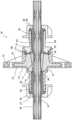
- the Figureshows a cross-sectional view of an anchor consistent with at least one embodiment of the present disclosure.
- intermediate anchor assembly 10in accordance with the invention includes anchor body 12, encapsulation 13, cap 21, front nut 22, and rear nut 24.
- Anchor body 12is encapsulated in encapsulation 13.
- Anchor body 12has anchor body bore 11 extending therethrough and adapted to receive tension member 27.
- Tension member 27may include sheathing 29. A portion of sheathing 29 may be removed from the portion of the tension member 27 that passes through anchor body bore 11 of anchor body 12.
- Anchor body 12may have a frustoconical inner surface defining a frustoconical inner chamber 15 in which a plurality of wedges 18 may seat to tension the tension member 27 extending through anchor body bore 11.
- Encapsulation 13has rear surface 14 and front surface 23.
- Rear surface 14includes rear encapsulation extension 30 extending outwardly therefrom.
- Rear encapsulation extension 30includes an inner bore coaxially aligned with anchor body bore 11.
- Rear encapsulation extension 30may be tubular.
- Rear encapsulation extension 30may or may not be tapered and may or may not include external threads or bayonet tabs or a groove or ridge for securing a snap-fit.
- the inside diameter of rear encapsulation extension 30may be greater than the outside diameter of tension member 27 or sheathing 29 so as to define an annular space therewith.
- Front surface 23includes a front encapsulation extension 32 extending outwardly therefrom, Front encapsulation extension 32 includes an inner bore coaxially aligned with anchor body bore 11. Front encapsulation extension 32 may be annular. Front encapsulation extension 32 may or may not include internal threads or bayonet tabs or a groove or ridge for securing a snap-fit.
- Rear seal 26sealingly engages rear encapsulation extension 30.
- Rear seal 26is a split seal having a longitudinal split that enables rear seal 26 to be applied to a tension member from the side, i.e. without requiring access to the tension member end.
- Rear seal 26may be made of a soft elastomer, rubber, silicone, or other suitably deformable sealing material.
- Rear seal 26is sized to fit in the annular space between rear encapsulation extension 30 and tension member 27.
- Rear nut 24may be provided to retain rear seal 26.
- Rear nut 24may concentrically engage rear encapsulation extension 30 at the external threads or bayonet tabs or a groove or ridge thereon, if present, and may include corresponding internal threads, bayonet tabs or a ridge or groove.
- rear encapsulation extension 30may be provided without an engagement feature and rear nut 24 may be a self-tapping nut that creates threads when it is threaded onto rear encapsulation extension 30.
- rear seal 26may have body 36 and head 37.
- the outside diameter of body 36may be the same as or smaller than the inside diameter of rear encapsulation extension 30 so that rear seal 26 may be applied to the side of tension member 27 and then slid along the tension member and into the annular space between rear encapsulation extension 30 and tension member 27.
- Rear seal 26may be sized to have a volume greater than the volume of the annular space between rear encapsulation extension 30 and tension member 27 so that when rear nut 24 is fully engaged on rear encapsulation extension 30 rear seal 26 is compressed into a volume that is smaller than it would otherwise occupy.
- Head 37 of rear seal 26may be compressed between the rear nut 24 and the end of rear encapsulation extension 30.
- Rear seal 26may be formed of a deformable material that conforms to the shape of the annular space so that when rear nut 24 is fully engaged on rear encapsulation extension 30 there are no unfilled voids between anchor body 12 and rear nut 24.
- Cap 21releasably engages front encapsulation extension 32 by, for example and without limitation, friction fit, threads, or bayonet connection.
- Cap 21may include an engagement interface 39, a cap extension 38, and has an inner bore that aligns with anchor body bore 11.
- Engagement interface 39may concentrically engage front encapsulation extension 32 at the internal threads or bayonet tabs or a groove or ridge, if present, and may include corresponding external threads, bayonet tabs or a ridge or groove.
- Cap extension 38may be tubular in shape.
- Cap extension 38may be tapered and may include external threads or bayonet tabs or a groove or ridge for securing a snap-fit.
- the inside diameter of cap extension 38may be greater than the outside diameter of tension member 27 so as to define an annular space therewith.
- Cap seal 17may be disposed in an annular groove 40 formed in cap 21 such that cap seal 17 sealingly engages at least one of anchor body 12 or encapsulation 13 when cap 21 is fully engaged on front encapsulation extension 32. Cap seal 17 may be annular.
- Front seal 20sealingly engages front encapsulation extension 32.
- Front seal 20is a split seal having a longitudinal split that enables front seal 20 to be applied to tension member 27 from the side, i.e. without requiring access to the tension member end.
- Front seal 20may be made of a soft elastomer, rubber, silicone, or other suitably deformable sealing material.
- Front seal 20is sized to fit in the annular space between cap extension 38 and tension member 27.
- Front nut 22may be provided to retain front seal 20.
- Front nut 22may engage cap extension 38 at the external threads or bayonet tabs or a groove or ridge thereon, if present, and may include corresponding internal threads, bayonet tabs or a ridge or groove.
- cap extension 38may be provided without an engagement feature and front nut 22 may be a self-tapping nut that creates threads when it is threaded onto cap extension 38.
- Front seal 20may have body 25 and head 28.
- the outside diameter of body 25may be the same as or smaller than the inside diameter of cap extension 38 so that front seal 20 may be applied to the side of tension member 27 and then slid along tension member 27 and into the annular space between cap extension 38 and tension member 27.
- Front seal 20may be sized to have a volume greater than the volume of the annular space between cap extension 38 and tension member 27 so that when front nut 22 is fully engaged on cap extension 38 front seal 20 is compressed into a volume that is smaller than it would otherwise occupy.
- Head 28 of front seal 20is compressed between front nut 22 and the end of cap extension 38.
- Front seal 20may be formed of a deformable material that conforms to the shape of the annular space so that when front nut 22 is fully engaged on cap extension 38 there are no unfilled voids between anchor body 12, cap 21, and rear nut 24.
- the components of the intermediate anchor assembly 10may be pre-assembled prior to delivery to the pour site or may be assembled at the pour site.
- the tension membermay be threaded through rear nut 24, anchor body 12 and encapsulation 13, cap 21, and front nut 22. Seals 20, 26 may or may not be present. Intermediate anchor assembly 10 may be slid along tension member 27 to a location on tension member 27. Rear nut 24 may then be disengaged from rear encapsulation extension 30 but remain on tension member 27. Rear seal 26 may be applied to tension member 27 between rear nut 24 and anchor body 12 and may be slid along tension member 27 into the annular space between rear encapsulation extension 30 and tension member 27. Head 37, if present, may abut the end of rear encapsulation extension 30. Rear nut 24 may then be re-engaged with rear encapsulation extension 30 such that rear seal 26 is compressed to fill voids between anchor body 12 and rear nut 24.
- Anchor assemblyincluding tension member 27 extending therethrough, may then be positioned such that a portion of a concrete form fits into the space defined by cap 21 and front nut 22. Front nut 22 is tightened such that intermediate anchor assembly 10 is retained in position. Additional fasteners, such as nails, may be used to further retain anchor assembly with respect to the concrete form and to keep it from rotating.
- Front nut 22 and cap 21may be disengaged from cap extension 38 and encapsulation 13, respectively, and slid along tension member 27 so as to allow wedges 18 to be inserted into anchor body bore 11. Once wedges 18 are seated on the frustoconical inner surface, tension member 27 may be tensioned.
- cap 21may be re-engaged with front encapsulation extension 32.
- Front seal 20may be applied to tension member 27 between front nut 22 and cap 21 and may be slid along tension member 27 and into the annular space between cap extension 38 and tension member 27. Head 28, if present, may abut the end of cap 21. In some embodiments, front seal 20 may be placed in cap 21.
- Front nut 22may then be re-engaged with cap extension 38 such that front seal 20 is compressed to fill voids between anchor body 12, cap 21, and front nut 22.
Landscapes
- Engineering & Computer Science (AREA)
- Architecture (AREA)
- Civil Engineering (AREA)
- Structural Engineering (AREA)
- Mechanical Engineering (AREA)
- Piles And Underground Anchors (AREA)
- Reinforcement Elements For Buildings (AREA)
Description
- The present disclosure relates generally to anchors for use in post-tensioning concrete, and specifically to intermediate anchors for post-tensioning tendons.
- Many structures are built using concrete, including, for instance, buildings, parking structures, apartments, condominiums, hotels, mixed-use structures, casinos, hospitals, medical buildings, government buildings, research/academic institutions, industrial buildings, malls, bridges, pavement, tanks, reservoirs, silos, foundations, sports courts, and other structures.
- The concrete may be poured into a concrete form. The concrete form may be a form or mold to give shape to the concrete as the concrete sets or hardens thus forming a concrete member.
- Prestressed concrete is structural concrete in which internal stresses are introduced to reduce potential tensile stresses in the concrete resulting from applied loads; prestressing may be accomplished by post-tensioned prestressing or pre-tensioned prestressing. In post-tensioned prestressing, a post-tensioning tendon embedded in the concrete is tensioned after the concrete has attained a specified strength. A post-tensioning tendon may include for example and without limitation, anchorages, the tension member, and sheathes or ducts.
- A post-tensioning tendon generally includes an anchorage at each end. The tension member is fixedly coupled to a fixed anchor positioned at one end of the post-tensioning tendon, sometimes referred to as the "fixed-end" or "dead end" anchor, and is stressed at the other anchor, sometimes referred to as the "stressing-end" or "live end" anchor.
- The tension member is stressed by pulling the tension member through the stressing anchor; when the pulling force is released, the anchors grip the tension member and retain the tension member in tension. In some instances, the anchors grip the tension member using wedges, so that the gripping force increases when the tension on the tension member increases.
- In some instances, it may be desirable to pour a long concrete slab in sections. In such instances, the sections are poured sequentially, with each pour section curing and being post-tensioned before the next, adjacent section is poured. In such instances, the anchors between adjacent slabs are known as "intermediate anchors." Because intermediate anchors typically entail an interruption of the sheathing that otherwise protects the tension member from corrosion, and because intermediate anchors are ultimately fully embedded in concrete, intermediate anchors need to be able to inhibit the ingress of liquid that may cause corrosion.
US 2002/083659 A1 discloses an intermediate anchorage of a post-tension system.- An anchor assembly for use in post-tensioning concrete includes an anchor body having an anchor body bore therethrough and an encapsulation, the encapsulation defining a front encapsulation extension and a rear encapsulation extension. Each of the front encapsulation extension and the rear encapsulation extension has a bore aligned with the anchor body bore, a rear nut engaging the rear encapsulation extension such that placement of a tension member in the anchor assembly enables the rear nut, the rear encapsulation extension, and the anchor body to define a rear annular space therewith. The anchor assembly also includes a cap engaging the front encapsulation extension, the cap having a bore therethrough, and a cap extension, a front nut engaging the cap extension such that placement of a tension member in the anchor assembly enables the front nut, the cap extension, and the anchor body to define a front annular space therebetween, a rear seal positioned in the rear annular space and configured such that engagement of the rear nut with the rear encapsulation extension deforms the rear seal if a tension member is present in the anchor assembly, and a front seal positioned in the front annular space and configured such that engagement of the front nut with the cap extension deforms the front seal if a tension member is present in the anchor assembly.
- The rear seal and the front seal are each a split seal. At least one of the front nut and the rear nut may be a self-tapping nut. The cap may include an annular groove and a cap seal disposed in the annular groove. At least one of the rear seal and the front seal may include a head and a tubular body extending therefrom. The rear seal and the front seal may each include a longitudinal split.
- A method for anchoring and sealing a tension member in a post-tensioning concrete application includes the steps of: a) providing an anchor assembly including an anchor body having an anchor body bore therethrough, a frustoconical inner chamber, and an encapsulation, the encapsulation defining a front encapsulation extension and a rear encapsulation extension, each of the front encapsulation extension and the rear encapsulation extension having a bore aligned with the anchor body bore; a rear nut coupled to the rear encapsulation extension, wherein placement of a tension member in the anchor assembly results in the rear nut, the rear encapsulation extension, and the anchor body defining a rear annular space therewith; a cap coupled to the front encapsulation extension, the cap having a bore therethrough, and a cap extension; and a front nut coupled to the cap extension, wherein placement of a tension member in the anchor assembly results in the front nut, the cap extension, and the anchor body defining a front annular space therewith; b) positioning the tension member in the anchor body bore; c) decoupling the cap from the front encapsulation extension; d) positioning at least one wedge in the frustoconical inner chamber; e) tensioning tension member; f) recoupling the cap to the front encapsulation extension; g) decoupling the rear nut from the rear encapsulation extension; h) positioning a deformable rear seal in the rear annular space; i) recoupling the rear nut to the rear encapsulation extension; j) decoupling the front nut from the cap extension; k) positioning a front seal in the front annular space; and l) recoupling the front nut to the cap extension.
- Completion of steps f) through l) may sealingly enclose a portion of the tension member between the rear seal and the front seal. Engagement of the rear nut with the rear encapsulation extension may deform the rear seal and engagement of the front nut with the cap extension may deform the front seal. The rear seal and the front seal may each be a split seal. Each of the rear seal and the front seal may include a longitudinal split. At least one of the rear seal and the front seal may include a head and a tubular body extending therefrom. At least one of the front nut and the rear nut may be a self-tapping nut. The cap may include an annular groove and a cap seal may be disposed in the annular groove. Engagement of the cap with the front encapsulation may deform the cap seal.
- The Figure shows a cross-sectional view of an anchor consistent with at least one embodiment of the present disclosure.
- Referring to the Figure,
intermediate anchor assembly 10 in accordance with the invention includesanchor body 12,encapsulation 13,cap 21,front nut 22, andrear nut 24.Anchor body 12 is encapsulated inencapsulation 13.Anchor body 12 hasanchor body bore 11 extending therethrough and adapted to receivetension member 27.Tension member 27 may includesheathing 29. A portion ofsheathing 29 may be removed from the portion of thetension member 27 that passes through anchor body bore 11 ofanchor body 12.Anchor body 12 may have a frustoconical inner surface defining a frustoconicalinner chamber 15 in which a plurality ofwedges 18 may seat to tension thetension member 27 extending throughanchor body bore 11. Encapsulation 13 hasrear surface 14 andfront surface 23.Rear surface 14 includesrear encapsulation extension 30 extending outwardly therefrom.Rear encapsulation extension 30 includes an inner bore coaxially aligned withanchor body bore 11.Rear encapsulation extension 30 may be tubular.Rear encapsulation extension 30 may or may not be tapered and may or may not include external threads or bayonet tabs or a groove or ridge for securing a snap-fit. The inside diameter ofrear encapsulation extension 30 may be greater than the outside diameter oftension member 27 or sheathing 29 so as to define an annular space therewith.Front surface 23 includes afront encapsulation extension 32 extending outwardly therefrom,Front encapsulation extension 32 includes an inner bore coaxially aligned withanchor body bore 11.Front encapsulation extension 32 may be annular.Front encapsulation extension 32 may or may not include internal threads or bayonet tabs or a groove or ridge for securing a snap-fit.Rear seal 26 sealingly engagesrear encapsulation extension 30.Rear seal 26 is a split seal having a longitudinal split that enablesrear seal 26 to be applied to a tension member from the side, i.e. without requiring access to the tension member end.Rear seal 26 may be made of a soft elastomer, rubber, silicone, or other suitably deformable sealing material.Rear seal 26 is sized to fit in the annular space betweenrear encapsulation extension 30 andtension member 27.Rear nut 24 may be provided to retainrear seal 26.Rear nut 24 may concentrically engagerear encapsulation extension 30 at the external threads or bayonet tabs or a groove or ridge thereon, if present, and may include corresponding internal threads, bayonet tabs or a ridge or groove. In some embodiments,rear encapsulation extension 30 may be provided without an engagement feature andrear nut 24 may be a self-tapping nut that creates threads when it is threaded ontorear encapsulation extension 30.- In some embodiments,
rear seal 26 may havebody 36 andhead 37. The outside diameter ofbody 36 may be the same as or smaller than the inside diameter ofrear encapsulation extension 30 so thatrear seal 26 may be applied to the side oftension member 27 and then slid along the tension member and into the annular space betweenrear encapsulation extension 30 andtension member 27.Rear seal 26 may be sized to have a volume greater than the volume of the annular space betweenrear encapsulation extension 30 andtension member 27 so that whenrear nut 24 is fully engaged onrear encapsulation extension 30rear seal 26 is compressed into a volume that is smaller than it would otherwise occupy.Head 37 ofrear seal 26 may be compressed between therear nut 24 and the end ofrear encapsulation extension 30.Rear seal 26 may be formed of a deformable material that conforms to the shape of the annular space so that whenrear nut 24 is fully engaged onrear encapsulation extension 30 there are no unfilled voids betweenanchor body 12 andrear nut 24. Cap 21 releasably engagesfront encapsulation extension 32 by, for example and without limitation, friction fit, threads, or bayonet connection.Cap 21 may include anengagement interface 39, acap extension 38, and has an inner bore that aligns with anchor body bore 11.Engagement interface 39 may concentrically engagefront encapsulation extension 32 at the internal threads or bayonet tabs or a groove or ridge, if present, and may include corresponding external threads, bayonet tabs or a ridge or groove.Cap extension 38 may be tubular in shape.Cap extension 38 may be tapered and may include external threads or bayonet tabs or a groove or ridge for securing a snap-fit. The inside diameter ofcap extension 38 may be greater than the outside diameter oftension member 27 so as to define an annular space therewith.Cap seal 17 may be disposed in anannular groove 40 formed incap 21 such thatcap seal 17 sealingly engages at least one ofanchor body 12 orencapsulation 13 whencap 21 is fully engaged onfront encapsulation extension 32.Cap seal 17 may be annular.Front seal 20 sealingly engagesfront encapsulation extension 32.Front seal 20 is a split seal having a longitudinal split that enablesfront seal 20 to be applied totension member 27 from the side,i.e. without requiring access to the tension member end.Front seal 20 may be made of a soft elastomer, rubber, silicone, or other suitably deformable sealing material.Front seal 20 is sized to fit in the annular space betweencap extension 38 andtension member 27.Front nut 22 may be provided to retainfront seal 20.Front nut 22 may engagecap extension 38 at the external threads or bayonet tabs or a groove or ridge thereon, if present, and may include corresponding internal threads, bayonet tabs or a ridge or groove. In some embodiments,cap extension 38 may be provided without an engagement feature andfront nut 22 may be a self-tapping nut that creates threads when it is threaded ontocap extension 38.Front seal 20 may havebody 25 andhead 28. The outside diameter ofbody 25 may be the same as or smaller than the inside diameter ofcap extension 38 so thatfront seal 20 may be applied to the side oftension member 27 and then slid alongtension member 27 and into the annular space betweencap extension 38 andtension member 27.Front seal 20 may be sized to have a volume greater than the volume of the annular space betweencap extension 38 andtension member 27 so that whenfront nut 22 is fully engaged oncap extension 38front seal 20 is compressed into a volume that is smaller than it would otherwise occupy.Head 28 offront seal 20 is compressed betweenfront nut 22 and the end ofcap extension 38.Front seal 20 may be formed of a deformable material that conforms to the shape of the annular space so that whenfront nut 22 is fully engaged oncap extension 38 there are no unfilled voids betweenanchor body 12,cap 21, andrear nut 24.- The components of the
intermediate anchor assembly 10 may be pre-assembled prior to delivery to the pour site or may be assembled at the pour site. - In operation as part of a sequential pour of concrete, the tension member may be threaded through
rear nut 24,anchor body 12 andencapsulation 13,cap 21, andfront nut 22.Seals Intermediate anchor assembly 10 may be slid alongtension member 27 to a location ontension member 27.Rear nut 24 may then be disengaged fromrear encapsulation extension 30 but remain ontension member 27.Rear seal 26 may be applied totension member 27 betweenrear nut 24 andanchor body 12 and may be slid alongtension member 27 into the annular space betweenrear encapsulation extension 30 andtension member 27.Head 37, if present, may abut the end ofrear encapsulation extension 30.Rear nut 24 may then be re-engaged withrear encapsulation extension 30 such thatrear seal 26 is compressed to fill voids betweenanchor body 12 andrear nut 24. - Anchor assembly, including
tension member 27 extending therethrough, may then be positioned such that a portion of a concrete form fits into the space defined bycap 21 andfront nut 22.Front nut 22 is tightened such thatintermediate anchor assembly 10 is retained in position. Additional fasteners, such as nails, may be used to further retain anchor assembly with respect to the concrete form and to keep it from rotating. - Once concrete has been poured, thereby embedding the encapsulated anchor body and attached
rear nut 24, the concrete form may be removed.Front nut 22 andcap 21 may be disengaged fromcap extension 38 andencapsulation 13, respectively, and slid alongtension member 27 so as to allowwedges 18 to be inserted into anchor body bore 11. Oncewedges 18 are seated on the frustoconical inner surface,tension member 27 may be tensioned. - Once
tension member 27 has been tensioned,cap 21 may be re-engaged withfront encapsulation extension 32.Front seal 20 may be applied totension member 27 betweenfront nut 22 andcap 21 and may be slid alongtension member 27 and into the annular space betweencap extension 38 andtension member 27.Head 28, if present, may abut the end ofcap 21. In some embodiments,front seal 20 may be placed incap 21. Front nut 22 may then be re-engaged withcap extension 38 such thatfront seal 20 is compressed to fill voids betweenanchor body 12,cap 21, andfront nut 22.- The foregoing outlines features of several embodiments so that a person of ordinary skill in the art may better understand the aspects of the present disclosure. Such features may be replaced by any one of numerous equivalent alternatives, only some of which are disclosed herein. One of ordinary skill in the art should appreciate that they may readily use the present disclosure as a basis for designing or modifying other processes and structures for carrying out the same purposes and/or achieving the same advantages of the embodiments introduced herein. One of ordinary skill in the art should also realize that such equivalent constructions do not depart from the scope of the present disclosure and that they may make various changes, substitutions, and alterations herein without departing from the scope of the present invention being defined by the appended claims.
- In the claims that follow, unless explicitly so recited, the sequential recitation of steps is not intended to require that the steps be recited sequentially or in the order recited. The steps may be performed in any order and two or more steps may be performed simultaneously.
Claims (14)
- An intermediate anchor assembly for use on a tension member in a post-tensioning concrete application, the intermediate anchor assembly comprising:an anchor body (12) having an anchor body bore (11) therethrough;an encapsulation (13), the encapsulation defining a front encapsulation extension (32) and a rear encapsulation extension (30), each of the front encapsulation extension and the rear encapsulation extension having a bore aligned with the anchor body bore;a rear nut (24) concentrically engaging the rear encapsulation extension;a cap (21) releasably engaging the front encapsulation extension, the cap having a bore therethrough, and a cap extension (38);a front nut (22) engaging the cap extension;a rear seal (26) positioned in a rear annular space, the rear seal being a split seal; anda front seal (20) positioned in a front annular space, the front seal being a split seal.
- The intermediate anchor assembly of claim 1, wherein at least one of the front nut and the rear nut is a self-tapping nut.
- The intermediate anchor assembly of claim 1 or claim 2, wherein the cap includes an annular groove (40), and wherein a cap seal (17) is disposed in the annular groove.
- The intermediate anchor assembly of any one of claims 1 to 3, wherein at least one of the rear seal and the front seal includes a head (37, 28) and a tubular body (36, 25) extending therefrom.
- The intermediate anchor assembly of any one of claims 1 to 4, wherein each of the rear seal and the front seal includes a longitudinal split.
- A method for anchoring and sealing a tension member in a post-tensioning concrete application, comprising the steps of:a) providing an intermediate anchor assembly comprising:an anchor body (12) having an anchor body bore (11) therethrough, a frustoconical inner chamber (15),an encapsulation (13), the encapsulation defining a front encapsulation extension (32) and a rear encapsulation extension (30), each of the front encapsulation extension and the rear encapsulation extension having a bore aligned with the anchor body bore;a rear nut (24) engaged with the rear encapsulation extension, wherein placement of a tension member (27) in the anchor assembly results in the rear nut, the rear encapsulation extension, and the anchor body defining a rear annular space therewith;a cap (21) engaged with the front encapsulation extension, the cap having a bore therethrough, and a cap extension (38); anda front nut (22) engaged with the cap extension, wherein placement of a tension member in the anchor assembly results in the front nut, the cap extension, and the anchor body defining a front annular space therewith;b) positioning the tension member in the anchor body bore;c) decoupling the cap from the front encapsulation extension;d) positioning at least one wedge in the frustoconical inner chamber;e) tensioning tension member;f) recoupling the cap to the front encapsulation extension;g) decoupling the rear nut from the rear encapsulation extension;h) positioning a deformable rear seal (26) in the rear annular space;i) recoupling the rear nut to the rear encapsulation extension;j) decoupling the front nut from the cap extension;k) positioning a front seal (20) in the front annular space; andl) recoupling the front nut to the cap extension.
- The method of claim 6 wherein completion of steps f) through l) sealingly encloses a portion of the tension member between the rear seal and the front seal.
- The method of claim 6 or claim 7, wherein engagement of the rear nut with the rear encapsulation extension deforms the rear seal.
- The method of any one of claims 6 to 8, wherein engagement of the front nut with the cap extension deforms the front seal.
- The method of any one of claims 6 to 9, wherein the rear seal and the front seal are each a split seal.
- The method of claim 10, wherein each of the rear seal and the front seal includes a longitudinal split.
- The method of any one of claims 6 to 11, wherein at least one of the rear seal and the front seal includes a head (37, 28) and a tubular body (36, 25) extending therefrom.
- The method of any one of claims 6 to 12, wherein at least one of the front nut and the rear nut is a self-tapping nut.
- The method of any one of claims 6 to 13, wherein the cap includes an annular groove (40), and wherein a cap seal (17) is disposed in the annular groove; and/or, wherein engagement of the cap with the front encapsulation deforms the cap seal.
Applications Claiming Priority (2)
| Application Number | Priority Date | Filing Date | Title |
|---|---|---|---|
| US201962853547P | 2019-05-28 | 2019-05-28 | |
| US16/876,017US11091913B2 (en) | 2019-05-28 | 2020-05-16 | Intermediate anchor for a post-tensioning tendon |
Publications (2)
| Publication Number | Publication Date |
|---|---|
| EP3744921A1 EP3744921A1 (en) | 2020-12-02 |
| EP3744921B1true EP3744921B1 (en) | 2023-08-09 |
Family
ID=70779462
Family Applications (1)
| Application Number | Title | Priority Date | Filing Date |
|---|---|---|---|
| EP20175370.4AActiveEP3744921B1 (en) | 2019-05-28 | 2020-05-19 | Intermediate anchor for a post-tensioning tendon |
Country Status (4)
| Country | Link |
|---|---|
| US (1) | US11091913B2 (en) |
| EP (1) | EP3744921B1 (en) |
| CA (1) | CA3081466A1 (en) |
| ES (1) | ES2960738T3 (en) |
Families Citing this family (3)
| Publication number | Priority date | Publication date | Assignee | Title |
|---|---|---|---|---|
| US11846102B2 (en)* | 2020-12-17 | 2023-12-19 | Polyform, Inc. | Sheathing clamps for unbonded post-tensioning assemblies |
| US11927012B2 (en)* | 2020-12-24 | 2024-03-12 | C & M Machines LLC | One piece molded post-tension tendon pocket former with push in retention tabs and method of use thereof |
| US20230125346A1 (en)* | 2021-09-26 | 2023-04-27 | Pvt Clean Energy Llc | Tailoring Thermoelastic Constants of Cellular and Lattice Materials with Pre-Stress for Lightweight Structures |
Family Cites Families (15)
| Publication number | Priority date | Publication date | Assignee | Title |
|---|---|---|---|---|
| DE8002045U1 (en)* | 1980-01-26 | 1980-04-30 | Dyckerhoff & Widmann Ag, 8000 Muenchen | RECOVERABLE SHUTTERING PART FOR THE ANCHORING AREA OF A TENSION LINK IN A CONCRETE COMPONENT |
| AT375716B (en)* | 1980-08-16 | 1984-09-10 | Dyckerhoff & Widmann Ag | RECOVERABLE FORMWORK FOR THE ANCHORING AREA OF A TENSION LINK IN A CONCRETE COMPONENT |
| US4363122A (en)* | 1980-09-16 | 1982-12-07 | Northern Telecom Limited | Mitigation of noise signal contrast in a digital speech interpolation transmission system |
| US5770286A (en) | 1996-04-10 | 1998-06-23 | Sorkin; Felix L. | Corrosion inhibitor retaining seal |
| US6098356A (en) | 1998-11-03 | 2000-08-08 | Sorkin; Felix L. | Method and apparatus for sealing an intermediate anchorage of a post-tension system |
| US6817148B1 (en) | 2000-08-28 | 2004-11-16 | Felix L. Sorkin | Corrosion protection seal for an anchor of a post-tension system |
| US6631596B1 (en) | 2000-10-16 | 2003-10-14 | Felix L. Sorkin | Corrosion protection tube for use on an anchor of a post-tension anchor system |
| US6381912B1 (en) | 2000-12-29 | 2002-05-07 | Felix L. Sorkin | Apparatus and method for sealing an intermediate anchor of a post-tension anchor system |
| US20020083659A1 (en) | 2000-12-29 | 2002-07-04 | Sorkin Felix L. | Method and apparatus for sealing an intermediate anchorage of a post-tension system |
| US6761002B1 (en) | 2002-12-03 | 2004-07-13 | Felix L. Sorkin | Connector assembly for intermediate post-tension anchorage system |
| US20040148882A1 (en) | 2003-02-03 | 2004-08-05 | Norris Hayes | Post-tension anchor seal cap |
| US7963078B1 (en)* | 2007-09-25 | 2011-06-21 | Sorkin Felix L | Compression cap sheathing lock |
| CA2946605C (en)* | 2014-05-19 | 2020-09-22 | Felix Sorkin | Cap for anchor of post-tension anchorage system |
| US10378210B2 (en) | 2015-02-02 | 2019-08-13 | Precision-Hayes International Inc. | Concrete tendon gripping and sealing apparatus and method |
| WO2017023893A1 (en)* | 2015-08-04 | 2017-02-09 | Felix Sorkin | Spindle lock anchor for post tensioned concrete member |
- 2020
- 2020-05-16USUS16/876,017patent/US11091913B2/enactiveActive
- 2020-05-19EPEP20175370.4Apatent/EP3744921B1/enactiveActive
- 2020-05-19ESES20175370Tpatent/ES2960738T3/enactiveActive
- 2020-05-27CACA3081466Apatent/CA3081466A1/enactivePending
Also Published As
| Publication number | Publication date |
|---|---|
| US20200378123A1 (en) | 2020-12-03 |
| CA3081466A1 (en) | 2020-11-28 |
| US11091913B2 (en) | 2021-08-17 |
| ES2960738T3 (en) | 2024-03-06 |
| EP3744921A1 (en) | 2020-12-02 |
Similar Documents
| Publication | Publication Date | Title |
|---|---|---|
| EP3744921B1 (en) | Intermediate anchor for a post-tensioning tendon | |
| US11512469B2 (en) | Intermediate concrete anchor system with cap | |
| US9879427B2 (en) | Modified permanent cap | |
| US20250092679A1 (en) | Intermediate anchor assembly | |
| US10072429B2 (en) | Modified pocket former | |
| US12000148B2 (en) | Multi-anchor concrete post-tensioning system | |
| US10113313B2 (en) | Sheathing retention capsule | |
| US10995494B2 (en) | Apparatus for repairing a tension member | |
| US11078668B2 (en) | Apparatus for repairing a tension member | |
| US11090885B2 (en) | Apparatus for repairing a tension member | |
| CA3113299A1 (en) | Intermediate anchor assembly | |
| CA3081461A1 (en) | Apparatus for repairing a tension member | |
| EP3128094B1 (en) | Anchoring system and method of coupling a tensioning member |
Legal Events
| Date | Code | Title | Description |
|---|---|---|---|
| PUAI | Public reference made under article 153(3) epc to a published international application that has entered the european phase | Free format text:ORIGINAL CODE: 0009012 | |
| STAA | Information on the status of an ep patent application or granted ep patent | Free format text:STATUS: THE APPLICATION HAS BEEN PUBLISHED | |
| AK | Designated contracting states | Kind code of ref document:A1 Designated state(s):AL AT BE BG CH CY CZ DE DK EE ES FI FR GB GR HR HU IE IS IT LI LT LU LV MC MK MT NL NO PL PT RO RS SE SI SK SM TR | |
| AX | Request for extension of the european patent | Extension state:BA ME | |
| STAA | Information on the status of an ep patent application or granted ep patent | Free format text:STATUS: REQUEST FOR EXAMINATION WAS MADE | |
| 17P | Request for examination filed | Effective date:20210528 | |
| RBV | Designated contracting states (corrected) | Designated state(s):AL AT BE BG CH CY CZ DE DK EE ES FI FR GB GR HR HU IE IS IT LI LT LU LV MC MK MT NL NO PL PT RO RS SE SI SK SM TR | |
| GRAP | Despatch of communication of intention to grant a patent | Free format text:ORIGINAL CODE: EPIDOSNIGR1 | |
| STAA | Information on the status of an ep patent application or granted ep patent | Free format text:STATUS: GRANT OF PATENT IS INTENDED | |
| INTG | Intention to grant announced | Effective date:20230302 | |
| GRAS | Grant fee paid | Free format text:ORIGINAL CODE: EPIDOSNIGR3 | |
| GRAA | (expected) grant | Free format text:ORIGINAL CODE: 0009210 | |
| STAA | Information on the status of an ep patent application or granted ep patent | Free format text:STATUS: THE PATENT HAS BEEN GRANTED | |
| P01 | Opt-out of the competence of the unified patent court (upc) registered | Effective date:20230613 | |
| AK | Designated contracting states | Kind code of ref document:B1 Designated state(s):AL AT BE BG CH CY CZ DE DK EE ES FI FR GB GR HR HU IE IS IT LI LT LU LV MC MK MT NL NO PL PT RO RS SE SI SK SM TR | |
| REG | Reference to a national code | Ref country code:GB Ref legal event code:FG4D | |
| REG | Reference to a national code | Ref country code:CH Ref legal event code:EP | |
| REG | Reference to a national code | Ref country code:IE Ref legal event code:FG4D | |
| REG | Reference to a national code | Ref country code:DE Ref legal event code:R096 Ref document number:602020015252 Country of ref document:DE | |
| REG | Reference to a national code | Ref country code:DE Ref legal event code:R082 Ref document number:602020015252 Country of ref document:DE Representative=s name:BOEHMERT & BOEHMERT ANWALTSPARTNERSCHAFT MBB -, DE | |
| REG | Reference to a national code | Ref country code:LT Ref legal event code:MG9D | |
| REG | Reference to a national code | Ref country code:NL Ref legal event code:MP Effective date:20230809 | |
| REG | Reference to a national code | Ref country code:AT Ref legal event code:MK05 Ref document number:1597687 Country of ref document:AT Kind code of ref document:T Effective date:20230809 | |
| PG25 | Lapsed in a contracting state [announced via postgrant information from national office to epo] | Ref country code:GR Free format text:LAPSE BECAUSE OF FAILURE TO SUBMIT A TRANSLATION OF THE DESCRIPTION OR TO PAY THE FEE WITHIN THE PRESCRIBED TIME-LIMIT Effective date:20231110 | |
| PG25 | Lapsed in a contracting state [announced via postgrant information from national office to epo] | Ref country code:IS Free format text:LAPSE BECAUSE OF FAILURE TO SUBMIT A TRANSLATION OF THE DESCRIPTION OR TO PAY THE FEE WITHIN THE PRESCRIBED TIME-LIMIT Effective date:20231209 | |
| PG25 | Lapsed in a contracting state [announced via postgrant information from national office to epo] | Ref country code:SE Free format text:LAPSE BECAUSE OF FAILURE TO SUBMIT A TRANSLATION OF THE DESCRIPTION OR TO PAY THE FEE WITHIN THE PRESCRIBED TIME-LIMIT Effective date:20230809 Ref country code:RS Free format text:LAPSE BECAUSE OF FAILURE TO SUBMIT A TRANSLATION OF THE DESCRIPTION OR TO PAY THE FEE WITHIN THE PRESCRIBED TIME-LIMIT Effective date:20230809 Ref country code:PT Free format text:LAPSE BECAUSE OF FAILURE TO SUBMIT A TRANSLATION OF THE DESCRIPTION OR TO PAY THE FEE WITHIN THE PRESCRIBED TIME-LIMIT Effective date:20231211 Ref country code:NO Free format text:LAPSE BECAUSE OF FAILURE TO SUBMIT A TRANSLATION OF THE DESCRIPTION OR TO PAY THE FEE WITHIN THE PRESCRIBED TIME-LIMIT Effective date:20231109 Ref country code:NL Free format text:LAPSE BECAUSE OF FAILURE TO SUBMIT A TRANSLATION OF THE DESCRIPTION OR TO PAY THE FEE WITHIN THE PRESCRIBED TIME-LIMIT Effective date:20230809 Ref country code:LV Free format text:LAPSE BECAUSE OF FAILURE TO SUBMIT A TRANSLATION OF THE DESCRIPTION OR TO PAY THE FEE WITHIN THE PRESCRIBED TIME-LIMIT Effective date:20230809 Ref country code:LT Free format text:LAPSE BECAUSE OF FAILURE TO SUBMIT A TRANSLATION OF THE DESCRIPTION OR TO PAY THE FEE WITHIN THE PRESCRIBED TIME-LIMIT Effective date:20230809 Ref country code:IS Free format text:LAPSE BECAUSE OF FAILURE TO SUBMIT A TRANSLATION OF THE DESCRIPTION OR TO PAY THE FEE WITHIN THE PRESCRIBED TIME-LIMIT Effective date:20231209 Ref country code:HR Free format text:LAPSE BECAUSE OF FAILURE TO SUBMIT A TRANSLATION OF THE DESCRIPTION OR TO PAY THE FEE WITHIN THE PRESCRIBED TIME-LIMIT Effective date:20230809 Ref country code:GR Free format text:LAPSE BECAUSE OF FAILURE TO SUBMIT A TRANSLATION OF THE DESCRIPTION OR TO PAY THE FEE WITHIN THE PRESCRIBED TIME-LIMIT Effective date:20231110 Ref country code:FI Free format text:LAPSE BECAUSE OF FAILURE TO SUBMIT A TRANSLATION OF THE DESCRIPTION OR TO PAY THE FEE WITHIN THE PRESCRIBED TIME-LIMIT Effective date:20230809 Ref country code:AT Free format text:LAPSE BECAUSE OF FAILURE TO SUBMIT A TRANSLATION OF THE DESCRIPTION OR TO PAY THE FEE WITHIN THE PRESCRIBED TIME-LIMIT Effective date:20230809 | |
| PG25 | Lapsed in a contracting state [announced via postgrant information from national office to epo] | Ref country code:PL Free format text:LAPSE BECAUSE OF FAILURE TO SUBMIT A TRANSLATION OF THE DESCRIPTION OR TO PAY THE FEE WITHIN THE PRESCRIBED TIME-LIMIT Effective date:20230809 | |
| REG | Reference to a national code | Ref country code:ES Ref legal event code:FG2A Ref document number:2960738 Country of ref document:ES Kind code of ref document:T3 Effective date:20240306 | |
| PG25 | Lapsed in a contracting state [announced via postgrant information from national office to epo] | Ref country code:SM Free format text:LAPSE BECAUSE OF FAILURE TO SUBMIT A TRANSLATION OF THE DESCRIPTION OR TO PAY THE FEE WITHIN THE PRESCRIBED TIME-LIMIT Effective date:20230809 Ref country code:RO Free format text:LAPSE BECAUSE OF FAILURE TO SUBMIT A TRANSLATION OF THE DESCRIPTION OR TO PAY THE FEE WITHIN THE PRESCRIBED TIME-LIMIT Effective date:20230809 Ref country code:EE Free format text:LAPSE BECAUSE OF FAILURE TO SUBMIT A TRANSLATION OF THE DESCRIPTION OR TO PAY THE FEE WITHIN THE PRESCRIBED TIME-LIMIT Effective date:20230809 Ref country code:DK Free format text:LAPSE BECAUSE OF FAILURE TO SUBMIT A TRANSLATION OF THE DESCRIPTION OR TO PAY THE FEE WITHIN THE PRESCRIBED TIME-LIMIT Effective date:20230809 Ref country code:CZ Free format text:LAPSE BECAUSE OF FAILURE TO SUBMIT A TRANSLATION OF THE DESCRIPTION OR TO PAY THE FEE WITHIN THE PRESCRIBED TIME-LIMIT Effective date:20230809 Ref country code:SK Free format text:LAPSE BECAUSE OF FAILURE TO SUBMIT A TRANSLATION OF THE DESCRIPTION OR TO PAY THE FEE WITHIN THE PRESCRIBED TIME-LIMIT Effective date:20230809 | |
| REG | Reference to a national code | Ref country code:DE Ref legal event code:R097 Ref document number:602020015252 Country of ref document:DE | |
| PLBE | No opposition filed within time limit | Free format text:ORIGINAL CODE: 0009261 | |
| STAA | Information on the status of an ep patent application or granted ep patent | Free format text:STATUS: NO OPPOSITION FILED WITHIN TIME LIMIT | |
| 26N | No opposition filed | Effective date:20240513 | |
| PG25 | Lapsed in a contracting state [announced via postgrant information from national office to epo] | Ref country code:SI Free format text:LAPSE BECAUSE OF FAILURE TO SUBMIT A TRANSLATION OF THE DESCRIPTION OR TO PAY THE FEE WITHIN THE PRESCRIBED TIME-LIMIT Effective date:20230809 | |
| PGFP | Annual fee paid to national office [announced via postgrant information from national office to epo] | Ref country code:IT Payment date:20240529 Year of fee payment:5 | |
| PG25 | Lapsed in a contracting state [announced via postgrant information from national office to epo] | Ref country code:BG Free format text:LAPSE BECAUSE OF FAILURE TO SUBMIT A TRANSLATION OF THE DESCRIPTION OR TO PAY THE FEE WITHIN THE PRESCRIBED TIME-LIMIT Effective date:20230809 | |
| PG25 | Lapsed in a contracting state [announced via postgrant information from national office to epo] | Ref country code:BG Free format text:LAPSE BECAUSE OF FAILURE TO SUBMIT A TRANSLATION OF THE DESCRIPTION OR TO PAY THE FEE WITHIN THE PRESCRIBED TIME-LIMIT Effective date:20230809 | |
| REG | Reference to a national code | Ref country code:CH Ref legal event code:PL | |
| PG25 | Lapsed in a contracting state [announced via postgrant information from national office to epo] | Ref country code:MC Free format text:LAPSE BECAUSE OF FAILURE TO SUBMIT A TRANSLATION OF THE DESCRIPTION OR TO PAY THE FEE WITHIN THE PRESCRIBED TIME-LIMIT Effective date:20230809 | |
| PG25 | Lapsed in a contracting state [announced via postgrant information from national office to epo] | Ref country code:LU Free format text:LAPSE BECAUSE OF NON-PAYMENT OF DUE FEES Effective date:20240519 | |
| PG25 | Lapsed in a contracting state [announced via postgrant information from national office to epo] | Ref country code:MC Free format text:LAPSE BECAUSE OF FAILURE TO SUBMIT A TRANSLATION OF THE DESCRIPTION OR TO PAY THE FEE WITHIN THE PRESCRIBED TIME-LIMIT Effective date:20230809 Ref country code:LU Free format text:LAPSE BECAUSE OF NON-PAYMENT OF DUE FEES Effective date:20240519 Ref country code:CH Free format text:LAPSE BECAUSE OF NON-PAYMENT OF DUE FEES Effective date:20240531 | |
| REG | Reference to a national code | Ref country code:BE Ref legal event code:MM Effective date:20240531 | |
| PG25 | Lapsed in a contracting state [announced via postgrant information from national office to epo] | Ref country code:IE Free format text:LAPSE BECAUSE OF NON-PAYMENT OF DUE FEES Effective date:20240519 | |
| PG25 | Lapsed in a contracting state [announced via postgrant information from national office to epo] | Ref country code:BE Free format text:LAPSE BECAUSE OF NON-PAYMENT OF DUE FEES Effective date:20240531 | |
| PGFP | Annual fee paid to national office [announced via postgrant information from national office to epo] | Ref country code:DE Payment date:20250529 Year of fee payment:6 | |
| PGFP | Annual fee paid to national office [announced via postgrant information from national office to epo] | Ref country code:GB Payment date:20250523 Year of fee payment:6 Ref country code:ES Payment date:20250611 Year of fee payment:6 | |
| PGFP | Annual fee paid to national office [announced via postgrant information from national office to epo] | Ref country code:FR Payment date:20250526 Year of fee payment:6 | |
| PG25 | Lapsed in a contracting state [announced via postgrant information from national office to epo] | Ref country code:CY Free format text:LAPSE BECAUSE OF FAILURE TO SUBMIT A TRANSLATION OF THE DESCRIPTION OR TO PAY THE FEE WITHIN THE PRESCRIBED TIME-LIMIT; INVALID AB INITIO Effective date:20200519 | |
| PG25 | Lapsed in a contracting state [announced via postgrant information from national office to epo] | Ref country code:HU Free format text:LAPSE BECAUSE OF FAILURE TO SUBMIT A TRANSLATION OF THE DESCRIPTION OR TO PAY THE FEE WITHIN THE PRESCRIBED TIME-LIMIT; INVALID AB INITIO Effective date:20200519 |