EP3741317A1 - Ultrasonically powered surgical instruments with rotating cutting implement - Google Patents
Ultrasonically powered surgical instruments with rotating cutting implementDownload PDFInfo
- Publication number
- EP3741317A1 EP3741317A1EP20182974.4AEP20182974AEP3741317A1EP 3741317 A1EP3741317 A1EP 3741317A1EP 20182974 AEP20182974 AEP 20182974AEP 3741317 A1EP3741317 A1EP 3741317A1
- Authority
- EP
- European Patent Office
- Prior art keywords
- blade
- ultrasonic
- outer sheath
- sheath
- motor
- Prior art date
- Legal status (The legal status is an assumption and is not a legal conclusion. Google has not performed a legal analysis and makes no representation as to the accuracy of the status listed.)
- Granted
Links
Images


Classifications
- A—HUMAN NECESSITIES
- A61—MEDICAL OR VETERINARY SCIENCE; HYGIENE
- A61B—DIAGNOSIS; SURGERY; IDENTIFICATION
- A61B17/00—Surgical instruments, devices or methods
- A61B17/32—Surgical cutting instruments
- A61B17/320068—Surgical cutting instruments using mechanical vibrations, e.g. ultrasonic
- A—HUMAN NECESSITIES
- A61—MEDICAL OR VETERINARY SCIENCE; HYGIENE
- A61B—DIAGNOSIS; SURGERY; IDENTIFICATION
- A61B17/00—Surgical instruments, devices or methods
- A61B17/32—Surgical cutting instruments
- A61B17/3205—Excision instruments
- A61B17/3207—Atherectomy devices working by cutting or abrading; Similar devices specially adapted for non-vascular obstructions
- A61B17/320758—Atherectomy devices working by cutting or abrading; Similar devices specially adapted for non-vascular obstructions with a rotating cutting instrument, e.g. motor driven
- A—HUMAN NECESSITIES
- A61—MEDICAL OR VETERINARY SCIENCE; HYGIENE
- A61B—DIAGNOSIS; SURGERY; IDENTIFICATION
- A61B17/00—Surgical instruments, devices or methods
- A61B17/32—Surgical cutting instruments
- A61B17/3205—Excision instruments
- A61B17/3207—Atherectomy devices working by cutting or abrading; Similar devices specially adapted for non-vascular obstructions
- A61B17/320783—Atherectomy devices working by cutting or abrading; Similar devices specially adapted for non-vascular obstructions through side-hole, e.g. sliding or rotating cutter inside catheter
- A—HUMAN NECESSITIES
- A61—MEDICAL OR VETERINARY SCIENCE; HYGIENE
- A61B—DIAGNOSIS; SURGERY; IDENTIFICATION
- A61B17/00—Surgical instruments, devices or methods
- A61B17/32—Surgical cutting instruments
- A61B17/320016—Endoscopic cutting instruments, e.g. arthroscopes, resectoscopes
- A61B17/32002—Endoscopic cutting instruments, e.g. arthroscopes, resectoscopes with continuously rotating, oscillating or reciprocating cutting instruments
- A—HUMAN NECESSITIES
- A61—MEDICAL OR VETERINARY SCIENCE; HYGIENE
- A61B—DIAGNOSIS; SURGERY; IDENTIFICATION
- A61B17/00—Surgical instruments, devices or methods
- A61B2017/00017—Electrical control of surgical instruments
- A61B2017/00022—Sensing or detecting at the treatment site
- A61B2017/00075—Motion
- A—HUMAN NECESSITIES
- A61—MEDICAL OR VETERINARY SCIENCE; HYGIENE
- A61B—DIAGNOSIS; SURGERY; IDENTIFICATION
- A61B17/00—Surgical instruments, devices or methods
- A61B2017/00017—Electrical control of surgical instruments
- A61B2017/00022—Sensing or detecting at the treatment site
- A61B2017/00106—Sensing or detecting at the treatment site ultrasonic
- A—HUMAN NECESSITIES
- A61—MEDICAL OR VETERINARY SCIENCE; HYGIENE
- A61B—DIAGNOSIS; SURGERY; IDENTIFICATION
- A61B17/00—Surgical instruments, devices or methods
- A61B2017/00477—Coupling
- A—HUMAN NECESSITIES
- A61—MEDICAL OR VETERINARY SCIENCE; HYGIENE
- A61B—DIAGNOSIS; SURGERY; IDENTIFICATION
- A61B17/00—Surgical instruments, devices or methods
- A61B17/32—Surgical cutting instruments
- A61B17/320068—Surgical cutting instruments using mechanical vibrations, e.g. ultrasonic
- A61B2017/320069—Surgical cutting instruments using mechanical vibrations, e.g. ultrasonic for ablating tissue
- A—HUMAN NECESSITIES
- A61—MEDICAL OR VETERINARY SCIENCE; HYGIENE
- A61B—DIAGNOSIS; SURGERY; IDENTIFICATION
- A61B17/00—Surgical instruments, devices or methods
- A61B17/32—Surgical cutting instruments
- A61B17/320068—Surgical cutting instruments using mechanical vibrations, e.g. ultrasonic
- A61B2017/32007—Surgical cutting instruments using mechanical vibrations, e.g. ultrasonic with suction or vacuum means
- A—HUMAN NECESSITIES
- A61—MEDICAL OR VETERINARY SCIENCE; HYGIENE
- A61B—DIAGNOSIS; SURGERY; IDENTIFICATION
- A61B17/00—Surgical instruments, devices or methods
- A61B17/32—Surgical cutting instruments
- A61B17/320068—Surgical cutting instruments using mechanical vibrations, e.g. ultrasonic
- A61B2017/320071—Surgical cutting instruments using mechanical vibrations, e.g. ultrasonic with articulating means for working tip
- A—HUMAN NECESSITIES
- A61—MEDICAL OR VETERINARY SCIENCE; HYGIENE
- A61B—DIAGNOSIS; SURGERY; IDENTIFICATION
- A61B17/00—Surgical instruments, devices or methods
- A61B17/32—Surgical cutting instruments
- A61B17/320068—Surgical cutting instruments using mechanical vibrations, e.g. ultrasonic
- A61B2017/320072—Working tips with special features, e.g. extending parts
- A—HUMAN NECESSITIES
- A61—MEDICAL OR VETERINARY SCIENCE; HYGIENE
- A61B—DIAGNOSIS; SURGERY; IDENTIFICATION
- A61B17/00—Surgical instruments, devices or methods
- A61B17/32—Surgical cutting instruments
- A61B17/320068—Surgical cutting instruments using mechanical vibrations, e.g. ultrasonic
- A61B2017/320088—Surgical cutting instruments using mechanical vibrations, e.g. ultrasonic with acoustic insulation, e.g. elements for damping vibrations between horn and surrounding sheath
- A—HUMAN NECESSITIES
- A61—MEDICAL OR VETERINARY SCIENCE; HYGIENE
- A61B—DIAGNOSIS; SURGERY; IDENTIFICATION
- A61B17/00—Surgical instruments, devices or methods
- A61B17/32—Surgical cutting instruments
- A61B17/320068—Surgical cutting instruments using mechanical vibrations, e.g. ultrasonic
- A61B2017/320089—Surgical cutting instruments using mechanical vibrations, e.g. ultrasonic node location
Definitions
- This localized heatcreates a narrow zone of coagulation, which will reduce or eliminate bleeding in small vessels, such as those less than one millimeter in diameter.
- the cutting efficiency of the blade 200, as well as the degree of hemostasis,will vary with the level of driving power applied, the cutting rate or force applied by the surgeon to the blade, the nature of the tissue type and the vascularity of the tissue.
- motor 190When power is applied to motor 190, motor 190 applies a "gross rotational motion" to the handpiece 110 to cause the ultrasonic surgical instrument 110 and blade 200 to rotate about central axis A-A.
- gross rotational motionis to be distinguished from that "torsional ultrasonic motion” that may be achieved when employing a non-homogeneous formed ultrasonic blade.
- gross rotational motioninstead encompasses rotational motion that is not solely generated by operation of the ultrasonic transducer assembly 114.
- Various embodimentsalso include a distal nosepiece 160 that may be removably attached to the distal end 103 of the housing 102 by fasteners 161. See FIG. 5 .
- One or more shim members 162may be positioned between the distal end 103 and the nosepiece 160 to facilitate coaxial attachment between the housing 102 and the nosepiece 160.
- the nosepiece 160may be fabricated from, for example, stainless steel or polycarbonate.
- the distal end 202 of the blade 200extends through a hollow coupler segment 210 that is journaled within an inner sheath seal 212.
- the usermay remove the Allen wrench or other tool from holes 108, 131 and insert a threaded plug (not shown) into hole 108 to prevent fluids/debris from entering the housing 102 therethrough.
- FIGS. 6 and 7illustrate another surgical instrument 300 wherein like numbers previously used to describe the various embodiments discussed above are used to designate like components.
- the surgical instrument 300includes a housing 302 that houses a transducer assembly 314 that is attached to an ultrasonic horn 324.
- the ultrasonic horn 324may be coupled to the proximal end 201 of the blade 200 in the manner described above.
- the ultrasonic horn 324may be rotatably supported within the housing 302 by a distal bearing 336.
- a nosepiece 160may be attached to the housing 302 by fasteners 161 in the manner described above.
- FIG. 8illustrates another surgical instrument 400 wherein like numbers previously used to describe the various embodiments discussed above are used to designate like components.
- the surgical instrument 400includes a housing 302 that houses an ultrasonic transducer assembly 314 that is attached to an ultrasonic horn 324.
- the ultrasonic horn 324may be coupled to the proximal end 201 of the blade 200 in the manner described above.
- the ultrasonic horn 324may be rotatably supported within the housing 302 by a distal bearing 336.
- a nosepiece 160may be attached to the housing 302 in the manner described above.
- the drive shaft 520rotates about axis A-A which also causes the PZT housing 602 and ultrasonic transducer assembly 314 to rotate about axis A-A.
- the cliniciandesires to power the ultrasonic transducer assembly 314, power is supplied from the ultrasonic generator 12 to the fixed contact 156 in the slip ring assembly 150. Power is transmitted to the ultrasonic transducer assembly 314 by virtue of rotational sliding contact or electrical communication between the inner contact 154 and the outer contact 156. Those signals are transmitted to the ultrasonic transducer assembly 314 by conductors 151, 152.
- the surgical instrument 500may include a control arrangement of the type described above and be used in the various modes described above.
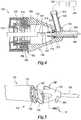
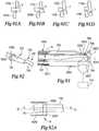
- FIG. 22illustrates use of blade 200 in connection with an outer sheath 230 that has a distal end portion 750 that includes a distally protruding nose segment 752.
- the nose segment 752may have an arcuate width "W" that comprises approximately ten (10) to thirty (30) percent of the circumference of the distal end portion 750 of the outer sheath 230.
- the nose segment 752may protrude distally from the end of the distal end portion 750 of the sheath 230 a length "L" that may be approximately 0.25 inches, for example.
- a low friction fender or guardmay be applied to the sides 753 of the nose segment 752 if desired.
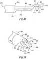
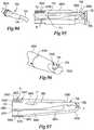
- the outer sheath 850may be substantially similar to the outer sheath 230 described above and have a distal sheath tip 852 attached thereto that has a window or opening 854 formed therein to expose the distal end portion 810 of the blade 800. See FIG. 31 .
- the outer sheath 850may comprise a hollow cylinder fabricated from for example, stainless steel.
- the window 854extends for approximately one half of the circular cross-section of the sheath 850 and forms a blade opening 858 therein.
- the distal sheath tip 852may be fabricated from metal such as, for example, stainless steel such that a relatively sharp cutting edge 860 extends around the blade opening 858.
- the sharp cutting edge 860has a first lateral cutting edge portion 862 and a second lateral cutting edge portion 864.
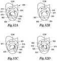
- FIGS. 33 and 34illustrate another blade embodiment 880 that may be substantially the same as blade 200 except for the differences noted below.
- the blade 880may include a waveguide or proximal portion 882 that that terminates in a distal tissue cutting portion 884.
- the proximal portion 882 of the blade 880may be configured to be threadably or otherwise attached to an ultrasonic horn of any of the various embodiments discussed above.
- the distal tissue cutting portion 884may have opposed arcuate channels 886, 888 formed therein.
- the first arcuate channel 886may define a first cutting edge 890 and the second arcuate channel 888 may define a second cutting edge 892.
- This blade embodimentmay be used in connection with any of the outer sheath configurations described above.
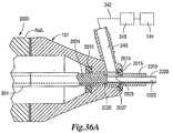
- This embodimentincludes a rotatable blade 2020 that is rotatably supported within the outer sheath 2010 and is coupled to a motor 510 supported within the housing 302.
- the motor 510may, for example, comprise a stepper motor of the type and construction described above.
- the motor 510may have an encoder associated therewith that communicates with a control module 24 ( FIG. 1 ) as was described above.
- the blade 2020may have a hollow distal portion 2022 and a solid proximal portion 2024. See FIG. 36A .
- the solid proximal portion 2024may be attached to the motor drive shaft 520 by a threaded or other suitable connection.
- the motor drive shaft 520may be rotatably supported within the housing 302 by a proximal bearing 342. When control signals are supplied to the motor 510, the drive shaft 520 rotates about axis A-A which also causes the blade 2020 to rotate about axis A-A within the outer sheath 2010.
- a distal end portion 2011 of the hollow outer sheathis closed and at least one opening or window 2012 is provided therein to expose a distal tissue cutting portion 2025 of the blade 2020.
- window 2012comprises an elongated slot and the distal tissue cutting portion also comprises an elongated slot 2026 in the blade 2020 ( FIGS. 37 and 38 ).
- suctionmay be applied from the suction source 244 into the hollow portion of blade 2020 through the port 240, the proximal sheath opening 2014 and the blade discharge port 2028.
- tissue "T"may be drawn into the hollow distal portion 2022 of blade 2020 as shown in FIG. 38 .
- the severed portions of tissue "T”'may pass through the hollow distal portion 2022 of blade 2020 and out through openings 2028, 2014 and into the collection receptacle 243.
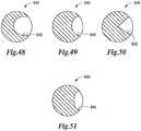
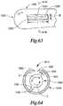
- FIG. 64the blade 1040 has a pair of radially-opposed cutting portions 1042 formed thereon that have relatively sharp cutting corners 1043.
- the cutting corners 1043may be serrated. In other embodiments the cutting corners 1043 are not serrated.
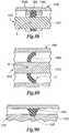
- FIG. 79depicts a non-limiting embodiment of a seal assembly 1470 that may be employed between in the waveguide or proximal portion 1412 of the ultrasonic implement 1410 and the outer sheath 1420.
- the seal 1470comprises an annular member that may be fabricated from silicon or other materials such as, for example, Ultem® and is over molded or otherwise sealingly attached to the waveguide 1412 at a node "N".
- the seal 1470may have a first annular seal portion 1472 that is molded onto the waveguide 1412 at a node "N” and two axial seal portions 1474, 1476 that extend axially in opposite axial directions beyond the first annular seal portion 1472 and which are separated by a groove 1478.
- FIG. 81depicts a non-limiting embodiment of a seal 1500 that may be employed between in the waveguide portion 1412 of the blade 1410 and the outer sheath 1420.
- the seal 1500comprises an annular member that may be fabricated from silicon or other materials, such as for example, Ultem® and is over molded or otherwise sealingly attached to the waveguide 1412 at a Node "N".
- the seal 1480may be arranged to be received within an annular groove 1423 provided in the outer sheath 1420.
- the outer sheath 1420may be fabricated from, for example, stainless steel.
- FIG. 102depicts a tissue cutting blade end 3112'that may be coated with a relatively hard, low-friction material to increase surface hardness and reduce friction.
- the coating materialmay comprise coating materials such as Titanium Nitride, Diamond-Like coating, Chromium Nitride, Graphit iCTM, etc.
- the blade 3060'may be employed in connection with an outer sheath tip that is fabricated from metal (e.g., stainless steel) in order to avoid blade galling and eventual blade breakage.
- the entire distal tissue cutting end of the blademay be coated with the coating material 3130.
Landscapes
- Health & Medical Sciences (AREA)
- Life Sciences & Earth Sciences (AREA)
- Surgery (AREA)
- Engineering & Computer Science (AREA)
- Medical Informatics (AREA)
- Nuclear Medicine, Radiotherapy & Molecular Imaging (AREA)
- Biomedical Technology (AREA)
- Heart & Thoracic Surgery (AREA)
- Molecular Biology (AREA)
- Animal Behavior & Ethology (AREA)
- General Health & Medical Sciences (AREA)
- Public Health (AREA)
- Veterinary Medicine (AREA)
- Vascular Medicine (AREA)
- Dentistry (AREA)
- Mechanical Engineering (AREA)
- Surgical Instruments (AREA)
Abstract
Description
- The present disclosure generally relates to ultrasonic surgical systems and, more particularly, to ultrasonic systems that allow surgeons to perform cutting and coagulation of tissue.
- Over the years, a variety of different types of non-ultrasonically powered cutters and shaving devices for performing surgical procedures have been developed. Some of these devices employ a rotary cutting instrument and other devices employ a reciprocating cutting member. For example, shavers are widely used in arthroscopic surgery. These devices generally consist of a power supply, a handpiece, and a single-use end effector. The end effector commonly has an inner and outer tube. The inner tube rotates relative to the outer tube and will cut tissue with its sharpened edges. The inner tube can rotate continuously or oscillate. In addition, such device may employ a suction channel that travels through the interior of the inner tube. For example,
U.S. Patent No. 4,970,354 to McGurk-Burleson, et al. , discloses a non-ultrasonically powered surgical cutting instrument that comprises a rotary cutter for cutting material with a shearing action. It employs an inner cutting member which is rotatable within an outer tube. U.S. Patent No. 3,776,238 to Peyman et al. discloses an ophthalmic instrument in which tissue is cut by a chopping action set-up by the sharp end of an inner tube moving against the inner surface of the end of an outer tube.U.S. Patent No. 5,226,910 to Kajiyama et al. discloses another surgical cutting instrument that has an inner member which moves relative to an outer member to cut tissue entering through an aperture in the outer member.U.S. Patent No. 4,922,902 to Wuchinich et al. discloses a method and apparatus for endoscopic removal of tissue utilizing an ultrasonic aspirator. The device uses an ultrasonic probe which disintegrates compliant tissue and aspirates it through a narrow orifice.U.S. Patent No. 4,634,420 to Spinosa et al. discloses an apparatus and method for removing tissue from an animal and includes an elongated instrument having a needle or probe, which is vibrated at an ultrasonic frequency in the lateral direction. The ultrasonic movement of the needle breaks-up the tissue into fragments. Pieces of tissue can be removed from the area of treatment by aspiration through a conduit in the needle.U.S. Patent No. 3,805,787 to Banko discloses yet another ultrasonic instrument that has a probe that is shielded to narrow the beam of ultrasonic energy radiated from the tip of the probe. In one embodiment the shield extends past the free-end of the probe to prevent the probe from coming into contact with the tissue.U.S. Patent No. 5,213,569 to Davis discloses a phaco-emulsification needle which focuses the ultrasonic energy. The focusing surfaces can be beveled, curved or faceted.U.S. Patent No. 6,984,220 to Wuchinich and U.S. Patent Publication No.US 2005/0177184 to Easley disclose ultrasonic tissue dissection systems that provide combined longitudinal and torsional motion through the use of longitudinal-torsional resonators. U. S Patent Publication no.US 2006/0030797 A1 to Zhou et al. discloses an orthopedic surgical device that has a driving motor for driving an ultrasound transducer and horn. An adapter is provided between the driving motor and transducer for supplying ultrasonic energy signals to the transducer.- While the use of ultrasonically powered surgical instruments provide several advantages over traditional mechanically powered saws, drills, and other instruments, temperature rise in bone and adjacent tissue due to frictional heating at the bone/tissue interface can still be a significant problem. Current arthroscopic surgical tools include punches, reciprocating shavers and radio frequency (RF) devices. Mechanical devices such as punches and shavers create minimal tissue damage, but can sometimes leave behind ragged cut lines, which are undesirable. RF devices can create smoother cut lines and also ablate large volumes of soft tissue; however, they tend to create more tissue damage than mechanical means. Thus, device which could provide increased cutting precision while forming smooth cutting surfaces without creating excessive tissue damage would be desirable.
- Arthroscopic surgery involves performing surgery in the joint space. To perform the surgery, the joints are commonly filled with pressurized saline for distention and visualization. Ultrasonic instruments which may be used in such surgeries must withstand the fluid pressure without leaking. However, conventional ultrasonic instruments generally experience significant forces during use. Current seals on ultrasonic devices are generally not robust enough to withstand this environment without leaking.
- It would be desirable to provide an ultrasonic surgical instrument that overcomes some of the deficiencies of current instruments. The ultrasonic surgical instruments described herein overcome many of those deficiencies.
- It would also be desirable to provide more robust sealing arrangements for ultrasonic surgical instruments used to cut and coagulate in the aqueous environment of arthroscopic surgery.
- The foregoing discussion is intended only to illustrate some of the shortcomings present in the field of various embodiments of the invention at the time, and should not be taken as a disavowal of claim scope.
- In one general aspect, various embodiments are directed to an ultrasonic surgical instrument that includes a housing that has an ultrasonic transducer assembly rotatably supported therein. A coupling member may be attached to the ultrasonic transducer assembly for transmitting ultrasonic motion to a blade attached thereto. A motor rotor may be directly coupled to the ultrasonic transducer assembly for rotation therewith. A motor stator may be non-movably supported within the housing adjacent to the motor rotor such that upon application of a motor drive signal to the motor stator, the motor rotor and the ultrasonic transducer assembly are caused to rotate within the housing. A slip ring assembly may be arranged to transmit the motor drive signal from a control system to the motor stator. The slip ring assembly may be further arranged to transmit ultrasonic electrical signals from an ultrasound signal generator to the ultrasonic transducer assembly.
- In one general aspect, various embodiments are directed to an ultrasonic surgical instrument that includes a housing that has an ultrasonic transducer assembly rotatably supported therein. A coupling member may be attached to the ultrasonic transducer assembly for transmitting ultrasonic motion to a blade attached thereto. A motor may be mounted within the housing and have a distal drive shaft portion that is coupled to the ultrasonic transducer assembly for applying rotational motion thereto. The motor may further have a proximal drive shaft portion that protrudes therefrom. The instrument may further include a slip ring assembly that has an inner contact that is supported by the proximal drive shaft portion for rotational travel therewith. The inner contact may be positioned in communication with the ultrasonic transducer assembly. A fixed contact may be positioned in rotational sliding contact with the first inner contact. The fixed contact may communicate with an ultrasound signal generator to transmit ultrasonic electrical signals to the inner contact.
- In connection with still another general aspect, there is provided an ultrasonic surgical instrument assembly that includes an instrument housing that rotatably supports a self-contained ultrasonic instrument therein. The self-contained ultrasonic surgical instrument may have an ultrasonic transducer assembly therein for applying ultrasonic motion to a blade that is attached thereto. A motor may be supported within the instrument housing and communicate with the self-contained ultrasonic surgical instrument to selectively apply a rotational motion thereto. A slip ring assembly may be supported within the instrument housing and communicate with an ultrasonic generator for supplying ultrasonic electrical signals to the ultrasonic transducer assembly in the self-contained ultrasonic surgical instrument.
- The features of various non-limiting embodiments are set forth with particularity in the appended claims. The various non-limiting embodiments, however, both as to organization and methods of operation, together with further objects and advantages thereof, may best be understood by reference to the following description, taken in conjunction with the accompanying drawings as follows.
FIG. 1 is a schematic view of a non-limiting embodiment of a surgical control system;FIG. 1A is a perspective view of a non-limiting embodiment of control system enclosure;FIG. 1B is a perspective view of another non-limiting embodiment of a control system enclosure arrangement;FIG. 2 is a cross-sectional view of anon-limiting embodiment of a handpiece;FIG. 3 is a partial cross-sectional view of an ultrasonic surgical handpiece that may be employed with various non-limiting embodiments;FIG. 4 is a cross-sectional view of a portion of a non-limiting nosepiece embodiment;FIG. 5 is a partial exploded assembly view of a non-limiting nosepiece embodiment;FIG. 6 is a partial cross-sectional view of a non-limiting embodiment of a surgical instrument handpiece;FIG. 7 is a perspective view of the non-limiting surgical instrument handpiece embodiment ofFIG. 6 ;FIG. 8 is a partial cross-sectional view of another non-limiting surgical instrument handpiece embodiment;FIG. 9 is a partial cross-sectional view of another non-limiting surgical instrument handpiece embodiment;FIG. 10 is a perspective view of the surgical instrument handpiece embodiment depicted inFIG. 9 ;FIG. 11 is a partial exploded assembly view of a non-limiting coupling assembly embodiment for coupling a motor to a transducer assembly;FIG. 12 is a side view of a thin plate member and drive shaft arrangement of a non-limiting coupling assembly embodiment;FIG. 13 is an end view of the non-limiting thin plate member embodiment ofFIG. 12 ;FIG. 14 is a side view of a non-limiting thin plate member and drive shaft arrangement of another non-limiting coupling assembly embodiment;FIG. 15 is an end view of the non-limiting thin plate member embodiment ofFIG. 14 ;FIG. 16 is a partial cross-sectional view of another non-limiting surgical instrument handpiece embodiment;FIG. 17 is a partial perspective view of a non-limiting outer sheath and blade embodiment;FIG. 18 is a partial perspective view of the non-limiting blade embodiment depicted inFIG. 17 ;FIG. 19 is a partial bottom perspective view of the blade ofFIGS. 17 and18 ;FIG. 20 is a side view of a portion of another non-limiting blade embodiment;FIG. 21 is a side view of a portion of another non-limiting blade embodiment;FIG. 22 is a partial perspective view of a distal end of another non-limiting outer sheath and blade arrangement;FIG. 23 is a partial perspective view of a distal end of another non-limiting outer sheath and blade arrangement;FIG. 23A is a side view of a portion of the non-limiting outer sheath embodiment depicted inFIG. 23 ;FIG. 24 is a side view of a portion of another non-limiting blade embodiment;FIG. 25 is a side view of a portion of another non-limiting blade embodiment;FIG. 26 is a partial perspective view the non-limiting blade embodiment ofFIG. 25 within a distal end of another non-limiting outer sheath embodiment;FIG. 27 is a side view of a portion of another non-limiting blade embodiment;FIG. 28 is a partial perspective view the non-limiting blade embodiment ofFIG. 27 within a distal end of another non-limiting outer sheath embodiment;FIG. 29 is a partial cross-sectional end view of the non-limiting blade and outer sheath embodiments ofFIG. 28 ;FIG. 30 is a side view of a portion of another non-limiting blade embodiment;FIG. 31 is a partial perspective view of the non-limiting blade embodiment ofFIG. 30 within a distal end of another non-limiting outer sheath embodiment;FIG. 32A illustrates a first rotational position of the non-limiting blade embodiment ofFIGS. 30 and 31 within the outer sheath embodiment ofFIG. 31 ;FIG. 32B illustrates a second rotational position of the non-limiting blade embodiment ofFIGS. 30 and 31 within the outer sheath embodiment ofFIG. 31 ;FIG. 32C illustrates a third rotational position of the blade embodiment ofFIGS. 30 and 31 within the outer sheath embodiment ofFIG. 31 ;FIG. 32D illustrates a fourth rotational position of the blade embodiment ofFIGS. 30 and 31 within the outer sheath embodiment ofFIG. 31 ;FIG. 33 is a perspective view of a portion of another non-limiting blade embodiment;FIG. 34 is a partial perspective view of the blade embodiment ofFIG. 33 within a non-limiting outer sheath embodiment;FIG. 34A is a partial perspective view of another non-limiting blade and outer sheath embodiment;FIG. 35 is a perspective view of a portion of another non-limiting blade embodiment;FIG. 36 is a partial cross-sectional view of another non-limiting ultrasonic surgical instrument embodiment;FIG. 36A is a partial cross-sectional view of a nosepiece portion of another non-limiting surgical instrument embodiment of the present invention;FIG. 37 is a partial perspective view of a distal end of the non-limiting outer sheath and blade arrangement ofFIG. 36 ;FIG. 38 is a cross-sectional view of distal portions of the outer sheath and blade embodiments depicted inFIG. 37 cutting tissue;FIG. 39 illustrates use of the surgical instrument embodiment ofFIG. 36 in connection with performing a discectomy;FIG. 40 depicts further use of the surgical instrument embodiment ofFIG. 36 in connection with performing a discectomy;FIG. 41 is a side elevational view of the surgical instrument embodiment ofFIG. 36 with a selectively retractable safety sheath mounted thereon;FIG. 42 is a partial perspective view of the retractable safety sheath embodiment illustrated inFIG. 41 starting to be retracted from a closed position;FIG. 43 is another partial perspective view of the retractable safety sheath embodiment illustrated inFIGS. 41 and42 with the safety sheath retracted to an open position;FIG. 44 is another partial perspective view of the retractable safety sheath embodiment illustrated inFIGS. 41-43 with the safety sheath retracted to an open position;FIG. 45 is a side elevational view of a portion of the outer sheath and safety sheath embodiments illustrated inFIGS. 41-44 with the safety sheath shown in cross-section in an open position;FIG. 46 is a perspective view of a portion of another non-limiting blade embodiment;FIG. 47 is a side view of a portion of another hollow outer sheath and blade arrangement of another non-limiting embodiment;FIG. 48 is a cross-sectional view of another non-limiting blade embodiment;FIG. 49 is a cross-sectional view of another non-limiting blade embodiment;FIG. 50 is a cross-sectional view of another non-limiting blade embodiment;FIG. 51 is a cross-sectional view of another non-limiting blade embodiment;FIG. 52 is a partial cross-sectional view of another non-limiting outer sheath and blade embodiment;FIG. 53 is another partial cross-sectional view of the outer sheath and blade embodiment ofFIG. 52 interacting with body tissue;FIG. 54 is an end cross-sectional view of the outer sheath and blade arrangement depicted inFIGS. 52 and 53 interacting with body tissue;FIG. 55 is a partial perspective view of another non-limiting outer sheath embodiment;FIG. 56 is a partial perspective view of another non-limiting outer sheath embodiment;FIG. 57 is a partial cross-sectional view of the outer sheath embodiment ofFIG. 56 supporting another non-limiting blade embodiment;FIG. 58 is a partial perspective view of another non-limiting outer sheath embodiment;FIG. 59 is a cross-sectional view of another non-limiting outer sheath and blade embodiment;FIG. 60 illustrates an angle between the cutting edges formed on a non-limiting outer sheath embodiment;FIG. 61 is a perspective view of another non-limiting outer sheath embodiment;FIG. 62 is a cross-sectional view of the outer sheath and blade embodiment ofFIG. 61 ;FIG. 63 is a perspective view of another non-limiting outer sheath embodiment;FIG. 64 is a cross-sectional view of the outer sheath and blade embodiment ofFIG. 63 ;FIG. 65 is a perspective view of another non-limiting outer sheath embodiment;FIG. 66 is a cross-sectional view of the outer sheath and blade embodiment ofFIG. 65 ;FIG. 67 is a cross-sectional end view of another non-limiting outer sheath and blade arrangement;FIG. 68 is a partial side cross-sectional view of the outer sheath and blade arrangement ofFIG. 67 ;FIG. 69 is a partial side view of a distal end portion of the outer sheath and blade arrangement ofFIGS. 67 and 68 ;FIG. 70 is a side view of a non-limiting handpiece housing embodiment attached to the outer sheath and blade arrangement ofFIGS. 67-69 ;FIG. 71 depicts a method of using the surgical instrument embodiment ofFIG. 70 ;FIG. 72 depicts another method of using the surgical instrument embodiment ofFIG. 70 ;FIG. 73 depicts another method of using the surgical instrument embodiment ofFIG. 70 ;FIG. 74 is a partial side cross-sectional view of another non-limiting surgical instrument embodiment;FIG. 75 is a perspective view of a portion of the outer sheath and blade arrangement employed with the surgical instrument embodiment depicted inFIG. 74 ;FIG. 76 is an end view of the outer sheath and blade arrangement ofFIG. 75 ;FIG. 77 is a cross-sectional end view of the sheath and blade arrangement ofFIGS. 75 and 76 ;FIG. 78 is a side view of another non-limiting ultrasonic surgical instrument embodiment;FIG. 79 is a partial cross-sectional view of a non-limiting seal embodiment between a hollow sheath and a waveguide portion of an ultrasonic implement embodiment;FIG. 80 is a partial cross-sectional view of another non-limiting seal embodiment between a hollow sheath and a waveguide portion of an ultrasonic implement embodiment;FIG. 81 is a partial cross-sectional view of another non-limiting seal embodiment between a hollow sheath and a waveguide portion of an ultrasonic implement embodiment;FIG. 82 is a partial cross-sectional view of another non-limiting seal embodiment between a hollow sheath and a waveguide portion of an ultrasonic implement embodiment;FIG. 83 is a partial cross-sectional view of another non-limiting seal embodiment between a hollow sheath and a waveguide portion of an ultrasonic implement embodiment, prior to being crimped in position;FIG. 84 is a partial cross-sectional view of the seal embodiment ofFIG. 83 after being crimped in position;FIG. 85 is a partial cross-sectional view of another non-limiting seal embodiment between a two-piece hollow sheath and a waveguide portion of an ultrasonic implement embodiment;FIG. 86 is a partial cross-sectional exploded assembly view of another non-limiting seal embodiment between another two-piece hollow sheath and a waveguide portion of an ultrasonic implement embodiment;FIG. 87 is a partial perspective view of a portion of the two piece hollow sheath embodiment ofFIG. 86 ;FIG. 88 is a partial cross-sectional view of another non-limiting seal embodiment between a hollow sheath and a waveguide portion of an ultrasonic implement embodiment;FIG. 89 is a partial cross-sectional view of another non-limiting seal embodiment between a hollow sheath and a waveguide portion of an ultrasonic implement embodiment;FIG. 90 is a partial cross-sectional view of another non-limiting seal embodiment between a hollow sheath and a waveguide portion of an ultrasonic implement embodiment;FIG. 91A is an illustration depicting an initial position of two cutting edge embodiments preparing to cut tough tissue;FIG. 91B is a second position of the cutting edges and tissue ofFIG. 91A ;FIG. 91C is a third position of the cutting edges and tissue ofFIGS. 91A-B ;FIG. 91D is a fourth position of the cutting edges and tissue ofFIGS. 91A-C ;FIG. 92 is a perspective view of a portion of a non-limiting cutting blade and bushing embodiment;FIG. 92A is a partial cross-sectional view of a portion of the blade and bushing embodiment ofFIG. 92 installed within an inner sheath of a non-limiting surgical instrument embodiment;FIG. 93 is a cross-sectional view of a portion of the blade and bushing embodiment ofFIG. 92 in a non-limiting surgical instrument embodiment;FIG. 94 is a perspective view of a portion of another non-limiting cutting blade and bushing embodiment;FIG. 95 is a cross-sectional view of a portion of the blade and bushing embodiment ofFIG. 94 in a non-limiting surgical instrument embodiment;FIG. 96 is a partial perspective view of a portion of a non-limiting blade and outer sheath embodiment;FIG. 97 is a cross-sectional view of the blade and outer sheath arrangement ofFIG. 96 ;FIG. 98 is a partial rear perspective view of a portion of the outer sheath and blade arrangement ofFIG. 97 ;FIG. 99 is a partial rear perspective view of a portion of another non-limiting outer sheath and blade embodiment;FIG. 100 is a partial perspective view of another non-limiting outer sheath embodiment;FIG. 101 is a cross-sectional end view of the outer sheath embodiment ofFIG. 100 supporting a cutting blade embodiment therein; andFIG. 102 is a perspective view of a portion of another non-limiting blade embodiment.- The owner of the present application also owns the following U.S. Patent Applications that were filed on even date herewith and which are herein incorporated by reference in their respective entireties:
- U.S. Patent Application Serial No._, entitled METHODS OF USING ULTRASONICALLY POWERED SURGICAL INSTRUMENTS WITH ROTATABLE CUTTING IMPLEMENTS, Attorney Docket No. END6689USNP/090342;
- U.S. Patent Application Serial No._, entitled SEAL ARRANGEMENTS FOR ULTRASONICALLY POWERED SURGICAL INSTRUMENTS, Attorney Docket No. END6690USNP /090343;
- U.S. Patent Application Serial No._, entitled ULTRASONIC SURGICAL INSTRUMENTS WITH ROTATABLE BLADE AND HOLLOW SHEATH ARRANGEMENTS, Attorney Docket No. END6691USNP/090344;
- U.S. Patent Application Serial No. , entitled ROTATABLE CUTTING IMPLEMENT ARRANGEMENTS FOR ULTRASONIC SURGICAL INSTRUMENTS, Attorney Docket No. END6692USNP/090345;
- U.S. Patent Application Serial No._, entitled ULTRASONIC SURGICAL INSTRUMENTS WITH PARTIALLY ROTATING BLADE AND FIXED PAD ARRANGEMENT, Attorney Docket No. END6693USNP/090346;
- U.S. Patent Application Serial No._, entitled DUAL PURPOSE SURGICAL INSTRUMENT FOR CUTTING AND COAGULATING TISSUE, Attorney Docket No. END6694USNP /090347;
- U.S. Patent Application Serial No._, entitled OUTER SHEATH AND BLADE ARRANGEMENTS FOR ULTRASONIC SURGICAL INSTRUMENTS, Attorney Docket No. END6695USNP/090348;
- U.S. Patent Application Serial No._, entitled ULTRASONIC SURGICAL INSTRUMENTS WITH MOVING CUTTING IMPLEMENT, Attorney Docket No. END6687USNP/090349; and
- U.S. Patent Application Serial No._, entitled ULTRASONIC SURGICAL INSTRUMENT WITH COMB-LIKE TISSUE TRIMMING DEVICE, Attorney Docket No. END6686USNP/090367.
- Various embodiments are directed to apparatuses, systems, and methods for the treatment of tissue. Numerous specific details are set forth to provide a thorough understanding of the overall structure, function, manufacture, and use of the embodiments as described in the specification and illustrated in the accompanying drawings. It will be understood by those skilled in the art, however, that the embodiments may be practiced without such specific details. In other instances, well-known operations, components, and elements have not been described in detail so as not to obscure the embodiments described in the specification. Those of ordinary skill in the art will understand that the embodiments described and illustrated herein are non-limiting examples, and thus it can be appreciated that the specific structural and functional details disclosed herein may be representative and do not necessarily limit the scope of the embodiments, the scope of which is defined solely by the appended claims.
- Reference throughout the specification to "various embodiments," "some embodiments," "one embodiment," or "an embodiment", or the like, means that a particular feature, structure, or characteristic described in connection with the embodiment is included in at least one embodiment. Thus, appearances of the phrases "in various embodiments," "in some embodiments," "in one embodiment," or "in an embodiment", or the like, in places throughout the specification are not necessarily all referring to the same embodiment. Furthermore, the particular features, structures, or characteristics may be combined in any suitable manner in one or more embodiments. Thus, the particular features, structures, or characteristics illustrated or described in connection with one embodiment may be combined, in whole or in part, with the features structures, or characteristics of one or more other embodiments without limitation.
- Various embodiments are directed to improved ultrasonic surgical systems and instruments configured for effecting tissue dissecting, cutting, and/or coagulation during surgical procedures as well as the cutting implements and sealing features employed thereby. In one embodiment, an ultrasonic surgical instrument apparatus is configured for use in open surgical procedures, but has applications in other types of surgery, such as laparoscopic, endoscopic, and robotic-assisted procedures. Versatile use is facilitated by selective use of ultrasonic energy and the selective rotation of the cutting/coagulation implement.
- It will be appreciated that the terms "proximal" and "distal" are used herein with reference to a clinician gripping a handpiece assembly. Thus, an end effector is distal with respect to the more proximal handpiece assembly. It will be further appreciated that, for convenience and clarity, spatial terms such as "top" and "bottom" also are used herein with respect to the clinician gripping the handpiece assembly. However, surgical instruments are used in many orientations and positions, and these terms are not intended to be limiting and absolute.
FIG. 1 illustrates in schematic form one non-limiting embodiment of asurgical system 10. Thesurgical system 10 may include aultrasonic generator 12 and an ultrasonicsurgical instrument assembly 100 that may include a "self-contained"ultrasonic instrument 110. As will be discussed in further detail below, theultrasonic generator 12 may be connected by acable 14 to anultrasonic transducer assembly 114 of the self-containedultrasonic instrument 110 by aslip ring assembly 150 located in ahousing portion 102 of thesurgical instrument assembly 100. In one embodiment, thesystem 10 further includes amotor control system 20 that includes apower supply 22 that is coupled to acontrol module 24 bycable 23 to supply, for example, 24VDC thereto. Themotor control module 24 may comprise a control module manufactured by National Instruments of Austin, Texas under Model No. NI cRIO-9073. However, other motor control modules may be employed. Thepower supply 22 may comprise a power supply manufactured by National Instruments. However, other power supplies may be successfully employed. Thepower supply 22 may be further coupled to amotor drive 26 bycable 25 to also supply 24VDC thereto. Themotor drive 26 may comprise a motor drive manufactured by National Instruments.Control module 24 may also be coupled to themotor drive 26 bycable 27 for supplying power thereto. Aconventional foot pedal 30 or other control switch arrangement may be attached to thecontrol module 24 by acable 31. As will be discussed in further detail below, the ultrasonicsurgical instrument 100 may include amotor 190 that has anencoder 194 associated therewith. Themotor 190 may comprise a motor manufactured by National Instruments under Model No. CTP12ELF10MAA00. Theencoder 194 may comprise an encoder manufactured by U.S. Digital of Vancouver, Washington under Model No.E2-500-197-I-D-D-B. However, other motors and encoders may be used. Theencoder 194 may be coupled to themotor control module 24 by anencoder cable 32 and themotor 190 may be coupled to themotor drive 26 bycable 33. Thesurgical system 10 may also include acomputer 40 that may communicate byEthernet cable 42 with themotor control module 24.- As can also be seen in
FIG. 1 , in various embodiments, themotor control system 20 is housed in anenclosure 21. To facilitate easy portability of the system, various components may be attached to themotor control system 20 by removable cable connectors. For example,foot pedal switch 30 may be attached to adetachable cable connector 37 bycable 35 to facilitate quick attachment of the foot pedal to thecontrol system 20. A/C power may be supplied to thepower supply 22 by a conventional plug/cable 50 that is attached to adetachable cable connector 54 that is attached tocable 52. Thecomputer 40 may have acable 60 that is attached todetachable cable connector 62 that is coupled tocable 42. Theencoder 194 may have anencoder cable 70 that is attached to adetachable connector 72. Likewise, themotor 190 may have acable 74 that is attached to thedetachable connector 72. Thedetachable connector 72 may be attached to thecontrol module 24 bycable 32 and theconnector 72 may be attached to themotor drive 26 bycable 33. Thus,cable connector 72 serves to couple theencoder 194 to thecontrol module 24 and themotor 190 to themotor drive 26. Thecables common sheath 76. - In an alternative embodiment, the
ultrasonic generator 12 and thecontrol system 20 may be housed in thesame enclosure 105. SeeFIG. 1A . In yet another embodiment, theultrasonic generator 12 may electrically communicate with themotor control system 20 by ajumper cable 107. Such arrangement may share a data link as well as a common means for supplying power (cord 50). SeeFIG. 1B . - In various embodiments, the
ultrasonic generator 12 may include anultrasonic generator module 13 and asignal generator module 15. SeeFIG. 1 . Theultrasonic generator module 13 and/or thesignal generator module 15 each may be integrated with theultrasonic generator 12 or may be provided as a separate circuit module electrically coupled to the ultrasonic generator 12 (shown in phantom to illustrate this option). In one embodiment, thesignal generator module 15 may be formed integrally with theultrasonic generator module 13. Theultrasonic generator 12 may comprise aninput device 17 located on a front panel of thegenerator 12 console. Theinput device 17 may comprise any suitable device that generates signals suitable for programming the operation of thegenerator 12 in a known manner. Still with reference toFIG. 1 , thecable 14 may comprise multiple electrical conductors for the application of electrical energy to positive (+) and negative (-) electrodes of anultrasonic transducer assembly 114 as will be discussed in further detail below. - Various forms of ultrasonic generators, ultrasonic generator modules and signal generator modules are known. For example, such devices are disclosed in commonly owned
U.S. Patent Application Serial No. 12/503,770 U.S. Patent No. 6,480,796 (Method for Improving the Start Up of an Ultrasonic System Under Zero Load Conditions);U.S. Patent No. 6,537,291 (Method for Detecting a Loose Blade in a Handle Connected to an Ultrasonic Surgical System);U.S. Patent No. 6,626,926 (Method for Driving an Ultrasonic System to Improve Acquisition of Blade Resonance Frequency at Startup);U.S. Patent No. 6,633,234 (Method for Detecting Blade Breakage Using Rate and/or Impedance Information);U.S. Patent No. 6,662,127 (Method for Detecting Presence of a Blade in an Ultrasonic System);U.S. Patent No. 6,678,621 (Output Displacement Control Using Phase Margin in an Ultrasonic Surgical Handle);U.S. Patent No. 6,679,899 (Method for Detecting Transverse Vibrations in an Ultrasonic Handle);U.S. Patent No. 6,908,472 (Apparatus and Method for Altering Generator Functions in an Ultrasonic Surgical System);U.S. Patent No. 6,977,495 (Detection Circuitry for Surgical Handpiece System);U.S. Patent No. 7,077,853 (Method for Calculating Transducer Capacitance to Determine Transducer Temperature);U.S. Patent No. 7,179,271 (Method for Driving an Ultrasonic System to Improve Acquisition of Blade Resonance Frequency at Startup); andU.S. Patent No. 7,273,483 (Apparatus and Method for Alerting Generator Function in an Ultrasonic Surgical System). - As can be seen in
FIG. 2 , an ultrasonicsurgical instrument handpiece 100 may comprise ahousing 102 that houses themotor 190, theencoder 194, theslip ring assembly 150 and the self-contained ultrasonicsurgical instrument 110. Thehousing 102 may be provided in two or more parts that are attached together by fasteners such as screws, snap features, etc. and may be fabricated from, for example, polycarbonate material. Themotor 190 may comprise, for example, a stepper motor manufactured by National Instruments under Model No. CTP12ELF10MAA00. However other motors may be employed to effectuate, for example, "gross" rotational motion of the self-contained ultrasonicsurgical instrument 110 relative to thehousing 102 on the order of 1-6000 rpm. Theencoder 194 converts the mechanical rotation of themotor shaft 192 into electrical pulses that provide speed and other motor control information to thecontrol module 24. - The self-contained ultrasonic
surgical instrument 110 may comprise a surgical instrument that is manufactured and sold by Ethicon Endo-Surgery under Model No. HP054. However, other ultrasonic instruments may be successfully employed. It will be understood that the term "self-contained" as used herein means that the ultrasonic surgical instrument may be effectively used as an ultrasonic surgical instrument on its own, apart from use with thesurgical instrument 100. As illustrated in more detail inFIG. 3 , the ultrasonicsurgical instrument 110 includes ahousing 112 that supports a piezoelectricultrasonic transducer assembly 114 for converting electrical energy to mechanical energy that results in longitudinal vibrational motion of the ends of thetransducer assembly 114. Theultrasonic transducer assembly 114 may comprise a stack of ceramic piezoelectric elements with a motion null point located at some point along the stack. Theultrasonic transducer assembly 114 may be mounted between twocylinders cylinder 118, which in turn is mounted to the housing at another motionnull point 122. Ahorn 124 may also be attached at the null point on one side and to acoupler 126 on the other side. Ablade 200 may be fixed to thecoupler 126. As a result, theblade 200 will vibrate in the longitudinal direction at an ultrasonic frequency rate with theultrasonic transducer assembly 114. The ends of theultrasonic transducer assembly 114 achieve maximum motion with a portion of the stack constituting a motionless node, when theultrasonic transducer assembly 114 is driven at maximum current at the transducer's resonant frequency. However, the current providing the maximum motion will vary with each instrument and is a value stored in the non-volatile memory of the instrument so the system can use it. - The parts of the
ultrasonic instrument 110 may be designed such that the combination will oscillate at the same resonant frequency. In particular, the elements may be tuned such that the resulting length of each such element is one-half wavelength or a multiple thereof. Longitudinal back and forth motion is amplified as the diameter closer to theblade 200 of theacoustical mounting horn 124 decreases. Thus, thehorn 124 as well as the blade/coupler may be shaped and dimensioned so as to amplify blade motion and provide ultrasonic vibration in resonance with the rest of the acoustic system, which produces the maximum back and forth motion of the end of theacoustical mounting horn 124 close to theblade 200. A motion from 20 to 25 microns at theultrasonic transducer assembly 114 may be amplified by thehorn 124 into blade movement of about 40 to 100 microns. - When power is applied to the
ultrasonic instrument 110 by operation of thefoot pedal 30 or other switch arrangement, thecontrol system 20 may, for example, cause theblade 200 to vibrate longitudinally at approximately 55.5 kHz, and the amount of longitudinal movement will vary proportionately with the amount of driving power (current) applied, as adjustably selected by the user. When relatively high cutting power is applied, theblade 200 may be designed to move longitudinally in the range of about 40 to 100 microns at the ultrasonic vibrational rate. Such ultrasonic vibration of theblade 200 will generate heat as the blade contacts tissue, i.e., the acceleration of theblade 200 through the tissue converts the mechanical energy of the movingblade 200 to thermal energy in a very narrow and localized area. This localized heat creates a narrow zone of coagulation, which will reduce or eliminate bleeding in small vessels, such as those less than one millimeter in diameter. The cutting efficiency of theblade 200, as well as the degree of hemostasis, will vary with the level of driving power applied, the cutting rate or force applied by the surgeon to the blade, the nature of the tissue type and the vascularity of the tissue. - As can be seen in
FIG. 2 , theultrasonic instrument 110 is supported within thehousing 102 by atailpiece drive adapter 130 and adistal handpiece adapter 134. Thetailpiece drive adapter 130 is rotatably supported withinhousing 102 by aproximal bearing 132 and is non-rotatably coupled to theoutput shaft 192 of themotor 190. SeeFIG. 2 . Thetailpiece drive adapter 130 may be pressed onto thehousing 112 of theultrasonic instrument 110 or, for example, be attached to thehousing 112 by setscrews or adhesive. Thedistal handpiece adapter 134 may be pressed onto adistal end 113 of thehandpiece housing 112 or be otherwise attached thereto by set screws or adhesive. Thedistal handpiece adapter 134 is rotatably supported in thehousing 102 by adistal bearing 136 that is mounted withinhousing 102. - When power is applied to
motor 190,motor 190 applies a "gross rotational motion" to thehandpiece 110 to cause the ultrasonicsurgical instrument 110 andblade 200 to rotate about central axis A-A. As used herein, the term "gross rotational motion" is to be distinguished from that "torsional ultrasonic motion" that may be achieved when employing a non-homogeneous formed ultrasonic blade. The term "gross rotational motion" instead encompasses rotational motion that is not solely generated by operation of theultrasonic transducer assembly 114. - To provide the
ultrasonic instrument 110 with power from theultrasonic generator 12, aslip ring assembly 150 may be employed. As can be seen inFIG. 2 ,conductors ultrasonic transducer assembly 114 and extend through ahollow stem portion 132 of the tailpiece drive adapter 130. Thehollow stem portion 132 is attached to thedrive shaft 192 of themotor 190 and is free to rotate within theslip ring assembly 150. A firstinner contact 154 is attached to thehollow stem portion 132 for rotational travel therewith about axis A-A. The firstinner contact 154 is positioned for rotational contact with a fixedouter contact 156 within theslip ring assembly 150. Thecontacts Conductors outer contact 156 andform generator cable 14.Conductors form motor cable 74 andconductors form encoder cable 70. Rotation of themotor shaft 192 results in the rotation of thetailpiece drive adapter 130 and theultrasonic instrument 110 attached thereto about axis A-A. Rotation of themotor drive shaft 192 also results in the rotation of theinner contact 154. Ultrasonic signals from theultrasonic generator 12 are transferred to theinner contact 154 by virtue of contact or "electrical communication" between theinner contact 154 and theouter contact 156. Those signals are transmitted to theultrasonic transducer assembly 114 byconductors - Various embodiments also include a
distal nosepiece 160 that may be removably attached to thedistal end 103 of thehousing 102 byfasteners 161. SeeFIG. 5 . One ormore shim members 162 may be positioned between thedistal end 103 and thenosepiece 160 to facilitate coaxial attachment between thehousing 102 and thenosepiece 160. Thenosepiece 160 may be fabricated from, for example, stainless steel or polycarbonate. In various embodiments, thedistal end 202 of theblade 200 extends through ahollow coupler segment 210 that is journaled within aninner sheath seal 212.Inner sheath seal 212 may comprise, for example, polytetrafluoroethylene (PTFE"), and serve to establish a substantially fluid-tight and/or airtight seal between thecoupler segment 210 and thenosepiece 160. Also in the embodiment ofFIG. 4 , aninner sheath 220 may be attached to thehollow coupler segment 210 by, for example, welding or thehollow coupler segment 210 may comprise an integral portion of theinner sheath 220. In one embodiment, a blade pin/torquingmember 216 may extend transversely through theblade member 200 and thehollow coupler segment 210 to facilitate movement of theinner sheath 220 with theblade member 200. One or more ventedsilicone bushings 214 may be journaled around theblade 200 to acoustically isolate theblade 200 from theinner sheath 220. Theblade member 200 may have aproximal end 201 that is internally threaded and adapted to removably engage a threaded portion of thecoupler 126. To facilitate tightening of theblade 200 to thecoupler 126, a tightening hole 108 (FIG. 2 ) may be provided through thehousing 102 to enable a tool (e.g., Allen wrench) to be inserted therethrough into ahole 131 in the tailpiece drive adapter 130 to prevent the rotation of the ultrasonicsurgical instrument 110 andcoupler 126 attached thereto. Once theblade 200 has been screwed onto thecoupler 126, the user may remove the Allen wrench or other tool fromholes hole 108 to prevent fluids/debris from entering thehousing 102 therethrough. - Also in various embodiments, an
outer sheath 230 may be coaxially aligned with theinner sheath 220 andblade member 200 and be attached to adistal end 163 ofnosepiece 160 by, for example, welding, brazing, overmolding or pressfit. As can be seen inFIG. 4 , asuction port 240 may be attached to thenosepiece 160 to communicate with the hollowouter sheath 230. Aflexible tube 242 may be attached to thesuction port 240 and communicate with acollection receptacle 243 that is coupled to a source of vacuum, generally depicted as 244. Thus, theouter sheath 230 forms a suction path extending around theinner sheath 220 that begins at a distal tip of theouter sheath 230 and goes out through thesuction port 240. Those of ordinary skill in the art will appreciate that alternate suction paths are also possible. In addition, in alternative embodiments, theinner sheath 220 is omitted. - Various embodiments of the
surgical system 10 provide the ability to selectively apply ultrasonic axial motion to theblade 200 and gross rotational motion to theblade 200 as well. If desired, the clinician may simply activate theultrasonic transducer assembly 114 without activating themotor 190. In such cases, theinstrument 100 may be used in ultrasonic mode simply as an ultrasonic instrument. Frequency ranges for longitudinal ultrasonic motion may be on the order of, for example, 30-80 kHz. Similarly, the clinician may desire to active themotor 190 without activating theultrasonic transducer assembly 114. Thus, gross rotational motion will be applied to theblade 200 in the rotation mode, without the application of longitudinal ultrasonic motion thereto. Gross rotational speeds may be, for example, on the order of 1-6000 rpm. In other applications, the clinician may desire to use theinstrument 100 in the ultrasonics and rotational modes wherein theblade 200 will experience longitudinal ultrasonic motion from thetransducer assembly 114 and gross rotational motion from the motor. Oscillatory motion of, for example, 2 to 10 revolutions per cycle (720 to 3600 degrees) or continuous unidirectional rotation may be achieved. Those of ordinary skill in the art will readily appreciate that various embodiments of thesurgical system 10 may be affectively employed in connection with arthroscopic as well as other surgical applications. - At least one non-limiting embodiment may further include a
control arrangement 170 on thehousing 102. SeeFIG. 2 . Thecontrol arrangement 170 may communicate with thecontrol module 24 bymulti-conductor cable 171. Thecontrol arrangement 170 may include afirst button 172 for activating/deactivating a "dual" mode that includes the "ultrasonic mode" and "rotational mode". In such arrangements, thecontrol module 24 may be pre-programmed to provide a pre-set amount of gross rotational motion to theblade 200. Thecontrol arrangement 170 may further include asecond button 174 for activating/deactivating the rotational mode without activating the ultrasonics mode to thereby cut without hemostasis. Thecontrol arrangement 170 may also include athird button 176 for activating/deactivating a "coagulation mode" wherein themotor 190 drives to a pre-set rotational orientation and then "parks" or deactivates, thereby exposing the ultrasonic blade surface at the distal end of theouter sheath 240 as will be discussed in further detail below. Also in this mode, theultrasonic transducer assembly 114 may be powered to provide spot coagulation or in an alternative embodiment, the clinician may simply activate a spot coagulation button 77 which activates theultrasonic transducer assembly 114 for a preset time period of, for example, five seconds. The control arrangement may further include abutton 178 to switch between ultrasonics and rotational modes. In accordance with various non-limiting embodiments, any combinations of the aforementioned functions/modes may be combined and controlled by one or more buttons without departing from the spirit and scope of the various non-limiting embodiments disclosed herein as well as their equivalent structures. - Those of ordinary skill in the art will understand that the
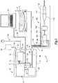
housing member 102 and the mountingadapters surgical instrument 100. Thus, thecontrol system 20 andinstrument 100 may be provided in "kit form" without theultrasonic handpiece 110 to enable the purchaser to install their existing ultrasonic handpiece therein without departing from the spirit and scope of the various non-limiting embodiments disclosed herein as well as their respective equivalent structures. FIGS. 6 and 7 illustrate anothersurgical instrument 300 wherein like numbers previously used to describe the various embodiments discussed above are used to designate like components. In these embodiments, thesurgical instrument 300 includes ahousing 302 that houses atransducer assembly 314 that is attached to anultrasonic horn 324. Theultrasonic horn 324 may be coupled to theproximal end 201 of theblade 200 in the manner described above. Theultrasonic horn 324 may be rotatably supported within thehousing 302 by adistal bearing 336. Anosepiece 160 may be attached to thehousing 302 byfasteners 161 in the manner described above.- In this embodiment, the
ultrasonic transducer assembly 314 hasmagnets 316 embedded or otherwise attached thereto to form an integral motor rotor, generally designated as 320. Amotor stator ring 330 is mounted within thehousing 302 as shown.Conductors motor stator ring 330 and pass through thecommon sheath 76 to be attached to themotor cable 33 in thecontrol system 20 as described above. Ahollow shaft 340 extends through themotor rotor 320 to form a passage forconductors Conductors ultrasonic transducer assembly 314 and aninner contact 154. Theinner contact 154 is attached to a portion of thehollow shaft 340 that rotatably extends into aslip ring assembly 150 that is also supported within thehousing 302. Thehollow shaft 340 is rotatably supported within thehousing 302 by aproximal bearing 342. Theslip ring assembly 150 is fixed (i.e., non-rotatable) within thehousing 302 and includes a fixedouter contact 156 that is coupled toconductors generator cable 14 as was described above. When power is supplied to themotor stator 330, therotor 320 and the integralultrasonic transducer 314 are caused to rotate about axis A-A. Ultrasonic signals from theultrasonic generator 12 are transferred to theinner contact 154 by virtue of rotating contact or electrical communication between theinner contact 154 and theouter contact 156. Those signals are transmitted to theultrasonic transducer assembly 314 byconductors surgical instrument 300 may include a control arrangement of the type described above and be used in the various modes described above. A suction may be applied between theblade 200 andouter sheath 230 throughport 240. Acollection receptacle 243 and source ofsuction 240 may be attached to theport 240 bytube 242. The distal end of the blade is exposed through a window in the distal end of theouter sheath 230 to expose the blade to tissue as will be further discussed below. FIG. 8 illustrates anothersurgical instrument 400 wherein like numbers previously used to describe the various embodiments discussed above are used to designate like components. In these embodiments, thesurgical instrument 400 includes ahousing 302 that houses anultrasonic transducer assembly 314 that is attached to anultrasonic horn 324. Theultrasonic horn 324 may be coupled to theproximal end 201 of theblade 200 in the manner described above. Theultrasonic horn 324 may be rotatably supported within thehousing 302 by adistal bearing 336. Anosepiece 160 may be attached to thehousing 302 in the manner described above.- In this embodiment, a brushed
motor 410 is integrally attached to theultrasonic transducer assembly 314. As used herein "integrally attached" means directly attached to or otherwise formed with theultrasonic transducer assembly 314 for travel therewith. The term "integrally attached" as used with reference to the attachment of the brushedmotor 410 to theultrasonic transducer assembly 314 does not encompass those configurations wherein the ultrasonic transducer assembly is attached to the motor via a driven shaft arrangement. Also in this embodiment,magnets 426 are provided in astator ring 420 that is fixed within thehousing 302.Conductors 432, 434 extend through ahollow shaft 340 that is attached to the brushedmotor 410. Thehollow shaft 340 is rotatably supported within thehousing 302 byproximal bearing 342. Themotor conductor 432 is attached to a firstinner motor contact 436 and the motor conductor 434 is attached to a secondinner motor contact 438. The first and secondinner motor contacts hollow shaft 340 that extends into a slip ring assembly, generally designated as 450. Theslip ring assembly 450 is fixed (i.e., non-rotatable) within thehousing 302 and includes a firstouter motor contact 440 that is coupled toconductor 441 and a secondouter motor contact 442 that is coupled toconductor 443. Theconductors form motor cable 74 as was described above. When the clinician desires to apply gross rotational motion to theultrasonic transducer assembly 314 and ultimately to theblade 200, the clinician causes power to be supplied to the brushedmotor 410 from themotor drive 26. - Also in this embodiment,
conductors ultrasonic transducer assembly 314 and extend through thehollow shaft 340 to be coupled toinner transducer contact 154 that is attached to thehollow shaft 340. Theslip ring assembly 450 includes a fixedouter transducer contact 156 that is coupled toconductors generator cable 14 as was described above. When power is supplied to the brushedmotor 410, themotor 410,ultrasonic transducer assembly 314, andmotor shaft 340 are caused to rotate about axis A-A. Ultrasonic signals from theultrasonic generator 12 are transferred to theinner contact 154 by virtue of rotational sliding contact or electrical communication between theinner contact 154 and theouter contact 156. Those signals are transmitted to theultrasonic transducer assembly 314 byconductors surgical instrument 400 may include a control arrangement of the type described above and be used in the various modes described above. It will be understood that theinstrument 400 may be used in rotation mode, ultrasonic mode, rotation and ultrasonic mode ("duel mode") or coagulation mode as described above. A suction may be applied between theblade 200 andouter sheath 230 throughport 240. Acollection receptacle 243 and source ofsuction 240 may be attached to theport 240 bytube 242. The distal end of the blade is exposed through a window in the distal end of theouter sheath 230 to expose the blade to tissue as will be further discussed below. FIGS. 9-13 illustrate anothersurgical instrument 500 wherein like numbers previously used to describe the various embodiments discussed above are used to designate like components. In these embodiments, thesurgical instrument 500 includes ahousing 302 that houses atransducer assembly 530 that is attached to anultrasonic horn 324. Theultrasonic horn 324 may be coupled to theproximal end 201 of theblade 200 in the manner described above. Theultrasonic horn 324 may be rotatably supported within thehousing 302 by adistal bearing 336. Anosepiece 160 may be attached to thehousing 302 in the manner described above.- This embodiment includes a
motor 510 that may comprise a stepper motor of the type and construction described above and may have an encoder portion associated therewith that communicates with thecontrol module 24 as was described above. Themotor 510 may receive power from themotor drive 26 throughconductors motor cable 74 that extends through thecommon sheath 76. Themotor 510 has ahollow motor shaft 520 attached thereto that extends through aslip ring assembly 150. Thehollow drive shaft 520 is rotatably supported within thehousing 302 by aproximal bearing 342. Theslip ring assembly 150 is fixed (i.e., non-rotatable) within thehousing 302 and includes a fixedouter contact 156 that is coupled toconductors generator cable 14 as was described above. Aninner contact 154 is mounted on thehollow drive shaft 520 and is in electrical contact or communication withouter contact 156.Conductors inner contact 154 and extend through thehollow drive shaft 520 to be coupled to theultrasonic transducer assembly 530. - In various embodiments, to facilitate ease of assembly and also to acoustically isolate the motor from the
ultrasonic transducer assembly 530, thehollow drive shaft 520 may be detachably coupled to theultrasonic transducer stack 530 by a coupling assembly, generally designated as 540. As can be seen inFIGS. 9 ,11, and 12 , thecoupling assembly 540 may include athin plate member 542 that is attached to adistal end 521 of thehollow drive shaft 520. Thethin plate member 542 may be fabricated from a material that has a relatively low stiffness in the axial direction and a high stiffness in rotation. SeeFIG. 12 . For example, thethin plate member 542 may be fabricated from 0.008 inch thick Aluminum 7075-T651and be attached to thedistal end 521 of thehollow drive shaft 520 by, for example, by a press fit or brazing. Thecoupling assembly 540 may further include a proximal end mass orflange portion 531 of theultrasonic transducer assembly 530. Theproximal end mass 531 may comprise, for example, a flange manufactured from stainless steel which is attached to theultrasonic transducer assembly 530 by, for example, a bolted or other connection. As can be seen inFIG. 11 , theend mass 531 has ahole 532 sized to receive thethin plate member 542 therein. In various embodiments, thethin plate member 542 may be sized to be pressed into thehole 532 such that rotation of thethin plate member 542 about axis A-A will cause theultrasonic transducer assembly 530 to rotate about axis A-A. In other embodiments, a separate fastener plate (not shown) or snap rings (not shown) or snap features (not shown) may be provided to retain thethin plate member 542 in non-rotatable engagement with theend mass 531 of theultrasonic transducer assembly 530. Such arrangements serve to minimize the transmission of acoustic vibrations to the motor from the ultrasonic transducer assembly. FIGS. 14 and 15 illustrate an alternative thin plate member 542' that may be employed. In this embodiment, the thin plate member 542' has a plurality ofradial notches 544 provided therein to formradial tabs 546. Thehole 532 would be formed with notches (not shown) to accommodate theradial tabs 546 therein. Such arrangement may reduce the moment force applied to theshaft 520. By employing thethin plate members 542, 542' the amount of acoustic vibrations that are transferred from theultrasonic transducer assembly 530 to thedrive shaft 520 may be minimized.- When power is supplied to the
motor 510, thedrive shaft 520 rotates bout axis A-A which also causes thetransducer assembly 530 to rotate about axis A-A. When the clinician desires to power theultrasonic transducer assembly 530, power is supplied form theultrasonic generator 12 to the fixedcontact 156 in theslip ring assembly 150. Power is transmitted to theultrasonic transducer assembly 530 by virtue of rotational sliding contact or electrical communication between theinner contact 154 and theouter contact 156. Those signals are transmitted to theultrasonic transducer assembly 530 byconductors surgical instrument 500 may include a control arrangement of the type described above and be used in the various modes described above. It will be understood that theinstrument 400 may be used in rotation mode, ultrasonic mode, rotation and ultrasonic mode ("duel mode") or coagulation mode as described above. A suction may be applied between theblade 200 andouter sheath 230 throughport 240. Acollection receptacle 243 and source ofsuction 240 may be attached to theport 240 bytube 242. The distal end of the blade is exposed through a window in the distal end of theouter sheath 230 to expose the blade to tissue as will be further discussed below. FIG. 16 illustrates anothersurgical instrument 600 wherein like numbers previously used to describe the various embodiments discussed above are used to designate like components. In these embodiments, thesurgical instrument 600 includes ahousing 302 that houses atransducer assembly 314 that is attached to anultrasonic horn 324. In this embodiment, thetransducer assembly 314 and theultrasonic horn 324 are attached to aPZT housing 602 that is rotatably supported within thehousing 302 by adistal bearing 336. Theultrasonic horn 324 may be coupled to the proximal end of theblade 200 in the manner described above. Anosepiece 160 may be attached to thehousing 302 byfasteners 161 in the manner described above.- This embodiment includes a
motor 510 that may comprise a stepper motor of the type and construction described above. Themotor 510 may have an encoder associated therewith that communicates with the control module 24 (FIG. 1 ) as was described above. Themotor 510 may receive power from the motor drive 26 (FIG. 1 ) throughconductors motor cable 74 that extends through thecommon sheath 76. Themotor 510 has ahollow motor shaft 520 attached thereto that extends through aslip ring assembly 150. Thehollow drive shaft 520 is rotatably supported within thehousing 302 by aproximal bearing 342. - The
slip ring assembly 150 is fixed (i.e., non-rotatable) within thehousing 302 and includes a fixedouter contact 156 that is coupled toconductors generator cable 14 as was described above. Aninner contact 154 is mounted on the rotatablehollow drive shaft 520 and is in electrical contact or communication withouter contact 156.Conductors inner contact 154 and extend through thehollow drive shaft 520 to be coupled to theultrasonic transducer assembly 314. In various embodiments, to facilitate ease of assembly and also acoustically isolate themotor 510 from theultrasonic transducer assembly 314, thehollow drive shaft 520 may be detachably coupled to thePZT housing 602 by a coupling assembly, generally designated as 540. Thecoupling assembly 540 may include athin plate member 542 that is attached to adistal end 521 of thehollow drive shaft 520. As discussed above, thethin plate member 542 may be fabricated from a material that has a relatively low stiffness in the axial direction and a high stiffness in rotation. ThePZT housing 602 has aproximal end portion 604 that has ahole 603 sized to receive thethin plate member 542 therein. In various embodiments, thethin plate member 542 may be sized to be pressed into thehole 603 such that rotation of thethin plate member 542 about axis A-A will cause thePZT housing 602 andultrasonic transducer assembly 314 andultrasonic horn 324 to rotate about axis A-A. In other embodiments, a separate fastener plate (not shown) or snap rings (not shown) or snap features (not shown) may be provided to retain thethin plate member 542 in non-rotatable engagement with theproximal end portion 604 of thePZT housing 602. This embodiment could also employ the thin plate member 542' as was discussed above. - When power is supplied to the
motor 510, thedrive shaft 520 rotates about axis A-A which also causes thePZT housing 602 andultrasonic transducer assembly 314 to rotate about axis A-A. When the clinician desires to power theultrasonic transducer assembly 314, power is supplied from theultrasonic generator 12 to the fixedcontact 156 in theslip ring assembly 150. Power is transmitted to theultrasonic transducer assembly 314 by virtue of rotational sliding contact or electrical communication between theinner contact 154 and theouter contact 156. Those signals are transmitted to theultrasonic transducer assembly 314 byconductors surgical instrument 500 may include a control arrangement of the type described above and be used in the various modes described above. It will be understood that theinstrument 400 may be used in rotation mode, ultrasonic mode, rotation and ultrasonic mode ("duel mode") or coagulation mode as described above. A suction may be applied between theblade 200 andouter sheath 230 throughport 240. Acollection receptacle 243 and source ofsuction 240 may be attached to theport 240 bytube 242. The distal end of the blade is exposed through a window in the distal end of theouter sheath 230 to expose the blade to tissue as will be further discussed below. - In an effort to reduce the overall size of the
housing 302 employed in each of theinstruments - Current arthroscopic tools include punches, reciprocating shavers, and radio frequency (RF) powered devices. Mechanical devices such as punches and shavers tend to create minimal tissue damage, but can sometimes leave behind ragged cut lines which are not desirable. RF powered blades can leave behind smoother cut lines and also ablate large volumes of soft tissue. However, such devices can create more tissue damage than pure mechanical instruments. The various non-limiting surgical instruments embodiments described above provide a host of advantages over conventional RF powered surgical instruments as well as conventional mechanical shavers that employ a rotating tissue cutting member. As will be discussed in further detail below, additional advantages may be realized by employing the unique and novel blade and sheath configurations of various non-limiting embodiments.
FIGS. 17-21 illustrate one form ofblade 200 andouter sheath 230 that may be employed in connection with the various surgical instruments described above. As can be seen in those Figures, theblade 200 may have adistal end portion 700 and theouter sheath 230 may have adistal end portion 720. Theblade 200 may be fabricated from, for example, titanium and theouter sheath 230 may be fabricated from, for example, Poly ether ether ketone ("PEEK"), Ultem®, or stainless steel. As was discussed above, theblade 200 may have a waveguide or proximal end portion that is configured to be threadably or otherwise attached to an ultrasonic horn 324 (FIGS. 6-10 and16 ) in a known manner. Thedistal end portion 700 of theblade 200 may have acurved tip portion 702 formed thereon. Thecurved tip 702 may have an arcuatetop segment 704 that has acutting edge 706 formed on eachlateral side 705. The cutting edges 706 may terminate distally in a common, substantially pointeddistal end 708. The pointeddistal end 708 may be relatively blunted or the pointeddistal end 708 may have a relatively sharpened point. As can be seen inFIG. 20 , the pointeddistal end 708 may curve inwardly to about the central axis A-A of the blade. As can be seen inFIG. 19 , in various embodiments, the cuttingedges 706 may not intersect each other but may be separated by acenter portion 707. As can be seen inFIG. 20 , theblade 200 may have a reducedneck portion 710 that protrudes distally from a waveguide orproximal blade portion 712. Anode 714 may be established at the area where theneck portion 710 protrudes from theproximal portion 712.- As can be seen in
FIG. 17 , theouter sheath 230 also has adistal end portion 720 that has a window or opening 722 formed therein to expose thedistal end portion 700 of theblade 200. As can be further seen inFIG. 17 , theouter sheath 230 may comprise a hollow cylinder that has a substantially bluntedend 724. In various embodiments, thewindow 722 extends for one half of the circular cross-section of thesheath 230. Such window configuration forms anarcuate ledge 725 that extends around the bluntedend 724. In various embodiments, theouter sheath 230 may be fabricated from, for example, Poly ether ether ketone ("PEEK"), Ultem®, or stainless steel. To prevent metal-to-metal contact between the cuttingedges 706 on thedistal end portion 700 of theblade 200 and theledge 725, apolymer fender 726 may be attached by, for example, adhesive or a T-slot around theledge 724. SeeFIG. 17 .Fender 726 may be fabricated from, for example, Teflon®, silicone or other reduced or "low friction" material. Thefender 726 may be sized to produce an interference fit of, for example, 0.005 inches with the cuttingedges 706 and the pointeddistal end 708. - In use, as the
blade 200 is rotated about axis A-A within theouter sheath 230 and introduced to tissue, the tissue is drawn into thewindow 722 by means of the suction applied between the inner sheath 220 (FIG. 4 ), and theouter sheath 230 as was described above. The tissue drawn into thewindow 722 is then cut as the cuttingedges 706 are rotated past thefender 726 and the cut tissue may pass between theinner sheath 220 andouter sheath 230 and out through the suction port 240 (FIGS. 4 ,6-10 , and16 ) to the collection receptacle 243 (FIGS. 4 ,6-10 , and16 ). - In another embodiment, an
axial suction passage 730 may be provided through theneck portion 710 of theblade 200. SeeFIG. 20 . Theaxial suction passage 730 may communicate with atransverse suction passage 732 in the area ofnode 714. Thus, the cut tissue may pass through thepassages inner sheath 220 andouter sheath 230 and out through the suction port 240 (FIGS. 4 ,6-10 , and16 ) to the collection receptacle 243 (FIGS. 4 ,6-10 , and16 ).FIG. 21 depicts an alternative embodiment wherein twoexit passages axial passage 730 and extend at an angle therefrom. In various embodiments, the exit passages 734,736 may extend from theaxial passage 730 at anangle 738 of, for example, forty-five (45) degrees. Such arrangement may serve to reduce impedance and power losses during ultrasonic activation which might have otherwise resulted from water being drawn in through thewindow 722 in theouter sheath 230. - In use, the clinician may elect to rotate the
blade 200 within theouter sheath 230 without applying ultrasonic motion thereto. The clinician may also elect to apply ultrasonic motion to the rotating blade or the clinician may wish apply ultrasonic motion to a parked (non-rotating) blade to use the portion of the blade exposed in thewindow 722 to coagulate tissue. FIG. 22 illustrates use ofblade 200 in connection with anouter sheath 230 that has adistal end portion 750 that includes a distally protrudingnose segment 752. In various embodiments, thenose segment 752 may have an arcuate width "W" that comprises approximately ten (10) to thirty (30) percent of the circumference of thedistal end portion 750 of theouter sheath 230. Thenose segment 752 may protrude distally from the end of thedistal end portion 750 of the sheath 230 a length "L" that may be approximately 0.25 inches, for example. In alternative embodiments, a low friction fender or guard (not shown) may be applied to thesides 753 of thenose segment 752 if desired. These embodiments may operate in a similar manner to the previous embodiment. However, this embodiment has the added ability to cut tissue with the exposed tip. As with the other embodiments, the clinician may apply gross rotational motion to theblade 200 without ultrasonic motion or with ultrasonic motion. In another alternative method of use, the exposedtip 708 and partially exposed cuttingedges 706 may be used to cut tissue when the blade is not being rotated or vibrated.FIGS. 23-24 illustrate another non-limiting blade and outer sheath embodiment. In this embodiment, theblade 200 has adistal end portion 760 that is substantially similar to thedistal end portion 700 of the blade configuration described above. However, thedistal blade portion 760 does not hook inwardly to the same degree such that theblade tip 762 does not intersect the central axis A-A. SeeFIG. 24 . As can be seen inFIG. 23 , the window 722' in thedistal end portion 720 of theouter sheath 230 does not extend the entire distance from anend wall 725 to theblunt tip 724. Thus, in this embodiment, theblunt tip 724 comprises a nose that extends more than 90° but less than 180° (i.e., angle "A" inFIG. 23A is greater than 90° but less than 180°).FIGS. 25 and 26 depict another non-limiting blade embodiment. In this embodiment, the blade 200' may be substantially similar toblade 200 or any of the other blades described herein. In this embodiment, the distal end 700' has a roughened upper surface 705'. Such roughened surface 705' creates higher friction forces between the distal end portion 700' of the blade 200' and the tissue to draw the tissue into the window 722' in thedistal end portion 720 of the outer sheath 230 (FIG. 26 ). By pulling more tissue into thewindow 722, the leading cutting edge 706' of the blade 200' may have a higher likelihood of cutting the tissue cleanly. In various embodiments, for example, the roughened surface may be formed by knurling or the upper surface may be coated with a hard material such as diamond or the likeFIGS. 27-29 illustrate another non-limiting blade embodiment. In this embodiment, theblade 200" may be substantially similar toblade 200 described herein. In this embodiment, thedistal end 700" has a series of radially extending cuttingteeth 707 protruding outward fromupper surface 705" for pulling and cutting tissue as theblade 200" is rotated within theouter sheath 230.FIGS. 30, 31 , and32A-D illustrate another non-limiting blade and outer sheath embodiment. During use of various instruments that employ a rotatable blade within an outer sheath, it has been experienced that the tissue may get "kicked out" of the sheath window as the blade rotates therein. This can lead to reduced cutting speeds as tissue is not adequately captured and held between the cutting edges. Theblade 800 of this embodiment addresses such potential shortcomings.- As can be seen in
FIG. 30 , theblade 800 may be substantially the same asblade 200 except for the differences noted herein. In particular, theblade 800 may include aneck portion 803 that that terminates in adistal end portion 810. Thedistal end portion 810 may have a somewhatcurved tip 812. A series ofteeth 817 may be provided on at least onelateral side 813 or 815 of thedistal end portion 810. In the embodiment depicted inFIGS. 32A-D ,teeth lateral sides 813, 815, respectively, of thedistal end portion 810. Thedistal end portion 810 further has a somewhat domedtop portion 821. In the embodiment shown inFIGS. 30-32D , theteeth 817 comprise relatively sharp points that define a series ofarcuate openings 823 therebetween.Teeth 819 also comprise relatively sharp points that have a series ofarcuate openings 825 therebetween. As shown inFIG. 30 , anaxial suction passage 805 may be provided through theneck portion 803 of theblade 800. Theaxial suction passage 805 may communicate with atransverse suction passage 807 in the area ofnode 808. Thus, the cut tissue may pass through thepassages outer sheath 850 and out through a suction port to a collection receptacle in the manner described hereinabove. Other suction path arrangements may also be successfully employed. - The
outer sheath 850 may be substantially similar to theouter sheath 230 described above and have adistal sheath tip 852 attached thereto that has a window or opening 854 formed therein to expose thedistal end portion 810 of theblade 800. SeeFIG. 31 . Theouter sheath 850 may comprise a hollow cylinder fabricated from for example, stainless steel. In various embodiments, thewindow 854 extends for approximately one half of the circular cross-section of thesheath 850 and forms ablade opening 858 therein. Thedistal sheath tip 852 may be fabricated from metal such as, for example, stainless steel such that a relativelysharp cutting edge 860 extends around theblade opening 858. For the purpose of explanation, thesharp cutting edge 860 has a first lateral cuttingedge portion 862 and a second lateral cuttingedge portion 864. FIGS. 32A-D illustrate a sequential rotation of theblade 800 within theouter sheath 850. Turning toFIG. 32A first, theblade 800 is shown being rotated in a counter clockwise "CCW" direction. As shown in that Figure, the cuttingteeth 817 on the firstlateral side 813 of theblade 800 are positioned to shear tissue (not shown) between theteeth 817 and the first lateral cuttingedge portion 862 of thecutting edge 860. When in that position, thearcuate openings 823 between theteeth 817 are exposed to collectively form a firstlateral suction path 870 between theblade 800 and thedistal sheath tip 852 to enable the tissue to be drawn therein by the suction being applied through the suction passage 805 (FIG. 30 ). As the rotational sequence continues, the domedupper portion 821 of theblade 800 covers theopening 854 in thedistal sheath tip 852 such that there are no exposed suction paths for tissue to enter into theopening 854. As the blade continues through its rotation,FIG. 32C illustrates that thearcuate openings 825 betweenteeth 819 collectively form a secondlateral suction path 872 between the second lateral cuttingedge portion 864 and theblade 800 to enable tissue to be drawn therein. As theblade 800 continues to rotate in the CCW direction, athird suction path 874 is exposed to enable tissue to be further drawn intoopening 854. Thus, such arrangement permits a sequential opening of suction paths from one lateral side of theblade opening 858 to the other to facilitate better tissue cutting. In use, the clinician may elect to rotate theblade 800 within theouter sheath 850 without applying ultrasonic motion thereto. The clinician may also elect to apply ultrasonic motion to the rotating blade or the clinician may wish apply ultrasonic motion to a parked (non-rotating) blade to use the portion of the blade exposed in theopening 854 to coagulate tissue.FIGS. 33 and 34 illustrate anotherblade embodiment 880 that may be substantially the same asblade 200 except for the differences noted below. In particular, theblade 880 may include a waveguide orproximal portion 882 that that terminates in a distaltissue cutting portion 884. Theproximal portion 882 of theblade 880 may be configured to be threadably or otherwise attached to an ultrasonic horn of any of the various embodiments discussed above. The distaltissue cutting portion 884 may have opposedarcuate channels arcuate channel 886 may define afirst cutting edge 890 and the secondarcuate channel 888 may define asecond cutting edge 892. This blade embodiment may be used in connection with any of the outer sheath configurations described above. In the depicted embodiment, hollowouter sheath 900 is employed which may be similar tosheath 230 for example and include adistal sheath tip 901 that has rounded or bluntednose portion 902 and awindow 904. The hollowouter sheath 900 may be fabricated from, for example, stainless steel and thedistal sheath tip 901 may be fabricated from metal such as, for example, stainless steel. Thewindow 904 forms an arcuate cutting edge 906 that cooperates with the cutting edges 890, 892 on theblade 880 to shear off tissue as theblade 880 is rotated within theouter sheath 900 in the various manners described above. In at least one embodiment, theproximal portion 882 ofblade 880 may be sized relative to the hollowouter sheath 900 such that a clearance is provided therebetween to enable a suction to be applied thereto in the manner described above, for example. As can be seen inFIG. 34 , as theblade 880 rotates (represented by arrow "R") thearcuate channels openings distal end 884 of theblade 880 and the walls of thedistal sheath tip 901 to enable tissue to be drawn therein by the suction (represented by arrows "S") applied to the area between the inner wall of theouter sheath 900 and theneck 882 of theblade 800. It will also be appreciated that theblade 880 may be rotated in a counter clockwise or clockwise direction or be selectively oscillated between such rotational directions and still effectively cut tissue drawn therein.FIG. 34A depicts an alternative sheath tip embodiment 901' that is fabricated from a metal material such as, for example, stainless steel that has a series of serrated cutting teeth 905' formed on each cutting edge 890', 892'.FIG. 35 depicts anotherblade embodiment 910 that may be substantially the same asblade 200 except for the differences noted below. In particular, theblade 910 may include a waveguide orproximal portion 912 that that terminates in a distaltissue cutting portion 914. Theproximal portion 912 of theblade 910 may be configured to be threadably or otherwise attached to an ultrasonic horn of any of the various embodiments discussed above. The distaltissue cutting portion 914 may have opposedchannels 916 formed therein that cooperate to define afirst cutting edge 920 and asecond cutting edge 922. This blade embodiment may be used in connection with any of the various outer sheath configurations described above and is designed to only rotate in a single direction "R" for tissue cutting purposes. As with the above-described embodiment, thearcuate channels 916 define openings between thetissue cutting portion 914 of theblade 910 and the inner walls of the distal sheath tip to enable tissue to be drawn therein as suction is applied to the area between theproximal portion 912 an the inner wall of the outer sheath.FIG. 36 illustrates anothersurgical instrument 2000 wherein like numbers previously used to describe the various embodiments discussed above are used to designate like components. In these embodiments, thesurgical instrument 2000 includes ahousing 302 that houses anultrasonic transducer assembly 314 that is attached to anultrasonic horn 324. In this embodiment, theultrasonic transducer assembly 314 and theultrasonic horn 324 may be non-rotatably supported within thehousing 302 in a known manner. Electrical control signals may be supplied to theultrasonic transducer assembly 314 from anultrasonic generator 12 byconductors ultrasonic generator 12 will cause theultrasonic transducer assembly 314 to apply ultrasonic motion to theultrasonic horn 324. In this embodiment, a hollowouter sheath 2010 is coupled to theultrasonic horn 324 for receiving ultrasonic motion therefrom. For example, in various embodiments, theouter sheath 2010 may be coupled to theultrasonic horn 324 by a threaded connection or other suitable fastening arrangement.- This embodiment includes a
rotatable blade 2020 that is rotatably supported within theouter sheath 2010 and is coupled to amotor 510 supported within thehousing 302. Themotor 510 may, for example, comprise a stepper motor of the type and construction described above. Themotor 510 may have an encoder associated therewith that communicates with a control module 24 (FIG. 1 ) as was described above. Theblade 2020 may have a hollowdistal portion 2022 and a solidproximal portion 2024. SeeFIG. 36A . The solidproximal portion 2024 may be attached to themotor drive shaft 520 by a threaded or other suitable connection. Themotor drive shaft 520 may be rotatably supported within thehousing 302 by aproximal bearing 342. When control signals are supplied to themotor 510, thedrive shaft 520 rotates about axis A-A which also causes theblade 2020 to rotate about axis A-A within theouter sheath 2010. - As can be further seen in
FIG. 36A , the hollowouter sheath 2010 is supported within ahollow nosepiece 160 that has asuction port 240 therein. Aflexible tube 242 may be attached to thesuction port 240 and communicate with acollection receptacle 243 that is coupled to a source of suction, generally depicted as 244. Thehollow sheath 2010 may be supported within thenosepiece 160 by aproximal seal 2013 and adistal seal 2015 which are located on each side of thesuction port 240 as shown inFIG. 36A and which serve to establish fluidtight seals therebetween. Thehollow sheath 2010 is provided with at least oneproximal sheath opening 2014 in registration with thesuction port 240 between theproximal seal 2013 and thedistal seal 2015. In addition, the hollowdistal portion 2022 of theblade 2020 is rotatably supported within thehollow sheath 2010 by at least aproximal blade seal 2025 and adistal blade seal 2027. At least oneblade discharge port 2028 may be provided through thehollow portion 2022 of theblade 2020 between theproximal blade seal 2025 and thedistal blade seal 2027 to discharge into the at least oneproximal sheath opening 2014. - Also in various embodiments, a
distal end portion 2011 of the hollow outer sheath is closed and at least one opening orwindow 2012 is provided therein to expose a distaltissue cutting portion 2025 of theblade 2020. In at least oneembodiment window 2012 comprises an elongated slot and the distal tissue cutting portion also comprises anelongated slot 2026 in the blade 2020 (FIGS. 37 and 38 ). Thus, suction may be applied from thesuction source 244 into the hollow portion ofblade 2020 through theport 240, theproximal sheath opening 2014 and theblade discharge port 2028. As thedistal openings distal portion 2022 ofblade 2020 as shown inFIG. 38 . The severed portions of tissue "T"' may pass through the hollowdistal portion 2022 ofblade 2020 and out throughopenings collection receptacle 243. - In use, the clinician may activate the
rotating blade 2020 to cut and evacuate tissue. When a bleeder is encountered, the clinician may activate theultrasonic transducer assembly 314 to send ultrasonic motions to theouter sheath 2010 for coagulation purposes. For example, spinal fusion surgeries require the removal of disc material due to a variety of disease states. Often times this material is toughened and requires quite a bit of force with conventional instrumentation to break up the disc and remove its fragments. Once the disc material is removed, the end plates must be scraped to reveal fresh surfaces to promote fusion of the plates to the cage. The plates must also be shaped to provide a good fit with the type of cage being used. Conventional instrumentation generally requires high forces from the surgeon very close to critical structures. In other embodiments, the motor may be coupled to rotate the ultrasonic transducer assembly and the blade may be attached to the ultrasonic transducer assembly as was described above so that the blade rotates and may have ultrasonic motion applied thereto. - Use of the above-described
surgical instrument 2000 may be particularly advantageous when performing, for example, a discectomy as shown inFIGS. 39 and 40 . As can be seen in those drawings, theouter sheath 2010 may be inserted into the disc "D". Therotating blade 2020 may be used to shave off small pieces of disc and suction them out. Such arrangement eliminates the need for repeated insertion/removal of surgical tools. The device may also be employed to prepare the vertebrae endplates. In the embodiment depicted inFIGS. 41-45 , therotatable cutting blade 2020 has a series ofserrated teeth 2021 formed on at least one side of thedistal opening 2026 to further assist with the cutting of tissue drawn in through theopening 2012 in theouter sheath 2010. Also in this embodiment, aretractable safety shield 2040 is movably mounted on theouter sheath 2010 and is selectively movable from a closed position substantially covering theopening 2012 in theouter sheath 2010 to an open position exposing the opening 2012 (FIGS. 43 and 44 ). Such arrangement covers theteeth 2021 on theblade 2020 during insertion and removal of theouter sheath 2010 adjacent vital nerves and other critical tissues. To facilitate movement of thesafety sheath 2040 on theouter sheath 2010, a thumb control tab 2042 (FIGS. 41 and45 ) may be formed on the proximal end of thesafety sheath 2040 to enable the clinician to apply sliding actuation forces thereto. In addition, in various embodiments, aretainer protrusion 2044 may be formed on thesafety sheath 2040 to engage at least one detent orgroove 2046 provided in theouter sheath 2010 to retain thesafety sheath 2040 in a corresponding open or closed position. For example, one detent orgroove 2046 may correspond to a closed position (wherein thesafety sheath 2040 covers the opening 2012) and another detent or groove 2046' may correspond to a partially opened position (wherein a portion of theopening 2012 is exposed) and another detent orgroove 2046" may correspond to a fully opened position (wherein theopening 2012 is fully exposed). FIGS. 46-51 illustrate ablade 940 that has a nearly straight distaltissue cutting portion 942. Such blade configuration may reduce potential impedance and power increases when theblade 940 is used in an aqueous environment when compared to the impedance and power requirements of various other blade configurations when used in that environment. That is, such relatively straighter blade designs may require less power to operate in an aqueous environment. Theblade 940 may have a round or blunteddistal end 944 and agroove 946 thatforms cutting edges 947, 948 for cutting tissue when theblade 940 is used in connection with anouter sheath 230 as described above. The groove may have a length "L" of, for example, one (1) inch. Theblade 942 may also have asuction passage 730 of the type and construction described above. As shown inFIG. 47 , a low friction fender or pad 726 of the type and construction described above may be employed around the exposeddistal end portion 720 of theouter sheath 230.FIGS. 48-51 depict alternative cross-sectional shapes of ablade 940 where differently shapedgrooves 946 are employed.FIGS. 52-55 depict another non-limiting blade and sheath embodiment. This embodiment employs a hollowouter sheath 950 that may be attached to the nosepiece or the ultrasonic transducer assembly of any of the surgical instruments described above by any suitable fastening method or connection arrangement. As can be seen inFIG. 55 , theouter sheath 950 has a closed rounded or bluntednose portion 952 and an elongated rectangular-shaped window oropening 954. In one embodiment, for example, the rectangular-shapedwindow 954 has a width "W" that is approximately one-fourth of the circumference of the hollowouter sheath 950 and a length of approximately 0.25 inches. Thesheath 950 may be fabricated from, for example, stainless steel.- This embodiment also employs a
blade 960 that can be used in connection with any of the surgical instrument embodiments described above or others. For example, a waveguide or proximal portion of the blade may be configured for attachment to the instrument's ultrasonic horn or motor drive shaft by a threaded or other connection. As can be seen inFIGS. 52-54 , theblade 960 has a pair of radially-opposed sharpenedcutting edges 962 formed thereon that serve to cut tissue "T" that is drawn into thewindow 954 of theouter sheath 950. In various embodiments, theblade 960 may be fabricated from, for example, Titanium and be sized relative to theouter sheath 950 such that a clearance "C" is provided between theinner wall 951 of theouter sheath 950 and the tips of the radially opposed sharpened cutting edges 962. SeeFIG. 54 . In some embodiments, for example, the clearance "C" may be approximately 0.001 inches. In this embodiment, theblade 960 may be fabricated from, for example, Titanium and have a flatteneddistal end 964. In use, when gross rotary motion is applied to theblade 960 in any of the various manners described above and suction is applied within the hollowouter sheath 950, the tissue "T" is drawn in through thewindow 954 and trapped between theblade 960 and theinner wall 951 of theouter sheath 950. This action isolates the tissue "T" long enough to cut when, for example, the device is employed in an aqueous environment as will be discussed in further detail below. In some embodiments, the cuttingedges 962 may be serrated. In other embodiments the cuttingedges 962 are not serrated. FIG. 57 depicts another non-limiting blade and sheath embodiment. This embodiment employs a hollowouter sheath 970 that may be attached to the nosepiece or ultrasonic transducer assembly of any of the various instruments described above. As can be seen inFIG. 56 , theouter sheath 970 has a rounded or bluntednose portion 972 and an elongated window or opening 974 that forms ablade access hole 976 in thenose portion 972 and two radially-opposedlateral window portions 978. In one embodiment, for example, wherein the outer diameter of theouter sheath 970 is approximately 0.157 inches, the diameter of theblade access hole 976 may be approximately 0.125 inches. Thelateral window portions 978 may each have a width "W" of approximately 0.090 inches and a length "L" of approximately 0.25 inches. Other window sizes/configurations may be employed. Thesheath 970 may be fabricated from, for example, stainless steel.- This embodiment also employs a
blade 980 that has a waveguide or proximal portion that is configured for attachment to the ultrasonic horn or motor drive shaft of any of the various surgical instrument embodiments described above324 by a threaded or other suitable connection. In various embodiments, theblade 980 may be substantially the same asblade 960 described above (with radially-opposed sharpened cutting edges 982), except thatblade 980 has a rounded/substantially blunteddistal tip portion 984 that protrudes out through theblade access hole 976 in theouter sheath 970. SeeFIG. 57 . In various embodiments, theblade 980 may be fabricated from, for example, Titanium and be sized relative to theouter sheath 970 such that a clearance is provided between theinner wall 971 of theouter sheath 970 and the tips of the radially opposed sharpened cutting edges 962. In some embodiments, for example, the clearance may be approximately 0.001 inches. In use, when gross rotary motion is applied to theblade 980 in any of the various manners described above and suction is applied within the hollowouter sheath 970, the tissue is drawn in through thewindow portions 978 and trapped between theblade 980 and theinner wall 971 of theouter sheath 970. This action isolates the tissue long enough to cut when, for example, the device is employed in an aqueous environment as will be discussed in further detail below. Also, in this embodiment, when theblade 980 is ultrasonically powered, the clinician can use the exposeddistal tip portion 984 for spot ablation of fibrous tissue or for spot coagulation purposes. In some embodiments, the cuttingedges 982 may be serrated. In other embodiments the cuttingedges 982 are not serrated. FIG. 59 depicts another non-limiting blade and sheath embodiment. This embodiment employs a hollowouter sheath 990 that may be attached to the nosepiece or ultrasonic transducer assembly of any of the above-described surgical instruments by any suitable fastening method or connection arrangement. As can be seen inFIG. 58 , theouter sheath 990 has a closed rounded or bluntednose portion 992 and an elongated rectangular-shaped window oropening 994. In one embodiment, for example, the rectangular-shapedwindow 994 has a width "W" that is approximately 0.100 inches and a length of approximately 0.25 inches. Thesheath 990 may be fabricated from, for example, a polyamide or similar material that does not result in the heating of ablade 1000 from contact therewith. Thewindow 994 may be defined bysharp edges FIG. 60 , edges 995, 997 may be provided with an angle "B" therebetween. In some embodiments, angle "B" may be approximately 110 degrees.- These embodiments also employ a
blade 1000 that has a waveguide or proximal portion that is configured for attachment to the ultrasonic horn or motor drive shaft of any of the above-described surgical instruments or others by a threaded or other suitable connection arrangement. As can be seen inFIG. 59 , theblade 1000 may have a pair of radially-opposed sharpenedcutting portions 1002 formed thereon that serve to cut tissue that is drawn into thewindow 994 in theouter sheath 990. In various embodiments, theblade 1000 may be fabricated from, for example, Titanium. The cuttingportions 1002 of theblade 1000 may havesharp cutting corners 1003 formed thereon. In some embodiments, the cuttingcorners 1003 may be serrated. In other embodiments thecutting corners 1003 are not serrated. The cuttingportions 1002 may be sized relative to theouter sheath 990 to establish a tissue shearing action between the cuttingcorners 1003 and thesharp edges 995, 996 of thewindow opening 994 as theblade 1000 is rotated or oscillated back and forth within theouter sheath 990. Theblade 1000 may be sized relative to theouter sheath 990 to create a slip fit therebetween that otherwise prevents tissue from becoming trapped between those two components. Theblade 990 could rotate back and forth (arrow "D") or rotate in a single direction (arrow "E") and if desire be ultrasonically activated as well as was discussed above. SeeFIG. 59 . In use, when gross rotary motion is applied to theblade 1000 in any of the various manners described above and suction is applied within the hollowouter sheath 990, the tissue "T" is drawn in through thewindow 994 and trapped between theblade 1000 and theinner wall 999 of theouter sheath 990. This action isolates the tissue long enough to cut when, for example, the device is employed in an aqueous environment as will be discussed in further detail below. FIG. 62 depicts another non-limiting blade and sheath embodiment. This embodiment employs a hollowouter sheath 1010 that may be attached to the nosepiece or ultrasonic transducer assembly of any of the above described surgical instruments by any suitable fastening method or connection arrangement. As can be seen inFIG. 61 , theouter sheath 1010 may have a closed rounded or bluntednose portion 1012 and an elongated rectangular-shaped window oropening 1014. In one embodiment, for example, thewindow 1014 has a first coined ordepressed edge 1016 and a second coined ordepressed edge 1018 to define anopening 1019 that may have a width W" that is approximately 0.100 inches.Window 1014 may have a length of approximately 0.25 inches. Thesheath 1010 may be fabricated from, for example, stainless steel- These embodiments also employ a
blade 1020 that has a waveguide or proximal portion that is configured for attachment to the ultrasonic horn or motor drive shaft of any of the above-described surgical instruments or others by a threaded or other suitable connection. As can be seen inFIG. 62 , theblade 1020 may have a pair of radially-opposed sharpenedcutting portions blade 1020 may be fabricated from, for example, Titanium and have relativesharp cutting corners 1025 formed on each cuttingportions corners 1025 may be serrated. In other embodiments thecutting corners 1025 are not serrated. The cuttingportions outer sheath 1010 to establish a tissue shearing action between thedepressed edges cutting corners 1025 as theblade 1020 is rotated or oscillated within theouter sheath 1010. Such arrangement forms a relatively small localized area to lessen contact issues between the blade and the outer sheath by also facilitates a scissoring effect on the tissue. In use, when gross rotary motion is applied to theblade 1020 in any of the various manners described above and suction is applied within the hollowouter sheath 1010, the tissue is drawn in through theopening 1019 and trapped between theblade 1020 and theinner wall 1011 of theouter sheath 1010. This action isolates the tissue long enough to cut when, for example, the device is employed in an aqueous environment as will be discussed in further detail below. FIG. 64 depicts another non-limiting blade and sheath embodiment. This embodiment employs a hollowouter sheath 1030 that may be attached to the nosepiece or ultrasonic transducer assembly of any of the above-described surgical instruments. As can be seen inFIG. 63 , theouter sheath 1030 may have a closed rounded or bluntednose portion 1032 and an elongated rectangular-shaped window oropening 1034. This embodiment may further include a pair of sharpened cutting inserts 1036, 1038. The cutting inserts 1036, 1038 may be fabricated from, for example, hardened stainless steel and be attached within thehollow sheath 1030 by, for example, welding.Window 1034 may have a width W" that is approximately 0.100 inches and a length of approximately 0.25 inches. Thesheath 1030 may be fabricated from, for example, stainless steel.- These embodiments also employ a
blade 1040 that has a waveguide or proximal portion that is configured for attachment to the ultrasonic horn or motor drive shaft of any of the surgical instruments described herein or others by a threaded or other suitable connection. As can be seen inFIG. 64 , theblade 1040 has a pair of radially-opposedcutting portions 1042 formed thereon that have relativelysharp cutting corners 1043. In some embodiments, the cuttingcorners 1043 may be serrated. In other embodiments thecutting corners 1043 are not serrated. In various embodiments, theblade 1040 may be fabricated from, for example, Titanium and be sized relative to the cutting inserts 1036, 1038 to establish a tissue shearing action between thesharp cutting corners 1043 and the cuttingportions 1042 as theblade 1020 is rotated or oscillated within the hollowouter sheath 1030. The outer diameter of theblade 1020 is smaller than the inner diameter of theouter sheath 1030 to provide clearance for theblade 1040 during operation. The only instance of contact would be between the cuttingportions 1042 of theblade 1040 and theinserts window opening 1034 wherein the tissue is pulled in by the suction. FIG. 66 depicts another non-limiting blade and sheath embodiment. This embodiment employs a hollowouter sheath 1110 that may be attached to the nosepiece or ultrasonic transducer assembly of any of the surgical instruments described above by any suitable fastening method or connection arrangement. As can be seen inFIG. 65 , theouter sheath 1110 may have a closed rounded or bluntednose portion 1112 and an elongated rectangular-shaped window oropening 1114. In this embodiment, thelateral edge portions window 1114 are coined or depressed inward.Window 1014 may have a width W" that is approximately 0.10 inches and a length of approximately 0.25 inches.- These embodiments also employ a
blade 1120 that has a waveguide or proximal portion that is configured for attachment to the ultrasonic horn or motor drive shaft of any of the surgical instrument embodiments described above or others by a threaded or other suitable connection arrangement. As can be seen inFIG. 66 , theblade 1120 has a pair of radially-opposedcutting portions 1122 formed thereon that have relatively sharp cutting corners 1023. In some embodiments, the cutting corners 1023 may be serrated. In other embodiments the cutting corners 1023 are not serrated. In various embodiments, theblade 1020 may be fabricated from, for example, Titanium and be sized relative to thedepressed edges portions 1122 as theblade 1120 is rotated or oscillated. Such arrangement defines a larger clearance C1 between the cuttingportions 1122 of theblade 1120 and the inner wall 1111 of thesheath 1110. To form a tissue shearing action between thelateral edges portions 1122, a clearance C2 that is less than C1 is provided. FIGS. 67-69 depict another non-limiting blade and sheath embodiment. This embodiment employs a hollowouter sheath 1210 that may be attached to the nosepiece or ultrasonic transducer assembly of any of the surgical instruments described above. The hollowouter sheath 1210 has adistal nose portion 1212 that includes anupper opening 1214 and alower opening 1215 that serve to define arcuatelateral side portions distal nose portion 1212 may further have aclosed end 1219 that extends between thelateral side portions - This embodiment further comprises a
blade 1220 that has a waveguide or proximal portion that is configured for attachment to the ultrasonic transducer assembly of any of the surgical instruments described above. Theblade 1220 further has adistal end portion 1221 that has acavity 1222 that serves to define a pair ofarcuate cutting portions lateral side portions hollow sheath 1210. One, both or neither of the cuttingportions serrated teeth 1227. In the embodiment depicted inFIG. 67 , thecavity 1222 has a cross-sectional shape that roughly resembles a flat bottom "C". However, thecavity 1222 may have other cross-sectional shapes. At least onesuction passage 1230 may be provided through theblade 1220 as shown. The suction passage may communicate with a source of suction (not shown). - In various embodiments, the
blade 1220 may be fabricated from, for example, Titanium and be sized relative to thedistal nose portion 1212 of thehollow sheath 1210 such that thebottom portion 1232 of theblade 1220 extends downward beyond thelateral sides nose portion 1212. Likewise, the cutting edges of thearcuate side portions lateral sides FIG. 67 . The exposedbottom portion 1232 of theblade 1220 may be used, for example, to coagulate tissue, while thecutting edges - The
proximal end 1211 of thehollow sheath 1210 protrudes from ahandle housing 1240 as shown inFIG. 70 . Thehandle housing 1240 houses an ultrasonic transducer assembly, a motor, and a slip ring assembly as was described above and is coupled to acontrol system 10. Thehandle housing 1240 may include aselector switch 1241 which enables the clinician to switch between a first "ultrasonic"mode 1242, a second "shaver"mode 1244, and a third "injection"mode 1246. Theswitching mechanism 1241 communicates with thecontrol system 10 to automatically orient theblade 1220 in a desired rotational orientation. For example, to employ thedevice 1200 in theultrasonic mode 1242, the clinician switches theselector switch 1241 to the ultrasonic mode position 1242 (depicted asaction 1250 inFIG. 71 ). When in the firstultrasonic configuration 1242, the motor will rotate theblade 1220 to the position shown inFIGS. 67 and 68 (depicted asaction 1252 inFIG. 71 ) and then park it in that position to expose thebottom portion 1232 of theblade 1220 through the hollow sheath 1210 (depicted asaction 1254 inFIG. 71 ). When in that position, the ultrasonic transducer assembly is activated to enable thebottom portion 1232 to be used to achieve hemostasis (depicted asaction 1257 inFIG. 71 ). More particularly, when in theultrasonic mode 1242, the clinician may orient thebottom portion 1232 against the tissue that is bleeding and then apply firm pressure to the tissue (depicted asaction 1256 inFIG. 71 ) with the exposedportion 1232 of theblade 1220. The clinician then activates the ultrasonic transducer assembly to achieve hemostasis (depicted as action 1258 inFIG. 71 ). In alternative embodiments, thedevice 1200 may be provided with a series of switches/buttons as was described above that communicate with a control system such that activation of one switch may initiate rotation. Activation of another switch may initiate rotatable oscillation and activation of another switch may, in cooperation with the control system rotate the blade to the ultrasonic position and park it and thereafter activate the ultrasonic transducer assembly or in still other embodiments, the ultrasonic transducer assembly may be activated by yet another separate switch. All of such alternative arrangements are within the scope of the various non-limiting embodiments disclosed herein and their respective equivalent structures. FIG. 72 illustrates use of thedevice 1200 when in theshaver mode 1244. In particular, theselector switch 1241 is moved to the shaver position 1242 (depicted asaction 1260 inFIG. 72 ). When in that position, the motor continuously rotates theblade 1220 within the hollow outer sheath 1210 (depicted asaction 1262 inFIG. 72 ). In other embodiments, the motor may rotatably oscillate theblade 1220 back and forth within theouter sheath 1210 or in other embodiments, the selector switch may be movable to yet another position wherein the rotatable oscillation is initiated. In either case, the clinician may then contact tissue with the rotating or oscillating blade (1220) to cause the tissue to be shaved and evacuated through the suction passage 1230 (depicted asaction 1264 inFIG. 72 ).FIG. 73 illustrates use of thedevice 1200 when in theinjection mode 1246. In particular, theselector switch 1241 is moved to the injection position 1246 (depicted asaction 1270 inFIG. 73 ). When in that position, theblade 1220 is retained in a parked position (depicted asaction 1272 inFIG. 73 ). The clinician may then orient the blade in a desired position and then inject the desired medicament (depicted asaction 1274 inFIG. 73 ). One form of medicament that may be injected for example may comprise a cell generating drug sold under the trademark "Carticel". However, other drugs and medicaments could be employed. The injection action may be accomplished by orienting theblade 1220 to a position within theouter sheath 1210 such that amedicament passage 1284 extending through theblade 1220 is exposed through theouter sheath 1210 to enable medicament to be advantageously applied to the adjacent site. The medicament may then be injected by activating apump 1280 that communicates with a source of themedicament 1282. SeeFIG. 70 . In various embodiments, thedevice 1200 may have aninjection trigger 1249 that communicates with thepump 1280 such that activation of theinjection trigger 1249 will cause thepump 1280 to inject the medicament out through the passage 1284 (FIG. 68 ). In alternative embodiments, the medicament may be manually injected by, for example, a syringe into a port (not shown) that communicates withmedicament passage 1284 inblade 1220.FIGS. 74-77 depict another non-limitingsurgical instrument embodiment 1300. Thedevice 1300 may include any one of thehandpiece devices device 1300 may include ahandpiece 300 that incorporates the difference noted below. Thehandpiece 300 includes ablade 200 that has a waveguide or proximal portion that is coupled to an ultrasonic transducer assembly that, when activated, applies ultrasonic motion to theblade 200. Theblade 200 may also be rotated by the motor arrangement contained within thehandpiece 300 as described above. Theblade 200 may extend through aninner sheath 1320 that protrudes from thehandpiece 300. Theblade 200 is free to be selectively vibrated and rotated within theinner sheath 1320. One ormore seal members 1322 may be provided between theblade 200 and theinner sheath 1320 to prevent fluids and tissue from entering the area between theinner sheath 1320 and theblade 200. Theseal members 1322 may be fabricated from, for example, silastic silicone.- The
device 1300 may further include anouter sheath 1330 that is movably received on theinner sheath 1320. Theouter sheath 1330 may be sized relative to theinner sheath 1320 such that asuction tube 1350 may extend between a portion of theinner sheath 1320 and a portion of theouter sheath 1330. Thesuction tube 1350 may communicate with a source of suction generally depicted as 1352. SeeFIG. 74 . As can be seen inFIGS. 74-77 , theouter sheath 1330 may include aswing arm portion 1332 that protrudes distally from a distal end portion 1331 of theouter sheath 1330. Theswing arm 1332 may be relatively straight (FIG. 75 ) or it may have a slightly curved distal end 1334 (FIG. 76 ). As can be seen inFIG. 76 , thedistal end 1334 may have a sharpenedcutting surface 1336 thereon. As can also be seen inFIGS. 74-76 , in some embodiments, theblade 200 may have acurved blade tip 1360 that has a pair oflateral cutting edges 1362 formed thereon. In other embodiments, theblade tip 1360 may be straight. In some embodiments, theblade 200 may be rotated in the various manners discussed above. In other embodiments, theblade 200 may not rotate. In such embodiments, for example, the clinician may choose not to activate the motor for rotating the blade or the handpiece may comprise a handpiece that does not include a motor for rotating the blade. - In use, the
swing arm portion 1332 may cover portions of thedistal end 1360 of theblade 200. In one mode of use, theouter sheath 1330 is retained in position wherein theswing arm portion 1332 covers the back side of theblade 200 as shown inFIG. 74 . Such arrangement leaves thecurved blade tip 1360 exposed. When in such position, for example, thecurved blade tip 1360 could be employed to transect tissue, such as the meniscus. In a second mode of operation, theswing arm portion 1332 is moving. - In the embodiment depicted in
FIGS. 74-77 , asuction tube 1350 is employed to draw loose tissue towards theblade tip 1360 and also remove small sections of transected tissue during cutting. In other embodiments, suction could occur in the annular space between thesheaths blade 200 may have a suction path (not shown) extending therethrough which ultimately communicates with a source of suction as was described above. Such suction path would most likely exit theblade 200 at the node at the proximal end. In still other embodiments, no suction is employed. - In some embodiments, the
swing arm portion 1332 may be permanently retained in position against theblade 200. In still other embodiments, a lubricious or low friction pad (not shown) may be mounted to theswing arm portion 1332 such that the pad contacts theblade 200. In other embodiments, a 0.002" - 0.010" clearance may be provided between theswing arm portion 1332 and theblade 200. In other embodiments, theswing arm portion 1332 extends around the length of the curved portion of theblade 200 so that theentire blade 200 is covered from the back side. - The various non-limiting embodiments described hereinabove may be effectively employed in a connection with a variety of different surgical applications and are particularly well-suited for cutting and coagulating tissue in the aqueous environment of arthroscopic surgery. In such applications, however, if fluid passes between the blade or waveguide and the inner sheath, the fluid may enter the housing and damage the components therein. Various sealing arrangements are known for use with ultrasonically powered surgical instruments. For example,
U.S. Patent No. 5,935,144 andU.S. Patent No. 5,944,737 , the disclosures of which are each herein incorporated by reference in their respective entireties, each disclose various sealing arrangement for use with ultrasonic surgical instruments in the traditional environment of laparoscopic surgery and open surgery (i.e., non-aqueous environments). However, various non-limiting embodiments discussed below employ improved sealing arrangements that may be better suited for use in aqueous environments. - More particularly and with reference to
FIG. 78 , there is shown anultrasonic device 1400 that includes ahousing 1402 that rotatably supports anultrasonic transducer assembly 1404 therein. For example, theultrasonic transducer assembly 1404 may be rotatably supported within thehousing 1402 by a series of bearings (not shown). Anultrasonic horn 1406 may be coupled to theultrasonic transducer assembly 1404 and an ultrasonic implement 1410 is attached thereto by conventional means which may typically comprise a threaded arrangement. As used herein, the term "ultrasonic implement" may encompass any one of the blade and cutting member embodiments described herein. The portion of the ultrasonic implement 1410 that is coupled to theultrasonic horn 1406 may be referred to as awaveguide portion 1412. Thewaveguide 1412 may comprise an integral portion of the ultrasonic implement 1410 or it may comprise a separate component attached thereto by, for example, a threaded connection. In the embodiment depicted inFIG. 78 , the ultrasonic implement 1410 extends through a hollowouter sheath 1420. Theouter sheath 1420 and the distal end of the ultrasonic implement 1410 may be configured in any one of the various blade and sheath configurations described hereinabove as well as others. - As can also be seen in
FIG. 78 , aproximal shaft 1430 is attached to theultrasonic transducer assembly 1404. Attached to theproximal shaft 1430 is a drivengear 1432 that is in meshing engagement with adrive gear 1434 coupled to anout put shaft 1436 of amotor 1440. Ultrasonic electrical signals and the motor control signals may be supplied from thecontrol system 10 through aslip ring assembly 1450 of the type and construction described above. Thedevice 1400 may further comprise the various control button arrangements described above, so that the device may be used in a ultrasonic mode, a non-ultrasonic mode (e.g., rotational shaving mode) and a combination of such modes. Unlike the various instruments described above, themotor 1440 is not coaxially aligned with the ultrasonic transducer assembly. FIG. 79 depicts a non-limiting embodiment of aseal assembly 1470 that may be employed between in the waveguide orproximal portion 1412 of the ultrasonic implement 1410 and theouter sheath 1420. Theseal 1470 comprises an annular member that may be fabricated from silicon or other materials such as, for example, Ultem® and is over molded or otherwise sealingly attached to thewaveguide 1412 at a node "N". Theseal 1470 may have a firstannular seal portion 1472 that is molded onto thewaveguide 1412 at a node "N" and twoaxial seal portions annular seal portion 1472 and which are separated by agroove 1478. Thegroove 1478 may enable the twoaxial seal portions outer sheath 1420. The narrower firstannular seal portion 1472 may avoid excessive heat buildup while providing a wider contact area wherein theseal 1470 contacts theouter sheath 1420.FIG. 80 depicts anon-limiting embodiment of aseal 1480 that may be employed between in the waveguide orproximal portion 1412 of the ultrasonic implement 1410 and theouter sheath 1420. Theseal 1480 comprises an annular member that may be fabricated from silicon or other materials, such as for example, Ultem® and is over molded or otherwise sealingly attached to thewaveguide 1412 at a Node "N". Theseal 1480 may be arranged to abut an inwardly-extendingannular abutment ring 1490 formed on theouter sheath 1420. Theseal 1480 is located distal with respect to theabutment ring 1490. When the fluid pressure builds up within the distal end of theouter sheath 1420, theseal 1480 is forced into theabutment ring 1490 thereby increasing the strength of the seal. Theouter sheath 1420 may be fabricated from, for example, stainless steel.FIG. 81 depicts a non-limiting embodiment of aseal 1500 that may be employed between in thewaveguide portion 1412 of theblade 1410 and theouter sheath 1420. Theseal 1500 comprises an annular member that may be fabricated from silicon or other materials, such as for example, Ultem® and is over molded or otherwise sealingly attached to thewaveguide 1412 at a Node "N". Theseal 1480 may be arranged to be received within anannular groove 1423 provided in theouter sheath 1420. Theouter sheath 1420 may be fabricated from, for example, stainless steel.FIG. 82 depicts a non-limiting embodiment of aseal 1510 that may be employed between in the waveguide orproximal portion 1412 of the ultrasonic implement 1410 and theouter sheath 1420. Theseal 1510 comprises an annular member that may be fabricated from silicon or other materials such as, for example, Ultem® and is over molded or otherwise sealingly attached to thewaveguide 1412 at a node "N". Theseal 1510 may have aninner rim portion 1512 that is molded onto thewaveguide 1412 at a node "N" and twoaxial seal portions inner portion 1512 and which are separated by agroove 1518. Theaxial portions groove 1520 provided in theouter sheath 1420. As can be seen inFIG. 82 , thegroove 1520 has an inwardly protrudingring 1522 sized to extend into thegroove 1518 in theseal 1510. In the illustrated embodiment, thering 1522 has an angledramp 1524 formed thereon that permits theseal 1510 to slide over it during assembly, then lock in place. Theouter sheath 1420 may be fabricated from, for example, Ultem®.FIGS. 83 and 84 depict a non-limiting embodiment of aseal 1530 that may be employed between in the waveguide orproximal portion 1412 of the ultrasonic implement 1410 and theouter sheath 1420. Theseal 1530 comprises an annular member that may be fabricated from silicon or other materials such as, for example, Ultem® and is over molded or otherwise sealingly attached to thewaveguide 1412 at a node "N". Theseal 1530 may have agroove 1532 therein as shown inFIG. 83 . Theouter sheath 1420 is then crimped to thereby crush theseal 1530 as shown inFIG. 84 . Theouter sheath 1420 could be crimped evenly all the way around the circumference, or it could be crimpled in discrete locations. For example, four evenly spaced (e.g., at 90 degree intervals) crimps may be employed. In such embodiments, theouter sheath 1420 may be fabricated from, for example, stainless steel.FIG. 85 depicts a portion of anouter sheath 1540 that has a proximalaxial portion 1542 and a distalaxial section 1544 that are adapted to be interconnected together by, for example, welding, press fit, threading or snapping together. As can be seen inFIG. 85 , the distalaxial section 1544 has agroove portion 1546 sized to engage a portion of anannular seal 1550 that is over molded or otherwise sealingly installed on the waveguide orproximal portion 1412 of the ultrasonic implement 1410 at a node "N". Thus, when attached together, the proximalaxial section 1542 and distalaxial section 1544 serve to trap and compress a portion of theseal 1550 therebetween. In alternative embodiments, thegroove portion 1546 may be provided in the proximalaxial section 1542 or eachsection annular seal 1550 therein.FIG. 86 depicts a portion of an outer sheath, generally designated as 1560 that consists of twolateral halves lateral half semi-annular groove segment 1566 formed therein. SeeFIG. 87 . Thesemi-annular groove segments 1566 form anannular groove 1568 sized to receive anannular seal 1570 that is over molded onto or otherwise attached to the waveguide orproximal portion 1412 when thelateral halves outer sheath 1560. By creating a two pieceouter sheath 1560, theseal 1570 could have much greater interference with theouter sheath 1560, than it generally could have if thewaveguide 1412 must be pushed down theouter sheath 1560 during the assembly process. The twoouter sheath halves seal 1570 may first be installed on thewaveguide 1412. Thereafter, the twohalves wave guide 1412 such that theseal 1570 is trapped within thegroove 1568. Thehalves FIG. 88 depicts a non-limiting embodiment of aseal 1580 that may be employed between in thewaveguide portion 1412 of the ultrasonic implement and theouter sheath 1420. Theseal 1580 comprises an annular member that may be fabricated from silicon or other materials such as, for example, Ultem® and is over molded or otherwise sealingly attached to the waveguide orproximal portion 1412 at a node "N". Theseal 1580 may be held in place by aproximal ring 1590 and adistal ring 1592. Theproximal ring 1590 may comprise an integral portion of theouter sheath 1420 or it could comprise a separate component that is pressed into theouter sheath 1420 or otherwise attached thereto. Thedistal ring 1592 may be glued, press fit or otherwise attached to theouter sheath 1420. Thedistal ring 1592, upon installation, may provide compression on theseal 1580. This would increase the force between theseal 1580 and thewaveguide 1412, further decreasing fluid movement past theseal 1580. Therings FIG. 88 thetings waveguide 1412 such that an amount of clearance "C" is provided therebetween.FIG. 89 depicts a non-limiting embodiment of aseal 1600 that may be employed between in the waveguide orproximal portion 1412 of an ultrasonic implement 1410 and theouter sheath 1420. Theseal 1600 comprises an annular member that may be fabricated from silicon or other materials such as, for example, Ultem® and is over molded or otherwise sealingly attached to thewaveguide 1412 at a node "N". Theseal 1600 may have an outer diameter that is greater than the inner diameter of theouter sheath 1420. Theseal 1600 may further have a proximal side 1602 and a distal side 1604. When assembled, an outer portion of the proximal side 1602 of theseal 1600 sealingly contacts the inner wall 1421 of theouter sheath 1420. Thus, when fluid pressure "P" builds up on the distal side of theseal 1600, theseal 1600 is further urged into sealing contact with theouter sheath 1420, thereby creating a better seal between thewaveguide 1412 and theouter sheath 1420.FIG. 90 depicts a non-limiting embodiment of aseal 1610 that may be employed between in the waveguide orproximal portion 1412 of the blade and theouter sheath 1420. Theseal 1610 comprises an annular member that may be fabricated from silicon or other materials such as, for example, Ultem® and is molded or otherwise attached to theouter sheath 1420 as shown. In this embodiment, anannular groove 1620 may be provided in thewaveguide 1412 for receiving a portion of theseal 1610 therein. In alternative embodiments, no groove is provided. It will be further understood that the seals depicted inFIGS. 79-82 may likewise be attached to the outer sheath instead of the waveguide or proximal portion of the cutting blade or implement as illustrated without departing from the spirit and scope of the various non-limiting embodiments disclosed herein and their respective equivalents. In addition, it will be further understood that the various seal embodiments described herein may be effectively employed with any of the surgical instrument embodiments described above. That is, the various non-limiting seal arrangements disclosed herein and their respective equivalent structures may be effectively employed to achieve a seal between the ultrasonic blade or waveguide and the corresponding inner sheath. In those embodiments that employ an inner sheath and an outer sheath, but do not apply a suction therebetween, the various non-limiting seal arrangements disclosed herein and their respective equivalents may also be effectively employed to achieve a substantially fluid-tight seal between the inner and outer sheaths. In yet other non-limiting embodiments, the seal may be employed between an ultrasonic blade and an outer sheath wherein the ultrasonic blade does not engage in gross-rotational motion relative to the outer sheath. In such embodiments, the seal may be rigidly attached to the ultrasonic blade and the outer sheath. In still other non-limiting embodiments, the ultrasonic blade may oscillate within the outer sheath. For example the ultrasonic blade may oscillate through a 90 degree arc (45 degrees on each side of a central axis). In such embodiments, the seal may be rigidly attached to the outer sheath and ultrasonic blade by, for example, adhesive, crimping, etc. The seal material may comprise an elastic rubber material or the like that would accommodate twisting of the seal for a range of ± 45 degrees. In such embodiments, the stretch experienced by the seal may help to return the blade to a neutral position of zero degrees (in alignment with the central axis).- Various of the above-described embodiments employ rotating blades that serve to shear off tissue between cutting edges formed on the blade and edges of the surrounding outer sheath. While such arrangements are very effective in cutting most tissues, tough tissue, such as tendon tissue for example, can be difficult to effectively cut because it can tend to "milk" between the blade and the outer sheath. Such problem is akin to problems encountered when scissors are used to cut through a tough material such as leather, for example. In short, the scissor blades separate and the material does not get cut. This phenomenon is graphically depicted in
FIGS. 91A-D . As can be seen in those Figures, twocutting blades 1700 are employed to cut through tough tissue "T". As theblades 1700 move inward toward the tissue "T", the tissue "T" moves between theblades 1700 and causes them to separate. - In various blade and sheath embodiments disclosed herein, it may be advantageous to minimize the amount of clearance between the cutting portion of the outer sheath and the cutting edge(s) of the blades. For example, it may be desirable to maintain the amount of clearance between the cutting portion of the outer sheath and the cutting edge(s) on the blades within the range of 0.001" to 0.005". In other non-limiting embodiments, one cutting edge or portion is harder than the other cutting portion. For example, the cutting edge(s) on the blades may be harder than the cutting portion of the outer sheath or visa versa. The motor may then be activated with or without ultrasound to achieve a near zero clearance between the cutting edges/portion. In addition to such approaches or in place of such approaches, other embodiments may employ structure to bias at least a distal portion the blade in an "off-center" arrangement within the outer sheath while still facilitating the rotation of the blade therein. More particularly and with reference to
FIGS. 92-93 , there is shown ablade 200 of the type and construction described above, extending through anouter sheath assembly 3000. In the depicted embodiment, theouter sheath assembly 3000 is used in connection with asurgical instrument 3001 that may be constructed in any of the manners described above to selectively apply gross rotational motion to theblade 200 as well as to selectively apply ultrasonic motion thereto. - In the embodiment depicted in
FIG. 93 , theblade 200 extends axially through aninner sheath 3020 that is mounted within a portion of theinstrument housing 3010. Theouter sheath assembly 3000 is attached to theinstrument housing 3010 and has adistal tip portion 3002 that has a window oropening 3004 therein. As discussed above, thewindow 3004 enables tissue to be drawn into atip cavity 3006 formed within thedistal tip portion 3002. Suction may be applied to thetip cavity 3006 through asuction port 3007 in thedistal tip portion 3002 of theouter sheath assembly 3000 that communicates with a source ofsuction 244.. In these embodiments, theblade 200 is somewhat flexible and may be fabricated from, for example, Titanium. In addition, the waveguide portion or proximal portion ofblade 200 extends through abushing 3030 that is mounted within theinner sheath 3020 in the location of node "N". In various embodiments, theinner sheath 3020 may be fabricated from material that is substantially rigid and resists bending. For example, theinner sheath 3020 may be fabricated from Ultem or similar materials. Thebushing 3030 may be fabricated from, for example Ultem® and be non-rotatably retained within theinner sheath 3020 by, for example, stainless steel. - As can be seen in
FIGS. 92A and 93 , the waveguide orproximal portion 701 ofblade 200 extends through ahole 3032 in thebushing 3030. The centerline CL-CL of thebushing hole 3032 is offset (i.e., not coaxial with) from the central axis A-A defined by theouter sheath 3000. Thebushing hole 3032 is sized relative to theproximal portion 701 of theblade 200 to permit theproximal portion 701 to rotate freely therein, yet also serves to bias thedistal end portion 700 of theblade 200 off the center axis A-A of theouter sheath 3000 such that the tissue cuttingdistal end 705 of theblade 200 is retained in rotatable contact with thecutting edge 3005 defined by thewindow opening 3004. In some embodiments, for example, theblade 200 may be biased off center a distance that can be as much as 0.030". Because the tissue cuttingdistal end 705 of theblade 200 is biased in such a manner, thedistal end 705 resists forces encountered when cutting tough tissue which may otherwise cause cuttingedges 706 on thedistal end 705 to move away from thecutting edge 3005 of thewindow opening 3004. FIGS. 94 and 95 illustrate another embodiment wherein aproximal portion 701 of theblade 200 coaxially extends through abushing 3040 that may be fabricated from, for example, silastic silicone or Ultem® and be retained within theinner sheath 3020 by, for example, a slip fit. As with the above embodiment, thebushing 3040 may be located at the node "N" along the waveguide or proximal portion of theblade 200. However, in this embodiment, the distal portion 711 (i.e., the portion of theblade 200 that extends distally from the bushing 3040) is bent slightly to bias the tissue cuttingdistal end 705 of theblade 200 into thecutting edge 3005 of thewindow opening 3004. For example, thedistal portion 711 of theblade 200 may be bent approximately 0.030 inches off-center (distance OS inFIG. 95 ). Such arrangement causes the tissue cuttingdistal end 705 of theblade 200 to resist forces when cutting tough tissue which may otherwise cause cuttingedges 706 on theblade 200 to move away from thecutting edge 3005 of thewindow opening 3004.FIGS. 96-97 depict another non-limitingouter sheath 3040 andblade 200 embodiment. In this embodiment, a distalouter sheath tip 3050 is employed. The distalouter sheath tip 3050 may be fabricated from metal such as, for example, stainless steel and have aproximal bearing portion 3052 that extends into an opendistal end 3062 of theouter sheath 3060. Theouter sheath 3060 may be fabricated from, for example, stainless steel and may be attached to the distalouter sheath tip 3050 by fasteners, adhesive, etc. Theproximal end 3062 of theouter sheath 3060 is attached to a portion of an instrument housing as was described above. The instrument may comprise many of the various instrument embodiments described in detail above that supplies gross rotational motion to theblade 200 as well as ultrasonic motions thereto.- The waveguide or
proximal portion 701 of theblade 200 may be attached to an ultrasonic horn (not shown) and extend through aninner sheath 3070 in the various manners described above. Theproximal portion 701 of theblade 200 may be rotatably supported within theinner sheath 3070 by abushing 3040 as was described above. Adistal portion 711 of theblade 200 rotatably extends through a lumen 3054 in the distalouter sheath tip 3050. SeeFIG. 97 . Awindow 3056 is formed in the distalouter sheath tip 3050 to expose the tissue cuttingdistal end 705 of theblade 200. As with various embodiments described above, thewindow 3056 may define at least onecutting edge 3057 that interacts with the rotating tissue cuttingdistal end 705 ofblade 200 to cut tissue drawn into thewindow 3056. In this embodiment, the outer diameter "OD" of the tissue cuttingdistal end portion 705 of theblade 200 at the point wherein thedistal end 705 of theblade 200 protrudes distally into thewindow opening 3056 is greater than the inner diameter "ID" of the lumen 3054. In some embodiments, for example, the inner lumen diameter "ID" may be approximately 0.140" and the blade "OD" may be approximately 0.150". Such arrangement results in an interference between the tissue cuttingdistal end 705 of theblade 200 and the distalouter sheath tip 3050. In such arrangement, thedistal portion 711 of theblade 200 essentially comprises a cantilevered beam which results in the tissue cuttingdistal end 705 of theblade 200 being pushed downward (FIG. 97 ) by the distalouter sheath tip 3050. - In the embodiments depicted in
FIGS. 92-97 , it may be desirable to provide an amount of clearance between thedistal end 3058 of the distalouter sheath tip 3050 and thecurved tip portion 702 of theblade 200. This clearance "C" is illustrated inFIG. 97 . Such clearance allows unimpeded ultrasonic motion of theblade 200. However, it may be desirable to minimize such clearance "C" to reduce suction loses around thecurved tip portion 702 which may hamper the device's ability to cut tissue. - Also, to facilitate the drawing of tissue into the
window opening 3056, suction must be applied within the distalouter sheath tip 3050 from a source of suction (not shown) in the various manners described above. In this embodiment, for example, asuction path 3080 is provided in the distalouter sheath tip 3050 as shown inFIGS. 97 and98 . A seal 3090 is journaled on thedistal portion 711 of theblade 200 to establish a fluid tight seal at a point wherein thedistal portion 711 of theblade 200 exits theinner sheath 3070. SeeFIG. 97 . Also in this embodiment, thedistal end 3072 of the inner sheath 2070 extends into anopening 3055 in thebearing portion 3052 of the distalouter sheath tip 3050 to provide relative rigid support thereto. As can be seen inFIG. 98 , thesuction path 3080 forms a discontinuity in the innersheath support surface 3057 defined by opening 3055.FIG. 99 depicts an alternative distal outer sheath tip 3050' wherein the suction path 3080' does not extend into the opening 3055' that supports thedistal end 3072 of theinner sheath 3070. - Various ultrasonic surgical instruments that employ an outer sheath and rotatable cutting member arrangement also face the challenge of outer sheath and blade deformation due to heat and high contact forces between those two components. Deformation of the distal tip portion of the outer sheath can be reduced by changing the tip material to metal, but this can result in the undesirable effect of damaging the blade via galling, which can ultimately result in broken blades and extremely limited blade life. Such sheath tip blade galling damage can occur due to metal-to-metal contact between the blade and the sheath tip. This condition may be exacerbated when cutting tough tissues such as tendon and the like. As was discussed above, such tough tissues may bias the cutting edges away from each other and force the opposite cutting edge or face of the blade into contact with the sheath tip, thereby resulting in galling.
- Various non-limiting embodiments described herein and their respective equivalents may employ a thin friction-reducing material on the inner wall of the tip cavity formed within the distal tip portion of the outer sheath or, in alternative embodiments, a low friction or friction reducing pad may be affixed within the tip cavity to protect the blade. One exemplary embodiment is depicted in
FIGS. 100 and 101 . As can be seen in those Figures, the outer sheath 900' that was described above has a friction-reducing polymeric coating orpad 3100 therein. In various embodiments, the distal tip portion 902' of the sheath 900' may be fabricated from metal such as stainless steel and the friction reducing material orpad 3100 may be fabricated from, for example, polyimide, carbon-filled polyimide, Teflon®, Teflon-Ceramic, etc. In those embodiments in which a pad is employed, the pad may be affixed within the tip portion 902' by, for example, adhesive or a dovetail joint arrangement. Thepad 3100 is preferably configured to match the corresponding geometry of the blade. For example, as shown inFIG. 101 , ablade 3110 that may be substantially similar toblade 200 described above, has adistal end portion 3112 that has acentral portion 3114 that separates two cutting faces 3116, 3118. The cutting faces 3116, 3118 have an arcuate shape and havecutting edges 3120 formed on each edge thereof. In that embodiment, thepolymeric pad 3100 also has a similar arcuately shapedupper surface 3101. The advantage of this concept is that it maintains a hard metallic cutting edge (e.g., stainless steel), which is advantageous for cutting tough tissue. It also protects the broad cutting faces 3116, 3118 of theblade 200 when thepad 3100 is fabricated from softer materials that can otherwise support the forces applied to the blade. In addition or in the alternative, the inner wall 903' of the tip portion 902' may be coated with a friction-reducingcoating 3130 of the type described above. Thecoating 3130 may comprise a separate component that is held in place via adhesive or it may comprise a deposition coating that is directly adhered to the inner surface 903' of the tip portion 902'. For example, a Teflon® material may be applied to portions of the inner wall 903' through vapor deposition. The portions of the tip 902' wherein the coating is not needed may be masked off using known masking techniques before exposing the tip 902' to the vapor deposition process. FIG. 102 depicts a tissue cutting blade end 3112'that may be coated with a relatively hard, low-friction material to increase surface hardness and reduce friction. In particular, as can be seen in that Figure, at least portions of the cutting faces 3116', 3118' are coated with thecoating material 3130. In some embodiments, for example, the coating material may comprise coating materials such as Titanium Nitride, Diamond-Like coating, Chromium Nitride, Graphit iC™, etc. The blade 3060' may be employed in connection with an outer sheath tip that is fabricated from metal (e.g., stainless steel) in order to avoid blade galling and eventual blade breakage. In alternative embodiments, the entire distal tissue cutting end of the blade may be coated with thecoating material 3130.- The devices disclosed herein can be designed to be disposed of after a single use, or they can be designed to be used multiple times. In either case, however, the device can be reconditioned for reuse after at least one use. Reconditioning can include any combination of the steps of disassembly of the device, followed by cleaning or replacement of particular pieces, and subsequent reassembly. In particular, the device can be disassembled, and any number of the particular pieces or parts of the device can be selectively replaced or removed in any combination. Upon cleaning and/or replacement of particular parts, the device can be reassembled for subsequent use either at a reconditioning facility, or by a surgical team immediately prior to a surgical procedure. Those skilled in the art will appreciate that reconditioning of a device can utilize a variety of techniques for disassembly, cleaning/replacement, and reassembly. Use of such techniques, and the resulting reconditioned device, are all within the scope of the present application.
- Preferably, the various embodiments described herein will be processed before surgery. First, a new or used instrument is obtained and if necessary cleaned. The instrument can then be sterilized. In one sterilization technique, the instrument is placed in a closed and sealed container, such as a plastic or TYVEK bag. The container and instrument are then placed in a field of radiation that can penetrate the container, such as gamma radiation, x-rays, or high-energy electrons. The radiation kills bacteria on the instrument and in the container. The sterilized instrument can then be stored in the sterile container. The sealed container keeps the instrument sterile until it is opened in the medical facility. Sterilization can also be done by any number of ways known to those skilled in the art including beta or gamma radiation, ethylene oxide, and/or steam.
- In various embodiments, an ultrasonic surgical instrument can be supplied to a surgeon with a waveguide and/or end effector already operably coupled with a transducer of the surgical instrument. In at least one such embodiment, the surgeon, or other clinician, can remove the ultrasonic surgical instrument from a sterilized package, plug the ultrasonic instrument into a generator, as outlined above, and use the ultrasonic instrument during a surgical procedure. Such a system can obviate the need for a surgeon, or other clinician, to assemble a waveguide and/or end effector to the ultrasonic surgical instrument. After the ultrasonic surgical instrument has been used, the surgeon, or other clinician, can place the ultrasonic instrument into a sealable package, wherein the package can be transported to a sterilization facility. At the sterilization facility, the ultrasonic instrument can be disinfected, wherein any expended parts can be discarded and replaced while any reusable parts can be sterilized and used once again. Thereafter, the ultrasonic instrument can be reassembled, tested, placed into a sterile package, and/or sterilized after being placed into a package. Once sterilized, the reprocessed ultrasonic surgical instrument can be used once again.
- Although various embodiments have been described herein, many modifications and variations to those embodiments may be implemented. For example, different types of end effectors may be employed. Also, where materials are disclosed for certain components, other materials may be used. The foregoing description and following claims are intended to cover all such modification and variations.
- All of the above U.S. Patents and U.S. Patent applications, and published U.S. Patent Applications referred to in this specification are incorporated herein by reference in their entirety, but only to the extent that the incorporated material does not conflict with existing definitions, statements, or other disclosure material set forth in this disclosure. As such, and to the extent necessary, the disclosure as explicitly set forth herein supersedes any conflicting material incorporated herein by reference. Any material, or portion thereof, that is said to be incorporated by reference herein, but which conflicts with existing definitions, statements, or other disclosure material set forth herein will only be incorporated to the extent that no conflict arises between that incorporated material and the existing disclosure material.
- The following is a list of embodiments that may or may not be claimed hereinafter:
- 1. An ultrasonic surgical instrument, comprising:
- a housing;
- an ultrasonic transducer assembly rotatably supported within said housing and coupled to a cutting member;
- a motor rotor directly coupled to said ultrasonic transducer assembly for rotation therewith;
- a motor stator non-movably supported within said housing adjacent said motor rotor such that upon application of a motor drive signal to said motor stator, said motor rotor and said ultrasonic transducer assembly are caused to rotate within said housing; and
- a slip ring assembly arranged to transmit said motor drive signal from a control system to said motor stator, said slip ring assembly further arranged to transmit ultrasonic electrical signals from an ultrasound signal generator to said ultrasonic transducer assembly.
- 2. The ultrasonic surgical instrument of
embodiment 1 wherein said motor rotor comprises at least one magnet integrally mounted with said ultrasonic transducer assembly. - 3. The ultrasonic surgical instrument of
embodiment 1 further comprising a plurality of actuation buttons on said housing. - 4. The ultrasonic surgical instrument of embodiment 3 wherein said plurality of actuation buttons comprises at least one of:
- a first actuation button to activate and deactivate the application of said motor drive signal to said motor stator and the application of said ultrasonic electrical signals from an ultrasound signal generator to said ultrasonic transducer assembly;
- a second actuation button to activate and deactivate and modify the application of said motor drive signal to said motor stator independent from the application of said ultrasonic electrical signals from an ultrasound signal generator to said ultrasonic transducer assembly;
- a third actuation button communicating with a control system to activate the application of said motor drive signal for a predetermined amount of time and then discontinue said application of said motor drive signal to park said ultrasonic transducer assembly in a predetermined rotational orientation, said third actuation button further activating/deactivating the application of said ultrasonic electrical signals from said ultrasonic signal generator to said ultrasonic transducer assembly; and
- a fourth actuation button communicating with said control system and configured to activate/deactivate application of a first motor drive signal for rotating said ultrasonic transducer assembly in a first rotational direction, a second motor drive signal for rotating said ultrasonic transducer assembly in a second rotational direction, or a third motor drive signal for oscillating said ultrasonic transducer assembly between said first and second rotational directions.
- 5. The ultrasonic surgical instrument of
embodiment 1 wherein said motor stator comprises at least one magnet non-movably mounted to said housing. - 6. The ultrasonic surgical instrument of
embodiment 1 further comprising:- a motor control system for generating said motor drive signal, said motor control system in communication with said slip ring assembly; and
- an ultrasonic control system for generating said ultrasonic electrical signals, said ultrasonic control system in communication with said slip ring assembly.
- 7. The ultrasonic surgical instrument of embodiment 6 wherein said motor control system and said ultrasonic control system are housed within a common control housing.
- 8. The ultrasonic surgical instrument of embodiment 6 further comprising at least one of a data link and a power supply conductor extending between said motor control system and said ultrasonic control system.
- 9. An ultrasonic surgical instrument, comprising:
- a housing;
- an ultrasonic transducer assembly rotatably supported within said housing and coupled to a blade;
- a motor mounted within said housing, said motor having a distal drive shaft portion coupled to said ultrasonic transducer assembly for applying rotational motion thereto, said motor further having a proximal drive shaft portion protruding therefrom; and
- a slip ring assembly comprising:
- an inner contact supported by said proximal drive shaft portion for rotational travel therewith, said inner contact in communication with said ultrasonic transducer assembly; and
- a fixed contact in sliding contact with said first inner contact and communicating with an ultrasound signal generator to transmit ultrasonic electrical signals to said inner contact.
- 10. The ultrasonic surgical instrument of embodiment 9 wherein said ultrasonic transducer assembly is supported by a transducer housing rotatably supported within said housing.
- 11. The ultrasonic surgical instrument of
embodiment 10 wherein said distal drive shaft portion is coupled to said transducer housing by a coupling assembly comprising:- a plate member coupled to said distal drive shaft portion; and
- a hole in said transducer housing for non-rotatably receiving said plate member therein to substantially acoustically isolate said motor from said ultrasonic transducer assembly.
- 12. The ultrasonic surgical instrument of embodiment 9 wherein said ultrasonic transducer assembly comprises a half wave transducer.
- 13. An ultrasonic surgical instrument assembly, comprising:
- an instrument housing;
- a self-contained ultrasonic instrument rotatably supported within said instrument housing said self-contained ultrasonic instrument having an ultrasonic transducer assembly therein for applying ultrasonic motion to a blade attached thereto;
- a motor supported within said instrument housing and communicating with said self contained ultrasonic instrument to selectively apply a rotational motion thereto; and
- a slip ring assembly supported within said instrument housing and communicating with an ultrasonic generator for supplying ultrasonic electrical signals to the ultrasonic transducer assembly in said self-contained ultrasonic instrument.
- 14. The ultrasonic surgical instrument of
embodiment 13 further comprising: a nosepiece coupled to said instrument housing; and
a hollow outer sheath coupled to said nose piece for rotatably supporting said blade therein. - 15. The ultrasonic surgical instrument of
embodiment 14 wherein said hollow outer sheath has at least one access window therein for exposing a tissue cutting distal end of said blade. - 16. The ultrasonic surgical instrument of
embodiment 14 further comprising a suction port in said nosepiece for applying suction from a source of suction into said hollow outer sheath. - 17. The ultrasonic surgical instrument of
embodiment 13 further comprising a plurality of actuation buttons on said housing. - 18. The ultrasonic surgical instrument of
embodiment 17 wherein said plurality of actuation buttons comprises at least one of:- a first actuation button to activate and deactivate the application of said motor drive signal to said motor and the application of said ultrasonic electrical signals from an ultrasound signal generator to said ultrasonic transducer assembly;
- a second actuation button to activate and deactivate the application of said motor drive signal to said motor independent from the application of said ultrasonic electrical signals from an ultrasound signal generator to said ultrasonic transducer assembly;
- a third actuation button communicating with a control system to activate the application of said motor drive signal for a predetermined amount of time and then discontinue said application of said motor drive signal to park said ultrasonic transducer assembly in a predetermined rotational orientation, said third actuation button further activating/deactivating the application of said ultrasonic electrical signals from said ultrasonic signal generator to said ultrasonic transducer assembly; and
- a fourth actuation button communicating with said control system and configured to activate/deactivate application of a first motor drive signal for rotating said ultrasonic transducer assembly in a first rotational direction, a second motor drive signal for rotating said ultrasonic transducer assembly in a second rotational direction, or a third motor drive signal for oscillating said ultrasonic transducer assembly between said first and second rotational directions.
Claims (4)
- An ultrasonic surgical instrument, comprising:a housing;an ultrasonic transducer assembly rotatably supported within said housing and coupled to a blade;a motor mounted within said housing, said motor having a distal drive shaft portion coupled to said ultrasonic transducer assembly for applying rotational motion thereto, said motor further having a proximal drive shaft portion protruding therefrom; anda slip ring assembly comprising:an inner contact supported by said proximal drive shaft portion for rotational travel therewith, said inner contact in communication with said ultrasonic transducer assembly; anda fixed contact in sliding contact with said first inner contact and communicating with an ultrasound signal generator to transmit ultrasonic electrical signals to said inner contact.
- The ultrasonic surgical instrument of claim 1 wherein said ultrasonic transducer assembly is supported by a transducer housing rotatably supported within said housing.
- The ultrasonic surgical instrument of claim 2 wherein said distal drive shaft portion is coupled to said transducer housing by a coupling assembly comprising:a plate member coupled to said distal drive shaft portion; anda hole in said transducer housing for non-rotatably receiving said plate member therein to substantially acoustically isolate said motor from said ultrasonic transducer assembly.
- The ultrasonic surgical instrument of claim 1 wherein said ultrasonic transducer assembly comprises a half wave transducer.
Applications Claiming Priority (3)
| Application Number | Priority Date | Filing Date | Title |
|---|---|---|---|
| US12/703,860US8531064B2 (en) | 2010-02-11 | 2010-02-11 | Ultrasonically powered surgical instruments with rotating cutting implement |
| PCT/US2011/024183WO2011100316A1 (en) | 2010-02-11 | 2011-02-09 | Ultrasonically powered surgical instruments with rotating cutting implement |
| EP11704380.2AEP2533706B1 (en) | 2010-02-11 | 2011-02-09 | Ultrasonically powered surgical instruments with rotating cutting implement |
Related Parent Applications (2)
| Application Number | Title | Priority Date | Filing Date |
|---|---|---|---|
| EP11704380.2ADivisionEP2533706B1 (en) | 2010-02-11 | 2011-02-09 | Ultrasonically powered surgical instruments with rotating cutting implement |
| EP11704380.2ADivision-IntoEP2533706B1 (en) | 2010-02-11 | 2011-02-09 | Ultrasonically powered surgical instruments with rotating cutting implement |
Publications (2)
| Publication Number | Publication Date |
|---|---|
| EP3741317A1true EP3741317A1 (en) | 2020-11-25 |
| EP3741317B1 EP3741317B1 (en) | 2022-06-01 |
Family
ID=43857676
Family Applications (3)
| Application Number | Title | Priority Date | Filing Date |
|---|---|---|---|
| EP20182974.4AActiveEP3741317B1 (en) | 2010-02-11 | 2011-02-09 | Ultrasonically powered surgical instruments with rotating cutting implement |
| EP11704380.2AActiveEP2533706B1 (en) | 2010-02-11 | 2011-02-09 | Ultrasonically powered surgical instruments with rotating cutting implement |
| EP20182946.2AWithdrawnEP3738531A1 (en) | 2010-02-11 | 2011-02-09 | Ultrasonically powered surgical instruments with rotating cutting implement |
Family Applications After (2)
| Application Number | Title | Priority Date | Filing Date |
|---|---|---|---|
| EP11704380.2AActiveEP2533706B1 (en) | 2010-02-11 | 2011-02-09 | Ultrasonically powered surgical instruments with rotating cutting implement |
| EP20182946.2AWithdrawnEP3738531A1 (en) | 2010-02-11 | 2011-02-09 | Ultrasonically powered surgical instruments with rotating cutting implement |
Country Status (8)
| Country | Link |
|---|---|
| US (1) | US8531064B2 (en) |
| EP (3) | EP3741317B1 (en) |
| JP (1) | JP5872489B2 (en) |
| CN (1) | CN102858258B (en) |
| AU (1) | AU2011215904B2 (en) |
| BR (1) | BR112012020230A2 (en) |
| CA (1) | CA2788921A1 (en) |
| WO (1) | WO2011100316A1 (en) |
Families Citing this family (229)
| Publication number | Priority date | Publication date | Assignee | Title |
|---|---|---|---|---|
| US11229472B2 (en) | 2001-06-12 | 2022-01-25 | Cilag Gmbh International | Modular battery powered handheld surgical instrument with multiple magnetic position sensors |
| US8182501B2 (en) | 2004-02-27 | 2012-05-22 | Ethicon Endo-Surgery, Inc. | Ultrasonic surgical shears and method for sealing a blood vessel using same |
| US20060079879A1 (en) | 2004-10-08 | 2006-04-13 | Faller Craig N | Actuation mechanism for use with an ultrasonic surgical instrument |
| US20070191713A1 (en) | 2005-10-14 | 2007-08-16 | Eichmann Stephen E | Ultrasonic device for cutting and coagulating |
| US7621930B2 (en) | 2006-01-20 | 2009-11-24 | Ethicon Endo-Surgery, Inc. | Ultrasound medical instrument having a medical ultrasonic blade |
| US8226675B2 (en) | 2007-03-22 | 2012-07-24 | Ethicon Endo-Surgery, Inc. | Surgical instruments |
| US8057498B2 (en) | 2007-11-30 | 2011-11-15 | Ethicon Endo-Surgery, Inc. | Ultrasonic surgical instrument blades |
| US20080234709A1 (en) | 2007-03-22 | 2008-09-25 | Houser Kevin L | Ultrasonic surgical instrument and cartilage and bone shaping blades therefor |
| US8911460B2 (en) | 2007-03-22 | 2014-12-16 | Ethicon Endo-Surgery, Inc. | Ultrasonic surgical instruments |
| US8142461B2 (en) | 2007-03-22 | 2012-03-27 | Ethicon Endo-Surgery, Inc. | Surgical instruments |
| US8808319B2 (en) | 2007-07-27 | 2014-08-19 | Ethicon Endo-Surgery, Inc. | Surgical instruments |
| US8882791B2 (en) | 2007-07-27 | 2014-11-11 | Ethicon Endo-Surgery, Inc. | Ultrasonic surgical instruments |
| US8348967B2 (en) | 2007-07-27 | 2013-01-08 | Ethicon Endo-Surgery, Inc. | Ultrasonic surgical instruments |
| US8523889B2 (en) | 2007-07-27 | 2013-09-03 | Ethicon Endo-Surgery, Inc. | Ultrasonic end effectors with increased active length |
| US8252012B2 (en) | 2007-07-31 | 2012-08-28 | Ethicon Endo-Surgery, Inc. | Ultrasonic surgical instrument with modulator |
| US9044261B2 (en) | 2007-07-31 | 2015-06-02 | Ethicon Endo-Surgery, Inc. | Temperature controlled ultrasonic surgical instruments |
| US8430898B2 (en) | 2007-07-31 | 2013-04-30 | Ethicon Endo-Surgery, Inc. | Ultrasonic surgical instruments |
| US8512365B2 (en) | 2007-07-31 | 2013-08-20 | Ethicon Endo-Surgery, Inc. | Surgical instruments |
| EP2217157A2 (en) | 2007-10-05 | 2010-08-18 | Ethicon Endo-Surgery, Inc. | Ergonomic surgical instruments |
| US10010339B2 (en) | 2007-11-30 | 2018-07-03 | Ethicon Llc | Ultrasonic surgical blades |
| US7901423B2 (en)* | 2007-11-30 | 2011-03-08 | Ethicon Endo-Surgery, Inc. | Folded ultrasonic end effectors with increased active length |
| US9089360B2 (en) | 2008-08-06 | 2015-07-28 | Ethicon Endo-Surgery, Inc. | Devices and techniques for cutting and coagulating tissue |
| US8058771B2 (en) | 2008-08-06 | 2011-11-15 | Ethicon Endo-Surgery, Inc. | Ultrasonic device for cutting and coagulating with stepped output |
| US9700339B2 (en) | 2009-05-20 | 2017-07-11 | Ethicon Endo-Surgery, Inc. | Coupling arrangements and methods for attaching tools to ultrasonic surgical instruments |
| US8650728B2 (en) | 2009-06-24 | 2014-02-18 | Ethicon Endo-Surgery, Inc. | Method of assembling a transducer for a surgical instrument |
| US9017326B2 (en) | 2009-07-15 | 2015-04-28 | Ethicon Endo-Surgery, Inc. | Impedance monitoring apparatus, system, and method for ultrasonic surgical instruments |
| US8663220B2 (en) | 2009-07-15 | 2014-03-04 | Ethicon Endo-Surgery, Inc. | Ultrasonic surgical instruments |
| US8461744B2 (en) | 2009-07-15 | 2013-06-11 | Ethicon Endo-Surgery, Inc. | Rotating transducer mount for ultrasonic surgical instruments |
| US9050093B2 (en) | 2009-10-09 | 2015-06-09 | Ethicon Endo-Surgery, Inc. | Surgical generator for ultrasonic and electrosurgical devices |
| US9168054B2 (en) | 2009-10-09 | 2015-10-27 | Ethicon Endo-Surgery, Inc. | Surgical generator for ultrasonic and electrosurgical devices |
| US10172669B2 (en) | 2009-10-09 | 2019-01-08 | Ethicon Llc | Surgical instrument comprising an energy trigger lockout |
| US11090104B2 (en) | 2009-10-09 | 2021-08-17 | Cilag Gmbh International | Surgical generator for ultrasonic and electrosurgical devices |
| USRE47996E1 (en) | 2009-10-09 | 2020-05-19 | Ethicon Llc | Surgical generator for ultrasonic and electrosurgical devices |
| US10441345B2 (en) | 2009-10-09 | 2019-10-15 | Ethicon Llc | Surgical generator for ultrasonic and electrosurgical devices |
| US8961547B2 (en) | 2010-02-11 | 2015-02-24 | Ethicon Endo-Surgery, Inc. | Ultrasonic surgical instruments with moving cutting implement |
| US8323302B2 (en) | 2010-02-11 | 2012-12-04 | Ethicon Endo-Surgery, Inc. | Methods of using ultrasonically powered surgical instruments with rotatable cutting implements |
| US8951272B2 (en) | 2010-02-11 | 2015-02-10 | Ethicon Endo-Surgery, Inc. | Seal arrangements for ultrasonically powered surgical instruments |
| US8486096B2 (en) | 2010-02-11 | 2013-07-16 | Ethicon Endo-Surgery, Inc. | Dual purpose surgical instrument for cutting and coagulating tissue |
| US8469981B2 (en) | 2010-02-11 | 2013-06-25 | Ethicon Endo-Surgery, Inc. | Rotatable cutting implement arrangements for ultrasonic surgical instruments |
| US9259234B2 (en) | 2010-02-11 | 2016-02-16 | Ethicon Endo-Surgery, Llc | Ultrasonic surgical instruments with rotatable blade and hollow sheath arrangements |
| US8382782B2 (en) | 2010-02-11 | 2013-02-26 | Ethicon Endo-Surgery, Inc. | Ultrasonic surgical instruments with partially rotating blade and fixed pad arrangement |
| US8579928B2 (en) | 2010-02-11 | 2013-11-12 | Ethicon Endo-Surgery, Inc. | Outer sheath and blade arrangements for ultrasonic surgical instruments |
| US8419759B2 (en) | 2010-02-11 | 2013-04-16 | Ethicon Endo-Surgery, Inc. | Ultrasonic surgical instrument with comb-like tissue trimming device |
| GB2480498A (en) | 2010-05-21 | 2011-11-23 | Ethicon Endo Surgery Inc | Medical device comprising RF circuitry |
| US8685052B2 (en) | 2010-06-30 | 2014-04-01 | Laurimed, Llc | Devices and methods for cutting tissue |
| US8795327B2 (en) | 2010-07-22 | 2014-08-05 | Ethicon Endo-Surgery, Inc. | Electrosurgical instrument with separate closure and cutting members |
| US9192431B2 (en) | 2010-07-23 | 2015-11-24 | Ethicon Endo-Surgery, Inc. | Electrosurgical cutting and sealing instrument |
| US8979890B2 (en) | 2010-10-01 | 2015-03-17 | Ethicon Endo-Surgery, Inc. | Surgical instrument with jaw member |
| US8968293B2 (en) | 2011-04-12 | 2015-03-03 | Covidien Lp | Systems and methods for calibrating power measurements in an electrosurgical generator |
| US9259265B2 (en) | 2011-07-22 | 2016-02-16 | Ethicon Endo-Surgery, Llc | Surgical instruments for tensioning tissue |
| EP2695681B1 (en)* | 2011-08-19 | 2016-03-02 | Olympus Corporation | Manufacturing method of ultrasonic generating device and manufacturing method of ultrasonic treatment device |
| USD700967S1 (en) | 2011-08-23 | 2014-03-11 | Covidien Ag | Handle for portable surgical device |
| US9763690B2 (en) | 2011-10-10 | 2017-09-19 | Ethicon Llc | Surgical instrument with transducer carrier assembly |
| US8734476B2 (en)* | 2011-10-13 | 2014-05-27 | Ethicon Endo-Surgery, Inc. | Coupling for slip ring assembly and ultrasonic transducer in surgical instrument |
| USD687549S1 (en) | 2011-10-24 | 2013-08-06 | Ethicon Endo-Surgery, Inc. | Surgical instrument |
| US9333025B2 (en) | 2011-10-24 | 2016-05-10 | Ethicon Endo-Surgery, Llc | Battery initialization clip |
| DE102011118208A1 (en)* | 2011-11-11 | 2013-05-16 | Artech Ultrasonic Systems Ag | Ultrasonic cutter |
| WO2013119336A1 (en)* | 2012-02-10 | 2013-08-15 | Laurimed, Llc | Vacuum powered rotary devices and methods |
| WO2013119545A1 (en) | 2012-02-10 | 2013-08-15 | Ethicon-Endo Surgery, Inc. | Robotically controlled surgical instrument |
| US9439668B2 (en) | 2012-04-09 | 2016-09-13 | Ethicon Endo-Surgery, Llc | Switch arrangements for ultrasonic surgical instruments |
| US9226766B2 (en) | 2012-04-09 | 2016-01-05 | Ethicon Endo-Surgery, Inc. | Serial communication protocol for medical device |
| US9241731B2 (en) | 2012-04-09 | 2016-01-26 | Ethicon Endo-Surgery, Inc. | Rotatable electrical connection for ultrasonic surgical instruments |
| US9237921B2 (en) | 2012-04-09 | 2016-01-19 | Ethicon Endo-Surgery, Inc. | Devices and techniques for cutting and coagulating tissue |
| US9724118B2 (en) | 2012-04-09 | 2017-08-08 | Ethicon Endo-Surgery, Llc | Techniques for cutting and coagulating tissue for ultrasonic surgical instruments |
| US9101385B2 (en)* | 2012-06-28 | 2015-08-11 | Ethicon Endo-Surgery, Inc. | Electrode connections for rotary driven surgical tools |
| US20140005705A1 (en) | 2012-06-29 | 2014-01-02 | Ethicon Endo-Surgery, Inc. | Surgical instruments with articulating shafts |
| US9198714B2 (en) | 2012-06-29 | 2015-12-01 | Ethicon Endo-Surgery, Inc. | Haptic feedback devices for surgical robot |
| US9393037B2 (en) | 2012-06-29 | 2016-07-19 | Ethicon Endo-Surgery, Llc | Surgical instruments with articulating shafts |
| US9326788B2 (en) | 2012-06-29 | 2016-05-03 | Ethicon Endo-Surgery, Llc | Lockout mechanism for use with robotic electrosurgical device |
| US9283045B2 (en) | 2012-06-29 | 2016-03-15 | Ethicon Endo-Surgery, Llc | Surgical instruments with fluid management system |
| US9820768B2 (en) | 2012-06-29 | 2017-11-21 | Ethicon Llc | Ultrasonic surgical instruments with control mechanisms |
| US9226767B2 (en) | 2012-06-29 | 2016-01-05 | Ethicon Endo-Surgery, Inc. | Closed feedback control for electrosurgical device |
| US9408622B2 (en) | 2012-06-29 | 2016-08-09 | Ethicon Endo-Surgery, Llc | Surgical instruments with articulating shafts |
| US9351754B2 (en) | 2012-06-29 | 2016-05-31 | Ethicon Endo-Surgery, Llc | Ultrasonic surgical instruments with distally positioned jaw assemblies |
| US20140005702A1 (en) | 2012-06-29 | 2014-01-02 | Ethicon Endo-Surgery, Inc. | Ultrasonic surgical instruments with distally positioned transducers |
| EP2900158B1 (en) | 2012-09-28 | 2020-04-15 | Ethicon LLC | Multi-function bi-polar forceps |
| US9649092B2 (en) | 2012-10-12 | 2017-05-16 | Muffin Incorporated | Devices and methods for three-dimensional internal ultrasound usage |
| CN104883983B (en) | 2012-10-12 | 2018-06-29 | 玛芬股份有限公司 | Mechanical scanning ultrasonic transducer with micro motor |
| JP6382202B2 (en) | 2012-10-12 | 2018-08-29 | マフィン・インコーポレイテッドMuffin Incorporated | Medical device with ultrasonic transducer |
| AU2013331627B2 (en)* | 2012-10-16 | 2018-01-18 | Muffin Incorporated | Internal transducer assembly with slip ring |
| US9095367B2 (en) | 2012-10-22 | 2015-08-04 | Ethicon Endo-Surgery, Inc. | Flexible harmonic waveguides/blades for surgical instruments |
| US10201365B2 (en) | 2012-10-22 | 2019-02-12 | Ethicon Llc | Surgeon feedback sensing and display methods |
| US20140135804A1 (en) | 2012-11-15 | 2014-05-15 | Ethicon Endo-Surgery, Inc. | Ultrasonic and electrosurgical devices |
| BR112015010926A2 (en) | 2012-11-20 | 2017-07-11 | Alcon Res Ltd | ultrasonic handpiece |
| US10265090B2 (en) | 2013-01-16 | 2019-04-23 | Covidien Lp | Hand held electromechanical surgical system including battery compartment diagnostic display |
| US10226273B2 (en) | 2013-03-14 | 2019-03-12 | Ethicon Llc | Mechanical fasteners for use with surgical energy devices |
| WO2014150373A1 (en) | 2013-03-15 | 2014-09-25 | Muffin Incorporated | Internal ultrasound assembly with port for fluid injection |
| US9241728B2 (en) | 2013-03-15 | 2016-01-26 | Ethicon Endo-Surgery, Inc. | Surgical instrument with multiple clamping mechanisms |
| WO2014150376A1 (en) | 2013-03-15 | 2014-09-25 | Muffin Incorporated | Internal ultrasound assembly fluid seal |
| WO2014162511A1 (en)* | 2013-04-02 | 2014-10-09 | カール シュトルツ ゲゼルシャフト ミット ベシュレンクテル ハフツング ウント コンパニー コマンディートゲゼルシャフト | Medical manipulator |
| US9907566B2 (en) | 2013-07-25 | 2018-03-06 | Cardiovascualar Systems, Inc. | Rotational atherectomy device with exchangeable drive shaft and meshing gears |
| US9750526B2 (en) | 2013-07-25 | 2017-09-05 | Cardiovascular Systems, Inc. | Rotational atherectomy device with exchangeable drive shaft and meshing gears |
| US9724123B2 (en) | 2013-07-25 | 2017-08-08 | Cardiovascular Systems, Inc. | Rotational atherectomy device with exchangeable drive shaft and meshing gears |
| US9439674B2 (en) | 2013-07-25 | 2016-09-13 | Cardiovascular Systems, Inc. | Rotational atherectomy device with exchangeable drive shaft and meshing gears |
| US9883887B2 (en) | 2013-07-25 | 2018-02-06 | Cardiovascular Systems, Inc. | Rotational atherectomy device with exchangeable drive shaft and meshing gears |
| CN103393437B (en)* | 2013-08-06 | 2015-04-08 | 深圳先进技术研究院 | Rotating control device, rotating control drawing-back system and ultrasonic imaging system |
| US9814514B2 (en) | 2013-09-13 | 2017-11-14 | Ethicon Llc | Electrosurgical (RF) medical instruments for cutting and coagulating tissue |
| EP3050525A4 (en) | 2013-09-27 | 2017-05-17 | Olympus Corporation | Probe unit, treatment tool and treatment system |
| WO2015046349A1 (en)* | 2013-09-27 | 2015-04-02 | オリンパスメディカルシステムズ株式会社 | Treatment tool and treatment system |
| US9265926B2 (en) | 2013-11-08 | 2016-02-23 | Ethicon Endo-Surgery, Llc | Electrosurgical devices |
| US9763688B2 (en)* | 2013-11-20 | 2017-09-19 | Ethicon Llc | Ultrasonic surgical instrument with features for forming bubbles to enhance cavitation |
| GB2521229A (en) | 2013-12-16 | 2015-06-17 | Ethicon Endo Surgery Inc | Medical device |
| GB2521228A (en) | 2013-12-16 | 2015-06-17 | Ethicon Endo Surgery Inc | Medical device |
| US9795436B2 (en) | 2014-01-07 | 2017-10-24 | Ethicon Llc | Harvesting energy from a surgical generator |
| US9382801B2 (en) | 2014-02-26 | 2016-07-05 | General Electric Company | Method for removing a rotor bucket from a turbomachine rotor wheel |
| US9554854B2 (en) | 2014-03-18 | 2017-01-31 | Ethicon Endo-Surgery, Llc | Detecting short circuits in electrosurgical medical devices |
| US10463421B2 (en) | 2014-03-27 | 2019-11-05 | Ethicon Llc | Two stage trigger, clamp and cut bipolar vessel sealer |
| US10092310B2 (en) | 2014-03-27 | 2018-10-09 | Ethicon Llc | Electrosurgical devices |
| US9737355B2 (en) | 2014-03-31 | 2017-08-22 | Ethicon Llc | Controlling impedance rise in electrosurgical medical devices |
| US9913680B2 (en) | 2014-04-15 | 2018-03-13 | Ethicon Llc | Software algorithms for electrosurgical instruments |
| US9700333B2 (en) | 2014-06-30 | 2017-07-11 | Ethicon Llc | Surgical instrument with variable tissue compression |
| US10285724B2 (en) | 2014-07-31 | 2019-05-14 | Ethicon Llc | Actuation mechanisms and load adjustment assemblies for surgical instruments |
| CN104161618A (en)* | 2014-09-10 | 2014-11-26 | 以诺康医疗科技(苏州)有限公司 | Ultrasonic emulsification handle |
| WO2016060882A1 (en)* | 2014-10-14 | 2016-04-21 | Cardiovascular Systems, Inc. | Rotational atherectomy device with exchangeable drive shaft and meshing gears |
| US10639092B2 (en) | 2014-12-08 | 2020-05-05 | Ethicon Llc | Electrode configurations for surgical instruments |
| US10159524B2 (en) | 2014-12-22 | 2018-12-25 | Ethicon Llc | High power battery powered RF amplifier topology |
| US10245095B2 (en) | 2015-02-06 | 2019-04-02 | Ethicon Llc | Electrosurgical instrument with rotation and articulation mechanisms |
| US10034668B2 (en)* | 2015-02-19 | 2018-07-31 | Covidien Lp | Circular knife blade for linear staplers |
| US10321950B2 (en) | 2015-03-17 | 2019-06-18 | Ethicon Llc | Managing tissue treatment |
| US10342602B2 (en) | 2015-03-17 | 2019-07-09 | Ethicon Llc | Managing tissue treatment |
| US10595929B2 (en) | 2015-03-24 | 2020-03-24 | Ethicon Llc | Surgical instruments with firing system overload protection mechanisms |
| US10314638B2 (en) | 2015-04-07 | 2019-06-11 | Ethicon Llc | Articulating radio frequency (RF) tissue seal with articulating state sensing |
| US10905459B2 (en) | 2015-06-08 | 2021-02-02 | Covidien Lp | Tissue-removing catheter, tissue-removing element, and method of making same |
| US10905458B2 (en) | 2015-06-08 | 2021-02-02 | Covidien Lp | Tissue-removing catheter, tissue-removing element, and method of making same |
| US10034684B2 (en) | 2015-06-15 | 2018-07-31 | Ethicon Llc | Apparatus and method for dissecting and coagulating tissue |
| US11020140B2 (en) | 2015-06-17 | 2021-06-01 | Cilag Gmbh International | Ultrasonic surgical blade for use with ultrasonic surgical instruments |
| EP4215135B8 (en) | 2015-06-17 | 2025-01-01 | Stryker European Operations Holdings LLC | Surgical instrument with ultrasonic tip for fibrous tissue removal |
| US11141213B2 (en) | 2015-06-30 | 2021-10-12 | Cilag Gmbh International | Surgical instrument with user adaptable techniques |
| US10357303B2 (en) | 2015-06-30 | 2019-07-23 | Ethicon Llc | Translatable outer tube for sealing using shielded lap chole dissector |
| US10034704B2 (en) | 2015-06-30 | 2018-07-31 | Ethicon Llc | Surgical instrument with user adaptable algorithms |
| US10898256B2 (en) | 2015-06-30 | 2021-01-26 | Ethicon Llc | Surgical system with user adaptable techniques based on tissue impedance |
| US11051873B2 (en) | 2015-06-30 | 2021-07-06 | Cilag Gmbh International | Surgical system with user adaptable techniques employing multiple energy modalities based on tissue parameters |
| US11129669B2 (en) | 2015-06-30 | 2021-09-28 | Cilag Gmbh International | Surgical system with user adaptable techniques based on tissue type |
| US10154852B2 (en) | 2015-07-01 | 2018-12-18 | Ethicon Llc | Ultrasonic surgical blade with improved cutting and coagulation features |
| US10631894B2 (en) | 2015-07-15 | 2020-04-28 | Covidien Lp | Tissue-removing catheter, tissue-removing element, and method of making same |
| WO2017027745A1 (en) | 2015-08-11 | 2017-02-16 | Reach Surgical, Inc. | Double hook ultrasonic surgical blade |
| EP3718494B1 (en) | 2015-08-12 | 2022-11-16 | Reach Surgical, Inc. | Curved ultrasonic surgical blade |
| WO2017027781A1 (en) | 2015-08-12 | 2017-02-16 | Muffin Incorporated | Device for three-dimensional, internal ultrasound with rotating transducer and rotating reflector |
| US11317892B2 (en) | 2015-08-12 | 2022-05-03 | Muffin Incorporated | Over-the-wire ultrasound system with torque-cable driven rotary transducer |
| US10194973B2 (en) | 2015-09-30 | 2019-02-05 | Ethicon Llc | Generator for digitally generating electrical signal waveforms for electrosurgical and ultrasonic surgical instruments |
| US10959771B2 (en) | 2015-10-16 | 2021-03-30 | Ethicon Llc | Suction and irrigation sealing grasper |
| US10595930B2 (en) | 2015-10-16 | 2020-03-24 | Ethicon Llc | Electrode wiping surgical device |
| US10959806B2 (en) | 2015-12-30 | 2021-03-30 | Ethicon Llc | Energized medical device with reusable handle |
| US10179022B2 (en) | 2015-12-30 | 2019-01-15 | Ethicon Llc | Jaw position impedance limiter for electrosurgical instrument |
| US10575892B2 (en) | 2015-12-31 | 2020-03-03 | Ethicon Llc | Adapter for electrical surgical instruments |
| US10507036B2 (en) | 2016-01-13 | 2019-12-17 | Covidien LLP | Tissue-removing catheter, tissue-removing element, and method of making same |
| US11129670B2 (en) | 2016-01-15 | 2021-09-28 | Cilag Gmbh International | Modular battery powered handheld surgical instrument with selective application of energy based on button displacement, intensity, or local tissue characterization |
| US12193698B2 (en) | 2016-01-15 | 2025-01-14 | Cilag Gmbh International | Method for self-diagnosing operation of a control switch in a surgical instrument system |
| US11229471B2 (en) | 2016-01-15 | 2022-01-25 | Cilag Gmbh International | Modular battery powered handheld surgical instrument with selective application of energy based on tissue characterization |
| US11051840B2 (en) | 2016-01-15 | 2021-07-06 | Ethicon Llc | Modular battery powered handheld surgical instrument with reusable asymmetric handle housing |
| US10716615B2 (en) | 2016-01-15 | 2020-07-21 | Ethicon Llc | Modular battery powered handheld surgical instrument with curved end effectors having asymmetric engagement between jaw and blade |
| US10555769B2 (en) | 2016-02-22 | 2020-02-11 | Ethicon Llc | Flexible circuits for electrosurgical instrument |
| US10456161B2 (en)* | 2016-04-14 | 2019-10-29 | Covidien Lp | Tissue-removing catheter with adjustment mechanism |
| US9962180B2 (en)* | 2016-04-27 | 2018-05-08 | Covidien Lp | Catheter including drive assembly for rotating and reciprocating tissue-removing element |
| US10856934B2 (en) | 2016-04-29 | 2020-12-08 | Ethicon Llc | Electrosurgical instrument with electrically conductive gap setting and tissue engaging members |
| US10646269B2 (en) | 2016-04-29 | 2020-05-12 | Ethicon Llc | Non-linear jaw gap for electrosurgical instruments |
| US10702329B2 (en) | 2016-04-29 | 2020-07-07 | Ethicon Llc | Jaw structure with distal post for electrosurgical instruments |
| US10987156B2 (en) | 2016-04-29 | 2021-04-27 | Ethicon Llc | Electrosurgical instrument with electrically conductive gap setting member and electrically insulative tissue engaging members |
| US10485607B2 (en) | 2016-04-29 | 2019-11-26 | Ethicon Llc | Jaw structure with distal closure for electrosurgical instruments |
| US10456193B2 (en) | 2016-05-03 | 2019-10-29 | Ethicon Llc | Medical device with a bilateral jaw configuration for nerve stimulation |
| CN106108945B (en)* | 2016-06-27 | 2017-05-24 | 杨浩 | Far-field ultrasonic probe for sonodynamic therapy |
| US10543014B2 (en) | 2016-07-01 | 2020-01-28 | Ethicon Llc | Ultrasonic surgical instrument with clamp arm deflection feature |
| US10245064B2 (en) | 2016-07-12 | 2019-04-02 | Ethicon Llc | Ultrasonic surgical instrument with piezoelectric central lumen transducer |
| US10893883B2 (en) | 2016-07-13 | 2021-01-19 | Ethicon Llc | Ultrasonic assembly for use with ultrasonic surgical instruments |
| US10842522B2 (en) | 2016-07-15 | 2020-11-24 | Ethicon Llc | Ultrasonic surgical instruments having offset blades |
| JP6749545B2 (en)* | 2016-08-02 | 2020-09-02 | 英博 山本 | Thin endoscopic surgical instrument |
| US10376305B2 (en) | 2016-08-05 | 2019-08-13 | Ethicon Llc | Methods and systems for advanced harmonic energy |
| US10285723B2 (en) | 2016-08-09 | 2019-05-14 | Ethicon Llc | Ultrasonic surgical blade with improved heel portion |
| USD847990S1 (en) | 2016-08-16 | 2019-05-07 | Ethicon Llc | Surgical instrument |
| US10736649B2 (en) | 2016-08-25 | 2020-08-11 | Ethicon Llc | Electrical and thermal connections for ultrasonic transducer |
| US10952759B2 (en) | 2016-08-25 | 2021-03-23 | Ethicon Llc | Tissue loading of a surgical instrument |
| US10751117B2 (en) | 2016-09-23 | 2020-08-25 | Ethicon Llc | Electrosurgical instrument with fluid diverter |
| US10603064B2 (en) | 2016-11-28 | 2020-03-31 | Ethicon Llc | Ultrasonic transducer |
| US11266430B2 (en) | 2016-11-29 | 2022-03-08 | Cilag Gmbh International | End effector control and calibration |
| US9833256B1 (en) | 2016-12-14 | 2017-12-05 | Ethicon Endo-Surgery, Llc | Ultrasonic surgical instrument with transducer slip joint |
| US11033325B2 (en) | 2017-02-16 | 2021-06-15 | Cilag Gmbh International | Electrosurgical instrument with telescoping suction port and debris cleaner |
| US10799284B2 (en) | 2017-03-15 | 2020-10-13 | Ethicon Llc | Electrosurgical instrument with textured jaws |
| US11497546B2 (en) | 2017-03-31 | 2022-11-15 | Cilag Gmbh International | Area ratios of patterned coatings on RF electrodes to reduce sticking |
| US10603117B2 (en) | 2017-06-28 | 2020-03-31 | Ethicon Llc | Articulation state detection mechanisms |
| US10820920B2 (en) | 2017-07-05 | 2020-11-03 | Ethicon Llc | Reusable ultrasonic medical devices and methods of their use |
| US10478211B2 (en) | 2017-07-07 | 2019-11-19 | Ethicon Llc | Features to promote removal of debris from within ultrasonic surgical instrument |
| US11033323B2 (en) | 2017-09-29 | 2021-06-15 | Cilag Gmbh International | Systems and methods for managing fluid and suction in electrosurgical systems |
| US11490951B2 (en) | 2017-09-29 | 2022-11-08 | Cilag Gmbh International | Saline contact with electrodes |
| US11484358B2 (en) | 2017-09-29 | 2022-11-01 | Cilag Gmbh International | Flexible electrosurgical instrument |
| US11529163B2 (en) | 2018-04-02 | 2022-12-20 | Stryker European Holdings I, Llc | Surgical systems and tools for moving energy applicators in superimposed modes |
| US11166845B2 (en)* | 2018-04-03 | 2021-11-09 | Alcon Inc. | Ultrasonic vitreous cutting tip |
| CN109303590B (en)* | 2018-11-01 | 2021-01-22 | 朱庚彪 | Nasal periosteum stripper for medical shape beautification |
| US11517342B2 (en) | 2018-11-09 | 2022-12-06 | Meditrina, Inc. | Surgical cutting device with gear mechanism |
| CA3116618A1 (en)* | 2018-12-03 | 2020-06-11 | Woodwelding Ag | Surgical apparatus, surgical system and method of setting up a surgical apparatus |
| US11324530B2 (en) | 2019-04-22 | 2022-05-10 | Medos International Sarl | Bone and tissue resection devices and methods |
| US11413056B2 (en) | 2019-04-22 | 2022-08-16 | Medos International Sarl | Bone and tissue resection devices and methods |
| US11389178B2 (en) | 2019-04-22 | 2022-07-19 | Medos International Sarl | Bone and tissue resection devices and methods |
| US11350948B2 (en) | 2019-04-22 | 2022-06-07 | Medos International Sarl | Bone and tissue resection devices and methods |
| EP3742592A1 (en)* | 2019-05-24 | 2020-11-25 | Siemens Aktiengesellschaft | Rotor for a rotating electric machine |
| US12426909B2 (en) | 2019-07-08 | 2025-09-30 | Covidien Lp | Ultrasonic transducer assembly and ultrasonic surgical instrument incorporating the same |
| US11627981B2 (en) | 2019-12-20 | 2023-04-18 | Covidien Lp | Ultrasonic transducer assembly and ultrasonic surgical instrument incorporating the same |
| US20210196362A1 (en) | 2019-12-30 | 2021-07-01 | Ethicon Llc | Electrosurgical end effectors with thermally insulative and thermally conductive portions |
| US12082808B2 (en) | 2019-12-30 | 2024-09-10 | Cilag Gmbh International | Surgical instrument comprising a control system responsive to software configurations |
| US11452525B2 (en) | 2019-12-30 | 2022-09-27 | Cilag Gmbh International | Surgical instrument comprising an adjustment system |
| US12343063B2 (en) | 2019-12-30 | 2025-07-01 | Cilag Gmbh International | Multi-layer clamp arm pad for enhanced versatility and performance of a surgical device |
| US12336747B2 (en) | 2019-12-30 | 2025-06-24 | Cilag Gmbh International | Method of operating a combination ultrasonic / bipolar RF surgical device with a combination energy modality end-effector |
| US12064109B2 (en) | 2019-12-30 | 2024-08-20 | Cilag Gmbh International | Surgical instrument comprising a feedback control circuit |
| US11944366B2 (en) | 2019-12-30 | 2024-04-02 | Cilag Gmbh International | Asymmetric segmented ultrasonic support pad for cooperative engagement with a movable RF electrode |
| US20210196357A1 (en) | 2019-12-30 | 2021-07-01 | Ethicon Llc | Electrosurgical instrument with asynchronous energizing electrodes |
| US11786291B2 (en) | 2019-12-30 | 2023-10-17 | Cilag Gmbh International | Deflectable support of RF energy electrode with respect to opposing ultrasonic blade |
| US11779387B2 (en) | 2019-12-30 | 2023-10-10 | Cilag Gmbh International | Clamp arm jaw to minimize tissue sticking and improve tissue control |
| US12114912B2 (en) | 2019-12-30 | 2024-10-15 | Cilag Gmbh International | Non-biased deflectable electrode to minimize contact between ultrasonic blade and electrode |
| US11660089B2 (en) | 2019-12-30 | 2023-05-30 | Cilag Gmbh International | Surgical instrument comprising a sensing system |
| US11937866B2 (en) | 2019-12-30 | 2024-03-26 | Cilag Gmbh International | Method for an electrosurgical procedure |
| US11779329B2 (en) | 2019-12-30 | 2023-10-10 | Cilag Gmbh International | Surgical instrument comprising a flex circuit including a sensor system |
| US11937863B2 (en) | 2019-12-30 | 2024-03-26 | Cilag Gmbh International | Deflectable electrode with variable compression bias along the length of the deflectable electrode |
| US12053224B2 (en) | 2019-12-30 | 2024-08-06 | Cilag Gmbh International | Variation in electrode parameters and deflectable electrode to modify energy density and tissue interaction |
| US11696776B2 (en) | 2019-12-30 | 2023-07-11 | Cilag Gmbh International | Articulatable surgical instrument |
| US12023086B2 (en) | 2019-12-30 | 2024-07-02 | Cilag Gmbh International | Electrosurgical instrument for delivering blended energy modalities to tissue |
| US12262937B2 (en) | 2019-12-30 | 2025-04-01 | Cilag Gmbh International | User interface for surgical instrument with combination energy modality end-effector |
| US11786294B2 (en) | 2019-12-30 | 2023-10-17 | Cilag Gmbh International | Control program for modular combination energy device |
| US11684412B2 (en) | 2019-12-30 | 2023-06-27 | Cilag Gmbh International | Surgical instrument with rotatable and articulatable surgical end effector |
| US11950797B2 (en) | 2019-12-30 | 2024-04-09 | Cilag Gmbh International | Deflectable electrode with higher distal bias relative to proximal bias |
| US11986201B2 (en) | 2019-12-30 | 2024-05-21 | Cilag Gmbh International | Method for operating a surgical instrument |
| US11911063B2 (en) | 2019-12-30 | 2024-02-27 | Cilag Gmbh International | Techniques for detecting ultrasonic blade to electrode contact and reducing power to ultrasonic blade |
| US11812957B2 (en) | 2019-12-30 | 2023-11-14 | Cilag Gmbh International | Surgical instrument comprising a signal interference resolution system |
| US12076006B2 (en) | 2019-12-30 | 2024-09-03 | Cilag Gmbh International | Surgical instrument comprising an orientation detection system |
| US11672590B2 (en) | 2020-07-02 | 2023-06-13 | Covidien Lp | Slip-ring contact assembly for electrosurgical instruments |
| US20220096270A1 (en)* | 2020-09-30 | 2022-03-31 | Johnson & Johnson Surgical Vision, Inc. | Ergonomic phacoemulsification handpiece with rotating needle |
| WO2022091357A1 (en)* | 2020-10-30 | 2022-05-05 | オリンパス株式会社 | Guiding device, treatment system, and treatment method |
| TWI763237B (en)* | 2021-01-06 | 2022-05-01 | 常廣股份有限公司 | tissue removal device |
| USD1034977S1 (en) | 2021-07-23 | 2024-07-09 | Ipg Photonics Corporation | Control handle grip for a catheter |
| US11957342B2 (en) | 2021-11-01 | 2024-04-16 | Cilag Gmbh International | Devices, systems, and methods for detecting tissue and foreign objects during a surgical operation |
| CN218651946U (en)* | 2022-07-19 | 2023-03-21 | 武汉微新坦医疗科技有限公司 | Myocardial bending and cutting device and system |
Citations (25)
| Publication number | Priority date | Publication date | Assignee | Title |
|---|---|---|---|---|
| US3776238A (en) | 1971-08-24 | 1973-12-04 | Univ California | Ophthalmic instrument |
| US3805787A (en) | 1972-06-16 | 1974-04-23 | Surgical Design Corp | Ultrasonic surgical instrument |
| US4634420A (en) | 1984-10-31 | 1987-01-06 | United Sonics Incorporated | Apparatus and method for removing tissue mass from an organism |
| US4922902A (en) | 1986-05-19 | 1990-05-08 | Valleylab, Inc. | Method for removing cellular material with endoscopic ultrasonic aspirator |
| US4970354A (en) | 1988-02-21 | 1990-11-13 | Asahi Chemical Research Laboratory Co., Ltd. | Electromagnetic wave shielding circuit and production method thereof |
| US5213569A (en) | 1992-03-31 | 1993-05-25 | Davis Peter L | Tip for a tissue phacoemulsification device |
| US5226910A (en) | 1989-07-05 | 1993-07-13 | Kabushiki Kaisha Topcon | Surgical cutter |
| US5935144A (en) | 1998-04-09 | 1999-08-10 | Ethicon Endo-Surgery, Inc. | Double sealed acoustic isolation members for ultrasonic |
| US5944737A (en) | 1997-10-10 | 1999-08-31 | Ethicon Endo-Surgery, Inc. | Ultrasonic clamp coagulator apparatus having improved waveguide support member |
| US6204592B1 (en)* | 1999-10-12 | 2001-03-20 | Ben Hur | Ultrasonic nailing and drilling apparatus |
| US6480796B2 (en) | 2000-10-20 | 2002-11-12 | Ethicon Endo-Surgery, Inc. | Method for improving the start up of an ultrasonic system under zero load conditions |
| US6537291B2 (en) | 2000-10-20 | 2003-03-25 | Ethicon Endo-Surgery, Inc. | Method for detecting a loose blade in a hand piece connected to an ultrasonic surgical system |
| US6626926B2 (en) | 2000-10-20 | 2003-09-30 | Ethicon Endo-Surgery, Inc. | Method for driving an ultrasonic system to improve acquisition of blade resonance frequency at startup |
| US6633234B2 (en) | 2000-10-20 | 2003-10-14 | Ethicon Endo-Surgery, Inc. | Method for detecting blade breakage using rate and/or impedance information |
| US6662127B2 (en) | 2000-10-20 | 2003-12-09 | Ethicon Endo-Surgery, Inc. | Method for detecting presence of a blade in an ultrasonic system |
| US6678621B2 (en) | 2000-10-20 | 2004-01-13 | Ethicon Endo-Surgery, Inc. | Output displacement control using phase margin in an ultrasonic surgical hand piece |
| US6679899B2 (en) | 2000-10-20 | 2004-01-20 | Ethicon Endo-Surgery, Inc. | Method for detecting transverse vibrations in an ultrasonic hand piece |
| US20050021065A1 (en)* | 2003-07-24 | 2005-01-27 | Olympus Corporation | Ultrasonic treatment apparatus |
| US6908472B2 (en) | 2000-10-20 | 2005-06-21 | Ethicon Endo-Surgery, Inc. | Apparatus and method for altering generator functions in an ultrasonic surgical system |
| US20050177184A1 (en) | 2004-02-09 | 2005-08-11 | Easley James C. | Torsional dissection tip |
| US6977495B2 (en) | 2000-10-20 | 2005-12-20 | Ethicon Endo-Surgery, Inc. | Detection circuitry for surgical handpiece system |
| US6984220B2 (en) | 2000-04-12 | 2006-01-10 | Wuchinich David G | Longitudinal-torsional ultrasonic tissue dissection |
| US20060030797A1 (en) | 2004-08-03 | 2006-02-09 | Zhaoying Zhou | Ultrasonic orthopedic surgical device with compound ultrasound vibration |
| US7077853B2 (en) | 2000-10-20 | 2006-07-18 | Ethicon Endo-Surgery, Inc. | Method for calculating transducer capacitance to determine transducer temperature |
| US7273483B2 (en) | 2000-10-20 | 2007-09-25 | Ethicon Endo-Surgery, Inc. | Apparatus and method for alerting generator functions in an ultrasonic surgical system |
Family Cites Families (579)
| Publication number | Priority date | Publication date | Assignee | Title |
|---|---|---|---|---|
| US1570025A (en)* | 1926-01-19 | John van doiten yottng | ||
| USRE25033E (en) | 1961-08-29 | Vibratory machine tool and vibratory abrasion method | ||
| US969528A (en) | 1909-12-23 | 1910-09-06 | Reuben B Disbrow | Butter-spade. |
| US2704333A (en)* | 1951-03-15 | 1955-03-15 | Raytheon Mfg Co | Ultrasonic vibratory devices |
| US2849788A (en) | 1952-08-02 | 1958-09-02 | A V Roe Canada Ltd | Method and apparatus for making hollow blades |
| US2736960A (en)* | 1954-01-29 | 1956-03-06 | James A Armstrong | Razor blade knife |
| US3015961A (en)* | 1960-05-02 | 1962-01-09 | Sheffield Corp | Machine component |
| US3526219A (en) | 1967-07-21 | 1970-09-01 | Ultrasonic Systems | Method and apparatus for ultrasonically removing tissue from a biological organism |
| US3636943A (en)* | 1967-10-27 | 1972-01-25 | Ultrasonic Systems | Ultrasonic cauterization |
| US3513848A (en) | 1967-12-11 | 1970-05-26 | Ultrasonic Systems | Ultrasonic suturing |
| US3614484A (en) | 1970-03-25 | 1971-10-19 | Branson Instr | Ultrasonic motion adapter for a machine tool |
| US3830098A (en) | 1973-03-22 | 1974-08-20 | Blackstone Corp | Output monitored electromechanical devices |
| US3900823A (en) | 1973-03-28 | 1975-08-19 | Nathan O Sokal | Amplifying and processing apparatus for modulated carrier signals |
| US3918442A (en) | 1973-10-10 | 1975-11-11 | Georgy Alexandrovich Nikolaev | Surgical instrument for ultrasonic joining of biological tissue |
| US3854737A (en) | 1974-01-21 | 1974-12-17 | Chemprene | Combination rotary and reciprocating unitary sealing mechanism |
| US3956826A (en) | 1974-03-19 | 1976-05-18 | Cavitron Corporation | Ultrasonic device and method |
| US3946738A (en)* | 1974-10-24 | 1976-03-30 | Newton David W | Leakage current cancelling circuit for use with electrosurgical instrument |
| US3955859A (en) | 1975-03-25 | 1976-05-11 | The Torrington Company | Bearing with multiple lip seal |
| US4180074A (en) | 1977-03-15 | 1979-12-25 | Fibra-Sonics, Inc. | Device and method for applying precise irrigation, aspiration, medication, ultrasonic power and dwell time to biotissue for surgery and treatment |
| US4200106A (en) | 1977-10-11 | 1980-04-29 | Dinkelkamp Henry T | Fixed arc cyclic ophthalmic surgical instrument |
| US4188927A (en)* | 1978-01-12 | 1980-02-19 | Valleylab, Inc. | Multiple source electrosurgical generator |
| GB2032221A (en) | 1978-10-23 | 1980-04-30 | Keeler Instr Ltd | Hand Held Ultrasonic Transducer Instrument |
| US4306570A (en) | 1980-08-20 | 1981-12-22 | Matthews Larry S | Counter rotating biopsy needle |
| US4445063A (en) | 1982-07-26 | 1984-04-24 | Solid State Systems, Corporation | Energizing circuit for ultrasonic transducer |
| US4491132A (en)* | 1982-08-06 | 1985-01-01 | Zimmer, Inc. | Sheath and retractable surgical tool combination |
| US4504264A (en)* | 1982-09-24 | 1985-03-12 | Kelman Charles D | Apparatus for and method of removal of material using ultrasonic vibraton |
| US4574615A (en)* | 1983-12-19 | 1986-03-11 | The Babcock & Wilcox Company | Sonic apparatus and method for detecting the presence of a gaseous substance in a closed space |
| US4617927A (en) | 1984-02-29 | 1986-10-21 | Aspen Laboratories, Inc. | Electrosurgical unit |
| US4633119A (en) | 1984-07-02 | 1986-12-30 | Gould Inc. | Broadband multi-resonant longitudinal vibrator transducer |
| EP0171967A3 (en) | 1984-08-15 | 1987-11-04 | Valleylab, Inc. | Electrosurgical generator |
| US4649919A (en)* | 1985-01-23 | 1987-03-17 | Precision Surgical Instruments, Inc. | Surgical instrument |
| US4640279A (en)* | 1985-08-08 | 1987-02-03 | Oximetrix, Inc. | Combination surgical scalpel and electrosurgical instrument |
| US4712722A (en) | 1985-09-04 | 1987-12-15 | Eg&G, Inc. | Concurrent ultrasonic weld evaluation system |
| JPS6266848A (en) | 1985-09-20 | 1987-03-26 | 住友ベークライト株式会社 | Surgical operation appliance |
| US4708127A (en) | 1985-10-24 | 1987-11-24 | The Birtcher Corporation | Ultrasonic generating system with feedback control |
| US4827911A (en) | 1986-04-02 | 1989-05-09 | Cooper Lasersonics, Inc. | Method and apparatus for ultrasonic surgical fragmentation and removal of tissue |
| JPS62170011U (en)* | 1986-04-16 | 1987-10-28 | ||
| US4838853A (en) | 1987-02-05 | 1989-06-13 | Interventional Technologies Inc. | Apparatus for trimming meniscus |
| US5217478A (en)* | 1987-02-18 | 1993-06-08 | Linvatec Corporation | Arthroscopic surgical instrument drive system |
| DE3807004A1 (en) | 1987-03-02 | 1988-09-15 | Olympus Optical Co | ULTRASONIC TREATMENT DEVICE |
| US4850354A (en) | 1987-08-13 | 1989-07-25 | Baxter Travenol Laboratories, Inc. | Surgical cutting instrument |
| US4965532A (en) | 1988-06-17 | 1990-10-23 | Olympus Optical Co., Ltd. | Circuit for driving ultrasonic transducer |
| US4896009A (en)* | 1988-07-11 | 1990-01-23 | James River Corporation | Gas permeable microwave reactive package |
| US4865159A (en) | 1988-07-18 | 1989-09-12 | Jamison Michael V | Acoustic horn and attachment device |
| US4903696A (en)* | 1988-10-06 | 1990-02-27 | Everest Medical Corporation | Electrosurgical generator |
| US5318570A (en) | 1989-01-31 | 1994-06-07 | Advanced Osseous Technologies, Inc. | Ultrasonic tool |
| US4981756A (en)* | 1989-03-21 | 1991-01-01 | Vac-Tec Systems, Inc. | Method for coated surgical instruments and tools |
| US5653713A (en) | 1989-04-24 | 1997-08-05 | Michelson; Gary Karlin | Surgical rongeur |
| US5123903A (en) | 1989-08-10 | 1992-06-23 | Medical Products Development, Inc. | Disposable aspiration sleeve for ultrasonic lipectomy |
| US5226909A (en) | 1989-09-12 | 1993-07-13 | Devices For Vascular Intervention, Inc. | Atherectomy device having helical blade and blade guide |
| US5176677A (en)* | 1989-11-17 | 1993-01-05 | Sonokinetics Group | Endoscopic ultrasonic rotary electro-cauterizing aspirator |
| IL93141A0 (en) | 1990-01-23 | 1990-11-05 | Urcan Medical Ltd | Ultrasonic recanalization system |
| US5391144A (en) | 1990-02-02 | 1995-02-21 | Olympus Optical Co., Ltd. | Ultrasonic treatment apparatus |
| US5126618A (en) | 1990-03-06 | 1992-06-30 | Brother Kogyo Kabushiki Kaisha | Longitudinal-effect type laminar piezoelectric/electrostrictive driver, and printing actuator using the driver |
| US5263957A (en) | 1990-03-12 | 1993-11-23 | Ultracision Inc. | Ultrasonic scalpel blade and methods of application |
| US5026387A (en) | 1990-03-12 | 1991-06-25 | Ultracision Inc. | Method and apparatus for ultrasonic surgical cutting and hemostatis |
| US5167725A (en) | 1990-08-01 | 1992-12-01 | Ultracision, Inc. | Titanium alloy blade coupler coated with nickel-chrome for ultrasonic scalpel |
| US5112300A (en) | 1990-04-03 | 1992-05-12 | Alcon Surgical, Inc. | Method and apparatus for controlling ultrasonic fragmentation of body tissue |
| CA2042006C (en)* | 1990-05-11 | 1995-08-29 | Morito Idemoto | Surgical ultrasonic horn |
| WO1991017716A1 (en) | 1990-05-17 | 1991-11-28 | Sumitomo Bakelite Company Limited | Surgical instrument |
| US5275609A (en) | 1990-06-22 | 1994-01-04 | Vance Products Incorporated | Surgical cutting instrument |
| US5911699A (en)* | 1990-07-17 | 1999-06-15 | Aziz Yehia Anis | Removal of tissue |
| USD332660S (en) | 1990-09-17 | 1993-01-19 | United States Surgical Corporation | Surgical clip applier |
| US5725529A (en) | 1990-09-25 | 1998-03-10 | Innovasive Devices, Inc. | Bone fastener |
| US5162044A (en) | 1990-12-10 | 1992-11-10 | Storz Instrument Company | Phacoemulsification transducer with rotatable handle |
| US5447509A (en) | 1991-01-11 | 1995-09-05 | Baxter International Inc. | Ultrasound catheter system having modulated output with feedback control |
| US5957882A (en) | 1991-01-11 | 1999-09-28 | Advanced Cardiovascular Systems, Inc. | Ultrasound devices for ablating and removing obstructive matter from anatomical passageways and blood vessels |
| US5304115A (en) | 1991-01-11 | 1994-04-19 | Baxter International Inc. | Ultrasonic angioplasty device incorporating improved transmission member and ablation probe |
| US5184605A (en)* | 1991-01-31 | 1993-02-09 | Excel Tech Ltd. | Therapeutic ultrasound generator with radiation dose control |
| WO1992014514A1 (en) | 1991-02-13 | 1992-09-03 | Applied Medical Resources, Inc. | Surgical trocar |
| US5438997A (en)* | 1991-03-13 | 1995-08-08 | Sieben; Wayne | Intravascular imaging apparatus and methods for use and manufacture |
| US5109819A (en) | 1991-03-29 | 1992-05-05 | Cummins Electronics Company, Inc. | Accelerator control system for a motor vehicle |
| JP3064458B2 (en) | 1991-04-02 | 2000-07-12 | 日本電気株式会社 | Thickness longitudinal vibration piezoelectric transformer and its driving method |
| US5163537A (en) | 1991-04-29 | 1992-11-17 | Simmons-Rand Company | Battery changing system for electric battery-powered vehicles |
| US5221282A (en) | 1991-05-29 | 1993-06-22 | Sonokinetics Group | Tapered tip ultrasonic aspirator |
| US5176695A (en)* | 1991-07-08 | 1993-01-05 | Davinci Medical, Inc. | Surgical cutting means |
| US5257988A (en) | 1991-07-19 | 1993-11-02 | L'esperance Medical Technologies, Inc. | Apparatus for phacoemulsifying cataractous-lens tissue within a protected environment |
| USD347474S (en) | 1991-10-11 | 1994-05-31 | Ethicon, Inc. | Endoscopic stapler |
| US5713896A (en)* | 1991-11-01 | 1998-02-03 | Medical Scientific, Inc. | Impedance feedback electrosurgical system |
| US5383874A (en) | 1991-11-08 | 1995-01-24 | Ep Technologies, Inc. | Systems for identifying catheters and monitoring their use |
| US5433725A (en)* | 1991-12-13 | 1995-07-18 | Unisurge, Inc. | Hand-held surgical device and tools for use therewith, assembly and method |
| US5324299A (en) | 1992-02-03 | 1994-06-28 | Ultracision, Inc. | Ultrasonic scalpel blade and methods of application |
| WO1993014708A1 (en) | 1992-02-03 | 1993-08-05 | Ultracision Inc. | Laparoscopic surgical apparatus and methods using ultrasonic energy |
| DE9290173U1 (en) | 1992-02-07 | 1994-10-27 | Valleylab, Inc., Boulder, Col. | Ultrasonic surgical device |
| US5695510A (en) | 1992-02-20 | 1997-12-09 | Hood; Larry L. | Ultrasonic knife |
| US5261922A (en) | 1992-02-20 | 1993-11-16 | Hood Larry L | Improved ultrasonic knife |
| US5411481A (en) | 1992-04-08 | 1995-05-02 | American Cyanamid Co. | Surgical purse string suturing instrument and method |
| US5353474A (en) | 1992-05-01 | 1994-10-11 | Good Wayne T | Transferrable personalized grip for a handle assembly and method for making same |
| JP3098858B2 (en) | 1992-06-08 | 2000-10-16 | オリンパス光学工業株式会社 | Ultrasonic motor |
| US5366466A (en) | 1992-07-09 | 1994-11-22 | Unisurge, Inc. | Surgical scissors |
| US5657429A (en)* | 1992-08-10 | 1997-08-12 | Computer Motion, Inc. | Automated endoscope system optimal positioning |
| US5282800A (en)* | 1992-09-18 | 1994-02-01 | Edward Weck, Inc. | Surgical instrument |
| US5601224A (en) | 1992-10-09 | 1997-02-11 | Ethicon, Inc. | Surgical instrument |
| AU672227B2 (en) | 1992-11-30 | 1996-09-26 | Sherwood Services Ag | An ultrasonic surgical handpiece and an energy initiator to maintain the vibration and linear dynamics |
| US5807393A (en)* | 1992-12-22 | 1998-09-15 | Ethicon Endo-Surgery, Inc. | Surgical tissue treating device with locking mechanism |
| US5403312A (en) | 1993-07-22 | 1995-04-04 | Ethicon, Inc. | Electrosurgical hemostatic device |
| US5322055B1 (en) | 1993-01-27 | 1997-10-14 | Ultracision Inc | Clamp coagulator/cutting system for ultrasonic surgical instruments |
| US5357423A (en) | 1993-02-22 | 1994-10-18 | Kulicke And Soffa Investments, Inc. | Apparatus and method for automatically adjusting power output of an ultrasonic generator |
| KR940019363A (en) | 1993-02-22 | 1994-09-14 | 요시히데 시바노 | Oscillator Oscillation Method in Ultrasonic Cleaning |
| US5381067A (en)* | 1993-03-10 | 1995-01-10 | Hewlett-Packard Company | Electrical impedance normalization for an ultrasonic transducer array |
| US5346502A (en) | 1993-04-15 | 1994-09-13 | Ultracision, Inc. | Laparoscopic ultrasonic surgical instrument and methods for manufacturing the instruments |
| US5540375A (en) | 1993-04-20 | 1996-07-30 | United States Surgical Corporation | Endoscopic stapler |
| US5449370A (en) | 1993-05-12 | 1995-09-12 | Ethicon, Inc. | Blunt tipped ultrasonic trocar |
| EP0699053B1 (en) | 1993-05-14 | 1999-03-17 | Sri International | Surgical apparatus |
| US5500216A (en)* | 1993-06-18 | 1996-03-19 | Julian; Jorge V. | Topical hydrophobic composition and method |
| USD354564S (en) | 1993-06-25 | 1995-01-17 | Richard-Allan Medical Industries, Inc. | Surgical clip applier |
| US5501654A (en)* | 1993-07-15 | 1996-03-26 | Ethicon, Inc. | Endoscopic instrument having articulating element |
| ATE209875T1 (en) | 1993-07-21 | 2001-12-15 | Charles H Klieman | SURGICAL INSTRUMENT FOR ENDOSCOPIC AND GENERAL OPERATIONS |
| US5792165A (en) | 1993-07-21 | 1998-08-11 | Charles H. Klieman | Endoscopic instrument with detachable end effector |
| US5827323A (en) | 1993-07-21 | 1998-10-27 | Charles H. Klieman | Surgical instrument for endoscopic and general surgery |
| US5419761A (en) | 1993-08-03 | 1995-05-30 | Misonix, Inc. | Liposuction apparatus and associated method |
| US5483501A (en)* | 1993-09-14 | 1996-01-09 | The Whitaker Corporation | Short distance ultrasonic distance meter |
| US5397333A (en) | 1993-09-24 | 1995-03-14 | Nusurg Medical, Inc. | Surgical hook knife |
| US5371429A (en) | 1993-09-28 | 1994-12-06 | Misonix, Inc. | Electromechanical transducer device |
| US6210403B1 (en) | 1993-10-07 | 2001-04-03 | Sherwood Services Ag | Automatic control for energy from an electrosurgical generator |
| US5607436A (en)* | 1993-10-08 | 1997-03-04 | United States Surgical Corporation | Apparatus for applying surgical clips |
| US5456689A (en) | 1993-10-13 | 1995-10-10 | Arnold J. Kresch | Method and device for tissue resection |
| US5472005A (en)* | 1993-11-16 | 1995-12-05 | Campbell; Keith S. | Ultrasonic cleaning apparatus for cleaning chandeliers |
| US5471988A (en)* | 1993-12-24 | 1995-12-05 | Olympus Optical Co., Ltd. | Ultrasonic diagnosis and therapy system in which focusing point of therapeutic ultrasonic wave is locked at predetermined position within observation ultrasonic scanning range |
| DE4447667C2 (en) | 1994-02-27 | 2002-10-24 | Rainer Hahn | Ultrasonic handpiece |
| US5507738A (en) | 1994-08-05 | 1996-04-16 | Microsonic Engineering Devices Company, Inc. | Ultrasonic vascular surgical system |
| TW266267B (en) | 1994-08-23 | 1995-12-21 | Ciba Geigy | Process for sterilizing articles and providing sterile storage environments |
| US5694936A (en) | 1994-09-17 | 1997-12-09 | Kabushiki Kaisha Toshiba | Ultrasonic apparatus for thermotherapy with variable frequency for suppressing cavitation |
| US5562610A (en) | 1994-10-07 | 1996-10-08 | Fibrasonics Inc. | Needle for ultrasonic surgical probe |
| US5562609A (en) | 1994-10-07 | 1996-10-08 | Fibrasonics, Inc. | Ultrasonic surgical probe |
| USD381077S (en) | 1994-10-25 | 1997-07-15 | Ethicon Endo-Surgery | Multifunctional surgical stapling instrument |
| JPH08153914A (en) | 1994-11-25 | 1996-06-11 | Philips Japan Ltd | Piezoelectric ceramic transformer |
| DE4444853B4 (en)* | 1994-12-16 | 2006-09-28 | Hilti Ag | Hand tool for material-removing machining with an electro-acoustic transducer for the generation of ultrasonic vibrations |
| US5505693A (en) | 1994-12-30 | 1996-04-09 | Mackool; Richard J. | Method and apparatus for reducing friction and heat generation by an ultrasonic device during surgery |
| US5486162A (en)* | 1995-01-11 | 1996-01-23 | Fibrasonics, Inc. | Bubble control device for an ultrasonic surgical probe |
| US6544264B2 (en) | 1995-03-10 | 2003-04-08 | Seedling Enterprises, Llc | Electrosurgery with cooled electrodes |
| US6056735A (en) | 1996-04-04 | 2000-05-02 | Olympus Optical Co., Ltd. | Ultrasound treatment system |
| US6669690B1 (en) | 1995-04-06 | 2003-12-30 | Olympus Optical Co., Ltd. | Ultrasound treatment system |
| US6575969B1 (en) | 1995-05-04 | 2003-06-10 | Sherwood Services Ag | Cool-tip radiofrequency thermosurgery electrode system for tumor ablation |
| US5674235A (en) | 1995-05-10 | 1997-10-07 | Ultralase Technologies International | Ultrasonic surgical cutting instrument |
| WO1996038091A1 (en) | 1995-06-02 | 1996-12-05 | Surgical Design Corporation | Phacoemulsification handpiece, sleeve, and tip |
| US7090672B2 (en) | 1995-06-07 | 2006-08-15 | Arthrocare Corporation | Method for treating obstructive sleep disorder includes removing tissue from the base of tongue |
| US5782396A (en) | 1995-08-28 | 1998-07-21 | United States Surgical Corporation | Surgical stapler |
| US5883615A (en)* | 1995-09-29 | 1999-03-16 | Liebel-Flarsheim Company | Foot-operated control system for a multi-function |
| US5630420A (en) | 1995-09-29 | 1997-05-20 | Ethicon Endo-Surgery, Inc. | Ultrasonic instrument for surgical applications |
| US5669922A (en) | 1996-02-20 | 1997-09-23 | Hood; Larry | Ultrasonically driven blade with a radial hook that defines a circular recess |
| US5702390A (en) | 1996-03-12 | 1997-12-30 | Ethicon Endo-Surgery, Inc. | Bioplar cutting and coagulation instrument |
| USD416089S (en) | 1996-04-08 | 1999-11-02 | Richard-Allan Medical Industries, Inc. | Endoscopic linear stapling and dividing surgical instrument |
| US5792135A (en) | 1996-05-20 | 1998-08-11 | Intuitive Surgical, Inc. | Articulated surgical instrument for performing minimally invasive surgery with enhanced dexterity and sensitivity |
| US5843109A (en) | 1996-05-29 | 1998-12-01 | Allergan | Ultrasonic handpiece with multiple piezoelectric elements and heat dissipator |
| US5746756A (en)* | 1996-06-03 | 1998-05-05 | Ethicon Endo-Surgery, Inc. | Internal ultrasonic tip amplifier |
| US6129735A (en) | 1996-06-21 | 2000-10-10 | Olympus Optical Co., Ltd. | Ultrasonic treatment appliance |
| JP3274826B2 (en) | 1997-10-15 | 2002-04-15 | オリンパス光学工業株式会社 | Ultrasonic treatment tool |
| US5906628A (en) | 1996-06-26 | 1999-05-25 | Olympus Optical Co., Ltd. | Ultrasonic treatment instrument |
| US6113594A (en) | 1996-07-02 | 2000-09-05 | Ethicon, Inc. | Systems, methods and apparatus for performing resection/ablation in a conductive medium |
| US6017354A (en) | 1996-08-15 | 2000-01-25 | Stryker Corporation | Integrated system for powered surgical tools |
| US6544260B1 (en) | 1996-08-20 | 2003-04-08 | Oratec Interventions, Inc. | Method for treating tissue in arthroscopic environment using precooling and apparatus for same |
| US5993972A (en) | 1996-08-26 | 1999-11-30 | Tyndale Plains-Hunter, Ltd. | Hydrophilic and hydrophobic polyether polyurethanes and uses therefor |
| US6364888B1 (en) | 1996-09-09 | 2002-04-02 | Intuitive Surgical, Inc. | Alignment of master and slave in a minimally invasive surgical apparatus |
| US20050143769A1 (en) | 2002-08-19 | 2005-06-30 | White Jeffrey S. | Ultrasonic dissector |
| CA2213948C (en) | 1996-09-19 | 2006-06-06 | United States Surgical Corporation | Ultrasonic dissector |
| US5833696A (en) | 1996-10-03 | 1998-11-10 | United States Surgical Corporation | Apparatus for applying surgical clips |
| US6109500A (en) | 1996-10-04 | 2000-08-29 | United States Surgical Corporation | Lockout mechanism for a surgical stapler |
| US5989274A (en) | 1996-10-17 | 1999-11-23 | Ethicon Endo-Surgery, Inc. | Methods and devices for improving blood flow to a heart of a patient |
| US5730752A (en)* | 1996-10-29 | 1998-03-24 | Femrx, Inc. | Tubular surgical cutters having aspiration flow control ports |
| US6238366B1 (en) | 1996-10-31 | 2001-05-29 | Ethicon, Inc. | System for fluid retention management |
| US6132368A (en) | 1996-12-12 | 2000-10-17 | Intuitive Surgical, Inc. | Multi-component telepresence system and method |
| US6331181B1 (en) | 1998-12-08 | 2001-12-18 | Intuitive Surgical, Inc. | Surgical robotic tools, data architecture, and use |
| US5808396A (en) | 1996-12-18 | 1998-09-15 | Alcon Laboratories, Inc. | System and method for tuning and controlling an ultrasonic handpiece |
| US6063098A (en) | 1996-12-23 | 2000-05-16 | Houser; Kevin | Articulable ultrasonic surgical apparatus |
| US6051010A (en) | 1996-12-23 | 2000-04-18 | Ethicon Endo-Surgery, Inc. | Methods and devices for joining transmission components |
| SE508289C2 (en) | 1997-01-28 | 1998-09-21 | Ericsson Telefon Ab L M | Method and apparatus for monitoring and controlling oscillator signal |
| US6156389A (en) | 1997-02-03 | 2000-12-05 | Cytonix Corporation | Hydrophobic coating compositions, articles coated with said compositions, and processes for manufacturing same |
| US5810859A (en) | 1997-02-28 | 1998-09-22 | Ethicon Endo-Surgery, Inc. | Apparatus for applying torque to an ultrasonic transmission component |
| US5968060A (en) | 1997-02-28 | 1999-10-19 | Ethicon Endo-Surgery, Inc. | Ultrasonic interlock and method of using the same |
| US6206844B1 (en)* | 1997-02-28 | 2001-03-27 | Ethicon Endo-Surgery, Inc. | Reusable ultrasonic surgical instrument with removable outer sheath |
| US5989275A (en) | 1997-02-28 | 1999-11-23 | Ethicon Endo-Surgery, Inc. | Damping ultrasonic transmission components |
| US5957943A (en) | 1997-03-05 | 1999-09-28 | Ethicon Endo-Surgery, Inc. | Method and devices for increasing ultrasonic effects |
| JP3832075B2 (en) | 1997-03-25 | 2006-10-11 | セイコーエプソン株式会社 | Inkjet recording head, method for manufacturing the same, and piezoelectric element |
| US5897569A (en) | 1997-04-16 | 1999-04-27 | Ethicon Endo-Surgery, Inc. | Ultrasonic generator with supervisory control circuitry |
| AU6357298A (en) | 1997-04-28 | 1998-10-29 | Ethicon Endo-Surgery, Inc. | Methods and devices for controlling the vibration of ultrasonic transmission components |
| US5968007A (en) | 1997-05-01 | 1999-10-19 | Sonics & Materials, Inc. | Power-limit control for ultrasonic surgical instrument |
| US6152902A (en) | 1997-06-03 | 2000-11-28 | Ethicon, Inc. | Method and apparatus for collecting surgical fluids |
| FR2764516B1 (en) | 1997-06-11 | 1999-09-03 | Inst Nat Sante Rech Med | ULTRASONIC INTRATISSULAIRE APPLICATOR FOR HYPERTHERMIA |
| US6231565B1 (en) | 1997-06-18 | 2001-05-15 | United States Surgical Corporation | Robotic arm DLUs for performing surgical tasks |
| JPH1112222A (en) | 1997-06-25 | 1999-01-19 | Nippon Shokubai Co Ltd | Recovery of acrylic acid |
| US5938633A (en) | 1997-07-09 | 1999-08-17 | Ethicon Endo-Surgery, Inc. | Ultrasonic surgical devices |
| DE69829921T2 (en) | 1997-08-04 | 2006-05-04 | Ethicon, Inc. | Device for the treatment of body tissue |
| US6024750A (en) | 1997-08-14 | 2000-02-15 | United States Surgical | Ultrasonic curved blade |
| US6267761B1 (en) | 1997-09-09 | 2001-07-31 | Sherwood Services Ag | Apparatus and method for sealing and cutting tissue |
| US6436116B1 (en) | 1997-10-06 | 2002-08-20 | Smith & Nephew, Inc. | Methods and apparatus for removing veins |
| US5954746A (en) | 1997-10-09 | 1999-09-21 | Ethicon Endo-Surgery, Inc. | Dual cam trigger for a surgical instrument |
| US5893835A (en) | 1997-10-10 | 1999-04-13 | Ethicon Endo-Surgery, Inc. | Ultrasonic clamp coagulator apparatus having dual rotational positioning |
| US5954736A (en) | 1997-10-10 | 1999-09-21 | Ethicon Endo-Surgery, Inc. | Coagulator apparatus having indexed rotational positioning |
| US5980510A (en) | 1997-10-10 | 1999-11-09 | Ethicon Endo-Surgery, Inc. | Ultrasonic clamp coagulator apparatus having improved clamp arm pivot mount |
| US6068647A (en) | 1997-10-10 | 2000-05-30 | Ethicon Endo-Surgery, Inc. | Ultrasonic clamp coagulator apparatus having improved clamp arm tissue pad |
| US6050943A (en) | 1997-10-14 | 2000-04-18 | Guided Therapy Systems, Inc. | Imaging, therapy, and temperature monitoring ultrasonic system |
| US6126629A (en) | 1997-12-18 | 2000-10-03 | Bausch & Lomb Surgical, Inc. | Multiple port phaco needle |
| US6033375A (en)* | 1997-12-23 | 2000-03-07 | Fibrasonics Inc. | Ultrasonic probe with isolated and teflon coated outer cannula |
| JPH11178833A (en) | 1997-12-24 | 1999-07-06 | Olympus Optical Co Ltd | Ultrasonic treatment implement |
| US6165150A (en) | 1997-12-29 | 2000-12-26 | Surgical Design Corporation | Tips for ultrasonic handpiece |
| US6388657B1 (en) | 1997-12-31 | 2002-05-14 | Anthony James Francis Natoli | Virtual reality keyboard system and method |
| US6296640B1 (en) | 1998-02-06 | 2001-10-02 | Ethicon Endo-Surgery, Inc. | RF bipolar end effector for use in electrosurgical instruments |
| JPH11225951A (en) | 1998-02-17 | 1999-08-24 | Olympus Optical Co Ltd | Treatment tool for endoscope |
| DE19806718A1 (en) | 1998-02-18 | 1999-08-26 | Storz Endoskop Gmbh | System for treating of body tissue using ultrasound with generator and unit transmitting ultrasound on tissue and hollow probe |
| US20060074442A1 (en) | 2000-04-06 | 2006-04-06 | Revascular Therapeutics, Inc. | Guidewire for crossing occlusions or stenoses |
| US6159160A (en) | 1998-03-26 | 2000-12-12 | Ethicon, Inc. | System and method for controlled infusion and pressure monitoring |
| US5897523A (en) | 1998-04-13 | 1999-04-27 | Ethicon Endo-Surgery, Inc. | Articulating ultrasonic surgical instrument |
| US6589200B1 (en) | 1999-02-22 | 2003-07-08 | Ethicon Endo-Surgery, Inc. | Articulating ultrasonic surgical shears |
| US6454782B1 (en) | 1998-04-13 | 2002-09-24 | Ethicon Endo-Surgery, Inc. | Actuation mechanism for surgical instruments |
| JP3686765B2 (en) | 1998-04-16 | 2005-08-24 | オリンパス株式会社 | Ultrasonic treatment device |
| US6270831B2 (en) | 1998-04-30 | 2001-08-07 | Medquest Products, Inc. | Method and apparatus for providing a conductive, amorphous non-stick coating |
| US6077285A (en) | 1998-06-29 | 2000-06-20 | Alcon Laboratories, Inc. | Torsional ultrasound handpiece |
| CA2276313C (en) | 1998-06-29 | 2008-01-29 | Ethicon Endo-Surgery, Inc. | Balanced ultrasonic blade including a plurality of balance asymmetries |
| CA2276316C (en) | 1998-06-29 | 2008-02-12 | Ethicon Endo-Surgery, Inc. | Method of balancing asymmetric ultrasonic surgical blades |
| US6309400B2 (en) | 1998-06-29 | 2001-10-30 | Ethicon Endo-Surgery, Inc. | Curved ultrasonic blade having a trapezoidal cross section |
| US6066132A (en) | 1998-06-30 | 2000-05-23 | Ethicon, Inc. | Articulating endometrial ablation device |
| US7534243B1 (en) | 1998-08-12 | 2009-05-19 | Maquet Cardiovascular Llc | Dissection and welding of tissue |
| US6086584A (en) | 1998-09-10 | 2000-07-11 | Ethicon, Inc. | Cellular sublimation probe and methods |
| US6174311B1 (en) | 1998-10-28 | 2001-01-16 | Sdgi Holdings, Inc. | Interbody fusion grafts and instrumentation |
| US6459926B1 (en) | 1998-11-20 | 2002-10-01 | Intuitive Surgical, Inc. | Repositioning and reorientation of master/slave relationship in minimally invasive telesurgery |
| DE19908721A1 (en) | 1999-03-01 | 2000-09-28 | Storz Karl Gmbh & Co Kg | Instrument for cutting biological and especially human tissue |
| US6027515A (en) | 1999-03-02 | 2000-02-22 | Sound Surgical Technologies Llc | Pulsed ultrasonic device and method |
| US20020022836A1 (en)* | 1999-03-05 | 2002-02-21 | Gyrus Medical Limited | Electrosurgery system |
| US6582451B1 (en) | 1999-03-16 | 2003-06-24 | The University Of Sydney | Device for use in surgery |
| US6416486B1 (en) | 1999-03-31 | 2002-07-09 | Ethicon Endo-Surgery, Inc. | Ultrasonic surgical device having an embedding surface and a coagulating surface |
| US6278218B1 (en) | 1999-04-15 | 2001-08-21 | Ethicon Endo-Surgery, Inc. | Apparatus and method for tuning ultrasonic transducers |
| CA2370076C (en) | 1999-04-15 | 2007-11-13 | Ethicon Endo-Surgery, Inc. | Ultrasonic transducer with improved compressive loading |
| US6689146B1 (en)* | 1999-04-29 | 2004-02-10 | Stryker Corporation | Powered surgical handpiece with integrated irrigator and suction application |
| US6233476B1 (en) | 1999-05-18 | 2001-05-15 | Mediguide Ltd. | Medical positioning system |
| US6454781B1 (en) | 1999-05-26 | 2002-09-24 | Ethicon Endo-Surgery, Inc. | Feedback control in an ultrasonic surgical instrument for improved tissue effects |
| US6273852B1 (en) | 1999-06-09 | 2001-08-14 | Ethicon, Inc. | Surgical instrument and method for treating female urinary incontinence |
| US6117152A (en) | 1999-06-18 | 2000-09-12 | Ethicon Endo-Surgery, Inc. | Multi-function ultrasonic surgical instrument |
| US6214023B1 (en) | 1999-06-21 | 2001-04-10 | Ethicon Endo-Surgery, Inc. | Ultrasonic surgical instrument with removable clamp arm |
| US6254623B1 (en) | 1999-06-30 | 2001-07-03 | Ethicon Endo-Surgery, Inc. | Ultrasonic clamp coagulator surgical instrument with improved blade geometry |
| US20010031950A1 (en) | 1999-07-16 | 2001-10-18 | Samantha Bell | Surgical blade coatings |
| US6423073B2 (en) | 1999-07-23 | 2002-07-23 | Ethicon, Inc. | Instrument for inserting graft fixation device |
| US6258034B1 (en) | 1999-08-04 | 2001-07-10 | Acuson Corporation | Apodization methods and apparatus for acoustic phased array aperture for diagnostic medical ultrasound transducer |
| US7077039B2 (en) | 2001-11-13 | 2006-07-18 | Sd3, Llc | Detection system for power equipment |
| US6524251B2 (en) | 1999-10-05 | 2003-02-25 | Omnisonics Medical Technologies, Inc. | Ultrasonic device for tissue ablation and sheath for use therewith |
| US20020077550A1 (en) | 1999-10-05 | 2002-06-20 | Rabiner Robert A. | Apparatus and method for treating gynecological diseases using an ultrasonic medical device operating in a transverse mode |
| US6325811B1 (en) | 1999-10-05 | 2001-12-04 | Ethicon Endo-Surgery, Inc. | Blades with functional balance asymmetries for use with ultrasonic surgical instruments |
| US6458142B1 (en) | 1999-10-05 | 2002-10-01 | Ethicon Endo-Surgery, Inc. | Force limiting mechanism for an ultrasonic surgical instrument |
| US20040097996A1 (en) | 1999-10-05 | 2004-05-20 | Omnisonics Medical Technologies, Inc. | Apparatus and method of removing occlusions using an ultrasonic medical device operating in a transverse mode |
| US20030036705A1 (en) | 1999-10-05 | 2003-02-20 | Omnisonics Medical Technologies, Inc. | Ultrasonic probe device having an impedance mismatch with rapid attachment and detachment means |
| US6551337B1 (en) | 1999-10-05 | 2003-04-22 | Omnisonics Medical Technologies, Inc. | Ultrasonic medical device operating in a transverse mode |
| US6432118B1 (en) | 1999-10-05 | 2002-08-13 | Ethicon Endo-Surgery, Inc. | Multifunctional curved blade for use with an ultrasonic surgical instrument |
| US6716215B1 (en) | 1999-10-29 | 2004-04-06 | Image-Guided Neurologics | Cranial drill with sterile barrier |
| US6443969B1 (en) | 2000-08-15 | 2002-09-03 | Misonix, Inc. | Ultrasonic cutting blade with cooling |
| US7153312B1 (en)* | 1999-12-02 | 2006-12-26 | Smith & Nephew Inc. | Closure device and method for tissue repair |
| US6352532B1 (en) | 1999-12-14 | 2002-03-05 | Ethicon Endo-Surgery, Inc. | Active load control of ultrasonic surgical instruments |
| US6416469B1 (en) | 2000-01-26 | 2002-07-09 | Genzyme Corporation | Suture organizing and retaining device and base member for surgical retractor |
| US6589239B2 (en) | 2000-02-01 | 2003-07-08 | Ashok C. Khandkar | Electrosurgical knife |
| US20020002377A1 (en)* | 2000-02-01 | 2002-01-03 | Cimino William W. | Aluminum ultrasonic surgical applicator and method of making such an applicator |
| JP2002186901A (en) | 2000-12-21 | 2002-07-02 | Olympus Optical Co Ltd | Ultrasonic surgical equipment |
| US6564806B1 (en) | 2000-02-18 | 2003-05-20 | Thomas J. Fogarty | Device for accurately marking tissue |
| US20010025183A1 (en) | 2000-02-25 | 2001-09-27 | Ramin Shahidi | Methods and apparatuses for maintaining a trajectory in sterotaxi for tracking a target inside a body |
| US6953461B2 (en) | 2002-05-16 | 2005-10-11 | Tissuelink Medical, Inc. | Fluid-assisted medical devices, systems and methods |
| US6428539B1 (en) | 2000-03-09 | 2002-08-06 | Origin Medsystems, Inc. | Apparatus and method for minimally invasive surgery using rotational cutting tool |
| US6423082B1 (en) | 2000-03-31 | 2002-07-23 | Ethicon Endo-Surgery, Inc. | Ultrasonic surgical blade with improved cutting and coagulation features |
| US6623501B2 (en) | 2000-04-05 | 2003-09-23 | Therasense, Inc. | Reusable ceramic skin-piercing device |
| DE60111517T2 (en) | 2000-04-27 | 2006-05-11 | Medtronic, Inc., Minneapolis | VIBRATION-SENSITIVE ABLATION DEVICE |
| DE10025352B4 (en) | 2000-05-23 | 2007-09-20 | Hilti Ag | Tool device with an ultrasonic adapter |
| WO2001095810A2 (en) | 2000-06-14 | 2001-12-20 | Harmonia Medical Technologies, Inc. | Surgical instrument and method of using the same |
| US6773443B2 (en) | 2000-07-31 | 2004-08-10 | Regents Of The University Of Minnesota | Method and apparatus for taking a biopsy |
| DE20013827U1 (en) | 2000-08-10 | 2001-12-20 | Kaltenbach & Voigt GmbH & Co., 88400 Biberach | Medical or dental treatment instrument with a tool holder in the form of a vibrating rod |
| IT1318881B1 (en) | 2000-09-19 | 2003-09-10 | St Microelectronics Srl | HIGH EFFICIENCY PILOTING CIRCUIT FOR CAPACITIVE LOADS. |
| US20020049551A1 (en) | 2000-10-20 | 2002-04-25 | Ethicon Endo-Surgery, Inc. | Method for differentiating between burdened and cracked ultrasonically tuned blades |
| USD511145S1 (en) | 2000-10-20 | 2005-11-01 | Ethicon Endo-Surgery, Inc. | Hand piece switch adapter |
| US6945981B2 (en) | 2000-10-20 | 2005-09-20 | Ethicon-Endo Surgery, Inc. | Finger operated switch for controlling a surgical handpiece |
| US6527736B1 (en)* | 2000-10-23 | 2003-03-04 | Grieshaber & Co. Ag Schaffhausen | Device for use in ophthalmologic procedures |
| US6656177B2 (en) | 2000-10-23 | 2003-12-02 | Csaba Truckai | Electrosurgical systems and techniques for sealing tissue |
| US6500176B1 (en) | 2000-10-23 | 2002-12-31 | Csaba Truckai | Electrosurgical systems and techniques for sealing tissue |
| JP2002143177A (en) | 2000-11-07 | 2002-05-21 | Miwatec:Kk | Ultrasonic handpiece and ultrasonic horn used for it |
| US6733506B1 (en) | 2000-11-16 | 2004-05-11 | Ethicon, Inc. | Apparatus and method for attaching soft tissue to bone |
| US6543452B1 (en) | 2000-11-16 | 2003-04-08 | Medilyfe, Inc. | Nasal intubation device and system for intubation |
| JP3561234B2 (en) | 2000-12-21 | 2004-09-02 | アイシン機工株式会社 | Ultrasonic generation transmission device |
| US8133218B2 (en) | 2000-12-28 | 2012-03-13 | Senorx, Inc. | Electrosurgical medical system and method |
| US7530986B2 (en) | 2001-01-08 | 2009-05-12 | Ethicon Endo-Surgery, Inc. | Laminated ultrasonic end effector |
| US6500188B2 (en) | 2001-01-29 | 2002-12-31 | Ethicon Endo-Surgery, Inc. | Ultrasonic surgical instrument with finger actuator |
| US6561983B2 (en) | 2001-01-31 | 2003-05-13 | Ethicon Endo-Surgery, Inc. | Attachments of components of ultrasonic blades or waveguides |
| USD444365S1 (en) | 2001-01-31 | 2001-07-03 | Campbell Hausfeld/Scott Fetzer Company | Handheld power tool housing and handle |
| US20040054364A1 (en) | 2002-02-08 | 2004-03-18 | Ernest Aranyi | Ultrasonic surgical instrument |
| JP2002238919A (en)* | 2001-02-20 | 2002-08-27 | Olympus Optical Co Ltd | Control apparatus for medical care system and medical care system |
| US6533784B2 (en)* | 2001-02-24 | 2003-03-18 | Csaba Truckai | Electrosurgical working end for transecting and sealing tissue |
| US6383194B1 (en) | 2001-02-26 | 2002-05-07 | Viswanadham Pothula | Flexible ultrasonic surgical snare |
| JP2002263579A (en) | 2001-03-07 | 2002-09-17 | Olympus Optical Co Ltd | Ultrasonic transducer drive unit |
| US8348880B2 (en) | 2001-04-04 | 2013-01-08 | Ethicon Endo-Surgery, Inc. | Ultrasonic surgical instrument incorporating fluid management |
| US20030229344A1 (en) | 2002-01-22 | 2003-12-11 | Dycus Sean T. | Vessel sealer and divider and method of manufacturing same |
| USD457958S1 (en) | 2001-04-06 | 2002-05-28 | Sherwood Services Ag | Vessel sealer and divider |
| US7101371B2 (en) | 2001-04-06 | 2006-09-05 | Dycus Sean T | Vessel sealer and divider |
| JP2002306504A (en) | 2001-04-18 | 2002-10-22 | Olympus Optical Co Ltd | Surgical system |
| US6783524B2 (en) | 2001-04-19 | 2004-08-31 | Intuitive Surgical, Inc. | Robotic surgical tool with ultrasound cauterizing and cutting instrument |
| US7824401B2 (en) | 2004-10-08 | 2010-11-02 | Intuitive Surgical Operations, Inc. | Robotic tool with wristed monopolar electrosurgical end effectors |
| US7959626B2 (en) | 2001-04-26 | 2011-06-14 | Medtronic, Inc. | Transmural ablation systems and methods |
| US6913579B2 (en) | 2001-05-01 | 2005-07-05 | Surgrx, Inc. | Electrosurgical working end and method for obtaining tissue samples for biopsy |
| US8052672B2 (en) | 2001-06-06 | 2011-11-08 | LENR Solutions, Inc. | Fat removal and nerve protection device and method |
| AU2002316563A1 (en)* | 2001-06-29 | 2003-03-03 | The Trustees Of Columbia University In City Of New York | Tripod knife for venous access |
| AU2002322374B2 (en) | 2001-06-29 | 2006-10-26 | Intuitive Surgical, Inc. | Platform link wrist mechanism |
| US6923804B2 (en) | 2001-07-12 | 2005-08-02 | Neothermia Corporation | Electrosurgical generator |
| US7037255B2 (en) | 2001-07-27 | 2006-05-02 | Ams Research Corporation | Surgical instruments for addressing pelvic disorders |
| IL144638A (en) | 2001-07-30 | 2005-12-18 | Nano Size Ltd | High power ultrasound reactor for the production of nano-powder materials |
| US7229455B2 (en) | 2001-09-03 | 2007-06-12 | Olympus Corporation | Ultrasonic calculus treatment apparatus |
| US6802843B2 (en) | 2001-09-13 | 2004-10-12 | Csaba Truckai | Electrosurgical working end with resistive gradient electrodes |
| GB2379878B (en) | 2001-09-21 | 2004-11-10 | Gyrus Medical Ltd | Electrosurgical system and method |
| US6616661B2 (en) | 2001-09-28 | 2003-09-09 | Ethicon, Inc. | Surgical device for clamping, ligating, and severing tissue |
| JP2003126110A (en) | 2001-10-24 | 2003-05-07 | Olympus Optical Co Ltd | Ultrasonic treatment equipment |
| US6929644B2 (en) | 2001-10-22 | 2005-08-16 | Surgrx Inc. | Electrosurgical jaw structure for controlled energy delivery |
| US7070597B2 (en) | 2001-10-18 | 2006-07-04 | Surgrx, Inc. | Electrosurgical working end for controlled energy delivery |
| US7041102B2 (en) | 2001-10-22 | 2006-05-09 | Surgrx, Inc. | Electrosurgical working end with replaceable cartridges |
| US7354440B2 (en) | 2001-10-22 | 2008-04-08 | Surgrx, Inc. | Electrosurgical instrument and method of use |
| US7125409B2 (en) | 2001-10-22 | 2006-10-24 | Surgrx, Inc. | Electrosurgical working end for controlled energy delivery |
| US7189233B2 (en) | 2001-10-22 | 2007-03-13 | Surgrx, Inc. | Electrosurgical instrument |
| US7311709B2 (en) | 2001-10-22 | 2007-12-25 | Surgrx, Inc. | Electrosurgical instrument and method of use |
| US6905497B2 (en) | 2001-10-22 | 2005-06-14 | Surgrx, Inc. | Jaw structure for electrosurgical instrument |
| US6926716B2 (en) | 2001-11-09 | 2005-08-09 | Surgrx Inc. | Electrosurgical instrument |
| US7083619B2 (en) | 2001-10-22 | 2006-08-01 | Surgrx, Inc. | Electrosurgical instrument and method of use |
| US6770072B1 (en) | 2001-10-22 | 2004-08-03 | Surgrx, Inc. | Electrosurgical jaw structure for controlled energy delivery |
| US7011657B2 (en) | 2001-10-22 | 2006-03-14 | Surgrx, Inc. | Jaw structure for electrosurgical instrument and method of use |
| JP2003126104A (en)* | 2001-10-23 | 2003-05-07 | Olympus Optical Co Ltd | Ultrasonic incision apparatus |
| JP3676997B2 (en) | 2001-11-07 | 2005-07-27 | 株式会社岳将 | Spindle structure of ultrasonic processing machine and support horn used therefor |
| AU2003205316A1 (en) | 2002-01-22 | 2003-09-02 | Sciogen Llc | Electrosurgical instrument and method of use |
| US6676660B2 (en) | 2002-01-23 | 2004-01-13 | Ethicon Endo-Surgery, Inc. | Feedback light apparatus and method for use with an electrosurgical instrument |
| US20080177268A1 (en) | 2002-02-14 | 2008-07-24 | Wolfgang Daum | Minimally-Invasive Approach to Bone-Obstructed Soft Tissue |
| US6610059B1 (en) | 2002-02-25 | 2003-08-26 | Hs West Investments Llc | Endoscopic instruments and methods for improved bubble aspiration at a surgical site |
| US7041083B2 (en) | 2002-02-26 | 2006-05-09 | Scimed Life Systems, Inc. | Medical catheter assembly including a removable inner sleeve and method of using the same |
| US7247161B2 (en) | 2002-03-22 | 2007-07-24 | Gyrus Ent L.L.C. | Powered surgical apparatus, method of manufacturing powered surgical apparatus, and method of using powered surgical apparatus |
| WO2003086223A1 (en) | 2002-04-12 | 2003-10-23 | San Diego Swiss Machining, Inc. | Ultrasonic microtube dental instruments and methods of using same |
| US20030204199A1 (en) | 2002-04-30 | 2003-10-30 | Novak Theodore A. D. | Device and method for ultrasonic tissue excision with tissue selectivity |
| US20030212332A1 (en) | 2002-05-13 | 2003-11-13 | Paul Fenton | Disposable ultrasonic soft tissue cutting and coagulation systems |
| US20030212422A1 (en) | 2002-05-13 | 2003-11-13 | Paul Fenton | Ultrasonic soft tissue cutting and coagulation systems with movable vibrating probe and fixed receiving clamp |
| GB2388741B (en) | 2002-05-17 | 2004-06-30 | Morgan Crucible Co | Transducer assembly |
| US6543456B1 (en) | 2002-05-31 | 2003-04-08 | Ethicon Endo-Surgery, Inc. | Method for minimally invasive surgery in the digestive system |
| US7153315B2 (en) | 2002-06-11 | 2006-12-26 | Boston Scientific Scimed, Inc. | Catheter balloon with ultrasonic microscalpel blades |
| US7331410B2 (en) | 2002-07-03 | 2008-02-19 | Smith International, Inc. | Drill bit arcuate-shaped inserts with cutting edges and method of manufacture |
| US6958071B2 (en) | 2002-07-13 | 2005-10-25 | Stryker Corporation | Surgical tool system |
| US20040047485A1 (en)* | 2002-07-16 | 2004-03-11 | Stewart Sherrit | Folded horns for vibration actuators |
| US20040030254A1 (en) | 2002-08-07 | 2004-02-12 | Eilaz Babaev | Device and method for ultrasound wound debridement |
| JP2004073582A (en) | 2002-08-20 | 2004-03-11 | Olympus Corp | Vital tissue abscise tool |
| US6942677B2 (en) | 2003-02-26 | 2005-09-13 | Flowcardia, Inc. | Ultrasound catheter apparatus |
| US7087054B2 (en) | 2002-10-01 | 2006-08-08 | Surgrx, Inc. | Electrosurgical instrument and method of use |
| JP4217215B2 (en) | 2002-10-02 | 2009-01-28 | オリンパス株式会社 | Surgery system |
| US7041088B2 (en) | 2002-10-11 | 2006-05-09 | Ethicon, Inc. | Medical devices having durable and lubricious polymeric coating |
| US20040092921A1 (en) | 2002-10-21 | 2004-05-13 | Kadziauskas Kenneth E. | System and method for pulsed ultrasonic power delivery employing cavitation effects |
| CA2502984A1 (en) | 2002-10-25 | 2004-05-06 | Hydrocision, Inc. | Surgical devices incorporating liquid jet assisted tissue manipulation and methods for their use |
| US8162966B2 (en) | 2002-10-25 | 2012-04-24 | Hydrocision, Inc. | Surgical devices incorporating liquid jet assisted tissue manipulation and methods for their use |
| US6786383B2 (en) | 2002-11-14 | 2004-09-07 | Kimberly-Clark Worldwide, Inc. | Ultrasonic horn assembly with fused stack components |
| US7390317B2 (en) | 2002-12-02 | 2008-06-24 | Applied Medical Resources Corporation | Universal access seal |
| JP4095919B2 (en) | 2002-12-09 | 2008-06-04 | ジンマー株式会社 | Measuring device for total knee replacement surgery |
| US20040176686A1 (en) | 2002-12-23 | 2004-09-09 | Omnisonics Medical Technologies, Inc. | Apparatus and method for ultrasonic medical device with improved visibility in imaging procedures |
| US6875220B2 (en) | 2002-12-30 | 2005-04-05 | Cybersonics, Inc. | Dual probe |
| US8454639B2 (en) | 2002-12-30 | 2013-06-04 | Cybersonics, Inc. | Dual probe with floating inner probe |
| JP2004248368A (en) | 2003-02-12 | 2004-09-02 | Asmo Co Ltd | Ultrasonic motor and manufacturing method thereof |
| US7169146B2 (en)* | 2003-02-14 | 2007-01-30 | Surgrx, Inc. | Electrosurgical probe and method of use |
| US20050015125A1 (en) | 2003-03-14 | 2005-01-20 | Mioduski Paul C. | Hyperthermia treatment systems and methods |
| US20040199192A1 (en) | 2003-04-04 | 2004-10-07 | Takayuki Akahoshi | Phacoemulsification needle |
| JP3840194B2 (en) | 2003-04-07 | 2006-11-01 | キヤノン株式会社 | Vibrating knife |
| US7566318B2 (en) | 2003-04-11 | 2009-07-28 | Cardiac Pacemakers, Inc. | Ultrasonic subcutaneous dissection tool incorporating fluid delivery |
| US7160299B2 (en)* | 2003-05-01 | 2007-01-09 | Sherwood Services Ag | Method of fusing biomaterials with radiofrequency energy |
| US7380696B2 (en) | 2003-05-20 | 2008-06-03 | Ethicon Endo-Surgery, Inc. | Articulating surgical stapling instrument incorporating a two-piece E-beam firing mechanism |
| US7380695B2 (en) | 2003-05-20 | 2008-06-03 | Ethicon Endo-Surgery, Inc. | Surgical stapling instrument having a single lockout mechanism for prevention of firing |
| ES2321390T3 (en)* | 2003-05-20 | 2009-06-05 | Dsm Ip Assets B.V. | NANO-STRUCTURED SURFACE COATING PROCESS, NANO-STRUCTURED COATINGS AND ITEMS THAT UNDERSTAND THE COVERING. |
| US9060770B2 (en) | 2003-05-20 | 2015-06-23 | Ethicon Endo-Surgery, Inc. | Robotically-driven surgical instrument with E-beam driver |
| EP2474272B1 (en) | 2003-06-17 | 2020-11-04 | Covidien LP | Surgical stapling device |
| CA2529740C (en)* | 2003-06-17 | 2013-12-24 | Ethicon Endo-Surgery, Inc. | Hand activated ultrasonic instrument |
| US20040260300A1 (en) | 2003-06-20 | 2004-12-23 | Bogomir Gorensek | Method of delivering an implant through an annular defect in an intervertebral disc |
| JP4206843B2 (en) | 2003-07-02 | 2009-01-14 | アイシン・エィ・ダブリュ株式会社 | Navigation device |
| US6786382B1 (en) | 2003-07-09 | 2004-09-07 | Ethicon Endo-Surgery, Inc. | Surgical stapling instrument incorporating an articulation joint for a firing bar track |
| JP3895709B2 (en) | 2003-07-10 | 2007-03-22 | オリンパス株式会社 | Ultrasonic coagulation / cutting device and control method of ultrasonic coagulation / cutting device |
| US7144403B2 (en) | 2003-07-29 | 2006-12-05 | Alcon, Inc. | Surgical knife |
| JP4472395B2 (en) | 2003-08-07 | 2010-06-02 | オリンパス株式会社 | Ultrasonic surgery system |
| JP2005058616A (en) | 2003-08-19 | 2005-03-10 | Olympus Corp | Control device for medical system and method of control for medical system |
| JP4217134B2 (en)* | 2003-08-28 | 2009-01-28 | オリンパス株式会社 | Switch control device |
| JP2005074088A (en) | 2003-09-02 | 2005-03-24 | Olympus Corp | Ultrasonic treating instrument |
| US7578820B2 (en) | 2003-09-02 | 2009-08-25 | Moore Jeffrey D | Devices and techniques for a minimally invasive disc space preparation and implant insertion |
| JP4129217B2 (en) | 2003-09-29 | 2008-08-06 | オリンパス株式会社 | Ultrasonic surgery system, abnormality detection method and abnormality detection program thereof |
| US7135018B2 (en) | 2003-09-30 | 2006-11-14 | Ethicon, Inc. | Electrosurgical instrument and method for transecting an organ |
| JP4391788B2 (en) | 2003-10-03 | 2009-12-24 | オリンパス株式会社 | Medical system control device |
| USD509589S1 (en) | 2003-10-17 | 2005-09-13 | Tyco Healthcare Group, Lp | Handle for surgical instrument |
| WO2005039395A2 (en) | 2003-10-23 | 2005-05-06 | Board Of Supervisors Of Louisiana State University And Agricultural And Mechanical College | Sonic and ultrasonic surgical tips |
| CA2543613A1 (en) | 2003-10-28 | 2005-05-12 | Uab Research Foundation | Electrosurgical control system |
| US20050096683A1 (en) | 2003-11-01 | 2005-05-05 | Medtronic, Inc. | Using thinner laminations to reduce operating temperature in a high speed hand-held surgical power tool |
| US7163548B2 (en) | 2003-11-05 | 2007-01-16 | Ethicon Endo-Surgery, Inc | Ultrasonic surgical blade and instrument having a gain step |
| US7309849B2 (en) | 2003-11-19 | 2007-12-18 | Surgrx, Inc. | Polymer compositions exhibiting a PTC property and methods of fabrication |
| US7118564B2 (en) | 2003-11-26 | 2006-10-10 | Ethicon Endo-Surgery, Inc. | Medical treatment system with energy delivery device for limiting reuse |
| US7317955B2 (en)* | 2003-12-12 | 2008-01-08 | Conmed Corporation | Virtual operating room integration |
| US20050149108A1 (en) | 2003-12-17 | 2005-07-07 | Microvention, Inc. | Implant delivery and detachment system and method |
| US7326236B2 (en)* | 2003-12-23 | 2008-02-05 | Xtent, Inc. | Devices and methods for controlling and indicating the length of an interventional element |
| CN1634601A (en) | 2003-12-26 | 2005-07-06 | 吉林省中立实业有限公司 | Method for sterilizing medical appliance |
| JP4262631B2 (en) | 2004-01-13 | 2009-05-13 | オリンパス株式会社 | Ultrasonic treatment device |
| CN1922563A (en) | 2004-02-25 | 2007-02-28 | 玛格戴恩医疗产品公司 | Electrosurgical counter and locking mechanism |
| US7124932B2 (en) | 2004-02-25 | 2006-10-24 | Megadyne Medical Products, Inc. | Electrosurgical counter and lockout mechanism |
| US20050192610A1 (en) | 2004-02-27 | 2005-09-01 | Houser Kevin L. | Ultrasonic surgical shears and tissue pad for same |
| US7625388B2 (en) | 2004-03-22 | 2009-12-01 | Alcon, Inc. | Method of controlling a surgical system based on a load on the cutting tip of a handpiece |
| US7220951B2 (en) | 2004-04-19 | 2007-05-22 | Surgrx, Inc. | Surgical sealing surfaces and methods of use |
| US20050261588A1 (en) | 2004-05-21 | 2005-11-24 | Makin Inder Raj S | Ultrasound medical system |
| US7708751B2 (en) | 2004-05-21 | 2010-05-04 | Ethicon Endo-Surgery, Inc. | MRI biopsy device |
| EP1758518A2 (en) | 2004-06-07 | 2007-03-07 | Edwards Lifesciences Corporation | Methods and devices for directionally ablating tissue |
| JP4343778B2 (en) | 2004-06-16 | 2009-10-14 | オリンパス株式会社 | Ultrasonic surgical device |
| JP2006006410A (en) | 2004-06-22 | 2006-01-12 | Olympus Corp | Ultrasonic surgery apparatus |
| USD536093S1 (en)* | 2004-07-15 | 2007-01-30 | Olympus Corporation | Treatment apparatus for endoscope |
| US7506790B2 (en) | 2004-07-28 | 2009-03-24 | Ethicon Endo-Surgery, Inc. | Surgical instrument incorporating an electrically actuated articulation mechanism |
| US20060184175A1 (en) | 2004-07-29 | 2006-08-17 | X-Sten, Inc. | Spinal ligament modification devices |
| CN100584285C (en) | 2004-09-14 | 2010-01-27 | 奥林巴斯株式会社 | Ultrasonic treatment instrument and probe for ultrasonic treatment instrument |
| WO2006034133A1 (en)* | 2004-09-21 | 2006-03-30 | Discus Dental Impressions, Inc | Dental instrument |
| USD531311S1 (en) | 2004-10-06 | 2006-10-31 | Sherwood Services Ag | Pistol grip style elongated dissecting and dividing instrument |
| US20060079879A1 (en) | 2004-10-08 | 2006-04-13 | Faller Craig N | Actuation mechanism for use with an ultrasonic surgical instrument |
| JP2006115631A (en) | 2004-10-15 | 2006-04-27 | Konica Minolta Holdings Inc | Piezoelectric driving device |
| JP4287354B2 (en) | 2004-10-25 | 2009-07-01 | 株式会社日立製作所 | Surgical instruments |
| US20060095045A1 (en) | 2004-11-01 | 2006-05-04 | Sdgi Holdings, Inc. | Methods for explantation of intervertebral disc implants |
| WO2006048966A1 (en) | 2004-11-04 | 2006-05-11 | Olympus Medical Systems Corp. | Ultrasonic treating device, endoscope device and treating method |
| US7479148B2 (en) | 2004-11-08 | 2009-01-20 | Crescendo Technologies, Llc | Ultrasonic shear with asymmetrical motion |
| US7156189B1 (en) | 2004-12-01 | 2007-01-02 | The United States Of America As Represented By The Administrator Of The National Aeronautics And Space Administration | Self mountable and extractable ultrasonic/sonic anchor |
| GB0426503D0 (en) | 2004-12-02 | 2005-01-05 | Orthosonics Ltd | Improved osteotome |
| JP2006158525A (en) | 2004-12-03 | 2006-06-22 | Olympus Medical Systems Corp | Ultrasonic surgical apparatus and driving method of ultrasonic treatment instrument |
| JP5219518B2 (en) | 2004-12-09 | 2013-06-26 | ザ ファウンドリー, エルエルシー | Aortic valve repair |
| JP2006217716A (en) | 2005-02-02 | 2006-08-17 | Olympus Corp | Ultrasonic actuator driving unit and ultrasonic actuator driving method |
| US8628534B2 (en) | 2005-02-02 | 2014-01-14 | DePuy Synthes Products, LLC | Ultrasonic cutting device |
| US7780054B2 (en) | 2005-02-18 | 2010-08-24 | Ethicon Endo-Surgery, Inc. | Surgical instrument with laterally moved shaft actuator coupled to pivoting articulation joint |
| US7654431B2 (en)* | 2005-02-18 | 2010-02-02 | Ethicon Endo-Surgery, Inc. | Surgical instrument with guided laterally moving articulation member |
| US7784662B2 (en) | 2005-02-18 | 2010-08-31 | Ethicon Endo-Surgery, Inc. | Surgical instrument with articulating shaft with single pivot closure and double pivot frame ground |
| US7559450B2 (en) | 2005-02-18 | 2009-07-14 | Ethicon Endo-Surgery, Inc. | Surgical instrument incorporating a fluid transfer controlled articulation mechanism |
| US7674263B2 (en) | 2005-03-04 | 2010-03-09 | Gyrus Ent, L.L.C. | Surgical instrument and method |
| US9031667B2 (en) | 2005-03-04 | 2015-05-12 | InterventionTechnology Pty Ltd | Minimal device and method for effecting hyperthermia derived anesthesia |
| US20060211943A1 (en) | 2005-03-15 | 2006-09-21 | Crescendo Technologies, Llc | Ultrasonic blade with terminal end balance features |
| US7285895B2 (en) | 2005-03-15 | 2007-10-23 | Crescendo Technologies, Llc | Ultrasonic medical device and method |
| WO2006110773A2 (en) | 2005-04-12 | 2006-10-19 | Ekos Corporation | Ultrasound catheter with cavitation promoting surface |
| US8092475B2 (en) | 2005-04-15 | 2012-01-10 | Integra Lifesciences (Ireland) Ltd. | Ultrasonic horn for removal of hard tissue |
| JP4398406B2 (en) | 2005-06-01 | 2010-01-13 | オリンパスメディカルシステムズ株式会社 | Surgical instruments |
| JP2007007810A (en) | 2005-07-01 | 2007-01-18 | Bosch Corp | Spindle for ultrasonic machining |
| US20070060935A1 (en) | 2005-07-11 | 2007-03-15 | Schwardt Jeffrey D | Apparatus and methods of tissue removal within a spine |
| WO2007008710A2 (en) | 2005-07-11 | 2007-01-18 | Kyphon Inc. | Apparatus and methods of tissue removal within a spine |
| US20070016236A1 (en)* | 2005-07-18 | 2007-01-18 | Crescendo Technologies, Llc | Balanced ultrasonic curved blade |
| WO2007014215A2 (en) | 2005-07-22 | 2007-02-01 | Berg Howard K | Ultrasonic scalpel device |
| WO2007014142A2 (en) | 2005-07-25 | 2007-02-01 | Piezoinnovations | Ultrasonic transducer devices and methods of manufacture |
| US7959050B2 (en) | 2005-07-26 | 2011-06-14 | Ethicon Endo-Surgery, Inc | Electrically self-powered surgical instrument with manual release |
| US8579176B2 (en) | 2005-07-26 | 2013-11-12 | Ethicon Endo-Surgery, Inc. | Surgical stapling and cutting device and method for using the device |
| US8632560B2 (en)* | 2005-08-11 | 2014-01-21 | Cook Medical Technologies Llc | System for breaking up thrombi and plaque in the vasculature |
| JP5124920B2 (en) | 2005-08-16 | 2013-01-23 | コニカミノルタアドバンストレイヤー株式会社 | Drive device |
| US7751115B2 (en) | 2005-08-26 | 2010-07-06 | Lg Electronics Inc. | Electronic paper display device, manufacturing method and driving method thereof |
| US20070078379A1 (en) | 2005-08-31 | 2007-04-05 | Alcon, Inc. | Controlling a phacoemulsification surgical system by transitioning between pulse and burst modes |
| US8800838B2 (en) | 2005-08-31 | 2014-08-12 | Ethicon Endo-Surgery, Inc. | Robotically-controlled cable-based surgical end effectors |
| US8852184B2 (en) | 2005-09-15 | 2014-10-07 | Cannuflow, Inc. | Arthroscopic surgical temperature control system |
| US7467740B2 (en) | 2005-09-21 | 2008-12-23 | Ethicon Endo-Surgery, Inc. | Surgical stapling instruments having flexible channel and anvil features for adjustable staple heights |
| US7451904B2 (en) | 2005-09-26 | 2008-11-18 | Ethicon Endo-Surgery, Inc. | Surgical stapling instrument having end effector gripping surfaces |
| US8152825B2 (en) | 2005-10-14 | 2012-04-10 | Ethicon Endo-Surgery, Inc. | Medical ultrasound system and handpiece and methods for making and tuning |
| US20080033465A1 (en) | 2006-08-01 | 2008-02-07 | Baxano, Inc. | Multi-Wire Tissue Cutter |
| US20080051812A1 (en) | 2006-08-01 | 2008-02-28 | Baxano, Inc. | Multi-Wire Tissue Cutter |
| US20070106317A1 (en) | 2005-11-09 | 2007-05-10 | Shelton Frederick E Iv | Hydraulically and electrically actuated articulation joints for surgical instruments |
| US20070130771A1 (en) | 2005-12-12 | 2007-06-14 | Kimberly-Clark Worldwide, Inc. | Methods for producing ultrasonic waveguides having improved amplification |
| US8033173B2 (en) | 2005-12-12 | 2011-10-11 | Kimberly-Clark Worldwide, Inc. | Amplifying ultrasonic waveguides |
| US20070149881A1 (en) | 2005-12-22 | 2007-06-28 | Rabin Barry H | Ultrasonically Powered Medical Devices and Systems, and Methods and Uses Thereof |
| US7670334B2 (en) | 2006-01-10 | 2010-03-02 | Ethicon Endo-Surgery, Inc. | Surgical instrument having an articulating end effector |
| US7871392B2 (en) | 2006-01-12 | 2011-01-18 | Integra Lifesciences (Ireland) Ltd. | Endoscopic ultrasonic surgical aspirator for use in fluid filled cavities |
| CN100463660C (en) | 2006-01-18 | 2009-02-25 | 重庆海扶(Hifu)技术有限公司 | Ultrasound Therapy Forceps |
| US20070173872A1 (en) | 2006-01-23 | 2007-07-26 | Ethicon Endo-Surgery, Inc. | Surgical instrument for cutting and coagulating patient tissue |
| US7770775B2 (en) | 2006-01-31 | 2010-08-10 | Ethicon Endo-Surgery, Inc. | Motor-driven surgical cutting and fastening instrument with adaptive user feedback |
| US20090318746A1 (en) | 2006-01-31 | 2009-12-24 | Angiotech Biocoatings Corp. | Lubricious echogenic coatings |
| US7845537B2 (en) | 2006-01-31 | 2010-12-07 | Ethicon Endo-Surgery, Inc. | Surgical instrument having recording capabilities |
| US7503893B2 (en) | 2006-02-03 | 2009-03-17 | Cannuflow, Inc. | Anti-extravasation sheath and method |
| US7854735B2 (en) | 2006-02-16 | 2010-12-21 | Ethicon Endo-Surgery, Inc. | Energy-based medical treatment system and method |
| JP4325630B2 (en)* | 2006-03-14 | 2009-09-02 | ソニー株式会社 | 3D integration device |
| US20070219481A1 (en) | 2006-03-16 | 2007-09-20 | Eilaz Babaev | Apparatus and methods for the treatment of avian influenza with ultrasound |
| US8394115B2 (en) | 2006-03-22 | 2013-03-12 | Ethicon Endo-Surgery, Inc. | Composite end effector for an ultrasonic surgical instrument |
| US8992422B2 (en) | 2006-03-23 | 2015-03-31 | Ethicon Endo-Surgery, Inc. | Robotically-controlled endoscopic accessory channel |
| US9675375B2 (en) | 2006-03-29 | 2017-06-13 | Ethicon Llc | Ultrasonic surgical system and method |
| US20070249941A1 (en) | 2006-04-21 | 2007-10-25 | Alcon, Inc. | Method for driving an ultrasonic handpiece with a class D amplifier |
| EP2015846A2 (en) | 2006-04-24 | 2009-01-21 | Ekos Corporation | Ultrasound therapy system |
| US9339326B2 (en) | 2006-05-03 | 2016-05-17 | Boston Scientific Scimed, Inc. | Diamond-like carbon electrode coating |
| US8366727B2 (en) | 2006-06-01 | 2013-02-05 | Ethicon Endo-Surgery, Inc. | Tissue pad ultrasonic surgical instrument |
| EP1862133A1 (en) | 2006-06-02 | 2007-12-05 | Olympus Medical Systems Corp. | Ultrasonic surgical apparatus and method of driving ultrasonic treatment device |
| JP2009539498A (en) | 2006-06-05 | 2009-11-19 | ブロンカス テクノロジーズ, インコーポレイテッド | Device for forming passages and detecting blood vessels |
| US7431704B2 (en) | 2006-06-07 | 2008-10-07 | Bacoustics, Llc | Apparatus and method for the treatment of tissue with ultrasound energy by direct contact |
| US20070287933A1 (en) | 2006-06-08 | 2007-12-13 | Chris Phan | Tissue debulking device and method of using the same |
| US8814870B2 (en)* | 2006-06-14 | 2014-08-26 | Misonix, Incorporated | Hook shaped ultrasonic cutting blade |
| JP4157574B2 (en) | 2006-07-04 | 2008-10-01 | オリンパスメディカルシステムズ株式会社 | Surgical instrument |
| US7431189B2 (en) | 2006-08-02 | 2008-10-07 | Ethicon Endo-Surgery, Inc. | Pneumatically powered surgical cutting and fastening instrument with mechanical linkage coupling end effector and trigger motion |
| US8430897B2 (en) | 2006-08-29 | 2013-04-30 | Misonix Incorporated | Ultrasonic wound debrider probe and method of use |
| US20080058775A1 (en) | 2006-08-29 | 2008-03-06 | Darian Alexander L | Ultrasonic debrider probe and method of use |
| US7506791B2 (en) | 2006-09-29 | 2009-03-24 | Ethicon Endo-Surgery, Inc. | Surgical stapling instrument with mechanical mechanism for limiting maximum tissue compression |
| US20080082098A1 (en) | 2006-09-29 | 2008-04-03 | Kazue Tanaka | Electric processing system |
| US20080082039A1 (en) | 2006-09-29 | 2008-04-03 | Eilaz Babaev | Ultrasound Liquid Delivery Device |
| US20090082716A1 (en) | 2006-10-13 | 2009-03-26 | Takayuki Akahoshi Akahoshi | Linear to Torsional Converter for Phaco Handpieces |
| JP2008119250A (en) | 2006-11-13 | 2008-05-29 | Miwatec:Kk | Ultrasonic surgical handpiece and horn |
| US7714481B2 (en) | 2006-11-30 | 2010-05-11 | Olympus Medical Systems Corp. | Ultrasonic treatment apparatus |
| JP2007054665A (en)* | 2006-12-04 | 2007-03-08 | Olympus Corp | Treatment instrument for surgery |
| US8684253B2 (en) | 2007-01-10 | 2014-04-01 | Ethicon Endo-Surgery, Inc. | Surgical instrument with wireless communication between a control unit of a robotic system and remote sensor |
| US20080171938A1 (en) | 2007-01-15 | 2008-07-17 | Shinya Masuda | Ultrasonic operating apparatus |
| US8529565B2 (en) | 2007-01-15 | 2013-09-10 | Olympus Medical Systems Corp. | Ultrasonic operating apparatus |
| JP5165696B2 (en) | 2007-01-16 | 2013-03-21 | エシコン・エンド−サージェリィ・インコーポレイテッド | Ultrasonic device for cutting and coagulation |
| US20080234709A1 (en)* | 2007-03-22 | 2008-09-25 | Houser Kevin L | Ultrasonic surgical instrument and cartilage and bone shaping blades therefor |
| US8057498B2 (en)* | 2007-11-30 | 2011-11-15 | Ethicon Endo-Surgery, Inc. | Ultrasonic surgical instrument blades |
| US8142461B2 (en) | 2007-03-22 | 2012-03-27 | Ethicon Endo-Surgery, Inc. | Surgical instruments |
| US8226675B2 (en) | 2007-03-22 | 2012-07-24 | Ethicon Endo-Surgery, Inc. | Surgical instruments |
| US8911460B2 (en) | 2007-03-22 | 2014-12-16 | Ethicon Endo-Surgery, Inc. | Ultrasonic surgical instruments |
| US7862560B2 (en) | 2007-03-23 | 2011-01-04 | Arthrocare Corporation | Ablation apparatus having reduced nerve stimulation and related methods |
| US8377044B2 (en) | 2007-03-30 | 2013-02-19 | Ethicon Endo-Surgery, Inc. | Detachable end effectors |
| US9259233B2 (en) | 2007-04-06 | 2016-02-16 | Hologic, Inc. | Method and device for distending a gynecological cavity |
| WO2008124650A1 (en) | 2007-04-06 | 2008-10-16 | Interlace Medical, Inc. | Method, system and device for tissue removal |
| WO2008130793A1 (en) | 2007-04-17 | 2008-10-30 | Tyco Healthcare Group Lp | Electrical connector adapter |
| GB0708783D0 (en) | 2007-05-04 | 2007-06-13 | Gyrus Medical Ltd | Electrosurgical system |
| US20090327715A1 (en) | 2007-05-04 | 2009-12-31 | Smith Kevin W | System and Method for Cryptographic Identification of Interchangeable Parts |
| US20080281200A1 (en) | 2007-05-10 | 2008-11-13 | Misonix, Incorporated | Elevated coupling liquid temperature during HIFU treatment method and hardware |
| US7549564B2 (en) | 2007-06-22 | 2009-06-23 | Ethicon Endo-Surgery, Inc. | Surgical stapling instrument with an articulating end effector |
| US7810693B2 (en) | 2007-05-30 | 2010-10-12 | Ethicon Endo-Surgery, Inc. | Surgical stapling and cutting instrument with articulatable end effector |
| US7798386B2 (en) | 2007-05-30 | 2010-09-21 | Ethicon Endo-Surgery, Inc. | Surgical instrument articulation joint cover |
| US8157145B2 (en) | 2007-05-31 | 2012-04-17 | Ethicon Endo-Surgery, Inc. | Pneumatically powered surgical cutting and fastening instrument with electrical feedback |
| US8931682B2 (en) | 2007-06-04 | 2015-01-13 | Ethicon Endo-Surgery, Inc. | Robotically-controlled shaft based rotary drive systems for surgical instruments |
| USD578643S1 (en) | 2007-06-20 | 2008-10-14 | Abbott Laboratories | Medical device delivery handle |
| USD578645S1 (en) | 2007-06-20 | 2008-10-14 | Abbott Laboratories | Medical device delivery handle |
| USD576725S1 (en) | 2007-06-20 | 2008-09-09 | Abbot Laboratories, Inc. | Medical device delivery handle |
| USD578644S1 (en) | 2007-06-20 | 2008-10-14 | Abbott Laboratories | Medical device delivery handle |
| US8348967B2 (en)* | 2007-07-27 | 2013-01-08 | Ethicon Endo-Surgery, Inc. | Ultrasonic surgical instruments |
| US8523889B2 (en)* | 2007-07-27 | 2013-09-03 | Ethicon Endo-Surgery, Inc. | Ultrasonic end effectors with increased active length |
| US8257377B2 (en)* | 2007-07-27 | 2012-09-04 | Ethicon Endo-Surgery, Inc. | Multiple end effectors ultrasonic surgical instruments |
| US8808319B2 (en)* | 2007-07-27 | 2014-08-19 | Ethicon Endo-Surgery, Inc. | Surgical instruments |
| US8882791B2 (en)* | 2007-07-27 | 2014-11-11 | Ethicon Endo-Surgery, Inc. | Ultrasonic surgical instruments |
| US8430898B2 (en)* | 2007-07-31 | 2013-04-30 | Ethicon Endo-Surgery, Inc. | Ultrasonic surgical instruments |
| US9044261B2 (en)* | 2007-07-31 | 2015-06-02 | Ethicon Endo-Surgery, Inc. | Temperature controlled ultrasonic surgical instruments |
| US8252012B2 (en) | 2007-07-31 | 2012-08-28 | Ethicon Endo-Surgery, Inc. | Ultrasonic surgical instrument with modulator |
| US8512365B2 (en)* | 2007-07-31 | 2013-08-20 | Ethicon Endo-Surgery, Inc. | Surgical instruments |
| US20090054894A1 (en)* | 2007-08-24 | 2009-02-26 | Chie Yachi | Surgical operating apparatus |
| US20090054886A1 (en)* | 2007-08-24 | 2009-02-26 | Chie Yachi | Surgical operating apparatus |
| DE102007040358A1 (en) | 2007-08-27 | 2009-03-05 | Technische Universität München | Trocar tube, trocar, obturator or rectoscope for transluminal endoscopic surgery over natural orifices |
| US7876030B2 (en)* | 2007-09-11 | 2011-01-25 | Ngk Spark Plug Co., Ltd. | Ultrasonic transducer which is either crimped or welded during assembly |
| US20090076506A1 (en) | 2007-09-18 | 2009-03-19 | Surgrx, Inc. | Electrosurgical instrument and method |
| EP2217157A2 (en) | 2007-10-05 | 2010-08-18 | Ethicon Endo-Surgery, Inc. | Ergonomic surgical instruments |
| USD594983S1 (en) | 2007-10-05 | 2009-06-23 | Ethicon Endo-Surgery, Inc. | Handle assembly for surgical instrument |
| US8758342B2 (en) | 2007-11-28 | 2014-06-24 | Covidien Ag | Cordless power-assisted medical cauterization and cutting device |
| US7901423B2 (en) | 2007-11-30 | 2011-03-08 | Ethicon Endo-Surgery, Inc. | Folded ultrasonic end effectors with increased active length |
| US10010339B2 (en) | 2007-11-30 | 2018-07-03 | Ethicon Llc | Ultrasonic surgical blades |
| US20090143800A1 (en) | 2007-12-03 | 2009-06-04 | Derek Dee Deville | Cordless Hand-Held Ultrasonic Cautery Cutting Device |
| US8425545B2 (en)* | 2007-12-03 | 2013-04-23 | Covidien Ag | Cordless hand-held ultrasonic cautery cutting device and method |
| US8061014B2 (en) | 2007-12-03 | 2011-11-22 | Covidien Ag | Method of assembling a cordless hand-held ultrasonic cautery cutting device |
| WO2009073859A1 (en) | 2007-12-07 | 2009-06-11 | Zevex, Inc. | Method of inducing transverse motion in langevin type transducers using split electroding of ceramic elements |
| US8147488B2 (en) | 2007-12-28 | 2012-04-03 | Olympus Medical Systems Corp. | Surgical operating apparatus |
| US9179912B2 (en) | 2008-02-14 | 2015-11-10 | Ethicon Endo-Surgery, Inc. | Robotically-controlled motorized surgical cutting and fastening instrument |
| US8573465B2 (en) | 2008-02-14 | 2013-11-05 | Ethicon Endo-Surgery, Inc. | Robotically-controlled surgical end effector system with rotary actuated closure systems |
| US7861906B2 (en) | 2008-02-14 | 2011-01-04 | Ethicon Endo-Surgery, Inc. | Surgical stapling apparatus with articulatable components |
| GB2460392B (en)* | 2008-02-29 | 2012-08-01 | Surgical Innovations Ltd | Handle |
| DE102008013590A1 (en) | 2008-03-11 | 2009-09-24 | Epcos Ag | Method for operating a piezoelectric element |
| US20090270853A1 (en) | 2008-04-28 | 2009-10-29 | Chie Yachi | Surgical operating apparatus |
| JP5430161B2 (en)* | 2008-06-19 | 2014-02-26 | オリンパスメディカルシステムズ株式会社 | Ultrasonic surgical device |
| JP5379501B2 (en) | 2008-06-19 | 2013-12-25 | オリンパスメディカルシステムズ株式会社 | Ultrasonic treatment device |
| JP4267055B1 (en)* | 2008-07-18 | 2009-05-27 | 規方 田熊 | Suction catheter and suction catheter system |
| US9247953B2 (en)* | 2008-08-01 | 2016-02-02 | Syntheon, Llc | Medical ultrasonic cauterization and cutting device and method |
| US8058771B2 (en)* | 2008-08-06 | 2011-11-15 | Ethicon Endo-Surgery, Inc. | Ultrasonic device for cutting and coagulating with stepped output |
| US9089360B2 (en) | 2008-08-06 | 2015-07-28 | Ethicon Endo-Surgery, Inc. | Devices and techniques for cutting and coagulating tissue |
| US20100036370A1 (en)* | 2008-08-07 | 2010-02-11 | Al Mirel | Electrosurgical instrument jaw structure with cutting tip |
| WO2010030850A2 (en)* | 2008-09-12 | 2010-03-18 | Ethicon Endo-Surgery, Inc. | Ultrasonic device for fingertip control |
| US9386983B2 (en) | 2008-09-23 | 2016-07-12 | Ethicon Endo-Surgery, Llc | Robotically-controlled motorized surgical instrument |
| US20100187283A1 (en) | 2009-01-26 | 2010-07-29 | Lawrence Crainich | Method For Feeding Staples In a Low Profile Surgical Stapler |
| US8287485B2 (en) | 2009-01-28 | 2012-10-16 | Olympus Medical Systems Corp. | Treatment system for surgery and control method of treatment system for surgery |
| US8485413B2 (en) | 2009-02-05 | 2013-07-16 | Ethicon Endo-Surgery, Inc. | Surgical stapling instrument comprising an articulation joint |
| US8423182B2 (en) | 2009-03-09 | 2013-04-16 | Intuitive Surgical Operations, Inc. | Adaptable integrated energy control system for electrosurgical tools in robotic surgical systems |
| US20100234906A1 (en) | 2009-03-16 | 2010-09-16 | Pacesetter, Inc. | System and method for controlling rate-adaptive pacing based on a cardiac force-frequency relation detected by an implantable medical device |
| US9730749B2 (en) | 2009-04-17 | 2017-08-15 | Domain Surgical, Inc. | Surgical scalpel with inductively heated regions |
| US20100298743A1 (en) | 2009-05-20 | 2010-11-25 | Ethicon Endo-Surgery, Inc. | Thermally-activated coupling arrangements and methods for attaching tools to ultrasonic surgical instruments |
| US9700339B2 (en) | 2009-05-20 | 2017-07-11 | Ethicon Endo-Surgery, Inc. | Coupling arrangements and methods for attaching tools to ultrasonic surgical instruments |
| US8650728B2 (en) | 2009-06-24 | 2014-02-18 | Ethicon Endo-Surgery, Inc. | Method of assembling a transducer for a surgical instrument |
| US8663220B2 (en)* | 2009-07-15 | 2014-03-04 | Ethicon Endo-Surgery, Inc. | Ultrasonic surgical instruments |
| US8461744B2 (en)* | 2009-07-15 | 2013-06-11 | Ethicon Endo-Surgery, Inc. | Rotating transducer mount for ultrasonic surgical instruments |
| US9017326B2 (en)* | 2009-07-15 | 2015-04-28 | Ethicon Endo-Surgery, Inc. | Impedance monitoring apparatus, system, and method for ultrasonic surgical instruments |
| US8939974B2 (en) | 2009-10-09 | 2015-01-27 | Ethicon Endo-Surgery, Inc. | Surgical instrument comprising first and second drive systems actuatable by a common trigger mechanism |
| US10441345B2 (en) | 2009-10-09 | 2019-10-15 | Ethicon Llc | Surgical generator for ultrasonic and electrosurgical devices |
| US9050093B2 (en) | 2009-10-09 | 2015-06-09 | Ethicon Endo-Surgery, Inc. | Surgical generator for ultrasonic and electrosurgical devices |
| US9168054B2 (en) | 2009-10-09 | 2015-10-27 | Ethicon Endo-Surgery, Inc. | Surgical generator for ultrasonic and electrosurgical devices |
| US8038693B2 (en) | 2009-10-21 | 2011-10-18 | Tyco Healthcare Group Ip | Methods for ultrasonic tissue sensing and feedback |
| US8382782B2 (en) | 2010-02-11 | 2013-02-26 | Ethicon Endo-Surgery, Inc. | Ultrasonic surgical instruments with partially rotating blade and fixed pad arrangement |
| US8579928B2 (en) | 2010-02-11 | 2013-11-12 | Ethicon Endo-Surgery, Inc. | Outer sheath and blade arrangements for ultrasonic surgical instruments |
| US8469981B2 (en) | 2010-02-11 | 2013-06-25 | Ethicon Endo-Surgery, Inc. | Rotatable cutting implement arrangements for ultrasonic surgical instruments |
| US8323302B2 (en) | 2010-02-11 | 2012-12-04 | Ethicon Endo-Surgery, Inc. | Methods of using ultrasonically powered surgical instruments with rotatable cutting implements |
| US9259234B2 (en) | 2010-02-11 | 2016-02-16 | Ethicon Endo-Surgery, Llc | Ultrasonic surgical instruments with rotatable blade and hollow sheath arrangements |
| US8961547B2 (en) | 2010-02-11 | 2015-02-24 | Ethicon Endo-Surgery, Inc. | Ultrasonic surgical instruments with moving cutting implement |
| US8419759B2 (en) | 2010-02-11 | 2013-04-16 | Ethicon Endo-Surgery, Inc. | Ultrasonic surgical instrument with comb-like tissue trimming device |
| US8486096B2 (en) | 2010-02-11 | 2013-07-16 | Ethicon Endo-Surgery, Inc. | Dual purpose surgical instrument for cutting and coagulating tissue |
| US8951272B2 (en) | 2010-02-11 | 2015-02-10 | Ethicon Endo-Surgery, Inc. | Seal arrangements for ultrasonically powered surgical instruments |
| USD631155S1 (en)* | 2010-02-23 | 2011-01-18 | Cambridge Endoscopic Devices, Inc. | Medical instrument |
| GB2480498A (en) | 2010-05-21 | 2011-11-23 | Ethicon Endo Surgery Inc | Medical device comprising RF circuitry |
| US9220559B2 (en) | 2010-09-24 | 2015-12-29 | Ethicon Endo-Surgery, Inc. | Articulation joint features for articulating surgical device |
| US8979890B2 (en) | 2010-10-01 | 2015-03-17 | Ethicon Endo-Surgery, Inc. | Surgical instrument with jaw member |
| US8888809B2 (en) | 2010-10-01 | 2014-11-18 | Ethicon Endo-Surgery, Inc. | Surgical instrument with jaw member |
| CN102595386A (en) | 2011-01-06 | 2012-07-18 | 北京三星通信技术研究有限公司 | Method for supporting mobility of user equipment (UE) |
| US8767970B2 (en) | 2011-02-16 | 2014-07-01 | Apple Inc. | Audio panning with multi-channel surround sound decoding |
- 2010
- 2010-02-11USUS12/703,860patent/US8531064B2/ennot_activeExpired - Fee Related
- 2011
- 2011-02-09CACA2788921Apatent/CA2788921A1/ennot_activeAbandoned
- 2011-02-09BRBR112012020230Apatent/BR112012020230A2/ennot_activeApplication Discontinuation
- 2011-02-09EPEP20182974.4Apatent/EP3741317B1/enactiveActive
- 2011-02-09WOPCT/US2011/024183patent/WO2011100316A1/enactiveApplication Filing
- 2011-02-09CNCN201180014420.XApatent/CN102858258B/ennot_activeExpired - Fee Related
- 2011-02-09AUAU2011215904Apatent/AU2011215904B2/ennot_activeCeased
- 2011-02-09EPEP11704380.2Apatent/EP2533706B1/enactiveActive
- 2011-02-09EPEP20182946.2Apatent/EP3738531A1/ennot_activeWithdrawn
- 2011-02-09JPJP2012552947Apatent/JP5872489B2/ennot_activeExpired - Fee Related
Patent Citations (26)
| Publication number | Priority date | Publication date | Assignee | Title |
|---|---|---|---|---|
| US3776238A (en) | 1971-08-24 | 1973-12-04 | Univ California | Ophthalmic instrument |
| US3805787A (en) | 1972-06-16 | 1974-04-23 | Surgical Design Corp | Ultrasonic surgical instrument |
| US4634420A (en) | 1984-10-31 | 1987-01-06 | United Sonics Incorporated | Apparatus and method for removing tissue mass from an organism |
| US4922902A (en) | 1986-05-19 | 1990-05-08 | Valleylab, Inc. | Method for removing cellular material with endoscopic ultrasonic aspirator |
| US4970354A (en) | 1988-02-21 | 1990-11-13 | Asahi Chemical Research Laboratory Co., Ltd. | Electromagnetic wave shielding circuit and production method thereof |
| US5226910A (en) | 1989-07-05 | 1993-07-13 | Kabushiki Kaisha Topcon | Surgical cutter |
| US5213569A (en) | 1992-03-31 | 1993-05-25 | Davis Peter L | Tip for a tissue phacoemulsification device |
| US5944737A (en) | 1997-10-10 | 1999-08-31 | Ethicon Endo-Surgery, Inc. | Ultrasonic clamp coagulator apparatus having improved waveguide support member |
| US5935144A (en) | 1998-04-09 | 1999-08-10 | Ethicon Endo-Surgery, Inc. | Double sealed acoustic isolation members for ultrasonic |
| US6204592B1 (en)* | 1999-10-12 | 2001-03-20 | Ben Hur | Ultrasonic nailing and drilling apparatus |
| US6984220B2 (en) | 2000-04-12 | 2006-01-10 | Wuchinich David G | Longitudinal-torsional ultrasonic tissue dissection |
| US6626926B2 (en) | 2000-10-20 | 2003-09-30 | Ethicon Endo-Surgery, Inc. | Method for driving an ultrasonic system to improve acquisition of blade resonance frequency at startup |
| US6908472B2 (en) | 2000-10-20 | 2005-06-21 | Ethicon Endo-Surgery, Inc. | Apparatus and method for altering generator functions in an ultrasonic surgical system |
| US6633234B2 (en) | 2000-10-20 | 2003-10-14 | Ethicon Endo-Surgery, Inc. | Method for detecting blade breakage using rate and/or impedance information |
| US6662127B2 (en) | 2000-10-20 | 2003-12-09 | Ethicon Endo-Surgery, Inc. | Method for detecting presence of a blade in an ultrasonic system |
| US6678621B2 (en) | 2000-10-20 | 2004-01-13 | Ethicon Endo-Surgery, Inc. | Output displacement control using phase margin in an ultrasonic surgical hand piece |
| US6679899B2 (en) | 2000-10-20 | 2004-01-20 | Ethicon Endo-Surgery, Inc. | Method for detecting transverse vibrations in an ultrasonic hand piece |
| US7273483B2 (en) | 2000-10-20 | 2007-09-25 | Ethicon Endo-Surgery, Inc. | Apparatus and method for alerting generator functions in an ultrasonic surgical system |
| US6537291B2 (en) | 2000-10-20 | 2003-03-25 | Ethicon Endo-Surgery, Inc. | Method for detecting a loose blade in a hand piece connected to an ultrasonic surgical system |
| US7179271B2 (en) | 2000-10-20 | 2007-02-20 | Ethicon Endo-Surgery, Inc | Method for driving an ultrasonic system to improve acquisition of blade resonance frequency at startup |
| US6977495B2 (en) | 2000-10-20 | 2005-12-20 | Ethicon Endo-Surgery, Inc. | Detection circuitry for surgical handpiece system |
| US6480796B2 (en) | 2000-10-20 | 2002-11-12 | Ethicon Endo-Surgery, Inc. | Method for improving the start up of an ultrasonic system under zero load conditions |
| US7077853B2 (en) | 2000-10-20 | 2006-07-18 | Ethicon Endo-Surgery, Inc. | Method for calculating transducer capacitance to determine transducer temperature |
| US20050021065A1 (en)* | 2003-07-24 | 2005-01-27 | Olympus Corporation | Ultrasonic treatment apparatus |
| US20050177184A1 (en) | 2004-02-09 | 2005-08-11 | Easley James C. | Torsional dissection tip |
| US20060030797A1 (en) | 2004-08-03 | 2006-02-09 | Zhaoying Zhou | Ultrasonic orthopedic surgical device with compound ultrasound vibration |
Also Published As
| Publication number | Publication date |
|---|---|
| EP3741317B1 (en) | 2022-06-01 |
| EP3738531A1 (en) | 2020-11-18 |
| JP2013519435A (en) | 2013-05-30 |
| CN102858258A (en) | 2013-01-02 |
| BR112012020230A2 (en) | 2017-01-24 |
| WO2011100316A1 (en) | 2011-08-18 |
| US20110196286A1 (en) | 2011-08-11 |
| EP2533706A1 (en) | 2012-12-19 |
| CA2788921A1 (en) | 2011-08-18 |
| EP2533706B1 (en) | 2021-01-20 |
| US8531064B2 (en) | 2013-09-10 |
| JP5872489B2 (en) | 2016-03-01 |
| AU2011215904A1 (en) | 2012-08-16 |
| CN102858258B (en) | 2016-02-17 |
| AU2011215904B2 (en) | 2015-07-16 |
Similar Documents
| Publication | Publication Date | Title |
|---|---|---|
| US11382642B2 (en) | Rotatable cutting implements with friction reducing material for ultrasonic surgical instruments | |
| US11369402B2 (en) | Control systems for ultrasonically powered surgical instruments | |
| US8531064B2 (en) | Ultrasonically powered surgical instruments with rotating cutting implement | |
| US9259234B2 (en) | Ultrasonic surgical instruments with rotatable blade and hollow sheath arrangements | |
| US8323302B2 (en) | Methods of using ultrasonically powered surgical instruments with rotatable cutting implements |
Legal Events
| Date | Code | Title | Description |
|---|---|---|---|
| PUAI | Public reference made under article 153(3) epc to a published international application that has entered the european phase | Free format text:ORIGINAL CODE: 0009012 | |
| STAA | Information on the status of an ep patent application or granted ep patent | Free format text:STATUS: THE APPLICATION HAS BEEN PUBLISHED | |
| AC | Divisional application: reference to earlier application | Ref document number:2533706 Country of ref document:EP Kind code of ref document:P | |
| AK | Designated contracting states | Kind code of ref document:A1 Designated state(s):AL AT BE BG CH CY CZ DE DK EE ES FI FR GB GR HR HU IE IS IT LI LT LU LV MC MK MT NL NO PL PT RO RS SE SI SK SM TR | |
| AX | Request for extension of the european patent | Extension state:BA ME | |
| STAA | Information on the status of an ep patent application or granted ep patent | Free format text:STATUS: REQUEST FOR EXAMINATION WAS MADE | |
| 17P | Request for examination filed | Effective date:20210525 | |
| RBV | Designated contracting states (corrected) | Designated state(s):AL AT BE BG CH CY CZ DE DK EE ES FI FR GB GR HR HU IE IS IT LI LT LU LV MC MK MT NL NO PL PT RO RS SE SI SK SM TR | |
| RIC1 | Information provided on ipc code assigned before grant | Ipc:A61B 17/00 20060101ALN20210902BHEP Ipc:A61B 17/3207 20060101ALI20210902BHEP Ipc:A61B 17/32 20060101AFI20210902BHEP | |
| GRAP | Despatch of communication of intention to grant a patent | Free format text:ORIGINAL CODE: EPIDOSNIGR1 | |
| STAA | Information on the status of an ep patent application or granted ep patent | Free format text:STATUS: GRANT OF PATENT IS INTENDED | |
| INTG | Intention to grant announced | Effective date:20211008 | |
| GRAJ | Information related to disapproval of communication of intention to grant by the applicant or resumption of examination proceedings by the epo deleted | Free format text:ORIGINAL CODE: EPIDOSDIGR1 | |
| STAA | Information on the status of an ep patent application or granted ep patent | Free format text:STATUS: REQUEST FOR EXAMINATION WAS MADE | |
| GRAP | Despatch of communication of intention to grant a patent | Free format text:ORIGINAL CODE: EPIDOSNIGR1 | |
| STAA | Information on the status of an ep patent application or granted ep patent | Free format text:STATUS: GRANT OF PATENT IS INTENDED | |
| INTC | Intention to grant announced (deleted) | ||
| RIC1 | Information provided on ipc code assigned before grant | Ipc:A61B 17/00 20060101ALN20220131BHEP Ipc:A61B 17/3207 20060101ALI20220131BHEP Ipc:A61B 17/32 20060101AFI20220131BHEP | |
| INTG | Intention to grant announced | Effective date:20220216 | |
| GRAS | Grant fee paid | Free format text:ORIGINAL CODE: EPIDOSNIGR3 | |
| GRAA | (expected) grant | Free format text:ORIGINAL CODE: 0009210 | |
| STAA | Information on the status of an ep patent application or granted ep patent | Free format text:STATUS: THE PATENT HAS BEEN GRANTED | |
| AC | Divisional application: reference to earlier application | Ref document number:2533706 Country of ref document:EP Kind code of ref document:P | |
| AK | Designated contracting states | Kind code of ref document:B1 Designated state(s):AL AT BE BG CH CY CZ DE DK EE ES FI FR GB GR HR HU IE IS IT LI LT LU LV MC MK MT NL NO PL PT RO RS SE SI SK SM TR | |
| REG | Reference to a national code | Ref country code:GB Ref legal event code:FG4D | |
| REG | Reference to a national code | Ref country code:AT Ref legal event code:REF Ref document number:1494868 Country of ref document:AT Kind code of ref document:T Effective date:20220615 Ref country code:CH Ref legal event code:EP | |
| REG | Reference to a national code | Ref country code:IE Ref legal event code:FG4D | |
| REG | Reference to a national code | Ref country code:DE Ref legal event code:R096 Ref document number:602011072967 Country of ref document:DE | |
| REG | Reference to a national code | Ref country code:LT Ref legal event code:MG9D | |
| REG | Reference to a national code | Ref country code:NL Ref legal event code:MP Effective date:20220601 | |
| PG25 | Lapsed in a contracting state [announced via postgrant information from national office to epo] | Ref country code:SE Free format text:LAPSE BECAUSE OF FAILURE TO SUBMIT A TRANSLATION OF THE DESCRIPTION OR TO PAY THE FEE WITHIN THE PRESCRIBED TIME-LIMIT Effective date:20220601 Ref country code:NO Free format text:LAPSE BECAUSE OF FAILURE TO SUBMIT A TRANSLATION OF THE DESCRIPTION OR TO PAY THE FEE WITHIN THE PRESCRIBED TIME-LIMIT Effective date:20220901 Ref country code:LT Free format text:LAPSE BECAUSE OF FAILURE TO SUBMIT A TRANSLATION OF THE DESCRIPTION OR TO PAY THE FEE WITHIN THE PRESCRIBED TIME-LIMIT Effective date:20220601 Ref country code:HR Free format text:LAPSE BECAUSE OF FAILURE TO SUBMIT A TRANSLATION OF THE DESCRIPTION OR TO PAY THE FEE WITHIN THE PRESCRIBED TIME-LIMIT Effective date:20220601 Ref country code:GR Free format text:LAPSE BECAUSE OF FAILURE TO SUBMIT A TRANSLATION OF THE DESCRIPTION OR TO PAY THE FEE WITHIN THE PRESCRIBED TIME-LIMIT Effective date:20220902 Ref country code:FI Free format text:LAPSE BECAUSE OF FAILURE TO SUBMIT A TRANSLATION OF THE DESCRIPTION OR TO PAY THE FEE WITHIN THE PRESCRIBED TIME-LIMIT Effective date:20220601 Ref country code:BG Free format text:LAPSE BECAUSE OF FAILURE TO SUBMIT A TRANSLATION OF THE DESCRIPTION OR TO PAY THE FEE WITHIN THE PRESCRIBED TIME-LIMIT Effective date:20220901 | |
| REG | Reference to a national code | Ref country code:AT Ref legal event code:MK05 Ref document number:1494868 Country of ref document:AT Kind code of ref document:T Effective date:20220601 | |
| PG25 | Lapsed in a contracting state [announced via postgrant information from national office to epo] | Ref country code:RS Free format text:LAPSE BECAUSE OF FAILURE TO SUBMIT A TRANSLATION OF THE DESCRIPTION OR TO PAY THE FEE WITHIN THE PRESCRIBED TIME-LIMIT Effective date:20220601 Ref country code:PL Free format text:LAPSE BECAUSE OF FAILURE TO SUBMIT A TRANSLATION OF THE DESCRIPTION OR TO PAY THE FEE WITHIN THE PRESCRIBED TIME-LIMIT Effective date:20220601 Ref country code:LV Free format text:LAPSE BECAUSE OF FAILURE TO SUBMIT A TRANSLATION OF THE DESCRIPTION OR TO PAY THE FEE WITHIN THE PRESCRIBED TIME-LIMIT Effective date:20220601 | |
| PG25 | Lapsed in a contracting state [announced via postgrant information from national office to epo] | Ref country code:NL Free format text:LAPSE BECAUSE OF FAILURE TO SUBMIT A TRANSLATION OF THE DESCRIPTION OR TO PAY THE FEE WITHIN THE PRESCRIBED TIME-LIMIT Effective date:20220601 | |
| PG25 | Lapsed in a contracting state [announced via postgrant information from national office to epo] | Ref country code:SM Free format text:LAPSE BECAUSE OF FAILURE TO SUBMIT A TRANSLATION OF THE DESCRIPTION OR TO PAY THE FEE WITHIN THE PRESCRIBED TIME-LIMIT Effective date:20220601 Ref country code:SK Free format text:LAPSE BECAUSE OF FAILURE TO SUBMIT A TRANSLATION OF THE DESCRIPTION OR TO PAY THE FEE WITHIN THE PRESCRIBED TIME-LIMIT Effective date:20220601 Ref country code:RO Free format text:LAPSE BECAUSE OF FAILURE TO SUBMIT A TRANSLATION OF THE DESCRIPTION OR TO PAY THE FEE WITHIN THE PRESCRIBED TIME-LIMIT Effective date:20220601 Ref country code:PT Free format text:LAPSE BECAUSE OF FAILURE TO SUBMIT A TRANSLATION OF THE DESCRIPTION OR TO PAY THE FEE WITHIN THE PRESCRIBED TIME-LIMIT Effective date:20221003 Ref country code:ES Free format text:LAPSE BECAUSE OF FAILURE TO SUBMIT A TRANSLATION OF THE DESCRIPTION OR TO PAY THE FEE WITHIN THE PRESCRIBED TIME-LIMIT Effective date:20220601 Ref country code:EE Free format text:LAPSE BECAUSE OF FAILURE TO SUBMIT A TRANSLATION OF THE DESCRIPTION OR TO PAY THE FEE WITHIN THE PRESCRIBED TIME-LIMIT Effective date:20220601 Ref country code:CZ Free format text:LAPSE BECAUSE OF FAILURE TO SUBMIT A TRANSLATION OF THE DESCRIPTION OR TO PAY THE FEE WITHIN THE PRESCRIBED TIME-LIMIT Effective date:20220601 Ref country code:AT Free format text:LAPSE BECAUSE OF FAILURE TO SUBMIT A TRANSLATION OF THE DESCRIPTION OR TO PAY THE FEE WITHIN THE PRESCRIBED TIME-LIMIT Effective date:20220601 | |
| PG25 | Lapsed in a contracting state [announced via postgrant information from national office to epo] | Ref country code:IS Free format text:LAPSE BECAUSE OF FAILURE TO SUBMIT A TRANSLATION OF THE DESCRIPTION OR TO PAY THE FEE WITHIN THE PRESCRIBED TIME-LIMIT Effective date:20221001 | |
| REG | Reference to a national code | Ref country code:DE Ref legal event code:R097 Ref document number:602011072967 Country of ref document:DE | |
| PG25 | Lapsed in a contracting state [announced via postgrant information from national office to epo] | Ref country code:AL Free format text:LAPSE BECAUSE OF FAILURE TO SUBMIT A TRANSLATION OF THE DESCRIPTION OR TO PAY THE FEE WITHIN THE PRESCRIBED TIME-LIMIT Effective date:20220601 | |
| PLBE | No opposition filed within time limit | Free format text:ORIGINAL CODE: 0009261 | |
| STAA | Information on the status of an ep patent application or granted ep patent | Free format text:STATUS: NO OPPOSITION FILED WITHIN TIME LIMIT | |
| PG25 | Lapsed in a contracting state [announced via postgrant information from national office to epo] | Ref country code:DK Free format text:LAPSE BECAUSE OF FAILURE TO SUBMIT A TRANSLATION OF THE DESCRIPTION OR TO PAY THE FEE WITHIN THE PRESCRIBED TIME-LIMIT Effective date:20220601 | |
| 26N | No opposition filed | Effective date:20230302 | |
| PG25 | Lapsed in a contracting state [announced via postgrant information from national office to epo] | Ref country code:SI Free format text:LAPSE BECAUSE OF FAILURE TO SUBMIT A TRANSLATION OF THE DESCRIPTION OR TO PAY THE FEE WITHIN THE PRESCRIBED TIME-LIMIT Effective date:20220601 | |
| REG | Reference to a national code | Ref country code:DE Ref legal event code:R119 Ref document number:602011072967 Country of ref document:DE | |
| PG25 | Lapsed in a contracting state [announced via postgrant information from national office to epo] | Ref country code:MC Free format text:LAPSE BECAUSE OF FAILURE TO SUBMIT A TRANSLATION OF THE DESCRIPTION OR TO PAY THE FEE WITHIN THE PRESCRIBED TIME-LIMIT Effective date:20220601 | |
| REG | Reference to a national code | Ref country code:CH Ref legal event code:PL | |
| REG | Reference to a national code | Ref country code:BE Ref legal event code:MM Effective date:20230228 | |
| GBPC | Gb: european patent ceased through non-payment of renewal fee | Effective date:20230209 | |
| PG25 | Lapsed in a contracting state [announced via postgrant information from national office to epo] | Ref country code:LU Free format text:LAPSE BECAUSE OF NON-PAYMENT OF DUE FEES Effective date:20230209 Ref country code:LI Free format text:LAPSE BECAUSE OF NON-PAYMENT OF DUE FEES Effective date:20230228 Ref country code:CH Free format text:LAPSE BECAUSE OF NON-PAYMENT OF DUE FEES Effective date:20230228 | |
| REG | Reference to a national code | Ref country code:IE Ref legal event code:MM4A | |
| PG25 | Lapsed in a contracting state [announced via postgrant information from national office to epo] | Ref country code:GB Free format text:LAPSE BECAUSE OF NON-PAYMENT OF DUE FEES Effective date:20230209 | |
| PG25 | Lapsed in a contracting state [announced via postgrant information from national office to epo] | Ref country code:IT Free format text:LAPSE BECAUSE OF NON-PAYMENT OF DUE FEES Effective date:20230209 Ref country code:IE Free format text:LAPSE BECAUSE OF NON-PAYMENT OF DUE FEES Effective date:20230209 Ref country code:GB Free format text:LAPSE BECAUSE OF NON-PAYMENT OF DUE FEES Effective date:20230209 Ref country code:FR Free format text:LAPSE BECAUSE OF NON-PAYMENT OF DUE FEES Effective date:20230228 Ref country code:DE Free format text:LAPSE BECAUSE OF NON-PAYMENT OF DUE FEES Effective date:20230901 | |
| PG25 | Lapsed in a contracting state [announced via postgrant information from national office to epo] | Ref country code:BE Free format text:LAPSE BECAUSE OF NON-PAYMENT OF DUE FEES Effective date:20230228 | |
| PG25 | Lapsed in a contracting state [announced via postgrant information from national office to epo] | Ref country code:BG Free format text:LAPSE BECAUSE OF FAILURE TO SUBMIT A TRANSLATION OF THE DESCRIPTION OR TO PAY THE FEE WITHIN THE PRESCRIBED TIME-LIMIT Effective date:20220601 | |
| PG25 | Lapsed in a contracting state [announced via postgrant information from national office to epo] | Ref country code:BG Free format text:LAPSE BECAUSE OF FAILURE TO SUBMIT A TRANSLATION OF THE DESCRIPTION OR TO PAY THE FEE WITHIN THE PRESCRIBED TIME-LIMIT Effective date:20220601 | |
| PG25 | Lapsed in a contracting state [announced via postgrant information from national office to epo] | Ref country code:CY Free format text:LAPSE BECAUSE OF FAILURE TO SUBMIT A TRANSLATION OF THE DESCRIPTION OR TO PAY THE FEE WITHIN THE PRESCRIBED TIME-LIMIT; INVALID AB INITIO Effective date:20110209 | |
| PG25 | Lapsed in a contracting state [announced via postgrant information from national office to epo] | Ref country code:HU Free format text:LAPSE BECAUSE OF FAILURE TO SUBMIT A TRANSLATION OF THE DESCRIPTION OR TO PAY THE FEE WITHIN THE PRESCRIBED TIME-LIMIT; INVALID AB INITIO Effective date:20110209 |