EP3740157B1 - Stent and method for repairing pipes - Google Patents
Stent and method for repairing pipesDownload PDFInfo
- Publication number
- EP3740157B1 EP3740157B1EP18913510.6AEP18913510AEP3740157B1EP 3740157 B1EP3740157 B1EP 3740157B1EP 18913510 AEP18913510 AEP 18913510AEP 3740157 B1EP3740157 B1EP 3740157B1
- Authority
- EP
- European Patent Office
- Prior art keywords
- stent
- spring
- pipe
- diameter
- sealing layer
- Prior art date
- Legal status (The legal status is an assumption and is not a legal conclusion. Google has not performed a legal analysis and makes no representation as to the accuracy of the status listed.)
- Active
Links
Images

Classifications
- F—MECHANICAL ENGINEERING; LIGHTING; HEATING; WEAPONS; BLASTING
- F16—ENGINEERING ELEMENTS AND UNITS; GENERAL MEASURES FOR PRODUCING AND MAINTAINING EFFECTIVE FUNCTIONING OF MACHINES OR INSTALLATIONS; THERMAL INSULATION IN GENERAL
- F16L—PIPES; JOINTS OR FITTINGS FOR PIPES; SUPPORTS FOR PIPES, CABLES OR PROTECTIVE TUBING; MEANS FOR THERMAL INSULATION IN GENERAL
- F16L55/00—Devices or appurtenances for use in, or in connection with, pipes or pipe systems
- F16L55/16—Devices for covering leaks in pipes or hoses, e.g. hose-menders
- F16L55/162—Devices for covering leaks in pipes or hoses, e.g. hose-menders from inside the pipe
- F16L55/163—Devices for covering leaks in pipes or hoses, e.g. hose-menders from inside the pipe a ring, a band or a sleeve being pressed against the inner surface of the pipe
- F—MECHANICAL ENGINEERING; LIGHTING; HEATING; WEAPONS; BLASTING
- F16—ENGINEERING ELEMENTS AND UNITS; GENERAL MEASURES FOR PRODUCING AND MAINTAINING EFFECTIVE FUNCTIONING OF MACHINES OR INSTALLATIONS; THERMAL INSULATION IN GENERAL
- F16L—PIPES; JOINTS OR FITTINGS FOR PIPES; SUPPORTS FOR PIPES, CABLES OR PROTECTIVE TUBING; MEANS FOR THERMAL INSULATION IN GENERAL
- F16L55/00—Devices or appurtenances for use in, or in connection with, pipes or pipe systems
- F16L55/26—Pigs or moles, i.e. devices movable in a pipe or conduit with or without self-contained propulsion means
- F16L55/28—Constructional aspects
- F16L55/40—Constructional aspects of the body
- F16L55/44—Constructional aspects of the body expandable
- F—MECHANICAL ENGINEERING; LIGHTING; HEATING; WEAPONS; BLASTING
- F16—ENGINEERING ELEMENTS AND UNITS; GENERAL MEASURES FOR PRODUCING AND MAINTAINING EFFECTIVE FUNCTIONING OF MACHINES OR INSTALLATIONS; THERMAL INSULATION IN GENERAL
- F16L—PIPES; JOINTS OR FITTINGS FOR PIPES; SUPPORTS FOR PIPES, CABLES OR PROTECTIVE TUBING; MEANS FOR THERMAL INSULATION IN GENERAL
- F16L2101/00—Uses or applications of pigs or moles
- F16L2101/60—Stopping leaks
Definitions
- This disclosurerelates to the field of pipe repair. More specifically, this disclosure relates to a stent for repairing a pipe.
- Piping systemsincluding municipal water systems, can develop breaks in pipe walls that can cause leaking.
- Example of breaks in a pipe wallcan include radial cracks, axial cracks, point crack, etc.
- Repairing a break in a pipe walloften requires the piping system to be shut off, which can be inconvenient for customers and costly for providers. Further, repairs can necessitate grandiose construction, including the digging up of streets, sidewalks, and the like, which can be costly and time-consuming.
- US8783297B2discloses a system for pipeline rehabilitation. The system includes repairing a leak in a pipe using a pair of substantially semi-cylindrical parts connected through a compliant j oint.
- the semi-cylindrical partsWhen the parts are compressed, the semi-cylindrical parts form a cylinder whose outside diameter is less than the inside diameter of a pipe with a defect thereby allowing the cylinder to be inserted into the pipe at a location of a leak. Once in place, the parts engage the inside surface of the pipe when the compression is released thereby to seal the leak.
- US5119862Adiscloses a pipe repair sleeve and liner with interlocking elements in a form of a coiled sheet which is covered with compressive gasket. An air bag is inserted into the coiled sleeve and moved to the location of the damaged pipe. Once in place, the air bag is inflated.
- the repair sleeveuncoils and the surrounding gasket is compressed against the damaged pipe.
- the sleevebegins to coil and forces a male end of the sleeve into the female end forming a male and female interlocking continuous sleeve inside the pipe.
- the inventionis a stent for repairing a leak in a pipe carrying water, gas and/or oil as defined in independent claim 1 and a method for repairing a pipe as defined in independent claim 13. Preferred embodiments are set out in the dependent claims.
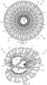
- FIG 1illustrates a first aspect of a stent 100, according to the present invention.
- the stent 100comprises a spring 110 and a sealing layer 130.
- Example aspects of the stent 100can be expandable and compressible, such that the stent 100 can be oriented in an expanded configuration 102, as shown in Figure 1 , and a compressed configuration 204, as shown in Figure 2 .
- the sealing layer 130is removed for visibility of the spring 110.
- the stent 100can be expanded within a pipe 550 (shown in Figure 5 ) such that the sealing layer 130 can engage an inner wall 552 of the pipe 550.
- the sealing layer 130can create a watertight seal between the stent 100 and the inner surface of the pipe 550 at the location of the damage to prevent leaking at the damage site.
- the spring 110biases the stent 100 to the expanded configuration 102.
- the spring 110is formed as a tubular mesh structure 111 defining opposing open ends 112a,b.
- the spring 110further defines an outer surface 314 (best seen in Figure 3 ) and an opposite inner surface 116.
- the inner surface 116can define an inner diameter of the spring 110 and the outer surface 314 can define an outer diameter of the spring 110.
- the inner surface 116defines a void 120 extending between the open ends 112a,b of the spring 110 and an axis 122 extending through a center of the void 120.
- the opposing open ends 112a,b of the spring 110can allow for fluid flow through the void 120.
- the spring 110can define a spring force.
- the spring 110can be formed from a plastic material, such as, for example, nylon, POM (polyoxymethylene), or PVC (polyvinyl chloride).
- the spring 110can be formed from a metal material, such as stainless steel, spring steel, aluminum, nitinol, cobalt chromium, or any other suitable material.
- the materialcan be an NSF certified material that can comply with various public health safety standards.
- the materialcan be approved as safe for use in drinking-water applications.
- the springcan comprise a corrosion-resistant coating.
- the stentcan comprise a balloon for biasing the stent 100 from the compressed configuration 204 to the expanded configuration 102, or any other suitable mechanism for expanding the stent 100.
- the sealing layer 130can be formed as a continuous, tubular sleeve structure 131 defining an outer surface 132 and an inner surface 134.
- the inner surface 134can define an inner diameter of the sealing layer 130, and the outer surface 132 can define an outer diameter of the sealing layer 130.
- the outer diameter of the sealing layer 130can be defined as the diameter of the stent 100 (the "stent diameter").
- the inner surface 134 of the sealing layer 130can engage the outer surface 314 of the spring 110.
- the sealing layer 130can wrap around a circumference of the spring 110 and can cover the entire outer surface 314 of the spring 110, as shown.
- the sealing layer 130can wrap around the circumference of the spring 110 and can cover only a portion of the outer surface 314 of the spring 110. In still other aspects, the sealing layer 130 does not wrap around the entire circumference of the spring 110.
- Example aspects of the sealing layer 130can comprise a flexible and compressible material, such as, for example, neoprene.
- the sealing layer 130can be formed from another synthetic rubber material such as EPDM rubber, natural rubber, foam, epoxy, silicone, a resin-soaked cloth, or any other suitable flexible material for providing a watertight seat between the stent 100 and the inner wall 552 of the pipe 550 (pipe 550 shown in Figure 5 ).
- the inner diameter of the sealing layer 130can substantially match or be slightly smaller than the outer diameter of the spring 110, such that the sealing layer 130 can fit snugly on the spring 110.
- the sealing layer 130in some aspects can be coupled to the spring 110 by a fastener (not shown), such as, for example, stitching, adhesives, ties, or any other suitable fastener known in the art.
- the spring forcecan bias the spring 110 and the sealing layer 130 radially outward relative to the axis 122, such that each of the spring 110 and sealing layer 130 define the relatively tubular shapes, as shown.
- the stent 100can define its largest possible stent diameter.
- a compression forcecan be applied to the outer surface 132 of the sealing layer 130 by a compression mechanism (not shown). The compression force can overcome the spring force, and the sealing layer 130 and spring 110 can compress or fold radially inward towards the void 120 to define a smaller stent diameter and a smaller overall stent volume than in the expanded configuration 102 (shown in Figure 1 ).
- the spring forcecan bias the stent 100 back to the expanded configuration 102.
- a tension forcei.e., a pulling force
- any other suitable forcecan be applied the stent 100 to bias the stent 100 to the compressed configuration 204.
- An expansion ratiocan be defined as the ratio between the stent diameter in the expanded configuration 102 and the stent diameter in the compressed configuration 204.
- the expansion ratiocan be between about 1.2/1 and 3/1.
- the expansion ratiocan be between about 1.4/1 and 2.4/1.
- the expansion ratiocan be about 2/1.
- the reduced stent diametercan allow for easier insertion of the stent 100 into a pipeline (not shown) and easier navigation of the stent 100 through the pipeline.
- Example aspects of the spring 110can be oriented in a rolled configuration 140 for use, as shown in Figures 1-3 , and an unrolled configuration 442, as shown in Figure 4 .
- the spring 110can be manufactured in the unrolled configuration 442, and rolled into the rolled configuration 140 thereafter for use.
- the spring 110in the unrolled configuration 442, can be substantially flat and can define a first end 444 and an opposing second end 446.
- Example aspects of the spring 110can be rolled into the rolled configuration 140 from the unrolled configuration 442.
- the first end 444 of the spring 110can be coupled to the second end 446 to retain the spring 110 in the rolled configuration 140, as shown in Figure 3 .
- the first end 444can be coupled to the second end 446 by a fastener, such as, for example, one or more nut and bolt assemblies 248, as best seen in Figure 2 .
- a fastenersuch as, for example, one or more nut and bolt assemblies 248, as best seen in Figure 2 .
- the fastenercan be adhesives, clips, snaps, ties, or any other suitable fastener or combination of fasteners know in the art.
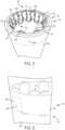
- Figure 5illustrates the stent 100 according to another aspect of the disclosure, not part of the present invention, wherein the stent 100 is in the expanded configuration 102 within a void 556 of the pipe 550.
- the pipe 550is illustrated as translucent for improved visibility of the stent 100.
- the void 556can be defined by the inner wall 552 of the pipe.
- the stent 100 of the current aspectcomprises the spring 110 and the sealing layer 130.
- the spring 110can be a wave-pattern spring 510.
- the wave-pattern spring 510can comprise a metal wire 524 defining a wave pattern in the axial direction.
- the spring 510can be rolled into a tubular structure 511 as shown.
- the spring 510 in the rolled configuration 140can define the void 120 and the axis 122 (shown in Figure 1 ) extending through the void 120.
- Example aspects of the void 120can be concentric to the void 556 of the pipe 550.
- the sealing layer 130can form the sleeve 131 and can wrap around the circumference of the spring 510, engaging the outer surface 314 (shown in Figure 3 ) of the spring 510. As shown in the present aspect, portions of the spring 510 can extend beyond the sealing layer 130, such that the sealing layer 130 covers only a portion of the outer surface 314 of the spring 510. In other aspects, the sealing layer 130 can completely cover the outer surface 314 of the spring 510.
- the sealing layer 130may not extend around the entire circumference of the spring 510.
- the sealing layer 130is coupled to the spring 510 by zip ties 560.
- the zip ties 560can be looped through spring loops 526 formed on the spring 510 and can engage the material of the sealing layer 130 to secure the sealing layer 130 to the spring 510.
- a fastener other than the zip ties 560can be used to attach the sealing layer 130 to the spring 510, such as, for example, sewing or an adhesive.
- example aspects of the spring 510can further comprise one or more tabs 528 extending inward towards the void 120.
- Each of the tabs 528can define an opening therethrough.
- a cable(not shown) can pass through the opening of each of the tabs 528 and can be tightened to contract the stent 100 to the compressed configuration through tension in the cable. The cable can be cut to release the contracting force on the stent 100 and to allow the spring 510 to bias the stent 100 to the expanded configuration 102.
- the stent 100can be compressed by another compression or contraction mechanism, such as a compression sleeve, a dissolvable wire, or any other suitable mechanisms known in the art.
- the wirecan be dissolved by electricity, chemicals, water, or any other suitable dissolving mechanism.
- the compression mechanismcan be a hose clamp.
- the hose clamp or other compression mechanismcan comprise a worm drive.
- the outer surface 132 of the sealing layer 130can press against the inner wall 552 of the pipe 550 to retain the stent 100 in position relative the pipe 550. Furthermore, the sealing layer 130 can press against a crack 554 in the pipe 550, or other damage to the pipe 550, to seal the crack 554 and prevent leakage at the crack 554.
- Figure 6illustrates the stent 100 of Figure 5 with a secondary sealing layer 630.
- the secondary sealing layer 630can be formed from the same material as the sealing layer 130, or can be formed from a different material.
- the sealing layer 130can be formed from neoprene and the secondary sealing layer 630 can be formed from an epoxy.
- Other aspects of the sealing layer 130 and secondary sealing layer 630can be formed from other materials.
- the secondary sealing layer 630can be provided for improved sealing capability at the site of the crack 554 or other damage.
- the sealing layer 130can serve as a general sealing solution and can provide support to the secondary sealing layer 630, while the secondary sealing layer 630 can serve as a more acute sealing solution.
- the secondary sealing layer 630can comprise a compliant material that can be pressed into the crack 554 or other damage.
- the sealing layer 130can comprise a less compliant material configured to provide structure to the stent and support to the secondary sealing layer.
- a compression force(or contraction force in some instances) can be applied to the stent 100 to orient the stent 100 in the compressed configuration 204, wherein the stent 100 has a reduced stent diameter as compared to the stent diameter in the expanded configuration 102.
- the compression forcecan be applied by a compression sleeve (not shown) having a smaller diameter than the stent diameter in the expanded configuration 102.
- the compression forcecan be applied by cables, ties, or another suitable compression mechanism.
- the reduced stent diameter and reduced stent volumecan allow for easy insertion of the stent 100 into the pipeline (not shown) and navigation through the pipeline.
- the pipelinecan comprise one or more pipes, such as the pipe 550 shown in Figure 5 .
- the pipelinecan transport a fluid along the pipeline, such as, for example, water, oil, or natural gas.
- the stent 100can be inserted into the pipeline in the compressed configuration 204 at an existing access point.
- the existing access pointcan be a fire hydrant.
- the existing access pointcan be the entrance or exit of the pipeline, a service entrance, or another suitable point of entry that allows for easy insertion of the stent 100 into the pipeline.
- the stent 100can be mechanically driven or motor-driven through the pipeline to the location of the crack 554 or other damage.
- a current of the fluidcan assist in moving the stent 100 through the pipeline.
- fluid in the pipelinecan continue to flow around and/or through the compressed stent 100.
- the flow of fluid in the pipelinecan continue uninterrupted as the stent 100 is navigated through the pipeline.
- Such a configurationprevents the need to shut off the fluid flow during repairs, which can save costs for the service provider and prevent interruption of service to customers.
- inserting the stent 100 into the pipeline at an existing access point and remotely navigating the stent 100 through the pipelinecan eliminate the need to dig up the surrounding terrain to access the damaged pipe, which can save time and costs when performing repairs.
- the compressed stent 100can be positioned in the pipeline proximate to the crack 554 in the pipe 550.
- the compression force applied to the stent 100 by the compression sleeve, or other compression mechanismcan be removed or reduced, such that the spring force can bias the stent 100 to the expanded configuration 102.
- the outer surface 132 of the sealing layer 130 of the stent 100can contact the inner wall 552 of the pipe 550 and can press against the crack 554 to create a watertight seal and prevent leakage at the crack location.
- a portion of the sealing layer 130can be pushed into the crack 554 for an improved seal.
- fluid pressure from the fluid flow in the pipelinecan also assist in biasing the stent 100 against the inner wall 552 of the pipe 550.
- the stent 100With the stent 100 positioned in the pipe 550 in the expanded configuration 102, fluid in the pipeline can flow through the void 120 in the stent 100.
- Example aspects of the stent 100can be sized and shaped to fit tightly in the pipeline in the expanded configuration 102.
- the stent diameter in the fully expanded configuration 102can be slightly greater than a diameter of the inner wall 552 of the pipe 550.
- the tight fit of the stent 100 within the pipe 550, along with fluid pressure against the stent 100,can aid in retaining the stent 100 in position at the location of the crack 554 or other damage.
- the stent 100 in the expanded configuration 102can also serve to add structural integrity to the pipe 550.
- the stent 100can be formed from materials of a sufficient strength and can be provided with a sufficient spring force for providing structural support to the pipe 550 at the location of the stent 100.
- Some aspects of the stent 100further can include a fastener for attaching the stent 100 to the inner wall 552 of the pipe 550, such as, for example, an adhesive.
- a fastenerfor attaching the stent 100 to the inner wall 552 of the pipe 550, such as, for example, an adhesive.
- any other suitable fastener known in the artcan be used to attach the stent 100 to the pipe 550.
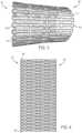
- Example aspects of the spring 110can be cut from a sheet 770 of material.
- the spring 510 of Figure 5can be cut from a flat sheet 770 of metal material, such as, for example, stainless steel.
- Other aspects of the spring 510can be formed from a sheet 770 of another material, such as spring steel, aluminium, plastic, nitinol, or any other suitable material in sheet form.
- a pattern of the spring 510, such as the wave pattern 772 depicted,can be etched, stamped, or otherwise cut into the sheet 770, and any excess sheet material 774 can be removed.
- the spring 110can be formed from a wire (not shown) and worked into the wave-pattern shape of the wave-pattern spring 510.
- the wirecan be hot worked or cold worked into the wave-pattern shape.
- the wirecan be worked into another desired spring shape.
- the spring 110after working the wire into the desired shape, can be heat treated to allow the spring 110 to retain a spring temper.
- Figure 8illustrates the spring 510 in the unrolled configuration 442 with the excess sheet material 774 removed.
- the spring 510can define the first end 444 and the opposite second end 446.
- the first end 444can define a pair of L-shaped hooks 880 extending downwardly therefrom, relative to the orientation shown.
- the second end 446can define a pair of mating L-shaped hooks 882 extending upwardly therefrom, relative to the orientation shown.
- the spring 510can be rolled to define the tubular structure 511 shown in Figure 5 , and the hooks 880 at the first end 444 can engage the mating hooks 882 at the second end 446 to retain the spring 510 in the rolled configuration 140.
- Figure 9illustrates another aspect, not part of the present invention, of the spring 110.
- the spring 110can be a wave pattern spring 910 substantially similar to the spring 510 of Figures 5-8 ; however, the spring 910 can define a length L 2 greater than a length L 1 (shown in Figure 8 ) of the spring 510.
- the spring 510can define a length L 1 of between about 5 inches and 7 inches, and in other aspects, the spring 510 can define a length L 1 of about 6 inches.
- the spring 910can define a length L 2 of between about 7 inches and 9 inches, and in other aspects, the spring 910 can define a length L 2 of about 8 inches.
- the lengths L 1 , L 2 of the springs 510,910, respectivelycan be greater or less than the example aspects described, and this disclosure should not be viewed as limiting.
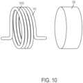
- Figure 10illustrates an exploded view of another aspect, not part of the present invention, of the stent 100.
- the stent 100can comprise the spring 110 and the sealing layer 130.
- the spring 110can be a torsion spring 1010.
- a twisting forcecan be applied to the torsion spring 1010, such that a diameter of the torsion spring 1010 and the overall stent diameter can be reduced.
- the twisting forcecan be removed and the torsion spring 1010 can spring radially outward, biasing the sealing layer 130 radially outward against the inner wall 552 of the pipe 550 (shown in Figure 5 ).
Landscapes
- Engineering & Computer Science (AREA)
- General Engineering & Computer Science (AREA)
- Mechanical Engineering (AREA)
- Chemical & Material Sciences (AREA)
- Combustion & Propulsion (AREA)
- Media Introduction/Drainage Providing Device (AREA)
- Application Of Or Painting With Fluid Materials (AREA)
Description
- This disclosure relates to the field of pipe repair. More specifically, this disclosure relates to a stent for repairing a pipe.
- Piping systems, including municipal water systems, can develop breaks in pipe walls that can cause leaking. Example of breaks in a pipe wall can include radial cracks, axial cracks, point crack, etc. Repairing a break in a pipe wall often requires the piping system to be shut off, which can be inconvenient for customers and costly for providers. Further, repairs can necessitate grandiose construction, including the digging up of streets, sidewalks, and the like, which can be costly and time-consuming.
US8783297B2 discloses a system for pipeline rehabilitation. The system includes repairing a leak in a pipe using a pair of substantially semi-cylindrical parts connected through a compliant j oint. When the parts are compressed, the semi-cylindrical parts form a cylinder whose outside diameter is less than the inside diameter of a pipe with a defect thereby allowing the cylinder to be inserted into the pipe at a location of a leak. Once in place, the parts engage the inside surface of the pipe when the compression is released thereby to seal the leak.US5119862A discloses a pipe repair sleeve and liner with interlocking elements in a form of a coiled sheet which is covered with compressive gasket. An air bag is inserted into the coiled sleeve and moved to the location of the damaged pipe. Once in place, the air bag is inflated. As a result of the inflation, the repair sleeve uncoils and the surrounding gasket is compressed against the damaged pipe. When the air bag is deflated, the sleeve begins to coil and forces a male end of the sleeve into the female end forming a male and female interlocking continuous sleeve inside the pipe. After the repair sleeve is installed in the pipe, the air bag is removed from the sleeve. - The invention is a stent for repairing a leak in a pipe carrying water, gas and/or oil as defined in independent claim 1 and a method for repairing a pipe as defined in independent claim 13. Preferred embodiments are set out in the dependent claims.
- The features and components of the following figures are illustrated to emphasize the general principles of the present disclosure. Corresponding features and components throughout the figures may be designated by matching reference characters for the sake of consistency and clarity.
FIG. 1 is an end view of a first aspect of a stent comprising a spring and a seal, according to the present disclosure, wherein the stent is in an expanded configuration.FIG. 2 is an end view of the spring of the stent ofFIG. 1 in a compressed configuration.FIG. 3 is a side view of the spring of the stent ofFIG. 1 in a rolled configuration.FIG. 4 is a side view of the spring of the stent ofFIG. 1 in an unrolled configuration.FIG. 5 is a perspective view of another aspect of the stent, according to the present disclosure, with the stent in the expanded configuration within a pipe.FIG. 6 is a perspective view of the stent ofFIG. 5 in the expanded configuration within the pipe ofFIG. 5 , the stent comprising a second sealing layer.FIG. 7 is a perspective view of a spring of the stent ofFIG. 5 formed in a piece of sheet material.FIG. 8 is a front view of the spring of the stent ofFIG. 5 in an unrolled configuration.FIG. 9 is another aspect of a spring according to the present disclosure in an unrolled configuration.FIG. 10 is an exploded view of another aspect of the stent according to the present disclosure.- The present disclosure can be understood more readily by reference to the following detailed description, examples, drawings, and claims, and the previous and following description. However, before the present devices, systems, and/or methods are disclosed and described, it is to be understood that this disclosure is not limited to the specific devices, systems, and/or methods disclosed unless otherwise specified, and, as such, can, of course, vary, and the inventions is defined as in the appended claims.
- It is also to be understood that the terminology used herein is for the purpose of describing particular aspects only and is not intended to be limiting.
Figure 1 illustrates a first aspect of astent 100, according to the present invention. Thestent 100 comprises aspring 110 and asealing layer 130. Example aspects of thestent 100 can be expandable and compressible, such that thestent 100 can be oriented in an expandedconfiguration 102, as shown inFigure 1 , and acompressed configuration 204, as shown inFigure 2 . (Note that inFigure 2 , thesealing layer 130 is removed for visibility of thespring 110.) According to example aspects, thestent 100 can be expanded within a pipe 550 (shown inFigure 5 ) such that thesealing layer 130 can engage aninner wall 552 of thepipe 550. In apipe 550 where a crack 554 (shown inFigure 5 ) or other damage is present, thesealing layer 130 can create a watertight seal between thestent 100 and the inner surface of thepipe 550 at the location of the damage to prevent leaking at the damage site.- As shown in
Figure 1 , thespring 110 biases thestent 100 to the expandedconfiguration 102. In the depicted aspect, thespring 110 is formed as atubular mesh structure 111 defining opposingopen ends 112a,b. Thespring 110 further defines an outer surface 314 (best seen inFigure 3 ) and an oppositeinner surface 116. Theinner surface 116 can define an inner diameter of thespring 110 and theouter surface 314 can define an outer diameter of thespring 110. Furthermore, theinner surface 116 defines avoid 120 extending between theopen ends 112a,b of thespring 110 and anaxis 122 extending through a center of thevoid 120. The opposingopen ends 112a,b of thespring 110 can allow for fluid flow through thevoid 120. Moreover, thespring 110 can define a spring force. In some aspects, thespring 110 can be formed from a plastic material, such as, for example, nylon, POM (polyoxymethylene), or PVC (polyvinyl chloride). In other aspects, thespring 110 can be formed from a metal material, such as stainless steel, spring steel, aluminum, nitinol, cobalt chromium, or any other suitable material. Optionally, the material can be an NSF certified material that can comply with various public health safety standards. For example, in some aspects, the material can be approved as safe for use in drinking-water applications. Furthermore, in some aspects, the spring can comprise a corrosion-resistant coating. In some aspects, instead of thespring 110, the stent can comprise a balloon for biasing thestent 100 from thecompressed configuration 204 to the expandedconfiguration 102, or any other suitable mechanism for expanding thestent 100. - In example aspects, the
sealing layer 130 can be formed as a continuous,tubular sleeve structure 131 defining anouter surface 132 and aninner surface 134. Theinner surface 134 can define an inner diameter of thesealing layer 130, and theouter surface 132 can define an outer diameter of thesealing layer 130. The outer diameter of thesealing layer 130 can be defined as the diameter of the stent 100 (the "stent diameter"). Theinner surface 134 of thesealing layer 130 can engage theouter surface 314 of thespring 110. In some aspects, thesealing layer 130 can wrap around a circumference of thespring 110 and can cover the entireouter surface 314 of thespring 110, as shown. However, in other aspects, such as the aspect ofFigure 5 , thesealing layer 130 can wrap around the circumference of thespring 110 and can cover only a portion of theouter surface 314 of thespring 110. In still other aspects, thesealing layer 130 does not wrap around the entire circumference of thespring 110. - Example aspects of the
sealing layer 130 can comprise a flexible and compressible material, such as, for example, neoprene. In other aspects, thesealing layer 130 can be formed from another synthetic rubber material such as EPDM rubber, natural rubber, foam, epoxy, silicone, a resin-soaked cloth, or any other suitable flexible material for providing a watertight seat between thestent 100 and theinner wall 552 of the pipe 550 (pipe 550 shown inFigure 5 ). According to example aspects, the inner diameter of thesealing layer 130 can substantially match or be slightly smaller than the outer diameter of thespring 110, such that thesealing layer 130 can fit snugly on thespring 110. Thesealing layer 130 in some aspects can be coupled to thespring 110 by a fastener (not shown), such as, for example, stitching, adhesives, ties, or any other suitable fastener known in the art. - In the expanded
configuration 102, as shown inFigure 1 , the spring force can bias thespring 110 and thesealing layer 130 radially outward relative to theaxis 122, such that each of thespring 110 and sealinglayer 130 define the relatively tubular shapes, as shown. In the expandedconfiguration 102, thestent 100 can define its largest possible stent diameter. In thecompressed configuration 204, as shown inFigure 2 , a compression force can be applied to theouter surface 132 of thesealing layer 130 by a compression mechanism (not shown). The compression force can overcome the spring force, and thesealing layer 130 andspring 110 can compress or fold radially inward towards the void 120 to define a smaller stent diameter and a smaller overall stent volume than in the expanded configuration 102 (shown inFigure 1 ). When the compression force is removed or reduced to less than the spring force, the spring force can bias thestent 100 back to the expandedconfiguration 102. In other aspects, instead of a compression force, a tension force (i.e., a pulling force) or any other suitable force can be applied thestent 100 to bias thestent 100 to thecompressed configuration 204. - An expansion ratio can be defined as the ratio between the stent diameter in the expanded
configuration 102 and the stent diameter in thecompressed configuration 204. In example aspects, the expansion ratio can be between about 1.2/1 and 3/1. In other aspects, the expansion ratio can be between about 1.4/1 and 2.4/1. In still other aspects, the expansion ratio can be about 2/1. As will be described in further detail below, in thecompressed configuration 204, the reduced stent diameter can allow for easier insertion of thestent 100 into a pipeline (not shown) and easier navigation of thestent 100 through the pipeline. - Example aspects of the
spring 110 can be oriented in a rolledconfiguration 140 for use, as shown inFigures 1-3 , and an unrolledconfiguration 442, as shown inFigure 4 . In example aspects, thespring 110 can be manufactured in the unrolledconfiguration 442, and rolled into the rolledconfiguration 140 thereafter for use. Referring toFigure 4 , in the unrolledconfiguration 442, thespring 110 can be substantially flat and can define afirst end 444 and an opposingsecond end 446. Example aspects of thespring 110 can be rolled into the rolledconfiguration 140 from the unrolledconfiguration 442. Thefirst end 444 of thespring 110 can be coupled to thesecond end 446 to retain thespring 110 in the rolledconfiguration 140, as shown inFigure 3 . According to example aspects, thefirst end 444 can be coupled to thesecond end 446 by a fastener, such as, for example, one or more nut andbolt assemblies 248, as best seen inFigure 2 . In other aspects, the fastener can be adhesives, clips, snaps, ties, or any other suitable fastener or combination of fasteners know in the art. Figure 5 illustrates thestent 100 according to another aspect of the disclosure, not part of the present invention, wherein thestent 100 is in the expandedconfiguration 102 within avoid 556 of thepipe 550. Thepipe 550 is illustrated as translucent for improved visibility of thestent 100. The void 556 can be defined by theinner wall 552 of the pipe. Like thestent 100 ofFigure 1 , thestent 100 of the current aspect comprises thespring 110 and thesealing layer 130. In the present aspect, thespring 110 can be a wave-pattern spring 510. The wave-pattern spring 510 can comprise ametal wire 524 defining a wave pattern in the axial direction. Thespring 510 can be rolled into atubular structure 511 as shown. Thespring 510 in the rolledconfiguration 140 can define thevoid 120 and the axis 122 (shown inFigure 1 ) extending through thevoid 120. Example aspects of the void 120 can be concentric to thevoid 556 of thepipe 550. Thesealing layer 130 can form thesleeve 131 and can wrap around the circumference of thespring 510, engaging the outer surface 314 (shown inFigure 3 ) of thespring 510. As shown in the present aspect, portions of thespring 510 can extend beyond thesealing layer 130, such that thesealing layer 130 covers only a portion of theouter surface 314 of thespring 510. In other aspects, thesealing layer 130 can completely cover theouter surface 314 of thespring 510. In still other aspects, thesealing layer 130 may not extend around the entire circumference of thespring 510. In the present aspect, thesealing layer 130 is coupled to thespring 510 byzip ties 560. The zip ties 560 can be looped throughspring loops 526 formed on thespring 510 and can engage the material of thesealing layer 130 to secure thesealing layer 130 to thespring 510. In other aspects, however, a fastener other than the zip ties 560 can be used to attach thesealing layer 130 to thespring 510, such as, for example, sewing or an adhesive.- As shown, example aspects of the
spring 510 can further comprise one ormore tabs 528 extending inward towards thevoid 120. Each of thetabs 528 can define an opening therethrough. In example aspects, a cable (not shown) can pass through the opening of each of thetabs 528 and can be tightened to contract thestent 100 to the compressed configuration through tension in the cable. The cable can be cut to release the contracting force on thestent 100 and to allow thespring 510 to bias thestent 100 to the expandedconfiguration 102. In other aspects, thestent 100 can be compressed by another compression or contraction mechanism, such as a compression sleeve, a dissolvable wire, or any other suitable mechanisms known in the art. In an aspect comprising a dissolvable wire, the wire can be dissolved by electricity, chemicals, water, or any other suitable dissolving mechanism. In still another aspect, the compression mechanism can be a hose clamp. In some aspects, the hose clamp or other compression mechanism can comprise a worm drive. - With the
stent 100 in the expandedconfiguration 102 within thepipe 550, theouter surface 132 of the sealing layer 130 (shown inFigure 1 ) can press against theinner wall 552 of thepipe 550 to retain thestent 100 in position relative thepipe 550. Furthermore, thesealing layer 130 can press against acrack 554 in thepipe 550, or other damage to thepipe 550, to seal thecrack 554 and prevent leakage at thecrack 554. Figure 6 illustrates thestent 100 ofFigure 5 with asecondary sealing layer 630. Thesecondary sealing layer 630 can be formed from the same material as thesealing layer 130, or can be formed from a different material. For example, in one aspect, thesealing layer 130 can be formed from neoprene and thesecondary sealing layer 630 can be formed from an epoxy. Other aspects of thesealing layer 130 andsecondary sealing layer 630 can be formed from other materials. In example aspects, thesecondary sealing layer 630 can be provided for improved sealing capability at the site of thecrack 554 or other damage. For example, thesealing layer 130 can serve as a general sealing solution and can provide support to thesecondary sealing layer 630, while thesecondary sealing layer 630 can serve as a more acute sealing solution. In some example aspects, thesecondary sealing layer 630 can comprise a compliant material that can be pressed into thecrack 554 or other damage. Furthermore, in some aspects, thesealing layer 130 can comprise a less compliant material configured to provide structure to the stent and support to the secondary sealing layer.- An example aspect of a method for using the
stent 100 is also disclosed. A compression force (or contraction force in some instances) can be applied to thestent 100 to orient thestent 100 in thecompressed configuration 204, wherein thestent 100 has a reduced stent diameter as compared to the stent diameter in the expandedconfiguration 102. In one aspect, the compression force can be applied by a compression sleeve (not shown) having a smaller diameter than the stent diameter in the expandedconfiguration 102. In other aspects, the compression force can be applied by cables, ties, or another suitable compression mechanism. - In the
compressed configuration 204, the reduced stent diameter and reduced stent volume can allow for easy insertion of thestent 100 into the pipeline (not shown) and navigation through the pipeline. The pipeline can comprise one or more pipes, such as thepipe 550 shown inFigure 5 . According to example aspects, the pipeline can transport a fluid along the pipeline, such as, for example, water, oil, or natural gas. Thestent 100 can be inserted into the pipeline in thecompressed configuration 204 at an existing access point. In an example aspect, the existing access point can be a fire hydrant. In other aspects, the existing access point can be the entrance or exit of the pipeline, a service entrance, or another suitable point of entry that allows for easy insertion of thestent 100 into the pipeline. - Once inserted into the pipeline, the
stent 100 can be mechanically driven or motor-driven through the pipeline to the location of thecrack 554 or other damage. In instances where thestent 100 is moving through the pipeline in the direction of the fluid flow, a current of the fluid can assist in moving thestent 100 through the pipeline. As thestent 100 moves through the pipeline, fluid in the pipeline can continue to flow around and/or through thecompressed stent 100. As such, the flow of fluid in the pipeline can continue uninterrupted as thestent 100 is navigated through the pipeline. Such a configuration prevents the need to shut off the fluid flow during repairs, which can save costs for the service provider and prevent interruption of service to customers. Furthermore, inserting thestent 100 into the pipeline at an existing access point and remotely navigating thestent 100 through the pipeline can eliminate the need to dig up the surrounding terrain to access the damaged pipe, which can save time and costs when performing repairs. - The
compressed stent 100 can be positioned in the pipeline proximate to thecrack 554 in thepipe 550. The compression force applied to thestent 100 by the compression sleeve, or other compression mechanism, can be removed or reduced, such that the spring force can bias thestent 100 to the expandedconfiguration 102. In the expandedconfiguration 102, theouter surface 132 of thesealing layer 130 of thestent 100 can contact theinner wall 552 of thepipe 550 and can press against thecrack 554 to create a watertight seal and prevent leakage at the crack location. In some aspects, a portion of thesealing layer 130 can be pushed into thecrack 554 for an improved seal. In example aspects, fluid pressure from the fluid flow in the pipeline can also assist in biasing thestent 100 against theinner wall 552 of thepipe 550. - With the
stent 100 positioned in thepipe 550 in the expandedconfiguration 102, fluid in the pipeline can flow through the void 120 in thestent 100. Example aspects of thestent 100 can be sized and shaped to fit tightly in the pipeline in the expandedconfiguration 102. For example, in one aspect, the stent diameter in the fully expandedconfiguration 102 can be slightly greater than a diameter of theinner wall 552 of thepipe 550. The tight fit of thestent 100 within thepipe 550, along with fluid pressure against thestent 100, can aid in retaining thestent 100 in position at the location of thecrack 554 or other damage. In some aspects, thestent 100 in the expandedconfiguration 102 can also serve to add structural integrity to thepipe 550. In such aspects, thestent 100 can be formed from materials of a sufficient strength and can be provided with a sufficient spring force for providing structural support to thepipe 550 at the location of thestent 100. Some aspects of thestent 100 further can include a fastener for attaching thestent 100 to theinner wall 552 of thepipe 550, such as, for example, an adhesive. However, in other aspects, any other suitable fastener known in the art can be used to attach thestent 100 to thepipe 550. - Example aspects of the
spring 110 can be cut from asheet 770 of material. Referring toFigure 7 , thespring 510 ofFigure 5 can be cut from aflat sheet 770 of metal material, such as, for example, stainless steel. Other aspects of thespring 510 can be formed from asheet 770 of another material, such as spring steel, aluminium, plastic, nitinol, or any other suitable material in sheet form. A pattern of thespring 510, such as thewave pattern 772 depicted, can be etched, stamped, or otherwise cut into thesheet 770, and anyexcess sheet material 774 can be removed. - In another aspect, not part of the present invention, the
spring 110 can be formed from a wire (not shown) and worked into the wave-pattern shape of the wave-pattern spring 510. For example, the wire can be hot worked or cold worked into the wave-pattern shape. In other aspects, the wire can be worked into another desired spring shape. Furthermore, in example aspects, after working the wire into the desired shape, thespring 110 can be heat treated to allow thespring 110 to retain a spring temper. Figure 8 illustrates thespring 510 in the unrolledconfiguration 442 with theexcess sheet material 774 removed. As shown, thespring 510 can define thefirst end 444 and the oppositesecond end 446. Thefirst end 444 can define a pair of L-shapedhooks 880 extending downwardly therefrom, relative to the orientation shown. Thesecond end 446 can define a pair of mating L-shaped hooks 882 extending upwardly therefrom, relative to the orientation shown. Thespring 510 can be rolled to define thetubular structure 511 shown inFigure 5 , and thehooks 880 at thefirst end 444 can engage the mating hooks 882 at thesecond end 446 to retain thespring 510 in the rolledconfiguration 140.Figure 9 illustrates another aspect, not part of the present invention, of thespring 110. In this aspect, thespring 110 can be awave pattern spring 910 substantially similar to thespring 510 ofFigures 5-8 ; however, thespring 910 can define a length L2 greater than a length L1 (shown inFigure 8 ) of thespring 510. For example, in one aspect, thespring 510 can define a length L1 of between about 5 inches and 7 inches, and in other aspects, thespring 510 can define a length L1 of about 6 inches. Furthermore, in one aspect, thespring 910 can define a length L2 of between about 7 inches and 9 inches, and in other aspects, thespring 910 can define a length L2 of about 8 inches. In other aspects, the lengths L1, L2 of the springs 510,910, respectively, can be greater or less than the example aspects described, and this disclosure should not be viewed as limiting.Figure 10 illustrates an exploded view of another aspect, not part of the present invention, of thestent 100. As shown, thestent 100 can comprise thespring 110 and thesealing layer 130. In the present aspect, thespring 110 can be atorsion spring 1010. In the compressed configuration, a twisting force can be applied to thetorsion spring 1010, such that a diameter of thetorsion spring 1010 and the overall stent diameter can be reduced. In the expanded configuration, the twisting force can be removed and thetorsion spring 1010 can spring radially outward, biasing thesealing layer 130 radially outward against theinner wall 552 of the pipe 550 (shown inFigure 5 ).
Claims (15)
- A stent (100) for repairing a leak in a pipe carrying water, gas, and/or oil, the stent (100) comprising:a spring (110) defining a tubular mesh structure, the spring (110) defining an outer surface and an inner surface, the inner surface defining a void (120); anda seal (130) wrapped around the outer surface of the spring (110);the stent (100) configurable in a compressed orientation, wherein the spring (110) is compressed, and an expanded orientation, wherein the spring (110) is expanded, the spring (110) biasing the stent to the expanded orientation.
- The stent (100) of claim 1, wherein a compression force is applied to the stent (100) in the compressed orientation by a compression mechanism, and wherein the compression mechanism is selected from one of a compression sleeve, a cable, a hose clamp, and a dissolvable wire.
- The stent (100) of claim 1, wherein a diameter of the stent (100) in the compressed orientation is smaller than a diameter of the stent in the expanded orientation.
- The stent (100) of claim 1, wherein the spring (110) comprises at least one of sheet metal, stainless steel, spring steel, nitinol, aluminium, nylon, polyoxymethylene, and polyvinyl chloride, and wherein the seal comprises a flexible material, the flexible material comprising at least one of foam, natural rubber, synthetic rubber, epoxy, a resin-soaked cloth, and silicone.
- The stent (100) of claim 1, wherein the stent defines a cylindrical structure in the expanded orientation, the cylindrical structure defining a pair of opposing open ends.
- The stent (100) of claim 1, wherein the spring defines a pattern, wherein the pattern is a mesh pattern.
- The stent (100) of claim 1, wherein the seal (130) is attached to the spring by a fastener.
- The stent (100) of claim 1, wherein the spring (110) is configurable in an unrolled configuration and a rolled configuration, the spring (110) defining a first end and a second end, the first end attached to the second end in the rolled configuration.
- A pipe assembly comprising:a pipe (550) comprising an inner wall, the inner wall defining a first void; anda stent (100) according to any of claims 1 to 8.
- The pipe assembly of claim 9, wherein the inner wall defines an inner diameter of the pipe (550) and the seal (130) defines an outer diameter of the stent (100), and wherein the outer diameter of the stent (100) in the compressed orientation is smaller than the inner diameter of the pipe (550).
- The pipe assembly of claim 10, wherein the outer diameter of the stent (100) in the expanded orientation is greater than or equal to the inner diameter of the pipe (550).
- The pipe assembly of claim 9, wherein the spring (110) defines an inner spring surface, the inner spring surface defining a second void, the second void concentric to the first void.
- A method for repairing a pipe (550) comprising:compressing a stent (100) according to any of claims 1 to 8;inserting the stent (100) into the pipe (550);positioning the stent (100) proximate to a leak in the pipe (550); andexpanding the stent (100) to cover the leak with the seal (130).
- The method of claim 13, wherein compressing the stent (100) comprises applying a compression force to the stent (100) with a compression mechanism, and wherein expanding the stent (100) comprises one of removing and reducing the compression force.
- The method of claim 13, wherein expanding the stent (100) comprises biasing the seal (130) against the leak with the spring (110).
Priority Applications (3)
| Application Number | Priority Date | Filing Date | Title |
|---|---|---|---|
| EP23204265.5AEP4286732B1 (en) | 2018-04-03 | 2018-11-30 | Stent and method for repairing pipes |
| EP25165571.8AEP4549800A3 (en) | 2018-04-03 | 2018-11-30 | Stent and method for repairing pipes |
| EP23179851.3AEP4223253B1 (en) | 2018-04-03 | 2018-11-30 | Stent and method thereof for repairing pipes |
Applications Claiming Priority (3)
| Application Number | Priority Date | Filing Date | Title |
|---|---|---|---|
| US201862651985P | 2018-04-03 | 2018-04-03 | |
| US16/112,207US10641427B2 (en) | 2018-04-03 | 2018-08-24 | Stents and methods for repairing pipes |
| PCT/US2018/063325WO2019194870A1 (en) | 2018-04-03 | 2018-11-30 | Stents and methods for repairing pipes |
Related Child Applications (4)
| Application Number | Title | Priority Date | Filing Date |
|---|---|---|---|
| EP25165571.8ADivisionEP4549800A3 (en) | 2018-04-03 | 2018-11-30 | Stent and method for repairing pipes |
| EP23179851.3ADivisionEP4223253B1 (en) | 2018-04-03 | 2018-11-30 | Stent and method thereof for repairing pipes |
| EP23179851.3ADivision-IntoEP4223253B1 (en) | 2018-04-03 | 2018-11-30 | Stent and method thereof for repairing pipes |
| EP23204265.5ADivisionEP4286732B1 (en) | 2018-04-03 | 2018-11-30 | Stent and method for repairing pipes |
Publications (3)
| Publication Number | Publication Date |
|---|---|
| EP3740157A1 EP3740157A1 (en) | 2020-11-25 |
| EP3740157A4 EP3740157A4 (en) | 2021-10-13 |
| EP3740157B1true EP3740157B1 (en) | 2023-09-20 |
Family
ID=68054153
Family Applications (4)
| Application Number | Title | Priority Date | Filing Date |
|---|---|---|---|
| EP18913510.6AActiveEP3740157B1 (en) | 2018-04-03 | 2018-11-30 | Stent and method for repairing pipes |
| EP25165571.8APendingEP4549800A3 (en) | 2018-04-03 | 2018-11-30 | Stent and method for repairing pipes |
| EP23179851.3AActiveEP4223253B1 (en) | 2018-04-03 | 2018-11-30 | Stent and method thereof for repairing pipes |
| EP23204265.5AActiveEP4286732B1 (en) | 2018-04-03 | 2018-11-30 | Stent and method for repairing pipes |
Family Applications After (3)
| Application Number | Title | Priority Date | Filing Date |
|---|---|---|---|
| EP25165571.8APendingEP4549800A3 (en) | 2018-04-03 | 2018-11-30 | Stent and method for repairing pipes |
| EP23179851.3AActiveEP4223253B1 (en) | 2018-04-03 | 2018-11-30 | Stent and method thereof for repairing pipes |
| EP23204265.5AActiveEP4286732B1 (en) | 2018-04-03 | 2018-11-30 | Stent and method for repairing pipes |
Country Status (4)
| Country | Link |
|---|---|
| US (2) | US10641427B2 (en) |
| EP (4) | EP3740157B1 (en) |
| CA (1) | CA3092322A1 (en) |
| WO (1) | WO2019194870A1 (en) |
Cited By (1)
| Publication number | Priority date | Publication date | Assignee | Title |
|---|---|---|---|---|
| US12305788B2 (en) | 2019-08-09 | 2025-05-20 | Mueller International, Llc | Stent spring for pipe repair device |
Families Citing this family (6)
| Publication number | Priority date | Publication date | Assignee | Title |
|---|---|---|---|---|
| US10641427B2 (en) | 2018-04-03 | 2020-05-05 | Mueller International, Llc | Stents and methods for repairing pipes |
| EP4509097A3 (en) | 2019-02-19 | 2025-08-20 | Mueller International, LLC | Stent springs and stents for repairing pipes |
| US11187366B2 (en) | 2019-03-15 | 2021-11-30 | Mueller International, Llc | Stent for repairing a pipe |
| US11079058B2 (en) | 2019-03-15 | 2021-08-03 | Mueller International , LLC | Stent with coiled spring |
| US11326731B2 (en) | 2019-04-24 | 2022-05-10 | Mueller International, Llc | Pipe repair assembly |
| US11391405B2 (en) | 2019-08-09 | 2022-07-19 | Mueller International, Llc | Deployment probe for pipe repair device |
Family Cites Families (45)
| Publication number | Priority date | Publication date | Assignee | Title |
|---|---|---|---|---|
| US3895652A (en) | 1974-01-11 | 1975-07-22 | Roger G Zach | Diametrically expansible coil spring conduit plug |
| US4589447A (en) | 1983-08-03 | 1986-05-20 | Owens-Corning Fiberglas Corporation | Method of depositing a membrane within a conduit |
| EP0159300A1 (en)* | 1984-03-30 | 1985-10-23 | Stig Westman | Repair sleeve for piping |
| DE3610626A1 (en)* | 1986-03-29 | 1987-10-08 | Norske Stats Oljeselskap | DEVICE FOR GENERATING FORCES RADIAL ON A CYLINDRICAL SURFACE, IN PARTICULAR EMPLOYEES OR HOLDING FORCES |
| US5119862A (en)* | 1988-10-31 | 1992-06-09 | Link-Pipe Technlogies, Inc. | Conduit repair apparatus |
| US5351720A (en)* | 1992-03-10 | 1994-10-04 | Link-Pipe, Inc. | Apparatus for repairing conduits |
| DE69317548T2 (en) | 1993-04-23 | 1998-08-13 | Schneider (Europe) Gmbh, Buelach | Stent with a coating of elastic material and method for applying the coating on the stent |
| US6820653B1 (en)* | 1999-04-12 | 2004-11-23 | Carnegie Mellon University | Pipe inspection and repair system |
| US7267141B1 (en) | 2000-06-05 | 2007-09-11 | Milliken & Company | Method of on-site production of novel textile reinforced thermoplastic or thermoset pipes |
| EP1345754A4 (en) | 2000-06-09 | 2006-04-19 | Fiberliner Networks | Method and apparatus for lining a conduit |
| US6648071B2 (en) | 2001-01-24 | 2003-11-18 | Schlumberger Technology Corporation | Apparatus comprising expandable bistable tubulars and methods for their use in wellbores |
| US6712556B2 (en)* | 2001-05-18 | 2004-03-30 | G. Gregory Penza | Method and apparatus for routing cable in existing pipelines |
| US20030017775A1 (en) | 2001-06-11 | 2003-01-23 | Scimed Life Systems. Inc.. | Composite ePTFE/textile prosthesis |
| US8488290B2 (en)* | 2001-06-15 | 2013-07-16 | George M. Kauffman | Protective device |
| DE60302459T2 (en) | 2002-05-29 | 2006-08-03 | Cook Inc., Bloomington | TRIGGER WIRE SYSTEM FOR A PROSTHESIS PLASMA DEVICE |
| US7611528B2 (en) | 2003-01-24 | 2009-11-03 | Medtronic Vascular, Inc. | Stent-graft delivery system |
| US7776078B2 (en) | 2003-05-22 | 2010-08-17 | Boston Scientfic Scimed, Inc. | Catheter balloon with improved retention |
| DE10357061B4 (en) | 2003-12-04 | 2005-09-08 | Tracto-Technik Gmbh | Cutting system, apparatus and method for cutting pipes |
| JP2005278993A (en)* | 2004-03-30 | 2005-10-13 | Terumo Corp | Stent for indwelling in living body, and production method of the same |
| KR100732864B1 (en) | 2005-08-10 | 2007-06-27 | 이철민 | Non excavation pipeline repair mesh wire installation method |
| WO2008066923A1 (en) | 2006-11-30 | 2008-06-05 | William Cook Europe Aps | Implant release mechanism |
| US7896915B2 (en) | 2007-04-13 | 2011-03-01 | Jenavalve Technology, Inc. | Medical device for treating a heart valve insufficiency |
| US20080269871A1 (en) | 2007-04-27 | 2008-10-30 | Uri Eli | Implantable device with miniature rotating portion and uses thereof |
| US20090308619A1 (en)* | 2008-06-12 | 2009-12-17 | Schlumberger Technology Corporation | Method and apparatus for modifying flow |
| US8652202B2 (en) | 2008-08-22 | 2014-02-18 | Edwards Lifesciences Corporation | Prosthetic heart valve and delivery apparatus |
| US9052051B2 (en)* | 2009-04-20 | 2015-06-09 | Link-Pipe, Inc. | Apparatus and method for internal repair of conduits |
| GB0911579D0 (en) | 2009-07-03 | 2009-08-12 | Brinker Technology Ltd | Apparatus and methods for maintenance and repair of vessels |
| US9326870B2 (en) | 2010-04-23 | 2016-05-03 | Medtronic Vascular, Inc. | Biodegradable stent having non-biodegradable end portions and mechanisms for increased stent hoop strength |
| CA2826022A1 (en) | 2011-02-03 | 2012-08-09 | Endospan Ltd. | Implantable medical devices constructed of shape memory material |
| US8783297B2 (en)* | 2011-04-27 | 2014-07-22 | Massachusetts Institute Of Technology | Robotic system for pipeline rehabilitation |
| US20130018450A1 (en) | 2011-07-13 | 2013-01-17 | Hunt James B | Prosthesis delivery system with retention sleeve |
| EP2604232B1 (en) | 2011-12-14 | 2021-02-24 | Cook Medical Technologies LLC | Circumferential trigger wire for deploying an endoluminal prosthesis |
| WO2014204807A1 (en) | 2013-06-19 | 2014-12-24 | Aga Medical Corporation | Collapsible valve having paravalvular leak protection |
| US20160238178A1 (en)* | 2013-10-29 | 2016-08-18 | Jeffrey M. Urbanski | Apparatus For Repairing A Pipe |
| US10111741B2 (en) | 2014-10-29 | 2018-10-30 | W. L. Gore & Associates, Inc. | Intralumenal stent graft fixation |
| US10265169B2 (en) | 2015-11-23 | 2019-04-23 | Edwards Lifesciences Corporation | Apparatus for controlled heart valve delivery |
| JP7222881B2 (en) | 2016-04-25 | 2023-02-15 | ソリナス メディカル インコーポレイテッド | Self-sealing tubular grafts, patches, methods of making and using same |
| US10627038B2 (en) | 2017-09-26 | 2020-04-21 | Mueller International, Llc | Devices and methods for repairing pipes |
| US10641427B2 (en) | 2018-04-03 | 2020-05-05 | Mueller International, Llc | Stents and methods for repairing pipes |
| EP4509097A3 (en) | 2019-02-19 | 2025-08-20 | Mueller International, LLC | Stent springs and stents for repairing pipes |
| US11187366B2 (en) | 2019-03-15 | 2021-11-30 | Mueller International, Llc | Stent for repairing a pipe |
| US11079058B2 (en) | 2019-03-15 | 2021-08-03 | Mueller International , LLC | Stent with coiled spring |
| US11326731B2 (en) | 2019-04-24 | 2022-05-10 | Mueller International, Llc | Pipe repair assembly |
| US11391405B2 (en) | 2019-08-09 | 2022-07-19 | Mueller International, Llc | Deployment probe for pipe repair device |
| US11802646B2 (en) | 2019-08-09 | 2023-10-31 | Mueller International, Llc | Pipe repair device |
- 2018
- 2018-08-24USUS16/112,207patent/US10641427B2/enactiveActive
- 2018-11-30EPEP18913510.6Apatent/EP3740157B1/enactiveActive
- 2018-11-30EPEP25165571.8Apatent/EP4549800A3/enactivePending
- 2018-11-30EPEP23179851.3Apatent/EP4223253B1/enactiveActive
- 2018-11-30WOPCT/US2018/063325patent/WO2019194870A1/ennot_activeCeased
- 2018-11-30CACA3092322Apatent/CA3092322A1/enactivePending
- 2018-11-30EPEP23204265.5Apatent/EP4286732B1/enactiveActive
- 2020
- 2020-03-31USUS16/836,468patent/US11221099B2/enactiveActive
Cited By (3)
| Publication number | Priority date | Publication date | Assignee | Title |
|---|---|---|---|---|
| US12305788B2 (en) | 2019-08-09 | 2025-05-20 | Mueller International, Llc | Stent spring for pipe repair device |
| US12392443B2 (en) | 2019-08-09 | 2025-08-19 | Mueller International, Llc | Method of repairing a pipe |
| US12392442B2 (en) | 2019-08-09 | 2025-08-19 | Mueller International, Llc | Pipe repair device |
Also Published As
| Publication number | Publication date |
|---|---|
| EP4223253B1 (en) | 2024-07-24 |
| EP3740157A4 (en) | 2021-10-13 |
| EP3740157A1 (en) | 2020-11-25 |
| CA3092322A1 (en) | 2019-10-10 |
| EP4286732A2 (en) | 2023-12-06 |
| WO2019194870A1 (en) | 2019-10-10 |
| US20200224811A1 (en) | 2020-07-16 |
| EP4286732A3 (en) | 2024-01-03 |
| US20190301657A1 (en) | 2019-10-03 |
| US11221099B2 (en) | 2022-01-11 |
| EP4286732B1 (en) | 2025-04-16 |
| EP4549800A2 (en) | 2025-05-07 |
| US10641427B2 (en) | 2020-05-05 |
| EP4223253A1 (en) | 2023-08-09 |
| EP4549800A3 (en) | 2025-06-18 |
Similar Documents
| Publication | Publication Date | Title |
|---|---|---|
| EP3740157B1 (en) | Stent and method for repairing pipes | |
| US5108533A (en) | Method and combination for installing a liner within a service pipe transversely connected to a main pipe | |
| US11480286B2 (en) | Stent for repairing a pipe | |
| US11781697B2 (en) | Stent springs and stents for repairing pipes | |
| JP2719831B2 (en) | Sleeve, liner, apparatus and method for pipe repair | |
| AU596892B2 (en) | Pipe renovation system | |
| AU755196B2 (en) | Liner and method for lining a pipeline | |
| EP1877692B1 (en) | Combination of a pipe and a flexible liner assembly for repairing or reinforcing the pipe | |
| US20040206411A1 (en) | Water supply pipe liner | |
| JP4603312B2 (en) | Sealing unit used for pipe rehabilitation connection method | |
| US6017064A (en) | Apparatus and methods for forming lateral openings in main pipelines and restraining apparatus for main and lateral pipe joints | |
| JP2589191B2 (en) | Waterproof coating | |
| US20190376634A1 (en) | Trenchless mechanical lining system for continuous repair of underground pipes and culverts, and method of installation | |
| JP2006077915A (en) | Fixture for shutting off water, structure for joining pipe, and method for joining pipe | |
| JPH0374698A (en) | Covering body for preventing water leakage for line and water leakage preventing method for line | |
| JP2002213645A (en) | Method of installing temporary pipe | |
| JPH0679887U (en) | Packer | |
| CA2005623A1 (en) | Internal pipe repair sleeve and liner | |
| JPH0374131A (en) | Body holder for conduit |
Legal Events
| Date | Code | Title | Description |
|---|---|---|---|
| STAA | Information on the status of an ep patent application or granted ep patent | Free format text:STATUS: THE INTERNATIONAL PUBLICATION HAS BEEN MADE | |
| PUAI | Public reference made under article 153(3) epc to a published international application that has entered the european phase | Free format text:ORIGINAL CODE: 0009012 | |
| STAA | Information on the status of an ep patent application or granted ep patent | Free format text:STATUS: REQUEST FOR EXAMINATION WAS MADE | |
| 17P | Request for examination filed | Effective date:20200819 | |
| AK | Designated contracting states | Kind code of ref document:A1 Designated state(s):AL AT BE BG CH CY CZ DE DK EE ES FI FR GB GR HR HU IE IS IT LI LT LU LV MC MK MT NL NO PL PT RO RS SE SI SK SM TR | |
| AX | Request for extension of the european patent | Extension state:BA ME | |
| DAV | Request for validation of the european patent (deleted) | ||
| DAX | Request for extension of the european patent (deleted) | ||
| A4 | Supplementary search report drawn up and despatched | Effective date:20210913 | |
| RIC1 | Information provided on ipc code assigned before grant | Ipc:F16L 101/60 20060101ALI20210907BHEP Ipc:F16L 55/44 20060101ALI20210907BHEP Ipc:F16L 55/163 20060101ALI20210907BHEP Ipc:E21B 43/10 20060101ALI20210907BHEP Ipc:A61F 2/966 20130101ALI20210907BHEP Ipc:A61F 2/95 20130101ALI20210907BHEP Ipc:A61F 2/89 20130101ALI20210907BHEP Ipc:A61F 2/848 20130101ALI20210907BHEP Ipc:A61F 2/07 20130101ALI20210907BHEP Ipc:A61F 2/04 20130101AFI20210907BHEP | |
| GRAP | Despatch of communication of intention to grant a patent | Free format text:ORIGINAL CODE: EPIDOSNIGR1 | |
| STAA | Information on the status of an ep patent application or granted ep patent | Free format text:STATUS: GRANT OF PATENT IS INTENDED | |
| INTG | Intention to grant announced | Effective date:20230417 | |
| P01 | Opt-out of the competence of the unified patent court (upc) registered | Effective date:20230523 | |
| GRAS | Grant fee paid | Free format text:ORIGINAL CODE: EPIDOSNIGR3 | |
| GRAA | (expected) grant | Free format text:ORIGINAL CODE: 0009210 | |
| STAA | Information on the status of an ep patent application or granted ep patent | Free format text:STATUS: THE PATENT HAS BEEN GRANTED | |
| AK | Designated contracting states | Kind code of ref document:B1 Designated state(s):AL AT BE BG CH CY CZ DE DK EE ES FI FR GB GR HR HU IE IS IT LI LT LU LV MC MK MT NL NO PL PT RO RS SE SI SK SM TR | |
| REG | Reference to a national code | Ref country code:GB Ref legal event code:FG4D | |
| REG | Reference to a national code | Ref country code:CH Ref legal event code:EP | |
| REG | Reference to a national code | Ref country code:IE Ref legal event code:FG4D | |
| REG | Reference to a national code | Ref country code:DE Ref legal event code:R096 Ref document number:602018058091 Country of ref document:DE | |
| REG | Reference to a national code | Ref country code:LT Ref legal event code:MG9D | |
| PG25 | Lapsed in a contracting state [announced via postgrant information from national office to epo] | Ref country code:GR Free format text:LAPSE BECAUSE OF FAILURE TO SUBMIT A TRANSLATION OF THE DESCRIPTION OR TO PAY THE FEE WITHIN THE PRESCRIBED TIME-LIMIT Effective date:20231221 | |
| REG | Reference to a national code | Ref country code:NL Ref legal event code:MP Effective date:20230920 | |
| PG25 | Lapsed in a contracting state [announced via postgrant information from national office to epo] | Ref country code:SE Free format text:LAPSE BECAUSE OF FAILURE TO SUBMIT A TRANSLATION OF THE DESCRIPTION OR TO PAY THE FEE WITHIN THE PRESCRIBED TIME-LIMIT Effective date:20230920 Ref country code:RS Free format text:LAPSE BECAUSE OF FAILURE TO SUBMIT A TRANSLATION OF THE DESCRIPTION OR TO PAY THE FEE WITHIN THE PRESCRIBED TIME-LIMIT Effective date:20230920 Ref country code:NO Free format text:LAPSE BECAUSE OF FAILURE TO SUBMIT A TRANSLATION OF THE DESCRIPTION OR TO PAY THE FEE WITHIN THE PRESCRIBED TIME-LIMIT Effective date:20231220 Ref country code:LV Free format text:LAPSE BECAUSE OF FAILURE TO SUBMIT A TRANSLATION OF THE DESCRIPTION OR TO PAY THE FEE WITHIN THE PRESCRIBED TIME-LIMIT Effective date:20230920 Ref country code:LT Free format text:LAPSE BECAUSE OF FAILURE TO SUBMIT A TRANSLATION OF THE DESCRIPTION OR TO PAY THE FEE WITHIN THE PRESCRIBED TIME-LIMIT Effective date:20230920 Ref country code:HR Free format text:LAPSE BECAUSE OF FAILURE TO SUBMIT A TRANSLATION OF THE DESCRIPTION OR TO PAY THE FEE WITHIN THE PRESCRIBED TIME-LIMIT Effective date:20230920 Ref country code:GR Free format text:LAPSE BECAUSE OF FAILURE TO SUBMIT A TRANSLATION OF THE DESCRIPTION OR TO PAY THE FEE WITHIN THE PRESCRIBED TIME-LIMIT Effective date:20231221 Ref country code:FI Free format text:LAPSE BECAUSE OF FAILURE TO SUBMIT A TRANSLATION OF THE DESCRIPTION OR TO PAY THE FEE WITHIN THE PRESCRIBED TIME-LIMIT Effective date:20230920 | |
| REG | Reference to a national code | Ref country code:AT Ref legal event code:MK05 Ref document number:1612819 Country of ref document:AT Kind code of ref document:T Effective date:20230920 | |
| PG25 | Lapsed in a contracting state [announced via postgrant information from national office to epo] | Ref country code:NL Free format text:LAPSE BECAUSE OF FAILURE TO SUBMIT A TRANSLATION OF THE DESCRIPTION OR TO PAY THE FEE WITHIN THE PRESCRIBED TIME-LIMIT Effective date:20230920 | |
| PG25 | Lapsed in a contracting state [announced via postgrant information from national office to epo] | Ref country code:IS Free format text:LAPSE BECAUSE OF FAILURE TO SUBMIT A TRANSLATION OF THE DESCRIPTION OR TO PAY THE FEE WITHIN THE PRESCRIBED TIME-LIMIT Effective date:20240120 | |
| PG25 | Lapsed in a contracting state [announced via postgrant information from national office to epo] | Ref country code:AT Free format text:LAPSE BECAUSE OF FAILURE TO SUBMIT A TRANSLATION OF THE DESCRIPTION OR TO PAY THE FEE WITHIN THE PRESCRIBED TIME-LIMIT Effective date:20230920 | |
| PG25 | Lapsed in a contracting state [announced via postgrant information from national office to epo] | Ref country code:ES Free format text:LAPSE BECAUSE OF FAILURE TO SUBMIT A TRANSLATION OF THE DESCRIPTION OR TO PAY THE FEE WITHIN THE PRESCRIBED TIME-LIMIT Effective date:20230920 | |
| PG25 | Lapsed in a contracting state [announced via postgrant information from national office to epo] | Ref country code:SM Free format text:LAPSE BECAUSE OF FAILURE TO SUBMIT A TRANSLATION OF THE DESCRIPTION OR TO PAY THE FEE WITHIN THE PRESCRIBED TIME-LIMIT Effective date:20230920 Ref country code:RO Free format text:LAPSE BECAUSE OF FAILURE TO SUBMIT A TRANSLATION OF THE DESCRIPTION OR TO PAY THE FEE WITHIN THE PRESCRIBED TIME-LIMIT Effective date:20230920 Ref country code:IS Free format text:LAPSE BECAUSE OF FAILURE TO SUBMIT A TRANSLATION OF THE DESCRIPTION OR TO PAY THE FEE WITHIN THE PRESCRIBED TIME-LIMIT Effective date:20240120 Ref country code:ES Free format text:LAPSE BECAUSE OF FAILURE TO SUBMIT A TRANSLATION OF THE DESCRIPTION OR TO PAY THE FEE WITHIN THE PRESCRIBED TIME-LIMIT Effective date:20230920 Ref country code:EE Free format text:LAPSE BECAUSE OF FAILURE TO SUBMIT A TRANSLATION OF THE DESCRIPTION OR TO PAY THE FEE WITHIN THE PRESCRIBED TIME-LIMIT Effective date:20230920 Ref country code:CZ Free format text:LAPSE BECAUSE OF FAILURE TO SUBMIT A TRANSLATION OF THE DESCRIPTION OR TO PAY THE FEE WITHIN THE PRESCRIBED TIME-LIMIT Effective date:20230920 Ref country code:AT Free format text:LAPSE BECAUSE OF FAILURE TO SUBMIT A TRANSLATION OF THE DESCRIPTION OR TO PAY THE FEE WITHIN THE PRESCRIBED TIME-LIMIT Effective date:20230920 Ref country code:PT Free format text:LAPSE BECAUSE OF FAILURE TO SUBMIT A TRANSLATION OF THE DESCRIPTION OR TO PAY THE FEE WITHIN THE PRESCRIBED TIME-LIMIT Effective date:20240122 Ref country code:SK Free format text:LAPSE BECAUSE OF FAILURE TO SUBMIT A TRANSLATION OF THE DESCRIPTION OR TO PAY THE FEE WITHIN THE PRESCRIBED TIME-LIMIT Effective date:20230920 | |
| PG25 | Lapsed in a contracting state [announced via postgrant information from national office to epo] | Ref country code:PL Free format text:LAPSE BECAUSE OF FAILURE TO SUBMIT A TRANSLATION OF THE DESCRIPTION OR TO PAY THE FEE WITHIN THE PRESCRIBED TIME-LIMIT Effective date:20230920 Ref country code:IT Free format text:LAPSE BECAUSE OF FAILURE TO SUBMIT A TRANSLATION OF THE DESCRIPTION OR TO PAY THE FEE WITHIN THE PRESCRIBED TIME-LIMIT Effective date:20230920 | |
| REG | Reference to a national code | Ref country code:DE Ref legal event code:R097 Ref document number:602018058091 Country of ref document:DE | |
| REG | Reference to a national code | Ref country code:CH Ref legal event code:PL | |
| PG25 | Lapsed in a contracting state [announced via postgrant information from national office to epo] | Ref country code:MC Free format text:LAPSE BECAUSE OF FAILURE TO SUBMIT A TRANSLATION OF THE DESCRIPTION OR TO PAY THE FEE WITHIN THE PRESCRIBED TIME-LIMIT Effective date:20230920 | |
| PG25 | Lapsed in a contracting state [announced via postgrant information from national office to epo] | Ref country code:DK Free format text:LAPSE BECAUSE OF FAILURE TO SUBMIT A TRANSLATION OF THE DESCRIPTION OR TO PAY THE FEE WITHIN THE PRESCRIBED TIME-LIMIT Effective date:20230920 | |
| PG25 | Lapsed in a contracting state [announced via postgrant information from national office to epo] | Ref country code:LU Free format text:LAPSE BECAUSE OF NON-PAYMENT OF DUE FEES Effective date:20231130 | |
| PG25 | Lapsed in a contracting state [announced via postgrant information from national office to epo] | Ref country code:CH Free format text:LAPSE BECAUSE OF NON-PAYMENT OF DUE FEES Effective date:20231130 | |
| PLBE | No opposition filed within time limit | Free format text:ORIGINAL CODE: 0009261 | |
| STAA | Information on the status of an ep patent application or granted ep patent | Free format text:STATUS: NO OPPOSITION FILED WITHIN TIME LIMIT | |
| PG25 | Lapsed in a contracting state [announced via postgrant information from national office to epo] | Ref country code:MC Free format text:LAPSE BECAUSE OF FAILURE TO SUBMIT A TRANSLATION OF THE DESCRIPTION OR TO PAY THE FEE WITHIN THE PRESCRIBED TIME-LIMIT Effective date:20230920 Ref country code:LU Free format text:LAPSE BECAUSE OF NON-PAYMENT OF DUE FEES Effective date:20231130 Ref country code:DK Free format text:LAPSE BECAUSE OF FAILURE TO SUBMIT A TRANSLATION OF THE DESCRIPTION OR TO PAY THE FEE WITHIN THE PRESCRIBED TIME-LIMIT Effective date:20230920 Ref country code:CH Free format text:LAPSE BECAUSE OF NON-PAYMENT OF DUE FEES Effective date:20231130 | |
| REG | Reference to a national code | Ref country code:BE Ref legal event code:MM Effective date:20231130 | |
| 26N | No opposition filed | Effective date:20240621 | |
| REG | Reference to a national code | Ref country code:IE Ref legal event code:MM4A | |
| PG25 | Lapsed in a contracting state [announced via postgrant information from national office to epo] | Ref country code:IE Free format text:LAPSE BECAUSE OF NON-PAYMENT OF DUE FEES Effective date:20231130 | |
| PG25 | Lapsed in a contracting state [announced via postgrant information from national office to epo] | Ref country code:BE Free format text:LAPSE BECAUSE OF NON-PAYMENT OF DUE FEES Effective date:20231130 | |
| PG25 | Lapsed in a contracting state [announced via postgrant information from national office to epo] | Ref country code:SI Free format text:LAPSE BECAUSE OF FAILURE TO SUBMIT A TRANSLATION OF THE DESCRIPTION OR TO PAY THE FEE WITHIN THE PRESCRIBED TIME-LIMIT Effective date:20230920 | |
| PG25 | Lapsed in a contracting state [announced via postgrant information from national office to epo] | Ref country code:SI Free format text:LAPSE BECAUSE OF FAILURE TO SUBMIT A TRANSLATION OF THE DESCRIPTION OR TO PAY THE FEE WITHIN THE PRESCRIBED TIME-LIMIT Effective date:20230920 Ref country code:IE Free format text:LAPSE BECAUSE OF NON-PAYMENT OF DUE FEES Effective date:20231130 Ref country code:BE Free format text:LAPSE BECAUSE OF NON-PAYMENT OF DUE FEES Effective date:20231130 | |
| PG25 | Lapsed in a contracting state [announced via postgrant information from national office to epo] | Ref country code:BG Free format text:LAPSE BECAUSE OF FAILURE TO SUBMIT A TRANSLATION OF THE DESCRIPTION OR TO PAY THE FEE WITHIN THE PRESCRIBED TIME-LIMIT Effective date:20230920 | |
| PG25 | Lapsed in a contracting state [announced via postgrant information from national office to epo] | Ref country code:BG Free format text:LAPSE BECAUSE OF FAILURE TO SUBMIT A TRANSLATION OF THE DESCRIPTION OR TO PAY THE FEE WITHIN THE PRESCRIBED TIME-LIMIT Effective date:20230920 | |
| PGFP | Annual fee paid to national office [announced via postgrant information from national office to epo] | Ref country code:DE Payment date:20241106 Year of fee payment:7 | |
| PGFP | Annual fee paid to national office [announced via postgrant information from national office to epo] | Ref country code:GB Payment date:20241108 Year of fee payment:7 | |
| PGFP | Annual fee paid to national office [announced via postgrant information from national office to epo] | Ref country code:FR Payment date:20241030 Year of fee payment:7 | |
| PG25 | Lapsed in a contracting state [announced via postgrant information from national office to epo] | Ref country code:CY Free format text:LAPSE BECAUSE OF FAILURE TO SUBMIT A TRANSLATION OF THE DESCRIPTION OR TO PAY THE FEE WITHIN THE PRESCRIBED TIME-LIMIT; INVALID AB INITIO Effective date:20181130 | |
| PG25 | Lapsed in a contracting state [announced via postgrant information from national office to epo] | Ref country code:HU Free format text:LAPSE BECAUSE OF FAILURE TO SUBMIT A TRANSLATION OF THE DESCRIPTION OR TO PAY THE FEE WITHIN THE PRESCRIBED TIME-LIMIT; INVALID AB INITIO Effective date:20181130 |