EP3740099B1 - Cover for a drawer, and vacuum drawer device with a cover - Google Patents
Cover for a drawer, and vacuum drawer device with a coverDownload PDFInfo
- Publication number
- EP3740099B1 EP3740099B1EP19700658.8AEP19700658AEP3740099B1EP 3740099 B1EP3740099 B1EP 3740099B1EP 19700658 AEP19700658 AEP 19700658AEP 3740099 B1EP3740099 B1EP 3740099B1
- Authority
- EP
- European Patent Office
- Prior art keywords
- drawer
- cover
- interior
- controller
- vacuum
- Prior art date
- Legal status (The legal status is an assumption and is not a legal conclusion. Google has not performed a legal analysis and makes no representation as to the accuracy of the status listed.)
- Active
Links
Images


Classifications
- F—MECHANICAL ENGINEERING; LIGHTING; HEATING; WEAPONS; BLASTING
- F25—REFRIGERATION OR COOLING; COMBINED HEATING AND REFRIGERATION SYSTEMS; HEAT PUMP SYSTEMS; MANUFACTURE OR STORAGE OF ICE; LIQUEFACTION SOLIDIFICATION OF GASES
- F25D—REFRIGERATORS; COLD ROOMS; ICE-BOXES; COOLING OR FREEZING APPARATUS NOT OTHERWISE PROVIDED FOR
- F25D25/00—Charging, supporting, and discharging the articles to be cooled
- F25D25/02—Charging, supporting, and discharging the articles to be cooled by shelves
- F25D25/024—Slidable shelves
- F25D25/025—Drawers
- A—HUMAN NECESSITIES
- A23—FOODS OR FOODSTUFFS; TREATMENT THEREOF, NOT COVERED BY OTHER CLASSES
- A23B—PRESERVATION OF FOODS, FOODSTUFFS OR NON-ALCOHOLIC BEVERAGES; CHEMICAL RIPENING OF FRUIT OR VEGETABLES
- A23B2/00—Preservation of foods or foodstuffs, in general
- A23B2/70—Preservation of foods or foodstuffs, in general by treatment with chemicals
- A23B2/704—Preservation of foods or foodstuffs, in general by treatment with chemicals in the form of gases, e.g. fumigation; Compositions or apparatus therefor
- A23B2/708—Preservation of foods or foodstuffs, in general by treatment with chemicals in the form of gases, e.g. fumigation; Compositions or apparatus therefor in a controlled atmosphere, e.g. partial vacuum, comprising only CO2, N2, O2 or H2O
- A—HUMAN NECESSITIES
- A23—FOODS OR FOODSTUFFS; TREATMENT THEREOF, NOT COVERED BY OTHER CLASSES
- A23B—PRESERVATION OF FOODS, FOODSTUFFS OR NON-ALCOHOLIC BEVERAGES; CHEMICAL RIPENING OF FRUIT OR VEGETABLES
- A23B2/00—Preservation of foods or foodstuffs, in general
- A23B2/80—Freezing; Subsequent thawing; Cooling
- A—HUMAN NECESSITIES
- A47—FURNITURE; DOMESTIC ARTICLES OR APPLIANCES; COFFEE MILLS; SPICE MILLS; SUCTION CLEANERS IN GENERAL
- A47B—TABLES; DESKS; OFFICE FURNITURE; CABINETS; DRAWERS; GENERAL DETAILS OF FURNITURE
- A47B77/00—Kitchen cabinets
- A47B77/04—Provision for particular uses of compartments or other parts ; Compartments moving up and down, revolving parts
- A47B77/16—Provision for particular uses of compartments or other parts ; Compartments moving up and down, revolving parts by adaptation of compartments or drawers for receiving or holding foodstuffs; by provision of rotatable or extensible containers for foodstuffs
- A—HUMAN NECESSITIES
- A47—FURNITURE; DOMESTIC ARTICLES OR APPLIANCES; COFFEE MILLS; SPICE MILLS; SUCTION CLEANERS IN GENERAL
- A47B—TABLES; DESKS; OFFICE FURNITURE; CABINETS; DRAWERS; GENERAL DETAILS OF FURNITURE
- A47B88/00—Drawers for tables, cabinets or like furniture; Guides for drawers
- A47B88/90—Constructional details of drawers
- A47B88/919—Accessories or additional elements for drawers, e.g. drawer lighting
- A—HUMAN NECESSITIES
- A47—FURNITURE; DOMESTIC ARTICLES OR APPLIANCES; COFFEE MILLS; SPICE MILLS; SUCTION CLEANERS IN GENERAL
- A47B—TABLES; DESKS; OFFICE FURNITURE; CABINETS; DRAWERS; GENERAL DETAILS OF FURNITURE
- A47B88/00—Drawers for tables, cabinets or like furniture; Guides for drawers
- A47B88/90—Constructional details of drawers
- A47B2088/901—Drawers having a lifting mechanism
- A—HUMAN NECESSITIES
- A47—FURNITURE; DOMESTIC ARTICLES OR APPLIANCES; COFFEE MILLS; SPICE MILLS; SUCTION CLEANERS IN GENERAL
- A47B—TABLES; DESKS; OFFICE FURNITURE; CABINETS; DRAWERS; GENERAL DETAILS OF FURNITURE
- A47B2210/00—General construction of drawers, guides and guide devices
- A47B2210/08—Covers or lids for sliding drawers
- A—HUMAN NECESSITIES
- A47—FURNITURE; DOMESTIC ARTICLES OR APPLIANCES; COFFEE MILLS; SPICE MILLS; SUCTION CLEANERS IN GENERAL
- A47B—TABLES; DESKS; OFFICE FURNITURE; CABINETS; DRAWERS; GENERAL DETAILS OF FURNITURE
- A47B2210/00—General construction of drawers, guides and guide devices
- A47B2210/17—Drawers used in connection with household appliances
- A47B2210/175—Refrigerators or freezers
- A—HUMAN NECESSITIES
- A47—FURNITURE; DOMESTIC ARTICLES OR APPLIANCES; COFFEE MILLS; SPICE MILLS; SUCTION CLEANERS IN GENERAL
- A47B—TABLES; DESKS; OFFICE FURNITURE; CABINETS; DRAWERS; GENERAL DETAILS OF FURNITURE
- A47B77/00—Kitchen cabinets
- A47B77/04—Provision for particular uses of compartments or other parts ; Compartments moving up and down, revolving parts
- A47B77/08—Provision for particular uses of compartments or other parts ; Compartments moving up and down, revolving parts for incorporating apparatus operated by power, including water power; for incorporating apparatus for cooking, cooling, or laundry purposes
- A—HUMAN NECESSITIES
- A47—FURNITURE; DOMESTIC ARTICLES OR APPLIANCES; COFFEE MILLS; SPICE MILLS; SUCTION CLEANERS IN GENERAL
- A47B—TABLES; DESKS; OFFICE FURNITURE; CABINETS; DRAWERS; GENERAL DETAILS OF FURNITURE
- A47B88/00—Drawers for tables, cabinets or like furniture; Guides for drawers
- A47B88/40—Sliding drawers; Slides or guides therefor
- B—PERFORMING OPERATIONS; TRANSPORTING
- B65—CONVEYING; PACKING; STORING; HANDLING THIN OR FILAMENTARY MATERIAL
- B65B—MACHINES, APPARATUS OR DEVICES FOR, OR METHODS OF, PACKAGING ARTICLES OR MATERIALS; UNPACKING
- B65B31/00—Packaging articles or materials under special atmospheric or gaseous conditions; Adding propellants to aerosol containers
- B—PERFORMING OPERATIONS; TRANSPORTING
- B65—CONVEYING; PACKING; STORING; HANDLING THIN OR FILAMENTARY MATERIAL
- B65F—GATHERING OR REMOVAL OF DOMESTIC OR LIKE REFUSE
- B65F2210/00—Equipment of refuse receptacles
- B65F2210/188—Vacuum drawing means
- F—MECHANICAL ENGINEERING; LIGHTING; HEATING; WEAPONS; BLASTING
- F25—REFRIGERATION OR COOLING; COMBINED HEATING AND REFRIGERATION SYSTEMS; HEAT PUMP SYSTEMS; MANUFACTURE OR STORAGE OF ICE; LIQUEFACTION SOLIDIFICATION OF GASES
- F25D—REFRIGERATORS; COLD ROOMS; ICE-BOXES; COOLING OR FREEZING APPARATUS NOT OTHERWISE PROVIDED FOR
- F25D2317/00—Details or arrangements for circulating cooling fluids; Details or arrangements for circulating gas, e.g. air, within refrigerated spaces, not provided for in other groups of this subclass
- F25D2317/04—Treating air flowing to refrigeration compartments
- F25D2317/041—Treating air flowing to refrigeration compartments by purification
- F25D2317/0411—Treating air flowing to refrigeration compartments by purification by dehumidification
- F25D2317/04111—Control means therefor
- F—MECHANICAL ENGINEERING; LIGHTING; HEATING; WEAPONS; BLASTING
- F25—REFRIGERATION OR COOLING; COMBINED HEATING AND REFRIGERATION SYSTEMS; HEAT PUMP SYSTEMS; MANUFACTURE OR STORAGE OF ICE; LIQUEFACTION SOLIDIFICATION OF GASES
- F25D—REFRIGERATORS; COLD ROOMS; ICE-BOXES; COOLING OR FREEZING APPARATUS NOT OTHERWISE PROVIDED FOR
- F25D2317/00—Details or arrangements for circulating cooling fluids; Details or arrangements for circulating gas, e.g. air, within refrigerated spaces, not provided for in other groups of this subclass
- F25D2317/04—Treating air flowing to refrigeration compartments
- F25D2317/043—Treating air flowing to refrigeration compartments by creating a vacuum in a storage compartment
Definitions
- the present inventiondescribes a cover for installation in a drawer body, which can be arranged in an operatively connectable manner with a linearly movable drawer, the cover being suitable for evacuating at least one drawer interior by means of evacuation means, so that the at least one drawer interior is evacuated when the drawer is in a closed position and prior to opening of the drawer can be ventilated, a vacuum drawer device and a method for converting a drawer body with a drawer, the drawer being mounted so that it can be moved linearly in a pushing movement direction by means of a drawer pull-out.
- the refrigeratorhas the advantage of being able to lower the internal temperature, thereby delaying the growth of destructive bacterial cultures.
- the refrigeratorcan also be seen as a closed storage place for food which, when closed, prevents unwanted influences such as insects or pollen from negatively affecting the quality of the food.
- the refrigeratoralso has some disadvantages, as it constantly requires electricity in order to generate cooling energy via a compressor. At the same time, waste heat is generated, which is released into the ambient air behind the refrigerator and through ventilation slots in the Kitchen screens are led into the room, which is not desirable in summer.
- the aim of the inventionis therefore to design a storage location for food that can do without refrigeration and still does not allow the food to spoil over as long a period of time as possible.
- a common way of keeping food fresh without refrigerationis vacuum packaging. This has prevailed above all in the hygienically sensitive area of meat products.
- vacuum packagingmeans the following: "Vacuum packaging is gas-tight packaging for a product in which gaps and thus reactive gases within the product have been largely removed. The most important thing is the removal of oxygen from the packaging.”
- This type of packaginghas several advantages. As with modified atmosphere packaging, the products have a longer shelf life because no oxygen gets to the products, which over time can lead to chemical reactions or biological processes rendering the products unusable.”
- the vacuum packagingconsists of plastic films, these films must be obtained from a manufacturer and disposed of again after use.
- the plastic filmsare usually disposed of by incineration, which in turn pollutes the environment.
- the refrigeratoris also not the ideal place for storing every type of food. Tomatoes, basil, bread, avocados, potatoes etc. should not be stored in the refrigerator.
- the patent documents DE202017006169 U1 , CH713601 B1 , JPH03170107A and EP1790270 A2disclose known drawers with lids.
- the present inventionhas set itself the task of creating the possibility of designing existing drawers with simple means and inexpensively as evacuable drawers of a vacuum drawer device.
- Foodstuffscan be stored in an evacuated state in vacuum drawer devices of this type, with the external appearance of a drawer body being more familiar Drawer bodies remain unchanged and the drawer can be quickly and easily converted.
- the covercan easily be integrated into a drawer unit and includes the components required for evacuation.
- Food that does not necessarily have to be cooledcan be stored at room temperature in a vacuum drawer unit, with no increased energy consumption for cooling. In this way, food can be kept edible or edible for longer in a simplified manner.
- a vacuum drawer unitcan be implemented without harmful materials such as refrigerants or thermal insulation.
- the consumption of plastic bags during vacuumingcan be significantly reduced.
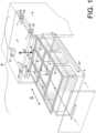
- a vacuum drawer device 0comprises a drawer 3, which is drawn in dashed lines, and a cover 2.
- the entire deviceis called vacuum drawer device 0 here and comprises the drawer 3, which can be operatively connected to the cover 2 and is mounted so that it can move linearly within a drawer body 9.
- the drawer body 9forms the outer shell in which the cover 2 and the drawer 3 are movably mounted and protected.
- a part of the present inventionis the possibility of designing an ordinary drawer 3, which comprises walls and a drawer interior R and is mounted in an ordinary drawer body 9 so that it can be moved open and closed in a linear pushing movement direction S, so that it can be evacuated.
- the drawer 3is mounted in a drawer extension 31' so that it can move linearly.
- the drawer pull-out in the form of the guide profile 31'is shown here as an example, with which the drawer 3 is held and can be brought into an open position and a closed position.
- the one-piece drawer interior Rwhich is delimited by the walls of the drawer 3, can be evacuated.
- a special embodiment of the drawer interior Ris designed here, since this evacuatable drawer interior R is formed by a plurality of containers 14, the containers 14 being positioned within the drawer 3 and each having the same height but different sizes.
- the containers 14are preferably designed as Gastronorm containers, the interiors of which can form the entire interior of the drawer R, which can be closed and evacuated by means of the cover 2.
- the containers 14are stored in the drawer 3 and can be moved with the drawer 3, but can also be removed.
- the key point for evacuating the drawer interior Ris the cover 2, which is arranged movably inside the drawer body 9 and is designed airtight and can be lowered onto the drawer 3 in a lifting direction H perpendicular to the pushing movement direction S.
- Lifting means 7are arranged on or in the cover 2 and inside the drawer body 9 , which hold the cover 2 movable in the lifting direction H within the drawer body 9 .
- the lid 2With a lid side facing the drawer 3, the lid 2 can be placed on the walls of the drawer 3 or on the edges of the containers 14, as a result of which the at least one drawer interior R can be closed.
- the cover 2is movably mounted relative to the drawer body 9 and the drawer 3 . Closing takes place only when the drawer 3 is in the closed position, when the drawer 3 is in the open position according to FIG figure 1 the cover 2 releases the drawer 3 completely.
- servomotors 7are attached to the cover 2 as lifting means 7 in an operatively connected manner with lifting means inside the drawer body 9 .
- Rotatable servo disks 71'are held within the body 9 via a screw with a bearing sleeve 72' in such a way that the cover 2 can be raised and lowered onto the drawer 3 or the containers 14 in opposite directions.
- the lid 2can lie flat on the edge of the container 14 and thus rest on the flange 140. An airtight seal is thus simplified.
- the containers 14 inside the drawer 3 of the vacuum drawer device 0can be closed off at the top compared to conventional drawers, in that the user closes the drawer 3 by hand and the lid 2 lowers onto the containers 14 in the closed position of the drawer 3 and seals them airtight from above completes.
- a closed position sensor 6On the front of the lid 2, a closed position sensor 6, an operating switch/on and off switch 15 and a proximity sensor 18 are attached.
- the containers 14are located within the drawer body 9 when the drawer 3 is in the closed position, with the cover 2 resting on the containers 14 in this situation and thereby sealing off the interior spaces R of the containers from above in an airtight manner.
- the cover 2is profiled in such a way that the evacuation means in the form of a controller 8 , a pump 1 , a pressure sensor 16 and a valve 4 are integrated into at least one recess A in the cover 2 .
- the profiled cover 2forms a frame 17 for the evacuation means.
- the cover 2includes here, for example, the profiling or the frame 17 and a foam layer 22'. However, the cover 2 can also be made in one piece from one material.
- an airtight membrane 21'is arranged on the lower side, facing the containers 14, on the lower side, facing the containers 14, an airtight membrane 21' is arranged.
- the interior of the container Rcan be sealed airtight by the airtight membrane 21', which is placed by means of the cover 2 on the opening of the drawer 3 or on the openings of the container 14.
- the airtight membrane 21'has an air inlet opening 23' for each container interior R.
- This air inlet opening 23 'leads either directly to an air duct 11' or through the foam layer 22' indirectly to an air duct 11'.
- the air channel 11 'traverses the cover 2 at least partially and leads out of the cover 2 .
- the air duct 11'is connected to at least one air inlet opening 23', so that air can be guided out of the cover 2 from the air inlet opening 23' through the air duct 11'. Air can be pumped from at least one container interior R through the cover 2 into the interior of the drawer body 9 by means of evacuation means.
- each container 14can be evacuated.
- the air duct 11'is connected to the inside of the cover or recesses A, in which the evacuation means are arranged.
- the controller 8, the pump 1, the pressure sensor 16 and the valve 4are each arranged in a recess A in the cover 2 or in a recess in the foam layer 22'.
- the pump 1is connected to the air duct 11' so that air can be pumped out of the container interior R through the air inlet opening 23', the airtight membrane 21', through the foam layer 22' and the air duct 11'.
- the cover 2has a very compact design due to the integration of the components and only control cables 11 lead through the cover 2 or the foam layer 22' and one cable from the cover 2 into a power supply unit 5.
- the valve 4is preferably designed as an electromagnetic valve 4 .
- the cover 2is in particular made of a dimensionally stable fibreboard, preferably an MDF board (medium-density fibreboard) with an airtight coating, in particular a lacquer.
- MDF boardmedium-density fibreboard
- At least one pressure sensor 16can be arranged, based on the signal from which the controller 8 regulates the evacuation.
- This pressure sensor 16is also arranged here in a recess A within the air duct 11'.
- the electronic devices 1, 4, 6, 7, 8, 16, 18are electrically connected via the at least one control cable 11.
- Each air inlet opening 23'is connected to the pump 1, the electromagnetic valve 4 and the pressure sensor 16 via the at least one air duct 11'.
- the power supply unit 5Inside and close to the rear wall of the drawer body 9, outside the cover 2 and the drawer 3 is the power supply unit 5, which is connected to the cover 2 via the power cable 10 and supplies the electronic devices with power.
- a handle 12On a front panel 13, which closes the drawer 3 in the opening direction, there is a handle 12 on the outside and on the front of the lid 2, aligned with the handle 12, the proximity sensor 18 and the closed position sensor 6.
- the required poweris supplied to the cover 2 or the devices in the drawer body 9 for controlling the vacuum in the interior of the container R, in that the cover 2 is connected by means of a power cable 10 , which in turn is connected to the power supply unit 5 .
- the power supply unit 5converts the mains voltage with alternating current into the required direct current.
- the DC voltageis fed to the controller 8 .
- the controller 8can use the proximity sensor 18 to detect whether the drawer 3 is open or closed.
- the proximity sensor 18is with connected to the controller 8 via the control cable 11.
- the proximity sensor 18is arranged on or in the lid 2, preferably inside the lid or in the at least one recess A, facing a front side of the drawer 3, so that contact with the drawer 3 can be detected and the vacuum in the at least one drawer interior R can be released in a targeted, controllable manner .
- the proximity sensor 18is preferably designed as a capacitive sensor.
- the controller 8also monitors the internal pressure in at least one container interior R of the drawer 3 using a pressure sensor 16.
- the controller 8also controls the vacuum pump 1 and the electromagnetic valve 4.
- An air hose or air duct 11' connected to the vacuum pump 1is used to Air, which was withdrawn from the drawer 3, released to the environment, which is indicated by a dashed arrow in figure 2 is marked.
- figure 3turns off the vacuum drawer device 0 figure 2 in the open position.
- the drawer 3is guided by the user, like known drawers, linearly in the direction of pushing movement S out of the drawer body 9 by pulling the handle 12 with his hand and the drawer 3, which is movably mounted by means of guide rails 31', with the containers 14 out of the Drawer body 9 pulls.
- the vacuumis broken and the container interior R under ambient conditions, at room temperature and current air pressure or atmospheric pressure at the location of the drawer 3.
- the cover 2 or the interior of the container Rmust first be ventilated.
- the proximity of the useris detected by means of a proximity sensor 18 and a corresponding signal is forwarded to the controller 8 via the control cable 11 .
- the controller 8then opens the Valve 4 and ambient air is admitted to vessels 14 to break the vacuum. Air flows through the air duct 11' into the at least one container interior Rein.
- the lid 2is lifted in the lifting direction H from the edges of the containers 14 controlled by the controller 8 by means of the lifting means 7 .
- This vertical movement of the lid 2is performed by the servo disks 71'.
- the usercan switch the electronic devices in the cover 2 on and off by means of the control switch 15 which is located inside the cover 2 on the front panel 13 and faces the side. Depending on whether the evacuation function is still desired.
- figure 4shows a cross section of the vacuum drawer device 0 at the height of the servomotors 7 in the closed position of the drawer 3.
- the cover 2is located above the containers 14 and is connected by the servomotors 7 via the servo disk 71' to the body via screws with bearing sleeves 72' 9 is connected, is pressed onto the openings of the containers 14, as a result of which the airtight membrane 21' seals the drawer interior R or the container interiors R airtight.
- the container interiors Rcan be evacuated via the air inlet openings 23'.
- the servomotors 7are connected to the controller 8 by means of a control cable 11 .
- the controller 8energizes the servomotors 7 via the control cable 11, as a result of which the servo disks 71' rotate and lift the lid 2 vertically from the container 14.
- the drawer 3can be opened by means of drawer extensions 31'.
- a negative pressure or vacuumis generated in the interior of the drawer R in the range of approximately 0-300 hPa, which is well below the normal atmospheric pressure in the area of approximately 1000 hPa.
- the power supply unit 5converts the AC voltage into DC voltage and feeds it to the controller 8, the vacuum pump 1 and the electromagnetic valves 4 by means of a control cable 11.
- the controller 8is directly connected to the proximity sensor 18 and the pressure sensor 16 via the control cable 11 .
- the evacuationshould only take place when the drawer 3 has been brought into a closed position in the vacuum drawer device 0 .
- the fact that the drawer 3 has been closedis detected by means of the closed position sensor 6 and is then forwarded to the controller 8 via a control cable 11 .
- the controller 8is the pump 1 in operation, which then the container interiors R on the Air inlet openings 23' and the air duct 11' are evacuated, with the air flowing into the interior of the body 9.
- the pressure sensor 16registers when the required negative pressure of around 200 hPa is reached and interrupts the circuit of the pump 1, which stops operating.
- the products and foods that are inside the container 14can now be stored in an airtight manner.
- a usernow wants to open the vacuum drawer device 0 or the evacuated drawer 3, he touches the front panel 13 with his hand near the effective circle of the proximity sensor 18.
- the proximity sensor 18forwards the registered touch via the control cable 11 to the controller 8.
- Thisputs the pump 1 out of operation and opens the electromagnetic valve 4 which connects the air duct 11' to the ambient air so that the vacuum is released.
- the controller 8then regulates the servomotors 7, which allow the servo disks 71' to rotate, so that the lid 2 is lifted off the container 14 in a lifting movement in the lifting direction H.
- the drawer 3is opened like a normal drawer by being pulled open linearly in the direction of the pushing movement S.
- the drawer 3 and its container 14can now be safely removed or replaced.
- the closed position sensor 6registers the closed position of the drawer 3 by recognizing the shortening of the distance to the front panel 13 and forwarding the signal to the controller 8 via the control cable 11 .
- the controller 8controls the servomotors 7, which causes the lid 2 to be lowered onto the containers 14 by rotating the servo disks 71'.
- the air-tight membrane 21'seals the container 14 air-tight at the top.
- the controller 8puts the pump 1 into operation, which sucks the air out of the containers 14 via the air inlet opening 23' and the at least one air duct 11' and into the environment gives.
- the pressure sensor 16sends the signal to the controller 8, which switches off the pump 1 and closes the electromagnetic valve 4 so that the ambient air cannot penetrate into the container 14.
- the negative pressurenow protects the contents in at least one container interior R of the vacuum drawer device 0.
- the usercan use the operating switch 15 to deactivate the electronics of the vacuum drawer device 0 if necessary.
- Servomotors 7, in particular a servo disk 71' and a screw 72' with a bearing sleeve,can be selected as lifting means 7, which are integrated in the interior of the lid or in the at least one recess A and interact with lifting means 7 in the interior of the drawer body 9.
- the proximity sensor 18 and the closed position sensor 6are preferably arranged on or in the cover 2, preferably inside the cover or in the at least one recess A, facing a front side of the drawer 3.
- the proximity sensor 18is preferably designed as a capacitive sensor.
- the closed position sensor 6is preferably designed as an induction sensor or microswitch.
- a proximity sensor 18 or a closed position sensor 6at least one acceleration sensor or one position sensor can be used. These can be arranged in different positions on the cover 2 or the drawer 3. If a user tries to raise the evacuated and closed drawer 3, this is through recognized by the acceleration sensor or position sensor, which registers the controller 8 and triggers ventilation of the interior of the drawer. Depending on the design of the drawer 3, the lifting means 7 or the sealing means 24, a lifting of the drawer 3 or the release of the sealing means 24 is made possible after activation and ventilation. Thereafter, the drawer 3 can be moved linearly relative to the cover 2 . When the drawer 3 is moved back into the closed position after an object has been removed, the closed position sensor 6 detects this, after which the evacuation is started.
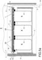
- a drawer 3is shown in a closed position, whereby in this embodiment of the lid 2 lifting means 7 are not absolutely necessary.
- inflatable sealing means 24are arranged on the cover surface facing the drawer 3 .
- the inflatable sealing means 24protrude away from the top surface in the direction of the drawer 3 and are inflated here.
- the interior of the drawer R or the interior of the gastronorm container 14is sealed airtight.
- Means for pumping up the sealing means 24 or for releasing the air from the sealing means 24are not shown here. Essentially, however, at least one sealant valve and one pump are required, which can be actuated in a targeted manner under the control of the controller 8 .
- the pump for the sealing means 24is the pump 1 for the evacuation.
- Such sealing means 24, the height of which can be adjusted,means that more complex lifting means 7 can be dispensed with.
- the ventilation and evacuation of the drawer 3otherwise takes place as described above. Through the air duct 11', air is removed from the interior of the drawer R pumped out and fed back through the valve 4 in order to be able to pull the drawer 3 out of the drawer body 9 .
- Figure 5b 14shows ventilated drawer interiors R with the air deflated from the sealants 24 and a gap formed between the sealants 24 and the flanges of the containers 14.
- FIG. In this open positionthe lid 2 is no longer in contact with the containers 14 or the drawer 3.
- the drawer 3is now pulled open in the direction of pushing movement S, so that food or containers 14 can be removed or added.
- the drawer 3is then moved linearly again and thus sunk into the drawer body 9 .
- the signal for pumping up the sealing means 24can then be given by the controller 8, which presses against the edges of the interior space R of the drawer if the air pressure in the sealing means 24 is sufficiently high.
- the controller 8controls the evacuation by means of the pump 1 via the air duct 11'.
- Tubular profilescan be selected as sealing means 24, which are glued or welded to the inner surface of the cover. If only one drawer interior R is to be sealed, the sealing means 24 are arranged to cover the edge of the drawer 3 on the inner surface of the lid. If several gastro containers form the drawer interior R, the sealing means 24 are shaped in such a way that the edges of the gastro containers are covered by the sealing means 24 . Because the sealing means 24 can be pumped up, the height of the sealing means 24 can be adjusted. In the inflated state, the sealing means 24 advantageously protrude between 5 and 10 mm further from the inner surface of the cover than in the deflated state.
- the sealing means 24can be made of different foils or membrane materials, which should be elastic and thermoplastic.
- the sealantsshould be 24 be designed food-safe so that they can be used in kitchens without any problems.
- the irradiation of the food in the container 14 or the interior of the drawer R with ultraviolet light in the wavelength range of 254-280 nmis advantageous.
- This ultraviolet lightis achieved by a stationary arrangement of at least one UVC LED, preferably on the cover 2 with associated wiring to the controller 8.
- the controller 8ensures a permanent or time-controlled irradiation with UVC light by corresponding actuation of the at least one UVC LED while the interior space R of the drawer is evacuated.
- the radiationactively destroys the DNA of the bacteria and can therefore not only inhibit growth but also kill the bacteria.
- At least one UVC LED per drawer interior Ris distributed on the cover 2 at the level of each drawer interior R. Closing the drawer interior R or the container 14 increases the relative humidity because the food releases moisture.
- the drawer interior R or the containers 14can be equipped with hygroscopic material, so that moisture is removed from the room air.
- the controller 8can be programmed in such a way that air is exchanged at regular time intervals.
- the current relative humiditycan be measured and, depending on the measured value, an air exchange can be carried out in a controlled manner.
- Corresponding moisture sensors and the connection to the controller 8are known to those skilled in the art. The placement of the Moisture sensors important so that correct values can be determined.
Landscapes
- Engineering & Computer Science (AREA)
- Life Sciences & Earth Sciences (AREA)
- Chemical & Material Sciences (AREA)
- Mechanical Engineering (AREA)
- Food Science & Technology (AREA)
- Polymers & Plastics (AREA)
- Zoology (AREA)
- Wood Science & Technology (AREA)
- General Engineering & Computer Science (AREA)
- Combustion & Propulsion (AREA)
- Physics & Mathematics (AREA)
- Thermal Sciences (AREA)
- Dispersion Chemistry (AREA)
- Sustainable Development (AREA)
- Vacuum Packaging (AREA)
- Storage Of Harvested Produce (AREA)
- Drawers Of Furniture (AREA)
- Cold Air Circulating Systems And Constructional Details In Refrigerators (AREA)
- Food Preservation Except Freezing, Refrigeration, And Drying (AREA)
- Fittings On The Vehicle Exterior For Carrying Loads, And Devices For Holding Or Mounting Articles (AREA)
- Pressure Vessels And Lids Thereof (AREA)
- Packages (AREA)
- Closures For Containers (AREA)
Description
Translated fromGermanDie vorliegende Erfindung beschreibt einen Deckel zum Einbau in einen Schubladenkorpus, welcher mit einer linear bewegbare Schublade wirkverbindbar anordbar ist, wobei der Deckel zur Evakuierung mindestens eines Schubladeninnenraums mittels Evakuiermitteln geeignet ist, sodass der mindestens eine Schubladeninnenraum bei in einer Geschlossenstellung befindlichen Schublade evakuiert und vor Öffnung der Schublade belüftbar ist, eine Vakuumschubladeneinrichtung sowie ein Umrüstverfahren eines Schubladenkorpus mit einer Schublade, wobei die Schublade linear mittels eines Schubladenauszugs in einer Schubbewegungsrichtung bewegbar gelagert ist.The present invention describes a cover for installation in a drawer body, which can be arranged in an operatively connectable manner with a linearly movable drawer, the cover being suitable for evacuating at least one drawer interior by means of evacuation means, so that the at least one drawer interior is evacuated when the drawer is in a closed position and prior to opening of the drawer can be ventilated, a vacuum drawer device and a method for converting a drawer body with a drawer, the drawer being mounted so that it can be moved linearly in a pushing movement direction by means of a drawer pull-out.
Gegenwärtig werden in den Privathaushalten der Industrieländer schnell verderbliche Lebensmittel im Kühlschrank aufbewahrt. Der Kühlschrank hat den Vorteil, die Innentemperatur senken zu können, um dadurch das Wachsen von zerstörenden Bakterienkulturen zu verzögern. Auch kann der Kühlschrank als abgeschlossener Aufbewahrungsort für Lebensmittel angesehen werden, der im geschlossenen Zustand verhindert, dass ungewollte Einflüsse, wie z.B. Insekten oder Pollen, die Qualität der Lebensmittel negativ beeinflussen.At present, perishable foodstuffs are stored in the refrigerator in private households in industrialized countries. The refrigerator has the advantage of being able to lower the internal temperature, thereby delaying the growth of destructive bacterial cultures. The refrigerator can also be seen as a closed storage place for food which, when closed, prevents unwanted influences such as insects or pollen from negatively affecting the quality of the food.
Weiter hat der Kühlschrank doch einige Nachteile, da er durchgehend Strom benötigt, um über einen Kompressor Kälteenergie zu erzeugen. Parallel entsteht Abwärme, die hinter dem Kühlschrank an die Umgebungsluft abgegeben und mittels Lüftungsschlitzen bei den Küchenblenden in den Raum geführt wird, was im Sommer nicht erwünscht ist.The refrigerator also has some disadvantages, as it constantly requires electricity in order to generate cooling energy via a compressor. At the same time, waste heat is generated, which is released into the ambient air behind the refrigerator and through ventilation slots in the Kitchen screens are led into the room, which is not desirable in summer.
In den letzten Jahrzehnten haben die Kühlschränke unsere Umwelt so stark negativ belastet, dass die Weltgemeinschaft einschreiten musste, um das ozonschädliche Kältemittel FCKW zu verbieten. Weitere Umweltprobleme stellen die ab 1990 verwendeten Schäumungsmittel zur Dämmung des Kühlschrankes dar. Die negativen Auswirkungen auf die Umwelt bei der Herstellung, des Betriebes und der Entsorgung der Kühlschränke konnte die Internationale Gemeinschaft auf Druck der Umweltverbände in den letzten Jahren immer mehr eingrenzen, aber nicht verhindern. Weniger Beachtung fand bisher das Innenklima des Kühlschrankes. Gemäss einer Untersuchung des Hygiene Council, welche eine internationalen Studie namens Hygiene Report 2010 durchgeführt hat, ist der Kühlschrank mit rund 11'400'000 Keime pro Quadratzentimeter mehr belastet, als die Toilette mit rund 100 Erreger pro Quadratzentimeter. Diese Meldung 2010 fand ein grosses Medienecho, doch ausser Empfehlungen, den Kühlschrank öfter zu reinigen, fanden bis jetzt keine wahrnehmbaren Verbesserungen statt. Die Anzahl der Keime sind nicht zwingend das Problem, da es vielmehr darauf ankommt, welche Keime für den Menschen am schädlichsten sind. Jean-Pierre Hugot vom Pariser Höpital Robert Debré hat die klimatischen Verhältnisse innerhalb des Kühlschrankes untersucht. Nach seinen Angaben fühlen sich die "kälteliebenden" Mikroben wie Yersilinen und Listerien, im Kühlschrank sehr wohl. Möglicherweise können diese Mikroben die Verdauungskrankheit Morbus Crohn verursachen.In recent decades, refrigerators have had such a negative impact on our environment that the world community had to step in to ban the ozone-depleting refrigerant CFCs. The foaming agents used to insulate refrigerators from 1990 onwards represent further environmental problems. In recent years, the international community has been able to limit the negative effects on the environment during the manufacture, operation and disposal of refrigerators under pressure from environmental organizations, but not prevent them . The interior climate of the refrigerator has so far received less attention. According to an investigation by the Hygiene Council, which carried out an international study called the Hygiene Report 2010, the refrigerator has around 11,400,000 germs per square centimeter more than the toilet with around 100 pathogens per square centimeter. This report in 2010 received a lot of media coverage, but apart from recommendations to clean the refrigerator more often, no noticeable improvements have taken place so far. The number of germs is not necessarily the problem, as it is more a matter of which germs are most harmful to humans. Jean-Pierre Hugot from the Paris Höpital Robert Debré examined the climatic conditions inside the refrigerator. According to him, the "cold-loving" microbes such as yersilines and listeria feel very comfortable in the refrigerator. It is possible that these microbes can cause the digestive disease Crohn's disease.
Auf Wikipedia steht am 22.10.16, nach der Erwähnung des Forschungsergebnisses von Jean-Pierre Hugot, folgender Satz: "Der Verzehr verdorbener Speisen wegen Verzicht auf die Kühlung, dürfte allerdings mit größeren Krankheitsrisiken behaftet sein." Dem Satz zufolge ist die Kühlung der Lebensmittel in einem Kühlschrank gerade mal etwas gesünder, als verdorbene Nahrung zu sich zu nehmen.On October 22nd, 2016, after mentioning the research result of Jean-Pierre Hugot, Wikipedia states the following sentence: "The consumption of spoiled food due to lack of refrigeration is likely to be associated with greater risks of illness." According to the sentence, keeping food cool in a refrigerator is just a little bit healthier than eating spoiled food.
Ziel der Erfindung ist daher, einen Aufbewahrungsort für Lebensmittel zu entwerfen, der auf Kühlung verzichten kann und trotzdem die Lebensmittel in einem möglichst langen Zeitraum nicht verderben lässt. Eine gebräuchliche Art, Lebensmittel ohne Kühlung frisch zu halten ist die Vakuumverpackung. Diese hat sich vor allem im hygienisch sensiblen Bereich der Fleischprodukte durchgesetzt. Gemäss Wikipedia am 22.10.16 versteht man unter einer Vakuumverpackung folgendes: "Eine Vakuumverpackung ist eine gasdichte Verpackung eines Produktes, in dem Zwischenräume und damit reaktionsfähige Gase innerhalb des Produktes weitgehend entfernt wurden. Wichtig ist vor allem der Entzug von Sauerstoff aus der Verpackung." Weiter: "Diese Verpackungsart hat mehrere Vorteile. Wie bei der Schutzgasverpackung sind die Produkte länger haltbar, da kein Sauerstoff an die Produkte gelangt, der durch chemische Reaktionen oder biologische Prozesse im Laufe der Zeit zur Unbrauchbarkeit der Produkte führt."The aim of the invention is therefore to design a storage location for food that can do without refrigeration and still does not allow the food to spoil over as long a period of time as possible. A common way of keeping food fresh without refrigeration is vacuum packaging. This has prevailed above all in the hygienically sensitive area of meat products. According to Wikipedia on October 22, 2016, vacuum packaging means the following: "Vacuum packaging is gas-tight packaging for a product in which gaps and thus reactive gases within the product have been largely removed. The most important thing is the removal of oxygen from the packaging." Furthermore: "This type of packaging has several advantages. As with modified atmosphere packaging, the products have a longer shelf life because no oxygen gets to the products, which over time can lead to chemical reactions or biological processes rendering the products unusable."
Da die Vakuumverpackungen aus Kunststofffolien bestehen, müssen diese Folien bei einem Hersteller bezogen und nach Gebrauch wieder entsorgt werden. Die Entsorgung der Kunststofffolien erfolgt in der Regel durch Verbrennung, welche wiederum die Umwelt belastet.Since the vacuum packaging consists of plastic films, these films must be obtained from a manufacturer and disposed of again after use. The plastic films are usually disposed of by incineration, which in turn pollutes the environment.
Auch nicht für jedes Lebensmittel bietet sich der Kühlschrank als Platz an zur Lagerung. Tomaten, Basilikum, Brot, Avocado, Kartoffeln etc. sollte man besser nicht im Kühlschrank lagern. Die Patentdokumente
Die vorliegende Erfindung hat sich zur Aufgabe gestellt die Möglichkeit zu schaffen, bestehende Schubladen mit einfachen Mitteln, kostengünstig als evakuierbare Schubladen einer Vakuumschubladeneinrichtung auszugestalten. In derartigen Vakuumschubladeneinrichtungen sind Lebensmitteln evakuiert lagerbar, wobei die äussere Erscheinung eines Schubladenkorpus bekannter Schubladenkorpusse unverändert bleibt und die Schublade einfach und schnell umrüstbar ist.The present invention has set itself the task of creating the possibility of designing existing drawers with simple means and inexpensively as evacuable drawers of a vacuum drawer device. Foodstuffs can be stored in an evacuated state in vacuum drawer devices of this type, with the external appearance of a drawer body being more familiar Drawer bodies remain unchanged and the drawer can be quickly and easily converted.
Diese Aufgabe wird mit einem Deckel gemäss Anspruch 1 gelöst. Der Deckel kann einfach in eine Schubladeneinrichtung integriert werden und umfasst die zur Evakuierung notwendigen Bauteile.This object is achieved with a lid according to claim 1. The cover can easily be integrated into a drawer unit and includes the components required for evacuation.
Nicht zwingend zu kühlende Lebensmittel können in einer Vakuumschubladeneinrichtung bei Raumtemperatur gelagert werden, wobei auf einen erhöhten Energieverbrauch zur Kühlung verzichtet wird. Lebensmittel können so auf vereinfachte Weise länger verzehrbar oder geniessbar gehalten werden.Food that does not necessarily have to be cooled can be stored at room temperature in a vacuum drawer unit, with no increased energy consumption for cooling. In this way, food can be kept edible or edible for longer in a simplified manner.
Durch die Verlagerung der Lebensmittel, die nicht unbedingt Kälte benötigen, in den Schubladenkorpus mit Vakuumschubladeneinrichtung, entsteht mehr Platz im Kühlschrank bzw. es müssen nicht immer grössere und dadurch umweltschädlichere Kühlschränke eingesetzt werden.By moving the food that does not necessarily need refrigeration into the drawer body with vacuum drawer equipment, more space is created in the refrigerator and larger and therefore more environmentally harmful refrigerators do not always have to be used.
Die Lagerung im Schubladenkorpus mit Vakuumschubladeneinrichtung benötigt weniger Energie als der Kühlschrank, da der Sauerstoffentzug im Innern nach wenigen Minuten abgeschlossen ist und danach keine weitere Elektrizität benötigt wird. Die Lebensmittel in der Vakuumschubladeneinrichtung bleiben frisch, da ein Feuchteentzug über die Umgebungsluft verhindert wird. Wenn die Umgebungsluft feuchter ist als die Lebensmittel, wie z.B. Kekse, können diese in der Vakuumschubladeneinrichtung vor Feuchtigkeit geschützt werden.Storage in a drawer body with a vacuum drawer device requires less energy than the refrigerator, since the oxygen deprivation inside is complete after a few minutes and no further electricity is then required. The food in the vacuum drawer device stays fresh, as moisture is prevented from being removed from the ambient air. If the surrounding air is more humid than the food, such as biscuits, they can be protected from moisture in the vacuum drawer device.
Eine Vakuumschubladeneinrichtung lässt sich umsetzen ohne schädliche Materialien wie Kältemittel oder Wärmedämmung.A vacuum drawer unit can be implemented without harmful materials such as refrigerants or thermal insulation.
Der Verbrauch von Kunststoffbeuteln bei der Vakuumierung kann signifikant reduziert werden.The consumption of plastic bags during vacuuming can be significantly reduced.
Bei bestehenden Küchen, welche vor allem im Mietbereich kleine Kühlschränke haben, bietet sich eine Umrüstung von bestehenden Schubladenkorpussen auf Vakuumschubladeneinrichtungen an. Eine bestehende Schublade kann schnell und einfach umgerüstet werden.In existing kitchens, which have small refrigerators, especially in the rental area, it is advisable to convert existing drawer bodies to vacuum drawer units. An existing drawer can be converted quickly and easily.
Durch die erwähnten Verbesserungen können Lebensmittel einfacher, umweltfreundlicher und energieeffizienter gelagert werden. Dies wirkt sich positiv auf die Qualität der Lebensmittel und die Gesundheit der Verbraucher aus. Es würden auch weniger Lebensmittel weggeworfen, da deren Qualität länger erhalten werden kann.As a result of the improvements mentioned, food can be stored more easily, in a more environmentally friendly and energy-efficient manner. This has a positive effect on the quality of food and the health of consumers. Less food would also be thrown away because its quality can be preserved for longer.
Bevorzugte Ausführungsbeispiele des Erfindungsgegenstandes werden nachstehend im Zusammenhang mit den anliegenden Zeichnungen beschrieben.
- Figur 1
- zeigt eine perspektivische Ansicht einer Vakuumschubladeneinrichtung in einem Schubladenkorpus bei offener Schublade.
Figur 2- zeigt einen teilweise schematisch dargestellten Längsschnitt durch eine Vakuumschubladeneinrichtung in einem Schubladenkorpus bei geschlossener Vakuumschubladeneinrichtung.
Figur 3- zeigt einen teilweise schematisch dargestellten Längsschnitt durch einen Schubladenkorpus mit halb herausgezogener Schublade.
Figur 4- zeigt einen teilweise schematisch dargestellten Querschnitt durch einen Schubladenkorpus mit geschlossener Schublade.
- Figur 5a
- zeigt einen teilweise schematisch dargestellten Längsschnitt durch eine abgewandelte Vakuumschubladeneinrichtung in einem Schubladenkorpus bei geschlossener Vakuumschubladeneinrichtung, während
- Figur 5b
- einen teilweise schematisch dargestellten Längsschnitt gemäss
Figur 5a mit belüfteter Schublade, also geöffneter Vakuumschubladeneinrichtung zeigt.
- figure 1
- shows a perspective view of a vacuum drawer device in a drawer body with the drawer open.
- figure 2
- shows a partially schematically illustrated longitudinal section through a vacuum drawer device in a drawer body with the vacuum drawer device closed.
- figure 3
- shows a partially schematically illustrated longitudinal section through a drawer body with a half-extended drawer.
- figure 4
- shows a partially schematic cross section through a drawer body with a closed drawer.
- Figure 5a
- shows a partially shown schematically Longitudinal section through a modified vacuum drawer device in a drawer body with the vacuum drawer device closed, while
- Figure 5b
- a longitudinal section shown partially schematically according to
Figure 5a with a ventilated drawer, ie with the vacuum drawer device open.
Im Folgenden wird eine Ausführungsform einer Vakuumschubladeneinrichtungen 0 anhand der
Ein Teil der vorliegenden Erfindung ist die Möglichkeit eine gewöhnliche Schublade 3, welche Wände und einen Schubladeninnenraum R umfasst und in einem gewöhnlichen Schubladenkorpus 9 in einer linearen Schubbewegungsrichtung S auf und zu bewegbar gelagert ist, evakuierbar auszugestalten. Hier ist die Schublade 3 in einem Schubladenauszug 31' linear bewegbar gelagert.A part of the present invention is the possibility of designing an
Da Mittel zur Lagerung der Schublade 3 von handelsüblichen Schubladen bekannt sind, ist hier schematisch der Schubladenauszug in Form des Führungsprofils 31' beispielhaft dargestellt, mit welchem die Schublade 3 gehalten wird und in eine Offenstellung und eine Schliessstellung bringbar ist.Since means for supporting the
In der einfachsten Variante ist der einteilige Schubladeninnenraum R, welcher von den Wänden der Schublade 3 begrenzt wird, evakuierbar.In the simplest variant, the one-piece drawer interior R, which is delimited by the walls of the
Hier ist eine besondere Ausführungsform des Schubladeninnenraums R ausgestaltet, da dieser evakuierbare Schubladeninnenraum R von einer Mehrzahl von Behältern 14 gebildet ist, wobei die Behälter 14 innerhalb der Schublade 3 positioniert angeordnet sind und jeweils die gleiche Höhe aufweisen, jedoch verschiedene Grössen. Bevorzugt sind die Behälter 14 als Gastronormbehälter ausgebildet, deren Innenräume den gesamten Schubladeninnenraum R bilden können, welcher mittels Deckel 2 verschliessbar und evakuierbar ist. Die Behälter 14 sind in der Schublade 3 gelagert und sind mit der Schublade 3 mitbewegbar, können aber auch entnommen werden.A special embodiment of the drawer interior R is designed here, since this evacuatable drawer interior R is formed by a plurality of
Der Kernpunkt zur Evakuierung des Schubladeninnenraums R ist der bewegbar innerhalb des Schubladenkorpus 9 angeordnete Deckel 2, welcher luftdicht ausgestaltet ist und in einer Hubrichtung H senkrecht zur Schubbewegungsrichtung S auf die Schublade 3 absenkbar gelagert ist.The key point for evacuating the drawer interior R is the
Am oder im Deckel 2 und innerhalb des Schubladenkorpus 9 sind Hubmittel 7 angeordnet, welche den Deckel 2 innerhalb des Schubladenkorpus 9 in Hubrichtung H bewegbar halten. Mit einer, der Schublade 3 zugewandten Deckelseite kann der Deckel 2 auf die Wände der Schublade 3 respektive auf Ränder der Behälter 14 aufgesetzt werden, wodurch der mindestens eine Schubladeninnenraum R verschliessbar ist. Der Deckel 2 ist relativ zum Schubladenkorpus 9 und zur Schublade 3 bewegbar gelagert. Das Verschliessen findet nur bei Geschlossenstellung der Schublade 3 statt, bei Offenstellung der Schublade 3 gemäss
Als Hubmittel 7 sind hier mehrere Servomotoren 7 am Deckel 2 wirkverbunden mit Hubmitteln innerhalb des Schubladenkorpus 9 befestigt. Drehbare Servoscheiben 71' sind jeweils über eine Schraube mit Lagerhülse 72' innerhalb des Korpus 9 so gehalten, dass der Deckel 2 von der Schublade 3 bzw. den Behältern 14 entgegengesetzt gesteuert anhebbar und auf diese absenkbar angeordnet ist.
Damit entsteht die Hubbewegung des Deckels 2 in Hubrichtung H senkrecht zur Schubbewegungsrichtung S der Schublade 3. Da der mindestens eine Behälter 14 einen umlaufenden Flansch 140 aufweist, kann der Deckel 2 plan auf dem Rand des Behälters 14 und damit auf dem Flansch 140 aufliegen. Ein luftdichter Abschluss ist somit vereinfacht möglich.This results in the lifting movement of the
Die Behälter 14 innerhalb der Schublade 3 der Vakuumschubladeneinrichtung 0 können gegenüber gebräuchlichen Schubladen gegen oben abgeschlossen werden, indem der Nutzer von Hand, die Schublade 3 schliesst und sich der Deckel 2 in der Geschlossenstellung der Schublade 3 auf die Behälter 14 herabsenkt und diese von oben luftdicht abschliesst. An der Vorderseite des Deckels 2 sind ein Geschlossenstellungssensor 6, ein Bedienschalter/An- und Ausschalter 15 und ein Näherungssensor 18 angebracht.The
Wie in
Der Deckel 2 ist derart profiliert ist, das Evakuiermittel in Form einer Steuerung 8, einer Pumpe 1, eines Drucksensors 16 und eines Ventils 4 in mindestens einer Aussparung A im Deckel 2 integriert befestigt sind. Der profilierte Deckel 2 bildet einen Rahmen 17 für die Evakuiermittel.The
Der Deckel 2 umfasst hier beispielhaft die Profilierung bzw. den Rahmen 17 und eine Schaumstofflage 22'. Der Deckel 2 kann aber auch einstückig aus einem Material hergestellt sein. Auf der unteren Seite, den Behältern 14 zugewandt ist eine luftdichte Membran 21' angeordnet. Durch die luftdichte Membran 21' welche mittels Deckel 2 auf die Öffnung der Schublade 3 bzw. auf die Öffnungen der Behälter 14 aufgesetzt wird, kann der Behälterinnenraum R luftdicht verschlossen werden.The
Die luftdichte Membran 21' weist zu jedem Behälterinnenraum R eine Lufteinlassöffnung 23' auf. Diese Lufteinlassöffnung 23' führt entweder direkt zu einem Luftkanal 11' oder durch die Schaumstofflage 22' indirekt zu einem Luftkanal 11'. Der Luftkanal 11' quert den Deckel 2 mindestens teilweise und führt aus dem Deckel 2 heraus. Der Luftkanal 11' ist mit mindestens einer Lufteinlassöffnung 23' verbunden, sodass Luft von der Lufteinlassöffnung 23' durch den Luftkanal 11' aus dem Deckel 2 heraus führbar ist. Luft kann mittels Evakuiermitteln aus mindestens einem Behälterinnenraum R durch den Deckel 2 in den Innenraum des Schubladenkorpus 9 gepumpt werden.The airtight membrane 21' has an air inlet opening 23' for each container interior R. This air inlet opening 23 'leads either directly to an air duct 11' or through the foam layer 22' indirectly to an air duct 11'. The air channel 11 'traverses the
Hier ist jeweils eine Lufteinlassöffnung 23' in jeden Behälterinnenraum R bzw. Schubladeninnenraum R führend, die luftdichte Membran 21' querend angeordnet, sodass bei abgesenktem Deckel 2 jeder Behälter 14 evakuierbar ist.Here in each case an air inlet opening 23' leading into each container interior R or drawer interior R is arranged crossing the airtight membrane 21', so that when the
Um Luft durch den Luftkanal 11' zu entnehmen ist der Luftkanal 11' mit dem Deckelinneren bzw. Aussparungen A verbunden, in welchen die Evakuiermittel angeordnet sind. Hier sind die Steuerung 8, die Pumpe 1, der Drucksensor 16 und das Ventil 4 jeweils in einer Aussparung A im Deckel 2 bzw. in einer Aussparung in der Schaumstofflage 22' angeordnet. Die Pumpe 1 ist mit dem Luftkanal 11' verbunden, sodass Luft aus dem Behälterinnenraum R durch die Lufteinlassöffnung 23', die luftdichte Membran 21' durch die Schaumstofflage 22' und den Luftkanal 11' ausgepumpt werden kann.In order to remove air through the air duct 11', the air duct 11' is connected to the inside of the cover or recesses A, in which the evacuation means are arranged. Here the
Wenn der Deckel 2 auf der Schublade 3 bzw. auf den Behältern 14 aufgesetzt wurde, wird Luft aus dem mindestens einen Schubladeninnenraum R durch den Luftkanal 11' gesteuert durch die Steuerung 8 abgepumpt. Der Deckel 2 ist durch Integration der Bauteile sehr kompakt ausgestaltet und es führen lediglich Steuerkabel 11 durch den Deckel 2 bzw. die Schaumstofflage 22' und ein Kabel vom Deckel 2 weg in ein Netzgerät 5.When the
Bevorzugt ist das Ventil 4 als Elektromagnetventil 4 ausgebildet. Der Deckel 2 ist insbesondere aus einer formstabilen Faserplatte, bevorzugt aus einer MDF-Platte (mitteldichte Holzfaserplatte) mit luftdichter Beschichtung, insbesondere eines Lackes, ausgebildet.The
Optional kann mindestens ein Drucksensor 16 angeordnet sein, auf dessen Signal die Steuerung 8 die Evakuierung regelt. Dieser Drucksensor 16 ist hier ebenfalls in einer Aussparung A angeordnet, innerhalb des Luftkanals 11'.Optionally, at least one
Die elektronischen Geräte 1, 4, 6, 7, 8, 16, 18 sind über das mindestens eine Steuerkabel 11 elektrisch verbunden. Jede Lufteinlassöffnung 23' ist über den mindestens einen Luftkanal 11' mit der Pumpe 1, dem Elektromagnetventil 4 und dem Drucksensor 16 verbunden. Innerhalb und nahe bei der Rückwand des Schubladenkorpus 9, ausserhalb des Deckels 2 und der Schublade 3 befindet sich das Netzgerät 5, welches über das Stromkabel 10 mit dem Deckel 2 verbunden ist und die elektronischen Geräte mit Strom versorgt. Auf einer Frontblende 13, welche die Schublade 3 in Öffnungsrichtung abschliesst, befindet sich auf der Aussenseite ein Griff 12 und auf Vorderseite des Deckels 2, zum Griff 12 ausgerichtet, der Näherungssensor 18 und der Geschlossenstellungssensor 6.The
Der benötigte Strom wird dem Deckel 2 bzw. den Geräten im Schubladenkorpus 9 zur Steuerung des Vakuums im Behälterinnenraum R zugeführt, indem der Deckel 2 mittels Stromkabel 10 verbunden ist, welches wiederum mit dem Netzgerät 5 verbunden ist. Das Netzgerät 5 wandelt die Netzspannung mit Wechselstrom in die benötigte Gleichspannung um. Die Gleichspannung wird der Steuerung 8 zugeführt.The required power is supplied to the
Die Steuerung 8 kann mittels Näherungssensor 18 erkennen, ob die Schublade 3 offen oder geschlossen ist. Der Näherungssensor 18 ist mit der Steuerung 8 über das Steuerkabel 11 verbunden. Der Näherungssensor 18 ist am oder im Deckel 2, bevorzugt im Deckelinneren bzw. in der mindestens einen Aussparung A, einer Frontseite der Schublade 3 zugewandt angeordnet, sodass eine Berührung der Schublade 3 erkennbar ist und das Vakuum im mindestens einen Schubladeninnenraum R gezielt steuerbar auflösbar ist. Bevorzugt ist der Näherungssensor 18 als kapazitiver Sensor ausgebildet.The
Weiter überwacht die Steuerung 8 mittels Drucksensor 16 den Innendruck im mindestens einen Behälterinnenraum R der Schublade 3. Zusätzlich übernimmt die Steuerung 8 die Regelung der Vakuumpumpe 1 und des Elektromagnetventils 4. Durch einen mit der Vakuumpumpe 1 verbundenen Luftschlauch bzw. dem Luftkanal 11' wird die Luft, welche der Schublade 3 entzogen wurde, an die Umgebung abgegeben, was mit einem gestrichelten Pfeil in
Damit die Schublade 3 herausgezogen werden kann, muss der Deckel 2 bzw. der Behälterinnenraum R vorgängig belüftet werden. Mittels Näherungssensor 18 wird die Näherung des Benutzers erkannt und ein entsprechendes Signal wird über das Steuerungskabel 11 an die Steuerung 8 weitergeleitet. Anschliessend öffnet die Steuerung 8 das Ventil 4 und Umgebungsluft wird in die Behälter 14 zum Auflösung des Vakuums eingelassen. Durch den Luftkanal 11' strömt Luft in den mindestens einen Behälterinnenraum Rein.So that the
Danach wird der Deckel 2 in der Hubrichtung H von den Rändern der Behälter 14 durch die Steuerung 8 gesteuert mittels der Hubmittel 7 angehoben. Diese vertikale Bewegung des Deckels 2 erfolgt durch die Servoscheiben 71'.Thereafter, the
Der Nutzer kann mittels Bedienschalter 15 der sich Innerhalb des Deckels 2 auf der Frontblende 13 zugewandten Seite befindet, die elektronischen Geräte im Deckel 2 ein- und ausschalten. Je nachdem, ob die Evakuierfunktion weiterhin gewünscht ist.The user can switch the electronic devices in the
Damit die Schublade 3 geöffnet werden kann bestromt die Steuerung 8 über die Steuerkabel 11 die Servomotoren 7, dadurch drehen sich die Servoscheiben 71' und heben den Deckel 2 vertikal von den Behälter 14 ab. Die Schublade 3 kann mittels Schubladenauszügen 31' geöffnet werden.So that the
Durch Anordnung der Schaumstofflage 22' unterhalb der luftdichten Membran 21' bzw. zwischen luftdichter Membran 21' und dem Profil des Deckels 2, ist eine plane luftdichte Auflage zur den Rändern der Behälter 14 gesichert. Luft kann dann nur durch die mindestens eine Lufteinlassöffnung 23', durch die Schaumstofflage 22' und bis durch den Luftkanal 11' aus dem von der luftdichten Membran 21' und dem Deckel 2 luftdicht verschlossenen mindestens einen Schubladeninnenraum R herausgepumpt werden.By arranging the foam layer 22' below the airtight membrane 21' or between the airtight membrane 21' and the profile of the
Die hier vorgestellte Vakuumschubladeneinrichtung 0, wie in den
Es wird ein Unterdruck bzw. ein Vakuum im Schubladeninnenraum R im Bereich von ca. 0-300 hPa erzeugt, welches deutlich unterhalb des normalen Luftdruckes der Umgebung von etwa 1000 hPa liegt.A negative pressure or vacuum is generated in the interior of the drawer R in the range of approximately 0-300 hPa, which is well below the normal atmospheric pressure in the area of approximately 1000 hPa.
Zum Betrieb der Vakuumschubladeneinrichtung 0, notwendig ist elektrische Energie, welche wie in
Befindet sich die Vakuumschubladeneinrichtung 0 wie in
Erst wenn die Schublade 3 in eine Geschlossenstellung in der Vakuumschubladeneinrichtung 0 gebracht ist, soll die Evakuierung stattfinden. Dass die Schublade 3 geschlossen wurde, wird mittels Geschlossenstellungssensor 6 erkannt und dann über Steuerkabel 11 an die Steuerung 8 weitergeleitet. Die Steuerung 8 setzt die Pumpe 1 in Betrieb, welche dann die Behälterinnenräume R über die Lufteinlassöffnungen 23' und den Luftkanal 11' evakuiert, wobei die Luft in den Innenraum des Korpus 9 strömt. Der Drucksensor 16 registriert wenn der erforderliche Unterdruck von rund 200 hPa erreicht wird und unterbricht den Stromkreis der Pumpe 1 die den Betrieb einstellt. Die Produkte und Lebensmittel die sich innerhalb der Behälter 14 befinden können nun luftdicht gelagert werden.The evacuation should only take place when the
Möchte nun ein Nutzer die Vakuumschubladeneinrichtung 0 bzw. die evakuierte Schublade 3 öffnen, so berührt er mit der Hand die Frontblende 13 in der Nähe des Wirkkreises des Näherungssensors 18. Die registrierte Berührung leitet der Näherungssensor 18 über die Steuerkabel 11 an die Steuerung 8 weiter. Diese setzt wiederum die Pumpe 1 ausser Betrieb und öffnet das Elektromagnetventil 4 welches den Luftkanal 11' mit der Umgebungsluft verbindet, sodass das Vakuum aufgelöst wird. Danach regelt die Steuerung 8 die Servomotoren 7 welche die Servoscheiben 71' drehen lassen so dass sich der Deckel 2 von den Behälter 14 in einer Hubbewegung in Hubrichtung H abhebt. Wie in
Die Schublade 3 und deren Behälter 14 können nun sicher entnommen oder wieder platziert werden.The
Schliesst der Nutzer die Schublade 3 registriert der Geschlossenstellungssensor 6 die Geschlossenstellung der Schublade 3 indem er die Verkürzung der Distanz zur Frontblende 13 erkennt und das Signal über die Steuerkabel 11 an die Steuerung 8 weiterleitet. Die Steuerung 8 steuert die Servomotoren 7 an, welche durch eine Drehbewegung der Servoscheiben 71' zur Absenkung des Deckels 2 auf die Behälter 14 führt. Die Luftdichte Membran 21' schliesst die Behälter 14 gegen oben luftdicht ab. Die Steuerung 8 setzt die Pumpe 1 in Betrieb welche die Luft aus den Behältern 14 über die Lufteinlassöffnung 23' und den mindestens einen Luftkanal 11' absaugt und an die Umgebung abgibt. Sobald der gewünscht Unterdruck erreicht wird, sendet der Drucksensor 16 das Signal an die Steuerung 8, welche die Pumpe 1 abstellt und das Elektromagnetventil 4 schliesst, damit die Umgebungsluft nicht in die Behälter 14 eindringen kann. Der Unterdruck schützt nun den Inhalt im mindestens einen Behälterinnenraum R der Vakuumschubladeneinrichtung 0.If the user closes the
Der Nutzer kann über den Bedienschalter 15 die Elektronik der Vakuumschubladeneinrichtung 0 bei Bedarf ausser Betrieb setzen.The user can use the
Als Hubmittel 7, welche im Deckelinneren bzw. in der mindestens einen Aussparung A integriert sind und mit Hubmitteln 7 im Innenraum des Schubladenkorpus 9 zusammenwirken, können Servomotoren 7, insbesondere jeweils eine Servoscheibe 71' und eine Schraube 72' mit Lagerhülse umfassend gewählt werden.
Der Näherungssensor 18 und der Geschlossenstellungssensor 6 sind bevorzugt am oder im Deckel 2, bevorzugt im Deckelinneren bzw. in der mindestens einen Aussparung A, einer Frontseite der Schublade 3 zugewandt angeordnet.The
Der Näherungssensor 18 ist bevorzugt als kapazitiver Sensor ausgebildet. Der Geschlossenstellungssensor 6 ist bevorzugt als Induktionssensor oder Mikroschalter ausgebildet.The
Anstelle eines Näherungssensors 18 bzw. Geschlossenstellungssensors 6 können mindestens ein Beschleunigungssensor oder ein Lagesensors verwendet werden. Diese sind an verschiedenen Positionen am Deckel 2 oder der Schublade 3 anordbar. Wenn ein Benutzer versucht die evakuiert und geschlossene Schublade 3 aufzuziehen, wird dies durch den Beschleunigungssensor oder Lagesensor erkannt, was die Steuerung 8 registriert und eine Belüftung des Schubladeninnenraums auslöst. Je nach Konstruktion der Schublade 3, der Hubmittel 7 oder Dichtmitteln 24, wird nach Auslösung und Belüftung ein Hub der Schublade 3 bzw. die Freistellung der Dichtmittel 24 ermöglicht. Danach kann die Schublade 3 relativ zum Deckel 2 linear verfahren werden. Wenn die Schublade 3 nach Entnahme eines Gegenstandes zurück in die Geschlossenstellung gefahren wird, erkennt dies der Geschlossenstellungssensor 6, wonach die Evakuierung gestartet wird.Instead of a
Es sind verschiedene Ausführungsformen der hier vorgestellten Vakuumschubladeneinrichtung 0 vorstellbar, wobei unterschiedlich gestaltete Schubladen 3 mit den zur Evakuierung nötigen Mitteln ausgestattet werden können.Various embodiments of the
In
Als Dichtmittel 24 können schlauchartige Profile gewählt werden, welche auf der Deckelinnenfläche aufgeklebt oder angeschweisst sind. Soll nur ein Schubladeninnenraum R abgedichtet werden, sind die Dichtmittel 24 den Rand der Schublade 3 überdeckend an der Deckelinnenfläche angeordnet. Wenn mehrere Gastrobehälter den Schubladeninnenraum R bilden, werden die Dichtmittel 24 derart geformt, dass die Ränder der Gastrobehälter von den Dichtmitteln 24 abgedeckt werden. Durch die Aufpumpbarkeit der Dichtmittel 24 wird eine Höhenverstellung der Dichtmittel 24 erreicht. Die Dichtmittel 24 ragen im aufgepumpten Zustand vorteilhafterweise zwischen 5 und 10 mm weiter von der Deckelinnenfläche weg, als im nicht aufgepumpten Zustand.Tubular profiles can be selected as sealing means 24, which are glued or welded to the inner surface of the cover. If only one drawer interior R is to be sealed, the sealing means 24 are arranged to cover the edge of the
Die Dichtmittel 24 können aus unterschiedlichen Folien oder Membranmaterialien hergestellt sein, welche elastisch und thermoplastisch sein sollten. Bevorzugt sollten die Dichtmittel 24 lebensmitteltauglich ausgestaltet sein, damit diese problemlos in Küchen einsetzbar sind.The sealing means 24 can be made of different foils or membrane materials, which should be elastic and thermoplastic. Preferably, the sealants should be 24 be designed food-safe so that they can be used in kitchens without any problems.
Eine Reduktion des Sauerstoffgehaltes durch Erzeugung des Unterdruckes bzw. die Evakuierung hemmt das Wachstum von Bakterien. Als zusätzliche Ausführungsvariante ist die Bestrahlung der Lebensmittel im Behälter 14 bzw. Schubladeninnenraum R mit ultraviolettem Licht im Wellenlängenbereich von 254-280nm vorteilhaft. Dieses ultraviolette Licht wird durch eine ortsfeste Anordnung mindestens einer UVC-LED bevorzugt am Deckel 2 mit zugehöriger Verkabelung an die Steuerung 8 erreicht. Die Steuerung 8 sorgt für eine dauerhafte oder zeitlich gesteuerte Bestrahlung mit UVC-Licht durch entsprechende Betätigung der mindestens einen UVC-LED, während der Schubladeninnenraum R evakuiert ist. Die Strahlung zerstört aktiv die DNA der Bakterien und kann daher nicht nur das Wachstum hemmen, sondern auch die Bakterien abtöten. Besonders bevorzugt sind am Deckel 2 auf Höhe jedes Schubladeninnenraum R verteilt, jeweils mindestens eine UVC-LED pro Schubladeninnenraum R angeordnet. Durch das verschliessen des Schubladeninnenraums R bzw. der Behälter 14 erhöht sich die relative Luftfeuchtigkeit, weil die Lebensmittel Feuchtigkeit abgeben. Der Schubladeninnenraum R bzw. die Behälter 14 können mit hygroskopischem Material ausgestattet werden, sodass Feuchtigkeit aus der Raumluft entnommen wird.A reduction in the oxygen content by generating the negative pressure or evacuation inhibits the growth of bacteria. As an additional variant, the irradiation of the food in the
Um einen zu starken Anstieg der relativen Luftfeuchtigkeit auf Dauer zu unterbinden, kann die Steuerung 8 derart programmiert sein, dass in regelmässigen Zeitintervallen ein Luftaustausch stattfindet. Bei Verwendung zusätzlicher Feuchtigkeitssensoren in den Behältern 14 oder im Schubladeninnenraum R, welche ebenfalls an die Steuerung 8 angeschlossen sind, kann die aktuelle relative Luftfeuchtigkeit gemessen und je nach Messwert ein Luftaustausch gesteuert durchgeführt werden. Entsprechende Feuchtigkeitssensoren und die Anbindung an die Steuerung 8 sind dem Fachmann bekannt. Dabei ist die Platzierung der Feuchtigkeitssensoren wichtig, sodass korrekte Werte ermittelt werden können.In order to permanently prevent an excessive increase in the relative humidity, the
- 00
- VakuumschubladeneinrichtungVacuum drawer facility
- 11
- Pumpe/Luftpumpe
11' Luftkanal/Belüftungskanalpump/air pump
11' air duct/ventilation duct - 22
- Deckel
21' luftdichte Membran
22' Schaumstofflage
23' Lufteinlassöffnung
24 DichtmittelLid
21' airtight membrane
22' foam layer
23' air inlet opening
24 sealant - 33
- Schublade
31' SchubladenauszugDrawer
31' drawer slide - 44
- Ventil/Elektromagnetventilvalve/solenoid valve
- 55
- Netzgerätpower supply
- 66
- Geschlossenstellungssensorclosed position sensor
- 77
- Hubmittel/Servomotor
71' Servoscheibe
72' Schraube mit Lagerhülselifting device/servo motor
71' servo disk
72' screw with bearing sleeve - 88th
- Steuerungsteering
- 99
- Schubladenkorpusdrawer body
- 1010
- Stromkabelpower cord
- 1111
- Steuerkabelcontrol cable
- 1212
- GriffHandle
- 1313
- Frontblendefront panel
- 1414
- Behältercontainer
- 1515
- Bedienschalter/An- und AusschalterOperating switch/on and off switch
- 1616
- Drucksensorpressure sensor
- 1717
- RahmenFrame
- 1818
- Näherungssensorproximity sensor
- RR
- Schubladeninnenraum/ein Innenraum oder der Innenraum eingestellter Gastronormbehälter 14Drawer interior/an interior or the interior of set
Gastronorm containers 14 - SS
- Schubbewegungsrichtungthrust movement direction
- HH
- Hubrichtungstroke direction
- AA
- Aussparungrecess
Claims (15)
- A cover (2), installable in a drawer body (9) and arrangeable so as to be operatively connectable to a linearly movable drawer (3), wherein the cover (2) for evacuating at least one drawer interior (R) of a drawer (3) by an evacuation system, so that the at least one drawer interior (R) can be evacuated when the drawer (3) is in a closed position and ventilated before the drawer (3) is opened,
characterized in thatthe cover (2) is designed to be airtight,the evacuation system is secured in the cover (2) in the form of a controller (8), a pump (1) and a valve (4), and lifting means (7) are arranged operatively connectably on the drawer body (9) and at least partially in the cover interior or, respectively, in at least one recess (A) of the cover (2) and connected to the controller (8) so that the cover (2) is secured such that the cover (2) can be lifted and lowered in an aligned manner relative to the drawer body in a lifting direction (H) perpendicular to the drawer movement direction (S) of the drawer (3) in an assembled condition, and the lifting means (7) are servo motors (7) and the cover (2) has at least one air channel (11') leading into the inside of the cover with the air channel (11') operatively connected to the evacuation system such that, when the cover (2) is placed on the drawer (3), air from the at least one drawer interior (R) is pumpable out of the at least one drawer interior (R) and the inside of the cover through the air channel (11'). - The cover (2) according to claim 1, wherein the side of the cover (2) facing the drawer (3) is covered with an airtight membrane (21'), which is provided with at least one air inlet opening (23') completely crossing the membrane (21'), such that a connection between the air inlet opening (23') and the air channel (11') is created.
- The cover (2) according to claim 2, wherein a foam layer (22') is inserted in the inside of the cover or, respectively, the at least one recess (A) of the cover (2), the foam layer (22') connected to the airtight membrane (21') on a side facing the at least one drawer interior (R) in its assembled condition such that air can only be pumped out of the at least one drawer interior (R), which is closed in an airtight manner by the cover (2), through the at least one air inlet opening (23'), through the foam layer (22') and through the air channel (11').
- The cover (2) according to claim 1, wherein inflatable sealing means (24) on the cover (2) are fixedly arranged on the cover surface facing towards the drawer (3) and the structural height of the sealing means (24) can be varied by air supply.
- The cover (2) according to claim 1, wherein each servomotor (7) comprises a servo disc (71') and a screw (72') with a bearing sleeve.
- The cover (2) according to one of the preceding claims, wherein a proximity sensor (18) facing a front side of the drawer (3) in its assembled condition is arranged on or in the cover (2), preferably inside the cover or, respectively, in at least one recess (A), and is connected to the controller (8), so that a contact of the drawer (3) can be detected by a proximity sensor (18) and the vacuum in the at least one drawer interior (R) can be generated or, respectively, relieved in a selectively controllable manner.
- The cover (2) according to claim 9, wherein the proximity sensor (18) is designed as capacitive sensor or as an acceleration sensor or a position sensor.
- The cover (2) according to one of the preceding claims, wherein a closed position sensor (6) facing a front side of the drawer in its assembled condition is arranged on or in the cover (2) and connected to the controller (8) so that the controller (8) in its assembled condition starts the evacuation system when the drawer (3) reaches the closed position.
- The cover (2) according to claim 8, wherein the closed position sensor (6) is designed as an induction sensor or microswitch.
- The cover (2) according to one of the preceding claims, wherein at least one UVC LED is arranged on the cover (2) and is connected to the controller (8).
- Use of a drawer (3) comprising a drawer interior (R) in combination with a cover (2) installed in a drawer body (9) for storing foodstuffs within the drawer interior (R) in an airtight manner, wherein an evacuation system in the form of a controller (8), a pump (1) and a valve (4) are arranged on or in the cover (2) and, after triggering a proximity sensor (18) as a capacitive sensor, an acceleration sensor or a position sensor, air can be pumped out of the drawer interior (R) in a controlled manner through an air channel (11') partially crossing the cover (2), wherein the cover (2) or the sealing means (24) can be brought from an open position into a closed position relative to the drawer (3) by the controller (8).
- A vacuum drawer device (0), comprising a drawer (3) which can be moved linearly in a drawer movement direction (S) and has at least one drawer interior (R) which can be closed by the cover (2) according to claim 1 with a lifting movement in a lifting direction (H) running perpendicular to the drawer movement direction (S).
- The vacuum drawer device (0) according to claim 12, wherein the drawer (3) accommodates a plurality of Gastronorm containers, the interiors of which form the drawer interior (R), and the cover (2) can be lifted and lowered and operatively connected on the edges of the Gastronorm containers so as to seal the interiors of the Gastronorm containers in an airtight manner.
- The vacuum drawer device (0) according to one of claims 12 to 13, wherein at least one humidity sensor is arranged in a container (14) and/or in the drawer interior (R) and is operatively connected to the controller (8).
- A method for converting a drawer body (9) with a drawer (3), wherein the drawer (3) is mounted so as to be linearly movable in a drawer movement direction (S) by a drawer pullout (31'), into the vacuum drawer device (0) according to one of claims 12 to 13,
characterized by- removing the drawer (3)- arranging drawer lifting means (7) inside the drawer body (9),- connecting the lifting means (7) of a cover (2) according to one of claims 1, 5 or 6 to the drawer lifting means (7) in the drawer body (9) and further connecting to the controller(8), whereby the cover (2) is secured in the drawer body (9) such that it can be lifted and lowered,arranging height-adjustable sealing means (24) on the cover surface facing the drawer (3) and connecting to the controller (8) and the pump (1), wherein
and/or- the connecting step occurs before laying electrical lines or, respectively, a power supply unit (5) for the main power supply takes place and- the drawer (3) is stored again in the drawer body (9).
Priority Applications (1)
| Application Number | Priority Date | Filing Date | Title |
|---|---|---|---|
| EP23158402.0AEP4205603B1 (en) | 2018-01-18 | 2019-01-10 | Lid for a drawer and vacuum drawer device with a lid |
Applications Claiming Priority (2)
| Application Number | Priority Date | Filing Date | Title |
|---|---|---|---|
| CH00054/18ACH714572A1 (en) | 2018-01-18 | 2018-01-18 | Cover for a drawer body and vacuum drawer device with a lid. |
| PCT/EP2019/050504WO2019141574A1 (en) | 2018-01-18 | 2019-01-10 | Cover for a drawer, and vacuum drawer device with a cover |
Related Child Applications (1)
| Application Number | Title | Priority Date | Filing Date |
|---|---|---|---|
| EP23158402.0ADivisionEP4205603B1 (en) | 2018-01-18 | 2019-01-10 | Lid for a drawer and vacuum drawer device with a lid |
Publications (2)
| Publication Number | Publication Date |
|---|---|
| EP3740099A1 EP3740099A1 (en) | 2020-11-25 |
| EP3740099B1true EP3740099B1 (en) | 2023-03-08 |
Family
ID=65031046
Family Applications (2)
| Application Number | Title | Priority Date | Filing Date |
|---|---|---|---|
| EP19700658.8AActiveEP3740099B1 (en) | 2018-01-18 | 2019-01-10 | Cover for a drawer, and vacuum drawer device with a cover |
| EP23158402.0AActiveEP4205603B1 (en) | 2018-01-18 | 2019-01-10 | Lid for a drawer and vacuum drawer device with a lid |
Family Applications After (1)
| Application Number | Title | Priority Date | Filing Date |
|---|---|---|---|
| EP23158402.0AActiveEP4205603B1 (en) | 2018-01-18 | 2019-01-10 | Lid for a drawer and vacuum drawer device with a lid |
Country Status (7)
| Country | Link |
|---|---|
| US (2) | US11530870B2 (en) |
| EP (2) | EP3740099B1 (en) |
| JP (1) | JP7356433B2 (en) |
| CN (2) | CN111885946B (en) |
| CH (1) | CH714572A1 (en) |
| ES (1) | ES2946606T3 (en) |
| WO (1) | WO2019141574A1 (en) |
Families Citing this family (20)
| Publication number | Priority date | Publication date | Assignee | Title |
|---|---|---|---|---|
| CH716910B1 (en) | 2019-12-09 | 2025-06-30 | Blum Gmbh Julius | Vacuum drawer device for food storage. |
| CH716912A2 (en) | 2019-12-09 | 2021-06-15 | Prins Intellectual Property Ag | Drawer device and lid with lifting means. |
| CH716911A2 (en)* | 2019-12-09 | 2021-06-15 | Prins Intellectual Property Ag | Multi-layer lid for a vacuum drawer device. |
| CH716909A2 (en) | 2019-12-09 | 2021-06-15 | Prins Intellectual Property Ag | Monitoring method of a drawer interior of a drawer of a vacuum drawer device. |
| GB2591458A (en)* | 2020-01-24 | 2021-08-04 | Howorth Air Tech Limited | Isolator |
| CN111562804A (en)* | 2020-05-15 | 2020-08-21 | 郑伯昂 | Positive and negative pressure system, operation method thereof and positive and negative pressure electric appliance using system |
| DE202020103761U1 (en)* | 2020-06-30 | 2020-07-07 | Scolotech Gmbh | Storage device for a residential vehicle and residential vehicle with the storage device |
| CN114183969A (en)* | 2020-09-15 | 2022-03-15 | 青岛海尔电冰箱有限公司 | A refrigerator with a sealed drawer on the door |
| CN112021836A (en)* | 2020-09-23 | 2020-12-04 | 深圳市吖咕智能科技有限公司 | Electric drawer |
| DE102020126359A1 (en) | 2020-10-08 | 2022-04-14 | Grass Gmbh | Drawer wall element for one drawer |
| WO2022178648A1 (en) | 2021-02-23 | 2022-09-01 | Novaris Ag | Vacuum drawer device having improved food shelf-life |
| CN112923643B (en)* | 2021-02-24 | 2022-05-10 | 长虹美菱股份有限公司 | Control method for vacuum chamber in refrigerator |
| DE202021101546U1 (en) | 2021-03-24 | 2022-06-27 | Grass Gmbh | Furniture with a furniture body and a movable furniture part |
| CN113203236B (en)* | 2021-04-19 | 2023-04-11 | 海信冰箱有限公司 | A kind of refrigerator |
| CN113340042B (en)* | 2021-04-19 | 2023-01-13 | 海信冰箱有限公司 | Preservation box assembly and refrigerator |
| DE102021204742A1 (en) | 2021-05-11 | 2022-11-17 | BSH Hausgeräte GmbH | Steamer tray for steam treatment drawer |
| ES1290096Y (en)* | 2022-04-12 | 2022-07-28 | Caro Oscar Moreno | vacuum drawer |
| CN115970203B (en)* | 2022-12-23 | 2024-05-03 | 四川威琦尔智能科技有限公司 | Fire control equipment box |
| AT527153A1 (en) | 2023-05-02 | 2024-11-15 | Blum Gmbh Julius | food storage container |
| EP4545881A1 (en) | 2023-10-26 | 2025-04-30 | Sinkroteksas, UAB | Vacuum cooling device for food cooling |
Family Cites Families (33)
| Publication number | Priority date | Publication date | Assignee | Title |
|---|---|---|---|---|
| JPH03170107A (en)* | 1989-08-08 | 1991-07-23 | Nikko Kinzoku Kogyo Kk | Drawer device with cover |
| US5918478A (en)* | 1996-08-30 | 1999-07-06 | Vesture Corporation | Insulated chest and method |
| US5806575A (en)* | 1997-04-11 | 1998-09-15 | Tsay; Shiu Chu | Vacuum extractor of a vacuum container |
| FR2780146B1 (en)* | 1998-06-18 | 2000-11-10 | Michel Jacques Arias | REFRIGERATOR COMPRISING A DEVICE FOR VACUUMING REMOVABLE CONTAINERS |
| US6170276B1 (en)* | 1999-02-26 | 2001-01-09 | Maytag Corporation | High performance food storage system for a refrigerator |
| AU3833900A (en)* | 2000-03-20 | 2001-10-03 | Mo-El S.R.L. | Device and method for the preservation of foods under vacuum |
| EP1368601B1 (en)* | 2001-03-13 | 2009-02-25 | Applied Design and Engineering Limited | Use of heat in cold storage appliances |
| WO2003012351A1 (en) | 2001-08-01 | 2003-02-13 | Jimpa, Inc. | Appliance having shelving |
| JP2004036917A (en)* | 2002-06-28 | 2004-02-05 | Toshiba Corp | refrigerator |
| JP2004251598A (en)* | 2003-02-21 | 2004-09-09 | Toshiba Corp | refrigerator |
| US20050061370A1 (en)* | 2003-08-16 | 2005-03-24 | Landen Higer | Vacuum packaging appliance spice rack |
| JP3100871U (en)* | 2003-10-06 | 2004-05-27 | ツァイ,シウ−チュ | Container lid with vacuum bleed function |
| US7325409B2 (en)* | 2004-03-24 | 2008-02-05 | Espinosa Edward P | Vacuum storage apparatus with sliding drawers |
| US7607444B2 (en)* | 2005-11-29 | 2009-10-27 | Maytag Corporation | Latching and sealing mechanism for a drawer-type dishwasher |
| US7562543B2 (en)* | 2005-12-30 | 2009-07-21 | Whirlpool Corporation | Vertical laundry module with backsplash |
| US7686860B2 (en)* | 2006-03-22 | 2010-03-30 | Drawervac, Llc | Debris receiver |
| US20080134706A1 (en)* | 2006-12-07 | 2008-06-12 | Patrick G. Ellis-Jones | Refrigerator |
| US8420016B2 (en)* | 2007-05-16 | 2013-04-16 | American Sterilizer Company | Microbial deactivation apparatus having integrated ultrasonic drying system |
| KR20130116741A (en)* | 2012-04-16 | 2013-10-24 | 엘지전자 주식회사 | A sealing structure for a vegetables container of a refrigerator |
| US9498551B2 (en)* | 2014-04-23 | 2016-11-22 | Richard D. Yanke | Anti-microbial cash drawer |
| US20150305496A1 (en)* | 2014-04-23 | 2015-10-29 | SK Innovative Products, LLC | Storage container with goose neck mirror |
| CN204297312U (en)* | 2014-12-12 | 2015-04-29 | 湖南沁森环保高科技有限公司 | A kind of solvent barrel seal cover |
| CN204693942U (en)* | 2015-04-28 | 2015-10-07 | Tcl智能科技(合肥)有限公司 | Vacuum refreshing drawer and refrigerator |
| WO2016187255A1 (en)* | 2015-05-18 | 2016-11-24 | Electrolux Home Products, Inc. | Drawer system including cover |
| DE102015013444A1 (en)* | 2015-10-15 | 2017-04-20 | Michatek K.S. | Vacuum drawer for vacuuming food |
| JP2017176758A (en)* | 2016-03-31 | 2017-10-05 | 大建工業株式会社 | Deodorant housing box |
| CN206068370U (en)* | 2016-10-12 | 2017-04-05 | 宁波市安通机械有限公司 | A kind of multifunctional vacuum storage bin |
| CN106275704B (en)* | 2016-10-12 | 2018-09-28 | 宁波市安通机械有限公司 | A kind of multifunctional vacuum storage bin |
| CN206842124U (en)* | 2017-03-17 | 2018-01-05 | 鑫宏益科技有限公司 | Convenient manufacture container negative pressure and for a long time container cover of sealing |
| CH713601B1 (en)* | 2017-03-21 | 2021-06-15 | Prins Intellectual Property Ag | Drawer body with drawer and evacuable waste container located therein and conversion process for a drawer body. |
| CN107323880A (en)* | 2017-06-27 | 2017-11-07 | 重庆多道电子技术有限公司 | A kind of pcb board packing case |
| CN207936610U (en)* | 2017-11-30 | 2018-10-02 | 青岛海尔股份有限公司 | Refrigerator and its drawer appliance |
| DE202017006169U1 (en) | 2017-11-30 | 2018-01-11 | Franc Lopic | vacuum drawer |
- 2018
- 2018-01-18CHCH00054/18Apatent/CH714572A1/ennot_activeApplication Discontinuation
- 2019
- 2019-01-10WOPCT/EP2019/050504patent/WO2019141574A1/ennot_activeCeased
- 2019-01-10CNCN201980009281.8Apatent/CN111885946B/enactiveActive
- 2019-01-10ESES19700658Tpatent/ES2946606T3/enactiveActive
- 2019-01-10CNCN202211398395.6Apatent/CN115808046A/enactivePending
- 2019-01-10EPEP19700658.8Apatent/EP3740099B1/enactiveActive
- 2019-01-10EPEP23158402.0Apatent/EP4205603B1/enactiveActive
- 2019-01-10USUS16/963,170patent/US11530870B2/enactiveActive
- 2019-01-10JPJP2020540273Apatent/JP7356433B2/enactiveActive
- 2022
- 2022-11-15USUS17/986,999patent/US12135163B2/enactiveActive
Also Published As
| Publication number | Publication date |
|---|---|
| JP2021510590A (en) | 2021-04-30 |
| EP4205603B1 (en) | 2024-11-06 |
| US20230072610A1 (en) | 2023-03-09 |
| CN115808046A (en) | 2023-03-17 |
| CN111885946A (en) | 2020-11-03 |
| WO2019141574A1 (en) | 2019-07-25 |
| CN111885946B (en) | 2022-12-13 |
| EP3740099A1 (en) | 2020-11-25 |
| ES2946606T3 (en) | 2023-07-21 |
| US12135163B2 (en) | 2024-11-05 |
| JP7356433B2 (en) | 2023-10-04 |
| US11530870B2 (en) | 2022-12-20 |
| EP4205603A1 (en) | 2023-07-05 |
| US20210123667A1 (en) | 2021-04-29 |
| CH714572A1 (en) | 2019-07-31 |
Similar Documents
| Publication | Publication Date | Title |
|---|---|---|
| EP3740099B1 (en) | Cover for a drawer, and vacuum drawer device with a cover | |
| WO2021115975A1 (en) | Drawer lid and method for monitoring a drawer interior | |
| EP4073444B1 (en) | Multi-layer lid of a vacuum drawer device | |
| DE2260911A1 (en) | SUBLIMATOR WITH MODULAR DEPARTMENTS | |
| CH713601B1 (en) | Drawer body with drawer and evacuable waste container located therein and conversion process for a drawer body. | |
| CH713233B1 (en) | Drawer body with a drawer that can be evacuated in a controlled manner and method for converting a drawer body. | |
| CH713594A2 (en) | Container with a container interior, which is evacuated controlled in a closed position of the lid. | |
| WO2021116043A1 (en) | Vacuum drawer device for storing food | |
| EP0650679B2 (en) | Kitchen cupboard with temperature-controlled compartment, particularly heated compartment | |
| EP2295907B1 (en) | Vacuum assembly for cooling foods | |
| DE102012022422A1 (en) | Self-service sale furniture e.g. refrigerated display case, for storing e.g. warm food products in bar, has flap operated in storage position in which flap is positioned within sales region such that opening is freely accessible | |
| DE3212753A1 (en) | Vacuum cabinet for preservation by atmospheric sterility | |
| WO1990013779A1 (en) | Vacuum refrigerator | |
| CN203388509U (en) | File cabinet | |
| DE2062340A1 (en) | Thermal cabinet for the household | |
| AT527153A1 (en) | food storage container | |
| WO2022178648A1 (en) | Vacuum drawer device having improved food shelf-life | |
| DE102012202022A1 (en) | Domestic appliance for storage of food product in refrigerator, comprises negative pressure device, and container with opening and holding device with surface adapted such that container is hermetically sealed in state pressed on to surface | |
| EP2568236A2 (en) | Compartment | |
| AT7341U1 (en) | COMPATIBLE FOR THE PREPARATION OF FINISHED TIMES ON TABLETS FOR COMMUNITIES | |
| DE20110249U1 (en) | Passive, portable fermenter | |
| CH231470A (en) | Multi-purpose kitchen cabinet. | |
| DE1956988U (en) | DEVICE FOR VENTILATION. |
Legal Events
| Date | Code | Title | Description |
|---|---|---|---|
| STAA | Information on the status of an ep patent application or granted ep patent | Free format text:STATUS: UNKNOWN | |
| STAA | Information on the status of an ep patent application or granted ep patent | Free format text:STATUS: THE INTERNATIONAL PUBLICATION HAS BEEN MADE | |
| PUAI | Public reference made under article 153(3) epc to a published international application that has entered the european phase | Free format text:ORIGINAL CODE: 0009012 | |
| STAA | Information on the status of an ep patent application or granted ep patent | Free format text:STATUS: REQUEST FOR EXAMINATION WAS MADE | |
| 17P | Request for examination filed | Effective date:20200810 | |
| AK | Designated contracting states | Kind code of ref document:A1 Designated state(s):AL AT BE BG CH CY CZ DE DK EE ES FI FR GB GR HR HU IE IS IT LI LT LU LV MC MK MT NL NO PL PT RO RS SE SI SK SM TR | |
| AX | Request for extension of the european patent | Extension state:BA ME | |
| DAV | Request for validation of the european patent (deleted) | ||
| DAX | Request for extension of the european patent (deleted) | ||
| RAP1 | Party data changed (applicant data changed or rights of an application transferred) | Owner name:JULIUS BLUM GMBH | |
| GRAP | Despatch of communication of intention to grant a patent | Free format text:ORIGINAL CODE: EPIDOSNIGR1 | |
| STAA | Information on the status of an ep patent application or granted ep patent | Free format text:STATUS: GRANT OF PATENT IS INTENDED | |
| INTG | Intention to grant announced | Effective date:20221111 | |
| GRAS | Grant fee paid | Free format text:ORIGINAL CODE: EPIDOSNIGR3 | |
| GRAA | (expected) grant | Free format text:ORIGINAL CODE: 0009210 | |
| STAA | Information on the status of an ep patent application or granted ep patent | Free format text:STATUS: THE PATENT HAS BEEN GRANTED | |
| AK | Designated contracting states | Kind code of ref document:B1 Designated state(s):AL AT BE BG CH CY CZ DE DK EE ES FI FR GB GR HR HU IE IS IT LI LT LU LV MC MK MT NL NO PL PT RO RS SE SI SK SM TR | |
| REG | Reference to a national code | Ref country code:CH Ref legal event code:EP Ref country code:AT Ref legal event code:REF Ref document number:1551993 Country of ref document:AT Kind code of ref document:T Effective date:20230315 | |
| REG | Reference to a national code | Ref country code:IE Ref legal event code:FG4D Free format text:LANGUAGE OF EP DOCUMENT: GERMAN | |
| REG | Reference to a national code | Ref country code:DE Ref legal event code:R096 Ref document number:502019007148 Country of ref document:DE | |
| REG | Reference to a national code | Ref country code:LT Ref legal event code:MG9D | |
| P01 | Opt-out of the competence of the unified patent court (upc) registered | Effective date:20230523 | |
| REG | Reference to a national code | Ref country code:NL Ref legal event code:MP Effective date:20230308 | |
| REG | Reference to a national code | Ref country code:ES Ref legal event code:FG2A Ref document number:2946606 Country of ref document:ES Kind code of ref document:T3 Effective date:20230721 | |
| PG25 | Lapsed in a contracting state [announced via postgrant information from national office to epo] | Ref country code:RS Free format text:LAPSE BECAUSE OF FAILURE TO SUBMIT A TRANSLATION OF THE DESCRIPTION OR TO PAY THE FEE WITHIN THE PRESCRIBED TIME-LIMIT Effective date:20230308 Ref country code:NO Free format text:LAPSE BECAUSE OF FAILURE TO SUBMIT A TRANSLATION OF THE DESCRIPTION OR TO PAY THE FEE WITHIN THE PRESCRIBED TIME-LIMIT Effective date:20230608 Ref country code:LV Free format text:LAPSE BECAUSE OF FAILURE TO SUBMIT A TRANSLATION OF THE DESCRIPTION OR TO PAY THE FEE WITHIN THE PRESCRIBED TIME-LIMIT Effective date:20230308 Ref country code:LT Free format text:LAPSE BECAUSE OF FAILURE TO SUBMIT A TRANSLATION OF THE DESCRIPTION OR TO PAY THE FEE WITHIN THE PRESCRIBED TIME-LIMIT Effective date:20230308 Ref country code:HR Free format text:LAPSE BECAUSE OF FAILURE TO SUBMIT A TRANSLATION OF THE DESCRIPTION OR TO PAY THE FEE WITHIN THE PRESCRIBED TIME-LIMIT Effective date:20230308 | |
| PG25 | Lapsed in a contracting state [announced via postgrant information from national office to epo] | Ref country code:SE Free format text:LAPSE BECAUSE OF FAILURE TO SUBMIT A TRANSLATION OF THE DESCRIPTION OR TO PAY THE FEE WITHIN THE PRESCRIBED TIME-LIMIT Effective date:20230308 Ref country code:NL Free format text:LAPSE BECAUSE OF FAILURE TO SUBMIT A TRANSLATION OF THE DESCRIPTION OR TO PAY THE FEE WITHIN THE PRESCRIBED TIME-LIMIT Effective date:20230308 Ref country code:GR Free format text:LAPSE BECAUSE OF FAILURE TO SUBMIT A TRANSLATION OF THE DESCRIPTION OR TO PAY THE FEE WITHIN THE PRESCRIBED TIME-LIMIT Effective date:20230609 Ref country code:FI Free format text:LAPSE BECAUSE OF FAILURE TO SUBMIT A TRANSLATION OF THE DESCRIPTION OR TO PAY THE FEE WITHIN THE PRESCRIBED TIME-LIMIT Effective date:20230308 | |
| PG25 | Lapsed in a contracting state [announced via postgrant information from national office to epo] | Ref country code:SM Free format text:LAPSE BECAUSE OF FAILURE TO SUBMIT A TRANSLATION OF THE DESCRIPTION OR TO PAY THE FEE WITHIN THE PRESCRIBED TIME-LIMIT Effective date:20230308 Ref country code:RO Free format text:LAPSE BECAUSE OF FAILURE TO SUBMIT A TRANSLATION OF THE DESCRIPTION OR TO PAY THE FEE WITHIN THE PRESCRIBED TIME-LIMIT Effective date:20230308 Ref country code:PT Free format text:LAPSE BECAUSE OF FAILURE TO SUBMIT A TRANSLATION OF THE DESCRIPTION OR TO PAY THE FEE WITHIN THE PRESCRIBED TIME-LIMIT Effective date:20230710 Ref country code:EE Free format text:LAPSE BECAUSE OF FAILURE TO SUBMIT A TRANSLATION OF THE DESCRIPTION OR TO PAY THE FEE WITHIN THE PRESCRIBED TIME-LIMIT Effective date:20230308 Ref country code:CZ Free format text:LAPSE BECAUSE OF FAILURE TO SUBMIT A TRANSLATION OF THE DESCRIPTION OR TO PAY THE FEE WITHIN THE PRESCRIBED TIME-LIMIT Effective date:20230308 | |
| PG25 | Lapsed in a contracting state [announced via postgrant information from national office to epo] | Ref country code:SK Free format text:LAPSE BECAUSE OF FAILURE TO SUBMIT A TRANSLATION OF THE DESCRIPTION OR TO PAY THE FEE WITHIN THE PRESCRIBED TIME-LIMIT Effective date:20230308 Ref country code:PL Free format text:LAPSE BECAUSE OF FAILURE TO SUBMIT A TRANSLATION OF THE DESCRIPTION OR TO PAY THE FEE WITHIN THE PRESCRIBED TIME-LIMIT Effective date:20230308 Ref country code:IS Free format text:LAPSE BECAUSE OF FAILURE TO SUBMIT A TRANSLATION OF THE DESCRIPTION OR TO PAY THE FEE WITHIN THE PRESCRIBED TIME-LIMIT Effective date:20230708 | |
| REG | Reference to a national code | Ref country code:DE Ref legal event code:R097 Ref document number:502019007148 Country of ref document:DE | |
| PLBE | No opposition filed within time limit | Free format text:ORIGINAL CODE: 0009261 | |
| STAA | Information on the status of an ep patent application or granted ep patent | Free format text:STATUS: NO OPPOSITION FILED WITHIN TIME LIMIT | |
| PG25 | Lapsed in a contracting state [announced via postgrant information from national office to epo] | Ref country code:SI Free format text:LAPSE BECAUSE OF FAILURE TO SUBMIT A TRANSLATION OF THE DESCRIPTION OR TO PAY THE FEE WITHIN THE PRESCRIBED TIME-LIMIT Effective date:20230308 Ref country code:DK Free format text:LAPSE BECAUSE OF FAILURE TO SUBMIT A TRANSLATION OF THE DESCRIPTION OR TO PAY THE FEE WITHIN THE PRESCRIBED TIME-LIMIT Effective date:20230308 | |
| 26N | No opposition filed | Effective date:20231211 | |
| PG25 | Lapsed in a contracting state [announced via postgrant information from national office to epo] | Ref country code:MC Free format text:LAPSE BECAUSE OF FAILURE TO SUBMIT A TRANSLATION OF THE DESCRIPTION OR TO PAY THE FEE WITHIN THE PRESCRIBED TIME-LIMIT Effective date:20230308 | |
| PG25 | Lapsed in a contracting state [announced via postgrant information from national office to epo] | Ref country code:MC Free format text:LAPSE BECAUSE OF FAILURE TO SUBMIT A TRANSLATION OF THE DESCRIPTION OR TO PAY THE FEE WITHIN THE PRESCRIBED TIME-LIMIT Effective date:20230308 | |
| REG | Reference to a national code | Ref country code:CH Ref legal event code:PL | |
| PG25 | Lapsed in a contracting state [announced via postgrant information from national office to epo] | Ref country code:LU Free format text:LAPSE BECAUSE OF NON-PAYMENT OF DUE FEES Effective date:20240110 | |
| GBPC | Gb: european patent ceased through non-payment of renewal fee | Effective date:20240110 | |
| PG25 | Lapsed in a contracting state [announced via postgrant information from national office to epo] | Ref country code:LU Free format text:LAPSE BECAUSE OF NON-PAYMENT OF DUE FEES Effective date:20240110 | |
| PG25 | Lapsed in a contracting state [announced via postgrant information from national office to epo] | Ref country code:GB Free format text:LAPSE BECAUSE OF NON-PAYMENT OF DUE FEES Effective date:20240110 | |
| PG25 | Lapsed in a contracting state [announced via postgrant information from national office to epo] | Ref country code:BE Free format text:LAPSE BECAUSE OF NON-PAYMENT OF DUE FEES Effective date:20240131 | |
| PG25 | Lapsed in a contracting state [announced via postgrant information from national office to epo] | Ref country code:FR Free format text:LAPSE BECAUSE OF NON-PAYMENT OF DUE FEES Effective date:20240131 | |
| PG25 | Lapsed in a contracting state [announced via postgrant information from national office to epo] | Ref country code:CH Free format text:LAPSE BECAUSE OF NON-PAYMENT OF DUE FEES Effective date:20240131 | |
| PG25 | Lapsed in a contracting state [announced via postgrant information from national office to epo] | Ref country code:GB Free format text:LAPSE BECAUSE OF NON-PAYMENT OF DUE FEES Effective date:20240110 Ref country code:FR Free format text:LAPSE BECAUSE OF NON-PAYMENT OF DUE FEES Effective date:20240131 Ref country code:CH Free format text:LAPSE BECAUSE OF NON-PAYMENT OF DUE FEES Effective date:20240131 Ref country code:BE Free format text:LAPSE BECAUSE OF NON-PAYMENT OF DUE FEES Effective date:20240131 | |
| REG | Reference to a national code | Ref country code:BE Ref legal event code:MM Effective date:20240131 | |
| PG25 | Lapsed in a contracting state [announced via postgrant information from national office to epo] | Ref country code:BG Free format text:LAPSE BECAUSE OF FAILURE TO SUBMIT A TRANSLATION OF THE DESCRIPTION OR TO PAY THE FEE WITHIN THE PRESCRIBED TIME-LIMIT Effective date:20230308 | |
| PG25 | Lapsed in a contracting state [announced via postgrant information from national office to epo] | Ref country code:BG Free format text:LAPSE BECAUSE OF FAILURE TO SUBMIT A TRANSLATION OF THE DESCRIPTION OR TO PAY THE FEE WITHIN THE PRESCRIBED TIME-LIMIT Effective date:20230308 | |
| PG25 | Lapsed in a contracting state [announced via postgrant information from national office to epo] | Ref country code:IE Free format text:LAPSE BECAUSE OF NON-PAYMENT OF DUE FEES Effective date:20240110 | |
| PG25 | Lapsed in a contracting state [announced via postgrant information from national office to epo] | Ref country code:IE Free format text:LAPSE BECAUSE OF NON-PAYMENT OF DUE FEES Effective date:20240110 | |
| PGFP | Annual fee paid to national office [announced via postgrant information from national office to epo] | Ref country code:DE Payment date:20250129 Year of fee payment:7 | |
| PGFP | Annual fee paid to national office [announced via postgrant information from national office to epo] | Ref country code:ES Payment date:20250210 Year of fee payment:7 | |
| PGFP | Annual fee paid to national office [announced via postgrant information from national office to epo] | Ref country code:AT Payment date:20250127 Year of fee payment:7 | |
| PGFP | Annual fee paid to national office [announced via postgrant information from national office to epo] | Ref country code:IT Payment date:20250122 Year of fee payment:7 | |
| PGFP | Annual fee paid to national office [announced via postgrant information from national office to epo] | Ref country code:TR Payment date:20250107 Year of fee payment:7 | |
| PG25 | Lapsed in a contracting state [announced via postgrant information from national office to epo] | Ref country code:CY Free format text:LAPSE BECAUSE OF FAILURE TO SUBMIT A TRANSLATION OF THE DESCRIPTION OR TO PAY THE FEE WITHIN THE PRESCRIBED TIME-LIMIT; INVALID AB INITIO Effective date:20190110 | |
| PG25 | Lapsed in a contracting state [announced via postgrant information from national office to epo] | Ref country code:HU Free format text:LAPSE BECAUSE OF FAILURE TO SUBMIT A TRANSLATION OF THE DESCRIPTION OR TO PAY THE FEE WITHIN THE PRESCRIBED TIME-LIMIT; INVALID AB INITIO Effective date:20190110 |