EP3738632B1 - Inhaler - Google Patents
InhalerDownload PDFInfo
- Publication number
- EP3738632B1 EP3738632B1EP20171293.2AEP20171293AEP3738632B1EP 3738632 B1EP3738632 B1EP 3738632B1EP 20171293 AEP20171293 AEP 20171293AEP 3738632 B1EP3738632 B1EP 3738632B1
- Authority
- EP
- European Patent Office
- Prior art keywords
- inhaler
- tobacco
- chamber
- nicotine
- inhaler component
- Prior art date
- Legal status (The legal status is an assumption and is not a legal conclusion. Google has not performed a legal analysis and makes no representation as to the accuracy of the status listed.)
- Revoked
Links
- SNICXCGAKADSCV-JTQLQIEISA-N(-)-NicotineChemical compoundCN1CCC[C@H]1C1=CC=CN=C1SNICXCGAKADSCV-JTQLQIEISA-N0.000claimsdescription127
- 229960002715nicotineDrugs0.000claimsdescription123
- SNICXCGAKADSCV-UHFFFAOYSA-NnicotineNatural productsCN1CCCC1C1=CC=CN=C1SNICXCGAKADSCV-UHFFFAOYSA-N0.000claimsdescription123
- LFQSCWFLJHTTHZ-UHFFFAOYSA-NEthanolChemical compoundCCOLFQSCWFLJHTTHZ-UHFFFAOYSA-N0.000claimsdescription96
- 239000000443aerosolSubstances0.000claimsdescription94
- 238000009833condensationMethods0.000claimsdescription75
- 230000005494condensationEffects0.000claimsdescription75
- 239000000203mixtureSubstances0.000claimsdescription72
- XLYOFNOQVPJJNP-UHFFFAOYSA-NwaterSubstancesOXLYOFNOQVPJJNP-UHFFFAOYSA-N0.000claimsdescription37
- 239000002131composite materialSubstances0.000claimsdescription32
- 239000006200vaporizerSubstances0.000claimsdescription20
- 239000000126substanceSubstances0.000claimsdescription16
- 239000000835fiberSubstances0.000claimsdescription15
- 230000015572biosynthetic processEffects0.000claimsdescription14
- 238000003860storageMethods0.000claimsdescription13
- 230000008016vaporizationEffects0.000claimsdescription12
- 238000009834vaporizationMethods0.000claimsdescription11
- 239000006260foamSubstances0.000claimsdescription8
- 239000013590bulk materialSubstances0.000claimsdescription6
- 239000000919ceramicSubstances0.000claimsdescription4
- 230000007246mechanismEffects0.000claimsdescription4
- 239000011230binding agentSubstances0.000claimsdescription3
- 239000006262metallic foamSubstances0.000claimsdescription3
- 229920002301cellulose acetatePolymers0.000claimsdescription2
- 238000004146energy storageMethods0.000claimsdescription2
- 239000000945fillerSubstances0.000claimsdescription2
- 241000208125NicotianaSpecies0.000description119
- 235000002637Nicotiana tabacumNutrition0.000description119
- 239000000243solutionSubstances0.000description82
- 238000011049fillingMethods0.000description68
- 239000000463materialSubstances0.000description66
- 239000007788liquidSubstances0.000description61
- 230000000694effectsEffects0.000description38
- 238000010438heat treatmentMethods0.000description32
- 229910052751metalInorganic materials0.000description29
- 239000002184metalSubstances0.000description29
- 239000011148porous materialSubstances0.000description25
- 235000019504cigarettesNutrition0.000description23
- 239000000110cooling liquidSubstances0.000description22
- 238000001704evaporationMethods0.000description22
- 239000000796flavoring agentSubstances0.000description20
- 239000012528membraneSubstances0.000description20
- 230000008020evaporationEffects0.000description19
- 239000002245particleSubstances0.000description18
- 239000007789gasSubstances0.000description17
- PEDCQBHIVMGVHV-UHFFFAOYSA-NGlycerineChemical compoundOCC(O)COPEDCQBHIVMGVHV-UHFFFAOYSA-N0.000description16
- 239000000853adhesiveSubstances0.000description16
- 230000001070adhesive effectEffects0.000description16
- 238000000034methodMethods0.000description16
- 235000019634flavorsNutrition0.000description14
- 239000011888foilSubstances0.000description14
- 239000011344liquid materialSubstances0.000description13
- 210000000214mouthAnatomy0.000description13
- 239000000779smokeSubstances0.000description13
- 239000000284extractSubstances0.000description12
- 239000002904solventSubstances0.000description12
- 239000010935stainless steelSubstances0.000description12
- 229910001220stainless steelInorganic materials0.000description12
- 230000035508accumulationEffects0.000description11
- 238000009825accumulationMethods0.000description11
- BVKZGUZCCUSVTD-UHFFFAOYSA-Ncarbonic acidChemical compoundOC(O)=OBVKZGUZCCUSVTD-UHFFFAOYSA-N0.000description10
- 230000006870functionEffects0.000description10
- 239000003921oilSubstances0.000description10
- 239000004033plasticSubstances0.000description10
- 229920003023plasticPolymers0.000description10
- 230000008569processEffects0.000description10
- 125000003118aryl groupChemical group0.000description9
- 238000001816coolingMethods0.000description9
- 230000008878couplingEffects0.000description9
- 238000010168coupling processMethods0.000description9
- 238000005859coupling reactionMethods0.000description9
- 238000013461designMethods0.000description9
- 238000005245sinteringMethods0.000description9
- 230000002349favourable effectEffects0.000description8
- 230000002209hydrophobic effectEffects0.000description8
- JVTAAEKCZFNVCJ-UHFFFAOYSA-Nlactic acidChemical groupCC(O)C(O)=OJVTAAEKCZFNVCJ-UHFFFAOYSA-N0.000description8
- 238000003466weldingMethods0.000description8
- NOOLISFMXDJSKH-KXUCPTDWSA-N(-)-MentholChemical compoundCC(C)[C@@H]1CC[C@@H](C)C[C@H]1ONOOLISFMXDJSKH-KXUCPTDWSA-N0.000description7
- 229910045601alloyInorganic materials0.000description7
- 239000000956alloySubstances0.000description7
- 235000013355food flavoring agentNutrition0.000description7
- 239000004615ingredientSubstances0.000description7
- NOOLISFMXDJSKH-UHFFFAOYSA-NDL-mentholNatural productsCC(C)C1CCC(C)CC1ONOOLISFMXDJSKH-UHFFFAOYSA-N0.000description6
- DNIAPMSPPWPWGF-UHFFFAOYSA-NPropylene glycolChemical compoundCC(O)CODNIAPMSPPWPWGF-UHFFFAOYSA-N0.000description6
- 239000000654additiveSubstances0.000description6
- 238000009835boilingMethods0.000description6
- 210000004072lungAnatomy0.000description6
- 238000004519manufacturing processMethods0.000description6
- 229940041616mentholDrugs0.000description6
- 230000002829reductive effectEffects0.000description6
- QTBSBXVTEAMEQO-UHFFFAOYSA-Nacetic acidSubstancesCC(O)=OQTBSBXVTEAMEQO-UHFFFAOYSA-N0.000description5
- WPYMKLBDIGXBTP-UHFFFAOYSA-Nbenzoic acidChemical compoundOC(=O)C1=CC=CC=C1WPYMKLBDIGXBTP-UHFFFAOYSA-N0.000description5
- 150000001735carboxylic acidsChemical class0.000description5
- 238000011161developmentMethods0.000description5
- 238000005516engineering processMethods0.000description5
- 238000000605extractionMethods0.000description5
- 229920000642polymerPolymers0.000description5
- 230000001681protective effectEffects0.000description5
- 230000009467reductionEffects0.000description5
- 239000000523sampleSubstances0.000description5
- 238000000926separation methodMethods0.000description5
- 238000009423ventilationMethods0.000description5
- IJGRMHOSHXDMSA-UHFFFAOYSA-NAtomic nitrogenChemical compoundN#NIJGRMHOSHXDMSA-UHFFFAOYSA-N0.000description4
- OKTJSMMVPCPJKN-UHFFFAOYSA-NCarbonChemical compound[C]OKTJSMMVPCPJKN-UHFFFAOYSA-N0.000description4
- 230000009471actionEffects0.000description4
- 238000000889atomisationMethods0.000description4
- 238000011217control strategyMethods0.000description4
- 239000002826coolantSubstances0.000description4
- 238000009792diffusion processMethods0.000description4
- 239000008187granular materialSubstances0.000description4
- 230000006872improvementEffects0.000description4
- 230000008595infiltrationEffects0.000description4
- 238000001764infiltrationMethods0.000description4
- 239000004310lactic acidSubstances0.000description4
- 235000014655lactic acidNutrition0.000description4
- 238000002156mixingMethods0.000description4
- 238000004806packaging method and processMethods0.000description4
- 238000005192partitionMethods0.000description4
- 239000012071phaseSubstances0.000description4
- 239000004810polytetrafluoroethyleneSubstances0.000description4
- 229920001343polytetrafluoroethylenePolymers0.000description4
- 238000011144upstream manufacturingMethods0.000description4
- JOOXCMJARBKPKM-UHFFFAOYSA-N4-oxopentanoic acidChemical compoundCC(=O)CCC(O)=OJOOXCMJARBKPKM-UHFFFAOYSA-N0.000description3
- 239000004925Acrylic resinSubstances0.000description3
- 229920000178Acrylic resinPolymers0.000description3
- WHXSMMKQMYFTQS-UHFFFAOYSA-NLithiumChemical compound[Li]WHXSMMKQMYFTQS-UHFFFAOYSA-N0.000description3
- 239000002250absorbentSubstances0.000description3
- 230000002745absorbentEffects0.000description3
- 239000004480active ingredientSubstances0.000description3
- 230000002411adverseEffects0.000description3
- YPZUZOLGGMJZJO-LQKXBSAESA-NambroxanChemical compoundCC([C@@H]1CC2)(C)CCC[C@]1(C)[C@@H]1[C@]2(C)OCC1YPZUZOLGGMJZJO-LQKXBSAESA-N0.000description3
- 230000004888barrier functionEffects0.000description3
- 239000011324beadSubstances0.000description3
- 239000004020conductorSubstances0.000description3
- 239000002274desiccantSubstances0.000description3
- XBDQKXXYIPTUBI-UHFFFAOYSA-NdimethylselenoniopropionateNatural productsCCC(O)=OXBDQKXXYIPTUBI-UHFFFAOYSA-N0.000description3
- 229940079593drugDrugs0.000description3
- 239000003814drugSubstances0.000description3
- 238000005530etchingMethods0.000description3
- 239000006261foam materialSubstances0.000description3
- 230000005484gravityEffects0.000description3
- 238000009533lab testMethods0.000description3
- 229910052744lithiumInorganic materials0.000description3
- 229910001416lithium ionInorganic materials0.000description3
- BDAGIHXWWSANSR-UHFFFAOYSA-Nmethanoic acidNatural productsOC=OBDAGIHXWWSANSR-UHFFFAOYSA-N0.000description3
- 238000012856packingMethods0.000description3
- 239000012466permeateSubstances0.000description3
- WLJVXDMOQOGPHL-UHFFFAOYSA-Nphenylacetic acidChemical compoundOC(=O)CC1=CC=CC=C1WLJVXDMOQOGPHL-UHFFFAOYSA-N0.000description3
- 239000013049sedimentSubstances0.000description3
- 230000000391smoking effectEffects0.000description3
- KDYFGRWQOYBRFD-UHFFFAOYSA-Nsuccinic acidChemical compoundOC(=O)CCC(O)=OKDYFGRWQOYBRFD-UHFFFAOYSA-N0.000description3
- 238000012360testing methodMethods0.000description3
- 238000005979thermal decomposition reactionMethods0.000description3
- XKRFYHLGVUSROY-UHFFFAOYSA-NArgonChemical compound[Ar]XKRFYHLGVUSROY-UHFFFAOYSA-N0.000description2
- 239000005711Benzoic acidSubstances0.000description2
- 239000004593EpoxySubstances0.000description2
- PXHVJJICTQNCMI-UHFFFAOYSA-NNickelChemical compound[Ni]PXHVJJICTQNCMI-UHFFFAOYSA-N0.000description2
- KDLHZDBZIXYQEI-UHFFFAOYSA-NPalladiumChemical compound[Pd]KDLHZDBZIXYQEI-UHFFFAOYSA-N0.000description2
- 239000004698PolyethyleneSubstances0.000description2
- 150000001298alcoholsChemical class0.000description2
- 239000003125aqueous solventSubstances0.000description2
- 239000012298atmosphereSubstances0.000description2
- 230000008901benefitEffects0.000description2
- 235000010233benzoic acidNutrition0.000description2
- 239000003795chemical substances by applicationSubstances0.000description2
- VNNRSPGTAMTISX-UHFFFAOYSA-Nchromium nickelChemical compound[Cr].[Ni]VNNRSPGTAMTISX-UHFFFAOYSA-N0.000description2
- 150000001875compoundsChemical class0.000description2
- 238000005520cutting processMethods0.000description2
- 238000001514detection methodMethods0.000description2
- 238000001035dryingMethods0.000description2
- 238000001914filtrationMethods0.000description2
- 239000010419fine particleSubstances0.000description2
- 230000009931harmful effectEffects0.000description2
- 238000007373indentationMethods0.000description2
- 238000002347injectionMethods0.000description2
- 239000007924injectionSubstances0.000description2
- 229910000953kanthalInorganic materials0.000description2
- 230000000873masking effectEffects0.000description2
- 238000005259measurementMethods0.000description2
- 239000008155medical solutionSubstances0.000description2
- 150000002739metalsChemical class0.000description2
- 229910001120nichromeInorganic materials0.000description2
- 229910052757nitrogenInorganic materials0.000description2
- 230000000704physical effectEffects0.000description2
- 229920000728polyesterPolymers0.000description2
- 229920000098polyolefinPolymers0.000description2
- 239000000843powderSubstances0.000description2
- 239000003755preservative agentSubstances0.000description2
- 239000000047productSubstances0.000description2
- 238000004080punchingMethods0.000description2
- 230000001105regulatory effectEffects0.000description2
- 235000019613sensory perceptions of tasteNutrition0.000description2
- 229910052709silverInorganic materials0.000description2
- 239000004332silverSubstances0.000description2
- 239000007787solidSubstances0.000description2
- 230000003381solubilizing effectEffects0.000description2
- 238000001179sorption measurementMethods0.000description2
- 230000035923taste sensationEffects0.000description2
- 210000005182tip of the tongueAnatomy0.000description2
- 238000005406washingMethods0.000description2
- 230000003313weakening effectEffects0.000description2
- 210000002268woolAnatomy0.000description2
- OSWFIVFLDKOXQC-UHFFFAOYSA-N4-(3-methoxyphenyl)anilineChemical compoundCOC1=CC=CC(C=2C=CC(N)=CC=2)=C1OSWFIVFLDKOXQC-UHFFFAOYSA-N0.000description1
- 241000894006BacteriaSpecies0.000description1
- UFHFLCQGNIYNRP-UHFFFAOYSA-NHydrogenChemical compound[H][H]UFHFLCQGNIYNRP-UHFFFAOYSA-N0.000description1
- 206010061217InfestationDiseases0.000description1
- HBBGRARXTFLTSG-UHFFFAOYSA-NLithium ionChemical compound[Li+]HBBGRARXTFLTSG-UHFFFAOYSA-N0.000description1
- 239000002202Polyethylene glycolSubstances0.000description1
- 239000004743PolypropyleneSubstances0.000description1
- BQCADISMDOOEFD-UHFFFAOYSA-NSilverChemical compound[Ag]BQCADISMDOOEFD-UHFFFAOYSA-N0.000description1
- 238000010521absorption reactionMethods0.000description1
- 230000001133accelerationEffects0.000description1
- 230000004913activationEffects0.000description1
- 230000000996additive effectEffects0.000description1
- 238000005273aerationMethods0.000description1
- 239000007864aqueous solutionSubstances0.000description1
- 229910052786argonInorganic materials0.000description1
- 238000005899aromatization reactionMethods0.000description1
- QVGXLLKOCUKJST-UHFFFAOYSA-Natomic oxygenChemical compound[O]QVGXLLKOCUKJST-UHFFFAOYSA-N0.000description1
- 244000052616bacterial pathogenSpecies0.000description1
- 230000000903blocking effectEffects0.000description1
- 238000004364calculation methodMethods0.000description1
- 229910052799carbonInorganic materials0.000description1
- 230000015556catabolic processEffects0.000description1
- 210000003169central nervous systemAnatomy0.000description1
- 230000008859changeEffects0.000description1
- 238000006243chemical reactionMethods0.000description1
- 239000007795chemical reaction productSubstances0.000description1
- 238000004891communicationMethods0.000description1
- 238000005056compactionMethods0.000description1
- 239000012809cooling fluidSubstances0.000description1
- 238000012937correctionMethods0.000description1
- 230000007797corrosionEffects0.000description1
- 238000005260corrosionMethods0.000description1
- 230000007547defectEffects0.000description1
- 230000001419dependent effectEffects0.000description1
- 238000009795derivationMethods0.000description1
- 238000010586diagramMethods0.000description1
- 238000010790dilutionMethods0.000description1
- 239000012895dilutionSubstances0.000description1
- 238000009826distributionMethods0.000description1
- 238000005553drillingMethods0.000description1
- BEFDCLMNVWHSGT-UHFFFAOYSA-NethenylcyclopentaneChemical compoundC=CC1CCCC1BEFDCLMNVWHSGT-UHFFFAOYSA-N0.000description1
- 239000002657fibrous materialSubstances0.000description1
- 238000005429filling processMethods0.000description1
- 230000004907fluxEffects0.000description1
- 235000019253formic acidNutrition0.000description1
- 239000003205fragranceSubstances0.000description1
- 230000002070germicidal effectEffects0.000description1
- PCHJSUWPFVWCPO-UHFFFAOYSA-NgoldChemical compound[Au]PCHJSUWPFVWCPO-UHFFFAOYSA-N0.000description1
- 229910052737goldInorganic materials0.000description1
- 239000010931goldSubstances0.000description1
- 210000003128headAnatomy0.000description1
- 230000036541healthEffects0.000description1
- 238000000265homogenisationMethods0.000description1
- 230000001771impaired effectEffects0.000description1
- 238000001727in vivoMethods0.000description1
- 230000006698inductionEffects0.000description1
- 230000003993interactionEffects0.000description1
- 230000007794irritationEffects0.000description1
- 238000002955isolationMethods0.000description1
- 229940040102levulinic acidDrugs0.000description1
- 238000011068loading methodMethods0.000description1
- 238000007726management methodMethods0.000description1
- 230000013011matingEffects0.000description1
- 229940126601medicinal productDrugs0.000description1
- 239000002905metal composite materialSubstances0.000description1
- 230000000813microbial effectEffects0.000description1
- 150000007522mineralic acidsChemical class0.000description1
- 238000010137moulding (plastic)Methods0.000description1
- 238000002663nebulizationMethods0.000description1
- 229910052759nickelInorganic materials0.000description1
- 150000004005nitrosaminesChemical class0.000description1
- 238000005457optimizationMethods0.000description1
- 210000000056organAnatomy0.000description1
- 150000007524organic acidsChemical class0.000description1
- 238000013021overheatingMethods0.000description1
- 230000003647oxidationEffects0.000description1
- 238000007254oxidation reactionMethods0.000description1
- 239000001301oxygenSubstances0.000description1
- 229910052760oxygenInorganic materials0.000description1
- 229910052763palladiumInorganic materials0.000description1
- 230000036961partial effectEffects0.000description1
- 235000011837pastiesNutrition0.000description1
- 230000000149penetrating effectEffects0.000description1
- 230000000144pharmacologic effectEffects0.000description1
- 229960003424phenylacetic acidDrugs0.000description1
- 239000003279phenylacetic acidSubstances0.000description1
- 238000005554picklingMethods0.000description1
- 238000009832plasma treatmentMethods0.000description1
- 229920001223polyethylene glycolPolymers0.000description1
- -1polytetrafluoroethylenePolymers0.000description1
- 238000003825pressingMethods0.000description1
- 230000002265preventionEffects0.000description1
- 238000012545processingMethods0.000description1
- 235000019260propionic acidNutrition0.000description1
- 230000001007puffing effectEffects0.000description1
- IUVKMZGDUIUOCP-BTNSXGMBSA-NquinboloneChemical compoundO([C@H]1CC[C@H]2[C@H]3[C@@H]([C@]4(C=CC(=O)C=C4CC3)C)CC[C@@]21C)C1=CCCC1IUVKMZGDUIUOCP-BTNSXGMBSA-N0.000description1
- KVZLHPXEUGJPAH-QNDGGIRCSA-Nrac-lactic acidChemical compoundC[C@@H](O)C(O)=O.C[C@H](O)C(O)=OKVZLHPXEUGJPAH-QNDGGIRCSA-N0.000description1
- 238000004064recyclingMethods0.000description1
- 230000000630rising effectEffects0.000description1
- 238000005096rolling processMethods0.000description1
- 235000015067saucesNutrition0.000description1
- 238000007789sealingMethods0.000description1
- 230000001953sensory effectEffects0.000description1
- 230000014860sensory perception of tasteEffects0.000description1
- 238000005476solderingMethods0.000description1
- 239000004334sorbic acidSubstances0.000description1
- 235000010199sorbic acidNutrition0.000description1
- 229940075582sorbic acidDrugs0.000description1
- 239000001384succinic acidSubstances0.000description1
- 230000008093supporting effectEffects0.000description1
- 239000000725suspensionSubstances0.000description1
- 229920002994synthetic fiberPolymers0.000description1
- 239000012209synthetic fiberSubstances0.000description1
- 235000019505tobacco productNutrition0.000description1
- 231100000331toxicToxicity0.000description1
- 230000002588toxic effectEffects0.000description1
- 238000012549trainingMethods0.000description1
- 239000012808vapor phaseSubstances0.000description1
- 238000009736wettingMethods0.000description1
- 230000003245working effectEffects0.000description1
Images


Classifications
- A—HUMAN NECESSITIES
- A61—MEDICAL OR VETERINARY SCIENCE; HYGIENE
- A61M—DEVICES FOR INTRODUCING MEDIA INTO, OR ONTO, THE BODY; DEVICES FOR TRANSDUCING BODY MEDIA OR FOR TAKING MEDIA FROM THE BODY; DEVICES FOR PRODUCING OR ENDING SLEEP OR STUPOR
- A61M11/00—Sprayers or atomisers specially adapted for therapeutic purposes
- A61M11/04—Sprayers or atomisers specially adapted for therapeutic purposes operated by the vapour pressure of the liquid to be sprayed or atomised
- A61M11/041—Sprayers or atomisers specially adapted for therapeutic purposes operated by the vapour pressure of the liquid to be sprayed or atomised using heaters
- A61M11/042—Sprayers or atomisers specially adapted for therapeutic purposes operated by the vapour pressure of the liquid to be sprayed or atomised using heaters electrical
- A—HUMAN NECESSITIES
- A24—TOBACCO; CIGARS; CIGARETTES; SIMULATED SMOKING DEVICES; SMOKERS' REQUISITES
- A24F—SMOKERS' REQUISITES; MATCH BOXES; SIMULATED SMOKING DEVICES
- A24F40/00—Electrically operated smoking devices; Component parts thereof; Manufacture thereof; Maintenance or testing thereof; Charging means specially adapted therefor
- A24F40/40—Constructional details, e.g. connection of cartridges and battery parts
- A24F40/44—Wicks
- A—HUMAN NECESSITIES
- A24—TOBACCO; CIGARS; CIGARETTES; SIMULATED SMOKING DEVICES; SMOKERS' REQUISITES
- A24F—SMOKERS' REQUISITES; MATCH BOXES; SIMULATED SMOKING DEVICES
- A24F40/00—Electrically operated smoking devices; Component parts thereof; Manufacture thereof; Maintenance or testing thereof; Charging means specially adapted therefor
- A24F40/40—Constructional details, e.g. connection of cartridges and battery parts
- A24F40/46—Shape or structure of electric heating means
- A—HUMAN NECESSITIES
- A24—TOBACCO; CIGARS; CIGARETTES; SIMULATED SMOKING DEVICES; SMOKERS' REQUISITES
- A24F—SMOKERS' REQUISITES; MATCH BOXES; SIMULATED SMOKING DEVICES
- A24F40/00—Electrically operated smoking devices; Component parts thereof; Manufacture thereof; Maintenance or testing thereof; Charging means specially adapted therefor
- A24F40/40—Constructional details, e.g. connection of cartridges and battery parts
- A24F40/48—Fluid transfer means, e.g. pumps
- A24F40/485—Valves; Apertures
- A—HUMAN NECESSITIES
- A61—MEDICAL OR VETERINARY SCIENCE; HYGIENE
- A61K—PREPARATIONS FOR MEDICAL, DENTAL OR TOILETRY PURPOSES
- A61K31/00—Medicinal preparations containing organic active ingredients
- A61K31/33—Heterocyclic compounds
- A61K31/395—Heterocyclic compounds having nitrogen as a ring hetero atom, e.g. guanethidine or rifamycins
- A61K31/435—Heterocyclic compounds having nitrogen as a ring hetero atom, e.g. guanethidine or rifamycins having six-membered rings with one nitrogen as the only ring hetero atom
- A61K31/465—Nicotine; Derivatives thereof
- A—HUMAN NECESSITIES
- A61—MEDICAL OR VETERINARY SCIENCE; HYGIENE
- A61M—DEVICES FOR INTRODUCING MEDIA INTO, OR ONTO, THE BODY; DEVICES FOR TRANSDUCING BODY MEDIA OR FOR TAKING MEDIA FROM THE BODY; DEVICES FOR PRODUCING OR ENDING SLEEP OR STUPOR
- A61M11/00—Sprayers or atomisers specially adapted for therapeutic purposes
- A61M11/04—Sprayers or atomisers specially adapted for therapeutic purposes operated by the vapour pressure of the liquid to be sprayed or atomised
- A61M11/041—Sprayers or atomisers specially adapted for therapeutic purposes operated by the vapour pressure of the liquid to be sprayed or atomised using heaters
- A—HUMAN NECESSITIES
- A61—MEDICAL OR VETERINARY SCIENCE; HYGIENE
- A61M—DEVICES FOR INTRODUCING MEDIA INTO, OR ONTO, THE BODY; DEVICES FOR TRANSDUCING BODY MEDIA OR FOR TAKING MEDIA FROM THE BODY; DEVICES FOR PRODUCING OR ENDING SLEEP OR STUPOR
- A61M15/00—Inhalators
- A61M15/0001—Details of inhalators; Constructional features thereof
- A61M15/0021—Mouthpieces therefor
- A—HUMAN NECESSITIES
- A61—MEDICAL OR VETERINARY SCIENCE; HYGIENE
- A61M—DEVICES FOR INTRODUCING MEDIA INTO, OR ONTO, THE BODY; DEVICES FOR TRANSDUCING BODY MEDIA OR FOR TAKING MEDIA FROM THE BODY; DEVICES FOR PRODUCING OR ENDING SLEEP OR STUPOR
- A61M15/00—Inhalators
- A61M15/0086—Inhalation chambers
- A—HUMAN NECESSITIES
- A61—MEDICAL OR VETERINARY SCIENCE; HYGIENE
- A61M—DEVICES FOR INTRODUCING MEDIA INTO, OR ONTO, THE BODY; DEVICES FOR TRANSDUCING BODY MEDIA OR FOR TAKING MEDIA FROM THE BODY; DEVICES FOR PRODUCING OR ENDING SLEEP OR STUPOR
- A61M15/00—Inhalators
- A61M15/06—Inhaling appliances shaped like cigars, cigarettes or pipes
- A—HUMAN NECESSITIES
- A24—TOBACCO; CIGARS; CIGARETTES; SIMULATED SMOKING DEVICES; SMOKERS' REQUISITES
- A24F—SMOKERS' REQUISITES; MATCH BOXES; SIMULATED SMOKING DEVICES
- A24F40/00—Electrically operated smoking devices; Component parts thereof; Manufacture thereof; Maintenance or testing thereof; Charging means specially adapted therefor
- A24F40/10—Devices using liquid inhalable precursors
- A—HUMAN NECESSITIES
- A61—MEDICAL OR VETERINARY SCIENCE; HYGIENE
- A61M—DEVICES FOR INTRODUCING MEDIA INTO, OR ONTO, THE BODY; DEVICES FOR TRANSDUCING BODY MEDIA OR FOR TAKING MEDIA FROM THE BODY; DEVICES FOR PRODUCING OR ENDING SLEEP OR STUPOR
- A61M16/00—Devices for influencing the respiratory system of patients by gas treatment, e.g. ventilators; Tracheal tubes
- A61M16/0003—Accessories therefor, e.g. sensors, vibrators, negative pressure
- A61M2016/0015—Accessories therefor, e.g. sensors, vibrators, negative pressure inhalation detectors
- A61M2016/0018—Accessories therefor, e.g. sensors, vibrators, negative pressure inhalation detectors electrical
- A61M2016/0021—Accessories therefor, e.g. sensors, vibrators, negative pressure inhalation detectors electrical with a proportional output signal, e.g. from a thermistor
- A—HUMAN NECESSITIES
- A61—MEDICAL OR VETERINARY SCIENCE; HYGIENE
- A61M—DEVICES FOR INTRODUCING MEDIA INTO, OR ONTO, THE BODY; DEVICES FOR TRANSDUCING BODY MEDIA OR FOR TAKING MEDIA FROM THE BODY; DEVICES FOR PRODUCING OR ENDING SLEEP OR STUPOR
- A61M2205/00—General characteristics of the apparatus
- A61M2205/11—General characteristics of the apparatus with means for preventing cross-contamination when used for multiple patients
- A—HUMAN NECESSITIES
- A61—MEDICAL OR VETERINARY SCIENCE; HYGIENE
- A61M—DEVICES FOR INTRODUCING MEDIA INTO, OR ONTO, THE BODY; DEVICES FOR TRANSDUCING BODY MEDIA OR FOR TAKING MEDIA FROM THE BODY; DEVICES FOR PRODUCING OR ENDING SLEEP OR STUPOR
- A61M2205/00—General characteristics of the apparatus
- A61M2205/36—General characteristics of the apparatus related to heating or cooling
- A61M2205/3606—General characteristics of the apparatus related to heating or cooling cooled
- A—HUMAN NECESSITIES
- A61—MEDICAL OR VETERINARY SCIENCE; HYGIENE
- A61M—DEVICES FOR INTRODUCING MEDIA INTO, OR ONTO, THE BODY; DEVICES FOR TRANSDUCING BODY MEDIA OR FOR TAKING MEDIA FROM THE BODY; DEVICES FOR PRODUCING OR ENDING SLEEP OR STUPOR
- A61M2205/00—General characteristics of the apparatus
- A61M2205/36—General characteristics of the apparatus related to heating or cooling
- A61M2205/3653—General characteristics of the apparatus related to heating or cooling by Joule effect, i.e. electric resistance
- A—HUMAN NECESSITIES
- A61—MEDICAL OR VETERINARY SCIENCE; HYGIENE
- A61M—DEVICES FOR INTRODUCING MEDIA INTO, OR ONTO, THE BODY; DEVICES FOR TRANSDUCING BODY MEDIA OR FOR TAKING MEDIA FROM THE BODY; DEVICES FOR PRODUCING OR ENDING SLEEP OR STUPOR
- A61M2205/00—General characteristics of the apparatus
- A61M2205/75—General characteristics of the apparatus with filters
- A61M2205/7536—General characteristics of the apparatus with filters allowing gas passage, but preventing liquid passage, e.g. liquophobic, hydrophobic, water-repellent membranes
- A—HUMAN NECESSITIES
- A61—MEDICAL OR VETERINARY SCIENCE; HYGIENE
- A61M—DEVICES FOR INTRODUCING MEDIA INTO, OR ONTO, THE BODY; DEVICES FOR TRANSDUCING BODY MEDIA OR FOR TAKING MEDIA FROM THE BODY; DEVICES FOR PRODUCING OR ENDING SLEEP OR STUPOR
- A61M2205/00—General characteristics of the apparatus
- A61M2205/82—Internal energy supply devices
- A61M2205/8206—Internal energy supply devices battery-operated
- A—HUMAN NECESSITIES
- A61—MEDICAL OR VETERINARY SCIENCE; HYGIENE
- A61M—DEVICES FOR INTRODUCING MEDIA INTO, OR ONTO, THE BODY; DEVICES FOR TRANSDUCING BODY MEDIA OR FOR TAKING MEDIA FROM THE BODY; DEVICES FOR PRODUCING OR ENDING SLEEP OR STUPOR
- A61M2205/00—General characteristics of the apparatus
- A61M2205/82—Internal energy supply devices
- A61M2205/8237—Charging means
Definitions
- inhalerrefers to medical as well as non-medical inhalers.
- the termalso refers to smoking articles and cigarette substitute articles, such as those contained in European patent class A24F47/00B, insofar as these are intended to provide the user with a vapor/air mixture and/or condensation aerosol.
- the inventionrelates to “draw inhalers” or to inhaler components of such draw inhalers which permit intermittent, draw-synchronous operation.
- One such mode of operationis when the nicotine solution is vaporized only during one puff while essentially no vaporization occurs at intervals between puffs.
- Draw inhalersare inhalers in which the vapor-air mixture formed and/or condensation aerosol is fed to the user in two steps, like a cigarette, namely first as a draw into the oral cavity (first step) and - after stopping the inhaler - in form of a subsequent one Lung inhalation (second step).
- the puff volumeis individually varying about 20-80mL.
- a "nicotine solution highly diluted with ethanol and/or water”is any nicotine-containing solution whose combined mass fraction of ethanol and/or water is at least 50%.
- a high proportion of ethanol and/or aqueous solvent in the nicotine solutionhas a number of advantageous effects.
- WO 03/101454(Mark Warchol et al. ) describes such highly diluted nicotine solutions, specifically buffered or pH-regulated nicotine solutions.
- the solvents usedare primarily ethanol and/or water, the mass fraction of which in the nicotine solution is at least 50%, preferably at least 90% and particularly preferably around 99%.
- WO 03/101454also describes the additional addition of propylene glycol, glycerol and/or polyethylene glycol to the highly diluted nicotine solution.
- these substancesIn addition to a fundamentally solubilizing effect, these substances also have an aerosol-forming effect. With regard to nicotine, these substances also have a masking effect by reducing the organoleptic potential of nicotine irritation through dilution. Finally are in WO 03/101454 various organic and inorganic acids to regulate the pH of the nicotine solution.
- nebulizers based on ultrasonic, compressed air or electrohydrodynamic atomization principlesas a means of aerosol formation
- highly diluted nicotine solutionscan also be converted into an inhalable aerosol, with restrictions, according to the vaporization and condensation principle described above, as our own extensive series of tests have shown.
- One such limitationis that the nicotine solution only vaporizes without residue contains ingredients, especially if the vaporizer is to be used repeatedly.
- a first advantageous effect of the high proportion of ethanol and/or watercan already be seen here, which namely significantly improves the evaporability of the nicotine solution due to their low boiling point.
- ingredients which do not evaporate without leaving a residuecan also be transferred to the condensation aerosol, largely without leaving a residue, that is to say viewed in isolation.
- An exampleis lactic acid, which can be used as a pH-regulating agent in the nicotine solution: evaporated as a single substance, lactic acid always leaves evaporation residues on the evaporation surface. If the lactic acid is evaporated in a solution highly diluted with ethanol and/or water, practically no evaporation residues remain. The improvement in vaporability goes hand in hand with a reduction in the thermal breakdown of less stable ingredients in the highly diluted nicotine solution. The nicotine itself also benefits from this (boiling point: 246°C), which evaporates as a single substance and shows a certain tendency towards thermal decomposition.
- Nicotine solutions highly diluted with ethanol and/or waterare proposed, lead to a number of problems when used in inhaler components of draw inhalers, as described above: the high solvent ballast leads to the fact that, measured against the actually supplied amount or dose of nicotine, comparatively large amounts of ethanol or vapor / And water are released in the chamber, which because of their high vapor pressure and the small amounts of air throughput (about 20-80mL) result in considerable amounts of condensate residues.
- the condensate residuesare mainly deposited on the chamber inner wall and on other structural components in the chamber and downstream of the chamber.
- the amount of condensate residues formeddepends secondarily on other factors, in particular on the specific flow conditions in the chamber and the mixing dynamics between the steam and the air.
- the separated condensate residuescan combine to form free-moving accumulations of condensate, which can disrupt the function of the inhaler component.
- the accumulations of condensatecan also reach the user's oral cavity via the mouthpiece opening and disturb the user's sense of taste there.
- such accumulations of condensatealways contain certain amounts of nicotine condensate, which, if it gets into the oral cavity in batches together with a larger accumulation of condensate, can also have harmful and toxic effects.
- US 6,155,268(Manabu Takeuchi ) describes an aroma-generating device consisting of ( 8 ) a liquid container 32 for holding a liquid flavoring agent 34, a capillary 371 formed by two plates 361, 362, which communicates with the liquid flavoring agent 34 and can be heated in an end section by means of two plate-shaped heating elements 421, 422.
- the liquid flavoring agent 34flows through the capillary forces acting in the capillary 371 to the heating element 421, 422, where it evaporates and flows as a stream of vapor into a chamber 121, which is at least partially formed by a mouthpiece 161.
- the aroma-generating devicecan be assigned to the so-called capillary tube aerosol generators.
- a filter 102can also optionally be provided in the mouthpiece.
- the plates 361, 362 and plate-shaped heating elements 421, 422are outside of a cylindrical Body 103 surrounded, an annular gap 104 is formed (see also 9 ).
- the annular gap 104 and the capillary 371are aligned in such a way that they point towards the outlet opening of the mouthpiece 161 .
- the air sucked in during an inhalation or a puffenters the device from the outside through the opening 18 and enters the annular gap 104.
- the vapor emerging from the capillary 371is encased by the air emerging from the annular gap 104 and reaches the outlet opening of the mouthpiece 161 guided.
- the liquid flavoring agent 34contains at least one flavoring agent.
- aerosol-forming substancescan also be contained, namely alcohols, sugar, water and a mixture of at least two of these substances. Examples of alcohols that can be used are glycerol, propylene glycol and mixtures thereof.
- the liquid flavoring agent 34may also contain tobacco components such as tobacco extracts and tobacco smoke condensate. The use of nicotine as an ingredient is not explicitly mentioned, but tobacco extracts and especially tobacco smoke condensate usually contain nicotine.
- US 5,666,977(Charles D. Higgins et al. ) describes an electrical smoking article 10 for the production and administration of tobacco flavors and/or tobacco aerosols consisting of ( Figures 1-3 ) a reusable part 20 and a replaceable filter insert 21, which is inserted into the reusable part 20 and through which the user relates the tobacco flavors or the aerosol formed.
- the reusable part 20includes a feed system 32, 33 for supplying liquid tobacco flavor to a heating element 23, a power source 22 for energizing the heating element 23 with electrical current, a control circuit 24 for various control tasks and finally a cartridge 28 for receiving the liquid tobacco flavors.
- the replaceable filter insert 21has the task of producing a flow resistance that is comfortable for the user.
- the replaceable filter insert 21also contains a wall part 21A which largely encloses the heating element 23 and the feed system 32,33. To this extent, this wall part 21A forms a barrier to permanent structural components of the reusable part 20, as a result of which the risk of condensate deposits on these structural components is reduced.
- the liquid tobacco flavorcan be noisy U.S. 5,666,977 consist of any liquid material as long as tobacco flavors are released when heated.
- the tobacco flavormay or may not include tobacco extracts. It is also desirable that the liquid tobacco flavor contains an aerosol forming material contains.
- tobacco extractsusually contain nicotine. What is certain is that the holding capacity of the inner surface of the wall part 21A for condensate is limited. If the liquid tobacco flavor consisted of a nicotine solution highly diluted by means of ethanol and/or water, problems similar to those already discussed above would arise U.S. 6,155,268 were presented.
- the deviceconsists of a probe 182 which is advanced to the lungs of a patient 180, at the end of which is placed a mass control unit 26E for the distribution of the aerosol formed.
- 9shows the structure of the mass control unit 26E: approximately in the center of the probe 182 runs the light guide 188, which is supplied by a laser 52E ( 7 ) is fed.
- the light guide 188is surrounded coaxially by the medication hose 190, which forms an opening 197 at its end.
- the opening 197is preferably about 100 microns in diameter.
- the focusing lens 199At the end of the light guide 188 and immediately in front of the opening 197 is the focusing lens 199, which is acted upon by the light emerging from the light guide 188 and focuses the light beam in such a way that the medical solution is nebulized without endangering the surrounding tissue.
- the aerosol particles 185 generated in this wayleave the probe 182 via the opening 194.
- the opening 194is formed by curved or cup-shaped boundary walls 183 and is in a vertically elevated position. This arrangement ensures that larger droplets formed in the course of atomization are separated at the boundary walls 183 and only relatively fine particles of a uniform size can pass through the opening 194.
- the boundary walls 183 or the inner wall of the probe 182are lined with an absorbent material 192 .
- the absorbent material 192is used to absorb unatomized residues of the medical solution and is made of paper or a plastic sponge, for example.
- additional gasfor example air, can be fed into the aerosol formation zone via a capillary line 201 .
- Another inhaler component for forming a vapor-air mixture containing nicotineis made of EP0295122A2 famous.
- the object of the inventionis to eliminate the disadvantages identified above.
- the inventionis based in particular on the object of designing an inhaler component of the type described above in such a way that the high proportion of ethanol and/or water in the nicotine solution to be evaporated and subsequently in the vapor-air mixture or condensation aerosol formed does not affect the function of the inhaler component nor has an adverse effect on the user or his environment.
- itshould be prevented that freely moving condensate accumulations are deposited inside the inhaler component over the entire service life of the inhaler component, which accumulations could get into the oral cavity of the user or interfere with the function of the inhaler component. Condensate residues should also not be able to get into the environment in any other way.
- the vapor-air mixture or condensation aerosol formedshould be able to be consumed by the user without disadvantageous organoleptic side effects.
- an inhaler component of the type described abovea cigarette substitute that is as valuable as possible should be created, both with regard to the pharmacological and pharmacokinetic effects and with regard to the organoleptic effects of the vapor-air mixture or condensation aerosol produced.
- the inhaler componentshould be ergonomic be handled and designed as compact and space-saving as possible, so that it can be used as a pocket inhaler.
- the inhaler componentcan have a two-stage solvent separation device, consisting firstly of a condensate drainage and storage device communicating with the chamber and secondly of a cooler through which the vapor-air mixture formed and/or condensation aerosol can flow.
- the two-stage solvent separation devicehas the effect that the considerable ethanol and/or water vapor ballast contained in the vapor-air mixture formed or condensation aerosol is largely condensed out and separated without the function of the inhaler component being disturbed.
- the condensate drainage and storage devicewhich represents the first stage of the solvent separation device, serves to receive, drain and store the condensate residues occurring in large quantities in the chamber.
- the condensate residuesare a result of the high vapor concentration in the chamber, especially in the vicinity of the evaporation surface or vapor outlet surface. Their formation is essentially determined by diffusion in the direction of cooler boundary walls and takes place in a flash.
- the condensate drainage and storage deviceprevents free-moving accumulations of condensate from forming in the chamber. Such accumulations of condensate could namely also contaminate the downstream cooler and impair its function.
- the condensate drainage and storage devicecan consist, for example, of one or more drainage channels which communicate with the chamber and drain the condensate residues formed in the chamber to a separate collection container. The derivation can be effected by gravity and/or capillary, for example by means of a wick.
- the collection containercan optionally contain a sponge (see explanation of terms below), which binds the condensate in a capillary manner.
- a separate collection containercan also be dispensed with, namely if the wick itself assumes the function of storing the condensate.
- the coolerwhich represents the second stage of the solvent separation device
- the vapor-air mixture or condensation aerosolis cooled. It Surprisingly, it was found that the problems described at the outset relating to the disadvantageous organoleptic effects associated with the high ethanol ballast and/or water ballast can be largely mitigated by the cooling.
- An attempt to explain the mechanisms of action involvedcould now also be undertaken: the vaporization of a nicotine solution highly diluted with ethanol and/or water requires a comparatively large amount of energy compared to the amount or dose of nicotine actually administered. This applies in particular to high proportions of water, because of the comparatively high specific heat capacity and enthalpy of vaporization of the water.
- the high rate of condensationapparently continues after the vapour-air mixture or condensation aerosol has passed into the user's oral cavity, where it seems to provoke the disadvantageous organoleptic effects.
- the coolingcauses a reduction in the saturation limit of the vapor contained in the vapor-air mixture or condensation aerosol and, associated with this, extensive condensing of the same.
- the condensatecan be separated from the vapour-air mixture or condensation aerosol in the cooler, or be deposited on the particles of the condensation aerosol and in this way enrich the particle phase.
- Evaporation surface or vapor exit surfacethe surface on which the vaporization of the nicotine solution takes place, or the surface or opening from which the vapor formed flows out.
- the free end of the capillary tubecorresponds to the vapor outlet surface.
- the condensate drainage and storage deviceconsists of a sponge arranged in the chamber.
- This arrangementmakes it possible to control the condensate residues occurring in the chamber in a structurally simple and effective manner.
- the spongeabsorbs the condensate residues on its outer surface and drains it inwards via its open capillary structure.
- the condensate residuesare collected, drained and stored where they occur, namely in the chamber. Neither the air flowing into the chamber nor the vapor-air mixture or condensation aerosol formed flows through the pores of the sponge.
- the poresare also not used to store the nicotine solution to be vaporized or to convey it to the vaporizer.
- the pores of the spongeserve the sole purpose of capillary binding of condensate residues.
- the drainage and storage of the condensate using a spongealso works without the supporting effect of gravity and is therefore independent of the position.
- the term "sponge"includes any open-cell porous body, provided that it has an adsorbing/absorbing effect on at least ethanol and/or water.
- the spongefills out most of the chamber. In this way, a large absorption capacity for the liquid condensate residues can be realized with a compact design. It is also favorable if the sponge consists of a dimensionally stable material which largely retains its shape even after complete infiltration with the condensate residues. The dimensional stability ensures that the flow conditions in the chamber and thus the conditions for the formation of the vapour-air mixture or condensation aerosol remain constant. In order to determine whether a specific material is dimensionally stable, it is sufficient to soak it in a solution of ethanol and water and check the dimensional stability after three days.
- the spongecan be made from a solid foam-like material such as metal foam or ceramic foam, from a porous sintered molded body a porous filling or bulk material without a tendency to swell, for example a desiccant granulate bulk, or a porous fiber composite, for example formed from natural or man-made fibers that are thermally bonded to one another or with the aid of a binder. It is also essential that the material is largely chemically inert to the condensate residues.
- the spongeis largely enclosed by the housing and is inseparably connected to the housing. This is intended to ensure that the sponge cannot come into direct contact with the environment and that it can only be removed from the housing by using force and destroying the housing and thus the inhaler component.
- This protective measureproves to be advantageous, since the condensate bound in the sponge always contains nicotine residues, which pose a threat to the environment.
- the inhaler componentforms a single-use item that must be disposed of in an environmentally friendly manner once it has reached its intended service life. Individual components of the inhaler component, including the sponge, can optionally be reused in the course of recycling.
- the cooleris designed as a liquid cooler.
- the vapor-air mixture or condensation aerosol formed in the form of gas bubblespermeates the cooling liquid of the liquid cooler.
- the driving forceis the buoyancy of the gas bubbles in the coolant.
- the liquid coolercan, for example, be designed in principle similar to a water pipe or gas washing bottle.
- the vapor-air mixture or condensation aerosolis advantageously introduced into the liquid via one or more nozzle openings or a frit. Since the draw volume of the inhaler component according to the invention is significantly smaller than the volume of air passed through a water pipe (20-80mL versus 0.5-1.0L), a comparatively small amount of cooling liquid is sufficient to bring about adequate cooling.
- the coolantpreferably consists of water and/or ethanol.
- ethanolis characterized by a germicidal and solubilizing effect.
- preservativessuch as carboxylic acids, e.g. sorbic acid or benzoic acid, be included.
- carboxylic acidse.g. sorbic acid or benzoic acid
- the cooling liquidcan also be acidified to such an extent that it is able to absorb and bind free, unprotonated nicotine from the vapor/air mixture or condensation aerosol.
- the free, unprotonated nicotinehas disadvantageous organoleptic properties and has a negative effect on the inhalability of the vapor-air mixture or condensation aerosol presented.
- the inhaler componentoptionally includes a mouthpiece opening formed by a mouthpiece, which communicates with the chamber and through which a user is presented with the nicotine-containing vapor-air mixture and/or condensation aerosol, and it is provided that the liquid cooler can be connected to the chamber on the one hand and to the mouthpiece opening on the other hand communicates via a liquid barrier in the form of an open-pore porous body or a semi-permeable membrane with hydrophobic material properties.
- the open-pored pore body or the semi-permeable membraneis permeable to the vapor-air mixture or condensation aerosol; however, its hydrophobic material properties prevent cooling fluid from entering the chamber or exiting through the mouthpiece opening, regardless of the spatial location of the inhaler component.
- the inhaler componentincludes a nozzle body for introducing the vapor-air mixture or condensation aerosol formed in the chamber into the cooling liquid of the liquid cooler, and the nozzle body is formed by the open-pored pore body or by the semipermeable membrane .
- the open-pore porous body or the semipermeable membranefulfills two tasks simultaneously, namely firstly the atomization of the vapour-air mixture or condensation aerosol in the cooling liquid, and secondly the prevention of the cooling liquid flowing out into the chamber.
- the inhaler componentincludes a mouthpiece through which a user inhales the nicotine-containing vapour-air mixture and/or condensation aerosol, and a flat housing that holds the cooling liquid of the liquid cooler, and it is provided that the mouthpiece attaches to an end face of the flat housing and protrudes in a curved manner from the end face without protruding beyond one of the boundary planes of the flat housing.
- This arrangement of the mouthpieceallows the user to maintain the flatpack in an approximately vertical position during a puff, assuming an upright or slightly tilted head position on the part of the user.
- the vertical positionensures that the cooling liquid has an approximately constant liquid level on all sides, and the gas bubbles permeate the cooling liquid relatively evenly over the entire cross section. Since the mouthpiece is arranged within the boundary planes of the flat housing, the flat housing always lies flat and is therefore stable after the inhaler component has been placed on a flat surface, for example a table surface.
- the coolercan also be formed by a regenerator material.
- the regenerator materialis able to quickly absorb a lot of heat with a large surface or heat exchange area without significant flow losses.
- Typical regenerator materialsare: metal wool, metal chips, metal mesh, knitted wire mesh, metal fiber fleece, open-cell metal foams, bulk metal or ceramic granules.
- the regenerator materialcauses an intimate mixing of the steam-air mixture or condensation aerosol flowing through, whereby its properties are homogenized, for example concentration peaks are reduced.
- the coolercan be formed by a porous body through which a flow can flow and which is largely permeable to the particles of the condensation aerosol formed.
- the aerosol particles formedhave a mass median aerodynamic diameter (MMAD) of less than 2 ⁇ m.
- the particlesshould flow through the porous body with as little loss as possible. Filtration of the particles is undesirable. Particles deposited in the porous body would gradually clog its pores, which would result in a sudden increase in the pressure drop in the porous body. Also included deposited particles always also nicotine. Nicotine already deposited in the pore body would reduce the efficiency of nicotine delivery.
- the porous bodytypically consists of a wide-pored material, for example an open-cell foam material, a coarse-pored, porous filling material or a fleece-like fiber material. However, in order to ensure a sufficiently large heat exchange surface for cooling and condensation, the volume of the porous body must be dimensioned sufficiently large. Like the regenerator material, the porous body also has a homogenizing effect on the vapor-air mixture or condensation aerosol flowing through it. The material used must also be as chemically inert as possible with respect to the vapor-air mixture or condensation
- the coolercontains tobacco and/or flavorings.
- the tobacco or the flavoringsenrich the vapor-air mixture or condensation aerosol flowing through with fragrances and flavorings, making it more pleasant for the user to consume.
- Dried fermented tobacco, reconstituted tobacco, expanded tobacco or mixtures thereofare particularly suitable as tobacco.
- the tobaccocan be in the form of cut tobacco or ground tobacco, for example. Tobacco extract, tobacco aroma oils, menthol, coffee extract, tobacco smoke condensate or a volatile aromatic fraction of a tobacco smoke condensate are suitable as flavoring substances.
- the cooleris formed by a tobacco filling.
- the tobacco fillingis able to combine all the previously mentioned effects of the cooler: cooling and condensation, homogenization and aromatization of the vapor-air mixture or condensation aerosol flowing through.
- other favorable effectswere also found: for example, the inhalability of the nicotine-containing vapor-air mixture and condensation aerosol could be improved, which can be attributed in part to the effects described above.
- additional mechanisms of actionare involved - in particular diffusion and adsorption processes relating to the free, unprotonated nicotine, which are discussed in detail were still to be explored.
- the filling density of the tobacco fillingis limited by the fact that on the one hand the filling must be as permeable as possible for the aerosol particles flowing through, and on the other hand the induced flow resistance should not be greater than that of cigarettes.
- the tobacco fillingcan be formed from cut tobacco, fine-cut tobacco, stuffing tobacco, from a cigar-like tobacco wrapper or from comparable or similar shapes of tobacco. Dried fermented tobacco, reconstituted tobacco, expanded tobacco or mixtures thereof are particularly suitable as tobacco.
- the tobaccocan be additionally flavored, flavored, flavored and/or perfumed by adding aromatic additives such as tobacco extract, tobacco aroma oils, menthol, coffee extract, tobacco smoke condensate or a volatile aromatic fraction of a tobacco smoke condensate.
- a tobacco fillingas a cooler can also make switching from tobacco products to the inhaler component according to the invention more attractive and/or easier.
- the volume of the tobacco fillingis greater than 3 cm 3 .
- the coolermay contain a desiccant and/or an activated carbon.
- the desiccant and the activated charcoalbring about an even further reduction in the ethanol and/or water content in the gas phase surrounding them through their adsorption capacity and microporosity, both during the flow through the cooler and during times when the inhaler component is not being used.
- the cooleris formed by a filling or bulk material, and the filling or bulk material is present as a prefabricated pack.
- a prefabricated packmakes assembling the inhaler components much easier.
- the packneed only be inserted into the housing of the inhaler component. A complex filling process can be avoided in this way.
- the packcan, for example, consist of a strand, in particular an endless strand, consisting of the porous filling or bulk material and a Filling or bulk material surrounding casing can be obtained.
- the casingcan be made of paper or plastic, for example.
- the two endscan optionally be closed using a perforated cover that is permeable to the vapor/air mixture or condensation aerosol.
- Packs produced in this wayalso have a comparatively homogeneous and constantly reproducible filling density.
- the coolerhas a multi-stage design. Due to the multi-stage cooler design, the properties of the vapor-air mixture or condensation aerosol can be influenced in an even more targeted manner, and in this way the quality of the same can be further improved. Different cooler types and materials or just different physical properties can be assigned to the individual cooler stages.
- the cooleris connected to the housing in a detachable manner. This arrangement makes it possible to replace the cooler independently of the other parts of the inhaler component. If the quality of the vapor-air mixture or condensation aerosol produced deteriorates, or if the cooler is already heavily laden with solvent condensate, only the cooler needs to be replaced, while the other parts of the inhaler component can continue to be used until their intended service life has been reached. In this way, the use of the inhaler component according to the invention can be made particularly economical.
- the inhaler componentincludes a mouthpiece through which a user is presented with the nicotine-containing vapor-air mixture and/or condensation aerosol, and it is provided that the cooler forms a structural unit with the mouthpiece, and the structural unit with is detachably connected to the housing.
- the coolercan also be replaced in this embodiment variant. Due to the fact that the cooler forms a structural unit with the mouthpiece, the manipulation of the replacement is particularly easy, in that the user grasps the structural unit at the mouthpiece and decouples it from the housing. A favorable side effect is that the user is actually forced to Regularly replacing the mouthpiece with a new one if he wants to maintain the effects of the cooler.
- the regular, for example daily replacement of the mouthpieceis undoubtedly advantageous from a hygienic point of view.
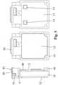
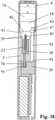
- the inhaler shown as an examplebasically consists of two parts, namely an inhaler part 1 and an inhaler component 2.
- the inhaler component 2consists of a housing 3 and includes, among other things, a liquid container 4 and a tobacco pipe-like mouthpiece 5.
- the liquid container 4contains nicotine in the form of a highly diluted ethanolic and/or aqueous solution, which is vaporized in the inhaler component 2 and converted into an inhalable vapor-air mixture or condensation aerosol.
- the vapor/air mixture or condensation aerosol formedis presented to the user via the mouthpiece 5 .
- the mass fraction of ethanol and/or water in the nicotine solutionis at least 50%.
- Table 1shows an example of the composition of a typical nicotine solution.
- SF8010, SF8011 or SF208118or according to patent publication no. DE19654945A1 , DE19630619A1 , DE3218760A1 , DE3148335A1 (Adam Müller et al. ) manufactured tobacco flavor oils;
- a prerequisite for the use of such tobacco aroma oils in the nicotine solutionis that they are as free as possible of tobacco-specific nitrosamines (TSNA).
- TSNAtobacco-specific nitrosamines
- the nicotine solution presented as an examplerepresents the provisional end point of our own extensive development work and in vivo test series
- the proportion of solventie the proportion of ethanol and water, is 85.3% by mass in the specific example.
- the glycerolit contains supports aerosol formation thanks to its extremely low vapor pressure ( ⁇ 0.1 Pa at 20°C) and also has a masking effect on nicotine, which dampens its organoleptic effects. To put it bluntly, glycerol replaces the tar in cigarette smoke.
- the mix of carboxylic acidsserves to regulate the pH value of the nicotine solution and is adjusted in such a way that the pH value of the vapour-air mixture or condensation aerosol produced is roughly comparable to the values of cigarette smoke.
- the nicotine-containing aerosol particles generated by condensationusually have a mass median aerodynamic diameter (MMAD) of less than 2 ⁇ m and thus also reach the alveoli, where the nicotine passes into the bloodstream in a flash.
- MMADmass median aerodynamic diameter
- the concentrated concentration of nicotinereaches its target organ - namely the central nervous system - just 7-10 seconds after inhalation.
- the inhaler part 1contains at least one energy store and an electrical circuit, the energy store being protected by a battery cover 6 and the circuit being protected by a circuit cover 7 .
- the inhaler part 1 and the inhaler component 2are designed to be detachable from one another in the specific exemplary embodiment.
- the solvable Couplingconsists of a snap connection formed by two snap hooks 8 and two detents 9 cooperating with these.
- This arrangementmakes the inhaler part 1 reusable, which makes sense in principle, considering that, firstly, the inhaler part 1 does not come into contact with the nicotine solution , i.e. is not contaminated with the nicotine solution, and secondly contains components which are more durable than the components of the inhaler component 2. After the nicotine solution in the liquid container 4 has been used up, the inhaler component 2 is properly disposed of by the user as a whole and replaced with a new inhaler component 2 replaced.
- the inhaler component 2represents a replaceable disposable item. Proper disposal is indicated because nicotine-containing condensate residues always form and deposit inside the housing 3 of the inhaler component 2 in the course of the formation of the vapour-air mixture and/or condensation aerosol. Residues of the nicotine solution always remain in the liquid container 4 as well.
- the inhaler part 1 and the inhaler component 2it would of course also be conceivable for the inhaler part 1 and the inhaler component 2 to be designed in one piece, that is to say inseparable from one another.
- this embodimentis likely to be less economical because in this case all parts and components of the inhaler, ie the inhaler as a whole, form a disposable item for single use.
- the subject inventionalso includes this embodiment, in which case the entire inhaler is to be regarded as an inhaler component.
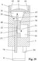
- the Figures 3 to 5show different views of the reusable inhaler part 1 with and without a lid.
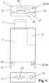
- the reusable inhaler part 1is composed essentially of the following three housing parts: the battery cover 6, the circuit cover 7 and a carrier housing 10 arranged between them.
- the three housing partsare preferably made of plastic for reasons of weight.
- the support housing 10accommodates the electrical circuit 11 and the energy store 12 and includes a partition wall 13 which separates the circuit 11 and the energy store 12 from one another.
- the electrical circuit 11is designed as a printed circuit board populated on one side, which is fastened to the partition wall 13, for example, by means of an adhesive bond.
- the energy store 12preferably consists of a rechargeable battery, for example a lithium-ion accumulator or a lithium-polymer accumulator, preferably in flat design.
- a rechargeable batteryfor example a lithium-ion accumulator or a lithium-polymer accumulator, preferably in flat design.
- These battery typescurrently provide the highest energy densities and currents and have been used in a variety of ways for a long time, with widespread use in mobile phones being the first to be mentioned.
- the poweris supplied from the battery 12 to the circuit board 11 via two flat contacts 14, which are soldered to the back of the circuit board 11 - see also 10 .
- the flat contacts 14protrude through two somewhat larger windows 15 in the partition wall 13 .
- the battery 12includes two mating contacts (not shown) which are pressed against the tabs 14, thereby making releasable electrical contact.
- the compressive force required for this purposeis preferably generated by a leaf spring (not shown) arranged between the battery 12 and the battery cover 6 .
- the battery cover 6is detachably connected to the carrier housing 10 - in the exemplary embodiment by means of a screw connection (see 1 ).
- the battery cover 6could alternatively also be designed as a lockable sliding cover.
- the circuit cover 7is preferably inseparably connected to the carrier housing 10, for example by means of an adhesive or welded connection. In this way, an unauthorized manipulation of the circuit 11 is to be counteracted. In the normally rare case of a circuit defect, the entire inhaler part 1, with the exception of the battery 12, must be replaced. Other components and properties of the reusable inhaler part 1 will be described in more detail later.
- the replaceable inhaler component 2is essentially formed by the housing 3 and includes, among other things, the liquid container 4 and the tobacco pipe-like mouthpiece 5.
- the liquid container 4 and the mouthpiece 5are inseparable from the housing 3 connected.
- the liquid container 4 and/or the mouthpiece 5it is of course also conceivable for the liquid container 4 and/or the mouthpiece 5 to be designed in one piece with the housing 3 .
- the housing 3, the liquid container 4 and the mouthpiece 5are preferably made of plastic for weight reasons, with the choice of material for the liquid container 4 plastics according to US 5,167,242 (James E Turner et al. ) and US 6,790,496 (Gustaf Levander et al. ) can be used.
- the liquid container 4is filled with the nicotine solution 16 via a filling hole 17, preferably under a protective gas atmosphere such as argon or nitrogen.
- a flap-like, openable closure 18On one end of the liquid container 4 there is a flap-like, openable closure 18 which is opened by the user before using the inhaler component 2 by pressing it.
- the openable shutter 18will be described later in detail.
- the liquid container 4is never completely filled with the nicotine solution 16. Due to the incompressibility of the nicotine solution 16, complete filling would result in the flap-like, openable closure 18, which always has a certain elasticity, no longer being able to be pressed in and opened.
- the filling hole 17is hermetically sealed with a sealing cap 19 .
- the closure cover 19can, for example, be glued or welded on, in which case the effect of heat on the nicotine solution 16 should be avoided as far as possible.
- the filling hole 17can be designed as a capillary bore, and the filling with the nicotine solution 16 can take place via an injection needle.
- the closure cap 19could be omitted and the capillary bore itself melted shut.
- Other components and properties of the replaceable inhaler component 2will be described in detail later.
- the 8shows the inhaler 1 with lifted circuit cover 7.
- the 8the snap connection, consisting of the two snap hooks 8 and the corresponding locking lugs 9, in the coupled, locked state.
- the snap hooks 8are designed as extensions of the housing 3, while the latching lugs 9 are formed by contact elements 20.
- the contact elements 20are attached to the carrier housing 10 of the reusable inhaler part 1 by an adhesive connection and fulfill other functions which will be described in detail later.
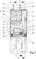
- the housing 3 of the replaceable inhaler component 2forms a chamber 21 on the inside 11 best shows from a vaporizer 22 bridge-like and thus interspersed without contact.
- the evaporator 22is in the form of a film or strip and consists of an electrical resistance heating element and a wick, which together form a flat composite.
- the capillary structure of the wickis suitable for absorbing the liquid nicotine solution 16.
- the heating element and the wickcan be designed and connected to one another in a wide variety of ways. Exemplary training forms will be described later.
- the flat evaporator 22rests with two end sections on two electrically conductive, plate-shaped contacts 23, on the surface of which it is also electrically contacted at the same time.
- the electrical contacting of the evaporator 22 on the plate-shaped contacts 23can be effected by a welded connection.
- the welded connectioncan be produced by spot welding, resistance welding, ultrasonic welding, laser welding, bonding or other suitable welding processes. It is advantageous here if the plate-shaped contacts 23 consist of the same or a similar material as the heating element, which results in favorable conditions for a welded connection as the contacting method. It is important to ensure that the wick or its capillary structure is not impaired by the welding if possible. If necessary, the welding should only be carried out selectively.
- the electrical contacting of the flat evaporator 22takes place by means of an adhesive connection using an electrically conductive adhesive, for example using an epoxy-based adhesive containing silver.
- an electrically conductive adhesivefor example using an epoxy-based adhesive containing silver.
- Such adhesivescan be obtained, for example, from Epoxy Technology, www.epotek.com.
- the plate-shaped contacts 23can in principle be made of any electrical contact material, as long as the material is compatible with the adhesive used; It is particularly favorable if the plate-shaped contacts 23 are formed by printed circuit boards, which are distinguished by the advantage of a particularly low weight.
- the area between the two plate-shaped contacts 23defines a heated section of the evaporator 22 which is arranged in the chamber 21 without contact.
- the non-contact arrangementmeans that the heat conduction losses in the thickness direction of the flat evaporator 22 are equal to zero. As a result, this section can heat up to the point where the nicotine solution 16 stored in the wick boils reached and evaporated.
- the capillary structure of the wickis largely exposed in said section, at least on one side of the flat evaporator 22 . This side is preferably the side 24 of the flat evaporator 22 facing away from the plate-shaped contacts 23, as will be explained later in the course of the description of exemplary embodiments of the evaporator flow out of the exposed capillary structure of the wick.
- the capillary structure of the wick in said sectionis also largely exposed on the side 25 of the flat evaporator 22 opposite the side 24, so that the evaporation surface and consequently also the maximum achievable evaporation capacity is doubled compared to the first case.
- the maximum achievable evaporation rateis defined by the first occurrence of a boiling crisis in the wick.
- the housing 3also defines an air inlet port 26 for the supply of air from the environment into the chamber 21.
- the supplied airmixes in the chamber 21 with the vapor emanating from the exposed capillary structure of the wick, in the course of which the vapour-air Mixture or condensation aerosol forms.
- the air inlet opening 26is designed as a slit-shaped channel.
- the slit-shaped channelis aligned parallel to the flat evaporator 22 .
- the slit-shaped channelis arranged somewhat laterally offset to the flat evaporator 22, namely on that side of the flat evaporator on which the capillary structure of the wick is largely exposed.
- This arrangementensures that the air flowing through the slit-shaped channel 26 into the chamber 21 flows completely over the exposed capillary structure of the wick, and homogeneous mixing conditions can be established.
- the flow velocity of the inflowing aircan be changed, and in this way the dynamics of aerosol formation and the properties of the aerosol generated can be influenced within certain limits be taken.
- a reduction in the flow velocitycauses the aerosol particles to increase in size on average.
- the geometric position of the Slot-shaped channel 26 in relation to the flat evaporator 22has an influence on the formation of aerosols.
- the 13shows an alternative arrangement of the air inlet opening 26: accordingly, the air inlet opening 26 is formed by two slit-shaped channels 26, which are arranged on opposite sides of the flat evaporator 22.
- the air flowing into the chamber 21thus flows around the flat evaporator 22 on both sides.
- This arrangementis particularly suitable for the embodiment variant of the flat evaporator 22 in which the capillary structure of the wick is exposed on both sides, since in this case steam flows off from both sides 24 and 25 of the flat evaporator 22 .
- the air inlet opening 26 designed as a slit-shaped ductdraws the air from a plenum chamber 27, which serves to distribute the air evenly over the slit-shaped duct 26, so that essentially the same flow conditions prevail in the slit-shaped duct on all sides.
- a flow restrictor 28Upstream of the plenum chamber 27 is a flow restrictor 28.
- the purpose of the flow restrictor 28is to create a flow resistance similar to that of a cigarette so that the user feels a similar drag during a puff as when puffing on a cigarette.
- the flow resistanceshould be in the range of 12-16 mbar at a flow rate of 1.05 L/min and have a characteristic that is as linear as possible.
- the flow restrictor 28can be formed, for example, from an open-pored sintered body made of metal or plastic, through the pores of which the air flows.
- porous plastic moldings from Porex, www.porex.comhave proven successful in prototypes.
- the plenum chamber 27is part of the replaceable inhaler component 2 and the flow restrictor 28 is part of the reusable inhaler part 1.
- the 10shows the further course of the air flow upstream of the flow throttle 28.
- the flowis indicated by arrows.
- the flow restrictor 28draws the air from a transverse channel 29 which in turn opens into the space between the circuit board 11 and the circuit cover 7 .
- the actual supply of air from the environmenttakes place via a feed opening 30 formed by the circuit cover 7.
- the feed opening 30is arranged on the end face of the inhaler opposite the mouthpiece 5. This position provides the best protection against the ingress of rainwater.
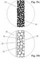
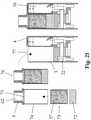
- the 14a, 14b and 15a, 15b , 15cshow exemplary configurations of the flat evaporator 22 based on cross-sectional representations, with "cross-section” being understood to mean a section normal to the longitudinal direction of the flat composite (cf. 9 ). Specifically, they show Figures 14a and 14b Embodiments with capillary structure exposed only on one side, while the Figures 15a and 15b Show embodiments in which the capillary structure of the wick is exposed on both sides of the flat evaporator.
- the evaporator 22consists of a composite of four layers: namely a metal foil 31 and three metal wire meshes 32 sintered onto it.
- the metalconsists of stainless steel (e.g.
- AISI 304 or AISI 316or of a heating conductor alloy - in particular from the group of NiCr alloys or CrFeAl alloys ("Kanthal").
- KanthalNiCr alloys or CrFeAl alloys
- the metal foil 31can be obtained in a stainless steel design, for example from Record Metall-Folien GmbH, www.recordmetall.de.
- the wire meshcan be obtained, for example, from the companies Haver & Boecker, www.haverboecker.com or Spörl KG, www.spoerl.de.
- the four layersare connected to each other by sintering.
- the sinteringis preferably carried out in a vacuum or under a protective hydrogen gas.
- a vacuum or under a protective hydrogen gasSuch sintering is part of the prior art and is routinely carried out, for example, by GKN Sinter Metals Filters GmbH, www.gkn-filters.com, and by Spörl KG, www.spoerl.de.
- the sinteringis advantageously carried out in the form of a multiple panel; This means that not individual flat composites are sintered, but larger flat panels, for example in the 200x200mm format.
- the individual evaporatorsare cut by laser or Punching obtained from the multiple use and then optionally etched in a pickling bath.
- Table 2shows an example of the specifications of flat composites or evaporators 22 used in prototypes.
- Metal foil thickness10 ⁇ m Metal Foil Material: AISI 304 1.
- wire mesh layer36 ⁇ 90 ⁇ m Wire diameter ⁇ mesh size 2.
- wire mesh layer30 ⁇ 71 ⁇ m Wire diameter ⁇ mesh size 3.
- wire mesh layer20 ⁇ 53 ⁇ m Wire diameter ⁇ mesh size
- Wire Cloth MaterialAISI 316L Composite Span: 14mm Compound width: 2-5mm Composite Thickness: 140-160 ⁇ m Etch rate: until 50% with bath stain Avesta 302 *) Porosity: 65-80% depending on the etch rate *) Manufacturer: Avesta Finishing Chemicals, www.avestafinishing.com
- the composite spancorresponds to that distance in the chamber 21 which the evaporator 22 bridges without contact; In the specific embodiment, this distance corresponds to the distance between the two plate-shaped contacts 23.
- the bond span and the bond widthhave an opposite influence on the resulting heating element resistance.
- the etch ratedefines the total mass loss achieved by the etch.
- the first layer of wire meshrests directly on the metal foil 31 .
- the third wire mesh layerforms the cover layer and at the same time the exposed capillary structure of the flat evaporator 22.
- the flat evaporator 22is preferably mounted with the metal foil 31 on the plate-shaped contacts 23.
- the electrical contacting of the metal foil 31is preferably carried out via a flat adhesive connection between the metal foil 31 and the electrically conductive, plate-shaped contacts 23.
- the contactcould also be made a welded connection to be made.
- a flat evaporator 22 contacted in such a way with the specifications according to Table 2, with a compound width of 2 mm and an etching rate of 35%has a heating element resistance of approximately 310 mOhm.
- the heating element resistancecan be increased significantly, specifically when using DIN material number 2.4872 (NiCr20AISi) compared to AISI 304/ AISI 316 by a factor of 1.8 and when using DIN material Number 1.4765 (CrAl255) by a factor of 2.0.
- a flat evaporator with a composite width of 5mm in the design DIN material number 2.4872 but otherwise the same specifications as mentioned abovewould have a heating element resistance of around 225 mOhm. If the energy supply is based on a lithium-polymer cell with a nominal or no-load voltage of 3.7V and a useful voltage under load of approx. 3.1V, the current flowing through the flat evaporator is calculated on the basis of Ohm's law, to 10A (for 310mOhm) or 13.8A (for 225mOhm). These amperages can easily be obtained from today's lithium polymer cells.
- the rated electrical poweris calculated, which is also the maximum heat output that can be achieved at 31W (for 310mOhm) or 42.7W (for 225mOhm). As will be described later, these powers can be arbitrarily reduced by the electrical circuit 11.
- the pore volume of the flat evaporator in the section of the composite spanis calculated at around 7.5 ⁇ L. This volume is filled by the nicotine solution 16 to be vaporized and corresponds to the maximum amount of liquid material that can be vaporized per puff (intermittent inhaler operation). If, for example, the nicotine concentration of 1.8% by mass or 1.5% by volume given in Table 1 is taken as a basis, this theoretically results in a maximum released nicotine dose of 110 ⁇ g or added up per vaporization or puff 10 inhalations a total dose of 1.1mg.
- the maximum achievable dosewill be slightly below the calculated values for various reasons.
- both the metal foil 31 and the metal wire mesh 32 sintered onto the foilcontribute to the electrical heating resistance.
- the electrical heating resistancecan be interpreted as a parallel connection of these individual resistances.
- the capillary effect of the wickis also based on the interaction of the wire mesh 32 with the metal foil 31, with even a single wire mesh layer in combination with the metal foil 31 being able to produce a capillary effect.
- FIG 14bshows a second exemplary embodiment of a flat evaporator 22 with a capillary structure that is only exposed on one side.
- This embodimentdiffers from that shown in FIG 14a only in that instead of the two outer wire mesh layers, a fiber composite in the form of a fleece 33 is provided, which is sintered onto the first wire mesh layer 32.
- Such fleeces 33can be made in stainless steel, for example, by the company GKN Sinter Metals Filters GmbH, www.gkn-filters.com according to customer specifications.
- the fleece 33preferably has a thickness of 100-300 ⁇ m and a porosity >70%.
- the fleece 33 forming the exposed capillary structure of the wickhas a significantly larger surface area in comparison to the wire mesh 32; the larger surface has a favorable effect on the evaporation process.
- the flat composite 22can optionally be etched again after sintering.
- Figure 15ashows an embodiment of a flat evaporator 22 with a capillary structure that is exposed on both sides.
- the evaporatorconsists of an open-pored sintered structure formed from a homogeneous granular, fibrous or flaky sintered composite 34.
- JP 2004/332069(Tsujimoto Tetsushi et al., Mitsubishi Materials Corporation ) describes, for example, a method for Production of thin, porous sintered metal composites in the preferred thickness range of 50-300 ⁇ m, which is characterized by the fact that removable fillers, in this specific case acrylic resin beads, are added to the metal powder to be processed.
- the acrylic resin beadsare placeholders, which sublime in a vacuum at around 500°C in the course of a heat treatment before the actual sintering, leaving cavities which remain during and after the sintering.
- flat compositesconsisting of stainless steel of specification AISI 316L with porosities of typically 70-90% were produced.
- the methodis suitable for producing an evaporator 22 for use in an inhaler component 2 according to the invention. It should only be noted that the average pore diameter in the homogeneous sintered composite is >10 ⁇ m if possible, in order to ensure sufficiently rapid infiltration of the wick with the nicotine solution 16 .
- the grain size of the metal powder to be processed and the acrylic resin beadsmust be matched to this condition.
- the one in the process JP 2004/332069The preferred thickness range of 50-300 ⁇ m mentioned coincides with the thickness range particularly preferred for the flat evaporator 22 .
- the sintered composite 34can optionally be etched again after sintering.
- the attachment and contacting of the flat sintered composite 34 on the plate-shaped contacts 23is preferably carried out by a welded connection.
- An adhesive connectionis only possible if the adhesive used has a sufficiently pasty or viscous consistency. Otherwise there would be a risk of the adhesive entering the pore structure of the composite and impairing the capillary action of the wick.
- FIG. 1shows another embodiment of an evaporator 22 with a capillary structure that is exposed on both sides.
- the flat evaporatorconsists of an open-pored foam 35 formed from an electrical resistance material.
- a foam materialcan be obtained in a stainless steel version (eg AISI 316L) from Mitsubishi Materials Corporation, www.mmc.co.jp. This is based on a standard foam material with a thickness of 0.5 mm, a pore diameter in the range of 50-150 ⁇ m and a porosity of around 90%, which material can be compacted in any thickness by rolling down to around 100 ⁇ m. The compacted material can then optionally be sintered.
- the flat evaporator 22can consist of a single foam layer or of several foam layers sintered together.
- the foam 35can optionally be sintered onto a thin carrier layer 36, for example onto a wire mesh made of stainless steel.
- heat conductor alloysin particular from the group of NiCr alloys and CrFeAl alloys ("Kanthal"), can of course also be processed according to the method.
- the supply of the vaporizer 22 with the nicotine solution 16will be described in more detail below. how 12a and 16 show, one end of the vaporizer 22 protrudes into a capillary gap 37.
- the capillary gap 37feeds the wick of the vaporizer with the liquid nicotine solution 16;
- the cross section of the capillary gap 37is larger than the cross section of the evaporator 22. This has the effect that the nicotine solution 16 flows mainly through the clear cross section of the capillary gap 37 to the evaporation zone, as a result of which the wick can be infiltrated more quickly. and the waiting time between two puffs or inhalations can be shortened.
- the effectworks at least up to the opening of the capillary gap 37 into the chamber 21.
- the capillary gap 37is basically formed by one of the two plate-shaped contacts 23 and an upper part 38 placed flat on this, by corresponding recesses forming the capillary gap 37 being machined into the upper part 38 and into the plate-shaped contact 23 . It should be noted that even a single recess, whether it is arranged in the upper part 38 or in the plate-shaped contact 23, would be sufficient to form a capillary gap 37.
- the recess in the plate-shaped contact 23can also be used as a positioning aid during the assembly of the evaporator 22 .
- the upper part 38is preferably connected to the plate-shaped contact 23 by a Adhesive bonded and consists of a material that can be easily wetted with the nicotine solution 16, preferably made of light metal or a wettable plastic; the wettability and also the bondability of plastics can be significantly improved by surface activation, for example by plasma treatment with oxygen as the process gas.
- the capillary gap 37is formed by two thin plates 39 arranged parallel and spaced apart (see Fig 16 ), One plate being connected to the upper part 38 and the other plate to the plate-shaped contact 23, preferably by an adhesive connection.
- the plates 39can be stamped from a stainless steel strip, for example. how 17-19 best show, the plates 39 forming the capillary gap 37 project into a reservoir 41 via an extension 40 .
- the reservoir 41connects directly to the liquid container 4 and is separated from it only by the flap-like closure 18 that can be opened.
- the openable closure 18is opened with the aid of a pin 42 .
- the pin 42is mounted in the housing 3 in an axially displaceable manner and is preferably made of stainless steel. A first end 43 of pin 42 is directed toward openable closure 18 .
- a second end 44protrudes from the outer surface of the housing 3 in the manner of an extension when the closure 18 is still closed.
- the second end 44 of the pin 42is in a plunger-like operative connection with one of the two contact elements 20 of the inhaler part 1, in that the contact element 20 presses against the second end 44 of the pin 42 during the course of the coupling of the inhaler component 2 to the inhaler part 1, and the pin 42 is thereby displaced into the housing 3.
- the compressive force exerted by the contact element 20is transmitted from the pin 42 to the openable closure 18.
- the openable closure 18has a material weakening 45 on its circumference, which is dimensioned such that when pressure is applied by the pin 42 it tears open like a predetermined breaking point over a wide circumferential area, but forms a hinge 46 on one side. In this way, the openable shutter 18 is caused to open like a flap.
- the pin 42has near the first end 43 a cross-sectional widening 47 which, like a stop, prevents the pin from sliding out of the housing 3 or being able to be removed.
- the supply of the vaporizer 22 with the nicotine solution 16will be explained in summary below, the 17 and 19 the flow conditions are illustrated by arrows: in the course of coupling the inhaler component 2 to the reusable inhaler part 1, the flap-like closure 18 is opened via the pin 42 and the reservoir 41 is then flooded with the liquid material 16 under the influence of gravity. In 18 the liquid levels before and after flooding are shown.
- the capillary gap 37sucks in the nicotine solution 16 via the extension 40 and feeds it to the vaporizer 22, as a result of which the wick is finally completely infiltrated with the liquid material 16.
- the extension 40 formed by the plates 39is intended to prevent gas bubbles from settling in the mouth area of the capillary gap 37, which could impede the capillary coupling.
- a ventilation channel 48is worked into the plate-shaped contact 23, which connects the reservoir 41 to the chamber 21 and causes pressure equalization. In this way, each portion of liquid material 16 which enters the capillary gap 37 is immediately replaced by an equal volume portion of air.
- a buffer memory 49is integrated into the upper part 38 - see 11 and 16 .
- the buffer memory 49consists of slots 50 which are arranged parallel to one another and which are incorporated into the upper part 38 .
- the slits 50communicate on the one hand via openings 51 with the capillary gap 37 and on the other hand via an aeration gap 52 with the chamber 21.
- the capillarity of the slits 50causes the liquid material 16 to flow out of the reservoir 41 via the capillary gap 37 and via the openings 51 into the Slots 50 flows, where it is temporarily stored and can be withdrawn from the wick of the vaporizer 22 as required, regardless of the position of the inhaler component 2.
- Figures 9-12 12also show a condensate drainage and storage device according to the invention arranged in the chamber 21 and consisting of two absorbent sponges 53.
- the basic effects of the condensate drainage and storage devicehave already been explained in more detail earlier.
- the two sponges 53are plate-shaped and spaced apart and arranged parallel to one another, with the flat evaporator 22 being covered by the two sponges 53 on both sides.
- a flow channel 54is formed between the two sponges 53, in which the formation of the steam-air mixture or condensation aerosol takes place.
- the main part of the condensate residuesis deposited on the wall sections 55 of the sponges 53 forming the flow channel 54 and immediately sucked up by the open pore structure of the sponges.
- the sponges 53are attached to two opposite walls of the chamber 21 by means of an adhesive bond, fill the majority of the chamber 21 and are preferably made of a highly porous, dimensionally stable and fine-pored material. If coarse-pored material is used, there is a risk that the capillary forces of the sponge material will no longer suffice to retain the liquid condensate in the event of abrupt movements or accelerations of the inhaler component 2, and parts of the condensate will be thrown out of the sponges 53. Fiber composites, formed from natural or man-made fibers that are thermally bonded to one another or with the aid of a binder, have proven to be particularly suitable as sponge material.
- Filtrona Richmond Inc.www.filtronaporoustechnologies.com, specializes in the production of such fiber composites, using triacetin-bonded cellulose acetate fibers as well as thermally bonded polyolefin and polyester fibers.
- the inhaler component 2should only be given to the consumer against a reasonable deposit. In this way it is ensured that the majority of the sponges 53 contaminated with nicotine residues are disposed of in an environmentally friendly manner.
- the sponges 53are arranged somewhat spaced apart from the upper part 38 and from the plate-shaped contact 23 connected to the upper part 38, so that a gap 56 is formed.
- the gap 56ensures that the ventilation channel 48 and the ventilation gap 52 can communicate with the chamber 21 unhindered.
- the sponges 53are to be dimensioned in such a way that their pore volume is able to absorb the amount of condensate residue formed over the useful life of the inhaler component 2 .
- the amount of condensatedepends primarily on the ethanol and water content in the nicotine solution 16 and on the air throughput through the air inlet opening 26 and through the flow channel 54 . The less air that is pushed through, the less vapor the air can absorb up to saturation.
- the chamber 21is downstream downstream of a cooler in the form of a tobacco filling 57 whose pores are formed by the vapor-air mixture or condensation aerosol.
- the main effects of the coolerhave already been explained in detail earlier.
- the tobacco filling 57is located in a filling space 58 which is delimited by a perforated wall 59 on the flow inlet side, by the mouthpiece 5 on the flow outlet side, and by the housing 3 and a wall of the liquid container 4 on the jacket side.
- the perforated wall 59supports the filling material 57 and at the same time stiffens the housing 3 .
- the hole wall 59is arranged somewhat spaced from the sponges 53 - see 12 .
- a first wire mesh 60is arranged between the tobacco filling 57 and the perforated wall 59 so that the filling material cannot escape from the holes in the perforated wall 59 .
- the tobacco filling 57is delimited by a second wire mesh 61, which prevents the filling material from getting into the mouthpiece channel 62 or even into the user's oral cavity.
- the mouthpiece 5forms a collection chamber 63, which causes the tobacco filling 57 to flow through evenly even in the end section.
- the second wire mesh 61is advantageously attached directly to the mouthpiece 5, eg melted onto it.
- the first wire mesh 60is placed on the perforated wall 59 .
- a predefined amount of tobacco or filling material 57is then introduced into the filling chamber 58, with filling also being able to take place in several stages, and the filling material 57 being intermediately compressed after each partial filling. In this way, a relatively homogeneous filling density can be achieved.
- the mouthpiece 5is mounted and the filling space 58 is closed.
- Fine-cut tobaccois characterized by a particularly small cutting width of usually 0.3mm.
- the small cutting widthcauses an extraordinarily large surface of the tobacco filling 57.
- These conditionsfavor both the heat exchange and the exchange of substances between the tobacco and the vapor-air mixture or condensation aerosol that permeates it.
- fine-cut tobaccolight American Blend fine-cut tobacco and dark fine-cut tobacco, mostly with a spicy character. Both fine cuts are suitable for producing a tobacco filling 57 according to the invention.
- the tobaccocan also be flavored, spiced, flavored and/or perfumed, with all the recipes and processes used by the tobacco industry being able to be adopted here.
- menthol and tobacco aroma oilsobtained by means of supercritical CO2 extraction (see Table 1) and coffee extract were successfully tested as aromatic additives.
- Tobacco smoke condensate or a volatile aromatic fraction thereofis also useful as a flavor additive.
- itshould be offered for sale in airtight packaging and the packaging should only be opened immediately before the inhaler component 2 is used. Even after the inhaler component 2 has been coupled to the inhaler part 1, there is still the possibility of suppressing the escape of aroma substances by closing the mouthpiece opening, for example by means of a cap or a plug (not shown).
- the packing density of the tobacco filling 57determines the flow resistance which the filling material 57 opposes to the vapor/air mixture or condensation aerosol; the packing density is to be matched to the flow resistance of the flow restrictor 28 in such a way that the resulting flow resistance is as far as possible within the aforementioned preferred range of 12-16 mbar at an air throughput of 1.05 l/min.
- a filter effect of the tobacco filling 57is undesirable; the aerosol particles generated in the chamber 21 should be able to penetrate the tobacco filling 57 with as few losses as possible.
- the alternative embodiment variant without a flow throttle 28also has an effect on the sensor-based detection of the start of the train, which effects will be explained in more detail later.
- any porous materialcan be used as an alternative filling material 57, provided it is largely permeable to the aerosol particles and largely chemically inert under the given conditions of use.
- a filter material that would cause the aerosol particles to be separatedis ruled out from the outset as a porous material.
- the pore materialmust therefore have sufficiently large or wide pores in order to qualify as filling material 57 for cooling the vapor-air mixture or condensation aerosol.
- regenerator materialsare suitable, such as fillings made of metal wool or metal chips, or beds made of metallic or ceramic granules, with the granules themselves advantageously having a porous structure.
- Fillings made of natural or man-made fiberscan also be considered, provided they have sufficiently large pores and are largely chemically inert.
- tobaccois suitable for flavoring the alternative filling material 57, for example added in dispersed form as a sauce. If the use of tobacco as an additive for flavoring is also prohibited, alternative recipes and processes must be used, which, however, can hardly ever reproduce the natural tobacco flavor in all its complexity.
- the cooleris designed as a liquid cooler 64 .
- the liquid cooler 64consists of a container 65 formed by the housing 3, which is arranged downstream of the chamber 21.
- the container 65contains a cooling liquid 66 through which the vapor-air mixture formed or condensation aerosol flows in the form of gas bubbles 67 .
- the cooling liquid 66essentially consists of water and/or ethanol. Preservatives can optionally be added to the cooling liquid 66 .
- the container 65is not completely filled with coolant. Rather, a buffer space 68 is provided, which allows the cooling liquid 66 to expand unhindered while the vapor-air mixture or condensation aerosol flows through. The following condition applies to the volume Vp of the buffer space 68: Vp>Vbl (Vbl ... total volume of all gas bubbles during the flow).
- the container 65is formed by the housing 3 on the casing side.
- the container 65communicates at the front with the chamber 21 on the one hand and with the mouthpiece 5 on the other hand via a liquid barrier in the form of two semipermeable membranes 69 and 70.
- Such membranescan be obtained, for example, from Porex Technologies, www.porex.com, in the form of porous, sintered Plastic membranes are obtained.
- Porex Technologiesmanufactures such membranes from naturally hydrophobic and extra hydrophobic plastics such as PTFE, PE and PP in thicknesses from 0.5mm and with pore diameters of 10-150 ⁇ m.
- the membranes made of PTFEare sold under the name Mupor ® .
- the pore diametershould be in the range of 50-150 ⁇ m; even smaller pore diameters led to impermissibly high flow and draft resistances.
- the membrane 69 on the chamber sidesimultaneously serves to introduce and atomize the vapor-air mixture or condensation aerosol into or in the cooling liquid 66.
- the membrane 69 on the chamber sideacts in this respect like a nozzle base or similar to a frit in a washing bottle.
- the chamber-side membrane 69is arranged somewhat spaced from the sponges 53 . As a result, the membrane 69 is acted upon almost uniformly over its entire cross-section by the vapor-air mixture or condensation aerosol flowing in from the flow channel 54 .
- the mouthpiece 5again forms a collection chamber 63, which also causes the membrane 70 to be emptied of the meanwhile cooled vapor/air mixture or condensation aerosol over its entire cross section is applied and enforced.
- the blocking effect of the membrane 70can be used over a large area, and at the same time the flow resistance can be kept at a low level.
- the cooling liquid 66has an approximately constant liquid level in relation to the membrane 69 on all sides. This is the only way to ensure that the gas bubbles 67 penetrate the cooling liquid 66 relatively evenly over the entire cross section, and that the potential of liquid cooling is fully exploited.
- the special arrangement and curved shape of the mouthpiece 5is intended to assist the user in holding the container 65 in the correct position.
- the indentation 71 formed by the curvature of the mouthpiece 5serves to accommodate the user's lower lip. It is also structurally remarkable that the mouthpiece 5, despite its considerable curvature, does not protrude beyond any of the delimiting planes Y of the housing 3 designed as a flat housing. The effect of this arrangement has been explained earlier.
- tobacco and/or flavoringscan optionally be added to the cooling liquid 66.
- tobacco and/or the flavoringscan also be dispersed in the cooling liquid 66 or present as sediment, or just float on the surface of the cooling liquid.
- the gas bubbles 67 penetrating the cooling liquid 66produce a considerable flow turbulence, which not only promotes the heat exchange but also the mass exchange.
- the addition of ground tobacco, such as that used in snuffhas proven its worth.
- the tobacco particlesare present in the cooling liquid 66 as a suspension, with a large part of the particles being deposited on the membrane 69 as sediment. During a train, the sediment is whirled up by the rising gas bubbles 67 and circulated as in a fluidized bed.
- menthol and tobacco aroma oils obtained by means of supercritical CO2 extractionsee Table 1 and coffee extract were successfully tested as aromatic additives in prototypes.
- itshould be offered for sale in airtight packaging, and the packaging first opened immediately before using the inhaler component. Even after the inhaler component 2 has been coupled to the inhaler part 1, there is still the possibility of suppressing the escape of aroma substances by closing the mouthpiece opening, for example by means of a cap or a plug (not shown).
- the coolerhas a two-stage structure and consists of a pre-cooler 72 and a tobacco filling 57 arranged downstream of this.
- the pre-cooler 72forms the first cooler stage and has the task of pre-cooling the vapour-air mixture or condensation aerosol as effectively and largely as possible before it fills the tobacco 57 reached.
- the pre-cooler 72shields the tobacco filling 57 from the chamber 21, so that the tobacco filling 57 is not affected by the condensation processes in the chamber 21. These conditions result in the tobacco filling 57 becoming less loaded with solvent condensate. Excessive condensate loading of the tobacco filling 57 can adversely affect the flavoring effect of the same.
- the pre-cooler 72can consist of a synthetic fiber fleece, for example.
- the company Freudenberg Vliesstoffe KG, www.freudenberg-filter.comoffers such a material in the form of mats/plates under the name Viledon ® filter mats.
- the materialcan be made to customer specifications. In particular, the material properties can be adjusted in such a way that the end product is largely permeable to the fine particles of the condensation aerosol produced.
- the mats/platesare made of polyolefin fibers (PE, PP) or polyester fibers and can be further processed by punching.
- the tobacco filling 57is in the form of a prefabricated pack and consists of a paper-wrapped tobacco rod 73 which is advantageously obtained from an endless rod.
- the tobacco rod 73 and the pre-cooler 72are pushed into a hollow cylinder 74 .
- the hollow cylinder 74is part of the mouthpiece 5.
- the tobacco filling 57is delimited by a wire mesh 75, which prevents the filling material from getting into the mouthpiece channel 62 or even into the user's oral cavity.
- the pre-cooler 72 and the tobacco rod 73 together with the mouthpiece 5form a structural unit 76 which can be inserted into the housing 3 of the inhaler component 2 via the housing opening 77 . This arrangement allows the user to operate the mouthpiece cooler unit 76 independently of the rest Replace parts of the inhaler component 2.
- the tobacco rod 73can optionally also be flavored. If they are in liquid form, the aromatic additives can be introduced into the tobacco rod 73 via one or more injection needles. Viscous and solid flavorings can be diluted or dissolved in a suitable solvent beforehand for this purpose. Typical aromatic additives are tobacco aroma oils obtained by means of supercritical CO2 extraction (see Table 1), coffee extract, tobacco smoke condensate or a volatile aromatic fraction of a tobacco smoke condensate, to name just a few examples.
- the tobacco rod 73can also be mentholized like cigarettes, with analogous methods being able to be used.
- the mouthpiece cooler unit 76is to be sealed airtight immediately after flavoring, for example by being sealed in a protective film. Welding preferably takes place under a protective gas atmosphere, e.g. under nitrogen; in this way, oxidation and microbial infestation by bacteria and mold can be prevented.
- the plate-shaped contacts 23 of the replaceable inhaler component 2protrude from the outer surface of the housing 3 in the form of two plug-in contacts 78 .
- the plug-in contacts 78form electrical contacts with corresponding spring contacts 79 in the course of the coupling of the inhaler component 2 to the inhaler part 1, via which electrical energy for evaporating the nicotine solution 16 is supplied to the electrical resistance heating element.
- the spring contacts 79are part of the contact elements 20 and are preferably connected to them by a welded connection - see also Figures 4-5 .
- the contact elements 20consist of a metallic contact material and can, for example, from the company Ami Doduco GmbH, www.amidoduco.com.
- the insufficient electrical conductivity of this materialrequires that the plate-shaped contacts 23 be at least partially of the plug contacts 78, for example, to be galvanically coated with a conductive layer made of gold, silver, palladium and/or nickel, as a result of which the electrical contact resistance is significantly reduced.
- the contact elements 20obtain the electrical energy via two wires 80 which connect the contact elements 20 to the board 11 - see Figures 4-5 .
- the wires 80are preferably attached on both sides by soldering.
- the contact elements 20fulfill three different tasks: first, as just described above, they transmit the electrical energy from the circuit board 11 to the plate-shaped contacts 23. Second, they form lateral latching lugs 9, which are connected to the snap hooks 8 of the housing 3 cooperate, whereby the snap connection between the inhaler component 2 and the inhaler part 1 is realized. And thirdly, one of the two contact elements 20 forms a stop for the pin 42, as a result of which the ram-like operative connection to the opening of the liquid container 4 is established.
- a positioning deviceFor coupling the inhaler component 2 to the inhaler part 1 in a precise position, a positioning device is provided, which consists of a centering projection 81 arranged on the carrier housing 10 and a centering recess 82 corresponding thereto and arranged on the housing 3 - see 3 , 6 , 10 and 12 .
- the centering projection 81has two vent holes 83 which vent the centering recess 82 in the course of the coupling.
- the pressure sensor 84forms an essential part of the inhaler according to the invention—see FIG 8 and 17 .
- the pressure sensor 84has the function of detecting the start of a puff, whereupon the electrical circuit 11 activates the supply of electrical energy to the heating element of the vaporizer 22 and vaporization of the nicotine solution 16 stored in the wick begins.
- the pressure sensor 84is glued into the carrier housing 10 and its electrical connections or pins 85 are soldered directly onto the circuit board 11 .
- the pressure sensor 84communicates with the plenum chamber 27 via a bore 86 and measures or monitors the pressure in the plenum chamber 27 - see 17 .
- a suitable pressure sensor 84is, for example, the type CPCL04GC from the manufacturer Honeywell Inc., www.honeywell.com, with a measuring range of +/-10 mbar.
- the sensor mentionedconsists essentially of a zero-point calibrated and temperature-compensated measuring bridge and can be connected as follows on circuit board 11: the negative sensor output is connected to ground via a high-impedance resistor with a defined resistance value - e.g. 2.2 MOhm, whereby the Output or measurement signal of the pressure sensor 84 is slightly distorted, or to put it another way, the offset of the measuring bridge is calibrated to a defined value.
- a switching thresholdis specified by the distortion or by the offset, which corresponds to a specific pressure threshold value.
- the measurement signal processed in this wayis applied to the input of a precision operational amplifier 87 connected as a comparator - for example of the type LTC1049CS8 from the manufacturer Linear Technology Inc., www.linear.com.
- This wiringresults in an output signal that shows the start of the train in digital form extremely quickly and precisely.
- the pressure sensor 84is of course only suitable as a sensor for detecting the start of traction if a flow throttle 28 is arranged upstream of the plenum chamber 27 . In this case, in relation to the environment, a negative pressure occurs in the plenum chamber 27 in the course of a train, which is typically in the range of 0-50 mbar.
- the pressure curveis approximately bell-shaped.
- the beginning of the traincan be detected in a simple manner by specifying a pressure threshold value, as described above, which is constantly compared with the actually measured pressure.
- the start of tractioncan be defined as the first time the pressure threshold is exceeded.
- a value in the range of 0.2-5 mbaris expediently selected for the pressure threshold value. The smaller the selected pressure threshold value, the faster the train detection responds.
- a lower limitis set by the specifications of the particular pressure sensor and operational amplifier used.
- the measuring bridgecontains a second thermistor of the same type for temperature compensation and is calibrated to a defined offset threshold value using precision resistors.
- the output signal of the measuring bridgeis then fed back to the input of an operational amplifier connected as a comparator.
- both thermistorsare at the same temperature level - typically in the range of 80-200°C, depending on the dissipated power.
- airflows through the transverse channel 29. The air cools the thermistor, which increases its resistance.
- the change in resistanceis processed by the measuring bridge.
- the comparatorflips over and emits a digital signal indicating the start of the train.
- the further processing of the signal output by the pressure or flow sensor and its wiringpreferably takes place in an integrated circuit 88--see FIG 8 .
- the integrated circuit 88can also be a microprocessor.
- the integrated circuit 88processes a large part of all electrical signals from the inhaler and carries out the control operations which are essential for the operation of the inhaler.
- a central control operationis the supply of electrical energy to the heating element of the evaporator 22 .
- the electrical energyis supplied by the energy store 12 .
- lithium polymer and lithium ion cellsare particularly suitable as energy stores 12 due to their high energy and power density. In the case of metallic heating elements, a single lithium polymer or lithium ion cell with an open circuit or nominal voltage of around 3.7V is sufficient.
- the energy and power supply to the heating element of the evaporator 22can be regulated in a simple manner by chopping the battery voltage over the duration of the energy supply with a variable degree of control and applying the resulting useful voltage to the heating element.
- the resulting useful voltageis a square-wave signal with a variable duty cycle.
- the amplitude of The square-wave signalcorresponds to the battery voltage, disregarding minor voltage losses.
- the actual choppingpreferably takes place by means of a power MOSFET 89, for example of the type IRF6635 from the manufacturer International Rectifier, www.irf.com, which is suitable for switching very high currents with a minimal drain-source on-resistance.
- the integrated circuit 88controls the gate of the power MOSFET 89.
- a very simple control strategywhich has also proven itself in prototypes according to the invention, consists of dividing the duration of the energy supply into two periods - a heating-up period and a subsequent one evaporation period.
- the duration of the energy supplyis based on the duration of a puff.
- An average puff duration of about 2.1sec (+/-0.4sec)can be assumed. The same value applies roughly to cigarettes. If one considers that even after the energy supply has been switched off, post-evaporation takes place to a certain extent because of the heat still stored in the evaporator 22, it seems appropriate to choose the duration of the energy supply somewhat shorter, eg a value in the range 1.5-1.8 seconds .
- the heating-up periodDuring the first of the two periods mentioned above - the heating-up period - the vaporizer 22 together with the nicotine solution 16 stored in the wick are heated by the heating element.
- the vaporization of the nicotine solution 16does not begin until the temperature of the vaporizer 22 has reached approximately the boiling range of the low-boiling fractions of the nicotine solution 16 .
- the heating-up periodshould therefore be as short as possible. In this respect, it makes sense to pass on the battery voltage to the heating element uninterrupted or with a modulation level or duty cycle of 100% during this period.
- the duration of the heating-up perioddepends above all on the specifications of the evaporator 22 and on the quantity and composition of the nicotine solution 16 and should be ⁇ 0.5 seconds if possible.
- the evaporation period--the degree of controlis significantly reduced, and the actual evaporation of the nicotine solution 16 takes place.
- the energy suppliedis used in this second period primarily to evaporate the nicotine solution 16 and secondarily to cover energy losses.
- the degree of controlBy appropriately selecting the degree of control, the vaporization performance and thus also the amount of nicotine solution 16 vaporized per puff or inhalation can be controlled within certain limits to be controlled.
- An upper limitis set by the occurrence of a boiling crisis and by local drying out and overheating of the wick.
- thermal decomposition of the liquid material 16can be counteracted by reducing or throttling the degree of modulation.
- control strategy just describedcan be expanded and refined as desired: for example, it can make sense to also take into account the state of battery 12 in the control strategy, since the battery voltage drops significantly as the battery discharges and ages, especially under load. This effect can be countered by increasing the modulation level. In order to be able to carry out this correction during the warm-up period as well, it is advisable not to control the battery voltage of a new, charged battery at 100%, as previously suggested, but only at 80%, for example, so that there is still enough leeway for an adjustment.
- the control of the power supply to the heating element of the evaporator 22also requires various auxiliary operations: for example, it must be provided that the power supply cannot be activated again immediately after the end of an evaporation cycle. Rather, a waiting time must be observed, which allows the nicotine solution 16 enough time to completely infiltrate the wick again.
- the minimum required waiting timedepends on the particular specifications of the evaporator 22 as well as the viscosity of the liquid material 16 . It could be shown in prototypes and calculations confirm that with an appropriate design a complete infiltration of the wick can be achieved in less than 10 seconds. A mandatory waiting time of this magnitude should be tolerated by most users, especially considering that in the case of the cigarette, the interval between two puffs averages 25 seconds.
- the integrated circuit 88preferably performs other control operations. Examples include: communication with the user (user interface), dosage recording, identification of the used Inhaler component 2, identification of the user, cell and charge management of the battery 12.
- control operationsinclude: communication with the user (user interface), dosage recording, identification of the used Inhaler component 2, identification of the user, cell and charge management of the battery 12.
- the implementation of all control operations in a circuit diagramcan be performed by any expert in this field using known methods, and will therefore not be discussed further in this context .
- the usermakes a new inhaler component 2 ready for use by coupling it to the reusable inhaler part 1 via the snap connection 8, 9.
- the liquid container 4is opened synchronously with the coupling to the inhaler part 1 by means of the pin 42 in cooperation with the contact element 20 (see FIG 18 ), whereupon the end of the capillary gap 37 designed as an extension 40 is wetted with the nicotine solution 16 .
- the capillary gap 37exerts a capillary force on the nicotine solution 16 wetting it, which causes the capillary gap 37 to be rapidly flooded.
- the nicotine solution 16reaches the vaporizer 22 (see 11 ).
- the evaporator 22consists of a wick and an electrical heating element, which together form a flat composite.
- the capillary forces in the wickcause it to be quickly infiltrated by the nicotine solution 16 as well.
- the buffer store 49consisting of slit-shaped capillaries 50 is also flooded with the nicotine solution 16 .
- the buffer store 49enables the inhaler to be operated in any position.
- the time between the opening of the liquid container 4 and the complete infiltration of the wickcorresponds to an obligatory waiting time for the user and is in any case less than 10 seconds if the design is appropriate.
- the inhaleris now ready for use.
- the useruses the mouthpiece 5 to take a puff similar to that of a cigarette.
- the pressure sensor 84( 8 and figure 18 ) detects the beginning of the puff and causes the integrated circuit 88 to supply the heating element of the evaporator 22 with electrical energy according to a predetermined control strategy. This results in the vaporizer 22 being heated up in a flash, and the nicotine solution 16 in the wick vaporizes. The vapor formed leaves the evaporator 22 via the wick surface which is exposed in large areas of the evaporator and mixes in the chamber 21 with the air flowing into the chamber 21 through the air inlet opening 26 . Mixing with the air, the vapor cools and forms a condensation aerosol ( Figures 9-10 ).
- the liquid container 4contains, for example, 5mL of effectively usable liquid material 16 ( 21 ), and the liquid material 16 contains nicotine in a concentration of typically 1.5 vol. 750 puffs correspond to about 75 cigarettes. If only 50 ⁇ g of nicotine is vaporized per puff, the range increases to 1500 puffs or inhalations, which corresponds to about 7 1/2 packs of cigarettes.
- the evaporator 22is always designed as a flat composite in the exemplary embodiments, consisting of an electrical heating element and a wick, the invention is of course not limited to this embodiment. Rather, the evaporator can have any desired embodiment, as long as it has an evaporation surface or vapor outlet surface arranged in the chamber 21 , from which the generated vapor passes into the chamber 21 .
- the evaporatorcould also be designed as a capillary tube evaporator according to FIG US 6,155,268 (Manabu Takeuchi ) or US 5,743,251 (Tony M. Howell et al. ) be formed, in which case the capillary tube opening would form the steam outlet surface.
- the vaporizercan also be supplied with the nicotine solution in any way and is not limited to the supply via a capillary gap 37 shown in the exemplary embodiments.
- the vaporizercould be heated with induction heat, radiant heat, or microwaves.
- Non-electric heat sourcescan also be used to vaporize the nicotine solution.
- the direct use of chemical reaction heatis mentioned as an example.
Landscapes
- Health & Medical Sciences (AREA)
- Engineering & Computer Science (AREA)
- Life Sciences & Earth Sciences (AREA)
- Veterinary Medicine (AREA)
- Public Health (AREA)
- General Health & Medical Sciences (AREA)
- Animal Behavior & Ethology (AREA)
- Biomedical Technology (AREA)
- Hematology (AREA)
- Heart & Thoracic Surgery (AREA)
- Anesthesiology (AREA)
- Pulmonology (AREA)
- Bioinformatics & Cheminformatics (AREA)
- Medicinal Chemistry (AREA)
- Chemical & Material Sciences (AREA)
- Pharmacology & Pharmacy (AREA)
- Epidemiology (AREA)
- Medicinal Preparation (AREA)
- Catching Or Destruction (AREA)
- Pharmaceuticals Containing Other Organic And Inorganic Compounds (AREA)
- Acyclic And Carbocyclic Compounds In Medicinal Compositions (AREA)
- Emergency Medicine (AREA)
Description
Translated fromGermanDie Erfindung betrifft eine Inhalatorkomponente für die Bildung eines nikotinhaltigen Dampf-Luft-Gemisches oder/und Kondensationsaerosols durch Verdampfung einer mittels Ethanol oder/und Wasser hochverdünnten Nikotinlösung, umfassend:
- ein Gehäuse;
- eine im Gehäuse angeordnete Kammer;
- eine Lufteinlaßöffnung für die Zufuhr von Luft aus der Umgebung in die Kammer;
- einen Verdampfer zur Verdampfung einer Portion der hochverdünnten Nikotinlösung mit einer in der Kammer angeordneten Verdampfungsfläche bzw. Dampfaustrittsfläche, aus welcher der erzeugte Dampf in die Kammer übertritt und sich in der Kammer mit der durch die Lufteinlaßöffnung zugeführten Luft mischt, wodurch sich schließlich das nikotinhaltige Dampf-Luft-Gemisch oder/und Kondensationsaerosol, wobei die Inhalatorkomponente eine Kondensat-Drainage- und Speichereinrichtung umfasst, wobei die Kondensat-Drainage- und Speichereinrichtung einen Schwamm umfasst.
- a housing;
- a chamber disposed in the housing;
- an air inlet port for admitting air from the environment into the chamber;
- an evaporator for evaporating a portion of the highly diluted nicotine solution with an evaporation surface or vapor outlet surface arranged in the chamber, from which the generated vapor passes into the chamber and mixes in the chamber with the air supplied through the air inlet opening, as a result of which the nicotine-containing vapor Air mixture and/or condensation aerosol, the inhaler component comprising a condensate drainage and storage device, the condensate drainage and storage device comprising a sponge.
In der gegenständlichen Patentanmeldung bezieht sich der Begriff "Inhalator" auf medizinische wie nicht-medizinische Inhalationsapparate. Der Begriff bezieht sich außerdem auf Rauchartikel und Zigarettenersatz-Artikel, wie sie beispielsweise in der Europäische Patentklasse A24F47/00B enthalten sind, soweit diese dazu bestimmt sind, dem Benutzer ein Dampf-Luft-Gemisch oder/und Kondensationsaerosol darzureichen.In the present patent application, the term "inhaler" refers to medical as well as non-medical inhalers. The term also refers to smoking articles and cigarette substitute articles, such as those contained in European patent class A24F47/00B, insofar as these are intended to provide the user with a vapor/air mixture and/or condensation aerosol.
Die Erfindung bezieht sich auf "Zug-Inhalatoren" bzw. auf Inhalatorkomponenten solcher Zug-Inhalatoren, welche einen intermittierenden, zugsynchronen Betrieb erlauben. Eine solche Betriebsart liegt vor, wenn die Nikotinlösung nur während eines Zuges verdampft wird, während in Intervallen zwischen zwei Zügen im Wesentlichen keine Verdampfung erfolgt. Zug-Inhalatoren sind Inhalationsapparate, bei welchen das gebildete Dampf-Luft-Gemisch oder/und Kondensationsaerosol dem Benutzer wie bei einer Zigarette in zwei Schritten zugeführt wird, nämlich zuerst als Zug in die Mundhöhle (erster Schritt) und - nach Absetzen des Inhalators - in Form einer daran anschließenden Lungeninhalation (zweiter Schritt). Das Zugvolumen beträgt dabei individuell variierend etwa 20-80mL. Im Gegensatz dazu erfolgt bei "klassischen Inhalatoren" die Zufuhr des gebildete Dampf-Luft-Gemisches oder/und Kondensationsaerosols in einem einzigen Schritt als direkte Lungeninhalation. Klassische Inhalatoren weisen im Vergleich zu Zug-Inhalatoren einen deutlich höheren Luftdurchsatz durch den Inhalator auf: ca. 100-750mL/s gegenüber 10-40mL/s. Der vergleichsweise geringe Luftdurchsatz führt bei Zug-Inhalatoren im Zusammenwirken mit einem hohen ethanolischen oder/und wässrigen Lösungsmittelanteil in der Nikotinlösung zu einer Reihe von Problemen, welche später noch im Detail erörtert werden.The invention relates to “draw inhalers” or to inhaler components of such draw inhalers which permit intermittent, draw-synchronous operation. One such mode of operation is when the nicotine solution is vaporized only during one puff while essentially no vaporization occurs at intervals between puffs. Draw inhalers are inhalers in which the vapor-air mixture formed and/or condensation aerosol is fed to the user in two steps, like a cigarette, namely first as a draw into the oral cavity (first step) and - after stopping the inhaler - in form of a subsequent one Lung inhalation (second step). The puff volume is individually varying about 20-80mL. In contrast to this, with "classic inhalers" the supply of the vapor-air mixture formed and/or condensation aerosol takes place in a single step as direct lung inhalation. Classic inhalers have a significantly higher air flow through the inhaler compared to draw inhalers: approx. 100-750mL/s compared to 10-40mL/s. In draw inhalers, the comparatively low air throughput, in conjunction with a high proportion of ethanolic and/or aqueous solvent in the nicotine solution, leads to a number of problems which will be discussed in detail later.
Als eine "mittels Ethanol oder/und Wasser hochverdünnte Nikotinlösung" gelte im Rahmen der gegenständlichen Patentanmeldung jede nikotinhaltige Lösung, deren Massenanteil an Ethanol oder/und Wasser zusammen mindestens 50% beträgt. Ein hoher ethanolischer oder/und wässriger Lösungsmittelanteil in der Nikotinlösung hat eine Reihe von vorteilhaften Effekten.
Obwohl die
Weitere vorteilhafte Wirkungen des hohen Anteils an Ethanol oder/und Wasser in der Nikotinlösung sind: Verbesserung der Dosierbarkeit des eigentlichen Wirkstoffes Nikotin, allgemeine Verbesserung der Löslichkeit für weitere Inhaltsstoffe in der Nikotinlösung, Verbesserung verschiedener physikalischer Eigenschaften, wie beispielsweise eine Verringerung der Viskosität der Nikotinlösung. Letzterer Effekt kommt vor allem zum Tragen, wenn der Transport der Nikotinlösung zum Verdampfer oder Zerstäuber mittels eines Dochts erfolgt. Wasser vermindert zudem die Hygroskopizität des gebildeten Aerosols und beugt so einem Austrocknen der Mundhöhle und des Rachens vor. Ethanol und Wasser wirken zusammen ferner keimtötend und vebessern dadurch die Hygiene der Aerosolerzeugung und -verabreichung.Other advantageous effects of the high proportion of ethanol and/or water in the nicotine solution are: improvement in the dosability of the actual active ingredient nicotine, general improvement in the solubility of other ingredients in the nicotine solution, improvement in various physical properties, such as a reduction in the viscosity of the nicotine solution. The latter effect is particularly noticeable when the nicotine solution is transported to the vaporizer or atomizer by means of a wick. Water also reduces the hygroscopicity of the aerosol formed and thus prevents the oral cavity and throat from drying out. Ethanol and water also act together to kill germs, thereby improving the hygiene of aerosol generation and administration.
Mittels Ethanol oder/und Wasser hochverdünnte Nikotinlösungen, wie sie beispielhaft in
Das flüssige Aromamittel 34 beinhaltet zumindest einen Aromastoff. Zusätzlich können noch aerosolbildende Substanzen enthalten sein, und zwar Alkohole, Zucker, Wasser sowie eine Mischung aus zumindest zwei dieser Substanzen. Als Alkohole können beispielsweise Glycerin, Propylenglykol sowie Mischungen derselben Verwendung finden. Im Fall, daß das Aroma-erzeugende Gerät als simulierender Rauchartikel (Zigarettenersatz) verwendet werden soll, kann das flüssige Aromamittel 34 auch Tabakkomponenten wie Tabakextrakte und Tabakrauchkondensat enthalten. Die Verwendung von Nikotin als Inhaltsstoff wird explizit nicht erwähnt, allerdings enthalten Tabakextrakte und insbesondere Tabakrauchkondensat in der Regel Nikotin.The
Grundsätzlich muß angemerkt werden, daß der Prozess der Bildung von Kondensatablagerungen in erster Linie durch molekulare Diffusionsvorgänge in der Dampfphase bestimmt wird und insofern von makroskopischen Strömungsbedingungen nur begrenzt beeinflußt werden kann. Bestünde das flüssige Aromamittel 34 aus einer mittels Ethanol oder/und Wasser hochverdünnten Nikotinlösung, und setzt man voraus, daß das Aroma-erzeugende Gerät nach dem Prinzip eines Zug-Inhalators arbeitet und zugsynchron betrieben wird, so wäre trotz der ergriffenen strömungstechnischen Optimierungsmaßnahmen mit erheblichen Diffusionsströmen in Richtung der Innenfläche der Kammer 121 bzw. des Mundstücks 161 und damit verbundenen mit erheblichen Kondensatabscheidungen zu rechnen. Die Aufnahmekapazität der Innenflächen der Kammer 121 und des Mundstücks 161 für Kondensatrückstände wäre jedenfalls schnell erschöpft. Würde das Mundstück 161 nicht in kurzen Abständen gewechselt werden, bildeten sich bald frei bewegliche Kondensatansammlungen, welche die Funktion des Aroma-erzeugenden Gerätes stören könnten. Aber auch schon allein die Möglichkeit an sich, das Kondensat vom Benutzer selbst aus dem Gerät entfernen zu lassen, birgt ein Risiko für die Umwelt, weil davon auszugehen ist, daß das Kondensat auch Nikotinreste enthält. Die Kondensatansammlungen im Inneren der Kammer 121 könnten aber auch über die Mundstücköffnung in die Mundhöhle des Benutzers gelangen, verbunden mit den bereits erwähnten Nachteilen und Gefahren. Im Fall, daß im Mundstück 161 der Filter 102 appliziert ist, könnten die Kondensatansammlungen den Filter 102 blockieren, wodurch der Strömungswiderstand sprunghaft ansteigen würde. Der Filter 102, welcher als Option vorgesehen ist, dient offenbar nur dazu, einen für den Benutzer komfortablen Strömungswiderstand einzustellen.Basically, it must be noted that the process of formation of condensate deposits is primarily determined by molecular diffusion processes in the vapor phase and can therefore only be influenced to a limited extent by macroscopic flow conditions. If the
Das flüssige Tabakaroma kann laut
Die Anordnung nach
Eine weitere Inhalatorkomponente zur Bildung eines nikotinhaltigen Dampf-Luft Gemisches ist aus
Die Erfindung wird in dem unabhängigen Anspruch 1 definiert. Bevorzugte Ausführungsformen bilden den Gegenstand der abhängigen Ansprüche.The invention is defined in
Der Erfindung liegt die Aufgabe zugrunde, die zuvor aufgezeigten Nachteile zu beheben. Der Erfindung liegt insbesondere die Aufgabe zugrunde, eine Inhalatorkomponente der eingangs geschilderten Art so auszugestalten, daß der hohe Ethanol- oder/und Wasseranteil in der zu verdampfenden Nikotinlösung und in der Folge im gebildeten Dampf-Luft-Gemisch bzw. Kondensationsaerosol sich weder auf die Funktion der Inhalatorkomponente noch auf den Benutzer oder dessen Umwelt nachteilig auswirkt. Konkret soll verhindert werden, daß sich im Inneren der Inhalatorkomponente über die gesamte Nutzungsdauer der Inhalatorkomponente hinweg frei bewegliche Kondensatansammlungen ablagern, welche in die Mundhöhle des Benutzers gelangen oder die Funktion der Inhalatorkomponente stören könnten. Kondensatrückstände sollen auch nicht auf anderem Wege in die Umwelt gelangen können. Ferner soll das gebildete Dampf-Luft-Gemisch bzw. Kondensationsaerosol vom Benutzer ohne nachteilige organoleptische Nebenwirkungen zu konsumieren sein. Insbesondere bedeutet dies, daß der Genuß des gebildeten nikotinhaltigen Dampf-Luft-Gemisches bzw. Kondensationsaerosols auf der Zungenspitze, auf den Lippen und in der Mundhöhle des Benutzers keine unangenehmen oder störenden Geschmacksempfindungen provozieren darf und gut inhalierbar sein soll, wobei vorausgesetzt wird, daß die verabreichte Nikotindosis mit jener von Zigaretten vergleichbar ist, also bis zu 0,2mg pro Zug betragen kann. Anders formuliert soll ausgehend von einer Inhalatorkomponente der eingangs geschilderten Art ein möglichst vollwertiger Zigarettenersatz geschaffen werden, und zwar sowohl hinsichtlich der pharmakologischen und pharmakokinetischen Wirkungen als auch hinsichtlich der organoleptischen Wirkungen des erzeugten Dampf-Luft-Gemisches bzw. Kondensationsaerosols. Die Inhalatorkomponente soll schließlich ergonomisch zu handhaben sein und möglichst kompakt und raumsparend ausgestaltet werden, so daß eine Verwendung als Tascheninhalator möglich ist.The object of the invention is to eliminate the disadvantages identified above. The invention is based in particular on the object of designing an inhaler component of the type described above in such a way that the high proportion of ethanol and/or water in the nicotine solution to be evaporated and subsequently in the vapor-air mixture or condensation aerosol formed does not affect the function of the inhaler component nor has an adverse effect on the user or his environment. In concrete terms, it should be prevented that freely moving condensate accumulations are deposited inside the inhaler component over the entire service life of the inhaler component, which accumulations could get into the oral cavity of the user or interfere with the function of the inhaler component. Condensate residues should also not be able to get into the environment in any other way. Furthermore, the vapor-air mixture or condensation aerosol formed should be able to be consumed by the user without disadvantageous organoleptic side effects. In particular, this means that the enjoyment of the nicotine-containing vapor-air mixture or condensation aerosol formed on the tip of the tongue, on the lips and in the oral cavity of the user must not provoke any unpleasant or disturbing taste sensations and should be easy to inhale, provided that the The dose of nicotine administered is comparable to that of cigarettes, i.e. it can amount to up to 0.2 mg per puff. In other words, based on an inhaler component of the type described above, a cigarette substitute that is as valuable as possible should be created, both with regard to the pharmacological and pharmacokinetic effects and with regard to the organoleptic effects of the vapor-air mixture or condensation aerosol produced. Finally, the inhaler component should be ergonomic be handled and designed as compact and space-saving as possible, so that it can be used as a pocket inhaler.
Die Inhalatorkomponente kann eine zweistufige Lösungsmittel-Abscheidevorrichtung aufweisen, bestehend erstens aus einer mit der Kammer kommunizierenden Kondensat-Drainage- und Speichereinrichtung und zweitens aus einem vom gebildeten Dampf-Luft-Gemisch oder/und Kondensationsaerosol durchströmbaren Kühler. Die zweistufige Lösungsmittel-Abscheidevorrichtung hat den Effekt, daß der im gebildeten Dampf-Luft-Gemisch bzw. Kondensationsaerosol enthaltene erhebliche Ethanol- oder/und Wasserdampfbalast sehr weitgehend auskondensiert und abgeschieden wird, ohne daß hierbei die Funktion der Inhalatorkomponente gestört würde. Die Kondensat-Drainage- und Speichereinrichtung, welche die erste Stufe der Lösungsmittel-Abscheidevorrichtung darstellt, dient dazu, die in der Kammer in großer Menge anfallenden Kondensatrückstände aufzunehmen, abzuleiten und zu speichern. Die Kondensatrückstände sind eine Folge der hohen Dampfkonzentration in der Kammer, insbesondere in der Nähe der Verdampfungsfläche bzw. Dampfaustrittsfläche. Ihre Bildung wird im Wesentlichen durch eine Diffusion in Richtung kühlerer Begrenzungswände bestimmt und erfolgt blitzartig. Die Kondensat-Drainage- und Speichereinrichtung verhindert, daß sich in der Kammer freibewegliche Kondensatansammlungen bilden. Solche Kondensatansammlungen könnten nämlich auch den nachgeordneten Kühler kontaminieren und dessen Funktion beeinträchtigen. Die Kondensat-Drainage- und Speichereinrichtung kann beispielsweise aus einem oder mehreren Drainage-Kanälen bestehen, welche mit der Kammer kommunizieren und die in der Kammer gebildeten Kondensatrückstände zu einem separaten Sammelbehälter ableiten. Die Ableitung kann durch die Schwerkraft oder/und kapillar, beispielsweise mittels eines Dochts erfolgen. Der Sammelbehälter kann optional einen Schwamm (siehe nachstehende Begriffserläuterung) beinhalten, wodurch das Kondensat kapillar gebunden wird. Im Fall, daß die Ableitung des Kondensats mittels eines Dochts erfolgt, kann auf einen separaten Sammelbehälter auch verzichtet werden, nämlich wenn der Docht selbst die Funktion der Kondensatspeicherung übernimmt.The inhaler component can have a two-stage solvent separation device, consisting firstly of a condensate drainage and storage device communicating with the chamber and secondly of a cooler through which the vapor-air mixture formed and/or condensation aerosol can flow. The two-stage solvent separation device has the effect that the considerable ethanol and/or water vapor ballast contained in the vapor-air mixture formed or condensation aerosol is largely condensed out and separated without the function of the inhaler component being disturbed. The condensate drainage and storage device, which represents the first stage of the solvent separation device, serves to receive, drain and store the condensate residues occurring in large quantities in the chamber. The condensate residues are a result of the high vapor concentration in the chamber, especially in the vicinity of the evaporation surface or vapor outlet surface. Their formation is essentially determined by diffusion in the direction of cooler boundary walls and takes place in a flash. The condensate drainage and storage device prevents free-moving accumulations of condensate from forming in the chamber. Such accumulations of condensate could namely also contaminate the downstream cooler and impair its function. The condensate drainage and storage device can consist, for example, of one or more drainage channels which communicate with the chamber and drain the condensate residues formed in the chamber to a separate collection container. The derivation can be effected by gravity and/or capillary, for example by means of a wick. The collection container can optionally contain a sponge (see explanation of terms below), which binds the condensate in a capillary manner. In the event that the condensate is drained off by means of a wick, a separate collection container can also be dispensed with, namely if the wick itself assumes the function of storing the condensate.
Im Kühler, welcher die zweite Stufe der Lösungsmittel-Abscheidevorrichtung darstellt, wird das Dampf-Luft-Gemisch bzw. Kondensationsaerosol gekühlt. Es zeigte sich überraschend, daß durch die Kühlung die eingangs beschriebene Problematik betreffend die mit dem hohen Ethanol- oder/und Wasserbalast zusammenhängenden nachteiligen organoleptischen Wirkungen weitgehend entschärft werden kann. Damit konnte nun auch ein Erklärungsversuch für die involvierten Wirkmechanismen unternommen werden: die Verdampfung einer mittels Ethanol oder/und Wasser hochverdünnten Nikotinlösung macht, gemessen an der eigentlich verabreichten Nikotinmenge bzw. -dosis, einen vergleichsweise großen Energiebetrag erforderlich. Dies gilt im besonderen Maße für hohe Wasseranteile, wegen der vergleichsweise hohen spezifischen Wärmekapazität und Verdampfungsenthalpie des Wassers. Ein wesentlicher Teil der im Zuge der Verdampfung zugeführten Wärme findet sich als thermische oder innere Energie im gebildeten Kondensationsaerosol wieder und manifestiert sich in einer vergleichsweise hohen Temperatur desselben. Mit zunehmender Temperatur steigt aber auch der Sättigungsdampfdruck des enthaltenen Ethanols oder/und Wassers sowie gegebenenfalls weiterer Inhaltsstoffe, insbesondere aerosolbildender Substanzen, deutlich an, was dazu führt, daß deren Konzentration in der Gasphase relativ hoch ist. Es wird ferner angenommen, daß die Flüchtigkeit von in der Partikelphase enthaltenen weiteren Substanzen, wie zum Beispiel aerosolbildenden Substanzen, durch den großen Ethanol- oder/und Wasseranteil deutlich erhöht wird. Diese Bedingungen bewirken relativ hohe Kondensationsflüsse in Richtung kühlerer Begrenzungswände und sonstiger beaufschlagter Strukturelemente. Die hohe Kondensationsrate setzt sich offenbar auch nach Übertreten des Dampf-Luft-Gemisches bzw. Kondensationsaerosols in die Mundhöhle des Benutzers fort, und scheint dort die nachteiligen organoleptischen Wirkungen zu provozieren. Die Kühlung bewirkt eine Herabsetzung der Sättigungsgrenze des im Dampf-Luft-Gemisch bzw. Kondensationsaerosol enthaltenen Dampfes und damit verbunden ein weitgehendes Auskondensieren desselben. Das Kondensat kann aus dem Dampf-Luft-Gemisch bzw. Kondensationsaerosol im Kühler abgeschieden werden, oder sich auf den Partikeln des Kondensationsaerosols niederschlagen und auf diese Weise die Partikelphase anreichern.In the cooler, which represents the second stage of the solvent separation device, the vapor-air mixture or condensation aerosol is cooled. It Surprisingly, it was found that the problems described at the outset relating to the disadvantageous organoleptic effects associated with the high ethanol ballast and/or water ballast can be largely mitigated by the cooling. An attempt to explain the mechanisms of action involved could now also be undertaken: the vaporization of a nicotine solution highly diluted with ethanol and/or water requires a comparatively large amount of energy compared to the amount or dose of nicotine actually administered. This applies in particular to high proportions of water, because of the comparatively high specific heat capacity and enthalpy of vaporization of the water. A substantial part of the heat supplied in the course of the evaporation is found again as thermal or internal energy in the condensation aerosol formed and manifests itself in a comparatively high temperature of the same. With increasing temperature, however, the saturation vapor pressure of the ethanol and/or water contained and any other ingredients, in particular aerosol-forming substances, also rises significantly, which means that their concentration in the gas phase is relatively high. It is also assumed that the volatility of other substances contained in the particle phase, such as, for example, aerosol-forming substances, is significantly increased by the large proportion of ethanol and/or water. These conditions cause relatively high condensate fluxes towards cooler boundary walls and other stressed structural elements. The high rate of condensation apparently continues after the vapour-air mixture or condensation aerosol has passed into the user's oral cavity, where it seems to provoke the disadvantageous organoleptic effects. The cooling causes a reduction in the saturation limit of the vapor contained in the vapor-air mixture or condensation aerosol and, associated with this, extensive condensing of the same. The condensate can be separated from the vapour-air mixture or condensation aerosol in the cooler, or be deposited on the particles of the condensation aerosol and in this way enrich the particle phase.
Begriffserläuterungen :
"Kammer": soll auch Kanäle mit einschließen; somit fällt auch ein rohrförmiger Kanal unter den Begriff "Kammer"; ein offenes Rohrende könnte in diesem Fall beispielsweise die Lufteinlaßöffnung bilden.Explanation of terms:
"Chamber": shall also include canals; thus also a tubular channel falls under the term "chamber"; in this case, for example, an open pipe end could form the air inlet opening.
"Verdampfungsfläche bzw. Dampfaustrittsfläche": jene Fläche, auf welcher die Verdampfung der Nikotinlösung stattfindet, bzw. jene Fläche oder Öffnung, aus welcher der gebildete Dampf ausströmt. Im Fall von Kapillarrohr-Aerosol-Generatoren entspricht das freie Kapillarrohrende der Dampfaustrittsfläche."Evaporation surface or vapor exit surface": the surface on which the vaporization of the nicotine solution takes place, or the surface or opening from which the vapor formed flows out. In the case of capillary tube aerosol generators, the free end of the capillary tube corresponds to the vapor outlet surface.
Erfindungsgemäß besteht die Kondensat-Drainage- und Speichereinrichtung aus einem in der Kammer angeordneten Schwamm. Durch diese Anordnung gelingt es, die in der Kammer anfallenden Kondensatrückstände auf konstruktiv einfache und effektive Weise zu beherrschen. Der Schwamm nimmt die Kondensatrückstände an seiner äußeren Oberfläche auf und leitet sie über seine offene Kapillarstruktur nach innen hin ab. Die Kondensatrückstände werden am Ort ihres Entstehens, nämlich in der Kammer, aufgenommen, abgeleitet und gespeichert. Die Poren des Schwamms werden weder von der in die Kammer einströmenden Luft noch vom gebildeten Dampf-Luft-Gemisch bzw. Kondensationsaerosol durchströmt. Die Poren dienen auch nicht dazu, die zu verdampfende Nikotinlösung zu speichern oder zum Verdampfer zu fördern. Die Poren des Schwamms dienen ausschließlich dem Zweck, Kondensatrückstände kapillar zu binden. Zusätzliche DrainageKanäle, Dochte oder separate Sammelbehälter erübrigen sich. Die Drainage und Speicherung des Kondensats mittels eines Schwamms funktioniert auch ohne die unterstützende Wirkung der Schwerkraft und ist damit lageunabhängig. Unter den Begriff "Schwamm" falle jeder offenzellige Porenkörper, sofern dieser zumindest auf Ethanol oder/und Wasser adsorbierend/ saugfähig wirkt.According to the invention, the condensate drainage and storage device consists of a sponge arranged in the chamber. This arrangement makes it possible to control the condensate residues occurring in the chamber in a structurally simple and effective manner. The sponge absorbs the condensate residues on its outer surface and drains it inwards via its open capillary structure. The condensate residues are collected, drained and stored where they occur, namely in the chamber. Neither the air flowing into the chamber nor the vapor-air mixture or condensation aerosol formed flows through the pores of the sponge. The pores are also not used to store the nicotine solution to be vaporized or to convey it to the vaporizer. The pores of the sponge serve the sole purpose of capillary binding of condensate residues. Additional drainage channels, wicks or separate collection containers are not required. The drainage and storage of the condensate using a sponge also works without the supporting effect of gravity and is therefore independent of the position. The term "sponge" includes any open-cell porous body, provided that it has an adsorbing/absorbing effect on at least ethanol and/or water.
In einer vorteilhaften Weiterbildung der Erfindung füllt der Schwamm den überwiegenden Teil der Kammer aus. Auf diese Weise kann bei kompakter Bauweise eine große Aufnahmekapazität für die flüssigen Kondensatrückstände realisiert werden. Günstig ist ferner, wenn der Schwamm aus einem formbeständigen Material besteht, welches auch nach vollständiger Infiltration mit den Kondensatrückständen seine Form weitgehend beibehält. Die Formbeständigkeit gewährleistet, daß die Strömungsverhältnisse in der Kammer, und damit die Bedingungen für die Bildung des Dampf-Luft-Gemisches bzw. Kondensationsaerosols konstant bleiben. Um festzustellen, ob ein konkretes Material formbeständig ist, reicht es aus, dieses mit einer Ethanol-Wasser-Lösung zu tränken, und nach drei Tagen Verweildauer die Formbeständigkeit zu überprüfen. Der Schwamm kann aus einem festen schaumartigen Material wie Metallschaum oder Keramikschaum, aus einem porösen Sinterformkörper, aus einem porösen Füll- oder Schüttmaterial ohne Blähneigung, beispielsweise aus einer Trocknungsmittel-Granulat-Schüttung, oder aus einem porösen Faserverbund, beispielsweise gebildet aus thermisch oder mit Hilfe eines Bindemittels miteinander verbundenen Natur- oder Chemiefasern, bestehen. Wesentlich ist außerdem, daß das Material gegenüber den Kondensatrückständen weitestgehend chemisch inert ist.In an advantageous development of the invention, the sponge fills out most of the chamber. In this way, a large absorption capacity for the liquid condensate residues can be realized with a compact design. It is also favorable if the sponge consists of a dimensionally stable material which largely retains its shape even after complete infiltration with the condensate residues. The dimensional stability ensures that the flow conditions in the chamber and thus the conditions for the formation of the vapour-air mixture or condensation aerosol remain constant. In order to determine whether a specific material is dimensionally stable, it is sufficient to soak it in a solution of ethanol and water and check the dimensional stability after three days. The sponge can be made from a solid foam-like material such as metal foam or ceramic foam, from a porous sintered molded body a porous filling or bulk material without a tendency to swell, for example a desiccant granulate bulk, or a porous fiber composite, for example formed from natural or man-made fibers that are thermally bonded to one another or with the aid of a binder. It is also essential that the material is largely chemically inert to the condensate residues.
Es wird ferner als erfindungsgemäß angesehen, daß der Schwamm vom Gehäuse weitgehend umschlossen wird und mit dem Gehäuse untrennbar verbunden ist. Damit soll erreicht werden, daß der Schwamm nicht direkt mit der Umwelt in Kontakt kommen kann, und eine Entfernung desselben aus dem Gehäuse nur durch Gewalteinwirkung und Zerstörung des Gehäuses und damit der Inhalatorkomponente möglich ist. Diese Schutzmaßnahme erweist sich als vorteilhaft, da das im Schwamm gebundene Kondensat stets auch Nikotinrückstände enthält, welche eine Gefahr für die Umwelt darstellen. Die Inhalatorkomponente bildet zusammen mit dem Schwamm einen Einwegartikel, welcher nach Erreichen der vorgesehenen Lebensdauer umweltgerecht zu entsorgen ist. Einzelbestandteile der Inhalatorkomponente einschließlich des Schwamms können gegebenenfalls im Zuge eines Recyclings wiederverwendet werden.It is also considered to be inventive that the sponge is largely enclosed by the housing and is inseparably connected to the housing. This is intended to ensure that the sponge cannot come into direct contact with the environment and that it can only be removed from the housing by using force and destroying the housing and thus the inhaler component. This protective measure proves to be advantageous, since the condensate bound in the sponge always contains nicotine residues, which pose a threat to the environment. Together with the sponge, the inhaler component forms a single-use item that must be disposed of in an environmentally friendly manner once it has reached its intended service life. Individual components of the inhaler component, including the sponge, can optionally be reused in the course of recycling.
Beispielsweise ist der Kühler als Flüssigkeitskühler ausgebildet. Die Kühlflüssigkeit des Flüssigkeitskühlers wird vom gebildeten Dampf-Luft-Gemisch bzw. Kondensationsaerosol in Form von Gasblasen durchsetzt. Die treibende Kraft ist die Auftriebskraft der Gasblasen in der Kühlflüssigkeit. Der Flüssigkeitskühler kann beispielsweise vom Prinzip her ähnlich einer Wasserpfeife oder Gaswaschflasche ausgebildet sein. Die Einleitung des Dampf-Luft-Gemisches bzw. Kondensationsaerosols in die Flüssigkeit erfolgt vorteilhafterweise über eine oder mehrere Düsenöffnungen oder eine Fritte. Da das Zugvolumen der erfindungsgemäßen Inhalatorkomponente wesentlich kleiner ist als das durch eine Wasserpfeife durchgesetzte Luftvolumen (20-80mL versus 0,5-1,0L), reicht schon eine vergleichsweise kleine Kühlflüssigkeitsmenge aus, um eine ausreichende Kühlung zu bewirken. Die Kühlflüssigkeit besteht vorzugsweise aus Wasser oder/und Ethanol. Ethanol zeichnet sich unter anderem durch eine keimtötende und lösungsvermittelnde Wirkung aus. Zusätzlich können in der Kühlflüssigkeit Konservierungsmittel wie Carbonsäuren, z.B. Sorbinsäure oder Benzoesäure, enthalten sein. Durch die Zugabe von Carbonsäuren kann die Kühlflüssigkeit ferner soweit angesäuert werden, daß sie in der Lage ist, aus dem Dampf-Luft-Gemisch bzw. Kondensationsaerosol freies, unprotonisiertes Nikotin aufzunehmen und zu binden. Das freie, unprotonisierte Nikotin hat nachteilige organoleptische Eigenschaften und wirkt sich negativ auf die Inhalierbarkeit des dargebotenen Dampf-Luft-Gemisches bzw. Kondensationsaerosols aus.For example, the cooler is designed as a liquid cooler. The vapor-air mixture or condensation aerosol formed in the form of gas bubbles permeates the cooling liquid of the liquid cooler. The driving force is the buoyancy of the gas bubbles in the coolant. The liquid cooler can, for example, be designed in principle similar to a water pipe or gas washing bottle. The vapor-air mixture or condensation aerosol is advantageously introduced into the liquid via one or more nozzle openings or a frit. Since the draw volume of the inhaler component according to the invention is significantly smaller than the volume of air passed through a water pipe (20-80mL versus 0.5-1.0L), a comparatively small amount of cooling liquid is sufficient to bring about adequate cooling. The coolant preferably consists of water and/or ethanol. Among other things, ethanol is characterized by a germicidal and solubilizing effect. In addition, preservatives such as carboxylic acids, e.g. sorbic acid or benzoic acid, be included. By adding carboxylic acids, the cooling liquid can also be acidified to such an extent that it is able to absorb and bind free, unprotonated nicotine from the vapor/air mixture or condensation aerosol. The free, unprotonated nicotine has disadvantageous organoleptic properties and has a negative effect on the inhalability of the vapor-air mixture or condensation aerosol presented.
Die Inhalatorkomponente umfaßt optionall eine von einem Mundstück gebildete Mundstücköffnung, welche mit der Kammer kommuniziert, und durch welche ein Benutzer das nikotinhaltige Dampf-Luft-Gemisch oder/und Kondensationsaerosol dargeboten erhält, und es ist vorgesehen, daß der Flüssigkeitskühler mit der Kammer einerseits und mit der Mundstücköffnung andererseits jeweils über eine Flüssigkeitssperre in Form eines offenporigen Porenkörpers oder einer semipermeablen Membran mit hydrophoben Materialeigenschaften kommuniziert. Der offenporige Porenkörper bzw. die semipermeable Membran ist für das Dampf-Luft-Gemisch bzw. Kondensationsaerosol durchlässig; seine hydrophoben Materialeigenschaften verhindern jedoch, daß Kühlflüssigkeit in die Kammer gelangt oder über die Mundstücköffnung austritt, und zwar unabhängig von der räumlichen Lage der Inhalatorkomponente. Als hydrophobes Material eignet sich grundsätzlich jedes von Natur aus hydrophobe Material sowie durch geeignete Verfahren hydrophobisiertes Material. Als typisches Beispiel für ein naturhydrophobes Material sei PTFE (Polytetrafluorethylen) genannt. In einer vorteilhaften Ausgestaltung umfaßt die Inhalatorkomponente einen Düsenkörper zur Einleitung des in der Kammer gebildeten Dampf-Luft-Gemisches bzw. Kondensationsaerosols in die Kühlflüssigkeit des Flüssigkeitskühlers, und es ist vorgesehen, daß der Düsenkörper durch den offenporigen Porenkörper bzw. durch die semipermeable Membran gebildet wird. Der offenporige Porenkörper bzw. die semipermeable Membran erfüllt in diesem Fall also zwei Aufgaben gleichzeitig, nämlich erstens die Verdüsung des Dampf-Luft-Gemisches bzw. Kondensationsaerosols in der Kühlflüssigkeit, und zweitens die Verhinderung eines Ausfließens der Kühlflüssigkeit in die Kammer.The inhaler component optionally includes a mouthpiece opening formed by a mouthpiece, which communicates with the chamber and through which a user is presented with the nicotine-containing vapor-air mixture and/or condensation aerosol, and it is provided that the liquid cooler can be connected to the chamber on the one hand and to the mouthpiece opening on the other hand communicates via a liquid barrier in the form of an open-pore porous body or a semi-permeable membrane with hydrophobic material properties. The open-pored pore body or the semi-permeable membrane is permeable to the vapor-air mixture or condensation aerosol; however, its hydrophobic material properties prevent cooling fluid from entering the chamber or exiting through the mouthpiece opening, regardless of the spatial location of the inhaler component. In principle, any naturally hydrophobic material as well as any material that has been made hydrophobic by suitable methods is suitable as the hydrophobic material. A typical example of a naturally hydrophobic material is PTFE (polytetrafluoroethylene). In an advantageous embodiment, the inhaler component includes a nozzle body for introducing the vapor-air mixture or condensation aerosol formed in the chamber into the cooling liquid of the liquid cooler, and the nozzle body is formed by the open-pored pore body or by the semipermeable membrane . In this case, the open-pore porous body or the semipermeable membrane fulfills two tasks simultaneously, namely firstly the atomization of the vapour-air mixture or condensation aerosol in the cooling liquid, and secondly the prevention of the cooling liquid flowing out into the chamber.
In einer Weiterbildung umfaßt die Inhalatorkomponente ein Mundstück, über welches ein Benutzer das nikotinhaltige Dampf-Luft-Gemisch oder/und Kondensationsaerosol dargeboten erhält, sowie ein die Kühlflüssigkeit des Flüssigkeitskühlers aufnehmendes Flachgehäuse, und es ist vorgesehen, daß das Mundstück an einer Stirnfläche des Flachgehäuses ansetzt und aus der Stirnfläche gekrümmt vorspringt, ohne über eine der Begrenzungsebenen des Flachgehäuses hinauszuragen. Diese Anordnung des Mundstücks ermöglicht es dem Benutzer, das Flachgehäuse während eines Zuges in annähernd vertikaler Lage zu halten, wenn man eine aufrechte oder leicht geneigte Kopfhaltung des Benutzers voraussetzt. Die vertikale Lage gewährleistet, daß die Kühlflüssigkeit allseits einen annähernd konstanten Flüssigkeitspegel aufweist, und die Gasblasen die Kühlflüssigkeit über den gesamten Querschnitt relativ gleichmäßig durchsetzen. Dadurch, daß das Mundstück innerhalb der Begrenzungsebenen des Flachgehäuses angeordnet ist, liegt das Flachgehäuse nach dem Ablegen der Inhalatorkomponente auf einer ebenen Fläche, zum Beispiel Tischfläche, stets flächig und damit stabil auf.In a further development, the inhaler component includes a mouthpiece through which a user inhales the nicotine-containing vapour-air mixture and/or condensation aerosol, and a flat housing that holds the cooling liquid of the liquid cooler, and it is provided that the mouthpiece attaches to an end face of the flat housing and protrudes in a curved manner from the end face without protruding beyond one of the boundary planes of the flat housing. This arrangement of the mouthpiece allows the user to maintain the flatpack in an approximately vertical position during a puff, assuming an upright or slightly tilted head position on the part of the user. The vertical position ensures that the cooling liquid has an approximately constant liquid level on all sides, and the gas bubbles permeate the cooling liquid relatively evenly over the entire cross section. Since the mouthpiece is arranged within the boundary planes of the flat housing, the flat housing always lies flat and is therefore stable after the inhaler component has been placed on a flat surface, for example a table surface.
Alternativ zu dem zuvor beschriebenen Flüssigkeitskühler kann der Kühler auch durch ein Regeneratormaterial gebildet werden. Das Regeneratormaterial ist in der Lage, bei einer großen Oberfläche bzw. Wärmeaustauschfläche ohne wesentliche Strömungsverluste schnell und viel Wärme aufzunehmen. Typische Regeneratormaterialien sind: Metallwolle, Metallspäne, Metallgewebe, Drahtgestricke, Metallfaservliese, offenzellige Metallschäume, Schüttungen aus metallischem oder keramischem Granulat. Selbstverständlich ist die Erfindung nicht auf diese beispielhafte Auswahl beschränkt. Neben dem Kühleffekt bewirkt das Regeneratormaterial eine innige Durchmischung des durchströmenden Dampf-Luft-Gemisches bzw. Kondensationsaerosols, wodurch dessen Eigenschaften homogenisiert werden, zum Beispiel Konzentrationsspitzen abgebaut werden.As an alternative to the liquid cooler described above, the cooler can also be formed by a regenerator material. The regenerator material is able to quickly absorb a lot of heat with a large surface or heat exchange area without significant flow losses. Typical regenerator materials are: metal wool, metal chips, metal mesh, knitted wire mesh, metal fiber fleece, open-cell metal foams, bulk metal or ceramic granules. Of course, the invention is not limited to this exemplary selection. In addition to the cooling effect, the regenerator material causes an intimate mixing of the steam-air mixture or condensation aerosol flowing through, whereby its properties are homogenized, for example concentration peaks are reduced.
Der Kühler kann durch einen durchströmbaren und für die Partikel des gebildeten Kondensationsaerosols weitgehend durchlässigen Porenkörper gebildet werden.The cooler can be formed by a porous body through which a flow can flow and which is largely permeable to the particles of the condensation aerosol formed.
Die gebildeten Aerosolpartikel haben einen massemedianen aerodynamischen Durchmesser (MMAD) kleiner als 2µm. Die Partikel sollen den Porenkörper möglichst ohne Verluste durchströmen. Eine Filtration der Partikel ist unerwünscht. Im Porenkörper abgeschiedene Partikel würden dessen Poren nach und nach verstopfen, was einen sprunghaften Anstieg des Druckverlustes im Porenkörper zur Folge hätte. Ferner enthalten die abgeschiedenen Partikel stets auch Nikotin. Bereits im Porenkörper abgeschiedenes Nikotin würde den Wirkungsgrad der Nikotinverabreichung schmälern. Der Porenkörper besteht typischerweise aus einem weitporigen Material, beispielsweise aus einem offenzelligen Schaummaterial, aus einem grobporigen, porösen Füllmaterial oder aus einem vliesartigen Fasermaterial. Um dennoch eine für die Kühlung und Kondensation ausreichend große Wärmeaustauschfläche zu gewährleisten, ist das Volumen des Porenkörpers ausreichend groß zu bemessen. Wie das Regeneratormaterial wirkt auch der Porenkörper auf das ihn durchströmende Dampf-Luft-Gemisch bzw. Kondensationsaerosol homogenisierend. Das verwendete Material muß außerdem gegenüber dem durchströmenden Dampf-Luft-Gemisch bzw. Kondensationsaerosol weitestgehend chemisch inert sein.The aerosol particles formed have a mass median aerodynamic diameter (MMAD) of less than 2 µm. The particles should flow through the porous body with as little loss as possible. Filtration of the particles is undesirable. Particles deposited in the porous body would gradually clog its pores, which would result in a sudden increase in the pressure drop in the porous body. Also included deposited particles always also nicotine. Nicotine already deposited in the pore body would reduce the efficiency of nicotine delivery. The porous body typically consists of a wide-pored material, for example an open-cell foam material, a coarse-pored, porous filling material or a fleece-like fiber material. However, in order to ensure a sufficiently large heat exchange surface for cooling and condensation, the volume of the porous body must be dimensioned sufficiently large. Like the regenerator material, the porous body also has a homogenizing effect on the vapor-air mixture or condensation aerosol flowing through it. The material used must also be as chemically inert as possible with respect to the vapor-air mixture or condensation aerosol flowing through.
In einer bevorzugten Ausgestaltung beinhaltet der Kühler Tabak oder/und Aromastoffe. Der Tabak bzw. die Aromastoffe reichern das durchströmende Dampf-Luft-Gemisch bzw. Kondensationsaerosol mit Riech- und Geschmacksstoffen an, wodurch es vom Benutzer angenehmer zu konsumieren ist. Als Tabak eignen sich insbesondere getrockneter fermentierter Tabak, rekonstituierter Tabak, expandierter Tabak oder Mischungen derselben. Der Tabak kann beispielsweise als Schnitttabak oder gemahlener Tabak vorliegen. Als Aromastoffe eignen sich beispielhaft Tabakextrakt, Tabakaromaöle, Menthol, Kaffeeextrakt, Tabakrauch-Kondensat oder eine flüchtige aromatische Fraktion eines Tabakrauch-Kondensats.In a preferred embodiment, the cooler contains tobacco and/or flavorings. The tobacco or the flavorings enrich the vapor-air mixture or condensation aerosol flowing through with fragrances and flavorings, making it more pleasant for the user to consume. Dried fermented tobacco, reconstituted tobacco, expanded tobacco or mixtures thereof are particularly suitable as tobacco. The tobacco can be in the form of cut tobacco or ground tobacco, for example. Tobacco extract, tobacco aroma oils, menthol, coffee extract, tobacco smoke condensate or a volatile aromatic fraction of a tobacco smoke condensate are suitable as flavoring substances.
In einer besonders bevorzugten Ausgestaltung wird der Kühler durch eine Tabakfüllung gebildet. Die Tabakfüllung vermag es, alle bisher genannten Wirkungen des Kühlers zu vereinen: Kühlung und Kondensation, Homogenisierung und Aromatisierung des durchströmenden Dampf-Luft-Gemisches bzw. Kondensationsaerosols. Bei labormäßigen Versuchen mit Prototypen wurden darüberhinaus noch weitere günstige Effekte festgestellt: beispielsweise konnte die Inhalierbarkeit des nikotinhaltigen Dampf-Luft-Gemisches und Kondensationsaerosols verbessert werden, was zum Teil gewiß auf die oben beschriebenen Effekte zurückzuführen ist. Es besteht jedoch die Hypothese, daß zusätzliche Wirkmechanismen beteiligt sind - insbesondere Diffusions- und Adsorptionsprozesse das freie, unprotonisierte Nikotin betreffend, welche im Detail noch zu erforschen wären. Die Fülldichte der Tabakfüllung ist nach oben hin dadurch beschränkt, daß die Füllung einerseits für die durchströmenden Aerosolpartikel möglichst durchlässig sein muß, und andererseits der induzierte Strömungswiderstand nicht größer sein sollte als jener von Zigaretten. Die Tabakfüllung kann aus Schnitttabak, Feinschnitt-Tabak, Stopftabak, aus einem zigarrenartigen Tabakwickel oder aus vergleichbaren oder ähnlichen Tabakformen gebildet werden. Als Tabak eignen sich insbesondere getrockneter fermentierter Tabak, rekonstituierter Tabak, expandierter Tabak oder Mischungen derselben. Der Tabak kann zusätzlich gesoßt, gewürzt, aromatisiert oder/und parfümiert werden, indem ihm aromatische Zusätze wie beispielsweise Tabakextrakt, Tabakaromaöle, Menthol, Kaffeeextrakt, Tabakrauch-Kondensat oder eine flüchtige aromatische Fraktion eines Tabakrauch-Kondensats zugesetzt werden. Die Verwendung einer Tabakfüllung als Kühler kann außerdem den Umstieg von Tabakwaren auf die erfindungsgemäße Inhalatorkomponente attraktiver machen oder/und erleichtern. In einer bevorzugten Weiterbildung der Erfindung ist vorgesehen, daß das Volumen der Tabakfüllung größer als 3cm3 ist. In eigenen labormäßigen Versuchen hat sich gezeigt, daß die oben genannten Wirkungen der Tabakfüllung erst ab dem zuvor spezifizierten Mindestvolumen in einem für den Benutzer zufriedenstellenden Maß zum Tragen kommen.In a particularly preferred embodiment, the cooler is formed by a tobacco filling. The tobacco filling is able to combine all the previously mentioned effects of the cooler: cooling and condensation, homogenization and aromatization of the vapor-air mixture or condensation aerosol flowing through. In laboratory tests with prototypes, other favorable effects were also found: for example, the inhalability of the nicotine-containing vapor-air mixture and condensation aerosol could be improved, which can be attributed in part to the effects described above. However, there is the hypothesis that additional mechanisms of action are involved - in particular diffusion and adsorption processes relating to the free, unprotonated nicotine, which are discussed in detail were still to be explored. The filling density of the tobacco filling is limited by the fact that on the one hand the filling must be as permeable as possible for the aerosol particles flowing through, and on the other hand the induced flow resistance should not be greater than that of cigarettes. The tobacco filling can be formed from cut tobacco, fine-cut tobacco, stuffing tobacco, from a cigar-like tobacco wrapper or from comparable or similar shapes of tobacco. Dried fermented tobacco, reconstituted tobacco, expanded tobacco or mixtures thereof are particularly suitable as tobacco. The tobacco can be additionally flavored, flavored, flavored and/or perfumed by adding aromatic additives such as tobacco extract, tobacco aroma oils, menthol, coffee extract, tobacco smoke condensate or a volatile aromatic fraction of a tobacco smoke condensate. The use of a tobacco filling as a cooler can also make switching from tobacco products to the inhaler component according to the invention more attractive and/or easier. In a preferred development of the invention, it is provided that the volume of the tobacco filling is greater than 3
Des Weiteren ist es möglich, daß der Kühler ein Trocknungsmittel oder/und eine Aktivkohle enthält. Das Trocknungsmittel und die Aktivkohle bewirken durch ihre Adsorptionsfähigkeit und Mikroporosität eine noch weitergehende Absenkung des Ethanol- oder/und Wassergehaltes in der sie umgebenden Gasphase, und zwar sowohl während der Durchströmung des Kühlers als auch während Zeiten des Nichtgebrauches der Inhalatorkomponente.Furthermore, it is possible for the cooler to contain a desiccant and/or an activated carbon. The desiccant and the activated charcoal bring about an even further reduction in the ethanol and/or water content in the gas phase surrounding them through their adsorption capacity and microporosity, both during the flow through the cooler and during times when the inhaler component is not being used.
In einer günstigen Ausgestaltungsvariante wird der Kühler durch ein Füll- oder Schüttmaterial gebildet, und das Füll- oder Schüttmaterial liegt als vorfabrizierte Packung vor. Die Verwendung einer vorfabrizierten Packung erleichtert das Assembling der Inhalatorkomponente erheblich. Die Packung braucht lediglich in das Gehäuse der Inhalatorkomponente eingesetzt zu werden. Ein aufwendiger Befüllungsprozess kann auf diese Weise vermieden werden. Die Packung kann beispielsweise aus einem Strang, insbesondere aus einem Endlosstrang, bestehend aus dem porösen Füll- oder Schüttmaterial und eine das Füll- oder Schüttmaterial umgebende Ummantelung gewonnen werden. Die Ummantelung kann beispielsweise aus Papier oder Kunststoff bestehen. Um ein Herausfallen des Füll- bzw. Schüttmaterials an den offenen Stirnseiten der Packung zu vermeiden, können die beiden Stirnseiten optional mittels einer perforierten und für das Dampf-Luft-Gemisch bzw. Kondensationsaerosol durchlässigen Abdeckung verschlossen werden. Auf solche Weise hergestellte Packungen weisen außerdem eine vergleichsweise homogene und konstant reproduzierbare Fülldichte auf.In a favorable embodiment variant, the cooler is formed by a filling or bulk material, and the filling or bulk material is present as a prefabricated pack. Using a prefabricated pack makes assembling the inhaler components much easier. The pack need only be inserted into the housing of the inhaler component. A complex filling process can be avoided in this way. The pack can, for example, consist of a strand, in particular an endless strand, consisting of the porous filling or bulk material and a Filling or bulk material surrounding casing can be obtained. The casing can be made of paper or plastic, for example. In order to prevent the filling or loose material from falling out at the open ends of the package, the two ends can optionally be closed using a perforated cover that is permeable to the vapor/air mixture or condensation aerosol. Packs produced in this way also have a comparatively homogeneous and constantly reproducible filling density.
In einer Weiterbildung ist der Kühler mehrstufig aufgebaut. Durch den mehrstufigen Kühleraufbau kann auf die Eigenschaften des Dampf-Luft-Gemisches bzw. Kondensationsaerosols noch gezielter Einfluß genommen werden, und auf diese Weise die Qualität desselben weiter verbessert werden. Den einzelnen Kühlerstufen können verschiedene Kühlerarten und -materialien oder auch nur unterschiedliche physikalische Eigenschaften zugeordnet sein.In a further development, the cooler has a multi-stage design. Due to the multi-stage cooler design, the properties of the vapor-air mixture or condensation aerosol can be influenced in an even more targeted manner, and in this way the quality of the same can be further improved. Different cooler types and materials or just different physical properties can be assigned to the individual cooler stages.
In einer optionalen Ausgestaltung ist vorgesehen, daß der Kühler mit dem Gehäuse trennbar verbunden ist. Diese Anordnung ermöglicht es, den Kühler unabhängig von den übrigen Bestandteilen der Inhalatorkomponente auszuwechseln. Läßt die Qualität des erzeugten Dampf-Luft-Gemisches bzw. Kondensationsaerosols nach, oder ist der Kühler bereits stark mit Lösungsmittelkondensat beladen, braucht nur der Kühler ausgetauscht zu werden, während die übrigen Bestandteile der Inhalatorkomponente bis zum Erreichen ihrer vorgesehenen Lebensdauergrenze weiterverwendet werden können. Auf diese Weise kann der Gebrauch der erfindungsgemäßen Inhalatorkomponente besonders wirtschaftlich gestaltet werden.In an optional embodiment, it is provided that the cooler is connected to the housing in a detachable manner. This arrangement makes it possible to replace the cooler independently of the other parts of the inhaler component. If the quality of the vapor-air mixture or condensation aerosol produced deteriorates, or if the cooler is already heavily laden with solvent condensate, only the cooler needs to be replaced, while the other parts of the inhaler component can continue to be used until their intended service life has been reached. In this way, the use of the inhaler component according to the invention can be made particularly economical.
In einer anderen optionalen Ausgestaltung umfaßt die Inhalatorkomponente ein Mundstück, über welches ein Benutzer das nikotinhaltige Dampf-Luft-Gemisch oder/und Kondensationsaerosol dargeboten erhält, und es ist vorgesehen, daß der Kühler mit dem Mundstück eine bauliche Einheit bildet, und die bauliche Einheit mit dem Gehäuse trennbar verbunden ist. Auch in dieser Ausgestaltungsvariante kann der Kühler ausgetauscht werden. Dadurch, daß der Kühler mit dem Mundstück eine bauliche Einheit bildet, gestaltet sich die Manipulation des Austausches besonders einfach, indem der Benutzer die bauliche Einheit am Mundstück ergreift und vom Gehäuse entkoppelt. Als günstiger Nebeneffekt ist zu werten, daß der Benutzer faktisch dazu gezwungen wird, das Mundstück regelmäßig durch ein neues Mundstück zu ersetzen, wenn er die Wirkungen des Kühlers aufrechterhalten möchte. Der regelmäßige, zum Beispiel tägliche Austausch des Mundstückes ist aus hygienischer Sicht zweifelsohne vorteilhaft.In another optional embodiment, the inhaler component includes a mouthpiece through which a user is presented with the nicotine-containing vapor-air mixture and/or condensation aerosol, and it is provided that the cooler forms a structural unit with the mouthpiece, and the structural unit with is detachably connected to the housing. The cooler can also be replaced in this embodiment variant. Due to the fact that the cooler forms a structural unit with the mouthpiece, the manipulation of the replacement is particularly easy, in that the user grasps the structural unit at the mouthpiece and decouples it from the housing. A favorable side effect is that the user is actually forced to Regularly replacing the mouthpiece with a new one if he wants to maintain the effects of the cooler. The regular, for example daily replacement of the mouthpiece is undoubtedly advantageous from a hygienic point of view.
Zweckmäßige und vorteilhafte Ausführungsbeispiele der Erfindung sind in den Zeichnungen dargestellt und werden in der nachfolgenden Beschreibung näher erläutert.Expedient and advantageous exemplary embodiments of the invention are illustrated in the drawings and are explained in more detail in the following description.
Es zeigen:
Fig.1 einen erfindungsgemäßen Zug-Inhalator in verschiedenen Ansichten;Fig. 2 einen Inhalator nachFig. 1 mit einem wiederverwendbaren Inhalatorteil und einer auswechselbaren Inhalatorkomponente im entkoppelten Zustand;Fig. 3 das wiederverwendbare Inhalatorteil in verschiedenen Ansichten;Fig. 4 undFig. 5 das wiederverwendbare Inhalatorteil ohne Batteriedeckel und ohne Schaltkreisdeckel in verschiedenen Ansichten;Fig. 6 die auswechselbare Inhalatorkomponente in verschiedenen Ansichten;Fig. 7 die auswechselbare Inhalatorkomponente mit getrennt dargestelltem Flüssigkeitsbehälter und Mundstück;Fig. 8 den Inhalator nachFig. 1 ohne Schaltkreisdeckel;Fig. 9 einen Längsschnitt durch den Inhalator nachFig. 8 in Höhe des flächigen Verdampfers, wobei die Schnittführung abseits des Verdampfers zweckmäßig angepaßt wurde;Fig. 10 eine Schnittansicht des Inhalators längs der Linie A-A inFig. 9 mit Schaltkreisdeckel;Fig. 11 einen Querschnitt des Inhalators nachFig. 1 in Höhe des flächigen Verdampfers;Fig. 12 das Detail a ausFig. 10 in einer vergrößerten Darstellung;Fig. 12a das Detail b ausFig. 12 in einer vergrößerten Darstellung;Fig. 13 eine alternative Ausführungsvarianten betreffend das Detail a;Fig. 14a, Fig. 14b sowieFig. 15a, Fig. 15b Querschnitte des flächigen Verdampfers in verschiedenen Ausführungsformen in vergrößerter Darstellung;Fig. 16 das Detail c ausFig. 11 in einer vergrößerten Darstellung;Fig. 17 das Detail d ausFig. 9 in einer vergrößerten Darstellung;Fig. 18 eine Schnittansicht des Inhalators längs der Linie B-B inFig. 9 mit Schaltkreisdeckel;Fig. 19 eine Schnittansicht der auswechselbaren Inhalatorkomponente längs der Linie C-C inFig. 7 undFig. 11 mit angedeutetem Flüssigkeitsbehälter;Fig. 20 eine auswechselbare Inhalatorkomponente in einer alternativen Ausführungsform in verschiedenen Schnittansichten;Fig. 21 eine auswechselbare Inhalatorkomponente in einer weiteren alternativen Ausführungsform in einer Schnittansicht.
Fig.1 a train inhaler according to the invention in different views;2 aninhaler 1 with a reusable inhaler part and an exchangeable inhaler component in the decoupled state;3 the reusable inhaler part in different views;4 andfigure 5 the reusable inhaler part without a battery cover and without a circuit cover in different views;6 the exchangeable inhaler component in different views;7 the replaceable inhaler component with the liquid container and mouthpiece shown separately;8 theinhaler 1 without circuit cover;9 a longitudinal section through theinhaler 8 at the level of the flat evaporator, with the incision being appropriately adapted away from the evaporator;10 a sectional view of the inhaler along the line AA in9 with circuit cover;11 a cross-section of theinhaler 1 at the level of the flat evaporator;12 the detail a out10 in an enlarged view;12a the detail b out12 in an enlarged view;13 an alternative embodiment variant relating to detail a;14a, 14b as15a, 15b Cross sections of the flat evaporator in various embodiments in an enlarged view;16 the detail c out11 in an enlarged view;17 the detail d out9 in an enlarged view;18 a sectional view of the inhaler along the line BB in9 with circuit cover;19 a sectional view of the replaceable inhaler component along the line CC in7 and11 with indicated liquid container;20 an exchangeable inhaler component in an alternative embodiment in different sectional views;21 a replaceable inhaler component in a further alternative embodiment in a sectional view.
Die exemplarisch dargestellte Nikotinlösung stellt den vorläufigen Endpunkt von eigenen umfangreichen Entwicklungsarbeiten und in vivo- Testreihen dar. Der Lösungsmittelanteil, das heißt der Anteil an Ethanol und Wasser beträgt im konkreten Beispiel 85,3 Massen-%. Das enthaltene Glycerol unterstützt durch seinen äußerst niedrigen Dampfdruck (< 0,1 Pa bei 20°C) die Aerosolbildung und hat außerdem auf Nikotin eine maskierende Wirkung, wodurch dessen organoleptischen Effekte gedämpft werden. Salopp formuliert tritt das Glycerol an die Stelle des Teers im Zigarettenrauch. Der Mix an Carbonsäuren dient zur Regulierung des pH-Wertes der Nikotinlösung und ist so abgestimmt, daß der pH-Wert des erzeugten Dampf-Luft-Gemisches bzw. Kondensationsaerosols mit den Werten von Zigarettenrauch etwa vergleichbar ist. Der pH-Wert hat einen wesentlichen Einfluß auf die Pharmakokinetik der Nikotinverabreichung. Die relativ komplexe Zusammensetzung der Carbonsäuren bewirkt außerdem ein mehrdimensionales Geschmacksempfinden, welches jenem von Zigarettenrauch ähnelt. Angemerkt sei, daß sämtliche in Tabelle 1 angeführten Carbonsäuren auch in Zigarettenrauch enthalten sind. Die exemplarisch angeführte Nikotinlösung enthält schließlich noch Solanon und mittels überkritischer CO2-Extraktion gewonnene Tabakaromaöle. Die Zugabe dieser Stoffe verleiht dem gebildeten Dampf-Luft-Gemisch bzw. Kondensationsaerosol eine typische Tabaknote. Optional können der Nikotinlösung noch weitere Aromastoffe wie Ambroxid oder Menthol zugegeben werden. Selbstverständlich ist die Erfindung nicht auf die in Tabelle 1 beispielhaft angeführte Nikotinlösung beschränkt; die Tabelle 1 soll lediglich dazu beitragen, das Verständnis der Erfindung zu vertiefen, und einen Fachmann dabei unterstützen, die Erfindung auszuführen.The nicotine solution presented as an example represents the provisional end point of our own extensive development work and in vivo test series The proportion of solvent, ie the proportion of ethanol and water, is 85.3% by mass in the specific example. The glycerol it contains supports aerosol formation thanks to its extremely low vapor pressure (< 0.1 Pa at 20°C) and also has a masking effect on nicotine, which dampens its organoleptic effects. To put it bluntly, glycerol replaces the tar in cigarette smoke. The mix of carboxylic acids serves to regulate the pH value of the nicotine solution and is adjusted in such a way that the pH value of the vapour-air mixture or condensation aerosol produced is roughly comparable to the values of cigarette smoke. pH has a significant impact on the pharmacokinetics of nicotine administration. The relatively complex composition of the carboxylic acids also causes a multidimensional taste sensation that is similar to that of cigarette smoke. It should be noted that all of the carboxylic acids listed in Table 1 are also contained in cigarette smoke. Finally, the nicotine solution given as an example also contains solanon and tobacco aroma oils obtained by means of supercritical CO2 extraction. The addition of these substances gives the vapor-air mixture or condensation aerosol formed a typical tobacco note. Optionally, other flavorings such as ambroxide or menthol can be added to the nicotine solution. Of course, the invention is not limited to the nicotine solution exemplified in Table 1; Table 1 is only intended to provide a better understanding of the invention and to assist a person skilled in the art in practicing the invention.
Die durch Kondensation erzeugten nikotinhaltigen Aerosolpartikel weisen in der Regel einen massemedianen aerodynamischen Durchmesser (MMAD) kleiner als 2µm auf und erreichen dadurch auch die Alveolen, wo das Nikotin blitzartig in den Blutkreislauf übergeht. Schon etwa 7-10 Sekunden nach der Inhalation erreicht das Nikotin in gebündelter Konzentration sein Zielorgan - nämlich das zentrale Nervensystem.The nicotine-containing aerosol particles generated by condensation usually have a mass median aerodynamic diameter (MMAD) of less than 2 µm and thus also reach the alveoli, where the nicotine passes into the bloodstream in a flash. The concentrated concentration of nicotine reaches its target organ - namely the central nervous system - just 7-10 seconds after inhalation.
Das Inhalatorteil 1 beinhaltet, wie nachfolgend noch im Detail erläutert wird, zumindest einen Energiespeicher und einen elektrischen Schaltkreis, wobei der Energiepeicher durch einen Batteriedeckel 6 und der Schaltkreis durch einen Schaltkreisdeckel 7 geschützt sind.As will be explained in detail below, the
Wie die
Die
Die
Die Befüllung des Flüssigkeitsbehälters 4 mit der Nikotinlösung 16 erfolgt über ein Füllloch 17 vorzugsweise unter Schutzgasatmosphäre wie Argon oder Stickstoff. An einer Stirnseite des Flüssigkeitsbehälters 4 befindet sich ein klappenartiger, öffenbarer Verschluß 18, welcher vom Benutzer vor der Verwendung der Inhalatorkomponente 2 durch Eindrücken geöffnet wird. Der öffenbare Verschluß 18 wird später noch im Detail beschrieben. Der Flüssigkeitsbehälter 4 wird niemals vollständig mit der Nikotinlösung 16 gefüllt. Eine vollständige Befüllung würde wegen der Inkompressibilität der Nikotinlösung 16 dazu führen, daß sich der klappenartige, öffenbare Verschluß 18, welcher stets eine gewisse Elastizität aufweist, nicht mehr eindrücken und öffnen ließe. Nach der Befüllung wird das Füllloch 17 mit einem Verschlußdeckel 19 luftdicht verschlossen. Der Verschlußdeckel 19 kann beispielsweise aufgeklebt oder aufgeschweißt werden, wobei eine Hitzeeinwirkung auf die Nikotinlösung 16 möglichst vermieden werden sollte. Alternativ kann das Füllloch 17 als Kapillarbohrung ausgebildet sein, und die Befüllung mit der Nikotinlösung 16 über eine Injektionsnadel erfolgen. In diesem Fall könnte der Verschlußdeckel 19 entfallen, und die Kapillarbohrung selbst zugeschmolzen werden. Weitere Bestandteile und Eigenschaften der auswechselbaren Inhalatorkomponente 2 werden später noch im Detail beschrieben.The
Die
Der Bereich zwischen den beiden plattenförmigen Kontakten 23 definiert im Ausführungsbeispiel einen beheizten Abschnitt des Verdampfers 22, welcher berührungsfrei in der Kammer 21 angeordnet ist. Die berührungsfreie Anordnung führt dazu, daß die Wärmeleitungsverluste in Dickenrichtung des flächigen Verdampfers 22 gleich null sind. Dadurch kann sich dieser Abschnitt so weit aufheizen, daß die im Docht gespeicherte Nikotinlösung 16 Siedetemperatur erreicht und verdampft. Die Kapillarstruktur des Dochts liegt im besagten Abschnitt zumindest auf einer Seite des flächigen Verdampfers 22 weitgehend frei. Diese Seite ist, wie später noch im Zuge der Beschreibung beispielhafter Ausbildungsformen des Verdampfers verständlich gemacht wird, vorzugsweise die den plattenförmigen Kontakten 23 abgewandte Seite 24 des flächigen Verdampfers 22. Der im Zuge der Verdamfung der Nikotinlösung gebildete Dampf kann also weitflächig und ohne wesentliche Behinderung aus der freiliegenden Kapillarstruktur des Dochts ausströmen. In einer zweiten Ausgestaltung des Verdampfers 22, welche ebenfalls später noch anhand von Beispielen beschrieben wird, liegt die Kapillarstruktur des Dochts im besagten Abschnitt zusätzlich auf der der Seite 24 gegenüberliegenden Seite 25 des flächigen Verdampfers 22 weitgehend frei, so daß sich die Verdampfungsfläche und folglich auch die maximal erzielbare Verdampfungsleistung gegenüber dem zuerst genannten Fall verdoppelt. Die maximal erzielbare Verdampfungsleistung sei durch das erstmalige Auftreten einer Siedekrise im Docht definiert.In the exemplary embodiment, the area between the two plate-shaped
Das Gehäuse 3 bildet ferner eine Lufteinlaßöffnung 26 für die Zufuhr von Luft aus der Umgebung in die Kammer 21. Die zugeführte Luft mischt sich in der Kammer 21 mit dem aus der freiliegenden Kapillarstruktur des Dochts ausströmenden Dampf, im Zuge dessen sich das Dampf-Luft-Gemisch bzw. Kondensationsaerosol ausbildet. Die Lufteinlaßöffnung 26 ist als schlitzförmiger Kanal ausgebildet. Der schlitzförmige Kanal ist parallel zum flächigen Verdampfer 22 ausgerichtet. Im Ausführungsbeispiel nach
Die
Die als schlitzförmiger Kanal ausgebildete Lufteinlaßöffnung 26 bezieht die Luft aus einer Plenumkammer 27, welche dazu dient, die Luft gleichmäßig auf den schlitzförmigen Kanal 26 zu verteilen, sodaß im schlitzförmigen Kanal im Wesentlichen allseits gleiche Strömungsbedingungen herrschen. Stromaufwärts der Plenumkammer 27 befindet sich eine Strömungsdrossel 28. Die Strömungsdrossel 28 hat den Zweck, einen Strömungswiderstand zu erzeugen, welcher dem einer Zigarette ähnlich ist, so daß der Benutzer während eines Zuges einen ähnlichen Zugwiderstand verspürt wie bei einem Zug an einer Zigarette. Konkret sollte der Strömungswiderstand bei einem Durchfluß von 1,05 L/min im Bereich 12-16mbar liegen und eine möglichst lineare Charakteristik aufweisen. Die Strömungsdrossel 28 kann beispielsweise aus einem offenporigen Sinterkörper aus Metall oder Kunststoff gebildet sein, dessen Poren von der Luft durchströmt werden. In Prototypen haben sich beispielsweise poröse Kunststoffformkörper der Firma Porex, www.porex.com bewährt. Im Ausführungsbeispiel ist die Plenumkammer 27 Teil der auswechselbaren Inhalatorkomponente 2 und die Strömungsdrossel 28 Teil des wiederverwendbaren Inhalatorteils 1. Grundsätzlich wäre es auch möglich, die Plenumkammer 27 und die Strömungsdrossel 28 in der auswechselbaren Inhalatorkomponente 2 anzuordnen, oder alternativ beide im wiederverwendbaren Inhalatorteil 1 anzuordnen.The air inlet opening 26 designed as a slit-shaped duct draws the air from a
Die
Die
Die Verbund-Spannweite entspricht jener Strecke in der Kammer 21, welche der Verdampfer 22 berührungsfrei überbrückt; im konkreten Ausführungsbeispiel entspricht diese Strecke dem Abstand zwischen den beiden plattenförmigen Kontakten 23. Die Verbund-Spannweite und die Verbund-Breite haben einen entgegengesetzten Einfluß auf den resultierenden Heizelement-Widerstand. Die Ätzrate definiert den insgesamt durch die Ätzung erzielten Massenverlust. Die erste Drahtgewebelage liegt direkt auf der Metallfolie 31 auf. Die dritte Drahtgewebelage bildet die Decklage und gleichzeitig die freiliegende Kapillarstruktur des flächigen Verdampfers 22. Der flächige Verdampfer 22 lagert vorzugsweise mit der Metallfolie 31 auf den plattenförmigen Kontakten 23. Die elektrische Kontaktierung der Metallfolie 31 erfolgt vorzugsweise über eine flächige Klebeverbindung zwischen der Metallfolie 31 und den elektrisch leitenden, plattenförmigen Kontakten 23. Grundsätzlich könnte die Kontaktierung auch durch eine Schweißverbindung hergestellt werden. Ein auf solche Weise kontaktierter flächiger Verdampfer 22 mit den Spezifikationen gemäß Tabelle 2, mit einer Verbund-Breite von 2mm und einer Ätzrate von 35% weist einen Heizelement-Widerstand von etwa 310mOhm auf. Bei Verwendung von Heizleiterlegierungen anstatt Edelstahl kann der Heizelement-Widerstand deutlich gesteigert werden, konkret bei Verwendung von DIN-Werkstoff-Nummer 2.4872 (NiCr20AISi) im Vergleich zu AISI 304/ AISI 316 um den Faktor 1,8 und bei Verwendung von DIN-Werkstoff-Nummer 1.4765 (CrAl255) gar um den Faktor 2,0. Folgedessen hätte ein flächiger Verdampfer mit einer Verbund-Breite von 5mm in Ausführung DIN-Werkstoff-Nummer 2.4872 aber ansonsten gleichen Spezifikationen, wie zuvor angeführt, einen Heizelement-Widerstand von etwa 225 mOhm. Erfolgt die Energiezufuhr auf Basis einer Lithium-Polymer-Zelle mit einer Nenn- oder Leerlaufspannung von 3,7V und einer Nutzspannung unter Last von ca. 3,1V, errechnet sich auf Basis des Ohmschen Gesetzes der Strom, welcher durch den flächigen Verdampfer fließt, zu 10A (für 310mOhm) bzw. 13,8A (für 225mOhm). Diese Stromstärken können aus heutigen Lithium-Polymer-Zellen problemlos bezogen werden. In einem weiteren Schritt errechnet sich die elektrische Nennleistung, das ist gleichzeitig die maximal realisierbare Heizleistung zu 31W (für 310mOhm) bzw. 42,7W (für 225mOhm). Wie später noch beschrieben wird, können diese Leistungen durch den elektrischen Schaltkreis 11 beliebig reduziert werden.The composite span corresponds to that distance in the
Auf Basis der zuvor angeführten Spezifikationen eines beispielhaften flächigen Verdampfers mit einer Verbund-Breite von 5mm und einer Ätzrate von 35% errechnet sich das Porenvolumen des flächigen Verdampfers im Abschnitt der Verbund-Spannweite (Verdampfungsabschitt) zu etwa 7,5µL. Dieses Volumen wird von der zu verdampfenden Nikotinlösung 16 ausgefüllt und entspricht jener Menge an flüssigem Material, welche pro Zug (intermittierender Inhalatorbetrieb) maximal verdampft werden kann. Legt man beispielhaft die in Tabelle 1 angeführte Nikotinkonzentration in Höhe von 1,8 Massen-% bzw. 1,5 Vol.-% zugrunde, so resultiert daraus theoretisch pro Verdampfung bzw. Zug eine maximal freigesetzte Nikotin-Dosis von 110µg bzw. aufgerechnet auf 10 Inhalationen eine Gesamtdosis von 1,1mg. Real wird die maximal erzielbare Dosis aus verschiedenen Gründen etwas unter den berechneten Werten liegen. Wesentlich ist jedoch die Tatsache, daß mit dem Inhalator die Nikotin-Dosen von heutigen Zigaretten (0,1-1,0mg) problemlos verabreicht werden können. Wesentlich ist ferner, daß sich die Wirkstoff-Dosis beliebig reduzieren läßt, sei es durch eine Verringerung der Wirkstoffkonzentration im flüssigen Material, sei es durch die Wahl einer kleineren Verbund-Breite, oder sei es durch eine Drosselung der zugeführten Heizleistung mittels des elektrischen Schaltkreises 11. Die letztere Maßnahme wirkt außerdem einer thermischen Zersetzung des flüssigen Materials 16 entgegen, da der Verbund 22 nicht so hoch aufgeheizt wird.Based on the above specifications of an exemplary flat evaporator with a composite width of 5mm and an etching rate of 35%, the pore volume of the flat evaporator in the section of the composite span (evaporation section) is calculated at around 7.5 µL. This volume is filled by the
Es sei angemerkt, daß sowohl die Metallfolie 31 als auch die auf die Folie aufgesinterten Metalldrahtgewebe 32 einen Beitrag zum elektrischen Heizwiderstand leisten. Der elektrische Heizwiderstand kann insofern als Parallelschaltung von diesen Einzelwiderständen interpretiert werden. Ebenso ist auch die Kapillarwirkung des Dochts im Zusammenwirken der Drahtgewebe 32 mit der Metallfolie 31 begründet, wobei auch schon eine einzelne Drahtgewebelage in Kombination mit der Metallfolie 31 einen Kapillareffekt erzeugen kann.It should be noted that both the
Angemerkt werden soll, daß bei den Ausführungsformen nach
Im Folgenden soll die Versorgung des Verdampfers 22 mit der Nikotinlösung 16 näher beschrieben werden. Wie
Weiter stromaufwärts wird der Kapillarspalt 37 durch zwei zueinander parallel und beabstandet angeordnete dünne Platten 39 gebildet (siehe
Die Versorgung des Verdampfers 22 mit der Nikotinlösung 16 soll im Folgenden zusammenfassend erläutert werden, wobei die
Die Schwämme 53 sind zum Oberteil 38 und zu dem mit dem Oberteil 38 verbundenen plattenförmigen Kontakt 23 etwas beabstandet angeordnet, sodaß sich ein Spalt 56 bildet. Der Spalt 56 gewährleistet, daß der Belüftungskanal 48 sowie der Belüftungsspalt 52 ungehindert mit der Kammer 21 kommunizieren können. Die Schwämme 53 sind so zu dimensionieren, daß deren Porenvolumen die über die Nutzungsdauer der Inhalatorkomponente 2 gebildete Menge an Kondensatrückständen aufzunehmen vermag. Die Kondensatmenge hängt in erster Linie vom Ethanol- und Wasseranteil in der Nikotinlösung 16 sowie vom Luftdurchsatz durch die Lufteinlaßöffnung 26 bzw. durch den Strömungskanal 54 ab. Je weniger Luft durchgesetzt wird, umso weniger Dampf kann die Luft bis zur Sättigung aufnehmen.The
Wie
Die Packungsdichte der Tabakfüllung 57 bestimmt den Strömungswiderstand, welchen das Füllmaterial 57 dem Dampf-Luft-Gemisch bzw. Kondensationsaerosol entgegensetzt; die Packungsdichte ist mit dem Strömungswiderstand der Strömungsdrossel 28 so abzustimmen, daß der resultierende Strömungswiderstand möglichst innerhalb des bereits genannten, bevorzugten Bereiches von 12-16mbar bei einem Luftdurchsatz von 1,05L/min liegt. Grundsätzlich ist es auch möglich, auf die Strömungsdrossel 28 ganz zu verzichten, und den gewünschten Strömungswiderstand allein durch die Tabakfüllung 57 zu erzeugen, indem deren Packungsdichte entsprechend erhöht wird. Generell sollte jedoch in diesem Zusammenhang beachtet werden, daß eine Filterwirkung der Tabakfüllung 57 unerwünscht ist; die in der Kammer 21 erzeugten Aerosolpartikel sollten die Tabakfüllung 57 möglichst ohne Verluste durchsetzen können. Die alternative Ausführungsvariante ohne Strömungsdrossel 28 hat außerdem Auswirkungen auf die sensortechnische Erfassung des Zugbeginns, welche Auswirkungen später noch näher erläutert werden.The packing density of the tobacco filling 57 determines the flow resistance which the filling
Anstatt Tabak könnten alternativ auch andere Füllmaterialien zur Kühlung des Dampf-Luft-Gemisches bzw. Kondensationsaerosols Verwendung finden, vor allem, wenn die Verwendung von Tabak als Arzneimittel aus scheinheiligen gesundheitspolitischen Gründen abgelehnt wird. Der Anmelder ist allerdings davon überzeugt, daß der Umstieg von der Zigarette auf die erfindungsgemäße Inhalatorkomponente durch die Verwendung von Tabak als Füllmaterial 57 wesentlich erleichtert wird. Es erscheint aus diesem Grund auch zweckdienlich, das Vorhandensein des Tabaks in der Inhalatorkomponente 2 durch geeignete Mittel hervorzuheben. Tabakfreie, "rein künstliche" Zigaretten-Ersatzprodukte würden beim Durchschnittsverbraucher, insbesondere bei ehemaligen Zigarettenrauchern, aller Wahrscheinlichkeit nach nicht dieselbe Akzeptanz finden. Der Tabak wird in der Inhalatorkomponente 2 weder verbrannt, noch wird er nennenswert erwärmt, so daß von ihm keine gesundheitsschädlichen Wirkungen ausgehen. Als alternatives Füllmaterial 57 bietet sich grundsätzlich jedes Porenmaterial an, sofern dieses für die Aerosolpartikel weitgehend durchlässig und unter den gegebenen Einsatzbedingungen weitestgehend chemisch inert ist. Ein Filtermaterial, welches eine Abscheidung der Aerosolpartikel bewirken würde, scheidet von vornherein als Porenmaterial aus. Das Porenmaterial muß also hinreichend grob- bzw. weitporig sein, um sich als Füllmaterial 57 zur Kühlung des Dampf-Luft-Gemisches bzw. Kondensationsaerosols zu qualifizieren. Als alternatives Füllmaterial 57 eignen sich beispielsweise Regeneratormaterialien, wie Füllungen aus Metallwolle oder Metallspänen, oder Schüttungen aus metallischem oder keramischem Granulat, wobei vorteilhafterweise das Granulat selbst eine poröse Struktur aufweisen sollte. Füllungen aus Natur- oder Chemiefasern kommen ebenfalls in Betracht, sofern diese hinreichend weitporig und weitestgehend chemisch inert sind. Zur Aromatisierung des alternativen Füllmaterials 57 eignet sich zuallererst Tabak, zum Beispiel in disperser Form als Soße zugesetzt. Verbietet sich auch die Verwendung von Tabak als Zusatz zur Aromatisierung, muß auf alternative Rezepturen und Verfahren ausgewichen werden, welche allerdings kaum das natürliche Tabakaroma in seiner ganzen Komplexität je nachbilden werden können.Instead of tobacco, other filling materials could alternatively be used to cool the vapor-air mixture or condensation aerosol, especially if the use of tobacco as a medicinal product is rejected for hypocritical health-political reasons. However, the applicant is convinced that the use of tobacco as filling
Der Behälter 65 wird mantelseitig durch das Gehäuse 3 gebildet. Stirnseitig kommuniziert der Behälter 65 mit der Kammer 21 einerseits und mit dem Mundstück 5 andererseits über eine Flüssigkeitssperre in Form zweier semipermeabler Membranen 69 und 70. Solche Membranen können beispielsweise von der Firma Porex Technologies, www.porex.com, in Form von porösen, gesinterten Kunststoff-Membranen bezogen werden. Porex Technologies fertigt solche Membranen unter anderem aus naturhydrophoben sowie extrahydrophobisierten Kunststoffen wie PTFE, PE und PP in Dicken ab 0,5mm und mit Porendurchmessern von 10-150µm. Die aus PTFE gefertigten Membranen werden unter der Bezeichnung Mupor® vertrieben. Der Porendurchmesser sollte im Bereich 50-150µm gewählt werden; noch kleinere Porendurchmesser führten zu unzulässig hohen Strömungs- bzw. Zugwiderständen. Die kammerseitige Membran 69 dient gleichzeitig zur Einleitung und Verdüsung des Dampf-Luft-Gemisches bzw. Kondensationsaerosols in die bzw. in der Kühlflüssigkeit 66. Die kammerseitige Membran 69 wirkt insofern wie ein Düsenboden oder ähnlich einer Fritte in einer Waschflasche. Die kammerseitige Membran 69 ist etwas beabstandet zu den Schwämmen 53 angeordnet. Dadurch wird erreicht, daß die Membran 69 vom aus dem Strömungskanal 54 zuströmenden Dampf-Luft-Gemisch bzw. Kondensationsaerosol über ihren gesamten Querschnitt annähernd gleichmäßig beaufschlagt wird. Zwischen der mundstückseitigen Membran 70 und dem Mundstückkanal 62 bildet das Mundstück 5 wieder eine Sammelkammer 63 aus, welche bewirkt, daß auch die Membran 70 vom mittlerweile gekühlten Dampf-Luft-Gemisch bzw. Kondensationsaerosol über ihren gesamten Querschnitt beaufschlagt und durchsetzt wird. Auf diese Weise kann der Sperreffekt der Membran 70 großflächig genutzt werden, und gleichzeitig der Strömungswiderstand auf einem niedrigen Niveau gehalten werden.The
Für den funktionsgerechten Betrieb des Flüssigkeitskühlers ist es wesentlich, daß der Benutzer den Behälter 65 annähernd senkrecht hält, sodaß die Kühlflüssigkeit 66 in Bezug auf die Membran 69 allseits einen annähernd konstanten Flüssigkeitspegel aufweist. Nur so kann gewährleistet werden, daß die Gasblasen 67 die Kühlflüssigkeit 66 über den gesamten Querschnitt relativ gleichmäßig durchsetzen, und das Potenzial der Flüssigkeitskühlung voll ausgeschöpft wird. Die spezielle Anordung und gekrümmte Form des Mundstückes 5 soll den Benutzer unterstützen, den Behälter 65 in der korrekten Lage zu halten. Die durch die Krümmung des Mundstückes 5 gebildete Einbuchtung 71 dient zur Aufnahme der Unterlippe des Benutzers. Konstruktiv bemerkenswert ist ferner, daß das Mundstück 5 trotz seiner beachtlichen Krümmung über keine der Begrenzungsebenen Y des als Flachgehäuse ausgebildeten Gehäuses 3 hinausragt. Der Effekt dieser Anordnung wurde bereits früher erläutert.For the functional operation of the liquid cooler, it is essential that the user holds the
Zur Aromatisierung des Flüssigkeitskühlers 64 können der Kühlflüssigkeit 66 optional Tabak oder/und Aromastoffe zugesetzt werden. Hierbei ist es nicht zwingend erforderlich, daß der Tabak oder/und die Aromastoffe in der Kühlflüssigkeit 66 löslich sind. Der Tabak oder/und die Aromastoffe können auch in der Kühlflüssigkeit 66 dispergiert oder als Sediment vorliegen, oder auch nur auf der Kühlflüssigkeitsoberfläche aufschwimmen. Die die Kühlflüssigkeit 66 durchsetzenden Gasblasen 67 erzeugen eine erhebliche Strömungsturbulenz, welche nicht nur den Wärmeaustausch sondern auch den Stoffaustausch begünstigt. In Prototypen hat sich die Zugabe von gemahlenem Tabak, wie er beispielsweise in Schnupftabak Verwendung findet, bewährt. Die Tabakpartikel liegen in der Kühlflüssigkeit 66 als Suspension vor, wobei sich ein Großteil der Partikel auf der Membran 69 als Sediment absetzt. Während eines Zuges wird das Sediment durch die aufsteigenden Gasblasen 67 aufgewirbelt und wie in einem Wirbelbett umgewälzt. In Prototypen wurden außerdem Menthol sowie mittels überkritischer CO2-Extraktion gewonnene Tabakaromaöle (vgl. Tabelle 1) und Kaffeeextrakt erfolgreich als aromatische Zusätze getestet. Um ein Entweichen von Aromastoffen aus der Inhalatorkomponente 2 zu verhindern, sollte diese in einer luftdichten Verpackung feilgeboten werden, und die Verpackung erst unmittelbar vor dem Gebrauch der Inhalatorkomponente geöffnet werden. Auch noch nach der Kopplung der Inhalatorkomponente 2 mit dem Inhalatorteil 1 besteht die Möglichkeit, durch Verschließen der Mundstücköffnung beispielsweise mittels einer Kappe oder eines Stöpsels (nicht dargestellt) ein Entweichen von Aromastoffen zu unterdrücken.To flavor the
Der Tabakstrang 73 kann optional zusätzlich aromatisiert werden. Die aromatischen Zusätze können, sofern sie in flüssiger Form vorliegen, über eine oder mehrere Injektionsnadeln in den Tabakstrang 73 eingebracht werden. Zähflüssige und feste Aromastoffe können zu diesem Zweck zuvor in einem geeigneten Lösungsmittel verdünnt bzw. gelöst werden. Typische aromatische Zusätze sind mittels überkritischer CO2-Extraktion gewonnene Tabakaromaöle (vgl. Tabelle 1), Kaffeeextrakt, Tabakrauch-Kondensat oder eine flüchtige aromatische Fraktion eines Tabakrauch-Kondensats, um nur einige Beispiele zu nennen. Der Tabakstrang 73 kann ferner wie Zigaretten mentholisiert werden, wobei analoge Verfahren zur Anwendung kommen können. Die Mundstück-Kühler-Einheit 76 ist nach der Aromatisierung sofort luftdicht zu verschließen, indem sie beispielsweise in eine Schutzfolie eingeschweißt wird. Das Einschweißen erfolgt vorzugsweise unter Schutzgasatmosphäre, z.B. unter Stickstoff; auf diese Weise kann einer Oxidation sowie einem mikrobiellen Befall durch Bakterien und Schimmelpilze vorgebeugt werden.The
Im Folgenden sollen noch weitere, allgemeine Bestandteile des Inhalators näher beschrieben werden, soweit diese für das Verständnis und die Ausführbarkeit der Erfindung relevant erscheinen: wie
Zur lagegenauen Kopplung der Inhalatorkomponente 2 mit dem Inhalatorteil 1 ist eine Positioniereinrichtung vorgesehen, welche aus einem am Trägergehäuse 10 angeordneten Zentriervorsprung 81, und einer mit diesem korrespondierenden und am Gehäuse 3 angeordneten Zentrierausnehmung 82 besteht - siehe
Einen wesentlichen Bestandteil des erfindungsgemäßen Inhalators bildet der Drucksensor 84 - siehe
Ist im Inhalator keine Strömungsdrossel 28 vorgesehen, und wird der gewünschte Strömungswiderstand bzw. Zugwiderstand allein durch den durchströmten Kühler erzeugt, so herrscht in der Plenumkammer 27 praktisch Umgebungsdruck. In diesem Fall ist es zweckmäßiger, den Zugbeginn mittels eines im Querkanal 29 angeordneten Strömungssensors (nicht dargestellt) zu detektieren, dessen Anschlüsse oder Pins vorteilhafterweise wieder direkt auf der Platine 11 verlötet sein können. Als Strömungssensor eignet sich vorzugsweise ein Thermistor, beispielsweise des Typs GR015 des Herstellers Betatherm Corporation, www.betatherm.com. Der Thermistor ist auf der Platine 11 zu einer Meßbrücke (nicht dargestellt) verschaltet. Die Meßbrücke beinhaltet zur Temperaturkompensation einen typgleichen zweiten Thermistor und wird mittels Präzisionswiderständen auf einen definierten Offset-Schwellwert kalibriert. Das Ausgangssignal der Meßbrücke wird sodann wieder auf den Eingang eines als Komparator geschalteten Operationsverstärkers gelegt. Im Gleichgewichtszustand befinden sich beide Thermistoren auf gleichem Temperaturniveau - typischerweise im Bereich 80-200°C, abhängig von der dissipierten Leistung. Sobald nun ein Benutzer am Mundstück 5 zieht, strömt Luft durch den Querkanal 29. Die Luft kühlt den Thermistor ab, wodurch dessen Widerstand steigt. Die Widerstandsänderung wird von der Meßbrücke verarbeitet. In dem Moment, wo das Ausgangssignal der Meßbrücke den Nullpunkt durchschreitet, kippt der Komparator und gibt ein den Zugbeginn kennzeichnendes digitales Signal aus.If no
Die Weiterverarbeitung des vom Druck- bzw. Strömungssensor und dessen Beschaltung ausgegebenen Signals erfolgt vorzugsweise in einem integrierten Schaltkreis 88 - siehe
Die soeben beschriebene Regelungsstrategie kann beliebig erweitert und verfeinert werden: zum Beispiel kann es sinnvoll sein, auch den Zustand der Batterie 12 in der Regelungsstrategie zu berücksichtigen, da die Batteriespannung mit zunehmender Entladung und zunehmendem Alter der Batterie vor allem unter Last deutlich sinkt. Diesem Effekt kann mit einer Erhöhung des Aussteuerungsgrades begegnet werden. Um diese Korrektur auch in der Aufheizperiode vornehmen zu können, ist es zweckmäßig, die Batteriespannung einer neuen, geladenen Batterie nicht wie früher vorgeschlagen zu 100%, sondern z.B. nur zu 80% auszusteuern, sodaß noch genügend Spielraum für eine Anpassung bleibt.The control strategy just described can be expanded and refined as desired: for example, it can make sense to also take into account the state of
Die Steuerung der Energiezufuhr zum Heizelement des Verdampfers 22 erfordert außerdem verschiedene Hilfs-Operationen: beispielsweise muß vorgesehen werden, daß die Energiezufuhr nach dem Ende eines Verdampfungszyklus nicht gleich nochmals aktiviert werden kann. Vielmehr ist eine Wartezeit einzuhalten, welche der Nikotinlösung 16 genügend Zeit läßt, den Docht von neuem vollständig zu infiltrieren. Die mindestens erforderliche Wartezeit hängt von den jeweiligen Spezifikationen des Verdampfers 22 sowie von der Zähigkeit des flüssigen Materials 16 ab. In Prototypen konnte gezeigt werden, und Berechnungen bestätigen, daß bei entsprechender Auslegung eine vollständige Infiltration des Dochts in weniger als 10sec erzielt werden kann. Eine verbindliche Wartezeit in dieser Größenordnung sollte von den meisten Benutzern toleriert werden, vor allem wenn man berücksichtigt, daß im Fall der Zigarette das Intervall zwischen zwei Zügen durchschnittlich 25sec beträgt. Eine solche Wartezeit ist gleichfalls nach dem Ankoppeln einer neuen Inhalatorkomponente 2 an das Inhalatorteil 1 einzuhalten. Eine andere Hilfs-Operation besteht darin, daß die Energiezufuhr zum Heizelement des Verdampfers 22 sofort abgebrochen wird, wenn der Benutzer den Zug vorzeitig abbricht. Auf diese Weise wird verhindert, daß in der Kammer 21 unnötig Dampf gebildet wird.The control of the power supply to the heating element of the
Der integrierte Schaltkreis 88 führt vorzugsweise noch weitere Steuer-Operationen aus. Als Beispiele seien genannt: Kommunikation mit dem Benutzer (Benutzer-Schnittstelle), Dosage Recording, Identifizierung der verwendeten Inhalatorkomponente 2, Identifizierung des Benutzers, Zell- und Lademanagement der Batterie 12. Die Umsetzung aller Steuer-Operationen in einen Schaltplan kann von jedem auf diesem Gebiet versierten Fachmann unter Anwendung bekannter Methoden geleistet werden, und soll daher in diesem Rahmen auch nicht weiter erörtert werden.The
Abschließend sei nochmals die Funktions- und Betriebsweise des Inhalators zusammenfassend dargestellt: der Benutzer macht eine neue Inhalatorkomponente 2 einsatzbereit, indem er sie über die Schnappverbindung 8, 9 mit dem wiederverwendbaren Inhalatorteil 1 koppelt. Das Öffnen des Flüssigkeitsbehälters 4 erfolgt synchron zur Kopplung mit dem Inhalatorteil 1 mittels des Stiftes 42 im Zusammenwirken mit dem Kontaktelement 20 (siehe
Obwohl der Verdampfer 22 in den Ausführungsbeispielen stets als flächiger Verbund, bestehend aus einem elektrischen Heizelement und einem Docht, ausgebildet ist, ist die Erfindung selbstverständlich nicht auf diese Ausführungsform beschränkt. Der Verdampfer kann vielmehr jede beliebige Ausführungsform aufweisen, solange er eine in der Kammer 21 angeordnete Verdampfungsfläche bzw. Dampfaustrittsfläche aufweist, aus welcher der erzeugte Dampf in die Kammer 21 übertritt. So könnte der Verdampfer beispielsweise auch als Kapillarrohr-Verdampfer gemäß
Abschließend sei noch erwähnt, daß durch die zusätzliche Beimischung von Kohlensäure (CO2) in die angesaugte Luft oder in das gebildete Dampf-Luft-Gemisch bzw. Kondensationsaerosol, beispielsweise durch Einspeisung in die Kammer 21, subjektiv keine nennenswerte Verbesserung der organoleptischen Eigenschaften des verabreichten Dampf-Luft-Gemisches bzw. Kondensationsaerosols erzielt werden konnte. Es wurden diesbezüglich umfangreiche labormäßige Versuche mit erfindungsgemäßen Prototypen und variierenden Kohlensäureanteilen durchgeführt.
- 11
- Inhalatorteilinhaler part
- 22
- Inhalatorkomponenteinhaler component
- 33
- Gehäusehousing
- 44
- Flüssigkeitsbehälterliquid container
- 55
- Mundstückmouthpiece
- 66
- Batteriedeckelbattery cover
- 77
- Schaltkreisdeckelcircuit cover
- 88th
- Schnapphakensnap hook
- 99
- Rastnasedetent
- 1010
- Trägergehäusecarrier housing
- 1111
- elektrischer Schaltkreis, Platineelectrical circuit, circuit board
- 1212
- Energiespeicher; Batterieenergy storage; battery
- 1313
- Trennwandpartition wall
- 1414
- Flachkontaktflat contact
- 1515
- Fensterwindow
- 1616
- flüssiges Material; Nikotinlösungliquid material; nicotine solution
- 1717
- Fülllochfilling hole
- 1818
- öffenbarer Verschlußopenable closure
- 1919
- Verschlußdeckelcap
- 2020
- Kontaktelementcontact element
- 2121
- Kammerchamber
- 2222
- Verdampfer; flächiger VerbundEvaporator; flat bond
- 2323
- plattenförmiger Kontaktplate contact
- 2424
- erste Seite des flächigen Verbundes bzw. Verdampfersfirst side of the flat composite or evaporator
- 2525
- zweite Seite des flächigen Verbundes bzw. Verdampferssecond side of the flat composite or evaporator
- 2626
- Lufteinlaßöffnung; schlitzförmiger Kanalair intake opening; slotted channel
- 2727
- Plenumkammerplenum chamber
- 2828
- Strömungsdrosselflow restrictor
- 2929
- Querkanalcross channel
- 3030
- Speiseöffnungfeed opening
- 3131
- Folie; MetallfolieFoil; metal foil
- 3232
- Gewebe; MetalldrahtgewebeTissue; metal wire mesh
- 3333
- offenporige Faserstruktur; Vliesopen-pored fiber structure; fleece
- 3434
- offenporige Sinterstruktur; körniger, faseriger oder flockiger Sinterverbundopen-pored sintered structure; granular, fibrous or flaky sintered composite
- 3535
- offenporiger Schaumopen cell foam
- 3636
- Trägerlagebacking layer
- 3737
- Kapillarspaltcapillary gap
- 3838
- Oberteiltop
- 3939
- Platteplate
- 4040
- Fortsatzextension
- 4141
- Reservoirreservoir
- 4242
- Stiftpen
- 4343
- erstes Endefirst end
- 4444
- zweites Endesecond end
- 4545
- Materialschwächungmaterial weakening
- 4646
- Scharnierhinge
- 4747
- Querschnittserweiterungcross-sectional enlargement
- 4848
- Belüftungskanalventilation channel
- 4949
- Pufferspeicherbuffer storage
- 5050
- Kapillare; SchlitzCapillary; slot
- 5151
- Öffnungopening
- 5252
- Belüftungsspaltventilation gap
- 5353
- Schwammsponge
- 5454
- Strömungskanalflow channel
- 5555
- Wandabschnittwall section
- 5656
- Spaltgap
- 5757
- Tabakfüllung; Füll- oder Schüttmaterialtobacco filling; filling or loose material
- 5858
- Füllraumfilling space
- 5959
- Lochwandperforated wall
- 6060
- erstes Drahtgewebefirst wire mesh
- 6161
- zweites Drahtgewebesecond wire mesh
- 6262
- Mundstückkanalmouthpiece channel
- 6363
- Sammelkammercollection chamber
- 6464
- Flüssigkeitskühlerliquid cooler
- 6565
- Behältercontainer
- 6666
- Kühlflüssigkeitcoolant
- 6767
- Gasblasengas bubbles
- 6868
- Pufferraumbuffer space
- 6969
- semipermeable Membran; Düsenbodensemipermeable membrane; nozzle bottom
- 7070
- semipermeable Membransemipermeable membrane
- 7171
- Einbuchtungindentation
- 7272
- Vorkühlerpre-cooler
- 7373
- vorfabrizierte Packung; Tabakstrangprefabricated pack; tobacco rod
- 7474
- Hohlzylinderhollow cylinder
- 7575
- Drahtgewebewire mesh
- 7676
- Mundstück-Kühler-EinheitMouthpiece cooler unit
- 7777
- Gehäuseöffnungcase opening
- 7878
- Steckkontaktplug contact
- 7979
- Federkontaktspring contact
- 8080
- Drahtwire
- 8181
- Zentriervorsprungcentering projection
- 8282
- Zentrierausnehmungcentering recess
- 8383
- Entlüftungslochvent hole
- 8484
- Drucksensorpressure sensor
- 8585
- elektrischer Anschluß; Pinelectrical connection; Pin code
- 8686
- Bohrungdrilling
- 8787
- Operationsverstärker; Komparatoroperational amplifiers; comparator
- 8888
- integrierter Schaltkreis; Mikroprozessorintegrated circuit; microprocessor
- 8989
- Leistungs-MOSFETPower MOSFET
- 9090
- Ladesteckercharging plug
Claims (7)
- Inhaler component for the formation of a nicotine-containing vapor-air mixture or/and condensation aerosol by vaporization of a nicotine solution highly diluted by means of ethanol or/and water, comprising:a housing (3);a chamber (21) arranged in the housing (3);an air inlet opening (26) for the supply of air from the environment into the chamber (21);a vaporizer (22) for vaporizing a portion of the highly diluted nicotine solution (16) with a vaporization surface or vapor exit surface arranged in the chamber (21), from which the generated vapor passes into the chamber (21) and mixes in the chamber (21) with the air supplied through the air inlet opening (26), whereby the nicotine-containing vapor-air mixture or/and condensation aerosol is finally formed,characterized in that the inhaler component (2) comprises a condensate drainage and storage means, wherein the condensate drainage and storage means comprises a sponge (53).
- The inhaler component (2) according to claim 1, wherein the sponge (53) is formed from a metal foam or a ceramic foam, from a porous sintered molded body, from a porous filler or bulk material without tendency to expand, or from a porous fiber composite formed from natural or chemical fibers bonded to one another thermally or with the aid of a binder.
- Inhaler component (2) according to any one of the preceding claims, wherein the sponge (53) is largely enclosed by the housing (3) and is inseparably connected to the housing (3).
- Inhaler component (2) according to any one of the preceding claims, wherein the inhaler component (2) comprises two plate-shaped sponges.
- Inhaler component (2) according to claim 4, wherein the sponges (53) are arranged parallel to each other.
- Inhaler component (2) according to any one of the preceding claims, wherein the sponge comprises cellulose acetate.
- Inhaler (1) comprising at least one energy storage mechanism (12), an electrical circuit (11) and an inhaler component (2) according to any one of claims 1 to 6.
Priority Applications (3)
| Application Number | Priority Date | Filing Date | Title |
|---|---|---|---|
| EP22155057.7AEP4026440B1 (en) | 2008-10-23 | 2009-10-21 | Inhaler |
| PL20171293TPL3738632T3 (en) | 2008-10-23 | 2009-10-21 | Inhaler |
| EP24188804.9AEP4424348A3 (en) | 2008-10-23 | 2009-10-21 | Inhaler |
Applications Claiming Priority (5)
| Application Number | Priority Date | Filing Date | Title |
|---|---|---|---|
| AT0166008AAT507187B1 (en) | 2008-10-23 | 2008-10-23 | INHALER |
| AT0059709AAT507188B1 (en) | 2008-10-23 | 2009-04-17 | INHALER |
| PCT/AT2009/000413WO2010045670A1 (en) | 2008-10-23 | 2009-10-21 | Inhaler |
| EP17189951.1AEP3284500B1 (en) | 2008-10-23 | 2009-10-21 | Inhaler |
| EP09756650.9AEP2358223B1 (en) | 2008-10-23 | 2009-10-21 | Inhaler |
Related Parent Applications (2)
| Application Number | Title | Priority Date | Filing Date |
|---|---|---|---|
| EP09756650.9ADivisionEP2358223B1 (en) | 2008-10-23 | 2009-10-21 | Inhaler |
| EP17189951.1ADivisionEP3284500B1 (en) | 2008-10-23 | 2009-10-21 | Inhaler |
Related Child Applications (2)
| Application Number | Title | Priority Date | Filing Date |
|---|---|---|---|
| EP22155057.7ADivisionEP4026440B1 (en) | 2008-10-23 | 2009-10-21 | Inhaler |
| EP24188804.9ADivisionEP4424348A3 (en) | 2008-10-23 | 2009-10-21 | Inhaler |
Publications (2)
| Publication Number | Publication Date |
|---|---|
| EP3738632A1 EP3738632A1 (en) | 2020-11-18 |
| EP3738632B1true EP3738632B1 (en) | 2022-02-16 |
Family
ID=41809014
Family Applications (10)
| Application Number | Title | Priority Date | Filing Date |
|---|---|---|---|
| EP25168886.7APendingEP4555881A3 (en) | 2008-10-23 | 2009-10-21 | Inhaler |
| EP22204218.6AActiveEP4162823B1 (en) | 2008-10-23 | 2009-10-21 | Inhaler |
| EP16166656.5AActiveEP3117860B1 (en) | 2008-10-23 | 2009-10-21 | Inhaler |
| EP20171293.2ARevokedEP3738632B1 (en) | 2008-10-23 | 2009-10-21 | Inhaler |
| EP09756651.7AActiveEP2358418B2 (en) | 2008-10-23 | 2009-10-21 | Inhaler component and inhaler |
| EP09756650.9AActiveEP2358223B1 (en) | 2008-10-23 | 2009-10-21 | Inhaler |
| EP22155057.7AActiveEP4026440B1 (en) | 2008-10-23 | 2009-10-21 | Inhaler |
| EP24188804.9APendingEP4424348A3 (en) | 2008-10-23 | 2009-10-21 | Inhaler |
| EP17189951.1AActiveEP3284500B1 (en) | 2008-10-23 | 2009-10-21 | Inhaler |
| EP18205608.5AActiveEP3527086B1 (en) | 2008-10-23 | 2009-10-21 | Inhaler |
Family Applications Before (3)
| Application Number | Title | Priority Date | Filing Date |
|---|---|---|---|
| EP25168886.7APendingEP4555881A3 (en) | 2008-10-23 | 2009-10-21 | Inhaler |
| EP22204218.6AActiveEP4162823B1 (en) | 2008-10-23 | 2009-10-21 | Inhaler |
| EP16166656.5AActiveEP3117860B1 (en) | 2008-10-23 | 2009-10-21 | Inhaler |
Family Applications After (6)
| Application Number | Title | Priority Date | Filing Date |
|---|---|---|---|
| EP09756651.7AActiveEP2358418B2 (en) | 2008-10-23 | 2009-10-21 | Inhaler component and inhaler |
| EP09756650.9AActiveEP2358223B1 (en) | 2008-10-23 | 2009-10-21 | Inhaler |
| EP22155057.7AActiveEP4026440B1 (en) | 2008-10-23 | 2009-10-21 | Inhaler |
| EP24188804.9APendingEP4424348A3 (en) | 2008-10-23 | 2009-10-21 | Inhaler |
| EP17189951.1AActiveEP3284500B1 (en) | 2008-10-23 | 2009-10-21 | Inhaler |
| EP18205608.5AActiveEP3527086B1 (en) | 2008-10-23 | 2009-10-21 | Inhaler |
Country Status (10)
| Country | Link |
|---|---|
| US (8) | US8833364B2 (en) |
| EP (10) | EP4555881A3 (en) |
| JP (7) | JP5612585B2 (en) |
| CN (4) | CN102264249A (en) |
| AT (2) | AT507187B1 (en) |
| ES (7) | ES2911514T3 (en) |
| HU (4) | HUE058124T2 (en) |
| PL (8) | PL4162823T3 (en) |
| RU (1) | RU2527351C2 (en) |
| WO (2) | WO2010045671A1 (en) |
Cited By (3)
| Publication number | Priority date | Publication date | Assignee | Title |
|---|---|---|---|---|
| US11744964B2 (en) | 2016-04-27 | 2023-09-05 | Nicoventures Trading Limited | Electronic aerosol provision system and vaporizer therefor |
| US12089640B2 (en) | 2011-02-11 | 2024-09-17 | Nicoventures Trading Limited | Inhaler component |
| US12274824B2 (en) | 2015-10-01 | 2025-04-15 | Nicoventures Trading Limited | Aerosol provision system |
Families Citing this family (851)
| Publication number | Priority date | Publication date | Assignee | Title |
|---|---|---|---|---|
| US9675109B2 (en) | 2005-07-19 | 2017-06-13 | J. T. International Sa | Method and system for vaporization of a substance |
| US20160345631A1 (en) | 2005-07-19 | 2016-12-01 | James Monsees | Portable devices for generating an inhalable vapor |
| US11647783B2 (en) | 2005-07-19 | 2023-05-16 | Juul Labs, Inc. | Devices for vaporization of a substance |
| US7726320B2 (en) | 2006-10-18 | 2010-06-01 | R. J. Reynolds Tobacco Company | Tobacco-containing smoking article |
| US8991402B2 (en) | 2007-12-18 | 2015-03-31 | Pax Labs, Inc. | Aerosol devices and methods for inhaling a substance and uses thereof |
| EP2113178A1 (en) | 2008-04-30 | 2009-11-04 | Philip Morris Products S.A. | An electrically heated smoking system having a liquid storage portion |
| AT507187B1 (en) | 2008-10-23 | 2010-03-15 | Helmut Dr Buchberger | INHALER |
| US20100300433A1 (en)* | 2009-05-28 | 2010-12-02 | Alexza Pharmaceuticals, Inc. | Substrates for Enhancing Purity or Yield of Compounds Forming a Condensation Aerosol |
| ES2608458T5 (en) | 2009-09-18 | 2022-04-04 | Altria Client Services Llc | Electronic cigarette |
| US10420374B2 (en) | 2009-09-18 | 2019-09-24 | Altria Client Services Llc | Electronic smoke apparatus |
| HUE058021T2 (en)* | 2009-10-13 | 2022-06-28 | Philip Morris Products Sa | Aerosol generator |
| EP2319334A1 (en) | 2009-10-27 | 2011-05-11 | Philip Morris Products S.A. | A smoking system having a liquid storage portion |
| AT509046B1 (en) | 2010-03-10 | 2011-06-15 | Helmut Dr Buchberger | FLAT EVAPORATOR |
| AT508244B1 (en) | 2010-03-10 | 2010-12-15 | Helmut Dr Buchberger | INHALATORKOMPONENTE |
| US9439455B2 (en) | 2010-04-30 | 2016-09-13 | Fontem Holdings 4 B.V. | Electronic smoking device |
| AU2013237685B2 (en)* | 2010-04-30 | 2017-02-02 | Fontem Holdings 4 B.V. | Electronic smoking device |
| US10136672B2 (en) | 2010-05-15 | 2018-11-27 | Rai Strategic Holdings, Inc. | Solderless directly written heating elements |
| US9095175B2 (en)* | 2010-05-15 | 2015-08-04 | R. J. Reynolds Tobacco Company | Data logging personal vaporizing inhaler |
| US10159278B2 (en) | 2010-05-15 | 2018-12-25 | Rai Strategic Holdings, Inc. | Assembly directed airflow |
| US9259035B2 (en) | 2010-05-15 | 2016-02-16 | R. J. Reynolds Tobacco Company | Solderless personal vaporizing inhaler |
| US9743691B2 (en)* | 2010-05-15 | 2017-08-29 | Rai Strategic Holdings, Inc. | Vaporizer configuration, control, and reporting |
| US11344683B2 (en) | 2010-05-15 | 2022-05-31 | Rai Strategic Holdings, Inc. | Vaporizer related systems, methods, and apparatus |
| US8757147B2 (en) | 2010-05-15 | 2014-06-24 | Minusa Holdings Llc | Personal vaporizing inhaler with internal light source |
| US9999250B2 (en) | 2010-05-15 | 2018-06-19 | Rai Strategic Holdings, Inc. | Vaporizer related systems, methods, and apparatus |
| US9861772B2 (en) | 2010-05-15 | 2018-01-09 | Rai Strategic Holdings, Inc. | Personal vaporizing inhaler cartridge |
| CN201830900U (en)* | 2010-06-09 | 2011-05-18 | 李永海 | Tobacco juice atomization device for electronic cigarette |
| EP2582468B1 (en)* | 2010-06-18 | 2016-10-19 | Boehringer Ingelheim International GmbH | Inhaler |
| US11247003B2 (en) | 2010-08-23 | 2022-02-15 | Darren Rubin | Systems and methods of aerosol delivery with airflow regulation |
| EP2608829A4 (en) | 2010-08-23 | 2015-11-18 | Darren Rubin | SYSTEMS AND METHODS FOR ADMINISTERING AEROSOL WITH AIRFLOW REGULATION |
| SMT202000393T1 (en) | 2010-08-24 | 2020-09-10 | Jt Int Sa | Inhalation device including substance usage controls |
| CN102160906B (en)* | 2010-11-01 | 2012-08-08 | 常州市富艾发进出口有限公司 | Oral Suction Portable Nebulizer |
| EP2460424A1 (en) | 2010-12-03 | 2012-06-06 | Philip Morris Products S.A. | An aerosol generating system with leakage prevention |
| WO2012079975A1 (en)* | 2010-12-14 | 2012-06-21 | Unilever Plc | Liquid dispensing device with refill unit |
| EP2468117A1 (en) | 2010-12-24 | 2012-06-27 | Philip Morris Products S.A. | An aerosol generating system having means for determining depletion of a liquid substrate |
| EP2468118A1 (en) | 2010-12-24 | 2012-06-27 | Philip Morris Products S.A. | An aerosol generating system with means for disabling a consumable |
| AT510837B1 (en) | 2011-07-27 | 2012-07-15 | Helmut Dr Buchberger | INHALATORKOMPONENTE |
| AT510405B1 (en)* | 2011-02-11 | 2012-04-15 | Helmut Dr Buchberger | INHALATORKOMPONENTE |
| US8528569B1 (en) | 2011-06-28 | 2013-09-10 | Kyle D. Newton | Electronic cigarette with liquid reservoir |
| US9078473B2 (en) | 2011-08-09 | 2015-07-14 | R.J. Reynolds Tobacco Company | Smoking articles and use thereof for yielding inhalation materials |
| KR102177660B1 (en) | 2011-08-16 | 2020-11-12 | 쥴 랩스, 인크. | Low temperature electronic vaporization device and methods |
| GB201207054D0 (en) | 2011-09-06 | 2012-06-06 | British American Tobacco Co | Heating smokeable material |
| CN103826481B (en) | 2011-09-06 | 2016-08-17 | 英美烟草(投资)有限公司 | Heating smokeable material |
| PL2753203T5 (en) | 2011-09-06 | 2023-05-08 | Nicoventures Trading Limited | Heating smokable material |
| US20140202476A1 (en) | 2011-09-06 | 2014-07-24 | British American Tobacco (Investments) Limited | Heating smokeable material |
| US10729176B2 (en) | 2011-09-06 | 2020-08-04 | British American Tobacco (Investments) Limited | Heating smokeable material |
| AT511344B1 (en) | 2011-10-21 | 2012-11-15 | Helmut Dr Buchberger | INHALATORKOMPONENTE |
| TWM432471U (en)* | 2011-11-18 | 2012-07-01 | Microbase Technology Corp | Atomizing device with negative pressure structure |
| CN202385728U (en)* | 2011-11-25 | 2012-08-22 | 周学武 | Electronic cigarette with built-in atomizer |
| UA112883C2 (en) | 2011-12-08 | 2016-11-10 | Філіп Морріс Продактс С.А. | DEVICE FOR THE FORMATION OF AEROSOL WITH A CAPILLARY BORDER LAYER |
| US9498588B2 (en)* | 2011-12-14 | 2016-11-22 | Atmos Nation, LLC | Portable pen sized electric herb vaporizer with ceramic heating chamber |
| EP2807935A4 (en)* | 2012-01-25 | 2015-11-11 | Fontem Holdings 1 Bv | ELECTRONIC CIGARETTE AND ITS ATOMIZER |
| US9854839B2 (en) | 2012-01-31 | 2018-01-02 | Altria Client Services Llc | Electronic vaping device and method |
| DE102012002044A1 (en)* | 2012-02-02 | 2013-08-08 | Marco Pfeffer | Stainless steel wick for use as glass fiber cover in electronic cigarette, has stainless steel wire fabric, and masses provided in rolled state, where wick is thermally treated to change conductive properties and exhibits high resistance |
| EP2817051B1 (en)* | 2012-02-22 | 2017-07-26 | Altria Client Services LLC | Electronic smoking article |
| US20130255702A1 (en) | 2012-03-28 | 2013-10-03 | R.J. Reynolds Tobacco Company | Smoking article incorporating a conductive substrate |
| GB201207039D0 (en) | 2012-04-23 | 2012-06-06 | British American Tobacco Co | Heating smokeable material |
| GB2502055A (en) | 2012-05-14 | 2013-11-20 | Nicoventures Holdings Ltd | Modular electronic smoking device |
| GB2502053B (en) | 2012-05-14 | 2014-09-24 | Nicoventures Holdings Ltd | Electronic smoking device |
| WO2013185358A1 (en)* | 2012-06-16 | 2013-12-19 | Liu Qiuming | Electronic cigarette box and electronic cigarette device thereof |
| US10004259B2 (en) | 2012-06-28 | 2018-06-26 | Rai Strategic Holdings, Inc. | Reservoir and heater system for controllable delivery of multiple aerosolizable materials in an electronic smoking article |
| GB2504074A (en) | 2012-07-16 | 2014-01-22 | Nicoventures Holdings Ltd | Electronic cigarette |
| GB2504076A (en)* | 2012-07-16 | 2014-01-22 | Nicoventures Holdings Ltd | Electronic smoking device |
| GB2504075A (en) | 2012-07-16 | 2014-01-22 | Nicoventures Holdings Ltd | Electronic smoking device |
| US10517530B2 (en) | 2012-08-28 | 2019-12-31 | Juul Labs, Inc. | Methods and devices for delivering and monitoring of tobacco, nicotine, or other substances |
| US20140060552A1 (en)* | 2012-08-28 | 2014-03-06 | Ploom, Inc. | Methods and devices for delivery and monitoring of tobacco, nicotine, or other substances |
| US8881737B2 (en) | 2012-09-04 | 2014-11-11 | R.J. Reynolds Tobacco Company | Electronic smoking article comprising one or more microheaters |
| US8910639B2 (en) | 2012-09-05 | 2014-12-16 | R. J. Reynolds Tobacco Company | Single-use connector and cartridge for a smoking article and related method |
| US20150189916A1 (en)* | 2012-09-29 | 2015-07-09 | Ahmad Thaer | Electronic smoking device |
| US10258753B2 (en) | 2012-10-04 | 2019-04-16 | Boehringer Ingelheim International Gmbh | System, method, use and information storage medium for practicing of an inhalation process |
| US10117460B2 (en) | 2012-10-08 | 2018-11-06 | Rai Strategic Holdings, Inc. | Electronic smoking article and associated method |
| US9854841B2 (en)* | 2012-10-08 | 2018-01-02 | Rai Strategic Holdings, Inc. | Electronic smoking article and associated method |
| GB2507102B (en) | 2012-10-19 | 2015-12-30 | Nicoventures Holdings Ltd | Electronic inhalation device |
| GB2507104A (en) | 2012-10-19 | 2014-04-23 | Nicoventures Holdings Ltd | Electronic inhalation device |
| GB2507103A (en)* | 2012-10-19 | 2014-04-23 | Nicoventures Holdings Ltd | Electronic inhalation device |
| US20140123989A1 (en)* | 2012-11-05 | 2014-05-08 | The Safe Cig, Llc | Device and method for vaporizing a fluid |
| GB2527210B (en)* | 2012-12-04 | 2020-02-05 | Fisher & Paykel Healthcare Ltd | A Breathing Tube and Method of Manufacturing a Breathing Tube |
| WO2014089757A1 (en)* | 2012-12-11 | 2014-06-19 | Liu Qiuming | Electronic cigarette and electronic cigarette device thereof |
| US20140174459A1 (en)* | 2012-12-21 | 2014-06-26 | Vapor Innovations, LLC | Smart Electronic Cigarette |
| CN112353001B (en)* | 2013-01-24 | 2025-02-25 | 富特姆投资有限公司 | Methods, compositions and devices for functionalization of aerosols for non-combustible smoking articles |
| US8910640B2 (en) | 2013-01-30 | 2014-12-16 | R.J. Reynolds Tobacco Company | Wick suitable for use in an electronic smoking article |
| US9993023B2 (en) | 2013-02-22 | 2018-06-12 | Altria Client Services Llc | Electronic smoking article |
| UA118101C2 (en)* | 2013-02-22 | 2018-11-26 | Олтріа Клайєнт Сервісиз Ллк | Electronic smoking article |
| MY189478A (en) | 2013-02-22 | 2022-02-16 | Altria Client Services Llc | Electronic smoking article |
| GB2511305A (en)* | 2013-02-27 | 2014-09-03 | British American Tobacco Co | A smoking device and a component for a smoking device |
| US10031183B2 (en) | 2013-03-07 | 2018-07-24 | Rai Strategic Holdings, Inc. | Spent cartridge detection method and system for an electronic smoking article |
| US20140261486A1 (en) | 2013-03-12 | 2014-09-18 | R.J. Reynolds Tobacco Company | Electronic smoking article having a vapor-enhancing apparatus and associated method |
| US9918495B2 (en) | 2014-02-28 | 2018-03-20 | Rai Strategic Holdings, Inc. | Atomizer for an aerosol delivery device and related input, aerosol production assembly, cartridge, and method |
| US20140261487A1 (en) | 2013-03-14 | 2014-09-18 | R. J. Reynolds Tobacco Company | Electronic smoking article with improved storage and transport of aerosol precursor compositions |
| US9277770B2 (en) | 2013-03-14 | 2016-03-08 | R. J. Reynolds Tobacco Company | Atomizer for an aerosol delivery device formed from a continuously extending wire and related input, cartridge, and method |
| US9220302B2 (en) | 2013-03-15 | 2015-12-29 | R.J. Reynolds Tobacco Company | Cartridge for an aerosol delivery device and method for assembling a cartridge for a smoking article |
| US9491974B2 (en) | 2013-03-15 | 2016-11-15 | Rai Strategic Holdings, Inc. | Heating elements formed from a sheet of a material and inputs and methods for the production of atomizers |
| US9423152B2 (en) | 2013-03-15 | 2016-08-23 | R. J. Reynolds Tobacco Company | Heating control arrangement for an electronic smoking article and associated system and method |
| US10279934B2 (en) | 2013-03-15 | 2019-05-07 | Juul Labs, Inc. | Fillable vaporizer cartridge and method of filling |
| US9609893B2 (en) | 2013-03-15 | 2017-04-04 | Rai Strategic Holdings, Inc. | Cartridge and control body of an aerosol delivery device including anti-rotation mechanism and related method |
| CA2907731A1 (en)* | 2013-03-22 | 2014-09-25 | Altria Client Services Llc | Electronic smoking article |
| GB2513637A (en)* | 2013-05-02 | 2014-11-05 | Nicoventures Holdings Ltd | Electronic cigarette |
| GB2513638A (en) | 2013-05-02 | 2014-11-05 | Nicoventures Holdings Ltd | Electronic cigarette |
| GB2513639A (en) | 2013-05-02 | 2014-11-05 | Nicoventures Holdings Ltd | Electronic cigarette |
| CN105263345A (en)* | 2013-05-06 | 2016-01-20 | 派克斯实验公司 | Nicotine salt formulations for aerosol devices and methods thereof |
| ITMO20130127A1 (en)* | 2013-05-14 | 2014-11-15 | Biodue S P A | METHOD FOR ADMINISTRATING FOOD OR CURING SUPPLEMENTS AND THE LIKE. |
| WO2014190079A2 (en) | 2013-05-22 | 2014-11-27 | Njoy, Inc. | Compositions, devices, and methods for nicotine aerosol delivery |
| GB2514893B (en) | 2013-06-04 | 2017-12-06 | Nicoventures Holdings Ltd | Container |
| EP3003074B1 (en) | 2013-06-04 | 2020-05-27 | Nicoventures Holdings Limited | Container |
| CN105473012B (en) | 2013-06-14 | 2020-06-19 | 尤尔实验室有限公司 | Multiple heating elements with separate vaporizable materials in electronic vaporization equipment |
| US20140376895A1 (en)* | 2013-06-19 | 2014-12-25 | Sihui Han | Dual-tube electronic cigarette atomizer |
| CA2916242C (en)* | 2013-06-19 | 2022-02-22 | Fontem Holdings 4 B.V. | Device and method for sensing mass airflow |
| UA117370C2 (en)* | 2013-07-03 | 2018-07-25 | Філіп Морріс Продактс С.А. | AEROSOL GENERATING MULTIPLE APPLICATION |
| CN103315404A (en)* | 2013-07-17 | 2013-09-25 | 中国烟草总公司郑州烟草研究院 | Non-combustion-type tobacco smoking device based on microwave heating |
| UA122320C2 (en) | 2013-07-19 | 2020-10-26 | Олтріа Клайєнт Сервісиз Ллк | Liquid aerosol formulation of an electronic smoking article |
| US11229239B2 (en) | 2013-07-19 | 2022-01-25 | Rai Strategic Holdings, Inc. | Electronic smoking article with haptic feedback |
| US10251422B2 (en) | 2013-07-22 | 2019-04-09 | Altria Client Services Llc | Electronic smoking article |
| US9918496B2 (en)* | 2013-07-24 | 2018-03-20 | Altria Client Services Llc | Electronic smoking article |
| US9848645B2 (en) | 2013-07-24 | 2017-12-26 | Sis Resources Ltd. | Cartomizer structure for automated assembly |
| CN110447963B (en)* | 2013-07-25 | 2023-01-10 | 奥驰亚客户服务有限责任公司 | Electronic smoking article |
| EP2835063B1 (en) | 2013-08-06 | 2019-04-10 | Fontem Holdings 1 B.V. | Electronic smoking device and process of manufacturing thereof |
| CN103549664A (en)* | 2013-08-07 | 2014-02-05 | 林光榕 | Heating wire component in electronic cigarette and welding method of heating wire component |
| FI125544B (en)† | 2013-08-14 | 2015-11-30 | Pixan Oy | Apparatus and method for controlling an electric vaporizer |
| CN203398241U (en)* | 2013-08-16 | 2014-01-15 | 刘秋明 | Cell assembly and electronic cigarette comprising cell assembly |
| US10172387B2 (en) | 2013-08-28 | 2019-01-08 | Rai Strategic Holdings, Inc. | Carbon conductive substrate for electronic smoking article |
| WO2015031836A1 (en)* | 2013-08-29 | 2015-03-05 | Loec, Inc. | Electronic smoking device configured for automated assembly |
| CN203986093U (en) | 2013-09-13 | 2014-12-10 | 惠州市吉瑞科技有限公司 | A kind of battery component of electronic cigarette, atomizing component and electronic cigarette |
| CN103948172B (en)* | 2013-09-29 | 2017-08-01 | 深圳麦克韦尔股份有限公司 | Electronic cigarette |
| CN103960782B (en)* | 2013-09-29 | 2016-09-21 | 深圳麦克韦尔股份有限公司 | Electronic cigarette |
| EP3222159B1 (en) | 2013-09-30 | 2020-06-17 | Japan Tobacco Inc. | Non-burning type flavor inhaler |
| GB2519101A (en) | 2013-10-09 | 2015-04-15 | Nicoventures Holdings Ltd | Electronic vapour provision system |
| US9820509B2 (en) | 2013-10-10 | 2017-11-21 | Kyle D. Newton | Electronic cigarette with encoded cartridge |
| SG11201601985VA (en) | 2013-10-29 | 2016-04-28 | British American Tobacco Co | Apparatus for heating smokable material |
| US10292424B2 (en) | 2013-10-31 | 2019-05-21 | Rai Strategic Holdings, Inc. | Aerosol delivery device including a pressure-based aerosol delivery mechanism |
| US10039321B2 (en) | 2013-11-12 | 2018-08-07 | Vmr Products Llc | Vaporizer |
| US20160278436A1 (en)* | 2013-11-12 | 2016-09-29 | VMR Products, LLC | Vaporizer |
| CN106102811B (en) | 2013-11-21 | 2020-03-10 | 方特慕控股第四私人有限公司 | Apparatus, method and system for recording smoking data |
| US9839237B2 (en) | 2013-11-22 | 2017-12-12 | Rai Strategic Holdings, Inc. | Reservoir housing for an electronic smoking article |
| KR20240070710A (en)* | 2013-12-05 | 2024-05-21 | 쥴 랩스, 인크. | Nicotine liquid formulations for aerosol devices and methods thereof |
| CN103977489B (en)* | 2013-12-18 | 2016-09-07 | 捷锐企业(上海)有限公司 | A kind of pipeline atomizer |
| US10159282B2 (en) | 2013-12-23 | 2018-12-25 | Juul Labs, Inc. | Cartridge for use with a vaporizer device |
| US20160366947A1 (en) | 2013-12-23 | 2016-12-22 | James Monsees | Vaporizer apparatus |
| US9549573B2 (en) | 2013-12-23 | 2017-01-24 | Pax Labs, Inc. | Vaporization device systems and methods |
| USD825102S1 (en) | 2016-07-28 | 2018-08-07 | Juul Labs, Inc. | Vaporizer device with cartridge |
| AT16038U3 (en)* | 2013-12-23 | 2019-02-15 | Juul Labs Uk Holdco Ltd | SYSTEMS FOR AN EVAPORATOR |
| USD842536S1 (en) | 2016-07-28 | 2019-03-05 | Juul Labs, Inc. | Vaporizer cartridge |
| US10076139B2 (en) | 2013-12-23 | 2018-09-18 | Juul Labs, Inc. | Vaporizer apparatus |
| DE202014011260U1 (en)* | 2013-12-23 | 2018-11-13 | Juul Labs Uk Holdco Limited | Systems for an evaporation device |
| US10058129B2 (en) | 2013-12-23 | 2018-08-28 | Juul Labs, Inc. | Vaporization device systems and methods |
| CN103720049B (en)* | 2013-12-31 | 2016-05-04 | 广东中烟工业有限责任公司 | Box-shaped tobacco material heating device |
| US20150196057A1 (en)* | 2014-01-14 | 2015-07-16 | Shenzhen Jieshibo Technology Co., Ltd. | Electronic atomization device |
| US9974334B2 (en) | 2014-01-17 | 2018-05-22 | Rai Strategic Holdings, Inc. | Electronic smoking article with improved storage of aerosol precursor compositions |
| GB201401524D0 (en)* | 2014-01-29 | 2014-03-12 | Batmark Ltd | Aerosol-forming member |
| GB201401519D0 (en)* | 2014-01-29 | 2014-03-12 | Batmark Ltd | Aerosol-forming member |
| EP3100623B1 (en)* | 2014-01-29 | 2018-12-26 | Japan Tobacco, Inc. | Noncombustion-type flavor inhaler |
| GB201401520D0 (en)* | 2014-01-29 | 2014-03-12 | Batmark Ltd | Aerosol-forming member |
| US10575558B2 (en) | 2014-02-03 | 2020-03-03 | Rai Strategic Holdings, Inc. | Aerosol delivery device comprising multiple outer bodies and related assembly method |
| US10238764B2 (en) | 2014-08-19 | 2019-03-26 | Vapium Inc. | Aromatherapy vaporization device |
| US11065402B2 (en)* | 2014-02-04 | 2021-07-20 | Gseh Holistic, Inc. | Aromatherapy vaporization device |
| US9451791B2 (en) | 2014-02-05 | 2016-09-27 | Rai Strategic Holdings, Inc. | Aerosol delivery device with an illuminated outer surface and related method |
| US10709173B2 (en) | 2014-02-06 | 2020-07-14 | Juul Labs, Inc. | Vaporizer apparatus |
| TWI761216B (en) | 2014-02-06 | 2022-04-11 | 美商尤爾實驗室有限公司 | A device for generating an inhalable aerosol and a separable cartridge for use therewith |
| US12279646B2 (en) | 2014-02-06 | 2025-04-22 | Juul Labs, Inc. | Cartridge of vaporization device systems having unequal transverse cartridge dimensions |
| US20150224268A1 (en) | 2014-02-07 | 2015-08-13 | R.J. Reynolds Tobacco Company | Charging Accessory Device for an Aerosol Delivery Device and Related System, Method, Apparatus, and Computer Program Product for Providing Interactive Services for Aerosol Delivery Devices |
| AU2014381789B2 (en)* | 2014-02-10 | 2019-03-14 | Philip Morris Products S.A. | Cartridge for an aerosol-generating system |
| KR20230167768A (en) | 2014-02-10 | 2023-12-11 | 필립모리스 프로덕츠 에스.에이. | Cartridge with a heater assembly for an aerosol-generating system |
| BR112016015685A8 (en) | 2014-02-10 | 2020-06-09 | Philip Morris Products Sa | fluid permeable heater assembly for an aerosol generating system and method for assembling a fluid permeable heater for an aerosol generating system, and aerosol generating system |
| KR102515717B1 (en)* | 2014-02-10 | 2023-03-30 | 필립모리스 프로덕츠 에스.에이. | An aerosol-generating system having a fluid-permeable heater assembly |
| KR20240042543A (en) | 2014-02-10 | 2024-04-02 | 필립모리스 프로덕츠 에스.에이. | An aerosol-generating system having a fluid-permeable heater assembly |
| US9833019B2 (en) | 2014-02-13 | 2017-12-05 | Rai Strategic Holdings, Inc. | Method for assembling a cartridge for a smoking article |
| EP2910268A1 (en)* | 2014-02-25 | 2015-08-26 | PARI Pharma GmbH | Inhalator and inhalator set |
| US10091839B2 (en) | 2014-02-28 | 2018-10-02 | Beyond Twenty Ltd. | Electronic vaporiser system |
| US10472226B2 (en)* | 2014-02-28 | 2019-11-12 | Ayr Ltd. | Electronic vaporiser system |
| US10588176B2 (en) | 2014-02-28 | 2020-03-10 | Ayr Ltd. | Electronic vaporiser system |
| US10130119B2 (en) | 2014-02-28 | 2018-11-20 | Beyond Twenty Ltd. | Electronic vaporiser system |
| US12295411B2 (en) | 2014-02-28 | 2025-05-13 | Ayr Ltd. | Electronic vaporizer system |
| US9839238B2 (en) | 2014-02-28 | 2017-12-12 | Rai Strategic Holdings, Inc. | Control body for an electronic smoking article |
| US10136674B2 (en) | 2014-02-28 | 2018-11-27 | Beyond Twenty Ltd. | Electronic vaporiser system |
| US11085550B2 (en) | 2014-02-28 | 2021-08-10 | Ayr Ltd. | Electronic vaporiser system |
| GB201413027D0 (en) | 2014-02-28 | 2014-09-03 | Beyond Twenty Ltd | Beyond 4 |
| US20150257447A1 (en)* | 2014-03-11 | 2015-09-17 | Voodoo Science Llc | Electronic Cigarette Assembly |
| US9597466B2 (en) | 2014-03-12 | 2017-03-21 | R. J. Reynolds Tobacco Company | Aerosol delivery system and related method, apparatus, and computer program product for providing control information to an aerosol delivery device via a cartridge |
| US11696604B2 (en) | 2014-03-13 | 2023-07-11 | Rai Strategic Holdings, Inc. | Aerosol delivery device and related method and computer program product for controlling an aerosol delivery device based on input characteristics |
| EP3119218B1 (en)* | 2014-03-19 | 2019-11-06 | Philip Morris Products S.a.s. | Monolithic plane with electrical contacts and methods for manufacturing the same |
| PL3119224T3 (en) | 2014-03-21 | 2023-10-23 | Nicoventures Trading Limited | Apparatus for heating smokable material and a method of identifying an article of smokable material |
| US10052449B2 (en) | 2014-03-21 | 2018-08-21 | Fisher & Paykel Healthcare Limited | Heating arrangements for humidification systems |
| GB201407056D0 (en) | 2014-04-22 | 2014-06-04 | Essentra Filter Products Dev Co Pte Ltd | Smoking article |
| USD775762S1 (en)* | 2014-03-31 | 2017-01-03 | Smiss Technology Co., Ltd | Electronic smoke device |
| USD753336S1 (en)* | 2014-03-31 | 2016-04-05 | Smiss Technology Co., Ltd | Electronic smoke device |
| US9642397B2 (en) | 2014-03-31 | 2017-05-09 | Westfield Limited (Ltd.) | Personal vaporizer with liquid supply by suction |
| CN203986095U (en)* | 2014-04-03 | 2014-12-10 | 惠州市吉瑞科技有限公司 | A kind of atomizer and electronic cigarette |
| US9877510B2 (en) | 2014-04-04 | 2018-01-30 | Rai Strategic Holdings, Inc. | Sensor for an aerosol delivery device |
| WO2015154864A2 (en) | 2014-04-07 | 2015-10-15 | Boehringer Ingelheim International Gmbh | Method, electronic device, inhalation training system and information storage medium for practicing and/or controlling an inhalation process of a patient |
| AU2015245626B2 (en) | 2014-04-07 | 2019-10-31 | Boehringer Ingelheim International Gmbh | Inhalation training device and system for practicing of an inhalation process of a patient |
| DE102014207154A1 (en) | 2014-04-14 | 2015-10-15 | Hauni Maschinenbau Ag | Smoke product with an electrical energy source and at least one electrical functional unit |
| CN103948177A (en)* | 2014-04-16 | 2014-07-30 | 深圳市合元科技有限公司 | Electronic smoking device with fingerprint identification function and usage |
| PL3133942T3 (en)* | 2014-04-23 | 2019-10-31 | Fontem Holdings 1 Bv | Electronic cigarette with coil-less atomizer |
| GB201407426D0 (en) | 2014-04-28 | 2014-06-11 | Batmark Ltd | Aerosol forming component |
| GB201407642D0 (en) | 2014-04-30 | 2014-06-11 | British American Tobacco Co | Aerosol-cooling element and arrangements for apparatus for heating a smokable material |
| MY189739A (en)* | 2014-05-02 | 2022-02-28 | Japan Tobacco Inc | Non-burning-type flavor inhaler |
| US9924741B2 (en) | 2014-05-05 | 2018-03-27 | Rai Strategic Holdings, Inc. | Method of preparing an aerosol delivery device |
| CA2985988C (en)* | 2014-05-12 | 2021-05-25 | Loto Labs, Inc. | Improved vaporizer device |
| WO2015175979A1 (en) | 2014-05-16 | 2015-11-19 | Pax Labs, Inc. | Systems and methods for aerosolizing a smokeable material |
| US20150335070A1 (en) | 2014-05-20 | 2015-11-26 | R.J. Reynolds Tobacco Company | Electrically-powered aerosol delivery system |
| TWI661782B (en) | 2014-05-21 | 2019-06-11 | 瑞士商菲利浦莫里斯製品股份有限公司 | Electrically heated aerosol-generating system,electrically heated aerosol-generating deviceand method of generating an aerosol |
| TWI666992B (en)* | 2014-05-21 | 2019-08-01 | 瑞士商菲利浦莫里斯製品股份有限公司 | Aerosol-generating system and cartridge for usein the aerosol-generating system |
| TWI660685B (en) | 2014-05-21 | 2019-06-01 | 瑞士商菲利浦莫里斯製品股份有限公司 | Electrothermal aerosol generating system and cylinder used in the system |
| TWI669072B (en) | 2014-05-21 | 2019-08-21 | 瑞士商菲利浦莫里斯製品股份有限公司 | Electrically heated aerosol-generating system and cartridge for use in such a system |
| US9955726B2 (en) | 2014-05-23 | 2018-05-01 | Rai Strategic Holdings, Inc. | Sealed cartridge for an aerosol delivery device and related assembly method |
| WO2015184250A1 (en)* | 2014-05-30 | 2015-12-03 | Carolina Vapordom, LLC | E-liquid vaporizing apparatus |
| GB201410171D0 (en) | 2014-06-09 | 2014-07-23 | Nicoventures Holdings Ltd | Electronic vapour provision system |
| GB201410562D0 (en)* | 2014-06-13 | 2014-07-30 | Nicoventures Holdings Ltd | Aerosol provision system |
| ES2991819T3 (en)* | 2014-06-27 | 2024-12-05 | Fontem Ventures Bv | Electronic smoking device and capsule system |
| GB201411483D0 (en)* | 2014-06-27 | 2014-08-13 | Batmark Ltd | Vaporizer Assembly |
| CN106659858B (en)* | 2014-06-30 | 2020-11-24 | Syqe医药有限公司 | Medication dose box for inhaler device |
| US10888119B2 (en) | 2014-07-10 | 2021-01-12 | Rai Strategic Holdings, Inc. | System and related methods, apparatuses, and computer program products for controlling operation of a device based on a read request |
| RS57811B1 (en) | 2014-07-11 | 2018-12-31 | Philip Morris Products Sa | Aerosol-generating system comprising cartridge detection |
| US10058123B2 (en) | 2014-07-11 | 2018-08-28 | R. J. Reynolds Tobacco Company | Heater for an aerosol delivery device and methods of formation thereof |
| ES2677543T3 (en) | 2014-07-11 | 2018-08-03 | Philip Morris Products S.A. | Aerosol generating system comprising a removable heater |
| GB2528673B (en) | 2014-07-25 | 2020-07-01 | Nicoventures Holdings Ltd | Aerosol provision system |
| GB2528712B (en) | 2014-07-29 | 2019-03-27 | Nicoventures Holdings Ltd | E-cigarette and re-charging pack |
| GB2528711B (en) | 2014-07-29 | 2019-02-20 | Nicoventures Holdings Ltd | E-cigarette and re-charging pack |
| GB201413835D0 (en) | 2014-08-05 | 2014-09-17 | Nicoventures Holdings Ltd | Electronic vapour provision system |
| CA160775S (en) | 2014-08-11 | 2015-09-29 | Ploom Inc | Electronic vaporization device with cartridge |
| GB2529201A (en) | 2014-08-13 | 2016-02-17 | Batmark Ltd | Device and method |
| CN104126877A (en)* | 2014-08-14 | 2014-11-05 | 刘团芳 | Atomizer device |
| US10765144B2 (en) | 2014-08-21 | 2020-09-08 | Rai Strategic Holdings, Inc. | Aerosol delivery device including a moveable cartridge and related assembly method |
| US9913493B2 (en) | 2014-08-21 | 2018-03-13 | Rai Strategic Holdings, Inc. | Aerosol delivery device including a moveable cartridge and related assembly method |
| US9609895B2 (en) | 2014-08-21 | 2017-04-04 | Rai Strategic Holdings, Inc. | System and related methods, apparatuses, and computer program products for testing components of an aerosol delivery device |
| GB2529629B (en) | 2014-08-26 | 2021-05-12 | Nicoventures Trading Ltd | Electronic aerosol provision system |
| EP4088594B1 (en)* | 2014-09-17 | 2023-09-06 | Fontem Ventures B.V. | Device for storing and vaporizing liquid media |
| GB2534336A (en)* | 2014-09-26 | 2016-07-27 | Kind Consumer Ltd | A method of assembling and testing a simulated cigarette |
| UA31653S (en) | 2014-09-29 | 2016-03-10 | Алтріа Клаент Се | SMOKING EQUIPMENT |
| ES3027188T3 (en)* | 2014-10-02 | 2025-06-13 | Cue Vapor Ltd | Disposable tank electronic cigarette, method of manufacture and method of use |
| US10251426B2 (en) | 2014-10-03 | 2019-04-09 | Fertin Pharma A/S | Electronic nicotine delivery system |
| CN107072315B (en) | 2014-10-15 | 2021-07-02 | 奥驰亚客户服务有限责任公司 | Electronic cigarette device and its components |
| GB201418817D0 (en) | 2014-10-22 | 2014-12-03 | British American Tobacco Co | Apparatus and method for generating an inhalable medium, and a cartridge for use therewith |
| GB2535427A (en)* | 2014-11-07 | 2016-08-24 | Nicoventures Holdings Ltd | Solution |
| KR101939004B1 (en) | 2014-11-10 | 2019-01-15 | 니뽄 다바코 산교 가부시키가이샤 | Cartridge and non-combusting flavor inhaler |
| GB2546934B (en) | 2014-11-11 | 2018-04-11 | Jt Int Sa | Electronic vapour inhalers |
| US11051554B2 (en) | 2014-11-12 | 2021-07-06 | Rai Strategic Holdings, Inc. | MEMS-based sensor for an aerosol delivery device |
| WO2016075028A1 (en)* | 2014-11-14 | 2016-05-19 | Jt International Sa | Container for an aerosol generating device |
| CN106686993A (en)* | 2014-11-14 | 2017-05-17 | 惠州市吉瑞科技有限公司深圳分公司 | Electronic cigarette and electronic cigarette atomization control method |
| CN204317492U (en) | 2014-11-14 | 2015-05-13 | 深圳市合元科技有限公司 | Be applicable to atomising device and the electronic cigarette of fluid matrix |
| WO2016090037A1 (en)* | 2014-12-02 | 2016-06-09 | Goldstein Gabriel Marc | Vaporizing reservoir |
| MX394125B (en) | 2014-12-05 | 2025-03-24 | Juul Labs Inc | CALIBRATED DOSE CONTROL |
| US10500600B2 (en) | 2014-12-09 | 2019-12-10 | Rai Strategic Holdings, Inc. | Gesture recognition user interface for an aerosol delivery device |
| GB2533135B (en) | 2014-12-11 | 2020-11-11 | Nicoventures Holdings Ltd | Aerosol provision systems |
| TWI674071B (en) | 2014-12-15 | 2019-10-11 | 瑞士商菲利浦莫里斯製品股份有限公司 | Aerosol-generating systems and methods for guiding an airflow inside an electrically heated aerosol-generating system |
| KR102164760B1 (en)* | 2014-12-15 | 2020-10-14 | 필립모리스 프로덕츠 에스.에이. | Continuous mode heater assembly for aerosol-generating system |
| KR102745597B1 (en) | 2014-12-15 | 2024-12-23 | 필립모리스 프로덕츠 에스.에이. | An aerosol-generating system suing the venturi effect to deliver substrate to a heating element |
| AR103016A1 (en) | 2014-12-15 | 2017-04-12 | Philip Morris Products Sa | AEROSOL GENERATOR SYSTEMS AND METHODS FOR DIRECTING AN AIR FLOW TOWARDS AN ELECTRIC HEATED AEROSOL GENERATOR SYSTEM |
| KR101696363B1 (en)* | 2014-12-16 | 2017-01-13 | 신종수 | Electronic Cigarette |
| CN107105766B (en)* | 2014-12-18 | 2020-05-05 | Jt国际公司 | Containers for aerosol generating equipment |
| WO2016101200A1 (en) | 2014-12-25 | 2016-06-30 | Fontem Holdings 2 B.V. | Dynamic output power management for electronic smoking device |
| US11291082B2 (en)* | 2014-12-26 | 2022-03-29 | Tuanfang Liu | Electronic cigarette |
| GB201423312D0 (en) | 2014-12-29 | 2015-02-11 | British American Tobacco Co | Heating device for apparatus for heating smokable material and method of manufacture |
| GB201423318D0 (en) | 2014-12-29 | 2015-02-11 | British American Tobacco Co | Cartridge for use with apparatus for heating smokable material |
| GB201423317D0 (en) | 2014-12-29 | 2015-02-11 | British American Tobacco Co | Apparatus for heating smokable material |
| GB201423316D0 (en)* | 2014-12-29 | 2015-02-11 | British American Tobacco Co | Cartridge for use with apparatus for heating smokable material |
| USD775413S1 (en)* | 2015-01-14 | 2016-12-27 | Huizhou Kimree Technology Co., Ltd | Atomizer for electronic cigarette |
| US10321711B2 (en) | 2015-01-29 | 2019-06-18 | Rai Strategic Holdings, Inc. | Proximity detection for an aerosol delivery device |
| GB201501951D0 (en)* | 2015-02-05 | 2015-03-25 | Jt Int Sa | Aerosol guiding device and aerosol generating system comprising said aerosol guiding device |
| PL229757B1 (en)* | 2015-02-06 | 2018-08-31 | Esmoking Inst Spolka Z Ograniczona Odpowiedzialnoscia | Electronic device for producing aerosol and the method for producing aerosol |
| CN104770888B (en)* | 2015-02-15 | 2017-11-10 | 卓尔悦欧洲控股有限公司 | an electronic cigarette |
| GB201503411D0 (en) | 2015-02-27 | 2015-04-15 | British American Tobacco Co | Apparatus and method for generating an inhalable medium, and a cartridge for use therewith |
| EP3261467B1 (en)* | 2015-02-27 | 2022-03-30 | Nicoventures Trading Limited | Cartridge, components and methods for generating an inhalable medium |
| US10027016B2 (en) | 2015-03-04 | 2018-07-17 | Rai Strategic Holdings Inc. | Antenna for an aerosol delivery device |
| US10010111B2 (en) | 2015-03-04 | 2018-07-03 | Altria Client Services Llc | E-vaping device |
| US9980516B2 (en) | 2015-03-09 | 2018-05-29 | Rai Strategic Holdings, Inc. | Aerosol delivery device including a wave guide and related method |
| US10172388B2 (en) | 2015-03-10 | 2019-01-08 | Rai Strategic Holdings, Inc. | Aerosol delivery device with microfluidic delivery component |
| US10179215B2 (en) | 2015-03-19 | 2019-01-15 | Altria Client Services Llc | Vaporizer for vaporizing a constituent of a plant material |
| US10765821B2 (en) | 2015-03-19 | 2020-09-08 | Altria Client Services Llc | Vaporizer for vaporizing a constituent of a plant material |
| GB201505595D0 (en) | 2015-03-31 | 2015-05-13 | British American Tobacco Co | Cartridge for use with apparatus for heating smokeable material |
| GB201505597D0 (en) | 2015-03-31 | 2015-05-13 | British American Tobacco Co | Article for use with apparatus for heating smokable material |
| GB201505593D0 (en) | 2015-03-31 | 2015-05-13 | British American Tobacco Co | Article for use with apparatus for heating smokable material |
| JP6637486B2 (en)* | 2015-04-02 | 2020-01-29 | 日本たばこ産業株式会社 | Flavor inhaler |
| US10881133B2 (en)* | 2015-04-16 | 2021-01-05 | R.J. Reynolds Tobacco Company | Tobacco-derived cellulosic sugar |
| US10278382B2 (en) | 2015-04-23 | 2019-05-07 | Wyndscent, Llc | Device for creating and distributing vaporized scent |
| RU2698550C2 (en) | 2015-04-30 | 2019-08-28 | Филип Моррис Продактс С.А. | Cartridge for aerosol generating system |
| KR102584909B1 (en)* | 2015-04-30 | 2023-10-05 | 필립모리스 프로덕츠 에스.에이. | Fault diagnosis equipment for electric smoking devices |
| CN107529832B (en)* | 2015-05-01 | 2021-07-20 | 日本烟草产业株式会社 | Non-combustible aroma aspirator, aroma suction source unit and atomization unit |
| US10136679B1 (en)* | 2015-05-04 | 2018-11-27 | Skapa Holdings, LLC | Electronic cigarette |
| CN107846974B (en) | 2015-05-04 | 2021-03-09 | 富特姆控股第一有限公司 | Electronic cigarette liquid guiding structure, coil-less heating element and power management unit |
| IL279264B (en) | 2015-05-06 | 2022-09-01 | Altria Client Services Llc | A non-flammable smoking device and its components |
| US11000069B2 (en) | 2015-05-15 | 2021-05-11 | Rai Strategic Holdings, Inc. | Aerosol delivery device and methods of formation thereof |
| USD782108S1 (en) | 2015-05-15 | 2017-03-21 | Altria Client Services Llc | Mouthpiece for electronic vaping device |
| USD767820S1 (en) | 2015-05-15 | 2016-09-27 | Altria Client Services Llc | Mouthpiece for electronic vaping device |
| CA165365S (en) | 2015-05-15 | 2016-11-22 | Altria Client Services Llc | Mouthpiece for electronic vaping device |
| US10238145B2 (en) | 2015-05-19 | 2019-03-26 | Rai Strategic Holdings, Inc. | Assembly substation for assembling a cartridge for a smoking article |
| CN109907372B (en) | 2015-05-29 | 2021-10-15 | 日本烟草产业株式会社 | Control circuit of non-combustion type fragrance aspirator |
| US11589427B2 (en)* | 2015-06-01 | 2023-02-21 | Altria Client Services Llc | E-vapor device including a compound heater structure |
| US20160353800A1 (en)* | 2015-06-08 | 2016-12-08 | Fernando Di Carlo | Dual-source vaporizer |
| CN106307614A (en)* | 2015-06-17 | 2017-01-11 | 深圳市新宜康科技有限公司 | Electronic cigarette atomization temperature control method and circuit and electronic cigarette atomization core with controllable temperature |
| USD767822S1 (en) | 2015-06-25 | 2016-09-27 | Altria Client Services Llc | Cartomizer for an electronic vaping device |
| US10314338B2 (en) | 2015-06-25 | 2019-06-11 | Altria Client Services Llc | Electronic vaping device |
| CA166053S (en) | 2015-06-25 | 2016-11-22 | Altria Client Services Llc | Electronic vaping device |
| GB201511359D0 (en) | 2015-06-29 | 2015-08-12 | Nicoventures Holdings Ltd | Electronic vapour provision system |
| GB201511349D0 (en) | 2015-06-29 | 2015-08-12 | Nicoventures Holdings Ltd | Electronic aerosol provision systems |
| GB201511361D0 (en) | 2015-06-29 | 2015-08-12 | Nicoventures Holdings Ltd | Electronic vapour provision system |
| GB201511358D0 (en) | 2015-06-29 | 2015-08-12 | Nicoventures Holdings Ltd | Electronic aerosol provision systems |
| GB2540135B (en) | 2015-07-01 | 2021-03-03 | Nicoventures Holdings Ltd | Electronic aerosol provision system |
| US10251425B2 (en) | 2015-07-06 | 2019-04-09 | Njoy, Llc | Vaporizing device with power component |
| EP3788892B1 (en) | 2015-07-14 | 2024-03-27 | Dynavap, LLC | Exothermal vaporizer |
| US10039323B2 (en)* | 2015-07-16 | 2018-08-07 | Njoy, Llc | Vaporizer tank with atomizer |
| US11504489B2 (en) | 2015-07-17 | 2022-11-22 | Rai Strategic Holdings, Inc. | Contained liquid system for refilling aerosol delivery devices |
| US10966460B2 (en) | 2015-07-17 | 2021-04-06 | Rai Strategic Holdings, Inc. | Load-based detection of an aerosol delivery device in an assembled arrangement |
| EP3325064A4 (en)* | 2015-07-20 | 2019-02-13 | Medical Developments International Limited | INHALATION DEVICE FOR INHALABLE LIQUIDS |
| US11134544B2 (en) | 2015-07-24 | 2021-09-28 | Rai Strategic Holdings, Inc. | Aerosol delivery device with radiant heating |
| US10206429B2 (en) | 2015-07-24 | 2019-02-19 | Rai Strategic Holdings, Inc. | Aerosol delivery device with radiant heating |
| US11033054B2 (en) | 2015-07-24 | 2021-06-15 | Rai Strategic Holdings, Inc. | Radio-frequency identification (RFID) authentication system for aerosol delivery devices |
| US10015987B2 (en) | 2015-07-24 | 2018-07-10 | Rai Strategic Holdings Inc. | Trigger-based wireless broadcasting for aerosol delivery devices |
| WO2017015791A1 (en)* | 2015-07-24 | 2017-02-02 | Fontem Holdings 1 B.V. | Liquid containers for electronic smoking device |
| US10721965B2 (en) | 2015-07-29 | 2020-07-28 | Altria Client Services Llc | E-vapor device including heater structure with recessed shell layer |
| US10869502B2 (en)* | 2015-07-31 | 2020-12-22 | 14Th Round Inc. | Disposable assembly for vaporizing e-liquid and a method of using the same |
| PL3127441T3 (en)* | 2015-08-06 | 2019-06-28 | Fontem Holdings 1 B.V. | Electronic smoking device with a glass capillary tube |
| MX2018001418A (en) | 2015-08-07 | 2018-04-13 | Philip Morris Products Sa | An aerosol-generating system with enhanced airflow management. |
| KR102659808B1 (en) | 2015-08-07 | 2024-04-23 | 필립모리스 프로덕츠 에스.에이. | Aerosol generation system with enhanced airflow management |
| US10211017B2 (en)* | 2015-08-09 | 2019-02-19 | Microsemi Corporation | High voltage relay systems and methods |
| DE102015113124A1 (en) | 2015-08-10 | 2017-02-16 | Schott Ag | Open-pore sintered glasses for use in electronic cigarettes |
| CN108135258B (en)* | 2015-08-20 | 2020-07-17 | 富特姆控股第一有限公司 | Electronic smoking device with capillary buffer |
| US11924930B2 (en) | 2015-08-31 | 2024-03-05 | Nicoventures Trading Limited | Article for use with apparatus for heating smokable material |
| US20170055584A1 (en) | 2015-08-31 | 2017-03-02 | British American Tobacco (Investments) Limited | Article for use with apparatus for heating smokable material |
| GB2542007B (en)* | 2015-09-01 | 2020-04-22 | Ayr Ltd | Electronic vaporiser system |
| CA2997119C (en)* | 2015-09-01 | 2023-10-24 | Beyond Twenty Limited | Electronic vaporiser system |
| GB2542006A (en)* | 2015-09-01 | 2017-03-08 | Beyond Twenty Ltd | Electronic vaporiser system |
| CN205143486U (en)* | 2015-09-02 | 2016-04-13 | 深圳市合元科技有限公司 | Atomising head, atomizer and electron cigarette |
| GB201516674D0 (en)* | 2015-09-21 | 2015-11-04 | Nicoventures Holdings Ltd | Topology |
| GB201516673D0 (en) | 2015-09-21 | 2015-11-04 | Nicoventures Holdings Ltd | Topology |
| GB201517087D0 (en) | 2015-09-28 | 2015-11-11 | Nicoventures Holdings Ltd | Vaping policy alert system and method |
| GB201517471D0 (en) | 2015-10-02 | 2015-11-18 | British American Tobacco Co | Apparatus for generating an inhalable medium |
| US10058125B2 (en) | 2015-10-13 | 2018-08-28 | Rai Strategic Holdings, Inc. | Method for assembling an aerosol delivery device |
| US10918134B2 (en) | 2015-10-21 | 2021-02-16 | Rai Strategic Holdings, Inc. | Power supply for an aerosol delivery device |
| US10582726B2 (en) | 2015-10-21 | 2020-03-10 | Rai Strategic Holdings, Inc. | Induction charging for an aerosol delivery device |
| US20170112194A1 (en) | 2015-10-21 | 2017-04-27 | Rai Strategic Holdings, Inc. | Rechargeable lithium-ion capacitor for an aerosol delivery device |
| CN205337599U (en)* | 2015-10-22 | 2016-06-29 | 深圳麦克韦尔股份有限公司 | Electron cigarette and atomization component and atomizing component thereof |
| US20170117654A1 (en)* | 2015-10-27 | 2017-04-27 | Dennis Cruz | Electronic cigarette connector |
| US20170119046A1 (en) | 2015-10-30 | 2017-05-04 | British American Tobacco (Investments) Limited | Apparatus for Heating Smokable Material |
| US12042809B2 (en) | 2015-11-02 | 2024-07-23 | Altria Client Services Llc | Aerosol-generating system comprising a vibratable element |
| MX2018004861A (en)* | 2015-11-02 | 2018-08-01 | Philip Morris Products Sa | AEROSOL GENERATOR SYSTEM THAT INCLUDES A VIBRATORY ELEMENT. |
| US10201187B2 (en) | 2015-11-02 | 2019-02-12 | Rai Strategic Holdings, Inc. | User interface for an aerosol delivery device |
| US10820630B2 (en) | 2015-11-06 | 2020-11-03 | Rai Strategic Holdings, Inc. | Aerosol delivery device including a wirelessly-heated atomizer and related method |
| USD797990S1 (en) | 2015-11-13 | 2017-09-19 | Altria Client Services Llc | Electronic vaporizer |
| GB201520056D0 (en) | 2015-11-13 | 2015-12-30 | British American Tobacco Co | Tobacco blend |
| USD847419S1 (en) | 2015-11-13 | 2019-04-30 | Altria Client Services, Llc | Electronic vaping device |
| USD790122S1 (en) | 2015-11-13 | 2017-06-20 | Altria Client Services Llc | Electronic vaping device |
| US11432959B2 (en)* | 2015-11-20 | 2022-09-06 | Forsight Vision4, Inc. | Porous structures for extended release drug delivery devices |
| MY193793A (en)* | 2015-11-24 | 2022-10-27 | Reynolds Tobacco Co R | Electrically-powered aerosol delivery system |
| EP3383460B1 (en)* | 2015-11-30 | 2020-07-15 | Philip Morris Products S.a.s. | Non-combustible smoking device and elements thereof |
| US10412995B2 (en)* | 2015-12-01 | 2019-09-17 | Altria Client Services Llc | E-vapor device including puncture device and sealed packet of pre-vapor formulation |
| JP6980657B2 (en)* | 2015-12-02 | 2021-12-15 | コーニンクレッカ フィリップス エヌ ヴェKoninklijke Philips N.V. | Method of measuring CO2 during non-invasive ventilation |
| US10440992B2 (en)* | 2015-12-07 | 2019-10-15 | Rai Strategic Holdings, Inc. | Motion sensing for an aerosol delivery device |
| US9955733B2 (en) | 2015-12-07 | 2018-05-01 | Rai Strategic Holdings, Inc. | Camera for an aerosol delivery device |
| US9844233B2 (en)* | 2015-12-15 | 2017-12-19 | Smiss Technology Co., Ltd. | Airflow preheating device |
| EP3386323B1 (en) | 2015-12-18 | 2021-02-03 | JT International S.A. | Personal vaporizer device |
| US11291252B2 (en) | 2015-12-18 | 2022-04-05 | Rai Strategic Holdings, Inc. | Proximity sensing for an aerosol delivery device |
| SG11201805302UA (en)* | 2015-12-23 | 2018-07-30 | Fisher & Paykel Healthcare Ltd | Heating arrangements for humidification systems |
| CN105433443A (en)* | 2015-12-25 | 2016-03-30 | 深圳市合元科技有限公司 | Atomizer and electronic smoking device |
| US10092036B2 (en)* | 2015-12-28 | 2018-10-09 | Rai Strategic Holdings, Inc. | Aerosol delivery device including a housing and a coupler |
| US10051891B2 (en) | 2016-01-05 | 2018-08-21 | Rai Strategic Holdings, Inc. | Capacitive sensing input device for an aerosol delivery device |
| US10194694B2 (en) | 2016-01-05 | 2019-02-05 | Rai Strategic Holdings, Inc. | Aerosol delivery device with improved fluid transport |
| JP2019500975A (en)* | 2016-01-11 | 2019-01-17 | アリゾナ ボード オブ リージェンツ オン ビハーフ オブ アリゾナ ステート ユニバーシティ | Heated steam suction device for pharmaceutical waxes, solids, biopolymers, or highly viscous oils and cannabinoids |
| US10258086B2 (en) | 2016-01-12 | 2019-04-16 | Rai Strategic Holdings, Inc. | Hall effect current sensor for an aerosol delivery device |
| US10104912B2 (en) | 2016-01-20 | 2018-10-23 | Rai Strategic Holdings, Inc. | Control for an induction-based aerosol delivery device |
| US10015989B2 (en) | 2016-01-27 | 2018-07-10 | Rai Strategic Holdings, Inc. | One-way valve for refilling an aerosol delivery device |
| WO2017155635A1 (en)* | 2016-02-01 | 2017-09-14 | Brandon Nedelman | Plurality of product concepts |
| USD858869S1 (en) | 2016-02-08 | 2019-09-03 | Juul Labs, Inc. | Vaporizer cartridge |
| CA173518S (en) | 2016-02-08 | 2017-09-01 | Nicoventures Holdings Ltd | Cartridge for an electronic cigarette |
| USD861975S1 (en) | 2016-02-08 | 2019-10-01 | Juul Labs, Inc. | Vaporizer device with cartridges |
| CO2018009342A2 (en) | 2016-02-11 | 2018-09-20 | Juul Labs Inc | Secure fixing cartridges for vaporizing devices |
| EP3413960B1 (en) | 2016-02-11 | 2021-03-31 | Juul Labs, Inc. | Fillable vaporizer cartridge and method of filling |
| US11412781B2 (en) | 2016-02-12 | 2022-08-16 | Rai Strategic Holdings, Inc. | Adapters for refilling an aerosol delivery device |
| UA126061C2 (en) | 2016-02-25 | 2022-08-10 | Джуул Лебз, Інк. | SYSTEMS AND METHODS OF CONTROLLING THE EVAPORATION DEVICE |
| US20170251722A1 (en)* | 2016-03-03 | 2017-09-07 | Altria Client Services Llc | Flavor assembly for electronic vaping device |
| US10455863B2 (en) | 2016-03-03 | 2019-10-29 | Altria Client Services Llc | Cartridge for electronic vaping device |
| US10433580B2 (en)* | 2016-03-03 | 2019-10-08 | Altria Client Services Llc | Methods to add menthol, botanic materials, and/or non-botanic materials to a cartridge, and/or an electronic vaping device including the cartridge |
| US10368580B2 (en) | 2016-03-08 | 2019-08-06 | Altria Client Services Llc | Combined cartridge for electronic vaping device |
| US9936733B2 (en) | 2016-03-09 | 2018-04-10 | Rai Strategic Holdings, Inc. | Accessory configured to charge an aerosol delivery device and related method |
| US10258087B2 (en) | 2016-03-10 | 2019-04-16 | Altria Client Services Llc | E-vaping cartridge and device |
| US10405582B2 (en) | 2016-03-10 | 2019-09-10 | Pax Labs, Inc. | Vaporization device with lip sensing |
| US10368581B2 (en) | 2016-03-11 | 2019-08-06 | Altria Client Services Llc | Multiple dispersion generator e-vaping device |
| US10357060B2 (en) | 2016-03-11 | 2019-07-23 | Altria Client Services Llc | E-vaping device cartridge holder |
| GB201605101D0 (en) | 2016-03-24 | 2016-05-11 | Nicoventures Holdings Ltd | Electronic vapour provision system |
| GB201605105D0 (en) | 2016-03-24 | 2016-05-11 | Nicoventures Holdings Ltd | Vapour provision apparatus |
| GB201605102D0 (en)* | 2016-03-24 | 2016-05-11 | Nicoventures Holdings Ltd | Mechanical connector for electronic vapour provision system |
| GB201605100D0 (en) | 2016-03-24 | 2016-05-11 | Nicoventures Holdings Ltd | Vapour provision system |
| US11207478B2 (en) | 2016-03-25 | 2021-12-28 | Rai Strategic Holdings, Inc. | Aerosol production assembly including surface with micro-pattern |
| US10334880B2 (en) | 2016-03-25 | 2019-07-02 | Rai Strategic Holdings, Inc. | Aerosol delivery device including connector comprising extension and receptacle |
| US10717313B2 (en)* | 2016-03-28 | 2020-07-21 | Nucoat, Inc. | Heated writing device for use with thermochromatic ink |
| US10333339B2 (en) | 2016-04-12 | 2019-06-25 | Rai Strategic Holdings, Inc. | Charger for an aerosol delivery device |
| US10945462B2 (en) | 2016-04-12 | 2021-03-16 | Rai Strategic Holdings, Inc. | Detachable power source for an aerosol delivery device |
| US10028534B2 (en) | 2016-04-20 | 2018-07-24 | Rai Strategic Holdings, Inc. | Aerosol delivery device, and associated apparatus and method of formation thereof |
| RU2738701C2 (en) | 2016-04-20 | 2020-12-15 | Филип Моррис Продактс С.А. | Hybrid element which generates an aerosol, and a method of making a hybrid aerosol-generating element |
| EP3445189A4 (en)* | 2016-04-22 | 2020-03-11 | Resolve Digital Health Inc. | An inhalation device, system and method |
| EP3446542A1 (en)* | 2016-04-22 | 2019-02-27 | Intrepid Brands, LLC | Oven assembly with a shaft element |
| WO2017185051A1 (en) | 2016-04-22 | 2017-10-26 | Pax Labs, Inc. | Aerosol devices having compartmentalized materials |
| EP3445188A4 (en)* | 2016-04-22 | 2020-03-25 | Resolve Digital Health Inc. | An inhalation device, system and method |
| US10405579B2 (en) | 2016-04-29 | 2019-09-10 | Rai Strategic Holdings, Inc. | Methods for assembling a cartridge for an aerosol delivery device, and associated systems and apparatuses |
| CN205624490U (en)* | 2016-05-16 | 2016-10-12 | 湖南中烟工业有限责任公司 | Ultrasonic atomization ware and electron cigarette |
| GB201608928D0 (en) | 2016-05-20 | 2016-07-06 | British American Tobacco Co | Article for use in apparatus for heating smokable material |
| US10342262B2 (en) | 2016-05-31 | 2019-07-09 | Altria Client Services Llc | Cartridge for an aerosol-generating system |
| CA3016859A1 (en)* | 2016-05-31 | 2017-12-07 | Philip Morris Products S.A. | Cartridge for an aerosol-generating system |
| CN105852222B (en)* | 2016-06-08 | 2019-06-14 | 卓尔悦欧洲控股有限公司 | A kind of electronic cigarette |
| US10111468B2 (en) | 2016-06-13 | 2018-10-30 | Db Innovation Inc. | Vaporization device |
| GB201610220D0 (en) | 2016-06-13 | 2016-07-27 | Nicoventures Holdings Ltd | Aerosol delivery device |
| USD849996S1 (en) | 2016-06-16 | 2019-05-28 | Pax Labs, Inc. | Vaporizer cartridge |
| US10959458B2 (en) | 2016-06-20 | 2021-03-30 | Rai Strategic Holdings, Inc. | Aerosol delivery device including an electrical generator assembly |
| JP2019522965A (en)* | 2016-06-20 | 2019-08-22 | フィリップ・モーリス・プロダクツ・ソシエテ・アノニム | Vaporizer assembly for aerosol generation system |
| USD836541S1 (en) | 2016-06-23 | 2018-12-25 | Pax Labs, Inc. | Charging device |
| USD848057S1 (en) | 2016-06-23 | 2019-05-07 | Pax Labs, Inc. | Lid for a vaporizer |
| USD851830S1 (en) | 2016-06-23 | 2019-06-18 | Pax Labs, Inc. | Combined vaporizer tamp and pick tool |
| US10292426B2 (en)* | 2016-06-24 | 2019-05-21 | Altria Client Services, Llc | E-vaping device cartridge with superabsorbent polymer |
| CN109414062A (en)* | 2016-06-27 | 2019-03-01 | 日本烟草产业株式会社 | Cartridge for scent inhaler and scent inhaler having cartridge for scent inhaler |
| CA3029388C (en)* | 2016-06-27 | 2022-09-06 | Japan Tobacco Inc. | Cartridge for aerosol inhaler, aerosol inhaler provided with same, and heat-generating sheet for aerosol inhaler |
| US10085485B2 (en) | 2016-07-06 | 2018-10-02 | Rai Strategic Holdings, Inc. | Aerosol delivery device with a reservoir housing and a vaporizer assembly |
| US10212964B2 (en)* | 2016-07-07 | 2019-02-26 | Altria Client Services | Additive assembly for electronic vaping device |
| US10463078B2 (en) | 2016-07-08 | 2019-11-05 | Rai Strategic Holdings, Inc. | Aerosol delivery device with condensing and non-condensing vaporization |
| US10231485B2 (en) | 2016-07-08 | 2019-03-19 | Rai Strategic Holdings, Inc. | Radio frequency to direct current converter for an aerosol delivery device |
| US10405581B2 (en) | 2016-07-08 | 2019-09-10 | Rai Strategic Holdings, Inc. | Gas sensing for an aerosol delivery device |
| US10617151B2 (en) | 2016-07-21 | 2020-04-14 | Rai Strategic Holdings, Inc. | Aerosol delivery device with a liquid transport element comprising a porous monolith and related method |
| US10602775B2 (en)* | 2016-07-21 | 2020-03-31 | Rai Strategic Holdings, Inc. | Aerosol delivery device with a unitary reservoir and liquid transport element comprising a porous monolith and related method |
| RU2741664C2 (en) | 2016-07-22 | 2021-01-28 | Никовенчерс Трейдинг Лимитед | Case for device for providing vapour |
| US20180020724A1 (en) | 2016-07-25 | 2018-01-25 | Fontem Holdings 1 B.V. | Data Connection for an Electronic Smoking Device |
| US10485267B2 (en) | 2016-07-25 | 2019-11-26 | Altria Client Services Llc | Fluid permeable heater assembly with cap |
| US9974338B2 (en) | 2016-07-25 | 2018-05-22 | Fontem Holdings 1 B.V. | Electronic cigarette with illuminated tip |
| US10383367B2 (en) | 2016-07-25 | 2019-08-20 | Fontem Holdings 1 B.V. | Electronic cigarette power supply portion |
| GB201612945D0 (en) | 2016-07-26 | 2016-09-07 | British American Tobacco Investments Ltd | Method of generating aerosol |
| US10306927B2 (en) | 2016-07-28 | 2019-06-04 | Altria Client Services Llc | Venturi effect-driven formulation delivery in e-vaping devices |
| US11019847B2 (en) | 2016-07-28 | 2021-06-01 | Rai Strategic Holdings, Inc. | Aerosol delivery devices including a selector and related methods |
| US10729177B2 (en)* | 2016-07-31 | 2020-08-04 | Altria Client Services Llc | Electronic vaping device, battery section, and charger |
| CN120531201A (en)* | 2016-08-05 | 2025-08-26 | 尤尔实验室有限公司 | Evaporator air speed auxiliary control |
| US10765146B2 (en) | 2016-08-08 | 2020-09-08 | Rai Strategic Holdings, Inc. | Boost converter for an aerosol delivery device |
| EP3496556B1 (en) | 2016-08-09 | 2022-10-05 | Nicoventures Trading Limited | Receptacle, cartridge, apparatus and methods for generating an inhalable medium |
| CN107752129B (en)* | 2016-08-19 | 2024-04-23 | 湖南中烟工业有限责任公司 | Ultrasonic atomization sheet and manufacturing method thereof, ultrasonic atomizer and electronic cigarette |
| GB2598492B (en)* | 2016-08-25 | 2022-07-06 | Nicoventures Trading Ltd | Electronic vapour provision device with absorbent element |
| GB2556024B (en)* | 2016-08-25 | 2021-12-08 | Nicoventures Trading Ltd | Electronic vapour provision device with absorbent element |
| GB2553136B (en)* | 2016-08-25 | 2020-09-16 | Nerudia Ltd | Device and system |
| US11937647B2 (en) | 2016-09-09 | 2024-03-26 | Rai Strategic Holdings, Inc. | Fluidic control for an aerosol delivery device |
| GB201615601D0 (en) | 2016-09-14 | 2016-10-26 | British American Tobacco Investments Ltd | Receptacle section |
| GB201615603D0 (en) | 2016-09-14 | 2016-10-26 | British American Tobacco Investments Ltd | Receptacle section |
| GB201615602D0 (en) | 2016-09-14 | 2016-10-26 | British American Tobacco Investments Ltd | Receptacle Section |
| GB2556331A (en) | 2016-09-14 | 2018-05-30 | British American Tobacco Investments Ltd | A container |
| CN108135262B (en)* | 2016-09-20 | 2022-04-22 | 惠州市吉瑞科技有限公司深圳分公司 | Electronic cigarette and identification method |
| GB201616036D0 (en)* | 2016-09-21 | 2016-11-02 | Nicoventures Holdings Ltd | Device with liquid flow restriction |
| US11660403B2 (en) | 2016-09-22 | 2023-05-30 | Juul Labs, Inc. | Leak-resistant vaporizer device |
| GB201616135D0 (en) | 2016-09-22 | 2016-11-09 | Nicoventures Holdings Limited | |
| US10080387B2 (en) | 2016-09-23 | 2018-09-25 | Rai Strategic Holdings, Inc. | Aerosol delivery device with replaceable wick and heater assembly |
| US10842193B2 (en) | 2016-10-04 | 2020-11-24 | Altria Client Services Llc | Non-combustible smoking device and elements thereof |
| USD805248S1 (en)* | 2016-10-11 | 2017-12-12 | Smiss Technology Co., Ltd | Electronic cigarette atomizer |
| US10477896B2 (en) | 2016-10-12 | 2019-11-19 | Rai Strategic Holdings, Inc. | Photodetector for measuring aerosol precursor composition in an aerosol delivery device |
| US10986873B2 (en) | 2016-10-12 | 2021-04-27 | Changzhou Patent Electronic Technology Co., LTD | Electronic cigarette |
| GB201618481D0 (en) | 2016-11-02 | 2016-12-14 | British American Tobacco Investments Ltd | Aerosol provision article |
| WO2018083465A2 (en)* | 2016-11-04 | 2018-05-11 | British American Tobacco (Investments) Limited | Composition useful to simulate tobacco aroma |
| CN106343615B (en)* | 2016-11-09 | 2023-06-09 | 云南中烟工业有限责任公司 | Photon heating low-temperature smoking set |
| RU2728621C1 (en) | 2016-11-10 | 2020-07-30 | Бритиш Америкэн Тобэкко (Инвестментс) Лимитед | Tobacco blend |
| JP6927503B2 (en) | 2016-11-10 | 2021-09-01 | ニコベンチャーズ トレーディング リミテッド | Tobacco mixture |
| US10492530B2 (en)* | 2016-11-15 | 2019-12-03 | Rai Strategic Holdings, Inc. | Two-wire authentication system for an aerosol delivery device |
| US9864947B1 (en) | 2016-11-15 | 2018-01-09 | Rai Strategic Holdings, Inc. | Near field communication for a tobacco-based article or package therefor |
| US10524508B2 (en) | 2016-11-15 | 2020-01-07 | Rai Strategic Holdings, Inc. | Induction-based aerosol delivery device |
| CN106404619B (en)* | 2016-11-15 | 2023-12-22 | 重庆科技学院 | Original particle size measurement system for sintering mixture |
| US11103012B2 (en) | 2016-11-17 | 2021-08-31 | Rai Strategic Holdings, Inc. | Satellite navigation for an aerosol delivery device |
| US10524509B2 (en) | 2016-11-18 | 2020-01-07 | Rai Strategic Holdings, Inc. | Pressure sensing for an aerosol delivery device |
| US10172392B2 (en) | 2016-11-18 | 2019-01-08 | Rai Strategic Holdings, Inc. | Humidity sensing for an aerosol delivery device |
| US10653183B2 (en) | 2016-11-18 | 2020-05-19 | Rai Strategic Holdings, Inc. | Power source for an aerosol delivery device |
| US10206431B2 (en) | 2016-11-18 | 2019-02-19 | Rai Strategic Holdings, Inc. | Charger for an aerosol delivery device |
| US10537137B2 (en) | 2016-11-22 | 2020-01-21 | Rai Strategic Holdings, Inc. | Rechargeable lithium-ion battery for an aerosol delivery device |
| CN106490686B (en)* | 2016-11-23 | 2024-06-18 | 深圳市合元科技有限公司 | Smoke generator, electronic cigarette and detachable atomizing device |
| CN206403199U (en)* | 2016-11-24 | 2017-08-15 | 深圳市合元科技有限公司 | Atomizer and separated electronic cigarette |
| US9993027B1 (en)* | 2016-12-06 | 2018-06-12 | Funai Electric Co., Ltd. | Heater element for a vaporization device |
| US11013266B2 (en) | 2016-12-09 | 2021-05-25 | Rai Strategic Holdings, Inc. | Aerosol delivery device sensory system including an infrared sensor and related method |
| JP2020500664A (en)* | 2016-12-12 | 2020-01-16 | ブイエムアール・プロダクツ・リミテッド・ライアビリティ・カンパニーVmr Products Llc | Vaporizer |
| JP6945629B2 (en) | 2016-12-12 | 2021-10-06 | ブイエムアール・プロダクツ・リミテッド・ライアビリティ・カンパニーVmr Products Llc | Vaporizer cartridge |
| CN206250251U (en)* | 2016-12-16 | 2017-06-13 | 常州市派腾电子技术服务有限公司 | A kind of battery component and its electronic cigarette |
| RU2750465C2 (en)* | 2016-12-16 | 2021-06-28 | Кей Ти Энд Джи Корпорейшн | Aerosol-generating apparatus |
| WO2018114441A1 (en) | 2016-12-19 | 2018-06-28 | Philip Morris Products S.A. | An aerosol-generating system comprising multiple aerosol-forming substrates and a piercing element |
| US11045615B2 (en) | 2016-12-19 | 2021-06-29 | Altria Client Services Llc | Vapor-generating systems |
| KR102593862B1 (en) | 2016-12-27 | 2023-10-24 | 쥴 랩스, 인크. | Thermal Wick for Electronic Vaporizers |
| US10433585B2 (en)* | 2016-12-28 | 2019-10-08 | Altria Client Services Llc | Non-combustible smoking systems, devices and elements thereof |
| GB201700136D0 (en) | 2017-01-05 | 2017-02-22 | British American Tobacco Investments Ltd | Aerosol generating device and article |
| CN108294360A (en)* | 2017-01-13 | 2018-07-20 | 田悦丰 | A kind of tobacco pipe improving smoker's experience |
| GB201700620D0 (en) | 2017-01-13 | 2017-03-01 | British American Tobacco Investments Ltd | Aerosol generating device and article |
| CN206603240U (en)* | 2017-01-19 | 2017-11-03 | 深圳市合元科技有限公司 | A kind of atomizer |
| US10517326B2 (en) | 2017-01-27 | 2019-12-31 | Rai Strategic Holdings, Inc. | Secondary battery for an aerosol delivery device |
| JP6826798B2 (en)* | 2017-02-09 | 2021-02-10 | ナチュラン・インターナショナル有限会社 | Suction tool |
| CN110267556B (en) | 2017-02-24 | 2022-10-18 | 菲利普莫里斯生产公司 | Aerosol-generating system and cartridge for an aerosol-generating system having a two-part liquid storage compartment |
| HUE059840T2 (en) | 2017-02-24 | 2023-01-28 | Philip Morris Products Sa | Moulded mounting for an aerosol-generating element in an aerosol-generating system |
| US10827783B2 (en) | 2017-02-27 | 2020-11-10 | Rai Strategic Holdings, Inc. | Digital compass for an aerosol delivery device |
| GB201703284D0 (en) | 2017-03-01 | 2017-04-12 | Nicoventures Holdings Ltd | Vapour provision device with liquid capture |
| CA3054492C (en)* | 2017-03-06 | 2022-11-29 | Japan Tobacco Inc. | Battery unit, flavor inhaler, method of controlling battery unit, and program |
| CN110475488B (en)* | 2017-03-30 | 2022-07-26 | 韩国烟草人参公社 | Aerosol-generating device and holder capable of accommodating the aerosol-generating device |
| RU2737855C1 (en) | 2017-03-30 | 2020-12-03 | Кей Ти Энд Джи Корпорейшн | Aerosol generation device and holder to accommodate device thereof |
| US11622582B2 (en) | 2017-04-11 | 2023-04-11 | Kt&G Corporation | Aerosol generating device and method for providing adaptive feedback through puff recognition |
| JP7180947B2 (en) | 2017-04-11 | 2022-11-30 | ケーティー アンド ジー コーポレイション | AEROSOL GENERATING DEVICES AND METHODS OF PROVIDING SMOKING RESTRICTION FEATURES IN AEROSOL GENERATING DEVICES |
| US12102131B2 (en) | 2017-04-11 | 2024-10-01 | Kt&G Corporation | Aerosol generating device and method for providing adaptive feedback through puff recognition |
| WO2018188231A1 (en)* | 2017-04-14 | 2018-10-18 | 常州市派腾电子技术服务有限公司 | Heating device, atomizer, and electronic cigarette |
| AT519470B1 (en)* | 2017-04-20 | 2018-07-15 | Von Erl Gmbh | Mouthpiece for an inhaler |
| US10314340B2 (en) | 2017-04-21 | 2019-06-11 | Rai Strategic Holdings, Inc. | Refillable aerosol delivery device and related method |
| EP3612313B1 (en)* | 2017-04-21 | 2023-04-12 | J. Wagner GmbH | Electrostatic atomizer for liquids and method for operating an electrostatic atomizer |
| US10285444B2 (en) | 2017-04-27 | 2019-05-14 | Rai Strategic Holdings, Inc. | Aerosol delivery device including a ceramic wicking element |
| GB201707050D0 (en) | 2017-05-03 | 2017-06-14 | British American Tobacco Investments Ltd | Data communication |
| GB201707194D0 (en) | 2017-05-05 | 2017-06-21 | Nicoventures Holdings Ltd | Electronic aerosol provision system |
| US11178910B2 (en) | 2017-05-11 | 2021-11-23 | Kt&G Corporation | Vaporizer and aerosol generation device including same |
| KR20180124739A (en)* | 2017-05-11 | 2018-11-21 | 주식회사 케이티앤지 | An aerosol generating device for controlling the temperature of a heater according to the type of cigarette and method thereof |
| US11297876B2 (en) | 2017-05-17 | 2022-04-12 | Rai Strategic Holdings, Inc. | Aerosol delivery device |
| JP2020520240A (en) | 2017-05-18 | 2020-07-09 | ジェイティー インターナショナル エス.エイ. | Vaporizer unit for personal vaporizer equipment |
| US10517330B2 (en) | 2017-05-23 | 2019-12-31 | RAI Stategic Holdings, Inc. | Heart rate monitor for an aerosol delivery device |
| US11589621B2 (en) | 2017-05-23 | 2023-02-28 | Rai Strategic Holdings, Inc. | Heart rate monitor for an aerosol delivery device |
| US10779576B2 (en) | 2017-05-24 | 2020-09-22 | VMR Products, LLC | Flavor disk |
| DE102017111435B4 (en) | 2017-05-24 | 2018-12-06 | Hauni Maschinenbau Gmbh | An evaporator unit for an inhaler and method for controlling an evaporator unit |
| KR102035313B1 (en) | 2017-05-26 | 2019-10-22 | 주식회사 케이티앤지 | Heater assembly and aerosol generating apparatus having the same |
| CN110740650A (en)* | 2017-06-02 | 2020-01-31 | 富特姆1有限公司 | Electronic cigarette suction core |
| GB201709201D0 (en) | 2017-06-09 | 2017-07-26 | Nicoventures Holdings Ltd | Electronic aerosol provision system |
| CN107252138B (en)* | 2017-06-16 | 2020-05-12 | 深圳麦克韦尔科技有限公司 | Heating type inhaler and heating assembly thereof |
| WO2018227593A1 (en)* | 2017-06-16 | 2018-12-20 | 深圳麦克韦尔股份有限公司 | Heated inhaler and heating element thereof |
| CN107280072A (en) | 2017-06-19 | 2017-10-24 | 深圳市合元科技有限公司 | Electronic cigarette and its control method |
| GB201709982D0 (en) | 2017-06-22 | 2017-08-09 | Nicoventures Holdings Ltd | Electronic vapour provision system |
| US10842197B2 (en) | 2017-07-12 | 2020-11-24 | Rai Strategic Holdings, Inc. | Detachable container for aerosol delivery having pierceable membrane |
| US10349674B2 (en) | 2017-07-17 | 2019-07-16 | Rai Strategic Holdings, Inc. | No-heat, no-burn smoking article |
| US11337456B2 (en) | 2017-07-17 | 2022-05-24 | Rai Strategic Holdings, Inc. | Video analytics camera system for an aerosol delivery device |
| EP3437496A1 (en)* | 2017-08-02 | 2019-02-06 | BSMW Limited | Rapid replace hygienic coil system |
| CN116172276A (en) | 2017-08-09 | 2023-05-30 | 韩国烟草人参公社 | Aerosol generating device and aerosol generating device control method |
| WO2019031871A1 (en) | 2017-08-09 | 2019-02-14 | 주식회사 케이티앤지 | Electronic cigarette control method and device |
| KR20190049391A (en) | 2017-10-30 | 2019-05-09 | 주식회사 케이티앤지 | Aerosol generating apparatus having heater |
| US20230309618A1 (en)* | 2017-08-09 | 2023-10-05 | Vuber Technologies Llc | Devices and methods for vaporization of liquids and solids |
| US10701977B2 (en)* | 2017-08-09 | 2020-07-07 | Vuber Technologies, Inc. | Permeable element based vaporization process and device |
| US11707090B2 (en)* | 2017-08-09 | 2023-07-25 | Vuber Technologies, Llc | Permeable element based vaporization process and device |
| CN107350617B (en)* | 2017-08-14 | 2023-10-20 | 上海华瑞气雾剂有限公司 | Steel wire mesh welding process and device for inhaler |
| KR102344996B1 (en) | 2017-08-18 | 2021-12-30 | 삼성전자주식회사 | Unit for supplying precursor, substrate processing apparatus and method for manufacturing semiconductor device using the same |
| JP6959429B2 (en) | 2017-09-06 | 2021-11-02 | ケーティー・アンド・ジー・コーポレーション | Aerosol generator |
| JP7335230B2 (en) | 2017-09-07 | 2023-08-29 | フィリップ・モーリス・プロダクツ・ソシエテ・アノニム | Aerosol generating device for use with different substrates and associated user interfaces and methods |
| US10786633B2 (en)* | 2017-09-08 | 2020-09-29 | Hcmed Innovations Co., Ltd. | Nebulizer and nozzle assembly thereof |
| CN107692317B (en)* | 2017-09-11 | 2019-07-16 | 云南中烟工业有限责任公司 | A device capable of automatically igniting or heating cigarettes |
| USD887632S1 (en) | 2017-09-14 | 2020-06-16 | Pax Labs, Inc. | Vaporizer cartridge |
| KR102140799B1 (en)* | 2017-09-18 | 2020-08-03 | 주식회사 케이티앤지 | An Auxiliary Apparatus for Providing Enhanced Smoking Experience to a User |
| JP7254779B2 (en) | 2017-09-18 | 2023-04-10 | フィリップ・モーリス・プロダクツ・ソシエテ・アノニム | Cartridges for aerosol generation systems |
| US11039645B2 (en) | 2017-09-19 | 2021-06-22 | Rai Strategic Holdings, Inc. | Differential pressure sensor for an aerosol delivery device |
| US10505383B2 (en) | 2017-09-19 | 2019-12-10 | Rai Strategic Holdings, Inc. | Intelligent charger for an aerosol delivery device |
| DE102017121664A1 (en)* | 2017-09-19 | 2019-03-21 | Hauni Maschinenbau Gmbh | Component part and base part for an inhaler, and method for manufacturing the same |
| US10157265B1 (en)* | 2017-09-21 | 2018-12-18 | Rai Strategic Holdings, Inc. | Clinical study product dispensing device |
| US10506830B2 (en)* | 2017-09-22 | 2019-12-17 | Altria Client Services Llc | Air flow design for an e-vaping cartridge, method of making the e-vaping cartridge, and e-vaping device including the cartridge |
| GB2604314A (en)* | 2017-09-22 | 2022-09-07 | Nerudia Ltd | Device, system and method |
| EP3687323B2 (en)* | 2017-09-27 | 2025-01-22 | Philip Morris Products S.A. | Support element for aerosol generating article |
| DE102017123000B4 (en) | 2017-10-04 | 2021-05-12 | Schott Ag | Sintered body with conductive coating, method for producing a sintered body with conductive coating and its use |
| CN107495482B (en)* | 2017-10-09 | 2019-12-24 | 深圳市你我网络科技有限公司 | Electronic cigarette |
| US12396482B2 (en) | 2017-10-11 | 2025-08-26 | Altria Client Services Llc | Electronic vaping device including transfer pad with oriented fibers |
| US12232224B2 (en) | 2017-10-11 | 2025-02-18 | Altria Client Services Llc | Folded heater for electronic vaping device |
| US10772356B2 (en) | 2017-10-11 | 2020-09-15 | Altria Client Services Llc | Electronic vaping device including transfer pad with oriented fibers |
| USD870375S1 (en) | 2017-10-11 | 2019-12-17 | Altria Client Services Llc | Battery for an electronic vaping device |
| GB201716732D0 (en) | 2017-10-12 | 2017-11-29 | British American Tobacco Investments Ltd | Vapour provision systems |
| GB201716730D0 (en)* | 2017-10-12 | 2017-11-29 | British American Tobacco Investments Ltd | Aerosol provision systems |
| US10660370B2 (en) | 2017-10-12 | 2020-05-26 | Rai Strategic Holdings, Inc. | Aerosol delivery device including a control body, an atomizer body, and a cartridge and related methods |
| DE102017123869B4 (en)* | 2017-10-13 | 2019-05-23 | Hauni Maschinenbau Gmbh | Liquid storage for an inhaler, in particular for an electronic cigarette product |
| DE102017123868B4 (en)* | 2017-10-13 | 2019-05-09 | Hauni Maschinenbau Gmbh | Evaporator unit for an inhaler, in particular for an electronic cigarette product |
| US11140895B2 (en) | 2017-10-13 | 2021-10-12 | Wyndscent, Llc | Electronic vapor dispenser for hunting |
| DE102017123870B4 (en)* | 2017-10-13 | 2019-05-09 | Hauni Maschinenbau Gmbh | Evaporator unit for an inhaler, in particular for an electronic cigarette product |
| GB201717476D0 (en)* | 2017-10-24 | 2017-12-06 | British American Tobacco Investments Ltd | Aerosol provision system and removable member |
| EP3701819A4 (en)* | 2017-10-24 | 2021-11-10 | Japan Tobacco Inc. | AEROSOL GENERATOR |
| DK3750418T3 (en) | 2017-10-30 | 2024-04-02 | Kt & G Corp | AEROSOL GENERATION DEVICE AND METHOD OF CONTROLLING THE SAME |
| WO2019088559A2 (en)* | 2017-10-30 | 2019-05-09 | 주식회사 케이티앤지 | Aerosol generating device |
| KR102138246B1 (en) | 2017-10-30 | 2020-07-28 | 주식회사 케이티앤지 | Vaporizer and aerosol generating apparatus comprising the same |
| US11700884B2 (en) | 2017-10-30 | 2023-07-18 | Kt&G Corporation | Aerosol generation device and heater for aerosol generation device |
| KR102141648B1 (en)* | 2017-10-30 | 2020-08-05 | 주식회사 케이티앤지 | An apparatus for generating aerosols and a method for controlling the apparatus |
| KR102138245B1 (en) | 2017-10-30 | 2020-07-28 | 주식회사 케이티앤지 | Aerosol generating apparatus |
| KR102057215B1 (en) | 2017-10-30 | 2019-12-18 | 주식회사 케이티앤지 | Method and apparatus for generating aerosols |
| KR102180421B1 (en)* | 2017-10-30 | 2020-11-18 | 주식회사 케이티앤지 | Apparatus for generating aerosols |
| KR102012851B1 (en)* | 2017-10-30 | 2019-08-21 | 주식회사 케이티앤지 | Aerosol generating device and method for controlling the same |
| US12317923B2 (en) | 2017-10-30 | 2025-06-03 | Kt&G Corporation | Aerosol generating device |
| CN111182802A (en) | 2017-10-30 | 2020-05-19 | 韩国烟草人参公社 | Optical module and aerosol-generating device comprising the same |
| EP3704970B1 (en)* | 2017-10-30 | 2025-01-01 | KT&G Corporation | Aerosol generating device |
| KR102057216B1 (en) | 2017-10-30 | 2019-12-18 | 주식회사 케이티앤지 | An apparatus for generating aerosols and A heater assembly therein |
| US10517332B2 (en) | 2017-10-31 | 2019-12-31 | Rai Strategic Holdings, Inc. | Induction heated aerosol delivery device |
| GB201718462D0 (en) | 2017-11-08 | 2017-12-20 | British American Tobacco Investments Ltd | Vapour provision systems |
| JP6925437B2 (en) | 2017-11-13 | 2021-08-25 | 日本たばこ産業株式会社 | Circuit board for non-combustion type flavor aspirator, and non-combustion type flavor aspirator |
| IL263217B (en) | 2017-11-24 | 2022-06-01 | Juul Labs Inc | Emission sensing and power circuit for vaporizers |
| US10537139B2 (en)* | 2017-11-26 | 2020-01-21 | Romo LLC | Disposable electronic nicotine delivery device |
| GB201720338D0 (en) | 2017-12-06 | 2018-01-17 | British American Tobacco Investments Ltd | Component for an aerosol-generating apparatus |
| US10806181B2 (en) | 2017-12-08 | 2020-10-20 | Rai Strategic Holdings, Inc. | Quasi-resonant flyback converter for an induction-based aerosol delivery device |
| GB201721821D0 (en) | 2017-12-22 | 2018-02-07 | Nicoventures Holdings Ltd | Electronic aerosol provision system |
| GB201722241D0 (en) | 2017-12-29 | 2018-02-14 | British American Tobacco Investments Ltd | Data capture across devices |
| GB201722278D0 (en) | 2017-12-29 | 2018-02-14 | British American Tobacco Investments Ltd | Device identification and method |
| US10687557B2 (en) | 2017-12-29 | 2020-06-23 | Altria Client Services Llc | Electronic vaping device with outlet-end illumination |
| US10555558B2 (en) | 2017-12-29 | 2020-02-11 | Rai Strategic Holdings, Inc. | Aerosol delivery device providing flavor control |
| CN108272136B (en)* | 2018-01-13 | 2024-01-12 | 深圳市新宜康科技股份有限公司 | Self-adjusting intelligent atomization core and manufacturing method thereof |
| GB201801146D0 (en) | 2018-01-24 | 2018-03-07 | Nicoventures Trading Ltd | Aerosol source for a vapour provision system |
| KR102654500B1 (en) | 2018-01-30 | 2024-04-08 | 필립모리스 프로덕츠 에스.에이. | Aerosol generating device with reduced leakage |
| US11019850B2 (en) | 2018-02-26 | 2021-06-01 | Rai Strategic Holdings, Inc. | Heat conducting substrate for electrically heated aerosol delivery device |
| GB201803648D0 (en) | 2018-03-07 | 2018-04-25 | Nicoventures Trading Ltd | Electronic aerosol provision system |
| US11206864B2 (en)* | 2018-03-26 | 2021-12-28 | Rai Strategic Holdings, Inc. | Aerosol delivery device providing flavor control |
| KR102167020B1 (en) | 2018-04-10 | 2020-10-16 | 주식회사 케이티앤지 | Rod Aerosol generating source supporting assembly and aerosol generating apparatus having the same |
| US10932490B2 (en)* | 2018-05-16 | 2021-03-02 | Rai Strategic Holdings, Inc. | Atomizer and aerosol delivery device |
| JP7045480B2 (en)* | 2018-05-25 | 2022-03-31 | ジェイティー インターナショナル エス.エイ. | A steam generator with a sensor for measuring the strain generated by the steam generator material |
| US12029237B2 (en) | 2018-05-29 | 2024-07-09 | Pax Labs, Inc. | Identification of a cartridge for a vaporizer device |
| KR102074934B1 (en)* | 2018-06-04 | 2020-02-07 | 주식회사 케이티앤지 | Apparatus for generating aerosols |
| US11399566B2 (en) | 2018-06-05 | 2022-08-02 | Kt&G Corporation | Aerosol generating device |
| KR102135804B1 (en)* | 2018-06-05 | 2020-07-20 | 주식회사 이엠텍 | Cartomizer for electric heating type aerosol generator |
| KR102135791B1 (en)* | 2018-06-05 | 2020-07-20 | 주식회사 이엠텍 | Electric heating type aerosol generator |
| KR102096065B1 (en)* | 2018-06-05 | 2020-04-01 | 주식회사 케이티앤지 | Apparatus for generating aerosols |
| KR102227135B1 (en)* | 2018-06-05 | 2021-03-15 | 주식회사 이엠텍 | Cartomizer for electric heating type aerosol generator |
| WO2019237052A1 (en) | 2018-06-07 | 2019-12-12 | Juul Labs, Inc. | Cartridges for vaporizer devices |
| CN108557495B (en)* | 2018-06-11 | 2025-01-17 | 东莞市泰利锐航机械科技有限公司 | PCB board feeding machine |
| KR102055749B1 (en)* | 2018-06-15 | 2019-12-13 | 주식회사 이엠텍 | Drip tip for electric heating type aerosol generator |
| KR102059415B1 (en)* | 2018-06-20 | 2019-12-27 | 주식회사 이엠텍 | Liquid catridge assembly for micro particle generator |
| JP6869436B2 (en) | 2018-06-22 | 2021-05-12 | 日本たばこ産業株式会社 | Aerosol generator and method and program to operate it |
| EP3813914B1 (en) | 2018-06-26 | 2023-10-25 | Juul Labs, Inc. | Vaporizer wicking elements |
| JP2021530268A (en)* | 2018-06-26 | 2021-11-11 | オメガ ライフ サイエンス リミテッド | Aerosol generator |
| US10888125B2 (en) | 2018-06-27 | 2021-01-12 | Juul Labs, Inc. | Vaporizer device with subassemblies |
| CN108851240B (en) | 2018-07-04 | 2021-05-11 | 江门摩尔科技有限公司 | Heating type inhaler and control method thereof |
| DE102018127926A1 (en) | 2018-07-09 | 2020-01-09 | Hauni Maschinenbau Gmbh | Vaporizer head for an inhaler, especially for an electronic cigarette product |
| KR102116118B1 (en)* | 2018-07-18 | 2020-05-27 | 주식회사 케이티앤지 | Method for controlling temperature of heater of aerosol generator and apparatus thereof |
| KR102146055B1 (en)* | 2018-07-19 | 2020-08-19 | 주식회사 케이티앤지 | Method for preventing overshoot of heater of aerosol generator and apparatus thereof |
| CN110754696A (en) | 2018-07-23 | 2020-02-07 | 尤尔实验室有限公司 | Airflow management for evaporator units |
| US12214562B2 (en) | 2018-07-23 | 2025-02-04 | Juul Labs, Inc. | Cartridge for vaporizer device |
| KR102849783B1 (en)* | 2018-07-26 | 2025-08-25 | 필립모리스 프로덕츠 에스.에이. | Articles for forming aerosols |
| US12431568B2 (en) | 2018-07-30 | 2025-09-30 | Altria Client Services Llc | Electronic vaping device |
| GB201812373D0 (en) | 2018-07-30 | 2018-09-12 | Nicoventures Trading Ltd | Generation of an inhalable medium |
| CN119632302A (en) | 2018-07-31 | 2025-03-18 | 尤尔实验室有限公司 | Cartridge-based heat-without-burn vaporizer |
| WO2020038868A1 (en)* | 2018-08-21 | 2020-02-27 | Philip Morris Products S.A. | Consumable product for an aerosol generating device and methods of filling and manufacturing a consumable product for an aerosol generating device |
| CA3110469A1 (en) | 2018-08-22 | 2020-02-27 | Respira Technologies, Inc. | Electronic device for producing an aerosol for inhalation by a person |
| GB201814197D0 (en) | 2018-08-31 | 2018-10-17 | Nicoventures Trading Ltd | Aerosol generating material characteristic determination |
| US11103013B2 (en) | 2018-09-07 | 2021-08-31 | Fontem Holdings 1 B.V. | Pivotable charging case for electronic smoking device |
| US11413409B2 (en) | 2018-09-12 | 2022-08-16 | Juul Labs, Inc. | Vaporizer including positive temperature coefficient of resistivity (PTCR) heating element |
| US12011033B2 (en) | 2018-09-27 | 2024-06-18 | Philip Morris Products S.A. | Mouthpiece for aerosol-generating device with woven fiber liner |
| KR20250048483A (en) | 2018-10-08 | 2025-04-08 | 쥴 랩스, 인크. | Heating element |
| AR116722A1 (en) | 2018-10-08 | 2021-06-09 | Juul Labs Inc | ASSEMBLY OF CHARGE ADAPTER OF A VAPORIZER |
| US11502466B2 (en) | 2018-10-12 | 2022-11-15 | Rai Strategic Holdings, Inc. | Aerosol delivery device with improved connectivity, airflow, and aerosol paths |
| US12171261B2 (en) | 2018-10-12 | 2024-12-24 | Rai Strategic Holdings, Inc. | Vaporization system |
| US10939702B2 (en) | 2018-10-12 | 2021-03-09 | Rai Strategic Holdings, Inc. | Connectors for forming electrical and mechanical connections between interchangeable units in an aerosol delivery system |
| US12342860B2 (en) | 2018-10-12 | 2025-07-01 | Rai Strategic Holdings, Inc. | Heater and liquid transport for an aerosol delivery system |
| US11678700B2 (en) | 2018-10-12 | 2023-06-20 | Rai Strategic Holdings, Inc. | Aerosol delivery device with visible indicator |
| US11291249B2 (en) | 2018-10-12 | 2022-04-05 | Rai Strategic Holdings, Inc. | Aerosol delivery device with visible indicator |
| US12232526B2 (en) | 2018-10-12 | 2025-02-25 | Rai Strategic Holdings, Inc. | Connectors for forming electrical and mechanical connections between interchangeable units in an aerosol delivery system |
| US11974603B2 (en) | 2018-10-12 | 2024-05-07 | Rai Strategic Holdings, Inc. | Aerosol delivery device with visible indicator |
| US10791767B2 (en) | 2018-10-12 | 2020-10-06 | Rai Strategic Holdings, Inc. | Connectors for forming electrical and mechanical connections between interchangeable units in an aerosol delivery system |
| SG11202103757VA (en) | 2018-10-15 | 2021-05-28 | Juul Labs Inc | Heating element |
| IE20190173A1 (en)* | 2018-10-17 | 2021-02-03 | Juul Labs Inc | Cartridge for a vaporizer device |
| US12256784B2 (en) | 2018-10-17 | 2025-03-25 | Juul Labs, Inc. | Cartridge for a vaporizer device |
| GB2613472B (en) | 2018-10-19 | 2023-09-06 | Juul Labs Inc | Vaporizer power system |
| WO2020086617A1 (en) | 2018-10-22 | 2020-04-30 | Juul Labs, Inc. | Vaporizer heater and temperature sensing element |
| GB201817554D0 (en)* | 2018-10-29 | 2018-12-12 | Nerudia Ltd | Smoking substitute consumable |
| KR102195129B1 (en)* | 2018-10-29 | 2020-12-24 | 주식회사 이엠텍 | Micro particle generator |
| KR102124911B1 (en)* | 2018-10-29 | 2020-06-19 | 주식회사 이엠텍 | A liquid cartridge assembly with an improved terminal structure |
| GB201817860D0 (en) | 2018-11-01 | 2018-12-19 | Nicoventures Trading Ltd | Aerosolised formulation |
| JP7660503B2 (en) | 2018-11-05 | 2025-04-11 | ジュール・ラブズ・インコーポレイテッド | Cartridges for vaporizer devices |
| EP4537877A3 (en) | 2018-11-05 | 2025-06-04 | Juul Labs, Inc. | Cartridges for vaporizer devices |
| ES2932748T3 (en) | 2018-11-05 | 2023-01-25 | Juul Labs Inc | Cartridges for vaporizer devices |
| EP3876761A1 (en) | 2018-11-05 | 2021-09-15 | Juul Labs, Inc. | Cartridges for vaporizer devices |
| US11553734B2 (en) | 2018-11-08 | 2023-01-17 | Juul Labs, Inc. | Cartridges for vaporizer devices |
| JP7502015B2 (en) | 2018-11-08 | 2024-06-18 | ジュール・ラブズ・インコーポレイテッド | Vaporizer device with one or more heating elements |
| KR102203851B1 (en)* | 2018-11-12 | 2021-01-15 | 주식회사 케이티앤지 | Aerosol generating device and method of controlling same |
| KR102203852B1 (en) | 2018-11-16 | 2021-01-15 | 주식회사 케이티앤지 | Apparatus and system for generating aerosols |
| KR102317838B1 (en)* | 2018-11-16 | 2021-10-26 | 주식회사 케이티앤지 | Method for controlling power of heater of aerosol generating apparatus and apparatus thereof |
| KR102199795B1 (en)* | 2018-11-19 | 2021-01-07 | 주식회사 케이티앤지 | Method for controlling power of heater of aerosol generating apparatus using signal below a certain frequency and apparatus thereof |
| US11156766B2 (en) | 2018-11-19 | 2021-10-26 | Rai Strategic Holdings, Inc. | Aerosol delivery device |
| US11614720B2 (en) | 2018-11-19 | 2023-03-28 | Rai Strategic Holdings, Inc. | Temperature control in an aerosol delivery device |
| US11592793B2 (en) | 2018-11-19 | 2023-02-28 | Rai Strategic Holdings, Inc. | Power control for an aerosol delivery device |
| US11372153B2 (en) | 2018-11-19 | 2022-06-28 | Rai Strategic Holdings, Inc. | Cartridge orientation for selection of a control function in a vaporization system |
| US12066654B2 (en) | 2018-11-19 | 2024-08-20 | Rai Strategic Holdings, Inc. | Charging control for an aerosol delivery device |
| WO2020142523A1 (en) | 2018-12-31 | 2020-07-09 | Juul Labs, Inc. | Cartridges for vaporizer devices |
| US10813843B2 (en)* | 2019-01-07 | 2020-10-27 | Lester Fowler | Personalized medication dispenser |
| KR102211820B1 (en)* | 2019-01-15 | 2021-02-03 | (주)아이피아이테크 | Heater for cigarette type electronic cigarette with excellent heat transfer efficiency and method of manufacturing the same |
| CN113939203A (en) | 2019-01-15 | 2022-01-14 | 尤尔实验室有限公司 | Evaporator device |
| KR102219853B1 (en)* | 2019-01-16 | 2021-02-24 | 주식회사 케이티앤지 | Method for controlling aerosol generating apparatus using multiple geomagnetic sensors and apparatus thereof |
| US11154086B2 (en)* | 2019-01-21 | 2021-10-26 | Altria Client Services Llc | Capsules, heat-not-burn (HNB) aerosol-generating devices, and methods of generating an aerosol |
| US11517684B2 (en)* | 2019-01-21 | 2022-12-06 | Altria Client Services Llc | Capsules, heat-not-burn (HNB) aerosol-generating devices, and methods of generating an aerosol |
| WO2020154690A1 (en) | 2019-01-25 | 2020-07-30 | Juul Labs, Inc. | Vaporizer device and cartridge |
| CN111493361B (en)* | 2019-01-29 | 2023-04-07 | 常州市派腾电子技术服务有限公司 | Voltage output circuit, electronic device and electronic cigarette |
| CN109619698B (en)* | 2019-01-29 | 2022-02-15 | 常州市派腾电子技术服务有限公司 | Battery device and electronic cigarette |
| GB201901210D0 (en)* | 2019-01-29 | 2019-03-20 | British American Tobacco Investments Ltd | Method and apparatus for manufacturing a consumable unit for an inhalation device, and a consumable unit for an inhalation device |
| USD870373S1 (en) | 2019-02-14 | 2019-12-17 | Glas, Inc. | Cartridge for use with a vaporization device |
| USD1083619S1 (en) | 2019-02-14 | 2025-07-15 | Glas, Inc. | Packaging for cartridges for use with a vaporization device |
| US10531693B1 (en) | 2019-02-14 | 2020-01-14 | Glas, Inc. | Vaporization device having remotely controllable operational modes |
| USD870370S1 (en) | 2019-02-14 | 2019-12-17 | Glas, Inc. | Vaporization device |
| USD870374S1 (en) | 2019-02-14 | 2019-12-17 | Glas, Inc. | Mouthpiece of a cartridge for use with a vaporization device |
| USD870369S1 (en) | 2019-02-14 | 2019-12-17 | Glas, Inc. | Vaporization device |
| DE102019103987A1 (en)* | 2019-02-18 | 2020-08-20 | Hauni Maschinenbau Gmbh | Vaporizer device for an inhaler, consumable unit, inhaler and manufacturing method |
| US11253001B2 (en)* | 2019-02-28 | 2022-02-22 | Juul Labs, Inc. | Vaporizer device with vaporizer cartridge |
| KR102728703B1 (en) | 2019-03-11 | 2024-11-08 | 니코벤처스 트레이딩 리미티드 | Aerosol delivery device |
| GB201903250D0 (en)* | 2019-03-11 | 2019-04-24 | Nicoventures Trading Ltd | Aerosol provision device |
| EP3937684A2 (en) | 2019-03-11 | 2022-01-19 | Nicoventures Trading Limited | Aerosol provision device |
| US11602164B2 (en)* | 2019-03-14 | 2023-03-14 | Rai Strategic Holdings, Inc. | Aerosol delivery device with graded porosity from inner to outer wall surfaces |
| EP3711511A1 (en)* | 2019-03-22 | 2020-09-23 | Nerudia Limited | Smoking substitute system |
| WO2020194286A1 (en)* | 2019-03-24 | 2020-10-01 | Omega Life Science Ltd. | Aerosol generation devices |
| CN109875127B (en)* | 2019-03-26 | 2024-12-24 | 索图电子(惠州)有限公司 | A particle-type low-temperature non-combustion smoking device |
| WO2020205561A1 (en) | 2019-03-29 | 2020-10-08 | Juul Labs, Inc. | Cartridges for vaporizer devices |
| US11666089B2 (en)* | 2019-04-04 | 2023-06-06 | Altria Client Services Llc | Heat-not-burn device and flavor carrier |
| PL3958696T3 (en) | 2019-04-23 | 2024-05-13 | Philip Morris Products S.A. | Aerosol generating device with puff detection and puff detection method |
| KR102216140B1 (en) | 2019-04-30 | 2021-02-16 | 주식회사 케이티앤지 | Aerosol generating device and operation method thereof |
| CN110132339B (en)* | 2019-05-06 | 2021-04-13 | 深圳雷炎科技有限公司 | Detection apparatus for electron flue gas flows inductor |
| US11181199B2 (en)* | 2019-06-04 | 2021-11-23 | 14Th Round Inc. | Assembly for preventing leakage in a vaporization device |
| WO2020248103A1 (en) | 2019-06-10 | 2020-12-17 | Nicoventures Trading Limited | Aerosol provision device |
| EP3983035B1 (en) | 2019-06-12 | 2025-05-28 | Juul Labs, Inc. | Vaporizable material insert for vaporizer device |
| DE102019116450A1 (en)* | 2019-06-18 | 2020-12-24 | Hauni Maschinenbau Gmbh | Method and assembly skeleton for producing a vaporizer assembly for an inhaler |
| DE102019116728A1 (en)* | 2019-06-20 | 2020-12-24 | Hauni Maschinenbau Gmbh | Vaporizer cartridge and inhaler with such a vaporizer cartridge |
| DE102019116725A1 (en)* | 2019-06-20 | 2020-12-24 | Hauni Maschinenbau Gmbh | Vaporizer cartridge and inhaler with such a vaporizer cartridge |
| DE102019116727A1 (en)* | 2019-06-20 | 2020-12-24 | Hauni Maschinenbau Gmbh | Vaporizer cartridge and inhaler with such a vaporizer cartridge |
| DE102019116729A1 (en)* | 2019-06-20 | 2020-12-24 | Hauni Maschinenbau Gmbh | Process for the production of a wick element for an evaporator cartridge as part of an inhaler |
| DE102019116726A1 (en)* | 2019-06-20 | 2020-12-24 | Hauni Maschinenbau Gmbh | Vaporizer cartridge and inhaler with such a vaporizer cartridge |
| EP3753595A1 (en)* | 2019-06-21 | 2020-12-23 | Nerudia Limited | Aerosol delivery device |
| US12369639B2 (en) | 2019-06-21 | 2025-07-29 | Imperial Tobacco Limited | Aerosol delivery device |
| US20220304383A1 (en)* | 2019-06-25 | 2022-09-29 | Philip Morris Products S.A. | An aerosol-generating system and a cartridge for an aerosol-generating system having improved heating assembly |
| US10690553B1 (en)* | 2019-06-28 | 2020-06-23 | All Zack Everything Llc | Vaporizable substance application tool having an integrated ideal temperature indicator |
| CN110302454B (en)* | 2019-07-05 | 2024-10-29 | 上海市第一人民医院 | Portable combined type asthma medicine built-in inhalation device |
| WO2021003590A1 (en)* | 2019-07-05 | 2021-01-14 | 尹利民 | Electric connector, power supply, atomizer and electronic cigarette |
| CN112274737B (en)* | 2019-07-12 | 2023-05-05 | 深圳市卓力能技术有限公司 | Medical nasal inhalation device |
| JP6683866B1 (en)* | 2019-07-17 | 2020-04-22 | 日本たばこ産業株式会社 | Power source unit for aerosol inhaler, power source diagnostic method for aerosol inhaler, and power source diagnostic program for aerosol inhaler |
| EP3999152B1 (en)* | 2019-07-19 | 2024-01-24 | Juul Labs, Inc. | Concentrate adaptor for vaporizer device |
| JP7614175B2 (en) | 2019-08-08 | 2025-01-15 | ジュール・ラブズ・インコーポレイテッド | Vaporizable material insert for vaporizer device |
| US11405983B2 (en)* | 2019-08-14 | 2022-08-02 | Altria Client Services Llc | Non-nicotine e-vaping section, and non-nicotine e-vaping device including non-nicotine e-vaping section |
| US12082603B2 (en)* | 2019-08-14 | 2024-09-10 | Altria Client Services Llc | Nicotine e-vaping section, and nicotine e-vaping device including nicotine e-vaping section |
| CN110547503B (en)* | 2019-08-27 | 2022-04-29 | 宁波帅特龙集团有限公司 | Ashtray for vehicle |
| EP3794989A1 (en)* | 2019-09-20 | 2021-03-24 | Nerudia Limited | Smoking substitute apparatus |
| EP3794979A1 (en)* | 2019-09-20 | 2021-03-24 | Nerudia Limited | Smoking substitute apparatus |
| CN110638101B (en)* | 2019-09-30 | 2024-07-05 | 深圳麦克韦尔科技有限公司 | Atomizer and electronic atomization device |
| US10842189B1 (en) | 2019-10-09 | 2020-11-24 | Cegnum LLC | Electronic smoking device including terminals arranged to provide for selective energizing of heating elements |
| US10721973B1 (en) | 2019-10-09 | 2020-07-28 | Cegnum LLC | Electronic smoking device with an indicator assembly for providing visual output based on operation of plural atomizers |
| KR102329281B1 (en)* | 2019-10-11 | 2021-11-19 | 주식회사 케이티앤지 | Aerosol generating device and operating method therefor |
| US20210113783A1 (en) | 2019-10-20 | 2021-04-22 | Respira Technologies, Inc. | Electronic devices and liquids for aerosolizing and inhaling therewith |
| CN211558820U (en)* | 2019-10-31 | 2020-09-25 | 刘敏娟 | Atomizer assembly and atomizer equipment comprising same |
| USD943158S1 (en) | 2019-11-14 | 2022-02-08 | Juul Labs, Inc. | Vaporizer cartridge |
| USD943160S1 (en) | 2019-11-14 | 2022-02-08 | Juul Labs, Inc. | Vaporizer device |
| USD943159S1 (en) | 2019-11-14 | 2022-02-08 | Juul Labs, Inc. | Component for a vaporizer cartridge |
| USD943161S1 (en) | 2019-11-14 | 2022-02-08 | Juul Labs, Inc. | Vaporizer device |
| US11684090B2 (en) | 2019-11-15 | 2023-06-27 | Juul Labs, Inc. | Machine for laser etching and tag writing a vaporizer cartridge |
| US11528937B2 (en) | 2019-11-26 | 2022-12-20 | Altria Client Services Llc | Nicotine pod assemblies and nicotine e-vaping devices |
| US11528939B2 (en) | 2019-11-26 | 2022-12-20 | Altria Client Services Llc | Non-nicotine pod assemblies and non-nicotine e-vaping devices |
| US11596172B2 (en)* | 2019-11-26 | 2023-03-07 | Altria Client Services Llc | Non-nicotine pod assemblies and non-nicotine e-vaping devices |
| US11576432B2 (en)* | 2019-11-26 | 2023-02-14 | Altria Client Services Llc | Nicotine pod assemblies and nicotine e-vaping devices |
| US11528938B2 (en) | 2019-11-26 | 2022-12-20 | Altria Client Services Llc | Non-nicotine pod assemblies and non-nicotine e-vaping devices |
| US11564416B2 (en) | 2019-11-26 | 2023-01-31 | Altria Client Services Llc | Non-nicotine pod assemblies and non-nicotine e-vaping devices |
| US11490656B2 (en) | 2019-11-26 | 2022-11-08 | Altria Client Services Llc | Nicotine pod assemblies and nicotine e-vaping devices |
| US11484062B2 (en) | 2019-11-26 | 2022-11-01 | Altria Client Services Llc | Nicotine pod assemblies and nicotine e-vaping devices |
| GB201917459D0 (en)* | 2019-11-29 | 2020-01-15 | Nicoventures Holdings Ltd | Non-combustible aerosol provision device |
| EP3831221B1 (en)* | 2019-12-02 | 2023-07-26 | JT International S.A. | Aerosol generating device with porous convection heater |
| CN114828671A (en)* | 2019-12-19 | 2022-07-29 | 日本烟草国际股份有限公司 | Aerosol generating device |
| KR102095226B1 (en)* | 2019-12-26 | 2020-04-01 | 한국항공촬영 주식회사 | Image processing system to improve the accuracy of captured images |
| EP4099856B1 (en) | 2020-02-04 | 2025-02-26 | Juul Labs, Inc. | Aerosol dispensing device with disposable container |
| US11793237B2 (en) | 2020-02-10 | 2023-10-24 | Altria Client Services Llc | Heating engine control algorithm for nicotine e-vapor device |
| US11751606B2 (en) | 2020-02-10 | 2023-09-12 | Altria Client Services Llc | Heating engine control algorithm for non-nicotine e-vapor device |
| US11278688B2 (en)* | 2020-03-12 | 2022-03-22 | Max Azevedo | Inhaling device for heavy metal salts and a method of use thereof for medical treatment |
| GB202004730D0 (en)* | 2020-03-31 | 2020-05-13 | Nicoventures Trading Ltd | Delivery system |
| GB202004705D0 (en) | 2020-03-31 | 2020-05-13 | Nicoventures Trading Ltd | Delivery system |
| GB202004702D0 (en) | 2020-03-31 | 2020-05-13 | Nicoventures Trading Ltd | Delivery system |
| GB202004704D0 (en) | 2020-03-31 | 2020-05-13 | Nicoventures Trading Ltd | Delivery system |
| GB202004701D0 (en) | 2020-03-31 | 2020-05-13 | Nicoventures Holdings Ltd | Delivery system |
| GB202004707D0 (en) | 2020-03-31 | 2020-05-13 | Nicoventures Holdings Ltd | Delivery system |
| GB202004731D0 (en)* | 2020-03-31 | 2020-05-13 | Nicoventures Trading Ltd | Delivery system |
| JP6785391B1 (en)* | 2020-04-02 | 2020-11-18 | 日本たばこ産業株式会社 | Power supply unit for aerosol aspirators and aerosol aspirators |
| CA3179807A1 (en) | 2020-04-15 | 2021-10-21 | Juul Labs, Inc. | Cartridge for vaporizer device |
| WO2021217292A1 (en)* | 2020-04-26 | 2021-11-04 | 深圳麦克韦尔科技有限公司 | Heating assembly, atomizer and electronic atomization device |
| US11535435B2 (en)* | 2020-05-15 | 2022-12-27 | Catherine Netter | Locking beverage container |
| CN113693285B (en)* | 2020-05-21 | 2024-11-08 | 云南中烟工业有限责任公司 | Heating smoking device with progressive sealing structure, heating assembly and use method thereof |
| KR102525021B1 (en) | 2020-06-12 | 2023-04-21 | 주식회사 케이티앤지 | Vaporizer and aerosol-generating apparatus including the same |
| KR102472655B1 (en) | 2020-06-12 | 2022-11-30 | 주식회사 케이티앤지 | Vaporizer and aerosol-generating apparatus including the same |
| KR102167030B1 (en)* | 2020-08-21 | 2020-10-16 | 주식회사 케이티앤지 | Rod Aerosol generating source supporting assembly and aerosol generating apparatus having the same |
| CA3191122A1 (en)* | 2020-08-28 | 2022-03-03 | Pifa Shen | An aerosolization module for an aerosol generating system having an optimized configuration |
| JP7324360B2 (en)* | 2020-09-07 | 2023-08-09 | ケーティー アンド ジー コーポレイション | aerosol generator |
| US11653703B2 (en)* | 2020-10-01 | 2023-05-23 | Made It LLC | Vaporizer system |
| US12121058B2 (en)* | 2020-10-01 | 2024-10-22 | Alexander Huf | Vaporizer system |
| US11856986B2 (en) | 2020-10-19 | 2024-01-02 | Rai Strategic Holdings, Inc. | Customizable panel for aerosol delivery device |
| USD990765S1 (en) | 2020-10-30 | 2023-06-27 | Nicoventures Trading Limited | Aerosol generator |
| JP1714442S (en) | 2020-10-30 | 2022-05-10 | Smoking aerosol generator | |
| JP1714441S (en) | 2020-10-30 | 2022-05-10 | Smoking aerosol generator | |
| JP1714440S (en) | 2020-10-30 | 2022-05-10 | Smoking aerosol generator | |
| JP1714443S (en) | 2020-10-30 | 2022-05-10 | Smoking aerosol generator | |
| JP1715888S (en) | 2020-10-30 | 2022-05-25 | Smoking aerosol generator | |
| CN214386076U (en)* | 2020-11-16 | 2021-10-15 | 深圳市合元科技有限公司 | Electronic atomization device |
| DE102020130560A1 (en) | 2020-11-19 | 2022-05-19 | Schott Ag | Electrically conductive, porous sintered body with at least two electrically conductive materials and method for the production thereof |
| DE102020130559A1 (en) | 2020-11-19 | 2022-05-19 | Schott Ag | Electrically conductive porous sintered body |
| KR102523579B1 (en)* | 2020-12-04 | 2023-04-20 | 주식회사 케이티앤지 | Aerosol generating device |
| US11832651B2 (en)* | 2020-12-16 | 2023-12-05 | Flume Sarl | Hookah bowl thermal vaporizer |
| WO2022140292A1 (en)* | 2020-12-21 | 2022-06-30 | Breatheasy Co. | Aerosol generating device and method |
| CN112675389A (en)* | 2020-12-29 | 2021-04-20 | 褚艳红 | Medical pediatric liquid medicine atomizing device and using method thereof |
| BR112023016989A2 (en)* | 2021-02-24 | 2023-10-10 | Rai Strategic Holdings Inc | AEROSOL PRECURSOR FORMULATIONS |
| EP4088284A4 (en)* | 2021-03-23 | 2024-01-17 | Cme Fz Llc | DEVICES, SYSTEMS AND METHODS FOR FLUID ABSORPTION MONITORING, HEALTH CARE GAMIFICATION AND HEALTH PREDICTION |
| EP4315515A1 (en) | 2021-03-31 | 2024-02-07 | Nicoventures Trading Limited | Electrical electrode pin and non-combustible aerosol provision system comprising said electrode pin |
| CA3211720A1 (en) | 2021-03-31 | 2022-10-06 | James Sheridan | Delivery system |
| WO2022208078A1 (en) | 2021-03-31 | 2022-10-06 | Nicoventures Trading Limited | Delivery system |
| CA3211716A1 (en) | 2021-03-31 | 2022-10-06 | James Sheridan | Delivery system |
| DE102021108387A1 (en) | 2021-04-01 | 2022-10-06 | Schott Ag | Electrically conductive coated porous sintered body with a homogeneous layer thickness |
| KR102545831B1 (en) | 2021-04-28 | 2023-06-20 | 주식회사 케이티앤지 | Device for generating aerosol |
| USD989384S1 (en) | 2021-04-30 | 2023-06-13 | Nicoventures Trading Limited | Aerosol generator |
| JP7201861B2 (en)* | 2021-05-10 | 2023-01-10 | 日本たばこ産業株式会社 | aerosol generator |
| JP7201862B2 (en)* | 2021-05-10 | 2023-01-10 | 日本たばこ産業株式会社 | aerosol generator |
| JP7467770B2 (en)* | 2021-05-10 | 2024-04-15 | 日本たばこ産業株式会社 | Aerosol generator power supply unit |
| WO2022239387A1 (en)* | 2021-05-10 | 2022-11-17 | 日本たばこ産業株式会社 | Power supply unit for aerosol generation device |
| KR20230163497A (en) | 2021-05-10 | 2023-11-30 | 니뽄 다바코 산교 가부시키가이샤 | Power unit of aerosol generating device |
| CN115336793B (en)* | 2021-05-14 | 2025-09-05 | 深圳麦克韦尔科技有限公司 | Atomizer, electronic atomization device, and aerosol generation method |
| KR102715275B1 (en)* | 2021-05-14 | 2024-10-11 | 주식회사 케이티앤지 | Aerosol generating article and aerosol generating device having the same |
| GB202110541D0 (en) | 2021-07-22 | 2021-09-08 | Nicoventures Trading Ltd | Delivery system |
| GB202110546D0 (en) | 2021-07-22 | 2021-09-08 | Nicoventures Trading Ltd | Delivery system |
| GB202110543D0 (en) | 2021-07-22 | 2021-09-08 | Nicoventures Trading Ltd | Delivery system |
| CN113424993A (en)* | 2021-08-18 | 2021-09-24 | 深圳中创雾联科技有限公司 | But intelligent recognition's multi-functional electron cigarette |
| CN113876042A (en)* | 2021-09-26 | 2022-01-04 | 深圳市克莱鹏科技有限公司 | Cigarette bullet and electron cigarette |
| US12144377B2 (en) | 2021-10-01 | 2024-11-19 | Rai Strategic Holdings, Inc. | Absorbent containing mouthpiece for aerosol delivery device |
| WO2023056610A1 (en)* | 2021-10-08 | 2023-04-13 | 深圳麦克韦尔科技有限公司 | Atomizer and electronic atomization apparatus |
| CN115956708A (en)* | 2021-10-08 | 2023-04-14 | 深圳麦克韦尔科技有限公司 | Atomizers and Electronic Atomization Devices |
| KR102760829B1 (en)* | 2021-10-20 | 2025-02-03 | 주식회사 케이티앤지 | Device for generating aerosol |
| US20240423269A1 (en)* | 2021-10-20 | 2024-12-26 | Kt&G Corporation | Aerosol-generating device |
| JP7686883B2 (en)* | 2021-10-20 | 2025-06-02 | ケーティー アンド ジー コーポレイション | Aerosol Generator |
| DE102021127532B4 (en) | 2021-10-22 | 2023-11-09 | Körber Technologies Gmbh | Vaporizer device, vaporizer tank unit, inhaler and method of making a vaporizer device |
| WO2023101323A1 (en)* | 2021-12-01 | 2023-06-08 | Kt&G Corporation | Aerosol generating device |
| CN118369008A (en)* | 2021-12-10 | 2024-07-19 | 日本烟草产业株式会社 | Power supply unit for aerosol generating device |
| JP2025500142A (en) | 2021-12-22 | 2025-01-09 | ニコベンチャーズ トレーディング リミテッド | Aerosol Delivery Systems |
| JP2025500134A (en) | 2021-12-22 | 2025-01-09 | ニコベンチャーズ トレーディング リミテッド | Aerosol Delivery Systems |
| EP4451973A1 (en) | 2021-12-22 | 2024-10-30 | Nicoventures Trading Limited | Delivery system |
| KR20240101955A (en) | 2021-12-22 | 2024-07-02 | 니코벤처스 트레이딩 리미티드 | provision system |
| EP4451972A1 (en) | 2021-12-22 | 2024-10-30 | Nicoventures Trading Limited | Heating elements for an aerosol delivery system |
| EP4451944A1 (en) | 2021-12-22 | 2024-10-30 | Nicoventures Trading Limited | Delivery system |
| WO2023118789A1 (en) | 2021-12-22 | 2023-06-29 | Nicoventures Trading Limited | Provision system |
| US20250072499A1 (en) | 2021-12-22 | 2025-03-06 | Nicoventures Trading Limited | Aerosol generating system |
| KR20240103055A (en)* | 2021-12-22 | 2024-07-03 | 니코벤처스 트레이딩 리미티드 | cartomizer |
| AU2022422735A1 (en) | 2021-12-22 | 2024-05-30 | Nicoventures Trading Limited | Aerosol generating system |
| WO2023118796A1 (en) | 2021-12-22 | 2023-06-29 | Nicoventures Trading Limited | Aerosol provision system |
| EP4460193A4 (en) | 2022-01-03 | 2025-04-16 | KT&G Corporation | CARTRIDGE AND AEROSOL-GENERATING DEVICE COMPRISING SAME |
| US20240389645A1 (en)* | 2022-03-23 | 2024-11-28 | Flume Sarl | Portable electronic mu'assal vaporizer |
| WO2023201543A1 (en)* | 2022-04-19 | 2023-10-26 | 深圳市华诚达精密工业有限公司 | Electronic atomizer and atomizing device thereof |
| US20240407432A1 (en)* | 2022-04-22 | 2024-12-12 | Qnovia, Inc. | Electronic devices for aerosolizing and inhaling liquid |
| US20230337735A1 (en)* | 2022-04-22 | 2023-10-26 | Qnovia, Inc. | Electronic devices for aerosolizing and inhaling liquid |
| DE102022110722A1 (en)* | 2022-05-02 | 2023-11-02 | Innovative Sensor Technology Ist Ag | Device for transferring an active ingredient into a gas phase |
| GB202208019D0 (en)* | 2022-05-31 | 2022-07-13 | Nicoventures Trading Ltd | Delivery device |
| CN115039920A (en)* | 2022-07-04 | 2022-09-13 | 深圳市吉迩科技有限公司 | Metal felt atomizer and metal felt atomizing device |
| CN115212460B (en)* | 2022-07-18 | 2024-10-25 | 山东福慧控股集团有限公司 | Therapeutic instrument with overcome tolerance function |
| EP4351369A4 (en)* | 2022-08-08 | 2024-11-06 | KT&G Corporation | METHOD FOR MANUFACTURING CARTRIDGE, CARTRIDGE MANUFACTURED BY THE MANUFACTURING METHOD, AND AEROSOL PRODUCTION DEVICE COMPRISING THE CARTRIDGE |
| CN117770510A (en)* | 2022-09-21 | 2024-03-29 | 上海琨纬科技有限公司 | Electronic atomizer and atomizer anti-self-starting device |
| KR102768911B1 (en)* | 2022-10-21 | 2025-02-19 | 주식회사 이노아이티 | Mountable liquid module and aerosol generating device including same |
| EP4611567A2 (en)* | 2022-11-04 | 2025-09-10 | Juul Labs, Inc. | Heat not burn vaporizer devices |
| GB202217022D0 (en)* | 2022-11-15 | 2022-12-28 | Nicoventures Trading Ltd | Heater assembly and method |
| GB202218990D0 (en) | 2022-12-15 | 2023-02-01 | Nicoventures Holdings Ltd | Aerosol provision system |
| GB202218992D0 (en) | 2022-12-15 | 2023-02-01 | Nicoventures Holdings Ltd | Aerosol provision system |
| GB202218991D0 (en) | 2022-12-15 | 2023-02-01 | Nicoventures Holdings Ltd | Aerosol provision system |
| CN120456942A (en)* | 2023-01-04 | 2025-08-08 | Gh研究爱尔兰有限公司 | Medicine pad |
| WO2024194632A2 (en) | 2023-03-21 | 2024-09-26 | Nicoventures Trading Limited | Article |
| WO2024194633A1 (en) | 2023-03-21 | 2024-09-26 | Nicoventures Trading Limited | Article |
| GB202311753D0 (en) | 2023-07-31 | 2023-09-13 | Nicoventures Trading Ltd | Aerosol generating component |
| GB202311750D0 (en) | 2023-07-31 | 2023-09-13 | Nicoventures Trading Ltd | Aerosol generating component |
| GB202311758D0 (en) | 2023-07-31 | 2023-09-13 | Nicoventures Trading Ltd | Aerosol generating component |
| WO2025027307A1 (en) | 2023-07-31 | 2025-02-06 | Nicoventures Trading Limited | Aerosol generating component |
| GB202311755D0 (en) | 2023-07-31 | 2023-09-13 | Nicoventures Trading Ltd | Aerosol generating component |
| WO2025027308A1 (en) | 2023-07-31 | 2025-02-06 | Nicoventures Trading Limited | Aerosol generating component |
| GB202311749D0 (en) | 2023-07-31 | 2023-09-13 | Nicoventures Trading Ltd | Aerosol generating component |
| GB202311754D0 (en) | 2023-07-31 | 2023-09-13 | Nicoventures Trading Ltd | Aerosol generating component |
| WO2025062135A1 (en) | 2023-09-21 | 2025-03-27 | Nicoventures Trading Limited | Article |
| WO2025122635A1 (en)* | 2023-12-04 | 2025-06-12 | Pneuma Respiratory, Inc. | Droplet delivery device with filtering |
| EP4591736A1 (en) | 2024-01-25 | 2025-07-30 | Nicoventures Trading Limited | Aerosol provision system |
| EP4591731A1 (en) | 2024-01-25 | 2025-07-30 | Nicoventures Trading Limited | Article |
| WO2025158157A1 (en) | 2024-01-25 | 2025-07-31 | Nicoventures Trading Limited | Aerosol provision system |
| WO2025158154A1 (en) | 2024-01-25 | 2025-07-31 | Nicoventures Trading Limited | Article |
| WO2025158152A1 (en) | 2024-01-25 | 2025-07-31 | Nicoventures Trading Limited | Article |
| WO2025158160A1 (en) | 2024-01-25 | 2025-07-31 | Nicoventures Trading Limited | Aerosol provision system |
| WO2025158153A1 (en) | 2024-01-25 | 2025-07-31 | Nicoventures Trading Limited | Article |
| EP4591729A1 (en) | 2024-01-25 | 2025-07-30 | Nicoventures Trading Limited | Article |
| EP4591738A1 (en) | 2024-01-25 | 2025-07-30 | Nicoventures Trading Limited | Aerosol provision system |
| WO2025158159A1 (en) | 2024-01-25 | 2025-07-31 | Nicoventures Trading Limited | Aerosol provision system |
| EP4591735A1 (en) | 2024-01-25 | 2025-07-30 | Nicoventures Trading Limited | Aerosol provision system |
| EP4591730A1 (en) | 2024-01-25 | 2025-07-30 | Nicoventures Trading Limited | Article |
| EP4620332A1 (en) | 2024-03-19 | 2025-09-24 | Nicoventures Trading Limited | Aerosol provision system |
| EP4627939A1 (en)* | 2024-04-04 | 2025-10-08 | Nicoventures Trading Limited | Methods |
Citations (23)
| Publication number | Priority date | Publication date | Assignee | Title |
|---|---|---|---|---|
| GB190903566A (en) | 1909-02-13 | 1909-06-24 | Adolf Speck | Tobacco Pipe. |
| GB438750A (en) | 1933-10-15 | 1935-11-22 | Louis Georges Gautron | Improvements in smoking devices having means for preventing nicotine contained in the tobacco smoke from being absorbed by the smoker |
| US3221752A (en) | 1962-07-02 | 1965-12-07 | Allen D Strahm | Smoking pipe trap and filter chamber |
| US3402724A (en) | 1965-10-21 | 1968-09-24 | Lester L. Blount | Apparatus for withdrawal from tobacco habit |
| US3804100A (en) | 1971-11-22 | 1974-04-16 | L Fariello | Smoking pipe |
| US4031906A (en) | 1974-11-29 | 1977-06-28 | Lawrence Robert Knapp | Water pipe |
| US4677992A (en) | 1986-02-10 | 1987-07-07 | Bliznak Bedrich V | Smoking apparatus having convoluted filtering/heat-reduction passageway |
| EP0295122A2 (en) | 1987-06-11 | 1988-12-14 | Imperial Tobacco Limited | Smoking device |
| EP0358002A2 (en) | 1988-09-08 | 1990-03-14 | R.J. Reynolds Tobacco Company | Smoking articles utilizing electrical energy |
| US4947875A (en) | 1988-09-08 | 1990-08-14 | R. J. Reynolds Tobacco Company | Flavor delivery articles utilizing electrical energy |
| US5247947A (en) | 1990-02-27 | 1993-09-28 | R. J. Reynolds Tobacco Company | Cigarette |
| US5540241A (en) | 1993-07-22 | 1996-07-30 | Kim; Yong-Sik | Cigarette holder with filter |
| US5666977A (en) | 1993-06-10 | 1997-09-16 | Philip Morris Incorporated | Electrical smoking article using liquid tobacco flavor medium delivery system |
| WO1997048293A1 (en) | 1996-06-17 | 1997-12-24 | Japan Tobacco Inc. | Flavor producing article |
| DE29719509U1 (en) | 1997-11-04 | 1998-01-29 | Dehn, Walter, 21524 Brunstorf | Tobacco smoke filter |
| EP0893071A1 (en) | 1997-07-23 | 1999-01-27 | Japan Tobacco Inc. | Flavor-generating device |
| WO2001002040A1 (en) | 1999-06-30 | 2001-01-11 | Maico Polzella | Cigarette-shaped device for inhaling the vapours from liquid substances |
| US20040081624A1 (en) | 2002-09-06 | 2004-04-29 | Chrysalis Technologies Incorporated | Liquid aerosol formulations and aerosol generating devices and methods for generating aerosols |
| EP1736065A1 (en) | 2004-04-14 | 2006-12-27 | Lik Hon | An aerosol electronic cigarette |
| US20080149118A1 (en) | 2005-02-02 | 2008-06-26 | Oglesby & Butler Research & Development | Device for Vaporising Vaporisable Matter |
| US20080241255A1 (en) | 2007-03-30 | 2008-10-02 | Duke University | Device and method for delivery of a medicament |
| US20090095311A1 (en) | 2006-05-16 | 2009-04-16 | Li Han | Aerosol Electronic Cigarette |
| WO2010045670A1 (en) | 2008-10-23 | 2010-04-29 | Helmut Buchberger | Inhaler |
Family Cites Families (269)
| Publication number | Priority date | Publication date | Assignee | Title |
|---|---|---|---|---|
| FR960469A (en) | 1950-04-20 | |||
| US2057353A (en) | 1936-10-13 | Vaporizing unit fob therapeutic | ||
| GB191125575A (en) | 1911-11-16 | 1912-03-28 | Elwin Kendal Hill | Improvements in Inhalers, Respirators and the like. |
| GB191125763A (en) | 1911-11-18 | 1912-08-08 | Neville Ivens Spriggs | Improvements in or relating to Apparatus for Repairing Indiarubber Goods. |
| GB191325575A (en) | 1913-11-08 | 1914-06-18 | Arthur William Rammage | Trough Flooring or Decking for Bridges, Piers, Subways, Culverts, Buildings, and the like. |
| US1276059A (en) | 1917-08-03 | 1918-08-20 | Robert A Hamilton | Pipe. |
| US2355652A (en) | 1940-11-16 | 1944-08-15 | Ward M Irvin | Smoking device |
| US2809634A (en) | 1956-08-07 | 1957-10-15 | Murai Hirotada | Inhaling and sniffing pipe |
| GB808154A (en) | 1956-09-06 | 1959-01-28 | Gen Motors Ltd | Improvements in filters for fluids |
| US3111396A (en)* | 1960-12-14 | 1963-11-19 | Gen Electric | Method of making a porous material |
| DE1927432U (en)* | 1965-08-28 | 1965-11-18 | Carl Esser | DEVICE FOR CUTTING NICOTINE CONTAINING CONDENSATES FROM TOBACCO SMOKE. |
| US3431393A (en)* | 1965-09-07 | 1969-03-04 | Dainippon Jochugiku Kk | Apparatus for vaporizing chemicals and perfumes by heating |
| US3433632A (en)* | 1967-06-30 | 1969-03-18 | Union Carbide Corp | Process for producing porous metal bodies |
| US3521643A (en) | 1968-02-26 | 1970-07-28 | Ernest Toth | Cigarette-simulating inhaler |
| US3604428A (en) | 1969-06-09 | 1971-09-14 | A K Moukaddem | Cigarette filter |
| DE1950439A1 (en) | 1969-10-07 | 1971-04-15 | Bbc Brown Boveri & Cie | Process for the production of a capillary structure for heat pipes |
| US3741221A (en) | 1970-06-18 | 1973-06-26 | W Shisler | Tobacco smoking and smoke processing device |
| AU6393173A (en) | 1972-10-23 | 1975-06-26 | Broken Hill Pty Co Ltd | Steel compacting and sintering ferrous metal flake powders to produce extruded wire particularly iron and stainless |
| US3964902A (en)* | 1974-02-27 | 1976-06-22 | The United States Of America As Represented By The United States National Aeronautics And Space Administration | Method of forming a wick for a heat pipe |
| JPS595273B2 (en) | 1974-03-08 | 1984-02-03 | サトウ シゲオ | An inexpensive mouthpiece that completely precipitates and cools smoke impurities in the holes and spaces, making the cigarette sweet and enjoyable. |
| US4009713A (en)* | 1976-04-23 | 1977-03-01 | Rama Corporation | Nebulizer |
| DE7622580U1 (en) | 1976-07-16 | 1977-08-11 | Hess, Leslie B., 6000 Frankfurt | SMOKING DEVICE FOR TRIAL AND TESTING PURPOSES, IN PARTICULAR FOR DETERMINING PROPORTIONS OF SUBSTANCES AND FOR SMOKING TOBACCO, HERBS, PLANTS AND THEIR EXTRACTS |
| US4094119A (en) | 1977-03-18 | 1978-06-13 | The Risdon Manufacturing Company | Method of making a product for dispensing a volatile substance |
| US4193513A (en) | 1977-04-19 | 1980-03-18 | Bull Glen C Jr | Non-aerosol type dispenser |
| US4161283A (en) | 1977-06-03 | 1979-07-17 | Sy Hyman | Article for the dispensing of volatiles |
| US4145001A (en) | 1977-09-15 | 1979-03-20 | American Can Company | Packaging for controlled release of volatile substances |
| JPS5752456A (en) | 1980-09-11 | 1982-03-27 | Matsushita Electric Industrial Co Ltd | Evaporating unit for liquid |
| DE3148335C2 (en) | 1981-12-07 | 1984-03-29 | Adam Dr. 8630 Coburg Müller | Process for obtaining flavorings from tobacco and their use |
| DE3218760A1 (en) | 1982-05-18 | 1983-12-01 | Adam Dr. 8630 Coburg Müller | Clear tobacco aroma oil, process for its isolation from a tobacco extract and use thereof |
| JPS59106340A (en) | 1982-12-13 | 1984-06-20 | Nissan Motor Co Ltd | Floor console |
| US4503851A (en) | 1983-08-05 | 1985-03-12 | Klaus Braunroth | Disposable face mask with odor masking attachment |
| JPS6196765A (en) | 1984-10-17 | 1986-05-15 | Toshiba Corp | Metal pattern forming method |
| JPS6196763A (en) | 1984-10-17 | 1986-05-15 | Fuji Electric Co Ltd | Control circuit for semiconductor devices |
| US4588976A (en) | 1984-11-19 | 1986-05-13 | Microelettrica Scientifica S.P.S. | Resistors obtained from sheet material |
| US4676237A (en)* | 1985-01-29 | 1987-06-30 | Boutade Worldwide Investments Nv | Inhaler device |
| US4735217A (en)* | 1986-08-21 | 1988-04-05 | The Procter & Gamble Company | Dosing device to provide vaporized medicament to the lungs as a fine aerosol |
| US4858630A (en)* | 1986-12-08 | 1989-08-22 | R. J. Reynolds Tobacco Company | Smoking article with improved aerosol forming substrate |
| US4830028A (en) | 1987-02-10 | 1989-05-16 | R. J. Reynolds Tobacco Company | Salts provided from nicotine and organic acid as cigarette additives |
| US5052413A (en) | 1987-02-27 | 1991-10-01 | R. J. Reynolds Tobacco Company | Method for making a smoking article and components for use therein |
| GB2202422B (en) | 1987-03-23 | 1991-09-25 | Imp Tobacco Co Ltd | Smoking material and process for making same |
| US5497792A (en) | 1987-11-19 | 1996-03-12 | Philip Morris Incorporated | Process and apparatus for the semicontinuous extraction of nicotine from tobacco |
| GB8803519D0 (en)* | 1988-02-16 | 1988-03-16 | Emi Plc Thorn | Electrical connectors |
| US4966171A (en)* | 1988-07-22 | 1990-10-30 | Philip Morris Incorporated | Smoking article |
| EP0358114A3 (en) | 1988-09-08 | 1990-11-14 | R.J. Reynolds Tobacco Company | Aerosol delivery articles utilizing electrical energy |
| US4922901A (en) | 1988-09-08 | 1990-05-08 | R. J. Reynolds Tobacco Company | Drug delivery articles utilizing electrical energy |
| US4885129A (en)* | 1988-10-24 | 1989-12-05 | The United States Of America As Represented By The Secretary Of The Air Force | Method of manufacturing heat pipe wicks |
| US4951659A (en) | 1988-11-04 | 1990-08-28 | Automatic Liquid Packaging, Inc. | Nebulizer with cooperating disengageable on-line heater |
| US4917301A (en) | 1988-11-15 | 1990-04-17 | International Flavors & Fragrances, Inc. | Container with microporous membrane for dispensing vapor from volatile liquid |
| IT1231085B (en) | 1989-09-29 | 1991-11-12 | Zobele Ind Chim | APPARATUS TO KEEP VOLATILE INSECTS AWAY FROM PEOPLE, IN PARTICULAR MOSQUITOES AND MANUFACTURING PROCEDURE. |
| US5060671A (en) | 1989-12-01 | 1991-10-29 | Philip Morris Incorporated | Flavor generating article |
| US5234008A (en)* | 1990-02-23 | 1993-08-10 | R. J. Reynolds Tobacco Company | Tobacco processing |
| US5099861A (en)* | 1990-02-27 | 1992-03-31 | R. J. Reynolds Tobacco Company | Aerosol delivery article |
| US5027837A (en) | 1990-02-27 | 1991-07-02 | R. J. Reynolds Tobacco Company | Cigarette |
| EP0444553A3 (en) | 1990-02-27 | 1993-04-14 | R.J. Reynolds Tobacco Company | Cigarette |
| US5390864A (en) | 1990-03-13 | 1995-02-21 | The Board Of Regents Of The University Of Nebraska | Apparatus for forming fine particles |
| US5167242A (en) | 1990-06-08 | 1992-12-01 | Kabi Pharmacia Aktiebolaq | Nicotine-impermeable container and method of fabricating the same |
| US5095921A (en) | 1990-11-19 | 1992-03-17 | Philip Morris Incorporated | Flavor generating article |
| US5179966A (en) | 1990-11-19 | 1993-01-19 | Philip Morris Incorporated | Flavor generating article |
| US5121881A (en) | 1991-01-04 | 1992-06-16 | Reckitt & Colman Inc. | Air-freshening liquid container |
| US5479948A (en)* | 1993-08-10 | 1996-01-02 | Philip Morris Incorporated | Electrical smoking article having continuous tobacco flavor web and flavor cassette therefor |
| US5505214A (en)* | 1991-03-11 | 1996-04-09 | Philip Morris Incorporated | Electrical smoking article and method for making same |
| US5665262A (en) | 1991-03-11 | 1997-09-09 | Philip Morris Incorporated | Tubular heater for use in an electrical smoking article |
| CN2092880U (en)* | 1991-05-22 | 1992-01-15 | 巫启源 | Multifunctional smoking device |
| JPH05309136A (en) | 1992-05-08 | 1993-11-22 | Nippon Carbureter Co Ltd | Humidifier for breath gas |
| US5322075A (en) | 1992-09-10 | 1994-06-21 | Philip Morris Incorporated | Heater for an electric flavor-generating article |
| DK0706352T3 (en)* | 1993-06-29 | 2002-07-15 | Ponwell Entpr Ltd | Dispenser |
| US5388574A (en) | 1993-07-29 | 1995-02-14 | Ingebrethsen; Bradley J. | Aerosol delivery article |
| DE4422710C1 (en)* | 1994-06-29 | 1995-09-14 | Boehringer Ingelheim Kg | Inhaler with storage container for aerosol |
| AR002035A1 (en) | 1995-04-20 | 1998-01-07 | Philip Morris Prod | A CIGARETTE, A CIGARETTE AND LIGHTER ADAPTED TO COOPERATE WITH THEMSELVES, A METHOD TO IMPROVE THE DELIVERY OF A SPRAY OF A CIGARETTE, A CONTINUOUS MATERIAL OF TOBACCO, A WORKING CIGARETTE, A MANUFACTURING MANUFACTURING METHOD , A METHOD FOR FORMING A HEATER AND AN ELECTRICAL SYSTEM FOR SMOKING |
| CN2220168Y (en)* | 1995-05-11 | 1996-02-21 | 王敬树 | Filter tobacco pipe |
| JPH08299862A (en) | 1995-05-11 | 1996-11-19 | Matsushita Seiko Co Ltd | Vapor generator |
| US5636787A (en) | 1995-05-26 | 1997-06-10 | Gowhari; Jacob F. | Eyeglasses-attached aromatic dispensing device |
| US5649554A (en)* | 1995-10-16 | 1997-07-22 | Philip Morris Incorporated | Electrical lighter with a rotatable tobacco supply |
| US5743251A (en) | 1996-05-15 | 1998-04-28 | Philip Morris Incorporated | Aerosol and a method and apparatus for generating an aerosol |
| US6089857A (en) | 1996-06-21 | 2000-07-18 | Japan Tobacco, Inc. | Heater for generating flavor and flavor generation appliance |
| DE19630619C2 (en) | 1996-07-29 | 1998-07-09 | Mueller Extract Co Gmbh | Essentially nicotine-free tobacco flavor oil and process for its production |
| DE19654945C2 (en) | 1996-07-29 | 1998-05-20 | Mueller Extract Co Gmbh | Essentially nicotine-free tobacco flavor oil and process for its production |
| FR2752291B1 (en) | 1996-08-12 | 1998-09-25 | Centre Nat Etd Spatiales | HAIR EVAPORATOR FOR DIPHASIC LOOP OF TRANSFER OF ENERGY BETWEEN A HOT SOURCE AND A COLD SOURCE |
| US6040560A (en) | 1996-10-22 | 2000-03-21 | Philip Morris Incorporated | Power controller and method of operating an electrical smoking system |
| SE510741E (en)* | 1997-04-07 | 2008-07-08 | Gibeck Ab Louis | Apparatus and method for supplying treatment gas to man or animals by gasification of treatment fluid |
| JP2984657B2 (en)* | 1997-07-23 | 1999-11-29 | 日本たばこ産業株式会社 | Flavor generator |
| WO1999054524A1 (en) | 1998-04-17 | 1999-10-28 | Gkn Sinter Metals Gmbh | Method for producing an openly porous sintered metal film |
| US6095505A (en) | 1998-07-15 | 2000-08-01 | Pegasus Research Corporation | Patient-end humidifier |
| US6234169B1 (en) | 1998-08-14 | 2001-05-22 | Arthur Slutsky | Inhaler |
| US6234167B1 (en) | 1998-10-14 | 2001-05-22 | Chrysalis Technologies, Incorporated | Aerosol generator and methods of making and using an aerosol generator |
| EP1139744A4 (en) | 1998-12-16 | 2003-01-02 | Univ South Florida | FORMULATION OF EXO-R-MECAMYLAMINE AND USE FOR TREATMENT |
| SE9900215D0 (en) | 1999-01-26 | 1999-01-26 | Pharmacia & Upjohn Ab | New use |
| US6196218B1 (en) | 1999-02-24 | 2001-03-06 | Ponwell Enterprises Ltd | Piezo inhaler |
| DE60015847T2 (en) | 1999-05-25 | 2005-10-27 | Use Techno Corp., Fukuchiyama | Liquid preparation for vaporizing against increase in blood sugar level and evaporator for the same |
| GB2356145B (en)* | 1999-11-10 | 2004-07-28 | Mas Mfg Ltd | Dressing |
| DE10001035A1 (en) | 2000-01-13 | 2001-07-26 | Bayer Ag | Active ingredient chip with integrated heating element |
| CA2403378C (en) | 2000-03-23 | 2010-01-05 | Philip Morris Products Inc. | Electrical smoking system and method |
| JP2001299916A (en) | 2000-04-18 | 2001-10-30 | Kao Corp | Mask type inhaler |
| EP1166814B1 (en) | 2000-06-21 | 2004-12-29 | Fisher & Paykel Healthcare Limited | Conduit with heated wick |
| IT1318093B1 (en) | 2000-06-30 | 2003-07-23 | Chemitronic S R L | WATER APPARATUS FOR THE TREATMENT OF INDUSTRIAL WASTE PRODUCTS |
| DE50115743D1 (en)* | 2000-09-29 | 2011-01-27 | Tormaxx Gmbh | GAS OR HEATER, GAS GENERATOR OR HEAT GENERATOR, SMOKE GENERATOR AND METHOD FOR CHECKING A GAS DETECTOR OR HEAT DETECTOR, AND METHOD FOR CHECKING A SMOKE GAS DETECTOR |
| US6799572B2 (en) | 2000-12-22 | 2004-10-05 | Chrysalis Technologies Incorporated | Disposable aerosol generator system and methods for administering the aerosol |
| US6701921B2 (en)* | 2000-12-22 | 2004-03-09 | Chrysalis Technologies Incorporated | Aerosol generator having heater in multilayered composite and method of use thereof |
| US6681998B2 (en) | 2000-12-22 | 2004-01-27 | Chrysalis Technologies Incorporated | Aerosol generator having inductive heater and method of use thereof |
| US6501052B2 (en) | 2000-12-22 | 2002-12-31 | Chrysalis Technologies Incorporated | Aerosol generator having multiple heating zones and methods of use thereof |
| US7674429B2 (en)* | 2001-01-22 | 2010-03-09 | Johnsondiversey, Inc. | Electrostatic disinfectant delivery |
| US7024723B2 (en) | 2001-06-15 | 2006-04-11 | Headwaters R&D, Inc. | Duster cleaning member for a vacuum cleaner |
| US20030005620A1 (en)* | 2001-07-06 | 2003-01-09 | Ananth Gopal P. | Wick based liquid emanation system |
| TWI239251B (en)* | 2001-07-31 | 2005-09-11 | Chrysalis Tech Inc | Method and apparatus for generating a volatilized liquid |
| US6640050B2 (en) | 2001-09-21 | 2003-10-28 | Chrysalis Technologies Incorporated | Fluid vaporizing device having controlled temperature profile heater/capillary tube |
| GB0126150D0 (en) | 2001-10-31 | 2002-01-02 | Gw Pharma Ltd | A device method and resistive element for vaporising a substance |
| US6681769B2 (en) | 2001-12-06 | 2004-01-27 | Crysalis Technologies Incorporated | Aerosol generator having a multiple path heater arrangement and method of use thereof |
| US20030106551A1 (en)* | 2001-12-06 | 2003-06-12 | Sprinkel F. Murphy | Resistive heater formed inside a fluid passage of a fluid vaporizing device |
| US6804458B2 (en)* | 2001-12-06 | 2004-10-12 | Chrysalis Technologies Incorporated | Aerosol generator having heater arranged to vaporize fluid in fluid passage between bonded layers of laminate |
| US20030168057A1 (en)* | 2001-12-14 | 2003-09-11 | Inhale Therapeutic Systems, Inc. | Electronically controllable aerosol delivery |
| US6701922B2 (en) | 2001-12-20 | 2004-03-09 | Chrysalis Technologies Incorporated | Mouthpiece entrainment airflow control for aerosol generators |
| AU2002357599A1 (en)* | 2001-12-28 | 2003-07-24 | Japan Tobacco Inc. | Smoking implement |
| WO2003059424A1 (en) | 2002-01-15 | 2003-07-24 | Aerogen, Inc. | Methods and systems for operating an aerosol generator |
| US6772756B2 (en)* | 2002-02-09 | 2004-08-10 | Advanced Inhalation Revolutions Inc. | Method and system for vaporization of a substance |
| US6871792B2 (en) | 2002-03-22 | 2005-03-29 | Chrysalis Technologies Incorporated | Apparatus and method for preparing and delivering fuel |
| US6829044B2 (en)* | 2002-04-24 | 2004-12-07 | Msp Corporation | Compact, high-efficiency condensation nucleus counter |
| US6830046B2 (en) | 2002-04-29 | 2004-12-14 | Hewlett-Packard Development Company, L.P. | Metered dose inhaler |
| AU2003222642A1 (en)* | 2002-05-10 | 2003-11-11 | Chrysalis Technologies Incorporated | Aerosol generator for drug formulation and methods of generating aerosol |
| RU2311859C2 (en) | 2002-05-13 | 2007-12-10 | Тинк! Глобал Б.В. | Inhaler |
| US7767698B2 (en) | 2002-06-03 | 2010-08-03 | Mcneil Ab | Formulation and use thereof |
| SE0201669D0 (en) | 2002-06-03 | 2002-06-03 | Pharmacia Ab | New formulation and use thereof |
| GB0215145D0 (en) | 2002-07-01 | 2002-08-07 | Reckitt Benckiser Uk Ltd | Electrical heated vapour dispensing apparatus |
| US7267120B2 (en)* | 2002-08-19 | 2007-09-11 | Allegiance Corporation | Small volume nebulizer |
| CN100473297C (en) | 2002-09-04 | 2009-04-01 | 日本烟草产业株式会社 | Filter for smoking |
| AU2003270320B2 (en) | 2002-09-06 | 2008-10-23 | Philip Morris Products S.A. | Aerosol generating device and method of use thereof |
| CA2497871C (en) | 2002-09-06 | 2012-04-17 | Chrysalis Technologies Incorporated | Aerosol generating devices and methods for generating aerosols having controlled particle sizes |
| JP4261851B2 (en) | 2002-09-11 | 2009-04-30 | キヤノン株式会社 | Inhalation device and method for controlling the inhalation device |
| US7719054B2 (en) | 2006-05-31 | 2010-05-18 | Advanced Analogic Technologies, Inc. | High-voltage lateral DMOS device |
| CN100381082C (en)* | 2003-03-14 | 2008-04-16 | 韩力 | Non-combustible electronic atomized cigarette |
| DE10330681B3 (en) | 2003-03-26 | 2004-06-24 | Ionto-Comed Gmbh | Steam generator to be used in cosmetics or aromatherapy, comprising separate boiling chamber and water reservoir |
| US7101341B2 (en) | 2003-04-15 | 2006-09-05 | Ross Tsukashima | Respiratory monitoring, diagnostic and therapeutic system |
| CN100381083C (en)* | 2003-04-29 | 2008-04-16 | 韩力 | Non-combustible electronic spray cigarette |
| US7100618B2 (en) | 2003-05-05 | 2006-09-05 | Armando Dominguez | Sensory smoking simulator |
| US7683029B2 (en) | 2003-05-07 | 2010-03-23 | Philip Morris Usa Inc. | Liquid aerosol formulations containing insulin and aerosol generating devices and methods for generating aerosolized insulin |
| JP4300871B2 (en) | 2003-05-09 | 2009-07-22 | 三菱マテリアル株式会社 | Method for producing sheet-like porous metal body |
| US7318659B2 (en)* | 2004-03-03 | 2008-01-15 | S. C. Johnson & Son, Inc. | Combination white light and colored LED light device with active ingredient emission |
| JP2005034021A (en) | 2003-07-17 | 2005-02-10 | Seiko Epson Corp | Electronic Cigarette |
| KR20050037919A (en) | 2003-10-20 | 2005-04-25 | (주)지엔씨 | Liquid evaporation and inhalation tool |
| DE10356925B4 (en) | 2003-12-05 | 2006-05-11 | Lts Lohmann Therapie-Systeme Ag | Inhaler for basic active pharmaceutical ingredients and process for its preparation |
| US20050133049A1 (en) | 2003-12-22 | 2005-06-23 | Philip Morris Usa Inc. | Smoking articles and filters including zeolite molecular sieve sorbent |
| US7997280B2 (en) | 2004-01-30 | 2011-08-16 | Joshua Rosenthal | Portable vaporizer |
| US20050194013A1 (en) | 2004-03-02 | 2005-09-08 | Wright Milton F. | Hydrated lime tobacco smoke filter |
| US6997243B2 (en)* | 2004-04-23 | 2006-02-14 | Hul-Chun Hsu | Wick structure of heat pipe |
| ES2559410T3 (en) | 2004-04-23 | 2016-02-12 | Philip Morris Products S.A. | Aerosol generators and methods for producing aerosols |
| US7540286B2 (en) | 2004-06-03 | 2009-06-02 | Alexza Pharmaceuticals, Inc. | Multiple dose condensation aerosol devices and methods of forming condensation aerosols |
| CA2854037C (en) | 2004-06-03 | 2020-06-23 | Alexza Pharmaceuticals, Inc. | Multiple dose condensation aerosol devices and uses thereof |
| US20060018840A1 (en)* | 2004-06-28 | 2006-01-26 | Nektar Therapeutics | Aerosolizable formulation comprising nicotine |
| WO2006029252A1 (en)* | 2004-09-08 | 2006-03-16 | The Dial Corporation | Methods and apparatus for a low-cost vapor-dispersing device |
| CN2754386Y (en)* | 2004-11-09 | 2006-02-01 | 周毅 | Liquid-absorbing cigarette filter |
| US20060137681A1 (en) | 2004-12-28 | 2006-06-29 | Ric Investments, Llc. | Actuator for a metered dose inhaler |
| US8322350B2 (en)* | 2004-12-30 | 2012-12-04 | Philip Morris Usa Inc. | Aerosol generator |
| JP4861033B2 (en) | 2005-03-30 | 2012-01-25 | キヤノン株式会社 | Drug delivery device |
| CH698603B1 (en) | 2005-04-29 | 2009-09-15 | Burger Soehne Man Ag | Portable inhaler especially for nicotine has micro plate heater fed by capillary from integral reservoir |
| US7363828B2 (en)* | 2005-08-25 | 2008-04-29 | Msp Corporation | Aerosol measurement by dilution and particle counting |
| US7186958B1 (en)* | 2005-09-01 | 2007-03-06 | Zhao Wei, Llc | Inhaler |
| WO2007035913A2 (en)* | 2005-09-21 | 2007-03-29 | Kurve Technology, Inc. | Medicament delivery control, monitoring, and reporting system and method |
| WO2007035940A2 (en)* | 2005-09-23 | 2007-03-29 | Alza Corporation | Transdermal norelgestromin delivery system |
| US20070102013A1 (en) | 2005-09-30 | 2007-05-10 | Philip Morris Usa Inc. | Electrical smoking system |
| JP4789567B2 (en) | 2005-10-04 | 2011-10-12 | キヤノン株式会社 | Liquid ejection device |
| DE102005054344B3 (en)* | 2005-11-15 | 2007-06-28 | Dräger Medical AG & Co. KG | A liquid vaporizer |
| US7494344B2 (en) | 2005-12-29 | 2009-02-24 | Molex Incorporated | Heating element connector assembly with press-fit terminals |
| US8357114B2 (en)* | 2006-01-06 | 2013-01-22 | Acelrx Pharmaceuticals, Inc. | Drug dispensing device with flexible push rod |
| DE102006004484A1 (en)* | 2006-01-29 | 2007-08-09 | Karsten Schmidt | Re-usable part for smoke-free cigarette, has filament preheated by attaching filter, where filament is brought to operating temperature, when pulling on entire construction of cigarette |
| US9642975B2 (en)* | 2006-06-09 | 2017-05-09 | Philip Morris Usa Inc. | Indirectly heated capillary aerosol generator |
| WO2008012625A2 (en) | 2006-07-20 | 2008-01-31 | Cnr Consiglio Nazionale Delle Ricerche | Apparatus for controlled and automatic medical gas dispensing |
| EP2047880B1 (en) | 2006-08-01 | 2017-08-30 | Japan Tobacco Inc. | Aerosol suction device, and its sucking method |
| JP2008035742A (en) | 2006-08-03 | 2008-02-21 | British American Tobacco Pacific Corporation | Evaporating apparatus |
| DE202006013439U1 (en) | 2006-09-01 | 2006-10-26 | W + S Wagner + Söhne Mess- und Informationstechnik GmbH & Co.KG | Device for generating nicotine aerosol, for use as a cigarette or cigar substitute, comprises mouthpiece, air inlet, nebulizer and a cartridge containing nicotine solution which is punctured by an opener on the nebulizer side |
| US7518123B2 (en) | 2006-09-25 | 2009-04-14 | Philip Morris Usa Inc. | Heat capacitor for capillary aerosol generator |
| WO2008037470A1 (en) | 2006-09-27 | 2008-04-03 | Niconovum Ab | Directional use |
| DE102007026979A1 (en)* | 2006-10-06 | 2008-04-10 | Friedrich Siller | inhalator |
| US7726320B2 (en)* | 2006-10-18 | 2010-06-01 | R. J. Reynolds Tobacco Company | Tobacco-containing smoking article |
| CN200966824Y (en) | 2006-11-10 | 2007-10-31 | 韩力 | Inhalation atomizing device |
| CN200983833Y (en) | 2006-12-25 | 2007-12-05 | 廖东燕 | Computerized health smoking device |
| US9061300B2 (en)* | 2006-12-29 | 2015-06-23 | Philip Morris Usa Inc. | Bent capillary tube aerosol generator |
| EP2125075A2 (en)* | 2007-01-22 | 2009-12-02 | Intelliject, Inc. | Medical injector with compliance tracking and monitoring |
| WO2008112661A2 (en) | 2007-03-09 | 2008-09-18 | Alexza Pharmaceuticals, Inc. | Heating unit for use in a drug delivery device |
| EP1972215A1 (en)* | 2007-03-20 | 2008-09-24 | Wedegree GmbH | Smoke-free cigarette substitute |
| EP1989946A1 (en) | 2007-05-11 | 2008-11-12 | Rauchless Inc. | Smoking device, charging means and method of using it |
| NZ609725A (en) | 2007-07-31 | 2014-10-31 | Resmed Ltd | Heating element, humidifier for respiratory apparatus including heating element and respiratory apparatus |
| CN100593982C (en) | 2007-09-07 | 2010-03-17 | 中国科学院理化技术研究所 | Electronic cigarette with nanoscale ultra-fine space heating atomization function |
| DE102007047415B3 (en) | 2007-10-04 | 2009-04-02 | Dräger Medical AG & Co. KG | A liquid vaporizer |
| WO2009069518A1 (en) | 2007-11-29 | 2009-06-04 | Japan Tobacco Inc. | Aerosol inhaling system |
| CN100581401C (en) | 2008-03-20 | 2010-01-20 | 修运强 | Electronic simulation cigarette smoking set and tobacco liquid capsule thereof |
| EP2110033A1 (en) | 2008-03-25 | 2009-10-21 | Philip Morris Products S.A. | Method for controlling the formation of smoke constituents in an electrical aerosol generating system |
| RU2360583C1 (en) | 2008-04-28 | 2009-07-10 | Владимир Николаевич Урцев | Tobacco pipe for smokeless smoking |
| EP2113178A1 (en) | 2008-04-30 | 2009-11-04 | Philip Morris Products S.A. | An electrically heated smoking system having a liquid storage portion |
| GB0808154D0 (en) | 2008-05-06 | 2008-06-11 | British American Tobacco Co | Aerosol dispensing device |
| US20090293892A1 (en) | 2008-05-30 | 2009-12-03 | Vapor For Life | Portable vaporizer for plant material |
| CN201238609Y (en) | 2008-07-21 | 2009-05-20 | 北京格林世界科技发展有限公司 | Electronic atomizer for electronic cigarette |
| WO2010014996A2 (en)* | 2008-08-01 | 2010-02-04 | Porex Corporation | Wicks for dispensers of vaporizable materials |
| US8480010B2 (en) | 2008-10-24 | 2013-07-09 | Panasonic Corporation | Surface acoustic wave atomizer |
| CN201379072Y (en) | 2009-02-11 | 2010-01-13 | 韩力 | An improved atomized electronic cigarette |
| RU2011138949A (en) | 2009-02-23 | 2013-03-27 | Джапан Тобакко Инк. | NON-HEATING FRAGRANCE INHALATION DEVICE |
| CN102395398B (en) | 2009-02-23 | 2016-03-16 | 日本烟草产业株式会社 | Non-power pattern of fever tobacco flavor extractor |
| CN101518361B (en) | 2009-03-24 | 2010-10-06 | 北京格林世界科技发展有限公司 | High-simulation electronic cigarette |
| CN201375023Y (en) | 2009-04-15 | 2010-01-06 | 中国科学院理化技术研究所 | A heating and atomizing electronic cigarette powered by a capacitor |
| KR200448259Y1 (en) | 2009-07-07 | 2010-03-29 | 윤성훈 | Electronic cigarette |
| CN101606758B (en) | 2009-07-14 | 2011-04-13 | 方晓林 | Electronic cigarette |
| CN101878958B (en) | 2009-07-14 | 2012-07-18 | 方晓林 | Atomizer of electronic cigarette |
| RU89927U1 (en) | 2009-07-22 | 2009-12-27 | Владимир Николаевич Урцев | SMOKELESS PIPE |
| CN101648041A (en) | 2009-09-02 | 2010-02-17 | 王成 | Medical micropore atomization medicine absorber |
| EP2319334A1 (en) | 2009-10-27 | 2011-05-11 | Philip Morris Products S.A. | A smoking system having a liquid storage portion |
| EP2327318A1 (en) | 2009-11-27 | 2011-06-01 | Philip Morris Products S.A. | An electrically heated smoking system with internal or external heater |
| EP2340729A1 (en) | 2009-12-30 | 2011-07-06 | Philip Morris Products S.A. | An improved heater for an electrically heated aerosol generating system |
| AT508244B1 (en) | 2010-03-10 | 2010-12-15 | Helmut Dr Buchberger | INHALATORKOMPONENTE |
| AT509046B1 (en) | 2010-03-10 | 2011-06-15 | Helmut Dr Buchberger | FLAT EVAPORATOR |
| RU94815U1 (en) | 2010-03-18 | 2010-06-10 | Евгений Иванович Евсюков | ELECTRONIC CIGARETTE |
| US8550068B2 (en) | 2010-05-15 | 2013-10-08 | Nathan Andrew Terry | Atomizer-vaporizer for a personal vaporizing inhaler |
| CN201830900U (en) | 2010-06-09 | 2011-05-18 | 李永海 | Tobacco juice atomization device for electronic cigarette |
| EA201300255A1 (en) | 2010-08-23 | 2013-06-28 | Такеда Гмбх | MOUNTED PARTICLES, CONTAINING A THERAPEUTICALLY ACTIVE SUBSTANCE |
| AT510504B1 (en) | 2010-09-30 | 2014-03-15 | Schriebl Franz | METHOD AND DEVICE FOR REMOVING PARTS ASSOCIATED TO VESSELS OR CONTAINERS |
| WO2012065310A1 (en) | 2010-11-19 | 2012-05-24 | Liu Qiuming | Electronic cigarette, electronic cigarette flare and atomizer thereof |
| CN201860753U (en) | 2010-12-09 | 2011-06-15 | 深圳市施美乐科技有限公司 | Disposable atomizing device of electronic cigarette |
| RU103281U1 (en) | 2010-12-27 | 2011-04-10 | Общество с ограниченной ответственностью "ПромКапитал" | ELECTRONIC CIGARETTE |
| CN103491815B (en) | 2011-02-11 | 2016-01-20 | 巴特马克有限公司 | Inhalator assembly |
| AT510837B1 (en) | 2011-07-27 | 2012-07-15 | Helmut Dr Buchberger | INHALATORKOMPONENTE |
| AT510405B1 (en) | 2011-02-11 | 2012-04-15 | Helmut Dr Buchberger | INHALATORKOMPONENTE |
| JP5598991B2 (en) | 2011-06-03 | 2014-10-01 | 日本たばこ産業株式会社 | Flavor generator |
| CN202172846U (en) | 2011-06-17 | 2012-03-28 | 北京正美华信生物科技有限公司 | Electronic cigarette capable of automatically inducing inspiration |
| CN103826481B (en) | 2011-09-06 | 2016-08-17 | 英美烟草(投资)有限公司 | Heating smokeable material |
| PL2753203T5 (en) | 2011-09-06 | 2023-05-08 | Nicoventures Trading Limited | Heating smokable material |
| GB201207054D0 (en) | 2011-09-06 | 2012-06-06 | British American Tobacco Co | Heating smokeable material |
| WO2013034453A1 (en) | 2011-09-06 | 2013-03-14 | British American Tobacco (Investments) Limited | Heating smokeable material |
| US20140202476A1 (en) | 2011-09-06 | 2014-07-24 | British American Tobacco (Investments) Limited | Heating smokeable material |
| RU2608712C2 (en) | 2011-09-06 | 2017-01-23 | Бритиш Америкэн Тобэкко (Инвестментс) Лимитед | Insulation |
| US20130087160A1 (en) | 2011-10-06 | 2013-04-11 | Alexandru Gherghe | Electronic pipe personal vaporizer with concealed removable atomizer/ cartomizer |
| RU115629U1 (en) | 2011-10-10 | 2012-05-10 | Сергей Павлович Кузьмин | ELECTRONIC CIGARETTE |
| AT511344B1 (en) | 2011-10-21 | 2012-11-15 | Helmut Dr Buchberger | INHALATORKOMPONENTE |
| CN107212484B (en) | 2011-11-28 | 2020-01-07 | 洛卡运动股份有限公司 | Swimsuit design and manufacture |
| EP2797445B1 (en) | 2011-12-30 | 2016-05-04 | Philip Morris Products S.a.s. | Aerosol generating device with improved temperature distribution |
| US9854839B2 (en) | 2012-01-31 | 2018-01-02 | Altria Client Services Llc | Electronic vaping device and method |
| US9289014B2 (en) | 2012-02-22 | 2016-03-22 | Altria Client Services Llc | Electronic smoking article and improved heater element |
| JP5978453B2 (en) | 2012-04-01 | 2016-08-24 | 恵州市吉瑞科技有限公司深▲せん▼分公司 | Atomization device and electronic cigarette |
| KR101930663B1 (en) | 2012-04-12 | 2018-12-18 | 제이티 인터내셔널 소시에떼 아노님 | Aerosol-generating devices |
| US20130284192A1 (en) | 2012-04-25 | 2013-10-31 | Eyal Peleg | Electronic cigarette with communication enhancements |
| US9427023B2 (en) | 2012-06-20 | 2016-08-30 | Huizhou Kimree Technology Co., Ltd., Shenzhen Branch | Electronic cigarette and electronic cigarette device |
| US10004259B2 (en) | 2012-06-28 | 2018-06-26 | Rai Strategic Holdings, Inc. | Reservoir and heater system for controllable delivery of multiple aerosolizable materials in an electronic smoking article |
| CN202722498U (en) | 2012-06-29 | 2013-02-13 | 陈超 | Electronic cigarette atomizer |
| GB2504074A (en) | 2012-07-16 | 2014-01-22 | Nicoventures Holdings Ltd | Electronic cigarette |
| GB2504076A (en) | 2012-07-16 | 2014-01-22 | Nicoventures Holdings Ltd | Electronic smoking device |
| GB2504075A (en) | 2012-07-16 | 2014-01-22 | Nicoventures Holdings Ltd | Electronic smoking device |
| RU122000U1 (en) | 2012-07-18 | 2012-11-20 | Общество с ограниченной ответственностью "САМАРИН" | VARIABLE TASTE ELECTRONIC CIGARETTE |
| CN204292193U (en) | 2012-07-23 | 2015-04-29 | 惠州市吉瑞科技有限公司 | Electronic cigarette |
| CN202750708U (en) | 2012-08-17 | 2013-02-27 | 深圳市愉康科技有限公司 | Improved structure of electronic cigarette |
| RU124120U1 (en) | 2012-09-03 | 2013-01-20 | Андрей Олегович Козулин | RECHARGEABLE (DISPOSABLE) ELECTRONIC CIGARETTE |
| US8881737B2 (en) | 2012-09-04 | 2014-11-11 | R.J. Reynolds Tobacco Company | Electronic smoking article comprising one or more microheaters |
| US8910639B2 (en) | 2012-09-05 | 2014-12-16 | R. J. Reynolds Tobacco Company | Single-use connector and cartridge for a smoking article and related method |
| JP5895062B2 (en) | 2012-10-18 | 2016-03-30 | 日本たばこ産業株式会社 | Non-burning flavor inhaler |
| US8910640B2 (en) | 2013-01-30 | 2014-12-16 | R.J. Reynolds Tobacco Company | Wick suitable for use in an electronic smoking article |
| CN203072896U (en) | 2013-01-31 | 2013-07-24 | 深圳市合元科技有限公司 | Electronic cigarette and atomizer for electronic cigarette |
| DE202013100606U1 (en) | 2013-02-11 | 2013-02-27 | Ewwk Ug | Electronic cigarette or pipe |
| MY189478A (en) | 2013-02-22 | 2022-02-16 | Altria Client Services Llc | Electronic smoking article |
| US9993023B2 (en) | 2013-02-22 | 2018-06-12 | Altria Client Services Llc | Electronic smoking article |
| UA118101C2 (en) | 2013-02-22 | 2018-11-26 | Олтріа Клайєнт Сервісиз Ллк | Electronic smoking article |
| JP2014179732A (en)* | 2013-03-14 | 2014-09-25 | Ricoh Co Ltd | Image reading device, image formation device having the same, image processing method and image processing program |
| US9277770B2 (en) | 2013-03-14 | 2016-03-08 | R. J. Reynolds Tobacco Company | Atomizer for an aerosol delivery device formed from a continuously extending wire and related input, cartridge, and method |
| US9877508B2 (en) | 2013-03-15 | 2018-01-30 | Altria Client Services Llc | Electronic cigarette |
| TW201446291A (en) | 2013-03-15 | 2014-12-16 | Philip Morris Products Sa | Aerosol-generating system with differential heating |
| US20140261488A1 (en) | 2013-03-15 | 2014-09-18 | Altria Client Services Inc. | Electronic smoking article |
| RU132318U1 (en) | 2013-04-29 | 2013-09-20 | Андрей Олегович Козулин | VEYPOR (ELECTRONIC INHALER) |
| GB2513637A (en) | 2013-05-02 | 2014-11-05 | Nicoventures Holdings Ltd | Electronic cigarette |
| GB2513638A (en) | 2013-05-02 | 2014-11-05 | Nicoventures Holdings Ltd | Electronic cigarette |
| GB2513639A (en) | 2013-05-02 | 2014-11-05 | Nicoventures Holdings Ltd | Electronic cigarette |
| GB201401520D0 (en) | 2014-01-29 | 2014-03-12 | Batmark Ltd | Aerosol-forming member |
| CN203986095U (en) | 2014-04-03 | 2014-12-10 | 惠州市吉瑞科技有限公司 | A kind of atomizer and electronic cigarette |
| GB201407426D0 (en) | 2014-04-28 | 2014-06-11 | Batmark Ltd | Aerosol forming component |
| US10398172B2 (en) | 2014-04-30 | 2019-09-03 | Philip Morris Products S.A. | Container having a heater for an aerosol-generating device, and aerosol-generating device |
| US10201198B2 (en) | 2014-12-23 | 2019-02-12 | Profit Royal Pharmaceutical Limited | Protective masks with coating comprising different electrospun fibers interweaved with each other, formulations forming the same, and method of producing thereof |
- 2008
- 2008-10-23ATAT0166008Apatent/AT507187B1/ennot_activeIP Right Cessation
- 2009
- 2009-04-17ATAT0059709Apatent/AT507188B1/enactive
- 2009-10-21EPEP25168886.7Apatent/EP4555881A3/enactivePending
- 2009-10-21HUHUE20171293Apatent/HUE058124T2/enunknown
- 2009-10-21ESES20171293Tpatent/ES2911514T3/enactiveActive
- 2009-10-21EPEP22204218.6Apatent/EP4162823B1/enactiveActive
- 2009-10-21HUHUE09756651Apatent/HUE028517T2/enunknown
- 2009-10-21JPJP2011532464Apatent/JP5612585B2/enactiveActive
- 2009-10-21EPEP16166656.5Apatent/EP3117860B1/enactiveActive
- 2009-10-21ESES17189951Tpatent/ES2805877T3/enactiveActive
- 2009-10-21PLPL22204218.6Tpatent/PL4162823T3/enunknown
- 2009-10-21EPEP20171293.2Apatent/EP3738632B1/ennot_activeRevoked
- 2009-10-21ESES22155057Tpatent/ES2988463T3/enactiveActive
- 2009-10-21CNCN2009801523954Apatent/CN102264249A/enactivePending
- 2009-10-21CNCN200980152394.XApatent/CN102264420B/enactiveActive
- 2009-10-21PLPL20171293Tpatent/PL3738632T3/enunknown
- 2009-10-21EPEP09756651.7Apatent/EP2358418B2/enactiveActive
- 2009-10-21HUHUE17189951Apatent/HUE050043T2/enunknown
- 2009-10-21ESES09756650.9Tpatent/ES2649363T3/enactiveActive
- 2009-10-21PLPL17189951Tpatent/PL3284500T3/enunknown
- 2009-10-21ESES18205608Tpatent/ES2936139T3/enactiveActive
- 2009-10-21CNCN201610255788.XApatent/CN105963833A/enactivePending
- 2009-10-21ESES09756651Tpatent/ES2588985T5/enactiveActive
- 2009-10-21EPEP09756650.9Apatent/EP2358223B1/enactiveActive
- 2009-10-21EPEP22155057.7Apatent/EP4026440B1/enactiveActive
- 2009-10-21CNCN201610256674.7Apatent/CN105919162B/enactiveActive
- 2009-10-21PLPL22155057.7Tpatent/PL4026440T3/enunknown
- 2009-10-21WOPCT/AT2009/000414patent/WO2010045671A1/enactiveApplication Filing
- 2009-10-21PLPL09756650Tpatent/PL2358223T3/enunknown
- 2009-10-21PLPL09756651.7Tpatent/PL2358418T5/enunknown
- 2009-10-21ESES16166656Tpatent/ES2720054T3/enactiveActive
- 2009-10-21HUHUE16166656Apatent/HUE043017T2/enunknown
- 2009-10-21WOPCT/AT2009/000413patent/WO2010045670A1/enactiveApplication Filing
- 2009-10-21EPEP24188804.9Apatent/EP4424348A3/enactivePending
- 2009-10-21RURU2011120430/14Apatent/RU2527351C2/enactive
- 2009-10-21PLPL16166656Tpatent/PL3117860T3/enunknown
- 2009-10-21PLPL18205608.5Tpatent/PL3527086T3/enunknown
- 2009-10-21EPEP17189951.1Apatent/EP3284500B1/enactiveActive
- 2009-10-21USUS13/125,343patent/US8833364B2/enactiveActive
- 2009-10-21EPEP18205608.5Apatent/EP3527086B1/enactiveActive
- 2014
- 2014-06-05USUS14/296,803patent/US10543323B2/enactiveActive
- 2014-06-17USUS14/306,831patent/US20140299125A1/ennot_activeAbandoned
- 2014-09-04JPJP2014179732Apatent/JP5969559B2/enactiveActive
- 2016
- 2016-07-07JPJP2016134648Apatent/JP6359053B2/enactiveActive
- 2017
- 2017-03-27USUS15/470,078patent/US20170197043A1/enactiveGranted
- 2017-03-27USUS15/470,089patent/US20170197046A1/ennot_activeAbandoned
- 2017-03-27USUS15/470,095patent/US20170197044A1/enactivePending
- 2018
- 2018-05-01JPJP2018088088Apatent/JP6736605B2/enactiveActive
- 2020
- 2020-07-15JPJP2020121265Apatent/JP7446936B2/enactiveActive
- 2020-09-17USUS16/948,413patent/US20210077752A1/ennot_activeAbandoned
- 2021
- 2021-01-29USUS17/248,596patent/US20210146067A1/enactivePending
- 2023
- 2023-12-07JPJP2023206560Apatent/JP2024028880A/enactivePending
- 2024
- 2024-12-02JPJP2024209644Apatent/JP2025027111A/enactivePending
Patent Citations (24)
| Publication number | Priority date | Publication date | Assignee | Title |
|---|---|---|---|---|
| GB190903566A (en) | 1909-02-13 | 1909-06-24 | Adolf Speck | Tobacco Pipe. |
| GB438750A (en) | 1933-10-15 | 1935-11-22 | Louis Georges Gautron | Improvements in smoking devices having means for preventing nicotine contained in the tobacco smoke from being absorbed by the smoker |
| US3221752A (en) | 1962-07-02 | 1965-12-07 | Allen D Strahm | Smoking pipe trap and filter chamber |
| US3402724A (en) | 1965-10-21 | 1968-09-24 | Lester L. Blount | Apparatus for withdrawal from tobacco habit |
| US3804100A (en) | 1971-11-22 | 1974-04-16 | L Fariello | Smoking pipe |
| US4031906A (en) | 1974-11-29 | 1977-06-28 | Lawrence Robert Knapp | Water pipe |
| US4677992A (en) | 1986-02-10 | 1987-07-07 | Bliznak Bedrich V | Smoking apparatus having convoluted filtering/heat-reduction passageway |
| EP0295122A2 (en) | 1987-06-11 | 1988-12-14 | Imperial Tobacco Limited | Smoking device |
| EP0358002A2 (en) | 1988-09-08 | 1990-03-14 | R.J. Reynolds Tobacco Company | Smoking articles utilizing electrical energy |
| US4947875A (en) | 1988-09-08 | 1990-08-14 | R. J. Reynolds Tobacco Company | Flavor delivery articles utilizing electrical energy |
| US5247947A (en) | 1990-02-27 | 1993-09-28 | R. J. Reynolds Tobacco Company | Cigarette |
| US5666977A (en) | 1993-06-10 | 1997-09-16 | Philip Morris Incorporated | Electrical smoking article using liquid tobacco flavor medium delivery system |
| US5540241A (en) | 1993-07-22 | 1996-07-30 | Kim; Yong-Sik | Cigarette holder with filter |
| WO1997048293A1 (en) | 1996-06-17 | 1997-12-24 | Japan Tobacco Inc. | Flavor producing article |
| EP0845220A1 (en) | 1996-06-17 | 1998-06-03 | Japan Tobacco Inc. | Flavor producing article |
| EP0893071A1 (en) | 1997-07-23 | 1999-01-27 | Japan Tobacco Inc. | Flavor-generating device |
| DE29719509U1 (en) | 1997-11-04 | 1998-01-29 | Dehn, Walter, 21524 Brunstorf | Tobacco smoke filter |
| WO2001002040A1 (en) | 1999-06-30 | 2001-01-11 | Maico Polzella | Cigarette-shaped device for inhaling the vapours from liquid substances |
| US20040081624A1 (en) | 2002-09-06 | 2004-04-29 | Chrysalis Technologies Incorporated | Liquid aerosol formulations and aerosol generating devices and methods for generating aerosols |
| EP1736065A1 (en) | 2004-04-14 | 2006-12-27 | Lik Hon | An aerosol electronic cigarette |
| US20080149118A1 (en) | 2005-02-02 | 2008-06-26 | Oglesby & Butler Research & Development | Device for Vaporising Vaporisable Matter |
| US20090095311A1 (en) | 2006-05-16 | 2009-04-16 | Li Han | Aerosol Electronic Cigarette |
| US20080241255A1 (en) | 2007-03-30 | 2008-10-02 | Duke University | Device and method for delivery of a medicament |
| WO2010045670A1 (en) | 2008-10-23 | 2010-04-29 | Helmut Buchberger | Inhaler |
Non-Patent Citations (1)
| Title |
|---|
| ANONYMOUS: "Electronic cigarette", WIKIPEDIA, 16 April 2009 (2009-04-16), pages 1 - 7, XP093002305 |
Cited By (3)
| Publication number | Priority date | Publication date | Assignee | Title |
|---|---|---|---|---|
| US12089640B2 (en) | 2011-02-11 | 2024-09-17 | Nicoventures Trading Limited | Inhaler component |
| US12274824B2 (en) | 2015-10-01 | 2025-04-15 | Nicoventures Trading Limited | Aerosol provision system |
| US11744964B2 (en) | 2016-04-27 | 2023-09-05 | Nicoventures Trading Limited | Electronic aerosol provision system and vaporizer therefor |
Also Published As
Similar Documents
| Publication | Publication Date | Title |
|---|---|---|
| EP3738632B1 (en) | Inhaler | |
| AT508244B1 (en) | INHALATORKOMPONENTE | |
| EP2456329B1 (en) | Smokeless cigarette substitute | |
| EP3075273B1 (en) | Inhalator component | |
| DE102011011676A1 (en) | Smoke-free cigarette, cigar or pipe | |
| HK40009724B (en) | Inhaler | |
| EP4555876A1 (en) | Aerosol generating device and method for generating an aerosol | |
| HK1224612A1 (en) | Inhaler | |
| HK1224612A (en) | Inhaler | |
| DE102019113704A1 (en) | E-cigarette for improved steam enjoyment | |
| HK1231420B (en) | Inhaler |
Legal Events
| Date | Code | Title | Description |
|---|---|---|---|
| PUAI | Public reference made under article 153(3) epc to a published international application that has entered the european phase | Free format text:ORIGINAL CODE: 0009012 | |
| STAA | Information on the status of an ep patent application or granted ep patent | Free format text:STATUS: THE APPLICATION HAS BEEN PUBLISHED | |
| AC | Divisional application: reference to earlier application | Ref document number:3284500 Country of ref document:EP Kind code of ref document:P Ref document number:2358223 Country of ref document:EP Kind code of ref document:P | |
| AK | Designated contracting states | Kind code of ref document:A1 Designated state(s):AT BE BG CH CY CZ DE DK EE ES FI FR GB GR HR HU IE IS IT LI LT LU LV MC MK MT NL NO PL PT RO SE SI SK SM TR | |
| RAP1 | Party data changed (applicant data changed or rights of an application transferred) | Owner name:NICOVENTURES TRADING LIMITED | |
| STAA | Information on the status of an ep patent application or granted ep patent | Free format text:STATUS: REQUEST FOR EXAMINATION WAS MADE | |
| 17P | Request for examination filed | Effective date:20210518 | |
| RBV | Designated contracting states (corrected) | Designated state(s):AT BE BG CH CY CZ DE DK EE ES FI FR GB GR HR HU IE IS IT LI LT LU LV MC MK MT NL NO PL PT RO SE SI SK SM TR | |
| GRAP | Despatch of communication of intention to grant a patent | Free format text:ORIGINAL CODE: EPIDOSNIGR1 | |
| STAA | Information on the status of an ep patent application or granted ep patent | Free format text:STATUS: GRANT OF PATENT IS INTENDED | |
| RIC1 | Information provided on ipc code assigned before grant | Ipc:A61M 15/06 20060101AFI20210826BHEP | |
| INTG | Intention to grant announced | Effective date:20210915 | |
| GRAS | Grant fee paid | Free format text:ORIGINAL CODE: EPIDOSNIGR3 | |
| GRAA | (expected) grant | Free format text:ORIGINAL CODE: 0009210 | |
| STAA | Information on the status of an ep patent application or granted ep patent | Free format text:STATUS: THE PATENT HAS BEEN GRANTED | |
| AC | Divisional application: reference to earlier application | Ref document number:2358223 Country of ref document:EP Kind code of ref document:P Ref document number:3284500 Country of ref document:EP Kind code of ref document:P | |
| AK | Designated contracting states | Kind code of ref document:B1 Designated state(s):AT BE BG CH CY CZ DE DK EE ES FI FR GB GR HR HU IE IS IT LI LT LU LV MC MK MT NL NO PL PT RO SE SI SK SM TR | |
| REG | Reference to a national code | Ref country code:GB Ref legal event code:FG4D Free format text:NOT ENGLISH | |
| REG | Reference to a national code | Ref country code:CH Ref legal event code:EP | |
| REG | Reference to a national code | Ref country code:DE Ref legal event code:R096 Ref document number:502009016417 Country of ref document:DE | |
| REG | Reference to a national code | Ref country code:AT Ref legal event code:REF Ref document number:1468507 Country of ref document:AT Kind code of ref document:T Effective date:20220315 | |
| REG | Reference to a national code | Ref country code:IE Ref legal event code:FG4D Free format text:LANGUAGE OF EP DOCUMENT: GERMAN | |
| REG | Reference to a national code | Ref country code:RO Ref legal event code:EPE | |
| REG | Reference to a national code | Ref country code:NL Ref legal event code:FP | |
| REG | Reference to a national code | Ref country code:ES Ref legal event code:FG2A Ref document number:2911514 Country of ref document:ES Kind code of ref document:T3 Effective date:20220519 | |
| REG | Reference to a national code | Ref country code:LT Ref legal event code:MG9D Ref country code:GR Ref legal event code:EP Ref document number:20220400808 Country of ref document:GR Effective date:20220509 | |
| REG | Reference to a national code | Ref country code:HU Ref legal event code:AG4A Ref document number:E058124 Country of ref document:HU | |
| PG25 | Lapsed in a contracting state [announced via postgrant information from national office to epo] | Ref country code:SE Free format text:LAPSE BECAUSE OF FAILURE TO SUBMIT A TRANSLATION OF THE DESCRIPTION OR TO PAY THE FEE WITHIN THE PRESCRIBED TIME-LIMIT Effective date:20220216 Ref country code:PT Free format text:LAPSE BECAUSE OF FAILURE TO SUBMIT A TRANSLATION OF THE DESCRIPTION OR TO PAY THE FEE WITHIN THE PRESCRIBED TIME-LIMIT Effective date:20220616 Ref country code:NO Free format text:LAPSE BECAUSE OF FAILURE TO SUBMIT A TRANSLATION OF THE DESCRIPTION OR TO PAY THE FEE WITHIN THE PRESCRIBED TIME-LIMIT Effective date:20220516 Ref country code:LT Free format text:LAPSE BECAUSE OF FAILURE TO SUBMIT A TRANSLATION OF THE DESCRIPTION OR TO PAY THE FEE WITHIN THE PRESCRIBED TIME-LIMIT Effective date:20220216 Ref country code:HR Free format text:LAPSE BECAUSE OF FAILURE TO SUBMIT A TRANSLATION OF THE DESCRIPTION OR TO PAY THE FEE WITHIN THE PRESCRIBED TIME-LIMIT Effective date:20220216 Ref country code:BG Free format text:LAPSE BECAUSE OF FAILURE TO SUBMIT A TRANSLATION OF THE DESCRIPTION OR TO PAY THE FEE WITHIN THE PRESCRIBED TIME-LIMIT Effective date:20220516 | |
| PG25 | Lapsed in a contracting state [announced via postgrant information from national office to epo] | Ref country code:LV Free format text:LAPSE BECAUSE OF FAILURE TO SUBMIT A TRANSLATION OF THE DESCRIPTION OR TO PAY THE FEE WITHIN THE PRESCRIBED TIME-LIMIT Effective date:20220216 Ref country code:FI Free format text:LAPSE BECAUSE OF FAILURE TO SUBMIT A TRANSLATION OF THE DESCRIPTION OR TO PAY THE FEE WITHIN THE PRESCRIBED TIME-LIMIT Effective date:20220216 | |
| PG25 | Lapsed in a contracting state [announced via postgrant information from national office to epo] | Ref country code:IS Free format text:LAPSE BECAUSE OF FAILURE TO SUBMIT A TRANSLATION OF THE DESCRIPTION OR TO PAY THE FEE WITHIN THE PRESCRIBED TIME-LIMIT Effective date:20220617 | |
| PG25 | Lapsed in a contracting state [announced via postgrant information from national office to epo] | Ref country code:SM Free format text:LAPSE BECAUSE OF FAILURE TO SUBMIT A TRANSLATION OF THE DESCRIPTION OR TO PAY THE FEE WITHIN THE PRESCRIBED TIME-LIMIT Effective date:20220216 Ref country code:SK Free format text:LAPSE BECAUSE OF FAILURE TO SUBMIT A TRANSLATION OF THE DESCRIPTION OR TO PAY THE FEE WITHIN THE PRESCRIBED TIME-LIMIT Effective date:20220216 Ref country code:EE Free format text:LAPSE BECAUSE OF FAILURE TO SUBMIT A TRANSLATION OF THE DESCRIPTION OR TO PAY THE FEE WITHIN THE PRESCRIBED TIME-LIMIT Effective date:20220216 Ref country code:DK Free format text:LAPSE BECAUSE OF FAILURE TO SUBMIT A TRANSLATION OF THE DESCRIPTION OR TO PAY THE FEE WITHIN THE PRESCRIBED TIME-LIMIT Effective date:20220216 | |
| REG | Reference to a national code | Ref country code:DE Ref legal event code:R026 Ref document number:502009016417 Country of ref document:DE | |
| PLBI | Opposition filed | Free format text:ORIGINAL CODE: 0009260 | |
| PLAX | Notice of opposition and request to file observation + time limit sent | Free format text:ORIGINAL CODE: EPIDOSNOBS2 | |
| PLAB | Opposition data, opponent's data or that of the opponent's representative modified | Free format text:ORIGINAL CODE: 0009299OPPO | |
| PLAB | Opposition data, opponent's data or that of the opponent's representative modified | Free format text:ORIGINAL CODE: 0009299OPPO | |
| 26 | Opposition filed | Opponent name:PHILIP MORRIS PRODUCTS S.A. Effective date:20221114 Opponent name:IMPERIAL TOBACCO VENTURES LIMITED Effective date:20221110 | |
| R26 | Opposition filed (corrected) | Opponent name:IMPERIAL TOBACCO LIMITED Effective date:20221110 | |
| R26 | Opposition filed (corrected) | Opponent name:IMPERIAL TOBACCO LIMITED Effective date:20221110 | |
| PG25 | Lapsed in a contracting state [announced via postgrant information from national office to epo] | Ref country code:SI Free format text:LAPSE BECAUSE OF FAILURE TO SUBMIT A TRANSLATION OF THE DESCRIPTION OR TO PAY THE FEE WITHIN THE PRESCRIBED TIME-LIMIT Effective date:20220216 | |
| PLBB | Reply of patent proprietor to notice(s) of opposition received | Free format text:ORIGINAL CODE: EPIDOSNOBS3 | |
| PG25 | Lapsed in a contracting state [announced via postgrant information from national office to epo] | Ref country code:MC Free format text:LAPSE BECAUSE OF FAILURE TO SUBMIT A TRANSLATION OF THE DESCRIPTION OR TO PAY THE FEE WITHIN THE PRESCRIBED TIME-LIMIT Effective date:20220216 | |
| P01 | Opt-out of the competence of the unified patent court (upc) registered | Effective date:20230504 | |
| PG25 | Lapsed in a contracting state [announced via postgrant information from national office to epo] | Ref country code:LU Free format text:LAPSE BECAUSE OF NON-PAYMENT OF DUE FEES Effective date:20221021 | |
| P02 | Opt-out of the competence of the unified patent court (upc) changed | Effective date:20230526 | |
| PG25 | Lapsed in a contracting state [announced via postgrant information from national office to epo] | Ref country code:IE Free format text:LAPSE BECAUSE OF NON-PAYMENT OF DUE FEES Effective date:20221021 | |
| PGFP | Annual fee paid to national office [announced via postgrant information from national office to epo] | Ref country code:NL Payment date:20231019 Year of fee payment:15 | |
| PGFP | Annual fee paid to national office [announced via postgrant information from national office to epo] | Ref country code:GB Payment date:20231020 Year of fee payment:15 | |
| PGFP | Annual fee paid to national office [announced via postgrant information from national office to epo] | Ref country code:ES Payment date:20231227 Year of fee payment:15 | |
| PGFP | Annual fee paid to national office [announced via postgrant information from national office to epo] | Ref country code:FR Payment date:20231026 Year of fee payment:15 Ref country code:DE Payment date:20231020 Year of fee payment:15 Ref country code:CZ Payment date:20231013 Year of fee payment:15 Ref country code:CH Payment date:20231102 Year of fee payment:15 Ref country code:AT Payment date:20231020 Year of fee payment:15 Ref country code:RO Payment date:20231018 Year of fee payment:15 Ref country code:IT Payment date:20231023 Year of fee payment:15 Ref country code:HU Payment date:20231024 Year of fee payment:15 | |
| PGFP | Annual fee paid to national office [announced via postgrant information from national office to epo] | Ref country code:PL Payment date:20231013 Year of fee payment:15 Ref country code:BE Payment date:20231019 Year of fee payment:15 | |
| REG | Reference to a national code | Ref country code:DE Ref legal event code:R103 Ref document number:502009016417 Country of ref document:DE Ref country code:DE Ref legal event code:R064 Ref document number:502009016417 Country of ref document:DE | |
| PG25 | Lapsed in a contracting state [announced via postgrant information from national office to epo] | Ref country code:CY Free format text:LAPSE BECAUSE OF FAILURE TO SUBMIT A TRANSLATION OF THE DESCRIPTION OR TO PAY THE FEE WITHIN THE PRESCRIBED TIME-LIMIT Effective date:20220216 | |
| RDAF | Communication despatched that patent is revoked | Free format text:ORIGINAL CODE: EPIDOSNREV1 | |
| PG25 | Lapsed in a contracting state [announced via postgrant information from national office to epo] | Ref country code:MK Free format text:LAPSE BECAUSE OF FAILURE TO SUBMIT A TRANSLATION OF THE DESCRIPTION OR TO PAY THE FEE WITHIN THE PRESCRIBED TIME-LIMIT Effective date:20220216 | |
| RDAG | Patent revoked | Free format text:ORIGINAL CODE: 0009271 | |
| STAA | Information on the status of an ep patent application or granted ep patent | Free format text:STATUS: PATENT REVOKED | |
| REG | Reference to a national code | Ref country code:CH Ref legal event code:PL | |
| 27W | Patent revoked | Effective date:20240416 | |
| GBPR | Gb: patent revoked under art. 102 of the ep convention designating the uk as contracting state | Effective date:20240416 | |
| REG | Reference to a national code | Ref country code:AT Ref legal event code:MA03 Ref document number:1468507 Country of ref document:AT Kind code of ref document:T Effective date:20240416 | |
| PGFP | Annual fee paid to national office [announced via postgrant information from national office to epo] | Ref country code:GR Payment date:20241021 Year of fee payment:16 | |
| PGFP | Annual fee paid to national office [announced via postgrant information from national office to epo] | Ref country code:TR Payment date:20241014 Year of fee payment:16 |