EP3735938A1 - Aortic insufficiency repair device - Google Patents
Aortic insufficiency repair deviceDownload PDFInfo
- Publication number
- EP3735938A1 EP3735938A1EP20178028.5AEP20178028AEP3735938A1EP 3735938 A1EP3735938 A1EP 3735938A1EP 20178028 AEP20178028 AEP 20178028AEP 3735938 A1EP3735938 A1EP 3735938A1
- Authority
- EP
- European Patent Office
- Prior art keywords
- leaflet
- support frame
- stent
- members
- support
- Prior art date
- Legal status (The legal status is an assumption and is not a legal conclusion. Google has not performed a legal analysis and makes no representation as to the accuracy of the status listed.)
- Pending
Links
Images


Classifications
- A—HUMAN NECESSITIES
- A61—MEDICAL OR VETERINARY SCIENCE; HYGIENE
- A61F—FILTERS IMPLANTABLE INTO BLOOD VESSELS; PROSTHESES; DEVICES PROVIDING PATENCY TO, OR PREVENTING COLLAPSING OF, TUBULAR STRUCTURES OF THE BODY, e.g. STENTS; ORTHOPAEDIC, NURSING OR CONTRACEPTIVE DEVICES; FOMENTATION; TREATMENT OR PROTECTION OF EYES OR EARS; BANDAGES, DRESSINGS OR ABSORBENT PADS; FIRST-AID KITS
- A61F2/00—Filters implantable into blood vessels; Prostheses, i.e. artificial substitutes or replacements for parts of the body; Appliances for connecting them with the body; Devices providing patency to, or preventing collapsing of, tubular structures of the body, e.g. stents
- A61F2/02—Prostheses implantable into the body
- A61F2/24—Heart valves ; Vascular valves, e.g. venous valves; Heart implants, e.g. passive devices for improving the function of the native valve or the heart muscle; Transmyocardial revascularisation [TMR] devices; Valves implantable in the body
- A61F2/2442—Annuloplasty rings or inserts for correcting the valve shape; Implants for improving the function of a native heart valve
- A61F2/246—Devices for obstructing a leak through a native valve in a closed condition
- A—HUMAN NECESSITIES
- A61—MEDICAL OR VETERINARY SCIENCE; HYGIENE
- A61F—FILTERS IMPLANTABLE INTO BLOOD VESSELS; PROSTHESES; DEVICES PROVIDING PATENCY TO, OR PREVENTING COLLAPSING OF, TUBULAR STRUCTURES OF THE BODY, e.g. STENTS; ORTHOPAEDIC, NURSING OR CONTRACEPTIVE DEVICES; FOMENTATION; TREATMENT OR PROTECTION OF EYES OR EARS; BANDAGES, DRESSINGS OR ABSORBENT PADS; FIRST-AID KITS
- A61F2/00—Filters implantable into blood vessels; Prostheses, i.e. artificial substitutes or replacements for parts of the body; Appliances for connecting them with the body; Devices providing patency to, or preventing collapsing of, tubular structures of the body, e.g. stents
- A61F2/02—Prostheses implantable into the body
- A61F2/24—Heart valves ; Vascular valves, e.g. venous valves; Heart implants, e.g. passive devices for improving the function of the native valve or the heart muscle; Transmyocardial revascularisation [TMR] devices; Valves implantable in the body
- A61F2/2442—Annuloplasty rings or inserts for correcting the valve shape; Implants for improving the function of a native heart valve
- A61F2/2466—Delivery devices therefor
- A—HUMAN NECESSITIES
- A61—MEDICAL OR VETERINARY SCIENCE; HYGIENE
- A61F—FILTERS IMPLANTABLE INTO BLOOD VESSELS; PROSTHESES; DEVICES PROVIDING PATENCY TO, OR PREVENTING COLLAPSING OF, TUBULAR STRUCTURES OF THE BODY, e.g. STENTS; ORTHOPAEDIC, NURSING OR CONTRACEPTIVE DEVICES; FOMENTATION; TREATMENT OR PROTECTION OF EYES OR EARS; BANDAGES, DRESSINGS OR ABSORBENT PADS; FIRST-AID KITS
- A61F2/00—Filters implantable into blood vessels; Prostheses, i.e. artificial substitutes or replacements for parts of the body; Appliances for connecting them with the body; Devices providing patency to, or preventing collapsing of, tubular structures of the body, e.g. stents
- A61F2/02—Prostheses implantable into the body
- A61F2/04—Hollow or tubular parts of organs, e.g. bladders, tracheae, bronchi or bile ducts
- A61F2/06—Blood vessels
- A61F2/07—Stent-grafts
- A—HUMAN NECESSITIES
- A61—MEDICAL OR VETERINARY SCIENCE; HYGIENE
- A61F—FILTERS IMPLANTABLE INTO BLOOD VESSELS; PROSTHESES; DEVICES PROVIDING PATENCY TO, OR PREVENTING COLLAPSING OF, TUBULAR STRUCTURES OF THE BODY, e.g. STENTS; ORTHOPAEDIC, NURSING OR CONTRACEPTIVE DEVICES; FOMENTATION; TREATMENT OR PROTECTION OF EYES OR EARS; BANDAGES, DRESSINGS OR ABSORBENT PADS; FIRST-AID KITS
- A61F2/00—Filters implantable into blood vessels; Prostheses, i.e. artificial substitutes or replacements for parts of the body; Appliances for connecting them with the body; Devices providing patency to, or preventing collapsing of, tubular structures of the body, e.g. stents
- A61F2/02—Prostheses implantable into the body
- A61F2/24—Heart valves ; Vascular valves, e.g. venous valves; Heart implants, e.g. passive devices for improving the function of the native valve or the heart muscle; Transmyocardial revascularisation [TMR] devices; Valves implantable in the body
- A61F2/2409—Support rings therefor, e.g. for connecting valves to tissue
- A—HUMAN NECESSITIES
- A61—MEDICAL OR VETERINARY SCIENCE; HYGIENE
- A61F—FILTERS IMPLANTABLE INTO BLOOD VESSELS; PROSTHESES; DEVICES PROVIDING PATENCY TO, OR PREVENTING COLLAPSING OF, TUBULAR STRUCTURES OF THE BODY, e.g. STENTS; ORTHOPAEDIC, NURSING OR CONTRACEPTIVE DEVICES; FOMENTATION; TREATMENT OR PROTECTION OF EYES OR EARS; BANDAGES, DRESSINGS OR ABSORBENT PADS; FIRST-AID KITS
- A61F2/00—Filters implantable into blood vessels; Prostheses, i.e. artificial substitutes or replacements for parts of the body; Appliances for connecting them with the body; Devices providing patency to, or preventing collapsing of, tubular structures of the body, e.g. stents
- A61F2/02—Prostheses implantable into the body
- A61F2/24—Heart valves ; Vascular valves, e.g. venous valves; Heart implants, e.g. passive devices for improving the function of the native valve or the heart muscle; Transmyocardial revascularisation [TMR] devices; Valves implantable in the body
- A61F2/2412—Heart valves ; Vascular valves, e.g. venous valves; Heart implants, e.g. passive devices for improving the function of the native valve or the heart muscle; Transmyocardial revascularisation [TMR] devices; Valves implantable in the body with soft flexible valve members, e.g. tissue valves shaped like natural valves
- A61F2/2418—Scaffolds therefor, e.g. support stents
- A—HUMAN NECESSITIES
- A61—MEDICAL OR VETERINARY SCIENCE; HYGIENE
- A61F—FILTERS IMPLANTABLE INTO BLOOD VESSELS; PROSTHESES; DEVICES PROVIDING PATENCY TO, OR PREVENTING COLLAPSING OF, TUBULAR STRUCTURES OF THE BODY, e.g. STENTS; ORTHOPAEDIC, NURSING OR CONTRACEPTIVE DEVICES; FOMENTATION; TREATMENT OR PROTECTION OF EYES OR EARS; BANDAGES, DRESSINGS OR ABSORBENT PADS; FIRST-AID KITS
- A61F2/00—Filters implantable into blood vessels; Prostheses, i.e. artificial substitutes or replacements for parts of the body; Appliances for connecting them with the body; Devices providing patency to, or preventing collapsing of, tubular structures of the body, e.g. stents
- A61F2/02—Prostheses implantable into the body
- A61F2/24—Heart valves ; Vascular valves, e.g. venous valves; Heart implants, e.g. passive devices for improving the function of the native valve or the heart muscle; Transmyocardial revascularisation [TMR] devices; Valves implantable in the body
- A61F2/2427—Devices for manipulating or deploying heart valves during implantation
- A61F2/2436—Deployment by retracting a sheath
- A—HUMAN NECESSITIES
- A61—MEDICAL OR VETERINARY SCIENCE; HYGIENE
- A61F—FILTERS IMPLANTABLE INTO BLOOD VESSELS; PROSTHESES; DEVICES PROVIDING PATENCY TO, OR PREVENTING COLLAPSING OF, TUBULAR STRUCTURES OF THE BODY, e.g. STENTS; ORTHOPAEDIC, NURSING OR CONTRACEPTIVE DEVICES; FOMENTATION; TREATMENT OR PROTECTION OF EYES OR EARS; BANDAGES, DRESSINGS OR ABSORBENT PADS; FIRST-AID KITS
- A61F2/00—Filters implantable into blood vessels; Prostheses, i.e. artificial substitutes or replacements for parts of the body; Appliances for connecting them with the body; Devices providing patency to, or preventing collapsing of, tubular structures of the body, e.g. stents
- A61F2/02—Prostheses implantable into the body
- A61F2/24—Heart valves ; Vascular valves, e.g. venous valves; Heart implants, e.g. passive devices for improving the function of the native valve or the heart muscle; Transmyocardial revascularisation [TMR] devices; Valves implantable in the body
- A61F2/2442—Annuloplasty rings or inserts for correcting the valve shape; Implants for improving the function of a native heart valve
- A61F2/2454—Means for preventing inversion of the valve leaflets, e.g. chordae tendineae prostheses
- A—HUMAN NECESSITIES
- A61—MEDICAL OR VETERINARY SCIENCE; HYGIENE
- A61F—FILTERS IMPLANTABLE INTO BLOOD VESSELS; PROSTHESES; DEVICES PROVIDING PATENCY TO, OR PREVENTING COLLAPSING OF, TUBULAR STRUCTURES OF THE BODY, e.g. STENTS; ORTHOPAEDIC, NURSING OR CONTRACEPTIVE DEVICES; FOMENTATION; TREATMENT OR PROTECTION OF EYES OR EARS; BANDAGES, DRESSINGS OR ABSORBENT PADS; FIRST-AID KITS
- A61F2/00—Filters implantable into blood vessels; Prostheses, i.e. artificial substitutes or replacements for parts of the body; Appliances for connecting them with the body; Devices providing patency to, or preventing collapsing of, tubular structures of the body, e.g. stents
- A61F2/82—Devices providing patency to, or preventing collapsing of, tubular structures of the body, e.g. stents
- A61F2/86—Stents in a form characterised by the wire-like elements; Stents in the form characterised by a net-like or mesh-like structure
- A61F2/88—Stents in a form characterised by the wire-like elements; Stents in the form characterised by a net-like or mesh-like structure the wire-like elements formed as helical or spiral coils
- A—HUMAN NECESSITIES
- A61—MEDICAL OR VETERINARY SCIENCE; HYGIENE
- A61F—FILTERS IMPLANTABLE INTO BLOOD VESSELS; PROSTHESES; DEVICES PROVIDING PATENCY TO, OR PREVENTING COLLAPSING OF, TUBULAR STRUCTURES OF THE BODY, e.g. STENTS; ORTHOPAEDIC, NURSING OR CONTRACEPTIVE DEVICES; FOMENTATION; TREATMENT OR PROTECTION OF EYES OR EARS; BANDAGES, DRESSINGS OR ABSORBENT PADS; FIRST-AID KITS
- A61F2/00—Filters implantable into blood vessels; Prostheses, i.e. artificial substitutes or replacements for parts of the body; Appliances for connecting them with the body; Devices providing patency to, or preventing collapsing of, tubular structures of the body, e.g. stents
- A61F2/82—Devices providing patency to, or preventing collapsing of, tubular structures of the body, e.g. stents
- A61F2/86—Stents in a form characterised by the wire-like elements; Stents in the form characterised by a net-like or mesh-like structure
- A61F2/90—Stents in a form characterised by the wire-like elements; Stents in the form characterised by a net-like or mesh-like structure characterised by a net-like or mesh-like structure
- A61F2/91—Stents in a form characterised by the wire-like elements; Stents in the form characterised by a net-like or mesh-like structure characterised by a net-like or mesh-like structure made from perforated sheets or tubes, e.g. perforated by laser cuts or etched holes
- A—HUMAN NECESSITIES
- A61—MEDICAL OR VETERINARY SCIENCE; HYGIENE
- A61F—FILTERS IMPLANTABLE INTO BLOOD VESSELS; PROSTHESES; DEVICES PROVIDING PATENCY TO, OR PREVENTING COLLAPSING OF, TUBULAR STRUCTURES OF THE BODY, e.g. STENTS; ORTHOPAEDIC, NURSING OR CONTRACEPTIVE DEVICES; FOMENTATION; TREATMENT OR PROTECTION OF EYES OR EARS; BANDAGES, DRESSINGS OR ABSORBENT PADS; FIRST-AID KITS
- A61F2/00—Filters implantable into blood vessels; Prostheses, i.e. artificial substitutes or replacements for parts of the body; Appliances for connecting them with the body; Devices providing patency to, or preventing collapsing of, tubular structures of the body, e.g. stents
- A61F2/95—Instruments specially adapted for placement or removal of stents or stent-grafts
- A61F2/958—Inflatable balloons for placing stents or stent-grafts
- A—HUMAN NECESSITIES
- A61—MEDICAL OR VETERINARY SCIENCE; HYGIENE
- A61F—FILTERS IMPLANTABLE INTO BLOOD VESSELS; PROSTHESES; DEVICES PROVIDING PATENCY TO, OR PREVENTING COLLAPSING OF, TUBULAR STRUCTURES OF THE BODY, e.g. STENTS; ORTHOPAEDIC, NURSING OR CONTRACEPTIVE DEVICES; FOMENTATION; TREATMENT OR PROTECTION OF EYES OR EARS; BANDAGES, DRESSINGS OR ABSORBENT PADS; FIRST-AID KITS
- A61F2/00—Filters implantable into blood vessels; Prostheses, i.e. artificial substitutes or replacements for parts of the body; Appliances for connecting them with the body; Devices providing patency to, or preventing collapsing of, tubular structures of the body, e.g. stents
- A61F2/02—Prostheses implantable into the body
- A61F2/04—Hollow or tubular parts of organs, e.g. bladders, tracheae, bronchi or bile ducts
- A61F2/06—Blood vessels
- A61F2/07—Stent-grafts
- A61F2002/077—Stent-grafts having means to fill the space between stent-graft and aneurysm wall, e.g. a sleeve
- A—HUMAN NECESSITIES
- A61—MEDICAL OR VETERINARY SCIENCE; HYGIENE
- A61F—FILTERS IMPLANTABLE INTO BLOOD VESSELS; PROSTHESES; DEVICES PROVIDING PATENCY TO, OR PREVENTING COLLAPSING OF, TUBULAR STRUCTURES OF THE BODY, e.g. STENTS; ORTHOPAEDIC, NURSING OR CONTRACEPTIVE DEVICES; FOMENTATION; TREATMENT OR PROTECTION OF EYES OR EARS; BANDAGES, DRESSINGS OR ABSORBENT PADS; FIRST-AID KITS
- A61F2/00—Filters implantable into blood vessels; Prostheses, i.e. artificial substitutes or replacements for parts of the body; Appliances for connecting them with the body; Devices providing patency to, or preventing collapsing of, tubular structures of the body, e.g. stents
- A61F2/82—Devices providing patency to, or preventing collapsing of, tubular structures of the body, e.g. stents
- A61F2002/825—Devices providing patency to, or preventing collapsing of, tubular structures of the body, e.g. stents having longitudinal struts
- A—HUMAN NECESSITIES
- A61—MEDICAL OR VETERINARY SCIENCE; HYGIENE
- A61F—FILTERS IMPLANTABLE INTO BLOOD VESSELS; PROSTHESES; DEVICES PROVIDING PATENCY TO, OR PREVENTING COLLAPSING OF, TUBULAR STRUCTURES OF THE BODY, e.g. STENTS; ORTHOPAEDIC, NURSING OR CONTRACEPTIVE DEVICES; FOMENTATION; TREATMENT OR PROTECTION OF EYES OR EARS; BANDAGES, DRESSINGS OR ABSORBENT PADS; FIRST-AID KITS
- A61F2210/00—Particular material properties of prostheses classified in groups A61F2/00 - A61F2/26 or A61F2/82 or A61F9/00 or A61F11/00 or subgroups thereof
- A61F2210/0061—Particular material properties of prostheses classified in groups A61F2/00 - A61F2/26 or A61F2/82 or A61F9/00 or A61F11/00 or subgroups thereof swellable
- A—HUMAN NECESSITIES
- A61—MEDICAL OR VETERINARY SCIENCE; HYGIENE
- A61F—FILTERS IMPLANTABLE INTO BLOOD VESSELS; PROSTHESES; DEVICES PROVIDING PATENCY TO, OR PREVENTING COLLAPSING OF, TUBULAR STRUCTURES OF THE BODY, e.g. STENTS; ORTHOPAEDIC, NURSING OR CONTRACEPTIVE DEVICES; FOMENTATION; TREATMENT OR PROTECTION OF EYES OR EARS; BANDAGES, DRESSINGS OR ABSORBENT PADS; FIRST-AID KITS
- A61F2220/00—Fixations or connections for prostheses classified in groups A61F2/00 - A61F2/26 or A61F2/82 or A61F9/00 or A61F11/00 or subgroups thereof
- A61F2220/0008—Fixation appliances for connecting prostheses to the body
- A61F2220/0016—Fixation appliances for connecting prostheses to the body with sharp anchoring protrusions, e.g. barbs, pins, spikes
- A—HUMAN NECESSITIES
- A61—MEDICAL OR VETERINARY SCIENCE; HYGIENE
- A61F—FILTERS IMPLANTABLE INTO BLOOD VESSELS; PROSTHESES; DEVICES PROVIDING PATENCY TO, OR PREVENTING COLLAPSING OF, TUBULAR STRUCTURES OF THE BODY, e.g. STENTS; ORTHOPAEDIC, NURSING OR CONTRACEPTIVE DEVICES; FOMENTATION; TREATMENT OR PROTECTION OF EYES OR EARS; BANDAGES, DRESSINGS OR ABSORBENT PADS; FIRST-AID KITS
- A61F2230/00—Geometry of prostheses classified in groups A61F2/00 - A61F2/26 or A61F2/82 or A61F9/00 or A61F11/00 or subgroups thereof
- A61F2230/0002—Two-dimensional shapes, e.g. cross-sections
- A61F2230/0004—Rounded shapes, e.g. with rounded corners
- A61F2230/001—Figure-8-shaped, e.g. hourglass-shaped
- A—HUMAN NECESSITIES
- A61—MEDICAL OR VETERINARY SCIENCE; HYGIENE
- A61F—FILTERS IMPLANTABLE INTO BLOOD VESSELS; PROSTHESES; DEVICES PROVIDING PATENCY TO, OR PREVENTING COLLAPSING OF, TUBULAR STRUCTURES OF THE BODY, e.g. STENTS; ORTHOPAEDIC, NURSING OR CONTRACEPTIVE DEVICES; FOMENTATION; TREATMENT OR PROTECTION OF EYES OR EARS; BANDAGES, DRESSINGS OR ABSORBENT PADS; FIRST-AID KITS
- A61F2230/00—Geometry of prostheses classified in groups A61F2/00 - A61F2/26 or A61F2/82 or A61F9/00 or A61F11/00 or subgroups thereof
- A61F2230/0063—Three-dimensional shapes
- A61F2230/0065—Three-dimensional shapes toroidal, e.g. ring-shaped, doughnut-shaped
- A—HUMAN NECESSITIES
- A61—MEDICAL OR VETERINARY SCIENCE; HYGIENE
- A61F—FILTERS IMPLANTABLE INTO BLOOD VESSELS; PROSTHESES; DEVICES PROVIDING PATENCY TO, OR PREVENTING COLLAPSING OF, TUBULAR STRUCTURES OF THE BODY, e.g. STENTS; ORTHOPAEDIC, NURSING OR CONTRACEPTIVE DEVICES; FOMENTATION; TREATMENT OR PROTECTION OF EYES OR EARS; BANDAGES, DRESSINGS OR ABSORBENT PADS; FIRST-AID KITS
- A61F2230/00—Geometry of prostheses classified in groups A61F2/00 - A61F2/26 or A61F2/82 or A61F9/00 or A61F11/00 or subgroups thereof
- A61F2230/0063—Three-dimensional shapes
- A61F2230/0091—Three-dimensional shapes helically-coiled or spirally-coiled, i.e. having a 2-D spiral cross-section
- A—HUMAN NECESSITIES
- A61—MEDICAL OR VETERINARY SCIENCE; HYGIENE
- A61F—FILTERS IMPLANTABLE INTO BLOOD VESSELS; PROSTHESES; DEVICES PROVIDING PATENCY TO, OR PREVENTING COLLAPSING OF, TUBULAR STRUCTURES OF THE BODY, e.g. STENTS; ORTHOPAEDIC, NURSING OR CONTRACEPTIVE DEVICES; FOMENTATION; TREATMENT OR PROTECTION OF EYES OR EARS; BANDAGES, DRESSINGS OR ABSORBENT PADS; FIRST-AID KITS
- A61F2250/00—Special features of prostheses classified in groups A61F2/00 - A61F2/26 or A61F2/82 or A61F9/00 or A61F11/00 or subgroups thereof
- A61F2250/0004—Special features of prostheses classified in groups A61F2/00 - A61F2/26 or A61F2/82 or A61F9/00 or A61F11/00 or subgroups thereof adjustable
- A—HUMAN NECESSITIES
- A61—MEDICAL OR VETERINARY SCIENCE; HYGIENE
- A61F—FILTERS IMPLANTABLE INTO BLOOD VESSELS; PROSTHESES; DEVICES PROVIDING PATENCY TO, OR PREVENTING COLLAPSING OF, TUBULAR STRUCTURES OF THE BODY, e.g. STENTS; ORTHOPAEDIC, NURSING OR CONTRACEPTIVE DEVICES; FOMENTATION; TREATMENT OR PROTECTION OF EYES OR EARS; BANDAGES, DRESSINGS OR ABSORBENT PADS; FIRST-AID KITS
- A61F2250/00—Special features of prostheses classified in groups A61F2/00 - A61F2/26 or A61F2/82 or A61F9/00 or A61F11/00 or subgroups thereof
- A61F2250/0058—Additional features; Implant or prostheses properties not otherwise provided for
- A61F2250/006—Additional features; Implant or prostheses properties not otherwise provided for modular
- A61F2250/0063—Nested prosthetic parts
Definitions
- This applicationrelates to methods, systems, and apparatus for safely replacing native heart valves with prosthetic heart valves.
- Prosthetic heart valveshave been used for many years to treat cardiac valvular disorders.
- the native heart valves(such as the aortic, pulmonary, tricuspid and mitral valves) serve critical functions in assuring the forward flow of an adequate supply of blood through the cardiovascular system.
- These heart valvescan be rendered less effective by congenital, inflammatory, or infectious conditions. Such conditions can eventually lead to serious cardiovascular compromise or death.
- the definitive treatment for such disorderswas the surgical repair or replacement of the valve during open heart surgery.
- a transvascular techniquefor introducing and implanting a prosthetic heart valve using a flexible catheter in a manner that is less invasive than open heart surgery.
- a prosthetic valveis mounted in a crimped state on the end portion of a flexible catheter and advanced through a blood vessel of the patient until the valve reaches the implantation site.
- the valve at the catheter tipis then expanded to its functional size at the site of the defective native valve, such as by inflating a balloon on which the valve is mounted.
- the valvecan have a resilient, self-expanding stent or frame that expands the valve to its functional size when it is advanced from a delivery sheath at the distal end of the catheter.
- Balloon-expandable valvesare commonly used for treating heart valve stenosis, a condition in which the leaflets of a valve (e.g ., an aortic valve) become hardened with calcium.
- the hardened leafletsprovide a good support structure on which the valve can be anchored within the valve annulus.
- the catheter ballooncan apply sufficient expanding force to anchor the frame of the prosthetic valve to the surrounding calcified tissue.
- aortic insufficiencyor aortic regurgitation
- aortic insufficiencyoccurs when an aortic valve does not close properly, allowing blood to flow back into the left ventricle.
- aortic insufficiencyis a dilated aortic annulus, which prevents the aortic valve from closing tightly.
- the leafletsare usually too soft to provide sufficient support for a balloon-expandable prosthetic valve.
- the diameter of the aortic annulusmay continue to vary over time, making it dangerous to install a prosthetic valve that is not reliably secured in the valve annulus. Mitral insufficiency (or mitral regurgitation) involves these same conditions but affects the mitral valve.
- Self-expanding prosthetic valvesare sometimes used for replacing defective native valves with non-calcified leaflets.
- Self-expanding prosthetic valveshowever, suffer from a number of significant drawbacks. For example, once a self-expanding prosthetic valve is placed within the patient's defective heart valve (e.g ., the aorta or mitral valve), it continues to exert an outward force on the valve annulus. This continuous outward pressure can cause the valve annulus to dilate further, exacerbating the condition the valve was intended to treat. Additionally, when implanting a self-expanding valve, the outward biasing force of the valve's frame tends to cause the valve to be ejected very quickly from the distal end of a delivery sheath.
- the size of the prosthetic valve to be implanted into a patientcan also be problematic when treating aortic or mitral insufficiency.
- the size of a prosthetic valve used to treat aortic or mitral insufficiencyis typically larger than a prosthetic valve used to treat aortic or mitral stenosis. This larger valve size makes the delivery procedure much more difficult.
- prosthetic heart valvesare retained by a stent or frame (i.e., a "pinch") placed in the aortic annulus prior to implantation of the valve, with the valve being configured to pinch the native valve leaflets against the frame.
- a stent or framei.e., a "pinch”
- such framestypically require attachment to the delivery apparatus to hold the frame in place before and/or during implantation of the prosthetic heart valve. This requires that the frame delivery apparatus remain in the patient during implantation of the prosthetic heart valve, which can complicate implantation of the valve.
- Embodiments of the methods, systems, and apparatusdesirably can be used to replace native heart valves that do not have calcified leaflets (e . g ., aortic valves suffering from aortic insufficiency). Furthermore, embodiments of the methods, systems, and apparatus desirably enable precise and controlled delivery of the prosthetic valves.
- An aortic insufficiency repair deviceimproves aortic valve function by reducing a diameter of the aortic valve annulus, either an actual diameter and/or effective diameter.
- Embodiments of the devicecomprise a percutaneous or minimally invasively implantable ring-shaped or annular support structure that is deployable and anchorable on the downstream side of the aortic valve. Some embodiments of the device clip onto the native leaflets of the aortic valve at or near the commissures, thereby reducing the effective diameter of the valve annulus. Some embodiments of the device are secured in an over-expanded state and reduce the actual diameter of the aortic valve when the device springs back towards its default size.
- Embodiments of the disclosed methods, systems, and apparatuscan be used, for example, to replace an aortic valve suffering from aortic insufficiency or a mitral valve suffering from mitral insufficiency. These embodiments are not limiting, however, as the disclosed methods, systems, and apparatus can be more generally applied to replace any heart valve.
- the support framefurther comprises one or more leaflet-engaging mechanisms located beneath respective peaks of the support frame.
- Each of the one or more leaflet-engaging mechanismsdefines a leaflet-receiving space between two opposing surfaces for engaging portions of adjacent leaflets therebetween, wherein the leaflet-receiving space can be adjustable to facilitate placement of the portions of the adjacent leaflets within the leaflet-engaging mechanism.
- the support framecan be radially expandable and collapsible.
- the one or more leaflet-engaging mechanismscan comprise one or more pairs of leaflet clipping arms located beneath respective peaks of the support frame, wherein each clipping arm comprises a fixed end portion and a free end portion, the free end portions of each pair being configured to engage portions of adjacent leaflets therebetween.
- the fixed end portion of each leaflet clipping armis connected to a respective strut at a location below a respective peak and the leaflet clipping arm extends from the fixed end portion to the free end portion in a direction toward the peak.
- the fixed end portion of each leaflet clipping armis connected to a respective strut at a location below a respective peak and the leaflet clipping arm extends from the fixed end portion to the free end portion in a direction away from the peak.
- each pair of leaflet clipping armscan be curved or bent away from each other.
- the one or more leaflet-engaging mechanismscan be movable between an open position and a closed position.
- the support frameis configured such that when the support frame is partially deployed from a delivery catheter the one or more leaflet-engaging mechanisms are in the open position.
- the support frameis configured such that when the support frame is fully deployed from the delivery catheter the one or more leaflet-engaging mechanisms move to the closed position.
- the support framefurther comprises one or more leaflet-engaging subunits.
- the one or more leaflet-engaging mechanismsare configured to be positioned over one or more commissures formed by the leaflets of the heart valve. In some embodiments, the one or more leaflet-engaging mechanisms comprise three leaflet-engaging mechanisms configured to engage the commissures of the aortic valve.
- the support framefurther comprises one or more retaining arms coupled to the one or more of the peaks, the one or more retaining arms being configured to engage a delivery device.
- the support frameis configured to reduce the orifice area of the heart valve after implantation.
- a method of treating valvular insufficiencycomprises inserting a delivery catheter into the vasculature of a heart proximate a heart valve, the delivery catheter carrying a support frame in a radially collapsed state.
- the methodcan further comprise positioning the delivery catheter such that one or more leaflet-engaging mechanisms of the support frame are aligned with commissures of the heart valve.
- Each of the one or more leaflet-engaging mechanismsis located below a respective apex of the support frame and defines a leaflet-receiving space between two opposing surfaces, wherein the leaflet-receiving space is adjustable.
- the methodfurther comprises at least partially deploying the support frame from the delivery catheter to allow the support frame to radially expand to at least a partially deployed state, and engaging one or more of the commissures of the heart valve with the one or more leaflet-engaging mechanisms.
- the act of at least partially deploying the support framecauses the one or more leaflet-engaging mechanisms to move to open position to increase the leaflet-receiving space.
- the methodfurther comprises fully deploying the support frame from the delivery catheter such that the one or more leaflet-engaging mechanisms move from the open position to a closed position.
- engaging one or more of the commissures of the heart valve with the one or more leaflet-engaging mechanismsis effective to reduce the orifice area of the heart valve.
- the methodfurther comprises releasing the support frame from the delivery catheter and allowing the leaflets to regulate the flow of blood through the heart valve.
- the methodfurther comprises, after releasing the support frame from the delivery catheter and allowing the leaflets to regulate the flow of blood through the heart valve, deploying a prosthetic heart valve within the leaflets such that the leaflets are captured between the support frame and the prosthetic heart valve.
- the act of engagingcomprises actuating one or more leaflet-engaging mechanisms from an open position to a closed position such that the leaflet-engaging mechanisms engage the commissures of the heart valve.
- the support framecan have one or more frame-retaining mechanisms configured to restrain movement of the support frame in the heart by engaging one or more portions of the aortic root and/or the aorta.
- the support framecan be radially expandable and collapsible.
- a support structure(sometimes referred to as a "support stent,” “support frame,” “support band,” or “support loop”) that can be used to secure a prosthetic heart valve within a native heart valve or reduce the orifice area of a native heart valve.
- a transcatheter heart valve(“THV")
- THVtranscatheter heart valve
- the disclosed support structure and THVcan be configured for use with any other heart valve as well.
- exemplary methods and systems for deploying the support structure and corresponding THVare also disclosed below.
- the exemplary methods and systemsare mainly described in connection with replacing an aortic or mitral valve, it should be understood that the disclosed methods and systems can be adapted to deliver a support structure and THV to any heart valve.
- the term “coupled”encompasses mechanical as well as other practical ways of coupling or linking items together, and does not exclude the presence of intermediate elements between the coupled items.
- embodiments of the disclosed support structurecan be used to secure a wide variety of THVs delivered through a variety of mechanisms (e.g., self-expanding heart valves, other balloon-expanding heart valves, and the like).
- mechanismse.g., self-expanding heart valves, other balloon-expanding heart valves, and the like.
- any of the embodiments described in U.S. Pat. No. 6,730,118can be used with embodiments of the disclosed support structure.
- U.S. Pat. No. 6,730,118is hereby expressly incorporated herein by reference.
- first catheterbeing "advanced" relative to a second catheter. It should be noted that this language not only encompasses situations where the first catheter is physically moved by an operator relative to the second catheter but also encompasses situations where the second catheter is physically moved by the operator relative to the first catheter (e.g ., the second catheter is withdrawn over the first catheter, thereby causing the first catheter to be advanced relative to the second catheter). Likewise, the specification and claims sometimes refer to a first catheter being "withdrawn” relative to a second catheter.
- this languagenot only encompasses situations where the first catheter is physically moved by an operator relative to the second catheter but also encompasses situations where the second catheter is physically moved by the operator relative to the first catheter (e.g ., the second catheter is advanced over the first catheter, thereby causing the first catheter to be withdrawn relative to the second catheter).
- Embodiments of the support structures, stents, or frames disclosed hereinare suitable for repairing aortic valve insufficiency or aortic valve regurgitation in which the native aortic valve leaflets no longer coapt properly or completely, allowing blood to leak or backflow through the aortic valve during diastole.
- Some of the support structures described belowcan repair or improve aortic insufficiency by reducing a diameter of the aortic valve annulus, either an actual diameter or an effective diameter.
- Some embodiments of the support structuresclip together the native aortic valve leaflets at or near the commissures, thereby reducing the effective diameter of the annulus.
- Some embodimentspull the annulus of the valve radially inwards, thereby reducing the actual diameter by radially overexpanding the support structure, engaging the support structure with one or more structures of the aortic valve, for example, the native leaflets and/or valve annulus, and allowing the support structure to radially contract to the default size, thereby reducing the diameter of the valve annulus. Some embodiments do both.
- the support structurewill by itself repair or ameliorate aortic insufficiency by itself. If the function of the valve deteriorates, for example, over the course of months or years, a THV is then deployed, using the support structure as a dock therefor, as described in detail below.
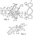
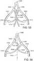
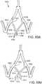
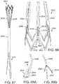
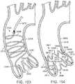
- FIG. 1is a perspective view showing an exemplary embodiment of a support stent or frame 10.
- Support stent 10has a generally annular or toroidal body formed from a suitable shape-memory metal or alloy, such as spring steel, cobalt-chromium alloy (Elgiloy®), or nitinol.
- a suitable shape-memory metal or alloysuch as spring steel, cobalt-chromium alloy (Elgiloy®), or nitinol.
- the material from which the support stent 10 is fabricatedallows the support stent to automatically expand to its functional size and shape when deployed but also allows the support stent to be radially compressed to a smaller profile for delivery through the patient's vasculature.
- the stentis not self expanding.
- other mechanisms for expanding the stentcan be used (e.g., a balloon catheter).
- the projection of the support stent 10 onto an x-y planehas a generally annular or toroidal shape.
- the illustrated support stent 10further defines a number of peaks and valleys (or crests and troughs) along its circumference.
- the support stent 10is sinusoidally shaped in the z direction.
- the support stent 10is shaped differently in the z direction (e.g., sawtooth-shaped, ringlet-shaped, square-wave shaped, or otherwise shaped to include peaks and valleys).
- the illustrated support stent 10includes three peaks 20, 22, 24 and three valleys 30, 32, 34.
- the peaks 20, 22, 24are positioned above the valleys 30, 32, 34 in the z direction.
- the peakshave greater radii than the valleys 30, 32, 34, or vice versa.
- the projection of the support stent 10 onto an x-y planeforms a closed shape having a variable radius (e.g ., a starfish shape).
- the size of the support stent 10can vary from implementation to implementation.
- the support stent 10is sized such that the support stent can be positioned within the aorta of a patient at a location adjacent to the aortic valve, thereby circumscribing the aortic valve.
- certain embodiments of the support stent 10have a diameter that is equal to or smaller than the diameter of the prosthetic heart valve when fully expanded.
- the support stentcan have an inner or outer diameter between 10 and 50 mm ( e . g ., between 17 and 28 mm) and a height between 5 and 35 mm ( e . g ., between 8 and 18 mm).
- the thickness of the annular body of the support stent 10may vary from embodiment to embodiment, but in certain embodiments is between 0.3 and 1.2 mm.
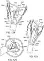
- FIG. 2is a perspective view of the exemplary support stent 10 positioned on the surface of an outflow side of a native aortic valve and further illustrates the shape of the support stent.
- the valleys 30, 32, 34 of the support stent 10are shaped so that they can be placed adjacent to commissures 50, 52, 54 of the native leaflets 60, 62, 64 of the aortic valve.
- the peaks 20, 22, 24are shaped so that they generally approximate or minor the size and shape of the leaflets 60, 62, 64 but are slightly smaller and lower than the height of the leaflets 60, 62, 64 at their tips when the aortic valve is fully opened.
- the peaks 20, 22, 24are oriented so that they are adjacent to the commissures 50, 52, 54 of the native leaflets 60, 62, 64 and the valleys are opposite the apexes of the leaflets 60, 62, 64.
- the support stent 10can be positioned in any other orientation within the aortic valve as well.
- the shape of the support stent or frame 10can vary from implementation to implementation.
- the support stentis not sinusoidal or otherwise shaped in the z-plane.
- the support stentis shaped as a cylindrical band or sleeve.
- the support stent or framecan be any shape that defines an interior through which a THV can be inserted, thereby causing the native leaflets of the aortic valve (or other heart valve) to be pinched or securely held between the support stent and the THV.
- the support stentcan have a more complex structure.
- the support stent illustrated in FIGS. 1 and 2is formed from a single annular member (or strut)
- the support stentcan comprise multiple annular elements that interlock or are otherwise connected to one another (e.g., via multiple longitudinal members).
- the illustrated support stent 10also include retaining arms 21, 23, 25 that can be used to help position and deploy the support stent 10 into its proper location relative to the native aortic valve.
- the retaining arms 21, 23, 25can have respective apertures 26, 27, 28.
- An exemplary deployment system and procedure for deploying the support stent 10 using the retaining arms 21, 23, 25are described in more detail below.
- the support stent 10can also have one or more barbs located on its surface. Such barbs allow the support stent 10 to be more securely affixed to the tissue surrounding the stent or the leaflets of the aorta.
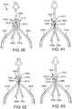
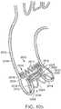
- FIGS. 3 and 4are side views of the distal end portion of an exemplary delivery apparatus 100 for delivering the support stent 10 to its location adjacent the native aortic valve through a patient's vasculature.
- FIG. 3shows the delivery apparatus when the support stent 10 is in a compressed, predeployed state
- FIG. 4shows the delivery apparatus when the support stent 10 is in a decompressed, deployed state.
- the delivery apparatus 100comprises a guide catheter 102 having an elongated shaft 104, whose distal end 105 is open in the illustrated embodiment.
- the distal end 105 of the guide catheter 102can be tapered into a conical shape comprising multiple "flaps" forming a protective nose cone that can be urged apart when the support stent 10 and any interior catheters are advanced therethrough.
- the guide catheter 102is shown as being partially cut away, thus revealing the catheters in its interior.
- a proximal end (not shown) of the guide catheter 102is connected to a handle of the delivery apparatus 100.
- the handlecan be used by a clinician to advance and retract the delivery apparatus through the patient's vasculature.
- the delivery apparatus 100is advanced through the aortic arch of a patient's heart in the retrograde direction after having been percutaneously inserted through the femoral artery.
- the guide cathetercan be configured to be selectively steerable or bendable to facilitate advancement of the delivery system 100 through the patient's vasculature.
- An exemplary steerable guide catheter as can be used in embodiments of the disclosed technologyis described in detail in U.S. Patent Application Publication No. 2007/0005131 ( U.S. patent application Ser. No. 11/152,288 ), which is hereby expressly incorporated herein by reference.
- the delivery apparatus 100also includes a stent delivery catheter 108 positioned in the interior of the guide catheter 102.
- the stent delivery catheter 108has an elongated shaft 110 and an outer fork 140 connected to a distal end portion of the shaft 110.
- the shaft 110 of the stent delivery catheter 108can be configured to be moveable axially relative to the shaft 104 of the guide catheter 102.
- the shaft 110 of the stent delivery catheter 108can be sized so that its exterior wall is adjacent to or in contact with the inner wall of the shaft 104 of the guide catheter 102.
- the delivery apparatus 100can also include an inner catheter 118 positioned in the interior of the stent deliver catheter 108.
- the inner catheter 118can have an elongated shaft 120 and an inner fork 138 secured to the distal end portion of the shaft 120.
- the shaft 120 of the inner catheter 118can be configured to be moveable axially relative to the shaft 104 of the guide catheter 102 and relative to the shaft 110 of the stent delivery catheter 108.
- the shaft 120 of the inner catheter 118can be sized so that its exterior wall is adjacent to or in contact with the inner wall of the shaft 110 of the stent delivery catheter 108.
- a guide wire(not shown) can be inserted into the interior of the inner catheter 118. The guide wire can be used, for example, to help ensure proper advancement of the guide catheter 102 and its interior catheters through the vasculature of a patient.
- a stent retaining mechanismis formed from the inner fork 138 attached to the distal end portion of the shaft 120 of the inner catheter 118 and the outer fork 140 attached to the distal end portion of the shaft 110 of the stent delivery catheter 108.
- the inner fork 138includes a plurality of flexible inner prongs 141, 142, 143 (three in the illustrated embodiment) at is distal end corresponding to the retaining arms 21, 23, 25 of the support stent 10, and a head portion 144 at its proximal end.
- the outer fork 140includes a plurality of flexible outer prongs 145, 146, 147 (three in the illustrated embodiment) at its distal end corresponding to the retaining arms 21, 23, of the stent 10, and a head portion 148 at its proximal end.
- the distal end portions of the outer prongs 145, 146, 147are formed with respective apertures 155, 156, 157 sized to receive the retaining arms 21, 23, 25.
- FIG. 6is a zoomed-in view of one of the retaining arms 21, 23, 25 as it interfaces with corresponding prongs of the outer fork 140 and the inner fork 138.
- retaining arm 21is shown, though it should be understood that the retaining mechanism is similarly formed for the retaining arms 23, 25.
- the distal end portion of the outer prong 145is formed with the aperture 155.
- the outer prong 145 and the retaining arm 21can be formed such that when the inner prong 141 is withdrawn from the aperture 26, the outer prong 145 flexes radially inward (downward in FIG. 7 ) and/or the retaining arm 21 of the support stent flexes radially outward (upward in FIG. 7 ), thereby causing the retaining arm 21 to be removed from the aperture 155.
- the retaining mechanism formed by the inner fork 138 and the outer fork 140create a releasable connection with the support stent 10 that is secure enough to retain the support stent to the stent delivery catheter 108 and to allow the user to adjust the position of the support stent after it is deployed.
- the connection between the support stent and the retaining mechanismcan be released by retracting the inner fork 138 relative to the outer fork 140, as further described below.
- the function of the inner fork and the outer forkcan be reversed.
- the prongs of the inner forkcan be formed with apertures sized to receive the corresponding retaining arms of the support stent and the prongs of the outer fork can be inserted through the apertures of the retaining arms when the retaining arms are placed through the apertures of the prongs of the inner fork.
- the head portion 144 of the inner forkcan be connected to the distal end portion of the shaft 120 of the inner catheter 118.
- the head portion 144 of the inner forkis formed with a plurality of angularly spaced, inwardly biased retaining flanges 154.
- An end piece of the shaft 120can be formed as a cylindrical shaft having an annular groove 121.
- the shaft 120can have a collar 122 with an outer diameter that is slightly greater than the diameter defined by the inner free ends of the flanges 154.
- the inner fork 138can be secured to the end piece by inserting head portion 144 of the inner fork onto the end piece of the shaft 120 until the flanges 154 flex inwardly into the annular groove 121 adjacent the collar 122, thereby forming a snap-fit connection between the head portion 144 and the shaft 120.
- the head portion 144can have a proximal end that engages an annular shoulder 123 of the shaft 120 that is slightly larger in diameter so as to prevent the head portion from sliding longitudinally along the shaft 120 in the proximal direction.
- the head portion 148 of the outer forkcan be secured to a distal end portion of the shaft 110 of the stent delivery catheter 108 in a similar manner. As shown in FIG. 5 , the head portion 148 can be formed with a plurality of angularly spaced, inwardly biased retaining flanges 155.
- An end piece of the shaft 110can be formed as a cylindrical shaft having an annular groove 111. On the distal side of the annular groove 111, the shaft 110 can have a collar 112 with an outer diameter that is slightly greater than the diameter defined by the free ends of the flanges 155.
- the outer fork 140can be secured to the end piece of the shaft 110 by inserting the shaft 110 onto the head portion 148 until the flanges flex inwardly into the groove 111, thereby forming a snap-fit connection between the head portion 148 and the shaft 110.
- the head portion 148can have a proximal end that engages an annular shoulder 123 of the shaft 110 that is slightly larger so as to prevent the head portion from sliding longitudinally along the shaft 110 in the proximal direction.
- the support stent 10is shown in a radially compressed state in the interior of the elongated shaft 104 of the guide catheter 102.
- the distance along the z axis between a peak and an adjacent valley of the support stentis greater than the distance along the z axis between the peak and the adjacent valley when the support stent is in it uncompressed state.
- the distal end portion of the shaft 104can also be referred to as a delivery sheath for the stent 10.
- the prongs of the outer fork 140 and the inner fork 138 of the stent delivery catheter 108 and the inner catheter 118engage the retaining arms 21, 23, 25 of the support stent 10 in the manner described above with respect to FIGS. 5 and 6 .
- the stent delivery catheter 108 and the inner catheter 118are advanced toward the distal end 105 of the guide catheter 102 using one or more control handles or mechanisms (not shown) located at the proximal end of the guide catheter 102. This action causes the support stent 10 to be advanced outwardly through the distal end 105 of the guide catheter 102 and expand into its relaxed, uncompressed state (shown, for example, in FIGS. 1 and 2 ).
- FIG. 4is a perspective view showing the support stent 10 after it has been advanced from the distal end of the guide catheter 102.
- the support stent 10now assumes its relaxed, uncompressed shape but remains connected to the outer fork 140 and the inner fork 138 at its retaining arms 21, 23, 25.
- the support stent 10can be rotated (in the clockwise or counter-clockwise directions) or repositioned (in the proximal and distal directions and/or into a different position in the x-y plane) into a proper orientation adjacent to its intended target area.
- the support stent 10can be positioned against the upper surfaces of leaflets of the aortic valve in the manner illustrated in FIG.
- a prosthetic valvee.g ., a THV
- a transapical approache.g., through the apex of the heart and through the left ventricle
- the prosthetic valveis secured in place by frictional engagement between the support stent, the native leaflets, and the prosthetic valve.
- the support stent 10is shaped so that the THV can be positioned in the interior of the support stent along with the native leaflets of the aortic valve. More specifically, the support stent 10 can be shaped such that the native leaflets become trapped or pinched between the support stent 10 and the exterior of the THV when the THV is installed.
- the diameter of the support stent 10can be equal to or smaller than the maximum diameter of the THV when fully expanded, thus causing the THV to be frictionally fit to the leaflets of the aortic valve and the support stent 10. This friction fit creates a solid foundation for the THV that is independent of the state or condition of the leaflets in the aortic valve.
- THVsare most commonly used for treating aortic stenosis, a condition in which the leaflets of the aortic valve become hardened with calcium.
- the hardened leafletstypically provide a good support structure for anchoring the THV within the aortic annulus.
- Other conditionsmay exist, however, in which it is desirable to implant a THV into the aortic valve and which do not result in a hardening of the leaflets of the aortic valve.
- the support stent 10can be used as a foundation for a THV when treating patients with aortic insufficiency. Aortic insufficiency results when the aortic annulus dilates such that the aortic valve does not close tightly.
- the aortic annulusis larger than normal and would otherwise require a large THV.
- a support stent or framesuch as the support stent or frame 10
- a smaller THVcan be used, thereby making the THV delivery process easier and safer.
- the use of a support stentprotects against displacement of the THV if there is any further dilation of the aortic valve.
- a support stentcan be used to secure a THV in any situation in which the aorta or aortic valve may not be in condition to help support the THV and is not limited to cases of aortic insufficiency.
- a support stent 10can be used in cases in which the aortic annulus is too dilated or in which the leaflets of the aorta are too weak or soft.
- the support stentcan be used to create an anchor for the THV, for instance, in cases in which the native leaflet tissue is too soft because of excess collagen in the aorta.
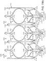
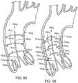
- FIGS. 7-13illustrate one exemplary procedure for deploying the support stent and securing a THV to the support stent.
- FIGS. 7-8are cross-sectional views through the left side of a patient's heart showing the acts performed in delivering the support stent 10 through the aortic arch to the aortic valve.
- FIGS. 9-13are cross-sectional views through the left side of a patient's heart showing the acts performed in deploying a THV 250 and having it engage the support stent 10.
- the guide catheter 102is shown partially cut away in FIGS. 7-13 .
- certain details concerning the delivery system of the THV 250are omitted.
- FIG. 7shows the guide catheter 102 of the delivery system 100 as it is advanced through the aortic arch 202 into a position near the surface of the outflow side of the aortic valve 210.
- the delivery system 100can be inserted through the femoral artery of the patient and advanced into the aorta in the retrograde direction.
- FIG. 7also shows the stent delivery catheter 108, the inner catheter 118, and the support stent 10.
- the support stent 10is in its radially compressed, predeployment state.
- the outer fork 140 and the inner fork 138which couple the radially compressed support stent 10 to the distal ends of the stent delivery catheter 108 and the inner catheter 118, respectively.
- FIG. 8shows the support stent 10 after it has been advanced through the distal end of the guide catheter 102 and assumes its final, uncompressed shape in a position above and adjacent to the aortic valve 210.
- the support stent 10can also be placed directly on the surface of the outflow side of the aortic valve.
- FIG. 8shows that the stent delivery catheter 108 and the inner catheter 118 have been advanced though the distal end of the guide catheter 102, thereby pushing the support stent 10 out of the guide catheter and allowing it to expand into its natural shape.
- the support stent 10is rotated and positioned as necessary so that the support stent generally circumscribes the aortic valve and so that the peaks of the support stent are aligned with the tips of the natural leaflets of the aortic valve 210. Therefore, when the THV is inserted and expanded within the aortic valve 210, the leaflets of the aortic valve will engage at least the majority of the surface in the interior of the support stent 10. This alignment will create an overall tighter fit between the support stent 10 and the THV.
- the support stent 10is rotated and positioned as necessary so that the peaks of the support stent 10 are aligned with the commissures or other portions of the aortic valve.
- the position of the guide catheter 102 and the support stent 10 relative to the aortic valve 210, as well as the position of other elements of the system,can be monitored using radiopaque markers and fluoroscopy, or using other imaging systems such as transesophageal echo, transthoracic echo, intravascular ultrasound imaging (“IVUS”), or an injectable dye that is radiopaque.
- the prongs of the outer fork 140 and the prongs of the inner fork 138are secured to the support stent 10 until the THV is deployed and frictionally engaged to the support stent.
- the inner and outer forksdesirably form a connection between the stent 10 and the delivery system that is secure and rigid enough to allow the clinician to hold the stent 10 at the desired implanted position against the flow of blood while the THV is being implanted.
- the support stent 10is self-expanding. In other embodiments, however, the support stent may not be self-expanding. In such embodiments, the support stent can be made of a suitable ductile material, such as stainless steel.
- a mechanism for expanding the support stentcan be included as part of the delivery system 100.
- the support stentcan be disposed around a balloon of a balloon catheter in a compressed state.
- the balloon cathetercan have a shaft that is interior to the inner catheter 118. Because the stent 10 is not self-expanding, the distal end portion of the guide catheter 102 need not extend over the compressed support stent.
- the support stent, balloon catheter, inner catheter 118, and stent delivery catheter 108can be advanced from the distal end of the guide catheter 102.
- the balloon portion of the balloon cathetercan be inflated, causing the support stent to expand.
- the balloon portioncan subsequently be deflated and the balloon catheter withdrawn into the delivery system 100 to remove the balloon from the interior of the support stent while the support stent remains connected to the inner catheter for positioning of the support stent.
- the delivery of the support stentotherwise proceeds as in the illustrated embodiment using the self-expanding support stent 10.
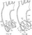
- FIG. 9shows an introducer sheath 220 passing into the left ventricle through a puncture 222 and over a guidewire 224 that extends upward through the aortic valve 210.
- the clinicianlocates a distal tip 221 of the introducer sheath 220 just to the inflow side of the aortic valve 210.
- the position of the introducer sheath 220 relative to the aortic valve 210, as well as the position of other elements of the system,can be monitored using radiopaque markers and fluoroscopy, or using other imaging systems.
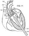
- FIG. 10shows the advancement of the balloon catheter 230 over the guidewire 224 and through the introducer sheath 220.
- the THV 250is located at the aortic annulus and between the native aortic leaflets.
- FIG. 11also illustrates retraction of the introducer sheath 220 from its more distal position in FIG. 10 .
- Radiopaque markersmay be provided on the distal end of the introducer sheath 220 to more accurately determine its position relative to the valve 210 and balloon 232.
- FIGS. 10-11do not show the front third of the support stent 10 or the corresponding outer and inner prong of the outer fork and the inner fork, respectively.
- FIGS. 12-13show the front third of the support stent 10 and the front of the THV 250, but do not show the portions of the native heart valve that would be secured by the front of the support stent 10. It is to be understood, however, that a corresponding leaflet of the native heart valve would be secured between the support stent 10 and the THV 250.
- the precise positioning of the THV 250may be accomplished by locating radiopaque markers on its distal and proximal ends.
- the cliniciancan adjust the position of the valve 250 by actuating a steering or deflecting mechanism within the balloon catheter 230.
- the rotational orientation of the valve 250can be adjusted relative to the cusps and commissures of the native aortic valve by twisting the balloon catheter 230 from its proximal end and observing specific markers on the valve (or balloon catheter) under fluoroscopy.
- One of the coronary ostia 280 opening into one of the sinuses of the ascending aortais also shown in FIG. 11 , and those of skill in the art will understand that it is important not to occlude the two coronary ostia with the prosthetic valve 250.
- FIG. 11shows the THV 250 in its contracted or unexpanded state crimped around the balloon 232.
- the balloon 232is expanded to engage the support stent 10 as seen in FIG. 12 .
- the engagement of the support stent 10 to the exterior of the THV 250pinches the leaflets of the aortic valve between the support stent and the THV 250, and thereby secures the THV within the annulus of the aortic valve.
- the inner catheter 118 of the delivery system 100can be retracted, thereby causing the prongs of the inner fork 138 to become disengaged from the retaining arms of the support stent 10.
- the prongs of the inner fork 138can be disengaged from the retaining arms by retracting the stent delivery catheter 108. Once disengaged from the support stent, the delivery system 100 can be retracted from the aortic arch and removed from the patient.
- valve 250can take a variety of different forms and may comprise an expandable stent portion that supports a valve structure.
- the stent portiondesirably has sufficient radial strength to hold the valve at the treatment site and to securely engage the support stent 10. Additional details regarding balloon expandable valve embodiments that can be used in connection with the disclosed technology are described in U.S. Pat. Nos. 6,730,118 and 6,893,460 , both of which are hereby expressly incorporated herein by reference.
- the balloon 232is deflated, and the entire delivery system including the balloon catheter 230 is withdrawn over the guidewire 224.
- the guidewire 224can then be withdrawn, followed by the introducer sheath 220.
- purse-string sutures 260 at the left ventricular apexcan be cinched tight and tied to close the puncture.
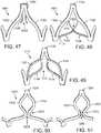
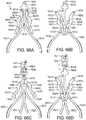
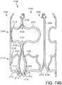
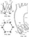
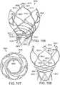
- FIGS. 14-16shows another embodiment of a support stent or frame 310 that can be used to help secure a THV into the interior of a native heart valve, such as the aortic valve.
- FIG. 14is a perspective view of the support stent 310
- FIG. 15is a top view of the support stent 310
- FIG. 16is a side view of the support stent 310.
- support stent 310has a generally annular or toroidal body formed from a suitable shape-memory metal or alloy, such as spring steel, cobalt-chromium alloy (Elgiloy®), or nitinol.
- the support stent 310is also radially compressible to a smaller profile and can self expand when deployed into its functional size and shape. In other embodiments, however, the support stent 310 is not self expanding.
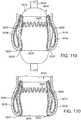
- the support stent 310includes a generally cylindrical main body portion 320 and a rim portion 330.
- the support stent 310can be a mesh structure, which can be formed, for example, from multiple elements in which approximately half of the elements are angled in a first direction and approximately half of the elements are angled in a second direction, thereby creating a criss-cross or diamond-shaped pattern.
- the rim portion 330has a greater diameter than the main body portion 320 and is formed as an extension at a bottom region of the main body portion that is folded outwardly from the main body portion and back toward a top region of the main body portion. The rim portion 330 thus forms a U-shaped rim or lip around the bottom region of the support stent 310.
- the rim portion 330is designed to have a diameter that is slightly larger than the walls of the aortic arch that surround the aortic valve.
- the rim portion 330expands to engage the surrounding aorta wall and frictionally secures the support stent 310.
- the main body portion 320defines an interior into which an expandable THV can be expanded and which further engages the native leaflets of the aortic valve.
- the main body portion 320operates in the same manner as the support stent 10 described above and illustrated in FIGS. 1-12 , whereas the rim portion 330 of the support stent 310 operates to secure the support stent in place by engaging the walls of the aorta that surround the aortic valve.
- the support stent 310further includes retaining arms 321, 322, 323 that can be used to help position and deploy the support stent 310 into its proper location relative to the native aortic valve.
- the retaining arms 321, 322, 323can have respective apertures 326, 327, 328.
- the retaining arms 321, 322, 323are constructed and function in a similar manner as retaining arms 21, 23, 25 described above in the embodiment illustrated in FIGS. 1-12 .
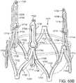
- FIGS. 17-18illustrate one exemplary procedure for deploying the support stent 310 and securing a THV 340 within an interior of the support stent.
- FIGS. 17-18are cross-sectional views through the left side of a patient's heart showing the acts performed in delivering the support stent 310 through the aortic arch to the aortic valve.
- certain details concerning the delivery system of the THV 340are omitted. Additional details and alternative embodiments of the delivery system for the THV 340 that may be used with the support stent described herein are discussed in U.S. Patent Application Publication No. 2008/0065011 ( U.S. application Ser. No. 11/852,977 ) and U.S. Patent Application Publication No. 2007/0005131 ( U.S. application Ser. No. 11/152,288 ), which are hereby expressly incorporated herein by reference.
- FIG. 17shows an outer catheter 352 (which can be a guide catheter) of a delivery system 350 as it is advanced through the aortic arch 302 into a position near the surface of the outflow side of the aortic valve 304.
- the delivery system 350can be inserted through the femoral artery of the patient and advanced into the aorta in the retrograde direction.
- FIG. 17also shows a stent delivery catheter 354, an inner catheter 356, and the support stent 310. Also seen in FIG. 17 are the outer fork 360 and the inner fork 362, which couple the support stent 310 to the distal ends of the stent delivery catheter 354 and the inner catheter 356, respectively.
- FIG. 17shows the support stent 310 after it has been advanced through the distal end of the guide catheter 352 and assumes its final, uncompressed shape in a position adjacent to the aortic valve 304.
- FIGS. 17-18do not show the entire front side of the support stent 310 or the corresponding valve leaflet that would be secured by the front side of the support stent 310. It is to be understood, however, that in practice the entire support stent 310 would exist and engage a corresponding leaflet of the native heart valve.
- the support stent 310can be positioned adjacent to the aortic valve 304 so that the rim portion 330 of the support stent engages the walls surrounding the aortic valve 304 and exerts an outward force against those walls, thereby securing the support stent 310 within the aorta.
- This positioningcan be achieved, for example, by advancing the guide catheter 352 to a position directly adjacent the aortic valve 304 while the stent delivery catheter 354 and the inner catheter 356 are undeployed and while the support stent 310 remains in its compressed state.
- the guide catheter 352can then be retracted while the stent delivery catheter 354 and the inner catheter 356 are held in place, thereby allowing the support stent 310 to expand toward its natural shape.
- the position of the guide catheter 352 and the support stent 310 relative to the aortic valve 304, as well as the position of other elements of the systemcan be monitored using radiopaque markers and fluoroscopy, or using other imaging systems such as transesophageal echo, transthoracic echo, IVUS, or an injectable dye that is radiopaque.
- the prongs of the inner fork 362can be disengaged from the corresponding apertures of the retaining arms of the support stent 310.
- the inner catheter 356can be retracted into the interior of the stent delivery catheter 354, thereby releasing the support stent 310 from the outer fork 360 and the inner fork 362.
- the delivery system 350can then be retracted from the aorta and removed from the patient's body.
- a THV(such as any of the THVs discussed above) can be introduced.
- a delivery system having a delivery catheter that is advanced through the patient's aortacan be used to deliver the THV.
- a transfemoral approachcan be used.
- any of the exemplary systems and methods described in U.S. Patent Application Publication No. 2008/0065011( U.S. application Ser. No. 11/852,977 ) or U.S. Patent Application Publication No. 2007/0005131 ( U.S. application Ser. No. 11/152,288 ) can be used with the support stent 310.
- the transapical approach shown in FIGS. 7-13can be used.
- FIG. 18shows delivery system 380 comprising an outer catheter 382 (which can be a guide catheter) and a balloon catheter 390 extending through the guide catheter.
- the balloon catheter 390has a balloon at its distal end on which the THV is mounted.
- the delivery system 380can be inserted through the femoral artery of the patient and advanced into the aorta in the retrograde direction.
- FIG. 18further shows a guidewire 392 that has been first inserted into the patient's vasculature and advanced into the left ventricle. The delivery system can then be inserted into the body and advanced over the guidewire 392 until the THV is positioned within the interior of the aortic valve.
- the THVis not only in the interior of the aortic valve 304 but also in the interior of the main body portion of the support stent 310.
- FIG. 18shows the THV 340 in its contracted (or unexpanded) state crimped around the balloon portion of the balloon catheter 390.
- the balloon of the balloon catheter 390can be expanded such that the THV 340 expands and urges the native leaflets of the aortic valve against the support stent 310, thereby securing the THV within the annulus of the aortic valve.
- the balloon of the balloon catheter 390is deflated, and the entire delivery system 380 including the balloon catheter is withdrawn over the guidewire 392. The guidewire 392 can then be withdrawn.
- a support stent and THVare delivered surgically to the desired heart valve (e.g ., in an open-heart surgical procedure).
- the support stent and THVare delivered surgically, non-compressible support stents and/or THVs are used.
- Aortic insufficiencycan cause dilatation of the ascending aorta, causing aneurisms, as well as the aortic annulus.
- embodiments of the present inventionprovide for anchoring of a deflector that directs blood away from the aneurysm while at the same time treating the insufficient heart valve.
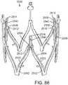
- a medical device 410 for treating AIincludes a support structure 412, a stent 414, a prosthetic valve 416 and a deflector 418.
- the support structure 412is configured, similar or the same as the support structures described hereinabove, to cooperate with the prosthetic valve 416 to pinch the native valve therebetween and provide an anchor for the stent 414 which extends into the aorta and supports the deflector 418 which is positioned to abate blood flow against the aneurysm.
- the support structure 412(stent or frame) includes, for example in FIG. 19 , peaks 420, 422, 424 and valleys 430, 432, 434 and retaining arms 421, 423, 425 defining apertures 426, 427, 428. Similar to the other embodiments of the support structures disclosed herein, a range of variations are possible for anchoring the both the stent 414 and the prosthetic valve 416 and the deflector 418.
- the shape of the support stent or frame 410can vary from implementation to implementation.
- the support stentis not sinusoidal or otherwise shaped in the z-plane.
- the support stentis shaped as a cylindrical band or sleeve.
- the support stent or framecan be any shape that defines an interior through which a THV can be inserted, thereby causing the native leaflets of the aortic valve (or other heart valve) to be pinched or securely held between the support stent and the THV.
- the support stentcan have a more complex structure.
- the support stent illustrated in FIG. 19is formed from a single annular member (or strut), the support stent can comprise multiple annular elements that interlock or are otherwise connected to one another ( e . g ., via multiple longitudinal members).
- the prosthetic valve 416 of the embodiment illustrated in FIG. 19is a THV that is similar to the one illustrated in FIG. 1 .
- THVTHV
- this particular usageis for illustrative purposes only and should not be construed as limiting.
- embodiments of the disclosed support structurecan be used to secure a wide variety of THVs delivered through a variety of mechanisms (e . g ., self-expanding heart valves, other balloon-expanding heart valves, and the like).
- any of the embodiments described in U.S. Pat. No. 6,730,118can be used with embodiments of the disclosed support structure.
- the stent 414is a scaffold that is coupled to the support structure 412 and extends from the support structure into the aorta (and over the insufficient portions of the aorta).
- the stent 414has a proximal end 430, a distal end 432, and a plurality of interconnected struts 434 defining a plurality of cells 436.
- the proximal (with respect to the heart) end 430 of the stent 414is connected or coupled to the support structure 412 by being formed therewith or attachment by wires or other supports.
- the support structure 412 and stent 414, including the plurality of interconnected struts 434may be laser cut from a single metal tube.
- couplingmay also be by assembly after separate formation, include assembly in vivo as each portion of the medical device 410 is delivered.
- the body of the stent 414that is formed by the interconnected struts 434 that define between them the cells 436.
- the interconnected struts 434are formed to promote flexibility and facilitate delivery through tortuous paths and extension over the aortic arch.
- the strut patternmay be as shown (as a flattened portion of a laser-cut blank prior to expansion) in FIG. 20 and include a plurality of rings 438 formed by sinusoidal struts connected end-to-end, wherein the rings are connected by a plurality of angled, flexible connectors 440.
- the rings 438may be formed to have variable lengths and the connectors 440 selectively located to promote directional preferences in flexibility and/or variations in cell sizes between them.
- LIFESTENTmanufactured by C.R. BARD, INC. which has a multi-dimensional helical structure that facilitates its use in tortuous paths of peripheral vasculature. Aspects of the LIFESTENT are described in U.S. Pat. No. 6,878,162 entitled “Helical Stent Having Improved Flexibility and Expandability" by Bales et al.
- the stent 414when extending along the aortic arch, has a tightly curved configuration with an external, long curvature 442 and an internal curvature 444.
- the cell sizesmay be larger to allow for the longer path length.
- These cell sizesmay be programmed into the stent by selective cutting and formation of the struts and cells and/or may appear due to the mechanical application of insertion and delivery into the aortic arch.
- the internal curvature 444may be programmed through selection of the strut structure and/or due to delivery.
- the stent 414may include structure that facilitates engagement, frictional or mechanical, of the surrounding lumen (e.g ., the aorta) where the lumen is in adjacent contact with the stent.
- the struts 434 and cells 436may have a pattern that facilitates frictional engagement, or may have barbs or hooks or microanchors or flared portions formed thereon to mechanically engage the lumen and facilitate the support structure 412's role of securing the medical device 410.
- the distal end 432 of the stent 414is positioned within the aortic arch distal the branch (e . g ., brachiocephalic, common carotid and left subclavian) arteries extending off of the aorta.
- the distal end 432may be a termination of the last row of the rings 438 or may include its own retaining arms 446 defining apertures 448. Use of the retaining arms 446 and apertures 448 enables use of the delivery apparatus 110 shown in FIGS. 3 and 4 and described hereinabove.
- the distal end 432may also include structure configured to engage the surrounding lumen walls for additional security of the medical device 410. For example, it may include hooks or barbs or micro anchors.
- the cells 436may include a relatively large cell structure positioned over and near the branch arteries. This facilitates perfusion of the branch arteries, such as by being located over the branch arteries at the aortic arch or closer to the valve for communication with the coronary arteries.
- the cell structureis relatively large in comparison to the remaining cells configured to support the lumen walls or abate blood flow against aneurysms or further vascular dilatation.
- the cell sizemay be selected to guard the branch arteries against embolic debris, so as to act as a partial deflector of such debris.
- the length of the device 410may be enough to extend from the native leaflets, through the sinus of valsalva, into the ascending aorta, over the aortic arch and potentially into the descending aorta.
- the length of the device 410may be 30 mm to 100 mm or longer.
- the stent 414may also be tapered, small at the annulus to larger at the ascending aorta, columnar or have ends that are a larger diameter for sealing and anchoring, as shown in FIG. 21 .
- this support structure 412 and stent 414act like a scaffold or anchoring device for other devices to be deployed inside of it, such as the prosthetic valve 416, which is delivered and anchored as described above, and one or more deflectors 418.
- the deflector 418is a covered stent or graft that is relatively impermeable ( e . g . to blood flow and is configured for positioning over an aneurysm in the aortic arch so as to direct blood flow away from the aneurysm.
- the deflector 418 of the embodiment of FIG. 19includes a deflector stent 450 supporting a tubular graft material 452 extending around the deflector stent.
- the deflector 450is mounted within the stent 414 as would a graft being fit within a vessel without the stent 414.
- the deflector 450may be delivered by a catheter extending retrograde to blood flow within the aorta, or extending from the heart chamber and through the aortic valve, and then expanded (or allowed to expand) once the desired location is reached.
- the stent 414guards the aneurysm against the expansion pressure of the deflector 418 and the deflector can have a much smaller expanded diameter than the aneurysm and still is assured of a firm anchor.
- Deployment of the medical device 410 of FIG. 19may include first deploying the support structure 412 and the stent 414 (if they're integrally attached to each other). Then, through the support structure 412 and the sent 414 the THV prosthetic valve 416 is delivered, anchoring it into the proximal end of the device (either the support structure 412 or the stent 414). The covered stent or graft deflector 418 is deployed in the stent 414, covering the area that has the aneurysm and avoiding the branch arteries and associated larger cells 436 of the stent 414. The deflector 418 would then redirect the pulsating blood away from the aneurysm so as to prevent dissection, and the new valve prosthesis 416 would ensure that correct blood flow is restored.
- the deflector 418is shown in FIG. 19 as being a single graft or covered stent, the term “deflector” should be construed broadly herein to include any structure that serves to abate (reduce) blood flow against the selected portion of the vessel wall.
- deflectors 418 in the form of grafts or covered stentscould be delivered and positioned to address anatomical variations in size and positioning of the aneurysm(s).
- the deflector 418need not be a tubular structure but could be a sheet or shield of material anchored to one side of the stent 414.
- the deflector 418need not be separately attached, but could be a portion of the stent 414 with reduced permeability, such as through a polymeric coating.
- FIG. 21shows another example wherein the stent 414 is covered with a deflector 418 at the time of delivery.
- FIG. 22shows another example wherein the stent 414 is covered with a deflector 418 in the form of a balloon 454.
- the balloonnot only deflects blood flow, but also can be inflated so as to expand into and fill the space between the stent 414 and the aneurysm wall.
- Inflationmay be by fluid, such as saline wherein the balloon may include a one-way check valve that stops outflow of the saline after detachment of the inflation lumen.
- inflationmay be by a polymer or other fluid that sets or cures or thickens and can therefore maintain the fill shape after intervention is complete.
- the expansion forces of the balloon 454are sufficiently low so as to not further expanded the aneurysm but at the same time cause the balloon to take the shape of the aneurysm space.
- the balloontherefore, may be comprised of a very pliable material such as a silicone that expands under low pressure and/or may even include a woven material.
- a very pliable materialsuch as a silicone that expands under low pressure
- the woven materialmay have a limit to expansion and will protect the aneurysm from dissection if the woven balloon is fashioned to fit the aneurysm.
- FIG. 23shows another example wherein the stent 414 is covered with a deflector 418 in the form of a foam sleeve 456.
- the foammay be an open celled foam or a closed-cell foam that promotes friction with the surrounding lumen at initial implantation. If open celled the blood will in-grow and create a barrier for the blood not to pass along the aortic wall.
- the foammay be configured for up to 300% compression.
- the foammay be configured, such as by being hydrophilic, to absorb and expand in blood and fill the space between the stent 414 and the lumen.
- a skin or impermeable layercan be also applied to the stent 414 or foam sleeve 456 so that the foam does not peel/break off and cause an embolism.
- the skin or impermeable layerinhibits seep of the passing blood through the foam to the aortic wall.
- an inner surface of the foam sleeve 456may have a relatively impermeable skin (such as a closed cell foam) to promote passage of blood therethrough while the outer surface is open celled and permeable for expansion.
- the foammay also have coagulation properties that promote buildup of clots to help secure the medical device 410 and fill the aneurismal space.
- the foammay include, for example, a flexible ester polyurethane, reticulated open cell, felted foam with a pore size of 80-100 ppi, a density of 5.4-6.3 pcf.
- thick woven sleevesmay be used that expand in response to absorbing blood, such as a hydrophilic weave or foam.
- the foam sleeve 456is crimped down with the stent 414 and then placed in the aorta of the patient.
- the stent 414expands and maintains its more rigid shape, whereas the foam can also expand and take up the current shape of the aorta.
- the foamadvantageously fills the void between the stent 414 and the aneurysm wall, preventing blood (the continued pulse force) from reaching the aneurysm.
- the foam sleeve 456creates a seal within the aorta forcing blood to be passed through the stent 414 diameter. It also has effective friction or outward forces on the aortic wall so as to restrict movement.
- FIG. 24shows another example wherein the deflector 418 has an annulus or donut shape, such as a foam or balloon annulus. With its reduced length, the donut may be positioned at the location of the aneurysm, thereby blocking the flow of blood to this particular section of the aortic wall.
- an annulus or donut shapesuch as a foam or balloon annulus.
- FIG. 25shows another example including two donut or annulus shaped deflectors 418 on the stent 414 which aid in retention of the device within the aorta.
- donutsmay be placed on opposite sides of the aneurysm and seal the aneurysm against blood flow.
- the donutsmay be foam, balloons or other expansion members.
- the deflector 418may include micro anchors attached to the foam or balloon section to aid in retention if the expansion force of the foam or balloon is not suitable in larger aortas.
- the deflector 418may include mechanical clot facilitators such as wires, coils or springs that fill the space between the stent 414 and the aneurysm walls to promote embolization therebetween.
- mechanical clot facilitatorssuch as wires, coils or springs that fill the space between the stent 414 and the aneurysm walls to promote embolization therebetween.
- FIG. 26shows another embodiment of the present invention wherein the deflector 418 (in the form of a graft) may include a seal 458 in the form of a slit configured to allow passage into the interior of the stent 414.
- the seal 458may include overlapping portions or lips of the graft material that self-seal by closing up after removal of delivery tool.
- the sealmay be a valve, such as a duckbill valve.
- the graft 418 with the seal 458may be used in a during a "trans-aortic" THV implantation wherein the graft is first deployed in a percutaneous delivery.
- the THVis then delivered through the chest wall with a delivery tool (e.g ., a catheter) and through a slit in the aorta (aortotomy) and finally through the slit or seal 458 in the graft.
- the slitthen seals around the delivery tool to prevent blood loss.
- the THVis expanded into place within the support structure 412 or stent 414.
- the seal 458closes when the delivery tool is removed, allowing the aorta to be sutured without blood escaping.
- the graft 418could be left behind - or it could be retrieved after completion of the procedure.
- Such a seal 458may be employed in a range of embodiments with the deflector 418, including the embodiments disclosed herein.
- FIG. 27shows another embodiment wherein the deflector 418 has an hourglass shape and is constructed of a resilient material that deflects in response to increased blood pressure of a heart beat and adds additional pumping action as the arterial pressure drops.
- the hourglass shapeis formed of resilient walls that deflect under pressure and spring back into shape as the pressure drops.
- the walls of the graftmay be relatively thick for an increased resiliency and additional pumping action.
- two anchoring stentsmay be connected by an elastic tube (e.g ., made out of silicone).
- One of the anchorsis deployed in the STJ (right above the native valve) and the other anchor is deployed on the other end of the aneurysm somewhere in the ascending aorta prior to the branches.
- the elasticity of the tubewould aid the heart's pumping action.
- each of the medical devices 410 described hereinis capable of a large amount of compression.
- the device 410including the embodiment of the stent 414 and its foam sleeve 456, can be compressed or crimped to a diameter that is 8 mm or less. Uncompressed, the diameter may be 50 mm to 90 mm.
- a method of using the medical device 410 disclosed hereinincludes delivering the support structure 412 to a position on or adjacent to the surface of the outflow side of the native heart valve of the patient, wherein the support structure defines a support-structure interior.
- the expandable prosthetic heart valve 416is delivered into the native heart valve and into the support-structure interior.
- the expandable prosthetic heart valve 416is expanded while it is in the support-structure interior and while the support structure is at the position on or adjacent to the surface of the outflow side of the native heart valve. This causes one or more of the native heart valve leaflets to be frictionally secured between the support structure 412 and the expanded prosthetic heart valve 416.
- the stent 414which is coupled to the support structure 412 either by co-formation or later attachment, is extended into a vessel (such as the aorta) extending from the native heart valve.
- the deflector 418is already present on the stent 414 and/or is delivered into and attached to the stent 414. Blood flow against the vessel is abated by the deflector 418.
- the methodalso may include delivering the stent 414 (or portions thereof) to a position adjacent the support structure 412 and coupling it to the support structure prior to extending the stent into the vessel.
- the deflector 418may be delivered to a support position on the stent 414 and coupled to the stent in vivo.
- the portionscould be individually delivered and coupled to each other in vivo.
- the methodincludes avoiding arteries extending from the vessel when positioning the deflector.
- the methodmay include expanding the deflector 418 to fill at least a portion of the space between an external surface of the stent 414 and the vessel.
- FIG. 29shows another embodiment of a support stent or frame 500 that can be used to treat valve insufficiency (e . g ., aortic insufficiency, mitral insufficiency, etc.), or to help secure a THV within the interior of a native heart valve.
- the support stent 500comprises an annular main body 501 formed by a plurality of angled struts 502 arranged in a zig-zag pattern and having one or more apices 504 formed by the intersection of two adjacent struts.
- the struts 502can be configured such that there is a gap 506 between adjacent struts underneath the apices 506 that receives portions of two adjacent leaflets forming a commissure of a native valve, as shown in FIG. 30 .
- the support stenthas a gap 506 for each commissure of the native valve where the support stent is to be implanted.
- the support stent 500desirably has three, angularly spaced gaps 506, with each gap being positioned at a commissure of the native valve when the support stent 500 is implanted.
- the gaps 506can be dimensioned to pinch or clamp adjacent leaflets to each other at respective commissures.
- the support stentdesirably has two gaps 504. In this manner, the support stent 500 can retain or clamp the native valve leaflets together, thereby reducing the effective orifice area of the valve which, in turn, can reduce regurgitation through the valve.
- a THVcan be deployed within the native valve, using a stent 500 as dock as shown in FIGS. 10-13 .
- the stent 500 and the THVcan be implanted in the same procedure, using the stent 500 as the dock for the THV.
- stent 500simplifies the procedure since the stent 500 can "clip" onto the commissures of the native leaflets and retain its position once deployed, which obviates the need to hold the stent in place using one catheter while the THV implanted using another catheter as is shown in FIG. 12 .
- the support stent 500can also be used to treat native valve insufficiency by reducing the diameter of the valve annulus.
- the support stent 500can be anchored in the valve annulus by one or more microanchors 508 comprising one or more sets of barbs 510.
- Exemplary embodiments of microanchors that can be used with the disclosed technologycan be found in U.S. Patent Application No. 13/910,975 ( U.S. Publication No. 2013/0331930 ), which is incorporated herein by reference.
- the microanchors 508can be positioned in the gaps 506 adjacent the apices 504 of the support stent and can be embedded in the tissue of the valve annulus.
- One or more sutures 512 coupled to the microanchors 508can extend upwardly toward a delivery system (not shown) and can comprise one or more suture securement devices, such as a suture clip 514.
- the suture clip 514can be configured to travel along the sutures 512 in the direction indicated by arrow 516 (i.e., toward the microanchors 508).
- tensionis applied to the sutures 512 (by pulling upwardly on sutures and/or pushing downwardly on the suture clip) the suture clip can resist travel of the sutures 512 through the suture clip 514 in the opposite direction (i.e., the suture clip can resist downward travel of the sutures relative to the clip).
- Exemplary embodiments of suture securement devices that can be used with this technologycan be found in U.S. Patent Application No. 13/938,071 ( U.S. Publication No. 2014/0031864 ), which is incorporated herein by reference.
- the suture clip 514retains tension on the sutures 512, thereby retaining the support stent and the surrounding tissue in the reduced diameter state after implantation. In this manner, the support stent 500 can be used to reduce the diameter of the valve annulus.
- the support stent 500can be implanted in a procedure in which the microanchors 508 are deployed adjacent the commissures of the native valve with each microanchor 508 being provided with a suture 512 that can extend to a delivery apparatus and/or outside the body.
- three microanchors 508(each having a respective suture) can be implanted.
- the sutures 512can be threaded through openings in the apices 504 of the support stent 500, which can then be advanced along the sutures until it is placed against the aortic surface of the native leaflets.
- a suture clip 514can be advanced down the sutures 512 to tension the sutures and draw the surrounding tissue inwardly to reduce the diameter of the native annulus (as depicted in FIGS. 31-32 ).
- the support stent 500can be made of a self-expanding material (e.g., Nitinol) and is delivered and deployed using an expansion mechanism (e.g., a balloon catheter).
- an expansion mechanisme.g., a balloon catheter.
- the expansion mechanismover expands the support stent (i.e., expands the support stent radially beyond its functional size) (such as by inflating the balloon of the balloon catheter) and places the support stent against the aortic surface of the native valve.
- the support stent 500can have barbs or anchors 508 can that engage, penetrate and/or grab adjacent tissue as the support stent 500 is placed against the native tissue.
- the support stent 500can be configured to clip onto commissures of the native valve when the commissures are placed in gaps 506.
- the expansion mechanismthen releases the support stent 500 (such as by deflating the balloon), allowing the support stent to shrink/return to its natural or functional size, pulling the surrounding tissue inwardly to reduce the size of the native annulus.
- the aortic annuluscan be reduced in size by suturing the support stent 500 in its functional size to the aortic valve.
- FIG. 33shows another embodiment of a support stent or frame 600 that can be used to treat heart valve insufficiency or help secure a THV within the interior of a native heart valve, such as the aortic valve.
- the support stent 600comprises an annular main body 601 formed by a plurality of angled struts 602 arranged in zig-zag pattern.
- the support frame 600can include one or more leaflet-engaging mechanisms 603.
- the leaflet-engaging mechanisms 603can comprise pairs of leaflet-engaging members 604 secured to respective struts 602 below one or more apices 606 formed by the intersection of the two adjacent struts 602.
- Each leaflet-engaging member 604has a fixed end portion 608 secured to a respective strut and a free end portion 610.
- the leaflet-engaging members 604extend upwardly toward the apex 606 and toward each other. In their normal, unbiased (i.e., non-deflected) state, the leaflet-engaging members 604 can be configured such that there is a small gap between respective free end portions 610 that receives portions of two adjacent leaflets 616 forming a commissure of a native valve, as further described below.
- the struts 602 and the leaflet-engaging members 604can be laser cut (or otherwise machined or formed) from a single piece of material ( e . g ., a tubular piece of metal) such that the leaflet-engaging members 604 are integral to the support stent. In other embodiments, the leaf springs 604 can be separately formed and welded to the struts 602.
- the support stenthas a pair of leaflet-engaging members 604 for each commissure of the native valve where the support stent is to be implanted.
- the support stent 600desirably has three, angularly spaced pairs of leaflet-engaging members 604, with each pair being positioned underneath an apex 606 that is positioned at a commissure of the native valve when the support stent 600 is implanted.
- the support stentdesirably has two pairs of leaflet-engaging members 604.
- the number of pairs of leaf springscan be less than the number of commissures of the native valve where the support stent is to be implanted.
- the support stent 600can have retaining arms 612 for releasably securing the support stent 600 to a delivery apparatus (e.g., delivery apparatus 350).
- FIG. 34shows the support stent 600 implanted in the aortic root behind the leaflets 616 of an aortic valve 614.
- the support stent 600can be mounted in a compressed state on a delivery apparatus 350 ( FIG. 17 ) and delivered to the vicinity of the native aortic valve, as described in detail above.
- the support stent 600can be deployed from the catheter 352, allowing the support stent to expand to its functional size.
- Each pair of leaflet-engaging members 604is rotationally aligned within one of the commissures of the aortic valve.
- each pair of leaflet-engaging members 604is further advanced toward the aortic valve, causing each pair of leaflet-engaging members 604 to slide over a pair of native leaflets 616 of one the commissures of the aortic valve.
- the gap between the free end portions 610 of the leaf springsis such that insertion of the native leaflets 616 can place the leaf springs in tension and pinch the native leaflets between the leaf springs.
- a THVcan be implanted within the interior of the aortic valve 614 (as shown in FIG. 18 ) and expanded against the native leaflets 614, which in turn are pressed radially outwardly against the support stent.
- FIG. 35shows a modification of the support stent 600 having leaflet-engaging members 604 with spherical free end portions 618 that are configured to contact each other in their normal, unbiased (non-deflected) state.
- the curved outer surfaces of the spherical free end portions 610can help to engage the native leaflets placed between the spherical free end portions 618 without damaging the leaflets.
- the leaflet-engaging members 604can flex such that the spherical free end portions 618 move upwardly and away from each other to allow the leaflets to slide between the spherical free end portions 618 (as depicted in FIG. 35 ).
- FIG. 36shows another modification of the support stent 600 having leaflet-engaging members 604 with curved free end portions 620, which can enhance the retention force against the leaflets while minimizing bulkiness of the leaflet-engaging members 604.
- FIG. 37shows the support stent of FIG. 36 implanted within the aortic root with a pair of leaflets 616 captured between the free end portions 620 of the leaflet-engaging members 604.
- FIG. 38shows another modification of the support stent 600 having a single leaflet-engaging member 604 below one or more selected apices 606.
- the leaflet-engaging member 604is configured to capture a pair of leaflets 616 between a spherical free end portion 618 of the leaflet-engaging member 604 a protrusion 622 extending toward the leaflet-engaging member 604.
- the protrusion 622is shaped to snag or bind against the adjacent leaflet 616 to help retain the leaflets 616 in place between the leaflet-engaging member 604 and the protrusion.
- the leaflets 616can be captured between the spherical free end portion 618 of the leaflet-engaging member 604 and the surface of an adjacent strut 602.
- FIG. 39illustrates another modification of the support frame 600, wherein the leaflet-engaging members 604 are configured to extend from distal apices 624 formed by the intersection of two adjacent struts 602 at the outflow end of the support frame 600.
- FIG. 40shows another embodiment of support stent 700 comprising an annular main body 701 (shown flattened) formed by a plurality of struts 702. Positioned beneath one or more selected apices 704 of the support stent are leaflet-engaging mechanisms 705 comprising pairs of leaflet-engaging members 706 configured to capture a respective pair of native leaflets.
- each leaflet-engaging member 706has a first end 708 secured to a strut 702 and a second end 710 secured to the same strut 702.
- Each leaflet-engaging member 706can have a plurality of curved sections 712 extending between the first and second ends 708, 710, respectively, allowing adjacent leaflet-engaging members 706 of a pair to deflect away from each other while a pair of native leaflets are inserted therebetween.
- Each pair of leaflet-engaging members 706can also apply sufficient compressive force against the leaflets once they are in place between the leaflet-engaging members 706 such that the leaflets are retained between the leaflet-engaging members 706.
- the leaflet-engaging members 706can be configured to define a small gap between the curved sections 712 of adjacent members 706.
- the curved sections 712can define points of contact that can contact corresponding contact points of an adjacent member 706 when the members 706 are in their non-deflected state.
- FIG. 41illustrates another embodiment of a support frame 800 shown in a flattened or unrolled state for purposes of illustration.
- the support frame 800comprises an annular main body 801 formed by a plurality of struts 802, and one or more leaflet-engaging mechanisms 803.
- the leaflet-engaging mechanisms 803can comprise pairs of semi-annular leaflet-engaging members 804 positioned beneath respective apices 806 of the support frame.
- Each leaflet-engaging member 804 in the illustrated embodimentcomprises first and second fixed end portions 808, 810 secured to a respective strut 802 and a peak 812 formed by a portion of the leaflet-engaging member 804 intermediate the two fixed end portions 808, 810.
- the leaflet-engaging members 804can extend generally in the direction of the outflow end of the support frame 800 such that the first fixed end portion 808 is closer to the apex 806 than is the peak 812.
- FIG. 42shows the support frame 800 implanted in the aortic root 814 with the native leaflets 816 of the aortic valve 818 captured between respective pairs of leaflet-engaging members 804.
- FIG. 43shows another embodiment of a support stent 900 comprising a plurality of struts 902 and a plurality of leaflet-engaging mechanisms 903.
- the leaflet-engaging mechanisms 903can comprise clipping members 904 secured to distal apices 916 of the struts 902 at the inflow end of the support stent 900.
- FIG. 44shows a clipping member 904 apart from the support stent 900.
- Each clipping member 904comprises two leg portions 906 secured to each other at an apex 908.
- Each leg portion 906has a free end portion 910 that can be angled inwardly toward the other free end portion 910 as shown.
- Each clipping member 904can be secured to the support frame 900 with a section of fabric cloth 912 that extends around the apex 908 of the clipping member 904 and an adjacent distal apex 916 of the support frame 900 at the inflow end of the support frame. Sutures can be used to secure the cloth 912 in place around the clipping member 904 and the adjacent distal apex 916 of the support frame 900. As can be seen in FIGS. 43 and 45 , two leg portions 906 of adjacent clipping members 904 can extend toward each other for capturing a pair of native leaflets 914.
- the clipping members 904can be separately formed from the support frame 900, and can be fabricated from metal wire having a diameter that is smaller than the diameter of the struts 902.
- the diameter of the clipping members 904can be from about 0.010 inch to about 0.023 inch.
- Each leg portion 906 of the clipping members 904can also have a length L of, for example, 5 mm or greater ( FIG. 46 ). In this manner, the clipping members 904 can be configured to apply an inward retaining force Fin on the aortic valve leaflets, as shown in FIGS. 45 and 46 .
- the retaining force F incan be about 3 N.
- the clipping members 904can also have a removal force F R needed to remove or reposition the device 900 along the leaflets 914, and a buckling force F B oriented axially with respect to struts 902.
- the removal force F R and the buckling force F Bcan be configured such that the application of the required removal force F R can result in a buckling force F B sufficient to cause the clipping members 904 to bend or buckle, thus reducing the risk of tearing the native valve leaflets 914 when repositioning or removing the support frame 900.
- the removal force F Rcan be about 6 N.
- the clipping members 904can be integrally formed with the support frame 900.
- FIG. 47shows another embodiment of support stent 1000 comprising an annular main body formed by a plurality of struts 1002. Positioned beneath one or more selected apices 1004 of the support stent 1000 are leaflet-engaging mechanisms 1003 comprising horseshoe-shaped leaflet-engaging members 1006 configured as clips corresponding to each of the three commissure locations of the native aortic valve. Each of the leaflet-engaging members 1006 can be configured to capture a respective pair of native leaflets at each commissure of the aorta.
- the leaflet-engaging members 1006 and support frame 1000can be integrally manufactured or separately manufactured and subsequently assembled using any suitable method or combination of, for example, welding, tying with suture or wire, adhesive, mechanically fastening, and the like.
- the phrases "integrally manufactured,” “integrally formed,” and “integral to”all refer to a construction that does not include any adhesive, fasteners, or other means for securing separately formed pieces of material to each other.
- FIGS. 48 and 49illustrates fragmentary views of another embodiment of a support frame 1100 comprising an annular main body formed by a plurality of struts 1102.
- the support frame 1100can comprise one or more leaflet-engaging mechanisms 1103 including a pair of integrated leaflet-engagement members 1104.
- the leaflet-engaging members 1104can be positioned beneath selected apices 1106 and can be configured to capture respective pairs of native leaflets.
- each leaflet-engaging member 1104has a first end 1108 secured to a strut 1102 and a second end 1110 secured to the same strut 1102.
- Each leaflet-engaging member 1104can be spring-biased, allowing adjacent leaflet-engaging members 1104 of a pair to deflect away from each other when a pair of native leaflets are inserted between the leaflet-engaging members 1104.
- the leaflet-engaging members 1104can be configured to apply force against the leaflets such that the leaflets are retained between the leaflet-engaging members 1104.
- the curved leaflet-engaging members 1104can define points of contact that contact corresponding contact points of an adjacent member 1104 when the members 1104 are in their non-deflected state.
- the members 1104can be configured to define a small gap between the curved sections of adjacent members 1104, as shown in FIG. 49 .
- the members 1104can also have diameters greater than, equal to ( FIG. 49 ), or less than ( FIG. 48 ) the diameter of the struts 1102 depending on, for example, the degree of spring-bias desired.
- FIGS. 50 and 51illustrate a fragmentary view of another embodiment of a support stent 1200 comprising an annular main body formed by a plurality of struts 1202. Beneath one or more selected apices 1204, the struts 1202 can be curved or otherwise shaped such that adjacent struts define a leaflet-engaging mechanism 1203 having a narrow leaflet-engagement region 1206 between the struts 1202.
- the leaflet-engagement region 1206can comprise a gap dimensioned to grip the native aortic valve leaflets.
- the struts 1202can be spring-biased, allowing adjacent pairs of struts 1202 to deflect away from each other when a pair of native leaflets are inserted between the struts 1202, and causing the struts 1202 to apply force against the leaflets sufficient to retain the leaflets in place between the struts 1202.
- the leaflet-engagement region 1206can include teeth or serrations 1208 configured to engage the native leaflets, thereby helping to keep the frame 1200 in place after implantation.
- FIG. 52shows another embodiment of a stent 1300 comprising an annular main body formed by a plurality of struts 1302.
- the support frame 1300can include leaflet-engaging mechanisms 1303 located beneath select apices 1304 and defined by the struts 1302.
- the struts 1302can be separated by narrow leaflet-engagement regions 1306.
- the leaflet-engagement regions 1306can comprise serrations 1308 configured to engage native leaflets when they are inserted between the struts 1302. In this manner, the stent 1300 can be held in place after implantation.
- FIGS. 53-55there is shown another embodiment of a support frame 1400 comprising an annular main body 1401 (shown flattened in FIG. 53 ) formed by a plurality of struts 1402.
- the support frame 1400can comprise one or more leaflet-engaging mechanisms 1403, which can include a pair of leaflet-engaging members 1404 secured to respective struts 1402 below one or more apices 1406 formed by the intersection of two adjacent struts 1402.
- Each leaflet-engaging member 1404can have a fixed end portion 1408 secured to a respective strut 1402 and a free end portion 1410.
- the leaflet-engaging members 1404can extend downwardly from near the apices 1406 at the outflow end of the support frame 1400 and toward each other, defining a narrow leaflet-engaging region 1405, before curving toward the struts 1402 near the inflow end of the frame 1400.
- the leaflet-engaging members 1404in their normal, unbiased (non-deflected) state, can be configured such that there is a small gap between free end portions 1410 and the struts 1402. In this manner the leaflet-engaging members 1404 can deflect toward adjacent struts 1402 when the leaflets 1414 of a native valve are inserted therebetween, as shown in FIG. 55 .
- the struts 1402 and the leaflet-engaging members 1404can be laser cut (or otherwise machined or formed) from a single piece of material (e.g., a tubular piece of metal) such that the leaflet-engaging members 1404 are integral to the support stent.
- the leaflet-engaging members 1404can be separately formed and welded to the struts 1402.
- the support frame 1400can comprise a pair of leaflet-engaging members 1404 located beneath each apex 1406 of the frame. This can make implantation of the support frame 1400 easier by reducing the amount by which the frame 1400 must be rotated in order to line up the pairs of leaflet-engaging members with the commissures of the native valve.
- the support frame 1400can have a pair of leaflet-engaging members 1404 for each commissure of the native valve where the support frame is to be implanted.
- the support frame 1400when the support frame 1400 is intended to be implanted at the aortic valve or the pulmonary valve, the support frame 1400 desirably has three, angularly spaced pairs of leaflet-engaging members 1404, with each pair being positioned underneath an apex 1406 that is positioned at a commissure of the native valve when the support frame 1400 is implanted.
- the support frame 1400desirably can have two pairs of leaflet-engaging members 1404.
- the number of pairs of leaflet-engaging members 1404can be less than the number of commissures of the native valve where the support stent is to be implanted.
- the support stent 1400can also have retaining arms 1412 ( FIG. 53 ) for releasably securing the support stent 1400 to a delivery apparatus (e.g., delivery apparatus 350).
- FIG. 56shows a modification of the support stent 1400 having leaflet-engaging members 1404 that overlap one another in their normal (non-deflected) state.
- the leaflet-engaging members 1404can be configured to retain the native valve leaflets 1414 by applying a preload to the leaflets 1414 once they are captured between the leaflet-engaging members 1404.
- the overlapping region of the leaflet-engaging members 1404is offset from a central axis 1416 extending though apex 1406, and the respective fixed end portions 1408 of the leaf springs are vertically offset from one another.
- the respective leaflet-engaging members 1404can overlap symmetrically about the central axis 1416 of the stent, and the fixed end portions 1408 can be fixed to the respective struts 1402 at the same vertical position.
- the free end portions 1410 of the leaflet-engaging members 1404contact the struts 1402 when the leaflet-engaging members 1404 are in their non-deflected state.
- the free end portions 1410can be spaced from the struts 1402 such that there is a gap between the free end portions 1410 and the struts 1402, depending upon the degree of spring bias desired in the leaflet-engaging members 1404.
- FIGS. 57 and 58show another modification of the support frame 1400 having leaflet-engaging members 1404 that comprise or serrations 1418 located in the leaflet engagement region 1405.
- the serrations 1418can be defined by circular cutouts 1420 such that the serrations 1418 extend outwardly from the leaflet-engaging members 1404 in a direction generally orthogonal to the surface of the leaflet-engaging members 1404, as shown in FIG. 57 .
- the serrations 1418can aid in retaining the native leaflets between the leaflet-engaging members 1404 after insertion.
- the leaflet-engaging members 1404can comprise angled cutouts 1422 such that the serrations 1418 are oriented generally in the direction of the outflow end of the support frame 1400, as shown in FIG. 58 .
- the serrations 1418can allow smooth insertion of the native leaflets between the leaflet-engaging members 1404 (i.e., the orientation of the serrations 1418 can minimize damage to the leaflets caused by the serrations 1418 during insertion) while retaining the native leaflets after insertion between the leaflet-engaging members 1404.
- the leaflet-engaging members 1404can comprise surface roughness in the leaflet-engagement region 1405 to increase retention of the native valve leaflets.
- FIGS. 59A and 59Bshow another modification of the support stent 1400 wherein respective leaflet-engaging members 1404 of each pair comprise protrusions 1424 and corresponding cutouts or recesses 1426 configured to receive the protrusions 1424.
- the leaflet-engaging members 1404can be spring-biased to move between an open position ( FIG. 59A ), wherein the respective leaf springs define a gap therebetween, and a closed position ( FIG. 59B ), wherein the recesses 1426 receive the protrusions 1424 of the corresponding leaflet-engaging member 1404.
- native valve leaflets inserted between the leaflet-engaging members 1404 when the leaflet-engaging members 1404 are in the open positioncan be engaged and retained between the protrusions 1424 and the recesses 1426 of the respective leaflet-engaging members 1404 when the leaflet-engaging members 1404 are in the closed position.
- FIG. 60shows a detail view of another embodiment of a stent 1500 comprising an annular main body formed by a plurality of struts 1502.
- Beneath apices 1504the support frame 1500 can comprise a leaflet-engaging mechanism 1503 in the form of a leaflet-engaging portion 1505 defined by the struts 1502.
- the leaflet-engaging portion 1505can define a gap 1506 configured to engage and retain native valve leaflets 1508 after insertion of the leaflets into the gap 1506.
- the leaflet-engagement portion 1505can include a cloth or fabric covering 1510 surrounding the respective struts 1502 and extending over the apex 1504.
- the fabric covering 1510can be configured to engage the native leaflets 1508 when the leaflets are inserted into the gap 1506.
- the fabric covering 1510can be configured to reduce wear and/or damage to the native leaflets, as well as to accommodate different leaflet thicknesses.
- Cloth or fabricis optionally included in any embodiment of the support frames disclosed herein at any location where tissue damage or wear is likely to occur.
- FIG. 61shows a modification of the stent 1500 having a leaflet-engagement portion 1505 that defines a first gap 1506 and a second gap 1514, with the first gap 1506 being narrower than the second gap 1514.
- the first gap 1506can be defined by an increase in thickness of the respective struts 1502 in the region of the first gap 1506, and can comprise serrations 1516 on the respective struts 1502.
- the first gap 1506, together with the serrations 1516,can aid in retaining the native leaflets 1508 after insertion into the leaflet-engaging portion 1505.
- the struts 1502can have a uniform first thickness except for the portion of the respective struts 1502 that define the first gap 1506, where the thickness of the struts 1502 can increase to a second thickness that is greater than the first thickness before returning to the first thickness in the region defining the second gap 1514.
- the struts 1502can have a third thickness in the region defining the second gap 1514 that is less than the first thickness, as shown in FIG. 62 .
- FIG. 63shows another modification of the stent 1500 wherein the first gap 1506 has a tapered shape, with the distance between respective struts 1502 decreasing from the inflow end of the first gap 1506 to the outflow end of the first gap 1506.
- the leaflet-engaging portion 1505can also include one or more projections or barbs 1518 located on respective struts 1502 and extending into the first gap 1506 and or the second gap 1514.
- the leaflet-engaging portion 1505can include barbs 1518 located on respective struts 1502 at the inflow end of the first gap 1506, and barbs 1518 located on the outflow end of the first gap 1506 and oriented generally in the direction of the second gap 1514.
- the support frame 1500can be retained in place after insertion of the native leaflets 1508 in the leaflet-engaging portion 1505.
- the leaflet-engaging portion 1505need not include barbs, or the barbs may be smooth projections rather than pointed projections.
- the struts 1502can define a single gap 1506 in the leaflet-engaging portion 1505, as shown in FIG. 64 .
- the gap 1506can comprise cutouts or serrations 1516 extending from the distal end of the gap 1506 to the proximal end, or any suitable length therebetween.
- FIG. 65is a detail view of another embodiment of a support frame 4200 comprising an annular main body formed by a plurality of angled struts 4202.
- the support frame 4200can include a leaflet-engaging mechanism 4203 comprising a pair of toothed or notched wheels 4204 rotatably secured to a leaflet-engaging portion 4206 of the frame 4200 below an apex 4212 defined by the intersection of the struts 4202.
- each wheel 4204can have an easy direction of rotation (indicated by arrows 4208), which permits native leaflets 4210 to easily enter the leaflet-engaging portion 4206 of the support frame 4200.
- wheels 4204can comprise a soft or elastomeric material contacting the leaflets 4210, thereby reducing wear or damage thereto.
- Some embodimentscan include only one wheel 4204, which can engage the leaflets 4210 between the wheel 4204 and a strut 4202 of the leaflet-engaging portion 4206.
- FIGS. 66A-66Dare detail views of another embodiment of a support frame 1600 comprising an annular main body formed by a plurality of struts 1602.
- the frame 1600can include one or more active leaflet-clipping mechanisms 1604 comprising two clipping arms 1606 movable between an open position ( FIG. 66A ) and a closed position ( FIG. 66B ).
- the clipping arms 1606can be biased towards the closed position.
- the clipping arms 1606can comprise respective proximal end portions 1608, intermediate portions 1610, and distal leaflet-engaging portions 1612.
- the proximal end portions 1608include holes or eyelets 1614 configured to receive wires or flexible prongs (e.g., flexible prongs 141 of the delivery system 350). In this manner, the clipping arms 1606 can be held in the open position when mounted on a delivery apparatus prior to implantation, as further described below.
- the intermediate portions 1610can include connecting members 1616 coupled to the struts 1602 of the stent 1600.
- the connecting members 1616can be coupled to the struts on or adjacent to the apices 1618 of the struts 1602.
- the connecting members 1616can be coupled to the struts 1602 at any suitable location along the length of the struts.
- the connecting members 1616can act as fulcrums about which the clipping arms 1606 pivot when moving between the open and closed positions.
- the leaflet-engaging portions 1612can be configured to engage the native leaflets 1622 when the clipping arms 1606 are in the closed position, as shown in FIGS. 66C and 66D .
- the leaflet-engaging portions 1612include projections 1620 configured to engage and retain the native leaflets 1622 between the clipping arms 1606.
- the leaflet-engaging portions 1612can include any suitable type of surface treatment to aid in retaining the leaflets 1622 between the clipping arms 1606 such as cutouts, serrations, surface roughness, etc.
- the leaflet-engaging portions 1612may not include any surface treatment.
- the struts 1602 and the one or more leaflet-engaging mechanisms 1604can be laser cut (or otherwise machined or formed) from a single piece of material (e.g., a tubular piece of metal) such that the leaflet-engaging mechanisms 1604 are integral to the support stent.
- the leaflet-engaging mechanisms 1604can be separately formed and welded or otherwise coupled to the struts 1602.
- the leaflet-engaging mechanisms 1604can be located on the interior of the stent annulus.
- the leaflet-engaging mechanisms 1604can be located on the exterior of the stent annulus.
- the clipping arms 1606can be arranged on respective sides of the struts 1602, with the connecting members coupled to the struts, as shown in FIG. 66A .
- the clipping arms 1606can then be shape set such that the clipping arms are biased toward the closed position, as shown in FIG. 66B .
- the flexible prongs 141 of the delivery system 350can be threaded through the apertures 1626 of the retaining arms 1624 and through the holes 1614 of the clipping arms such that the clipping arms 1606 are held in the open position, as shown in FIG. 66C .
- the flexible prongs 141can be retracted through the holes 1614, releasing the clipping arms 1606.
- the clipping arms 1606can then move to the closed position, capturing the leaflets 1622 between respective leaflet-engaging portions 1612 of the clipping arms, as shown in FIG. 66D .
- the flexible prongs 141can then be retracted through the apertures 1626 of the retaining arms 1624, and the delivery system 350 can be withdrawn, leaving the stent secured to the leaflets 1622 in the native valve.
- FIGS. 67A, 67B , 68A , and 68Billustrate another embodiment of a support frame 1700 comprising an annular main body 1701 formed by a plurality of struts 1702.
- the stent 1700can include one or more active leaflet-engaging mechanisms 1704 comprising an elongated member 1706 configured to move between an open position ( FIG. 67A ) and a closed position ( FIG. 67B ), in a direction indicated by arrow 1724.
- the elongated member 1706can comprise a proximal end portion 1708 having an eyelet or hole 1710, and a distal end portion 1712 coupled to an apex 1714 of the stent and/or the base of a retaining arm 1716.
- the elongated member 1706can be disposed in an opening 1726 defined by the retaining arm 1716 when the elongated member 1706 is in the open position, and can move out of the opening 1726 when moving to the closed position.
- the proximal end portion 1708 of the elongated member 1706can be curved radially inward (i.e., curved in a direction toward the center of the valve annulus), as shown in FIG. 67B .
- the proximal end portion 1708can be straight or otherwise conform to the vertical profile of the retaining arms 1714, as shown in FIG. 67A .
- the distal end portion 1712can comprise a spring portion 1718, which can be shape set such that the elongated member 1706 is biased toward the closed position, as shown in FIG. 67B .
- the leaflet-engaging mechanisms 1704can be integrally formed (e.g., by laser cutting, machining, or forming) with the stent 1700 from a single piece of material (e.g., a piece of metal). Alternatively, the leaflet-engaging mechanisms 1704 can be separately formed and welded or otherwise coupled to the stent 1700.
- the support stent 1700desirably has three, angularly spaced leaflet-engaging mechanisms 1704, with each mechanism being positioned at a commissure of the native valve when the support stent 1700 is implanted, as shown in FIGS. 68A and 68B .
- the support stentdesirably has two leaflet-engaging mechanisms 1704.
- the elongated member 1706Prior to implantation, the elongated member 1706 can be shape set such that it is biased toward the closed position, as described above.
- the flexible prongs 141 of the delivery system 350can be threaded through the apertures 1720 of the retaining arms 1716 and through the holes 1710 of the elongated member 1706 such that the elongated member is held in the open position, as shown in FIG. 68A .
- FIG. 68Bafter positioning the stent over and around the valve leaflets 1722 (shown in phantom), the prongs 141 can be retracted through the holes 1710, releasing the elongated members 1706.
- the elongated members 1706can then move to the closed position, engaging and retaining the leaflets 1722 between struts 1702, as shown in FIG. 66D .
- the prongs 141can then be retracted through the apertures 1720 of the retaining arms 1716, and the delivery system 350 can be withdrawn, leaving the stent secured to the leaflets 1722 in the native valve.
- FIGS. 69A and 69Bshow a detail view of another embodiment of a support frame 1800 comprising an annular main body formed by a plurality of struts 1802.
- the stent 1800can include one or more active leaflet-engaging mechanisms 1804 comprising a pair of leaflet-engaging members 1806 secured to respective struts 1802.
- the leaflet-engaging members 1806can be movable between an open position, as shown in FIG. 69B , and a closed position, as shown in FIG. 69A .
- Each leaflet-engaging member 1806can have a fixed end portion 1808 secured to a respective strut 1802 and a free end portion 1810.
- the leaflet-engaging members 1806can extend distally from the struts 1802 toward the inflow end of the frame 1800 and toward one another, such that the free end portions 1810 are substantially coincident when the leaflet-engaging members 1806 are in the closed position.
- the fixed end portions 1808 of the leaflet-engaging members 1806are secured to the struts 1802 at the midpoint of the struts.
- the leaflet-engaging members 1806can be secured to the struts 1802 at any suitable location.
- each leaflet-engaging member 1806comprises a foot 1814 that can be directed towards the received leaflets (not shown), which can aid in retaining the leaflets between the leaflet-engaging members 1806.
- the free end portions 1810can comprise other leaflet-engaging features such as barbs, serrations, cutouts, hooks, surface roughness, etc.
- the open and closed positionscan correspond to a radially collapsed state and a radially expanded state of the frame 1800, respectively.
- the struts 1802can be circumferentially displaced toward one another, as shown in FIG. 69B . Circumferential displacement of the struts 1802 toward one another can cause the free end portions 1810 of the leaflet-engaging members 1806 to be circumferentially displaced away from one another, thereby defining a leaflet-engagement region 1812 between the free end portions 1810 of the respective leaflet-engaging members 1806.
- the frame 1800can be partially deployed from the delivery catheter and positioned such that the native valve leaflets (not shown) are located in the leaflet-engagement regions 1812 of the respective leaflet-engaging mechanisms 1804.
- the frame 1800can then be fully deployed from the delivery catheter, causing the frame 1800 to expand to its functional size and causing the leaflet-engaging members 1806 to be circumferentially displaced to the closed position (causing the end portion 1810 to move toward each other, FIG. 69A ), thereby engaging the leaflets at or near their commissures between the free end portions 1810 of the members 1806.
- FIGS. 70A and 70Bshow a perspective view of another embodiment of a support frame 1900 comprising an annular main body 1901 formed by a plurality of struts 1902.
- the frame 1900can comprise one or more leaflet-engaging mechanisms 1903 comprising pairs of leaflet-engaging members 1904 extending circumferentially between alternating first and second apices 1906a, 1906b.
- Each leaflet-engaging member 1904can comprise a fixed end portion 1908 coupled to a first apex 1906a, an intermediate portion 1910 coupled to an adjacent second apex 1906b, or to the struts 1902 immediately below the second apex 1906b, and a free end portion 1912 disposed beneath the second apex 1906b.
- the pairs of leaflet-engaging members 1904can be configured to move between an open position ( FIG. 70B ) and a closed position ( FIG. 70A ) corresponding to a partially deployed (i.e., a partially radially collapsed) configuration and a fully deployed configuration of the stent 1900, respectively.
- the intermediate portions 1910 of the leaflet-engaging members 1904can comprise peaks 1918 located approximately equidistant between the first and second apices 1906a, 1906b.
- the peaks 1918, along with the relatively long length of the intermediate portions 1910,can provide the leaflet-engaging members 1904 with some resiliency or flexibility which, in concert with the curved contact area, can reduce the risk of damage to the leaflets.
- the free end portions 1912 of the leaflet-engaging members 1904 of each respective paircan define a leaflet-engaging region or gap 1914 dimensioned to engage and retain the leaflets (not shown) of a native heart valve.
- the free end portions 1912 of the leaflet-engaging members 1904can define a curved leaflet contact area 1920, which can reduce the risk of damage to the leaflets.
- the leaflet contact areas 1920can include surface treatment such as projections, cutouts, surface roughness, etc., to aid in retaining the leaflets between the leaflet-engaging members.
- the first apices 1906acan comprise retaining arms 1916.
- the second apices 1906bcan emerge from the delivery catheter 1922 first, while the retaining arms 1916 of the first apices 1906a remain within the lumen of the delivery catheter 1922, as shown in FIG. 70B .
- Thiscan cause the retaining arms 1916 and the associated first apices 1906a to flex radially inward, in turn drawing the struts 1902 of the second apices 1906b apart.
- Thiscan cause the free end portions 1912 of the leaflet-engaging members 1904 to be drawn into the open position, allowing the leaflets to be inserted in the leaflet-engaging region 1914.
- the retaining arms 1916can be fully deployed from the delivery catheter 1922, allowing the frame 1900 to expand to its functional size and causing the leaflet-engaging members 1904 to move into the closed position, engaging and retaining the native leaflets.
- the curved free end portions 1912 of the leaflet-engaging members 1904can be configured to contact the leaflets in both the open and closed configurations, which can permit the leaflet-engaging members 1904 to roll into place as the support frame expands to the closed configuration, thereby reducing the risk of damage to the native leaflets.
- the leaflet-engaging members 1904can be integrally formed with the stent 1900, or can be separately formed and secured to the stent by, e.g., welding, brazing, adhesive, etc.
- the fixed-end portions 1908are integrally formed with the first apices 1906a, while the intermediate portions 1910 are welded to the radially outward-facing surfaces of the struts 1902 of the second apices 1906b.
- the fixed-end portions 1908 and the intermediate portions 1910can both be integrally formed with the respective first and second apices 1906a, 1906b, or the fixed end portions 1908 and the intermediate portions 1910 can be separately formed and secured to the respective apices 1906a, 1906b as described above.
- FIGS. 71, 72A, 72B , and 73illustrate another embodiment of a support frame 2000 comprising an annular main body 2001 having a plurality of leaflet-engaging mechanisms configured as frame subunits 2002 formed by a corresponding number of branching members 2004.
- the frame subunits 2002can comprise an actuator portion 2006 and a leaflet-engaging portion 2008.
- the leaflet-engaging portion 2008can comprise two leaflet-clipping subunits 2010 movable between an open position ( FIG. 72A ) and a closed position ( FIGS. 71 and 72B ) by actuation of the actuator portion 2006.
- the frame 2000includes three frame subunits 2002 formed by three respective branching members 2004, and interconnected by connecting members 2012.
- the actuator portion 2006can comprise a peak 2014 and a valley 2016.
- the peak 2014can be formed by the intersection of a first branch 2018 and a second branch 2020 of the branching member 2004 at a proximal end of the actuator portion 2006.
- the first and second branches 2018, 2020 of the branching member 2004can be arcuate, and can further branch into third and fourth branches 2022, 2024, and fifth and sixth branches 2026, 2028, respectively.
- the valley 2016can be defined by the convergence of the fourth and fifth branches 2024, 2026 of the branching member 2004 near a proximal end of the leaflet-engaging portion 2008.
- the fourth and fifth branches 2024, 2026converge toward one another, but do not intersect to form a single integral member. However, in alternative embodiments, the fourth and fifth branches 2024, 2026 can intersect to form an integral member, as desired.
- the peak 2010can further comprise a retaining arm 2011.
- the leaflet-clipping subunits 2010can each have a peak 2030 and a valley 2032.
- the peaks 2030can be formed by the respective proximal intersections of the third and fourth branches 2022, 2024, and the fifth and sixth branches 2026, 2028, respectively, of the branching member 2002.
- the valleys 2032can be formed by the respective distal intersections of the third and fourth branches 2022, 2024, and the fifth and sixth branches 2026, 2028, respectively.
- the respective peaks 2030 of the leaflet-clipping subunits 2010can be angled away from one another such that the leaflet-clipping subunits 2010 are biased toward the closed position when the frame is in the fully expanded configuration.
- the leaflet-clipping subunits 2010can be configured to engage and retain native leaflets 2038 between the respective leaflet-clipping subunits 2010 when the frame 2000 is deployed in a native valve 2034, as shown in FIG. 73 .
- the fourth and fifth branches 2024, 2026can also be interconnected by a spring member 2036, which can aid in biasing the leaflet-clipping subunits 2010 toward the closed position.
- the support frame 2000can be configured such that when partially deployed from the end of a delivery catheter 2040 with the actuator portions 2006 of the respective frame subunits 2002 within the catheter and the leaflet-clipping subunits 2010 outside the catheter, radial compression of the actuator portions 2006 can actuate or lever the leaflet-clipping subunits 2010 into the open position, as shown in FIG. 72A . In this manner, a user can position the support frame 2000 over the commissures 2042 of the native valve leaflets 2038 such that the leaflets are located between respective leaflet-clipping subunits 2010 of the leaflet-engaging portions 2008.
- FIG. 72Bis an illustration of the support frame partially deployed from the delivery catheter 2040 with the leaflet-clipping subunits 2010 intermediate the open and closed positions.
- FIG. 73is a top view of the support frame fully deployed in an aortic valve 2034.
- the branching members 2004 of the support framecan be laser cut (or otherwise machined or formed) from a single piece of material (e.g., a tubular piece of metal) such that the frame subunits 2002 are integral to the support stent.
- the various branches of the branching members 2004can be separately formed and welded or otherwise coupled together to form the frame subunits 2002.
- respective frame subunitscan be integrally formed and then joined together by, for example, welding, brazing, adhesives, etc.
- FIGS. 74A and 74Billustrate another embodiment of a support frame 2100 comprising an annular main body 2101 including a plurality of leaflet-engaging mechanisms configured as frame subunits 2102.
- the frame subunits 2102can be formed by a plurality of first and second frame members 2104, 2106 configured as retaining arms.
- FIG. 74Ais a side elevation view of a flattened layout pattern of the support frame 2100, while FIG. 74B illustrates the support frame 2100 in a fully expanded configuration.
- the frame subunits 2102can comprise an actuator portion 2108 and a leaflet-engaging portion 2110.
- the leaflet-engaging portion 2110can comprise two leaflet-clipping subunits 2112 movable between an open position and a closed position by actuation of the actuator portion 2108, similar to the embodiment of FIG. 71 .
- the frame 2100includes three frame subunits 2102, although the frame can include any suitable number of frame subunits depending upon the valve structure into which the frame is to be implanted.
- Each of the first frame members 2104can comprise first and second internal branches 2114, 2116, which can define the actuator portions 2108 of the respective frame subunits 2102, as further described below.
- Each of the second frame members 2106can comprise first and second external branches 2118, 2120, which can define respective boundaries of the leaflet-engaging portions 2110.
- the frame subunits 2102can be bounded by respective second frame members 2106.
- the actuator portion 2108can comprise a peak 2122 and a valley 2124.
- the peak 2122can be formed by the intersection of the first internal branch 2114 and the second internal branch 2116 of the first frame member 2104 at a proximal end of the first frame member 2104.
- the first and second internal branches 2114, 2116 of the first frame member 2104can be symmetrically arcuate, and can intersect one another at an intersection 2126 located at a distal end of the actuator portion 2108, thereby defining the valley 2124 of the actuator portion 2108.
- the intersection 2126can act as a lever, causing the leaflet-clipping subunits 2112 to move to the open position when radial compression is applied to the first and second internal branches 2114, 2116 of the actuator portion 2106.
- the first and second internal branches 2114, 2116 of the first frame member 2104need not intersect.
- the first and second internal branches 2114, 2116 of the first frame member 2104can continue to extend distally from the intersection 2126 to a distal end of the leaflet-engaging portion 2110 where they can intersect the first and second external branches 2118, 2120 of the second frame member 2106 to form valleys 2128 of the respective leaflet-clipping subunits 2110.
- the first internal branches 2114 and the second external branches 2120, and the second internal branches 2116 and the first external branches 2118,can be interconnected by respective interconnecting members 2130.
- the interconnecting members 2130can define peaks 2132, which can be angled away from one another.
- the interconnecting members 2130can act as springs biasing the leaflet-clipping subunits 2112 toward the closed position when the stent 2100 is in the fully expanded configuration.
- the leaflet-clipping subunits 2112can be configured to engage and retain native valve leaflets between the respective leaflet-clipping subunits when the frame is deployed in a native valve.
- the support frame 2100can be configured such that when partially deployed from the end of a catheter with the actuator portions 2108 of the respective frame subunits 2102 within the catheter and the leaflet-clipping subunits 2112 outside the catheter, radial compression of the actuator portions 2108 can actuate or lever the leaflet-clipping subunits 2112 into the open position, similar to the embodiment of FIG. 71 . In this manner, a user can position the support frame 2100 over the commissures of the native valve leaflets such that the leaflets are located between respective leaflet-clipping subunits 2112 of the leaflet-engaging portions 2110.
- the radial compression of the actuator portions 2108can be released, causing the leaflet-clipping subunits 2112 to move to the closed position, capturing the leaflets of the native valve therebetween. Partially retracting the support frame 2100 back into the catheter can reopen the leaflet-clipping subunits 2112 by reapplying radial compression to the actuator portions 2108, permitting the user to reposition the device.
- the first and second frame members 2104, 2106 of the support frame 2100can be laser cut (or otherwise machined or formed) from a single piece of material (e.g., a tubular piece of metal) such that the frame subunits 2102 are integral to the support stent.
- the various branches of the first and second frame members 2104, 2106can be separately formed and welded or otherwise coupled together to form the frame subunits 2102.
- FIGS. 75A and 75Billustrate another embodiment of a support frame 2200 comprising an annular main body 2201 including a plurality of leaflet-engaging mechanisms configured as frame subunits 2202.
- the frame subunits 2202can be formed by a plurality of frame members 2204 configured as retaining arms, similar to the embodiment of FIGS. 74A and 74B .
- FIG. 75Ais a side elevation view of a flattened layout pattern of the support frame 2200, while FIG. 75B illustrates the support frame 2200 in a fully expanded configuration.
- the frame subunits 2202can comprise an actuator portion 2206 and a leaflet-engaging portion 2208.
- the leaflet-engaging portion 2208can comprise two leaflet-clipping subunits 2210, 2211 movable between an open position and a closed position by actuation of the actuator portion 2206, similar to the embodiment of FIG. 71 .
- the frame 2200includes three frame subunits 2202, although the frame can include any suitable number of frame subunits depending upon the valve structure into which the frame is to be implanted.
- Each of the frame members 2204can comprise first and second branches 2212, 2214, which can define the actuator portions 2206 of respective frame subunits 2202, as further described below.
- Each respective first branch 2212can further divide into third and fourth branches 2216, 2218, which can define respective boundaries of the leaflet-clipping subunits 2210, 2211.
- each respective second branch 2214can further divide into fifth and sixth branches 2220, 2222.
- the actuator portion 2206can comprise a peak 2224 and two valleys 2226.
- the peak 2224can be formed by the intersection of the first branch 2212 and the second branch 2214 of the frame member 2204 at a proximal end of the frame member 2204.
- the valleys 2226can be defined by the fourth and fifth branches 2218, 2220, and an interconnecting member 2228, which can extend between the fourth and fifth branches 2218, 2220.
- the second branch 2214can have an arcuate portion 2232 extending laterally with respect to a longitudinal axis of the support frame 2200. In this manner, radial compression of the actuator portion 2206, and particularly of the second branch 2214, can cause the leaflet-clipping subunits 2210, 2211 to move to the open position.
- the third and fourth branches 2216, 2218 of the frame member 2204can extend distally from the first branch 2212 to a distal end of the leaflet-engaging portion 2208 where they can intersect the sixth and fifth branches 2222, 2220, respectively.
- the third and sixth branches 2216, 2222 of the frame member 2204can define a valley 2235 of the leaflet-clipping subunit 2210
- the fourth and fifth branches 2218, 2220can define a valley 2234 of the leaflet-clipping subunit 2211.
- the sixth branch 2222 and the third branch 2216can also be interconnected by an interconnecting member 2229, similar to the interconnecting member 2228.
- the interconnecting members 2228, 2229can comprise central peaks 2230, 2231, respectively, and can be angled away from one another. In this manner, the interconnecting members 2228, 2229 can act as springs, biasing the leaflet-clipping subunits 2210, 2211 toward the closed position when the stent 2200 is in the fully expanded configuration. In this manner, the leaflet-clipping subunits 2210, 2211 can be configured to engage and retain the native leaflets of a heart valve between the respective leaflet-clipping subunits when the frame is deployed in a native valve.
- the support frame 2200can be configured such that when partially deployed from the end of a catheter with the actuator portions 2206 of the respective frame subunits 2202 within the catheter and the leaflet-clipping subunits 2210, 2211 outside the catheter, radial compression of the actuator portions 2206 can actuate or lever the leaflet-clipping subunits 2210, 2211 into the open position, similar to the embodiment of FIG. 71 .
- a usercan position the support frame over the commissures of the native valve leaflets such that the leaflets are located between respective leaflet-clipping subunits 2210, 2211 of the leaflet-engaging portions 2208.
- the radial compression of the actuator portions 2206can be released, causing the leaflet-clipping subunits 2210, 2211 to move to the closed position, capturing the leaflets of the native valve therebetween. Partially retracting the support frame 2200 back into the catheter can reopen the leaflet-clipping subunits 2210, 2211 by reapplying radial compression to the actuator portions 2206, permitting the user to reposition the device.
- FIGS. 76A and 76Billustrate another embodiment of a support frame 2300 comprising an annular main body including a plurality of leaflet-engaging mechanisms configured as frame subunits 2302.
- the plurality of frame subunits 2302can be formed by a corresponding number of branching members 2304, similar to the embodiment of FIG. 71 .
- the frame subunits 2302can comprise an actuator portion 2306 and a leaflet-engaging portion 2308.
- the leaflet-engaging portion 2308can comprise two leaflet-clipping subunits 2310 movable between an open position ( FIG. 76B ) and a closed position ( FIG. 76A ) by actuation of the actuator portion 2306.
- the frame 2300includes three frame subunits 2302 formed by three respective branching members 2304, and interconnected by connecting members 2312.
- the actuator portion 2306can comprise a peak 2314 and a valley 2316.
- the peak 2314can be formed by the intersection of a first branch 2318 and a second branch 2320 of the branching member 2004 at a proximal end of the actuator portion 2306.
- the first and second branches 2318, 2320 of the branching member 2304can be angular, and can further branch into third and fourth branches 2322, 2324, and fifth and sixth branches 2326, 2328, respectively.
- the third, fourth, fifth, and sixth branches 2322, 2324, 2326, 2328are thicker than the first and second branches 2318, 2320 from which they originate.
- first and second branches 2318, 2320can be configured to deform to a greater degree than the leaflet-clipping subunits 2310 when the when the support frame is in the open configuration.
- all branches of the branching member 2304can have the same thickness.
- the valley 2316can be defined by the convergence of the fourth and fifth branches 2324, 2326 of the branching member 2304 near a proximal end of the leaflet-engaging portion 2308, where the fourth and fifth branches 2324, 2326 can be interconnected by a spring member 2334.
- the fourth and fifth branches 2324, 2326converge, but do not intersect to form a single integral member.
- the fourth and fifth branches 2324, 2326can intersect to form an integral member, as desired.
- the peak 2314can further comprise a retaining arm 2311.
- the leaflet-clipping subunits 2310can each have a peak 2330 and a valley 2332.
- the peaks 2330can be formed by the respective proximal intersections of the third and fourth branches 2322, 2324, and the fifth and sixth branches 2326, 2328, respectively, of the branching member 2302.
- the valleys 2332can be formed by the respective distal intersections of the third and fourth branches 2322, 2324, and the fifth and sixth branches 2326, 2328, respectively.
- the respective peaks 2330 of the leaflet-clipping subunits 2310can be angled away from one another such that the leaflet-clipping subunits are biased toward the closed position when the frame is in the fully expanded configuration.
- the leaflet-clipping subunits 2310can be configured to engage and retain the native leaflets between the respective leaflet-clipping subunits 2310 when the frame 2300 is deployed in a native valve.
- the fourth and fifth branches 2324, 2326can also be interconnected by a spring member 2334, which can aid in biasing the leaflet-clipping subunits 2310 toward the closed position.
- the support frame 2300can be configured such that when partially deployed from the end of a catheter with the actuator portions 2306 of the respective frame subunits 2302 within the catheter and the leaflet-clipping subunits 2310 outside the catheter, radial compression of the actuator portions 2306 can actuate or lever the leaflet-clipping subunits 2310 into the open position ( FIG. 76B ), as described above with respect to the embodiment of FIG. 71 . In this manner, a user can position the support frame 2300 over the commissures of the native valve such that the leaflets are located between respective leaflet-clipping subunits 2310 of the leaflet-engaging portions 2308.
- the radial compression of the actuator portions 2306can be released, causing the leaflet-clipping subunits 2310 to close ( FIG. 76A ), capturing the leaflets of the native valve therebetween.
- Partially retracting the support frame back into the cathetercan reopen the leaflet-clipping subunits 2310 by reapplying radial compression to the actuator portion 2306, permitting the user to reposition the device.
- the branching members 2304 of the support framecan be laser cut (or otherwise machined or formed) from a single piece of material (e.g., a tubular piece of metal) such that the frame subunits 2302 are integral to the support stent.
- the various branches of the branching members 2304can be separately formed and welded or otherwise coupled together to form the frame subunits 2302.
- respective frame subunitscan be integrally formed and then joined together by, for example, welding, brazing, adhesives, etc.
- FIGS. 77A and 77Billustrate another embodiment of a support frame 2400 comprising an annular main body 2401 ( FIG. 77B ) formed by a plurality of struts 2402, which can include a plurality of apices 2404 formed by the intersection of two adjacent struts 2402.
- the support framecan further include one or more leaflet-engaging mechanisms 2406 comprising first and second pairs 2408, 2410 of struts 2402 extending distally from respective apices 2404.
- the struts 2402 of each respective pair 2408, 2410can be angled away from one another such that the pairs 2408, 2410 of struts 2402 define a leaflet capture region 2412 therebetween.
- each leaflet-engaging portion 2406can also be angled away from one another such that the leaflet capture region 2412 defined therebetween narrows toward the proximal end of the support frame 2400 before terminating at the respective apices 2404.
- the first pair 2408 of struts 2402can be angled such that the struts 2402 extend radially inward from the respective apices 2404.
- the second pair 2410 of struts 2402can be angled such that the struts 2402 extend radially outward from the respective apices 2404.
- the leaflet-engaging portions 2406can be slipped over the native leaflets of the aorta like paperclips.
- the distal end portions of the struts 2402 of the first and second pairs 2408, 2410can include surface treatments such as threads, grooves, surface roughness, etc., to aid in retaining the native leaflets 2414 after implantation.
- the leaflet-engaging mechanisms 2406can be oriented at right angles to the annular main body 2401. In this manner, the leaflet-engaging mechanisms 2406 can be slipped over the commissures 2418 formed by the native leaflets 2414 of the aorta 2420. In this manner, the support frame 2400 can reduce the valvular orifice area of the aorta 2420 by restricting the degree to which the native leaflets 2414 are allowed to open.
- FIGS. 78-89illustrate another embodiment of a stent 2500 comprising an annular main body 2501 formed by a plurality of struts 2502.
- the stent 2500can include one or more active leaflet-engaging mechanisms 2504 situated on three respective apices 2506 formed by the intersection of two adjacent struts 2502.
- the leaflet-engaging mechanisms 2504can comprise leaflet clips 2508 having two clipping arms 2510 slidably disposed in an annular constraint 2512.
- the clipping arms 2510 of the leaflet clips 2508can be movable between an open position (see, e.g., FIG. 78 ) and a closed position (see, e.g., FIG.
- the leaflet-engaging mechanisms 2504can permit a user to position the support frame 2500 in a first step and clip the leaflets of a native valve in a second step, thereby providing improved control on both positioning and clipping force.
- the leaflet-engaging mechanisms 2504can be disposed on the interior of the support frame 2500, as shown in FIG. 78 , or on the exterior of the support frame, as shown in FIG. 79 .
- the leaflet clips 2508can comprise a proximal hairpin portion 2514 formed by parallel sections of the clipping arms 2510, an intermediate portion 2516 in which the clipping arms 2510 diverge, and a leaflet-engaging portion 2518 in which end portions 2520 of the respective clipping arms 2510 are oriented toward one another.
- the hairpin portions 2514 of the leaflet clips 2508can extend above the respective apices 2506 of the stent such that proximal movement of the leaflet clips 2508 through the annular constraints 2512 can cause the annular constraints 2512 to apply force to the clipping arms 2510.
- the leaflet clips 2508can be configured to match the geometric profile of the struts 2502 of the support frame 2500 such that the potential for the leaflet clips 2508 to interfere with positioning of the stent is reduced.
- the clipping arms 2510can define an angle ⁇ between the hairpin portion 2514 and the intermediate portion 2516. The angle ⁇ can be configured such that the diverging portions of the clipping arms 2510 approximate the profile of the struts 2502 of the support frame 2500.
- the end portions 2520 of the clipping arms 2510can be oriented at an angle ⁇ with the diverging portions of the clipping arms 2510 of the intermediate portion 2516.
- the end portions 2520 of the clipping arms 2510can also have a length L.
- the angle ⁇ and the length L of the end portions 2520can be selected to reduce the tendency of the leaflet clips 2508 to interfere with placement of the stent 2500 during implantation, while allowing the end portions 2520 to engage and retain the native leaflets.
- the angle ⁇can be from about 130 degrees to about 170 degrees. In some embodiments, the angle ⁇ can be about 147 degrees. In some embodiments, the angle ⁇ can be from about 45 degrees to about 60 degrees.
- the clipping arms 2510 of the leaflet clips 2508can have a rectangular cross-sectional shape. This can increase the torsional stiffness of the clipping arms 2510, reducing the tendency of the end portions 2520 to rotate inwardly or outwardly when the clipping arms are forced together by the annular constraint 2512.
- the clipping arms 2510can have a round cross-sectional shape, or any other suitable cross-sectional shape.
- the annular constraints 2512can be configured as, for example, tubular members, suture loops, or folding tabs. In the embodiment shown, the annular constraints 2512 are configured as suture loops encircling each respective apex 2506 to which a leaflet-engaging mechanism 2504 is mounted. The annular constraints 2506 can also be configured as one or more suture loops that encircle each strut 2502 below the apex 2506 to which a leaflet-engaging mechanism 2504 is mounted. The annular constraints 2512 can be integral to the support frame 2500, or can be separately attached.
- FIG. 81illustrates a portion of an actuation assembly 2534 of a deployment device 2522 ( FIG. 83 ) for actuating the leaflet-engaging mechanisms 2504.
- the actuation assembly 2534can comprise an actuator member catheter 2524 dimensioned to receive the proximal hairpin portion 2514 of a leaflet clip 2508, and an actuator member 2526 slidably disposed in the actuator member catheter 2524.
- a distal end portion 2528 of the actuator member 2526can comprise a tab 2530 including a pin 2532.
- the pin 2532can be dimensioned to engage the proximal end of the hairpin portion 2514, as shown in FIG. 82A .
- the actuator member catheter 2524can then be moved over the distal end portion 2528 of the actuator member 2526 and the engaged hairpin portion 2514 in the direction of arrow 2548, thereby securing the leaflet clip 2508 to the actuator member 2526, as shown in FIG. 82B .
- longitudinal movement of the actuator member 2526 in the actuator member catheter 2524can cause corresponding movement of the leaflet clip 2508 through the annular constraint 2512.
- Thisin turn, can cause the clipping arms 2510 of the leaflet clip 2508 to move between the open and closed positions.
- the leaflet clip 2508can be released by retracting the actuator member catheter 2524, exposing the distal end portion 2528 of the actuator member 2526 and allowing the hairpin portion 2514 to disengage from the pin 2532.
- the deployment device 2522can comprise a corresponding actuation assembly 2534 for each leaflet-clipping mechanism 2504 of the support frame 2500, as shown in FIG. 83 .
- FIGS. 84 and 85illustrate alternative embodiments of the distal end portions 2528 of the actuator members 2526.
- FIG. 84shows distal end portions 2528 of the actuator member 2526 comprising hooks 2536 configured to engage the hairpin portions 2514 of the leaflet clips 2508.
- the actuator member of FIG. 84can be used in conjunction with the frame of FIG. 86 , which includes integral tabs 2540 extending from respective apices 2506 and located radially inward of the leaflet-clipping mechanisms 2504.
- FIG. 85shows another embodiment of a distal end portion 2528 of the actuator member 2526 having a circular protrusion 2538 located toward a proximal end of the tab 2530. The round shape of the protrusion 2538, along with its location toward the proximal end of the tab 2530 can reduce the tendency of the leaflet clips 2508 to prematurely disengage from the actuator member 2526.
- FIG. 87is a perspective view of the deployment device 2522 coupled to the support frame 2500.
- the deployment devicecan comprise an outer sheath 2550.
- the actuator member catheters 2524 and associated actuator members 2526can engage the respective leaflet clipping mechanisms 2504, and can pass through the outer sheath 2550.
- retaining-arm-engaging members 2552can pass through the outer sheath 2550 and can engage the respective retaining arms 2556 of the support frame.
- the various actuator member catheters 2524, actuator members 2525, retaining-arm-engaging members 2552, and retaining member catheters 2556can be actuated independently of one another.
- FIG. 88illustrates the support frame 2500 engaged to the deployment device 2522 with the actuator members 2526 retracted and the leaflet clips 2508 of the leaflet-clipping mechanisms 2504 in the closed position.
- FIGS. 89A and 89Billustrate perspective views of one embodiment of an outer sheath 2540 for use with the support frame 2500.
- the outer sheath 2540can comprise an outer proximal catheter 2542, and three distal catheters 2544 extending from and in communication with the outer proximal catheter 2542.
- the outer sheath 2540can further comprise an inner proximal catheter 2546, shown in FIG. 88B , which can configured to be contained within the outer proximal catheter 2542.
- the actuator members 2526 of the respective actuator assemblies 2534can be configured to travel in the lumens of the respective distal catheters 2544.
- support framesthat are configured to be self-retaining in the native valve through application of pressure to various anatomical structures of the native valve, such as via one or more frame-retaining mechanisms configured to engage portions of the aortic root and/or the aorta.
- frame-retaining mechanismsconfigured to engage portions of the aortic root and/or the aorta.
- leaflet-engaging mechanismscan be provided with one or more frame-retaining mechanisms described in detail below, unless the context suggests otherwise.
- any of the embodiments described herein having one or more frame-retaining mechanismscan be provided with one or more leaflet-engaging mechanisms, unless the context suggests otherwise.
- a support frame or stent 2600can comprise an annular main body 2601 formed by a plurality of angled struts 2602.
- the support stent 2600can include one or more retaining arms 2604 (e.g., three equally spaced retaining arms 2604) extending proximally from the apices 2606 of the struts 2602.
- the retaining arms 2604can be used to form a releasable connection with the distal end of a delivery apparatus, as previously described.
- the support stent 2600can include one or more projections or protrusions (not shown) that can assist in retaining a THV in the implanted position within the interior of the support stent 2600, as further described in U.S. Patent Application No. 61/729,109 and WIPO Publication No. 2014/081796 , which are incorporated herein by reference.
- FIGS. 91 and 92show another embodiment of a support frame 2700 comprising an annular main body formed by a plurality of angled struts 2702, similar to the embodiment of FIG. 90.
- FIG. 91shows the support frame 2700 located in a partial cross-section of an aorta 2704.
- the support frame 2700can further comprise one or more frame-retaining mechanisms configured as arcuate members 2706.
- the arcuate memberscan be configured to extend radially outwardly from the support frame and contact the walls of the aortic root 2708. For purposes of illustration, the front half of the support frame is not shown.
- FIG. 92is a cross-sectional plan view of the support frame 2700 located in the aorta 2704.
- the arcuate members 2706can comprise metal or polymer strips or hoops. In the embodiment shown, the arcuate members 2706 can contact the walls of the aortic root 2708 from substantially the aortic valve 2710 to substantially the sinotubular junction 2712. In this manner, the arcuate members 2706 can retain the support frame 2700 in place after implantation. In alternative embodiments, the height of the arcuate members 2706 can be configured such that the arcuate members 2708 contact any suitable portion of the walls of the aortic root 2708.
- FIGS. 93-96show various embodiments of another support frame 2800 located in a partial cross-section of the aorta 2802.
- the support stent 2800can comprise an annular main body formed by a plurality of angled struts 2804 similar to the embodiment of FIG. 90 above.
- the support stent 2800can further include one or more elongated frame-retaining mechanisms configured as vertical members 2806 extending proximally from apices 2808 formed by the intersection of respective adjacent struts 2804.
- the one or more vertical members 2806in turn, can comprise one or more elongated horizontal members 2810 configured to contact the walls of the ascending aorta 2812, thereby retaining the support stent 2800 in place after implantation.
- the vertical members 2806can be shape set such that the they are biased against the walls of the ascending aorta 2812 when the support stent 2800 is expanded to its fully expanded configuration.
- the one or more horizontal members 2810can be shape set to have a radius larger than the radius of the ascending aorta 2812 such that the horizontal members 2810 are biased against the walls of the ascending aorta 2812 when the support stent is fully expanded.
- the vertical and horizontal members 2806, 2810can thereby work in concert to retain the support frame 2800 in position after implantation.
- the vertical and horizontal members 2806, 2810can be fabricated from suitable shape-memory metals or alloys, such as spring steel, cobalt-chromium alloy (Elgiloy®), or nitinol, or from various polymeric materials.
- the support stent 2800can include vertical members 2806 extending from each apex 2808 and horizontal members 2810 located at intervals along the length of the vertical members 2806.
- the horizontal members 2810can be further configured to extend around substantially the entire circumference of the ascending aorta 2812.
- the horizontal members 2810can be coupled to each of the vertical members 2806.
- the horizontal members 2810can be coupled to a single vertical member 2806, or any other suitable number of vertical members 2806.
- the horizontal members 2810can extend around less than the entire circumference of the ascending aorta 2812, and can be vertically offset from one another, as shown in FIGS. 94 and 96 . More specifically, as shown in FIG. 94 , each of the horizontal members 2810 can be centered about a single vertical member 2806, and can extend around the two adjacent vertical members 2806 without extending around the entire circumference of the ascending aorta 2812. Alternatively, each of the horizontal members 2810 can be centered about a single vertical member 2806 without extending around the adjacent vertical members, as shown in FIG. 96 .
- the support stent 2800can comprise a frame-retaining mechanism configured as a single vertical member 2806 extending from a single apex 2808.
- the vertical member 2806can further include one or more horizontal members 2810 centered about and coupled to the vertical member 2806.
- the horizontal members 2810can be configured to extend around substantially the entire circumference of the ascending aorta 2812, or any portion thereof, as desired.
- the vertical and horizontal members 2806, 2810can be shape set or otherwise configured to contact the walls of the ascending aorta 2812 to retain the support frame 2800 in position after implantation, as described above.
- the vertical and horizontal members 2806, 2810can be integrally formed with the support frame 2800, or can be separately formed and secured to the support frame and/or to one another by, for example, welding, brazing, suture, adhesives, etc.
- FIG. 97there is shown another embodiment of a support frame 2900 comprising an annular main body formed by a plurality of angled struts 2902 and having a plurality of apices 2904 formed by the intersection of two adjacent struts 2902, similar to the embodiment of FIG. 90 above.
- the support frame 2900is shown located in a partial cross-section of an aorta 2906.
- the support frame 2900can further comprise frame-retaining mechanism configured as an annular member 2908 coupled to the support frame 2900 by one or more rigid, or semi-rigid, vertical members 2910 extending from respective apices 2904.
- the annular member 2908can be located in the aortic root 2912 and can be configured to contact the walls of the aortic root 2912 substantially beneath the sinotubular junction 2914. In this manner, the annular member 2908 in combination with the one or more vertical members 2910 can restrain upward movement of the support frame 2900 in the aortic root 2912.
- the support frame 2900can comprise two vertical members 2910 on the portion of the support frame located in the dorsal half of the aorta 2906, and two vertical members 2910 on the portion of the support frame located in the ventral half of the aorta 2906 (not shown).
- the support frame 2900can include any suitable number of vertical members 2910 located on any suitable portion of the support frame 2900.
- the vertical members 2910can be integrally formed with the support frame 2900, or can be separately formed and secured to the support frame by, for example, welding, brazing, suture, adhesives, etc.
- FIG. 98shows another embodiment of a support frame 3000 comprising an annular main body formed by a plurality of angled struts 3002 similar to the embodiment of FIG. 90 above.
- the support frame 3000is shown located in a partial cross-section of an aorta 3004.
- the support frame 3000can have a plurality of proximal apices 3006 and distal apices 3008 formed by the intersections of two adjacent struts 3002 at respective proximal and distal ends of the support frame.
- the struts 3002can thereby define a height H extending from the proximal apices 3006 to the distal apices 3008.
- the struts 3002can also be configured to conform to the contours of the aortic root 3010 such that the struts contact the walls of the aortic root 3010.
- the support frame 3000can be shape set to have a diameter greater than the diameter of the aortic root 3010, causing the struts 3002 to contact the walls of the aortic root 3010 to retain the support stent in place after implantation.
- the height Hcan be configured such that the proximal apices 3004 are located adjacent the sinotubular junction 3012 and the distal apices 3008 are located adjacent the aortic valve 3014.
- the struts 3002can operate as a frame-retaining mechanism by contacting and exerting force against the walls of the aortic root 3010 along substantially the entire length of the aortic root 3010 from adjacent the sinotubular junction 3014 to adjacent the aortic valve leaflets 3014.
- the height Hcan be configured such that the struts 3002 contact any suitable portion of the walls of the aortic root 3010.
- the proximal apices 3006can be configured to contact the sinotubular junction 3012 and the distal apices 3008 can be configured to contact the aortic valve leaflets 3014.
- FIGS. 99A, 99B, and 100illustrate another embodiment of a support frame 3100 comprising an annular main 3101 body formed by a plurality of angled struts 3102, similar to the embodiment of FIG. 90 above.
- the support frame 3100can have a plurality of proximal apices 3104 and distal apices 3106 formed by the intersections of two adjacent struts 3102 at respective proximal and distal ends of the support frame.
- the proximal apices 3104can comprise retaining arms 3118 extending proximally therefrom.
- the support frame 3100can further comprise a plurality of frame-retaining mechanisms configured as arcuate members 3108.
- the arcuate members 3108can extend distally from respective distal apices 3106 before curving radially outward and ending at rounded distal end portions 3110. In the embodiment shown, the distal end portions 3110 can be oriented generally proximally with respect to the support frame 3100. Referring to FIG. 100 , when implanted in the aorta 3112, the arcuate members 3108 can be configured to contact and apply pressure to the walls of the aortic root 3114, thereby retaining the support frame 3100 in place after implantation. In some embodiments, the arcuate members 3108 can also be configured to contact the bases of the aortic valve leaflets 3116, as shown in FIG. 100 . The arcuate members 3108 can be integrally formed with the support frame 3100, or can be separately formed and secured to the support frame 3100 by, for example, welding, brazing, suture, adhesives, etc.
- FIG. 101illustrates another embodiment of a support frame 3200 comprising an annular main body formed by a plurality of angled struts 3202.
- the support frame 3200is shown located in a partial cross-section of an aorta 3204, and can further comprise a plurality of apices 3206 formed by the intersection of two adjacent struts 3202.
- the support framecan include one or more frame-retaining mechanisms configured as retaining arms 3208 extending proximally from the apices 3206.
- the retaining arms 3208can be configured to contact and exert pressure against the walls of the aortic root 3210 and/or the sinotubular junction 3212, thereby urging the support frame 3200 downward and aiding in retaining the support frame in place after implantation.
- the retaining arms 3208can be flexible such that they deflect radially inward upon contacting the walls of the aortic root 3210 and/or the sinotubular junction 3212.
- the retaining arms 3208can be made from metal (e.g., nitinol) or suitable biocompatible polymers, and can be integrally formed with the support frame 3200 or separately formed and secured to the support frame by, for example, welding, brazing, suture, adhesives, etc.
- FIG. 102illustrates another embodiment of a support frame 3300 comprising an annular main body formed by a plurality of angled struts 3302.
- the support frame 3300is shown located in a partial cross-section of an aorta 3304, and can further comprise a plurality of apices 3306 formed by the intersection of two adjacent struts 3302.
- the support frame 3300can further comprise a frame-retaining mechanism configured as a spring member 3308 extending proximally from an apex 3306 of the support frame 2300 into the ascending aorta 3310.
- the spring member 3308can be helically wound or coiled, and can be shape set to have a diameter greater than the ascending aorta 3310 such that the spring member 3308 contacts and exerts a force against the walls of the ascending aorta 3310. This, in turn, can urge the support frame 3300 downward, helping to retain the support frame in place after implantation.
- the spring member 3308can originate from a single apex 3306. However, in alternative embodiments, the spring member 3308 can originate from any suitable number of apices 3306, including all of the apices 3306.
- the spring member 3308can be configured as a retaining arm, which can engage with a delivery device 3312, as shown in FIG. 103 .
- the spring member 3308can be made from metal (e.g., nitinol) or suitable biocompatible polymers, and can be integrally formed with the support frame 3300 or separately formed and secured to the support frame by, for example, welding, brazing, suture, adhesives, etc.
- FIG. 104illustrates another embodiment of a support frame 3400 located in a partial cross-section of an aorta 3402.
- the support frame 3400can comprise a first annular frame 3404 formed by a plurality of angled struts 3406, and a second annular frame 3408 formed by a plurality of angled struts 3410.
- the first annular frame 3404can be situated in the aortic root 3412 proximate the aortic valve leaflets 3414, while the second annular frame 3408 can be situated in the ascending aorta 3416 proximate the sinotubular junction 3418.
- the second annular frame 3408can be configured to have a diameter greater than the diameter of the ascending aorta 3416 such that the second annular frame 3408 exerts a radial force against the walls of the ascending aorta 3416. This can allow the second annular frame 3408 to resist proximal and/or distal motion within the ascending aorta 3416.
- the first and second annular frames 3404, 3408can be interconnected by one or more frame-retaining mechanisms configured as interconnecting members 3420.
- the one or more interconnecting members 3420can be coupled to proximal apices 3422 of the first annular frame 3404 and to distal apices 3424 of the second annular frame 3408, and can be spring-biased. In this manner, the interconnecting members 3420 can urge the first annular frame 3404 downwardly, thereby helping to retain the support frame 3400 in place after implantation.
- the interconnecting members 3420can be configured to deflect and contact the walls of the aortic root and/or the sinotubular junction 3418, further increasing the stability of the support frame 3400 after implantation.
- the interconnecting members 3420can be made from metal (e.g., nitinol) or suitable biocompatible polymers, and can be integrally formed with the first and second annular frames 3404, 3408.
- the interconnecting members 3420 and the first and second annular frames 3404, 3408can be separately formed and secured together by, for example, welding, brazing, suture, adhesives, etc.
- FIG. 105illustrates another embodiment of a support frame 3500 located in a partial cross-section of an aorta 3502.
- the support frame 3500can comprise a first annular frame 3504 formed by a plurality of angled struts 3506, and a second annular frame 3508 formed by a plurality of angled struts 3510, similar to the embodiment of FIG. 104 .
- the first annular frame 3504can be situated in the aortic root 3512 proximate the aortic valve leaflets 3514, while the second annular frame 3508 can be situated in the ascending aorta 3516 proximate the sinotubular junction 3518.
- the second annular frame 3508can be configured to have a diameter greater than the diameter of the ascending aorta 3516 such that the second annular frame 3508 exerts a radial force against the walls of the ascending aorta 3502. This can allow the second annular frame 3508 to resist proximal and/or distal motion within the ascending aorta 3516.
- the first and second annular frames 3504, 3508can be interconnected by a frame-retaining mechanism configured as a spring member 3520.
- the spring member 3520can be coupled to a respective proximal apex 3522 of the first annular frame 3504 and to a respective distal apex 3524 of the second annular frame 3508, and can be helically coiled. In this manner, the spring member 3520 can urge the first annular frame 3504 downwardly, thereby helping to retain the support frame 3500 in place after implantation.
- the spring member 3520is coupled to a single proximal apex 3522 of the first annular frame 3504 and a single distal apex 3524 of the second annular frame 3508.
- the spring member 3520can be coupled to multiple proximal apices 3522 and/or multiple distal apices 3524 of the first and second annular frames 3504, 3508, respectively.
- the support frame 3500can comprise multiple spring members 3520.
- the spring member 3520can be made from metal (e.g., nitinol) or suitable biocompatible polymers, and can be integrally formed with the first and second annular frames 3504, 3508.
- the spring member 3520 and the first and second annular frames 3504, 3508can be separately formed and secured together by, for example, welding, brazing, suture, adhesives, etc.
- FIGS. 106-108illustrate another embodiment of a support frame 3600 comprising a first annular frame 3602 formed by a plurality of angled struts 3604, and a second annular frame 3606 comprising a plurality of frame subunits 3608 formed by a corresponding number of branching members 3610.
- the first annular frame 3602can be configured to be located in the aortic root, while the second annular frame 3606 can be configured to be located in the ascending aorta, similar to the embodiments of FIGS. 104 and 105 .
- the frame subunits 3608 of the second annular frame 3606can comprise proximal apices 3612 formed by the proximal intersection of two respective branching members 3610 and distal apices 3614 formed by corresponding distal intersections of the branching members 3610. In the embodiment shown, alternating proximal apices 3612 can comprise retaining arms 3616 extending therefrom.
- the second annular frame 3606can be configured to have a diameter greater than the diameter of the ascending aorta such that the second annular frame 3608 exerts a radial force against the walls of the ascending aorta. This can allow the second annular frame 3606 to resist proximal and/or distal motion within the ascending aorta.
- the frame subunits 3608can be optionally coupled by short coupling members 3622, which can increase the rigidity of the second frame 3606.
- the first and second annular frames 3602, 3606can be interconnected by one or more frame-retaining mechanisms configured as interconnecting members 3618.
- the one or more interconnecting members 3618can be coupled to respective proximal apices 3620 of the first annular frame 3602 and to respective distal apices 3614 of the second annular frame 3606, and can be helically coiled. In this manner, the interconnecting members 3618 can urge the first annular frame 3602 downwardly, thereby helping to retain the support frame 3600 in place after implantation.
- an interconnecting member 3618interconnects each proximal apex 3620 of the first annular frame 3602 with each distal apex 3614 of the second annular frame 3606.
- interconnecting members 3618can interconnect every other proximal apex 3620 of the first annular frame 3602 with every other distal apex 3614 of the second annular frame 3606.
- each proximal apex 3620 of the first annular frame 3602can be interconnected with each distal apex 3614 of the second annular frame 3606 by pairs of interconnecting members 3618, as shown in FIG. 108 .
- FIG. 108In the embodiment of FIG.
- the interconnecting members 3618 of each respective paircan extend in opposite radial directions around the support frame 3600 from the respective proximal apices 3620 of the first annular frame 3602 to the distal apices 3614 of the second annular frame (i.e., one interconnecting member 3618 can extend in a clockwise direction while the other interconnecting member can extend in a counterclockwise direction before coupling to the respective distal apex 3614 of the second frame 3606).
- the support frame 3600, and particularly the second frame 3608can be configured to be axially compliant such that the geometry of the support frame 3600 can change to accommodate variations in the shape of the ascending aorta.
- FIGS. 109-112illustrate another embodiment of a support frame 3700 comprising an annular main body 3701 formed by a plurality of angled struts 3702 and having a plurality of apices 3704 formed by the intersection of two adjacent struts 3702.
- the support frame 3700is shown located in a partial cross-section of an aorta 3706.
- the support frame 3700can further comprise a frame-retaining mechanism configured as a semi-annular member 3708 coupled to the support frame 3700 by two rigid, or semi-rigid, vertical members 3710 extending from respective apices 3704, similar to the embodiment of FIG. 97 .
- the support frame 3700can be located in the aortic root 3712, while the semi-annular member 3708 can be located in the ascending aorta 3714, as shown in FIGS. 110 and 112 .
- the vertical members 3710can be integral with the semi-annular member 3708, and can be shape set such that the semi-annular member 3708 has a diameter greater than the ascending aorta 3714.
- the semi-annular member 3708can be configured to exert radial force against the walls of the ascending aorta 3714 which, in combination with the two vertical members 3710, can restrain upward movement of the support frame 3700 in the aortic root 3712.
- the vertical members 3710can be shape set such that they extend away from one another at an angle in the proximal direction, thereby urging the semi-annular member 3708 radially outward.
- the semi-annular member 3708can have a diameter greater than the diameter of the ascending aorta 3714 when the support frame is in the fully expanded configuration.
- the vertical members 3710can be shape set such that they are oriented substantially parallel to a longitudinal axis of the support frame 3700 when the support frame is in the expanded configuration, and the semi-annular member 3708 can be configured to have a diameter greater than the diameter of the ascending aorta 3714 without urging by the vertical members 3710, as shown in FIG. 111 .
- the vertical members 3710can be urged toward one another by radial compression of the semi-annular member 3708 imposed by the walls of the ascending aorta 3714, as shown in FIGS. 110 and 112 , respectively, which can aid in retaining the support frame 3700 in place after implantation.
- the vertical members 3710 and the semi-annular member 3708can be made from metal (e.g., nitinol) or from suitable biocompatible polymers, and can be integrally formed with the support frame 3700. Alternatively, the vertical members 3710 and the semi-annular member 3708 can be separately formed and secured to the support frame 3700 by, for example, welding, brazing, suture, adhesives, etc.
- FIGS. 113-115illustrate another embodiment of a support frame 3800 comprising an annular main body 3801 formed by a plurality of angled struts 3802 and having a plurality of apices 3804 formed by the intersection of two adjacent struts 3802.
- the support frame 3800can include a plurality of frame retaining members 3806 configured as retaining loops 3808.
- the retaining loops 3808can be located in the aortic root 3818 behind the native leaflets 3820 (see, e.g., FIGS. 117 and 118 ), and can be configured to exert radial force against the walls of the aortic root 3818 to aid in retaining the support frame 3800 in place after implantation.
- Each retaining member 3806can comprise a proximal portion 3810 and a distal portion 3812.
- the proximal portion 3810can be formed by respective end portions 3814 of loop or wire 3808, which can extend proximally from respective apices 3804, before curving distally.
- the proximal portion 3810can define a leaflet-engaging region 3822 configured to receive the native leaflets 3820, and the respective end portions 3814 of the loops 3808 can extend over the native valve leaflets 3820 when the support frame is implanted (see, e.g., FIGS. 117 and 118 ).
- the distal portion 3812 of the retaining member 3806can be defined by an intermediate portion 3816 of the loop or wire 3808, and can have a radiused profile to distribute force against the walls of the aortic root 3818 (e.g., during the period of maximum pressure differential during the cardiac cycle).
- the loop or wire 3808can extend proximally from the apices 3804 of the support frame 3800 for a distance of from about 5 mm to about 10 mm before curving distally.
- the distal portions 3812 of the retaining members 3806can have a height of from about 12 mm to about 18 mm. In this manner, the height of the retaining members 3806 can be approximately equal to the height of the native valve leaflets 3820, which can reduce the likelihood of damage to the leaflets 3820 during and after implantation.
- the support frame 3800can be radially collapsible such that it can be loaded onto a delivery apparatus 3824 in the direction of arrows 3832 via a loading device such as the funnel loader 3826, shown in phantom in FIG. 114 .
- the support frame 3800can be loaded on to the delivery device 3824 with any of various other loading devices, including reverse crimpers and circular spreaders.
- the support frame 3800can be radially collapsed around a transcatheter heart valve (“THV”) 3828, which can itself be radially collapsed around a balloon catheter 3830.
- the THV 3828can have a balloon-expandable metal frame supporting a valve member, such as multiple tissue leaflets supported by the frame.
- the support frame 3800can be held in place by an external sheath 3834. Retracting the external sheath 3834 can allow the retaining loops 3808 to expand radially into the aortic root 3818 behind the native valve leaflets 3820, as shown in FIGS. 117 and 118 . With the retaining loops 3808 in place behind the leaflets 3820, the balloon catheter 3830 can be inflated, thereby radially expanding the THV 3828 into its fully expanded configuration, and capturing the leaflets 3820 between the THV 3828 and the support frame 3800, as shown in FIG. 119 .
- the balloon catheter 3830can be deflated, and the delivery device 3824 can be retracted, leaving the support frame 3800 and the THV 3828 implanted in the aortic root 3818, as shown in FIG. 120 .
- the support frame 3800can be configured such that as the THV 3828 and the support frame 3800 are radially expanded by the balloon catheter 3830, the support frame 3800 exerts a constant or nearly constant radial force on the THV 3828.
- the THV 3828can be configured to have a diameter of about 6 mm when radially collapsed around the delivery device 3824, and a diameter of about 30 mm when fully expanded.
- the support frame 3800which can be collapsed onto the delivery device 3824 over the THV 3828, can have corresponding diameters when radially collapsed and expanded.
- any of the support frames/stents described hereincan be implanted with a THV using the delivery apparatus 3824 and the delivery technique described above.
- the retaining loops 3808can comprise planar members 3840 coupled to and suspended from a pair of coupling members 3842.
- the coupling members 3842can extend proximally from respective apices 3804 before curving distally and coupling to the planar members 3840, thereby defining leaflet-engaging regions 3844 similar to the leaflet-engaging regions 3822.
- the planar members 3840can comprise thin sheets of material (e.g., metals such as nitinol, polymeric materials, etc.), and can have a radiused profile.
- the planar members 3840 and/or the coupling members 3842can be covered in a cloth material to cushion the load applied to the walls of the aortic sinuses 3818 and to promote ingrowth of the surrounding tissue.
- the delivery device 3824need not include a THV 3828. Rather, the support frame 3800 can be implanted in the aorta and positioned so as to reshape the leaflets 3820 to address, for example, aortic insufficiency.
- FIGS. 122-126illustrate another embodiment of a support frame 3900 comprising an annular main body 3901 formed by a plurality of first and second struts 3902, 3904. Respective pairs of first struts 3902 can intersect at first proximal apices 3906 and define leaflet-engaging mechanisms 3908. Similarly, respective pairs of second struts 3904 can intersect at second proximal apices 3910, thereby defining actuator mechanisms 3912.
- the leaflet-engaging mechanisms 3908can be movable between an open position ( FIG. 124 ) and a closed position ( FIG. 125 ) by action of a delivery device 3914, the relevant portion of which is shown in FIGS. 124-126 .
- the delivery device 3914can comprise a plurality of first and second actuator members 3922, 3924 configured to engage the first and second apices 3906, 3910 of the leaflet-engaging mechanisms 3908 and the actuator mechanisms 3912, respectively.
- the first actuator members 3922can be configured to apply compressive axial force to the first apices 3906 of the leaflet-engaging mechanisms 3908 in the direction indicated by arrows 3928 (i.e., the first actuator members 3922 can be configured to push downwardly on the first apices 3906 of the leaflet-engaging mechanisms 3908).
- the second actuator members 3924can be configured to apply tensile force to the second apices 3910 of the actuator mechanisms 3912 in the direction indicated by arrows 3930 (i.e., the second actuator members 3924 can be configured to pull upwardly on the second apices 3910 of the actuator mechanisms 3912).
- the combined action of the first and second actuator members 3922, 3924can cause the second struts 3904 of the actuator mechanisms 3912 to be drawn together while the first struts 3902 of the respective leaflet-engaging mechanisms 3908 are drawn apart, thereby moving the leaflet-engaging mechanisms 3908 into the open position, as shown in FIG. 124 .
- the leaflet-engaging mechanisms 3908can return to the closed position ( FIG. 125 ). In this manner, the leaflet-engaging mechanisms 3908 can engage and retain native valve leaflets 3944 when the support frame 3900 is implanted in the aorta 3946, as shown in FIG. 126 .
- FIG. 123illustrates a detail view of a representative leaflet-engaging mechanism 3908.
- Each leaflet-engaging mechanism 3908can comprise a proximal portion 3916, a spring portion 3918, and a leaflet-engaging portion 3920.
- the proximal portion 3916can include an aperture 3926 configured to engage a respective first actuator member 3922 of the delivery device 3914 ( FIG. 124 ).
- the spring portion 3918can comprise two spring subunits 3932, one spring subunit 3932 being located on each respective first strut 3902 of the leaflet-engaging mechanism 3908.
- Each spring subunit 3932can comprise a spring member 3934 and a pair of travel-limiting members 3936. Each respective pair of travel-limiting members 3936 can define a gap 3938 therebetween.
- the struts 3902can be drawn apart in the direction of arrows 3948. This can bias the spring members 3934 away from one another. Meanwhile, the respective travel-limiting members 3936 of each pair can be drawn together until the travel-limiting members 3936 make contact, thereby limiting further travel of the spring members 3934 and, consequently, of the first struts 3902.
- the leaflet-engaging portion 3920 of the leaflet-engaging mechanism 3908can define a leaflet-engaging region 3940 between the respective first struts 3902 configured to receive the native leaflets 3944.
- the leaflet-engaging region 3940can extend between the respective spring members 3934 of the spring subunits 3932.
- the opposing surfaces of the first struts 3902 of the leaflet-engaging portion 3920can comprise barbs 3942 configured to engage and retain the native leaflets.
- the opposing surfaces of the first struts 3902 of the leaflet-engaging portion 3920can comprise any suitable surface treatment such as projections, cutouts, surface roughness, etc., as desired.
- first and second struts 3902, 3904can be integrally formed with the support frame 3900.
- first and second struts 3902, 3904can be separately formed and secured together by, for example, welding, brazing, suture, adhesives, etc.
- FIGS. 127-129illustrate another embodiment of a support frame 4000 comprising an annular main body formed by a plurality of curved inner and outer members 4002, 4004, the inner and outer members intersecting at three respective apices or crowns 4006.
- the support frame 4000can be configured to have a diameter less than the diameter of a regurgitant native valve such that when implanted, the support frame 4000 can reduce the valve circumference and, thereby, the valvular orifice area.
- the support frame 4000can effectively "re-model" the structure of the regurgitant valve at the base of the leaflets.
- the support frame 4000can pull together the commissures of the native valve, thereby improving leaflet coaptation (improving valve function).
- the support frame 4000can also provide a restraint against further progression of valve dilatation.
- the inner members 4002can be arranged to form an inner clover 4008 having three inner apices 4010 formed by the intersection of adjacent inner members 4002.
- the outer members 4004can be arranged to form an outer clover 4012 that is concentrically located with the inner clover 4008 and has a diameter greater than the inner clover 4008.
- the inner apices 4010 of the inner clover 4008can be coupled to the respective crowns 4006 near the center of the crowns 4006, while the outer members 4004 can be coupled to sides of the respective crowns 4006. In this manner, the inner and outer members 4002, 4004 can define gaps 4014 therebetween extending along each aspect of the support frame 4000.
- the inner and outer members 4002, 4004can be generally parallel, with the inner members 4002 extending radially inward of the outer members 4004.
- the gaps 4014can be configured to receive the native leaflets 4016 of the aortic valve 4018 (shown in phantom), with the inner members 4002 situated along the ventricular surface of the leaflets 4016 and the outer members 4004 situated along the aortic surface of the leaflets 4016 (when implanted in the native aortic valve).
- the inner and outer members 4002, 4004can be shape set such that they are spring-biased toward one another.
- the inner and outer members 4002, 4004can pinch and retain the native leaflets 4016 when the leaflets are inserted therebetween, thereby remodeling the aortic valve 4018 by reducing the valve circumference and/or the valvular orifice area.
- the inner and outer members 4002, 4004can be made from metal (e.g., nitinol) or from suitable biocompatible polymers, and can be integrally formed with the support frame 4000.
- the inner and outer members 4002, 4004can be separately formed and secured to the support frame 4000 by, for example, welding, brazing, suture, adhesives, etc.
- the support frame 4000can be configured to be loaded onto a delivery device 4020 in a radially collapsed state.
- the delivery device 4020can be configured such that the inner clover 4008 is held in a radially collapsed state by an inner sheath 4022, and the outer clover 4012 is held in a radially collapsed state by an outer sheath 4024.
- the outer sheath 4024can be partially retracted in the direction of arrow 4026, thereby exposing the distal aspect of the outer clover 4012. This partial exposure of the outer clover 4012 can cause the outer members 4004 to flare open to a diameter greater than the diameter of the aortic valve.
- the outer members 4004can be positioned in the native pockets/sinuses behind the native leaflets.
- the inner sheath 4022can then be advanced in the direction of arrow 4028, exposing the inner clover 4008. Because the proximal aspect of the inner clover 4008 is still constrained by the outer sheath 4024, the inner members 4002 can flare outward to a diameter greater than the diameter of the inner clover in its fully expanded configuration.
- the outer sheath 4024can be fully retracted.
- the inner and outer clovers 4008, 4012can then return to their respective natural diameters, engaging the native leaflets between the inner and outer clovers 4008, 4012 and drawing the native leaflets together, thereby reducing the circumference of the aortic valve and/or reducing the orifice area of the aortic valve.
- a proximal end portion of the inner sheath 4022can include a balloon 4032 configured to flare the outer members 4004 of the partially exposed outer clover 4012 when inflated.
- the inner sheath 4022can have a region of increased diameter configured to flare the outer members 4004 of the outer clover 4012 when the outer sheath 4024 is retracted.
- FIG. 130illustrates another embodiment of a support frame 4100 comprising an annular main body configured as a clover 4104 formed by a plurality of angled struts 4102.
- the clover 4104can have three apices 4106 formed by the intersection of adjacent struts 4102.
- the support frame 4100can further include a leaflet-engaging mechanism in the form of clipping members 4108 coupled to each of the respective apices 4106.
- the clipping members 4108can comprise retaining arms 4110, which can extend through sleeves 4111 coupled to the apices 4106 of the clover 4104.
- the retaining arms 4110can comprise coupling members configured as claws 4122, which can engage a spherical end portion 4124 of an elongated member 4112 of a delivery device 4114, shown in FIG. 130 .
- the clipping members 4108can be movable between a clamped position and an unclamped position by action of the elongated members 4112 of the delivery device 4114.
- the clipping members 4108can be located at the commissures 4118 of the aortic valve 4116 such that when the clipping members 4108 are moved from the unclamped to the clamped position, the native leaflets 4120 can be pinched against the underlying struts 4102 of the clover 4104.
- the clover 4104can be configured to have a diameter less than the natural diameter of the aortic valve 4116. In this manner, when the native leaflets 4120 are clipped against the clover 4104 by the clipping members 4108, the support frame 4100 can remodel the aortic valve 4116 by drawing the native valve leaflets 4120 together. This can reduce the circumference of the aortic valve 4116 and reduce the area of the valve orifice, thereby reducing regurgitation.
- the support frame 4100can be loaded onto the delivery device 4114 with the coupling members 4122 of the clipping members 4108 engaged with spherical end portions 4124 of the elongated members 4112. Initially, the clipping members 4108 can be located above the clover 4104 so as not to interfere with the placement of the clover 4104.
- the delivery device 4124can be advanced through a surgical opening in the left ventricle and into the aorta, where the clover 4104 can be positioned such that the apices 4106 are located between the leaflets 4120 at the commissures 4118 of the aortic valve 4116.
- the elongated members 4112can be retracted, thereby moving the clipping members 4108 from the unclamped to the clamped position. This, in turn, can cause the leaflets 4120 to be pinched between the clipping members 4108 and the struts 4102 of the clover 4104.
- the coupling members 4122can then be disengaged from the spherical end portions 4124 of the elongated members 4112, and the delivery device 4114 can be retracted.
Landscapes
- Health & Medical Sciences (AREA)
- Cardiology (AREA)
- Engineering & Computer Science (AREA)
- Biomedical Technology (AREA)
- Life Sciences & Earth Sciences (AREA)
- Transplantation (AREA)
- Heart & Thoracic Surgery (AREA)
- Vascular Medicine (AREA)
- Oral & Maxillofacial Surgery (AREA)
- Animal Behavior & Ethology (AREA)
- General Health & Medical Sciences (AREA)
- Public Health (AREA)
- Veterinary Medicine (AREA)
- Gastroenterology & Hepatology (AREA)
- Pulmonology (AREA)
- Prostheses (AREA)
Abstract
Description
- This application relates to methods, systems, and apparatus for safely replacing native heart valves with prosthetic heart valves.
- Prosthetic heart valves have been used for many years to treat cardiac valvular disorders. The native heart valves (such as the aortic, pulmonary, tricuspid and mitral valves) serve critical functions in assuring the forward flow of an adequate supply of blood through the cardiovascular system. These heart valves can be rendered less effective by congenital, inflammatory, or infectious conditions. Such conditions can eventually lead to serious cardiovascular compromise or death. For many years the definitive treatment for such disorders was the surgical repair or replacement of the valve during open heart surgery.
- More recently a transvascular technique has been developed for introducing and implanting a prosthetic heart valve using a flexible catheter in a manner that is less invasive than open heart surgery. In this technique, a prosthetic valve is mounted in a crimped state on the end portion of a flexible catheter and advanced through a blood vessel of the patient until the valve reaches the implantation site. The valve at the catheter tip is then expanded to its functional size at the site of the defective native valve, such as by inflating a balloon on which the valve is mounted. Alternatively, the valve can have a resilient, self-expanding stent or frame that expands the valve to its functional size when it is advanced from a delivery sheath at the distal end of the catheter.
- Balloon-expandable valves are commonly used for treating heart valve stenosis, a condition in which the leaflets of a valve (e.g., an aortic valve) become hardened with calcium. The hardened leaflets provide a good support structure on which the valve can be anchored within the valve annulus. Further, the catheter balloon can apply sufficient expanding force to anchor the frame of the prosthetic valve to the surrounding calcified tissue. There are several heart conditions, however, that do not involve hardened valve leaflets but which are still desirably treated by valve replacement. For example, aortic insufficiency (or aortic regurgitation) occurs when an aortic valve does not close properly, allowing blood to flow back into the left ventricle. One cause for aortic insufficiency is a dilated aortic annulus, which prevents the aortic valve from closing tightly. In such cases, the leaflets are usually too soft to provide sufficient support for a balloon-expandable prosthetic valve. Additionally, the diameter of the aortic annulus may continue to vary over time, making it dangerous to install a prosthetic valve that is not reliably secured in the valve annulus. Mitral insufficiency (or mitral regurgitation) involves these same conditions but affects the mitral valve.
- Self-expanding prosthetic valves are sometimes used for replacing defective native valves with non-calcified leaflets. Self-expanding prosthetic valves, however, suffer from a number of significant drawbacks. For example, once a self-expanding prosthetic valve is placed within the patient's defective heart valve (e.g., the aorta or mitral valve), it continues to exert an outward force on the valve annulus. This continuous outward pressure can cause the valve annulus to dilate further, exacerbating the condition the valve was intended to treat. Additionally, when implanting a self-expanding valve, the outward biasing force of the valve's frame tends to cause the valve to be ejected very quickly from the distal end of a delivery sheath.
- The size of the prosthetic valve to be implanted into a patient can also be problematic when treating aortic or mitral insufficiency. Specifically, the size of a prosthetic valve used to treat aortic or mitral insufficiency is typically larger than a prosthetic valve used to treat aortic or mitral stenosis. This larger valve size makes the delivery procedure much more difficult.
- Additionally, many prosthetic heart valves are retained by a stent or frame (i.e., a "pinch") placed in the aortic annulus prior to implantation of the valve, with the valve being configured to pinch the native valve leaflets against the frame. However, such frames typically require attachment to the delivery apparatus to hold the frame in place before and/or during implantation of the prosthetic heart valve. This requires that the frame delivery apparatus remain in the patient during implantation of the prosthetic heart valve, which can complicate implantation of the valve.
- Accordingly, there exists a need for improved methods, systems, and apparatus for delivering expandable prosthetic heart valves (e.g., balloon-expandable prosthetic valves). Embodiments of the methods, systems, and apparatus desirably can be used to replace native heart valves that do not have calcified leaflets (e.g., aortic valves suffering from aortic insufficiency). Furthermore, embodiments of the methods, systems, and apparatus desirably enable precise and controlled delivery of the prosthetic valves.
- An aortic insufficiency repair device improves aortic valve function by reducing a diameter of the aortic valve annulus, either an actual diameter and/or effective diameter. Embodiments of the device comprise a percutaneous or minimally invasively implantable ring-shaped or annular support structure that is deployable and anchorable on the downstream side of the aortic valve. Some embodiments of the device clip onto the native leaflets of the aortic valve at or near the commissures, thereby reducing the effective diameter of the valve annulus. Some embodiments of the device are secured in an over-expanded state and reduce the actual diameter of the aortic valve when the device springs back towards its default size.
- Also disclosed below are representative embodiments of methods, systems, and apparatus used to replace deficient native heart valves with prosthetic heart valves. Embodiments of the disclosed methods, systems, and apparatus can be used, for example, to replace an aortic valve suffering from aortic insufficiency or a mitral valve suffering from mitral insufficiency. These embodiments are not limiting, however, as the disclosed methods, systems, and apparatus can be more generally applied to replace any heart valve.
- In another representative embodiment a support frame configured to be implanted in a heart valve comprises an annular main body formed by a plurality of angled struts, the main body including a plurality of peaks formed by the intersection of respective adjacent struts. The support frame further comprises one or more leaflet-engaging mechanisms located beneath respective peaks of the support frame. Each of the one or more leaflet-engaging mechanisms defines a leaflet-receiving space between two opposing surfaces for engaging portions of adjacent leaflets therebetween, wherein the leaflet-receiving space can be adjustable to facilitate placement of the portions of the adjacent leaflets within the leaflet-engaging mechanism. The support frame can be radially expandable and collapsible.
- In particular embodiments, the one or more leaflet-engaging mechanisms can comprise one or more pairs of leaflet clipping arms located beneath respective peaks of the support frame, wherein each clipping arm comprises a fixed end portion and a free end portion, the free end portions of each pair being configured to engage portions of adjacent leaflets therebetween. In some embodiments, the fixed end portion of each leaflet clipping arm is connected to a respective strut at a location below a respective peak and the leaflet clipping arm extends from the fixed end portion to the free end portion in a direction toward the peak. In other embodiments, the fixed end portion of each leaflet clipping arm is connected to a respective strut at a location below a respective peak and the leaflet clipping arm extends from the fixed end portion to the free end portion in a direction away from the peak.
- In some embodiments, the free end portions of each pair of leaflet clipping arms can be curved or bent away from each other.
- In some embodiments, the one or more leaflet-engaging mechanisms can be movable between an open position and a closed position. In some embodiments, the support frame is configured such that when the support frame is partially deployed from a delivery catheter the one or more leaflet-engaging mechanisms are in the open position. In some embodiments, the support frame is configured such that when the support frame is fully deployed from the delivery catheter the one or more leaflet-engaging mechanisms move to the closed position.
- In some embodiments, the support frame further comprises one or more leaflet-engaging subunits.
- In some embodiments, the one or more leaflet-engaging mechanisms are configured to be positioned over one or more commissures formed by the leaflets of the heart valve. In some embodiments, the one or more leaflet-engaging mechanisms comprise three leaflet-engaging mechanisms configured to engage the commissures of the aortic valve.
- In some embodiments, the support frame further comprises one or more retaining arms coupled to the one or more of the peaks, the one or more retaining arms being configured to engage a delivery device.
- In some embodiments, the support frame is configured to reduce the orifice area of the heart valve after implantation.
- In another representative embodiment, a method of treating valvular insufficiency comprises inserting a delivery catheter into the vasculature of a heart proximate a heart valve, the delivery catheter carrying a support frame in a radially collapsed state. The method can further comprise positioning the delivery catheter such that one or more leaflet-engaging mechanisms of the support frame are aligned with commissures of the heart valve. Each of the one or more leaflet-engaging mechanisms is located below a respective apex of the support frame and defines a leaflet-receiving space between two opposing surfaces, wherein the leaflet-receiving space is adjustable. The method further comprises at least partially deploying the support frame from the delivery catheter to allow the support frame to radially expand to at least a partially deployed state, and engaging one or more of the commissures of the heart valve with the one or more leaflet-engaging mechanisms.
- In some embodiments, the act of at least partially deploying the support frame causes the one or more leaflet-engaging mechanisms to move to open position to increase the leaflet-receiving space.
- In some embodiments, the method further comprises fully deploying the support frame from the delivery catheter such that the one or more leaflet-engaging mechanisms move from the open position to a closed position.
- In some embodiments, engaging one or more of the commissures of the heart valve with the one or more leaflet-engaging mechanisms is effective to reduce the orifice area of the heart valve.
- In some embodiments, the method further comprises releasing the support frame from the delivery catheter and allowing the leaflets to regulate the flow of blood through the heart valve.
- In some embodiments, the method further comprises, after releasing the support frame from the delivery catheter and allowing the leaflets to regulate the flow of blood through the heart valve, deploying a prosthetic heart valve within the leaflets such that the leaflets are captured between the support frame and the prosthetic heart valve.
- In some embodiments, the act of engaging comprises actuating one or more leaflet-engaging mechanisms from an open position to a closed position such that the leaflet-engaging mechanisms engage the commissures of the heart valve.
- In another representative embodiment, a support frame configured to be implanted in a heart valve comprises an annular main body formed by a plurality of angled struts, the main body including a plurality of peaks formed by the intersection of respective adjacent struts. In lieu of or in addition to one or more leaflet-engaging mechanisms, the support frame can have one or more frame-retaining mechanisms configured to restrain movement of the support frame in the heart by engaging one or more portions of the aortic root and/or the aorta. The support frame can be radially expandable and collapsible.
- The foregoing and other objects, features, and advantages of the invention will become more apparent from the following detailed description, which proceeds with reference to the accompanying figures.
FIG. 1 is a perspective view of an exemplary embodiment of a support structure according to the disclosed technology.FIG. 2 is a cross-sectional view of a native aortic valve with the support structure ofFIG. 1 positioned therein.FIGS. 3 and 4 are perspective views of an exemplary delivery system for the support structure ofFIG. 1 . In particular,FIG. 3 shows the delivery system before the support structure is deployed, andFIG. 4 shows the delivery system after the support structure is deployed.FIG. 5 is an exploded view of the components of the exemplary delivery system shown inFIGS. 3 and 4 .FIG. 6 is a zoomed-in perspective view showing the mechanism for releasably connecting the support structure to the exemplary delivery system ofFIGS. 3 and 4 .FIGS. 7 and8 are cross-sectional views of a patient's heart illustrating how the delivery system ofFIGS. 3 and 4 can operate to deploy the support structure ofFIG. 1 to a desired position on the patient's aortic valve.FIGS. 9-13 are cross-sectional views of a patient's heart illustrating how an exemplary transcatheter heart valve ("THV") can be deployed to the patient's aortic valve and frictionally secured to the native leaflets using the support structure ofFIG. 1 .FIG. 14 is a perspective view of another exemplary embodiment of a support structure according to the disclosed technology.FIG. 15 is a top view of the support structure embodiment shown inFIG. 14 FIG. 16 is a side view of the support structure embodiment shown inFIG. 14 .FIG. 17 is a cross-sectional view of a patient's heart illustrating how a delivery system can operate to deploy the support structure ofFIG. 14 to a desired position on the patient's aortic valve.FIG. 18 is a cross-sectional view of a patient's heart illustrating how an exemplary THV can be deployed through the aortic arch and into the patient's aortic valve, where it can be frictionally secured to the native leaflets using the support structure ofFIG. 14 .FIG. 19 is a cross-sectional view of a patient's heart showing a medical device of another embodiment of the present invention including a stent that supports a deflector for treating vessel aneurysms.FIG. 20 is a plan view of a portion of a scaffold of the stent ofFIG. 19 .FIG. 21 is a cross-sectional view of a patient's heart showing a medical device of another embodiment wherein a stent is covered with a deflector and is tapered.FIG. 22 is a cross-sectional view of a patient's heart showing a medical device of another embodiment wherein a stent is covered with a balloon configured to fill an aneurysm in the insufficient vessel.FIG. 23 is a cross-sectional view of a medical device of another embodiment wherein a stent is covered with a foam sleeve deflector.FIG. 24 is a cross-sectional view of a patient's heart showing a medical device of another embodiment including a deflector with an annulus shape.FIG. 25 is a cross-sectional view of a patient's heart showing a medical device of another embodiment including a pair of annulus shaped deflectors.FIG. 26 is a cross-sectional view of a patient's heart showing a medical device of another embodiment including a deflector with a seal allowing passage of THV delivery device.FIG. 27 is cross-sectional view of a patient's heart showing a medical device of another embodiment including a deflector with a resilient hourglass shape configured to resiliently aid in the pumping of blood.FIG. 28 is a cross-sectional view of a patient's heart showing a medical device of another embodiment including anchors on a foam deflector supported by a stent.FIG. 29 is a perspective view of another embodiment of a support frame.FIG. 30 is a cross-sectional perspective view of the support frame ofFIG. 29 implanted in a native heart valve.FIG. 31 is a cross-sectional view of the support frame ofFIG. 29 implanted in a partial cross-section of the aorta.FIG. 32 is another cross-sectional view of the support frame ofFIG. 29 implanted in a partial cross-section of the aorta.FIG. 33 is a perspective view of another embodiment of a support frame including one or more pairs of leaflet-engaging members.FIG. 34 is a perspective view of the support frame ofFIG. 33 implanted in a partial section of an aorta.FIG. 35 is a partial side elevation view of another embodiment of the support frame ofFIG. 33 in which free end portions of the leaflet-engaging members are spherical.FIG. 36 is a partial side elevation view of another embodiment of the support frame ofFIG. 33 in which free end portions of the leaflet-engaging members are curved.FIG. 37 is a partial side elevation view of the support frame ofFIG. 36 illustrating native leaflets engaged between the leaflet-engaging members.FIG. 38 is a partial side elevation view of another embodiment of the support frame ofFIG. 33 having a single leaflet-engaging member.FIG. 39 is a partial side elevation view of another embodiment of the support frame ofFIG. 33 having leaflet-engagement members extending from distal apices of the support frame.FIG. 40 is a side elevation view of another embodiment of a support frame in a flattened state including pairs of leaflet-engaging members having curved sections.FIG. 41 is a side elevation view of another embodiment of a support frame in a flattened state including pairs of semi-annular leaflet-engaging members.FIG. 42 is a plan view of the support frame ofFIG. 41 implanted in the aortic root.FIG. 43 is a partial side elevation view of another embodiment of a support frame including a plurality of clipping members.FIG. 44 is a side elevation view of a clipping arm of the support frame ofFIG. 43 FIG. 45 is a partial side elevation view of the clipping members of the support frame ofFIG. 43 illustrating the clipping members engaging leaflets of a native valve.FIG. 46 is a side elevation view of a portion of a clipping member ofFIG. 43 illustrating forces applied to the clipping member.FIG. 47 is a partial side elevation view another embodiment of a support frame including one or more commissure clips.FIG. 48 is a partial side elevation view of another embodiment of a support frame including one or more pairs of curved leaflet-engaging members.FIG. 49 is a partial side elevation view of another embodiment of the support frame ofFIG. 48 including one or more pairs of leaflet-engaging members defining a gap therebetween.FIG. 50 is a partial side elevation view of another embodiment of a support frame including a plurality of curved struts that define a leaflet engagement region therebetween.FIG. 51 is a partial side elevation view of another embodiment of the support frame ofFIG. 50 wherein the curved struts comprise serrations.FIG. 52 is a partial side elevation view of another embodiment of a support frame including a plurality of struts which define leaflet capture regions beneath select apices.FIG. 53 is a side elevation view of another embodiment of a support frame in a flattened state including pairs of spring members.FIG. 54 is a partial side elevation view of the support frame ofFIG. 53 .FIG. 55 is a partial side elevation view of the support frame ofFIG. 53 with native valve leaflets engaged between the spring members.FIG. 56 is a partial side elevation view of an alternative embodiment of the support frame ofFIG. 53 including spring members configured to overlap one another.FIG. 57 is a partial side elevation view of another embodiment of the support frame ofFIG. 53 including spring members having serrations orthogonal to the surfaces of the spring members.FIG. 58 is a partial side elevation view of another embodiment of the support frame ofFIG. 53 including spring members having serrations oriented in the direction of the outflow end of the support frame.FIG. 59A is a partial side elevation view of another embodiment of the support frame ofFIG. 53 wherein one spring member of each pair of spring members has circular protrusions and one spring member has circular cutouts.FIG. 59B is a partial side elevation view of the support frame ofFIG. 59A illustrating the circular protrusions of one respective spring member received in the circular cutouts of the other respective spring member.FIG. 60 is a partial side elevation view of another embodiment of a support frame including a leaflet-engaging portion.FIG. 61 is a partial side elevation view of another embodiment of the support frame ofFIG. 60 in which the leaflet-engaging portion includes two gaps defined by differences in thickness of the struts.FIG. 62 is a partial side elevation view of another embodiment of the support frame ofFIG. 61 , in which the leaflet-engaging portion includes barbs.FIG. 63 is a partial side elevation view of another embodiment of the support frame ofFIG. 61 , wherein a gap of the leaflet-engaging portion comprises a tapered shape and one or more barbs.FIG. 64 is a partial side elevation view of another embodiment of the support frame ofFIG. 60 comprising serrations.FIG. 65 is a partial side elevation view of another embodiment of the support frame ofFIG. 60 comprising a pair of leaflet-engaging wheels.FIG. 66A is a partial side elevation view of another embodiment of a support frame including a leaflet-clipping mechanism configured as a pair of clipping arms.FIG. 66B is a partial side elevation view of the support frame ofFIG. 66A illustrating the leaflet-clipping mechanism in the closed position.FIG. 66C is a partial side elevation view of the support frame ofFIG. 66A illustrating the leaflet-clipping mechanism held in the open position by a delivery device.FIG. 66D is a partial side elevation view of the support frame ofFIG. 66A illustrating the leaflet-clipping mechanism engaging a pair of native valve leaflets.FIG. 67A is a partial side elevation view of another embodiment of a support frame including an elongated member configured as a leaflet-engaging mechanism.FIG. 67B is a partial side elevation view of the support frame ofFIG. 67A illustrating the leaflet-engaging mechanism in the closed position.FIG. 68A is a perspective view of the support frame ofFIG. 67A illustrating the leaflet-engaging mechanisms held in the open position by a delivery device.FIG. 68B is a perspective view of the support frame ofFIG. 67A illustrating the leaflet-engaging mechanisms engaging native valve leaflets.FIG. 69A is a partial side elevation view of another embodiment of a support frame including a leaflet-engaging mechanism configured as a pair of leaflet-engaging members.FIG. 69B is a partial side elevation view of the support frame ofFIG. 69A illustrating the leaflet-engaging mechanism in the open position.FIG. 70A is a perspective view of another embodiment of support frame including leaflet-engaging mechanisms configured as pairs of leaflet-engaging members.FIG. 70B is a perspective view of the support frame ofFIG. 70A illustrating the leaflet-engaging mechanisms in the open position when the support frame is partially deployed from a delivery device.FIG. 71 is a side elevation view of another embodiment of a support frame comprising a plurality of branching members defining leaflet-engaging mechanisms.FIG. 72A is a perspective view of the support frame ofFIG. 71 partially deployed from a delivery device with the leaflet-engaging mechanisms in the open position.FIG. 72B is a perspective view of the support frame ofFIG. 71 partially deployed from a delivery device with the leaflet-engaging mechanisms in the closed position.FIG. 73 is a plan view of the support frame ofFIG. 71 implanted in an aortic valve.FIG. 74A is a side elevation view of another embodiment of a support frame in a flattened state comprising a plurality of subunits, the subunits defining leaflet-engaging mechanisms.FIG. 74B is a side elevation view of the support frame ofFIG. 74A in a fully expanded configuration.FIG. 75A is a side elevation view of another embodiment of a support frame in a flattened state and comprising a plurality of subunits, the subunits defining leaflet-engaging mechanisms.FIG. 75B is a side elevation view of the support frame ofFIG. 75A in a fully expanded configuration.FIG. 76A is a side elevation view of another embodiment of a support frame in a flattened state and comprising a plurality of subunits, the subunits defining leaflet-engaging mechanisms.FIG. 76B is a side elevation view of the support frame ofFIG. 76A in a flattened state illustrating the leaflet-engaging mechanisms in the open position.FIG. 77A is a partial perspective view of another embodiment of a support frame comprising one or more leaflet-engaging mechanisms including pairs of struts.FIG. 77B is a perspective view of the support frame ofFIG. 77A .FIG. 77C is a plan view illustrating an alternative embodiment of the support frame ofFIG. 77A located in a native heart valve.FIG. 78 is a perspective view of another embodiment of support frame comprising leaflet-clipping mechanisms configured as clipping arms located on the interior of the support frame.FIG. 79 is a perspective view of another embodiment of a support frame comprising leaflet-clipping mechanisms configured as clipping arms located on the exterior of the support frame.FIG. 80 is a side elevation view of a clipping arm.FIG. 81 is a side elevation view of a portion of an actuation assembly of a delivery device.FIG. 82A is a perspective view of the support frame ofFIG. 78 illustrating a portion of an actuator assembly engaged with a clipping mechanism and showing an actuator assembly catheter in a retracted position.FIG. 82B is a perspective view of the support frame ofFIG. 78 illustrating a portion of an actuator assembly engaged with a clipping mechanism and showing an actuator assembly catheter in an advanced position.FIG. 83 is a perspective view illustrating the support frame ofFIG. 78 coupled to a delivery device.FIG. 84 is a side elevation view of a portion of an alternative embodiment of an actuator member.FIG. 85 is a side elevation view of a portion of another alternative embodiment of an actuator member.FIG. 86 is a perspective view of another embodiment of the support frame ofFIG. 78 intended for use with the actuator member ofFIG. 85 .FIG. 87 is a side elevation view of an embodiment of a delivery device for use with the support frame ofFIG. 78 .FIG. 88 is a perspective view of the support frame ofFIG. 78 engaged with the delivery device and illustrating the clipping members in the closed position.FIG. 89A is a perspective view of another embodiment of an outer sheath of a delivery device for use with the support frame ofFIG. 78 .FIG. 89B is a perspective view of an inner sheath of the delivery device ofFIG. 88A .FIG. 90 is a perspective view of another embodiment of a support frame.FIG. 91 is a cross-sectional side elevation view of another embodiment of a support frame comprising one or more arcuate members implanted in the aortic root.FIG. 92 is a plan view illustrating the support frame ofFIG. 91 implanted in a cross-section of the aorta.FIG. 93 is a cross-sectional side elevation view of another embodiment of a support frame comprising one or more vertical and horizontal members extending into the ascending aorta.FIG. 94 is a cross-sectional side elevation view of an alternative embodiment of the support frame ofFIG. 93 having horizontal members that extend around the two adjacent vertical members.FIG. 95 is a cross-sectional side elevation view of another alternative embodiment of the support frame ofFIG. 93 having a single vertical member.FIG. 96 is a cross-sectional side elevation view of another alternative embodiment of the support frame ofFIG. 93 having horizontal members that are centered about respective vertical members without extending around adjacent vertical members.FIG. 97 is a cross-sectional side elevation view of another embodiment of a support frame implanted in the aortic root and including an annular member located at the sinotubular junction.FIG. 98 is a cross-sectional side elevation view of another embodiment of a support frame implanted in the aortic root and including a plurality of struts configured to conform to the contours of the aortic sinuses.FIG. 99A is a perspective view of another embodiment of a support frame comprising a plurality of distally-extending arcuate members.FIG. 99B is a plan view of the support frame ofFIG. 99A .FIG. 100 is a cross-sectional side elevation view of the support frame ofFIG. 99A implanted in the aortic root.FIG. 101 is a cross-sectional side elevation view of another embodiment of a support frame including a plurality of retaining arms configured to exert pressure against the sinotubular junction and the walls of the aortic sinuses.FIG. 102 is a cross-sectional side elevation view of another embodiment of a support frame located in the aortic root and comprising a spring member extending into the ascending aorta.FIG. 103 is a cross-sectional side elevation view of the support frame ofFIG. 102 illustrating the spring member connected to the distal end of a delivery device.FIG. 104 is a cross-sectional side elevation view of another embodiment of a support frame located in the aorta including a first frame and a second frame interconnected by one or more elongated members.FIG. 105 is a cross-sectional side elevation view of another embodiment of a support frame located in the aorta and including a first frame and a second frame interconnected by a spring member.FIG. 106 is a perspective view of another embodiment of a support frame including a first frame and a second frame interconnected by a plurality of interconnecting members.FIG. 107 is a plan view of the support frame ofFIG. 106 .FIG. 108 is a side elevation view of the support frame ofFIG. 106 .FIG. 109 is a perspective view of another embodiment of a support frame including a semi-annular member supported by vertical members shape set such that the semi-annular member has a diameter greater than the diameter of the ascending aorta.FIG. 110 is a side elevation view of the support frame ofFIG. 109 located in a cross-section of the aortic root.FIG. 111 is a perspective view of an alternative embodiment of the support frame ofFIG. 109 including a semi-annular member shape set to have a diameter greater than the diameter of the ascending aorta such that vertical members supporting the semi-annular member remain vertical in an unconstrained configuration.FIG. 112 is a side elevation view of the support frame ofFIG. 111 located in a cross-section of the aortic root.FIG. 113 is a perspective view of another embodiment of a another embodiment of a support frame including a plurality of retaining loops.FIG. 114 is a side elevation view illustrating the loading of the support frame ofFIG. 113 onto a delivery device.FIG. 115 is a partial cross-sectional view of a delivery device illustrating the support frame ofFIG. 113 loaded thereon.FIG. 116 is a plot of stress versus strain for the support frame ofFIG. 113 illustrating the stress exerted by the support frame on a transcatheter heart valve crimped beneath the support frame on a delivery device as the support frame and the transcatheter heart valve are expanded from a radially collapsed state to a radially expanded state.FIG. 117 is a cross-sectional side elevation view of the support frame ofFIG. 113 located in the aortic root.FIG. 118 is a plan view of the support frame ofFIG. 113 located in a cross-section of the aortic root.FIG. 119 is a cross-sectional side elevation view of the support frame ofFIG. 113 located in the aortic root and being expanded by a balloon catheter.FIG. 120 is a cross-sectional side-elevation view of the support frame ofFIG. 113 located in the aortic root and surrounding a transcatheter heart valve.FIG. 121 is a perspective view of another embodiment of the support frame ofFIG. 113 including a plurality of planar members.FIG. 122 is a perspective view of another embodiment of a support frame including a plurality of leaflet-engaging mechanisms and a plurality of actuator mechanisms.FIG. 123 is a side elevation view of a portion of a leaflet-engaging mechanism of the support frame ofFIG. 122 .FIG. 124 is a perspective view of the support frame ofFIG. 122 coupled to a delivery device and illustrating the support frame in the open position.FIG. 125 is a perspective view of the support frame ofFIG. 122 coupled to a delivery device and illustrating the support frame in the closed position.FIG. 126 is a perspective view of the support frame ofFIG. 122 being implanted in a cross-section of the aortic root.FIG. 127 is a perspective view of another embodiment of a support frame including an inner clover and an outer clover configured to pinch the leaflets of a native valve therebtween.FIG. 128 is a side elevation view of the support frame ofFIG. 127 partially deployed from a delivery device.FIG. 129 is a side elevation view of the support frame ofFIG. 127 partially deployed from an alternative embodiment of a delivery device including a balloon.FIG. 130 is a perspective view of the support frame ofFIG. 130 coupled to a delivery device.- Disclosed below are representative embodiments of a support structure (sometimes referred to as a "support stent," "support frame," "support band," or "support loop") that can be used to secure a prosthetic heart valve within a native heart valve or reduce the orifice area of a native heart valve. For illustrative purposes, embodiments of the support structure are described as being used to secure a transcatheter heart valve ("THV") in the aortic valve or the mitral valve of a heart. It should be understood that the disclosed support structure and THV can be configured for use with any other heart valve as well. Also disclosed herein are exemplary methods and systems for deploying the support structure and corresponding THV. Although the exemplary methods and systems are mainly described in connection with replacing an aortic or mitral valve, it should be understood that the disclosed methods and systems can be adapted to deliver a support structure and THV to any heart valve. Further, as used herein, the term "coupled" encompasses mechanical as well as other practical ways of coupling or linking items together, and does not exclude the presence of intermediate elements between the coupled items.
- For illustrative purposes, certain embodiments of the support structure are described as being used in connection with embodiments of the balloon-expandable THV described in
U.S. Patent Application Publication Nos. 2007/0112422 (U.S. application Ser. No. 11/280,063 ) and2010/0049313 (U.S. application Ser. No. 12/429,040 ), which is hereby expressly incorporated herein by reference. It should be understood, however, that this particular usage is for illustrative purposes only and should not be construed as limiting. Instead, embodiments of the disclosed support structure can be used to secure a wide variety of THVs delivered through a variety of mechanisms (e.g., self-expanding heart valves, other balloon-expanding heart valves, and the like). For instance, any of the embodiments described inU.S. Pat. No. 6,730,118 can be used with embodiments of the disclosed support structure.U.S. Pat. No. 6,730,118 is hereby expressly incorporated herein by reference. - The specification and claims sometimes refer to a first catheter being "advanced" relative to a second catheter. It should be noted that this language not only encompasses situations where the first catheter is physically moved by an operator relative to the second catheter but also encompasses situations where the second catheter is physically moved by the operator relative to the first catheter (e.g., the second catheter is withdrawn over the first catheter, thereby causing the first catheter to be advanced relative to the second catheter). Likewise, the specification and claims sometimes refer to a first catheter being "withdrawn" relative to a second catheter. It should be noted that this language not only encompasses situations where the first catheter is physically moved by an operator relative to the second catheter but also encompasses situations where the second catheter is physically moved by the operator relative to the first catheter (e.g., the second catheter is advanced over the first catheter, thereby causing the first catheter to be withdrawn relative to the second catheter).
- The described methods, systems, and apparatus should not be construed as limiting in any way. Instead, the present disclosure is directed toward all novel and nonobvious features and aspects of the various disclosed embodiments, alone and in various combinations and sub-combinations with one another. The disclosed methods, systems, and apparatus are not limited to any specific aspect, feature, or combination thereof, nor do the disclosed methods, systems, and apparatus require that any one or more specific advantages be present or problems be solved.
- Although the operations of some of the disclosed methods are described in a particular, sequential order for convenient presentation, it should be understood that this manner of description encompasses rearrangement, unless a particular ordering is required by specific language set forth below. For example, operations described sequentially may in some cases be rearranged or performed concurrently. Moreover, for the sake of simplicity, the attached figures may not show the various ways in which the disclosed methods, systems, and apparatus can be used in conjunction with other systems, methods, and apparatus.
- Embodiments of the support structures, stents, or frames disclosed herein are suitable for repairing aortic valve insufficiency or aortic valve regurgitation in which the native aortic valve leaflets no longer coapt properly or completely, allowing blood to leak or backflow through the aortic valve during diastole. Some of the support structures described below can repair or improve aortic insufficiency by reducing a diameter of the aortic valve annulus, either an actual diameter or an effective diameter. Some embodiments of the support structures clip together the native aortic valve leaflets at or near the commissures, thereby reducing the effective diameter of the annulus. Some embodiments pull the annulus of the valve radially inwards, thereby reducing the actual diameter by radially overexpanding the support structure, engaging the support structure with one or more structures of the aortic valve, for example, the native leaflets and/or valve annulus, and allowing the support structure to radially contract to the default size, thereby reducing the diameter of the valve annulus. Some embodiments do both.
- In some cases, the support structure will by itself repair or ameliorate aortic insufficiency by itself. If the function of the valve deteriorates, for example, over the course of months or years, a THV is then deployed, using the support structure as a dock therefor, as described in detail below.
FIG. 1 is a perspective view showing an exemplary embodiment of a support stent orframe 10.Support stent 10 has a generally annular or toroidal body formed from a suitable shape-memory metal or alloy, such as spring steel, cobalt-chromium alloy (Elgiloy®), or nitinol. Desirably, the material from which thesupport stent 10 is fabricated allows the support stent to automatically expand to its functional size and shape when deployed but also allows the support stent to be radially compressed to a smaller profile for delivery through the patient's vasculature. In other embodiments, however, the stent is not self expanding. In these embodiments, and as more fully explained below, other mechanisms for expanding the stent can be used(e.g., a balloon catheter).- In the illustrated embodiment, the projection of the
support stent 10 onto an x-y plane has a generally annular or toroidal shape. The illustratedsupport stent 10 further defines a number of peaks and valleys (or crests and troughs) along its circumference. For example, thesupport stent 10 is sinusoidally shaped in the z direction. In other embodiments, thesupport stent 10 is shaped differently in the z direction (e.g., sawtooth-shaped, ringlet-shaped, square-wave shaped, or otherwise shaped to include peaks and valleys). - The illustrated
support stent 10 includes threepeaks valleys peaks valleys valleys support stent 10 onto an x-y plane forms a closed shape having a variable radius (e.g., a starfish shape). - The size of the
support stent 10 can vary from implementation to implementation. In particular embodiments, thesupport stent 10 is sized such that the support stent can be positioned within the aorta of a patient at a location adjacent to the aortic valve, thereby circumscribing the aortic valve. Furthermore, in order to frictionally secure a prosthetic heart valve in its interior, certain embodiments of thesupport stent 10 have a diameter that is equal to or smaller than the diameter of the prosthetic heart valve when fully expanded. In particular embodiments, for instance, the support stent can have an inner or outer diameter between 10 and 50 mm (e.g., between 17 and 28 mm) and a height between 5 and 35 mm (e.g., between 8 and 18 mm). Furthermore, the thickness of the annular body of thesupport stent 10 may vary from embodiment to embodiment, but in certain embodiments is between 0.3 and 1.2 mm. FIG. 2 is a perspective view of theexemplary support stent 10 positioned on the surface of an outflow side of a native aortic valve and further illustrates the shape of the support stent. In particular, it can be seen fromFIG. 2 that thevalleys support stent 10 are shaped so that they can be placed adjacent tocommissures native leaflets peaks leaflets leaflets peaks commissures native leaflets leaflets support stent 10 can be positioned in any other orientation within the aortic valve as well.- It should be understood that the shape of the support stent or
frame 10 can vary from implementation to implementation. For example, in some embodiments, the support stent is not sinusoidal or otherwise shaped in the z-plane. In other embodiments, the support stent is shaped as a cylindrical band or sleeve. In general, the support stent or frame can be any shape that defines an interior through which a THV can be inserted, thereby causing the native leaflets of the aortic valve (or other heart valve) to be pinched or securely held between the support stent and the THV. Furthermore, the support stent can have a more complex structure. For example, although the support stent illustrated inFIGS. 1 and 2 is formed from a single annular member (or strut), the support stent can comprise multiple annular elements that interlock or are otherwise connected to one another (e.g., via multiple longitudinal members). - Returning to
FIG. 1 , the illustratedsupport stent 10 also include retainingarms support stent 10 into its proper location relative to the native aortic valve. The retainingarms respective apertures support stent 10 using the retainingarms support stent 10 can also have one or more barbs located on its surface. Such barbs allow thesupport stent 10 to be more securely affixed to the tissue surrounding the stent or the leaflets of the aorta. FIGS. 3 and 4 are side views of the distal end portion of anexemplary delivery apparatus 100 for delivering thesupport stent 10 to its location adjacent the native aortic valve through a patient's vasculature. In particular,FIG. 3 shows the delivery apparatus when thesupport stent 10 is in a compressed, predeployed state, whereasFIG. 4 shows the delivery apparatus when thesupport stent 10 is in a decompressed, deployed state. Thedelivery apparatus 100 comprises aguide catheter 102 having anelongated shaft 104, whosedistal end 105 is open in the illustrated embodiment. In other embodiments, thedistal end 105 of theguide catheter 102 can be tapered into a conical shape comprising multiple "flaps" forming a protective nose cone that can be urged apart when thesupport stent 10 and any interior catheters are advanced therethrough. Furthermore, for illustrative purposes, theguide catheter 102 is shown as being partially cut away, thus revealing the catheters in its interior.- A proximal end (not shown) of the
guide catheter 102 is connected to a handle of thedelivery apparatus 100. During delivery of a support stent, the handle can be used by a clinician to advance and retract the delivery apparatus through the patient's vasculature. In a particular use, thedelivery apparatus 100 is advanced through the aortic arch of a patient's heart in the retrograde direction after having been percutaneously inserted through the femoral artery. The guide catheter can be configured to be selectively steerable or bendable to facilitate advancement of thedelivery system 100 through the patient's vasculature. An exemplary steerable guide catheter as can be used in embodiments of the disclosed technology is described in detail inU.S. Patent Application Publication No. 2007/0005131 (U.S. patent application Ser. No. 11/152,288 ), which is hereby expressly incorporated herein by reference. - The
delivery apparatus 100 also includes astent delivery catheter 108 positioned in the interior of theguide catheter 102. Thestent delivery catheter 108 has an elongatedshaft 110 and anouter fork 140 connected to a distal end portion of theshaft 110. Theshaft 110 of thestent delivery catheter 108 can be configured to be moveable axially relative to theshaft 104 of theguide catheter 102. Furthermore, theshaft 110 of thestent delivery catheter 108 can be sized so that its exterior wall is adjacent to or in contact with the inner wall of theshaft 104 of theguide catheter 102. - The
delivery apparatus 100 can also include aninner catheter 118 positioned in the interior of the stent delivercatheter 108. Theinner catheter 118 can have anelongated shaft 120 and aninner fork 138 secured to the distal end portion of theshaft 120. Theshaft 120 of theinner catheter 118 can be configured to be moveable axially relative to theshaft 104 of theguide catheter 102 and relative to theshaft 110 of thestent delivery catheter 108. Furthermore, theshaft 120 of theinner catheter 118 can be sized so that its exterior wall is adjacent to or in contact with the inner wall of theshaft 110 of thestent delivery catheter 108. A guide wire (not shown) can be inserted into the interior of theinner catheter 118. The guide wire can be used, for example, to help ensure proper advancement of theguide catheter 102 and its interior catheters through the vasculature of a patient. - As best shown in
FIG. 5 , a stent retaining mechanism is formed from theinner fork 138 attached to the distal end portion of theshaft 120 of theinner catheter 118 and theouter fork 140 attached to the distal end portion of theshaft 110 of thestent delivery catheter 108. Theinner fork 138 includes a plurality of flexibleinner prongs arms support stent 10, and ahead portion 144 at its proximal end. Theouter fork 140 includes a plurality of flexibleouter prongs arms stent 10, and ahead portion 148 at its proximal end. The distal end portions of theouter prongs respective apertures arms FIG. 6 is a zoomed-in view of one of the retainingarms outer fork 140 and theinner fork 138. In this example, retainingarm 21 is shown, though it should be understood that the retaining mechanism is similarly formed for the retainingarms outer prong 145 is formed with theaperture 155. When assembled, the retainingarm 21 of the stent is inserted through theaperture 155 of theprong 145 of the outer fork and theprong 141 of the inner fork is inserted through theaperture 26 of the retainingarm 21 so as to retain the retainingarm 21 in theaperture 155.- Retracting the
inner prong 141 proximally (in the direction of arrow 152) to remove the prong from theaperture 26 allows the retainingarm 21 to be removed from theaperture 155, effectively releasing the retaining arm from the retaining mechanism. For instance, theouter prong 145 and the retainingarm 21 can be formed such that when theinner prong 141 is withdrawn from theaperture 26, theouter prong 145 flexes radially inward (downward inFIG. 7 ) and/or the retainingarm 21 of the support stent flexes radially outward (upward inFIG. 7 ), thereby causing the retainingarm 21 to be removed from theaperture 155. In this manner, the retaining mechanism formed by theinner fork 138 and theouter fork 140 create a releasable connection with thesupport stent 10 that is secure enough to retain the support stent to thestent delivery catheter 108 and to allow the user to adjust the position of the support stent after it is deployed. When thesupport stent 10 is positioned at the desired location adjacent to the leaflets of the aortic valve, the connection between the support stent and the retaining mechanism can be released by retracting theinner fork 138 relative to theouter fork 140, as further described below. In other embodiments, the function of the inner fork and the outer fork can be reversed. For example, the prongs of the inner fork can be formed with apertures sized to receive the corresponding retaining arms of the support stent and the prongs of the outer fork can be inserted through the apertures of the retaining arms when the retaining arms are placed through the apertures of the prongs of the inner fork. - As best shown in the exploded view in
FIG. 5 , thehead portion 144 of the inner fork can be connected to the distal end portion of theshaft 120 of theinner catheter 118. In the illustrated embodiment, for example, thehead portion 144 of the inner fork is formed with a plurality of angularly spaced, inwardly biased retainingflanges 154. An end piece of theshaft 120 can be formed as a cylindrical shaft having anannular groove 121. On the distal side of theannular groove 121, theshaft 120 can have acollar 122 with an outer diameter that is slightly greater than the diameter defined by the inner free ends of theflanges 154. Thus, theinner fork 138 can be secured to the end piece by insertinghead portion 144 of the inner fork onto the end piece of theshaft 120 until theflanges 154 flex inwardly into theannular groove 121 adjacent thecollar 122, thereby forming a snap-fit connection between thehead portion 144 and theshaft 120. Thehead portion 144 can have a proximal end that engages an annular shoulder 123 of theshaft 120 that is slightly larger in diameter so as to prevent the head portion from sliding longitudinally along theshaft 120 in the proximal direction. - The
head portion 148 of the outer fork can be secured to a distal end portion of theshaft 110 of thestent delivery catheter 108 in a similar manner. As shown inFIG. 5 , thehead portion 148 can be formed with a plurality of angularly spaced, inwardly biased retainingflanges 155. An end piece of theshaft 110 can be formed as a cylindrical shaft having anannular groove 111. On the distal side of theannular groove 111, theshaft 110 can have acollar 112 with an outer diameter that is slightly greater than the diameter defined by the free ends of theflanges 155. Thus, theouter fork 140 can be secured to the end piece of theshaft 110 by inserting theshaft 110 onto thehead portion 148 until the flanges flex inwardly into thegroove 111, thereby forming a snap-fit connection between thehead portion 148 and theshaft 110. Thehead portion 148 can have a proximal end that engages an annular shoulder 123 of theshaft 110 that is slightly larger so as to prevent the head portion from sliding longitudinally along theshaft 110 in the proximal direction. - In
FIG. 3 , thesupport stent 10 is shown in a radially compressed state in the interior of theelongated shaft 104 of theguide catheter 102. In the radially compressed state, the distance along the z axis between a peak and an adjacent valley of the support stent is greater than the distance along the z axis between the peak and the adjacent valley when the support stent is in it uncompressed state. The distal end portion of theshaft 104 can also be referred to as a delivery sheath for thestent 10. In this undeployed and compressed state, the prongs of theouter fork 140 and theinner fork 138 of thestent delivery catheter 108 and theinner catheter 118 engage the retainingarms support stent 10 in the manner described above with respect toFIGS. 5 and 6 . To deploy thesupport stent 10 in the illustrated embodiment (advance the stent from the delivery system), thestent delivery catheter 108 and theinner catheter 118 are advanced toward thedistal end 105 of theguide catheter 102 using one or more control handles or mechanisms (not shown) located at the proximal end of theguide catheter 102. This action causes thesupport stent 10 to be advanced outwardly through thedistal end 105 of theguide catheter 102 and expand into its relaxed, uncompressed state (shown, for example, inFIGS. 1 and 2 ). FIG. 4 is a perspective view showing thesupport stent 10 after it has been advanced from the distal end of theguide catheter 102. As seen inFIG. 4 , thesupport stent 10 now assumes its relaxed, uncompressed shape but remains connected to theouter fork 140 and theinner fork 138 at its retainingarms support stent 10 can be rotated (in the clockwise or counter-clockwise directions) or repositioned (in the proximal and distal directions and/or into a different position in the x-y plane) into a proper orientation adjacent to its intended target area. For example, thesupport stent 10 can be positioned against the upper surfaces of leaflets of the aortic valve in the manner illustrated inFIG. 2 while thesupport stent 10 remains connected to thedelivery system 100 via the retainingarms FIGS. 7-12 , a prosthetic valve (e.g., a THV) can be delivered to the aortic valve through a transapical approach (e.g., through the apex of the heart and through the left ventricle) and deployed within the native valve such that the prosthetic valve is secured in place by frictional engagement between the support stent, the native leaflets, and the prosthetic valve.- In particular embodiments, the
support stent 10 is shaped so that the THV can be positioned in the interior of the support stent along with the native leaflets of the aortic valve. More specifically, thesupport stent 10 can be shaped such that the native leaflets become trapped or pinched between thesupport stent 10 and the exterior of the THV when the THV is installed. For instance, the diameter of thesupport stent 10 can be equal to or smaller than the maximum diameter of the THV when fully expanded, thus causing the THV to be frictionally fit to the leaflets of the aortic valve and thesupport stent 10. This friction fit creates a solid foundation for the THV that is independent of the state or condition of the leaflets in the aortic valve. For example, THVs are most commonly used for treating aortic stenosis, a condition in which the leaflets of the aortic valve become hardened with calcium. The hardened leaflets typically provide a good support structure for anchoring the THV within the aortic annulus. Other conditions may exist, however, in which it is desirable to implant a THV into the aortic valve and which do not result in a hardening of the leaflets of the aortic valve. For instance, thesupport stent 10 can be used as a foundation for a THV when treating patients with aortic insufficiency. Aortic insufficiency results when the aortic annulus dilates such that the aortic valve does not close tightly. With this condition, the aortic annulus is larger than normal and would otherwise require a large THV. Using a support stent or frame (such as the support stent or frame 10), however, a smaller THV can be used, thereby making the THV delivery process easier and safer. Furthermore, the use of a support stent protects against displacement of the THV if there is any further dilation of the aortic valve. - A support stent can be used to secure a THV in any situation in which the aorta or aortic valve may not be in condition to help support the THV and is not limited to cases of aortic insufficiency. For example, a
support stent 10 can be used in cases in which the aortic annulus is too dilated or in which the leaflets of the aorta are too weak or soft. The support stent can be used to create an anchor for the THV, for instance, in cases in which the native leaflet tissue is too soft because of excess collagen in the aorta. FIGS. 7-13 illustrate one exemplary procedure for deploying the support stent and securing a THV to the support stent. In particular,FIGS. 7-8 are cross-sectional views through the left side of a patient's heart showing the acts performed in delivering thesupport stent 10 through the aortic arch to the aortic valve.FIGS. 9-13 are cross-sectional views through the left side of a patient's heart showing the acts performed in deploying aTHV 250 and having it engage thesupport stent 10. In order to better illustrate the components of thedelivery system 100, theguide catheter 102 is shown partially cut away inFIGS. 7-13 . For the sake of brevity, certain details concerning the delivery system of theTHV 250 are omitted. Additional details and alternative embodiments of the delivery system for theTHV 250 that may be used with the support stent described herein are discussed inU.S. Patent Application Publication No. 2007/0112422 (U.S. application Ser. No. 11/280,063 ), which is hereby expressly incorporated herein by reference.FIG. 7 shows theguide catheter 102 of thedelivery system 100 as it is advanced through theaortic arch 202 into a position near the surface of the outflow side of theaortic valve 210. Thedelivery system 100 can be inserted through the femoral artery of the patient and advanced into the aorta in the retrograde direction.FIG. 7 also shows thestent delivery catheter 108, theinner catheter 118, and thesupport stent 10. InFIG. 7 , thesupport stent 10 is in its radially compressed, predeployment state. Also seen inFIG. 7 are theouter fork 140 and theinner fork 138, which couple the radially compressedsupport stent 10 to the distal ends of thestent delivery catheter 108 and theinner catheter 118, respectively.FIG. 8 shows thesupport stent 10 after it has been advanced through the distal end of theguide catheter 102 and assumes its final, uncompressed shape in a position above and adjacent to theaortic valve 210. Thesupport stent 10 can also be placed directly on the surface of the outflow side of the aortic valve.FIG. 8 shows that thestent delivery catheter 108 and theinner catheter 118 have been advanced though the distal end of theguide catheter 102, thereby pushing thesupport stent 10 out of the guide catheter and allowing it to expand into its natural shape. In particular embodiments, thesupport stent 10 is rotated and positioned as necessary so that the support stent generally circumscribes the aortic valve and so that the peaks of the support stent are aligned with the tips of the natural leaflets of theaortic valve 210. Therefore, when the THV is inserted and expanded within theaortic valve 210, the leaflets of the aortic valve will engage at least the majority of the surface in the interior of thesupport stent 10. This alignment will create an overall tighter fit between thesupport stent 10 and the THV. In other embodiments, thesupport stent 10 is rotated and positioned as necessary so that the peaks of thesupport stent 10 are aligned with the commissures or other portions of the aortic valve. The position of theguide catheter 102 and thesupport stent 10 relative to theaortic valve 210, as well as the position of other elements of the system, can be monitored using radiopaque markers and fluoroscopy, or using other imaging systems such as transesophageal echo, transthoracic echo, intravascular ultrasound imaging ("IVUS"), or an injectable dye that is radiopaque.- Also seen in
FIG. 8 are the prongs of theouter fork 140 and the prongs of theinner fork 138. In the exemplary procedure, the prongs of theouter fork 140 and theinner fork 138 remain secured to thesupport stent 10 until the THV is deployed and frictionally engaged to the support stent. The inner and outer forks desirably form a connection between thestent 10 and the delivery system that is secure and rigid enough to allow the clinician to hold thestent 10 at the desired implanted position against the flow of blood while the THV is being implanted. - In
FIG. 8 , thesupport stent 10 is self-expanding. In other embodiments, however, the support stent may not be self-expanding. In such embodiments, the support stent can be made of a suitable ductile material, such as stainless steel. In addition, a mechanism for expanding the support stent can be included as part of thedelivery system 100. For example, the support stent can be disposed around a balloon of a balloon catheter in a compressed state. The balloon catheter can have a shaft that is interior to theinner catheter 118. Because thestent 10 is not self-expanding, the distal end portion of theguide catheter 102 need not extend over the compressed support stent. During delivery of the support stent, the support stent, balloon catheter,inner catheter 118, andstent delivery catheter 108 can be advanced from the distal end of theguide catheter 102. The balloon portion of the balloon catheter can be inflated, causing the support stent to expand. The balloon portion can subsequently be deflated and the balloon catheter withdrawn into thedelivery system 100 to remove the balloon from the interior of the support stent while the support stent remains connected to the inner catheter for positioning of the support stent. The delivery of the support stent otherwise proceeds as in the illustrated embodiment using the self-expandingsupport stent 10. FIG. 9 shows anintroducer sheath 220 passing into the left ventricle through apuncture 222 and over aguidewire 224 that extends upward through theaortic valve 210. The clinician locates adistal tip 221 of theintroducer sheath 220 just to the inflow side of theaortic valve 210. The position of theintroducer sheath 220 relative to theaortic valve 210, as well as the position of other elements of the system, can be monitored using radiopaque markers and fluoroscopy, or using other imaging systems.FIG. 10 shows the advancement of theballoon catheter 230 over theguidewire 224 and through theintroducer sheath 220. Ultimately, as seen inFIG. 11 , theTHV 250 is located at the aortic annulus and between the native aortic leaflets.FIG. 11 also illustrates retraction of theintroducer sheath 220 from its more distal position inFIG. 10 . Radiopaque markers may be provided on the distal end of theintroducer sheath 220 to more accurately determine its position relative to thevalve 210 andballoon 232. In order to better illustrate the components of the delivery system for the THV,FIGS. 10-11 do not show the front third of thesupport stent 10 or the corresponding outer and inner prong of the outer fork and the inner fork, respectively. Furthermore, for purpose of illustrating the relative position of thesupport stent 10 on theTHV 250,FIGS. 12-13 show the front third of thesupport stent 10 and the front of theTHV 250, but do not show the portions of the native heart valve that would be secured by the front of thesupport stent 10. It is to be understood, however, that a corresponding leaflet of the native heart valve would be secured between thesupport stent 10 and theTHV 250.- Again, the precise positioning of the
THV 250 may be accomplished by locating radiopaque markers on its distal and proximal ends. In some embodiments, the clinician can adjust the position of thevalve 250 by actuating a steering or deflecting mechanism within theballoon catheter 230. Furthermore, the rotational orientation of thevalve 250 can be adjusted relative to the cusps and commissures of the native aortic valve by twisting theballoon catheter 230 from its proximal end and observing specific markers on the valve (or balloon catheter) under fluoroscopy. One of thecoronary ostia 280 opening into one of the sinuses of the ascending aorta is also shown inFIG. 11 , and those of skill in the art will understand that it is important not to occlude the two coronary ostia with theprosthetic valve 250. FIG. 11 shows theTHV 250 in its contracted or unexpanded state crimped around theballoon 232. When the clinician is satisfied of the proper positioning and rotational orientation of thevalve 250, theballoon 232 is expanded to engage thesupport stent 10 as seen inFIG. 12 . The engagement of thesupport stent 10 to the exterior of theTHV 250 pinches the leaflets of the aortic valve between the support stent and theTHV 250, and thereby secures the THV within the annulus of the aortic valve. Once secured into this position, theinner catheter 118 of thedelivery system 100 can be retracted, thereby causing the prongs of theinner fork 138 to become disengaged from the retaining arms of thesupport stent 10. Once the prongs of theinner fork 138 are disengaged, the prongs of theouter fork 140 can be disengaged from the retaining arms by retracting thestent delivery catheter 108. Once disengaged from the support stent, thedelivery system 100 can be retracted from the aortic arch and removed from the patient.- It should be noted that the
valve 250 can take a variety of different forms and may comprise an expandable stent portion that supports a valve structure. The stent portion desirably has sufficient radial strength to hold the valve at the treatment site and to securely engage thesupport stent 10. Additional details regarding balloon expandable valve embodiments that can be used in connection with the disclosed technology are described inU.S. Pat. Nos. 6,730,118 and6,893,460 , both of which are hereby expressly incorporated herein by reference. - Once the
valve 250 is properly implanted, as seen inFIG. 13 , theballoon 232 is deflated, and the entire delivery system including theballoon catheter 230 is withdrawn over theguidewire 224. Theguidewire 224 can then be withdrawn, followed by theintroducer sheath 220. Ultimately, purse-string sutures 260 at the left ventricular apex can be cinched tight and tied to close the puncture. FIGS. 14-16 shows another embodiment of a support stent orframe 310 that can be used to help secure a THV into the interior of a native heart valve, such as the aortic valve. In particular,FIG. 14 is a perspective view of thesupport stent 310,FIG. 15 is a top view of thesupport stent 310, andFIG. 16 is a side view of thesupport stent 310. Likesupport stent 10,support stent 310 has a generally annular or toroidal body formed from a suitable shape-memory metal or alloy, such as spring steel, cobalt-chromium alloy (Elgiloy®), or nitinol. Thesupport stent 310 is also radially compressible to a smaller profile and can self expand when deployed into its functional size and shape. In other embodiments, however, thesupport stent 310 is not self expanding.- The
support stent 310 includes a generally cylindricalmain body portion 320 and arim portion 330. Thesupport stent 310 can be a mesh structure, which can be formed, for example, from multiple elements in which approximately half of the elements are angled in a first direction and approximately half of the elements are angled in a second direction, thereby creating a criss-cross or diamond-shaped pattern. In the illustrated embodiment, therim portion 330 has a greater diameter than themain body portion 320 and is formed as an extension at a bottom region of the main body portion that is folded outwardly from the main body portion and back toward a top region of the main body portion. Therim portion 330 thus forms a U-shaped rim or lip around the bottom region of thesupport stent 310. In general, therim portion 330 is designed to have a diameter that is slightly larger than the walls of the aortic arch that surround the aortic valve. Thus, when thesupport stent 310 is delivered to the aortic valve and deployed at the aorta, therim portion 330 expands to engage the surrounding aorta wall and frictionally secures thesupport stent 310. At the same time, themain body portion 320 defines an interior into which an expandable THV can be expanded and which further engages the native leaflets of the aortic valve. Thus, themain body portion 320 operates in the same manner as thesupport stent 10 described above and illustrated inFIGS. 1-12 , whereas therim portion 330 of thesupport stent 310 operates to secure the support stent in place by engaging the walls of the aorta that surround the aortic valve. - As best seen in
FIGS. 14 and 16 , thesupport stent 310 further includes retainingarms support stent 310 into its proper location relative to the native aortic valve. The retainingarms respective apertures arms arms FIGS. 1-12 . FIGS. 17-18 illustrate one exemplary procedure for deploying thesupport stent 310 and securing aTHV 340 within an interior of the support stent. In particular,FIGS. 17-18 are cross-sectional views through the left side of a patient's heart showing the acts performed in delivering thesupport stent 310 through the aortic arch to the aortic valve. For the sake of brevity, certain details concerning the delivery system of theTHV 340 are omitted. Additional details and alternative embodiments of the delivery system for theTHV 340 that may be used with the support stent described herein are discussed inU.S. Patent Application Publication No. 2008/0065011 (U.S. application Ser. No. 11/852,977 ) andU.S. Patent Application Publication No. 2007/0005131 (U.S. application Ser. No. 11/152,288 ), which are hereby expressly incorporated herein by reference.FIG. 17 shows an outer catheter 352 (which can be a guide catheter) of adelivery system 350 as it is advanced through theaortic arch 302 into a position near the surface of the outflow side of theaortic valve 304. Thedelivery system 350 can be inserted through the femoral artery of the patient and advanced into the aorta in the retrograde direction.FIG. 17 also shows astent delivery catheter 354, aninner catheter 356, and thesupport stent 310. Also seen inFIG. 17 are theouter fork 360 and theinner fork 362, which couple thesupport stent 310 to the distal ends of thestent delivery catheter 354 and theinner catheter 356, respectively.- More specifically,
FIG. 17 shows thesupport stent 310 after it has been advanced through the distal end of theguide catheter 352 and assumes its final, uncompressed shape in a position adjacent to theaortic valve 304. In order to better illustrate the components of the delivery system for the THV,FIGS. 17-18 do not show the entire front side of thesupport stent 310 or the corresponding valve leaflet that would be secured by the front side of thesupport stent 310. It is to be understood, however, that in practice theentire support stent 310 would exist and engage a corresponding leaflet of the native heart valve. - The
support stent 310 can be positioned adjacent to theaortic valve 304 so that therim portion 330 of the support stent engages the walls surrounding theaortic valve 304 and exerts an outward force against those walls, thereby securing thesupport stent 310 within the aorta. This positioning can be achieved, for example, by advancing theguide catheter 352 to a position directly adjacent theaortic valve 304 while thestent delivery catheter 354 and theinner catheter 356 are undeployed and while thesupport stent 310 remains in its compressed state. Theguide catheter 352 can then be retracted while thestent delivery catheter 354 and theinner catheter 356 are held in place, thereby allowing thesupport stent 310 to expand toward its natural shape. As with thedelivery system 100 described above, the position of theguide catheter 352 and thesupport stent 310 relative to theaortic valve 304, as well as the position of other elements of the system, can be monitored using radiopaque markers and fluoroscopy, or using other imaging systems such as transesophageal echo, transthoracic echo, IVUS, or an injectable dye that is radiopaque. - Once the
support stent 310 is positioned into the desired location adjacent theaortic valve 304, the prongs of theinner fork 362 can be disengaged from the corresponding apertures of the retaining arms of thesupport stent 310. For example, theinner catheter 356 can be retracted into the interior of thestent delivery catheter 354, thereby releasing thesupport stent 310 from theouter fork 360 and theinner fork 362. Thedelivery system 350 can then be retracted from the aorta and removed from the patient's body. - With the
support stent 310 secured to the aortic valve, a THV (such as any of the THVs discussed above) can be introduced. In contrast to the procedure illustrated inFIGS. 7-13 , a delivery system having a delivery catheter that is advanced through the patient's aorta can be used to deliver the THV. In other words, a transfemoral approach can be used. For instance, any of the exemplary systems and methods described inU.S. Patent Application Publication No. 2008/0065011 (U.S. application Ser. No. 11/852,977 ) orU.S. Patent Application Publication No. 2007/0005131 (U.S. application Ser. No. 11/152,288 ) can be used with thesupport stent 310. Alternatively, the transapical approach shown inFIGS. 7-13 can be used. FIG. 18 showsdelivery system 380 comprising an outer catheter 382 (which can be a guide catheter) and aballoon catheter 390 extending through the guide catheter. Theballoon catheter 390 has a balloon at its distal end on which the THV is mounted. As with thedelivery system 350, thedelivery system 380 can be inserted through the femoral artery of the patient and advanced into the aorta in the retrograde direction.FIG. 18 further shows aguidewire 392 that has been first inserted into the patient's vasculature and advanced into the left ventricle. The delivery system can then be inserted into the body and advanced over theguidewire 392 until the THV is positioned within the interior of the aortic valve. As shown, the THV is not only in the interior of theaortic valve 304 but also in the interior of the main body portion of thesupport stent 310.FIG. 18 shows theTHV 340 in its contracted (or unexpanded) state crimped around the balloon portion of theballoon catheter 390. When the clinician is satisfied of the proper positioning, the balloon of theballoon catheter 390 can be expanded such that theTHV 340 expands and urges the native leaflets of the aortic valve against thesupport stent 310, thereby securing the THV within the annulus of the aortic valve. Once theTHV 340 is properly implanted, the balloon of theballoon catheter 390 is deflated, and theentire delivery system 380 including the balloon catheter is withdrawn over theguidewire 392. Theguidewire 392 can then be withdrawn.- Other methods of delivering a support stent and THV to the aortic valve or any other heart valve are also possible. For example, in certain embodiments, the support stent and the THV are delivered surgically to the desired heart valve (e.g., in an open-heart surgical procedure). Furthermore, in certain embodiments in which the support stent and THV are delivered surgically, non-compressible support stents and/or THVs are used.
- Aortic insufficiency (AI) can cause dilatation of the ascending aorta, causing aneurisms, as well as the aortic annulus. In order to prevent further dilatation, embodiments of the present invention provide for anchoring of a deflector that directs blood away from the aneurysm while at the same time treating the insufficient heart valve.
- As shown in
FIG. 19 , one embodiment of amedical device 410 for treating AI (or aneurism(s) or defects of any other vessel associated with a valve) includes asupport structure 412, astent 414, aprosthetic valve 416 and adeflector 418. Thesupport structure 412 is configured, similar or the same as the support structures described hereinabove, to cooperate with theprosthetic valve 416 to pinch the native valve therebetween and provide an anchor for thestent 414 which extends into the aorta and supports thedeflector 418 which is positioned to abate blood flow against the aneurysm. - The support structure 412 (stent or frame) includes, for example in
FIG. 19 ,peaks 420, 422, 424 andvalleys arms apertures stent 414 and theprosthetic valve 416 and thedeflector 418. - As noted above, it should be understood that the shape of the support stent or
frame 410 can vary from implementation to implementation. For example, in some embodiments, the support stent is not sinusoidal or otherwise shaped in the z-plane. In other embodiments, the support stent is shaped as a cylindrical band or sleeve. In general, the support stent or frame can be any shape that defines an interior through which a THV can be inserted, thereby causing the native leaflets of the aortic valve (or other heart valve) to be pinched or securely held between the support stent and the THV. Furthermore, the support stent can have a more complex structure. For example, although the support stent illustrated inFIG. 19 is formed from a single annular member (or strut), the support stent can comprise multiple annular elements that interlock or are otherwise connected to one another (e.g., via multiple longitudinal members). - The
prosthetic valve 416 of the embodiment illustrated inFIG. 19 is a THV that is similar to the one illustrated inFIG. 1 . As noted above, it should be understood, however, that this particular usage is for illustrative purposes only and should not be construed as limiting. Instead, embodiments of the disclosed support structure can be used to secure a wide variety of THVs delivered through a variety of mechanisms (e.g., self-expanding heart valves, other balloon-expanding heart valves, and the like). For instance, any of the embodiments described inU.S. Pat. No. 6,730,118 can be used with embodiments of the disclosed support structure. - As shown in
FIG. 19 , thestent 414 is a scaffold that is coupled to thesupport structure 412 and extends from the support structure into the aorta (and over the insufficient portions of the aorta). Thestent 414 has aproximal end 430, adistal end 432, and a plurality ofinterconnected struts 434 defining a plurality ofcells 436. - In
FIG. 19 , the proximal (with respect to the heart) end 430 of thestent 414 is connected or coupled to thesupport structure 412 by being formed therewith or attachment by wires or other supports. For example, thesupport structure 412 andstent 414, including the plurality ofinterconnected struts 434, may be laser cut from a single metal tube. As described hereinbelow, coupling may also be by assembly after separate formation, include assembly in vivo as each portion of themedical device 410 is delivered. - Extending from the
proximal end 430 in the distal direction is the body of thestent 414 that is formed by theinterconnected struts 434 that define between them thecells 436. Preferably, theinterconnected struts 434 are formed to promote flexibility and facilitate delivery through tortuous paths and extension over the aortic arch. For example, the strut pattern may be as shown (as a flattened portion of a laser-cut blank prior to expansion) inFIG. 20 and include a plurality ofrings 438 formed by sinusoidal struts connected end-to-end, wherein the rings are connected by a plurality of angled,flexible connectors 440. Also, therings 438 may be formed to have variable lengths and theconnectors 440 selectively located to promote directional preferences in flexibility and/or variations in cell sizes between them. - An example of a flexible stent structure is the LIFESTENT manufactured by C.R. BARD, INC. which has a multi-dimensional helical structure that facilitates its use in tortuous paths of peripheral vasculature. Aspects of the LIFESTENT are described in
U.S. Pat. No. 6,878,162 entitled "Helical Stent Having Improved Flexibility and Expandability" by Bales et al. - Such flexibility is advantageous for treatment of AI in that the
stent 414, when extending along the aortic arch, has a tightly curved configuration with an external, long curvature 442 and an internal curvature 444. Along the external curvature 442 the cell sizes may be larger to allow for the longer path length. These cell sizes may be programmed into the stent by selective cutting and formation of the struts and cells and/or may appear due to the mechanical application of insertion and delivery into the aortic arch. Similarly, the internal curvature 444 may be programmed through selection of the strut structure and/or due to delivery. - In addition, the
stent 414 may include structure that facilitates engagement, frictional or mechanical, of the surrounding lumen (e.g., the aorta) where the lumen is in adjacent contact with the stent. For instance, thestruts 434 andcells 436 may have a pattern that facilitates frictional engagement, or may have barbs or hooks or microanchors or flared portions formed thereon to mechanically engage the lumen and facilitate thesupport structure 412's role of securing themedical device 410. - The
distal end 432 of thestent 414 is positioned within the aortic arch distal the branch (e.g., brachiocephalic, common carotid and left subclavian) arteries extending off of the aorta. Thedistal end 432 may be a termination of the last row of therings 438 or may include its own retaining arms 446 defining apertures 448. Use of the retaining arms 446 and apertures 448 enables use of thedelivery apparatus 110 shown inFIGS. 3 and 4 and described hereinabove. Thedistal end 432 may also include structure configured to engage the surrounding lumen walls for additional security of themedical device 410. For example, it may include hooks or barbs or micro anchors. - In another aspect, the
cells 436 may include a relatively large cell structure positioned over and near the branch arteries. This facilitates perfusion of the branch arteries, such as by being located over the branch arteries at the aortic arch or closer to the valve for communication with the coronary arteries. The cell structure is relatively large in comparison to the remaining cells configured to support the lumen walls or abate blood flow against aneurysms or further vascular dilatation. In another aspect, the cell size may be selected to guard the branch arteries against embolic debris, so as to act as a partial deflector of such debris. - The length of the
device 410, including thesupport structure 412 andstent 414, may be enough to extend from the native leaflets, through the sinus of valsalva, into the ascending aorta, over the aortic arch and potentially into the descending aorta. For example, the length of thedevice 410 may be 30 mm to 100 mm or longer. Thestent 414 may also be tapered, small at the annulus to larger at the ascending aorta, columnar or have ends that are a larger diameter for sealing and anchoring, as shown inFIG. 21 . - Once this
support structure 412 andstent 414 are deployed they act like a scaffold or anchoring device for other devices to be deployed inside of it, such as theprosthetic valve 416, which is delivered and anchored as described above, and one ormore deflectors 418. - In
FIG. 19 , thedeflector 418 is a covered stent or graft that is relatively impermeable (e.g. to blood flow and is configured for positioning over an aneurysm in the aortic arch so as to direct blood flow away from the aneurysm. Thedeflector 418 of the embodiment ofFIG. 19 includes a deflector stent 450 supporting a tubular graft material 452 extending around the deflector stent. The deflector 450 is mounted within thestent 414 as would a graft being fit within a vessel without thestent 414. For example, the deflector 450 may be delivered by a catheter extending retrograde to blood flow within the aorta, or extending from the heart chamber and through the aortic valve, and then expanded (or allowed to expand) once the desired location is reached. - Advantageously, the
stent 414 guards the aneurysm against the expansion pressure of thedeflector 418 and the deflector can have a much smaller expanded diameter than the aneurysm and still is assured of a firm anchor. - Deployment of the
medical device 410 ofFIG. 19 may include first deploying thesupport structure 412 and the stent 414 (if they're integrally attached to each other). Then, through thesupport structure 412 and the sent 414 the THVprosthetic valve 416 is delivered, anchoring it into the proximal end of the device (either thesupport structure 412 or the stent 414). The covered stent orgraft deflector 418 is deployed in thestent 414, covering the area that has the aneurysm and avoiding the branch arteries and associatedlarger cells 436 of thestent 414. Thedeflector 418 would then redirect the pulsating blood away from the aneurysm so as to prevent dissection, and thenew valve prosthesis 416 would ensure that correct blood flow is restored. - Although the
deflector 418 is shown inFIG. 19 as being a single graft or covered stent, the term "deflector" should be construed broadly herein to include any structure that serves to abate (reduce) blood flow against the selected portion of the vessel wall. For example,multiple deflectors 418 in the form of grafts or covered stents could be delivered and positioned to address anatomical variations in size and positioning of the aneurysm(s). Also, thedeflector 418 need not be a tubular structure but could be a sheet or shield of material anchored to one side of thestent 414. Also, thedeflector 418 need not be separately attached, but could be a portion of thestent 414 with reduced permeability, such as through a polymeric coating.FIG. 21 shows another example wherein thestent 414 is covered with adeflector 418 at the time of delivery. FIG. 22 shows another example wherein thestent 414 is covered with adeflector 418 in the form of aballoon 454. The balloon not only deflects blood flow, but also can be inflated so as to expand into and fill the space between thestent 414 and the aneurysm wall. Inflation may be by fluid, such as saline wherein the balloon may include a one-way check valve that stops outflow of the saline after detachment of the inflation lumen. Also, inflation may be by a polymer or other fluid that sets or cures or thickens and can therefore maintain the fill shape after intervention is complete. Preferably, the expansion forces of theballoon 454 are sufficiently low so as to not further expanded the aneurysm but at the same time cause the balloon to take the shape of the aneurysm space. The balloon, therefore, may be comprised of a very pliable material such as a silicone that expands under low pressure and/or may even include a woven material. For woven materials, another advantage is that the woven material may have a limit to expansion and will protect the aneurysm from dissection if the woven balloon is fashioned to fit the aneurysm.FIG. 23 shows another example wherein thestent 414 is covered with adeflector 418 in the form of afoam sleeve 456. The foam may be an open celled foam or a closed-cell foam that promotes friction with the surrounding lumen at initial implantation. If open celled the blood will in-grow and create a barrier for the blood not to pass along the aortic wall. The foam may be configured for up to 300% compression.- Also, the foam may be configured, such as by being hydrophilic, to absorb and expand in blood and fill the space between the
stent 414 and the lumen. A skin or impermeable layer can be also applied to thestent 414 orfoam sleeve 456 so that the foam does not peel/break off and cause an embolism. The skin or impermeable layer inhibits seep of the passing blood through the foam to the aortic wall. For example, an inner surface of thefoam sleeve 456 may have a relatively impermeable skin (such as a closed cell foam) to promote passage of blood therethrough while the outer surface is open celled and permeable for expansion. - The foam may also have coagulation properties that promote buildup of clots to help secure the
medical device 410 and fill the aneurismal space. The foam may include, for example, a flexible ester polyurethane, reticulated open cell, felted foam with a pore size of 80-100 ppi, a density of 5.4-6.3 pcf. Also, thick woven sleeves may be used that expand in response to absorbing blood, such as a hydrophilic weave or foam. - During delivery, the
foam sleeve 456 is crimped down with thestent 414 and then placed in the aorta of the patient. Upon expansion, thestent 414 expands and maintains its more rigid shape, whereas the foam can also expand and take up the current shape of the aorta. The foam advantageously fills the void between thestent 414 and the aneurysm wall, preventing blood (the continued pulse force) from reaching the aneurysm. Thefoam sleeve 456 creates a seal within the aorta forcing blood to be passed through thestent 414 diameter. It also has effective friction or outward forces on the aortic wall so as to restrict movement. FIG. 24 shows another example wherein thedeflector 418 has an annulus or donut shape, such as a foam or balloon annulus. With its reduced length, the donut may be positioned at the location of the aneurysm, thereby blocking the flow of blood to this particular section of the aortic wall.FIG. 25 shows another example including two donut or annulus shapeddeflectors 418 on thestent 414 which aid in retention of the device within the aorta. In this variation, donuts may be placed on opposite sides of the aneurysm and seal the aneurysm against blood flow. The donuts may be foam, balloons or other expansion members. There may be several (more than two) of the annulus deflectors depending up the number and positioning and size of the aneurysms.- As shown in
FIG. 28 , thedeflector 418 may include micro anchors attached to the foam or balloon section to aid in retention if the expansion force of the foam or balloon is not suitable in larger aortas. - In another aspect, the
deflector 418 may include mechanical clot facilitators such as wires, coils or springs that fill the space between thestent 414 and the aneurysm walls to promote embolization therebetween. FIG. 26 shows another embodiment of the present invention wherein the deflector 418 (in the form of a graft) may include aseal 458 in the form of a slit configured to allow passage into the interior of thestent 414. For example, theseal 458 may include overlapping portions or lips of the graft material that self-seal by closing up after removal of delivery tool. Or, the seal may be a valve, such as a duckbill valve.- The
graft 418 with theseal 458 may be used in a during a "trans-aortic" THV implantation wherein the graft is first deployed in a percutaneous delivery. The THV is then delivered through the chest wall with a delivery tool (e.g., a catheter) and through a slit in the aorta (aortotomy) and finally through the slit orseal 458 in the graft. The slit then seals around the delivery tool to prevent blood loss. The THV is expanded into place within thesupport structure 412 orstent 414. Theseal 458 closes when the delivery tool is removed, allowing the aorta to be sutured without blood escaping. Thegraft 418 could be left behind - or it could be retrieved after completion of the procedure. Such aseal 458 may be employed in a range of embodiments with thedeflector 418, including the embodiments disclosed herein. FIG. 27 shows another embodiment wherein thedeflector 418 has an hourglass shape and is constructed of a resilient material that deflects in response to increased blood pressure of a heart beat and adds additional pumping action as the arterial pressure drops. For example, the hourglass shape is formed of resilient walls that deflect under pressure and spring back into shape as the pressure drops. In another aspect, the walls of the graft may be relatively thick for an increased resiliency and additional pumping action.- In another embodiment, two anchoring stents may be connected by an elastic tube (e.g., made out of silicone). One of the anchors is deployed in the STJ (right above the native valve) and the other anchor is deployed on the other end of the aneurysm somewhere in the ascending aorta prior to the branches. The elasticity of the tube would aid the heart's pumping action.
- Preferably, each of the
medical devices 410 described herein is capable of a large amount of compression. For example thedevice 410, including the embodiment of thestent 414 and itsfoam sleeve 456, can be compressed or crimped to a diameter that is 8 mm or less. Uncompressed, the diameter may be 50 mm to 90 mm. - A method of using the
medical device 410 disclosed herein includes delivering thesupport structure 412 to a position on or adjacent to the surface of the outflow side of the native heart valve of the patient, wherein the support structure defines a support-structure interior. The expandableprosthetic heart valve 416 is delivered into the native heart valve and into the support-structure interior. The expandableprosthetic heart valve 416 is expanded while it is in the support-structure interior and while the support structure is at the position on or adjacent to the surface of the outflow side of the native heart valve. This causes one or more of the native heart valve leaflets to be frictionally secured between thesupport structure 412 and the expandedprosthetic heart valve 416. - The
stent 414, which is coupled to thesupport structure 412 either by co-formation or later attachment, is extended into a vessel (such as the aorta) extending from the native heart valve. Thedeflector 418 is already present on thestent 414 and/or is delivered into and attached to thestent 414. Blood flow against the vessel is abated by thedeflector 418. - The method also may include delivering the stent 414 (or portions thereof) to a position adjacent the
support structure 412 and coupling it to the support structure prior to extending the stent into the vessel. Also, thedeflector 418 may be delivered to a support position on thestent 414 and coupled to the stent in vivo. Further, in the case where thestent 414 has a plurality of portions, the portions could be individually delivered and coupled to each other in vivo. Preferably, the method includes avoiding arteries extending from the vessel when positioning the deflector. - Also, the method may include expanding the
deflector 418 to fill at least a portion of the space between an external surface of thestent 414 and the vessel. FIG. 29 shows another embodiment of a support stent orframe 500 that can be used to treat valve insufficiency (e.g., aortic insufficiency, mitral insufficiency, etc.), or to help secure a THV within the interior of a native heart valve. Thesupport stent 500 comprises an annularmain body 501 formed by a plurality ofangled struts 502 arranged in a zig-zag pattern and having one ormore apices 504 formed by the intersection of two adjacent struts. Thestruts 502 can be configured such that there is agap 506 between adjacent struts underneath theapices 506 that receives portions of two adjacent leaflets forming a commissure of a native valve, as shown inFIG. 30 . In particular embodiments, the support stent has agap 506 for each commissure of the native valve where the support stent is to be implanted. Thus, as shown inFIGS. 29 and 30 , when thesupport stent 500 is intended to be implanted at the aortic valve or the pulmonary valve, thesupport stent 500 desirably has three, angularly spacedgaps 506, with each gap being positioned at a commissure of the native valve when thesupport stent 500 is implanted. Thegaps 506 can be dimensioned to pinch or clamp adjacent leaflets to each other at respective commissures. Similarly, if the support stent is configured to be implanted at the native mitral valve, the support stent desirably has twogaps 504. In this manner, thesupport stent 500 can retain or clamp the native valve leaflets together, thereby reducing the effective orifice area of the valve which, in turn, can reduce regurgitation through the valve.- If the
stent 500 alone does not sufficiently reduce regurgitation or if the native valve further deteriorates over time after implantation of thestent 500, a THV can be deployed within the native valve, using astent 500 as dock as shown inFIGS. 10-13 . In some embodiments, thestent 500 and the THV can be implanted in the same procedure, using thestent 500 as the dock for the THV. As can appreciated, as compared to the implantation steps shownFIGS. 1-13 , use of thestent 500 simplifies the procedure since thestent 500 can "clip" onto the commissures of the native leaflets and retain its position once deployed, which obviates the need to hold the stent in place using one catheter while the THV implanted using another catheter as is shown inFIG. 12 . - Referring to
FIGS. 31 and 32 , thesupport stent 500 can also be used to treat native valve insufficiency by reducing the diameter of the valve annulus. Thesupport stent 500 can be anchored in the valve annulus by one or more microanchors 508 comprising one or more sets ofbarbs 510. Exemplary embodiments of microanchors that can be used with the disclosed technology can be found inU.S. Patent Application No. 13/910,975 (U.S. Publication No. 2013/0331930 ), which is incorporated herein by reference. As shown inFIG. 31 , themicroanchors 508 can be positioned in thegaps 506 adjacent theapices 504 of the support stent and can be embedded in the tissue of the valve annulus. One ormore sutures 512 coupled to themicroanchors 508 can extend upwardly toward a delivery system (not shown) and can comprise one or more suture securement devices, such as asuture clip 514. Thesuture clip 514 can be configured to travel along thesutures 512 in the direction indicated by arrow 516 (i.e., toward the microanchors 508). As tension is applied to the sutures 512 (by pulling upwardly on sutures and/or pushing downwardly on the suture clip) the suture clip can resist travel of thesutures 512 through thesuture clip 514 in the opposite direction (i.e., the suture clip can resist downward travel of the sutures relative to the clip). Exemplary embodiments of suture securement devices that can be used with this technology can be found inU.S. Patent Application No. 13/938,071 (U.S. Publication No. 2014/0031864 ), which is incorporated herein by reference. - Once the
microanchors 508 are implanted in the tissue of the valve annulus, tension can be applied to thesutures 512 such that themicroanchors 508 are drawn toward one another, thereby reducing the diameter of the valve annulus (FIG. 32 ). Thesuture clip 514 retains tension on thesutures 512, thereby retaining the support stent and the surrounding tissue in the reduced diameter state after implantation. In this manner, thesupport stent 500 can be used to reduce the diameter of the valve annulus. - In other embodiments, the
support stent 500 can be implanted in a procedure in which themicroanchors 508 are deployed adjacent the commissures of the native valve with each microanchor 508 being provided with asuture 512 that can extend to a delivery apparatus and/or outside the body. When implanting at the native aortic valve, three microanchors 508 (each having a respective suture) can be implanted. Thesutures 512 can be threaded through openings in theapices 504 of thesupport stent 500, which can then be advanced along the sutures until it is placed against the aortic surface of the native leaflets. Asuture clip 514 can be advanced down thesutures 512 to tension the sutures and draw the surrounding tissue inwardly to reduce the diameter of the native annulus (as depicted inFIGS. 31-32 ). - In alternative embodiments, the
support stent 500 can be made of a self-expanding material (e.g., Nitinol) and is delivered and deployed using an expansion mechanism (e.g., a balloon catheter). When thesupport stent 500 is adjacent the native valve, the expansion mechanism over expands the support stent (i.e., expands the support stent radially beyond its functional size) (such as by inflating the balloon of the balloon catheter) and places the support stent against the aortic surface of the native valve. Thesupport stent 500 can have barbs or anchors 508 can that engage, penetrate and/or grab adjacent tissue as thesupport stent 500 is placed against the native tissue. In lieu of or in addition to barbs or anchors, thesupport stent 500 can be configured to clip onto commissures of the native valve when the commissures are placed ingaps 506. The expansion mechanism then releases the support stent 500 (such as by deflating the balloon), allowing the support stent to shrink/return to its natural or functional size, pulling the surrounding tissue inwardly to reduce the size of the native annulus. - Alternatively, the aortic annulus can be reduced in size by suturing the
support stent 500 in its functional size to the aortic valve. FIG. 33 shows another embodiment of a support stent orframe 600 that can be used to treat heart valve insufficiency or help secure a THV within the interior of a native heart valve, such as the aortic valve. Thesupport stent 600 comprises an annularmain body 601 formed by a plurality ofangled struts 602 arranged in zig-zag pattern. Thesupport frame 600 can include one or more leaflet-engagingmechanisms 603. The leaflet-engagingmechanisms 603 can comprise pairs of leaflet-engagingmembers 604 secured torespective struts 602 below one ormore apices 606 formed by the intersection of the twoadjacent struts 602. Each leaflet-engagingmember 604 has a fixedend portion 608 secured to a respective strut and afree end portion 610. The leaflet-engagingmembers 604 extend upwardly toward the apex 606 and toward each other. In their normal, unbiased (i.e., non-deflected) state, the leaflet-engagingmembers 604 can be configured such that there is a small gap between respectivefree end portions 610 that receives portions of twoadjacent leaflets 616 forming a commissure of a native valve, as further described below. Thestruts 602 and the leaflet-engagingmembers 604 can be laser cut (or otherwise machined or formed) from a single piece of material (e.g., a tubular piece of metal) such that the leaflet-engagingmembers 604 are integral to the support stent. In other embodiments, theleaf springs 604 can be separately formed and welded to thestruts 602.- In particular embodiments, the support stent has a pair of leaflet-engaging
members 604 for each commissure of the native valve where the support stent is to be implanted. Thus, as shown inFIG. 33 , when thesupport stent 600 is intended to be implanted at the aortic valve or the pulmonary valve, thesupport stent 600 desirably has three, angularly spaced pairs of leaflet-engagingmembers 604, with each pair being positioned underneath an apex 606 that is positioned at a commissure of the native valve when thesupport stent 600 is implanted. If the support stent is configured to be implanted at the native mitral valve, the support stent desirably has two pairs of leaflet-engagingmembers 604. Although less desirable, in some embodiments, the number of pairs of leaf springs can be less than the number of commissures of the native valve where the support stent is to be implanted. Similar to thesupport stent 310, thesupport stent 600 can have retainingarms 612 for releasably securing thesupport stent 600 to a delivery apparatus (e.g., delivery apparatus 350). FIG. 34 shows thesupport stent 600 implanted in the aortic root behind theleaflets 616 of anaortic valve 614. To deliver and deploy the support stent at the implantation site, thesupport stent 600 can be mounted in a compressed state on a delivery apparatus 350 (FIG. 17 ) and delivered to the vicinity of the native aortic valve, as described in detail above. When thesupport stent 600 is adjacent the aortic valve 614 (e.g., within or just above the aortic root), thesupport stent 600 can be deployed from thecatheter 352, allowing the support stent to expand to its functional size. Each pair of leaflet-engagingmembers 604 is rotationally aligned within one of the commissures of the aortic valve. Thereafter, thedelivery apparatus 350 is further advanced toward the aortic valve, causing each pair of leaflet-engagingmembers 604 to slide over a pair ofnative leaflets 616 of one the commissures of the aortic valve. The gap between thefree end portions 610 of the leaf springs is such that insertion of thenative leaflets 616 can place the leaf springs in tension and pinch the native leaflets between the leaf springs. Once the native leaflets are captured by thesupport stent 600, the support stent can be released from thedelivery apparatus 350. The compressive force of the leaflet-engagingmembers 604 against thenative leaflets 616 is sufficient to hold thesupport stent 600 in place against the flow of blood. Thereafter, if desired, a THV can be implanted within the interior of the aortic valve 614 (as shown inFIG. 18 ) and expanded against thenative leaflets 614, which in turn are pressed radially outwardly against the support stent.FIG. 35 shows a modification of thesupport stent 600 having leaflet-engagingmembers 604 with sphericalfree end portions 618 that are configured to contact each other in their normal, unbiased (non-deflected) state. The curved outer surfaces of the sphericalfree end portions 610 can help to engage the native leaflets placed between the sphericalfree end portions 618 without damaging the leaflets. During insertion of native leaflets between the leaflet-engagingmembers 604, the leaflet-engagingmembers 604 can flex such that the sphericalfree end portions 618 move upwardly and away from each other to allow the leaflets to slide between the spherical free end portions 618 (as depicted inFIG. 35 ).FIG. 36 shows another modification of thesupport stent 600 having leaflet-engagingmembers 604 with curvedfree end portions 620, which can enhance the retention force against the leaflets while minimizing bulkiness of the leaflet-engagingmembers 604.FIG. 37 shows the support stent ofFIG. 36 implanted within the aortic root with a pair ofleaflets 616 captured between thefree end portions 620 of the leaflet-engagingmembers 604.FIG. 38 shows another modification of thesupport stent 600 having a single leaflet-engagingmember 604 below one or moreselected apices 606. In this embodiment, the leaflet-engagingmember 604 is configured to capture a pair ofleaflets 616 between a sphericalfree end portion 618 of the leaflet-engaging member 604 aprotrusion 622 extending toward the leaflet-engagingmember 604. In the embodiment shown, theprotrusion 622 is shaped to snag or bind against theadjacent leaflet 616 to help retain theleaflets 616 in place between the leaflet-engagingmember 604 and the protrusion. In alternative embodiments, theleaflets 616 can be captured between the sphericalfree end portion 618 of the leaflet-engagingmember 604 and the surface of anadjacent strut 602.FIG. 39 illustrates another modification of thesupport frame 600, wherein the leaflet-engagingmembers 604 are configured to extend fromdistal apices 624 formed by the intersection of twoadjacent struts 602 at the outflow end of thesupport frame 600.FIG. 40 shows another embodiment ofsupport stent 700 comprising an annular main body 701 (shown flattened) formed by a plurality ofstruts 702. Positioned beneath one or moreselected apices 704 of the support stent are leaflet-engaging mechanisms 705 comprising pairs of leaflet-engagingmembers 706 configured to capture a respective pair of native leaflets. In the illustrated embodiment, each leaflet-engagingmember 706 has afirst end 708 secured to astrut 702 and asecond end 710 secured to thesame strut 702. Each leaflet-engagingmember 706 can have a plurality ofcurved sections 712 extending between the first and second ends 708, 710, respectively, allowing adjacent leaflet-engagingmembers 706 of a pair to deflect away from each other while a pair of native leaflets are inserted therebetween. Each pair of leaflet-engagingmembers 706 can also apply sufficient compressive force against the leaflets once they are in place between the leaflet-engagingmembers 706 such that the leaflets are retained between the leaflet-engagingmembers 706. In the embodiment shown, the leaflet-engagingmembers 706 can be configured to define a small gap between thecurved sections 712 ofadjacent members 706. In alternative embodiments, thecurved sections 712 can define points of contact that can contact corresponding contact points of anadjacent member 706 when themembers 706 are in their non-deflected state.FIG. 41 illustrates another embodiment of asupport frame 800 shown in a flattened or unrolled state for purposes of illustration. Thesupport frame 800 comprises an annularmain body 801 formed by a plurality ofstruts 802, and one or more leaflet-engagingmechanisms 803. The leaflet-engagingmechanisms 803 can comprise pairs of semi-annular leaflet-engagingmembers 804 positioned beneathrespective apices 806 of the support frame. Each leaflet-engagingmember 804 in the illustrated embodiment comprises first and secondfixed end portions respective strut 802 and apeak 812 formed by a portion of the leaflet-engagingmember 804 intermediate the twofixed end portions members 804 can extend generally in the direction of the outflow end of thesupport frame 800 such that the firstfixed end portion 808 is closer to the apex 806 than is thepeak 812.FIG. 42 shows thesupport frame 800 implanted in theaortic root 814 with thenative leaflets 816 of theaortic valve 818 captured between respective pairs of leaflet-engagingmembers 804.FIG. 43 shows another embodiment of a support stent 900 comprising a plurality ofstruts 902 and a plurality of leaflet-engagingmechanisms 903. The leaflet-engagingmechanisms 903 can comprise clippingmembers 904 secured todistal apices 916 of thestruts 902 at the inflow end of the support stent 900.FIG. 44 shows a clippingmember 904 apart from the support stent 900. Each clippingmember 904 comprises twoleg portions 906 secured to each other at an apex 908. Eachleg portion 906 has afree end portion 910 that can be angled inwardly toward the otherfree end portion 910 as shown. Each clippingmember 904 can be secured to the support frame 900 with a section offabric cloth 912 that extends around theapex 908 of the clippingmember 904 and an adjacentdistal apex 916 of the support frame 900 at the inflow end of the support frame. Sutures can be used to secure thecloth 912 in place around the clippingmember 904 and the adjacentdistal apex 916 of the support frame 900. As can be seen inFIGS. 43 and 45 , twoleg portions 906 ofadjacent clipping members 904 can extend toward each other for capturing a pair ofnative leaflets 914.- In some embodiments, the clipping
members 904 can be separately formed from the support frame 900, and can be fabricated from metal wire having a diameter that is smaller than the diameter of thestruts 902. For example, in some embodiments, the diameter of the clippingmembers 904 can be from about 0.010 inch to about 0.023 inch. Eachleg portion 906 of the clippingmembers 904 can also have a length L of, for example, 5 mm or greater (FIG. 46 ). In this manner, the clippingmembers 904 can be configured to apply an inward retaining force Fin on the aortic valve leaflets, as shown inFIGS. 45 and 46 . In some embodiments, the retaining force Fin can be about 3 N. The clippingmembers 904 can also have a removal force FR needed to remove or reposition the device 900 along theleaflets 914, and a buckling force FB oriented axially with respect to struts 902. The removal force FR and the buckling force FB can be configured such that the application of the required removal force FR can result in a buckling force FB sufficient to cause theclipping members 904 to bend or buckle, thus reducing the risk of tearing thenative valve leaflets 914 when repositioning or removing the support frame 900. In some embodiments, the removal force FR can be about 6 N. In alternative embodiments, the clippingmembers 904 can be integrally formed with the support frame 900. FIG. 47 shows another embodiment ofsupport stent 1000 comprising an annular main body formed by a plurality ofstruts 1002. Positioned beneath one or moreselected apices 1004 of thesupport stent 1000 are leaflet-engagingmechanisms 1003 comprising horseshoe-shaped leaflet-engagingmembers 1006 configured as clips corresponding to each of the three commissure locations of the native aortic valve. Each of the leaflet-engagingmembers 1006 can be configured to capture a respective pair of native leaflets at each commissure of the aorta. The leaflet-engagingmembers 1006 andsupport frame 1000 can be integrally manufactured or separately manufactured and subsequently assembled using any suitable method or combination of, for example, welding, tying with suture or wire, adhesive, mechanically fastening, and the like. In this application, the phrases "integrally manufactured," "integrally formed," and "integral to" all refer to a construction that does not include any adhesive, fasteners, or other means for securing separately formed pieces of material to each other.FIGS. 48 and 49 illustrates fragmentary views of another embodiment of asupport frame 1100 comprising an annular main body formed by a plurality ofstruts 1102. Thesupport frame 1100 can comprise one or more leaflet-engagingmechanisms 1103 including a pair of integrated leaflet-engagement members 1104. The leaflet-engagingmembers 1104 can be positioned beneath selectedapices 1106 and can be configured to capture respective pairs of native leaflets. In the illustrated embodiment, each leaflet-engagingmember 1104 has afirst end 1108 secured to astrut 1102 and asecond end 1110 secured to thesame strut 1102. Each leaflet-engagingmember 1104 can be spring-biased, allowing adjacent leaflet-engagingmembers 1104 of a pair to deflect away from each other when a pair of native leaflets are inserted between the leaflet-engagingmembers 1104. The leaflet-engagingmembers 1104 can be configured to apply force against the leaflets such that the leaflets are retained between the leaflet-engagingmembers 1104.- In the embodiment of
FIG. 48 , the curved leaflet-engagingmembers 1104 can define points of contact that contact corresponding contact points of anadjacent member 1104 when themembers 1104 are in their non-deflected state. Alternatively, themembers 1104 can be configured to define a small gap between the curved sections ofadjacent members 1104, as shown inFIG. 49 . Themembers 1104 can also have diameters greater than, equal to (FIG. 49 ), or less than (FIG. 48 ) the diameter of thestruts 1102 depending on, for example, the degree of spring-bias desired. FIGS. 50 and 51 illustrate a fragmentary view of another embodiment of asupport stent 1200 comprising an annular main body formed by a plurality ofstruts 1202. Beneath one or moreselected apices 1204, thestruts 1202 can be curved or otherwise shaped such that adjacent struts define a leaflet-engagingmechanism 1203 having a narrow leaflet-engagement region 1206 between thestruts 1202. The leaflet-engagement region 1206 can comprise a gap dimensioned to grip the native aortic valve leaflets. Thestruts 1202 can be spring-biased, allowing adjacent pairs ofstruts 1202 to deflect away from each other when a pair of native leaflets are inserted between thestruts 1202, and causing thestruts 1202 to apply force against the leaflets sufficient to retain the leaflets in place between thestruts 1202. In some embodiments, the leaflet-engagement region 1206 can include teeth orserrations 1208 configured to engage the native leaflets, thereby helping to keep theframe 1200 in place after implantation.FIG. 52 shows another embodiment of astent 1300 comprising an annular main body formed by a plurality ofstruts 1302. Thesupport frame 1300 can include leaflet-engagingmechanisms 1303 located beneathselect apices 1304 and defined by thestruts 1302. Thestruts 1302 can be separated by narrow leaflet-engagement regions 1306. The leaflet-engagement regions 1306 can compriseserrations 1308 configured to engage native leaflets when they are inserted between thestruts 1302. In this manner, thestent 1300 can be held in place after implantation.- Referring to
FIGS. 53-55 there is shown another embodiment of asupport frame 1400 comprising an annular main body 1401 (shown flattened inFIG. 53 ) formed by a plurality ofstruts 1402. Thesupport frame 1400 can comprise one or more leaflet-engagingmechanisms 1403, which can include a pair of leaflet-engagingmembers 1404 secured torespective struts 1402 below one ormore apices 1406 formed by the intersection of twoadjacent struts 1402. Each leaflet-engagingmember 1404 can have a fixedend portion 1408 secured to arespective strut 1402 and afree end portion 1410. The leaflet-engagingmembers 1404 can extend downwardly from near theapices 1406 at the outflow end of thesupport frame 1400 and toward each other, defining a narrow leaflet-engagingregion 1405, before curving toward thestruts 1402 near the inflow end of theframe 1400. As best shown inFIG. 54 , in their normal, unbiased (non-deflected) state, the leaflet-engagingmembers 1404 can be configured such that there is a small gap betweenfree end portions 1410 and thestruts 1402. In this manner the leaflet-engagingmembers 1404 can deflect towardadjacent struts 1402 when theleaflets 1414 of a native valve are inserted therebetween, as shown inFIG. 55 . As with embodiments previously described, thestruts 1402 and the leaflet-engagingmembers 1404 can be laser cut (or otherwise machined or formed) from a single piece of material (e.g., a tubular piece of metal) such that the leaflet-engagingmembers 1404 are integral to the support stent. Alternatively, the leaflet-engagingmembers 1404 can be separately formed and welded to thestruts 1402. - In the embodiment shown, the
support frame 1400 can comprise a pair of leaflet-engagingmembers 1404 located beneath each apex 1406 of the frame. This can make implantation of thesupport frame 1400 easier by reducing the amount by which theframe 1400 must be rotated in order to line up the pairs of leaflet-engaging members with the commissures of the native valve. Alternatively, thesupport frame 1400 can have a pair of leaflet-engagingmembers 1404 for each commissure of the native valve where the support frame is to be implanted. Thus, similar to the embodiment ofFIG. 33 above, when thesupport frame 1400 is intended to be implanted at the aortic valve or the pulmonary valve, thesupport frame 1400 desirably has three, angularly spaced pairs of leaflet-engagingmembers 1404, with each pair being positioned underneath an apex 1406 that is positioned at a commissure of the native valve when thesupport frame 1400 is implanted. Similarly, if thesupport frame 1400 is configured to be implanted at the native mitral valve, thesupport frame 1400 desirably can have two pairs of leaflet-engagingmembers 1404. Although less desirable, in some embodiments, the number of pairs of leaflet-engagingmembers 1404 can be less than the number of commissures of the native valve where the support stent is to be implanted. Similar to thesupport stent 310, thesupport stent 1400 can also have retaining arms 1412 (FIG. 53 ) for releasably securing thesupport stent 1400 to a delivery apparatus (e.g., delivery apparatus 350). FIG. 56 shows a modification of thesupport stent 1400 having leaflet-engagingmembers 1404 that overlap one another in their normal (non-deflected) state. In this manner, the leaflet-engagingmembers 1404 can be configured to retain thenative valve leaflets 1414 by applying a preload to theleaflets 1414 once they are captured between the leaflet-engagingmembers 1404. In the embodiment shown, the overlapping region of the leaflet-engagingmembers 1404 is offset from acentral axis 1416 extending though apex 1406, and the respectivefixed end portions 1408 of the leaf springs are vertically offset from one another. Alternatively, the respective leaflet-engagingmembers 1404 can overlap symmetrically about thecentral axis 1416 of the stent, and thefixed end portions 1408 can be fixed to therespective struts 1402 at the same vertical position. In the embodiment shown, thefree end portions 1410 of the leaflet-engagingmembers 1404 contact thestruts 1402 when the leaflet-engagingmembers 1404 are in their non-deflected state. Alternatively, thefree end portions 1410 can be spaced from thestruts 1402 such that there is a gap between thefree end portions 1410 and thestruts 1402, depending upon the degree of spring bias desired in the leaflet-engagingmembers 1404.FIGS. 57 and 58 show another modification of thesupport frame 1400 having leaflet-engagingmembers 1404 that comprise orserrations 1418 located in theleaflet engagement region 1405. Theserrations 1418 can be defined bycircular cutouts 1420 such that theserrations 1418 extend outwardly from the leaflet-engagingmembers 1404 in a direction generally orthogonal to the surface of the leaflet-engagingmembers 1404, as shown inFIG. 57 . Theserrations 1418 can aid in retaining the native leaflets between the leaflet-engagingmembers 1404 after insertion. Alternatively, the leaflet-engagingmembers 1404 can compriseangled cutouts 1422 such that theserrations 1418 are oriented generally in the direction of the outflow end of thesupport frame 1400, as shown inFIG. 58 . In this manner, theserrations 1418 can allow smooth insertion of the native leaflets between the leaflet-engaging members 1404 (i.e., the orientation of theserrations 1418 can minimize damage to the leaflets caused by theserrations 1418 during insertion) while retaining the native leaflets after insertion between the leaflet-engagingmembers 1404. In further alternative embodiments, the leaflet-engagingmembers 1404 can comprise surface roughness in the leaflet-engagement region 1405 to increase retention of the native valve leaflets.FIGS. 59A and 59B show another modification of thesupport stent 1400 wherein respective leaflet-engagingmembers 1404 of each pair compriseprotrusions 1424 and corresponding cutouts orrecesses 1426 configured to receive theprotrusions 1424. In some embodiments, the leaflet-engagingmembers 1404 can be spring-biased to move between an open position (FIG. 59A ), wherein the respective leaf springs define a gap therebetween, and a closed position (FIG. 59B ), wherein therecesses 1426 receive theprotrusions 1424 of the corresponding leaflet-engagingmember 1404. In this manner, native valve leaflets inserted between the leaflet-engagingmembers 1404 when the leaflet-engagingmembers 1404 are in the open position can be engaged and retained between theprotrusions 1424 and therecesses 1426 of the respective leaflet-engagingmembers 1404 when the leaflet-engagingmembers 1404 are in the closed position.FIG. 60 shows a detail view of another embodiment of astent 1500 comprising an annular main body formed by a plurality ofstruts 1502. Beneathapices 1504, thesupport frame 1500 can comprise a leaflet-engagingmechanism 1503 in the form of a leaflet-engagingportion 1505 defined by thestruts 1502. The leaflet-engagingportion 1505 can define agap 1506 configured to engage and retainnative valve leaflets 1508 after insertion of the leaflets into thegap 1506. The leaflet-engagement portion 1505 can include a cloth or fabric covering 1510 surrounding therespective struts 1502 and extending over the apex 1504. The fabric covering 1510 can be configured to engage thenative leaflets 1508 when the leaflets are inserted into thegap 1506. The fabric covering 1510 can be configured to reduce wear and/or damage to the native leaflets, as well as to accommodate different leaflet thicknesses. Cloth or fabric is optionally included in any embodiment of the support frames disclosed herein at any location where tissue damage or wear is likely to occur.FIG. 61 shows a modification of thestent 1500 having a leaflet-engagement portion 1505 that defines afirst gap 1506 and asecond gap 1514, with thefirst gap 1506 being narrower than thesecond gap 1514. Thefirst gap 1506 can be defined by an increase in thickness of therespective struts 1502 in the region of thefirst gap 1506, and can compriseserrations 1516 on therespective struts 1502. Thefirst gap 1506, together with theserrations 1516, can aid in retaining thenative leaflets 1508 after insertion into the leaflet-engagingportion 1505. In some embodiments, thestruts 1502 can have a uniform first thickness except for the portion of therespective struts 1502 that define thefirst gap 1506, where the thickness of thestruts 1502 can increase to a second thickness that is greater than the first thickness before returning to the first thickness in the region defining thesecond gap 1514. In alternative embodiments, thestruts 1502 can have a third thickness in the region defining thesecond gap 1514 that is less than the first thickness, as shown inFIG. 62 .FIG. 63 shows another modification of thestent 1500 wherein thefirst gap 1506 has a tapered shape, with the distance betweenrespective struts 1502 decreasing from the inflow end of thefirst gap 1506 to the outflow end of thefirst gap 1506. The leaflet-engagingportion 1505 can also include one or more projections orbarbs 1518 located onrespective struts 1502 and extending into thefirst gap 1506 and or thesecond gap 1514. For example, as shown inFIG. 63 , the leaflet-engagingportion 1505 can includebarbs 1518 located onrespective struts 1502 at the inflow end of thefirst gap 1506, andbarbs 1518 located on the outflow end of thefirst gap 1506 and oriented generally in the direction of thesecond gap 1514. In this manner, thesupport frame 1500 can be retained in place after insertion of thenative leaflets 1508 in the leaflet-engagingportion 1505. In alternative embodiments, the leaflet-engagingportion 1505 need not include barbs, or the barbs may be smooth projections rather than pointed projections.- In another alternative embodiment of the
support frame 1500, thestruts 1502 can define asingle gap 1506 in the leaflet-engagingportion 1505, as shown inFIG. 64 . Thegap 1506 can comprise cutouts orserrations 1516 extending from the distal end of thegap 1506 to the proximal end, or any suitable length therebetween. FIG. 65 is a detail view of another embodiment of a support frame 4200 comprising an annular main body formed by a plurality ofangled struts 4202. The support frame 4200 can include a leaflet-engagingmechanism 4203 comprising a pair of toothed or notchedwheels 4204 rotatably secured to a leaflet-engagingportion 4206 of the frame 4200 below an apex 4212 defined by the intersection of thestruts 4202. In the illustrated embodiment, eachwheel 4204 can have an easy direction of rotation (indicated by arrows 4208), which permitsnative leaflets 4210 to easily enter the leaflet-engagingportion 4206 of the support frame 4200. Rotating eachwheel 4204 in an opposite direction is more difficult, thereby tending to keep theleaflets 4210 engaged in the leaflet-engagingportion 4206. Some embodiments of thewheels 4204 can comprise a soft or elastomeric material contacting theleaflets 4210, thereby reducing wear or damage thereto. Some embodiments can include only onewheel 4204, which can engage theleaflets 4210 between thewheel 4204 and astrut 4202 of the leaflet-engagingportion 4206.FIGS. 66A-66D are detail views of another embodiment of asupport frame 1600 comprising an annular main body formed by a plurality ofstruts 1602. Theframe 1600 can include one or more active leaflet-clipping mechanisms 1604 comprising two clippingarms 1606 movable between an open position (FIG. 66A ) and a closed position (FIG. 66B ). In some embodiments, the clippingarms 1606 can be biased towards the closed position. The clippingarms 1606 can comprise respectiveproximal end portions 1608,intermediate portions 1610, and distal leaflet-engagingportions 1612. In the embodiment shown, theproximal end portions 1608 include holes oreyelets 1614 configured to receive wires or flexible prongs (e.g.,flexible prongs 141 of the delivery system 350). In this manner, the clippingarms 1606 can be held in the open position when mounted on a delivery apparatus prior to implantation, as further described below.- The
intermediate portions 1610 can include connectingmembers 1616 coupled to thestruts 1602 of thestent 1600. In the embodiment shown, the connectingmembers 1616 can be coupled to the struts on or adjacent to theapices 1618 of thestruts 1602. However, the connectingmembers 1616 can be coupled to thestruts 1602 at any suitable location along the length of the struts. The connectingmembers 1616 can act as fulcrums about which the clippingarms 1606 pivot when moving between the open and closed positions. - The leaflet-engaging
portions 1612 can be configured to engage thenative leaflets 1622 when the clippingarms 1606 are in the closed position, as shown inFIGS. 66C and 66D . In the embodiment shown, the leaflet-engagingportions 1612 includeprojections 1620 configured to engage and retain thenative leaflets 1622 between the clippingarms 1606. Alternatively, the leaflet-engagingportions 1612 can include any suitable type of surface treatment to aid in retaining theleaflets 1622 between the clippingarms 1606 such as cutouts, serrations, surface roughness, etc. In further alternative embodiments, the leaflet-engagingportions 1612 may not include any surface treatment. - The
struts 1602 and the one or more leaflet-engagingmechanisms 1604 can be laser cut (or otherwise machined or formed) from a single piece of material (e.g., a tubular piece of metal) such that the leaflet-engagingmechanisms 1604 are integral to the support stent. In other embodiments, the leaflet-engagingmechanisms 1604 can be separately formed and welded or otherwise coupled to thestruts 1602. In some embodiments, the leaflet-engagingmechanisms 1604 can be located on the interior of the stent annulus. Alternatively, the leaflet-engagingmechanisms 1604 can be located on the exterior of the stent annulus. [Advantages?] - After fabrication of the stent, the clipping
arms 1606 can be arranged on respective sides of thestruts 1602, with the connecting members coupled to the struts, as shown inFIG. 66A . The clippingarms 1606 can then be shape set such that the clipping arms are biased toward the closed position, as shown inFIG. 66B . Prior to insertion into a patient, theflexible prongs 141 of thedelivery system 350 can be threaded through theapertures 1626 of the retainingarms 1624 and through theholes 1614 of the clipping arms such that the clippingarms 1606 are held in the open position, as shown inFIG. 66C . After positioning the stent over and around thevalve leaflets 1622, theflexible prongs 141 can be retracted through theholes 1614, releasing the clippingarms 1606. The clippingarms 1606 can then move to the closed position, capturing theleaflets 1622 between respective leaflet-engagingportions 1612 of the clipping arms, as shown inFIG. 66D . Theflexible prongs 141 can then be retracted through theapertures 1626 of the retainingarms 1624, and thedelivery system 350 can be withdrawn, leaving the stent secured to theleaflets 1622 in the native valve. FIGS. 67A, 67B ,68A , and68B illustrate another embodiment of asupport frame 1700 comprising an annularmain body 1701 formed by a plurality ofstruts 1702. Thestent 1700 can include one or more active leaflet-engagingmechanisms 1704 comprising anelongated member 1706 configured to move between an open position (FIG. 67A ) and a closed position (FIG. 67B ), in a direction indicated byarrow 1724. In the embodiment shown, theelongated member 1706 can comprise aproximal end portion 1708 having an eyelet orhole 1710, and adistal end portion 1712 coupled to anapex 1714 of the stent and/or the base of aretaining arm 1716. In the embodiment shown, theelongated member 1706 can be disposed in anopening 1726 defined by the retainingarm 1716 when theelongated member 1706 is in the open position, and can move out of theopening 1726 when moving to the closed position.- In some embodiments, the
proximal end portion 1708 of theelongated member 1706 can be curved radially inward (i.e., curved in a direction toward the center of the valve annulus), as shown inFIG. 67B . Alternatively, theproximal end portion 1708 can be straight or otherwise conform to the vertical profile of the retainingarms 1714, as shown inFIG. 67A . Thedistal end portion 1712 can comprise aspring portion 1718, which can be shape set such that theelongated member 1706 is biased toward the closed position, as shown inFIG. 67B . - The leaflet-engaging
mechanisms 1704 can be integrally formed (e.g., by laser cutting, machining, or forming) with thestent 1700 from a single piece of material (e.g., a piece of metal). Alternatively, the leaflet-engagingmechanisms 1704 can be separately formed and welded or otherwise coupled to thestent 1700. When thesupport frame 1700 is intended to be implanted at the aortic valve or the pulmonary valve, thesupport stent 1700 desirably has three, angularly spaced leaflet-engagingmechanisms 1704, with each mechanism being positioned at a commissure of the native valve when thesupport stent 1700 is implanted, as shown inFIGS. 68A and68B . Similarly, if the support stent is configured to be implanted at the native mitral valve, the support stent desirably has two leaflet-engagingmechanisms 1704. - Prior to implantation, the
elongated member 1706 can be shape set such that it is biased toward the closed position, as described above. Theflexible prongs 141 of thedelivery system 350 can be threaded through theapertures 1720 of the retainingarms 1716 and through theholes 1710 of theelongated member 1706 such that the elongated member is held in the open position, as shown inFIG. 68A . Referring toFIG. 68B , after positioning the stent over and around the valve leaflets 1722 (shown in phantom), theprongs 141 can be retracted through theholes 1710, releasing theelongated members 1706. Theelongated members 1706 can then move to the closed position, engaging and retaining theleaflets 1722 betweenstruts 1702, as shown inFIG. 66D . Theprongs 141 can then be retracted through theapertures 1720 of the retainingarms 1716, and thedelivery system 350 can be withdrawn, leaving the stent secured to theleaflets 1722 in the native valve. FIGS. 69A and 69B show a detail view of another embodiment of asupport frame 1800 comprising an annular main body formed by a plurality ofstruts 1802. Thestent 1800 can include one or more active leaflet-engagingmechanisms 1804 comprising a pair of leaflet-engagingmembers 1806 secured torespective struts 1802. The leaflet-engagingmembers 1806 can be movable between an open position, as shown inFIG. 69B , and a closed position, as shown inFIG. 69A . Each leaflet-engagingmember 1806 can have a fixedend portion 1808 secured to arespective strut 1802 and afree end portion 1810. The leaflet-engagingmembers 1806 can extend distally from thestruts 1802 toward the inflow end of theframe 1800 and toward one another, such that thefree end portions 1810 are substantially coincident when the leaflet-engagingmembers 1806 are in the closed position. In the embodiment shown, thefixed end portions 1808 of the leaflet-engagingmembers 1806 are secured to thestruts 1802 at the midpoint of the struts. However, in alternative embodiments, the leaflet-engagingmembers 1806 can be secured to thestruts 1802 at any suitable location. In the illustrated embodiment, thefree end portion 1810 of each leaflet-engagingmember 1806 comprises afoot 1814 that can be directed towards the received leaflets (not shown), which can aid in retaining the leaflets between the leaflet-engagingmembers 1806. In alternative embodiments, thefree end portions 1810 can comprise other leaflet-engaging features such as barbs, serrations, cutouts, hooks, surface roughness, etc.- The open and closed positions can correspond to a radially collapsed state and a radially expanded state of the
frame 1800, respectively. For example, when theframe 1800 is in a radially collapsed state, such as when loaded or partially deployed from a delivery catheter, thestruts 1802 can be circumferentially displaced toward one another, as shown inFIG. 69B . Circumferential displacement of thestruts 1802 toward one another can cause thefree end portions 1810 of the leaflet-engagingmembers 1806 to be circumferentially displaced away from one another, thereby defining a leaflet-engagement region 1812 between thefree end portions 1810 of the respective leaflet-engagingmembers 1806. During implantation, theframe 1800 can be partially deployed from the delivery catheter and positioned such that the native valve leaflets (not shown) are located in the leaflet-engagement regions 1812 of the respective leaflet-engagingmechanisms 1804. Theframe 1800 can then be fully deployed from the delivery catheter, causing theframe 1800 to expand to its functional size and causing the leaflet-engagingmembers 1806 to be circumferentially displaced to the closed position (causing theend portion 1810 to move toward each other,FIG. 69A ), thereby engaging the leaflets at or near their commissures between thefree end portions 1810 of themembers 1806. FIGS. 70A and 70B show a perspective view of another embodiment of asupport frame 1900 comprising an annularmain body 1901 formed by a plurality ofstruts 1902. Theframe 1900 can comprise one or more leaflet-engagingmechanisms 1903 comprising pairs of leaflet-engagingmembers 1904 extending circumferentially between alternating first and second apices 1906a, 1906b. Each leaflet-engagingmember 1904 can comprise afixed end portion 1908 coupled to afirst apex 1906a, anintermediate portion 1910 coupled to an adjacentsecond apex 1906b, or to thestruts 1902 immediately below thesecond apex 1906b, and afree end portion 1912 disposed beneath thesecond apex 1906b. The pairs of leaflet-engagingmembers 1904 can be configured to move between an open position (FIG. 70B ) and a closed position (FIG. 70A ) corresponding to a partially deployed (i.e., a partially radially collapsed) configuration and a fully deployed configuration of thestent 1900, respectively.- In the illustrated embodiment, the
intermediate portions 1910 of the leaflet-engagingmembers 1904 can comprisepeaks 1918 located approximately equidistant between the first and second apices 1906a, 1906b. Thepeaks 1918, along with the relatively long length of theintermediate portions 1910, can provide the leaflet-engagingmembers 1904 with some resiliency or flexibility which, in concert with the curved contact area, can reduce the risk of damage to the leaflets. Thefree end portions 1912 of the leaflet-engagingmembers 1904 of each respective pair can define a leaflet-engaging region orgap 1914 dimensioned to engage and retain the leaflets (not shown) of a native heart valve. In the embodiment shown, thefree end portions 1912 of the leaflet-engagingmembers 1904 can define a curvedleaflet contact area 1920, which can reduce the risk of damage to the leaflets. In some embodiments, theleaflet contact areas 1920 can include surface treatment such as projections, cutouts, surface roughness, etc., to aid in retaining the leaflets between the leaflet-engaging members. - In the embodiment shown, the first apices 1906a can comprise retaining
arms 1916. In this manner, as the stent is deployed from adelivery catheter 1922, the second apices 1906b can emerge from thedelivery catheter 1922 first, while the retainingarms 1916 of thefirst apices 1906a remain within the lumen of thedelivery catheter 1922, as shown inFIG. 70B . This can cause the retainingarms 1916 and the associatedfirst apices 1906a to flex radially inward, in turn drawing thestruts 1902 of thesecond apices 1906b apart. This can cause thefree end portions 1912 of the leaflet-engagingmembers 1904 to be drawn into the open position, allowing the leaflets to be inserted in the leaflet-engagingregion 1914. Once situated about the leaflets, the retainingarms 1916 can be fully deployed from thedelivery catheter 1922, allowing theframe 1900 to expand to its functional size and causing the leaflet-engagingmembers 1904 to move into the closed position, engaging and retaining the native leaflets. In some embodiments, the curvedfree end portions 1912 of the leaflet-engagingmembers 1904 can be configured to contact the leaflets in both the open and closed configurations, which can permit the leaflet-engagingmembers 1904 to roll into place as the support frame expands to the closed configuration, thereby reducing the risk of damage to the native leaflets. - The leaflet-engaging
members 1904 can be integrally formed with thestent 1900, or can be separately formed and secured to the stent by, e.g., welding, brazing, adhesive, etc. In the embodiment shown, the fixed-end portions 1908 are integrally formed with the first apices 1906a, while theintermediate portions 1910 are welded to the radially outward-facing surfaces of thestruts 1902 of thesecond apices 1906b. In alternative embodiments, the fixed-end portions 1908 and theintermediate portions 1910 can both be integrally formed with the respective first and second apices 1906a, 1906b, or thefixed end portions 1908 and theintermediate portions 1910 can be separately formed and secured to the respective apices 1906a, 1906b as described above. FIGS. 71, 72A, 72B , and73 illustrate another embodiment of asupport frame 2000 comprising an annularmain body 2001 having a plurality of leaflet-engaging mechanisms configured asframe subunits 2002 formed by a corresponding number of branchingmembers 2004. Theframe subunits 2002 can comprise anactuator portion 2006 and a leaflet-engagingportion 2008. The leaflet-engagingportion 2008 can comprise two leaflet-clippingsubunits 2010 movable between an open position (FIG. 72A ) and a closed position (FIGS. 71 and 72B ) by actuation of theactuator portion 2006. In the embodiment shown, theframe 2000 includes threeframe subunits 2002 formed by three respective branchingmembers 2004, and interconnected by connectingmembers 2012.- Referring to the
frame subunit 2002 shown fully inFIG. 71 , theactuator portion 2006 can comprise apeak 2014 and avalley 2016. Thepeak 2014 can be formed by the intersection of afirst branch 2018 and asecond branch 2020 of the branchingmember 2004 at a proximal end of theactuator portion 2006. The first andsecond branches member 2004 can be arcuate, and can further branch into third andfourth branches sixth branches valley 2016 can be defined by the convergence of the fourth andfifth branches member 2004 near a proximal end of the leaflet-engagingportion 2008. In the embodiment shown, the fourth andfifth branches fifth branches peak 2010 can further comprise aretaining arm 2011. - The leaflet-clipping
subunits 2010 can each have apeak 2030 and avalley 2032. Thepeaks 2030 can be formed by the respective proximal intersections of the third andfourth branches sixth branches member 2002. Similarly, thevalleys 2032 can be formed by the respective distal intersections of the third andfourth branches sixth branches respective peaks 2030 of the leaflet-clippingsubunits 2010 can be angled away from one another such that the leaflet-clippingsubunits 2010 are biased toward the closed position when the frame is in the fully expanded configuration. In this manner, the leaflet-clippingsubunits 2010 can be configured to engage and retainnative leaflets 2038 between the respective leaflet-clippingsubunits 2010 when theframe 2000 is deployed in anative valve 2034, as shown inFIG. 73 . The fourth andfifth branches spring member 2036, which can aid in biasing the leaflet-clippingsubunits 2010 toward the closed position. - The
support frame 2000 can be configured such that when partially deployed from the end of adelivery catheter 2040 with theactuator portions 2006 of therespective frame subunits 2002 within the catheter and the leaflet-clippingsubunits 2010 outside the catheter, radial compression of theactuator portions 2006 can actuate or lever the leaflet-clippingsubunits 2010 into the open position, as shown inFIG. 72A . In this manner, a user can position thesupport frame 2000 over thecommissures 2042 of thenative valve leaflets 2038 such that the leaflets are located between respective leaflet-clippingsubunits 2010 of the leaflet-engagingportions 2008. As thesupport frame 2000 is more fully deployed, the radial compression of theactuator portions 2006 can be released, causing the leaflet-clippingsubunits 2010 to close, capturing theleaflets 2038 of thenative valve 2034 therebetween, as shown inFIG. 73 . Partially retracting thesupport frame 2000 back into thecatheter 2040 can reopen the leaflet-clippingsubunits 2010 by applying radial compression to theactuator portion 2006, permitting the user to reposition the device.FIG. 72B is an illustration of the support frame partially deployed from thedelivery catheter 2040 with the leaflet-clippingsubunits 2010 intermediate the open and closed positions.FIG. 73 is a top view of the support frame fully deployed in anaortic valve 2034. - The branching
members 2004 of the support frame can be laser cut (or otherwise machined or formed) from a single piece of material (e.g., a tubular piece of metal) such that theframe subunits 2002 are integral to the support stent. In other embodiments, the various branches of the branchingmembers 2004 can be separately formed and welded or otherwise coupled together to form theframe subunits 2002. In further alternative embodiments, respective frame subunits can be integrally formed and then joined together by, for example, welding, brazing, adhesives, etc. FIGS. 74A and74B illustrate another embodiment of asupport frame 2100 comprising an annularmain body 2101 including a plurality of leaflet-engaging mechanisms configured asframe subunits 2102. Theframe subunits 2102 can be formed by a plurality of first andsecond frame members FIG. 74A is a side elevation view of a flattened layout pattern of thesupport frame 2100, whileFIG. 74B illustrates thesupport frame 2100 in a fully expanded configuration. Theframe subunits 2102 can comprise anactuator portion 2108 and a leaflet-engagingportion 2110. The leaflet-engagingportion 2110 can comprise two leaflet-clippingsubunits 2112 movable between an open position and a closed position by actuation of theactuator portion 2108, similar to the embodiment ofFIG. 71 . In the embodiment shown, theframe 2100 includes threeframe subunits 2102, although the frame can include any suitable number of frame subunits depending upon the valve structure into which the frame is to be implanted.- Each of the
first frame members 2104 can comprise first and secondinternal branches actuator portions 2108 of therespective frame subunits 2102, as further described below. Each of thesecond frame members 2106 can comprise first and secondexternal branches portions 2110. In the embodiment shown, theframe subunits 2102 can be bounded by respectivesecond frame members 2106. - The
actuator portion 2108 can comprise apeak 2122 and avalley 2124. Thepeak 2122 can be formed by the intersection of the firstinternal branch 2114 and the secondinternal branch 2116 of thefirst frame member 2104 at a proximal end of thefirst frame member 2104. The first and secondinternal branches first frame member 2104 can be symmetrically arcuate, and can intersect one another at anintersection 2126 located at a distal end of theactuator portion 2108, thereby defining thevalley 2124 of theactuator portion 2108. In the embodiment shown, theintersection 2126 can act as a lever, causing the leaflet-clippingsubunits 2112 to move to the open position when radial compression is applied to the first and secondinternal branches actuator portion 2106. In alternative embodiments, the first and secondinternal branches first frame member 2104 need not intersect. - Referring to the leaflet-engaging
portion 2110, the first and secondinternal branches first frame member 2104 can continue to extend distally from theintersection 2126 to a distal end of the leaflet-engagingportion 2110 where they can intersect the first and secondexternal branches second frame member 2106 to formvalleys 2128 of the respective leaflet-clippingsubunits 2110. The firstinternal branches 2114 and the secondexternal branches 2120, and the secondinternal branches 2116 and the firstexternal branches 2118, can be interconnected by respective interconnectingmembers 2130. The interconnectingmembers 2130 can definepeaks 2132, which can be angled away from one another. In this manner, the interconnectingmembers 2130 can act as springs biasing the leaflet-clippingsubunits 2112 toward the closed position when thestent 2100 is in the fully expanded configuration. In this manner, the leaflet-clippingsubunits 2112 can be configured to engage and retain native valve leaflets between the respective leaflet-clipping subunits when the frame is deployed in a native valve. - The
support frame 2100 can be configured such that when partially deployed from the end of a catheter with theactuator portions 2108 of therespective frame subunits 2102 within the catheter and the leaflet-clippingsubunits 2112 outside the catheter, radial compression of theactuator portions 2108 can actuate or lever the leaflet-clippingsubunits 2112 into the open position, similar to the embodiment ofFIG. 71 . In this manner, a user can position thesupport frame 2100 over the commissures of the native valve leaflets such that the leaflets are located between respective leaflet-clippingsubunits 2112 of the leaflet-engagingportions 2110. As thesupport frame 2100 is more fully deployed, the radial compression of theactuator portions 2108 can be released, causing the leaflet-clippingsubunits 2112 to move to the closed position, capturing the leaflets of the native valve therebetween. Partially retracting thesupport frame 2100 back into the catheter can reopen the leaflet-clippingsubunits 2112 by reapplying radial compression to theactuator portions 2108, permitting the user to reposition the device. - The first and
second frame members support frame 2100 can be laser cut (or otherwise machined or formed) from a single piece of material (e.g., a tubular piece of metal) such that theframe subunits 2102 are integral to the support stent. In other embodiments, the various branches of the first andsecond frame members frame subunits 2102. FIGS. 75A and75B illustrate another embodiment of asupport frame 2200 comprising an annularmain body 2201 including a plurality of leaflet-engaging mechanisms configured asframe subunits 2202. Theframe subunits 2202 can be formed by a plurality offrame members 2204 configured as retaining arms, similar to the embodiment ofFIGS. 74A and74B .FIG. 75A is a side elevation view of a flattened layout pattern of thesupport frame 2200, whileFIG. 75B illustrates thesupport frame 2200 in a fully expanded configuration. Theframe subunits 2202 can comprise anactuator portion 2206 and a leaflet-engagingportion 2208. The leaflet-engagingportion 2208 can comprise two leaflet-clippingsubunits actuator portion 2206, similar to the embodiment ofFIG. 71 . In the embodiment shown, theframe 2200 includes threeframe subunits 2202, although the frame can include any suitable number of frame subunits depending upon the valve structure into which the frame is to be implanted.- Each of the
frame members 2204 can comprise first andsecond branches actuator portions 2206 ofrespective frame subunits 2202, as further described below. Each respectivefirst branch 2212 can further divide into third andfourth branches subunits second branch 2214 can further divide into fifth andsixth branches - Referring to the
frame subunits 2202 generally, theactuator portion 2206 can comprise apeak 2224 and twovalleys 2226. Thepeak 2224 can be formed by the intersection of thefirst branch 2212 and thesecond branch 2214 of theframe member 2204 at a proximal end of theframe member 2204. Thevalleys 2226 can be defined by the fourth andfifth branches member 2228, which can extend between the fourth andfifth branches second branch 2214 can have anarcuate portion 2232 extending laterally with respect to a longitudinal axis of thesupport frame 2200. In this manner, radial compression of theactuator portion 2206, and particularly of thesecond branch 2214, can cause the leaflet-clippingsubunits - Referring to the leaflet-engaging
portion 2208, the third andfourth branches frame member 2204 can extend distally from thefirst branch 2212 to a distal end of the leaflet-engagingportion 2208 where they can intersect the sixth andfifth branches sixth branches frame member 2204 can define avalley 2235 of the leaflet-clippingsubunit 2210, and the fourth andfifth branches valley 2234 of the leaflet-clippingsubunit 2211. Thesixth branch 2222 and thethird branch 2216 can also be interconnected by an interconnectingmember 2229, similar to the interconnectingmember 2228. The interconnectingmembers central peaks members subunits stent 2200 is in the fully expanded configuration. In this manner, the leaflet-clippingsubunits - The
support frame 2200 can be configured such that when partially deployed from the end of a catheter with theactuator portions 2206 of therespective frame subunits 2202 within the catheter and the leaflet-clippingsubunits actuator portions 2206 can actuate or lever the leaflet-clippingsubunits FIG. 71 . In this manner, a user can position the support frame over the commissures of the native valve leaflets such that the leaflets are located between respective leaflet-clippingsubunits portions 2208. As thesupport frame 2200 is more fully deployed, the radial compression of theactuator portions 2206 can be released, causing the leaflet-clippingsubunits support frame 2200 back into the catheter can reopen the leaflet-clippingsubunits actuator portions 2206, permitting the user to reposition the device. FIGS. 76A and 76B illustrate another embodiment of asupport frame 2300 comprising an annular main body including a plurality of leaflet-engaging mechanisms configured asframe subunits 2302. The plurality offrame subunits 2302 can be formed by a corresponding number of branchingmembers 2304, similar to the embodiment ofFIG. 71 . Theframe subunits 2302 can comprise anactuator portion 2306 and a leaflet-engagingportion 2308. The leaflet-engagingportion 2308 can comprise two leaflet-clippingsubunits 2310 movable between an open position (FIG. 76B ) and a closed position (FIG. 76A ) by actuation of theactuator portion 2306. In the embodiment shown, theframe 2300 includes threeframe subunits 2302 formed by three respective branchingmembers 2304, and interconnected by connecting members 2312.- Referring to the
frame subunits 2302 generally, theactuator portion 2306 can comprise apeak 2314 and avalley 2316. Thepeak 2314 can be formed by the intersection of afirst branch 2318 and asecond branch 2320 of the branchingmember 2004 at a proximal end of theactuator portion 2306. The first andsecond branches member 2304 can be angular, and can further branch into third andfourth branches sixth branches sixth branches second branches second branches subunits 2310 when the when the support frame is in the open configuration. However, in alternative embodiments, all branches of the branchingmember 2304 can have the same thickness. - The
valley 2316 can be defined by the convergence of the fourth andfifth branches member 2304 near a proximal end of the leaflet-engagingportion 2308, where the fourth andfifth branches spring member 2334. In the embodiment shown, the fourth andfifth branches fifth branches peak 2314 can further comprise aretaining arm 2311. - The leaflet-clipping
subunits 2310 can each have apeak 2330 and avalley 2332. Thepeaks 2330 can be formed by the respective proximal intersections of the third andfourth branches sixth branches member 2302. Similarly, thevalleys 2332 can be formed by the respective distal intersections of the third andfourth branches sixth branches respective peaks 2330 of the leaflet-clippingsubunits 2310 can be angled away from one another such that the leaflet-clipping subunits are biased toward the closed position when the frame is in the fully expanded configuration. In this manner, the leaflet-clippingsubunits 2310 can be configured to engage and retain the native leaflets between the respective leaflet-clippingsubunits 2310 when theframe 2300 is deployed in a native valve. As noted above, the fourth andfifth branches spring member 2334, which can aid in biasing the leaflet-clippingsubunits 2310 toward the closed position. - The
support frame 2300 can be configured such that when partially deployed from the end of a catheter with theactuator portions 2306 of therespective frame subunits 2302 within the catheter and the leaflet-clippingsubunits 2310 outside the catheter, radial compression of theactuator portions 2306 can actuate or lever the leaflet-clippingsubunits 2310 into the open position (FIG. 76B ), as described above with respect to the embodiment ofFIG. 71 . In this manner, a user can position thesupport frame 2300 over the commissures of the native valve such that the leaflets are located between respective leaflet-clippingsubunits 2310 of the leaflet-engagingportions 2308. As thesupport frame 2300 is more fully deployed, the radial compression of theactuator portions 2306 can be released, causing the leaflet-clippingsubunits 2310 to close (FIG. 76A ), capturing the leaflets of the native valve therebetween. Partially retracting the support frame back into the catheter can reopen the leaflet-clippingsubunits 2310 by reapplying radial compression to theactuator portion 2306, permitting the user to reposition the device. - The branching
members 2304 of the support frame can be laser cut (or otherwise machined or formed) from a single piece of material (e.g., a tubular piece of metal) such that theframe subunits 2302 are integral to the support stent. In other embodiments, the various branches of the branchingmembers 2304 can be separately formed and welded or otherwise coupled together to form theframe subunits 2302. In further alternative embodiments, respective frame subunits can be integrally formed and then joined together by, for example, welding, brazing, adhesives, etc. FIGS. 77A and 77B illustrate another embodiment of asupport frame 2400 comprising an annular main body 2401 (FIG. 77B ) formed by a plurality ofstruts 2402, which can include a plurality ofapices 2404 formed by the intersection of twoadjacent struts 2402. The support frame can further include one or more leaflet-engagingmechanisms 2406 comprising first andsecond pairs struts 2402 extending distally fromrespective apices 2404. Thestruts 2402 of eachrespective pair pairs struts 2402 define aleaflet capture region 2412 therebetween. Thepairs struts 2402 of each leaflet-engagingportion 2406 can also be angled away from one another such that theleaflet capture region 2412 defined therebetween narrows toward the proximal end of thesupport frame 2400 before terminating at therespective apices 2404.- For example, in the embodiment shown in
FIGS. 77A and 77B , thefirst pair 2408 ofstruts 2402 can be angled such that thestruts 2402 extend radially inward from therespective apices 2404. Similarly, thesecond pair 2410 ofstruts 2402 can be angled such that thestruts 2402 extend radially outward from therespective apices 2404. In this manner, the leaflet-engagingportions 2406 can be slipped over the native leaflets of the aorta like paperclips. In some embodiments, the distal end portions of thestruts 2402 of the first andsecond pairs native leaflets 2414 after implantation. - In an alternative embodiment shown in
FIG. 77C , the leaflet-engagingmechanisms 2406 can be oriented at right angles to the annularmain body 2401. In this manner, the leaflet-engagingmechanisms 2406 can be slipped over thecommissures 2418 formed by thenative leaflets 2414 of theaorta 2420. In this manner, thesupport frame 2400 can reduce the valvular orifice area of theaorta 2420 by restricting the degree to which thenative leaflets 2414 are allowed to open. FIGS. 78-89 illustrate another embodiment of astent 2500 comprising an annularmain body 2501 formed by a plurality ofstruts 2502. Thestent 2500 can include one or more active leaflet-engagingmechanisms 2504 situated on threerespective apices 2506 formed by the intersection of twoadjacent struts 2502. The leaflet-engagingmechanisms 2504 can compriseleaflet clips 2508 having two clippingarms 2510 slidably disposed in anannular constraint 2512. The clippingarms 2510 of the leaflet clips 2508 can be movable between an open position (see, e.g.,FIG. 78 ) and a closed position (see, e.g.,FIG. 89 ) as theleaflet clip 2508 is drawn distally and proximally, respectively, through theannular constraint 2512. In this manner, the leaflet-engagingmechanisms 2504 can permit a user to position thesupport frame 2500 in a first step and clip the leaflets of a native valve in a second step, thereby providing improved control on both positioning and clipping force. The leaflet-engagingmechanisms 2504 can be disposed on the interior of thesupport frame 2500, as shown inFIG. 78 , or on the exterior of the support frame, as shown inFIG. 79 .- Referring to
FIG. 80 , the leaflet clips 2508 can comprise aproximal hairpin portion 2514 formed by parallel sections of the clippingarms 2510, anintermediate portion 2516 in which the clippingarms 2510 diverge, and a leaflet-engagingportion 2518 in whichend portions 2520 of therespective clipping arms 2510 are oriented toward one another. In some embodiments, thehairpin portions 2514 of the leaflet clips 2508 can extend above therespective apices 2506 of the stent such that proximal movement of the leaflet clips 2508 through theannular constraints 2512 can cause theannular constraints 2512 to apply force to the clippingarms 2510. Application of force to the clippingarms 2510 by theannular constraint 2512 can cause theend portions 2520 of the clippingarms 2510 to move toward one another. The distance between therespective end portions 2520 of the clippingarms 2510, and the resultant force applied to the native leaflets therebetween, can be controlled by appropriate vertical positioning of the leaflet clips 2508 in theannular constraints 2512. - In some embodiments, the leaflet clips 2508 can be configured to match the geometric profile of the
struts 2502 of thesupport frame 2500 such that the potential for the leaflet clips 2508 to interfere with positioning of the stent is reduced. For example, the clippingarms 2510 can define an angle θ between thehairpin portion 2514 and theintermediate portion 2516. The angle θ can be configured such that the diverging portions of the clippingarms 2510 approximate the profile of thestruts 2502 of thesupport frame 2500. Similarly, theend portions 2520 of the clippingarms 2510 can be oriented at an angle α with the diverging portions of the clippingarms 2510 of theintermediate portion 2516. Theend portions 2520 of the clippingarms 2510 can also have a length L. The angle α and the length L of theend portions 2520 can be selected to reduce the tendency of the leaflet clips 2508 to interfere with placement of thestent 2500 during implantation, while allowing theend portions 2520 to engage and retain the native leaflets. In some embodiments, the angle θ can be from about 130 degrees to about 170 degrees. In some embodiments, the angle θ can be about 147 degrees. In some embodiments, the angle α can be from about 45 degrees to about 60 degrees. - In some embodiments, the clipping
arms 2510 of the leaflet clips 2508 can have a rectangular cross-sectional shape. This can increase the torsional stiffness of the clippingarms 2510, reducing the tendency of theend portions 2520 to rotate inwardly or outwardly when the clipping arms are forced together by theannular constraint 2512. In alternative embodiments, the clippingarms 2510 can have a round cross-sectional shape, or any other suitable cross-sectional shape. - The
annular constraints 2512 can be configured as, for example, tubular members, suture loops, or folding tabs. In the embodiment shown, theannular constraints 2512 are configured as suture loops encircling eachrespective apex 2506 to which a leaflet-engagingmechanism 2504 is mounted. Theannular constraints 2506 can also be configured as one or more suture loops that encircle eachstrut 2502 below the apex 2506 to which a leaflet-engagingmechanism 2504 is mounted. Theannular constraints 2512 can be integral to thesupport frame 2500, or can be separately attached. FIG. 81 illustrates a portion of anactuation assembly 2534 of a deployment device 2522 (FIG. 83 ) for actuating the leaflet-engagingmechanisms 2504. Theactuation assembly 2534 can comprise anactuator member catheter 2524 dimensioned to receive theproximal hairpin portion 2514 of aleaflet clip 2508, and anactuator member 2526 slidably disposed in theactuator member catheter 2524. Adistal end portion 2528 of theactuator member 2526 can comprise atab 2530 including apin 2532. Thepin 2532 can be dimensioned to engage the proximal end of thehairpin portion 2514, as shown inFIG. 82A . Theactuator member catheter 2524 can then be moved over thedistal end portion 2528 of theactuator member 2526 and the engagedhairpin portion 2514 in the direction ofarrow 2548, thereby securing theleaflet clip 2508 to theactuator member 2526, as shown inFIG. 82B . In this manner, longitudinal movement of theactuator member 2526 in theactuator member catheter 2524 can cause corresponding movement of theleaflet clip 2508 through theannular constraint 2512. This, in turn, can cause the clippingarms 2510 of theleaflet clip 2508 to move between the open and closed positions. Theleaflet clip 2508 can be released by retracting theactuator member catheter 2524, exposing thedistal end portion 2528 of theactuator member 2526 and allowing thehairpin portion 2514 to disengage from thepin 2532. Thedeployment device 2522 can comprise acorresponding actuation assembly 2534 for each leaflet-clipping mechanism 2504 of thesupport frame 2500, as shown inFIG. 83 .FIGS. 84 and 85 illustrate alternative embodiments of thedistal end portions 2528 of theactuator members 2526.FIG. 84 showsdistal end portions 2528 of theactuator member 2526 comprisinghooks 2536 configured to engage thehairpin portions 2514 of the leaflet clips 2508. The actuator member ofFIG. 84 can be used in conjunction with the frame ofFIG. 86 , which includesintegral tabs 2540 extending fromrespective apices 2506 and located radially inward of the leaflet-clipping mechanisms 2504.FIG. 85 shows another embodiment of adistal end portion 2528 of theactuator member 2526 having acircular protrusion 2538 located toward a proximal end of thetab 2530. The round shape of theprotrusion 2538, along with its location toward the proximal end of thetab 2530 can reduce the tendency of the leaflet clips 2508 to prematurely disengage from theactuator member 2526.FIG. 87 is a perspective view of thedeployment device 2522 coupled to thesupport frame 2500. The deployment device can comprise anouter sheath 2550. Theactuator member catheters 2524 and associatedactuator members 2526 can engage the respectiveleaflet clipping mechanisms 2504, and can pass through theouter sheath 2550. Similarly, retaining-arm-engagingmembers 2552 can pass through theouter sheath 2550 and can engage the respective retainingarms 2556 of the support frame. In this manner, the variousactuator member catheters 2524, actuator members 2525, retaining-arm-engagingmembers 2552, and retainingmember catheters 2556 can be actuated independently of one another.FIG. 88 illustrates thesupport frame 2500 engaged to thedeployment device 2522 with theactuator members 2526 retracted and the leaflet clips 2508 of the leaflet-clipping mechanisms 2504 in the closed position.FIGS. 89A and 89B illustrate perspective views of one embodiment of anouter sheath 2540 for use with thesupport frame 2500. Theouter sheath 2540 can comprise an outerproximal catheter 2542, and threedistal catheters 2544 extending from and in communication with the outerproximal catheter 2542. Theouter sheath 2540 can further comprise an innerproximal catheter 2546, shown inFIG. 88B , which can configured to be contained within the outerproximal catheter 2542. Theactuator members 2526 of therespective actuator assemblies 2534 can be configured to travel in the lumens of the respectivedistal catheters 2544.- The following description concerns various embodiments of support frames that are configured to be self-retaining in the native valve through application of pressure to various anatomical structures of the native valve, such as via one or more frame-retaining mechanisms configured to engage portions of the aortic root and/or the aorta. Any of the embodiments described herein having leaflet-engaging mechanisms can be provided with one or more frame-retaining mechanisms described in detail below, unless the context suggests otherwise. Similarly, any of the embodiments described herein having one or more frame-retaining mechanisms can be provided with one or more leaflet-engaging mechanisms, unless the context suggests otherwise.
- The following embodiments can be used for treating valve insufficiency by, for example, reducing the valvular circumference or reducing the valvular orifice area. The following embodiments can also be used for supporting a transcatheter heart valve (THV), and can be used in combination with any of the support frames described herein. Referring to
FIG. 90 , a support frame orstent 2600 can comprise an annularmain body 2601 formed by a plurality ofangled struts 2602. Thesupport stent 2600 can include one or more retaining arms 2604 (e.g., three equally spaced retaining arms 2604) extending proximally from theapices 2606 of thestruts 2602. The retainingarms 2604 can be used to form a releasable connection with the distal end of a delivery apparatus, as previously described. In some embodiments, thesupport stent 2600 can include one or more projections or protrusions (not shown) that can assist in retaining a THV in the implanted position within the interior of thesupport stent 2600, as further described inU.S. Patent Application No. 61/729,109 2014/081796 , which are incorporated herein by reference. FIGS. 91 and 92 show another embodiment of asupport frame 2700 comprising an annular main body formed by a plurality ofangled struts 2702, similar to the embodiment ofFIG. 90. FIG. 91 shows thesupport frame 2700 located in a partial cross-section of anaorta 2704. Thesupport frame 2700 can further comprise one or more frame-retaining mechanisms configured asarcuate members 2706. The arcuate members can be configured to extend radially outwardly from the support frame and contact the walls of theaortic root 2708. For purposes of illustration, the front half of the support frame is not shown.FIG. 92 is a cross-sectional plan view of thesupport frame 2700 located in theaorta 2704.- The
arcuate members 2706 can comprise metal or polymer strips or hoops. In the embodiment shown, thearcuate members 2706 can contact the walls of theaortic root 2708 from substantially theaortic valve 2710 to substantially thesinotubular junction 2712. In this manner, thearcuate members 2706 can retain thesupport frame 2700 in place after implantation. In alternative embodiments, the height of thearcuate members 2706 can be configured such that thearcuate members 2708 contact any suitable portion of the walls of theaortic root 2708. FIGS. 93-96 show various embodiments of anothersupport frame 2800 located in a partial cross-section of theaorta 2802. Thesupport stent 2800 can comprise an annular main body formed by a plurality ofangled struts 2804 similar to the embodiment ofFIG. 90 above. Thesupport stent 2800 can further include one or more elongated frame-retaining mechanisms configured asvertical members 2806 extending proximally fromapices 2808 formed by the intersection of respectiveadjacent struts 2804. The one or morevertical members 2806, in turn, can comprise one or more elongatedhorizontal members 2810 configured to contact the walls of theascending aorta 2812, thereby retaining thesupport stent 2800 in place after implantation.- In some embodiments, the
vertical members 2806 can be shape set such that the they are biased against the walls of theascending aorta 2812 when thesupport stent 2800 is expanded to its fully expanded configuration. Similarly, the one or morehorizontal members 2810 can be shape set to have a radius larger than the radius of theascending aorta 2812 such that thehorizontal members 2810 are biased against the walls of theascending aorta 2812 when the support stent is fully expanded. The vertical andhorizontal members support frame 2800 in position after implantation. The vertical andhorizontal members - The number, size, and position of the vertical and
horizontal members FIG. 93 , thesupport stent 2800 can includevertical members 2806 extending from each apex 2808 andhorizontal members 2810 located at intervals along the length of thevertical members 2806. Thehorizontal members 2810 can be further configured to extend around substantially the entire circumference of theascending aorta 2812. In some embodiments, thehorizontal members 2810 can be coupled to each of thevertical members 2806. Alternatively, thehorizontal members 2810 can be coupled to a singlevertical member 2806, or any other suitable number ofvertical members 2806. - In further alternative embodiments, the
horizontal members 2810 can extend around less than the entire circumference of theascending aorta 2812, and can be vertically offset from one another, as shown inFIGS. 94 and96 . More specifically, as shown inFIG. 94 , each of thehorizontal members 2810 can be centered about a singlevertical member 2806, and can extend around the two adjacentvertical members 2806 without extending around the entire circumference of theascending aorta 2812. Alternatively, each of thehorizontal members 2810 can be centered about a singlevertical member 2806 without extending around the adjacent vertical members, as shown inFIG. 96 . - In another alternative embodiment shown in
FIG. 95 , thesupport stent 2800 can comprise a frame-retaining mechanism configured as a singlevertical member 2806 extending from asingle apex 2808. Thevertical member 2806 can further include one or morehorizontal members 2810 centered about and coupled to thevertical member 2806. Thehorizontal members 2810 can be configured to extend around substantially the entire circumference of theascending aorta 2812, or any portion thereof, as desired. The vertical andhorizontal members ascending aorta 2812 to retain thesupport frame 2800 in position after implantation, as described above. The vertical andhorizontal members support frame 2800, or can be separately formed and secured to the support frame and/or to one another by, for example, welding, brazing, suture, adhesives, etc. - Referring now to
FIG. 97 , there is shown another embodiment of asupport frame 2900 comprising an annular main body formed by a plurality ofangled struts 2902 and having a plurality ofapices 2904 formed by the intersection of twoadjacent struts 2902, similar to the embodiment ofFIG. 90 above. Thesupport frame 2900 is shown located in a partial cross-section of anaorta 2906. Thesupport frame 2900 can further comprise frame-retaining mechanism configured as anannular member 2908 coupled to thesupport frame 2900 by one or more rigid, or semi-rigid,vertical members 2910 extending fromrespective apices 2904. Theannular member 2908 can be located in theaortic root 2912 and can be configured to contact the walls of theaortic root 2912 substantially beneath thesinotubular junction 2914. In this manner, theannular member 2908 in combination with the one or morevertical members 2910 can restrain upward movement of thesupport frame 2900 in theaortic root 2912. - In the embodiment shown, the
support frame 2900 can comprise twovertical members 2910 on the portion of the support frame located in the dorsal half of theaorta 2906, and twovertical members 2910 on the portion of the support frame located in the ventral half of the aorta 2906 (not shown). However, in alternative embodiments, thesupport frame 2900 can include any suitable number ofvertical members 2910 located on any suitable portion of thesupport frame 2900. Thevertical members 2910 can be integrally formed with thesupport frame 2900, or can be separately formed and secured to the support frame by, for example, welding, brazing, suture, adhesives, etc. FIG. 98 shows another embodiment of asupport frame 3000 comprising an annular main body formed by a plurality ofangled struts 3002 similar to the embodiment ofFIG. 90 above. Thesupport frame 3000 is shown located in a partial cross-section of anaorta 3004. Thesupport frame 3000 can have a plurality ofproximal apices 3006 anddistal apices 3008 formed by the intersections of twoadjacent struts 3002 at respective proximal and distal ends of the support frame. Thestruts 3002 can thereby define a height H extending from theproximal apices 3006 to thedistal apices 3008. Thestruts 3002 can also be configured to conform to the contours of theaortic root 3010 such that the struts contact the walls of theaortic root 3010. For example, thesupport frame 3000 can be shape set to have a diameter greater than the diameter of theaortic root 3010, causing thestruts 3002 to contact the walls of theaortic root 3010 to retain the support stent in place after implantation.- In the embodiment shown, the height H can be configured such that the
proximal apices 3004 are located adjacent thesinotubular junction 3012 and thedistal apices 3008 are located adjacent theaortic valve 3014. In this manner, thestruts 3002 can operate as a frame-retaining mechanism by contacting and exerting force against the walls of theaortic root 3010 along substantially the entire length of theaortic root 3010 from adjacent thesinotubular junction 3014 to adjacent theaortic valve leaflets 3014. Alternatively, the height H can be configured such that thestruts 3002 contact any suitable portion of the walls of theaortic root 3010. In further alternative embodiments, theproximal apices 3006 can be configured to contact thesinotubular junction 3012 and thedistal apices 3008 can be configured to contact theaortic valve leaflets 3014. FIGS. 99A, 99B, and 100 illustrate another embodiment of asupport frame 3100 comprising an annular main 3101 body formed by a plurality ofangled struts 3102, similar to the embodiment ofFIG. 90 above. Thesupport frame 3100 can have a plurality ofproximal apices 3104 anddistal apices 3106 formed by the intersections of twoadjacent struts 3102 at respective proximal and distal ends of the support frame. In the embodiment shown, theproximal apices 3104 can comprise retainingarms 3118 extending proximally therefrom. Thesupport frame 3100 can further comprise a plurality of frame-retaining mechanisms configured asarcuate members 3108. Thearcuate members 3108 can extend distally from respectivedistal apices 3106 before curving radially outward and ending at roundeddistal end portions 3110. In the embodiment shown, thedistal end portions 3110 can be oriented generally proximally with respect to thesupport frame 3100. Referring toFIG. 100 , when implanted in theaorta 3112, thearcuate members 3108 can be configured to contact and apply pressure to the walls of theaortic root 3114, thereby retaining thesupport frame 3100 in place after implantation. In some embodiments, thearcuate members 3108 can also be configured to contact the bases of theaortic valve leaflets 3116, as shown inFIG. 100 . Thearcuate members 3108 can be integrally formed with thesupport frame 3100, or can be separately formed and secured to thesupport frame 3100 by, for example, welding, brazing, suture, adhesives, etc.FIG. 101 illustrates another embodiment of asupport frame 3200 comprising an annular main body formed by a plurality ofangled struts 3202. Thesupport frame 3200 is shown located in a partial cross-section of anaorta 3204, and can further comprise a plurality ofapices 3206 formed by the intersection of twoadjacent struts 3202. The support frame can include one or more frame-retaining mechanisms configured as retainingarms 3208 extending proximally from theapices 3206. The retainingarms 3208 can be configured to contact and exert pressure against the walls of theaortic root 3210 and/or thesinotubular junction 3212, thereby urging thesupport frame 3200 downward and aiding in retaining the support frame in place after implantation. In the embodiment shown, the retainingarms 3208 can be flexible such that they deflect radially inward upon contacting the walls of theaortic root 3210 and/or thesinotubular junction 3212. The retainingarms 3208 can be made from metal (e.g., nitinol) or suitable biocompatible polymers, and can be integrally formed with thesupport frame 3200 or separately formed and secured to the support frame by, for example, welding, brazing, suture, adhesives, etc.FIG. 102 illustrates another embodiment of asupport frame 3300 comprising an annular main body formed by a plurality ofangled struts 3302. Thesupport frame 3300 is shown located in a partial cross-section of anaorta 3304, and can further comprise a plurality ofapices 3306 formed by the intersection of twoadjacent struts 3302. Thesupport frame 3300 can further comprise a frame-retaining mechanism configured as aspring member 3308 extending proximally from anapex 3306 of thesupport frame 2300 into theascending aorta 3310. Thespring member 3308 can be helically wound or coiled, and can be shape set to have a diameter greater than the ascendingaorta 3310 such that thespring member 3308 contacts and exerts a force against the walls of theascending aorta 3310. This, in turn, can urge thesupport frame 3300 downward, helping to retain the support frame in place after implantation. In the embodiment shown, thespring member 3308 can originate from asingle apex 3306. However, in alternative embodiments, thespring member 3308 can originate from any suitable number ofapices 3306, including all of theapices 3306. In some embodiments, thespring member 3308 can be configured as a retaining arm, which can engage with adelivery device 3312, as shown inFIG. 103 . Thespring member 3308 can be made from metal (e.g., nitinol) or suitable biocompatible polymers, and can be integrally formed with thesupport frame 3300 or separately formed and secured to the support frame by, for example, welding, brazing, suture, adhesives, etc.FIG. 104 illustrates another embodiment of asupport frame 3400 located in a partial cross-section of anaorta 3402. Thesupport frame 3400 can comprise a firstannular frame 3404 formed by a plurality ofangled struts 3406, and a secondannular frame 3408 formed by a plurality of angled struts 3410. The firstannular frame 3404 can be situated in theaortic root 3412 proximate theaortic valve leaflets 3414, while the secondannular frame 3408 can be situated in theascending aorta 3416 proximate thesinotubular junction 3418. In some embodiments, the secondannular frame 3408 can be configured to have a diameter greater than the diameter of theascending aorta 3416 such that the secondannular frame 3408 exerts a radial force against the walls of theascending aorta 3416. This can allow the secondannular frame 3408 to resist proximal and/or distal motion within the ascendingaorta 3416.- The first and second
annular frames members 3420. The one ormore interconnecting members 3420 can be coupled toproximal apices 3422 of the firstannular frame 3404 and todistal apices 3424 of the secondannular frame 3408, and can be spring-biased. In this manner, the interconnectingmembers 3420 can urge the firstannular frame 3404 downwardly, thereby helping to retain thesupport frame 3400 in place after implantation. In the embodiment shown, the interconnectingmembers 3420 can be configured to deflect and contact the walls of the aortic root and/or thesinotubular junction 3418, further increasing the stability of thesupport frame 3400 after implantation. In some embodiments, the interconnectingmembers 3420 can be made from metal (e.g., nitinol) or suitable biocompatible polymers, and can be integrally formed with the first and secondannular frames members 3420 and the first and secondannular frames FIG. 105 illustrates another embodiment of asupport frame 3500 located in a partial cross-section of anaorta 3502. Thesupport frame 3500 can comprise a firstannular frame 3504 formed by a plurality ofangled struts 3506, and a secondannular frame 3508 formed by a plurality ofangled struts 3510, similar to the embodiment ofFIG. 104 . The firstannular frame 3504 can be situated in theaortic root 3512 proximate theaortic valve leaflets 3514, while the secondannular frame 3508 can be situated in theascending aorta 3516 proximate thesinotubular junction 3518. In some embodiments, the secondannular frame 3508 can be configured to have a diameter greater than the diameter of theascending aorta 3516 such that the secondannular frame 3508 exerts a radial force against the walls of theascending aorta 3502. This can allow the secondannular frame 3508 to resist proximal and/or distal motion within the ascendingaorta 3516.- The first and second
annular frames spring member 3520. Thespring member 3520 can be coupled to a respectiveproximal apex 3522 of the firstannular frame 3504 and to a respectivedistal apex 3524 of the secondannular frame 3508, and can be helically coiled. In this manner, thespring member 3520 can urge the firstannular frame 3504 downwardly, thereby helping to retain thesupport frame 3500 in place after implantation. In the embodiment shown, thespring member 3520 is coupled to a singleproximal apex 3522 of the firstannular frame 3504 and a singledistal apex 3524 of the secondannular frame 3508. Alternatively, thespring member 3520 can be coupled to multipleproximal apices 3522 and/or multipledistal apices 3524 of the first and secondannular frames support frame 3500 can comprisemultiple spring members 3520. In some embodiments, thespring member 3520 can be made from metal (e.g., nitinol) or suitable biocompatible polymers, and can be integrally formed with the first and secondannular frames spring member 3520 and the first and secondannular frames FIGS. 106-108 illustrate another embodiment of asupport frame 3600 comprising a firstannular frame 3602 formed by a plurality ofangled struts 3604, and a secondannular frame 3606 comprising a plurality offrame subunits 3608 formed by a corresponding number of branchingmembers 3610. The firstannular frame 3602 can be configured to be located in the aortic root, while the secondannular frame 3606 can be configured to be located in the ascending aorta, similar to the embodiments ofFIGS. 104 and105 . Theframe subunits 3608 of the secondannular frame 3606 can compriseproximal apices 3612 formed by the proximal intersection of two respective branchingmembers 3610 anddistal apices 3614 formed by corresponding distal intersections of the branchingmembers 3610. In the embodiment shown, alternatingproximal apices 3612 can comprise retainingarms 3616 extending therefrom. The secondannular frame 3606 can be configured to have a diameter greater than the diameter of the ascending aorta such that the secondannular frame 3608 exerts a radial force against the walls of the ascending aorta. This can allow the secondannular frame 3606 to resist proximal and/or distal motion within the ascending aorta. Theframe subunits 3608 can be optionally coupled byshort coupling members 3622, which can increase the rigidity of thesecond frame 3606.- The first and second
annular frames members 3618. The one ormore interconnecting members 3618 can be coupled to respectiveproximal apices 3620 of the firstannular frame 3602 and to respectivedistal apices 3614 of the secondannular frame 3606, and can be helically coiled. In this manner, the interconnectingmembers 3618 can urge the firstannular frame 3602 downwardly, thereby helping to retain thesupport frame 3600 in place after implantation. In the embodiment shown, an interconnectingmember 3618 interconnects eachproximal apex 3620 of the firstannular frame 3602 with eachdistal apex 3614 of the secondannular frame 3606. Alternatively, interconnectingmembers 3618 can interconnect every otherproximal apex 3620 of the firstannular frame 3602 with every otherdistal apex 3614 of the secondannular frame 3606. In further alternative embodiments, eachproximal apex 3620 of the firstannular frame 3602 can be interconnected with eachdistal apex 3614 of the secondannular frame 3606 by pairs of interconnectingmembers 3618, as shown inFIG. 108 . In the embodiment ofFIG. 108 , the interconnectingmembers 3618 of each respective pair can extend in opposite radial directions around thesupport frame 3600 from the respectiveproximal apices 3620 of the firstannular frame 3602 to thedistal apices 3614 of the second annular frame (i.e., one interconnectingmember 3618 can extend in a clockwise direction while the other interconnecting member can extend in a counterclockwise direction before coupling to the respectivedistal apex 3614 of the second frame 3606). Additionally, in some embodiments thesupport frame 3600, and particularly thesecond frame 3608, can be configured to be axially compliant such that the geometry of thesupport frame 3600 can change to accommodate variations in the shape of the ascending aorta. FIGS. 109-112 illustrate another embodiment of asupport frame 3700 comprising an annularmain body 3701 formed by a plurality ofangled struts 3702 and having a plurality ofapices 3704 formed by the intersection of twoadjacent struts 3702. InFIGS. 110 and 112 , thesupport frame 3700 is shown located in a partial cross-section of anaorta 3706. Thesupport frame 3700 can further comprise a frame-retaining mechanism configured as asemi-annular member 3708 coupled to thesupport frame 3700 by two rigid, or semi-rigid,vertical members 3710 extending fromrespective apices 3704, similar to the embodiment ofFIG. 97 . Thesupport frame 3700 can be located in theaortic root 3712, while thesemi-annular member 3708 can be located in theascending aorta 3714, as shown inFIGS. 110 and 112 .- In the embodiment shown, the
vertical members 3710 can be integral with thesemi-annular member 3708, and can be shape set such that thesemi-annular member 3708 has a diameter greater than the ascendingaorta 3714. In this manner, thesemi-annular member 3708 can be configured to exert radial force against the walls of theascending aorta 3714 which, in combination with the twovertical members 3710, can restrain upward movement of thesupport frame 3700 in theaortic root 3712. For example, in the embodiment ofFIG. 109 , thevertical members 3710 can be shape set such that they extend away from one another at an angle in the proximal direction, thereby urging thesemi-annular member 3708 radially outward. In this manner, thesemi-annular member 3708 can have a diameter greater than the diameter of theascending aorta 3714 when the support frame is in the fully expanded configuration. Alternatively, thevertical members 3710 can be shape set such that they are oriented substantially parallel to a longitudinal axis of thesupport frame 3700 when the support frame is in the expanded configuration, and thesemi-annular member 3708 can be configured to have a diameter greater than the diameter of theascending aorta 3714 without urging by thevertical members 3710, as shown inFIG. 111 . In this manner, thevertical members 3710 can be urged toward one another by radial compression of thesemi-annular member 3708 imposed by the walls of theascending aorta 3714, as shown inFIGS. 110 and 112 , respectively, which can aid in retaining thesupport frame 3700 in place after implantation. - The
vertical members 3710 and thesemi-annular member 3708 can be made from metal (e.g., nitinol) or from suitable biocompatible polymers, and can be integrally formed with thesupport frame 3700. Alternatively, thevertical members 3710 and thesemi-annular member 3708 can be separately formed and secured to thesupport frame 3700 by, for example, welding, brazing, suture, adhesives, etc. FIGS. 113-115 illustrate another embodiment of asupport frame 3800 comprising an annularmain body 3801 formed by a plurality ofangled struts 3802 and having a plurality ofapices 3804 formed by the intersection of twoadjacent struts 3802. Thesupport frame 3800 can include a plurality offrame retaining members 3806 configured as retainingloops 3808. The retainingloops 3808 can be located in theaortic root 3818 behind the native leaflets 3820 (see, e.g.,FIGS. 117 and 118 ), and can be configured to exert radial force against the walls of theaortic root 3818 to aid in retaining thesupport frame 3800 in place after implantation.- Each retaining
member 3806 can comprise aproximal portion 3810 and adistal portion 3812. Theproximal portion 3810 can be formed byrespective end portions 3814 of loop orwire 3808, which can extend proximally fromrespective apices 3804, before curving distally. In this manner, theproximal portion 3810 can define a leaflet-engagingregion 3822 configured to receive thenative leaflets 3820, and therespective end portions 3814 of theloops 3808 can extend over thenative valve leaflets 3820 when the support frame is implanted (see, e.g.,FIGS. 117 and 118 ). Thedistal portion 3812 of the retainingmember 3806 can be defined by anintermediate portion 3816 of the loop orwire 3808, and can have a radiused profile to distribute force against the walls of the aortic root 3818 (e.g., during the period of maximum pressure differential during the cardiac cycle). - In some embodiments, the loop or
wire 3808 can extend proximally from theapices 3804 of thesupport frame 3800 for a distance of from about 5 mm to about 10 mm before curving distally. In some embodiments, thedistal portions 3812 of the retainingmembers 3806 can have a height of from about 12 mm to about 18 mm. In this manner, the height of the retainingmembers 3806 can be approximately equal to the height of thenative valve leaflets 3820, which can reduce the likelihood of damage to theleaflets 3820 during and after implantation. - Referring to
FIGS. 114 and 115 , thesupport frame 3800 can be radially collapsible such that it can be loaded onto adelivery apparatus 3824 in the direction ofarrows 3832 via a loading device such as thefunnel loader 3826, shown in phantom inFIG. 114 . Alternatively, thesupport frame 3800 can be loaded on to thedelivery device 3824 with any of various other loading devices, including reverse crimpers and circular spreaders. In some embodiments, thesupport frame 3800 can be radially collapsed around a transcatheter heart valve ("THV") 3828, which can itself be radially collapsed around aballoon catheter 3830. TheTHV 3828 can have a balloon-expandable metal frame supporting a valve member, such as multiple tissue leaflets supported by the frame. - As shown in
FIG. 115 , thesupport frame 3800 can be held in place by anexternal sheath 3834. Retracting theexternal sheath 3834 can allow the retainingloops 3808 to expand radially into theaortic root 3818 behind thenative valve leaflets 3820, as shown inFIGS. 117 and 118 . With the retainingloops 3808 in place behind theleaflets 3820, theballoon catheter 3830 can be inflated, thereby radially expanding theTHV 3828 into its fully expanded configuration, and capturing theleaflets 3820 between theTHV 3828 and thesupport frame 3800, as shown inFIG. 119 . With theTHV 3828 anchored in place, theballoon catheter 3830 can be deflated, and thedelivery device 3824 can be retracted, leaving thesupport frame 3800 and theTHV 3828 implanted in theaortic root 3818, as shown inFIG. 120 . - The
support frame 3800 can be configured such that as theTHV 3828 and thesupport frame 3800 are radially expanded by theballoon catheter 3830, thesupport frame 3800 exerts a constant or nearly constant radial force on theTHV 3828. For example, as shown in the stress-strain plot ofFIG. 116 , theTHV 3828 can be configured to have a diameter of about 6 mm when radially collapsed around thedelivery device 3824, and a diameter of about 30 mm when fully expanded. Thesupport frame 3800, which can be collapsed onto thedelivery device 3824 over theTHV 3828, can have corresponding diameters when radially collapsed and expanded. As thesupport frame 3800 and theTHV 3828 are expanded from the radially collapsed state to the fully expanded state, the radial force exerted on theTHV 3828 by thesupport frame 3800 can remain constant or increase only slightly. This is illustrated by thearea 3836 between thecurves FIG. 116 , indicating that thesupport frame 3800 absorbs a nearly constant amount of strain energy as the support frame andTHV 3828 are expanded. In this manner, the rate and degree of expansion of theTHV 3828 with theballoon catheter 3830 can be precisely controlled. In alternative embodiments, any of the support frames/stents described herein can be implanted with a THV using thedelivery apparatus 3824 and the delivery technique described above. - In an alternative embodiment shown in
FIG. 121 , the retainingloops 3808 can compriseplanar members 3840 coupled to and suspended from a pair ofcoupling members 3842. Thecoupling members 3842 can extend proximally fromrespective apices 3804 before curving distally and coupling to theplanar members 3840, thereby defining leaflet-engagingregions 3844 similar to the leaflet-engagingregions 3822. In some embodiments, theplanar members 3840 can comprise thin sheets of material (e.g., metals such as nitinol, polymeric materials, etc.), and can have a radiused profile. In some embodiments, theplanar members 3840 and/or thecoupling members 3842 can be covered in a cloth material to cushion the load applied to the walls of theaortic sinuses 3818 and to promote ingrowth of the surrounding tissue. In further alternative embodiments, thedelivery device 3824 need not include aTHV 3828. Rather, thesupport frame 3800 can be implanted in the aorta and positioned so as to reshape theleaflets 3820 to address, for example, aortic insufficiency. FIGS. 122-126 illustrate another embodiment of asupport frame 3900 comprising an annularmain body 3901 formed by a plurality of first andsecond struts first struts 3902 can intersect at firstproximal apices 3906 and define leaflet-engagingmechanisms 3908. Similarly, respective pairs ofsecond struts 3904 can intersect at secondproximal apices 3910, thereby definingactuator mechanisms 3912. The leaflet-engagingmechanisms 3908 can be movable between an open position (FIG. 124 ) and a closed position (FIG. 125 ) by action of adelivery device 3914, the relevant portion of which is shown inFIGS. 124-126 .- The
delivery device 3914 can comprise a plurality of first andsecond actuator members second apices mechanisms 3908 and theactuator mechanisms 3912, respectively. Thefirst actuator members 3922 can be configured to apply compressive axial force to thefirst apices 3906 of the leaflet-engagingmechanisms 3908 in the direction indicated by arrows 3928 (i.e., thefirst actuator members 3922 can be configured to push downwardly on thefirst apices 3906 of the leaflet-engaging mechanisms 3908). Meanwhile, thesecond actuator members 3924 can be configured to apply tensile force to thesecond apices 3910 of theactuator mechanisms 3912 in the direction indicated by arrows 3930 (i.e., thesecond actuator members 3924 can be configured to pull upwardly on thesecond apices 3910 of the actuator mechanisms 3912). In this manner, the combined action of the first andsecond actuator members second struts 3904 of theactuator mechanisms 3912 to be drawn together while thefirst struts 3902 of the respective leaflet-engagingmechanisms 3908 are drawn apart, thereby moving the leaflet-engagingmechanisms 3908 into the open position, as shown inFIG. 124 . When the respective compressive and tensile forces applied to the leaflet-engagingmechanisms 3908 andactuator mechanisms 3912 are released, the leaflet-engagingmechanisms 3908 can return to the closed position (FIG. 125 ). In this manner, the leaflet-engagingmechanisms 3908 can engage and retainnative valve leaflets 3944 when thesupport frame 3900 is implanted in theaorta 3946, as shown inFIG. 126 . FIG. 123 illustrates a detail view of a representative leaflet-engagingmechanism 3908. Each leaflet-engagingmechanism 3908 can comprise aproximal portion 3916, aspring portion 3918, and a leaflet-engagingportion 3920. Theproximal portion 3916 can include anaperture 3926 configured to engage a respectivefirst actuator member 3922 of the delivery device 3914 (FIG. 124 ). Thespring portion 3918 can comprise twospring subunits 3932, onespring subunit 3932 being located on each respectivefirst strut 3902 of the leaflet-engagingmechanism 3908. Eachspring subunit 3932 can comprise aspring member 3934 and a pair of travel-limitingmembers 3936. Each respective pair of travel-limitingmembers 3936 can define agap 3938 therebetween. As axial force is applied to the leaflet-engagingmechanism 3908 and tensile force is applied to theadjacent actuator mechanisms 3912 by respective first andsecond actuator members delivery device 3914, thestruts 3902 can be drawn apart in the direction ofarrows 3948. This can bias thespring members 3934 away from one another. Meanwhile, the respective travel-limitingmembers 3936 of each pair can be drawn together until the travel-limitingmembers 3936 make contact, thereby limiting further travel of thespring members 3934 and, consequently, of thefirst struts 3902.- The leaflet-engaging
portion 3920 of the leaflet-engagingmechanism 3908 can define a leaflet-engagingregion 3940 between the respectivefirst struts 3902 configured to receive thenative leaflets 3944. In some embodiments, the leaflet-engagingregion 3940 can extend between therespective spring members 3934 of thespring subunits 3932. In the embodiment shown, the opposing surfaces of thefirst struts 3902 of the leaflet-engagingportion 3920 can comprisebarbs 3942 configured to engage and retain the native leaflets. In alternative embodiments, the opposing surfaces of thefirst struts 3902 of the leaflet-engagingportion 3920 can comprise any suitable surface treatment such as projections, cutouts, surface roughness, etc., as desired. In some embodiments, the first andsecond struts support frame 3900. Alternatively, the first andsecond struts FIGS. 127-129 illustrate another embodiment of asupport frame 4000 comprising an annular main body formed by a plurality of curved inner andouter members support frame 4000 can be configured to have a diameter less than the diameter of a regurgitant native valve such that when implanted, thesupport frame 4000 can reduce the valve circumference and, thereby, the valvular orifice area. Thus, thesupport frame 4000 can effectively "re-model" the structure of the regurgitant valve at the base of the leaflets. In some embodiments, thesupport frame 4000 can pull together the commissures of the native valve, thereby improving leaflet coaptation (improving valve function). Thesupport frame 4000 can also provide a restraint against further progression of valve dilatation.- The
inner members 4002 can be arranged to form aninner clover 4008 having threeinner apices 4010 formed by the intersection of adjacentinner members 4002. Theouter members 4004 can be arranged to form anouter clover 4012 that is concentrically located with theinner clover 4008 and has a diameter greater than theinner clover 4008. Theinner apices 4010 of theinner clover 4008 can be coupled to therespective crowns 4006 near the center of thecrowns 4006, while theouter members 4004 can be coupled to sides of the respective crowns 4006. In this manner, the inner andouter members gaps 4014 therebetween extending along each aspect of thesupport frame 4000. - In the embodiment shown, the inner and
outer members inner members 4002 extending radially inward of theouter members 4004. In this manner, thegaps 4014 can be configured to receive thenative leaflets 4016 of the aortic valve 4018 (shown in phantom), with theinner members 4002 situated along the ventricular surface of theleaflets 4016 and theouter members 4004 situated along the aortic surface of the leaflets 4016 (when implanted in the native aortic valve). In some embodiments, the inner andouter members outer members native leaflets 4016 when the leaflets are inserted therebetween, thereby remodeling theaortic valve 4018 by reducing the valve circumference and/or the valvular orifice area. The inner andouter members support frame 4000. Alternatively, the inner andouter members support frame 4000 by, for example, welding, brazing, suture, adhesives, etc. - Referring to
FIG. 128 , thesupport frame 4000 can be configured to be loaded onto adelivery device 4020 in a radially collapsed state. Thedelivery device 4020 can be configured such that theinner clover 4008 is held in a radially collapsed state by aninner sheath 4022, and theouter clover 4012 is held in a radially collapsed state by anouter sheath 4024. When thedelivery device 4020 is located in the aorta, theouter sheath 4024 can be partially retracted in the direction ofarrow 4026, thereby exposing the distal aspect of theouter clover 4012. This partial exposure of theouter clover 4012 can cause theouter members 4004 to flare open to a diameter greater than the diameter of the aortic valve. Theouter members 4004 can be positioned in the native pockets/sinuses behind the native leaflets. Theinner sheath 4022 can then be advanced in the direction ofarrow 4028, exposing theinner clover 4008. Because the proximal aspect of theinner clover 4008 is still constrained by theouter sheath 4024, theinner members 4002 can flare outward to a diameter greater than the diameter of the inner clover in its fully expanded configuration. - When the
outer members 4004 of theouter clover 4012 are properly located behind the native leaflets (i.e., on the aortic side of the leaflets) and theinner members 4002 of theinner clover 4008 are properly located on the ventricular side of the native leaflets, theouter sheath 4024 can be fully retracted. The inner andouter clovers outer clovers - In an alternative embodiment shown in
FIG. 129 , a proximal end portion of theinner sheath 4022 can include aballoon 4032 configured to flare theouter members 4004 of the partially exposedouter clover 4012 when inflated. Alternatively, theinner sheath 4022 can have a region of increased diameter configured to flare theouter members 4004 of theouter clover 4012 when theouter sheath 4024 is retracted. FIG. 130 illustrates another embodiment of asupport frame 4100 comprising an annular main body configured as aclover 4104 formed by a plurality ofangled struts 4102. Theclover 4104 can have threeapices 4106 formed by the intersection ofadjacent struts 4102. Thesupport frame 4100 can further include a leaflet-engaging mechanism in the form of clippingmembers 4108 coupled to each of therespective apices 4106. Theclipping members 4108 can comprise retainingarms 4110, which can extend throughsleeves 4111 coupled to theapices 4106 of theclover 4104. The retainingarms 4110 can comprise coupling members configured asclaws 4122, which can engage aspherical end portion 4124 of anelongated member 4112 of adelivery device 4114, shown inFIG. 130 . In this manner, theclipping members 4108 can be movable between a clamped position and an unclamped position by action of theelongated members 4112 of thedelivery device 4114.- The
clipping members 4108 can be located at thecommissures 4118 of theaortic valve 4116 such that when theclipping members 4108 are moved from the unclamped to the clamped position, thenative leaflets 4120 can be pinched against the underlyingstruts 4102 of theclover 4104. In some embodiments, theclover 4104 can be configured to have a diameter less than the natural diameter of theaortic valve 4116. In this manner, when thenative leaflets 4120 are clipped against theclover 4104 by theclipping members 4108, thesupport frame 4100 can remodel theaortic valve 4116 by drawing thenative valve leaflets 4120 together. This can reduce the circumference of theaortic valve 4116 and reduce the area of the valve orifice, thereby reducing regurgitation. - The
support frame 4100 can be loaded onto thedelivery device 4114 with thecoupling members 4122 of theclipping members 4108 engaged withspherical end portions 4124 of theelongated members 4112. Initially, theclipping members 4108 can be located above theclover 4104 so as not to interfere with the placement of theclover 4104. Thedelivery device 4124 can be advanced through a surgical opening in the left ventricle and into the aorta, where theclover 4104 can be positioned such that theapices 4106 are located between theleaflets 4120 at thecommissures 4118 of theaortic valve 4116. When theclover 4104 is properly located, theelongated members 4112 can be retracted, thereby moving theclipping members 4108 from the unclamped to the clamped position. This, in turn, can cause theleaflets 4120 to be pinched between the clippingmembers 4108 and thestruts 4102 of theclover 4104. Thecoupling members 4122 can then be disengaged from thespherical end portions 4124 of theelongated members 4112, and thedelivery device 4114 can be retracted. - In view of the many possible embodiments to which the principles of the disclosed invention may be applied, it should be recognized that the illustrated embodiments are only preferred examples of the invention and should not be taken as limiting the scope of the invention. Rather, the scope of the invention is defined by the following claims. We therefore claim as our invention all that comes within the scope and spirit of these claims.
- The application further comprises the following embodiments:
- In a first embodiment, a support frame configured to be implanted in a heart valve comprising a plurality of leaflets comprises an annular main body formed by a plurality of angled struts, the main body including a plurality of peaks formed by the intersection of respective adjacent struts; and one or more leaflet-engaging mechanisms located beneath respective peaks of the support frame, each of the one or more leaflet-engaging mechanisms defining a leaflet-receiving space between two opposing surfaces for engaging portions of adjacent leaflets therebetween, wherein the leaflet-receiving space is adjustable to facilitate placement of the portions of the adjacent leaflets within the leaflet-engaging mechanism; wherein the support frame is radially expandable and collapsible.
- In a second embodiment of the support frame according to the first embodiment, the one or more leaflet-engaging mechanisms comprises one or more pairs of leaflet clipping arms located beneath respective peaks of the support frame, wherein each clipping arm comprises a fixed end portion and a free end portion, the free end portions of each pair being configured to engage portions of adjacent leaflets therebetween.
- In a third embodiment of the support frame according to the second embodiment, the fixed end portion of each leaflet clipping arm is connected to a respective strut at a location below a respective peak and the leaflet clipping arm extends from the fixed end portion to the free end portion in a direction toward the peak.
- In a fourth embodiment of the support frame according to the second embodiment, the fixed end portion of each leaflet clipping arm is connected to a respective strut at a location below a respective peak and the leaflet clipping arm extends from the fixed end portion to the free end portion in a direction away from the peak.
- In a fifth embodiment of the support frame according to any of the second to the fourth embodiments, the free end portions of each pair of leaflet clipping arms are curved or bent away from each other.
- In a sixth embodiment of the support frame according to any preceding embodiment, the one or more leaflet-engaging mechanisms are movable between an open position and a closed position.
- In a seventh embodiment, the support frame according to the sixth embodiment configured such that when the support frame is partially deployed from a delivery catheter the one or more leaflet-engaging mechanisms are in the open position.
- In an eighth embodiment, the support frame according to the seventh embodiment configured such that when the support frame is fully deployed from the delivery catheter the one or more leaflet-engaging mechanisms move to the closed position.
- In a ninth embodiment, the support frame according to any preceding embodiment further comprises one or more leaflet-engaging subunits.
- In a tenth embodiment of the support frame according to any preceding embodiment, the one or more leaflet-engaging mechanisms are configured to be positioned over one or more commissures formed by the leaflets of the heart valve.
- In an eleventh embodiment of the support frame according to any preceding embodiment, the one or more leaflet-engaging mechanisms comprise three leaflet-engaging mechanisms configured to engage the commissures of the aortic valve.
- In a twelfth embodiment, the support frame according to any preceding embodiment further comprises one or more retaining arms coupled to the one or more of the peaks, the one or more retaining arms being configured to engage a delivery device.
- In a thirteenth embodiment of the support frame according to any preceding embodiment, the support frame is configured to reduce the orifice area of the heart valve after implantation.
Claims (15)
- A support frame (4100) configured to be implanted at a native heart valve, comprising:a main body configured as a clover (4104) formed by a plurality of angled struts (4102); anda leaflet-engaging mechanism coupled to the main body and configured to secure the support frame at the native heart valve.
- The support frame of claim 1, wherein the clover (4104) comprises three apices (4106) formed by the intersection of adjacent struts (4102) of the plurality of angled struts (4102).
- The support frame of claim 1 or 2, wherein the leaflet-engaging mechanism comprises clipping members (4108).
- The support frame of claim 3, wherein the clipping members (4108) are movable between a clamped position and an unclamped position.
- The support frame of claim 4, wherein when the clipping members (4108) are in the clamped position, the clipping members (4108) are configured to pinch native heart valve leaflets (4120) between the clipping members (4108) and the struts (4102) of the clover (4104).
- The support frame of claim 4 or 5, wherein when the clipping members (4108) are in the unclamped position, the clipping members (4108) are located above the clover (4104).
- The support frame of any preceding claim, wherein the leaflet-engaging mechanism comprises retaining arms (4110).
- The support frame of claim 7, wherein the retaining arms (4110) extend through sleeves (4111) coupled to the main body.
- The support frame of claim 8, wherein the sleeves (4111) are coupled to the apices (4106) of the main body.
- A system, comprising:the support frame of any of claims 1 to 9;a delivery device (4114) comprising a plurality of elongated members (4112) coupled to the support frame.
- The system of claim 10, wherein each of the plurality of elongated members (4112) is configured to move between two positions.
- The system of claim 10 or 11, wherein the leaflet-engaging mechanism comprises retaining arms (4110) comprising coupling members configured as claws (4122) that are engaged with a spherical end portion (4124) of the elongated members (4112).
- The system of claim 12, wherein the leaflet-engaging mechanism comprises clipping members (4108) moveable between a clamped position and an unclamped position, wherein the clipping members (4108) are movable between the clamped position and the unclamped position by action of the elongated members (4112).
- The system of claim 13, wherein when elongated members (4112) are retracted, the clipping members (4108) move from the unclamped position to the clamped position.
- The system of any of claims 12 to 14, wherein the coupling members (4122) can be disengaged from the spherical end portions (4124) of the elongated members (4112).
Priority Applications (1)
| Application Number | Priority Date | Filing Date | Title |
|---|---|---|---|
| EP23169994.3AEP4233790A3 (en) | 2013-11-22 | 2014-11-21 | Aortic insufficiency repair device |
Applications Claiming Priority (5)
| Application Number | Priority Date | Filing Date | Title |
|---|---|---|---|
| US201361907650P | 2013-11-22 | 2013-11-22 | |
| US14/549,431US9622863B2 (en) | 2013-11-22 | 2014-11-20 | Aortic insufficiency repair device and method |
| EP14864719.1AEP3071150B1 (en) | 2013-11-22 | 2014-11-21 | Heart valve repair device |
| EP19161374.4AEP3527172A1 (en) | 2013-11-22 | 2014-11-21 | Aortic insufficiency repair device |
| PCT/US2014/066879WO2015077599A1 (en) | 2013-11-22 | 2014-11-21 | Aortic insufficiency repair device and method |
Related Parent Applications (2)
| Application Number | Title | Priority Date | Filing Date |
|---|---|---|---|
| EP14864719.1ADivisionEP3071150B1 (en) | 2013-11-22 | 2014-11-21 | Heart valve repair device |
| EP19161374.4ADivisionEP3527172A1 (en) | 2013-11-22 | 2014-11-21 | Aortic insufficiency repair device |
Related Child Applications (1)
| Application Number | Title | Priority Date | Filing Date |
|---|---|---|---|
| EP23169994.3ADivisionEP4233790A3 (en) | 2013-11-22 | 2014-11-21 | Aortic insufficiency repair device |
Publications (1)
| Publication Number | Publication Date |
|---|---|
| EP3735938A1true EP3735938A1 (en) | 2020-11-11 |
Family
ID=53180197
Family Applications (4)
| Application Number | Title | Priority Date | Filing Date |
|---|---|---|---|
| EP20178028.5APendingEP3735938A1 (en) | 2013-11-22 | 2014-11-21 | Aortic insufficiency repair device |
| EP23169994.3APendingEP4233790A3 (en) | 2013-11-22 | 2014-11-21 | Aortic insufficiency repair device |
| EP14864719.1AActiveEP3071150B1 (en) | 2013-11-22 | 2014-11-21 | Heart valve repair device |
| EP19161374.4AWithdrawnEP3527172A1 (en) | 2013-11-22 | 2014-11-21 | Aortic insufficiency repair device |
Family Applications After (3)
| Application Number | Title | Priority Date | Filing Date |
|---|---|---|---|
| EP23169994.3APendingEP4233790A3 (en) | 2013-11-22 | 2014-11-21 | Aortic insufficiency repair device |
| EP14864719.1AActiveEP3071150B1 (en) | 2013-11-22 | 2014-11-21 | Heart valve repair device |
| EP19161374.4AWithdrawnEP3527172A1 (en) | 2013-11-22 | 2014-11-21 | Aortic insufficiency repair device |
Country Status (5)
| Country | Link |
|---|---|
| US (7) | US9622863B2 (en) |
| EP (4) | EP3735938A1 (en) |
| CN (4) | CN105792780B (en) |
| CA (2) | CA2928203C (en) |
| WO (1) | WO2015077599A1 (en) |
Families Citing this family (239)
| Publication number | Priority date | Publication date | Assignee | Title |
|---|---|---|---|---|
| JP2007527742A (en) | 2004-02-03 | 2007-10-04 | アトリア メディカル インク | Apparatus and method for controlling pressure in a living body |
| WO2007083288A2 (en) | 2006-01-23 | 2007-07-26 | Atria Medical Inc. | Heart anchor device |
| US8323335B2 (en) | 2008-06-20 | 2012-12-04 | Edwards Lifesciences Corporation | Retaining mechanisms for prosthetic valves and methods for using |
| US10517719B2 (en) | 2008-12-22 | 2019-12-31 | Valtech Cardio, Ltd. | Implantation of repair devices in the heart |
| US8366767B2 (en) | 2009-03-30 | 2013-02-05 | Causper Medical Inc. | Methods and devices for transapical delivery of a sutureless valve prosthesis |
| US10076403B1 (en) | 2009-05-04 | 2018-09-18 | V-Wave Ltd. | Shunt for redistributing atrial blood volume |
| US12186176B2 (en) | 2009-05-04 | 2025-01-07 | V-Wave Ltd. | Shunt for redistributing atrial blood volume |
| US9034034B2 (en) | 2010-12-22 | 2015-05-19 | V-Wave Ltd. | Devices for reducing left atrial pressure, and methods of making and using same |
| US20210161637A1 (en) | 2009-05-04 | 2021-06-03 | V-Wave Ltd. | Shunt for redistributing atrial blood volume |
| WO2010128501A1 (en) | 2009-05-04 | 2010-11-11 | V-Wave Ltd. | Device and method for regulating pressure in a heart chamber |
| US8449599B2 (en) | 2009-12-04 | 2013-05-28 | Edwards Lifesciences Corporation | Prosthetic valve for replacing mitral valve |
| US8870950B2 (en) | 2009-12-08 | 2014-10-28 | Mitral Tech Ltd. | Rotation-based anchoring of an implant |
| HUE059497T2 (en) | 2010-03-05 | 2022-11-28 | Edwards Lifesciences Corp | Support structures for heart valve prosthesis |
| US8579964B2 (en) | 2010-05-05 | 2013-11-12 | Neovasc Inc. | Transcatheter mitral valve prosthesis |
| US8657872B2 (en) | 2010-07-19 | 2014-02-25 | Jacques Seguin | Cardiac valve repair system and methods of use |
| US11653910B2 (en) | 2010-07-21 | 2023-05-23 | Cardiovalve Ltd. | Helical anchor implantation |
| US9326853B2 (en) | 2010-07-23 | 2016-05-03 | Edwards Lifesciences Corporation | Retaining mechanisms for prosthetic valves |
| US9554897B2 (en) | 2011-04-28 | 2017-01-31 | Neovasc Tiara Inc. | Methods and apparatus for engaging a valve prosthesis with tissue |
| US9308087B2 (en) | 2011-04-28 | 2016-04-12 | Neovasc Tiara Inc. | Sequentially deployed transcatheter mitral valve prosthesis |
| EP3345573B1 (en) | 2011-06-23 | 2020-01-29 | Valtech Cardio, Ltd. | Closure element for use with annuloplasty structure |
| US11135054B2 (en) | 2011-07-28 | 2021-10-05 | V-Wave Ltd. | Interatrial shunts having biodegradable material, and methods of making and using same |
| US9629715B2 (en) | 2011-07-28 | 2017-04-25 | V-Wave Ltd. | Devices for reducing left atrial pressure having biodegradable constriction, and methods of making and using same |
| US9078747B2 (en) | 2011-12-21 | 2015-07-14 | Edwards Lifesciences Corporation | Anchoring device for replacing or repairing a heart valve |
| CA3095260C (en) | 2012-01-31 | 2023-09-19 | Mitral Valve Technologies Sarl | Mitral valve docking devices, systems and methods |
| US9345573B2 (en) | 2012-05-30 | 2016-05-24 | Neovasc Tiara Inc. | Methods and apparatus for loading a prosthesis onto a delivery system |
| US9283072B2 (en) | 2012-07-25 | 2016-03-15 | W. L. Gore & Associates, Inc. | Everting transcatheter valve and methods |
| US10376360B2 (en) | 2012-07-27 | 2019-08-13 | W. L. Gore & Associates, Inc. | Multi-frame prosthetic valve apparatus and methods |
| US10543088B2 (en) | 2012-09-14 | 2020-01-28 | Boston Scientific Scimed, Inc. | Mitral valve inversion prostheses |
| US10849755B2 (en) | 2012-09-14 | 2020-12-01 | Boston Scientific Scimed, Inc. | Mitral valve inversion prostheses |
| US9144492B2 (en) | 2012-12-19 | 2015-09-29 | W. L. Gore & Associates, Inc. | Truncated leaflet for prosthetic heart valves, preformed valve |
| US10321986B2 (en) | 2012-12-19 | 2019-06-18 | W. L. Gore & Associates, Inc. | Multi-frame prosthetic heart valve |
| US9101469B2 (en) | 2012-12-19 | 2015-08-11 | W. L. Gore & Associates, Inc. | Prosthetic heart valve with leaflet shelving |
| US10966820B2 (en) | 2012-12-19 | 2021-04-06 | W. L. Gore & Associates, Inc. | Geometric control of bending character in prosthetic heart valve leaflets |
| US9737398B2 (en) | 2012-12-19 | 2017-08-22 | W. L. Gore & Associates, Inc. | Prosthetic valves, frames and leaflets and methods thereof |
| US9968443B2 (en) | 2012-12-19 | 2018-05-15 | W. L. Gore & Associates, Inc. | Vertical coaptation zone in a planar portion of prosthetic heart valve leaflet |
| US9439763B2 (en) | 2013-02-04 | 2016-09-13 | Edwards Lifesciences Corporation | Prosthetic valve for replacing mitral valve |
| US11406497B2 (en) | 2013-03-14 | 2022-08-09 | Jc Medical, Inc. | Heart valve prosthesis |
| US11259923B2 (en) | 2013-03-14 | 2022-03-01 | Jc Medical, Inc. | Methods and devices for delivery of a prosthetic valve |
| CA2905422A1 (en) | 2013-03-14 | 2014-10-02 | Cardiovantage Medical, Inc. | Embolic protection devices and methods of use |
| US9572665B2 (en) | 2013-04-04 | 2017-02-21 | Neovasc Tiara Inc. | Methods and apparatus for delivering a prosthetic valve to a beating heart |
| EP2999412B1 (en) | 2013-05-21 | 2020-05-06 | V-Wave Ltd. | Apparatus for delivering devices for reducing left atrial pressure |
| CA3199859A1 (en) | 2013-08-12 | 2015-02-19 | Mitral Valve Technologies Sarl | Apparatus and methods for implanting a replacement heart valve |
| LT3545906T (en) | 2013-08-14 | 2021-03-10 | Mitral Valve Technologies Sarl | Replacement heart valve apparatus |
| US10195028B2 (en) | 2013-09-10 | 2019-02-05 | Edwards Lifesciences Corporation | Magnetic retaining mechanisms for prosthetic valves |
| US9622863B2 (en) | 2013-11-22 | 2017-04-18 | Edwards Lifesciences Corporation | Aortic insufficiency repair device and method |
| SG11201606836TA (en) | 2014-02-20 | 2016-09-29 | Mitral Valve Technologies Sarl | Coiled anchor for supporting prosthetic heart valve, prosthetic heart valve, and deployment device |
| EP3782585B1 (en) | 2014-02-21 | 2023-06-28 | Mitral Valve Technologies Sàrl | Prosthetic mitral valve and anchoring device |
| US10111749B2 (en)* | 2014-06-11 | 2018-10-30 | Medtronic Vascular, Inc. | Prosthetic valve with flow director |
| US9180005B1 (en)* | 2014-07-17 | 2015-11-10 | Millipede, Inc. | Adjustable endolumenal mitral valve ring |
| US10667931B2 (en)* | 2014-07-20 | 2020-06-02 | Restore Medical Ltd. | Pulmonary artery implant apparatus and methods of use thereof |
| EP3174502B1 (en) | 2014-07-30 | 2022-04-06 | Cardiovalve Ltd | Apparatus for implantation of an articulatable prosthetic valve |
| US10016272B2 (en) | 2014-09-12 | 2018-07-10 | Mitral Valve Technologies Sarl | Mitral repair and replacement devices and methods |
| US9827094B2 (en) | 2014-09-15 | 2017-11-28 | W. L. Gore & Associates, Inc. | Prosthetic heart valve with retention elements |
| US10383729B2 (en) | 2014-09-29 | 2019-08-20 | The Provost, Fellows Foundation Scholars, and The Other Members of the Board, of the College of The Holy and Undivided Trinity of Queen Elizabeth Near Dublin (TCD) | Heart valve treatment device and method |
| WO2016090308A1 (en) | 2014-12-04 | 2016-06-09 | Edwards Lifesciences Corporation | Percutaneous clip for repairing a heart valve |
| CN110141399B (en) | 2015-02-05 | 2021-07-27 | 卡迪尔维尔福股份有限公司 | Prosthetic valve with axial sliding frame |
| US10231834B2 (en) | 2015-02-09 | 2019-03-19 | Edwards Lifesciences Corporation | Low profile transseptal catheter and implant system for minimally invasive valve procedure |
| US10039637B2 (en) | 2015-02-11 | 2018-08-07 | Edwards Lifesciences Corporation | Heart valve docking devices and implanting methods |
| US20160235525A1 (en)* | 2015-02-12 | 2016-08-18 | Medtronic, Inc. | Integrated valve assembly and method of delivering and deploying an integrated valve assembly |
| US9848983B2 (en) | 2015-02-13 | 2017-12-26 | Millipede, Inc. | Valve replacement using rotational anchors |
| EP3291773A4 (en) | 2015-05-07 | 2019-05-01 | The Medical Research, Infrastructure, And Health Services Fund Of The Tel Aviv Medical Center | TEMPORARY INTERAURICULAR SHUNTS |
| EP3294219B1 (en) | 2015-05-14 | 2020-05-13 | Edwards Lifesciences Corporation | Heart valve sealing devices and delivery devices therefor |
| CN107847323B (en) | 2015-06-01 | 2020-04-24 | 爱德华兹生命科学公司 | Heart valve repair device configured for percutaneous delivery |
| US10179041B2 (en)* | 2015-08-12 | 2019-01-15 | Boston Scientific Scimed Icn. | Pinless release mechanism |
| US10335275B2 (en) | 2015-09-29 | 2019-07-02 | Millipede, Inc. | Methods for delivery of heart valve devices using intravascular ultrasound imaging |
| CN111329541B (en) | 2015-11-17 | 2023-09-19 | 波士顿科学国际有限公司 | Implantable devices and delivery systems for reshaping cardiac annulus |
| CA3007660A1 (en) | 2015-12-15 | 2017-06-22 | Neovasc Tiara Inc. | Transseptal delivery system |
| EP3399947B1 (en)* | 2016-01-07 | 2024-12-25 | Medtronic Vascular, Inc. | Prosthetic valve with flow director |
| US10299916B2 (en)* | 2016-01-07 | 2019-05-28 | Medtronic Vascular, Inc. | Bioprosthetic tissue repair and reinforcement |
| US10433952B2 (en) | 2016-01-29 | 2019-10-08 | Neovasc Tiara Inc. | Prosthetic valve for avoiding obstruction of outflow |
| US10363130B2 (en) | 2016-02-05 | 2019-07-30 | Edwards Lifesciences Corporation | Devices and systems for docking a heart valve |
| US10531866B2 (en) | 2016-02-16 | 2020-01-14 | Cardiovalve Ltd. | Techniques for providing a replacement valve and transseptal communication |
| US10799675B2 (en) | 2016-03-21 | 2020-10-13 | Edwards Lifesciences Corporation | Cam controlled multi-direction steerable handles |
| US11219746B2 (en) | 2016-03-21 | 2022-01-11 | Edwards Lifesciences Corporation | Multi-direction steerable handles for steering catheters |
| US10835394B2 (en) | 2016-05-31 | 2020-11-17 | V-Wave, Ltd. | Systems and methods for making encapsulated hourglass shaped stents |
| US20170340460A1 (en) | 2016-05-31 | 2017-11-30 | V-Wave Ltd. | Systems and methods for making encapsulated hourglass shaped stents |
| US10973638B2 (en) | 2016-07-07 | 2021-04-13 | Edwards Lifesciences Corporation | Device and method for treating vascular insufficiency |
| US10828150B2 (en) | 2016-07-08 | 2020-11-10 | Edwards Lifesciences Corporation | Docking station for heart valve prosthesis |
| US12329641B2 (en) | 2016-08-26 | 2025-06-17 | Edwards Lifesciences Corporation | Heart valve docking devices and systems |
| WO2018039631A1 (en)* | 2016-08-26 | 2018-03-01 | Edwards Lifesciences Corporation | Multi-portion replacement heat valve prosthesis |
| CR20190069A (en) | 2016-08-26 | 2019-05-14 | Edwards Lifesciences Corp | VALVES AND COUPLING SYSTEMS OF CORAZON VALVES |
| US10722359B2 (en) | 2016-08-26 | 2020-07-28 | Edwards Lifesciences Corporation | Heart valve docking devices and systems |
| US10357361B2 (en)* | 2016-09-15 | 2019-07-23 | Edwards Lifesciences Corporation | Heart valve pinch devices and delivery systems |
| US11771434B2 (en) | 2016-09-28 | 2023-10-03 | Restore Medical Ltd. | Artery medical apparatus and methods of use thereof |
| US10653862B2 (en) | 2016-11-07 | 2020-05-19 | Edwards Lifesciences Corporation | Apparatus for the introduction and manipulation of multiple telescoping catheters |
| CA3042588A1 (en) | 2016-11-21 | 2018-05-24 | Neovasc Tiara Inc. | Methods and systems for rapid retraction of a transcatheter heart valve delivery system |
| US10603165B2 (en)* | 2016-12-06 | 2020-03-31 | Edwards Lifesciences Corporation | Mechanically expanding heart valve and delivery apparatus therefor |
| TR201618240A2 (en)* | 2016-12-09 | 2017-01-23 | Ahmet Elibol | MEASUREMENT AND SIMULATION EQUIPMENT USED IN AORTIC LID PROTECTIVE ROOT REPLACEMENT SURGERY |
| PT3554424T (en) | 2016-12-16 | 2023-04-03 | Edwards Lifesciences Corp | Deployment systems, tools, and methods for delivering an anchoring device for a prosthetic valve |
| CA3047396A1 (en) | 2016-12-20 | 2018-06-28 | Edwards Lifesciences Corporation | Systems and mechanisms for deploying a docking device for a replacement heart valve |
| US10813749B2 (en) | 2016-12-20 | 2020-10-27 | Edwards Lifesciences Corporation | Docking device made with 3D woven fabric |
| US10905554B2 (en) | 2017-01-05 | 2021-02-02 | Edwards Lifesciences Corporation | Heart valve coaptation device |
| US10653523B2 (en) | 2017-01-19 | 2020-05-19 | 4C Medical Technologies, Inc. | Systems, methods and devices for delivery systems, methods and devices for implanting prosthetic heart valves |
| US11654023B2 (en) | 2017-01-23 | 2023-05-23 | Edwards Lifesciences Corporation | Covered prosthetic heart valve |
| US11185406B2 (en) | 2017-01-23 | 2021-11-30 | Edwards Lifesciences Corporation | Covered prosthetic heart valve |
| US11013600B2 (en) | 2017-01-23 | 2021-05-25 | Edwards Lifesciences Corporation | Covered prosthetic heart valve |
| US10561495B2 (en) | 2017-01-24 | 2020-02-18 | 4C Medical Technologies, Inc. | Systems, methods and devices for two-step delivery and implantation of prosthetic heart valve |
| USD867595S1 (en) | 2017-02-01 | 2019-11-19 | Edwards Lifesciences Corporation | Stent |
| US10548731B2 (en) | 2017-02-10 | 2020-02-04 | Boston Scientific Scimed, Inc. | Implantable device and delivery system for reshaping a heart valve annulus |
| WO2018158747A1 (en) | 2017-03-03 | 2018-09-07 | V-Wave Ltd. | Shunt for redistributing atrial blood volume |
| US11291807B2 (en) | 2017-03-03 | 2022-04-05 | V-Wave Ltd. | Asymmetric shunt for redistributing atrial blood volume |
| US12029647B2 (en) | 2017-03-07 | 2024-07-09 | 4C Medical Technologies, Inc. | Systems, methods and devices for prosthetic heart valve with single valve leaflet |
| US11224511B2 (en) | 2017-04-18 | 2022-01-18 | Edwards Lifesciences Corporation | Heart valve sealing devices and delivery devices therefor |
| EP4613214A2 (en) | 2017-04-18 | 2025-09-10 | Edwards Lifesciences Corporation | Heart valve sealing devices and delivery devices therefor |
| US10799312B2 (en) | 2017-04-28 | 2020-10-13 | Edwards Lifesciences Corporation | Medical device stabilizing apparatus and method of use |
| US10959846B2 (en) | 2017-05-10 | 2021-03-30 | Edwards Lifesciences Corporation | Mitral valve spacer device |
| US10842619B2 (en) | 2017-05-12 | 2020-11-24 | Edwards Lifesciences Corporation | Prosthetic heart valve docking assembly |
| WO2018225059A1 (en) | 2017-06-05 | 2018-12-13 | Restore Medical Ltd | Double walled fixed length stent like apparatus and methods of use thereof |
| CA3066361A1 (en) | 2017-06-07 | 2018-12-13 | Shifamed Holdings, Llc | Intravascular fluid movement devices, systems, and methods of use |
| US12036113B2 (en) | 2017-06-14 | 2024-07-16 | 4C Medical Technologies, Inc. | Delivery of heart chamber prosthetic valve implant |
| CN116196149A (en) | 2017-06-30 | 2023-06-02 | 爱德华兹生命科学公司 | Transcatheter valve docking station |
| EP4397285A3 (en) | 2017-06-30 | 2024-09-25 | Edwards Lifesciences Corporation | Lock and release mechanisms for trans-catheter implantable devices |
| US10765503B2 (en)* | 2017-07-31 | 2020-09-08 | Edwards Lifesciences Corporation | Bicuspid valve dissection device |
| US11793633B2 (en) | 2017-08-03 | 2023-10-24 | Cardiovalve Ltd. | Prosthetic heart valve |
| USD890333S1 (en) | 2017-08-21 | 2020-07-14 | Edwards Lifesciences Corporation | Heart valve docking coil |
| CA3073834A1 (en) | 2017-08-25 | 2019-02-28 | Neovasc Tiara Inc. | Sequentially deployed transcatheter mitral valve prosthesis |
| US11051940B2 (en) | 2017-09-07 | 2021-07-06 | Edwards Lifesciences Corporation | Prosthetic spacer device for heart valve |
| US11065117B2 (en) | 2017-09-08 | 2021-07-20 | Edwards Lifesciences Corporation | Axisymmetric adjustable device for treating mitral regurgitation |
| WO2019055577A1 (en) | 2017-09-12 | 2019-03-21 | W. L. Gore & Associates, Inc. | Leaflet frame attachment for prosthetic valves |
| US11040174B2 (en) | 2017-09-19 | 2021-06-22 | Edwards Lifesciences Corporation | Multi-direction steerable handles for steering catheters |
| US20190083242A1 (en)* | 2017-09-19 | 2019-03-21 | Cardiovalve Ltd. | Systems and methods for implanting a prosthetic valve within a native heart valve |
| CN111132636B (en) | 2017-09-27 | 2022-04-08 | W.L.戈尔及同仁股份有限公司 | Prosthetic valve with expandable frame and related systems and methods |
| CN111163728B (en) | 2017-09-27 | 2022-04-29 | W.L.戈尔及同仁股份有限公司 | Prosthetic valve with mechanically coupled leaflets |
| US11090153B2 (en) | 2017-10-13 | 2021-08-17 | W. L. Gore & Associates, Inc. | Telescoping prosthetic valve and delivery system |
| CA3078412C (en)* | 2017-10-19 | 2022-05-24 | Shanghai Hanyu Medical Technology Co., Ltd | Valve clamping device |
| CN109717987B (en)* | 2017-10-30 | 2024-06-14 | 北京领健医疗科技有限公司 | Valve repair device |
| JP7072062B2 (en) | 2017-10-31 | 2022-05-19 | ダブリュ.エル.ゴア アンド アソシエイツ,インコーポレイティド | Transcatheter placement system and related methods |
| EP3703618A1 (en) | 2017-10-31 | 2020-09-09 | W. L. Gore & Associates, Inc. | Prosthetic heart valve |
| US11154397B2 (en) | 2017-10-31 | 2021-10-26 | W. L. Gore & Associates, Inc. | Jacket for surgical heart valve |
| CN111295158A (en) | 2017-10-31 | 2020-06-16 | W.L.戈尔及同仁股份有限公司 | Medical valve and valve leaflet for promoting tissue ingrowth |
| WO2019094963A1 (en) | 2017-11-13 | 2019-05-16 | Shifamed Holdings, Llc | Intravascular fluid movement devices, systems, and methods of use |
| CN109793596B (en)* | 2017-11-17 | 2025-03-28 | 上海微创心通医疗科技有限公司 | Valve stents, valve prostheses, and delivery devices |
| US20190201192A1 (en)* | 2018-01-02 | 2019-07-04 | 4C Medical Technologies, Inc. | Stent features and methods to aid with apposition and alignment to native anatomy, mitigation of paravalvular leak and functional efficiency of prosthetic heart valve |
| AU2019205321A1 (en) | 2018-01-07 | 2020-07-23 | Jc Medical, Inc. | Prosthetic heart valve delivery system |
| CN209864177U (en) | 2018-01-07 | 2019-12-31 | 苏州杰成医疗科技有限公司 | heart valve prosthesis |
| US10245144B1 (en) | 2018-01-09 | 2019-04-02 | Edwards Lifesciences Corporation | Native valve repair devices and procedures |
| US10136993B1 (en) | 2018-01-09 | 2018-11-27 | Edwards Lifesciences Corporation | Native valve repair devices and procedures |
| US10231837B1 (en) | 2018-01-09 | 2019-03-19 | Edwards Lifesciences Corporation | Native valve repair devices and procedures |
| US10238493B1 (en) | 2018-01-09 | 2019-03-26 | Edwards Lifesciences Corporation | Native valve repair devices and procedures |
| US10973639B2 (en) | 2018-01-09 | 2021-04-13 | Edwards Lifesciences Corporation | Native valve repair devices and procedures |
| US10159570B1 (en) | 2018-01-09 | 2018-12-25 | Edwards Lifesciences Corporation | Native valve repair devices and procedures |
| FI3964175T3 (en) | 2018-01-09 | 2024-12-03 | Edwards Lifesciences Corp | Native valve repair devices |
| US10123873B1 (en) | 2018-01-09 | 2018-11-13 | Edwards Lifesciences Corporation | Native valve repair devices and procedures |
| US10105222B1 (en) | 2018-01-09 | 2018-10-23 | Edwards Lifesciences Corporation | Native valve repair devices and procedures |
| US10111751B1 (en) | 2018-01-09 | 2018-10-30 | Edwards Lifesciences Corporation | Native valve repair devices and procedures |
| US10898698B1 (en) | 2020-05-04 | 2021-01-26 | V-Wave Ltd. | Devices with dimensions that can be reduced and increased in vivo, and methods of making and using the same |
| US11458287B2 (en) | 2018-01-20 | 2022-10-04 | V-Wave Ltd. | Devices with dimensions that can be reduced and increased in vivo, and methods of making and using the same |
| WO2019142152A1 (en) | 2018-01-20 | 2019-07-25 | V-Wave Ltd. | Devices and methods for providing passage between heart chambers |
| CN112004563B (en) | 2018-02-01 | 2024-08-06 | 施菲姆德控股有限责任公司 | Intravascular blood pump and methods of use and manufacture |
| CN110101486B (en)* | 2018-02-01 | 2024-02-27 | 上海微创心通医疗科技有限公司 | Heart valve prosthesis and conveyor thereof |
| JP7300455B2 (en) | 2018-02-09 | 2023-06-29 | ザ プロボースト,フェローズ,ファンデーション スカラーズ,アンド ジ アザー メンバーズ オブ ボード,オブ ザ カレッジ オブ ザ ホーリー アンド アンディバイデッド トリニティ オブ クイーン エリザベス ニア ダブリン | heart valve therapy device |
| WO2019195860A2 (en) | 2018-04-04 | 2019-10-10 | Vdyne, Llc | Devices and methods for anchoring transcatheter heart valve |
| US11389297B2 (en)* | 2018-04-12 | 2022-07-19 | Edwards Lifesciences Corporation | Mitral valve spacer device |
| US11207181B2 (en) | 2018-04-18 | 2021-12-28 | Edwards Lifesciences Corporation | Heart valve sealing devices and delivery devices therefor |
| WO2019239409A1 (en) | 2018-06-13 | 2019-12-19 | Endoron Medical Ltd | Graft securing system, applicator and method |
| EP3806779B1 (en)* | 2018-06-15 | 2023-12-13 | Sutra Medical, Inc. | Heart valve leaflet replacement device and multi-stage, multi-lumen heart valve delivery system |
| US12161857B2 (en) | 2018-07-31 | 2024-12-10 | Shifamed Holdings, Llc | Intravascular blood pumps and methods of use |
| US11857441B2 (en) | 2018-09-04 | 2024-01-02 | 4C Medical Technologies, Inc. | Stent loading device |
| US11000000B2 (en)* | 2018-09-14 | 2021-05-11 | 4C Medical Technologies, Inc. | Repositioning wires and methods for repositioning prosthetic heart valve devices within a heart chamber and related systems, devices and methods |
| US11071627B2 (en) | 2018-10-18 | 2021-07-27 | Vdyne, Inc. | Orthogonally delivered transcatheter heart valve frame for valve in valve prosthesis |
| US12186187B2 (en) | 2018-09-20 | 2025-01-07 | Vdyne, Inc. | Transcatheter deliverable prosthetic heart valves and methods of delivery |
| US10321995B1 (en) | 2018-09-20 | 2019-06-18 | Vdyne, Llc | Orthogonally delivered transcatheter heart valve replacement |
| US11278437B2 (en) | 2018-12-08 | 2022-03-22 | Vdyne, Inc. | Compression capable annular frames for side delivery of transcatheter heart valve replacement |
| US11344413B2 (en) | 2018-09-20 | 2022-05-31 | Vdyne, Inc. | Transcatheter deliverable prosthetic heart valves and methods of delivery |
| US10595994B1 (en) | 2018-09-20 | 2020-03-24 | Vdyne, Llc | Side-delivered transcatheter heart valve replacement |
| WO2020073047A1 (en) | 2018-10-05 | 2020-04-09 | Shifamed Holdings, Llc | Intravascular blood pumps and methods of use |
| US10945844B2 (en) | 2018-10-10 | 2021-03-16 | Edwards Lifesciences Corporation | Heart valve sealing devices and delivery devices therefor |
| KR20210082188A (en)* | 2018-10-19 | 2021-07-02 | 에드워즈 라이프사이언시스 코포레이션 | Artificial heart valve with non-cylindrical frame |
| US11109969B2 (en) | 2018-10-22 | 2021-09-07 | Vdyne, Inc. | Guidewire delivery of transcatheter heart valve |
| CN113271890B (en) | 2018-11-08 | 2024-08-30 | 内奥瓦斯克迪亚拉公司 | Ventricular deployment of transcatheter mitral valve prosthesis |
| CN113226223A (en) | 2018-11-20 | 2021-08-06 | 爱德华兹生命科学公司 | Deployment tools and methods for delivering devices to native heart valves |
| CA3118988A1 (en) | 2018-11-21 | 2020-05-28 | Edwards Lifesciences Corporation | Heart valve sealing devices, delivery devices therefor, and retrieval devices |
| CR20210312A (en) | 2018-11-29 | 2021-09-14 | Edwards Lifesciences Corp | Catheterization method and apparatus |
| CN109350307B (en)* | 2018-12-03 | 2023-08-29 | 宁波健世科技股份有限公司 | Transcatheter prosthetic valve replacement system |
| CN109481082B (en)* | 2018-12-19 | 2023-12-19 | 云南省阜外心血管病医院 | Transapical release of ascending aorta stent graft |
| US11253359B2 (en) | 2018-12-20 | 2022-02-22 | Vdyne, Inc. | Proximal tab for side-delivered transcatheter heart valves and methods of delivery |
| WO2020146842A1 (en) | 2019-01-10 | 2020-07-16 | Vdyne, Llc | Anchor hook for side-delivery transcatheter heart valve prosthesis |
| US11273032B2 (en) | 2019-01-26 | 2022-03-15 | Vdyne, Inc. | Collapsible inner flow control component for side-deliverable transcatheter heart valve prosthesis |
| US11185409B2 (en) | 2019-01-26 | 2021-11-30 | Vdyne, Inc. | Collapsible inner flow control component for side-delivered transcatheter heart valve prosthesis |
| ES2969252T3 (en) | 2019-02-14 | 2024-05-17 | Edwards Lifesciences Corp | Heart valve sealing devices and delivery devices therefor |
| JP7531504B2 (en) | 2019-02-25 | 2024-08-09 | エドワーズ ライフサイエンシーズ コーポレイション | Devices and methods for repairing valvular insufficiency - Patents.com |
| US11497601B2 (en) | 2019-03-01 | 2022-11-15 | W. L. Gore & Associates, Inc. | Telescoping prosthetic valve with retention element |
| WO2020181154A2 (en) | 2019-03-05 | 2020-09-10 | Vdyne, Inc. | Tricuspid regurgitation control devices for orthogonal transcatheter heart valve prosthesis |
| CA3132873A1 (en) | 2019-03-08 | 2020-09-17 | Neovasc Tiara Inc. | Retrievable prosthesis delivery system |
| US11173027B2 (en) | 2019-03-14 | 2021-11-16 | Vdyne, Inc. | Side-deliverable transcatheter prosthetic valves and methods for delivering and anchoring the same |
| US11076956B2 (en) | 2019-03-14 | 2021-08-03 | Vdyne, Inc. | Proximal, distal, and anterior anchoring tabs for side-delivered transcatheter mitral valve prosthesis |
| FI3941392T3 (en)* | 2019-03-20 | 2025-07-28 | Inqb8 Medical Tech Llc | Aortic dissection implant |
| CA3135753C (en) | 2019-04-01 | 2023-10-24 | Neovasc Tiara Inc. | Controllably deployable prosthetic valve |
| US12226602B2 (en) | 2019-04-03 | 2025-02-18 | V-Wave Ltd. | Systems for delivering implantable devices across an atrial septum |
| US11612385B2 (en) | 2019-04-03 | 2023-03-28 | V-Wave Ltd. | Systems and methods for delivering implantable devices across an atrial septum |
| US11491006B2 (en) | 2019-04-10 | 2022-11-08 | Neovasc Tiara Inc. | Prosthetic valve with natural blood flow |
| US11452628B2 (en) | 2019-04-15 | 2022-09-27 | 4C Medical Technologies, Inc. | Loading systems for collapsible prosthetic heart valve devices and methods thereof |
| CA3138875A1 (en) | 2019-05-04 | 2020-11-12 | Vdyne, Inc. | Cinch device and method for deployment of a side-delivered prosthetic heart valve in a native annulus |
| US11779742B2 (en) | 2019-05-20 | 2023-10-10 | Neovasc Tiara Inc. | Introducer with hemostasis mechanism |
| EP3972499A1 (en) | 2019-05-20 | 2022-03-30 | V-Wave Ltd. | Systems and methods for creating an interatrial shunt |
| JP7520897B2 (en) | 2019-06-20 | 2024-07-23 | ニオバスク ティアラ インコーポレイテッド | Thin prosthetic mitral valve |
| CN110420044B (en)* | 2019-06-28 | 2020-12-18 | 先健科技(深圳)有限公司 | Blocking device |
| WO2021011473A1 (en) | 2019-07-12 | 2021-01-21 | Shifamed Holdings, Llc | Intravascular blood pumps and methods of manufacture and use |
| US11654275B2 (en) | 2019-07-22 | 2023-05-23 | Shifamed Holdings, Llc | Intravascular blood pumps with struts and methods of use and manufacture |
| CA3148739A1 (en) | 2019-08-05 | 2021-02-11 | Croivalve Ltd. | Apparatus and methods for treating a defective cardiac valve |
| EP4480458A3 (en) | 2019-08-20 | 2025-04-09 | Vdyne, Inc. | Delivery devices for side-deliverable transcatheter prosthetic valves |
| CN120531525A (en) | 2019-08-26 | 2025-08-26 | 维迪内股份有限公司 | Laterally deliverable transcatheter prosthetic valve and method for its delivery and anchoring |
| WO2021062265A1 (en) | 2019-09-25 | 2021-04-01 | Shifamed Holdings, Llc | Intravascular blood pump systems and methods of use and control thereof |
| EP4501393A3 (en) | 2019-09-25 | 2025-04-09 | Shifamed Holdings, LLC | Catheter blood pumps and collapsible pump housings |
| US12121713B2 (en) | 2019-09-25 | 2024-10-22 | Shifamed Holdings, Llc | Catheter blood pumps and collapsible blood conduits |
| EP4072650A4 (en) | 2019-12-11 | 2024-01-10 | Shifamed Holdings, LLC | Descending aorta and vena cava blood pumps |
| US11234813B2 (en) | 2020-01-17 | 2022-02-01 | Vdyne, Inc. | Ventricular stability elements for side-deliverable prosthetic heart valves and methods of delivery |
| US12133797B2 (en) | 2020-01-31 | 2024-11-05 | 4C Medical Technologies, Inc. | Prosthetic heart valve delivery system: paddle attachment feature |
| US11931253B2 (en) | 2020-01-31 | 2024-03-19 | 4C Medical Technologies, Inc. | Prosthetic heart valve delivery system: ball-slide attachment |
| US12053375B2 (en) | 2020-03-05 | 2024-08-06 | 4C Medical Technologies, Inc. | Prosthetic mitral valve with improved atrial and/or annular apposition and paravalvular leakage mitigation |
| US11992403B2 (en) | 2020-03-06 | 2024-05-28 | 4C Medical Technologies, Inc. | Devices, systems and methods for improving recapture of prosthetic heart valve device with stent frame having valve support with inwardly stent cells |
| US11707355B2 (en) | 2020-05-28 | 2023-07-25 | Medtronic, Inc. | Modular heart valve prosthesis |
| US11938022B2 (en)* | 2020-06-26 | 2024-03-26 | Highlife Sas | Transcatheter valve prosthesis and method for implanting the same |
| US20230248513A1 (en)* | 2020-07-07 | 2023-08-10 | Anteris Technologies Corporation | Expandable frame for improved hemodynamic performance of transcatheter replacement heart valve |
| CN112220594B (en)* | 2020-10-14 | 2024-04-26 | 天津大学 | Cone spiral valve anti-reflux biliary tract stent |
| CN112155789A (en)* | 2020-10-26 | 2021-01-01 | 黄健兵 | Valve seat for preventing descending of interventional aortic valve |
| US11234702B1 (en) | 2020-11-13 | 2022-02-01 | V-Wave Ltd. | Interatrial shunt having physiologic sensor |
| CN114515213B (en)* | 2020-11-20 | 2025-07-18 | 深圳市健心医疗科技有限公司 | Prosthetic valve and prosthetic valve system |
| US11957583B2 (en)* | 2020-12-14 | 2024-04-16 | Versa Vascular Inc. | System and method for cardiac valve repair |
| US12357460B2 (en) | 2020-12-14 | 2025-07-15 | Versa Vascular Inc. | System and method for cardiac valve repair |
| WO2022156335A1 (en)* | 2021-01-20 | 2022-07-28 | 上海纽脉医疗科技股份有限公司 | Interventional artificial heart valve and medical apparatus |
| KR20240009978A (en)* | 2021-05-18 | 2024-01-23 | 보스톤 싸이엔티픽 싸이메드 인코포레이티드 | Medical systems, devices and related methods |
| US11806233B2 (en)* | 2021-08-04 | 2023-11-07 | Laguna Tech USA Inc. | Prosthetic heart valve device |
| WO2023012680A1 (en)* | 2021-08-04 | 2023-02-09 | Laguna Tech Usa, Inc. | Prosthetic heart valve device, frame, delivery system, interventional system and related methods |
| WO2023062551A1 (en)* | 2021-10-12 | 2023-04-20 | Laguna Tech Usa, Inc. | Prosthesis heart valve device, delivery system, interventional system and relate method |
| JP2024541394A (en)* | 2021-11-17 | 2024-11-08 | 北京佰仁医療科技股▲ふん▼有限公司 | Transcatheter bicuspid valve system with separate and precise anchoring |
| CA3238584A1 (en)* | 2021-11-17 | 2023-05-25 | Beijing Balance Medical Technology Co., Ltd. | Split type precisely-anchorable transcatheter aortic valve system |
| JP2024541396A (en)* | 2021-11-17 | 2024-11-08 | 北京佰仁医療科技股▲ふん▼有限公司 | Separate, precisely anchored transcatheter tricuspid valve system |
| CN116407346A (en)* | 2021-12-31 | 2023-07-11 | 上海蓝帆博奥医疗科技有限公司 | Artificial valve fixation device and valve replacement device comprising same |
| CN114681159A (en)* | 2022-03-11 | 2022-07-01 | 北京昕为医疗科技有限公司 | Prosthetic device suitable for treating leaflet insufficiency |
| WO2023184639A1 (en)* | 2022-03-28 | 2023-10-05 | 科凯(南通)生命科学有限公司 | Anti-backflow heart valve stent |
| AU2023252664A1 (en) | 2022-04-14 | 2024-10-17 | V-Wave Ltd. | Interatrial shunt with expanded neck region |
| US11701224B1 (en)* | 2022-06-28 | 2023-07-18 | Seven Summits Medical, Inc. | Prosthetic heart valve for multiple positions and applications |
| JP2024035142A (en)* | 2022-08-31 | 2024-03-13 | オーバスネイチ・メディカル(シェンゼン)・カンパニー・リミテッド | Artificial heart valve prosthesis anchoring device and kit, and method of use |
| WO2024081569A1 (en)* | 2022-10-10 | 2024-04-18 | Edwards Lifesciences Corporation | Compliance implant devices with elastic tubes |
| WO2024186674A1 (en)* | 2023-03-08 | 2024-09-12 | Edwards Lifesciences Corporation | Prosthetic valves with apex coverings |
| WO2024246844A1 (en)* | 2023-06-02 | 2024-12-05 | Endoron Medical Ltd. | Intravascular device for anchoring a graft to tissue |
| USD1071198S1 (en) | 2023-06-28 | 2025-04-15 | Edwards Lifesciences Corporation | Cradle |
| US12296122B2 (en) | 2023-10-18 | 2025-05-13 | V-Wave Ltd. | Hybrid devices with dimensions that can be adjusted in vivo and methods of manufacturing thereof |
Citations (10)
| Publication number | Priority date | Publication date | Assignee | Title |
|---|---|---|---|---|
| US5855601A (en)* | 1996-06-21 | 1999-01-05 | The Trustees Of Columbia University In The City Of New York | Artificial heart valve and method and device for implanting the same |
| US6730118B2 (en) | 2001-10-11 | 2004-05-04 | Percutaneous Valve Technologies, Inc. | Implantable prosthetic valve |
| US6878162B2 (en) | 2002-08-30 | 2005-04-12 | Edwards Lifesciences Ag | Helical stent having improved flexibility and expandability |
| US20070005131A1 (en) | 2005-06-13 | 2007-01-04 | Taylor David M | Heart valve delivery system |
| US20070112422A1 (en) | 2005-11-16 | 2007-05-17 | Mark Dehdashtian | Transapical heart valve delivery system and method |
| US20080065011A1 (en) | 2006-09-08 | 2008-03-13 | Philippe Marchand | Integrated heart valve delivery system |
| US20100049313A1 (en) | 2008-08-22 | 2010-02-25 | Edwards Lifesciences Corporation | Prosthetic heart valve and delivery apparatus |
| US20120022633A1 (en)* | 2010-07-23 | 2012-01-26 | Christopher Olson | Retaining mechanisms for prosthetic valves |
| US20130331930A1 (en) | 2012-06-07 | 2013-12-12 | Edwards Lifesciences Corporation | Systems for implanting annuloplasty rings with microanchors |
| US20140031864A1 (en) | 2012-07-10 | 2014-01-30 | Edwards Lifesciences Corporation | Suture securement devices |
Family Cites Families (733)
| Publication number | Priority date | Publication date | Assignee | Title |
|---|---|---|---|---|
| GB1127325A (en) | 1965-08-23 | 1968-09-18 | Henry Berry | Improved instrument for inserting artificial heart valves |
| US3587115A (en) | 1966-05-04 | 1971-06-28 | Donald P Shiley | Prosthetic sutureless heart valves and implant tools therefor |
| US3472230A (en) | 1966-12-19 | 1969-10-14 | Fogarty T J | Umbrella catheter |
| US3548417A (en) | 1967-09-05 | 1970-12-22 | Ronnie G Kischer | Heart valve having a flexible wall which rotates between open and closed positions |
| US3570014A (en)* | 1968-09-16 | 1971-03-16 | Warren D Hancock | Stent for heart valve |
| US3671979A (en) | 1969-09-23 | 1972-06-27 | Univ Utah | Catheter mounted artificial heart valve for implanting in close proximity to a defective natural heart valve |
| US3657744A (en) | 1970-05-08 | 1972-04-25 | Univ Minnesota | Method for fixing prosthetic implants in a living body |
| US3714671A (en) | 1970-11-30 | 1973-02-06 | Cutter Lab | Tissue-type heart valve with a graft support ring or stent |
| US3755823A (en) | 1971-04-23 | 1973-09-04 | Hancock Laboratories Inc | Flexible stent for heart valve |
| DE2232914A1 (en) | 1971-07-12 | 1973-02-08 | Jeanette Lois Rubricius | SURGICAL CLAMP |
| GB1402255A (en) | 1971-09-24 | 1975-08-06 | Smiths Industries Ltd | Medical or surgical devices of the kind having an inflatable balloon |
| US3874388A (en) | 1973-02-12 | 1975-04-01 | Ochsner Med Found Alton | Shunt defect closure system |
| US4340091A (en) | 1975-05-07 | 1982-07-20 | Albany International Corp. | Elastomeric sheet materials for heart valve and other prosthetic implants |
| US4035849A (en) | 1975-11-17 | 1977-07-19 | William W. Angell | Heart valve stent and process for preparing a stented heart valve prosthesis |
| CA1069652A (en) | 1976-01-09 | 1980-01-15 | Alain F. Carpentier | Supported bioprosthetic heart valve with compliant orifice ring |
| US4491986A (en) | 1976-05-12 | 1985-01-08 | Shlomo Gabbay | Heart valve |
| US4056854A (en) | 1976-09-28 | 1977-11-08 | The United States Of America As Represented By The Department Of Health, Education And Welfare | Aortic heart valve catheter |
| US4297749A (en) | 1977-04-25 | 1981-11-03 | Albany International Corp. | Heart valve prosthesis |
| US4222126A (en) | 1978-12-14 | 1980-09-16 | The United States Of America As Represented By The Secretary Of The Department Of Health, Education & Welfare | Unitized three leaflet heart valve |
| US4265694A (en) | 1978-12-14 | 1981-05-05 | The United States Of America As Represented By The Department Of Health, Education And Welfare | Method of making unitized three leaflet heart valve |
| US4574803A (en) | 1979-01-19 | 1986-03-11 | Karl Storz | Tissue cutter |
| GB2056023B (en) | 1979-08-06 | 1983-08-10 | Ross D N Bodnar E | Stent for a cardiac valve |
| US4373216A (en) | 1980-10-27 | 1983-02-15 | Hemex, Inc. | Heart valves having edge-guided occluders |
| US4388735A (en) | 1980-11-03 | 1983-06-21 | Shiley Inc. | Low profile prosthetic xenograft heart valve |
| US4339831A (en) | 1981-03-27 | 1982-07-20 | Medtronic, Inc. | Dynamic annulus heart valve and reconstruction ring |
| US4470157A (en) | 1981-04-27 | 1984-09-11 | Love Jack W | Tricuspid prosthetic tissue heart valve |
| US4345340A (en) | 1981-05-07 | 1982-08-24 | Vascor, Inc. | Stent for mitral/tricuspid heart valve |
| US4501030A (en) | 1981-08-17 | 1985-02-26 | American Hospital Supply Corporation | Method of leaflet attachment for prosthetic heart valves |
| US4406022A (en) | 1981-11-16 | 1983-09-27 | Kathryn Roy | Prosthetic valve means for cardiovascular surgery |
| SE445884B (en) | 1982-04-30 | 1986-07-28 | Medinvent Sa | DEVICE FOR IMPLANTATION OF A RODFORM PROTECTION |
| JPS5936A (en) | 1982-06-24 | 1984-01-05 | オリンパス光学工業株式会社 | Flexible tube of endoscope |
| IT1212547B (en) | 1982-08-09 | 1989-11-30 | Iorio Domenico | INSTRUMENT FOR SURGICAL USE INTENDED TO MAKE INTERVENTIONS FOR THE IMPLANTATION OF BIOPROTESIS IN HUMAN ORGANS EASIER AND SAFER |
| US4506669A (en) | 1982-09-22 | 1985-03-26 | Blake Joseph W Iii | Skin approximator |
| GB8300636D0 (en) | 1983-01-11 | 1983-02-09 | Black M M | Heart valve replacements |
| US4535483A (en) | 1983-01-17 | 1985-08-20 | Hemex, Inc. | Suture rings for heart valves |
| US4693248A (en) | 1983-06-20 | 1987-09-15 | Ethicon, Inc. | Two-piece tissue fastener with deformable retaining receiver |
| US4612011A (en) | 1983-07-22 | 1986-09-16 | Hans Kautzky | Central occluder semi-biological heart valve |
| US4585705A (en) | 1983-11-09 | 1986-04-29 | Dow Corning Corporation | Hard organopolysiloxane release coating |
| US4787899A (en) | 1983-12-09 | 1988-11-29 | Lazarus Harrison M | Intraluminal graft device, system and method |
| US4627436A (en) | 1984-03-01 | 1986-12-09 | Innoventions Biomedical Inc. | Angioplasty catheter and method for use thereof |
| US4592340A (en) | 1984-05-02 | 1986-06-03 | Boyles Paul W | Artificial catheter means |
| US4883458A (en) | 1987-02-24 | 1989-11-28 | Surgical Systems & Instruments, Inc. | Atherectomy system and method of using the same |
| US4979939A (en) | 1984-05-14 | 1990-12-25 | Surgical Systems & Instruments, Inc. | Atherectomy system with a guide wire |
| US5007896A (en) | 1988-12-19 | 1991-04-16 | Surgical Systems & Instruments, Inc. | Rotary-catheter for atherectomy |
| DE3426300A1 (en) | 1984-07-17 | 1986-01-30 | Doguhan Dr.med. 6000 Frankfurt Baykut | TWO-WAY VALVE AND ITS USE AS A HEART VALVE PROSTHESIS |
| US4590937A (en) | 1985-01-07 | 1986-05-27 | American Cyanamid Company | Nonmetallic surgical clip |
| DE3442088A1 (en) | 1984-11-17 | 1986-05-28 | Beiersdorf Ag, 2000 Hamburg | HEART VALVE PROSTHESIS |
| SU1271508A1 (en) | 1984-11-29 | 1986-11-23 | Горьковский государственный медицинский институт им.С.М.Кирова | Artificial heart valve |
| US4759758A (en) | 1984-12-07 | 1988-07-26 | Shlomo Gabbay | Prosthetic heart valve |
| US4733665C2 (en) | 1985-11-07 | 2002-01-29 | Expandable Grafts Partnership | Expandable intraluminal graft and method and apparatus for implanting an expandable intraluminal graft |
| DE3640745A1 (en) | 1985-11-30 | 1987-06-04 | Ernst Peter Prof Dr M Strecker | Catheter for producing or extending connections to or between body cavities |
| CH672247A5 (en) | 1986-03-06 | 1989-11-15 | Mo Vysshee Tekhnicheskoe Uchil | |
| US4878906A (en) | 1986-03-25 | 1989-11-07 | Servetus Partnership | Endoprosthesis for repairing a damaged vessel |
| US5125895A (en) | 1986-07-22 | 1992-06-30 | Medtronic Versaflex, Inc. | Steerable catheter |
| US4777951A (en) | 1986-09-19 | 1988-10-18 | Mansfield Scientific, Inc. | Procedure and catheter instrument for treating patients for aortic stenosis |
| US4762128A (en) | 1986-12-09 | 1988-08-09 | Advanced Surgical Intervention, Inc. | Method and apparatus for treating hypertrophy of the prostate gland |
| US4803983A (en) | 1987-03-23 | 1989-02-14 | Siegel Irwin M | Muscle biopsy clamp |
| US5478353A (en) | 1987-05-14 | 1995-12-26 | Yoon; Inbae | Suture tie device system and method for suturing anatomical tissue proximate an opening |
| US4878495A (en) | 1987-05-15 | 1989-11-07 | Joseph Grayzel | Valvuloplasty device with satellite expansion means |
| US4796629A (en) | 1987-06-03 | 1989-01-10 | Joseph Grayzel | Stiffened dilation balloon catheter device |
| US4829990A (en) | 1987-06-25 | 1989-05-16 | Thueroff Joachim | Implantable hydraulic penile erector |
| US4851001A (en) | 1987-09-17 | 1989-07-25 | Taheri Syde A | Prosthetic valve for a blood vein and an associated method of implantation of the valve |
| US5266073A (en) | 1987-12-08 | 1993-11-30 | Wall W Henry | Angioplasty stent |
| CA1330285C (en) | 1987-12-22 | 1994-06-21 | Geoffrey S. Martin | Triple lumen catheter |
| US5032128A (en) | 1988-07-07 | 1991-07-16 | Medtronic, Inc. | Heart valve prosthesis |
| DE8815082U1 (en) | 1988-11-29 | 1989-05-18 | Biotronik Meß- und Therapiegeräte GmbH & Co Ingenieurbüro Berlin, 1000 Berlin | Heart valve prosthesis |
| US4856516A (en) | 1989-01-09 | 1989-08-15 | Cordis Corporation | Endovascular stent apparatus and method |
| US4966604A (en) | 1989-01-23 | 1990-10-30 | Interventional Technologies Inc. | Expandable atherectomy cutter with flexibly bowed blades |
| US4994077A (en) | 1989-04-21 | 1991-02-19 | Dobben Richard L | Artificial heart valve for implantation in a blood vessel |
| US5609626A (en) | 1989-05-31 | 1997-03-11 | Baxter International Inc. | Stent devices and support/restrictor assemblies for use in conjunction with prosthetic vascular grafts |
| JP3127378B2 (en) | 1989-05-31 | 2001-01-22 | バクスター インターナショナル インコーポレーテッド | Biological valve prosthesis |
| US5047041A (en) | 1989-08-22 | 1991-09-10 | Samuels Peter B | Surgical apparatus for the excision of vein valves in situ |
| US4986830A (en) | 1989-09-22 | 1991-01-22 | Schneider (U.S.A.) Inc. | Valvuloplasty catheter with balloon which remains stable during inflation |
| US5108370A (en) | 1989-10-03 | 1992-04-28 | Paul Walinsky | Perfusion balloon catheter |
| US5089015A (en) | 1989-11-28 | 1992-02-18 | Promedica International | Method for implanting unstented xenografts and allografts |
| US5141494A (en) | 1990-02-15 | 1992-08-25 | Danforth Biomedical, Inc. | Variable wire diameter angioplasty dilatation balloon catheter |
| US5037434A (en) | 1990-04-11 | 1991-08-06 | Carbomedics, Inc. | Bioprosthetic heart valve with elastic commissures |
| US5059177A (en) | 1990-04-19 | 1991-10-22 | Cordis Corporation | Triple lumen balloon catheter |
| DK124690D0 (en) | 1990-05-18 | 1990-05-18 | Henning Rud Andersen | FAT PROTECTION FOR IMPLEMENTATION IN THE BODY FOR REPLACEMENT OF NATURAL FLEET AND CATS FOR USE IN IMPLEMENTING A SUCH FAT PROTECTION |
| US5411552A (en) | 1990-05-18 | 1995-05-02 | Andersen; Henning R. | Valve prothesis for implantation in the body and a catheter for implanting such valve prothesis |
| US5085635A (en) | 1990-05-18 | 1992-02-04 | Cragg Andrew H | Valved-tip angiographic catheter |
| CA2049123C (en) | 1990-09-13 | 2002-01-15 | David T. Green | Apparatus and method for subcuticular stapling of body tissue |
| US5611794A (en) | 1990-10-11 | 1997-03-18 | Lasersurge, Inc. | Clamp for approximating tissue sections |
| US5152771A (en) | 1990-12-31 | 1992-10-06 | The Board Of Supervisors Of Louisiana State University | Valve cutter for arterial by-pass surgery |
| US5171252A (en) | 1991-02-05 | 1992-12-15 | Friedland Thomas W | Surgical fastening clip formed of a shape memory alloy, a method of making such a clip and a method of using such a clip |
| US5282847A (en) | 1991-02-28 | 1994-02-01 | Medtronic, Inc. | Prosthetic vascular grafts with a pleated structure |
| JPH05184611A (en) | 1991-03-19 | 1993-07-27 | Kenji Kusuhara | Valvular annulation retaining member and its attaching method |
| US5295958A (en) | 1991-04-04 | 1994-03-22 | Shturman Cardiology Systems, Inc. | Method and apparatus for in vivo heart valve decalcification |
| US5167628A (en) | 1991-05-02 | 1992-12-01 | Boyles Paul W | Aortic balloon catheter assembly for indirect infusion of the coronary arteries |
| US5397351A (en) | 1991-05-13 | 1995-03-14 | Pavcnik; Dusan | Prosthetic valve for percutaneous insertion |
| US5370685A (en) | 1991-07-16 | 1994-12-06 | Stanford Surgical Technologies, Inc. | Endovascular aortic valve replacement |
| US5769812A (en) | 1991-07-16 | 1998-06-23 | Heartport, Inc. | System for cardiac procedures |
| US5232446A (en) | 1991-10-30 | 1993-08-03 | Scimed Life Systems, Inc. | Multi-sinus perfusion balloon dilatation catheter |
| US5363861A (en) | 1991-11-08 | 1994-11-15 | Ep Technologies, Inc. | Electrode tip assembly with variable resistance to bending |
| US5192297A (en) | 1991-12-31 | 1993-03-09 | Medtronic, Inc. | Apparatus and method for placement and implantation of a stent |
| US5756476A (en) | 1992-01-14 | 1998-05-26 | The United States Of America As Represented By The Department Of Health And Human Services | Inhibition of cell proliferation using antisense oligonucleotides |
| US5163953A (en) | 1992-02-10 | 1992-11-17 | Vince Dennis J | Toroidal artificial heart valve stent |
| US5327905A (en) | 1992-02-14 | 1994-07-12 | Boaz Avitall | Biplanar deflectable catheter for arrhythmogenic tissue ablation |
| US5683448A (en) | 1992-02-21 | 1997-11-04 | Boston Scientific Technology, Inc. | Intraluminal stent and graft |
| US5332402A (en) | 1992-05-12 | 1994-07-26 | Teitelbaum George P | Percutaneously-inserted cardiac valve |
| JPH08502438A (en) | 1993-02-22 | 1996-03-19 | ヴァリーラブ・インコーポレーテッド | Laparoscopic distraction tension retractor device and method |
| US6010531A (en) | 1993-02-22 | 2000-01-04 | Heartport, Inc. | Less-invasive devices and methods for cardiac valve surgery |
| US5797960A (en) | 1993-02-22 | 1998-08-25 | Stevens; John H. | Method and apparatus for thoracoscopic intracardiac procedures |
| US5389077A (en) | 1993-03-03 | 1995-02-14 | Uresil Corporation | Minimally invasive body cavity penetrating instruments |
| NL9300572A (en) | 1993-03-31 | 1994-10-17 | Cordis Europ | Method for manufacturing an extrusion profile with length-varying properties and catheter manufactured therewith. |
| GB9312666D0 (en) | 1993-06-18 | 1993-08-04 | Vesely Ivan | Bioprostetic heart valve |
| CA2125258C (en) | 1993-08-05 | 1998-12-22 | Dinah B Quiachon | Multicapsule intraluminal grafting system and method |
| US5411522A (en) | 1993-08-25 | 1995-05-02 | Linvatec Corporation | Unitary anchor for soft tissue fixation |
| US5450860A (en) | 1993-08-31 | 1995-09-19 | W. L. Gore & Associates, Inc. | Device for tissue repair and method for employing same |
| US5607462A (en) | 1993-09-24 | 1997-03-04 | Cardiac Pathways Corporation | Catheter assembly, catheter and multi-catheter introducer for use therewith |
| US5545209A (en) | 1993-09-30 | 1996-08-13 | Texas Petrodet, Inc. | Controlled deployment of a medical device |
| US5480424A (en) | 1993-11-01 | 1996-01-02 | Cox; James L. | Heart valve replacement using flexible tubes |
| US6245040B1 (en) | 1994-01-14 | 2001-06-12 | Cordis Corporation | Perfusion balloon brace and method of use |
| US5609627A (en) | 1994-02-09 | 1997-03-11 | Boston Scientific Technology, Inc. | Method for delivering a bifurcated endoluminal prosthesis |
| US5728068A (en) | 1994-06-14 | 1998-03-17 | Cordis Corporation | Multi-purpose balloon catheter |
| US5554185A (en) | 1994-07-18 | 1996-09-10 | Block; Peter C. | Inflatable prosthetic cardiovascular valve for percutaneous transluminal implantation of same |
| US5599305A (en) | 1994-10-24 | 1997-02-04 | Cardiovascular Concepts, Inc. | Large-diameter introducer sheath having hemostasis valve and removable steering mechanism |
| US5487746A (en) | 1994-11-23 | 1996-01-30 | Yu; George W. | Surgical clip having a longitudinal opening through which clamped tissue protrudes |
| US5609598A (en) | 1994-12-30 | 1997-03-11 | Vnus Medical Technologies, Inc. | Method and apparatus for minimally invasive treatment of chronic venous insufficiency |
| US5695504A (en) | 1995-02-24 | 1997-12-09 | Heartport, Inc. | Devices and methods for performing a vascular anastomosis |
| US5626607A (en) | 1995-04-03 | 1997-05-06 | Heartport, Inc. | Clamp assembly and method of use |
| US5888247A (en) | 1995-04-10 | 1999-03-30 | Cardiothoracic Systems, Inc | Method for coronary artery bypass |
| US5891112A (en) | 1995-04-28 | 1999-04-06 | Target Therapeutics, Inc. | High performance superelastic alloy braid reinforced catheter |
| US5565004A (en) | 1995-05-30 | 1996-10-15 | Christoudias; George C. | Christoudias twin forceps approximator |
| US5639274A (en) | 1995-06-02 | 1997-06-17 | Fischell; Robert E. | Integrated catheter system for balloon angioplasty and stent delivery |
| US5716417A (en) | 1995-06-07 | 1998-02-10 | St. Jude Medical, Inc. | Integral supporting structure for bioprosthetic heart valve |
| US5571175A (en) | 1995-06-07 | 1996-11-05 | St. Jude Medical, Inc. | Suture guard for prosthetic heart valve |
| JP3782113B2 (en) | 1995-06-12 | 2006-06-07 | コーディス ウェブスター,インコーポレイティド | Catheter with electromagnetic guidance sensor |
| DE19532846A1 (en) | 1995-09-06 | 1997-03-13 | Georg Dr Berg | Valve for use in heart |
| US5836311A (en) | 1995-09-20 | 1998-11-17 | Medtronic, Inc. | Method and apparatus for temporarily immobilizing a local area of tissue |
| US5591195A (en) | 1995-10-30 | 1997-01-07 | Taheri; Syde | Apparatus and method for engrafting a blood vessel |
| DE19546692C2 (en) | 1995-12-14 | 2002-11-07 | Hans-Reiner Figulla | Self-expanding heart valve prosthesis for implantation in the human body via a catheter system |
| FR2742994B1 (en) | 1995-12-28 | 1998-04-03 | Sgro Jean-Claude | INTRACORPOREAL LIGHT SURGICAL TREATMENT ASSEMBLY |
| US5855602A (en) | 1996-09-09 | 1999-01-05 | Shelhigh, Inc. | Heart valve prosthesis |
| CN1142351A (en) | 1996-01-09 | 1997-02-12 | 郑宏 | Closing device for atrial septal defect |
| US5782746A (en) | 1996-02-15 | 1998-07-21 | Wright; John T. M. | Local cardiac immobilization surgical device |
| US6182664B1 (en) | 1996-02-19 | 2001-02-06 | Edwards Lifesciences Corporation | Minimally invasive cardiac valve surgery procedure |
| US5727569A (en) | 1996-02-20 | 1998-03-17 | Cardiothoracic Systems, Inc. | Surgical devices for imposing a negative pressure to fix the position of cardiac tissue during surgery |
| US5894843A (en) | 1996-02-20 | 1999-04-20 | Cardiothoracic Systems, Inc. | Surgical method for stabilizing the beating heart during coronary artery bypass graft surgery |
| US5716370A (en) | 1996-02-23 | 1998-02-10 | Williamson, Iv; Warren | Means for replacing a heart valve in a minimally invasive manner |
| US6132370A (en) | 1996-04-26 | 2000-10-17 | Genzyme Corporation | Retractor-mounted coronary stabilizer |
| EP0808614B1 (en) | 1996-05-23 | 2003-02-26 | Samsung Electronics Co., Ltd. | Flexible self-expandable stent and method for making the same |
| DE19627992A1 (en) | 1996-07-11 | 1998-01-22 | Storz Karl Gmbh & Co | Instrument with two independent jaws |
| GB9614950D0 (en) | 1996-07-16 | 1996-09-04 | Anson Medical Ltd | A ductus stent and delivery catheter |
| US6217585B1 (en) | 1996-08-16 | 2001-04-17 | Converge Medical, Inc. | Mechanical stent and graft delivery system |
| JP3968444B2 (en) | 1996-08-23 | 2007-08-29 | ボストン サイエンティフィック サイムド,インコーポレイテッド | Stent delivery mechanism with stent fixation device |
| US5741297A (en) | 1996-08-28 | 1998-04-21 | Simon; Morris | Daisy occluder and method for septal defect repair |
| US5968068A (en) | 1996-09-12 | 1999-10-19 | Baxter International Inc. | Endovascular delivery system |
| US5749890A (en) | 1996-12-03 | 1998-05-12 | Shaknovich; Alexander | Method and system for stent placement in ostial lesions |
| NL1004827C2 (en) | 1996-12-18 | 1998-06-19 | Surgical Innovations Vof | Device for regulating blood circulation. |
| US5921979A (en) | 1996-12-18 | 1999-07-13 | Guidant Corporation | Apparatus and method for tissue and organ stabilization |
| EP0850607A1 (en) | 1996-12-31 | 1998-07-01 | Cordis Corporation | Valve prosthesis for implantation in body channels |
| GB9701479D0 (en) | 1997-01-24 | 1997-03-12 | Aortech Europ Ltd | Heart valve |
| US5891017A (en) | 1997-01-31 | 1999-04-06 | Baxter Research Medical, Inc. | Surgical stabilizer and method for isolating and immobilizing cardiac tissue |
| US5938616A (en) | 1997-01-31 | 1999-08-17 | Acuson Corporation | Steering mechanism and steering line for a catheter-mounted ultrasonic transducer |
| US5972020A (en) | 1997-02-14 | 1999-10-26 | Cardiothoracic Systems, Inc. | Surgical instrument for cardiac valve repair on the beating heart |
| US6508825B1 (en) | 1997-02-28 | 2003-01-21 | Lumend, Inc. | Apparatus for treating vascular occlusions |
| US5885271A (en) | 1997-03-14 | 1999-03-23 | Millennium Cardiac Strategies, Inc. | Device for regional immobilization of a compliant body |
| US5957949A (en) | 1997-05-01 | 1999-09-28 | World Medical Manufacturing Corp. | Percutaneous placement valve stent |
| US6017358A (en) | 1997-05-01 | 2000-01-25 | Inbae Yoon | Surgical instrument with multiple rotatably mounted offset end effectors |
| US6206917B1 (en) | 1997-05-02 | 2001-03-27 | St. Jude Medical, Inc. | Differential treatment of prosthetic devices |
| US6245102B1 (en) | 1997-05-07 | 2001-06-12 | Iowa-India Investments Company Ltd. | Stent, stent graft and stent valve |
| US5855597A (en) | 1997-05-07 | 1999-01-05 | Iowa-India Investments Co. Limited | Stent valve and stent graft for percutaneous surgery |
| US5957835A (en) | 1997-05-16 | 1999-09-28 | Guidant Corporation | Apparatus and method for cardiac stabilization and arterial occlusion |
| US6004329A (en) | 1997-05-29 | 1999-12-21 | Baxter International Inc. | Shape-adjustable surgical implement handle |
| EP2133030A1 (en) | 1997-06-27 | 2009-12-16 | The Trustees of Columbia University of the City of New York | Method and apparatus for circulatory valve repair |
| FR2768324B1 (en) | 1997-09-12 | 1999-12-10 | Jacques Seguin | SURGICAL INSTRUMENT FOR PERCUTANEOUSLY FIXING TWO AREAS OF SOFT TISSUE, NORMALLY MUTUALLY REMOTE, TO ONE ANOTHER |
| US5984959A (en) | 1997-09-19 | 1999-11-16 | United States Surgical | Heart valve replacement tools and procedures |
| US5925063A (en) | 1997-09-26 | 1999-07-20 | Khosravi; Farhad | Coiled sheet valve, filter or occlusive device and methods of use |
| US6120496A (en) | 1998-05-05 | 2000-09-19 | Scimed Life Systems, Inc. | Surgical method and apparatus for positioning a diagnostic or therapeutic element within the body and coupling device for use with same |
| US6086600A (en) | 1997-11-03 | 2000-07-11 | Symbiosis Corporation | Flexible endoscopic surgical instrument for invagination and fundoplication |
| US5910170A (en) | 1997-12-17 | 1999-06-08 | St. Jude Medical, Inc. | Prosthetic heart valve stent utilizing mounting clips |
| US6200315B1 (en) | 1997-12-18 | 2001-03-13 | Medtronic, Inc. | Left atrium ablation catheter |
| US6530952B2 (en) | 1997-12-29 | 2003-03-11 | The Cleveland Clinic Foundation | Bioprosthetic cardiovascular valve system |
| EP1049425B1 (en) | 1997-12-29 | 2009-11-25 | Cleveland Clinic Foundation The | System for minimally invasive insertion of a bioprosthetic heart valve |
| US6193734B1 (en) | 1998-01-23 | 2001-02-27 | Heartport, Inc. | System for performing vascular anastomoses |
| US5944738A (en) | 1998-02-06 | 1999-08-31 | Aga Medical Corporation | Percutaneous catheter directed constricting occlusion device |
| EP0935978A1 (en) | 1998-02-16 | 1999-08-18 | Medicorp S.A. | Angioplasty and stent delivery catheter |
| US6949106B2 (en) | 1998-02-24 | 2005-09-27 | Endovia Medical, Inc. | Surgical instrument |
| US6174327B1 (en) | 1998-02-27 | 2001-01-16 | Scimed Life Systems, Inc. | Stent deployment apparatus and method |
| EP0943300A1 (en) | 1998-03-17 | 1999-09-22 | Medicorp S.A. | Reversible action endoprosthesis delivery device. |
| US5980570A (en) | 1998-03-27 | 1999-11-09 | Sulzer Carbomedics Inc. | System and method for implanting an expandable medical device into a body |
| US6527979B2 (en) | 1999-08-27 | 2003-03-04 | Corazon Technologies, Inc. | Catheter systems and methods for their use in the treatment of calcified vascular occlusions |
| US7569062B1 (en) | 1998-07-15 | 2009-08-04 | St. Jude Medical, Inc. | Mitral and tricuspid valve repair |
| US6165183A (en) | 1998-07-15 | 2000-12-26 | St. Jude Medical, Inc. | Mitral and tricuspid valve repair |
| US6468285B1 (en) | 1998-09-03 | 2002-10-22 | The Cleveland Clinic Foundation | Surgical instruments and procedures |
| US6334873B1 (en) | 1998-09-28 | 2002-01-01 | Autogenics | Heart valve having tissue retention with anchors and an outer sheath |
| US6544215B1 (en) | 1998-10-02 | 2003-04-08 | Scimed Life Systems, Inc. | Steerable device for introducing diagnostic and therapeutic apparatus into the body |
| US5980534A (en) | 1998-10-07 | 1999-11-09 | Gimpelson; Richard J. | Cervical clamp |
| DE19857887B4 (en) | 1998-12-15 | 2005-05-04 | Fraunhofer-Gesellschaft zur Förderung der angewandten Forschung e.V. | Anchoring support for a heart valve prosthesis |
| CA2358387C (en) | 1998-12-31 | 2007-11-13 | Jeffrey E. Yeung | Tissue fastening devices and delivery means |
| US6193732B1 (en) | 1999-01-08 | 2001-02-27 | Cardiothoracic System | Surgical clips and apparatus and method for clip placement |
| FR2788217A1 (en) | 1999-01-12 | 2000-07-13 | Brice Letac | PROSTHETIC VALVE IMPLANTABLE BY CATHETERISM, OR SURGICAL |
| US6350277B1 (en) | 1999-01-15 | 2002-02-26 | Scimed Life Systems, Inc. | Stents with temporary retaining bands |
| WO2000042950A2 (en) | 1999-01-26 | 2000-07-27 | Edwards Lifesciences Corporation | Flexible heart valve |
| US6425916B1 (en) | 1999-02-10 | 2002-07-30 | Michi E. Garrison | Methods and devices for implanting cardiac valves |
| DE19907646A1 (en) | 1999-02-23 | 2000-08-24 | Georg Berg | Valve for blood vessels uses flap holders and counterpart holders on stent to latch together in place and all channeled for guide wire. |
| US6210408B1 (en) | 1999-02-24 | 2001-04-03 | Scimed Life Systems, Inc. | Guide wire system for RF recanalization of vascular blockages |
| US7811296B2 (en) | 1999-04-09 | 2010-10-12 | Evalve, Inc. | Fixation devices for variation in engagement of tissue |
| AU770243B2 (en) | 1999-04-09 | 2004-02-19 | Evalve, Inc. | Methods and apparatus for cardiac valve repair |
| US8216256B2 (en) | 1999-04-09 | 2012-07-10 | Evalve, Inc. | Detachment mechanism for implantable fixation devices |
| US20040044350A1 (en) | 1999-04-09 | 2004-03-04 | Evalve, Inc. | Steerable access sheath and methods of use |
| US6752813B2 (en) | 1999-04-09 | 2004-06-22 | Evalve, Inc. | Methods and devices for capturing and fixing leaflets in valve repair |
| US7226467B2 (en)* | 1999-04-09 | 2007-06-05 | Evalve, Inc. | Fixation device delivery catheter, systems and methods of use |
| US6231602B1 (en) | 1999-04-16 | 2001-05-15 | Edwards Lifesciences Corporation | Aortic annuloplasty ring |
| WO2000064381A2 (en) | 1999-04-28 | 2000-11-02 | St. Jude Medical, Inc. | Heart valve prostheses |
| WO2000067641A1 (en) | 1999-05-11 | 2000-11-16 | Williamson Warren P Iv | Surgical clamp devices and methods especially useful in cardiac surgery |
| US6241743B1 (en) | 1999-05-13 | 2001-06-05 | Intellicardia, Inc. | Anastomosis device and method |
| EP1057460A1 (en) | 1999-06-01 | 2000-12-06 | Numed, Inc. | Replacement valve assembly and method of implanting same |
| US6299637B1 (en) | 1999-08-20 | 2001-10-09 | Samuel M. Shaolian | Transluminally implantable venous valve |
| IT1307268B1 (en) | 1999-09-30 | 2001-10-30 | Sorin Biomedica Cardio Spa | DEVICE FOR HEART VALVE REPAIR OR REPLACEMENT. |
| US6312447B1 (en) | 1999-10-13 | 2001-11-06 | The General Hospital Corporation | Devices and methods for percutaneous mitral valve repair |
| US6626930B1 (en) | 1999-10-21 | 2003-09-30 | Edwards Lifesciences Corporation | Minimally invasive mitral valve repair method and apparatus |
| US6440164B1 (en) | 1999-10-21 | 2002-08-27 | Scimed Life Systems, Inc. | Implantable prosthetic valve |
| FR2800984B1 (en) | 1999-11-17 | 2001-12-14 | Jacques Seguin | DEVICE FOR REPLACING A HEART VALVE PERCUTANEOUSLY |
| FR2815844B1 (en) | 2000-10-31 | 2003-01-17 | Jacques Seguin | TUBULAR SUPPORT FOR THE PERCUTANEOUS POSITIONING OF A REPLACEMENT HEART VALVE |
| US7018406B2 (en) | 1999-11-17 | 2006-03-28 | Corevalve Sa | Prosthetic valve for transluminal delivery |
| DE19955490A1 (en) | 1999-11-18 | 2001-06-13 | Thermamed Gmbh | Medical heating device |
| US6458153B1 (en) | 1999-12-31 | 2002-10-01 | Abps Venture One, Ltd. | Endoluminal cardiac and venous valve prostheses and methods of manufacture and delivery thereof |
| BR0107897A (en) | 2000-01-27 | 2002-11-05 | 3F Therapeutics Inc | Prosthetic heart valve without stent, semi-lunar heart valve without stent, process for producing a prosthetic tubular heart valve without stent, process for making a prosthetic heart valve, and, process for producing a prosthetic valve |
| MXPA02007426A (en) | 2000-01-31 | 2003-10-14 | Cook Biotech Inc | Stent valves and uses of same. |
| US6797002B2 (en) | 2000-02-02 | 2004-09-28 | Paul A. Spence | Heart valve repair apparatus and methods |
| US20050070999A1 (en) | 2000-02-02 | 2005-03-31 | Spence Paul A. | Heart valve repair apparatus and methods |
| DE10010073B4 (en) | 2000-02-28 | 2005-12-22 | Fraunhofer-Gesellschaft zur Förderung der angewandten Forschung e.V. | Anchoring for implantable heart valve prostheses |
| DE10010074B4 (en) | 2000-02-28 | 2005-04-14 | Fraunhofer-Gesellschaft zur Förderung der angewandten Forschung e.V. | Device for fastening and anchoring heart valve prostheses |
| US6454799B1 (en) | 2000-04-06 | 2002-09-24 | Edwards Lifesciences Corporation | Minimally-invasive heart valves and methods of use |
| US7083628B2 (en) | 2002-09-03 | 2006-08-01 | Edwards Lifesciences Corporation | Single catheter mitral valve repair device and method for use |
| US6869444B2 (en) | 2000-05-22 | 2005-03-22 | Shlomo Gabbay | Low invasive implantable cardiac prosthesis and method for helping improve operation of a heart valve |
| US6419695B1 (en) | 2000-05-22 | 2002-07-16 | Shlomo Gabbay | Cardiac prosthesis for helping improve operation of a heart valve |
| US20050043757A1 (en) | 2000-06-12 | 2005-02-24 | Michael Arad | Medical devices formed from shape memory alloys displaying a stress-retained martensitic state and method for use thereof |
| US6419696B1 (en) | 2000-07-06 | 2002-07-16 | Paul A. Spence | Annuloplasty devices and related heart valve repair methods |
| US7077861B2 (en) | 2000-07-06 | 2006-07-18 | Medtentia Ab | Annuloplasty instrument |
| JP4940390B2 (en) | 2000-07-14 | 2012-05-30 | クック メディカル テクノロジーズ エルエルシー | Medical device having knitted structure and coil |
| SE0002878D0 (en) | 2000-08-11 | 2000-08-11 | Kimblad Ola | Device and method of treatment of atrioventricular regurgitation |
| WO2002022054A1 (en) | 2000-09-12 | 2002-03-21 | Gabbay S | Valvular prosthesis and method of using same |
| US7510572B2 (en) | 2000-09-12 | 2009-03-31 | Shlomo Gabbay | Implantation system for delivery of a heart valve prosthesis |
| US7381220B2 (en) | 2000-09-20 | 2008-06-03 | Ample Medical, Inc. | Devices, systems, and methods for supplementing, repairing, or replacing a native heart valve leaflet |
| US6461382B1 (en)* | 2000-09-22 | 2002-10-08 | Edwards Lifesciences Corporation | Flexible heart valve having moveable commissures |
| US6269829B1 (en) | 2000-09-29 | 2001-08-07 | Industrial Technology Research Institute | Integrated gas meter |
| US6723038B1 (en) | 2000-10-06 | 2004-04-20 | Myocor, Inc. | Methods and devices for improving mitral valve function |
| DE10049813C1 (en) | 2000-10-09 | 2002-04-18 | Universitaetsklinikum Freiburg | Instrument for the local removal of built-up matter at an aortic valve, in a human or animal heart, is a hollow catheter with a cutting unit at the far end within a closure cap for minimum invasion |
| DE10049812B4 (en) | 2000-10-09 | 2004-06-03 | Universitätsklinikum Freiburg | Device for filtering out macroscopic particles from the bloodstream during local removal of an aortic valve on the human or animal heart |
| DE10049814B4 (en) | 2000-10-09 | 2006-10-19 | Universitätsklinikum Freiburg | Device for supporting surgical procedures within a vessel, in particular for minimally invasive explantation and implantation of heart valves |
| DE10049815B4 (en) | 2000-10-09 | 2005-10-13 | Universitätsklinikum Freiburg | Device for local ablation of an aortic valve on the human or animal heart |
| US6482228B1 (en) | 2000-11-14 | 2002-11-19 | Troy R. Norred | Percutaneous aortic valve replacement |
| JP4328093B2 (en) | 2000-11-21 | 2009-09-09 | レックス メディカル リミテッド パートナーシップ | Percutaneous aortic valve |
| US6494909B2 (en) | 2000-12-01 | 2002-12-17 | Prodesco, Inc. | Endovascular valve |
| US6508806B1 (en) | 2000-12-13 | 2003-01-21 | Advanced Cardiovascular Systems, Inc. | Catheter with multi-layer wire reinforced wall construction |
| EP1341487B1 (en) | 2000-12-15 | 2005-11-23 | Angiomed GmbH & Co. Medizintechnik KG | Stent with valve |
| US6468660B2 (en) | 2000-12-29 | 2002-10-22 | St. Jude Medical, Inc. | Biocompatible adhesives |
| US20020107531A1 (en) | 2001-02-06 | 2002-08-08 | Schreck Stefan G. | Method and system for tissue repair using dual catheters |
| US20020107535A1 (en) | 2001-02-08 | 2002-08-08 | Jeng Wei | Union for connection of artificial vessel to human vessel |
| US6537290B2 (en) | 2001-03-05 | 2003-03-25 | Edwards Lifesciences Corporation | Sealing access cannula system |
| US6488704B1 (en) | 2001-05-07 | 2002-12-03 | Biomed Solutions, Llc | Implantable particle measuring apparatus |
| US6733525B2 (en) | 2001-03-23 | 2004-05-11 | Edwards Lifesciences Corporation | Rolled minimally-invasive heart valves and methods of use |
| US7374571B2 (en) | 2001-03-23 | 2008-05-20 | Edwards Lifesciences Corporation | Rolled minimally-invasive heart valves and methods of manufacture |
| US7556646B2 (en) | 2001-09-13 | 2009-07-07 | Edwards Lifesciences Corporation | Methods and apparatuses for deploying minimally-invasive heart valves |
| US7037334B1 (en) | 2001-04-24 | 2006-05-02 | Mitralign, Inc. | Method and apparatus for catheter-based annuloplasty using local plications |
| US6837867B2 (en) | 2001-04-30 | 2005-01-04 | Biosense Webster, Inc. | Steerable catheter with reinforced tip |
| US6936067B2 (en) | 2001-05-17 | 2005-08-30 | St. Jude Medical Inc. | Prosthetic heart valve with slit stent |
| US20020173811A1 (en) | 2001-05-21 | 2002-11-21 | Hosheng Tu | Apparatus and methods for valve removal |
| US7338514B2 (en) | 2001-06-01 | 2008-03-04 | St. Jude Medical, Cardiology Division, Inc. | Closure devices, related delivery methods and tools, and related methods of use |
| FR2828263B1 (en) | 2001-08-03 | 2007-05-11 | Philipp Bonhoeffer | DEVICE FOR IMPLANTATION OF AN IMPLANT AND METHOD FOR IMPLANTATION OF THE DEVICE |
| EP1432369B1 (en) | 2001-08-31 | 2008-02-27 | Mitral Interventions | Apparatus for valve repair |
| US6760883B2 (en) | 2001-09-13 | 2004-07-06 | Agere Systems Inc. | Generating log-likelihood values in a maximum a posteriori processor |
| AU2002362442B2 (en) | 2001-10-01 | 2008-08-07 | Ample Medical, Inc. | Methods and devices for heart valve treatments |
| WO2003068306A1 (en) | 2001-10-30 | 2003-08-21 | Applied Medical Resources Corporation | Vascular exclusion catheter |
| US6740105B2 (en) | 2001-11-23 | 2004-05-25 | Mind Guard Ltd. | Expandable delivery appliance particularly for delivering intravascular devices |
| US7182779B2 (en) | 2001-12-03 | 2007-02-27 | Xtent, Inc. | Apparatus and methods for positioning prostheses for deployment from a catheter |
| US20070198038A1 (en) | 2001-12-03 | 2007-08-23 | Cohen Adam L | Microdevices for Tissue Approximation and Retention, Methods for Using, and Methods for Making |
| WO2003053256A1 (en) | 2001-12-13 | 2003-07-03 | Sumitomo Bakelite Company Limited | Clip device for endoscope and clip for endoscope for use therein |
| US20030144573A1 (en) | 2001-12-19 | 2003-07-31 | Heilman Marlin S. | Back-flow limiting valve member |
| US6764510B2 (en) | 2002-01-09 | 2004-07-20 | Myocor, Inc. | Devices and methods for heart valve treatment |
| US7331992B2 (en) | 2002-02-20 | 2008-02-19 | Bard Peripheral Vascular, Inc. | Anchoring device for an endoluminal prosthesis |
| US7887573B2 (en) | 2002-02-22 | 2011-02-15 | Boston Scientific Scimed, Inc. | Method and apparatus for deployment of an endoluminal device |
| US7048754B2 (en) | 2002-03-01 | 2006-05-23 | Evalve, Inc. | Suture fasteners and methods of use |
| US6855137B2 (en) | 2002-03-07 | 2005-02-15 | Visionary Biomedical, Inc. | Catheter shaft with coextruded stiffener |
| US20070185376A1 (en) | 2002-03-11 | 2007-08-09 | Wilson Roger F | System and method for positioning a laparoscopic device |
| WO2003077730A2 (en) | 2002-03-11 | 2003-09-25 | Wardle John L | Surgical coils and methods of deploying |
| US7094244B2 (en) | 2002-03-26 | 2006-08-22 | Edwards Lifesciences Corporation | Sequential heart valve leaflet repair device and method of use |
| US7141064B2 (en) | 2002-05-08 | 2006-11-28 | Edwards Lifesciences Corporation | Compressed tissue for heart valve leaflets |
| US7101395B2 (en) | 2002-06-12 | 2006-09-05 | Mitral Interventions, Inc. | Method and apparatus for tissue connection |
| US8348963B2 (en) | 2002-07-03 | 2013-01-08 | Hlt, Inc. | Leaflet reinforcement for regurgitant valves |
| US8172856B2 (en) | 2002-08-02 | 2012-05-08 | Cedars-Sinai Medical Center | Methods and apparatus for atrioventricular valve repair |
| EP1534146B1 (en) | 2002-08-13 | 2008-01-23 | The General Hospital Corporation | Cardiac devices for percutaneous repair of atrioventricular valves |
| US20040034365A1 (en) | 2002-08-16 | 2004-02-19 | Lentz David J. | Catheter having articulation system |
| US7727247B2 (en) | 2002-08-21 | 2010-06-01 | Olympus Corporation | Living tissue ligation device |
| US7322995B2 (en) | 2002-09-13 | 2008-01-29 | Damage Control Surgical Technologies, Inc. | Method and apparatus for vascular and visceral clipping |
| US8454628B2 (en) | 2002-09-20 | 2013-06-04 | Syntheon, Llc | Surgical fastener aligning instrument particularly for transoral treatment of gastroesophageal reflux disease |
| US7137184B2 (en) | 2002-09-20 | 2006-11-21 | Edwards Lifesciences Corporation | Continuous heart valve support frame and method of manufacture |
| CN100553590C (en) | 2002-10-01 | 2009-10-28 | 安普尔医药公司 | The device of finishing semilunar valve annulus |
| AU2003277118A1 (en) | 2002-10-01 | 2004-04-23 | Ample Medical, Inc. | Devices for retaining native heart valve leaflet |
| US20050119735A1 (en) | 2002-10-21 | 2005-06-02 | Spence Paul A. | Tissue fastening systems and methods utilizing magnetic guidance |
| AU2003290979A1 (en) | 2002-11-15 | 2004-06-15 | The Government Of The United States Of America As Represented By The Secretary Of Health And Human Services | Method and device for catheter-based repair of cardiac valves |
| US20040111006A1 (en) | 2002-12-17 | 2004-06-10 | Scout Medical Technologies, Llc | System and method for regulating blood pressure |
| EP1572009A2 (en) | 2002-12-17 | 2005-09-14 | Applied Medical Resources Corporation | Surgical staple-clip and applier |
| US6945956B2 (en) | 2002-12-23 | 2005-09-20 | Medtronic, Inc. | Steerable catheter |
| US20070156197A1 (en) | 2005-12-15 | 2007-07-05 | Cardiac Pacemakers, Inc. | Method and apparatus for improved medical device profile |
| JP4145149B2 (en) | 2003-01-17 | 2008-09-03 | オリンパス株式会社 | Biological tissue clip device |
| US6987995B2 (en) | 2003-03-12 | 2006-01-17 | Biosense Webster, Inc. | Multifunctional catheter handle |
| US7250041B2 (en) | 2003-03-12 | 2007-07-31 | Abbott Cardiovascular Systems Inc. | Retrograde pressure regulated infusion |
| US7381210B2 (en) | 2003-03-14 | 2008-06-03 | Edwards Lifesciences Corporation | Mitral valve repair system and method for use |
| US7399315B2 (en) | 2003-03-18 | 2008-07-15 | Edwards Lifescience Corporation | Minimally-invasive heart valve with cusp positioners |
| US7175656B2 (en) | 2003-04-18 | 2007-02-13 | Alexander Khairkhahan | Percutaneous transcatheter heart valve replacement |
| AU2004233848B2 (en) | 2003-04-24 | 2010-03-04 | Cook Medical Technologies Llc | Artificial valve prosthesis with improved flow dynamics |
| US20040220593A1 (en) | 2003-05-01 | 2004-11-04 | Secant Medical, Llc | Restraining clip for mitral valve repair |
| US6913614B2 (en) | 2003-05-08 | 2005-07-05 | Cardia, Inc. | Delivery system with safety tether |
| US10631871B2 (en) | 2003-05-19 | 2020-04-28 | Evalve, Inc. | Fixation devices, systems and methods for engaging tissue |
| EP1635736A2 (en) | 2003-06-05 | 2006-03-22 | FlowMedica, Inc. | Systems and methods for performing bi-lateral interventions or diagnosis in branched body lumens |
| US7972347B2 (en) | 2003-06-27 | 2011-07-05 | Surgical Security, Llc | Device for surgical repair, closure, and reconstruction |
| US7621948B2 (en) | 2003-07-21 | 2009-11-24 | The Trustees Of The University Of Pennsylvania | Percutaneous heart valve |
| US7160322B2 (en) | 2003-08-13 | 2007-01-09 | Shlomo Gabbay | Implantable cardiac prosthesis for mitigating prolapse of a heart valve |
| US8021421B2 (en) | 2003-08-22 | 2011-09-20 | Medtronic, Inc. | Prosthesis heart valve fixturing device |
| US7452363B2 (en) | 2003-09-30 | 2008-11-18 | Ethicon Endo-Surgery, Inc. | Applier for fastener for single lumen access anastomosis |
| US20050075725A1 (en) | 2003-10-02 | 2005-04-07 | Rowe Stanton J. | Implantable prosthetic valve with non-laminar flow |
| US20060259137A1 (en) | 2003-10-06 | 2006-11-16 | Jason Artof | Minimally invasive valve replacement system |
| US8828078B2 (en) | 2003-12-23 | 2014-09-09 | Sadra Medical, Inc. | Methods and apparatus for endovascular heart valve replacement comprising tissue grasping elements |
| US20050137691A1 (en) | 2003-12-23 | 2005-06-23 | Sadra Medical | Two piece heart valve and anchor |
| US7959666B2 (en) | 2003-12-23 | 2011-06-14 | Sadra Medical, Inc. | Methods and apparatus for endovascularly replacing a heart valve |
| US7780725B2 (en) | 2004-06-16 | 2010-08-24 | Sadra Medical, Inc. | Everting heart valve |
| US7748389B2 (en) | 2003-12-23 | 2010-07-06 | Sadra Medical, Inc. | Leaflet engagement elements and methods for use thereof |
| US7381219B2 (en) | 2003-12-23 | 2008-06-03 | Sadra Medical, Inc. | Low profile heart valve and delivery system |
| US8840663B2 (en) | 2003-12-23 | 2014-09-23 | Sadra Medical, Inc. | Repositionable heart valve method |
| US8182528B2 (en) | 2003-12-23 | 2012-05-22 | Sadra Medical, Inc. | Locking heart valve anchor |
| US7887574B2 (en) | 2003-12-23 | 2011-02-15 | Scimed Life Systems, Inc. | Stent delivery catheter |
| US7824443B2 (en) | 2003-12-23 | 2010-11-02 | Sadra Medical, Inc. | Medical implant delivery and deployment tool |
| US20050165429A1 (en) | 2004-01-23 | 2005-07-28 | Peter Douglas | Surgical clamp possessing a combined parallel and scissor style clamp head |
| CA2556077C (en) | 2004-02-05 | 2012-05-01 | Children's Medical Center Corporation | Transcatheter delivery of a replacement heart valve |
| US8337545B2 (en) | 2004-02-09 | 2012-12-25 | Cook Medical Technologies Llc | Woven implantable device |
| US7311730B2 (en) | 2004-02-13 | 2007-12-25 | Shlomo Gabbay | Support apparatus and heart valve prosthesis for sutureless implantation |
| CA2813136A1 (en) | 2004-02-27 | 2005-09-15 | Aortx, Inc. | Prosthetic heart valve delivery systems and methods |
| ITTO20040135A1 (en) | 2004-03-03 | 2004-06-03 | Sorin Biomedica Cardio Spa | CARDIAC VALVE PROSTHESIS |
| JP2007535342A (en) | 2004-03-11 | 2007-12-06 | パーキュテイニアス カルディオバスキュラー ソリューションズ ピー・ティー・ワイ リミテッド | Percutaneous prosthetic heart valve |
| US7753932B2 (en) | 2004-03-25 | 2010-07-13 | Boston Scientific Scimed, Inc. | Medical device and related methods of packaging |
| NL1025830C2 (en) | 2004-03-26 | 2005-02-22 | Eric Berreklouw | Prosthesis e.g. heart valve secured in place by ring with shape memory material anchor, includes anchor temperature control system |
| US20060004323A1 (en) | 2004-04-21 | 2006-01-05 | Exploramed Nc1, Inc. | Apparatus and methods for dilating and modifying ostia of paranasal sinuses and other intranasal or paranasal structures |
| BRPI0510107A (en) | 2004-04-23 | 2007-09-25 | 3F Therapeutics Inc | implantable protein valve |
| US7704268B2 (en) | 2004-05-07 | 2010-04-27 | Nmt Medical, Inc. | Closure device with hinges |
| US8444657B2 (en) | 2004-05-07 | 2013-05-21 | Usgi Medical, Inc. | Apparatus and methods for rapid deployment of tissue anchors |
| JP4774048B2 (en) | 2004-05-14 | 2011-09-14 | エヴァルヴ インコーポレイテッド | Locking mechanism of fixing device engaged with tissue and tissue engaging method |
| US20050288766A1 (en) | 2004-06-28 | 2005-12-29 | Xtent, Inc. | Devices and methods for controlling expandable prostheses during deployment |
| US7276078B2 (en) | 2004-06-30 | 2007-10-02 | Edwards Lifesciences Pvt | Paravalvular leak detection, sealing, and prevention |
| US7462191B2 (en) | 2004-06-30 | 2008-12-09 | Edwards Lifesciences Pvt, Inc. | Device and method for assisting in the implantation of a prosthetic valve |
| US9061120B2 (en) | 2004-08-05 | 2015-06-23 | Oscor Inc. | Catheter control mechanism and steerable catheter |
| US20060052867A1 (en) | 2004-09-07 | 2006-03-09 | Medtronic, Inc | Replacement prosthetic heart valve, system and method of implant |
| US7704277B2 (en) | 2004-09-14 | 2010-04-27 | Edwards Lifesciences Ag | Device and method for treatment of heart valve regurgitation |
| EP1827247B8 (en) | 2004-09-24 | 2020-05-06 | W.L. Gore & Associates, Inc. | Occluder device double securement system for delivery/recovery of such occluder device |
| WO2006037073A2 (en) | 2004-09-27 | 2006-04-06 | Evalve, Inc. | Methods and devices for tissue grasping and assessment |
| US8052592B2 (en) | 2005-09-27 | 2011-11-08 | Evalve, Inc. | Methods and devices for tissue grasping and assessment |
| US20060178700A1 (en) | 2004-12-15 | 2006-08-10 | Martin Quinn | Medical device suitable for use in treatment of a valve |
| JP4758173B2 (en) | 2004-12-24 | 2011-08-24 | オリンパス株式会社 | Ligation device |
| US7691095B2 (en) | 2004-12-28 | 2010-04-06 | St. Jude Medical, Atrial Fibrillation Division, Inc. | Bi-directional steerable catheter control handle |
| US7869865B2 (en) | 2005-01-07 | 2011-01-11 | Biosense Webster, Inc. | Current-based position sensing |
| CA2597066C (en) | 2005-02-07 | 2014-04-15 | Evalve, Inc. | Methods, systems and devices for cardiac valve repair |
| US20100298929A1 (en) | 2005-02-07 | 2010-11-25 | Thornton Troy L | Methods, systems and devices for cardiac valve repair |
| WO2011034628A1 (en) | 2005-02-07 | 2011-03-24 | Evalve, Inc. | Methods, systems and devices for cardiac valve repair |
| CN102247225B (en) | 2005-02-28 | 2015-07-22 | 梅德坦提亚国际有限公司 | Device for improving the function of heart valve and kit |
| US7579381B2 (en) | 2005-03-25 | 2009-08-25 | Edwards Lifesciences Corporation | Treatment of bioprosthetic tissues to mitigate post implantation calcification |
| US7708748B2 (en) | 2005-03-30 | 2010-05-04 | Ethicon Endo-Surgery, Inc. | Anastomosis device |
| US8062359B2 (en) | 2005-04-06 | 2011-11-22 | Edwards Lifesciences Corporation | Highly flexible heart valve connecting band |
| EP1893131A1 (en) | 2005-04-20 | 2008-03-05 | The Cleveland Clinic Foundation | Apparatus and method for replacing a cardiac valve |
| SE531468C2 (en) | 2005-04-21 | 2009-04-14 | Edwards Lifesciences Ag | An apparatus for controlling blood flow |
| WO2006127509A2 (en) | 2005-05-20 | 2006-11-30 | Mayo Foundation For Medical Education And Research | Devices and methods for reducing cardiac valve regurgitation |
| JP4912395B2 (en)* | 2005-05-24 | 2012-04-11 | エドワーズ ライフサイエンシーズ コーポレイション | Rapid placement prosthetic heart valve |
| US7618413B2 (en) | 2005-06-22 | 2009-11-17 | Boston Scientific Scimed, Inc. | Medical device control system |
| US20080058856A1 (en) | 2005-06-28 | 2008-03-06 | Venkatesh Ramaiah | Non-occluding dilation device |
| US8790396B2 (en) | 2005-07-27 | 2014-07-29 | Medtronic 3F Therapeutics, Inc. | Methods and systems for cardiac valve delivery |
| US8147506B2 (en) | 2005-08-05 | 2012-04-03 | Ethicon Endo-Surgery, Inc. | Method and clamp for gastric reduction surgery |
| US8128691B2 (en) | 2005-09-07 | 2012-03-06 | Medtentia International Ltd. Oy | Device and method for improving the function of a heart valve |
| US8167932B2 (en) | 2005-10-18 | 2012-05-01 | Edwards Lifesciences Corporation | Heart valve delivery system with valve catheter |
| US8092525B2 (en) | 2005-10-26 | 2012-01-10 | Cardiosolutions, Inc. | Heart valve implant |
| US7785366B2 (en) | 2005-10-26 | 2010-08-31 | Maurer Christopher W | Mitral spacer |
| JP2009513255A (en) | 2005-10-26 | 2009-04-02 | ザ・ブリガム・アンド・ウイメンズ・ホスピタル・インコーポレイテッド | Apparatus and method for treating mitral regurgitation |
| US8449606B2 (en) | 2005-10-26 | 2013-05-28 | Cardiosolutions, Inc. | Balloon mitral spacer |
| US8778017B2 (en) | 2005-10-26 | 2014-07-15 | Cardiosolutions, Inc. | Safety for mitral valve implant |
| US9259317B2 (en) | 2008-06-13 | 2016-02-16 | Cardiosolutions, Inc. | System and method for implanting a heart implant |
| EP1959864B1 (en) | 2005-12-07 | 2018-03-07 | Medtronic, Inc. | Connection systems for two piece prosthetic heart valve assemblies |
| US20070156224A1 (en) | 2006-01-04 | 2007-07-05 | Iulian Cioanta | Handle system for deploying a prosthetic implant |
| WO2007083288A2 (en) | 2006-01-23 | 2007-07-26 | Atria Medical Inc. | Heart anchor device |
| US20070191154A1 (en) | 2006-02-10 | 2007-08-16 | Genereux Dana A | Racquet sport apparatus & method |
| EP1988851A2 (en) | 2006-02-14 | 2008-11-12 | Sadra Medical, Inc. | Systems and methods for delivering a medical implant |
| EP1991168B1 (en)* | 2006-02-16 | 2016-01-27 | Transcatheter Technologies GmbH | Minimally invasive heart valve replacement |
| US8147541B2 (en) | 2006-02-27 | 2012-04-03 | Aortx, Inc. | Methods and devices for delivery of prosthetic heart valves and other prosthetics |
| US20140066736A1 (en) | 2006-03-31 | 2014-03-06 | Abbott Diabetes Care Inc. | Analyte Sensor Calibration Management |
| US7737060B2 (en) | 2006-03-31 | 2010-06-15 | Boston Scientific Scimed, Inc. | Medical devices containing multi-component fibers |
| US8518024B2 (en) | 2006-04-24 | 2013-08-27 | Transenterix, Inc. | System and method for multi-instrument surgical access using a single access port |
| WO2007127477A2 (en) | 2006-04-27 | 2007-11-08 | Synecor, Llc | Renal blood flow augmentation for congestive heart failure treatment |
| WO2007130880A1 (en) | 2006-04-29 | 2007-11-15 | Arbor Surgical Technologies, Inc | Guide shields for multiple component prosthetic heart valve assemblies and apparatus and methods for using them |
| US20080091169A1 (en) | 2006-05-16 | 2008-04-17 | Wayne Heideman | Steerable catheter using flat pull wires and having torque transfer layer made of braided flat wires |
| US20080234660A2 (en) | 2006-05-16 | 2008-09-25 | Sarah Cumming | Steerable Catheter Using Flat Pull Wires and Method of Making Same |
| US8932348B2 (en) | 2006-05-18 | 2015-01-13 | Edwards Lifesciences Corporation | Device and method for improving heart valve function |
| US8052731B2 (en) | 2006-06-02 | 2011-11-08 | Cardiac Pacemakers, Inc. | Medical electrical lead with expandable fixation features |
| IE20070428A1 (en) | 2006-06-15 | 2007-12-21 | Mednua Ltd | A medical device suitable for use in treatment of a valve |
| US8449605B2 (en) | 2006-06-28 | 2013-05-28 | Kardium Inc. | Method for anchoring a mitral valve |
| US8167894B2 (en) | 2006-08-09 | 2012-05-01 | Coherex Medical, Inc. | Methods, systems and devices for reducing the size of an internal tissue opening |
| US9220487B2 (en) | 2006-08-09 | 2015-12-29 | Coherex Medical, Inc. | Devices for reducing the size of an internal tissue opening |
| US8529597B2 (en) | 2006-08-09 | 2013-09-10 | Coherex Medical, Inc. | Devices for reducing the size of an internal tissue opening |
| US8894682B2 (en) | 2006-09-11 | 2014-11-25 | Boston Scientific Scimed, Inc. | PFO clip |
| US7713284B2 (en) | 2006-09-13 | 2010-05-11 | Crofford Theodore W | Self-opening skin staple |
| US8876894B2 (en) | 2006-09-19 | 2014-11-04 | Medtronic Ventor Technologies Ltd. | Leaflet-sensitive valve fixation member |
| US8834564B2 (en) | 2006-09-19 | 2014-09-16 | Medtronic, Inc. | Sinus-engaging valve fixation member |
| US8029556B2 (en) | 2006-10-04 | 2011-10-04 | Edwards Lifesciences Corporation | Method and apparatus for reshaping a ventricle |
| US7749235B2 (en) | 2006-10-20 | 2010-07-06 | Ethicon Endo-Surgery, Inc. | Stomach invagination method and apparatus |
| CN103933612B (en) | 2006-10-27 | 2016-06-22 | 爱德华兹生命科学公司 | Biological tissue for Srgery grafting |
| US20110257723A1 (en) | 2006-11-07 | 2011-10-20 | Dc Devices, Inc. | Devices and methods for coronary sinus pressure relief |
| EP2097012A4 (en) | 2006-11-07 | 2012-08-15 | David Stephen Celermajer | Devices and methods for the treatment of heart failure |
| SE530568C2 (en) | 2006-11-13 | 2008-07-08 | Medtentia Ab | Device and method for improving the function of a heart valve |
| US8052732B2 (en) | 2006-11-14 | 2011-11-08 | Medtronic Vascular, Inc. | Delivery system for stent-graft with anchoring pins |
| US8585716B2 (en) | 2006-12-13 | 2013-11-19 | Boston Scientific Scimed, Inc. | Apparatus for applying hemostatic clips |
| US20080177389A1 (en) | 2006-12-21 | 2008-07-24 | Rob Gene Parrish | Intervertebral disc spacer |
| US8236045B2 (en) | 2006-12-22 | 2012-08-07 | Edwards Lifesciences Corporation | Implantable prosthetic valve assembly and method of making the same |
| US7731706B2 (en) | 2006-12-29 | 2010-06-08 | St. Jude Medical, Atrial Fibrillation Division, Inc. | True angular catheter shaft deflection apparatus |
| US9192471B2 (en) | 2007-01-08 | 2015-11-24 | Millipede, Inc. | Device for translumenal reshaping of a mitral valve annulus |
| EP2444031B1 (en) | 2007-01-19 | 2015-07-15 | Medtronic, Inc. | Stent delivery device |
| WO2008089365A2 (en) | 2007-01-19 | 2008-07-24 | The Cleveland Clinic Foundation | Method for implanting a cardiovascular valve |
| US20080173691A1 (en) | 2007-01-24 | 2008-07-24 | Medtronic Vascular, Inc. | Low-Profile Vascular Closure Systems and Methods of Using Same |
| US8986326B2 (en) | 2007-01-26 | 2015-03-24 | Olympus Medical Systems Corp. | Gasper and grasping tool |
| EP2129332B1 (en)* | 2007-02-16 | 2019-01-23 | Medtronic, Inc. | Replacement prosthetic heart valves |
| US7753949B2 (en) | 2007-02-23 | 2010-07-13 | The Trustees Of The University Of Pennsylvania | Valve prosthesis systems and methods |
| US8070802B2 (en) | 2007-02-23 | 2011-12-06 | The Trustees Of The University Of Pennsylvania | Mitral valve system |
| US20080208327A1 (en) | 2007-02-27 | 2008-08-28 | Rowe Stanton J | Method and apparatus for replacing a prosthetic valve |
| US8979872B2 (en) | 2007-03-13 | 2015-03-17 | Longevity Surgical, Inc. | Devices for engaging, approximating and fastening tissue |
| US9138315B2 (en)* | 2007-04-13 | 2015-09-22 | Jenavalve Technology Gmbh | Medical device for treating a heart valve insufficiency or stenosis |
| DE202007005491U1 (en)* | 2007-04-13 | 2007-06-14 | Jenavalve Technology Gmbh | Medical device for treating aortic valve insufficiency of patient, has self-expandable endoprosthesis for positioning and fixing heart valve implant in arota of patient, and retaining segment with brackets for receiving implant |
| FR2915087B1 (en) | 2007-04-20 | 2021-11-26 | Corevalve Inc | IMPLANT FOR TREATMENT OF A HEART VALVE, IN PARTICULAR OF A MITRAL VALVE, EQUIPMENT INCLUDING THIS IMPLANT AND MATERIAL FOR PLACING THIS IMPLANT. |
| US8480730B2 (en) | 2007-05-14 | 2013-07-09 | Cardiosolutions, Inc. | Solid construct mitral spacer |
| EP3375479B1 (en) | 2007-05-18 | 2023-03-22 | Boston Scientific Scimed, Inc. | Medical drive systems |
| US20080294230A1 (en) | 2007-05-24 | 2008-11-27 | Cook Incorporated | Apparatus and methods for deploying self-expanding stents |
| US20080294247A1 (en) | 2007-05-25 | 2008-11-27 | Medical Entrepreneurs Ii, Inc. | Prosthetic Heart Valve |
| ES2788453T3 (en) | 2007-06-04 | 2020-10-21 | St Jude Medical Llc | Prosthetic heart valves |
| US7771416B2 (en) | 2007-06-14 | 2010-08-10 | Ethicon Endo-Surgery, Inc. | Control mechanism for flexible endoscopic device and method of use |
| US7914515B2 (en) | 2007-07-18 | 2011-03-29 | St. Jude Medical, Atrial Fibrillation Division, Inc. | Catheter and introducer catheter having torque transfer layer and method of manufacture |
| US9566178B2 (en)* | 2010-06-24 | 2017-02-14 | Edwards Lifesciences Cardiaq Llc | Actively controllable stent, stent graft, heart valve and method of controlling same |
| WO2009026563A2 (en) | 2007-08-23 | 2009-02-26 | Direct Flow Medical, Inc. | Translumenally implantable heart valve with formed in place support |
| US8728154B2 (en) | 2007-08-24 | 2014-05-20 | St. Jude Medical, Inc. | Prosthetic aortic heart valves |
| DE102007043830A1 (en) | 2007-09-13 | 2009-04-02 | Lozonschi, Lucian, Madison | Heart valve stent |
| US9125632B2 (en) | 2007-10-19 | 2015-09-08 | Guided Delivery Systems, Inc. | Systems and methods for cardiac remodeling |
| ES2781686T3 (en) | 2007-12-14 | 2020-09-04 | Edwards Lifesciences Corp | Leaflet Junction Frame for a Prosthetic Valve |
| US8357387B2 (en) | 2007-12-21 | 2013-01-22 | Edwards Lifesciences Corporation | Capping bioprosthetic tissue to reduce calcification |
| US20090171456A1 (en) | 2007-12-28 | 2009-07-02 | Kveen Graig L | Percutaneous heart valve, system, and method |
| US8431057B2 (en) | 2007-12-30 | 2013-04-30 | St. Jude Medical, Atrial Fibrillation Division, Inc. | Catheter shaft and method of its manufacture |
| CA2714062A1 (en) | 2008-01-24 | 2009-07-30 | Medtronic, Inc. | Stents for prosthetic heart valves |
| US8398704B2 (en) | 2008-02-26 | 2013-03-19 | Jenavalve Technology, Inc. | Stent for the positioning and anchoring of a valvular prosthesis in an implantation site in the heart of a patient |
| US8968393B2 (en) | 2008-02-28 | 2015-03-03 | Medtronic, Inc. | System and method for percutaneous mitral valve repair |
| EP3912597A1 (en) | 2008-02-29 | 2021-11-24 | Edwards Lifesciences Corporation | Expandable member for deploying a prosthetic device |
| US8048024B2 (en) | 2008-03-17 | 2011-11-01 | Boston Scientific Scimed, Inc. | Steering mechanism |
| US8313525B2 (en) | 2008-03-18 | 2012-11-20 | Medtronic Ventor Technologies, Ltd. | Valve suturing and implantation procedures |
| US20090276040A1 (en) | 2008-05-01 | 2009-11-05 | Edwards Lifesciences Corporation | Device and method for replacing mitral valve |
| US8128642B2 (en) | 2008-05-02 | 2012-03-06 | Tyco Healthcare Group Lp | Fluid delivery system for surgical instruments |
| US8096985B2 (en) | 2008-05-07 | 2012-01-17 | Guided Delivery Systems Inc. | Deflectable guide |
| US9061119B2 (en) | 2008-05-09 | 2015-06-23 | Edwards Lifesciences Corporation | Low profile delivery system for transcatheter heart valve |
| US20090287304A1 (en) | 2008-05-13 | 2009-11-19 | Kardium Inc. | Medical Device for Constricting Tissue or a Bodily Orifice, for example a mitral valve |
| PL4223257T3 (en) | 2008-06-06 | 2024-09-23 | Edwards Lifesciences Corporation | LOW-PROFILE TRANSCATHETIC HEART VALVE |
| US8323335B2 (en) | 2008-06-20 | 2012-12-04 | Edwards Lifesciences Corporation | Retaining mechanisms for prosthetic valves and methods for using |
| EP2815724B2 (en) | 2008-07-15 | 2024-03-13 | St. Jude Medical, Inc. | Collapsible and re-expandable prosthetic heart valve cuff designs and complementary technological applications |
| US8137308B2 (en) | 2008-09-16 | 2012-03-20 | Biosense Webster, Inc. | Catheter with adjustable deflection sensitivity |
| EP3238661B1 (en) | 2008-10-10 | 2019-05-22 | Boston Scientific Scimed, Inc. | Medical devices and delivery systems for delivering medical devices |
| JP2010125200A (en) | 2008-11-28 | 2010-06-10 | Mizutec:Kk | Medical grasping device |
| US8147542B2 (en) | 2008-12-22 | 2012-04-03 | Valtech Cardio, Ltd. | Adjustable repair chords and spool mechanism therefor |
| US20100249497A1 (en) | 2009-03-30 | 2010-09-30 | Peine William J | Surgical instrument |
| US8366767B2 (en) | 2009-03-30 | 2013-02-05 | Causper Medical Inc. | Methods and devices for transapical delivery of a sutureless valve prosthesis |
| US8819073B2 (en) | 2009-04-02 | 2014-08-26 | Telefonaktiebolaget L M Ericsson (Publ) | Method for managing a directory, controller, system including servers, and computer program |
| US20100262233A1 (en) | 2009-04-12 | 2010-10-14 | Texas Tech University System | Mitral Valve Coaptation Plate For Mitral Valve Regurgitation |
| CA2961053C (en) | 2009-04-15 | 2019-04-30 | Edwards Lifesciences Cardiaq Llc | Vascular implant and delivery system |
| NZ596179A (en) | 2009-04-29 | 2014-05-30 | Cleveland Clinic Foundation | Apparatus and method for replacing a diseased cardiac valve |
| AU2010242820B2 (en) | 2009-05-01 | 2014-12-11 | Cayenne Medical, Inc. | Meniscal repair systems and methods |
| DE102009037739A1 (en) | 2009-06-29 | 2010-12-30 | Be Innovative Gmbh | Percutaneously implantable valve stent, device for its application and method for producing the valve stent |
| US8439970B2 (en) | 2009-07-14 | 2013-05-14 | Edwards Lifesciences Corporation | Transapical delivery system for heart valves |
| US10034748B2 (en) | 2009-09-18 | 2018-07-31 | The Regents Of The University Of California | Endovascular prosthetic heart valve replacement |
| ES2592173T3 (en) | 2009-09-25 | 2016-11-28 | Boston Scientific Scimed, Inc. | Tissue approach devices |
| WO2011041571A2 (en) | 2009-10-01 | 2011-04-07 | Kardium Inc. | Medical device, kit and method for constricting tissue or a bodily orifice, for example, a mitral valve |
| US8377115B2 (en) | 2009-11-16 | 2013-02-19 | Medtronic Vascular, Inc. | Implantable valve prosthesis for treating venous valve insufficiency |
| US20130190861A1 (en) | 2012-01-23 | 2013-07-25 | Tendyne Holdings, Inc. | Prosthetic Valve for Replacing Mitral Valve |
| US8449599B2 (en) | 2009-12-04 | 2013-05-28 | Edwards Lifesciences Corporation | Prosthetic valve for replacing mitral valve |
| US8870950B2 (en) | 2009-12-08 | 2014-10-28 | Mitral Tech Ltd. | Rotation-based anchoring of an implant |
| US10433956B2 (en)* | 2010-02-24 | 2019-10-08 | Medtronic Ventor Technologies Ltd. | Mitral prosthesis and methods for implantation |
| HUE059497T2 (en)* | 2010-03-05 | 2022-11-28 | Edwards Lifesciences Corp | Support structures for heart valve prosthesis |
| WO2011120050A1 (en)* | 2010-03-26 | 2011-09-29 | Thubrikar Aortic Valve, Inc. | Valve component, frame component and prosthetic valve device including the same for implantation in a body lumen |
| JP5588711B2 (en) | 2010-03-30 | 2014-09-10 | 富士フイルム株式会社 | Ligation device |
| DK2560580T3 (en) | 2010-04-21 | 2019-08-12 | Medtronic Inc | PROTEST CLAP WITH SEALING ELEMENTS |
| WO2011147849A1 (en)* | 2010-05-25 | 2011-12-01 | Jenavalve Technology Inc. | Prosthetic heart valve and transcatheter delivered endoprosthesis comprising a prosthetic heart valve and a stent |
| US8657872B2 (en) | 2010-07-19 | 2014-02-25 | Jacques Seguin | Cardiac valve repair system and methods of use |
| WO2012031141A2 (en) | 2010-09-01 | 2012-03-08 | Maurice Buchbinder | Cardiac valve support structure |
| WO2012033847A1 (en) | 2010-09-07 | 2012-03-15 | Spence Paul A | Cannula systems and methods |
| AU2011300644B2 (en)* | 2010-09-10 | 2015-08-20 | Symetis Sa | Valve replacement devices and a system comprising the valve replacement device and a delivery device therefor |
| US10076327B2 (en) | 2010-09-14 | 2018-09-18 | Evalve, Inc. | Flexible actuator mandrel for tissue apposition systems |
| US8104149B1 (en) | 2010-09-22 | 2012-01-31 | Geraghty, Llc | Money clip |
| DK4233795T3 (en) | 2010-10-05 | 2024-08-26 | Edwards Lifesciences Corp | Prosthetic heart valve |
| US9149607B2 (en) | 2010-10-08 | 2015-10-06 | Greatbatch Ltd. | Bi-directional catheter steering handle |
| EP2627264B1 (en) | 2010-10-11 | 2015-06-17 | Cook Medical Technologies LLC | Medical devices with detachable pivotable jaws |
| JP5989653B2 (en) | 2010-11-03 | 2016-09-07 | バイオカーディア, インコーポレイテッドBiocardia, Inc. | Steerable introducer sheath system |
| US8764774B2 (en) | 2010-11-09 | 2014-07-01 | Cook Medical Technologies Llc | Clip system having tether segments for closure |
| US9072517B2 (en) | 2010-11-15 | 2015-07-07 | Wake Forest University Health Sciences | Natural orifice transluminal endoscopic devices for closure of luminal perforations and associated methods |
| RU2485908C2 (en) | 2010-12-07 | 2013-06-27 | Компания с ограниченной ответственностью Глобитек 2000 | Method of creating hemostasis with possibility of blood flow recovery in tubular elastic structures of organism and devices for its realisation |
| US10398445B2 (en) | 2011-01-11 | 2019-09-03 | Amsel Medical Corporation | Method and apparatus for clamping tissue layers and occluding tubular body structures |
| EP2478868A1 (en) | 2011-01-25 | 2012-07-25 | The Provost, Fellows, Foundation Scholars, and the other Members of Board, of the College of the Holy and Undivided Trinity of Queen Elizabeth | Implant device |
| US8888843B2 (en) | 2011-01-28 | 2014-11-18 | Middle Peak Medical, Inc. | Device, system, and method for transcatheter treatment of valve regurgitation |
| US9554897B2 (en) | 2011-04-28 | 2017-01-31 | Neovasc Tiara Inc. | Methods and apparatus for engaging a valve prosthesis with tissue |
| EP2520250B1 (en) | 2011-05-04 | 2014-02-19 | Medtentia International Ltd Oy | Medical device for a cardiac valve implant |
| US8771347B2 (en) | 2011-05-23 | 2014-07-08 | California Institute Of Technology | Accommodating intraocular lens |
| JP5872692B2 (en) | 2011-06-21 | 2016-03-01 | トゥエルヴ, インコーポレイテッド | Artificial therapy device |
| US9364326B2 (en) | 2011-06-29 | 2016-06-14 | Mitralix Ltd. | Heart valve repair devices and methods |
| US9161837B2 (en) | 2011-07-27 | 2015-10-20 | The Cleveland Clinic Foundation | Apparatus, system, and method for treating a regurgitant heart valve |
| EP2739214B1 (en) | 2011-08-05 | 2018-10-10 | Cardiovalve Ltd | Percutaneous mitral valve replacement and sealing |
| US20140324164A1 (en) | 2011-08-05 | 2014-10-30 | Mitraltech Ltd. | Techniques for percutaneous mitral valve replacement and sealing |
| US8852272B2 (en) | 2011-08-05 | 2014-10-07 | Mitraltech Ltd. | Techniques for percutaneous mitral valve replacement and sealing |
| WO2013021374A2 (en) | 2011-08-05 | 2013-02-14 | Mitraltech Ltd. | Techniques for percutaneous mitral valve replacement and sealing |
| US20130041314A1 (en) | 2011-08-11 | 2013-02-14 | Cook Medical Technologies Llc | Steerable Catheters |
| EP2747709A4 (en) | 2011-09-09 | 2015-04-15 | Univ Emory | SYSTEMS, DEVICES AND METHODS FOR REPAIRING CARDIAC VALVE LESIONS |
| US9387075B2 (en) | 2011-09-12 | 2016-07-12 | Highlife Sas | Transcatheter valve prosthesis |
| CN103917194B (en)* | 2011-09-12 | 2017-02-15 | 高品质生活简化股份公司 | Transcatheter valve prosthesis |
| US9011468B2 (en) | 2011-09-13 | 2015-04-21 | Abbott Cardiovascular Systems Inc. | Independent gripper |
| US8945177B2 (en) | 2011-09-13 | 2015-02-03 | Abbott Cardiovascular Systems Inc. | Gripper pusher mechanism for tissue apposition systems |
| JP5343113B2 (en) | 2011-09-15 | 2013-11-13 | 富士フイルム株式会社 | Clip unit and ligating apparatus using the same |
| US9039757B2 (en) | 2011-10-19 | 2015-05-26 | Twelve, Inc. | Prosthetic heart valve devices, prosthetic mitral valves and associated systems and methods |
| CN104023656B (en) | 2011-12-05 | 2017-02-15 | Pi-R-方形有限公司 | Calcium deposits in broken heart valves |
| ES2752453T3 (en) | 2011-12-21 | 2020-04-06 | Univ Pennsylvania | Platforms for mitral valve replacement |
| US9078747B2 (en) | 2011-12-21 | 2015-07-14 | Edwards Lifesciences Corporation | Anchoring device for replacing or repairing a heart valve |
| EP2620125B1 (en) | 2012-01-24 | 2017-10-11 | Medtentia International Ltd Oy | An arrangement, a loop-shaped support, a prosthetic heart valve and a method of repairing or replacing a native heart valve |
| CA3095260C (en) | 2012-01-31 | 2023-09-19 | Mitral Valve Technologies Sarl | Mitral valve docking devices, systems and methods |
| US20130304197A1 (en) | 2012-02-28 | 2013-11-14 | Mvalve Technologies Ltd. | Cardiac valve modification device |
| US20150094802A1 (en) | 2012-02-28 | 2015-04-02 | Mvalve Technologies Ltd. | Single-ring cardiac valve support |
| CA2872611C (en) | 2012-05-16 | 2020-09-15 | Edwards Lifesciences Corporation | Systems and methods for placing a coapting member between valvular leaflets |
| US9474605B2 (en) | 2012-05-16 | 2016-10-25 | Edwards Lifesciences Corporation | Devices and methods for reducing cardiac valve regurgitation |
| CN108742951B (en) | 2012-06-06 | 2021-05-25 | 洋红医疗有限公司 | Artificial kidney valve |
| US10327810B2 (en) | 2016-07-05 | 2019-06-25 | Mainstay Medical Limited | Systems and methods for enhanced implantation of electrode leads between tissue layers |
| US20150157268A1 (en) | 2012-07-04 | 2015-06-11 | Vectorious Medical Technologies Ltd | Organ wall retention mechanism for implants |
| ES2735536T3 (en) | 2012-08-10 | 2019-12-19 | Sorin Group Italia Srl | A valve prosthesis and a kit |
| US9468525B2 (en) | 2012-08-13 | 2016-10-18 | Medtronic, Inc. | Heart valve prosthesis |
| WO2014034254A1 (en) | 2012-08-30 | 2014-03-06 | オリンパスメディカルシステムズ株式会社 | Opening closer |
| US9510946B2 (en) | 2012-09-06 | 2016-12-06 | Edwards Lifesciences Corporation | Heart valve sealing devices |
| JP5607695B2 (en) | 2012-09-13 | 2014-10-15 | ファナック株式会社 | Machine tool thermal displacement compensation device |
| US9220507B1 (en) | 2012-10-14 | 2015-12-29 | Manoj B. Patel | Tissue spreading vascular clips with locking mechanism and non-slip clamping surfaces |
| US9282972B1 (en) | 2012-10-14 | 2016-03-15 | Innovative Urololy, Llc | Surgical clips with penetrating locking mechanism and non-slip clamping surfaces |
| WO2014064694A2 (en) | 2012-10-23 | 2014-05-01 | Valtech Cardio, Ltd. | Controlled steering functionality for implant-delivery tool |
| US10029073B2 (en) | 2012-11-13 | 2018-07-24 | Abbott Cardiovascular Systems, Inc. | Steerable assembly for surgical catheter |
| EP4162902A1 (en) | 2012-11-21 | 2023-04-12 | Edwards Lifesciences Corporation | Retaining mechanisms for prosthetic heart valves |
| FR2999069B1 (en) | 2012-12-06 | 2016-03-11 | In2Bones | COMPRESSION STAPLE WITH CONVERGENT LEGS |
| US8986371B2 (en) | 2013-01-08 | 2015-03-24 | Medtronic CV Luxembourg S.a.r.l. | Method of treating paravalvular leakage after prosthetic valve implantation |
| US20140200662A1 (en) | 2013-01-16 | 2014-07-17 | Mvalve Technologies Ltd. | Anchoring elements for intracardiac devices |
| US20150351906A1 (en) | 2013-01-24 | 2015-12-10 | Mitraltech Ltd. | Ventricularly-anchored prosthetic valves |
| US9439763B2 (en) | 2013-02-04 | 2016-09-13 | Edwards Lifesciences Corporation | Prosthetic valve for replacing mitral valve |
| US9926719B2 (en) | 2013-02-13 | 2018-03-27 | Nabors Drilling Technologies Usa, Inc. | Slingshot side saddle substructure |
| WO2014138482A1 (en) | 2013-03-07 | 2014-09-12 | Cedars-Sinai Medical Center | Method and apparatus for percutaneous delivery and deployment of a cardiovascular prosthesis |
| US9657817B2 (en) | 2013-03-11 | 2017-05-23 | Boston Scientific Scimed, Inc. | Deflection mechanism |
| US20140277427A1 (en) | 2013-03-14 | 2014-09-18 | Cardiaq Valve Technologies, Inc. | Prosthesis for atraumatically grasping intralumenal tissue and methods of delivery |
| US9232998B2 (en) | 2013-03-15 | 2016-01-12 | Cardiosolutions Inc. | Trans-apical implant systems, implants and methods |
| JP6221300B2 (en) | 2013-03-28 | 2017-11-01 | 住友ベークライト株式会社 | Catheter and catheter operation part |
| CN105307598B (en)* | 2013-04-19 | 2017-09-12 | 海峡接入控股(私人)有限公司 | Heart valve prosthesis |
| WO2014179763A1 (en) | 2013-05-03 | 2014-11-06 | Medtronic Inc. | Valve delivery tool |
| US9763781B2 (en) | 2013-05-07 | 2017-09-19 | George Kramer | Inflatable transcatheter intracardiac devices and methods for treating incompetent atrioventricular valves |
| US10149759B2 (en) | 2013-05-09 | 2018-12-11 | Mitrassist Medical Ltd. | Heart valve assistive prosthesis |
| EP2805695A1 (en) | 2013-05-21 | 2014-11-26 | Medtentia International Ltd Oy | Medical system for annuloplasty |
| EP3003220A1 (en) | 2013-05-29 | 2016-04-13 | Mvalve Technologies Ltd. | Cardiac valve support device fitted with valve leaflets |
| WO2014201452A1 (en) | 2013-06-14 | 2014-12-18 | Cardiosolutions, Inc. | Mitral valve spacer and system and method for implanting the same |
| WO2014204257A2 (en) | 2013-06-19 | 2014-12-24 | 주식회사 엘지화학 | Bag material film |
| CA3199859A1 (en) | 2013-08-12 | 2015-02-19 | Mitral Valve Technologies Sarl | Apparatus and methods for implanting a replacement heart valve |
| LT3545906T (en) | 2013-08-14 | 2021-03-10 | Mitral Valve Technologies Sarl | Replacement heart valve apparatus |
| US9393111B2 (en) | 2014-01-15 | 2016-07-19 | Sino Medical Sciences Technology Inc. | Device and method for mitral valve regurgitation treatment |
| US20150100116A1 (en) | 2013-10-07 | 2015-04-09 | Medizinische Universitat Wien | Implant and method for improving coaptation of an atrioventricular valve |
| EP3062744B1 (en) | 2013-10-28 | 2020-01-22 | Tendyne Holdings, Inc. | Prosthetic heart valve and systems for delivering the same |
| US9622863B2 (en) | 2013-11-22 | 2017-04-18 | Edwards Lifesciences Corporation | Aortic insufficiency repair device and method |
| JP2016538076A (en) | 2013-11-28 | 2016-12-08 | ムバルブ・テクノロジーズ・リミテッド | Intracardiac device comprising a stabilizing element with improved fatigue resistance |
| WO2015112645A1 (en) | 2014-01-21 | 2015-07-30 | Levita Magnetics International Corp. | Laparoscopic graspers and systems therefor |
| CN108836414B (en) | 2014-02-14 | 2021-06-29 | 爱德华兹生命科学公司 | Percutaneous leaflet augmentation |
| EP3107494B1 (en) | 2014-02-18 | 2023-12-06 | HVR Cardio Oy | Medical device for a cardiac valve implant |
| SG11201606836TA (en) | 2014-02-20 | 2016-09-29 | Mitral Valve Technologies Sarl | Coiled anchor for supporting prosthetic heart valve, prosthetic heart valve, and deployment device |
| EP3782585B1 (en) | 2014-02-21 | 2023-06-28 | Mitral Valve Technologies Sàrl | Prosthetic mitral valve and anchoring device |
| US20150257757A1 (en) | 2014-03-14 | 2015-09-17 | Boston Scientific Scimed, Inc. | Methods and apparatus for clipping tissue |
| US9572666B2 (en) | 2014-03-17 | 2017-02-21 | Evalve, Inc. | Mitral valve fixation device removal devices and methods |
| US10390943B2 (en) | 2014-03-17 | 2019-08-27 | Evalve, Inc. | Double orifice device for transcatheter mitral valve replacement |
| US9532870B2 (en) | 2014-06-06 | 2017-01-03 | Edwards Lifesciences Corporation | Prosthetic valve for replacing a mitral valve |
| US10111749B2 (en) | 2014-06-11 | 2018-10-30 | Medtronic Vascular, Inc. | Prosthetic valve with flow director |
| EP3157469B2 (en) | 2014-06-18 | 2024-10-02 | Polares Medical Inc. | Mitral valve implants for the treatment of valvular regurgitation |
| US9700412B2 (en) | 2014-06-26 | 2017-07-11 | Mitralix Ltd. | Heart valve repair devices for placement in ventricle and delivery systems for implanting heart valve repair devices |
| JP6799526B2 (en) | 2014-07-23 | 2020-12-16 | コルヴィア メディカル インコーポレイテッド | Equipment and methods for the treatment of heart failure |
| JP2017527373A (en) | 2014-09-08 | 2017-09-21 | メドテンティア・インターナショナル・リミテッド・オサケユキチュアMedtentia International Ltd Oy | Annuloplasty implant |
| US10016272B2 (en) | 2014-09-12 | 2018-07-10 | Mitral Valve Technologies Sarl | Mitral repair and replacement devices and methods |
| US10105225B2 (en) | 2014-10-22 | 2018-10-23 | Medtronic, Inc. | Devices, systems and methods for tissue approximation, including approximating mitral valve leaflets |
| US9750605B2 (en) | 2014-10-23 | 2017-09-05 | Caisson Interventional, LLC | Systems and methods for heart valve therapy |
| US9700445B2 (en) | 2014-11-04 | 2017-07-11 | Abbott Cardiovascular Systems, Inc. | One-way actuator knob |
| US11173031B2 (en) | 2014-11-17 | 2021-11-16 | Mitrassist Medical Ltd. | Assistive device for a cardiac valve |
| US9901352B2 (en) | 2014-12-12 | 2018-02-27 | Atricure, Inc. | Occlusion clip |
| US10188392B2 (en) | 2014-12-19 | 2019-01-29 | Abbott Cardiovascular Systems, Inc. | Grasping for tissue repair |
| RU2708222C2 (en) | 2015-01-05 | 2019-12-04 | Стрейт Эксесс Текнолоджиз Холдингз (Пти) Лтд | Heart valve leaflet capture device |
| US10188833B2 (en) | 2015-01-21 | 2019-01-29 | Medtronic Vascular, Inc. | Guide catheter with steering mechanisms |
| US10039637B2 (en) | 2015-02-11 | 2018-08-07 | Edwards Lifesciences Corporation | Heart valve docking devices and implanting methods |
| US10524912B2 (en) | 2015-04-02 | 2020-01-07 | Abbott Cardiovascular Systems, Inc. | Tissue fixation devices and methods |
| US9872141B2 (en) | 2015-05-14 | 2018-01-16 | Verint Systems Ltd. | System and method for accurate location of wireless terminals using mobile interrogation device |
| EP3294219B1 (en) | 2015-05-14 | 2020-05-13 | Edwards Lifesciences Corporation | Heart valve sealing devices and delivery devices therefor |
| US10376673B2 (en) | 2015-06-19 | 2019-08-13 | Evalve, Inc. | Catheter guiding system and methods |
| US10238494B2 (en) | 2015-06-29 | 2019-03-26 | Evalve, Inc. | Self-aligning radiopaque ring |
| US10667815B2 (en) | 2015-07-21 | 2020-06-02 | Evalve, Inc. | Tissue grasping devices and related methods |
| EP3324855B1 (en) | 2015-07-23 | 2024-03-20 | Cedars-Sinai Medical Center | Device for securing heart valve leaflets |
| US10413408B2 (en) | 2015-08-06 | 2019-09-17 | Evalve, Inc. | Delivery catheter systems, methods, and devices |
| EP3334382B1 (en) | 2015-08-14 | 2020-12-16 | Caisson Interventional, LLC | Systems and methods for heart valve therapy |
| CN106491245B (en) | 2015-09-06 | 2018-08-07 | 先健科技(深圳)有限公司 | Valve clamping device |
| USD809139S1 (en) | 2015-10-09 | 2018-01-30 | Evalve, Inc. | Handle for a medical device |
| US10456243B2 (en) | 2015-10-09 | 2019-10-29 | Medtronic Vascular, Inc. | Heart valves prostheses and methods for percutaneous heart valve replacement |
| US10238495B2 (en) | 2015-10-09 | 2019-03-26 | Evalve, Inc. | Delivery catheter handle and methods of use |
| US10226309B2 (en) | 2015-10-09 | 2019-03-12 | Evalve, Inc. | Devices, systems, and methods to support, stabilize, and position a medical device |
| FR3043907A1 (en) | 2015-11-23 | 2017-05-26 | Alain Dibie | ASSEMBLY FOR REPLACING THE TRICUSPID ATRIO-VENTRICULAR VALVE |
| US10099050B2 (en) | 2016-01-21 | 2018-10-16 | Medtronic, Inc. | Interventional medical devices, device systems, and fixation components thereof |
| DE102016001196B4 (en) | 2016-02-03 | 2018-05-30 | Audi Ag | Circuit arrangement and electrical system for a motor vehicle |
| US10675442B2 (en) | 2016-02-08 | 2020-06-09 | Nextern, Inc. | Robotically augmented catheter manipulation handle |
| US10299924B2 (en) | 2016-02-10 | 2019-05-28 | Abbott Cardiovascular Systems Inc. | System and method for implant delivery |
| WO2017153603A1 (en) | 2016-03-11 | 2017-09-14 | Cerus Endovascular Limited | Occlusion device |
| US10799675B2 (en) | 2016-03-21 | 2020-10-13 | Edwards Lifesciences Corporation | Cam controlled multi-direction steerable handles |
| US10307243B2 (en) | 2016-03-29 | 2019-06-04 | Spiration, Inc. | Dual membrane airway valve |
| CN105726072B (en) | 2016-04-14 | 2018-02-27 | 江苏大学 | A kind of bicuspid valve air bag closure plate occluder and method for implantation being implanted into through the apex of the heart |
| US11185413B2 (en) | 2016-07-13 | 2021-11-30 | Medfree, Inc. | Tissue grasping devices and related methods |
| WO2018013856A1 (en) | 2016-07-13 | 2018-01-18 | Medfree, Inc. | Tissue grasping devices and related methods |
| US10478304B2 (en) | 2016-07-20 | 2019-11-19 | Abbott Cardiovascular Systems Inc. | Independent system for tricuspid valve repair |
| US10350062B2 (en) | 2016-07-21 | 2019-07-16 | Edwards Lifesciences Corporation | Replacement heart valve prosthesis |
| CN106175986B (en) | 2016-07-26 | 2017-12-01 | 复旦大学附属中山医院 | A kind of valve clamping machine |
| WO2018022919A1 (en) | 2016-07-28 | 2018-02-01 | Evalve, Inc. | Systems and methods for intra-procedural cardiac pressure monitoring |
| CN106175845B (en) | 2016-08-01 | 2019-01-15 | 上海纽脉医疗科技有限公司 | A kind of mitral leaflet reparation closing device |
| CN107789017B (en) | 2016-08-31 | 2020-12-01 | 上海锦葵医疗器械股份有限公司 | Mitral valve clip |
| WO2018050200A1 (en) | 2016-09-16 | 2018-03-22 | Coramaze Technologies Gmbh | Heart implant |
| WO2018050203A1 (en) | 2016-09-16 | 2018-03-22 | Coramaze Technologies Gmbh | Heart implant |
| US10420574B2 (en) | 2016-09-19 | 2019-09-24 | Richard Devere Thrasher, III | Double forceps |
| US11071564B2 (en) | 2016-10-05 | 2021-07-27 | Evalve, Inc. | Cardiac valve cutting device |
| US10653862B2 (en) | 2016-11-07 | 2020-05-19 | Edwards Lifesciences Corporation | Apparatus for the introduction and manipulation of multiple telescoping catheters |
| US10398552B2 (en) | 2016-11-15 | 2019-09-03 | Abbott Cardiovascular Systems Inc. | Fixation devices, systems and methods for heart valve leaf repair |
| US10420565B2 (en) | 2016-11-29 | 2019-09-24 | Abbott Cardiovascular Systems Inc. | Cinch and post for tricuspid valve repair |
| US10575841B1 (en) | 2016-11-29 | 2020-03-03 | The Lonnie and Shannon Paulos Trust | Soft locking suture anchor assembly and methods of use |
| US10548614B2 (en) | 2016-11-29 | 2020-02-04 | Evalve, Inc. | Tricuspid valve repair system |
| WO2018106710A1 (en) | 2016-12-06 | 2018-06-14 | Boston Scientific Scimed, Inc. | Compressive coupler for reloadable hemostasis clipping device |
| US10779837B2 (en) | 2016-12-08 | 2020-09-22 | Evalve, Inc. | Adjustable arm device for grasping tissues |
| WO2018119192A1 (en) | 2016-12-21 | 2018-06-28 | TriFlo Cardiovascular Inc. | Heart valve support device and methods for making and using the same |
| US10905554B2 (en) | 2017-01-05 | 2021-02-02 | Edwards Lifesciences Corporation | Heart valve coaptation device |
| US11013600B2 (en) | 2017-01-23 | 2021-05-25 | Edwards Lifesciences Corporation | Covered prosthetic heart valve |
| WO2018145055A1 (en) | 2017-02-06 | 2018-08-09 | Caisson Interventional Llc | Systems and methods for heart valve therapy |
| US10675439B2 (en) | 2017-02-21 | 2020-06-09 | Abbott Cardiovascular Systems Inc. | High torsion delivery catheter element |
| US10952852B2 (en) | 2017-02-24 | 2021-03-23 | Abbott Cardiovascular Systems Inc. | Double basket assembly for valve repair |
| EP4613214A2 (en) | 2017-04-18 | 2025-09-10 | Edwards Lifesciences Corporation | Heart valve sealing devices and delivery devices therefor |
| US11224511B2 (en) | 2017-04-18 | 2022-01-18 | Edwards Lifesciences Corporation | Heart valve sealing devices and delivery devices therefor |
| US10959846B2 (en) | 2017-05-10 | 2021-03-30 | Edwards Lifesciences Corporation | Mitral valve spacer device |
| WO2018209313A1 (en) | 2017-05-12 | 2018-11-15 | Evalve, Inc. | Long arm valve repair clip |
| US10779829B2 (en) | 2017-06-07 | 2020-09-22 | Evalve, Inc. | Tissue compression device for cardiac valve repair |
| EP3417831B2 (en) | 2017-06-19 | 2023-05-24 | HVR Cardio Oy | Delivery device for an annuloplasty implant |
| EP3648678A4 (en) | 2017-07-06 | 2021-03-24 | Raghuveer Basude | TISSUE GRIPPING DEVICES AND RELATED PROCEDURES |
| US20190030285A1 (en) | 2017-07-27 | 2019-01-31 | Evalve, Inc. | Intravascular delivery system with centralized steering |
| PL422397A1 (en) | 2017-07-29 | 2019-02-11 | Endoscope Spółka Z Ograniczoną Odpowiedzialnością | System for controlling the medical probe tip, preferably the endoscope probe and the endoscope handle |
| US11173032B2 (en) | 2017-08-28 | 2021-11-16 | Edwards Lifesciences Corporation | Transcatheter device for treating mitral regurgitation |
| US11051940B2 (en) | 2017-09-07 | 2021-07-06 | Edwards Lifesciences Corporation | Prosthetic spacer device for heart valve |
| CA3078412C (en) | 2017-10-19 | 2022-05-24 | Shanghai Hanyu Medical Technology Co., Ltd | Valve clamping device |
| WO2019083999A1 (en) | 2017-10-24 | 2019-05-02 | St. Jude Medical, Cardiology Division, Inc. | System for measuring impedance between a plurality of electrodes of a medical device |
| US20190159782A1 (en) | 2017-11-28 | 2019-05-30 | Covidien Lp | Surgical ligation clip with tissue stop member |
| CN109953779B (en) | 2017-12-26 | 2021-08-31 | 先健科技(深圳)有限公司 | Clamping device and system for securing tissue |
| US10130475B1 (en) | 2018-01-09 | 2018-11-20 | Edwards Lifesciences Corporation | Native valve repair devices and procedures |
| US10159570B1 (en) | 2018-01-09 | 2018-12-25 | Edwards Lifesciences Corporation | Native valve repair devices and procedures |
| US10111751B1 (en) | 2018-01-09 | 2018-10-30 | Edwards Lifesciences Corporation | Native valve repair devices and procedures |
| US10105222B1 (en) | 2018-01-09 | 2018-10-23 | Edwards Lifesciences Corporation | Native valve repair devices and procedures |
| US10231837B1 (en) | 2018-01-09 | 2019-03-19 | Edwards Lifesciences Corporation | Native valve repair devices and procedures |
| US10076415B1 (en) | 2018-01-09 | 2018-09-18 | Edwards Lifesciences Corporation | Native valve repair devices and procedures |
| US10123873B1 (en) | 2018-01-09 | 2018-11-13 | Edwards Lifesciences Corporation | Native valve repair devices and procedures |
| US10238493B1 (en) | 2018-01-09 | 2019-03-26 | Edwards Lifesciences Corporation | Native valve repair devices and procedures |
| FI3964175T3 (en) | 2018-01-09 | 2024-12-03 | Edwards Lifesciences Corp | Native valve repair devices |
| US10507109B2 (en) | 2018-01-09 | 2019-12-17 | Edwards Lifesciences Corporation | Native valve repair devices and procedures |
| US10136993B1 (en) | 2018-01-09 | 2018-11-27 | Edwards Lifesciences Corporation | Native valve repair devices and procedures |
| WO2019157331A1 (en) | 2018-02-08 | 2019-08-15 | Spence Paul A | Methods, apparatus and devices to treat heart valves |
| US11389297B2 (en) | 2018-04-12 | 2022-07-19 | Edwards Lifesciences Corporation | Mitral valve spacer device |
| US11207181B2 (en) | 2018-04-18 | 2021-12-28 | Edwards Lifesciences Corporation | Heart valve sealing devices and delivery devices therefor |
| CN119700378A (en) | 2018-04-24 | 2025-03-28 | 拉古维尔·巴苏德 | Retrievable tissue grasping device, spacer, artificial valve and related methods |
| CN110495972B (en) | 2018-05-17 | 2025-04-25 | 杭州德晋医疗科技有限公司 | Valve clip and valve clip system |
| KR102747261B1 (en) | 2018-07-29 | 2024-12-26 | 쿠스파 엘티디. | Transcatheter artificial leaflet for valvular regurgitation |
| US10945844B2 (en) | 2018-10-10 | 2021-03-16 | Edwards Lifesciences Corporation | Heart valve sealing devices and delivery devices therefor |
| US11364117B2 (en) | 2018-10-15 | 2022-06-21 | St. Jude Medical, Cardiology Division, Inc. | Braid connections for prosthetic heart valves |
| CN209996540U (en) | 2018-11-04 | 2020-01-31 | 上海汇挚医疗科技有限公司 | Clamp, valve annulus clamp assembly and valve annulus repair system |
| CN113226223A (en) | 2018-11-20 | 2021-08-06 | 爱德华兹生命科学公司 | Deployment tools and methods for delivering devices to native heart valves |
| CA3118988A1 (en) | 2018-11-21 | 2020-05-28 | Edwards Lifesciences Corporation | Heart valve sealing devices, delivery devices therefor, and retrieval devices |
| CR20210312A (en) | 2018-11-29 | 2021-09-14 | Edwards Lifesciences Corp | Catheterization method and apparatus |
| WO2020163112A1 (en) | 2019-02-08 | 2020-08-13 | Edwards Lifesciences Corporation | Direct cardiac pressure monitoring |
| JP2022520377A (en) | 2019-02-11 | 2022-03-30 | エドワーズ ライフサイエンシーズ コーポレイション | Heart valve sealing device and its delivery device |
| ES2969252T3 (en) | 2019-02-14 | 2024-05-17 | Edwards Lifesciences Corp | Heart valve sealing devices and delivery devices therefor |
| SG11202108429PA (en) | 2019-02-20 | 2021-09-29 | Edwards Lifesciences Corp | Counterflexing steerable catheter for transcatheter heart valve therapy |
| JP7531504B2 (en) | 2019-02-25 | 2024-08-09 | エドワーズ ライフサイエンシーズ コーポレイション | Devices and methods for repairing valvular insufficiency - Patents.com |
| CN113660916A (en) | 2019-02-25 | 2021-11-16 | 爱德华兹生命科学公司 | heart valve sealing device |
| EP4585166A3 (en) | 2019-04-22 | 2025-10-15 | Edwards Lifesciences Corporation | Heart valve repair |
| US11701227B2 (en) | 2019-05-06 | 2023-07-18 | The Regents Of The University Of California | Delivery system for transcatheter valves |
| JP7147079B2 (en) | 2019-05-17 | 2022-10-04 | ボストン サイエンティフィック サイムド,インコーポレイテッド | Medical imaging device and system |
| MX2021013557A (en) | 2019-05-20 | 2021-12-10 | Edwards Lifesciences Corp | Heart valve sealing devices, delivery devices therefor, and retrieval devices. |
| US10842628B1 (en) | 2019-05-22 | 2020-11-24 | TriFlo Cardiovascular Inc. | Heart valve support device |
| EP4005532A4 (en) | 2019-07-31 | 2022-09-28 | Hangzhou Valgen Medtech Co., Ltd. | Valve clamp having membrane and valve clamping system |
| CN110338857B (en) | 2019-08-02 | 2024-03-29 | 上海纽脉医疗科技有限公司 | Clamp holder for repairing valve leaflet |
| CN211723546U (en) | 2019-08-06 | 2020-10-23 | 上海捍宇医疗科技有限公司 | A valve clamp and its clamping system |
| CN211243911U (en) | 2019-08-12 | 2020-08-14 | 杭州德晋医疗科技有限公司 | Recoverable valve clamping device and valve clamping device recovery system |
| EP4014894A4 (en) | 2019-08-13 | 2022-08-31 | Hangzhou Valgen Medtech Co., Ltd. | Adjustable valve clamping device and valve clamping system |
| US11497506B2 (en) | 2019-08-28 | 2022-11-15 | Shanghai Huihe Healthcare Technology Co., Ltd. | Clamping instrument and clamping assembly |
| CN110537946B (en) | 2019-09-26 | 2024-07-26 | 上海纽脉医疗科技有限公司 | Tissue clamping device and application method thereof |
| EP4037613A1 (en) | 2019-09-30 | 2022-08-10 | Edwards Lifesciences Corporation | Heart valve sealing devices and delivery devices therefor |
| MX2021014819A (en) | 2019-10-09 | 2022-01-18 | Edwards Lifesciences Corp | SEALING DEVICES FOR HEART VALVES AND SUPPLY DEVICES THEREFORE. |
| BR112021024928A2 (en) | 2019-10-15 | 2022-04-26 | Edwards Lifesciences Corp | Heart valve sealing devices and delivery devices therefor |
| CN110664515A (en) | 2019-10-15 | 2020-01-10 | 北京航天卡迪技术开发研究所 | Transverse and vertical clamping mitral valve clamp and conveying system |
| CN212346813U (en) | 2019-10-31 | 2021-01-15 | 杭州德晋医疗科技有限公司 | Valve clamping device capable of detecting clamping state of valve and valve clamping system |
| WO2021098371A1 (en) | 2019-11-19 | 2021-05-27 | 杭州德晋医疗科技有限公司 | Independently controllable valve clamping system |
| US12109115B2 (en) | 2019-12-18 | 2024-10-08 | Evalve, Inc. | Wide clip with deformable width |
| CR20210634A (en) | 2019-12-23 | 2022-05-30 | Edwards Lifesciences Corp | HEART VALVE SEALING DEVICES AND ADMINISTRATION DEVICES THEREOF |
| CN116211543A (en) | 2020-03-18 | 2023-06-06 | 杭州德晋医疗科技有限公司 | Valve clamping device and valve clamping system |
| KR20220155380A (en) | 2020-03-31 | 2022-11-22 | 상하이 뉴메드 메디컬 씨오., 엘티디. | tissue clamping device |
| EP4591910A3 (en) | 2020-03-31 | 2025-09-17 | Edwards Lifesciences Corporation | High flexibility implant catheter with low compression |
| CN212415988U (en) | 2020-04-02 | 2021-01-29 | 科凯(南通)生命科学有限公司 | Valve repair clamp |
| EP4125723B1 (en) | 2020-05-11 | 2024-09-04 | Shanghai Newmed Medical Co., Ltd. | Mitral valve repair device and control handle thereof |
| US20210401434A1 (en) | 2020-06-24 | 2021-12-30 | Medtronic Vascular, Inc. | Apparatus and methods for removal of heart valve ligation clip |
| WO2022006087A2 (en) | 2020-06-30 | 2022-01-06 | Edwards Lifesciences Corporation | Systems and methods for heart valve leaflet repair |
| US20230270549A1 (en) | 2020-07-22 | 2023-08-31 | Mtex Cardio Ag | Cardiac leaflet coapters |
| EP4196052A1 (en) | 2020-08-14 | 2023-06-21 | Edwards Lifesciences Corporation | Valve repair implant with leaflet tension indication |
| CN212490263U (en) | 2020-08-17 | 2021-02-09 | 杭州德晋医疗科技有限公司 | Valve clamping device with adjustable supporting force and valve clamping system |
| AU2021336779A1 (en) | 2020-09-01 | 2023-03-16 | Edwards Lifesciences Corporation | Medical device stabilizing systems |
| CN111870399A (en) | 2020-09-07 | 2020-11-03 | 上海捍宇医疗科技有限公司 | A valve clamp with occlusion function |
| CN111870398B (en) | 2020-09-07 | 2025-06-06 | 上海捍宇医疗科技股份有限公司 | Valve clamp |
| CN111920549A (en) | 2020-09-10 | 2020-11-13 | 上海纽脉医疗科技有限公司 | Clip body of mitral valve clamping device, mitral valve clamping device and repair equipment |
| CN112120831A (en) | 2020-09-25 | 2020-12-25 | 上海捍宇医疗科技有限公司 | A clamp with expandable arms |
| WO2022068188A1 (en) | 2020-09-29 | 2022-04-07 | 上海捍宇医疗科技股份有限公司 | Clamping device |
| CN112168427A (en) | 2020-11-02 | 2021-01-05 | 上海竑宇医疗科技有限公司 | Heart apex implantation cusp clamping device and heart apex implantation cusp clamping method |
| JP2023549243A (en) | 2020-11-13 | 2023-11-22 | エドワーズ ライフサイエンシーズ イノベーション (イスラエル) リミテッド | Valve leaflet treatment system and method |
| KR20230124011A (en) | 2020-12-23 | 2023-08-24 | 에드워즈 라이프사이언시스 코포레이션 | Heart valve repair device and delivery device therefor |
| JP2024502674A (en) | 2021-01-15 | 2024-01-22 | エドワーズ ライフサイエンシーズ イノベーション (イスラエル) リミテッド | Leaflet support between commissures |
| JP2024503697A (en) | 2021-01-15 | 2024-01-26 | エドワーズ ライフサイエンシーズ コーポレイション | Heart valve sealing device and delivery device therefor |
| JP2024504346A (en) | 2021-01-21 | 2024-01-31 | エドワーズ ライフサイエンシーズ イノベーション (イスラエル) リミテッド | Fasteners for percutaneous devices |
| WO2022177640A1 (en) | 2021-02-18 | 2022-08-25 | St. Jude Medical, Cardiology Division, Inc. | A contact quality system and method |
| EP4308042A1 (en) | 2021-03-19 | 2024-01-24 | Evalve, Inc. | Systems for tissue grasping and assessment |
| WO2022212172A1 (en) | 2021-03-30 | 2022-10-06 | Edwards Lifesciences Corporation | Medical device support and method of use |
| CN215019733U (en) | 2021-04-02 | 2021-12-07 | 上海汇禾医疗科技有限公司 | Clamping apparatus |
| WO2023278663A2 (en) | 2021-07-01 | 2023-01-05 | Edwards Lifesciences Corporation | Heart valve repair devices and delivery devices therefor |
| EP4370065A1 (en) | 2021-07-16 | 2024-05-22 | Edwards Lifesciences Corporation | Devices and methods for addressing valve leaflet problems |
| EP4373393A1 (en) | 2021-07-20 | 2024-05-29 | Edwards Lifesciences Corporation | Sensing heart valve repair devices |
| MX2024000291A (en) | 2021-07-23 | 2024-03-14 | Edwards Lifesciences Corp | Heart valve repair devices. |
| US20230218291A1 (en) | 2021-08-13 | 2023-07-13 | Ventrimend, Inc | Edge to edge repair of the mitral valve |
| CN113476182B (en) | 2021-09-06 | 2021-11-19 | 上海汇禾医疗器械有限公司 | Conveying interface of human heart implantation instrument and using method |
| CN113855328A (en) | 2021-09-30 | 2021-12-31 | 宁波健世科技股份有限公司 | A transcatheter heart valve replacement system |
| EP4432933A1 (en) | 2021-11-15 | 2024-09-25 | Boston Scientific Scimed Inc. | Devices, systems, and methods for positioning a leaflet clip |
- 2014
- 2014-11-20USUS14/549,431patent/US9622863B2/enactiveActive
- 2014-11-21CACA2928203Apatent/CA2928203C/enactiveActive
- 2014-11-21CNCN201480064026.0Apatent/CN105792780B/enactiveActive
- 2014-11-21CNCN202411322071.3Apatent/CN119184915A/enactivePending
- 2014-11-21EPEP20178028.5Apatent/EP3735938A1/enactivePending
- 2014-11-21CNCN201811234626.3Apatent/CN109303626B/enactiveActive
- 2014-11-21CACA3149993Apatent/CA3149993A1/enactivePending
- 2014-11-21EPEP23169994.3Apatent/EP4233790A3/enactivePending
- 2014-11-21CNCN202110391956.9Apatent/CN113143542B/enactiveActive
- 2014-11-21WOPCT/US2014/066879patent/WO2015077599A1/enactiveApplication Filing
- 2014-11-21EPEP14864719.1Apatent/EP3071150B1/enactiveActive
- 2014-11-21EPEP19161374.4Apatent/EP3527172A1/ennot_activeWithdrawn
- 2017
- 2017-04-07USUS15/482,555patent/US10507106B2/enactiveActive
- 2018
- 2018-11-06USUS16/181,858patent/US11337810B2/enactiveActive
- 2020
- 2020-01-06USUS16/735,352patent/US11589988B2/enactiveActive
- 2022
- 2022-12-08USUS18/063,510patent/US12156813B2/enactiveActive
- 2023
- 2023-02-22USUS18/172,806patent/US12419746B2/enactiveActive
- 2024
- 2024-10-30USUS18/932,308patent/US20250049572A1/enactivePending
Patent Citations (11)
| Publication number | Priority date | Publication date | Assignee | Title |
|---|---|---|---|---|
| US5855601A (en)* | 1996-06-21 | 1999-01-05 | The Trustees Of Columbia University In The City Of New York | Artificial heart valve and method and device for implanting the same |
| US6730118B2 (en) | 2001-10-11 | 2004-05-04 | Percutaneous Valve Technologies, Inc. | Implantable prosthetic valve |
| US6893460B2 (en) | 2001-10-11 | 2005-05-17 | Percutaneous Valve Technologies Inc. | Implantable prosthetic valve |
| US6878162B2 (en) | 2002-08-30 | 2005-04-12 | Edwards Lifesciences Ag | Helical stent having improved flexibility and expandability |
| US20070005131A1 (en) | 2005-06-13 | 2007-01-04 | Taylor David M | Heart valve delivery system |
| US20070112422A1 (en) | 2005-11-16 | 2007-05-17 | Mark Dehdashtian | Transapical heart valve delivery system and method |
| US20080065011A1 (en) | 2006-09-08 | 2008-03-13 | Philippe Marchand | Integrated heart valve delivery system |
| US20100049313A1 (en) | 2008-08-22 | 2010-02-25 | Edwards Lifesciences Corporation | Prosthetic heart valve and delivery apparatus |
| US20120022633A1 (en)* | 2010-07-23 | 2012-01-26 | Christopher Olson | Retaining mechanisms for prosthetic valves |
| US20130331930A1 (en) | 2012-06-07 | 2013-12-12 | Edwards Lifesciences Corporation | Systems for implanting annuloplasty rings with microanchors |
| US20140031864A1 (en) | 2012-07-10 | 2014-01-30 | Edwards Lifesciences Corporation | Suture securement devices |
Also Published As
| Publication number | Publication date |
|---|---|
| US12156813B2 (en) | 2024-12-03 |
| WO2015077599A1 (en) | 2015-05-28 |
| US20250049572A1 (en) | 2025-02-13 |
| CA2928203A1 (en) | 2015-05-28 |
| EP4233790A3 (en) | 2023-10-11 |
| US20150148896A1 (en) | 2015-05-28 |
| CA3149993A1 (en) | 2015-05-28 |
| CN113143542B (en) | 2024-10-08 |
| US11337810B2 (en) | 2022-05-24 |
| US12419746B2 (en) | 2025-09-23 |
| US20230190469A1 (en) | 2023-06-22 |
| CA2928203C (en) | 2022-05-10 |
| EP3071150A1 (en) | 2016-09-28 |
| EP3527172A1 (en) | 2019-08-21 |
| CN109303626A (en) | 2019-02-05 |
| CN113143542A (en) | 2021-07-23 |
| US9622863B2 (en) | 2017-04-18 |
| CN105792780A (en) | 2016-07-20 |
| EP4233790A2 (en) | 2023-08-30 |
| WO2015077599A8 (en) | 2016-05-19 |
| EP3071150A4 (en) | 2017-05-17 |
| US10507106B2 (en) | 2019-12-17 |
| US20200138568A1 (en) | 2020-05-07 |
| US20170209265A1 (en) | 2017-07-27 |
| CN109303626B (en) | 2021-05-04 |
| EP3071150B1 (en) | 2019-05-22 |
| CN105792780B (en) | 2018-11-16 |
| US20190069994A1 (en) | 2019-03-07 |
| US20230109568A1 (en) | 2023-04-06 |
| CN119184915A (en) | 2024-12-27 |
| US11589988B2 (en) | 2023-02-28 |
Similar Documents
| Publication | Publication Date | Title |
|---|---|---|
| US12419746B2 (en) | Valvular insufficiency repair device and method | |
| US20250205054A1 (en) | Retaining mechanisms for prosthetic valves | |
| US9999506B2 (en) | System and method for treating valve insufficiency or vessel dilatation | |
| AU2007329243B2 (en) | System and method for transapical delivery of an annulus anchored self-expanding valve | |
| EP2922592B1 (en) | Retaining mechanisms for prosthetic heart valves | |
| HK40085597A (en) | A system for delivering a prosthetic valve |
Legal Events
| Date | Code | Title | Description |
|---|---|---|---|
| PUAI | Public reference made under article 153(3) epc to a published international application that has entered the european phase | Free format text:ORIGINAL CODE: 0009012 | |
| STAA | Information on the status of an ep patent application or granted ep patent | Free format text:STATUS: THE APPLICATION HAS BEEN PUBLISHED | |
| AC | Divisional application: reference to earlier application | Ref document number:3527172 Country of ref document:EP Kind code of ref document:P Ref document number:3071150 Country of ref document:EP Kind code of ref document:P | |
| AK | Designated contracting states | Kind code of ref document:A1 Designated state(s):AL AT BE BG CH CY CZ DE DK EE ES FI FR GB GR HR HU IE IS IT LI LT LU LV MC MK MT NL NO PL PT RO RS SE SI SK SM TR | |
| STAA | Information on the status of an ep patent application or granted ep patent | Free format text:STATUS: REQUEST FOR EXAMINATION WAS MADE | |
| 17P | Request for examination filed | Effective date:20210511 | |
| RBV | Designated contracting states (corrected) | Designated state(s):AL AT BE BG CH CY CZ DE DK EE ES FI FR GB GR HR HU IE IS IT LI LT LU LV MC MK MT NL NO PL PT RO RS SE SI SK SM TR | |
| P01 | Opt-out of the competence of the unified patent court (upc) registered | Effective date:20230929 | |
| GRAP | Despatch of communication of intention to grant a patent | Free format text:ORIGINAL CODE: EPIDOSNIGR1 | |
| STAA | Information on the status of an ep patent application or granted ep patent | Free format text:STATUS: GRANT OF PATENT IS INTENDED | |
| INTG | Intention to grant announced | Effective date:20240704 | |
| GRAJ | Information related to disapproval of communication of intention to grant by the applicant or resumption of examination proceedings by the epo deleted | Free format text:ORIGINAL CODE: EPIDOSDIGR1 | |
| STAA | Information on the status of an ep patent application or granted ep patent | Free format text:STATUS: REQUEST FOR EXAMINATION WAS MADE | |
| INTC | Intention to grant announced (deleted) | ||
| GRAP | Despatch of communication of intention to grant a patent | Free format text:ORIGINAL CODE: EPIDOSNIGR1 | |
| STAA | Information on the status of an ep patent application or granted ep patent | Free format text:STATUS: GRANT OF PATENT IS INTENDED | |
| INTG | Intention to grant announced | Effective date:20241217 | |
| GRAJ | Information related to disapproval of communication of intention to grant by the applicant or resumption of examination proceedings by the epo deleted | Free format text:ORIGINAL CODE: EPIDOSDIGR1 | |
| STAA | Information on the status of an ep patent application or granted ep patent | Free format text:STATUS: REQUEST FOR EXAMINATION WAS MADE | |
| INTC | Intention to grant announced (deleted) | ||
| GRAP | Despatch of communication of intention to grant a patent | Free format text:ORIGINAL CODE: EPIDOSNIGR1 | |
| STAA | Information on the status of an ep patent application or granted ep patent | Free format text:STATUS: GRANT OF PATENT IS INTENDED |