EP3735846A1 - Cartridge and use thereof for yielding inhalation materials - Google Patents
Cartridge and use thereof for yielding inhalation materialsDownload PDFInfo
- Publication number
- EP3735846A1 EP3735846A1EP20178108.5AEP20178108AEP3735846A1EP 3735846 A1EP3735846 A1EP 3735846A1EP 20178108 AEP20178108 AEP 20178108AEP 3735846 A1EP3735846 A1EP 3735846A1
- Authority
- EP
- European Patent Office
- Prior art keywords
- cartridge
- inhalable substance
- substance medium
- heating member
- heating
- Prior art date
- Legal status (The legal status is an assumption and is not a legal conclusion. Google has not performed a legal analysis and makes no representation as to the accuracy of the status listed.)
- Granted
Links
Images


Classifications
- A—HUMAN NECESSITIES
- A24—TOBACCO; CIGARS; CIGARETTES; SIMULATED SMOKING DEVICES; SMOKERS' REQUISITES
- A24F—SMOKERS' REQUISITES; MATCH BOXES; SIMULATED SMOKING DEVICES
- A24F40/00—Electrically operated smoking devices; Component parts thereof; Manufacture thereof; Maintenance or testing thereof; Charging means specially adapted therefor
- A24F40/40—Constructional details, e.g. connection of cartridges and battery parts
- A24F40/42—Cartridges or containers for inhalable precursors
- A—HUMAN NECESSITIES
- A24—TOBACCO; CIGARS; CIGARETTES; SIMULATED SMOKING DEVICES; SMOKERS' REQUISITES
- A24B—MANUFACTURE OR PREPARATION OF TOBACCO FOR SMOKING OR CHEWING; TOBACCO; SNUFF
- A24B15/00—Chemical features or treatment of tobacco; Tobacco substitutes, e.g. in liquid form
- A24B15/10—Chemical features of tobacco products or tobacco substitutes
- A24B15/16—Chemical features of tobacco products or tobacco substitutes of tobacco substitutes
- A24B15/167—Chemical features of tobacco products or tobacco substitutes of tobacco substitutes in liquid or vaporisable form, e.g. liquid compositions for electronic cigarettes
- A—HUMAN NECESSITIES
- A24—TOBACCO; CIGARS; CIGARETTES; SIMULATED SMOKING DEVICES; SMOKERS' REQUISITES
- A24B—MANUFACTURE OR PREPARATION OF TOBACCO FOR SMOKING OR CHEWING; TOBACCO; SNUFF
- A24B15/00—Chemical features or treatment of tobacco; Tobacco substitutes, e.g. in liquid form
- A24B15/18—Treatment of tobacco products or tobacco substitutes
- A24B15/28—Treatment of tobacco products or tobacco substitutes by chemical substances
- A24B15/30—Treatment of tobacco products or tobacco substitutes by chemical substances by organic substances
- A24B15/32—Treatment of tobacco products or tobacco substitutes by chemical substances by organic substances by acyclic compounds
- A—HUMAN NECESSITIES
- A24—TOBACCO; CIGARS; CIGARETTES; SIMULATED SMOKING DEVICES; SMOKERS' REQUISITES
- A24F—SMOKERS' REQUISITES; MATCH BOXES; SIMULATED SMOKING DEVICES
- A24F40/00—Electrically operated smoking devices; Component parts thereof; Manufacture thereof; Maintenance or testing thereof; Charging means specially adapted therefor
- A24F40/40—Constructional details, e.g. connection of cartridges and battery parts
- A24F40/46—Shape or structure of electric heating means
- A—HUMAN NECESSITIES
- A24—TOBACCO; CIGARS; CIGARETTES; SIMULATED SMOKING DEVICES; SMOKERS' REQUISITES
- A24F—SMOKERS' REQUISITES; MATCH BOXES; SIMULATED SMOKING DEVICES
- A24F40/00—Electrically operated smoking devices; Component parts thereof; Manufacture thereof; Maintenance or testing thereof; Charging means specially adapted therefor
- A24F40/50—Control or monitoring
- A24F40/51—Arrangement of sensors
- A—HUMAN NECESSITIES
- A24—TOBACCO; CIGARS; CIGARETTES; SIMULATED SMOKING DEVICES; SMOKERS' REQUISITES
- A24F—SMOKERS' REQUISITES; MATCH BOXES; SIMULATED SMOKING DEVICES
- A24F40/00—Electrically operated smoking devices; Component parts thereof; Manufacture thereof; Maintenance or testing thereof; Charging means specially adapted therefor
- A24F40/50—Control or monitoring
- A24F40/57—Temperature control
- A—HUMAN NECESSITIES
- A24—TOBACCO; CIGARS; CIGARETTES; SIMULATED SMOKING DEVICES; SMOKERS' REQUISITES
- A24F—SMOKERS' REQUISITES; MATCH BOXES; SIMULATED SMOKING DEVICES
- A24F40/00—Electrically operated smoking devices; Component parts thereof; Manufacture thereof; Maintenance or testing thereof; Charging means specially adapted therefor
- A24F40/60—Devices with integrated user interfaces
- A—HUMAN NECESSITIES
- A24—TOBACCO; CIGARS; CIGARETTES; SIMULATED SMOKING DEVICES; SMOKERS' REQUISITES
- A24F—SMOKERS' REQUISITES; MATCH BOXES; SIMULATED SMOKING DEVICES
- A24F40/00—Electrically operated smoking devices; Component parts thereof; Manufacture thereof; Maintenance or testing thereof; Charging means specially adapted therefor
- A24F40/90—Arrangements or methods specially adapted for charging batteries thereof
- A—HUMAN NECESSITIES
- A24—TOBACCO; CIGARS; CIGARETTES; SIMULATED SMOKING DEVICES; SMOKERS' REQUISITES
- A24F—SMOKERS' REQUISITES; MATCH BOXES; SIMULATED SMOKING DEVICES
- A24F40/00—Electrically operated smoking devices; Component parts thereof; Manufacture thereof; Maintenance or testing thereof; Charging means specially adapted therefor
- A24F40/10—Devices using liquid inhalable precursors
- A—HUMAN NECESSITIES
- A24—TOBACCO; CIGARS; CIGARETTES; SIMULATED SMOKING DEVICES; SMOKERS' REQUISITES
- A24F—SMOKERS' REQUISITES; MATCH BOXES; SIMULATED SMOKING DEVICES
- A24F40/00—Electrically operated smoking devices; Component parts thereof; Manufacture thereof; Maintenance or testing thereof; Charging means specially adapted therefor
- A24F40/20—Devices using solid inhalable precursors
Definitions
- the present inventionrelates to aerosol delivery articles and uses thereof for yielding tobacco components or other materials in an inhalable form.
- the articlesmay be made or derived from tobacco or otherwise incorporate tobacco for human consumption. More particularly, the invention provides articles wherein tobacco, a tobacco derived material, or other material is heated, preferably without significant combustion, to provide an inhalable substance, the substance, in the various embodiments, being in a vapor or aerosol form.
- Still further examplesinclude products commercially available under the names ACCORD®; HEATBARTM; HYBRID CIGARETTE®, RUYAN VEGASTM; RUYAN E-GARTM; RUYAN C-GARTM; E-MYSTICKTM; and IOLITE® Vaporizer.
- Articles that produce the taste and sensation of smoking by electrically heating tobaccohave suffered from inconsistent release of flavors or other inhalable materials.
- Electrically heated smoking deviceshave further been limited in many instances to the requirement of an external heating device that was inconvenient and that detracted from the smoking experience. Accordingly, it can be desirable to provide a smoking article that can provide the sensations of cigarette, cigar, or pipe smoking, that does so without combusting tobacco, that does so without the need of a combustion heat source, and that does not produce combustion products.
- the present inventiongenerally provides articles that may be used for pulmonary delivery of one or more inhalable substances (including nicotine).
- the inventionrelates to smoking articles that employ an electrical heating element and an electrical power source to provide the inhalable substance in a vapor or aerosol form, and also provide other sensations associated with smoking, preferably without substantially burning or completely burning tobacco or other substances, producing little or no combustion or pyrolysis products, including carbon monoxide, and producing little or no side stream smoke or odor.
- the electrical heating memberprovides for heating almost immediately upon taking a puff from the article and can provide for delivery of an aerosol throughout the puff and over about 6 to about 10 puffs on the article, which is similar to the number of puffs obtained from a typical cigarette.
- the inventionthus provides an article for formation of an inhalable substance.
- the articlecan comprise a substantially tubular shaped cartridge body having an engaging end, an opposing mouth end configured to allow passage of the inhalable substance to a consumer, and a wall with an outer surface and an inner surface.
- the inner surface of the cartridge body wallcan define an interior cartridge space that includes a substantially tubular shaped inhalable substance medium having a wall with an inner surface and an outer surface so as to define an annular space of a specified volume between the outer surface of the inhalable substance medium wall and the inner surface of the cartridge wall.
- the inhalable substance mediumparticularly also can have a first end in proximity to the mouth end of the cartridge and a second end in proximity to the engaging end of the cartridge.
- the articlefurther can comprise an electrical heating member that heats at least a segment of the inhalable substance medium wall sufficiently to form a vapor comprising the inhalable substance within the annular space.
- the articlealso can comprise a control housing having a receiving end that engages the engaging end of the cartridge.
- the control housing and the cartridge bodycan be characterized as being operatively connected.
- Such receiving endmay particularly include a chamber with an open end for receiving the engaging end of the cartridge.
- the control housingfurther can comprise an electrical energy source (at least part of which can be positioned at the receiving end and/or within the receiving chamber) that provides power to the electrical heating member.
- the inhalable substance medium and the electrical heating memberalign so as to allow for heating of at least a segment of the inhalable substance medium.
- the electrical energy source(or a component or extension thereof) also may so align with the inhalable substance medium and the electrical heating member.
- the electrical heating member(and optionally the electrical energy source) can be characterized as being operatively positioned with the inhalable substance medium.
- the inventive articlecan take on a number of shapes and sizes.
- the cartridgecan be substantially cylindrically shaped.
- the cartridgecan have a cross-section defined by a shape selected from the group consisting of round, oval, and square.
- the engaging end of the cartridgealso can include an opening that is sufficiently sized and shaped to receive at least one component of the electrical energy source.
- the cartridgealso can comprise an overwrap that can be useful to provide various properties to the article.
- the overwrapmay include a filter material positioned in proximity to the mouth end of the cartridge.
- the mouth end of the cartridgemay be characterized as being partially occluded, which characterization also can relate to further components of the cartridge, such as the cartridge frame at the mouth end of the cartridge.
- the inhalable substance mediumcan comprise a variety of materials useful for facilitating delivery of one or more inhalable substances to a consumer.
- the inhalable substance mediumcan comprise tobacco and/or a tobacco-derived material.
- the inhalable substance mediumalso may comprise an aerosol-forming material, which itself may include a tobacco-derived material.
- the aerosol-forming materialcan be a polyhydric alcohol (e.g., glycerin).
- the inhalable substance mediumcan comprise a solid substrate. Such substrate may itself comprise tobacco (e.g., a tobacco paper formed from reconstituted tobacco), such that the inhalable substance may be natural to the substrate.
- the substratemay simply be a paper material or other material that has the inhalable substance coated thereon or that has the inhalable substance absorbed or adsorbed therein.
- the inhalable substance mediumcan comprise a slurry of tobacco and an aerosol-forming material coated on or absorbed or adsorbed in the solid substrate.
- the inhalable substance mediumfurther may comprise other components, such as a vapor barrier on one of the inner surface or the outer surface of the wall. Particularly, the vapor barrier can be positioned on the surface of the inhalable substance medium wall that is adjacent to the electrical heating member when the inhalable substance medium is heated.
- the inhalable substance mediummay be attached to the cartridge body only at the ends of the inhalable substance medium.
- the inhalable substance mediumcan be characterized as being tensioned within the cartridge.
- the volume of the annular space between the outer surface of the inhalable substance medium wall and the inner surface of the cartridge body wallcan be about 5 ml to about 100 ml, and can provide a dynamic head space that provides for passage of a combination of aerosol and air that substantially corresponds to an average puff volume desired to deliver a desired amount of the inhalable substance (i.e., in the form of the aerosol).
- the attachment of the inhalable substance medium to the engaging end of the cartridge bodycan be configured to facilitate movement of air into the annular space so as to direct the aerosol and the inhalable substance through the mouth end of the article for inhalation by a user.
- the receiving chamber of the control housingcan be defined by a wall with an inner surface and an outer surface, the wall having a cross-section that is substantially similarly shaped to the cross-section of the cartridge.
- the chamber wallalso can include one or more openings therein for allowing entry of ambient air into the chamber and thus facilitate movement of the inhalable substance out of the annular space, as described above.
- the chambermay be absent from the receiving end of the control housing or may be replaced with one or more guide components (e.g., extensions of the casing of the control housing) that guide the cartridge into a proper alignment with the control housing.
- the walls defining the chambermay be characterized as examples of a guide component.
- the guide componentcould be substantially similar in dimensions with the chamber walls.
- the electrical energy sourcecan essentially be a receptacle that provides for transmission of electrical current from the power source to the heating member.
- the electrical energy sourcecan include a projection that extends from the control housing (e.g., through the receiving chamber, and preferably approximately to the open end of the chamber).
- the electrical heating membermay be specifically attached to this projection on the electrical energy source.
- the heating membercan include electrical contacts that extend from the heating member and insert into the receptacle in the electrical energy source. This can be a permanent, non-removable connection of the contacts into the receptacle.
- the heating membercan specifically be a resistance wire that generates heat as an electrical current passes therethrough.
- the heating membermay be integral to the inhalation substance medium.
- the heating membercan comprise multiple components.
- the heating membermay comprise a resistance wire of substantially small dimensions, and a heat spreading member may be associated therewith to spread the generated heat across a wider area.
- the electrical heating member(or the heat spreading member) particularly may be present on the projection only along a segment of defined length, and such segment particularly may be in proximity to the end of the projection at the open end of the chamber.
- the segment of defined lengthmay encompass about 5% to about 50% of the length of the projection.
- segmented heatingcan be provided in that the heating member will only encompass an area of the inhalable substance medium that is less than the entire length of the medium.
- the heating member (or the heat spreading member)encompasses a length of about one-sixth to about one-tenth of the inhalable substance medium whereby the medium can be completely used in about six to about 10 segments or puffs.
- the cartridgemay specifically index a distance past the projection segment having the electrical heating member present thereon.
- Such indexingcan be manually controlled by a consumer, such as using a pushbutton to advance the cartridge within the receiving chamber or by simply tapping on the cartridge.
- the articlecan comprise a puff actuated switch that automatically indexes the cartridge past the projection segment. Thereby, the distance traveled by the cartridge during indexing can be directly related to the duration of the puff.
- the electrical heating memberstill may be positioned in the control housing, but the article may provide for bulk heating of the inhalable substance medium rather than segmented heating.
- the electrical heating member(or the heat spreading member) may be present on the projection along a segment that is about 75% to about 125% the length of the inhalable substance medium.
- the cartridgeis inserted substantially completely into the receiving chamber for the duration of use, and each puff on the article heats the entire (or almost entire) length of the inhalable substance medium.
- Electrical contacts present on the heating memberpermanently engage the receptacle (i.e., the electrical energy source) so that electrical current can be delivered to the heating member.
- the cartridgecan be characterized as being combined with the control housing such that the projection is inserted substantially into the inhalable substance to the full extent allowed by the specific structure thereof.
- the heating membercan be a component part of the cartridge rather than the control housing.
- Such configurationcan allow for bulk heating of the inhalable substance medium.
- the heating membercan be present along substantially the entire length of the inhalable substrate medium and can include electrical contacts that engage the receptacle in the electrical energy source. When heating is activated, heating occurs along the entire length of the electrical heating member.
- the electrical heating member(or the heat spreading component) may be present within the cartridge along a segment that is about 75% to about 100% the length of the inhalable substance medium.
- Segmented heatingalso can be provided when the heating member is present within the cartridge.
- the projection of the electrical energy sourcecan include electrical leads in proximity to the end of the projection at the open end of the chamber.
- the electrical leadsform an electrical connection with discrete segments of the electrical heating member such that when heating occurs, only the portion of the inhalable substance medium in proximity to the segment of the electrical heating member in electrical connection with the projection is heated.
- the segment of the electrical heating member that is in electrical connection with the electrical leads of the projectioncan encompass about 5% to about 50% of the length of the inhalable subject medium.
- Segmented heatingalso may be provided by other heating means.
- a plurality of heating membersmay be positioned in relation to the inhalable substance medium such that only a specific segment of the inhalable substance medium is heated by a given heating member.
- the plurality of heating membersmay be components of the control housing or the cartridge, and the plurality of heating members may be specifically coated with the inhalable substance.
- a bulk heater structuremay be provided but can be adapted for electronic control such that only specific segments of the bulk heater are powered at a given time to heat only specific segments of the inhalable substance medium.
- the control housingmay include further components necessary for function of the article.
- the control housingcan include switching components for actuating flow of electrical current from the electrical energy source to the heating member upon application of proper stimulus.
- Such actuationcan be manual (e.g., use of a pushbutton) or automatic (e.g., puff actuated heating).
- actuationinitiates uninterrupted current flow to quickly heat the heating member.
- the articlepreferably includes further components for controlling current flow.
- Thismay include time-based control wherein current is allowed to flow for a defined period of time prior to deactuation of the current flow.
- time-based regulationcan include periods of cycling wherein the current flow is rapidly actuated and deactuated to maintain the heater at a defined temperature.
- the current regulatormay deactuate the current flow until a new puff initiates actuation again.
- the actuation and deactuation achieved by the switching componentspreferably provide for a working temperature for the heating member of about 120 °C to about 300 °C.
- the control housingstill further includes an electrical power source to provide power to the electrical energy source.
- electrical power sourcemay include one or more batteries and/or at least one capacitor (or other means for providing a stored source of power).
- the general components of the articlemay exist separately.
- the inventionprovides a disposable unit for use with a reusable smoking article.
- Such disposable unitcan comprise any of the subject matter described herein in relation to the cartridge.
- a disposable unit for use with a reusable smoking articlecan comprise a substantially tubular shaped cartridge body having an engaging end configured to engage the reusable smoking article, an opposing mouth end configured to allow passage of an inhalable substance to a consumer, and a wall with an outer surface and an inner surface that defines an interior cartridge space that includes a substantially tubular shaped inhalable substance medium having a wall with an inner surface and an outer surface so as to define an annular space of a specified volume between the outer surface of the inhalable substance medium wall and the inner surface of the cartridge body wall, the inhalable substance medium having a first end in proximity to the mouth end of the cartridge and having a second end in proximity to the engaging end of the cartridge.
- the disposable unitfurther can comprise an electrical heating member that heats at least a segment of the inhalable substance medium sufficiently to form a vapor comprising the inhalable substance within the annular space.
- the electrical heating memberfurther can comprise contacts for making electrical connection with an electrical energy source in the reusable smoking article.
- the electrical heating membercan be positioned within the tubular shaped inhalable substance medium and, preferably, is in direct contact with the inhalable substance medium.
- the vapor barriermay include components so as to function has an electrical heating member as well.
- the disposable unitfurther can comprise an overwrap that surrounds the cartridge body and which can extend beyond the engaging end of the cartridge body (e.g., by a distance that is about 10% to about 90% of the length of the cartridge body).
- the overwrapalso can include a filter material positioned in proximity to the mouth end of the cartridge body.
- the inventionprovides a reusable control unit that can be used with a disposable smoking article.
- reusable control unitmay generally comprise any of the subject matter described herein in relation to the control housing.
- a reusable control unit for use with a disposable smoking articlecan comprise a control housing including: a receiving end for receiving an engaging end of the disposable smoking article and including an electrical energy source that delivers power to an electrical heating member, the electrical energy source including a projection that extends outward from the receiving end of the control housing and including a component that forms an electrical connection with electrical contacts on the electrical heating member; and a control unit section that houses a power source, a switching component that actuates flow electrical current from the electrical energy source to the heating member, and a flow regulating component that regulates a previously initiated current flow from the electrical energy source to the electrical heating member.
- the receiving endparticularly can include a receiving chamber defined by walls that surround the projection.
- Exemplary power sourcescan include a battery and/or at least one capacitor.
- the switching componentcan comprise a puff-actuated switch or may comprise a pushbutton.
- the current regulating componentspecifically can be a time-based component. As such, the current regulating component may stop current to the electrical heating member once a defined temperature has been achieved. Further, the current regulating component may cycle the current to the electrical heating member off and on once a defined temperature has been achieved so as to maintain the defined temperature for a defined period of time.
- the component that forms an electrical connection with the electrical contactsmay be a receptacle that is housed in the electrical energy source. Alternatively, the component that forms an electrical connection with the electrical contacts may be located on the projection.
- kitsthat can provide various components of the inventive article, and accessories therefor, in a variety of combinations.
- individual kitsmay include any combination of one or more cartridges, one or more control units, one or more heating members, one or more batteries, and one or more charging components.
- the kitmay include packaging, (e.g., a case or similar item) that can store one or more of the components of the kit.
- the casemay be sized for carrying in the pocket of a consumer (e.g., sized to fit in a typical shirt pocket, trouser pocket, or jacket pocket).
- the casemay be hard or soft, depending upon the components of the kit.
- the casealso may be a storage mechanism that can function as a charging station for the inventive article.
- the present inventionprovides articles that use electrical energy to heat a material (preferably without combusting the material to any significant degree) to form an inhalable substance, the articles being sufficiently compact to be considered "hand-held” devices.
- the articlescan particularly be characterized as smoking articles.
- the termis intended to mean an article that provides the taste and/or the sensation (e.g., hand-feel or mouth-feel) of smoking a cigarette, cigar, or pipe without the actual combustion of any component of the article.
- smoking articledoes not necessarily indicate that, in operation, the article produces smoke in the sense of the by-product of combustion or pyrolysis.
- the inventive articlescan be characterized as being vapor-producing articles, aerosolization articles, or pharmaceutical delivery articles.
- the articlescan be arranged so as to provide one or more substances in an inhalable state.
- the inhalable substancecan be substantially in the form of a vapor (i.e., a substance that is in the gas phase at a temperature lower than its critical point).
- the inhalable substancecan be in the form of an aerosol (i.e., a suspension of fine solid particles or liquid droplets in a gas).
- inhalable substanceis not necessarily limited by the nature of the inventive articles but rather may depend upon the nature of the medium and the inhalable substance itself as to whether it exists in a vapor state or an aerosol state.
- the termsmay be interchangeable.
- the terms as used to describe the inventionare understood to be interchangeable unless stated otherwise.
- an article according to the inventiongenerally can comprise an electrical energy source, a heating member powered by the electrical energy source, a control component or control housing related to the delivery of electrical energy from the electrical energy source to the heating member, and an inhalable substance medium that is positionable in proximity to or in direct contact with the heating member.
- an inhalable substance mediumthat is positionable in proximity to or in direct contact with the heating member.
- an article 10can comprise a control housing 200 and a cartridge 300.
- the control housing 200may be referred to as being reusable, and the cartridge 300 may be referred to as being disposable.
- the entire article 10may be characterized as being disposable in that the control housing 200 may be configured for only a limited number of uses (e.g., until a battery power component no longer provides sufficient power to the article) with a limited number of cartridges 300 and, thereafter, the entire article 10, including the control housing 200, may be discarded.
- the control housing 200may have a replaceable battery such that the control housing 200 can be reused through a number of battery exchanges and with many cartridges 300.
- the article 10may be rechargeable and thus may be combined with any type of recharging technology, including connection to a typical electrical outlet, connection to a car charger (i.e., cigarette lighter receptacle), and connection to a computer, such as through a USB cable.
- a typical electrical outletconnection to a car charger (i.e., cigarette lighter receptacle)
- a car chargeri.e., cigarette lighter receptacle
- connection to a computersuch as through a USB cable.
- a consumermay have a reusable control housing that is substantially cylindrical in shape having an open end (or, when chamber walls are absent, a projection end) and an opposing, closed end.
- the closed end of the control housingmay include one or more indicators of active use of the article.
- the consumerfurther can have one or more cartridges that engage the open end of the control housing.
- the consumercan insert the cartridge into the open end of the control housing or otherwise combine the cartridge with the control housing so that the article is operable as discussed herein.
- the cartridgecan be inserted as far into the control housing as allowed by the overall structure of the components.
- a portion of the cartridge that is at least sufficiently sized for insertion into the mouth of the consumer for puffing thereoncan remain outside of the control housing. This may be referred to as the mouth end of the cartridge.
- the consumerinitiates heating of a heating member that is adjacent an inhalable substance medium (or a specific layer thereof), and heating of the medium releases the inhalable substance within a space inside the cartridge so as to yield an inhalable substance.
- a heating memberthat is adjacent an inhalable substance medium (or a specific layer thereof)
- heating of the mediumreleases the inhalable substance within a space inside the cartridge so as to yield an inhalable substance.
- airis drawn into the cartridge through openings in the control housing and/or the cartridge itself.
- the combination of the drawn air and the released inhalable substanceis inhaled by the consumer as the drawn materials exit the mouth end of the cartridge into the mouth of the consumer.
- the consumermay manually actuate a pushbutton or similar component that causes the heating member to receive electrical energy from the battery or other energy source.
- the electrical energymay be supplied for a pre-determined length of time or may be manually controlled.
- flow of electrical energydoes not substantially proceed in between puffs on the article (although energy flow may proceed to maintain a baseline temperature greater than ambient temperature - e.g., a temperature that facilitates rapid heating to the active heating temperature).
- heatingmay be initiated by the puffing action of the consumer through use of various sensors, as otherwise described herein. Once the puff is discontinued, heating will stop or be reduced.
- the cartridgecan be removed from the control housing and discarded.
- the cartridgemay initially only be inserted a short distance into the control housing. During use, the cartridge can be incrementally pushed further into the control housing. The number of such indexes into the control housing can correspond to the number of puffs to be supplied by the individual cartridge. In relation to each puff, the cartridge is indexed further into the control housing. Once the cartridge has been fully indexed into the housing and all puffs have been taken, the cartridge can be removed from the control housing and discarded.
- the foregoing description of use of the articlecan be applied to the various embodiments described through minor modifications, which can be apparent to the person of skill in the art in light of the further disclosure provided herein. The above description of use, however, is not intended to limit the use of the inventive article but is provided to comply with all necessary requirements of disclosure of the present invention.
- an article 10 according to the inventioncan have an overall shape that may be defined as being substantially rod-like or substantially tubular shaped or substantially cylindrically shaped.
- the article 10has a substantially round cross-section; however, other cross-sectional shapes (e.g., oval, square, triangle, etc.) also are encompassed by the present disclosure.
- Such language that is descriptive of the physical shape of the articlemay also be applied to the individual components thereof, including the control housing 200 and the cartridge 300.
- the control housing 200 and the cartridge 300are specifically configured so as to engage one another in a sliding or otherwise indexable manner. As seen in FIG. 1 , the cartridge 300 slides into an open end of the control housing 200 such that, during functioning, the cartridge 300 and the control housing 200 are in a coaxial relationship.
- the control housing 200can comprise a control segment 205 and a receiving chamber 210 into which the cartridge 300 is inserted.
- FIG. 2 and FIG. 3illustrate the nature whereby, in some embodiments, the article 10 may become gradually shortened during use.
- the cartridge 300can be continually or segmentally indexed into the control housing 200 such that the cartridge 300 is understood to have been completely used once the article 10 has achieved its minimum length. Reverse indexing also may be used.
- the cartridge 300may move continuously without predetermined stops at defined positions within the receiving chamber 210.
- predetermined stops or predetermined lengths of movement of the cartridge 300 within the receiving chamber 210can be provided such that indexing of the cartridge 300 results in movement by only the predetermined length.
- Various indexing meansare encompassed by the invention as further discussed herein.
- the cartridge 300can be partially or completely inserted into the control housing 200 at the beginning of use by a consumer. Although indexing is described in relation to the cartridge being gradually shortened, the invention also encompasses embodiments wherein, in use, the cartridge is fully inserted into the control housing, and the cartridge indexes outward therefrom.
- the cartridge 300comprises a cartridge body 305 formed of a wall having an outer surface and an inner surface and providing the cartridge body 305 with a substantially tubular shape.
- the cartridge body 305has opposing terminal ends that define an engaging end 310 that engages the receiving chamber 210 of the control housing 200 and a mouth end 315 configured to allow passage of an inhalable substance to a consumer.
- the presence of the flangescan provide for a dead space 389 between the cartridge and the overwrap (as illustrated in FIG. 4a ).
- the cartridge body 305can be formed of any material suitable for forming and maintaining an appropriate conformation, such as a tubular shape, and for retaining therein an inhalable substance medium 350.
- the cartridge body 305can be formed of a single wall, as shown in FIG. 4a .
- the cartridge body 305is formed of a material (natural or synthetic) that is heat resistant so as to retain its structural integrity - e.g., does not degrade - at least at a temperature that is the heating temperature provided by the electrical heating member, as further discussed herein.
- a heat resistant polymermay be used.
- the cartridge body 305may be formed from paper, such as a paper that is substantially straw-shaped.
- the cartridge body 305such as a paper tube, may have one or more layers associated therewith that function to substantially prevent movement of vapor therethrough.
- an aluminum foil layermay be laminated to one surface of the cartridge body. Ceramic materials also may be used.
- an insulating materialmay be used so as not to unnecessarily move heat away from the inhalable substance medium.
- the cartridge body 305when formed of a single layer, may have a thickness that preferably is about 0.2 mm to about 5.0 mm, about 0.5 mm to about 4.0 mm, about 0.5 mm to about 3.0 mm, or about 1.0 mm to about 3.0 mm.
- the inner surface of the wall of the cartridge body 305defines an interior cartridge space, and an inhalable substance medium 350 is included within said space.
- the inhalable substance medium 350can be any material that, when heated, releases an inhalable substance, such as a flavor-containing substance.
- the inhalable substance medium 350is a solid substrate comprising the inhalable substance.
- the inhalable substancespecifically may be a tobacco component or a tobacco-derived material (i.e., a material that is found naturally in tobacco that may be isolated directly from the tobacco or synthetically prepared).
- the inhalable substance mediumcan comprise tobacco extracts or fractions thereof combined with an inert substrate.
- the inhalable substance mediumfurther may comprise unburned tobacco or a composition containing unburned tobacco that, when heated to a temperature below its combustion temperature, releases an inhalable substance.
- the inhalable substance mediummay comprise tobacco condensates or fractions thereof (i.e., condensed components of the smoke produced by the combustion of tobacco, leaving flavors and, possibly, nicotine).
- Tobacco materials useful in the present inventioncan vary and can include, for example, flue-cured tobacco, burley tobacco, Oriental tobacco or Maryland tobacco, dark tobacco, dark-fired tobacco and Rustica tobaccos, as well as other rare or specialty tobaccos, or blends thereof.
- Tobacco materialsalso can include so-called “blended” forms and processed forms, such as processed tobacco stems (e.g., cut-rolled or cut-puffed stems), volume expanded tobacco (e.g., puffed tobacco, such as dry ice expanded tobacco (DIET), preferably in cut filler form), reconstituted tobaccos (e.g., reconstituted tobaccos manufactured using paper-making type or cast sheet type processes).
- processed tobacco stemse.g., cut-rolled or cut-puffed stems
- volume expanded tobaccoe.g., puffed tobacco, such as dry ice expanded tobacco (DIET), preferably in cut filler form
- reconstituted tobaccose.g., reconstituted tobaccos manufactured using paper-making type or cast
- the inhalable substance medium 350may comprise an inert substrate having the inhalable substance, or a precursor thereof, integrated therein or otherwise deposited thereon.
- a liquid comprising the inhalable substancemay be coated on or absorbed or adsorbed into the inert substrate such that, upon application of heat, the inhalable substance is released in a form that can be withdrawn from the inventive article through application of positive or negative pressure.
- the inhalable substance mediumcan comprise one or more aerosol-forming or vapor-forming materials, such as a polyhydric alcohol (e.g., glycerin, propylene glycol, or a mixture thereof) and/or water.
- aerosol forming materialsare set forth in US Pat. Nos. 4,793,365 to Sensabaugh, Jr. et al. ; and 5,101,839 to Jakob et al. ; PCT WO 98/57556 to Biggs et al. ; and Chemical and Biological Studies on New Cigarette Prototypes that Heat Instead of Burn Tobacco, R. J.
- a preferred aerosol forming materialproduces a visible aerosol upon the application of sufficient heat thereto, and a highly preferred aerosol forming material produces an aerosol that can be considered to be "smoke-like.”
- tobacco materialssuch as a tobacco aroma oil, a tobacco essence, a spray dried tobacco extract, a freeze dried tobacco extract, tobacco dust, or the like may be combined with the vapor-forming or aerosol-forming material.
- the inhalable substanceitself may be in a form whereby, upon heating, the inhalable substance is released as a vapor, aerosol, or combination thereof.
- the inhalable substancemay not necessarily release in a vapor or aerosol form, but the vapor-forming or aerosol-forming material that may be combined therewith can form a vapor or aerosol upon heating and function essentially as a carrier for the inhalable substance itself.
- the inhalable substancecan be characterized as being coated on a substrate, as being absorbed in a substrate, as being adsorbed in a substrate, or as being a natural component of the substrate (i.e., the material forming the substrate, such as a tobacco or a tobacco-derived material).
- an aerosol-forming or vapor-forming materialmay be similarly characterized.
- the inhalable substance mediumparticularly may comprise a substrate with the inhalable substance and a separate aerosol forming material included therewith.
- the substratecan be heated, the aerosol forming material can be volatilized into a vapor form taking with it the inhalable substance.
- the inhalable substance mediumcan comprise a solid substrate with a slurry of tobacco and an aerosol-forming material and/or vapor-forming material coated thereon or absorbed or adsorbed therein.
- the substrate componentmay be any material that does not combust or otherwise degrade at the temperatures described herein that the heating member achieves to facilitate release of the inhalable substance.
- a paper materialmay be used, including a tobacco paper (e.g., a paper-like material comprising tobacco fibers and/or reconstituted tobacco).
- the inhalable substance mediumcan be characterized as comprising the inhalable substance, alternately as comprising the inhalable substance and a separate aerosol-former or vapor-former, alternately as comprising the inhalable substance and a substrate, or alternately as comprising the inhalable substance medium, the separate aerosol-former or vapor-former, and the substrate.
- the substratemay contain one or both of the inhalable substance and the aerosol-former or vapor-former.
- the tobacco material or the inhalable substance mediumgenerally can further include other components, such as sugars, glycerin, vanilla, cocoa, licorice, and other flavoring materials, such as menthol.
- exemplary plant-derived compositionsthat may be used are disclosed in US App. Nos. 12/971,746 to Dube et al. , and 13/015,744 to Dube et al.
- the selection of such further componentscan vary based upon factors such as the sensory characteristics that are desired for the present article, and the present invention is intended to encompass any such further components that may be readily apparent to those skilled in the art of tobacco and tobacco-related or tobacco-derived products. See, Gutcho, Tobacco Flavoring Substances and Methods, Noyes Data Corp. (1972 ) and Leffingwell et al., Tobacco Flavoring for Smoking Products (1972 ).
- the inhalable substance and/or the separate vapor forming materialmay be provided on the substrate in a variety of configurations.
- both materialsmay be associated with the substrate such that the concentration of each material along the length of the substrate is substantially constant (e.g., when dividing the substrate into a plurality of lengthwise segments, the total concentration of material in each individual segment can be substantially similar, such as varying by less than 10%, less than 5%, or less than 2% by mass).
- one or both of the materialsmay be present in a defined pattern.
- the patternmay be a gradient wherein the concentration continually increases or decreases along the length of the substrate.
- the first puff on the articlemay provide an amount of the inhalable substance that is significantly greater than or less than the amount of the inhalable substance in the last puff.
- the patternmay be such that a bolus of inhalable substance is provided at some point along the length of the substrate (e.g., corresponding to the first puff, the last puff, or some intermediate puff on the article). Any variety of such patterns may be envisioned in light of the present disclosure, and such variations are likewise encompassed by the present invention. Such patterning likewise may apply to further components as described herein (e.g., flavorants).
- a bolus of a flavorantmay be provided on the substrate in a position to substantially correspond to the last puff or the last two or three puffs on the article. The release of such flavor may signal to the consumer that the final puff on the device is approaching or has been achieved.
- release of the inhalable substancemay be associated with activation of specific heating member.
- a plurality of heating membersmay be provided, and at least two different inhalable substances may be individually associated with two different heating members.
- ten heating membersmay be provided; nine of the heating members may be associated with a first inhalable substance (e.g., a tobacco component); and one of the heating members may be associated with a specific flavorant (e.g., menthol).
- two heating membersmay be provided; the first heating member may provide heating of an inhalable substance medium for release of aerosol sufficient for about six to about ten puffs by a consumer; the second heating member may provide heating to a second inhalable substance medium for release of aerosol sufficient for about one or two puffs.
- the inventive articlecan be equipped with a user controlled switching mechanism (or even a pre-programmed mechanism for automatic switching) to allow two or more selected heating members to be activated at essentially the same time to provide an aerosol with the sensory components associated with the respective heating members.
- a user controlled switching mechanismor even a pre-programmed mechanism for automatic switching
- one or more flavorsmay be associated with individual heating members so that a consumer may obtain aerosol of a different flavor during individual puffs on the article.
- the inhalable substance mediumcan comprise a solid substrate and have a high surface area to volume ratio. This can be particularly beneficial to simultaneously increase the volume of vapor or aerosol that can be released from the substrate and into an air flow and lower the temperature required to provide the desired release volume without requiring a high thermal conductivity material as the substrate.
- increased surface areaallows for a larger area of contact of the substrate with the heating member, which in turn allows for lower heating temperatures. More particularly, increases in surface area can facilitate aerosol formation at lower vapor pressures, thereby allowing the desired amount of aerosol to be formed at lower temperature, which can correlate to a reduced energy requirement and less potential to form unwanted byproducts of heat decomposition.
- increased surface areacan be provided through use of substrates having a high porosity and/or having a convoluted surface profile.
- the substratealso may particularly be characterized in relation to thickness.
- the substrateis relatively thin so as to facilitate rapid heat transfer from the heating member to the inhalable substance to be volatilized.
- the substratemay have an average thickness of less than 5 mm, less than 3 mm, less than 2 mm, less than 1 mm, less than 0.75 mm, or less than 0.5 mm.
- the inhalable substance medium 350is substantially tubular shaped and is formed of a wall 352 with an inner surface and an outer surface.
- the substrate wall 352may be formed substantially of a material that can include the inhalable substance naturally therein (e.g., tobacco paper) or may be formed of any further material (e.g., paper) that can have the inhalable substance and/or the vapor-former or aerosol-former entrained therein.
- the substrate wallmay comprise additional components.
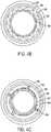
- a vapor barrier 375may be included on the inner surface of the wall of the inhalable substance medium (as illustrated in FIG.
- any vapor barrier materialsuch as a metal foil, may be used.
- the vapor barriermay be on the outer surface of the inhalable substance medium wall 352 in embodiments where the heating member contacts the outer surface as opposed to the inner surface of the inhalable substance medium wall 352.
- the vapor barrieris positioned on the wall surface that is adjacent (or in contact with) the heating member when the inhalable substance medium 350 is heated.
- the vapor barriermay be formed of a material that is electrical insulating or may comprise a layer of electrically insulating material that can be in contact with the heating member 400.
- a metal foilmay be used as the vapor barrier, and the foil may have an insulating monolayer - e.g., a metal oxide layer - in contact with the heating member.
- the inhalable substance mediummay be formed of a material that softens or changes phase (especially from solid to molten) at about the working temperature of the article.
- the inhalable substance mediummay be a wax or a gel, and the inhalable substance may be entrained therein.
- itcan be particularly useful to include the vapor barrier (or similar material) that provides support to the inhalable substance medium and substantially prevents the inhalable substance medium from contacting the heating member.
- the inhalable substance mediummay comprise a vapor barrier layer coated with an inhalable substance and/or an aerosol forming material.
- one or more of such coating materialsmay be in a microencapsulated form that preferably releases its components at a temperature within one or more of the working ranges otherwise described herein.
- Microencapsulation technologythat may be useful in such embodiments is disclosed, for example, in US Pat. No. 4,464,434 to Davis .
- the cartridge body 305may be formed with multiple layers.
- FIG. 4billustrates an alternate embodiment wherein the cartridge body is formed of a first, outer layer 306 formed of a first material and a second, inner layer 307 formed of the same or a different material.
- the first, outer layer 306is formed of a material with a closed structure.
- closed structureis meant that the material substantially prevents passage of aerosol or vapor into the interior of the layer such that the aerosol or vapor may propagate along the length of the cartridge body 305 to the mouth end 315 thereof.
- the first, outer layer 306may comprise a paper material or a suitable polymer material, as already described above.
- Such first, outer layermay have a thickness that preferably is less than about 1 mm, less than about 0.9 mm, less than about 0.8 mm, less than about 0.7 mm, less than about 0.6 mm, or less than about 0.5 mm.
- the first, outer layermay have a thickness of about 0.1 mm to about 1.0 mm, about 0.2 mm to about 0.8 mm, about 0.25 mm to about 0.75 mm, or about 0.3 mm to about 0.7 mm.
- the second, inner layer 307preferably has a greater thickness than the first, outer layer 306, and can be about 0.8 mm to about 4 mm, about 1 mm to about 3.5 mm, or about 1.2 mm to about 3.0 mm.
- the second, inner layermay be in direct contact with the tobacco substrate material 350. As such, it is preferable for the second, inner layer to have a substantially open structure. By being in direct contact, the second, inner layer may provide greater support to the inhalable substance medium 350.
- the cartridge body, and particularly the second, inner layer 307 thereofmay be characterized as providing continuous support for the inhalable substance medium 350 along substantially the entire length thereof (e.g., at least about 75%, at least about 85%, at least about 90%, or at least about 95% of the length thereof).
- the second, inner layercan permit passage of formed aerosol or vapor from the inhalable substance medium, and the open structure preferably extends along the length of the cartridge body to the mouth end 315 thereof.
- the annular space 319 defined by the inner surface of the cartridge body and the outer surface of the inhalable substance medium, as other wise described herein,is replaced by the open structured second, inner layer of the cartridge body and provides the same function.
- the void in the second, inner layer of the cartridgemay exhibit substantially the same characteristics as otherwise described herein (e.g., volume, etc.) for the annular space.
- the open structure of the second, inner layeris such that at least about 50%, at least about 60%, at least about 70%, at least about 80%, or at least about 85% of the layer, based on volume, is the open void space.
- the open space of the second, inner layermay be about 50% to about 90%, about 60% to about 85%, or about 65% to about 80% by volume of the second, inner layer.
- This relatively thick and porous layercan be characterized as providing an aerosol collection/generation area and may be, in one example, an accordion layer of paper or polymeric material.
- the second, inner layermay be a porous mat of material such as cellulose acetate tow, cotton fibers, or any number of materials useful to form a non-woven porous mat such as spun bonded polypropylene, PLA fibers, PHA fibers, glass fibers, and the like. This may be described as an open cell material.
- the cartridge bodymay be formed of a first, outer layer 306 that is substantially closed in structure and a second, inner layer 307 that exhibits an open structure, as described above, and the two layers may be separated by a void space 308 as otherwise described herein.
- the inhalable substance medium 350is provided substantially continuous support, the generated vapor or aerosol is allowed to pass therethrough into the void 308, and the vapor or aerosol can pass along the length of the void to the mouth end 315 of the cartridge body without substantially permeating through the first, outer layer.
- the void spacemay include one or more struts 309 interconnecting the first, outer layer with the second, inner layer without limiting passage of any aerosol or vapor along the length of the cartridge body within the void space.
- the tubular wall 352 of the inhalable substance medium 350has opposing terminal ends, the first end 353 being in proximity to the mouth end 315 of the cartridge body 305, and the second end 354 being in proximity to the engaging end 310 of the cartridge body 305.
- the inhalable substance mediumparticularly may be attached to the cartridge body at the respective terminal ends of each component. Such attachment may be direct or indirect.
- the second end 354 of the inhalable substance medium 350is directly attached to the engaging end 310 of the cartridge body 305 (specifically in the area of the flange 302 ).
- Such direct attachmentcan be by any suitable means, such as an adhesive.
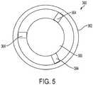
- the first end 353 of the inhalable substance medium 350is indirectly attached to the mouth end 315 of the cartridge body 305 via a frame member 360.
- the frame member 360comprises an outer wall 361, a wall flange 362, a central hub 363, and a plurality of spokes 364 connecting the central hub 363 to the outer wall 361 such that open space exists between the outer wall 361 and the central hub 363.
- FIG. 5provides an end view of the cartridge (without overwrap 380 ), and this view essentially shows the frame member.
- the central hub 363has a cross-sectional shape that is substantially identical to the cross-sectional shape of the inhalable substance medium (i.e., round in the present embodiment), and the hub has an outer diameter of a size suitable such that hub is secured within the first end 353 of the inhalable substance medium, the wall 352 of the inhalable substance medium at the first end being in direct contact with the hub and, preferably, being secured thereto (e.g., by an adhesive or similarly suitable attachment).
- the hubspecifically may have an elongate outer wall that provides sufficient area for attachment for the inhalable substance medium and for attachment to the spokes 364.
- the hubmay have a thickness that is substantially equal to the length of the elongate wall, or the elongate wall may have a length that is greater than the thickness of the hub, the additional length extending one or both of anterior and posterior to the body of the hub.
- Tensioning of the inhalable substance mediumcan be particularly useful to provide for specific performance of the inventive article. As otherwise described herein, it can be beneficial for the inhalable substance medium to have a relatively small thickness such that heat is efficiently transferred, particularly when substrates, such as paper, that exhibit relatively low heat transfer are used. Substrates of small thickness, however, can have relatively low strength in certain dimensions while exhibiting relatively high strength in other dimensions. For example, thin paper, in tension, exhibits high strength relative to the strength of the same paper in compression. Tensioning also can facilitate direct contact of the heating member to the surface of the inhalable substance medium to be heated (including a substrate that is used or a vapor barrier that may be present).
- the heating memberwith an outer diameter that is greater than the inner diameter of the inhalable substance medium tube so that the heating member actually provides tension to the inhalable substance medium substantially perpendicularly to the lengthwise axis of the inhalable substance medium.
- the outer diameter of the heating membermay exceed the inner diameter of the inhalable substance medium (or the inner diameter of any further layer, such as a vapor barrier, that is interior thereto) by about 1% to about 20%, about 2% to about 15%, about 3% to about 12%, or about 5% to about 10%.
- the engaging end 310 of the cartridge 300is sized and shaped for insertion into the control housing 200.
- the receiving chamber 210 of the control housing 200can be characterized as being defined by a wall 212 with an inner surface and an outer surface, the inner surface defining the interior volume of the receiving chamber.
- the greatest outer diameter (or other dimension depending upon the specific cross-sectional shape of the embodiments) of the cartridge 300preferably is sized to be less than the inner diameter (or other dimension) at the inner surface of the wall of the open end of the receiving chamber in the control housing.
- the difference in the respective diametersis sufficiently small so that the cartridge fits snugly into the receiving chamber, and frictional forces prevent the cartridge from being moved without an applied force.
- the article 10may be configured such that the cartridge (or a portion thereof) slides over and around the receiving chamber of the control housing.
- the cartridgemay be configured such that the cartridge overwrap 380 has an inner diameter that is greater than the outer diameter of the control housing at the end of the receiving chamber. In this manner, the cartridge overwrap slides over the control housing but further components of the cartridge still can be considered as being inserted into the receiving chamber of the control housing.
- the article 10may take on a size that is comparative to a cigarette or cigar shape.
- the articlemay have a diameter of about 5 mm to about 25 mm, about 5 mm to about 20 mm, about 6 mm to about 15 mm, or about 6 mm to about 10 mm.
- Such dimensionmay particularly correspond to the outer diameter of the control housing 200.
- the outer diameter of the cartridge 300can be sufficiently less so as to allow for indexing of the cartridge within the receiving chamber 210, as discussed herein.
- the overwrap 380 of the cartridgemay be formed to have an area of increased diameter at the mouth-end 315. This area of increased diameter preferably is such that the diameter is at least the diameter of the receiving end of the control housing.
- a mouth-end wall 316is formed to function as a stop to prevent the cartridge from being inserted entirely into the receiving chamber of the control housing.
- the mouth-end wallmay define the mouth-end of the cartridge as the distance therefrom to the terminal mouth-end of the cartridge. This may be the area of greater diameter illustrated in FIG. 4 .
- the length of the mouth-end portion having the area of greater diametercan vary, such as being about 5 mm to about 25 mm, about 8 mm to about 22 mm, or about 10 mm to about 20 mm. This area may include a filter component as otherwise described herein.
- the mouth-end of the overwrap or cartridgemay be substantially of the same diameter of the remaining portion thereof.
- the mouth-endcould be defined as the section of the cartridge that is not heated in use and on which the consumer's lips would be placed.
- a mouth-end wallstill may be present to function as a stop.
- other stop meansmay be provided, including means interior to the cartridge and/or the receiving chamber of the control housing.
- the control housing 200 and cartridge 300may likewise be characterized in relation to overall length.
- the control housingmay have a length of about 40 mm to about 120 mm, about 45 mm to about 110 mm, or about 50 mm to about 100 mm.
- the cartridgemay have a length of about 20 mm to about 60 mm, about 25 mm to about 55 mm, or about 30 mm to about 50 mm.
- the length of the control housingmay be divided substantially equally between the control segment 205 and the receiving end (which may be defined by the receiving chamber 210, or by the projection 225 ). Alternatively, one or the other may encompass about 55%, about 60%, about 65%, or about 70% of the total length of the control housing.
- the receiving chambermay have a length that is about 70% to about 120%, about 80% to about 110%, or about 85% to about 100% of the length of the cartridge.
- the projectionspecifically may have a length of about 10 mm to about 50 mm, about 15 mm to about 45 mm, or about 20 mm to about 40 mm.
- the projectionmay be formed of a variety of materials. In specific embodiments, it can be useful for the projection to be formed of a thermal insulator. This can be desirable so as to maximize heat flow from the heating member to the inhalable substance medium rather than to the projection.
- the cartridge overwrap 380may be formed of any material useful for providing additional structure and/or size to the cartridge body 305.
- the overwrapcomprises a material that resists transfer of heat, which may include a paper or other fibrous material, such as a cellulose.
- the overwrapalso may be formed of multiple layers, such as an underlying, bulk layer and an overlying layer, such as a typical wrapping paper in a cigarette.
- the overwrapparticularly may comprise a material typically used in a filter element of a conventional cigarette, such as cellulose acetate.
- the overall length thereofcan vary from being substantially identical to the length of the cartridge body (and the inhalable substance medium 350 ) up to about two times the length of the cartridge body.
- the overwrapcan be characterized as extending beyond the engaging end 310 of the cartridge body and/or as extending beyond the mouth end 315 of the cartridge body.
- the cartridge body and the inhalable substance mediumeach have a length that is up to about 50%, up to about 30%, or up to about 10% less than the length of the overwrap.
- the cartridge body and the inhalable substance mediumeach have a length that is at least 10%, at least 15%, or at least 20% less than the length of the overwrap.
- the distance the overwrap extends beyond the engaging end 310 of the cartridge bodycan be about 5%, about 10%, about 15%, about 20%, about 25%, about 30%, about 40%, about 50%, about 60%, about 70%, about 80%, about 90%, or about 100% of the length of the cartridge body. Further, the distance the overwrap extends beyond the engaging end of the cartridge body can be about 5% to about 100%, about 10% to about 90%, about 15% to about 80%, about 20% to about 75%, about 25% to about 70%, or about 30% to about 60% of the length of the cartridge body.
- the distance the overwrap extends beyond the mouth end of the cartridge bodycan be at least about 1%, at least about 2%, at least about 3%, at least about 4%, at least about 5%, at least about 6%, at least about 7%, at least about 8%, at least about 9%, or at least about 10% of the length of the cartridge body. In other embodiments, the distance can be about 2% to about 20%, about 4% to about 18%, or about 5% to about 15% of the length of the cartridge body.
- the excess length of the overwrap at the engaging end of the cartridgecan function to protect the inhalable substance medium within and also to provide structural integrity to the article 10 when the cartridge is inserted into the receiving chamber 210 only to a point wherein the heating member just makes contact with the inhalable substance medium.
- the excess length of the overwrap at the mouth end of the cartridgecan function to simply separate the cartridge body from the mouth of a consumer or to provide space for positioning of a filter material or to affect draw on the article or to affect flow characteristics of the vapor or aerosol leaving the article during draw.
- the overwrapmay be absent, and the inhalable substance medium may simply be substantially shorter in length than the cartridge body.
- the overwrap and the cartridge bodymay essentially be combined into a single element that provides the functions of both elements as otherwise described herein.
- the annular space 319 wherein the vapor is formedmay be the space between the inhalable substance medium and the outer body (i.e., the combined cartridge body and overwrap).
- the cartridge body 305may be absent, and the overwrap 380 can essentially function also as the cartridge body - i.e., the outer body.
- the second end 354 of the inhalable substance medium 350may be attached directly to the outer body.
- a ferrule(not shown) may be used to attach the second end of the inhalable substance medium to the outer body.
- the inhalable substance mediummay be perforated so as to allow air flow into the annular space.
- perforationsmay be formed in the outer body (or cartridge and/or overwrap, depending upon the particular embodiment) in the area of the annular space.
- the inventionin all embodiments encompasses the presence of perforations or apertures in the components as necessary to allow ambient air to flow directly into the annular space (e.g., without having to pass through the second end of the inhalable substance medium).
- the overwrapalso can function to provide particular characteristics at the mouth end of the cartridge.
- the construction and/or shape and/or dimension of the overwrapcan function to provide the sensation of a conventional cigarette in the mouth of a user.
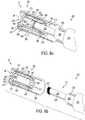
- the overwrapmay comprise a filter 390 (e.g., cellulose acetate or polypropylene) positioned in proximity to the mouth end of the cartridge (such as shown in FIG. 6 , wherein the terminus of the mouth end 315 of the cartridge is removed to reveal the filter underneath) to increase the structural integrity thereof and/or to provide filtering capacity, if desired, and/or to provide resistance to draw.
- a filter 390e.g., cellulose acetate or polypropylene
- an article according to the inventioncan exhibit a pressure drop of about 50 to about 250 mm water pressure drop at 17.5 cc/second air flow.
- pressure dropcan be about 60 mm to about 180 mm or about 70 mm to about 150 mm.
- Pressure drop valuemay be measured using a Filtrona Filter Test Station (CTS Series) available from Filtrona Instruments and Automation Ltd or a Quality Test Module (QTM) available from the Cerulean Division of Molins, PLC.
- CTS SeriesFiltrona Filter Test Station
- QTMQuality Test Module
- the thickness of the filter along the length of the cartridgecan vary - e.g., about 2 mm to about 20 mm, about 5 mm to about 20 mm, or about 10 mm to about 15 mm.
- the filtermay be separate from the overwrap, and the filter may be held in position near the cartridge by the overwrap.
- Exemplary types of wrapping materials, wrapping material components, and treated wrapping materials that may be used in overwrap 380 in the present inventionare described in US Pat. Nos. 5,105,838 to White et al. ; 5,271,419 to Arzonico et al. ; 5,220,930 to Gentry ; 6,908,874 to Woodhead et al. ; 6,929,013 to Ashcraft et al. ; 7,195,019 to Hancock et al. ; 7,276,120 to Holmes ; 7,275,548 to Hancock et al. ; PCT WO 01/08514 to Fournier et al. ; and PCT WO 03/043450 to Hajaligol et al.
- wrapping materialsare commercially available as R. J. Reynolds Tobacco Company Grades 119, 170, 419, 453, 454, 456, 465, 466, 490, 525, 535, 557, 652, 664, 672, 676 and 680 from Schweitzer-Maudit International.
- the porosity of the wrapping materialcan vary, and frequently is between about 5 CORESTA units and about 30,000 CORESTA units, often is between about 10 CORESTA units and about 90 CORESTA units, and frequently is between about 8 CORESTA units and about 80 CORESTA units.
- a wrapping material used in the overwrap 380can incorporate a fibrous material and at least one filler material imbedded or dispersed within the fibrous material.
- the fibrous materialcan vary and can be, for example, a cellulosic material.
- the filler materialcan have the form of essentially water insoluble particles. Additionally, the filler material can incorporate inorganic components.
- one or more layers of non-porous cigarette papermay be used to envelop the cartridge (with or without the overwrap present).
- suitable non-porous cigarette papersare commercially available from Kimberly-Clark Corp. as KC-63-5, P878-5, P878-16-2 and 780-63-5.
- the overwrapis a material that is substantially impermeable to the vapor formed during use of the inventive article.
- the overwrapcan comprise a resilient paperboard material, foil-lined paperboard, metal, polymeric materials, or the like, and this material can be circumscribed by a cigarette paper wrap.
- the overwrap 380may comprise a tipping paper that circumscribes the component and optionally may be used to attach a filter material to the cartridge 300, as otherwise described herein.
- the portion of the overwrap at the mouth end 315 of the cartridge 300actually extends beyond the end of the cartridge body 305 and includes an opening 381 to allow free movement of vapor and/or aerosol from the article 10 to a consumer.
- a filter materialspecifically in this area of the article, such as positioned between the mouth end 315 of the cartridge body 305 and the terminal mouth end of the overwrap 380 (as shown in FIG. 6 ).
- the mouth end of the cartridgemay be characterized as being partially occluded (i.e., by the presence of the filter material and/or by the size of the opening). This can be beneficial to limit the concentration of the inhalable substance that is delivered to the consumer or control resistance to draw.
- any filter material that is usedmay be designed with relatively low removal efficiency so as not to significantly limit the aerosol delivered therethrough.
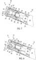
- the control housing 200includes an electrical energy source 220 that provides power to the electrical heating member 400.
- the energy sourceincludes a projection 225 that extends therefrom such that the terminal end of the projection extends approximately to the end of the receiving chamber 210.
- the electrical energy sourceis surrounded by a base 230 that can provide insulating properties and also can function as a dead stop to prevent the cartridge 300 from being inserted into the control housing a distance such that the projection extends through the mouth end 315 of the cartridge.
- the projectionis dimensioned to slide inside the interior space defined by the inner surface of the wall 352 of the inhalable substance medium 350.
- the projectionalso is dimensioned to provide the electrical heating member in sufficient proximity to the inhalable substance medium (preferably in direct contact therewith) to heat the medium and cause release of the inhalable substance.
- the engaging end 310 of the cartridge generally or the cartridge body 305specifically can be characterized as including an opening that is sufficiently sized and shaped to receive at least one component of the electrical energy source (i.e., the projection 225 ).
- the electrical energy source 220can be characterized as being an electrical receptacle that is in electrical connection with a power source 275 (shown in FIG. 6 ) and that provides for switch-operated delivery of electrical energy to the heating member 400, such as via the contacts 410, as illustrated in FIG. 4 .
- the contactsmay be permanently inserted into the receptacle or electrical energy source 220.
- the electrical energy sourcemay function as a more literal receptacle in that the contacts are not permanently inserted therein but only make an electrical connection with the electrical energy source when the cartridge 300 is inserted into the receiving chamber 210 sufficiently so that the contacts are moved into electrical connection with the electrical energy source.
- the projection 225can function as an extension of the electrical energy source in that electrical leads 222 (as seen in FIG. 9 ) are present on the projection, and the electrical heating member 400 receives electrical energy from the electrical energy source only when the electrical heating member (or a portion thereof) makes contact with the electrical leads.
- the electrical heating member 400can be any device suitable to provide heat sufficient to facilitate release of the inhalable substance for inhalation by a consumer.
- the electrical heating memberis a resistance heating element.
- Useful heating elementscan be those having low mass, low density, and moderate resistivity and that are thermally stable at the temperatures experienced during use. Useful heating elements heat and cool rapidly, and thus provide for the efficient use of energy. Rapid heating of the element also provides almost immediate volatilization of the aerosol-forming substance. Rapid cooling prevents substantial volatilization (and hence waste) of the aerosol-forming substance during periods when aerosol formation is not desired.
- Such heating elementsalso permit relatively precise control of the temperature range experienced by the aerosol-forming substance, especially when time based current control is employed.
- Useful heating elementsalso are chemically non-reactive with the materials comprising the inhalable substance medium being heated so as not to adversely affect the flavor or content of the aerosol or vapor that is produced.
- Exemplary, non-limiting, materials that may comprise the heating elementinclude carbon, graphite, carbon/graphite composites, metallic and non-metallic carbides, nitrides, silicides, inter-metallic compounds, cermets, metal alloys, and metal foils.
- refractory materialsmay be useful.
- Various, different materialscan be mixed to achieve the desired properties of resistivity, mass, thermal conductivity, and surface properties. As seen in FIG.
- the electrical heating memberis configured as a coil 405 positioned near the terminal end of the projection 225 with contacts 410 connecting the coil to the electrical energy source.
- Such coil(and optionally the leads) may be formed of any suitable material, such as described above, and preferably exhibits properties, such as described above.
- the heating member 400can take on other configurations.
- the heating membermay comprise an array of individual heating elements that are individually controlled to heat only the portion of the inhalable substance medium 350 in direct contact with the individual element. Such direct contact can be preferred in light of the ability to provide conduction heating that is more rapid and that requires less resistance.
- the projection 225may comprise such an array in a shape that corresponds to the shape of the inhalable substance medium in the cartridge 300. More specifically, when the inhalable substance medium is tubular, the heating member may be a tubular member divided into sections along the length thereof to provide an array of resistive heaters. Alternatively, the tubular member may be divided into sections around the circumference thereof to provide an array of resistive heaters.
- the tubular inhalable substance mediumcan only be heated in the section corresponding to the section of the heater array that is heated (only one section being heatable at any one time).
- such sections of the heater arraycan be separated by non-heating or insulative sections so as to avoid overlap of heated sections on the inhalable substance medium.
- the heater arraymay be linear, and the inhalable substance medium may be shaped and dimensioned to interact with such linear shape. Examples of such heater arrays that may be adapted for use in the present invention per the discussion provided above can be found in US Pat. Nos. 5,060,671 to Counts et al. ; 5,093,894 to Deevi et al.
- the inventionalso encompasses embodiments wherein the inhalable substance medium 350 may be coated, laminated, or otherwise attached directly to the heating element(s).
- the heating elementmay be in the form of a metal foil - e.g., stainless steel foil, aluminum foil, copper foil, and the like.
- the foilmay have a thickness of about 0.05 mm to about 10 mm, about 0.1 mm to about 8 mm, about 0.2 mm to about 6 mm, about 0.5 mm to about 5 mm, or about 1 mm to about 4 mm.
- the foillikewise may have a length of about 20 mm to about 150 mm, about 40 mm to about 120 mm, or about 50 mm to about 100 mm.
- the heating element foilmay be provided in any useful configuration, such as a significantly straight line or coiled (e.g., having a coil diameter of about 4 mm to about 15 mm, about 5 mm to about 12 mm, or about 6 mm to about 10 mm) or otherwise provided in a convoluted configuration.
- the heating elementmay be provided as multiple layers of discs (e.g., diameter of about 1 mm to about 6 mm, about 1.5 mm to about 5 mm, or about 2 mm to about 4 mm) may be arranged in sequence (and optionally activated in sequence) to release aerosol forming materials coated thereon or adjacent thereto.
- the heating elementfurther may comprise a fibrous material having a high surface area and an adsorbent, porous, wettable characteristic in order to carry a suitable amount of the inhalable substance alone or in combination with a separate aerosol-former.
- the heating elementmay be in the form of porous metal wires or films; carbon yarns, cloths, fibers, discs, or strips; graphite cylinders, fabrics, or paints; microporous high temperature polymers having moderate resistivities; porous substrates in intimate contact with resistance heating components; and the like.
- the inhalable substance medium 350may comprise a mix of finely ground tobacco, tobacco extract, spray dried tobacco extract, or other tobacco form mixed with optional inorganic materials (such as calcium carbonate), optional flavors, and the aerosol forming materials to form a substantially solid or moldable (e.g., extrudable) substrate.
- This solid or moldable substratethen may be attached directly to the heating element.
- multiple heater elements with the inhalable substance medium 350 directly attached theretomay be arranged in and activated in sequence to release their aerosol forming materials.
- the heating membercan be integral with (e.g., embedded within) the inhalable substance medium.
- the inhalable substance medium 350may be formed of a material as described above and may include one or more conductive materials mixed therein.
- Contacts 410as described herein, may be connected directly to the inhalable substance medium such that, when the cartridge 300 is inserted into the receiving chamber 210 of the control housing 200, the contacts make electrical connection with the electrical energy source 220.
- the contactsmay be integral with the electrical energy source and extend into the receiving chamber such that, when the cartridge is inserted into the receiving chamber of the control housing, the contacts make electrical connection with the inhalable substance medium.
- the heating membermay be described as being integral with the inhalable substance medium.
- graphite or other suitable, conductive materialsmay be mixed with, embedded in, or otherwise present directly on or within the material forming the inhalable substance medium to make the heating member integral with the medium.
- a conventional heating memberaccording to the various constructions described herein also may be combined with the inhalable substance medium so to be at least partially embedded therein.
- the heating coil 407may be integrally formed with the inhalable substance medium 350 so that at least a portion of the heating coil is fully located within the outer and inner walls of the inhalable substance medium.
- the electrical contacts 410may extend out of the inhalable substance medium.
- a vapor barrier that is present on the inhalable substance mediummay function as the heating member also.
- the control housing 200further can include additional components that preferably are present in the control segment 205 (although one or more of such additional components may be located completely or partially within the receiving chamber 210 or be in communication with the receiving chamber).
- the control housingpreferably includes a control circuit 260 (which may be connected to further components, as further described herein) that is connected by electrically conductive wires (not shown) to a power source 275.
- the control circuitparticularly can control when and how the heating member 400 receives electrical energy to heat the inhalable substance medium 350 for release of the inhalable substance for inhalation by a consumer.
- Such controlcan relate to actuation of pressure sensitive switches or the like, which are described in greater detail hereinafter.
- the control componentsparticularly can be configured to closely control the amount of heat provided to the inhalable substance medium 350. While the heat needed to volatilize the aerosol-forming substance in a sufficient volume to provide a desired dosing of the inhalable substance for a single puff can vary for each particular substance used, it can be particularly useful for the heating member to heat to a temperature of at least 120 °C, at least 130 °C, or at least 140 °C. In some embodiments, in order to volatilize an appropriate amount of the aerosol-forming substance and thus provide a desired dosing of the inhalable substance, the heating temperature may be at least 150 °C, at least 200 °C, at least 300 °C, or at least 350 °C.
- heatingcan be particularly desirable, however, to avoid heating to temperatures substantially in excess of about 550 °C in order to avoid degradation and/or excessive, premature volatilization of the aerosol-forming substance. Heating specifically should be at a sufficiently low temperature and sufficiently short time so as to avoid significant combustion (preferably any combustion) of the inhalable substance medium.
- the present inventionparticularly can provide the components of the present article in combinations and modes of use that will yield the inhalable substance in desired amounts at relatively low temperatures. As such, yielding can refer to one or both of generation of the aerosol within the article and delivery out of the article to a consumer.
- the heating temperaturecan be about 120 °C to about 300 °C, about 130 °C to about 290 °C, about 140 °C to about 280 °C, about 150 °C to about 250 °C, or about 160 °C to about 200 °C.
- the duration of heatingcan be controlled by a number of factors, as discussed in greater detail hereinbelow. Heating temperature and duration may depend upon the desired volume of aerosol and ambient air that is desired to be drawn through the annular space 319 defined by the inner surface of the wall of the cartridge body 305 and the outer surface of the wall 352 of the inhalable substance medium 350, as further described herein.
- durationmay be varied depending upon the heating rate of the heating member, as the article may be configured such that the heating member is energized only until a desired temperature is reached.
- duration of heatingmay be coupled to the duration of a puff on the article by a consumer.
- the temperature and time of heatingcan be controlled by one or more components contained in the control housing, as noted above.
- the amount of inhalable material released by the inventive article 10can vary based upon the nature of the inhalable material.
- the article 10is configured with a sufficient amount of the inhalable material, with a sufficient amount of any aerosol-former, and to function at a sufficient temperature for a sufficient time to release a desired amount over a course of use.
- the amountmay be provided in a single inhalation from the article 10 or may be divided so as to be provided through a number of puffs from the article over a relatively short length of time (e.g., less than 30 minutes, less than 20 minutes, less than 15 minutes, less than 10 minutes, or less than 5 minutes).
- the articlemay provide nicotine in an amount of about 0.05 mg to about 1.0 mg, about 0.08 mg to about 0.5 mg, about 0.1 mg to about 0.3 mg, or about 0.15 mg to about 0.25 mg per puff on the article 10.
- a desired amountmay be characterized in relation to the amount of wet total particulate matter delivered based on puff duration and volume.
- the article 10may deliver at least 1.0 mg of wet total particulate matter on each puff, for a defined number of puffs (as otherwise described herein), when smoked under standard FTC smoking conditions of 2 second, 35 ml puffs. Such testing may be carried out using any standard smoking machine.
- the amount of wet total particulate matter (WTPM) delivered under the same conditions on each puffmay be at least 1.5 mg, at least 1.7 mg, at least 2.0 mg, at least 2.5 mg, at least 3.0 mg, about 1.0 mg to about 5.0 mg, about 1.5 mg to about 4.0 mg, about 2.0 mg to about 4.0 mg, or about 2.0 mg to about 3.0 mg.
- WTPMwet total particulate matter
- the articleis indexable to provide segmented heating of the inhalable substance medium 350.
- the engaging end 310(including any overwrap that is present and extending beyond the end of the cartridge wall 305 ) of a cartridge 300 is inserted into the receiving chamber 210 of the control housing 200.
- the inhalable substance medium 350, the electrical heating member 400, and the electrical energy source 220align so as to allow for heating of at least a segment of the inhalable substance medium 350.
- Such alignmentcan result from the direct cross-sectional alignment of the three components (e.g., the inhalable substance medium 350, the electrical heating member 400, and the projection 225 functioning as an extension of the electrical energy source 220 are all aligned such that a cross-section of the area of alignment can encompass a portion of all three components).
- the inhalable substance medium 350 and the electrical heating member 400may be in a direct cross-sectional alignment, but the electrical energy source 220 may be considered aligned therewith in that the electrical heating member is aligned with the electrical energy source 220 so as to make an electrical connection therewith. This may be referred to as an operable alignment.
- FIG. 4 and FIG. 7provides for segmented heating of the inhalable substrate medium 350, the segmented heating proceeding axially from the second end 354 of the inhalable substrate medium to the first end 353 of the inhalable substrate medium.
- the cartridge 300has been inserted into the receiving chamber 210 of the control housing 200 the minimum distance necessary such that the heating member 400 that is attached to the projection 225 and in electrical connection with the electrical energy source 220 has been positioned inside the central cavity 351 of the tubular inhalable substance medium.
- the second end 354 of the inhalable substance mediumhas been segmented, the segmented end being the point of attachment to the engaging end 310 of the cartridge body 305.
- the segmented nature of the second end of the inhalable substance mediumcan be such that one or more openings are provided in the engaging end 310 of the cartridge to facilitate air entry into the annular space 319.
- the segmented endalso can be flared, which can allow for the tubular body of the inhalable substance medium to have a diameter that is less than the diameter of the segmented end of the inhalable substance medium.
- Such segmented and (optionally) flared arrangementfacilitates one or more of the following: tensioning of the inhalable substance medium within the cartridge body; configuration of the tubular inhalable substance medium to have a diameter that is less than the diameter of the tubular cartridge body; and provision for passage of air through the annular space defined by the outer surface of the wall 352 of the inhalable substance medium and the inner surface of the wall of the cartridge body.
- the cartridgecan be characterized as including a flow path therethrough such that fluid passage from the engaging end of the cartridge to the mouth end 315 of the cartridge is substantially limited to passage through the annular space 319 between the inner surface of the cartridge body wall and the outer surface of the inhalable substance medium wall.
- the inhalable substance mediummay be attached to a ferrule that is directly attached to the cartridge body.
- the ferrule and/or a portion of the inhalable substance medium near the ferrulemay be perforated.
- the configuration of the cartridge body 305 and the cartridge overwrap 380preferably is such that air passage around the cartridge body and between the cartridge body and the overwrap is significantly prevented.
- the flange 302 at the engaging end 310 of the cartridge bodyis sized such that outer rim of the flange is in direct contact with the cartridge overwrap around the entire circumference thereof.
- the receiving chamber wall 212can include one or more apertures 213 therein for allowing entrance of ambient air into the interior of the receiving chamber 210.
- airthus can be drawn into the receiving chamber, pass into the cartridge, be drawn through the segmented and flared second end 354 of the inhalable substance medium 350, enter the annular space 319 between the inhalable substance medium and the cartridge body 305, and pass through the open space in the cartridge frame member 360 for inhalation by the consumer.
- the drawn aircarries the inhalable substance through the optional filter 390 (illustrated in FIG. 6 ) and out of the opening 381 at the mouth end of the overwrap.
- the wider opening of the cartridge body 305 at the engaging end 310 thereoffacilitates ease of directing the projection 225 (with the heating member 400 thereon) into the interior space of the tubular inhalable substance medium 350.
- the heating memberWith the heating member positioned inside the beginning section of the tubular portion of the inhalable substance medium, the heating member can be activated to heat the inhalable substance medium and cause release of the inhalable substance into the annular space between the inhalable substance medium and the cartridge body.
- activation of the heating membermay volatilize the aerosol forming material and/or the inhalable substance of the inhalable substance medium such that, when ambient air is drawn through the annular space, the volatilized material(s) become aerosolized and entrained in the air flowing through the annular space and to the mouth end for inhalation by the consumer.
- segmented heatingis provided with a heating member 400 that is physically a component of the control housing 200
- the heating membertypically will be present on the projection 225 only a long a segment of defined length.
- the segment wherein the heating member is locatedcan be in proximity to the end of the projection at the open end of the receiving chamber 210.
- the relative percentage of the projection that includes the heating membercan be based on the total length of the inhalable substance medium 350 and the number of puffs to be delivered by a single cartridge 300.
- a single cartridgecan provide about 4 to about 12, about 5 to about 11, or about 6 to about 10 puffs, which approximates the number of puffs in a typical cigarette.
- the segment of the projection that includes the heating membercan encompass about 5% to about 50% of the overall length of the projection. In other embodiments, the segment can encompass about 5% to about 40%, about 5% to about 30%, about 5% to about 20%, or about 10% to about 20% of the overall length of the projection.
- a vapor barrier 375(as illustrated in FIG. 4a ) may be present on the inner surface of the wall 352 of the inhalable substance medium 350 to reduce or prevent aerosol or vapor formation within the interior space of the tubular inhalable substance medium and maximize aerosol or vapor formation within the noted annular space.
- the presence of the heating member 400 within the interior space of the tubular inhalable substance mediumcan reduce vapor losses that may result from interaction of the vapor and the heating member. Still further, such positioning can function to separate the heating member from the airstream flowing within the article during draw (as described above).
- This configurationcan provide for lower energy consumption necessary to achieve the necessary heating temperature, and this in turn can facilitate increased battery life (or can lessen the energy content that must be stored in a capacitor for complete use of a cartridge).
- the content of aerosol or vapor and the inhalable substance that is released during heatingcan be based on a variety of factors.
- the annular spacecan have a volume of at least 0.25 ml, at least 0.5 ml, at least 0.75 ml, at least 1.0 ml, or at least 1.25 ml.
- the volume of the annular spacecan be about 0.25 ml to about 5.0 ml, about 0.5 ml to about 3.0 ml, about 0.7 ml to about 2.0 ml, or about 0.7 ml to about 1.5 ml.
- the total volume of aerosol that is generated in a single puffmay be greater than the annular space volume since aerosol being formed is continuously swept away with air that is pulled through the annular space to combine with the aerosol for passage to the consumer as the total puff volume.
- a puff volume of about 25 ml to about 75 ml, about 30 ml to about 70 ml, about 35 ml to about 65 ml, or about 40 ml to about 60 mlmay be delivered to the consumer.
- Such total puff volumemay provide, in certain embodiments, the WTPM content previously described.
- WTPM as deliveredmay be characterized in relation to the total puff volume - e.g., about 1 mg to about 4 mg WTPM in a total puff volume of about 25 ml to about 75 ml.
- Such characterizationis inclusive of all puff volume values and WTPM values described herein.
- the annular spacecan be defined in relation to providing both an actual head space and a dynamic head space.
- the annular spaceprovides an actual head space in that the annular space has a quantifiable volume based upon the length of the inhalable substance medium, the relative diameters of the inhalable substance medium and the cartridge, and the actual shape of each component.
- the annular spacecan be defined as a dynamic head space in that the inventive article is not limited to aerosol production of a volume only sufficient to fill the actual annular space volume during a single puff. Rather, during a single puff, aerosol may be formed continuously, and the formed aerosol is continuously drawn out of the annular space during the puff.
- the annular spaceprovides a dynamic head space that can be quantified in terms of the total puff volume that is drawn through the annular space during a single puff.
- the dynamic head spacemay vary between puffs depending upon draw strength and puff length.
- the dynamic head spacein certain embodiments, may have a volume as described above over an average puff time of about 2 seconds.
- the cartridgemay include one or more markings (or a graduated scale) on the exterior thereof (e.g., on the outer surface of the cartridge overwrap 380 ).
- a single markmay indicate the depth of insertion required to achieve this initial position for use (e.g., as illustrated in FIG. 7 ).
- Further marksmay indicate the distance the cartridge must be indexed into the receiving chamber to position the heating member on a fresh section of the inhalable substance medium that has not previously been heated for release of the inhalable substance.
- the cartridge and the receiving chambermay include one or a series of grooves (or detents) and projections (interchangeable between the two components) that provide a tactile indication of when the initial heating position has been reached and when the cartridge has been indexed a further distance necessary to position the heating member on a fresh section of the inhalable substance medium that has not previously been heated for release of the inhalable substance.
- Any such means that can enable a consumer to recognize and understand that the cartridge has been indexed sufficiently in the receiving chamber to position the heating member on a fresh section of the inhalable substance mediummay be used in the present article 10.
- FIG. 8further illustrates the segmented heating of the present embodiment.
- the cartridge 300is then further indexed into the receiving chamber 210 such that the cartridge indexes past the segment of the projection 225 having the electrical heating member present thereon.
- FIG. 8shows the article 10 after said indexing has occurred.
- the heating membernow is positioned within the tubular inhalable substance medium closer to the mouth end of the cartridge body 305 and beyond the segment of the inhalable substance medium that was previously heated. Thus, the heating member now is positioned near a fresh section of the inhalable substance medium.
- indexing of the cartridge within the receiving chamber for heating individual segments of the inhalable substance mediumcan be achieved via a variety of mechanisms, any of which can be encompassed by the invention.
- the indexingmay be manually controlled by a user such that, after a puff, the cartridge may be manually pushed further into the receiving chamber by tapping on the mouth end of the cartridge or otherwise applying force manually to push the cartridge further into the receiving chamber.
- the usermay determine the appropriate distance the cartridge needs to be pushed into the receiving chamber via the graduated markings on the cartridge, as described, or by the tactile sensation of the cartridge passing through another notch within the receiving chamber, both of which are already described above.
- the article 10may include further components useful to facilitate indexing of the cartridge 300 within the receiving chamber 210.
- the articlemay include a pushbutton 15 that may actuate indexing of the cartridge into the receiving chamber 210 by mechanical means (not shown).
- the control housing 200may include an engaging member that removably attaches to the cartridge, and actuation of the pushbutton may function to move a pawl that allows a spring attached to the engaging member to move the cartridge one position further into the receiving chamber and thus move the inhalable substance medium 350 relative to the heating member 400 such that the heating member is in position to heat a fresh section of the inhalable substance medium.
- the pushbuttonmay be linked to the control circuit 260 for manual control of the heating member and, optionally, the actuation of the cartridge.
- the consumermay use the pushbutton to energize the heating member.
- the pushbuttonstill may be mechanically linked to the cartridge, such as in the example described above, so that actuation of the pushbutton moves the cartridge one segment forward and then energizes the heating member to heat the fresh segment of the inhalable substance medium.
- actuation of the pushbuttonmay first energize the heating member (already positioned at a fresh section of the inhalable substance medium) and then, upon release of the button (or after a defined delay), the mechanical elements may engage to move the cartridge one segment forward so that the heating member is already positioned at a fresh segment of the inhalable substance medium for when the pushbutton is actuated again to energize the heating member.
- Similar functionality tied to the pushbuttonmay be achieved by other mechanical means or non-mechanical means (e.g., magnetic or electromagnetic). Similar functionality also may be achieved automatically via an internal switch activated by either pressure or airflow provided by the consumer during a puff.
- activation of the heating member and indexing of the cartridgecan be controlled by a single pushbutton.
- multiple pushbuttonsmay be provided to control each action separately.
- One or more pushbuttons presentmay be substantially flush with the casing of the control housing.
- the inventive article 10can include components that energize the heating member 400 in response to the consumer's drawing on the article (i.e., puff-actuated heating).
- the articlemay include a switch 280 in the control segment 205 of the control housing 200 that is sensitive either to pressure changes or air flow changes as the consumer draws on the article (i.e., a puff-actuated switch).
- Other suitable current actuation/deactuation mechanismsmay include a temperature actuated on/off switch or a lip pressure actuated switch.
- An exemplary mechanism that can provide such puff-actuation capabilityincludes a Model 163PC01D36 silicon sensor, manufactured by the MicroSwitch division of Honeywell, Inc., Freeport, Ill.
- the heating memberis activated rapidly by a change in pressure when the consumer draws on the article.
- flow sensing devicessuch as those using hot-wire anemometry principles, may be used to cause the energizing of the heater member 400 sufficiently rapidly after sensing a change in air flow.
- a further puff actuated switchthat may be used is a pressure differential switch, such as Model No. MPL-502-V, range A, from Micro Pneumatic Logic, Inc., Ft. Lauderdale, Fla.
- Another suitable puff actuated mechanismis a sensitive pressure transducer (e.g., equipped with an amplifier or gain stage) which is in turn coupled with a comparator for detecting a predetermined threshold pressure.
- Yet another suitable puff actuated mechanismis a vane which is deflected by airflow, the motion of which vane is detected by a movement sensing means.
- Yet another suitable actuation mechanismis a piezoelectric switch.
- Also usefulis a suitably connected Honeywell MicroSwitch Microbridge Airflow Sensor, Part No. AWM 2100V from MicroSwitch Division of Honeywell, Inc., Freeport, Ill. Further examples of demand-operated electrical switches that may be employed in a heating circuit according to the present invention are described in US Pat. No. 4,735,217 to Gerth et al. , which is incorporated herein by reference in its entirety.
- a pressure-sensing tube or other passage providing fluid connection between the puff actuated switch and the receiving chamber 210preferably is included in the control housing 200 so that pressure changes during draw are readily identified by the switch.
- the current actuation meanscan permit unrestricted or uninterrupted flow of current through the resistance heating member 400 to generate heat rapidly. Because of the rapid heating, it can be useful to include current regulating components to (i) regulate current flow through the heating member to control heating of the resistance element and the temperature experienced thereby, and (ii) prevent overheating and degradation of the inhalable substance medium 350.
- the current regulating circuitparticularly may be time based.
- a circuitincludes a means for permitting uninterrupted current flow through the heating element for an initial time period during draw, and a timer means for subsequently regulating current flow until draw is completed.
- the subsequent regulationcan include the rapid on-off switching of current flow (e.g., on the order of about every 1 to 50 milliseconds) to maintain the heating element within the desired temperature range.
- regulationmay comprise simply allowing uninterrupted current flow until the desired temperature is achieved then turning off the current flow completely.
- the heating membermay be reactivated by the consumer initiating another puff on the article (or manually actuating the pushbutton, depending upon the specific switch embodiment employed for activating the heater).
- the subsequent regulationcan involve the modulation of current flow through the heating element to maintain the heating element within a desired temperature range.
- the heating membermay be energized for a duration of about 0.2 second to about 5.0 seconds, about 0.3 second to about 4.0 seconds, about 0.4 second to about 3.0 seconds, about 0.5 second to about 2.0 seconds, or about 0.6 second to about 1.5 seconds.
- One exemplary time-based current regulating circuitcan include a transistor, a timer, a comparator, and a capacitor. Suitable transistors, timers, comparators, and capacitors are commercially available and will be apparent to the skilled artisan.
- Exemplary timersare those available from NEC Electronics as C-1555C and from General Electric Intersil, Inc. as ICM7555, as well as various other sizes and configurations of so-called "555 Timers".
- An exemplary comparatoris available from National Semiconductor as LM311. Further description of such time-based current regulating circuits is provided in US Pat. No. 4,947,874 to Brooks et al. , which is incorporated herein by reference in its entirety.
- the inventive article 10can comprise a timer for regulating current flow in the article (such as during draw by a consumer).
- the articlefurther can comprise a timer responsive switch that enables and disables current flow to the heating member.
- Current flow regulationalso can comprise use of a capacitor and components for charging and discharging the capacitor at a defined rate (e.g., a rate that approximates a rate at which the heating member heats and cools).
- Current flowspecifically may be regulated such that there is uninterrupted current flow through the heating member for an initial time period during draw, but the current flow may be turned off or cycled alternately off and on after the initial time period until draw is completed.
- Such cyclingmay be controlled by a timer, as discussed above, which can generate a preset switching cycle.
- the timermay generate a periodic digital wave form.
- the flow during the initial time periodfurther may be regulated by use of a comparator that compares a first voltage at a first input to a threshold voltage at a threshold input and generates an output signal when the first voltage is equal to the threshold voltage, which enables the timer.
- Such embodimentsfurther can include components for generating the threshold voltage at the threshold input and components for generating the threshold voltage at the first input upon passage of the initial time period.
- puff actuation of the heating member 400may be coupled to movement of the cartridge 300 through the receiving chamber 210.
- the current regulating componentmay allow the heating member to rapidly achieve the desired temperature and then remain at that temperature for the duration of the puff by the consumer.
- puff actuated movement of the cartridge through the receiving chambermay be continuous for the duration of the puff. Once the puff ceases, the heating member will be deactivated, and the cartridge will cease movement within the receiving chamber.
- the distance traveled by the cartridge during automatic indexingcan be directly related to the duration of a puff. In this manner, the consumer may have control over the amount of the inhalable substance that is delivered by a single puff. A short puff can only deliver a small amount of the inhalable substance.
- a longer puffcan deliver a greater amount of the inhalable substance.
- a large, initial puffmay provide a bolus of the inhalable substance, and shorter puffs thereafter may provide smaller amounts of the inhalable substance.
- Exemplary puff actuation devicesthat may be useful according to the invention are disclosed in US Pat. Nos. 4,922,901 , 4,947,874 , and 4,947,874, all to Brooks et al. , all of which are incorporated herein by reference in their entireties.
- the power source 275 used to provide power to the various electrical components of the inventive article 10can take on various embodiments.
- the power sourceis able to deliver sufficient energy to rapidly heat the heating member 400 in the manner described above and power the article through use with multiple cartridges 300 while still fitting conveniently in the article.
- a useful power sourceis a N50-AAA CADNICA nickel-cadmium cell produced by Sanyo Electric Company, Ltd., of Japan.
- a plurality of such batteries, providing 1.2-volts each,may be connected in series.
- Other power sources, such as rechargeable lithium-manganese dioxide batteries,can be used. Any of these batteries or combinations thereof can be used in the power source, but rechargeable batteries are preferred because of cost and disposal considerations associated with disposable batteries.
- control segment 205if disposable batteries are used, the control segment 205 must be openable for replacement of the battery.
- the control segmentfurther can comprise charging contacts 217, as shown in FIG. 1 , for interaction with corresponding contacts in a conventional recharging unit (not shown) deriving power from a standard 120-volt AC wall outlet, or other sources such as an automobile electrical system or a separate portable power supply.
- the power source 275also may comprise a capacitor.
- Capacitorsare capable of discharging more quickly than batteries and can be charged between puffs, allowing the battery to discharge into the capacitor at a lower rate than if it were used to power the heating member 400 directly.
- a supercapacitor -i.e., an electric double-layer capacitor (EDLC) - may be used separate from or in combination with a battery. When used alone, the supercapacitor may be recharged before each use of the article 10.
- the inventionalso may include a charger component that can be attached to the device between uses to replenish the supercapacitor. Thin film batteries may be used in certain embodiments of the invention.
- the article 10also may comprise one or more indicators 219 (as illustrated in FIG. 1 ).
- Such indicators 219may be lights (e.g., light emitting diodes) that can provide indication of multiple aspects of use of the inventive article.
- a series of lights as shown in FIG. 1may correspond to the number of puffs for a given cartridge. Specifically, the lights may become lit with each puff indicating to a consumer that the cartridge 300 was completely used when all lights were lit. Alternatively, all lights may be lit upon the cartridge engaging the receiving chamber 210, and a light may turn off with each puff indicating to a consumer that the cartridge was completely used when all lights were off.
- only a single indicatormay be present, and lighting thereof may indicate that current was flowing to the heating member 400 and the article 10 was actively heating. This may ensure that a consumer did not unknowingly leave an article unattended in an actively heating mode.
- one or more of the indicatorsmay be a component of the cartridge.
- visual indicatorsalso may include changes in light color or intensity to show progression of the smoking experience.
- Tactile indicators and sound indicatorssimilarly are encompassed by the invention. Combinations of such indicators also may be used in a single article.
- US 5,967,148 to Harris et al.discloses receptacles in a smoking device that include an identifier that detects a non-uniformity in infrared transmissivity of an inserted component and a controller that executes a detection routine as the component is inserted into the receptacle;
- US 6,040,560 to Fleischhauer et al.describes a defined executable power cycle with multiple differential phases;
- US 5,934,289 to Watkins et al.discloses photonic-optronic components; US 5,954,979 to Counts et al.
- components related to electronic aerosol delivery articles and disclosing materials or components that may be used in the present articleinclude 4,735,217 to Gerth et al. ; US Pat. No. 5,249,586 to Morgan et al. ; US Pat. No. 5,666,977 to Higgins et al. ; US Pat. No. 6,053,176 to Adams et al. ; US 6,164,287 to White ; US Pat No. 6,196,218 to Voges ; US Pat. No. 6,810,883 to Felter et al. ; US Pat. No. 6,854,461 to Nichols ; US Pat. No. 7,832,410 to Hon ; US Pat. No.
- FIG. 8aillustrates the embodiment from FIG. 8 but wherein the control housing 200 does not include a receiving chamber. Rather, the control housing can be described as comprising a receiving end 211 (as shown in FIG. 8b ). Such receiving end can include all of the components otherwise described herein in relation to embodiments including the receiving chamber.
- the chamber wallis absent, however, such that the further components (e.g., the projection 225 ) define the receiving end and extend from the control segment portion of the control housing.
- FIG. 9illustrates another embodiment of segmented heating wherein the electrical heating member is a component part of the cartridge 300.
- the heating member(which in this embodiment is a heating coil 406 ) particularly can be present in the interior space of the tubular inhalable substance medium 350, and the heating member may be maintained therein by frictional forces, and/or outwardly directed pressure exerted on the inhalable substance medium by the heating coil (e.g., wherein the heating coil exhibits springing action and is compressed to some extent prior to insertion), and/or by being at least partially embedded within the inhalable substance medium.
- Use of the article 10 in such embodimentscan be substantially identical to the use as described above.
- a consumercan insert the cartridge 300 into the receiving chamber 210 of the control housing 200 (or slide the cartridge over the projection 225 when the chamber walls are absent).
- the components of the cartridgecan be positioned within the cartridge to align with and receive the projection 225 as the cartridge slides into the receiving chamber.
- the minimum distance required to align all components for heating of the inhalable substance medium 350can be the distance required for the electrical leads 222 present on the projection to make an electrical connection with the heating coil 406 (or for an alternative electrical connection to be operatively engaged). Segmented heating is provided in that electrical current can only flow in the portion of the heating coil between the electrical leads.
- Indexing of the cartridgecan proceed as described above after the first segment of the inhalable substance medium 350 had been heated so that the electrical leads may make contact with the heating coil in the next segment of the cartridge. Puff-actuated heating followed by indexing may continue until the entire inhalable substance medium had been used (i.e., the inhalable substance and the aerosol-forming material released from the inhalable substance medium).
- segmented heating embodiments of the inventioncan arise from any combination of the heating element and the inhalable substance medium in a manner wherein only a portion of the inhalable substance medium is heated at a single time.
- an essentially fresh section of the inhalable substance mediumis in alignment with the heating element for heating.
- the inventionencompasses any variation of the segmented heating embodiments described herein wherein one or both of the inhalable substance medium and the heating member (which may extend to the cartridge and the control housing as well) are manipulated such that only a portion of the inhalable substance medium is heated at any given time and the manipulation positions the heating member of a fresh portion of the inhalable substance medium for each subsequent puff.
- twisting of one of the control housing or the cartridgemay be effective to place the heater on a fresh area of inhalable substance medium (with optional inward or outward movement of the cartridge within the receiving chamber control housing).
- the heating membermay comprise a lateral heating element (or series of elements) that may be substantially the same length as the inhalable substance medium.
- the electrical leads 222can be present on the projection 225 in proximity to the end of the projection 225 at the open end of the receiving chamber 210.
- the electrical leads 222form an electrical connection with discrete segments of the electrical heating coil 406 such that when heating occurs, only the portion of the inhalable substance medium 350 in proximity to the segment of the electrical heating coil 406 in electrical connection with the projection 225 is heated.
- the segment of the electrical heating coil 406 that is in electrical connection with the electrical leads 222 of the projection 225encompasses about 5% to about 50% of the length of the inhalable subject medium 350.
- the segment of the electrical heating coil 406 that is in electrical connection with the electrical leads 222 of the projection 225encompasses about 5% to about 40%, about 5% to about 30%, about 5% to about 20%, or about 10% to about 20% of the length of the inhalable subject medium 350.
- the inventionencompasses articles 10 wherein segmented heating of the inhalable substance medium 350 is provided.
- the heating member 400can be reusable, can be provided as a component of the control housing 200, and can be provided on only a segment of the projection 225.
- only a segment of the inhalable substance medium 350is in contact with the heating member 400 at any single time during use. No portion of the inhalable substance medium 350 is in physical contact with or in proximity to with the heating member 400 until the cartridge 300 is inserted into the receiving chamber 210 of the controller 200 for use by the consumer.
- the heating member 400can be disposable and be provided as a component of the cartridge 300.
- the heating member 400requires only a single set of contacts 410 or electrical leads 222 for connection to the electrical energy source 220 (e.g., for direct insertion into a receptacle in the electrical energy source 220, or formed on the projection 225 of the electrical energy source 220 ).
- the inhalable substance medium 350can be modified as desired to control various aspects of release, amount, and flavor.
- the inhalable substancemay be evenly dispersed on or within the inhalable substance medium 350 so that each respective segment that is heated will release substantially the same content of the inhalable substance.
- the initial area of the inhalable substance medium 350i.e., at the second end thereof
- the heating member 400may be supercharged with the inhalable substance.
- a single segment of the inhalable substance medium 350 corresponding to the size of the area heated by the heating member 400may comprise about 30% to about 90%, about 35% to about 75%, or about 40% to about 60% of the total amount of the inhalable substance present in the inhalable substance medium 350.
- a single segmentsuch as the final segment of the inhalable substance medium 350 heated by the heating member 400, may include a flavor or other material that is different from the remaining portion of the inhalable substance medium 350.
- Such final release of flavor or other materialmay function as a signal to a consumer that the cartridge 300 has been completely used.
- the articlecan be characterized in relation to the total area of the inhalable substance medium that is heated or maximally heated at a given time.
- segmented heating embodimentsonly a specific segment of the inhalable substance medium is heated or maximally heated at a given time (e.g., about one-sixth to about one-tenth of the area of the inhalable substance medium, or other fraction as necessary to provide the desired number of puffs from a single inhalable substance medium).
- the heating member underlying the heat spreading membermay have a width as small as 0.5% to 5% of the total length of the projection 225.
- the heat spreading membermay have a width that is about 10% to about 30%, about 10% to about 20%, or about 10% to about 15% of the total length of the projection.
- the heat spreading membercan have a width that is about 75% to about 125%, about 85% to about 110%, or about 90% to about 100% of the length of the inhalable substance medium.
- the vapor barrier 375may essentially function as a heating spreading member.
- the heating member 400may be relatively small, as discussed above, and may be inserted into the interior space of the inhalable substance medium 350. In contact with the vapor barrier, heat from the heating member may pass to the vapor barrier, which in turn may spread the heat a defined distance upstream and downstream of the actual position of the heating member.
- the heat spreading in such mannermay not be constant along the length of the vapor barrier. Rather, the heat can be greatest in the area directly adjacent the heating member, and the temperature of the vapor barrier can decrease moving away from the position of the heating member.
- Heat spreading in this mannermay be controlled, for instance, by varying the thickness of the vapor barrier and/or the heat conduction capacity of the vapor barrier.
- the vapor barriermay be formed with heat insulating materials formed therein such that heat spreading can continue upstream and downstream only until the heat insulating material was reached.
- the area of the vapor barrier between respective heat insulating sectionscan correspond to the segments of the inhalable substance medium that can be individually heated in segmented heating embodiments.
- heatingcan be characterized in relation to the amount of aerosol to be generated.
- the articlecan be configured to provide an amount of heat necessary to generate a defined volume of aerosol (e.g., about 25 ml to about 75 ml, or any other volume deemed useful in a smoking article).
- the articlepreferably can provide about 1 to about 10 Joules of heat per second (J/s), about 2 J/s to about 6 J/s, about 2.5 J/s to about 5 J/s, or about 3 J/s to about 4 J/s.
- the article 10can provide bulk heating of the inhalable substance medium 350.
- the heating membershown as heating coil 407
- the heating coilis wrapped around the projection 225, and electrical contacts 410 extend therefrom into the receptacle in the electrical energy source 220.
- the heating coilis present along substantially the full length of the projection (which may be described as being present on a large segment of the projection).
- the length of the heating coil on the projectioncan be characterized in relation to the inhalable substance medium.
- the electrical heating coil 407(or electrical heating member generally) can be present on the projection along a segment is about 75% to about 125% the length of the inhalable substance medium 350.
- the segmentcan be about 80% to about 120%, about 85% to about 115%, or about 90% to about 110% the length of the inhalable substance medium.
- a heating spreading membermay be used and may have a length that is substantially identical to the total length of the inhalable substance medium, or a different length as discussed above.
- FIG. 11illustrates the embodiment from FIG. 10 wherein the cartridge 300 has been fully inserted into the receiving chamber 210 of the control housing 200.
- complete insertion of the cartridgecan correspond to the distance that the cartridge typically can be inserted to begin use of the cartridge.
- full insertionis not required, and a consumer can have the option to only partially insert the cartridge so as to reduce the amount of inhalable substance and any aerosol-former released during heating.
- the cartridgemay be indexed further into the receiving chamber so that the heating coil 407 contacts substantially the full length of the inhalable substance medium 350 (e.g., at least 90%, at least 95%, or at least 98% of the length of the inhalable substance medium).
- Bulk heatingcan be useful for embodiments wherein it may be desirable to provide a bolus of the inhalable substance with the initial puff and provide a lower, more constant amount with each subsequent puff.
- FIG. 12illustrates a further embodiment of bulk heating wherein the heating coil 407 is provided as a component of the cartridge 300 and thus is disposable.
- the electrical contacts 410 for the heating coilcan be configured such that when the cartridge is fully inserted into the receiving chamber 210 of the control housing 200, the contacts make an electrical connection with the receptacle of the electrical energy source 220. It can be preferable for the electrical heating member (i.e., the coil 407 ) to be present within the cartridge along a segment that is about 75% to about 100% the length of the inhalable substance medium 350.
- the heating coilcan be present the cartridge along a segment that is about 80% to about 100%, about 90% to about 100%, or about 95% to about 100% the length of the inhalable substance medium.
- the heating membermay take on a different configuration, and a heat spreading member may be used, as described above, and may have relative lengths noted above. In such embodiments, use of a vapor barrier as the heat spreading member may be particularly beneficial. Likewise, the vapor barrier could function as the heating member in such embodiments to reduce the amount of material in a disposable cartridge.
- cartridge 300 and control housing 200can be provided together as a complete smoking article or pharmaceutical delivery article generally, the components also may be provided separately.
- the inventionalso encompasses a disposable unit for use with a reusable smoking article or a reusable pharmaceutical delivery article.
- such disposable unit(which may be a cartridge 300 as illustrated in the appended figures) can comprise a substantially tubular shaped cartridge body 305 having an engaging end 310 configured to engage the reusable smoking article or pharmaceutical delivery article, an opposing mouth end 315 configured to allow passage of an inhalable substance to a consumer, and a wall with an outer surface and an inner surface that defines an interior cartridge space.
- the interior cartridge spacecan include a substantially tubular shaped inhalable substance medium 350 having a wall 352 with an inner surface and an outer surface so as to define an annular space of a specified volume between the outer surface of the inhalable substance medium wall 352 and the inner surface of the wall of the cartridge body 305.
- the inhalable substance mediumhas a first end 353 in proximity to the mouth end 315 of the cartridge body 305 and a second end 354 in proximity to the engaging end 310 of the cartridge 301.
- Such disposable unitcan be substantially similar in nature to the cartridge 300 illustrated in FIG. 4 .
- the unitcan comprise an electrical heating member 400 that heats at least a segment of the inhalable substance medium 350 sufficiently to form a vapor or aerosol comprising the inhalable substance within the annular space.
- the heating memberfurther may comprise electrical contacts 410 for engaging a receptacle in an electrical power source to allow for current flow through the electrical heating member.
- Such disposable unit that also comprises a heating membercan be substantially similar in nature to the cartridge illustrated in FIG. 9 or FIG. 12 .
- the disposable unitparticularly can vary between such embodiments based on the nature of the electrical heating member and associated components in its various embodiments.
- control unit 200for use in a reusable smoking article or a reusable pharmaceutical delivery article.
- control unitmay generally be a housing having a receiving end (which may include a receiving chamber 210 with an open end) for receiving an engaging end of a separately provided cartridge.
- the control unitfurther may include an electrical energy source 220 that provides power to an electrical heating member, which may be a component of the control unit or may be included in a cartridge to be used with the control unit.
- the electrical energy sourcecan include a projection 225 that extends therefrom. The projection can have an electrical heating member 400 combined therewith (as in component of FIG. 4 and FIG.
- the electrical heating membercan have associated electrical contacts 410 that connect the heating member to the electrical energy source.
- the projectionmay comprise electrical contacts that can interact with an electrical heating member provided in a disposable cartridge (as in component 222 in FIG. 9 ).
- the control unitalso can include further components, including an electrical power source (such as a battery), components for actuating current flow into a heating member, and components for regulating such current flow to maintain a desired temperature for a desired time and/or to cycle current flow or stop current flow when a desired temperature has been reached or the heating member has been heating for a desired length of time.
- the control unitfurther may comprise one or more pushbuttons associated with one or both of the components for actuating current flow into the heating member, and the components for regulating such current flow.
- the control uniteven further may comprise indicators, such as lights indicating the heater is heating and/or indicating the number of puffs remaining for a cartridge that is used with the control unit.
- control housing 200 and the cartridge 300may exist as individual devices. Accordingly, any discussion otherwise provided herein in relation to the components in combination also should be understood as applying to the control housing and the cartridge as individual and separate components.
- kitsthat provide a variety of components as described herein.
- a kitmay comprise a control housing with one or more cartridges.
- a kit furthermay comprise a control housing with one or more charging components.
- a kit furthermay comprise a control housing with one or more batteries.
- a kit furthermay comprise a control housing with one or more cartridges and one or more charging components and/or one or more batteries.
- a kitmay comprise a plurality of cartridges.
- a kit furthermay comprise a plurality of cartridges and one or more batteries and/or one or more charging components.
- the cartridges or the control housingmay be provided with a heating member inclusive thereto.
- the inventive kitsfurther can include a case (or other packaging, carrying, or storage component) that accommodates one or more of the further kit components.
- the casecould be a reusable hard or soft container. Further, the case could be simply a box or other packaging structure.
Landscapes
- Chemical & Material Sciences (AREA)
- Chemical Kinetics & Catalysis (AREA)
- General Chemical & Material Sciences (AREA)
- Engineering & Computer Science (AREA)
- Human Computer Interaction (AREA)
- Health & Medical Sciences (AREA)
- General Health & Medical Sciences (AREA)
- Toxicology (AREA)
- Manufacture Of Tobacco Products (AREA)
- Catching Or Destruction (AREA)
- Cigarettes, Filters, And Manufacturing Of Filters (AREA)
- Resistance Heating (AREA)
- Medicinal Preparation (AREA)
- Packaging Of Annular Or Rod-Shaped Articles, Wearing Apparel, Cassettes, Or The Like (AREA)
Abstract
Description
- The present invention relates to aerosol delivery articles and uses thereof for yielding tobacco components or other materials in an inhalable form. The articles may be made or derived from tobacco or otherwise incorporate tobacco for human consumption. More particularly, the invention provides articles wherein tobacco, a tobacco derived material, or other material is heated, preferably without significant combustion, to provide an inhalable substance, the substance, in the various embodiments, being in a vapor or aerosol form.
- Many smoking articles have been proposed through the years as improvements upon, or alternatives to, smoking products based upon combusting tobacco. Exemplary alternatives have included devices wherein a solid or liquid fuel is combusted to transfer heat to tobacco or wherein a chemical reaction is used to provide such heat source.
- The point of the improvements or alternatives to smoking articles typically has been to provide the sensations associated with cigarette, cigar, or pipe smoking, without delivering considerable quantities of incomplete combustion and pyrolysis products. To this end, there have been proposed numerous smoking products, flavor generators, and medicinal inhalers which utilize electrical energy to vaporize or heat a volatile material, or attempt to provide the sensations of cigarette, cigar, or pipe smoking without burning tobacco.
- Representative cigarettes or smoking articles that have been described and, in some instances, been made commercially available include those described in
US Pat. No. 4,735,217 to Gerth et al. ;US Pat Nos. 4,922,901 ,4,947,874 , and4,947,875 to Brooks et al. ;US Pat. No. 5,060,671 to Counts et al. ;US Pat. No. 5,249,586 to Morgan et al. ;US Pat. No. 5,388,594 to Counts et al. ;US Pat. No. 5,666,977 to Higgins et al. ;US Pat. No. 6,053,176 to Adams et al. ;US 6,164,287 to White ;US Pat No. 6,196,218 to Voges ;US Pat. No. 6,810,883 to Felter et al. ;US Pat. No. 6,854,461 to Nichols ;US Pat. No. 7,832,410 to Hon ;US Pat. No. 7,513,253 to Kobayashi ;U.S. Pat. No. 7,726,320 to Robinson et al. ;US Pat. No. 7,896,006 to Hamano ;US Pat. No. 6,772,756 to Shayan ;US Pat. Pub. No. 2009/0095311 to Hon ;US Pat. Pub. Nos. 2006/0196518 ,2009/0126745 , and2009/0188490 to Hon ;US Pat. Pub. No. 2009/0272379 to Thorens et al. ;US Pat. Pub. Nos. 2009/0260641 and2009/0260642 to Monsees et al. ;US Pat. Pub. Nos. 2008/0149118 and2010/0024834 to Oglesby et al. ;US Pat. Pub. No. 2010/0307518 to Wang ; andWO 2010/091593 to Hon . Still further examples include products commercially available under the names ACCORD®; HEATBAR™; HYBRID CIGARETTE®, RUYAN VEGAS™; RUYAN E-GAR™; RUYAN C-GAR™; E-MYSTICK™; and IOLITE® Vaporizer. - Articles that produce the taste and sensation of smoking by electrically heating tobacco have suffered from inconsistent release of flavors or other inhalable materials. Electrically heated smoking devices have further been limited in many instances to the requirement of an external heating device that was inconvenient and that detracted from the smoking experience. Accordingly, it can be desirable to provide a smoking article that can provide the sensations of cigarette, cigar, or pipe smoking, that does so without combusting tobacco, that does so without the need of a combustion heat source, and that does not produce combustion products.
- The present invention generally provides articles that may be used for pulmonary delivery of one or more inhalable substances (including nicotine). In certain embodiments, the invention relates to smoking articles that employ an electrical heating element and an electrical power source to provide the inhalable substance in a vapor or aerosol form, and also provide other sensations associated with smoking, preferably without substantially burning or completely burning tobacco or other substances, producing little or no combustion or pyrolysis products, including carbon monoxide, and producing little or no side stream smoke or odor. The electrical heating member provides for heating almost immediately upon taking a puff from the article and can provide for delivery of an aerosol throughout the puff and over about 6 to about 10 puffs on the article, which is similar to the number of puffs obtained from a typical cigarette.
- In certain embodiments, the invention thus provides an article for formation of an inhalable substance. The article can comprise a substantially tubular shaped cartridge body having an engaging end, an opposing mouth end configured to allow passage of the inhalable substance to a consumer, and a wall with an outer surface and an inner surface. The inner surface of the cartridge body wall can define an interior cartridge space that includes a substantially tubular shaped inhalable substance medium having a wall with an inner surface and an outer surface so as to define an annular space of a specified volume between the outer surface of the inhalable substance medium wall and the inner surface of the cartridge wall. The inhalable substance medium particularly also can have a first end in proximity to the mouth end of the cartridge and a second end in proximity to the engaging end of the cartridge. The article further can comprise an electrical heating member that heats at least a segment of the inhalable substance medium wall sufficiently to form a vapor comprising the inhalable substance within the annular space. The article also can comprise a control housing having a receiving end that engages the engaging end of the cartridge. As such, the control housing and the cartridge body can be characterized as being operatively connected. Such receiving end may particularly include a chamber with an open end for receiving the engaging end of the cartridge. The control housing further can comprise an electrical energy source (at least part of which can be positioned at the receiving end and/or within the receiving chamber) that provides power to the electrical heating member. In specific embodiments, when the engaging end of the cartridge engages the receiving end of the control housing (such as when it slides a defined distance into the chamber of the control housing), the inhalable substance medium and the electrical heating member align so as to allow for heating of at least a segment of the inhalable substance medium. The electrical energy source (or a component or extension thereof) also may so align with the inhalable substance medium and the electrical heating member. Thus, the electrical heating member (and optionally the electrical energy source) can be characterized as being operatively positioned with the inhalable substance medium.
- The inventive article can take on a number of shapes and sizes. For example, the cartridge can be substantially cylindrically shaped. Further, the cartridge can have a cross-section defined by a shape selected from the group consisting of round, oval, and square. The engaging end of the cartridge also can include an opening that is sufficiently sized and shaped to receive at least one component of the electrical energy source. The cartridge also can comprise an overwrap that can be useful to provide various properties to the article. For example, the overwrap may include a filter material positioned in proximity to the mouth end of the cartridge. Thus, the mouth end of the cartridge may be characterized as being partially occluded, which characterization also can relate to further components of the cartridge, such as the cartridge frame at the mouth end of the cartridge.
- The inhalable substance medium can comprise a variety of materials useful for facilitating delivery of one or more inhalable substances to a consumer. In particular embodiments, the inhalable substance medium can comprise tobacco and/or a tobacco-derived material. The inhalable substance medium also may comprise an aerosol-forming material, which itself may include a tobacco-derived material. In specific embodiments, the aerosol-forming material can be a polyhydric alcohol (e.g., glycerin). In other embodiments, the inhalable substance medium can comprise a solid substrate. Such substrate may itself comprise tobacco (e.g., a tobacco paper formed from reconstituted tobacco), such that the inhalable substance may be natural to the substrate. Alternatively, the substrate may simply be a paper material or other material that has the inhalable substance coated thereon or that has the inhalable substance absorbed or adsorbed therein. In a particular embodiment, the inhalable substance medium can comprise a slurry of tobacco and an aerosol-forming material coated on or absorbed or adsorbed in the solid substrate. The inhalable substance medium further may comprise other components, such as a vapor barrier on one of the inner surface or the outer surface of the wall. Particularly, the vapor barrier can be positioned on the surface of the inhalable substance medium wall that is adjacent to the electrical heating member when the inhalable substance medium is heated.
- The inhalable substance medium may be attached to the cartridge body only at the ends of the inhalable substance medium. In this manner, the inhalable substance medium can be characterized as being tensioned within the cartridge. The volume of the annular space between the outer surface of the inhalable substance medium wall and the inner surface of the cartridge body wall can be about 5 ml to about 100 ml, and can provide a dynamic head space that provides for passage of a combination of aerosol and air that substantially corresponds to an average puff volume desired to deliver a desired amount of the inhalable substance (i.e., in the form of the aerosol). The attachment of the inhalable substance medium to the engaging end of the cartridge body can be configured to facilitate movement of air into the annular space so as to direct the aerosol and the inhalable substance through the mouth end of the article for inhalation by a user.
- The receiving chamber of the control housing can be defined by a wall with an inner surface and an outer surface, the wall having a cross-section that is substantially similarly shaped to the cross-section of the cartridge. The chamber wall also can include one or more openings therein for allowing entry of ambient air into the chamber and thus facilitate movement of the inhalable substance out of the annular space, as described above. Alternatively, the chamber may be absent from the receiving end of the control housing or may be replaced with one or more guide components (e.g., extensions of the casing of the control housing) that guide the cartridge into a proper alignment with the control housing. In some embodiments, the walls defining the chamber may be characterized as examples of a guide component. Thus, the guide component could be substantially similar in dimensions with the chamber walls.
- The electrical energy source can essentially be a receptacle that provides for transmission of electrical current from the power source to the heating member. In specific embodiments, the electrical energy source can include a projection that extends from the control housing (e.g., through the receiving chamber, and preferably approximately to the open end of the chamber). When the electrical heating member is a component part of the control housing, the electrical heating member may be specifically attached to this projection on the electrical energy source. In such embodiments, the heating member can include electrical contacts that extend from the heating member and insert into the receptacle in the electrical energy source. This can be a permanent, non-removable connection of the contacts into the receptacle.
- The heating member can specifically be a resistance wire that generates heat as an electrical current passes therethrough. In specific embodiments, the heating member may be integral to the inhalation substance medium.
- In specific embodiments, the heating member can comprise multiple components. For example, the heating member may comprise a resistance wire of substantially small dimensions, and a heat spreading member may be associated therewith to spread the generated heat across a wider area.
- The electrical heating member (or the heat spreading member) particularly may be present on the projection only along a segment of defined length, and such segment particularly may be in proximity to the end of the projection at the open end of the chamber. The segment of defined length may encompass about 5% to about 50% of the length of the projection. In this manner, segmented heating can be provided in that the heating member will only encompass an area of the inhalable substance medium that is less than the entire length of the medium. Preferably, the heating member (or the heat spreading member) encompasses a length of about one-sixth to about one-tenth of the inhalable substance medium whereby the medium can be completely used in about six to about 10 segments or puffs. To achieve this, the cartridge may specifically index a distance past the projection segment having the electrical heating member present thereon. Such indexing can be manually controlled by a consumer, such as using a pushbutton to advance the cartridge within the receiving chamber or by simply tapping on the cartridge. In specific embodiments, the article can comprise a puff actuated switch that automatically indexes the cartridge past the projection segment. Thereby, the distance traveled by the cartridge during indexing can be directly related to the duration of the puff.
- In other embodiments, the electrical heating member still may be positioned in the control housing, but the article may provide for bulk heating of the inhalable substance medium rather than segmented heating. For example, the electrical heating member (or the heat spreading member) may be present on the projection along a segment that is about 75% to about 125% the length of the inhalable substance medium. In this manner, the cartridge is inserted substantially completely into the receiving chamber for the duration of use, and each puff on the article heats the entire (or almost entire) length of the inhalable substance medium. Electrical contacts present on the heating member permanently engage the receptacle (i.e., the electrical energy source) so that electrical current can be delivered to the heating member. When the chamber walls are absent, the cartridge can be characterized as being combined with the control housing such that the projection is inserted substantially into the inhalable substance to the full extent allowed by the specific structure thereof.
- In other embodiments, the heating member can be a component part of the cartridge rather than the control housing. Such configuration can allow for bulk heating of the inhalable substance medium. Specifically, the heating member can be present along substantially the entire length of the inhalable substrate medium and can include electrical contacts that engage the receptacle in the electrical energy source. When heating is activated, heating occurs along the entire length of the electrical heating member. Specifically, the electrical heating member (or the heat spreading component) may be present within the cartridge along a segment that is about 75% to about 100% the length of the inhalable substance medium.
- Segmented heating also can be provided when the heating member is present within the cartridge. To achieve such segmented heating, the projection of the electrical energy source can include electrical leads in proximity to the end of the projection at the open end of the chamber. The electrical leads form an electrical connection with discrete segments of the electrical heating member such that when heating occurs, only the portion of the inhalable substance medium in proximity to the segment of the electrical heating member in electrical connection with the projection is heated. The segment of the electrical heating member that is in electrical connection with the electrical leads of the projection can encompass about 5% to about 50% of the length of the inhalable subject medium. Aspects of the invention described above in relation to the article generally may apply to any of the embodiments, such as the use of puff actuated indexing.
- Segmented heating also may be provided by other heating means. For example, a plurality of heating members may be positioned in relation to the inhalable substance medium such that only a specific segment of the inhalable substance medium is heated by a given heating member. The plurality of heating members may be components of the control housing or the cartridge, and the plurality of heating members may be specifically coated with the inhalable substance. Moreover, a bulk heater structure may be provided but can be adapted for electronic control such that only specific segments of the bulk heater are powered at a given time to heat only specific segments of the inhalable substance medium.
- The control housing may include further components necessary for function of the article. The control housing can include switching components for actuating flow of electrical current from the electrical energy source to the heating member upon application of proper stimulus. Such actuation can be manual (e.g., use of a pushbutton) or automatic (e.g., puff actuated heating). In specific embodiments, actuation initiates uninterrupted current flow to quickly heat the heating member.
- The article preferably includes further components for controlling current flow. This may include time-based control wherein current is allowed to flow for a defined period of time prior to deactuation of the current flow. Such time-based regulation can include periods of cycling wherein the current flow is rapidly actuated and deactuated to maintain the heater at a defined temperature. In other embodiments, once a defined temperature is achieved, the current regulator may deactuate the current flow until a new puff initiates actuation again. The actuation and deactuation achieved by the switching components preferably provide for a working temperature for the heating member of about 120 °C to about 300 °C.
- The control housing still further includes an electrical power source to provide power to the electrical energy source. Such power source may include one or more batteries and/or at least one capacitor (or other means for providing a stored source of power).
- In other embodiments, the general components of the article may exist separately. For example, the invention provides a disposable unit for use with a reusable smoking article. Such disposable unit can comprise any of the subject matter described herein in relation to the cartridge.
- In specific embodiments, a disposable unit for use with a reusable smoking article can comprise a substantially tubular shaped cartridge body having an engaging end configured to engage the reusable smoking article, an opposing mouth end configured to allow passage of an inhalable substance to a consumer, and a wall with an outer surface and an inner surface that defines an interior cartridge space that includes a substantially tubular shaped inhalable substance medium having a wall with an inner surface and an outer surface so as to define an annular space of a specified volume between the outer surface of the inhalable substance medium wall and the inner surface of the cartridge body wall, the inhalable substance medium having a first end in proximity to the mouth end of the cartridge and having a second end in proximity to the engaging end of the cartridge. The disposable unit further can comprise an electrical heating member that heats at least a segment of the inhalable substance medium sufficiently to form a vapor comprising the inhalable substance within the annular space. The electrical heating member further can comprise contacts for making electrical connection with an electrical energy source in the reusable smoking article. Moreover, the electrical heating member can be positioned within the tubular shaped inhalable substance medium and, preferably, is in direct contact with the inhalable substance medium. In certain embodiments, the vapor barrier may include components so as to function has an electrical heating member as well. The disposable unit further can comprise an overwrap that surrounds the cartridge body and which can extend beyond the engaging end of the cartridge body (e.g., by a distance that is about 10% to about 90% of the length of the cartridge body). The overwrap also can include a filter material positioned in proximity to the mouth end of the cartridge body.
- Likewise, the invention provides a reusable control unit that can be used with a disposable smoking article. Such reusable control unit may generally comprise any of the subject matter described herein in relation to the control housing.
- In specific embodiments, a reusable control unit for use with a disposable smoking article can comprise a control housing including: a receiving end for receiving an engaging end of the disposable smoking article and including an electrical energy source that delivers power to an electrical heating member, the electrical energy source including a projection that extends outward from the receiving end of the control housing and including a component that forms an electrical connection with electrical contacts on the electrical heating member; and a control unit section that houses a power source, a switching component that actuates flow electrical current from the electrical energy source to the heating member, and a flow regulating component that regulates a previously initiated current flow from the electrical energy source to the electrical heating member. The receiving end particularly can include a receiving chamber defined by walls that surround the projection. Exemplary power sources can include a battery and/or at least one capacitor. The switching component can comprise a puff-actuated switch or may comprise a pushbutton. The current regulating component specifically can be a time-based component. As such, the current regulating component may stop current to the electrical heating member once a defined temperature has been achieved. Further, the current regulating component may cycle the current to the electrical heating member off and on once a defined temperature has been achieved so as to maintain the defined temperature for a defined period of time. The component that forms an electrical connection with the electrical contacts may be a receptacle that is housed in the electrical energy source. Alternatively, the component that forms an electrical connection with the electrical contacts may be located on the projection.
- In another aspect, the invention also relates to kits that can provide various components of the inventive article, and accessories therefor, in a variety of combinations. Specifically, individual kits may include any combination of one or more cartridges, one or more control units, one or more heating members, one or more batteries, and one or more charging components. The kit may include packaging, (e.g., a case or similar item) that can store one or more of the components of the kit. Particularly, the case may be sized for carrying in the pocket of a consumer (e.g., sized to fit in a typical shirt pocket, trouser pocket, or jacket pocket). The case may be hard or soft, depending upon the components of the kit. The case also may be a storage mechanism that can function as a charging station for the inventive article.
- In order to assist the understanding of embodiments of the invention, reference will now be made to the appended drawings, in which like reference numerals refer to like elements and which are not necessarily drawn to scale. The drawings are exemplary only, and should not be construed as limiting the invention.
FIG. 1 is a perspective view of an article according to an embodiment of the invention comprising a cartridge engaging a control housing, wherein the cartridge is inserted only a minimum distance into the control housing;FIG. 2 is a perspective view of the article illustrated inFIG. 1 , wherein the cartridge is indexed a further distance into the control housing;FIG. 3 is a perspective view of the article illustrated inFIG. 1 , wherein the cartridge is indexed fully into the control housing;FIG. 4 is a perspective view of a portion of an article according an embodiment of the invention showing a cartridge disengaged from the receiving chamber of a control housing (which is only partially shown), the control housing including a heating member located on a projection to provide for segmented heating of the inhalable substance medium in the cartridge, the cartridge and receiving chamber being partially cut away to reveal the underlying components of the article;FIG. 4a is a cross-section of a cartridge according to an embodiment of the invention, the cross-section being through the plane shown by dashed lines inFIG. 4 , the cross-section illustrating the spatial relationship and configuration of certain components of the cartridge;FIG. 4b is a cross-section of an alternate embodiment of a cartridge according to the invention, the cross-section being through the plane shown by dashed lines inFIG. 4 , the cross-section illustrating the spatial relationship and configuration of certain components of the cartridge;FIG. 4c is a cross-section of a further alternate embodiment of a cartridge according to the invention, the cross-section being through the plane shown by dashed lines inFIG. 4 , the cross-section illustrating the spatial relationship and configuration of certain components of the cartridge;FIG. 5 is a front, plan view of the cartridge frame member from the mouth end of the cartridge fromFIG. 4 , the frame member being illustrated separate from the cartridge to show components thereof in detail;FIG. 6 is a perspective view of an article according to an embodiment of the invention showing a cartridge engaging a control housing, wherein a portion of the exterior of the control housing is removed to reveal interior components thereof;FIG. 7 is a perspective view of the article fromFIG. 4 , wherein the cartridge is inserted a minimum distance into the receiving chamber of the control housing, said minimum distance being a distance such that the heating member on the projection is positioned within the central cavity of the tubular inhalable substance medium and in sufficient contact therewith to heat at least a portion of the inhalable substance medium;FIG. 8 is a perspective view of the article fromFIG. 7 , wherein the cartridge is indexed into the receiving chamber of the control housing such that the heating member on the projection is positioned further into the central cavity of the tubular inhalable substance medium so as to have moved a distance away from the engaging end of the cartridge and the same distance toward the mouth end of the cartridge;FIG. 8a is a perspective view of a portion of an article according an embodiment of the invention showing a cartridge engaging the receiving end of a control housing (which is only partially shown), the control housing including a projection with a heating member thereon to provide for segmented heating of the inhalable substance medium in the cartridge, the cartridge being partially cut away to reveal the underlying components of the article;FIG. 8b is a perspective view of a portion of an article according an embodiment of the invention showing a cartridge disengaged from the receiving end of a control housing (which is only partially shown and which does not include walls defining a chamber), the control housing including a heating member located on a projection and surrounded by a heat spreading member to provide for segmented heating of the inhalable substance medium in the cartridge, the cartridge being partially cut away to reveal the underlying components of the article;FIG. 9 is a perspective view of a portion of an article according an embodiment of the invention showing a cartridge with a heating member located therein partially engaging the receiving chamber of a control housing (which is only partially shown), the control housing including a projection with electrical leads thereon that interact with the heating member in the cartridge to provide for segmented heating of the inhalable substance medium in the cartridge, the cartridge and receiving chamber being partially cut away to reveal the underlying components of the article;FIG. 10 is a perspective view of a portion of an article according an embodiment of the invention showing a cartridge disengaged from the receiving chamber of a control housing (which is only partially shown), the control housing including a heating member located on a projection to provide for bulk heating of the inhalable substance medium in the cartridge, the cartridge and receiving chamber being partially cut away to reveal the underlying components of the article;FIG. 11 is a perspective view of the article fromFIG. 10 , wherein the cartridge is fully inserted into the receiving chamber of the control housing such that the projection with the heating member thereon is fully inserted into the central cavity of the tubular inhalable substance medium and thus positioned to provide for bulk heating of the inhalable substance medium; andFIG. 12 is a perspective view of a portion of an article according an embodiment of the invention showing a cartridge with a heating member located therein disengaged from the receptacle in the receiving chamber of a control housing (which is only partially shown), the control housing including an electrical energy source with a receptacle for receiving electrical contacts on the heating member to provide for bulk heating of the inhalable substance medium in the cartridge, the cartridge and receiving chamber being partially cut away to reveal the underlying components of the article.- The present invention now will be described more fully hereinafter. This invention may, however, be embodied in many different forms and should not be construed as limited to the embodiments set forth herein; rather, these embodiments are provided so that this disclosure will be thorough and complete, and will fully convey the scope of the invention to those skilled in the art. It must be noted that, as used in this specification, the singular forms "a," "an," and "the" include plural referents unless the context clearly dictates otherwise.
- The present invention provides articles that use electrical energy to heat a material (preferably without combusting the material to any significant degree) to form an inhalable substance, the articles being sufficiently compact to be considered "hand-held" devices. In certain embodiments, the articles can particularly be characterized as smoking articles. As used herein, the term is intended to mean an article that provides the taste and/or the sensation (e.g., hand-feel or mouth-feel) of smoking a cigarette, cigar, or pipe without the actual combustion of any component of the article. The term smoking article does not necessarily indicate that, in operation, the article produces smoke in the sense of the by-product of combustion or pyrolysis. Rather, smoking relates to the physical action of an individual in using the article - e.g., holding the article in a hand, drawing on one end of the article, and inhaling from the article. In further embodiments, the inventive articles can be characterized as being vapor-producing articles, aerosolization articles, or pharmaceutical delivery articles. Thus, the articles can be arranged so as to provide one or more substances in an inhalable state. In other embodiments, the inhalable substance can be substantially in the form of a vapor (i.e., a substance that is in the gas phase at a temperature lower than its critical point). In other embodiments, the inhalable substance can be in the form of an aerosol (i.e., a suspension of fine solid particles or liquid droplets in a gas). The physical form of the inhalable substance is not necessarily limited by the nature of the inventive articles but rather may depend upon the nature of the medium and the inhalable substance itself as to whether it exists in a vapor state or an aerosol state. In some embodiments, the terms may be interchangeable. Thus, for simplicity, the terms as used to describe the invention are understood to be interchangeable unless stated otherwise.
- In one aspect, an article according to the invention generally can comprise an electrical energy source, a heating member powered by the electrical energy source, a control component or control housing related to the delivery of electrical energy from the electrical energy source to the heating member, and an inhalable substance medium that is positionable in proximity to or in direct contact with the heating member. When the heating member heats the inhalable substance medium, an inhalable substance is formed from, released from, or generated from the inhalable substance medium in a physical form suitable for inhalation by a consumer. It should be noted that the foregoing terms are meant to be interchangeable such that reference to release, releasing, releases, or released includes form or generate, forming or generating, forms or generates, and formed or generated. Specifically, the inhalable substance is released in the form of a vapor or aerosol or mixture thereof.
- Referring now to the figures, an
article 10 according to the invention can comprise acontrol housing 200 and acartridge 300. In specific embodiments, thecontrol housing 200 may be referred to as being reusable, and thecartridge 300 may be referred to as being disposable. In some embodiments, theentire article 10 may be characterized as being disposable in that thecontrol housing 200 may be configured for only a limited number of uses (e.g., until a battery power component no longer provides sufficient power to the article) with a limited number ofcartridges 300 and, thereafter, theentire article 10, including thecontrol housing 200, may be discarded. In other embodiments, thecontrol housing 200 may have a replaceable battery such that thecontrol housing 200 can be reused through a number of battery exchanges and withmany cartridges 300. Thearticle 10 may be rechargeable and thus may be combined with any type of recharging technology, including connection to a typical electrical outlet, connection to a car charger (i.e., cigarette lighter receptacle), and connection to a computer, such as through a USB cable. - Although an article according to the invention may take on a variety of embodiments, as discussed in detail below, the use of the article by a consumer will be similar in scope. In particular, the article can be provided as a plurality of components that are combined by the consumer for use and then are dismantled by the consumer thereafter. Specifically, a consumer may have a reusable control housing that is substantially cylindrical in shape having an open end (or, when chamber walls are absent, a projection end) and an opposing, closed end. The closed end of the control housing may include one or more indicators of active use of the article. The consumer further can have one or more cartridges that engage the open end of the control housing. To use the article, the consumer can insert the cartridge into the open end of the control housing or otherwise combine the cartridge with the control housing so that the article is operable as discussed herein. In some embodiments, the cartridge can be inserted as far into the control housing as allowed by the overall structure of the components. Typically, a portion of the cartridge that is at least sufficiently sized for insertion into the mouth of the consumer for puffing thereon can remain outside of the control housing. This may be referred to as the mouth end of the cartridge.
- During use, the consumer initiates heating of a heating member that is adjacent an inhalable substance medium (or a specific layer thereof), and heating of the medium releases the inhalable substance within a space inside the cartridge so as to yield an inhalable substance. When the consumer inhales on the mouth end of the cartridge, air is drawn into the cartridge through openings in the control housing and/or the cartridge itself. The combination of the drawn air and the released inhalable substance is inhaled by the consumer as the drawn materials exit the mouth end of the cartridge into the mouth of the consumer. To initiate heating, the consumer may manually actuate a pushbutton or similar component that causes the heating member to receive electrical energy from the battery or other energy source. The electrical energy may be supplied for a pre-determined length of time or may be manually controlled. Preferably, flow of electrical energy does not substantially proceed in between puffs on the article (although energy flow may proceed to maintain a baseline temperature greater than ambient temperature - e.g., a temperature that facilitates rapid heating to the active heating temperature). In further embodiments, heating may be initiated by the puffing action of the consumer through use of various sensors, as otherwise described herein. Once the puff is discontinued, heating will stop or be reduced. When the consumer has taken a sufficient number of puffs so as to have released a sufficient amount of the inhalable substance (e.g., an amount sufficient to equate to a typical smoking experience), the cartridge can be removed from the control housing and discarded.
- In other embodiments, the cartridge may initially only be inserted a short distance into the control housing. During use, the cartridge can be incrementally pushed further into the control housing. The number of such indexes into the control housing can correspond to the number of puffs to be supplied by the individual cartridge. In relation to each puff, the cartridge is indexed further into the control housing. Once the cartridge has been fully indexed into the housing and all puffs have been taken, the cartridge can be removed from the control housing and discarded. The foregoing description of use of the article can be applied to the various embodiments described through minor modifications, which can be apparent to the person of skill in the art in light of the further disclosure provided herein. The above description of use, however, is not intended to limit the use of the inventive article but is provided to comply with all necessary requirements of disclosure of the present invention.
- Turning to the specific embodiments, as seen in the embodiments of
FIG. 1 through FIG. 3 , anarticle 10 according to the invention can have an overall shape that may be defined as being substantially rod-like or substantially tubular shaped or substantially cylindrically shaped. In the embodiments ofFIG. 1 through FIG. 3 , thearticle 10 has a substantially round cross-section; however, other cross-sectional shapes (e.g., oval, square, triangle, etc.) also are encompassed by the present disclosure. Such language that is descriptive of the physical shape of the article may also be applied to the individual components thereof, including thecontrol housing 200 and thecartridge 300. - The
control housing 200 and thecartridge 300 are specifically configured so as to engage one another in a sliding or otherwise indexable manner. As seen inFIG. 1 , thecartridge 300 slides into an open end of thecontrol housing 200 such that, during functioning, thecartridge 300 and thecontrol housing 200 are in a coaxial relationship. In such embodiments, thecontrol housing 200 can comprise acontrol segment 205 and a receivingchamber 210 into which thecartridge 300 is inserted. As further discussed below,FIG. 2 and FIG. 3 illustrate the nature whereby, in some embodiments, thearticle 10 may become gradually shortened during use. Specifically, in certain embodiments, thecartridge 300 can be continually or segmentally indexed into thecontrol housing 200 such that thecartridge 300 is understood to have been completely used once thearticle 10 has achieved its minimum length. Reverse indexing also may be used. Thecartridge 300 may move continuously without predetermined stops at defined positions within the receivingchamber 210. In other embodiments, predetermined stops or predetermined lengths of movement of thecartridge 300 within the receivingchamber 210 can be provided such that indexing of thecartridge 300 results in movement by only the predetermined length. Various indexing means are encompassed by the invention as further discussed herein. In some embodiments, thecartridge 300 can be partially or completely inserted into thecontrol housing 200 at the beginning of use by a consumer. Although indexing is described in relation to the cartridge being gradually shortened, the invention also encompasses embodiments wherein, in use, the cartridge is fully inserted into the control housing, and the cartridge indexes outward therefrom. - An
article 10 according to the invention can be further described in relation to the specific embodiment shown inFIG. 4 wherein a portion of the article is cut away to reveal the interior components of thecartridge 300 and the receivingchamber 210 of thecontrol housing 200. Thecartridge 300 comprises acartridge body 305 formed of a wall having an outer surface and an inner surface and providing thecartridge body 305 with a substantially tubular shape. Thecartridge body 305 has opposing terminal ends that define anengaging end 310 that engages the receivingchamber 210 of thecontrol housing 200 and amouth end 315 configured to allow passage of an inhalable substance to a consumer. Although not required, it can be beneficial for the wall of thecartridge body 305 to be reinforced at one or both of the terminal ends, such as with theflanges 302 illustrated inFIG. 4 . When anoverwrap 380 is present, the presence of the flanges can provide for adead space 389 between the cartridge and the overwrap (as illustrated inFIG. 4a ). - The
cartridge body 305 can be formed of any material suitable for forming and maintaining an appropriate conformation, such as a tubular shape, and for retaining therein aninhalable substance medium 350. Thecartridge body 305 can be formed of a single wall, as shown inFIG. 4a . In some embodiments, thecartridge body 305 is formed of a material (natural or synthetic) that is heat resistant so as to retain its structural integrity - e.g., does not degrade - at least at a temperature that is the heating temperature provided by the electrical heating member, as further discussed herein. In some embodiments, a heat resistant polymer may be used. In other embodiments, thecartridge body 305 may be formed from paper, such as a paper that is substantially straw-shaped. As further discussed herein, thecartridge body 305, such as a paper tube, may have one or more layers associated therewith that function to substantially prevent movement of vapor therethrough. In one example, an aluminum foil layer may be laminated to one surface of the cartridge body. Ceramic materials also may be used. In further embodiments, an insulating material may be used so as not to unnecessarily move heat away from the inhalable substance medium. Thecartridge body 305, when formed of a single layer, may have a thickness that preferably is about 0.2 mm to about 5.0 mm, about 0.5 mm to about 4.0 mm, about 0.5 mm to about 3.0 mm, or about 1.0 mm to about 3.0 mm. Further exemplary types of components and materials that may be used to provide the functions described above or be used as alternatives to the materials and components noted above can be those of the types set forth inUS Pub. Nos. 2010/00186757 to Crooks et al. 2010/00186757 to Crooks et al. 2011/0041861 to Sebastian et al. ; the disclosures of the documents being incorporated herein by reference in their entireties. - The inner surface of the wall of the
cartridge body 305 defines an interior cartridge space, and aninhalable substance medium 350 is included within said space. Theinhalable substance medium 350 can be any material that, when heated, releases an inhalable substance, such as a flavor-containing substance. In the embodiment ofFIG. 4 , theinhalable substance medium 350 is a solid substrate comprising the inhalable substance. The inhalable substance specifically may be a tobacco component or a tobacco-derived material (i.e., a material that is found naturally in tobacco that may be isolated directly from the tobacco or synthetically prepared). For example, the inhalable substance medium can comprise tobacco extracts or fractions thereof combined with an inert substrate. The inhalable substance medium further may comprise unburned tobacco or a composition containing unburned tobacco that, when heated to a temperature below its combustion temperature, releases an inhalable substance. Although less preferred, the inhalable substance medium may comprise tobacco condensates or fractions thereof (i.e., condensed components of the smoke produced by the combustion of tobacco, leaving flavors and, possibly, nicotine). - Tobacco materials useful in the present invention can vary and can include, for example, flue-cured tobacco, burley tobacco, Oriental tobacco or Maryland tobacco, dark tobacco, dark-fired tobacco andRustica tobaccos, as well as other rare or specialty tobaccos, or blends thereof. Tobacco materials also can include so-called "blended" forms and processed forms, such as processed tobacco stems (e.g., cut-rolled or cut-puffed stems), volume expanded tobacco (e.g., puffed tobacco, such as dry ice expanded tobacco (DIET), preferably in cut filler form), reconstituted tobaccos (e.g., reconstituted tobaccos manufactured using paper-making type or cast sheet type processes). Various representative tobacco types, processed types of tobaccos, and types of tobacco blends are set forth in
US Pat. Nos. 4,836,224 to Lawson et al. ;4,924,888 to Perfetti et al. ;5,056,537 to Brown et al. ;5,159,942 to Brinkley et al. ;5,220,930 to Gentry ;5,360,023 to Blakley et al. ;6,701,936 to Shafer et al. ;7,011,096 to Li et al. ; and7,017,585 to Li et al. ;7,025,066 to Lawson et al. ;US Pat. App. Pub. No. 2004-0255965 to Perfetti et al. ;PCT WO 02/37990 to Bereman US Pat. No. 7,726,320 to Robinson et al. , which is incorporated herein by reference in its entirety. - Still further, the
inhalable substance medium 350 may comprise an inert substrate having the inhalable substance, or a precursor thereof, integrated therein or otherwise deposited thereon. For example, a liquid comprising the inhalable substance may be coated on or absorbed or adsorbed into the inert substrate such that, upon application of heat, the inhalable substance is released in a form that can be withdrawn from the inventive article through application of positive or negative pressure. - In addition to the inhalable substance (e.g., flavors, nicotine, or pharmaceuticals generally), the inhalable substance medium can comprise one or more aerosol-forming or vapor-forming materials, such as a polyhydric alcohol (e.g., glycerin, propylene glycol, or a mixture thereof) and/or water. Representative types of aerosol forming materials are set forth in
US Pat. Nos. 4,793,365 to Sensabaugh, Jr. et al. ; and5,101,839 to Jakob et al. ;PCT WO 98/57556 to Biggs et al. - If desired, the tobacco material or the inhalable substance medium generally can further include other components, such as sugars, glycerin, vanilla, cocoa, licorice, and other flavoring materials, such as menthol. Exemplary plant-derived compositions that may be used are disclosed in
US App. Nos. 12/971,746 to Dube et al. 13/015,744 to Dube et al. - The inhalable substance and/or the separate vapor forming material may be provided on the substrate in a variety of configurations. For example, both materials may be associated with the substrate such that the concentration of each material along the length of the substrate is substantially constant (e.g., when dividing the substrate into a plurality of lengthwise segments, the total concentration of material in each individual segment can be substantially similar, such as varying by less than 10%, less than 5%, or less than 2% by mass). In other embodiments, one or both of the materials may be present in a defined pattern. For example, the pattern may be a gradient wherein the concentration continually increases or decreases along the length of the substrate. In this manner, the first puff on the article may provide an amount of the inhalable substance that is significantly greater than or less than the amount of the inhalable substance in the last puff. Moreover, the pattern may be such that a bolus of inhalable substance is provided at some point along the length of the substrate (e.g., corresponding to the first puff, the last puff, or some intermediate puff on the article). Any variety of such patterns may be envisioned in light of the present disclosure, and such variations are likewise encompassed by the present invention. Such patterning likewise may apply to further components as described herein (e.g., flavorants). For example, a bolus of a flavorant may be provided on the substrate in a position to substantially correspond to the last puff or the last two or three puffs on the article. The release of such flavor may signal to the consumer that the final puff on the device is approaching or has been achieved.
- Still further, release of the inhalable substance (and any further components, such as flavorants) may be associated with activation of specific heating member. For example, a plurality of heating members may be provided, and at least two different inhalable substances may be individually associated with two different heating members. In a non-limiting example, ten heating members may be provided; nine of the heating members may be associated with a first inhalable substance (e.g., a tobacco component); and one of the heating members may be associated with a specific flavorant (e.g., menthol). Alternately, two heating members may be provided; the first heating member may provide heating of an inhalable substance medium for release of aerosol sufficient for about six to about ten puffs by a consumer; the second heating member may provide heating to a second inhalable substance medium for release of aerosol sufficient for about one or two puffs. Further combinations of individual heating elements with different inhalable components also are encompassed. If desired, the inventive article can be equipped with a user controlled switching mechanism (or even a pre-programmed mechanism for automatic switching) to allow two or more selected heating members to be activated at essentially the same time to provide an aerosol with the sensory components associated with the respective heating members. For example, one or more flavors may be associated with individual heating members so that a consumer may obtain aerosol of a different flavor during individual puffs on the article.
- In specific embodiments, it can be particularly preferable for the inhalable substance medium to comprise a solid substrate and have a high surface area to volume ratio. This can be particularly beneficial to simultaneously increase the volume of vapor or aerosol that can be released from the substrate and into an air flow and lower the temperature required to provide the desired release volume without requiring a high thermal conductivity material as the substrate. Moreover, increased surface area allows for a larger area of contact of the substrate with the heating member, which in turn allows for lower heating temperatures. More particularly, increases in surface area can facilitate aerosol formation at lower vapor pressures, thereby allowing the desired amount of aerosol to be formed at lower temperature, which can correlate to a reduced energy requirement and less potential to form unwanted byproducts of heat decomposition. In particular embodiments, increased surface area can be provided through use of substrates having a high porosity and/or having a convoluted surface profile.
- The substrate also may particularly be characterized in relation to thickness. Preferably, the substrate is relatively thin so as to facilitate rapid heat transfer from the heating member to the inhalable substance to be volatilized. The substrate may have an average thickness of less than 5 mm, less than 3 mm, less than 2 mm, less than 1 mm, less than 0.75 mm, or less than 0.5 mm.
- In the embodiment of
FIG. 4 , theinhalable substance medium 350 is substantially tubular shaped and is formed of awall 352 with an inner surface and an outer surface. As noted above, thesubstrate wall 352 may be formed substantially of a material that can include the inhalable substance naturally therein (e.g., tobacco paper) or may be formed of any further material (e.g., paper) that can have the inhalable substance and/or the vapor-former or aerosol-former entrained therein. In addition to the inhalable substance and/or the vapor-forming or aerosol-forming substance, the substrate wall may comprise additional components. For example, avapor barrier 375 may be included on the inner surface of the wall of the inhalable substance medium (as illustrated inFIG. 4a ) to prevent release of vapor or aerosol into the interior volume of the inhalable substance medium and facilitate release of the vapor or aerosol into anannular space 319 defined by the outer surface of the inhalablesubstance medium wall 352 and the inner surface of the wall of thecartridge body 305. Such annular space can encompass a portion of the interior cartridge space. Any vapor barrier material, such as a metal foil, may be used. Alternatively, the vapor barrier may be on the outer surface of the inhalablesubstance medium wall 352 in embodiments where the heating member contacts the outer surface as opposed to the inner surface of the inhalablesubstance medium wall 352. Preferably, the vapor barrier is positioned on the wall surface that is adjacent (or in contact with) the heating member when theinhalable substance medium 350 is heated. In particular embodiments, the vapor barrier may be formed of a material that is electrical insulating or may comprise a layer of electrically insulating material that can be in contact with theheating member 400. For example, a metal foil may be used as the vapor barrier, and the foil may have an insulating monolayer - e.g., a metal oxide layer - in contact with the heating member. - In further embodiments, the inhalable substance medium may be formed of a material that softens or changes phase (especially from solid to molten) at about the working temperature of the article. For example, the inhalable substance medium may be a wax or a gel, and the inhalable substance may be entrained therein. In such embodiments, it can be particularly useful to include the vapor barrier (or similar material) that provides support to the inhalable substance medium and substantially prevents the inhalable substance medium from contacting the heating member. Likewise, the inhalable substance medium may comprise a vapor barrier layer coated with an inhalable substance and/or an aerosol forming material. For example, one or more of such coating materials may be in a microencapsulated form that preferably releases its components at a temperature within one or more of the working ranges otherwise described herein. Microencapsulation technology that may be useful in such embodiments is disclosed, for example, in
US Pat. No. 4,464,434 to Davis . - In alternative embodiments (such as shown in
FIG. 4b ), thecartridge body 305 may be formed with multiple layers. For example,FIG. 4b illustrates an alternate embodiment wherein the cartridge body is formed of a first,outer layer 306 formed of a first material and a second,inner layer 307 formed of the same or a different material. Further layers also are envisioned. Preferably, the first,outer layer 306 is formed of a material with a closed structure. By closed structure is meant that the material substantially prevents passage of aerosol or vapor into the interior of the layer such that the aerosol or vapor may propagate along the length of thecartridge body 305 to themouth end 315 thereof. For example, the first,outer layer 306 may comprise a paper material or a suitable polymer material, as already described above. Such first, outer layer may have a thickness that preferably is less than about 1 mm, less than about 0.9 mm, less than about 0.8 mm, less than about 0.7 mm, less than about 0.6 mm, or less than about 0.5 mm. Alternatively, the first, outer layer may have a thickness of about 0.1 mm to about 1.0 mm, about 0.2 mm to about 0.8 mm, about 0.25 mm to about 0.75 mm, or about 0.3 mm to about 0.7 mm. - The second,
inner layer 307 preferably has a greater thickness than the first,outer layer 306, and can be about 0.8 mm to about 4 mm, about 1 mm to about 3.5 mm, or about 1.2 mm to about 3.0 mm. The second, inner layer may be in direct contact with thetobacco substrate material 350. As such, it is preferable for the second, inner layer to have a substantially open structure. By being in direct contact, the second, inner layer may provide greater support to theinhalable substance medium 350. Thus, the cartridge body, and particularly the second,inner layer 307 thereof, may be characterized as providing continuous support for theinhalable substance medium 350 along substantially the entire length thereof (e.g., at least about 75%, at least about 85%, at least about 90%, or at least about 95% of the length thereof). By having an open structure, the second, inner layer can permit passage of formed aerosol or vapor from the inhalable substance medium, and the open structure preferably extends along the length of the cartridge body to themouth end 315 thereof. In this manner, theannular space 319 defined by the inner surface of the cartridge body and the outer surface of the inhalable substance medium, as other wise described herein, is replaced by the open structured second, inner layer of the cartridge body and provides the same function. Thus, the void in the second, inner layer of the cartridge may exhibit substantially the same characteristics as otherwise described herein (e.g., volume, etc.) for the annular space. In specific embodiments, the open structure of the second, inner layer is such that at least about 50%, at least about 60%, at least about 70%, at least about 80%, or at least about 85% of the layer, based on volume, is the open void space. In specific embodiments, the open space of the second, inner layer may be about 50% to about 90%, about 60% to about 85%, or about 65% to about 80% by volume of the second, inner layer. This relatively thick and porous layer can be characterized as providing an aerosol collection/generation area and may be, in one example, an accordion layer of paper or polymeric material. Alternately, the second, inner layer may be a porous mat of material such as cellulose acetate tow, cotton fibers, or any number of materials useful to form a non-woven porous mat such as spun bonded polypropylene, PLA fibers, PHA fibers, glass fibers, and the like. This may be described as an open cell material. - In further embodiments, as seen in
FIG. 4c , the cartridge body may be formed of a first,outer layer 306 that is substantially closed in structure and a second,inner layer 307 that exhibits an open structure, as described above, and the two layers may be separated by avoid space 308 as otherwise described herein. In this manner, theinhalable substance medium 350 is provided substantially continuous support, the generated vapor or aerosol is allowed to pass therethrough into thevoid 308, and the vapor or aerosol can pass along the length of the void to themouth end 315 of the cartridge body without substantially permeating through the first, outer layer. The void space may include one ormore struts 309 interconnecting the first, outer layer with the second, inner layer without limiting passage of any aerosol or vapor along the length of the cartridge body within the void space. - As with the
cartridge 300 generally, thetubular wall 352 of theinhalable substance medium 350 has opposing terminal ends, thefirst end 353 being in proximity to themouth end 315 of thecartridge body 305, and thesecond end 354 being in proximity to theengaging end 310 of thecartridge body 305. The inhalable substance medium particularly may be attached to the cartridge body at the respective terminal ends of each component. Such attachment may be direct or indirect. For example, inFIG. 4 , thesecond end 354 of theinhalable substance medium 350 is directly attached to theengaging end 310 of the cartridge body305 (specifically in the area of the flange302). Such direct attachment can be by any suitable means, such as an adhesive. Thefirst end 353 of theinhalable substance medium 350, however, is indirectly attached to themouth end 315 of thecartridge body 305 via aframe member 360. In this embodiment, theframe member 360 comprises anouter wall 361, awall flange 362, acentral hub 363, and a plurality ofspokes 364 connecting thecentral hub 363 to theouter wall 361 such that open space exists between theouter wall 361 and thecentral hub 363. For clarity,FIG. 5 provides an end view of the cartridge (without overwrap380), and this view essentially shows the frame member. Thecentral hub 363 has a cross-sectional shape that is substantially identical to the cross-sectional shape of the inhalable substance medium (i.e., round in the present embodiment), and the hub has an outer diameter of a size suitable such that hub is secured within thefirst end 353 of the inhalable substance medium, thewall 352 of the inhalable substance medium at the first end being in direct contact with the hub and, preferably, being secured thereto (e.g., by an adhesive or similarly suitable attachment). The hub specifically may have an elongate outer wall that provides sufficient area for attachment for the inhalable substance medium and for attachment to thespokes 364. The hub may have a thickness that is substantially equal to the length of the elongate wall, or the elongate wall may have a length that is greater than the thickness of the hub, the additional length extending one or both of anterior and posterior to the body of the hub. In this manner, the inhalable substance medium is suspended within the cartridge body and is maintained therein through tension along the length of the tubular shaped inhalable substance medium originating from the attachments at the first end and second end thereof to themouth end 315 andengaging end 310, respectively, of the cartridge body. - Tensioning of the inhalable substance medium can be particularly useful to provide for specific performance of the inventive article. As otherwise described herein, it can be beneficial for the inhalable substance medium to have a relatively small thickness such that heat is efficiently transferred, particularly when substrates, such as paper, that exhibit relatively low heat transfer are used. Substrates of small thickness, however, can have relatively low strength in certain dimensions while exhibiting relatively high strength in other dimensions. For example, thin paper, in tension, exhibits high strength relative to the strength of the same paper in compression. Tensioning also can facilitate direct contact of the heating member to the surface of the inhalable substance medium to be heated (including a substrate that is used or a vapor barrier that may be present). This further can be facilitated by providing the heating member with an outer diameter that is greater than the inner diameter of the inhalable substance medium tube so that the heating member actually provides tension to the inhalable substance medium substantially perpendicularly to the lengthwise axis of the inhalable substance medium. Specifically, the outer diameter of the heating member may exceed the inner diameter of the inhalable substance medium (or the inner diameter of any further layer, such as a vapor barrier, that is interior thereto) by about 1% to about 20%, about 2% to about 15%, about 3% to about 12%, or about 5% to about 10%.
- As discussed above, the
engaging end 310 of thecartridge 300 is sized and shaped for insertion into thecontrol housing 200. The receivingchamber 210 of thecontrol housing 200 can be characterized as being defined by awall 212 with an inner surface and an outer surface, the inner surface defining the interior volume of the receiving chamber. Thus, the greatest outer diameter (or other dimension depending upon the specific cross-sectional shape of the embodiments) of thecartridge 300 preferably is sized to be less than the inner diameter (or other dimension) at the inner surface of the wall of the open end of the receiving chamber in the control housing. Ideally, the difference in the respective diameters is sufficiently small so that the cartridge fits snugly into the receiving chamber, and frictional forces prevent the cartridge from being moved without an applied force. On the other hand, the difference should be sufficient to allow the cartridge to slide or otherwise be indexed within the receiving chamber without requiring undue force. In alternative embodiments, thearticle 10 may be configured such that the cartridge (or a portion thereof) slides over and around the receiving chamber of the control housing. For example, the cartridge may be configured such that thecartridge overwrap 380 has an inner diameter that is greater than the outer diameter of the control housing at the end of the receiving chamber. In this manner, the cartridge overwrap slides over the control housing but further components of the cartridge still can be considered as being inserted into the receiving chamber of the control housing. - In preferred embodiments, the
article 10 may take on a size that is comparative to a cigarette or cigar shape. Thus, the article may have a diameter of about 5 mm to about 25 mm, about 5 mm to about 20 mm, about 6 mm to about 15 mm, or about 6 mm to about 10 mm. Such dimension may particularly correspond to the outer diameter of thecontrol housing 200. Thus, the outer diameter of thecartridge 300 can be sufficiently less so as to allow for indexing of the cartridge within the receivingchamber 210, as discussed herein. As seen inFIG. 4 , theoverwrap 380 of the cartridge may be formed to have an area of increased diameter at the mouth-end 315. This area of increased diameter preferably is such that the diameter is at least the diameter of the receiving end of the control housing. Thus, a mouth-end wall 316 is formed to function as a stop to prevent the cartridge from being inserted entirely into the receiving chamber of the control housing. - The mouth-end wall may define the mouth-end of the cartridge as the distance therefrom to the terminal mouth-end of the cartridge. This may be the area of greater diameter illustrated in
FIG. 4 . The length of the mouth-end portion having the area of greater diameter can vary, such as being about 5 mm to about 25 mm, about 8 mm to about 22 mm, or about 10 mm to about 20 mm. This area may include a filter component as otherwise described herein. Moreover, in other embodiments, the mouth-end of the overwrap or cartridge may be substantially of the same diameter of the remaining portion thereof. In such embodiments, the mouth-end could be defined as the section of the cartridge that is not heated in use and on which the consumer's lips would be placed. Further, in such embodiments, a mouth-end wall still may be present to function as a stop. Alternatively, other stop means may be provided, including means interior to the cartridge and/or the receiving chamber of the control housing. - The
control housing 200 andcartridge 300 may likewise be characterized in relation to overall length. For example, the control housing may have a length of about 40 mm to about 120 mm, about 45 mm to about 110 mm, or about 50 mm to about 100 mm. The cartridge may have a length of about 20 mm to about 60 mm, about 25 mm to about 55 mm, or about 30 mm to about 50 mm. The length of the control housing may be divided substantially equally between thecontrol segment 205 and the receiving end (which may be defined by the receivingchamber 210, or by the projection225). Alternatively, one or the other may encompass about 55%, about 60%, about 65%, or about 70% of the total length of the control housing. In other embodiments, the receiving chamber may have a length that is about 70% to about 120%, about 80% to about 110%, or about 85% to about 100% of the length of the cartridge. The projection specifically may have a length of about 10 mm to about 50 mm, about 15 mm to about 45 mm, or about 20 mm to about 40 mm. - The projection may be formed of a variety of materials. In specific embodiments, it can be useful for the projection to be formed of a thermal insulator. This can be desirable so as to maximize heat flow from the heating member to the inhalable substance medium rather than to the projection.
- The
cartridge overwrap 380 may be formed of any material useful for providing additional structure and/or size to thecartridge body 305. Preferably the overwrap comprises a material that resists transfer of heat, which may include a paper or other fibrous material, such as a cellulose. The overwrap also may be formed of multiple layers, such as an underlying, bulk layer and an overlying layer, such as a typical wrapping paper in a cigarette. The overwrap particularly may comprise a material typically used in a filter element of a conventional cigarette, such as cellulose acetate. When the overwrap is present, the overall length thereof can vary from being substantially identical to the length of the cartridge body (and the inhalable substance medium350) up to about two times the length of the cartridge body. Thus, the overwrap can be characterized as extending beyond theengaging end 310 of the cartridge body and/or as extending beyond themouth end 315 of the cartridge body. Thus, the cartridge body and the inhalable substance medium each have a length that is up to about 50%, up to about 30%, or up to about 10% less than the length of the overwrap. Preferably, the cartridge body and the inhalable substance medium each have a length that is at least 10%, at least 15%, or at least 20% less than the length of the overwrap. More specifically, the distance the overwrap extends beyond theengaging end 310 of the cartridge body can be about 5%, about 10%, about 15%, about 20%, about 25%, about 30%, about 40%, about 50%, about 60%, about 70%, about 80%, about 90%, or about 100% of the length of the cartridge body. Further, the distance the overwrap extends beyond the engaging end of the cartridge body can be about 5% to about 100%, about 10% to about 90%, about 15% to about 80%, about 20% to about 75%, about 25% to about 70%, or about 30% to about 60% of the length of the cartridge body. The distance the overwrap extends beyond the mouth end of the cartridge body can be at least about 1%, at least about 2%, at least about 3%, at least about 4%, at least about 5%, at least about 6%, at least about 7%, at least about 8%, at least about 9%, or at least about 10% of the length of the cartridge body. In other embodiments, the distance can be about 2% to about 20%, about 4% to about 18%, or about 5% to about 15% of the length of the cartridge body. The excess length of the overwrap at the engaging end of the cartridge can function to protect the inhalable substance medium within and also to provide structural integrity to thearticle 10 when the cartridge is inserted into the receivingchamber 210 only to a point wherein the heating member just makes contact with the inhalable substance medium. The excess length of the overwrap at the mouth end of the cartridge can function to simply separate the cartridge body from the mouth of a consumer or to provide space for positioning of a filter material or to affect draw on the article or to affect flow characteristics of the vapor or aerosol leaving the article during draw. - Alternatively, the overwrap may be absent, and the inhalable substance medium may simply be substantially shorter in length than the cartridge body. Similarly, the overwrap and the cartridge body may essentially be combined into a single element that provides the functions of both elements as otherwise described herein. In such embodiments, the
annular space 319 wherein the vapor is formed may be the space between the inhalable substance medium and the outer body (i.e., the combined cartridge body and overwrap). For example, referring toFIG. 4 , thecartridge body 305 may be absent, and theoverwrap 380 can essentially function also as the cartridge body - i.e., the outer body. Specifically, thesecond end 354 of theinhalable substance medium 350 may be attached directly to the outer body. For example, a ferrule (not shown) may be used to attach the second end of the inhalable substance medium to the outer body. The inhalable substance medium may be perforated so as to allow air flow into the annular space. Alternatively, perforations may be formed in the outer body (or cartridge and/or overwrap, depending upon the particular embodiment) in the area of the annular space. Thus, the invention in all embodiments encompasses the presence of perforations or apertures in the components as necessary to allow ambient air to flow directly into the annular space (e.g., without having to pass through the second end of the inhalable substance medium). - The overwrap also can function to provide particular characteristics at the mouth end of the cartridge. For example, the construction and/or shape and/or dimension of the overwrap can function to provide the sensation of a conventional cigarette in the mouth of a user. Moreover, the overwrap may comprise a filter390 (e.g., cellulose acetate or polypropylene) positioned in proximity to the mouth end of the cartridge (such as shown in
FIG. 6 , wherein the terminus of themouth end 315 of the cartridge is removed to reveal the filter underneath) to increase the structural integrity thereof and/or to provide filtering capacity, if desired, and/or to provide resistance to draw. For example, an article according to the invention can exhibit a pressure drop of about 50 to about 250 mm water pressure drop at 17.5 cc/second air flow. In further embodiments, pressure drop can be about 60 mm to about 180 mm or about 70 mm to about 150 mm. Pressure drop value may be measured using a Filtrona Filter Test Station (CTS Series) available from Filtrona Instruments and Automation Ltd or a Quality Test Module (QTM) available from the Cerulean Division of Molins, PLC. The thickness of the filter along the length of the cartridge can vary - e.g., about 2 mm to about 20 mm, about 5 mm to about 20 mm, or about 10 mm to about 15 mm. In some embodiments, the filter may be separate from the overwrap, and the filter may be held in position near the cartridge by the overwrap. - Exemplary types of wrapping materials, wrapping material components, and treated wrapping materials that may be used in
overwrap 380 in the present invention are described inUS Pat. Nos. 5,105,838 to White et al. ;5,271,419 to Arzonico et al. ;5,220,930 to Gentry ;6,908,874 to Woodhead et al. ;6,929,013 to Ashcraft et al. ;7,195,019 to Hancock et al. ;7,276,120 to Holmes ;7,275,548 to Hancock et al. ;PCT WO 01/08514 to Fournier et al. PCT WO 03/043450 to Hajaligol et al. - In various embodiments, a wrapping material used in the
overwrap 380 can incorporate a fibrous material and at least one filler material imbedded or dispersed within the fibrous material. The fibrous material can vary and can be, for example, a cellulosic material. The filler material can have the form of essentially water insoluble particles. Additionally, the filler material can incorporate inorganic components. - To maximize aerosol and flavor delivery which otherwise may be diluted by radial (i.e., outside) air infiltration through the
overwrap 380, one or more layers of non-porous cigarette paper may be used to envelop the cartridge (with or without the overwrap present). Examples of suitable non-porous cigarette papers are commercially available from Kimberly-Clark Corp. as KC-63-5, P878-5, P878-16-2 and 780-63-5. Preferably, the overwrap is a material that is substantially impermeable to the vapor formed during use of the inventive article. If desired, the overwrap can comprise a resilient paperboard material, foil-lined paperboard, metal, polymeric materials, or the like, and this material can be circumscribed by a cigarette paper wrap. Moreover, theoverwrap 380 may comprise a tipping paper that circumscribes the component and optionally may be used to attach a filter material to thecartridge 300, as otherwise described herein. - Referring again to
FIG. 4 , it can be seen that the portion of the overwrap at themouth end 315 of thecartridge 300 actually extends beyond the end of thecartridge body 305 and includes anopening 381 to allow free movement of vapor and/or aerosol from thearticle 10 to a consumer. In some embodiments, it may be desirable to include a filter material specifically in this area of the article, such as positioned between themouth end 315 of thecartridge body 305 and the terminal mouth end of the overwrap380 (as shown inFIG. 6 ). Thus, the mouth end of the cartridge may be characterized as being partially occluded (i.e., by the presence of the filter material and/or by the size of the opening). This can be beneficial to limit the concentration of the inhalable substance that is delivered to the consumer or control resistance to draw. Alternatively, any filter material that is used may be designed with relatively low removal efficiency so as not to significantly limit the aerosol delivered therethrough. - The
control housing 200 includes anelectrical energy source 220 that provides power to theelectrical heating member 400. The energy source includes aprojection 225 that extends therefrom such that the terminal end of the projection extends approximately to the end of the receivingchamber 210. The electrical energy source is surrounded by a base230 that can provide insulating properties and also can function as a dead stop to prevent thecartridge 300 from being inserted into the control housing a distance such that the projection extends through themouth end 315 of the cartridge. The projection is dimensioned to slide inside the interior space defined by the inner surface of thewall 352 of theinhalable substance medium 350. The projection also is dimensioned to provide the electrical heating member in sufficient proximity to the inhalable substance medium (preferably in direct contact therewith) to heat the medium and cause release of the inhalable substance. Thus, theengaging end 310 of the cartridge generally or thecartridge body 305 specifically can be characterized as including an opening that is sufficiently sized and shaped to receive at least one component of the electrical energy source (i.e., the projection225). - The
electrical energy source 220 can be characterized as being an electrical receptacle that is in electrical connection with a power source275 (shown inFIG. 6 ) and that provides for switch-operated delivery of electrical energy to theheating member 400, such as via thecontacts 410, as illustrated inFIG. 4 . In some embodiments, the contacts may be permanently inserted into the receptacle orelectrical energy source 220. In other embodiments, the electrical energy source may function as a more literal receptacle in that the contacts are not permanently inserted therein but only make an electrical connection with the electrical energy source when thecartridge 300 is inserted into the receivingchamber 210 sufficiently so that the contacts are moved into electrical connection with the electrical energy source. In still other embodiments, theprojection 225 can function as an extension of the electrical energy source in that electrical leads222 (as seen inFIG. 9 ) are present on the projection, and theelectrical heating member 400 receives electrical energy from the electrical energy source only when the electrical heating member (or a portion thereof) makes contact with the electrical leads. - The
electrical heating member 400 can be any device suitable to provide heat sufficient to facilitate release of the inhalable substance for inhalation by a consumer. In certain embodiments, the electrical heating member is a resistance heating element. Useful heating elements can be those having low mass, low density, and moderate resistivity and that are thermally stable at the temperatures experienced during use. Useful heating elements heat and cool rapidly, and thus provide for the efficient use of energy. Rapid heating of the element also provides almost immediate volatilization of the aerosol-forming substance. Rapid cooling prevents substantial volatilization (and hence waste) of the aerosol-forming substance during periods when aerosol formation is not desired. Such heating elements also permit relatively precise control of the temperature range experienced by the aerosol-forming substance, especially when time based current control is employed. Useful heating elements also are chemically non-reactive with the materials comprising the inhalable substance medium being heated so as not to adversely affect the flavor or content of the aerosol or vapor that is produced. Exemplary, non-limiting, materials that may comprise the heating element include carbon, graphite, carbon/graphite composites, metallic and non-metallic carbides, nitrides, silicides, inter-metallic compounds, cermets, metal alloys, and metal foils. In particular, refractory materials may be useful. Various, different materials can be mixed to achieve the desired properties of resistivity, mass, thermal conductivity, and surface properties. As seen inFIG. 4 , the electrical heating member is configured as acoil 405 positioned near the terminal end of theprojection 225 withcontacts 410 connecting the coil to the electrical energy source. Such coil (and optionally the leads) may be formed of any suitable material, such as described above, and preferably exhibits properties, such as described above. - In other embodiments, the
heating member 400 can take on other configurations. For example, the heating member may comprise an array of individual heating elements that are individually controlled to heat only the portion of theinhalable substance medium 350 in direct contact with the individual element. Such direct contact can be preferred in light of the ability to provide conduction heating that is more rapid and that requires less resistance. For example, theprojection 225 may comprise such an array in a shape that corresponds to the shape of the inhalable substance medium in thecartridge 300. More specifically, when the inhalable substance medium is tubular, the heating member may be a tubular member divided into sections along the length thereof to provide an array of resistive heaters. Alternatively, the tubular member may be divided into sections around the circumference thereof to provide an array of resistive heaters. In each embodiment, the tubular inhalable substance medium can only be heated in the section corresponding to the section of the heater array that is heated (only one section being heatable at any one time). Preferably, such sections of the heater array can be separated by non-heating or insulative sections so as to avoid overlap of heated sections on the inhalable substance medium. In other embodiments, the heater array may be linear, and the inhalable substance medium may be shaped and dimensioned to interact with such linear shape. Examples of such heater arrays that may be adapted for use in the present invention per the discussion provided above can be found inUS Pat. Nos. 5,060,671 to Counts et al. ;5,093,894 to Deevi et al. ;5,224,498 to Deevi et al. ;5,228,460 to Sprinkel Jr., et al. ;5,322,075 to Deevi et al. ;5,353,813 to Deevi et al. ;5,468,936 to Deevi et al. ;5,498,850 to Das ;5,659,656 to Das ;5,498,855 to Deevi et al. ;5,530,225 to Hajaligol ;5,665,262 to Hajaligol ;5,573,692 to Das et al. ; and5,591,368 to Fleischhauer et al. , which are incorporated herein by reference in their entireties. - In light of the various possible heater configurations, the invention also encompasses embodiments wherein the
inhalable substance medium 350 may be coated, laminated, or otherwise attached directly to the heating element(s). In one example, the heating element may be in the form of a metal foil - e.g., stainless steel foil, aluminum foil, copper foil, and the like. For example the foil may have a thickness of about 0.05 mm to about 10 mm, about 0.1 mm to about 8 mm, about 0.2 mm to about 6 mm, about 0.5 mm to about 5 mm, or about 1 mm to about 4 mm. The foil likewise may have a length of about 20 mm to about 150 mm, about 40 mm to about 120 mm, or about 50 mm to about 100 mm. The heating element foil may be provided in any useful configuration, such as a significantly straight line or coiled (e.g., having a coil diameter of about 4 mm to about 15 mm, about 5 mm to about 12 mm, or about 6 mm to about 10 mm) or otherwise provided in a convoluted configuration. In still other embodiments, the heating element may be provided as multiple layers of discs (e.g., diameter of about 1 mm to about 6 mm, about 1.5 mm to about 5 mm, or about 2 mm to about 4 mm) may be arranged in sequence (and optionally activated in sequence) to release aerosol forming materials coated thereon or adjacent thereto. The heating element further may comprise a fibrous material having a high surface area and an adsorbent, porous, wettable characteristic in order to carry a suitable amount of the inhalable substance alone or in combination with a separate aerosol-former. For example, the heating element may be in the form of porous metal wires or films; carbon yarns, cloths, fibers, discs, or strips; graphite cylinders, fabrics, or paints; microporous high temperature polymers having moderate resistivities; porous substrates in intimate contact with resistance heating components; and the like. In preferred designs, it can be useful to maximize heater surface area, which can result in a reduced heater temperature requirement to achieve the proper aerosol release. In a specific example, theinhalable substance medium 350 may comprise a mix of finely ground tobacco, tobacco extract, spray dried tobacco extract, or other tobacco form mixed with optional inorganic materials (such as calcium carbonate), optional flavors, and the aerosol forming materials to form a substantially solid or moldable (e.g., extrudable) substrate. This solid or moldable substrate then may be attached directly to the heating element. As noted above, multiple heater elements with theinhalable substance medium 350 directly attached thereto may be arranged in and activated in sequence to release their aerosol forming materials. - In particular embodiments, the heating member can be integral with (e.g., embedded within) the inhalable substance medium. For example, the
inhalable substance medium 350 may be formed of a material as described above and may include one or more conductive materials mixed therein.Contacts 410, as described herein, may be connected directly to the inhalable substance medium such that, when thecartridge 300 is inserted into the receivingchamber 210 of thecontrol housing 200, the contacts make electrical connection with theelectrical energy source 220. Alternatively, the contacts may be integral with the electrical energy source and extend into the receiving chamber such that, when the cartridge is inserted into the receiving chamber of the control housing, the contacts make electrical connection with the inhalable substance medium. Because of the presence of the conductive material in the inhalable substance medium, the application of power from the electrical energy source to the inhalable substance medium allows electrical current to flow and thus produce heat from the conductive material. Thus, the heating member may be described as being integral with the inhalable substance medium. As a non-limiting example, graphite or other suitable, conductive materials may be mixed with, embedded in, or otherwise present directly on or within the material forming the inhalable substance medium to make the heating member integral with the medium. - In even further embodiments, a conventional heating member according to the various constructions described herein also may be combined with the inhalable substance medium so to be at least partially embedded therein. For example, referring to
FIG. 12 , theheating coil 407 may be integrally formed with theinhalable substance medium 350 so that at least a portion of the heating coil is fully located within the outer and inner walls of the inhalable substance medium. In such embodiments, theelectrical contacts 410 may extend out of the inhalable substance medium. In even further embodiments, a vapor barrier that is present on the inhalable substance medium may function as the heating member also. - The
control housing 200 further can include additional components that preferably are present in the control segment205 (although one or more of such additional components may be located completely or partially within the receivingchamber 210 or be in communication with the receiving chamber). For example, the control housing preferably includes a control circuit260 (which may be connected to further components, as further described herein) that is connected by electrically conductive wires (not shown) to apower source 275. The control circuit particularly can control when and how theheating member 400 receives electrical energy to heat theinhalable substance medium 350 for release of the inhalable substance for inhalation by a consumer. Such control can relate to actuation of pressure sensitive switches or the like, which are described in greater detail hereinafter. - The control components particularly can be configured to closely control the amount of heat provided to the
inhalable substance medium 350. While the heat needed to volatilize the aerosol-forming substance in a sufficient volume to provide a desired dosing of the inhalable substance for a single puff can vary for each particular substance used, it can be particularly useful for the heating member to heat to a temperature of at least 120 °C, at least 130 °C, or at least 140 °C. In some embodiments, in order to volatilize an appropriate amount of the aerosol-forming substance and thus provide a desired dosing of the inhalable substance, the heating temperature may be at least 150 °C, at least 200 °C, at least 300 °C, or at least 350 °C. It can be particularly desirable, however, to avoid heating to temperatures substantially in excess of about 550 °C in order to avoid degradation and/or excessive, premature volatilization of the aerosol-forming substance. Heating specifically should be at a sufficiently low temperature and sufficiently short time so as to avoid significant combustion (preferably any combustion) of the inhalable substance medium. The present invention particularly can provide the components of the present article in combinations and modes of use that will yield the inhalable substance in desired amounts at relatively low temperatures. As such, yielding can refer to one or both of generation of the aerosol within the article and delivery out of the article to a consumer. In specific embodiments, the heating temperature can be about 120 °C to about 300 °C, about 130 °C to about 290 °C, about 140 °C to about 280 °C, about 150 °C to about 250 °C, or about 160 °C to about 200 °C. The duration of heating can be controlled by a number of factors, as discussed in greater detail hereinbelow. Heating temperature and duration may depend upon the desired volume of aerosol and ambient air that is desired to be drawn through theannular space 319 defined by the inner surface of the wall of thecartridge body 305 and the outer surface of thewall 352 of theinhalable substance medium 350, as further described herein. The duration, however, may be varied depending upon the heating rate of the heating member, as the article may be configured such that the heating member is energized only until a desired temperature is reached. Alternatively, duration of heating may be coupled to the duration of a puff on the article by a consumer. The temperature and time of heating can be controlled by one or more components contained in the control housing, as noted above. - The amount of inhalable material released by the
inventive article 10 can vary based upon the nature of the inhalable material. Preferably, thearticle 10 is configured with a sufficient amount of the inhalable material, with a sufficient amount of any aerosol-former, and to function at a sufficient temperature for a sufficient time to release a desired amount over a course of use. The amount may be provided in a single inhalation from thearticle 10 or may be divided so as to be provided through a number of puffs from the article over a relatively short length of time (e.g., less than 30 minutes, less than 20 minutes, less than 15 minutes, less than 10 minutes, or less than 5 minutes). For example, the article may provide nicotine in an amount of about 0.05 mg to about 1.0 mg, about 0.08 mg to about 0.5 mg, about 0.1 mg to about 0.3 mg, or about 0.15 mg to about 0.25 mg per puff on thearticle 10. In other embodiments, a desired amount may be characterized in relation to the amount of wet total particulate matter delivered based on puff duration and volume. For example, thearticle 10 may deliver at least 1.0 mg of wet total particulate matter on each puff, for a defined number of puffs (as otherwise described herein), when smoked under standard FTC smoking conditions of 2 second, 35 ml puffs. Such testing may be carried out using any standard smoking machine. In other embodiments, the amount of wet total particulate matter (WTPM) delivered under the same conditions on each puff may be at least 1.5 mg, at least 1.7 mg, at least 2.0 mg, at least 2.5 mg, at least 3.0 mg, about 1.0 mg to about 5.0 mg, about 1.5 mg to about 4.0 mg, about 2.0 mg to about 4.0 mg, or about 2.0 mg to about 3.0 mg. The same values may be applied when characterizing the article in terms of the amount of vapor or aerosol that is yielded per puff. - Returning to
FIG. 4 , a particular embodiment of theinventive article 10 is illustrated wherein the article is indexable to provide segmented heating of theinhalable substance medium 350. In use, according to this embodiment, the engaging end310 (including any overwrap that is present and extending beyond the end of the cartridge wall305) of acartridge 300 is inserted into the receivingchamber 210 of thecontrol housing 200. As seen more clearly inFIG. 7 , when the engaging end of the cartridge slides a minimum, operably distance into the receiving chamber, theinhalable substance medium 350, theelectrical heating member 400, and theelectrical energy source 220 align so as to allow for heating of at least a segment of theinhalable substance medium 350. Such alignment can result from the direct cross-sectional alignment of the three components (e.g., theinhalable substance medium 350, theelectrical heating member 400, and theprojection 225 functioning as an extension of theelectrical energy source 220 are all aligned such that a cross-section of the area of alignment can encompass a portion of all three components). Alternatively, only theinhalable substance medium 350 and theelectrical heating member 400 may be in a direct cross-sectional alignment, but theelectrical energy source 220 may be considered aligned therewith in that the electrical heating member is aligned with theelectrical energy source 220 so as to make an electrical connection therewith. This may be referred to as an operable alignment. - The embodiment illustrated in
FIG. 4 andFIG. 7 provides for segmented heating of theinhalable substrate medium 350, the segmented heating proceeding axially from thesecond end 354 of the inhalable substrate medium to thefirst end 353 of the inhalable substrate medium. As seen inFIG. 7 , thecartridge 300 has been inserted into the receivingchamber 210 of thecontrol housing 200 the minimum distance necessary such that theheating member 400 that is attached to theprojection 225 and in electrical connection with theelectrical energy source 220 has been positioned inside thecentral cavity 351 of the tubular inhalable substance medium. In this embodiment, thesecond end 354 of the inhalable substance medium has been segmented, the segmented end being the point of attachment to theengaging end 310 of thecartridge body 305. The segmented nature of the second end of the inhalable substance medium can be such that one or more openings are provided in theengaging end 310 of the cartridge to facilitate air entry into theannular space 319. In particular embodiments, the segmented end also can be flared, which can allow for the tubular body of the inhalable substance medium to have a diameter that is less than the diameter of the segmented end of the inhalable substance medium. Such segmented and (optionally) flared arrangement facilitates one or more of the following: tensioning of the inhalable substance medium within the cartridge body; configuration of the tubular inhalable substance medium to have a diameter that is less than the diameter of the tubular cartridge body; and provision for passage of air through the annular space defined by the outer surface of thewall 352 of the inhalable substance medium and the inner surface of the wall of the cartridge body. Thus, the cartridge can be characterized as including a flow path therethrough such that fluid passage from the engaging end of the cartridge to themouth end 315 of the cartridge is substantially limited to passage through theannular space 319 between the inner surface of the cartridge body wall and the outer surface of the inhalable substance medium wall. - In further embodiments, other means can be provided to allow air flow into the annular space. For example, the inhalable substance medium may be attached to a ferrule that is directly attached to the cartridge body. In such embodiments, the ferrule and/or a portion of the inhalable substance medium near the ferrule may be perforated. Alternatively, the cartridge (and optionally the overwrap, when present) may include apertures or perforation that allow air flow directly into the annular space.
- The configuration of the
cartridge body 305 and thecartridge overwrap 380 preferably is such that air passage around the cartridge body and between the cartridge body and the overwrap is significantly prevented. Thus, as seen inFIG. 7 , theflange 302 at theengaging end 310 of the cartridge body is sized such that outer rim of the flange is in direct contact with the cartridge overwrap around the entire circumference thereof. - The receiving
chamber wall 212 can include one ormore apertures 213 therein for allowing entrance of ambient air into the interior of the receivingchamber 210. When a consumer draws on the mouth end of thecartridge 300, air thus can be drawn into the receiving chamber, pass into the cartridge, be drawn through the segmented and flaredsecond end 354 of theinhalable substance medium 350, enter theannular space 319 between the inhalable substance medium and thecartridge body 305, and pass through the open space in thecartridge frame member 360 for inhalation by the consumer. In embodiments wherein theoverwrap 380 is present, the drawn air carries the inhalable substance through the optional filter390 (illustrated inFIG. 6 ) and out of theopening 381 at the mouth end of the overwrap. - The wider opening of the
cartridge body 305 at theengaging end 310 thereof (along with the segmented and flared nature of thesecond end 354 of the inhalable substance medium350) facilitates ease of directing the projection225 (with theheating member 400 thereon) into the interior space of the tubularinhalable substance medium 350. With the heating member positioned inside the beginning section of the tubular portion of the inhalable substance medium, the heating member can be activated to heat the inhalable substance medium and cause release of the inhalable substance into the annular space between the inhalable substance medium and the cartridge body. In some embodiments, activation of the heating member may volatilize the aerosol forming material and/or the inhalable substance of the inhalable substance medium such that, when ambient air is drawn through the annular space, the volatilized material(s) become aerosolized and entrained in the air flowing through the annular space and to the mouth end for inhalation by the consumer. - In embodiments wherein segmented heating is provided with a
heating member 400 that is physically a component of thecontrol housing 200, the heating member typically will be present on theprojection 225 only a long a segment of defined length. As shown inFIG. 4 andFIG. 7 , the segment wherein the heating member is located can be in proximity to the end of the projection at the open end of the receivingchamber 210. The relative percentage of the projection that includes the heating member can be based on the total length of theinhalable substance medium 350 and the number of puffs to be delivered by asingle cartridge 300. A single cartridge can provide about 4 to about 12, about 5 to about 11, or about 6 to about 10 puffs, which approximates the number of puffs in a typical cigarette. For segmented heating, the segment of the projection that includes the heating member can encompass about 5% to about 50% of the overall length of the projection. In other embodiments, the segment can encompass about 5% to about 40%, about 5% to about 30%, about 5% to about 20%, or about 10% to about 20% of the overall length of the projection. - As noted above, a vapor barrier375 (as illustrated in
FIG. 4a ) may be present on the inner surface of thewall 352 of theinhalable substance medium 350 to reduce or prevent aerosol or vapor formation within the interior space of the tubular inhalable substance medium and maximize aerosol or vapor formation within the noted annular space. Further, the presence of theheating member 400 within the interior space of the tubular inhalable substance medium can reduce vapor losses that may result from interaction of the vapor and the heating member. Still further, such positioning can function to separate the heating member from the airstream flowing within the article during draw (as described above). This can be beneficial to maximize heat delivery from the heating member to the inhalable substance medium and thus allow for lower heating temperatures and/or shorter heating duration while still achieving the desired aerosol formation and release of the inhalable substance. This configuration can provide for lower energy consumption necessary to achieve the necessary heating temperature, and this in turn can facilitate increased battery life (or can lessen the energy content that must be stored in a capacitor for complete use of a cartridge). - The content of aerosol or vapor and the inhalable substance that is released during heating can be based on a variety of factors. In some embodiments, it can be useful for the
annular space 319 between theinhalable substance medium 350 and the cartridge body305 (or the outer body in embodiments wherein the cartridge and the overwrap are combined) to be of a defined volume. For example, the annular space can have a volume of at least 0.25 ml, at least 0.5 ml, at least 0.75 ml, at least 1.0 ml, or at least 1.25 ml. In other embodiments, the volume of the annular space can be about 0.25 ml to about 5.0 ml, about 0.5 ml to about 3.0 ml, about 0.7 ml to about 2.0 ml, or about 0.7 ml to about 1.5 ml. In various embodiments, the total volume of aerosol that is generated in a single puff may be greater than the annular space volume since aerosol being formed is continuously swept away with air that is pulled through the annular space to combine with the aerosol for passage to the consumer as the total puff volume. For example, in an average puff time of about 2 seconds, a puff volume of about 25 ml to about 75 ml, about 30 ml to about 70 ml, about 35 ml to about 65 ml, or about 40 ml to about 60 ml may be delivered to the consumer. Such total puff volume may provide, in certain embodiments, the WTPM content previously described. Thus, WTPM as delivered may be characterized in relation to the total puff volume - e.g., about 1 mg to about 4 mg WTPM in a total puff volume of about 25 ml to about 75 ml. Such characterization is inclusive of all puff volume values and WTPM values described herein. - From the above, it is evident that the annular space can be defined in relation to providing both an actual head space and a dynamic head space. The annular space provides an actual head space in that the annular space has a quantifiable volume based upon the length of the inhalable substance medium, the relative diameters of the inhalable substance medium and the cartridge, and the actual shape of each component. By contrast, the annular space can be defined as a dynamic head space in that the inventive article is not limited to aerosol production of a volume only sufficient to fill the actual annular space volume during a single puff. Rather, during a single puff, aerosol may be formed continuously, and the formed aerosol is continuously drawn out of the annular space during the puff. Thus, the annular space provides a dynamic head space that can be quantified in terms of the total puff volume that is drawn through the annular space during a single puff. The dynamic head space may vary between puffs depending upon draw strength and puff length. The dynamic head space, in certain embodiments, may have a volume as described above over an average puff time of about 2 seconds.
- In some embodiments, it may be useful to provide some indication of when the
cartridge 300 has achieved the minimum distance of insertion into the receivingchamber 210 such that theheating member 400 on theprojection 225 is positioned precisely into the initial, heatable section or segment of the tubularinhalable substance medium 350. For example, the cartridge may include one or more markings (or a graduated scale) on the exterior thereof (e.g., on the outer surface of the cartridge overwrap380). A single mark may indicate the depth of insertion required to achieve this initial position for use (e.g., as illustrated inFIG. 7 ). Further marks may indicate the distance the cartridge must be indexed into the receiving chamber to position the heating member on a fresh section of the inhalable substance medium that has not previously been heated for release of the inhalable substance. Alternatively, the cartridge and the receiving chamber may include one or a series of grooves (or detents) and projections (interchangeable between the two components) that provide a tactile indication of when the initial heating position has been reached and when the cartridge has been indexed a further distance necessary to position the heating member on a fresh section of the inhalable substance medium that has not previously been heated for release of the inhalable substance. Any such means that can enable a consumer to recognize and understand that the cartridge has been indexed sufficiently in the receiving chamber to position the heating member on a fresh section of the inhalable substance medium may be used in thepresent article 10. FIG. 8 further illustrates the segmented heating of the present embodiment. After theheating member 400 has been activated in relation toFIG. 7 and the inhalable substance on the heated section of theinhalable substance medium 350 has been released for inhalation by the consumer, thecartridge 300 is then further indexed into the receivingchamber 210 such that the cartridge indexes past the segment of theprojection 225 having the electrical heating member present thereon.FIG. 8 shows thearticle 10 after said indexing has occurred. The heating member now is positioned within the tubular inhalable substance medium closer to the mouth end of thecartridge body 305 and beyond the segment of the inhalable substance medium that was previously heated. Thus, the heating member now is positioned near a fresh section of the inhalable substance medium. This indexing of the cartridge within the receiving chamber for heating individual segments of the inhalable substance medium can be achieved via a variety of mechanisms, any of which can be encompassed by the invention. For example, the indexing may be manually controlled by a user such that, after a puff, the cartridge may be manually pushed further into the receiving chamber by tapping on the mouth end of the cartridge or otherwise applying force manually to push the cartridge further into the receiving chamber. The user may determine the appropriate distance the cartridge needs to be pushed into the receiving chamber via the graduated markings on the cartridge, as described, or by the tactile sensation of the cartridge passing through another notch within the receiving chamber, both of which are already described above.- In other embodiments, the
article 10 may include further components useful to facilitate indexing of thecartridge 300 within the receivingchamber 210. For example, the article may include apushbutton 15 that may actuate indexing of the cartridge into the receivingchamber 210 by mechanical means (not shown). In such embodiments, thecontrol housing 200 may include an engaging member that removably attaches to the cartridge, and actuation of the pushbutton may function to move a pawl that allows a spring attached to the engaging member to move the cartridge one position further into the receiving chamber and thus move theinhalable substance medium 350 relative to theheating member 400 such that the heating member is in position to heat a fresh section of the inhalable substance medium. In specific embodiments, the pushbutton may be linked to thecontrol circuit 260 for manual control of the heating member and, optionally, the actuation of the cartridge. For example, the consumer may use the pushbutton to energize the heating member. Optionally, the pushbutton still may be mechanically linked to the cartridge, such as in the example described above, so that actuation of the pushbutton moves the cartridge one segment forward and then energizes the heating member to heat the fresh segment of the inhalable substance medium. Alternatively, actuation of the pushbutton may first energize the heating member (already positioned at a fresh section of the inhalable substance medium) and then, upon release of the button (or after a defined delay), the mechanical elements may engage to move the cartridge one segment forward so that the heating member is already positioned at a fresh segment of the inhalable substance medium for when the pushbutton is actuated again to energize the heating member. Similar functionality tied to the pushbutton may be achieved by other mechanical means or non-mechanical means (e.g., magnetic or electromagnetic). Similar functionality also may be achieved automatically via an internal switch activated by either pressure or airflow provided by the consumer during a puff. Thusly, activation of the heating member and indexing of the cartridge can be controlled by a single pushbutton. Alternatively, multiple pushbuttons may be provided to control each action separately. One or more pushbuttons present may be substantially flush with the casing of the control housing. - Instead of (or in addition to) the
pushbutton 15, theinventive article 10 can include components that energize theheating member 400 in response to the consumer's drawing on the article (i.e., puff-actuated heating). For example, the article may include aswitch 280 in thecontrol segment 205 of thecontrol housing 200 that is sensitive either to pressure changes or air flow changes as the consumer draws on the article (i.e., a puff-actuated switch). Other suitable current actuation/deactuation mechanisms may include a temperature actuated on/off switch or a lip pressure actuated switch. An exemplary mechanism that can provide such puff-actuation capability includes a Model 163PC01D36 silicon sensor, manufactured by the MicroSwitch division of Honeywell, Inc., Freeport, Ill. With such sensor, the heating member is activated rapidly by a change in pressure when the consumer draws on the article. In addition, flow sensing devices, such as those using hot-wire anemometry principles, may be used to cause the energizing of theheater member 400 sufficiently rapidly after sensing a change in air flow. A further puff actuated switch that may be used is a pressure differential switch, such as Model No. MPL-502-V, range A, from Micro Pneumatic Logic, Inc., Ft. Lauderdale, Fla. Another suitable puff actuated mechanism is a sensitive pressure transducer (e.g., equipped with an amplifier or gain stage) which is in turn coupled with a comparator for detecting a predetermined threshold pressure. Yet another suitable puff actuated mechanism is a vane which is deflected by airflow, the motion of which vane is detected by a movement sensing means. Yet another suitable actuation mechanism is a piezoelectric switch. Also useful is a suitably connected Honeywell MicroSwitch Microbridge Airflow Sensor, Part No. AWM 2100V from MicroSwitch Division of Honeywell, Inc., Freeport, Ill. Further examples of demand-operated electrical switches that may be employed in a heating circuit according to the present invention are described inUS Pat. No. 4,735,217 to Gerth et al. , which is incorporated herein by reference in its entirety. Other suitable differential switches, analog pressure sensors, flow rate sensors, or the like, will be apparent to the skilled artisan with the knowledge of the present disclosure. A pressure-sensing tube or other passage providing fluid connection between the puff actuated switch and the receivingchamber 210 preferably is included in thecontrol housing 200 so that pressure changes during draw are readily identified by the switch. - When the consumer draws on the mouth end of the
article 10, the current actuation means can permit unrestricted or uninterrupted flow of current through theresistance heating member 400 to generate heat rapidly. Because of the rapid heating, it can be useful to include current regulating components to (i) regulate current flow through the heating member to control heating of the resistance element and the temperature experienced thereby, and (ii) prevent overheating and degradation of theinhalable substance medium 350. - The current regulating circuit particularly may be time based. Specifically, such a circuit includes a means for permitting uninterrupted current flow through the heating element for an initial time period during draw, and a timer means for subsequently regulating current flow until draw is completed. For example, the subsequent regulation can include the rapid on-off switching of current flow (e.g., on the order of about every 1 to 50 milliseconds) to maintain the heating element within the desired temperature range. Further, regulation may comprise simply allowing uninterrupted current flow until the desired temperature is achieved then turning off the current flow completely. The heating member may be reactivated by the consumer initiating another puff on the article (or manually actuating the pushbutton, depending upon the specific switch embodiment employed for activating the heater). Alternatively, the subsequent regulation can involve the modulation of current flow through the heating element to maintain the heating element within a desired temperature range. In some embodiments, so as to release the desired dosing of the inhalable substance, the heating member may be energized for a duration of about 0.2 second to about 5.0 seconds, about 0.3 second to about 4.0 seconds, about 0.4 second to about 3.0 seconds, about 0.5 second to about 2.0 seconds, or about 0.6 second to about 1.5 seconds. One exemplary time-based current regulating circuit can include a transistor, a timer, a comparator, and a capacitor. Suitable transistors, timers, comparators, and capacitors are commercially available and will be apparent to the skilled artisan. Exemplary timers are those available from NEC Electronics as C-1555C and from General Electric Intersil, Inc. as ICM7555, as well as various other sizes and configurations of so-called "555 Timers". An exemplary comparator is available from National Semiconductor as LM311. Further description of such time-based current regulating circuits is provided in
US Pat. No. 4,947,874 to Brooks et al. , which is incorporated herein by reference in its entirety. - In light of the foregoing, it can be seen that a variety of mechanisms can be employed to facilitate actuation/deactuation of current to the
heating member 400. For example, theinventive article 10 can comprise a timer for regulating current flow in the article (such as during draw by a consumer). The article further can comprise a timer responsive switch that enables and disables current flow to the heating member. Current flow regulation also can comprise use of a capacitor and components for charging and discharging the capacitor at a defined rate (e.g., a rate that approximates a rate at which the heating member heats and cools). Current flow specifically may be regulated such that there is uninterrupted current flow through the heating member for an initial time period during draw, but the current flow may be turned off or cycled alternately off and on after the initial time period until draw is completed. Such cycling may be controlled by a timer, as discussed above, which can generate a preset switching cycle. In specific embodiments, the timer may generate a periodic digital wave form. The flow during the initial time period further may be regulated by use of a comparator that compares a first voltage at a first input to a threshold voltage at a threshold input and generates an output signal when the first voltage is equal to the threshold voltage, which enables the timer. Such embodiments further can include components for generating the threshold voltage at the threshold input and components for generating the threshold voltage at the first input upon passage of the initial time period. - In further embodiments wherein segmented heating is provided, puff actuation of the
heating member 400 may be coupled to movement of thecartridge 300 through the receivingchamber 210. For example, the current regulating component may allow the heating member to rapidly achieve the desired temperature and then remain at that temperature for the duration of the puff by the consumer. Further, puff actuated movement of the cartridge through the receiving chamber may be continuous for the duration of the puff. Once the puff ceases, the heating member will be deactivated, and the cartridge will cease movement within the receiving chamber. Thus, the distance traveled by the cartridge during automatic indexing can be directly related to the duration of a puff. In this manner, the consumer may have control over the amount of the inhalable substance that is delivered by a single puff. A short puff can only deliver a small amount of the inhalable substance. A longer puff can deliver a greater amount of the inhalable substance. Thus, a large, initial puff may provide a bolus of the inhalable substance, and shorter puffs thereafter may provide smaller amounts of the inhalable substance. Exemplary puff actuation devices that may be useful according to the invention are disclosed inUS Pat. Nos. 4,922,901 ,4,947,874 , and4,947,874, all to Brooks et al. , all of which are incorporated herein by reference in their entireties. - The
power source 275 used to provide power to the various electrical components of theinventive article 10 can take on various embodiments. Preferably, the power source is able to deliver sufficient energy to rapidly heat theheating member 400 in the manner described above and power the article through use withmultiple cartridges 300 while still fitting conveniently in the article. One example of a useful power source is a N50-AAA CADNICA nickel-cadmium cell produced by Sanyo Electric Company, Ltd., of Japan. A plurality of such batteries, providing 1.2-volts each, may be connected in series. Other power sources, such as rechargeable lithium-manganese dioxide batteries, can be used. Any of these batteries or combinations thereof can be used in the power source, but rechargeable batteries are preferred because of cost and disposal considerations associated with disposable batteries. In addition, if disposable batteries are used, thecontrol segment 205 must be openable for replacement of the battery. In embodiments where rechargeable batteries are used, the control segment further can comprise chargingcontacts 217, as shown inFIG. 1 , for interaction with corresponding contacts in a conventional recharging unit (not shown) deriving power from a standard 120-volt AC wall outlet, or other sources such as an automobile electrical system or a separate portable power supply. - In further embodiments, the
power source 275 also may comprise a capacitor. Capacitors are capable of discharging more quickly than batteries and can be charged between puffs, allowing the battery to discharge into the capacitor at a lower rate than if it were used to power theheating member 400 directly. For example, a supercapacitor - i.e., an electric double-layer capacitor (EDLC) - may be used separate from or in combination with a battery. When used alone, the supercapacitor may be recharged before each use of thearticle 10. Thus, the invention also may include a charger component that can be attached to the device between uses to replenish the supercapacitor. Thin film batteries may be used in certain embodiments of the invention. - The
article 10 also may comprise one or more indicators219 (as illustrated inFIG. 1 ).Such indicators 219 may be lights (e.g., light emitting diodes) that can provide indication of multiple aspects of use of the inventive article. For example, a series of lights as shown inFIG. 1 may correspond to the number of puffs for a given cartridge. Specifically, the lights may become lit with each puff indicating to a consumer that thecartridge 300 was completely used when all lights were lit. Alternatively, all lights may be lit upon the cartridge engaging the receivingchamber 210, and a light may turn off with each puff indicating to a consumer that the cartridge was completely used when all lights were off. In still other embodiments, only a single indicator may be present, and lighting thereof may indicate that current was flowing to theheating member 400 and thearticle 10 was actively heating. This may ensure that a consumer did not unknowingly leave an article unattended in an actively heating mode. In alternative embodiments, one or more of the indicators may be a component of the cartridge. Although the indicators are described above in relation to visual indicators in an on/off method, other indices of operation also are encompassed. For example, visual indicators also may include changes in light color or intensity to show progression of the smoking experience. Tactile indicators and sound indicators similarly are encompassed by the invention. Combinations of such indicators also may be used in a single article. - Although a variety of materials for use in the present device, such as heaters, batteries, capacitors, switching components, and the like have been described, the invention should not be construed as being limited to only the exemplified embodiments. Rather, one of skill in the art can recognize based on the present disclosure similar components in the field that may be interchanged with any specific component of the present invention. For example,
US 5,261,424 to Sprinkel, Jr. discloses piezoelectric sensors that can be associated with the mouth-end of a device to detect user lip activity associated with taking a draw and then trigger heating;US 5,372,148 to McCafferty et al. discloses a puff sensor for controlling energy flow into a heating load array in response to pressure drop through a mouthpiece;US 5,967,148 to Harris et al. discloses receptacles in a smoking device that include an identifier that detects a non-uniformity in infrared transmissivity of an inserted component and a controller that executes a detection routine as the component is inserted into the receptacle;US 6,040,560 to Fleischhauer et al. describes a defined executable power cycle with multiple differential phases;US 5,934,289 to Watkins et al. discloses photonic-optronic components;US 5,954,979 to Counts et al. discloses means for altering draw resistance through a smoking device;US 6,803,545 to Blake et al. discloses specific battery configurations for use in smoking devices;US 7,293,565 to Griffen et al. discloses various charging systems for use with smoking devices;US 2009/0320863 by Fernando et al. discloses computer interfacing means for smoking devices to facilitate charging and allow computer control of the device;US 2010/0163063 by Fernando et al. discloses identification systems for smoking devices; andWO 2010/003480 by Flick discloses a fluid flow sensing system indicative of a puff in an aerosol generating system; all of the foregoing disclosures being incorporated herein by reference in their entireties. Further examples of components related to electronic aerosol delivery articles and disclosing materials or components that may be used in the present article include4,735,217 to Gerth et al. ;US Pat. No. 5,249,586 to Morgan et al. ;US Pat. No. 5,666,977 to Higgins et al. ;US Pat. No. 6,053,176 to Adams et al. ;US 6,164,287 to White ;US Pat No. 6,196,218 to Voges ;US Pat. No. 6,810,883 to Felter et al. ;US Pat. No. 6,854,461 to Nichols ;US Pat. No. 7,832,410 to Hon ;US Pat. No. 7,513,253 to Kobayashi ;US Pat. No. 7,896,006 to Hamano ;US Pat. No. 6,772,756 to Shayan ;US Pat. Pub. Nos. 2009/0095311 ,2006/0196518 ,2009/0126745 , and2009/0188490 to Hon ;US Pat. Pub. No. 2009/0272379 to Thorens et al. ;US Pat. Pub. Nos. 2009/0260641 and2009/0260642 to Monsees et al. ;US Pat. Pub. Nos. 2008/0149118 and2010/0024834 to Oglesby et al. ;US Pat. Pub. No. 2010/0307518 to Wang ; andWO 2010/091593 to Hon . A variety of the materials disclosed by the foregoing documents may be incorporated into the present devices in various embodiments, and all of the foregoing disclosures are incorporated herein by reference in their entireties. - Although the inventive article has been discussed in relation to certain embodiments, the invention also encompasses a variety of further embodiments. For example,
FIG. 8a illustrates the embodiment fromFIG. 8 but wherein thecontrol housing 200 does not include a receiving chamber. Rather, the control housing can be described as comprising a receiving end211 (as shown inFIG. 8b ). Such receiving end can include all of the components otherwise described herein in relation to embodiments including the receiving chamber. The chamber wall is absent, however, such that the further components (e.g., the projection225) define the receiving end and extend from the control segment portion of the control housing. - While the foregoing has particularly described segmented heating wherein the
electrical heating member 400 is attached to theprojection 225 or is otherwise provided as a component part of thecontrol housing 200,FIG. 9 illustrates another embodiment of segmented heating wherein the electrical heating member is a component part of thecartridge 300. In such embodiments, the heating member (which in this embodiment is a heating coil406) particularly can be present in the interior space of the tubularinhalable substance medium 350, and the heating member may be maintained therein by frictional forces, and/or outwardly directed pressure exerted on the inhalable substance medium by the heating coil (e.g., wherein the heating coil exhibits springing action and is compressed to some extent prior to insertion), and/or by being at least partially embedded within the inhalable substance medium. - Use of the
article 10 in such embodiments can be substantially identical to the use as described above. In particular, a consumer can insert thecartridge 300 into the receivingchamber 210 of the control housing200 (or slide the cartridge over theprojection 225 when the chamber walls are absent). The components of the cartridge can be positioned within the cartridge to align with and receive theprojection 225 as the cartridge slides into the receiving chamber. The minimum distance required to align all components for heating of theinhalable substance medium 350 can be the distance required for theelectrical leads 222 present on the projection to make an electrical connection with the heating coil406 (or for an alternative electrical connection to be operatively engaged). Segmented heating is provided in that electrical current can only flow in the portion of the heating coil between the electrical leads. Indexing of the cartridge can proceed as described above after the first segment of theinhalable substance medium 350 had been heated so that the electrical leads may make contact with the heating coil in the next segment of the cartridge. Puff-actuated heating followed by indexing may continue until the entire inhalable substance medium had been used (i.e., the inhalable substance and the aerosol-forming material released from the inhalable substance medium). - Generally, segmented heating embodiments of the invention can arise from any combination of the heating element and the inhalable substance medium in a manner wherein only a portion of the inhalable substance medium is heated at a single time. Thusly, for each puff on the device, an essentially fresh section of the inhalable substance medium is in alignment with the heating element for heating. Accordingly, the invention encompasses any variation of the segmented heating embodiments described herein wherein one or both of the inhalable substance medium and the heating member (which may extend to the cartridge and the control housing as well) are manipulated such that only a portion of the inhalable substance medium is heated at any given time and the manipulation positions the heating member of a fresh portion of the inhalable substance medium for each subsequent puff. For example, twisting of one of the control housing or the cartridge (with the other not moving) may be effective to place the heater on a fresh area of inhalable substance medium (with optional inward or outward movement of the cartridge within the receiving chamber control housing). In such embodiments, the heating member may comprise a lateral heating element (or series of elements) that may be substantially the same length as the inhalable substance medium.
- As seen in
FIG. 9 , it can be preferable for theelectrical leads 222 to be present on theprojection 225 in proximity to the end of theprojection 225 at the open end of the receivingchamber 210. Thus, in connection with the description above, theelectrical leads 222 form an electrical connection with discrete segments of theelectrical heating coil 406 such that when heating occurs, only the portion of theinhalable substance medium 350 in proximity to the segment of theelectrical heating coil 406 in electrical connection with theprojection 225 is heated. In certain embodiments, the segment of theelectrical heating coil 406 that is in electrical connection with theelectrical leads 222 of theprojection 225 encompasses about 5% to about 50% of the length of the inhalablesubject medium 350. In other embodiments, the segment of theelectrical heating coil 406 that is in electrical connection with theelectrical leads 222 of theprojection 225 encompasses about 5% to about 40%, about 5% to about 30%, about 5% to about 20%, or about 10% to about 20% of the length of the inhalablesubject medium 350. - As seen in relation to the foregoing description, the invention encompasses
articles 10 wherein segmented heating of theinhalable substance medium 350 is provided. Particularly, theheating member 400 can be reusable, can be provided as a component of thecontrol housing 200, and can be provided on only a segment of theprojection 225. Thus, only a segment of theinhalable substance medium 350 is in contact with theheating member 400 at any single time during use. No portion of theinhalable substance medium 350 is in physical contact with or in proximity to with theheating member 400 until thecartridge 300 is inserted into the receivingchamber 210 of thecontroller 200 for use by the consumer. In other embodiments, theheating member 400 can be disposable and be provided as a component of thecartridge 300. In both embodiments, theheating member 400 requires only a single set ofcontacts 410 orelectrical leads 222 for connection to the electrical energy source220 (e.g., for direct insertion into a receptacle in theelectrical energy source 220, or formed on theprojection 225 of the electrical energy source220). - When segmented heating is used, the
inhalable substance medium 350 can be modified as desired to control various aspects of release, amount, and flavor. For example, the inhalable substance may be evenly dispersed on or within theinhalable substance medium 350 so that each respective segment that is heated will release substantially the same content of the inhalable substance. Alternatively, the initial area of the inhalable substance medium350 (i.e., at the second end thereof) that contacts theheating member 400 may be supercharged with the inhalable substance. For example, a single segment of theinhalable substance medium 350 corresponding to the size of the area heated by theheating member 400 may comprise about 30% to about 90%, about 35% to about 75%, or about 40% to about 60% of the total amount of the inhalable substance present in theinhalable substance medium 350. Similarly, a single segment, such as the final segment of theinhalable substance medium 350 heated by theheating member 400, may include a flavor or other material that is different from the remaining portion of theinhalable substance medium 350. Such final release of flavor or other material may function as a signal to a consumer that thecartridge 300 has been completely used. Thus, it can be seen that segmented heating can provide for consistent dosing of the inhalable substance in each heated segment, can provide for clear indication of progress, and can allow for greater control of the device by the consumer. - In various embodiments, the article can be characterized in relation to the total area of the inhalable substance medium that is heated or maximally heated at a given time. For example, in segmented heating embodiments, only a specific segment of the inhalable substance medium is heated or maximally heated at a given time (e.g., about one-sixth to about one-tenth of the area of the inhalable substance medium, or other fraction as necessary to provide the desired number of puffs from a single inhalable substance medium). In some embodiments, it may be useful to provide an electrically resistive heating member, as otherwise described herein, that encompasses only a small heating area - e.g., on a single coil or strip). Thus, it also may be useful according to the invention to include a heat spreading member401 (as shown in
FIG. 8b ). The inclusion of such member positioned between the heating member and the inhalable substance medium can allow for the use of a relatively small heating member to heat a larger area of the inhalable substance medium. For example, the heating member underlying the heat spreading member may have a width as small as 0.5% to 5% of the total length of theprojection 225. The heat spreading member, however, may have a width that is about 10% to about 30%, about 10% to about 20%, or about 10% to about 15% of the total length of the projection. In bulk heating embodiments, the heat spreading member can have a width that is about 75% to about 125%, about 85% to about 110%, or about 90% to about 100% of the length of the inhalable substance medium. - In still other embodiments, the
vapor barrier 375 may essentially function as a heating spreading member. For example, theheating member 400 may be relatively small, as discussed above, and may be inserted into the interior space of theinhalable substance medium 350. In contact with the vapor barrier, heat from the heating member may pass to the vapor barrier, which in turn may spread the heat a defined distance upstream and downstream of the actual position of the heating member. Typically, the heat spreading in such manner may not be constant along the length of the vapor barrier. Rather, the heat can be greatest in the area directly adjacent the heating member, and the temperature of the vapor barrier can decrease moving away from the position of the heating member. Heat spreading in this manner may be controlled, for instance, by varying the thickness of the vapor barrier and/or the heat conduction capacity of the vapor barrier. The vapor barrier may be formed with heat insulating materials formed therein such that heat spreading can continue upstream and downstream only until the heat insulating material was reached. The area of the vapor barrier between respective heat insulating sections can correspond to the segments of the inhalable substance medium that can be individually heated in segmented heating embodiments. - In further embodiments, heating can be characterized in relation to the amount of aerosol to be generated. Specifically, the article can be configured to provide an amount of heat necessary to generate a defined volume of aerosol (e.g., about 25 ml to about 75 ml, or any other volume deemed useful in a smoking article). In some embodiments, such as in resistive heating, to achieve this end, the article preferably can provide about 1 to about 10 Joules of heat per second (J/s), about 2 J/s to about 6 J/s, about 2.5 J/s to about 5 J/s, or about 3 J/s to about 4 J/s.
- In other embodiments, the
article 10 can provide bulk heating of theinhalable substance medium 350. One such embodiment is shown inFIG. 10 , wherein the heating member (shown as heating coil407) is provided as a component of thecontrol housing 200. Similar to the embodiment illustrated inFIG. 4 , the heating coil is wrapped around theprojection 225, andelectrical contacts 410 extend therefrom into the receptacle in theelectrical energy source 220. Instead of being present on only a small segment of the projection, however, the heating coil is present along substantially the full length of the projection (which may be described as being present on a large segment of the projection). In some embodiments, the length of the heating coil on the projection can be characterized in relation to the inhalable substance medium. For example, the electrical heating coil407 (or electrical heating member generally) can be present on the projection along a segment is about 75% to about 125% the length of theinhalable substance medium 350. The segment can be about 80% to about 120%, about 85% to about 115%, or about 90% to about 110% the length of the inhalable substance medium. In other embodiments, a heating spreading member may be used and may have a length that is substantially identical to the total length of the inhalable substance medium, or a different length as discussed above. FIG. 11 illustrates the embodiment fromFIG. 10 wherein thecartridge 300 has been fully inserted into the receivingchamber 210 of thecontrol housing 200. Different from segmented heating, in bulk heating embodiments, complete insertion of the cartridge can correspond to the distance that the cartridge typically can be inserted to begin use of the cartridge. Of course, full insertion is not required, and a consumer can have the option to only partially insert the cartridge so as to reduce the amount of inhalable substance and any aerosol-former released during heating. After one or two heating cycles, the cartridge may be indexed further into the receiving chamber so that theheating coil 407 contacts substantially the full length of the inhalable substance medium350 (e.g., at least 90%, at least 95%, or at least 98% of the length of the inhalable substance medium). Bulk heating can be useful for embodiments wherein it may be desirable to provide a bolus of the inhalable substance with the initial puff and provide a lower, more constant amount with each subsequent puff.FIG. 12 illustrates a further embodiment of bulk heating wherein theheating coil 407 is provided as a component of thecartridge 300 and thus is disposable. In such embodiments, theelectrical contacts 410 for the heating coil can be configured such that when the cartridge is fully inserted into the receivingchamber 210 of thecontrol housing 200, the contacts make an electrical connection with the receptacle of theelectrical energy source 220. It can be preferable for the electrical heating member (i.e., the coil407) to be present within the cartridge along a segment that is about 75% to about 100% the length of theinhalable substance medium 350. In further embodiments, the heating coil can be present the cartridge along a segment that is about 80% to about 100%, about 90% to about 100%, or about 95% to about 100% the length of the inhalable substance medium. Moreover, the heating member may take on a different configuration, and a heat spreading member may be used, as described above, and may have relative lengths noted above. In such embodiments, use of a vapor barrier as the heat spreading member may be particularly beneficial. Likewise, the vapor barrier could function as the heating member in such embodiments to reduce the amount of material in a disposable cartridge.- Although the
cartridge 300 and controlhousing 200 can be provided together as a complete smoking article or pharmaceutical delivery article generally, the components also may be provided separately. For example, the invention also encompasses a disposable unit for use with a reusable smoking article or a reusable pharmaceutical delivery article. - In specific embodiments, such disposable unit (which may be a
cartridge 300 as illustrated in the appended figures) can comprise a substantially tubular shapedcartridge body 305 having anengaging end 310 configured to engage the reusable smoking article or pharmaceutical delivery article, an opposingmouth end 315 configured to allow passage of an inhalable substance to a consumer, and a wall with an outer surface and an inner surface that defines an interior cartridge space. The interior cartridge space can include a substantially tubular shapedinhalable substance medium 350 having awall 352 with an inner surface and an outer surface so as to define an annular space of a specified volume between the outer surface of the inhalablesubstance medium wall 352 and the inner surface of the wall of thecartridge body 305. In this manner, the inhalable substance medium has afirst end 353 in proximity to themouth end 315 of thecartridge body 305 and asecond end 354 in proximity to theengaging end 310 of the cartridge301. Such disposable unit can be substantially similar in nature to thecartridge 300 illustrated inFIG. 4 . - In further embodiments wherein a
cartridge 300 is configured to be a disposable unit, the unit can comprise anelectrical heating member 400 that heats at least a segment of theinhalable substance medium 350 sufficiently to form a vapor or aerosol comprising the inhalable substance within the annular space. The heating member further may compriseelectrical contacts 410 for engaging a receptacle in an electrical power source to allow for current flow through the electrical heating member. Such disposable unit that also comprises a heating member can be substantially similar in nature to the cartridge illustrated inFIG. 9 orFIG. 12 . The disposable unit particularly can vary between such embodiments based on the nature of the electrical heating member and associated components in its various embodiments. - In addition to the disposable unit, the invention further may be characterized as providing a
separate control unit 200 for use in a reusable smoking article or a reusable pharmaceutical delivery article. In specific embodiments, the control unit may generally be a housing having a receiving end (which may include a receivingchamber 210 with an open end) for receiving an engaging end of a separately provided cartridge. The control unit further may include anelectrical energy source 220 that provides power to an electrical heating member, which may be a component of the control unit or may be included in a cartridge to be used with the control unit. The electrical energy source can include aprojection 225 that extends therefrom. The projection can have anelectrical heating member 400 combined therewith (as in component ofFIG. 4 andFIG. 10 ), and the electrical heating member can have associatedelectrical contacts 410 that connect the heating member to the electrical energy source. In other embodiments, instead of including a heating member, the projection may comprise electrical contacts that can interact with an electrical heating member provided in a disposable cartridge (as incomponent 222 inFIG. 9 ). The control unit also can include further components, including an electrical power source (such as a battery), components for actuating current flow into a heating member, and components for regulating such current flow to maintain a desired temperature for a desired time and/or to cycle current flow or stop current flow when a desired temperature has been reached or the heating member has been heating for a desired length of time. The control unit further may comprise one or more pushbuttons associated with one or both of the components for actuating current flow into the heating member, and the components for regulating such current flow. The control unit even further may comprise indicators, such as lights indicating the heater is heating and/or indicating the number of puffs remaining for a cartridge that is used with the control unit. - Although the various figures described herein illustrate the
control housing 200 and thecartridge 300 in a working relationship, it is understood that the control housing and the cartridge may exist as individual devices. Accordingly, any discussion otherwise provided herein in relation to the components in combination also should be understood as applying to the control housing and the cartridge as individual and separate components. - In another aspect, the invention can be directed to kits that provide a variety of components as described herein. For example, a kit may comprise a control housing with one or more cartridges. A kit further may comprise a control housing with one or more charging components. A kit further may comprise a control housing with one or more batteries. A kit further may comprise a control housing with one or more cartridges and one or more charging components and/or one or more batteries. In further embodiments, a kit may comprise a plurality of cartridges. A kit further may comprise a plurality of cartridges and one or more batteries and/or one or more charging components. In the above embodiments, the cartridges or the control housing may be provided with a heating member inclusive thereto. The inventive kits further can include a case (or other packaging, carrying, or storage component) that accommodates one or more of the further kit components. The case could be a reusable hard or soft container. Further, the case could be simply a box or other packaging structure.
- The invention will now be described with reference to the following paragraphs:
- 1. An electronic smoking article comprising:
- a substantially tubular shaped cartridge body;
- a substantially tubular shaped inhalable substance medium that includes an inhalable substance therewith, the inhalable substance medium being positioned within the cartridge body so as to define an annular space between the inhalable substance medium and the cartridge body;
- an electrical heating member; and
- a control housing with an engaging end operatively connected to the cartridge and including an electrical energy source that provides power to the electrical heating member;
- wherein the inhalable substance medium is operatively positioned with the electrical heating member so as to heat at least a segment of the inhalable substance medium sufficiently to form a vapor comprising the inhalable substance within the annular space.
- 2. The electronic smoking article of paragraph 1, wherein the cartridge body is substantially cylindrically shaped.
- 3. The electronic smoking article of paragraph 1 or paragraph 2, wherein the cartridge body includes an engaging end that is operatively connected to the engaging end of the control housing, wherein the engaging end of the cartridge body comprises an opening that is sized and shaped to receive at least one component of the electrical energy source.
- 4. The electronic smoking article of any one of paragraphs 1 to 3, wherein the inhalable substance comprises a tobacco-derived material.
- 5. The electronic smoking article of any one of paragraphs 1 to 4, wherein the inhalable substance comprises an aerosol-forming material.
- 6. The electronic smoking article of paragraph 5, wherein the aerosol-forming material comprises a polyhydric alcohol.
- 7. The electronic smoking article of paragraph 6, wherein the polyhydric alcohol is glycerin.
- 8. The electronic smoking article of any one of paragraphs 1 to 7, wherein the inhalable substance medium comprises a solid substrate.
- 9. The electronic smoking article of paragraph 8, wherein the solid substrate comprises tobacco.
- 10. The electronic smoking article of paragraph 8, wherein the solid substrate comprises a tobacco-derived material.
- 11. The electronic smoking article of paragraph 8, wherein the solid substrate is a paper material.
- 12. The electronic smoking article of paragraph 8, wherein the solid substrate is a tobacco-paper tube.
- 13. The electronic smoking article of any one of paragraphs 8 to 12, wherein the solid substrate further comprises an aerosol-forming material.
- 14. The electronic smoking article of any one of paragraphs 1 to 13, wherein the inhalable substance medium includes a vapor barrier.
- 15. The electronic smoking article of paragraph 14, wherein the vapor barrier is positioned on a wall of the inhalable substance medium such that the vapor barrier is adjacent the electrical heating member.
- 16. The electronic smoking article of any one of paragraphs 1 to 15, wherein the inhalable substance medium is attached to the cartridge body only at opposing ends of the inhalable substance medium.
- 17. The electronic smoking article of any one of paragraphs 1 to 16, wherein the annular space between the inhalable substance medium and the cartridge body has a volume of about 5 ml to about 100 ml.
- 18. The electronic smoking article of any one of paragraphs 1 to 17, wherein the engaging end of the control housing comprises a chamber with an open end.
- 19. The electronic smoking article of paragraph 18, wherein the chamber is formed of a wall that includes one or more openings that allow entry of ambient air into the chamber.
- 20. The electronic smoking article of any one of paragraphs 1 to 19, wherein the electrical energy source includes a projection.
- 21. The electronic smoking article of paragraph 20, wherein the projection has a length of about 10 mm to about 50 mm.
- 22. The electronic smoking article of paragraph 20, wherein the electrical heating member is attached to the projection on the electrical energy source.
- 23. The electronic smoking article of paragraph 22, where the electrical heating member is a resistance wire.
- 24. The electronic smoking article of paragraph 22, further comprising a heat spreading member positioned over the electrical heating member.
- 25. The electronic smoking article of paragraph 24, wherein the heat spreading member has a width that is about 10% to about 30% of the length of the inhalable substance medium.
- 26. The electronic smoking article of any one of paragraphs 20 to 25, wherein the cartridge body is configured to index a distance past a segment of the projection having the electrical heating member present thereon.
- 27. The electronic smoking article of paragraph 26, wherein the article is adapted for manual control of the indexing.
- 28. The electronic smoking article of paragraph 26, wherein the article comprises a puff actuated controller that automatically indexes the cartridge body past the projection segment.
- 29. The electronic smoking article of paragraph 28, wherein the indexing distance is directly related to the duration of the puff.
- 30. The electronic smoking article of paragraph 26, wherein the segment of the projection with the electrical heating member has a length that is about 75% to about 125% of the length of the inhalable substance medium.
- 31. The electronic smoking article of paragraph 1, wherein the electrical heating member is positioned within the cartridge body.
- 32. The electronic smoking article of paragraph 31, wherein the electrical energy source includes a projection, and wherein the electrical heating member includes electrical contacts adapted for interaction with corresponding contacts on the projection such that when heating is activated, heating occurs along the entire length of the electrical heating member.
- 33. The electronic smoking article of paragraph 32, wherein the electrical heating member is present within the cartridge body along a segment that is about 75% to about 100% the length of the inhalable substance medium.
- 34. The electronic smoking article of paragraph 32, wherein the projection of the electrical energy source includes electrical leads
- 35. The electronic smoking article of paragraph 34, wherein the electrical leads form an electrical connection with discrete segments of the electrical heating member such that when heating occurs, only the portion of the inhalable substance medium in proximity to a segment of the electrical heating member in electrical connection with the projection is heated.
- 36. The electronic smoking article of
paragraph 35, wherein the segment of the electrical heating member that is in electrical connection with the electrical leads of the projection encompasses about 5% to about 50% of the length of the inhalable subject medium. - 37. The electronic smoking article of paragraph 36, wherein the cartridge body is configured to index a distance past the projection segment having the electrical leads present thereon.
- 38. The electronic smoking article of paragraph 37, wherein the article is adapted for manual control of the indexing.
- 39. The electronic smoking article of paragraph 37, wherein the article comprises a puff actuated controller that automatically indexes the cartridge body past the projection segment.
- 40. The electrical smoking article of paragraph 39, wherein the indexing distance is directly related to the duration of the puff.
- 41. The electronic smoking article of paragraph 1, wherein the electrical heating member comprises a plurality of individual heater elements that individually provide heat to corresponding, individual segments of the inhalable substance medium.
- 42. The electronic smoking article of paragraph 1, wherein the electrical heating member is an electrically conductive material with a defined resistance that is integrally formed with the inhalable substance medium.
- 43. The electronic smoking article of paragraph 1, wherein the control housing further comprises a component that actuates current flow from the electrical energy source to the electrical heating member.
- 44. The electronic smoking article of paragraph 1, wherein the control housing further comprises a component that regulates a previously initiated current flow from the electrical energy source to the electrical heating member.
- 45. The electronic smoking article of paragraph 1, wherein the cartridge includes a flow path therethrough such that fluid passage along the length of the cartridge body including the inhalable substance medium is substantially limited to passage through the annular space between the cartridge body and the inhalable substance medium.
- Many modifications and other embodiments of the invention will come to mind to one skilled in the art to which this invention pertains having the benefit of the teachings presented in the foregoing description; and it will be apparent to those skilled in the art that variations and modifications of the present invention can be made without departing from the scope or spirit of the invention. Therefore, it is to be understood that the invention is not to be limited to the specific embodiments disclosed and that modifications and other embodiments are intended to be included within the scope of the appended claims. Although specific terms are employed herein, they are used in a generic and descriptive sense only and not for purposes of limitation.
Claims (14)
wherein the inner surface of the wall of the cartridge body (305) defines an interior cartridge space, and
an inhalable substance medium is included within said space, the inhalable substance medium comprising a substrate having an inhalable substance, or precursor thereof, integrated therein or deposited thereon, and
wherein the cartridge (300) includes one or more markings on the exterior thereof for indicating the depth of insertion required into a reusable control unit.
Applications Claiming Priority (4)
| Application Number | Priority Date | Filing Date | Title |
|---|---|---|---|
| US13/205,841US9078473B2 (en) | 2011-08-09 | 2011-08-09 | Smoking articles and use thereof for yielding inhalation materials |
| PCT/US2012/049942WO2013022936A1 (en) | 2011-08-09 | 2012-08-08 | Smoking articles and use thereof for yielding inhalation materials |
| EP15192867.8AEP3020291B1 (en) | 2011-08-09 | 2012-08-08 | Smoking articles and use thereof for yielding inhalation materials |
| EP12748326.1AEP2741626B1 (en) | 2011-08-09 | 2012-08-08 | Smoking articles and use thereof for yielding inhalation materials |
Related Parent Applications (3)
| Application Number | Title | Priority Date | Filing Date |
|---|---|---|---|
| EP12748326.1ADivisionEP2741626B1 (en) | 2011-08-09 | 2012-08-08 | Smoking articles and use thereof for yielding inhalation materials |
| EP15192867.8ADivisionEP3020291B1 (en) | 2011-08-09 | 2012-08-08 | Smoking articles and use thereof for yielding inhalation materials |
| EP15192867.8ADivision-IntoEP3020291B1 (en) | 2011-08-09 | 2012-08-08 | Smoking articles and use thereof for yielding inhalation materials |
Publications (2)
| Publication Number | Publication Date |
|---|---|
| EP3735846A1true EP3735846A1 (en) | 2020-11-11 |
| EP3735846B1 EP3735846B1 (en) | 2023-11-22 |
Family
ID=46690724
Family Applications (6)
| Application Number | Title | Priority Date | Filing Date |
|---|---|---|---|
| EP12748326.1AActiveEP2741626B1 (en) | 2011-08-09 | 2012-08-08 | Smoking articles and use thereof for yielding inhalation materials |
| EP20178108.5AActiveEP3735846B1 (en) | 2011-08-09 | 2012-08-08 | Cartridge and use thereof for yielding inhalation materials |
| EP15192867.8AActiveEP3020291B1 (en) | 2011-08-09 | 2012-08-08 | Smoking articles and use thereof for yielding inhalation materials |
| EP22155026.2APendingEP4026439A1 (en) | 2011-08-09 | 2012-08-08 | Smoking articles and use thereof for yielding inhalation materials |
| EP21168804.9AActiveEP3881693B1 (en) | 2011-08-09 | 2012-08-08 | Smoking articles and use thereof for yielding inhalation materials |
| EP20178107.7AActiveEP3729984B1 (en) | 2011-08-09 | 2012-08-08 | Smoking articles and use thereof for yielding inhalation materials |
Family Applications Before (1)
| Application Number | Title | Priority Date | Filing Date |
|---|---|---|---|
| EP12748326.1AActiveEP2741626B1 (en) | 2011-08-09 | 2012-08-08 | Smoking articles and use thereof for yielding inhalation materials |
Family Applications After (4)
| Application Number | Title | Priority Date | Filing Date |
|---|---|---|---|
| EP15192867.8AActiveEP3020291B1 (en) | 2011-08-09 | 2012-08-08 | Smoking articles and use thereof for yielding inhalation materials |
| EP22155026.2APendingEP4026439A1 (en) | 2011-08-09 | 2012-08-08 | Smoking articles and use thereof for yielding inhalation materials |
| EP21168804.9AActiveEP3881693B1 (en) | 2011-08-09 | 2012-08-08 | Smoking articles and use thereof for yielding inhalation materials |
| EP20178107.7AActiveEP3729984B1 (en) | 2011-08-09 | 2012-08-08 | Smoking articles and use thereof for yielding inhalation materials |
Country Status (12)
| Country | Link |
|---|---|
| US (9) | US9078473B2 (en) |
| EP (6) | EP2741626B1 (en) |
| JP (1) | JP5978303B2 (en) |
| KR (7) | KR102251595B1 (en) |
| CN (1) | CN103929988B (en) |
| DE (3) | DE202012013746U1 (en) |
| ES (3) | ES2562336T3 (en) |
| HK (1) | HK1224152A1 (en) |
| HU (1) | HUE060685T2 (en) |
| PL (4) | PL3735846T3 (en) |
| RU (1) | RU2604313C2 (en) |
| WO (1) | WO2013022936A1 (en) |
Families Citing this family (586)
| Publication number | Priority date | Publication date | Assignee | Title |
|---|---|---|---|---|
| US20160345631A1 (en) | 2005-07-19 | 2016-12-01 | James Monsees | Portable devices for generating an inhalable vapor |
| US7726320B2 (en) | 2006-10-18 | 2010-06-01 | R. J. Reynolds Tobacco Company | Tobacco-containing smoking article |
| US11344683B2 (en) | 2010-05-15 | 2022-05-31 | Rai Strategic Holdings, Inc. | Vaporizer related systems, methods, and apparatus |
| US9999250B2 (en) | 2010-05-15 | 2018-06-19 | Rai Strategic Holdings, Inc. | Vaporizer related systems, methods, and apparatus |
| US9095175B2 (en) | 2010-05-15 | 2015-08-04 | R. J. Reynolds Tobacco Company | Data logging personal vaporizing inhaler |
| US9259035B2 (en) | 2010-05-15 | 2016-02-16 | R. J. Reynolds Tobacco Company | Solderless personal vaporizing inhaler |
| US9861772B2 (en) | 2010-05-15 | 2018-01-09 | Rai Strategic Holdings, Inc. | Personal vaporizing inhaler cartridge |
| US8757147B2 (en) | 2010-05-15 | 2014-06-24 | Minusa Holdings Llc | Personal vaporizing inhaler with internal light source |
| US10136672B2 (en) | 2010-05-15 | 2018-11-27 | Rai Strategic Holdings, Inc. | Solderless directly written heating elements |
| US10159278B2 (en) | 2010-05-15 | 2018-12-25 | Rai Strategic Holdings, Inc. | Assembly directed airflow |
| US9743691B2 (en) | 2010-05-15 | 2017-08-29 | Rai Strategic Holdings, Inc. | Vaporizer configuration, control, and reporting |
| US9078473B2 (en) | 2011-08-09 | 2015-07-14 | R.J. Reynolds Tobacco Company | Smoking articles and use thereof for yielding inhalation materials |
| US20140202476A1 (en) | 2011-09-06 | 2014-07-24 | British American Tobacco (Investments) Limited | Heating smokeable material |
| US10729176B2 (en) | 2011-09-06 | 2020-08-04 | British American Tobacco (Investments) Limited | Heating smokeable material |
| PL2753203T5 (en) | 2011-09-06 | 2023-05-08 | Nicoventures Trading Limited | Heating smokable material |
| US9854839B2 (en) | 2012-01-31 | 2018-01-02 | Altria Client Services Llc | Electronic vaping device and method |
| EP2817051B1 (en) | 2012-02-22 | 2017-07-26 | Altria Client Services LLC | Electronic smoking article |
| GB201207039D0 (en) | 2012-04-23 | 2012-06-06 | British American Tobacco Co | Heating smokeable material |
| GB2502054A (en)* | 2012-05-14 | 2013-11-20 | Nicoventures Holdings Ltd | Electronic smoking device |
| GB2502053B (en) | 2012-05-14 | 2014-09-24 | Nicoventures Holdings Ltd | Electronic smoking device |
| US9155336B2 (en)* | 2012-06-16 | 2015-10-13 | Huizhou Kimree Technology Co., Ltd., Shenzhen Branch | Electronic cigarette and electronic cigarette device |
| GB2504076A (en) | 2012-07-16 | 2014-01-22 | Nicoventures Holdings Ltd | Electronic smoking device |
| GB2504075A (en) | 2012-07-16 | 2014-01-22 | Nicoventures Holdings Ltd | Electronic smoking device |
| US8881737B2 (en) | 2012-09-04 | 2014-11-11 | R.J. Reynolds Tobacco Company | Electronic smoking article comprising one or more microheaters |
| US8910639B2 (en) | 2012-09-05 | 2014-12-16 | R. J. Reynolds Tobacco Company | Single-use connector and cartridge for a smoking article and related method |
| WO2014075209A1 (en)* | 2012-11-13 | 2014-05-22 | Liu Qiuming | Electronic cigarette and atomization device therefor |
| US10034988B2 (en) | 2012-11-28 | 2018-07-31 | Fontem Holdings I B.V. | Methods and devices for compound delivery |
| US9210738B2 (en) | 2012-12-07 | 2015-12-08 | R.J. Reynolds Tobacco Company | Apparatus and method for winding a substantially continuous heating element about a substantially continuous wick |
| PL2939553T3 (en)* | 2012-12-28 | 2018-01-31 | Japan Tobacco Inc | Flavor source for non-combustion inhalation-type tobacco product, and non-combustion inhalation-type tobacco product |
| US20140182612A1 (en)* | 2012-12-28 | 2014-07-03 | Shenzhen Smoore Technology Limited | Electronic atomizing inhalation device |
| CN203152480U (en)* | 2012-12-28 | 2013-08-28 | 刘秋明 | Electronic cigarette |
| US10031183B2 (en) | 2013-03-07 | 2018-07-24 | Rai Strategic Holdings, Inc. | Spent cartridge detection method and system for an electronic smoking article |
| US9918495B2 (en) | 2014-02-28 | 2018-03-20 | Rai Strategic Holdings, Inc. | Atomizer for an aerosol delivery device and related input, aerosol production assembly, cartridge, and method |
| US20140261487A1 (en) | 2013-03-14 | 2014-09-18 | R. J. Reynolds Tobacco Company | Electronic smoking article with improved storage and transport of aerosol precursor compositions |
| US9277770B2 (en) | 2013-03-14 | 2016-03-08 | R. J. Reynolds Tobacco Company | Atomizer for an aerosol delivery device formed from a continuously extending wire and related input, cartridge, and method |
| US9877508B2 (en) | 2013-03-15 | 2018-01-30 | Altria Client Services Llc | Electronic cigarette |
| US10279934B2 (en) | 2013-03-15 | 2019-05-07 | Juul Labs, Inc. | Fillable vaporizer cartridge and method of filling |
| SG11201507442TA (en)* | 2013-03-15 | 2015-10-29 | Philip Morris Products Sa | An aerosol-generating system with a replacable mouthpiece cover |
| US9609893B2 (en) | 2013-03-15 | 2017-04-04 | Rai Strategic Holdings, Inc. | Cartridge and control body of an aerosol delivery device including anti-rotation mechanism and related method |
| US9491974B2 (en) | 2013-03-15 | 2016-11-15 | Rai Strategic Holdings, Inc. | Heating elements formed from a sheet of a material and inputs and methods for the production of atomizers |
| US9220302B2 (en) | 2013-03-15 | 2015-12-29 | R.J. Reynolds Tobacco Company | Cartridge for an aerosol delivery device and method for assembling a cartridge for a smoking article |
| ITSO20130002A1 (en)* | 2013-03-19 | 2014-09-20 | Raffaele Pettinato | ANTI-LOAD SECURITY SYSTEM FOR A DISPOSABLE MOUTHPIECE |
| WO2014146297A1 (en)* | 2013-03-22 | 2014-09-25 | Liu Qiuming | Electronic cigarette |
| US9629394B2 (en) | 2013-04-09 | 2017-04-25 | Alan Benet Aronie | Portable vaporizer with central pin heater having heat diffuser-mixer blades |
| CN203279840U (en)* | 2013-05-21 | 2013-11-13 | 深圳市博格科技有限公司 | Novel plant essential oil atomizer |
| PL2810570T3 (en)* | 2013-06-03 | 2019-06-28 | Fontem Holdings 1 B.V. | System with electronic smoking device and capsule |
| CN203327956U (en)* | 2013-07-05 | 2013-12-11 | 刘秋明 | Electronic cigarette |
| US20150013704A1 (en)* | 2013-07-09 | 2015-01-15 | Michael Maglione | Smoking pipe for both tobacco leaves and oil resin |
| CN203341011U (en)* | 2013-07-09 | 2013-12-18 | 刘团芳 | Atomizer with soft holder |
| US11229239B2 (en) | 2013-07-19 | 2022-01-25 | Rai Strategic Holdings, Inc. | Electronic smoking article with haptic feedback |
| US10390562B2 (en) | 2013-07-23 | 2019-08-27 | Altria Client Services Llc | Electronic smoking article |
| US9877511B2 (en) | 2013-07-24 | 2018-01-30 | Altria Client Services Llc | Electronic smoking article |
| US9848645B2 (en) | 2013-07-24 | 2017-12-26 | Sis Resources Ltd. | Cartomizer structure for automated assembly |
| US9854843B2 (en)* | 2013-08-08 | 2018-01-02 | Haze Industries, Inc. | Vaporizer |
| US9629391B2 (en) | 2013-08-08 | 2017-04-25 | R.J. Reynolds Tobacco Company | Tobacco-derived pyrolysis oil |
| GB2518598B (en) | 2013-08-30 | 2016-06-01 | Nicoventures Holdings Ltd | Apparatus with battery power control |
| US10194693B2 (en) | 2013-09-20 | 2019-02-05 | Fontem Holdings 1 B.V. | Aerosol generating device |
| CN103932401B (en)* | 2013-09-29 | 2015-09-30 | 深圳麦克韦尔股份有限公司 | Electronic cigarette |
| CN105592736B (en)* | 2013-09-30 | 2018-10-16 | 日本烟草产业株式会社 | Non-combustible aroma inhaler |
| EP3222159B1 (en)* | 2013-09-30 | 2020-06-17 | Japan Tobacco Inc. | Non-burning type flavor inhaler |
| DE102013017149A1 (en)* | 2013-10-16 | 2015-04-16 | ThePeople.de GmbH | Arrangement and method for using printed batteries in electric cigarettes |
| SG11201601985VA (en) | 2013-10-29 | 2016-04-28 | British American Tobacco Co | Apparatus for heating smokable material |
| US10292424B2 (en) | 2013-10-31 | 2019-05-21 | Rai Strategic Holdings, Inc. | Aerosol delivery device including a pressure-based aerosol delivery mechanism |
| US10039321B2 (en) | 2013-11-12 | 2018-08-07 | Vmr Products Llc | Vaporizer |
| WO2015073975A1 (en)* | 2013-11-15 | 2015-05-21 | VMR Products, LLC | Vaporizer with cover sleeve |
| GB201320231D0 (en) | 2013-11-15 | 2014-01-01 | British American Tobacco Co | Aerosol generating material and devices including the same |
| US9839237B2 (en) | 2013-11-22 | 2017-12-12 | Rai Strategic Holdings, Inc. | Reservoir housing for an electronic smoking article |
| KR102343546B1 (en)* | 2013-12-03 | 2021-12-28 | 필립모리스 프로덕츠 에스.에이. | Aerosol-generating article and electrically operated system incorporating a taggant |
| US20160366947A1 (en) | 2013-12-23 | 2016-12-22 | James Monsees | Vaporizer apparatus |
| DE202014011260U1 (en) | 2013-12-23 | 2018-11-13 | Juul Labs Uk Holdco Limited | Systems for an evaporation device |
| USD842536S1 (en) | 2016-07-28 | 2019-03-05 | Juul Labs, Inc. | Vaporizer cartridge |
| US10076139B2 (en) | 2013-12-23 | 2018-09-18 | Juul Labs, Inc. | Vaporizer apparatus |
| USD825102S1 (en) | 2016-07-28 | 2018-08-07 | Juul Labs, Inc. | Vaporizer device with cartridge |
| US10058129B2 (en) | 2013-12-23 | 2018-08-28 | Juul Labs, Inc. | Vaporization device systems and methods |
| US10159282B2 (en) | 2013-12-23 | 2018-12-25 | Juul Labs, Inc. | Cartridge for use with a vaporizer device |
| CN103653245B (en)* | 2013-12-31 | 2017-01-18 | 广东中烟工业有限责任公司 | An adjustable heating mechanism for a smoke material heating device |
| CA2928678A1 (en)* | 2013-12-31 | 2015-07-09 | Philip Morris Products S.A. | An aerosol-generating device, and a capsule for use in an aerosol-generating device |
| US9861132B2 (en)* | 2013-12-31 | 2018-01-09 | Shenzhen First Union Technology Co., Ltd. | Atomizer and electronic cigarette having same |
| CN103653263A (en)* | 2013-12-31 | 2014-03-26 | 广东中烟工业有限责任公司 | Heating mechanism of tobacco heating device |
| CN103704885B (en)* | 2013-12-31 | 2016-03-23 | 广东中烟工业有限责任公司 | Adjustable heating mechanism of tobacco heating device |
| TWM478798U (en)* | 2014-01-28 | 2014-05-21 | Wei-Li Tsai | Smoke blowing device |
| US10575558B2 (en) | 2014-02-03 | 2020-03-03 | Rai Strategic Holdings, Inc. | Aerosol delivery device comprising multiple outer bodies and related assembly method |
| US11065402B2 (en) | 2014-02-04 | 2021-07-20 | Gseh Holistic, Inc. | Aromatherapy vaporization device |
| US10238764B2 (en) | 2014-08-19 | 2019-03-26 | Vapium Inc. | Aromatherapy vaporization device |
| US9451791B2 (en) | 2014-02-05 | 2016-09-27 | Rai Strategic Holdings, Inc. | Aerosol delivery device with an illuminated outer surface and related method |
| US12279646B2 (en) | 2014-02-06 | 2025-04-22 | Juul Labs, Inc. | Cartridge of vaporization device systems having unequal transverse cartridge dimensions |
| US10709173B2 (en) | 2014-02-06 | 2020-07-14 | Juul Labs, Inc. | Vaporizer apparatus |
| TWI761216B (en) | 2014-02-06 | 2022-04-11 | 美商尤爾實驗室有限公司 | A device for generating an inhalable aerosol and a separable cartridge for use therewith |
| US20150224268A1 (en) | 2014-02-07 | 2015-08-13 | R.J. Reynolds Tobacco Company | Charging Accessory Device for an Aerosol Delivery Device and Related System, Method, Apparatus, and Computer Program Product for Providing Interactive Services for Aerosol Delivery Devices |
| US9833019B2 (en) | 2014-02-13 | 2017-12-05 | Rai Strategic Holdings, Inc. | Method for assembling a cartridge for a smoking article |
| US9839238B2 (en) | 2014-02-28 | 2017-12-12 | Rai Strategic Holdings, Inc. | Control body for an electronic smoking article |
| GB201413027D0 (en) | 2014-02-28 | 2014-09-03 | Beyond Twenty Ltd | Beyond 4 |
| EP2915443B1 (en)* | 2014-03-03 | 2019-08-14 | Fontem Holdings 1 B.V. | Electronic smoking device |
| US9597466B2 (en) | 2014-03-12 | 2017-03-21 | R. J. Reynolds Tobacco Company | Aerosol delivery system and related method, apparatus, and computer program product for providing control information to an aerosol delivery device via a cartridge |
| US11696604B2 (en) | 2014-03-13 | 2023-07-11 | Rai Strategic Holdings, Inc. | Aerosol delivery device and related method and computer program product for controlling an aerosol delivery device based on input characteristics |
| CN103859591B (en)* | 2014-03-14 | 2016-08-17 | 川渝中烟工业有限责任公司 | Gas flow optimized lift fired heater |
| CN103976475B (en)* | 2014-03-14 | 2016-03-02 | 川渝中烟工业有限责任公司 | Gas flow optimized lift smoked sheet heater |
| CN203828084U (en)* | 2014-03-18 | 2014-09-17 | 刘秋明 | Electronic cigarette |
| GB2524296B (en)* | 2014-03-19 | 2018-10-24 | Kind Consumer Ltd | An inhaler |
| US9924741B2 (en) | 2014-05-05 | 2018-03-27 | Rai Strategic Holdings, Inc. | Method of preparing an aerosol delivery device |
| US9955726B2 (en) | 2014-05-23 | 2018-05-01 | Rai Strategic Holdings, Inc. | Sealed cartridge for an aerosol delivery device and related assembly method |
| CN104114050B (en)* | 2014-05-30 | 2019-01-18 | 深圳麦克韦尔股份有限公司 | Electronic cigarette and its atomizer |
| US10888119B2 (en) | 2014-07-10 | 2021-01-12 | Rai Strategic Holdings, Inc. | System and related methods, apparatuses, and computer program products for controlling operation of a device based on a read request |
| US10058123B2 (en) | 2014-07-11 | 2018-08-28 | R. J. Reynolds Tobacco Company | Heater for an aerosol delivery device and methods of formation thereof |
| CA160775S (en) | 2014-08-11 | 2015-09-29 | Ploom Inc | Electronic vaporization device with cartridge |
| US9913493B2 (en) | 2014-08-21 | 2018-03-13 | Rai Strategic Holdings, Inc. | Aerosol delivery device including a moveable cartridge and related assembly method |
| US9609895B2 (en) | 2014-08-21 | 2017-04-04 | Rai Strategic Holdings, Inc. | System and related methods, apparatuses, and computer program products for testing components of an aerosol delivery device |
| US10765144B2 (en) | 2014-08-21 | 2020-09-08 | Rai Strategic Holdings, Inc. | Aerosol delivery device including a moveable cartridge and related assembly method |
| WO2016037362A1 (en)* | 2014-09-12 | 2016-03-17 | 深圳麦克韦尔股份有限公司 | Electronic cigarette and air switch apparatus thereof |
| EP4088594B1 (en)* | 2014-09-17 | 2023-09-06 | Fontem Ventures B.V. | Device for storing and vaporizing liquid media |
| KR200482800Y1 (en)* | 2014-10-08 | 2017-03-07 | 황일영 | Switch module and electric cigarette having the same |
| WO2016069903A1 (en) | 2014-10-29 | 2016-05-06 | Altria Client Services Llc | E-vaping cartridge |
| EP3560364B1 (en)* | 2014-10-29 | 2024-12-04 | Altria Client Services LLC | Apparatus with a body of pre-vapour formulation |
| EA033136B1 (en)* | 2014-11-10 | 2019-08-30 | Джапан Тобакко Инк. | Non-combusting flavor inhaler |
| US11051554B2 (en) | 2014-11-12 | 2021-07-06 | Rai Strategic Holdings, Inc. | MEMS-based sensor for an aerosol delivery device |
| MX394125B (en) | 2014-12-05 | 2025-03-24 | Juul Labs Inc | CALIBRATED DOSE CONTROL |
| US10500600B2 (en) | 2014-12-09 | 2019-12-10 | Rai Strategic Holdings, Inc. | Gesture recognition user interface for an aerosol delivery device |
| GB201423318D0 (en)* | 2014-12-29 | 2015-02-11 | British American Tobacco Co | Cartridge for use with apparatus for heating smokable material |
| GB201423317D0 (en) | 2014-12-29 | 2015-02-11 | British American Tobacco Co | Apparatus for heating smokable material |
| GB201423316D0 (en)* | 2014-12-29 | 2015-02-11 | British American Tobacco Co | Cartridge for use with apparatus for heating smokable material |
| GB201423312D0 (en) | 2014-12-29 | 2015-02-11 | British American Tobacco Co | Heating device for apparatus for heating smokable material and method of manufacture |
| CN104544574B (en)* | 2015-01-14 | 2017-05-10 | 周雯心 | Electronic cigarette |
| CN104489935B (en)* | 2015-01-14 | 2017-08-15 | 东莞市泽迈五金科技有限公司 | Electronic cigarette |
| CN104544572B (en)* | 2015-01-14 | 2017-09-08 | 黄文辉 | Electronic cigarette |
| CN107028222B8 (en)* | 2015-01-14 | 2020-01-31 | 深圳尊一品科技有限公司 | Electronic cigarette controlled by microprocessor and working method thereof |
| CN104489936B (en)* | 2015-01-14 | 2017-09-08 | 黄文辉 | Electronic cigarette |
| CN104544573B (en)* | 2015-01-14 | 2017-07-11 | 叶泽波 | Electronic cigarette |
| JP6833701B2 (en)* | 2015-01-28 | 2021-02-24 | フィリップ・モーリス・プロダクツ・ソシエテ・アノニム | Aerosol generating article with integrated heating element |
| GB201501429D0 (en)* | 2015-01-28 | 2015-03-11 | British American Tobacco Co | Apparatus for heating aerosol generating material |
| US10321711B2 (en)* | 2015-01-29 | 2019-06-18 | Rai Strategic Holdings, Inc. | Proximity detection for an aerosol delivery device |
| MX2017009956A (en)* | 2015-02-06 | 2018-03-01 | Philip Morris Products Sa | Containers for aerosol-generating devices. |
| CA2977246C (en)* | 2015-02-25 | 2019-08-27 | Robert Schneider | Handheld apparatus for vaporization of plant-based or synthetic compounds by laser |
| US10027016B2 (en) | 2015-03-04 | 2018-07-17 | Rai Strategic Holdings Inc. | Antenna for an aerosol delivery device |
| US9980516B2 (en) | 2015-03-09 | 2018-05-29 | Rai Strategic Holdings, Inc. | Aerosol delivery device including a wave guide and related method |
| US10172388B2 (en) | 2015-03-10 | 2019-01-08 | Rai Strategic Holdings, Inc. | Aerosol delivery device with microfluidic delivery component |
| EP2921065A1 (en)* | 2015-03-31 | 2015-09-23 | Philip Morris Products S.a.s. | Extended heating and heating assembly for an aerosol generating system |
| GB201505595D0 (en)* | 2015-03-31 | 2015-05-13 | British American Tobacco Co | Cartridge for use with apparatus for heating smokeable material |
| GB201505593D0 (en) | 2015-03-31 | 2015-05-13 | British American Tobacco Co | Article for use with apparatus for heating smokable material |
| CN106455703B (en)* | 2015-03-31 | 2020-12-08 | 惠州市吉瑞科技有限公司 | The method of e-liquid for e-cigarette and e-cigarette |
| GB201505597D0 (en)* | 2015-03-31 | 2015-05-13 | British American Tobacco Co | Article for use with apparatus for heating smokable material |
| GB201505592D0 (en)* | 2015-03-31 | 2015-05-13 | British American Tobacco Co | Apparatus for heating smokable material |
| JP6637486B2 (en)* | 2015-04-02 | 2020-01-29 | 日本たばこ産業株式会社 | Flavor inhaler |
| MX2017012644A (en)* | 2015-04-07 | 2018-01-24 | Philip Morris Products Sa | Sachet of aerosol-forming substrate, method of manufacturing same, and aerosol-generating device for use with sachet. |
| US10602774B2 (en) | 2015-04-22 | 2020-03-31 | Altria Client Services Llc | E-vapor devices including pre-sealed cartridges |
| IL294323B2 (en)* | 2015-04-22 | 2024-08-01 | Altria Client Services Llc | E-vapor devices including pre-sealed cartridges |
| RU2698550C2 (en)* | 2015-04-30 | 2019-08-28 | Филип Моррис Продактс С.А. | Cartridge for aerosol generating system |
| IL279264B (en) | 2015-05-06 | 2022-09-01 | Altria Client Services Llc | A non-flammable smoking device and its components |
| US11000069B2 (en)* | 2015-05-15 | 2021-05-11 | Rai Strategic Holdings, Inc. | Aerosol delivery device and methods of formation thereof |
| US10238145B2 (en) | 2015-05-19 | 2019-03-26 | Rai Strategic Holdings, Inc. | Assembly substation for assembling a cartridge for a smoking article |
| CN109907372B (en) | 2015-05-29 | 2021-10-15 | 日本烟草产业株式会社 | Control circuit of non-combustion type fragrance aspirator |
| US10226073B2 (en) | 2015-06-09 | 2019-03-12 | Rai Strategic Holdings, Inc. | Electronic smoking article including a heating apparatus implementing a solid aerosol generating source, and associated apparatus and method |
| EP3315035B1 (en)* | 2015-06-26 | 2019-12-25 | Japan Tobacco Inc. | Atomizing unit |
| GB201511349D0 (en) | 2015-06-29 | 2015-08-12 | Nicoventures Holdings Ltd | Electronic aerosol provision systems |
| GB201511361D0 (en) | 2015-06-29 | 2015-08-12 | Nicoventures Holdings Ltd | Electronic vapour provision system |
| CN104983073A (en)* | 2015-07-07 | 2015-10-21 | 深圳市赛尔美电子科技有限公司 | Cigarette distillation device |
| EP3319466B1 (en) | 2015-07-10 | 2025-08-13 | Juul Labs, Inc. | Wickless vaporizing devices and methods |
| EP3788892B1 (en)* | 2015-07-14 | 2024-03-27 | Dynavap, LLC | Exothermal vaporizer |
| US11504489B2 (en) | 2015-07-17 | 2022-11-22 | Rai Strategic Holdings, Inc. | Contained liquid system for refilling aerosol delivery devices |
| US10966460B2 (en) | 2015-07-17 | 2021-04-06 | Rai Strategic Holdings, Inc. | Load-based detection of an aerosol delivery device in an assembled arrangement |
| US11033054B2 (en) | 2015-07-24 | 2021-06-15 | Rai Strategic Holdings, Inc. | Radio-frequency identification (RFID) authentication system for aerosol delivery devices |
| US10015987B2 (en) | 2015-07-24 | 2018-07-10 | Rai Strategic Holdings Inc. | Trigger-based wireless broadcasting for aerosol delivery devices |
| US10206429B2 (en) | 2015-07-24 | 2019-02-19 | Rai Strategic Holdings, Inc. | Aerosol delivery device with radiant heating |
| US11134544B2 (en) | 2015-07-24 | 2021-09-28 | Rai Strategic Holdings, Inc. | Aerosol delivery device with radiant heating |
| US10869502B2 (en)* | 2015-07-31 | 2020-12-22 | 14Th Round Inc. | Disposable assembly for vaporizing e-liquid and a method of using the same |
| RU2706924C2 (en) | 2015-08-14 | 2019-11-21 | Филип Моррис Продактс С.А. | Capsule in blister and container for aerosol generating system |
| US11924930B2 (en) | 2015-08-31 | 2024-03-05 | Nicoventures Trading Limited | Article for use with apparatus for heating smokable material |
| US20170055584A1 (en) | 2015-08-31 | 2017-03-02 | British American Tobacco (Investments) Limited | Article for use with apparatus for heating smokable material |
| CN205143486U (en)* | 2015-09-02 | 2016-04-13 | 深圳市合元科技有限公司 | Atomising head, atomizer and electron cigarette |
| CN105090923B (en)* | 2015-10-06 | 2017-02-01 | 广东力新热能科技有限公司 | Efficient energy-saving aluminum casting body |
| US10058125B2 (en) | 2015-10-13 | 2018-08-28 | Rai Strategic Holdings, Inc. | Method for assembling an aerosol delivery device |
| US20170112194A1 (en) | 2015-10-21 | 2017-04-27 | Rai Strategic Holdings, Inc. | Rechargeable lithium-ion capacitor for an aerosol delivery device |
| US10582726B2 (en) | 2015-10-21 | 2020-03-10 | Rai Strategic Holdings, Inc. | Induction charging for an aerosol delivery device |
| US10918134B2 (en) | 2015-10-21 | 2021-02-16 | Rai Strategic Holdings, Inc. | Power supply for an aerosol delivery device |
| CN205337599U (en)* | 2015-10-22 | 2016-06-29 | 深圳麦克韦尔股份有限公司 | Electron cigarette and atomization component and atomizing component thereof |
| CN108135275B (en)* | 2015-10-22 | 2022-03-11 | 菲利普莫里斯生产公司 | Aerosol-generating article, aerosol-generating pellet, method of forming an aerosol-generating pellet, and aerosol-generating system comprising an aerosol-generating pellet |
| US20170119046A1 (en) | 2015-10-30 | 2017-05-04 | British American Tobacco (Investments) Limited | Apparatus for Heating Smokable Material |
| US10201187B2 (en) | 2015-11-02 | 2019-02-12 | Rai Strategic Holdings, Inc. | User interface for an aerosol delivery device |
| US10820630B2 (en) | 2015-11-06 | 2020-11-03 | Rai Strategic Holdings, Inc. | Aerosol delivery device including a wirelessly-heated atomizer and related method |
| US10165799B2 (en)* | 2015-11-17 | 2019-01-01 | Altria Client Services Llc | Aerosol-generating system with self-activated electric heater |
| US10440992B2 (en) | 2015-12-07 | 2019-10-15 | Rai Strategic Holdings, Inc. | Motion sensing for an aerosol delivery device |
| US9955733B2 (en) | 2015-12-07 | 2018-05-01 | Rai Strategic Holdings, Inc. | Camera for an aerosol delivery device |
| US10314334B2 (en) | 2015-12-10 | 2019-06-11 | R.J. Reynolds Tobacco Company | Smoking article |
| US11744296B2 (en) | 2015-12-10 | 2023-09-05 | R. J. Reynolds Tobacco Company | Smoking article |
| US9844233B2 (en)* | 2015-12-15 | 2017-12-19 | Smiss Technology Co., Ltd. | Airflow preheating device |
| US11291252B2 (en) | 2015-12-18 | 2022-04-05 | Rai Strategic Holdings, Inc. | Proximity sensing for an aerosol delivery device |
| US10092036B2 (en) | 2015-12-28 | 2018-10-09 | Rai Strategic Holdings, Inc. | Aerosol delivery device including a housing and a coupler |
| US10051891B2 (en) | 2016-01-05 | 2018-08-21 | Rai Strategic Holdings, Inc. | Capacitive sensing input device for an aerosol delivery device |
| US10194694B2 (en)* | 2016-01-05 | 2019-02-05 | Rai Strategic Holdings, Inc. | Aerosol delivery device with improved fluid transport |
| US10258086B2 (en)* | 2016-01-12 | 2019-04-16 | Rai Strategic Holdings, Inc. | Hall effect current sensor for an aerosol delivery device |
| US10104912B2 (en) | 2016-01-20 | 2018-10-23 | Rai Strategic Holdings, Inc. | Control for an induction-based aerosol delivery device |
| US10015989B2 (en) | 2016-01-27 | 2018-07-10 | Rai Strategic Holdings, Inc. | One-way valve for refilling an aerosol delivery device |
| CN108471809B (en)* | 2016-02-09 | 2021-05-14 | 菲利普莫里斯生产公司 | Component for an electrically operated aerosol-generating system having dual functionality |
| US11064741B2 (en) | 2016-02-09 | 2021-07-20 | Altria Client Services Llc | Element for an electrically operated aerosol-generating system having a dual function |
| EP3413960B1 (en) | 2016-02-11 | 2021-03-31 | Juul Labs, Inc. | Fillable vaporizer cartridge and method of filling |
| CO2018009342A2 (en) | 2016-02-11 | 2018-09-20 | Juul Labs Inc | Secure fixing cartridges for vaporizing devices |
| US11412781B2 (en) | 2016-02-12 | 2022-08-16 | Rai Strategic Holdings, Inc. | Adapters for refilling an aerosol delivery device |
| GB201602831D0 (en)* | 2016-02-18 | 2016-04-06 | British American Tobacco Co | Flavour delivery device |
| WO2017140898A1 (en) | 2016-02-19 | 2017-08-24 | Philip Morris Products S.A. | Aerosol-generating system with usage determination |
| UA126061C2 (en) | 2016-02-25 | 2022-08-10 | Джуул Лебз, Інк. | SYSTEMS AND METHODS OF CONTROLLING THE EVAPORATION DEVICE |
| US10455863B2 (en) | 2016-03-03 | 2019-10-29 | Altria Client Services Llc | Cartridge for electronic vaping device |
| US10433580B2 (en) | 2016-03-03 | 2019-10-08 | Altria Client Services Llc | Methods to add menthol, botanic materials, and/or non-botanic materials to a cartridge, and/or an electronic vaping device including the cartridge |
| US20170251724A1 (en)* | 2016-03-04 | 2017-09-07 | Rai Strategic Holdings, Inc. | Flexible display for an aerosol delivery device |
| US10368580B2 (en) | 2016-03-08 | 2019-08-06 | Altria Client Services Llc | Combined cartridge for electronic vaping device |
| US9936733B2 (en) | 2016-03-09 | 2018-04-10 | Rai Strategic Holdings, Inc. | Accessory configured to charge an aerosol delivery device and related method |
| US10405582B2 (en) | 2016-03-10 | 2019-09-10 | Pax Labs, Inc. | Vaporization device with lip sensing |
| US20170258140A1 (en)* | 2016-03-11 | 2017-09-14 | Altria Client Services Llc | Multiple dispersion generator e-vaping device |
| US10357060B2 (en) | 2016-03-11 | 2019-07-23 | Altria Client Services Llc | E-vaping device cartridge holder |
| US10368581B2 (en) | 2016-03-11 | 2019-08-06 | Altria Client Services Llc | Multiple dispersion generator e-vaping device |
| US10251424B2 (en) | 2016-03-22 | 2019-04-09 | Altria Client Services Llc | Electronic vaping device |
| US11207478B2 (en) | 2016-03-25 | 2021-12-28 | Rai Strategic Holdings, Inc. | Aerosol production assembly including surface with micro-pattern |
| US10334880B2 (en) | 2016-03-25 | 2019-07-02 | Rai Strategic Holdings, Inc. | Aerosol delivery device including connector comprising extension and receptacle |
| GB201605357D0 (en)* | 2016-03-30 | 2016-05-11 | British American Tobacco Co | Apparatus for heating aerosol generating material and a cartridge for the apparatus |
| US10104914B2 (en) | 2016-03-31 | 2018-10-23 | Altria Client Services Llc | Airflow in aerosol generating system with mouthpiece |
| MX2018011466A (en) | 2016-03-31 | 2019-01-10 | Philip Morris Products Sa | Airflow in aerosol generating system with mouthpiece. |
| US20170280769A1 (en)* | 2016-04-04 | 2017-10-05 | Altria Client Services Llc | Electronic vaping device and kit |
| US10463076B2 (en) | 2016-04-11 | 2019-11-05 | Altria Client Services Llc | Electronic vaping device |
| US10945462B2 (en) | 2016-04-12 | 2021-03-16 | Rai Strategic Holdings, Inc. | Detachable power source for an aerosol delivery device |
| US10333339B2 (en) | 2016-04-12 | 2019-06-25 | Rai Strategic Holdings, Inc. | Charger for an aerosol delivery device |
| US10028534B2 (en) | 2016-04-20 | 2018-07-24 | Rai Strategic Holdings, Inc. | Aerosol delivery device, and associated apparatus and method of formation thereof |
| WO2017185051A1 (en) | 2016-04-22 | 2017-10-26 | Pax Labs, Inc. | Aerosol devices having compartmentalized materials |
| US10405579B2 (en) | 2016-04-29 | 2019-09-10 | Rai Strategic Holdings, Inc. | Methods for assembling a cartridge for an aerosol delivery device, and associated systems and apparatuses |
| CA3014587A1 (en) | 2016-04-29 | 2017-11-02 | Philip Morris Products S.A. | Aerosol-generating device with visual feedback device |
| US10849360B2 (en)* | 2016-04-29 | 2020-12-01 | Altria Client Services Llc | Aerosol-generating device with visual feedback device |
| TW201740827A (en)* | 2016-05-13 | 2017-12-01 | 英美煙草(投資)有限公司 | Apparatus and method for heating a smokable material |
| US20170325502A1 (en)* | 2016-05-13 | 2017-11-16 | Altria Client Services Llc | Connector assembly and method |
| GB201608931D0 (en)* | 2016-05-20 | 2016-07-06 | British American Tobacco Co | Article for use in apparatus for heating smokeable material |
| GB201608928D0 (en) | 2016-05-20 | 2016-07-06 | British American Tobacco Co | Article for use in apparatus for heating smokable material |
| CN109152894B (en) | 2016-05-31 | 2021-11-23 | 菲利普莫里斯生产公司 | Aerosol-generating device with multiple heaters |
| US10918135B2 (en) | 2016-05-31 | 2021-02-16 | Altria Client Services Llc | Heat diffuser for an aerosol-generating system |
| US10952472B2 (en) | 2016-05-31 | 2021-03-23 | Altria Client Services Llc | Heat diffuser for an aerosol-generating system |
| CA3014136A1 (en) | 2016-05-31 | 2017-12-07 | Philip Morris Products S.A. | Aerosol generating article with heat diffuser |
| EP3756712B1 (en) | 2016-05-31 | 2023-05-24 | Philip Morris Products S.A. | Aerosol generating device with integral heater assembly |
| US10952471B2 (en) | 2016-05-31 | 2021-03-23 | Altria Client Services Llc | Aerosol-generating device with integral heater assembly |
| EP3462942B1 (en) | 2016-05-31 | 2022-11-02 | Philip Morris Products S.A. | Electrically operated aerosol-generating system with means to detect a tubular aerosol-generating article |
| MX2018014310A (en)* | 2016-05-31 | 2019-02-25 | Philip Morris Products Sa | Aerosol-generating system comprising a heated aerosol-generating article. |
| US10660368B2 (en) | 2016-05-31 | 2020-05-26 | Altria Client Services Llc | Aerosol generating article with heat diffuser |
| MX2018014052A (en)* | 2016-05-31 | 2019-04-04 | Philip Morris Products Sa | Aerosol-generating device having a side cavity. |
| RU2731860C2 (en) | 2016-05-31 | 2020-09-08 | Филип Моррис Продактс С.А. | Device for heat dissipation for aerosol generating system |
| US11076638B2 (en) | 2016-06-08 | 2021-08-03 | Philip Morris Products S.A. | Electrically operated aerosol-generating system with multiplecomponent aerosol-generating article |
| USD849996S1 (en) | 2016-06-16 | 2019-05-28 | Pax Labs, Inc. | Vaporizer cartridge |
| US10959458B2 (en) | 2016-06-20 | 2021-03-30 | Rai Strategic Holdings, Inc. | Aerosol delivery device including an electrical generator assembly |
| USD851830S1 (en) | 2016-06-23 | 2019-06-18 | Pax Labs, Inc. | Combined vaporizer tamp and pick tool |
| USD848057S1 (en) | 2016-06-23 | 2019-05-07 | Pax Labs, Inc. | Lid for a vaporizer |
| USD836541S1 (en) | 2016-06-23 | 2018-12-25 | Pax Labs, Inc. | Charging device |
| CN109414062A (en)* | 2016-06-27 | 2019-03-01 | 日本烟草产业株式会社 | Cartridge for scent inhaler and scent inhaler having cartridge for scent inhaler |
| CA3029388C (en)* | 2016-06-27 | 2022-09-06 | Japan Tobacco Inc. | Cartridge for aerosol inhaler, aerosol inhaler provided with same, and heat-generating sheet for aerosol inhaler |
| US10085485B2 (en) | 2016-07-06 | 2018-10-02 | Rai Strategic Holdings, Inc. | Aerosol delivery device with a reservoir housing and a vaporizer assembly |
| US10231485B2 (en) | 2016-07-08 | 2019-03-19 | Rai Strategic Holdings, Inc. | Radio frequency to direct current converter for an aerosol delivery device |
| US10405581B2 (en) | 2016-07-08 | 2019-09-10 | Rai Strategic Holdings, Inc. | Gas sensing for an aerosol delivery device |
| US10463078B2 (en) | 2016-07-08 | 2019-11-05 | Rai Strategic Holdings, Inc. | Aerosol delivery device with condensing and non-condensing vaporization |
| GB201612231D0 (en)* | 2016-07-14 | 2016-08-31 | British American Tobacco Investments Ltd | Mouthpiece |
| US10602775B2 (en) | 2016-07-21 | 2020-03-31 | Rai Strategic Holdings, Inc. | Aerosol delivery device with a unitary reservoir and liquid transport element comprising a porous monolith and related method |
| US10617151B2 (en) | 2016-07-21 | 2020-04-14 | Rai Strategic Holdings, Inc. | Aerosol delivery device with a liquid transport element comprising a porous monolith and related method |
| US10278424B2 (en) | 2016-07-21 | 2019-05-07 | Altria Client Services Llc | Electronic vaping device |
| GB201612945D0 (en) | 2016-07-26 | 2016-09-07 | British American Tobacco Investments Ltd | Method of generating aerosol |
| US11019847B2 (en) | 2016-07-28 | 2021-06-01 | Rai Strategic Holdings, Inc. | Aerosol delivery devices including a selector and related methods |
| US10791760B2 (en) | 2016-07-29 | 2020-10-06 | Altria Client Services Llc | Aerosol-generating system including a cartridge containing a gel |
| CN109414056A (en) | 2016-07-29 | 2019-03-01 | 菲利普莫里斯生产公司 | Aerosol generating system including cartridge containing gel |
| US10765146B2 (en) | 2016-08-08 | 2020-09-08 | Rai Strategic Holdings, Inc. | Boost converter for an aerosol delivery device |
| US11903099B2 (en) | 2016-08-12 | 2024-02-13 | Altria Client Services Llc | Vaporizer of an electronic vaping device and method of forming a vaporizer |
| US11937647B2 (en) | 2016-09-09 | 2024-03-26 | Rai Strategic Holdings, Inc. | Fluidic control for an aerosol delivery device |
| GB2556331A (en) | 2016-09-14 | 2018-05-30 | British American Tobacco Investments Ltd | A container |
| GB201615603D0 (en) | 2016-09-14 | 2016-10-26 | British American Tobacco Investments Ltd | Receptacle section |
| GB201615602D0 (en)* | 2016-09-14 | 2016-10-26 | British American Tobacco Investments Ltd | Receptacle Section |
| GB201615601D0 (en) | 2016-09-14 | 2016-10-26 | British American Tobacco Investments Ltd | Receptacle section |
| US11660403B2 (en) | 2016-09-22 | 2023-05-30 | Juul Labs, Inc. | Leak-resistant vaporizer device |
| US10092038B2 (en)* | 2016-09-23 | 2018-10-09 | Yongjie James Xu | Single use cartridge with contact point |
| US10080387B2 (en) | 2016-09-23 | 2018-09-25 | Rai Strategic Holdings, Inc. | Aerosol delivery device with replaceable wick and heater assembly |
| US10842193B2 (en) | 2016-10-04 | 2020-11-24 | Altria Client Services Llc | Non-combustible smoking device and elements thereof |
| US10477896B2 (en) | 2016-10-12 | 2019-11-19 | Rai Strategic Holdings, Inc. | Photodetector for measuring aerosol precursor composition in an aerosol delivery device |
| US10524508B2 (en) | 2016-11-15 | 2020-01-07 | Rai Strategic Holdings, Inc. | Induction-based aerosol delivery device |
| US9864947B1 (en) | 2016-11-15 | 2018-01-09 | Rai Strategic Holdings, Inc. | Near field communication for a tobacco-based article or package therefor |
| US10492530B2 (en) | 2016-11-15 | 2019-12-03 | Rai Strategic Holdings, Inc. | Two-wire authentication system for an aerosol delivery device |
| US11103012B2 (en) | 2016-11-17 | 2021-08-31 | Rai Strategic Holdings, Inc. | Satellite navigation for an aerosol delivery device |
| US10172392B2 (en) | 2016-11-18 | 2019-01-08 | Rai Strategic Holdings, Inc. | Humidity sensing for an aerosol delivery device |
| US10524509B2 (en) | 2016-11-18 | 2020-01-07 | Rai Strategic Holdings, Inc. | Pressure sensing for an aerosol delivery device |
| US10206431B2 (en) | 2016-11-18 | 2019-02-19 | Rai Strategic Holdings, Inc. | Charger for an aerosol delivery device |
| US10653183B2 (en) | 2016-11-18 | 2020-05-19 | Rai Strategic Holdings, Inc. | Power source for an aerosol delivery device |
| US10537137B2 (en) | 2016-11-22 | 2020-01-21 | Rai Strategic Holdings, Inc. | Rechargeable lithium-ion battery for an aerosol delivery device |
| WO2018102696A1 (en) | 2016-12-02 | 2018-06-07 | Vmr Products Llc | Vaporizer |
| US11013266B2 (en) | 2016-12-09 | 2021-05-25 | Rai Strategic Holdings, Inc. | Aerosol delivery device sensory system including an infrared sensor and related method |
| RU2758298C2 (en)* | 2016-12-12 | 2021-10-28 | Филип Моррис Продактс С.А. | Product detection in aerosol generating devices |
| RU2750465C2 (en) | 2016-12-16 | 2021-06-28 | Кей Ти Энд Джи Корпорейшн | Aerosol-generating apparatus |
| EP3554289B1 (en) | 2016-12-19 | 2023-11-22 | Philip Morris Products S.A. | Aerosol-generating system having a cartridge with a side aperture |
| US10820633B2 (en)* | 2016-12-19 | 2020-11-03 | Altria Client Services Llc | Aerosol-generating system comprising multiple aerosol-forming substrates and a transfer element |
| JP7121746B2 (en) | 2016-12-19 | 2022-08-18 | フィリップ・モーリス・プロダクツ・ソシエテ・アノニム | Aerosol generating system with external cartridge |
| US10433585B2 (en) | 2016-12-28 | 2019-10-08 | Altria Client Services Llc | Non-combustible smoking systems, devices and elements thereof |
| EP4585081A2 (en) | 2016-12-30 | 2025-07-16 | JT International SA | Aerosol generating system |
| GB201700136D0 (en) | 2017-01-05 | 2017-02-22 | British American Tobacco Investments Ltd | Aerosol generating device and article |
| GB201700620D0 (en) | 2017-01-13 | 2017-03-01 | British American Tobacco Investments Ltd | Aerosol generating device and article |
| GB201700812D0 (en) | 2017-01-17 | 2017-03-01 | British American Tobacco Investments Ltd | Apparatus for heating smokable material |
| US10517326B2 (en) | 2017-01-27 | 2019-12-31 | Rai Strategic Holdings, Inc. | Secondary battery for an aerosol delivery device |
| US12016391B2 (en) | 2017-02-07 | 2024-06-25 | Philip Morris Products S.A. | Inductively heated aerosol-generating device comprising a reusable susceptor |
| US10251420B2 (en)* | 2017-02-07 | 2019-04-09 | David Ognibene | Botanical cartridge for smoking device |
| WO2018146738A1 (en) | 2017-02-08 | 2018-08-16 | 日本たばこ産業株式会社 | Cartridge and inhaler |
| US9986769B1 (en)* | 2017-02-24 | 2018-06-05 | Lily Liu | Atomizer for an electronic cigarette |
| US10827783B2 (en) | 2017-02-27 | 2020-11-10 | Rai Strategic Holdings, Inc. | Digital compass for an aerosol delivery device |
| US10226074B2 (en) | 2017-03-02 | 2019-03-12 | Vitali Servutas | Electronic cigarette and electronic cigarette cartridge |
| USD813448S1 (en) | 2017-03-07 | 2018-03-20 | Vitali Servutas | Electronic cigarette cartridge |
| US10440995B2 (en)* | 2017-03-29 | 2019-10-15 | Rai Strategic Holdings, Inc. | Aerosol delivery device including substrate with improved absorbency properties |
| US10674765B2 (en) | 2017-03-29 | 2020-06-09 | Rai Strategic Holdings, Inc. | Aerosol delivery device with improved atomizer |
| RU2737855C1 (en) | 2017-03-30 | 2020-12-03 | Кей Ти Энд Джи Корпорейшн | Aerosol generation device and holder to accommodate device thereof |
| JP7180947B2 (en) | 2017-04-11 | 2022-11-30 | ケーティー アンド ジー コーポレイション | AEROSOL GENERATING DEVICES AND METHODS OF PROVIDING SMOKING RESTRICTION FEATURES IN AEROSOL GENERATING DEVICES |
| US12102131B2 (en) | 2017-04-11 | 2024-10-01 | Kt&G Corporation | Aerosol generating device and method for providing adaptive feedback through puff recognition |
| US11432593B2 (en) | 2017-04-11 | 2022-09-06 | Kt&G Corporation | Device for cleaning smoking member, and smoking member system |
| CN115024512B (en) | 2017-04-11 | 2025-09-19 | 韩国烟草人参公社 | Aerosol generating device |
| JP6930687B2 (en) | 2017-04-11 | 2021-09-01 | ケーティー・アンド・ジー・コーポレーション | Aerosol generator |
| US11622582B2 (en) | 2017-04-11 | 2023-04-11 | Kt&G Corporation | Aerosol generating device and method for providing adaptive feedback through puff recognition |
| CN115708600A (en) | 2017-04-11 | 2023-02-24 | 韩国烟草人参公社 | Aerosol generating device |
| US10314340B2 (en) | 2017-04-21 | 2019-06-11 | Rai Strategic Holdings, Inc. | Refillable aerosol delivery device and related method |
| US10285444B2 (en) | 2017-04-27 | 2019-05-14 | Rai Strategic Holdings, Inc. | Aerosol delivery device including a ceramic wicking element |
| KR102821550B1 (en)* | 2017-05-10 | 2025-06-20 | 필립모리스 프로덕츠 에스.에이. | Aerosol-generating article, device and system for use with a plurality of aerosolforming substrates |
| US11297876B2 (en) | 2017-05-17 | 2022-04-12 | Rai Strategic Holdings, Inc. | Aerosol delivery device |
| JP2020520240A (en) | 2017-05-18 | 2020-07-09 | ジェイティー インターナショナル エス.エイ. | Vaporizer unit for personal vaporizer equipment |
| US11589621B2 (en) | 2017-05-23 | 2023-02-28 | Rai Strategic Holdings, Inc. | Heart rate monitor for an aerosol delivery device |
| US10517330B2 (en) | 2017-05-23 | 2019-12-31 | RAI Stategic Holdings, Inc. | Heart rate monitor for an aerosol delivery device |
| US10779576B2 (en) | 2017-05-24 | 2020-09-22 | VMR Products, LLC | Flavor disk |
| KR102035313B1 (en) | 2017-05-26 | 2019-10-22 | 주식회사 케이티앤지 | Heater assembly and aerosol generating apparatus having the same |
| US10383369B2 (en) | 2017-06-07 | 2019-08-20 | Rai Strategic Holdings, Inc. | Fibrous filtration material for electronic smoking article |
| GB201709201D0 (en)* | 2017-06-09 | 2017-07-26 | Nicoventures Holdings Ltd | Electronic aerosol provision system |
| JP3212228U (en)* | 2017-06-16 | 2017-08-31 | 株式会社 東亜産業 | Electronic cigarette cartridge using tobacco plant or non-tobacco plant and supporting member thereof |
| US11160936B2 (en)* | 2017-06-23 | 2021-11-02 | Altria Client Services Llc | Non-combustible vaping device |
| US10842197B2 (en) | 2017-07-12 | 2020-11-24 | Rai Strategic Holdings, Inc. | Detachable container for aerosol delivery having pierceable membrane |
| US11337456B2 (en) | 2017-07-17 | 2022-05-24 | Rai Strategic Holdings, Inc. | Video analytics camera system for an aerosol delivery device |
| EP4364592A3 (en)* | 2017-07-17 | 2024-07-03 | Freelander Innovations USA, LLC | Biodegradable wrapping for cartridges |
| US10349674B2 (en) | 2017-07-17 | 2019-07-16 | Rai Strategic Holdings, Inc. | No-heat, no-burn smoking article |
| US11478590B2 (en) | 2017-07-21 | 2022-10-25 | Philip Morris Products S.A. | Aerosol generating device with spiral movement for heating |
| WO2019031871A1 (en) | 2017-08-09 | 2019-02-14 | 주식회사 케이티앤지 | Electronic cigarette control method and device |
| CN116172276A (en)* | 2017-08-09 | 2023-05-30 | 韩国烟草人参公社 | Aerosol generating device and aerosol generating device control method |
| RU2737441C1 (en)* | 2017-08-09 | 2020-11-30 | Филип Моррис Продактс С.А. | Aerosol-generating device with induction heater and movable components |
| US11297882B2 (en)* | 2017-08-23 | 2022-04-12 | Philip Morris Products S.A. | Aerosol-generating system with charging device |
| JP6959429B2 (en) | 2017-09-06 | 2021-11-02 | ケーティー・アンド・ジー・コーポレーション | Aerosol generator |
| USD887632S1 (en) | 2017-09-14 | 2020-06-16 | Pax Labs, Inc. | Vaporizer cartridge |
| US10505383B2 (en) | 2017-09-19 | 2019-12-10 | Rai Strategic Holdings, Inc. | Intelligent charger for an aerosol delivery device |
| US11039645B2 (en) | 2017-09-19 | 2021-06-22 | Rai Strategic Holdings, Inc. | Differential pressure sensor for an aerosol delivery device |
| US10157265B1 (en) | 2017-09-21 | 2018-12-18 | Rai Strategic Holdings, Inc. | Clinical study product dispensing device |
| US12232224B2 (en) | 2017-10-11 | 2025-02-18 | Altria Client Services Llc | Folded heater for electronic vaping device |
| US10772356B2 (en) | 2017-10-11 | 2020-09-15 | Altria Client Services Llc | Electronic vaping device including transfer pad with oriented fibers |
| US12396482B2 (en) | 2017-10-11 | 2025-08-26 | Altria Client Services Llc | Electronic vaping device including transfer pad with oriented fibers |
| GB201716732D0 (en) | 2017-10-12 | 2017-11-29 | British American Tobacco Investments Ltd | Vapour provision systems |
| US10660370B2 (en) | 2017-10-12 | 2020-05-26 | Rai Strategic Holdings, Inc. | Aerosol delivery device including a control body, an atomizer body, and a cartridge and related methods |
| GB201716730D0 (en) | 2017-10-12 | 2017-11-29 | British American Tobacco Investments Ltd | Aerosol provision systems |
| CN107594613A (en)* | 2017-10-18 | 2018-01-19 | 李庭玉 | Cigarette containing sweet wormwood and schizonepeta |
| BR112020005129A2 (en)* | 2017-10-19 | 2020-09-15 | Philip Morris Products S.A. | aerosol generator item with detachable purifying segment |
| GB201717498D0 (en) | 2017-10-24 | 2017-12-06 | British American Tobacco Investments Ltd | Aerosol provision device |
| GB201717497D0 (en) | 2017-10-24 | 2017-12-06 | British American Tobacco Investments Ltd | A mouthpiece assembly |
| CN107647482A (en)* | 2017-10-24 | 2018-02-02 | 谢宏林 | Electronic cigarette |
| CN107836755A (en)* | 2017-10-24 | 2018-03-27 | 谢宏林 | Electronic cigarette |
| US10517332B2 (en) | 2017-10-31 | 2019-12-31 | Rai Strategic Holdings, Inc. | Induction heated aerosol delivery device |
| JP6704889B2 (en)* | 2017-11-07 | 2020-06-03 | アール・エイ・アイ・ストラテジック・ホールディングス・インコーポレイテッド | Electronic smoking article with one or more micro-heaters |
| GB201720338D0 (en) | 2017-12-06 | 2018-01-17 | British American Tobacco Investments Ltd | Component for an aerosol-generating apparatus |
| US10806181B2 (en) | 2017-12-08 | 2020-10-20 | Rai Strategic Holdings, Inc. | Quasi-resonant flyback converter for an induction-based aerosol delivery device |
| GB201720535D0 (en)* | 2017-12-08 | 2018-01-24 | British American Tobacco Investments Ltd | Aerosolisable structure |
| US10786010B2 (en) | 2017-12-15 | 2020-09-29 | Rai Strategic Holdings, Inc. | Aerosol delivery device with multiple aerosol delivery pathways |
| GB201721765D0 (en) | 2017-12-22 | 2018-02-07 | Nicoventures Holdings Ltd | Vapour provisions systems |
| JP7680121B2 (en) | 2017-12-22 | 2025-05-20 | フィリップ・モーリス・プロダクツ・ソシエテ・アノニム | Aerosol generator with an easy-to-clean heated chamber |
| GB201721821D0 (en) | 2017-12-22 | 2018-02-07 | Nicoventures Holdings Ltd | Electronic aerosol provision system |
| US10555558B2 (en) | 2017-12-29 | 2020-02-11 | Rai Strategic Holdings, Inc. | Aerosol delivery device providing flavor control |
| US10687557B2 (en) | 2017-12-29 | 2020-06-23 | Altria Client Services Llc | Electronic vaping device with outlet-end illumination |
| GB201802590D0 (en)* | 2018-02-16 | 2018-04-04 | Nicoventures Trading Ltd | Aerosol provision article |
| GB201802591D0 (en) | 2018-02-16 | 2018-04-04 | Nicoventures Trading Ltd | Aerosol provision article |
| US11019850B2 (en) | 2018-02-26 | 2021-06-01 | Rai Strategic Holdings, Inc. | Heat conducting substrate for electrically heated aerosol delivery device |
| US12102118B2 (en)* | 2018-03-09 | 2024-10-01 | Rai Strategic Holdings, Inc. | Electronically heated heat-not-burn smoking article |
| US10813385B2 (en) | 2018-03-09 | 2020-10-27 | Rai Strategic Holdings, Inc. | Buck regulator with operational amplifier feedback for an aerosol delivery device |
| US10945465B2 (en) | 2018-03-15 | 2021-03-16 | Rai Strategic Holdings, Inc. | Induction heated susceptor and aerosol delivery device |
| US10798969B2 (en) | 2018-03-16 | 2020-10-13 | R. J. Reynolds Tobacco Company | Smoking article with heat transfer component |
| US11382356B2 (en)* | 2018-03-20 | 2022-07-12 | Rai Strategic Holdings, Inc. | Aerosol delivery device with indexing movement |
| US11206864B2 (en) | 2018-03-26 | 2021-12-28 | Rai Strategic Holdings, Inc. | Aerosol delivery device providing flavor control |
| GB201805234D0 (en) | 2018-03-29 | 2018-05-16 | Nicoventures Trading Ltd | Aerosol generating device |
| GB201805268D0 (en) | 2018-03-29 | 2018-05-16 | Nicoventures Trading Ltd | Apaaratus for generating aerosol from an aerosolisable medium, an article of aerosolisable medium and a method of operating an aerosol generating apparatus |
| GB201805258D0 (en)* | 2018-03-29 | 2018-05-16 | Nicoventures Holdings Ltd | Apparatus for generating aerosol from an aerosolisable medium, an article of aerosolisable medium and method of determing a parameter of an article |
| GB201806245D0 (en)* | 2018-04-17 | 2018-05-30 | Nicoventures Trading Ltd | Delivery vehicle |
| EP3560362A1 (en)* | 2018-04-24 | 2019-10-30 | JT International SA | Electronic cigarette with protective cover |
| KR101970103B1 (en)* | 2018-05-11 | 2019-04-17 | 박선순 | Roll type steam generator, Hybrid type steam Generator using the roll type steam generator and manufacturing method for the roll type steam generator |
| US10932490B2 (en) | 2018-05-16 | 2021-03-02 | Rai Strategic Holdings, Inc. | Atomizer and aerosol delivery device |
| US10959459B2 (en) | 2018-05-16 | 2021-03-30 | Rai Strategic Holdings, Inc. | Voltage regulator for an aerosol delivery device |
| KR102074934B1 (en)* | 2018-06-04 | 2020-02-07 | 주식회사 케이티앤지 | Apparatus for generating aerosols |
| WO2019237052A1 (en) | 2018-06-07 | 2019-12-12 | Juul Labs, Inc. | Cartridges for vaporizer devices |
| US11191298B2 (en) | 2018-06-22 | 2021-12-07 | Rai Strategic Holdings, Inc. | Aerosol source member having combined susceptor and aerosol precursor material |
| EP3809885B1 (en)* | 2018-06-22 | 2023-03-29 | Philip Morris Products S.A. | Aerosol generating article comprising a hollow rod of aerosol generating substrate |
| GB201810994D0 (en)* | 2018-07-04 | 2018-08-15 | British American Tobacco Investments Ltd | A consumable article for use with an apparatus for heating aersolisable material |
| JP7497304B2 (en)* | 2018-07-10 | 2024-06-10 | フィリップ・モーリス・プロダクツ・ソシエテ・アノニム | Aerosol generating system with air quality sensor |
| US11723399B2 (en) | 2018-07-13 | 2023-08-15 | R.J. Reynolds Tobacco Company | Smoking article with detachable cartridge |
| US12431568B2 (en) | 2018-07-30 | 2025-09-30 | Altria Client Services Llc | Electronic vaping device |
| GB201812506D0 (en)* | 2018-07-31 | 2018-09-12 | Nicoventures Holdings Ltd | Aerosol generation |
| GB201812500D0 (en)* | 2018-07-31 | 2018-09-12 | Nicoventures Holdings Ltd | Aerosol generation |
| GB201812508D0 (en)* | 2018-07-31 | 2018-09-12 | Nicoventures Holdings Ltd | Aerosol generation |
| GB201812489D0 (en)* | 2018-07-31 | 2018-09-12 | Nicoventures Trading Ltd | Consumable |
| GB201812507D0 (en) | 2018-07-31 | 2018-09-12 | Nicoventures Holdings Ltd | aerosol generation |
| GB201812501D0 (en) | 2018-07-31 | 2018-09-12 | Nicoventures Trading Ltd | Aerosol generation |
| GB201812503D0 (en) | 2018-07-31 | 2018-09-12 | Nicoventures Holdings Ltd | Aerosol generation |
| GB201812495D0 (en) | 2018-07-31 | 2018-09-12 | Nicoventures Trading Ltd | Aerosol generation |
| CN119632302A (en) | 2018-07-31 | 2025-03-18 | 尤尔实验室有限公司 | Cartridge-based heat-without-burn vaporizer |
| GB201812490D0 (en)* | 2018-07-31 | 2018-09-12 | Nicoventures Trading Ltd | Consumable for use with apparatus for heating aerosolisable material |
| US11094993B2 (en) | 2018-08-10 | 2021-08-17 | Rai Strategic Holdings, Inc. | Charge circuitry for an aerosol delivery device |
| CA3107669A1 (en) | 2018-08-10 | 2020-02-13 | Jt International Sa | Electronic cigarette and capsule for an electronic cigarette |
| WO2020038780A1 (en) | 2018-08-22 | 2020-02-27 | Philip Morris Products S.A. | Heater assembly with anchoring legs |
| US10939707B2 (en) | 2018-08-23 | 2021-03-09 | Rai Strategic Holdings, Inc. | Aerosol delivery device with segmented electrical heater |
| US11265974B2 (en) | 2018-08-27 | 2022-03-01 | Rai Strategic Holdings, Inc. | Aerosol delivery device with integrated thermal conductor |
| GB201814197D0 (en) | 2018-08-31 | 2018-10-17 | Nicoventures Trading Ltd | Aerosol generating material characteristic determination |
| USD870962S1 (en) | 2018-09-07 | 2019-12-24 | Vessel Brand, Inc. | Vape pen |
| US11103013B2 (en)* | 2018-09-07 | 2021-08-31 | Fontem Holdings 1 B.V. | Pivotable charging case for electronic smoking device |
| CA3112933A1 (en) | 2018-09-18 | 2020-03-26 | Airgraft Inc. | Methods and systems for vaporizer security and traceability management |
| US11247005B2 (en) | 2018-09-26 | 2022-02-15 | Rai Strategic Holdings, Inc. | Aerosol delivery device with conductive inserts |
| EP4115757A1 (en) | 2018-09-28 | 2023-01-11 | Philip Morris Products S.A. | Aerosol generating system with substrate advance |
| WO2020064876A1 (en) | 2018-09-28 | 2020-04-02 | Philip Morris Products S.A. | Aerosol-generating system providing preferential evaporation of nicotine |
| USD871665S1 (en) | 2018-10-09 | 2019-12-31 | Vessel Brand, Inc. | Vape pen |
| US11974603B2 (en) | 2018-10-12 | 2024-05-07 | Rai Strategic Holdings, Inc. | Aerosol delivery device with visible indicator |
| US11678700B2 (en) | 2018-10-12 | 2023-06-20 | Rai Strategic Holdings, Inc. | Aerosol delivery device with visible indicator |
| US10939702B2 (en) | 2018-10-12 | 2021-03-09 | Rai Strategic Holdings, Inc. | Connectors for forming electrical and mechanical connections between interchangeable units in an aerosol delivery system |
| US11502466B2 (en) | 2018-10-12 | 2022-11-15 | Rai Strategic Holdings, Inc. | Aerosol delivery device with improved connectivity, airflow, and aerosol paths |
| US11291249B2 (en) | 2018-10-12 | 2022-04-05 | Rai Strategic Holdings, Inc. | Aerosol delivery device with visible indicator |
| US12171261B2 (en) | 2018-10-12 | 2024-12-24 | Rai Strategic Holdings, Inc. | Vaporization system |
| US12232526B2 (en) | 2018-10-12 | 2025-02-25 | Rai Strategic Holdings, Inc. | Connectors for forming electrical and mechanical connections between interchangeable units in an aerosol delivery system |
| US10791767B2 (en) | 2018-10-12 | 2020-10-06 | Rai Strategic Holdings, Inc. | Connectors for forming electrical and mechanical connections between interchangeable units in an aerosol delivery system |
| US12342860B2 (en) | 2018-10-12 | 2025-07-01 | Rai Strategic Holdings, Inc. | Heater and liquid transport for an aerosol delivery system |
| KR102364066B1 (en)* | 2018-10-12 | 2022-02-16 | 주식회사 케이티앤지 | Disposable liquid type aerosol-generating articles and device comprising theh same |
| JP7612759B2 (en)* | 2018-10-26 | 2025-01-14 | 日本たばこ産業株式会社 | Housing and flavor inhaler having the same |
| KR102425542B1 (en)* | 2018-10-30 | 2022-07-26 | 주식회사 케이티앤지 | Disposable liquid type aerosol-generating device and device comprising theh same |
| US20200128880A1 (en) | 2018-10-30 | 2020-04-30 | R.J. Reynolds Tobacco Company | Smoking article cartridge |
| ES2932748T3 (en) | 2018-11-05 | 2023-01-25 | Juul Labs Inc | Cartridges for vaporizer devices |
| JP7502015B2 (en) | 2018-11-08 | 2024-06-18 | ジュール・ラブズ・インコーポレイテッド | Vaporizer device with one or more heating elements |
| US11553734B2 (en) | 2018-11-08 | 2023-01-17 | Juul Labs, Inc. | Cartridges for vaporizer devices |
| JP7646541B2 (en) | 2018-11-13 | 2025-03-17 | フィリップ・モーリス・プロダクツ・ソシエテ・アノニム | Heater Array |
| US12066654B2 (en) | 2018-11-19 | 2024-08-20 | Rai Strategic Holdings, Inc. | Charging control for an aerosol delivery device |
| US20210386119A1 (en)* | 2018-11-19 | 2021-12-16 | Jt International S.A. | An Aerosol Generating Device |
| US11372153B2 (en) | 2018-11-19 | 2022-06-28 | Rai Strategic Holdings, Inc. | Cartridge orientation for selection of a control function in a vaporization system |
| US11592793B2 (en) | 2018-11-19 | 2023-02-28 | Rai Strategic Holdings, Inc. | Power control for an aerosol delivery device |
| US11156766B2 (en) | 2018-11-19 | 2021-10-26 | Rai Strategic Holdings, Inc. | Aerosol delivery device |
| US11614720B2 (en) | 2018-11-19 | 2023-03-28 | Rai Strategic Holdings, Inc. | Temperature control in an aerosol delivery device |
| US11753750B2 (en)* | 2018-11-20 | 2023-09-12 | R.J. Reynolds Tobacco Company | Conductive aerosol generating composite substrate for aerosol source member |
| US20200154785A1 (en) | 2018-11-20 | 2020-05-21 | R.J. Reynolds Tobacco Company | Overwrap material containing aerosol former for aerosol source member |
| US11547816B2 (en) | 2018-11-28 | 2023-01-10 | Rai Strategic Holdings, Inc. | Micropump for an aerosol delivery device |
| WO2020115321A1 (en) | 2018-12-07 | 2020-06-11 | Philip Morris Products S.A. | Aerosol generating system and cartridge with leakage protection |
| CN109275963A (en)* | 2018-12-10 | 2019-01-29 | 山东精彩香料科技开发有限公司 | A kind of low temperature does not burn smoke grenade structure |
| JP7541004B2 (en)* | 2018-12-13 | 2024-08-27 | フィリップ・モーリス・プロダクツ・ソシエテ・アノニム | Aerosol generating device comparator |
| CN113226078B (en) | 2018-12-21 | 2024-10-18 | 尤尔实验室有限公司 | Evaporator device |
| GB201900627D0 (en)* | 2019-01-16 | 2019-03-06 | British American Tobacco Investments Ltd | Tobacco constituent releasing components, methods of making the components and articles comprising the components |
| WO2020154690A1 (en) | 2019-01-25 | 2020-07-30 | Juul Labs, Inc. | Vaporizer device and cartridge |
| GB201901204D0 (en)* | 2019-01-29 | 2019-03-20 | British American Tobacco Investments Ltd | Method and apparatus for manufacturing a consumable unit for an inhalation device, and a consumable unit for an inhalation device |
| US20200237018A1 (en) | 2019-01-29 | 2020-07-30 | Rai Strategic Holdings, Inc. | Susceptor arrangement for induction-heated aerosol delivery device |
| US11096419B2 (en) | 2019-01-29 | 2021-08-24 | Rai Strategic Holdings, Inc. | Air pressure sensor for an aerosol delivery device |
| US20200245696A1 (en) | 2019-02-06 | 2020-08-06 | Rai Strategic Holdings, Inc. | Buck-boost regulator circuit for an aerosol delivery device |
| US11456480B2 (en) | 2019-02-07 | 2022-09-27 | Rai Strategic Holdings, Inc. | Non-inverting amplifier circuit for an aerosol delivery device |
| CN113382644B (en)* | 2019-02-28 | 2024-08-09 | 菲利普莫里斯生产公司 | Aerosol generating system and aerosol-generating article comprising an aerosol-forming substrate |
| US12140978B2 (en) | 2019-03-01 | 2024-11-12 | Rai Strategic Holdings, Inc. | Temperature control circuitry for an aerosol delivery device |
| US11324249B2 (en) | 2019-03-06 | 2022-05-10 | R.J. Reynolds Tobacco Company | Aerosol delivery device with nanocellulose substrate |
| GB201903281D0 (en)* | 2019-03-11 | 2019-04-24 | Nicoventures Trading Ltd | An article for use in a non-combustible aerosol provision system |
| GB201903291D0 (en) | 2019-03-11 | 2019-04-24 | Nicoventures Trading Ltd | Aerosol generation |
| GB201903264D0 (en) | 2019-03-11 | 2019-04-24 | Nicoventures Trading Ltd | Aerosol provision system |
| GB201903245D0 (en) | 2019-03-11 | 2019-04-24 | Nicoventures Trading Ltd | Aerosol provision device |
| GB201903249D0 (en)* | 2019-03-11 | 2019-04-24 | Nicoventures Trading Ltd | Aerosol provision device |
| GB201903248D0 (en) | 2019-03-11 | 2019-04-24 | Nicoventures Trading Ltd | Aerosol provision device |
| GB201903285D0 (en)* | 2019-03-11 | 2019-04-24 | Nicoventures Trading Ltd | Aerosol provision system |
| GB201903302D0 (en)* | 2019-03-11 | 2019-04-24 | Nicoventures Trading Ltd | Aerosol-generating device |
| GB201903283D0 (en)* | 2019-03-11 | 2019-04-24 | Nicoventures Trading Ltd | Aerosol provision system |
| GB201903282D0 (en)* | 2019-03-11 | 2019-04-24 | Nicoventures Trading Ltd | An article for use in a non-combustable aerosol provision |
| GB201903284D0 (en)* | 2019-03-11 | 2019-04-24 | Nicoventures Trading Ltd | An article for use in a non-combustible aerosol provision system |
| GB201903290D0 (en)* | 2019-03-11 | 2019-04-24 | Nicoventures Trading Ltd | An article for use in a non-combustible aerosol provision system |
| GB201903288D0 (en)* | 2019-03-11 | 2019-04-24 | Nicoventures Trading Ltd | An aerosol provision system |
| US11602164B2 (en) | 2019-03-14 | 2023-03-14 | Rai Strategic Holdings, Inc. | Aerosol delivery device with graded porosity from inner to outer wall surfaces |
| EP3711514A1 (en)* | 2019-03-22 | 2020-09-23 | Nerudia Limited | Smoking substitute system |
| US11935350B2 (en) | 2019-04-02 | 2024-03-19 | Rai Strategic Holdings, Inc. | Functional control and age verification of electronic devices through speaker communication |
| US11200770B2 (en) | 2019-04-02 | 2021-12-14 | Rai Strategic Holdings, Inc. | Functional control and age verification of electronic devices through visual communication |
| US11676438B2 (en) | 2019-04-02 | 2023-06-13 | Rai Strategic Holdings, Inc. | Authentication and age verification for an aerosol delivery device |
| US11751599B2 (en) | 2019-04-04 | 2023-09-12 | Altria Client Services Llc | Flavor carriers for electronic vaping device |
| EP3952675B1 (en)* | 2019-04-08 | 2024-06-12 | Philip Morris Products S.A. | Aerosol-generating substrate comprising an aerosol-generating film |
| KR102629346B1 (en) | 2019-04-10 | 2024-01-26 | 삼성전자주식회사 | The foldable electronic device including a plurality of camera modules |
| US11783395B2 (en) | 2019-04-24 | 2023-10-10 | Rai Strategic Holdings, Inc. | Decentralized identity storage for tobacco products |
| US11690405B2 (en) | 2019-04-25 | 2023-07-04 | Rai Strategic Holdings, Inc. | Artificial intelligence in an aerosol delivery device |
| US11517688B2 (en) | 2019-05-10 | 2022-12-06 | Rai Strategic Holdings, Inc. | Flavor article for an aerosol delivery device |
| KR102271274B1 (en)* | 2019-05-16 | 2021-06-30 | 주식회사 케이티앤지 | Aerosol generating device and method for controlling same |
| US12232543B2 (en) | 2019-05-17 | 2025-02-25 | Rai Strategic Holdings, Inc. | Age verification with registered cartridges for an aerosol delivery device |
| US11589425B2 (en) | 2019-05-24 | 2023-02-21 | Rai Strategic Holdings, Inc. | Shape memory material for controlled liquid delivery in an aerosol delivery device |
| DE102019114473A1 (en)* | 2019-05-29 | 2020-12-03 | Hauni Maschinenbau Gmbh | Vaporizer device for an electric inhaler |
| US11181199B2 (en) | 2019-06-04 | 2021-11-23 | 14Th Round Inc. | Assembly for preventing leakage in a vaporization device |
| CN110332563B (en)* | 2019-06-06 | 2021-10-08 | 陈方健 | Cigarette lighter |
| GB201908354D0 (en)* | 2019-06-11 | 2019-07-24 | Nicoventures Trading Ltd | A mouthpiece and an article for use in an aerosol provision system |
| WO2020249600A1 (en)* | 2019-06-12 | 2020-12-17 | Philip Morris Products S.A. | Aerosol-generating article comprising three dimensional code |
| EP3983035B1 (en) | 2019-06-12 | 2025-05-28 | Juul Labs, Inc. | Vaporizable material insert for vaporizer device |
| US11998681B2 (en) | 2019-07-03 | 2024-06-04 | Airja, Inc. | Aerosol delivery devices and methods of using same |
| CA3145730A1 (en)* | 2019-07-03 | 2021-01-07 | Airja, Inc. | Aerosol delivery devices and methods of using same |
| US12075819B2 (en) | 2019-07-18 | 2024-09-03 | R.J. Reynolds Tobacco Company | Aerosol delivery device with consumable cartridge |
| US12022859B2 (en) | 2019-07-18 | 2024-07-02 | R.J. Reynolds Tobacco Company | Thermal energy absorbers for tobacco heating products |
| US12232542B2 (en) | 2019-07-19 | 2025-02-25 | R.J. Reynolds Tobacco Company | Aerosol delivery device with sliding sleeve |
| US12082607B2 (en) | 2019-07-19 | 2024-09-10 | R.J. Reynolds Tobacco Company | Aerosol delivery device with clamshell holder for cartridge |
| US20210015177A1 (en) | 2019-07-19 | 2021-01-21 | R.J. Reynolds Tobacco Company | Aerosol delivery device with separable heat source and substrate |
| US11330838B2 (en) | 2019-07-19 | 2022-05-17 | R. J. Reynolds Tobacco Company | Holder for aerosol delivery device with detachable cartridge |
| US11395510B2 (en) | 2019-07-19 | 2022-07-26 | R.J. Reynolds Tobacco Company | Aerosol delivery device with rotatable enclosure for cartridge |
| KR102353865B1 (en) | 2019-08-08 | 2022-01-20 | 주식회사 케이티앤지 | Aerosol generating system |
| JP7614175B2 (en) | 2019-08-08 | 2025-01-15 | ジュール・ラブズ・インコーポレイテッド | Vaporizable material insert for vaporizer device |
| WO2021026660A1 (en) | 2019-08-13 | 2021-02-18 | Airgraft Inc. | Methods and systems for heating carrier material using a vaporizer |
| US12082603B2 (en) | 2019-08-14 | 2024-09-10 | Altria Client Services Llc | Nicotine e-vaping section, and nicotine e-vaping device including nicotine e-vaping section |
| US11405983B2 (en) | 2019-08-14 | 2022-08-02 | Altria Client Services Llc | Non-nicotine e-vaping section, and non-nicotine e-vaping device including non-nicotine e-vaping section |
| EP3782481A1 (en)* | 2019-08-23 | 2021-02-24 | Nerudia Limited | A substitute smoking consumable |
| PL4017291T3 (en)* | 2019-08-23 | 2025-03-31 | Imperial Tobacco Limited | A substitute smoking consumable |
| WO2021053165A1 (en)* | 2019-09-18 | 2021-03-25 | Jt International S.A. | Display bar graph and adaptive control |
| US11785991B2 (en) | 2019-10-04 | 2023-10-17 | Rai Strategic Holdings, Inc. | Use of infrared temperature detection in an aerosol delivery device |
| JP7661320B2 (en)* | 2019-10-18 | 2025-04-14 | フィリップ・モーリス・プロダクツ・ソシエテ・アノニム | Shisha system having a heating unit including two electrodes |
| US11470689B2 (en) | 2019-10-25 | 2022-10-11 | Rai Strategic Holdings, Inc. | Soft switching in an aerosol delivery device |
| KR20220100946A (en) | 2019-11-18 | 2022-07-18 | 레이 스트라티직 홀딩스, 인크. | security tag |
| CN110876494B (en) | 2019-11-26 | 2021-10-01 | 深圳麦克韦尔科技有限公司 | Atomizer, ceramic atomizing core thereof and preparation method of ceramic atomizing core |
| US20220408823A1 (en)* | 2019-11-29 | 2022-12-29 | Nicoventures Trading Limited | Non-combustible aerosol provision device and a method of heating an aerosol-generating material |
| GB201917479D0 (en)* | 2019-11-29 | 2020-01-15 | Nicoventures Trading Ltd | Electronic aerosol provision system |
| GB201917471D0 (en)* | 2019-11-29 | 2020-01-15 | Nicoventures Trading Ltd | Electronic aerosol provision system |
| US11259569B2 (en) | 2019-12-10 | 2022-03-01 | Rai Strategic Holdings, Inc. | Aerosol delivery device with downstream flavor cartridge |
| KR20220113854A (en)* | 2019-12-12 | 2022-08-17 | 퓨처 테크놀로지 가부시키가이샤 | Supporting member for heated tobacco and cartridge for heated tobacco |
| JP6982925B2 (en)* | 2019-12-12 | 2021-12-17 | 株式会社東亜産業 | Heat-not-burn tobacco cartridge |
| CN110973720A (en)* | 2019-12-13 | 2020-04-10 | 深圳麦克韦尔科技有限公司 | Electronic atomization device, atomizer thereof and manufacturing method of vent pipe |
| WO2021123366A1 (en)* | 2019-12-19 | 2021-06-24 | Jt International Sa | Aerosol generation device |
| US20210195938A1 (en) | 2019-12-27 | 2021-07-01 | Nicoventures Trading Limited | Substrate with multiple aerosol forming materials for aerosol delivery device |
| US20210204593A1 (en) | 2020-01-02 | 2021-07-08 | R.J. Reynolds Tobacco Company | Smoking article with downstream flavor addition |
| US11607511B2 (en) | 2020-01-08 | 2023-03-21 | Nicoventures Trading Limited | Inductively-heated substrate tablet for aerosol delivery device |
| US11457665B2 (en) | 2020-01-16 | 2022-10-04 | Nicoventures Trading Limited | Susceptor arrangement for an inductively-heated aerosol delivery device |
| US11910838B2 (en) | 2020-01-22 | 2024-02-27 | Altria Client Services Llc | Hot wire anemometer air flow measurement, puff detection and ambient temperature tracking |
| US11918050B2 (en) | 2020-01-22 | 2024-03-05 | Altria Client Services Llc | Hot wire anemometer air flow measurement, puff detection and ambient temperature tracking |
| US11712059B2 (en) | 2020-02-24 | 2023-08-01 | Nicoventures Trading Limited | Beaded tobacco material and related method of manufacture |
| US12016369B2 (en) | 2020-04-14 | 2024-06-25 | Nicoventures Trading Limited | Regenerated cellulose substrate for aerosol delivery device |
| US20210321655A1 (en) | 2020-04-16 | 2021-10-21 | R.J. Reynolds Tobacco Company | Aerosol delivery device including a segregated substrate |
| US20210321674A1 (en) | 2020-04-21 | 2021-10-21 | Rai Strategic Holdings, Inc. | Pressure-sensing user interface for an aerosol delivery device |
| US11439189B2 (en) | 2020-04-28 | 2022-09-13 | Rai Strategic Holdings, Inc. | Mesh network charging for aerosol delivery devices |
| US11439185B2 (en) | 2020-04-29 | 2022-09-13 | R. J. Reynolds Tobacco Company | Aerosol delivery device with sliding and transversely rotating locking mechanism |
| US11589616B2 (en) | 2020-04-29 | 2023-02-28 | R.J. Reynolds Tobacco Company | Aerosol delivery device with sliding and axially rotating locking mechanism |
| US11839240B2 (en) | 2020-04-29 | 2023-12-12 | Rai Strategic Holdings, Inc. | Piezo sensor for a power source |
| EP3930511B1 (en)* | 2020-05-07 | 2024-05-01 | KT&G Corporation | Apparatus for generating aerosol comprising multilayer thermally conductive member |
| WO2021224878A1 (en) | 2020-05-08 | 2021-11-11 | R.J. Reynolds Tobacco Company | Aerosol delivery device |
| JP2020127424A (en)* | 2020-05-12 | 2020-08-27 | アール・エイ・アイ・ストラテジック・ホールディングス・インコーポレイテッド | Electronic smoking article including one or more micro-heaters |
| US11533946B2 (en) | 2020-06-22 | 2022-12-27 | R. J. Reynolds Tobacco Co. | Systems and methods for determining a characteristic of a smoking article |
| US20220000178A1 (en) | 2020-07-01 | 2022-01-06 | Nicoventures Trading Limited | 3d-printed substrate for aerosol delivery device |
| US11839239B2 (en) | 2020-08-12 | 2023-12-12 | DES Products Ltd. | Adjustable airflow cartridge for electronic vaporizer |
| US11771132B2 (en) | 2020-08-27 | 2023-10-03 | Rai Strategic Holdings, Inc. | Atomization nozzle for aerosol delivery device |
| EP4210512A1 (en) | 2020-09-11 | 2023-07-19 | Nicoventures Trading Limited | Alginate-based substrates |
| US11707088B2 (en) | 2020-09-25 | 2023-07-25 | Rai Strategic Holdings, Inc. | Aroma delivery system for aerosol delivery device |
| US11771136B2 (en) | 2020-09-28 | 2023-10-03 | Rai Strategic Holdings, Inc. | Aerosol delivery device |
| US20220104532A1 (en) | 2020-10-07 | 2022-04-07 | NIlCOVENTURES TRADING LIMITED | Methods of making tobacco-free substrates for aerosol delivery devices |
| US11856986B2 (en) | 2020-10-19 | 2024-01-02 | Rai Strategic Holdings, Inc. | Customizable panel for aerosol delivery device |
| JP1714443S (en) | 2020-10-30 | 2022-05-10 | Smoking aerosol generator | |
| JP1715888S (en) | 2020-10-30 | 2022-05-25 | Smoking aerosol generator | |
| USD990765S1 (en) | 2020-10-30 | 2023-06-27 | Nicoventures Trading Limited | Aerosol generator |
| JP1714442S (en) | 2020-10-30 | 2022-05-10 | Smoking aerosol generator | |
| JP1714440S (en) | 2020-10-30 | 2022-05-10 | Smoking aerosol generator | |
| JP1714441S (en) | 2020-10-30 | 2022-05-10 | Smoking aerosol generator | |
| US11889869B2 (en) | 2020-11-16 | 2024-02-06 | Rai Strategic Holdings, Inc. | Closed-loop control of temperature and pressure sensing for an aerosol provision device |
| US11930861B2 (en) | 2020-12-07 | 2024-03-19 | Rai Strategic Holdings, Inc. | Aerosol provision system with integrated charger |
| GB202019625D0 (en)* | 2020-12-11 | 2021-01-27 | Nicoventures Trading Ltd | Aerosol generating material |
| US20220183389A1 (en) | 2020-12-11 | 2022-06-16 | Rai Strategic Holdings, Inc. | Sleeve for smoking article |
| WO2021102451A1 (en)* | 2020-12-29 | 2021-05-27 | Michael Mcneil | Mini oven and personal pyrolysizer using same |
| CN112568507B (en)* | 2020-12-29 | 2025-08-08 | 深圳麦克韦尔科技有限公司 | Atomization components and electronic atomization devices |
| US11744286B2 (en)* | 2021-01-06 | 2023-09-05 | China Tobacco Yunnan Industrial Co., Ltd | Electronic cigarette (e-cigarette) capable of holding, heating, and quantitatively supplying gelled electronic liquid (e-liquid) |
| CN112690509B (en)* | 2021-01-06 | 2024-07-05 | 云南中烟工业有限责任公司 | Electronic cigarette capable of heating gel state tobacco tar by sucking mouth by mouth |
| US11789476B2 (en) | 2021-01-18 | 2023-10-17 | Altria Client Services Llc | Heat-not-burn (HNB) aerosol-generating devices including intra-draw heater control, and methods of controlling a heater |
| US12114695B2 (en) | 2021-02-12 | 2024-10-15 | Predictably Human, Inc. | Addiction cessation systems, devices, and methods |
| MX2023010996A (en) | 2021-03-19 | 2023-11-24 | Nicoventures Trading Ltd | Extruded substrates for aerosol delivery devices. |
| KR20230159852A (en) | 2021-03-19 | 2023-11-22 | 니코벤처스 트레이딩 리미티드 | Bead-containing substrates for aerosol delivery devices |
| CN112841735B (en)* | 2021-03-31 | 2024-09-13 | 湖北中烟工业有限责任公司 | Aerosol generating device with adjustable heating chamber |
| US12250969B2 (en) | 2021-04-02 | 2025-03-18 | R. J. Reynolds Tobacco Company | Aerosol delivery device with modular lighter |
| US12426634B2 (en) | 2021-04-02 | 2025-09-30 | R. J. Reynolds Tobacco Company | Aerosol delivery device with integrated lighter |
| US11825872B2 (en) | 2021-04-02 | 2023-11-28 | R.J. Reynolds Tobacco Company | Aerosol delivery device with protective sleeve |
| US12433340B2 (en) | 2021-04-02 | 2025-10-07 | R. J. Reynolds Tobacco Company | Aerosol delivery device consumable unit |
| US12426633B2 (en) | 2021-04-02 | 2025-09-30 | R. J. Reynolds Tobacco Company | Aerosol delivery device with integrated inductive heater |
| USD989384S1 (en) | 2021-04-30 | 2023-06-13 | Nicoventures Trading Limited | Aerosol generator |
| JP7720929B2 (en)* | 2021-06-18 | 2025-08-08 | ニコベンチャーズ トレーディング リミテッド | Body of aerosol-generating material for use with a non-combustible aerosol delivery device - Patent Application 20070122997 |
| IL309645A (en) | 2021-06-30 | 2024-02-01 | Nicoventures Trading Ltd | Substrate with multiple aerosol forming materials for aerosol delivery device |
| JP2024527568A (en) | 2021-07-09 | 2024-07-25 | ニコベンチャーズ トレーディング リミテッド | Extruded Structure |
| WO2023007440A1 (en) | 2021-07-30 | 2023-02-02 | Nicoventures Trading Limited | Aerosol generating substrate comprising microcrystalline cellulose |
| US12426637B2 (en) | 2021-08-17 | 2025-09-30 | Rai Strategic Holdings, Inc. | Inductively heated aerosol delivery device consumable |
| US12144377B2 (en) | 2021-10-01 | 2024-11-19 | Rai Strategic Holdings, Inc. | Absorbent containing mouthpiece for aerosol delivery device |
| US20230107943A1 (en) | 2021-10-01 | 2023-04-06 | Rai Strategic Holdings, Inc. | Mouthpiece for aerosol delivery device |
| WO2023112247A1 (en)* | 2021-12-16 | 2023-06-22 | 日本たばこ産業株式会社 | Aerosol generation system and terminal device |
| US20230189877A1 (en) | 2021-12-20 | 2023-06-22 | Nicoventures Trading Limited | Substrate material comprising beads for aerosol delivery devices |
| US12279648B2 (en) | 2021-12-20 | 2025-04-22 | Rai Strategic Holdings, Inc. | Aerosol delivery device with improved sealing arrangement |
| US20230413897A1 (en) | 2022-06-27 | 2023-12-28 | R.J. Reynolds Tobacco Company | Alternative filter materials and components for an aerosol delivery device |
| US20240057691A1 (en) | 2022-08-19 | 2024-02-22 | Rai Strategic Holdings, Inc. | Pressurized aerosol delivery device |
| US12329199B2 (en) | 2022-08-30 | 2025-06-17 | R.J. Reynolds Tobaco Company | Aerosol delivery device with improved mouthpieces |
| US12357024B2 (en) | 2022-08-30 | 2025-07-15 | R. J. Reynolds Tobacco Company | Aerosol delivery device with static ignitor contacts |
| US20240065337A1 (en) | 2022-08-30 | 2024-02-29 | R.J. Reynolds Tobacco Company | Aerosol delivery device with actuatable ignitor contacts and dual-purpose slider actuator |
| US20240065322A1 (en) | 2022-08-30 | 2024-02-29 | R.J. Reynolds Tobacco Company | Aerosol delivery device with alternative consumable loading and ejection configurations |
| WO2024069544A1 (en) | 2022-09-30 | 2024-04-04 | Nicoventures Trading Limited | Reconstituted tobacco substrate for aerosol delivery device |
| WO2024069542A1 (en) | 2022-09-30 | 2024-04-04 | R. J. Reynolds Tobacco Company | Method for forming reconstituted tobacco |
| DE102022126973B4 (en) | 2022-10-14 | 2024-05-16 | Michail Turko | Device for multiple ignition and extinguishing of cigarettes |
| GB202215644D0 (en)* | 2022-10-21 | 2022-12-07 | Nicoventures Trading Ltd | A consumable |
| US20240196994A1 (en) | 2022-12-14 | 2024-06-20 | R.J. Reynolds Tobacco Company | Aerosol delivery device with improved cartridge loading |
| US20240196971A1 (en) | 2022-12-14 | 2024-06-20 | R.J. Reynolds Tobacco Company | Aerosol delivery device with automatic consumable loading and ejecting |
| US20240196972A1 (en) | 2022-12-14 | 2024-06-20 | R.J. Reynolds Tobacco Company | Aerosol delivery device with deflectable or collapsible housing |
| WO2024161353A1 (en) | 2023-02-02 | 2024-08-08 | Nicoventures Trading Limited | Capsule-containing aerosol-generating substrate for aerosol delivery device |
| WO2024171119A1 (en) | 2023-02-17 | 2024-08-22 | Nicoventures Trading Limited | Fibrous material for aerosol delivery device |
Citations (78)
| Publication number | Priority date | Publication date | Assignee | Title |
|---|---|---|---|---|
| US4464434A (en) | 1978-03-13 | 1984-08-07 | Celanese Corporation | Microencapsulated alkaloidal material and method of producing same |
| WO1986002528A1 (en)* | 1984-11-01 | 1986-05-09 | Sven Erik Lennart Nilsson | Tobacco compositions, method and device for releasing essentially pure nicotine |
| US4735217A (en) | 1986-08-21 | 1988-04-05 | The Procter & Gamble Company | Dosing device to provide vaporized medicament to the lungs as a fine aerosol |
| US4793365A (en) | 1984-09-14 | 1988-12-27 | R. J. Reynolds Tobacco Company | Smoking article |
| US4836224A (en) | 1987-02-10 | 1989-06-06 | R. J. Reynolds Tobacco Company | Cigarette |
| US4922901A (en) | 1988-09-08 | 1990-05-08 | R. J. Reynolds Tobacco Company | Drug delivery articles utilizing electrical energy |
| US4924888A (en) | 1987-05-15 | 1990-05-15 | R. J. Reynolds Tobacco Company | Smoking article |
| US4947874A (en) | 1988-09-08 | 1990-08-14 | R. J. Reynolds Tobacco Company | Smoking articles utilizing electrical energy |
| US4947875A (en) | 1988-09-08 | 1990-08-14 | R. J. Reynolds Tobacco Company | Flavor delivery articles utilizing electrical energy |
| US5056537A (en) | 1989-09-29 | 1991-10-15 | R. J. Reynolds Tobacco Company | Cigarette |
| US5060671A (en) | 1989-12-01 | 1991-10-29 | Philip Morris Incorporated | Flavor generating article |
| US5093894A (en) | 1989-12-01 | 1992-03-03 | Philip Morris Incorporated | Electrically-powered linear heating element |
| US5101839A (en) | 1990-08-15 | 1992-04-07 | R. J. Reynolds Tobacco Company | Cigarette and smokable filler material therefor |
| US5105838A (en) | 1990-10-23 | 1992-04-21 | R.J. Reynolds Tobacco Company | Cigarette |
| US5159942A (en) | 1991-06-04 | 1992-11-03 | R. J. Reynolds Tobacco Company | Process for providing smokable material for a cigarette |
| US5220930A (en) | 1992-02-26 | 1993-06-22 | R. J. Reynolds Tobacco Company | Cigarette with wrapper having additive package |
| US5224498A (en) | 1989-12-01 | 1993-07-06 | Philip Morris Incorporated | Electrically-powered heating element |
| US5228460A (en) | 1991-12-12 | 1993-07-20 | Philip Morris Incorporated | Low mass radial array heater for electrical smoking article |
| US5249586A (en) | 1991-03-11 | 1993-10-05 | Philip Morris Incorporated | Electrical smoking |
| US5261424A (en) | 1991-05-31 | 1993-11-16 | Philip Morris Incorporated | Control device for flavor-generating article |
| US5271419A (en) | 1989-09-29 | 1993-12-21 | R. J. Reynolds Tobacco Company | Cigarette |
| US5322075A (en) | 1992-09-10 | 1994-06-21 | Philip Morris Incorporated | Heater for an electric flavor-generating article |
| US5353813A (en) | 1992-08-19 | 1994-10-11 | Philip Morris Incorporated | Reinforced carbon heater with discrete heating zones |
| US5360023A (en) | 1988-05-16 | 1994-11-01 | R. J. Reynolds Tobacco Company | Cigarette filter |
| US5372148A (en) | 1993-02-24 | 1994-12-13 | Philip Morris Incorporated | Method and apparatus for controlling the supply of energy to a heating load in a smoking article |
| US5388594A (en) | 1991-03-11 | 1995-02-14 | Philip Morris Incorporated | Electrical smoking system for delivering flavors and method for making same |
| US5468936A (en) | 1993-03-23 | 1995-11-21 | Philip Morris Incorporated | Heater having a multiple-layer ceramic substrate and method of fabrication |
| US5498850A (en) | 1992-09-11 | 1996-03-12 | Philip Morris Incorporated | Semiconductor electrical heater and method for making same |
| US5498855A (en) | 1992-09-11 | 1996-03-12 | Philip Morris Incorporated | Electrically powered ceramic composite heater |
| US5530225A (en) | 1991-03-11 | 1996-06-25 | Philip Morris Incorporated | Interdigitated cylindrical heater for use in an electrical smoking article |
| US5573692A (en) | 1991-03-11 | 1996-11-12 | Philip Morris Incorporated | Platinum heater for electrical smoking article having ohmic contact |
| US5591368A (en) | 1991-03-11 | 1997-01-07 | Philip Morris Incorporated | Heater for use in an electrical smoking system |
| US5665262A (en) | 1991-03-11 | 1997-09-09 | Philip Morris Incorporated | Tubular heater for use in an electrical smoking article |
| US5666977A (en) | 1993-06-10 | 1997-09-16 | Philip Morris Incorporated | Electrical smoking article using liquid tobacco flavor medium delivery system |
| WO1998057556A1 (en) | 1997-06-19 | 1998-12-23 | British American Tobacco Investments Limited | Smoking article and smoking material therefor |
| US5934289A (en) | 1996-10-22 | 1999-08-10 | Philip Morris Incorporated | Electronic smoking system |
| US5954979A (en) | 1997-10-16 | 1999-09-21 | Philip Morris Incorporated | Heater fixture of an electrical smoking system |
| US5967148A (en) | 1997-10-16 | 1999-10-19 | Philip Morris Incorporated | Lighter actuation system |
| US6040560A (en) | 1996-10-22 | 2000-03-21 | Philip Morris Incorporated | Power controller and method of operating an electrical smoking system |
| US6053176A (en) | 1999-02-23 | 2000-04-25 | Philip Morris Incorporated | Heater and method for efficiently generating an aerosol from an indexing substrate |
| US6164287A (en) | 1998-06-10 | 2000-12-26 | R. J. Reynolds Tobacco Company | Smoking method |
| WO2001008514A1 (en) | 1999-07-28 | 2001-02-08 | Philip Morris Products Inc. | Smoking article wrapper with improved filler |
| US6196218B1 (en) | 1999-02-24 | 2001-03-06 | Ponwell Enterprises Ltd | Piezo inhaler |
| WO2002037990A2 (en) | 2000-11-10 | 2002-05-16 | Vector Tobacco Ltd. | Method and product for removing carcinogens from tobacco smoke |
| WO2003043450A1 (en) | 2001-11-15 | 2003-05-30 | Philip Morris Products Inc. | Cigarette paper wrapper having heat-degradable filler particle |
| US6701936B2 (en) | 2000-05-11 | 2004-03-09 | Philip Morris Incorporated | Cigarette with smoke constituent attenuator |
| US6772756B2 (en) | 2002-02-09 | 2004-08-10 | Advanced Inhalation Revolutions Inc. | Method and system for vaporization of a substance |
| US6803545B2 (en) | 2002-06-05 | 2004-10-12 | Philip Morris Incorporated | Electrically heated smoking system and methods for supplying electrical power from a lithium ion power source |
| US6810883B2 (en) | 2002-11-08 | 2004-11-02 | Philip Morris Usa Inc. | Electrically heated cigarette smoking system with internal manifolding for puff detection |
| US20040255965A1 (en) | 2003-06-17 | 2004-12-23 | R. J. Reynolds Tobacco Company | Reconstituted tobaccos containing additive materials |
| US6854461B2 (en) | 2002-05-10 | 2005-02-15 | Philip Morris Usa Inc. | Aerosol generator for drug formulation and methods of generating aerosol |
| US6908874B2 (en) | 2001-09-14 | 2005-06-21 | Rothmans, Benson & Hedges Inc. | Process for making metal oxide-coated microporous materials |
| US6929013B2 (en) | 2001-08-14 | 2005-08-16 | R. J. Reynolds Tobacco Company | Wrapping materials for smoking articles |
| US7011096B2 (en) | 2001-08-31 | 2006-03-14 | Philip Morris Usa Inc. | Oxidant/catalyst nanoparticles to reduce carbon monoxide in the mainstream smoke of a cigarette |
| US7025066B2 (en) | 2002-10-31 | 2006-04-11 | Jerry Wayne Lawson | Method of reducing the sucrose ester concentration of a tobacco mixture |
| US20060196518A1 (en) | 2003-04-29 | 2006-09-07 | Lik Hon | Flameless electronic atomizing cigarette |
| US7195019B2 (en) | 2002-12-20 | 2007-03-27 | R. J. Reynolds Tobacco Company | Equipment for manufacturing cigarettes |
| US7276120B2 (en) | 2003-05-16 | 2007-10-02 | R.J. Reynolds Tobacco Company | Materials and methods for manufacturing cigarettes |
| US7275548B2 (en) | 2001-06-27 | 2007-10-02 | R.J. Reynolds Tobacco Company | Equipment for manufacturing cigarettes |
| US7293565B2 (en) | 2003-06-30 | 2007-11-13 | Philip Morris Usa Inc. | Electrically heated cigarette smoking system |
| DE102006041042A1 (en)* | 2006-09-01 | 2008-03-20 | W + S Wagner + Söhne Mess- und Informationstechnik GmbH & Co.KG | Nicotine-containing aerosol delivering device i.e. tobacco smoker set, has container formed through cartridge, and opening device provided in housing, where cartridge is breakthroughable by opening device in automizer-side |
| US20080092912A1 (en)* | 2006-10-18 | 2008-04-24 | R. J. Reynolds Tobacco Company | Tobacco-Containing Smoking Article |
| US20080149118A1 (en) | 2005-02-02 | 2008-06-26 | Oglesby & Butler Research & Development | Device for Vaporising Vaporisable Matter |
| US7513253B2 (en) | 2004-08-02 | 2009-04-07 | Canon Kabushiki Kaisha | Liquid medication cartridge and inhaler using the cartridge |
| US20090095311A1 (en) | 2006-05-16 | 2009-04-16 | Li Han | Aerosol Electronic Cigarette |
| US20090188490A1 (en) | 2006-11-10 | 2009-07-30 | Li Han | Aerosolizing Inhalation Device |
| US20090260642A1 (en) | 2005-07-19 | 2009-10-22 | Ploom, Inc., A Delaware Corporation | Method and system for vaporization of a substance |
| US20090272379A1 (en) | 2008-04-30 | 2009-11-05 | Philip Morris Usa Inc. | Electrically heated smoking system having a liquid storage portion |
| US20090320863A1 (en) | 2008-04-17 | 2009-12-31 | Philip Morris Usa Inc. | Electrically heated smoking system |
| WO2010003480A1 (en) | 2008-07-08 | 2010-01-14 | Philip Morris Products S.A. | A flow sensor system |
| US20100024834A1 (en) | 2006-09-05 | 2010-02-04 | Oglesby & Butler Research & Development Limited | Container comprising vaporisable matter for use in a vaporising device for vaporising a vaporisable constituent thereof |
| US20100163063A1 (en) | 2008-12-24 | 2010-07-01 | Philip Morris Usa Inc. | Article Including Identification Information for Use in an Electrically Heated Smoking System |
| US20100186757A1 (en) | 2005-08-01 | 2010-07-29 | Crooks Evon L | Smoking Article |
| CA2752255A1 (en)* | 2009-02-11 | 2010-08-19 | Lik Hon | An improved atomizing electronic cigarette |
| US7832410B2 (en) | 2004-04-14 | 2010-11-16 | Best Partners Worldwide Limited | Electronic atomization cigarette |
| US20100307518A1 (en) | 2007-05-11 | 2010-12-09 | Smokefree Innotec Corporation | Smoking device, charging means and method of using it |
| US20110041861A1 (en) | 2009-08-24 | 2011-02-24 | Andries Don Sebastian | Segmented smoking article with insulation mat |
| US7896006B2 (en) | 2006-07-25 | 2011-03-01 | Canon Kabushiki Kaisha | Medicine inhaler and medicine ejection method |
Family Cites Families (591)
| Publication number | Priority date | Publication date | Assignee | Title |
|---|---|---|---|---|
| US2057353A (en) | 1936-10-13 | Vaporizing unit fob therapeutic | ||
| US494787A (en) | 1893-04-04 | Automatic cut-out fob electric signaling mechanisms | ||
| US438310A (en) | 1890-10-14 | Lamp-base | ||
| US705919A (en) | 1901-11-15 | 1902-07-29 | Edwin R Gill | Electric battery. |
| US780087A (en) | 1904-03-04 | 1905-01-17 | Martin C Burt | Incandescent-electric-light bulb. |
| US1016844A (en) | 1911-06-29 | 1912-02-06 | Adolph Moonelis | Artificial tobacco and process of making same. |
| GB191125575A (en) | 1911-11-16 | 1912-03-28 | Elwin Kendal Hill | Improvements in Inhalers, Respirators and the like. |
| US1147416A (en) | 1912-01-25 | 1915-07-20 | Udolpho Snead | Vaporizing device. |
| US1084304A (en) | 1913-01-27 | 1914-01-13 | Sarah C Vaughn | Inhaling device. |
| US1347631A (en) | 1917-04-25 | 1920-07-27 | Lyonnaise Des Rechauds Catalyt | Catalytic heating apparatus |
| US1304075A (en) | 1917-09-29 | 1919-05-20 | Ralco Mfg Company | Electrical connector. |
| US1446087A (en) | 1919-10-27 | 1923-02-20 | Electric Vaporizing Nozzle Com | Gasoline vaporizer |
| US1514682A (en) | 1923-05-03 | 1924-11-11 | Wilson Harold | Electric vaporizer |
| US1517584A (en) | 1923-07-26 | 1924-12-02 | Wilbur M Reece | Theftproof electric-light bulb |
| US1771366A (en) | 1926-10-30 | 1930-07-22 | R W Cramer & Company Inc | Medicating apparatus |
| US1879128A (en) | 1929-10-16 | 1932-09-27 | Ernest W Desper | Cigarette |
| US1968509A (en) | 1932-07-13 | 1934-07-31 | Tiffany Technical Corp | Therapeutic apparatus |
| US2032695A (en) | 1934-05-17 | 1936-03-03 | Zippo Mfg Co | Pocket lighter |
| US2086192A (en) | 1935-04-04 | 1937-07-06 | William L Schumaker | Electric light bulb |
| US2104266A (en) | 1935-09-23 | 1938-01-04 | William J Mccormick | Means for the production and inhalation of tobacco fumes |
| US2140516A (en) | 1936-10-15 | 1938-12-20 | Cowan Harry | Electrical steam generator |
| US2461664A (en) | 1941-08-30 | 1949-02-15 | Gilbert Co A C | Vapor generation and puffing with audible effects in toys |
| GB588117A (en) | 1945-01-29 | 1947-05-14 | John Terry Hayward Butt | Improvements in or relating to inhalers for analgesic or anaesthetic purposes |
| US2472282A (en) | 1945-05-04 | 1949-06-07 | Ronson Art Metal Works Inc | Pyrophoric lighter construction |
| US2545851A (en) | 1949-01-26 | 1951-03-20 | Kardos Gene | Imitation cigar |
| GB755475A (en) | 1954-07-23 | 1956-08-22 | Johan Alsing Petersen | Machine for the production of moulded articles |
| US2805669A (en) | 1955-02-07 | 1957-09-10 | Papel Para Cigarros S A | Refluxed tobacco extract and method of making the same |
| US2959664A (en) | 1956-06-08 | 1960-11-08 | Casco Products Corp | Cigar lighter heating element |
| BE577784A (en) | 1958-05-16 | |||
| CH401788A (en) | 1961-11-02 | 1965-10-31 | Seuthe Eberhard | Device for generating steam, in particular for use with a toy |
| US3203025A (en) | 1962-08-15 | 1965-08-31 | Pacific Res Lab | Writing instrument |
| US3200819A (en) | 1963-04-17 | 1965-08-17 | Herbert A Gilbert | Smokeless non-tobacco cigarette |
| GB989703A (en) | 1963-04-29 | 1965-04-22 | British American Tobacco Co | Improvements relating to the processing of smoking tobacco |
| US3281637A (en) | 1963-09-23 | 1966-10-25 | American Optical Corp | Rechargeable flashlight-directly accessible batteries |
| US3258015A (en) | 1964-02-04 | 1966-06-28 | Battelle Memorial Institute | Smoking device |
| US3292635A (en) | 1964-10-22 | 1966-12-20 | Maxwell H Kolodny | Integral cigarette-cigarette holder |
| US3431393A (en) | 1965-09-07 | 1969-03-04 | Dainippon Jochugiku Kk | Apparatus for vaporizing chemicals and perfumes by heating |
| US3356094A (en) | 1965-09-22 | 1967-12-05 | Battelle Memorial Institute | Smoking devices |
| US3428053A (en) | 1965-10-07 | 1969-02-18 | American Tobacco Co | Production of reconstituted tobacco |
| DE1532058C3 (en) | 1966-01-14 | 1975-01-23 | Hauni-Werke Koerber & Co Kg, 2050 Hamburg | Method for supplying an admixture to tobacco and tobacco sorting device and device for carrying out the method |
| US3393927A (en) | 1966-02-07 | 1968-07-23 | Itt | Electrical connector |
| DE1692938A1 (en) | 1966-03-05 | 1972-03-16 | Reemtsma H F & Ph | Process for influencing the taste properties of tobacco smoke |
| US3502588A (en) | 1966-05-18 | 1970-03-24 | Du Pont | Chemiluminescent aerosols |
| US3385303A (en) | 1966-06-16 | 1968-05-28 | Philip Morris Inc | Reconstituted tobacco product |
| US3398754A (en) | 1966-06-27 | 1968-08-27 | Gallaher Ltd | Method for producing a reconstituted tobacco web |
| US3424171A (en) | 1966-08-15 | 1969-01-28 | William A Rooker | Tobacco aromatics enriched nontobacco smokable product and method of making same |
| US3486508A (en) | 1967-02-08 | 1969-12-30 | Walter Sipos | Cigarette filter assembly |
| GB1228747A (en) | 1967-09-07 | 1971-04-15 | ||
| US3479561A (en) | 1967-09-25 | 1969-11-18 | John L Janning | Breath operated device |
| US3516417A (en) | 1968-04-05 | 1970-06-23 | Clayton Small Moses | Method of smoking and means therefor |
| US3651240A (en) | 1969-01-31 | 1972-03-21 | Trw Inc | Heat transfer device |
| US3766000A (en) | 1970-03-02 | 1973-10-16 | Mc Donnell Douglas Corp | Low thermal expansion composites |
| US3738374A (en) | 1970-03-05 | 1973-06-12 | B Lab | Cigar or cigarette having substitute filler |
| GB1314872A (en) | 1970-03-23 | 1973-04-26 | Ici Ltd | Smoking mixture |
| US3685521A (en) | 1970-06-16 | 1972-08-22 | H 2 O Filter Corp The | Cigarette holder containing actuated carbon and frangible capsule |
| SE349676B (en) | 1971-01-11 | 1972-10-02 | N Stemme | |
| US3685522A (en) | 1971-07-16 | 1972-08-22 | Herbert F Kleinhans | Cigarette holder |
| DE2135637C3 (en) | 1971-07-16 | 1980-05-29 | Hauni-Werke Koerber & Co Kg, 2050 Hamburg | Method and device for adding an admixture to tobacco |
| BE788198A (en) | 1971-09-08 | 1973-02-28 | Ici Ltd | IMPROVED SMOKING MIX |
| US3933643A (en) | 1971-09-10 | 1976-01-20 | The Carborundum Company | Electrically conducting filter media for fluids |
| IE37524B1 (en) | 1972-04-20 | 1977-08-17 | Gallaher Ltd | Synthetic smoking product |
| GB1431045A (en) | 1972-04-20 | 1976-04-07 | Gallaher Ltd | Synthetic smoking product |
| US4044777A (en) | 1972-04-20 | 1977-08-30 | Gallaher Limited | Synthetic smoking product |
| GB1444461A (en) | 1973-02-02 | 1976-07-28 | Sigri Elektrographit Gmbh | Porous heating devices |
| DE2315268C3 (en) | 1973-03-27 | 1978-08-17 | Hermann J. Prof. 8000 Muenchen Schladitz | Electric heater |
| US3860012A (en) | 1973-05-21 | 1975-01-14 | Kimberly Clark Co | Method of producing a reconstituted tobacco product |
| US3931824A (en) | 1973-09-10 | 1976-01-13 | Celanese Corporation | Smoking materials |
| US4016878A (en) | 1975-06-27 | 1977-04-12 | Foundation For Ocean Research | Heater and humidifier for breathing apparatus |
| GB1531463A (en) | 1975-07-08 | 1978-11-08 | Molins Ltd | Manufacture of smokers' articles |
| US4286604A (en) | 1976-10-05 | 1981-09-01 | Gallaher Limited | Smoking materials |
| US4079742A (en) | 1976-10-20 | 1978-03-21 | Philip Morris Incorporated | Process for the manufacture of synthetic smoking materials |
| US4131117A (en) | 1976-12-21 | 1978-12-26 | Philip Morris Incorporated | Method for removal of potassium nitrate from tobacco extracts |
| DE2653133A1 (en) | 1976-11-23 | 1978-05-24 | Lorant Dr Kovacs | Smoking substitute using aromatic substances - consists of tube with mouthpiece, impregnated plug for flavour, and throttle or valve controlling suction |
| DE2704218A1 (en) | 1976-11-23 | 1978-08-03 | Lorant Dr Kovacs | Smoking simulator with heater and aromatic substances - has combustible gas source and electrically ignited heater in suction channel |
| US4150677A (en) | 1977-01-24 | 1979-04-24 | Philip Morris Incorporated | Treatment of tobacco |
| US4270552A (en) | 1977-10-04 | 1981-06-02 | Brown & Williamson Tobacco Corporation | Process and apparatus for producing paper reconstituted tobacco |
| US4219032A (en) | 1977-11-30 | 1980-08-26 | Reiner Steven H | Smoking device |
| US4190046A (en) | 1978-03-10 | 1980-02-26 | Baxter Travenol Laboratories, Inc. | Nebulizer cap system having heating means |
| US4233993A (en) | 1978-03-17 | 1980-11-18 | Celanese Corporation | Smoking material |
| US4207457A (en) | 1978-06-29 | 1980-06-10 | The Kanthal Corporation | Porcupine wire coil electric resistance fluid heater |
| US4284089A (en) | 1978-10-02 | 1981-08-18 | Ray Jon P | Simulated smoking device |
| DE2964870D1 (en) | 1978-12-11 | 1983-03-24 | Gallaher Ltd | Method of making a smoking product |
| US4219031A (en) | 1979-03-05 | 1980-08-26 | Philip Morris Incorporated | Smoking product having core of fibrillar carbonized matter |
| GB2064296B (en) | 1979-11-16 | 1983-06-22 | Imp Group Ltd | Cigarette or cigarette-like device which produces aerosol in smoke |
| US4259970A (en) | 1979-12-17 | 1981-04-07 | Green Jr William D | Smoke generating and dispensing apparatus and method |
| GB2070409A (en) | 1980-01-18 | 1981-09-09 | British American Tobacco Co | Filament, comprising smoke- modifying agent, in smoking article |
| US4589428A (en) | 1980-02-21 | 1986-05-20 | Philip Morris Incorporated | Tobacco treatment |
| US4391285A (en) | 1980-05-09 | 1983-07-05 | Philip Morris, Incorporated | Smoking article |
| US4347855A (en) | 1980-07-23 | 1982-09-07 | Philip Morris Incorporated | Method of making smoking articles |
| US4635651A (en) | 1980-08-29 | 1987-01-13 | Jacobs Allen W | Process for the inclusion of a solid particulate component into aerosol formulations of inhalable nicotine |
| US4303083A (en) | 1980-10-10 | 1981-12-01 | Burruss Jr Robert P | Device for evaporation and inhalation of volatile compounds and medications |
| US4361374A (en) | 1980-11-14 | 1982-11-30 | The Bendix Corporation | Electrical connector bayonet coupling pin |
| IT1140368B (en) | 1981-01-02 | 1986-09-24 | Skf Kugellagerfabriken Gmbh | WINDER LOCKING DEVICE IN WIRING IRONERS |
| US4449541A (en) | 1981-06-02 | 1984-05-22 | R. J. Reynolds Tobacco Company | Tobacco treatment process |
| US4531178A (en) | 1981-08-14 | 1985-07-23 | Uke Alan K | Diver's flashlight |
| IN158943B (en) | 1981-12-07 | 1987-02-21 | Mueller Adam | |
| DE3264319D1 (en) | 1981-12-14 | 1985-07-25 | Allied Corp | Electrical connector member |
| US5060676A (en) | 1982-12-16 | 1991-10-29 | Philip Morris Incorporated | Process for making a carbon heat source and smoking article including the heat source and a flavor generator |
| US4874000A (en) | 1982-12-30 | 1989-10-17 | Philip Morris Incorporated | Method and apparatus for drying and cooling extruded tobacco-containing material |
| US4510950A (en) | 1982-12-30 | 1985-04-16 | Philip Morris Incorporated | Foamed, extruded, tobacco-containing smoking article and method of making same |
| US4629665A (en) | 1983-02-07 | 1986-12-16 | Sanyo Electric Co., Ltd. | Cylindrical battery |
| GB8315988D0 (en) | 1983-06-10 | 1983-07-13 | British American Tobacco Co | Recordering of tobacco |
| US4674519A (en) | 1984-05-25 | 1987-06-23 | Philip Morris Incorporated | Cohesive tobacco composition |
| DE8424654U1 (en) | 1984-08-20 | 1985-12-19 | Allied Corp., Morristown, N.J. | Connectors, in particular circular connectors |
| US5020548A (en) | 1985-08-26 | 1991-06-04 | R. J. Reynolds Tobacco Company | Smoking article with improved fuel element |
| US4676237A (en) | 1985-01-29 | 1987-06-30 | Boutade Worldwide Investments Nv | Inhaler device |
| US4637407A (en) | 1985-02-28 | 1987-01-20 | Cangro Industries, Inc. | Cigarette holder |
| US4928714A (en) | 1985-04-15 | 1990-05-29 | R. J. Reynolds Tobacco Company | Smoking article with embedded substrate |
| US4800903A (en) | 1985-05-24 | 1989-01-31 | Ray Jon P | Nicotine dispenser with polymeric reservoir of nicotine |
| US4756318A (en) | 1985-10-28 | 1988-07-12 | R. J. Reynolds Tobacco Company | Smoking article with tobacco jacket |
| US5033483A (en) | 1985-10-28 | 1991-07-23 | R. J. Reynolds Tobacco Company | Smoking article with tobacco jacket |
| US4917128A (en) | 1985-10-28 | 1990-04-17 | R. J. Reynolds Tobacco Co. | Cigarette |
| US4700727A (en) | 1985-12-20 | 1987-10-20 | Challenger Industries, Ltd. | Method of treating lettuce and other leafy vegetable plants and products produced therefrom |
| US4880018A (en) | 1986-02-05 | 1989-11-14 | R. J. Reynolds Tobacco Company | Extruded tobacco materials |
| US4941486A (en) | 1986-02-10 | 1990-07-17 | Dube Michael F | Cigarette having sidestream aroma |
| GB8704196D0 (en) | 1987-02-23 | 1987-04-01 | British American Tobacco Co | Tobacco reconstitution |
| US4708151A (en) | 1986-03-14 | 1987-11-24 | R. J. Reynolds Tobacco Company | Pipe with replaceable cartridge |
| US5076297A (en) | 1986-03-14 | 1991-12-31 | R. J. Reynolds Tobacco Company | Method for preparing carbon fuel for smoking articles and product produced thereby |
| US4771795A (en) | 1986-05-15 | 1988-09-20 | R. J. Reynolds Tobacco Company | Smoking article with dual burn rate fuel element |
| GB8614805D0 (en) | 1986-06-18 | 1986-07-23 | British American Tobacco Co | Aerosol device |
| US4771295B1 (en) | 1986-07-01 | 1995-08-01 | Hewlett Packard Co | Thermal ink jet pen body construction having improved ink storage and feed capability |
| US4893639A (en) | 1986-07-22 | 1990-01-16 | R. J. Reynolds Tobacco Company | Densified particulate materials for smoking products and process for preparing the same |
| GB8622606D0 (en) | 1986-09-19 | 1986-10-22 | Imp Tobacco Ltd | Smoking article |
| US4887619A (en) | 1986-11-28 | 1989-12-19 | R. J. Reynolds Tobacco Company | Method and apparatus for treating particulate material |
| EP0270738B1 (en) | 1986-12-11 | 1994-11-23 | Kowa Display Co., Inc. | Cigarette-like snuff |
| US4771796A (en) | 1987-01-07 | 1988-09-20 | Fritz Myer | Electrically operated simulated cigarette |
| US4819665A (en) | 1987-01-23 | 1989-04-11 | R. J. Reynolds Tobacco Company | Aerosol delivery article |
| EP0283672B1 (en) | 1987-02-10 | 1993-09-22 | R.J. Reynolds Tobacco Company | Cigarette |
| GB8704197D0 (en) | 1987-02-23 | 1987-04-01 | British American Tobacco Co | Tobacco reconstitution |
| GB2202422B (en) | 1987-03-23 | 1991-09-25 | Imp Tobacco Co Ltd | Smoking material and process for making same |
| US5025814A (en) | 1987-05-12 | 1991-06-25 | R. J. Reynolds Tobacco Company | Cigarette filters containing strands of tobacco-containing materials |
| GB8713645D0 (en) | 1987-06-11 | 1987-07-15 | Imp Tobacco Ltd | Smoking device |
| DE3725364A1 (en) | 1987-07-31 | 1989-02-09 | Hauni Werke Koerber & Co Kg | METHOD AND ARRANGEMENT FOR MAKING A STRAND OF FIBERS OF TOBACCO OR ANOTHER SMOKEABLE MATERIAL |
| US5019122A (en) | 1987-08-21 | 1991-05-28 | R. J. Reynolds Tobacco Company | Smoking article with an enclosed heat conductive capsule containing an aerosol forming substance |
| US4797692A (en) | 1987-09-02 | 1989-01-10 | Xerox Corporation | Thermal ink jet printer having ink nucleation control |
| US4821749A (en) | 1988-01-22 | 1989-04-18 | R. J. Reynolds Tobacco Company | Extruded tobacco materials |
| US5005593A (en) | 1988-01-27 | 1991-04-09 | R. J. Reynolds Tobacco Company | Process for providing tobacco extracts |
| US4807809A (en) | 1988-02-12 | 1989-02-28 | R. J. Reynolds Tobacco Company | Rod making apparatus for smoking article manufacture |
| US5435325A (en) | 1988-04-21 | 1995-07-25 | R. J. Reynolds Tobacco Company | Process for providing tobacco extracts using a solvent in a supercritical state |
| JPH069497B2 (en) | 1988-04-28 | 1994-02-09 | 大日精化工業株式会社 | Cigarette molding, manufacturing method thereof, and cigarette |
| US5137034A (en) | 1988-05-16 | 1992-08-11 | R. J. Reynolds Tobacco Company | Smoking article with improved means for delivering flavorants |
| IN172374B (en) | 1988-05-16 | 1993-07-10 | Reynolds Tobacco Co R | |
| US5074321A (en) | 1989-09-29 | 1991-12-24 | R. J. Reynolds Tobacco Company | Cigarette |
| US5345951A (en) | 1988-07-22 | 1994-09-13 | Philip Morris Incorporated | Smoking article |
| US4981522A (en) | 1988-07-22 | 1991-01-01 | Philip Morris Incorporated | Thermally releasable flavor source for smoking articles |
| US5159940A (en) | 1988-07-22 | 1992-11-03 | Philip Morris Incorporated | Smoking article |
| US5076296A (en) | 1988-07-22 | 1991-12-31 | Philip Morris Incorporated | Carbon heat source |
| US4966171A (en) | 1988-07-22 | 1990-10-30 | Philip Morris Incorporated | Smoking article |
| US4991606A (en) | 1988-07-22 | 1991-02-12 | Philip Morris Incorporated | Smoking article |
| GB8819291D0 (en) | 1988-08-12 | 1988-09-14 | British American Tobacco Co | Improvements relating to smoking articles |
| US4990939A (en) | 1988-09-01 | 1991-02-05 | Ricoh Company, Ltd. | Bubble jet printer head with improved operational speed |
| EP0358114A3 (en) | 1988-09-08 | 1990-11-14 | R.J. Reynolds Tobacco Company | Aerosol delivery articles utilizing electrical energy |
| US5040551A (en) | 1988-11-01 | 1991-08-20 | Catalytica, Inc. | Optimizing the oxidation of carbon monoxide |
| US4924886A (en) | 1988-11-21 | 1990-05-15 | Brown & Williamson Tobacco Corporation | Smoking article |
| US4920990A (en) | 1988-11-23 | 1990-05-01 | R. J. Reynolds Tobacco Company | Cigarette |
| US4913168A (en) | 1988-11-30 | 1990-04-03 | R. J. Reynolds Tobacco Company | Flavor delivery article |
| US4917119A (en) | 1988-11-30 | 1990-04-17 | R. J. Reynolds Tobacco Company | Drug delivery article |
| US4917121A (en) | 1988-12-09 | 1990-04-17 | Brown & Williamson Tobacco Corporation | Smoking article |
| US5211684A (en) | 1989-01-10 | 1993-05-18 | R. J. Reynolds Tobacco Company | Catalyst containing smoking articles for reducing carbon monoxide |
| US5092353A (en) | 1989-01-18 | 1992-03-03 | R. J. Reynolds Tobacco Company | Cigarette |
| GB8901579D0 (en) | 1989-01-25 | 1989-03-15 | Imp Tobacco Co Ltd | Improvements to smoking articles |
| US4892109A (en) | 1989-03-08 | 1990-01-09 | Brown & Williamson Tobacco Corporation | Simulated smoking article |
| US4945448A (en) | 1989-03-17 | 1990-07-31 | Allen-Bradley Company, Inc. | Memory cartridge for a circuit board module |
| DE3910059C1 (en) | 1989-03-28 | 1990-11-15 | B.A.T. Cigarettenfabriken Gmbh, 2000 Hamburg, De | Smokable article |
| US4961438A (en) | 1989-04-03 | 1990-10-09 | Brown & Williamson Tobacco Corporation | Smoking device |
| US4986286A (en) | 1989-05-02 | 1991-01-22 | R. J. Reynolds Tobacco Company | Tobacco treatment process |
| EP0399252A3 (en) | 1989-05-22 | 1992-04-15 | R.J. Reynolds Tobacco Company | Smoking article with improved insulating material |
| US4972854A (en) | 1989-05-24 | 1990-11-27 | Philip Morris Incorporated | Apparatus and method for manufacturing tobacco sheet material |
| US4941484A (en) | 1989-05-30 | 1990-07-17 | R. J. Reynolds Tobacco Company | Tobacco processing |
| GB8914508D0 (en) | 1989-06-23 | 1989-08-09 | British American Tobacco Co | Improvements relating to the making of smoking articles |
| US5129409A (en) | 1989-06-29 | 1992-07-14 | R. J. Reynolds Tobacco Company | Extruded cigarette |
| US4945931A (en) | 1989-07-14 | 1990-08-07 | Brown & Williamson Tobacco Corporation | Simulated smoking device |
| US4987906A (en) | 1989-09-13 | 1991-01-29 | R. J. Reynolds Tobacco Company | Tobacco reconstitution process |
| US4938236A (en) | 1989-09-18 | 1990-07-03 | R. J. Reynolds Tobacco Company | Tobacco smoking article |
| US4941483A (en) | 1989-09-18 | 1990-07-17 | R. J. Reynolds Tobacco Company | Aerosol delivery article |
| US5105836A (en) | 1989-09-29 | 1992-04-21 | R. J. Reynolds Tobacco Company | Cigarette and smokable filler material therefor |
| US5408574A (en) | 1989-12-01 | 1995-04-18 | Philip Morris Incorporated | Flat ceramic heater having discrete heating zones |
| US5269327A (en) | 1989-12-01 | 1993-12-14 | Philip Morris Incorporated | Electrical smoking article |
| US5144962A (en) | 1989-12-01 | 1992-09-08 | Philip Morris Incorporated | Flavor-delivery article |
| US5060669A (en) | 1989-12-18 | 1991-10-29 | R. J. Reynolds Tobacco Company | Tobacco treatment process |
| US5121757A (en) | 1989-12-18 | 1992-06-16 | R. J. Reynolds Tobacco Company | Tobacco treatment process |
| US5099864A (en) | 1990-01-05 | 1992-03-31 | R. J. Reynolds Tobacco Company | Tobacco reconstitution process |
| US5042510A (en) | 1990-01-08 | 1991-08-27 | Curtiss Philip F | Simulated cigarette |
| US5022416A (en) | 1990-02-20 | 1991-06-11 | Philip Morris Incorporated | Spray cylinder with retractable pins |
| US5065775A (en) | 1990-02-23 | 1991-11-19 | R. J. Reynolds Tobacco Company | Tobacco processing |
| US5099861A (en) | 1990-02-27 | 1992-03-31 | R. J. Reynolds Tobacco Company | Aerosol delivery article |
| US5027837A (en)* | 1990-02-27 | 1991-07-02 | R. J. Reynolds Tobacco Company | Cigarette |
| US5247947A (en) | 1990-02-27 | 1993-09-28 | R. J. Reynolds Tobacco Company | Cigarette |
| US5183062A (en) | 1990-02-27 | 1993-02-02 | R. J. Reynolds Tobacco Company | Cigarette |
| US5307481A (en) | 1990-02-28 | 1994-04-26 | Hitachi, Ltd. | Highly reliable online system |
| US4968263A (en) | 1990-03-28 | 1990-11-06 | Molex Incorporated | Multi-pin electrical connector with floating terminal pins |
| US5099862A (en) | 1990-04-05 | 1992-03-31 | R. J. Reynolds Tobacco Company | Tobacco extraction process |
| US5074319A (en) | 1990-04-19 | 1991-12-24 | R. J. Reynolds Tobacco Company | Tobacco extraction process |
| DE69123825T2 (en) | 1990-07-18 | 1997-04-10 | Japan Tobacco Inc | ARTICLES FOR SMOKING |
| US5240014A (en) | 1990-07-20 | 1993-08-31 | Philip Morris Incorporated | Catalytic conversion of carbon monoxide from carbonaceous heat sources |
| US5103842A (en) | 1990-08-14 | 1992-04-14 | Philip Morris Incorporated | Conditioning cylinder with flights, backmixing baffles, conditioning nozzles and air recirculation |
| US5396911A (en) | 1990-08-15 | 1995-03-14 | R. J. Reynolds Tobacco Company | Substrate material for smoking articles |
| US5415186A (en) | 1990-08-15 | 1995-05-16 | R. J. Reynolds Tobacco Company | Substrates material for smoking articles |
| US5327917A (en) | 1990-08-15 | 1994-07-12 | R. J. Reynolds Tobacco Company | Method for providing a reconstituted tobacco material |
| US5060667A (en) | 1990-08-16 | 1991-10-29 | Brown & Williamson Tobacco Corporation | Smoking article |
| US5148821A (en) | 1990-08-17 | 1992-09-22 | R. J. Reynolds Tobacco Company | Processes for producing a smokable and/or combustible tobacco material |
| US5065776A (en) | 1990-08-29 | 1991-11-19 | R. J. Reynolds Tobacco Company | Cigarette with tobacco/glass fuel wrapper |
| US5105837A (en) | 1990-08-28 | 1992-04-21 | R. J. Reynolds Tobacco Company | Smoking article with improved wrapper |
| US5124200A (en) | 1990-09-12 | 1992-06-23 | Petco | Fray resistant and absorbent liquid transfer wick |
| NO904226D0 (en) | 1990-09-28 | 1990-09-28 | Forsvarets Forsknings | MOISTURE DEVICES. |
| US5097850A (en) | 1990-10-17 | 1992-03-24 | Philip Morris Incorporated | Reflector sleeve for flavor generating article |
| US5179966A (en) | 1990-11-19 | 1993-01-19 | Philip Morris Incorporated | Flavor generating article |
| US5095921A (en) | 1990-11-19 | 1992-03-17 | Philip Morris Incorporated | Flavor generating article |
| JP2875076B2 (en) | 1990-11-29 | 1999-03-24 | 三井化学株式会社 | Flexible wiring board |
| US5143097A (en) | 1991-01-28 | 1992-09-01 | R. J. Reynolds Tobacco Company | Tobacco reconstitution process |
| US5203355A (en) | 1991-02-14 | 1993-04-20 | R. J. Reynolds Tobacco Company | Cigarette with cellulosic substrate |
| FI86477C (en) | 1991-02-28 | 1992-08-25 | Neste Oy | Plastic storage and transport packaging for loose cartridges |
| ATE121909T1 (en) | 1991-03-11 | 1995-05-15 | Philip Morris Prod | FLAVOR PRODUCING ITEMS. |
| US5726421A (en) | 1991-03-11 | 1998-03-10 | Philip Morris Incorporated | Protective and cigarette ejection system for an electrical smoking system |
| US5505214A (en) | 1991-03-11 | 1996-04-09 | Philip Morris Incorporated | Electrical smoking article and method for making same |
| US5479948A (en) | 1993-08-10 | 1996-01-02 | Philip Morris Incorporated | Electrical smoking article having continuous tobacco flavor web and flavor cassette therefor |
| US5131415A (en) | 1991-04-04 | 1992-07-21 | R. J. Reynolds Tobacco Company | Tobacco extraction process |
| US5240016A (en) | 1991-04-19 | 1993-08-31 | Philip Morris Incorporated | Thermally releasable gel-based flavor source for smoking articles |
| US5146934A (en) | 1991-05-13 | 1992-09-15 | Philip Morris Incorporated | Composite heat source comprising metal carbide, metal nitride and metal |
| US5318050A (en) | 1991-06-04 | 1994-06-07 | R. J. Reynolds Tobacco Company | Tobacco treatment process |
| CA2069687A1 (en) | 1991-06-28 | 1992-12-29 | Chandra Kumar Banerjee | Tobacco smoking article with electrochemical heat source |
| US5285798A (en) | 1991-06-28 | 1994-02-15 | R. J. Reynolds Tobacco Company | Tobacco smoking article with electrochemical heat source |
| US5178167A (en) | 1991-06-28 | 1993-01-12 | R. J. Reynolds Tobacco Company | Carbonaceous composition for fuel elements of smoking articles and method of modifying the burning characteristics thereof |
| US5235992A (en) | 1991-06-28 | 1993-08-17 | R. J. Reynolds Tobacco Company | Processes for producing flavor substances from tobacco and smoking articles made therewith |
| US5246018A (en) | 1991-07-19 | 1993-09-21 | Philip Morris Incorporated | Manufacturing of composite heat sources containing carbon and metal species |
| US5243999A (en) | 1991-09-03 | 1993-09-14 | R. J. Reynolds Tobacco Company | Tobacco processing |
| US5230354A (en) | 1991-09-03 | 1993-07-27 | R. J. Reynolds Tobacco Company | Tobacco processing |
| US5177424A (en) | 1991-09-20 | 1993-01-05 | Welch Allyn, Inc. | Instrument handle for use with interchangeable batteries |
| US5501237A (en) | 1991-09-30 | 1996-03-26 | R. J. Reynolds Tobacco Company | Tobacco reconstitution process |
| US5224265A (en) | 1991-10-29 | 1993-07-06 | International Business Machines Corporation | Fabrication of discrete thin film wiring structures |
| US5301694A (en) | 1991-11-12 | 1994-04-12 | Philip Morris Incorporated | Process for isolating plant extract fractions |
| GB9126828D0 (en) | 1991-12-18 | 1992-02-19 | British American Tobacco Co | Improvements relating to smoking articles |
| US5322076A (en) | 1992-02-06 | 1994-06-21 | R. J. Reynolds Tobacco Company | Process for providing tobacco-containing papers for cigarettes |
| US5282798A (en) | 1992-02-12 | 1994-02-01 | Heraeus Surgical, Inc. | Apparatus for supporting an orbicularly tipped surgical laser fiber |
| IL104930A (en) | 1992-03-25 | 1995-12-31 | Reynolds Tobacco Co R | Components for smoking articles and their manufacture |
| DE69306295T2 (en) | 1992-04-24 | 1997-04-03 | Hewlett Packard Co | Regulation of the back pressure in color jet printing |
| US5293883A (en) | 1992-05-04 | 1994-03-15 | Edwards Patrica T | Non-combustible anti-smoking device with nicotine impregnated mouthpiece |
| US5339838A (en) | 1992-08-17 | 1994-08-23 | R. J. Reynolds Tobacco Company | Method for providing a reconstituted tobacco material |
| US5445169A (en) | 1992-08-17 | 1995-08-29 | R. J. Reynolds Tobacco Company | Process for providing a tobacco extract |
| US5692526A (en) | 1992-09-11 | 1997-12-02 | Philip Morris Incorporated | Cigarette for electrical smoking system |
| US5613505A (en) | 1992-09-11 | 1997-03-25 | Philip Morris Incorporated | Inductive heating systems for smoking articles |
| US5499636A (en) | 1992-09-11 | 1996-03-19 | Philip Morris Incorporated | Cigarette for electrical smoking system |
| TW245766B (en) | 1992-09-11 | 1995-04-21 | Philip Morris Prod | |
| US5692525A (en) | 1992-09-11 | 1997-12-02 | Philip Morris Incorporated | Cigarette for electrical smoking system |
| US5666976A (en) | 1992-09-11 | 1997-09-16 | Philip Morris Incorporated | Cigarette and method of manufacturing cigarette for electrical smoking system |
| US5369723A (en) | 1992-09-11 | 1994-11-29 | Philip Morris Incorporated | Tobacco flavor unit for electrical smoking article comprising fibrous mat |
| US5469871A (en) | 1992-09-17 | 1995-11-28 | R. J. Reynolds Tobacco Company | Cigarette and method of making same |
| US5345955A (en) | 1992-09-17 | 1994-09-13 | R. J. Reynolds Tobacco Company | Composite fuel element for smoking articles |
| US5327915A (en) | 1992-11-13 | 1994-07-12 | Brown & Williamson Tobacco Corp. | Smoking article |
| SK139993A3 (en) | 1992-12-17 | 1994-09-07 | Philip Morris Prod | Method of impregnation and expanding of tobacco and device for its performing |
| US5441060A (en) | 1993-02-08 | 1995-08-15 | Duke University | Dry powder delivery system |
| PH30299A (en) | 1993-04-07 | 1997-02-20 | Reynolds Tobacco Co R | Fuel element composition |
| GB9307710D0 (en) | 1993-04-14 | 1993-06-02 | Rothmans Benson & Hedges | Smoking apparatus-l |
| IT1265998B1 (en) | 1993-04-20 | 1996-12-16 | Comas Costruzioni Macchine Spe | PROCEDURE FOR PERFUMING THE CHOPPED TOBACCO AND EQUIPMENT TO PERFORM THE PROCEDURE |
| US5377698A (en) | 1993-04-30 | 1995-01-03 | Brown & Williamson Tobacco Corporation | Reconstituted tobacco product |
| DE69412483T2 (en) | 1993-05-28 | 1998-12-17 | Brown & Williamson Tobacco Corp., Louisville, Ky. | SMOKING ITEMS |
| US5588446A (en) | 1993-06-02 | 1996-12-31 | R. J. Reynolds Tobacco Company | Cigarette with improved cellulosic substrate |
| US5468266A (en) | 1993-06-02 | 1995-11-21 | Philip Morris Incorporated | Method for making a carbonaceous heat source containing metal oxide |
| DK0706352T3 (en) | 1993-06-29 | 2002-07-15 | Ponwell Entpr Ltd | Dispenser |
| US5388574A (en) | 1993-07-29 | 1995-02-14 | Ingebrethsen; Bradley J. | Aerosol delivery article |
| CH686872A5 (en) | 1993-08-09 | 1996-07-31 | Disetronic Ag | Medical Inhalationsgeraet. |
| DE4328243C1 (en) | 1993-08-19 | 1995-03-09 | Sven Mielordt | Smoke or inhalation device |
| DE4328001C2 (en) | 1993-08-20 | 1997-03-20 | Dia Nielsen Gmbh | Ink tank |
| US6322268B1 (en) | 1993-11-12 | 2001-11-27 | Avery Dennison Corporation | Efficient fluid dispensing utensil |
| ATE200611T1 (en) | 1994-01-26 | 2001-05-15 | Japan Tobacco Inc | SMOKING ITEMS |
| IE72523B1 (en) | 1994-03-10 | 1997-04-23 | Elan Med Tech | Nicotine oral delivery device |
| US6102036A (en) | 1994-04-12 | 2000-08-15 | Smoke-Stop | Breath activated inhaler |
| US5533530A (en) | 1994-09-01 | 1996-07-09 | R. J. Reynolds Tobacco Company | Tobacco reconstitution process |
| DK0781101T3 (en) | 1994-09-07 | 2000-09-04 | British American Tobacco Co | smoking articles |
| AR002035A1 (en) | 1995-04-20 | 1998-01-07 | Philip Morris Prod | A CIGARETTE, A CIGARETTE AND LIGHTER ADAPTED TO COOPERATE WITH THEMSELVES, A METHOD TO IMPROVE THE DELIVERY OF A SPRAY OF A CIGARETTE, A CONTINUOUS MATERIAL OF TOBACCO, A WORKING CIGARETTE, A MANUFACTURING MANUFACTURING METHOD , A METHOD FOR FORMING A HEATER AND AN ELECTRICAL SYSTEM FOR SMOKING |
| US5829453A (en) | 1995-06-09 | 1998-11-03 | R. J. Reynolds Tobacco Company | Low-density tobacco filler and a method of making low-density tobacco filler and smoking articles therefrom |
| US5745985A (en) | 1995-06-23 | 1998-05-05 | Texas Instruments Incorporated | Method of attaching a semiconductor microchip to a circuit board |
| JPH0988753A (en) | 1995-09-22 | 1997-03-31 | Yamaha Motor Co Ltd | Fuel piping structure of engine for small surface travelling boat |
| US5649554A (en) | 1995-10-16 | 1997-07-22 | Philip Morris Incorporated | Electrical lighter with a rotatable tobacco supply |
| US5564442A (en) | 1995-11-22 | 1996-10-15 | Angus Collingwood MacDonald | Battery powered nicotine vaporizer |
| GB9602575D0 (en) | 1996-02-08 | 1996-04-10 | Imp Tobacco Co Ltd | A process for treatment of tobacco |
| GB9605554D0 (en) | 1996-03-07 | 1996-05-15 | British American Tobacco Co | Suitable filler material for smoking articles |
| GB9605117D0 (en) | 1996-03-07 | 1996-05-08 | British American Tobacco Co | Smokable filler material for smoking articles |
| US5880439A (en) | 1996-03-12 | 1999-03-09 | Philip Morris Incorporated | Functionally stepped, resistive ceramic |
| CN1135860A (en) | 1996-05-09 | 1996-11-20 | 徐度 | Atomized cigarette |
| US5743251A (en) | 1996-05-15 | 1998-04-28 | Philip Morris Incorporated | Aerosol and a method and apparatus for generating an aerosol |
| JPH09326299A (en) | 1996-06-04 | 1997-12-16 | Afuitsuto:Kk | Light source driving device and fluctuation signal generating device |
| DE69724559T2 (en) | 1996-06-17 | 2004-07-15 | Japan Tobacco Inc. | FLAVORED ARTICLE |
| US6125853A (en) | 1996-06-17 | 2000-10-03 | Japan Tobacco, Inc. | Flavor generation device |
| US6089857A (en) | 1996-06-21 | 2000-07-18 | Japan Tobacco, Inc. | Heater for generating flavor and flavor generation appliance |
| US6033623A (en) | 1996-07-11 | 2000-03-07 | Philip Morris Incorporated | Method of manufacturing iron aluminide by thermomechanical processing of elemental powders |
| US6591841B1 (en) | 1996-08-01 | 2003-07-15 | Jackie Lee White | Method of providing flavorful and aromatic tobacco suspension |
| WO1998016125A1 (en) | 1996-10-15 | 1998-04-23 | Rothmans, Benson & Hedges, Inc. | Cigarette sidestream smoke and free-burn rate control device |
| US5878752A (en) | 1996-11-25 | 1999-03-09 | Philip Morris Incorporated | Method and apparatus for using, cleaning, and maintaining electrical heat sources and lighters useful in smoking systems and other apparatuses |
| US5944025A (en) | 1996-12-30 | 1999-08-31 | Brown & Williamson Tobacco Company | Smokeless method and article utilizing catalytic heat source for controlling products of combustion |
| JPH10318539A (en) | 1997-05-20 | 1998-12-04 | Tokai:Kk | Combustor for liquid fuel |
| US5865186A (en) | 1997-05-21 | 1999-02-02 | Volsey, Ii; Jack J | Simulated heated cigarette |
| CN2293957Y (en)* | 1997-05-23 | 1998-10-14 | 赵玉忠 | Electronic controlled cigarette holder |
| CN2291796Y (en) | 1997-05-23 | 1998-09-23 | 张辉 | Intermediate and short size cigarette |
| KR100289448B1 (en) | 1997-07-23 | 2001-05-02 | 미즈노 마사루 | Flavor generator |
| JPH1175807A (en) | 1997-09-08 | 1999-03-23 | Motoshi Moriya | False smoking tool |
| US6232784B1 (en) | 1997-09-22 | 2001-05-15 | Richard Dulasky | Circuit continuity tester and method |
| DE1149602T1 (en) | 1997-11-19 | 2002-04-04 | Microflow Engineering S.A., Neuenburg/Neuchatel | Spray device for an inhaler suitable for respiratory therapy |
| CN1044314C (en) | 1997-12-01 | 1999-07-28 | 蒲邯名 | Healthy cigarette |
| US6271542B1 (en) | 1997-12-08 | 2001-08-07 | International Business Machines Corporation | Merged logic and memory combining thin film and bulk Si transistors |
| US6146934A (en) | 1997-12-19 | 2000-11-14 | Advanced Micro Devices, Inc. | Semiconductor device with asymmetric PMOS source/drain implant and method of manufacture thereof |
| US6311561B1 (en) | 1997-12-22 | 2001-11-06 | Rosemount Aerospace Inc. | Media compatible pressure sensor |
| EP1043348A4 (en) | 1997-12-26 | 2004-03-24 | Daikin Ind Ltd | FLEXIBLE HEAT RESISTANT MATERIAL FOR OFFICE EQUIPMENT AND COATING MATERIAL |
| HUP0101273A3 (en) | 1998-01-06 | 2001-10-29 | Philip Morris Products Inc Ric | Cigarette having reduced sidestream smoke |
| US5996589A (en) | 1998-03-03 | 1999-12-07 | Brown & Williamson Tobacco Corporation | Aerosol-delivery smoking article |
| CA2231968A1 (en) | 1998-03-11 | 1999-09-11 | Smoke-Stop, A Partnership Consisting Of Art Slutsky | Method of producing a nicotine medicament |
| CN1233436A (en) | 1998-04-27 | 1999-11-03 | 高洪斌 | Liquid odour type cigarette |
| US6062213A (en) | 1998-06-16 | 2000-05-16 | Fuisz Technologies Ltd. | Single unit dose inhalation therapy device |
| US6095153A (en) | 1998-06-19 | 2000-08-01 | Kessler; Stephen B. | Vaporization of volatile materials |
| JP2949114B1 (en) | 1998-08-04 | 1999-09-13 | 日本たばこ産業株式会社 | Electric flavor generation article heating control device |
| US6234167B1 (en) | 1998-10-14 | 2001-05-22 | Chrysalis Technologies, Incorporated | Aerosol generator and methods of making and using an aerosol generator |
| US6116247A (en) | 1998-10-21 | 2000-09-12 | Philip Morris Incorporated | Cleaning unit for the heater fixture of a smoking device |
| US6125866A (en) | 1998-11-10 | 2000-10-03 | Philip Morris Incorporated | Pump cleaning unit for the heater fixture of a smoking device |
| EP1130982B1 (en) | 1998-11-10 | 2006-11-29 | Philip Morris Products Inc. | Brush cleaning unit for the heater fixture of a smoking device |
| US6119700A (en) | 1998-11-10 | 2000-09-19 | Philip Morris Incorporated | Brush cleaning unit for the heater fixture of a smoking device |
| DE19854012C2 (en) | 1998-11-12 | 2001-05-10 | Reemtsma H F & Ph | Inhalable aerosol delivery system |
| DE19854008C2 (en) | 1998-11-12 | 2001-04-26 | Reemtsma H F & Ph | Inhalable aerosol delivery system |
| DE19854005C2 (en) | 1998-11-12 | 2001-05-17 | Reemtsma H F & Ph | Inhalable aerosol delivery system |
| DE19854009C2 (en)* | 1998-11-12 | 2001-04-26 | Reemtsma H F & Ph | Inhalable aerosol delivery system |
| SE9900369D0 (en) | 1999-02-04 | 1999-02-04 | Siemens Elema Ab | Ultrasonic nebuliser |
| US6349729B1 (en) | 1999-05-17 | 2002-02-26 | Pop Up Nails, Inc. | Portable nail polish table |
| US6216706B1 (en) | 1999-05-27 | 2001-04-17 | Philip Morris Incorporated | Method and apparatus for producing reconstituted tobacco sheets |
| US6285017B1 (en) | 1999-06-18 | 2001-09-04 | Eaton Corporation | Alignment indicator for photoelectric sensors |
| US6289898B1 (en) | 1999-07-28 | 2001-09-18 | Philip Morris Incorporated | Smoking article wrapper with improved filler |
| US6354301B2 (en) | 1999-08-02 | 2002-03-12 | Mccoy Mark Scott | Two-piece smoking pipe vaporization chamber with directed heat intake |
| CA2385324C (en) | 1999-09-22 | 2008-03-25 | Miodrag Oljaca | Liquid atomization methods and devices |
| CA2403378C (en) | 2000-03-23 | 2010-01-05 | Philip Morris Products Inc. | Electrical smoking system and method |
| JP4446548B2 (en) | 2000-04-10 | 2010-04-07 | 河村 隆司 | Electronic candle |
| US6625400B2 (en) | 2000-05-01 | 2003-09-23 | Fuji Photo Film Co., Ltd. | Brownie film and camera |
| US6446426B1 (en) | 2000-05-03 | 2002-09-10 | Philip Morris Incorporated | Miniature pulsed heat source |
| US6349728B1 (en) | 2000-05-03 | 2002-02-26 | Philip Morris Incorporated | Portable cigarette smoking apparatus |
| US7559324B2 (en) | 2000-06-21 | 2009-07-14 | Fisher & Paykel Healthcare Limited | Conduit with heated wick |
| US6537186B1 (en) | 2000-07-05 | 2003-03-25 | Baumgartner Papiers S.A. | Process and apparatus for high-speed filling of composite cigarette filters |
| EP1247447B1 (en) | 2001-04-05 | 2004-09-15 | C.T.R., Consultoria, Técnica e Representaçoes Lda | Device for vaporising fluids, particularly insecticides and/or perfumes |
| US6501052B2 (en) | 2000-12-22 | 2002-12-31 | Chrysalis Technologies Incorporated | Aerosol generator having multiple heating zones and methods of use thereof |
| US6533395B2 (en) | 2001-01-18 | 2003-03-18 | Philip Morris Incorporated | Inkjet printhead with high nozzle to pressure activator ratio |
| US6767807B2 (en) | 2001-03-02 | 2004-07-27 | Fuji Photo Film Co., Ltd. | Method for producing organic thin film device and transfer material used therein |
| CN1513069A (en) | 2001-06-21 | 2004-07-14 | 大金工业株式会社 | Nonwoven fabrics and laminates and tapes using such nonwoven fabrics |
| US7034814B2 (en) | 2001-07-13 | 2006-04-25 | Apple Computer, Inc. | Methods and apparatuses using control indicators for data processing systems |
| EP1411327A4 (en) | 2001-07-26 | 2006-09-06 | Hitachi Ltd | METHOD AND DEVICE FOR MEASURING THERMAL AIR FLOW, ITS FLOW METER AND INTERNAL COMBUSTION ENGINE |
| TWI239251B (en) | 2001-07-31 | 2005-09-11 | Chrysalis Tech Inc | Method and apparatus for generating a volatilized liquid |
| US6730832B1 (en) | 2001-09-10 | 2004-05-04 | Luis Mayan Dominguez | High threonine producing lines of Nicotiana tobacum and methods for producing |
| US7445007B2 (en) | 2001-09-29 | 2008-11-04 | Vaporbrothers, Inc. | Thermal vaporization apparatus and method |
| US6532965B1 (en) | 2001-10-24 | 2003-03-18 | Brown & Williamson Tobacco Corporation | Smoking article using steam as an aerosol-generating source |
| US6598607B2 (en) | 2001-10-24 | 2003-07-29 | Brown & Williamson Tobacco Corporation | Non-combustible smoking device and fuel element |
| US6804458B2 (en) | 2001-12-06 | 2004-10-12 | Chrysalis Technologies Incorporated | Aerosol generator having heater arranged to vaporize fluid in fluid passage between bonded layers of laminate |
| AU2002357599A1 (en) | 2001-12-28 | 2003-07-24 | Japan Tobacco Inc. | Smoking implement |
| US6615840B1 (en) | 2002-02-15 | 2003-09-09 | Philip Morris Incorporated | Electrical smoking system and method |
| US7431570B2 (en) | 2002-02-19 | 2008-10-07 | Vapore, Inc. | Capillary pumps for vaporization of liquids |
| US6719443B2 (en) | 2002-02-27 | 2004-04-13 | Robert A. Gutstein | Electrically illuminated flame simulator |
| US7173322B2 (en) | 2002-03-13 | 2007-02-06 | Mitsui Mining & Smelting Co., Ltd. | COF flexible printed wiring board and method of producing the wiring board |
| ES2425392T3 (en) | 2002-03-20 | 2013-10-15 | Mannkind Corporation | Cartridge for an inhalation device |
| EP1349429A3 (en) | 2002-03-25 | 2007-10-24 | Tokyo Electron Limited | Carbon wire heating object sealing heater and fluid heating apparatus using the same heater |
| US6880951B2 (en) | 2002-04-04 | 2005-04-19 | Altec Co., Ltd. | Flashlight using a light emitting diode as a lamp |
| US6938986B2 (en) | 2002-04-30 | 2005-09-06 | Hewlett-Packard Development Company, L.P. | Surface characteristic apparatus and method |
| US6722756B2 (en) | 2002-07-01 | 2004-04-20 | Hewlett-Packard Development Company, L.P. | Capping shroud for fluid ejection device |
| KR100469625B1 (en) | 2002-07-26 | 2005-02-02 | 김제규 | Electornic cigar |
| US6945256B2 (en) | 2002-08-05 | 2005-09-20 | Earl Gerald W | Folding toothbrush with paste in handle |
| US6722763B1 (en) | 2002-10-18 | 2004-04-20 | International United Technology | Inkjet pen and pressure control device thereof |
| CA2502171C (en) | 2002-10-31 | 2013-01-15 | Philip Morris Products S.A. | Electrically heated cigarette including controlled-release flavoring |
| US20050172976A1 (en) | 2002-10-31 | 2005-08-11 | Newman Deborah J. | Electrically heated cigarette including controlled-release flavoring |
| US6690121B1 (en) | 2002-11-20 | 2004-02-10 | Visteon Global Technologies, Inc. | High precision luminance control for PWM-driven lamp |
| WO2004049912A2 (en) | 2002-12-02 | 2004-06-17 | Scott Laboratories, Inc. | Respiratory monitoring systems and methods |
| US7163015B2 (en) | 2003-01-30 | 2007-01-16 | Philip Morris Usa Inc. | Opposed seam electrically heated cigarette smoking system |
| US6994096B2 (en) | 2003-01-30 | 2006-02-07 | Philip Morris Usa Inc. | Flow distributor of an electrically heated cigarette smoking system |
| US6803550B2 (en) | 2003-01-30 | 2004-10-12 | Philip Morris Usa Inc. | Inductive cleaning system for removing condensates from electronic smoking systems |
| US7185659B2 (en) | 2003-01-31 | 2007-03-06 | Philip Morris Usa Inc. | Inductive heating magnetic structure for removing condensates from electrical smoking device |
| US20040173229A1 (en) | 2003-03-05 | 2004-09-09 | Crooks Evon Llewellyn | Smoking article comprising ultrafine particles |
| CN100381082C (en) | 2003-03-14 | 2008-04-16 | 韩力 | Non-combustible electronic atomized cigarette |
| DE10321379A1 (en) | 2003-05-12 | 2004-12-30 | Nicstic Ag | Smokeless Cigarette |
| JP2007516149A (en) | 2003-05-21 | 2007-06-21 | アレックザ ファーマシューティカルズ, インコーポレイテッド | Method for controlling uniformity of substrate temperature, built-in heating unit and chemical supply unit using the same |
| CN1846051A (en) | 2003-07-01 | 2006-10-11 | 蒂艾克思股份有限公司 | Recuperators and combustion chambers for external combustion engines and systems using them to generate electricity |
| US20050005947A1 (en) | 2003-07-11 | 2005-01-13 | Schweitzer-Mauduit International, Inc. | Smoking articles having reduced carbon monoxide delivery |
| JP2005034021A (en) | 2003-07-17 | 2005-02-10 | Seiko Epson Corp | Electronic Cigarette |
| US7290549B2 (en) | 2003-07-22 | 2007-11-06 | R. J. Reynolds Tobacco Company | Chemical heat source for use in smoking articles |
| JP4411901B2 (en) | 2003-08-11 | 2010-02-10 | セイコーエプソン株式会社 | Atomizer |
| US6808407B1 (en) | 2003-08-22 | 2004-10-26 | Agilent Technologies, Inc. | Locking precision male BNC connector with latch mechanism allowing cable rotation |
| US7234470B2 (en) | 2003-08-28 | 2007-06-26 | Philip Morris Usa Inc. | Electromagnetic mechanism for positioning heater blades of an electrically heated cigarette smoking system |
| US7392809B2 (en) | 2003-08-28 | 2008-07-01 | Philip Morris Usa Inc. | Electrically heated cigarette smoking system lighter cartridge dryer |
| ATE354296T1 (en) | 2003-09-30 | 2007-03-15 | Reynolds Tobacco Co R | SMOKABLE ROD FOR A CIGARETTE |
| US20050066986A1 (en) | 2003-09-30 | 2005-03-31 | Nestor Timothy Brian | Smokable rod for a cigarette |
| US8701681B2 (en) | 2003-10-27 | 2014-04-22 | Philip Morris Usa Inc. | Use of oxyhydroxide compounds in cigarette paper for reducing carbon monoxide in the mainstream smoke of a cigarette |
| US20050115243A1 (en) | 2003-12-01 | 2005-06-02 | Adle Donald L. | Flywheel vane combustion engine |
| US20050151126A1 (en) | 2003-12-31 | 2005-07-14 | Intel Corporation | Methods of producing carbon nanotubes using peptide or nucleic acid micropatterning |
| US7997280B2 (en) | 2004-01-30 | 2011-08-16 | Joshua Rosenthal | Portable vaporizer |
| JP4278549B2 (en) | 2004-03-30 | 2009-06-17 | 長野計器株式会社 | Pressure sensor |
| US20050274390A1 (en) | 2004-06-15 | 2005-12-15 | Banerjee Chandra K | Ultra-fine particle catalysts for carbonaceous fuel elements |
| US7775459B2 (en) | 2004-06-17 | 2010-08-17 | S.C. Johnson & Son, Inc. | Liquid atomizing device with reduced settling of atomized liquid droplets |
| US20060016453A1 (en) | 2004-07-22 | 2006-01-26 | Kim In Y | Cigarette substitute device |
| WO2006022714A1 (en) | 2004-08-12 | 2006-03-02 | Alexza Pharmaceuticals, Inc. | Aerosol drug delivery device incorporating percussively activated heat packages |
| US7337782B2 (en) | 2004-08-18 | 2008-03-04 | R.J. Reynolds Tobacco Company | Process to remove protein and other biomolecules from tobacco extract or slurry |
| US7879128B2 (en) | 2004-10-25 | 2011-02-01 | Philip Morris Usa Inc. | Palladium-containing nanoscale catalysts |
| WO2006046422A1 (en) | 2004-10-25 | 2006-05-04 | Japan Tobacco Inc. | Heat source rod production machine and its production method |
| US20060162733A1 (en) | 2004-12-01 | 2006-07-27 | Philip Morris Usa Inc. | Process of reducing generation of benzo[a]pyrene during smoking |
| DE102004061883A1 (en) | 2004-12-22 | 2006-07-06 | Vishay Electronic Gmbh | Heating device for inhalation device, inhaler and heating method |
| US20060185687A1 (en) | 2004-12-22 | 2006-08-24 | Philip Morris Usa Inc. | Filter cigarette and method of making filter cigarette for an electrical smoking system |
| US7878211B2 (en) | 2005-02-04 | 2011-02-01 | Philip Morris Usa Inc. | Tobacco powder supported catalyst particles |
| US8056557B2 (en) | 2005-03-09 | 2011-11-15 | Ric Investments, Llc | Nebulizing drug delivery device with barrier |
| CN2777995Y (en) | 2005-03-30 | 2006-05-10 | 韩力 | atomizing electronic pipe |
| US7878209B2 (en) | 2005-04-13 | 2011-02-01 | Philip Morris Usa Inc. | Thermally insulative smoking article filter components |
| EP1910085B1 (en) | 2005-07-01 | 2012-08-01 | Fujifilm Dimatix, Inc. | Non-wetting coating on a fluid ejector |
| DE102005034169B4 (en) | 2005-07-21 | 2008-05-29 | NjoyNic Ltd., Glen Parva | Smoke-free cigarette |
| KR100636287B1 (en) | 2005-07-29 | 2006-10-19 | 주식회사 케이티앤지 | Electric Cigarette Heaters |
| US7647932B2 (en) | 2005-08-01 | 2010-01-19 | R.J. Reynolds Tobacco Company | Smoking article |
| CN2819833Y (en) | 2005-09-15 | 2006-09-27 | 杨林 | Electronic cigarette |
| US20070062549A1 (en) | 2005-09-22 | 2007-03-22 | Holton Darrell E Jr | Smokeless tobacco composition |
| US20070102013A1 (en) | 2005-09-30 | 2007-05-10 | Philip Morris Usa Inc. | Electrical smoking system |
| US20070074734A1 (en) | 2005-09-30 | 2007-04-05 | Philip Morris Usa Inc. | Smokeless cigarette system |
| CN201394016Y (en) | 2005-10-18 | 2010-02-03 | 帕特里克·H·巴柳有限公司 | Transportable automatic electronic system for realizing human body measurement |
| US8881738B2 (en) | 2005-10-26 | 2014-11-11 | Gary Bryman | Integrated smoking device |
| CN1775123A (en) | 2005-11-28 | 2006-05-24 | 杨印海 | Safety electronic atomized cigarette |
| WO2007078273A1 (en) | 2005-12-22 | 2007-07-12 | Augite Incorporation | No-tar electronic smoking utensils |
| FR2895644B1 (en) | 2006-01-03 | 2008-05-16 | Didier Gerard Martzel | SUBSTITUTE OF CIGARETTE |
| CN2870485Y (en) | 2006-01-23 | 2007-02-21 | 张�诚 | Electronic cigarette |
| DE102006004484A1 (en) | 2006-01-29 | 2007-08-09 | Karsten Schmidt | Re-usable part for smoke-free cigarette, has filament preheated by attaching filter, where filament is brought to operating temperature, when pulling on entire construction of cigarette |
| US8371310B2 (en) | 2006-02-17 | 2013-02-12 | Jake Brenneise | Portable vaporizing device and method for inhalation and/or aromatherapy without combustion |
| JP2008035742A (en)* | 2006-08-03 | 2008-02-21 | British American Tobacco Pacific Corporation | Evaporating apparatus |
| US7734159B2 (en) | 2006-08-31 | 2010-06-08 | S.C. Johnson & Son, Inc. | Dispersion device for dispersing multiple volatile materials |
| CN1931040A (en) | 2006-09-29 | 2007-03-21 | 冯相斌 | Solution for electronic intelligent atomized cigarette and its prepn process |
| CN1931042A (en) | 2006-09-29 | 2007-03-21 | 冯相斌 | Usage of gas flow sensor in electronic intelligent atomized cigarette |
| DE102007026979A1 (en) | 2006-10-06 | 2008-04-10 | Friedrich Siller | inhalator |
| US8042550B2 (en) | 2006-11-02 | 2011-10-25 | Vladimir Nikolaevich Urtsev | Smoke-simulating pipe |
| EP2083642A4 (en) | 2006-11-06 | 2013-02-20 | Rock Sci Intellectual Llc | Mechanically regulated vaporization pipe |
| CN100536951C (en) | 2006-11-11 | 2009-09-09 | 达福堡国际有限公司 | Intrapulmonary administration device |
| CN200997909Y (en) | 2006-12-15 | 2008-01-02 | 王玉民 | Disposable electric purified cigarette |
| CN201018927Y (en) | 2007-01-04 | 2008-02-13 | 王月华 | Electronic liquid cigarette |
| GB0703152D0 (en) | 2007-02-17 | 2007-03-28 | Rowley Thomas J | Anti-smoking device |
| ES2382165T3 (en) | 2007-03-16 | 2012-06-06 | Hans-Jürgen Hoffmann | Smokeless cigarette and manufacturing procedure |
| US7845359B2 (en) | 2007-03-22 | 2010-12-07 | Pierre Denain | Artificial smoke cigarette |
| US8186360B2 (en) | 2007-04-04 | 2012-05-29 | R.J. Reynolds Tobacco Company | Cigarette comprising dark air-cured tobacco |
| US20080257367A1 (en) | 2007-04-23 | 2008-10-23 | Greg Paterno | Electronic evaporable substance delivery device and method |
| EP2162025B1 (en) | 2007-06-25 | 2014-06-25 | Kind Consumer Limited | A simulated cigarette device |
| CN100593982C (en) | 2007-09-07 | 2010-03-17 | 中国科学院理化技术研究所 | Electronic cigarette with nanoscale ultra-fine space heating atomization function |
| US20090065010A1 (en) | 2007-09-11 | 2009-03-12 | Shands Charles W | Power operated smoking device |
| CN201085044Y (en) | 2007-09-18 | 2008-07-16 | 方晓林 | Electronic cigarette |
| CN201104488Y (en) | 2007-09-30 | 2008-08-27 | 深圳市康尔科技有限公司 | Non-ignitability atomizing electric cigarette |
| CA2706928C (en) | 2007-11-30 | 2013-05-28 | Japan Tobacco Inc. | Aerosol-generating liquid for use in aerosol inhalator |
| US8991402B2 (en) | 2007-12-18 | 2015-03-31 | Pax Labs, Inc. | Aerosol devices and methods for inhaling a substance and uses thereof |
| WO2009084458A1 (en) | 2007-12-27 | 2009-07-09 | Japan Tobacco Inc. | Non-combustion type smoking article with carbonaceous heat source |
| FI121361B (en) | 2008-01-22 | 2010-10-29 | Stagemode Oy | Tobacco product and process for its manufacture |
| US8123082B2 (en) | 2008-01-22 | 2012-02-28 | McNeil-AB | Hand-held dispensing device |
| ES2706326T3 (en) | 2008-02-29 | 2019-03-28 | Yunqiang Xiu | Electronic simulated cigarette and smoking equipment comprising said electronic simulated cigarette |
| EP2100525A1 (en) | 2008-03-14 | 2009-09-16 | Philip Morris Products S.A. | Electrically heated aerosol generating system and method |
| CN201226774Y (en) | 2008-04-18 | 2009-04-29 | 华健 | Electric cigarette with air switch |
| RU2360583C1 (en) | 2008-04-28 | 2009-07-10 | Владимир Николаевич Урцев | Tobacco pipe for smokeless smoking |
| US20090283103A1 (en) | 2008-05-13 | 2009-11-19 | Nielsen Michael D | Electronic vaporizing devices and docking stations |
| KR100929382B1 (en) | 2008-05-23 | 2009-12-02 | 조여찬 | Electronic cigarette |
| US20090293892A1 (en) | 2008-05-30 | 2009-12-03 | Vapor For Life | Portable vaporizer for plant material |
| CN202197836U (en) | 2008-06-27 | 2012-04-25 | 马斯·伯纳德 | alternative to cigarettes |
| WO2010009469A2 (en) | 2008-07-18 | 2010-01-21 | Peckerar Martin C | Thin flexible rechargeable electrochemical energy cell and method of fabrication |
| US8469035B2 (en) | 2008-09-18 | 2013-06-25 | R. J. Reynolds Tobacco Company | Method for preparing fuel element for smoking article |
| US8617263B2 (en) | 2008-09-18 | 2013-12-31 | R. J. Reynolds Tobacco Company | Method for preparing fuel element for smoking article |
| AT507187B1 (en) | 2008-10-23 | 2010-03-15 | Helmut Dr Buchberger | INHALER |
| CA2641869A1 (en) | 2008-11-06 | 2010-05-06 | Hao Ran Xia | Environmental friendly, non-combustible, atomizing electronic cigarette having the function of a cigarette substitute |
| KR20100006995U (en) | 2008-12-30 | 2010-07-08 | 조여언 | Liquid vaporizing and inhaling apparatus |
| WO2010080709A1 (en) | 2009-01-08 | 2010-07-15 | Hancock Medical | Self-contained, intermittent positive airway pressure systems and methods for treating sleep apnea, snoring, and other respiratory disorders |
| CN101518361B (en) | 2009-03-24 | 2010-10-06 | 北京格林世界科技发展有限公司 | High-simulation electronic cigarette |
| KR100933516B1 (en) | 2009-03-31 | 2009-12-23 | (주)성운상역 | Electronic cigar for giving up smoking |
| US8950587B2 (en) | 2009-04-03 | 2015-02-10 | Hollingsworth & Vose Company | Filter media suitable for hydraulic applications |
| CN201683029U (en) | 2009-04-15 | 2010-12-29 | 中国科学院理化技术研究所 | Heating atomization electronic cigarette adopting capacitor for power supply |
| US8851068B2 (en)* | 2009-04-21 | 2014-10-07 | Aj Marketing Llc | Personal inhalation devices |
| GB2469850A (en) | 2009-04-30 | 2010-11-03 | British American Tobacco Co | Volatilization device |
| EP2253233A1 (en) | 2009-05-21 | 2010-11-24 | Philip Morris Products S.A. | An electrically heated smoking system |
| ES1070375Y (en) | 2009-05-28 | 2009-11-04 | Arkochim Espana S A | ELECTRONIC CIGARETTE WITH DISPOSABLE LIQUID TANK AND AROMATIZANTS. |
| US8495998B2 (en) | 2009-06-17 | 2013-07-30 | British American Tobacco (Investments) Limited | Inhaler |
| KR20110001457A (en) | 2009-06-30 | 2011-01-06 | 미래에너지기술(주) | Solar cell heat dissipation cooling system |
| KR200448259Y1 (en)* | 2009-07-07 | 2010-03-29 | 윤성훈 | Electronic cigarette |
| KR101069544B1 (en) | 2009-07-07 | 2011-10-05 | 주식회사 에이티에스엔지니어링 | Gate valve |
| EP2275259A1 (en) | 2009-07-14 | 2011-01-19 | Pantec GS Systems AG | Press or embossing unit and work cylinder therefor |
| CN101606758B (en) | 2009-07-14 | 2011-04-13 | 方晓林 | Electronic cigarette |
| ITNA20090023U1 (en) | 2009-07-21 | 2011-01-22 | Rml S R L | ELECTRONIC CIGARETTE WITH ATOMISER INCORPORATED IN THE FAILED FILTER. |
| US8897628B2 (en) | 2009-07-27 | 2014-11-25 | Gregory D. Conley | Electronic vaporizer |
| DE202009010400U1 (en) | 2009-07-31 | 2009-11-12 | Asch, Werner, Dipl.-Biol. | Control and control of electronic inhalation smoke machines |
| WO2011022431A1 (en) | 2009-08-17 | 2011-02-24 | Chong Corporation | Vaporized tobacco product and methods of use |
| WO2011081558A1 (en) | 2009-08-21 | 2011-07-07 | Komissarov Jury Vladimirovich | Smoking device for giving up tobacco smoking |
| ES2608458T5 (en) | 2009-09-18 | 2022-04-04 | Altria Client Services Llc | Electronic cigarette |
| US8490627B2 (en) | 2009-09-29 | 2013-07-23 | Steven Elliot Levin | Vaporizer with foil heat exchanger |
| MX344758B (en) | 2009-10-09 | 2017-01-05 | Philip Morris Products Sa | Aerosol generator including multi-component wick. |
| US8528567B2 (en) | 2009-10-15 | 2013-09-10 | Philip Morris Usa Inc. | Smoking article having exothermal catalyst downstream of fuel element |
| RU92305U1 (en)* | 2009-10-23 | 2010-03-20 | Валентин Владимирович Техты | PIPE FOR SIMULATING SMOKING |
| EP2319334A1 (en)* | 2009-10-27 | 2011-05-11 | Philip Morris Products S.A. | A smoking system having a liquid storage portion |
| EP2316286A1 (en) | 2009-10-29 | 2011-05-04 | Philip Morris Products S.A. | An electrically heated smoking system with improved heater |
| EP2327318A1 (en) | 2009-11-27 | 2011-06-01 | Philip Morris Products S.A. | An electrically heated smoking system with internal or external heater |
| EP2338361A1 (en)* | 2009-12-23 | 2011-06-29 | Philip Morris Products S.A. | An elongate heater for an electrically heated aerosol-generating system |
| EP2340730A1 (en)* | 2009-12-30 | 2011-07-06 | Philip Morris Products S.A. | A shaped heater for an aerosol generating system |
| EP2340729A1 (en) | 2009-12-30 | 2011-07-06 | Philip Morris Products S.A. | An improved heater for an electrically heated aerosol generating system |
| RU94815U1 (en)* | 2010-03-18 | 2010-06-10 | Евгений Иванович Евсюков | ELECTRONIC CIGARETTE |
| US9439455B2 (en) | 2010-04-30 | 2016-09-13 | Fontem Holdings 4 B.V. | Electronic smoking device |
| US20120042885A1 (en) | 2010-08-19 | 2012-02-23 | James Richard Stone | Segmented smoking article with monolithic substrate |
| US8314591B2 (en) | 2010-05-15 | 2012-11-20 | Nathan Andrew Terry | Charging case for a personal vaporizing inhaler |
| US9259035B2 (en) | 2010-05-15 | 2016-02-16 | R. J. Reynolds Tobacco Company | Solderless personal vaporizing inhaler |
| US20110290248A1 (en) | 2010-05-25 | 2011-12-01 | Steven Michael Schennum | Aerosol Generator |
| US8578942B2 (en)* | 2010-05-25 | 2013-11-12 | British American Tobacco (Investments) Limited | Aerosol generator |
| CN201830900U (en)* | 2010-06-09 | 2011-05-18 | 李永海 | Tobacco juice atomization device for electronic cigarette |
| WO2012017265A1 (en) | 2010-08-02 | 2012-02-09 | Intertechnique | Tube with protrusions for inflatable harness of breathing mask |
| SMT202000393T1 (en) | 2010-08-24 | 2020-09-10 | Jt Int Sa | Inhalation device including substance usage controls |
| US8499766B1 (en) | 2010-09-15 | 2013-08-06 | Kyle D. Newton | Electronic cigarette with function illuminator |
| CN102160906B (en) | 2010-11-01 | 2012-08-08 | 常州市富艾发进出口有限公司 | Oral Suction Portable Nebulizer |
| CN201900065U (en) | 2010-11-18 | 2011-07-20 | 龙功运 | Electronic cigarette atomizer and electronic cigarette |
| WO2012065310A1 (en) | 2010-11-19 | 2012-05-24 | Liu Qiuming | Electronic cigarette, electronic cigarette flare and atomizer thereof |
| KR20120058138A (en) | 2010-11-29 | 2012-06-07 | 삼성전자주식회사 | Micro heater and micro heater array |
| US9427533B2 (en) | 2010-11-29 | 2016-08-30 | Sanofi-Aventis Deutschland Gmbh | Medicated module for an inhaler |
| EP2460423A1 (en) | 2010-12-03 | 2012-06-06 | Philip Morris Products S.A. | An electrically heated aerosol generating system having improved heater control |
| EP2460424A1 (en) | 2010-12-03 | 2012-06-06 | Philip Morris Products S.A. | An aerosol generating system with leakage prevention |
| EP2460422A1 (en) | 2010-12-03 | 2012-06-06 | Philip Morris Products S.A. | An aerosol generating system with provention of condensate leakage |
| US8978663B2 (en) | 2010-12-06 | 2015-03-17 | Kyle D. Newton | Charger package for electronic cigarette components |
| CN201860753U (en) | 2010-12-09 | 2011-06-15 | 深圳市施美乐科技有限公司 | Disposable atomizing device of electronic cigarette |
| WO2012076628A1 (en) | 2010-12-09 | 2012-06-14 | Sanofi-Aventis Deutschland Gmbh | Drug delivery device |
| KR200452359Y1 (en)* | 2010-12-20 | 2011-02-22 | (주)에니코 | Electronic cigarette |
| EP2468116A1 (en) | 2010-12-24 | 2012-06-27 | Philip Morris Products S.A. | An aerosol generating system having means for handling consumption of a liquid substrate |
| EP2468118A1 (en) | 2010-12-24 | 2012-06-27 | Philip Morris Products S.A. | An aerosol generating system with means for disabling a consumable |
| RU103281U1 (en)* | 2010-12-27 | 2011-04-10 | Общество с ограниченной ответственностью "ПромКапитал" | ELECTRONIC CIGARETTE |
| US8757169B2 (en) | 2010-12-29 | 2014-06-24 | David Gysland | Electronic cigarette refilling apparatus |
| KR101241782B1 (en) | 2011-01-07 | 2013-03-14 | 이영인 | Structure for Supplying Outer Air in Electric Cigarette |
| CN102132957A (en) | 2011-01-26 | 2011-07-27 | 唐群 | Electronic cigarette capable of displaying battery power |
| US9149586B2 (en) | 2011-02-07 | 2015-10-06 | Seibo Ping-Cheng SHEN | Herbal vaporization apparatus and method |
| US20120199146A1 (en) | 2011-02-09 | 2012-08-09 | Bill Marangos | Electronic cigarette |
| US9399110B2 (en) | 2011-03-09 | 2016-07-26 | Chong Corporation | Medicant delivery system |
| US20120231464A1 (en) | 2011-03-10 | 2012-09-13 | Instrument Technology Research Center, National Applied Research Laboratories | Heatable Droplet Device |
| CN103687503A (en) | 2011-04-12 | 2014-03-26 | 罗伯特·列维兹 | Battery connector for e-cigarettes with side air intakes |
| US20120260926A1 (en) | 2011-04-13 | 2012-10-18 | Martin Tu | Multi-functional electronic cigarette with function of laser pointer |
| WO2012161685A1 (en) | 2011-05-23 | 2012-11-29 | Boehringer Ingelheim International Gmbh | Nebulizer |
| KR101165778B1 (en) | 2011-06-02 | 2012-07-13 | 조여언 | Liquid vaporizing and inhaling apparatus |
| KR20110006928U (en) | 2011-06-10 | 2011-07-07 | 남동환 | an electronic cigarette |
| US20120318882A1 (en) | 2011-06-16 | 2012-12-20 | Vapor Corp. | Vapor delivery devices |
| CN103124501B (en) | 2011-06-22 | 2015-06-03 | 张重光 | Harmless cigarette made by tobacco |
| US8528569B1 (en) | 2011-06-28 | 2013-09-10 | Kyle D. Newton | Electronic cigarette with liquid reservoir |
| US9078473B2 (en) | 2011-08-09 | 2015-07-14 | R.J. Reynolds Tobacco Company | Smoking articles and use thereof for yielding inhalation materials |
| KR102177660B1 (en) | 2011-08-16 | 2020-11-12 | 쥴 랩스, 인크. | Low temperature electronic vaporization device and methods |
| US9351522B2 (en) | 2011-09-29 | 2016-05-31 | Robert Safari | Cartomizer e-cigarette |
| US9205220B2 (en) | 2011-09-30 | 2015-12-08 | Carefusion 207, Inc. | Fluted heater wire |
| MY154105A (en) | 2011-12-15 | 2015-04-30 | Foo Kit Seng | An electronic vaporisation cigarette |
| AR089602A1 (en) | 2011-12-30 | 2014-09-03 | Philip Morris Products Sa | AEROSOL GENERATOR ARTICLE FOR USE WITH AN AEROSOL GENERATOR DEVICE |
| EP2609820A1 (en) | 2011-12-30 | 2013-07-03 | Philip Morris Products S.A. | Detection of aerosol-forming substrate in an aerosol generating device |
| HUE030009T2 (en) | 2012-01-03 | 2017-04-28 | Philip Morris Products Sa | Aerosol-generating device and system |
| US9854839B2 (en) | 2012-01-31 | 2018-01-02 | Altria Client Services Llc | Electronic vaping device and method |
| EP2817051B1 (en) | 2012-02-22 | 2017-07-26 | Altria Client Services LLC | Electronic smoking article |
| US9289014B2 (en) | 2012-02-22 | 2016-03-22 | Altria Client Services Llc | Electronic smoking article and improved heater element |
| US20130228190A1 (en) | 2012-03-01 | 2013-09-05 | Craig Weiss | Electronic cigarette sleeve |
| WO2013138384A2 (en) | 2012-03-12 | 2013-09-19 | Uptoke Llc | Electronic vaporizing device and methods for use |
| US20140083442A1 (en) | 2012-09-26 | 2014-03-27 | Mark Scatterday | Electronic cigarette configured to simulate the natural burn of a traditional cigarette |
| US20130247924A1 (en) | 2012-03-23 | 2013-09-26 | Mark Scatterday | Electronic cigarette having a flexible and soft configuration |
| US20140334804A1 (en) | 2012-03-26 | 2014-11-13 | Enbright Co., Ltd. | Atomization control unit and a portable atomizing apparatus having the same |
| US20130255702A1 (en) | 2012-03-28 | 2013-10-03 | R.J. Reynolds Tobacco Company | Smoking article incorporating a conductive substrate |
| US11517042B2 (en) | 2012-04-25 | 2022-12-06 | Altria Client Services Llc | Digital marketing applications for electronic cigarette users |
| US20130284192A1 (en) | 2012-04-25 | 2013-10-31 | Eyal Peleg | Electronic cigarette with communication enhancements |
| US20130340775A1 (en) | 2012-04-25 | 2013-12-26 | Bernard Juster | Application development for a network with an electronic cigarette |
| WO2013172072A1 (en) | 2012-05-18 | 2013-11-21 | 日本電気株式会社 | Optical system, optical deveice, and optical connection method |
| US20130319431A1 (en) | 2012-05-30 | 2013-12-05 | Gilbert Cyphert | Electronic cigarette |
| JP5960352B2 (en) | 2012-06-05 | 2016-08-02 | キムリー ハイ テック インク.Kimree Hi−Tech Inc. | Electronic cigarette and electronic cigarette suction device |
| US10004259B2 (en) | 2012-06-28 | 2018-06-26 | Rai Strategic Holdings, Inc. | Reservoir and heater system for controllable delivery of multiple aerosolizable materials in an electronic smoking article |
| WO2014008646A1 (en) | 2012-07-12 | 2014-01-16 | Shenzhen L-Rider Technology Co, Ltd. | Tip charging electronic cigarette and system and method for charging the same |
| GB2504077A (en) | 2012-07-16 | 2014-01-22 | Nicoventures Holdings Ltd | Electronic smoking device |
| GB2504076A (en) | 2012-07-16 | 2014-01-22 | Nicoventures Holdings Ltd | Electronic smoking device |
| CN204292193U (en) | 2012-07-23 | 2015-04-29 | 惠州市吉瑞科技有限公司 | Electronic cigarette |
| US20140060552A1 (en) | 2012-08-28 | 2014-03-06 | Ploom, Inc. | Methods and devices for delivery and monitoring of tobacco, nicotine, or other substances |
| US8881737B2 (en) | 2012-09-04 | 2014-11-11 | R.J. Reynolds Tobacco Company | Electronic smoking article comprising one or more microheaters |
| US8910639B2 (en) | 2012-09-05 | 2014-12-16 | R. J. Reynolds Tobacco Company | Single-use connector and cartridge for a smoking article and related method |
| CN202774133U (en) | 2012-09-11 | 2013-03-13 | 刘秋明 | Electronic cigarette and electronic cigarette device thereof |
| US9308336B2 (en) | 2012-09-19 | 2016-04-12 | Kyle D. Newton | Refill diverter for electronic cigarette |
| CN103960781A (en) | 2013-09-29 | 2014-08-06 | 深圳市麦克韦尔科技有限公司 | Electronic cigarette |
| US10117460B2 (en) | 2012-10-08 | 2018-11-06 | Rai Strategic Holdings, Inc. | Electronic smoking article and associated method |
| US9854841B2 (en) | 2012-10-08 | 2018-01-02 | Rai Strategic Holdings, Inc. | Electronic smoking article and associated method |
| GB2507103A (en) | 2012-10-19 | 2014-04-23 | Nicoventures Holdings Ltd | Electronic inhalation device |
| US9210738B2 (en) | 2012-12-07 | 2015-12-08 | R.J. Reynolds Tobacco Company | Apparatus and method for winding a substantially continuous heating element about a substantially continuous wick |
| US9301549B2 (en) | 2013-01-08 | 2016-04-05 | Huizhou Kimree Technology Co., Ltd., Shenzhen Branch | Electronic cigarette device, electronic cigarette and atomization device thereof |
| US8910640B2 (en) | 2013-01-30 | 2014-12-16 | R.J. Reynolds Tobacco Company | Wick suitable for use in an electronic smoking article |
| US10031183B2 (en) | 2013-03-07 | 2018-07-24 | Rai Strategic Holdings, Inc. | Spent cartridge detection method and system for an electronic smoking article |
| US20140261486A1 (en) | 2013-03-12 | 2014-09-18 | R.J. Reynolds Tobacco Company | Electronic smoking article having a vapor-enhancing apparatus and associated method |
| US9277770B2 (en) | 2013-03-14 | 2016-03-08 | R. J. Reynolds Tobacco Company | Atomizer for an aerosol delivery device formed from a continuously extending wire and related input, cartridge, and method |
| US9918495B2 (en) | 2014-02-28 | 2018-03-20 | Rai Strategic Holdings, Inc. | Atomizer for an aerosol delivery device and related input, aerosol production assembly, cartridge, and method |
| US20140261487A1 (en) | 2013-03-14 | 2014-09-18 | R. J. Reynolds Tobacco Company | Electronic smoking article with improved storage and transport of aerosol precursor compositions |
| US9491974B2 (en) | 2013-03-15 | 2016-11-15 | Rai Strategic Holdings, Inc. | Heating elements formed from a sheet of a material and inputs and methods for the production of atomizers |
| US9423152B2 (en) | 2013-03-15 | 2016-08-23 | R. J. Reynolds Tobacco Company | Heating control arrangement for an electronic smoking article and associated system and method |
| US9723876B2 (en) | 2013-03-15 | 2017-08-08 | Altria Client Services Llc | Electronic smoking article |
| US9609893B2 (en) | 2013-03-15 | 2017-04-04 | Rai Strategic Holdings, Inc. | Cartridge and control body of an aerosol delivery device including anti-rotation mechanism and related method |
| US9220302B2 (en) | 2013-03-15 | 2015-12-29 | R.J. Reynolds Tobacco Company | Cartridge for an aerosol delivery device and method for assembling a cartridge for a smoking article |
| CN105163609B (en) | 2013-03-26 | 2018-06-12 | 吉瑞高新科技股份有限公司 | Electronic cigarette |
| CN105263345A (en) | 2013-05-06 | 2016-01-20 | 派克斯实验公司 | Nicotine salt formulations for aerosol devices and methods thereof |
| CN105473012B (en) | 2013-06-14 | 2020-06-19 | 尤尔实验室有限公司 | Multiple heating elements with separate vaporizable materials in electronic vaporization equipment |
| WO2015026948A1 (en) | 2013-08-20 | 2015-02-26 | VMR Products, LLC | Vaporizer |
| US9714878B2 (en) | 2013-09-12 | 2017-07-25 | Arrow Electronics, Inc. | Pressure sensitive device for flow detection |
| KR20130127412A (en) | 2013-11-05 | 2013-11-22 | 주식회사 엔브라이트 | Control unit controlling atomization and portable apparatus of atomization having the same |
| US10039321B2 (en) | 2013-11-12 | 2018-08-07 | Vmr Products Llc | Vaporizer |
| CN103584287B (en) | 2013-11-21 | 2015-11-25 | 林光榕 | Electronic cigarette and manufacture method, suction nozzle liquid storage structure, atomising head assembly, battery structure |
| US9549573B2 (en) | 2013-12-23 | 2017-01-24 | Pax Labs, Inc. | Vaporization device systems and methods |
| DE202014011260U1 (en) | 2013-12-23 | 2018-11-13 | Juul Labs Uk Holdco Limited | Systems for an evaporation device |
| US9993024B2 (en) | 2014-01-22 | 2018-06-12 | Huizhou Kimree Technology Co., Ltd. Shenzhen Branch | Battery rod and electronic cigarette |
| WO2015110924A2 (en) | 2014-01-27 | 2015-07-30 | Sis Resources Ltd. | Wire communication in an e-vaping device |
| US9839238B2 (en) | 2014-02-28 | 2017-12-12 | Rai Strategic Holdings, Inc. | Control body for an electronic smoking article |
| CN104095291B (en) | 2014-07-28 | 2017-01-11 | 四川中烟工业有限责任公司 | tobacco suction system based on electromagnetic heating |
- 2011
- 2011-08-09USUS13/205,841patent/US9078473B2/enactiveActive
- 2012
- 2012-08-08KRKR1020207002568Apatent/KR102251595B1/enactiveActive
- 2012-08-08KRKR1020207002567Apatent/KR102169542B1/enactiveActive
- 2012-08-08DEDE202012013746.8Upatent/DE202012013746U1/ennot_activeExpired - Lifetime
- 2012-08-08EPEP12748326.1Apatent/EP2741626B1/enactiveActive
- 2012-08-08DEDE202012013732.8Upatent/DE202012013732U1/ennot_activeExpired - Lifetime
- 2012-08-08PLPL20178108.5Tpatent/PL3735846T3/enunknown
- 2012-08-08CNCN201280047201.6Apatent/CN103929988B/enactiveActive
- 2012-08-08ESES12748326.1Tpatent/ES2562336T3/enactiveActive
- 2012-08-08DEDE202012013733.6Upatent/DE202012013733U1/ennot_activeExpired - Lifetime
- 2012-08-08JPJP2014525108Apatent/JP5978303B2/enactiveActive
- 2012-08-08HUHUE20178107Apatent/HUE060685T2/enunknown
- 2012-08-08ESES20178107Tpatent/ES2933691T3/enactiveActive
- 2012-08-08EPEP20178108.5Apatent/EP3735846B1/enactiveActive
- 2012-08-08KRKR1020197010525Apatent/KR20190042101A/ennot_activeCeased
- 2012-08-08KRKR1020217011327Apatent/KR102592608B1/enactiveActive
- 2012-08-08KRKR1020237035551Apatent/KR102764592B1/enactiveActive
- 2012-08-08EPEP15192867.8Apatent/EP3020291B1/enactiveActive
- 2012-08-08EPEP22155026.2Apatent/EP4026439A1/enactivePending
- 2012-08-08WOPCT/US2012/049942patent/WO2013022936A1/enactiveApplication Filing
- 2012-08-08KRKR1020257003410Apatent/KR20250022898A/enactivePending
- 2012-08-08PLPL15192867.8Tpatent/PL3020291T3/enunknown
- 2012-08-08PLPL20178107.7Tpatent/PL3729984T3/enunknown
- 2012-08-08KRKR1020147006121Apatent/KR101971306B1/enactiveActive
- 2012-08-08EPEP21168804.9Apatent/EP3881693B1/enactiveActive
- 2012-08-08ESES20178108Tpatent/ES2971936T3/enactiveActive
- 2012-08-08EPEP20178107.7Apatent/EP3729984B1/enactiveActive
- 2012-08-08PLPL21168804.9Tpatent/PL3881693T3/enunknown
- 2012-08-08RURU2014104166/12Apatent/RU2604313C2/enactive
- 2015
- 2015-06-12USUS14/737,706patent/US9930915B2/enactiveActive
- 2016
- 2016-11-03HKHK16112672.2Apatent/HK1224152A1/enunknown
- 2018
- 2018-03-08USUS15/915,679patent/US10588355B2/enactiveActive
- 2018-11-07USUS16/183,418patent/US10362809B2/enactiveActive
- 2019
- 2019-09-09USUS16/564,902patent/US10492542B1/enactiveActive
- 2020
- 2020-02-13USUS16/789,928patent/US11779051B2/enactiveActive
- 2021
- 2021-04-15USUS17/231,296patent/US12016384B2/enactiveActive
- 2024
- 2024-05-10USUS18/661,193patent/US20240292891A1/enactivePending
- 2025
- 2025-01-15USUS19/022,249patent/US20250204588A1/enactivePending
Patent Citations (84)
| Publication number | Priority date | Publication date | Assignee | Title |
|---|---|---|---|---|
| US4464434A (en) | 1978-03-13 | 1984-08-07 | Celanese Corporation | Microencapsulated alkaloidal material and method of producing same |
| US4793365A (en) | 1984-09-14 | 1988-12-27 | R. J. Reynolds Tobacco Company | Smoking article |
| WO1986002528A1 (en)* | 1984-11-01 | 1986-05-09 | Sven Erik Lennart Nilsson | Tobacco compositions, method and device for releasing essentially pure nicotine |
| US4735217A (en) | 1986-08-21 | 1988-04-05 | The Procter & Gamble Company | Dosing device to provide vaporized medicament to the lungs as a fine aerosol |
| US4836224A (en) | 1987-02-10 | 1989-06-06 | R. J. Reynolds Tobacco Company | Cigarette |
| US4924888A (en) | 1987-05-15 | 1990-05-15 | R. J. Reynolds Tobacco Company | Smoking article |
| US5360023A (en) | 1988-05-16 | 1994-11-01 | R. J. Reynolds Tobacco Company | Cigarette filter |
| US4922901A (en) | 1988-09-08 | 1990-05-08 | R. J. Reynolds Tobacco Company | Drug delivery articles utilizing electrical energy |
| US4947874A (en) | 1988-09-08 | 1990-08-14 | R. J. Reynolds Tobacco Company | Smoking articles utilizing electrical energy |
| US4947875A (en) | 1988-09-08 | 1990-08-14 | R. J. Reynolds Tobacco Company | Flavor delivery articles utilizing electrical energy |
| US5271419A (en) | 1989-09-29 | 1993-12-21 | R. J. Reynolds Tobacco Company | Cigarette |
| US5056537A (en) | 1989-09-29 | 1991-10-15 | R. J. Reynolds Tobacco Company | Cigarette |
| US5060671A (en) | 1989-12-01 | 1991-10-29 | Philip Morris Incorporated | Flavor generating article |
| US5224498A (en) | 1989-12-01 | 1993-07-06 | Philip Morris Incorporated | Electrically-powered heating element |
| US5093894A (en) | 1989-12-01 | 1992-03-03 | Philip Morris Incorporated | Electrically-powered linear heating element |
| US5101839A (en) | 1990-08-15 | 1992-04-07 | R. J. Reynolds Tobacco Company | Cigarette and smokable filler material therefor |
| US5105838A (en) | 1990-10-23 | 1992-04-21 | R.J. Reynolds Tobacco Company | Cigarette |
| US5388594A (en) | 1991-03-11 | 1995-02-14 | Philip Morris Incorporated | Electrical smoking system for delivering flavors and method for making same |
| US5573692A (en) | 1991-03-11 | 1996-11-12 | Philip Morris Incorporated | Platinum heater for electrical smoking article having ohmic contact |
| US5530225A (en) | 1991-03-11 | 1996-06-25 | Philip Morris Incorporated | Interdigitated cylindrical heater for use in an electrical smoking article |
| US5249586A (en) | 1991-03-11 | 1993-10-05 | Philip Morris Incorporated | Electrical smoking |
| US5591368A (en) | 1991-03-11 | 1997-01-07 | Philip Morris Incorporated | Heater for use in an electrical smoking system |
| US5665262A (en) | 1991-03-11 | 1997-09-09 | Philip Morris Incorporated | Tubular heater for use in an electrical smoking article |
| US5261424A (en) | 1991-05-31 | 1993-11-16 | Philip Morris Incorporated | Control device for flavor-generating article |
| US5159942A (en) | 1991-06-04 | 1992-11-03 | R. J. Reynolds Tobacco Company | Process for providing smokable material for a cigarette |
| US5228460A (en) | 1991-12-12 | 1993-07-20 | Philip Morris Incorporated | Low mass radial array heater for electrical smoking article |
| US5220930A (en) | 1992-02-26 | 1993-06-22 | R. J. Reynolds Tobacco Company | Cigarette with wrapper having additive package |
| US5353813A (en) | 1992-08-19 | 1994-10-11 | Philip Morris Incorporated | Reinforced carbon heater with discrete heating zones |
| US5322075A (en) | 1992-09-10 | 1994-06-21 | Philip Morris Incorporated | Heater for an electric flavor-generating article |
| US5498850A (en) | 1992-09-11 | 1996-03-12 | Philip Morris Incorporated | Semiconductor electrical heater and method for making same |
| US5498855A (en) | 1992-09-11 | 1996-03-12 | Philip Morris Incorporated | Electrically powered ceramic composite heater |
| US5659656A (en) | 1992-09-11 | 1997-08-19 | Philip Morris Incorporated | Semiconductor electrical heater and method for making same |
| US5372148A (en) | 1993-02-24 | 1994-12-13 | Philip Morris Incorporated | Method and apparatus for controlling the supply of energy to a heating load in a smoking article |
| US5468936A (en) | 1993-03-23 | 1995-11-21 | Philip Morris Incorporated | Heater having a multiple-layer ceramic substrate and method of fabrication |
| US5666977A (en) | 1993-06-10 | 1997-09-16 | Philip Morris Incorporated | Electrical smoking article using liquid tobacco flavor medium delivery system |
| US5934289A (en) | 1996-10-22 | 1999-08-10 | Philip Morris Incorporated | Electronic smoking system |
| US6040560A (en) | 1996-10-22 | 2000-03-21 | Philip Morris Incorporated | Power controller and method of operating an electrical smoking system |
| WO1998057556A1 (en) | 1997-06-19 | 1998-12-23 | British American Tobacco Investments Limited | Smoking article and smoking material therefor |
| US5954979A (en) | 1997-10-16 | 1999-09-21 | Philip Morris Incorporated | Heater fixture of an electrical smoking system |
| US5967148A (en) | 1997-10-16 | 1999-10-19 | Philip Morris Incorporated | Lighter actuation system |
| US6164287A (en) | 1998-06-10 | 2000-12-26 | R. J. Reynolds Tobacco Company | Smoking method |
| US6053176A (en) | 1999-02-23 | 2000-04-25 | Philip Morris Incorporated | Heater and method for efficiently generating an aerosol from an indexing substrate |
| US6196218B1 (en) | 1999-02-24 | 2001-03-06 | Ponwell Enterprises Ltd | Piezo inhaler |
| WO2001008514A1 (en) | 1999-07-28 | 2001-02-08 | Philip Morris Products Inc. | Smoking article wrapper with improved filler |
| US6701936B2 (en) | 2000-05-11 | 2004-03-09 | Philip Morris Incorporated | Cigarette with smoke constituent attenuator |
| WO2002037990A2 (en) | 2000-11-10 | 2002-05-16 | Vector Tobacco Ltd. | Method and product for removing carcinogens from tobacco smoke |
| US7275548B2 (en) | 2001-06-27 | 2007-10-02 | R.J. Reynolds Tobacco Company | Equipment for manufacturing cigarettes |
| US6929013B2 (en) | 2001-08-14 | 2005-08-16 | R. J. Reynolds Tobacco Company | Wrapping materials for smoking articles |
| US7017585B2 (en) | 2001-08-31 | 2006-03-28 | Philip Morris Usa Inc. | Oxidant/catalyst nanoparticles to reduce tobacco smoke constituents such as carbon monoxide |
| US7011096B2 (en) | 2001-08-31 | 2006-03-14 | Philip Morris Usa Inc. | Oxidant/catalyst nanoparticles to reduce carbon monoxide in the mainstream smoke of a cigarette |
| US6908874B2 (en) | 2001-09-14 | 2005-06-21 | Rothmans, Benson & Hedges Inc. | Process for making metal oxide-coated microporous materials |
| WO2003043450A1 (en) | 2001-11-15 | 2003-05-30 | Philip Morris Products Inc. | Cigarette paper wrapper having heat-degradable filler particle |
| US6772756B2 (en) | 2002-02-09 | 2004-08-10 | Advanced Inhalation Revolutions Inc. | Method and system for vaporization of a substance |
| US6854461B2 (en) | 2002-05-10 | 2005-02-15 | Philip Morris Usa Inc. | Aerosol generator for drug formulation and methods of generating aerosol |
| US6803545B2 (en) | 2002-06-05 | 2004-10-12 | Philip Morris Incorporated | Electrically heated smoking system and methods for supplying electrical power from a lithium ion power source |
| US7025066B2 (en) | 2002-10-31 | 2006-04-11 | Jerry Wayne Lawson | Method of reducing the sucrose ester concentration of a tobacco mixture |
| US6810883B2 (en) | 2002-11-08 | 2004-11-02 | Philip Morris Usa Inc. | Electrically heated cigarette smoking system with internal manifolding for puff detection |
| US7195019B2 (en) | 2002-12-20 | 2007-03-27 | R. J. Reynolds Tobacco Company | Equipment for manufacturing cigarettes |
| US20060196518A1 (en) | 2003-04-29 | 2006-09-07 | Lik Hon | Flameless electronic atomizing cigarette |
| US7276120B2 (en) | 2003-05-16 | 2007-10-02 | R.J. Reynolds Tobacco Company | Materials and methods for manufacturing cigarettes |
| US20040255965A1 (en) | 2003-06-17 | 2004-12-23 | R. J. Reynolds Tobacco Company | Reconstituted tobaccos containing additive materials |
| US7293565B2 (en) | 2003-06-30 | 2007-11-13 | Philip Morris Usa Inc. | Electrically heated cigarette smoking system |
| US7832410B2 (en) | 2004-04-14 | 2010-11-16 | Best Partners Worldwide Limited | Electronic atomization cigarette |
| US7513253B2 (en) | 2004-08-02 | 2009-04-07 | Canon Kabushiki Kaisha | Liquid medication cartridge and inhaler using the cartridge |
| US20080149118A1 (en) | 2005-02-02 | 2008-06-26 | Oglesby & Butler Research & Development | Device for Vaporising Vaporisable Matter |
| US20090260642A1 (en) | 2005-07-19 | 2009-10-22 | Ploom, Inc., A Delaware Corporation | Method and system for vaporization of a substance |
| US20090260641A1 (en) | 2005-07-19 | 2009-10-22 | Ploom, Inc., A Delaware Corporation | Method and system for vaporization of a substance |
| US20100186757A1 (en) | 2005-08-01 | 2010-07-29 | Crooks Evon L | Smoking Article |
| US20090095311A1 (en) | 2006-05-16 | 2009-04-16 | Li Han | Aerosol Electronic Cigarette |
| US20090126745A1 (en) | 2006-05-16 | 2009-05-21 | Lik Hon | Emulation Aerosol Sucker |
| US7896006B2 (en) | 2006-07-25 | 2011-03-01 | Canon Kabushiki Kaisha | Medicine inhaler and medicine ejection method |
| DE102006041042A1 (en)* | 2006-09-01 | 2008-03-20 | W + S Wagner + Söhne Mess- und Informationstechnik GmbH & Co.KG | Nicotine-containing aerosol delivering device i.e. tobacco smoker set, has container formed through cartridge, and opening device provided in housing, where cartridge is breakthroughable by opening device in automizer-side |
| US20100024834A1 (en) | 2006-09-05 | 2010-02-04 | Oglesby & Butler Research & Development Limited | Container comprising vaporisable matter for use in a vaporising device for vaporising a vaporisable constituent thereof |
| US20080092912A1 (en)* | 2006-10-18 | 2008-04-24 | R. J. Reynolds Tobacco Company | Tobacco-Containing Smoking Article |
| US7726320B2 (en) | 2006-10-18 | 2010-06-01 | R. J. Reynolds Tobacco Company | Tobacco-containing smoking article |
| US20090188490A1 (en) | 2006-11-10 | 2009-07-30 | Li Han | Aerosolizing Inhalation Device |
| US20100307518A1 (en) | 2007-05-11 | 2010-12-09 | Smokefree Innotec Corporation | Smoking device, charging means and method of using it |
| US20090320863A1 (en) | 2008-04-17 | 2009-12-31 | Philip Morris Usa Inc. | Electrically heated smoking system |
| US20090272379A1 (en) | 2008-04-30 | 2009-11-05 | Philip Morris Usa Inc. | Electrically heated smoking system having a liquid storage portion |
| WO2010003480A1 (en) | 2008-07-08 | 2010-01-14 | Philip Morris Products S.A. | A flow sensor system |
| US20100163063A1 (en) | 2008-12-24 | 2010-07-01 | Philip Morris Usa Inc. | Article Including Identification Information for Use in an Electrically Heated Smoking System |
| CA2752255A1 (en)* | 2009-02-11 | 2010-08-19 | Lik Hon | An improved atomizing electronic cigarette |
| WO2010091593A1 (en) | 2009-02-11 | 2010-08-19 | Hon Lik | Improved atomizing electronic cigarette |
| US20110041861A1 (en) | 2009-08-24 | 2011-02-24 | Andries Don Sebastian | Segmented smoking article with insulation mat |
Non-Patent Citations (3)
| Title |
|---|
| "Chemical and Biological Studies on New Cigarette Prototypes that Heat Instead of Burn Tobacco", R. J. REYNOLDS TOBACCO COMPANY MONOGRAPH, 1988 |
| BOMBICK ET AL., FUND. APPL. TOXICOL., vol. 39, 1997, pages 11 - 17 |
| LEFFINGWELL ET AL., TOBACCO FLAVORING FOR SMOKING PRODUCTS, 1972 |
Also Published As
Similar Documents
| Publication | Publication Date | Title |
|---|---|---|
| US12016384B2 (en) | Smoking articles and use thereof for yielding inhalation materials | |
| HK40061439A (en) | Smoking articles and use thereof for yielding inhalation materials | |
| HK40030843A (en) | Cartridge and use thereof for yielding inhalation materials | |
| HK40037866A (en) | Smoking articles and use thereof for yielding inhalation materials | |
| HK1199183B (en) | Smoking articles and use thereof for yielding inhalation materials |
Legal Events
| Date | Code | Title | Description |
|---|---|---|---|
| PUAI | Public reference made under article 153(3) epc to a published international application that has entered the european phase | Free format text:ORIGINAL CODE: 0009012 | |
| STAA | Information on the status of an ep patent application or granted ep patent | Free format text:STATUS: THE APPLICATION HAS BEEN PUBLISHED | |
| AC | Divisional application: reference to earlier application | Ref document number:3020291 Country of ref document:EP Kind code of ref document:P Ref document number:2741626 Country of ref document:EP Kind code of ref document:P | |
| AK | Designated contracting states | Kind code of ref document:A1 Designated state(s):AL AT BE BG CH CY CZ DE DK EE ES FI FR GB GR HR HU IE IS IT LI LT LU LV MC MK MT NL NO PL PT RO RS SE SI SK SM TR | |
| REG | Reference to a national code | Ref country code:HK Ref legal event code:DE Ref document number:40030843 Country of ref document:HK | |
| STAA | Information on the status of an ep patent application or granted ep patent | Free format text:STATUS: REQUEST FOR EXAMINATION WAS MADE | |
| 17P | Request for examination filed | Effective date:20210511 | |
| RBV | Designated contracting states (corrected) | Designated state(s):AL AT BE BG CH CY CZ DE DK EE ES FI FR GB GR HR HU IE IS IT LI LT LU LV MC MK MT NL NO PL PT RO RS SE SI SK SM TR | |
| STAA | Information on the status of an ep patent application or granted ep patent | Free format text:STATUS: EXAMINATION IS IN PROGRESS | |
| 17Q | First examination report despatched | Effective date:20210810 | |
| RIC1 | Information provided on ipc code assigned before grant | Ipc:A24F 40/20 20200101ALN20230308BHEP Ipc:A24F 40/46 20200101ALI20230308BHEP Ipc:A24F 40/40 20200101ALI20230308BHEP Ipc:A24F 40/42 20200101AFI20230308BHEP | |
| P01 | Opt-out of the competence of the unified patent court (upc) registered | Effective date:20230504 | |
| GRAP | Despatch of communication of intention to grant a patent | Free format text:ORIGINAL CODE: EPIDOSNIGR1 | |
| STAA | Information on the status of an ep patent application or granted ep patent | Free format text:STATUS: GRANT OF PATENT IS INTENDED | |
| RIC1 | Information provided on ipc code assigned before grant | Ipc:A24F 40/20 20200101ALN20230607BHEP Ipc:A24F 40/46 20200101ALI20230607BHEP Ipc:A24F 40/40 20200101ALI20230607BHEP Ipc:A24F 40/42 20200101AFI20230607BHEP | |
| INTG | Intention to grant announced | Effective date:20230621 | |
| RIC1 | Information provided on ipc code assigned before grant | Ipc:A24F 40/20 20200101ALN20230612BHEP Ipc:A24F 40/46 20200101ALI20230612BHEP Ipc:A24F 40/40 20200101ALI20230612BHEP Ipc:A24F 40/42 20200101AFI20230612BHEP | |
| GRAS | Grant fee paid | Free format text:ORIGINAL CODE: EPIDOSNIGR3 | |
| GRAA | (expected) grant | Free format text:ORIGINAL CODE: 0009210 | |
| STAA | Information on the status of an ep patent application or granted ep patent | Free format text:STATUS: THE PATENT HAS BEEN GRANTED | |
| AC | Divisional application: reference to earlier application | Ref document number:2741626 Country of ref document:EP Kind code of ref document:P Ref document number:3020291 Country of ref document:EP Kind code of ref document:P | |
| AK | Designated contracting states | Kind code of ref document:B1 Designated state(s):AL AT BE BG CH CY CZ DE DK EE ES FI FR GB GR HR HU IE IS IT LI LT LU LV MC MK MT NL NO PL PT RO RS SE SI SK SM TR | |
| REG | Reference to a national code | Ref country code:GB Ref legal event code:FG4D | |
| REG | Reference to a national code | Ref country code:CH Ref legal event code:EP Ref country code:DE Ref legal event code:R096 Ref document number:602012080333 Country of ref document:DE | |
| REG | Reference to a national code | Ref country code:IE Ref legal event code:FG4D | |
| REG | Reference to a national code | Ref country code:LT Ref legal event code:MG9D | |
| REG | Reference to a national code | Ref country code:GR Ref legal event code:EP Ref document number:20240400237 Country of ref document:GR Effective date:20240312 | |
| REG | Reference to a national code | Ref country code:NL Ref legal event code:MP Effective date:20231122 | |
| PG25 | Lapsed in a contracting state [announced via postgrant information from national office to epo] | Ref country code:IS Free format text:LAPSE BECAUSE OF FAILURE TO SUBMIT A TRANSLATION OF THE DESCRIPTION OR TO PAY THE FEE WITHIN THE PRESCRIBED TIME-LIMIT Effective date:20240322 | |
| PG25 | Lapsed in a contracting state [announced via postgrant information from national office to epo] | Ref country code:LT Free format text:LAPSE BECAUSE OF FAILURE TO SUBMIT A TRANSLATION OF THE DESCRIPTION OR TO PAY THE FEE WITHIN THE PRESCRIBED TIME-LIMIT Effective date:20231122 | |
| REG | Reference to a national code | Ref country code:AT Ref legal event code:MK05 Ref document number:1633018 Country of ref document:AT Kind code of ref document:T Effective date:20231122 | |
| PG25 | Lapsed in a contracting state [announced via postgrant information from national office to epo] | Ref country code:NL Free format text:LAPSE BECAUSE OF FAILURE TO SUBMIT A TRANSLATION OF THE DESCRIPTION OR TO PAY THE FEE WITHIN THE PRESCRIBED TIME-LIMIT Effective date:20231122 | |
| PG25 | Lapsed in a contracting state [announced via postgrant information from national office to epo] | Ref country code:AT Free format text:LAPSE BECAUSE OF FAILURE TO SUBMIT A TRANSLATION OF THE DESCRIPTION OR TO PAY THE FEE WITHIN THE PRESCRIBED TIME-LIMIT Effective date:20231122 | |
| PG25 | Lapsed in a contracting state [announced via postgrant information from national office to epo] | Ref country code:NL Free format text:LAPSE BECAUSE OF FAILURE TO SUBMIT A TRANSLATION OF THE DESCRIPTION OR TO PAY THE FEE WITHIN THE PRESCRIBED TIME-LIMIT Effective date:20231122 Ref country code:LT Free format text:LAPSE BECAUSE OF FAILURE TO SUBMIT A TRANSLATION OF THE DESCRIPTION OR TO PAY THE FEE WITHIN THE PRESCRIBED TIME-LIMIT Effective date:20231122 Ref country code:IS Free format text:LAPSE BECAUSE OF FAILURE TO SUBMIT A TRANSLATION OF THE DESCRIPTION OR TO PAY THE FEE WITHIN THE PRESCRIBED TIME-LIMIT Effective date:20240322 Ref country code:BG Free format text:LAPSE BECAUSE OF FAILURE TO SUBMIT A TRANSLATION OF THE DESCRIPTION OR TO PAY THE FEE WITHIN THE PRESCRIBED TIME-LIMIT Effective date:20240222 Ref country code:AT Free format text:LAPSE BECAUSE OF FAILURE TO SUBMIT A TRANSLATION OF THE DESCRIPTION OR TO PAY THE FEE WITHIN THE PRESCRIBED TIME-LIMIT Effective date:20231122 Ref country code:PT Free format text:LAPSE BECAUSE OF FAILURE TO SUBMIT A TRANSLATION OF THE DESCRIPTION OR TO PAY THE FEE WITHIN THE PRESCRIBED TIME-LIMIT Effective date:20240322 | |
| PG25 | Lapsed in a contracting state [announced via postgrant information from national office to epo] | Ref country code:SE Free format text:LAPSE BECAUSE OF FAILURE TO SUBMIT A TRANSLATION OF THE DESCRIPTION OR TO PAY THE FEE WITHIN THE PRESCRIBED TIME-LIMIT Effective date:20231122 Ref country code:RS Free format text:LAPSE BECAUSE OF FAILURE TO SUBMIT A TRANSLATION OF THE DESCRIPTION OR TO PAY THE FEE WITHIN THE PRESCRIBED TIME-LIMIT Effective date:20231122 Ref country code:NO Free format text:LAPSE BECAUSE OF FAILURE TO SUBMIT A TRANSLATION OF THE DESCRIPTION OR TO PAY THE FEE WITHIN THE PRESCRIBED TIME-LIMIT Effective date:20240222 Ref country code:LV Free format text:LAPSE BECAUSE OF FAILURE TO SUBMIT A TRANSLATION OF THE DESCRIPTION OR TO PAY THE FEE WITHIN THE PRESCRIBED TIME-LIMIT Effective date:20231122 Ref country code:HR Free format text:LAPSE BECAUSE OF FAILURE TO SUBMIT A TRANSLATION OF THE DESCRIPTION OR TO PAY THE FEE WITHIN THE PRESCRIBED TIME-LIMIT Effective date:20231122 | |
| REG | Reference to a national code | Ref country code:ES Ref legal event code:FG2A Ref document number:2971936 Country of ref document:ES Kind code of ref document:T3 Effective date:20240610 | |
| PG25 | Lapsed in a contracting state [announced via postgrant information from national office to epo] | Ref country code:DK Free format text:LAPSE BECAUSE OF FAILURE TO SUBMIT A TRANSLATION OF THE DESCRIPTION OR TO PAY THE FEE WITHIN THE PRESCRIBED TIME-LIMIT Effective date:20231122 | |
| PG25 | Lapsed in a contracting state [announced via postgrant information from national office to epo] | Ref country code:SK Free format text:LAPSE BECAUSE OF FAILURE TO SUBMIT A TRANSLATION OF THE DESCRIPTION OR TO PAY THE FEE WITHIN THE PRESCRIBED TIME-LIMIT Effective date:20231122 | |
| PG25 | Lapsed in a contracting state [announced via postgrant information from national office to epo] | Ref country code:SM Free format text:LAPSE BECAUSE OF FAILURE TO SUBMIT A TRANSLATION OF THE DESCRIPTION OR TO PAY THE FEE WITHIN THE PRESCRIBED TIME-LIMIT Effective date:20231122 Ref country code:SK Free format text:LAPSE BECAUSE OF FAILURE TO SUBMIT A TRANSLATION OF THE DESCRIPTION OR TO PAY THE FEE WITHIN THE PRESCRIBED TIME-LIMIT Effective date:20231122 Ref country code:EE Free format text:LAPSE BECAUSE OF FAILURE TO SUBMIT A TRANSLATION OF THE DESCRIPTION OR TO PAY THE FEE WITHIN THE PRESCRIBED TIME-LIMIT Effective date:20231122 Ref country code:DK Free format text:LAPSE BECAUSE OF FAILURE TO SUBMIT A TRANSLATION OF THE DESCRIPTION OR TO PAY THE FEE WITHIN THE PRESCRIBED TIME-LIMIT Effective date:20231122 | |
| REG | Reference to a national code | Ref country code:DE Ref legal event code:R097 Ref document number:602012080333 Country of ref document:DE | |
| PLBE | No opposition filed within time limit | Free format text:ORIGINAL CODE: 0009261 | |
| STAA | Information on the status of an ep patent application or granted ep patent | Free format text:STATUS: NO OPPOSITION FILED WITHIN TIME LIMIT | |
| PGFP | Annual fee paid to national office [announced via postgrant information from national office to epo] | Ref country code:DE Payment date:20240612 Year of fee payment:13 | |
| PGFP | Annual fee paid to national office [announced via postgrant information from national office to epo] | Ref country code:GR Payment date:20240712 Year of fee payment:13 | |
| PGFP | Annual fee paid to national office [announced via postgrant information from national office to epo] | Ref country code:CZ Payment date:20240724 Year of fee payment:13 | |
| PG25 | Lapsed in a contracting state [announced via postgrant information from national office to epo] | Ref country code:SI Free format text:LAPSE BECAUSE OF FAILURE TO SUBMIT A TRANSLATION OF THE DESCRIPTION OR TO PAY THE FEE WITHIN THE PRESCRIBED TIME-LIMIT Effective date:20231122 | |
| 26N | No opposition filed | Effective date:20240823 | |
| PG25 | Lapsed in a contracting state [announced via postgrant information from national office to epo] | Ref country code:SI Free format text:LAPSE BECAUSE OF FAILURE TO SUBMIT A TRANSLATION OF THE DESCRIPTION OR TO PAY THE FEE WITHIN THE PRESCRIBED TIME-LIMIT Effective date:20231122 | |
| PGFP | Annual fee paid to national office [announced via postgrant information from national office to epo] | Ref country code:RO Payment date:20240715 Year of fee payment:13 Ref country code:IT Payment date:20240710 Year of fee payment:13 | |
| REG | Reference to a national code | Ref country code:CH Ref legal event code:PL | |
| PG25 | Lapsed in a contracting state [announced via postgrant information from national office to epo] | Ref country code:LU Free format text:LAPSE BECAUSE OF NON-PAYMENT OF DUE FEES Effective date:20240808 | |
| PG25 | Lapsed in a contracting state [announced via postgrant information from national office to epo] | Ref country code:MC Free format text:LAPSE BECAUSE OF FAILURE TO SUBMIT A TRANSLATION OF THE DESCRIPTION OR TO PAY THE FEE WITHIN THE PRESCRIBED TIME-LIMIT Effective date:20231122 Ref country code:CH Free format text:LAPSE BECAUSE OF NON-PAYMENT OF DUE FEES Effective date:20240831 | |
| REG | Reference to a national code | Ref country code:BE Ref legal event code:MM Effective date:20240831 | |
| PGFP | Annual fee paid to national office [announced via postgrant information from national office to epo] | Ref country code:PL Payment date:20250612 Year of fee payment:14 | |
| PGFP | Annual fee paid to national office [announced via postgrant information from national office to epo] | Ref country code:GB Payment date:20250619 Year of fee payment:14 | |
| PG25 | Lapsed in a contracting state [announced via postgrant information from national office to epo] | Ref country code:BE Free format text:LAPSE BECAUSE OF NON-PAYMENT OF DUE FEES Effective date:20240831 | |
| PGFP | Annual fee paid to national office [announced via postgrant information from national office to epo] | Ref country code:FR Payment date:20250610 Year of fee payment:14 | |
| PG25 | Lapsed in a contracting state [announced via postgrant information from national office to epo] | Ref country code:IE Free format text:LAPSE BECAUSE OF NON-PAYMENT OF DUE FEES Effective date:20240808 | |
| PG25 | Lapsed in a contracting state [announced via postgrant information from national office to epo] | Ref country code:FI Free format text:LAPSE BECAUSE OF FAILURE TO SUBMIT A TRANSLATION OF THE DESCRIPTION OR TO PAY THE FEE WITHIN THE PRESCRIBED TIME-LIMIT Effective date:20231122 | |
| PGFP | Annual fee paid to national office [announced via postgrant information from national office to epo] | Ref country code:ES Payment date:20250905 Year of fee payment:14 |