EP3735164B1 - A deflectable medical probe - Google Patents
A deflectable medical probeDownload PDFInfo
- Publication number
- EP3735164B1 EP3735164B1EP18836898.9AEP18836898AEP3735164B1EP 3735164 B1EP3735164 B1EP 3735164B1EP 18836898 AEP18836898 AEP 18836898AEP 3735164 B1EP3735164 B1EP 3735164B1
- Authority
- EP
- European Patent Office
- Prior art keywords
- flexible section
- distal tip
- wires
- coupled
- spring
- Prior art date
- Legal status (The legal status is an assumption and is not a legal conclusion. Google has not performed a legal analysis and makes no representation as to the accuracy of the status listed.)
- Active
Links
Images

Classifications
- A—HUMAN NECESSITIES
- A61—MEDICAL OR VETERINARY SCIENCE; HYGIENE
- A61M—DEVICES FOR INTRODUCING MEDIA INTO, OR ONTO, THE BODY; DEVICES FOR TRANSDUCING BODY MEDIA OR FOR TAKING MEDIA FROM THE BODY; DEVICES FOR PRODUCING OR ENDING SLEEP OR STUPOR
- A61M25/00—Catheters; Hollow probes
- A61M25/01—Introducing, guiding, advancing, emplacing or holding catheters
- A61M25/0105—Steering means as part of the catheter or advancing means; Markers for positioning
- A61M25/0133—Tip steering devices
- A61M25/0147—Tip steering devices with movable mechanical means, e.g. pull wires
- A—HUMAN NECESSITIES
- A61—MEDICAL OR VETERINARY SCIENCE; HYGIENE
- A61B—DIAGNOSIS; SURGERY; IDENTIFICATION
- A61B1/00—Instruments for performing medical examinations of the interior of cavities or tubes of the body by visual or photographical inspection, e.g. endoscopes; Illuminating arrangements therefor
- A61B1/005—Flexible endoscopes
- A61B1/0051—Flexible endoscopes with controlled bending of insertion part
- A61B1/0052—Constructional details of control elements, e.g. handles
- A—HUMAN NECESSITIES
- A61—MEDICAL OR VETERINARY SCIENCE; HYGIENE
- A61B—DIAGNOSIS; SURGERY; IDENTIFICATION
- A61B1/00—Instruments for performing medical examinations of the interior of cavities or tubes of the body by visual or photographical inspection, e.g. endoscopes; Illuminating arrangements therefor
- A61B1/005—Flexible endoscopes
- A61B1/0051—Flexible endoscopes with controlled bending of insertion part
- A61B1/0055—Constructional details of insertion parts, e.g. vertebral elements
- A—HUMAN NECESSITIES
- A61—MEDICAL OR VETERINARY SCIENCE; HYGIENE
- A61B—DIAGNOSIS; SURGERY; IDENTIFICATION
- A61B1/00—Instruments for performing medical examinations of the interior of cavities or tubes of the body by visual or photographical inspection, e.g. endoscopes; Illuminating arrangements therefor
- A61B1/005—Flexible endoscopes
- A61B1/0051—Flexible endoscopes with controlled bending of insertion part
- A61B1/0057—Constructional details of force transmission elements, e.g. control wires
- A—HUMAN NECESSITIES
- A61—MEDICAL OR VETERINARY SCIENCE; HYGIENE
- A61B—DIAGNOSIS; SURGERY; IDENTIFICATION
- A61B1/00—Instruments for performing medical examinations of the interior of cavities or tubes of the body by visual or photographical inspection, e.g. endoscopes; Illuminating arrangements therefor
- A61B1/005—Flexible endoscopes
- A61B1/01—Guiding arrangements therefore
- A—HUMAN NECESSITIES
- A61—MEDICAL OR VETERINARY SCIENCE; HYGIENE
- A61B—DIAGNOSIS; SURGERY; IDENTIFICATION
- A61B18/00—Surgical instruments, devices or methods for transferring non-mechanical forms of energy to or from the body
- A61B18/04—Surgical instruments, devices or methods for transferring non-mechanical forms of energy to or from the body by heating
- A61B18/12—Surgical instruments, devices or methods for transferring non-mechanical forms of energy to or from the body by heating by passing a current through the tissue to be heated, e.g. high-frequency current
- A61B18/14—Probes or electrodes therefor
- A61B18/1492—Probes or electrodes therefor having a flexible, catheter-like structure, e.g. for heart ablation
- A—HUMAN NECESSITIES
- A61—MEDICAL OR VETERINARY SCIENCE; HYGIENE
- A61B—DIAGNOSIS; SURGERY; IDENTIFICATION
- A61B5/00—Measuring for diagnostic purposes; Identification of persons
- A61B5/24—Detecting, measuring or recording bioelectric or biomagnetic signals of the body or parts thereof
- A61B5/25—Bioelectric electrodes therefor
- A61B5/279—Bioelectric electrodes therefor specially adapted for particular uses
- A61B5/28—Bioelectric electrodes therefor specially adapted for particular uses for electrocardiography [ECG]
- A61B5/283—Invasive
- A61B5/287—Holders for multiple electrodes, e.g. electrode catheters for electrophysiological study [EPS]
- A—HUMAN NECESSITIES
- A61—MEDICAL OR VETERINARY SCIENCE; HYGIENE
- A61B—DIAGNOSIS; SURGERY; IDENTIFICATION
- A61B5/00—Measuring for diagnostic purposes; Identification of persons
- A61B5/68—Arrangements of detecting, measuring or recording means, e.g. sensors, in relation to patient
- A61B5/6846—Arrangements of detecting, measuring or recording means, e.g. sensors, in relation to patient specially adapted to be brought in contact with an internal body part, i.e. invasive
- A61B5/6847—Arrangements of detecting, measuring or recording means, e.g. sensors, in relation to patient specially adapted to be brought in contact with an internal body part, i.e. invasive mounted on an invasive device
- A61B5/6852—Catheters
- A—HUMAN NECESSITIES
- A61—MEDICAL OR VETERINARY SCIENCE; HYGIENE
- A61M—DEVICES FOR INTRODUCING MEDIA INTO, OR ONTO, THE BODY; DEVICES FOR TRANSDUCING BODY MEDIA OR FOR TAKING MEDIA FROM THE BODY; DEVICES FOR PRODUCING OR ENDING SLEEP OR STUPOR
- A61M25/00—Catheters; Hollow probes
- A61M25/0009—Making of catheters or other medical or surgical tubes
- A61M25/001—Forming the tip of a catheter, e.g. bevelling process, join or taper
- A—HUMAN NECESSITIES
- A61—MEDICAL OR VETERINARY SCIENCE; HYGIENE
- A61M—DEVICES FOR INTRODUCING MEDIA INTO, OR ONTO, THE BODY; DEVICES FOR TRANSDUCING BODY MEDIA OR FOR TAKING MEDIA FROM THE BODY; DEVICES FOR PRODUCING OR ENDING SLEEP OR STUPOR
- A61M25/00—Catheters; Hollow probes
- A61M25/0067—Catheters; Hollow probes characterised by the distal end, e.g. tips
- A61M25/008—Strength or flexibility characteristics of the catheter tip
- A—HUMAN NECESSITIES
- A61—MEDICAL OR VETERINARY SCIENCE; HYGIENE
- A61M—DEVICES FOR INTRODUCING MEDIA INTO, OR ONTO, THE BODY; DEVICES FOR TRANSDUCING BODY MEDIA OR FOR TAKING MEDIA FROM THE BODY; DEVICES FOR PRODUCING OR ENDING SLEEP OR STUPOR
- A61M25/00—Catheters; Hollow probes
- A61M25/0067—Catheters; Hollow probes characterised by the distal end, e.g. tips
- A61M25/0082—Catheter tip comprising a tool
- A—HUMAN NECESSITIES
- A61—MEDICAL OR VETERINARY SCIENCE; HYGIENE
- A61M—DEVICES FOR INTRODUCING MEDIA INTO, OR ONTO, THE BODY; DEVICES FOR TRANSDUCING BODY MEDIA OR FOR TAKING MEDIA FROM THE BODY; DEVICES FOR PRODUCING OR ENDING SLEEP OR STUPOR
- A61M25/00—Catheters; Hollow probes
- A61M25/01—Introducing, guiding, advancing, emplacing or holding catheters
- A61M25/0105—Steering means as part of the catheter or advancing means; Markers for positioning
- A61M25/0133—Tip steering devices
- A61M25/0136—Handles therefor
- A—HUMAN NECESSITIES
- A61—MEDICAL OR VETERINARY SCIENCE; HYGIENE
- A61M—DEVICES FOR INTRODUCING MEDIA INTO, OR ONTO, THE BODY; DEVICES FOR TRANSDUCING BODY MEDIA OR FOR TAKING MEDIA FROM THE BODY; DEVICES FOR PRODUCING OR ENDING SLEEP OR STUPOR
- A61M25/00—Catheters; Hollow probes
- A61M25/01—Introducing, guiding, advancing, emplacing or holding catheters
- A61M25/0105—Steering means as part of the catheter or advancing means; Markers for positioning
- A61M25/0133—Tip steering devices
- A61M25/0141—Tip steering devices having flexible regions as a result of using materials with different mechanical properties
- A—HUMAN NECESSITIES
- A61—MEDICAL OR VETERINARY SCIENCE; HYGIENE
- A61B—DIAGNOSIS; SURGERY; IDENTIFICATION
- A61B17/00—Surgical instruments, devices or methods
- A61B17/00234—Surgical instruments, devices or methods for minimally invasive surgery
- A61B2017/00292—Surgical instruments, devices or methods for minimally invasive surgery mounted on or guided by flexible, e.g. catheter-like, means
- A61B2017/003—Steerable
- A61B2017/00318—Steering mechanisms
- A61B2017/00323—Cables or rods
- A61B2017/00327—Cables or rods with actuating members moving in opposite directions
- A—HUMAN NECESSITIES
- A61—MEDICAL OR VETERINARY SCIENCE; HYGIENE
- A61B—DIAGNOSIS; SURGERY; IDENTIFICATION
- A61B18/00—Surgical instruments, devices or methods for transferring non-mechanical forms of energy to or from the body
- A61B2018/00315—Surgical instruments, devices or methods for transferring non-mechanical forms of energy to or from the body for treatment of particular body parts
- A61B2018/00345—Vascular system
- A61B2018/00351—Heart
- A61B2018/00357—Endocardium
- A—HUMAN NECESSITIES
- A61—MEDICAL OR VETERINARY SCIENCE; HYGIENE
- A61B—DIAGNOSIS; SURGERY; IDENTIFICATION
- A61B18/00—Surgical instruments, devices or methods for transferring non-mechanical forms of energy to or from the body
- A61B2018/00571—Surgical instruments, devices or methods for transferring non-mechanical forms of energy to or from the body for achieving a particular surgical effect
- A61B2018/00577—Ablation
- A—HUMAN NECESSITIES
- A61—MEDICAL OR VETERINARY SCIENCE; HYGIENE
- A61M—DEVICES FOR INTRODUCING MEDIA INTO, OR ONTO, THE BODY; DEVICES FOR TRANSDUCING BODY MEDIA OR FOR TAKING MEDIA FROM THE BODY; DEVICES FOR PRODUCING OR ENDING SLEEP OR STUPOR
- A61M25/00—Catheters; Hollow probes
- A61M25/01—Introducing, guiding, advancing, emplacing or holding catheters
- A61M25/0105—Steering means as part of the catheter or advancing means; Markers for positioning
- A61M25/0133—Tip steering devices
- A61M25/0147—Tip steering devices with movable mechanical means, e.g. pull wires
- A61M2025/015—Details of the distal fixation of the movable mechanical means
- A—HUMAN NECESSITIES
- A61—MEDICAL OR VETERINARY SCIENCE; HYGIENE
- A61M—DEVICES FOR INTRODUCING MEDIA INTO, OR ONTO, THE BODY; DEVICES FOR TRANSDUCING BODY MEDIA OR FOR TAKING MEDIA FROM THE BODY; DEVICES FOR PRODUCING OR ENDING SLEEP OR STUPOR
- A61M25/00—Catheters; Hollow probes
- A61M25/01—Introducing, guiding, advancing, emplacing or holding catheters
- A61M25/0105—Steering means as part of the catheter or advancing means; Markers for positioning
- A61M25/0133—Tip steering devices
- A61M25/0138—Tip steering devices having flexible regions as a result of weakened outer material, e.g. slots, slits, cuts, joints or coils
Definitions
- the present inventionrelates generally to medical probes, and particularly to methods and systems for deflecting medical probe distal ends.
- Medical probessuch as deflectable catheters, are used in some medical applications.
- Various types of deflectable cathetersare known in the art.
- U.S. patent 5,431,168describes a steerable catheter comprising an elongated catheter body and a tip portion.
- First and second lumensextend through the catheter body and tip portion.
- the first lumenis open at the distal end of the catheter.
- the second lumenis offaxis.
- U.S. patent 5,242,441describes a cardiac arrhythmia ablation catheter that has a highly flexible tubular distal segment particularly adapted for navigating and exploring a ventridular cardiac chamber.
- U.S. Patent Application Publication 2002/0077590describes a deflectable catheter comprising a catheter body, a tip section, and a control handle for affecting deflection of the tip section.
- the tip sectioncomprises a flexible tubing having proximal and distal ends and at least two lumens extending therethrough.
- U.S. patent 5,195,968discloses a catheter steering mechanism including a steering shaft coupled to a controller which includes a handle and apparatus for manipulating the distal end of the steering shaft.
- the steering shaftincludes a flexible coiled spring having a lead spring fixed in position with respect to a distal end thereof in the distal end of the steering shaft.
- One or more steering wiresis affixed at the distal ends thereof to the lead spring.
- the steering wiresextend through the steering shaft to the controller, and the steering apparatus of the controller is used to place tension on one or both of the steering wires.
- the attachment of the distal ends of the steering wires to the lead springmay be opposite one another or may be offset for providing greater maneuverability.
- Tensionmay be placed on the steering wires by wedges mounted transversely to the controller housing, or by rotation of a shaft mounted transversely to the controller housing, the steering wires being attached to the shaft such that rotation in one direction tenses one steering sire, and rotation in the other direction tenses the other steering wire.
- Two independently rotatable shaftsmay be used to separately control the two steering wires.
- An embodiment of the present inventionthat is described herein provides a medical probe including a shaft for navigation in a patient body, and first and second deflection mechanisms.
- the shaftends with a flexible section and a spring, followed by a rigid distal tip having one or more medical devices coupled thereto.
- the first deflection mechanismis configured to deflect the flexible section relative to the shaft.
- the second deflection mechanismis configured to deflect the distal tip relative to the first flexible section by using the spring.
- the first deflection mechanismincludes one or more wires coupled to the flexible section.
- the medical probeincludes a device external to the patient body, the wires extend between the flexible section and the device, and the device is configured to deflect the flexible section relative to the shaft by applying a force to at least one of the wires.
- the forceincludes a pulling force.
- the second deflection mechanismincludes one or more other wires coupled to the distal tip.
- the medical probeincludes a device external to the patient body, the other wires extend between the distal tip and the device, and the device is configured to deflect the distal tip relative to the flexible section by applying a force to at least one of the other wires.
- the forceincludes a pulling force.
- the medical probeincludes a handle, which is coupled to at least one of the first and second deflection mechanism, and which is configured to deflect at least one of the distal tip and the flexible section, using, respectively, one or more of the first and second deflection mechanisms.
- a method for producing a medical probeincludes assembling a shaft ending with a flexible section and a spring, followed by a rigid distal tip having one or more medical devices coupled thereto.
- First and second deflection mechanismsare connected to the medical probe, the first deflection mechanism deflects the flexible section relative to the shaft, and the second deflection mechanism deflects the distal tip relative to the first flexible section.
- Some medical proceduresmay involve navigating a medical probe to a target location in an organ of a patient.
- a physician that carries out the proceduremay face challenges in navigating the probe into the organ in question and in setting the probe at the target location. For example, forcing the catheter into the patient body may cause damage to the organ tissue.
- Embodiments of the present inventionaddress these challenges, by providing a medical probe having a flexible distal end assembly that comprises multiple deflectable sections coupled along a longitudinal axis of the probe, each section is configured to deflect independently of the other section or sections using a different deflection mechanism.
- the probecomprises a rigid distal tip having one or more medical devices, such as sensing electrodes, coupled to an external surface of the distal tip.
- the distal tipmay have a hollow profile so as to enable passage of leads coupled to the electrodes.
- the leadsare configured to conduct electrical signals between the electrodes and a computer coupled to the proximal end of the probes.
- the probecomprises a shaft for navigating the probe in a patient body.
- the shaftends with a hollow flexible section and a spring, followed by the distal tip.
- the flexible sectionhas some inherent level of flexibility that allows some deflection in response to bending forces applied to the flexible section, for example, using a manipulator device located at the proximal end of the probe.
- the springconnects between the distal tip and the flexible section, along the longitudinal axis of the medical probe. In response to bending forces applied to the flexible section, the spring is configured to deflect the distal tip relative to the flexible section of the probe.
- the medical probecomprises one or more pulling wires coupled, at respective coupling locations, to the inner surfaces of the hollow distal tip and flexible section.
- the pulling wiresare adapted, when pulled by the physician, to apply bending forces that induce deflection of the flexible section relative to shaft, and deflection of the distal tip relative to the flexible section.
- the physicianmay control the degree of deflection by controlling the pulling force applied to each of the pulling wires.
- the distal tipis coupled to one set of one or more pulling wires
- the flexible sectionis coupled to another set of one or more pulling wires, so that the distal tip and flexible section can be deflected independently of one another.
- the pulling wiresmay be coupled to a manipulator device, also referred to herein as a handle, which is coupled to the proximal end of the medical probe, so as to control the levels of deflection caused to the distal tip and the flexible section using a single manipulator device.
- a manipulator devicealso referred to herein as a handle, which is coupled to the proximal end of the medical probe, so as to control the levels of deflection caused to the distal tip and the flexible section using a single manipulator device.
- the probemay comprise any suitable number of pulling wires coupled to the inner surface at any suitable configuration, so as to control the angles and levels of deflection of the distal tip and the flexible section.
- the disclosed techniquesincrease the maneuverability and functionality of medical catheters by enabling improved flexibility of the distal end assembly, and independent manipulation of multiple sections along the longitudinal axis of the probe.
- Fig. 1is a schematic, pictorial illustration of a catheterization system 20, in accordance with an embodiment of the present invention.
- System 20comprises a probe, in the present example a cardiac catheter 22, and a control console 24.
- catheter 22may be used for any suitable therapeutic and/or diagnostic purposes, such as for sensing electro-potential signals or for ablating tissue in a heart 26 of a patient 28.
- console 24comprises a processor 34, typically a general-purpose computer, with suitable front end and interface circuits for receiving signals from catheter 22 and for controlling the other components of system 20 described herein.
- processor 34typically a general-purpose computer, with suitable front end and interface circuits for receiving signals from catheter 22 and for controlling the other components of system 20 described herein.
- console 24further comprises a memory 48, and a display 46, which is configured to display data, such as an image 44 of at least part of heart 26 of patient 28.
- image 44may be acquired using any suitable anatomical imaging system, such as computerized tomography (CT) or fluoroscopic imaging.
- CTcomputerized tomography
- fluoroscopic imagingany suitable anatomical imaging system, such as computerized tomography (CT) or fluoroscopic imaging.
- catheter 22comprises a shaft 23 for navigation the catheter in a patient body.
- shaft 23, or any other suitable component of catheter 22is coupled to a distal-end assembly 40, depicted in detail in Fig. 2 below.
- Physician 30moves assembly 40 in the vicinity of the target region in heart 26 by manipulating shaft 23 of catheter 22 using a manipulator 32 coupled near the proximal end of catheter 22.
- the proximal end of catheter 22is connected to interface circuitry of processor 34.
- the position of distal-end assembly 40 in the heart cavityis typically measured using position sensing techniques.
- This method of position sensingis implemented, for example, in the CARTO TM system, produced by Biosense Webster Inc. (Irvine, Calif.) and is described in detail in U.S. Patents 5,391,199 , 6,690,963 , 6,484,118 , 6,239,724 , 6,618,612 and 6,332,089 , in PCT Patent Publication WO 96/05768 , and in U.S. Patent Application Publications 2002/0065455 A1 , 2003/0120150 A1 and 2004/0068178 A1 .
- console 24comprises a driver circuit 42, which drives magnetic field generators 36 placed at known positions external to patient 28, e.g., below the patient's torso.
- processor 34is programmed in software to carry out the functions described herein.
- the softwaremay be downloaded to the computer in electronic form, over a network, for example, or it may, alternatively or additionally, be provided and/or stored on nontransitory tangible media, such as magnetic, optical, or electronic memory.
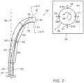
- Fig. 2is a schematic, pictorial illustration of distal end assembly 40, in accordance with an embodiment of the present invention.
- distal end assembly 40comprises a rigid distal tip 50 made from any suitable rigid material such as metal or plastic.
- distal tip 50comprises one or more electrodes (not shown), coupled to the outer surface of distal tip 50 and configured to exchange, via catheter 22, electrical signals between console 24 and the tissue of heart 26.
- the electrodesmay be used for sensing signals from heart 26, and/or for applying ablation signals for ablating the tissue of heart 26.
- distal tip 50may be hollow, so as to enable passage of electrical leads configured to conduct the electrical signals between console 24 and the electrodes.
- distal tip 50may comprise a flexible substrate, e.g., a flexible printed circuit board (PCB), wrapped around a solid profile of tip 50.
- the PCBmay comprise the leads formed thereon, and the electrodes formed and/or mounted thereon.
- distal tip 50may have a tubular shape as shown in Fig. 2 , or any other suitable shape, such as a balloon shape, a lasso, or a basket catheter.
- distal end assembly 40comprises a hollow flexible section 66, which is coupled to shaft 23 of catheter 22 along a longitudinal axis 55 of assembly 40, and is configured to deflect relative to shaft 23 in response to a bending force, as will be described below. Note that in a non-deflected position (e.g., when assembly 40 is inserted into the body of patient 28,) flexible section 66 is typically aligned with distal tip 50 and with shaft 23, along longitudinal axis 55.
- the distal end assemblycomprises a spring 60, which is coupled to distal tip 50 at one end of the spring and to flexible section 66 at the opposite end of the spring, along longitudinal axis 55.
- spring 60is configured to enable deflection of distal tip 50 relative to flexible section 66.
- flexible section 66 and spring 60are hollow, so as to allow passage of the electrical leads between catheter 22 and distal tip 50.
- distal end assembly 40comprises a pair of pulling wires 53 and 54, and a pair of pulling wires 63 and 64. Each pair serves as a, typically independent, deflection mechanism.
- wires 53 and 54are adapted to deflect distal tip 50 relative to flexible section 66, thereby serving as one deflection mechanism, whereas wires 63 and 64 are adapted to deflect flexible section 66 relative to shaft 23, thereby serving a different deflection mechanism.
- wires 53 and 63are coupled to one section (referred to herein as the "right section") of the inner surface of assembly 40
- wires 54 and 64are coupled to an opposite section (referred to herein as the "left section") of the inner surface of assembly 40.
- system 20may comprise one or more mechanical-based and/or electrical-based control assemblies (not shown) that are respectively coupled, together or separately, to pulling wires 53, 54, 63 and 64.
- control assembliesmay be coupled to manipulator 32, e.g., as two separate control knobs, one for distal tip 50 and the other for flexible section 66.
- physician 30may use the control knobs to control the respective directions and levels of deflection of distal tip 50 and flexible section 66.
- manipulator 32may comprise any other suitable configuration of controlling features.
- the control assembliesmay be controlled, using a suitable software, executed, for example, by processor 34 in control console 24.
- wire 53is coupled to the inner surface of the right section of distal tip 50, at a coupling point 51.
- wire 54is coupled to the inner surface of the left section of distal tip 50, at a coupling point 52 facing coupling point 51.
- physician 30may deflect distal tip 50 to a desired side by pulling a selected wire among wires 53 and 54.
- physician 30applied the respective control knob to pull wire 53, so as to apply bending force on distal tip 50, thereby to deflect assembly 40 to a desired spatial angle.
- distal tip 50is deflectable in two dimensions indicated by the directions of arrows 59A and 59B.
- physician 30may deflect assembly 40 in other directions, relative to axis 55, by a combined operation that comprises both rotating distal end assembly 40 about axis 55, shown by an arrow 69, and pulling wire 53 or 54.
- assembly 40may comprise any additional wires coupled to the inner surface of tip 50 at respective locations.
- distal end assembly 40may comprise two additional pulling wires (not shown) coupled to the inner surface of distal tip 50 at coupling points 56 and 57, thereby allowing deflection in directions indicated by respective arrows 67A and 67B.
- physician 30may pull, for example, two or more wires coupled to distal tip 50 at coupling points 52 and 57, so as to deflect the distal tip in a different direction indicated by an arrow 68, which is a sum of vectors of forces indicated by arrows 59A and 67B.
- any other suitable number of wiresmay be coupled to the inner surface of distal tip 50 at any suitable configuration.
- the probemay comprise a single pulling wire and a rotation capability about axis 55.
- the pulling wiresmay be coupled at the same sectional slice (e.g., section AA) or at different distance from the distal edge of assembly 40.
- distal end assembly 40further comprises additional pulling wires, such as wires 63 and 64, coupled to flexible section 66 at respective coupling points 61 and 62.
- additional pulling wiressuch as wires 63 and 64
- physiciancan deflect flexible section 66 to the directions indicated by arrows 59B and 59A, respectively.
- flexible section 66is typically less flexible than spring 60, so that the deflection level of flexible section 66 is lower compared to the deflection level of distal tip 50.
- any suitable number of pulling wiresmay be coupled at any other suitable location and angle to the inner surface of flexible section 66, instead of or in addition to wires 63 and 64.
- wires 53 and 54, and wires 63 and 64may be coupled to the outer surfaces of distal tip 50 and flexible section 66, respectively, or at any other suitable locations.
- distal end assembly 40may comprise one or more rigid wires in addition to, or instead of, some of the pulling wires.
- the rigid wiresmay be used for deflecting distal tip 50 relative to flexible section 66, and flexible section 66 relative to shaft 23, by applying, for example, a pushing force instead of, or in addition to, the pulling force described above.
- distal end assembly 40 shown in Fig. 2is an example configuration, which is chosen purely for the sake of conceptual clarity. In alternative embodiments, any other suitable configuration can also be used.
- assembly 40may comprise any suitable number of sections, such as distal tip 50 and flexible section 66, coupled along the longitudinal axis of catheter 22 at any suitable configuration.
- the sectionsmay be coupled to one another using any suitable number and type of flexible elements, having any suitable degree of flexibility.
Landscapes
- Health & Medical Sciences (AREA)
- Life Sciences & Earth Sciences (AREA)
- Engineering & Computer Science (AREA)
- Animal Behavior & Ethology (AREA)
- Biomedical Technology (AREA)
- Heart & Thoracic Surgery (AREA)
- General Health & Medical Sciences (AREA)
- Public Health (AREA)
- Veterinary Medicine (AREA)
- Surgery (AREA)
- Biophysics (AREA)
- Molecular Biology (AREA)
- Medical Informatics (AREA)
- Physics & Mathematics (AREA)
- Pathology (AREA)
- Anesthesiology (AREA)
- Pulmonology (AREA)
- Hematology (AREA)
- Nuclear Medicine, Radiotherapy & Molecular Imaging (AREA)
- Optics & Photonics (AREA)
- Radiology & Medical Imaging (AREA)
- Cardiology (AREA)
- Otolaryngology (AREA)
- Plasma & Fusion (AREA)
- Mechanical Engineering (AREA)
- Physiology (AREA)
- Surgical Instruments (AREA)
- Media Introduction/Drainage Providing Device (AREA)
- Electrotherapy Devices (AREA)
Description
- The present invention relates generally to medical probes, and particularly to methods and systems for deflecting medical probe distal ends.
- Medical probes, such as deflectable catheters, are used in some medical applications. Various types of deflectable catheters are known in the art.
- For example,
U.S. patent 5,431,168 describes a steerable catheter comprising an elongated catheter body and a tip portion. First and second lumens extend through the catheter body and tip portion. The first lumen is open at the distal end of the catheter. The second lumen is offaxis. U.S. patent 5,242,441 describes a cardiac arrhythmia ablation catheter that has a highly flexible tubular distal segment particularly adapted for navigating and exploring a ventridular cardiac chamber.U.S. Patent Application Publication 2002/0077590 describes a deflectable catheter comprising a catheter body, a tip section, and a control handle for affecting deflection of the tip section. The tip section comprises a flexible tubing having proximal and distal ends and at least two lumens extending therethrough.U.S. patent 5,195,968 discloses a catheter steering mechanism including a steering shaft coupled to a controller which includes a handle and apparatus for manipulating the distal end of the steering shaft. The steering shaft includes a flexible coiled spring having a lead spring fixed in position with respect to a distal end thereof in the distal end of the steering shaft. One or more steering wires is affixed at the distal ends thereof to the lead spring. The steering wires extend through the steering shaft to the controller, and the steering apparatus of the controller is used to place tension on one or both of the steering wires. The attachment of the distal ends of the steering wires to the lead spring may be opposite one another or may be offset for providing greater maneuverability. Tension may be placed on the steering wires by wedges mounted transversely to the controller housing, or by rotation of a shaft mounted transversely to the controller housing, the steering wires being attached to the shaft such that rotation in one direction tenses one steering sire, and rotation in the other direction tenses the other steering wire. Two independently rotatable shafts may be used to separately control the two steering wires.- An embodiment of the present invention that is described herein provides a medical probe including a shaft for navigation in a patient body, and first and second deflection mechanisms. The shaft ends with a flexible section and a spring, followed by a rigid distal tip having one or more medical devices coupled thereto. The first deflection mechanism is configured to deflect the flexible section relative to the shaft. The second deflection mechanism is configured to deflect the distal tip relative to the first flexible section by using the spring.
- The first deflection mechanism includes one or more wires coupled to the flexible section. In other embodiments, the medical probe includes a device external to the patient body, the wires extend between the flexible section and the device, and the device is configured to deflect the flexible section relative to the shaft by applying a force to at least one of the wires. In yet other embodiments, the force includes a pulling force.
- In an embodiment, the second deflection mechanism includes one or more other wires coupled to the distal tip. In another embodiment, the medical probe includes a device external to the patient body, the other wires extend between the distal tip and the device, and the device is configured to deflect the distal tip relative to the flexible section by applying a force to at least one of the other wires.
- In some embodiments, the force includes a pulling force. In other embodiments, the medical probe includes a handle, which is coupled to at least one of the first and second deflection mechanism, and which is configured to deflect at least one of the distal tip and the flexible section, using, respectively, one or more of the first and second deflection mechanisms.
- There is additionally provided, in accordance with an embodiment of the present invention, a method for producing a medical probe, the method includes assembling a shaft ending with a flexible section and a spring, followed by a rigid distal tip having one or more medical devices coupled thereto. First and second deflection mechanisms are connected to the medical probe, the first deflection mechanism deflects the flexible section relative to the shaft, and the second deflection mechanism deflects the distal tip relative to the first flexible section.
- The present invention will be more fully understood from the following detailed description of the embodiments thereof, taken together with the drawings in which:
Fig. 1 is a schematic, pictorial illustration of a catheterization system, in accordance with an embodiment of the present invention; andFig. 2 is a schematic, pictorial illustration of a deflectable distal end assembly of a catheter, in accordance with an embodiment of the present invention.- Some medical procedures, such as cardiac electrophysiology (EP) and sinuplasty, may involve navigating a medical probe to a target location in an organ of a patient. In some cases, a physician that carries out the procedure may face challenges in navigating the probe into the organ in question and in setting the probe at the target location. For example, forcing the catheter into the patient body may cause damage to the organ tissue. Furthermore, in some procedures it is important to approach the tissue with the probe from a desired angle and to make a proper physical contact between the probe and tissue at the target location.
- Embodiments of the present invention address these challenges, by providing a medical probe having a flexible distal end assembly that comprises multiple deflectable sections coupled along a longitudinal axis of the probe, each section is configured to deflect independently of the other section or sections using a different deflection mechanism.
- The probe comprises a rigid distal tip having one or more medical devices, such as sensing electrodes, coupled to an external surface of the distal tip. In an embodiment, the distal tip may have a hollow profile so as to enable passage of leads coupled to the electrodes. The leads are configured to conduct electrical signals between the electrodes and a computer coupled to the proximal end of the probes.
- The probe comprises a shaft for navigating the probe in a patient body. The shaft ends with a hollow flexible section and a spring, followed by the distal tip. The flexible section has some inherent level of flexibility that allows some deflection in response to bending forces applied to the flexible section, for example, using a manipulator device located at the proximal end of the probe.
- In some embodiments, the spring connects between the distal tip and the flexible section, along the longitudinal axis of the medical probe. In response to bending forces applied to the flexible section, the spring is configured to deflect the distal tip relative to the flexible section of the probe.
- In some embodiments, the medical probe comprises one or more pulling wires coupled, at respective coupling locations, to the inner surfaces of the hollow distal tip and flexible section. The pulling wires are adapted, when pulled by the physician, to apply bending forces that induce deflection of the flexible section relative to shaft, and deflection of the distal tip relative to the flexible section. The physician may control the degree of deflection by controlling the pulling force applied to each of the pulling wires.
- Note that typically the distal tip is coupled to one set of one or more pulling wires, and the flexible section is coupled to another set of one or more pulling wires, so that the distal tip and flexible section can be deflected independently of one another.
- In some embodiments, the pulling wires may be coupled to a manipulator device, also referred to herein as a handle, which is coupled to the proximal end of the medical probe, so as to control the levels of deflection caused to the distal tip and the flexible section using a single manipulator device.
- In some embodiments, the probe may comprise any suitable number of pulling wires coupled to the inner surface at any suitable configuration, so as to control the angles and levels of deflection of the distal tip and the flexible section.
- The disclosed techniques increase the maneuverability and functionality of medical catheters by enabling improved flexibility of the distal end assembly, and independent manipulation of multiple sections along the longitudinal axis of the probe.
Fig. 1 is a schematic, pictorial illustration of acatheterization system 20, in accordance with an embodiment of the present invention.System 20 comprises a probe, in the present example acardiac catheter 22, and acontrol console 24.- In the embodiment described herein,
catheter 22 may be used for any suitable therapeutic and/or diagnostic purposes, such as for sensing electro-potential signals or for ablating tissue in aheart 26 of apatient 28. - In some embodiments,
console 24 comprises aprocessor 34, typically a general-purpose computer, with suitable front end and interface circuits for receiving signals fromcatheter 22 and for controlling the other components ofsystem 20 described herein. - In some embodiments,
console 24 further comprises amemory 48, and adisplay 46, which is configured to display data, such as an image 44 of at least part ofheart 26 ofpatient 28. In some embodiments, image 44 may be acquired using any suitable anatomical imaging system, such as computerized tomography (CT) or fluoroscopic imaging. - A
physician 30, insertscatheter 22 through the vascular system ofpatient 28 lying on a table 29. - Reference is now made to an
inset 38. In some embodiments,catheter 22 comprises ashaft 23 for navigation the catheter in a patient body. In some embodiments,shaft 23, or any other suitable component ofcatheter 22, is coupled to a distal-end assembly 40, depicted in detail inFig. 2 below.Physician 30moves assembly 40 in the vicinity of the target region inheart 26 by manipulatingshaft 23 ofcatheter 22 using amanipulator 32 coupled near the proximal end ofcatheter 22. The proximal end ofcatheter 22 is connected to interface circuitry ofprocessor 34. - According to the present disclosure, the position of distal-
end assembly 40 in the heart cavity is typically measured using position sensing techniques. This method of position sensing is implemented, for example, in the CARTO™ system, produced by Biosense Webster Inc. (Irvine, Calif.) and is described in detail inU.S. Patents 5,391,199 ,6,690,963 ,6,484,118 ,6,239,724 ,6,618,612 and6,332,089 , inPCT Patent Publication WO 96/05768 U.S. Patent Application Publications 2002/0065455 A1 ,2003/0120150 A1 and2004/0068178 A1 . - In some embodiments,
console 24 comprises adriver circuit 42, which drivesmagnetic field generators 36 placed at known positions external topatient 28, e.g., below the patient's torso. - In some embodiments,
processor 34 is programmed in software to carry out the functions described herein. The software may be downloaded to the computer in electronic form, over a network, for example, or it may, alternatively or additionally, be provided and/or stored on nontransitory tangible media, such as magnetic, optical, or electronic memory. Fig. 2 is a schematic, pictorial illustration ofdistal end assembly 40, in accordance with an embodiment of the present invention. In some embodiments,distal end assembly 40 comprises a rigiddistal tip 50 made from any suitable rigid material such as metal or plastic.- In some embodiments,
distal tip 50 comprises one or more electrodes (not shown), coupled to the outer surface ofdistal tip 50 and configured to exchange, viacatheter 22, electrical signals betweenconsole 24 and the tissue ofheart 26. The electrodes may be used for sensing signals fromheart 26, and/or for applying ablation signals for ablating the tissue ofheart 26. - In some embodiments,
distal tip 50 may be hollow, so as to enable passage of electrical leads configured to conduct the electrical signals betweenconsole 24 and the electrodes. In other embodiments,distal tip 50 may comprise a flexible substrate, e.g., a flexible printed circuit board (PCB), wrapped around a solid profile oftip 50. In these embodiments, the PCB may comprise the leads formed thereon, and the electrodes formed and/or mounted thereon. - In some embodiments,
distal tip 50 may have a tubular shape as shown inFig. 2 , or any other suitable shape, such as a balloon shape, a lasso, or a basket catheter. - In some embodiments,
distal end assembly 40 comprises a hollow flexible section 66, which is coupled toshaft 23 ofcatheter 22 along alongitudinal axis 55 ofassembly 40, and is configured to deflect relative toshaft 23 in response to a bending force, as will be described below. Note that in a non-deflected position (e.g., whenassembly 40 is inserted into the body ofpatient 28,) flexible section 66 is typically aligned withdistal tip 50 and withshaft 23, alonglongitudinal axis 55. - According to the invention, the distal end assembly comprises a
spring 60, which is coupled todistal tip 50 at one end of the spring and to flexible section 66 at the opposite end of the spring, alonglongitudinal axis 55. - According to the invention,
spring 60 is configured to enable deflection ofdistal tip 50 relative to flexible section 66. In some embodiments, flexible section 66 andspring 60 are hollow, so as to allow passage of the electrical leads betweencatheter 22 anddistal tip 50. - In some embodiments,
distal end assembly 40 comprises a pair of pullingwires wires wires distal tip 50 relative to flexible section 66, thereby serving as one deflection mechanism, whereaswires shaft 23, thereby serving a different deflection mechanism. In the example ofFig. 2 ,wires assembly 40, andwires assembly 40. - In some embodiments,
system 20 may comprise one or more mechanical-based and/or electrical-based control assemblies (not shown) that are respectively coupled, together or separately, to pullingwires - In some embodiments, the control assemblies may be coupled to
manipulator 32, e.g., as two separate control knobs, one fordistal tip 50 and the other for flexible section 66. In these embodiments,physician 30 may use the control knobs to control the respective directions and levels of deflection ofdistal tip 50 and flexible section 66. In other embodiments,manipulator 32 may comprise any other suitable configuration of controlling features. Additionally or alternatively, the control assemblies may be controlled, using a suitable software, executed, for example, byprocessor 34 incontrol console 24. - In some embodiments,
wire 53 is coupled to the inner surface of the right section ofdistal tip 50, at acoupling point 51. Similarly,wire 54 is coupled to the inner surface of the left section ofdistal tip 50, at acoupling point 52 facingcoupling point 51. - In some embodiments,
physician 30 may deflectdistal tip 50 to a desired side by pulling a selected wire amongwires Fig. 2 ,physician 30 applied the respective control knob to pullwire 53, so as to apply bending force ondistal tip 50, thereby to deflectassembly 40 to a desired spatial angle. - Reference is now made to an
inset 58 showing a sectional top view AA ofdistal tip 50. - In the configuration of
Fig. 2 ,distal tip 50 is deflectable in two dimensions indicated by the directions ofarrows 59A and 59B. In some embodiments,physician 30 may deflectassembly 40 in other directions, relative toaxis 55, by a combined operation that comprises both rotatingdistal end assembly 40 aboutaxis 55, shown by anarrow 69, and pullingwire - In other embodiments,
assembly 40 may comprise any additional wires coupled to the inner surface oftip 50 at respective locations. For example,distal end assembly 40 may comprise two additional pulling wires (not shown) coupled to the inner surface ofdistal tip 50 at coupling points 56 and 57, thereby allowing deflection in directions indicated byrespective arrows - In this configuration,
physician 30 may pull, for example, two or more wires coupled todistal tip 50 at coupling points 52 and 57, so as to deflect the distal tip in a different direction indicated by anarrow 68, which is a sum of vectors of forces indicated byarrows 59A and 67B. - In alternative embodiments, any other suitable number of wires may be coupled to the inner surface of
distal tip 50 at any suitable configuration. For example, the probe may comprise a single pulling wire and a rotation capability aboutaxis 55. Note that the pulling wires may be coupled at the same sectional slice (e.g., section AA) or at different distance from the distal edge ofassembly 40. - In some embodiments,
distal end assembly 40 further comprises additional pulling wires, such aswires wire arrows 59B and 59A, respectively. - Note that flexible section 66 is typically less flexible than
spring 60, so that the deflection level of flexible section 66 is lower compared to the deflection level ofdistal tip 50. - In other embodiments, any suitable number of pulling wires may be coupled at any other suitable location and angle to the inner surface of flexible section 66, instead of or in addition to
wires - In alternative embodiments,
wires wires distal tip 50 and flexible section 66, respectively, or at any other suitable locations. - In other embodiments,
distal end assembly 40 may comprise one or more rigid wires in addition to, or instead of, some of the pulling wires. The rigid wires may be used for deflectingdistal tip 50 relative to flexible section 66, and flexible section 66 relative toshaft 23, by applying, for example, a pushing force instead of, or in addition to, the pulling force described above. - The configuration of
distal end assembly 40 shown inFig. 2 is an example configuration, which is chosen purely for the sake of conceptual clarity. In alternative embodiments, any other suitable configuration can also be used. - For example,
assembly 40 may comprise any suitable number of sections, such asdistal tip 50 and flexible section 66, coupled along the longitudinal axis ofcatheter 22 at any suitable configuration. The sections may be coupled to one another using any suitable number and type of flexible elements, having any suitable degree of flexibility. - Although the embodiments described herein mainly address cardiac procedures, the methods and systems described herein can also be used in other applications, such as in sinuplasty, surgery, endoscopy, otolaryngology and neurology.
- It will thus be appreciated that the embodiments described above are cited by way of example, and that the present invention is defined in the appended set of claims.
Claims (12)
- A medical probe, comprising:a shaft (23) for navigation in a patient body, the shaft (23) ending with a flexible section (66) and a spring (60), followed by a rigid distal tip (50) having one or more medical devices coupled thereto, wherein the flexible section (66), the spring (60), and the rigid distal tip (50) form a distal end assembly (40), wherein the spring (60) is coupled to the rigid distal tip (50) at one end of the spring (60) and to the flexible section (66) at the opposite end of the spring (60) along a longitudinal axis (55) of the distal end assembly (40);a first deflection mechanism, which is configured to deflect the flexible section relative to the shaft, wherein the first deflection mechanism comprises one or more wires (63, 64) coupled to the flexible section; anda second deflection mechanism, which is configured to deflect the distal tip relative to the first flexible section by using the spring (60).
- The medical probe according to claim 1, and comprising a device external to the patient body, wherein the wires (63, 64) extend between the flexible section (66) and the device, and wherein the device is configured to deflect the flexible section relative to the shaft by applying a force to at least one of the wires.
- The medical probe according to claim 2, wherein the force comprises a pulling force.
- The medical probe according to claim 1, wherein the second deflection mechanism comprises one or more other wires (53, 54) coupled to the distal tip (50).
- The medical probe according to claim 4, and comprising a device external to the patient body, wherein the other wires (53, 54) extend between the distal tip (50) and the device, and wherein the device is configured to deflect the distal tip relative to the flexible section (66) by applying a force to at least one of the other wires (53, 54) .
- The medical probe according to claim 5, wherein the force comprises a pulling force.
- The medical probe according to claim 1, and comprising a handle, which is coupled to at least one of the first and second deflection mechanism, and which is configured to deflect at least one of the distal tip and the flexible section, using, respectively, one or more of the first and second deflection mechanisms.
- A method for producing a medical probe, the method comprising:assembling a shaft (23) ending with a flexible section (66) and a spring (60), followed by a rigid distal tip (50) having one or more medical devices coupled thereto, wherein the flexible section (66), the spring (60), and the rigid distal tip (50) form a distal end assembly, wherein the spring (60) is coupled to the rigid distal tip (50) at one end of the spring (60) and to the flexible section (66) at the opposite end of the spring (60) along a longitudinal axis (55) of the distal end assembly (40); andconnecting, to the medical probe, first and second deflection mechanisms, wherein the first deflection mechanism deflects the flexible section (66) relative to the shaft (23), and the second deflection mechanism deflects the distal tip relative to the first flexible section (66),wherein the first deflection mechanism comprises one or more wires (63, 64) coupled to the flexible section (66) .
- The method according to claim 8, and comprising coupling, to the medical probe, a device for deflecting the flexible section (66) relative to the shaft (23), and extending the wires between the flexible section (66) and the device.
- The method according to claim 8, wherein the second deflection mechanism comprises one or more other wires (53, 54) coupled to the distal tip.
- The method according to claim 10, and comprising coupling, to the medical probe, a device for deflecting the distal tip (50) relative to the flexible section (66), and extending the other wires between the distal tip (50) and the device.
- The method according to claim 8, and comprising, coupling a handle to at least one of the first and second deflection mechanism for deflecting at least one of the distal tip (50) and the flexible section (66), using, respectively, one or more of the first and second deflection mechanisms.
Applications Claiming Priority (2)
| Application Number | Priority Date | Filing Date | Title |
|---|---|---|---|
| US15/860,235US11517715B2 (en) | 2018-01-02 | 2018-01-02 | Deflectable medical probe |
| PCT/IB2018/060307WO2019135138A1 (en) | 2018-01-02 | 2018-12-19 | A deflectable medical probe |
Publications (2)
| Publication Number | Publication Date |
|---|---|
| EP3735164A1 EP3735164A1 (en) | 2020-11-11 |
| EP3735164B1true EP3735164B1 (en) | 2023-08-02 |
Family
ID=65139050
Family Applications (1)
| Application Number | Title | Priority Date | Filing Date |
|---|---|---|---|
| EP18836898.9AActiveEP3735164B1 (en) | 2018-01-02 | 2018-12-19 | A deflectable medical probe |
Country Status (6)
| Country | Link |
|---|---|
| US (2) | US11517715B2 (en) |
| EP (1) | EP3735164B1 (en) |
| JP (1) | JP7326327B2 (en) |
| CN (1) | CN111683581B (en) |
| IL (1) | IL275679B2 (en) |
| WO (1) | WO2019135138A1 (en) |
Families Citing this family (26)
| Publication number | Priority date | Publication date | Assignee | Title |
|---|---|---|---|---|
| US10905329B2 (en) | 2016-06-09 | 2021-02-02 | Biosense Webster (Israel) Ltd. | Multi-function conducting elements for a catheter |
| US12029545B2 (en) | 2017-05-30 | 2024-07-09 | Biosense Webster (Israel) Ltd. | Catheter splines as location sensors |
| US11517715B2 (en)* | 2018-01-02 | 2022-12-06 | Biosense Webster (Israel) Ltd. | Deflectable medical probe |
| US20190314083A1 (en) | 2018-04-11 | 2019-10-17 | Biosense Webster (Israel) Ltd. | Flexible Multi-Arm Catheter with Diametrically Opposed Sensing Electrodes |
| EP3768185B1 (en) | 2018-05-21 | 2023-06-14 | St. Jude Medical, Cardiology Division, Inc. | Radio-frequency ablation and direct current electroporation catheters |
| US11045628B2 (en) | 2018-12-11 | 2021-06-29 | Biosense Webster (Israel) Ltd. | Balloon catheter with high articulation |
| US11207016B2 (en) | 2018-12-28 | 2021-12-28 | Biosense Webster (Israel) Ltd. | Mapping ECG signals using a multipole electrode assembly |
| US11850051B2 (en) | 2019-04-30 | 2023-12-26 | Biosense Webster (Israel) Ltd. | Mapping grid with high density electrode array |
| US11712172B2 (en) | 2019-07-18 | 2023-08-01 | Biosense Webster (Israel) Ltd. | Visual guidance for positioning a distal end of a medical probe |
| US11950930B2 (en) | 2019-12-12 | 2024-04-09 | Biosense Webster (Israel) Ltd. | Multi-dimensional acquisition of bipolar signals from a catheter |
| US11517218B2 (en) | 2019-12-20 | 2022-12-06 | Biosense Webster (Israel) Ltd. | Selective graphical presentation of electrophysiological parameters |
| US12232874B2 (en) | 2020-05-29 | 2025-02-25 | Biosense Webster (Israel) Ltd. | Electrode apparatus for diagnosis of arrhythmias |
| US11987017B2 (en) | 2020-06-08 | 2024-05-21 | Biosense Webster (Israel) Ltd. | Features to assist in assembly and testing of devices |
| WO2022038546A1 (en) | 2020-08-18 | 2022-02-24 | St. Jude Medical, Cardiology Division, Inc. | High-density electrode catheters with magnetic position tracking |
| US12048479B2 (en) | 2020-09-10 | 2024-07-30 | Biosense Webster (Israel) Ltd. | Surface mounted electrode catheter |
| US11950840B2 (en) | 2020-09-22 | 2024-04-09 | Biosense Webster (Israel) Ltd. | Basket catheter having insulated ablation electrodes |
| US11950841B2 (en) | 2020-09-22 | 2024-04-09 | Biosense Webster (Israel) Ltd. | Basket catheter having insulated ablation electrodes and diagnostic electrodes |
| US12082875B2 (en) | 2020-09-24 | 2024-09-10 | Biosense Webster (Israel) Ltd | Balloon catheter having a coil for sensing tissue temperature and position of the balloon |
| US11974803B2 (en) | 2020-10-12 | 2024-05-07 | Biosense Webster (Israel) Ltd. | Basket catheter with balloon |
| US12201786B2 (en) | 2020-12-17 | 2025-01-21 | Biosense Webster (Israel) Ltd. | Measurement of distal end dimension of catheters using magnetic fields |
| US11918383B2 (en) | 2020-12-21 | 2024-03-05 | Biosense Webster (Israel) Ltd. | Visualizing performance of catheter electrodes |
| US12064170B2 (en) | 2021-05-13 | 2024-08-20 | Biosense Webster (Israel) Ltd. | Distal assembly for catheter with lumens running along spines |
| US12364426B2 (en) | 2021-08-12 | 2025-07-22 | Biosense Webster (Israel) Ltd. | Electro-anatomical mapping and annotation presented in electrophysiological procedures |
| US12004804B2 (en) | 2021-09-09 | 2024-06-11 | Biosense Webster (Israel) Ltd. | Basket catheter with mushroom shape distal tip |
| US12011280B2 (en) | 2021-10-04 | 2024-06-18 | Biosense Webster (Israel) Ltd. | Electrophysiological mapping in the presence of injury current |
| US12419683B2 (en) | 2021-12-22 | 2025-09-23 | Biosense Webster (Israel) Ltd. | Irreversible electroporation with shorted electrodes |
Family Cites Families (45)
| Publication number | Priority date | Publication date | Assignee | Title |
|---|---|---|---|---|
| CH667207A5 (en) | 1985-11-21 | 1988-09-30 | Sarcem Sa | REMOTE CONTROL CATHETER WITH MICRO-BALLOON. |
| DE69122853T2 (en)* | 1990-02-02 | 1997-10-09 | Ep Technologies, Inc., Sunnyvale, Calif. | STEERING MECHANISM FOR CATHETER |
| US5195968A (en) | 1990-02-02 | 1993-03-23 | Ingemar Lundquist | Catheter steering mechanism |
| US6033378A (en) | 1990-02-02 | 2000-03-07 | Ep Technologies, Inc. | Catheter steering mechanism |
| US5242441A (en) | 1992-02-24 | 1993-09-07 | Boaz Avitall | Deflectable catheter with rotatable tip electrode |
| EP0746373A1 (en)* | 1992-12-01 | 1996-12-11 | Intelliwire, Inc. | Vibratory element for crossing stenoses |
| US5391199A (en) | 1993-07-20 | 1995-02-21 | Biosense, Inc. | Apparatus and method for treating cardiac arrhythmias |
| US5431168A (en) | 1993-08-23 | 1995-07-11 | Cordis-Webster, Inc. | Steerable open-lumen catheter |
| US5882333A (en) | 1994-05-13 | 1999-03-16 | Cardima, Inc. | Catheter with deflectable distal section |
| AU1693095A (en) | 1994-08-19 | 1996-03-14 | Biosense, Inc. | Medical diagnosis, treatment and imaging systems |
| US6690963B2 (en) | 1995-01-24 | 2004-02-10 | Biosense, Inc. | System for determining the location and orientation of an invasive medical instrument |
| US6618612B1 (en) | 1996-02-15 | 2003-09-09 | Biosense, Inc. | Independently positionable transducers for location system |
| AU709081B2 (en) | 1996-02-15 | 1999-08-19 | Biosense, Inc. | Medical procedures and apparatus using intrabody probes |
| US6239724B1 (en) | 1997-12-30 | 2001-05-29 | Remon Medical Technologies, Ltd. | System and method for telemetrically providing intrabody spatial position |
| US6198974B1 (en)* | 1998-08-14 | 2001-03-06 | Cordis Webster, Inc. | Bi-directional steerable catheter |
| US6374476B1 (en) | 1999-03-03 | 2002-04-23 | Codris Webster, Inc. | Method for making a catheter tip section |
| US6183435B1 (en)* | 1999-03-22 | 2001-02-06 | Cordis Webster, Inc. | Multi-directional steerable catheters and control handles |
| US20040044350A1 (en)* | 1999-04-09 | 2004-03-04 | Evalve, Inc. | Steerable access sheath and methods of use |
| US6599254B2 (en) | 2000-05-08 | 2003-07-29 | R. Edward Winters | Multi-feature steerable guidewire for vascular systems |
| US6484118B1 (en) | 2000-07-20 | 2002-11-19 | Biosense, Inc. | Electromagnetic position single axis system |
| US7729742B2 (en) | 2001-12-21 | 2010-06-01 | Biosense, Inc. | Wireless position sensor |
| US20040068178A1 (en) | 2002-09-17 | 2004-04-08 | Assaf Govari | High-gradient recursive locating system |
| US7811277B2 (en)* | 2004-09-30 | 2010-10-12 | Boston Scientific Scimed, Inc. | Steerable device and system |
| US9833595B2 (en)* | 2005-12-30 | 2017-12-05 | Biosense Webster, Inc. | Dual-lever bi-directional handle |
| US20070225681A1 (en) | 2006-03-21 | 2007-09-27 | Medtronic Vascular | Catheter Having a Selectively Formable Distal Section |
| US8236010B2 (en)* | 2006-03-23 | 2012-08-07 | Ethicon Endo-Surgery, Inc. | Surgical fastener and cutter with mimicking end effector |
| US7780648B2 (en)* | 2007-12-28 | 2010-08-24 | Boston Scientific Scimed, Inc. | Controlling movement of distal portion of medical device |
| WO2009094511A1 (en)* | 2008-01-24 | 2009-07-30 | Boston Scientific Scimed, Inc. | Structure for use as part of a medical device |
| JP5245138B2 (en)* | 2008-03-19 | 2013-07-24 | 哲丸 宮脇 | Endoscope |
| US8083691B2 (en)* | 2008-11-12 | 2011-12-27 | Hansen Medical, Inc. | Apparatus and method for sensing force |
| US10046141B2 (en)* | 2008-12-30 | 2018-08-14 | Biosense Webster, Inc. | Deflectable sheath introducer |
| JP5253689B1 (en)* | 2011-07-15 | 2013-07-31 | オリンパスメディカルシステムズ株式会社 | Insertion equipment |
| JP6430831B2 (en)* | 2011-10-14 | 2018-11-28 | インテュイティブ サージカル オペレーションズ, インコーポレイテッド | Catheter system |
| US9101269B2 (en)* | 2011-12-15 | 2015-08-11 | Biosense Webster (Israel), Ltd. | Self-holding medical device control handle with cam actuated clutch mechanism |
| US9216056B2 (en)* | 2012-03-02 | 2015-12-22 | Biosense Webster (Israel) Ltd. | Catheter for treatment of atrial flutter having single action dual deflection mechanism |
| US9717547B2 (en)* | 2012-04-23 | 2017-08-01 | St. Jude Medical, Inc. | Ultrasonic lesion feedback, antipop monitoring, and force detection |
| US10639099B2 (en)* | 2012-05-25 | 2020-05-05 | Biosense Webster (Israel), Ltd. | Catheter having a distal section with spring sections for biased deflection |
| EP2783621B1 (en)* | 2012-07-02 | 2017-10-04 | Olympus Corporation | Insertion instrument |
| US11096736B2 (en)* | 2013-12-09 | 2021-08-24 | Biosense Webster (Israel) Ltd. | Pericardial catheter with temperature sensing array |
| US9937323B2 (en)* | 2014-02-28 | 2018-04-10 | Cook Medical Technologies Llc | Deflectable catheters, systems, and methods for the visualization and treatment of bodily passages |
| EP3125738A4 (en)* | 2014-03-31 | 2017-12-06 | Human Extensions Ltd. | Steerable medical device |
| JP6454029B2 (en)* | 2015-04-02 | 2019-01-16 | コーニンクレッカ フィリップス エヌ ヴェKoninklijke Philips N.V. | Deflectable medical device |
| US11033715B2 (en)* | 2015-05-18 | 2021-06-15 | Biosense Webster (Israel) Ltd. | Catheter with adjustable deflection |
| US11517715B2 (en)* | 2018-01-02 | 2022-12-06 | Biosense Webster (Israel) Ltd. | Deflectable medical probe |
| WO2020008571A1 (en)* | 2018-07-04 | 2020-01-09 | オリンパス株式会社 | Endoscope |
- 2018
- 2018-01-02USUS15/860,235patent/US11517715B2/enactiveActive
- 2018-12-19ILIL275679Apatent/IL275679B2/enunknown
- 2018-12-19WOPCT/IB2018/060307patent/WO2019135138A1/ennot_activeCeased
- 2018-12-19EPEP18836898.9Apatent/EP3735164B1/enactiveActive
- 2018-12-19JPJP2020556352Apatent/JP7326327B2/enactiveActive
- 2018-12-19CNCN201880085149.0Apatent/CN111683581B/enactiveActive
- 2022
- 2022-11-22USUS17/991,976patent/US20230078216A1/enactivePending
Also Published As
| Publication number | Publication date |
|---|---|
| JP7326327B2 (en) | 2023-08-15 |
| WO2019135138A1 (en) | 2019-07-11 |
| US20190201664A1 (en) | 2019-07-04 |
| IL275679B1 (en) | 2023-06-01 |
| EP3735164A1 (en) | 2020-11-11 |
| CN111683581A (en) | 2020-09-18 |
| US20230078216A1 (en) | 2023-03-16 |
| IL275679B2 (en) | 2023-10-01 |
| US11517715B2 (en) | 2022-12-06 |
| CN111683581B (en) | 2024-09-24 |
| JP2021509628A (en) | 2021-04-01 |
| IL275679A (en) | 2020-08-31 |
Similar Documents
| Publication | Publication Date | Title |
|---|---|---|
| EP3735164B1 (en) | A deflectable medical probe | |
| EP3710094B1 (en) | A catheter handle | |
| US9078667B2 (en) | Catheter having reduced force concentration at tissue contact site | |
| EP4031007B1 (en) | Catheter instrument with three pull wires | |
| EP1631196B1 (en) | Articulating mechanism for remote manipulation of a surgical or diagnostic tool | |
| CN112584737B (en) | Apparatus and accessory for percutaneous endoscopic access and ablation system | |
| WO2010009427A1 (en) | A positionable medical system for positioning medical components on or within a body | |
| EP4137080B1 (en) | Catheter having electrodes with adjustable size | |
| US12295602B2 (en) | Medical probe having improved maneuverability | |
| EP3813706B1 (en) | Unibody intravascular catheter shaft | |
| US20220331553A1 (en) | Wire management coupler for a medical device | |
| JP2023500018A (en) | CATHETER INCLUDING A FLEXABLE SHAFT AND METHOD FOR ASSEMBLY THEREOF | |
| JP7413354B2 (en) | Deflection mechanism inside the balloon to improve balloon maneuverability |
Legal Events
| Date | Code | Title | Description |
|---|---|---|---|
| STAA | Information on the status of an ep patent application or granted ep patent | Free format text:STATUS: UNKNOWN | |
| STAA | Information on the status of an ep patent application or granted ep patent | Free format text:STATUS: THE INTERNATIONAL PUBLICATION HAS BEEN MADE | |
| PUAI | Public reference made under article 153(3) epc to a published international application that has entered the european phase | Free format text:ORIGINAL CODE: 0009012 | |
| STAA | Information on the status of an ep patent application or granted ep patent | Free format text:STATUS: REQUEST FOR EXAMINATION WAS MADE | |
| 17P | Request for examination filed | Effective date:20200625 | |
| AK | Designated contracting states | Kind code of ref document:A1 Designated state(s):AL AT BE BG CH CY CZ DE DK EE ES FI FR GB GR HR HU IE IS IT LI LT LU LV MC MK MT NL NO PL PT RO RS SE SI SK SM TR | |
| AX | Request for extension of the european patent | Extension state:BA ME | |
| DAV | Request for validation of the european patent (deleted) | ||
| DAX | Request for extension of the european patent (deleted) | ||
| RAP3 | Party data changed (applicant data changed or rights of an application transferred) | Owner name:BIOSENSE WEBSTER (ISRAEL) LTD. | |
| GRAP | Despatch of communication of intention to grant a patent | Free format text:ORIGINAL CODE: EPIDOSNIGR1 | |
| STAA | Information on the status of an ep patent application or granted ep patent | Free format text:STATUS: GRANT OF PATENT IS INTENDED | |
| RAP3 | Party data changed (applicant data changed or rights of an application transferred) | Owner name:BIOSENSE WEBSTER (ISRAEL) LTD. | |
| INTG | Intention to grant announced | Effective date:20220607 | |
| GRAJ | Information related to disapproval of communication of intention to grant by the applicant or resumption of examination proceedings by the epo deleted | Free format text:ORIGINAL CODE: EPIDOSDIGR1 | |
| STAA | Information on the status of an ep patent application or granted ep patent | Free format text:STATUS: REQUEST FOR EXAMINATION WAS MADE | |
| GRAP | Despatch of communication of intention to grant a patent | Free format text:ORIGINAL CODE: EPIDOSNIGR1 | |
| STAA | Information on the status of an ep patent application or granted ep patent | Free format text:STATUS: GRANT OF PATENT IS INTENDED | |
| INTC | Intention to grant announced (deleted) | ||
| INTG | Intention to grant announced | Effective date:20221108 | |
| GRAS | Grant fee paid | Free format text:ORIGINAL CODE: EPIDOSNIGR3 | |
| GRAA | (expected) grant | Free format text:ORIGINAL CODE: 0009210 | |
| STAA | Information on the status of an ep patent application or granted ep patent | Free format text:STATUS: THE PATENT HAS BEEN GRANTED | |
| AK | Designated contracting states | Kind code of ref document:B1 Designated state(s):AL AT BE BG CH CY CZ DE DK EE ES FI FR GB GR HR HU IE IS IT LI LT LU LV MC MK MT NL NO PL PT RO RS SE SI SK SM TR | |
| REG | Reference to a national code | Ref country code:GB Ref legal event code:FG4D | |
| REG | Reference to a national code | Ref country code:CH Ref legal event code:EP | |
| REG | Reference to a national code | Ref country code:DE Ref legal event code:R096 Ref document number:602018054716 Country of ref document:DE | |
| REG | Reference to a national code | Ref country code:IE Ref legal event code:FG4D | |
| REG | Reference to a national code | Ref country code:LT Ref legal event code:MG9D | |
| REG | Reference to a national code | Ref country code:NL Ref legal event code:MP Effective date:20230802 | |
| REG | Reference to a national code | Ref country code:AT Ref legal event code:MK05 Ref document number:1593698 Country of ref document:AT Kind code of ref document:T Effective date:20230802 | |
| PG25 | Lapsed in a contracting state [announced via postgrant information from national office to epo] | Ref country code:GR Free format text:LAPSE BECAUSE OF FAILURE TO SUBMIT A TRANSLATION OF THE DESCRIPTION OR TO PAY THE FEE WITHIN THE PRESCRIBED TIME-LIMIT Effective date:20231103 | |
| PG25 | Lapsed in a contracting state [announced via postgrant information from national office to epo] | Ref country code:IS Free format text:LAPSE BECAUSE OF FAILURE TO SUBMIT A TRANSLATION OF THE DESCRIPTION OR TO PAY THE FEE WITHIN THE PRESCRIBED TIME-LIMIT Effective date:20231202 | |
| PG25 | Lapsed in a contracting state [announced via postgrant information from national office to epo] | Ref country code:SE Free format text:LAPSE BECAUSE OF FAILURE TO SUBMIT A TRANSLATION OF THE DESCRIPTION OR TO PAY THE FEE WITHIN THE PRESCRIBED TIME-LIMIT Effective date:20230802 Ref country code:RS Free format text:LAPSE BECAUSE OF FAILURE TO SUBMIT A TRANSLATION OF THE DESCRIPTION OR TO PAY THE FEE WITHIN THE PRESCRIBED TIME-LIMIT Effective date:20230802 Ref country code:PT Free format text:LAPSE BECAUSE OF FAILURE TO SUBMIT A TRANSLATION OF THE DESCRIPTION OR TO PAY THE FEE WITHIN THE PRESCRIBED TIME-LIMIT Effective date:20231204 Ref country code:NO Free format text:LAPSE BECAUSE OF FAILURE TO SUBMIT A TRANSLATION OF THE DESCRIPTION OR TO PAY THE FEE WITHIN THE PRESCRIBED TIME-LIMIT Effective date:20231102 Ref country code:NL Free format text:LAPSE BECAUSE OF FAILURE TO SUBMIT A TRANSLATION OF THE DESCRIPTION OR TO PAY THE FEE WITHIN THE PRESCRIBED TIME-LIMIT Effective date:20230802 Ref country code:LV Free format text:LAPSE BECAUSE OF FAILURE TO SUBMIT A TRANSLATION OF THE DESCRIPTION OR TO PAY THE FEE WITHIN THE PRESCRIBED TIME-LIMIT Effective date:20230802 Ref country code:LT Free format text:LAPSE BECAUSE OF FAILURE TO SUBMIT A TRANSLATION OF THE DESCRIPTION OR TO PAY THE FEE WITHIN THE PRESCRIBED TIME-LIMIT Effective date:20230802 Ref country code:IS Free format text:LAPSE BECAUSE OF FAILURE TO SUBMIT A TRANSLATION OF THE DESCRIPTION OR TO PAY THE FEE WITHIN THE PRESCRIBED TIME-LIMIT Effective date:20231202 Ref country code:HR Free format text:LAPSE BECAUSE OF FAILURE TO SUBMIT A TRANSLATION OF THE DESCRIPTION OR TO PAY THE FEE WITHIN THE PRESCRIBED TIME-LIMIT Effective date:20230802 Ref country code:GR Free format text:LAPSE BECAUSE OF FAILURE TO SUBMIT A TRANSLATION OF THE DESCRIPTION OR TO PAY THE FEE WITHIN THE PRESCRIBED TIME-LIMIT Effective date:20231103 Ref country code:FI Free format text:LAPSE BECAUSE OF FAILURE TO SUBMIT A TRANSLATION OF THE DESCRIPTION OR TO PAY THE FEE WITHIN THE PRESCRIBED TIME-LIMIT Effective date:20230802 Ref country code:AT Free format text:LAPSE BECAUSE OF FAILURE TO SUBMIT A TRANSLATION OF THE DESCRIPTION OR TO PAY THE FEE WITHIN THE PRESCRIBED TIME-LIMIT Effective date:20230802 | |
| PG25 | Lapsed in a contracting state [announced via postgrant information from national office to epo] | Ref country code:PL Free format text:LAPSE BECAUSE OF FAILURE TO SUBMIT A TRANSLATION OF THE DESCRIPTION OR TO PAY THE FEE WITHIN THE PRESCRIBED TIME-LIMIT Effective date:20230802 | |
| PG25 | Lapsed in a contracting state [announced via postgrant information from national office to epo] | Ref country code:ES Free format text:LAPSE BECAUSE OF FAILURE TO SUBMIT A TRANSLATION OF THE DESCRIPTION OR TO PAY THE FEE WITHIN THE PRESCRIBED TIME-LIMIT Effective date:20230802 | |
| PG25 | Lapsed in a contracting state [announced via postgrant information from national office to epo] | Ref country code:SM Free format text:LAPSE BECAUSE OF FAILURE TO SUBMIT A TRANSLATION OF THE DESCRIPTION OR TO PAY THE FEE WITHIN THE PRESCRIBED TIME-LIMIT Effective date:20230802 Ref country code:RO Free format text:LAPSE BECAUSE OF FAILURE TO SUBMIT A TRANSLATION OF THE DESCRIPTION OR TO PAY THE FEE WITHIN THE PRESCRIBED TIME-LIMIT Effective date:20230802 Ref country code:ES Free format text:LAPSE BECAUSE OF FAILURE TO SUBMIT A TRANSLATION OF THE DESCRIPTION OR TO PAY THE FEE WITHIN THE PRESCRIBED TIME-LIMIT Effective date:20230802 Ref country code:EE Free format text:LAPSE BECAUSE OF FAILURE TO SUBMIT A TRANSLATION OF THE DESCRIPTION OR TO PAY THE FEE WITHIN THE PRESCRIBED TIME-LIMIT Effective date:20230802 Ref country code:DK Free format text:LAPSE BECAUSE OF FAILURE TO SUBMIT A TRANSLATION OF THE DESCRIPTION OR TO PAY THE FEE WITHIN THE PRESCRIBED TIME-LIMIT Effective date:20230802 Ref country code:CZ Free format text:LAPSE BECAUSE OF FAILURE TO SUBMIT A TRANSLATION OF THE DESCRIPTION OR TO PAY THE FEE WITHIN THE PRESCRIBED TIME-LIMIT Effective date:20230802 Ref country code:SK Free format text:LAPSE BECAUSE OF FAILURE TO SUBMIT A TRANSLATION OF THE DESCRIPTION OR TO PAY THE FEE WITHIN THE PRESCRIBED TIME-LIMIT Effective date:20230802 | |
| REG | Reference to a national code | Ref country code:DE Ref legal event code:R097 Ref document number:602018054716 Country of ref document:DE | |
| PLBE | No opposition filed within time limit | Free format text:ORIGINAL CODE: 0009261 | |
| STAA | Information on the status of an ep patent application or granted ep patent | Free format text:STATUS: NO OPPOSITION FILED WITHIN TIME LIMIT | |
| 26N | No opposition filed | Effective date:20240503 | |
| PG25 | Lapsed in a contracting state [announced via postgrant information from national office to epo] | Ref country code:SI Free format text:LAPSE BECAUSE OF FAILURE TO SUBMIT A TRANSLATION OF THE DESCRIPTION OR TO PAY THE FEE WITHIN THE PRESCRIBED TIME-LIMIT Effective date:20230802 | |
| REG | Reference to a national code | Ref country code:CH Ref legal event code:PL | |
| PG25 | Lapsed in a contracting state [announced via postgrant information from national office to epo] | Ref country code:LU Free format text:LAPSE BECAUSE OF NON-PAYMENT OF DUE FEES Effective date:20231219 | |
| PG25 | Lapsed in a contracting state [announced via postgrant information from national office to epo] | Ref country code:MC Free format text:LAPSE BECAUSE OF FAILURE TO SUBMIT A TRANSLATION OF THE DESCRIPTION OR TO PAY THE FEE WITHIN THE PRESCRIBED TIME-LIMIT Effective date:20230802 | |
| REG | Reference to a national code | Ref country code:BE Ref legal event code:MM Effective date:20231231 | |
| PG25 | Lapsed in a contracting state [announced via postgrant information from national office to epo] | Ref country code:MC Free format text:LAPSE BECAUSE OF FAILURE TO SUBMIT A TRANSLATION OF THE DESCRIPTION OR TO PAY THE FEE WITHIN THE PRESCRIBED TIME-LIMIT Effective date:20230802 Ref country code:LU Free format text:LAPSE BECAUSE OF NON-PAYMENT OF DUE FEES Effective date:20231219 | |
| REG | Reference to a national code | Ref country code:IE Ref legal event code:MM4A | |
| PG25 | Lapsed in a contracting state [announced via postgrant information from national office to epo] | Ref country code:IE Free format text:LAPSE BECAUSE OF NON-PAYMENT OF DUE FEES Effective date:20231219 | |
| PG25 | Lapsed in a contracting state [announced via postgrant information from national office to epo] | Ref country code:BE Free format text:LAPSE BECAUSE OF NON-PAYMENT OF DUE FEES Effective date:20231231 | |
| PG25 | Lapsed in a contracting state [announced via postgrant information from national office to epo] | Ref country code:CH Free format text:LAPSE BECAUSE OF NON-PAYMENT OF DUE FEES Effective date:20231231 | |
| PG25 | Lapsed in a contracting state [announced via postgrant information from national office to epo] | Ref country code:IE Free format text:LAPSE BECAUSE OF NON-PAYMENT OF DUE FEES Effective date:20231219 Ref country code:CH Free format text:LAPSE BECAUSE OF NON-PAYMENT OF DUE FEES Effective date:20231231 Ref country code:BE Free format text:LAPSE BECAUSE OF NON-PAYMENT OF DUE FEES Effective date:20231231 | |
| PG25 | Lapsed in a contracting state [announced via postgrant information from national office to epo] | Ref country code:BG Free format text:LAPSE BECAUSE OF FAILURE TO SUBMIT A TRANSLATION OF THE DESCRIPTION OR TO PAY THE FEE WITHIN THE PRESCRIBED TIME-LIMIT Effective date:20230802 | |
| PG25 | Lapsed in a contracting state [announced via postgrant information from national office to epo] | Ref country code:BG Free format text:LAPSE BECAUSE OF FAILURE TO SUBMIT A TRANSLATION OF THE DESCRIPTION OR TO PAY THE FEE WITHIN THE PRESCRIBED TIME-LIMIT Effective date:20230802 | |
| PGFP | Annual fee paid to national office [announced via postgrant information from national office to epo] | Ref country code:DE Payment date:20241029 Year of fee payment:7 | |
| PGFP | Annual fee paid to national office [announced via postgrant information from national office to epo] | Ref country code:GB Payment date:20241031 Year of fee payment:7 | |
| PGFP | Annual fee paid to national office [announced via postgrant information from national office to epo] | Ref country code:FR Payment date:20241111 Year of fee payment:7 | |
| PGFP | Annual fee paid to national office [announced via postgrant information from national office to epo] | Ref country code:IT Payment date:20241112 Year of fee payment:7 | |
| PG25 | Lapsed in a contracting state [announced via postgrant information from national office to epo] | Ref country code:CY Free format text:LAPSE BECAUSE OF FAILURE TO SUBMIT A TRANSLATION OF THE DESCRIPTION OR TO PAY THE FEE WITHIN THE PRESCRIBED TIME-LIMIT; INVALID AB INITIO Effective date:20181219 | |
| PG25 | Lapsed in a contracting state [announced via postgrant information from national office to epo] | Ref country code:HU Free format text:LAPSE BECAUSE OF FAILURE TO SUBMIT A TRANSLATION OF THE DESCRIPTION OR TO PAY THE FEE WITHIN THE PRESCRIBED TIME-LIMIT; INVALID AB INITIO Effective date:20181219 |