EP3733060B1 - Utilization of electrode spatial arrangements for characterizing cardiac conduction conditions - Google Patents
Utilization of electrode spatial arrangements for characterizing cardiac conduction conditionsDownload PDFInfo
- Publication number
- EP3733060B1 EP3733060B1EP20179775.0AEP20179775AEP3733060B1EP 3733060 B1EP3733060 B1EP 3733060B1EP 20179775 AEP20179775 AEP 20179775AEP 3733060 B1EP3733060 B1EP 3733060B1
- Authority
- EP
- European Patent Office
- Prior art keywords
- electrodes
- vector
- electrogram
- catheter
- signals
- Prior art date
- Legal status (The legal status is an assumption and is not a legal conclusion. Google has not performed a legal analysis and makes no representation as to the accuracy of the status listed.)
- Active
Links
Images


Classifications
- A—HUMAN NECESSITIES
- A61—MEDICAL OR VETERINARY SCIENCE; HYGIENE
- A61B—DIAGNOSIS; SURGERY; IDENTIFICATION
- A61B18/00—Surgical instruments, devices or methods for transferring non-mechanical forms of energy to or from the body
- A61B18/04—Surgical instruments, devices or methods for transferring non-mechanical forms of energy to or from the body by heating
- A61B18/12—Surgical instruments, devices or methods for transferring non-mechanical forms of energy to or from the body by heating by passing a current through the tissue to be heated, e.g. high-frequency current
- A61B18/14—Probes or electrodes therefor
- A61B18/1492—Probes or electrodes therefor having a flexible, catheter-like structure, e.g. for heart ablation
- A—HUMAN NECESSITIES
- A61—MEDICAL OR VETERINARY SCIENCE; HYGIENE
- A61B—DIAGNOSIS; SURGERY; IDENTIFICATION
- A61B34/00—Computer-aided surgery; Manipulators or robots specially adapted for use in surgery
- A61B34/20—Surgical navigation systems; Devices for tracking or guiding surgical instruments, e.g. for frameless stereotaxis
- A—HUMAN NECESSITIES
- A61—MEDICAL OR VETERINARY SCIENCE; HYGIENE
- A61B—DIAGNOSIS; SURGERY; IDENTIFICATION
- A61B5/00—Measuring for diagnostic purposes; Identification of persons
- A61B5/06—Devices, other than using radiation, for detecting or locating foreign bodies ; Determining position of diagnostic devices within or on the body of the patient
- A61B5/061—Determining position of a probe within the body employing means separate from the probe, e.g. sensing internal probe position employing impedance electrodes on the surface of the body
- A—HUMAN NECESSITIES
- A61—MEDICAL OR VETERINARY SCIENCE; HYGIENE
- A61B—DIAGNOSIS; SURGERY; IDENTIFICATION
- A61B5/00—Measuring for diagnostic purposes; Identification of persons
- A61B5/24—Detecting, measuring or recording bioelectric or biomagnetic signals of the body or parts thereof
- A61B5/25—Bioelectric electrodes therefor
- A61B5/279—Bioelectric electrodes therefor specially adapted for particular uses
- A61B5/28—Bioelectric electrodes therefor specially adapted for particular uses for electrocardiography [ECG]
- A61B5/283—Invasive
- A61B5/287—Holders for multiple electrodes, e.g. electrode catheters for electrophysiological study [EPS]
- A—HUMAN NECESSITIES
- A61—MEDICAL OR VETERINARY SCIENCE; HYGIENE
- A61B—DIAGNOSIS; SURGERY; IDENTIFICATION
- A61B5/00—Measuring for diagnostic purposes; Identification of persons
- A61B5/24—Detecting, measuring or recording bioelectric or biomagnetic signals of the body or parts thereof
- A61B5/316—Modalities, i.e. specific diagnostic methods
- A61B5/318—Heart-related electrical modalities, e.g. electrocardiography [ECG]
- A61B5/346—Analysis of electrocardiograms
- A61B5/349—Detecting specific parameters of the electrocardiograph cycle
- A—HUMAN NECESSITIES
- A61—MEDICAL OR VETERINARY SCIENCE; HYGIENE
- A61B—DIAGNOSIS; SURGERY; IDENTIFICATION
- A61B5/00—Measuring for diagnostic purposes; Identification of persons
- A61B5/24—Detecting, measuring or recording bioelectric or biomagnetic signals of the body or parts thereof
- A61B5/316—Modalities, i.e. specific diagnostic methods
- A61B5/318—Heart-related electrical modalities, e.g. electrocardiography [ECG]
- A61B5/367—Electrophysiological study [EPS], e.g. electrical activation mapping or electro-anatomical mapping
- A—HUMAN NECESSITIES
- A61—MEDICAL OR VETERINARY SCIENCE; HYGIENE
- A61B—DIAGNOSIS; SURGERY; IDENTIFICATION
- A61B5/00—Measuring for diagnostic purposes; Identification of persons
- A61B5/72—Signal processing specially adapted for physiological signals or for diagnostic purposes
- A61B5/7203—Signal processing specially adapted for physiological signals or for diagnostic purposes for noise prevention, reduction or removal
- A—HUMAN NECESSITIES
- A61—MEDICAL OR VETERINARY SCIENCE; HYGIENE
- A61B—DIAGNOSIS; SURGERY; IDENTIFICATION
- A61B17/00—Surgical instruments, devices or methods
- A61B2017/00017—Electrical control of surgical instruments
- A61B2017/00022—Sensing or detecting at the treatment site
- A61B2017/00039—Electric or electromagnetic phenomena other than conductivity, e.g. capacity, inductivity, Hall effect
- A61B2017/00044—Sensing electrocardiography, i.e. ECG
- A61B2017/00048—Spectral analysis
- A61B2017/00053—Mapping
- A—HUMAN NECESSITIES
- A61—MEDICAL OR VETERINARY SCIENCE; HYGIENE
- A61B—DIAGNOSIS; SURGERY; IDENTIFICATION
- A61B18/00—Surgical instruments, devices or methods for transferring non-mechanical forms of energy to or from the body
- A61B2018/00571—Surgical instruments, devices or methods for transferring non-mechanical forms of energy to or from the body for achieving a particular surgical effect
- A61B2018/00577—Ablation
- A—HUMAN NECESSITIES
- A61—MEDICAL OR VETERINARY SCIENCE; HYGIENE
- A61B—DIAGNOSIS; SURGERY; IDENTIFICATION
- A61B18/00—Surgical instruments, devices or methods for transferring non-mechanical forms of energy to or from the body
- A61B2018/00636—Sensing and controlling the application of energy
- A61B2018/00773—Sensed parameters
- A61B2018/00839—Bioelectrical parameters, e.g. ECG, EEG
- A—HUMAN NECESSITIES
- A61—MEDICAL OR VETERINARY SCIENCE; HYGIENE
- A61B—DIAGNOSIS; SURGERY; IDENTIFICATION
- A61B34/00—Computer-aided surgery; Manipulators or robots specially adapted for use in surgery
- A61B34/20—Surgical navigation systems; Devices for tracking or guiding surgical instruments, e.g. for frameless stereotaxis
- A61B2034/2046—Tracking techniques
- A61B2034/2051—Electromagnetic tracking systems
- A61B2034/2053—Tracking an applied voltage gradient
- A—HUMAN NECESSITIES
- A61—MEDICAL OR VETERINARY SCIENCE; HYGIENE
- A61B—DIAGNOSIS; SURGERY; IDENTIFICATION
- A61B2218/00—Details of surgical instruments, devices or methods for transferring non-mechanical forms of energy to or from the body
- A61B2218/001—Details of surgical instruments, devices or methods for transferring non-mechanical forms of energy to or from the body having means for irrigation and/or aspiration of substances to and/or from the surgical site
- A61B2218/002—Irrigation
- A—HUMAN NECESSITIES
- A61—MEDICAL OR VETERINARY SCIENCE; HYGIENE
- A61B—DIAGNOSIS; SURGERY; IDENTIFICATION
- A61B5/00—Measuring for diagnostic purposes; Identification of persons
- A61B5/06—Devices, other than using radiation, for detecting or locating foreign bodies ; Determining position of diagnostic devices within or on the body of the patient
- A61B5/061—Determining position of a probe within the body employing means separate from the probe, e.g. sensing internal probe position employing impedance electrodes on the surface of the body
- A61B5/062—Determining position of a probe within the body employing means separate from the probe, e.g. sensing internal probe position employing impedance electrodes on the surface of the body using magnetic field
- A—HUMAN NECESSITIES
- A61—MEDICAL OR VETERINARY SCIENCE; HYGIENE
- A61B—DIAGNOSIS; SURGERY; IDENTIFICATION
- A61B5/00—Measuring for diagnostic purposes; Identification of persons
- A61B5/72—Signal processing specially adapted for physiological signals or for diagnostic purposes
- A61B5/7235—Details of waveform analysis
- A61B5/7239—Details of waveform analysis using differentiation including higher order derivatives
Definitions
- This disclosurerelates to systems, apparatuses and methods for utilizing electrode spatial arrangements within a mapping system.
- the instant disclosurerelates to systems, apparatuses and methods for characterizing cardiac conduction conditions in a catheter orientation independent manner using electrode spatial arrangements in 3D mapping systems.
- Electrophysiology (EP) cathetersare used in a variety of diagnostic, therapeutic, and/or mapping and ablative procedures to diagnose and/or correct conditions such as atrial arrhythmias, including for example, ectopic atrial tachycardia, atrial fibrillation, and atrial flutter.
- Arrhythmiascan create a variety of conditions including irregular heart rates, loss of synchronous atrioventricular contractions and stasis of blood flow in a chamber of a heart which can lead to a variety of symptomatic and asymptomatic ailments and even death.
- a catheteris deployed and manipulated through a patient's vasculature to the intended site, for example, a site within a patient's heart.
- the cathetercarries one or more electrodes that can be used for cardiac mapping or diagnosis, ablation and/or other therapy delivery modes, or both, for example.
- treatmentcan include, for example, radio frequency (RF) ablation, cryoablation, laser ablation, chemical ablation, high-intensity focused ultrasound-based ablation, microwave ablation, and/or other ablation treatments.
- RFradio frequency
- cryoablationlaser ablation
- chemical ablationhigh-intensity focused ultrasound-based ablation
- microwave ablationmicrowave ablation
- the catheterimparts ablative energy to cardiac tissue to create one or more lesions in the cardiac tissue. This lesion disrupts undesirable cardiac activation pathways and thereby limits, corrals, or prevents errant conduction signals that can form the basis for arrhythmias.
- some type of navigationmay be used, such as using mechanical steering features incorporated into the catheter (or a sheath).
- medical personnelmay manually manipulate and/or operate the catheter using the mechanical steering features.
- a navigating systemmay be used for visualization and to facilitate the advancement of catheters through a patient's vasculature to specific locations within the body.
- Such navigating systemsmay include, for example, electric and/or magnetic field based positioning and navigating systems that are able to determine the position and orientation of the catheter (and similar devices) within the body.
- Conduction disorders in the bodycan result from abnormal conduction in regions as small as 1-4 mm.
- ablation in these regionsmust be restricted to the pathological tissue to preserve electrical and mechanical function, particularly with ventricular arrhythmias.
- Today, many cathetersemploy electrode pairs spaced greater than 4 mm apart which can make it difficult to reliably allow discrimination or localization of defects. Even when the electrodes are more closely spaced, around 1 mm to around 2 mm, the orientation of the pair of electrodes is a prominent factor in the amplitude and morphology of the resulting signals.
- EP 1 166 714 A1relates to invasive methods for mapping of organs in a body of a patient, in particular, for mapping electrical activity in the heart of the patient.
- WO 2012/037471 A2relates to systems and methods for computing activation maps, wherein an activation time can be computed for each of a plurality of points as a function of corresponding local activation vectors.
- US 5,297,549relates to a system for measuring electrical signals originating within cardiac tissue and generating a map of the electrical activity of the heart.
- a system for determining electrophysiological datacomprises an electronic control unit configured to receive electrogram data for a set of electrodes, receive position and orientation information for the set of electrodes from a mapping system, determine catheter orientation independent information of a tissue, and output the orientation independent information to the mapping system.
- a method of determining electrophysiological dataincludes receiving electrogram data for a set of electrodes, receiving position and orientation information for the set of electrodes from a mapping system, determining catheter orientation independent information of a tissue, and outputting orientation independent information.
- the present disclosurerelates to a system and method for utilizing electrode spatial arrangements within a mapping system.
- the instant disclosurerelates to systems, apparatuses and methods for characterizing cardiac conduction conditions in a catheter orientation independent manner using electrode spatial arrangements in 3D mapping systems.
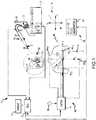
- FIG. 1illustrates one embodiment of a system 10 for navigating a medical device within a body 12.
- the medical devicecomprises a catheter 14 that is shown schematically entering a heart, which is depicted in an exploded view away from the body 12 for purposes of illustration.
- the catheter 14, in this embodimentis depicted as an irrigated radiofrequency (RF) ablation catheter for use in the treatment of cardiac tissue 16 in the body 12.
- RFradiofrequency
- the system 10may be used to navigate an electrophysiological mapping catheter, an intracardiac echocardiography (ICE) catheter, or an ablation catheter using a different type of ablation energy (e.g., cryoablation, ultrasound, etc.). Further, it should be understood that the system 10 may be used to navigate medical devices used in the diagnosis or treatment of portions of the body 12 other than cardiac tissue 16.
- ICEintracardiac echocardiography
- ablation catheterusing a different type of ablation energy (e.g., cryoablation, ultrasound, etc.).
- ablation energye.g., cryoablation, ultrasound, etc.
- the ablation catheter 14is connected to a fluid source 18 for delivering a biocompatible irrigation fluid such as saline through a pump 20, which may comprise, for example, a fixed rate roller pump or variable volume syringe pump with a gravity feed supply from fluid source 18 as shown.
- the catheter 14is also electrically connected to an ablation generator 22 for delivery of RF energy.
- the catheter 14may include a handle 24; a cable connector or interface 26 at a proximal end of the handle 24; and a shaft 28 having a proximal end 30, a distal end 32, and one or more electrodes 34.
- the connector 26provides mechanical, fluid, and electrical connections for conduits or cables extending from the pump 20 and the ablation generator 22.
- the catheter 14may also include other conventional components not illustrated herein such as a temperature sensor, additional electrodes, and corresponding conductors or leads.
- the handle 24provides a location for the physician to hold the catheter 14 and may further provide means for steering or guiding the shaft 28 within the body 12.
- the handle 24may include means to change the length of one or more pull wires extending through the catheter 14 from the handle 24 to the distal end 32 of shaft 28.
- the construction of the handle 24may vary.
- the shaft 28may be made from conventional materials such as polyurethane and may define one or more lumens configured to house and/or transport electrical conductors, pull wires, fluids, or surgical tools.
- the shaft 28may be introduced into a blood vessel or other structure within the body 12 through a conventional introducer.
- the shaft 28may then be steered or guided through the body 12 to a desired location such as the tissue 16 using guide wires or pull wires or other means known in the art including remote control guidance systems.
- the shaft 28may also permit transport, delivery, and/or removal of fluids (including irrigation fluids and bodily fluids), medicines, and/or surgical tools or instruments.
- the system 10may include an electric-field-based positioning system 36, a magnetic-field-based positioning system 38, a display 40, and an electronic control unit (ECU) 42.
- ECUelectronice control unit
- the electric-field-based positioning system 36is provided to determine the position and orientation of the catheter 14 and similar devices within the body 12.
- the system 36may comprise, for example, the ENSITE NAVX system sold by St. Jude Medical, Inc. of St. Paul, Minnesota, and described in, for example, U.S. Patent No. 7,263,397 titled "Method and Apparatus for Catheter Navigation and Location Mapping in the Heart".
- the electric-field-based positioning system 36further includes three pairs of patch electrodes 44, which are provided to generate electrical signals used in determining the position of the catheter 14 within a three-dimensional coordinate system 46.
- the electrodes 44may also be used to generate EP data regarding the tissue 16.
- the patch electrodesare placed on opposed surfaces of the body 12 (e.g., chest and back, left and right sides of the thorax, and neck and leg) and form generally orthogonal x, y, and z axes.
- a reference electrode/patch(not shown) is typically placed near the stomach and provides a reference value and acts as the origin of the coordinate system 46 for the navigation system.
- the patch electrodesinclude right side patch 44X1, left side patch 44X2, neck patch 44Y1, leg patch 44Y2, chest patch 44Z1, and back patch 44Z2; and each patch electrode is connected to a switch 48 (e.g., a multiplex switch) and a signal generator 50.
- the patch electrodes 44X1, 44X2are placed along a first (x) axis; the patch electrodes 44Y1, 44Y2 are placed along a second (y) axis, and the patch electrodes 44Z1, 44Z2 are placed along a third (z) axis.
- Sinusoidal currentsare driven through each pair of patch electrodes, and voltage measurements for one or more position sensors (e.g., ring electrodes 34 or a tip electrode located near the distal end 32 of catheter shaft 28) associated with the catheter 14 are obtained.
- the measured voltagesare a function of the distance of the position sensors from the patch electrodes.
- the measured voltagesare compared to the potential at the reference electrode and a position of the position sensors within the coordinate system 46 of the navigation system is determined.
- the magnetic-field-based positioning system 38 in this exemplary embodimentemploys magnetic fields to detect the position and orientation of the catheter 14 within the body 12.
- the system 38may include the GMPS system made available by MediGuide, Ltd. and generally shown and described in, for example, U.S. Patent No. 7,386,339 titled "Medical Imaging and Navigation System".
- a magnetic field generator 52may be employed having three orthogonally arranged coils (not shown) to create a magnetic field within the body 12 and to control the strength, orientation, and frequency of the field.
- the magnetic field generator 52may be located above or below the patient (e.g., under a patient table) or in another appropriate location.
- Magnetic fieldsare generated by the coils and current or voltage measurements for one or more position sensors (not shown) associated with the catheter 14 are obtained.
- the measured currents or voltagesare diminishing functions of the distance of the sensors from the coils, thereby allowing determination of a position of the sensors within a coordinate system 54 of system 38.
- the display 40is provided to convey information to a physician to assist in diagnosis and treatment.
- the display 40may comprise one or more conventional computer monitors or other display devices.
- the display 40may present a graphical user interface (GUI) to the physician.
- GUIgraphical user interface
- the GUImay include a variety of information including, for example, an image of the geometry of the tissue 16, electrophysiology data associated with the tissue 16, graphs illustrating voltage levels over time for various electrodes 34, and images of the catheter 14 and other medical devices and related information indicative of the position of the catheter 14 and other devices relative to the tissue 16.
- the ECU 42provides a means for controlling the operation of various components of the system 10, including the catheter 14, the ablation generator 22, and the switch 48 of the electric-field-based positioning system 36, and magnetic generator 52 of the magnetic-field-based positioning system 38.
- the ECU 42may be configured through appropriate software to provide control signals to switch 48 and thereby sequentially couple pairs of patch electrodes 44 to the signal generator 50. Excitation of each pair of electrodes 44 generates an electromagnetic field within the body 12 and within an area of interest such as the heart.
- the ECU 42may also provide a means for determining the geometry of the tissue 16, electrophysiology characteristics of the tissue 16, and the position and orientation of the catheter 14 relative to tissue 16 and the body 12.
- the ECU 42also provides a means for generating display signals used to control the display 40.
- the depicted ECU 42represents any processing arrangement such as, for example, single device processors, multiple device processors (e.g., co-processors, master/slave processors, etc.), distributed processing across multiple components/systems, system on chip (SOC) devices, or the like.
- single device processorse.g., single device processors, multiple device processors (e.g., co-processors, master/slave processors, etc.), distributed processing across multiple components/systems, system on chip (SOC) devices, or the like.
- SOCsystem on chip
- the voltage readings from the electrodes 34change, thereby indicating the location of catheter 14 within the electric field and within the coordinate system 46 established by the system 36.
- the electrodes 34communicate position signals to ECU 42 through a conventional interface (not shown).
- High density catheterscan be used together with a 3D mapping system and ECU 42.
- the ECU 42includes software and/or hardware configured to enable the high density catheters to diagnose and map rhythm disorders with accuracy, consistency, and speed.
- the techniques and catheters described hereinenable new and better characterizations of cardiac conduction which can result in faster and more successful therapeutic procedures.
- ECMsLocal electrogram signals
- the electronic control unit 10can use this information to derive depolarization related normal and tangent E-fields (En and Et respectively) which are catheter orientation independent signals with reliable amplitudes, morphology/timing, and instantaneous conduction velocity vectors among other uses.
- the electronic control unitenables more reliable EGM amplitudes and morphologies to allow better EGM reduction measures.
- the electronic control unitenables the local assessment of conduction velocity as a critical isthmus in the tissue or a lesion gap is approached.
- the electronic control unitalso enables characterizations of ablation lesions from En and Et before, during, and after ablation to help determine the growth and effectiveness of any lesions that have been formed.
- Local electrophysiologic propagation informationmay also be determined by pacing with such a catheter and observing the resulting spread of depolarization from immediately adjacent to the site where capture occurs. This is difficult currently and the directional information as described in this disclosure may serve as a clue to anatomic or functional conduction blocks. Even without pacing, conduction around obstacles such as valve orifices or blocks is known to become curved and slowed and this may be detected and directly mapped in some embodiments.
- the electronic control unitcan also allow for more consistent substrate amplitude maps that can show activation direction and conduction velocity.
- Embodiments of this disclosureemploy closely spaced electrodes in spatial arrangements that can be used to derive an approximate local electric field (E-field) on an endocardial or epicardial surface and in so doing derive useful measures of conduction that are insensitive to catheter orientation.
- E-fieldapproximate local electric field
- EP catheters in the hands of skilled operatorscan be placed in almost any location, it is often the case that achievable catheter orientations are few. This lack of achievable orientations can limit the data that can be collected by the catheters.
- the catheters and mapping system described in this disclosureuse additional (i.e., segmented) electrodes to determine properties of myocardium by putting information into its proper 2-D and 3-D spatial and temporal contexts.
- embodimentsalso contemplate the use of ablation catheters with these same or similar advantages.
- the resultis an expanded and catheter orientation independent set of local electrophysiologic information such as: normal EGM amplitude, tangent EGM amplitude and direction, tangent EGM eccentricity, 2-D and 3-D E-Field amplitude, activation times derived from signals of reliable morphology, and conduction velocity magnitude and direction.
- EGM amplitudenormal EGM amplitude
- tangent EGM amplitude and directiontangent EGM eccentricity
- 2-D and 3-D E-Field amplitudeactivation times derived from signals of reliable morphology
- conduction velocity magnitude and directioncan prove valuable when applied to a diagnostic catheter and even more so when applied to a catheter that will also deliver ablation energy during an EP procedure.
- the electronic control systemAfter receiving electrogram data for a set of electrodes 80, the first step is to compensate for artifacts in sensor positions in the mapping system; a situation which can be common in segmented electrode catheters located by electric-field-based positioning systems 81.
- the second stepis to resolve the bipolar signals into a 3D vector electrogram in the mapping system's coordinates, with a component normal to the cardiac surface and another tangent to the surface 82.
- planar electrode bipolar signalscan be resolved into a 2D vector electrogram in the mapping system's coordinates that is tangent to the cardiac surface.
- the third step, performed if local conduction velocity is of interest,is to manipulate observed unipolar voltage signals and the tangent component of the vector E-field to arrive at a valid local estimate of the conduction velocity vector 83 on a beat-by-beat basis similar to that available today for peak-to-peak amplitude or local activation time.
- the electronic control systemcan then output the orientation independent information to a user, a display, or other device 84.
- the first 2 or all 3 stepsmay be done with catheters or other medical devices that include segmented or more conventional electrodes.
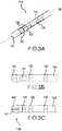
- a segmented electrodeis one which does not extend around the entire circumference of a catheter. Multiple segmented electrodes can extend around a circumference of a catheter at the same position along a longitudinal axis of the catheter. Further, segmented electrodes can comprise electrodes that are often smaller and distributed in proximity to one another. They may sometimes resemble split or "segmented" conventional electrodes and need to be placed appropriately on the catheter to determine properties of myocardium by putting information into its proper 2-D and 3-D spatial and temporal contexts. This can be seen, for example, as segmented electrodes 121, 122, and 123 in FIG. 3A .
- FIGS. 3A and 3Bare isometric and side views of an example ablation catheter 110 with a segmented ring electrode and several more conventional ring electrodes.
- the catheter 110has a tip electrode 120 which can be suitable for RF ablation, a first, second, and third split ring or segmented electrode 121, 122, 123, and one or more circumferential ring electrodes 124, 125.
- the segmented electrodescan be utilized in conjunction with adjacent tip and/or ring electrodes to permit one or more 3-D determinations of the local E-field as depolarization occurs.
- other catheters with segmented electrodescan also use the procedures set forth within.
- catheters with segmented electrodesinclude U.S.
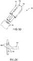
- FIGS. 3C and 3Dshow side and isometric views of alternative ablation catheters having a segmented tip configuration which can be used to obtain orientation independent information.
- FIG. 3Cis a side view of another embodiment of an ablation catheter 145 with a segmented tip assembly 146.
- the ablation catheter 145comprises first, second, and third ring electrodes 142, 143, 144 and a segmented tip assembly 146 that is divided into at least two electrodes.
- FIG. 3Ddepicts an isometric view of another embodiment of a segmented tip assembly 154 and a catheter body 153.
- the segmented tip assembly 154comprises a first segmented tip segment 150, a second segmented tip electrode 151, and an electrically non-conductive area 152 between the first and second segmented tip electrodes.
- the segmented tip electrodecan comprise four discrete segmented tip electrodes and an electrically non-conductive area surrounding each segmented tip electrode.
- FIG. 3Eillustrates a side view of a diagnostic catheter with opposing electrodes suitable for 2-D determinations of the local E-field. The catheter illustrated in FIG.
- 3Ecomprises a catheter body 162, and a plurality of segmented electrodes around a circular, or lasso, catheter tip.
- the cathetercomprises a first plurality of segmented electrodes 160 that face distally on the circular catheter, and a second plurality of segmented electrodes 161 that faces proximally on the circular catheter.
- the number and spacing between the segmented electrodes in both the first and second plurality of segmented electrodes 160,161can vary in different embodiments. In some embodiments only the first plurality of segmented electrodes 160 or the second plurality of segmented electrodes 161 can be present on the circular catheter.
- FIGS. 4A and 4Bshow the two exemplary ablation catheter designs paired up with a tetrahedron and inverted pyramid.
- the catheter of FIGS. 3A and 3Bis represented by the tetrahedron of FIG. 4A .
- the tip electrode 120is shown in relation to the split ring electrodes 121, 122, and 123. The position coordinates of these electrodes are denoted D, 2, 3, and 4 respectively.
- the catheter of FIGS. 3C and 3Dis represented by the inverted pyramid of FIG. 4B .
- the four tip electrodes 220, 221, 222, and 223are shown in relation to the adjacent ring electrode 224. The position coordinates of these electrodes are denoted D, 2, 3, 4, and 5 respectively.
- the first step to extracting orientation independent informationentails a further aspect of this disclosure, the compensation for electrode impedance location and navigational artifacts that may be prominent with small electrodes, particularly those that are split or segmented on the surface of a catheter shaft. Constraints of physical construction, scaling error, and non-ideal electrode/amplifier impedance characteristics are combined to estimate a more realistic electrode spatial distribution with the result that suitable local E-field determinations may be made as well as more reliable and catheter orientation independent clinical assessments.
- Impedance localization artifactscan arise from a variety of sources.
- a high electrode impedance coupling to the body's conductive mediumis an artifact that disturbs electrode positions in a characteristic manner. These electrodes are displaced toward the external reference electrode, which is typically around 200-400 mm inferior to the heart. As little as a 1% deviation in this manner thus produces a 2-4 mm shift.
- the extent of such a shiftdepends on a variety of factors, including: other electrode impedances, electrode surface area, measured impedance, electrode surface contaminants, and tissue contact, among others. Other instances of known shift and drift, and apparatus and methods to correct are disclosed in U.S. Patent Application No. 13/690,737, filed 30 November 2012 . These factors are only partly known ahead of time.
- correction of this artifactcan thus be helped by referring to other electrodes on the catheter and by knowledge of its physical construction.
- the other electrodes being referred toare larger electrodes or circumferential electrodes and are thus less susceptible to this type of deviation.
- larger electrodesmay be adjusted in such a manner as to position them properly with respect to the segmented electrodes. Since this effect can be dominant and is systematic, it can be compensated, for example, by introducing a multiplicative correction factor.
- a factor in the vicinity of 1.002-1.010is selected and is conditioned on bringing the affected segmented electrodes to approximately the correct location with respect to the other conventional electrodes. Conversely a factor of 0.990-0.998 may bring conventional electrodes to a correct location relative to the segmented electrodes.
- the electronic control unitcan compensate for impedance localization artifacts by the following general steps.
- the steps in this specific embodimentbe used to compensate for smaller or segmented electrodes on a catheter that also includes ring electrodes as currently known in the art.
- the following stepsdetail how the electronic control unit can be used, in some embodiments, to compensate for position artifacts with the catheter shown in FIGS. 3A, 3B , and 4A .
- the measured coordinates of the large circumferential ring electrodes 124, 125 and the tip electrode 120are used to fit a line and thereby determine the catheter's distal longitudinal axis.
- the observed locations of electrodes 120, 124 and 125(denoted D, 5, and 6 in FIG.
- the electronic control unitthen computes the centroid of the first, second, and third segmented ring electrodes 121, 122, 123 from the measured coordinates denoted 2, 3, and 4 in FIG. 7 and denotes this location as C M (not shown).
- the next stepcan include using the physical proportion of the distance between the tip electrode 120 and the first ring electrode 124, and assigning an equivalent location on the best fit line for the centroid of the first, second, and third segmented electrodes 121, 122, 123 and denoting this location C A (not shown).
- the electronic control unituses the discrepancy between C M and C A to determine impedance scale factor zs > 1 (e.g.
- the traditional electrodescomprise the tip electrode 120, the first ring electrode 124, and the second ring electrode 125.
- the electronic control unitcan next expand the measured first, second, and third segmented electrode 121, 122, 123 coordinates by zs so they now lie between the tip electrode 120 and the first ring electrode 124.
- This stepintroduces electrode impedance compensation, a dominant source of electrode position error.
- the extent of compensation for the electrodescan vary with factors such as surface area and tissue contact, among others.
- the electronic control unitcan next project along the axis A 130 the resulting compensated first, second, and third segmented electrode 121, 122, 123 coordinates onto a plane P A that passes through C A and is perpendicular to the best fit axis A 130, and translate the coordinates of the first, second, and third segmented electrodes 121, 122, 123 so that their centroid lies at C A in the plane P A .
- the first, second, and third segmented electrode 121, 122, 123 coordinatesare now at their best fit locations.
- the electrodes of the catheter illustrated in FIGS. 3A and 3Bform two tetrahedra.
- the first tetrahedroncomprises the tip electrode 120 and the first, second, and third segmented electrodes 121, 122, 123.
- the second tetrahedroncomprises the first ring electrode 124 and the first, second, and third segmented electrodes 121, 122, 123.
- FIG. 4Aillustrates the distal tetrahedron of the catheter formed by the tip electrode 120 and the first, second, and third segmented electrodes 121, 122, 123.
- the electronic control unitcan construct an equilateral triangle with split ring electrodes at its vertices, centered at C A with sides that have the length of scale factors times the distance between electrodes 121, 122, and 123, and find the angle of rotation about C A in plane P A that minimizes the sum-squared distance between corresponding electrodes/vertices.
- This resultallows the electronic control unit to have best fit positions for all of the electrodes from the tip electrode 120 to the first ring electrode 124 which correspond to coordinates D ⁇ , 2 ⁇ , 3 ⁇ , 4 ⁇ , and 5 ⁇ of FIG. 8 .
- the electronic control unitcan now proceed to resolve local EP information.
- the compensation step for electrode impedance location and navigational artifactscan introduce knowledge of segmented electrode positions, an estimate of segment electrode scaling error obtained from large conventional electrode spacing, and the measured coordinates of the segmented electrodes.
- Software in the ECU 42 or other device employing parameters specific to a segmented catheter designcan be used to determine the correct compensation.
- systematic artifacts that result from proximity of the electrode to an insulated catheter shaftmay be modeled and corrected.
- measured electrode positions, modeled in electric field software such as Coulomb, sold by INTEGRATED Engineering Softwarecan be predictably altered and the measured positions can then be adjusted based on displacements predicted by the model.
- the second step to extracting orientation independent informationentails deriving an E-field from the observed bipolar signals, by considering the E-field to be projected onto bipole vectors which typically form a non-orthogonal set of basis vectors. From this set of basis vectors the E-field is then expressed in orthonormal mapping system coordinates. The surface geometry and the catheter's location then yield a unit vector that is the local surface normal, also referred to as n-hat or n ⁇ .
- Catheters with high density arrays of electrodes which can be maneuvered into lying along a surfaceoffer a 2D variant of this process.
- cells or cliquesare composed of the three or four neighboring electrodes on 2 splines or arms that are closest to each other.
- these cliquesform rectangular elements with dimensions roughly 2x3 mm.
- the resulting possible bipolar signals(of which only 3 are linearly independent) over determine the local 2D tangent E-field.
- these signalsare converted to best fit coefficients for an orthonormal basis which is Et in the mapping system coordinates.
- catheter orientation independent amplitude and more consistent timing measurescan be derived as well as local conduction velocity vector determination described below.
- a catheterhas a plurality of electrodes that form two tetrahedra when lines are drawn between adjacent electrodes.
- the tetrahedra formed between the electrodes in the catheter shown in FIG. 3Ais illustrated in FIG. 4 .
- the 3 (x,y,z) mapping system coordinates of the 4 electrodes for each of the two tetrahedramay be placed into 3x4 matrices.
- the mapping systemcan then denote one of these tetrahedra by coordinate matrix X. After choosing one vertex as a reference (e.g.
- Fis the appropriate 4x3 pairwise subtraction matrix comprised of 0, +1, and -1's.
- dXis an invertible 3x3 matrix.
- the electronic control unitthen lets E stand for the local electric field in the mapping system coordinate frame.
- dXwas determined from the mapping system coordinates in a navigational electric field, the same effects are present for electrogram signals.
- phi or ⁇is a 4x1 vector of unipolar electric potentials at each of the electrodes of the tetrahedron.
- the electronic control unitcan sample data from the electrodes at various frequencies. Unipolar voltages ⁇ change rapidly with time whereas the electrode coordinates and thus dX change much more slowly. In one embodiment, ⁇ can be sampled by the electronic control unit at 2034 Hz while the electrode coordinates can be sampled at 102 Hz and can be filtered to under 1 Hz.
- the above sampling ratesare only one example of the frequencies that can be used by the system or ECU.
- the sampling rates of the electronic control unitcan be any that allow for proper location and data collection to occur.
- Conduction velocity magnitude and directioncan be determined in a novel manner over a single beat from a system of a few closely spaced electrodes capable of resolving the local tangent E-field (Et) and measuring the local unipolar voltage.
- EtE-field
- orthogonal unit vectors a-hat ( â ) and w-hat ( ⁇ )can be defined in the tangent plane.
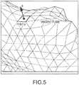
- FIG. 6illustrates a homogenous depolarization wavefront travelling from left to right on the endocardial surface.
- âis defined as the direction along which the wavefront is propagating (also the direction of conduction velocity) and ⁇ is parallel to the wavefront.
- the assumption that the static distribution of potential varies only along vcomes from an inability to distinguish an inclined wavefront moving at velocity v from a wavefront that is not inclined (is perpendicular to v ) moving at another velocity.
- a unipolar endocardial voltage distribution ⁇ (r, s, t 0 ) or ⁇ ( p , t 0 )is present.
- v( v r , v s ) is the wavefront velocity vector in coordinate frame r-s which is tangent to the local endocardial surface.
- utime invariant
- the equation aboverelates the time varying voltage at point p to 2-D conduction velocity vector v through static potential distribution u.
- the electronic control unitcan directly obtain the four time varying unipolar voltages. This allows the electronic control unit to estimate various EP properties of point p.
- Surface point phas unit normal n ⁇ and tangent plane as shown in FIG. 5 .
- the electronic control unitbegins with the physics of a scalar potential field and the segmented catheter electrode array.
- the time varying voltage ⁇ (t) at point pcan be estimated from the mean of the observed electrodes.
- Wavefront conduction velocitya catheter orientation independent property of the substrate and conduction system
- Wavefront conduction velocity vcan be used by an electrophysiologist and is generally difficult or time consuming to determine using traditional techniques.
- the electronic control unitcan then take the total derivative of v with respect to t, hoping to recognize measureable quantities and be able to solve for v .
- the electronic control unitcan next consider the vector electric field at point p to be composed of normal and tangent components.
- E nbe the 3D vector normal component in the direction of unit vector n ⁇
- the electronic control unitcan represent E t also as a 2D vector in (r,s) coordinates, where it is the gradient of the local potential field on the endocardial surface which can be identified as - ⁇ u.
- E talso as a 2D vector in (r,s) coordinates, where it is the gradient of the local potential field on the endocardial surface which can be identified as - ⁇ u.
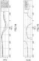
- FIGS. 9-13illustrates electrode unipole signals from each of the electrodes in the catheter seen in FIG. 3A as determined by the mapping system and denoted as phi ( ⁇ ).
- the unipole signalspossess typical unipolar morphology ( FIG. 9 ).
- phitime derivative phi-dot
- FIG. 10the mapping system
- FIG. 11illustrates the conduction velocity magnitude estimated by taking the instantaneous ratio of ⁇ to Ea, which is seen to be approximately 1 mm/ms.
- FIGS. 14-19illustrate further mapping system recordings of unipolar signals and derived conduction velocity magnitudes.
- FIGS. 14-19illustrate three pairs of recordings with FIGS. 14 and 15 plotting a first recording, FIGS. 16 and 17 plotting a second recording, and FIGS. 18 and 19 plotting a third recording.
- the conduction velocity magnitudes in these figureswere approximately 1 mm/ms.
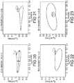
- Etshould consist of voltage swings along a single dominant axis-aligned with the direction of propagation ( â ). As illustrated in FIGS. 20-23 looking at Et in its plane with the horizontal +x direction chosen to be along â , there is around 3-8 times more signal along x than y. This signal indicates that, at least locally, planar wavefronts pass by as if conducted in a fairly homogeneous medium. The eccentricity of these loops can be assessed and can indicate non-uniform local conduction which may be of clinical interest.
- the systems described by this disclosureare intended to provide catheter orientation-independent characterization of cardiac conduction that would enable an electrophysiologist to diagnose disorders and deliver therapy. Typically this would be realized using a multi-electrode catheter that would be used in conjunction with the system's algorithms and along with an amplifier for measuring electrograms, electrode locations, and orientations.
- Embodimentsare described herein of various apparatuses, systems, and/or methods. Numerous specific details are set forth to provide a thorough understanding of the overall structure, function, manufacture, and use of the embodiments as described in the specification and illustrated in the accompanying drawings. It will be understood by those skilled in the art, however, that the embodiments may be practiced without such specific details. In other instances, well-known operations, components, and elements have not been described in detail so as not to obscure the embodiments described in the specification. Those of ordinary skill in the art will understand that the embodiments described and illustrated herein are non-limiting examples, and thus it can be appreciated that the specific structural and functional details disclosed herein may be representative and do not necessarily limit the scope of all embodiments.
- proximal and distalmay be used throughout the specification with reference to a clinician manipulating one end of an instrument used to treat a patient.
- proximalrefers to the portion of the instrument closest to the clinician and the term “distal” refers to the portion located furthest from the clinician.
- distalrefers to the portion located furthest from the clinician.
- spatial or directional termssuch as “vertical,” “horizontal,” “up,” “down,” “clockwise,” and “counterclockwise” may be used herein with respect to the illustrated embodiments.
- medical instrumentsmay be used in many orientations and positions, and these terms are not intended to be limiting and absolute.
- joinder referencesare to be construed broadly and may include intermediate members between a connection of elements and relative movement between elements. As such, joinder references do not necessarily infer that two elements are directly connected and in fixed relation to each other. Changes in detail or structure may be made without departing from the scope of the invention as defined in the appended claims.
Landscapes
- Health & Medical Sciences (AREA)
- Life Sciences & Earth Sciences (AREA)
- Engineering & Computer Science (AREA)
- Surgery (AREA)
- Medical Informatics (AREA)
- Biomedical Technology (AREA)
- Heart & Thoracic Surgery (AREA)
- Molecular Biology (AREA)
- Animal Behavior & Ethology (AREA)
- General Health & Medical Sciences (AREA)
- Public Health (AREA)
- Veterinary Medicine (AREA)
- Cardiology (AREA)
- Physics & Mathematics (AREA)
- Pathology (AREA)
- Biophysics (AREA)
- Nuclear Medicine, Radiotherapy & Molecular Imaging (AREA)
- Physiology (AREA)
- Signal Processing (AREA)
- Human Computer Interaction (AREA)
- Plasma & Fusion (AREA)
- Otolaryngology (AREA)
- Robotics (AREA)
- Artificial Intelligence (AREA)
- Computer Vision & Pattern Recognition (AREA)
- Psychiatry (AREA)
- Measurement And Recording Of Electrical Phenomena And Electrical Characteristics Of The Living Body (AREA)
- Surgical Instruments (AREA)
Description
- This disclosure relates to systems, apparatuses and methods for utilizing electrode spatial arrangements within a mapping system. In particular, the instant disclosure relates to systems, apparatuses and methods for characterizing cardiac conduction conditions in a catheter orientation independent manner using electrode spatial arrangements in 3D mapping systems.
- Electrophysiology (EP) catheters are used in a variety of diagnostic, therapeutic, and/or mapping and ablative procedures to diagnose and/or correct conditions such as atrial arrhythmias, including for example, ectopic atrial tachycardia, atrial fibrillation, and atrial flutter. Arrhythmias can create a variety of conditions including irregular heart rates, loss of synchronous atrioventricular contractions and stasis of blood flow in a chamber of a heart which can lead to a variety of symptomatic and asymptomatic ailments and even death.
- Typically, a catheter is deployed and manipulated through a patient's vasculature to the intended site, for example, a site within a patient's heart. The catheter carries one or more electrodes that can be used for cardiac mapping or diagnosis, ablation and/or other therapy delivery modes, or both, for example. Once at the intended site, treatment can include, for example, radio frequency (RF) ablation, cryoablation, laser ablation, chemical ablation, high-intensity focused ultrasound-based ablation, microwave ablation, and/or other ablation treatments. The catheter imparts ablative energy to cardiac tissue to create one or more lesions in the cardiac tissue. This lesion disrupts undesirable cardiac activation pathways and thereby limits, corrals, or prevents errant conduction signals that can form the basis for arrhythmias.
- To position a catheter at a desired site within the body, some type of navigation may be used, such as using mechanical steering features incorporated into the catheter (or a sheath). In some examples, medical personnel may manually manipulate and/or operate the catheter using the mechanical steering features.
- A navigating system may be used for visualization and to facilitate the advancement of catheters through a patient's vasculature to specific locations within the body. Such navigating systems may include, for example, electric and/or magnetic field based positioning and navigating systems that are able to determine the position and orientation of the catheter (and similar devices) within the body.
- Conduction disorders in the body can result from abnormal conduction in regions as small as 1-4 mm. In addition, ablation in these regions must be restricted to the pathological tissue to preserve electrical and mechanical function, particularly with ventricular arrhythmias. Today, many catheters employ electrode pairs spaced greater than 4 mm apart which can make it difficult to reliably allow discrimination or localization of defects. Even when the electrodes are more closely spaced, around 1 mm to around 2 mm, the orientation of the pair of electrodes is a prominent factor in the amplitude and morphology of the resulting signals.
EP 1 166 714 A1WO 2012/037471 A2 relates to systems and methods for computing activation maps, wherein an activation time can be computed for each of a plurality of points as a function of corresponding local activation vectors.US 5,297,549 relates to a system for measuring electrical signals originating within cardiac tissue and generating a map of the electrical activity of the heart.- The foregoing discussion is intended only to illustrate the present field and should not be taken as a disavowal of claim scope.
- According to the invention, which is defined by the appended claims, a system for determining electrophysiological data comprises an electronic control unit configured to receive electrogram data for a set of electrodes, receive position and orientation information for the set of electrodes from a mapping system, determine catheter orientation independent information of a tissue, and output the orientation independent information to the mapping system.
- In another embodiment, a method of determining electrophysiological data includes receiving electrogram data for a set of electrodes, receiving position and orientation information for the set of electrodes from a mapping system, determining catheter orientation independent information of a tissue, and outputting orientation independent information.
FIG. 1 is diagrammatic view of one embodiment of a system for navigating a medical device within a body.FIG. 2 is a flow chart associated with a method for determining electrophysiological data, in accordance with embodiments of the present disclosure.FIG. 3A and 3B are isometric and side views of an ablation catheter with a tip electrode, a segmented ring electrode and several regular ring electrodes.FIG. 3C and3D are isometric and side views of an ablation catheter with a segmented tip electrode and several regular ring electrodes.FIG. 3E is a side view of a diagnostic catheter with opposing electrodes.FIG. 4A is an isometric view of the distal tetrahedron along with the corresponding side view of the segmented ring ablation catheter.FIG. 4B is an isometric view of the distal pyramid along with the corresponding side view of the segmented tip ablation catheter.FIG. 5 is a diagrammatic view of the surface anatomy near a point of interest and the unit surface normal.FIG. 6 is a diagrammatic view of a traveling depolarization wave along with the unit vector directions.FIG. 7 is a plot of the electrode coordinates with artifacts for the segmented ring ablation catheter fromFIG 2A and 2B that can be introduced when using an impedance based mapping system.FIG. 8 is a plot of the corrected location of the electrode coordinates for the segmented ring ablation catheter fromFIG 2A and 2B .FIGS. 9-13 are plots of EP signals derived from the five distal most electrodes on the catheter ofFIG. 2A and 2B taken during a procedure.FIGS. 14-15 ,16-17 , and18-19 are plots of three consecutive beats featuring expanded views of EP signals derived from the five distal most electrodes on the catheter ofFIG. 2A and 2B .FIGS. 20-23 are plots of EP signal Et in its tangent plane for four consecutive cardiac cycles.- The present disclosure relates to a system and method for utilizing electrode spatial arrangements within a mapping system. In particular, the instant disclosure relates to systems, apparatuses and methods for characterizing cardiac conduction conditions in a catheter orientation independent manner using electrode spatial arrangements in 3D mapping systems.
- Referring now to the figures, in which like reference numerals refer to the same or similar features in the various views,
FIG. 1 illustrates one embodiment of asystem 10 for navigating a medical device within abody 12. In the illustrated embodiment, the medical device comprises a catheter 14 that is shown schematically entering a heart, which is depicted in an exploded view away from thebody 12 for purposes of illustration. The catheter 14, in this embodiment, is depicted as an irrigated radiofrequency (RF) ablation catheter for use in the treatment of cardiac tissue 16 in thebody 12. It should be understood, however, that thesystem 10 may find application in connection with a wide variety of medical devices used within thebody 12 for diagnosis or treatment. For example, thesystem 10 may be used to navigate an electrophysiological mapping catheter, an intracardiac echocardiography (ICE) catheter, or an ablation catheter using a different type of ablation energy (e.g., cryoablation, ultrasound, etc.). Further, it should be understood that thesystem 10 may be used to navigate medical devices used in the diagnosis or treatment of portions of thebody 12 other than cardiac tissue 16. - Referring still to
FIG. 1 , the ablation catheter 14 is connected to afluid source 18 for delivering a biocompatible irrigation fluid such as saline through apump 20, which may comprise, for example, a fixed rate roller pump or variable volume syringe pump with a gravity feed supply fromfluid source 18 as shown. The catheter 14 is also electrically connected to anablation generator 22 for delivery of RF energy. The catheter 14 may include ahandle 24; a cable connector or interface 26 at a proximal end of thehandle 24; and ashaft 28 having a proximal end 30, adistal end 32, and one ormore electrodes 34. The connector 26 provides mechanical, fluid, and electrical connections for conduits or cables extending from thepump 20 and theablation generator 22. The catheter 14 may also include other conventional components not illustrated herein such as a temperature sensor, additional electrodes, and corresponding conductors or leads. - The
handle 24 provides a location for the physician to hold the catheter 14 and may further provide means for steering or guiding theshaft 28 within thebody 12. For example, thehandle 24 may include means to change the length of one or more pull wires extending through the catheter 14 from thehandle 24 to thedistal end 32 ofshaft 28. The construction of thehandle 24 may vary. - The
shaft 28 may be made from conventional materials such as polyurethane and may define one or more lumens configured to house and/or transport electrical conductors, pull wires, fluids, or surgical tools. Theshaft 28 may be introduced into a blood vessel or other structure within thebody 12 through a conventional introducer. Theshaft 28 may then be steered or guided through thebody 12 to a desired location such as the tissue 16 using guide wires or pull wires or other means known in the art including remote control guidance systems. Theshaft 28 may also permit transport, delivery, and/or removal of fluids (including irrigation fluids and bodily fluids), medicines, and/or surgical tools or instruments. - The
system 10 may include an electric-field-basedpositioning system 36, a magnetic-field-basedpositioning system 38, adisplay 40, and an electronic control unit (ECU) 42. Each of the exemplary system components is described further below. - The electric-field-based
positioning system 36 is provided to determine the position and orientation of the catheter 14 and similar devices within thebody 12. Thesystem 36 may comprise, for example, the ENSITE NAVX system sold by St. Jude Medical, Inc. of St. Paul, Minnesota, and described in, for example,U.S. Patent No. 7,263,397 titled "Method and Apparatus for Catheter Navigation and Location Mapping in the Heart". Thesystem 36 operates based upon the principle that when low amplitude electrical current signals are passed through the thorax, thebody 12 acts as a voltage divider (or potentiometer or rheostat) such that the electrical potential measured at one ormore electrodes 34 on the catheter 14 may be used to determine the position of the electrodes, and, therefore, of the catheter 14, relative to a pair of external patch electrodes using Ohm's law and the relative location of a reference electrode (e.g., in the coronary sinus). - In the configuration shown in
FIG. 1 , the electric-field-basedpositioning system 36 further includes three pairs ofpatch electrodes 44, which are provided to generate electrical signals used in determining the position of the catheter 14 within a three-dimensional coordinatesystem 46. Theelectrodes 44 may also be used to generate EP data regarding the tissue 16. To create axes-specific electric fields withinbody 12, the patch electrodes are placed on opposed surfaces of the body 12 (e.g., chest and back, left and right sides of the thorax, and neck and leg) and form generally orthogonal x, y, and z axes. A reference electrode/patch (not shown) is typically placed near the stomach and provides a reference value and acts as the origin of the coordinatesystem 46 for the navigation system. - In accordance with this
exemplary system 36 as depicted inFIG. 1 , the patch electrodes include right side patch 44X1, left side patch 44X2, neck patch 44Y1, leg patch 44Y2, chest patch 44Z1, and back patch 44Z2; and each patch electrode is connected to a switch 48 (e.g., a multiplex switch) and asignal generator 50. The patch electrodes 44X1, 44X2 are placed along a first (x) axis; the patch electrodes 44Y1, 44Y2 are placed along a second (y) axis, and the patch electrodes 44Z1, 44Z2 are placed along a third (z) axis. Sinusoidal currents are driven through each pair of patch electrodes, and voltage measurements for one or more position sensors (e.g.,ring electrodes 34 or a tip electrode located near thedistal end 32 of catheter shaft 28) associated with the catheter 14 are obtained. The measured voltages are a function of the distance of the position sensors from the patch electrodes. The measured voltages are compared to the potential at the reference electrode and a position of the position sensors within the coordinatesystem 46 of the navigation system is determined. - The magnetic-field-based
positioning system 38 in this exemplary embodiment employs magnetic fields to detect the position and orientation of the catheter 14 within thebody 12. Thesystem 38 may include the GMPS system made available by MediGuide, Ltd. and generally shown and described in, for example,U.S. Patent No. 7,386,339 titled "Medical Imaging and Navigation System". In such a system, amagnetic field generator 52 may be employed having three orthogonally arranged coils (not shown) to create a magnetic field within thebody 12 and to control the strength, orientation, and frequency of the field. Themagnetic field generator 52 may be located above or below the patient (e.g., under a patient table) or in another appropriate location. Magnetic fields are generated by the coils and current or voltage measurements for one or more position sensors (not shown) associated with the catheter 14 are obtained. The measured currents or voltages are diminishing functions of the distance of the sensors from the coils, thereby allowing determination of a position of the sensors within a coordinatesystem 54 ofsystem 38. - The
display 40 is provided to convey information to a physician to assist in diagnosis and treatment. Thedisplay 40 may comprise one or more conventional computer monitors or other display devices. Thedisplay 40 may present a graphical user interface (GUI) to the physician. The GUI may include a variety of information including, for example, an image of the geometry of the tissue 16, electrophysiology data associated with the tissue 16, graphs illustrating voltage levels over time forvarious electrodes 34, and images of the catheter 14 and other medical devices and related information indicative of the position of the catheter 14 and other devices relative to the tissue 16. - The
ECU 42 provides a means for controlling the operation of various components of thesystem 10, including the catheter 14, theablation generator 22, and theswitch 48 of the electric-field-basedpositioning system 36, andmagnetic generator 52 of the magnetic-field-basedpositioning system 38. For example, theECU 42 may be configured through appropriate software to provide control signals to switch 48 and thereby sequentially couple pairs ofpatch electrodes 44 to thesignal generator 50. Excitation of each pair ofelectrodes 44 generates an electromagnetic field within thebody 12 and within an area of interest such as the heart. TheECU 42 may also provide a means for determining the geometry of the tissue 16, electrophysiology characteristics of the tissue 16, and the position and orientation of the catheter 14 relative to tissue 16 and thebody 12. TheECU 42 also provides a means for generating display signals used to control thedisplay 40. The depictedECU 42 represents any processing arrangement such as, for example, single device processors, multiple device processors (e.g., co-processors, master/slave processors, etc.), distributed processing across multiple components/systems, system on chip (SOC) devices, or the like. - As the catheter 14 moves within the
body 12, and within the electric field generated by the electric-field-basedpositioning system 36, the voltage readings from theelectrodes 34 change, thereby indicating the location of catheter 14 within the electric field and within the coordinatesystem 46 established by thesystem 36. Theelectrodes 34 communicate position signals toECU 42 through a conventional interface (not shown). - High density catheters can be used together with a 3D mapping system and
ECU 42. In some embodiments, theECU 42 includes software and/or hardware configured to enable the high density catheters to diagnose and map rhythm disorders with accuracy, consistency, and speed. The techniques and catheters described herein enable new and better characterizations of cardiac conduction which can result in faster and more successful therapeutic procedures. - Conventional mapping techniques suffer from bipole orientation induced amplitude uncertainty and morphology variations and can suffer from activation timing variation. Slow conduction can denote cardiac tissue that is diseased or compromised and is one cause of arrhythmias. However, the present disclosure discusses removing bipole orientation uncertainty by resolving the local electric field into components aligned with the anatomy. Local electrogram signals (EGMs) reflect the local 3-D electric field produced by depolarization and may be evaluated on myocardial surfaces at regions of interest. The
electronic control unit 10 can use this information to derive depolarization related normal and tangent E-fields (En and Et respectively) which are catheter orientation independent signals with reliable amplitudes, morphology/timing, and instantaneous conduction velocity vectors among other uses. - One or more of these characteristics can also enable clinicians to acquire better substrate amplitude maps and more reliable scar border delineation and characterizations of scar volume and depth. Scar tissue is known to contribute to VT and other arrhythmias. Scar depth can also influence 3-D E-fields. Deeper scar tissue can alter the derived waveforms in a manner that allows discrimination of superficial scar tissue from deep scar tissue. Also, local determinations of low amplitude and/or slow conduction velocity can help identify critical pathways for arrhythmias that are amenable to ablation therapy. In one embodiment, the electronic control unit enables more reliable EGM amplitudes and morphologies to allow better EGM reduction measures. In another embodiment, the electronic control unit enables the local assessment of conduction velocity as a critical isthmus in the tissue or a lesion gap is approached. The electronic control unit also enables characterizations of ablation lesions from En and Et before, during, and after ablation to help determine the growth and effectiveness of any lesions that have been formed.
- Local electrophysiologic propagation information may also be determined by pacing with such a catheter and observing the resulting spread of depolarization from immediately adjacent to the site where capture occurs. This is difficult currently and the directional information as described in this disclosure may serve as a clue to anatomic or functional conduction blocks. Even without pacing, conduction around obstacles such as valve orifices or blocks is known to become curved and slowed and this may be detected and directly mapped in some embodiments. The electronic control unit can also allow for more consistent substrate amplitude maps that can show activation direction and conduction velocity.
- Embodiments of this disclosure employ closely spaced electrodes in spatial arrangements that can be used to derive an approximate local electric field (E-field) on an endocardial or epicardial surface and in so doing derive useful measures of conduction that are insensitive to catheter orientation. Although EP catheters in the hands of skilled operators can be placed in almost any location, it is often the case that achievable catheter orientations are few. This lack of achievable orientations can limit the data that can be collected by the catheters. The catheters and mapping system described in this disclosure use additional (i.e., segmented) electrodes to determine properties of myocardium by putting information into its proper 2-D and 3-D spatial and temporal contexts.
- In addition to enhanced maps from multi-electrode diagnostic catheters, embodiments also contemplate the use of ablation catheters with these same or similar advantages. The result is an expanded and catheter orientation independent set of local electrophysiologic information such as: normal EGM amplitude, tangent EGM amplitude and direction, tangent EGM eccentricity, 2-D and 3-D E-Field amplitude, activation times derived from signals of reliable morphology, and conduction velocity magnitude and direction. One or more such measures can prove valuable when applied to a diagnostic catheter and even more so when applied to a catheter that will also deliver ablation energy during an EP procedure.
- There are at least three steps that can be performed by the electronic control system to extract orientation independent information from closely spaced multi-electrode catheters in an electrical mapping environment. The three steps are illustrated in
FIG. 2 . After receiving electrogram data for a set ofelectrodes 80, the first step is to compensate for artifacts in sensor positions in the mapping system; a situation which can be common in segmented electrode catheters located by electric-field-basedpositioning systems 81. The second step is to resolve the bipolar signals into a 3D vector electrogram in the mapping system's coordinates, with a component normal to the cardiac surface and another tangent to thesurface 82. In a separate embodiment, planar electrode bipolar signals can be resolved into a 2D vector electrogram in the mapping system's coordinates that is tangent to the cardiac surface. The third step, performed if local conduction velocity is of interest, is to manipulate observed unipolar voltage signals and the tangent component of the vector E-field to arrive at a valid local estimate of theconduction velocity vector 83 on a beat-by-beat basis similar to that available today for peak-to-peak amplitude or local activation time. The electronic control system can then output the orientation independent information to a user, a display, orother device 84. The first 2 or all 3 steps may be done with catheters or other medical devices that include segmented or more conventional electrodes. A segmented electrode is one which does not extend around the entire circumference of a catheter. Multiple segmented electrodes can extend around a circumference of a catheter at the same position along a longitudinal axis of the catheter. Further, segmented electrodes can comprise electrodes that are often smaller and distributed in proximity to one another. They may sometimes resemble split or "segmented" conventional electrodes and need to be placed appropriately on the catheter to determine properties of myocardium by putting information into its proper 2-D and 3-D spatial and temporal contexts. This can be seen, for example, assegmented electrodes FIG. 3A . FIGS. 3A and 3B are isometric and side views of anexample ablation catheter 110 with a segmented ring electrode and several more conventional ring electrodes. As shown inFIG. 3A , thecatheter 110 has atip electrode 120 which can be suitable for RF ablation, a first, second, and third split ring orsegmented electrode circumferential ring electrodes U.S. Patent Publication No. 2010/0168560 titled "Devices and Methods For Catheter Location," andU.S. Patent Publication No. 2010/0168557 titled "Multi-Electrode Ablation Sensing Catheter and System".FIGS. 3C and3D show side and isometric views of alternative ablation catheters having a segmented tip configuration which can be used to obtain orientation independent information.FIG. 3C is a side view of another embodiment of anablation catheter 145 with asegmented tip assembly 146. Theablation catheter 145 comprises first, second, andthird ring electrodes segmented tip assembly 146 that is divided into at least two electrodes. In the illustrated example a firstsegmented tip electrode 140 and a secondsegmented tip electrode 141 are illustrated.FIG. 3D depicts an isometric view of another embodiment of asegmented tip assembly 154 and acatheter body 153. The segmentedtip assembly 154 comprises a firstsegmented tip segment 150, a secondsegmented tip electrode 151, and an electricallynon-conductive area 152 between the first and second segmented tip electrodes. In other embodiments the segmented tip electrode can comprise four discrete segmented tip electrodes and an electrically non-conductive area surrounding each segmented tip electrode.FIG. 3E illustrates a side view of a diagnostic catheter with opposing electrodes suitable for 2-D determinations of the local E-field. The catheter illustrated inFIG. 3E comprises acatheter body 162, and a plurality of segmented electrodes around a circular, or lasso, catheter tip. The catheter comprises a first plurality ofsegmented electrodes 160 that face distally on the circular catheter, and a second plurality ofsegmented electrodes 161 that faces proximally on the circular catheter. The number and spacing between the segmented electrodes in both the first and second plurality of segmented electrodes 160,161 can vary in different embodiments. In some embodiments only the first plurality ofsegmented electrodes 160 or the second plurality ofsegmented electrodes 161 can be present on the circular catheter.- The illustrations of
FIGS. 4A and 4B show the two exemplary ablation catheter designs paired up with a tetrahedron and inverted pyramid. The catheter ofFIGS. 3A and 3B is represented by the tetrahedron ofFIG. 4A . Thetip electrode 120 is shown in relation to thesplit ring electrodes FIGS. 3C and3D is represented by the inverted pyramid ofFIG. 4B . The fourtip electrodes adjacent ring electrode 224. The position coordinates of these electrodes are denoted D, 2, 3, 4, and 5 respectively. - The first step to extracting orientation independent information entails a further aspect of this disclosure, the compensation for electrode impedance location and navigational artifacts that may be prominent with small electrodes, particularly those that are split or segmented on the surface of a catheter shaft. Constraints of physical construction, scaling error, and non-ideal electrode/amplifier impedance characteristics are combined to estimate a more realistic electrode spatial distribution with the result that suitable local E-field determinations may be made as well as more reliable and catheter orientation independent clinical assessments.
- Impedance localization artifacts can arise from a variety of sources. A high electrode impedance coupling to the body's conductive medium is an artifact that disturbs electrode positions in a characteristic manner. These electrodes are displaced toward the external reference electrode, which is typically around 200-400 mm inferior to the heart. As little as a 1% deviation in this manner thus produces a 2-4 mm shift. The extent of such a shift depends on a variety of factors, including: other electrode impedances, electrode surface area, measured impedance, electrode surface contaminants, and tissue contact, among others. Other instances of known shift and drift, and apparatus and methods to correct are disclosed in
U.S. Patent Application No. 13/690,737, filed 30 November 2012 - The electronic control unit can compensate for impedance localization artifacts by the following general steps. The steps in this specific embodiment be used to compensate for smaller or segmented electrodes on a catheter that also includes ring electrodes as currently known in the art. The following steps detail how the electronic control unit can be used, in some embodiments, to compensate for position artifacts with the catheter shown in
FIGS. 3A, 3B , and4A . First, the measured coordinates of the largecircumferential ring electrodes tip electrode 120 are used to fit a line and thereby determine the catheter's distal longitudinal axis. The observed locations ofelectrodes FIG. 7 ) are then adjusted to lie on this axis by determining the locations on the axis closest to their measured coordinates (denoted DΔ, 5Δ, and 6Δ inFIG. 8 ). The electronic control unit can then denote the resulting bestfit axis A 130 and the best guess for the tip andring electrodes FIG. 8 . Another method of estimating the spatial orientation of a catheter in a mapping system is disclosed inU.S. Patent Application No. 12/347,271, filed 31 December 2008 - In some embodiments, the mapping system can next compute from the electronic control unit's measured and physical distances (dmeasured and dphysical) between the
tip electrode 120 and thefirst ring electrode 124, and thefirst ring electrode 124 and the second ring electrode 125 a global (i.e., location and direction independent) scale factor s such that s∗dphysical = dmeasured. - The electronic control unit then computes the centroid of the first, second, and third
segmented ring electrodes FIG. 7 and denotes this location as CM (not shown). The next step can include using the physical proportion of the distance between thetip electrode 120 and thefirst ring electrode 124, and assigning an equivalent location on the best fit line for the centroid of the first, second, and thirdsegmented electrodes FIGS. 3A and 3B the traditional electrodes comprise thetip electrode 120, thefirst ring electrode 124, and thesecond ring electrode 125. - The electronic control unit can next expand the measured first, second, and third
segmented electrode tip electrode 120 and thefirst ring electrode 124. This step introduces electrode impedance compensation, a dominant source of electrode position error. The extent of compensation for the electrodes can vary with factors such as surface area and tissue contact, among others. - The electronic control unit can next project along the
axis A 130 the resulting compensated first, second, and thirdsegmented electrode fit axis A 130, and translate the coordinates of the first, second, and thirdsegmented electrodes segmented electrode FIGS. 3A and 3B form two tetrahedra. The first tetrahedron comprises thetip electrode 120 and the first, second, and thirdsegmented electrodes first ring electrode 124 and the first, second, and thirdsegmented electrodes FIG. 4A illustrates the distal tetrahedron of the catheter formed by thetip electrode 120 and the first, second, and thirdsegmented electrodes - As a possible additional step, the electronic control unit can construct an equilateral triangle with split ring electrodes at its vertices, centered at CA with sides that have the length of scale factors times the distance between
electrodes tip electrode 120 to thefirst ring electrode 124 which correspond to coordinates DΔ, 2Δ, 3Δ, 4Δ, and 5Δ ofFIG. 8 . The electronic control unit can now proceed to resolve local EP information. - The compensation step for electrode impedance location and navigational artifacts can introduce knowledge of segmented electrode positions, an estimate of segment electrode scaling error obtained from large conventional electrode spacing, and the measured coordinates of the segmented electrodes. Software in the
ECU 42 or other device employing parameters specific to a segmented catheter design can be used to determine the correct compensation. Alternatively or in addition, systematic artifacts that result from proximity of the electrode to an insulated catheter shaft may be modeled and corrected. In one embodiment, measured electrode positions, modeled in electric field software such as Coulomb, sold by INTEGRATED Engineering Software, can be predictably altered and the measured positions can then be adjusted based on displacements predicted by the model. - The second step to extracting orientation independent information entails deriving an E-field from the observed bipolar signals, by considering the E-field to be projected onto bipole vectors which typically form a non-orthogonal set of basis vectors. From this set of basis vectors the E-field is then expressed in orthonormal mapping system coordinates. The surface geometry and the catheter's location then yield a unit vector that is the local surface normal, also referred to as n-hat orn̂. A 3D vector E-field E = En + Et can then be decomposed by the electronic control unit into a component aligned with the surface normal denoted En and the remainder which lies in a 2D subspace tangent to the surface which is denoted Et.
- Catheters with high density arrays of electrodes which can be maneuvered into lying along a surface offer a 2D variant of this process. After compensating for mapping system artifacts by some or all the techniques outlined above, cells or cliques are composed of the three or four neighboring electrodes on 2 splines or arms that are closest to each other. In one embodiment, these cliques form rectangular elements with dimensions roughly 2x3 mm. The resulting possible bipolar signals (of which only 3 are linearly independent) over determine the local 2D tangent E-field. Using a pseudo-inverse form of linear algebra, these signals are converted to best fit coefficients for an orthonormal basis which is Et in the mapping system coordinates. Again, catheter orientation independent amplitude and more consistent timing measures can be derived as well as local conduction velocity vector determination described below.
- In one embodiment, as seen in
FIG. 3A . a catheter has a plurality of electrodes that form two tetrahedra when lines are drawn between adjacent electrodes. The tetrahedra formed between the electrodes in the catheter shown inFIG. 3A is illustrated inFIG. 4 . When a catheter such as that seen inFIG. 3A comprises electrodes that form two tetrahedra then the 3 (x,y,z) mapping system coordinates of the 4 electrodes for each of the two tetrahedra may be placed into 3x4 matrices. The mapping system can then denote one of these tetrahedra by coordinate matrix X. After choosing one vertex as a reference (e.g. D), the electronic control unit computes vertex displacementsdX from D to each remaining vertex by pairwise subtraction using X and captures this operation in matrix notation asdX = X . F where F is the appropriate 4x3 pairwise subtraction matrix comprised of 0, +1, and -1's. As it is non-degenerate,dX is an invertible 3x3 matrix. - The electronic control unit then lets E stand for the local electric field in the mapping system coordinate frame. AsdX was determined from the mapping system coordinates in a navigational electric field, the same effects are present for electrogram signals. In this embodiment phi orϕ is a 4x1 vector of unipolar electric potentials at each of the electrodes of the tetrahedron. Similarly the electronic control unit can define the corresponding 3x1 vector of bipole signalsdϕ =FT ·ϕ and relates the local electric field to the 3 measured bipole potentialsdϕ by

- And as a result the electronic control unit determines the value of E from measured quantities X and ϕ by calculating:

FIGS. 3C ,3D , and4B the overdetermined electric field E may be best fit to the observed bipole potentialsdϕ by using a pseudo-inverse as in
- This is the local E field in the mapping system body coordinates derived from measured bipoles or unipoles and electrode coordinates. The electronic control unit can sample data from the electrodes at various frequencies. Unipolar voltagesϕ change rapidly with time whereas the electrode coordinates and thusdX change much more slowly. In one embodiment,ϕ can be sampled by the electronic control unit at 2034 Hz while the electrode coordinates can be sampled at 102 Hz and can be filtered to under 1 Hz. The above sampling rates are only one example of the frequencies that can be used by the system or ECU. The sampling rates of the electronic control unit can be any that allow for proper location and data collection to occur.
- Conduction velocity magnitude and direction can be determined in a novel manner over a single beat from a system of a few closely spaced electrodes capable of resolving the local tangent E-field (Et) and measuring the local unipolar voltage. Locally, if the depolarization wavefront passes the catheter electrodes as a planar front progressing uniformly in a homogenous medium, then orthogonal unit vectors a-hat (â) and w-hat (ŵ) can be defined in the tangent plane.
FIG. 6 illustrates a homogenous depolarization wavefront travelling from left to right on the endocardial surface.â is defined as the direction along which the wavefront is propagating (also the direction of conduction velocity) andŵ is parallel to the wavefront.â should also be aligned with the direction along which maximum voltage swings are expected for Et. The component of Et alongâ is defined as Ea. So
- Recognizing that the potential fieldϕ is a function of space and time,ϕ(x, y, z, t), the total derivative ofϕ can be defined as


- An alternate way to derive and explain the conduction velocity described in the equation above is presented next. In the idealized case of a wavefront traveling at uniform velocity and direction on an endocardial surface, the surface can be parameterized by variables r and s in an orthonormal fashion and the 2D position vectorp = (pr, ps). In this example, x, y, or z are avoided as they are reserved for the mapping system coordinates. To ensure the wavefront in this example is idealized and local, several assumptions are made: the distribution of potential is unchanged (static) except for translation in time, the translation in time occurs with a uniform velocity vectorv = (vr,vs), and the static distribution of potential is continuously differentiable and varies only in the direction ofv (in the plane r-s). The assumption that the static distribution of potential varies only alongv comes from an inability to distinguish an inclined wavefront moving at velocityv from a wavefront that is not inclined (is perpendicular tov) moving at another velocity.
- At time t0 a unipolar endocardial voltage distribution ϕ(r, s, t0) or ϕ(p, t0) is present. When the electronic control unit uses the idealized assumption of a uniform travelling wave, at some time t > t0 the voltage distribution is simply translated in space from its earlier distribution

- wherev = (vr, vs) is the wavefront velocity vector in coordinate frame r-s which is tangent to the local endocardial surface. A convenient shorthand is to consider a static (time invariant) wave distribution to beu(r, s). Then the travelling wave is the static distribution u(r,s) translated in a time-dependent manner.

- From a collection of four closely spaced non-coplanar electrodes around point p on the surface of the heart, the electronic control unit can directly obtain the four time varying unipolar voltages. This allows the electronic control unit to estimate various EP properties of point p. Surface point p has unit normaln̂ and tangent plane as shown in
FIG. 5 . - The electronic control unit begins with the physics of a scalar potential field and the segmented catheter electrode array. The time varying voltage ϕ(t) at point p can be estimated from the mean of the observed electrodes. The time varying local electric fieldE(t) = -∇ϕ(t) may also be estimated from an appropriate transformation of three or more bipole signals. This can be used to resolve coordinate frames and electrode spacing.
- Wavefront conduction velocity, a catheter orientation independent property of the substrate and conduction system, can be derived tangent to the surface at point p. An example of the wavefront is illustrated in
FIG. 6 . Wavefront conduction velocityv can be used by an electrophysiologist and is generally difficult or time consuming to determine using traditional techniques. The electronic control unit can then take the total derivative ofv with respect to t, hoping to recognize measureable quantities and be able to solve forv. Starting from the equation that relates u and ϕ above,


- The electronic control unit can next consider the vector electric field at point p to be composed of normal and tangent components. By havingEn be the 3D vector normal component in the direction of unit vectorn̂, the electronic control unit can define the tangent componentEt to be

- The electronic control unit can representEt also as a 2D vector in (r,s) coordinates, where it is the gradient of the local potential field on the endocardial surface which can be identified as-∇u. The key result is that

- The electronic control unit can then obtain a properly directed estimate of wavefront velocity at point p from observable quantities by the following and recognizing thatEt =Eaâ:

FIGS. 9-13 illustrates electrode unipole signals from each of the electrodes in the catheter seen inFIG. 3A as determined by the mapping system and denoted as phi (ϕ). In the illustrated embodiment the unipole signals possess typical unipolar morphology (FIG. 9 ). From each phi, its time derivative phi-dot (ϕ̇) is computed and plotted by the mapping system (FIG. 10 ). If the determined unipoles, phi, are mainly negative going single phase pulses, then phi-dots are mainly biphasic with a negative going phase followed by a positive phase. Both waveforms for En, shown inFIG. 12 , from the proximal and distal tetrahedra are consistent and reveal a single phase positive waveform of peak-to-peak amplitude 1.4 mV. The Ea signals inFIG. 13 are also consistent across the proximal and distal tetrahedra.FIG. 11 illustrates the conduction velocity magnitude estimated by taking the instantaneous ratio ofϕ̇ to Ea, which is seen to be approximately 1 mm/ms.FIGS. 14-19 illustrate further mapping system recordings of unipolar signals and derived conduction velocity magnitudes.FIGS. 14-19 illustrate three pairs of recordings withFIGS. 14 and 15 plotting a first recording,FIGS. 16 and 17 plotting a second recording, andFIGS. 18 and 19 plotting a third recording. The conduction velocity magnitudes in these figures were approximately 1 mm/ms.- If the wavefront passes the catheter electrodes as a planar front progressing uniformly in a homogeneous medium, then Et should consist of voltage swings along a single dominant axis-aligned with the direction of propagation (â). As illustrated in
FIGS. 20-23 looking at Et in its plane with the horizontal +x direction chosen to be alongâ, there is around 3-8 times more signal along x than y. This signal indicates that, at least locally, planar wavefronts pass by as if conducted in a fairly homogeneous medium. The eccentricity of these loops can be assessed and can indicate non-uniform local conduction which may be of clinical interest. - The systems described by this disclosure are intended to provide catheter orientation-independent characterization of cardiac conduction that would enable an electrophysiologist to diagnose disorders and deliver therapy. Typically this would be realized using a multi-electrode catheter that would be used in conjunction with the system's algorithms and along with an amplifier for measuring electrograms, electrode locations, and orientations.
- Embodiments are described herein of various apparatuses, systems, and/or methods. Numerous specific details are set forth to provide a thorough understanding of the overall structure, function, manufacture, and use of the embodiments as described in the specification and illustrated in the accompanying drawings. It will be understood by those skilled in the art, however, that the embodiments may be practiced without such specific details. In other instances, well-known operations, components, and elements have not been described in detail so as not to obscure the embodiments described in the specification. Those of ordinary skill in the art will understand that the embodiments described and illustrated herein are non-limiting examples, and thus it can be appreciated that the specific structural and functional details disclosed herein may be representative and do not necessarily limit the scope of all embodiments.
- Reference throughout the specification to "various embodiments," "some embodiments," "one embodiment," or "an embodiment," or the like, means that a particular feature, structure, or characteristic described in connection with the embodiment(s) is included in at least one embodiment. Thus, appearances of the phrases "in various embodiments," "in some embodiments," "in one embodiment," or "in an embodiment," or the like, in places throughout the specification, are not necessarily all referring to the same embodiment. Furthermore, the particular features, structures, or characteristics may be combined in any suitable manner in one or more embodiments. Thus, the particular features, structures, or characteristics illustrated or described in connection with one embodiment may be combined, in whole or in part, with the features, structures, or characteristics of one or more other embodiments without limitation given that such combination is not illogical or non-functional.
- It will be appreciated that the terms "proximal" and "distal" may be used throughout the specification with reference to a clinician manipulating one end of an instrument used to treat a patient. The term "proximal" refers to the portion of the instrument closest to the clinician and the term "distal" refers to the portion located furthest from the clinician. It will be further appreciated that for conciseness and clarity, spatial or directional terms such as "vertical," "horizontal," "up," "down," "clockwise," and "counterclockwise" may be used herein with respect to the illustrated embodiments. However, medical instruments may be used in many orientations and positions, and these terms are not intended to be limiting and absolute. Joinder references (e.g., attached, coupled, connected, and the like) are to be construed broadly and may include intermediate members between a connection of elements and relative movement between elements. As such, joinder references do not necessarily infer that two elements are directly connected and in fixed relation to each other. Changes in detail or structure may be made without departing from the scope of the invention as defined in the appended claims.


Claims (15)
- A system for determining electrophysiological data, comprising:an electronic control unit configured to:receive electrogram data for a set of electrodes, wherein the electrogram data comprises a plurality of unipole signals and a plurality of bipole signals;receive position and orientation information for the set of electrodes from a mapping system;compose a clique comprising a subset of neighboring electrodes in the set of electrodes, wherein each clique comprises at least three electrodes from the set of electrodes;derive a local E-field from one of the plurality of bipole signals and the plurality of unipole signals of the clique;determine catheter orientation independent information of a tissue based on the local E-field; andoutput the orientation independent information to a user or process.
- The system according to claim 1, wherein the orientation independent information comprises at least one of a 2D vector electric field, a 3D vector electric field, a normal electric field, a tangent electric field, the eccentricity of the tangent electric field loop, derived normal and tangent bipolar electrogram signals, a wavefront conduction velocity, or a unit direction vector.
- The system according to claim 1, wherein the electronic control unit is further configured to resolve the electrogram data into a vector electrogram in a coordinate system of the mapping system.
- The system according to claim 3, wherein the vector electrogram comprises a 3D vector electrogram.
- The system according to claim 3, wherein the vector electrogram comprises a 2D vector electrogram.
- The system according to claim 3, wherein the electronic control unit is further configured to determine a local estimate of a conduction velocity vector from the vector electrogram and the unipole signals.
- The system according to claim 6, wherein the local estimate of the conduction velocity vector occurs on a beat-by-beat basis.
- They system according to claim 1, wherein catheter orientation independent information can be determined over a single beat.
- A method of determining electrophysiological data, performed by an electronic control unit, comprising:receiving electrogram data for a set of electrodes, wherein the electrogram data comprises a plurality of unipole signals and a plurality of bipole signals;receiving position and orientation information for the set of electrodes from a mapping system;composing a clique comprising a subset of neighboring electrodes in the set of electrodes, wherein the clique comprises at least three electrodes from the set of electrodes;deriving a local E-field from one of the plurality of bipole signals and the plurality of unipole signals of the clique;determining catheter orientation independent information of a tissue based on the local E-field; andoutputting the orientation independent information to a user or process.
- The method according to claim 9, wherein the electronic control unit is further configured to resolve the electrogram data into a vector electrogram in a coordinate system of the mapping system.
- The method according to claim 10, wherein the vector electrogram comprises a 3D vector electrogram.
- The method according to claim 10, wherein the vector electrogram comprises a 2D vector electrogram.
- The method according to claim 10, wherein the electronic control unit is further configured to determine a local estimate of a conduction velocity vector from the vector electrogram and the unipole signals.
- The method according to claim 13, wherein the local estimate of the conduction velocity vector occurs on a beat-by-beat basis.
- They method according to claim 10, wherein catheter orientation independent information can be determined over a single beat.
Applications Claiming Priority (3)
| Application Number | Priority Date | Filing Date | Title |
|---|---|---|---|
| US201361855058P | 2013-05-07 | 2013-05-07 | |
| PCT/US2014/037160WO2014182822A1 (en) | 2013-05-07 | 2014-05-07 | Utilization of electrode spatial arrangements for characterizing cardiac conduction conditions |
| EP14731100.5AEP2956055B1 (en) | 2013-05-07 | 2014-05-07 | Utilization of electrode spatial arrangements for characterizing cardiac conduction conditions |
Related Parent Applications (2)
| Application Number | Title | Priority Date | Filing Date |
|---|---|---|---|
| EP14731100.5ADivision-IntoEP2956055B1 (en) | 2013-05-07 | 2014-05-07 | Utilization of electrode spatial arrangements for characterizing cardiac conduction conditions |
| EP14731100.5ADivisionEP2956055B1 (en) | 2013-05-07 | 2014-05-07 | Utilization of electrode spatial arrangements for characterizing cardiac conduction conditions |
Publications (2)
| Publication Number | Publication Date |
|---|---|
| EP3733060A1 EP3733060A1 (en) | 2020-11-04 |
| EP3733060B1true EP3733060B1 (en) | 2021-06-16 |
Family
ID=50972783
Family Applications (2)
| Application Number | Title | Priority Date | Filing Date |
|---|---|---|---|
| EP20179775.0AActiveEP3733060B1 (en) | 2013-05-07 | 2014-05-07 | Utilization of electrode spatial arrangements for characterizing cardiac conduction conditions |
| EP14731100.5AActiveEP2956055B1 (en) | 2013-05-07 | 2014-05-07 | Utilization of electrode spatial arrangements for characterizing cardiac conduction conditions |
Family Applications After (1)
| Application Number | Title | Priority Date | Filing Date |
|---|---|---|---|
| EP14731100.5AActiveEP2956055B1 (en) | 2013-05-07 | 2014-05-07 | Utilization of electrode spatial arrangements for characterizing cardiac conduction conditions |
Country Status (5)
| Country | Link |
|---|---|
| US (2) | US9808171B2 (en) |
| EP (2) | EP3733060B1 (en) |
| JP (1) | JP6408563B2 (en) |
| CN (1) | CN105307565B (en) |
| WO (1) | WO2014182822A1 (en) |
Families Citing this family (55)
| Publication number | Priority date | Publication date | Assignee | Title |
|---|---|---|---|---|
| US11826170B2 (en)* | 2012-10-10 | 2023-11-28 | G-Tech Medical, Inc. | Artificial intelligence models for wireless patch data acquisition for gastrointestinal electrodiagnostics |
| EP3733060B1 (en) | 2013-05-07 | 2021-06-16 | St. Jude Medical, Atrial Fibrillation Division, Inc. | Utilization of electrode spatial arrangements for characterizing cardiac conduction conditions |
| JP6393768B2 (en) | 2014-02-25 | 2018-09-19 | セント・ジュード・メディカル,カーディオロジー・ディヴィジョン,インコーポレイテッド | System and method for local electrophysiological representation of cardiac matrix characteristics using a multi-electrode catheter |
| US9848795B2 (en) | 2014-06-04 | 2017-12-26 | Boston Scientific Scimed Inc. | Electrode assembly |
| EP3900618B1 (en) | 2014-10-17 | 2024-11-20 | G-Tech Medical, Inc. | Systems and methods for processing electromyographic signals of the gastrointestinal tract |
| AU2016228986B2 (en) | 2015-03-10 | 2021-02-04 | Stent Tek Limited | Surgical system, device and methods of use thereof for the percutaneous creation of an arteriovenous fistula (AVF) |
| WO2016168435A1 (en)* | 2015-04-14 | 2016-10-20 | Crysanthe, Inc. | System and method for selective treatment of skin and subcutaneous fat using a single frequency dual mode radio frequency antenna device |
| EP3270776B1 (en) | 2015-05-12 | 2020-05-27 | St. Jude Medical, Cardiology Division, Inc. | Systems and methods for orientation independent sensing |
| WO2016181317A2 (en) | 2015-05-12 | 2016-11-17 | Navix International Limited | Calculation of an ablation plan |
| US11033201B2 (en) | 2015-09-04 | 2021-06-15 | Biosense Webster (Israel) Ltd. | Inconsistent field-based patch location coordinate correction |
| US11006853B2 (en)* | 2015-09-04 | 2021-05-18 | Biosense Webster (Israel) Ltd. | Field-based location coordinate correction |
| US12220199B2 (en)* | 2015-09-07 | 2025-02-11 | Cortex, Inc. | Systems, devices, components and methods for detecting the locations of sources of cardiac rhythm disorders in a patient's heart using improved electrographic flow (EGF) methods |
| US10201277B2 (en)* | 2015-09-07 | 2019-02-12 | Ablacon Inc. | Systems, devices, components and methods for detecting the locations of sources of cardiac rhythm disorders in a patient's heart |
| US11484239B2 (en)* | 2016-09-07 | 2022-11-01 | Ablacon Inc. | Systems, devices, components and methods for detecting the locations of sources of cardiac rhythm disorders in a patient's heart |
| US20220248956A1 (en)* | 2015-09-07 | 2022-08-11 | Ablacon Inc. | Systems, Devices, Components and Methods for Detecting the Locations of Sources of Cardiac Rhythm Disorders in a Patient's Heart Using Body Surface Electrodes and/or Cardiac Monitoring Patches |
| US11389102B2 (en)* | 2018-03-16 | 2022-07-19 | Ablacon Inc. | Systems, devices, components and methods for detecting the locations of sources of cardiac rhythm disorders in a patient's heart |
| EP3359073B1 (en) | 2015-11-20 | 2020-02-12 | St. Jude Medical, Cardiology Division, Inc. | Multi-electrode ablator tip having dual-mode, omni-directional feedback capabilities |
| US11350996B2 (en) | 2016-07-14 | 2022-06-07 | Navix International Limited | Characteristic track catheter navigation |
| US11058342B2 (en)* | 2016-08-11 | 2021-07-13 | Biosense Webster (Israel) Ltd. | Classifying ECG signals |
| US10702342B2 (en) | 2016-09-08 | 2020-07-07 | Medtronic, Inc. | Navigation guidance method for complex catheters |
| WO2018078540A1 (en) | 2016-10-25 | 2018-05-03 | Navix International Limited | Systems and methods for registration of intra-body electrical readings with a pre-acquired three dimensional image |
| WO2018092059A1 (en) | 2016-11-16 | 2018-05-24 | Navix International Limited | Tissue model dynamic visual rendering |
| CN110072449B (en) | 2016-11-16 | 2023-02-24 | 纳维斯国际有限公司 | Esophageal position detection by electrical mapping |
| WO2018092062A1 (en) | 2016-11-16 | 2018-05-24 | Navix International Limited | Real-time display of tissue deformation by interactions with an intra-body probe |
| WO2018092071A1 (en) | 2016-11-16 | 2018-05-24 | Navix International Limited | Estimators for ablation effectiveness |
| US10709507B2 (en) | 2016-11-16 | 2020-07-14 | Navix International Limited | Real-time display of treatment-related tissue changes using virtual material |
| US11471067B2 (en) | 2017-01-12 | 2022-10-18 | Navix International Limited | Intrabody probe navigation by electrical self-sensing |
| US11730395B2 (en) | 2017-01-12 | 2023-08-22 | Navix International Limited | Reconstruction of an anatomical structure from intrabody measurements |
| EP3568068A1 (en) | 2017-01-12 | 2019-11-20 | Navix International Limited | Systems and methods for reconstruction of intra-body electrical readings to anatomical structure |
| EP3795079B9 (en) | 2017-04-14 | 2022-12-21 | St. Jude Medical, Cardiology Division, Inc. | Orientation independent sensing, mapping, interface and analysis systems and methods |
| US10959638B2 (en)* | 2017-05-09 | 2021-03-30 | Cardioinsight Technologies, Inc. | Conduction velocity and pattern mapping |
| CN111050641B (en) | 2017-08-17 | 2023-06-09 | 纳维斯国际有限公司 | Remote imaging based on field gradients |
| CN116392238A (en)* | 2017-10-13 | 2023-07-07 | 圣犹达医疗用品心脏病学部门有限公司 | Catheters with High Density Mapping Electrodes |
| US11246537B2 (en) | 2018-02-01 | 2022-02-15 | Cardiac Pacemakers, Inc. | Signal amplitude correction using spatial vector mapping |
| EP3752246B1 (en) | 2018-02-16 | 2023-08-30 | St. Jude Medical, Cardiology Division, Inc. | Deflectable mapping guide sheath for his bundle pacing |
| US20210153932A1 (en) | 2018-04-05 | 2021-05-27 | St. Jude Medical, Cardiology Division, Inc. | High density electrode mapping catheter |
| CN112601500B (en)* | 2018-04-20 | 2025-08-15 | 斯滕特泰克有限公司 | Apparatus and method for directional display and alignment in a percutaneous device |
| US10729345B2 (en)* | 2018-05-04 | 2020-08-04 | Cardioinsight Technologies, Inc. | Detection of regions exhibiting irregular electrophysiological activity |
| US10686715B2 (en) | 2018-05-09 | 2020-06-16 | Biosig Technologies, Inc. | Apparatus and methods for removing a large-signal voltage offset from a biomedical signal |
| US20190350489A1 (en)* | 2018-05-21 | 2019-11-21 | Biosense Webster (Israel) Ltd. | Scaling impedance location measurements of a balloon catheter |
| JP7175333B2 (en) | 2018-09-10 | 2022-11-18 | セント・ジュード・メディカル,カーディオロジー・ディヴィジョン,インコーポレイテッド | Systems and methods for displaying electrophysiological signals from multidimensional catheters |
| CN111166329B (en)* | 2018-10-24 | 2024-01-30 | 四川锦江电子医疗器械科技股份有限公司 | Stretchable annular catheter form determination method and device |
| US11766206B2 (en)* | 2018-12-20 | 2023-09-26 | Biosense Webster (Israel) Ltd. | Electrode arrangement to sense cardiac wave vector |
| EP4243578A3 (en) | 2019-03-27 | 2023-10-25 | St. Jude Medical, Cardiology Division, Inc. | Ablation catheter tip with flexible electronic circuitry |
| EP3965870A4 (en)* | 2019-05-06 | 2023-01-04 | University Health Network | INTELLIGENT VECTOR ELECTRODE FOR A PACEMAKER OR AN IMPLANTABLE CARDIOVERTER DEFIBRILLATOR |
| US12262999B2 (en)* | 2019-11-05 | 2025-04-01 | Biosense Webster (Israel) Ltd. | Using statistical characteristics of multiple grouped ECG signals to detect inconsistent signals |
| CN110974219A (en)* | 2019-12-20 | 2020-04-10 | 北京脑陆科技有限公司 | Human brain idea recognition system based on invasive BCI |
| CN113261972B (en)* | 2020-02-17 | 2023-06-27 | 华为技术有限公司 | Electrocardiogram detection device, circuit and method |
| EP4117527B1 (en) | 2020-05-19 | 2023-12-13 | St. Jude Medical, Cardiology Division, Inc. | System and method for mapping electrophysiological activation |
| CN112263323B (en)* | 2020-09-30 | 2021-10-08 | 杭州睿笛生物科技有限公司 | Impedance measuring device and ablation equipment |
| US12420088B2 (en)* | 2021-05-24 | 2025-09-23 | Biosense Webster (Israel) Ltd. | Computing local propagation velocities in real-time |
| CN115707432B (en)* | 2021-08-20 | 2025-10-03 | 四川锦江电子医疗器械科技股份有限公司 | A detection system for indicating the degree of contact between catheter electrodes |
| CN115721291B (en)* | 2021-08-31 | 2024-12-17 | 上海微创电生理医疗科技股份有限公司 | Positioning system, method, interventional operation system, electronic device and storage medium |
| CN115068106B (en)* | 2022-05-25 | 2024-06-07 | 绍兴梅奥心磁医疗科技有限公司 | Catheter pressure vector measurement method and device |
| WO2024044205A1 (en)* | 2022-08-23 | 2024-02-29 | St. Jude Medical, Cardiology Division, Inc. | System and method to selectively display mapping data based on electrode orientation relative to adjacent tissue |
Family Cites Families (37)
| Publication number | Priority date | Publication date | Assignee | Title |
|---|---|---|---|---|
| US5297549A (en)* | 1992-09-23 | 1994-03-29 | Endocardial Therapeutics, Inc. | Endocardial mapping system |
| CA2678625A1 (en)* | 1992-09-23 | 1994-03-31 | St. Jude Medical, Atrial Fibrillation Division, Inc. | Endocardial mapping system |
| IL116699A (en)* | 1996-01-08 | 2001-09-13 | Biosense Ltd | Method of constructing cardiac map |
| WO1995010979A1 (en) | 1993-10-19 | 1995-04-27 | Ep Technologies, Inc. | Locating accessory pathways in the heart |
| US6690963B2 (en) | 1995-01-24 | 2004-02-10 | Biosense, Inc. | System for determining the location and orientation of an invasive medical instrument |
| US5848972A (en) | 1995-09-15 | 1998-12-15 | Children's Medical Center Corporation | Method for endocardial activation mapping using a multi-electrode catheter |
| US5693641A (en) | 1996-08-16 | 1997-12-02 | Berlex Laboratories Inc. | Bicyclic pyrimidine derivatives and their use as anti-coagulants |
| EP0884024B1 (en) | 1997-06-13 | 2003-08-13 | Sulzer Osypka GmbH | Multipolar ablation catheter |
| EP0973440B1 (en) | 1998-01-22 | 2006-08-02 | Biosense Webster, Inc. | Intrabody measurement |
| US7263397B2 (en) | 1998-06-30 | 2007-08-28 | St. Jude Medical, Atrial Fibrillation Division, Inc. | Method and apparatus for catheter navigation and location and mapping in the heart |
| US6301496B1 (en)* | 1998-07-24 | 2001-10-09 | Biosense, Inc. | Vector mapping of three-dimensionally reconstructed intrabody organs and method of display |
| US6233476B1 (en) | 1999-05-18 | 2001-05-15 | Mediguide Ltd. | Medical positioning system |
| US7386339B2 (en) | 1999-05-18 | 2008-06-10 | Mediguide Ltd. | Medical imaging and navigation system |
| JP3213602B2 (en) | 1999-07-27 | 2001-10-02 | 笠貫 宏 | Intracardiac potential analyzer and method |
| JP2001061769A (en) | 1999-08-24 | 2001-03-13 | Olympus Optical Co Ltd | Production of curving pipe joint parts for endoscope |
| US6400981B1 (en)* | 2000-06-21 | 2002-06-04 | Biosense, Inc. | Rapid mapping of electrical activity in the heart |
| US6546270B1 (en) | 2000-07-07 | 2003-04-08 | Biosense, Inc. | Multi-electrode catheter, system and method |
| US6773402B2 (en) | 2001-07-10 | 2004-08-10 | Biosense, Inc. | Location sensing with real-time ultrasound imaging |
| US8945116B2 (en) | 2004-05-17 | 2015-02-03 | Boston Scientific Scimed, Inc. | Mapping and ablation method for the treatment of ventricular tachycardia |
| US7197354B2 (en) | 2004-06-21 | 2007-03-27 | Mediguide Ltd. | System for determining the position and orientation of a catheter |
| US20070225589A1 (en)* | 2005-01-11 | 2007-09-27 | Viswanathan Raju R | Single catheter diagnosis, navigation and treatment of arrhythmias |
| US7604601B2 (en) | 2005-04-26 | 2009-10-20 | Biosense Webster, Inc. | Display of catheter tip with beam direction for ultrasound system |
| US7869854B2 (en)* | 2006-02-23 | 2011-01-11 | Magnetecs, Inc. | Apparatus for magnetically deployable catheter with MOSFET sensor and method for mapping and ablation |
| US9549689B2 (en) | 2007-03-09 | 2017-01-24 | St. Jude Medical, Atrial Fibrillation Division, Inc. | System and method for correction of inhomogeneous fields |
| US8478379B2 (en)* | 2008-11-12 | 2013-07-02 | Biosense Webster, Inc. | Probe visualization based on mechanical properties |
| US8700129B2 (en) | 2008-12-31 | 2014-04-15 | St. Jude Medical, Atrial Fibrillation Division, Inc. | Devices and methods for catheter localization |
| US20100168557A1 (en) | 2008-12-30 | 2010-07-01 | Deno D Curtis | Multi-electrode ablation sensing catheter and system |
| US9398862B2 (en) | 2009-04-23 | 2016-07-26 | Rhythmia Medical, Inc. | Multi-electrode mapping system |
| WO2012037471A2 (en) | 2010-09-17 | 2012-03-22 | Cardioinsight Technologies, Inc. | System and methods for computing activation maps |
| WO2012092016A1 (en)* | 2010-12-30 | 2012-07-05 | St. Jude Medical, Atrial Fibrillation Division, Inc. | System and method for diagnosing arrhythmias and directing catheter therapies |
| US9277872B2 (en)* | 2011-01-13 | 2016-03-08 | Rhythmia Medical, Inc. | Electroanatomical mapping |
| JP2015506234A (en) | 2012-01-10 | 2015-03-02 | ボストン サイエンティフィック サイムド,インコーポレイテッドBoston Scientific Scimed,Inc. | Electrophysiology system |
| US8862213B2 (en) | 2012-07-26 | 2014-10-14 | National Central University | System and method for improved complex fractionated electrogram ablation |
| WO2014031865A1 (en) | 2012-08-22 | 2014-02-27 | Boston Scientific Scimed, Inc | High resolution map and ablate catheter |
| US20140200639A1 (en) | 2013-01-16 | 2014-07-17 | Advanced Neuromodulation Systems, Inc. | Self-expanding neurostimulation leads having broad multi-electrode arrays |
| WO2014182842A1 (en) | 2013-05-07 | 2014-11-13 | Boston Scientific Scimed Inc. | System for identifying rotor propagation vectors |
| EP3733060B1 (en) | 2013-05-07 | 2021-06-16 | St. Jude Medical, Atrial Fibrillation Division, Inc. | Utilization of electrode spatial arrangements for characterizing cardiac conduction conditions |
- 2014
- 2014-05-07EPEP20179775.0Apatent/EP3733060B1/enactiveActive
- 2014-05-07EPEP14731100.5Apatent/EP2956055B1/enactiveActive
- 2014-05-07USUS14/782,134patent/US9808171B2/enactiveActive
- 2014-05-07CNCN201480026256.8Apatent/CN105307565B/enactiveActive
- 2014-05-07JPJP2016513042Apatent/JP6408563B2/enactiveActive
- 2014-05-07WOPCT/US2014/037160patent/WO2014182822A1/enactiveApplication Filing
- 2017
- 2017-10-04USUS15/725,128patent/US10499826B2/enactiveActive
Also Published As
| Publication number | Publication date |
|---|---|
| EP2956055B1 (en) | 2020-07-29 |
| CN105307565B (en) | 2019-03-15 |
| US10499826B2 (en) | 2019-12-10 |
| JP2016521180A (en) | 2016-07-21 |
| US20160045133A1 (en) | 2016-02-18 |
| US9808171B2 (en) | 2017-11-07 |
| US20180153428A1 (en) | 2018-06-07 |
| EP2956055A1 (en) | 2015-12-23 |
| WO2014182822A1 (en) | 2014-11-13 |
| EP3733060A1 (en) | 2020-11-04 |
| CN105307565A (en) | 2016-02-03 |
| JP6408563B2 (en) | 2018-10-17 |
Similar Documents
| Publication | Publication Date | Title |
|---|---|---|
| US10499826B2 (en) | Utilization of electrode spatial arrangements for characterizing cardiac conduction conditions | |
| US11826108B2 (en) | Systems and methods for orientation independent sensing | |
| EP1125549B1 (en) | Catheter for generating an electrical map of a chamber of the heart | |
| CA2351041C (en) | Rapid mapping of electrical activity in the heart | |
| US8706195B2 (en) | Method for producing an electrophysiological map of the heart | |
| JP2025502629A (en) | Cardiac venous ablation visualization system and catheter | |
| US11553867B2 (en) | Systems and methods for displaying EP maps using confidence metrics | |
| US20200397329A1 (en) | Methods and systems for transmural tissue mapping | |
| US20230337931A1 (en) | System and method for mapping repolarization of cardiac tissue | |
| Mattison et al. | Cardiac Mapping Technologies | |
| Scinicariello et al. | Cardiac Mapping Technologies | |
| HK1037507B (en) | Catheter for generating an electrical map of a chamber of the heart |
Legal Events
| Date | Code | Title | Description |
|---|---|---|---|
| PUAI | Public reference made under article 153(3) epc to a published international application that has entered the european phase | Free format text:ORIGINAL CODE: 0009012 | |
| STAA | Information on the status of an ep patent application or granted ep patent | Free format text:STATUS: REQUEST FOR EXAMINATION WAS MADE | |
| 17P | Request for examination filed | Effective date:20200612 | |
| AC | Divisional application: reference to earlier application | Ref document number:2956055 Country of ref document:EP Kind code of ref document:P | |
| AK | Designated contracting states | Kind code of ref document:A1 Designated state(s):AL AT BE BG CH CY CZ DE DK EE ES FI FR GB GR HR HU IE IS IT LI LT LU LV MC MK MT NL NO PL PT RO RS SE SI SK SM TR | |
| REG | Reference to a national code | Ref country code:DE Ref legal event code:R079 Ref document number:602014078230 Country of ref document:DE Free format text:PREVIOUS MAIN CLASS: A61B0005042000 Ipc:A61B0005060000 | |
| GRAP | Despatch of communication of intention to grant a patent | Free format text:ORIGINAL CODE: EPIDOSNIGR1 | |
| STAA | Information on the status of an ep patent application or granted ep patent | Free format text:STATUS: GRANT OF PATENT IS INTENDED | |
| RIC1 | Information provided on ipc code assigned before grant | Ipc:A61B 5/287 20210101ALI20210115BHEP Ipc:A61B 5/349 20210101ALI20210115BHEP Ipc:A61B 5/367 20210101ALI20210115BHEP Ipc:A61B 34/20 20160101ALI20210115BHEP Ipc:A61B 18/00 20060101ALN20210115BHEP Ipc:A61B 18/14 20060101ALN20210115BHEP Ipc:A61B 17/00 20060101ALN20210115BHEP Ipc:A61B 5/00 20060101ALN20210115BHEP Ipc:A61B 5/06 20060101AFI20210115BHEP | |
| INTG | Intention to grant announced | Effective date:20210202 | |
| GRAS | Grant fee paid | Free format text:ORIGINAL CODE: EPIDOSNIGR3 | |
| GRAA | (expected) grant | Free format text:ORIGINAL CODE: 0009210 | |
| STAA | Information on the status of an ep patent application or granted ep patent | Free format text:STATUS: THE PATENT HAS BEEN GRANTED | |
| AC | Divisional application: reference to earlier application | Ref document number:2956055 Country of ref document:EP Kind code of ref document:P | |
| AK | Designated contracting states | Kind code of ref document:B1 Designated state(s):AL AT BE BG CH CY CZ DE DK EE ES FI FR GB GR HR HU IE IS IT LI LT LU LV MC MK MT NL NO PL PT RO RS SE SI SK SM TR | |
| REG | Reference to a national code | Ref country code:GB Ref legal event code:FG4D | |
| REG | Reference to a national code | Ref country code:CH Ref legal event code:EP | |
| REG | Reference to a national code | Ref country code:DE Ref legal event code:R096 Ref document number:602014078230 Country of ref document:DE | |
| REG | Reference to a national code | Ref country code:AT Ref legal event code:REF Ref document number:1401627 Country of ref document:AT Kind code of ref document:T Effective date:20210715 | |
| REG | Reference to a national code | Ref country code:IE Ref legal event code:FG4D | |
| REG | Reference to a national code | Ref country code:LT Ref legal event code:MG9D | |
| PG25 | Lapsed in a contracting state [announced via postgrant information from national office to epo] | Ref country code:FI Free format text:LAPSE BECAUSE OF FAILURE TO SUBMIT A TRANSLATION OF THE DESCRIPTION OR TO PAY THE FEE WITHIN THE PRESCRIBED TIME-LIMIT Effective date:20210616 Ref country code:LT Free format text:LAPSE BECAUSE OF FAILURE TO SUBMIT A TRANSLATION OF THE DESCRIPTION OR TO PAY THE FEE WITHIN THE PRESCRIBED TIME-LIMIT Effective date:20210616 Ref country code:HR Free format text:LAPSE BECAUSE OF FAILURE TO SUBMIT A TRANSLATION OF THE DESCRIPTION OR TO PAY THE FEE WITHIN THE PRESCRIBED TIME-LIMIT Effective date:20210616 Ref country code:BG Free format text:LAPSE BECAUSE OF FAILURE TO SUBMIT A TRANSLATION OF THE DESCRIPTION OR TO PAY THE FEE WITHIN THE PRESCRIBED TIME-LIMIT Effective date:20210916 | |
| REG | Reference to a national code | Ref country code:AT Ref legal event code:MK05 Ref document number:1401627 Country of ref document:AT Kind code of ref document:T Effective date:20210616 | |
| REG | Reference to a national code | Ref country code:NL Ref legal event code:MP Effective date:20210616 | |
| PG25 | Lapsed in a contracting state [announced via postgrant information from national office to epo] | Ref country code:GR Free format text:LAPSE BECAUSE OF FAILURE TO SUBMIT A TRANSLATION OF THE DESCRIPTION OR TO PAY THE FEE WITHIN THE PRESCRIBED TIME-LIMIT Effective date:20210917 Ref country code:NO Free format text:LAPSE BECAUSE OF FAILURE TO SUBMIT A TRANSLATION OF THE DESCRIPTION OR TO PAY THE FEE WITHIN THE PRESCRIBED TIME-LIMIT Effective date:20210916 Ref country code:LV Free format text:LAPSE BECAUSE OF FAILURE TO SUBMIT A TRANSLATION OF THE DESCRIPTION OR TO PAY THE FEE WITHIN THE PRESCRIBED TIME-LIMIT Effective date:20210616 Ref country code:SE Free format text:LAPSE BECAUSE OF FAILURE TO SUBMIT A TRANSLATION OF THE DESCRIPTION OR TO PAY THE FEE WITHIN THE PRESCRIBED TIME-LIMIT Effective date:20210616 Ref country code:RS Free format text:LAPSE BECAUSE OF FAILURE TO SUBMIT A TRANSLATION OF THE DESCRIPTION OR TO PAY THE FEE WITHIN THE PRESCRIBED TIME-LIMIT Effective date:20210616 | |
| PG25 | Lapsed in a contracting state [announced via postgrant information from national office to epo] | Ref country code:CZ Free format text:LAPSE BECAUSE OF FAILURE TO SUBMIT A TRANSLATION OF THE DESCRIPTION OR TO PAY THE FEE WITHIN THE PRESCRIBED TIME-LIMIT Effective date:20210616 Ref country code:AT Free format text:LAPSE BECAUSE OF FAILURE TO SUBMIT A TRANSLATION OF THE DESCRIPTION OR TO PAY THE FEE WITHIN THE PRESCRIBED TIME-LIMIT Effective date:20210616 Ref country code:SM Free format text:LAPSE BECAUSE OF FAILURE TO SUBMIT A TRANSLATION OF THE DESCRIPTION OR TO PAY THE FEE WITHIN THE PRESCRIBED TIME-LIMIT Effective date:20210616 Ref country code:RO Free format text:LAPSE BECAUSE OF FAILURE TO SUBMIT A TRANSLATION OF THE DESCRIPTION OR TO PAY THE FEE WITHIN THE PRESCRIBED TIME-LIMIT Effective date:20210616 Ref country code:PT Free format text:LAPSE BECAUSE OF FAILURE TO SUBMIT A TRANSLATION OF THE DESCRIPTION OR TO PAY THE FEE WITHIN THE PRESCRIBED TIME-LIMIT Effective date:20211018 Ref country code:NL Free format text:LAPSE BECAUSE OF FAILURE TO SUBMIT A TRANSLATION OF THE DESCRIPTION OR TO PAY THE FEE WITHIN THE PRESCRIBED TIME-LIMIT Effective date:20210616 Ref country code:ES Free format text:LAPSE BECAUSE OF FAILURE TO SUBMIT A TRANSLATION OF THE DESCRIPTION OR TO PAY THE FEE WITHIN THE PRESCRIBED TIME-LIMIT Effective date:20210616 Ref country code:EE Free format text:LAPSE BECAUSE OF FAILURE TO SUBMIT A TRANSLATION OF THE DESCRIPTION OR TO PAY THE FEE WITHIN THE PRESCRIBED TIME-LIMIT Effective date:20210616 Ref country code:SK Free format text:LAPSE BECAUSE OF FAILURE TO SUBMIT A TRANSLATION OF THE DESCRIPTION OR TO PAY THE FEE WITHIN THE PRESCRIBED TIME-LIMIT Effective date:20210616 | |
| PG25 | Lapsed in a contracting state [announced via postgrant information from national office to epo] | Ref country code:PL Free format text:LAPSE BECAUSE OF FAILURE TO SUBMIT A TRANSLATION OF THE DESCRIPTION OR TO PAY THE FEE WITHIN THE PRESCRIBED TIME-LIMIT Effective date:20210616 | |
| REG | Reference to a national code | Ref country code:DE Ref legal event code:R097 Ref document number:602014078230 Country of ref document:DE | |
| PLBE | No opposition filed within time limit | Free format text:ORIGINAL CODE: 0009261 | |
| STAA | Information on the status of an ep patent application or granted ep patent | Free format text:STATUS: NO OPPOSITION FILED WITHIN TIME LIMIT | |
| PG25 | Lapsed in a contracting state [announced via postgrant information from national office to epo] | Ref country code:DK Free format text:LAPSE BECAUSE OF FAILURE TO SUBMIT A TRANSLATION OF THE DESCRIPTION OR TO PAY THE FEE WITHIN THE PRESCRIBED TIME-LIMIT Effective date:20210616 | |
| 26N | No opposition filed | Effective date:20220317 | |
| PG25 | Lapsed in a contracting state [announced via postgrant information from national office to epo] | Ref country code:AL Free format text:LAPSE BECAUSE OF FAILURE TO SUBMIT A TRANSLATION OF THE DESCRIPTION OR TO PAY THE FEE WITHIN THE PRESCRIBED TIME-LIMIT Effective date:20210616 | |
| REG | Reference to a national code | Ref country code:CH Ref legal event code:PL | |
| REG | Reference to a national code | Ref country code:BE Ref legal event code:MM Effective date:20220531 | |
| PG25 | Lapsed in a contracting state [announced via postgrant information from national office to epo] | Ref country code:MC Free format text:LAPSE BECAUSE OF FAILURE TO SUBMIT A TRANSLATION OF THE DESCRIPTION OR TO PAY THE FEE WITHIN THE PRESCRIBED TIME-LIMIT Effective date:20210616 Ref country code:LU Free format text:LAPSE BECAUSE OF NON-PAYMENT OF DUE FEES Effective date:20220507 Ref country code:LI Free format text:LAPSE BECAUSE OF NON-PAYMENT OF DUE FEES Effective date:20220531 Ref country code:CH Free format text:LAPSE BECAUSE OF NON-PAYMENT OF DUE FEES Effective date:20220531 | |
| PG25 | Lapsed in a contracting state [announced via postgrant information from national office to epo] | Ref country code:IE Free format text:LAPSE BECAUSE OF NON-PAYMENT OF DUE FEES Effective date:20220507 | |
| PG25 | Lapsed in a contracting state [announced via postgrant information from national office to epo] | Ref country code:BE Free format text:LAPSE BECAUSE OF NON-PAYMENT OF DUE FEES Effective date:20220531 | |
| P01 | Opt-out of the competence of the unified patent court (upc) registered | Effective date:20230616 | |
| REG | Reference to a national code | Ref country code:DE Ref legal event code:R082 Ref document number:602014078230 Country of ref document:DE Representative=s name:ALPSPITZ IP ALLGAYER UND PARTNER PATENTANWAELT, DE | |
| PG25 | Lapsed in a contracting state [announced via postgrant information from national office to epo] | Ref country code:MK Free format text:LAPSE BECAUSE OF FAILURE TO SUBMIT A TRANSLATION OF THE DESCRIPTION OR TO PAY THE FEE WITHIN THE PRESCRIBED TIME-LIMIT Effective date:20210616 Ref country code:CY Free format text:LAPSE BECAUSE OF FAILURE TO SUBMIT A TRANSLATION OF THE DESCRIPTION OR TO PAY THE FEE WITHIN THE PRESCRIBED TIME-LIMIT Effective date:20210616 | |
| PG25 | Lapsed in a contracting state [announced via postgrant information from national office to epo] | Ref country code:HU Free format text:LAPSE BECAUSE OF FAILURE TO SUBMIT A TRANSLATION OF THE DESCRIPTION OR TO PAY THE FEE WITHIN THE PRESCRIBED TIME-LIMIT; INVALID AB INITIO Effective date:20140507 | |
| PG25 | Lapsed in a contracting state [announced via postgrant information from national office to epo] | Ref country code:TR Free format text:LAPSE BECAUSE OF FAILURE TO SUBMIT A TRANSLATION OF THE DESCRIPTION OR TO PAY THE FEE WITHIN THE PRESCRIBED TIME-LIMIT Effective date:20210616 | |
| PG25 | Lapsed in a contracting state [announced via postgrant information from national office to epo] | Ref country code:MT Free format text:LAPSE BECAUSE OF FAILURE TO SUBMIT A TRANSLATION OF THE DESCRIPTION OR TO PAY THE FEE WITHIN THE PRESCRIBED TIME-LIMIT Effective date:20210616 | |
| PGFP | Annual fee paid to national office [announced via postgrant information from national office to epo] | Ref country code:DE Payment date:20250409 Year of fee payment:12 | |
| PGFP | Annual fee paid to national office [announced via postgrant information from national office to epo] | Ref country code:GB Payment date:20250410 Year of fee payment:12 | |
| PGFP | Annual fee paid to national office [announced via postgrant information from national office to epo] | Ref country code:IT Payment date:20250512 Year of fee payment:12 | |
| PGFP | Annual fee paid to national office [announced via postgrant information from national office to epo] | Ref country code:FR Payment date:20250409 Year of fee payment:12 |