EP3731405B1 - System and method for reactive power control of a wind turbine by varying switching frequency of rotor side converter - Google Patents
System and method for reactive power control of a wind turbine by varying switching frequency of rotor side converterDownload PDFInfo
- Publication number
- EP3731405B1 EP3731405B1EP20169891.7AEP20169891AEP3731405B1EP 3731405 B1EP3731405 B1EP 3731405B1EP 20169891 AEP20169891 AEP 20169891AEP 3731405 B1EP3731405 B1EP 3731405B1
- Authority
- EP
- European Patent Office
- Prior art keywords
- switching frequency
- reactive power
- power
- generator
- wind turbine
- Prior art date
- Legal status (The legal status is an assumption and is not a legal conclusion. Google has not performed a legal analysis and makes no representation as to the accuracy of the status listed.)
- Active
Links
Images


Classifications
- F—MECHANICAL ENGINEERING; LIGHTING; HEATING; WEAPONS; BLASTING
- F03—MACHINES OR ENGINES FOR LIQUIDS; WIND, SPRING, OR WEIGHT MOTORS; PRODUCING MECHANICAL POWER OR A REACTIVE PROPULSIVE THRUST, NOT OTHERWISE PROVIDED FOR
- F03D—WIND MOTORS
- F03D7/00—Controlling wind motors
- F03D7/02—Controlling wind motors the wind motors having rotation axis substantially parallel to the air flow entering the rotor
- F03D7/04—Automatic control; Regulation
- F03D7/042—Automatic control; Regulation by means of an electrical or electronic controller
- H—ELECTRICITY
- H02—GENERATION; CONVERSION OR DISTRIBUTION OF ELECTRIC POWER
- H02P—CONTROL OR REGULATION OF ELECTRIC MOTORS, ELECTRIC GENERATORS OR DYNAMO-ELECTRIC CONVERTERS; CONTROLLING TRANSFORMERS, REACTORS OR CHOKE COILS
- H02P9/00—Arrangements for controlling electric generators for the purpose of obtaining a desired output
- H02P9/007—Control circuits for doubly fed generators
- F—MECHANICAL ENGINEERING; LIGHTING; HEATING; WEAPONS; BLASTING
- F03—MACHINES OR ENGINES FOR LIQUIDS; WIND, SPRING, OR WEIGHT MOTORS; PRODUCING MECHANICAL POWER OR A REACTIVE PROPULSIVE THRUST, NOT OTHERWISE PROVIDED FOR
- F03D—WIND MOTORS
- F03D7/00—Controlling wind motors
- F03D7/02—Controlling wind motors the wind motors having rotation axis substantially parallel to the air flow entering the rotor
- F03D7/0272—Controlling wind motors the wind motors having rotation axis substantially parallel to the air flow entering the rotor by measures acting on the electrical generator
- F—MECHANICAL ENGINEERING; LIGHTING; HEATING; WEAPONS; BLASTING
- F03—MACHINES OR ENGINES FOR LIQUIDS; WIND, SPRING, OR WEIGHT MOTORS; PRODUCING MECHANICAL POWER OR A REACTIVE PROPULSIVE THRUST, NOT OTHERWISE PROVIDED FOR
- F03D—WIND MOTORS
- F03D7/00—Controlling wind motors
- F03D7/02—Controlling wind motors the wind motors having rotation axis substantially parallel to the air flow entering the rotor
- F03D7/028—Controlling wind motors the wind motors having rotation axis substantially parallel to the air flow entering the rotor controlling wind motor output power
- F03D7/0284—Controlling wind motors the wind motors having rotation axis substantially parallel to the air flow entering the rotor controlling wind motor output power in relation to the state of the electric grid
- F—MECHANICAL ENGINEERING; LIGHTING; HEATING; WEAPONS; BLASTING
- F03—MACHINES OR ENGINES FOR LIQUIDS; WIND, SPRING, OR WEIGHT MOTORS; PRODUCING MECHANICAL POWER OR A REACTIVE PROPULSIVE THRUST, NOT OTHERWISE PROVIDED FOR
- F03D—WIND MOTORS
- F03D9/00—Adaptations of wind motors for special use; Combinations of wind motors with apparatus driven thereby; Wind motors specially adapted for installation in particular locations
- F03D9/20—Wind motors characterised by the driven apparatus
- F03D9/25—Wind motors characterised by the driven apparatus the apparatus being an electrical generator
- F03D9/255—Wind motors characterised by the driven apparatus the apparatus being an electrical generator connected to electrical distribution networks; Arrangements therefor
- H—ELECTRICITY
- H02—GENERATION; CONVERSION OR DISTRIBUTION OF ELECTRIC POWER
- H02J—CIRCUIT ARRANGEMENTS OR SYSTEMS FOR SUPPLYING OR DISTRIBUTING ELECTRIC POWER; SYSTEMS FOR STORING ELECTRIC ENERGY
- H02J3/00—Circuit arrangements for AC mains or AC distribution networks
- H02J3/12—Circuit arrangements for AC mains or AC distribution networks for adjusting voltage in AC networks by changing a characteristic of the network load
- H02J3/16—Circuit arrangements for AC mains or AC distribution networks for adjusting voltage in AC networks by changing a characteristic of the network load by adjustment of reactive power
- H—ELECTRICITY
- H02—GENERATION; CONVERSION OR DISTRIBUTION OF ELECTRIC POWER
- H02J—CIRCUIT ARRANGEMENTS OR SYSTEMS FOR SUPPLYING OR DISTRIBUTING ELECTRIC POWER; SYSTEMS FOR STORING ELECTRIC ENERGY
- H02J3/00—Circuit arrangements for AC mains or AC distribution networks
- H02J3/18—Arrangements for adjusting, eliminating or compensating reactive power in networks
- H02J3/1821—Arrangements for adjusting, eliminating or compensating reactive power in networks using shunt compensators
- H02J3/1835—Arrangements for adjusting, eliminating or compensating reactive power in networks using shunt compensators with stepless control
- H02J3/1842—Arrangements for adjusting, eliminating or compensating reactive power in networks using shunt compensators with stepless control wherein at least one reactive element is actively controlled by a bridge converter, e.g. active filters
- H—ELECTRICITY
- H02—GENERATION; CONVERSION OR DISTRIBUTION OF ELECTRIC POWER
- H02J—CIRCUIT ARRANGEMENTS OR SYSTEMS FOR SUPPLYING OR DISTRIBUTING ELECTRIC POWER; SYSTEMS FOR STORING ELECTRIC ENERGY
- H02J3/00—Circuit arrangements for AC mains or AC distribution networks
- H02J3/38—Arrangements for parallely feeding a single network by two or more generators, converters or transformers
- H02J3/381—Dispersed generators
- H—ELECTRICITY
- H02—GENERATION; CONVERSION OR DISTRIBUTION OF ELECTRIC POWER
- H02M—APPARATUS FOR CONVERSION BETWEEN AC AND AC, BETWEEN AC AND DC, OR BETWEEN DC AND DC, AND FOR USE WITH MAINS OR SIMILAR POWER SUPPLY SYSTEMS; CONVERSION OF DC OR AC INPUT POWER INTO SURGE OUTPUT POWER; CONTROL OR REGULATION THEREOF
- H02M1/00—Details of apparatus for conversion
- H02M1/12—Arrangements for reducing harmonics from AC input or output
- H—ELECTRICITY
- H02—GENERATION; CONVERSION OR DISTRIBUTION OF ELECTRIC POWER
- H02M—APPARATUS FOR CONVERSION BETWEEN AC AND AC, BETWEEN AC AND DC, OR BETWEEN DC AND DC, AND FOR USE WITH MAINS OR SIMILAR POWER SUPPLY SYSTEMS; CONVERSION OF DC OR AC INPUT POWER INTO SURGE OUTPUT POWER; CONTROL OR REGULATION THEREOF
- H02M1/00—Details of apparatus for conversion
- H02M1/42—Circuits or arrangements for compensating for or adjusting power factor in converters or inverters
- H—ELECTRICITY
- H02—GENERATION; CONVERSION OR DISTRIBUTION OF ELECTRIC POWER
- H02M—APPARATUS FOR CONVERSION BETWEEN AC AND AC, BETWEEN AC AND DC, OR BETWEEN DC AND DC, AND FOR USE WITH MAINS OR SIMILAR POWER SUPPLY SYSTEMS; CONVERSION OF DC OR AC INPUT POWER INTO SURGE OUTPUT POWER; CONTROL OR REGULATION THEREOF
- H02M5/00—Conversion of AC power input into AC power output, e.g. for change of voltage, for change of frequency, for change of number of phases
- H02M5/40—Conversion of AC power input into AC power output, e.g. for change of voltage, for change of frequency, for change of number of phases with intermediate conversion into DC
- H02M5/42—Conversion of AC power input into AC power output, e.g. for change of voltage, for change of frequency, for change of number of phases with intermediate conversion into DC by static converters
- H02M5/44—Conversion of AC power input into AC power output, e.g. for change of voltage, for change of frequency, for change of number of phases with intermediate conversion into DC by static converters using discharge tubes or semiconductor devices to convert the intermediate DC into AC
- H02M5/453—Conversion of AC power input into AC power output, e.g. for change of voltage, for change of frequency, for change of number of phases with intermediate conversion into DC by static converters using discharge tubes or semiconductor devices to convert the intermediate DC into AC using devices of a triode or transistor type requiring continuous application of a control signal
- H02M5/458—Conversion of AC power input into AC power output, e.g. for change of voltage, for change of frequency, for change of number of phases with intermediate conversion into DC by static converters using discharge tubes or semiconductor devices to convert the intermediate DC into AC using devices of a triode or transistor type requiring continuous application of a control signal using semiconductor devices only
- H02M5/4585—Conversion of AC power input into AC power output, e.g. for change of voltage, for change of frequency, for change of number of phases with intermediate conversion into DC by static converters using discharge tubes or semiconductor devices to convert the intermediate DC into AC using devices of a triode or transistor type requiring continuous application of a control signal using semiconductor devices only having a rectifier with controlled elements
- H—ELECTRICITY
- H02—GENERATION; CONVERSION OR DISTRIBUTION OF ELECTRIC POWER
- H02P—CONTROL OR REGULATION OF ELECTRIC MOTORS, ELECTRIC GENERATORS OR DYNAMO-ELECTRIC CONVERTERS; CONTROLLING TRANSFORMERS, REACTORS OR CHOKE COILS
- H02P9/00—Arrangements for controlling electric generators for the purpose of obtaining a desired output
- H02P9/10—Control effected upon generator excitation circuit to reduce harmful effects of overloads or transients, e.g. sudden application of load, sudden removal of load, sudden change of load
- H02P9/105—Control effected upon generator excitation circuit to reduce harmful effects of overloads or transients, e.g. sudden application of load, sudden removal of load, sudden change of load for increasing the stability
- H—ELECTRICITY
- H02—GENERATION; CONVERSION OR DISTRIBUTION OF ELECTRIC POWER
- H02P—CONTROL OR REGULATION OF ELECTRIC MOTORS, ELECTRIC GENERATORS OR DYNAMO-ELECTRIC CONVERTERS; CONTROLLING TRANSFORMERS, REACTORS OR CHOKE COILS
- H02P9/00—Arrangements for controlling electric generators for the purpose of obtaining a desired output
- H02P9/14—Arrangements for controlling electric generators for the purpose of obtaining a desired output by variation of field
- H02P9/26—Arrangements for controlling electric generators for the purpose of obtaining a desired output by variation of field using discharge tubes or semiconductor devices
- H02P9/30—Arrangements for controlling electric generators for the purpose of obtaining a desired output by variation of field using discharge tubes or semiconductor devices using semiconductor devices
- H—ELECTRICITY
- H02—GENERATION; CONVERSION OR DISTRIBUTION OF ELECTRIC POWER
- H02P—CONTROL OR REGULATION OF ELECTRIC MOTORS, ELECTRIC GENERATORS OR DYNAMO-ELECTRIC CONVERTERS; CONTROLLING TRANSFORMERS, REACTORS OR CHOKE COILS
- H02P9/00—Arrangements for controlling electric generators for the purpose of obtaining a desired output
- H02P9/42—Arrangements for controlling electric generators for the purpose of obtaining a desired output to obtain desired frequency without varying speed of the generator
- F—MECHANICAL ENGINEERING; LIGHTING; HEATING; WEAPONS; BLASTING
- F05—INDEXING SCHEMES RELATING TO ENGINES OR PUMPS IN VARIOUS SUBCLASSES OF CLASSES F01-F04
- F05B—INDEXING SCHEME RELATING TO WIND, SPRING, WEIGHT, INERTIA OR LIKE MOTORS, TO MACHINES OR ENGINES FOR LIQUIDS COVERED BY SUBCLASSES F03B, F03D AND F03G
- F05B2220/00—Application
- F05B2220/70—Application in combination with
- F05B2220/706—Application in combination with an electrical generator
- F—MECHANICAL ENGINEERING; LIGHTING; HEATING; WEAPONS; BLASTING
- F05—INDEXING SCHEMES RELATING TO ENGINES OR PUMPS IN VARIOUS SUBCLASSES OF CLASSES F01-F04
- F05B—INDEXING SCHEME RELATING TO WIND, SPRING, WEIGHT, INERTIA OR LIKE MOTORS, TO MACHINES OR ENGINES FOR LIQUIDS COVERED BY SUBCLASSES F03B, F03D AND F03G
- F05B2270/00—Control
- F05B2270/30—Control parameters, e.g. input parameters
- F05B2270/327—Rotor or generator speeds
- F—MECHANICAL ENGINEERING; LIGHTING; HEATING; WEAPONS; BLASTING
- F05—INDEXING SCHEMES RELATING TO ENGINES OR PUMPS IN VARIOUS SUBCLASSES OF CLASSES F01-F04
- F05B—INDEXING SCHEME RELATING TO WIND, SPRING, WEIGHT, INERTIA OR LIKE MOTORS, TO MACHINES OR ENGINES FOR LIQUIDS COVERED BY SUBCLASSES F03B, F03D AND F03G
- F05B2270/00—Control
- F05B2270/40—Type of control system
- F05B2270/402—Type of control system passive or reactive, e.g. using large wind vanes
- H—ELECTRICITY
- H02—GENERATION; CONVERSION OR DISTRIBUTION OF ELECTRIC POWER
- H02J—CIRCUIT ARRANGEMENTS OR SYSTEMS FOR SUPPLYING OR DISTRIBUTING ELECTRIC POWER; SYSTEMS FOR STORING ELECTRIC ENERGY
- H02J2300/00—Systems for supplying or distributing electric power characterised by decentralized, dispersed, or local generation
- H02J2300/20—The dispersed energy generation being of renewable origin
- H02J2300/28—The renewable source being wind energy
- H—ELECTRICITY
- H02—GENERATION; CONVERSION OR DISTRIBUTION OF ELECTRIC POWER
- H02P—CONTROL OR REGULATION OF ELECTRIC MOTORS, ELECTRIC GENERATORS OR DYNAMO-ELECTRIC CONVERTERS; CONTROLLING TRANSFORMERS, REACTORS OR CHOKE COILS
- H02P2101/00—Special adaptation of control arrangements for generators
- H02P2101/15—Special adaptation of control arrangements for generators for wind-driven turbines
- Y—GENERAL TAGGING OF NEW TECHNOLOGICAL DEVELOPMENTS; GENERAL TAGGING OF CROSS-SECTIONAL TECHNOLOGIES SPANNING OVER SEVERAL SECTIONS OF THE IPC; TECHNICAL SUBJECTS COVERED BY FORMER USPC CROSS-REFERENCE ART COLLECTIONS [XRACs] AND DIGESTS
- Y02—TECHNOLOGIES OR APPLICATIONS FOR MITIGATION OR ADAPTATION AGAINST CLIMATE CHANGE
- Y02E—REDUCTION OF GREENHOUSE GAS [GHG] EMISSIONS, RELATED TO ENERGY GENERATION, TRANSMISSION OR DISTRIBUTION
- Y02E40/00—Technologies for an efficient electrical power generation, transmission or distribution
- Y02E40/30—Reactive power compensation
Definitions
- Each of the RSC and the LSCtypically includes a bank of pulse width modulated switching devices, for example insulated gate bipolar transistors (IGBT modules).
- IGBT modulesinsulated gate bipolar transistors
- the LSCconverts the DC power on the DC link into AC output power that is combined with the power from the generator stator to provide multi-phase power having a frequency maintained substantially at the frequency of the electrical grid bus (e.g. 50 HZ or 60 HZ).
- the above systemis generally referred to as a doubly-fed induction generator (DFIG) system, whose operating principles include that the rotor windings are connected to the grid via slip rings and the power converter controls rotor current and voltage. Control of rotor voltage and current enables the generator to remain synchronized with the grid frequency while the wind turbine speed varies (e.g., rotor frequency can differ from the grid frequency). Also, the primary source of reactive power from the DFIG system is from the RSC via the generator (generator stator-side reactive power) and the LSC (generator line-side reactive power).
- DFIGdoubly-fed induction generator
- US2014319838A1discloses a doubly fed induction generator wind turbine electric power generation system comprising a controller, a line side converter, and a rotor side converter.
- the present disclosurefurther encompasses a power generation system configured to supply real and reactive power to a load, the system including a generator operable at a generator rotor speed.
- a power converteris coupled to the generator and includes a plurality of switching elements configured to generate the reactive power.
- a controllerin communication with the power converter and, as the generator rotor speed approaches synchronous speed, generates a control command to decrease a switching frequency of the switching elements from a first switching frequency to a second switching frequency to increase the reactive power output of the power converter.
- the second switching frequencyis determined in real time by the controller and is based on providing the defined reactive power value generated by the power converter at a changed generator rotor speed, such as a speed at or near synchronous speed, while maintain the switching elements within defined thermal limits.
- Each rotor blade 22may be spaced about the hub 20 to facilitate rotating the rotor 18 to enable kinetic energy to be transferred from the wind into usable mechanical energy, and subsequently, electrical energy.
- the rotor 18may be rotatably coupled to an electric generator 120 ( FIG. 2 ) to permit electrical energy to be produced.
- alternating current power generated at the DFIG 120 by rotating the rotor 18is provided to the electrical grid 184 via dual paths defined by the stator bus 154 and the rotor bus 156.
- sinusoidal multi-phase (e.g. three-phase) alternating current (AC) poweris provided to the power converter 162.
- the rotor side power converter 166converts the AC power provided from the rotor bus 156 into direct current (DC) power and provides the DC power to the DC link 136.
- switching elementse.g. IGBTs
- IGBTsswitching elements used in the bridge circuits of the rotor side power converter 166 may be modulated to convert the AC power provided from the rotor bus 156 into DC power suitable for the DC link 136.
- the power converter 162also compensates or adjusts the frequency of the three-phase power from the rotor for changes, for example, in the wind speed at hub 20 and blades 22. Therefore, mechanical and electrical rotor frequencies are decoupled and the electrical stator and rotor frequency matching is facilitated substantially independently of the mechanical rotor speed.
- the method 300includes generating alternating current (AC) power with a generator of a power generation system, such as a wind turbine power system incorporating a DFIG as discussed above.
- the AC powermay be a multiphase alternating current power, such as a three-phase alternating current power.
- the desired reactive power generation value required for production by the power converter at the changed generator rotor speedmay be pre-defined based on known characteristics of the power generation system at the first switching frequency and/or the known load (grid) reactive power requirements and entered into the look-up table to determine the second switching frequency.
- the reactive power output of the power convertermay be measured at the first switching frequency and used to enter the look-up table 216 to determine the second switching frequency that will be needed at the changed generator rotor speed.
Landscapes
- Engineering & Computer Science (AREA)
- Power Engineering (AREA)
- Life Sciences & Earth Sciences (AREA)
- Sustainable Development (AREA)
- Sustainable Energy (AREA)
- Chemical & Material Sciences (AREA)
- Combustion & Propulsion (AREA)
- Mechanical Engineering (AREA)
- General Engineering & Computer Science (AREA)
- Control Of Eletrric Generators (AREA)
Description
- The present disclosure relates generally to wind turbines and, more particularly, to a system and method to enhance reactive power capability of the wind turbine by controlling the switching frequency of the rotor-side converter (RSC) in a doubly-fed induction generator (DFIG) system.
- Generally, during operation of a wind turbine, wind impacts the rotor blades and the blades transform wind energy into a mechanical rotational torque that drives a low-speed shaft. The low-speed shaft drives a gearbox that subsequently steps up the low rotational speed of the low-speed shaft to drive a high-speed shaft at an increased rotational speed, wherein the high-speed shaft rotatably drives a generator rotor. In many conventional wind turbine configurations, the generator is electrically coupled to a bi-directional power converter that includes a rotor-side converter (RSC) joined to a line-side converter (LSC) via a regulated DC link. Each of the RSC and the LSC typically includes a bank of pulse width modulated switching devices, for example insulated gate bipolar transistors (IGBT modules). The LSC converts the DC power on the DC link into AC output power that is combined with the power from the generator stator to provide multi-phase power having a frequency maintained substantially at the frequency of the electrical grid bus (e.g. 50 HZ or 60 HZ).
- The above system is generally referred to as a doubly-fed induction generator (DFIG) system, whose operating principles include that the rotor windings are connected to the grid via slip rings and the power converter controls rotor current and voltage. Control of rotor voltage and current enables the generator to remain synchronized with the grid frequency while the wind turbine speed varies (e.g., rotor frequency can differ from the grid frequency). Also, the primary source of reactive power from the DFIG system is from the RSC via the generator (generator stator-side reactive power) and the LSC (generator line-side reactive power). Use of the power converter, in particular the RSC, to control the rotor current/voltage makes it is possible to adjust the reactive power (and real power) fed to the grid from the RSC independently of the rotational speed of the generator. In addition, the generator is able to import or export reactive power, which allows the system to support the grid during extreme voltage fluctuations on the grid.
- Typically, the amount of reactive power to be supplied by a wind farm to the grid during steady-state and transient conditions is established by a code requirement dictated by the grid operator, wherein a wind farm controller determines the reactive power demand made on each wind turbine within the wind farm. A local controller at each wind turbine receives and allocates the reactive power demand between the generator sources (e.g., between generator-side reactive power and line-side reactive power).
- As the generator speed approaches synchronous speed, the rotor fundamental frequency approaches DC where the thermal cycling of the IGBTs is greatest, resulting in a peak temperature of the rotor side IGBT at or near the synchronous speed. This results in a reduction of the total output current capability of the RSC, and thus a reduction in the reactive power capability of the RSC. Typically, the switching frequency on the rotor side of a DFIG power convertor is maintained at an elevated frequency (e.g., about 2000 or 3000 Hz) for all rotor speeds. While this elevated switching frequency is desirable for most operating speeds, at or near synchronous generator rotor speeds, it generates peak temperatures and thermal cycling stresses in the IGBTs and limits the reactive power capability of the DFIG system.
- In addition, operation of a DFIG generator at or near synchronous speed is even more complicated because current harmonics are feed through the generator from the rotor side to the stator side and then directly to the transmission utility grid. These harmonics must be controlled to levels dictated by utility grid harmonic requirements.
U.S. Pat. No. 8,853,876 describes a system and method for operating a DFIG power generation system in a wind turbine. A control command is generated to control a switching frequency of the switching elements in the power converter to an adjusted switching frequency that is substantially equal to a fundamental frequency of the load when the generator is at or near synchronous speed. By reducing the switching frequency with reductions in the generator speed, power losses in the switching elements may be reduced. With such a reduction in power loss, the temperature rise in the switching elements may also be reduced, which may provide an extra margin in the output current capability of the power convertor and may also increase the component life of the switching elements. In addition, by closely matching the switching frequency with the fundamental frequency of the grid, a reduction in the amount of harmonics fed through to the line side of the converter may also be obtained, thereby decreasing the harmonic distortion to the grid.U.S. Pat. No. 9,625,921 US2014319838A1 discloses a doubly fed induction generator wind turbine electric power generation system comprising a controller, a line side converter, and a rotor side converter. Z- A system and method that operate a power converter in a power generation system, such as a wind turbine DFIG system, in a manner to enhance the reactive power generation capability of the system in real time while maintaining harmonic distortions within limits would be desirable in the industry.
- Aspects and advantages of the invention will be set forth in part in the following description, or may be obvious from the description, or may be learned through practice of the invention. The invention is defined in the independent Claims.
- In one aspect, the present disclosure is directed to a method for operating a power generation system that supplies real and reactive power to a load. A power converter in the system includes switching elements and receives alternating current power generated by a generator, the power converter generating the reactive power within an operating range of generator rotor speed. As the generator rotor speed changes and approaches synchronous speed, a control command is generated to decrease a switching frequency of the switching elements in the power converter from a first switching frequency to a second switching frequency, wherein the reactive power output of the power converter is increased at the second switching frequency. The second switching frequency is determined in real operating time of the generator and is based on providing a defined reactive power value generated by the power converter at a changed generator rotor speed, such as a speed at or near synchronous speed, while maintain the switching elements within defined thermal limits.
- The second switching frequency may also be based on maintaining total harmonic distortion (THD) of the system within defined limits, which may be limits dictated by the grid operator, by minimizing harmonic distortions induced by the power converter and transferred to the load.
- In a certain embodiment of the method, the power converter comprises a line-side converter (LSC) and a rotor-side converter (RSC), where the RSC generates the reactive power.
- In a particular embodiment, the generator (with LSC and RSC) may be a doubly fed induction generator (DFIG) in a wind turbine power generation system.
- In one embodiment, the switching elements may be insulated gate bipolar transistor (IGBT) elements.
- In a particular embodiment, a controller determines the second switching frequency from a look-up table that cross-references reactive power values generated at the second switching frequency for different generator rotor speeds. The look-up table may provide the different generator rotor speeds as a plurality of sub-ranges, wherein for each sub-range a second switching frequency is provided for a particular reactive power value. The look-up table may provide a plurality of different reactive power values and corresponding second switching frequencies for each sub-range of generator rotor speeds.
- In one embodiment, the reactive power value required from the power generation system at a particular generator rotor speed is pre-defined (e.g., based on known characteristics of the power generation system and known load requirements) and entered into the look-up table to determine the second switching frequency.
- In an alternate embodiment, the reactive power value required from the power generation system at a particular generator rotor speed is computed or otherwise determined in real time (e.g., by measuring the load reactive power or the reactive power supplied by the power generation system at a normal operating rotor speed of the generator, such as a normal super-synchronous speed, before reduction of the rotor generator speed to at or near synchronous speed) and entered into the look-up table to determine the second switching frequency.
- Also, the second switching frequency may be determined so that harmonic distortions induced by the power converter and transferred to the load are within a pre-defined limit value.
- The present disclosure also encompasses a wind turbine system configured to supply real and reactive power to a load, the system including a wind turbine rotor comprising a hub and a plurality of blades coupled to the hub. A doubly fed induction generator (DFIG) is coupled to the wind turbine rotor and is operable in a range of generator rotor speeds. A power converter is operationally configured with the DFIG and includes a line-side converter (LSC) and a rotor-side converter (RSC), the RSC configured to generate the reactive power. A controller is in communication with the power converter and, as the generator rotor speed changes and approaches synchronous speed, the controller generates a control command to decrease a switching frequency of the switching elements (e.g., insulated gate bipolar transistor (IGBT) elements) in the RSC from a first switching frequency to a second switching frequency to increase the reactive power output of the RSC. The second switching frequency is determined in real operating time of the generator by the controller to provide a defined reactive power value generated by the RSC at a changed generator rotor speed, such as a speed at or near synchronous speed, while maintaining the switching elements within defined thermal limits.
- In a particular embodiment of the system, the controller determines the second switching frequency from a look-up table that cross-references reactive power values generated at the second switching frequency for different generator rotor speeds. The look-up table may provide the different generator rotor speeds as a plurality of sub-ranges, wherein for each sub-range a second switching frequency is provided for a particular reactive power value. The look-up table may provide a plurality of different reactive power values and corresponding second switching frequencies for each sub-range of generator rotor speeds.
- In one embodiment of the system, the reactive power value required from the RSC at a particular generator rotor speed is pre-defined (e.g., based on known characteristics of the power generation system and known load requirements) and entered into the look-up table to determine the second switching frequency.
- In an alternate embodiment of the system, the reactive power value required from the RSC at a particular generator rotor speed is measured in real time (e.g., by measuring the load reactive power or the reactive power supplied by the power generation system at a normal operating rotor speed of the generator, such as a normal super-synchronous speed, before reduction of the rotor generator speed to at or near synchronous speed) and entered into the look-up table to determine the second switching frequency.
- The present disclosure further encompasses a power generation system configured to supply real and reactive power to a load, the system including a generator operable at a generator rotor speed. A power converter is coupled to the generator and includes a plurality of switching elements configured to generate the reactive power. A controller in communication with the power converter and, as the generator rotor speed approaches synchronous speed, generates a control command to decrease a switching frequency of the switching elements from a first switching frequency to a second switching frequency to increase the reactive power output of the power converter. The second switching frequency is determined in real time by the controller and is based on providing the defined reactive power value generated by the power converter at a changed generator rotor speed, such as a speed at or near synchronous speed, while maintain the switching elements within defined thermal limits.
- It should be understood that the methods and systems may further include any combination of the additional features and/or steps as described herein.
- These and other features, aspects and advantages of the present invention will become better understood with reference to the following description and appended claims. The accompanying drawings, which are incorporated in and constitute a part of this specification, illustrate embodiments of the invention and, together with the description, serve to explain the principles of the invention.
- A full and enabling disclosure of the present invention, including the best mode thereof, directed to one of ordinary skill in the art, is set forth in the specification, which makes reference to the appended figures, in which:
FIG. 1 illustrates a perspective view of an embodiment of a wind turbine according to the present disclosure;FIG. 2 illustrates a schematic view of one embodiment of a wind turbine electrical power system suitable for use with the wind turbine shown inFIG. 1 ;FIG. 3 is a schematic diagram of one embodiment of a power converter of a wind turbine according to the present disclosure;FIG. 4 is a flow diagram of one embodiment of a method for operating the switching devices of a power converter of an electrical power system connected to a power grid or load according to the present disclosure; andFIG. 5 is an example of a look-up table in accordance with aspects of the present disclosure.- Reference now will be made in detail to embodiments of the invention, one or more examples of which are illustrated in the drawings. Each example is provided by way of explanation of the invention, not limitation of the invention. In fact, it will be apparent to those skilled in the art that various modifications and variations can be made in the present invention without departing from the scope or spirit of the invention. For instance, features illustrated or described as part of one embodiment can be used with another embodiment to yield a still further embodiment. Thus, it is intended that the present invention covers such modifications and variations as come within the scope of the appended claims and their equivalents.
- In general, the present subject matter is directed to a system and method for operating a power generation system, such as a wind turbine configured with a doubly fed induction generator (DFIG) system. As mentioned, in a particular embodiment of the system and method, the present subject matter is directed to a system and method for operating a power converter of a wind-driven DFIG in a manner that increases reactive power output of the power converter when the generator is operating at or near its synchronous speed while maintaining the switching elements within defined thermal limits and controlling harmonic distortions introduced by the converter. For example, under normal power-generation speeds, a DFIG is typically operated at super-synchronous speeds. However, during specific operating modes (e.g., during a noise-reduced operating mode of the wind turbine system), the generator may be operated at speeds at or near its synchronous speed where reactive power capability of the power converter is limited by the thermal cycling constraints of the switching elements (e.g., the IGBTs). In such instances, the present method and system propose to increase the reactive power output of the power converter by reducing the switching frequency of the switching elements to a frequency that is determined in real time by the controller and is based on providing pre-defined reactive power values from the power converter at different generator rotor speeds The reduced switching frequency is also based on maintaining the switching elements within defined thermal limit (e.g., below a defined delta temperature value during thermal cycling of the devices).
- Although not limited to such configurations, for sake of explanation, the present method and system aspects of the invention are described herein with reference to a wind turbine power generating system, and more particularly to a wind turbine DFIG system that supplies real and reactive power to a grid.
- Referring now to the drawings,
FIG. 1 illustrates a perspective view of one embodiment of awind turbine 10. As shown, thewind turbine 10 generally includes atower 12 extending from asupport surface 14, anacelle 16 mounted on thetower 12, and arotor 18 coupled to thenacelle 16. Therotor 18 includes arotatable hub 20 and at least onerotor blade 22 coupled to and extending outwardly from thehub 20. For example, in the illustrated embodiment, therotor 18 includes threerotor blades 22. However, in an alternative embodiment, therotor 18 may include more or less than threerotor blades 22. Eachrotor blade 22 may be spaced about thehub 20 to facilitate rotating therotor 18 to enable kinetic energy to be transferred from the wind into usable mechanical energy, and subsequently, electrical energy. For instance, as will be described below, therotor 18 may be rotatably coupled to an electric generator 120 (FIG. 2 ) to permit electrical energy to be produced. - Wind power generation is typically provided by a wind farm having a large number (often 100 or more) of the wind turbines, wherein each
individual wind turbine 10 typically experiences a unique wind force. Accordingly, the output power for each individualwind turbine generator 120 may vary from onewind turbine 10 to anotherwind turbine 10 within the wind farm. - As is generally understood, active power (P) and reactive power (Q) are provided by each
wind turbine generator 120. In some embodiments, a farm-level controller provides reactive power commands to thewind turbine generators 120, based on transmission grid needs (which may be dictated by the grid operator or determined based on grid voltage). The (Q) demand may be identical for each wind turbine generator. In an alternate control methodology, the reactive power commands may be individually tailored to thewind turbine generators 120 in the wind farm based on the different power generation characteristics of the respectivewind turbine generators 120, as described, for example inUS Pat. Pub. No. 2015/0295529 . It should be appreciated that the present invention is not limited to the manner or methodology in which the reactive power command for an individualwind turbine generator 120 is generated. - Referring now to
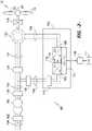
FIG. 2 , a schematic diagram of one embodiment of a wind turbineDFIG power system 100 is illustrated in accordance with aspects of the present subject matter. Although the present subject matter will generally be described herein with reference to thesystem 100 shown inFIG. 2 , those of ordinary skill in the art, using the disclosures provided herein, should understand that aspects of the present disclosure may also be applicable in other power generation systems, and that the invention is not limited to wind turbine systems. - In the embodiment of
FIG. 2 , therotor 18 of the wind turbine 10 (FIG. 1 ) may, optionally, be coupled to agear box 118, which is, in turn, coupled to thegenerator 120, which may be a doubly fed induction generator (DFIG). - As shown, the
DFIG 120 is connected to astator bus 154. A power converter is connected to theDFIG 120 via arotor bus 156, and to thestator bus 154 via aline side bus 188. Thestator bus 154 provides an output multiphase power (e.g. three-phase power) from a stator of theDFIG 120, and therotor bus 156 provides an output multiphase power (e.g. three-phase power) from a rotor of theDFIG 120. Thepower converter 162 includes a rotor side converter (RSC) 166 and a line side converter (LSC) 168. TheDFIG 120 is coupled via therotor bus 156 to therotor side converter 166. Additionally, theRSC 166 is coupled to theLSC 168 via aDC link 136 across which is aDC link capacitor 138. TheLSC 168 is, in turn, coupled to aline side bus 188. - The
RSC 166 and theLSC 168 may be configured for normal operating mode in a three-phase, pulse width modulation (PWM) arrangement using insulated gate bipolar transistor (IGBT) switching elements, as will be discussed in more detail with respect toFIG. 3 . - In addition, the
power converter 162 is coupled to aconverter controller 174 in order to control the operation of therotor side converter 166 and theline side converter 168. It should be noted that thecontroller 174 may, in several embodiments, be configured as an interface between thepower converter 162 and alocal controller 176 and include any number of control devices. In one embodiment, theconverter controller 174 may include a processing device (e.g. microprocessor, microcontroller, etc.) executing computer-readable instructions stored in a computer-readable medium. The instructions when executed by the processing device may cause the processing device to perform operations, including providing control commands (e.g. switching frequency commands) to the switching elements of thepower converter 162. - It should be appreciated that the
converter controller 174 and the localwind turbine controllers 176 may each correspond to any suitable computing device and/or any combination of computing devices. For instance, a controller may include one or more processor(s) and associated memory device(s) configured to perform a variety of computer-implemented functions. As used herein, the term "processor" refers not only to integrated circuits referred to in the art as being included in a computer, but also refers to a controller, a microcontroller, a microcomputer, a programmable logic controller (PLC), an application specific integrated circuit, and other programmable circuits. Additionally, the memory device(s) may generally comprise memory element(s) including, but not limited to, computer readable medium (e.g., random access memory (RAM)), computer readable non-volatile medium (e.g., a flash memory), a floppy disk, a compact disc-read only memory (CD-ROM), a magneto-optical disk (MOD), a digital versatile disc (DVD) and/or other suitable memory elements. Such memory device(s) may generally be configured to store suitable computer-readable instructions that, when implemented by the processor(s), configure the controller to perform various functions, such as the steps disclosed herein. - As mentioned, for an individual DFIG wind
turbine power system 100, the reactive power (Q) is supplied primarily by the RSC, via thegenerator 120 and the LSC. - In typical configurations, various line contactors and circuit breakers including, for example, a
grid breaker 182 may also be included for isolating the various components as necessary for normal operation of theDFIG 120 during connection to and disconnection from a load, such as theelectrical grid 184. For example, asystem circuit breaker 178 may couple thesystem bus 160 to atransformer 180, which may be coupled to theelectrical grid 184 via thegrid breaker 182. In alternative embodiments, fuses may replace some or all of the circuit breakers. - In operation, alternating current power generated at the
DFIG 120 by rotating therotor 18 is provided to theelectrical grid 184 via dual paths defined by thestator bus 154 and therotor bus 156. On therotor bus side 156, sinusoidal multi-phase (e.g. three-phase) alternating current (AC) power is provided to thepower converter 162. The rotorside power converter 166 converts the AC power provided from therotor bus 156 into direct current (DC) power and provides the DC power to theDC link 136. As is generally understood, switching elements (e.g. IGBTs) used in the bridge circuits of the rotorside power converter 166 may be modulated to convert the AC power provided from therotor bus 156 into DC power suitable for theDC link 136. - In addition, the
line side converter 168 converts the DC power on the DC link 136 into AC output power suitable for theelectrical grid 184. In particular, switching elements (e.g. IGBTs) used in bridge circuits of the lineside power converter 168 can be modulated to convert the DC power on the DC link 136 into AC power on theline side bus 188. The AC power from thepower converter 162 can be combined with the power from the stator ofDFIG 120 to provide multi-phase power (e.g. three-phase power) having a frequency maintained substantially at the frequency of the electrical grid 184 (e.g. 50 Hz or 60 Hz). - Additionally, various circuit breakers and switches, such as
grid breaker 182,system breaker 178,stator sync switch 158,converter breaker 186, andline contactor 172 may be included in the windturbine power system 100 to connect or disconnect corresponding buses, for example, when current flow is excessive and may damage components of the windturbine power system 100 or for other operational considerations. Additional protection components may also be included in the windturbine power system 100. - Moreover, the
power converter 162 may receive control signals from thelocal controller 176 via theconverter controller 174. The control signals may be based, among other things, on sensed conditions or operating characteristics of the windturbine power system 100, and provide for control of the operation of thepower converter 162. For example, feedback in the form of a sensed speed of theDFIG 120 may be used to control the conversion of the output power from therotor bus 156 to maintain a proper and balanced multi-phase (e.g. three-phase) power supply. In particular, as will be described below, the sensed speed may be used as a basis for adjusting the switching frequency of the switching elements (e.g., when theDIFG 120 is operating at or near its synchronous speed). Other feedback from other sensors may also be used by thecontroller 174 to control thepower converter 162, including, for example, stator and rotor bus voltages and current feedbacks. Using the various forms of feedback information, switching control signals (e.g. gate timing commands for IGBTs), stator synchronizing control signals, and circuit breaker signals may be generated. - The
power converter 162 also compensates or adjusts the frequency of the three-phase power from the rotor for changes, for example, in the wind speed athub 20 andblades 22. Therefore, mechanical and electrical rotor frequencies are decoupled and the electrical stator and rotor frequency matching is facilitated substantially independently of the mechanical rotor speed. - Under some conditions, the bi-directional characteristics of the
power converter 162, and specifically, the bi-directional characteristics of theLSC 168 andRSC 166, facilitate feeding back at least some of the generated electrical power into generator rotor. More specifically, electrical power is transmitted from thestator bus 154 toline side bus 188 and subsequently through theline contactor 172 and into thepower converter 162, specifically theLSC 168 which acts as a rectifier and rectifies the sinusoidal, three-phase AC power to DC power. The DC power is transmitted intoDC link 136.Capacitor 138 facilitates mitigating DC link voltage amplitude variations by facilitating mitigation of a DC ripple sometimes associated with three-phase AC rectification. - The DC power is subsequently transmitted to the
RSC 166 that converts the DC electrical power to a three-phase, sinusoidal AC electrical power with predetermined voltages, currents, and frequencies. This conversion is monitored and controlled viacontroller 174. The converted AC power is transmitted fromRSC 166 viarotor bus 156 to the generator rotor. In this manner, generator reactive power control is facilitated by controlling rotor current and voltage. - Referring now to
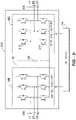
FIG. 3 , a schematic diagram of one embodiment of the power converter shown inFIG. 2 is illustrated in accordance with aspects of the present subject matter. As shown, the rotor side converter (RSC) 166 includes a plurality of bridge circuits (e.g. H-bridge circuits), with each phase of therotor bus 156 input to therotor side converter 166 being coupled to a single bridge circuit. In addition, the line side converter (LSC) 168 may also include a plurality of bridge circuits. Similar to therotor side converter 166, theline side converter 168 also includes a single bridge circuit for each output phase of theline converter 168. In other embodiments, theline side converter 168, therotor side converter 166, or both theline side converter 168 and therotor side converter 166 may include parallel bridge circuits without deviating from the scope of the present disclosure. - Each bridge circuit may generally include a plurality of switching elements (e.g. IGBTs) coupled in series with one another. For instance, as shown in
FIG. 3 , each bridge circuit includes an upper IGBT (e.g. IGBT 212) and a lower IGBT (e.g. IGBT 214). In addition, a diode may be coupled in parallel with each of the IGBTs. In alternative embodiments, parallel IGBTs and diodes may be used to increase the current rating of the converter. As is generally understood, theline side converter 168 and therotor side converter 166 may be controlled, for instance, by providing control commands, using a suitable driver circuit, to the gates of the IGBTs. For example, thecontroller 174 may provide suitable gate timing commands to the gates of the IGBTs of the bridge circuits. The control commands may control the switching frequency of the IGBTs to provide a desired output. It should be appreciated by those of ordinary skill in the art that, as an alternative to IGBTs, thepower convertor 162 may include any other suitable switching elements. - Referring to
FIG. 3 , eachIGBT 212 includes a power diode, wherein the IGBT and power diode are joined to positive or negative DC lines and output lines output three-phase voltages. Changes to the output current of theIGBTs 212, used to produce a three-phase output current waveform at the output lines, can result in power losses, resulting in a higher junction temperature at theIGBTs 212. Such junction temperatures may result in mechanical strain and/or deformation of the bond wires, thereby shortening the lifespan of theconverters - It is recognized that the junction thermal cycle temperature difference (ΔT) generated in cycling of the IGBTs from ON to OFF significantly affects the number of cycles that the device can sustain, and thus the life of the IGBT. For example, a reduction in a temperature change (ΔT) by approximately 10° C. may improve the semiconductor life by a factor of two. Changing the ΔT from 10° C. to 30° C. may improve the life from under 100,000 cycles to more than 400,000 cycles. By reducing the switching frequency of the
RSC 166, the ΔT is reduced. Thus, the second switching frequency may also be established based on maintaining the junction ΔT below a defined value. - Referring now to
FIG. 4 , a flow diagram of one embodiment of amethod 300 for operating a power generation system is illustrated in accordance with aspects of the present subject matter. In general, themethod 300 is described herein as implemented using a wind turbine power system, such as the DFIG windturbine power system 100 described above with reference toFIG. 2 . However, it should be appreciated that the disclosedmethod 300 may be implemented using any other suitable power generation system that is configured to supply power, including reactive power, for application to a load, such as a power grid. In addition, althoughFIG. 4 depicts steps performed in a particular order for purposes of illustration and discussion, the methods described herein are not limited to any particular order or arrangement. One skilled in the art, using the disclosures provided herein, will appreciate that various steps of the methods can be omitted, rearranged, combined and/or adapted in various ways. - At (302), the
method 300 includes generating alternating current (AC) power with a generator of a power generation system, such as a wind turbine power system incorporating a DFIG as discussed above. The AC power may be a multiphase alternating current power, such as a three-phase alternating current power. - At (304), the AC power is received by a power converter via a bus and is converted by the power converter to an output power suitable for application to a load (e.g., to an electrical grid). The output power includes real power (P) and reactive power (Q). The power converter includes a plurality of switching elements, such as IGBTs, wherein pulse width modulation of the switching elements may be controlled at a first switching frequency to provide output power for application to the load at a first operating speed of generator rotor. The first switching frequency on the rotor side converter (RSC) of a DFIG power convertor may be the frequency typically used for all generator rotor speeds within the generator's normal operating speed range (e.g., about 2000 or 3000 Hz). However, as discussed above, while this first (elevated) switching is desirable for most operating speeds, it results in peak temperatures and thermal cycling stresses in the switching elements and limits the reactive power output of the power converter (particularly, the RSC) at or near synchronous speeds of the generator rotor.
- At (306), a reduced second switching frequency is determined for the switching elements at a changed generator rotor speed, in particular speeds at or near synchronous speed. The power converter receives a control command to reduce the switching frequency of the switching elements to the second switching frequency from a controller. The second switching frequency is determined in real operating time of the generator based on the changed generator rotor speed and is selected to provide a defined reactive power value from the power converter at the changed generator rotor speeds at or near synchronous speed. The second switching frequency may also be defined based on maintaining the IGBTs below a junction ΔT value. The second switching frequency compensates for the deficiency in reactive power that would otherwise result if the first switching frequency were maintained at the changed generator rotor speeds.
- It should be appreciated that the second switching frequency based on the variables of rotor speed, reactive power, and ΔT limit may be determined empirically, via computer modeling, testing of actual systems, and by any other suitable means.
- In a certain embodiment, the change (deficiency) in reactive power at the power converter may be measured in real time as the generator rotor speed changes, wherein the switching frequency of the IGBTs is reduced in a feedback control loop until the deficiency of reactive power is compensated for by the second switching frequency.
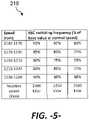
- In an alternate embodiment, the second switching frequency may be pre-defined. For example, a controller may determine the second switching frequency from a pre-defined and stored look-up table 216 (
FIG. 5 ) that cross-references reactive power values generated at the second switching frequency for different generator rotor speeds at or near synchronous speed (in the embodiment of the look-up table 216 depicted inFig. 5 , synchronous speed of the generator rotor is 1200 rpm). Information in the look-up table can be presented in various ways within the scope and spirit of "predefined" values. For example, referring toFIG. 5 , the look-up table 216 provides the different generator rotor speeds as a plurality of sub-ranges (e.g., 1140-1170 rpm; 1170-1190 rpm; etc.), wherein for each sub-range a second switching frequency is provided for a particular reactive power value, the second switching frequency also determined to meet the ΔT limit defined for the switching elements. For example, to provide 2250 kVar from the power converter at a generator rotor speed within the sub-range of 1190-1210 rpm, the second switching frequency is 75% of the first switching frequency (base value) at normal operating speeds of the generator rotor (e.g., speeds outside of the "at or near" synchronous speed band). As shown inFig. 5 , the look-up table 216 may provide a plurality of different reactive power values and corresponding second switching frequencies for each sub-range of generator rotor speeds. For example, to provide 2300 kVar from the power converter at the same generator rotor speed within the sub-range of 1190-1210 rpm, the second switching frequency is 70% of the first switching frequency. - The desired reactive power generation value required for production by the power converter at the changed generator rotor speed (e.g., 2200 kVar or 2300 kVar) may be pre-defined based on known characteristics of the power generation system at the first switching frequency and/or the known load (grid) reactive power requirements and entered into the look-up table to determine the second switching frequency. Alternatively, the reactive power output of the power converter may be measured at the first switching frequency and used to enter the look-up table 216 to determine the second switching frequency that will be needed at the changed generator rotor speed.
- It certain embodiments, it may also be desired to limit or define the second switching frequencies so that harmonic distortions induced by the power converter and transferred to the grid via the LSC or the generator are within a pre-defined Total Harmonic Distortion (THD) value set for the power generation system.
- At (308), a command is generated (e.g., from the controller 174) to reduce the switching frequency to the second switching frequency in order to increase the reactive power output of the power converter. This command may be generated before the generator rotor speed changes, during the speed change, or after the speed change of the generator rotor.
- At (310), the increased reactive power output from the power converter at the changed speed of the generator rotor is supplied to the load, which may be an electrical grid. However, in other embodiments, the load may be a motor, resistive load or any other load. It should be appreciated that, while an electrical grid is traditionally a supplier of power, the electrical grid may act as a load for the disclosed wind
turbine power system 100. - It should be appreciated that, as indicated above, the "synchronous speed" of a generator generally refers to the speed at which the rotor current is equal to DC current. In addition, it should be appreciated that the operating speed of a generator may be "at or near" its synchronous speed when the operating speed is within +/- 10% of the synchronous speed, such as by operating the generator at a speed of within +/- 5% of the synchronous speed or at a speed of within +/- 2.5% of the synchronous speed and any other subranges therebetween.
Claims (15)
- A method (300) for operating a power generation system (100) that supplies real and reactive power to a load, comprising:with a power converter (162) having switching elements, receiving (304) alternating current power from a generator (120) and generating the reactive power within an operating range of generator rotor speed;as the generator rotor speed changes and approaches synchronous speed, generating (308) a control command to decrease a switching frequency of the switching elements from a first switching frequency to a second switching frequency, wherein the reactive power output of the power converter (162) is increased at the second switching frequency; andwherein the second switching frequency is determined in real operating time of the generator (120) based on providing a defined reactive power value from the power converter (162) at the changed generator rotor speed at or near synchronous speed and maintaining the switching elements within defined thermal limits.
- The method as in claim 1, wherein the power converter (162) comprises a line-side converter, LSC (168), and a rotor-side converter, RSC (166), the RSC (166) generating the reactive power.
- The method as in claim 2, wherein the generator (120) is a doubly fed induction generator, DFIG, in a wind turbine power generation system (100).
- The method as in claim 2, wherein the switching elements comprise insulated gate bipolar transistor, IGBT, elements (212, 214).
- The method of any of the preceding claims, wherein a controller (174) determines the second switching frequency from a look-up table that cross-references reactive power values generated at the second switching frequency at different generator rotor speeds.
- The method as in claim 5, wherein the look-up table provides the different generator rotor speeds as a plurality of sub-ranges, and for each sub-range a second switching frequency is provided for the reactive power value.
- The method as in claim 6, wherein the look-up table provides a plurality of the reactive power values and a corresponding second switching frequency for each sub range at each of the reactive power values.
- The method as in claim 5, wherein the reactive power value required from the power generation system (100) at a particular generator rotor speed is pre-defined and entered into the look-up table to determine the second switching frequency.
- The method as in claim 5, wherein the reactive power value required from the power generation system (100) at a particular generator rotor speed is measured in real time and entered into the look-up table to determine the second switching frequency.
- The method of any of the preceding claims, wherein the second switching frequency is determined so that harmonic distortions induced by the power converter (162) in the load are within a pre-defined limit value.
- A wind turbine system (100) configured to supply real and reactive power to a load, comprising:a wind turbine rotor (18) comprising a hub (20) and a plurality of blades (22) coupled to the hub (20);a doubly fed induction generator, DFIG (120), coupled to the wind turbine rotor (18) and operable at a generator rotor speed;a power converter (162) configured with the DFIG (120) and comprising a line-side converter, LSC (168) and a rotor-side converter, RSC (166), the RSC (166) comprising a plurality of switching elements configured to generate the reactive power;a controller (174) in communication with the power converter (162) and, as generator rotor speed changes and approaches synchronous speed, configured to generate a control command to decrease a switching frequency of the switching elements in the RSC (166) from a first switching frequency to a second switching frequency to increase an output of the reactive power from the RSC (166); andwherein the second switching frequency is determined in real operating time of the generator by the controller (174) to provide a defined reactive power value generated by the RSC (166) at a changed generator rotor speed at or near synchronous speed while maintain the switching elements within defined thermal limits.
- The wind turbine system (100) as in claim 11, wherein the switching elements comprise insulated gate bipolar transistor, IGBT, elements (212, 214).
- The wind turbine system (100) of claims 11-12, wherein the controller (174) determines the second switching frequency from a look-up table that cross-references reactive power values generated at the second switching frequency at different generator rotor speeds.
- The wind turbine system (100) as in claim 13, wherein the look-up table comprises the different generator rotor speeds presented as a plurality of sub-ranges, and for each sub-range a second switching frequency is provided for a particular reactive power value.
- The wind turbine system (100) as in claim 14, wherein the look-up table comprises a plurality of the reactive power values and corresponding second switching frequencies at the sub-ranges of generator rotor speeds.
Applications Claiming Priority (1)
| Application Number | Priority Date | Filing Date | Title |
|---|---|---|---|
| US16/390,547US10742149B1 (en) | 2019-04-22 | 2019-04-22 | System and method for reactive power control of a wind turbine by varying switching frequency of rotor side converter |
Publications (2)
| Publication Number | Publication Date |
|---|---|
| EP3731405A1 EP3731405A1 (en) | 2020-10-28 |
| EP3731405B1true EP3731405B1 (en) | 2022-09-14 |
Family
ID=70292895
Family Applications (1)
| Application Number | Title | Priority Date | Filing Date |
|---|---|---|---|
| EP20169891.7AActiveEP3731405B1 (en) | 2019-04-22 | 2020-04-16 | System and method for reactive power control of a wind turbine by varying switching frequency of rotor side converter |
Country Status (5)
| Country | Link |
|---|---|
| US (1) | US10742149B1 (en) |
| EP (1) | EP3731405B1 (en) |
| CN (1) | CN111828251B (en) |
| DK (1) | DK3731405T3 (en) |
| ES (1) | ES2933288T3 (en) |
Families Citing this family (9)
| Publication number | Priority date | Publication date | Assignee | Title |
|---|---|---|---|---|
| JP2019146301A (en)* | 2018-02-16 | 2019-08-29 | 本田技研工業株式会社 | Inverter generator |
| US11296612B2 (en)* | 2019-12-30 | 2022-04-05 | General Electric Company | Carrier-based pulse width modulation control for back-to-back voltage source converters |
| CN112145358B (en)* | 2020-10-30 | 2021-07-23 | 上海电气风电集团股份有限公司 | Wind generating set and calibration method of wind direction rose diagram thereof |
| EP3996228A1 (en)* | 2020-11-04 | 2022-05-11 | Siemens Gamesa Renewable Energy Innovation & Technology S.L. | Control of a dfig grid side converter |
| CN113381588B (en)* | 2021-06-09 | 2022-06-21 | 重庆大学 | Thermal management optimization control method applied to IGBT modules |
| EP4117171A1 (en)* | 2021-07-06 | 2023-01-11 | Siemens Gamesa Renewable Energy Innovation & Technology S.L. | Method and apparatus for computer-implemented controlling of a doubly-fed electric machine |
| CN113992084B (en)* | 2021-12-29 | 2022-04-01 | 苏州乾能电气有限公司 | Method, system, device and medium for inhibiting generator vibration |
| CN114396359B (en)* | 2022-03-21 | 2025-09-23 | 上海电力大学 | A method, system and storage medium for thermal management of IGBT in a doubly-fed wind turbine converter |
| US12244244B2 (en)* | 2022-04-28 | 2025-03-04 | General Electric Renovables Espana, S.L. | Fault tolerant system and method for continuous skip-fire pulse width modulation for an active neutral point clamped converter |
Family Cites Families (69)
| Publication number | Priority date | Publication date | Assignee | Title |
|---|---|---|---|---|
| US904607A (en) | 1908-03-16 | 1908-11-24 | Hjalmar Elmblad | Seal-lock. |
| US5798631A (en)* | 1995-10-02 | 1998-08-25 | The State Of Oregon Acting By And Through The State Board Of Higher Education On Behalf Of Oregon State University | Performance optimization controller and control method for doubly-fed machines |
| EP1284045A1 (en)* | 2000-05-23 | 2003-02-19 | Vestas Wind System A/S | Variable speed wind turbine having a matrix converter |
| US7071579B2 (en) | 2002-06-07 | 2006-07-04 | Global Energyconcepts,Llc | Wind farm electrical system |
| WO2004025803A1 (en) | 2002-09-13 | 2004-03-25 | Abb Ab | Wind power fed network |
| EP1563598B1 (en)* | 2002-11-01 | 2012-10-03 | Vestas Wind Systems A/S | Circuit arrangement for use in a variable speed wind turbine system comprising a double-fed induction generator and a back-to-back converter |
| JP2004208450A (en)* | 2002-12-26 | 2004-07-22 | Sanden Corp | Motor controller |
| US7095597B1 (en) | 2003-04-30 | 2006-08-22 | Clipper Windpower Technology, Inc. | Distributed static var compensation (DSVC) system for wind and water turbine applications |
| WO2004098261A2 (en) | 2003-05-02 | 2004-11-18 | Xantrex Technology Inc. | Control system for doubly fed induction generator |
| US6924565B2 (en) | 2003-08-18 | 2005-08-02 | General Electric Company | Continuous reactive power support for wind turbine generators |
| US7119452B2 (en) | 2003-09-03 | 2006-10-10 | General Electric Company | Voltage control for wind generators |
| US7013203B2 (en) | 2003-10-22 | 2006-03-14 | General Electric Company | Wind turbine system control |
| TW200530566A (en)* | 2004-03-05 | 2005-09-16 | Hitachi Ind Equipment Sys | Method for detecting temperature of semiconductor element and semiconductor power converter |
| US7356441B2 (en)* | 2005-09-28 | 2008-04-08 | Rockwell Automation Technologies, Inc. | Junction temperature prediction method and apparatus for use in a power conversion module |
| US7567160B2 (en) | 2006-02-15 | 2009-07-28 | American Superconductor Corporation | Supplementary transformer cooling in a reactive power compensation system |
| US7622815B2 (en)* | 2006-12-29 | 2009-11-24 | Ingeteam Energy, S.A. | Low voltage ride through system for a variable speed wind turbine having an exciter machine and a power converter not connected to the grid |
| JP5016967B2 (en)* | 2007-04-20 | 2012-09-05 | 株式会社日立産機システム | Power converter and power cycle life prediction method |
| US7847526B2 (en)* | 2007-09-28 | 2010-12-07 | General Electric Company | System and method for controlling torque ripples in synchronous machines |
| US7884492B2 (en)* | 2007-11-13 | 2011-02-08 | General Electric Company | Methods and systems for wind turbine generators |
| CN201167296Y (en) | 2007-12-14 | 2008-12-17 | 张勇 | Directly-drive type ac excitation wind power generator system |
| DE102008003299B4 (en)* | 2008-01-07 | 2016-06-09 | Woodward Kempen Gmbh | Method for operating a wind energy plant |
| US8242735B2 (en)* | 2008-07-09 | 2012-08-14 | Caterpillar Inc. | Method and system for temperature-based power converter control |
| US8188610B2 (en)* | 2008-09-08 | 2012-05-29 | General Electric Company | Wind turbine having a main power converter and an auxiliary power converter and a method for the control thereof |
| US8148929B2 (en) | 2008-09-30 | 2012-04-03 | Rockwell Automation Technologies, Inc. | Power electronic module IGBT protection method and system |
| WO2010079235A2 (en)* | 2009-01-12 | 2010-07-15 | Vestas Wind Systems A/S | Load dependent converter switching frequency |
| US8360636B2 (en)* | 2009-07-02 | 2013-01-29 | Renesas Electronics America Inc. | Temperature detection and reporting system and method in power driving and/or consuming system |
| WO2011012733A1 (en) | 2009-07-27 | 2011-02-03 | Gamesa Innovation & Technology, S.L. | System for reactive power compensation in electricity system |
| US7923862B2 (en) | 2009-10-06 | 2011-04-12 | General Electric Company | Reactive power regulation and voltage support for renewable energy plants |
| US8046109B2 (en) | 2009-12-16 | 2011-10-25 | General Electric Company | Method and systems for operating a wind turbine |
| US9236742B2 (en) | 2010-02-25 | 2016-01-12 | Vestas Wind Systems A/S | Method and control arrangement for controlling a reactive power source |
| US8471516B2 (en) | 2010-05-24 | 2013-06-25 | Rockwell Automation Technologies, Inc. | Adjustable speed drive lifetime improvement method |
| US8432052B2 (en)* | 2010-05-27 | 2013-04-30 | Rockwell Automation Technologies, Inc. | Wind power converter system with grid side reactive power control |
| AU2011260701B2 (en) | 2010-06-03 | 2015-08-20 | Vestas Wind Systems A/S | Method and control arrangement for controlling central capacitors in wind power plants |
| US8736091B2 (en)* | 2010-06-18 | 2014-05-27 | Rockwell Automation Technologies, Inc. | Converter lifetime improvement method for doubly fed induction generator |
| WO2011161692A2 (en) | 2010-06-21 | 2011-12-29 | Raghunathan V R | Reactive power management for wind turbine applications |
| US8664800B2 (en) | 2010-08-31 | 2014-03-04 | General Electric Company | System and method for distribution of inverter VAR support |
| JP5549505B2 (en)* | 2010-09-28 | 2014-07-16 | 日産自動車株式会社 | Temperature protection device, motor control device, and temperature protection method |
| US8093741B2 (en)* | 2010-10-29 | 2012-01-10 | General Electric Company | Method and system for providing increased turbine output for doubly fed induction generator |
| EP2503146B1 (en) | 2011-03-21 | 2013-12-18 | Siemens Aktiengesellschaft | Method and arrangement for controlling an operation of an electric energy production facility during a disconnection to a utility grid. |
| CN102810875B (en)* | 2011-05-30 | 2014-10-22 | 通用电气公司 | System using converter for energy conversion and operating method of system |
| US9368971B2 (en) | 2011-06-23 | 2016-06-14 | Inventus Holdings, Llc | Multiple renewables site electrical generation and reactive power control |
| JP5578197B2 (en)* | 2012-06-01 | 2014-08-27 | 株式会社デンソー | Temperature detection device |
| CA2879578A1 (en)* | 2012-08-03 | 2014-02-06 | Abb Technology Ag | Overload limitation in peak power operation |
| JP5930911B2 (en)* | 2012-08-08 | 2016-06-08 | 株式会社日立製作所 | Power converter |
| CN104641529B (en) | 2012-09-17 | 2018-09-18 | 维斯塔斯风力系统集团公司 | Method for determining the individual set point in generating equipment controller and generating equipment controller |
| IN2015DN02395A (en) | 2012-09-17 | 2015-09-04 | Vestas Wind Sys As | |
| CN102882229B (en) | 2012-09-21 | 2015-06-17 | 北京金风科创风电设备有限公司 | Wind farm dynamic voltage automatic control system |
| EP2741392A3 (en) | 2012-12-04 | 2016-12-14 | ABB Research Ltd. | Systems and methods for utilizing an active compensator to augment a diode rectifier |
| US9680307B2 (en) | 2012-12-21 | 2017-06-13 | General Electric Company | System and method for voltage regulation of a renewable energy plant |
| WO2014124644A1 (en) | 2013-02-15 | 2014-08-21 | Vestas Wind Systems A/S | A method of operating a wind turbine plant |
| US8853876B1 (en) | 2013-04-26 | 2014-10-07 | General Electric Company | Switching-based control for a power converter |
| US9083260B2 (en) | 2013-05-21 | 2015-07-14 | Control Techniques Limited | Inverter controller and method of controlling an inverter |
| US8975768B2 (en)* | 2013-06-05 | 2015-03-10 | General Electic Company | Methods for operating wind turbine system having dynamic brake |
| US10411480B2 (en) | 2013-11-28 | 2019-09-10 | Vestas Wind Systems A/S | Reconfiguration of the reactive power loop of a wind power plant |
| JP5907236B2 (en)* | 2013-12-11 | 2016-04-26 | 株式会社デンソー | Temperature detection device |
| US9419439B2 (en) | 2014-01-14 | 2016-08-16 | Siemens Aktiengesellschaft | Reconnecting a wind power plant to a utility grid |
| US9780710B2 (en) | 2014-04-15 | 2017-10-03 | General Electric Company | Reactive power control for wind turbine generators |
| US9447772B2 (en)* | 2014-12-18 | 2016-09-20 | General Electric Company | Systems and methods for increasing wind turbine power output |
| US9831810B2 (en) | 2015-03-10 | 2017-11-28 | General Electric Company | System and method for improved reactive power speed-of-response for a wind farm |
| CN104795835B (en)* | 2015-03-26 | 2017-02-01 | 同济大学 | Control method and system for controlling switching frequency of double-fed wind power converter |
| US9625921B2 (en) | 2015-04-03 | 2017-04-18 | Ge Energy Power Conversion Technology Ltd | Life of a semiconductor by reducing temperature changes therein via switching frequency |
| US10496052B2 (en)* | 2015-04-10 | 2019-12-03 | The Board Of Trustees Of The University Of Alabama | Systems, methods and devices for vector control of induction machines using artificial neural networks |
| US10107260B2 (en) | 2015-11-19 | 2018-10-23 | General Electric Company | Wind turbine auxiliary circuit control |
| WO2018093593A1 (en)* | 2016-11-17 | 2018-05-24 | General Electric Company | Method and system for operating a hybrid power generation system |
| US10103663B1 (en)* | 2017-04-18 | 2018-10-16 | General Electric Company | Control method for protecting switching devices in power converters in doubly fed induction generator power systems |
| BR112019022448B1 (en)* | 2017-04-28 | 2023-12-19 | General Electric Company | POWER GENERATION SYSTEM AND METHOD FOR IMPROVING ELECTRICAL POWER PRODUCTION BY A POWER GENERATION SYSTEM |
| US10707789B2 (en)* | 2017-05-12 | 2020-07-07 | General Electric Company | Adaptive current damping module for improved power converter control in wind turbine systems |
| US10731630B2 (en)* | 2018-01-03 | 2020-08-04 | General Electric Company | Extended reaction power for wind farms |
| US10615727B2 (en)* | 2018-08-27 | 2020-04-07 | General Electric Company | Dynamic brake circuit assembly for a wind turbine |
- 2019
- 2019-04-22USUS16/390,547patent/US10742149B1/enactiveActive
- 2020
- 2020-04-16EPEP20169891.7Apatent/EP3731405B1/enactiveActive
- 2020-04-16DKDK20169891.7Tpatent/DK3731405T3/enactive
- 2020-04-16ESES20169891Tpatent/ES2933288T3/enactiveActive
- 2020-04-22CNCN202010321848.XApatent/CN111828251B/enactiveActive
Also Published As
| Publication number | Publication date |
|---|---|
| CN111828251B (en) | 2025-02-18 |
| EP3731405A1 (en) | 2020-10-28 |
| US10742149B1 (en) | 2020-08-11 |
| ES2933288T3 (en) | 2023-02-03 |
| DK3731405T3 (en) | 2022-11-21 |
| CN111828251A (en) | 2020-10-27 |
Similar Documents
| Publication | Publication Date | Title |
|---|---|---|
| EP3731405B1 (en) | System and method for reactive power control of a wind turbine by varying switching frequency of rotor side converter | |
| EP3745553B1 (en) | System and method for operating a wind farm during low wind speeds | |
| US8853876B1 (en) | Switching-based control for a power converter | |
| US11296612B2 (en) | Carrier-based pulse width modulation control for back-to-back voltage source converters | |
| US10581247B1 (en) | System and method for reactive power control of wind turbines in a wind farm supported with auxiliary reactive power compensation | |
| EP3893383A1 (en) | System and method for controlling wind turbine converters during high voltage ride through events | |
| US11056884B2 (en) | Wind turbine system with integrated reactive power compensation device | |
| US11196260B2 (en) | System and method for control of reactive power from a reactive power compensation device in a wind turbine system | |
| EP3736940B1 (en) | System and method for coordinated control of reactive power from a generator and a reactive power compensation device in a wind turbine system | |
| EP4024695A1 (en) | Method for operating doubly-fed wind turbine generator as a virtual synchronous machine to provide grid-forming control thereof | |
| US10218298B2 (en) | Spillover of reactive current to line side converter | |
| EP4623494A1 (en) | System and method for providing blackstart of grid-forming inverter-based resources | |
| CA3139584A1 (en) | System and method for operating an asynchronous inverter-based resource as a virtual synchronous machine to provide grid-formimg control thereof | |
| US10958200B1 (en) | System and method for operating a wind turbine power system during low wind speeds to improve efficiency | |
| US12009770B2 (en) | System and method for providing grid-forming control of an inverter-based resource | |
| WO2025141303A1 (en) | System and method for providing blackstart of grid-forming inverter-based resources | |
| EP4609500A1 (en) | System and method for extending the operating speed threshold of a grid-forming inverter-based resource | |
| WO2025085048A1 (en) | System and method of operating an inverter-based resource in multiple operating modes | |
| WO2025078856A1 (en) | System and method for providing blackstart of grid-forming inverter-based resources | |
| WO2025155283A1 (en) | System and method for providing blackstart of grid-forming inverter-based resources | |
| EP4627690A1 (en) | System and method for operating an inverter-based resource in grid-forming mode (gfm) for enhanced stability |
Legal Events
| Date | Code | Title | Description |
|---|---|---|---|
| PUAI | Public reference made under article 153(3) epc to a published international application that has entered the european phase | Free format text:ORIGINAL CODE: 0009012 | |
| STAA | Information on the status of an ep patent application or granted ep patent | Free format text:STATUS: THE APPLICATION HAS BEEN PUBLISHED | |
| AK | Designated contracting states | Kind code of ref document:A1 Designated state(s):AL AT BE BG CH CY CZ DE DK EE ES FI FR GB GR HR HU IE IS IT LI LT LU LV MC MK MT NL NO PL PT RO RS SE SI SK SM TR | |
| AX | Request for extension of the european patent | Extension state:BA ME | |
| STAA | Information on the status of an ep patent application or granted ep patent | Free format text:STATUS: REQUEST FOR EXAMINATION WAS MADE | |
| 17P | Request for examination filed | Effective date:20210420 | |
| RBV | Designated contracting states (corrected) | Designated state(s):AL AT BE BG CH CY CZ DE DK EE ES FI FR GB GR HR HU IE IS IT LI LT LU LV MC MK MT NL NO PL PT RO RS SE SI SK SM TR | |
| GRAP | Despatch of communication of intention to grant a patent | Free format text:ORIGINAL CODE: EPIDOSNIGR1 | |
| STAA | Information on the status of an ep patent application or granted ep patent | Free format text:STATUS: GRANT OF PATENT IS INTENDED | |
| RIC1 | Information provided on ipc code assigned before grant | Ipc:H02P 9/00 20060101AFI20220308BHEP | |
| INTG | Intention to grant announced | Effective date:20220405 | |
| GRAS | Grant fee paid | Free format text:ORIGINAL CODE: EPIDOSNIGR3 | |
| GRAA | (expected) grant | Free format text:ORIGINAL CODE: 0009210 | |
| STAA | Information on the status of an ep patent application or granted ep patent | Free format text:STATUS: THE PATENT HAS BEEN GRANTED | |
| AK | Designated contracting states | Kind code of ref document:B1 Designated state(s):AL AT BE BG CH CY CZ DE DK EE ES FI FR GB GR HR HU IE IS IT LI LT LU LV MC MK MT NL NO PL PT RO RS SE SI SK SM TR | |
| REG | Reference to a national code | Ref country code:GB Ref legal event code:FG4D | |
| REG | Reference to a national code | Ref country code:CH Ref legal event code:EP | |
| REG | Reference to a national code | Ref country code:DE Ref legal event code:R096 Ref document number:602020005074 Country of ref document:DE | |
| REG | Reference to a national code | Ref country code:IE Ref legal event code:FG4D | |
| REG | Reference to a national code | Ref country code:AT Ref legal event code:REF Ref document number:1519312 Country of ref document:AT Kind code of ref document:T Effective date:20221015 | |
| REG | Reference to a national code | Ref country code:DK Ref legal event code:T3 Effective date:20221116 | |
| REG | Reference to a national code | Ref country code:LT Ref legal event code:MG9D | |
| REG | Reference to a national code | Ref country code:NL Ref legal event code:MP Effective date:20220914 | |
| PG25 | Lapsed in a contracting state [announced via postgrant information from national office to epo] | Ref country code:SE Free format text:LAPSE BECAUSE OF FAILURE TO SUBMIT A TRANSLATION OF THE DESCRIPTION OR TO PAY THE FEE WITHIN THE PRESCRIBED TIME-LIMIT Effective date:20220914 Ref country code:RS Free format text:LAPSE BECAUSE OF FAILURE TO SUBMIT A TRANSLATION OF THE DESCRIPTION OR TO PAY THE FEE WITHIN THE PRESCRIBED TIME-LIMIT Effective date:20220914 Ref country code:NO Free format text:LAPSE BECAUSE OF FAILURE TO SUBMIT A TRANSLATION OF THE DESCRIPTION OR TO PAY THE FEE WITHIN THE PRESCRIBED TIME-LIMIT Effective date:20221214 Ref country code:LV Free format text:LAPSE BECAUSE OF FAILURE TO SUBMIT A TRANSLATION OF THE DESCRIPTION OR TO PAY THE FEE WITHIN THE PRESCRIBED TIME-LIMIT Effective date:20220914 Ref country code:LT Free format text:LAPSE BECAUSE OF FAILURE TO SUBMIT A TRANSLATION OF THE DESCRIPTION OR TO PAY THE FEE WITHIN THE PRESCRIBED TIME-LIMIT Effective date:20220914 Ref country code:FI Free format text:LAPSE BECAUSE OF FAILURE TO SUBMIT A TRANSLATION OF THE DESCRIPTION OR TO PAY THE FEE WITHIN THE PRESCRIBED TIME-LIMIT Effective date:20220914 | |
| REG | Reference to a national code | Ref country code:ES Ref legal event code:FG2A Ref document number:2933288 Country of ref document:ES Kind code of ref document:T3 Effective date:20230203 | |
| REG | Reference to a national code | Ref country code:AT Ref legal event code:MK05 Ref document number:1519312 Country of ref document:AT Kind code of ref document:T Effective date:20220914 | |
| PG25 | Lapsed in a contracting state [announced via postgrant information from national office to epo] | Ref country code:HR Free format text:LAPSE BECAUSE OF FAILURE TO SUBMIT A TRANSLATION OF THE DESCRIPTION OR TO PAY THE FEE WITHIN THE PRESCRIBED TIME-LIMIT Effective date:20220914 Ref country code:GR Free format text:LAPSE BECAUSE OF FAILURE TO SUBMIT A TRANSLATION OF THE DESCRIPTION OR TO PAY THE FEE WITHIN THE PRESCRIBED TIME-LIMIT Effective date:20221215 | |
| PG25 | Lapsed in a contracting state [announced via postgrant information from national office to epo] | Ref country code:SM Free format text:LAPSE BECAUSE OF FAILURE TO SUBMIT A TRANSLATION OF THE DESCRIPTION OR TO PAY THE FEE WITHIN THE PRESCRIBED TIME-LIMIT Effective date:20220914 Ref country code:RO Free format text:LAPSE BECAUSE OF FAILURE TO SUBMIT A TRANSLATION OF THE DESCRIPTION OR TO PAY THE FEE WITHIN THE PRESCRIBED TIME-LIMIT Effective date:20220914 Ref country code:PT Free format text:LAPSE BECAUSE OF FAILURE TO SUBMIT A TRANSLATION OF THE DESCRIPTION OR TO PAY THE FEE WITHIN THE PRESCRIBED TIME-LIMIT Effective date:20230116 Ref country code:CZ Free format text:LAPSE BECAUSE OF FAILURE TO SUBMIT A TRANSLATION OF THE DESCRIPTION OR TO PAY THE FEE WITHIN THE PRESCRIBED TIME-LIMIT Effective date:20220914 Ref country code:AT Free format text:LAPSE BECAUSE OF FAILURE TO SUBMIT A TRANSLATION OF THE DESCRIPTION OR TO PAY THE FEE WITHIN THE PRESCRIBED TIME-LIMIT Effective date:20220914 | |
| PG25 | Lapsed in a contracting state [announced via postgrant information from national office to epo] | Ref country code:SK Free format text:LAPSE BECAUSE OF FAILURE TO SUBMIT A TRANSLATION OF THE DESCRIPTION OR TO PAY THE FEE WITHIN THE PRESCRIBED TIME-LIMIT Effective date:20220914 Ref country code:PL Free format text:LAPSE BECAUSE OF FAILURE TO SUBMIT A TRANSLATION OF THE DESCRIPTION OR TO PAY THE FEE WITHIN THE PRESCRIBED TIME-LIMIT Effective date:20220914 Ref country code:IS Free format text:LAPSE BECAUSE OF FAILURE TO SUBMIT A TRANSLATION OF THE DESCRIPTION OR TO PAY THE FEE WITHIN THE PRESCRIBED TIME-LIMIT Effective date:20230114 Ref country code:EE Free format text:LAPSE BECAUSE OF FAILURE TO SUBMIT A TRANSLATION OF THE DESCRIPTION OR TO PAY THE FEE WITHIN THE PRESCRIBED TIME-LIMIT Effective date:20220914 | |
| REG | Reference to a national code | Ref country code:DE Ref legal event code:R097 Ref document number:602020005074 Country of ref document:DE | |
| PG25 | Lapsed in a contracting state [announced via postgrant information from national office to epo] | Ref country code:NL Free format text:LAPSE BECAUSE OF FAILURE TO SUBMIT A TRANSLATION OF THE DESCRIPTION OR TO PAY THE FEE WITHIN THE PRESCRIBED TIME-LIMIT Effective date:20220914 Ref country code:AL Free format text:LAPSE BECAUSE OF FAILURE TO SUBMIT A TRANSLATION OF THE DESCRIPTION OR TO PAY THE FEE WITHIN THE PRESCRIBED TIME-LIMIT Effective date:20220914 | |
| P01 | Opt-out of the competence of the unified patent court (upc) registered | Effective date:20230530 | |
| PLBE | No opposition filed within time limit | Free format text:ORIGINAL CODE: 0009261 | |
| STAA | Information on the status of an ep patent application or granted ep patent | Free format text:STATUS: NO OPPOSITION FILED WITHIN TIME LIMIT | |
| 26N | No opposition filed | Effective date:20230615 | |
| PG25 | Lapsed in a contracting state [announced via postgrant information from national office to epo] | Ref country code:SI Free format text:LAPSE BECAUSE OF FAILURE TO SUBMIT A TRANSLATION OF THE DESCRIPTION OR TO PAY THE FEE WITHIN THE PRESCRIBED TIME-LIMIT Effective date:20220914 | |
| REG | Reference to a national code | Ref country code:CH Ref legal event code:PL | |
| REG | Reference to a national code | Ref country code:DE Ref legal event code:R081 Ref document number:602020005074 Country of ref document:DE Owner name:GENERAL ELECTRIC RENOVABLES ESPANA, S.L., ES Free format text:FORMER OWNER: GENERAL ELECTRIC COMPANY, SCHENECTADY, NY, US Ref country code:DE Ref legal event code:R082 Ref document number:602020005074 Country of ref document:DE Representative=s name:ZIMMERMANN & PARTNER PATENTANWAELTE MBB, DE Ref country code:DE Ref legal event code:R082 Ref document number:602020005074 Country of ref document:DE | |
| PG25 | Lapsed in a contracting state [announced via postgrant information from national office to epo] | Ref country code:LU Free format text:LAPSE BECAUSE OF NON-PAYMENT OF DUE FEES Effective date:20230416 | |
| REG | Reference to a national code | Ref country code:BE Ref legal event code:MM Effective date:20230430 | |
| PG25 | Lapsed in a contracting state [announced via postgrant information from national office to epo] | Ref country code:MC Free format text:LAPSE BECAUSE OF FAILURE TO SUBMIT A TRANSLATION OF THE DESCRIPTION OR TO PAY THE FEE WITHIN THE PRESCRIBED TIME-LIMIT Effective date:20220914 | |
| PG25 | Lapsed in a contracting state [announced via postgrant information from national office to epo] | Ref country code:MC Free format text:LAPSE BECAUSE OF FAILURE TO SUBMIT A TRANSLATION OF THE DESCRIPTION OR TO PAY THE FEE WITHIN THE PRESCRIBED TIME-LIMIT Effective date:20220914 Ref country code:LI Free format text:LAPSE BECAUSE OF NON-PAYMENT OF DUE FEES Effective date:20230430 Ref country code:FR Free format text:LAPSE BECAUSE OF NON-PAYMENT OF DUE FEES Effective date:20230430 Ref country code:CH Free format text:LAPSE BECAUSE OF NON-PAYMENT OF DUE FEES Effective date:20230430 | |
| REG | Reference to a national code | Ref country code:IE Ref legal event code:MM4A | |
| PG25 | Lapsed in a contracting state [announced via postgrant information from national office to epo] | Ref country code:BE Free format text:LAPSE BECAUSE OF NON-PAYMENT OF DUE FEES Effective date:20230430 | |
| REG | Reference to a national code | Ref country code:DE Ref legal event code:R082 Ref document number:602020005074 Country of ref document:DE Representative=s name:ZIMMERMANN & PARTNER PATENTANWAELTE MBB, DE | |
| PG25 | Lapsed in a contracting state [announced via postgrant information from national office to epo] | Ref country code:IE Free format text:LAPSE BECAUSE OF NON-PAYMENT OF DUE FEES Effective date:20230416 | |
| PG25 | Lapsed in a contracting state [announced via postgrant information from national office to epo] | Ref country code:IE Free format text:LAPSE BECAUSE OF NON-PAYMENT OF DUE FEES Effective date:20230416 | |
| PG25 | Lapsed in a contracting state [announced via postgrant information from national office to epo] | Ref country code:IT Free format text:LAPSE BECAUSE OF FAILURE TO SUBMIT A TRANSLATION OF THE DESCRIPTION OR TO PAY THE FEE WITHIN THE PRESCRIBED TIME-LIMIT Effective date:20220914 | |
| REG | Reference to a national code | Ref country code:ES Ref legal event code:PC2A Owner name:GENERAL ELECTRIC RENOVABLES ESPANA S.L. Effective date:20240809 | |
| PG25 | Lapsed in a contracting state [announced via postgrant information from national office to epo] | Ref country code:BG Free format text:LAPSE BECAUSE OF FAILURE TO SUBMIT A TRANSLATION OF THE DESCRIPTION OR TO PAY THE FEE WITHIN THE PRESCRIBED TIME-LIMIT Effective date:20220914 | |
| PG25 | Lapsed in a contracting state [announced via postgrant information from national office to epo] | Ref country code:BG Free format text:LAPSE BECAUSE OF FAILURE TO SUBMIT A TRANSLATION OF THE DESCRIPTION OR TO PAY THE FEE WITHIN THE PRESCRIBED TIME-LIMIT Effective date:20220914 | |
| GBPC | Gb: european patent ceased through non-payment of renewal fee | Effective date:20240416 | |
| PG25 | Lapsed in a contracting state [announced via postgrant information from national office to epo] | Ref country code:GB Free format text:LAPSE BECAUSE OF NON-PAYMENT OF DUE FEES Effective date:20240416 | |
| PG25 | Lapsed in a contracting state [announced via postgrant information from national office to epo] | Ref country code:GB Free format text:LAPSE BECAUSE OF NON-PAYMENT OF DUE FEES Effective date:20240416 | |
| PGFP | Annual fee paid to national office [announced via postgrant information from national office to epo] | Ref country code:DK Payment date:20250319 Year of fee payment:6 | |
| PGFP | Annual fee paid to national office [announced via postgrant information from national office to epo] | Ref country code:DE Payment date:20250319 Year of fee payment:6 | |
| PGFP | Annual fee paid to national office [announced via postgrant information from national office to epo] | Ref country code:ES Payment date:20250502 Year of fee payment:6 | |
| PG25 | Lapsed in a contracting state [announced via postgrant information from national office to epo] | Ref country code:CY Free format text:LAPSE BECAUSE OF FAILURE TO SUBMIT A TRANSLATION OF THE DESCRIPTION OR TO PAY THE FEE WITHIN THE PRESCRIBED TIME-LIMIT; INVALID AB INITIO Effective date:20200416 | |
| PG25 | Lapsed in a contracting state [announced via postgrant information from national office to epo] | Ref country code:HU Free format text:LAPSE BECAUSE OF FAILURE TO SUBMIT A TRANSLATION OF THE DESCRIPTION OR TO PAY THE FEE WITHIN THE PRESCRIBED TIME-LIMIT; INVALID AB INITIO Effective date:20200416 |