EP3730169B1 - Drug delivery device with detection of position of the plunger - Google Patents
Drug delivery device with detection of position of the plungerDownload PDFInfo
- Publication number
- EP3730169B1 EP3730169B1EP20174878.7AEP20174878AEP3730169B1EP 3730169 B1EP3730169 B1EP 3730169B1EP 20174878 AEP20174878 AEP 20174878AEP 3730169 B1EP3730169 B1EP 3730169B1
- Authority
- EP
- European Patent Office
- Prior art keywords
- drug
- plunger
- drug container
- container
- light
- Prior art date
- Legal status (The legal status is an assumption and is not a legal conclusion. Google has not performed a legal analysis and makes no representation as to the accuracy of the status listed.)
- Active
Links
Images


Classifications
- A—HUMAN NECESSITIES
- A61—MEDICAL OR VETERINARY SCIENCE; HYGIENE
- A61M—DEVICES FOR INTRODUCING MEDIA INTO, OR ONTO, THE BODY; DEVICES FOR TRANSDUCING BODY MEDIA OR FOR TAKING MEDIA FROM THE BODY; DEVICES FOR PRODUCING OR ENDING SLEEP OR STUPOR
- A61M5/00—Devices for bringing media into the body in a subcutaneous, intra-vascular or intramuscular way; Accessories therefor, e.g. filling or cleaning devices, arm-rests
- A61M5/14—Infusion devices, e.g. infusing by gravity; Blood infusion; Accessories therefor
- A61M5/168—Means for controlling media flow to the body or for metering media to the body, e.g. drip meters, counters ; Monitoring media flow to the body
- A61M5/16886—Means for controlling media flow to the body or for metering media to the body, e.g. drip meters, counters ; Monitoring media flow to the body for measuring fluid flow rate, i.e. flowmeters
- A—HUMAN NECESSITIES
- A61—MEDICAL OR VETERINARY SCIENCE; HYGIENE
- A61M—DEVICES FOR INTRODUCING MEDIA INTO, OR ONTO, THE BODY; DEVICES FOR TRANSDUCING BODY MEDIA OR FOR TAKING MEDIA FROM THE BODY; DEVICES FOR PRODUCING OR ENDING SLEEP OR STUPOR
- A61M5/00—Devices for bringing media into the body in a subcutaneous, intra-vascular or intramuscular way; Accessories therefor, e.g. filling or cleaning devices, arm-rests
- A61M5/178—Syringes
- A61M5/31—Details
- A61M5/315—Pistons; Piston-rods; Guiding, blocking or restricting the movement of the rod or piston; Appliances on the rod for facilitating dosing ; Dosing mechanisms
- A61M5/31565—Administration mechanisms, i.e. constructional features, modes of administering a dose
- A61M5/31566—Means improving security or handling thereof
- A61M5/31568—Means keeping track of the total dose administered, e.g. since the cartridge was inserted
- A—HUMAN NECESSITIES
- A61—MEDICAL OR VETERINARY SCIENCE; HYGIENE
- A61M—DEVICES FOR INTRODUCING MEDIA INTO, OR ONTO, THE BODY; DEVICES FOR TRANSDUCING BODY MEDIA OR FOR TAKING MEDIA FROM THE BODY; DEVICES FOR PRODUCING OR ENDING SLEEP OR STUPOR
- A61M5/00—Devices for bringing media into the body in a subcutaneous, intra-vascular or intramuscular way; Accessories therefor, e.g. filling or cleaning devices, arm-rests
- A61M5/14—Infusion devices, e.g. infusing by gravity; Blood infusion; Accessories therefor
- A61M5/142—Pressure infusion, e.g. using pumps
- A61M5/14244—Pressure infusion, e.g. using pumps adapted to be carried by the patient, e.g. portable on the body
- A61M5/14248—Pressure infusion, e.g. using pumps adapted to be carried by the patient, e.g. portable on the body of the skin patch type
- A—HUMAN NECESSITIES
- A61—MEDICAL OR VETERINARY SCIENCE; HYGIENE
- A61M—DEVICES FOR INTRODUCING MEDIA INTO, OR ONTO, THE BODY; DEVICES FOR TRANSDUCING BODY MEDIA OR FOR TAKING MEDIA FROM THE BODY; DEVICES FOR PRODUCING OR ENDING SLEEP OR STUPOR
- A61M5/00—Devices for bringing media into the body in a subcutaneous, intra-vascular or intramuscular way; Accessories therefor, e.g. filling or cleaning devices, arm-rests
- A61M5/14—Infusion devices, e.g. infusing by gravity; Blood infusion; Accessories therefor
- A61M5/142—Pressure infusion, e.g. using pumps
- A61M5/145—Pressure infusion, e.g. using pumps using pressurised reservoirs, e.g. pressurised by means of pistons
- A61M5/1452—Pressure infusion, e.g. using pumps using pressurised reservoirs, e.g. pressurised by means of pistons pressurised by means of pistons
- A61M5/1454—Pressure infusion, e.g. using pumps using pressurised reservoirs, e.g. pressurised by means of pistons pressurised by means of pistons spring-actuated, e.g. by a clockwork
- A—HUMAN NECESSITIES
- A61—MEDICAL OR VETERINARY SCIENCE; HYGIENE
- A61M—DEVICES FOR INTRODUCING MEDIA INTO, OR ONTO, THE BODY; DEVICES FOR TRANSDUCING BODY MEDIA OR FOR TAKING MEDIA FROM THE BODY; DEVICES FOR PRODUCING OR ENDING SLEEP OR STUPOR
- A61M5/00—Devices for bringing media into the body in a subcutaneous, intra-vascular or intramuscular way; Accessories therefor, e.g. filling or cleaning devices, arm-rests
- A61M5/14—Infusion devices, e.g. infusing by gravity; Blood infusion; Accessories therefor
- A61M5/168—Means for controlling media flow to the body or for metering media to the body, e.g. drip meters, counters ; Monitoring media flow to the body
- A61M5/16831—Monitoring, detecting, signalling or eliminating infusion flow anomalies
- A61M5/1684—Monitoring, detecting, signalling or eliminating infusion flow anomalies by detecting the amount of infusate remaining, e.g. signalling end of infusion
- A—HUMAN NECESSITIES
- A61—MEDICAL OR VETERINARY SCIENCE; HYGIENE
- A61M—DEVICES FOR INTRODUCING MEDIA INTO, OR ONTO, THE BODY; DEVICES FOR TRANSDUCING BODY MEDIA OR FOR TAKING MEDIA FROM THE BODY; DEVICES FOR PRODUCING OR ENDING SLEEP OR STUPOR
- A61M5/00—Devices for bringing media into the body in a subcutaneous, intra-vascular or intramuscular way; Accessories therefor, e.g. filling or cleaning devices, arm-rests
- A61M5/178—Syringes
- A61M5/20—Automatic syringes, e.g. with automatically actuated piston rod, with automatic needle injection, filling automatically
- A61M5/2033—Spring-loaded one-shot injectors with or without automatic needle insertion
- G—PHYSICS
- G01—MEASURING; TESTING
- G01F—MEASURING VOLUME, VOLUME FLOW, MASS FLOW OR LIQUID LEVEL; METERING BY VOLUME
- G01F13/00—Apparatus for measuring by volume and delivering fluids or fluent solid materials, not provided for in the preceding groups
- A—HUMAN NECESSITIES
- A61—MEDICAL OR VETERINARY SCIENCE; HYGIENE
- A61M—DEVICES FOR INTRODUCING MEDIA INTO, OR ONTO, THE BODY; DEVICES FOR TRANSDUCING BODY MEDIA OR FOR TAKING MEDIA FROM THE BODY; DEVICES FOR PRODUCING OR ENDING SLEEP OR STUPOR
- A61M5/00—Devices for bringing media into the body in a subcutaneous, intra-vascular or intramuscular way; Accessories therefor, e.g. filling or cleaning devices, arm-rests
- A61M5/14—Infusion devices, e.g. infusing by gravity; Blood infusion; Accessories therefor
- A61M5/142—Pressure infusion, e.g. using pumps
- A61M5/14244—Pressure infusion, e.g. using pumps adapted to be carried by the patient, e.g. portable on the body
- A61M5/14248—Pressure infusion, e.g. using pumps adapted to be carried by the patient, e.g. portable on the body of the skin patch type
- A61M2005/14252—Pressure infusion, e.g. using pumps adapted to be carried by the patient, e.g. portable on the body of the skin patch type with needle insertion means
- A—HUMAN NECESSITIES
- A61—MEDICAL OR VETERINARY SCIENCE; HYGIENE
- A61M—DEVICES FOR INTRODUCING MEDIA INTO, OR ONTO, THE BODY; DEVICES FOR TRANSDUCING BODY MEDIA OR FOR TAKING MEDIA FROM THE BODY; DEVICES FOR PRODUCING OR ENDING SLEEP OR STUPOR
- A61M5/00—Devices for bringing media into the body in a subcutaneous, intra-vascular or intramuscular way; Accessories therefor, e.g. filling or cleaning devices, arm-rests
- A61M5/14—Infusion devices, e.g. infusing by gravity; Blood infusion; Accessories therefor
- A61M5/142—Pressure infusion, e.g. using pumps
- A61M5/145—Pressure infusion, e.g. using pumps using pressurised reservoirs, e.g. pressurised by means of pistons
- A61M5/1452—Pressure infusion, e.g. using pumps using pressurised reservoirs, e.g. pressurised by means of pistons pressurised by means of pistons
- A61M2005/14533—Pressure infusion, e.g. using pumps using pressurised reservoirs, e.g. pressurised by means of pistons pressurised by means of pistons cam actuated
- A—HUMAN NECESSITIES
- A61—MEDICAL OR VETERINARY SCIENCE; HYGIENE
- A61M—DEVICES FOR INTRODUCING MEDIA INTO, OR ONTO, THE BODY; DEVICES FOR TRANSDUCING BODY MEDIA OR FOR TAKING MEDIA FROM THE BODY; DEVICES FOR PRODUCING OR ENDING SLEEP OR STUPOR
- A61M5/00—Devices for bringing media into the body in a subcutaneous, intra-vascular or intramuscular way; Accessories therefor, e.g. filling or cleaning devices, arm-rests
- A61M5/178—Syringes
- A61M5/20—Automatic syringes, e.g. with automatically actuated piston rod, with automatic needle injection, filling automatically
- A61M2005/2073—Automatic syringes, e.g. with automatically actuated piston rod, with automatic needle injection, filling automatically preventing premature release, e.g. by making use of a safety lock
- A—HUMAN NECESSITIES
- A61—MEDICAL OR VETERINARY SCIENCE; HYGIENE
- A61M—DEVICES FOR INTRODUCING MEDIA INTO, OR ONTO, THE BODY; DEVICES FOR TRANSDUCING BODY MEDIA OR FOR TAKING MEDIA FROM THE BODY; DEVICES FOR PRODUCING OR ENDING SLEEP OR STUPOR
- A61M5/00—Devices for bringing media into the body in a subcutaneous, intra-vascular or intramuscular way; Accessories therefor, e.g. filling or cleaning devices, arm-rests
- A61M5/178—Syringes
- A61M5/31—Details
- A61M5/315—Pistons; Piston-rods; Guiding, blocking or restricting the movement of the rod or piston; Appliances on the rod for facilitating dosing ; Dosing mechanisms
- A61M5/31511—Piston or piston-rod constructions, e.g. connection of piston with piston-rod
- A61M2005/31518—Piston or piston-rod constructions, e.g. connection of piston with piston-rod designed to reduce the overall size of an injection device, e.g. using flexible or pivotally connected chain-like rod members
- A—HUMAN NECESSITIES
- A61—MEDICAL OR VETERINARY SCIENCE; HYGIENE
- A61M—DEVICES FOR INTRODUCING MEDIA INTO, OR ONTO, THE BODY; DEVICES FOR TRANSDUCING BODY MEDIA OR FOR TAKING MEDIA FROM THE BODY; DEVICES FOR PRODUCING OR ENDING SLEEP OR STUPOR
- A61M2202/00—Special media to be introduced, removed or treated
- A61M2202/04—Liquids
- A61M2202/0468—Liquids non-physiological
- A—HUMAN NECESSITIES
- A61—MEDICAL OR VETERINARY SCIENCE; HYGIENE
- A61M—DEVICES FOR INTRODUCING MEDIA INTO, OR ONTO, THE BODY; DEVICES FOR TRANSDUCING BODY MEDIA OR FOR TAKING MEDIA FROM THE BODY; DEVICES FOR PRODUCING OR ENDING SLEEP OR STUPOR
- A61M2205/00—General characteristics of the apparatus
- A61M2205/33—Controlling, regulating or measuring
- A61M2205/3306—Optical measuring means
- A—HUMAN NECESSITIES
- A61—MEDICAL OR VETERINARY SCIENCE; HYGIENE
- A61M—DEVICES FOR INTRODUCING MEDIA INTO, OR ONTO, THE BODY; DEVICES FOR TRANSDUCING BODY MEDIA OR FOR TAKING MEDIA FROM THE BODY; DEVICES FOR PRODUCING OR ENDING SLEEP OR STUPOR
- A61M2205/00—General characteristics of the apparatus
- A61M2205/33—Controlling, regulating or measuring
- A61M2205/3317—Electromagnetic, inductive or dielectric measuring means
- A—HUMAN NECESSITIES
- A61—MEDICAL OR VETERINARY SCIENCE; HYGIENE
- A61M—DEVICES FOR INTRODUCING MEDIA INTO, OR ONTO, THE BODY; DEVICES FOR TRANSDUCING BODY MEDIA OR FOR TAKING MEDIA FROM THE BODY; DEVICES FOR PRODUCING OR ENDING SLEEP OR STUPOR
- A61M2205/00—General characteristics of the apparatus
- A61M2205/33—Controlling, regulating or measuring
- A61M2205/3379—Masses, volumes, levels of fluids in reservoirs, flow rates
- A61M2205/3389—Continuous level detection
- A—HUMAN NECESSITIES
- A61—MEDICAL OR VETERINARY SCIENCE; HYGIENE
- A61M—DEVICES FOR INTRODUCING MEDIA INTO, OR ONTO, THE BODY; DEVICES FOR TRANSDUCING BODY MEDIA OR FOR TAKING MEDIA FROM THE BODY; DEVICES FOR PRODUCING OR ENDING SLEEP OR STUPOR
- A61M2205/00—General characteristics of the apparatus
- A61M2205/58—Means for facilitating use, e.g. by people with impaired vision
- A61M2205/581—Means for facilitating use, e.g. by people with impaired vision by audible feedback
- A—HUMAN NECESSITIES
- A61—MEDICAL OR VETERINARY SCIENCE; HYGIENE
- A61M—DEVICES FOR INTRODUCING MEDIA INTO, OR ONTO, THE BODY; DEVICES FOR TRANSDUCING BODY MEDIA OR FOR TAKING MEDIA FROM THE BODY; DEVICES FOR PRODUCING OR ENDING SLEEP OR STUPOR
- A61M2205/00—General characteristics of the apparatus
- A61M2205/58—Means for facilitating use, e.g. by people with impaired vision
- A61M2205/582—Means for facilitating use, e.g. by people with impaired vision by tactile feedback
- A—HUMAN NECESSITIES
- A61—MEDICAL OR VETERINARY SCIENCE; HYGIENE
- A61M—DEVICES FOR INTRODUCING MEDIA INTO, OR ONTO, THE BODY; DEVICES FOR TRANSDUCING BODY MEDIA OR FOR TAKING MEDIA FROM THE BODY; DEVICES FOR PRODUCING OR ENDING SLEEP OR STUPOR
- A61M2205/00—General characteristics of the apparatus
- A61M2205/58—Means for facilitating use, e.g. by people with impaired vision
- A61M2205/583—Means for facilitating use, e.g. by people with impaired vision by visual feedback
- A61M2205/584—Means for facilitating use, e.g. by people with impaired vision by visual feedback having a color code
- A—HUMAN NECESSITIES
- A61—MEDICAL OR VETERINARY SCIENCE; HYGIENE
- A61M—DEVICES FOR INTRODUCING MEDIA INTO, OR ONTO, THE BODY; DEVICES FOR TRANSDUCING BODY MEDIA OR FOR TAKING MEDIA FROM THE BODY; DEVICES FOR PRODUCING OR ENDING SLEEP OR STUPOR
- A61M5/00—Devices for bringing media into the body in a subcutaneous, intra-vascular or intramuscular way; Accessories therefor, e.g. filling or cleaning devices, arm-rests
- A61M5/14—Infusion devices, e.g. infusing by gravity; Blood infusion; Accessories therefor
- A61M5/168—Means for controlling media flow to the body or for metering media to the body, e.g. drip meters, counters ; Monitoring media flow to the body
- A61M5/16831—Monitoring, detecting, signalling or eliminating infusion flow anomalies
- A61M5/1684—Monitoring, detecting, signalling or eliminating infusion flow anomalies by detecting the amount of infusate remaining, e.g. signalling end of infusion
- A61M5/1685—Monitoring, detecting, signalling or eliminating infusion flow anomalies by detecting the amount of infusate remaining, e.g. signalling end of infusion by detection of position of a floating member
- A—HUMAN NECESSITIES
- A61—MEDICAL OR VETERINARY SCIENCE; HYGIENE
- A61M—DEVICES FOR INTRODUCING MEDIA INTO, OR ONTO, THE BODY; DEVICES FOR TRANSDUCING BODY MEDIA OR FOR TAKING MEDIA FROM THE BODY; DEVICES FOR PRODUCING OR ENDING SLEEP OR STUPOR
- A61M5/00—Devices for bringing media into the body in a subcutaneous, intra-vascular or intramuscular way; Accessories therefor, e.g. filling or cleaning devices, arm-rests
- A61M5/178—Syringes
- A61M5/31—Details
- A61M5/3129—Syringe barrels
- A—HUMAN NECESSITIES
- A61—MEDICAL OR VETERINARY SCIENCE; HYGIENE
- A61M—DEVICES FOR INTRODUCING MEDIA INTO, OR ONTO, THE BODY; DEVICES FOR TRANSDUCING BODY MEDIA OR FOR TAKING MEDIA FROM THE BODY; DEVICES FOR PRODUCING OR ENDING SLEEP OR STUPOR
- A61M5/00—Devices for bringing media into the body in a subcutaneous, intra-vascular or intramuscular way; Accessories therefor, e.g. filling or cleaning devices, arm-rests
- A61M5/178—Syringes
- A61M5/31—Details
- A61M5/315—Pistons; Piston-rods; Guiding, blocking or restricting the movement of the rod or piston; Appliances on the rod for facilitating dosing ; Dosing mechanisms
- A61M5/31533—Dosing mechanisms, i.e. setting a dose
- A61M5/31545—Setting modes for dosing
- A61M5/31548—Mechanically operated dose setting member
- A61M5/3155—Mechanically operated dose setting member by rotational movement of dose setting member, e.g. during setting or filling of a syringe
- G—PHYSICS
- G01—MEASURING; TESTING
- G01F—MEASURING VOLUME, VOLUME FLOW, MASS FLOW OR LIQUID LEVEL; METERING BY VOLUME
- G01F11/00—Apparatus requiring external operation adapted at each repeated and identical operation to measure and separate a predetermined volume of fluid or fluent solid material from a supply or container, without regard to weight, and to deliver it
- G01F11/02—Apparatus requiring external operation adapted at each repeated and identical operation to measure and separate a predetermined volume of fluid or fluent solid material from a supply or container, without regard to weight, and to deliver it with measuring chambers which expand or contract during measurement
- G01F11/021—Apparatus requiring external operation adapted at each repeated and identical operation to measure and separate a predetermined volume of fluid or fluent solid material from a supply or container, without regard to weight, and to deliver it with measuring chambers which expand or contract during measurement of the piston type
- G01F11/029—Apparatus requiring external operation adapted at each repeated and identical operation to measure and separate a predetermined volume of fluid or fluent solid material from a supply or container, without regard to weight, and to deliver it with measuring chambers which expand or contract during measurement of the piston type provided with electric controlling means
Definitions
- Embodimentsgenerally relate to medication delivery. More particularly, embodiments relate to wearable drug delivery devices.
- US2009/0278875A1discloses a jetting device for jetting droplets of viscous medium onto a substrate, said jetting device comprising an ejector element for performing the jetting process and a jetting outlet through which said droplets are jetted.
- the documentis related to a method, a measuring device, a jetting device, and a viscous medium container for use in such a jetting device for measuring or monitoring a level or volume of viscous medium during a jetting process and/or measuring electrical properties of the viscous medium to determine characteristics of the medium.
- US6539286B1discloses a fluid level sensor used in a container in a system for dispensing adhesive used in the formation of electronic devices.
- the sensorincludes a pair of electrical conductors positioned inside the container. A voltage is applied across the conductors to cause a current flow through the fluid in the container. The magnitude of the current flow represents the amount of fluid remaining in the container. If an empty container is detected, the system is shut off.
- US4371790Arelates to an apparatus for measuring the level, volume or rate of flow of an electrically conductive fluid, such as water.
- the apparatusincludes a reference conductor connected to a reference potential and a plurality of additional, vertically spaced conductors affixed to an insulating surface.
- the reference conductoris normally placed at the lowest point of the liquid container whereas the other conductors are positioned within the liquid container at various points above the reference conductor.
- the liquideffects an electrical conduction path between the conductors below the liquid level and the reference conductor and thus with the reference potential.
- the conductorsare connected through a logic circuit to a plurality of display elements, which are selectively actuated to provide an indication of the level of the liquid corresponding to the uppermost conductor covered by the liquid and thereby connected to the reference potential.
- US3947692Arelates to a digital transducer comprising a container having two disparate materials therein defining an interface, the interface being movable through the container responsive to a force, or forces, applied to one, or both, of the materials.
- a plurality of sensorsare spaced along the container for sensing the interface, each of which is responsive to the presence of one of the materials.
- Meansare included for suppressing the outputs of all of the sensing means responsive to the one material except that one sensing means which is responsive to the one material and nearest the interface.
- the inventioncomprises a wearable drug delivery device as defined in claim 1. Additional features of preferred embodiments are defined in the dependent claims. Particular reference regarding the invention is made to FIG. 11 and 12 , and the respective paragraphs of the following detailed description.
- This disclosurepresents various systems, components, and methods related to a wearable drug delivery device and/or monitoring systems for determining a fill status of a drug container of a wearable drug delivery device.
- Each of the systems, components, and methods disclosed hereinprovides one or more advantages over conventional systems, components, and methods.
- Various embodimentsinclude systems and methods for monitoring an operational state and/or a fill status of a drug container of a drug delivery device.
- the drug containercan hold a liquid drug.
- a plungercan be positioned within the drug container.
- a drive systemcan advance the plunger to expel the liquid drug from the container.
- a monitoring systemcan detect a movement and/or a position of the plunger and/or any component coupled to the plunger. The detection can enable determination of an amount of liquid drug that has been expelled and/or an amount of liquid drug remaining in the drug container. Dosing rates, flow rates, and dosage completion can also be determined. Other embodiments are disclosed and described.
- FIG. 1illustrates an exemplary drug container 102.
- the drug container 102can hold or store a liquid drug or other therapeutic agent 104.
- the drug container 102can be used within a drug delivery device such as, for Embodiment, a wearable drug delivery device.
- a plunger 106can be used to expel the liquid drug 104 from the drug container 102 for delivery to a patient.
- a drive system or mechanism(not shown in FIG. 1 for simplicity) can provide a force on the plunger 106 to drive or advance the plunger 106 in a direction 108 to expel the liquid drug 104 from the drug container 102 (e.g., to advance the plunger 106 from a first position to a second position further into the drug container 102 to expel the liquid drug 104).
- a needle conduit 110can provide the expelled liquid drug 104 to a patient. As shown in FIG. 1 , the needle conduit 110 can be coupled to the plunger 106 such that the expelled liquid drug 104 exits from a first end 112 of the drug container 102. Alternatively, the needle conduit 110 can be coupled to a second end 114 of the drug container 102 such that the expelled liquid drug 104 exits from the second end 114 of the drug container 102. The liquid drug 104 can be provided to the patient over one or more doses based on control of the drive mechanism.
- the drug container 102can be made of a variety of materials including, for Embodiment, glass or plastic.
- the drug container 102is not limited to the shape and size shown in FIG. 1 . Instead, the drug container 102 can be of any size or shape.
- the drug container 102can be a prefilled or a fillable container.
- the drug container 102can be an International Organization for Standardization (ISO) drug container such as, for Embodiment, an ISO vial.
- ISOInternational Organization for Standardization
- Various embodiments described hereinprovide systems and methods for a patient to readily determine, at any point during use of the drug container 102, how much of the liquid drug 104 is held in the drug container 102, how much of the liquid drug 104 has been expelled from the drug container 104, and/or when a desired dose of the liquid drug 104 has been provided to the patient.
- Various embodiments described hereinprovide systems and methods for determining this information based on a position or movement of the plunger 106 and/or based on a position or movement of the drive mechanism used to advance the plunger 106 (or any component of a drug delivery device coupled thereto). Such information allows the patient to confirm proper dose delivery and to verify proper operation of the drug delivery device in which the drug container 102 is used.
- the patientmay not be able to confirm whether any liquid drug 104 remains in the drug container 102, how much of the liquid drug 104 has been delivered to the patient, and/or how much of the liquid drug 104 remains to be delivered to the patient.
- Conventional drug delivery devicesdo not provide mechanisms for readily determining such information regarding the operational state and/or fill status of drug containers such as the exemplary drug container 102.
- FIG. 2illustrates a first exemplary drug delivery system 200.
- the drug delivery system 200can include the drug container 102.
- the drug delivery system 200can further include a drive mechanism for driving the plunger 106 in the direction 108 to expel the stored liquid drug 104.
- the drive mechanismcan include a drive spring 202 and a number of spherical elements or components 204 (e.g., a plurality of spherical elements or spheres 204).
- the spherical elements 204can be referred to as spherical energy transfer elements or components, or force transfer spheres.
- the spherical elements 204can be referenced using any of these terms including, for Embodiment, spheres 204.
- the spherical elements 204can be positioned within a track (not shown in FIG. 2 for simplicity).
- the drive spring 202can expand in a direction 206 to push the spherical elements 204 towards the plunger 106.
- the force from the drive spring 202is transferred to the plunger 106 by the spherical elements 204 to drive the plunger 106 in the direction 108, thereby expelling the liquid drug 104 from the drug container 102.
- a direction of movement of the spherical elements 204 in response to the expansion of the drive spring 202is shown by indicators 208.
- the drug delivery system 200further includes a needle mechanism 210.
- the needle mechanism 210is coupled to the needle conduit 110. Expelled liquid drug 104 is transferred to the needle mechanism 210 by the needle conduit 110, which then provides the expelled liquid drug 104 to the patient.
- the drug delivery system 200can be part of a drug delivery system such as, for Embodiment, a wearable drug delivery system.
- the drive mechanisme.g., the drive spring 202 and the spherical elements 204 of the drug delivery system 200 is exemplary as a variety of different drive mechanisms can be used to expel the liquid drug 104 by advancing the plunger 106 in the direction 108.
- the drug delivery system 200can include a number of mechanisms and/or systems for determining the position of the plunger 106 within the drug container 106.
- the position of the plunger 106 within the drug container 102can be used to determine how much liquid drug 104 remains in the drug container 102 and/or how much liquid drug 104 has been expelled from the drug container 102. Based on one or more of these determinations, proper operation of the drug delivery system 200 and dosing of the liquid drug 104 can be verified.
- the position of the plunger 106 within the drug container 102can be determined directly and/or can be determined based on positional information of one or more other components of the drug delivery system 200 as further described herein.
- the drug delivery system 200can further include one or more sensors such as, for Embodiment, a first sensor 212 positioned near the first end 112 of the drug container 102 and a second sensor 214 positioned near the second end 114 of the drug container 102.
- the sensors 212 and 214can be used to determine how much liquid drug 104 remains in the drug container 102 and/or how much liquid drug 104 has been expelled from the drug container 102 based on a determination of the position of the plunger 106 within the drug container 102 and/or based on a position of one or more components of a drive mechanism used to advance the plunger 106.
- the sensors 212 and 214can be Hall effect sensors that can detect the movement and/or position of the plunger 106 and/or the spherical elements 204.
- the sensors 212 and 214can detect the movement of the plunger 106 and/or the spherical elements 204.
- an indication of the position of the plunger 106 within the drug container 102can be determined, thereby providing a determination of how much liquid drug 104 has been expelled and/or remains in the drug container 102.
- the sensors 212 and 214can determine how many spherical elements 204 have passed by each respective sensor 212 and 214. Based on a known size of each spherical element 204, a determination on the position of the plunger 106 and/or the rate of movement of the plunger 106 can be made. In various embodiments, the sensors 212 and 214 can determine a position of the plunger 106 along any portion of the drug container 102. In various embodiments, any number of sensors can be used. As Hall effect sensors, the sensors 212 and 214 can measure a varying magnetic field resulting from movement and/or a change in position of the plunger 106 and/or the spherical elements 204.
- the spherical elements 204can comprise a metallic material.
- the spherical elements 204can include a metallic core that is surrounded by a non-metallic material such as plastic or rubber.
- the spherical elements 204can be made of different types of metal such that the magnetic response of each spherical element 204 as detected by the sensors 212 and 214 differs and can be distinguished.
- only certain spherical elements 204can be comprised of a metallic material that can be detected by one of the sensors 212 and 214.
- every other spherical element 204can comprise a metallic material that can be detected by one of the sensors 212 and 214.
- a portion of the plunger 106can comprise a metallic material such that the sensors 212 and 214 can detect the position of the plunger 106 within the drug container 102.
- any number of sensorscan be used and can be arranged along the drug container 102.
- the detection of the position of the plunger 106is not limited to the drive mechanism shown in FIG. 2 .
- the drug delivery system 200can include any drive system configured such that the sensors 212 and 214 can be used to detect the position of the plunger 106 based on detection of the plunger 106 position directly and/or detecting a position of any portion of a drive system used to advance the plunger 106 in the direction 108.
- the drive systemcan include a push rod, one or more cylinders, and/or one or more springs for driving movement of the plunger 106 with the sensors 212 and 214 operating to detect the position or movement of any of these components.
- a push rodfor determining the fill status of a drug container 102 and/or a position or movement of the plunger 106, either directly or indirectly, are applicable to any such drive mechanism, such as those described above, as will be appreciated by a person of ordinary skill in the art.
- the sensors 212 and 214can detect and measure a magnetic field as it varies as the plunger 102 and the spherical elements 204 are advanced in the direction 108.
- the sensors 212 and 214can each generate signals indicative of the measured magnetic field.
- a controller(not shown in FIG. 2 ) can be coupled to the sensors 212 and 214 and can receive signals generated by the sensors 212 and 214.
- the controllercan detect characteristic waveforms corresponding to the plunger 102 and/or the spherical elements 204 (or any other component of a drive system) so as to track a movement or position of the plunger and/or the spherical elements 204 and/or count a number spherical elements 204 that pass each of the sensors 212 and 214. In general, based on signals generated by the sensors 212 and 214, the controller can determine a position of the plunger 106 within the drug container 102. In this way, the controller can determine a fill status of the drug container 102 and/or the beginning or end of the stroke of the plunger 106.
- the sensors 212 and 214can be optical sensors. In various embodiments, the sensors 212 and 214 can detect the position of the plunger 106 based on optical detection.
- the drug delivery system 200can include a first light emitting device or light source 216 and a second light emitting device or light source 218. A first light beam 220 emitted by the first light emitting device 216 can be detected by the first sensor 212 and a second light beam 222 emitted by the second light emitting device 218 can be detected by the second sensor 214.
- the first and second light beams 220 and 222 emitted from the first and second light emitting devices 216 and 218, respectively,can be interrupted or blocked by the plunger 106 and/or the spherical elements 204 (or any other drive mechanism component) as the drive mechanism drives the plunger 106 in the direction 108.
- the sensors 212 and 214 and corresponding light sources 216 and 218can positioned off center from a central axis of the spherical elements 204 such that, as the spherical elements 204 are advanced, reception of the light beams 220 and 222 by the sensors 212 and 214, respectively, can be occasionally interrupted.
- the sensors 212 and 214can detect these interruptions in detection of the first and second light beams 220 and 222, respectively, and can use the detections to determine the position of the plunger 106.
- the sensors 212 and 214can count the number of spherical elements 204 that have passed into the drug container 102 by counting a number of interruptions, thereby providing an estimate of the position of the plunger 106.
- the position of the plunger 106can be determined as the plunger 106 itself interrupts light detection by a number of sensors positioned along the drug container 102.
- the sensors 212 and 214themselves can emit light and can detect reflected light from any portion of the plunger 106 and/or any portion of the drive mechanism (e.g., the spherical elements 204).
- the plunger 106 and/or the spherical elements 204can be coated with different light absorbing and/or reflecting materials, such that each element reflects and/or absorbs light differently. Based on the light reflected by the elements, the sensors 212 and 214 can detect the advancement of the plunger 106 and/or the spherical elements 204 and therefore the position of the plunger 106.
- the sensors 212 and 214 and operation thereof to detect the position of the plunger 106can be independent of the drive mechanism used to advance the plunger 106.
- the position of the plunger 106can be determined based on sensors 212 and 214 as Hall effect sensors or optical sensors.
- the sensors 212 and 214can be electrically coupled to a controller (not shown in FIG. 2 ) that can determine the position of the plunger 106 based on information collected or determined by the sensors 212 and 214.
- the sensors 212 and 214can form a portion of a monitoring system for the drug delivery system 200 that can determine an operational state or fill status of the drug container 102 such that how much liquid drug 104 has been expelled or remains in the drug container 102 can be determined.
- the monitoring system of which the sensors 212 and 214 can be a partcan aid this determination based on detection of a position and/or movement of the plunger 106 and/or any component of a drive system used to advance the plunger 106.
- FIG. 3illustrates a second exemplary drug delivery system 300.
- the drug delivery system 300can operate in a similar manner with respect to the drug delivery system 200 to expel the liquid drug 104 from the drug container 102 for delivery to the patient.
- the drug delivery system 300can include a needle conduit 302 and one or more sensors such as, for Embodiment, a first sensor 304 and a second sensor 306.
- the needle conduit 302can be an encoded needle conduit as described further herein.
- the needle conduit 302can be encoded along its length in a manner to reveal or indicate positional information of the needle conduit 302 as it moves with the plunger 106 as the plunger 106 is advanced into the drug container 102.
- the first and second sensors 304 and 306can detect the encoded positional information of the needle conduit 302 to thereby determine the position of the plunger 106.
- the needle conduit 302can comprise a metal tubing that is coated in various regions with a non-conductive coating.
- the sensors 304 and 306can detect the conductive and non-conductive regions of the needle conduit 302. As the needle conduit 302 advances and passes over the sensors 304 and 306 (e.g., making electrical contact with the sensors 304 and 306), the sensors 304 and 306 can distinguish the conductive and non-conductive regions.
- the sensors 304 and 306can be coupled to a controller (not shown in FIG. 3 ) that tracks the count and/or length of these different regions.
- the controllercan determine the position of the plunger 106. Further, the controller can determine a rate of movement of the plunger 106. This information can then be used to determine a fill status of the drug container 103 and a dosing status of the liquid drug 104.
- the sensors 304 and 306can be arranged to be coupled to the needle conduit 302 as the needle conduit 302 advances in response to movement of the plunger 106.
- the sensors 304 and 306can further be arranged to not interfere with the drive mechanism (e.g., the spherical elements 204). Further, any number of sensors can be arranged to be coupled to the needle conduit 302.
- FIG. 4illustrates a portion of an exemplary encoded needle conduit 400.
- the encoded needle conduit 400can represent the needle conduit 302 depicted in FIG. 3 .
- the encoded needle conduit 400includes conductive regions 402 and non-conductive regions 404.
- the conductive regions 404can be spaced apart by a distance 406.
- the sizes of the conductive regions 402 and the non-conductive regions 404 (and therefore the distance 406) of the encoded needle conduit 400can be uniform but is not so limited.
- any known or predetermined arrangement of the conductive regions 402 and the non-conductive regions 404can be used to determine the position of the plunger 106.
- the conductive regions 402can exhibit substantially the same or different levels of conductivity that can also be used to determine a position and/or a movement of the plunger 106.
- the sensors 304 and 306can distinguish the conductive regions 402 from the non-conductive regions 404 and can determine what portion of the encoded needle conduit 400 is passing over each of the sensors 304 and 306.
- the sensors 304 and 306can further detect the rate of movement of the encoded needle conduit 400 and can estimate a position and/or movement of the plunger 106 relative to the position and/or movement of the encoded needle conduit 400.
- the sensors 304 and 306can be optical sensors.
- the needle conduit 302can marked in a manner for the sensors 304 and 306 to detect positional information of the needle conduit 302.
- the needle conduit 302can be laser marked or etched so as to distinguish different segments of the needle conduit 302 that the sensors 304 and 306 can identify.
- the needle conduit 302can be marked with one or more bar codes along one or more portions of the needle conduit 302 so as to distinguish different segments of the needle conduit 302 that the sensors 304 and 306 can identify.
- the sensors 304 and 306can optically detect what portion of the encoded needle conduit 302 is passing each of the sensors 304 and 306, enabling the position of the plunger 106 to be determined.
- the sensors 304 and 306 and the encoded needle conduit 302can form a portion of a monitoring system for the drug delivery system 300 that can determine an operational state and/or fill status of the drug container 102 such that how much liquid drug 104 has been expelled or remains in the drug container 102 can be determined.
- the monitoring system of which the sensors 304 and 306 and the needle conduit 302 can be a partcan aid this determination based on detection of a position and/or movement of the needle conduit 302 that is coupled to the plunger 106.
- a window or viewing areacan be positioned on a drug delivery device to enable the patient to view a portion of a drug container and/or a portion of the drive mechanism to enable the patient to determine the fill status of the drug container and/or the operational status of the drug container.
- the windowcan be part of any drug delivery device or drug delivery system described herein and can be used in conjunction with any mechanism described herein for determining the fill status of a drug container.
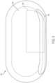
- FIG. 5illustrates a top view of an exemplary drug delivery device 500.
- the drug delivery device 500can include an upper portion 502.
- the upper portion 502can be a top portion or a cover of the drug delivery device 500.
- the drug delivery device 500can further include a raised portion 504.
- the raised portion 504can be elongated and can run along a side of the drug delivery device 500.
- a container for holding a liquid drugcan be approximately positioned under the raised portion 504 such that the raised portion 504 accommodates the size and positioning of the liquid drug container within the drug delivery device 500.
- a containersuch as the drug container 102 can be positioned under the raised portion 504. Any drug delivery system described herein can be positioned within the drug delivery device 500.
- the upper portion 502 of the drug delivery device 500can include a window or viewing area 506.
- the window 506, for Embodimentcan be made of plastic and can be transparent.
- the window 506can be of any size and shape and can be positioned on any portion of the drug delivery device 500.
- the window 506can allow a patient to view internal components of the drug delivery device 500 such as, for Embodiment, a portion of the drug container positioned within the drug delivery device 500 (e.g., under a portion of the raised portion 504) and/or a portion of the drive mechanism coupled to the drug container.
- the patientcan determine how much liquid drug is in an internal drug container by viewing the drug container through the window 506.
- the spherical elements 204can be differently colored to indicate a dosing status of the liquid drug 104 (and/or a fill status of the drug container 102).
- the window 506can be positioned on the upper portion 502 to allow a user to view all or a portion of the drug container 102.
- the spherical elements 204can be driven into the drug container 102 as the spherical elements 204 push on the plunger 106.
- the usercan view the spherical elements 204 enter the drug cartridge 102.
- the spherical elements 204can be colored differently (or marked or otherwise visually distinguished) in a predetermined sequence or manner to indicate how much of the liquid drug 104 has been expelled from the drug container 102.
- the marking or coloring of the spherical elements 204can be adjusted based on the size of a dose of the liquid drug 104 or an entire amount of liquid drug 104 stored in the drug container 102.
- an initial set of spherical elements 204can be marked in a first manner (e.g., by a first color such as green) to indicate an initial expulsion of the liquid drug 104 when the initial set of spherical elements 204 enter the drug container 102 and can be viewed.
- An intermediate set of spherical elements 204can be marked in a second manner (e.g., by a second color such as yellow) to indicate an intermediate expulsion of the liquid drug 104 when the intermediate set of spherical elements 204 enter the drug container 102 and can also be viewed.
- a final set or final spherical element 204can be marked in a third manner (e.g., by a third color such as red) to indicate a final expulsion of the liquid drug 104 (e.g., end of dose or completion of dose) when the final set or final spherical element 204 enters the drug container 102 and is visible to the user through the window 506.
- a third colorsuch as red
- any type of markinge.g., coloring
- any number of groupings and corresponding distinctionse.g., number of intervals or gradations
- any drive mechanism component used to drive the plunger 106 -including, for Embodiment, a push rod, one or more cylinders, and/or one or more springs - that enters the drug container 102 can be marked in a manner to indicate dosing status or fill status of the drug container 102 based on the extent to which any portion of the drive mechanism component has entered the drug container 102. Further, any marking or coloring of any component of the drive system can be based on a predetermined dose size and/or a total amount of the liquid drug 104 stored in the drug container 102. In various embodiments, the drive mechanism component or components can be marked to simply indicate a completion of a dose - for Embodiment, when a red colored portion of the drive mechanism is visible in the drug container 102, dose completion can be indicated.
- a sensorcan be positioned adjacent to the drug container 102 that can track or a count a number of the spherical elements 204 or other drive system components that enter the drug container 102 to provide an indication of dosing status or fill status of the drug container 102.
- a sensorcan be positioned adjacent to a first end 112 of the drug container 102.
- the sensorcan mechanically or can electromechanically count a number of the spherical elements 204 that pass the sensor as the spherical elements 204 enter the drug container 102.
- the sensorcan be a switch that is triggered each time a spherical element 204 passes the sensor.
- the switchcould be implemented as a mechanical switch or can be implemented as an electromechanical switch.
- the sensorcan be coupled to a display (e.g., an LED display) for indicating dosing status or fill status of the drug container 102.
- a displaye.g., an LED display
- a mechanical implementationcan include a wheel that has different colors or symbols indicating dose status that can be rotated by the passing of the spherical elements 204.
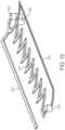
- FIG. 6illustrates a third exemplary drug delivery system 600.
- the drug delivery system 600can include features of the drug delivery system 200 and can further include a dosing wheel 602.
- the dosing wheel 602can include a number of arms or spokes 604 that radially extend from a hub.
- the dosing wheel 602can have any number of arms 604.
- One or more of the arms 604can be positioned between adjacent spheres 204.
- the dosing wheel 602can rotate in a direction 606 as shown about an axis of the dosing wheel 602 to move the spheres 204 forward toward the drug container 102.
- the drive spring 202can provide the force to move the spheres 204 as regulated by the dosing wheel 602.
- the drug delivery device 600can operate as a single dose or multiple dose drug delivery device by regulating movement of the spheres 204.
- movement of the dosing wheel 602can trigger a counter or other device to track rotational movement of the dosing wheel 602.
- a counter coupled to the dosing wheel 602can track the number of times the dosing wheel 602 has advanced a single sphere 204 forward. In doing so, the counter can provide the patient with an indication of how much liquid drug 104 has been delivered.
- the countercan be coupled to the dosing wheel 602 mechanically.
- the countercan be coupled to a gear system of the dosing wheel 602 and/or can be arranged to be triggered by contact with the arms 604 as the arms 604 rotate.
- the dosing wheel 602can be coupled to a controller (not shown in FIG. 6 ) that can track the rotational movement of the dosing wheel 602 and can provide an indication of the filling status of the drug container 102 to the patient.
- the drug delivery system 600can be housed within a device (e.g., the drug delivery device 500) having a window 608 (shown in phantom).
- the window 608can enable a user to view a portion of the dosing wheel 602, a portion of the drug container 102, and/or a position of the plunger 106 within the drug container 102.
- the window 608can be positioned over a portion of the dosing wheel 602 to allow the patient to view the rotation of the arms 604.
- the arms 604 of the dosing wheel 602can be differently colored (e.g., color coded) or otherwise distinguished visually (e.g., by text or other symbols or markings) to indicate how far the dosing wheel 602 has rotated, thereby providing an indication of how far the plunger 106 has advanced into the drug container 102.
- FIG. 7illustrates an optical monitoring system 700 for determining the amount of liquid drug stored in a drug container.
- the optical monitoring system 700includes a printed circuit board (PCB) 702, a drug container 704, a plunger 706, an attenuating light pipe 708, a non-attenuating light pipe 710, a light emitting source 712, and a detector 714.
- PCBprinted circuit board
- the drug container 704can be positioned adjacent to the PCB 102 and can store a liquid drug or other therapeutic agent.
- the plunger 706can be positioned within the drug container 704 and can be used to expel the liquid drug from the drug container 704.
- the plunger 706can include a head portion 716 and a base or rod portion 718.
- the rod 718can extend out of the drug container 704.
- a drive mechanism(not shown in FIG. 7 ) can drive the plunger 706 in a direction 720 to expel stored liquid drug from the drug container 704 for delivery to a patient.
- the plungercan include a reflective portion 722 such as, for Embodiment, a reflective O-ring.
- the reflective O-ring 722can be positioned on the head portion 716 of the plunger 706.
- the reflective portion 722can reflect light that is incident on the plunger 706.
- the light emitting source 712can be a light emitting diode (LED).
- the detector 714can be a photodiode.
- the non-attenuating light pipe 710can be positioned on top of the attenuating light pipe 708.
- the attenuating light pipe 708can be coupled to the light emitting source 712.
- the light pipes 708 and 710can be positioned adjacent to the drug container 704.
- the attenuating light pipe 708can be configured to emit light from the light emitting source 712 out of the attenuating light pipe 708.
- the non-attenuating light pipe 710can be configured to receive light reflected off the reflective portion 722 and to provide the received light to the detector 714.
- the attenuating light pipe 708can be configured to emit light from the attenuating light pipe at a first angle and the non-attenuating light pipe 710 can be configured to receive light from a second angle that is orthogonal to the first angle.
- the first and second anglesare not limited to being orthogonal to one another.
- the first and second anglescan be acute or obtuse to one another.
- the first and second anglescan be oriented to adjust the effective intensity of light energy received by the non-attenuating light pipe 710.
- the light emitting source 712can emit light and provide emitted light into the attenuating light source 708. Light provided to the attenuating light pipe 708 from the light emitting source 712 can then be emitted from the attenuating light pipe 708.
- the attenuating light pipe 708can be configured to attenuate the light it receives along the length of the attenuating light pipe 708. Specifically, light emitted from the attenuating light pipe 708 that is further from the light emitting source 712 can be attenuated more than light emitted from the attenuating light pipe 708 that is closer to the light emitting source 712.
- the non-attenuating light pipe 710is not specifically configured to attenuate light within the non-attenuating light pipe 710.
- the non-attenuating light pipe 710can be coupled to the detector 714 such that light received by the non-attenuating light pipe 710 can be provided to the detector 714.
- a reflector 724can be positioned between the attenuating light pipe 708 and the non-attenuating light pipe 710.
- the reflector 724can be positioned over a top surface of the attenuating light pipe 708 and below a button surface of the non-attenuating light pipe 710.
- the reflector 724can prevent light from passing between the attenuating light pipe 708 and the non-attenuating light pipe 710 (e.g., directly passing).
- the reflector 714can be a film or painted component positioned between the attenuating light pipe 708 and the non-attenuating light pipe 710 or provided on a surface of one of the attenuating light pipe 708 and the non-attenuating light pipe 710.
- the light emitting source 712can provide a stable source of light to the attenuating light pipe 708.
- the light provided to the attenuating light pipe 708can be emitted from the attenuating light pipe 708 along the length of the attenuating light pipe 708.
- the emitted lightcan illuminate the internal portion of the drug container 704 and the plunger 706.
- a portion of the light that enters the drug container 704 from the attenuating light pipe 708can be reflected by the reflective portion 722. This reflected light can then be received by the non-attenuating light pipe 710.
- the light received by the non-attenuating light pipe 710can then be provided to the detector 714.
- the detector 714can determine an intensity of the light received or provided to the detector 714.
- the detector 714can generate a signal based on the intensity of light received.
- the intensity of the reflected lightcan vary linearly with the movement of the plunger 706 based on the characteristics of the attenuating light pipe 708.
- the detector 714can detect the changing intensity of the received light that is reflected off the reflective portion 722. Based on the intensity of the received light, the detector 714 can determine a position of the reflective portion 722 and therefore the plunger 706 within the drug container 704.
- a determination of how much liquid drug remains in the drug containercan be made. Further, the measured signals from the detector 714 can be used to determine a rate of movement of the plunger 706. Depending on the movement of the plunger 706 relative to the light emitting source 712, the intensity of the light detected by the detector 714 can increase or decrease as the plunger 706 advances further into the drug container 704.
- the optical monitoring system 700is arranged to provide relatively lower attenuated light to the detector 714 when the plunger 706 is positioned closer to the light source 712 (and to provide relatively higher attenuated light to the detector 714 when the plunger 706 is positioned closer to the detector 714).
- the intensity of the light provided to the detector 714will increase as the plunger 706 is advanced to expel additional liquid drug from the drug container 704.
- the optical monitoring system 700is not limited to this arrangement. In various embodiments, the optical monitoring system 700 can be arranged such that the intensity of the light provided to the detector 714 will decrease as the plunger 706 is advanced to expel additional liquid drug from the drug container 704.
- the optical monitoring system 700can be arranged to provide light to the detector 714 that varies in intensity based on movement of the plunger 706 (e.g., advancement of the plunger 706 to expel the liquid drug).
- a controller(not shown in FIG. 7 ) coupled to the detector 714 can detect a position of the plunger 706 based on the signals generated by the detector 714 that indicate the intensity of light received by the detector 714.
- the optical monitoring system 700can be used with any drug container storing a liquid drug that is expelled by any linear translating component having a reflective portion.
- the drug container 102 and the plunger 106can be used in the optical monitoring system 700.
- any portion of the plunger 706can be reflective including any component coupled to the plunger 706 that moves with the plunger 706 to expel a stored liquid drug.
- the drug container 704 used with the optical monitoring systemcan be a transparent container (or a portion thereof can be transparent).
- the optical monitoring system 700can use any type of radiation emitting/detecting pair such as, for Embodiment, an infrared, a visible light, or an ultraviolet source of radiation and corresponding detector.
- the optical monitoring system 700can include a controller (not shown in FIG. 7 ) that can be coupled to the light emitting source 712 and the detector 714.
- the controllercan be configured to control operation of the light emitting source 712 and/or the detector 714.
- Signals generated by the detector - for Embodiment, signals indicating a position of the plunger 706 based on a detected intensity of reflected light received -can be provided to the controller.
- the controllercan subsequently determine a position and movement of the plunger 706 or any component of the drive system for operating the plunger 706 based on signals generated by the detector 714. The controller can further determine how much liquid drug has been expelled and/or how much liquid drug remains in the drug container 704.
- FIG. 8illustrates an exemplary arrangement of the attenuating light pipe 708 and the non-attenuating light pipe 710 depicted in FIG. 7 .
- the attenuating light pipe 708 and the non-attenuating light pipe 710can each include windows 808 for emitting light and receiving light, respectively.
- Certain windows 808can be covered with an anti-reflective (e.g., non-transmissive) coating 802 such that no light is emitted or received through a window 808 coated with anti-reflective coating 802.
- an anti-reflective coating 802such that no light is emitted or received through a window 808 coated with anti-reflective coating 802.
- the anti-reflective coating 802can be placed on the windows 808 that are oriented at a first angle relative to the light emitted by the light emitting source 712. As such, as shown in FIG. 8 , light can only be passed through those windows 808 that are not covered by the anti-reflective coating 802.
- the windows 808 of the attenuating light pipe 708 that can pass lightcan be oriented at a second angle that is orthogonal to the first angle as shown.
- Indicator 804shows an exemplary direction of light that can be emitted or passed from the attenuating light pipe 708.
- the anti-reflective coating 802can be placed on windows 808 that are orthogonal to the windows 808 of the attenuating light pipe 708 that are coated with the anti-reflective coating 802 as shown in FIG. 8 . Accordingly, the non-attenuating light pipe 710 can receive light through windows 808 that are orthogonal to the windows 808 of the attenuating light pipe 708 that can emit light, but are not so limited. That is, the windows 808 of the attenuating light pipe 708 that emit light can be oriented according to any angle with respect to the windows 808 of the non-attenuating light pipe 710.
- the windows 808 for emitting and receiving lightcan be oriented at an obtuse or an acute angle with respect to one another.
- the angle of orientationcan be adjusted to provide a desired effective intensity for the light energy received by the non-attenuating light pipe 710.
- Indicator 806shows an exemplary direction of light that can be received by the non-attenuating light pipe 710.
- the arrangement of the windows 808 and the coated windows 802 of the attenuating light pipe 708 and the non-attenuating light pipe 710can ensure that attenuated light emitted by the attenuating light pipe 708 is directed toward the detector 714 after it reflects off the plunger 706.
- reflected light from the plunger 706can pass through an uncoated window 808 of the non-attenuating light pipe 710 and then directed toward the detector 714.
- FIG. 9illustrates an exemplary arrangement of the attenuating light pipe 708 depicted in FIGs. 7 and 8 .
- Emitted light 902represents the light emitted from the light emitting source 712 and its intensity (e.g., as indicated by a size of the corresponding arrow representing the light).
- the emitted light 902can travel down the attenuating light pipe 708 and can exit from windows 808 that are not covered with coating 802.
- Emitted light 904-1 through 904-5represents the light that passes through each corresponding window 808 and its intensity.
- the attenuating light pipe 708can be configured to have an attenuation profile that attenuates the emitted light 902 more the further the light is from the light emitting source 712 (e.g., compare the relatively higher intensity of the emitted light 904-1 to the relatively lower intensity emitted light 904-5). Accordingly, the intensity of the light that is emitted from the windows 808 that are closer to the light emitting source 712 - such as, emitted light 904-1 - can be greater than the intensity of the light that is emitted from the windows 808 that are further from the light emitting source 712 - such as, emitted light 904-5.
- the different levels of intensities of the emitted light 904-1 through 904-5can be reflected off the reflective portion 722 of the plunger 706 as the plunger 706 advances into the drug container 704 and moves along the length of the attenuating light pipe 708 as described above.
- the intensity of the light received by the detector 714can change (e.g., increase or decrease as the plunger 706 moves further into the drug container 704 depending upon the arrangement of the components of the optical monitoring system 700).
- the varying intensity of the light received by the detector 714can be used to determine a position of the plunger 706.
- the emitted light 904-1when reflected off of the reflective portion 722 and then received by the non-attenuating light pipe 710 and the detector 714, can indicate a first position of the plunger 706.
- emitted light 904-5when reflected off of the reflective portion 722 and then received by the non-attenuating light pipe 710 and the detector 714, can indicate a second, different position of the plunger 706.
- the detector 714can generate a signal indicative of the intensity of the received light. The signal can be provided to the controller that can then use the signal to determine a position and/or movement of the plunger 706.
- the fill status of the drug container 704(e.g., how much liquid drug remains in the drug container 704 or has been expelled) can then be determined.
- the attenuating light pipe 708can be configured to have any attenuation profile. In various embodiments, the attenuating light pipe 708 can be configured to have a linear attenuation profile.
- the attenuating light pipe 708can be formed of a material having a homogenous attenuation profile that can scatter and/or absorb light to cause attenuation. In general, as light travels further into the attenuation light pipe 708, more attenuation is provided, thereby causing larger decreases in intensity in the light as it travels further into the attenuating light pipe 708 (e.g., further away from the light source 712).
- the attenuating light pipe 708can be made from various types of materials including plastics and can be covered with an attenuation coating or other material. In various embodiments, the attenuating light pipe 708 can be formed from polymethylmethacrylate (PMMA).
- FIG. 10illustrates an exemplary operation of the optical monitoring system 700.
- the attenuating light pipe 708is positioned on top of the non-attenuating light pipe 710.
- the reflector 724is positioned between the attenuating light pipe 708 and the non-attenuating light pipe 710.
- a light beam 1002is shown entering the attenuating light pipe 708.
- the light beam 1002can be provided by the light emitting source 712 depicted in FIG. 7 .
- the light beam 1002can travel along the attenuating light pipe 708 and can exit as an attenuated version of the light beam 1002 from any of the windows 808 that are not coated windows 802.
- the light beam 1002can exit a first window 1020 along the attenuated light pipe 708 as a first exit light beam 1004.
- the first exit light beam 1004can be an attenuated version of the light beam 1002.
- the first exit light beam 1004can be attenuated by a first amount relative to the intensity of the light beam 1002.
- the light beam 1002can further exit a second window 1022 along the attenuated light pipe 708 as a second exit light beam 1012.
- the second exit light beam 1012can be also be an attenuated version of the light beam 1002.
- Indicator 1024can specify a direction of increasing attenuation by the attenuating light pipe 708.
- the attenuating light pipe 708, as described hereincan attenuate the light beam 1002 more further along the length of the attenuating light pipe 708 relative to an entry point of the light beam 1002.
- the first exit light beam 1004can be attenuated less than the second exit light beam 1012.
- the first exit light beam 1004is shown to be wider than the second exit light beam 1012 to represent that the second exit light beam 1012 is more attenuated than the first exit light beam 1004.
- the second exit light beam 1012can be attenuated by a second amount relative to the intensity of the light beam 1002.
- Object 1006can represent a first position of the plunger 706 (and/or a position of any reflective portion of the plunger 706). As shown in FIG. 10 , the first exit light beam 1004 is reflected off the object 1006 as a first reflective light beam 1008. The first reflective light beam 1008 can pass through any of the windows 808 of the non-attenuating light pipe 710 that are not coated windows 802. The first reflective light beam 1008 can then travel through the non-attenuating light pipe 710 and can be provided to the detector 714 depicted in FIG. 7 .
- Indicator 1010represents a travel path of the plunger 706. As shown in FIG. 10 , the travel path 1010 of the plunger 706 can be substantially parallel to the arrangement of the attenuating and non-attenuating light pipes 708 and 710.
- Object 1014can represent a second position of the plunger 706 (and/or a position of any reflective portion of the plunger 706). As shown in FIG. 10 , the second exit light beam 1012 is reflected off the object 1014 as a second reflective light beam 1016. The second reflective light beam 1016 can pass through any of the windows 808 of the non-attenuating light pipe 710 that are not coated windows 802. The second reflective light beam 1016 can then travel through the non-attenuating light pipe 710 and can be provided to the detector 714 depicted in FIG. 7 .
- Light beam 1018can represent light that exits the non-attenuating light pipe 710 and is provided to the detector 714.
- the light beam 1018can be an attenuated version of the light beam 1002.
- the level of attenuation experienced by the light beam 1018can be substantially based on the level of attenuation experienced by the initial light beam 1002 from the attenuating light pipe 708, which is then reflected by the plunger 706.
- the light beam 1018will experience less attenuation and will be more intense if the plunger 706 is positioned closer to a first end 1024 of the attenuating light pipe 708 in comparison to when the plunger 706 is positioned closer to a second end 1026 of the attenuating light pipe 708.
- the detector 714can detect the light beam 1018. As described herein, the detector 714 can measure an intensity of the light beam 1018. For Embodiment, the detector 714 can generate a signal based on the measured intensity of the light beam 1018. Signals generated by the detector 714 can be provided to a controller (not shown in FIG. 10 ). The controller can determine a position of the plunger 706 within the drug container 704 based on the signal provided to the controller by the detector 714. For Embodiment, the controller can determine the plunger 706 is positioned closer to the first end 1024 of the attenuating light pipe 708 when the detector 714 generates a signal in response to a relatively more intense light beam 1018.
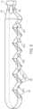
- the monitoring system 1100can also include a number of pins 1108.
- the pins 1108can be positioned within the drug container 1102.
- the pins 1108can be molded into the drug container 1102.
- the pins 1108can be made from a conductive material such as a metal.
- the pins 1108can be positioned and shaped so as to be flush (aligned) or approximately flush with an inner or interior surface of the drug container 1102.
- the pinscan also be positioned and shaped so as to be flush (aligned) or approximately flush with an outer or outside surface of the drug container 1102.
- pins 1108are shown as inserted molded into the drug container 1102 - pins 1108-1 through 1108-7. Any number of pins 1108 can be positioned in the drug container 1102 and can be arranged in any manner.
- the liquid drug 1104 stored in the drug container 1102can provide electrical conductivity between the pins 1108.
- a controller and/or other circuitry coupled to the pins 1108can monitor the electrical connectivity of the pins 1108 relative to one another and/or the liquid drug 1106. As the plunger 1106 is moved to expel the liquid drug 1104 from the drug container 1102, a portion of the pins 1108 can become electrically decoupled from the other pins 1108 and/or the liquid drug 1104.
- the controllercan monitor the changing status of the electrical connectivity of the pins 1108 to determine a position and/or movement of the plunger 1106. In this way, the monitoring system 1100 can determine a fill status of the drug container 1102 and/or other information regarding dosing rate, an amount of the liquid drug 1104 expelled from the drug container 1102, and/or a rate of movement of the plunger 1106. As shown in FIG. 11 , all of the pins 1108-1 through 1108-7 can be electrically coupled to one another as each pin 1108 is coupled to the liquid drug 1104.
- FIG. 12illustrates the monitoring system 1100 after a portion of the liquid drug 1104 has been expelled from the drug container 1102.
- the plunger 1106has moved past the pins 1108-1 through 1108-3 and is positioned adjacent to the pin 1108-4.
- the pins 1108-1 through 1108-4are no longer coupled to the liquid drug 1104. Consequently, the pins 1108-1 through 1108-4 are no longer electrically connected or coupled to any other pin 1108.
- the controller coupled to the pins 1108can determine which pins 1108 are electrically coupled together (e.g., and/or coupled to the liquid drug 1104) and can determine a position of the plunger 1104. For Embodiment, as shown in FIG.
- the controllercan determine that a front surface of the plunger 1106 (e.g., a surface of the plunger in contact with the liquid drug 1104) can be positioned between the pin 1108-4 and the pin 1108-5.
- the controllercan also determine that pins 1108-5 through 1108-7 are electrically connected and coupled to the liquid drug 1104. Accordingly, the monitoring system 1100 allows an approximate position of the plunger 1106 to be determined.
- the monitoring system 110can determine how much of the liquid drug 1104 remains in the drug container 1102 and how much liquid drug 1104 has been expelled from the drug container 1102.
- the monitoring system 1100can use number of pins 1108.
- the pins 1108can be spaced apart from one another by a fixed distance but are not so limited.
- the monitoring system 1100can use more pins 1108 to provide a better or more accurate approximation as to the location of the plunger 1106 within the drug container (and therefore a better or more accurate approximation of the fill status of the drug container 1102).
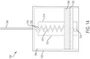
- FIG. 13illustrates a second exemplary monitoring system 1300.
- the monitoring system 1300can include a drug container 1302.
- the drug container 1302can hold or store a liquid drug 1306.
- the monitoring system 1300can further include a plunger 1304 positioned in the drug container 1302.
- the plunger 1304can be moved or advanced to expel the liquid drug 1306 from the drug container 1302.
- the drug container 1302can represent the drug container 102.
- the plunger 1304can be moved to expel the liquid drug 1306 out of the drug container 1302 through a fluid path 1308 (e.g., by moving toward the fluid path 1308).
- the plunger 1302 and the fluid path 1308can be arranged to enable the liquid drug 1306 to be expelled through the plunger 1304 (e.g., through an opposite end of the drug container 1302 from what is shown in FIG. 13 ), for Embodiment as described above in relation to FIG. 2 .
- the monitoring system 1300can further include a first conductive component or trace 1310, a second conductive component or trace 1312, a third conductive component or trace 1314, a first conductive pin 1316, a second conductive pin 1318, and a third conductive pin 1320.
- the traces 1310, 1312, and 1314 and the pins 1316, 1318, and 1320can be formed of an electrically conductive material.
- a conductive ring or wiper 1322can be positioned around the plunger 1034.
- the ring 1322can be formed of an electrically conductive material.
- the first trace 1310can be coupled to the pin 1318.
- the first trace 1310can be positioned inside of the drug container 1302.
- the first trace 1310can be coupled to an inner surface of the drug container 1302.
- the first trace 1310can extend along a substantial portion of a longitudinal length of the drug container 1302.
- the second trace 1312can be coupled between the pin 1318 and the pin 1316.
- the second tracecan also be coupled to the inner surface of the drug container 1302.
- the second tracecan also extend along a substantial portion of the longitudinal length of the drug container 1302.
- the second trace 1312can be formed of a material having an increasing resistance (e.g., a linearly increasing resistance).
- the third trace 1314can be coupled to the pin 1316 and the pin 1320.
- the third trace 1314can be positioned outside of the drug container 1302.
- the third trace 1314can be coupled to an outer surface of the drug container 1302.
- the third trace 1314can extend along a substantial portion of the longitudinal length of the drug container 1302.
- the pins 1318 and 1320can be coupled to one or more output circuits and/or a controller (not shown in FIG. 13 for simplicity).
- the traces 1310, 1312, and 1314, and the pins 1316, 1318, and 1320can form a variable resistive network.
- the variable resistive networkcan be used to determine a position of the plunger 1306 within the drug container 1302, enabling a fill status of the drug container 1302 to be determined.
- the ring 1322electrically couples (e.g., shorts) the trace 1310 to the trace 1312 along different corresponding portions of the traces 1310 and 1312. Coupling the trace 1310 to the trace 1312 completes a circuit.
- the coupling of the trace 1310 to the trace 1312completes a circuit having different resistance values based on the location of the plunger 1304.
- the completed circuitwhen the ring 1322 couples the trace 1310 to the trace 1312 at a far end of the drug container 1302 (e.g., in close proximity to the pin 1316), the completed circuit can have a relatively lower resistance, as only a relatively small portion of the trace 1312 is included in the completed circuit (due to the shorting of the traces 1310 and 1312 by the ring 1322).
- the completed circuitcan have a relatively higher resistance, as a relatively larger portion of the trace 1312 is included in the completed circuit.
- FIG. 14illustrates a top view of the monitoring system 1300 depicted in FIG. 13 .
- the arrangement of the traces 1310, 1312, and 1314 along the length of the drug container 1302is shown. Further, the electrical coupling of the trace 1310 and the trace 1312 by the ring 1322 is illustrated.
- the circuit completed by the ring 1322includes larger portions of the trace 1312 as the plunger 1304 moves closer to the fluid path 1308. Accordingly, a controller coupled to the output pins 1318 and 1320 can determine the position of the plunger 1304 based on the variable (e.g., increasing) resistance of the completed circuit.
- FIG. 15illustrates a portion of the monitoring system 1300. Specifically, FIG. 15 illustrates the traces 1310, 1312, and 1314 and the pins 1316, 1318, and 1320. These components can be considered to form a variable resistive network as described above (or a portion of a potentiometer as will be appreciated by a person of ordinary skill in the art).
- the trace 1312is shown to have a zigzag shape but is not so limited. In various embodiments, the trace 1312 can be a form a substantially straight trace.
- a controller of the monitoring systemscan be coupled to a remote user interface device (e.g., a mobile device) and can provide a patient or user with notifications regarding a fill status of a drug container.
- the notificationcan alert a user to an amount of liquid drug expelled and/or remaining.
- the notificationcan alert a user to when a desired dose of liquid drug has been provided to a patient and/or when the drug container is empty.
Landscapes
- Health & Medical Sciences (AREA)
- Vascular Medicine (AREA)
- Engineering & Computer Science (AREA)
- Anesthesiology (AREA)
- Biomedical Technology (AREA)
- Heart & Thoracic Surgery (AREA)
- Hematology (AREA)
- Life Sciences & Earth Sciences (AREA)
- Animal Behavior & Ethology (AREA)
- General Health & Medical Sciences (AREA)
- Public Health (AREA)
- Veterinary Medicine (AREA)
- Dermatology (AREA)
- Physics & Mathematics (AREA)
- Fluid Mechanics (AREA)
- General Physics & Mathematics (AREA)
- Infusion, Injection, And Reservoir Apparatuses (AREA)
Description
- Embodiments generally relate to medication delivery. More particularly, embodiments relate to wearable drug delivery devices.
- Many conventional drug delivery devices expel a liquid drug from a drug container for delivery to a patient. These conventional drug delivery devices often fail to inform the patient as to the fill status of the drug container. As a result, the patient is often unaware of how much liquid drug has been provided to the patient, when a desired dose has been completed, and/or how much liquid drug remains in the drug container. Accordingly, there is a need for a monitoring system for use in drug delivery devices that can determine and provide the patient with the fill status of the drug container holding the liquid drug.
US2009/0278875A1 discloses a jetting device for jetting droplets of viscous medium onto a substrate, said jetting device comprising an ejector element for performing the jetting process and a jetting outlet through which said droplets are jetted. In particular, the document is related to a method, a measuring device, a jetting device, and a viscous medium container for use in such a jetting device for measuring or monitoring a level or volume of viscous medium during a jetting process and/or measuring electrical properties of the viscous medium to determine characteristics of the medium.US6068615A relates to measurements of insulin quantities in a syringe, which are performed inductively in an integrated insulin dose recorder/blood glucose meter. The syringe is placed in a holder before the administration of the dose, and the liquid quantity in the syringe is recorded. Inductors may be situated within the syringe and/or outside the syringe in various geometries. Standard or customized syringes may be used. Liquid quantities in the syringe are determined by comparing inductive response patterns of the syringe with calibration data stored in the device. Insulin dose and blood glucose histories are downloaded to a patient computer for transfer to a clinician's computer.US6539286B1 discloses a fluid level sensor used in a container in a system for dispensing adhesive used in the formation of electronic devices. The sensor includes a pair of electrical conductors positioned inside the container. A voltage is applied across the conductors to cause a current flow through the fluid in the container. The magnitude of the current flow represents the amount of fluid remaining in the container. If an empty container is detected, the system is shut off.US4371790A relates to an apparatus for measuring the level, volume or rate of flow of an electrically conductive fluid, such as water. The apparatus includes a reference conductor connected to a reference potential and a plurality of additional, vertically spaced conductors affixed to an insulating surface. The reference conductor is normally placed at the lowest point of the liquid container whereas the other conductors are positioned within the liquid container at various points above the reference conductor. When the level of the liquid is above the position of one or more of the additional conductors, the liquid effects an electrical conduction path between the conductors below the liquid level and the reference conductor and thus with the reference potential. The conductors are connected through a logic circuit to a plurality of display elements, which are selectively actuated to provide an indication of the level of the liquid corresponding to the uppermost conductor covered by the liquid and thereby connected to the reference potential.US3947692A relates to a digital transducer comprising a container having two disparate materials therein defining an interface, the interface being movable through the container responsive to a force, or forces, applied to one, or both, of the materials. A plurality of sensors are spaced along the container for sensing the interface, each of which is responsive to the presence of one of the materials. Means are included for suppressing the outputs of all of the sensing means responsive to the one material except that one sensing means which is responsive to the one material and nearest the interface.- The invention comprises a wearable drug delivery device as defined in claim 1. Additional features of preferred embodiments are defined in the dependent claims. Particular reference regarding the invention is made to
FIG. 11 and12 , and the respective paragraphs of the following detailed description. FIG. 1 illustrates an exemplary drug container.FIG. 2 illustrates a first exemplary drug delivery system.FIG. 3 illustrates a second exemplary drug delivery system.FIG. 4 illustrates a portion of an exemplary encoded needle conduit.FIG. 5 illustrates a top view of an exemplary drug delivery device.FIG. 6 illustrates a third exemplary drug delivery system.FIG. 7 illustrates an optical monitoring system.FIG. 8 illustrates an exemplary arrangement of an attenuating light pipe and a non-attenuating light pipe depicted inFIG. 7 .FIG. 9 illustrates an exemplary arrangement of the attenuating light pipe depicted inFIGs. 7 and8 .FIG. 10 illustrates an exemplary operation of the optical monitoring system depicted inFIG. 7 .FIG. 11 illustrates an exemplary monitoring system.FIG. 12 illustrates operation of the exemplary monitoring system ofFIG. 11 .FIG. 13 illustrates a second exemplary monitoring system.FIG. 14 illustrates a top view of the exemplary monitoring system ofFIG. 13 .FIG. 15 illustrates a portion of the exemplary monitoring system ofFIG. 13 .- This disclosure presents various systems, components, and methods related to a wearable drug delivery device and/or monitoring systems for determining a fill status of a drug container of a wearable drug delivery device. Each of the systems, components, and methods disclosed herein provides one or more advantages over conventional systems, components, and methods.
- Various embodiments include systems and methods for monitoring an operational state and/or a fill status of a drug container of a drug delivery device. The drug container can hold a liquid drug. A plunger can be positioned within the drug container. A drive system can advance the plunger to expel the liquid drug from the container. A monitoring system can detect a movement and/or a position of the plunger and/or any component coupled to the plunger. The detection can enable determination of an amount of liquid drug that has been expelled and/or an amount of liquid drug remaining in the drug container. Dosing rates, flow rates, and dosage completion can also be determined. Other embodiments are disclosed and described.
FIG. 1 illustrates anexemplary drug container 102. Thedrug container 102 can hold or store a liquid drug or othertherapeutic agent 104. Thedrug container 102 can be used within a drug delivery device such as, for Embodiment, a wearable drug delivery device. Aplunger 106 can be used to expel theliquid drug 104 from thedrug container 102 for delivery to a patient. A drive system or mechanism (not shown inFIG. 1 for simplicity) can provide a force on theplunger 106 to drive or advance theplunger 106 in adirection 108 to expel theliquid drug 104 from the drug container 102 (e.g., to advance theplunger 106 from a first position to a second position further into thedrug container 102 to expel the liquid drug 104).- A
needle conduit 110 can provide the expelledliquid drug 104 to a patient. As shown inFIG. 1 , theneedle conduit 110 can be coupled to theplunger 106 such that the expelledliquid drug 104 exits from afirst end 112 of thedrug container 102. Alternatively, theneedle conduit 110 can be coupled to asecond end 114 of thedrug container 102 such that the expelledliquid drug 104 exits from thesecond end 114 of thedrug container 102. Theliquid drug 104 can be provided to the patient over one or more doses based on control of the drive mechanism. - The
drug container 102 can be made of a variety of materials including, for Embodiment, glass or plastic. Thedrug container 102 is not limited to the shape and size shown inFIG. 1 . Instead, thedrug container 102 can be of any size or shape. In various embodiments, thedrug container 102 can be a prefilled or a fillable container. In various embodiments, thedrug container 102 can be an International Organization for Standardization (ISO) drug container such as, for Embodiment, an ISO vial. - Various embodiments described herein provide systems and methods for a patient to readily determine, at any point during use of the
drug container 102, how much of theliquid drug 104 is held in thedrug container 102, how much of theliquid drug 104 has been expelled from thedrug container 104, and/or when a desired dose of theliquid drug 104 has been provided to the patient. Various embodiments described herein provide systems and methods for determining this information based on a position or movement of theplunger 106 and/or based on a position or movement of the drive mechanism used to advance the plunger 106 (or any component of a drug delivery device coupled thereto). Such information allows the patient to confirm proper dose delivery and to verify proper operation of the drug delivery device in which thedrug container 102 is used. Without such knowledge, the patient may not be able to confirm whether anyliquid drug 104 remains in thedrug container 102, how much of theliquid drug 104 has been delivered to the patient, and/or how much of theliquid drug 104 remains to be delivered to the patient. Conventional drug delivery devices do not provide mechanisms for readily determining such information regarding the operational state and/or fill status of drug containers such as theexemplary drug container 102. FIG. 2 illustrates a first exemplarydrug delivery system 200. Thedrug delivery system 200 can include thedrug container 102. Thedrug delivery system 200 can further include a drive mechanism for driving theplunger 106 in thedirection 108 to expel the storedliquid drug 104. As an Embodiment, the drive mechanism can include adrive spring 202 and a number of spherical elements or components 204 (e.g., a plurality of spherical elements or spheres 204). Thespherical elements 204 can be referred to as spherical energy transfer elements or components, or force transfer spheres. As used herein, thespherical elements 204 can be referenced using any of these terms including, for Embodiment,spheres 204.- The
spherical elements 204 can be positioned within a track (not shown inFIG. 2 for simplicity). Thedrive spring 202 can expand in adirection 206 to push thespherical elements 204 towards theplunger 106. The force from thedrive spring 202 is transferred to theplunger 106 by thespherical elements 204 to drive theplunger 106 in thedirection 108, thereby expelling theliquid drug 104 from thedrug container 102. A direction of movement of thespherical elements 204 in response to the expansion of thedrive spring 202 is shown byindicators 208. - The
drug delivery system 200 further includes aneedle mechanism 210. Theneedle mechanism 210 is coupled to theneedle conduit 110. Expelledliquid drug 104 is transferred to theneedle mechanism 210 by theneedle conduit 110, which then provides the expelledliquid drug 104 to the patient. Thedrug delivery system 200 can be part of a drug delivery system such as, for Embodiment, a wearable drug delivery system. The drive mechanism (e.g., thedrive spring 202 and the spherical elements 204) of thedrug delivery system 200 is exemplary as a variety of different drive mechanisms can be used to expel theliquid drug 104 by advancing theplunger 106 in thedirection 108. - The
drug delivery system 200 can include a number of mechanisms and/or systems for determining the position of theplunger 106 within thedrug container 106. The position of theplunger 106 within thedrug container 102 can be used to determine how muchliquid drug 104 remains in thedrug container 102 and/or how muchliquid drug 104 has been expelled from thedrug container 102. Based on one or more of these determinations, proper operation of thedrug delivery system 200 and dosing of theliquid drug 104 can be verified. The position of theplunger 106 within thedrug container 102 can be determined directly and/or can be determined based on positional information of one or more other components of thedrug delivery system 200 as further described herein. - As shown in
FIG. 2 , thedrug delivery system 200 can further include one or more sensors such as, for Embodiment, afirst sensor 212 positioned near thefirst end 112 of thedrug container 102 and asecond sensor 214 positioned near thesecond end 114 of thedrug container 102. Thesensors liquid drug 104 remains in thedrug container 102 and/or how muchliquid drug 104 has been expelled from thedrug container 102 based on a determination of the position of theplunger 106 within thedrug container 102 and/or based on a position of one or more components of a drive mechanism used to advance theplunger 106. - In various embodiments, the
sensors plunger 106 and/or thespherical elements 204. For Embodiment, as theplunger 106 and thespherical elements 204 move in thedirection 108 and into thedrug container 102, thesensors plunger 106 and/or thespherical elements 204. As a result, an indication of the position of theplunger 106 within thedrug container 102 can be determined, thereby providing a determination of how muchliquid drug 104 has been expelled and/or remains in thedrug container 102. - In various embodiments, the
sensors spherical elements 204 have passed by eachrespective sensor spherical element 204, a determination on the position of theplunger 106 and/or the rate of movement of theplunger 106 can be made. In various embodiments, thesensors plunger 106 along any portion of thedrug container 102. In various embodiments, any number of sensors can be used. As Hall effect sensors, thesensors plunger 106 and/or thespherical elements 204. - In various embodiments, the
spherical elements 204 can comprise a metallic material. In various embodiments, thespherical elements 204 can include a metallic core that is surrounded by a non-metallic material such as plastic or rubber. In various embodiments, thespherical elements 204 can be made of different types of metal such that the magnetic response of eachspherical element 204 as detected by thesensors spherical elements 204 can be comprised of a metallic material that can be detected by one of thesensors spherical element 204 can comprise a metallic material that can be detected by one of thesensors spherical elements 204, as the drive mechanism advances theplunger 106, positional information of theplunger 106 can be determined. - In various embodiments, a portion of the
plunger 106 can comprise a metallic material such that thesensors plunger 106 within thedrug container 102. In various embodiments, any number of sensors can be used and can be arranged along thedrug container 102. The detection of the position of theplunger 106 is not limited to the drive mechanism shown inFIG. 2 . In general, thedrug delivery system 200 can include any drive system configured such that thesensors plunger 106 based on detection of theplunger 106 position directly and/or detecting a position of any portion of a drive system used to advance theplunger 106 in thedirection 108. For Embodiment, the drive system can include a push rod, one or more cylinders, and/or one or more springs for driving movement of theplunger 106 with thesensors drug container 102 and/or a position or movement of theplunger 106, either directly or indirectly, are applicable to any such drive mechanism, such as those described above, as will be appreciated by a person of ordinary skill in the art. - In general, as Hall effect sensors, the
sensors plunger 102 and thespherical elements 204 are advanced in thedirection 108. Thesensors FIG. 2 ) can be coupled to thesensors sensors plunger 102 and/or the spherical elements 204 (or any other component of a drive system) so as to track a movement or position of the plunger and/or thespherical elements 204 and/or count a numberspherical elements 204 that pass each of thesensors sensors plunger 106 within thedrug container 102. In this way, the controller can determine a fill status of thedrug container 102 and/or the beginning or end of the stroke of theplunger 106. - In various embodiments, the
sensors sensors plunger 106 based on optical detection. As an Embodiment, thedrug delivery system 200 can include a first light emitting device orlight source 216 and a second light emitting device orlight source 218. Afirst light beam 220 emitted by the firstlight emitting device 216 can be detected by thefirst sensor 212 and a secondlight beam 222 emitted by the secondlight emitting device 218 can be detected by thesecond sensor 214. The first and secondlight beams light emitting devices plunger 106 and/or the spherical elements 204 (or any other drive mechanism component) as the drive mechanism drives theplunger 106 in thedirection 108. As an Embodiment, thesensors light sources spherical elements 204 such that, as thespherical elements 204 are advanced, reception of thelight beams sensors - The
sensors light beams plunger 106. In various embodiments, thesensors spherical elements 204 that have passed into thedrug container 102 by counting a number of interruptions, thereby providing an estimate of the position of theplunger 106. In various embodiments, the position of theplunger 106 can be determined as theplunger 106 itself interrupts light detection by a number of sensors positioned along thedrug container 102. - In various other embodiments, the
sensors plunger 106 and/or any portion of the drive mechanism (e.g., the spherical elements 204). In various embodiments, theplunger 106 and/or thespherical elements 204 can be coated with different light absorbing and/or reflecting materials, such that each element reflects and/or absorbs light differently. Based on the light reflected by the elements, thesensors plunger 106 and/or thespherical elements 204 and therefore the position of theplunger 106. - In general, the
sensors plunger 106 can be independent of the drive mechanism used to advance theplunger 106. As noted above, the position of theplunger 106 can be determined based onsensors sensors FIG. 2 ) that can determine the position of theplunger 106 based on information collected or determined by thesensors sensors drug delivery system 200 that can determine an operational state or fill status of thedrug container 102 such that how muchliquid drug 104 has been expelled or remains in thedrug container 102 can be determined. The monitoring system of which thesensors plunger 106 and/or any component of a drive system used to advance theplunger 106. FIG. 3 illustrates a second exemplarydrug delivery system 300. Thedrug delivery system 300 can operate in a similar manner with respect to thedrug delivery system 200 to expel theliquid drug 104 from thedrug container 102 for delivery to the patient. As shown inFIG. 3 , thedrug delivery system 300 can include aneedle conduit 302 and one or more sensors such as, for Embodiment, afirst sensor 304 and asecond sensor 306. Theneedle conduit 302 can be an encoded needle conduit as described further herein. In various embodiments, theneedle conduit 302 can be encoded along its length in a manner to reveal or indicate positional information of theneedle conduit 302 as it moves with theplunger 106 as theplunger 106 is advanced into thedrug container 102. The first andsecond sensors needle conduit 302 to thereby determine the position of theplunger 106.- In various embodiments, the
needle conduit 302 can comprise a metal tubing that is coated in various regions with a non-conductive coating. Thesensors needle conduit 302. As theneedle conduit 302 advances and passes over thesensors 304 and 306 (e.g., making electrical contact with thesensors 304 and 306), thesensors sensors FIG. 3 ) that tracks the count and/or length of these different regions. Based on a predetermined arrangement of the conductive and non-conductive regions of the encoded needle conduit 302 - for Embodiment, based on the number of different regions and their lengths or sizes - the controller can determine the position of theplunger 106. Further, the controller can determine a rate of movement of theplunger 106. This information can then be used to determine a fill status of the drug container 103 and a dosing status of theliquid drug 104. - The
sensors needle conduit 302 as theneedle conduit 302 advances in response to movement of theplunger 106. Thesensors needle conduit 302. FIG. 4 illustrates a portion of an exemplary encodedneedle conduit 400. The encodedneedle conduit 400 can represent theneedle conduit 302 depicted inFIG. 3 . As shown inFIG. 4 , the encodedneedle conduit 400 includesconductive regions 402 andnon-conductive regions 404. Theconductive regions 404 can be spaced apart by adistance 406. The sizes of theconductive regions 402 and the non-conductive regions 404 (and therefore the distance 406) of the encodedneedle conduit 400 can be uniform but is not so limited. In general, any known or predetermined arrangement of theconductive regions 402 and thenon-conductive regions 404 can be used to determine the position of theplunger 106. Theconductive regions 402 can exhibit substantially the same or different levels of conductivity that can also be used to determine a position and/or a movement of theplunger 106.- As the
sensors conductive regions 402 and/or thenon-conductive regions 404, thesensors conductive regions 402 from thenon-conductive regions 404 and can determine what portion of the encodedneedle conduit 400 is passing over each of thesensors sensors needle conduit 400 and can estimate a position and/or movement of theplunger 106 relative to the position and/or movement of the encodedneedle conduit 400. - In various embodiments, the
sensors needle conduit 302 can marked in a manner for thesensors needle conduit 302. For Embodiment, theneedle conduit 302 can be laser marked or etched so as to distinguish different segments of theneedle conduit 302 that thesensors needle conduit 302 can be marked with one or more bar codes along one or more portions of theneedle conduit 302 so as to distinguish different segments of theneedle conduit 302 that thesensors needle conduit 302 passes over thesensors sensors 304 and 306 (e.g., as barcode readers) can optically detect what portion of the encodedneedle conduit 302 is passing each of thesensors plunger 106 to be determined. - The
sensors needle conduit 302 can form a portion of a monitoring system for thedrug delivery system 300 that can determine an operational state and/or fill status of thedrug container 102 such that how muchliquid drug 104 has been expelled or remains in thedrug container 102 can be determined. The monitoring system of which thesensors needle conduit 302 can be a part can aid this determination based on detection of a position and/or movement of theneedle conduit 302 that is coupled to theplunger 106. - In various embodiments, a window or viewing area can be positioned on a drug delivery device to enable the patient to view a portion of a drug container and/or a portion of the drive mechanism to enable the patient to determine the fill status of the drug container and/or the operational status of the drug container. The window can be part of any drug delivery device or drug delivery system described herein and can be used in conjunction with any mechanism described herein for determining the fill status of a drug container.
FIG. 5 illustrates a top view of an exemplary drug delivery device 500. As shown inFIG. 5 , the drug delivery device 500 can include an upper portion 502. The upper portion 502 can be a top portion or a cover of the drug delivery device 500. The drug delivery device 500 can further include a raised portion 504. The raised portion 504 can be elongated and can run along a side of the drug delivery device 500. A container for holding a liquid drug can be approximately positioned under the raised portion 504 such that the raised portion 504 accommodates the size and positioning of the liquid drug container within the drug delivery device 500. As an Embodiment, a container such as thedrug container 102 can be positioned under the raised portion 504. Any drug delivery system described herein can be positioned within the drug delivery device 500.- The upper portion 502 of the drug delivery device 500 can include a window or viewing area 506. The window 506, for Embodiment, can be made of plastic and can be transparent. The window 506 can be of any size and shape and can be positioned on any portion of the drug delivery device 500. The window 506 can allow a patient to view internal components of the drug delivery device 500 such as, for Embodiment, a portion of the drug container positioned within the drug delivery device 500 (e.g., under a portion of the raised portion 504) and/or a portion of the drive mechanism coupled to the drug container. The patient can determine how much liquid drug is in an internal drug container by viewing the drug container through the window 506.
- In various embodiments, the
spherical elements 204 can be differently colored to indicate a dosing status of the liquid drug 104 (and/or a fill status of the drug container 102). For Embodiment, the window 506 can be positioned on the upper portion 502 to allow a user to view all or a portion of thedrug container 102. Thespherical elements 204 can be driven into thedrug container 102 as thespherical elements 204 push on theplunger 106. The user can view thespherical elements 204 enter thedrug cartridge 102. Thespherical elements 204 can be colored differently (or marked or otherwise visually distinguished) in a predetermined sequence or manner to indicate how much of theliquid drug 104 has been expelled from thedrug container 102. The marking or coloring of thespherical elements 204 can be adjusted based on the size of a dose of theliquid drug 104 or an entire amount ofliquid drug 104 stored in thedrug container 102. - For Embodiment, an initial set of
spherical elements 204 can be marked in a first manner (e.g., by a first color such as green) to indicate an initial expulsion of theliquid drug 104 when the initial set ofspherical elements 204 enter thedrug container 102 and can be viewed. An intermediate set ofspherical elements 204 can be marked in a second manner (e.g., by a second color such as yellow) to indicate an intermediate expulsion of theliquid drug 104 when the intermediate set ofspherical elements 204 enter thedrug container 102 and can also be viewed. A final set or finalspherical element 204 can be marked in a third manner (e.g., by a third color such as red) to indicate a final expulsion of the liquid drug 104 (e.g., end of dose or completion of dose) when the final set or finalspherical element 204 enters thedrug container 102 and is visible to the user through the window 506. - As will be appreciated by a person of ordinary skill in the art, any type of marking (e.g., coloring) including text or other symbols and any number of groupings and corresponding distinctions (e.g., number of intervals or gradations) can be used to indicate the dosing status or the fill status of the
drug container 102 based on thespherical elements 204 entering thedrug container 102. Further, as will be appreciate by a person of ordinary skill in the art, any drive mechanism component used to drive the plunger 106 - including, for Embodiment, a push rod, one or more cylinders, and/or one or more springs - that enters thedrug container 102 can be marked in a manner to indicate dosing status or fill status of thedrug container 102 based on the extent to which any portion of the drive mechanism component has entered thedrug container 102. Further, any marking or coloring of any component of the drive system can be based on a predetermined dose size and/or a total amount of theliquid drug 104 stored in thedrug container 102. In various embodiments, the drive mechanism component or components can be marked to simply indicate a completion of a dose - for Embodiment, when a red colored portion of the drive mechanism is visible in thedrug container 102, dose completion can be indicated. - In various embodiments, a sensor can be positioned adjacent to the
drug container 102 that can track or a count a number of thespherical elements 204 or other drive system components that enter thedrug container 102 to provide an indication of dosing status or fill status of thedrug container 102. For Embodiment, with reference toFIG. 2 , a sensor can be positioned adjacent to afirst end 112 of thedrug container 102. The sensor can mechanically or can electromechanically count a number of thespherical elements 204 that pass the sensor as thespherical elements 204 enter thedrug container 102. In various embodiments, the sensor can be a switch that is triggered each time aspherical element 204 passes the sensor. The switch could be implemented as a mechanical switch or can be implemented as an electromechanical switch. As part of an electromechanical system, the sensor can be coupled to a display (e.g., an LED display) for indicating dosing status or fill status of thedrug container 102. A mechanical implementation can include a wheel that has different colors or symbols indicating dose status that can be rotated by the passing of thespherical elements 204. FIG. 6 illustrates a third exemplarydrug delivery system 600. Thedrug delivery system 600 can include features of thedrug delivery system 200 and can further include adosing wheel 602. Thedosing wheel 602 can include a number of arms orspokes 604 that radially extend from a hub. Thedosing wheel 602 can have any number ofarms 604. One or more of thearms 604 can be positioned betweenadjacent spheres 204. Thedosing wheel 602 can rotate in a direction 606 as shown about an axis of thedosing wheel 602 to move thespheres 204 forward toward thedrug container 102. Thedrive spring 202 can provide the force to move thespheres 204 as regulated by thedosing wheel 602. That is, thedosing wheel 602 can impede forward movement of thespheres 204 until thedosing wheel 602 rotates a desired amount in the direction 606. Thedrug delivery device 600 can operate as a single dose or multiple dose drug delivery device by regulating movement of thespheres 204.- In various embodiments, movement of the
dosing wheel 602 can trigger a counter or other device to track rotational movement of thedosing wheel 602. For Embodiment, a counter coupled to thedosing wheel 602 can track the number of times thedosing wheel 602 has advanced asingle sphere 204 forward. In doing so, the counter can provide the patient with an indication of how muchliquid drug 104 has been delivered. In various embodiments, the counter can be coupled to thedosing wheel 602 mechanically. For Embodiment, the counter can be coupled to a gear system of thedosing wheel 602 and/or can be arranged to be triggered by contact with thearms 604 as thearms 604 rotate. In various embodiments, thedosing wheel 602 can be coupled to a controller (not shown inFIG. 6 ) that can track the rotational movement of thedosing wheel 602 and can provide an indication of the filling status of thedrug container 102 to the patient. - In various embodiments, the
drug delivery system 600 can be housed within a device (e.g., the drug delivery device 500) having a window 608 (shown in phantom). The window 608 can enable a user to view a portion of thedosing wheel 602, a portion of thedrug container 102, and/or a position of theplunger 106 within thedrug container 102. In various embodiments, the window 608 can be positioned over a portion of thedosing wheel 602 to allow the patient to view the rotation of thearms 604. In various embodiments, thearms 604 of thedosing wheel 602 can be differently colored (e.g., color coded) or otherwise distinguished visually (e.g., by text or other symbols or markings) to indicate how far thedosing wheel 602 has rotated, thereby providing an indication of how far theplunger 106 has advanced into thedrug container 102. FIG. 7 illustrates an optical monitoring system 700 for determining the amount of liquid drug stored in a drug container. As shown inFIG. 7 , the optical monitoring system 700 includes a printed circuit board (PCB) 702, adrug container 704, aplunger 706, an attenuatinglight pipe 708, a non-attenuatinglight pipe 710, alight emitting source 712, and adetector 714.- The
drug container 704 can be positioned adjacent to thePCB 102 and can store a liquid drug or other therapeutic agent. Theplunger 706 can be positioned within thedrug container 704 and can be used to expel the liquid drug from thedrug container 704. Theplunger 706 can include ahead portion 716 and a base orrod portion 718. Therod 718 can extend out of thedrug container 704. A drive mechanism (not shown inFIG. 7 ) can drive theplunger 706 in adirection 720 to expel stored liquid drug from thedrug container 704 for delivery to a patient. The plunger can include areflective portion 722 such as, for Embodiment, a reflective O-ring. The reflective O-ring 722 can be positioned on thehead portion 716 of theplunger 706. Thereflective portion 722 can reflect light that is incident on theplunger 706. - The
light emitting source 712 can be a light emitting diode (LED). Thedetector 714 can be a photodiode. The non-attenuatinglight pipe 710 can be positioned on top of the attenuatinglight pipe 708. The attenuatinglight pipe 708 can be coupled to thelight emitting source 712. Thelight pipes drug container 704. The attenuatinglight pipe 708 can be configured to emit light from thelight emitting source 712 out of the attenuatinglight pipe 708. The non-attenuatinglight pipe 710 can be configured to receive light reflected off thereflective portion 722 and to provide the received light to thedetector 714. In various embodiments, the attenuatinglight pipe 708 can be configured to emit light from the attenuating light pipe at a first angle and the non-attenuatinglight pipe 710 can be configured to receive light from a second angle that is orthogonal to the first angle. The first and second angles are not limited to being orthogonal to one another. In various embodiments, the first and second angles can be acute or obtuse to one another. In various embodiments, the first and second angles can be oriented to adjust the effective intensity of light energy received by the non-attenuatinglight pipe 710. - The
light emitting source 712 can emit light and provide emitted light into the attenuatinglight source 708. Light provided to the attenuatinglight pipe 708 from thelight emitting source 712 can then be emitted from the attenuatinglight pipe 708. The attenuatinglight pipe 708 can be configured to attenuate the light it receives along the length of the attenuatinglight pipe 708. Specifically, light emitted from the attenuatinglight pipe 708 that is further from thelight emitting source 712 can be attenuated more than light emitted from the attenuatinglight pipe 708 that is closer to thelight emitting source 712. The non-attenuatinglight pipe 710 is not specifically configured to attenuate light within the non-attenuatinglight pipe 710. The non-attenuatinglight pipe 710 can be coupled to thedetector 714 such that light received by the non-attenuatinglight pipe 710 can be provided to thedetector 714. - A
reflector 724 can be positioned between the attenuatinglight pipe 708 and the non-attenuatinglight pipe 710. In various embodiments, thereflector 724 can be positioned over a top surface of the attenuatinglight pipe 708 and below a button surface of the non-attenuatinglight pipe 710. Thereflector 724 can prevent light from passing between the attenuatinglight pipe 708 and the non-attenuating light pipe 710 (e.g., directly passing). Thereflector 714 can be a film or painted component positioned between the attenuatinglight pipe 708 and the non-attenuatinglight pipe 710 or provided on a surface of one of the attenuatinglight pipe 708 and the non-attenuatinglight pipe 710. - The
light emitting source 712 can provide a stable source of light to the attenuatinglight pipe 708. The light provided to the attenuatinglight pipe 708 can be emitted from the attenuatinglight pipe 708 along the length of the attenuatinglight pipe 708. The emitted light can illuminate the internal portion of thedrug container 704 and theplunger 706. A portion of the light that enters thedrug container 704 from the attenuatinglight pipe 708 can be reflected by thereflective portion 722. This reflected light can then be received by the non-attenuatinglight pipe 710. The light received by the non-attenuatinglight pipe 710 can then be provided to thedetector 714. - The
detector 714 can determine an intensity of the light received or provided to thedetector 714. Thedetector 714 can generate a signal based on the intensity of light received. As theplunger 706 moves along the length of thedrug container 704, light of different intensities will be reflected off of thereflective portion 722 of theplunger 706. In general, the intensity of the reflected light can vary linearly with the movement of theplunger 706 based on the characteristics of the attenuatinglight pipe 708. Thedetector 714 can detect the changing intensity of the received light that is reflected off thereflective portion 722. Based on the intensity of the received light, thedetector 714 can determine a position of thereflective portion 722 and therefore theplunger 706 within thedrug container 704. In turn, a determination of how much liquid drug remains in the drug container can be made. Further, the measured signals from thedetector 714 can be used to determine a rate of movement of theplunger 706. Depending on the movement of theplunger 706 relative to thelight emitting source 712, the intensity of the light detected by thedetector 714 can increase or decrease as theplunger 706 advances further into thedrug container 704. - As shown in
FIG. 7 , the optical monitoring system 700 is arranged to provide relatively lower attenuated light to thedetector 714 when theplunger 706 is positioned closer to the light source 712 (and to provide relatively higher attenuated light to thedetector 714 when theplunger 706 is positioned closer to the detector 714). As a result, the intensity of the light provided to thedetector 714 will increase as theplunger 706 is advanced to expel additional liquid drug from thedrug container 704. The optical monitoring system 700 is not limited to this arrangement. In various embodiments, the optical monitoring system 700 can be arranged such that the intensity of the light provided to thedetector 714 will decrease as theplunger 706 is advanced to expel additional liquid drug from thedrug container 704. Overall, the optical monitoring system 700 can be arranged to provide light to thedetector 714 that varies in intensity based on movement of the plunger 706 (e.g., advancement of theplunger 706 to expel the liquid drug). A controller (not shown inFIG. 7 ) coupled to thedetector 714 can detect a position of theplunger 706 based on the signals generated by thedetector 714 that indicate the intensity of light received by thedetector 714. - The optical monitoring system 700 can be used with any drug container storing a liquid drug that is expelled by any linear translating component having a reflective portion. For Embodiment, the
drug container 102 and theplunger 106 can be used in the optical monitoring system 700. Further, any portion of theplunger 706 can be reflective including any component coupled to theplunger 706 that moves with theplunger 706 to expel a stored liquid drug. Thedrug container 704 used with the optical monitoring system can be a transparent container (or a portion thereof can be transparent). - The optical monitoring system 700 can use any type of radiation emitting/detecting pair such as, for Embodiment, an infrared, a visible light, or an ultraviolet source of radiation and corresponding detector. The optical monitoring system 700 can include a controller (not shown in
FIG. 7 ) that can be coupled to thelight emitting source 712 and thedetector 714. The controller can be configured to control operation of thelight emitting source 712 and/or thedetector 714. Signals generated by the detector - for Embodiment, signals indicating a position of theplunger 706 based on a detected intensity of reflected light received - can be provided to the controller. The controller can subsequently determine a position and movement of theplunger 706 or any component of the drive system for operating theplunger 706 based on signals generated by thedetector 714. The controller can further determine how much liquid drug has been expelled and/or how much liquid drug remains in thedrug container 704. FIG. 8 illustrates an exemplary arrangement of the attenuatinglight pipe 708 and the non-attenuatinglight pipe 710 depicted inFIG. 7 . As shown inFIG. 8 , the attenuatinglight pipe 708 and the non-attenuatinglight pipe 710 can each includewindows 808 for emitting light and receiving light, respectively.Certain windows 808 can be covered with an anti-reflective (e.g., non-transmissive) coating 802 such that no light is emitted or received through awindow 808 coated withanti-reflective coating 802.- For the attenuating
light pipe 708, theanti-reflective coating 802 can be placed on thewindows 808 that are oriented at a first angle relative to the light emitted by thelight emitting source 712. As such, as shown inFIG. 8 , light can only be passed through thosewindows 808 that are not covered by theanti-reflective coating 802. Thewindows 808 of the attenuatinglight pipe 708 that can pass light can be oriented at a second angle that is orthogonal to the first angle as shown.Indicator 804 shows an exemplary direction of light that can be emitted or passed from the attenuatinglight pipe 708. - For the non-attenuating
light pipe 710, theanti-reflective coating 802 can be placed onwindows 808 that are orthogonal to thewindows 808 of the attenuatinglight pipe 708 that are coated with theanti-reflective coating 802 as shown inFIG. 8 . Accordingly, the non-attenuatinglight pipe 710 can receive light throughwindows 808 that are orthogonal to thewindows 808 of the attenuatinglight pipe 708 that can emit light, but are not so limited. That is, thewindows 808 of the attenuatinglight pipe 708 that emit light can be oriented according to any angle with respect to thewindows 808 of the non-attenuatinglight pipe 710. In various embodiments, thewindows 808 for emitting and receiving light can be oriented at an obtuse or an acute angle with respect to one another. In general, the angle of orientation can be adjusted to provide a desired effective intensity for the light energy received by the non-attenuatinglight pipe 710. Indicator 806 shows an exemplary direction of light that can be received by the non-attenuatinglight pipe 710. The arrangement of thewindows 808 and thecoated windows 802 of the attenuatinglight pipe 708 and the non-attenuatinglight pipe 710 can ensure that attenuated light emitted by the attenuatinglight pipe 708 is directed toward thedetector 714 after it reflects off theplunger 706. In particular, reflected light from theplunger 706 can pass through anuncoated window 808 of the non-attenuatinglight pipe 710 and then directed toward thedetector 714.FIG. 9 illustrates an exemplary arrangement of the attenuatinglight pipe 708 depicted inFIGs. 7 and8 . Emitted light 902 represents the light emitted from thelight emitting source 712 and its intensity (e.g., as indicated by a size of the corresponding arrow representing the light). The emitted light 902 can travel down the attenuatinglight pipe 708 and can exit fromwindows 808 that are not covered withcoating 802. Emitted light 904-1 through 904-5 represents the light that passes through eachcorresponding window 808 and its intensity. The attenuatinglight pipe 708 can be configured to have an attenuation profile that attenuates the emitted light 902 more the further the light is from the light emitting source 712 (e.g., compare the relatively higher intensity of the emitted light 904-1 to the relatively lower intensity emitted light 904-5). Accordingly, the intensity of the light that is emitted from thewindows 808 that are closer to the light emitting source 712 - such as, emitted light 904-1 - can be greater than the intensity of the light that is emitted from thewindows 808 that are further from the light emitting source 712 - such as, emitted light 904-5.- The different levels of intensities of the emitted light 904-1 through 904-5 can be reflected off the
reflective portion 722 of theplunger 706 as theplunger 706 advances into thedrug container 704 and moves along the length of the attenuatinglight pipe 708 as described above. As such, the intensity of the light received by thedetector 714 can change (e.g., increase or decrease as theplunger 706 moves further into thedrug container 704 depending upon the arrangement of the components of the optical monitoring system 700). The varying intensity of the light received by thedetector 714 can be used to determine a position of theplunger 706. For Embodiment, the emitted light 904-1, when reflected off of thereflective portion 722 and then received by the non-attenuatinglight pipe 710 and thedetector 714, can indicate a first position of theplunger 706. Correspondingly, emitted light 904-5, when reflected off of thereflective portion 722 and then received by the non-attenuatinglight pipe 710 and thedetector 714, can indicate a second, different position of theplunger 706. In various embodiments, thedetector 714 can generate a signal indicative of the intensity of the received light. The signal can be provided to the controller that can then use the signal to determine a position and/or movement of theplunger 706. The fill status of the drug container 704 (e.g., how much liquid drug remains in thedrug container 704 or has been expelled) can then be determined. - The attenuating
light pipe 708 can be configured to have any attenuation profile. In various embodiments, the attenuatinglight pipe 708 can be configured to have a linear attenuation profile. The attenuatinglight pipe 708 can be formed of a material having a homogenous attenuation profile that can scatter and/or absorb light to cause attenuation. In general, as light travels further into theattenuation light pipe 708, more attenuation is provided, thereby causing larger decreases in intensity in the light as it travels further into the attenuating light pipe 708 (e.g., further away from the light source 712). The attenuatinglight pipe 708 can be made from various types of materials including plastics and can be covered with an attenuation coating or other material. In various embodiments, the attenuatinglight pipe 708 can be formed from polymethylmethacrylate (PMMA). FIG. 10 illustrates an exemplary operation of the optical monitoring system 700. As shown inFIG. 10 , the attenuatinglight pipe 708 is positioned on top of the non-attenuatinglight pipe 710. Thereflector 724 is positioned between the attenuatinglight pipe 708 and the non-attenuatinglight pipe 710. Alight beam 1002 is shown entering the attenuatinglight pipe 708. Thelight beam 1002 can be provided by thelight emitting source 712 depicted inFIG. 7 . Thelight beam 1002 can travel along the attenuatinglight pipe 708 and can exit as an attenuated version of thelight beam 1002 from any of thewindows 808 that are not coatedwindows 802. For Embodiment, thelight beam 1002 can exit afirst window 1020 along theattenuated light pipe 708 as a firstexit light beam 1004. The firstexit light beam 1004 can be an attenuated version of thelight beam 1002. The firstexit light beam 1004 can be attenuated by a first amount relative to the intensity of thelight beam 1002.- The
light beam 1002 can further exit asecond window 1022 along theattenuated light pipe 708 as a secondexit light beam 1012. The secondexit light beam 1012 can be also be an attenuated version of thelight beam 1002.Indicator 1024 can specify a direction of increasing attenuation by the attenuatinglight pipe 708. Specifically, the attenuatinglight pipe 708, as described herein, can attenuate thelight beam 1002 more further along the length of the attenuatinglight pipe 708 relative to an entry point of thelight beam 1002. Accordingly, the firstexit light beam 1004 can be attenuated less than the secondexit light beam 1012. For purposes of explanation, the firstexit light beam 1004 is shown to be wider than the secondexit light beam 1012 to represent that the secondexit light beam 1012 is more attenuated than the firstexit light beam 1004. The secondexit light beam 1012 can be attenuated by a second amount relative to the intensity of thelight beam 1002. Object 1006 can represent a first position of the plunger 706 (and/or a position of any reflective portion of the plunger 706). As shown inFIG. 10 , the firstexit light beam 1004 is reflected off theobject 1006 as a firstreflective light beam 1008. The firstreflective light beam 1008 can pass through any of thewindows 808 of the non-attenuatinglight pipe 710 that are not coatedwindows 802. The firstreflective light beam 1008 can then travel through the non-attenuatinglight pipe 710 and can be provided to thedetector 714 depicted inFIG. 7 .Indicator 1010 represents a travel path of theplunger 706. As shown inFIG. 10 , thetravel path 1010 of theplunger 706 can be substantially parallel to the arrangement of the attenuating and non-attenuatinglight pipes Object 1014 can represent a second position of the plunger 706 (and/or a position of any reflective portion of the plunger 706). As shown inFIG. 10 , the secondexit light beam 1012 is reflected off theobject 1014 as a secondreflective light beam 1016. The secondreflective light beam 1016 can pass through any of thewindows 808 of the non-attenuatinglight pipe 710 that are not coatedwindows 802. The secondreflective light beam 1016 can then travel through the non-attenuatinglight pipe 710 and can be provided to thedetector 714 depicted inFIG. 7 .Light beam 1018 can represent light that exits the non-attenuatinglight pipe 710 and is provided to thedetector 714. Thelight beam 1018 can be an attenuated version of thelight beam 1002. The level of attenuation experienced by thelight beam 1018 can be substantially based on the level of attenuation experienced by theinitial light beam 1002 from the attenuatinglight pipe 708, which is then reflected by theplunger 706. For Embodiment, thelight beam 1018 will experience less attenuation and will be more intense if theplunger 706 is positioned closer to afirst end 1024 of the attenuatinglight pipe 708 in comparison to when theplunger 706 is positioned closer to asecond end 1026 of the attenuatinglight pipe 708. That is, when the position of theplunger 706 can be represented by theobject 1006, the intensity of thelight beam 1018 will be relatively larger (e.g., due to relatively lower experienced attenuation) since the firstreflective light beam 1008 is reflected off of theplunger 706. When the position of theplunger 706 can be represented by theobject 1014, the intensity of thelight beam 1018 will be relatively smaller (e.g., due to relatively higher experienced attenuation) since the secondreflective light beam 1016 is reflected off theplunger 706.- The
detector 714 can detect thelight beam 1018. As described herein, thedetector 714 can measure an intensity of thelight beam 1018. For Embodiment, thedetector 714 can generate a signal based on the measured intensity of thelight beam 1018. Signals generated by thedetector 714 can be provided to a controller (not shown inFIG. 10 ). The controller can determine a position of theplunger 706 within thedrug container 704 based on the signal provided to the controller by thedetector 714. For Embodiment, the controller can determine theplunger 706 is positioned closer to thefirst end 1024 of the attenuatinglight pipe 708 when thedetector 714 generates a signal in response to a relatively moreintense light beam 1018. The controller can determine theplunger 706 is positioned closer to thesecond end 1026 of the attenuatinglight pipe 708 when thedetector 714 generates a signal in response to a relatively lessintense light beam 1018. The position of theplunger 706 relative to thedrug container 704 can therefore be determined, enabling a determination of how much liquid drug remains in the drug container or how much liquid drug has been expelled from thedrug container 704. Further determinations such as a rate of movement of theplunger 706 can also be determined. FIG. 11 illustrates anexemplary monitoring system 1100. Themonitoring system 1100 can include adrug container 1102. A portion of thedrug container 1102 is shown inFIG. 11 . Thedrug container 1102 can hold or store aliquid drug 1104. Themonitoring system 1100 can further include aplunger 1106 positioned in thedrug container 1102. Theplunger 1106 can be moved or advanced to expel theliquid drug 1104 from thedrug container 1102. Thedrug container 1102 can represent thedrug container 102. Theplunger 1106 can be moved to expel theliquid drug 1104 out of either end of thedrug container 1102 as will be appreciated by a person having ordinary skill in the art, for Embodiment as described above in relation toFIG. 2 .- As shown in
FIG. 11 , themonitoring system 1100 can also include a number of pins 1108. The pins 1108 can be positioned within thedrug container 1102. The pins 1108 can be molded into thedrug container 1102. The pins 1108 can be made from a conductive material such as a metal. The pins 1108 can be positioned and shaped so as to be flush (aligned) or approximately flush with an inner or interior surface of thedrug container 1102. The pins can also be positioned and shaped so as to be flush (aligned) or approximately flush with an outer or outside surface of thedrug container 1102. - As shown in
FIG. 11 , seven (7) pins 1108 are shown as inserted molded into the drug container 1102 - pins 1108-1 through 1108-7. Any number of pins 1108 can be positioned in thedrug container 1102 and can be arranged in any manner. Theliquid drug 1104 stored in thedrug container 1102 can provide electrical conductivity between the pins 1108. A controller and/or other circuitry coupled to the pins 1108 (not shown inFIG. 11 for simplicity) can monitor the electrical connectivity of the pins 1108 relative to one another and/or theliquid drug 1106. As theplunger 1106 is moved to expel theliquid drug 1104 from thedrug container 1102, a portion of the pins 1108 can become electrically decoupled from the other pins 1108 and/or theliquid drug 1104. The controller can monitor the changing status of the electrical connectivity of the pins 1108 to determine a position and/or movement of theplunger 1106. In this way, themonitoring system 1100 can determine a fill status of thedrug container 1102 and/or other information regarding dosing rate, an amount of theliquid drug 1104 expelled from thedrug container 1102, and/or a rate of movement of theplunger 1106. As shown inFIG. 11 , all of the pins 1108-1 through 1108-7 can be electrically coupled to one another as each pin 1108 is coupled to theliquid drug 1104. FIG. 12 illustrates themonitoring system 1100 after a portion of theliquid drug 1104 has been expelled from thedrug container 1102. As shown inFIG. 12 , theplunger 1106 has moved past the pins 1108-1 through 1108-3 and is positioned adjacent to the pin 1108-4. The pins 1108-1 through 1108-4 are no longer coupled to theliquid drug 1104. Consequently, the pins 1108-1 through 1108-4 are no longer electrically connected or coupled to any other pin 1108. The controller coupled to the pins 1108 can determine which pins 1108 are electrically coupled together (e.g., and/or coupled to the liquid drug 1104) and can determine a position of theplunger 1104. For Embodiment, as shown inFIG. 12 , the controller can determine that a front surface of the plunger 1106 (e.g., a surface of the plunger in contact with the liquid drug 1104) can be positioned between the pin 1108-4 and the pin 1108-5. The controller can also determine that pins 1108-5 through 1108-7 are electrically connected and coupled to theliquid drug 1104. Accordingly, themonitoring system 1100 allows an approximate position of theplunger 1106 to be determined. In turn, themonitoring system 110 can determine how much of theliquid drug 1104 remains in thedrug container 1102 and howmuch liquid drug 1104 has been expelled from thedrug container 1102.- As mentioned above, the
monitoring system 1100 can use number of pins 1108. The pins 1108 can be spaced apart from one another by a fixed distance but are not so limited. As will be appreciated by a person of ordinary skill in the art, themonitoring system 1100 can use more pins 1108 to provide a better or more accurate approximation as to the location of theplunger 1106 within the drug container (and therefore a better or more accurate approximation of the fill status of the drug container 1102). FIG. 13 illustrates a secondexemplary monitoring system 1300. Themonitoring system 1300 can include adrug container 1302. Thedrug container 1302 can hold or store aliquid drug 1306. Themonitoring system 1300 can further include aplunger 1304 positioned in thedrug container 1302. Theplunger 1304 can be moved or advanced to expel theliquid drug 1306 from thedrug container 1302. Thedrug container 1302 can represent thedrug container 102. Theplunger 1304 can be moved to expel theliquid drug 1306 out of thedrug container 1302 through a fluid path 1308 (e.g., by moving toward the fluid path 1308). As will be appreciated by a person of ordinary skill in the art, theplunger 1302 and thefluid path 1308 can be arranged to enable theliquid drug 1306 to be expelled through the plunger 1304 (e.g., through an opposite end of thedrug container 1302 from what is shown inFIG. 13 ), for Embodiment as described above in relation toFIG. 2 .- As shown in
FIG. 13 , themonitoring system 1300 can further include a first conductive component ortrace 1310, a second conductive component ortrace 1312, a third conductive component ortrace 1314, a firstconductive pin 1316, a secondconductive pin 1318, and a thirdconductive pin 1320. Thetraces pins wiper 1322 can be positioned around the plunger 1034. Thering 1322 can be formed of an electrically conductive material. - The
first trace 1310 can be coupled to thepin 1318. Thefirst trace 1310 can be positioned inside of thedrug container 1302. Thefirst trace 1310 can be coupled to an inner surface of thedrug container 1302. Thefirst trace 1310 can extend along a substantial portion of a longitudinal length of thedrug container 1302. - The
second trace 1312 can be coupled between thepin 1318 and thepin 1316. The second trace can also be coupled to the inner surface of thedrug container 1302. The second trace can also extend along a substantial portion of the longitudinal length of thedrug container 1302. Thesecond trace 1312 can be formed of a material having an increasing resistance (e.g., a linearly increasing resistance). - The
third trace 1314 can be coupled to thepin 1316 and thepin 1320. Thethird trace 1314 can be positioned outside of thedrug container 1302. Thethird trace 1314 can be coupled to an outer surface of thedrug container 1302. Thethird trace 1314 can extend along a substantial portion of the longitudinal length of thedrug container 1302. - A portion of the
pin 1318 can extend into thedrug container 1302 and a portion of thepin 1318 can extend outside of thedrug container 1302. A portion of thepin 1316 can also extend into thedrug container 1302 and a portion of thepin 1316 can also extend outside of thedrug container 1302. Thepin 1320 can be positioned on the outside of thedrug container 1302. The portions of thepins drug container 102 and thetraces liquid drug 1306 stored in thedrug container 1302. Thetrace 1314 and thepin 1320 can be positioned so as to not be in contact with theliquid drug 1306. - The
pins FIG. 13 for simplicity). Thetraces pins plunger 1306 within thedrug container 1302, enabling a fill status of thedrug container 1302 to be determined. As theplunger 1304 moves from an initial position (e.g., at or near a far end of the drug container 1302) toward thefluid path 1308, thering 1322 electrically couples (e.g., shorts) thetrace 1310 to thetrace 1312 along different corresponding portions of thetraces trace 1310 to thetrace 1312 completes a circuit. Based on the variable resistivity of thetrace 1312, the coupling of thetrace 1310 to thetrace 1312 completes a circuit having different resistance values based on the location of theplunger 1304. - For Embodiment, when the
ring 1322 couples thetrace 1310 to thetrace 1312 at a far end of the drug container 1302 (e.g., in close proximity to the pin 1316), the completed circuit can have a relatively lower resistance, as only a relatively small portion of thetrace 1312 is included in the completed circuit (due to the shorting of thetraces ring 1322 couples thetrace 1310 to thetrace 1312 at a near end of the drug container 1302 (e.g., in closer proximity to thefluid path 1308 and/or the pin 1318), the completed circuit can have a relatively higher resistance, as a relatively larger portion of thetrace 1312 is included in the completed circuit. Inclusion of a larger portion of thetrace 1312 in the completed circuit results in the completed circuit having relatively higher resistance values, such that movement of theplunger 1304 can result in completed circuits of increasing resistance (e.g., linearly increasing resistance). The completed circuit - referenced to thepins 1318 and 1320 - can be provided or coupled to the controller or other output circuits. Based on the variable resistance of the completed circuit, the controller can determine a position of theplunger 1304 and therefore a fill status of thedrug container 1302. FIG. 14 illustrates a top view of themonitoring system 1300 depicted inFIG. 13 . The arrangement of thetraces drug container 1302 is shown. Further, the electrical coupling of thetrace 1310 and thetrace 1312 by thering 1322 is illustrated. The circuit completed by thering 1322 includes larger portions of thetrace 1312 as theplunger 1304 moves closer to thefluid path 1308. Accordingly, a controller coupled to theoutput pins plunger 1304 based on the variable (e.g., increasing) resistance of the completed circuit.FIG. 15 illustrates a portion of themonitoring system 1300. Specifically,FIG. 15 illustrates thetraces pins trace 1312 is shown to have a zigzag shape but is not so limited. In various embodiments, thetrace 1312 can be a form a substantially straight trace.- As described herein, systems and methods for monitoring an operational state and/or fill status of a drug container have been provided. Each of the monitoring systems described herein can be combined with any other described monitoring system. The described monitoring systems can be coupled to a user interface device. For Embodiment, a controller of the monitoring systems can be coupled to a remote user interface device (e.g., a mobile device) and can provide a patient or user with notifications regarding a fill status of a drug container. In various embodiments, the notification can alert a user to an amount of liquid drug expelled and/or remaining. In various embodiments, the notification can alert a user to when a desired dose of liquid drug has been provided to a patient and/or when the drug container is empty. In various embodiments, the notification can indicate a dosing rate or flow rate of the liquid drug being delivered to the patient. Notifications to the patient can include audible notifications, visual notifications, and/or vibrational notifications. In various embodiments, any described controller can be considered to be a part of any of the described sensors or can be considered to be a separate component of the monitoring systems described herein. In various embodiments, the monitoring systems can associate plunger position with a time stamp such that flow rates, dosing rate, and/or a dosing profile for delivery of a liquid drug to the patient can be determined. In various embodiments, the monitoring systems described herein can be implemented in a wearable drug delivery device.
Claims (12)
- A wearable drug delivery device, comprising:a drug container (1102) configured to hold a liquid drug (1104);a plunger (1106) positioned in the drug container (1102);a drive system coupled to the plunger (1106), the drive system configured to advance the plunger (1106) to expel a portion of the liquid drug (1104) from the drug container (1102) for delivery to a patient; anda needle conduit coupled to the drug container (1102) or to the plunger (1106), wherein the needle conduit is configured to provide expelled liquid drug (1104) to a patient;characterized by a plurality of conductive pins (1108) positioned in the drug container (1102), wherein the plurality of conductive pins (1108) are electrically couplable to the liquid drug (1104) and spaced along the drug container (1102); andby a controller electrically coupled to each of the plurality of conductive pins (1108), wherein the controller is configured to monitor an electrical connectivity of each of the plurality of conductive pins (1108).
- The wearable drug delivery device of claim 1, wherein an inner surface of the drug container (1102) is aligned with a first end surface of each conductive pin (1108).
- The wearable drug delivery device of claim 2, wherein the first end surface of each conductive pin (1108) is disposed in an interior of the drug container (1102).
- The wearable drug delivery device of claim 2, wherein an outer surface of the drug container (1102) is aligned with a second end surface of each conductive pin (1108).
- The wearable drug delivery device of claim 4, wherein the second end surface of each conductive pin (1108) is disposed in an exterior of the drug container (1102).
- The wearable drug delivery device of claim 4, wherein the second end surface of each conductive pin (1108) is electrically coupled to the controller.
- The wearable drug delivery device of claim 1, wherein the plurality of conductive pins (1108) are positioned through the drug container (1102).
- The wearable drug delivery device of claim 1, wherein the controller is configured to monitor an electrical connectivity of each of the plurality of conductive pins (1108) relative to one another.
- The wearable drug delivery device of claim 1, wherein the controller is configured to monitor an electrical connectivity of each of the plurality of conductive pins (1108) relative to the liquid drug (1104).
- The wearable drug delivery device of claim 1, wherein the controller is configured to determine a position of the plunger (1106) within the drug container (1102) based on the monitored electrical connectivity of the plurality of conductive pins (1108).
- The wearable drug delivery device of claim 10, wherein the controller is configured to determine a fill status of the drug container (1102) based on the determined position of the plunger (1106).
- The wearable drug delivery device of claim 1, wherein the conductive pins (1108) are evenly spaced along the drug container (1102).
Applications Claiming Priority (7)
| Application Number | Priority Date | Filing Date | Title |
|---|---|---|---|
| US201662374881P | 2016-08-14 | 2016-08-14 | |
| US201662375026P | 2016-08-15 | 2016-08-15 | |
| US201662385749P | 2016-09-09 | 2016-09-09 | |
| US201762449845P | 2017-01-24 | 2017-01-24 | |
| US201762449849P | 2017-01-24 | 2017-01-24 | |
| PCT/US2017/046777WO2018035051A1 (en) | 2016-08-14 | 2017-08-14 | Drug delivery device with detection of position of the plunger |
| EP17755031.6AEP3496787B1 (en) | 2016-08-14 | 2017-08-14 | Drug delivery device with detection of position of the plunger |
Related Parent Applications (2)
| Application Number | Title | Priority Date | Filing Date |
|---|---|---|---|
| EP17755031.6ADivisionEP3496787B1 (en) | 2016-08-14 | 2017-08-14 | Drug delivery device with detection of position of the plunger |
| EP17755031.6ADivision-IntoEP3496787B1 (en) | 2016-08-14 | 2017-08-14 | Drug delivery device with detection of position of the plunger |
Publications (2)
| Publication Number | Publication Date |
|---|---|
| EP3730169A1 EP3730169A1 (en) | 2020-10-28 |
| EP3730169B1true EP3730169B1 (en) | 2023-08-02 |
Family
ID=59677455
Family Applications (3)
| Application Number | Title | Priority Date | Filing Date |
|---|---|---|---|
| EP20174878.7AActiveEP3730169B1 (en) | 2016-08-14 | 2017-08-14 | Drug delivery device with detection of position of the plunger |
| EP17757988.5AWithdrawnEP3496789A1 (en) | 2016-08-14 | 2017-08-14 | Automatic drug delivery device with trigger mechanism |
| EP17755031.6AActiveEP3496787B1 (en) | 2016-08-14 | 2017-08-14 | Drug delivery device with detection of position of the plunger |
Family Applications After (2)
| Application Number | Title | Priority Date | Filing Date |
|---|---|---|---|
| EP17757988.5AWithdrawnEP3496789A1 (en) | 2016-08-14 | 2017-08-14 | Automatic drug delivery device with trigger mechanism |
| EP17755031.6AActiveEP3496787B1 (en) | 2016-08-14 | 2017-08-14 | Drug delivery device with detection of position of the plunger |
Country Status (3)
| Country | Link |
|---|---|
| US (5) | US10561797B2 (en) |
| EP (3) | EP3730169B1 (en) |
| WO (2) | WO2018035032A1 (en) |
Families Citing this family (34)
| Publication number | Priority date | Publication date | Assignee | Title |
|---|---|---|---|---|
| EP1762259B2 (en) | 2005-09-12 | 2025-01-01 | Unomedical A/S | Inserter for an infusion set with a first and second spring units |
| WO2012123274A1 (en) | 2011-03-14 | 2012-09-20 | Unomedical A/S | Inserter system with transport protection |
| EP2583715A1 (en) | 2011-10-19 | 2013-04-24 | Unomedical A/S | Infusion tube system and method for manufacture |
| EP4406568A3 (en) | 2012-03-30 | 2024-10-16 | Insulet Corporation | Fluid delivery device with transcutaneous access tool, insertion mechanism and blood glucose monitoring for use therewith |
| FI3060276T3 (en) | 2013-10-24 | 2023-06-07 | Infusion system for preventing mischanneling of multiple medicaments | |
| EP3319662B1 (en) | 2015-07-08 | 2023-09-13 | Trustees of Boston University | Infusion system and components thereof |
| CN108778370B (en) | 2016-01-19 | 2021-10-08 | 优诺医疗有限公司 | Cannula and infusion set |
| US10363374B2 (en) | 2016-05-26 | 2019-07-30 | Insulet Corporation | Multi-dose drug delivery device |
| EP3730169B1 (en)* | 2016-08-14 | 2023-08-02 | Insulet Corporation | Drug delivery device with detection of position of the plunger |
| ES2985905T3 (en) | 2016-11-22 | 2024-11-07 | Lts Device Tech Ltd | Apparatus for delivering a therapeutic substance |
| BR112019013985A2 (en) | 2017-01-06 | 2020-03-03 | Trustees Of Boston University | INFUSION SYSTEM AND COMPONENTS OF THE SAME |
| WO2018136699A1 (en) | 2017-01-19 | 2018-07-26 | Insulet Corporation | Cartridge hold-up volume reduction |
| CN111032119A (en)* | 2017-06-20 | 2020-04-17 | 瓦莱里塔斯有限公司 | Delay Mechanism of Hydraulic Medicine Delivery Device |
| US11280327B2 (en) | 2017-08-03 | 2022-03-22 | Insulet Corporation | Micro piston pump |
| US11786668B2 (en) | 2017-09-25 | 2023-10-17 | Insulet Corporation | Drug delivery devices, systems, and methods with force transfer elements |
| WO2019149868A1 (en)* | 2018-02-05 | 2019-08-08 | Sanofi | Pressure sensor assembly and methods for injection devices |
| EP3545993A1 (en)* | 2018-03-29 | 2019-10-02 | Tecpharma Licensing AG | Status indicator for drug delivery systems |
| EP3545992A1 (en) | 2018-03-29 | 2019-10-02 | Tecpharma Licensing AG | State estimation for drug delivery systems |
| EP3545991A1 (en) | 2018-03-29 | 2019-10-02 | Tecpharma Licensing AG | Power supply for drug delivery systems |
| US10874803B2 (en) | 2018-05-31 | 2020-12-29 | Insulet Corporation | Drug cartridge with drive system |
| US11229736B2 (en) | 2018-06-06 | 2022-01-25 | Insulet Corporation | Linear shuttle pump for drug delivery |
| WO2019241335A1 (en)* | 2018-06-12 | 2019-12-19 | University Of Massachusetts | Electronic position sensing system, method, and apparatus |
| ES2986346T3 (en) | 2018-10-05 | 2024-11-11 | Lts Device Tech Ltd | Activation sequence |
| US11446435B2 (en) | 2018-11-28 | 2022-09-20 | Insulet Corporation | Drug delivery shuttle pump system and valve assembly |
| US11458292B2 (en) | 2019-05-20 | 2022-10-04 | Unomedical A/S | Rotatable infusion device and methods thereof |
| IL267610A (en)* | 2019-06-24 | 2019-10-31 | Dali Medical Devices Ltd | Dosage monitoring |
| CA3146964A1 (en) | 2019-07-16 | 2021-01-21 | Beta Bionics, Inc. | Ambulatory device and components thereof |
| US11369735B2 (en) | 2019-11-05 | 2022-06-28 | Insulet Corporation | Component positioning of a linear shuttle pump |
| US11278661B2 (en) | 2020-03-10 | 2022-03-22 | Beta Bionics, Inc. | Infusion system and components thereof |
| USD1031975S1 (en) | 2020-03-10 | 2024-06-18 | Beta Bionics, Inc. | Medicament infusion pump device |
| AU2022205300B2 (en)* | 2021-01-08 | 2025-04-17 | Insulet Corporation | Single actuated precision dose intermediate pumping chamber |
| US11419976B1 (en) | 2021-04-30 | 2022-08-23 | Fresenius Kabi Deutschland Gmbh | Wearable drug delivery device with pressurized fluid dispensing |
| EP4346945A1 (en) | 2021-05-28 | 2024-04-10 | Insulet Corporation | Spring-based status sensors |
| US20230414864A1 (en)* | 2022-06-28 | 2023-12-28 | Insulet Corporation | Methods and systems for optical-based fluid control in a fluid delivery system |
Family Cites Families (312)
| Publication number | Priority date | Publication date | Assignee | Title |
|---|---|---|---|---|
| CA606281A (en) | 1960-10-04 | Dann Morris | Cartridge for metering syringe | |
| US1441508A (en) | 1921-12-06 | 1923-01-09 | Jensen Anton Marius | Cylindrical slide valve |
| GB357139A (en) | 1929-06-14 | 1931-09-14 | Paul Von Vago | |
| US2198666A (en) | 1936-09-30 | 1940-04-30 | Lakeland Foundation | Syringe |
| FR1078911A (en)* | 1949-08-17 | 1954-11-24 | Automatic hypodermic syringe and its ampoule | |
| GB810488A (en) | 1955-03-01 | 1959-03-18 | Eduard Woydt | Liquid pressure piston-engine or reciprocating pump |
| GB875034A (en) | 1957-07-01 | 1961-08-16 | Renault | Improvements in or relating to valves for fluids under pressure |
| US3176712A (en) | 1961-10-03 | 1965-04-06 | Ramsden Clement | Non-return valve |
| US3297260A (en) | 1964-09-21 | 1967-01-10 | Conrad R Barlow | Nozzle and valve assembly |
| US3464359A (en) | 1967-11-13 | 1969-09-02 | Medimeter Corp The | Apparatus for moving fluid from one system to a second system |
| US3505809A (en) | 1968-05-20 | 1970-04-14 | Thermal Hydraulics Corp | Thermal motor |
| DE7121836U (en) | 1970-06-13 | 1972-01-27 | Ismatec Sa | DOSING PISTON PUMP |
| US3946732A (en) | 1973-08-08 | 1976-03-30 | Ampoules, Inc. | Two-chamber mixing syringe |
| US3885662A (en) | 1973-12-26 | 1975-05-27 | Ibm | Steerable follower selection mechanism |
| US3947692A (en)* | 1974-08-05 | 1976-03-30 | Viron E. Payne, Inc. | Digital transducers |
| IL46017A (en) | 1974-11-07 | 1977-11-30 | Ampoules Inc | Two-chamber mixing syringe |
| US3993061A (en) | 1975-02-28 | 1976-11-23 | Ivac Corporation | Syringe pump drive system and disposable syringe cartridge |
| FR2348709A1 (en) | 1976-04-23 | 1977-11-18 | Pistor Michel | MESOTHERAPIC TREATMENT PROCESS AND INJECTION DEVICE, FORMING AUTOMATIC MICRO-INJECTOR, INCLUDING APPLICATION |
| US4210173A (en) | 1976-12-06 | 1980-07-01 | American Hospital Supply Corporation | Syringe pumping system with valves |
| US4152098A (en) | 1977-01-03 | 1979-05-01 | Clark Ivan P | Micropump |
| DE2749251C3 (en) | 1977-11-03 | 1981-10-08 | Danfoss A/S, 6430 Nordborg | Adjustable heating device for small masses, especially the expansion means in heat setting devices |
| FR2455269A1 (en) | 1978-01-17 | 1980-11-21 | Marceau Serge | Dynamic dosing of liquid food product - utilises compressed air operation of cylinders to move liquid dose to outlet |
| US4221219A (en) | 1978-07-31 | 1980-09-09 | Metal Bellows Corporation | Implantable infusion apparatus and method |
| US4265601A (en) | 1978-09-05 | 1981-05-05 | Harold Mandroian | Three valve precision pump apparatus with head pressure flowthrough protection |
| US4257324A (en) | 1978-10-30 | 1981-03-24 | Bell & Howell Company | Position monitoring methods and apparatus |
| WO1981001658A1 (en) | 1979-12-13 | 1981-06-25 | M Loeb | Wearable insulin infusion system having a tubular reservoir and a positive displacement metering means |
| US4268150A (en) | 1980-01-28 | 1981-05-19 | Laurence Chen | Disposable camera with simplified film advance and indicator |
| US4313439A (en)* | 1980-03-24 | 1982-02-02 | Biotek, Inc. | Automated, spring-powered medicament infusion system |
| CA1169323A (en) | 1980-06-03 | 1984-06-19 | Anthony M. Albisser | Insulin infusion device |
| US4371790A (en)* | 1980-09-19 | 1983-02-01 | Rmr Systems, Inc. | Fluid measuring system |
| US4424720A (en) | 1980-12-15 | 1984-01-10 | Ivac Corporation | Mechanism for screw drive and syringe plunger engagement/disengagement |
| IN155982B (en) | 1980-12-31 | 1985-04-20 | Choi Soo Bong | |
| JPS57163309A (en) | 1981-04-01 | 1982-10-07 | Olympus Optical Co Ltd | Capsule apparatus for medical use |
| FR2507637B1 (en) | 1981-06-16 | 1986-09-26 | Libero Elettrotecnica | THERMOELECTRIC ACTUATION DEVICE, IN PARTICULAR FOR ACTIVATING DISPENSERS OF DETERGENTS AND / OR GLOSS AGENTS IN WASHING MACHINES |
| US4435173A (en) | 1982-03-05 | 1984-03-06 | Delta Medical Industries | Variable rate syringe pump for insulin delivery |
| US4498843A (en) | 1982-08-02 | 1985-02-12 | Schneider Philip H | Insulin infusion pump |
| US4551134A (en) | 1982-08-06 | 1985-11-05 | Nuvatec, Inc. | Intravenous set |
| US4475905A (en) | 1982-09-30 | 1984-10-09 | Himmelstrup Anders B | Injection device |
| DE3468173D1 (en) | 1983-09-07 | 1988-02-04 | Disetronic Ag | Portable infusion apparatus |
| NL8303908A (en) | 1983-11-15 | 1985-06-03 | Unilever Nv | METHOD AND APPARATUS FOR THE VOLUMETRIC DOSING OF VISCOUS PRODUCTS |
| US4678408A (en) | 1984-01-06 | 1987-07-07 | Pacesetter Infusion, Ltd. | Solenoid drive apparatus for an external infusion pump |
| US4685903A (en) | 1984-01-06 | 1987-08-11 | Pacesetter Infusion, Ltd. | External infusion pump apparatus |
| US4562751A (en) | 1984-01-06 | 1986-01-07 | Nason Clyde K | Solenoid drive apparatus for an external infusion pump |
| US4684368A (en) | 1984-06-01 | 1987-08-04 | Parker Hannifin Corporation | Inverted pump |
| US4634427A (en) | 1984-09-04 | 1987-01-06 | American Hospital Supply Company | Implantable demand medication delivery assembly |
| US4567549A (en) | 1985-02-21 | 1986-01-28 | Blazer International Corp. | Automatic takeup and overload protection device for shape memory metal actuator |
| US4908017A (en) | 1985-05-14 | 1990-03-13 | Ivion Corporation | Failsafe apparatus and method for effecting syringe drive |
| US4846797A (en) | 1985-05-14 | 1989-07-11 | Intelligent Medicine, Inc. | Syringe positioning device for enhancing fluid flow control |
| DK160633C (en) | 1985-05-15 | 1991-09-02 | Henning Munk Ejlersen | HOSE PUMP, ISSUE FOR EVENING AS INSULIN PUMP |
| US4689042A (en) | 1985-05-20 | 1987-08-25 | Survival Technology, Inc. | Automatic medicament ingredient mixing and injecting apparatus |
| US5349852A (en) | 1986-03-04 | 1994-09-27 | Deka Products Limited Partnership | Pump controller using acoustic spectral analysis |
| US4778451A (en) | 1986-03-04 | 1988-10-18 | Kamen Dean L | Flow control system using boyle's law |
| US4766889A (en) | 1986-06-26 | 1988-08-30 | Medical Engineering Corporation | Infusion erectile system |
| GB8701731D0 (en) | 1987-01-27 | 1987-03-04 | Patcentre Benelux Nv Sa | Pumps |
| EP0315656B1 (en) | 1987-05-18 | 1993-07-07 | Disetronic Ag | Infusion apparatus |
| US4898579A (en) | 1987-06-26 | 1990-02-06 | Pump Controller Corporation | Infusion pump |
| US4858619A (en) | 1987-06-29 | 1989-08-22 | Toth Marie A | Intracranial pressure monitoring system |
| ATA228987A (en) | 1987-09-09 | 1993-07-15 | Pickhard Ewald | INJECTION DEVICE WITH A DEFORMABLE Vial |
| US5062841A (en) | 1988-08-12 | 1991-11-05 | The Regents Of The University Of California | Implantable, self-regulating mechanochemical insulin pump |
| US5222362A (en) | 1989-01-10 | 1993-06-29 | Maus Daryl D | Heat-activated drug delivery system and thermal actuators therefor |
| US5205819A (en) | 1989-05-11 | 1993-04-27 | Bespak Plc | Pump apparatus for biomedical use |
| US4991743A (en) | 1989-11-06 | 1991-02-12 | Cobe Laboratories, Inc. | Controlled flow accumulator |
| US5020325A (en) | 1990-02-13 | 1991-06-04 | Procedes Vernet | Heat motor |
| US5097122A (en) | 1990-04-16 | 1992-03-17 | Pacesetter Infusion, Ltd. | Medication infusion system having optical motion sensor to detect drive mechanism malfunction |
| US5007458A (en) | 1990-04-23 | 1991-04-16 | Parker Hannifin Corporation | Poppet diaphragm valve |
| JPH0451966A (en) | 1990-06-19 | 1992-02-20 | Toichi Ishikawa | Medical fluid continuous injector |
| GB9027859D0 (en) | 1990-12-21 | 1991-02-13 | Cmb Foodcan Plc | Metering apparatus |
| US5236416A (en) | 1991-05-23 | 1993-08-17 | Ivac Corporation | Syringe plunger position detection and alarm generation |
| US5213483A (en) | 1991-06-19 | 1993-05-25 | Strato Medical Corporation | Peristaltic infusion pump with removable cassette and mechanically keyed tube set |
| DE4129271C1 (en) | 1991-09-03 | 1992-09-17 | Fresenius Ag, 6380 Bad Homburg, De | |
| DE4200595C2 (en) | 1992-01-13 | 1994-10-13 | Michail Efune | Assembly for the infusion set for an insulin pump |
| US5911716A (en) | 1992-01-24 | 1999-06-15 | I-Flow Corporation | Platen pump |
| US5267956A (en) | 1992-02-05 | 1993-12-07 | Alcon Surgical, Inc. | Surgical cassette |
| DK47992D0 (en) | 1992-04-10 | 1992-04-10 | Novo Nordisk As | APPARATUS |
| US5346476A (en) | 1992-04-29 | 1994-09-13 | Edward E. Elson | Fluid delivery system |
| US5261884A (en) | 1992-04-29 | 1993-11-16 | Becton, Dickinson And Company | Syringe pump control system |
| JPH0663133A (en) | 1992-06-18 | 1994-03-08 | Raifu Technol Kenkyusho | Portable automatic chemical injection device |
| US6068615A (en)* | 1994-07-22 | 2000-05-30 | Health Hero Network, Inc. | Inductance-based dose measurement in syringes |
| DE4241943C2 (en) | 1992-12-11 | 1994-12-01 | Busak & Luyken Gmbh & Co | Closure means and sealing valve for container openings |
| CH685461B5 (en) | 1993-01-05 | 1996-01-31 | Jean Claude Berney | liquid substances therapeutic infusion sets and portable device comprising such a device. |
| US5433710A (en) | 1993-03-16 | 1995-07-18 | Minimed, Inc. | Medication infusion pump with fluoropolymer valve seat |
| DE4310808C2 (en) | 1993-04-02 | 1995-06-22 | Boehringer Mannheim Gmbh | Liquid dosing system |
| JP3381301B2 (en) | 1993-04-14 | 2003-02-24 | 株式会社ジェイ・エム・エス | Syringe pump |
| US5261882A (en) | 1993-04-26 | 1993-11-16 | Sealfon Andrew I | Negator spring-powered syringe |
| DE69431994T2 (en) | 1993-10-04 | 2003-10-30 | Res Int Inc | MICRO-MACHINED FLUID TREATMENT DEVICE WITH FILTER AND CONTROL VALVE |
| US5807075A (en) | 1993-11-23 | 1998-09-15 | Sarcos, Inc. | Disposable ambulatory microprocessor controlled volumetric pump |
| JPH0824832A (en) | 1994-07-08 | 1996-01-30 | Takamichi Iida | Treatment of waste material of inorganic fiber filter |
| US5582593A (en) | 1994-07-21 | 1996-12-10 | Hultman; Barry W. | Ambulatory medication delivery system |
| US5520661A (en) | 1994-07-25 | 1996-05-28 | Baxter International Inc. | Fluid flow regulator |
| CA2154937A1 (en) | 1994-07-29 | 1996-01-30 | John C. Tanner | System for administration of a liquid agent to a patient with a syringe pump |
| JPH0858897A (en) | 1994-08-12 | 1996-03-05 | Japan Storage Battery Co Ltd | Fluid supply device |
| US5637095A (en) | 1995-01-13 | 1997-06-10 | Minimed Inc. | Medication infusion pump with flexible drive plunger |
| US5665070A (en) | 1995-01-19 | 1997-09-09 | I-Flow Corporation | Infusion pump with magnetic bag compression |
| JP2697663B2 (en) | 1995-03-04 | 1998-01-14 | 株式会社ニッショー | Multiple chemical solution injection tool |
| FR2731475B1 (en) | 1995-03-07 | 1997-05-30 | Thomson Dauphinoise | DEVICE FOR MOUNTING AN ELECTRIC HEATING AND / OR COOLING COMPONENT ON A THERMAL CYLINDER |
| US5503628A (en) | 1995-03-15 | 1996-04-02 | Jettek, Inc. | Patient-fillable hypodermic jet injector |
| PT821566E (en) | 1995-04-20 | 2004-03-31 | Acist Medical Sys Inc | ANGIOGRAPHIC INJECTOR |
| US5618269A (en) | 1995-05-04 | 1997-04-08 | Sarcos, Inc. | Pressure-driven attachable topical fluid delivery system |
| EP0789146B1 (en) | 1995-07-27 | 2002-04-10 | Seiko Epson Corporation | Microvalve and method of manufacturing the same, micropump using the microvalve and method of manufacturing the same, and apparatus using the micropump |
| US5702488A (en) | 1995-09-12 | 1997-12-30 | Model & Instrument Development Corporation | Prosthetic pylon having an enclosed compressible volume of fluid to support a patient's weight |
| US5779676A (en) | 1995-10-11 | 1998-07-14 | Science Incorporated | Fluid delivery device with bolus injection site |
| US5776103A (en) | 1995-10-11 | 1998-07-07 | Science Incorporated | Fluid delivery device with bolus injection site |
| US6050457A (en) | 1995-12-06 | 2000-04-18 | The Procter & Gamble Company | High pressure manually-actuated spray pump |
| US5628309A (en) | 1996-01-25 | 1997-05-13 | Raya Systems, Inc. | Meter for electrically measuring and recording injection syringe doses |
| GB9606829D0 (en) | 1996-03-30 | 1996-06-05 | Jeffrey Peter | Supplying materials etc |
| US5976109A (en) | 1996-04-30 | 1999-11-02 | Medtronic, Inc. | Apparatus for drug infusion implanted within a living body |
| US5785688A (en) | 1996-05-07 | 1998-07-28 | Ceramatec, Inc. | Fluid delivery apparatus and method |
| IL118689A (en) | 1996-06-20 | 2000-10-31 | Gadot Amir | Intravenous infusion apparatus |
| US5748827A (en) | 1996-10-23 | 1998-05-05 | University Of Washington | Two-stage kinematic mount |
| US6883778B1 (en) | 1996-11-18 | 2005-04-26 | Nypro Inc. | Apparatus for reducing fluid drawback through a medical valve |
| KR0138353Y1 (en) | 1996-12-13 | 1999-04-01 | 주식회사부윤테크 | Syringe device |
| CH692240A5 (en) | 1997-03-26 | 2002-04-15 | Disetronic Licensing Ag | Catheter system for transdermal passage devices. |
| CN1179983A (en) | 1997-06-03 | 1998-04-29 | 王坤山 | Medical device composed of elastic valve type bottle plug and puncture needle |
| DE19723648C1 (en) | 1997-06-05 | 1998-08-27 | Disetronic Licensing Ag | Controlled infusion equipment with leak and reverse flow prevention used e.g. in insulin therapy |
| US5957890A (en) | 1997-06-09 | 1999-09-28 | Minimed Inc. | Constant flow medication infusion pump |
| US5954643A (en) | 1997-06-09 | 1999-09-21 | Minimid Inc. | Insertion set for a transcutaneous sensor |
| US6200293B1 (en) | 1997-08-27 | 2001-03-13 | Science Incorporated | Fluid delivery device with temperature controlled energy source |
| US6527744B1 (en) | 1997-08-27 | 2003-03-04 | Science Incorporated | Fluid delivery device with light activated energy source |
| US6485462B1 (en) | 1997-08-27 | 2002-11-26 | Science Incorporated | Fluid delivery device with heat activated energy source |
| US5961492A (en) | 1997-08-27 | 1999-10-05 | Science Incorporated | Fluid delivery device with temperature controlled energy source |
| US6569115B1 (en) | 1997-08-28 | 2003-05-27 | Mdc Investment Holdings, Inc. | Pre-filled retractable needle injection device |
| EP0975395A1 (en) | 1997-08-29 | 2000-02-02 | Graber Products, Inc. | Exercise resistance device |
| US6019747A (en) | 1997-10-21 | 2000-02-01 | I-Flow Corporation | Spring-actuated infusion syringe |
| WO2000029047A1 (en) | 1998-11-18 | 2000-05-25 | Phiscience Gmbh, Entwicklung Von Sensoren | Portable device and method for the mobile supply of medicaments with wireless transmission of data for control or programming purposes |
| US5897530A (en) | 1997-12-24 | 1999-04-27 | Baxter International Inc. | Enclosed ambulatory pump |
| US6159188A (en) | 1998-01-14 | 2000-12-12 | Robert L. Rogers | Apparatus and method for delivery of micro and submicro quantities of materials |
| US6539286B1 (en)* | 1998-01-26 | 2003-03-25 | Micron Technology, Inc. | Fluid level sensor |
| EP1058565B1 (en) | 1998-02-02 | 2003-05-02 | Medtronic, Inc. | Implantable drug infusion device having a safety valve |
| JP4425465B2 (en) | 1998-03-23 | 2010-03-03 | エラン コーポレーション ピーエルシー | Drug delivery device |
| US5919167A (en) | 1998-04-08 | 1999-07-06 | Ferring Pharmaceuticals | Disposable micropump |
| EP1082151A1 (en) | 1998-06-04 | 2001-03-14 | ELAN CORPORATION, Plc | Gas driven drug delivery device |
| US5906597A (en) | 1998-06-09 | 1999-05-25 | I-Flow Corporation | Patient-controlled drug administration device |
| US5993423A (en) | 1998-08-18 | 1999-11-30 | Choi; Soo Bong | Portable automatic syringe device and injection needle unit thereof |
| US6375638B2 (en) | 1999-02-12 | 2002-04-23 | Medtronic Minimed, Inc. | Incremental motion pump mechanisms powered by shape memory alloy wire or the like |
| US20040069044A1 (en) | 1999-04-29 | 2004-04-15 | Gilad Lavi | Device for measuring a volume of drug |
| WO2000074751A1 (en) | 1999-06-08 | 2000-12-14 | Medical Research Group, Inc. | Method and apparatus for infusing liquids using a chemical reaction in an implanted infusion device |
| DK1065378T3 (en) | 1999-06-28 | 2002-07-29 | California Inst Of Techn | Elastomeric micropump and micro valve systems |
| US6577899B2 (en) | 2000-01-21 | 2003-06-10 | Medtronic Minimed, Inc. | Microprocessor controlled ambulatory medical apparatus with hand held communication device |
| US7003336B2 (en) | 2000-02-10 | 2006-02-21 | Medtronic Minimed, Inc. | Analyte sensor method of making the same |
| EP1265659A4 (en) | 2000-03-22 | 2006-12-13 | Docusys Inc | A drug delivery and monitoring system |
| TW523415B (en) | 2000-03-24 | 2003-03-11 | Novo Nordisk As | A flexible piston rod |
| US6485461B1 (en) | 2000-04-04 | 2002-11-26 | Insulet, Inc. | Disposable infusion device |
| US6585699B2 (en) | 2000-04-13 | 2003-07-01 | Nna/S | Drug delivery device provided with a one-way mechanism |
| US6494433B2 (en) | 2000-06-06 | 2002-12-17 | The Regents Of The University Of Michigan | Thermally activated polymer device |
| US6589229B1 (en) | 2000-07-31 | 2003-07-08 | Becton, Dickinson And Company | Wearable, self-contained drug infusion device |
| CA2421133C (en) | 2000-09-08 | 2012-06-26 | Insulet Corporation | Devices, systems and methods for patient infusion |
| US6363609B1 (en) | 2000-10-20 | 2002-04-02 | Short Block Technologies, Inc. | Method and apparatus for aligning crankshaft sections |
| US6644944B2 (en) | 2000-11-06 | 2003-11-11 | Nanostream, Inc. | Uni-directional flow microfluidic components |
| ES2281457T3 (en) | 2000-11-09 | 2007-10-01 | Insulet Corporation | TRANSCUTANEOUS SUPPLY MEDIA. |
| US6537249B2 (en) | 2000-12-18 | 2003-03-25 | Science, Incorporated | Multiple canopy |
| WO2002057627A1 (en) | 2001-01-17 | 2002-07-25 | M 2 Medical A/S | Shape memory alloy actuator |
| GB0107601D0 (en) | 2001-03-27 | 2001-05-16 | Dca Design Int Ltd | Improvements in and relating to and injection device |
| EP1815879A3 (en) | 2001-05-18 | 2007-11-14 | Deka Products Limited Partnership | Infusion set for a fluid pump |
| US7235063B2 (en) | 2001-08-21 | 2007-06-26 | D'antonio Consultants International, Inc. | Hypodermic injection system |
| US20040094733A1 (en) | 2001-08-31 | 2004-05-20 | Hower Robert W. | Micro-fluidic system |
| US20030055380A1 (en) | 2001-09-19 | 2003-03-20 | Flaherty J. Christopher | Plunger for patient infusion device |
| NL1019126C1 (en) | 2001-10-05 | 2003-04-08 | Fondse Valves B V | Dosing pump for e.g. measuring intercellular moisture, contains pump chamber with ejector and sliding part for sealing inlet and outlet ports |
| US20040078028A1 (en) | 2001-11-09 | 2004-04-22 | Flaherty J. Christopher | Plunger assembly for patient infusion device |
| US20030109827A1 (en) | 2001-12-07 | 2003-06-12 | Elan Pharma International Limited | Drug delivery system and method |
| US6878136B2 (en) | 2002-02-28 | 2005-04-12 | Medical Product Specialists | Huber needle with anti-rebound safety mechanism |
| JP4350525B2 (en) | 2002-03-18 | 2009-10-21 | イーライ リリー アンド カンパニー | Drug dispensing device with gear set giving mechanical advantages |
| CN1375338A (en) | 2002-03-22 | 2002-10-23 | 张�浩 | Heating infusion device |
| US7104275B2 (en) | 2002-04-01 | 2006-09-12 | Emerson Electric Co. | Pinch valve |
| US7052251B2 (en) | 2002-04-22 | 2006-05-30 | Medtronic Minimed, Inc. | Shape memory alloy wire driven positive displacement micropump with pulsatile output |
| US20040153032A1 (en) | 2002-04-23 | 2004-08-05 | Garribotto John T. | Dispenser for patient infusion device |
| US6960192B1 (en) | 2002-04-23 | 2005-11-01 | Insulet Corporation | Transcutaneous fluid delivery system |
| US6656158B2 (en) | 2002-04-23 | 2003-12-02 | Insulet Corporation | Dispenser for patient infusion device |
| US20050238507A1 (en) | 2002-04-23 | 2005-10-27 | Insulet Corporation | Fluid delivery device |
| US6656159B2 (en) | 2002-04-23 | 2003-12-02 | Insulet Corporation | Dispenser for patient infusion device |
| GB0211294D0 (en)* | 2002-05-17 | 2002-06-26 | Owen Mumford Ltd | Improvements relating to injection devices |
| US7160272B1 (en) | 2002-05-31 | 2007-01-09 | Elcam Plastic | Y-site medical valve |
| US6723072B2 (en) | 2002-06-06 | 2004-04-20 | Insulet Corporation | Plunger assembly for patient infusion device |
| US20040010207A1 (en) | 2002-07-15 | 2004-01-15 | Flaherty J. Christopher | Self-contained, automatic transcutaneous physiologic sensing system |
| US7018360B2 (en) | 2002-07-16 | 2006-03-28 | Insulet Corporation | Flow restriction system and method for patient infusion device |
| US6749407B2 (en) | 2002-08-22 | 2004-06-15 | Motorola, Inc. | Method of installing valves in a micro-pump |
| EP1403519A1 (en) | 2002-09-27 | 2004-03-31 | Novo Nordisk A/S | Membrane pump with stretchable pump membrane |
| US7128727B2 (en) | 2002-09-30 | 2006-10-31 | Flaherty J Christopher | Components and methods for patient infusion device |
| US7144384B2 (en) | 2002-09-30 | 2006-12-05 | Insulet Corporation | Dispenser components and methods for patient infusion device |
| US20040068224A1 (en) | 2002-10-02 | 2004-04-08 | Couvillon Lucien Alfred | Electroactive polymer actuated medication infusion pumps |
| US7399401B2 (en) | 2002-10-09 | 2008-07-15 | Abbott Diabetes Care, Inc. | Methods for use in assessing a flow condition of a fluid |
| DE60336834D1 (en) | 2002-10-09 | 2011-06-01 | Abbott Diabetes Care Inc | FUEL FEEDING DEVICE, SYSTEM AND METHOD |
| WO2004056412A2 (en) | 2002-12-23 | 2004-07-08 | M2 Medical A/S | A disposable, wearable insulin dispensing device, a combination of such a device and a programming controller and a method of controlling the operation of such a device |
| JP2004247271A (en) | 2003-02-12 | 2004-09-02 | Bimetal Japan Kk | Voltage sensing switch |
| JP2004274719A (en) | 2003-02-18 | 2004-09-30 | Fujitsu Hitachi Plasma Display Ltd | Predriver circuit, capacitive load drive circuit, and plasma display |
| WO2004093648A2 (en) | 2003-04-18 | 2004-11-04 | Insulet Corporation | User interface for infusion pump remote controller and method of using the same |
| MXPA05013437A (en) | 2003-06-09 | 2007-08-24 | Nipro Diabetes Systems Inc | Coupling system for an infusion pump. |
| DE10327254B4 (en) | 2003-06-17 | 2010-01-28 | Disetronic Licensing Ag | Modular infusion pump |
| JP4047803B2 (en) | 2003-12-25 | 2008-02-13 | 日機装株式会社 | Diaphragm pump |
| SI1729848T1 (en) | 2004-03-08 | 2015-08-31 | Ichor Medical Systems Inc. | Improved apparatus for electrically mediated delivery of therapeutic agents |
| US20050255724A1 (en)* | 2004-03-19 | 2005-11-17 | Touridan Inc. | Flexible leak detection sensor |
| US7220245B2 (en) | 2004-05-26 | 2007-05-22 | Kriesel Marshall S | Infusion apparatus |
| US7507221B2 (en)* | 2004-10-13 | 2009-03-24 | Mallinckrodt Inc. | Powerhead of a power injection system |
| JP2006159228A (en) | 2004-12-06 | 2006-06-22 | Mitsubishi Heavy Ind Ltd | Brazing method for heat exchanger and preheating apparatus for brazing |
| US7470237B2 (en) | 2005-01-10 | 2008-12-30 | Ethicon Endo-Surgery, Inc. | Biopsy instrument with improved needle penetration |
| US20060173439A1 (en) | 2005-01-18 | 2006-08-03 | Thorne Gale H Jr | Syringe drive system |
| US20060178633A1 (en) | 2005-02-03 | 2006-08-10 | Insulet Corporation | Chassis for fluid delivery device |
| JP4997708B2 (en) | 2005-03-08 | 2012-08-08 | Dic株式会社 | Method for producing fluorinated alkyl group-containing oligomer |
| EP1877115A1 (en) | 2005-04-06 | 2008-01-16 | M 2 Medical A/S | An actuator |
| US20060253085A1 (en) | 2005-05-06 | 2006-11-09 | Medtronic Minimed, Inc. | Dual insertion set |
| US7691086B2 (en) | 2005-06-14 | 2010-04-06 | Tengiz Tkebuchava | Catheter for introduction of medications to the tissues of a heart or other organ |
| DE102005040344A1 (en) | 2005-08-25 | 2007-03-01 | Fresenius Kabi Deutschland Gmbh | Pump for use as infusion pump, has delivery bolt or piston supported in housing in movable manner, and drive unit for driving delivery bolt or piston, where movement of delivery bolt or piston is limited by upper and lower end stops |
| US8105279B2 (en) | 2005-09-26 | 2012-01-31 | M2 Group Holdings, Inc. | Dispensing fluid from an infusion pump system |
| US20070088271A1 (en) | 2005-10-18 | 2007-04-19 | Richards Cynthia C | Medication device |
| JP5072850B2 (en) | 2005-11-02 | 2012-11-14 | インジェクティカ アーゲー | Implantable injection device |
| US20070146442A1 (en)* | 2005-11-14 | 2007-06-28 | Mydata Automation Ab | System, assembly and method for jetting viscous medium onto a substrate |
| GB2433032A (en) | 2005-12-08 | 2007-06-13 | Owen Mumford Ltd | Syringe with dose adjustment means |
| EP3165247B1 (en) | 2006-02-09 | 2020-10-28 | DEKA Products Limited Partnership | Pumping fluid delivery systems and methods using force application assembley |
| WO2007115039A2 (en) | 2006-03-30 | 2007-10-11 | Valeritas, Llc | Multi-cartridge fluid delivery device |
| CA2653401A1 (en) | 2006-05-29 | 2007-12-06 | Novo Nordisk A/S | Mechanism for injection device |
| US20070282269A1 (en) | 2006-05-31 | 2007-12-06 | Seattle Medical Technologies | Cannula delivery apparatus and method for a disposable infusion device |
| US9119582B2 (en) | 2006-06-30 | 2015-09-01 | Abbott Diabetes Care, Inc. | Integrated analyte sensor and infusion device and methods therefor |
| US7682338B2 (en) | 2006-08-23 | 2010-03-23 | Medtronic Minimed, Inc. | Infusion medium delivery system, device and method with needle inserter and needle inserter device and method |
| US20080172028A1 (en) | 2006-10-17 | 2008-07-17 | Blomquist Michael L | Insulin pump having selectable insulin absorption models |
| GB2456681B (en) | 2006-10-26 | 2009-11-11 | Starbridge Systems Ltd | Pump |
| ITPD20060419A1 (en) | 2006-11-13 | 2008-05-14 | Federico Nalesso | DEVICE FOR THE MAINTENANCE TREATMENT OF CENTRAL VENOUS CATHETERS |
| US8172799B2 (en) | 2007-01-10 | 2012-05-08 | Acist Medical Systems, Inc. | Volumetric pump |
| US8798284B2 (en) | 2007-04-02 | 2014-08-05 | Baxter International Inc. | User selectable masking sounds for medical instruments |
| DE102007018868A1 (en) | 2007-04-19 | 2008-10-23 | Lts Lohmann Therapie-Systeme Ag | Disposable injector with at least one towing hook and a sliding wedge gear for unlocking releasing a locking element |
| US20100152674A1 (en) | 2007-04-30 | 2010-06-17 | Medtronic Minimed, Inc | Needle inserting and fluid flow connection for infusion medium delivery system |
| JP5102350B2 (en) | 2007-04-30 | 2012-12-19 | メドトロニック ミニメド インコーポレイテッド | Reservoir filling / bubble management / infusion medium delivery system and method using the system |
| US8211059B2 (en) | 2007-06-25 | 2012-07-03 | Kriesel Marshall S | Fluid dispenser with additive sub-system |
| CN101801438B (en) | 2007-07-20 | 2013-08-07 | 梅丁格有限公司 | Manually operable portable infusion device |
| US9968742B2 (en) | 2007-08-29 | 2018-05-15 | Medtronic Minimed, Inc. | Combined sensor and infusion set using separated sites |
| WO2009039214A2 (en) | 2007-09-17 | 2009-03-26 | Satish Sundar | High precision infusion pumps |
| US8702405B2 (en) | 2007-11-17 | 2014-04-22 | Brian Leonard Verrilli | Twisting translational displacement pump cartridge |
| US7771392B2 (en) | 2007-11-29 | 2010-08-10 | Roche Diagnostics Operations, Inc. | Lead screw delivery device using reusable shape memory actuator drive |
| US8206353B2 (en) | 2008-04-11 | 2012-06-26 | Medtronic Minimed, Inc. | Reservoir barrier layer systems and methods |
| EP2288400B1 (en) | 2008-05-20 | 2012-09-19 | Tecpharma Licensing AG | Device for administering an injectable product comprising a residual amount display |
| US8231577B2 (en) | 2008-06-26 | 2012-07-31 | Calibra Medical, Inc. | Disposable infusion device with automatically releasable cannula driver |
| DE102008038751B3 (en) | 2008-08-12 | 2010-04-15 | Fresenius Medical Care Deutschland Gmbh | Reverse osmosis system with a device for noise reduction and method for noise reduction of a reverse osmosis system |
| CA2930329A1 (en) | 2008-08-18 | 2010-02-25 | Calibra Medical, Inc. | Drug infusion system with reusable and disposable components |
| US9238112B2 (en) | 2008-12-09 | 2016-01-19 | Becton, Dickinson And Company | Multi-stroke delivery pumping mechanism for a drug delivery device for high pressure injections |
| KR20110099031A (en) | 2008-12-12 | 2011-09-05 | 사노피-아벤티스 도이칠란트 게엠베하 | Resettable drive mechanism and drug release device for drug release device |
| US9370621B2 (en) | 2008-12-16 | 2016-06-21 | Medtronic Minimed, Inc. | Needle insertion systems and methods |
| US9572927B2 (en) | 2009-02-05 | 2017-02-21 | Sanofi-Aventis Deutschland Gmbh | Medicament delivery devices |
| CN102458521B (en) | 2009-06-04 | 2014-06-04 | 诺沃—诺迪斯克保健股份有限公司 | Mixing device with piston coupling arrangement |
| IN2012DN01517A (en) | 2009-07-23 | 2015-06-05 | Swissinnov Product S Rl | |
| EP2724739B1 (en) | 2009-07-30 | 2015-07-01 | Tandem Diabetes Care, Inc. | Portable infusion pump system |
| US8900190B2 (en) | 2009-09-02 | 2014-12-02 | Medtronic Minimed, Inc. | Insertion device systems and methods |
| US8157769B2 (en) | 2009-09-15 | 2012-04-17 | Medimop Medical Projects Ltd. | Cartridge insertion assembly for drug delivery system |
| US8775842B2 (en) | 2009-09-16 | 2014-07-08 | Sharp Kabushiki Kaisha | Memory device, display device equipped with memory device, drive method for memory device, and drive method for display device |
| WO2011054755A1 (en) | 2009-11-03 | 2011-05-12 | F. Hoffmann-La Roche Ag | Device for the application of a fluid medium at low germ count |
| EP3192548B1 (en) | 2009-12-07 | 2021-01-27 | Sanofi-Aventis Deutschland GmbH | Drive assembly for a drug delivery device and drug delivery device |
| EP2512564A4 (en) | 2009-12-14 | 2017-11-01 | SHL Group AB | Medicament delivery device |
| US9677555B2 (en) | 2011-12-21 | 2017-06-13 | Deka Products Limited Partnership | System, method, and apparatus for infusing fluid |
| CN102803725B (en) | 2010-03-17 | 2016-08-10 | 森西勒Pat股份公司 | micro pump |
| IL211800A (en) | 2010-03-21 | 2014-03-31 | Isaac Zukier | Device for injecting fluids or gels |
| CN103108665A (en) | 2010-04-20 | 2013-05-15 | 迷你泵有限责任公司 | Electrolytically driven drug pump devices |
| NZ702172A (en) | 2010-04-21 | 2016-03-31 | Abbvie Biotechnology Ltd | Wearable automatic injection device for controlled delivery of therapeutic agents |
| DK2397181T3 (en) | 2010-06-18 | 2014-03-31 | Hoffmann La Roche | Insertion device with a permanently lockable and rotatable needle cover means |
| WO2012059460A1 (en) | 2010-11-03 | 2012-05-10 | Sanofi-Aventis Deutschland Gmbh | Needle assembly for the delivery of at least two medicaments |
| GB201020472D0 (en) | 2010-12-02 | 2011-01-19 | Oval Medical Technologies Ltd | A drive assembly for an autoinjector |
| EP2468338A1 (en) | 2010-12-21 | 2012-06-27 | Sanofi-Aventis Deutschland GmbH | Auto-injector |
| US9192716B2 (en) | 2011-03-16 | 2015-11-24 | Sanofi-Aventis Deutschland Gmbh | Drive mechanism for a drug delivery device and drug delivery device |
| JP2014513613A (en) | 2011-03-31 | 2014-06-05 | サノフィ−アベンティス・ドイチュラント・ゲゼルシャフト・ミット・ベシュレンクテル・ハフツング | Dosing mechanism |
| AU2012245211B2 (en) | 2011-04-21 | 2016-03-10 | Abbvie Inc. | Wearable automatic injection device |
| JP5853289B2 (en) | 2011-04-26 | 2016-02-09 | 大成化工株式会社 | Elastic seal body for prefilled syringe |
| US8499913B2 (en) | 2011-05-20 | 2013-08-06 | The Boeing Company | Shape memory alloy actuator system and method |
| EP2731641B1 (en) | 2011-09-02 | 2021-09-29 | UNL Holdings LLC | Drive mechanism for drug delivery pumps with integrated status indication |
| JP5861341B2 (en) | 2011-09-12 | 2016-02-16 | 頴 小西 | Pump device |
| EP2572740A1 (en) | 2011-09-20 | 2013-03-27 | Roche Diagnostics GmbH | Drug injection devices and systems with an analyte measurement module |
| EP2763722B1 (en) | 2011-10-07 | 2016-08-10 | Novo Nordisk A/S | System for determining position of element based on three-axial magnetic sensors |
| US8382703B1 (en) | 2011-10-18 | 2013-02-26 | King Saud University | Piezoelectric dual-syringe insulin pump |
| EP2626097A1 (en) | 2012-02-09 | 2013-08-14 | Arte Corporation | Device for accomodating a freeze-dried pharmaceutical product and method of manufacturing a sealed vessel accomodating a freeze-dried pharmaceutical product |
| JP6006509B2 (en) | 2012-03-08 | 2016-10-12 | 武蔵エンジニアリング株式会社 | Liquid dispensing apparatus and coating apparatus |
| IN2014DN07773A (en) | 2012-03-15 | 2015-05-15 | Becton Dickinson Co | |
| DE102012102274B4 (en) | 2012-03-19 | 2018-05-24 | B. Braun Melsungen Ag | piston pump |
| EP4406568A3 (en) | 2012-03-30 | 2024-10-16 | Insulet Corporation | Fluid delivery device with transcutaneous access tool, insertion mechanism and blood glucose monitoring for use therewith |
| HK1210974A1 (en) | 2012-08-20 | 2016-05-13 | F. Hoffmann-La Roche Ag | Therapeutic system with an adaptor for an infusion set |
| US20150202386A1 (en)* | 2012-08-28 | 2015-07-23 | Osprey Medical, Inc. | Volume monitoring device utilizing hall sensor-based systems |
| JP6098988B2 (en) | 2012-09-28 | 2017-03-22 | 味の素株式会社 | Support-containing prepolymer sheet |
| DK2928522T3 (en) | 2012-12-10 | 2020-08-24 | Sanofi Aventis Deutschland | MEDICAL PUMP AND METHOD FOR OPERATING IT |
| DE102012024371A1 (en) | 2012-12-13 | 2014-06-18 | Schott Ag | Storage device Storage of liquid media, in particular medicines and methods for dispensing liquid media |
| US9925331B2 (en) | 2013-03-11 | 2018-03-27 | Boston Scientific Limited | Double action infusion system |
| JP6748432B2 (en) | 2013-03-13 | 2020-09-02 | サノフィ−アベンティス・ドイチュラント・ゲゼルシャフト・ミット・ベシュレンクテル・ハフツング | Assembly for drug delivery device including feedback structure |
| SG11201507878SA (en) | 2013-03-22 | 2015-10-29 | Amgen Inc | Injector and method of assembly |
| WO2014179774A1 (en) | 2013-05-03 | 2014-11-06 | Becton, Dickinson And Company | Drug delivery device |
| KR102274902B1 (en) | 2013-05-31 | 2021-07-07 | 쓰리엠 이노베이티브 프로퍼티즈 컴파니 | Microneedle injection and infusion apparatus and method of using same |
| JP6297794B2 (en) | 2013-06-12 | 2018-03-20 | 株式会社ダイセル | Syringe |
| AU2014308659B2 (en) | 2013-08-23 | 2018-11-01 | Unl Holdings Llc | Integrated pierceable seal fluid pathway connection and drug containers for drug delivery pumps |
| CN105682712B (en) | 2013-09-03 | 2020-06-26 | 赛诺菲 | Mechanism for a drug delivery device and drug delivery device comprising the mechanism |
| EP3052165B1 (en) | 2013-09-30 | 2019-03-20 | Medimop Medical Projects Ltd. | Needle retraction mechanism for autoinjector |
| CN105828853B (en) | 2013-11-15 | 2018-02-09 | 艾韦尼克斯股份有限公司 | Fluid Flow Regulator Components |
| CN204446979U (en)* | 2013-12-01 | 2015-07-08 | 贝克顿·迪金森公司 | Device for establishing a sterile connection and medical device |
| DK2881128T3 (en) | 2013-12-04 | 2019-01-28 | Hoffmann La Roche | Ambulatory infusion system comprising a step switch mechanism for valve control |
| CN105939742B (en) | 2014-02-06 | 2022-05-10 | 诺和诺德股份有限公司 | Combined cartridge and needle assembly |
| WO2015157174A1 (en) | 2014-04-07 | 2015-10-15 | Becton, Dickinson And Company | Rotational metering pump for insulin patch |
| US10004845B2 (en) | 2014-04-18 | 2018-06-26 | Becton, Dickinson And Company | Split piston metering pump |
| WO2015164648A1 (en) | 2014-04-24 | 2015-10-29 | Becton, Dickinson And Company | Catheter insertion mechanism for a patch pump |
| EP3134156B1 (en) | 2014-04-24 | 2020-11-04 | Becton, Dickinson and Company | Cannula insertion and retraction device for infusion device |
| KR101524678B1 (en) | 2014-04-29 | 2015-06-03 | 최규동 | Short Length Driver for Injection Appartus |
| EP3145564B1 (en) | 2014-05-19 | 2020-03-04 | Medicom Innovation Partner a/s | A medical cartridge comprising a one way valve |
| US9416775B2 (en) | 2014-07-02 | 2016-08-16 | Becton, Dickinson And Company | Internal cam metering pump |
| CA2994803C (en) | 2014-08-18 | 2023-09-12 | Windgap Medical, Inc. | Portable drug mixing and delivery device and associated methods |
| CA2900913C (en) | 2014-08-20 | 2023-03-21 | Dreamwell, Ltd. | Smart pillows and processes for providing active noise cancellation and biofeedback |
| WO2016040423A1 (en) | 2014-09-10 | 2016-03-17 | Becton, Dickinson And Company | Activation system and method for on-body medical devices |
| EP3050585B1 (en) | 2015-01-27 | 2019-04-10 | Idorsia Pharmaceuticals Ltd | Dosing device for dispensing a fluid under aseptic conditions |
| GB201600234D0 (en) | 2016-01-06 | 2016-02-17 | Vicentra B V | Shape memory actuator |
| GB201600232D0 (en) | 2016-01-06 | 2016-02-17 | Vicentra B V | Fluid delivery system |
| CN108697845B (en) | 2016-01-28 | 2021-09-17 | 德卡产品有限公司 | Apparatus for monitoring, regulating or controlling fluid flow |
| WO2017148855A1 (en) | 2016-03-01 | 2017-09-08 | Novo Nordisk A/S | Switch arrangement for drug delivery device with data capture |
| US20170290975A1 (en) | 2016-04-06 | 2017-10-12 | Flextronics Ap, Llc | Automatic injection device having a drive system with a shape memory spring |
| GB2549750A (en) | 2016-04-27 | 2017-11-01 | Owen Mumford Ltd | Medicament delivery device |
| EP3463520B1 (en) | 2016-05-30 | 2024-01-24 | Novo Nordisk A/S | Mounting feature for accessory device |
| US10709845B2 (en) | 2016-07-21 | 2020-07-14 | Amgen Inc. | Drug delivery device with a rotatable drive mechanism |
| EP3730169B1 (en)* | 2016-08-14 | 2023-08-02 | Insulet Corporation | Drug delivery device with detection of position of the plunger |
| EP3354303B1 (en) | 2017-01-31 | 2020-01-08 | Société Industrielle de Sonceboz S.A. | Drug delivery system |
| FR3063015B1 (en) | 2017-02-20 | 2021-10-01 | Aptar France Sas | AUTOMATIC FLUID PRODUCT INJECTION DEVICE. |
| US10792425B2 (en) | 2017-03-03 | 2020-10-06 | Jerry Joseph | Treatment system with automated cannula and sensor inserter, fluid delivery device, and drive mechanism for use therewith |
| US10695485B2 (en) | 2017-03-07 | 2020-06-30 | Insulet Corporation | Very high volume user filled drug delivery device |
| CN107096091A (en) | 2017-06-08 | 2017-08-29 | 广州欧浦瑞医疗科技有限公司 | A kind of mechanical infusion pressurizer and pressure method |
| WO2021016452A1 (en) | 2019-07-25 | 2021-01-28 | Becton, Dickinson And Company | Rotational metering pump for insulin patch |
- 2017
- 2017-08-14EPEP20174878.7Apatent/EP3730169B1/enactiveActive
- 2017-08-14EPEP17757988.5Apatent/EP3496789A1/ennot_activeWithdrawn
- 2017-08-14WOPCT/US2017/046737patent/WO2018035032A1/ennot_activeCeased
- 2017-08-14EPEP17755031.6Apatent/EP3496787B1/enactiveActive
- 2017-08-14WOPCT/US2017/046777patent/WO2018035051A1/ennot_activeCeased
- 2017-08-14USUS15/676,604patent/US10561797B2/enactiveActive
- 2017-08-14USUS15/676,289patent/US10441723B2/enactiveActive
- 2019
- 2019-07-29USUS16/524,647patent/US11439765B2/enactiveActive
- 2019-08-07USUS16/534,376patent/US11497856B2/enactiveActive
- 2022
- 2022-10-11USUS18/045,739patent/US12420022B2/enactiveActive
Also Published As
| Publication number | Publication date |
|---|---|
| US20190358409A1 (en) | 2019-11-28 |
| EP3730169A1 (en) | 2020-10-28 |
| US10441723B2 (en) | 2019-10-15 |
| US20190344020A1 (en) | 2019-11-14 |
| WO2018035032A1 (en) | 2018-02-22 |
| US20230063696A1 (en) | 2023-03-02 |
| US10561797B2 (en) | 2020-02-18 |
| US11439765B2 (en) | 2022-09-13 |
| US20180043089A1 (en) | 2018-02-15 |
| EP3496787B1 (en) | 2020-07-08 |
| US11497856B2 (en) | 2022-11-15 |
| EP3496789A1 (en) | 2019-06-19 |
| WO2018035051A1 (en) | 2018-02-22 |
| US20180043105A1 (en) | 2018-02-15 |
| US12420022B2 (en) | 2025-09-23 |
| EP3496787A1 (en) | 2019-06-19 |
Similar Documents
| Publication | Publication Date | Title |
|---|---|---|
| EP3730169B1 (en) | Drug delivery device with detection of position of the plunger | |
| JP7489947B2 (en) | COVER FOR A LIQUID DELIVERY SYSTEM HAVING INTEGRATED PLUNGER POSITION SENSING AND CORRESPONDING METHODS - Patent application | |
| CN101612424B (en) | Encoding and sensing of syringe information | |
| ES2386417T3 (en) | Imaging systems of a syringe | |
| CA2631830C (en) | Syringe for use in spectroscopy | |
| JP5301829B2 (en) | Motion rate sensor | |
| JP2000316971A (en) | Syringe pump | |
| WO2011032960A1 (en) | Arrangement for determining a longitudinal position of a stopper | |
| EP3111975A1 (en) | Injection device and rear end detection device | |
| JP2014504186A (en) | Drug delivery device | |
| US20240050661A1 (en) | Liquid delivery cap devices, systems, and methods | |
| JP2003225028A (en) | Ingestion monitoring system | |
| CN114206415B (en) | Liquid delivery cap with alignment confirmation | |
| US20200306458A1 (en) | Liquid delivery cap devices, systems, and methods | |
| HK1249774B (en) | Cover for liquid delivery system with integrated plunger position sensing, and corresponding method |
Legal Events
| Date | Code | Title | Description |
|---|---|---|---|
| PUAI | Public reference made under article 153(3) epc to a published international application that has entered the european phase | Free format text:ORIGINAL CODE: 0009012 | |
| STAA | Information on the status of an ep patent application or granted ep patent | Free format text:STATUS: REQUEST FOR EXAMINATION WAS MADE | |
| STAA | Information on the status of an ep patent application or granted ep patent | Free format text:STATUS: EXAMINATION IS IN PROGRESS | |
| 17P | Request for examination filed | Effective date:20200515 | |
| AC | Divisional application: reference to earlier application | Ref document number:3496787 Country of ref document:EP Kind code of ref document:P | |
| AK | Designated contracting states | Kind code of ref document:A1 Designated state(s):AL AT BE BG CH CY CZ DE DK EE ES FI FR GB GR HR HU IE IS IT LI LT LU LV MC MK MT NL NO PL PT RO RS SE SI SK SM TR | |
| 17Q | First examination report despatched | Effective date:20201009 | |
| RIC1 | Information provided on ipc code assigned before grant | Ipc:A61M 5/142 19900101ALN20230111BHEP Ipc:A61M 5/168 19900101ALN20230111BHEP Ipc:A61M 5/315 19740701ALN20230111BHEP Ipc:G01F 13/00 19680901ALI20230111BHEP Ipc:G01F 23/24 19680901ALI20230111BHEP Ipc:A61M 5/24 19680901ALI20230111BHEP Ipc:A61M 5/145 19900101AFI20230111BHEP | |
| GRAP | Despatch of communication of intention to grant a patent | Free format text:ORIGINAL CODE: EPIDOSNIGR1 | |
| STAA | Information on the status of an ep patent application or granted ep patent | Free format text:STATUS: GRANT OF PATENT IS INTENDED | |
| INTG | Intention to grant announced | Effective date:20230228 | |
| RIC1 | Information provided on ipc code assigned before grant | Ipc:A61M 5/142 20060101ALN20230217BHEP Ipc:A61M 5/168 20060101ALN20230217BHEP Ipc:A61M 5/315 20060101ALN20230217BHEP Ipc:G01F 13/00 20060101ALI20230217BHEP Ipc:G01F 23/24 20060101ALI20230217BHEP Ipc:A61M 5/24 20060101ALI20230217BHEP Ipc:A61M 5/145 20060101AFI20230217BHEP | |
| GRAS | Grant fee paid | Free format text:ORIGINAL CODE: EPIDOSNIGR3 | |
| GRAA | (expected) grant | Free format text:ORIGINAL CODE: 0009210 | |
| STAA | Information on the status of an ep patent application or granted ep patent | Free format text:STATUS: THE PATENT HAS BEEN GRANTED | |
| AC | Divisional application: reference to earlier application | Ref document number:3496787 Country of ref document:EP Kind code of ref document:P | |
| AK | Designated contracting states | Kind code of ref document:B1 Designated state(s):AL AT BE BG CH CY CZ DE DK EE ES FI FR GB GR HR HU IE IS IT LI LT LU LV MC MK MT NL NO PL PT RO RS SE SI SK SM TR | |
| REG | Reference to a national code | Ref country code:GB Ref legal event code:FG4D | |
| REG | Reference to a national code | Ref country code:CH Ref legal event code:EP | |
| REG | Reference to a national code | Ref country code:DE Ref legal event code:R096 Ref document number:602017072358 Country of ref document:DE | |
| REG | Reference to a national code | Ref country code:IE Ref legal event code:FG4D | |
| REG | Reference to a national code | Ref country code:LT Ref legal event code:MG9D | |
| REG | Reference to a national code | Ref country code:NL Ref legal event code:MP Effective date:20230802 | |
| REG | Reference to a national code | Ref country code:AT Ref legal event code:MK05 Ref document number:1593923 Country of ref document:AT Kind code of ref document:T Effective date:20230802 | |
| PG25 | Lapsed in a contracting state [announced via postgrant information from national office to epo] | Ref country code:GR Free format text:LAPSE BECAUSE OF FAILURE TO SUBMIT A TRANSLATION OF THE DESCRIPTION OR TO PAY THE FEE WITHIN THE PRESCRIBED TIME-LIMIT Effective date:20231103 | |
| PG25 | Lapsed in a contracting state [announced via postgrant information from national office to epo] | Ref country code:IS Free format text:LAPSE BECAUSE OF FAILURE TO SUBMIT A TRANSLATION OF THE DESCRIPTION OR TO PAY THE FEE WITHIN THE PRESCRIBED TIME-LIMIT Effective date:20231202 | |
| PG25 | Lapsed in a contracting state [announced via postgrant information from national office to epo] | Ref country code:SE Free format text:LAPSE BECAUSE OF FAILURE TO SUBMIT A TRANSLATION OF THE DESCRIPTION OR TO PAY THE FEE WITHIN THE PRESCRIBED TIME-LIMIT Effective date:20230802 Ref country code:RS Free format text:LAPSE BECAUSE OF FAILURE TO SUBMIT A TRANSLATION OF THE DESCRIPTION OR TO PAY THE FEE WITHIN THE PRESCRIBED TIME-LIMIT Effective date:20230802 Ref country code:PT Free format text:LAPSE BECAUSE OF FAILURE TO SUBMIT A TRANSLATION OF THE DESCRIPTION OR TO PAY THE FEE WITHIN THE PRESCRIBED TIME-LIMIT Effective date:20231204 Ref country code:NO Free format text:LAPSE BECAUSE OF FAILURE TO SUBMIT A TRANSLATION OF THE DESCRIPTION OR TO PAY THE FEE WITHIN THE PRESCRIBED TIME-LIMIT Effective date:20231102 Ref country code:NL Free format text:LAPSE BECAUSE OF FAILURE TO SUBMIT A TRANSLATION OF THE DESCRIPTION OR TO PAY THE FEE WITHIN THE PRESCRIBED TIME-LIMIT Effective date:20230802 Ref country code:LV Free format text:LAPSE BECAUSE OF FAILURE TO SUBMIT A TRANSLATION OF THE DESCRIPTION OR TO PAY THE FEE WITHIN THE PRESCRIBED TIME-LIMIT Effective date:20230802 Ref country code:LT Free format text:LAPSE BECAUSE OF FAILURE TO SUBMIT A TRANSLATION OF THE DESCRIPTION OR TO PAY THE FEE WITHIN THE PRESCRIBED TIME-LIMIT Effective date:20230802 Ref country code:IS Free format text:LAPSE BECAUSE OF FAILURE TO SUBMIT A TRANSLATION OF THE DESCRIPTION OR TO PAY THE FEE WITHIN THE PRESCRIBED TIME-LIMIT Effective date:20231202 Ref country code:HR Free format text:LAPSE BECAUSE OF FAILURE TO SUBMIT A TRANSLATION OF THE DESCRIPTION OR TO PAY THE FEE WITHIN THE PRESCRIBED TIME-LIMIT Effective date:20230802 Ref country code:GR Free format text:LAPSE BECAUSE OF FAILURE TO SUBMIT A TRANSLATION OF THE DESCRIPTION OR TO PAY THE FEE WITHIN THE PRESCRIBED TIME-LIMIT Effective date:20231103 Ref country code:FI Free format text:LAPSE BECAUSE OF FAILURE TO SUBMIT A TRANSLATION OF THE DESCRIPTION OR TO PAY THE FEE WITHIN THE PRESCRIBED TIME-LIMIT Effective date:20230802 Ref country code:AT Free format text:LAPSE BECAUSE OF FAILURE TO SUBMIT A TRANSLATION OF THE DESCRIPTION OR TO PAY THE FEE WITHIN THE PRESCRIBED TIME-LIMIT Effective date:20230802 | |
| PG25 | Lapsed in a contracting state [announced via postgrant information from national office to epo] | Ref country code:PL Free format text:LAPSE BECAUSE OF FAILURE TO SUBMIT A TRANSLATION OF THE DESCRIPTION OR TO PAY THE FEE WITHIN THE PRESCRIBED TIME-LIMIT Effective date:20230802 | |
| REG | Reference to a national code | Ref country code:CH Ref legal event code:PL | |
| PG25 | Lapsed in a contracting state [announced via postgrant information from national office to epo] | Ref country code:LU Free format text:LAPSE BECAUSE OF NON-PAYMENT OF DUE FEES Effective date:20230814 | |
| PG25 | Lapsed in a contracting state [announced via postgrant information from national office to epo] | Ref country code:ES Free format text:LAPSE BECAUSE OF FAILURE TO SUBMIT A TRANSLATION OF THE DESCRIPTION OR TO PAY THE FEE WITHIN THE PRESCRIBED TIME-LIMIT Effective date:20230802 | |
| PG25 | Lapsed in a contracting state [announced via postgrant information from national office to epo] | Ref country code:SM Free format text:LAPSE BECAUSE OF FAILURE TO SUBMIT A TRANSLATION OF THE DESCRIPTION OR TO PAY THE FEE WITHIN THE PRESCRIBED TIME-LIMIT Effective date:20230802 Ref country code:RO Free format text:LAPSE BECAUSE OF FAILURE TO SUBMIT A TRANSLATION OF THE DESCRIPTION OR TO PAY THE FEE WITHIN THE PRESCRIBED TIME-LIMIT Effective date:20230802 Ref country code:LU Free format text:LAPSE BECAUSE OF NON-PAYMENT OF DUE FEES Effective date:20230814 Ref country code:ES Free format text:LAPSE BECAUSE OF FAILURE TO SUBMIT A TRANSLATION OF THE DESCRIPTION OR TO PAY THE FEE WITHIN THE PRESCRIBED TIME-LIMIT Effective date:20230802 Ref country code:EE Free format text:LAPSE BECAUSE OF FAILURE TO SUBMIT A TRANSLATION OF THE DESCRIPTION OR TO PAY THE FEE WITHIN THE PRESCRIBED TIME-LIMIT Effective date:20230802 Ref country code:DK Free format text:LAPSE BECAUSE OF FAILURE TO SUBMIT A TRANSLATION OF THE DESCRIPTION OR TO PAY THE FEE WITHIN THE PRESCRIBED TIME-LIMIT Effective date:20230802 Ref country code:CZ Free format text:LAPSE BECAUSE OF FAILURE TO SUBMIT A TRANSLATION OF THE DESCRIPTION OR TO PAY THE FEE WITHIN THE PRESCRIBED TIME-LIMIT Effective date:20230802 Ref country code:CH Free format text:LAPSE BECAUSE OF NON-PAYMENT OF DUE FEES Effective date:20230831 Ref country code:SK Free format text:LAPSE BECAUSE OF FAILURE TO SUBMIT A TRANSLATION OF THE DESCRIPTION OR TO PAY THE FEE WITHIN THE PRESCRIBED TIME-LIMIT Effective date:20230802 | |
| REG | Reference to a national code | Ref country code:DE Ref legal event code:R097 Ref document number:602017072358 Country of ref document:DE | |
| REG | Reference to a national code | Ref country code:BE Ref legal event code:MM Effective date:20230831 | |
| REG | Reference to a national code | Ref country code:IE Ref legal event code:MM4A | |
| PG25 | Lapsed in a contracting state [announced via postgrant information from national office to epo] | Ref country code:IT Free format text:LAPSE BECAUSE OF FAILURE TO SUBMIT A TRANSLATION OF THE DESCRIPTION OR TO PAY THE FEE WITHIN THE PRESCRIBED TIME-LIMIT Effective date:20230802 Ref country code:MC Free format text:LAPSE BECAUSE OF FAILURE TO SUBMIT A TRANSLATION OF THE DESCRIPTION OR TO PAY THE FEE WITHIN THE PRESCRIBED TIME-LIMIT Effective date:20230802 | |
| PLBE | No opposition filed within time limit | Free format text:ORIGINAL CODE: 0009261 | |
| STAA | Information on the status of an ep patent application or granted ep patent | Free format text:STATUS: NO OPPOSITION FILED WITHIN TIME LIMIT | |
| PG25 | Lapsed in a contracting state [announced via postgrant information from national office to epo] | Ref country code:IE Free format text:LAPSE BECAUSE OF NON-PAYMENT OF DUE FEES Effective date:20230814 | |
| 26N | No opposition filed | Effective date:20240503 | |
| PG25 | Lapsed in a contracting state [announced via postgrant information from national office to epo] | Ref country code:IE Free format text:LAPSE BECAUSE OF NON-PAYMENT OF DUE FEES Effective date:20230814 Ref country code:SI Free format text:LAPSE BECAUSE OF FAILURE TO SUBMIT A TRANSLATION OF THE DESCRIPTION OR TO PAY THE FEE WITHIN THE PRESCRIBED TIME-LIMIT Effective date:20230802 | |
| PG25 | Lapsed in a contracting state [announced via postgrant information from national office to epo] | Ref country code:BE Free format text:LAPSE BECAUSE OF NON-PAYMENT OF DUE FEES Effective date:20230831 | |
| PGFP | Annual fee paid to national office [announced via postgrant information from national office to epo] | Ref country code:DE Payment date:20240821 Year of fee payment:8 | |
| PGFP | Annual fee paid to national office [announced via postgrant information from national office to epo] | Ref country code:GB Payment date:20240826 Year of fee payment:8 | |
| PGFP | Annual fee paid to national office [announced via postgrant information from national office to epo] | Ref country code:FR Payment date:20240830 Year of fee payment:8 | |
| PG25 | Lapsed in a contracting state [announced via postgrant information from national office to epo] | Ref country code:BG Free format text:LAPSE BECAUSE OF FAILURE TO SUBMIT A TRANSLATION OF THE DESCRIPTION OR TO PAY THE FEE WITHIN THE PRESCRIBED TIME-LIMIT Effective date:20230802 | |
| PG25 | Lapsed in a contracting state [announced via postgrant information from national office to epo] | Ref country code:BG Free format text:LAPSE BECAUSE OF FAILURE TO SUBMIT A TRANSLATION OF THE DESCRIPTION OR TO PAY THE FEE WITHIN THE PRESCRIBED TIME-LIMIT Effective date:20230802 | |
| PG25 | Lapsed in a contracting state [announced via postgrant information from national office to epo] | Ref country code:CY Free format text:LAPSE BECAUSE OF FAILURE TO SUBMIT A TRANSLATION OF THE DESCRIPTION OR TO PAY THE FEE WITHIN THE PRESCRIBED TIME-LIMIT; INVALID AB INITIO Effective date:20170814 | |
| PG25 | Lapsed in a contracting state [announced via postgrant information from national office to epo] | Ref country code:HU Free format text:LAPSE BECAUSE OF FAILURE TO SUBMIT A TRANSLATION OF THE DESCRIPTION OR TO PAY THE FEE WITHIN THE PRESCRIBED TIME-LIMIT; INVALID AB INITIO Effective date:20170814 |