EP3722860A1 - Bi-directional stiffness for optical image stabilization and auto-focus in a digital camera - Google Patents
Bi-directional stiffness for optical image stabilization and auto-focus in a digital cameraDownload PDFInfo
- Publication number
- EP3722860A1 EP3722860A1EP20178663.9AEP20178663AEP3722860A1EP 3722860 A1EP3722860 A1EP 3722860A1EP 20178663 AEP20178663 AEP 20178663AEP 3722860 A1EP3722860 A1EP 3722860A1
- Authority
- EP
- European Patent Office
- Prior art keywords
- lens
- camera module
- folded camera
- opfe
- module
- Prior art date
- Legal status (The legal status is an assumption and is not a legal conclusion. Google has not performed a legal analysis and makes no representation as to the accuracy of the status listed.)
- Granted
Links
Images


Classifications
- G—PHYSICS
- G02—OPTICS
- G02B—OPTICAL ELEMENTS, SYSTEMS OR APPARATUS
- G02B27/00—Optical systems or apparatus not provided for by any of the groups G02B1/00 - G02B26/00, G02B30/00
- G02B27/64—Imaging systems using optical elements for stabilisation of the lateral and angular position of the image
- G—PHYSICS
- G02—OPTICS
- G02B—OPTICAL ELEMENTS, SYSTEMS OR APPARATUS
- G02B7/00—Mountings, adjusting means, or light-tight connections, for optical elements
- G02B7/02—Mountings, adjusting means, or light-tight connections, for optical elements for lenses
- G02B7/04—Mountings, adjusting means, or light-tight connections, for optical elements for lenses with mechanism for focusing or varying magnification
- G02B7/08—Mountings, adjusting means, or light-tight connections, for optical elements for lenses with mechanism for focusing or varying magnification adapted to co-operate with a remote control mechanism
- G—PHYSICS
- G03—PHOTOGRAPHY; CINEMATOGRAPHY; ANALOGOUS TECHNIQUES USING WAVES OTHER THAN OPTICAL WAVES; ELECTROGRAPHY; HOLOGRAPHY
- G03B—APPARATUS OR ARRANGEMENTS FOR TAKING PHOTOGRAPHS OR FOR PROJECTING OR VIEWING THEM; APPARATUS OR ARRANGEMENTS EMPLOYING ANALOGOUS TECHNIQUES USING WAVES OTHER THAN OPTICAL WAVES; ACCESSORIES THEREFOR
- G03B5/00—Adjustment of optical system relative to image or object surface other than for focusing
- G03B5/02—Lateral adjustment of lens
- G—PHYSICS
- G02—OPTICS
- G02B—OPTICAL ELEMENTS, SYSTEMS OR APPARATUS
- G02B27/00—Optical systems or apparatus not provided for by any of the groups G02B1/00 - G02B26/00, G02B30/00
- G02B27/64—Imaging systems using optical elements for stabilisation of the lateral and angular position of the image
- G02B27/646—Imaging systems using optical elements for stabilisation of the lateral and angular position of the image compensating for small deviations, e.g. due to vibration or shake
- G—PHYSICS
- G02—OPTICS
- G02B—OPTICAL ELEMENTS, SYSTEMS OR APPARATUS
- G02B7/00—Mountings, adjusting means, or light-tight connections, for optical elements
- G02B7/02—Mountings, adjusting means, or light-tight connections, for optical elements for lenses
- G02B7/04—Mountings, adjusting means, or light-tight connections, for optical elements for lenses with mechanism for focusing or varying magnification
- G02B7/09—Mountings, adjusting means, or light-tight connections, for optical elements for lenses with mechanism for focusing or varying magnification adapted for automatic focusing or varying magnification
- G—PHYSICS
- G03—PHOTOGRAPHY; CINEMATOGRAPHY; ANALOGOUS TECHNIQUES USING WAVES OTHER THAN OPTICAL WAVES; ELECTROGRAPHY; HOLOGRAPHY
- G03B—APPARATUS OR ARRANGEMENTS FOR TAKING PHOTOGRAPHS OR FOR PROJECTING OR VIEWING THEM; APPARATUS OR ARRANGEMENTS EMPLOYING ANALOGOUS TECHNIQUES USING WAVES OTHER THAN OPTICAL WAVES; ACCESSORIES THEREFOR
- G03B13/00—Viewfinders; Focusing aids for cameras; Means for focusing for cameras; Autofocus systems for cameras
- G03B13/32—Means for focusing
- G03B13/34—Power focusing
- G03B13/36—Autofocus systems
- G—PHYSICS
- G03—PHOTOGRAPHY; CINEMATOGRAPHY; ANALOGOUS TECHNIQUES USING WAVES OTHER THAN OPTICAL WAVES; ELECTROGRAPHY; HOLOGRAPHY
- G03B—APPARATUS OR ARRANGEMENTS FOR TAKING PHOTOGRAPHS OR FOR PROJECTING OR VIEWING THEM; APPARATUS OR ARRANGEMENTS EMPLOYING ANALOGOUS TECHNIQUES USING WAVES OTHER THAN OPTICAL WAVES; ACCESSORIES THEREFOR
- G03B17/00—Details of cameras or camera bodies; Accessories therefor
- G03B17/02—Bodies
- G03B17/12—Bodies with means for supporting objectives, supplementary lenses, filters, masks, or turrets
- G—PHYSICS
- G03—PHOTOGRAPHY; CINEMATOGRAPHY; ANALOGOUS TECHNIQUES USING WAVES OTHER THAN OPTICAL WAVES; ELECTROGRAPHY; HOLOGRAPHY
- G03B—APPARATUS OR ARRANGEMENTS FOR TAKING PHOTOGRAPHS OR FOR PROJECTING OR VIEWING THEM; APPARATUS OR ARRANGEMENTS EMPLOYING ANALOGOUS TECHNIQUES USING WAVES OTHER THAN OPTICAL WAVES; ACCESSORIES THEREFOR
- G03B3/00—Focusing arrangements of general interest for cameras, projectors or printers
- G03B3/10—Power-operated focusing
- G—PHYSICS
- G03—PHOTOGRAPHY; CINEMATOGRAPHY; ANALOGOUS TECHNIQUES USING WAVES OTHER THAN OPTICAL WAVES; ELECTROGRAPHY; HOLOGRAPHY
- G03B—APPARATUS OR ARRANGEMENTS FOR TAKING PHOTOGRAPHS OR FOR PROJECTING OR VIEWING THEM; APPARATUS OR ARRANGEMENTS EMPLOYING ANALOGOUS TECHNIQUES USING WAVES OTHER THAN OPTICAL WAVES; ACCESSORIES THEREFOR
- G03B5/00—Adjustment of optical system relative to image or object surface other than for focusing
- H—ELECTRICITY
- H04—ELECTRIC COMMUNICATION TECHNIQUE
- H04N—PICTORIAL COMMUNICATION, e.g. TELEVISION
- H04N23/00—Cameras or camera modules comprising electronic image sensors; Control thereof
- H04N23/45—Cameras or camera modules comprising electronic image sensors; Control thereof for generating image signals from two or more image sensors being of different type or operating in different modes, e.g. with a CMOS sensor for moving images in combination with a charge-coupled device [CCD] for still images
- H—ELECTRICITY
- H04—ELECTRIC COMMUNICATION TECHNIQUE
- H04N—PICTORIAL COMMUNICATION, e.g. TELEVISION
- H04N23/00—Cameras or camera modules comprising electronic image sensors; Control thereof
- H04N23/50—Constructional details
- H04N23/55—Optical parts specially adapted for electronic image sensors; Mounting thereof
- H—ELECTRICITY
- H04—ELECTRIC COMMUNICATION TECHNIQUE
- H04N—PICTORIAL COMMUNICATION, e.g. TELEVISION
- H04N23/00—Cameras or camera modules comprising electronic image sensors; Control thereof
- H04N23/57—Mechanical or electrical details of cameras or camera modules specially adapted for being embedded in other devices
- H—ELECTRICITY
- H04—ELECTRIC COMMUNICATION TECHNIQUE
- H04N—PICTORIAL COMMUNICATION, e.g. TELEVISION
- H04N23/00—Cameras or camera modules comprising electronic image sensors; Control thereof
- H04N23/60—Control of cameras or camera modules
- H04N23/68—Control of cameras or camera modules for stable pick-up of the scene, e.g. compensating for camera body vibrations
- H04N23/682—Vibration or motion blur correction
- H04N23/685—Vibration or motion blur correction performed by mechanical compensation
- H04N23/687—Vibration or motion blur correction performed by mechanical compensation by shifting the lens or sensor position
- G—PHYSICS
- G03—PHOTOGRAPHY; CINEMATOGRAPHY; ANALOGOUS TECHNIQUES USING WAVES OTHER THAN OPTICAL WAVES; ELECTROGRAPHY; HOLOGRAPHY
- G03B—APPARATUS OR ARRANGEMENTS FOR TAKING PHOTOGRAPHS OR FOR PROJECTING OR VIEWING THEM; APPARATUS OR ARRANGEMENTS EMPLOYING ANALOGOUS TECHNIQUES USING WAVES OTHER THAN OPTICAL WAVES; ACCESSORIES THEREFOR
- G03B2205/00—Adjustment of optical system relative to image or object surface other than for focusing
- G03B2205/0007—Movement of one or more optical elements for control of motion blur
Definitions
- Embodiments disclosed hereinrelate in general to digital cameras and in particular to optical image stabilization (OIS) and auto-focus (AF) in single and/or dual-aperture (“dual-optical module”) digital cameras.
- OISoptical image stabilization
- AFauto-focus
- a main rear-facing camerai.e. a camera on the back side of the device, facing away from the user and often used for casual photography
- a secondary front-facing camerai.e. a camera located on the front side of the device and often used for video conferencing
- the design of most of these camerasis very similar to the traditional structure of a digital still camera, i.e. they comprise an optical component (or a train of several optical elements and a main aperture) placed on top of an image sensor.
- the optical componentalso referred to as "optics" refracts the incoming light rays and bends them to create an image of a scene on the sensor.
- the dimensions of these camerasare largely determined by the size of the sensor and by the height of the optics. These are usually tied together through the focal length (“f") of the lens and its field of view (FOV) - a lens that has to image a certain FOV on a sensor of a certain size has a specific focal length. Keeping the FOV constant, the larger the sensor dimensions (e.g. in a X-Y plane) the larger the focal length and the optics height.
- modern camerasusually further include mechanical motion (actuation) mechanism for two main purposes: focusing of the image on the sensor and optical image stabilization (OIS).
- actuationfocusing of the image on the sensor
- OISoptical image stabilization
- the position of the lens moduleor at least one lens element in the lens module
- the focus distancecan be changed in accordance with the captured object or scene.
- the trend in digital still camerasis to increase the zooming capabilities (e.g. to 5x, 10x or more) and, in cell-phone (and particularly smart-phone) cameras, to decrease the pixel size and increase the pixel count.
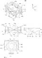
- FIG. 1shows an exemplary classical four rod-springs ( 102a-d ) OIS structure in a single-aperture camera module 100 .
- the four rod-springsare rigidly connected to an upper frame 104 that usually accommodates an AF actuator (not shown) that moves the lens module 106 .
- This structureallows desired modes of movement in the X-Y plane (translation), FIG. 1a , but also allows a mode of unwanted rotation (also referred to as “ ⁇ -rotation” or “torsion”) around the Z axis, FIG. 1b .
- the lattermay be due to a combination of several causes such as asymmetric forces applied by the coils or by a user's (or phone) movements, imperfections of the rod-springs and the high rotational compliance of the four spring rod spring + frame structure.
- FIG. 2ashows a rotation mode around an axis 202 roughly centered between two camera modules 204 and 206 of a dual-aperture camera 200 . Because of the location of rotation axis 202 , the rotation may cause significant deterioration in the image quality.
- the rotationcauses each lens to shift away in undesired directions (shown by arrows in FIG. 2b ), without having any ability to predict when and if this may happen.
- the resultis motion blur of the image and a shift of the two lenses in opposite Y directions caused by the unwanted rotation that results in decenter between images received by each camera module, and therefore potentially in a catastrophic influence on fusion algorithm results.
- Camera 300comprises a folded optics camera module 302 and an upright (non-folded) camera module 304 .
- folded optics camera module 302comprises a lens actuation sub-assembly for moving a lens module 306 (and a lens therein, which is referred to henceforth as "folded lens") in the X-Y plane.
- the lens actuation sub-assemblyincludes a hanging structure with four flexible hanging members (i.e.
- hanging members 308a-dmay be in the form of four wires and may be referred to as "wire springs" or "poles".
- the hanging structureallows in-plane motion as known in the art and described exemplarily in co-owned US patent application No. 14/373490 .
- a first movement direction 312 of the lensis used to achieve Auto-Focus (AF) and a second movement direction 314 is used to achieve OIS.
- AFAuto-Focus
- OISOIS
- an unwanted rotation 316 of the lens about an axis parallel to the Z axis as described aboveactually causes an unwanted effect of dynamic tilt of the lens (the lens' optical axis may not be perpendicular to the sensor's surface due to that rotation) and may result in images that are usually sharp on one side and blurry on the other side.
- FIGS. 4(a)-(c)show the simulated behavior of a standard rigid plate supported by four round rod-spring poles.
- the rigid platemay represent any optical element (such as, for example, a lens).
- the rod-spring poleshave the same rigidity to movement in any direction in the X-Y plane (which is perpendicular to the pole's neutral axis).
- the figuresshow the compliance of the structure expressed in terms of a natural frequency ratio for each different movement mode: FIG. 4a refers to X-translation, FIG. 4b refers to Y-translation and FIG.
- 4crefers to rotation around the Z axis.
- the arrowsshow schematically the different movements.
- the reference barindicates deformation scale in millimeters.
- the normalized (relative to the first frequency which in this exemplary case is of 33.6Hz) natural frequencies for X and Y translationsare of the same order (specifically 1 in (a) and 1.1 in (b)), whilst the natural frequency for rotation (c) has a relative value of 1.8, which is also of the same order of the X and Y translations.
- the ratio between natural frequencies for torsion (rotation around Z) and for X or Y translationis about 1.8.
- known ratiosare no larger than 2. This means that the chance that the torsion mode will arise is almost the same as the chance that the X and Y translation modes will arise. This may cause problems in dual-aperture and/or folded zoom cameras (where it will be expressed as dynamic tilt) as described above.
- a mechanism for providing optical image stabilization (OIS) in at least one direction in a digital cameracomprising: a plurality of springs mechanically coupled to at least a lens module carrying a lens of the digital camera, wherein the plurality of springs provides overall low stiffness to movement of the lens module in two, first and second directions orthogonal to each other and high stiffness to torsion of the lens module such that a ratio between natural frequencies arising from the high stiffness and the low stiffness is greater than 2.
- OISoptical image stabilization
- the plurality of springsincludes a first plurality of springs with low stiffness in the first direction and high stiffness in the second direction; and a second plurality of springs with high stiffness in the first direction and low stiffness in the second direction.
- the ratio between natural frequencies arising from the high stiffness and the low stiffnessis greater than 3.
- the ratio between natural frequencies arising from the high stiffness and the low stiffnessis greater than 5.
- the ratio between natural frequencies arising from the high stiffness and the low stiffnessis greater than 10.
- the mechanismis dimensioned to accommodate the lens module without obstructing an optical path passing through the lens.
- the first pluralityincludes two pairs of leaf springs and the second plurality includes a pair of cross springs.
- the first pluralityincludes a pair of leaf springs and one cross spring and the second plurality includes a pair of cross springs.
- each of the first and second pluralitiesincludes a pair of cross springs.
- the digital camerais a dual-optical module camera.
- the lensis a folded lens.
- the camerais adapted to perform auto-focus.
- lens support structures used for AF and OISmay be designed with support members that have different compliance (stiffness) to movements in different directions of different types of movements.
- the different compliance in different movement directions or for different movement typesmay be obtained by non-round or non-square supports cross sections of such support members.
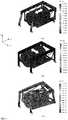
- FIG. 5shows an exemplary embodiment of a folded lens 500 held by a support structure numbered 502 in (a) an isometric view, (b) side view and (c) radial cross section.
- support structure 502may comprise four support spring members 502a-d , each spring member being essentially a thin leaf spring with high stiffness in one direction (e.g. Y) and low stiffness in a second direction (e.g. X) perpendicular to the first direction.
- the term "high stiffness" used with reference to a spring structurerefers to a spring structure having a natural frequency in the range of hundreds to thousands of Hertz, exemplarily between 200-4000 Hz.
- low stiffnessused with reference to a spring structure refers to a spring structure having a natural frequency in the range of tens of Hertz, exemplarily between 30-100 Hz. In general, the natural frequency of a spring is proportional to the square root of its stiffness.
- support spring members 502are referred to as "leaf springs".
- a leaf spring 502a-dhas a length L3 of 4.8-5.5mm and a rectangular cross section, with a small (exemplarily 20-60 ⁇ m) thickness d 1 in the flexing direction (here X) and with a significantly larger (exemplarily 0.5-1 mm) width d 2 in the non-flexing direction (here Y).
- the structure and mechanical properties of the leaf springsallows only movement for AF in the X direction.
- Each leaf springis rigidly connected at a respective upper end 504a-d to a rigid upper frame 506 and at a respective bottom end to a base such as base 310 .
- Leaf springs 502a and 502bmay optionally be connected at a bottom end by a bar 530 .
- Support structure 502 -furthercomprises two support springs 508a and 508b coupled rigidly to frame 506 at an upper end 510 and to a lens support plate 512 at a lower end (respectively 514a and 514b ).
- Support springs 508a and 508bare designed to have low stiffness in the Y direction for OIS movement, and high stiffness in the X direction, while not adding significantly to the camera module width.
- springs 508a or 508binclude two leaf spring members 520 and 521 connected by two diagonal leaf spring members 522 and 524 .
- a support springsuch as a spring 508 is referred to as "cross spring”.
- a diagonal leaf spring memberhas a rectangular cross section with a thickness of the same order of that of a leaf spring 502a-d (exemplarily 20-60 ⁇ m) and a width d 3 of about 0.2 mm.
- a cross spring 508a or 508bmay have a length dimension L4 in the range of 7-10mm and a height H in the range of 4-5mm. Exemplarily in an embodiment, L4 is approximately 9.5mm and H is approximately 4.6mm.
- leaf springs 502a and 502bmay be replaced by a cross spring 508a or 508b , with care being taken (if necessary) not to obstruct an optical path.
- a cross spring 508a or 508bmay also replace leaf springs 502c and 502d, with care being taken (if necessary) not to obstruct an optical path.
- FIG. 6shows the first three modes of the support structure of FIG. 5 resulting from modal Finite Element Analysis where: (a) describes a mode of movement in the X-direction for AF, (b) describes a mode of movement in the Y direction for OIS and (c) describes a mode of (unwanted) tilt around a rotation axis like movement 316 thin FIG. 3 .
- the arrowsshow schematically the different movements.
- the lens and upper frame 506is actuated to move in the X direction while flexing springs 502 . Movement in the Y direction and unwanted rotation such a rotation 316 around the Z-axis in FIG. 3 are minimal.
- lens movement in the Y directionis allowed by the flexing of cross springs 508a or 508b (see also FIG. 6b ), while movement in the X direction and unwanted rotation around the Z-axis are again minimal.
- the normalized (relative to a first frequency which in this exemplary case is of 40 Hz) natural frequencies for X and Y translationsare of the same order (specifically 1 in (a) and 1.2 in (b)), whilst the natural frequency for rotation (c) has a relative value of 29.3. That is, the natural frequency in FIG. 6c is of a significantly higher order than that in FIGS. 6a and 6b .
- the arrangement of separate leaf springs (flexible in the X-direction) and cross springs (flexible in the Y direction)prevents unwanted rotation motion around the Z-axis.
- the springsare made of a copper-nickel-tin mx-215 alloy with an elastic modulus of 125 GPa.
- the springsmay be made of some other metal alloy or of a non-metal, for example of polymer or plastic material, a composite material or a combination of metal/ceramic and/or plastic materials, chosen such that the dimensions and elastic properties fit the camera form requirements.
- FIG. 7shows an isometric view of another exemplary embodiment of a support structure in a folded optics camera 700 .
- an upper frame 706is closed and leaf springs 702c and 702d are connected at the bottom by a bar 704 , imparting added stiffness in the Y direction.
- the leaf springs and barmay be replaced by a cross spring.
- the frameis closed behind the optical path folding element (prism or mirror) so there is no problem of disturbing the optical path to this element.
- an upper frame 906has a closed rectangular shape strengthened by two cross bar members 906a and 906b .
- FIG. 8shows an isometric view of an exemplary embodiment of a dual-aperture camera 800 with two camera modules 802 and 804 held by a support structure disclosed herein.
- An upper frame 806is closed like frame 706 in FIG. 7 , while the support structure is comprised of cross springs 808a-d .
- the support structureis designed for OIS in two directions - X and Y.
- FIG. 9shows the first three modes of another exemplary embodiment of a support structure in a folded optics camera module, as resulting from modal simulation, where: (a) describes a mode of movement in the X-direction for AF, (b) describes a mode of movement in the Y direction for OIS and (c) describes a mode of (unwanted) tilt around a rotation axis.
- the arrowsshow schematically the different movements.
- the first frequencyis 100 Hz
- the normalized natural frequencies for X and Y translationsare of the same order (specifically 1 in (a) and 1.2 in (b)), whilst the natural frequency for torsion (c) has a relative value of 23.9.
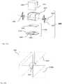
- FIG. 10Ashows an exploded isometric view of an optical path folding element (OPFE) actuation sub-assembly 1060 , according to an example of the presently disclosed subject matter.
- the OPFEmay be for example a prism (e.g. 1008 in FIG. 10A ) or a mirror (e.g. 1008 in FIG. 10C ).
- OPFE actuation sub-assembly 1060includes hinge springs 1036a-b that suspend the prism and can convert linear to angular motion. These hinge springs allow tilting of prism 1008 around a hinge axis 1032 , which is parallel to, or along the Y axis. The tilt can be for example ⁇ 1° from a zero (rest) position of the prism.
- the hinge springsmay be in the form of single-part flexible supports 1036a and 1036b , each attached at a side of the prism.
- the prism and its reflecting surface plane 1010 , hinge axis 1032 and flexible support 1036bare also shown in a side view in FIG. 10B .
- Actuation sub-assembly 1060further includes an actuator 1038 that includes a magnet 1042 rigidly coupled to prism 1008 (in the illustrated example - through an adaptor 1015 ) and a coil 1044 rigidly coupled to base 1012 .
- the hinge springmay comprise two single-part flexible supports 1036a and 1036b attached at each side of the prism.
- FIGS. 10C and 10DAnother design is illustrated in FIGS. 10C and 10D.
- FIG. 10Cshows an isometric exploded view of another embodiment of an OPFE actuation sub-assembly 1060' , in which the OPFE is in the form of a mirror 1008.
- FIG 5Dshows actuation sub-assembly 1060' assembled, in a side view.
- Actuation sub-assembly 1060'includes a hinge spring having two sets of leaf springs mounted at each side of the mirror, a first set having two spring members 1040a and 1040b perpendicular to each other and a second set having two spring members 1040c and 1040d perpendicular to each other.
- the rotation axiswill be around a virtual line drawn between the intersection points of each springs set 1040a-b and 1040c-d .
- FIG. 10Eshows schematically the AF and OIS movements of the lens module and the OIS tilt movement of the OPFE.
- the hinge spring of any of the embodiments presentedmay convert force in any direction parallel to the X-Z plane to a torque around the Y axis such that tilt around the Y axis is created.
- a Lorentz forcemay be applied between coil 1044 and magnet 1042 in order to move magnet 1042 in a direction indicated by an arrow 1054 ( FIG. 10D ).
- This force (and magnet movement)is then converted by the hinge to a tilt motion around the Y axis indicated by an arrow 1056 ( FIG. 10D ).
- the motionis measured by a Hall-bar sensor 1046 .
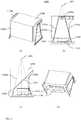
- FIG. 11shows various views of another embodiment of an OPFE actuation sub-assembly, numbered 1160, in which the OPFE is in the form of a prism 1108 with a reflecting surface 1106 , according to an example of the presently disclosed subject matter: (a) perspective view, (b) external side view, (c) internal side view and (d) bottom perspective view.
- OPFE actuation sub-assembly 1160comprises a hanging structure that includes four flexible hanging members 1192a-d that hang prism 1108 over a base 1110 .
- Flexible hanging members 1192a-dare similar to flexible hanging members 308a-d , except that instead of being parallel they are tilted. They are therefore referred to as "tilted hanging members”.
- Tilted hanging members 1192a-dare fixedly mounted on base 1110 at one respective member end and attached to the prism at another member end through hinge points 1198a and 1198b and through side panels 1196a and 1196b .
- tilted hanging members 1192a and 1192bare attached through hinge point 1198a to side panel 1196a and tilted hanging members 1192c and 1192d are attached through hinge point 1198b to side panel 1196b .
- the side panelsare fixedly coupled to opposite sides of the prism.
- Tilted hanging embers 1192a-dallow tilting of prism 1108 around a (virtual) hinge axis 1194 , which is parallel to, or along the Y axis.
- Actuation sub-assembly 1190further includes an actuator 1138 that includes a magnet 1144 rigidly coupled to prism 1108 and a coil 1146 rigidly coupled to base 1110 . This actuator serves in a similar capacity as the actuator comprising magnet 1044 and coil 1046 in actuator 1038 above.
- a Lorentz forcemay be applied between coil 1144 and magnet 1146 to move magnet 1146 either to the left or to the right (e.g. in FIG. 11(b) ).
- This force (and magnet movement)is then converted by the tilted hanging members to a tilt ("pendulum") motion around axis 1194 .
- the tiltmay be typically ⁇ 1° from a zero (rest) position of the prism.
- the motionis measured by a Hall-bar (not shown) as explained above.
- Such an embodimentallows increase in the Hall-bar sensitivity to tilt actuation, by increasing the relative motion between magnet 1144 and the Hall-bar.
Landscapes
- Physics & Mathematics (AREA)
- General Physics & Mathematics (AREA)
- Optics & Photonics (AREA)
- Engineering & Computer Science (AREA)
- Multimedia (AREA)
- Signal Processing (AREA)
- Human Computer Interaction (AREA)
- Adjustment Of Camera Lenses (AREA)
- Studio Devices (AREA)
Abstract
Description
- This application is a continuation application from
US patent application No. 16/017,144 filed June 25, 2018 , which was a continuation application fromUS patent application No. 15/310,887 filed November 14, 2016 issued as US Patent No. 10,036,895 PCT/IB2016/053026 US Provisional Patent Application No. 62/167,571 filed on May 28, 2015 - Embodiments disclosed herein relate in general to digital cameras and in particular to optical image stabilization (OIS) and auto-focus (AF) in single and/or dual-aperture ("dual-optical module") digital cameras.
- In recent years, mobile devices such as cell-phones (and in particular smart-phones), tablets and laptops have become ubiquitous. Most of these devices include one or two compact cameras: a main rear-facing camera (i.e. a camera on the back side of the device, facing away from the user and often used for casual photography) and a secondary front-facing camera (i.e. a camera located on the front side of the device and often used for video conferencing).
- Although relatively compact in nature, the design of most of these cameras is very similar to the traditional structure of a digital still camera, i.e. they comprise an optical component (or a train of several optical elements and a main aperture) placed on top of an image sensor. The optical component (also referred to as "optics") refracts the incoming light rays and bends them to create an image of a scene on the sensor. The dimensions of these cameras are largely determined by the size of the sensor and by the height of the optics. These are usually tied together through the focal length ("f") of the lens and its field of view (FOV) - a lens that has to image a certain FOV on a sensor of a certain size has a specific focal length. Keeping the FOV constant, the larger the sensor dimensions (e.g. in a X-Y plane) the larger the focal length and the optics height.
- In addition to the optics and sensor, modern cameras usually further include mechanical motion (actuation) mechanism for two main purposes: focusing of the image on the sensor and optical image stabilization (OIS). For focusing, in more advanced cameras, the position of the lens module (or at least one lens element in the lens module) can be changed by means of an actuator and the focus distance can be changed in accordance with the captured object or scene. In these cameras it is possible to capture objects from a very short distance (e.g., 10cm) to infinity. The trend in digital still cameras is to increase the zooming capabilities (e.g. to 5x, 10x or more) and, in cell-phone (and particularly smart-phone) cameras, to decrease the pixel size and increase the pixel count. These trends result in greater sensitivity to hand-shake or in a need for longer exposure time. An OIS mechanism is required to answer the needs in these trends.
- In OIS-enabled cameras, the lens or camera module can change its lateral position or tilt angle in a fast manner to cancel the handshake during the image capture. Handshakes move the camera module in 6 degrees of freedom, namely linear movements in three degrees of freedom (X, Y & Z), pitch (tilt around the X axis), yaw (tilt around the Y axis) and roll (tilt around the Z axis).
FIG. 1 shows an exemplary classical four rod-springs (102a-d) OIS structure in a single-aperture camera module 100. The four rod-springs are rigidly connected to anupper frame 104 that usually accommodates an AF actuator (not shown) that moves thelens module 106. This structure allows desired modes of movement in the X-Y plane (translation),FIG. 1a , but also allows a mode of unwanted rotation (also referred to as "θ-rotation" or "torsion") around the Z axis,FIG. 1b . The latter may be due to a combination of several causes such as asymmetric forces applied by the coils or by a user's (or phone) movements, imperfections of the rod-springs and the high rotational compliance of the four spring rod spring + frame structure. - In the case of a centered single-aperture camera module, this rotation does not affect the image quality severely, since the lens is axisymmetric. However, this does affect OIS in a dual-camera module,
FIGS. 2a and 2b. FIG. 2a shows a rotation mode around anaxis 202 roughly centered between twocamera modules aperture camera 200. Because of the location ofrotation axis 202, the rotation may cause significant deterioration in the image quality. The rotation causes each lens to shift away in undesired directions (shown by arrows inFIG. 2b ), without having any ability to predict when and if this may happen. The result is motion blur of the image and a shift of the two lenses in opposite Y directions caused by the unwanted rotation that results in decenter between images received by each camera module, and therefore potentially in a catastrophic influence on fusion algorithm results. - Yet another problem may occur in a folded optics zoom dual-aperture camera, such as a
camera 300 shown inFIG. 3 . Such a camera is described for example in detail in co-owned international patent applicationPCT/IB2016/052179 which is incorporated herein by reference in its entirety.Camera 300 comprises a foldedoptics camera module 302 and an upright (non-folded)camera module 304. Among other components, foldedoptics camera module 302 comprises a lens actuation sub-assembly for moving a lens module 306 (and a lens therein, which is referred to henceforth as "folded lens") in the X-Y plane. The lens actuation sub-assembly includes a hanging structure with four flexible hanging members (i.e. the "rod-springs" referred to above)308 a-d thathang lens module 306 over abase 310. In some embodiments, hangingmembers 308a-d may be in the form of four wires and may be referred to as "wire springs" or "poles". The hanging structure allows in-plane motion as known in the art and described exemplarily in co-ownedUS patent application No. 14/373490 . Exemplarily, afirst movement direction 312 of the lens is used to achieve Auto-Focus (AF) and asecond movement direction 314 is used to achieve OIS. A third movement, anunwanted rotation 316 of the lens about an axis parallel to the Z axis as described above actually causes an unwanted effect of dynamic tilt of the lens (the lens' optical axis may not be perpendicular to the sensor's surface due to that rotation) and may result in images that are usually sharp on one side and blurry on the other side. - The physical quantities that reflect the tendency of any structure to dynamically behave one way or another are the natural frequency values that characterize each mode of behavior. This is of course also relevant for the hanging structure described above.
FIGS. 4(a)-(c) show the simulated behavior of a standard rigid plate supported by four round rod-spring poles. The rigid plate may represent any optical element (such as, for example, a lens). The rod-spring poles have the same rigidity to movement in any direction in the X-Y plane (which is perpendicular to the pole's neutral axis). The figures show the compliance of the structure expressed in terms of a natural frequency ratio for each different movement mode:FIG. 4a refers to X-translation,FIG. 4b refers to Y-translation andFIG. 4c refers to rotation around the Z axis. The arrows show schematically the different movements. The reference bar indicates deformation scale in millimeters. The normalized (relative to the first frequency which in this exemplary case is of 33.6Hz) natural frequencies for X and Y translations are of the same order (specifically 1 in (a) and 1.1 in (b)), whilst the natural frequency for rotation (c) has a relative value of 1.8, which is also of the same order of the X and Y translations. Thus the ratio between natural frequencies for torsion (rotation around Z) and for X or Y translation is about 1.8. In general, known ratios are no larger than 2. This means that the chance that the torsion mode will arise is almost the same as the chance that the X and Y translation modes will arise. This may cause problems in dual-aperture and/or folded zoom cameras (where it will be expressed as dynamic tilt) as described above. - In view of the above, it would be very difficult to get the desired movement of the lens without an active control loop (having such a control loop is one possible way to overcome the described problems). The unwanted torsion may be reduced significantly by means of electrical control over the force applied by the coils (i.e. by using several coils and controlling them so the resultant torque acts to limit the rotation of the lens within specified acceptable limits). However, the addition of an active control loop to avoid tilt complicates the design and adds to cost. It would be therefore advantageous to have lens actuation sub-assemblies for OIS without an active control loop for rotation/tilt.
- In an exemplary embodiment, there is provided a mechanism for providing optical image stabilization (OIS) in at least one direction in a digital camera, comprising: a plurality of springs mechanically coupled to at least a lens module carrying a lens of the digital camera, wherein the plurality of springs provides overall low stiffness to movement of the lens module in two, first and second directions orthogonal to each other and high stiffness to torsion of the lens module such that a ratio between natural frequencies arising from the high stiffness and the low stiffness is greater than 2.
- In an exemplary embodiment, the plurality of springs includes a first plurality of springs with low stiffness in the first direction and high stiffness in the second direction; and a second plurality of springs with high stiffness in the first direction and low stiffness in the second direction.
- In an exemplary embodiment, the ratio between natural frequencies arising from the high stiffness and the low stiffness is greater than 3.
- In an exemplary embodiment, the ratio between natural frequencies arising from the high stiffness and the low stiffness is greater than 5.
- In an exemplary embodiment, the ratio between natural frequencies arising from the high stiffness and the low stiffness is greater than 10.
- In an exemplary embodiment, the mechanism is dimensioned to accommodate the lens module without obstructing an optical path passing through the lens.
- In an exemplary embodiment, the first plurality includes two pairs of leaf springs and the second plurality includes a pair of cross springs.
- In an exemplary embodiment, the first plurality includes a pair of leaf springs and one cross spring and the second plurality includes a pair of cross springs.
- In an exemplary embodiment, each of the first and second pluralities includes a pair of cross springs.
- In an exemplary embodiment, the digital camera is a dual-optical module camera.
- In an exemplary embodiment, the lens is a folded lens.
- In an exemplary embodiment, the camera is adapted to perform auto-focus.
- Non-limiting examples of embodiments disclosed herein are described below with reference to figures attached hereto that are listed following this paragraph. The drawings and descriptions are meant to illuminate and clarify embodiments disclosed herein, and should not be considered limiting in any way. Like elements in different drawings may be indicated like numerals.
FIG. 1 shows a camera module with an exemplary classical four rod-springs OIS structure: (a) modes of wanted X-Y translations, and (b) mode of unwanted rotation around the Z axis;FIG. 2 shows a dual-aperture camera: (a) rotation mode around an axis roughly centered between two camera modules, and (b) movement of each lens in undesired directions;FIG. 3 shows a dual-camera module with a folded optics camera module;FIG. 4 show the simulated behavior of a standard rigid plate supported by four round rod-spring poles: (a) movement in the X-direction, (b) movement in the Y direction and (c) tilt around a rotation axis;FIG. 5 shows an exemplary embodiment of an OIS and AF support structure disclosed herein in a folded optics camera module in (a) an isometric view, (b) side view and (c) radial cross section;FIG. 6 shows the simulated behavior of the support structure ofFIG. 5 for (a) movement in the X-direction, (b) movement in the Y direction and (c) tilt around a rotation axis.FIG. 7 shows an isometric view of another exemplary embodiment of an OIS and AF support structure in a folded optics camera module;FIG. 8 shows an isometric view of an exemplary embodiment of a dual-aperture camera with two camera modules held by a support structure disclosed herein;FIG. 9 shows the simulated behavior of another exemplary embodiment of a support structure in a folded optics camera module for (a) movement in the X-direction, (b) movement in the Y direction and (c) tilt around a rotation axis;FIG. 10A shows an exploded isometric view of an embodiment of an optical path folding element (OPFE) actuation sub-assembly, in which the OPFE in the form of a prism, according to an example of the presently disclosed subject matter;FIG. 10B shows a side view of part of the OPFE actuation sub-assembly ofFIG. 10A , according to an example of the presently disclosed subject matter;FIG. 10C shows an isometric exploded view of an OPFE actuation sub-assembly, in which the OPFE is in the form of a mirror, according to an example of the presently disclosed subject matter;FIG. 10D shows a side view of part of the OPFE actuation sub-assembly ofFIG. 10C , according to an example of the presently disclosed subject matter;FIG. 10E shows schematically the AF and OIS movements of the lens module and the OIS tilt movement of the OPFE, according to an example of the presently disclosed subject matter;FIG. 11 shows various views of another embodiment of an OPFE actuation sub-assembly, in which the OPFE in the form of a prism, according to an example of the presently disclosed subject matter: (a) perspective view, (b) external side view, (c) internal side view and (d) bottom perspective view.- We have determined that lens support structures used for AF and OIS may be designed with support members that have different compliance (stiffness) to movements in different directions of different types of movements. The different compliance in different movement directions or for different movement types may be obtained by non-round or non-square supports cross sections of such support members.
FIG. 5 shows an exemplary embodiment of a foldedlens 500 held by a support structure numbered502 in (a) an isometric view, (b) side view and (c) radial cross section. Exemplarily, support structure502 may comprise foursupport spring members 502a-d, each spring member being essentially a thin leaf spring with high stiffness in one direction (e.g. Y) and low stiffness in a second direction (e.g. X) perpendicular to the first direction. In this description, the term "high stiffness" used with reference to a spring structure refers to a spring structure having a natural frequency in the range of hundreds to thousands of Hertz, exemplarily between 200-4000 Hz. The term "low stiffness" used with reference to a spring structure refers to a spring structure having a natural frequency in the range of tens of Hertz, exemplarily between 30-100 Hz. In general, the natural frequency of a spring is proportional to the square root of its stiffness.- Henceforth, support spring members502 are referred to as "leaf springs". Exemplarily, a
leaf spring 502a-d has a length L3 of 4.8-5.5mm and a rectangular cross section, with a small (exemplarily 20-60µm) thicknessd1 in the flexing direction (here X) and with a significantly larger (exemplarily 0.5-1 mm) widthd2 in the non-flexing direction (here Y). The structure and mechanical properties of the leaf springs allows only movement for AF in the X direction. Each leaf spring is rigidly connected at a respectiveupper end 504a-d to a rigidupper frame 506 and at a respective bottom end to a base such asbase 310. Leaf springs502a and502b may optionally be connected at a bottom end by abar 530. Support structure502-further comprises twosupport springs upper end 510 and to alens support plate 512 at a lower end (respectively514a and514b). Support springs508a and508b are designed to have low stiffness in the Y direction for OIS movement, and high stiffness in the X direction, while not adding significantly to the camera module width. Exemplarily and as shown separately, springs508a or508b include twoleaf spring members leaf spring members member 523. Hereinafter, a support spring such as a spring508 is referred to as "cross spring". Exemplarily, a diagonal leaf spring member has a rectangular cross section with a thickness of the same order of that of aleaf spring 502a-d (exemplarily 20-60µm) and a widthd3 of about 0.2 mm. Exemplarily, across spring leaf springs cross spring cross spring leaf springs Frame 506 may exemplarily be made of a plastic material such as LCP (VECTRA® E525T).Plate 512 is rigidly connected to a lens516 (or to a lens carrier carrying the lens). In this embodiment,upper frame 506 has a U-shape so as not to block an optical path to a path-folding optical element (e.g. mirror or prism, not shown). Exemplarily,frame 506 has dimensions of L1= 11.9 mm and L2= 7.6 mm. More generally, the ratio L2/L1 can be between 0.5-0.7.FIG. 6 shows the first three modes of the support structure ofFIG. 5 resulting from modal Finite Element Analysis where: (a) describes a mode of movement in the X-direction for AF, (b) describes a mode of movement in the Y direction for OIS and (c) describes a mode of (unwanted) tilt around a rotation axis likemovement 316 thinFIG. 3 . The arrows show schematically the different movements. In use for AF, the lens andupper frame 506 is actuated to move in the X direction while flexing springs502. Movement in the Y direction and unwanted rotation such arotation 316 around the Z-axis inFIG. 3 are minimal. For OIS, lens movement in the Y direction is allowed by the flexing ofcross springs FIG. 6b ), while movement in the X direction and unwanted rotation around the Z-axis are again minimal. Specifically, the normalized (relative to a first frequency which in this exemplary case is of 40 Hz) natural frequencies for X and Y translations are of the same order (specifically 1 in (a) and 1.2 in (b)), whilst the natural frequency for rotation (c) has a relative value of 29.3. That is, the natural frequency inFIG. 6c is of a significantly higher order than that inFIGS. 6a and 6b . Advantageously, the arrangement of separate leaf springs (flexible in the X-direction) and cross springs (flexible in the Y direction) prevents unwanted rotation motion around the Z-axis.- In an embodiment and exemplarily, the springs are made of a copper-nickel-tin mx-215 alloy with an elastic modulus of 125 GPa. In other exemplary embodiments, the springs may be made of some other metal alloy or of a non-metal, for example of polymer or plastic material, a composite material or a combination of metal/ceramic and/or plastic materials, chosen such that the dimensions and elastic properties fit the camera form requirements.
FIG. 7 shows an isometric view of another exemplary embodiment of a support structure in a foldedoptics camera 700. Here, anupper frame 706 is closed andleaf springs bar 704, imparting added stiffness in the Y direction. Alternatively, the leaf springs and bar may be replaced by a cross spring. The frame is closed behind the optical path folding element (prism or mirror) so there is no problem of disturbing the optical path to this element. In yet another embodiment shown inFIG. 9 , anupper frame 906 has a closed rectangular shape strengthened by twocross bar members FIG. 8 shows an isometric view of an exemplary embodiment of a dual-aperture camera 800 with twocamera modules upper frame 806 is closed likeframe 706 inFIG. 7 , while the support structure is comprised ofcross springs 808a-d. Here, the support structure is designed for OIS in two directions - X and Y.FIG. 9 shows the first three modes of another exemplary embodiment of a support structure in a folded optics camera module, as resulting from modal simulation, where: (a) describes a mode of movement in the X-direction for AF, (b) describes a mode of movement in the Y direction for OIS and (c) describes a mode of (unwanted) tilt around a rotation axis. The arrows show schematically the different movements. The first frequency is 100 Hz, and the normalized natural frequencies for X and Y translations are of the same order (specifically 1 in (a) and 1.2 in (b)), whilst the natural frequency for torsion (c) has a relative value of 23.9.FIG. 10A shows an exploded isometric view of an optical path folding element (OPFE)actuation sub-assembly 1060, according to an example of the presently disclosed subject matter. The OPFE may be for example a prism (e.g.1008 inFIG. 10A ) or a mirror (e.g.1008 inFIG. 10C ). According to the illustrated example,OPFE actuation sub-assembly 1060 includes hinge springs1036a-b that suspend the prism and can convert linear to angular motion. These hinge springs allow tilting ofprism 1008 around ahinge axis 1032, which is parallel to, or along the Y axis. The tilt can be for example ±1° from a zero (rest) position of the prism.- In the embodiment shown in
FIG. 10A , the hinge springs may be in the form of single-partflexible supports 1036a and1036b, each attached at a side of the prism. The prism and its reflectingsurface plane 1010,hinge axis 1032 andflexible support 1036b are also shown in a side view inFIG. 10B .Actuation sub-assembly 1060 further includes anactuator 1038 that includes amagnet 1042 rigidly coupled to prism1008 (in the illustrated example - through an adaptor1015) and acoil 1044 rigidly coupled tobase 1012. - Regarding a hinge spring, it can be designed in at least two different ways. In one design, mentioned and shown in
FIGS. 10A and 10B , the hinge spring may comprise two single-partflexible supports 1036a and1036b attached at each side of the prism. Another design is illustrated inFIGS. 10C and 10D. FIG. 10C shows an isometric exploded view of another embodiment of an OPFE actuation sub-assembly1060', in which the OPFE is in the form of amirror 1008.FIG 5D shows actuation sub-assembly1060' assembled, in a side view. Actuation sub-assembly1060' includes a hinge spring having two sets of leaf springs mounted at each side of the mirror, a first set having twospring members spring members FIG. 10E shows schematically the AF and OIS movements of the lens module and the OIS tilt movement of the OPFE. - The hinge spring of any of the embodiments presented may convert force in any direction parallel to the X-Z plane to a torque around the Y axis such that tilt around the Y axis is created.
- As described with reference to
FIGS. 10C and 10D and further below, in operation, a Lorentz force may be applied betweencoil 1044 andmagnet 1042 in order to movemagnet 1042 in a direction indicated by an arrow1054 (FIG. 10D ). This force (and magnet movement) is then converted by the hinge to a tilt motion around the Y axis indicated by an arrow1056 (FIG. 10D ). The motion is measured by a Hall-bar sensor 1046. FIG. 11 shows various views of another embodiment of an OPFE actuation sub-assembly, numbered1160, in which the OPFE is in the form of aprism 1108 with a reflectingsurface 1106, according to an example of the presently disclosed subject matter: (a) perspective view, (b) external side view, (c) internal side view and (d) bottom perspective view.OPFE actuation sub-assembly 1160 comprises a hanging structure that includes fourflexible hanging members 1192a-d that hangprism 1108 over abase 1110.Flexible hanging members 1192a-d are similar toflexible hanging members 308a-d, except that instead of being parallel they are tilted. They are therefore referred to as "tilted hanging members". Tilted hangingmembers 1192a-d are fixedly mounted onbase 1110 at one respective member end and attached to the prism at another member end throughhinge points side panels members hinge point 1198a toside panel 1196a and tilted hangingmembers hinge point 1198b toside panel 1196b. The side panels are fixedly coupled to opposite sides of the prism. Tilted hangingembers 1192a-d allow tilting ofprism 1108 around a (virtual)hinge axis 1194, which is parallel to, or along the Y axis. Actuation sub-assembly1190 further includes anactuator 1138 that includes amagnet 1144 rigidly coupled toprism 1108 and acoil 1146 rigidly coupled tobase 1110. This actuator serves in a similar capacity as theactuator comprising magnet 1044 andcoil 1046 inactuator 1038 above.- In operation, a Lorentz force may be applied between
coil 1144 andmagnet 1146 to movemagnet 1146 either to the left or to the right (e.g. inFIG. 11(b) ). This force (and magnet movement) is then converted by the tilted hanging members to a tilt ("pendulum") motion aroundaxis 1194. The tilt may be typically ±1° from a zero (rest) position of the prism. The motion is measured by a Hall-bar (not shown) as explained above. Such an embodiment allows increase in the Hall-bar sensitivity to tilt actuation, by increasing the relative motion betweenmagnet 1144 and the Hall-bar. - In summary, the performance of the support structures provided herein in terms of avoidance of unwanted linear movement and rotation (torsion) while performing AF and OIS is much superior to that of any known support structure used for the same purposes.
- While this disclosure has been described in terms of certain embodiments and generally associated methods, alterations and permutations of the embodiments and methods will be apparent to those skilled in the art. The disclosure is to be understood as not limited by the specific embodiments described herein, but only by the scope of the appended claims.
Claims (15)
- A folded camera module, comprising:a) a lens module having a lens optical axis;b) an optical path folding element (OPFE) for folding light from a first optical path to a second optical path towards an image sensor, the second optical path being along the lens optical axis;c) a lens actuation sub-assembly configured to actuate the lens module to be moved for auto-focus (AF) along a first direction substantially parallel to the second optical path and to be moved for optical image stabilization (OIS) along a second direction substantially orthogonal to both the first and second optical paths to compensate for tilt of the folded camera module around the first direction; andd) an OPFE actuation sub-assembly configured to tilt the OPFE for OIS around an OPFE tilt axis which is parallel to the second direction to compensate for tilt of the folded camera module around the second direction,wherein the lens actuation sub-assembly comprises a plurality of springs mechanically coupled to a lens support plate carrying the lens module, wherein the plurality of springs provides overall low stiffness to movement of the lens module in the first and second directions and high stiffness of the lens module to torsion, such that a ratio between natural frequencies arising from the high stiffness to torsion and the low stiffness to movement in each of the first and second directions is greater than 2.
- The folded camera module of claim 1, wherein the ratio between natural frequencies arising from the high stiffness to torsion and the low stiffness to movement in each of the first and second directions is greater than 3.
- The folded camera module of claim 1, wherein the ratio between natural frequencies arising from the high stiffness to torsion and the low stiffness to movement in each of the first and second directions is greater than 5.
- The folded camera module of claim 1, wherein the ratio between natural frequencies arising from the high stiffness to torsion and the low stiffness to movement in each of the first and second directions is greater than 10.
- The folded camera module of any one or more of claims 1 to 4, wherein the lens actuation sub-assembly is dimensioned to accommodate the lens module without obstructing an optical path passing through the lens module.
- The folded camera module of any one or more of claims 1 to 5, further comprising one or more position sensors that enable measurement of a position of the lens module along the first and second directions and measurement of the OPFE tilt.
- The folded camera module of claim 6, wherein the position sensors are Hall sensors.
- The folded camera module of any one or more of claims 1 to 7, wherein the OPFE actuation sub-assembly includes a plurality of flexible hanging members.
- The folded camera module of any one or more of claims 1 to 8, wherein the OPFE tilt axis is a virtual axis.
- The folded camera module of any one or more of claims 1 to 9, wherein the OPFE actuation sub-assembly includes at least one coil-magnet pair for actuating the OPFE tilt.
- The folded camera module of any one or more of claims 1 to 10, wherein the OPFE includes a prism or a mirror.
- The folded camera module of any one or more of claims 1 to 11, wherein the lens actuation sub-assembly includes a plurality of coil-magnet pairs for actuating the lens module movement.
- The folded camera module of claim 12, wherein the plurality of coil-magnet pairs includes two coil-magnet pairs.
- The folded camera module of any one or more of claims 1 to 13, wherein the folded camera module has a folded camera height in the range of 4 -7mm and wherein the lens module has an effective focal length EFLF in the range of 6 -15mm.
- The folded camera module of any one or more of claims 1 to 14, included in a smart-phone.
Applications Claiming Priority (3)
| Application Number | Priority Date | Filing Date | Title |
|---|---|---|---|
| US201562167571P | 2015-05-28 | 2015-05-28 | |
| PCT/IB2016/053026WO2016189455A1 (en) | 2015-05-28 | 2016-05-24 | Bi-directional stiffness for optical image stabilization and auto-focus in a dual-aperture digital camera |
| EP16799452.4AEP3304161B1 (en) | 2015-05-28 | 2016-05-24 | Bi-directional stiffness for optical image stabilization in a digital camera |
Related Parent Applications (2)
| Application Number | Title | Priority Date | Filing Date |
|---|---|---|---|
| EP16799452.4ADivisionEP3304161B1 (en) | 2015-05-28 | 2016-05-24 | Bi-directional stiffness for optical image stabilization in a digital camera |
| EP16799452.4ADivision-IntoEP3304161B1 (en) | 2015-05-28 | 2016-05-24 | Bi-directional stiffness for optical image stabilization in a digital camera |
Publications (2)
| Publication Number | Publication Date |
|---|---|
| EP3722860A1true EP3722860A1 (en) | 2020-10-14 |
| EP3722860B1 EP3722860B1 (en) | 2023-04-19 |
Family
ID=57393805
Family Applications (2)
| Application Number | Title | Priority Date | Filing Date |
|---|---|---|---|
| EP20178663.9AActiveEP3722860B1 (en) | 2015-05-28 | 2016-05-24 | Bi-directional stiffness for optical image stabilization and auto-focus in a digital camera |
| EP16799452.4AActiveEP3304161B1 (en) | 2015-05-28 | 2016-05-24 | Bi-directional stiffness for optical image stabilization in a digital camera |
Family Applications After (1)
| Application Number | Title | Priority Date | Filing Date |
|---|---|---|---|
| EP16799452.4AActiveEP3304161B1 (en) | 2015-05-28 | 2016-05-24 | Bi-directional stiffness for optical image stabilization in a digital camera |
Country Status (5)
| Country | Link |
|---|---|
| US (3) | US10036895B2 (en) |
| EP (2) | EP3722860B1 (en) |
| KR (3) | KR102114595B1 (en) |
| CN (3) | CN110687655B (en) |
| WO (1) | WO2016189455A1 (en) |
Families Citing this family (51)
| Publication number | Priority date | Publication date | Assignee | Title |
|---|---|---|---|---|
| KR101634516B1 (en) | 2013-06-13 | 2016-06-28 | 코어포토닉스 리미티드 | Dual aperture zoom digital camera |
| JP2016523389A (en) | 2013-07-04 | 2016-08-08 | コアフォトニクス リミテッド | Compact telephoto lens assembly |
| US9857568B2 (en) | 2013-07-04 | 2018-01-02 | Corephotonics Ltd. | Miniature telephoto lens assembly |
| US9392188B2 (en) | 2014-08-10 | 2016-07-12 | Corephotonics Ltd. | Zoom dual-aperture camera with folded lens |
| CN112433331B (en) | 2015-01-03 | 2022-07-08 | 核心光电有限公司 | Miniature telephoto lens module and camera using the same |
| CN112394467B (en)* | 2015-04-16 | 2023-06-09 | 核心光电有限公司 | Autofocus and Optical Image Stabilization in a Compact Folding Camera |
| KR102212611B1 (en) | 2017-02-23 | 2021-02-05 | 코어포토닉스 리미티드 | Folded camera lens designs |
| US11306706B2 (en) | 2017-05-05 | 2022-04-19 | Hutchinson Technology Incorporated | Shape memory alloy actuators and methods thereof |
| US11333134B2 (en) | 2017-05-05 | 2022-05-17 | Hutchinson Technology Incorporated | Shape memory alloy actuators and methods thereof |
| US11815794B2 (en) | 2017-05-05 | 2023-11-14 | Hutchinson Technology Incorporated | Shape memory alloy actuators and methods thereof |
| GB2602950B (en) | 2017-05-05 | 2022-10-26 | Hutchinson Technology | Shape memory alloy actuators and methods thereof |
| US11105319B2 (en) | 2017-05-05 | 2021-08-31 | Hutchinson Technology Incorporated | Shape memory alloy actuators and methods thereof |
| KR20200022489A (en)* | 2017-06-30 | 2020-03-03 | 폴라이트 에이에스에이 | Module with multiple cameras for integration in mobile devices |
| US10462370B2 (en) | 2017-10-03 | 2019-10-29 | Google Llc | Video stabilization |
| US10969652B2 (en) | 2018-01-10 | 2021-04-06 | Apple Inc. | Camera with folded optics having moveable lens |
| KR102391155B1 (en)* | 2018-01-26 | 2022-04-29 | 애플 인크. | Foldable camera with actuator for moving optics |
| US11061213B2 (en) | 2018-02-07 | 2021-07-13 | Apple Inc. | Folded camera |
| US10171738B1 (en) | 2018-05-04 | 2019-01-01 | Google Llc | Stabilizing video to reduce camera and face movement |
| US11314147B1 (en) | 2018-05-31 | 2022-04-26 | Apple Inc. | Folded camera with actuator for moving optics |
| CN110611752A (en)* | 2018-06-14 | 2019-12-24 | 中兴通讯股份有限公司 | Camera module, method for controlling double cameras and terminal |
| US11336830B2 (en) | 2019-01-03 | 2022-05-17 | Corephotonics Ltd. | Multi-aperture cameras with at least one two state zoom camera |
| CN111698397B (en)* | 2019-03-13 | 2021-12-07 | 三赢科技(深圳)有限公司 | Camera module and electronic device |
| GB2582965B (en)* | 2019-04-11 | 2021-09-15 | Dualitas Ltd | A diffuser assembly |
| WO2021033047A1 (en) | 2019-08-21 | 2021-02-25 | Corephotonics Ltd. | Low total track length for large sensor format |
| US12072609B2 (en) | 2019-09-24 | 2024-08-27 | Corephotonics Ltd. | Slim pop-out cameras and lenses for such cameras |
| US11656538B2 (en) | 2019-11-25 | 2023-05-23 | Corephotonics Ltd. | Folded zoom camera module with adaptive aperture |
| KR102319598B1 (en) | 2019-12-30 | 2021-11-02 | 삼성전기주식회사 | Camera Module |
| US11770609B2 (en) | 2020-05-30 | 2023-09-26 | Corephotonics Ltd. | Systems and methods for obtaining a super macro image |
| KR102765964B1 (en) | 2020-07-22 | 2025-02-07 | 코어포토닉스 리미티드 | Folded camera lens design |
| US11190689B1 (en) | 2020-07-29 | 2021-11-30 | Google Llc | Multi-camera video stabilization |
| CN119414645A (en) | 2020-07-31 | 2025-02-11 | 核心光电有限公司 | camera |
| CN114167569B (en)* | 2020-08-21 | 2023-08-22 | 华为技术有限公司 | Optical lens, camera module and electronic equipment |
| EP4127788A4 (en) | 2020-09-18 | 2024-06-19 | Corephotonics Ltd. | Pop-out zoom camera |
| TWI782512B (en)* | 2020-10-12 | 2022-11-01 | 大陽科技股份有限公司 | Imaging lens driving module, image capturing apparatus and electronic device |
| US12271105B2 (en) | 2020-11-05 | 2025-04-08 | Corephotonics Ltd. | Scanning Tele camera based on two prism field of view scanning |
| KR102241321B1 (en)* | 2020-11-30 | 2021-04-16 | 삼성전기주식회사 | Mirror Module for OIS and Camera module including the same |
| KR20250008791A (en) | 2020-12-01 | 2025-01-15 | 코어포토닉스 리미티드 | Folded camera with continuously adaptive zoom factor |
| CN117425062A (en) | 2021-01-25 | 2024-01-19 | 核心光电有限公司 | Lens system for compact digital camera |
| KR20230147168A (en)* | 2021-02-22 | 2023-10-20 | 허친슨 테크놀로지 인코포레이티드 | Shape memory alloy actuator and method thereof |
| WO2022200965A1 (en) | 2021-03-22 | 2022-09-29 | Corephotonics Ltd. | Folded cameras with continuously adaptive zoom factor |
| US11859598B2 (en) | 2021-06-10 | 2024-01-02 | Hutchinson Technology Incorporated | Shape memory alloy actuators and methods thereof |
| KR20240012438A (en) | 2021-06-23 | 2024-01-29 | 코어포토닉스 리미티드 | Compact folded tele camera |
| KR102685591B1 (en) | 2021-09-23 | 2024-07-15 | 코어포토닉스 리미티드 | Large aperture continuous zoom folded telecamera |
| US12425710B1 (en) | 2021-09-24 | 2025-09-23 | Apple Inc. | Insert molded optics holder |
| CN120315167A (en) | 2021-12-14 | 2025-07-15 | 核心光电有限公司 | Large aperture compact scan telephoto camera |
| US12328505B2 (en)* | 2022-03-24 | 2025-06-10 | Corephotonics Ltd. | Slim compact lens optical image stabilization |
| KR20240167867A (en)* | 2022-04-30 | 2024-11-28 | 코어포토닉스 리미티드 | Pop-out mobile camera and compact actuator |
| US12368960B2 (en) | 2022-08-05 | 2025-07-22 | Corephotonics Ltd. | Systems and methods for zoom digital camera with automatic adjustable zoom field of view |
| US12143703B2 (en) | 2023-03-22 | 2024-11-12 | Apple Inc. | Camera modules with interlocked frames |
| US11982263B1 (en) | 2023-05-02 | 2024-05-14 | Hutchinson Technology Incorporated | Shape metal alloy (SMA) bimorph actuators with reduced wire exit angle |
| US20250243851A1 (en)* | 2024-01-26 | 2025-07-31 | Hutchinson Technology Incorporated | Cross-Spring Actuator Designs |
Citations (3)
| Publication number | Priority date | Publication date | Assignee | Title |
|---|---|---|---|---|
| US20070058958A1 (en)* | 2005-09-15 | 2007-03-15 | Pentax Corporation | Anti-shake system |
| EP1931135A1 (en)* | 2006-12-04 | 2008-06-11 | Samsung Electronics Co., Ltd. | Apparatus and method for correcting shake of image photographing device |
| US20120249815A1 (en)* | 2011-03-29 | 2012-10-04 | Mircrosoft Corporation | Folded imaging path camera |
Family Cites Families (271)
| Publication number | Priority date | Publication date | Assignee | Title |
|---|---|---|---|---|
| US4199785A (en) | 1979-01-05 | 1980-04-22 | Honeywell Inc. | Electronic zoom system |
| JPS59191146A (en)* | 1983-04-13 | 1984-10-30 | Hitachi Ltd | Optical scanner |
| JPH064415Y2 (en)* | 1984-04-23 | 1994-02-02 | パイオニア株式会社 | Lens drive |
| US5099263A (en) | 1984-11-10 | 1992-03-24 | Minolta Camera Kabushiki Kaisha | Variable focal length camera |
| DE58902538D1 (en) | 1988-05-19 | 1992-12-03 | Siemens Ag | METHOD FOR OBSERVING A SCENE AND DEVICE FOR IMPLEMENTING THE METHOD. |
| DE3927334C1 (en) | 1989-08-18 | 1991-01-10 | Messerschmitt-Boelkow-Blohm Gmbh, 8012 Ottobrunn, De | |
| US5032917A (en) | 1990-03-12 | 1991-07-16 | Rca Licensing Corporation | Video signal blending apparatus |
| JPH0443773A (en) | 1990-06-11 | 1992-02-13 | Matsushita Electric Ind Co Ltd | Arithmetic circuit |
| US5041852A (en) | 1990-10-18 | 1991-08-20 | Fjui Photo Film Co., Ltd. | Camera shake correction system |
| JP3261152B2 (en) | 1991-03-13 | 2002-02-25 | シャープ株式会社 | Imaging device having a plurality of optical systems |
| US5394520A (en) | 1991-09-26 | 1995-02-28 | Hughes Aircraft Company | Imaging apparatus for providing a composite digital representation of a scene within a field of regard |
| US5657402A (en) | 1991-11-01 | 1997-08-12 | Massachusetts Institute Of Technology | Method of creating a high resolution still image using a plurality of images and apparatus for practice of the method |
| US5248971A (en) | 1992-05-19 | 1993-09-28 | Mandl William J | Method and apparatus for multiplexed oversampled analog to digital modulation |
| JPH06177706A (en) | 1992-12-08 | 1994-06-24 | Sony Corp | Signal processing unit |
| KR940017747A (en) | 1992-12-29 | 1994-07-27 | 에프. 제이. 스미트 | Image processing device |
| US5682198A (en) | 1993-06-28 | 1997-10-28 | Canon Kabushiki Kaisha | Double eye image pickup apparatus |
| US6128416A (en) | 1993-09-10 | 2000-10-03 | Olympus Optical Co., Ltd. | Image composing technique for optimally composing a single image from a plurality of digital images |
| US6714665B1 (en) | 1994-09-02 | 2004-03-30 | Sarnoff Corporation | Fully automated iris recognition system utilizing wide and narrow fields of view |
| CA2155719C (en) | 1994-11-22 | 2005-11-01 | Terry Laurence Glatt | Video surveillance system with pilot and slave cameras |
| US5768443A (en) | 1995-12-19 | 1998-06-16 | Cognex Corporation | Method for coordinating multiple fields of view in multi-camera |
| US5982951A (en) | 1996-05-28 | 1999-11-09 | Canon Kabushiki Kaisha | Apparatus and method for combining a plurality of images |
| US5926190A (en) | 1996-08-21 | 1999-07-20 | Apple Computer, Inc. | Method and system for simulating motion in a computer graphics application using image registration and view interpolation |
| JPH10126796A (en) | 1996-09-12 | 1998-05-15 | Eastman Kodak Co | Digital camera for dynamic and still images using dual mode software processing |
| US5960218A (en) | 1997-02-18 | 1999-09-28 | Mobi Corporation | Dual focal length camera |
| US5940641A (en) | 1997-07-10 | 1999-08-17 | Eastman Kodak Company | Extending panoramic images |
| US6148120A (en) | 1997-10-30 | 2000-11-14 | Cognex Corporation | Warping of focal images to correct correspondence error |
| US6268611B1 (en) | 1997-12-18 | 2001-07-31 | Cellavision Ab | Feature-free registration of dissimilar images using a robust similarity metric |
| JP3695119B2 (en) | 1998-03-05 | 2005-09-14 | 株式会社日立製作所 | Image synthesizing apparatus and recording medium storing program for realizing image synthesizing method |
| US6208765B1 (en) | 1998-06-19 | 2001-03-27 | Sarnoff Corporation | Method and apparatus for improving image resolution |
| US6611289B1 (en) | 1999-01-15 | 2003-08-26 | Yanbin Yu | Digital cameras using multiple sensors with multiple lenses |
| US20020063711A1 (en) | 1999-05-12 | 2002-05-30 | Imove Inc. | Camera system with high resolution image inside a wide angle view |
| US20020075258A1 (en) | 1999-05-12 | 2002-06-20 | Imove Inc. | Camera system with high resolution image inside a wide angle view |
| US6738073B2 (en) | 1999-05-12 | 2004-05-18 | Imove, Inc. | Camera system with both a wide angle view and a high resolution view |
| US6346950B1 (en) | 1999-05-20 | 2002-02-12 | Compaq Computer Corporation | System and method for display images using anamorphic video |
| US7038716B2 (en) | 1999-07-30 | 2006-05-02 | Pixim, Inc. | Mobile device equipped with digital image sensor |
| US7015954B1 (en) | 1999-08-09 | 2006-03-21 | Fuji Xerox Co., Ltd. | Automatic video system using multiple cameras |
| US6650368B1 (en) | 1999-10-26 | 2003-11-18 | Hewlett-Packard Development Company, Lp. | Digital camera and method of enhancing zoom effects |
| US6643416B1 (en) | 1999-11-30 | 2003-11-04 | Eastman Kodak Company | Method for determining necessary resolution for zoom and crop images |
| US20020005902A1 (en) | 2000-06-02 | 2002-01-17 | Yuen Henry C. | Automatic video recording system using wide-and narrow-field cameras |
| JP4511766B2 (en)* | 2000-07-10 | 2010-07-28 | 株式会社リコー | Image capturing apparatus and shake correction method in image capturing apparatus |
| US7002583B2 (en) | 2000-08-03 | 2006-02-21 | Stono Technologies, Llc | Display of images and image transitions |
| US6778207B1 (en) | 2000-08-07 | 2004-08-17 | Koninklijke Philips Electronics N.V. | Fast digital pan tilt zoom video |
| US7345277B2 (en) | 2000-08-09 | 2008-03-18 | Evan Zhang | Image intensifier and LWIR fusion/combination system |
| JP2002214662A (en) | 2001-01-23 | 2002-07-31 | Olympus Optical Co Ltd | Shake correcting device for optical device |
| US6741250B1 (en) | 2001-02-09 | 2004-05-25 | Be Here Corporation | Method and system for generation of multiple viewpoints into a scene viewed by motionless cameras and for presentation of a view path |
| US7346217B1 (en) | 2001-04-25 | 2008-03-18 | Lockheed Martin Corporation | Digital image enhancement using successive zoom images |
| JP2002341220A (en) | 2001-05-14 | 2002-11-27 | Olympus Optical Co Ltd | Optical instrument |
| GB0116877D0 (en) | 2001-07-10 | 2001-09-05 | Hewlett Packard Co | Intelligent feature selection and pan zoom control |
| DE10134640B4 (en)* | 2001-07-17 | 2005-07-14 | Texas Instruments Deutschland Gmbh | PLL circuit and method for automatically setting its output frequency |
| US6680748B1 (en) | 2001-09-27 | 2004-01-20 | Pixim, Inc., | Multi-mode camera and method therefor |
| US20030093805A1 (en) | 2001-11-15 | 2003-05-15 | Gin J.M. Jack | Dual camera surveillance and control system |
| US7339621B2 (en) | 2001-12-13 | 2008-03-04 | Psion Teklogix Systems, Inc. | Imager output signal processing |
| JP4198449B2 (en) | 2002-02-22 | 2008-12-17 | 富士フイルム株式会社 | Digital camera |
| JP4657564B2 (en) | 2002-04-30 | 2011-03-23 | イーストマン コダック カンパニー | Electronic still camera and image processing method |
| GB2388265B (en) | 2002-04-30 | 2005-10-12 | Hewlett Packard Co | Improvements in and relating to processing of images |
| CA2386560A1 (en) | 2002-05-15 | 2003-11-15 | Idelix Software Inc. | Controlling optical hardware and dynamic data viewing systems with detail-in-context viewing tools |
| JP4174240B2 (en)* | 2002-05-30 | 2008-10-29 | キヤノン株式会社 | Vibration correction apparatus and optical apparatus provided with the same |
| JP3870124B2 (en) | 2002-06-14 | 2007-01-17 | キヤノン株式会社 | Image processing apparatus and method, computer program, and computer-readable storage medium |
| US6839067B2 (en) | 2002-07-26 | 2005-01-04 | Fuji Xerox Co., Ltd. | Capturing and producing shared multi-resolution video |
| US20040061788A1 (en) | 2002-09-26 | 2004-04-01 | Logitech Europe S.A. | Multiple mode capture button for a digital camera |
| US7321470B2 (en) | 2002-10-08 | 2008-01-22 | Olympus Corporation | Camera |
| GB2394852B (en) | 2002-10-31 | 2006-12-20 | Hewlett Packard Co | Image capture systems using motion detection |
| JP2004219569A (en) | 2003-01-10 | 2004-08-05 | Olympus Corp | Electronic image pickup unit |
| JP4055599B2 (en) | 2003-02-13 | 2008-03-05 | コニカミノルタオプト株式会社 | Imaging lens device and electronic apparatus equipped with the same |
| JP2004311774A (en)* | 2003-04-08 | 2004-11-04 | Nikon Corp | Optical device, position detecting device and exposure device |
| CN1574894A (en) | 2003-06-02 | 2005-02-02 | 宾得株式会社 | Multiple-focal imaging device, and a mobile device having the multiple-focal-length imaging device |
| US7596284B2 (en) | 2003-07-16 | 2009-09-29 | Hewlett-Packard Development Company, L.P. | High resolution image reconstruction |
| US7619683B2 (en) | 2003-08-29 | 2009-11-17 | Aptina Imaging Corporation | Apparatus including a dual camera module and method of using the same |
| JP2005176293A (en)* | 2003-11-21 | 2005-06-30 | Pentax Corp | Imaging device |
| JP2005208194A (en) | 2004-01-21 | 2005-08-04 | Konica Minolta Photo Imaging Inc | Photographing apparatus |
| KR20050090780A (en) | 2004-03-10 | 2005-09-14 | 삼성전자주식회사 | Image photographing apparatus |
| WO2006040687A2 (en) | 2004-07-19 | 2006-04-20 | Grandeye, Ltd. | Automatically expanding the zoom capability of a wide-angle video camera |
| JP4894041B2 (en) | 2004-07-20 | 2012-03-07 | 株式会社ファイブ・ディー | Electronic imaging device |
| US20060054782A1 (en) | 2004-08-25 | 2006-03-16 | Olsen Richard I | Apparatus for multiple camera devices and method of operating same |
| US7916180B2 (en) | 2004-08-25 | 2011-03-29 | Protarius Filo Ag, L.L.C. | Simultaneous multiple field of view digital cameras |
| US7564019B2 (en) | 2005-08-25 | 2009-07-21 | Richard Ian Olsen | Large dynamic range cameras |
| KR101054344B1 (en) | 2004-11-17 | 2011-08-04 | 삼성전자주식회사 | Thin film transistor array panel and manufacturing method thereof |
| US7688364B2 (en) | 2004-12-10 | 2010-03-30 | Ambarella, Inc. | Decimating and cropping based zoom factor for a digital camera |
| KR100636969B1 (en) | 2004-12-30 | 2006-10-19 | 매그나칩 반도체 유한회사 | ISP built-in image sensor and dual camera system |
| US7573514B2 (en) | 2005-02-03 | 2009-08-11 | Eastman Kodak Company | Digital imaging system with digital zoom warning |
| US7663662B2 (en) | 2005-02-09 | 2010-02-16 | Flir Systems, Inc. | High and low resolution camera systems and methods |
| US7236306B2 (en) | 2005-02-18 | 2007-06-26 | Eastman Kodak Company | Digital camera using an express zooming mode to provide expedited operation over an extended zoom range |
| US7206136B2 (en) | 2005-02-18 | 2007-04-17 | Eastman Kodak Company | Digital camera using multiple lenses and image sensors to provide an extended zoom range |
| US7561191B2 (en) | 2005-02-18 | 2009-07-14 | Eastman Kodak Company | Camera phone using multiple lenses and image sensors to provide an extended zoom range |
| US7256944B2 (en) | 2005-02-18 | 2007-08-14 | Eastman Kodak Company | Compact image capture assembly using multiple lenses and image sensors to provide an extended zoom range |
| US20060187322A1 (en) | 2005-02-18 | 2006-08-24 | Janson Wilbert F Jr | Digital camera using multiple fixed focal length lenses and multiple image sensors to provide an extended zoom range |
| WO2006137253A1 (en) | 2005-06-22 | 2006-12-28 | Matsushita Electric Industrial Co., Ltd. | Image forming device, and image forming method |
| JP2007033879A (en) | 2005-07-27 | 2007-02-08 | Sony Corp | Imaging lens device and imaging apparatus |
| US7424218B2 (en) | 2005-07-28 | 2008-09-09 | Microsoft Corporation | Real-time preview for panoramic images |
| JP4573725B2 (en) | 2005-08-01 | 2010-11-04 | イーストマン コダック カンパニー | Imaging apparatus having a plurality of optical systems |
| JP4573724B2 (en) | 2005-08-01 | 2010-11-04 | イーストマン コダック カンパニー | Imaging apparatus having a plurality of optical systems |
| US7964835B2 (en) | 2005-08-25 | 2011-06-21 | Protarius Filo Ag, L.L.C. | Digital cameras with direct luminance and chrominance detection |
| JP4449880B2 (en) | 2005-10-12 | 2010-04-14 | ソニー株式会社 | Imaging device |
| US7822330B2 (en) | 2005-11-14 | 2010-10-26 | Nikon Corporation | Image blur correction device and camera |
| JP4788953B2 (en) | 2005-11-16 | 2011-10-05 | ソニー株式会社 | Imaging device and zoom lens |
| JP2007163595A (en)* | 2005-12-09 | 2007-06-28 | Canon Inc | Optical equipment |
| US8238695B1 (en) | 2005-12-15 | 2012-08-07 | Grandeye, Ltd. | Data reduction techniques for processing wide-angle video |
| US20070177025A1 (en) | 2006-02-01 | 2007-08-02 | Micron Technology, Inc. | Method and apparatus minimizing die area and module size for a dual-camera mobile device |
| EP1984774A4 (en) | 2006-02-06 | 2010-11-24 | Nokia Corp | OPTICAL IMAGE STABILIZER WITH A CARDANPRISMA |
| JP4579842B2 (en) | 2006-02-06 | 2010-11-10 | イーストマン コダック カンパニー | Imaging device |
| JP4669047B2 (en) | 2006-02-06 | 2011-04-13 | ノキア コーポレイション | Method and device for position detection in an imaging system |
| US9182228B2 (en) | 2006-02-13 | 2015-11-10 | Sony Corporation | Multi-lens array system and method |
| US7773121B1 (en) | 2006-05-03 | 2010-08-10 | The United States Of America As Represented By The Administrator Of The National Aeronautics And Space Administration | High-resolution, continuous field-of-view (FOV), non-rotating imaging system |
| JP2007310084A (en)* | 2006-05-17 | 2007-11-29 | Alps Electric Co Ltd | Movable optical apparatus |
| KR100749337B1 (en) | 2006-06-13 | 2007-08-14 | 삼성전자주식회사 | Method and apparatus for photographing using a mobile communication terminal having a plurality of camera lenses |
| US7737379B2 (en) | 2006-07-19 | 2010-06-15 | Witdouck Calvin J | System and method for sorting larvae cocoons |
| US8189100B2 (en) | 2006-07-25 | 2012-05-29 | Qualcomm Incorporated | Mobile device with dual digital camera sensors and methods of using the same |
| US7756330B2 (en) | 2006-07-27 | 2010-07-13 | Eastman Kodak Company | Producing an extended dynamic range digital image |
| US7667762B2 (en) | 2006-08-01 | 2010-02-23 | Lifesize Communications, Inc. | Dual sensor video camera |
| US20080030592A1 (en) | 2006-08-01 | 2008-02-07 | Eastman Kodak Company | Producing digital image with different resolution portions |
| JP2008096584A (en) | 2006-10-10 | 2008-04-24 | Nikon Corp | camera |
| JP4448844B2 (en) | 2006-11-22 | 2010-04-14 | 富士フイルム株式会社 | Compound eye imaging device |
| US7533819B2 (en) | 2007-01-31 | 2009-05-19 | Symbol Technologies, Inc. | Dual camera assembly for an imaging-based bar code reader |
| US7978239B2 (en) | 2007-03-01 | 2011-07-12 | Eastman Kodak Company | Digital camera using multiple image sensors to provide improved temporal sampling |
| US7683962B2 (en) | 2007-03-09 | 2010-03-23 | Eastman Kodak Company | Camera using multiple lenses and image sensors in a rangefinder configuration to provide a range map |
| US7859588B2 (en) | 2007-03-09 | 2010-12-28 | Eastman Kodak Company | Method and apparatus for operating a dual lens camera to augment an image |
| US7676146B2 (en) | 2007-03-09 | 2010-03-09 | Eastman Kodak Company | Camera using multiple lenses and image sensors to provide improved focusing capability |
| US7729602B2 (en) | 2007-03-09 | 2010-06-01 | Eastman Kodak Company | Camera using multiple lenses and image sensors operable in a default imaging mode |
| EP2149067A1 (en) | 2007-04-19 | 2010-02-03 | D.V.P. Technologies Ltd. | Imaging system and method for use in monitoring a field of regard |
| US7918398B2 (en) | 2007-06-04 | 2011-04-05 | Hand Held Products, Inc. | Indicia reading terminal having multiple setting imaging lens |
| US8390729B2 (en) | 2007-09-05 | 2013-03-05 | International Business Machines Corporation | Method and apparatus for providing a video image having multiple focal lengths |
| US20090086074A1 (en) | 2007-09-27 | 2009-04-02 | Omnivision Technologies, Inc. | Dual mode camera solution apparatus, system, and method |
| JP2009109904A (en) | 2007-10-31 | 2009-05-21 | Sony Corp | Lens barrel and imaging apparatus |
| US20090122195A1 (en) | 2007-11-09 | 2009-05-14 | Van Baar Jeroen | System and Method for Combining Image Sequences |
| US20090128644A1 (en) | 2007-11-15 | 2009-05-21 | Camp Jr William O | System and method for generating a photograph |
| US8310587B2 (en) | 2007-12-04 | 2012-11-13 | DigitalOptics Corporation International | Compact camera optics |
| US8824833B2 (en) | 2008-02-01 | 2014-09-02 | Omnivision Technologies, Inc. | Image data fusion systems and methods |
| US8115825B2 (en) | 2008-02-20 | 2012-02-14 | Apple Inc. | Electronic device with two image sensors |
| US20100097444A1 (en) | 2008-10-16 | 2010-04-22 | Peter Lablans | Camera System for Creating an Image From a Plurality of Images |
| US8866920B2 (en) | 2008-05-20 | 2014-10-21 | Pelican Imaging Corporation | Capturing and processing of images using monolithic camera array with heterogeneous imagers |
| FI20085510L (en) | 2008-05-28 | 2009-11-29 | Valtion Teknillinen | A zoom-camera arrangement comprising several sub-cameras |
| JP4513906B2 (en) | 2008-06-27 | 2010-07-28 | ソニー株式会社 | Image processing apparatus, image processing method, program, and recording medium |
| US8134589B2 (en) | 2008-07-17 | 2012-03-13 | Eastman Kodak Company | Zoom by multiple image capture |
| GB2462095A (en) | 2008-07-23 | 2010-01-27 | Snell & Wilcox Ltd | Processing of images to represent a transition in viewpoint |
| US8237807B2 (en) | 2008-07-24 | 2012-08-07 | Apple Inc. | Image capturing device with touch screen for adjusting camera settings |
| CN201233466Y (en)* | 2008-07-31 | 2009-05-06 | 宁波金诚泰电子有限公司 | Reed for camera lens driving mechanism |
| CN102150078B (en) | 2008-09-10 | 2013-09-04 | 松下电器产业株式会社 | Camera body and imaging device |
| CN101394487B (en) | 2008-10-27 | 2011-09-14 | 华为技术有限公司 | Image synthesizing method and system |
| JP5230376B2 (en) | 2008-11-28 | 2013-07-10 | 三星電子株式会社 | Imaging apparatus and imaging method |
| JP5039019B2 (en)* | 2008-12-25 | 2012-10-03 | 富士フイルム株式会社 | Camera shake correction apparatus and optical apparatus |
| JP5265336B2 (en)* | 2008-12-25 | 2013-08-14 | 富士フイルム株式会社 | Camera shake correction apparatus and optical apparatus |
| CN101833157A (en) | 2009-03-13 | 2010-09-15 | 鸿富锦精密工业(深圳)有限公司 | Camera module |
| US8542287B2 (en) | 2009-03-19 | 2013-09-24 | Digitaloptics Corporation | Dual sensor camera |
| WO2010116368A1 (en) | 2009-04-07 | 2010-10-14 | Nextvision Stabilized Systems Ltd | Methods for compensating for light distortions related noise in a camera system having multiple image sensors |
| WO2010122841A1 (en) | 2009-04-22 | 2010-10-28 | コニカミノルタオプト株式会社 | Mirror-lens barrel, image pickup device and method for manufacturing a mirror-lens barrel |
| US8553106B2 (en) | 2009-05-04 | 2013-10-08 | Digitaloptics Corporation | Dual lens digital zoom |
| CN102447836A (en) | 2009-06-16 | 2012-05-09 | 英特尔公司 | Camera applications in a handheld device |
| US20100321494A1 (en) | 2009-06-18 | 2010-12-23 | Theia Technologies, Llc | Compact dome camera |
| CN102461157B (en) | 2009-06-22 | 2016-01-20 | 豪威科技有限公司 | The exercisable system and method for imageing sensor in many video standards |
| JP5846346B2 (en) | 2009-08-21 | 2016-01-20 | ミツミ電機株式会社 | Camera shake correction device |
| KR101613928B1 (en) | 2009-09-09 | 2016-04-20 | 엘지전자 주식회사 | Portable terminal |
| KR101617289B1 (en) | 2009-09-30 | 2016-05-02 | 엘지전자 주식회사 | Mobile terminal and operation control method thereof |
| JP5513834B2 (en) | 2009-10-13 | 2014-06-04 | 台湾東電化股▲ふん▼有限公司 | Lens drive device |
| EP2502410B1 (en) | 2009-11-19 | 2019-05-01 | eSight Corporation | A method for augmenting sight |
| EP2502115A4 (en) | 2009-11-20 | 2013-11-06 | Pelican Imaging Corp | CAPTURE AND IMAGE PROCESSING USING A MONOLITHIC CAMERAS NETWORK EQUIPPED WITH HETEROGENEOUS IMAGERS |
| US8400555B1 (en) | 2009-12-01 | 2013-03-19 | Adobe Systems Incorporated | Focused plenoptic camera employing microlenses with different focal lengths |
| US20110128288A1 (en) | 2009-12-02 | 2011-06-02 | David Petrou | Region of Interest Selector for Visual Queries |
| CN102906763A (en) | 2010-01-28 | 2013-01-30 | 美国路通创新科技公司 | Document Imaging System with Capture Scanner and PC-based Processing Software |
| KR20110094723A (en)* | 2010-02-17 | 2011-08-24 | 삼성전기주식회사 | Lens Drive Actuators and Camera Modules |
| JP5445235B2 (en) | 2010-03-09 | 2014-03-19 | ソニー株式会社 | Image processing apparatus, image processing method, and program |
| JP2011205374A (en) | 2010-03-25 | 2011-10-13 | Fujifilm Corp | Display apparatus |
| JP4783465B1 (en) | 2010-03-26 | 2011-09-28 | 富士フイルム株式会社 | Imaging device and display device |
| US8456518B2 (en) | 2010-03-31 | 2013-06-04 | James Cameron & Vincent Pace | Stereoscopic camera with automatic obstruction removal |
| US20110242342A1 (en) | 2010-04-05 | 2011-10-06 | Qualcomm Incorporated | Combining data from multiple image sensors |
| US8547389B2 (en) | 2010-04-05 | 2013-10-01 | Microsoft Corporation | Capturing image structure detail from a first image and color from a second image |
| US8446484B2 (en) | 2010-04-21 | 2013-05-21 | Nokia Corporation | Image processing architecture with pre-scaler |
| US20130250150A1 (en) | 2010-05-03 | 2013-09-26 | Michael R. Malone | Devices and methods for high-resolution image and video capture |
| US9369621B2 (en) | 2010-05-03 | 2016-06-14 | Invisage Technologies, Inc. | Devices and methods for high-resolution image and video capture |
| DE102010017057B4 (en) | 2010-05-21 | 2015-03-19 | Jena-Optronik Gmbh | Camera with several fixed focal lengths |
| EA201201649A1 (en) | 2010-07-13 | 2013-06-28 | Рам Шрикант Мирлай | PHOTO-CAMERA DEVICE OF CAPTIVAL PHOTOGRAPHY FOR OBTAINING A THREE-DIMENSIONAL IMAGE WITH A VARIABLE DEPTH OF PERCEPTION |
| US8896655B2 (en) | 2010-08-31 | 2014-11-25 | Cisco Technology, Inc. | System and method for providing depth adaptive video conferencing |
| JP5609467B2 (en) | 2010-09-15 | 2014-10-22 | 株式会社リコー | Imaging apparatus and imaging method |
| US8780251B2 (en) | 2010-09-20 | 2014-07-15 | Canon Kabushiki Kaisha | Image capture with focus adjustment |
| US20120075489A1 (en) | 2010-09-24 | 2012-03-29 | Nishihara H Keith | Zoom camera image blending technique |
| US20140192238A1 (en) | 2010-10-24 | 2014-07-10 | Linx Computational Imaging Ltd. | System and Method for Imaging and Image Processing |
| US9204026B2 (en) | 2010-11-01 | 2015-12-01 | Lg Electronics Inc. | Mobile terminal and method of controlling an image photographing therein |
| JP5719148B2 (en) | 2010-11-10 | 2015-05-13 | キヤノン株式会社 | Imaging apparatus, control method therefor, and program |
| US9426344B2 (en)* | 2010-11-15 | 2016-08-23 | DigitalOptics Corporation MEMS | Camera modules with inertial sensors |
| WO2012075250A1 (en) | 2010-12-01 | 2012-06-07 | Magna Electronics Inc. | System and method of establishing a multi-camera image using pixel remapping |
| US10200671B2 (en) | 2010-12-27 | 2019-02-05 | 3Dmedia Corporation | Primary and auxiliary image capture devices for image processing and related methods |
| US8274552B2 (en) | 2010-12-27 | 2012-09-25 | 3Dmedia Corporation | Primary and auxiliary image capture devices for image processing and related methods |
| JP2012141442A (en) | 2010-12-28 | 2012-07-26 | Sony Corp | Lens protection device, lens unit, and image pickup apparatus |
| US8803990B2 (en) | 2011-01-25 | 2014-08-12 | Aptina Imaging Corporation | Imaging system with multiple sensors for producing high-dynamic-range images |
| US8520080B2 (en) | 2011-01-31 | 2013-08-27 | Hand Held Products, Inc. | Apparatus, system, and method of use of imaging assembly on mobile terminal |
| JP5814566B2 (en) | 2011-02-28 | 2015-11-17 | オリンパス株式会社 | IMAGING DEVICE, IMAGING METHOD, AND IMAGING DEVICE CONTROL PROGRAM |
| US20120229663A1 (en) | 2011-03-08 | 2012-09-13 | Spectral Instruments Imaging , Llc | Imaging system having primary and auxiliary camera systems |
| JP5708097B2 (en) | 2011-03-18 | 2015-04-30 | 株式会社リコー | Imaging apparatus, imaging method, and imaging program |
| US8553129B2 (en) | 2011-05-10 | 2013-10-08 | Htc Corporation | Handheld electronic device with two lens modules, dual image capturing method applying for the handheld electronic device, and computer program product for load into the handheld electronic device |
| EP2523450B1 (en) | 2011-05-10 | 2014-05-14 | HTC Corporation | Handheld electronic device with dual image capturing method and computer program product |
| KR101224790B1 (en) | 2011-06-14 | 2013-01-21 | 삼성전기주식회사 | Image Photographing Device |
| US8605199B2 (en) | 2011-06-28 | 2013-12-10 | Canon Kabushiki Kaisha | Adjustment of imaging properties for an imaging assembly having light-field optics |
| JP5821356B2 (en) | 2011-07-15 | 2015-11-24 | ミツミ電機株式会社 | Lens drive device |
| US9270875B2 (en) | 2011-07-20 | 2016-02-23 | Broadcom Corporation | Dual image capture processing |
| JP6103840B2 (en) | 2011-07-28 | 2017-03-29 | キヤノン株式会社 | Correction optical apparatus and imaging apparatus |
| JP2013083692A (en)* | 2011-10-06 | 2013-05-09 | Sony Corp | Blur correction device and imaging apparatus |
| EP2592823A3 (en) | 2011-10-12 | 2013-06-19 | Canon Kabushiki Kaisha | Image-capturing device |
| JP5884421B2 (en) | 2011-11-14 | 2016-03-15 | ソニー株式会社 | Image processing apparatus, image processing apparatus control method, and program |
| US8619148B1 (en) | 2012-01-04 | 2013-12-31 | Audience, Inc. | Image correction after combining images from multiple cameras |
| JP2013143753A (en) | 2012-01-12 | 2013-07-22 | Olympus Corp | Imaging apparatus |
| JP5818707B2 (en)* | 2012-01-31 | 2015-11-18 | キヤノン株式会社 | Vibration wave drive device, two-dimensional drive device, and image shake correction device |
| KR20130090225A (en) | 2012-02-03 | 2013-08-13 | 삼성전자주식회사 | Method of changing an operation mode of a camera image sensor |
| GB2499200B (en) | 2012-02-07 | 2014-12-17 | Canon Kk | Method and device for transitioning between an image of a first video sequence and an image for a second video sequence |
| US8866943B2 (en) | 2012-03-09 | 2014-10-21 | Apple Inc. | Video camera providing a composite video sequence |
| US20130258044A1 (en) | 2012-03-30 | 2013-10-03 | Zetta Research And Development Llc - Forc Series | Multi-lens camera |
| US9029759B2 (en) | 2012-04-12 | 2015-05-12 | Nan Chang O-Film Optoelectronics Technology Ltd | Compact camera modules with features for reducing Z-height and facilitating lens alignment and methods for manufacturing the same |
| JP2013238848A (en) | 2012-04-20 | 2013-11-28 | Hoya Corp | Imaging apparatus |
| CN102722321A (en) | 2012-05-22 | 2012-10-10 | 中兴通讯股份有限公司 | Method and device for switching between double cameras |
| US8953084B2 (en) | 2012-05-30 | 2015-02-10 | Digimarc Corporation | Plural focal-plane imaging |
| JP5828039B2 (en) | 2012-06-11 | 2015-12-02 | 株式会社ソニー・コンピュータエンタテインメント | Image generating apparatus and image generating method |
| KR101991719B1 (en) | 2012-06-29 | 2019-06-21 | 엘지이노텍 주식회사 | Camera Module |
| US9134503B2 (en)* | 2012-07-06 | 2015-09-15 | Apple Inc. | VCM OIS actuator module |
| JP6444733B2 (en) | 2012-07-12 | 2018-12-26 | ソニー株式会社 | Image blur correction apparatus, image blur correction method, and imaging apparatus |
| US9398264B2 (en) | 2012-10-19 | 2016-07-19 | Qualcomm Incorporated | Multi-camera system using folded optics |
| EP2915325A4 (en) | 2012-10-31 | 2016-06-01 | Invisage Technologies Inc | IMAGE AND VIDEO CAPTURE WITH EXTENDED FIELD OF VISION |
| WO2014076959A1 (en) | 2012-11-16 | 2014-05-22 | パナソニック株式会社 | Camera drive device |
| US9568713B2 (en) | 2013-01-05 | 2017-02-14 | Light Labs Inc. | Methods and apparatus for using multiple optical chains in parallel to support separate color-capture |
| US20140313316A1 (en) | 2013-01-30 | 2014-10-23 | SeeScan, Inc. | Adjustable variable resolution inspection systems and methods using multiple image sensors |
| US20140218587A1 (en) | 2013-02-07 | 2014-08-07 | Motorola Mobility Llc | Double sided camera module |
| WO2014152855A2 (en) | 2013-03-14 | 2014-09-25 | Geerds Joergen | Camera system |
| US9851803B2 (en) | 2013-03-15 | 2017-12-26 | Eyecam, LLC | Autonomous computing and telecommunications head-up displays glasses |
| JP6214206B2 (en) | 2013-05-13 | 2017-10-18 | キヤノン株式会社 | Imaging apparatus, control method, and program |
| JP6100089B2 (en) | 2013-05-17 | 2017-03-22 | キヤノン株式会社 | Image processing apparatus, image processing method, and program |
| DE102013209829B4 (en) | 2013-05-27 | 2016-04-28 | Fraunhofer-Gesellschaft zur Förderung der angewandten Forschung e.V. | Optical structure with webs disposed thereon and method of making the same |
| CN115061256B (en)* | 2013-05-29 | 2024-08-20 | Lg伊诺特有限公司 | Lens driving device, camera module and mobile phone |
| KR101634516B1 (en) | 2013-06-13 | 2016-06-28 | 코어포토닉스 리미티드 | Dual aperture zoom digital camera |
| TWI546570B (en) | 2013-07-01 | 2016-08-21 | 台灣東電化股份有限公司 | Optical anti-shake apparatus with switchable light path |
| JP6103503B2 (en) | 2013-07-31 | 2017-03-29 | パナソニックIpマネジメント株式会社 | Imaging device |
| US9285566B2 (en) | 2013-08-08 | 2016-03-15 | Apple Inc. | Mirror tilt actuation |
| US9494769B2 (en) | 2013-09-12 | 2016-11-15 | Hong Kong Applied Science And Technology Research Institute Co. Ltd. | Multi-lens imaging module and actuator with auto-focus adjustment |
| WO2015041496A1 (en) | 2013-09-23 | 2015-03-26 | 엘지이노텍 주식회사 | Camera module and manufacturing method for same |
| US9615012B2 (en) | 2013-09-30 | 2017-04-04 | Google Inc. | Using a second camera to adjust settings of first camera |
| US9736365B2 (en) | 2013-10-26 | 2017-08-15 | Light Labs Inc. | Zoom related methods and apparatus |
| CN105492954B (en) | 2013-11-06 | 2018-04-27 | 核心光电有限公司 | Electromagnetic Actuators for Digital Video Cameras |
| US9344626B2 (en) | 2013-11-18 | 2016-05-17 | Apple Inc. | Modeless video and still frame capture using interleaved frames of video and still resolutions |
| CN104680501B (en) | 2013-12-03 | 2018-12-07 | 华为技术有限公司 | The method and device of image mosaic |
| US9215377B2 (en) | 2013-12-04 | 2015-12-15 | Nokia Technologies Oy | Digital zoom with sensor mode change |
| EP3067746B1 (en) | 2013-12-06 | 2019-08-21 | Huawei Device Co., Ltd. | Photographing method for dual-camera device and dual-camera device |
| US9894287B2 (en) | 2013-12-06 | 2018-02-13 | Huawei Device (Dongguan) Co., Ltd. | Method and apparatus for acquiring a high dynamic image using multiple cameras |
| CN105340267A (en) | 2013-12-06 | 2016-02-17 | 华为终端有限公司 | Method for generating picture and twin-lens device |
| KR101916355B1 (en) | 2013-12-06 | 2018-11-07 | 후아웨이 디바이스 (둥관) 컴퍼니 리미티드 | Photographing method of dual-lens device, and dual-lens device |
| US9348197B2 (en)* | 2013-12-24 | 2016-05-24 | Pv Labs Inc. | Platform stabilization system |
| US9538096B2 (en) | 2014-01-27 | 2017-01-03 | Raytheon Company | Imaging system and methods with variable lateral magnification |
| KR102128468B1 (en) | 2014-02-19 | 2020-06-30 | 삼성전자주식회사 | Image Processing Device and Method including a plurality of image signal processors |
| US9316810B2 (en) | 2014-03-07 | 2016-04-19 | Apple Inc. | Folded telephoto camera lens system |
| US9557627B2 (en) | 2014-03-07 | 2017-01-31 | Apple Inc. | Folded camera lens systems |
| US20150271471A1 (en) | 2014-03-19 | 2015-09-24 | Htc Corporation | Blocking detection method for camera and electronic apparatus with cameras |
| US9383550B2 (en) | 2014-04-04 | 2016-07-05 | Qualcomm Incorporated | Auto-focus in low-profile folded optics multi-camera system |
| CN105024516B (en) | 2014-04-30 | 2017-12-01 | 光宝电子(广州)有限公司 | Voice coil motor array module |
| CN105556935B (en) | 2014-05-15 | 2019-04-19 | 华为技术有限公司 | Method and terminal for multi-frame noise reduction |
| US20150334309A1 (en) | 2014-05-16 | 2015-11-19 | Htc Corporation | Handheld electronic apparatus, image capturing apparatus and image capturing method thereof |
| US9360671B1 (en) | 2014-06-09 | 2016-06-07 | Google Inc. | Systems and methods for image zoom |
| JP6458378B2 (en)* | 2014-07-11 | 2019-01-30 | ミツミ電機株式会社 | Lens driving device, camera module, and mobile terminal with camera |
| US9392188B2 (en) | 2014-08-10 | 2016-07-12 | Corephotonics Ltd. | Zoom dual-aperture camera with folded lens |
| JP2016057468A (en) | 2014-09-10 | 2016-04-21 | Hoya株式会社 | Bending imaging device |
| CN108924428A (en) | 2014-09-30 | 2018-11-30 | 华为技术有限公司 | A kind of Atomatic focusing method, device and electronic equipment |
| WO2016081567A1 (en) | 2014-11-19 | 2016-05-26 | Orlo James Fiske | Thin optical system and camera |
| KR102287013B1 (en) | 2014-11-25 | 2021-08-06 | 삼성디스플레이 주식회사 | Thin film transistor, organic light emitting diode display including the same and manufacuring method thereof |
| US10634867B2 (en) | 2014-11-28 | 2020-04-28 | Samsung Electro-Mechanics Co., Ltd. | Camera module |
| US9286680B1 (en) | 2014-12-23 | 2016-03-15 | Futurewei Technologies, Inc. | Computational multi-camera adjustment for smooth view switching and zooming |
| US9800798B2 (en) | 2015-02-13 | 2017-10-24 | Qualcomm Incorporated | Systems and methods for power optimization for imaging devices with dual cameras |
| CN112394467B (en) | 2015-04-16 | 2023-06-09 | 核心光电有限公司 | Autofocus and Optical Image Stabilization in a Compact Folding Camera |
| US9485432B1 (en) | 2015-04-29 | 2016-11-01 | Uurmi Systems Private Limited | Methods, systems and apparatuses for dual-camera based zooming |
| US20160353012A1 (en) | 2015-05-25 | 2016-12-01 | Htc Corporation | Zooming control method for camera and electronic apparatus with camera |
| KR102060259B1 (en) | 2015-06-24 | 2019-12-27 | 코어포토닉스 리미티드 | Low profile tri-axis actuator for folded lens camera |
| CN106709899B (en) | 2015-07-15 | 2020-06-02 | 华为终端有限公司 | Method, device and equipment for calculating relative positions of two cameras |
| KR20170075442A (en) | 2015-12-23 | 2017-07-03 | 삼성전자주식회사 | Photographing apparatus module, user terminal comprising the photographing apparatus and method of operating the photographing apparatus module |
| KR20170112491A (en) | 2016-03-31 | 2017-10-12 | 엘지전자 주식회사 | Mobile terminal and method for controlling the same |
| US10303042B2 (en) | 2016-07-12 | 2019-05-28 | Tdk Taiwan Corp. | Lens driving module |
| TWM533229U (en) | 2016-08-26 | 2016-12-01 | Largan Precision Co Ltd | Optical path folding element, imaging lens module and electronic device |
| US10334149B2 (en) | 2017-02-23 | 2019-06-25 | Qualcomm Incorporated | Adjustment for cameras for low power mode operation |
| KR102426728B1 (en) | 2017-04-10 | 2022-07-29 | 삼성전자주식회사 | Method and electronic device for focus control |
- 2016
- 2016-05-24CNCN201910749365.7Apatent/CN110687655B/enactiveActive
- 2016-05-24KRKR1020197022444Apatent/KR102114595B1/enactiveActive
- 2016-05-24CNCN201910748816.5Apatent/CN110471156B/enactiveActive
- 2016-05-24CNCN201680023891.XApatent/CN107533208B/enactiveActive
- 2016-05-24USUS15/310,887patent/US10036895B2/enactiveActive
- 2016-05-24WOPCT/IB2016/053026patent/WO2016189455A1/ennot_activeCeased
- 2016-05-24KRKR1020187029768Apatent/KR102007379B1/enactiveActive
- 2016-05-24KRKR1020177032243Apatent/KR101911198B1/enactiveActive
- 2016-05-24EPEP20178663.9Apatent/EP3722860B1/enactiveActive
- 2016-05-24EPEP16799452.4Apatent/EP3304161B1/enactiveActive
- 2018
- 2018-06-25USUS16/017,144patent/US10379371B2/enactiveActive
- 2019
- 2019-02-26USUS16/285,953patent/US10670879B2/enactiveActive
Patent Citations (3)
| Publication number | Priority date | Publication date | Assignee | Title |
|---|---|---|---|---|
| US20070058958A1 (en)* | 2005-09-15 | 2007-03-15 | Pentax Corporation | Anti-shake system |
| EP1931135A1 (en)* | 2006-12-04 | 2008-06-11 | Samsung Electronics Co., Ltd. | Apparatus and method for correcting shake of image photographing device |
| US20120249815A1 (en)* | 2011-03-29 | 2012-10-04 | Mircrosoft Corporation | Folded imaging path camera |
Also Published As
| Publication number | Publication date |
|---|---|
| US10379371B2 (en) | 2019-08-13 |
| EP3304161A4 (en) | 2018-05-23 |
| KR20190093686A (en) | 2019-08-09 |
| KR20180115810A (en) | 2018-10-23 |
| KR101911198B1 (en) | 2018-10-24 |
| US20180307057A1 (en) | 2018-10-25 |
| US10036895B2 (en) | 2018-07-31 |
| US20190187486A1 (en) | 2019-06-20 |
| US20180120583A1 (en) | 2018-05-03 |
| WO2016189455A1 (en) | 2016-12-01 |
| CN110471156B (en) | 2021-08-03 |
| CN110687655A (en) | 2020-01-14 |
| EP3304161B1 (en) | 2021-02-17 |
| KR20170128611A (en) | 2017-11-22 |
| CN107533208A (en) | 2018-01-02 |
| CN107533208B (en) | 2019-09-13 |
| US10670879B2 (en) | 2020-06-02 |
| KR102007379B1 (en) | 2019-08-05 |
| CN110687655B (en) | 2022-10-21 |
| EP3722860B1 (en) | 2023-04-19 |
| KR102114595B1 (en) | 2020-05-25 |
| EP3304161A1 (en) | 2018-04-11 |
| CN110471156A (en) | 2019-11-19 |
Similar Documents
| Publication | Publication Date | Title |
|---|---|---|
| US10670879B2 (en) | Bi-directional stiffness for optical image stabilization in a dual-aperture digital camera | |
| US10372022B2 (en) | Low profile tri-axis actuator for folded lens camera | |
| US12222474B2 (en) | Auto focus and optical image stabilization in a compact folded camera | |
| US10498961B2 (en) | Auto focus and optical image stabilization with roll compensation in a compact folded camera |
Legal Events
| Date | Code | Title | Description |
|---|---|---|---|
| PUAI | Public reference made under article 153(3) epc to a published international application that has entered the european phase | Free format text:ORIGINAL CODE: 0009012 | |
| STAA | Information on the status of an ep patent application or granted ep patent | Free format text:STATUS: EXAMINATION IS IN PROGRESS | |
| 17P | Request for examination filed | Effective date:20200608 | |
| AC | Divisional application: reference to earlier application | Ref document number:3304161 Country of ref document:EP Kind code of ref document:P | |
| AK | Designated contracting states | Kind code of ref document:A1 Designated state(s):AL AT BE BG CH CY CZ DE DK EE ES FI FR GB GR HR HU IE IS IT LI LT LU LV MC MK MT NL NO PL PT RO RS SE SI SK SM TR | |
| REG | Reference to a national code | Ref country code:DE Ref legal event code:R079 Free format text:PREVIOUS MAIN CLASS: G02B0007040000 Ipc:H04N0023550000 Ref country code:DE Ref legal event code:R079 Ref document number:602016078994 Country of ref document:DE Free format text:PREVIOUS MAIN CLASS: G02B0007040000 Ipc:H04N0023550000 | |
| GRAP | Despatch of communication of intention to grant a patent | Free format text:ORIGINAL CODE: EPIDOSNIGR1 | |
| STAA | Information on the status of an ep patent application or granted ep patent | Free format text:STATUS: GRANT OF PATENT IS INTENDED | |
| RIC1 | Information provided on ipc code assigned before grant | Ipc:H04N 23/57 20230101ALI20230123BHEP Ipc:G02B 7/08 20060101ALI20230123BHEP Ipc:H04N 23/68 20230101ALI20230123BHEP Ipc:G02B 27/64 20060101ALI20230123BHEP Ipc:G02B 7/09 20060101ALI20230123BHEP Ipc:G02B 7/04 20060101ALI20230123BHEP Ipc:H04N 23/55 20230101AFI20230123BHEP | |
| GRAS | Grant fee paid | Free format text:ORIGINAL CODE: EPIDOSNIGR3 | |
| INTG | Intention to grant announced | Effective date:20230209 | |
| GRAA | (expected) grant | Free format text:ORIGINAL CODE: 0009210 | |
| STAA | Information on the status of an ep patent application or granted ep patent | Free format text:STATUS: THE PATENT HAS BEEN GRANTED | |
| AC | Divisional application: reference to earlier application | Ref document number:3304161 Country of ref document:EP Kind code of ref document:P | |
| AK | Designated contracting states | Kind code of ref document:B1 Designated state(s):AL AT BE BG CH CY CZ DE DK EE ES FI FR GB GR HR HU IE IS IT LI LT LU LV MC MK MT NL NO PL PT RO RS SE SI SK SM TR | |
| REG | Reference to a national code | Ref country code:GB Ref legal event code:FG4D | |
| REG | Reference to a national code | Ref country code:CH Ref legal event code:EP | |
| REG | Reference to a national code | Ref country code:DE Ref legal event code:R096 Ref document number:602016078994 Country of ref document:DE | |
| REG | Reference to a national code | Ref country code:IE Ref legal event code:FG4D | |
| REG | Reference to a national code | Ref country code:AT Ref legal event code:REF Ref document number:1562085 Country of ref document:AT Kind code of ref document:T Effective date:20230515 | |
| REG | Reference to a national code | Ref country code:NL Ref legal event code:FP | |
| REG | Reference to a national code | Ref country code:LT Ref legal event code:MG9D | |
| REG | Reference to a national code | Ref country code:AT Ref legal event code:MK05 Ref document number:1562085 Country of ref document:AT Kind code of ref document:T Effective date:20230419 | |
| PG25 | Lapsed in a contracting state [announced via postgrant information from national office to epo] | Ref country code:SE Free format text:LAPSE BECAUSE OF FAILURE TO SUBMIT A TRANSLATION OF THE DESCRIPTION OR TO PAY THE FEE WITHIN THE PRESCRIBED TIME-LIMIT Effective date:20230419 Ref country code:PT Free format text:LAPSE BECAUSE OF FAILURE TO SUBMIT A TRANSLATION OF THE DESCRIPTION OR TO PAY THE FEE WITHIN THE PRESCRIBED TIME-LIMIT Effective date:20230821 Ref country code:NO Free format text:LAPSE BECAUSE OF FAILURE TO SUBMIT A TRANSLATION OF THE DESCRIPTION OR TO PAY THE FEE WITHIN THE PRESCRIBED TIME-LIMIT Effective date:20230719 Ref country code:ES Free format text:LAPSE BECAUSE OF FAILURE TO SUBMIT A TRANSLATION OF THE DESCRIPTION OR TO PAY THE FEE WITHIN THE PRESCRIBED TIME-LIMIT Effective date:20230419 Ref country code:AT Free format text:LAPSE BECAUSE OF FAILURE TO SUBMIT A TRANSLATION OF THE DESCRIPTION OR TO PAY THE FEE WITHIN THE PRESCRIBED TIME-LIMIT Effective date:20230419 | |
| PG25 | Lapsed in a contracting state [announced via postgrant information from national office to epo] | Ref country code:RS Free format text:LAPSE BECAUSE OF FAILURE TO SUBMIT A TRANSLATION OF THE DESCRIPTION OR TO PAY THE FEE WITHIN THE PRESCRIBED TIME-LIMIT Effective date:20230419 Ref country code:PL Free format text:LAPSE BECAUSE OF FAILURE TO SUBMIT A TRANSLATION OF THE DESCRIPTION OR TO PAY THE FEE WITHIN THE PRESCRIBED TIME-LIMIT Effective date:20230419 Ref country code:LV Free format text:LAPSE BECAUSE OF FAILURE TO SUBMIT A TRANSLATION OF THE DESCRIPTION OR TO PAY THE FEE WITHIN THE PRESCRIBED TIME-LIMIT Effective date:20230419 Ref country code:LT Free format text:LAPSE BECAUSE OF FAILURE TO SUBMIT A TRANSLATION OF THE DESCRIPTION OR TO PAY THE FEE WITHIN THE PRESCRIBED TIME-LIMIT Effective date:20230419 Ref country code:IS Free format text:LAPSE BECAUSE OF FAILURE TO SUBMIT A TRANSLATION OF THE DESCRIPTION OR TO PAY THE FEE WITHIN THE PRESCRIBED TIME-LIMIT Effective date:20230819 Ref country code:HR Free format text:LAPSE BECAUSE OF FAILURE TO SUBMIT A TRANSLATION OF THE DESCRIPTION OR TO PAY THE FEE WITHIN THE PRESCRIBED TIME-LIMIT Effective date:20230419 Ref country code:GR Free format text:LAPSE BECAUSE OF FAILURE TO SUBMIT A TRANSLATION OF THE DESCRIPTION OR TO PAY THE FEE WITHIN THE PRESCRIBED TIME-LIMIT Effective date:20230720 | |
| PG25 | Lapsed in a contracting state [announced via postgrant information from national office to epo] | Ref country code:FI Free format text:LAPSE BECAUSE OF FAILURE TO SUBMIT A TRANSLATION OF THE DESCRIPTION OR TO PAY THE FEE WITHIN THE PRESCRIBED TIME-LIMIT Effective date:20230419 | |
| REG | Reference to a national code | Ref country code:CH Ref legal event code:PL | |
| PG25 | Lapsed in a contracting state [announced via postgrant information from national office to epo] | Ref country code:SK Free format text:LAPSE BECAUSE OF FAILURE TO SUBMIT A TRANSLATION OF THE DESCRIPTION OR TO PAY THE FEE WITHIN THE PRESCRIBED TIME-LIMIT Effective date:20230419 | |
| PG25 | Lapsed in a contracting state [announced via postgrant information from national office to epo] | Ref country code:MC Free format text:LAPSE BECAUSE OF FAILURE TO SUBMIT A TRANSLATION OF THE DESCRIPTION OR TO PAY THE FEE WITHIN THE PRESCRIBED TIME-LIMIT Effective date:20230419 | |
| REG | Reference to a national code | Ref country code:DE Ref legal event code:R097 Ref document number:602016078994 Country of ref document:DE | |
| REG | Reference to a national code | Ref country code:BE Ref legal event code:MM Effective date:20230531 | |
| PG25 | Lapsed in a contracting state [announced via postgrant information from national office to epo] | Ref country code:SM Free format text:LAPSE BECAUSE OF FAILURE TO SUBMIT A TRANSLATION OF THE DESCRIPTION OR TO PAY THE FEE WITHIN THE PRESCRIBED TIME-LIMIT Effective date:20230419 Ref country code:SK Free format text:LAPSE BECAUSE OF FAILURE TO SUBMIT A TRANSLATION OF THE DESCRIPTION OR TO PAY THE FEE WITHIN THE PRESCRIBED TIME-LIMIT Effective date:20230419 Ref country code:RO Free format text:LAPSE BECAUSE OF FAILURE TO SUBMIT A TRANSLATION OF THE DESCRIPTION OR TO PAY THE FEE WITHIN THE PRESCRIBED TIME-LIMIT Effective date:20230419 Ref country code:MC Free format text:LAPSE BECAUSE OF FAILURE TO SUBMIT A TRANSLATION OF THE DESCRIPTION OR TO PAY THE FEE WITHIN THE PRESCRIBED TIME-LIMIT Effective date:20230419 Ref country code:LU Free format text:LAPSE BECAUSE OF NON-PAYMENT OF DUE FEES Effective date:20230524 Ref country code:LI Free format text:LAPSE BECAUSE OF NON-PAYMENT OF DUE FEES Effective date:20230531 Ref country code:EE Free format text:LAPSE BECAUSE OF FAILURE TO SUBMIT A TRANSLATION OF THE DESCRIPTION OR TO PAY THE FEE WITHIN THE PRESCRIBED TIME-LIMIT Effective date:20230419 Ref country code:DK Free format text:LAPSE BECAUSE OF FAILURE TO SUBMIT A TRANSLATION OF THE DESCRIPTION OR TO PAY THE FEE WITHIN THE PRESCRIBED TIME-LIMIT Effective date:20230419 Ref country code:CZ Free format text:LAPSE BECAUSE OF FAILURE TO SUBMIT A TRANSLATION OF THE DESCRIPTION OR TO PAY THE FEE WITHIN THE PRESCRIBED TIME-LIMIT Effective date:20230419 Ref country code:CH Free format text:LAPSE BECAUSE OF NON-PAYMENT OF DUE FEES Effective date:20230531 | |
| PLBE | No opposition filed within time limit | Free format text:ORIGINAL CODE: 0009261 | |
| STAA | Information on the status of an ep patent application or granted ep patent | Free format text:STATUS: NO OPPOSITION FILED WITHIN TIME LIMIT | |
| REG | Reference to a national code | Ref country code:IE Ref legal event code:MM4A | |
| 26N | No opposition filed | Effective date:20240122 | |
| PG25 | Lapsed in a contracting state [announced via postgrant information from national office to epo] | Ref country code:IE Free format text:LAPSE BECAUSE OF NON-PAYMENT OF DUE FEES Effective date:20230524 | |
| PG25 | Lapsed in a contracting state [announced via postgrant information from national office to epo] | Ref country code:IE Free format text:LAPSE BECAUSE OF NON-PAYMENT OF DUE FEES Effective date:20230524 | |
| PG25 | Lapsed in a contracting state [announced via postgrant information from national office to epo] | Ref country code:SI Free format text:LAPSE BECAUSE OF FAILURE TO SUBMIT A TRANSLATION OF THE DESCRIPTION OR TO PAY THE FEE WITHIN THE PRESCRIBED TIME-LIMIT Effective date:20230419 | |
| PG25 | Lapsed in a contracting state [announced via postgrant information from national office to epo] | Ref country code:SI Free format text:LAPSE BECAUSE OF FAILURE TO SUBMIT A TRANSLATION OF THE DESCRIPTION OR TO PAY THE FEE WITHIN THE PRESCRIBED TIME-LIMIT Effective date:20230419 Ref country code:IT Free format text:LAPSE BECAUSE OF FAILURE TO SUBMIT A TRANSLATION OF THE DESCRIPTION OR TO PAY THE FEE WITHIN THE PRESCRIBED TIME-LIMIT Effective date:20230419 Ref country code:BE Free format text:LAPSE BECAUSE OF NON-PAYMENT OF DUE FEES Effective date:20230531 | |
| PG25 | Lapsed in a contracting state [announced via postgrant information from national office to epo] | Ref country code:BG Free format text:LAPSE BECAUSE OF FAILURE TO SUBMIT A TRANSLATION OF THE DESCRIPTION OR TO PAY THE FEE WITHIN THE PRESCRIBED TIME-LIMIT Effective date:20230419 | |
| PG25 | Lapsed in a contracting state [announced via postgrant information from national office to epo] | Ref country code:BG Free format text:LAPSE BECAUSE OF FAILURE TO SUBMIT A TRANSLATION OF THE DESCRIPTION OR TO PAY THE FEE WITHIN THE PRESCRIBED TIME-LIMIT Effective date:20230419 | |
| PGFP | Annual fee paid to national office [announced via postgrant information from national office to epo] | Ref country code:NL Payment date:20250521 Year of fee payment:10 | |
| PGFP | Annual fee paid to national office [announced via postgrant information from national office to epo] | Ref country code:DE Payment date:20250521 Year of fee payment:10 | |
| PGFP | Annual fee paid to national office [announced via postgrant information from national office to epo] | Ref country code:GB Payment date:20250527 Year of fee payment:10 | |
| PGFP | Annual fee paid to national office [announced via postgrant information from national office to epo] | Ref country code:FR Payment date:20250528 Year of fee payment:10 | |
| PG25 | Lapsed in a contracting state [announced via postgrant information from national office to epo] | Ref country code:CY Free format text:LAPSE BECAUSE OF FAILURE TO SUBMIT A TRANSLATION OF THE DESCRIPTION OR TO PAY THE FEE WITHIN THE PRESCRIBED TIME-LIMIT; INVALID AB INITIO Effective date:20160524 | |
| PG25 | Lapsed in a contracting state [announced via postgrant information from national office to epo] | Ref country code:HU Free format text:LAPSE BECAUSE OF FAILURE TO SUBMIT A TRANSLATION OF THE DESCRIPTION OR TO PAY THE FEE WITHIN THE PRESCRIBED TIME-LIMIT; INVALID AB INITIO Effective date:20160524 |