EP3721821B1 - Surgical tool with sheath - Google Patents
Surgical tool with sheathDownload PDFInfo
- Publication number
- EP3721821B1 EP3721821B1EP20178117.6AEP20178117AEP3721821B1EP 3721821 B1EP3721821 B1EP 3721821B1EP 20178117 AEP20178117 AEP 20178117AEP 3721821 B1EP3721821 B1EP 3721821B1
- Authority
- EP
- European Patent Office
- Prior art keywords
- rigid sheath
- outer tube
- rigid
- connector portion
- sheath
- Prior art date
- Legal status (The legal status is an assumption and is not a legal conclusion. Google has not performed a legal analysis and makes no representation as to the accuracy of the status listed.)
- Active
Links
Images


Classifications
- A—HUMAN NECESSITIES
- A61—MEDICAL OR VETERINARY SCIENCE; HYGIENE
- A61B—DIAGNOSIS; SURGERY; IDENTIFICATION
- A61B17/00—Surgical instruments, devices or methods
- A61B17/32—Surgical cutting instruments
- A61B17/320016—Endoscopic cutting instruments, e.g. arthroscopes, resectoscopes
- A61B17/32002—Endoscopic cutting instruments, e.g. arthroscopes, resectoscopes with continuously rotating, oscillating or reciprocating cutting instruments
- A—HUMAN NECESSITIES
- A61—MEDICAL OR VETERINARY SCIENCE; HYGIENE
- A61B—DIAGNOSIS; SURGERY; IDENTIFICATION
- A61B17/00—Surgical instruments, devices or methods
- A61B17/32—Surgical cutting instruments
- A61B17/3203—Fluid jet cutting instruments
- A—HUMAN NECESSITIES
- A61—MEDICAL OR VETERINARY SCIENCE; HYGIENE
- A61B—DIAGNOSIS; SURGERY; IDENTIFICATION
- A61B17/00—Surgical instruments, devices or methods
- A61B17/16—Instruments for performing osteoclasis; Drills or chisels for bones; Trepans
- A61B17/1613—Component parts
- A61B17/1622—Drill handpieces
- A—HUMAN NECESSITIES
- A61—MEDICAL OR VETERINARY SCIENCE; HYGIENE
- A61B—DIAGNOSIS; SURGERY; IDENTIFICATION
- A61B17/00—Surgical instruments, devices or methods
- A61B17/16—Instruments for performing osteoclasis; Drills or chisels for bones; Trepans
- A61B17/1613—Component parts
- A61B17/1631—Special drive shafts, e.g. flexible shafts
- A—HUMAN NECESSITIES
- A61—MEDICAL OR VETERINARY SCIENCE; HYGIENE
- A61B—DIAGNOSIS; SURGERY; IDENTIFICATION
- A61B17/00—Surgical instruments, devices or methods
- A61B17/16—Instruments for performing osteoclasis; Drills or chisels for bones; Trepans
- A61B17/1613—Component parts
- A61B17/1633—Sleeves, i.e. non-rotating parts surrounding the bit shaft, e.g. the sleeve forming a single unit with the bit shaft
- A—HUMAN NECESSITIES
- A61—MEDICAL OR VETERINARY SCIENCE; HYGIENE
- A61B—DIAGNOSIS; SURGERY; IDENTIFICATION
- A61B17/00—Surgical instruments, devices or methods
- A61B17/16—Instruments for performing osteoclasis; Drills or chisels for bones; Trepans
- A61B17/1613—Component parts
- A61B17/1615—Drill bits, i.e. rotating tools extending from a handpiece to contact the worked material
- A—HUMAN NECESSITIES
- A61—MEDICAL OR VETERINARY SCIENCE; HYGIENE
- A61B—DIAGNOSIS; SURGERY; IDENTIFICATION
- A61B17/00—Surgical instruments, devices or methods
- A61B2017/0046—Surgical instruments, devices or methods with a releasable handle; with handle and operating part separable
- A—HUMAN NECESSITIES
- A61—MEDICAL OR VETERINARY SCIENCE; HYGIENE
- A61B—DIAGNOSIS; SURGERY; IDENTIFICATION
- A61B17/00—Surgical instruments, devices or methods
- A61B2017/0046—Surgical instruments, devices or methods with a releasable handle; with handle and operating part separable
- A61B2017/00464—Surgical instruments, devices or methods with a releasable handle; with handle and operating part separable for use with different instruments
- A—HUMAN NECESSITIES
- A61—MEDICAL OR VETERINARY SCIENCE; HYGIENE
- A61B—DIAGNOSIS; SURGERY; IDENTIFICATION
- A61B17/00—Surgical instruments, devices or methods
- A61B2017/00477—Coupling
- A—HUMAN NECESSITIES
- A61—MEDICAL OR VETERINARY SCIENCE; HYGIENE
- A61B—DIAGNOSIS; SURGERY; IDENTIFICATION
- A61B17/00—Surgical instruments, devices or methods
- A61B2017/00973—Surgical instruments, devices or methods pedal-operated
- A—HUMAN NECESSITIES
- A61—MEDICAL OR VETERINARY SCIENCE; HYGIENE
- A61B—DIAGNOSIS; SURGERY; IDENTIFICATION
- A61B17/00—Surgical instruments, devices or methods
- A61B17/28—Surgical forceps
- A61B17/29—Forceps for use in minimally invasive surgery
- A61B2017/2901—Details of shaft
- A61B2017/2904—Details of shaft curved, but rigid
- A—HUMAN NECESSITIES
- A61—MEDICAL OR VETERINARY SCIENCE; HYGIENE
- A61B—DIAGNOSIS; SURGERY; IDENTIFICATION
- A61B17/00—Surgical instruments, devices or methods
- A61B17/32—Surgical cutting instruments
- A61B17/320016—Endoscopic cutting instruments, e.g. arthroscopes, resectoscopes
- A61B17/32002—Endoscopic cutting instruments, e.g. arthroscopes, resectoscopes with continuously rotating, oscillating or reciprocating cutting instruments
- A61B2017/320032—Details of the rotating or oscillating shaft, e.g. using a flexible shaft
Definitions
- This disclosurerelates to improved surgical tools, methods of performing surgical procedures with a surgical tool assembly, and to surgical tool kits.
- the disclosurerelates to such surgical tool assemblies usable to shave, cut, resect, abrade and/or remove tissue, bone and or other bodily materials using rigid sheaths having different shapes.
- Surgical apparatus used to shave, cut, resect, abrade and/or remove tissue, bone and or other bodily materialsare known.
- Such surgical apparatuscan include a cutting surface, such as a rotating blade, disposed on an elongated inner tube that is rotated within an elongated outer tube having a cutting window.
- the inner and outer tubestogether forming a surgical cutting blade.
- the elongated outer tubeincludes a distal end defining an opening or cutting window that exposes the cutting surface of the inner tube (at the distal end of the inner tube) to tissue, bone and/or any other bodily materials.
- a powered handpieceis used to rotate the inner tube with respect to the outer tube while an outer tube hub (connected to the proximal end of the outer tube) is rigidly fixed to the handpiece and an inner tube hub (connected to the proximal end of the inner tube) is loosely held in place by the powered handpiece and can move axially.
- US 2004/181250 A1discloses a surgical elongate blade assembly with an interchangeable inner member such that the interchangeable inner member can be removed from a tubular outer member and inserted into another tubular outer member having a different configuration during a surgical procedure.
- US 2009/306655 A1discloses a catheter suitable for medical procedures such as cardiac ablation.
- US 5529580 Adiscloses a surgical resecting tool, whereby a cartilage, cartilage knob or tumor within a body cavity is resected from outside the body cavity without being incised and is taken out of the body cavity, is provided with a rigid outer tube removably provided in the front part of a body part which is also a holding part and has a rotary power source.
- a flexible cutting bladeis provided that is selectively connectable to a plurality of rigid sheaths having different shapes.
- the arrangementallows the surgeon to use one blade for many surgical applications (because the blade can be coupled with a sheath having any desired shape) without having the need to purchase, store and use large quantities of blade inventory to meet the demands of surgery.
- a main unitmay be provided that allows for the attachment of a rigid sheath.
- the rigid sheathmay advantageously be formed in a straight or angled configuration such that insertion of the main unit into the rigid sheath conforms the main unit to the configuration of the sheath.
- the main unitallows for such conformation via flexible portions of its inner and outer tubes. These flexible portions conform to any bend of the rigid sheath and thus allow the surgeon to use one main unit at different angles (or in a straight configuration) by attaching different angled sheaths.
- a first connector portionis located on the main unit and a second connector portion is located on the rigid sheath that allow for the coupling between the main unit and the rigid sheath.
- a surgical toolmay include a main unit having inner and outer tubes, each having first and second ends.
- the inner tubemay include a cutting surface at the first end and a flexible portion located between the first end and the second end.
- the outer tubemay include a cutting window at the first end and a flexible portion located between the first end and the second end.
- the inner tubeis received within the outer tube so as to align the cutting surface of the inner tube with the cutting window of the outer tube.
- the surgical toolmay also include a rigid sheath having a first end and a second end such that the rigid sheath removably receives the main unit allowing the cutting window to extend beyond an opening of the first end of the rigid sheath.
- the surgical toolfurther includes a connector having a first connector portion located on the main unit and a second connector portion located on the rigid sheath.
- the first connector portionwhen connected to the second connector portion, detachably couples the rigid sheath to the main unit.
- the main unitcan be completely removed from the rigid sheath when the first and second connector portions are uncoupled from each other.
- the rigid sheathincludes a first tapered portion extending from the first end of the rigid sheath for a first tapered distance along the rigid sheath. In some embodiments, the rigid sheath includes a second tapered portion extending from the second end of the rigid sheath for a second tapered distance along the rigid sheath. Additionally, in some embodiments, a rigid sheath includes an untapered portion extending between the first tapered portion and the second tapered portion, the untapered portion having a larger diameter than the first and second tapered portions.
- the flexible portion of the inner tube and the flexible portion of the outer tubeare radially, symmetrically bendable about a longitudinal, central axis of the surgical tool.
- the rigid sheathis straight along its entire length.
- the rigid sheathincludes a curved portion at least near the first end of the rigid sheath.
- an angle of the curved portioncan be one of 15°, 30°, 40°, 60°, 75°, and 110°; however, other angles of the curved portion are possible.
- the flexible portion of the inner and outer tubesassumes a substantially straight orientation when the main unit is not inserted into the rigid sheath.
- the first and second connector portionsare adjustably connectable to each other such that an orientation of the cutting window relative to a longitudinal axis of the rigid sheath can be radially adjusted.
- one of the first and second connector portionsincludes a plurality of individually selectable engagement members, and the other of the first and second connector portions includes an engaging member that is selectively engaged with one of the engagement members to select a desired orientation of the cutting window.
- the four selectable orientationsare provided at intervals of 90° about the longitudinal axis of the surgical tool.
- the engagement membersare provided on the rigid sheath and the engaging member is provided on the main unit.
- the engaging memberis a protruding key
- the engagement membersare a plurality of slots.
- the first connector portionis provided on the outer tube.
- the flexible portion of the inner tubeis located at least near the first end of the inner tube, and the flexible portion of the outer tube is located at least near the first end of the outer tube.
- the outer tube of the main unitcannot rotate relative to the rigid sheath when the first and second connector portions are coupled to each other.
- a surgical tool kitincludes a main unit, a first rigid sheath and at least one additional rigid sheath.
- the main unitincludes inner and outer tubes having first and second ends.
- the inner tubeincludes a cutting surface at the first end and a flexible portion located between the first end and the second end.
- the outer tubeincludes a cutting window at the first end and a flexible portion located between the first end and the second end.
- the inner tubeis received within the outer tube so as to align the cutting surface of the inner tube with the cutting window of the outer tube.
- the first rigid sheathhas a first end and a second end and is removably attachable to the main unit such that the cutting window extends beyond an opening of the first end of the first rigid sheath.
- the at least one additional rigid sheathhas a first end and a second end and is removably attachable to the main unit instead of the first rigid sheath such that the cutting window extends beyond an opening of the first end of the at least one additional rigid sheath.
- the at least one additional rigid sheathhas a shape that is different from a shape of the first rigid sheath.
- the first rigid sheathis straight and the at least one additional rigid sheath has a curved portion at least near the first end thereof.
- the kitfurther includes a plurality of the additional rigid sheaths, each having a differently-curved curved portion.
- the kitfurther includes a plurality of the additional rigid sheaths, each having a shape that is different from each other and from the shape of the first rigid sheath.
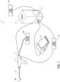
- Fig. 1is a schematic of a powered surgical tool system. Except for the cutting tool, to be described hereafter, the system may be in accordance with the system disclosed in U.S. Patent No. 7,247,161 .
- the powered surgical tool system 1includes a handle 2, a footswitch 4 (with pedal 12), power source 16, fluid (liquid and/or gas) source 22, suction source 28, a controller 6, console 3, fluid pump 5 and a fluid inlet/irrigation outlet 7.
- the handle 2is connected, at its distal end, to a surgical tool 8.
- the surgical tool 8includes a cutting instrument 8a at its distal end that is used to cut, shave, remove, resect and/or abrade tissue, bone and/or other bodily materials.
- Fig. 2illustrates a perspective view of an exemplary embodiment of the surgical tool 8, in accordance with aspects of the invention.
- the tool 8incorporates an inner tube 9, an outer tube 10 and a rigid sheath 11.
- an inner tube hub 13is formed on the second end 14 of the inner tube 9 and an outer tube hub 15 is formed on the second end 17 of the outer tube 10.
- the inner tube 9is inserted into a fluid passage 20 ( Fig. 3A ) formed within the outer tube 10 so that the inner tube 9 is co-axially disposed within the outer tube 10 until the top portion 19 of the inner tube hub 13 contacts or nearly contacts the bottom portion 18 of the outer tube hub 15.
- the outer tube 10has a larger diameter than the inner tube 9, thus allowing for insertion of the inner tube 9 within the outer tube 10.
- the inner and outer tubeswill be pre-assembled prior to delivery to the customer. Thus, a customer will most likely not be inserting the inner tube into the outer tube. Instead, the customer will merely be attaching and detaching the rigid sheath from the main unit.
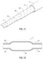
- Fig. 12illustrates a cross-sectional view of the rigid sheath 11.
- the rigid sheath 11includes a first tapered portion 53, a second tapered portion 54, and an untapered portion 55.
- the first tapered portion 53extends from the first end 41 of the rigid sheath 11 for a first tapered distance 56 along the rigid sheath 11.
- the second tapered portion 54extends from the second end 42 of the rigid sheath 11 for a second tapered distance 57 along the rigid sheath 11.
- the untapered portion 55extends between the first tapered portion 53 and the second tapered portion 54.
- the untapered portionhas a larger diameter than the first tapered portion 53 and second tapered portion 54.
- the larger diameter of the portion 55makes it easier to push the main unit (tubes 9 and 10) through the sheath 11, especially when the sheath 11 includes one or more curves.
- the tapered portions 53, 54help prevent vibration between the rigid sheath 11 and the tubes (inner 9 and outer 10).
- the diameter of the larger-diameter untapered portion 55depends on a length of the rigid cutting portion at the distal end of the outer tube 10. However, in a straight rigid sheath 11, for example, the entire rigid sheath 11 may include only a small diameter like the tapered portions 53 and 54.
- the inner tube 9, inner tube hub 13, outer tube 10 and outer tube hub 15form a main unit 21 ( Fig. 7 ).
- the inner and outer tube hubs 13, 15couple the inner and outer tubes 9, 10, respectively, to the handle 2 such that the inner and outer tubes 9, 10 are rotatable relative to one another and the handle 2.
- Fig. 3illustrates a cross-sectional view of the surgical tool 8 with the inner tube 9 co-axially disposed within the fluid passage 20 of the outer tube 10.
- Fig. 3Ais an enlarged view of the distal end of the tool.
- the inner tube 9includes a fluid/bodily materials removal passage 23 that extends the length of the inner tube 9.
- the inner tube 9also includes a cutting surface 26 at its first end 24 while the outer tube includes a cutting window 27 at its first end 25.
- the inner tube 9is co-axially disposed within the outer tube 10 such that the cutting surface 26 is exposed at the cutting window 27.
- the cutting surface 26 disposed within the cutting window 27form a cutting instrument 8a, which cuts by rotating the inner tube 9 within the outer tube 10.
- a spring 29is disposed on the interior of the outer tube hub 15 and on the exterior of the outer tube 10.
- the spring 29allows for movement of a compliance portion 31 of the outer tube 10.
- the compliance portion 31is disposed around the circumference of the outer tube 10 and fixed thereto. When pressure is applied to the compliance portion 31 along an axial direction 30, the compliance portion 31 is depressed within an acceptance portion 32 of the outer tube hub 15 via compression movement of the spring 29 to a compressed position (not shown).
- the movement of the compliance portion 31allows for ease of connection of the rigid sheath 11 to the outer tube 10. When pressure is removed from the compliance portion 31 and the rigid sheath 11 is not attached, the compliance portion 31 returns to its original position (i.e., uncompressed position).
- the compliance portion 31In the uncompressed position, the compliance portion 31 is disposed on an exterior side 33 of the acceptance portion 32 and the spring 29 is uncompressed.
- the compliance structure 31When pressure is removed from the compliance portion 31 and the rigid sheath 11 is attached, the compliance structure 31 is in a semi-compressed position such that a portion of the compliance structure 31 remains within the acceptance portion 32, as illustrated in Fig. 5C .
- the spring 29can be disposed on the exterior of the outer tube hub 15.
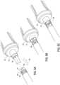
- Figs. 4A-Cillustrate perspective views of the inner tube 9 ( Fig. 4A ) removed from being disposed within the outer tube 10 ( Fig. 4B ), and the rigid sheath 11 ( Fig. 4C ) removed from being disposed around the outer tube 10.
- the inner tube 9includes at least one flexible portion 34 and a rigid portion 36.
- the rigid portion 36may include at least a portion of the inner tube 9 including the cutting surface 26 at the first end 24 of the inner tube and may also include a portion of the inner tube 9 near the second end 14 of the inner tube 9.
- the circumferential flexible portion 34 of the inner tube 9is located near the first end 24 of the inner tube 9 and extends for a distance along the length of the inner tube 9, as illustrated in Fig. 4A .
- the flexible portion 34 of the inner tube 9can be located along any portion or the entire length of the inner tube 9. Additionally, the flexible portion 34 of the inner tube 9 can be located at multiple, different locations along the inner tube 9.
- the outer tubeincludes at least one flexible portion 35 and the rigid portion 37.
- the rigid portion 37may include at least a portion of the outer tube 10 including the cutting window 27 at the first end 25 of the outer tube and may also include a portion of the outer tube 10 near the second end 17 of the outer tube 10.
- the circumferential flexible portion 35 of the outer tube 10is located near the first end 25 of the outer tube 10 and extends for a distance along the length of the outer tube 10, as shown in Fig. 4B .
- the inventionis not limited to the configuration of the exemplary embodiment of Fig. 4B .
- the flexible portion 35 of the outer tube 10can be located along any portion or the entire length of the outer tube 10. Additionally, the flexible portion 35 of the outer tube 10 can be located at multiple, different locations along the outer tube 10.
- the flexible portion 35 of the outer tube 10can encompass a greater portion of the outer tube 10 than the flexible portion 34 of the inner tube 9 or, in the alternative, the flexible portion 34 of the inner tube 9 can encompass a greater portion of the inner tube 9 than the flexible portion 35 of the outer tube 10.
- the flexible portion 35 of the outer tube 10starts at a position close to the cutting window 27 and extends for a distance
- the flexible portion 34 of the inner tube 9starts at a position close to the cutting surface 26 and extends for a distance.
- the flexible portions 34, 35are radially, symmetrically bendable about a longitudinal axis 40 of the main unit 21 ( Figs. 3 and 7 ). That is, the flexible portions 34, 35 can be bend in any direction (up, down, left, right, and all directions in between). However, in one embodiment, for example, the flexible portions 34, 35 assume a substantially straight orientation when the main unit 21 is not inserted into the rigid sheath 11 ( Fig. 7 ). In accordance with some embodiments, the flexible portions 34, 35 with the rigid portions 36, 37 can be formed in a one- or two-piece configuration. However, the flexible portions 34, 35 are not limited to these configurations and other configurations of the flexible portions 34, 35 are possible.
- the inner and outer tubes 9, 10are formed of a rigid material.
- the flexible portions 34, 35are formed on the inner and outer tubes 9, 10 by laser cutting pieces of the rigid material of the tubes 9, 10 to form openings therein.
- the tubes 9, 10 including the openingsare then wrapped with a layer of pliable material in order hold the inner and outer tubes, respectively, together.
- One such example of flexible portionscan be found in U.S. Patent No. 5,707,350.
- the rigid portions of the inner and outer tubes 9, 10are formed of a rigid material.
- the flexible portions 34, 35are formed separately from the rigid portions of the inner and outer tubes 9, 10.
- a first thin strip of metalis formed into a coil.
- a second thin strip of metalis formed into a coil around the first thin strip of metal.
- the second thin strip of metalis coiled around the first thin strip of metal in a direction opposite that of the first thin strip of metal.
- a third thin strip of metalcan be formed into a coil around the first and second thin strips of metal.
- the third thin strip of metalis coiled around the first and second thin strips of metal in a direction opposite that of the second thin strip of metal.
- the rigid portions of the inner and outer tubescan be attached to the flexible portion, for example, by spot welding.
- One such example of flexible portionscan be found in U.S. Patent No. 4,646,738 .
- Fig. 11illustrates the configuration of the exemplary embodiment. In this two-piece configuration, the first thin strip 10a, second thin strip 10b and third thin strip 10c make up the flexible portion 35 of the outer tube 10.
- the inner tube 9can be formed in the same manner as the outer tube so as to have a first thin strip, second thin strip and third thin strip (not shown) but could be formed from less strips such as one thin strip or from more strips.
- a first connector portion 38is fixed to the outer tube 10, closer to the second end 17 of the outer tube 10 than the flexible portion 35, and a second connector portion 39 is formed on a second end 42 of the rigid sheath 11.
- the second connector portion 39includes a plurality of individually selectable engagement members 39a-39d ( Fig. 10 ) and the first connector portion 38 is an engaging member that can be selectively engaged in one of the engagement members 39a-39d.
- the engaging membercan be a protruding key and the engagement members 39a-d can be a plurality of slots; however, the invention is not limited to a key and slot arrangement and can employ any configuration of an engaging member and engagement members while still allowing for the selective and rotationally adjustable coupling of the rigid sheath 11 to the main unit 21.
- the engagement of the engaging member 38 with one of the engagement members 39a-ddetachably couples the rigid sheath 11 to the main unit 21 such that the outer tube 10 cannot rotate relative to the rigid sheath 11.
- the main unit 21can be completely removed from the rigid sheath 11.
- the placement of the first connector portion 38 and second connector portion 39is not limited to the embodiment described above and illustrated herein.
- the first connector portioncan include either a plurality of individually selectable engagement members or an engaging member. Additionally, the first connector portion 38 can be located anywhere on the main unit 21 or rigid sheath 11 as long as the rigid sheath 11 is removably attachable to the main unit 21.
- the second connector portion 39can include the other of either a plurality of individually selectable engagement members or an engaging member. Additionally, the second connector portion can be located anywhere on the main unit 21 or rigid sheath 11 as long as the rigid sheath 11 is removably attachable to the main unit 21.
- the inner tube 9is inserted into the fluid passage 20 of the outer tube 10 via the second end 17 of the outer tube 10 until the cutting surface 26 of the inner tube 9 is aligned with the cutting window 27 of the outer tube 10 ( Fig. 7).
- Fig. 7illustrates the substantially straight orientation of the inner and outer tubes 9, 10 when not disposed in the rigid sheath 11.
- the inner and outer tubeswill be pre-assembled prior to delivery to the customer.
- a customerwill most likely not be inserting the inner tube into the outer tube. Instead, the customer will merely be attaching and detaching the rigid sheath from the main unit.
- Figs. 5A-Cillustrate the connection between the engaging member 38 and one of the engagement members 39.
- the main unit 21is inserted into the an opening 44 of the second end 42 of the rigid sheath 11 ( Fig. 5A ) until the cutting window 27 with exposed cutting surface 26 extends beyond an opening 43 of the first end 41 of the rigid sheath 11 ( Figs. 4 and 6A-D ).
- the engaging member 38extends through an opening 46 of the one engagement member 39 for a distance until a base 47 of the rigid sheath 11 contacts the compliance portion 31.
- the rigid sheath 11can be decoupled from the outer tube 10 by applying pressure to the rigid sheath 11 thus forcing the compliance portion 31 to become depressed within the acceptance portion 32 of the outer tube hub 15 via compression movement of the spring 29 to the compressed position (not shown). In this compressed position, the engaging member 38 contacts or nearly contacts the top 48 of the engagement member 39.
- the rigid sheath 11is then rotated in the reverse circumferential direction (reverse of the direction used to couple of the rigid sheath 11 to the outer tube 10) before the compressing force is released thus allowing the compliance portion 31 to return to the uncompressed position and the engaging member 38 to be located in the opening 46 of the engagement member.
- the main unit 21can then be completely removed from the rigid sheath 11.
- the second connector portion 39includes four engagement members 39a-d.
- the four engagement members 39are formed on the rigid sheath 11 in intervals of 90° about the longitudinal axis 40 of the surgical tool.
- the second connector portionis not limited to this configuration.
- the second connector portion 39should include at least one engagement member 39 but is not limited to four engagement members 39.
- the adjustable connection between engaging member 38 and a single or plurality of engagement members 39allows for the orientation of the cutting window 27 relative to the longitudinal axis 40 of the rigid sheath 11 to be radially adjusted.
- Figs. 6A-Dillustrate the adjustment of the orientation of the cutting window 27 relative to the longitudinal axis 40 of the rigid sheath 11 by engagement of the engaging member 38 with each of the four engagement members 39a-d of the exemplary embodiment.
- Fig. 6Aillustrates the engagement of the engaging member 38 with the first engagement member 39a so as to orient the cutting window 27 in an outwardly facing position.
- Fig. 6Billustrates the engagement of the engaging member 38 with the second engagement member 39b so as to orient the cutting window 27 in an upwardly facing position.
- Fig. 6Cillustrates the engagement of the engaging member 38 with the third engagement member 39c so as to orient the cutting window 27 in a downwardly facing position.
- Fig. 6Dillustrates the engagement of the engaging member 38 with the fourth engagement member 39d so as to orient the cutting window 27 in a backwardly facing position.
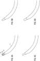
- Fig. 8illustrates an exemplary embodiment of a set or kit of rigid sheaths 1 1a-f having different shapes.
- rigid sheath 11fis straight along its entire length and thus orients the flexible portions 34, 35 of the inner and outer tubes 9, 10, respectively, to have a straight orientation.
- Each of rigid sheaths 11a-einclude a curved portion 50 at least near the first end 41 of the rigid sheath.
- An angle of the curved portioncan be one of 15°, 30°, 40° (not shown), 60°, 75°, and 110°, but is not limited to these angles.
- the rigid sheathorients the flexible portions 34, 35 of the inner and outer tubes 9, 10, respectively, to the angle of the curved portion 50 of the rigid sheath.
- the set of rigid sheathscan be supplied with a single main unit 21. During surgery, the surgeon can selectively use the main unit with one, more than one, or all of the rigid sheaths.
- the surgical tool 8 of the above described embodimentscan be used to perform surgical procedures.
- the surgical tool including the main unit 21 and a first rigid sheath 11fis inserted into a passage 51 of a patient so as to perform surgery using the surgical tool 8.
- the surgical toolis then removed from the passage of the patient 51 ( Fig. 9B ).
- the first rigid sheath 11fis completely removed from the main unit 21, as described above ( Fig. 9C ), and a second rigid sheath 11b is attached to the main unit 21 ( Fig. 9D ).
- the second rigid sheath 11bhas a different shape from the first rigid sheath 11a.
- the surgical tool including the main unit 21 and second rigid sheath 11bis inserted into the passage of the patient 51 so as to perform surgery using the surgical tool 8 having the main unit 21 coupled to the second rigid sheath 11b ( Fig. 9E ).
- the surgeoncan decouple the rigid sheath from the main unit 21, change the orientation of the cutting window to the same rigid sheath (by rotating the rigid sheath relative to the main unit), and then recouple the main unit 21 to the same rigid sheath.
- a surgical tool kitcan be provided to the surgeon.
- the surgical tool kitprovides a plurality of differently shaped sheaths (i.e., sheaths with curved portions of varying angles), as discussed above, and a single main unit 21.
- the surgical tool kitallows for the continued use of the single main unit 21 and the interchangeability of the sheaths so as to orient the inner and outer tubes 9, 10 of the main unit 21 to specific angles without having to completely change the main unit 21.
- the surgical tool kitprovides at least a first rigid sheath 11a having a first end 41a and a second end 42a.
- the first rigid sheath 11acan be removably attached to the main unit 21 such that the cutting window extends beyond an opening 43a of the first end 41a of the first rigid sheath 11a, as disclosed above with respect to the coupling of the rigid sheath 11 to the main unit 21.
- the first rigid sheath 11acan be exchanged for the second rigid sheath 11b.
- the second rigid sheath 11bis then removably attached to the main unit 21 such that the cutting window extends beyond an opening 43b of the first end 41b of the second rigid sheath 11b, as disclosed above with respect to the coupling of the rigid sheath 11 to the main unit 21.
- kit embodimentsmay include sheaths having curved portions of any angle, as well as providing any number of sheath options to choose from.
Landscapes
- Health & Medical Sciences (AREA)
- Life Sciences & Earth Sciences (AREA)
- Surgery (AREA)
- Molecular Biology (AREA)
- General Health & Medical Sciences (AREA)
- Biomedical Technology (AREA)
- Heart & Thoracic Surgery (AREA)
- Medical Informatics (AREA)
- Nuclear Medicine, Radiotherapy & Molecular Imaging (AREA)
- Animal Behavior & Ethology (AREA)
- Engineering & Computer Science (AREA)
- Public Health (AREA)
- Veterinary Medicine (AREA)
- Orthopedic Medicine & Surgery (AREA)
- Dentistry (AREA)
- Oral & Maxillofacial Surgery (AREA)
- Surgical Instruments (AREA)
Description
- This disclosure relates to improved surgical tools, methods of performing surgical procedures with a surgical tool assembly, and to surgical tool kits. In particular, the disclosure relates to such surgical tool assemblies usable to shave, cut, resect, abrade and/or remove tissue, bone and or other bodily materials using rigid sheaths having different shapes.
- Surgical apparatus used to shave, cut, resect, abrade and/or remove tissue, bone and or other bodily materials are known. Such surgical apparatus can include a cutting surface, such as a rotating blade, disposed on an elongated inner tube that is rotated within an elongated outer tube having a cutting window. The inner and outer tubes together forming a surgical cutting blade. In general, the elongated outer tube includes a distal end defining an opening or cutting window that exposes the cutting surface of the inner tube (at the distal end of the inner tube) to tissue, bone and/or any other bodily materials. A powered handpiece is used to rotate the inner tube with respect to the outer tube while an outer tube hub (connected to the proximal end of the outer tube) is rigidly fixed to the handpiece and an inner tube hub (connected to the proximal end of the inner tube) is loosely held in place by the powered handpiece and can move axially.
- During surgery, it may be necessary or helpful to precisely orient a tip of the surgical cutting blade (defining the cutting surface within the cutting window) at a specific angle. Because of this requirement, it is known to provide multiple surgical cutting blades having first ends angled to different fixed degrees. Thus, depending on the needs or requirements of the surgery, a surgeon can switch between multiple different surgical cutting blades multiple times during surgery so as to precisely orient the selected surgical cutting blade in the exact location he/she is trying to reach.
- A number of difficulties have been encountered in attempting to develop reliable flexible-shaft surgical blades that would allow the surgeon to use only one surgical cutting blade, as opposed to changing between different surgical cutting blades having different shapes and/or window orientations based on a newly desired target orientation. For example, surgical cutting blades have been developed that are initially straight and can then be bent to a desired angle. However, the drawback for this design is that once the surgical cutting blade instrument is bent, any rebend of the surgical cutting blade instrument to obtain a different angled configuration is not effective or reliable in allowing for proper rotation of the inner tube. Instead, a new surgical cutting blade must be used if a different angle configuration of the blade is required/desired. Another example involves the use of a lever arm that allows a surgeon to bend the surgical cutting blade instrument to a specific angle and hold the instrument at that angle. However, the drawback for this design is that the lever cannot be locked into place and thus requires the surgeon to continuously apply pressure to the lever in order to hold the instrument in the desired angled orientation. Additionally, typically, the bending of the instrument using the lever is limited to only one direction (typically concave) and is not bi-directional.
US 5282821 A discloses an adjustable surgical instrument in which adjustment of curvature may be provided during the surgical procedure while the instrument is within a body cavity.US 5741286 A discloses a laparoscopic surgical instrument including an actuation handle, a control member, a flexible tube, a rigid tube, and an end effector assembly.US 2004/181250 A1 discloses a surgical elongate blade assembly with an interchangeable inner member such that the interchangeable inner member can be removed from a tubular outer member and inserted into another tubular outer member having a different configuration during a surgical procedure.US 2009/306655 A1 discloses a catheter suitable for medical procedures such as cardiac ablation.US 5529580 A discloses a surgical resecting tool, whereby a cartilage, cartilage knob or tumor within a body cavity is resected from outside the body cavity without being incised and is taken out of the body cavity, is provided with a rigid outer tube removably provided in the front part of a body part which is also a holding part and has a rotary power source. - The invention is defined in independent claim 1 and other embodiments are listed in the dependent claims.
- User preferences, such as those of the surgeons, as well as the demands of surgery dictate limitless requirements for the curvature of a surgical tool and for the orientation of the cutting window of the tool. Accommodating such user preferences and surgery requirements during surgical procedures requires the use of many surgical tools having different angled configurations and/or window orientations. The use of multiple surgical tools can be very costly and requires hospitals/surgeons to come equipped with a large variety of surgical tools so as to accommodate any and all needs that arise during surgery.
- It would be advantageous to provide an arrangement that would allow the surgeon to utilize one surgical cutting tool (or blade) for all surgery requirements. A flexible cutting blade is provided that is selectively connectable to a plurality of rigid sheaths having different shapes. The arrangement allows the surgeon to use one blade for many surgical applications (because the blade can be coupled with a sheath having any desired shape) without having the need to purchase, store and use large quantities of blade inventory to meet the demands of surgery.
- In various exemplary embodiments, a main unit may be provided that allows for the attachment of a rigid sheath. The rigid sheath may advantageously be formed in a straight or angled configuration such that insertion of the main unit into the rigid sheath conforms the main unit to the configuration of the sheath. The main unit allows for such conformation via flexible portions of its inner and outer tubes. These flexible portions conform to any bend of the rigid sheath and thus allow the surgeon to use one main unit at different angles (or in a straight configuration) by attaching different angled sheaths. A first connector portion is located on the main unit and a second connector portion is located on the rigid sheath that allow for the coupling between the main unit and the rigid sheath.
- In accordance with one aspect of the disclosure, a surgical tool may include a main unit having inner and outer tubes, each having first and second ends. The inner tube may include a cutting surface at the first end and a flexible portion located between the first end and the second end. The outer tube may include a cutting window at the first end and a flexible portion located between the first end and the second end. The inner tube is received within the outer tube so as to align the cutting surface of the inner tube with the cutting window of the outer tube. The surgical tool may also include a rigid sheath having a first end and a second end such that the rigid sheath removably receives the main unit allowing the cutting window to extend beyond an opening of the first end of the rigid sheath. The surgical tool further includes a connector having a first connector portion located on the main unit and a second connector portion located on the rigid sheath. The first connector portion, when connected to the second connector portion, detachably couples the rigid sheath to the main unit. The main unit can be completely removed from the rigid sheath when the first and second connector portions are uncoupled from each other.
- In some embodiments, the rigid sheath includes a first tapered portion extending from the first end of the rigid sheath for a first tapered distance along the rigid sheath. In some embodiments, the rigid sheath includes a second tapered portion extending from the second end of the rigid sheath for a second tapered distance along the rigid sheath. Additionally, in some embodiments, a rigid sheath includes an untapered portion extending between the first tapered portion and the second tapered portion, the untapered portion having a larger diameter than the first and second tapered portions.
- In some embodiments, the flexible portion of the inner tube and the flexible portion of the outer tube are radially, symmetrically bendable about a longitudinal, central axis of the surgical tool.
- In some embodiments, the rigid sheath is straight along its entire length.
- In some embodiments, the rigid sheath includes a curved portion at least near the first end of the rigid sheath. In some embodiments, for example, an angle of the curved portion can be one of 15°, 30°, 40°, 60°, 75°, and 110°; however, other angles of the curved portion are possible.
- In some embodiments, the flexible portion of the inner and outer tubes assumes a substantially straight orientation when the main unit is not inserted into the rigid sheath.
- In some embodiments, the first and second connector portions are adjustably connectable to each other such that an orientation of the cutting window relative to a longitudinal axis of the rigid sheath can be radially adjusted.
- In some embodiments, one of the first and second connector portions includes a plurality of individually selectable engagement members, and the other of the first and second connector portions includes an engaging member that is selectively engaged with one of the engagement members to select a desired orientation of the cutting window.
- In some embodiments, for example, there are four of the engagement members to provide for selectable orientation of the cutting window.
- In some embodiments, for example, the four selectable orientations are provided at intervals of 90° about the longitudinal axis of the surgical tool. In some embodiments, the engagement members are provided on the rigid sheath and the engaging member is provided on the main unit.
- In some embodiments, the engaging member is a protruding key, and the engagement members are a plurality of slots.
- In some embodiments, the first connector portion is provided on the outer tube.
- In some embodiments, the flexible portion of the inner tube is located at least near the first end of the inner tube, and the flexible portion of the outer tube is located at least near the first end of the outer tube.
- In some embodiments, the outer tube of the main unit cannot rotate relative to the rigid sheath when the first and second connector portions are coupled to each other.
- In accordance with another aspect of the disclosure, a surgical tool kit includes a main unit, a first rigid sheath and at least one additional rigid sheath. The main unit includes inner and outer tubes having first and second ends. The inner tube includes a cutting surface at the first end and a flexible portion located between the first end and the second end. The outer tube includes a cutting window at the first end and a flexible portion located between the first end and the second end. The inner tube is received within the outer tube so as to align the cutting surface of the inner tube with the cutting window of the outer tube. The first rigid sheath has a first end and a second end and is removably attachable to the main unit such that the cutting window extends beyond an opening of the first end of the first rigid sheath. The at least one additional rigid sheath has a first end and a second end and is removably attachable to the main unit instead of the first rigid sheath such that the cutting window extends beyond an opening of the first end of the at least one additional rigid sheath. The at least one additional rigid sheath has a shape that is different from a shape of the first rigid sheath.
- In some embodiments, the first rigid sheath is straight and the at least one additional rigid sheath has a curved portion at least near the first end thereof.
- In some embodiments, the kit further includes a plurality of the additional rigid sheaths, each having a differently-curved curved portion.
- In some embodiments, the kit further includes a plurality of the additional rigid sheaths, each having a shape that is different from each other and from the shape of the first rigid sheath.
- Various exemplary embodiments of the disclosed surgical tool will be described in detail with reference to the following drawings in which:
Fig. 1 illustrates a perspective view of a powered surgical tool system that incorporates a controller, power source, fluid source and suction source;Fig. 2 is a perspective view of an exemplary embodiment of the main unit in accordance with the present disclosure;Fig. 3B is a cross-sectional view of the surgical tool ofFig. 2 , andFig. 3A is an enlarged view of the curved end of the surgical tool ofFig. 3 ;Figs. 4A-C are simplified, perspective views of the inner tube, outer tube and rigid sheath, separated from any connection with each other;Figs. 5A-C are enlarged, perspective views of the outer tube disconnected from and connected to the rigid sheath, respectively;Figs. 6A-D are simplified, side views of a portion of the surgical tool ofFig. 2 ;Fig. 7 is a perspective view of the orientation of the surgical tool when the inner tube is disposed in the outer tube only (no rigid sheath is provided);Fig. 8 is a simplified, side view of a set (or kit) of sheaths having different curved portions that can be used with the inner and outer tubes ofFig. 7 , for example;Figs. 9A-E are side views of the surgical tool ofFig. 2 during a surgical procedure in which it is deployed in the passage of a patient;Fig. 10 is a simplified, top view of the engagement portions having been cut down the longitudinal axis and laid open, according to an exemplary embodiment;Fig. 11 is an elongated, perspective view of the inner and outer tubes ofFig. 2 ; andFig. 12 is a cross-sectional view of an exemplary embodiment of the rigid sheath.- The following exemplary embodiments are described below with reference to the figures in the context of human surgery, such as ear, nose and throat surgery, and in particular sinus surgery as well as head and neck surgery. The following exemplary embodiments may also be utilized in spinal surgery, orthopedic surgery, and various other surgical applications. All exemplary embodiments of the invention are intended to be used in any applicable field of endeavor.
Fig. 1 is a schematic of a powered surgical tool system. Except for the cutting tool, to be described hereafter, the system may be in accordance with the system disclosed inU.S. Patent No. 7,247,161 . As shown inFig. 1 , the powered surgical tool system 1 includes ahandle 2, a footswitch 4 (with pedal 12),power source 16, fluid (liquid and/or gas)source 22,suction source 28, acontroller 6, console 3,fluid pump 5 and a fluid inlet/irrigation outlet 7. Thehandle 2 is connected, at its distal end, to asurgical tool 8. Thesurgical tool 8 includes a cuttinginstrument 8a at its distal end that is used to cut, shave, remove, resect and/or abrade tissue, bone and/or other bodily materials.Fig. 2 illustrates a perspective view of an exemplary embodiment of thesurgical tool 8, in accordance with aspects of the invention. Thetool 8 incorporates aninner tube 9, anouter tube 10 and arigid sheath 11. In this exemplary embodiment, aninner tube hub 13 is formed on thesecond end 14 of theinner tube 9 and anouter tube hub 15 is formed on thesecond end 17 of theouter tube 10. Theinner tube 9 is inserted into a fluid passage 20 (Fig. 3A ) formed within theouter tube 10 so that theinner tube 9 is co-axially disposed within theouter tube 10 until thetop portion 19 of theinner tube hub 13 contacts or nearly contacts thebottom portion 18 of theouter tube hub 15. Theouter tube 10 has a larger diameter than theinner tube 9, thus allowing for insertion of theinner tube 9 within theouter tube 10. However, it should be appreciated that the inner and outer tubes will be pre-assembled prior to delivery to the customer. Thus, a customer will most likely not be inserting the inner tube into the outer tube. Instead, the customer will merely be attaching and detaching the rigid sheath from the main unit.Fig. 12 illustrates a cross-sectional view of therigid sheath 11. In this exemplary embodiment, therigid sheath 11 includes a first taperedportion 53, a second taperedportion 54, and anuntapered portion 55. The first taperedportion 53 extends from thefirst end 41 of therigid sheath 11 for a first tapereddistance 56 along therigid sheath 11. The second taperedportion 54 extends from thesecond end 42 of therigid sheath 11 for a second tapereddistance 57 along therigid sheath 11. Theuntapered portion 55 extends between the first taperedportion 53 and the second taperedportion 54. The untapered portion has a larger diameter than the first taperedportion 53 and second taperedportion 54. The larger diameter of theportion 55 makes it easier to push the main unit (tubes 9 and 10) through thesheath 11, especially when thesheath 11 includes one or more curves. Thetapered portions rigid sheath 11 and the tubes (inner 9 and outer 10). The diameter of the larger-diameteruntapered portion 55 depends on a length of the rigid cutting portion at the distal end of theouter tube 10. However, in a straightrigid sheath 11, for example, the entirerigid sheath 11 may include only a small diameter like the taperedportions - The
inner tube 9,inner tube hub 13,outer tube 10 andouter tube hub 15 form a main unit 21 (Fig. 7 ). The inner andouter tube hubs outer tubes handle 2 such that the inner andouter tubes handle 2. Fig. 3 illustrates a cross-sectional view of thesurgical tool 8 with theinner tube 9 co-axially disposed within thefluid passage 20 of theouter tube 10.Fig. 3A is an enlarged view of the distal end of the tool. Theinner tube 9 includes a fluid/bodilymaterials removal passage 23 that extends the length of theinner tube 9. Theinner tube 9 also includes a cuttingsurface 26 at itsfirst end 24 while the outer tube includes a cuttingwindow 27 at itsfirst end 25. Theinner tube 9 is co-axially disposed within theouter tube 10 such that the cuttingsurface 26 is exposed at the cuttingwindow 27. The cuttingsurface 26 disposed within the cuttingwindow 27 form acutting instrument 8a, which cuts by rotating theinner tube 9 within theouter tube 10.- In an exemplary embodiment, for example, a
spring 29 is disposed on the interior of theouter tube hub 15 and on the exterior of theouter tube 10. Thespring 29 allows for movement of acompliance portion 31 of theouter tube 10. Thecompliance portion 31 is disposed around the circumference of theouter tube 10 and fixed thereto. When pressure is applied to thecompliance portion 31 along anaxial direction 30, thecompliance portion 31 is depressed within anacceptance portion 32 of theouter tube hub 15 via compression movement of thespring 29 to a compressed position (not shown). The movement of thecompliance portion 31 allows for ease of connection of therigid sheath 11 to theouter tube 10. When pressure is removed from thecompliance portion 31 and therigid sheath 11 is not attached, thecompliance portion 31 returns to its original position (i.e., uncompressed position). In the uncompressed position, thecompliance portion 31 is disposed on anexterior side 33 of theacceptance portion 32 and thespring 29 is uncompressed. When pressure is removed from thecompliance portion 31 and therigid sheath 11 is attached, thecompliance structure 31 is in a semi-compressed position such that a portion of thecompliance structure 31 remains within theacceptance portion 32, as illustrated inFig. 5C . - In another exemplary embodiment, the
spring 29 can be disposed on the exterior of theouter tube hub 15. Figs. 4A-C illustrate perspective views of the inner tube 9 (Fig. 4A ) removed from being disposed within the outer tube 10 (Fig. 4B ), and the rigid sheath 11 (Fig. 4C ) removed from being disposed around theouter tube 10. Theinner tube 9 includes at least oneflexible portion 34 and arigid portion 36. Therigid portion 36 may include at least a portion of theinner tube 9 including the cuttingsurface 26 at thefirst end 24 of the inner tube and may also include a portion of theinner tube 9 near thesecond end 14 of theinner tube 9. The circumferentialflexible portion 34 of theinner tube 9 is located near thefirst end 24 of theinner tube 9 and extends for a distance along the length of theinner tube 9, as illustrated inFig. 4A . However, the invention is not limited to the configuration of the exemplary embodiment ofFig. 4A . Theflexible portion 34 of theinner tube 9 can be located along any portion or the entire length of theinner tube 9. Additionally, theflexible portion 34 of theinner tube 9 can be located at multiple, different locations along theinner tube 9.- The outer tube includes at least one
flexible portion 35 and therigid portion 37. Therigid portion 37 may include at least a portion of theouter tube 10 including the cuttingwindow 27 at thefirst end 25 of the outer tube and may also include a portion of theouter tube 10 near thesecond end 17 of theouter tube 10. The circumferentialflexible portion 35 of theouter tube 10 is located near thefirst end 25 of theouter tube 10 and extends for a distance along the length of theouter tube 10, as shown inFig. 4B . However, the invention is not limited to the configuration of the exemplary embodiment ofFig. 4B . Theflexible portion 35 of theouter tube 10 can be located along any portion or the entire length of theouter tube 10. Additionally, theflexible portion 35 of theouter tube 10 can be located at multiple, different locations along theouter tube 10. - The
flexible portion 35 of theouter tube 10 can encompass a greater portion of theouter tube 10 than theflexible portion 34 of theinner tube 9 or, in the alternative, theflexible portion 34 of theinner tube 9 can encompass a greater portion of theinner tube 9 than theflexible portion 35 of theouter tube 10. In the illustrated embodiment, theflexible portion 35 of theouter tube 10 starts at a position close to the cuttingwindow 27 and extends for a distance, and theflexible portion 34 of theinner tube 9 starts at a position close to the cuttingsurface 26 and extends for a distance. - The
flexible portions longitudinal axis 40 of the main unit 21 (Figs. 3 and7 ). That is, theflexible portions flexible portions main unit 21 is not inserted into the rigid sheath 11 (Fig. 7 ). In accordance with some embodiments, theflexible portions rigid portions flexible portions flexible portions - In the one-piece configuration, the inner and
outer tubes flexible portions outer tubes tubes tubes U.S. Patent No. 5,707,350. - In the two-piece configuration, the rigid portions of the inner and
outer tubes flexible portions outer tubes flexible portions U.S. Patent No. 4,646,738 .Fig. 11 illustrates the configuration of the exemplary embodiment. In this two-piece configuration, the firstthin strip 10a, secondthin strip 10b and thirdthin strip 10c make up theflexible portion 35 of theouter tube 10. Theinner tube 9 can be formed in the same manner as the outer tube so as to have a first thin strip, second thin strip and third thin strip (not shown) but could be formed from less strips such as one thin strip or from more strips. - As illustrated in
Figs. 5A-C , afirst connector portion 38 is fixed to theouter tube 10, closer to thesecond end 17 of theouter tube 10 than theflexible portion 35, and asecond connector portion 39 is formed on asecond end 42 of therigid sheath 11. In the exemplary embodiment, thesecond connector portion 39 includes a plurality of individuallyselectable engagement members 39a-39d (Fig. 10 ) and thefirst connector portion 38 is an engaging member that can be selectively engaged in one of theengagement members 39a-39d. The engaging member can be a protruding key and theengagement members 39a-d can be a plurality of slots; however, the invention is not limited to a key and slot arrangement and can employ any configuration of an engaging member and engagement members while still allowing for the selective and rotationally adjustable coupling of therigid sheath 11 to themain unit 21. The engagement of the engagingmember 38 with one of theengagement members 39a-d detachably couples therigid sheath 11 to themain unit 21 such that theouter tube 10 cannot rotate relative to therigid sheath 11. When the engagingmember 38 is not engaged with one of theengagement members 39a-d, themain unit 21 can be completely removed from therigid sheath 11. - The placement of the
first connector portion 38 andsecond connector portion 39 is not limited to the embodiment described above and illustrated herein. The first connector portion can include either a plurality of individually selectable engagement members or an engaging member. Additionally, thefirst connector portion 38 can be located anywhere on themain unit 21 orrigid sheath 11 as long as therigid sheath 11 is removably attachable to themain unit 21. Thesecond connector portion 39 can include the other of either a plurality of individually selectable engagement members or an engaging member. Additionally, the second connector portion can be located anywhere on themain unit 21 orrigid sheath 11 as long as therigid sheath 11 is removably attachable to themain unit 21. - In order to assemble the surgical tool, the
inner tube 9 is inserted into thefluid passage 20 of theouter tube 10 via thesecond end 17 of theouter tube 10 until the cuttingsurface 26 of theinner tube 9 is aligned with the cuttingwindow 27 of the outer tube 10 (Fig. 7). Fig. 7 illustrates the substantially straight orientation of the inner andouter tubes rigid sheath 11. However, as discussed previously, it should be appreciated that the inner and outer tubes will be pre-assembled prior to delivery to the customer. Thus, a customer will most likely not be inserting the inner tube into the outer tube. Instead, the customer will merely be attaching and detaching the rigid sheath from the main unit. Figs. 5A-C illustrate the connection between the engagingmember 38 and one of theengagement members 39. Themain unit 21 is inserted into the anopening 44 of thesecond end 42 of the rigid sheath 11 (Fig. 5A ) until the cuttingwindow 27 with exposed cuttingsurface 26 extends beyond anopening 43 of thefirst end 41 of the rigid sheath 11 (Figs. 4 and6A-D ). The engagingmember 38 extends through anopening 46 of the oneengagement member 39 for a distance until abase 47 of therigid sheath 11 contacts thecompliance portion 31. Pressure is then applied to therigid sheath 11 forcing movement of thecompliance portion 31 in anaxial direction 30 so that thecompliance portion 31 is depressed within theacceptance portion 32 of theouter tube hub 15 via compression movement of thespring 29 to the compressed position (Fig. 5B ). In this compressed position, the engagingmember 38 contacts or nearly contacts the top 48 of theengagement member 39. Therigid sheath 11 is then rotated in the circumferential direction for a distance before the compressing force is released thus allowing thecompliance portion 31 to move to a semi-compressed position and the engagingmember 38 to contact thelock portion 49 of theengagement member 39. In this position, therigid sheath 11 is temporarily fixed/coupled to theouter tube 10 of the main unit 21 (Fig. 5C ).- The
rigid sheath 11 can be decoupled from theouter tube 10 by applying pressure to therigid sheath 11 thus forcing thecompliance portion 31 to become depressed within theacceptance portion 32 of theouter tube hub 15 via compression movement of thespring 29 to the compressed position (not shown). In this compressed position, the engagingmember 38 contacts or nearly contacts the top 48 of theengagement member 39. Therigid sheath 11 is then rotated in the reverse circumferential direction (reverse of the direction used to couple of therigid sheath 11 to the outer tube 10) before the compressing force is released thus allowing thecompliance portion 31 to return to the uncompressed position and the engagingmember 38 to be located in theopening 46 of the engagement member. Themain unit 21 can then be completely removed from therigid sheath 11. - In the exemplary embodiment of
Fig. 10 , thesecond connector portion 39 includes fourengagement members 39a-d. The fourengagement members 39 are formed on therigid sheath 11 in intervals of 90° about thelongitudinal axis 40 of the surgical tool. However, the second connector portion is not limited to this configuration. At a minimum, thesecond connector portion 39 should include at least oneengagement member 39 but is not limited to fourengagement members 39. The adjustable connection between engagingmember 38 and a single or plurality ofengagement members 39 allows for the orientation of the cuttingwindow 27 relative to thelongitudinal axis 40 of therigid sheath 11 to be radially adjusted. Figs. 6A-D illustrate the adjustment of the orientation of the cuttingwindow 27 relative to thelongitudinal axis 40 of therigid sheath 11 by engagement of the engagingmember 38 with each of the fourengagement members 39a-d of the exemplary embodiment.Fig. 6A illustrates the engagement of the engagingmember 38 with thefirst engagement member 39a so as to orient the cuttingwindow 27 in an outwardly facing position.Fig. 6B illustrates the engagement of the engagingmember 38 with thesecond engagement member 39b so as to orient the cuttingwindow 27 in an upwardly facing position.Fig. 6C illustrates the engagement of the engagingmember 38 with thethird engagement member 39c so as to orient the cuttingwindow 27 in a downwardly facing position.Fig. 6D illustrates the engagement of the engagingmember 38 with thefourth engagement member 39d so as to orient the cuttingwindow 27 in a backwardly facing position.Fig. 8 illustrates an exemplary embodiment of a set or kit of rigid sheaths 1 1a-f having different shapes. For example,rigid sheath 11f is straight along its entire length and thus orients theflexible portions outer tubes rigid sheaths 11a-e include acurved portion 50 at least near thefirst end 41 of the rigid sheath. An angle of the curved portion can be one of 15°, 30°, 40° (not shown), 60°, 75°, and 110°, but is not limited to these angles. Thus, the rigid sheath orients theflexible portions outer tubes curved portion 50 of the rigid sheath. The set of rigid sheaths can be supplied with a singlemain unit 21. During surgery, the surgeon can selectively use the main unit with one, more than one, or all of the rigid sheaths.- The
surgical tool 8 of the above described embodiments can be used to perform surgical procedures. As illustrated inFig. 9A , the surgical tool including themain unit 21 and a firstrigid sheath 11f is inserted into apassage 51 of a patient so as to perform surgery using thesurgical tool 8. The surgical tool is then removed from the passage of the patient 51 (Fig. 9B ). The firstrigid sheath 11f is completely removed from themain unit 21, as described above (Fig. 9C ), and a secondrigid sheath 11b is attached to the main unit 21 (Fig. 9D ). The secondrigid sheath 11b has a different shape from the firstrigid sheath 11a. The surgical tool including themain unit 21 and secondrigid sheath 11b is inserted into the passage of the patient 51 so as to perform surgery using thesurgical tool 8 having themain unit 21 coupled to the secondrigid sheath 11b (Fig. 9E ). In addition to replacing one rigid sheath with another, the surgeon can decouple the rigid sheath from themain unit 21, change the orientation of the cutting window to the same rigid sheath (by rotating the rigid sheath relative to the main unit), and then recouple themain unit 21 to the same rigid sheath. - As noted above, a surgical tool kit can be provided to the surgeon. The surgical tool kit provides a plurality of differently shaped sheaths (i.e., sheaths with curved portions of varying angles), as discussed above, and a single
main unit 21. The surgical tool kit allows for the continued use of the singlemain unit 21 and the interchangeability of the sheaths so as to orient the inner andouter tubes main unit 21 to specific angles without having to completely change themain unit 21. The surgical tool kit provides at least a firstrigid sheath 11a having afirst end 41a and asecond end 42a. The firstrigid sheath 11a can be removably attached to themain unit 21 such that the cutting window extends beyond anopening 43a of thefirst end 41a of the firstrigid sheath 11a, as disclosed above with respect to the coupling of therigid sheath 11 to themain unit 21. The firstrigid sheath 11a can be exchanged for the secondrigid sheath 11b. The secondrigid sheath 11b is then removably attached to themain unit 21 such that the cutting window extends beyond anopening 43b of thefirst end 41b of the secondrigid sheath 11b, as disclosed above with respect to the coupling of therigid sheath 11 to themain unit 21. Various kit embodiments may include sheaths having curved portions of any angle, as well as providing any number of sheath options to choose from. - The invention is defined solely by the appended claims.
Claims (13)
- A rigid sheath (11) of a surgical tool (8), the surgical tool comprising a main unit (21) comprising an inner tube (9) and an outer tube (10), the rigid sheath being configured to removably receive the main unit, and the rigid sheath comprising:a first opening end (41);a second opening end (42) facing in a direction of a central longitudinal axis (40) of the rigid sheath; anda connector portion (39) located adjacent to the second opening end, the connector portion being connectable to a second connector portion (38) located on the outer tube of the main unit of the surgical tool, the connector portion being configured to detachably couple the rigid sheath to the outer tube of the main unit when connected to the second connector portion such that the rigid sheath and the outer tube cannot rotate relative to each other.
- The rigid sheath (11) of claim 1, wherein the connector portion (39) includes a plurality of individually selectable engagement members (39a-d) that are selectively engageable with an engaging member (38) located on the outer tube (10) of the surgical tool (8).
- The rigid sheath (11) of claim 2, wherein the engagement members (39a-d) are a plurality of slots.
- The rigid sheath (11) of claim 2 or 3, wherein the engaging member (38) is a protruding key.
- The rigid sheath (11) of any of claims 1-4, wherein the rigid sheath is straight along its entire length.
- The rigid sheath (11) of any of claims 1-4, wherein the rigid sheath includes a curved portion.
- The rigid sheath (11) of any of claims 1-6, wherein the rigid sheath is surgically sterile.
- The rigid sheath (11) of any of claims 1-7, further including a first tapered portion (53) extending a first distance from the first opening end (41), the first tapered portion having a diameter smaller than a diameter of a central portion (55) of the rigid sheath.
- The rigid sheath (11) of claim 8, further including a second tapered portion (54) extending a second distance from the second opening end (42), the second tapered portion having a diameter smaller than the diameter of the central portion (55) of the rigid sheath.
- The rigid sheath (11) of claim 9, further including an untapered portion (55) extending between the first (53) and second (54) tapered portions and having a diameter larger than the diameters of the first and second tapered portions.
- The rigid sheath (11) of any of claims 1-10, wherein the connector portion (39) is configured to be connected to the second connector portion (38) on the outer tube by moving the rigid sheath axially over the outer tube (10) until the second connector portion extends through an opening in the connector portion, and then rotating the rigid sheath in a circumferential direction for a distance to connect the connector portion and the second connector portion.
- The rigid sheath (11) of any one of claims 1-11, wherein the connector portion (39) is adjustably connectable to the second connector portion (38) on the outer tube (10) such than an orientation of a cutting window (27) of the outer tube (10) relative to the central longitudinal axis (40) of the rigid sheath can be radially adjusted.
- The rigid sheath (11) of claim 2, wherein the plurality of individually selectable engagement members (39a-d) are selectively engageable with the engaging member (38) located on the outer tube (10) to select a desired radial orientation of the cutting window (27).
Applications Claiming Priority (3)
| Application Number | Priority Date | Filing Date | Title |
|---|---|---|---|
| US12/938,786US9308013B2 (en) | 2010-11-03 | 2010-11-03 | Surgical tool with sheath |
| PCT/US2011/054562WO2012060959A2 (en) | 2010-11-03 | 2011-10-03 | Surgical tool with sheath |
| EP11773602.5AEP2635204B1 (en) | 2010-11-03 | 2011-10-03 | Surgical tool with sheath |
Related Parent Applications (2)
| Application Number | Title | Priority Date | Filing Date |
|---|---|---|---|
| EP11773602.5ADivisionEP2635204B1 (en) | 2010-11-03 | 2011-10-03 | Surgical tool with sheath |
| EP11773602.5ADivision-IntoEP2635204B1 (en) | 2010-11-03 | 2011-10-03 | Surgical tool with sheath |
Publications (2)
| Publication Number | Publication Date |
|---|---|
| EP3721821A1 EP3721821A1 (en) | 2020-10-14 |
| EP3721821B1true EP3721821B1 (en) | 2023-12-06 |
Family
ID=44863225
Family Applications (2)
| Application Number | Title | Priority Date | Filing Date |
|---|---|---|---|
| EP20178117.6AActiveEP3721821B1 (en) | 2010-11-03 | 2011-10-03 | Surgical tool with sheath |
| EP11773602.5AActiveEP2635204B1 (en) | 2010-11-03 | 2011-10-03 | Surgical tool with sheath |
Family Applications After (1)
| Application Number | Title | Priority Date | Filing Date |
|---|---|---|---|
| EP11773602.5AActiveEP2635204B1 (en) | 2010-11-03 | 2011-10-03 | Surgical tool with sheath |
Country Status (6)
| Country | Link |
|---|---|
| US (3) | US9308013B2 (en) |
| EP (2) | EP3721821B1 (en) |
| JP (2) | JP5793736B2 (en) |
| CN (2) | CN103200885B (en) |
| AU (1) | AU2011323989B2 (en) |
| WO (1) | WO2012060959A2 (en) |
Families Citing this family (38)
| Publication number | Priority date | Publication date | Assignee | Title |
|---|---|---|---|---|
| US9198685B2 (en) | 2011-08-24 | 2015-12-01 | Gyrus Ent, L.L.C. | Surgical instrument with malleable tubing |
| US8882680B2 (en) | 2011-12-02 | 2014-11-11 | Interscope, Inc. | Insertable endoscopic instrument for tissue removal |
| US9204868B2 (en) | 2011-12-02 | 2015-12-08 | Interscope, Inc. | Methods and apparatus for removing material from within a mammalian cavity using an insertable endoscopic instrument |
| US11076840B2 (en) | 2011-12-02 | 2021-08-03 | Interscope, Inc. | Surgical console, specimen receiver, and insertable endoscopic instrument for tissue removal |
| US9808146B2 (en) | 2011-12-02 | 2017-11-07 | Interscope, Inc. | Endoscopic tool for debriding and removing polyps |
| US9033895B2 (en)* | 2011-12-02 | 2015-05-19 | Interscope, Inc. | Endoscope including an torque generation component or torque delivery component disposed within an insertable portion of the endoscope and a surgical cutting assembly insertable within the endoscope |
| US9028424B2 (en) | 2011-12-02 | 2015-05-12 | Interscope, Inc. | Endoscope including a torque generation component or torque delivery component disposed within an insertable portion of the endoscope and a surgical cutting assembly insertable within the endoscope |
| US9033864B2 (en) | 2011-12-02 | 2015-05-19 | Interscope, Inc. | Endoscope including a torque generation component or torque delivery component disposed within an insertable portion of the endoscope and a surgical cutting assembly insertable within the endoscope |
| USD855802S1 (en) | 2011-12-23 | 2019-08-06 | Interscope, Inc. | Disposable tool |
| US9232958B2 (en) | 2012-05-16 | 2016-01-12 | Smith & Nephew, Inc. | Reusable blade hub assembly |
| US9226792B2 (en) | 2012-06-12 | 2016-01-05 | Medtronic Advanced Energy Llc | Debridement device and method |
| US8956355B2 (en) | 2012-11-30 | 2015-02-17 | Gyrus Acmi, Inc. | Integrated blade assembly and identification circuit |
| CN103919594B (en)* | 2013-01-14 | 2016-09-14 | 林士闳 | Vertebral Reamer |
| EP3513747A1 (en)* | 2013-05-17 | 2019-07-24 | Interscope, Inc. | Insertable endoscopic instrument for tissue removal |
| EP3057517B1 (en) | 2013-10-15 | 2020-04-08 | Stryker Corporation | Device for creating a void space in a living tissue, the device including a handle with a control knob that can be set regardless of the orientation of the handle |
| US10178998B2 (en) | 2013-11-29 | 2019-01-15 | Chongqing Xishan Science & Technology Co., Ltd. | Lateral grinding drill with continuously variable angle and driving component thereof |
| CN103767759B (en)* | 2014-01-28 | 2015-04-15 | 重庆西山科技有限公司 | Medical grinding cutter |
| WO2015161061A1 (en) | 2014-04-17 | 2015-10-22 | Stryker Corporation | Surgical tool with selectively bendable shaft that resists buckling |
| US10070882B2 (en) | 2014-08-20 | 2018-09-11 | Gyrus Acmi, Inc. | Apparatus and method for cutting tissue |
| US10376302B2 (en) | 2015-02-18 | 2019-08-13 | Medtronic Xomed, Inc. | Rotating electrical connector for RF energy enabled tissue debridement device |
| AU2016219980B2 (en) | 2015-02-18 | 2020-09-03 | Medtronic Xomed, Inc. | RF energy enabled tissue debridement device |
| US10188456B2 (en) | 2015-02-18 | 2019-01-29 | Medtronic Xomed, Inc. | Electrode assembly for RF energy enabled tissue debridement device |
| US10206706B2 (en) | 2015-05-29 | 2019-02-19 | Medtronic Xomed, Inc. | Inner tubular member for angled rotary surgical instrument |
| CN105534573B (en)* | 2015-12-15 | 2019-03-05 | 宁波华科润生物科技有限公司 | A kind of medical adjustable bending tissue removal instrument |
| US10390814B2 (en)* | 2016-04-20 | 2019-08-27 | Medos International Sarl | Meniscal repair devices, systems, and methods |
| EP3721820B1 (en) | 2016-07-14 | 2022-01-19 | Stryker European Operations Holdings LLC | Cutting assembly for a surgical instrument having a drive assembly |
| WO2018086135A1 (en)* | 2016-11-14 | 2018-05-17 | 惠州科赛医疗有限公司 | Medical tool bit structure, medical water jet instrument and molding method therefor |
| IT201600116509A1 (en)* | 2016-11-17 | 2018-05-17 | Medacta Int Sa | GUIDE FOR INTRAMIDOLLAR REAMER |
| JP6901582B2 (en)* | 2017-02-22 | 2021-07-14 | ジャイラス エーシーエムアイ インク | Improved covered flexible needle assembly |
| US10874406B2 (en)* | 2017-02-28 | 2020-12-29 | MFr Technologies, Inc. | Handheld surgical instrument |
| CN109602479B (en)* | 2018-11-07 | 2020-03-10 | 海南科技职业学院 | Rigid sheath for surgical tools |
| US11849986B2 (en) | 2019-04-24 | 2023-12-26 | Stryker Corporation | Systems and methods for off-axis augmentation of a vertebral body |
| CN110403665B (en)* | 2019-08-12 | 2020-11-10 | 无锡市太湖医院 | Operation tool for cartilage injury |
| US20210093836A1 (en)* | 2019-09-30 | 2021-04-01 | Abiomed, Inc. | Collapsible catheter |
| US11723638B2 (en) | 2019-10-04 | 2023-08-15 | Gyrus Acmi, Inc. | Curved blade flex wrap with seal lining |
| USD956222S1 (en) | 2020-08-21 | 2022-06-28 | Stryker European Operations Limited | Surgical bur assembly |
| US12390242B2 (en) | 2021-01-08 | 2025-08-19 | Gyrus Acmi, Inc. | Method to improve cutting performance of a malleable blade |
| US20240115285A1 (en)* | 2022-10-06 | 2024-04-11 | Arthrex, Inc. | Automatic surgical shaver window lock system and method |
Family Cites Families (54)
| Publication number | Priority date | Publication date | Assignee | Title |
|---|---|---|---|---|
| US3844272A (en)* | 1969-02-14 | 1974-10-29 | A Banko | Surgical instruments |
| US4674500A (en) | 1985-09-27 | 1987-06-23 | Minnesota Mining And Manufacturing Company | Sheathed knife instrument |
| US4646738A (en) | 1985-12-05 | 1987-03-03 | Concept, Inc. | Rotary surgical tool |
| US5529580A (en)* | 1987-10-30 | 1996-06-25 | Olympus Optical Co., Ltd. | Surgical resecting tool |
| US5152744A (en) | 1990-02-07 | 1992-10-06 | Smith & Nephew Dyonics | Surgical instrument |
| EP0481760B1 (en)* | 1990-10-19 | 1998-05-27 | Smith & Nephew, Inc. | Surgical device |
| US5192292A (en) | 1990-11-02 | 1993-03-09 | Stryker Corporation | Surgical apparatus useable for arthroscopic surgery |
| US5282821A (en) | 1993-01-26 | 1994-02-01 | Donahue John R | Adjustable surgical instrument |
| US5833692A (en)* | 1993-01-29 | 1998-11-10 | Smith & Nephew, Inc. | Surgical instrument |
| US5346502A (en)* | 1993-04-15 | 1994-09-13 | Ultracision, Inc. | Laparoscopic ultrasonic surgical instrument and methods for manufacturing the instruments |
| US5364395A (en)* | 1993-05-14 | 1994-11-15 | West Jr Hugh S | Arthroscopic surgical instrument with cauterizing capability |
| US5601583A (en)* | 1995-02-15 | 1997-02-11 | Smith & Nephew Endoscopy Inc. | Surgical instrument |
| US5741084A (en)* | 1995-03-27 | 1998-04-21 | Del Rio; Eddy H. | Wear compensating axial connection |
| US5741286A (en) | 1996-06-07 | 1998-04-21 | Symbiosis Corporation | Laparoscopic instrument kit including a plurality of rigid tubes |
| DE69734845T2 (en) | 1996-09-24 | 2006-09-14 | Xomed Surgical Products, Inc., North Jacksonville | Assembly of surgical blades |
| US5741287A (en)* | 1996-11-01 | 1998-04-21 | Femrx, Inc. | Surgical tubular cutter having a tapering cutting chamber |
| US5810809A (en)* | 1997-01-13 | 1998-09-22 | Enhanced Orthopaedic Technologies, Inc. | Arthroscopic shaver incorporating electrocautery |
| US5989275A (en)* | 1997-02-28 | 1999-11-23 | Ethicon Endo-Surgery, Inc. | Damping ultrasonic transmission components |
| US6206844B1 (en)* | 1997-02-28 | 2001-03-27 | Ethicon Endo-Surgery, Inc. | Reusable ultrasonic surgical instrument with removable outer sheath |
| WO1998049953A1 (en) | 1997-05-09 | 1998-11-12 | Xomed Surgical Products, Inc. | Angled rotary tissue cutting instrument |
| EP1017451A1 (en)* | 1997-09-24 | 2000-07-12 | United States Surgical Corporation | Devices and methods for performing transmyocardial revascularization |
| US5924206A (en) | 1997-09-30 | 1999-07-20 | Becton, Dickinson And Company | Reusable device handle |
| US6024749A (en) | 1997-10-27 | 2000-02-15 | Shturman Cardiology Systems, Inc. | Rotational atherectomy device with improved exchangeable drive shaft cartridge |
| US5911701A (en) | 1998-01-29 | 1999-06-15 | Sdgi Holidings, Inc. | Surgical cutting instrument |
| US6464711B1 (en) | 1999-03-19 | 2002-10-15 | Medtronic Xomed, Inc. | Articulating mechanism for steerable surgical cutting instruments |
| US6533749B1 (en) | 1999-09-24 | 2003-03-18 | Medtronic Xomed, Inc. | Angled rotary tissue cutting instrument with flexible inner member |
| US6325811B1 (en)* | 1999-10-05 | 2001-12-04 | Ethicon Endo-Surgery, Inc. | Blades with functional balance asymmetries for use with ultrasonic surgical instruments |
| JP2003235856A (en)* | 2002-02-15 | 2003-08-26 | Olympus Optical Co Ltd | Surgical treatment instrument |
| US7247161B2 (en)* | 2002-03-22 | 2007-07-24 | Gyrus Ent L.L.C. | Powered surgical apparatus, method of manufacturing powered surgical apparatus, and method of using powered surgical apparatus |
| CA2493356A1 (en)* | 2002-07-13 | 2004-01-22 | Stryker Corporation | System and method for performing irrigated nose and throat surgery |
| CA2516321A1 (en)* | 2003-02-20 | 2004-09-02 | Kenneth M. Adams | Surgical elongate blade assembly with interchangeable inner member, kit and method relating thereto |
| US7785337B2 (en)* | 2003-09-09 | 2010-08-31 | Medtronic Xomed, Inc. | Surgical micro-burring instrument and method of performing sinus surgery |
| US7276074B2 (en) | 2004-01-21 | 2007-10-02 | Medtronic Xomed, Inc. | Angled tissue cutting instrument having variably positionable cutting window, indexing tool for use therewith and method of variably positioning a cutting window of an angled tissue cutting instrument |
| US8277474B2 (en)* | 2004-05-26 | 2012-10-02 | Medtronic, Inc. | Surgical cutting instrument |
| US7947034B2 (en) | 2004-07-30 | 2011-05-24 | Tyco Healthcare Group Lp | Flexible shaft extender and method of using same |
| US7226460B2 (en)* | 2004-08-02 | 2007-06-05 | Karl Storz Endovision, Inc. | Surgical instrument attachment system |
| US9326756B2 (en)* | 2006-05-17 | 2016-05-03 | St. Jude Medical, Atrial Fibrillation Division, Inc. | Transseptal catheterization assembly and methods |
| US8062230B1 (en)* | 2004-10-14 | 2011-11-22 | Suros Surgical Systems, Inc. | Surgical site marker delivery system |
| US20060122640A1 (en)* | 2004-12-02 | 2006-06-08 | Gordon Jeremy R | Surgical tool arrangement |
| US7699846B2 (en)* | 2005-03-04 | 2010-04-20 | Gyrus Ent L.L.C. | Surgical instrument and method |
| US9504521B2 (en)* | 2005-03-17 | 2016-11-29 | Stryker Corporation | Surgical tool arrangement |
| US20070162062A1 (en)* | 2005-12-08 | 2007-07-12 | Norton Britt K | Reciprocating apparatus and methods for removal of intervertebral disc tissues |
| US20080021278A1 (en) | 2006-07-24 | 2008-01-24 | Leonard Robert F | Surgical device with removable end effector |
| US8529565B2 (en)* | 2007-01-15 | 2013-09-10 | Olympus Medical Systems Corp. | Ultrasonic operating apparatus |
| US8142461B2 (en)* | 2007-03-22 | 2012-03-27 | Ethicon Endo-Surgery, Inc. | Surgical instruments |
| US8226675B2 (en)* | 2007-03-22 | 2012-07-24 | Ethicon Endo-Surgery, Inc. | Surgical instruments |
| JP4956268B2 (en) | 2007-05-10 | 2012-06-20 | 本田技研工業株式会社 | Car body rear structure |
| US8252012B2 (en)* | 2007-07-31 | 2012-08-28 | Ethicon Endo-Surgery, Inc. | Ultrasonic surgical instrument with modulator |
| DE102008015418A1 (en)* | 2008-03-20 | 2009-09-24 | Richard Wolf Gmbh | Medical instrument |
| US8206385B2 (en)* | 2008-06-09 | 2012-06-26 | St. Jude Medical, Atrial Fibrillation Division, Inc. | Catheter assembly with front-loaded tip and multi-contact connector |
| US8979744B2 (en)* | 2008-09-08 | 2015-03-17 | Covidien Lp | Tunneling system |
| US8968210B2 (en)* | 2008-10-01 | 2015-03-03 | Covidien LLP | Device for needle biopsy with integrated needle protection |
| US20100087711A1 (en) | 2008-10-06 | 2010-04-08 | Gyrus Ent, L.L.C. | Repeatably flexible surgical instrument |
| US8475482B2 (en)* | 2011-02-17 | 2013-07-02 | Gyrus Ent L.L.C. | Surgical instrument with distal suction capability |
- 2010
- 2010-11-03USUS12/938,786patent/US9308013B2/enactiveActive
- 2011
- 2011-10-03EPEP20178117.6Apatent/EP3721821B1/enactiveActive
- 2011-10-03AUAU2011323989Apatent/AU2011323989B2/ennot_activeCeased
- 2011-10-03CNCN201180052647.3Apatent/CN103200885B/ennot_activeExpired - Fee Related
- 2011-10-03WOPCT/US2011/054562patent/WO2012060959A2/enactiveApplication Filing
- 2011-10-03CNCN201610136223.XApatent/CN105816220B/ennot_activeExpired - Fee Related
- 2011-10-03EPEP11773602.5Apatent/EP2635204B1/enactiveActive
- 2011-10-03JPJP2013537675Apatent/JP5793736B2/ennot_activeExpired - Fee Related
- 2015
- 2015-06-25JPJP2015127785Apatent/JP6138862B2/ennot_activeExpired - Fee Related
- 2016
- 2016-02-26USUS15/054,942patent/US10646244B2/enactiveActive
- 2020
- 2020-04-03USUS16/839,619patent/US11751897B2/enactiveActive
Also Published As
| Publication number | Publication date |
|---|---|
| CN103200885A (en) | 2013-07-10 |
| JP2013545528A (en) | 2013-12-26 |
| JP5793736B2 (en) | 2015-10-14 |
| US11751897B2 (en) | 2023-09-12 |
| US20160174999A1 (en) | 2016-06-23 |
| US20200229838A1 (en) | 2020-07-23 |
| AU2011323989A8 (en) | 2013-06-06 |
| AU2011323989A1 (en) | 2013-05-09 |
| CN105816220B (en) | 2018-07-06 |
| EP3721821A1 (en) | 2020-10-14 |
| US20120109130A1 (en) | 2012-05-03 |
| WO2012060959A3 (en) | 2013-03-14 |
| EP2635204A2 (en) | 2013-09-11 |
| US10646244B2 (en) | 2020-05-12 |
| JP6138862B2 (en) | 2017-05-31 |
| CN105816220A (en) | 2016-08-03 |
| CN103200885B (en) | 2016-04-06 |
| US9308013B2 (en) | 2016-04-12 |
| AU2011323989B2 (en) | 2015-06-04 |
| JP2015186622A (en) | 2015-10-29 |
| WO2012060959A2 (en) | 2012-05-10 |
| EP2635204B1 (en) | 2020-07-15 |
Similar Documents
| Publication | Publication Date | Title |
|---|---|---|
| US11751897B2 (en) | Method of performing a surgical procedure with a surgical tool assembly | |
| EP2667803B1 (en) | Surgical cutting instrument with distal suction capability | |
| EP2667794B1 (en) | Surgical cutting instrument with distal suction capabiilty | |
| EP2747677B1 (en) | Surgical instrument with malleable tubing | |
| EP1263337B1 (en) | Angled rotary tissue cutting instrument with flexible inner member | |
| US8657840B2 (en) | Surgical instrument with distal suction capability | |
| US7131975B2 (en) | Apparatus and methods for straightening angled tissue cutting instruments | |
| US20120172877A1 (en) | Surgical tool coupling | |
| WO2014123874A1 (en) | System for performing surgical procedures with a tool tube that is bent to provide a view of the tissue working member at the end of the tube | |
| AU2015204335A1 (en) | Surgical tool with sheath | |
| JPH0572819B2 (en) | ||
| AU2015204376A1 (en) | Surgical instrument with malleable tubing |
Legal Events
| Date | Code | Title | Description |
|---|---|---|---|
| PUAI | Public reference made under article 153(3) epc to a published international application that has entered the european phase | Free format text:ORIGINAL CODE: 0009012 | |
| STAA | Information on the status of an ep patent application or granted ep patent | Free format text:STATUS: THE APPLICATION HAS BEEN PUBLISHED | |
| AC | Divisional application: reference to earlier application | Ref document number:2635204 Country of ref document:EP Kind code of ref document:P | |
| AK | Designated contracting states | Kind code of ref document:A1 Designated state(s):AL AT BE BG CH CY CZ DE DK EE ES FI FR GB GR HR HU IE IS IT LI LT LU LV MC MK MT NL NO PL PT RO RS SE SI SK SM TR | |
| STAA | Information on the status of an ep patent application or granted ep patent | Free format text:STATUS: REQUEST FOR EXAMINATION WAS MADE | |
| 17P | Request for examination filed | Effective date:20210319 | |
| RBV | Designated contracting states (corrected) | Designated state(s):AL AT BE BG CH CY CZ DE DK EE ES FI FR GB GR HR HU IE IS IT LI LT LU LV MC MK MT NL NO PL PT RO RS SE SI SK SM TR | |
| P01 | Opt-out of the competence of the unified patent court (upc) registered | Effective date:20230531 | |
| GRAP | Despatch of communication of intention to grant a patent | Free format text:ORIGINAL CODE: EPIDOSNIGR1 | |
| STAA | Information on the status of an ep patent application or granted ep patent | Free format text:STATUS: GRANT OF PATENT IS INTENDED | |
| INTG | Intention to grant announced | Effective date:20230810 | |
| GRAS | Grant fee paid | Free format text:ORIGINAL CODE: EPIDOSNIGR3 | |
| GRAA | (expected) grant | Free format text:ORIGINAL CODE: 0009210 | |
| STAA | Information on the status of an ep patent application or granted ep patent | Free format text:STATUS: THE PATENT HAS BEEN GRANTED | |
| AC | Divisional application: reference to earlier application | Ref document number:2635204 Country of ref document:EP Kind code of ref document:P | |
| AK | Designated contracting states | Kind code of ref document:B1 Designated state(s):AL AT BE BG CH CY CZ DE DK EE ES FI FR GB GR HR HU IE IS IT LI LT LU LV MC MK MT NL NO PL PT RO RS SE SI SK SM TR | |
| REG | Reference to a national code | Ref country code:GB Ref legal event code:FG4D | |
| REG | Reference to a national code | Ref country code:CH Ref legal event code:EP | |
| REG | Reference to a national code | Ref country code:DE Ref legal event code:R096 Ref document number:602011074459 Country of ref document:DE | |
| REG | Reference to a national code | Ref country code:IE Ref legal event code:FG4D | |
| REG | Reference to a national code | Ref country code:LT Ref legal event code:MG9D | |
| PG25 | Lapsed in a contracting state [announced via postgrant information from national office to epo] | Ref country code:GR Free format text:LAPSE BECAUSE OF FAILURE TO SUBMIT A TRANSLATION OF THE DESCRIPTION OR TO PAY THE FEE WITHIN THE PRESCRIBED TIME-LIMIT Effective date:20240307 | |
| REG | Reference to a national code | Ref country code:NL Ref legal event code:MP Effective date:20231206 | |
| PG25 | Lapsed in a contracting state [announced via postgrant information from national office to epo] | Ref country code:LT Free format text:LAPSE BECAUSE OF FAILURE TO SUBMIT A TRANSLATION OF THE DESCRIPTION OR TO PAY THE FEE WITHIN THE PRESCRIBED TIME-LIMIT Effective date:20231206 | |
| PG25 | Lapsed in a contracting state [announced via postgrant information from national office to epo] | Ref country code:ES Free format text:LAPSE BECAUSE OF FAILURE TO SUBMIT A TRANSLATION OF THE DESCRIPTION OR TO PAY THE FEE WITHIN THE PRESCRIBED TIME-LIMIT Effective date:20231206 | |
| PG25 | Lapsed in a contracting state [announced via postgrant information from national office to epo] | Ref country code:LT Free format text:LAPSE BECAUSE OF FAILURE TO SUBMIT A TRANSLATION OF THE DESCRIPTION OR TO PAY THE FEE WITHIN THE PRESCRIBED TIME-LIMIT Effective date:20231206 Ref country code:GR Free format text:LAPSE BECAUSE OF FAILURE TO SUBMIT A TRANSLATION OF THE DESCRIPTION OR TO PAY THE FEE WITHIN THE PRESCRIBED TIME-LIMIT Effective date:20240307 Ref country code:ES Free format text:LAPSE BECAUSE OF FAILURE TO SUBMIT A TRANSLATION OF THE DESCRIPTION OR TO PAY THE FEE WITHIN THE PRESCRIBED TIME-LIMIT Effective date:20231206 Ref country code:BG Free format text:LAPSE BECAUSE OF FAILURE TO SUBMIT A TRANSLATION OF THE DESCRIPTION OR TO PAY THE FEE WITHIN THE PRESCRIBED TIME-LIMIT Effective date:20240306 | |
| REG | Reference to a national code | Ref country code:AT Ref legal event code:MK05 Ref document number:1637649 Country of ref document:AT Kind code of ref document:T Effective date:20231206 | |
| PG25 | Lapsed in a contracting state [announced via postgrant information from national office to epo] | Ref country code:NL Free format text:LAPSE BECAUSE OF FAILURE TO SUBMIT A TRANSLATION OF THE DESCRIPTION OR TO PAY THE FEE WITHIN THE PRESCRIBED TIME-LIMIT Effective date:20231206 | |
| PG25 | Lapsed in a contracting state [announced via postgrant information from national office to epo] | Ref country code:SE Free format text:LAPSE BECAUSE OF FAILURE TO SUBMIT A TRANSLATION OF THE DESCRIPTION OR TO PAY THE FEE WITHIN THE PRESCRIBED TIME-LIMIT Effective date:20231206 Ref country code:RS Free format text:LAPSE BECAUSE OF FAILURE TO SUBMIT A TRANSLATION OF THE DESCRIPTION OR TO PAY THE FEE WITHIN THE PRESCRIBED TIME-LIMIT Effective date:20231206 Ref country code:NO Free format text:LAPSE BECAUSE OF FAILURE TO SUBMIT A TRANSLATION OF THE DESCRIPTION OR TO PAY THE FEE WITHIN THE PRESCRIBED TIME-LIMIT Effective date:20240306 Ref country code:NL Free format text:LAPSE BECAUSE OF FAILURE TO SUBMIT A TRANSLATION OF THE DESCRIPTION OR TO PAY THE FEE WITHIN THE PRESCRIBED TIME-LIMIT Effective date:20231206 Ref country code:LV Free format text:LAPSE BECAUSE OF FAILURE TO SUBMIT A TRANSLATION OF THE DESCRIPTION OR TO PAY THE FEE WITHIN THE PRESCRIBED TIME-LIMIT Effective date:20231206 Ref country code:HR Free format text:LAPSE BECAUSE OF FAILURE TO SUBMIT A TRANSLATION OF THE DESCRIPTION OR TO PAY THE FEE WITHIN THE PRESCRIBED TIME-LIMIT Effective date:20231206 | |
| PG25 | Lapsed in a contracting state [announced via postgrant information from national office to epo] | Ref country code:IS Free format text:LAPSE BECAUSE OF FAILURE TO SUBMIT A TRANSLATION OF THE DESCRIPTION OR TO PAY THE FEE WITHIN THE PRESCRIBED TIME-LIMIT Effective date:20240406 | |
| PG25 | Lapsed in a contracting state [announced via postgrant information from national office to epo] | Ref country code:CZ Free format text:LAPSE BECAUSE OF FAILURE TO SUBMIT A TRANSLATION OF THE DESCRIPTION OR TO PAY THE FEE WITHIN THE PRESCRIBED TIME-LIMIT Effective date:20231206 Ref country code:AT Free format text:LAPSE BECAUSE OF FAILURE TO SUBMIT A TRANSLATION OF THE DESCRIPTION OR TO PAY THE FEE WITHIN THE PRESCRIBED TIME-LIMIT Effective date:20231206 | |
| PG25 | Lapsed in a contracting state [announced via postgrant information from national office to epo] | Ref country code:SK Free format text:LAPSE BECAUSE OF FAILURE TO SUBMIT A TRANSLATION OF THE DESCRIPTION OR TO PAY THE FEE WITHIN THE PRESCRIBED TIME-LIMIT Effective date:20231206 | |
| PG25 | Lapsed in a contracting state [announced via postgrant information from national office to epo] | Ref country code:SM Free format text:LAPSE BECAUSE OF FAILURE TO SUBMIT A TRANSLATION OF THE DESCRIPTION OR TO PAY THE FEE WITHIN THE PRESCRIBED TIME-LIMIT Effective date:20231206 Ref country code:SK Free format text:LAPSE BECAUSE OF FAILURE TO SUBMIT A TRANSLATION OF THE DESCRIPTION OR TO PAY THE FEE WITHIN THE PRESCRIBED TIME-LIMIT Effective date:20231206 Ref country code:RO Free format text:LAPSE BECAUSE OF FAILURE TO SUBMIT A TRANSLATION OF THE DESCRIPTION OR TO PAY THE FEE WITHIN THE PRESCRIBED TIME-LIMIT Effective date:20231206 Ref country code:IT Free format text:LAPSE BECAUSE OF FAILURE TO SUBMIT A TRANSLATION OF THE DESCRIPTION OR TO PAY THE FEE WITHIN THE PRESCRIBED TIME-LIMIT Effective date:20231206 Ref country code:IS Free format text:LAPSE BECAUSE OF FAILURE TO SUBMIT A TRANSLATION OF THE DESCRIPTION OR TO PAY THE FEE WITHIN THE PRESCRIBED TIME-LIMIT Effective date:20240406 Ref country code:EE Free format text:LAPSE BECAUSE OF FAILURE TO SUBMIT A TRANSLATION OF THE DESCRIPTION OR TO PAY THE FEE WITHIN THE PRESCRIBED TIME-LIMIT Effective date:20231206 Ref country code:CZ Free format text:LAPSE BECAUSE OF FAILURE TO SUBMIT A TRANSLATION OF THE DESCRIPTION OR TO PAY THE FEE WITHIN THE PRESCRIBED TIME-LIMIT Effective date:20231206 Ref country code:AT Free format text:LAPSE BECAUSE OF FAILURE TO SUBMIT A TRANSLATION OF THE DESCRIPTION OR TO PAY THE FEE WITHIN THE PRESCRIBED TIME-LIMIT Effective date:20231206 | |
| PG25 | Lapsed in a contracting state [announced via postgrant information from national office to epo] | Ref country code:PL Free format text:LAPSE BECAUSE OF FAILURE TO SUBMIT A TRANSLATION OF THE DESCRIPTION OR TO PAY THE FEE WITHIN THE PRESCRIBED TIME-LIMIT Effective date:20231206 Ref country code:PT Free format text:LAPSE BECAUSE OF FAILURE TO SUBMIT A TRANSLATION OF THE DESCRIPTION OR TO PAY THE FEE WITHIN THE PRESCRIBED TIME-LIMIT Effective date:20240408 | |
| PG25 | Lapsed in a contracting state [announced via postgrant information from national office to epo] | Ref country code:PT Free format text:LAPSE BECAUSE OF FAILURE TO SUBMIT A TRANSLATION OF THE DESCRIPTION OR TO PAY THE FEE WITHIN THE PRESCRIBED TIME-LIMIT Effective date:20240408 Ref country code:PL Free format text:LAPSE BECAUSE OF FAILURE TO SUBMIT A TRANSLATION OF THE DESCRIPTION OR TO PAY THE FEE WITHIN THE PRESCRIBED TIME-LIMIT Effective date:20231206 | |
| REG | Reference to a national code | Ref country code:DE Ref legal event code:R097 Ref document number:602011074459 Country of ref document:DE | |
| PG25 | Lapsed in a contracting state [announced via postgrant information from national office to epo] | Ref country code:DK Free format text:LAPSE BECAUSE OF FAILURE TO SUBMIT A TRANSLATION OF THE DESCRIPTION OR TO PAY THE FEE WITHIN THE PRESCRIBED TIME-LIMIT Effective date:20231206 | |
| PLBE | No opposition filed within time limit | Free format text:ORIGINAL CODE: 0009261 | |
| STAA | Information on the status of an ep patent application or granted ep patent | Free format text:STATUS: NO OPPOSITION FILED WITHIN TIME LIMIT | |
| PG25 | Lapsed in a contracting state [announced via postgrant information from national office to epo] | Ref country code:SI Free format text:LAPSE BECAUSE OF FAILURE TO SUBMIT A TRANSLATION OF THE DESCRIPTION OR TO PAY THE FEE WITHIN THE PRESCRIBED TIME-LIMIT Effective date:20231206 | |
| PG25 | Lapsed in a contracting state [announced via postgrant information from national office to epo] | Ref country code:SI Free format text:LAPSE BECAUSE OF FAILURE TO SUBMIT A TRANSLATION OF THE DESCRIPTION OR TO PAY THE FEE WITHIN THE PRESCRIBED TIME-LIMIT Effective date:20231206 Ref country code:DK Free format text:LAPSE BECAUSE OF FAILURE TO SUBMIT A TRANSLATION OF THE DESCRIPTION OR TO PAY THE FEE WITHIN THE PRESCRIBED TIME-LIMIT Effective date:20231206 | |
| 26N | No opposition filed | Effective date:20240909 | |
| PGFP | Annual fee paid to national office [announced via postgrant information from national office to epo] | Ref country code:DE Payment date:20241029 Year of fee payment:14 | |
| REG | Reference to a national code | Ref country code:CH Ref legal event code:PL | |
| GBPC | Gb: european patent ceased through non-payment of renewal fee | Effective date:20241003 | |
| PG25 | Lapsed in a contracting state [announced via postgrant information from national office to epo] | Ref country code:MC Free format text:LAPSE BECAUSE OF FAILURE TO SUBMIT A TRANSLATION OF THE DESCRIPTION OR TO PAY THE FEE WITHIN THE PRESCRIBED TIME-LIMIT Effective date:20231206 | |
| PG25 | Lapsed in a contracting state [announced via postgrant information from national office to epo] | Ref country code:GB Free format text:LAPSE BECAUSE OF NON-PAYMENT OF DUE FEES Effective date:20241003 | |
| PG25 | Lapsed in a contracting state [announced via postgrant information from national office to epo] | Ref country code:BE Free format text:LAPSE BECAUSE OF NON-PAYMENT OF DUE FEES Effective date:20241031 Ref country code:LU Free format text:LAPSE BECAUSE OF NON-PAYMENT OF DUE FEES Effective date:20241003 | |
| PG25 | Lapsed in a contracting state [announced via postgrant information from national office to epo] | Ref country code:FR Free format text:LAPSE BECAUSE OF NON-PAYMENT OF DUE FEES Effective date:20241031 | |
| PG25 | Lapsed in a contracting state [announced via postgrant information from national office to epo] | Ref country code:CH Free format text:LAPSE BECAUSE OF NON-PAYMENT OF DUE FEES Effective date:20241031 | |
| REG | Reference to a national code | Ref country code:BE Ref legal event code:MM Effective date:20241031 | |
| PG25 | Lapsed in a contracting state [announced via postgrant information from national office to epo] | Ref country code:FI Free format text:LAPSE BECAUSE OF FAILURE TO SUBMIT A TRANSLATION OF THE DESCRIPTION OR TO PAY THE FEE WITHIN THE PRESCRIBED TIME-LIMIT Effective date:20231207 |