EP3714719A2 - Aerosol delivery device with improved fluid transport - Google Patents
Aerosol delivery device with improved fluid transportDownload PDFInfo
- Publication number
- EP3714719A2 EP3714719A2EP20174946.2AEP20174946AEP3714719A2EP 3714719 A2EP3714719 A2EP 3714719A2EP 20174946 AEP20174946 AEP 20174946AEP 3714719 A2EP3714719 A2EP 3714719A2
- Authority
- EP
- European Patent Office
- Prior art keywords
- porous
- reservoir
- transport element
- liquid transport
- heater
- Prior art date
- Legal status (The legal status is an assumption and is not a legal conclusion. Google has not performed a legal analysis and makes no representation as to the accuracy of the status listed.)
- Granted
Links
Images


Classifications
- A—HUMAN NECESSITIES
- A24—TOBACCO; CIGARS; CIGARETTES; SIMULATED SMOKING DEVICES; SMOKERS' REQUISITES
- A24F—SMOKERS' REQUISITES; MATCH BOXES; SIMULATED SMOKING DEVICES
- A24F40/00—Electrically operated smoking devices; Component parts thereof; Manufacture thereof; Maintenance or testing thereof; Charging means specially adapted therefor
- A24F40/40—Constructional details, e.g. connection of cartridges and battery parts
- A24F40/42—Cartridges or containers for inhalable precursors
- A—HUMAN NECESSITIES
- A24—TOBACCO; CIGARS; CIGARETTES; SIMULATED SMOKING DEVICES; SMOKERS' REQUISITES
- A24F—SMOKERS' REQUISITES; MATCH BOXES; SIMULATED SMOKING DEVICES
- A24F47/00—Smokers' requisites not otherwise provided for
- A—HUMAN NECESSITIES
- A24—TOBACCO; CIGARS; CIGARETTES; SIMULATED SMOKING DEVICES; SMOKERS' REQUISITES
- A24B—MANUFACTURE OR PREPARATION OF TOBACCO FOR SMOKING OR CHEWING; TOBACCO; SNUFF
- A24B15/00—Chemical features or treatment of tobacco; Tobacco substitutes, e.g. in liquid form
- A24B15/10—Chemical features of tobacco products or tobacco substitutes
- A24B15/16—Chemical features of tobacco products or tobacco substitutes of tobacco substitutes
- A24B15/167—Chemical features of tobacco products or tobacco substitutes of tobacco substitutes in liquid or vaporisable form, e.g. liquid compositions for electronic cigarettes
- A—HUMAN NECESSITIES
- A24—TOBACCO; CIGARS; CIGARETTES; SIMULATED SMOKING DEVICES; SMOKERS' REQUISITES
- A24F—SMOKERS' REQUISITES; MATCH BOXES; SIMULATED SMOKING DEVICES
- A24F40/00—Electrically operated smoking devices; Component parts thereof; Manufacture thereof; Maintenance or testing thereof; Charging means specially adapted therefor
- A24F40/10—Devices using liquid inhalable precursors
- A—HUMAN NECESSITIES
- A24—TOBACCO; CIGARS; CIGARETTES; SIMULATED SMOKING DEVICES; SMOKERS' REQUISITES
- A24F—SMOKERS' REQUISITES; MATCH BOXES; SIMULATED SMOKING DEVICES
- A24F40/00—Electrically operated smoking devices; Component parts thereof; Manufacture thereof; Maintenance or testing thereof; Charging means specially adapted therefor
- A24F40/40—Constructional details, e.g. connection of cartridges and battery parts
- A24F40/44—Wicks
- A—HUMAN NECESSITIES
- A24—TOBACCO; CIGARS; CIGARETTES; SIMULATED SMOKING DEVICES; SMOKERS' REQUISITES
- A24F—SMOKERS' REQUISITES; MATCH BOXES; SIMULATED SMOKING DEVICES
- A24F40/00—Electrically operated smoking devices; Component parts thereof; Manufacture thereof; Maintenance or testing thereof; Charging means specially adapted therefor
- A24F40/40—Constructional details, e.g. connection of cartridges and battery parts
- A24F40/46—Shape or structure of electric heating means
- A—HUMAN NECESSITIES
- A24—TOBACCO; CIGARS; CIGARETTES; SIMULATED SMOKING DEVICES; SMOKERS' REQUISITES
- A24F—SMOKERS' REQUISITES; MATCH BOXES; SIMULATED SMOKING DEVICES
- A24F40/00—Electrically operated smoking devices; Component parts thereof; Manufacture thereof; Maintenance or testing thereof; Charging means specially adapted therefor
- A24F40/40—Constructional details, e.g. connection of cartridges and battery parts
- A24F40/48—Fluid transfer means, e.g. pumps
- H—ELECTRICITY
- H05—ELECTRIC TECHNIQUES NOT OTHERWISE PROVIDED FOR
- H05B—ELECTRIC HEATING; ELECTRIC LIGHT SOURCES NOT OTHERWISE PROVIDED FOR; CIRCUIT ARRANGEMENTS FOR ELECTRIC LIGHT SOURCES, IN GENERAL
- H05B6/00—Heating by electric, magnetic or electromagnetic fields
- H05B6/02—Induction heating
- H05B6/10—Induction heating apparatus, other than furnaces, for specific applications
- H05B6/105—Induction heating apparatus, other than furnaces, for specific applications using a susceptor
- H05B6/108—Induction heating apparatus, other than furnaces, for specific applications using a susceptor for heating a fluid
- H—ELECTRICITY
- H05—ELECTRIC TECHNIQUES NOT OTHERWISE PROVIDED FOR
- H05B—ELECTRIC HEATING; ELECTRIC LIGHT SOURCES NOT OTHERWISE PROVIDED FOR; CIRCUIT ARRANGEMENTS FOR ELECTRIC LIGHT SOURCES, IN GENERAL
- H05B2203/00—Aspects relating to Ohmic resistive heating covered by group H05B3/00
- H05B2203/021—Heaters specially adapted for heating liquids
- H—ELECTRICITY
- H05—ELECTRIC TECHNIQUES NOT OTHERWISE PROVIDED FOR
- H05B—ELECTRIC HEATING; ELECTRIC LIGHT SOURCES NOT OTHERWISE PROVIDED FOR; CIRCUIT ARRANGEMENTS FOR ELECTRIC LIGHT SOURCES, IN GENERAL
- H05B2203/00—Aspects relating to Ohmic resistive heating covered by group H05B3/00
- H05B2203/022—Heaters specially adapted for heating gaseous material
Definitions
- the present disclosurerelates to aerosol delivery devices such as smoking articles, and more particularly to aerosol delivery devices that may utilize electrically generated heat for the production of aerosol (e.g., smoking articles commonly referred to as electronic cigarettes).
- the smoking articlesmay be configured to heat an aerosol precursor, which may incorporate materials that may be made or derived from tobacco or otherwise incorporate tobacco, the precursor being capable of forming an inhalable substance for human consumption.
- the present disclosurerelates to aerosol delivery devices, methods of forming such devices, and elements of such devices.
- the aerosol delivery devicescan incorporate one or more components or elements formed of a porous monolithic material.
- the porous monolithic materialcan comprise a porous glass.
- porous glasscan be utilized as one or both of a reservoir and a liquid transport element.
- the porous monolithic materialcan comprise a porous ceramic.
- porous ceramiccan be utilized as one or both of a reservoir and a liquid transport element.
- the present disclosurethus can provide an aerosol delivery device comprising: an outer housing; a reservoir containing a liquid; a heater configured to vaporize the liquid; and a liquid transport element configured to provide the liquid to the heater.
- a liquid transport elementconfigured to provide the liquid to the heater.
- one or both of the liquid transport element and the reservoiris formed of a porous monolith, which can be one or both of a porous glass and a porous ceramic.
- the aerosol delivery devicecan be defined in relation to the following statements, which are non-limiting and can be combined in any number and/or order.
- the heatercan be printed on the liquid transport element or annealed to the liquid transport element.
- the heatercan be in a heating arrangement with an external portion of the liquid transport element.
- the heatercan be in a radiant heating arrangement with the liquid transport element.
- At least a portion of the liquid transport elementcan be substantially planar, and the heater can be at least partially positioned on the substantially planar portion of the liquid transport element.
- the liquid transport element and the reservoircan be both formed of porous glass.
- the liquid transport element and the reservoircan be both formed of porous ceramic.
- One of the liquid transport element and the reservoircan be formed of porous glass and the other of the liquid transport element and the reservoir can be formed of porous ceramic.
- the reservoir and the liquid transport elementcan be a unitary element.
- the reservoircan have a first porosity
- the liquid transport elementcan have a second porosity that is different from the first porosity
- the porous glasscan comprise one or more etchings.
- the porous ceramiccan comprise one or more etchings.
- the liquid transport elementcan be formed of porous glass, and the liquid transport element can be substantially cylindrical.
- the liquid transport elementcan be formed of porous ceramic, and the liquid transport element can be substantially cylindrical.
- the heatercan be a wire that is wrapped around at least a portion of the liquid transport element.
- the reservoircan be formed of porous glass, and the liquid transport element can be a fibrous wick.
- the reservoircan be formed of porous ceramic, and the liquid transport element can be a fibrous wick.
- the reservoircan be formed of a fibrous material, and the liquid transport element can be a porous glass.
- the reservoircan be formed of a fibrous material, and the liquid transport element can be a porous ceramic.
- the reservoircan be substantially shaped as a cylinder having a wall.
- One or more portions of the fibrous wickcan be in fluid connection with the reservoir wall.
- the reservoir wallcan include one or more grooves.
- the groovescan have a porosity that is different from the porosity of the remaining portions of the reservoir wall.
- the reservoircan be substantially shaped as a hollow cylinder.
- the liquid transport elementcan comprise a core and a shell.
- the shellcan be formed of porous glass.
- the shellcan be formed of porous ceramic.
- the corecan be formed of a fibrous material.
- the porous glass or porous ceramic shellcan have opposing ends, and the core of the liquid transport element can extend beyond the opposing ends of the porous glass or porous ceramic shell.
- the heatercan be a wire and can be wrapped around at least a portion of the porous glass or porous ceramic shell.
- the outer housingcan comprise an air entry and can comprise a mouthend with an aerosol port.
- the devicefurther can comprise one or more of an electrical power source, a pressure sensor, and a microcontroller.
- One or more of the electrical power source, the pressure sensor, and the microcontrollercan be positioned within a separate control housing that is connectable with the outer housing.
- an atomizerthat can be particularly suitable for use in an aerosol delivery device.
- an atomizercan comprise a substantially planar porous monolith vapor substrate configured for transport of a liquid aerosol precursor composition and a heater in a heating arrangement with the substantially planar porous monolith vapor substrate.
- the atomizercan be defined in relation to the following statements, which are non-limiting and can be combined in any number and/or order.
- the porous monolith vapor substratecan be a porous glass.
- the porous monolith vapor substratecan be a porous ceramic.
- the atomizercan comprise a porous glass reservoir connected to a substantially planar porous glass vapor substrate.
- the substantially planar porous glass vapor substratecan have a first porosity
- the porous glass reservoircan have a second porosity that is different form the first porosity
- One or both of the substantially planar porous glass vapor substrate and the porous glass reservoircan include one or more etchings.
- the atomizercan comprise a porous ceramic reservoir connected to a substantially planar porous ceramic vapor substrate.
- the atomizercan comprise a porous glass reservoir connected to a substantially planar porous ceramic vapor substrate.
- the atomizercan comprise a porous ceramic reservoir connected to a substantially planar porous glass vapor substrate.
- a liquid transport elementcan comprise an elongated core having a length and being formed of a wicking material and a shell surrounding the elongated core along at least of a portion of the length thereof, the shell being formed of a porous monolith, which can be a porous glass or a porous ceramic.
- the wicking materialcan be a fibrous material.
- the inventionincludes, without limitation, the following embodiments:
- Aerosol delivery systemsuse electrical energy to heat a material (preferably without combusting the material to any significant degree and/or without significant chemical alteration of the material) to form an inhalable substance; and components of such systems have the form of articles that most preferably are sufficiently compact to be considered hand-held devices. That is, use of components of preferred aerosol delivery systems does not result in the production of smoke - i.e., from byproducts of combustion or pyrolysis of tobacco, but rather, use of those preferred systems results in the production of vapors/aerosols resulting from volatilization or vaporization of certain components incorporated therein.
- components of aerosol delivery systemsmay be characterized as electronic cigarettes, and those electronic cigarettes most preferably incorporate tobacco and/or components derived from tobacco, and hence deliver tobacco derived components in aerosol form.
- Aerosol generating pieces of certain preferred aerosol delivery systemsmay provide many of the sensations (e.g., inhalation and exhalation rituals, types of tastes or flavors, organoleptic effects, physical feel, use rituals, visual cues such as those provided by visible aerosol, and the like) of smoking a cigarette, cigar, or pipe that is employed by lighting and burning tobacco (and hence inhaling tobacco smoke), without any substantial degree of combustion of any component thereof.
- the user of an aerosol generating piece of the present disclosurecan hold and use that piece much like a smoker employs a traditional type of smoking article, draw on one end of that piece for inhalation of aerosol produced by that piece, take or draw puffs at selected intervals of time, and the like.
- the devices described herein, however,are not limited to devices that are substantially shaped and dimensioned as a traditional cigarette. Rather, the present devices may take on any shape and can be substantially larger than a traditional cigarette.
- Aerosol delivery devices of the present disclosurealso can be characterized as being vapor-producing articles or medicament delivery articles.
- articles or devicescan be adapted so as to provide one or more substances (e.g., flavors and/or pharmaceutical active ingredients) in an inhalable form or state.
- substancese.g., flavors and/or pharmaceutical active ingredients
- inhalable substancescan be substantially in the form of a vapor (i.e., a substance that is in the gas phase at a temperature lower than its critical point).
- inhalable substancescan be in the form of an aerosol (i.e., a suspension of fine solid particles or liquid droplets in a gas).
- aerosolas used herein is meant to include vapors, gases, and aerosols of a form or type suitable for human inhalation, whether or not visible, and whether or not of a form that might be considered to be smoke-like.
- Aerosol delivery devices of the present disclosuregenerally include a number of components provided within an outer body or shell, which may be referred to as a housing.
- the overall design of the outer body or shellcan vary, and the format or configuration of the outer body that can define the overall size and shape of the aerosol delivery device can vary.
- an elongated body resembling the shape of a cigarette or cigarcan be a formed from a single, unitary housing, or the elongated housing can be formed of two or more separable bodies.
- an aerosol delivery devicecan comprise an elongated shell or body that can be substantially tubular in shape and, as such, resemble the shape of a conventional cigarette or cigar.
- an aerosol delivery devicecan comprise two or more housings that are joined and are separable.
- an aerosol delivery devicecan possess at one end a control body comprising a housing containing one or more components (e.g., a battery and various electronics for controlling the operation of that article), and at the other end and removably attached thereto an outer body or shell containing aerosol forming components (e.g., one or more aerosol precursor components, such as flavors and aerosol formers, one or more heaters, and/or one or more wicks).
- one or more componentse.g., a battery and various electronics for controlling the operation of that article
- aerosol forming componentse.g., one or more aerosol precursor components, such as flavors and aerosol formers, one or more heaters, and/or one or more wicks.
- Aerosol delivery devices of the present disclosurecan be formed of an outer housing or shell that is not substantially tubular in shape but may be formed to substantially greater dimensions - i.e., be substantially "palm-sized" for being held in the palm of a user.
- the housing or shellcan be configured to include a mouthpiece and/or may be configured to receive a separate shell (e.g., a cartridge) that can include consumable elements, such as a liquid aerosol former, and can include a vaporizer or atomizer.
- Aerosol delivery devices of the present disclosuremost preferably comprise some combination of a power source (i.e., an electrical power source), at least one control component (e.g., means for actuating, controlling, regulating and ceasing power for heat generation, such as by controlling electrical current flow the power source to other components of the article - e.g., a microcontroller or microprocessor), a heater or heat generation member (e.g., an electrical resistance heating element or other component, which alone or in combination with one or more further elements may be commonly referred to as an "atomizer”), an aerosol precursor composition (e.g., commonly a liquid capable of yielding an aerosol upon application of sufficient heat, such as ingredients commonly referred to as "smoke juice,” “e-liquid” and “e-juice”), and a mouthpiece or mouth region for allowing draw upon the aerosol delivery device for aerosol inhalation (e.g., a defined airflow path through the article such that aerosol generated can be withdrawn therefrom upon draw).
- the aerosol delivery device 100can comprise a control body 102 and a cartridge 104 that can be permanently or detachably aligned in a functioning relationship. Engagement of the control body 102 and the cartridge 104 can be press fit (as illustrated), threaded, interference fit, magnetic, or the like.
- connection componentssuch as further described herein may be used.
- the control bodymay include a coupler that is adapted to engage a connector on the cartridge.
- control body 102 and the cartridge 104may be referred to as being disposable or as being reusable.
- the control bodymay have a replaceable battery or a rechargeable battery and thus may be combined with any type of recharging technology, including connection to a typical electrical outlet, connection to a car charger (i.e., cigarette lighter receptacle), and connection to a computer, such as through a universal serial bus (USB) cable.
- USBuniversal serial bus
- an adaptor including a USB connector at one end and a control body connector at an opposing endis disclosed in U.S. Pat. Pub. No. 2014/0261495 to Novak et al. , which is incorporated herein by reference in its entirety.
- the cartridgemay comprise a single-use cartridge, as disclosed in U.S. Pat. No. 8,910,639 to Chang et al. , which is incorporated herein by reference in its entirety.
- a control body 102can be formed of a control body shell 101 that can include a control component 106 (e.g., a printed circuit board (PCB), an integrated circuit, a memory component, a microcontroller, or the like), a flow sensor 108, a battery 110, and an LED 112, and such components can be variably aligned. Further indicators (e.g., a haptic feedback component, an audio feedback component, or the like) can be included in addition to or as an alternative to the LED. Additional representative types of components that yield visual cues or indicators, such as light emitting diode (LED) components, and the configurations and uses thereof, are described in U.S. Pat. Nos.
- LEDlight emitting diode
- a cartridge 104can be formed of a cartridge shell 103 enclosing the reservoir 144 that is in fluid communication with a liquid transport element 136 adapted to wick or otherwise transport an aerosol precursor composition stored in the reservoir housing to a heater 134.
- a liquid transport element 136adapted to wick or otherwise transport an aerosol precursor composition stored in the reservoir housing to a heater 134.
- Various embodiments of materials configured to produce heat when electrical current is applied therethroughmay be employed to form the resistive heating element 134.
- Example materials from which the wire coil may be formedinclude Kanthal (FeCrAl), Nichrome, Molybdenum disilicide (MoSi 2 ), molybdenum silicide (MoSi), Molybdenum disilicide doped with Aluminum (Mo(Si,Al) 2 ), titanium, platinum, silver, palladium, graphite and graphite-based materials (e.g., carbon-based foams and yarns) and ceramics (e.g., positive or negative temperature coefficient ceramics).
- a heatermay comprise a variety of materials configured to provide electromagnetic radiation, including laser diodes.
- An opening 128may be present in the cartridge shell 103 (e.g., at the mouthend) to allow for egress of formed aerosol from the cartridge 104.
- Such componentsare representative of the components that may be present in a cartridge and are not intended to limit the scope of cartridge components that are encompassed by the present disclosure.
- the cartridge 104also may include one or more electronic components 150, which may include an integrated circuit, a memory component, a sensor, or the like.
- the electronic component 150may be adapted to communicate with the control component 106 and/or with an external device by wired or wireless means.
- the electronic component 150may be positioned anywhere within the cartridge 104 or its base 140.
- control component 106 and the flow sensor 108are illustrated separately, it is understood that the control component and the flow sensor may be combined as an electronic circuit board with the air flow sensor attached directly thereto. Further, the electronic circuit board may be positioned horizontally relative the illustration of FIG. 1 in that the electronic circuit board can be lengthwise parallel to the central axis of the control body.
- the air flow sensormay comprise its own circuit board or other base element to which it can be attached.
- a flexible circuit boardmay be utilized. A flexible circuit board may be configured into a variety of shapes, include substantially tubular shapes.
- the control body 102 and the cartridge 104may include components adapted to facilitate a fluid engagement therebetween.
- the control body 102can include a coupler 124 having a cavity 125 therein.
- the cartridge 104can include a base 140 adapted to engage the coupler 124 and can include a projection 141 adapted to fit within the cavity 125. Such engagement can facilitate a stable connection between the control body 102 and the cartridge 104 as well as establish an electrical connection between the battery 110 and control component 106 in the control body and the heater 134 in the cartridge.
- control body shell 101can include an air intake 118, which may be a notch in the shell where it connects to the coupler 124 that allows for passage of ambient air around the coupler and into the shell where it then passes through the cavity 125 of the coupler and into the cartridge through the projection 141.
- an air intake 118which may be a notch in the shell where it connects to the coupler 124 that allows for passage of ambient air around the coupler and into the shell where it then passes through the cavity 125 of the coupler and into the cartridge through the projection 141.
- a coupler as seen in FIG. 1may define an outer periphery 126 configured to mate with an inner periphery 142 of the base 140.
- the inner periphery of the basemay define a radius that is substantially equal to, or slightly greater than, a radius of the outer periphery of the coupler.
- the coupler 124may define one or more protrusions 129 at the outer periphery 126 configured to engage one or more recesses 178 defined at the inner periphery of the base.
- connection between the base 140 of the cartridge 104 and the coupler 124 of the control body 102may be substantially permanent, whereas in other embodiments the connection therebetween may be releasable such that, for example, the control body may be reused with one or more additional cartridges that may be disposable and/or refillable.
- the aerosol delivery device 100may be substantially rod-like or substantially tubular shaped or substantially cylindrically shaped in some embodiments. In other embodiments, further shapes and dimensions are encompassed - e.g., a rectangular or triangular cross-section, multifaceted shapes, or the like.
- the reservoir 144 illustrated in FIG. 1can take on any design configured for retaining a liquid, such as a container or a mass configured for absorbing and/or adsorbing the liquid - e.g., a fibrous reservoir or a porous monolith, as presently described.
- the reservoir 144can comprise one or more layers of nonwoven fibers substantially formed into the shape of a tube encircling the interior of the cartridge shell 103.
- An aerosol precursor compositioncan be retained in the reservoir 144.
- Liquid componentsfor example, can be sorptively retained by the reservoir 144.
- the reservoir 144can be in fluid connection with a liquid transport element 136.
- the liquid transport element 136can transport the aerosol precursor composition stored in the reservoir 144 via capillary action to the heating element 134 that is in the form of a metal wire coil in this embodiment. As such, the heating element 134 is in a heating arrangement with the liquid transport element 136.
- the heating element 134is activated, and the components for the aerosol precursor composition are vaporized by the heating element 134.
- Drawing upon the mouthend of the article 100causes ambient air to enter the air intake 118 and pass through the cavity 125 in the coupler 124 and the central opening in the projection 141 of the base 140.
- the drawn aircombines with the formed vapor to form an aerosol.
- the aerosolis whisked, aspirated, or otherwise drawn away from the heating element 134 and out the mouth opening 128 in the mouthend of the article 100.
- An input elementmay be included with the aerosol delivery device.
- the inputmay be included to allow a user to control functions of the device and/or for output of information to a user.
- Any component or combination of componentsmay be utilized as an input for controlling the function of the device.
- one or more pushbuttonsmay be used as described in U.S. Pat. App. Ser. No. 14/193,961, filed February 28, 2014, to Worm et al. , which is incorporated herein by reference.
- a touchscreenmay be used as described in U.S. Pat. App. Ser. No. 14/643,626, filed March 10, 2015, to Sears et al. , which is incorporated herein by reference.
- components adapted for gesture recognition based on specified movements of the aerosol delivery devicemay be used as an input. See U.S. Pat. App. Ser. No. 14/565,137, filed December 9, 2014, to Henry et al. , which is incorporated herein by reference.
- an inputmay comprise a computer or computing device, such as a smartphone or tablet.
- the aerosol delivery devicemay be wired to the computer or other device, such as via use of a USB cord or similar protocol.
- the aerosol delivery devicealso may communicate with a computer or other device acting as an input via wireless communication. See, for example, the systems and methods for controlling a device via a read request as described in U.S. Pat. App. Ser. No. 14/327,776, filed July 10, 2014, to Ampolini et al. , the disclosure of which is incorporated herein by reference.
- an APP or other computer programmay be used in connection with a computer or other computing device to input control instructions to the aerosol delivery device, such control instructions including, for example, the ability to form an aerosol of specific composition by choosing the nicotine content and/or content of further flavors to be included.
- an aerosol delivery devicecan be chosen from components described in the art and commercially available.
- Examples of batteries that can be used according to the disclosureare described in U.S. Pat. Pub. No. 2010/0028766 to Peckerar et al. , the disclosure of which is incorporated herein by reference in its entirety.
- the aerosol delivery devicecan incorporate a sensor or detector for control of supply of electric power to the heat generation element when aerosol generation is desired (e.g., upon draw during use).
- a sensor or detectorfor control of supply of electric power to the heat generation element when aerosol generation is desired (e.g., upon draw during use).
- Additional representative types of sensing or detection mechanisms, structure and configuration thereof, components thereof, and general methods of operation thereof,are described in U.S. Pat. Nos. 5,261,424 to Sprinkel, Jr. ; 5,372,148 to McCafferty et al. ; and PCT WO 2010/003480 to Flick ; which are incorporated herein by reference.
- the aerosol delivery devicemost preferably incorporates a control mechanism for controlling the amount of electric power to the heat generation element during draw.
- Representative types of electronic components, structure and configuration thereof, features thereof, and general methods of operation thereof,are described in U.S. Pat. Nos. 4,735,217 to Gerth et al. ; 4,947,874 to Brooks et al. ; 5,372,148 to McCafferty et al. ; 6,040,560 to Fleischhauer et al. ; 7,040,314 to Nguyen et al. and 8,205,622 to Pan ; U.S. Pat. Pub. Nos. 2009/0230117 to Fernando et al.
- the aerosol precursor compositionmost preferably incorporates tobacco or components derived from tobacco.
- the tobaccomay be provided as parts or pieces of tobacco, such as finely ground, milled or powdered tobacco lamina.
- the tobaccomay be provided in the form of an extract, such as a spray dried extract that incorporates many of the water soluble components of tobacco.
- tobacco extractsmay have the form of relatively high nicotine content extracts, which extracts also incorporate minor amounts of other extracted components derived from tobacco.
- components derived from tobaccomay be provided in a relatively pure form, such as certain flavoring agents that are derived from tobacco.
- a component that is derived from tobacco, and that may be employed in a highly purified or essentially pure formis nicotine (e.g., pharmaceutical grade nicotine).
- the aerosol precursor compositionalso referred to as a vapor precursor composition, may comprise a variety of components including, by way of example, a polyhydric alcohol (e.g., glycerin, propylene glycol, or a mixture thereof), nicotine, tobacco, tobacco extract, and/or flavorants.
- a polyhydric alcohole.g., glycerin, propylene glycol, or a mixture thereof
- nicotinetobacco, tobacco extract, and/or flavorants.
- Representative types of aerosol precursor components and formulationsalso are set forth and characterized in U.S. Pat. No. 7,217,320 to Robinson et al. and U.S. Pat. Pub. Nos. 2013/0008457 to Zheng et al. ; 2013/0213417 to Chong et al. ; 2014/0060554 to Collett et al. ; 2015/0020823 to Lipowicz et al.
- aerosol precursorsthat may be employed include the aerosol precursors that have been incorporated in the VUSE® product by R. J. Reynolds Vapor Company, the BLUTM product by Lorillard Technologies, the MISTIC MENTHOL product by Mistic Ecigs, and the VYPE product by CN Creative Ltd. Also desirable are the so-called "smoke juices" for electronic cigarettes that have been available from Johnson Creek Enterprises LLC.
- the amount of aerosol precursor that is incorporated within the aerosol delivery systemis such that the aerosol generating piece provides acceptable sensory and desirable performance characteristics.
- sufficient amounts of aerosol forming materiale.g., glycerin and/or propylene glycol
- the amount of aerosol precursor within the aerosol generating systemmay be dependent upon factors such as the number of puffs desired per aerosol generating piece.
- the amount of aerosol precursor incorporated within the aerosol delivery system, and particularly within the aerosol generating pieceis less than about 2 g, generally less than about 1.5 g, often less than about 1 g and frequently less than about 0.5 g.
- the present disclosurecan relate to the use of a porous monolithic material in one or more components of an aerosol delivery device.
- a porous monolithic materialor “porous monolith” is intended to mean comprising a substantially single unit which, in some embodiments, may be a single piece formed, composed, or created without joints or seams and comprising a substantially, but not necessarily rigid, uniform whole.
- a monolith according to the present disclosuremay be undifferentiated, i.e., formed of a single material, or may be formed of a plurality of units that are permanently combined, such as a sintered conglomerate.
- porous glassis intended to refer to glass that has a three-dimensional interconnected porous microstructure.
- the termspecifically can exclude materials made of bundles (i.e., wovens or non-wovens) of glass fibers.
- porous glasscan exclude fibrous glass.
- Porous glassmay also be referred to as controlled pore glass (CPG) and may be known by the trade name VYCOR®.
- Porous glass suitable for use according to the present disclosurecan be prepared by known methods such as, for example, metastable phase separation in borosilicate glasses followed by liquid extraction (e.g., acidic extraction or combined acidic and alkaline extraction) of one of the formed phases, via a sol-gel process, or by sintering of glass powder.
- the porous glassparticularly can be a high-silica glass, such as comprising 90% or greater, 95%, 96% or greater, or 98% or greater silica by weight.
- Porous glass materials and methods of preparing porous glass that can be suitable for use according to the present disclosureare described in U.S. Pat. No. 2,106,744 to Hood et al. , U.S. Pat. No.
- porous “glass”may be used herein, it should not be construed as limiting the scope of the disclosure in that a “glass” can encompass a variety of silica based materials.
- the porous glasscan be defined in some embodiments in relation to its average pore size.
- the porous glasscan have an average pore size of about 1 nm to about 1000 ⁇ m, about 2 nm to about 500 ⁇ m, about 5 nm to about 200 ⁇ m, or about 10 nm to about 100 ⁇ m.
- porous glass for use according to the present disclosurecan be differentiated based upon the average pore size.
- a small pore porous glasscan have an average pore size of 1 nm up to 500 nm
- an intermediate pore porous classcan have an average pore size of 500 nm up to 10 ⁇ m
- a large pore porous glasscan have an average pore size of 10 ⁇ m up to 1000 ⁇ m.
- a large pore porous glasscan preferably be useful as a storage element
- a small pore porous glass and/or an intermediate pore porous glasscan preferably be useful as a transport element.
- the porous glassalso can be defined in some embodiments in relation to its surface area.
- the porous glasscan have a surface area of at least 100 m 2 /g, at least 150 m 2 /g, at least 200 m 2 /g, or at least 250 m 2 /g, such as about 100 m 2 /g to about 600 m 2 /g, about 150 m 2 /g to about 500 m 2 /g, or about 200 m 2 /g to about 450 m 2 /g.
- the porous glasscan be defined in some embodiments in relation to its porosity (i.e., the volumetric fraction of the material encompassed by the pores).
- the porous glasscan have a porosity of at least 20%, at least 25%, or at least 30%, such as about 20% to about 80%, about 25% to about 70%, or about 30% to about 60% by volume.
- a lower porositymay be desirable, such as a porosity of about 5% to about 50%, about 10% to about 40%, or about 15% to about 30% by volume.
- the porous glasscan be further defined in some embodiments in relation to its density.
- the porous glasscan have a density of 0.25 g/cm 3 to about 3 g/cm 3 , about 0.5 g/cm 3 to about 2.5 g/cm 3 , or about 0.75 g/cm 3 to about 2 g/cm 3 .
- porous ceramicis intended to refer to a ceramic material that has a three-dimensional interconnected porous microstructure. Porous ceramic materials and methods of making porous ceramics suitable for use according to the present disclosure are described in U.S. Pat. No. 3,090,094 to Schwartzwalder et al. , U.S. Pat. No. 3,833,386 to Frisch et al. , U.S. Pat. No. 4,814,300 to Helferich , U.S. Pat. No. 5,171,720 to Kawakami , U.S. Pat. No.
- porous “ceramic”may be used herein, it should not be construed as limiting the scope of the disclosure in that a “ceramic” can encompass a variety of alumina based materials.
- the porous ceramiclikewise can be defined in some embodiments in relation to its average pore size.
- the porous ceramiccan have an average pore size of about 1 nm to about 1000 ⁇ m, about 2 nm to about 500 ⁇ m, about 5 nm to about 200 ⁇ m, or about 10 nm to about 100 ⁇ m.
- porous ceramic for use according to the present disclosurecan be differentiated based upon the average pore size.
- a small pore porous ceramiccan have an average pore size of 1 nm up to 500 nm
- an intermediate pore porous ceramiccan have an average pore size of 500 nm up to 10 ⁇ m
- a large pore porous ceramiccan have an average pore size of 10 ⁇ m up to 1000 ⁇ m.
- a large pore porous ceramiccan preferably be useful as a storage element
- a small pore porous ceramic and/or an intermediate pore porous ceramiccan preferably be useful as a transport element.
- the porous ceramicalso can be defined in some embodiments in relation to its surface area.
- the porous ceramiccan have a surface area of at least 100 m 2 /g, at least 150 m 2 /g, at least 200 m 2 /g, or at least 250 m 2 /g, such as about 100 m 2 /g to about 600 m 2 /g, about 150 m 2 /g to about 500 m 2 /g, or about 200 m 2 /g to about 450 m 2 /g.
- the porous ceramiccan be defined in some embodiments in relation to its porosity (i.e., the volumetric fraction of the material encompassed by the pores).
- the porous ceramiccan have a porosity of at least 20%, at least 25%, or at least 30%, such as about 20% to about 80%, about 25% to about 70%, or about 30% to about 60% by volume.
- a lower porositymay be desirable, such as a porosity of about 5% to about 50%, about 10% to about 40%, or about 15% to about 30% by volume.
- the porous ceramiccan be further defined in some embodiments in relation to its density.
- the porous ceramiccan have a density of 0.25 g/cm 3 to about 3 g/cm 3 , about 0.5 g/cm 3 to about 2.5 g/cm 3 , or about 0.75 g/cm 3 to about 2 g/cm 3 .
- a porous monolithin some embodiments, can comprise a variety of aluminosilicate materials.
- various zeolitesmay be utilized according to the present disclosure.
- a porous monolith used according to the present disclosurecan be provided in a variety of sizes and shapes.
- the porous monolithmay be substantially elongated, substantially flattened or planar, substantially curved (e.g., "U-shaped"), substantially in the form of a walled cylinder, or in any other form suitable for use according to the present disclosure.
- a porous monolith according to the present disclosurecan be characterized in relation to wicking rate.
- wicking ratecan be calculated by measuring the mass uptake of a known liquid, and the rate (in mg/s) can be measured using a microbalance tensiometer or similar instrument.
- the wicking rateis substantially within the range of the desired mass of aerosol to be produced over the duration of a puff on an aerosol forming article including the porous monolith.
- Wicking ratecan be, for example, in the range of about 0.05 mg/s to about 15 mg/s, about 0.1 mg/s to about 12 mg/s, or about 0.5 mg/s to about 10 mg/s.
- Wicking ratecan vary based upon the liquid being wicked.
- wicking rates as described hereincan be referenced to substantially pure water, substantially pure glycerol, substantially pure propylene glycol, a mixture of water and glycerol, a mixture of water and propylene glycol, a mixture of glycerol and propylene glycol, or a mixture of water, glycerol, and propylene glycol.
- Wicking ratealso can vary based upon the use of the porous monolith. For example, a porous monolith used as a liquid transport element may have a greater wicking rate than a porous monolith used as a reservoir. Wicking rates may be varied by control of one or more of pore size, pore size distribution, and wettability, as well as the composition of the material being wicked.
- FIG. 2An exemplary embodiment of the present disclosure in relation to a porous monolith is illustrated in FIG. 2 .
- a liquid transport element 236is surrounded by and in contact with a reservoir 244.
- a liquid transport element or a reservoircan be characterized as being a vapor substrate.
- the term "vapor substrate"thus refers to a substrate that stores and/or transports a liquid for vaporization and which can be in contact with a heater for vaporization of at least a portion of the liquid that is stored and/or transported by the vapor substrate.
- a single porous monolithmay function as a reservoir that can be in direct contact with a heater to provide for vapor formation without the need for a separate liquid transport element (or wick).
- the reservoirwould be considered a vapor substrate.
- a separate liquid transport elementmay be in contact with a heater and in contact with a separate reservoir so that liquid is transported from the reservoir to the heater for vaporization. In such instances, the liquid transport element would be considered a vapor substrate.
- a reservoiris otherwise discussed herein, it is understood that such reservoir may properly be characterized as being a vapor substrate.
- a liquid transport elementis otherwise discussed herein, it is understood that such liquid transport element may properly be characterized as being a vapor substrate.
- the porous monolithcan comprise a porous glass.
- either or both of the liquid transport element 236 and the reservoir 244can be a porous glass as described herein.
- both of the liquid transport element 236 and the reservoir 244are formed of porous glass and, preferentially, they may each be formed of a different porous glass (i.e., a first porous glass and a second porous glass).
- the first porous glass and the second porous glasscan differ in one or more characteristics that can affect the storage and/or transport ability of the respective porous glass. For example, they may differ in one or more of density, porosity, surface area, and average pore size.
- the differential between the liquid transport element 236 and the reservoir 244is sufficient to provide a wicking gradient wherein wicking ability is greater in the liquid transport element than in the reservoir.
- Such configurationmay be characterized as a gradient porosity or a dual porosity configuration.
- the porous monolithcan comprise a porous ceramic.
- one or both of the liquid transport element 236 and the reservoir 244may be formed of porous ceramic.
- one of the liquid transport element 236 and the reservoir 244may be formed of porous glass, and the other of the liquid transport element and the reservoir may be formed of porous ceramic.
- the porous glass and the porous ceramiccan have properties that are substantially matched to provide substantially identical flow characteristics, or the porous glass and the porous ceramic can have properties that are substantially different to provide substantially different flow characteristics.
- a heater 234is positioned relative to the liquid transport element 236 so as to be configured for vaporization of liquid aerosol precursor material that can be stored in the reservoir 244 and transported therefrom to the heater by the liquid transport element.
- the heater 234can be, for example, a printed microheater, an annealed microheater, a flat ribbon heater, or any similar configuration suitable for vaporization of an aerosol precursor composition as otherwise described herein.
- the heater 234may be in direct contact with the liquid transport element 236 or may be in a radiant heating configuration relative to the liquid transport element - i.e., in very close proximity to, but not directly touching the liquid transport element.
- supplemental liquidmay be wicked from the reservoir 244 to the proximity of the heater 234 by the liquid transport element and fill the area where the liquid was depleted by vaporization.
- one or more etchingsmay be present on one or both of the reservoir 244 and the liquid transport element 236.
- the grooves or channelsmay be formed by an etching process, use of the term “etchings” is not meant to be limiting of the process by which the grooves or channels are formed.
- a first set of grooves 256is etched into the liquid transport element 236 around the heater 234. The first set of grooves 256 is useful to limit direct contact of the liquid aerosol precursor composition with the heater 234.
- the porous monolithmay be insulated, coated, or sealed to prevent the liquid aerosol precursor composition form coming into direct contact with the heater, which could function to damage the heater.
- a second set of grooves 254may be etched in the surface of the reservoir 244 so that the liquid aerosol precursor composition is substantially directed toward the central area of the heater where Joule heating is at a maximum.
- the second set of grooves 254may substantially align with and/or interconnect with the first set of grooves 256.
- the presence of the second set of grooves 254is not dependent upon the presence of the first set of grooves 256 and vice versa.
- the combination of the heater 234, liquid transport element 236, and reservoir 244may be characterized as an atomizer 20.
- the reservoir 244may be absent from the atomizer 20.
- reservoir 244 and liquid transport element 236are illustrated as separate elements, such separation is not required.
- a single porous monolith substratemay be utilized and area treatments may provide for differentiation between a reservoir area and a liquid transport area.
- the reservoir 244 and liquid transport element 236are illustrated in FIG. 2 as being substantially planar, other shapes are also encompassed.
- the reservoir and liquid transport elementmay independently be cylindrical, flat, oval-shaped, circular, square, rectangular, or the like.
- at least a portion of a surface of at least the liquid transport elementis substantially flat to provide a location for placement of the heater.
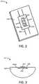
- FIG. 3Such embodiments are exemplified in FIG. 3 , wherein the reservoir 344 is substantially in the form of a half cylinder.
- the liquid transport element 336is inset in the flat surface 344a of the reservoir; however, the liquid transport element may be layered on the flat surface of the reservoir.
- the heater 334is positioned on the liquid transport element 336, and etchings 356 are present in the liquid transport element.
- the heater 434can comprise a heater substrate 434a upon which a heater trace 434b is provided.
- the heater substrate 434ais preferably a chemically stable and heat-resistant material (e.g., silicon or glass), and the heater trace 434b can be a material suitable for rapid heating, such as a heating wire as otherwise described herein.
- An atomizer 20 as illustrated in FIG. 2can be incorporated into a cartridge 104 as seen in FIG. 1 .
- the atomizer 20may be included in place of the heater 134, the liquid transport element 136, and optionally the reservoir 144. In some embodiments, the atomizer 20 may simply be included in addition to the further elements illustrated in FIG. 1 .
- a porous monolithmay be used as the liquid transport element alone.
- a cartridge 504is formed of a shell 503 and a reservoir 544 that is holding a liquid aerosol precursor composition.
- the reservoir 544may be a fibrous mat into which the liquid is absorbed or may be a container with suitable openings therein to receive the liquid transport element 536.
- the liquid transport element 536is formed of a porous monolith and has respective ends 536a and 536b that extend into the reservoir 544.
- a heater 534 in the form of a resistive heating wireis wrapped around the liquid transport element 536 at an approximate middle section 536c thereof, and the wire includes terminals 535 for making an electrical connection with a power source.
- the liquid transport element 536can be a porous glass. In further embodiments, the liquid transport element 536 can be a porous ceramic. In one or more embodiments, one or both of the liquid transport element 536 and the reservoir 544 can be a porous glass, or one or both of the liquid transport element and the reservoir can be a porous ceramic. In some embodiments, one of the liquid transport element 536 and the reservoir 544 can be a porous glass, and the other of the liquid transport element and the reservoir can be a porous ceramic.
- a liquid transport element according to the present disclosurecan be substantially in a core/shell form.
- a core 636acan have at least a portion thereof surrounded with a shell 636b, which can be formed of a porous monolith.
- the core 636amay also be formed of a porous monolith.
- the core 636amay be formed of a porous glass with one or more different properties from the porous glass forming the shell 636b so that differential characteristics of the combined elements may be provided.
- the core 636amay be formed of a porous glass configured for improved storage of a liquid
- the shell 636bmay be formed of a porous glass configured for improved transport of the liquid for rapid wicking to the heater 634 that can be a wire that is substantially wrapped around the shell.
- the core 636amay be formed of a material other than porous glass, such as a fibrous material.
- the core 636amay be formed of a glass fiber, cotton, cellulose acetate, or like materials.
- one or both of the core 636a and the shell 636bcan be formed of a porous ceramic.
- one of the core 636a and the shell 636bcan be formed of a porous glass, and the other of the core and the shell can be formed of a porous ceramic.
- the porous monolith shell 636bhas opposing ends 636b' and 636b", and the core 636a is sized so that it extends beyond the opposing ends of the porous monolith shell.
- One or both of the ends 636a' and 636a" of the core 636acan be positioned in an aerosol delivery device so as to extend into a reservoir (e.g., a fibrous mat or a bulk liquid storage container) and thus wick liquid to the shell 636b so that the liquid is vaporized by the heater 634.
- the heater 634can include terminals 635 for making an electrical connection with a power source.
- Such core/shell designcan be particularly beneficial in that the core material can be shielded from potential scorching by the high heat provided by the heating wire.
- air flow for entraining formed vapormay pass substantially across the porous monolith shell and have little or substantially no direct flow across the core material.
- FIG. 6The combination of elements in FIG. 6 may be characterized collectively as an atomizer 60. Nevertheless, it is understood that one or more of the elements (e.g., the core 636a and/or the shell 636b and/or the heater 634) may be utilized separate from the unit in combination with one or more further embodiments described herein.
- the elementse.g., the core 636a and/or the shell 636b and/or the heater 634
- a porous monolithcan be used as a reservoir that can be substantially shaped as a cylinder.
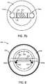
- FIG. 7a and FIG. 7billustrate an atomizer 70 comprising a reservoir 744 formed of a porous monolith that is shaped as a cylinder.
- the reservoir 744has a wall 745 with a thickness that can vary, and a central opening 746 is defined by the wall.
- a liquid transport element 736is configured with a central portion 736c and respective end portions 736a' and 736a" extending away from the central portion.
- the respective end portions 736a' and 736a"are configured to be in fluid connection with the wall 745 of the reservoir 744.
- the liquid transport element 736 and the reservoir 744can be formed of a porous glass.
- the liquid transport element 736may be formed of porous glass with one or more properties that are different from the properties of the porous glass forming the reservoir 744.
- the liquid transport element 736can be formed of a fibrous material and thus may be referred to as a fibrous wick.
- a heater 734 in the form of a wireis wrapped around the central portion 736c of the liquid transport element 736 can include terminals 735 for making an electrical connection with a power source.
- one or both of the liquid transport element 736 and the reservoir 744can be formed of a porous ceramic.
- one of the liquid transport element 736 and the reservoir 744can be formed of a porous glass, and the other of the liquid transport element and the reservoir can be formed of a porous ceramic.
- the reservoir wall 745can include one or more grooves 744a.
- the respective end portions 736a' and 736a" of the liquid transport element 736in particular may engage the reservoir 744 in the grooves 744a.
- the grooves 744acan be configured to have one or more properties that are different that the remaining sections of the reservoir, such as having a different porosity. In this manner, liquid stored in the reservoir 744 can be preferentially directed toward the grooves 744a to be taken up by the liquid transport element 736 for delivery to the heater 734.
- FIG. 7a and FIG. 7bare illustrated as a unit forming an atomizer 70, it is understood that one or more of the elements (e.g., the reservoir 744 and/or the liquid transport element 736 and/or the heater 734) may be utilized separate from the unit in combination with one or more further embodiments described herein.
- the elementse.g., the reservoir 744 and/or the liquid transport element 736 and/or the heater 734.
- a porous monolith forming a liquid transport elementcan have a heating member contained therein.
- a cartridge 804is formed of a shell 803 and a reservoir 844 that is holding a liquid aerosol precursor composition.
- the reservoir 844may be a fibrous mat into which the liquid is absorbed or may be a walled container with suitable openings therein to receive the liquid transport element 836.
- the liquid transport element 836is formed of a porous monolith and has respective ends 836a and 836b that extend into the reservoir 844.
- a heater 834 in the form of a resistive heating wireis positioned within the liquid transport element 836, and the wire includes terminals 835 for making an electrical connection with a power source.
- a flow tube 839is included and can be useful for directing air across the liquid transport element 836 so that vapor evolved by internal heating of the liquid transport element by the heater 834 becomes entrained in the air to form an aerosol that can be withdrawn by a consumer.
- the liquid transport element 836can be a porous glass.
- the liquid transport element 836can be a porous ceramic.
- one or both of the liquid transport element 836 and the reservoir 844can be a porous glass, or one or both of the liquid transport element and the reservoir can be a porous ceramic.
- one of the liquid transport element 836 and the reservoir 844can be a porous glass, and the other of the liquid transport element and the reservoir can be a porous ceramic. Further, the liquid transport element 844 can be a porous glass or a porous ceramic, and the reservoir 844 can be a fibrous mat or a storage container.
- the heater 834can be included within the liquid transport element 836 in a variety of manners.
- the heatercan be embedded within the porous monolith.
- the porous monolithcan be formed with the heater in place so that the heater is substantially entrapped within the liquid transport element.
- the heater 934is embedded in the liquid transport element 936, and an end of the heater extends out from the liquid transport element to make electrical connection with the terminals (see element 835 in FIG. 8 ).
- the porous monolithcan be hollow, can be substantially in the form or a tube, can have a slot, channel, or the like formed therein, or can otherwise include a void into which the heater is place so as to be substantially internal to the liquid transport element.
- the liquid transport element 936is a hollow tube, and the heater 934 is positioned within a cavity 937 of the hollow tube.
- the liquid transport element 936includes a cavity 937 substantially in the form of a channel along at least a portion of the length of the liquid transport element, and the heater 934 is positioned in the cavity.
- the heater that is internal to the liquid transport elementcan be in direct contact with at least a portion of the liquid transport element so as to provide conductive heating thereof.
- the heater that is internal to the liquid transport elementcan be substantially, predominately, or approximately completely in a radiative heating relationship with the liquid transport element.
- a substantially radiative heating relationshipcan mean that radiative heating occurs but does not provide a majority of the heating - e.g., 50% or less of the heating is radiative heating but a measurable quantity of the heating is radiative.
- a predominately radiative heating relationshipcan mean that radiative heating provides a majority of the heating but not all of the heating - i.e., greater than 50% of the heating is radiative.
- An approximately complete radiative heating relationshipcan mean that at least 90%, preferably at least 95%, and more preferably at least 98% or at least 99% of the heating is radiative.
- the present disclosurefurther can provide for methods of preparing an aerosol delivery device or a component useful in an aerosol delivery device.
- Such methodscan include providing a porous monolith in the form of a reservoir and/or in the form of a liquid transport element, and combining the porous monolith reservoir and/or liquid transport element with a heater and optionally with one or more further components described herein as being useful in an aerosol delivery device.
- One or both of the reservoir and the liquid transport elementcan be a porous glass.
- One or both of the reservoir and the liquid transport elementcan be a porous ceramic.
- One of the reservoir and the liquid transport elementcan be a porous glass, and the other of the reservoir and the liquid transport element can be a porous ceramic.
- one of the reservoir and the liquid transport elementcan be a fibrous material.
Landscapes
- Chemical & Material Sciences (AREA)
- Chemical Kinetics & Catalysis (AREA)
- General Chemical & Material Sciences (AREA)
- Physics & Mathematics (AREA)
- Electromagnetism (AREA)
- Medicinal Preparation (AREA)
- Physical Or Chemical Processes And Apparatus (AREA)
- Glass Compositions (AREA)
- Chemical Vapour Deposition (AREA)
- Catching Or Destruction (AREA)
- Resistance Heating (AREA)
- Disinfection, Sterilisation Or Deodorisation Of Air (AREA)
- Feeding, Discharge, Calcimining, Fusing, And Gas-Generation Devices (AREA)
- Coating By Spraying Or Casting (AREA)
- Nozzles (AREA)
- Special Spraying Apparatus (AREA)
Abstract
Description
- The present disclosure is a divisional application and relates to the subject matter disclosed in European application number
17 701 182.2 of January 4, 2017 - The present disclosure relates to aerosol delivery devices such as smoking articles, and more particularly to aerosol delivery devices that may utilize electrically generated heat for the production of aerosol (e.g., smoking articles commonly referred to as electronic cigarettes). The smoking articles may be configured to heat an aerosol precursor, which may incorporate materials that may be made or derived from tobacco or otherwise incorporate tobacco, the precursor being capable of forming an inhalable substance for human consumption.
- Many smoking devices have been proposed through the years as improvements upon, or alternatives to, smoking products that require combusting tobacco for use. Many of those devices purportedly have been designed to provide the sensations associated with cigarette, cigar, or pipe smoking, but without delivering considerable quantities of incomplete combustion and pyrolysis products that result from the burning of tobacco. To this end, there have been proposed numerous smoking products, flavor generators, and medicinal inhalers that utilize electrical energy to vaporize or heat a volatile material, or attempt to provide the sensations of cigarette, cigar, or pipe smoking without burning tobacco to a significant degree. See, for example, the various alternative smoking articles, aerosol delivery devices, and heat generating sources set forth in the background art described in
U.S. Pat. No. 7,726,320 to Robinson et al. ,U.S. Pat. Pub. No. 2013/0255702 to Griffith Jr. et al. , andU.S. Pat. Pub. No. 2014/0096781 to Sears et al. , which are incorporated herein by reference. See also, for example, the various types of smoking articles, aerosol delivery devices, and electrically powered heat generating sources referenced by brand name and commercial source inU.S. Pat. Pub. No. 2015/0216236 to Bless et al., filed February 3, 2014 , which is incorporated herein by reference. - It would be desirable to provide a reservoir for an aerosol precursor composition for use in an aerosol delivery device, the reservoir being provided so as to improve formation of the aerosol delivery device. It would also be desirable to provide aerosol delivery devices that are prepared utilizing such reservoirs.
- The present disclosure relates to aerosol delivery devices, methods of forming such devices, and elements of such devices. The aerosol delivery devices can incorporate one or more components or elements formed of a porous monolithic material. In one or more embodiments, the porous monolithic material can comprise a porous glass. In particular, porous glass can be utilized as one or both of a reservoir and a liquid transport element. In one or more further embodiments, the porous monolithic material can comprise a porous ceramic. In particular, porous ceramic can be utilized as one or both of a reservoir and a liquid transport element.
- In one or more aspects, the present disclosure thus can provide an aerosol delivery device comprising: an outer housing; a reservoir containing a liquid; a heater configured to vaporize the liquid; and a liquid transport element configured to provide the liquid to the heater. In particular, one or both of the liquid transport element and the reservoir is formed of a porous monolith, which can be one or both of a porous glass and a porous ceramic. In one or more embodiments, the aerosol delivery device can be defined in relation to the following statements, which are non-limiting and can be combined in any number and/or order.
- The heater can be printed on the liquid transport element or annealed to the liquid transport element.
- The heater can be in a heating arrangement with an external portion of the liquid transport element.
- The heater can be in a radiant heating arrangement with the liquid transport element.
- At least a portion of the liquid transport element can be substantially planar, and the heater can be at least partially positioned on the substantially planar portion of the liquid transport element.
- The liquid transport element and the reservoir can be both formed of porous glass.
- The liquid transport element and the reservoir can be both formed of porous ceramic.
- One of the liquid transport element and the reservoir can be formed of porous glass and the other of the liquid transport element and the reservoir can be formed of porous ceramic.
- The reservoir and the liquid transport element can be a unitary element.
- The reservoir can have a first porosity, and the liquid transport element can have a second porosity that is different from the first porosity.
- The porous glass can comprise one or more etchings.
- The porous ceramic can comprise one or more etchings.
- The liquid transport element can be formed of porous glass, and the liquid transport element can be substantially cylindrical.
- The liquid transport element can be formed of porous ceramic, and the liquid transport element can be substantially cylindrical.
- The heater can be a wire that is wrapped around at least a portion of the liquid transport element.
- The reservoir can be formed of porous glass, and the liquid transport element can be a fibrous wick.
- The reservoir can be formed of porous ceramic, and the liquid transport element can be a fibrous wick.
- The reservoir can be formed of a fibrous material, and the liquid transport element can be a porous glass.
- The reservoir can be formed of a fibrous material, and the liquid transport element can be a porous ceramic.
- The reservoir can be substantially shaped as a cylinder having a wall.
- One or more portions of the fibrous wick can be in fluid connection with the reservoir wall.
- The reservoir wall can include one or more grooves.
- The grooves can have a porosity that is different from the porosity of the remaining portions of the reservoir wall.
- The reservoir can be substantially shaped as a hollow cylinder.
- The liquid transport element can comprise a core and a shell.
- The shell can be formed of porous glass.
- The shell can be formed of porous ceramic.
- The core can be formed of a fibrous material.
- The porous glass or porous ceramic shell can have opposing ends, and the core of the liquid transport element can extend beyond the opposing ends of the porous glass or porous ceramic shell.
- The heater can be a wire and can be wrapped around at least a portion of the porous glass or porous ceramic shell.
- The outer housing can comprise an air entry and can comprise a mouthend with an aerosol port.
- The device further can comprise one or more of an electrical power source, a pressure sensor, and a microcontroller.
- One or more of the electrical power source, the pressure sensor, and the microcontroller can be positioned within a separate control housing that is connectable with the outer housing.
- In one or more aspects, the present disclosure can relate to an atomizer that can be particularly suitable for use in an aerosol delivery device. In exemplary embodiments, an atomizer can comprise a substantially planar porous monolith vapor substrate configured for transport of a liquid aerosol precursor composition and a heater in a heating arrangement with the substantially planar porous monolith vapor substrate. In one or more embodiments, the atomizer can be defined in relation to the following statements, which are non-limiting and can be combined in any number and/or order.
- The porous monolith vapor substrate can be a porous glass.
- The porous monolith vapor substrate can be a porous ceramic.
- The atomizer can comprise a porous glass reservoir connected to a substantially planar porous glass vapor substrate.
- The substantially planar porous glass vapor substrate can have a first porosity, and the porous glass reservoir can have a second porosity that is different form the first porosity.
- One or both of the substantially planar porous glass vapor substrate and the porous glass reservoir can include one or more etchings.
- The atomizer can comprise a porous ceramic reservoir connected to a substantially planar porous ceramic vapor substrate.
- The atomizer can comprise a porous glass reservoir connected to a substantially planar porous ceramic vapor substrate.
- The atomizer can comprise a porous ceramic reservoir connected to a substantially planar porous glass vapor substrate.
- In one or more aspects, the present disclosure can relate to fluid transport element that can be particularly suitable for use in an aerosol delivery device. In exemplary embodiments, a liquid transport element can comprise an elongated core having a length and being formed of a wicking material and a shell surrounding the elongated core along at least of a portion of the length thereof, the shell being formed of a porous monolith, which can be a porous glass or a porous ceramic. In particular, the wicking material can be a fibrous material.
- The invention includes, without limitation, the following embodiments:
- Embodiment 1: An aerosol delivery device comprising: an outer housing; a reservoir containing a liquid; a heater configured to vaporize the liquid; and a liquid transport element configured to provide the liquid to the heater; wherein one or both of the liquid transport element and the reservoir is formed of porous glass.
- Embodiment 2: The aerosol delivery device according to any previous or subsequent embodiment, wherein the heater is printed on the liquid transport element or annealed to the liquid transport element.
- Embodiment 3: The aerosol delivery device according to any previous or subsequent embodiment, wherein the heater is in a radiant heating arrangement with the liquid transport element.
- Embodiment 4: The aerosol delivery device according to any previous or subsequent embodiment, wherein at least a portion of the liquid transport element is substantially planar, and wherein the heater is at least partially positioned on the substantially planar portion of the liquid transport element.
- Embodiment 5: The aerosol delivery device according to any previous or subsequent embodiment, wherein the liquid transport element and the reservoir are both formed of porous glass.
- Embodiment 6: The aerosol delivery device according to any previous or subsequent embodiment, wherein the reservoir and the liquid transport element are a unitary element.
- Embodiment 7: The aerosol delivery device according to any previous or subsequent embodiment, wherein the reservoir has a first porosity, and the liquid transport element has a second porosity that is different from the first porosity.
- Embodiment 8: The aerosol delivery device according to any previous or subsequent embodiment, wherein the porous glass comprises one or more etchings.
- Embodiment 9: The aerosol delivery device according to any previous or subsequent embodiment, wherein the liquid transport element is formed of porous glass, and wherein the liquid transport element is substantially cylindrical.
- Embodiment 10: The aerosol delivery device according to any previous or subsequent embodiment, wherein the heater is a wire that is wrapped around at least a portion of the liquid transport element.
- Embodiment 11: The aerosol delivery device according to any previous or subsequent embodiment, wherein the reservoir is formed of porous glass and the liquid transport element is a fibrous wick.
- Embodiment 12: The aerosol delivery device according to any previous or subsequent embodiment, wherein the reservoir is substantially shaped as a cylinder having a wall.
- Embodiment 13: The aerosol delivery device according to any previous or subsequent embodiment, wherein one or more portions of the fibrous wick are in fluid connection with the reservoir wall.
- Embodiment 14: The aerosol delivery device according to any previous or subsequent embodiment, wherein the reservoir wall includes one or more grooves.
- Embodiment 15: The aerosol delivery device according to any previous or subsequent embodiment, wherein the one or more grooves have a porosity that is different from the porosity of the remaining portions of the reservoir wall.
- Embodiment 16: The aerosol delivery device according to any previous or subsequent embodiment, wherein the reservoir is substantially shaped as a hollow cylinder.
- Embodiment 17: The aerosol delivery device according to any previous or subsequent embodiment, the liquid transport element comprises a core and a shell.
- Embodiment 18: The aerosol delivery device according to any previous or subsequent embodiment, wherein the shell is formed of porous glass.
- Embodiment 19: The aerosol delivery device according to any previous or subsequent embodiment, wherein the core is formed of a fibrous material.
- Embodiment 20: The aerosol delivery device according to any previous or subsequent embodiment, wherein the porous glass shell has opposing ends, and wherein the core of the liquid transport element extends beyond the opposing ends of the porous glass shell.
- Embodiment 21: The aerosol delivery device according to any previous or subsequent embodiment, wherein the heater is a wire and is wrapped around at least a portion of the porous glass shell.
- Embodiment 22: The aerosol delivery device according to any previous or subsequent embodiment, wherein the outer housing comprises an air entry and comprises a mouthend with an aerosol port.
- Embodiment 23: The aerosol delivery device according to any previous or subsequent embodiment, wherein the device further comprises one or more of an electrical power source, a pressure sensor, and a microcontroller.
- Embodiment 24: The aerosol delivery device according to any previous embodiment, wherein one or more of the electrical power source, the pressure sensor, and the microcontroller are positioned within a separate control housing that is connectable with the outer housing.
- Embodiment 25: An atomizer comprising: a vapor substrate formed of a porous monolith and configured for transport of a liquid aerosol precursor composition; and a heater in a heating arrangement with the vapor substrate.
- Embodiment 26: The atomizer according to any previous or subsequent embodiment, wherein the atomizer further comprises a reservoir.
- Embodiment 27: The atomizer according to any previous or subsequent embodiment, wherein the reservoir is formed of a porous monolith.
- Embodiment 28: The atomizer according to any previous or subsequent embodiment, wherein the reservoir is connected to the vapor substrate.
- Embodiment 29: The atomizer according to any previous or subsequent embodiment, wherein the reservoir and the vapor substrate are a unitary element.
- Embodiment 30: The atomizer according to any previous or subsequent embodiment, wherein the vapor substrate has a first porosity, and the reservoir has a second porosity that is different form the first porosity.
- Embodiment 31: The atomizer according to any previous or subsequent embodiment, wherein one or both of the vapor substrate and the reservoir includes one or more etchings.
- Embodiment 32: The atomizer according to any previous or subsequent embodiment, wherein: one or both of the vapor substrate and the reservoir is a porous glass; one or both of the vapor substrate and the reservoir is a porous ceramic; or one of the vapor substrate and the reservoir is a porous glass, and the other of the vapor substrate and the reservoir is a porous ceramic.
- Embodiment 33: The atomizer according to any previous or subsequent embodiment, wherein the reservoir is formed of porous glass and the vapor substrate is a fibrous wick.
- Embodiment 34: The atomizer according to any previous or subsequent embodiment, wherein the reservoir is substantially shaped as a cylinder having a wall.
- Embodiment 35: The atomizer according to any previous or subsequent embodiment, wherein one or more portions of the fibrous wick are in fluid connection with the reservoir wall.
- Embodiment 36: The atomizer according to any previous or subsequent embodiment, wherein the reservoir wall includes one or more grooves.
- Embodiment 37: The atomizer according to any previous or subsequent embodiment, wherein the one or more grooves have a porosity that is different from the porosity of the remaining portions of the reservoir wall.
- Embodiment 38: The atomizer according to any previous or subsequent embodiment, wherein the reservoir is substantially shaped as a hollow cylinder.
- Embodiment 39: The atomizer according to any previous or subsequent embodiment, wherein the vapor substrate is substantially planar.
- Embodiment 40: The atomizer according to any previous or subsequent embodiment, wherein the heater is at least partially positioned on the substantially planar portion of the vapor substrate
- Embodiment 41: The atomizer according to any previous or subsequent embodiment, wherein at least a portion of the heater is internal to the vapor substrate.
- Embodiment 42: The atomizer according to any previous or subsequent embodiment, wherein the vapor substrate is substantially in the form of a hollow tube or the vapor substrate includes a channel formed therein.
- Embodiment 43: The atomizer according to any previous or subsequent embodiment, wherein the heater is printed on the vapor substrate or annealed to the vapor substrate.
- Embodiment 44: The atomizer according to any previous or subsequent embodiment, wherein the heater is in a radiant heating arrangement with the vapor substrate.
- Embodiment 45: The atomizer according to any previous or subsequent embodiment, wherein the vapor substrate is formed of porous glass, and wherein the vapor substrate is substantially cylindrical.
- Embodiment 46: The atomizer according to any previous or subsequent embodiment, wherein the heater is a wire that is wrapped around at least a portion of the vapor substrate.
- Embodiment 47: The atomizer according to any previous or subsequent embodiment, the vapor substrate comprises a core and a shell.
- Embodiment 48: The atomizer according to any previous or subsequent embodiment, wherein the shell is formed of porous glass.
- Embodiment 49: The atomizer according to any previous or subsequent embodiment, wherein the core is formed of a fibrous material.
- Embodiment 50: The atomizer according to any previous or subsequent embodiment, wherein the porous glass shell has opposing ends, and wherein the core of the liquid transport element extends beyond the opposing ends of the porous glass shell.
- Embodiment 51: The atomizer according to any previous or subsequent embodiment, wherein the heater is a wire and is wrapped around at least a portion of the porous glass shell.
- Embodiment 52: An aerosol delivery device comprising an outer housing and an atomizer according to any previous or subsequent embodiment.
- Embodiment 53: A liquid transport element for an aerosol delivery device, the liquid transport element comprising: an elongated core having a length and being formed of a wicking material; and a shell surrounding the elongated core along at least of a portion of the length thereof, the shell being formed of a porous monolith.
- Embodiment 54: The liquid transport element according to any previous embodiment, wherein the wicking material is a fibrous material.
- These and other features, aspects, and advantages of the disclosure will be apparent from a reading of the following detailed description together with the accompanying drawings, which are briefly described below. The invention includes any combination of two, three, four, or more of the above-noted embodiments as well as combinations of any two, three, four, or more features or elements set forth in this disclosure, regardless of whether such features or elements are expressly combined in a specific embodiment description herein. This disclosure is intended to be read holistically such that any separable features or elements of the disclosed invention, in any of its various aspects and embodiments, should be viewed as combinable unless the context clearly dictates otherwise.
- Having thus described the disclosure in the foregoing general terms, reference will now be made to the accompanying drawings, which are not necessarily drawn to scale, and wherein:
FIG. 1 is a partially cut-away view of an aerosol delivery device comprising a cartridge and a control body including a variety of elements that may be utilized in an aerosol delivery device according to various embodiments of the present disclosure;FIG. 2 is a perspective view an atomizer according to one or more embodiments of the present disclosure including a reservoir and a liquid transport element that are one or both formed of a porous monolith, including porous glass and/or porous ceramic;FIG. 3 is a partial cross-section of an atomizer according to one or more embodiments of the present disclosure including a reservoir and a liquid transport element that are one or both formed of a porous monolith, including porous glass and/or porous ceramic;FIG. 4 is a perspective view of a heater that may be used according to one or more embodiments of the present disclosure;FIG. 5 is a partial cross-section of a cartridge according to one or more embodiments of the present disclosure including a reservoir and a porous monolith liquid transport element with a heater wire in a heating arrangement with an external portion of the liquid transport element;FIG. 6 illustrates a core/shell liquid transport element according to one or more embodiments of the present disclosure having a shell formed of a porous monolith and a core that optionally is formed of a porous monolith or a different wicking material;FIG. 7a is a perspective view of an atomizer according to one or more embodiments of the present disclosure including a reservoir formed of a porous monolith substantially in the shape of a walled cylinder and having a liquid transport element combined therewith;FIG. 7b is a bottom view of the atomizer ofFIG. 7a ;FIG. 8 is a partial cross-section of a cartridge according to one or more embodiments of the present disclosure including a reservoir and a porous monolith liquid transport element with a heater wire in a heating arrangement with an internal portion of the liquid transport element;FIG. 9a is a cross-section of a liquid transport element with a heater embedded therein;FIG. 9b is a cross-section of a liquid transport element substantially in the form of a hollow tube with a heater present in a cavity of the hollow tube; andFIG. 9c is a cross-section of a liquid transport element with a heater present in a cavity that is substantially in the form of a channel.- The present disclosure will now be described more fully hereinafter with reference to exemplary embodiments thereof. These exemplary embodiments are described so that this disclosure will be thorough and complete, and will fully convey the scope of the disclosure to those skilled in the art. Indeed, the disclosure may be embodied in many different forms and should not be construed as limited to the embodiments set forth herein; rather, these embodiments are provided so that this disclosure will satisfy applicable legal requirements. As used in the specification, and in the appended claims, the singular forms "a", "an", "the", include plural referents unless the context clearly dictates otherwise.
- As described hereinafter, embodiments of the present disclosure relate to aerosol delivery systems. Aerosol delivery systems according to the present disclosure use electrical energy to heat a material (preferably without combusting the material to any significant degree and/or without significant chemical alteration of the material) to form an inhalable substance; and components of such systems have the form of articles that most preferably are sufficiently compact to be considered hand-held devices. That is, use of components of preferred aerosol delivery systems does not result in the production of smoke - i.e., from byproducts of combustion or pyrolysis of tobacco, but rather, use of those preferred systems results in the production of vapors/aerosols resulting from volatilization or vaporization of certain components incorporated therein. In preferred embodiments, components of aerosol delivery systems may be characterized as electronic cigarettes, and those electronic cigarettes most preferably incorporate tobacco and/or components derived from tobacco, and hence deliver tobacco derived components in aerosol form.
- Aerosol generating pieces of certain preferred aerosol delivery systems may provide many of the sensations (e.g., inhalation and exhalation rituals, types of tastes or flavors, organoleptic effects, physical feel, use rituals, visual cues such as those provided by visible aerosol, and the like) of smoking a cigarette, cigar, or pipe that is employed by lighting and burning tobacco (and hence inhaling tobacco smoke), without any substantial degree of combustion of any component thereof. For example, the user of an aerosol generating piece of the present disclosure can hold and use that piece much like a smoker employs a traditional type of smoking article, draw on one end of that piece for inhalation of aerosol produced by that piece, take or draw puffs at selected intervals of time, and the like. The devices described herein, however, are not limited to devices that are substantially shaped and dimensioned as a traditional cigarette. Rather, the present devices may take on any shape and can be substantially larger than a traditional cigarette.
- Aerosol delivery devices of the present disclosure also can be characterized as being vapor-producing articles or medicament delivery articles. Thus, such articles or devices can be adapted so as to provide one or more substances (e.g., flavors and/or pharmaceutical active ingredients) in an inhalable form or state. For example, inhalable substances can be substantially in the form of a vapor (i.e., a substance that is in the gas phase at a temperature lower than its critical point). Alternatively, inhalable substances can be in the form of an aerosol (i.e., a suspension of fine solid particles or liquid droplets in a gas). For purposes of simplicity, the term "aerosol" as used herein is meant to include vapors, gases, and aerosols of a form or type suitable for human inhalation, whether or not visible, and whether or not of a form that might be considered to be smoke-like.
- Aerosol delivery devices of the present disclosure generally include a number of components provided within an outer body or shell, which may be referred to as a housing. The overall design of the outer body or shell can vary, and the format or configuration of the outer body that can define the overall size and shape of the aerosol delivery device can vary. In exemplary embodiments, an elongated body resembling the shape of a cigarette or cigar can be a formed from a single, unitary housing, or the elongated housing can be formed of two or more separable bodies. For example, an aerosol delivery device can comprise an elongated shell or body that can be substantially tubular in shape and, as such, resemble the shape of a conventional cigarette or cigar. In one embodiment, all of the components of the aerosol delivery device are contained within one housing. Alternatively, an aerosol delivery device can comprise two or more housings that are joined and are separable. For example, an aerosol delivery device can possess at one end a control body comprising a housing containing one or more components (e.g., a battery and various electronics for controlling the operation of that article), and at the other end and removably attached thereto an outer body or shell containing aerosol forming components (e.g., one or more aerosol precursor components, such as flavors and aerosol formers, one or more heaters, and/or one or more wicks).
- Aerosol delivery devices of the present disclosure can be formed of an outer housing or shell that is not substantially tubular in shape but may be formed to substantially greater dimensions - i.e., be substantially "palm-sized" for being held in the palm of a user. The housing or shell can be configured to include a mouthpiece and/or may be configured to receive a separate shell (e.g., a cartridge) that can include consumable elements, such as a liquid aerosol former, and can include a vaporizer or atomizer.
- Aerosol delivery devices of the present disclosure most preferably comprise some combination of a power source (i.e., an electrical power source), at least one control component (e.g., means for actuating, controlling, regulating and ceasing power for heat generation, such as by controlling electrical current flow the power source to other components of the article - e.g., a microcontroller or microprocessor), a heater or heat generation member (e.g., an electrical resistance heating element or other component, which alone or in combination with one or more further elements may be commonly referred to as an "atomizer"), an aerosol precursor composition (e.g., commonly a liquid capable of yielding an aerosol upon application of sufficient heat, such as ingredients commonly referred to as "smoke juice," "e-liquid" and "e-juice"), and a mouthpiece or mouth region for allowing draw upon the aerosol delivery device for aerosol inhalation (e.g., a defined airflow path through the article such that aerosol generated can be withdrawn therefrom upon draw).
- More specific formats, configurations and arrangements of components within the aerosol delivery systems of the present disclosure will be evident in light of the further disclosure provided hereinafter. Additionally, the selection and arrangement of various aerosol delivery system components can be appreciated upon consideration of the commercially available electronic aerosol delivery devices, such as those representative products referenced in background art section of the present disclosure.
- One example embodiment of an
aerosol delivery device 100 illustrating components that may be utilized in an aerosol delivery device according to the present disclosure is provided inFIG. 1 . As seen in the cut-away view illustrated therein, theaerosol delivery device 100 can comprise acontrol body 102 and acartridge 104 that can be permanently or detachably aligned in a functioning relationship. Engagement of thecontrol body 102 and thecartridge 104 can be press fit (as illustrated), threaded, interference fit, magnetic, or the like. In particular, connection components, such as further described herein may be used. For example, the control body may include a coupler that is adapted to engage a connector on the cartridge. - In specific embodiments, one or both of the
control body 102 and thecartridge 104 may be referred to as being disposable or as being reusable. For example, the control body may have a replaceable battery or a rechargeable battery and thus may be combined with any type of recharging technology, including connection to a typical electrical outlet, connection to a car charger (i.e., cigarette lighter receptacle), and connection to a computer, such as through a universal serial bus (USB) cable. For example, an adaptor including a USB connector at one end and a control body connector at an opposing end is disclosed inU.S. Pat. Pub. No. 2014/0261495 to Novak et al. , which is incorporated herein by reference in its entirety. Further, in some embodiments the cartridge may comprise a single-use cartridge, as disclosed inU.S. Pat. No. 8,910,639 to Chang et al. , which is incorporated herein by reference in its entirety. - As illustrated in
FIG. 1 , acontrol body 102 can be formed of acontrol body shell 101 that can include a control component 106 (e.g., a printed circuit board (PCB), an integrated circuit, a memory component, a microcontroller, or the like), aflow sensor 108, abattery 110, and anLED 112, and such components can be variably aligned. Further indicators (e.g., a haptic feedback component, an audio feedback component, or the like) can be included in addition to or as an alternative to the LED. Additional representative types of components that yield visual cues or indicators, such as light emitting diode (LED) components, and the configurations and uses thereof, are described inU.S. Pat. Nos. 5,154,192 to Sprinkel et al. ;8,499,766 to Newton and8,539,959 to Scatterday ; andU.S. Pat. App. Ser. No. 14/173,266, filed February 5, 2014, to Sears et al. - A
cartridge 104 can be formed of acartridge shell 103 enclosing thereservoir 144 that is in fluid communication with aliquid transport element 136 adapted to wick or otherwise transport an aerosol precursor composition stored in the reservoir housing to aheater 134. Various embodiments of materials configured to produce heat when electrical current is applied therethrough may be employed to form theresistive heating element 134. Example materials from which the wire coil may be formed include Kanthal (FeCrAl), Nichrome, Molybdenum disilicide (MoSi2), molybdenum silicide (MoSi), Molybdenum disilicide doped with Aluminum (Mo(Si,Al)2), titanium, platinum, silver, palladium, graphite and graphite-based materials (e.g., carbon-based foams and yarns) and ceramics (e.g., positive or negative temperature coefficient ceramics). As further described herein, a heater may comprise a variety of materials configured to provide electromagnetic radiation, including laser diodes. - An
opening 128 may be present in the cartridge shell 103 (e.g., at the mouthend) to allow for egress of formed aerosol from thecartridge 104. Such components are representative of the components that may be present in a cartridge and are not intended to limit the scope of cartridge components that are encompassed by the present disclosure. - The
cartridge 104 also may include one or moreelectronic components 150, which may include an integrated circuit, a memory component, a sensor, or the like. Theelectronic component 150 may be adapted to communicate with thecontrol component 106 and/or with an external device by wired or wireless means. Theelectronic component 150 may be positioned anywhere within thecartridge 104 or itsbase 140. - Although the
control component 106 and theflow sensor 108 are illustrated separately, it is understood that the control component and the flow sensor may be combined as an electronic circuit board with the air flow sensor attached directly thereto. Further, the electronic circuit board may be positioned horizontally relative the illustration ofFIG. 1 in that the electronic circuit board can be lengthwise parallel to the central axis of the control body. In some embodiments, the air flow sensor may comprise its own circuit board or other base element to which it can be attached. In some embodiments, a flexible circuit board may be utilized. A flexible circuit board may be configured into a variety of shapes, include substantially tubular shapes. - The
control body 102 and thecartridge 104 may include components adapted to facilitate a fluid engagement therebetween. As illustrated inFIG. 1 , thecontrol body 102 can include acoupler 124 having acavity 125 therein. Thecartridge 104 can include a base 140 adapted to engage thecoupler 124 and can include aprojection 141 adapted to fit within thecavity 125. Such engagement can facilitate a stable connection between thecontrol body 102 and thecartridge 104 as well as establish an electrical connection between thebattery 110 andcontrol component 106 in the control body and theheater 134 in the cartridge. Further, thecontrol body shell 101 can include anair intake 118, which may be a notch in the shell where it connects to thecoupler 124 that allows for passage of ambient air around the coupler and into the shell where it then passes through thecavity 125 of the coupler and into the cartridge through theprojection 141. - A coupler and a base useful according to the present disclosure are described in
U.S. Pat. Pub. No. 2014/0261495 to Novak et al. , the disclosure of which is incorporated herein by reference in its entirety. For example, a coupler as seen inFIG. 1 may define anouter periphery 126 configured to mate with aninner periphery 142 of thebase 140. In one embodiment the inner periphery of the base may define a radius that is substantially equal to, or slightly greater than, a radius of the outer periphery of the coupler. Further, thecoupler 124 may define one ormore protrusions 129 at theouter periphery 126 configured to engage one ormore recesses 178 defined at the inner periphery of the base. However, various other embodiments of structures, shapes, and components may be employed to couple the base to the coupler. In some embodiments the connection between the base 140 of thecartridge 104 and thecoupler 124 of thecontrol body 102 may be substantially permanent, whereas in other embodiments the connection therebetween may be releasable such that, for example, the control body may be reused with one or more additional cartridges that may be disposable and/or refillable. - The
aerosol delivery device 100 may be substantially rod-like or substantially tubular shaped or substantially cylindrically shaped in some embodiments. In other embodiments, further shapes and dimensions are encompassed - e.g., a rectangular or triangular cross-section, multifaceted shapes, or the like. - The
reservoir 144 illustrated inFIG. 1 can take on any design configured for retaining a liquid, such as a container or a mass configured for absorbing and/or adsorbing the liquid - e.g., a fibrous reservoir or a porous monolith, as presently described. As illustrated inFIG. 1 , thereservoir 144 can comprise one or more layers of nonwoven fibers substantially formed into the shape of a tube encircling the interior of thecartridge shell 103. An aerosol precursor composition can be retained in thereservoir 144. Liquid components, for example, can be sorptively retained by thereservoir 144. Thereservoir 144 can be in fluid connection with aliquid transport element 136. Theliquid transport element 136 can transport the aerosol precursor composition stored in thereservoir 144 via capillary action to theheating element 134 that is in the form of a metal wire coil in this embodiment. As such, theheating element 134 is in a heating arrangement with theliquid transport element 136. - In use, when a user draws on the
article 100, airflow is detected by thesensor 108, theheating element 134 is activated, and the components for the aerosol precursor composition are vaporized by theheating element 134. Drawing upon the mouthend of thearticle 100 causes ambient air to enter theair intake 118 and pass through thecavity 125 in thecoupler 124 and the central opening in theprojection 141 of thebase 140. In thecartridge 104, the drawn air combines with the formed vapor to form an aerosol. The aerosol is whisked, aspirated, or otherwise drawn away from theheating element 134 and out themouth opening 128 in the mouthend of thearticle 100. - An input element may be included with the aerosol delivery device. The input may be included to allow a user to control functions of the device and/or for output of information to a user. Any component or combination of components may be utilized as an input for controlling the function of the device. For example, one or more pushbuttons may be used as described in
U.S. Pat. App. Ser. No. 14/193,961, filed February 28, 2014, to Worm et al. U.S. Pat. App. Ser. No. 14/643,626, filed March 10, 2015, to Sears et al. U.S. Pat. App. Ser. No. 14/565,137, filed December 9, 2014, to Henry et al. - In some embodiments, an input may comprise a computer or computing device, such as a smartphone or tablet. In particular, the aerosol delivery device may be wired to the computer or other device, such as via use of a USB cord or similar protocol. The aerosol delivery device also may communicate with a computer or other device acting as an input via wireless communication. See, for example, the systems and methods for controlling a device via a read request as described in
U.S. Pat. App. Ser. No. 14/327,776, filed July 10, 2014, to Ampolini et al. - The various components of an aerosol delivery device according to the present disclosure can be chosen from components described in the art and commercially available. Examples of batteries that can be used according to the disclosure are described in
U.S. Pat. Pub. No. 2010/0028766 to Peckerar et al. , the disclosure of which is incorporated herein by reference in its entirety. - The aerosol delivery device can incorporate a sensor or detector for control of supply of electric power to the heat generation element when aerosol generation is desired (e.g., upon draw during use). As such, for example, there is provided a manner or method for turning off the power supply to the heat generation element when the aerosol delivery device is not be drawn upon during use, and for turning on the power supply to actuate or trigger the generation of heat by the heat generation element during draw. Additional representative types of sensing or detection mechanisms, structure and configuration thereof, components thereof, and general methods of operation thereof, are described in
U.S. Pat. Nos. 5,261,424 to Sprinkel, Jr. ;5,372,148 to McCafferty et al. ; andPCT WO 2010/003480 to Flick ; which are incorporated herein by reference. - The aerosol delivery device most preferably incorporates a control mechanism for controlling the amount of electric power to the heat generation element during draw. Representative types of electronic components, structure and configuration thereof, features thereof, and general methods of operation thereof, are described in
U.S. Pat. Nos. 4,735,217 to Gerth et al. ;4,947,874 to Brooks et al. ;5,372,148 to McCafferty et al. ;6,040,560 to Fleischhauer et al. ;7,040,314 to Nguyen et al. and8,205,622 to Pan ;U.S. Pat. Pub. Nos. 2009/0230117 to Fernando et al. ,2014/0060554 to Collett et al. , and2014/0270727 to Ampolini et al. ; andU.S. Pat. App. Ser. No. 14/209,191, filed March 13, 2014, to Henry et al. - Representative types of substrates, reservoirs or other components for supporting the aerosol precursor are described in
U.S. Pat. No. 8,528,569 to Newton ;U.S. Pat. Pub. Nos. 2014/0261487 to Chapman et al. and2014/0059780 to Davis et al. ; andU.S. Pat. App. Ser. No. 14/170,838, filed February 3, 2014, to Bless et al. U.S. Pat. No. 8,910,640 to Sears et al. ; which is incorporated herein by reference. - For aerosol delivery systems that are characterized as electronic cigarettes, the aerosol precursor composition most preferably incorporates tobacco or components derived from tobacco. In one regard, the tobacco may be provided as parts or pieces of tobacco, such as finely ground, milled or powdered tobacco lamina. In another regard, the tobacco may be provided in the form of an extract, such as a spray dried extract that incorporates many of the water soluble components of tobacco. Alternatively, tobacco extracts may have the form of relatively high nicotine content extracts, which extracts also incorporate minor amounts of other extracted components derived from tobacco. In another regard, components derived from tobacco may be provided in a relatively pure form, such as certain flavoring agents that are derived from tobacco. In one regard, a component that is derived from tobacco, and that may be employed in a highly purified or essentially pure form, is nicotine (e.g., pharmaceutical grade nicotine).
- The aerosol precursor composition, also referred to as a vapor precursor composition, may comprise a variety of components including, by way of example, a polyhydric alcohol (e.g., glycerin, propylene glycol, or a mixture thereof), nicotine, tobacco, tobacco extract, and/or flavorants. Representative types of aerosol precursor components and formulations also are set forth and characterized in
U.S. Pat. No. 7,217,320 to Robinson et al. andU.S. Pat. Pub. Nos. 2013/0008457 to Zheng et al. ;2013/0213417 to Chong et al. ;2014/0060554 to Collett et al. ;2015/0020823 to Lipowicz et al. ; and2015/0020830 to Koller , as well asWO 2014/182736 to Bowen et al , the disclosures of which are incorporated herein by reference. Other aerosol precursors that may be employed include the aerosol precursors that have been incorporated in the VUSE® product by R. J. Reynolds Vapor Company, the BLU™ product by Lorillard Technologies, the MISTIC MENTHOL product by Mistic Ecigs, and the VYPE product by CN Creative Ltd. Also desirable are the so-called "smoke juices" for electronic cigarettes that have been available from Johnson Creek Enterprises LLC. - The amount of aerosol precursor that is incorporated within the aerosol delivery system is such that the aerosol generating piece provides acceptable sensory and desirable performance characteristics. For example, it is highly preferred that sufficient amounts of aerosol forming material (e.g., glycerin and/or propylene glycol), be employed in order to provide for the generation of a visible mainstream aerosol that in many regards resembles the appearance of tobacco smoke. The amount of aerosol precursor within the aerosol generating system may be dependent upon factors such as the number of puffs desired per aerosol generating piece. Typically, the amount of aerosol precursor incorporated within the aerosol delivery system, and particularly within the aerosol generating piece, is less than about 2 g, generally less than about 1.5 g, often less than about 1 g and frequently less than about 0.5 g.
- Yet other features, controls or components that can be incorporated into aerosol delivery systems of the present disclosure are described in
U.S. Pat. Nos. 5,967,148 to Harris et al. ;5,934,289 to Watkins et al. ;U.S. Pat. No. 5,954,979 to Counts et al. ;6,040,560 to Fleischhauer et al. ;8,365,742 to Hon ;8,402,976 to Fernando et al. ;U.S. Pat. Pub. Nos. 2010/0163063 to Fernando et al. ;2013/0192623 to Tucker et al. ;2013/0298905 to Leven et al. ;2013/0180553 to Kim et al. ,2014/0000638 to Sebastian et al. ,2014/0261495 to Novak et al. , and2014/0261408 to DePiano et al. ; which are incorporated herein by reference. - The foregoing description of use of the article can be applied to the various embodiments described herein through minor modifications, which can be apparent to the person of skill in the art in light of the further disclosure provided herein. The above description of use, however, is not intended to limit the use of the article but is provided to comply with all necessary requirements of disclosure of the present disclosure. Any of the elements shown in the article illustrated in
FIG. 1 or as otherwise described above may be included in an aerosol delivery device according to the present disclosure. - In one or more embodiments, the present disclosure can relate to the use of a porous monolithic material in one or more components of an aerosol delivery device. As used herein, a "porous monolithic material" or "porous monolith" is intended to mean comprising a substantially single unit which, in some embodiments, may be a single piece formed, composed, or created without joints or seams and comprising a substantially, but not necessarily rigid, uniform whole. In some embodiments, a monolith according to the present disclosure may be undifferentiated, i.e., formed of a single material, or may be formed of a plurality of units that are permanently combined, such as a sintered conglomerate.
- In some embodiments, the use of a porous monolith particularly can relate to the use of a porous glass in components of an aerosol delivery device. As used herein, "porous glass" is intended to refer to glass that has a three-dimensional interconnected porous microstructure. The term specifically can exclude materials made of bundles (i.e., wovens or non-wovens) of glass fibers. Thus, porous glass can exclude fibrous glass. Porous glass may also be referred to as controlled pore glass (CPG) and may be known by the trade name VYCOR®. Porous glass suitable for use according to the present disclosure can be prepared by known methods such as, for example, metastable phase separation in borosilicate glasses followed by liquid extraction (e.g., acidic extraction or combined acidic and alkaline extraction) of one of the formed phases, via a sol-gel process, or by sintering of glass powder. The porous glass particularly can be a high-silica glass, such as comprising 90% or greater, 95%, 96% or greater, or 98% or greater silica by weight. Porous glass materials and methods of preparing porous glass that can be suitable for use according to the present disclosure are described in
U.S. Pat. No. 2,106,744 to Hood et al. ,U.S. Pat. No. 2,215,039 to Hood et al. ,U.S. Pat. No. 3, 485,687 to Chapman et al. ,U.S. Pat. No. 4,657,875 to Nakashima et al. ,U.S. Pat. No. 9,003,833 to Kotani et al. U.S. Pat. Pub. No. 2013/0045853 to Kotani et al. ,U.S. Pat. Pub. No. 2013/0067957 to Zhang et al. ,U.S. Pat. Pub. No. 2013/0068725 to Takashima et al. , andU.S. Pat. Pub. No. 2014/0075993 to Himanshu , the disclosures of which are incorporated herein by reference. Although the term porous "glass" may be used herein, it should not be construed as limiting the scope of the disclosure in that a "glass" can encompass a variety of silica based materials. - The porous glass can be defined in some embodiments in relation to its average pore size. For example, the porous glass can have an average pore size of about 1 nm to about 1000 µm, about 2 nm to about 500 µm, about 5 nm to about 200 µm, or about 10 nm to about 100 µm. In certain embodiments, porous glass for use according to the present disclosure can be differentiated based upon the average pore size. For example, a small pore porous glass can have an average pore size of 1 nm up to 500 nm, an intermediate pore porous class can have an average pore size of 500 nm up to 10 µm, and a large pore porous glass can have an average pore size of 10 µm up to 1000 µm. In some embodiments, a large pore porous glass can preferably be useful as a storage element, and a small pore porous glass and/or an intermediate pore porous glass can preferably be useful as a transport element.
- The porous glass also can be defined in some embodiments in relation to its surface area. For example, the porous glass can have a surface area of at least 100 m2/g, at least 150 m2/g, at least 200 m2/g, or at least 250 m2/g, such as about 100 m2/g to about 600 m2/g, about 150 m2/g to about 500 m2/g, or about 200 m2/g to about 450 m2/g.
- The porous glass can be defined in some embodiments in relation to its porosity (i.e., the volumetric fraction of the material encompassed by the pores). For example, the porous glass can have a porosity of at least 20%, at least 25%, or at least 30%, such as about 20% to about 80%, about 25% to about 70%, or about 30% to about 60% by volume. In certain embodiments, a lower porosity may be desirable, such as a porosity of about 5% to about 50%, about 10% to about 40%, or about 15% to about 30% by volume.
- The porous glass can be further defined in some embodiments in relation to its density. For example, the porous glass can have a density of 0.25 g/cm3 to about 3 g/cm3, about 0.5 g/cm3 to about 2.5 g/cm3, or about 0.75 g/cm3 to about 2 g/cm3.
- In some embodiments, the use of a porous monolith particularly can relate to the use of a porous ceramic in components of an aerosol delivery device. As used herein, "porous ceramic" is intended to refer to a ceramic material that has a three-dimensional interconnected porous microstructure. Porous ceramic materials and methods of making porous ceramics suitable for use according to the present disclosure are described in
U.S. Pat. No. 3,090,094 to Schwartzwalder et al. ,U.S. Pat. No. 3,833,386 to Frisch et al. ,U.S. Pat. No. 4,814,300 to Helferich ,U.S. Pat. No. 5,171,720 to Kawakami ,U.S. Pat. No. 5,185,110 to Kunikazu et al. ,U.S. Pat. No. 5,227,342 to Anderson et al. ,U.S. Pat. No. 5,645,891 to Liu et al. ,U.S. Pat. No. 5,750,449 to Niihara et al. ,U.S. Pat. No. 6,753,282 to Fleischmann et al. ,U.S. Pat. No. 7,208,108 to Otsuka et al. ,U.S. Pat. No. 7,537,716 to Matsunaga et al. ,U.S. Pat. No. 8,609,235 to Hotta et al. , the disclosures of which are incorporated herein by reference. Although the term porous "ceramic" may be used herein, it should not be construed as limiting the scope of the disclosure in that a "ceramic" can encompass a variety of alumina based materials. - The porous ceramic likewise can be defined in some embodiments in relation to its average pore size. For example, the porous ceramic can have an average pore size of about 1 nm to about 1000 µm, about 2 nm to about 500 µm, about 5 nm to about 200 µm, or about 10 nm to about 100 µm. In certain embodiments, porous ceramic for use according to the present disclosure can be differentiated based upon the average pore size. For example, a small pore porous ceramic can have an average pore size of 1 nm up to 500 nm, an intermediate pore porous ceramic can have an average pore size of 500 nm up to 10 µm, and a large pore porous ceramic can have an average pore size of 10 µm up to 1000 µm. In some embodiments, a large pore porous ceramic can preferably be useful as a storage element, and a small pore porous ceramic and/or an intermediate pore porous ceramic can preferably be useful as a transport element.
- The porous ceramic also can be defined in some embodiments in relation to its surface area. For example, the porous ceramic can have a surface area of at least 100 m2/g, at least 150 m2/g, at least 200 m2/g, or at least 250 m2/g, such as about 100 m2/g to about 600 m2/g, about 150 m2/g to about 500 m2/g, or about 200 m2/g to about 450 m2/g.
- The porous ceramic can be defined in some embodiments in relation to its porosity (i.e., the volumetric fraction of the material encompassed by the pores). For example, the porous ceramic can have a porosity of at least 20%, at least 25%, or at least 30%, such as about 20% to about 80%, about 25% to about 70%, or about 30% to about 60% by volume. In certain embodiments, a lower porosity may be desirable, such as a porosity of about 5% to about 50%, about 10% to about 40%, or about 15% to about 30% by volume.
- The porous ceramic can be further defined in some embodiments in relation to its density. For example, the porous ceramic can have a density of 0.25 g/cm3 to about 3 g/cm3, about 0.5 g/cm3 to about 2.5 g/cm3, or about 0.75 g/cm3 to about 2 g/cm3.
- Although silica-based materials (e.g., porous glass) and alumina-based materials (e.g., porous ceramic) may be discussed separately herein, it is understood that a porous monolith, in some embodiments, can comprise a variety of aluminosilicate materials. For example, various zeolites may be utilized according to the present disclosure.
- A porous monolith used according to the present disclosure can be provided in a variety of sizes and shapes. Preferably, the porous monolith may be substantially elongated, substantially flattened or planar, substantially curved (e.g., "U-shaped"), substantially in the form of a walled cylinder, or in any other form suitable for use according to the present disclosure.
- In one or more embodiments, a porous monolith according to the present disclosure can be characterized in relation to wicking rate. As a non-limiting example, wicking rate can be calculated by measuring the mass uptake of a known liquid, and the rate (in mg/s) can be measured using a microbalance tensiometer or similar instrument. Preferably, the wicking rate is substantially within the range of the desired mass of aerosol to be produced over the duration of a puff on an aerosol forming article including the porous monolith. Wicking rate can be, for example, in the range of about 0.05 mg/s to about 15 mg/s, about 0.1 mg/s to about 12 mg/s, or about 0.5 mg/s to about 10 mg/s. Wicking rate can vary based upon the liquid being wicked. In some embodiments, wicking rates as described herein can be referenced to substantially pure water, substantially pure glycerol, substantially pure propylene glycol, a mixture of water and glycerol, a mixture of water and propylene glycol, a mixture of glycerol and propylene glycol, or a mixture of water, glycerol, and propylene glycol. Wicking rate also can vary based upon the use of the porous monolith. For example, a porous monolith used as a liquid transport element may have a greater wicking rate than a porous monolith used as a reservoir. Wicking rates may be varied by control of one or more of pore size, pore size distribution, and wettability, as well as the composition of the material being wicked.
- An exemplary embodiment of the present disclosure in relation to a porous monolith is illustrated in
FIG. 2 . As seen therein, aliquid transport element 236 is surrounded by and in contact with areservoir 244. In some embodiments, a liquid transport element or a reservoir can be characterized as being a vapor substrate. The term "vapor substrate" thus refers to a substrate that stores and/or transports a liquid for vaporization and which can be in contact with a heater for vaporization of at least a portion of the liquid that is stored and/or transported by the vapor substrate. For example, a single porous monolith may function as a reservoir that can be in direct contact with a heater to provide for vapor formation without the need for a separate liquid transport element (or wick). In such instances, the reservoir would be considered a vapor substrate. In other embodiments, a separate liquid transport element may be in contact with a heater and in contact with a separate reservoir so that liquid is transported from the reservoir to the heater for vaporization. In such instances, the liquid transport element would be considered a vapor substrate. Where a reservoir is otherwise discussed herein, it is understood that such reservoir may properly be characterized as being a vapor substrate. Likewise, where a liquid transport element is otherwise discussed herein, it is understood that such liquid transport element may properly be characterized as being a vapor substrate. - In one or more embodiments, the porous monolith can comprise a porous glass. For example, either or both of the
liquid transport element 236 and thereservoir 244 can be a porous glass as described herein. For exemplary purposes, both of theliquid transport element 236 and thereservoir 244 are formed of porous glass and, preferentially, they may each be formed of a different porous glass (i.e., a first porous glass and a second porous glass). In one or more embodiments, the first porous glass and the second porous glass can differ in one or more characteristics that can affect the storage and/or transport ability of the respective porous glass. For example, they may differ in one or more of density, porosity, surface area, and average pore size. The differential between theliquid transport element 236 and thereservoir 244 is sufficient to provide a wicking gradient wherein wicking ability is greater in the liquid transport element than in the reservoir. Such configuration may be characterized as a gradient porosity or a dual porosity configuration. - In further embodiments, the porous monolith can comprise a porous ceramic. As such, one or both of the
liquid transport element 236 and thereservoir 244 may be formed of porous ceramic. Also, one of theliquid transport element 236 and thereservoir 244 may be formed of porous glass, and the other of the liquid transport element and the reservoir may be formed of porous ceramic. As such, the porous glass and the porous ceramic can have properties that are substantially matched to provide substantially identical flow characteristics, or the porous glass and the porous ceramic can have properties that are substantially different to provide substantially different flow characteristics. - A heater 234 is positioned relative to the
liquid transport element 236 so as to be configured for vaporization of liquid aerosol precursor material that can be stored in thereservoir 244 and transported therefrom to the heater by the liquid transport element. The heater 234 can be, for example, a printed microheater, an annealed microheater, a flat ribbon heater, or any similar configuration suitable for vaporization of an aerosol precursor composition as otherwise described herein. The heater 234 may be in direct contact with theliquid transport element 236 or may be in a radiant heating configuration relative to the liquid transport element - i.e., in very close proximity to, but not directly touching the liquid transport element. As liquid aerosol precursor material is vaporized at the surface of theliquid transport element 236 due to heating by the heater 234, supplemental liquid may be wicked from thereservoir 244 to the proximity of the heater 234 by the liquid transport element and fill the area where the liquid was depleted by vaporization. - In some embodiments, one or more etchings (i.e., grooves or channels) may be present on one or both of the
reservoir 244 and theliquid transport element 236. Although the grooves or channels may be formed by an etching process, use of the term "etchings" is not meant to be limiting of the process by which the grooves or channels are formed. As seen inFIG. 2 , a first set ofgrooves 256 is etched into theliquid transport element 236 around the heater 234. The first set ofgrooves 256 is useful to limit direct contact of the liquid aerosol precursor composition with the heater 234. To this end, if desired, the porous monolith (particularly in the area of the heater) may be insulated, coated, or sealed to prevent the liquid aerosol precursor composition form coming into direct contact with the heater, which could function to damage the heater. In one or more embodiments, a second set ofgrooves 254 may be etched in the surface of thereservoir 244 so that the liquid aerosol precursor composition is substantially directed toward the central area of the heater where Joule heating is at a maximum. Although not illustrated, it is understood that the second set ofgrooves 254 may substantially align with and/or interconnect with the first set ofgrooves 256. Likewise, the presence of the second set ofgrooves 254 is not dependent upon the presence of the first set ofgrooves 256 and vice versa. - The combination of the heater 234,
liquid transport element 236, andreservoir 244 may be characterized as anatomizer 20. In one or more embodiments, thereservoir 244 may be absent from theatomizer 20. - While the
reservoir 244 andliquid transport element 236 are illustrated as separate elements, such separation is not required. In some embodiments, a single porous monolith substrate may be utilized and area treatments may provide for differentiation between a reservoir area and a liquid transport area. - Moreover, while the
reservoir 244 andliquid transport element 236 are illustrated inFIG. 2 as being substantially planar, other shapes are also encompassed. For example, one or both of the reservoir and liquid transport element may independently be cylindrical, flat, oval-shaped, circular, square, rectangular, or the like. Preferentially, at least a portion of a surface of at least the liquid transport element is substantially flat to provide a location for placement of the heater. Such embodiments are exemplified inFIG. 3 , wherein thereservoir 344 is substantially in the form of a half cylinder. Theliquid transport element 336 is inset in theflat surface 344a of the reservoir; however, the liquid transport element may be layered on the flat surface of the reservoir. As seen inFIG. 3 , theheater 334 is positioned on theliquid transport element 336, andetchings 356 are present in the liquid transport element. - An
exemplary heater 434 is illustrated inFIG. 4 , and such embodiments may particularly relate to so-called micro-heaters, such as described inU.S. Pat. Pub. No. 2014/0060554 to Collett et al. , which is incorporated herein by reference. As illustrated inFIG. 4 , theheater 434 can comprise aheater substrate 434a upon which aheater trace 434b is provided. Theheater substrate 434a is preferably a chemically stable and heat-resistant material (e.g., silicon or glass), and theheater trace 434b can be a material suitable for rapid heating, such as a heating wire as otherwise described herein. - An
atomizer 20 as illustrated inFIG. 2 , for example, can be incorporated into acartridge 104 as seen inFIG. 1 . Theatomizer 20 may be included in place of theheater 134, theliquid transport element 136, and optionally thereservoir 144. In some embodiments, theatomizer 20 may simply be included in addition to the further elements illustrated inFIG. 1 . - In one or more embodiments, a porous monolith may be used as the liquid transport element alone. For example, as illustrated in
FIG. 5 , acartridge 504 is formed of ashell 503 and areservoir 544 that is holding a liquid aerosol precursor composition. Thereservoir 544 may be a fibrous mat into which the liquid is absorbed or may be a container with suitable openings therein to receive theliquid transport element 536. Theliquid transport element 536 is formed of a porous monolith and hasrespective ends 536a and 536b that extend into thereservoir 544. Aheater 534 in the form of a resistive heating wire is wrapped around theliquid transport element 536 at an approximatemiddle section 536c thereof, and the wire includesterminals 535 for making an electrical connection with a power source. In some embodiments, theliquid transport element 536 can be a porous glass. In further embodiments, theliquid transport element 536 can be a porous ceramic. In one or more embodiments, one or both of theliquid transport element 536 and thereservoir 544 can be a porous glass, or one or both of the liquid transport element and the reservoir can be a porous ceramic. In some embodiments, one of theliquid transport element 536 and thereservoir 544 can be a porous glass, and the other of the liquid transport element and the reservoir can be a porous ceramic. - In some embodiments, a liquid transport element according to the present disclosure can be substantially in a core/shell form. As illustrated, for example, in
FIG. 6 , acore 636a can have at least a portion thereof surrounded with ashell 636b, which can be formed of a porous monolith. If desired, thecore 636a may also be formed of a porous monolith. For example, thecore 636a may be formed of a porous glass with one or more different properties from the porous glass forming theshell 636b so that differential characteristics of the combined elements may be provided. In particular, thecore 636a may be formed of a porous glass configured for improved storage of a liquid, and theshell 636b may be formed of a porous glass configured for improved transport of the liquid for rapid wicking to theheater 634 that can be a wire that is substantially wrapped around the shell. In some embodiments, thecore 636a may be formed of a material other than porous glass, such as a fibrous material. As non-limiting examples, thecore 636a may be formed of a glass fiber, cotton, cellulose acetate, or like materials. In some embodiments, one or both of thecore 636a and theshell 636b can be formed of a porous ceramic. In further embodiments, one of thecore 636a and theshell 636b can be formed of a porous glass, and the other of the core and the shell can be formed of a porous ceramic. - As illustrated in
FIG. 6 , theporous monolith shell 636b has opposing ends 636b' and 636b", and thecore 636a is sized so that it extends beyond the opposing ends of the porous monolith shell. One or both of theends 636a' and 636a" of thecore 636a can be positioned in an aerosol delivery device so as to extend into a reservoir (e.g., a fibrous mat or a bulk liquid storage container) and thus wick liquid to theshell 636b so that the liquid is vaporized by theheater 634. As before, theheater 634 can includeterminals 635 for making an electrical connection with a power source. Such core/shell design can be particularly beneficial in that the core material can be shielded from potential scorching by the high heat provided by the heating wire. Likewise, in use, air flow for entraining formed vapor may pass substantially across the porous monolith shell and have little or substantially no direct flow across the core material. - The combination of elements in
FIG. 6 may be characterized collectively as anatomizer 60. Nevertheless, it is understood that one or more of the elements (e.g., thecore 636a and/or theshell 636b and/or the heater 634) may be utilized separate from the unit in combination with one or more further embodiments described herein. - In one or more embodiments, a porous monolith can be used as a reservoir that can be substantially shaped as a cylinder. For example,
FIG. 7a andFIG. 7b illustrate anatomizer 70 comprising areservoir 744 formed of a porous monolith that is shaped as a cylinder. Thereservoir 744 has awall 745 with a thickness that can vary, and acentral opening 746 is defined by the wall. Aliquid transport element 736 is configured with acentral portion 736c andrespective end portions 736a' and 736a" extending away from the central portion. Therespective end portions 736a' and 736a" are configured to be in fluid connection with thewall 745 of thereservoir 744. One or both of theliquid transport element 736 and thereservoir 744 can be formed of a porous glass. For example, theliquid transport element 736 may be formed of porous glass with one or more properties that are different from the properties of the porous glass forming thereservoir 744. In some embodiments, theliquid transport element 736 can be formed of a fibrous material and thus may be referred to as a fibrous wick. Aheater 734 in the form of a wire is wrapped around thecentral portion 736c of theliquid transport element 736 can includeterminals 735 for making an electrical connection with a power source. In one or more embodiments, one or both of theliquid transport element 736 and thereservoir 744 can be formed of a porous ceramic. In some embodiments, one of theliquid transport element 736 and thereservoir 744 can be formed of a porous glass, and the other of the liquid transport element and the reservoir can be formed of a porous ceramic. - In some embodiments, the
reservoir wall 745 can include one ormore grooves 744a. Therespective end portions 736a' and 736a" of theliquid transport element 736 in particular may engage thereservoir 744 in thegrooves 744a. If desired, thegrooves 744a can be configured to have one or more properties that are different that the remaining sections of the reservoir, such as having a different porosity. In this manner, liquid stored in thereservoir 744 can be preferentially directed toward thegrooves 744a to be taken up by theliquid transport element 736 for delivery to theheater 734. - Although the elements in
FIG. 7a andFIG. 7b are illustrated as a unit forming anatomizer 70, it is understood that one or more of the elements (e.g., thereservoir 744 and/or theliquid transport element 736 and/or the heater 734) may be utilized separate from the unit in combination with one or more further embodiments described herein. - In one or more embodiments, a porous monolith forming a liquid transport element can have a heating member contained therein. For example, as illustrated in
FIG. 8 , acartridge 804 is formed of ashell 803 and areservoir 844 that is holding a liquid aerosol precursor composition. Thereservoir 844 may be a fibrous mat into which the liquid is absorbed or may be a walled container with suitable openings therein to receive theliquid transport element 836. Theliquid transport element 836 is formed of a porous monolith and hasrespective ends 836a and 836b that extend into thereservoir 844. Aheater 834 in the form of a resistive heating wire is positioned within theliquid transport element 836, and the wire includesterminals 835 for making an electrical connection with a power source. Aflow tube 839 is included and can be useful for directing air across theliquid transport element 836 so that vapor evolved by internal heating of the liquid transport element by theheater 834 becomes entrained in the air to form an aerosol that can be withdrawn by a consumer. In some embodiments, theliquid transport element 836 can be a porous glass. In further embodiments, theliquid transport element 836 can be a porous ceramic. In one or more embodiments, one or both of theliquid transport element 836 and thereservoir 844 can be a porous glass, or one or both of the liquid transport element and the reservoir can be a porous ceramic. In some embodiments, one of theliquid transport element 836 and thereservoir 844 can be a porous glass, and the other of the liquid transport element and the reservoir can be a porous ceramic. Further, theliquid transport element 844 can be a porous glass or a porous ceramic, and thereservoir 844 can be a fibrous mat or a storage container. - The
heater 834 can be included within theliquid transport element 836 in a variety of manners. In some embodiments, the heater can be embedded within the porous monolith. For example, the porous monolith can be formed with the heater in place so that the heater is substantially entrapped within the liquid transport element. In the illustration ofFIG. 9a , for example, theheater 934 is embedded in theliquid transport element 936, and an end of the heater extends out from the liquid transport element to make electrical connection with the terminals (seeelement 835 inFIG. 8 ). In some embodiments, the porous monolith can be hollow, can be substantially in the form or a tube, can have a slot, channel, or the like formed therein, or can otherwise include a void into which the heater is place so as to be substantially internal to the liquid transport element. For example, inFIG. 9b , theliquid transport element 936 is a hollow tube, and theheater 934 is positioned within acavity 937 of the hollow tube. InFIG. 9c , for example, theliquid transport element 936 includes acavity 937 substantially in the form of a channel along at least a portion of the length of the liquid transport element, and theheater 934 is positioned in the cavity. - In one or more embodiments, the heater that is internal to the liquid transport element can be in direct contact with at least a portion of the liquid transport element so as to provide conductive heating thereof. In one or more embodiments, the heater that is internal to the liquid transport element can be substantially, predominately, or approximately completely in a radiative heating relationship with the liquid transport element. A substantially radiative heating relationship can mean that radiative heating occurs but does not provide a majority of the heating - e.g., 50% or less of the heating is radiative heating but a measurable quantity of the heating is radiative. A predominately radiative heating relationship can mean that radiative heating provides a majority of the heating but not all of the heating - i.e., greater than 50% of the heating is radiative. An approximately complete radiative heating relationship can mean that at least 90%, preferably at least 95%, and more preferably at least 98% or at least 99% of the heating is radiative.
- In some embodiments, the present disclosure further can provide for methods of preparing an aerosol delivery device or a component useful in an aerosol delivery device. Such methods can include providing a porous monolith in the form of a reservoir and/or in the form of a liquid transport element, and combining the porous monolith reservoir and/or liquid transport element with a heater and optionally with one or more further components described herein as being useful in an aerosol delivery device. One or both of the reservoir and the liquid transport element can be a porous glass. One or both of the reservoir and the liquid transport element can be a porous ceramic. One of the reservoir and the liquid transport element can be a porous glass, and the other of the reservoir and the liquid transport element can be a porous ceramic. In one or more embodiments, one of the reservoir and the liquid transport element can be a fibrous material.
- Many modifications and other embodiments of the disclosure will come to mind to one skilled in the art to which this disclosure pertains having the benefit of the teachings presented in the foregoing descriptions and the associated drawings. Therefore, it is to be understood that the disclosure is not to be limited to the specific embodiments disclosed herein and that modifications and other embodiments are intended to be included within the scope of the appended claims. Although specific terms are employed herein, they are used in a generic and descriptive sense only and not for purposes of limitation.
Claims (15)
- An atomizer for an aerosol delivery device, the atomizer comprising:a porous monolith formed of a ceramic, the porous monolith being configured to retain an aerosol precursor composition in a portion thereof, and the porous monolith being configured to transport the aerosol precursor composition through a portion thereof; anda vaporization element positioned relative to the porous monolith so as to be configured for vaporization of the aerosol precursor composition.
- The atomizer according to claim 1, wherein the porous monolith has a substantially square or substantially rectangular cross-section.
- The atomizer according to claim 1 or 2, wherein the vaporization element is a heater; optionally, wherein at least a portion of a surface of the ceramic monolith is substantially planar.
- The atomizer according to claim 3, wherein the heater is at least partially positioned on the substantially planar portion of the ceramic monolith.
- The atomizer according to claim 4, wherein one of the following applies:the heater is printed on the ceramic monolith;the heater is annealed to the ceramic monolith;the heater is a flat ribbon heater.
- The atomizer according to any one of claims 1 to 5, further comprising a reservoir that is separate from the porous monolith.
- The atomizer according to claim 6, wherein the portion of the porous monolith that is configured to retain the aerosol precursor composition is further configured to receive the aerosol precursor composition from the reservoir.
- The atomizer according to claim 6, wherein the porous monolith includes one or more etchings.
- An aerosol delivery device comprising:an outer housing;a porous monolith formed of a ceramic and positioned within the outer housing, the porous monolith being configured to retain an aerosol precursor composition in a portion thereof, and the porous monolith being configured to transport the aerosol precursor composition through a portion thereof;a vaporization element positioned within the outer housing relative to the porous monolith so as to be configured for vaporization of the aerosol precursor composition to form a vapor.
- The aerosol delivery device according to claim 9, further comprising an air entry, a mouth end, and an aerosol port formed in the mouth end.
- The aerosol delivery device according to claim 10, wherein an air flow passing between the air entry and the aerosol port is configured to pass substantially across a surface of the porous monolith.
- The aerosol delivery device according to claim 11, wherein one or more of the following applies:the porous monolith has a substantially square or substantially rectangular cross-section;the vaporization element is a heater.
- The aerosol delivery device according to claim 12, wherein at least a portion of a surface of the ceramic monolith is substantially planar.
- The aerosol delivery device according to claim 13, wherein the heater is at least partially positioned on the substantially planar portion of the ceramic monolith.
- The aerosol delivery device according to claim 14, wherein the heater is printed on the ceramic monolith or is annealed to the ceramic monolith.
Priority Applications (1)
| Application Number | Priority Date | Filing Date | Title |
|---|---|---|---|
| EP25175623.5AEP4576939A2 (en) | 2016-01-05 | 2017-01-04 | Aerosol delivery device with improved fluid transport |
Applications Claiming Priority (3)
| Application Number | Priority Date | Filing Date | Title |
|---|---|---|---|
| US14/988,109US10194694B2 (en) | 2016-01-05 | 2016-01-05 | Aerosol delivery device with improved fluid transport |
| PCT/IB2017/050025WO2017118927A1 (en) | 2016-01-05 | 2017-01-04 | Aerosol delivery device with improved fluid transport |
| EP17701182.2AEP3402348B1 (en) | 2016-01-05 | 2017-01-04 | Aerosol delivery device with improved fluid transport |
Related Parent Applications (2)
| Application Number | Title | Priority Date | Filing Date |
|---|---|---|---|
| EP17701182.2ADivisionEP3402348B1 (en) | 2016-01-05 | 2017-01-04 | Aerosol delivery device with improved fluid transport |
| EP17701182.2ADivision-IntoEP3402348B1 (en) | 2016-01-05 | 2017-01-04 | Aerosol delivery device with improved fluid transport |
Related Child Applications (1)
| Application Number | Title | Priority Date | Filing Date |
|---|---|---|---|
| EP25175623.5ADivisionEP4576939A2 (en) | 2016-01-05 | 2017-01-04 | Aerosol delivery device with improved fluid transport |
Publications (3)
| Publication Number | Publication Date |
|---|---|
| EP3714719A2true EP3714719A2 (en) | 2020-09-30 |
| EP3714719A3 EP3714719A3 (en) | 2021-02-24 |
| EP3714719B1 EP3714719B1 (en) | 2025-05-14 |
Family
ID=57868294
Family Applications (3)
| Application Number | Title | Priority Date | Filing Date |
|---|---|---|---|
| EP17701182.2AActiveEP3402348B1 (en) | 2016-01-05 | 2017-01-04 | Aerosol delivery device with improved fluid transport |
| EP20174946.2AActiveEP3714719B1 (en) | 2016-01-05 | 2017-01-04 | Aerosol delivery device with improved fluid transport |
| EP25175623.5APendingEP4576939A2 (en) | 2016-01-05 | 2017-01-04 | Aerosol delivery device with improved fluid transport |
Family Applications Before (1)
| Application Number | Title | Priority Date | Filing Date |
|---|---|---|---|
| EP17701182.2AActiveEP3402348B1 (en) | 2016-01-05 | 2017-01-04 | Aerosol delivery device with improved fluid transport |
Family Applications After (1)
| Application Number | Title | Priority Date | Filing Date |
|---|---|---|---|
| EP25175623.5APendingEP4576939A2 (en) | 2016-01-05 | 2017-01-04 | Aerosol delivery device with improved fluid transport |
Country Status (15)
| Country | Link |
|---|---|
| US (3) | US10194694B2 (en) |
| EP (3) | EP3402348B1 (en) |
| JP (3) | JP2019506896A (en) |
| KR (2) | KR20240070695A (en) |
| CN (2) | CN108697177B (en) |
| BR (1) | BR112018013700B1 (en) |
| CA (1) | CA3010444A1 (en) |
| ES (1) | ES2813601T3 (en) |
| HU (1) | HUE050425T2 (en) |
| MY (1) | MY193237A (en) |
| PH (1) | PH12018501440A1 (en) |
| PL (2) | PL3714719T3 (en) |
| RU (1) | RU2741896C2 (en) |
| UA (2) | UA128214C2 (en) |
| WO (1) | WO2017118927A1 (en) |
Families Citing this family (94)
| Publication number | Priority date | Publication date | Assignee | Title |
|---|---|---|---|---|
| US20160345631A1 (en) | 2005-07-19 | 2016-12-01 | James Monsees | Portable devices for generating an inhalable vapor |
| US10279934B2 (en) | 2013-03-15 | 2019-05-07 | Juul Labs, Inc. | Fillable vaporizer cartridge and method of filling |
| US20160366947A1 (en) | 2013-12-23 | 2016-12-22 | James Monsees | Vaporizer apparatus |
| US10058129B2 (en) | 2013-12-23 | 2018-08-28 | Juul Labs, Inc. | Vaporization device systems and methods |
| USD825102S1 (en) | 2016-07-28 | 2018-08-07 | Juul Labs, Inc. | Vaporizer device with cartridge |
| USD842536S1 (en) | 2016-07-28 | 2019-03-05 | Juul Labs, Inc. | Vaporizer cartridge |
| US10076139B2 (en) | 2013-12-23 | 2018-09-18 | Juul Labs, Inc. | Vaporizer apparatus |
| US10159282B2 (en) | 2013-12-23 | 2018-12-25 | Juul Labs, Inc. | Cartridge for use with a vaporizer device |
| DE202014011260U1 (en) | 2013-12-23 | 2018-11-13 | Juul Labs Uk Holdco Limited | Systems for an evaporation device |
| CN104161308A (en)* | 2014-09-04 | 2014-11-26 | 昂纳自动化技术(深圳)有限公司 | Heating module of electronic cigarette atomizer |
| MX394125B (en) | 2014-12-05 | 2025-03-24 | Juul Labs Inc | CALIBRATED DOSE CONTROL |
| PL3108759T3 (en)* | 2015-06-25 | 2020-05-18 | Fontem Holdings 2 B.V. | Electronic smoking device and atomizer |
| CO2018009342A2 (en) | 2016-02-11 | 2018-09-20 | Juul Labs Inc | Secure fixing cartridges for vaporizing devices |
| EP3413960B1 (en) | 2016-02-11 | 2021-03-31 | Juul Labs, Inc. | Fillable vaporizer cartridge and method of filling |
| US10405582B2 (en) | 2016-03-10 | 2019-09-10 | Pax Labs, Inc. | Vaporization device with lip sensing |
| WO2017185051A1 (en) | 2016-04-22 | 2017-10-26 | Pax Labs, Inc. | Aerosol devices having compartmentalized materials |
| US10772354B2 (en)* | 2016-05-31 | 2020-09-15 | Altria Client Services Llc | Heater and wick assembly for an aerosol generating system |
| USD849996S1 (en) | 2016-06-16 | 2019-05-28 | Pax Labs, Inc. | Vaporizer cartridge |
| USD851830S1 (en) | 2016-06-23 | 2019-06-18 | Pax Labs, Inc. | Combined vaporizer tamp and pick tool |
| USD836541S1 (en) | 2016-06-23 | 2018-12-25 | Pax Labs, Inc. | Charging device |
| US9795169B1 (en)* | 2016-07-05 | 2017-10-24 | Xiaochun Zhu | Replaceable vaporizer assembly and electronic cigarette having the same |
| US10602775B2 (en) | 2016-07-21 | 2020-03-31 | Rai Strategic Holdings, Inc. | Aerosol delivery device with a unitary reservoir and liquid transport element comprising a porous monolith and related method |
| US10617151B2 (en)* | 2016-07-21 | 2020-04-14 | Rai Strategic Holdings, Inc. | Aerosol delivery device with a liquid transport element comprising a porous monolith and related method |
| US11234465B2 (en)* | 2017-01-31 | 2022-02-01 | Ahkeo Labs, Llc | Heating mechanisms for vaporizers |
| US10674765B2 (en)* | 2017-03-29 | 2020-06-09 | Rai Strategic Holdings, Inc. | Aerosol delivery device with improved atomizer |
| US11576424B2 (en)* | 2017-04-05 | 2023-02-14 | Altria Client Services Llc | Susceptor for use with an inductively heated aerosol-generating device or system |
| KR20230169389A (en) | 2017-04-05 | 2023-12-15 | 필립모리스 프로덕츠 에스.에이. | Susceptor for use with an inductively heated aerosol-generating device or system |
| US10314340B2 (en)* | 2017-04-21 | 2019-06-11 | Rai Strategic Holdings, Inc. | Refillable aerosol delivery device and related method |
| GB2561867B (en) | 2017-04-25 | 2021-04-07 | Nerudia Ltd | Aerosol delivery system |
| EP3415439B1 (en)* | 2017-06-13 | 2021-08-04 | HS Marston Aerospace Limited | Method and apparatus for fuel vaporising in catalytic fuel tank inerting |
| US10701977B2 (en)* | 2017-08-09 | 2020-07-07 | Vuber Technologies, Inc. | Permeable element based vaporization process and device |
| EP3675661B1 (en) | 2017-08-28 | 2023-06-07 | Juul Labs, Inc. | Wick for vaporizer device |
| CN107454697A (en)* | 2017-09-09 | 2017-12-08 | 深圳市余看智能科技有限公司 | A kind of heat stepwise ceramic heating tube for being used to heat not burning tobacco |
| USD887632S1 (en) | 2017-09-14 | 2020-06-16 | Pax Labs, Inc. | Vaporizer cartridge |
| DE102017123866A1 (en) | 2017-10-13 | 2019-04-18 | Hauni Maschinenbau Gmbh | Inhaler, in particular electronic cigarette product |
| DE102017123867A1 (en)* | 2017-10-13 | 2019-04-18 | Hauni Maschinenbau Gmbh | Inhaler, in particular electronic cigarette product, and computer program product |
| US10786010B2 (en)* | 2017-12-15 | 2020-09-29 | Rai Strategic Holdings, Inc. | Aerosol delivery device with multiple aerosol delivery pathways |
| CN108095203A (en)* | 2018-02-09 | 2018-06-01 | 昆明纳太科技有限公司 | A kind of electrical heating is not burnt cigarette radiant type heating unit |
| KR102706449B1 (en) | 2018-02-27 | 2024-09-12 | 쥴 랩스, 인크. | Mass Output Controlled Carburetor |
| US10932490B2 (en) | 2018-05-16 | 2021-03-02 | Rai Strategic Holdings, Inc. | Atomizer and aerosol delivery device |
| CN108741229B (en)* | 2018-05-29 | 2021-01-12 | 深圳市新宜康科技股份有限公司 | Method for manufacturing aerosol generator |
| WO2019237052A1 (en) | 2018-06-07 | 2019-12-12 | Juul Labs, Inc. | Cartridges for vaporizer devices |
| CN208875406U (en) | 2018-07-17 | 2019-05-21 | 深圳市合元科技有限公司 | Atomizers and Electronic Cigarettes |
| CN110754696A (en) | 2018-07-23 | 2020-02-07 | 尤尔实验室有限公司 | Airflow management for evaporator units |
| US20200077703A1 (en) | 2018-09-11 | 2020-03-12 | Rai Strategic Holdings, Inc. | Wicking element for aerosol delivery device |
| CN108887753A (en)* | 2018-09-17 | 2018-11-27 | 苏州晶品新材料股份有限公司 | The inorganic three-dimensional oil storage body of one kind, atomising device and electronic cigarette |
| US10791767B2 (en) | 2018-10-12 | 2020-10-06 | Rai Strategic Holdings, Inc. | Connectors for forming electrical and mechanical connections between interchangeable units in an aerosol delivery system |
| US12171261B2 (en)* | 2018-10-12 | 2024-12-24 | Rai Strategic Holdings, Inc. | Vaporization system |
| US12256784B2 (en) | 2018-10-17 | 2025-03-25 | Juul Labs, Inc. | Cartridge for a vaporizer device |
| JP7502015B2 (en) | 2018-11-08 | 2024-06-18 | ジュール・ラブズ・インコーポレイテッド | Vaporizer device with one or more heating elements |
| DE102018130106B4 (en)* | 2018-11-28 | 2025-04-24 | Körber Technologies Gmbh | Evaporator device, consumption unit, inhaler and method for producing electrically heatable heaters and seal carriers |
| CN209376696U (en)* | 2018-11-29 | 2019-09-13 | 深圳市合元科技有限公司 | Electronic cigarette vaporizer and electronic cigarette containing the same |
| CN209546930U (en)* | 2018-12-13 | 2019-10-29 | 常州市派腾电子技术服务有限公司 | Atomizing head, atomizer and electronic cigarette |
| DE102019202046A1 (en)* | 2019-02-15 | 2020-08-20 | Hauni Maschinenbau Gmbh | Vaporizer-tank unit for an inhaler, preferably an electronic cigarette product, electronic cigarette product and wick structure |
| EP3935975A4 (en)* | 2019-03-08 | 2022-10-12 | Japan Tobacco Inc. | INHALER CARTRIDGE AND INHALATOR EQUIPPED THEREOF |
| CN113365517A (en) | 2019-03-08 | 2021-09-07 | 日本烟草产业株式会社 | Steam generating unit for non-combustion type fragrance suction device and manufacturing method thereof |
| US11602164B2 (en)* | 2019-03-14 | 2023-03-14 | Rai Strategic Holdings, Inc. | Aerosol delivery device with graded porosity from inner to outer wall surfaces |
| US11517688B2 (en)* | 2019-05-10 | 2022-12-06 | Rai Strategic Holdings, Inc. | Flavor article for an aerosol delivery device |
| US12396480B2 (en) | 2019-05-22 | 2025-08-26 | Rai Strategic Holdings, Inc. | Reservoir configuration for aerosol delivery device |
| US11589425B2 (en) | 2019-05-24 | 2023-02-21 | Rai Strategic Holdings, Inc. | Shape memory material for controlled liquid delivery in an aerosol delivery device |
| EP3987957A4 (en)* | 2019-06-18 | 2023-08-30 | Japan Tobacco Inc. | Heating part and non-combustion-type inhaler |
| US20220304383A1 (en)* | 2019-06-25 | 2022-09-29 | Philip Morris Products S.A. | An aerosol-generating system and a cartridge for an aerosol-generating system having improved heating assembly |
| CN112167725B (en)* | 2019-07-03 | 2023-03-14 | 深圳市合元科技有限公司 | Application of organic porous material in aerosol generating device and atomizer using material |
| KR102386859B1 (en)* | 2019-07-30 | 2022-04-14 | 주식회사 케이티앤지 | An atomizer and a cartridge comprising thereof |
| CN110477456B (en)* | 2019-08-02 | 2024-07-16 | 深圳麦克韦尔科技有限公司 | Porous structure assembly and electronic cigarette |
| US11207711B2 (en) | 2019-08-19 | 2021-12-28 | Rai Strategic Holdings, Inc. | Detachable atomization assembly for aerosol delivery device |
| US11889861B2 (en) | 2019-09-23 | 2024-02-06 | Rai Strategic Holdings, Inc. | Arrangement of atomization assemblies for aerosol delivery device |
| US11304451B2 (en) | 2019-10-18 | 2022-04-19 | Rai Strategic Holdings, Inc. | Aerosol delivery device with dual reservoir |
| US12414586B2 (en) | 2019-10-18 | 2025-09-16 | Rai Strategic Holdings, Inc. | Surface acoustic wave atomizer for aerosol delivery device |
| CN110664017B (en)* | 2019-11-05 | 2022-08-16 | 深圳市新宜康科技股份有限公司 | Method for alternately heating multiple heating bodies of atomizer and atomizer |
| CA3162544A1 (en) | 2019-12-23 | 2021-07-01 | Pax Labs, Inc. | Vaporizer cartridge |
| WO2021146251A1 (en) | 2020-01-14 | 2021-07-22 | Juul Labs, Inc. | Hybrid gel-fiber wick for use in a vaporizer device |
| WO2021142778A1 (en)* | 2020-01-17 | 2021-07-22 | 深圳麦克韦尔科技有限公司 | Electronic atomization device, and atomizer and atomization assembly thereof |
| KR102466510B1 (en)* | 2020-01-31 | 2022-11-11 | 주식회사 케이티앤지 | Porous wick, vaporizer and aerosol-generating apparatus including the same |
| KR102487584B1 (en)* | 2020-03-02 | 2023-01-11 | 주식회사 케이티앤지 | Vaporizer and aerosol-generating apparatus including the same |
| WO2021153895A1 (en)* | 2020-01-31 | 2021-08-05 | Kt&G Corporation | Vaporizer and aerosol-generating device including the same |
| KR102471107B1 (en)* | 2020-01-31 | 2022-11-25 | 주식회사 케이티앤지 | Porous wick and vaporizer including the same |
| WO2021240444A2 (en) | 2020-05-29 | 2021-12-02 | Nicoventures Trading Limited | Aerosol delivery device |
| KR102513604B1 (en) | 2020-06-12 | 2023-03-23 | 주식회사 케이티앤지 | Aerosol-generating apparatus and power control method thereof |
| KR102450718B1 (en) | 2020-06-12 | 2022-10-05 | 주식회사 케이티앤지 | Aerosol-generating apparatus and power control method thereof |
| WO2022003802A1 (en)* | 2020-06-30 | 2022-01-06 | 日本たばこ産業株式会社 | Non-combustion type suction device |
| US20220007720A1 (en)* | 2020-07-07 | 2022-01-13 | Kmm Technology, Incorporated | Vaping tank devices and atomizer for vaping tank devices |
| US11707088B2 (en) | 2020-09-25 | 2023-07-25 | Rai Strategic Holdings, Inc. | Aroma delivery system for aerosol delivery device |
| US11856986B2 (en) | 2020-10-19 | 2024-01-02 | Rai Strategic Holdings, Inc. | Customizable panel for aerosol delivery device |
| US11969545B2 (en) | 2020-12-01 | 2024-04-30 | Rai Strategic Holdings, Inc. | Liquid feed systems for an aerosol delivery device |
| US20220168514A1 (en) | 2020-12-01 | 2022-06-02 | Rai Strategic Holdings, Inc. | Microchannel Feed System for an Aerosol Delivery Device |
| EP4277679A4 (en) | 2021-02-10 | 2024-07-31 | QV Technologies Corp | ATOMIZATION CORES AND METHODS OF MANUFACTURING THE SAME |
| USD1028336S1 (en) | 2021-06-22 | 2024-05-21 | Pax Labs, Inc. | Vaporizer cartridge |
| WO2022268801A1 (en)* | 2021-06-24 | 2022-12-29 | Jt International Sa | Aerosol generation device with grip-dependent opening |
| WO2023045600A1 (en)* | 2021-09-22 | 2023-03-30 | 常州市派腾电子技术服务有限公司 | Atomizing core, atomizer, aerosol generating device, and atomizing core processing method |
| US20230107943A1 (en) | 2021-10-01 | 2023-04-06 | Rai Strategic Holdings, Inc. | Mouthpiece for aerosol delivery device |
| US12144377B2 (en) | 2021-10-01 | 2024-11-19 | Rai Strategic Holdings, Inc. | Absorbent containing mouthpiece for aerosol delivery device |
| EP4197365A1 (en)* | 2021-12-16 | 2023-06-21 | Imperial Tobacco Limited | Vapour generating system |
| WO2024053106A1 (en)* | 2022-09-09 | 2024-03-14 | 日本たばこ産業株式会社 | Heater for atomizer, atomizer for aerosol inhaler, and aerosol inhaler |
Citations (62)
| Publication number | Priority date | Publication date | Assignee | Title |
|---|---|---|---|---|
| US2106744A (en) | 1934-03-19 | 1938-02-01 | Corning Glass Works | Treated borosilicate glass |
| US3090094A (en) | 1961-02-21 | 1963-05-21 | Gen Motors Corp | Method of making porous ceramic articles |
| US3485687A (en) | 1966-07-15 | 1969-12-23 | Corning Glass Works | Porous high silica glass |
| US3833386A (en) | 1972-07-07 | 1974-09-03 | Grace W R & Co | Method of prepairing porous ceramic structures by firing a polyurethane foam that is impregnated with inorganic material |
| US4657875A (en) | 1984-07-31 | 1987-04-14 | Miyazaki Prefecture | Articles of porous glass and process for preparing the same |
| US4735217A (en) | 1986-08-21 | 1988-04-05 | The Procter & Gamble Company | Dosing device to provide vaporized medicament to the lungs as a fine aerosol |
| US4814300A (en) | 1987-12-02 | 1989-03-21 | The Duriron Company, Inc. | Porous ceramic shapes, compositions for the preparation thereof, and method for producing same |
| US4947874A (en) | 1988-09-08 | 1990-08-14 | R. J. Reynolds Tobacco Company | Smoking articles utilizing electrical energy |
| US5154192A (en) | 1989-07-18 | 1992-10-13 | Philip Morris Incorporated | Thermal indicators for smoking articles and the method of application of the thermal indicators to the smoking article |
| US5171720A (en) | 1988-09-20 | 1992-12-15 | Asahi Kogaku Kogyo K.K. | Porous ceramic sinter and process for producing same |
| US5185110A (en) | 1990-03-30 | 1993-02-09 | Ngk Insulators, Ltd. | Method of producing porous ceramic filter, using cordierite composition including talc and silica powders |
| US5227342A (en) | 1991-05-01 | 1993-07-13 | Wisconsin Alumni Research Foundation | Process of making porous ceramic materials with controlled porosity |
| US5261424A (en) | 1991-05-31 | 1993-11-16 | Philip Morris Incorporated | Control device for flavor-generating article |
| US5372148A (en) | 1993-02-24 | 1994-12-13 | Philip Morris Incorporated | Method and apparatus for controlling the supply of energy to a heating load in a smoking article |
| US5645891A (en) | 1994-11-23 | 1997-07-08 | Battelle Memorial Institute | Ceramic porous material and method of making same |
| US5750449A (en) | 1993-06-14 | 1998-05-12 | Sumitomo Electric Industries, Ltd. | Ceramic porous bodies and method of producing the same |
| US5934289A (en) | 1996-10-22 | 1999-08-10 | Philip Morris Incorporated | Electronic smoking system |
| US5954979A (en) | 1997-10-16 | 1999-09-21 | Philip Morris Incorporated | Heater fixture of an electrical smoking system |
| US5967148A (en) | 1997-10-16 | 1999-10-19 | Philip Morris Incorporated | Lighter actuation system |
| US6040560A (en) | 1996-10-22 | 2000-03-21 | Philip Morris Incorporated | Power controller and method of operating an electrical smoking system |
| US6753282B2 (en) | 2000-03-14 | 2004-06-22 | Tami Deutschland Gmbh | Method for producing monolithic, porous, ceramic shaped bodies |
| US7040314B2 (en) | 2002-09-06 | 2006-05-09 | Philip Morris Usa Inc. | Aerosol generating devices and methods for generating aerosols suitable for forming propellant-free aerosols |
| US7208108B2 (en) | 2001-12-07 | 2007-04-24 | Ngk Insulators, Ltd. | Method for producing porous ceramic article |
| US7217320B2 (en) | 2001-01-26 | 2007-05-15 | Memc Electronics Materials, Inc. | Low defect density silicon having a vacancy-dominated core substantially free of oxidation induced stacking faults |
| US7537716B2 (en) | 2003-02-12 | 2009-05-26 | Toagosei Co., Ltd. | Method for producing porous ceramic |
| US20090230117A1 (en) | 2008-03-14 | 2009-09-17 | Philip Morris Usa Inc. | Electrically heated aerosol generating system and method |
| WO2010003480A1 (en) | 2008-07-08 | 2010-01-14 | Philip Morris Products S.A. | A flow sensor system |
| US20100028766A1 (en) | 2008-07-18 | 2010-02-04 | University Of Maryland | Thin flexible rechargeable electrochemical energy cell and method of fabrication |
| US7726320B2 (en) | 2006-10-18 | 2010-06-01 | R. J. Reynolds Tobacco Company | Tobacco-containing smoking article |
| US20100163063A1 (en) | 2008-12-24 | 2010-07-01 | Philip Morris Usa Inc. | Article Including Identification Information for Use in an Electrically Heated Smoking System |
| US8205622B2 (en) | 2009-03-24 | 2012-06-26 | Guocheng Pan | Electronic cigarette |
| US20130008457A1 (en) | 2011-07-04 | 2013-01-10 | Junxiang Zheng | Kind of preparation method of e-cigarette liquid |
| US8365742B2 (en) | 2006-05-16 | 2013-02-05 | Ruyan Investment (Holdings) Limited | Aerosol electronic cigarette |
| US20130045853A1 (en) | 2010-05-20 | 2013-02-21 | Canon Kabushiki Kaisha | Method of producing porous glass |
| US20130067957A1 (en) | 2010-06-01 | 2013-03-21 | Canon Kabushiki Kaisha | Method of producing glass |
| US20130068725A1 (en) | 2010-06-01 | 2013-03-21 | Canon Kabushiki Kaisha | Method of producing porous glass |
| US8402976B2 (en) | 2008-04-17 | 2013-03-26 | Philip Morris Usa Inc. | Electrically heated smoking system |
| US20130180553A1 (en) | 2012-01-12 | 2013-07-18 | Meiko Maschinenbau Gmbh & Co. Kg | Dishwasher |
| US20130192623A1 (en) | 2012-01-31 | 2013-08-01 | Altria Client Services Inc. | Electronic cigarette |
| US8499766B1 (en) | 2010-09-15 | 2013-08-06 | Kyle D. Newton | Electronic cigarette with function illuminator |
| US20130213417A1 (en) | 2009-08-17 | 2013-08-22 | Chong Corporation | Tobacco Solution for Vaporized Inhalation |
| US8528569B1 (en) | 2011-06-28 | 2013-09-10 | Kyle D. Newton | Electronic cigarette with liquid reservoir |
| US8539959B1 (en) | 2012-03-23 | 2013-09-24 | Njoy, Inc. | Electronic cigarette configured to simulate the natural burn of a traditional cigarette |
| US20130255702A1 (en) | 2012-03-28 | 2013-10-03 | R.J. Reynolds Tobacco Company | Smoking article incorporating a conductive substrate |
| US20130298905A1 (en) | 2012-03-12 | 2013-11-14 | UpToke, LLC | Electronic vaporizing device and methods for use |
| US8609235B2 (en) | 2006-06-23 | 2013-12-17 | Kuraray Co., Ltd. | Porous ceramic material and method of producing the same |
| US20140000638A1 (en) | 2012-06-28 | 2014-01-02 | R.J. Reynolds Tobacco Company | Reservoir and heater system for controllable delivery of multiple aerosolizable materials in an electronic smoking article |
| US20140059780A1 (en) | 2009-12-17 | 2014-03-06 | Stryker Corporation | Patient support |
| US20140060554A1 (en) | 2012-09-04 | 2014-03-06 | R.J. Reynolds Tobacco Company | Electronic smoking article comprising one or more microheaters |
| US20140075993A1 (en) | 2010-03-16 | 2014-03-20 | Lehigh University | Fabrication of Porous Glass Bioscaffolds By Sol-Gel and Polymer Sponge Methods |
| US20140096781A1 (en) | 2012-10-08 | 2014-04-10 | R. J. Reynolds Tobacco Company | Electronic smoking article and associated method |
| US20140261487A1 (en) | 2013-03-14 | 2014-09-18 | R. J. Reynolds Tobacco Company | Electronic smoking article with improved storage and transport of aerosol precursor compositions |
| US20140270727A1 (en) | 2013-03-15 | 2014-09-18 | R. J. Reynolds Tobacco Company | Heating control arrangement for an electronic smoking article and associated system and method |
| US20140261495A1 (en) | 2013-03-15 | 2014-09-18 | R.J. Reynolds Tobacco Company | Cartridge and control body of an aerosol delivery device including anti-rotation mechanism and related method |
| US20140261408A1 (en) | 2013-03-15 | 2014-09-18 | R.J. Reynolds Tobacco Company | Cartridge for an aerosol delivery device and method for assembling a cartridge for a smoking article |
| WO2014182736A1 (en) | 2013-05-06 | 2014-11-13 | Ploom, Inc. | Nicotine salt formulations for aerosol devices and methods thereof |
| US8910640B2 (en) | 2013-01-30 | 2014-12-16 | R.J. Reynolds Tobacco Company | Wick suitable for use in an electronic smoking article |
| US8910639B2 (en) | 2012-09-05 | 2014-12-16 | R. J. Reynolds Tobacco Company | Single-use connector and cartridge for a smoking article and related method |
| US20150020823A1 (en) | 2013-07-19 | 2015-01-22 | Altria Client Services Inc. | Liquid aerosol formulation of an electronic smoking article |
| US20150020830A1 (en) | 2013-07-22 | 2015-01-22 | Altria Client Services Inc. | Electronic smoking article |
| US9003833B2 (en) | 2010-11-30 | 2015-04-14 | Canon Kabushiki Kaisha | Porous glass, method of manufacturing the same and optical element |
| US20150216236A1 (en) | 2014-02-03 | 2015-08-06 | R.J. Reynolds Tobacco Company | Aerosol Delivery Device Comprising Multiple Outer Bodies and Related Assembly Method |
Family Cites Families (176)
| Publication number | Priority date | Publication date | Assignee | Title |
|---|---|---|---|---|
| US2057353A (en) | 1936-10-13 | Vaporizing unit fob therapeutic | ||
| US1771366A (en) | 1926-10-30 | 1930-07-22 | R W Cramer & Company Inc | Medicating apparatus |
| US2104266A (en) | 1935-09-23 | 1938-01-04 | William J Mccormick | Means for the production and inhalation of tobacco fumes |
| US3200819A (en) | 1963-04-17 | 1965-08-17 | Herbert A Gilbert | Smokeless non-tobacco cigarette |
| US4284089A (en) | 1978-10-02 | 1981-08-18 | Ray Jon P | Simulated smoking device |
| US4303083A (en) | 1980-10-10 | 1981-12-01 | Burruss Jr Robert P | Device for evaporation and inhalation of volatile compounds and medications |
| SE8405479D0 (en) | 1984-11-01 | 1984-11-01 | Nilsson Sven Erik | WANT TO ADMINISTER VOCABULARY, PHYSIOLOGY, ACTIVE SUBJECTS AND DEVICE FOR THIS |
| GB8713645D0 (en) | 1987-06-11 | 1987-07-15 | Imp Tobacco Ltd | Smoking device |
| US5019122A (en) | 1987-08-21 | 1991-05-28 | R. J. Reynolds Tobacco Company | Smoking article with an enclosed heat conductive capsule containing an aerosol forming substance |
| US4922901A (en) | 1988-09-08 | 1990-05-08 | R. J. Reynolds Tobacco Company | Drug delivery articles utilizing electrical energy |
| US4947875A (en) | 1988-09-08 | 1990-08-14 | R. J. Reynolds Tobacco Company | Flavor delivery articles utilizing electrical energy |
| US4986286A (en) | 1989-05-02 | 1991-01-22 | R. J. Reynolds Tobacco Company | Tobacco treatment process |
| US4945931A (en) | 1989-07-14 | 1990-08-07 | Brown & Williamson Tobacco Corporation | Simulated smoking device |
| US5093894A (en) | 1989-12-01 | 1992-03-03 | Philip Morris Incorporated | Electrically-powered linear heating element |
| US5408574A (en) | 1989-12-01 | 1995-04-18 | Philip Morris Incorporated | Flat ceramic heater having discrete heating zones |
| US5144962A (en) | 1989-12-01 | 1992-09-08 | Philip Morris Incorporated | Flavor-delivery article |
| US5060671A (en) | 1989-12-01 | 1991-10-29 | Philip Morris Incorporated | Flavor generating article |
| US5042510A (en) | 1990-01-08 | 1991-08-27 | Curtiss Philip F | Simulated cigarette |
| US5196171A (en)* | 1991-03-11 | 1993-03-23 | In-Vironmental Integrity, Inc. | Electrostatic vapor/aerosol/air ion generator |
| US5726421A (en) | 1991-03-11 | 1998-03-10 | Philip Morris Incorporated | Protective and cigarette ejection system for an electrical smoking system |
| US5505214A (en) | 1991-03-11 | 1996-04-09 | Philip Morris Incorporated | Electrical smoking article and method for making same |
| US5530225A (en) | 1991-03-11 | 1996-06-25 | Philip Morris Incorporated | Interdigitated cylindrical heater for use in an electrical smoking article |
| US5249586A (en) | 1991-03-11 | 1993-10-05 | Philip Morris Incorporated | Electrical smoking |
| IL104930A (en) | 1992-03-25 | 1995-12-31 | Reynolds Tobacco Co R | Components for smoking articles and their manufacture |
| US5353813A (en) | 1992-08-19 | 1994-10-11 | Philip Morris Incorporated | Reinforced carbon heater with discrete heating zones |
| US5322075A (en) | 1992-09-10 | 1994-06-21 | Philip Morris Incorporated | Heater for an electric flavor-generating article |
| US5369723A (en) | 1992-09-11 | 1994-11-29 | Philip Morris Incorporated | Tobacco flavor unit for electrical smoking article comprising fibrous mat |
| US5498850A (en) | 1992-09-11 | 1996-03-12 | Philip Morris Incorporated | Semiconductor electrical heater and method for making same |
| US5441060A (en) | 1993-02-08 | 1995-08-15 | Duke University | Dry powder delivery system |
| US5468936A (en) | 1993-03-23 | 1995-11-21 | Philip Morris Incorporated | Heater having a multiple-layer ceramic substrate and method of fabrication |
| US5666977A (en) | 1993-06-10 | 1997-09-16 | Philip Morris Incorporated | Electrical smoking article using liquid tobacco flavor medium delivery system |
| DK0706352T3 (en) | 1993-06-29 | 2002-07-15 | Ponwell Entpr Ltd | Dispenser |
| US5388574A (en) | 1993-07-29 | 1995-02-14 | Ingebrethsen; Bradley J. | Aerosol delivery article |
| CH686872A5 (en) | 1993-08-09 | 1996-07-31 | Disetronic Ag | Medical Inhalationsgeraet. |
| DE4328243C1 (en) | 1993-08-19 | 1995-03-09 | Sven Mielordt | Smoke or inhalation device |
| IE72523B1 (en) | 1994-03-10 | 1997-04-23 | Elan Med Tech | Nicotine oral delivery device |
| US5663536A (en)* | 1995-10-10 | 1997-09-02 | Amsted Industries Incorporated | Sound attenuation assembly for air-cooling apparatus |
| US5647053A (en)* | 1995-10-11 | 1997-07-08 | S. C. Johnson & Son, Inc. | Vapor dipensing device |
| US5649554A (en) | 1995-10-16 | 1997-07-22 | Philip Morris Incorporated | Electrical lighter with a rotatable tobacco supply |
| US5564442A (en) | 1995-11-22 | 1996-10-15 | Angus Collingwood MacDonald | Battery powered nicotine vaporizer |
| US5743251A (en) | 1996-05-15 | 1998-04-28 | Philip Morris Incorporated | Aerosol and a method and apparatus for generating an aerosol |
| DE69724559T2 (en) | 1996-06-17 | 2004-07-15 | Japan Tobacco Inc. | FLAVORED ARTICLE |
| US6125853A (en) | 1996-06-17 | 2000-10-03 | Japan Tobacco, Inc. | Flavor generation device |
| US6089857A (en) | 1996-06-21 | 2000-07-18 | Japan Tobacco, Inc. | Heater for generating flavor and flavor generation appliance |
| US5878752A (en) | 1996-11-25 | 1999-03-09 | Philip Morris Incorporated | Method and apparatus for using, cleaning, and maintaining electrical heat sources and lighters useful in smoking systems and other apparatuses |
| US5865186A (en) | 1997-05-21 | 1999-02-02 | Volsey, Ii; Jack J | Simulated heated cigarette |
| KR100289448B1 (en) | 1997-07-23 | 2001-05-02 | 미즈노 마사루 | Flavor generator |
| DE1149602T1 (en) | 1997-11-19 | 2002-04-04 | Microflow Engineering S.A., Neuenburg/Neuchatel | Spray device for an inhaler suitable for respiratory therapy |
| CN1044314C (en) | 1997-12-01 | 1999-07-28 | 蒲邯名 | Healthy cigarette |
| US6164287A (en) | 1998-06-10 | 2000-12-26 | R. J. Reynolds Tobacco Company | Smoking method |
| US6095153A (en) | 1998-06-19 | 2000-08-01 | Kessler; Stephen B. | Vaporization of volatile materials |
| US6234167B1 (en) | 1998-10-14 | 2001-05-22 | Chrysalis Technologies, Incorporated | Aerosol generator and methods of making and using an aerosol generator |
| US6053176A (en) | 1999-02-23 | 2000-04-25 | Philip Morris Incorporated | Heater and method for efficiently generating an aerosol from an indexing substrate |
| US6196218B1 (en) | 1999-02-24 | 2001-03-06 | Ponwell Enterprises Ltd | Piezo inhaler |
| CA2385324C (en) | 1999-09-22 | 2008-03-25 | Miodrag Oljaca | Liquid atomization methods and devices |
| CA2403378C (en) | 2000-03-23 | 2010-01-05 | Philip Morris Products Inc. | Electrical smoking system and method |
| US7559324B2 (en) | 2000-06-21 | 2009-07-14 | Fisher & Paykel Healthcare Limited | Conduit with heated wick |
| EP1334313A2 (en)* | 2000-10-09 | 2003-08-13 | The Dial Corporation | Method and apparatus for fastening a fluid transport mechanism to a container |
| EP1247447B1 (en) | 2001-04-05 | 2004-09-15 | C.T.R., Consultoria, Técnica e Representaçoes Lda | Device for vaporising fluids, particularly insecticides and/or perfumes |
| US7674429B2 (en)* | 2001-01-22 | 2010-03-09 | Johnsondiversey, Inc. | Electrostatic disinfectant delivery |
| US6598607B2 (en) | 2001-10-24 | 2003-07-29 | Brown & Williamson Tobacco Corporation | Non-combustible smoking device and fuel element |
| AU2002357599A1 (en) | 2001-12-28 | 2003-07-24 | Japan Tobacco Inc. | Smoking implement |
| US6772756B2 (en) | 2002-02-09 | 2004-08-10 | Advanced Inhalation Revolutions Inc. | Method and system for vaporization of a substance |
| US6615840B1 (en) | 2002-02-15 | 2003-09-09 | Philip Morris Incorporated | Electrical smoking system and method |
| AU2003222642A1 (en) | 2002-05-10 | 2003-11-11 | Chrysalis Technologies Incorporated | Aerosol generator for drug formulation and methods of generating aerosol |
| US6803545B2 (en) | 2002-06-05 | 2004-10-12 | Philip Morris Incorporated | Electrically heated smoking system and methods for supplying electrical power from a lithium ion power source |
| CA2502171C (en) | 2002-10-31 | 2013-01-15 | Philip Morris Products S.A. | Electrically heated cigarette including controlled-release flavoring |
| US6810883B2 (en) | 2002-11-08 | 2004-11-02 | Philip Morris Usa Inc. | Electrically heated cigarette smoking system with internal manifolding for puff detection |
| CN100381082C (en) | 2003-03-14 | 2008-04-16 | 韩力 | Non-combustible electronic atomized cigarette |
| CN100381083C (en) | 2003-04-29 | 2008-04-16 | 韩力 | Non-combustible electronic spray cigarette |
| US7293565B2 (en) | 2003-06-30 | 2007-11-13 | Philip Morris Usa Inc. | Electrically heated cigarette smoking system |
| JP2005034021A (en) | 2003-07-17 | 2005-02-10 | Seiko Epson Corp | Electronic Cigarette |
| CN2719043Y (en) | 2004-04-14 | 2005-08-24 | 韩力 | Atomized electronic cigarette |
| US7775459B2 (en) | 2004-06-17 | 2010-08-17 | S.C. Johnson & Son, Inc. | Liquid atomizing device with reduced settling of atomized liquid droplets |
| US20060016453A1 (en) | 2004-07-22 | 2006-01-26 | Kim In Y | Cigarette substitute device |
| US7513253B2 (en) | 2004-08-02 | 2009-04-07 | Canon Kabushiki Kaisha | Liquid medication cartridge and inhaler using the cartridge |
| DE102004059489C5 (en) | 2004-12-10 | 2011-12-08 | Clariant Produkte (Deutschland) Gmbh | Process for the preparation of pure alpha-alkoxy-omega-hydroxy-polyalkylene glycols |
| DE102004061883A1 (en) | 2004-12-22 | 2006-07-06 | Vishay Electronic Gmbh | Heating device for inhalation device, inhaler and heating method |
| DE102005000690B3 (en)* | 2005-01-04 | 2006-05-11 | Dräger Medical AG & Co. KG | Artificial ventilation humidifier for use in active humidification system, has evaporator that has non-heated region made of porous glass or ceramic sinter at lower portion and heated region made of porous metal sinter at upper portion |
| DE102005034169B4 (en) | 2005-07-21 | 2008-05-29 | NjoyNic Ltd., Glen Parva | Smoke-free cigarette |
| US20070215167A1 (en) | 2006-03-16 | 2007-09-20 | Evon Llewellyn Crooks | Smoking article |
| US20070102013A1 (en) | 2005-09-30 | 2007-05-10 | Philip Morris Usa Inc. | Electrical smoking system |
| US20070074734A1 (en) | 2005-09-30 | 2007-04-05 | Philip Morris Usa Inc. | Smokeless cigarette system |
| DE102005054344B3 (en)* | 2005-11-15 | 2007-06-28 | Dräger Medical AG & Co. KG | A liquid vaporizer |
| WO2007078273A1 (en) | 2005-12-22 | 2007-07-12 | Augite Incorporation | No-tar electronic smoking utensils |
| FR2895644B1 (en) | 2006-01-03 | 2008-05-16 | Didier Gerard Martzel | SUBSTITUTE OF CIGARETTE |
| DE102006004484A1 (en) | 2006-01-29 | 2007-08-09 | Karsten Schmidt | Re-usable part for smoke-free cigarette, has filament preheated by attaching filter, where filament is brought to operating temperature, when pulling on entire construction of cigarette |
| JP4895388B2 (en) | 2006-07-25 | 2012-03-14 | キヤノン株式会社 | Drug delivery device |
| EP1884786B1 (en) | 2006-08-04 | 2011-01-12 | STMicroelectronics Srl | Differential input signal rectifier |
| US7734159B2 (en) | 2006-08-31 | 2010-06-08 | S.C. Johnson & Son, Inc. | Dispersion device for dispersing multiple volatile materials |
| DE102006041042B4 (en) | 2006-09-01 | 2009-06-25 | W + S Wagner + Söhne Mess- und Informationstechnik GmbH & Co.KG | Device for dispensing a nicotine-containing aerosol |
| DE102007026979A1 (en) | 2006-10-06 | 2008-04-10 | Friedrich Siller | inhalator |
| EP2083642A4 (en) | 2006-11-06 | 2013-02-20 | Rock Sci Intellectual Llc | Mechanically regulated vaporization pipe |
| CN200966824Y (en) | 2006-11-10 | 2007-10-31 | 韩力 | Inhalation atomizing device |
| CN100536951C (en) | 2006-11-11 | 2009-09-09 | 达福堡国际有限公司 | Intrapulmonary administration device |
| CN200997909Y (en) | 2006-12-15 | 2008-01-02 | 王玉民 | Disposable electric purified cigarette |
| US7845359B2 (en) | 2007-03-22 | 2010-12-07 | Pierre Denain | Artificial smoke cigarette |
| US20080257367A1 (en) | 2007-04-23 | 2008-10-23 | Greg Paterno | Electronic evaporable substance delivery device and method |
| EP1989946A1 (en) | 2007-05-11 | 2008-11-12 | Rauchless Inc. | Smoking device, charging means and method of using it |
| EP2162025B1 (en) | 2007-06-25 | 2014-06-25 | Kind Consumer Limited | A simulated cigarette device |
| CN100593982C (en) | 2007-09-07 | 2010-03-17 | 中国科学院理化技术研究所 | Electronic cigarette with nanoscale ultra-fine space heating atomization function |
| US8123082B2 (en) | 2008-01-22 | 2012-02-28 | McNeil-AB | Hand-held dispensing device |
| ES2706326T3 (en) | 2008-02-29 | 2019-03-28 | Yunqiang Xiu | Electronic simulated cigarette and smoking equipment comprising said electronic simulated cigarette |
| US20110073539A1 (en) | 2008-03-31 | 2011-03-31 | Takuya Yotani | Liquid chromatography component |
| RU2360583C1 (en) | 2008-04-28 | 2009-07-10 | Владимир Николаевич Урцев | Tobacco pipe for smokeless smoking |
| EP2113178A1 (en) | 2008-04-30 | 2009-11-04 | Philip Morris Products S.A. | An electrically heated smoking system having a liquid storage portion |
| US20090283103A1 (en) | 2008-05-13 | 2009-11-19 | Nielsen Michael D | Electronic vaporizing devices and docking stations |
| CN202197836U (en) | 2008-06-27 | 2012-04-25 | 马斯·伯纳德 | alternative to cigarettes |
| GB0813686D0 (en) | 2008-07-25 | 2008-09-03 | Gamucci Ltd | A method and apparatus relating to electronic smoking-substitute devices |
| US7834295B2 (en)* | 2008-09-16 | 2010-11-16 | Alexza Pharmaceuticals, Inc. | Printable igniters |
| AT507187B1 (en) | 2008-10-23 | 2010-03-15 | Helmut Dr Buchberger | INHALER |
| CA2641869A1 (en) | 2008-11-06 | 2010-05-06 | Hao Ran Xia | Environmental friendly, non-combustible, atomizing electronic cigarette having the function of a cigarette substitute |
| CN201379072Y (en) | 2009-02-11 | 2010-01-13 | 韩力 | An improved atomized electronic cigarette |
| CN201683029U (en) | 2009-04-15 | 2010-12-29 | 中国科学院理化技术研究所 | Heating atomization electronic cigarette adopting capacitor for power supply |
| GB2469850A (en) | 2009-04-30 | 2010-11-03 | British American Tobacco Co | Volatilization device |
| EP2253233A1 (en) | 2009-05-21 | 2010-11-24 | Philip Morris Products S.A. | An electrically heated smoking system |
| CN101606758B (en) | 2009-07-14 | 2011-04-13 | 方晓林 | Electronic cigarette |
| ITNA20090023U1 (en) | 2009-07-21 | 2011-01-22 | Rml S R L | ELECTRONIC CIGARETTE WITH ATOMISER INCORPORATED IN THE FAILED FILTER. |
| DE202009010400U1 (en) | 2009-07-31 | 2009-11-12 | Asch, Werner, Dipl.-Biol. | Control and control of electronic inhalation smoke machines |
| WO2011022431A1 (en) | 2009-08-17 | 2011-02-24 | Chong Corporation | Vaporized tobacco product and methods of use |
| MX344758B (en) | 2009-10-09 | 2017-01-05 | Philip Morris Products Sa | Aerosol generator including multi-component wick. |
| EP2319334A1 (en) | 2009-10-27 | 2011-05-11 | Philip Morris Products S.A. | A smoking system having a liquid storage portion |
| EP2316286A1 (en) | 2009-10-29 | 2011-05-04 | Philip Morris Products S.A. | An electrically heated smoking system with improved heater |
| EP2327318A1 (en) | 2009-11-27 | 2011-06-01 | Philip Morris Products S.A. | An electrically heated smoking system with internal or external heater |
| EP2340729A1 (en)* | 2009-12-30 | 2011-07-06 | Philip Morris Products S.A. | An improved heater for an electrically heated aerosol generating system |
| EP2340730A1 (en) | 2009-12-30 | 2011-07-06 | Philip Morris Products S.A. | A shaped heater for an aerosol generating system |
| AT509046B1 (en)* | 2010-03-10 | 2011-06-15 | Helmut Dr Buchberger | FLAT EVAPORATOR |
| US9439455B2 (en) | 2010-04-30 | 2016-09-13 | Fontem Holdings 4 B.V. | Electronic smoking device |
| US20120042885A1 (en) | 2010-08-19 | 2012-02-23 | James Richard Stone | Segmented smoking article with monolithic substrate |
| US8314591B2 (en) | 2010-05-15 | 2012-11-20 | Nathan Andrew Terry | Charging case for a personal vaporizing inhaler |
| US8550068B2 (en) | 2010-05-15 | 2013-10-08 | Nathan Andrew Terry | Atomizer-vaporizer for a personal vaporizing inhaler |
| US9259035B2 (en) | 2010-05-15 | 2016-02-16 | R. J. Reynolds Tobacco Company | Solderless personal vaporizing inhaler |
| US9999250B2 (en)* | 2010-05-15 | 2018-06-19 | Rai Strategic Holdings, Inc. | Vaporizer related systems, methods, and apparatus |
| US20110290248A1 (en) | 2010-05-25 | 2011-12-01 | Steven Michael Schennum | Aerosol Generator |
| SMT202000393T1 (en) | 2010-08-24 | 2020-09-10 | Jt Int Sa | Inhalation device including substance usage controls |
| WO2012065310A1 (en) | 2010-11-19 | 2012-05-24 | Liu Qiuming | Electronic cigarette, electronic cigarette flare and atomizer thereof |
| KR20120058138A (en) | 2010-11-29 | 2012-06-07 | 삼성전자주식회사 | Micro heater and micro heater array |
| EP2460424A1 (en) | 2010-12-03 | 2012-06-06 | Philip Morris Products S.A. | An aerosol generating system with leakage prevention |
| EP2460423A1 (en) | 2010-12-03 | 2012-06-06 | Philip Morris Products S.A. | An electrically heated aerosol generating system having improved heater control |
| EP2468118A1 (en) | 2010-12-24 | 2012-06-27 | Philip Morris Products S.A. | An aerosol generating system with means for disabling a consumable |
| WO2012100523A1 (en) | 2011-01-27 | 2012-08-02 | Tu Martin | Multi-functional inhalation type electronic smoke generator with memory device |
| US20120231464A1 (en) | 2011-03-10 | 2012-09-13 | Instrument Technology Research Center, National Applied Research Laboratories | Heatable Droplet Device |
| US20120318882A1 (en) | 2011-06-16 | 2012-12-20 | Vapor Corp. | Vapor delivery devices |
| US9078473B2 (en)* | 2011-08-09 | 2015-07-14 | R.J. Reynolds Tobacco Company | Smoking articles and use thereof for yielding inhalation materials |
| US9351522B2 (en) | 2011-09-29 | 2016-05-31 | Robert Safari | Cartomizer e-cigarette |
| US9205220B2 (en) | 2011-09-30 | 2015-12-08 | Carefusion 207, Inc. | Fluted heater wire |
| US20130087160A1 (en)* | 2011-10-06 | 2013-04-11 | Alexandru Gherghe | Electronic pipe personal vaporizer with concealed removable atomizer/ cartomizer |
| TWI546023B (en)* | 2011-10-27 | 2016-08-21 | 菲利浦莫里斯製品股份有限公司 | Electrically operated aerosol generating system with aerosol production control |
| MY154105A (en) | 2011-12-15 | 2015-04-30 | Foo Kit Seng | An electronic vaporisation cigarette |
| US11517042B2 (en) | 2012-04-25 | 2022-12-06 | Altria Client Services Llc | Digital marketing applications for electronic cigarette users |
| US20130340775A1 (en) | 2012-04-25 | 2013-12-26 | Bernard Juster | Application development for a network with an electronic cigarette |
| US9814262B2 (en)* | 2012-07-11 | 2017-11-14 | Sis Resources, Ltd. | Hot-wire control for an electronic cigarette |
| GB2504075A (en)* | 2012-07-16 | 2014-01-22 | Nicoventures Holdings Ltd | Electronic smoking device |
| GB2504076A (en)* | 2012-07-16 | 2014-01-22 | Nicoventures Holdings Ltd | Electronic smoking device |
| CN103960781A (en) | 2013-09-29 | 2014-08-06 | 深圳市麦克韦尔科技有限公司 | Electronic cigarette |
| US9854841B2 (en) | 2012-10-08 | 2018-01-02 | Rai Strategic Holdings, Inc. | Electronic smoking article and associated method |
| US10058122B2 (en) | 2012-10-25 | 2018-08-28 | Matthew Steingraber | Electronic cigarette |
| US9210738B2 (en) | 2012-12-07 | 2015-12-08 | R.J. Reynolds Tobacco Company | Apparatus and method for winding a substantially continuous heating element about a substantially continuous wick |
| US10031183B2 (en) | 2013-03-07 | 2018-07-24 | Rai Strategic Holdings, Inc. | Spent cartridge detection method and system for an electronic smoking article |
| US20140261486A1 (en) | 2013-03-12 | 2014-09-18 | R.J. Reynolds Tobacco Company | Electronic smoking article having a vapor-enhancing apparatus and associated method |
| US9277770B2 (en)* | 2013-03-14 | 2016-03-08 | R. J. Reynolds Tobacco Company | Atomizer for an aerosol delivery device formed from a continuously extending wire and related input, cartridge, and method |
| US9491974B2 (en) | 2013-03-15 | 2016-11-15 | Rai Strategic Holdings, Inc. | Heating elements formed from a sheet of a material and inputs and methods for the production of atomizers |
| US12290631B2 (en)* | 2013-07-19 | 2025-05-06 | Altria Client Services Llc | Electronic smoking article |
| US10172387B2 (en) | 2013-08-28 | 2019-01-08 | Rai Strategic Holdings, Inc. | Carbon conductive substrate for electronic smoking article |
| CN103932401B (en)* | 2013-09-29 | 2015-09-30 | 深圳麦克韦尔股份有限公司 | Electronic cigarette |
| CN203748667U (en)* | 2013-12-24 | 2014-08-06 | 深圳市合元科技有限公司 | Atomizer for electronic cigarette and electronic cigarette |
| US9861132B2 (en)* | 2013-12-31 | 2018-01-09 | Shenzhen First Union Technology Co., Ltd. | Atomizer and electronic cigarette having same |
| EP3162778B1 (en)* | 2014-06-16 | 2019-08-07 | Shenzhen Smoore Technology Limited | Method for preparing porous ceramics |
| CN204180936U (en)* | 2014-09-01 | 2015-03-04 | 深圳市思摩科技有限公司 | A kind of Novel electronic cigarette atomizer |
| US10251426B2 (en)* | 2014-10-03 | 2019-04-09 | Fertin Pharma A/S | Electronic nicotine delivery system |
| CN204404868U (en)* | 2014-12-08 | 2015-06-17 | 成都英力拓信息技术有限公司 | A kind of liquid-sucking core of heat pipe |
| CN104522891A (en)* | 2014-12-19 | 2015-04-22 | 深圳市麦克韦尔科技有限公司 | Electronic cigarette and atomization device thereof |
| CN204426685U (en)* | 2014-12-19 | 2015-07-01 | 深圳市麦克韦尔科技有限公司 | Electronic cigarette and atomising device thereof |
| CN204598339U (en)* | 2015-03-31 | 2015-08-26 | 东莞市国研电热材料有限公司 | A sheet ceramic heating element |
| US10820630B2 (en)* | 2015-11-06 | 2020-11-03 | Rai Strategic Holdings, Inc. | Aerosol delivery device including a wirelessly-heated atomizer and related method |
| US9795170B1 (en)* | 2016-08-07 | 2017-10-24 | Xiaochun Zhu | E-liquid separation mechanism and electronic cigarette having the same |
- 2016
- 2016-01-05USUS14/988,109patent/US10194694B2/enactiveActive
- 2017
- 2017-01-04KRKR1020247015076Apatent/KR20240070695A/enactivePending
- 2017-01-04ESES17701182Tpatent/ES2813601T3/enactiveActive
- 2017-01-04PLPL20174946.2Tpatent/PL3714719T3/enunknown
- 2017-01-04EPEP17701182.2Apatent/EP3402348B1/enactiveActive
- 2017-01-04BRBR112018013700-6Apatent/BR112018013700B1/enactiveIP Right Grant
- 2017-01-04EPEP20174946.2Apatent/EP3714719B1/enactiveActive
- 2017-01-04KRKR1020187022324Apatent/KR102665213B1/enactiveActive
- 2017-01-04HUHUE17701182Apatent/HUE050425T2/enunknown
- 2017-01-04CNCN201780014959.2Apatent/CN108697177B/enactiveActive
- 2017-01-04WOPCT/IB2017/050025patent/WO2017118927A1/ennot_activeCeased
- 2017-01-04EPEP25175623.5Apatent/EP4576939A2/enactivePending
- 2017-01-04UAUAA202102691Apatent/UA128214C2/enunknown
- 2017-01-04PLPL17701182Tpatent/PL3402348T3/enunknown
- 2017-01-04RURU2018128217Apatent/RU2741896C2/enactive
- 2017-01-04MYMYPI2018702337Apatent/MY193237A/enunknown
- 2017-01-04CACA3010444Apatent/CA3010444A1/enactivePending
- 2017-01-04JPJP2018553334Apatent/JP2019506896A/ennot_activeCeased
- 2017-01-04CNCN202110190052.XApatent/CN112956752A/enactivePending
- 2017-01-04UAUAA201808422Apatent/UA124700C2/enunknown
- 2018
- 2018-07-05PHPH12018501440Apatent/PH12018501440A1/enunknown
- 2018-12-20USUS16/227,547patent/US12156539B2/enactiveActive
- 2020
- 2020-01-08USUS16/737,226patent/US20200138102A1/enactivePending
- 2021
- 2021-08-04JPJP2021127990Apatent/JP2021184726A/enactivePending
- 2023
- 2023-05-29JPJP2023087517Apatent/JP2023106567A/enactivePending
Patent Citations (63)
| Publication number | Priority date | Publication date | Assignee | Title |
|---|---|---|---|---|
| US2106744A (en) | 1934-03-19 | 1938-02-01 | Corning Glass Works | Treated borosilicate glass |
| US2215039A (en) | 1934-03-19 | 1940-09-17 | Corning Glass Works | Method of treating borosilicate glasses |
| US3090094A (en) | 1961-02-21 | 1963-05-21 | Gen Motors Corp | Method of making porous ceramic articles |
| US3485687A (en) | 1966-07-15 | 1969-12-23 | Corning Glass Works | Porous high silica glass |
| US3833386A (en) | 1972-07-07 | 1974-09-03 | Grace W R & Co | Method of prepairing porous ceramic structures by firing a polyurethane foam that is impregnated with inorganic material |
| US4657875A (en) | 1984-07-31 | 1987-04-14 | Miyazaki Prefecture | Articles of porous glass and process for preparing the same |
| US4735217A (en) | 1986-08-21 | 1988-04-05 | The Procter & Gamble Company | Dosing device to provide vaporized medicament to the lungs as a fine aerosol |
| US4814300A (en) | 1987-12-02 | 1989-03-21 | The Duriron Company, Inc. | Porous ceramic shapes, compositions for the preparation thereof, and method for producing same |
| US4947874A (en) | 1988-09-08 | 1990-08-14 | R. J. Reynolds Tobacco Company | Smoking articles utilizing electrical energy |
| US5171720A (en) | 1988-09-20 | 1992-12-15 | Asahi Kogaku Kogyo K.K. | Porous ceramic sinter and process for producing same |
| US5154192A (en) | 1989-07-18 | 1992-10-13 | Philip Morris Incorporated | Thermal indicators for smoking articles and the method of application of the thermal indicators to the smoking article |
| US5185110A (en) | 1990-03-30 | 1993-02-09 | Ngk Insulators, Ltd. | Method of producing porous ceramic filter, using cordierite composition including talc and silica powders |
| US5227342A (en) | 1991-05-01 | 1993-07-13 | Wisconsin Alumni Research Foundation | Process of making porous ceramic materials with controlled porosity |
| US5261424A (en) | 1991-05-31 | 1993-11-16 | Philip Morris Incorporated | Control device for flavor-generating article |
| US5372148A (en) | 1993-02-24 | 1994-12-13 | Philip Morris Incorporated | Method and apparatus for controlling the supply of energy to a heating load in a smoking article |
| US5750449A (en) | 1993-06-14 | 1998-05-12 | Sumitomo Electric Industries, Ltd. | Ceramic porous bodies and method of producing the same |
| US5645891A (en) | 1994-11-23 | 1997-07-08 | Battelle Memorial Institute | Ceramic porous material and method of making same |
| US5934289A (en) | 1996-10-22 | 1999-08-10 | Philip Morris Incorporated | Electronic smoking system |
| US6040560A (en) | 1996-10-22 | 2000-03-21 | Philip Morris Incorporated | Power controller and method of operating an electrical smoking system |
| US5954979A (en) | 1997-10-16 | 1999-09-21 | Philip Morris Incorporated | Heater fixture of an electrical smoking system |
| US5967148A (en) | 1997-10-16 | 1999-10-19 | Philip Morris Incorporated | Lighter actuation system |
| US6753282B2 (en) | 2000-03-14 | 2004-06-22 | Tami Deutschland Gmbh | Method for producing monolithic, porous, ceramic shaped bodies |
| US7217320B2 (en) | 2001-01-26 | 2007-05-15 | Memc Electronics Materials, Inc. | Low defect density silicon having a vacancy-dominated core substantially free of oxidation induced stacking faults |
| US7208108B2 (en) | 2001-12-07 | 2007-04-24 | Ngk Insulators, Ltd. | Method for producing porous ceramic article |
| US7040314B2 (en) | 2002-09-06 | 2006-05-09 | Philip Morris Usa Inc. | Aerosol generating devices and methods for generating aerosols suitable for forming propellant-free aerosols |
| US7537716B2 (en) | 2003-02-12 | 2009-05-26 | Toagosei Co., Ltd. | Method for producing porous ceramic |
| US8365742B2 (en) | 2006-05-16 | 2013-02-05 | Ruyan Investment (Holdings) Limited | Aerosol electronic cigarette |
| US8609235B2 (en) | 2006-06-23 | 2013-12-17 | Kuraray Co., Ltd. | Porous ceramic material and method of producing the same |
| US7726320B2 (en) | 2006-10-18 | 2010-06-01 | R. J. Reynolds Tobacco Company | Tobacco-containing smoking article |
| US20090230117A1 (en) | 2008-03-14 | 2009-09-17 | Philip Morris Usa Inc. | Electrically heated aerosol generating system and method |
| US8402976B2 (en) | 2008-04-17 | 2013-03-26 | Philip Morris Usa Inc. | Electrically heated smoking system |
| WO2010003480A1 (en) | 2008-07-08 | 2010-01-14 | Philip Morris Products S.A. | A flow sensor system |
| US20100028766A1 (en) | 2008-07-18 | 2010-02-04 | University Of Maryland | Thin flexible rechargeable electrochemical energy cell and method of fabrication |
| US20100163063A1 (en) | 2008-12-24 | 2010-07-01 | Philip Morris Usa Inc. | Article Including Identification Information for Use in an Electrically Heated Smoking System |
| US8205622B2 (en) | 2009-03-24 | 2012-06-26 | Guocheng Pan | Electronic cigarette |
| US20130213417A1 (en) | 2009-08-17 | 2013-08-22 | Chong Corporation | Tobacco Solution for Vaporized Inhalation |
| US20140059780A1 (en) | 2009-12-17 | 2014-03-06 | Stryker Corporation | Patient support |
| US20140075993A1 (en) | 2010-03-16 | 2014-03-20 | Lehigh University | Fabrication of Porous Glass Bioscaffolds By Sol-Gel and Polymer Sponge Methods |
| US20130045853A1 (en) | 2010-05-20 | 2013-02-21 | Canon Kabushiki Kaisha | Method of producing porous glass |
| US20130067957A1 (en) | 2010-06-01 | 2013-03-21 | Canon Kabushiki Kaisha | Method of producing glass |
| US20130068725A1 (en) | 2010-06-01 | 2013-03-21 | Canon Kabushiki Kaisha | Method of producing porous glass |
| US8499766B1 (en) | 2010-09-15 | 2013-08-06 | Kyle D. Newton | Electronic cigarette with function illuminator |
| US9003833B2 (en) | 2010-11-30 | 2015-04-14 | Canon Kabushiki Kaisha | Porous glass, method of manufacturing the same and optical element |
| US8528569B1 (en) | 2011-06-28 | 2013-09-10 | Kyle D. Newton | Electronic cigarette with liquid reservoir |
| US20130008457A1 (en) | 2011-07-04 | 2013-01-10 | Junxiang Zheng | Kind of preparation method of e-cigarette liquid |
| US20130180553A1 (en) | 2012-01-12 | 2013-07-18 | Meiko Maschinenbau Gmbh & Co. Kg | Dishwasher |
| US20130192623A1 (en) | 2012-01-31 | 2013-08-01 | Altria Client Services Inc. | Electronic cigarette |
| US20130298905A1 (en) | 2012-03-12 | 2013-11-14 | UpToke, LLC | Electronic vaporizing device and methods for use |
| US8539959B1 (en) | 2012-03-23 | 2013-09-24 | Njoy, Inc. | Electronic cigarette configured to simulate the natural burn of a traditional cigarette |
| US20130255702A1 (en) | 2012-03-28 | 2013-10-03 | R.J. Reynolds Tobacco Company | Smoking article incorporating a conductive substrate |
| US20140000638A1 (en) | 2012-06-28 | 2014-01-02 | R.J. Reynolds Tobacco Company | Reservoir and heater system for controllable delivery of multiple aerosolizable materials in an electronic smoking article |
| US20140060554A1 (en) | 2012-09-04 | 2014-03-06 | R.J. Reynolds Tobacco Company | Electronic smoking article comprising one or more microheaters |
| US8910639B2 (en) | 2012-09-05 | 2014-12-16 | R. J. Reynolds Tobacco Company | Single-use connector and cartridge for a smoking article and related method |
| US20140096781A1 (en) | 2012-10-08 | 2014-04-10 | R. J. Reynolds Tobacco Company | Electronic smoking article and associated method |
| US8910640B2 (en) | 2013-01-30 | 2014-12-16 | R.J. Reynolds Tobacco Company | Wick suitable for use in an electronic smoking article |
| US20140261487A1 (en) | 2013-03-14 | 2014-09-18 | R. J. Reynolds Tobacco Company | Electronic smoking article with improved storage and transport of aerosol precursor compositions |
| US20140261408A1 (en) | 2013-03-15 | 2014-09-18 | R.J. Reynolds Tobacco Company | Cartridge for an aerosol delivery device and method for assembling a cartridge for a smoking article |
| US20140261495A1 (en) | 2013-03-15 | 2014-09-18 | R.J. Reynolds Tobacco Company | Cartridge and control body of an aerosol delivery device including anti-rotation mechanism and related method |
| US20140270727A1 (en) | 2013-03-15 | 2014-09-18 | R. J. Reynolds Tobacco Company | Heating control arrangement for an electronic smoking article and associated system and method |
| WO2014182736A1 (en) | 2013-05-06 | 2014-11-13 | Ploom, Inc. | Nicotine salt formulations for aerosol devices and methods thereof |
| US20150020823A1 (en) | 2013-07-19 | 2015-01-22 | Altria Client Services Inc. | Liquid aerosol formulation of an electronic smoking article |
| US20150020830A1 (en) | 2013-07-22 | 2015-01-22 | Altria Client Services Inc. | Electronic smoking article |
| US20150216236A1 (en) | 2014-02-03 | 2015-08-06 | R.J. Reynolds Tobacco Company | Aerosol Delivery Device Comprising Multiple Outer Bodies and Related Assembly Method |
Also Published As
| Publication number | Publication date |
|---|---|
| UA124700C2 (en) | 2021-11-03 |
| ES2813601T3 (en) | 2021-03-24 |
| US12156539B2 (en) | 2024-12-03 |
| HK1255890A1 (en) | 2019-08-30 |
| US20200138102A1 (en) | 2020-05-07 |
| JP2023106567A (en) | 2023-08-01 |
| US10194694B2 (en) | 2019-02-05 |
| RU2741896C2 (en) | 2021-01-29 |
| US20170188626A1 (en) | 2017-07-06 |
| EP3714719B1 (en) | 2025-05-14 |
| RU2018128217A3 (en) | 2020-03-18 |
| PL3402348T3 (en) | 2020-12-28 |
| WO2017118927A1 (en) | 2017-07-13 |
| EP4576939A2 (en) | 2025-06-25 |
| PH12018501440A1 (en) | 2019-03-04 |
| CN108697177B (en) | 2021-02-26 |
| EP3402348A1 (en) | 2018-11-21 |
| US20190124991A1 (en) | 2019-05-02 |
| JP2021184726A (en) | 2021-12-09 |
| PL3714719T3 (en) | 2025-08-11 |
| EP3402348B1 (en) | 2020-07-15 |
| RU2018128217A (en) | 2020-02-07 |
| MY193237A (en) | 2022-09-27 |
| UA128214C2 (en) | 2024-05-08 |
| KR102665213B1 (en) | 2024-05-13 |
| KR20180111832A (en) | 2018-10-11 |
| JP2019506896A (en) | 2019-03-14 |
| CN108697177A (en) | 2018-10-23 |
| BR112018013700A2 (en) | 2018-12-11 |
| KR20240070695A (en) | 2024-05-21 |
| CN112956752A (en) | 2021-06-15 |
| CA3010444A1 (en) | 2017-07-13 |
| HUE050425T2 (en) | 2020-12-28 |
| BR112018013700B1 (en) | 2023-04-11 |
| EP3714719A3 (en) | 2021-02-24 |
Similar Documents
| Publication | Publication Date | Title |
|---|---|---|
| US12156539B2 (en) | Aerosol delivery device with improved fluid transport | |
| US11672930B2 (en) | Aerosol delivery device with improved atomizer | |
| US11964098B2 (en) | Aerosol delivery device with a liquid transport element comprising a porous monolith and related method | |
| KR102450136B1 (en) | Aerosol delivery device and related device and method for forming the same | |
| HK1255890B (en) | Aerosol delivery device with improved fluid transport | |
| HK1260772A1 (en) | Aerosol delivery device, and associated apparatus and method of formation thereof | |
| HK1260772B (en) | Aerosol delivery device, and associated apparatus and method of formation thereof |
Legal Events
| Date | Code | Title | Description |
|---|---|---|---|
| PUAI | Public reference made under article 153(3) epc to a published international application that has entered the european phase | Free format text:ORIGINAL CODE: 0009012 | |
| STAA | Information on the status of an ep patent application or granted ep patent | Free format text:STATUS: THE APPLICATION HAS BEEN PUBLISHED | |
| AC | Divisional application: reference to earlier application | Ref document number:3402348 Country of ref document:EP Kind code of ref document:P | |
| AK | Designated contracting states | Kind code of ref document:A2 Designated state(s):AL AT BE BG CH CY CZ DE DK EE ES FI FR GB GR HR HU IE IS IT LI LT LU LV MC MK MT NL NO PL PT RO RS SE SI SK SM TR | |
| RIC1 | Information provided on ipc code assigned before grant | Ipc:A24F 47/00 20200101AFI20200908BHEP | |
| RIN1 | Information on inventor provided before grant (corrected) | Inventor name:SEBASTIAN, ANDRIES D. Inventor name:SEARS, STEPHEN BENSON Inventor name:GARCIA, ERCILIA HERNANDEZ Inventor name:ROGERS, JAMES WILLIAM Inventor name:PHILLIPS, PERCY D. Inventor name:HUBBARD, SAWYER Inventor name:DAVIS, MICHAEL F. Inventor name:TALUSKIE, KAREN V. | |
| RIN1 | Information on inventor provided before grant (corrected) | Inventor name:TALUSKIE, KAREN V. Inventor name:ROGERS, JAMES WILLIAM Inventor name:HUBBARD, SAWYER Inventor name:DAVIS, MICHAEL F. Inventor name:GARCIA, ERCILIA HERNANDEZ Inventor name:PHILLIPS, PERCY D. Inventor name:SEBASTIAN, ANDRIES D. Inventor name:SEARS, STEPHEN BENSON | |
| PUAL | Search report despatched | Free format text:ORIGINAL CODE: 0009013 | |
| AK | Designated contracting states | Kind code of ref document:A3 Designated state(s):AL AT BE BG CH CY CZ DE DK EE ES FI FR GB GR HR HU IE IS IT LI LT LU LV MC MK MT NL NO PL PT RO RS SE SI SK SM TR | |
| RIC1 | Information provided on ipc code assigned before grant | Ipc:A24F 47/00 20200101AFI20210121BHEP | |
| RIN1 | Information on inventor provided before grant (corrected) | Inventor name:TALUSKIE, KAREN V. Inventor name:SEBASTIAN, ANDRIES D. Inventor name:SEARS, STEPHEN BENSON Inventor name:ROGERS, JAMES WILLIAM Inventor name:PHILLIPS, PERCY D. Inventor name:HUBBARD, SAWYER Inventor name:GARCIA, ERCILIA HERNANDEZ Inventor name:DAVIS, MICHAEL F. | |
| STAA | Information on the status of an ep patent application or granted ep patent | Free format text:STATUS: REQUEST FOR EXAMINATION WAS MADE | |
| 17P | Request for examination filed | Effective date:20210823 | |
| RBV | Designated contracting states (corrected) | Designated state(s):AL AT BE BG CH CY CZ DE DK EE ES FI FR GB GR HR HU IE IS IT LI LT LU LV MC MK MT NL NO PL PT RO RS SE SI SK SM TR | |
| P01 | Opt-out of the competence of the unified patent court (upc) registered | Effective date:20230504 | |
| P02 | Opt-out of the competence of the unified patent court (upc) changed | Effective date:20230619 | |
| STAA | Information on the status of an ep patent application or granted ep patent | Free format text:STATUS: EXAMINATION IS IN PROGRESS | |
| 17Q | First examination report despatched | Effective date:20240115 | |
| REG | Reference to a national code | Ref country code:DE Ref legal event code:R079 Free format text:PREVIOUS MAIN CLASS: A24F0047000000 Ipc:A24F0040420000 Ref country code:DE Ref legal event code:R079 Ref document number:602017089514 Country of ref document:DE Free format text:PREVIOUS MAIN CLASS: A24F0047000000 Ipc:A24F0040420000 | |
| GRAP | Despatch of communication of intention to grant a patent | Free format text:ORIGINAL CODE: EPIDOSNIGR1 | |
| STAA | Information on the status of an ep patent application or granted ep patent | Free format text:STATUS: GRANT OF PATENT IS INTENDED | |
| RIC1 | Information provided on ipc code assigned before grant | Ipc:H05B 6/10 20060101ALI20241211BHEP Ipc:A24F 40/46 20200101ALI20241211BHEP Ipc:A24F 40/44 20200101ALI20241211BHEP Ipc:A24F 40/10 20200101ALI20241211BHEP Ipc:A24F 40/42 20200101AFI20241211BHEP | |
| INTG | Intention to grant announced | Effective date:20241220 | |
| GRAS | Grant fee paid | Free format text:ORIGINAL CODE: EPIDOSNIGR3 | |
| GRAA | (expected) grant | Free format text:ORIGINAL CODE: 0009210 | |
| STAA | Information on the status of an ep patent application or granted ep patent | Free format text:STATUS: THE PATENT HAS BEEN GRANTED | |
| AC | Divisional application: reference to earlier application | Ref document number:3402348 Country of ref document:EP Kind code of ref document:P | |
| AK | Designated contracting states | Kind code of ref document:B1 Designated state(s):AL AT BE BG CH CY CZ DE DK EE ES FI FR GB GR HR HU IE IS IT LI LT LU LV MC MK MT NL NO PL PT RO RS SE SI SK SM TR | |
| REG | Reference to a national code | Ref country code:GB Ref legal event code:FG4D | |
| REG | Reference to a national code | Ref country code:CH Ref legal event code:EP | |
| REG | Reference to a national code | Ref country code:DE Ref legal event code:R096 Ref document number:602017089514 Country of ref document:DE | |
| REG | Reference to a national code | Ref country code:IE Ref legal event code:FG4D | |
| REG | Reference to a national code | Ref country code:NL Ref legal event code:MP Effective date:20250514 | |
| PG25 | Lapsed in a contracting state [announced via postgrant information from national office to epo] | Ref country code:PT Free format text:LAPSE BECAUSE OF FAILURE TO SUBMIT A TRANSLATION OF THE DESCRIPTION OR TO PAY THE FEE WITHIN THE PRESCRIBED TIME-LIMIT Effective date:20250915 Ref country code:FI Free format text:LAPSE BECAUSE OF FAILURE TO SUBMIT A TRANSLATION OF THE DESCRIPTION OR TO PAY THE FEE WITHIN THE PRESCRIBED TIME-LIMIT Effective date:20250514 Ref country code:ES Free format text:LAPSE BECAUSE OF FAILURE TO SUBMIT A TRANSLATION OF THE DESCRIPTION OR TO PAY THE FEE WITHIN THE PRESCRIBED TIME-LIMIT Effective date:20250514 | |
| REG | Reference to a national code | Ref country code:LT Ref legal event code:MG9D |