EP3711793B1 - A method of connecting a cartridge to an automatic injector - Google Patents
A method of connecting a cartridge to an automatic injectorDownload PDFInfo
- Publication number
- EP3711793B1 EP3711793B1EP20172474.7AEP20172474AEP3711793B1EP 3711793 B1EP3711793 B1EP 3711793B1EP 20172474 AEP20172474 AEP 20172474AEP 3711793 B1EP3711793 B1EP 3711793B1
- Authority
- EP
- European Patent Office
- Prior art keywords
- cartridge
- receiving frame
- optionally
- plunger
- distal
- Prior art date
- Legal status (The legal status is an assumption and is not a legal conclusion. Google has not performed a legal analysis and makes no representation as to the accuracy of the status listed.)
- Active
Links
- 238000000034methodMethods0.000titleclaimsdescription15
- 230000003100immobilizing effectEffects0.000claimsdescription9
- 238000013519translationMethods0.000claimsdescription8
- 230000002452interceptive effectEffects0.000claimsdescription7
- 230000033001locomotionEffects0.000description27
- 239000003814drugSubstances0.000description26
- 230000000295complement effectEffects0.000description23
- 230000007246mechanismEffects0.000description21
- 238000002347injectionMethods0.000description20
- 239000007924injectionSubstances0.000description20
- 239000012530fluidSubstances0.000description17
- 230000005540biological transmissionEffects0.000description16
- 229940079593drugDrugs0.000description14
- 230000008901benefitEffects0.000description10
- 230000008878couplingEffects0.000description7
- 238000010168coupling processMethods0.000description7
- 238000005859coupling reactionMethods0.000description7
- 238000004891communicationMethods0.000description6
- 238000012377drug deliveryMethods0.000description6
- 238000003780insertionMethods0.000description6
- 230000037431insertionEffects0.000description6
- 239000000463materialSubstances0.000description5
- 238000010586diagramMethods0.000description3
- 238000010348incorporationMethods0.000description3
- 238000007373indentationMethods0.000description3
- 230000002401inhibitory effectEffects0.000description3
- 238000000465mouldingMethods0.000description3
- 230000002829reductive effectEffects0.000description3
- 230000005945translocationEffects0.000description3
- 229920000089Cyclic olefin copolymerPolymers0.000description2
- 230000009471actionEffects0.000description2
- 239000000853adhesiveSubstances0.000description2
- 230000001070adhesive effectEffects0.000description2
- 229940090047auto-injectorDrugs0.000description2
- 238000005452bendingMethods0.000description2
- 239000002360explosiveSubstances0.000description2
- 230000036512infertilityEffects0.000description2
- 230000000670limiting effectEffects0.000description2
- 230000036961partial effectEffects0.000description2
- 239000004033plasticSubstances0.000description2
- 229920003023plasticPolymers0.000description2
- 230000008569processEffects0.000description2
- 230000000284resting effectEffects0.000description2
- 230000000452restraining effectEffects0.000description2
- 239000003381stabilizerSubstances0.000description2
- 239000000126substanceSubstances0.000description2
- 230000001960triggered effectEffects0.000description2
- 239000004743PolypropyleneSubstances0.000description1
- 229910000639Spring steelInorganic materials0.000description1
- 230000003213activating effectEffects0.000description1
- 230000004913activationEffects0.000description1
- 238000004873anchoringMethods0.000description1
- 229940088560citric acid / sodium bicarbonateDrugs0.000description1
- 239000011248coating agentSubstances0.000description1
- 238000000576coating methodMethods0.000description1
- 230000006835compressionEffects0.000description1
- 238000007906compressionMethods0.000description1
- 238000010276constructionMethods0.000description1
- 230000001419dependent effectEffects0.000description1
- 238000007599dischargingMethods0.000description1
- 238000006073displacement reactionMethods0.000description1
- 229940126534drug productDrugs0.000description1
- 230000000694effectsEffects0.000description1
- 229920002457flexible plasticPolymers0.000description1
- 239000007788liquidSubstances0.000description1
- 235000015097nutrientsNutrition0.000description1
- 206010033675panniculitisDiseases0.000description1
- 230000037368penetrate the skinEffects0.000description1
- 239000000825pharmaceutical preparationSubstances0.000description1
- 239000000902placeboSubstances0.000description1
- 229940068196placeboDrugs0.000description1
- 239000004417polycarbonateSubstances0.000description1
- 229920000515polycarbonatePolymers0.000description1
- 229920000642polymerPolymers0.000description1
- -1polypropylenePolymers0.000description1
- 229920001155polypropylenePolymers0.000description1
- 230000002028prematureEffects0.000description1
- 230000035939shockEffects0.000description1
- 230000000087stabilizing effectEffects0.000description1
- 210000004304subcutaneous tissueAnatomy0.000description1
- 238000012360testing methodMethods0.000description1
Images


Classifications
- A—HUMAN NECESSITIES
- A61—MEDICAL OR VETERINARY SCIENCE; HYGIENE
- A61M—DEVICES FOR INTRODUCING MEDIA INTO, OR ONTO, THE BODY; DEVICES FOR TRANSDUCING BODY MEDIA OR FOR TAKING MEDIA FROM THE BODY; DEVICES FOR PRODUCING OR ENDING SLEEP OR STUPOR
- A61M5/00—Devices for bringing media into the body in a subcutaneous, intra-vascular or intramuscular way; Accessories therefor, e.g. filling or cleaning devices, arm-rests
- A61M5/14—Infusion devices, e.g. infusing by gravity; Blood infusion; Accessories therefor
- A61M5/142—Pressure infusion, e.g. using pumps
- A61M5/14244—Pressure infusion, e.g. using pumps adapted to be carried by the patient, e.g. portable on the body
- A61M5/14248—Pressure infusion, e.g. using pumps adapted to be carried by the patient, e.g. portable on the body of the skin patch type
- A—HUMAN NECESSITIES
- A61—MEDICAL OR VETERINARY SCIENCE; HYGIENE
- A61M—DEVICES FOR INTRODUCING MEDIA INTO, OR ONTO, THE BODY; DEVICES FOR TRANSDUCING BODY MEDIA OR FOR TAKING MEDIA FROM THE BODY; DEVICES FOR PRODUCING OR ENDING SLEEP OR STUPOR
- A61M5/00—Devices for bringing media into the body in a subcutaneous, intra-vascular or intramuscular way; Accessories therefor, e.g. filling or cleaning devices, arm-rests
- A61M5/14—Infusion devices, e.g. infusing by gravity; Blood infusion; Accessories therefor
- A61M5/1413—Modular systems comprising interconnecting elements
- A—HUMAN NECESSITIES
- A61—MEDICAL OR VETERINARY SCIENCE; HYGIENE
- A61M—DEVICES FOR INTRODUCING MEDIA INTO, OR ONTO, THE BODY; DEVICES FOR TRANSDUCING BODY MEDIA OR FOR TAKING MEDIA FROM THE BODY; DEVICES FOR PRODUCING OR ENDING SLEEP OR STUPOR
- A61M5/00—Devices for bringing media into the body in a subcutaneous, intra-vascular or intramuscular way; Accessories therefor, e.g. filling or cleaning devices, arm-rests
- A61M5/178—Syringes
- A61M5/31—Details
- A61M5/315—Pistons; Piston-rods; Guiding, blocking or restricting the movement of the rod or piston; Appliances on the rod for facilitating dosing ; Dosing mechanisms
- A61M5/31533—Dosing mechanisms, i.e. setting a dose
- A61M5/31545—Setting modes for dosing
- A—HUMAN NECESSITIES
- A61—MEDICAL OR VETERINARY SCIENCE; HYGIENE
- A61M—DEVICES FOR INTRODUCING MEDIA INTO, OR ONTO, THE BODY; DEVICES FOR TRANSDUCING BODY MEDIA OR FOR TAKING MEDIA FROM THE BODY; DEVICES FOR PRODUCING OR ENDING SLEEP OR STUPOR
- A61M5/00—Devices for bringing media into the body in a subcutaneous, intra-vascular or intramuscular way; Accessories therefor, e.g. filling or cleaning devices, arm-rests
- A61M5/178—Syringes
- A61M5/31—Details
- A61M5/315—Pistons; Piston-rods; Guiding, blocking or restricting the movement of the rod or piston; Appliances on the rod for facilitating dosing ; Dosing mechanisms
- A61M5/31565—Administration mechanisms, i.e. constructional features, modes of administering a dose
- A61M5/31576—Constructional features or modes of drive mechanisms for piston rods
- A61M5/31583—Constructional features or modes of drive mechanisms for piston rods based on rotational translation, i.e. movement of piston rod is caused by relative rotation between the user activated actuator and the piston rod
- A—HUMAN NECESSITIES
- A61—MEDICAL OR VETERINARY SCIENCE; HYGIENE
- A61M—DEVICES FOR INTRODUCING MEDIA INTO, OR ONTO, THE BODY; DEVICES FOR TRANSDUCING BODY MEDIA OR FOR TAKING MEDIA FROM THE BODY; DEVICES FOR PRODUCING OR ENDING SLEEP OR STUPOR
- A61M5/00—Devices for bringing media into the body in a subcutaneous, intra-vascular or intramuscular way; Accessories therefor, e.g. filling or cleaning devices, arm-rests
- A61M5/14—Infusion devices, e.g. infusing by gravity; Blood infusion; Accessories therefor
- A61M5/142—Pressure infusion, e.g. using pumps
- A61M5/14244—Pressure infusion, e.g. using pumps adapted to be carried by the patient, e.g. portable on the body
- A61M5/14248—Pressure infusion, e.g. using pumps adapted to be carried by the patient, e.g. portable on the body of the skin patch type
- A61M2005/14252—Pressure infusion, e.g. using pumps adapted to be carried by the patient, e.g. portable on the body of the skin patch type with needle insertion means
- A61M2005/14256—Pressure infusion, e.g. using pumps adapted to be carried by the patient, e.g. portable on the body of the skin patch type with needle insertion means with means for preventing access to the needle after use
- A—HUMAN NECESSITIES
- A61—MEDICAL OR VETERINARY SCIENCE; HYGIENE
- A61M—DEVICES FOR INTRODUCING MEDIA INTO, OR ONTO, THE BODY; DEVICES FOR TRANSDUCING BODY MEDIA OR FOR TAKING MEDIA FROM THE BODY; DEVICES FOR PRODUCING OR ENDING SLEEP OR STUPOR
- A61M5/00—Devices for bringing media into the body in a subcutaneous, intra-vascular or intramuscular way; Accessories therefor, e.g. filling or cleaning devices, arm-rests
- A61M5/14—Infusion devices, e.g. infusing by gravity; Blood infusion; Accessories therefor
- A61M5/158—Needles for infusions; Accessories therefor, e.g. for inserting infusion needles, or for holding them on the body
- A61M2005/1585—Needle inserters
- A—HUMAN NECESSITIES
- A61—MEDICAL OR VETERINARY SCIENCE; HYGIENE
- A61M—DEVICES FOR INTRODUCING MEDIA INTO, OR ONTO, THE BODY; DEVICES FOR TRANSDUCING BODY MEDIA OR FOR TAKING MEDIA FROM THE BODY; DEVICES FOR PRODUCING OR ENDING SLEEP OR STUPOR
- A61M5/00—Devices for bringing media into the body in a subcutaneous, intra-vascular or intramuscular way; Accessories therefor, e.g. filling or cleaning devices, arm-rests
- A61M5/178—Syringes
- A61M5/20—Automatic syringes, e.g. with automatically actuated piston rod, with automatic needle injection, filling automatically
- A61M2005/2006—Having specific accessories
- A—HUMAN NECESSITIES
- A61—MEDICAL OR VETERINARY SCIENCE; HYGIENE
- A61M—DEVICES FOR INTRODUCING MEDIA INTO, OR ONTO, THE BODY; DEVICES FOR TRANSDUCING BODY MEDIA OR FOR TAKING MEDIA FROM THE BODY; DEVICES FOR PRODUCING OR ENDING SLEEP OR STUPOR
- A61M5/00—Devices for bringing media into the body in a subcutaneous, intra-vascular or intramuscular way; Accessories therefor, e.g. filling or cleaning devices, arm-rests
- A61M5/178—Syringes
- A61M5/20—Automatic syringes, e.g. with automatically actuated piston rod, with automatic needle injection, filling automatically
- A61M2005/2026—Semi-automatic, e.g. user activated piston is assisted by additional source of energy
- A—HUMAN NECESSITIES
- A61—MEDICAL OR VETERINARY SCIENCE; HYGIENE
- A61M—DEVICES FOR INTRODUCING MEDIA INTO, OR ONTO, THE BODY; DEVICES FOR TRANSDUCING BODY MEDIA OR FOR TAKING MEDIA FROM THE BODY; DEVICES FOR PRODUCING OR ENDING SLEEP OR STUPOR
- A61M5/00—Devices for bringing media into the body in a subcutaneous, intra-vascular or intramuscular way; Accessories therefor, e.g. filling or cleaning devices, arm-rests
- A61M5/178—Syringes
- A61M5/20—Automatic syringes, e.g. with automatically actuated piston rod, with automatic needle injection, filling automatically
- A61M2005/206—With automatic needle insertion
- A—HUMAN NECESSITIES
- A61—MEDICAL OR VETERINARY SCIENCE; HYGIENE
- A61M—DEVICES FOR INTRODUCING MEDIA INTO, OR ONTO, THE BODY; DEVICES FOR TRANSDUCING BODY MEDIA OR FOR TAKING MEDIA FROM THE BODY; DEVICES FOR PRODUCING OR ENDING SLEEP OR STUPOR
- A61M5/00—Devices for bringing media into the body in a subcutaneous, intra-vascular or intramuscular way; Accessories therefor, e.g. filling or cleaning devices, arm-rests
- A61M5/178—Syringes
- A61M5/24—Ampoule syringes, i.e. syringes with needle for use in combination with replaceable ampoules or carpules, e.g. automatic
- A61M2005/2433—Ampoule fixed to ampoule holder
- A61M2005/2437—Ampoule fixed to ampoule holder by clamping means
- A61M2005/244—Ampoule fixed to ampoule holder by clamping means by flexible clip
- A—HUMAN NECESSITIES
- A61—MEDICAL OR VETERINARY SCIENCE; HYGIENE
- A61M—DEVICES FOR INTRODUCING MEDIA INTO, OR ONTO, THE BODY; DEVICES FOR TRANSDUCING BODY MEDIA OR FOR TAKING MEDIA FROM THE BODY; DEVICES FOR PRODUCING OR ENDING SLEEP OR STUPOR
- A61M5/00—Devices for bringing media into the body in a subcutaneous, intra-vascular or intramuscular way; Accessories therefor, e.g. filling or cleaning devices, arm-rests
- A61M5/178—Syringes
- A61M5/24—Ampoule syringes, i.e. syringes with needle for use in combination with replaceable ampoules or carpules, e.g. automatic
- A61M2005/2485—Ampoule holder connected to rest of syringe
- A61M2005/2492—Ampoule holder connected to rest of syringe via snap connection
- A—HUMAN NECESSITIES
- A61—MEDICAL OR VETERINARY SCIENCE; HYGIENE
- A61M—DEVICES FOR INTRODUCING MEDIA INTO, OR ONTO, THE BODY; DEVICES FOR TRANSDUCING BODY MEDIA OR FOR TAKING MEDIA FROM THE BODY; DEVICES FOR PRODUCING OR ENDING SLEEP OR STUPOR
- A61M5/00—Devices for bringing media into the body in a subcutaneous, intra-vascular or intramuscular way; Accessories therefor, e.g. filling or cleaning devices, arm-rests
- A61M5/14—Infusion devices, e.g. infusing by gravity; Blood infusion; Accessories therefor
- A61M5/142—Pressure infusion, e.g. using pumps
- A61M5/145—Pressure infusion, e.g. using pumps using pressurised reservoirs, e.g. pressurised by means of pistons
- A61M5/1452—Pressure infusion, e.g. using pumps using pressurised reservoirs, e.g. pressurised by means of pistons pressurised by means of pistons
- A—HUMAN NECESSITIES
- A61—MEDICAL OR VETERINARY SCIENCE; HYGIENE
- A61M—DEVICES FOR INTRODUCING MEDIA INTO, OR ONTO, THE BODY; DEVICES FOR TRANSDUCING BODY MEDIA OR FOR TAKING MEDIA FROM THE BODY; DEVICES FOR PRODUCING OR ENDING SLEEP OR STUPOR
- A61M5/00—Devices for bringing media into the body in a subcutaneous, intra-vascular or intramuscular way; Accessories therefor, e.g. filling or cleaning devices, arm-rests
- A61M5/178—Syringes
- A61M5/20—Automatic syringes, e.g. with automatically actuated piston rod, with automatic needle injection, filling automatically
- A—HUMAN NECESSITIES
- A61—MEDICAL OR VETERINARY SCIENCE; HYGIENE
- A61M—DEVICES FOR INTRODUCING MEDIA INTO, OR ONTO, THE BODY; DEVICES FOR TRANSDUCING BODY MEDIA OR FOR TAKING MEDIA FROM THE BODY; DEVICES FOR PRODUCING OR ENDING SLEEP OR STUPOR
- A61M5/00—Devices for bringing media into the body in a subcutaneous, intra-vascular or intramuscular way; Accessories therefor, e.g. filling or cleaning devices, arm-rests
- A61M5/178—Syringes
- A61M5/31—Details
- A61M5/32—Needles; Details of needles pertaining to their connection with syringe or hub; Accessories for bringing the needle into, or holding the needle on, the body; Devices for protection of needles
- A61M5/3287—Accessories for bringing the needle into the body; Automatic needle insertion
Definitions
- the present inventionin some embodiments thereof, relates to automatic injectors and, more particularly, but not exclusively, to force containment in automatic injectors.
- U.S. Patent 6500150 , U.S. Patent 6824529 , and U.S. Patent 6843782disclose a drug delivery device having a base member defining a skin-contacting surface, a syringe serving as a reservoir for the drug, and means for expelling drug from the syringe.
- the syringeis connected to the base member such that the longitudinal axis of the syringe is substantially parallel to the skin surface.
- a delivery needleis in communication with the syringe.
- the needlehas an angled bend which directs the tip of the needle substantially perpendicular to the skin-contacting surface. In use, the tip of the needle is adapted to penetrate the skin of the subject.
- U.S. Patent 5858001discloses a liquid drug delivery device adhered to the skin of a subject by a base member defining a skin-contacting surface having an adhesive coating.
- a columnar cartridgeserves as reservoir for the drug and is incorporated in a housing which is connected to the base member such that in use the longitudinal axis of the cartridge is disposed substantially parallel to the skin-contacting surface.
- a delivery needle communicating in use with the interior of the cartridgepenetrates the skin of the subject when the housing snaps downward relative to the base member.
- This actionalso causes the actuation of a citric acid/sodium bicarbonate gas generator which generates a gas to move a piston within the cartridge, compressing the drug compartment.
- This compressioncauses a stopper to be penetrated by a conduit in communication with the delivery needle, allowing the drug to be ejected from the compartment through the needle and into the subcutaneous tissue of the subject.
- the inventionis defined by claim 1. It comprises a method of connecting a cartridge having a connection feature to an automatic injector having a motor, the cartridge being interconnected to a needle at its distal end. Additional features of preferred embodiments of the invention are defined in the dependent claims.
- the present inventionin some embodiments thereof, relates to automatic injectors and, more particularly, but not exclusively, to force containment in automatic injectors.
- An aspect of several embodiments of the inventionrelates to immobilizing a cartridge with respect to an automatic injector mounting plate, the mounting plate used for mounting over an injection subject.
- immobilizingincludes reducing axial translation of the cartridge, for example, axial translation of the cartridge towards the distal end of the mounting plate, defined as the end comprising an injection needle, and/or axial translation of the cartridge towards the proximal end of the mounting plate, defined as the end comprising a plunger.
- immobilizingcomprises inhibiting rotational movement of the cartridge, for example, movement in the form of rotation around the longitudinal axis of the cartridge.
- the cartridgeis immobilized in the injector sufficiently that operating the plunger mechanism to expel the contents does not move the cartridge. If the cartridge were to move then the needle may cause discomfort to the patient in the skin around the needle. This is especially relevant for a cartridge having a bent fluid path, which translates any rotational movement of the cartridge into an axial translation movement of the elongated axis of the needle.
- a receiving frameis provided within the injector mounting plate to receive the cartridge.
- the cartridgeis fixedly received, i.e. while the cartridge is received it is also fixed to the receiving frame.
- fixedincludes immobilizing movement of more than 0.1 mm, and/or more than 0.5 mm, and/or more than 1 mm, and/or more than 2mm, and/or more than 4 mm.
- the receiving frameengages the cartridge such that forces exerted on the cartridge, forces which might cause its translation and/or rotation, are sufficiently reduced.
- the receiving frameis provided to contain force generated by components which are mechanically coupled to the cartridge.
- the cartridgeis mechanically coupled to a plunger driver, optionally by having a driving system which is mechanically connected to a plunger residing within the reservoir of the cartridge.
- the plunger driveris found in a mechanical operable communication with a motor, optionally through a transmission system.
- forces generated by the motor, and/or by the plunger driverare contained within the receiving frame.
- a single frameis used for fixedly receiving the cartridge and its associated plunger driver and/or motor.
- the receiving frameis formed as a unitary frame.
- unitaryincludes being formed and/or molded as a single unit, without having more than one component. It should be noted that having a plurality of components being interlocked to form a single unit, are not included herein in the scope of the term unitary.
- the receiving framecomprises a dorsal side for fixedly receiving at least the cartridge, and a ventral side for placing onto a mounting plate.
- the receiving frameis hingely connected to the mounting plate, optionally at its sides.
- it is desirable that the injector housingwould have a small height, potentially enabling easier gripping.
- the heightmay be reduced by positioning of the cartridge, the driver mount and the motor in a side-by-side arrangement, for example by positioning the longitudinal axes of each of the cartridge, the plunger driver and the motor on the same plane, optionally, parallel to the plane defined by the base of the housing, and/or the plane used for mounting on the injection subject.
- the receiving framecomprises at least one interference element which has a geometry for holding the cartridge.
- the interference elementengages with a connection feature, such as for example a complementary geometry, comprised in the cartridge.
- the interference elementmay include holders into which complementary geometry in the form of extensions on the body of the cartridge can slide into.
- the cartridge and its complementary geometryslide towards the distal end of the housing, up to a distal stop.
- the complementary geometryis then latched at a final resting position by a catch located behind, so that the cartridge can be inserted with a down, slide and click operation.
- an interference elementincludes a restraining geometry for engaging with a connection feature of the cartridge, for example, by enveloping the connection feature from three directions, or being enveloped by the connection feature in three directions.
- the cartridgemay include a complementary geometry in the form of flange and/or cut out and/or bevel and/or an indentation and/or a protrusion and/or a pin and/or a stabilizer and/or a hole and/or a snap fitting and/or hook and/or a pin designed to mate with the fitting of the interference element of the receiving frame.
- the interference elementincludes a flange and/or cut out and/or bevel and/or an indentation and/or a protrusion and/or a pin and/or a stabilizer and/or a hole and/or a snap fitting and/or hook and/or a pin.
- a non-symmetric cartridgeis provided.
- loading the non-symmetric syringe into a device in the correct orientationrequires reference points and/or connection features.
- the fitted geometry of the interference elements with the complementary geometry of the cartridgeserves as reference points.
- interference elementsare sized and shaped to accommodate three sides of the complementary geometry, optionally the dorsal side, the ventral side and the distal side, resulting in a holder which holds the complementary geometry in three directions.
- itis the complementary geometry which surrounds the interference element, optionally across the dorsal side, the ventral side and the proximal side.
- mechanically interfering across the dorsal and ventral portions of the complementary elementsmechanically hinders their movement.
- at least two interference elementsare provided in opposite locations positions along the longitudinal axis of the cartridge, each positioned at an opposite location across the cartridge reservoir. Potentially, providing mechanical interference in at least two locations positioned across the circular diameter of the cartridge reduces rotational movement.
- an elastic elementcloses a fourth side of the cartridge.
- a snapmay be elastically pushed down when lowering the cartridge into the receiving frame, and once the cartridge slides towards the distal end, the elastic element is released and secures the cartridge from a fourth side, such as the proximal side.
- the elastic elementis a snap.
- at least two snapsare provided, each securing an engagement of at least two interference elements with complementary geometries.
- securing the complementary geometry of the cartridge from the distal end, such as by the distal stop, and from the proximal end, such as by the elastic elementreduces movement in a lateral, axial translocation.
- the receiving frameis configured to hold the proximal side of the cartridge and the plunger driver together.
- the walled driver mountbalances rearward forces of the plunger driver while the interference elements balance longitudinal forces between the plunger driver and the cartridge.
- torque formed between the transmission, the plunger driver and the cartridgeis directed to the proximal portion of the receiving frame.
- the interference elements and the walled containmentsprevent movement in a distal direction, in an upwards direction or in a rotation around the axis of the cartridge.
- the proximal elastic elementprevents the cartridge from moving proximally and also prevents the cartridge from being disconnected from the receiving frame.
- the receiving framecomprises a distal complementary element for engaging and stabilizing a distal portion of the cartridge near the needle.
- the cartridgecomprises a bent fluid path extending from a dorsal outlet and bending towards the ventral side of the cartridge.
- the distal complementary elementis positioned on the free ventral side of the cartridge.
- forces emanating from the needlesuch as from usage of the needle or from delivery shocks, are dissipated.
- a distal portion of a cartridgemight have has an elongated protrusion, extending beyond the edge of the cartridge, and being complementary to slide into a hole provided in the receiving frame.
- distal connectorshold the needle steady against vertical forces of needle insertion or lateral forces against the needle.
- the fitting geometryalso prevents forward movement in the axial direction.
- the distal pinis within the cross section of the cartridge and does not interfere with a process for filling the cartridge.
- the cartridgeitself comprises complementary geometry elements for fitting with geometric elements in the receiving frame.
- a cross-section across a reservoir of the cartridgelacks an axial symmetry, for example, it is not round.
- the cross-section across a reservoir of the cartridgehas a central symmetry, for example, by having a geometrical element on either side of the reservoir.
- the cartridgeis manufactured by molding, optionally Crystal Zenith. A potential advantage of molding is the possibility to build into the cartridge geometric features which make the syringe easier to mount in an injection device.
- the syringemay include a molded component.
- the molded componentincludes the extension.
- the molded componentmay be made of Daikyo Resin CZ (Crystal Zenith) or other Cyclic Olefin Polymer (COP) or any moldable material suitable to use with drug product.
- molded componentsmay be made of, for example, polycarbonate and/or polypropylene and/or other polymers.
- An aspect of some embodiments of the inventionrelates to a receiving frame to be fit within of an automatic injector, optionally within a proximal portion, and for containing forces generated between a motor, a plunger driver and a cartridge comprising the plunger.
- a unitary frameis provided having at least two mount containments, one for each of the plunger driver and the cartridge.
- the unitary frameis further provided with a third mount containment for the motor.
- the unitary framecomprises walls for containing and dissipating the forces emanating from each of the motor and/or the plunger driver.
- the receiving frameis configured to receive from above a cartridge being mechanically coupled to the plunger driver.
- the cartridgeis mechanically coupled to the plunger driver through a plunger which resides within the reservoir of the cartridge and is mechanically connected to at least one arm of the plunger driver.
- the plunger drivercomprises a driving assembly, optionally a telescopic system.
- the plunger drivermay include threaded telescoping rods such that when a transmission is rotated (for example by a motor) the telescoping rods expand the plunger into the reservoir possibly causing discharge of a pharmaceutical substance out of the cartridge fluid path.
- the receiving frameis configured to receive from above a cartridge being mechanically coupled to the plunger driver and to the motor, for example, through a transmission mechanically coupling an operative communication between the motor and the plunger driver.
- the mount containments of the receiving framecomprise an open top, allowing the lowering of the cartridge and its associated components into the receiving frame from above.
- the geometry of the receiving frameis configured to allow lateral sliding of the cartridge with the plunger driver, for example towards the distal end of the receiving frame.
- an electric motoris provided to operate the plunger.
- the motoris in some embodiments placed along an axis that is on the same plane as an axis of the cartridge.
- the motor and the cartridge/plunger axesare parallel to each other. Further optionally, both are substantially perpendicular to the axis of injection into the skin, for example, when the cartridge comprises a bent fluid path.
- a cartridge mountis provided in the receiving frame for receiving the cartridge from above.
- the cartridgeis fixed to the receiving frame after it is lowered into the receiving frame.
- the cartridgeis fixed to the receiving frame while it is being lowered into the receiving frame.
- fixed to the receiving framerelates to restraining the cartridge in place, for example inhibiting its movement for more than 0.1 mm, and/or more than 0.5 mm, and/or more than 1 mm, and/or more than 2mm, and/or more than 4 mm.
- the cartridge mountcomprises the interference element with the distal stop, the interference element sized to slidably receive the cartridge and allow the cartridge to slide up to the distal stop.
- a driver mountis provided in the receiving frame for fixedly containing the driver mount.
- the driver mountcomprises a walled compartment, at least partially surrounding the plunger driver.
- the close proximity of the walls of the compartment to the plunger drivercauses forces generated in the plunger driver to dissipate, such that forces that might reach the cartridge are reduced.
- the walled containment of the driver mountcomprises a gap in its proximal end, sized to accommodate a proximal portion of the driver plunger.
- the gapassists in eliminating mechanical interference when lowering the cartridge with the driver plunger into the receiving frame.
- the gapno longer accommodates the driver plunger.
- a housing top covercomprises an extension sized and/or shaped to fit between the gap and the proximal portion of the plunger driver.
- the cover extensionserves as an additional supporting wall, aiding in the force dissipation of the driver mount.
- a motor mountis provided in the receiving frame to contain the motor and dissipate forces generated by the motor.
- the motor mountcomprises an open top for receiving the motor from above.
- the motor mountcomprises at least two walls, optionally oppositely positioned, sized to fit over the motor sides, optionally its longitudinal sides.
- the wallscomprise a rail for slidably guiding and securing the receiving of the motor.
- the receiving frameis provided with a transmission mount.
- the transmission mountis positioned between the motor mount and the plunger driver mount.
- the transmission mountcomprises an elongated rod configured for fitting with a center of a wheeled transmission system.
- the driver mount and/or the motor mountare suitable for containing forces of at least 10 Kg ⁇ cm, or at least 15 Kg ⁇ cm, or at least 20 Kg ⁇ cm, or at least 25 Kg ⁇ cm.
- An aspect of some embodiments of the inventionrelates to force containment between a cartridge having a bent fluid path and an automatic injector apparatus.
- force containmentcomprises reducing movement of a needle of the cartridge with respect to the injector base, which might arise from force exerted on the cartridge, for example, when driving fluid out of the cartridge.
- an injector baseis provided with a unitary mounting frame having interfering geometry for fitting with the cartridge, optionally at least for fitting with a distal portion of the cartridge and a proximal portion of the cartridge.
- the unitary frameis configured to contain forces along a longitudinal axis of the cartridge.
- the high forces between the plunger driver system and the plungerare dissipated.
- relatively high forcesmay be exerted on the cartridge by the plunger driving system, for example, about 3-4 Kg. High forces may cause instability of the cartridge which may lead to movement and/or breakage of the cartridge.
- the unitary frameis configured to contain rotational forces.
- the cartridgeis connected to the needle at an angle, resulting in a configuration which is sensitive to both lateral and rotational movements of the cartridge, where small movements (rotation and/or translation) of the syringe may cause pain to the user or failure of the device. This is as opposed to syringes having a straight needle, which typically are not sensitive to a rotational displacement.
- the unitary frame structureis designed to create a local force balance at cartridge locations prone to impact, for example, at the distal end of the cartridge comprising the needle, where force is exerted when the needle is being pushed into a user's body, and/or at the proximal end comprising the plunger driving assembly, where forces are exerted on the plunger in order to drive fluid out of the cartridge.
- a potential advantage of using a unitary frame for containing longitudinal force along an axisis the durability of the frame to withstand the forces exerted by the injector operation, potentially reducing breakage and/or disassembly, which might arise in a plurality of interconnected components.
- proximal plunger driving forcesmay be absorbed by a door at the proximal end, while a distal force against the cartridge may be absorbed by the injector housing at the front of the injector. This may cause instability of the injector and/or cause high forces on joints between parts.
- a low profile patch auto injectormay include a frame fitted to accommodate a cartridge.
- the frameis walled.
- the frameis pivotly connected at the front, distal end (needle end) of the injector to a base.
- the injectorincludes a cover.
- the syringe in the cartridgeis symmetric.
- the syringe in the cartridgeis non-symmetric.
- the frameincludes a receiving frame that supports the cartridge.
- the walled frameis floored.
- the height of the frame wallvaries at different locations.
- the wallis continuous throughout its circumference.
- the wallis discontinuous in portions of its circumference.
- the coverfits over the frame wall.
- the cover wallsfollow and parallel the frame wall.
- the cover wallcovers missing portions of the frame wall.
- the coverincludes a removable central section.
- the cover central sectionincludes a wall that parallels a portion of the cover wall forming a double wall at that location.
- the receiving frameincludes a stress containment enclosure.
- the stress containment enclosuremechanically mediates stress effected on the frame by the syringe and vice versa.
- the enclosureincludes a portion of the injector cover.
- the stress containment enclosuresteadies and stabilizes the cartridge.
- the receiving frameincludes means for supporting the cartridge.
- the receiving frameincludes coupling mechanisms to attach the cartridge thereto.
- the coupling mechanismincludes the injector cover.
- the cartridgeincludes gripping members.
- the receiving frame-cartridge coupling mechanismsfunction as guides and guide a cartridge being mounted to its correct final location on the receiving frame.
- the receiving framesupports the injector syringe plunger driving power train.
- the receiving framesupports a printed circuit board (PCB). In some embodiments, the receiving frame supports cover locking/unlocking mechanism. In some embodiments, the receiving frame provides structural support to the frame.
- PCBprinted circuit board
- the receiving framesupports cover locking/unlocking mechanism. In some embodiments, the receiving frame provides structural support to the frame.
- the cartridgemay be pre-filled in a sterile aseptic environment using standard equipment for filling syringes prior to insertion in the injector.
- the injectoritself need not be sterile.
- As the needle is molded into the cartridgeit is desirable that the cartridge is immobilized in the injector sufficiently that operating the plunger mechanism to expel the contents does not move the cartridge. If the cartridge were to move then the needle may cause discomfort to the patient in the skin around the needle.
- the catch mechanismmay include bridge holders into which extensions on the body of the cartridge can slide and then be latched at a final resting position by a catch located behind, so that the cartridge can be inserted with a down, slide and click operation.
- the injectormay provide for insertion of the needle by a simple action of pressing by the user, whether patient or medical personnel when the injector is located on the skin.
- the needle coveris removed, the injector is placed on the skin and a button is pressed.
- FIG. 1shows a block diagram representing an automatic injector mounting frame for fitting with a cartridge and a driving system of the cartridge, in accordance with some embodiments of the invention.
- an automatic patch injectoris mounted on an injection subject.
- the automatic injectorcomprises mounting plate 101.
- mounting plate 101is used for holding the device and for containing the internal components of the injector, such as cartridge 120 having needle 116 at its distal end 104 and plunger 141 at its proximal end 106.
- cartridge 120comprises a reservoir, optionally filled with a pharmaceutical substance.
- a pharmaceutical substancecomprises any fluid used for injecting into an injection subject, such as a drug, a placebo, a nutrient and so forth.
- mounting plate 101comprises receiving frame 110 for fixedly containing at least some of the internal components of the automatic injector.
- receiving frame 110is unitary, i.e. made from a single piece of material.
- receiving frame 110comprises a ventral side for fixing with mounting plate 101 and/or the injector's base portion, and a dorsal side having geometry for containing internal injector components.
- forcesare generated by motor 170 and transmitted to plunger driver 140, optionally through a transmission system.
- large forcesfor example 3-5 Kg, are generated by plunger driver 140 when driving plunger 141 inside cartridge 120.
- forcesare dissipated by receiving frame 110 in proximity to their generation site.
- receiving frame 110comprises geometries for fixedly containing force generating components and/or force affected components.
- receiving frame 110may comprise the driving system of the injector which includes at least a cartridge mount for fixedly receiving cartridge 120, a driver mount for containing plunger driver 140 and a motor mount for containing motor 170.
- forcesare locally balanced.
- receiving frame 110comprises geometry which contains the components of the driving system of the injector in proximity to one another, for example in proximal end 106.
- a potential advantage of containing force exerting and exerted components in proximityis that forces may be dissipated close to where they are generated and/or affecting, without being projected to other regions of the injector.
- Another potential advantage of a limited space for containing forceis that force containing structures in receiving frame 110 are provided at the limited region, reducing redundancy of structures.
- receiving frame 110comprises a platform, e.g. a planer structure.
- the components of the driving system, at least cartridge 120, plunger driver 140 and motor 170are contained side-by-side over the platform, optionally each of the components are placed along their longitudinal axis.
- the longitudinal axes of cartridge 120, plunger driver 140 and motor 170are positioned on the same plane, and/or parallel planes, optionally additionally parallel to the injector base plane.
- a potential advantage of placing the longitudinal axes laterally on substantially the same planeis limiting the height of the housing and injector device, possibly making it easier to be held by hand, and easier to transport.
- FIG. 2showing a high level overview of a method for immobilizing movement of a cartridge with respect to an automatic injector housing, in accordance with some embodiments of the invention.
- a housingis provided 202 having within it a receiving frame.
- the receiving frameserves as a chassis, containing the internal components of the injector.
- a cartridgeis lowered 204 into the receiving frame fitted within the housing from above.
- the cartridgeis lowered while being mechanically coupled to a plunger driver.
- mechanical coupling between the cartridge and the plunger drivercomprises an arm, optionally telescopically extended, which mechanically connects to a plunger residing within the reservoir of the cartridge.
- the cartridgemay be lowered into the receiving frame while being mechanically coupled to a motor, the motor being in operable mechanical communication with the plunger driver, optionally through a transmission system.
- the cartridge, and possibly its associated componentsis being laterally moved by sliding 206 towards the distal end of the receiving frame, defined as the end fitting with the distal portion of the cartridge, which comprises the needle outlet.
- the cartridgeis interlocked 208 with the receiving frame, optionally by engaging with geometry provided in the receiving frame, such as interference elements and/or snap latches.
- geometry provided in the receiving framesuch as interference elements and/or snap latches.
- the cartridgeis lowered down from above while being mechanically coupled with the driving system of the injector, e.g. the plunger driver and/or the motor.
- the receiving framecontains walled compartments for receiving the coupled components of the cartridge.
- the walled compartmentsare not uniform in wall height, for example having gaps, and enable some portions of the driving system to extend beyond the boundaries of the walled compartments.
- the driving system components extending beyond the boundariesare shifted to be positioned as a whole inside the boundaries of the walled compartments.
- a spaceis formed between the wall having the gap and the driving system components.
- the receiving frameis covered 210 with a housing cover.
- the housing covercomplements gapped regions in the walled compartments of the receiving frame.
- the housing covercomprises extensions sized and/or shaped for fitting in the space between the wall and the shifted component.
- the filling in of the extensionprovides mechanical support for the components, aiding in the dissipation of the force emanating from the components.
- the plunger drivermay be found in a proximal position to the cartridge. A gap in the walled compartment containing the plunger driver enables the proximal portion of the plunger driver to extend beyond the boundary of the wall. When the cartridge is shifted distally by sliding, so does the coupled plunger driver. By shifting distally, the plunger driver may now be fully contained within the compartment.
- the plunger driverdelivers 212 fluid by extending a threaded telescopic extension towards the distal direction, where the plunger is with respect to the plunger driver. The plunger is then pushed towards the distally located outlet comprising the needle, driving the fluid out of the cartridge.
- FIG. 3Aillustrating an exemplary unitary mounting frame illustrating a distal and proximal geometry for fitting with and immobilizing components of an injector, in accordance with some embodiments of the invention.
- receiving frame 110comprises two regions of geometric fitting, a proximal region and a distal region.
- a distal regionsecures the distal portion of cartridge 120 by distal mount 325, exemplified and illustrated, for example in FIG. 4 , showing the distal mounting pin 422 of cartridge 120 and FIG. 10 showing the distal mount engaged with the distal mounting pin 422 of cartridge 120.
- a proximal region of receiving frame 110comprises the proximal force generating components of the injector.
- the two regionsare positioned on floor 111 of receiving frame, which is optionally not continuous between the regions, as exemplified and shown in FIG. 10 .
- floor 111is substantially flat and serves as a base on which the complementary geometries of receiving frame 110 .
- a proximal portion of receiving framecomprises a cartridge mount 327, a plunger driver mount 315 and a motor mount 317.
- all mountsare found in proximity to one another, potentially dissipating forces near their generation sites and reducing forces propagation into less secured components and regions.
- each mountcontains geometric features which are sized and shaped to contain the injector components.
- the receiving frame and its geometric featuresare unitary, for example, by generating them in a molding process.
- the mountscomprise joint walls and/or geometries for containing forces from both sides of the mounts.
- cartridge mount 327comprises complementary geometry for fitting with geometric structures in the proximal end of cartridge 120.
- interference elements 332, distal stop 333 and snaps 334which are further exemplified and illustrated in FIGs. 6 , 8A , 8B , 9 and 10 .
- driver mount 315comprises walls 316 defining a containing compartment, optionally covering at least a portion of three sides of the plunger driver.
- a forth side of the plunger driveris secured by being mechanically coupled to cartridge 120 .
- the wallsstabilize the forces generated by plunger driver 140 and prevent its movement in at least three directions. It is a potential advantage to immobilize the plunger driver when it is mechanically coupled to the cartridge, in order to reduce movement which would result in movement of the cartridge. In addition, dissipating forces close to their generating sites reduces the effect of these forces at other sites.
- driver mount 317is open topped, allowing for the plunger driver to be loaded from above.
- the geometry of driver mount 317permits a distal translocation of plunger driver 140 , for example, by providing a walled compartment which is bigger than the distal-proximal axis of plunger driver 140.
- a space formed between the proximal wall and the proximal end of driver 140is filled by an extension of the housing cover, optionally sized and/or shaped for fitting into the formed space.
- gap 320is provided to allow for a more proximal positioning of driver 140, without mechanical interference by the proximal wall. Gap 320 is further shown and illustrated in FIG. 3B and FIG. 9 .
- a motor mount 317is provided, optionally in proximity to the proximal end of the cartridge which is relatively secured. In some embodiments, motor mount is positioned laterally with respect to driver mount 315. In some embodiments, motor mount comprises walls 318 fitting the width of motor 170. Optionally, walls 318 comprise guiding rails 319, guiding an insertion of motor 170 into its mount 317. In some embodiments, walls 318 are not continuous and provide access for a transmission system to interconnect between the motor 170 and plunger driver 140.
- FIG. 3Ban exemplary unitary mounting frame fitted with some components of an automatic injector, in accordance with some embodiments of the invention.
- an automatic injector deviceincludes an actuator, for example motor 170, optionally DC motor.
- an automatic injector deviceincludes transmission 302, for example mechanically coupled to a plunger driver 140.
- an automatic injector deviceincludes a power source. When the power source is electrically connected to motor 170, motor 170 optionally rotates gear wheels of transmission 302 being attached to driving plunger 141 to discharge a drug.
- a cartridge 120may be installed into the device (for example preinstalled and/or installed by a user).
- the cartridgemay include reservoir 410 optionally containing a drug and/or plugged at a proximal location with a plunger seal 140 and/or having an extension 305 and/or needle 116, optionally protected by a needle cap (not shown).
- plunger driver 140may also be a part of cartridge 120. Alternatively or additionally plunger driver 140 may be part of the injector device.
- receiving frame 110further comprises an electric motor 170 for operating plunger 141 to empty the reservoir 410 into needle 116, optionally to inject fluid from the reservoir 410 into the injection subject.
- the motor and the reservoirhave parallel longitudinal axes, optionally typically perpendicular to the axis of the needle at the point of injection.
- motor 170is held to receiving frame 110 by mountings 318 and operates transmission 302, optionally having a succession of gear wheels, to advance plunger 141.
- FIG. 4illustrating an exemplary cartridge having distal and proximal mounting pins for connecting with a mounting frame, in accordance with some embodiments of the invention.
- the automatic injector cartridgecomprises complementary geometry for fitting with the geometry provided in receiving frame 110 .
- the proximal end of cartridge 120comprises mounting pins 425 , which may engage with cavities 332 in receiving frame 110.
- mounting pins 425extend beyond the outer boundary of the body of reservoir 410.
- mounting pins 425are connected through pin connection 427, which may be for example an extended rod connecting between the pins and potentially providing greater stability and strength than pins which are unrelated to one another.
- mounting pins 425, and optionally connection 427, together with their complementary geometry in the receiving framedetermine the directionality of insertion of cartridge 120 into the injector. It is a potential advantage to provide directionality indicators such as pins 425, when using an off-centered fluid outlet, and/or when using a bent fluid path, both defining a preferable orientation with respect to an injection subject.
- a distal complementary geometryis provided at the distal end of cartridge 120.
- distal mounting pin 422is provided as an extension protruding from the distal boundary of the cartridge, optionally centered.
- pin 422is sized to fit with fitting geometry on the proximal end of receiving frame 110.
- both pins 425 and pin 422are shaped to engage with cavities which are positioned distally to the pins. This directionality enables the loading of the cartridge by sliding it towards the distal cavities until reaching a mechanical stop. For example, until pins 425 run into distal stop 333, and/or until pin 422 is fully inserted into cavity 325 and the cartridge distal wall mechanically inhibits further movement.
- mounting pins 425are proximally secured by snaps which elastically deflect to allow lowering the cartridge, and snap back into position when the mounting pins 425 are slid distally.
- FIG. 5illustrating an explosive view of an automatic injector being loaded with a cartridge and covered with a cover, in accordance with some embodiments of the invention.
- the injectorhas a base part 520 which is placed in contact with the skin of a subject to receive the injection.
- receiving frame 110receives and fixes cartridge 120 within mounting plate 101.
- the mounting plate 101is pivotally mounted on base 520.
- receiving frame 110comprises an interference element 332 with a distal stop 333 and optionally snap, for example elastic snap lock 334.
- the cartridgeis lowered vertically into the slide connecter, pushing down snap 334.
- the cartridgeis then slid forward to the distal stop and upon reaching the distal stop the latch is released to latch the cartridge in place from behind against the distal stop.
- the down, slide, click motion of inserting the cartridge into receiving frame 110is illustrated by arrows A and B, illustrating the downwards loading and the lateral sliding towards the distal end, respectively.
- cover 510fits on mounting plate 101 over the reservoir part of the cartridge 120, after the cartridge is placed in position, optionally having extensions, for example extension 512, for filling in the space which is formed between plunger driver 140 and receiving frame 110.
- FIG. 6illustrating a close-up cross-sectional view of an exemplary geometry and interference connection of a proximal portion of a unitary mounting frame with a proximal portion of a cartridge, in accordance with some embodiments of the invention.
- Illustratedis a perspective view of an exemplary proximal connector structure, showing interference elements and snaps for mounting a cartridge to a receiving frame.
- snaps and/or fittings and/or pinsmay be molded into the cartridge.
- fittingsmay include a plastic snap, a rivet, a pin, a cut out, an indentation, a protuberance, snap clamps, a catch, a ball fitting, a latch, a barb etc.
- interference elements 332two interference elements are provided, for example interference elements 332. It should be noted that the view illustrated in FIG. 6 shows only one interference element 332, but another one is found on the opposite side not shown in this view. This is applicable to all other components which are mentioned herein to include two members, but showing only one, unless mentioned otherwise.
- interference elements 332are shaped to have a cavity shape by covering three sides of pins 425.
- the bottom sideis covered by the receiving frame's floor 111, optionally in an offset position to the fitting from other directions, as in some embodiments, the mounting pin 425 extends along the entire length of the cartridge proximal side through connection 427, as shown in FIG. 4 .
- the top sideis, for example, covered by an overhanging portion of interference elements 332 which overhangs mounting pin 425.
- the distal side of the mounting pin 425is, for example, covered with distal stop 333, which in some embodiments comprised of a distal mechanically interfering wall, optionally part of interfering element 332.
- latches 334latch to pins 425 to hold the proximal end of cartridge 120 to a receiving frame 110.
- latches 334are flexible plastic. As cartridge 120 is lowered onto receiving frame 110, pins 425, for example see FIG. 5 , pushes latches 334 downwards, for example by elastically bending plastic latches 334. Once cartridge 120 is in place, latches 334 snap back to secure pins 425 from their proximal side.
- latches 334may be made of spring steel and/or may be rigid and held by a pivot and/or spring etc.
- plunger driver 140Illustrated in FIG. 6 is an exemplary telescoping plunger driver 140.
- plunger drivermay include threaded telescoping rods such that when a transmission is rotated (for example by a motor) the telescoping rods expand driving plunger seal 141 into reservoir 410 and/or discharging the pharmaceutical substance out of fluid path 305.
- driver mount 315having containing walls for containing plunger driver 140, and having gap 320 and space 620, which is formed in some embodiments between plunger driver 140 and the proximal wall of driver mount 315, and is optionally filled with cover extension 512.
- FIG. 7illustrating a perspective top view of an exemplary side-by-side configuration of the cartridge and the driving system of the cartridge, in accordance with some embodiments of the invention.
- cartridge 120, plunger driver 140 and motor 170are provided side by side on top of receiving frame 110 , potentially reducing the height of the injector, potentially leading to an injector being held more easily by an injection subject and/or a caregiver.
- the componentsare arranged in proximity to one another, potentially dissipating forces in proximity to their generation site by the containing structure of receiving frame 110.
- FIGs. 8A and 8Billustrating a side view of a snap fitting and immobilization of a cartridge, in accordance with some embodiments of the invention, wherein FIG. 8A illustrates a cross-sectional view of FIG. 8B illustrates a partial perspective view.
- FIG. 8Aillustrates a wide view of a side cross-section of the receiving frame 110, mounted with cartridge 120. Illustrated are distal mount 325 and proximal mounting assembly, comprising interference elements 332 and snaps 334. In some embodiments, the containing compartment 315 of plunger driver is positioned in proximity to the proximal end of cartridge 120 .
- FIG. 8Billustrates the proximal mechanical proximity of cartridge 120 with plunger driver 140, when they are mechanically coupled through plunger 141 residing in reservoir 410. Also shown in FIG. 8B is the proximity of the proximal fitting assembly of cartridge 120 with receiving frame 110, comprising for example mounting pins 425 surrounded by interference elements 332, distal stop 333 and snaps 334.
- a potential advantage of providing a securing assembly such as the proximal fitting assembly in proximity to the plunger driveris by dissipating the forces near their generation site where they affect the most, and potentially reducing the propagation of the forces into less secured or sturdy regions of the cartridge.
- FIG. 9illustrating a cross-sectional side view of the automatic injector, illustrating an incorporation of a cover extension in the immobilization system, in accordance with some embodiments of the invention.
- gap 320is utilized for receiving the proximal end of plunger driver 140 before it is shifted distally by sliding being mechanically coupled to cartridge 120, through plunger 141.
- extension 512provides mechanical contra for the force exerted by the proximal portion of plunger driver 140, which results from extending the threaded telescoping rod system of plunger driver 140.
- extension 512prevents plunger driver 140 from shifting in a proximal direction, and enables plunger 141 to be pushed in a distal direction.
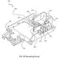
- FIG. 10illustrating a bottom perspective view of an exemplary unitary mounting frame, showing a distal fitting with a cartridge, in accordance with some embodiments of the invention.
- a frame floor 111serves as a base structure of receiving frame 110, and giving mechanical support for the complementary and/or containing geometry of receiving frame 110, and also connecting between the geometrical features.
- FIG. 10shows a bottom view of the geometrical features as positioned on floor 111.
- distal mounting pin 422fitted with distal mount 325.
- distal mount 325comprises a cavity sized for insertion of pin 422.
- distal mount 325covers at least the top portion of pin 422, potentially balancing mechanical forces reaching from the ventral direction from inserting the needle 116 into an injection subject.
- distal mount 325also secures cartridge 120 by mechanically inhibiting further distal movement of the cartridge with respect to receiving frame 110.
- the floor 111 of receiving frame 110is continuous at least between the proximal end of the driving system and the distal end of the cartridge, serving as a wide mechanical platform base.
- floor 111is not continuous and comprises apertures.
- at least the proximal end and/or at least the distal endinclude continuous regions of floor 111. A potential advantage of splitting the continuous regions is that each region would contain forces generated in proximity to it, and the forces would propagate less to other regions.
- the payload of a reservoirmay include, for example between 0.5 and 2ml and/or between 2 and 4ml and/or between 4 and 6 ml and/or between 4 and 10 ml of a drug and/or more.
- the injectormay discharge the entire payload as a single dose.
- a drug delivery devicemay include, for example, a patch injector, and/or an internally powered driver to drive the plunger and/or discharge the payload.
- an internally powered injector drivermay be defined as a drive mechanism powered by energy stored at least temporarily within the injector.
- Powermay be stored in a power supply, for instance as chemical potential (for example a chemical that produces an expanding gas and/or a battery) and/or mechanical potential (for example stored in an elastic member and/or a spring and/or a pressurized gas).
- chemical potentialfor example a chemical that produces an expanding gas and/or a battery
- mechanical potentialfor example stored in an elastic member and/or a spring and/or a pressurized gas.
- the drivermay be designed to discharge the payload over a time period ranging between 20 and 120 seconds and/or between 120 and 600 seconds and/or between 600 seconds and an hour and/or between an hour and a day and/or longer.
- dischargemay be driven by a driver.
- An internally powered drivermay be powered by various mechanisms including for example a motor as discussed, including for example a DC motor, an actuator, a brushless motor, and/or a transmission including for example a telescoping assembly and/or a threaded element and/or a gear and/or a coupling and/or an elastic mechanism (for example a spring and/or a rubber band) and/or an expanding gas and/or a hydraulic actuator).
- a motorincluding for example a DC motor, an actuator, a brushless motor, and/or a transmission including for example a telescoping assembly and/or a threaded element and/or a gear and/or a coupling and/or an elastic mechanism (for example a spring and/or a rubber band) and/or an expanding gas and/or a hydraulic actuator).
- a drug delivery device in accordance with some embodiments of the present inventionmay include a reservoir part as discussed.
- a reservoirmay include a medicine container and/or a syringe.
- a syringemay be preloaded with medicine using standard equipment and/or in an aseptic room.
- a preloaded syringemay optionally include a proximal opening.
- a plungermay optionally seal the proximal opening and/or protect the sterility of the contents of the syringe.
- a sterile needletypically hollow, may optionally be connected to the syringe barrel.
- the hollow of the needlemay be in fluid communication with the interior of the barrel.
- the needlemay optionally be rigidly attached to the extension at the distal end of the barrel.
- the sterility of all and/or part of the needlemay for example be protected by a sterile cover.
- the sterile covermay remain on the needle when the syringe is supplied and/or installed into an injector.
- the medicine containermay optionally include a cylindrical barrel rigidly attached to a needle.
- a plungermay slide axially along the inside of the barrel to discharge a medicine payload.
- the medicinemay be discharged through the hollow needle.
- the protruding tip of the needlemay be oriented at an angle to the axis of the barrel.
- An aspect ratio of the basemay be defined as the ratio of the length of the longest axis of the base to the shortest axis.
- the axis ratiomay range between 1 to 1.5 and/or 1.5 to 2 and/or between 2 to 3 and/or greater than 3.
- the height of the injectormay range between half the length of the short axis of the base to the length of the short axis of the base and/or between the length of the short axis of the base to twice the length of the short axis of the base and/or greater than the twice length of the short axis of the base.
- the height of the injectormay supply leverage for pivoting the adhesive off the skin of a patient after use.
- the force to insert the needle to the skin of a patientmay range for example between 0.02 to 0.2 N and/or between 0.2 and 0.5 N and/or between 0.5 to 5 N.
- the force required to inject the drug(for example the force on a syringe plunger) may range for example between 5 to 60 N.
- the force required to inject the drugmay depend on the injection rate and/or the viscosity of the drug and/or the syringe geometry and/or the needle dimensions.
- a needle protection mechanismmay be triggered by a linear force greater than, for example, between 10 to 60 N.
- drug delivery devicemay include an auto-injector.
- the auto-injectormay be activated by manually pushing with enough force to insert the needle.
- the devicemay then apply an injection force to inject a drug. Once the entire drug is injected and/or when there is an obstruction and/or occlusion, the injection force may rise until it passes a threshold triggering safeguarding of the needle and/or ending injection.
- the linear force generated by the devicemay increase to the level of up to 60 N.
- a needle safeguarding mechanism(for example a needle retraction mechanism) may be sensitive to the force.
- the mechanismmay include a snap that gives way at 40 N returning the needle to the retracted position.
- the stress to inject a medicine and/or to trigger safeguarding of a needlemay include a torque.
- injection of medicinemay be driven by a plunger.
- the plungermay optionally be driven by a threaded assembly, for example a threaded screw and/or teeth and/or a telescoping assembly.
- the pitch of the teeth and/or an associated screwmay range for example between 0.5 and 2 mm.
- the diameter of the screwmay range for example between 2.5 and 15 mm.
- the torque to power injectionmay range for example between 0.2 and 1.0 N ⁇ cm.
- the trigger torque(the torque at which the needle safeguarding is triggered) may range for example between to 0.5 to 2 and/or from 2 to 4 and/or from 4 to 10N ⁇ cm.
- the linear movement of a plungermay range for example between 10-50mm.
- the length of movement of the plungermay vary for example with the volume of medicine to be injected that may range for example between 0.5 to 3ml.
- a safeguarding mechanismmay be sensitive to a torque.
- the needlemay be retracted when the mechanism is exposed to a twisting moment.
- dischargemay be driven by a torque.
- the drivermay apply torque to threaded element pushing a plunger.
- the needlemay be released and/or retracted and/or a needle shield may be deployed.
- the trigger mechanismmay require both a torque and a linear force. For example, requiring both a torque and a linear stress may prevent premature activation due to momentary friction.
- the reservoirmay have a length ranging for example between 20 and 42 and/or 42 and 48 mm and/or 48 and 80 mm and/or 80 and 200 mm.
- an internal cylindrical space of a reservoirmay have an average width ranging for example between 1 and 3 mm and/or 3 and 10 and/or 10 and 15 mm and/or 15 and 25 mm and/or 25 and 50 mm.
- a reservoirmay have a circular cross section such that width is the diameter of the circle.
- an extensionmay have a straight end portion with a length ranging for example between 1 and 3mm or 3 and 7 mm or 7 and 8 or 8 and 10mm or 10 and 15 mm or 15 and 50 mm.
- the exposed straight portion of a needlemay have a length ranging for example between 1 and 5 mm or 5 and 7 mm or 7 and 10 mm or 10 and 20 mm.
- an average outer widthmay be defined as the width of the smallest oval that can enclose the neck averaged over the length of the neck.
- a fluid path between the extension and a reservoir cavitymay include a 27 gauge needle or a needle ranging between 25 and 30 gauge or a needle ranging between 20 and 25 gauge or a needle ranging between 30 and 32 gauge.
- a needle protruding from an extensionmay include a 27 gauge needle or a needle ranging between 25 and 30 gauge or a needle ranging between 20 and 25 gauge or a needle ranging between 30 and 32 gauge.
Landscapes
- Health & Medical Sciences (AREA)
- Vascular Medicine (AREA)
- Engineering & Computer Science (AREA)
- Anesthesiology (AREA)
- Biomedical Technology (AREA)
- Heart & Thoracic Surgery (AREA)
- Hematology (AREA)
- Life Sciences & Earth Sciences (AREA)
- Animal Behavior & Ethology (AREA)
- General Health & Medical Sciences (AREA)
- Public Health (AREA)
- Veterinary Medicine (AREA)
- Dermatology (AREA)
- Infusion, Injection, And Reservoir Apparatuses (AREA)
Description
- The present invention, in some embodiments thereof, relates to automatic injectors and, more particularly, but not exclusively, to force containment in automatic injectors.
U.S. Patent 6500150 ,U.S. Patent 6824529 , andU.S. Patent 6843782 disclose a drug delivery device having a base member defining a skin-contacting surface, a syringe serving as a reservoir for the drug, and means for expelling drug from the syringe. The syringe is connected to the base member such that the longitudinal axis of the syringe is substantially parallel to the skin surface. A delivery needle is in communication with the syringe. The needle has an angled bend which directs the tip of the needle substantially perpendicular to the skin-contacting surface. In use, the tip of the needle is adapted to penetrate the skin of the subject.- For such relatively slow release, an automatic expulsion device has also been suggested.
U.S. Patent 5858001 discloses a liquid drug delivery device adhered to the skin of a subject by a base member defining a skin-contacting surface having an adhesive coating. A columnar cartridge serves as reservoir for the drug and is incorporated in a housing which is connected to the base member such that in use the longitudinal axis of the cartridge is disposed substantially parallel to the skin-contacting surface. A delivery needle communicating in use with the interior of the cartridge penetrates the skin of the subject when the housing snaps downward relative to the base member. This action also causes the actuation of a citric acid/sodium bicarbonate gas generator which generates a gas to move a piston within the cartridge, compressing the drug compartment. This compression causes a stopper to be penetrated by a conduit in communication with the delivery needle, allowing the drug to be ejected from the compartment through the needle and into the subcutaneous tissue of the subject. - Additional background art includes
U.S. Patent no. 6189292 .U.S. Patent Publication No. 20130253434 ,U.S. Patent Publication No. 2009/093,792 ,U.S. Patent No. 7967795 . - The invention is defined by claim 1. It comprises a method of connecting a cartridge having a connection feature to an automatic injector having a motor, the cartridge being interconnected to a needle at its distal end. Additional features of preferred embodiments of the invention are defined in the dependent claims.
- Unless otherwise defined, all technical and/or scientific terms used herein have the same meaning as commonly understood by one of ordinary skill in the art to which the invention pertains. Although methods and materials similar or equivalent to those described herein can be used in the practice or testing of embodiments of the invention, exemplary methods and/or materials are described below. In case of conflict, the patent specification, including definitions, will control. In addition, the materials, methods, and examples are illustrative only and are not intended to be necessarily limiting.
- Some embodiments of the invention are herein described, by way of example only, with reference to the accompanying drawings. With specific reference now to the drawings in detail, it is stressed that the particulars shown are by way of example and for purposes of illustrative discussion of embodiments of the invention. In this regard, the description taken with the drawings makes apparent to those skilled in the art how embodiments of the invention may be practiced.
- In the drawings:
FIG. 1 is a block diagram schematically representing an automatic injector receiving frame for fitting with a cartridge and a driving system of the cartridge, in accordance with some embodiments of the invention;FIG. 2 is a high level overview of a method for immobilizing movement of a cartridge with respect to an automatic injector assembly, in accordance with some embodiments of the invention;FIG. 3A is an exemplary unitary receiving frame illustrating a distal and proximal geometry for fitting with and immobilizing components of an automatic injector, in accordance with some embodiments of the invention;FIG. 3B is an exemplary unitary receiving frame fitted with various components of an automatic injector, in accordance with some embodiments of the invention;FIG. 4 is an exemplary cartridge having distal and proximal mounting pins for connecting with a receiving frame, in accordance with some embodiments of the invention;FIG. 5 is an explosive view of an automatic injector being loaded with a cartridge and covered with a cover, in accordance with some embodiments of the invention;FIG. 6 is a close-up cross-sectional view of an exemplary geometry and interference connection of a proximal portion of a unitary receiving frame with a proximal portion of a cartridge, in accordance with some embodiments of the invention;FIG. 7 is a perspective top view of an exemplary side-by-side configuration of the cartridge and the driving system of the cartridge, in accordance with some embodiments of the invention;FIGs. 8A and 8B illustrate a side view of a snap fitting and immobilization of a cartridge, in accordance with some embodiments of the invention, whereinFIG. 8A illustrates a cross-sectional view ofFIG. 8B illustrates a partial perspective view;FIG. 9 is a cross-sectional side view of the automatic injector, illustrating an incorporation of a cover extension in the immobilization system, in accordance with some embodiments of the invention; andFIG. 10 illustrates a bottom perspective view of an exemplary unitary receiving frame, showing a distal fitting with a cartridge, in accordance with some embodiments of the invention.- The present invention, in some embodiments thereof, relates to automatic injectors and, more particularly, but not exclusively, to force containment in automatic injectors.
- An aspect of several embodiments of the invention relates to immobilizing a cartridge with respect to an automatic injector mounting plate, the mounting plate used for mounting over an injection subject. In some embodiments, immobilizing includes reducing axial translation of the cartridge, for example, axial translation of the cartridge towards the distal end of the mounting plate, defined as the end comprising an injection needle, and/or axial translation of the cartridge towards the proximal end of the mounting plate, defined as the end comprising a plunger. Alternatively or additionally, immobilizing comprises inhibiting rotational movement of the cartridge, for example, movement in the form of rotation around the longitudinal axis of the cartridge.
- In some embodiments, it is desirable that the cartridge is immobilized in the injector sufficiently that operating the plunger mechanism to expel the contents does not move the cartridge. If the cartridge were to move then the needle may cause discomfort to the patient in the skin around the needle. This is especially relevant for a cartridge having a bent fluid path, which translates any rotational movement of the cartridge into an axial translation movement of the elongated axis of the needle.
- In order to provide such immobilization, in some embodiments, a receiving frame is provided within the injector mounting plate to receive the cartridge. Optionally, the cartridge is fixedly received, i.e. while the cartridge is received it is also fixed to the receiving frame. For example, fixed includes immobilizing movement of more than 0.1 mm, and/or more than 0.5 mm, and/or more than 1 mm, and/or more than 2mm, and/or more than 4 mm. In some embodiments, the receiving frame engages the cartridge such that forces exerted on the cartridge, forces which might cause its translation and/or rotation, are sufficiently reduced. Alternatively or additionally, the receiving frame is provided to contain force generated by components which are mechanically coupled to the cartridge. In some embodiments, the cartridge is mechanically coupled to a plunger driver, optionally by having a driving system which is mechanically connected to a plunger residing within the reservoir of the cartridge. In some embodiments, the plunger driver is found in a mechanical operable communication with a motor, optionally through a transmission system. Optionally, forces generated by the motor, and/or by the plunger driver are contained within the receiving frame. In some embodiments, a single frame is used for fixedly receiving the cartridge and its associated plunger driver and/or motor.
- Optionally, the receiving frame is formed as a unitary frame. As used herein, unitary includes being formed and/or molded as a single unit, without having more than one component. It should be noted that having a plurality of components being interlocked to form a single unit, are not included herein in the scope of the term unitary. In order to avoid movement of the distal portion of the cartridge, where the needle is positioned, it is preferable to dissipate forces near their source, e.g. the proximal portion comprising the motor and driving system. Alternatively or additionally, it is useful to utilize a receiving frame having as little as possible different parts, such as no more than three, or no more than two, or no more than one unitary frame.
- In some embodiments, the receiving frame comprises a dorsal side for fixedly receiving at least the cartridge, and a ventral side for placing onto a mounting plate. Optionally, the receiving frame is hingely connected to the mounting plate, optionally at its sides. In some embodiments, it is desirable that the injector housing would have a small height, potentially enabling easier gripping. In some embodiments, the height may be reduced by positioning of the cartridge, the driver mount and the motor in a side-by-side arrangement, for example by positioning the longitudinal axes of each of the cartridge, the plunger driver and the motor on the same plane, optionally, parallel to the plane defined by the base of the housing, and/or the plane used for mounting on the injection subject.
- In some embodiments, the receiving frame comprises at least one interference element which has a geometry for holding the cartridge. In some embodiments, the interference element engages with a connection feature, such as for example a complementary geometry, comprised in the cartridge. For example, the interference element may include holders into which complementary geometry in the form of extensions on the body of the cartridge can slide into. In some embodiments, the cartridge and its complementary geometry slide towards the distal end of the housing, up to a distal stop. Optionally, the complementary geometry is then latched at a final resting position by a catch located behind, so that the cartridge can be inserted with a down, slide and click operation. As used herein, an interference element includes a restraining geometry for engaging with a connection feature of the cartridge, for example, by enveloping the connection feature from three directions, or being enveloped by the connection feature in three directions.
- Alternatively or additionally, the cartridge may include a complementary geometry in the form of flange and/or cut out and/or bevel and/or an indentation and/or a protrusion and/or a pin and/or a stabilizer and/or a hole and/or a snap fitting and/or hook and/or a pin designed to mate with the fitting of the interference element of the receiving frame. Optionally, the interference element includes a flange and/or cut out and/or bevel and/or an indentation and/or a protrusion and/or a pin and/or a stabilizer and/or a hole and/or a snap fitting and/or hook and/or a pin.
- In some embodiments, a non-symmetric cartridge is provided. Optionally, loading the non-symmetric syringe into a device in the correct orientation requires reference points and/or connection features. In some embodiments, the fitted geometry of the interference elements with the complementary geometry of the cartridge serves as reference points.
- In some embodiments, interference elements are sized and shaped to accommodate three sides of the complementary geometry, optionally the dorsal side, the ventral side and the distal side, resulting in a holder which holds the complementary geometry in three directions. Alternatively, it is the complementary geometry which surrounds the interference element, optionally across the dorsal side, the ventral side and the proximal side. In some embodiments, mechanically interfering across the dorsal and ventral portions of the complementary elements mechanically hinders their movement. In some embodiments, at least two interference elements are provided in opposite locations positions along the longitudinal axis of the cartridge, each positioned at an opposite location across the cartridge reservoir. Potentially, providing mechanical interference in at least two locations positioned across the circular diameter of the cartridge reduces rotational movement.
- In some embodiments, after the cartridge slides to be engaged with the interference elements, up to the distal stop, an elastic element closes a fourth side of the cartridge. For example, a snap may be elastically pushed down when lowering the cartridge into the receiving frame, and once the cartridge slides towards the distal end, the elastic element is released and secures the cartridge from a fourth side, such as the proximal side. Optionally, the elastic element is a snap. In some embodiments, at least two snaps are provided, each securing an engagement of at least two interference elements with complementary geometries. In some embodiments, securing the complementary geometry of the cartridge from the distal end, such as by the distal stop, and from the proximal end, such as by the elastic element, reduces movement in a lateral, axial translocation.
- In some embodiments, the receiving frame is configured to hold the proximal side of the cartridge and the plunger driver together. In some embodiments, the walled driver mount balances rearward forces of the plunger driver while the interference elements balance longitudinal forces between the plunger driver and the cartridge. In some embodiments, torque formed between the transmission, the plunger driver and the cartridge is directed to the proximal portion of the receiving frame. In some embodiments, the interference elements and the walled containments prevent movement in a distal direction, in an upwards direction or in a rotation around the axis of the cartridge. In some embodiments, the proximal elastic element prevents the cartridge from moving proximally and also prevents the cartridge from being disconnected from the receiving frame.
- In some embodiments, the receiving frame comprises a distal complementary element for engaging and stabilizing a distal portion of the cartridge near the needle. In some embodiments, the cartridge comprises a bent fluid path extending from a dorsal outlet and bending towards the ventral side of the cartridge. In some embodiments, the distal complementary element is positioned on the free ventral side of the cartridge. In some embodiments, when the distal complementary element is engaged with the receiving frame, forces emanating from the needle, such as from usage of the needle or from delivery shocks, are dissipated. For example, a distal portion of a cartridge might have has an elongated protrusion, extending beyond the edge of the cartridge, and being complementary to slide into a hole provided in the receiving frame. In some embodiments, distal connectors hold the needle steady against vertical forces of needle insertion or lateral forces against the needle. In some embodiments, the fitting geometry also prevents forward movement in the axial direction. In some embodiments, the distal pin is within the cross section of the cartridge and does not interfere with a process for filling the cartridge.
- In some embodiments, the cartridge itself comprises complementary geometry elements for fitting with geometric elements in the receiving frame. In some embodiments, a cross-section across a reservoir of the cartridge lacks an axial symmetry, for example, it is not round. Alternatively or additionally, the cross-section across a reservoir of the cartridge has a central symmetry, for example, by having a geometrical element on either side of the reservoir. In some embodiments, the cartridge is manufactured by molding, optionally Crystal Zenith. A potential advantage of molding is the possibility to build into the cartridge geometric features which make the syringe easier to mount in an injection device. Alternatively or additionally, the syringe may include a molded component. Optionally the molded component includes the extension. For example the molded component may be made of Daikyo Resin CZ (Crystal Zenith) or other Cyclic Olefin Polymer (COP) or any moldable material suitable to use with drug product. Alternatively or additionally, molded components may be made of, for example, polycarbonate and/or polypropylene and/or other polymers.
- An aspect of some embodiments of the invention relates to a receiving frame to be fit within of an automatic injector, optionally within a proximal portion, and for containing forces generated between a motor, a plunger driver and a cartridge comprising the plunger. In some embodiments, a unitary frame is provided having at least two mount containments, one for each of the plunger driver and the cartridge. In some embodiments, the unitary frame is further provided with a third mount containment for the motor. Optionally, the unitary frame comprises walls for containing and dissipating the forces emanating from each of the motor and/or the plunger driver.
- In some embodiments, the receiving frame is configured to receive from above a cartridge being mechanically coupled to the plunger driver. Optionally, the cartridge is mechanically coupled to the plunger driver through a plunger which resides within the reservoir of the cartridge and is mechanically connected to at least one arm of the plunger driver. In some embodiments, the plunger driver comprises a driving assembly, optionally a telescopic system. For example, the plunger driver may include threaded telescoping rods such that when a transmission is rotated (for example by a motor) the telescoping rods expand the plunger into the reservoir possibly causing discharge of a pharmaceutical substance out of the cartridge fluid path.
- Alternatively, the receiving frame is configured to receive from above a cartridge being mechanically coupled to the plunger driver and to the motor, for example, through a transmission mechanically coupling an operative communication between the motor and the plunger driver.
- In some embodiments, the mount containments of the receiving frame comprise an open top, allowing the lowering of the cartridge and its associated components into the receiving frame from above. In some embodiments, the geometry of the receiving frame is configured to allow lateral sliding of the cartridge with the plunger driver, for example towards the distal end of the receiving frame.
- For automatic operation, in some embodiments, an electric motor is provided to operate the plunger. In order to lower the profile of the device so that it is easy to hold flat and still against the skin, the motor is in some embodiments placed along an axis that is on the same plane as an axis of the cartridge. Optionally, the motor and the cartridge/plunger axes are parallel to each other. Further optionally, both are substantially perpendicular to the axis of injection into the skin, for example, when the cartridge comprises a bent fluid path.
- In some embodiments, a cartridge mount is provided in the receiving frame for receiving the cartridge from above. Optionally the cartridge is fixed to the receiving frame after it is lowered into the receiving frame. Alternatively, the cartridge is fixed to the receiving frame while it is being lowered into the receiving frame. As used herein, fixed to the receiving frame relates to restraining the cartridge in place, for example inhibiting its movement for more than 0.1 mm, and/or more than 0.5 mm, and/or more than 1 mm, and/or more than 2mm, and/or more than 4 mm. In some embodiments, the cartridge mount comprises the interference element with the distal stop, the interference element sized to slidably receive the cartridge and allow the cartridge to slide up to the distal stop.
- In some embodiments, a driver mount is provided in the receiving frame for fixedly containing the driver mount. In some embodiments, the driver mount comprises a walled compartment, at least partially surrounding the plunger driver. In some embodiments, the close proximity of the walls of the compartment to the plunger driver causes forces generated in the plunger driver to dissipate, such that forces that might reach the cartridge are reduced.
- In some embodiments, the walled containment of the driver mount comprises a gap in its proximal end, sized to accommodate a proximal portion of the driver plunger. Optionally, the gap assists in eliminating mechanical interference when lowering the cartridge with the driver plunger into the receiving frame. In some embodiments, once the cartridge and its associated driver plunger are shifted towards the distal side of the housing, the gap no longer accommodates the driver plunger. Optionally, a housing top cover comprises an extension sized and/or shaped to fit between the gap and the proximal portion of the plunger driver. Optionally, the cover extension serves as an additional supporting wall, aiding in the force dissipation of the driver mount.
- In some embodiments, a motor mount is provided in the receiving frame to contain the motor and dissipate forces generated by the motor. In some embodiments, the motor mount comprises an open top for receiving the motor from above. Optionally, the motor mount comprises at least two walls, optionally oppositely positioned, sized to fit over the motor sides, optionally its longitudinal sides. In some embodiments, the walls comprise a rail for slidably guiding and securing the receiving of the motor.
- Optionally, the receiving frame is provided with a transmission mount. In some embodiments, the transmission mount is positioned between the motor mount and the plunger driver mount. In some embodiments, the transmission mount comprises an elongated rod configured for fitting with a center of a wheeled transmission system.
- In some embodiments, the driver mount and/or the motor mount are suitable for containing forces of at least 10 Kg∗cm, or at least 15 Kg∗cm, or at least 20 Kg∗cm, or at least 25 Kg∗cm.
- An aspect of some embodiments of the invention relates to force containment between a cartridge having a bent fluid path and an automatic injector apparatus. In some embodiments, force containment comprises reducing movement of a needle of the cartridge with respect to the injector base, which might arise from force exerted on the cartridge, for example, when driving fluid out of the cartridge. In some embodiments, an injector base is provided with a unitary mounting frame having interfering geometry for fitting with the cartridge, optionally at least for fitting with a distal portion of the cartridge and a proximal portion of the cartridge.
- In some embodiments, the unitary frame is configured to contain forces along a longitudinal axis of the cartridge. Specifically, in some embodiments, the high forces between the plunger driver system and the plunger are dissipated. Typically, relatively high forces may be exerted on the cartridge by the plunger driving system, for example, about 3-4 Kg. High forces may cause instability of the cartridge which may lead to movement and/or breakage of the cartridge.
- Alternatively or additionally, the unitary frame is configured to contain rotational forces. In some embodiments, the cartridge is connected to the needle at an angle, resulting in a configuration which is sensitive to both lateral and rotational movements of the cartridge, where small movements (rotation and/or translation) of the syringe may cause pain to the user or failure of the device. This is as opposed to syringes having a straight needle, which typically are not sensitive to a rotational displacement.
- In some embodiments, the unitary frame structure is designed to create a local force balance at cartridge locations prone to impact, for example, at the distal end of the cartridge comprising the needle, where force is exerted when the needle is being pushed into a user's body, and/or at the proximal end comprising the plunger driving assembly, where forces are exerted on the plunger in order to drive fluid out of the cartridge. A potential advantage of using a unitary frame for containing longitudinal force along an axis is the durability of the frame to withstand the forces exerted by the injector operation, potentially reducing breakage and/or disassembly, which might arise in a plurality of interconnected components. Often longitudinal forces are balanced on different parts and/or at different ends of the syringe. For example, proximal plunger driving forces may be absorbed by a door at the proximal end, while a distal force against the cartridge may be absorbed by the injector housing at the front of the injector. This may cause instability of the injector and/or cause high forces on joints between parts.
- An aspect of some embodiments of the invention relates to a low profile patch auto injector. In some embodiments a low profile patch auto injector may include a frame fitted to accommodate a cartridge. In some embodiments, the frame is walled. In some embodiments, the frame is pivotly connected at the front, distal end (needle end) of the injector to a base. In some embodiments the injector includes a cover. In some embodiments, the syringe in the cartridge is symmetric. In some embodiments, the syringe in the cartridge is non-symmetric. In some embodiments the frame includes a receiving frame that supports the cartridge.
- In some embodiments, at least a portion of the walled frame is floored. In some embodiments, the height of the frame wall varies at different locations. In some embodiments, the wall is continuous throughout its circumference. In some embodiments, the wall is discontinuous in portions of its circumference. In some embodiments, the cover fits over the frame wall. In some embodiments, the cover walls follow and parallel the frame wall. In some embodiments, the cover wall covers missing portions of the frame wall. In some embodiments, the cover includes a removable central section. In some embodiments, the cover central section includes a wall that parallels a portion of the cover wall forming a double wall at that location.
- An aspect of some embodiments of the invention relates to a receiving frame that supports the cartridge. In some embodiments, the receiving frame includes a stress containment enclosure. In some embodiments, the stress containment enclosure mechanically mediates stress effected on the frame by the syringe and vice versa. In some embodiments the enclosure includes a portion of the injector cover. In some embodiments, the stress containment enclosure steadies and stabilizes the cartridge. In some embodiments, the receiving frame includes means for supporting the cartridge. In some embodiments, the receiving frame includes coupling mechanisms to attach the cartridge thereto. In some embodiments, the coupling mechanism includes the injector cover. In some embodiments the cartridge includes gripping members. In some embodiments, the receiving frame-cartridge coupling mechanisms function as guides and guide a cartridge being mounted to its correct final location on the receiving frame. In some embodiments the receiving frame supports the injector syringe plunger driving power train.
- In some embodiments, the receiving frame supports a printed circuit board (PCB). In some embodiments, the receiving frame supports cover locking/unlocking mechanism. In some embodiments, the receiving frame provides structural support to the frame.
- The cartridge may be pre-filled in a sterile aseptic environment using standard equipment for filling syringes prior to insertion in the injector. The injector itself need not be sterile. As the needle is molded into the cartridge it is desirable that the cartridge is immobilized in the injector sufficiently that operating the plunger mechanism to expel the contents does not move the cartridge. If the cartridge were to move then the needle may cause discomfort to the patient in the skin around the needle. In order to provide such immobilization, there may be provided a clip that fits within the injector and which has a catch mechanism for holding the cartridge. The catch mechanism may include bridge holders into which extensions on the body of the cartridge can slide and then be latched at a final resting position by a catch located behind, so that the cartridge can be inserted with a down, slide and click operation.
- The injector may provide for insertion of the needle by a simple action of pressing by the user, whether patient or medical personnel when the injector is located on the skin. The needle cover is removed, the injector is placed on the skin and a button is pressed.
- Before explaining at least one embodiment of the invention in detail, it is to be understood that the invention is not necessarily limited in its application to the details of construction and the arrangement of the components and/or methods set forth in the following description and/or illustrated in the drawings and/or the Examples. The invention is capable of other embodiments or of being practiced or carried out in various ways.
- Referring now to the drawings,
FIG. 1 shows a block diagram representing an automatic injector mounting frame for fitting with a cartridge and a driving system of the cartridge, in accordance with some embodiments of the invention. - In some embodiments, an automatic patch injector is mounted on an injection subject. In some embodiments, the automatic injector comprises mounting
plate 101. In some embodiments, mountingplate 101 is used for holding the device and for containing the internal components of the injector, such ascartridge 120 havingneedle 116 at itsdistal end 104 andplunger 141 at itsproximal end 106. In some embodiments,cartridge 120 comprises a reservoir, optionally filled with a pharmaceutical substance. As used herein, a pharmaceutical substance comprises any fluid used for injecting into an injection subject, such as a drug, a placebo, a nutrient and so forth. - In some embodiments, mounting
plate 101 comprises receivingframe 110 for fixedly containing at least some of the internal components of the automatic injector. Optionally, receivingframe 110 is unitary, i.e. made from a single piece of material. In some embodiments, receivingframe 110 comprises a ventral side for fixing with mountingplate 101 and/or the injector's base portion, and a dorsal side having geometry for containing internal injector components. - In some embodiments, forces are generated by
motor 170 and transmitted toplunger driver 140, optionally through a transmission system. In some embodiments, large forces, for example 3-5 Kg, are generated byplunger driver 140 when drivingplunger 141 insidecartridge 120. In order to eliminate forces over the longitudinal axis of the cartridge, which might give in and break, in some embodiments forces are dissipated by receivingframe 110 in proximity to their generation site. - In some embodiments, receiving
frame 110 comprises geometries for fixedly containing force generating components and/or force affected components. For example, receivingframe 110 may comprise the driving system of the injector which includes at least a cartridge mount for fixedly receivingcartridge 120, a driver mount for containingplunger driver 140 and a motor mount for containingmotor 170. In some embodiments, forces are locally balanced. In some embodiments, receivingframe 110 comprises geometry which contains the components of the driving system of the injector in proximity to one another, for example inproximal end 106. A potential advantage of containing force exerting and exerted components in proximity is that forces may be dissipated close to where they are generated and/or affecting, without being projected to other regions of the injector. Another potential advantage of a limited space for containing force is that force containing structures in receivingframe 110 are provided at the limited region, reducing redundancy of structures. - In some embodiments, receiving
frame 110 comprises a platform, e.g. a planer structure. In some embodiments, the components of the driving system, atleast cartridge 120,plunger driver 140 andmotor 170, are contained side-by-side over the platform, optionally each of the components are placed along their longitudinal axis. In some embodiments, the longitudinal axes ofcartridge 120,plunger driver 140 andmotor 170 are positioned on the same plane, and/or parallel planes, optionally additionally parallel to the injector base plane. A potential advantage of placing the longitudinal axes laterally on substantially the same plane is limiting the height of the housing and injector device, possibly making it easier to be held by hand, and easier to transport. - Reference is now made to
FIG. 2 , showing a high level overview of a method for immobilizing movement of a cartridge with respect to an automatic injector housing, in accordance with some embodiments of the invention. - In some embodiments, a housing is provided202 having within it a receiving frame. In some embodiments, the receiving frame serves as a chassis, containing the internal components of the injector. In some embodiments, a cartridge is lowered204 into the receiving frame fitted within the housing from above. Optionally, the cartridge is lowered while being mechanically coupled to a plunger driver. In some embodiments, mechanical coupling between the cartridge and the plunger driver comprises an arm, optionally telescopically extended, which mechanically connects to a plunger residing within the reservoir of the cartridge. Alternatively or additionally, the cartridge may be lowered into the receiving frame while being mechanically coupled to a motor, the motor being in operable mechanical communication with the plunger driver, optionally through a transmission system.
- In some embodiments, the cartridge, and possibly its associated components, is being laterally moved by sliding206 towards the distal end of the receiving frame, defined as the end fitting with the distal portion of the cartridge, which comprises the needle outlet. In some embodiments, by sliding the cartridge in206, the cartridge is interlocked208 with the receiving frame, optionally by engaging with geometry provided in the receiving frame, such as interference elements and/or snap latches. A potential advantage of activating engagement by positional translocation into a fitting geometry is that it enables a delicate interlocking mechanism, i.e. a mechanism which requires a small amount of force to apply, as opposed to a mechanism of elastic fitting which operates on the basis of first pushing away the interfering element, instead of sliding into it.
- In some embodiments, the cartridge is lowered down from above while being mechanically coupled with the driving system of the injector, e.g. the plunger driver and/or the motor. In some embodiments, the receiving frame contains walled compartments for receiving the coupled components of the cartridge. In some embodiments, the walled compartments are not uniform in wall height, for example having gaps, and enable some portions of the driving system to extend beyond the boundaries of the walled compartments. Optionally, by sliding206 the cartridge into its interlocked position, the driving system components extending beyond the boundaries are shifted to be positioned as a whole inside the boundaries of the walled compartments. In some embodiments, a space is formed between the wall having the gap and the driving system components.
- Optionally, the receiving frame is covered210 with a housing cover. In some embodiments, the housing cover complements gapped regions in the walled compartments of the receiving frame. In some embodiments, the housing cover comprises extensions sized and/or shaped for fitting in the space between the wall and the shifted component. In some embodiments, the filling in of the extension provides mechanical support for the components, aiding in the dissipation of the force emanating from the components. For example, being mechanically connected to the plunger, the plunger driver may be found in a proximal position to the cartridge. A gap in the walled compartment containing the plunger driver enables the proximal portion of the plunger driver to extend beyond the boundary of the wall. When the cartridge is shifted distally by sliding, so does the coupled plunger driver. By shifting distally, the plunger driver may now be fully contained within the compartment.
- However, the remaining gap may lead to insufficient containment of forces which cause the plunger driver to shift towards a proximal direction. Filling this space with the cover, may provide a supporting wall that would balance these forces, reducing movement of the plunger driver. In some embodiments, the plunger driver delivers212 fluid by extending a threaded telescopic extension towards the distal direction, where the plunger is with respect to the plunger driver. The plunger is then pushed towards the distally located outlet comprising the needle, driving the fluid out of the cartridge. Providing the proximal support in the form of the walled compartment, provides an anchoring point enables the extending arm to push the plunger distally, against the pressure of the fluid, rather than having the plunger driver being pushed proximally.
- Reference is now made to
FIG. 3A , illustrating an exemplary unitary mounting frame illustrating a distal and proximal geometry for fitting with and immobilizing components of an injector, in accordance with some embodiments of the invention. - In some embodiments, receiving
frame 110 comprises two regions of geometric fitting, a proximal region and a distal region. In some embodiments, a distal region secures the distal portion ofcartridge 120 bydistal mount 325, exemplified and illustrated, for example inFIG. 4 , showing thedistal mounting pin 422 ofcartridge 120 andFIG. 10 showing the distal mount engaged with thedistal mounting pin 422 ofcartridge 120. In some embodiments, a proximal region of receivingframe 110 comprises the proximal force generating components of the injector. In some embodiments, the two regions are positioned onfloor 111 of receiving frame, which is optionally not continuous between the regions, as exemplified and shown inFIG. 10 . In some embodiments,floor 111 is substantially flat and serves as a base on which the complementary geometries of receivingframe 110. - In some embodiments, a proximal portion of receiving frame comprises a
cartridge mount 327, aplunger driver mount 315 and amotor mount 317. Optionally, all mounts are found in proximity to one another, potentially dissipating forces near their generation sites and reducing forces propagation into less secured components and regions. In some embodiments, each mount contains geometric features which are sized and shaped to contain the injector components. Optionally, the receiving frame and its geometric features are unitary, for example, by generating them in a molding process. In some embodiments, the mounts comprise joint walls and/or geometries for containing forces from both sides of the mounts. - In some embodiments,
cartridge mount 327 comprises complementary geometry for fitting with geometric structures in the proximal end ofcartridge 120. For example,interference elements 332,distal stop 333 and snaps334, which are further exemplified and illustrated inFIGs. 6 ,8A ,8B ,9 and10 . - In some embodiments,
driver mount 315 compriseswalls 316 defining a containing compartment, optionally covering at least a portion of three sides of the plunger driver. In some embodiments, a forth side of the plunger driver is secured by being mechanically coupled tocartridge 120. Potentially, the walls stabilize the forces generated byplunger driver 140 and prevent its movement in at least three directions. It is a potential advantage to immobilize the plunger driver when it is mechanically coupled to the cartridge, in order to reduce movement which would result in movement of the cartridge. In addition, dissipating forces close to their generating sites reduces the effect of these forces at other sites. - In some embodiments,
driver mount 317 is open topped, allowing for the plunger driver to be loaded from above. In some embodiments, due to its coupling tocartridge 120, and sincecartridge 120 is distally shifted, the geometry ofdriver mount 317 permits a distal translocation ofplunger driver 140, for example, by providing a walled compartment which is bigger than the distal-proximal axis ofplunger driver 140. In some embodiments, a space formed between the proximal wall and the proximal end ofdriver 140 is filled by an extension of the housing cover, optionally sized and/or shaped for fitting into the formed space. In some embodiments,gap 320 is provided to allow for a more proximal positioning ofdriver 140, without mechanical interference by the proximal wall.Gap 320 is further shown and illustrated inFIG. 3B andFIG. 9 . - In some embodiments, a
motor mount 317 is provided, optionally in proximity to the proximal end of the cartridge which is relatively secured. In some embodiments, motor mount is positioned laterally with respect todriver mount 315. In some embodiments, motor mount compriseswalls 318 fitting the width ofmotor 170. Optionally,walls 318 comprise guidingrails 319, guiding an insertion ofmotor 170 into itsmount 317. In some embodiments,walls 318 are not continuous and provide access for a transmission system to interconnect between themotor 170 andplunger driver 140. - Reference is now made to
FIG. 3B , an exemplary unitary mounting frame fitted with some components of an automatic injector, in accordance with some embodiments of the invention. - In some embodiments, an automatic injector device includes an actuator, for
example motor 170, optionally DC motor. In some embodiments, an automatic injector device includestransmission 302, for example mechanically coupled to aplunger driver 140. In some embodiments, an automatic injector device includes a power source. When the power source is electrically connected tomotor 170,motor 170 optionally rotates gear wheels oftransmission 302 being attached to drivingplunger 141 to discharge a drug. - Optionally a
cartridge 120 may be installed into the device (for example preinstalled and/or installed by a user). In some embodiments the cartridge may includereservoir 410 optionally containing a drug and/or plugged at a proximal location with aplunger seal 140 and/or having anextension 305 and/orneedle 116, optionally protected by a needle cap (not shown).Optionally plunger driver 140 may also be a part ofcartridge 120. Alternatively or additionallyplunger driver 140 may be part of the injector device. - In some embodiments, receiving
frame 110 further comprises anelectric motor 170 for operatingplunger 141 to empty thereservoir 410 intoneedle 116, optionally to inject fluid from thereservoir 410 into the injection subject. In some embodiments, the motor and the reservoir have parallel longitudinal axes, optionally typically perpendicular to the axis of the needle at the point of injection. In some embodiments,motor 170 is held to receivingframe 110 bymountings 318 and operatestransmission 302, optionally having a succession of gear wheels, to advanceplunger 141. - Reference is now made to
FIG. 4 , illustrating an exemplary cartridge having distal and proximal mounting pins for connecting with a mounting frame, in accordance with some embodiments of the invention. - In some embodiments, the automatic injector cartridge comprises complementary geometry for fitting with the geometry provided in receiving
frame 110. For example, the proximal end ofcartridge 120 comprises mountingpins 425, which may engage withcavities 332 in receivingframe 110. In some embodiments, mountingpins 425 extend beyond the outer boundary of the body ofreservoir 410. Optionally, mountingpins 425 are connected throughpin connection 427, which may be for example an extended rod connecting between the pins and potentially providing greater stability and strength than pins which are unrelated to one another. In some embodiments, mountingpins 425, andoptionally connection 427, together with their complementary geometry in the receiving frame, determine the directionality of insertion ofcartridge 120 into the injector. It is a potential advantage to provide directionality indicators such aspins 425, when using an off-centered fluid outlet, and/or when using a bent fluid path, both defining a preferable orientation with respect to an injection subject. - In some embodiments, a distal complementary geometry is provided at the distal end of
cartridge 120. For example,distal mounting pin 422 is provided as an extension protruding from the distal boundary of the cartridge, optionally centered. In some embodiments,pin 422 is sized to fit with fitting geometry on the proximal end of receivingframe 110. - In some embodiments, both
pins 425 and pin422 are shaped to engage with cavities which are positioned distally to the pins. This directionality enables the loading of the cartridge by sliding it towards the distal cavities until reaching a mechanical stop. For example, untilpins 425 run intodistal stop 333, and/or untilpin 422 is fully inserted intocavity 325 and the cartridge distal wall mechanically inhibits further movement. Optionally, mountingpins 425 are proximally secured by snaps which elastically deflect to allow lowering the cartridge, and snap back into position when the mountingpins 425 are slid distally. - Reference is now made to
FIG. 5 , illustrating an explosive view of an automatic injector being loaded with a cartridge and covered with a cover, in accordance with some embodiments of the invention. - In some embodiments, the injector has a
base part 520 which is placed in contact with the skin of a subject to receive the injection. In some embodiments, receivingframe 110 receives and fixescartridge 120 within mountingplate 101. The mountingplate 101 is pivotally mounted onbase 520. - In some embodiments, receiving
frame 110 comprises aninterference element 332 with adistal stop 333 and optionally snap, for exampleelastic snap lock 334. The cartridge is lowered vertically into the slide connecter, pushing downsnap 334. The cartridge is then slid forward to the distal stop and upon reaching the distal stop the latch is released to latch the cartridge in place from behind against the distal stop. The down, slide, click motion of inserting the cartridge into receivingframe 110 is illustrated by arrowsA andB, illustrating the downwards loading and the lateral sliding towards the distal end, respectively. - In some embodiments, cover510 fits on mounting
plate 101 over the reservoir part of thecartridge 120, after the cartridge is placed in position, optionally having extensions, forexample extension 512, for filling in the space which is formed betweenplunger driver 140 and receivingframe 110. - Reference is now made to
FIG. 6 , illustrating a close-up cross-sectional view of an exemplary geometry and interference connection of a proximal portion of a unitary mounting frame with a proximal portion of a cartridge, in accordance with some embodiments of the invention. - Illustrated is a perspective view of an exemplary proximal connector structure, showing interference elements and snaps for mounting a cartridge to a receiving frame. Optionally snaps and/or fittings and/or pins may be molded into the cartridge. For example fittings may include a plastic snap, a rivet, a pin, a cut out, an indentation, a protuberance, snap clamps, a catch, a ball fitting, a latch, a barb etc.
- In some embodiments, two interference elements are provided, for
example interference elements 332. It should be noted that the view illustrated inFIG. 6 shows only oneinterference element 332, but another one is found on the opposite side not shown in this view. This is applicable to all other components which are mentioned herein to include two members, but showing only one, unless mentioned otherwise. - In some embodiments,
interference elements 332 are shaped to have a cavity shape by covering three sides ofpins 425. For example, the bottom side is covered by the receiving frame'sfloor 111, optionally in an offset position to the fitting from other directions, as in some embodiments, the mountingpin 425 extends along the entire length of the cartridge proximal side throughconnection 427, as shown inFIG. 4 . The top side is, for example, covered by an overhanging portion ofinterference elements 332 which overhangs mountingpin 425. The distal side of the mountingpin 425 is, for example, covered withdistal stop 333, which in some embodiments comprised of a distal mechanically interfering wall, optionally part of interferingelement 332. - In some embodiments, for example, two
snaps 334 latch topins 425 to hold the proximal end ofcartridge 120 to a receivingframe 110. Optionally latches334 are flexible plastic. Ascartridge 120 is lowered onto receivingframe 110, pins425, for example seeFIG. 5 , pushes latches334 downwards, for example by elastically bending plastic latches334. Oncecartridge 120 is in place, latches334 snap back to securepins 425 from their proximal side. Alternatively or additionally, latches334 may be made of spring steel and/or may be rigid and held by a pivot and/or spring etc. - Illustrated in
FIG. 6 is an exemplarytelescoping plunger driver 140. For example, plunger driver may include threaded telescoping rods such that when a transmission is rotated (for example by a motor) the telescoping rods expand drivingplunger seal 141 intoreservoir 410 and/or discharging the pharmaceutical substance out offluid path 305. - Also illustrated in
FIG. 6 aredriver mount 315, having containing walls for containingplunger driver 140, and havinggap 320 andspace 620, which is formed in some embodiments betweenplunger driver 140 and the proximal wall ofdriver mount 315, and is optionally filled withcover extension 512. - Reference is now made to
FIG. 7 , illustrating a perspective top view of an exemplary side-by-side configuration of the cartridge and the driving system of the cartridge, in accordance with some embodiments of the invention. - In some embodiments,
cartridge 120,plunger driver 140 andmotor 170 are provided side by side on top of receivingframe 110, potentially reducing the height of the injector, potentially leading to an injector being held more easily by an injection subject and/or a caregiver. In some embodiments, the components are arranged in proximity to one another, potentially dissipating forces in proximity to their generation site by the containing structure of receivingframe 110. - Reference is now made to
FIGs. 8A and 8B , illustrating a side view of a snap fitting and immobilization of a cartridge, in accordance with some embodiments of the invention, whereinFIG. 8A illustrates a cross-sectional view ofFIG. 8B illustrates a partial perspective view. FIG. 8A illustrates a wide view of a side cross-section of the receivingframe 110, mounted withcartridge 120. Illustrated aredistal mount 325 and proximal mounting assembly, comprisinginterference elements 332 and snaps334. In some embodiments, the containingcompartment 315 of plunger driver is positioned in proximity to the proximal end ofcartridge 120.FIG. 8B illustrates the proximal mechanical proximity ofcartridge 120 withplunger driver 140, when they are mechanically coupled throughplunger 141 residing inreservoir 410. Also shown inFIG. 8B is the proximity of the proximal fitting assembly ofcartridge 120 with receivingframe 110, comprising forexample mounting pins 425 surrounded byinterference elements 332,distal stop 333 and snaps334. A potential advantage of providing a securing assembly such as the proximal fitting assembly in proximity to the plunger driver is by dissipating the forces near their generation site where they affect the most, and potentially reducing the propagation of the forces into less secured or sturdy regions of the cartridge.- Reference is now made to
FIG. 9 , illustrating a cross-sectional side view of the automatic injector, illustrating an incorporation of a cover extension in the immobilization system, in accordance with some embodiments of the invention. - In some embodiments,
gap 320 is utilized for receiving the proximal end ofplunger driver 140 before it is shifted distally by sliding being mechanically coupled tocartridge 120, throughplunger 141. Shown inFIG. 9 is gap filling byextension 512 ofcover 510. In some embodiments,extension 512 provides mechanical contra for the force exerted by the proximal portion ofplunger driver 140, which results from extending the threaded telescoping rod system ofplunger driver 140. In some embodiments,extension 512 preventsplunger driver 140 from shifting in a proximal direction, and enablesplunger 141 to be pushed in a distal direction. - Reference is now made to
FIG. 10 , illustrating a bottom perspective view of an exemplary unitary mounting frame, showing a distal fitting with a cartridge, in accordance with some embodiments of the invention. - In some embodiments, a
frame floor 111 serves as a base structure of receivingframe 110, and giving mechanical support for the complementary and/or containing geometry of receivingframe 110, and also connecting between the geometrical features.FIG. 10 shows a bottom view of the geometrical features as positioned onfloor 111. - Shown in
FIG. 10 , for example, isdistal mounting pin 422 fitted withdistal mount 325. In some embodiments,distal mount 325 comprises a cavity sized for insertion ofpin 422. Optionally,distal mount 325 covers at least the top portion ofpin 422, potentially balancing mechanical forces reaching from the ventral direction from inserting theneedle 116 into an injection subject. In some embodiments,distal mount 325 also securescartridge 120 by mechanically inhibiting further distal movement of the cartridge with respect to receivingframe 110. - Also shown in
FIG. 10 is a bottom view ofsnaps 334. In some embodiments, thefloor 111 of receivingframe 110 is continuous at least between the proximal end of the driving system and the distal end of the cartridge, serving as a wide mechanical platform base. Alternatively, and as exemplified inFIG. 10 ,floor 111 is not continuous and comprises apertures. Optionally, at least the proximal end and/or at least the distal end include continuous regions offloor 111. A potential advantage of splitting the continuous regions is that each region would contain forces generated in proximity to it, and the forces would propagate less to other regions. - In some embodiments the payload of a reservoir (for example a syringe) may include, for example between 0.5 and 2ml and/or between 2 and 4ml and/or between 4 and 6 ml and/or between 4 and 10 ml of a drug and/or more. In some embodiments, the injector may discharge the entire payload as a single dose. A drug delivery device may include, for example, a patch injector, and/or an internally powered driver to drive the plunger and/or discharge the payload. For the sake of this application an internally powered injector driver may be defined as a drive mechanism powered by energy stored at least temporarily within the injector. Power may be stored in a power supply, for instance as chemical potential (for example a chemical that produces an expanding gas and/or a battery) and/or mechanical potential (for example stored in an elastic member and/or a spring and/or a pressurized gas). For example the driver may be designed to discharge the payload over a time period ranging between 20 and 120 seconds and/or between 120 and 600 seconds and/or between 600 seconds and an hour and/or between an hour and a day and/or longer.
- In general, discharge may be driven by a driver. An internally powered driver may be powered by various mechanisms including for example a motor as discussed, including for example a DC motor, an actuator, a brushless motor, and/or a transmission including for example a telescoping assembly and/or a threaded element and/or a gear and/or a coupling and/or an elastic mechanism (for example a spring and/or a rubber band) and/or an expanding gas and/or a hydraulic actuator).
- A drug delivery device in accordance with some embodiments of the present invention may include a reservoir part as discussed. For example a reservoir may include a medicine container and/or a syringe. Optionally a syringe may be preloaded with medicine using standard equipment and/or in an aseptic room. A preloaded syringe may optionally include a proximal opening. A plunger may optionally seal the proximal opening and/or protect the sterility of the contents of the syringe. A sterile needle, typically hollow, may optionally be connected to the syringe barrel. For example, the hollow of the needle may be in fluid communication with the interior of the barrel.
- The needle may optionally be rigidly attached to the extension at the distal end of the barrel. The sterility of all and/or part of the needle may for example be protected by a sterile cover. The sterile cover may remain on the needle when the syringe is supplied and/or installed into an injector. For example, the medicine container may optionally include a cylindrical barrel rigidly attached to a needle. In some embodiments a plunger may slide axially along the inside of the barrel to discharge a medicine payload. For example, the medicine may be discharged through the hollow needle. The protruding tip of the needle may be oriented at an angle to the axis of the barrel.
- An aspect ratio of the base may be defined as the ratio of the length of the longest axis of the base to the shortest axis. Optionally the axis ratio may range between 1 to 1.5 and/or 1.5 to 2 and/or between 2 to 3 and/or greater than 3. In some embodiments, the height of the injector may range between half the length of the short axis of the base to the length of the short axis of the base and/or between the length of the short axis of the base to twice the length of the short axis of the base and/or greater than the twice length of the short axis of the base. The height of the injector may supply leverage for pivoting the adhesive off the skin of a patient after use.
- In some embodiments, the force to insert the needle to the skin of a patient may range for example between 0.02 to 0.2 N and/or between 0.2 and 0.5 N and/or between 0.5 to 5 N. Optionally, the force required to inject the drug (for example the force on a syringe plunger) may range for example between 5 to 60 N. For example the force required to inject the drug may depend on the injection rate and/or the viscosity of the drug and/or the syringe geometry and/or the needle dimensions.
- In some embodiments a needle protection mechanism may be triggered by a linear force greater than, for example, between 10 to 60 N.
- For example, drug delivery device may include an auto-injector. The auto-injector may be activated by manually pushing with enough force to insert the needle. The device may then apply an injection force to inject a drug. Once the entire drug is injected and/or when there is an obstruction and/or occlusion, the injection force may rise until it passes a threshold triggering safeguarding of the needle and/or ending injection.
- For example in the event of an occlusion and/or at the end of delivery, the linear force generated by the device may increase to the level of up to 60 N. A needle safeguarding mechanism (for example a needle retraction mechanism) may be sensitive to the force. For example the mechanism may include a snap that gives way at 40 N returning the needle to the retracted position.
- In some embodiments, the stress to inject a medicine and/or to trigger safeguarding of a needle may include a torque. For example, injection of medicine may be driven by a plunger. The plunger may optionally be driven by a threaded assembly, for example a threaded screw and/or teeth and/or a telescoping assembly. Optionally the pitch of the teeth and/or an associated screw may range for example between 0.5 and 2 mm. The diameter of the screw may range for example between 2.5 and 15 mm. The torque to power injection may range for example between 0.2 and 1.0 N∗cm. The trigger torque (the torque at which the needle safeguarding is triggered) may range for example between to 0.5 to 2 and/or from 2 to 4 and/or from 4 to 10N∗cm.
- During injection, the linear movement of a plunger may range for example between 10-50mm. The length of movement of the plunger may vary for example with the volume of medicine to be injected that may range for example between 0.5 to 3ml.
- In some embodiments, a safeguarding mechanism may be sensitive to a torque. For example, the needle may be retracted when the mechanism is exposed to a twisting moment. Optionally, discharge may be driven by a torque. For example the driver may apply torque to threaded element pushing a plunger. When the torque on the driver reaches a threshold value, the needle may be released and/or retracted and/or a needle shield may be deployed. Alternatively or additionally the trigger mechanism may require both a torque and a linear force. For example, requiring both a torque and a linear stress may prevent premature activation due to momentary friction.
- In some embodiments the reservoir may have a length ranging for example between 20 and 42 and/or 42 and 48 mm and/or 48 and 80 mm and/or 80 and 200 mm. In some embodiments an internal cylindrical space of a reservoir may have an average width ranging for example between 1 and 3 mm and/or 3 and 10 and/or 10 and 15 mm and/or 15 and 25 mm and/or 25 and 50 mm. Optionally a reservoir may have a circular cross section such that width is the diameter of the circle. In some embodiments an extension may have a straight end portion with a length ranging for example between 1 and 3mm or 3 and 7 mm or 7 and 8 or 8 and 10mm or 10 and 15 mm or 15 and 50 mm. In some embodiments the exposed straight portion of a needle may have a length ranging for example between 1 and 5 mm or 5 and 7 mm or 7 and 10 mm or 10 and 20 mm.
- For a non-uniform cross section an average outer width may be defined as the width of the smallest oval that can enclose the neck averaged over the length of the neck. In some embodiments a fluid path between the extension and a reservoir cavity may include a 27 gauge needle or a needle ranging between 25 and 30 gauge or a needle ranging between 20 and 25 gauge or a needle ranging between 30 and 32 gauge. In some embodiments a needle protruding from an extension may include a 27 gauge needle or a needle ranging between 25 and 30 gauge or a needle ranging between 20 and 25 gauge or a needle ranging between 30 and 32 gauge.
Claims (4)
- A method of connecting a cartridge (120) having a connection feature to an automatic injector having a motor (170), said cartridge (120) interconnected to a needle (116) at its distal end and mechanically coupled to a plunger driver (140) at its proximal end, the method comprising:lowering said cartridge (120) while being mechanically coupled with said plunger driver (140) into a receiving frame (110) of said automatic injector, said receiving frame (110) having an open top and a cartridge mount (327) comprising an interference element (332) with a distal stop (333), the interference element (332) sized to slidably receive the cartridge (220) and allow the cartridge (120) to slide up to the distal stop (333);elastically pushing down a snap (334) when lowering the cartridge (120) into the receiving frame (110);sliding said cartridge (120) in a direction of said distal end until reaching the distal stop (333) and therebylinking said connection feature to the interference element (332) of said receiving frame (110) wherein upon sliding the cartridge towards the distal end the snap (334) is released to secure the cartridge (120), such that disconnection of said cartridge (120) is inhibited; andcontaining forces generated by said plunger driver (140) on said cartridge (120) through said receiving frame (110), thereby immobilizing said cartridge (120) with respect to said automatic injector.
- The method of claim 1, wherein said containing forces comprises mechanically interfering with an axial translation of said cartridge (120).
- The method of claim 1, wherein said containing forces comprises mechanically interfering with a rotational translation of said cartridge (120).
- The method of any claims 1 to 3, wherein said interlocking comprises surrounding a portion of said cartridge (120) from at least four directions being a dorsal side, a ventral side, a proximal side and a distal side.
Applications Claiming Priority (3)
| Application Number | Priority Date | Filing Date | Title |
|---|---|---|---|
| US201662281536P | 2016-01-21 | 2016-01-21 | |
| EP16823534.9AEP3405227B1 (en) | 2016-01-21 | 2016-12-22 | Force containment in an automatic injector |
| PCT/US2016/068371WO2017127216A1 (en) | 2016-01-21 | 2016-12-22 | Force containment in an automatic injector |
Related Parent Applications (2)
| Application Number | Title | Priority Date | Filing Date |
|---|---|---|---|
| EP16823534.9ADivisionEP3405227B1 (en) | 2016-01-21 | 2016-12-22 | Force containment in an automatic injector |
| EP16823534.9ADivision-IntoEP3405227B1 (en) | 2016-01-21 | 2016-12-22 | Force containment in an automatic injector |
Publications (2)
| Publication Number | Publication Date |
|---|---|
| EP3711793A1 EP3711793A1 (en) | 2020-09-23 |
| EP3711793B1true EP3711793B1 (en) | 2021-12-01 |
Family
ID=57758852
Family Applications (2)
| Application Number | Title | Priority Date | Filing Date |
|---|---|---|---|
| EP20172474.7AActiveEP3711793B1 (en) | 2016-01-21 | 2016-12-22 | A method of connecting a cartridge to an automatic injector |
| EP16823534.9AActiveEP3405227B1 (en) | 2016-01-21 | 2016-12-22 | Force containment in an automatic injector |
Family Applications After (1)
| Application Number | Title | Priority Date | Filing Date |
|---|---|---|---|
| EP16823534.9AActiveEP3405227B1 (en) | 2016-01-21 | 2016-12-22 | Force containment in an automatic injector |
Country Status (5)
| Country | Link |
|---|---|
| US (3) | US10610638B2 (en) |
| EP (2) | EP3711793B1 (en) |
| JP (1) | JP6513297B2 (en) |
| CN (2) | CN111544704B (en) |
| WO (1) | WO2017127216A1 (en) |
Cited By (1)
| Publication number | Priority date | Publication date | Assignee | Title |
|---|---|---|---|---|
| US12064585B2 (en) | 2019-10-01 | 2024-08-20 | Unomedical A/S | Connector |
Families Citing this family (14)
| Publication number | Priority date | Publication date | Assignee | Title |
|---|---|---|---|---|
| EP1762259B2 (en) | 2005-09-12 | 2025-01-01 | Unomedical A/S | Inserter for an infusion set with a first and second spring units |
| KR20130018783A (en) | 2010-03-30 | 2013-02-25 | 우노메디컬 에이/에스 | Medical device |
| WO2012123274A1 (en) | 2011-03-14 | 2012-09-20 | Unomedical A/S | Inserter system with transport protection |
| EP2583715A1 (en) | 2011-10-19 | 2013-04-24 | Unomedical A/S | Infusion tube system and method for manufacture |
| IL295010B1 (en) | 2015-03-10 | 2025-06-01 | Regeneron Pharma | Pollution-free piercing system and method |
| CN108778370B (en) | 2016-01-19 | 2021-10-08 | 优诺医疗有限公司 | Cannula and infusion set |
| US12161838B2 (en) | 2017-01-17 | 2024-12-10 | West Pharma. Services IL, Ltd. | Bent spring powered injector |
| CN119950880A (en) | 2017-05-05 | 2025-05-09 | 里珍纳龙药品有限公司 | Auto-injectors and related methods of use |
| JP6857282B2 (en) | 2017-09-15 | 2021-04-14 | ウェスト ファーマ サービシーズ イスラエル リミテッド | Patch syringe |
| US11918542B2 (en)* | 2019-01-31 | 2024-03-05 | West Pharma. Services IL, Ltd. | Liquid transfer device |
| US11458292B2 (en) | 2019-05-20 | 2022-10-04 | Unomedical A/S | Rotatable infusion device and methods thereof |
| US11980739B2 (en) | 2020-08-18 | 2024-05-14 | Becton, Dickinson And Company | Double-acting, telescoping screw-driven pump mechanism disposed externally to reservoir in fluid delivery device |
| US12329927B2 (en) | 2020-08-18 | 2025-06-17 | Becton, Dickinson And Company | Multiple telescoping screw-driven pump mechanism with anti-rotation of innermost screw keyed to reservoir plunger in fluid delivery device |
| USD1007676S1 (en) | 2021-11-16 | 2023-12-12 | Regeneron Pharmaceuticals, Inc. | Wearable autoinjector |
Family Cites Families (847)
| Publication number | Priority date | Publication date | Assignee | Title |
|---|---|---|---|---|
| US1321550A (en) | 1919-11-11 | Syringe | ||
| US232432A (en) | 1880-09-21 | Coupling for tubes | ||
| US1125887A (en) | 1914-04-08 | 1915-01-19 | Gustav R Schimmel | Hypodermic syringe. |
| US1704921A (en) | 1924-02-11 | 1929-03-12 | Carl C Quale | Capsule for hypodermic syringes |
| US1795530A (en) | 1928-01-06 | 1931-03-10 | Watson Waddell Ltd | Machine for thrashing and scutching flax |
| US1795630A (en) | 1928-04-24 | 1931-03-10 | Raymond M Ramsey | Screw jack |
| US2453590A (en) | 1946-11-04 | 1948-11-09 | Noel J Poux | Hypodermic syringe |
| BE497017A (en) | 1949-11-25 | |||
| US2702547A (en) | 1950-02-27 | 1955-02-22 | Antonina S Glass | Motor-driven medical injection apparatus and cartridges therefor |
| DE855313C (en) | 1950-03-31 | 1952-11-13 | August Stoeckert | Injection syringe |
| US2677373A (en) | 1952-05-19 | 1954-05-04 | P M Ind Inc | Plastic injection device |
| DE1064693B (en) | 1956-03-08 | 1959-09-03 | Josef Klinger | Device for the automatic insertion of an injection needle |
| US2860635A (en) | 1957-03-20 | 1958-11-18 | Edgar H Wilburn | Sterilizable and sterilized hypodermic syringe assemblies |
| GB999506A (en) | 1960-11-02 | 1965-07-28 | Engis Ltd | Improvements in syringes for dispensing paste or the like |
| US3203269A (en) | 1962-10-22 | 1965-08-31 | Lockheed Aircraft Corp | Telescoping screw sequencing device |
| US3623474A (en) | 1966-07-25 | 1971-11-30 | Medrad Inc | Angiographic injection equipment |
| US3585439A (en) | 1969-06-10 | 1971-06-15 | Westinghouse Electric Corp | A camera tube with porous switching layer |
| BE756550A (en) | 1969-09-23 | 1971-03-01 | Sherwood Medical Ind Inc | REAR LOADING SYRINGE AND PROCEDURE FOR ITS FILLING |
| US3708945A (en) | 1971-01-06 | 1973-01-09 | Upjohn Co | Syringe assembling method and machine |
| US3834387A (en) | 1972-08-10 | 1974-09-10 | Sherwood Medical Ind Inc | Breech loaded syringe with deformable piston |
| US3794028A (en) | 1973-02-27 | 1974-02-26 | A Griffin | Method for injecting chemicals into the papilla for depilation |
| US3994295A (en) | 1975-08-22 | 1976-11-30 | Wulff Goldwyn L | Hypodermic syringe needle mounting |
| DE7603096U1 (en) | 1976-02-04 | 1976-08-19 | Espe Pharm Praep | Device for the dosed delivery of viscous masses |
| US4273122A (en) | 1976-11-12 | 1981-06-16 | Whitney Douglass G | Self contained powered injection system |
| US4085747A (en) | 1976-12-13 | 1978-04-25 | Milstein Medical Research Foundation, Inc. | Infusion pumps and dosage control means therefor |
| US4195636A (en) | 1978-03-27 | 1980-04-01 | Behnke Robert C | Arm flesh injection site clamp |
| US4218724A (en) | 1978-11-21 | 1980-08-19 | Kaufman Lance R | Compact circuit package having improved circuit connectors |
| US4324262A (en) | 1979-01-02 | 1982-04-13 | University Of Virginia Alumni Patents Foundation | Aspirating culture catheter and method of use |
| DE2906830C2 (en) | 1979-02-22 | 1981-07-16 | B. Braun Melsungen Ag, 3508 Melsungen | Device for continuous infusions |
| US4241381A (en) | 1979-04-04 | 1980-12-23 | Amp Incorporated | Bus bar assembly for circuit cards |
| US4254768A (en) | 1979-09-14 | 1981-03-10 | Ty Perla J | Hypodermic syringe |
| US4403987A (en) | 1982-01-25 | 1983-09-13 | Gottinger Company, Inc. | Device for aiding injection of a hypodermic syringe |
| US4435173A (en) | 1982-03-05 | 1984-03-06 | Delta Medical Industries | Variable rate syringe pump for insulin delivery |
| US4425120A (en) | 1982-04-15 | 1984-01-10 | Sampson Norma A | Shielded hypodermic syringe |
| US4465478A (en) | 1982-10-14 | 1984-08-14 | Collagen Corporation | Syringe force amplification device |
| ATE23802T1 (en) | 1982-10-27 | 1986-12-15 | Duphar Int Res | AUTOMATIC INJECTION DEVICE. |
| US4710178A (en) | 1982-11-03 | 1987-12-01 | Micro-Mega S.A. | Precision injection system and method for intraligmental anesthesia |
| HU189198B (en) | 1982-12-10 | 1986-06-30 | Adorjan,Andras,Hu | Plastic syringe for single use as well as plastic piston particularly for plastic syringes |
| US4504263A (en) | 1982-12-22 | 1985-03-12 | Valleylab, Inc. | Flow rate monitor with optical sensing chamber |
| US4502488A (en) | 1983-01-13 | 1985-03-05 | Allied Corporation | Injection system |
| WO1984004673A1 (en) | 1983-05-20 | 1984-12-06 | Bengt Gustavsson | A device for transferring a substance |
| DE3468173D1 (en) | 1983-09-07 | 1988-02-04 | Disetronic Ag | Portable infusion apparatus |
| FR2556214B1 (en) | 1983-12-08 | 1986-08-14 | Merieux Inst | PROCESS FOR THE SERIAL PREPARATION OF SELF-INJECTION SYRINGES CONTAINING A LYOPHILIZED MEDICAMENT AND DEVICE FOR CARRYING OUT SAID METHOD |
| US4549554A (en) | 1984-01-03 | 1985-10-29 | Markham Charles W | Aspiration biopsy device |
| US4685903A (en) | 1984-01-06 | 1987-08-11 | Pacesetter Infusion, Ltd. | External infusion pump apparatus |
| US4583974A (en) | 1984-04-04 | 1986-04-22 | Kokernak Denis T | Syringe for balloon dilation catheters |
| US4601702A (en) | 1984-05-21 | 1986-07-22 | Quest Medical, Inc. | Volumetric infusion actuator |
| US4599082A (en) | 1984-08-13 | 1986-07-08 | Becton, Dickinson And Company | Two-component syringe assembly |
| US4810215A (en) | 1985-06-06 | 1989-03-07 | Yazaki Corporation | Position compensating connector |
| FR2589215B1 (en) | 1985-10-29 | 1989-05-05 | Thomson Csf | ELECTRICAL JOINT BETWEEN CONDUCTIVE, ORTHOGONAL, INDEPENDENT WALLS |
| US4636201A (en) | 1985-11-01 | 1987-01-13 | American Hospital Supply Corporation | Hypodermic syringe having a protective sheath cover |
| US4695274A (en) | 1986-01-31 | 1987-09-22 | Fox Richard L | Protected hypodermic needle |
| DE3606163A1 (en) | 1986-02-26 | 1987-08-27 | Hoechst Ag | DEVICE FOR APPLICATING MEDICAL SUSPENSIONS |
| US4664654A (en) | 1986-03-07 | 1987-05-12 | Strauss Eric C | Automatic protracting and locking hypodermic needle guard |
| US4735311A (en) | 1986-04-09 | 1988-04-05 | The West Company | Needle shield assembly |
| US4702738A (en) | 1986-05-22 | 1987-10-27 | Spencer Treesa A | Disposable hypodermic syringe and needle combination having retractable, accident preventing sheath |
| DE3638984C3 (en) | 1986-11-14 | 1993-11-18 | Haselmeier Wilhelm Fa | Injection device |
| US4867743A (en) | 1986-11-24 | 1989-09-19 | Vaillancourt Vincent L | Ambulatory disposable infusion delivery system |
| US4698055A (en) | 1986-11-24 | 1987-10-06 | Sealfon Andrew I | Hypodermic syringe |
| GB8630016D0 (en)* | 1986-12-16 | 1987-01-28 | Id Tech Ltd | Dental injection device |
| CA1283827C (en) | 1986-12-18 | 1991-05-07 | Giorgio Cirelli | Appliance for injection of liquid formulations |
| US4882575A (en) | 1987-01-28 | 1989-11-21 | Sharp Kabushiki Kaisha | Monitor for blocked condition in tube for fluid infusion pump |
| US4737144A (en) | 1987-03-09 | 1988-04-12 | Choksi Pradip V | Syringe with selectively exposed and enveloped needle |
| US4810249A (en) | 1987-03-12 | 1989-03-07 | Habley Medical Technology Corp. | Linear and Vernier-type syringe |
| CA1285441C (en) | 1987-03-17 | 1991-07-02 | Roy D. Mcnaughton | Mcnaughton syringe shield type b |
| US4758231A (en) | 1987-04-27 | 1988-07-19 | Habley Medical Technology Corporation | Shielded safety syringe |
| NL8701091A (en) | 1987-05-08 | 1988-12-01 | Spruyt Hillen Bv | INJECTION PEN. |
| US4772272A (en) | 1987-05-11 | 1988-09-20 | Mcfarland Barton C | Needle protective sleeve |
| US5080648A (en) | 1987-06-08 | 1992-01-14 | Antonio Nicholas F D | Hypodermic fluid dispenser |
| US4813426A (en) | 1987-11-09 | 1989-03-21 | Habley Medical Technology Corporation | Shielded safety syringe having a retractable needle |
| US4919596A (en) | 1987-12-04 | 1990-04-24 | Pacesetter Infusion, Ltd. | Fluid delivery control and monitoring apparatus for a medication infusion system |
| CH675078A5 (en) | 1988-01-22 | 1990-08-31 | Nosta Ag | |
| US4863434A (en) | 1988-01-29 | 1989-09-05 | Bayless William B | Automatic needle sheath for disposable syringe |
| US4840185A (en) | 1988-02-17 | 1989-06-20 | Manuel Hernandez | Blood sampling device with shield |
| US4923446A (en) | 1988-04-14 | 1990-05-08 | Page Mary J | Shield for devices capable of penetrating skin |
| US4897083A (en) | 1988-05-09 | 1990-01-30 | Martell Michael D | Syringe needle guard |
| JPH056995Y2 (en) | 1988-05-27 | 1993-02-23 | ||
| US5156599A (en) | 1988-06-28 | 1992-10-20 | Sherwood Medical Company | Syringe and sliding locking needle shield |
| US5147326A (en) | 1988-06-28 | 1992-09-15 | Sherwood Medical Company | Combined syringe and needle shield and method of manufacture |
| US5088988A (en) | 1988-06-28 | 1992-02-18 | Sherwood Medical Company | Combined dental syringe and needle shield |
| US5217437A (en) | 1988-06-28 | 1993-06-08 | Sherwood Medical Company | Needle protecting device |
| US5127910A (en) | 1988-06-28 | 1992-07-07 | Sherwood Medical Company | Combined syringe and needle shield and method of manufacture |
| US5131816A (en) | 1988-07-08 | 1992-07-21 | I-Flow Corporation | Cartridge fed programmable ambulatory infusion pumps powered by DC electric motors |
| US4861341A (en) | 1988-07-18 | 1989-08-29 | Woodburn Robert T | Subcutaneous venous access device and needle system |
| US4892521A (en) | 1988-08-03 | 1990-01-09 | Lincoln Mills, Inc. | Protective cover for hypodermic needle |
| US4929241A (en) | 1988-08-05 | 1990-05-29 | Kulli John C | Medical needle puncture guard |
| US4900310A (en) | 1988-10-07 | 1990-02-13 | International Medication Systems Limited | Protective device for cannula used to draw blood |
| US4919569A (en) | 1988-11-10 | 1990-04-24 | Wittenzellner Siegfried | Process for disposing of waste |
| US4950241A (en) | 1988-12-27 | 1990-08-21 | Sherwood Medical Company | Disposable syringe |
| DK68789A (en) | 1989-02-14 | 1990-08-15 | Novo Nordisk As | injector |
| US5019051A (en) | 1989-03-02 | 1991-05-28 | Needlepoint Guard, Inc. | Hypodermic needle guard |
| US5062828A (en) | 1989-03-13 | 1991-11-05 | Waltz Roger L | Hypodermic syringe |
| IT1231916B (en) | 1989-05-29 | 1992-01-15 | Ampliscientifica S R L | WEARABLE ARTIFICIAL PANCREAS |
| US4998924A (en) | 1989-07-25 | 1991-03-12 | Sherwood Medical Company | Double sleeve safety syringe |
| USD322671S (en) | 1989-11-22 | 1991-12-24 | Becton, Dickinson And Company | Needle shield or the like |
| US4964866A (en) | 1989-11-22 | 1990-10-23 | Becton, Dickinson And Company | Needle sheath assembly |
| US5109850A (en) | 1990-02-09 | 1992-05-05 | Massachusetts Institute Of Technology | Automatic blood monitoring for medication delivery method and apparatus |
| US4994045A (en) | 1990-04-20 | 1991-02-19 | Sherwood Medical Company | Split sleeve safety syringe |
| US5624400A (en) | 1990-05-09 | 1997-04-29 | Safety Syringes, Inc. | Disposable self-shielding aspirating syringe |
| US5051109A (en) | 1990-07-16 | 1991-09-24 | Simon Alexander Z | Protector for catheter needle |
| US5190521A (en) | 1990-08-22 | 1993-03-02 | Tecnol Medical Products, Inc. | Apparatus and method for raising a skin wheal and anesthetizing skin |
| TW279133B (en) | 1990-12-13 | 1996-06-21 | Elan Med Tech | |
| US5527288A (en) | 1990-12-13 | 1996-06-18 | Elan Medical Technologies Limited | Intradermal drug delivery device and method for intradermal delivery of drugs |
| US5298023A (en) | 1991-03-08 | 1994-03-29 | Habley Medical Technology Corporation | Multiple pharmaceutical dispenser with accumulator |
| WO1992017131A1 (en) | 1991-03-29 | 1992-10-15 | Collagen Corporation | Device and method for treating facial lines |
| DK175491D0 (en) | 1991-10-18 | 1991-10-18 | Novo Nordisk As | APPARATUS |
| AT397467B (en) | 1991-10-22 | 1994-04-25 | Wimmer Erwin | DISPOSABLE SYRINGE |
| US5300119A (en) | 1992-01-10 | 1994-04-05 | Hansa Medical Products, Inc. | Delivery system |
| US5269762A (en) | 1992-04-21 | 1993-12-14 | Sterling Winthrop, Inc. | Portable hand-held power assister device |
| US5295966A (en) | 1992-04-29 | 1994-03-22 | Becton, Dickinson And Company | Syringe pump with biased lockable syringe clamp |
| US5282593A (en) | 1992-06-05 | 1994-02-01 | Tri W-G, Inc. | Adjustable leg |
| EP0598867B1 (en) | 1992-06-15 | 1997-03-05 | WYSSMANN, Max | Device for the intentional and controllable distribution of a liquid or visquous material |
| US5254096A (en) | 1992-09-23 | 1993-10-19 | Becton, Dickinson And Company | Syringe pump with graphical display or error conditions |
| US5246670A (en) | 1992-09-23 | 1993-09-21 | Habley Medical Technology Corporation | Pharmaceutical mixing container with buoyant mixing element |
| US5376785A (en) | 1992-10-02 | 1994-12-27 | Chin; Philip K. | Optical displacement sensor utilizing optical diffusion |
| IL107038A (en) | 1992-10-05 | 1997-04-15 | Senetek Plc | Medicament injectors and methods for injection using same |
| US5267977A (en) | 1992-10-29 | 1993-12-07 | Feeney Jr Richard J | No-stick syringe |
| US5342313A (en) | 1992-11-02 | 1994-08-30 | Infusion Technologies Corporation | Fluid pump for a flexible, variable geometry reservoir |
| US5496274A (en) | 1992-11-23 | 1996-03-05 | Becton, Dickinson And Company | Locking safety needle assembly |
| CH685461B5 (en) | 1993-01-05 | 1996-01-31 | Jean Claude Berney | liquid substances therapeutic infusion sets and portable device comprising such a device. |
| WO1994016991A1 (en) | 1993-01-29 | 1994-08-04 | Schering-Plough Healthcare Products, Inc. | Stable sulfide compositions, uses, and process for preparation thereof |
| AU682670B2 (en) | 1993-02-05 | 1997-10-16 | Becton Dickinson & Company | Syringe needle isolation device |
| US5383865A (en) | 1993-03-15 | 1995-01-24 | Eli Lilly And Company | Medication dispensing device |
| US5894015A (en) | 1993-04-07 | 1999-04-13 | Rechtin; Michael D. | Disinfection of medical sharps |
| US5300045A (en) | 1993-04-14 | 1994-04-05 | Plassche Jr Walter M | Interventional needle having an automatically capping stylet |
| JP3199524B2 (en) | 1993-08-06 | 2001-08-20 | 日本メジフィジックス株式会社 | Luer needle unit and syringe |
| US5338311A (en) | 1993-08-23 | 1994-08-16 | Mahurkar Sakharam D | Hypodermic needle assembly |
| FR2710537B1 (en) | 1993-09-30 | 1995-12-01 | Becton Dickinson Co | Method and device for detecting occlusions in a perfusion line. |
| USD356150S (en) | 1993-10-04 | 1995-03-07 | Abbott Laboratories | Container closure with drip chamber |
| SE9303568D0 (en) | 1993-10-29 | 1993-10-29 | Kabi Pharmacia Ab | Improvements in injection devices |
| US5348544A (en) | 1993-11-24 | 1994-09-20 | Becton, Dickinson And Company | Single-handedly actuatable safety shield for needles |
| JP3223684B2 (en) | 1993-12-31 | 2001-10-29 | ニプロ株式会社 | Chemical injection device |
| US5478316A (en) | 1994-02-02 | 1995-12-26 | Becton, Dickinson And Company | Automatic self-injection device |
| US5804331A (en) | 1994-02-15 | 1998-09-08 | Mag Instrument, Inc. | Battery device |
| US5645955A (en) | 1994-02-15 | 1997-07-08 | Mag Instrument, Inc. | Battery |
| US5522804A (en) | 1994-02-15 | 1996-06-04 | Lynn; Lawrence A. | Aspiration, mixing, and injection syringe |
| US5536249A (en) | 1994-03-09 | 1996-07-16 | Visionary Medical Products, Inc. | Pen-type injector with a microprocessor and blood characteristic monitor |
| US5482446A (en) | 1994-03-09 | 1996-01-09 | Baxter International Inc. | Ambulatory infusion pump |
| US5415645A (en) | 1994-04-29 | 1995-05-16 | Friend; John M. | Retractable sheath for hypodermic needle |
| EP0680767A1 (en) | 1994-05-06 | 1995-11-08 | Nardino Righi | Non-reusable safety syringe |
| BR9502149A (en) | 1994-05-30 | 1996-01-02 | Carlos Maria Baron | Self-disposing hypodermic syringe |
| US5478315A (en) | 1994-08-08 | 1995-12-26 | Brothers Family Investments, L.C. | Local anesthetic injection system |
| US5658256A (en) | 1994-08-22 | 1997-08-19 | Shields; Jack W. | Universal sharps shield |
| US5505709A (en) | 1994-09-15 | 1996-04-09 | Minimed, Inc., A Delaware Corporation | Mated infusion pump and syringe |
| US5609580A (en) | 1994-09-16 | 1997-03-11 | Vital Signs, Inc. | Injection holder for a plungerless syringe and combination plungerless syringe and injection holder |
| GB9419316D0 (en) | 1994-09-24 | 1994-11-09 | Robertson William F | A needle guard |
| US7027859B1 (en) | 1994-09-26 | 2006-04-11 | Alza Corporation | Electrotransport delivery device having improved safety and reduced abuse potential |
| US5456360A (en) | 1994-09-30 | 1995-10-10 | The Perkin-Elmer Corporation | Holder assembly for reaction tubes |
| CA2159052C (en) | 1994-10-28 | 2007-03-06 | Rainer Alex | Injection device |
| IE72524B1 (en) | 1994-11-04 | 1997-04-23 | Elan Med Tech | Analyte-controlled liquid delivery device and analyte monitor |
| US5743879A (en) | 1994-12-02 | 1998-04-28 | Science Incorporated | Medicament dispenser |
| US5637095A (en) | 1995-01-13 | 1997-06-10 | Minimed Inc. | Medication infusion pump with flexible drive plunger |
| GB9501218D0 (en) | 1995-01-21 | 1995-03-15 | Boc Group Plc | Medical devices |
| US5690618A (en) | 1995-02-22 | 1997-11-25 | Mark Timothy Smith | Electronic syringe |
| US5647853A (en) | 1995-03-03 | 1997-07-15 | Minimed Inc. | Rapid response occlusion detector for a medication infusion pump |
| IL114960A0 (en) | 1995-03-20 | 1995-12-08 | Medimop Medical Projects Ltd | Flow control device |
| US5562686A (en) | 1995-04-19 | 1996-10-08 | United States Surgical Corporation | Apparaus and method for suturing body tissue |
| EP0821600B1 (en) | 1995-04-20 | 2003-12-10 | ACIST Medical Systems, Inc. | Self-purging angiographic injector |
| GB9511169D0 (en) | 1995-06-02 | 1995-07-26 | Lilly Co Eli | Containers for liquid medicaments |
| CA2151407A1 (en) | 1995-06-09 | 1996-12-10 | Duncan Newman | Injection device |
| WO1997000091A1 (en) | 1995-06-14 | 1997-01-03 | Berney Jean Claude | Linear-transmission syringe plunger |
| US5645530A (en) | 1995-08-28 | 1997-07-08 | Alcon Laboratories, Inc. | Phacoemulsification sleeve |
| NZ318852A (en) | 1995-09-11 | 1998-10-28 | Elan Med Tech | Medicament delivery device includes a reservoir, driving means and a hollow needle which extends through the periphery of the skin contacting surface |
| IE77523B1 (en) | 1995-09-11 | 1997-12-17 | Elan Med Tech | Medicament delivery device |
| US5776103A (en)* | 1995-10-11 | 1998-07-07 | Science Incorporated | Fluid delivery device with bolus injection site |
| US6277095B1 (en)* | 1995-10-11 | 2001-08-21 | Science Incorporated | Fluid delivery device with full adapter |
| US5989221A (en) | 1995-10-20 | 1999-11-23 | Pharmacia & Upjohn Ab | Arrangement in electronically controlled injection devices |
| US5697916A (en) | 1995-11-21 | 1997-12-16 | Stat Medical Devices Inc. | Hypodermic dosage measuring device |
| ZA9610374B (en) | 1995-12-11 | 1997-06-23 | Elan Med Tech | Cartridge-based drug delivery device |
| US5830187A (en) | 1995-12-22 | 1998-11-03 | Science Incorporated | Fluid delivery device with conformable ullage and fill assembly |
| DE69740097D1 (en) | 1996-03-12 | 2011-02-17 | Novo Nordisk As | Injection device with electronic display of the selected dose |
| GB9606829D0 (en) | 1996-03-30 | 1996-06-05 | Jeffrey Peter | Supplying materials etc |
| US7468055B2 (en) | 1996-06-20 | 2008-12-23 | Becton Dickinson And Company | Multi-beveled point needle and syringe having a multi-beveled point needle |
| US5858008A (en) | 1997-04-22 | 1999-01-12 | Becton, Dickinson And Company | Cannula sealing shield assembly |
| JP3531149B2 (en) | 1996-07-31 | 2004-05-24 | ニプロ株式会社 | Blood collection needle waste container |
| USD393314S (en) | 1996-08-28 | 1998-04-07 | Medisense, Inc. | Meter for analysis of blood constituents |
| JP3035448U (en) | 1996-09-04 | 1997-03-18 | 株式会社ジーシー | Periodontal pocket drug injector |
| US6146361A (en) | 1996-09-26 | 2000-11-14 | Becton Dickinson And Company | Medication delivery pen having a 31 gauge needle |
| US5697908A (en) | 1996-09-26 | 1997-12-16 | Becton Dickinson France, S.A. | Lockable safety shield for a prefillable syringe |
| US5662678A (en) | 1996-10-11 | 1997-09-02 | Macklin; John W. | Self injection arm clamp |
| US5868710A (en) | 1996-11-22 | 1999-02-09 | Liebel Flarsheim Company | Medical fluid injector |
| US5766186A (en) | 1996-12-03 | 1998-06-16 | Simon Fraser University | Suturing device |
| WO1998033538A1 (en) | 1997-02-04 | 1998-08-06 | Novo Nordisk A/S | A device for the administration of a liquid medicament suspension |
| US5851197A (en) | 1997-02-05 | 1998-12-22 | Minimed Inc. | Injector for a subcutaneous infusion set |
| US7899511B2 (en) | 2004-07-13 | 2011-03-01 | Dexcom, Inc. | Low oxygen in vivo analyte sensor |
| DE19717107B4 (en) | 1997-04-23 | 2005-06-23 | Disetronic Licensing Ag | System of container and drive device for a piston, which is held in the container containing a drug fluid |
| US6530900B1 (en) | 1997-05-06 | 2003-03-11 | Elan Pharma International Limited | Drug delivery device |
| US6186982B1 (en) | 1998-05-05 | 2001-02-13 | Elan Corporation, Plc | Subcutaneous drug delivery device with improved filling system |
| CZ301183B6 (en) | 1997-05-14 | 2009-12-02 | Atherogenics, Inc. | Compound and pharmaceutical composition containing thereof |
| US6558351B1 (en) | 1999-06-03 | 2003-05-06 | Medtronic Minimed, Inc. | Closed loop system for controlling insulin infusion |
| US6500150B1 (en) | 1997-06-16 | 2002-12-31 | Elan Pharma International Limited | Pre-filled drug-delivery device and method of manufacture and assembly of same |
| CA2294612A1 (en) | 1997-06-16 | 1998-12-23 | Elan Corporation Plc | Pre-filled drug-delivery device and method of manufacture and assembly of same |
| US5961496A (en) | 1997-06-17 | 1999-10-05 | Novo Nordisk A/S | Syringe with tiltable nut for quick piston disengagement |
| US5968011A (en) | 1997-06-20 | 1999-10-19 | Maersk Medical A/S | Subcutaneous injection set |
| WO1999002210A1 (en) | 1997-07-11 | 1999-01-21 | Novo Nordisk A/S | An apparatus for the registration of the setting of a medical device |
| US5944699A (en) | 1997-08-11 | 1999-08-31 | Barrelle; Laurent | Pre-assembled syringe |
| US5810784A (en) | 1997-08-15 | 1998-09-22 | Tamaro; Frank A. | Safety cap assembly for needles and catheters |
| US6004296A (en) | 1997-09-30 | 1999-12-21 | Becton Dickinson France, S.A. | Lockable safety shield assembly for a prefillable syringe |
| FR2770136B1 (en) | 1997-10-27 | 2000-03-10 | Njc Innovations | DEVICE FOR ADMINISTERING THERAPEUTIC SUBSTANCES WITH A MOTORIZED SYRINGE |
| US5984697A (en) | 1997-12-03 | 1999-11-16 | Qualcomm Incorporated | Ground clip apparatus for circuit boards |
| US6033245A (en) | 1997-12-05 | 2000-03-07 | Simplex Time Recorder Co. | Self-aligning electrical connector |
| WO1999033504A1 (en) | 1997-12-31 | 1999-07-08 | Minimed Inc. | Insertion device for an insertion set and method of using the same |
| US5926596A (en) | 1998-01-28 | 1999-07-20 | The Whitaker Corporation | Overmolded alignment ferrule |
| CZ297361B6 (en) | 1998-01-30 | 2006-11-15 | Novo Nordisk A/S | Injection syringe |
| US5957895A (en) | 1998-02-20 | 1999-09-28 | Becton Dickinson And Company | Low-profile automatic injection device with self-emptying reservoir |
| US5954697A (en) | 1998-03-02 | 1999-09-21 | Srisathapat; Chad | Threaded nut syringe plunger for use with a medication infusion pump |
| AU3001299A (en) | 1998-03-13 | 1999-09-27 | Becton Dickinson & Company | Method for manufacturing, filling and packaging medical containers |
| US6186979B1 (en) | 1998-03-16 | 2001-02-13 | Edward D. Dysarz | One-handed retractable blood collection device with trap-in container |
| JP4425465B2 (en) | 1998-03-23 | 2010-03-03 | エラン コーポレーション ピーエルシー | Drug delivery device |
| US6391005B1 (en) | 1998-03-30 | 2002-05-21 | Agilent Technologies, Inc. | Apparatus and method for penetration with shaft having a sensor for sensing penetration depth |
| US5919167A (en) | 1998-04-08 | 1999-07-06 | Ferring Pharmaceuticals | Disposable micropump |
| US6200289B1 (en) | 1998-04-10 | 2001-03-13 | Milestone Scientific, Inc. | Pressure/force computer controlled drug delivery system and the like |
| TW406018B (en) | 1998-05-21 | 2000-09-21 | Elan Corp Plc | Improved adhesive system for medical devices |
| US6503231B1 (en) | 1998-06-10 | 2003-01-07 | Georgia Tech Research Corporation | Microneedle device for transport of molecules across tissue |
| US5941850A (en) | 1998-06-29 | 1999-08-24 | Shah; Binod | Safety cannula |
| US6554798B1 (en) | 1998-08-18 | 2003-04-29 | Medtronic Minimed, Inc. | External infusion device with remote programming, bolus estimator and/or vibration alarm capabilities |
| US5993423A (en) | 1998-08-18 | 1999-11-30 | Choi; Soo Bong | Portable automatic syringe device and injection needle unit thereof |
| JP2000107289A (en) | 1998-10-05 | 2000-04-18 | Showa Yakuhin Kako Kk | Cartridge type dental syringe unit |
| US6064797A (en) | 1998-10-12 | 2000-05-16 | B. Braun Medical, Inc. | Volumetric flow equalizing drive control wheel |
| SE9803662D0 (en) | 1998-10-26 | 1998-10-26 | Pharmacia & Upjohn Ab | autoinjector |
| US6248093B1 (en) | 1998-10-29 | 2001-06-19 | Minimed Inc. | Compact pump drive system |
| US6800071B1 (en) | 1998-10-29 | 2004-10-05 | Medtronic Minimed, Inc. | Fluid reservoir piston |
| US7621893B2 (en) | 1998-10-29 | 2009-11-24 | Medtronic Minimed, Inc. | Methods and apparatuses for detecting occlusions in an ambulatory infusion pump |
| US20020173748A1 (en) | 1998-10-29 | 2002-11-21 | Mcconnell Susan | Reservoir connector |
| US7766873B2 (en) | 1998-10-29 | 2010-08-03 | Medtronic Minimed, Inc. | Method and apparatus for detecting occlusions in an ambulatory infusion pump |
| CA2345439C (en) | 1998-10-29 | 2005-08-09 | Minimed, Inc. | Compact pump drive system |
| US6907679B2 (en) | 1998-11-12 | 2005-06-21 | Qlt Usa, Inc. | Method for lyophilizing an active agent |
| WO2000029049A1 (en) | 1998-11-13 | 2000-05-25 | Elan Pharma International Limited | Drug delivery systems and methods |
| US6162197A (en) | 1998-12-22 | 2000-12-19 | Mohammad; Owais | Retractable needle assembly and method of making the same |
| US20010018937A1 (en) | 1998-12-28 | 2001-09-06 | Shigeru Nemoto | Method and device for pre-filling a syringe with a contrast agent |
| US6645177B1 (en) | 1999-02-09 | 2003-11-11 | Alaris Medical Systems, Inc. | Directly engaged syringe driver system |
| US6423029B1 (en) | 1999-04-29 | 2002-07-23 | Medtronic, Inc. | System and method for detecting abnormal medicament pump fluid pressure |
| US6336729B1 (en) | 1999-05-20 | 2002-01-08 | Richard Pavelle | Emergency light device |
| US6458102B1 (en) | 1999-05-28 | 2002-10-01 | Medtronic Minimed, Inc. | External gas powered programmable infusion device |
| US7806886B2 (en) | 1999-06-03 | 2010-10-05 | Medtronic Minimed, Inc. | Apparatus and method for controlling insulin infusion with state variable feedback |
| US6743211B1 (en) | 1999-11-23 | 2004-06-01 | Georgia Tech Research Corporation | Devices and methods for enhanced microneedle penetration of biological barriers |
| US6752787B1 (en) | 1999-06-08 | 2004-06-22 | Medtronic Minimed, Inc., | Cost-sensitive application infusion device |
| US6270481B1 (en) | 1999-06-16 | 2001-08-07 | Breg, Inc. | Patient-controlled medication delivery system |
| US6277099B1 (en) | 1999-08-06 | 2001-08-21 | Becton, Dickinson And Company | Medication delivery pen |
| US6377848B1 (en) | 1999-08-25 | 2002-04-23 | Vyteris, Inc. | Devices activating an iontophoretic delivery device |
| US6224569B1 (en) | 1999-09-24 | 2001-05-01 | Becton, Dickinson And Company | Compact needle point shield |
| AU7839900A (en) | 1999-09-29 | 2001-04-30 | Sterling Medivations, Inc. | Reusable medication delivery device |
| US20020193740A1 (en) | 1999-10-14 | 2002-12-19 | Alchas Paul G. | Method of intradermally injecting substances |
| US6383173B1 (en) | 1999-10-22 | 2002-05-07 | Roy H. Hunt | Syringe drench adapter for livestock |
| US7063684B2 (en) | 1999-10-28 | 2006-06-20 | Medtronic Minimed, Inc. | Drive system seal |
| US6394984B1 (en) | 1999-10-28 | 2002-05-28 | Frank C Hill | Syringe |
| US6520930B2 (en) | 1999-11-24 | 2003-02-18 | Medrad, Inc. | Injectors, injector systems and injector control |
| US6958053B1 (en) | 1999-11-24 | 2005-10-25 | Medrad, Inc. | Injector providing drive member advancement and engagement with syringe plunger, and method of connecting a syringe to an injector |
| US6673033B1 (en) | 1999-11-24 | 2004-01-06 | Medrad, Inc. | Injectors, injector systems and injector control |
| US6302633B1 (en) | 1999-12-17 | 2001-10-16 | L. Richard Poe | Multiple pitch threaded fastener apparatus |
| US20030060765A1 (en) | 2000-02-16 | 2003-03-27 | Arthur Campbell | Infusion device menu structure and method of using the same |
| DE10012575A1 (en) | 2000-03-15 | 2001-09-27 | Schott Glas | Transport device for medical containers |
| EP1265659A4 (en) | 2000-03-22 | 2006-12-13 | Docusys Inc | A drug delivery and monitoring system |
| US20010041869A1 (en) | 2000-03-23 | 2001-11-15 | Causey James D. | Control tabs for infusion devices and methods of using the same |
| US6485465B2 (en) | 2000-03-29 | 2002-11-26 | Medtronic Minimed, Inc. | Methods, apparatuses, and uses for infusion pump fluid pressure and force detection |
| US6836687B2 (en) | 2000-03-31 | 2004-12-28 | Medtronic, Inc. | Method and system for delivery of a medical electrical lead within a venous system |
| US6485461B1 (en) | 2000-04-04 | 2002-11-26 | Insulet, Inc. | Disposable infusion device |
| US6716198B2 (en) | 2000-05-18 | 2004-04-06 | Novo Nordisk A/S | Injection device |
| SE0001893D0 (en) | 2000-05-22 | 2000-05-22 | Pharmacia & Upjohn Ab | Medical arrangement |
| US6511336B1 (en) | 2000-05-25 | 2003-01-28 | Illinois Tool Works Inc. | Solderless flex termination for motor tab |
| DE10026172A1 (en) | 2000-05-26 | 2001-11-29 | Roche Diagnostics Gmbh | Body fluid withdrawal system |
| US6517517B1 (en) | 2000-06-08 | 2003-02-11 | Mayo Foundation For Medical Education And Research | Automated injection device for administration of liquid medicament |
| US7530964B2 (en) | 2000-06-30 | 2009-05-12 | Elan Pharma International Limited | Needle device and method thereof |
| AUPQ867900A0 (en) | 2000-07-10 | 2000-08-03 | Medrad, Inc. | Medical injector system |
| US6589229B1 (en) | 2000-07-31 | 2003-07-08 | Becton, Dickinson And Company | Wearable, self-contained drug infusion device |
| US6986760B2 (en) | 2000-08-02 | 2006-01-17 | Becton, Dickinson And Company | Pen needle and safety shield system |
| US6554800B1 (en) | 2000-08-09 | 2003-04-29 | Medtronic Minimed, Inc. | Compact pump motor system and dispensing process |
| US6652482B2 (en) | 2000-08-17 | 2003-11-25 | Milestone Scientific Inc | Dental anesthetic and delivery injection unit with automated rate control |
| US20040260233A1 (en) | 2000-09-08 | 2004-12-23 | Garibotto John T. | Data collection assembly for patient infusion system |
| CA2421133C (en) | 2000-09-08 | 2012-06-26 | Insulet Corporation | Devices, systems and methods for patient infusion |
| EP1332440B1 (en) | 2000-10-04 | 2012-04-11 | Insulet Corporation | Data collection assembly for patient infusion system |
| JP2002191695A (en) | 2000-10-20 | 2002-07-09 | Mitsubishi Pencil Co Ltd | Needle tip part cover member, assembly method of injection needle with needle tip part cover member, injection needle with needle guard member and syringe with needle guard member |
| EP1333872A1 (en) | 2000-10-27 | 2003-08-13 | Novo Nordisk A/S | A medication delivery device with telescopic piston rod |
| US6508788B2 (en) | 2000-10-27 | 2003-01-21 | Novo Nordisk A/S | Medication delivery device with telescopic piston rod |
| US6572604B1 (en) | 2000-11-07 | 2003-06-03 | Baxter International Inc. | Occlusion detection method and system for ambulatory drug infusion pump |
| ES2281457T3 (en) | 2000-11-09 | 2007-10-01 | Insulet Corporation | TRANSCUTANEOUS SUPPLY MEDIA. |
| AU2002241567A1 (en) | 2000-11-30 | 2002-07-24 | Biovalve Technologies, Inc. | Fluid delivery and measurement systems and methods |
| USD461243S1 (en) | 2000-12-04 | 2002-08-06 | Bracco Diagnostics Inc. | Ellipsoidal syringe barrel |
| US20020086036A1 (en) | 2000-12-05 | 2002-07-04 | Allergan Sales, Inc. | Methods for treating hyperhidrosis |
| US6387078B1 (en) | 2000-12-21 | 2002-05-14 | Gillespie, Iii Richard D. | Automatic mixing and injecting apparatus |
| AU2002239709B2 (en) | 2000-12-21 | 2007-02-15 | Insulet Corporation | Medical apparatus remote control and method |
| IT1320868B1 (en) | 2000-12-29 | 2003-12-10 | Cane Srl | PORTABLE DRUG INFUSION DEVICE. |
| US6666821B2 (en) | 2001-01-08 | 2003-12-23 | Medtronic, Inc. | Sensor system |
| DE10101932A1 (en) | 2001-01-17 | 2002-07-25 | Disetronic Licensing Ag | Suction piece for a device for administering an injectable product comprises a suction chamber which is placeable on the skin, and has a fluid connection to a product reservoir |
| US6743237B2 (en) | 2001-01-17 | 2004-06-01 | Innon Holdings, Llc | Endoscopic stone extraction device with improved basket |
| US7018363B2 (en) | 2001-01-18 | 2006-03-28 | Medrad, Inc. | Encoding and sensing of syringe information |
| US6905298B1 (en) | 2001-02-08 | 2005-06-14 | Joseph E. Haring | Telescopic nut |
| EP1381408A4 (en) | 2001-02-22 | 2007-06-13 | Insulet Corp | Modular infusion device and method |
| US20040034331A1 (en) | 2001-02-23 | 2004-02-19 | Jason Toman | Integrated medication delivery system |
| JP4058498B2 (en) | 2001-02-23 | 2008-03-12 | ストライカー コーポレイション | Integrated drug delivery system |
| AUPR373001A0 (en) | 2001-03-14 | 2001-04-12 | Glenord Pty Ltd | Improved non-reusable syringe |
| GB0107604D0 (en) | 2001-03-27 | 2001-05-16 | Dca Design Int Ltd | Improvements in and relating to injection device |
| CN100379473C (en) | 2001-04-04 | 2008-04-09 | 阿尔扎公司 | Transdermal electrotransport delivery device comprising an antimicrobial compatible reservoir composition |
| US6595960B2 (en) | 2001-04-12 | 2003-07-22 | Becton, Dickinson And Company | Flexible needle assembly |
| WO2002083209A1 (en) | 2001-04-13 | 2002-10-24 | Nipro Diabetes Systems | Drive system for an infusion pump |
| US20020161332A1 (en) | 2001-04-13 | 2002-10-31 | Kirk Ramey | Infusion set with tape |
| ES2365807T3 (en) | 2001-05-16 | 2011-10-11 | ELI LILLY & COMPANY | MEDICATION INJECTOR DEVICE WITH MOTOR ASSEMBLY THAT FACILITATES REARME. |
| US20120209197A1 (en) | 2002-01-04 | 2012-08-16 | Lanigan Richard J | Infusion pump assembly |
| US8034026B2 (en) | 2001-05-18 | 2011-10-11 | Deka Products Limited Partnership | Infusion pump assembly |
| EP2014324B1 (en) | 2001-05-22 | 2010-10-13 | Becton, Dickinson & Company | Needle Shield Assembly Having Hinged Needle Shield |
| US7308300B2 (en) | 2001-05-30 | 2007-12-11 | Acist Medical Systems, Inc. | Medical injection system |
| US6767341B2 (en) | 2001-06-13 | 2004-07-27 | Abbott Laboratories | Microneedles for minimally invasive drug delivery |
| US6565541B2 (en) | 2001-07-18 | 2003-05-20 | Inviro Medical Devices Ltd. | Cannula guard and cannula for a syringe |
| CN100544780C (en) | 2001-07-27 | 2009-09-30 | 贝克顿迪肯森公司 | Rule connector assembly |
| DE10163328B4 (en) | 2001-07-30 | 2005-08-11 | Tecpharma Licensing Ag | Administration device with anti-rotation device |
| DE10163325B4 (en) | 2001-07-30 | 2005-07-28 | Tecpharma Licensing Ag | Locking lock for connection of housing sections of an administering device |
| CH695288A5 (en) | 2001-08-21 | 2006-03-15 | Tecpharma Licensing Ag | Fixing device for injection needles. |
| US6722916B2 (en) | 2001-08-30 | 2004-04-20 | Siemens Vdo Automotive Corporation | Surface battery clip |
| USD471983S1 (en) | 2001-09-04 | 2003-03-18 | Hypoguard Limited | Blood glucose meter |
| US6827702B2 (en) | 2001-09-07 | 2004-12-07 | Medtronic Minimed, Inc. | Safety limits for closed-loop infusion pump control |
| US8152789B2 (en) | 2001-10-23 | 2012-04-10 | Medtronic Minimed, Inc. | System and method for providing closed loop infusion formulation delivery |
| CN100349629C (en) | 2001-09-12 | 2007-11-21 | 贝克顿迪肯森公司 | Microneedle-based pen device for drug delivery and method of using same |
| US20060122577A1 (en) | 2001-09-26 | 2006-06-08 | Poulsen Jens U | Modular drug delivery system |
| US6572565B2 (en) | 2001-10-10 | 2003-06-03 | Maxxon, Inc. | Blood sampling assembly with a retractable needle |
| FR2830765B1 (en) | 2001-10-15 | 2004-07-23 | Plastic Omnium Cie | SAFETY DEVICE FOR A SYRINGE |
| US7549977B2 (en) | 2002-12-20 | 2009-06-23 | Medrad, Inc. | Front load pressure jacket system with syringe holder and light illumination |
| USD465026S1 (en) | 2001-11-13 | 2002-10-29 | Hypoguard Limited | Blood glucose meter |
| US7291126B2 (en) | 2001-11-26 | 2007-11-06 | Nilimedix Ltd. | Drug delivery device and method |
| US7311693B2 (en) | 2001-11-26 | 2007-12-25 | Nilimedix Ltd. | Drug delivery device and method |
| GB0129171D0 (en) | 2001-12-06 | 2002-01-23 | Dca Design Int Ltd | Improvements in and relating to a medicament cartridge |
| US7204823B2 (en) | 2001-12-19 | 2007-04-17 | Medtronic Minimed, Inc. | Medication delivery system and monitor |
| US7247149B2 (en) | 2001-12-20 | 2007-07-24 | Advanced Cardiovascular Systems, Inc. | Contact and penetration depth sensor for a needle assembly |
| JP3763141B2 (en) | 2001-12-28 | 2006-04-05 | ニプロ株式会社 | Syringe type chemical container |
| ITTO20011228A1 (en) | 2001-12-28 | 2003-06-28 | Cane Srl | DISPOSABLE NEEDLE CONTAINER. |
| JP2005515383A (en) | 2002-01-25 | 2005-05-26 | ノボ・ノルデイスク・エー/エス | Linear actuator and medical dosing device incorporating such a linear actuator |
| GB0201689D0 (en) | 2002-01-25 | 2002-03-13 | Dca Design Consultants Ltd | Improvements in and relating to a medicament injection device |
| US6786890B2 (en) | 2002-01-25 | 2004-09-07 | Novo Nordisk A/S | Linear actuator and a medical delivery device comprising such linear actuator |
| WO2003068290A2 (en) | 2002-02-11 | 2003-08-21 | Antares Pharma, Inc. | Intradermal injector |
| USD471274S1 (en) | 2002-02-23 | 2003-03-04 | Stryker Instruments | Medication delivery pump |
| US7267669B2 (en) | 2002-02-23 | 2007-09-11 | Stryker Corporation | Two site infusion apparatus |
| US7033338B2 (en) | 2002-02-28 | 2006-04-25 | Smiths Medical Md, Inc. | Cartridge and rod for axially loading medication pump |
| US7041082B2 (en) | 2002-02-28 | 2006-05-09 | Smiths Medical Md, Inc. | Syringe pump control systems and methods |
| US6744350B2 (en) | 2002-02-28 | 2004-06-01 | Smiths Medical Md, Inc. | Insulin pump having missed meal bolus alarm |
| AU2003213816B2 (en) | 2002-03-08 | 2008-06-05 | Vicentra B.V. | Low profile, pivotal connection infusion assembly |
| US6805687B2 (en) | 2002-03-22 | 2004-10-19 | Codman & Shurtleff, Inc. | Infusion pump with access regulator |
| US7004929B2 (en) | 2002-03-29 | 2006-02-28 | Mdc Investment Holdings, Inc. | Safety pre-filled cartridge injector |
| US7052251B2 (en) | 2002-04-22 | 2006-05-30 | Medtronic Minimed, Inc. | Shape memory alloy wire driven positive displacement micropump with pulsatile output |
| US6656159B2 (en) | 2002-04-23 | 2003-12-02 | Insulet Corporation | Dispenser for patient infusion device |
| US6960192B1 (en) | 2002-04-23 | 2005-11-01 | Insulet Corporation | Transcutaneous fluid delivery system |
| US20050238507A1 (en) | 2002-04-23 | 2005-10-27 | Insulet Corporation | Fluid delivery device |
| US6656158B2 (en) | 2002-04-23 | 2003-12-02 | Insulet Corporation | Dispenser for patient infusion device |
| DK1503816T3 (en) | 2002-05-02 | 2007-04-23 | Pa Consulting Services | injection device |
| US6776777B2 (en) | 2002-05-10 | 2004-08-17 | Becton, Dickinson And Company | Passive safety shield system for injection devices |
| US6979316B1 (en) | 2002-05-23 | 2005-12-27 | Seedlings Life Science Ventures Llc | Apparatus and method for rapid auto-injection of medication |
| EP1511526A1 (en) | 2002-05-24 | 2005-03-09 | Eli Lilly And Company | Medical syringe pump with motor driven piston |
| US20030236489A1 (en) | 2002-06-21 | 2003-12-25 | Baxter International, Inc. | Method and apparatus for closed-loop flow control system |
| GB0214452D0 (en) | 2002-06-22 | 2002-07-31 | Liversidge Barry P | Medical needle assemblies |
| US7338465B2 (en) | 2002-07-02 | 2008-03-04 | Patton Medical Devices, Lp | Infusion device and method thereof |
| US6752783B2 (en) | 2002-07-10 | 2004-06-22 | Ming-Kan Hung | Safety device for syringe |
| US20040010207A1 (en) | 2002-07-15 | 2004-01-15 | Flaherty J. Christopher | Self-contained, automatic transcutaneous physiologic sensing system |
| CN100479875C (en) | 2002-07-22 | 2009-04-22 | 贝克顿·迪金森公司 | Patch-like infusion device |
| DE60310233T2 (en) | 2002-07-24 | 2007-09-13 | Deka Products Ltd. Partnership | OPTICAL SHIFT SENSOR FOR INFUSION DEVICES |
| US7740600B2 (en) | 2002-08-02 | 2010-06-22 | Candela Corporation | Apparatus and method for inhibiting pain signals transmitted during a skin related medical treatment |
| US20040049160A1 (en) | 2002-09-10 | 2004-03-11 | Chung-Chieh Hsieh | Safety hypodermic syringe |
| CN1723053A (en) | 2002-09-12 | 2006-01-18 | 儿童医院医疗中心 | Method and device for painless drug injection |
| US7435238B2 (en) | 2002-09-13 | 2008-10-14 | Alan Reid | Needle device having retractable needle providing enhanced safety |
| DE10242984B4 (en) | 2002-09-17 | 2010-09-23 | Sanatis Gmbh | Device for producing mixtures of two components |
| JP4448448B2 (en) | 2002-09-24 | 2010-04-07 | エス・ホー・エル・グループ・アクチボラゲット | Injection device |
| US7144384B2 (en) | 2002-09-30 | 2006-12-05 | Insulet Corporation | Dispenser components and methods for patient infusion device |
| US7128727B2 (en) | 2002-09-30 | 2006-10-31 | Flaherty J Christopher | Components and methods for patient infusion device |
| ES2328806T3 (en) | 2002-10-11 | 2009-11-18 | Becton, Dickinson And Company | INSULIN RELEASE SYSTEM WITH SENSOR. |
| US20040082911A1 (en) | 2002-10-25 | 2004-04-29 | Bruce Tiu | Syringe having needle safely receiving structure |
| DE10255133B3 (en) | 2002-11-26 | 2004-04-08 | Disetronic Licensing Ag | Apparatus for inserting needle unit, especially infusion head, into tissue comprises casing, to which a swiveling arm is attached which has mounting for unit at one end and can be lowered by release button on casing |
| US20040116866A1 (en) | 2002-12-17 | 2004-06-17 | William Gorman | Skin attachment apparatus and method for patient infusion device |
| EP2526996B1 (en) | 2002-12-20 | 2019-09-11 | Xeris Pharmaceuticals, Inc. | Formulation for intracutaneous injection |
| US6846302B2 (en) | 2002-12-31 | 2005-01-25 | Teva Medical Ltd. | Needle protector device |
| US6767336B1 (en) | 2003-01-09 | 2004-07-27 | Sheldon Kaplan | Automatic injector |
| CA2513029A1 (en) | 2003-01-16 | 2004-08-05 | John M. Brittingham | Intradermal cellular delivery using narrow gauge micro-cannula |
| US20090204076A1 (en) | 2003-02-03 | 2009-08-13 | Barry Peter Liversidge | Medical Injector |
| US7229419B2 (en) | 2003-02-11 | 2007-06-12 | Promex/U.S. Biosy Llc | Single-handed biopsy system |
| CN1764484B (en) | 2003-02-24 | 2011-04-06 | 贝克顿迪金森法国公司 | Stand for injector main block packaging |
| GB0304823D0 (en) | 2003-03-03 | 2003-04-09 | Dca Internat Ltd | Improvements in and relating to a pen-type injector |
| GB0304824D0 (en) | 2003-03-03 | 2003-04-09 | Dca Internat Ltd | Improvements in and relating to a pen-type injector |
| US7225694B2 (en) | 2003-03-03 | 2007-06-05 | Lockheed Martin Corporation | Telescopic actuator |
| US7390314B2 (en) | 2003-03-05 | 2008-06-24 | Medtronic Minimed, Inc. | Lead screw driven reservoir with integral plunger nut and method of using the same |
| US6997727B1 (en) | 2003-03-14 | 2006-02-14 | Zierick Manufacturing Corp | Compliant surface mount electrical contacts for circuit boards and method of making and using same |
| CA2433205A1 (en) | 2003-03-18 | 2004-09-18 | James Alexander Keenan | Drug delivery, bodily fluid drainage, and biopsy device with enhanced ultrasonic visibility |
| NZ542864A (en) | 2003-04-16 | 2008-04-30 | Allergan Inc | Controlled volume injection/aspiration device |
| WO2004093648A2 (en) | 2003-04-18 | 2004-11-04 | Insulet Corporation | User interface for infusion pump remote controller and method of using the same |
| EP1631336B1 (en) | 2003-05-08 | 2010-02-17 | Novo Nordisk A/S | Pivotable injection needle unit |
| EP1475113A1 (en) | 2003-05-08 | 2004-11-10 | Novo Nordisk A/S | External needle inserter |
| JP4509100B2 (en) | 2003-05-08 | 2010-07-21 | ノボ・ノルデイスク・エー/エス | Infusion device attachable to skin with removable needle insertion actuation |
| CA2526597C (en) | 2003-05-29 | 2011-05-17 | Adam Bloom | Syringe with locking member |
| US7500963B2 (en) | 2003-07-22 | 2009-03-10 | Safety Syringes, Inc. | Systems and methods for automatic medical injection with safeguard |
| US20050027255A1 (en) | 2003-07-31 | 2005-02-03 | Sid Technologies, Llc | Automatic injector |
| EP1660158B1 (en) | 2003-07-31 | 2008-12-24 | Sid Technologies Llc | Syringe with automatically triggered safety sleeve |
| EP1502613A1 (en) | 2003-08-01 | 2005-02-02 | Novo Nordisk A/S | Needle device with retraction means |
| EP1502616A1 (en) | 2003-08-01 | 2005-02-02 | Bünder Glas GmbH | Needle protector for a glass syringe |
| CA2530263C (en) | 2003-08-12 | 2012-04-17 | Eli Lilly And Company | Medication dispensing apparatus with triple screw threads for mechanical advantage |
| CN1863566B (en) | 2003-08-12 | 2010-09-01 | 贝克顿·迪金森公司 | Patch-like infusion device |
| EP3695862A1 (en) | 2003-08-12 | 2020-08-19 | Becton, Dickinson and Company | Patch-like infusion device |
| US7097637B2 (en) | 2003-08-27 | 2006-08-29 | C. R. Bard, Inc. | Safety needle with positive flush |
| AT7347U1 (en) | 2003-08-29 | 2005-02-25 | Pharma Consult Ges M B H & Co | DEVICE FOR THE AUTOMATIC INJECTION OF INJECTION LIQUIDS |
| IL157984A (en) | 2003-09-17 | 2015-02-26 | Dali Medical Devices Ltd | Autoneedle |
| US7415525B2 (en) | 2003-09-29 | 2008-08-19 | Nokia Corporation | USB application adopting bluetooth profile with a sharing implementation |
| US9033920B2 (en) | 2003-10-02 | 2015-05-19 | Medtronic, Inc. | Determining catheter status |
| KR20060099520A (en) | 2003-10-21 | 2006-09-19 | 노보 노르디스크 에이/에스 | Medical Skin Mounting Device |
| WO2005037350A2 (en) | 2003-10-21 | 2005-04-28 | Novo Nordisk A/S | Internal fluid connector for establishing a fluid connection |
| IN2014MN00187A (en) | 2003-10-30 | 2015-08-21 | Teva Medical Ltd | |
| WO2005046436A2 (en) | 2003-11-06 | 2005-05-26 | Misonix Incorporated | Rf cauterization and ultrasonic ablation instrument with multi-hole collar and electrode mounting sleeve |
| US7850658B2 (en) | 2003-11-10 | 2010-12-14 | Smiths Medical Asd, Inc. | Subcutaneous infusion device and method including release feature for adhesive portion |
| FR2876035B1 (en) | 2003-11-14 | 2007-03-30 | Plastic Omnium Cie | SAFETY ASSEMBLY FOR EQUIPPING A SYRINGE AND SYRINGE ASSEMBLY |
| US7004104B1 (en) | 2003-12-15 | 2006-02-28 | Jerome Kundus | Adjustable golf flagstick |
| CH696421A5 (en) | 2003-12-18 | 2007-06-15 | Tecpharma Licensing Ag | Autoinjector with arresting the drug container. |
| US20050177136A1 (en) | 2003-12-19 | 2005-08-11 | Miller Landon C. | Externally disposed pump for use with an internally mounted and compliant catheter |
| US20050154353A1 (en) | 2004-01-09 | 2005-07-14 | Alheidt Thomas A. | Positive displacement flush syringe |
| US8007475B2 (en) | 2004-01-09 | 2011-08-30 | Becton, Dickinson And Company | Positive displacement flush syringe |
| US20050159706A1 (en) | 2004-01-20 | 2005-07-21 | Becton, Dickinson And Company | Medical syringe with safety shield system |
| WO2005072795A2 (en) | 2004-01-29 | 2005-08-11 | M 2 Medical A/S | Disposable medicine dispensing device |
| ES2385140T3 (en) | 2004-02-18 | 2012-07-18 | Ares Trading S.A. | Portable electronic injection device for injecting liquid medications |
| JP4549079B2 (en) | 2004-03-05 | 2010-09-22 | パナソニック株式会社 | Medical dosing device |
| CN2689323Y (en) | 2004-03-11 | 2005-03-30 | 鸿富锦精密工业(深圳)有限公司 | Fixer of host computer board |
| US7565208B2 (en) | 2004-03-25 | 2009-07-21 | Boston Scientific Scimed, Inc. | Catheter with sensor tips, tool and device and methods of use of same |
| US7699829B2 (en) | 2004-03-25 | 2010-04-20 | Boston Scientific Scimed, Inc. | Catheter with sensor tip and method of use of same |
| US7585287B2 (en) | 2004-06-16 | 2009-09-08 | Smiths Medical Md, Inc. | Device and method for insertion of a cannula of an infusion device |
| US7588559B2 (en) | 2004-07-01 | 2009-09-15 | W&H Dentalwerk Bürmoos GmbH | Injection systems |
| US7255684B2 (en) | 2004-08-09 | 2007-08-14 | Boris Zubry | Medical injection system |
| GB0418256D0 (en) | 2004-08-16 | 2004-09-15 | The Technology Partnership Plc | Liquid dispensing device |
| WO2006032689A1 (en) | 2004-09-22 | 2006-03-30 | Novo Nordisk A/S | Medical device with transcutaneous cannula device |
| EP1640029A1 (en) | 2004-09-24 | 2006-03-29 | Novo Nordisk A/S | Injection device with cap |
| MX2007003682A (en) | 2004-10-04 | 2007-08-07 | Sanofi Aventis Deutschland | Drive mechanism for a drug delivery device. |
| JP5147407B2 (en) | 2004-10-21 | 2013-02-20 | ノボ・ノルデイスク・エー/エス | Infusion device with processor for collecting release information |
| WO2006045523A1 (en) | 2004-10-21 | 2006-05-04 | Novo Nordisk A/S | Medication delivery system with a detector for providing a signal indicative of an amount of an ejected dose of drug |
| US7255689B2 (en) | 2004-10-29 | 2007-08-14 | Safety Syringes, Inc. | Syringe with anti-rotation for luer lock |
| EP1814616A1 (en) | 2004-11-04 | 2007-08-08 | Sid Technologies Llc | Automatic injector |
| JP2006142369A (en) | 2004-11-24 | 2006-06-08 | Ykk Corp | ELECTRIC INJECTION UNIT, DIE-CAST MACHINE HAVING THE UNIT, AND ELECTRIC INJECTION METHOD |
| ES2557778T3 (en) | 2004-11-24 | 2016-01-28 | Group Ab Shl | Injection device |
| US7303543B1 (en) | 2004-12-03 | 2007-12-04 | Medtronic Minimed, Inc. | Medication infusion set |
| USD544092S1 (en) | 2004-12-03 | 2007-06-05 | Kci Licensing, Inc. | Wearable negative pressure wound care appliance |
| MX2007006974A (en) | 2004-12-09 | 2007-10-11 | West Pharm Serv Inc | Automatic injection and retraction syringe. |
| US7418880B1 (en) | 2004-12-13 | 2008-09-02 | Michael P Smith | Sample collector using a syringe with a side port in the barrel |
| US20090043245A1 (en) | 2004-12-22 | 2009-02-12 | Li Nguyen | Device for administering an injection and method of using same |
| WO2006070313A2 (en) | 2004-12-27 | 2006-07-06 | Koninklijke Philips Electronics, N.V. | Otc automatic external defibrillator with quick install battery |
| US9636450B2 (en) | 2007-02-19 | 2017-05-02 | Udo Hoss | Pump system modular components for delivering medication and analyte sensing at seperate insertion sites |
| DE102004063664A1 (en) | 2004-12-31 | 2006-07-20 | Tecpharma Licensing Ag | Real-time display of a device for metered administration of a product |
| US20060173439A1 (en) | 2005-01-18 | 2006-08-03 | Thorne Gale H Jr | Syringe drive system |
| US8167841B2 (en) | 2005-01-24 | 2012-05-01 | Novo Nordisk A/S | Transcutaneous device assembly |
| US7731686B2 (en) | 2005-02-01 | 2010-06-08 | Intelliject, Inc. | Devices, systems and methods for medicament delivery |
| US8231573B2 (en) | 2005-02-01 | 2012-07-31 | Intelliject, Inc. | Medicament delivery device having an electronic circuit system |
| US7547281B2 (en) | 2005-02-01 | 2009-06-16 | Medtronic Minimed, Inc. | Algorithm sensor augmented bolus estimator for semi-closed loop infusion system |
| US9022980B2 (en) | 2005-02-01 | 2015-05-05 | Kaleo, Inc. | Medical injector simulation device |
| AU2006210865B2 (en) | 2005-02-01 | 2008-12-04 | Kaleo, Inc. | Devices, systems, and methods for medicament delivery |
| US7704229B2 (en) | 2005-02-03 | 2010-04-27 | Medtronic Minimed, Inc. | Insertion device |
| WO2006086980A1 (en) | 2005-02-21 | 2006-08-24 | Novo Nordisk A/S | A method for ensuring constant speed of a motor in an injection device |
| JP2008531093A (en) | 2005-02-23 | 2008-08-14 | ノボ・ノルデイスク・エー/エス | Method and apparatus for reversing a piston rod in an injection device |
| JP2008535548A (en) | 2005-03-21 | 2008-09-04 | アボット ダイアビーティーズ ケア インコーポレイテッド | Method and system for providing an integrated pharmaceutical infusion / specimen monitoring system |
| WO2006102676A1 (en) | 2005-03-23 | 2006-09-28 | Tissue Engineering Refraction, Inc. | Injectable polyethylene oxide dermal fillers and related devices |
| EP1704883B1 (en) | 2005-03-24 | 2008-11-12 | Disetronic Licensing AG | Device for the dosed administration of a fluid product |
| CA2597024A1 (en) | 2005-03-28 | 2006-10-05 | Insulet Corporation | Fluid delivery device |
| JP2008534131A (en) | 2005-03-28 | 2008-08-28 | インシュレット コーポレイション | Fluid dosing device |
| EP1877115A1 (en) | 2005-04-06 | 2008-01-16 | M 2 Medical A/S | An actuator |
| WO2006111862A1 (en) | 2005-04-20 | 2006-10-26 | Becton Dickinson France | Injection set and injection assistance device |
| US7699833B2 (en) | 2005-05-06 | 2010-04-20 | Moberg Sheldon B | Pump assembly and method for infusion device |
| US7905868B2 (en) | 2006-08-23 | 2011-03-15 | Medtronic Minimed, Inc. | Infusion medium delivery device and method with drive device for driving plunger in reservoir |
| US8277415B2 (en) | 2006-08-23 | 2012-10-02 | Medtronic Minimed, Inc. | Infusion medium delivery device and method with drive device for driving plunger in reservoir |
| CN101175516B (en) | 2005-05-13 | 2011-02-16 | 诺和诺德公司 | Medical device suitable for detecting detachment of a percutaneous device |
| CN101184523B (en) | 2005-05-27 | 2011-04-13 | 奥林巴斯株式会社 | Device introduced into the subject |
| DE102005025639B4 (en) | 2005-06-03 | 2011-04-07 | Innovacell Biotechnologie Gmbh | injection device |
| US20060283465A1 (en) | 2005-06-16 | 2006-12-21 | Nickel Janice H | Smart drug delivery system and a method of implementation thereof |
| CN101282756A (en) | 2005-06-21 | 2008-10-08 | 伊莱利利公司 | Apparatus and method for injecting a pharmaceutical |
| US8920383B2 (en) | 2005-07-27 | 2014-12-30 | Novo Nordisk A/S | Dose mechanism for an injection device for limiting a dose setting corresponding to the amount of medicament left |
| US20070025879A1 (en) | 2005-07-27 | 2007-02-01 | Dakocytomation Denmark A/S | Method and apparatus for syringe-based sample introduction within a flow cytometer |
| US7713240B2 (en) | 2005-09-13 | 2010-05-11 | Medtronic Minimed, Inc. | Modular external infusion device |
| US7534226B2 (en) | 2005-09-26 | 2009-05-19 | M2 Group Holdings, Inc. | Dispensing fluid from an infusion pump system |
| DK1933902T3 (en) | 2005-09-26 | 2015-03-23 | Asante Solutions Inc | Infusion Pump WITH A DRIVE THAT HAVE AN PALLEGEME- AND CONGEST HAGE-COMBINATION |
| US8057436B2 (en) | 2005-09-26 | 2011-11-15 | Asante Solutions, Inc. | Dispensing fluid from an infusion pump system |
| US8105279B2 (en) | 2005-09-26 | 2012-01-31 | M2 Group Holdings, Inc. | Dispensing fluid from an infusion pump system |
| US8409142B2 (en) | 2005-09-26 | 2013-04-02 | Asante Solutions, Inc. | Operating an infusion pump system |
| US8551046B2 (en) | 2006-09-18 | 2013-10-08 | Asante Solutions, Inc. | Dispensing fluid from an infusion pump system |
| US8469984B2 (en) | 2005-10-25 | 2013-06-25 | Bayer Healthcare Llc | Single use lancing device |
| JP5072850B2 (en) | 2005-11-02 | 2012-11-14 | インジェクティカ アーゲー | Implantable injection device |
| US7935104B2 (en) | 2005-11-07 | 2011-05-03 | Medingo, Ltd. | Systems and methods for sustained medical infusion and devices related thereto |
| US8475408B2 (en) | 2005-11-08 | 2013-07-02 | Asante Solutions, Inc. | Infusion pump system |
| GB2433032A (en) | 2005-12-08 | 2007-06-13 | Owen Mumford Ltd | Syringe with dose adjustment means |
| JP4358821B2 (en) | 2005-12-15 | 2009-11-04 | オリンパス株式会社 | Intra-subject introduction device |
| WO2007073228A1 (en) | 2005-12-20 | 2007-06-28 | Siemens Aktiengesellschaft | Backplane for a programmable logic controller |
| CA2631435C (en) | 2005-12-20 | 2014-08-12 | Antares Pharma, Inc. | Needle-free injection device |
| DK1962926T3 (en) | 2005-12-23 | 2009-09-28 | Unomedical As | injection device |
| GB0600351D0 (en) | 2006-01-10 | 2006-02-15 | Weston Terence E | Safe hypodermic needle |
| WO2007119178A2 (en) | 2006-01-23 | 2007-10-25 | Neuren Pharmaceuticals Limited | Infusion pump |
| CN102600548A (en) | 2006-02-09 | 2012-07-25 | 阿德兰斯研究学院有限公司 | Apparatus and methods for delivering fluid and material to a subject |
| USD578210S1 (en) | 2006-03-14 | 2008-10-07 | Hisamitsu Pharmaceutical Co., Inc. | Injector |
| US8114064B2 (en) | 2006-03-16 | 2012-02-14 | Calibra Medical, Inc. | Infusion device with piston pump |
| DE102006013322A1 (en) | 2006-03-21 | 2007-09-27 | Sarstedt Ag & Co. | Canula has protective housing consisting of two sections plugged into each other, wherein inner housing has lamella pair, and outer housing is formed as sleeve which is less elastic with regard to inner housing |
| GB2436526B (en) | 2006-03-29 | 2010-01-27 | Arash Bakhtyari-Nejad-Esfahani | Syringe |
| US9392969B2 (en) | 2008-08-31 | 2016-07-19 | Abbott Diabetes Care Inc. | Closed loop control and signal attenuation detection |
| AT502791B1 (en) | 2006-04-06 | 2007-05-15 | Pharma Consult Ges M B H & Co | Injection syringe, has plastic needle holder enclosing stainless steel injection needle, where holder receives injection solution in relation to interior of cylinder and is sealed off by sealing insert, by which rear end of needle protrudes |
| US8551045B2 (en) | 2006-04-19 | 2013-10-08 | Novo Nordisk A/S | Fluid infusion system, a method of assembling such system and drug reservoir for use in the system |
| JP5297372B2 (en) | 2006-04-19 | 2013-09-25 | ノボ・ノルデイスク・エー/エス | Fluid injection system, method for assembling the system, and drug container used in the system |
| US7589974B2 (en) | 2006-04-21 | 2009-09-15 | Helwett-Packard Development Company, L.P. | Modular server and method |
| TWI298216B (en) | 2006-04-21 | 2008-06-21 | Hon Hai Prec Ind Co Ltd | Power supply devices and electronic products using the same |
| FR2900749B1 (en) | 2006-05-05 | 2008-07-25 | Thales Sa | METHOD AND DEVICE FOR SECURING THE MEMORY OF A COMPUTER AGAINST ERRORS DUE TO RADIATION |
| JP4833731B2 (en) | 2006-05-16 | 2011-12-07 | テルモ株式会社 | Syringe pump |
| JP5253387B2 (en) | 2006-05-18 | 2013-07-31 | ノボ・ノルデイスク・エー/エス | Injection device with mode locking means |
| US20070282269A1 (en) | 2006-05-31 | 2007-12-06 | Seattle Medical Technologies | Cannula delivery apparatus and method for a disposable infusion device |
| EP2035065B1 (en) | 2006-06-28 | 2014-06-18 | Perf-Action Technologies Ltd. | Intradermal needle-less injection device |
| KR101396797B1 (en)* | 2006-06-30 | 2014-05-26 | 애브비 바이오테크놀로지 리미티드 | Automatic injection device |
| US7666165B2 (en) | 2006-07-06 | 2010-02-23 | Warsaw Orthopedic, Inc. | Cannulated sensing device |
| JP4738275B2 (en) | 2006-07-07 | 2011-08-03 | 日本航空電子工業株式会社 | Lamp tube connector |
| US8382718B2 (en) | 2006-07-31 | 2013-02-26 | B. Braun Melsungen Ag | Needle assembly and components thereof |
| US7740792B2 (en) | 2006-08-03 | 2010-06-22 | Medrad, Inc. | Methods of molding a syringe |
| GB0615589D0 (en) | 2006-08-04 | 2006-09-13 | Salvus Technology Ltd | Safety needle accessory |
| US8206296B2 (en) | 2006-08-07 | 2012-06-26 | Abbott Diabetes Care Inc. | Method and system for providing integrated analyte monitoring and infusion system therapy management |
| US7682338B2 (en) | 2006-08-23 | 2010-03-23 | Medtronic Minimed, Inc. | Infusion medium delivery system, device and method with needle inserter and needle inserter device and method |
| TWI391422B (en) | 2006-08-28 | 2013-04-01 | Teijin Ltd | A polycarbonate resin composition having a component derived from a plant |
| ATE493162T1 (en) | 2006-08-28 | 2011-01-15 | Novo Nordisk As | AXIAL LOCKABLE AND ROTATION OPEN MEDICATION ADMINISTRATION SYSTEM |
| CN100596233C (en) | 2006-08-31 | 2010-03-24 | 华为技术有限公司 | Mobile communication handover method, system and base station |
| US20080097387A1 (en) | 2006-09-04 | 2008-04-24 | Spector David M | Oral cavity liquid delivery system including pre-angled needle assembly and method for using the same |
| US8162923B2 (en) | 2006-09-06 | 2012-04-24 | Calibra Medical, Inc. | Disposable infusion device with automatic unlocking mechanism |
| FR2905273B1 (en) | 2006-09-06 | 2009-04-03 | Becton Dickinson France Soc Pa | AUTOMATIC INJECTION DEVICE WITH TIMING MEANS. |
| DE102006049528A1 (en) | 2006-09-28 | 2008-04-03 | Robert Bosch Gmbh | Device and method for mounting a needle guard on a syringe body |
| US20100121314A1 (en) | 2006-10-12 | 2010-05-13 | Mario Iobbi | Regulated drug delivery system |
| US8974410B2 (en) | 2006-10-30 | 2015-03-10 | Vidacare LLC | Apparatus and methods to communicate fluids and/or support intraosseous devices |
| WO2008057976A2 (en) | 2006-11-03 | 2008-05-15 | Avanca Medical Devices, Inc. | Multiple dose syringes |
| US7780637B2 (en) | 2006-11-06 | 2010-08-24 | Steven Jerde | Medical device container |
| GB2443606B (en) | 2006-11-13 | 2011-07-20 | Cilag Gmbh Int | Injection device |
| EP1923083A1 (en) | 2006-11-17 | 2008-05-21 | Sanofi-Aventis Deutschland GmbH | Drive mechanisms for use in drug delivery devices |
| US7704227B2 (en) | 2006-11-29 | 2010-04-27 | Medtronic Minimed, Inc. | Methods and apparatuses for detecting medical device acceleration, temperature, and humidity conditions |
| US8282599B2 (en) | 2006-12-08 | 2012-10-09 | Boston Scientific Scimed, Inc. | Therapeutic catheter with displacement sensing transducer |
| WO2008072229A2 (en) | 2006-12-12 | 2008-06-19 | Nanopass Technologies Ltd. | Methods for dermal filling using microneedles |
| ES2365931T3 (en) | 2006-12-13 | 2011-10-13 | Shl Group Ab | AUTOMATIC INJECTOR |
| US8057431B2 (en) | 2006-12-21 | 2011-11-15 | B. Braun Melsungen Ag | Hinged cap for needle device |
| DK3632488T3 (en) | 2006-12-22 | 2023-06-06 | Hoffmann La Roche | Device for continuous administration of a therapeutic fluid |
| US7488181B2 (en) | 2007-01-09 | 2009-02-10 | Laird Technologies, Inc. | Electrocoated contacts compatible with surface mount technology |
| US9283177B2 (en) | 2007-01-16 | 2016-03-15 | Juventio, Llc | Topical anesthetic for rapid local anesthesia and method of applying a topical anesthetic |
| US7540858B2 (en) | 2007-01-23 | 2009-06-02 | Becton, Dickinson And Company | Retracting safety pen needle |
| US8038654B2 (en) | 2007-02-26 | 2011-10-18 | Becton, Dickinson And Company | Syringe having a hinged needle shield |
| FR2913202A1 (en) | 2007-03-02 | 2008-09-05 | Becton Dickinson France Soc Pa | PROTECTION FOR COVERING THE END OF AN ADMINISTRATION DEVICE OR A SUBASSEMBLY, SUBASSEMBLY, AND ADMINISTRATION DEVICE |
| ATE477011T1 (en) | 2007-03-14 | 2010-08-15 | Hoffmann La Roche | INSERTION DEVICE FOR AN INSERTION HEAD, IN PARTICULAR FOR AN INFUSION SET |
| DE102007013838A1 (en) | 2007-03-22 | 2008-09-25 | Tecpharma Licensing Ag | Injection device with time-constant Ausschüttsignal |
| BRPI0809265A2 (en)* | 2007-03-23 | 2014-10-07 | Novo Nordisk As | INJECTION DEVICE INCLUDING A TIGHTENING NUT |
| EP1974759A1 (en) | 2007-03-29 | 2008-10-01 | Jürgen Schmidt-Evers | Injection device, especially insulin-pen |
| US8034019B2 (en) | 2007-04-10 | 2011-10-11 | Amrita Vishwa Vidyapeetham | Dual microcontroller-based liquid infusion system |
| US7501587B2 (en) | 2007-04-16 | 2009-03-10 | Laird Technologies, Inc. | Mounting clips for use with electromagnetic interference shielding and methods of using the same |
| WO2008131440A1 (en) | 2007-04-23 | 2008-10-30 | Sid Technologies, Llc | Methods and devices for intradermal injection |
| US20080269723A1 (en) | 2007-04-25 | 2008-10-30 | Medtronic Minimed, Inc. | Closed loop/semi-closed loop therapy modification system |
| FI7960U1 (en) | 2007-04-27 | 2008-07-28 | Bayer Schering Pharma Oy | Membrane shell for an implantable dosing system |
| US8323250B2 (en) | 2007-04-30 | 2012-12-04 | Medtronic Minimed, Inc. | Adhesive patch systems and methods |
| JP5102350B2 (en) | 2007-04-30 | 2012-12-19 | メドトロニック ミニメド インコーポレイテッド | Reservoir filling / bubble management / infusion medium delivery system and method using the system |
| US7963954B2 (en) | 2007-04-30 | 2011-06-21 | Medtronic Minimed, Inc. | Automated filling systems and methods |
| CN101682528B (en) | 2007-05-02 | 2014-05-14 | 西纳普斯无线股份有限公司 | System and method for dynamically configuring node behavior in a sensor network |
| EP2155299B1 (en) | 2007-05-07 | 2022-01-26 | Unomedical A/S | Delivery device |
| US9138534B2 (en) | 2007-05-11 | 2015-09-22 | Roche Diabetes Care, Inc. | Positive displacement pump |
| US7794426B2 (en) | 2007-05-21 | 2010-09-14 | Asante Solutions, Inc. | Infusion pump system with contamination-resistant features |
| CA123145S (en) | 2007-05-31 | 2008-06-26 | Danfoss Bionics As | Insulin pump |
| US8157693B2 (en) | 2007-06-19 | 2012-04-17 | American Axle & Manufacturing, Inc. | Helical differential assembly with preloaded adjustment mechanism |
| US8002752B2 (en) | 2007-06-25 | 2011-08-23 | Medingo, Ltd. | Protector apparatus |
| US9173991B2 (en) | 2007-07-02 | 2015-11-03 | Roche Diabetes Care, Inc. | Device for drug delivery |
| CN101801438B (en) | 2007-07-20 | 2013-08-07 | 梅丁格有限公司 | Manually operable portable infusion device |
| US8147446B2 (en) | 2007-08-01 | 2012-04-03 | Medingo Ltd. | Detachable portable infusion device |
| GB2451666B (en) | 2007-08-08 | 2012-08-22 | Cilag Gmbh Int | Injection device |
| GB2452030A (en) | 2007-08-10 | 2009-02-25 | Owen Mumford Ltd | Injection devices |
| US7717903B2 (en) | 2007-09-06 | 2010-05-18 | M2 Group Holdings, Inc. | Operating an infusion pump system |
| US7828528B2 (en) | 2007-09-06 | 2010-11-09 | Asante Solutions, Inc. | Occlusion sensing system for infusion pumps |
| US7879026B2 (en) | 2007-09-07 | 2011-02-01 | Asante Solutions, Inc. | Controlled adjustment of medicine dispensation from an infusion pump device |
| US8032226B2 (en) | 2007-09-07 | 2011-10-04 | Asante Solutions, Inc. | User profile backup system for an infusion pump device |
| ES2532598T3 (en) | 2007-09-25 | 2015-03-30 | Becton Dickinson France | Device for automatic injection |
| WO2009040603A1 (en) | 2007-09-25 | 2009-04-02 | Becton Dickinson France | Autoinjector with deshielder comprising tamper evidence means |
| EP2237819B1 (en) | 2007-09-27 | 2013-09-18 | Becton, Dickinson and Company | Cartridge for powder and liquid drug |
| US8226607B2 (en) | 2007-09-28 | 2012-07-24 | Calibra Medical, Inc. | Disposable infusion device with dual valve system |
| US7771391B2 (en) | 2007-09-28 | 2010-08-10 | Calibra Medical, Inc. | Disposable infusion device with snap action actuation |
| WO2009043564A1 (en) | 2007-10-01 | 2009-04-09 | Roche Diagnostics Gmbh | Cartridge adapter for use in an infusion system |
| US9656019B2 (en)* | 2007-10-02 | 2017-05-23 | Medimop Medical Projects Ltd. | Apparatuses for securing components of a drug delivery system during transport and methods of using same |
| US9345836B2 (en) | 2007-10-02 | 2016-05-24 | Medimop Medical Projects Ltd. | Disengagement resistant telescoping assembly and unidirectional method of assembly for such |
| US10420880B2 (en) | 2007-10-02 | 2019-09-24 | West Pharma. Services IL, Ltd. | Key for securing components of a drug delivery system during assembly and/or transport and methods of using same |
| BRPI0817907B8 (en) | 2007-10-02 | 2021-06-22 | Lamodel Ltd | apparatus for administering a substance to an individual |
| US7967795B1 (en)* | 2010-01-19 | 2011-06-28 | Lamodel Ltd. | Cartridge interface assembly with driving plunger |
| EP2195048B1 (en) | 2007-10-11 | 2018-12-12 | Roche Diabetes Care GmbH | Carrier for an infusion system |
| FR2922112B1 (en) | 2007-10-11 | 2009-12-04 | Rexam Pharma La Verpilliere | SAFETY DEVICE FOR A LIQUID INJECTION SYRINGE AND SYRINGE ASSEMBLY COMPRISING SAID DEVICE |
| DE102007049446A1 (en) | 2007-10-16 | 2009-04-23 | Cequr Aps | Catheter introducer |
| US7922695B2 (en) | 2007-10-18 | 2011-04-12 | Roche Diagnostics Operations, Inc. | Drug delivery pump drive using linear piezoelectric motor |
| EP2052677A1 (en) | 2007-10-23 | 2009-04-29 | Sensile Pat AG | Medical device for glucose monitoring or regulation |
| JP5215632B2 (en) | 2007-10-25 | 2013-06-19 | テルモ株式会社 | Connector priming method |
| DE602008006458D1 (en) | 2007-11-12 | 2011-06-01 | Bang & Olufsen Medicom As | AUTOMATIC INJECTOR WITH AUTOMATIC NEEDLE FEED |
| WO2009063030A1 (en) | 2007-11-14 | 2009-05-22 | Shl Group Ab | Automatic injection device with actively triggered syringe withdrawal |
| JP2009119171A (en) | 2007-11-19 | 2009-06-04 | Daikyo Seiko Ltd | Plunger rod and syringe |
| GB2446247B (en) | 2007-11-27 | 2008-12-17 | Robert Joseph Wagener | Homeostatic insulin pump |
| WO2009069064A1 (en) | 2007-11-27 | 2009-06-04 | Koninklijke Philips Electronics N.V. | Implantable therapeutic substance delivery device |
| US7918825B2 (en) | 2007-11-29 | 2011-04-05 | Insulet Corporation | Interfacing a prefilled syringe with an infusion pump to fill the infusion pump |
| US7771392B2 (en) | 2007-11-29 | 2010-08-10 | Roche Diagnostics Operations, Inc. | Lead screw delivery device using reusable shape memory actuator drive |
| US7806868B2 (en)* | 2007-11-30 | 2010-10-05 | Roche Diagnostics Operations, Inc. | Drug reservoir loading and unloading mechanism for a drug delivery device using a unidirectional rotated shaft |
| US20090149830A1 (en) | 2007-12-07 | 2009-06-11 | Donald Spector | Intelligent needle technology for acupuncture and injection of cosmetic preparations subcutaneously |
| DK2230991T3 (en) | 2007-12-26 | 2018-08-06 | Hoffmann La Roche | Glycemic Control System |
| US8313467B2 (en) | 2007-12-27 | 2012-11-20 | Medtronic Minimed, Inc. | Reservoir pressure equalization systems and methods |
| DK2240222T3 (en) | 2008-01-11 | 2018-06-25 | Ucb Biopharma Sprl | SYSTEMS FOR THE ADMINISTRATION OF PHARMACEUTICALS FOR PATIENTS WITH RHEUMATOID ARTHRITIS |
| CN102716532A (en) | 2008-01-15 | 2012-10-10 | 西部制药服务公司 | Collet mechanism and method of molding cannula to a syringe barrel |
| US8721603B2 (en) | 2008-01-15 | 2014-05-13 | West Pharmaceutical Services, Inc. | Syringe with co-molded hub and cannula |
| US8708961B2 (en) | 2008-01-28 | 2014-04-29 | Medsolve Technologies, Inc. | Apparatus for infusing liquid to a body |
| USD604835S1 (en) | 2008-02-01 | 2009-11-24 | Conley N Sharon | Patient controlled timed medication dispenser |
| GB0802351D0 (en) | 2008-02-08 | 2008-03-12 | Owen Mumford Ltd | Injection devices |
| US20090209896A1 (en) | 2008-02-19 | 2009-08-20 | Selevan James R | Method and apparatus for time-dependent and temperature-dependent clinical alert |
| WO2009113075A1 (en) | 2008-03-12 | 2009-09-17 | Medingo Ltd. | Devices and methods for improving accuracy of fluid delivery |
| US8540673B2 (en) | 2008-03-18 | 2013-09-24 | Calibra Medical, Inc. | Disposable infusion device with actuation lock-out |
| US20110022464A1 (en)* | 2009-07-21 | 2011-01-27 | Microsoft Corporation | Optimizing ads by customization for a target device |
| ES2670793T3 (en) | 2008-04-04 | 2018-06-01 | Hygieia, Inc. | Apparatus for optimizing an insulin dosage regimen for a patient |
| DK3260145T3 (en) | 2008-04-09 | 2020-02-17 | Hoffmann La Roche | Fluid level sensor for a modular, skin adhesive medical fluid delivery system |
| US20090259176A1 (en) | 2008-04-09 | 2009-10-15 | Los Gatos Research, Inc. | Transdermal patch system |
| US8287520B2 (en) | 2008-04-10 | 2012-10-16 | Medtronic, Inc. | Automated integrity tests |
| CN103041478B (en) | 2008-04-10 | 2015-01-21 | 松下健康医疗控股株式会社 | Medication administering device |
| ES2403057T3 (en) | 2008-04-18 | 2013-05-13 | Kuros Biosurgery Ag | Supply device, kit containing the device, and method of operating the device |
| JP5227645B2 (en) | 2008-04-21 | 2013-07-03 | 矢崎総業株式会社 | Board connector |
| DK2276524T3 (en) | 2008-05-07 | 2012-04-23 | Hoffmann La Roche | View in connection with an infusion management facility |
| US8177749B2 (en) | 2008-05-20 | 2012-05-15 | Avant Medical Corp. | Cassette for a hidden injection needle |
| CA3070618C (en)* | 2008-05-20 | 2021-07-20 | Avant Medical Corp. | Autoinjector system |
| CA2670489C (en) | 2008-06-30 | 2017-10-24 | Animas Corporation | Drive mechanism and method of use |
| US20090326509A1 (en) | 2008-06-30 | 2009-12-31 | Muse Philip A | Context aware medical monitoring and dosage delivery device |
| WO2010003885A1 (en) | 2008-07-07 | 2010-01-14 | Unomedical A/S | Inserter for transcutaneous device |
| DE102008033887B4 (en) | 2008-07-18 | 2012-02-09 | weiss Präzisionstechnik GmbH & Co. KG | Telescopic double spindle drive |
| US8706863B2 (en) | 2008-07-18 | 2014-04-22 | Apple Inc. | Systems and methods for monitoring data and bandwidth usage |
| USD602586S1 (en) | 2008-07-23 | 2009-10-20 | Animas Corporation | Drug delivery pod |
| USD602155S1 (en) | 2008-07-28 | 2009-10-13 | Animas Corporation | Drug delivery pod |
| US8986250B2 (en) | 2008-08-01 | 2015-03-24 | Wisconsin Alumni Research Foundation | Drug delivery platform utilizing hydrogel pumping mechanism |
| US8795259B2 (en) | 2008-08-01 | 2014-08-05 | Wisconsin Alumni Research Foundation | Drug delivery platform incorporating hydrogel pumping mechanism with guided fluid flow |
| KR101013581B1 (en) | 2008-08-06 | 2011-02-14 | 라종주 | Electric skin beauty machine |
| DE102008037310B4 (en) | 2008-08-11 | 2023-11-16 | Ypsomed Ag | Automatic injection device for administering a fixed dose |
| GB0814747D0 (en) | 2008-08-13 | 2008-09-17 | Owen Mumford Ltd | Autoinjection devices |
| US8029526B2 (en) | 2008-08-14 | 2011-10-04 | Abbott Diabetes Care Inc. | Cocking mechanism for lancing device |
| CA2930329A1 (en) | 2008-08-18 | 2010-02-25 | Calibra Medical, Inc. | Drug infusion system with reusable and disposable components |
| GB0815897D0 (en) | 2008-09-01 | 2008-10-08 | Benmore Ventures Ltd | Container illumination device |
| EP2350894B1 (en) | 2008-09-11 | 2019-07-03 | Roche Diabetes Care GmbH | Methods and devices for tailoring a bolus delivery pattern |
| US9393369B2 (en) | 2008-09-15 | 2016-07-19 | Medimop Medical Projects Ltd. | Stabilized pen injector |
| US9427529B2 (en) | 2008-09-15 | 2016-08-30 | Medimop Medical Projects Ltd. | Safeguard mechanism for autoinjector needle |
| US8876778B2 (en) | 2008-09-29 | 2014-11-04 | Becton Dickinson France | Injection device with retaining means actuated by needle shield |
| WO2010035057A1 (en) | 2008-09-29 | 2010-04-01 | Becton Dickinson France | Autoinjector with audible indication of completed delivery |
| US20100145305A1 (en) | 2008-11-10 | 2010-06-10 | Ruth Alon | Low volume accurate injector |
| US8888742B2 (en) | 2008-11-18 | 2014-11-18 | B. Braun Melsungen Ag | Protective shield for hypodermic syringe |
| EP2198904A1 (en) | 2008-12-19 | 2010-06-23 | Sanofi-Aventis Deutschland GmbH | Interlock mechanism for a drug delivery device and drug delivery device |
| EP2201968A1 (en) | 2008-12-24 | 2010-06-30 | Roche Diagnostics GmbH | Insertion system and insertion device |
| US8152779B2 (en) | 2008-12-30 | 2012-04-10 | Medimop Medical Projects Ltd. | Needle assembly for drug pump |
| EP3332805B1 (en) | 2008-12-31 | 2022-02-23 | ReVance Therapeutics, Inc. | Injectable botulinum toxin formulations |
| WO2010076792A1 (en) | 2008-12-31 | 2010-07-08 | Medingo Ltd. | Portable medical fluid delivery device with drive screw articulated with reservoir plunger |
| US8790295B1 (en) | 2009-01-05 | 2014-07-29 | Medtronic, Inc. | Pressure monitoring to control delivery of therapeutic agent |
| KR20100086881A (en) | 2009-01-23 | 2010-08-02 | 삼성전자주식회사 | Backlight assembly and liquid crystal display having the same |
| US8221352B2 (en) | 2009-01-29 | 2012-07-17 | Michael Merchant | Disposable safety needle system and safety enclosure means |
| US9572927B2 (en) | 2009-02-05 | 2017-02-21 | Sanofi-Aventis Deutschland Gmbh | Medicament delivery devices |
| NZ594318A (en) | 2009-02-05 | 2012-12-21 | Sanofi Aventis Deutschland | Medicament delivery devices with a telescopic piston rod assembly |
| BRPI1007894A8 (en) | 2009-02-05 | 2016-09-13 | Sanofi Aventis Deutschland | medicine shipping devices |
| EP2241344B1 (en) | 2009-04-16 | 2013-12-11 | F. Hoffmann-La Roche AG | Ambulatory infusion device with sensor testing unit |
| EP2451508B1 (en) | 2009-07-08 | 2013-11-06 | Novo Nordisk A/S | Frost protected injection device |
| AU2010272600A1 (en) | 2009-07-15 | 2012-02-02 | Sanofi-Aventis Deutschland Gmbh | Drive mechanism for an injection device and an injection device with such a drive mechanism |
| US8529509B2 (en) | 2009-07-23 | 2013-09-10 | Panasonic Corporation | Syringe drive device and medication dispensing apparatus |
| EP2456572B1 (en)* | 2009-07-24 | 2014-02-26 | BAYER Medical Care Inc. | Multi-fluid medical injector system |
| EP3354312A1 (en)* | 2009-07-31 | 2018-08-01 | 3M Innovative Properties Co. | Hollow microneedle arrays |
| CN102481403B (en) | 2009-08-07 | 2014-06-04 | 贝克顿迪金森法国公司 | Tray for positioning elongated objects, in particular syringe bodies or syringes |
| US8900190B2 (en) | 2009-09-02 | 2014-12-02 | Medtronic Minimed, Inc. | Insertion device systems and methods |
| US8308679B2 (en) | 2009-12-30 | 2012-11-13 | Medtronic Minimed, Inc. | Alignment systems and methods |
| US10071196B2 (en)* | 2012-05-15 | 2018-09-11 | West Pharma. Services IL, Ltd. | Method for selectively powering a battery-operated drug-delivery device and device therefor |
| US8157769B2 (en) | 2009-09-15 | 2012-04-17 | Medimop Medical Projects Ltd. | Cartridge insertion assembly for drug delivery system |
| US8773660B2 (en) | 2009-09-18 | 2014-07-08 | Sanofi—Aventis Deutschland GmbH | Arrangement for determining a longitudinal position of a stopper |
| JP5701889B2 (en) | 2009-10-08 | 2015-04-15 | エス・ホー・エル・グループ・アクチボラゲットShl Group Ab | Drug supply device |
| WO2011047298A2 (en) | 2009-10-16 | 2011-04-21 | Centocor Ortho Biotech Inc. | Palm activated drug delivery device |
| JP2011136151A (en) | 2009-10-19 | 2011-07-14 | Terumo Medical Corp | Syringe assembly having detachable needle assembly and low dead space |
| CN102665800B (en) | 2009-10-21 | 2015-02-18 | 欧文蒙福德有限公司 | auto injector |
| JP5408541B2 (en) | 2009-11-06 | 2014-02-05 | 北川工業株式会社 | Surface mount clip |
| US8241240B2 (en) | 2009-11-09 | 2012-08-14 | Medtronic Xomed, Inc. | Adjustable valve setting with motor control |
| ATE553800T1 (en) | 2009-11-26 | 2012-05-15 | Hoffmann La Roche | EXTERNALLY TRIGGERABLE CANNULA ARRANGEMENT |
| EP2512580A4 (en) | 2009-12-16 | 2013-06-12 | Becton Dickinson Co | Self-injection device |
| US8795260B2 (en) | 2009-12-18 | 2014-08-05 | Medtronic, Inc. | Refill of implantable fluid delivery devices based on therapeutic fluid expiration |
| US8858500B2 (en) | 2009-12-30 | 2014-10-14 | Medtronic Minimed, Inc. | Engagement and sensing systems and methods |
| US8435209B2 (en) | 2009-12-30 | 2013-05-07 | Medtronic Minimed, Inc. | Connection and alignment detection systems and methods |
| US20110172645A1 (en) | 2010-01-08 | 2011-07-14 | Ratio, Inc. | Wearable drug delivery device including integrated pumping and activation elements |
| US8348898B2 (en) | 2010-01-19 | 2013-01-08 | Medimop Medical Projects Ltd. | Automatic needle for drug pump |
| US9789247B2 (en) | 2011-12-21 | 2017-10-17 | Deka Products Limited Partnership | Syringe pump, and related method and system |
| US9295778B2 (en) | 2011-12-21 | 2016-03-29 | Deka Products Limited Partnership | Syringe pump |
| JP6002041B2 (en) | 2010-01-22 | 2016-10-05 | サノフィ−アベンティス・ドイチュラント・ゲゼルシャフト・ミット・ベシュレンクテル・ハフツング | Cartridge holder for use with a drug delivery device |
| USD650079S1 (en) | 2010-02-08 | 2011-12-06 | Abbott Diabetes Care Inc. | Analyte meter |
| JP5807022B2 (en) | 2010-02-18 | 2015-11-10 | サノフィ−アベンティス・ドイチュラント・ゲゼルシャフト・ミット・ベシュレンクテル・ハフツング | Automatic syringe |
| EP2361648A1 (en) | 2010-02-18 | 2011-08-31 | Sanofi-Aventis Deutschland GmbH | Remover for a protective needle shield |
| DK2536455T3 (en) | 2010-02-18 | 2014-06-23 | Sanofi Aventis Deutschland | FINGER PROTECTION FOR AN INJECTION DEVICE |
| DK2536452T3 (en) | 2010-02-18 | 2019-01-02 | Sanofi Aventis Deutschland | autoinjector |
| CA2790283A1 (en) | 2010-02-22 | 2011-08-25 | Sanofi-Aventis Deutschland Gmbh | Force transmission arrangement for auto-injector |
| WO2011101382A1 (en) | 2010-02-22 | 2011-08-25 | Sanofi-Aventis Deutschland Gmbh | Auto - injector with needle shroud and needle protection cap |
| CN102869399B (en) | 2010-03-09 | 2015-06-24 | Shl集团有限责任公司 | Medicament delivery device |
| EP2364739A1 (en) | 2010-03-09 | 2011-09-14 | Sanofi-Aventis Deutschland GmbH | Re-usable autoinjector |
| US8751237B2 (en) | 2010-03-11 | 2014-06-10 | Panasonic Corporation | Text-to-speech device and text-to-speech method |
| GB201004102D0 (en) | 2010-03-12 | 2010-04-28 | Liversidge Barry P | Syringe barrels and handling systems |
| US8674288B2 (en) | 2010-03-24 | 2014-03-18 | Medtronic Minimed, Inc. | Motor assembly sensor capture systems and methods |
| USD652503S1 (en) | 2010-04-08 | 2012-01-17 | Cequr Sa | Medical device |
| BR112012025861A2 (en) | 2010-04-09 | 2016-06-28 | Sanofi Aventis Deutschland | drug reservoir connection element coded with bendable locking elements |
| US8810394B2 (en) | 2010-04-16 | 2014-08-19 | Medtronic, Inc. | Reservoir monitoring for implantable fluid delivery devices |
| JP5878115B2 (en) | 2010-04-16 | 2016-03-08 | 株式会社根本杏林堂 | Syringe holding structure |
| CN201692438U (en) | 2010-04-20 | 2011-01-05 | 深圳市利泰尔科技有限公司 | Insulin pump for allocating automatic drug administration transmission assembly |
| NZ702172A (en) | 2010-04-21 | 2016-03-31 | Abbvie Biotechnology Ltd | Wearable automatic injection device for controlled delivery of therapeutic agents |
| EP2560710B1 (en) | 2010-04-23 | 2014-03-19 | Sanofi-Aventis Deutschland GmbH | Coded keying insert for a medicament cartridge |
| CN102946927B (en) | 2010-04-23 | 2015-01-21 | 赛诺菲-安万特德国有限公司 | Labeled Cartridge Components |
| CN102958550B (en) | 2010-04-23 | 2016-05-18 | 赛诺菲-安万特德国有限公司 | Cartridge case retainer and alignment interface |
| JP2013524906A (en) | 2010-04-23 | 2013-06-20 | サノフィ−アベンティス・ドイチュラント・ゲゼルシャフト・ミット・ベシュレンクテル・ハフツング | Coded ferrules for drug delivery devices |
| US8246573B2 (en) | 2010-04-27 | 2012-08-21 | Medtronic, Inc. | Detecting empty medical pump reservoir |
| EP2569031B1 (en) | 2010-05-10 | 2017-10-11 | Medimop Medical Projects Ltd. | Low volume accurate injector |
| BR112012029642B1 (en)* | 2010-05-20 | 2020-05-26 | Becton, Dickinson And Company | DRUG ADMINISTRATION DEVICE |
| EP2575936A1 (en) | 2010-06-07 | 2013-04-10 | Sanofi-Aventis Deutschland GmbH | Drug delivery device with light source |
| SG194370A1 (en) | 2010-06-07 | 2013-11-29 | Amgen Inc | Drug delivery device |
| JP5898190B2 (en) | 2010-06-22 | 2016-04-06 | ソラテック コーポレーション | Fluid delivery system and method for monitoring a fluid delivery system |
| EP2399627A1 (en) | 2010-06-28 | 2011-12-28 | Sanofi-Aventis Deutschland GmbH | Auto-injector |
| EP2399631A1 (en) | 2010-06-28 | 2011-12-28 | Sanofi-Aventis Deutschland GmbH | Auto-injector with injection damper |
| EP2399628A1 (en) | 2010-06-28 | 2011-12-28 | Sanofi-Aventis Deutschland GmbH | Auto-injector |
| US9427531B2 (en) | 2010-06-28 | 2016-08-30 | Sanofi-Aventis Deutschland Gmbh | Auto-injector |
| EP2399633A1 (en) | 2010-06-28 | 2011-12-28 | Sanofi-Aventis Deutschland GmbH | Needle safety arrangement and method for operating it |
| EP2605862B1 (en) | 2010-06-29 | 2020-04-29 | SiO2 Medical Products, Inc. | Syringe with integrated needle |
| US20110319861A1 (en) | 2010-06-29 | 2011-12-29 | Robert Wilk | Medical device mechanical pump |
| US8172591B2 (en) | 2010-07-05 | 2012-05-08 | Hon Hai Precision Ind. Co., Ltd. | Electrical connector assembly having electrical connector with low profile and processor with cone pins |
| USD650903S1 (en) | 2010-07-09 | 2011-12-20 | Becton, Dickinson And Company | Syringe barrel |
| WO2012007246A1 (en) | 2010-07-13 | 2012-01-19 | Novo Nordisk A/S | A piston rod foot |
| US9675751B2 (en) | 2010-07-31 | 2017-06-13 | Becton, Dickinson And Company | Infusion reservoir with push-on connector features and/or attachments therefor |
| CA2806989A1 (en) | 2010-08-06 | 2012-02-09 | Sanofi-Aventis Deutschland Gmbh | Method and system for retaining a cartridge in a holder |
| EP2585145B1 (en) | 2010-08-19 | 2014-03-05 | West Pharmaceutical Services, Inc. | Rigid needle shield |
| WO2012032411A2 (en) | 2010-09-07 | 2012-03-15 | Tecpharma Licensing Ag | Automatic injection device |
| US9381300B2 (en) | 2010-09-24 | 2016-07-05 | Perqflo, Llc | Infusion pumps |
| JP5940545B2 (en) | 2010-10-08 | 2016-06-29 | サノフィ−アベンティス・ドイチュラント・ゲゼルシャフト・ミット・ベシュレンクテル・ハフツング | Automatic syringe |
| US8495918B2 (en) | 2010-10-20 | 2013-07-30 | Medtronic Minimed, Inc. | Sensor assembly and medical device incorporating same |
| US8479595B2 (en) | 2010-10-20 | 2013-07-09 | Medtronic Minimed, Inc. | Sensor assembly and medical device incorporating same |
| US8474332B2 (en) | 2010-10-20 | 2013-07-02 | Medtronic Minimed, Inc. | Sensor assembly and medical device incorporating same |
| US9402569B2 (en) | 2010-10-28 | 2016-08-02 | Medtronic Minimed, Inc. | System and/or method for glucose sensor calibration |
| US8353869B2 (en) | 2010-11-02 | 2013-01-15 | Baxa Corporation | Anti-tampering apparatus and method for drug delivery devices |
| JP4685198B1 (en) | 2010-11-11 | 2011-05-18 | 株式会社アルテ | Manufacturing method of packaging plate, syringe holding container, and container combined syringe |
| TWI425719B (en) | 2010-11-16 | 2014-02-01 | Compal Electronics Inc | Connecting port |
| US8446733B2 (en) | 2010-11-24 | 2013-05-21 | Lear Corporation | Printed circuit board connection assembly |
| WO2012072559A1 (en) | 2010-11-29 | 2012-06-07 | Sanofi-Aventis Deutschland Gmbh | Auto-injector device with a medicated module |
| US8795230B2 (en) | 2010-11-30 | 2014-08-05 | Becton, Dickinson And Company | Adjustable height needle infusion device |
| GB201020472D0 (en) | 2010-12-02 | 2011-01-19 | Oval Medical Technologies Ltd | A drive assembly for an autoinjector |
| EP2468332A1 (en) | 2010-12-21 | 2012-06-27 | Sanofi-Aventis Deutschland GmbH | Auto-injector |
| EP2468331A1 (en) | 2010-12-21 | 2012-06-27 | Sanofi-Aventis Deutschland GmbH | Auto-injector |
| US8197444B1 (en) | 2010-12-22 | 2012-06-12 | Medtronic Minimed, Inc. | Monitoring the seating status of a fluid reservoir in a fluid infusion device |
| US8469942B2 (en) | 2010-12-22 | 2013-06-25 | Medtronic Minimed, Inc. | Occlusion detection for a fluid infusion device |
| CN201941304U (en) | 2010-12-22 | 2011-08-24 | 刘天野 | File box with alarming function |
| US8628510B2 (en) | 2010-12-22 | 2014-01-14 | Medtronic Minimed, Inc. | Monitoring the operating health of a force sensor in a fluid infusion device |
| US8690855B2 (en) | 2010-12-22 | 2014-04-08 | Medtronic Minimed, Inc. | Fluid reservoir seating procedure for a fluid infusion device |
| KR101989342B1 (en) | 2011-01-24 | 2019-06-14 | 애브비 바이오테크놀로지 리미티드 | Removal of needle shields from syringes and automatic injection devices |
| EP2489381A1 (en) | 2011-02-18 | 2012-08-22 | Sanofi-Aventis Deutschland GmbH | Auto-injector |
| EP2489383A1 (en) | 2011-02-18 | 2012-08-22 | Sanofi-Aventis Deutschland GmbH | Auto-injector |
| GB2488579A (en) | 2011-03-02 | 2012-09-05 | Owen Mumford Ltd | Autoinjector with "injection complete" indicator |
| USD702834S1 (en) | 2011-03-22 | 2014-04-15 | Medimop Medical Projects Ltd. | Cartridge for use in injection device |
| GB2486748B (en) | 2011-03-24 | 2013-04-10 | Owen Mumford Ltd | Autoinjector devices |
| AU2012245211B2 (en) | 2011-04-21 | 2016-03-10 | Abbvie Inc. | Wearable automatic injection device |
| US8795231B2 (en) | 2011-05-10 | 2014-08-05 | Medtronic Minimed, Inc. | Automated reservoir fill system |
| DK2714141T3 (en) | 2011-05-25 | 2018-10-08 | Sanofi Aventis Deutschland | MEDICINAL INJECTION DEVICE AND PRELIMINARY OPERATION |
| US20140228768A1 (en) | 2011-05-25 | 2014-08-14 | Sanofi-Aventis Deutschland Gmbh | Handheld medicament injection device with illuminated dose button |
| WO2012164389A2 (en) | 2011-06-02 | 2012-12-06 | Ucb Pharma S.A. | Auto-injector |
| GB201109620D0 (en) | 2011-06-09 | 2011-07-20 | Ardehali Massoud H | Injection apparatus |
| US8292647B1 (en) | 2011-06-13 | 2012-10-23 | Tyco Electronics Corporation | Socket connector |
| WO2013032841A1 (en) | 2011-08-29 | 2013-03-07 | Sid Technologies Llc | Subcutaneous and intradermal patch infusers |
| EP2750738B1 (en) | 2011-08-31 | 2024-05-15 | SHL Medical AG | Injection device |
| USD657462S1 (en) | 2011-09-02 | 2012-04-10 | I & J Fisnar, Inc. | Liquid dispensing syringe barrel |
| CN103764197B (en)* | 2011-09-07 | 2017-03-15 | 3M创新有限公司 | Delivery system for hollow microneedle arrays |
| BR112014005465A2 (en) | 2011-09-09 | 2017-03-21 | Merck Patent Gmbh | autoinjector with separate needle injection |
| EP2574355A1 (en) | 2011-09-27 | 2013-04-03 | Sanofi-Aventis Deutschland GmbH | Package for a medicament delivery device |
| US9597455B2 (en) | 2011-09-30 | 2017-03-21 | Becton Dickinson France S.A.S. | Syringe having a spring action plunger rod |
| KR20130038503A (en) | 2011-10-10 | 2013-04-18 | 삼성전자주식회사 | Sturcture for stacking printed board assemblies in an electronic device |
| US9233212B2 (en) | 2011-10-17 | 2016-01-12 | Shl Group Ab | Device for removing delivery member shields |
| US8603028B2 (en) | 2011-11-18 | 2013-12-10 | Allergan, Inc. | Injection device having an angled tip portion |
| EP2596823A1 (en) | 2011-11-24 | 2013-05-29 | Sanofi-Aventis Deutschland GmbH | Autoinjector |
| EP2596822A1 (en) | 2011-11-24 | 2013-05-29 | Sanofi-Aventis Deutschland GmbH | Autoinjector |
| US10722645B2 (en) | 2011-12-21 | 2020-07-28 | Deka Products Limited Partnership | Syringe pump, and related method and system |
| US20130172808A1 (en) | 2011-12-30 | 2013-07-04 | G. Ford Gilbert | Medical infusion device producing adenosine triphosphate from carbohydrates |
| EP2809375B1 (en) | 2012-01-31 | 2021-08-11 | Medimop Medical Projects Ltd. | Time dependent drug delivery apparatus |
| WO2013127428A1 (en) | 2012-02-27 | 2013-09-06 | F. Hoffmann-La Roche Ag | Spring force assembly for biasing or actuating stoppers of syringes, injection pen cartridges and the like |
| US8603026B2 (en) | 2012-03-20 | 2013-12-10 | Medtronic Minimed, Inc. | Dynamic pulse-width modulation motor control and medical device incorporating same |
| US8603027B2 (en) | 2012-03-20 | 2013-12-10 | Medtronic Minimed, Inc. | Occlusion detection using pulse-width modulation and medical device incorporating same |
| US8523803B1 (en) | 2012-03-20 | 2013-09-03 | Medtronic Minimed, Inc. | Motor health monitoring and medical device incorporating same |
| US9463280B2 (en)* | 2012-03-26 | 2016-10-11 | Medimop Medical Projects Ltd. | Motion activated septum puncturing drug delivery device |
| US9072827B2 (en) | 2012-03-26 | 2015-07-07 | Medimop Medical Projects Ltd. | Fail safe point protector for needle safety flap |
| EP2650032A1 (en) | 2012-04-11 | 2013-10-16 | PharmaSens AG | Subcutaneous needle insertion mechanism |
| GB201206766D0 (en) | 2012-04-17 | 2012-05-30 | Univ Antwerpen | Prefillable intradermal delivery device |
| US20130296824A1 (en) | 2012-05-03 | 2013-11-07 | Uc Biodevices Corporation | Microneedle based transdermal drug delivery device and method |
| US9849252B2 (en) | 2012-05-04 | 2017-12-26 | Sofia Eleni Armes | Electromechanical manipulating device for medical needle and syringe with sensory biofeedback and pain suppression capability |
| JP2015521892A (en) | 2012-07-04 | 2015-08-03 | ヴィグメッド アーベー | Needle shield and needle assembly for a needle assembly |
| JP6479655B2 (en)* | 2012-07-05 | 2019-03-06 | ユーエヌエル ホールディングス エルエルシーUNL Holdings LLC | Automatic injector for injectable cartridge and drive control mechanism therefor |
| JP6069936B2 (en) | 2012-08-01 | 2017-02-01 | 株式会社ジェイ・エム・エス | Infusion set |
| US10471213B2 (en) | 2012-08-10 | 2019-11-12 | Sanofi-Aventis Deutschland Gmbh | Pen-type drug injection device and electronic add-on monitoring module for|monitoring and logging dose setting and administration |
| US8808269B2 (en)* | 2012-08-21 | 2014-08-19 | Medtronic Minimed, Inc. | Reservoir plunger position monitoring and medical device incorporating same |
| EP2712650A1 (en) | 2012-09-27 | 2014-04-02 | F. Hoffmann-La Roche AG | Adapter and drug cartridge alignment device |
| US9539384B2 (en) | 2012-09-28 | 2017-01-10 | Animas Corporation | Telescoping piston drive for medical infusion device |
| US8870818B2 (en) | 2012-11-15 | 2014-10-28 | Medtronic Minimed, Inc. | Systems and methods for alignment and detection of a consumable component |
| US9421323B2 (en) | 2013-01-03 | 2016-08-23 | Medimop Medical Projects Ltd. | Door and doorstop for portable one use drug delivery apparatus |
| US9522223B2 (en) | 2013-01-18 | 2016-12-20 | Medtronic Minimed, Inc. | Systems for fluid reservoir retention |
| US9107994B2 (en) | 2013-01-18 | 2015-08-18 | Medtronic Minimed, Inc. | Systems for fluid reservoir retention |
| US9033924B2 (en) | 2013-01-18 | 2015-05-19 | Medtronic Minimed, Inc. | Systems for fluid reservoir retention |
| US9089475B2 (en) | 2013-01-23 | 2015-07-28 | Icu Medical, Inc. | Pressure-regulating vial adaptors |
| US9802030B2 (en) | 2013-01-25 | 2017-10-31 | Unl Holdings Llc | Integrated sliding seal fluid pathway connection and drug containers for drug delivery pumps |
| US20140214001A1 (en) | 2013-01-31 | 2014-07-31 | Alpimed Sarl | Fluid dispensing device |
| US9308321B2 (en) | 2013-02-18 | 2016-04-12 | Medtronic Minimed, Inc. | Infusion device having gear assembly initialization |
| CN105007975B (en) | 2013-02-28 | 2019-04-05 | 泰尔茂株式会社 | cap |
| US9814871B2 (en) | 2013-03-15 | 2017-11-14 | Bayer Healthcare Llc | Connector assembly for syringe system |
| US8979802B2 (en) | 2013-03-15 | 2015-03-17 | B. Braun Melsungen Ag | Safety IV catheter assembly with seal |
| DK2983746T3 (en)* | 2013-04-10 | 2020-03-23 | Sanofi Sa | INJECTION DEVICE AND PROCEDURE FOR COLLECTION |
| US9011164B2 (en) | 2013-04-30 | 2015-04-21 | Medimop Medical Projects Ltd. | Clip contact for easy installation of printed circuit board PCB |
| EP2991705B1 (en) | 2013-05-01 | 2019-10-16 | UNL Holdings LLC | Plunger-driven auto-injectors |
| WO2014179774A1 (en) | 2013-05-03 | 2014-11-06 | Becton, Dickinson And Company | Drug delivery device |
| AU2014274061C1 (en) | 2013-05-31 | 2019-06-13 | Mannkind Corporation | A fluid delivery device having an insertable prefilled cartridge |
| US9539757B2 (en) | 2013-06-26 | 2017-01-10 | Tekni-Plex, Inc. | Packing tray having cell pockets with expandable sidewalls and floating base, and method of manufacture |
| US20150005703A1 (en) | 2013-06-28 | 2015-01-01 | Animas Corporation | Drug infusion device with safety interlock |
| EP2823837A1 (en) | 2013-07-09 | 2015-01-14 | Sanofi-Aventis Deutschland GmbH | Autoinjector |
| EP2832390A1 (en) | 2013-07-30 | 2015-02-04 | Sensile Pat AG | Drug delivery device with needle actuation mechanism |
| GB201313782D0 (en) | 2013-08-01 | 2013-09-18 | Oval Medical Technologies Ltd | Drug delivery device |
| CN104619366B (en)* | 2013-08-14 | 2017-05-31 | 泰尔茂株式会社 | syringe |
| US10369279B2 (en) | 2013-09-05 | 2019-08-06 | Sanofi-Aventis Deutschland Gmbh | Drive mechanism for a needle insertion arrangement |
| US10046111B2 (en) | 2013-09-05 | 2018-08-14 | Sanofi-Aventis Deutchland Gmbh | Needle insertion and retraction arrangment with manually triggered, spring-loaded drive mechanism |
| CN105517593B (en) | 2013-09-05 | 2019-06-21 | 赛诺菲-安万特德国有限公司 | Drive mechanism for needle insertion assembly |
| US20160228652A1 (en) | 2013-09-30 | 2016-08-11 | Medimop Medical Projects Ltd. | Needle retraction mechanism for autoinjector |
| EP3052165B1 (en) | 2013-09-30 | 2019-03-20 | Medimop Medical Projects Ltd. | Needle retraction mechanism for autoinjector |
| US20150112278A1 (en) | 2013-10-21 | 2015-04-23 | Optima MDevice Technology Corporation | Systems and Methods for Needle for Subclavian Vein Penetration |
| TWI569832B (en) | 2013-10-23 | 2017-02-11 | 卡貝歐洲有限公司 | Medicament delivery device |
| US9463889B2 (en) | 2013-10-25 | 2016-10-11 | Medtronic, Inc. | Prefilled reservoir apparatus for ambulatory infusion device |
| DE102013112167A1 (en) | 2013-11-05 | 2015-05-07 | Schott Ag | Support structure for simultaneously holding a plurality of containers for substances for medical, pharmaceutical or cosmetic applications as well as transport and packaging containers with self and method |
| EP2878321A1 (en) | 2013-11-28 | 2015-06-03 | Sanofi-Aventis Deutschland GmbH | Needle safety device and drug delivery device |
| EP2886144A1 (en) | 2013-12-20 | 2015-06-24 | Sanofi-Aventis Deutschland GmbH | Drug delivery device |
| JP2016540581A (en) | 2013-12-20 | 2016-12-28 | サノフィ−アベンティス・ドイチュラント・ゲゼルシャフト・ミット・ベシュレンクテル・ハフツング | Disposable delivery assembly for drug delivery device |
| CN106413800B (en) | 2014-01-31 | 2019-05-10 | 伯尔拉工业有限公司 | Valved Connectors for Medical Lines |
| JP2017510391A (en) | 2014-02-03 | 2017-04-13 | ノボ・ノルデイスク・エー/エス | Telescopic drive mechanism |
| GB201402261D0 (en) | 2014-02-10 | 2014-03-26 | Owen Mumford Ltd | Injector apparatus |
| JP2017513537A (en) | 2014-02-17 | 2017-06-01 | ノボ・ノルデイスク・エー/エス | Telescopic drive mechanism with Oldham coupling |
| CA2941686A1 (en) | 2014-03-04 | 2015-09-11 | The Children's Hospital Of Philadelphia | Methods for managing care of patients predisposed to progressive mitral valve diseases |
| TWI616218B (en) | 2014-03-06 | 2018-03-01 | 卡貝歐洲有限公司 | Device for delivering drugs |
| US10881796B2 (en) | 2014-03-12 | 2021-01-05 | Min Wei | Automatic medication injection device |
| US10335550B2 (en) | 2014-04-25 | 2019-07-02 | Phc Holdings Corporation | Pharmaceutical injection device |
| ES2682088T3 (en) | 2014-09-02 | 2018-09-18 | Eli Lilly And Company | Sensor system to detect a piston in a medical fluid container |
| GB2532300B (en) | 2014-09-30 | 2018-09-19 | Owen Mumford Ltd | Injection devices |
| US10576213B2 (en) | 2014-11-04 | 2020-03-03 | Shl Medical Ag | Autoinjector with delayed signal of complete medication delivery |
| US20160144117A1 (en) | 2014-11-21 | 2016-05-26 | Thomas Chun | Hypodermic syringe that automatically ejects medicament from a needle |
| EP3028947A1 (en) | 2014-12-05 | 2016-06-08 | F. Hoffmann-La Roche AG | Closing a chamber of a container for a pharmaceutical product |
| EP3028946A1 (en) | 2014-12-05 | 2016-06-08 | F. Hoffmann-La Roche AG | Preparing a double chamber container |
| JP6716566B2 (en) | 2014-12-19 | 2020-07-01 | アムジエン・インコーポレーテツド | Drug delivery device with proximity sensor |
| US10569014B2 (en) | 2015-03-02 | 2020-02-25 | Amgen Inc. | Device and method for making aseptic connections |
| US10293120B2 (en) | 2015-04-10 | 2019-05-21 | West Pharma. Services IL, Ltd. | Redundant injection device status indication |
| US10149943B2 (en) | 2015-05-29 | 2018-12-11 | West Pharma. Services IL, Ltd. | Linear rotation stabilizer for a telescoping syringe stopper driverdriving assembly |
| TW201707740A (en) | 2015-06-03 | 2017-03-01 | 賽諾菲阿凡提斯德意志有限公司 | Drug delivery device |
| JP6703813B2 (en) | 2015-08-06 | 2020-06-03 | 国立大学法人横浜国立大学 | Cooling device and motor |
| DE102016201268A1 (en) | 2016-01-28 | 2017-08-03 | Schott Schweiz Ag | Support plate for pharmaceutical containers |
| JOP20170042B1 (en) | 2016-02-12 | 2022-09-15 | Amgen Inc | Means of drug delivery, method of manufacture and method of use |
| US11389597B2 (en) | 2016-03-16 | 2022-07-19 | West Pharma. Services IL, Ltd. | Staged telescopic screw assembly having different visual indicators |
| US10376647B2 (en) | 2016-03-18 | 2019-08-13 | West Pharma. Services IL, Ltd. | Anti-rotation mechanism for telescopic screw assembly |
| JP6724133B2 (en) | 2016-03-30 | 2020-07-15 | テルモ株式会社 | Chemical dosing device |
| EP3260147A1 (en) | 2016-06-23 | 2017-12-27 | TecPharma Licensing AG | A segmented piston rod for a medication delivery device |
| US10898658B2 (en) | 2016-07-06 | 2021-01-26 | LynJohnston, LLC | Compact injection device with telescoping components |
| FR3055216A1 (en) | 2016-08-31 | 2018-03-02 | Nemera La Verpilliere | AUTOMATIC INJECTION DEVICE WITH OPTIMIZED ARRANGEMENT |
| USD838367S1 (en) | 2016-09-26 | 2019-01-15 | West Pharma. Services IL, Ltd. | Syringe barrel |
| NZ767760A (en) | 2017-01-20 | 2025-07-25 | L G P Tech Holdings Llc | Auto-injector device |
| GB2560524B (en) | 2017-03-13 | 2019-07-31 | Univ Cape Town | An auto-injector |
| GB201704143D0 (en) | 2017-03-15 | 2017-04-26 | Owen Mumford Ltd | Low force trigger |
| EP3630226A1 (en) | 2017-05-30 | 2020-04-08 | West Pharma. Services Il, Ltd. | Modular drive train for wearable injector |
| JP7126544B2 (en) | 2017-07-07 | 2022-08-26 | ニューロダーム リミテッド | Vial adapter, method and filling system for filling a reservoir of a drug delivery device with a flowable drug using the vial adapter |
| US20190071217A1 (en) | 2017-09-01 | 2019-03-07 | Pinnpack Packaging, Llc | Cup cake tray |
| JP7086976B2 (en) | 2017-09-29 | 2022-06-20 | テルモ株式会社 | Plunger assembly, chemical administration device and method of driving the plunger assembly |
| CN112188907A (en) | 2018-05-24 | 2021-01-05 | 诺华股份有限公司 | Automatic drug delivery device |
| CN113164685A (en) | 2018-12-14 | 2021-07-23 | 艾斯曲尔医疗公司 | Automatic injector |
| EP3941552A1 (en) | 2019-03-22 | 2022-01-26 | Phillips-Medisize A/S | Auto injector with bi-stable clutch plate |
| US11278669B2 (en) | 2020-01-21 | 2022-03-22 | Repro Med Systems, Inc. | Gear-driven infusion assemblies, systems, and methods |
- 2016
- 2016-12-22EPEP20172474.7Apatent/EP3711793B1/enactiveActive
- 2016-12-22CNCN202010230499.0Apatent/CN111544704B/enactiveActive
- 2016-12-22JPJP2018538164Apatent/JP6513297B2/enactiveActive
- 2016-12-22CNCN201680083812.4Apatent/CN109219456B/enactiveActive
- 2016-12-22WOPCT/US2016/068371patent/WO2017127216A1/ennot_activeCeased
- 2016-12-22USUS16/071,574patent/US10610638B2/enactiveActive
- 2016-12-22EPEP16823534.9Apatent/EP3405227B1/enactiveActive
- 2019
- 2019-09-16USUS16/572,024patent/US11364337B2/enactiveActive
- 2022
- 2022-05-17USUS17/745,881patent/US20220273866A1/ennot_activeAbandoned
Cited By (1)
| Publication number | Priority date | Publication date | Assignee | Title |
|---|---|---|---|---|
| US12064585B2 (en) | 2019-10-01 | 2024-08-20 | Unomedical A/S | Connector |
Also Published As
| Publication number | Publication date |
|---|---|
| CN111544704B (en) | 2022-06-03 |
| CN111544704A (en) | 2020-08-18 |
| US20200009316A1 (en) | 2020-01-09 |
| WO2017127216A1 (en) | 2017-07-27 |
| JP6513297B2 (en) | 2019-05-22 |
| CN109219456A (en) | 2019-01-15 |
| JP2019502489A (en) | 2019-01-31 |
| EP3711793A1 (en) | 2020-09-23 |
| CN109219456B (en) | 2020-05-15 |
| US10610638B2 (en) | 2020-04-07 |
| US20190030241A1 (en) | 2019-01-31 |
| EP3405227B1 (en) | 2020-06-17 |
| US11364337B2 (en) | 2022-06-21 |
| EP3405227A1 (en) | 2018-11-28 |
| US20220273866A1 (en) | 2022-09-01 |
Similar Documents
| Publication | Publication Date | Title |
|---|---|---|
| US20220273866A1 (en) | Force containment in an automatic injector | |
| US8672901B2 (en) | Product container holder for an injection device and for receiving a product container | |
| EP2180912B1 (en) | Injection system with base station | |
| US9539392B2 (en) | Auto-injector | |
| EP2654843B1 (en) | Auto-injector | |
| US9737663B2 (en) | Auto-injector | |
| CN104411350B (en) | Drive control mechanism and the automatic injector for injectable casket | |
| US9272098B2 (en) | Auto-injector | |
| EP3290075A1 (en) | Injector with variable dosage |
Legal Events
| Date | Code | Title | Description |
|---|---|---|---|
| PUAI | Public reference made under article 153(3) epc to a published international application that has entered the european phase | Free format text:ORIGINAL CODE: 0009012 | |
| STAA | Information on the status of an ep patent application or granted ep patent | Free format text:STATUS: THE APPLICATION HAS BEEN PUBLISHED | |
| AC | Divisional application: reference to earlier application | Ref document number:3405227 Country of ref document:EP Kind code of ref document:P | |
| AK | Designated contracting states | Kind code of ref document:A1 Designated state(s):AL AT BE BG CH CY CZ DE DK EE ES FI FR GB GR HR HU IE IS IT LI LT LU LV MC MK MT NL NO PL PT RO RS SE SI SK SM TR | |
| STAA | Information on the status of an ep patent application or granted ep patent | Free format text:STATUS: REQUEST FOR EXAMINATION WAS MADE | |
| 17P | Request for examination filed | Effective date:20210322 | |
| RBV | Designated contracting states (corrected) | Designated state(s):AL AT BE BG CH CY CZ DE DK EE ES FI FR GB GR HR HU IE IS IT LI LT LU LV MC MK MT NL NO PL PT RO RS SE SI SK SM TR | |
| GRAP | Despatch of communication of intention to grant a patent | Free format text:ORIGINAL CODE: EPIDOSNIGR1 | |
| STAA | Information on the status of an ep patent application or granted ep patent | Free format text:STATUS: GRANT OF PATENT IS INTENDED | |
| INTG | Intention to grant announced | Effective date:20210617 | |
| GRAS | Grant fee paid | Free format text:ORIGINAL CODE: EPIDOSNIGR3 | |
| GRAA | (expected) grant | Free format text:ORIGINAL CODE: 0009210 | |
| STAA | Information on the status of an ep patent application or granted ep patent | Free format text:STATUS: THE PATENT HAS BEEN GRANTED | |
| AC | Divisional application: reference to earlier application | Ref document number:3405227 Country of ref document:EP Kind code of ref document:P | |
| AK | Designated contracting states | Kind code of ref document:B1 Designated state(s):AL AT BE BG CH CY CZ DE DK EE ES FI FR GB GR HR HU IE IS IT LI LT LU LV MC MK MT NL NO PL PT RO RS SE SI SK SM TR | |
| REG | Reference to a national code | Ref country code:GB Ref legal event code:FG4D | |
| REG | Reference to a national code | Ref country code:AT Ref legal event code:REF Ref document number:1451173 Country of ref document:AT Kind code of ref document:T Effective date:20211215 Ref country code:CH Ref legal event code:EP | |
| REG | Reference to a national code | Ref country code:IE Ref legal event code:FG4D | |
| REG | Reference to a national code | Ref country code:DE Ref legal event code:R096 Ref document number:602016067058 Country of ref document:DE | |
| REG | Reference to a national code | Ref country code:LT Ref legal event code:MG9D | |
| REG | Reference to a national code | Ref country code:NL Ref legal event code:MP Effective date:20211201 | |
| REG | Reference to a national code | Ref country code:AT Ref legal event code:MK05 Ref document number:1451173 Country of ref document:AT Kind code of ref document:T Effective date:20211201 | |
| PG25 | Lapsed in a contracting state [announced via postgrant information from national office to epo] | Ref country code:RS Free format text:LAPSE BECAUSE OF FAILURE TO SUBMIT A TRANSLATION OF THE DESCRIPTION OR TO PAY THE FEE WITHIN THE PRESCRIBED TIME-LIMIT Effective date:20211201 Ref country code:LT Free format text:LAPSE BECAUSE OF FAILURE TO SUBMIT A TRANSLATION OF THE DESCRIPTION OR TO PAY THE FEE WITHIN THE PRESCRIBED TIME-LIMIT Effective date:20211201 Ref country code:FI Free format text:LAPSE BECAUSE OF FAILURE TO SUBMIT A TRANSLATION OF THE DESCRIPTION OR TO PAY THE FEE WITHIN THE PRESCRIBED TIME-LIMIT Effective date:20211201 Ref country code:BG Free format text:LAPSE BECAUSE OF FAILURE TO SUBMIT A TRANSLATION OF THE DESCRIPTION OR TO PAY THE FEE WITHIN THE PRESCRIBED TIME-LIMIT Effective date:20220301 Ref country code:AT Free format text:LAPSE BECAUSE OF FAILURE TO SUBMIT A TRANSLATION OF THE DESCRIPTION OR TO PAY THE FEE WITHIN THE PRESCRIBED TIME-LIMIT Effective date:20211201 | |
| PG25 | Lapsed in a contracting state [announced via postgrant information from national office to epo] | Ref country code:SE Free format text:LAPSE BECAUSE OF FAILURE TO SUBMIT A TRANSLATION OF THE DESCRIPTION OR TO PAY THE FEE WITHIN THE PRESCRIBED TIME-LIMIT Effective date:20211201 Ref country code:PL Free format text:LAPSE BECAUSE OF FAILURE TO SUBMIT A TRANSLATION OF THE DESCRIPTION OR TO PAY THE FEE WITHIN THE PRESCRIBED TIME-LIMIT Effective date:20211201 Ref country code:NO Free format text:LAPSE BECAUSE OF FAILURE TO SUBMIT A TRANSLATION OF THE DESCRIPTION OR TO PAY THE FEE WITHIN THE PRESCRIBED TIME-LIMIT Effective date:20220301 Ref country code:LV Free format text:LAPSE BECAUSE OF FAILURE TO SUBMIT A TRANSLATION OF THE DESCRIPTION OR TO PAY THE FEE WITHIN THE PRESCRIBED TIME-LIMIT Effective date:20211201 Ref country code:HR Free format text:LAPSE BECAUSE OF FAILURE TO SUBMIT A TRANSLATION OF THE DESCRIPTION OR TO PAY THE FEE WITHIN THE PRESCRIBED TIME-LIMIT Effective date:20211201 Ref country code:GR Free format text:LAPSE BECAUSE OF FAILURE TO SUBMIT A TRANSLATION OF THE DESCRIPTION OR TO PAY THE FEE WITHIN THE PRESCRIBED TIME-LIMIT Effective date:20220302 | |
| PG25 | Lapsed in a contracting state [announced via postgrant information from national office to epo] | Ref country code:NL Free format text:LAPSE BECAUSE OF FAILURE TO SUBMIT A TRANSLATION OF THE DESCRIPTION OR TO PAY THE FEE WITHIN THE PRESCRIBED TIME-LIMIT Effective date:20211201 | |
| PG25 | Lapsed in a contracting state [announced via postgrant information from national office to epo] | Ref country code:SM Free format text:LAPSE BECAUSE OF FAILURE TO SUBMIT A TRANSLATION OF THE DESCRIPTION OR TO PAY THE FEE WITHIN THE PRESCRIBED TIME-LIMIT Effective date:20211201 Ref country code:SK Free format text:LAPSE BECAUSE OF FAILURE TO SUBMIT A TRANSLATION OF THE DESCRIPTION OR TO PAY THE FEE WITHIN THE PRESCRIBED TIME-LIMIT Effective date:20211201 Ref country code:RO Free format text:LAPSE BECAUSE OF FAILURE TO SUBMIT A TRANSLATION OF THE DESCRIPTION OR TO PAY THE FEE WITHIN THE PRESCRIBED TIME-LIMIT Effective date:20211201 Ref country code:PT Free format text:LAPSE BECAUSE OF FAILURE TO SUBMIT A TRANSLATION OF THE DESCRIPTION OR TO PAY THE FEE WITHIN THE PRESCRIBED TIME-LIMIT Effective date:20220401 Ref country code:ES Free format text:LAPSE BECAUSE OF FAILURE TO SUBMIT A TRANSLATION OF THE DESCRIPTION OR TO PAY THE FEE WITHIN THE PRESCRIBED TIME-LIMIT Effective date:20211201 Ref country code:EE Free format text:LAPSE BECAUSE OF FAILURE TO SUBMIT A TRANSLATION OF THE DESCRIPTION OR TO PAY THE FEE WITHIN THE PRESCRIBED TIME-LIMIT Effective date:20211201 Ref country code:CZ Free format text:LAPSE BECAUSE OF FAILURE TO SUBMIT A TRANSLATION OF THE DESCRIPTION OR TO PAY THE FEE WITHIN THE PRESCRIBED TIME-LIMIT Effective date:20211201 | |
| REG | Reference to a national code | Ref country code:CH Ref legal event code:PL | |
| PG25 | Lapsed in a contracting state [announced via postgrant information from national office to epo] | Ref country code:MC Free format text:LAPSE BECAUSE OF FAILURE TO SUBMIT A TRANSLATION OF THE DESCRIPTION OR TO PAY THE FEE WITHIN THE PRESCRIBED TIME-LIMIT Effective date:20211201 | |
| REG | Reference to a national code | Ref country code:DE Ref legal event code:R097 Ref document number:602016067058 Country of ref document:DE | |
| REG | Reference to a national code | Ref country code:BE Ref legal event code:MM Effective date:20211231 | |
| PG25 | Lapsed in a contracting state [announced via postgrant information from national office to epo] | Ref country code:IS Free format text:LAPSE BECAUSE OF FAILURE TO SUBMIT A TRANSLATION OF THE DESCRIPTION OR TO PAY THE FEE WITHIN THE PRESCRIBED TIME-LIMIT Effective date:20220401 | |
| PLBE | No opposition filed within time limit | Free format text:ORIGINAL CODE: 0009261 | |
| STAA | Information on the status of an ep patent application or granted ep patent | Free format text:STATUS: NO OPPOSITION FILED WITHIN TIME LIMIT | |
| PG25 | Lapsed in a contracting state [announced via postgrant information from national office to epo] | Ref country code:LU Free format text:LAPSE BECAUSE OF NON-PAYMENT OF DUE FEES Effective date:20211222 Ref country code:DK Free format text:LAPSE BECAUSE OF FAILURE TO SUBMIT A TRANSLATION OF THE DESCRIPTION OR TO PAY THE FEE WITHIN THE PRESCRIBED TIME-LIMIT Effective date:20211201 Ref country code:AL Free format text:LAPSE BECAUSE OF FAILURE TO SUBMIT A TRANSLATION OF THE DESCRIPTION OR TO PAY THE FEE WITHIN THE PRESCRIBED TIME-LIMIT Effective date:20211201 | |
| 26N | No opposition filed | Effective date:20220902 | |
| PG25 | Lapsed in a contracting state [announced via postgrant information from national office to epo] | Ref country code:SI Free format text:LAPSE BECAUSE OF FAILURE TO SUBMIT A TRANSLATION OF THE DESCRIPTION OR TO PAY THE FEE WITHIN THE PRESCRIBED TIME-LIMIT Effective date:20211201 Ref country code:BE Free format text:LAPSE BECAUSE OF NON-PAYMENT OF DUE FEES Effective date:20211231 | |
| PG25 | Lapsed in a contracting state [announced via postgrant information from national office to epo] | Ref country code:LI Free format text:LAPSE BECAUSE OF NON-PAYMENT OF DUE FEES Effective date:20211231 Ref country code:CH Free format text:LAPSE BECAUSE OF NON-PAYMENT OF DUE FEES Effective date:20211231 | |
| PG25 | Lapsed in a contracting state [announced via postgrant information from national office to epo] | Ref country code:IT Free format text:LAPSE BECAUSE OF FAILURE TO SUBMIT A TRANSLATION OF THE DESCRIPTION OR TO PAY THE FEE WITHIN THE PRESCRIBED TIME-LIMIT Effective date:20211201 | |
| PG25 | Lapsed in a contracting state [announced via postgrant information from national office to epo] | Ref country code:CY Free format text:LAPSE BECAUSE OF FAILURE TO SUBMIT A TRANSLATION OF THE DESCRIPTION OR TO PAY THE FEE WITHIN THE PRESCRIBED TIME-LIMIT Effective date:20211201 | |
| P01 | Opt-out of the competence of the unified patent court (upc) registered | Effective date:20230529 | |
| PG25 | Lapsed in a contracting state [announced via postgrant information from national office to epo] | Ref country code:HU Free format text:LAPSE BECAUSE OF FAILURE TO SUBMIT A TRANSLATION OF THE DESCRIPTION OR TO PAY THE FEE WITHIN THE PRESCRIBED TIME-LIMIT; INVALID AB INITIO Effective date:20161222 | |
| PG25 | Lapsed in a contracting state [announced via postgrant information from national office to epo] | Ref country code:MK Free format text:LAPSE BECAUSE OF FAILURE TO SUBMIT A TRANSLATION OF THE DESCRIPTION OR TO PAY THE FEE WITHIN THE PRESCRIBED TIME-LIMIT Effective date:20211201 | |
| PG25 | Lapsed in a contracting state [announced via postgrant information from national office to epo] | Ref country code:MT Free format text:LAPSE BECAUSE OF FAILURE TO SUBMIT A TRANSLATION OF THE DESCRIPTION OR TO PAY THE FEE WITHIN THE PRESCRIBED TIME-LIMIT Effective date:20211201 | |
| PGFP | Annual fee paid to national office [announced via postgrant information from national office to epo] | Ref country code:GB Payment date:20241227 Year of fee payment:9 | |
| PGFP | Annual fee paid to national office [announced via postgrant information from national office to epo] | Ref country code:FR Payment date:20241226 Year of fee payment:9 | |
| PGFP | Annual fee paid to national office [announced via postgrant information from national office to epo] | Ref country code:IE Payment date:20241227 Year of fee payment:9 | |
| PGFP | Annual fee paid to national office [announced via postgrant information from national office to epo] | Ref country code:DE Payment date:20241227 Year of fee payment:9 |