EP3708031A1 - Connecting device - Google Patents
Connecting deviceDownload PDFInfo
- Publication number
- EP3708031A1 EP3708031A1EP19185621.0AEP19185621AEP3708031A1EP 3708031 A1EP3708031 A1EP 3708031A1EP 19185621 AEP19185621 AEP 19185621AEP 3708031 A1EP3708031 A1EP 3708031A1
- Authority
- EP
- European Patent Office
- Prior art keywords
- wall
- connecting device
- engaging
- furniture piece
- mounting
- Prior art date
- Legal status (The legal status is an assumption and is not a legal conclusion. Google has not performed a legal analysis and makes no representation as to the accuracy of the status listed.)
- Granted
Links
Images


Classifications
- F—MECHANICAL ENGINEERING; LIGHTING; HEATING; WEAPONS; BLASTING
- F16—ENGINEERING ELEMENTS AND UNITS; GENERAL MEASURES FOR PRODUCING AND MAINTAINING EFFECTIVE FUNCTIONING OF MACHINES OR INSTALLATIONS; THERMAL INSULATION IN GENERAL
- F16B—DEVICES FOR FASTENING OR SECURING CONSTRUCTIONAL ELEMENTS OR MACHINE PARTS TOGETHER, e.g. NAILS, BOLTS, CIRCLIPS, CLAMPS, CLIPS OR WEDGES; JOINTS OR JOINTING
- F16B12/00—Jointing of furniture or the like, e.g. hidden from exterior
- F16B12/10—Jointing of furniture or the like, e.g. hidden from exterior using pegs, bolts, tenons, clamps, clips, or the like
- F16B12/12—Jointing of furniture or the like, e.g. hidden from exterior using pegs, bolts, tenons, clamps, clips, or the like for non-metal furniture parts, e.g. made of wood, of plastics
- F16B12/26—Jointing of furniture or the like, e.g. hidden from exterior using pegs, bolts, tenons, clamps, clips, or the like for non-metal furniture parts, e.g. made of wood, of plastics using snap-action elements
- A—HUMAN NECESSITIES
- A47—FURNITURE; DOMESTIC ARTICLES OR APPLIANCES; COFFEE MILLS; SPICE MILLS; SUCTION CLEANERS IN GENERAL
- A47B—TABLES; DESKS; OFFICE FURNITURE; CABINETS; DRAWERS; GENERAL DETAILS OF FURNITURE
- A47B88/00—Drawers for tables, cabinets or like furniture; Guides for drawers
- A47B88/90—Constructional details of drawers
- A47B88/941—Drawers being constructed from two or more parts
- A—HUMAN NECESSITIES
- A47—FURNITURE; DOMESTIC ARTICLES OR APPLIANCES; COFFEE MILLS; SPICE MILLS; SUCTION CLEANERS IN GENERAL
- A47B—TABLES; DESKS; OFFICE FURNITURE; CABINETS; DRAWERS; GENERAL DETAILS OF FURNITURE
- A47B88/00—Drawers for tables, cabinets or like furniture; Guides for drawers
- A47B88/90—Constructional details of drawers
- A47B2088/902—Corner connectors for drawers
- F—MECHANICAL ENGINEERING; LIGHTING; HEATING; WEAPONS; BLASTING
- F16—ENGINEERING ELEMENTS AND UNITS; GENERAL MEASURES FOR PRODUCING AND MAINTAINING EFFECTIVE FUNCTIONING OF MACHINES OR INSTALLATIONS; THERMAL INSULATION IN GENERAL
- F16B—DEVICES FOR FASTENING OR SECURING CONSTRUCTIONAL ELEMENTS OR MACHINE PARTS TOGETHER, e.g. NAILS, BOLTS, CIRCLIPS, CLAMPS, CLIPS OR WEDGES; JOINTS OR JOINTING
- F16B12/00—Jointing of furniture or the like, e.g. hidden from exterior
- F16B12/10—Jointing of furniture or the like, e.g. hidden from exterior using pegs, bolts, tenons, clamps, clips, or the like
- F16B12/28—Jointing of furniture or the like, e.g. hidden from exterior using pegs, bolts, tenons, clamps, clips, or the like for metal furniture parts
- F16B12/38—Jointing of furniture or the like, e.g. hidden from exterior using pegs, bolts, tenons, clamps, clips, or the like for metal furniture parts using snap-action elements
- F—MECHANICAL ENGINEERING; LIGHTING; HEATING; WEAPONS; BLASTING
- F16—ENGINEERING ELEMENTS AND UNITS; GENERAL MEASURES FOR PRODUCING AND MAINTAINING EFFECTIVE FUNCTIONING OF MACHINES OR INSTALLATIONS; THERMAL INSULATION IN GENERAL
- F16B—DEVICES FOR FASTENING OR SECURING CONSTRUCTIONAL ELEMENTS OR MACHINE PARTS TOGETHER, e.g. NAILS, BOLTS, CIRCLIPS, CLAMPS, CLIPS OR WEDGES; JOINTS OR JOINTING
- F16B12/00—Jointing of furniture or the like, e.g. hidden from exterior
- F16B12/44—Leg joints; Corner joints
- F16B12/46—Non-metal corner connections
- F—MECHANICAL ENGINEERING; LIGHTING; HEATING; WEAPONS; BLASTING
- F16—ENGINEERING ELEMENTS AND UNITS; GENERAL MEASURES FOR PRODUCING AND MAINTAINING EFFECTIVE FUNCTIONING OF MACHINES OR INSTALLATIONS; THERMAL INSULATION IN GENERAL
- F16B—DEVICES FOR FASTENING OR SECURING CONSTRUCTIONAL ELEMENTS OR MACHINE PARTS TOGETHER, e.g. NAILS, BOLTS, CIRCLIPS, CLAMPS, CLIPS OR WEDGES; JOINTS OR JOINTING
- F16B12/00—Jointing of furniture or the like, e.g. hidden from exterior
- F16B12/44—Leg joints; Corner joints
- F16B12/50—Metal corner connections
Definitions
- the present inventionrelates to a connecting device, and more particularly, to a connecting device which connects two walls of a furniture piece.
- a fastening device for connecting two wall parts of a furniture pieceis disclosed, and more particularly, the fastening device is for connecting a rear wall to a side wall of a drawer.
- a wall part of the fastening devicehas at least one locking projection which is resiliently movable about a virtual spring axis, and the locking projection can be locked, preferably detachably locked, into a locking receiver fastened to or formed on the other wall part.
- the virtual spring axis of the locking projectionis provided transversely, preferably substantially perpendicularly, relative to a wall of the wall part.
- the locking receiveris formed on the other wall part as an opening. A virtual normal of the opening is substantially parallel to the virtual spring axis of the resilient locking projection.
- the fastening device of the aforesaid US patentis configured to barely protrude from a plane (shown in FIG. 3a of the US patent with Pat. No. 8,998,356 B2 ), a corresponding wall is arranged with a combining element which is bent correspondingly to be connected to the fastening device. It is apparently that the arrangement is unfavorably for installing a solid wall (such as a wood wall), and extra accessories are required for the installation.
- the present inventionaims at providing a connecting device.
- the claimed connecting deviceis adapted to connect a first wall and a second wall of a furniture piece.
- the connecting deviceincludes a base portion and at least one engaging arm.
- the base portionis connected to the first wall of the furniture piece.
- the at least one engaging armis arranged at the base portion.
- the at least one engaging armis resiliently movable around a hypothetical axis.
- the at least one engaging armis arranged with an engaging portion.
- the hypothetical axisis substantially parallel to the first wall.
- the second wall of the furniture pieceis mountable to the engaging portion along a mounting direction.
- the mounting directionis substantially perpendicular to the hypothetical axis.
- the phrase “substantially perpendicular” or “substantially perpendicularly”refers that a member/feature is configured to be perpendicular relative to the other member/feature. However, due to manufacturing tolerance or other factors, the member/feature is not perfectly perpendicular relative to the other member/feature. For example, an included angle between the member/feature and the other member/feature ranging from 85 degrees to 95 degrees and an included angle between the member/feature and the other member/feature ranging from 88 degrees to 92 degrees are within the scope of the present invention.
- the phrase “substantially parallel”refers that a member/feature is configured to be parallel relative to the other member/feature.
- the member/featureis not perfectly parallel relative to the other member/feature.
- an included angle between the member/feature and the other member/feature less than 5 degrees and an included angle between the member/feature and the other member/feature less than 2 degreesare within the scope of the present invention.
- the phrase “substantially a plane”refers that a member/feature is configured to be a plane.
- the member/featureis not a perfect plane.
- the meaning of the phrase “substantially transversely”is similar to that of the phrase “substantially perpendicularly", and thus does not repeated herein.
- a furniture piece 20can be mounted to a cabinet 23 via a pair of slide rail assemblies 22.
- the furniture piece 20can be a drawer, but the present invention is not limited thereto.
- each of the slide rail assemblies 22includes a fixed rail 24 and a movable rail 26 longitudinally movable relative to the fixed rail 24.
- the furniture piece 20includes a plurality of walls, such as a first wall 20a and a second wall 20b.
- the first wall 20ais carried by the movable rail 26, such that the furniture piece 20 can be moved along the movable rail 26 relative to the fixed rail 24 via the first wall 20a.
- the first wall 20ais a side wall and is longitudinally arranged
- the second wall 20bis a rear wall and is transversely arranged with respect to the first wall 20a, but the present invention is not limited thereto.
- the first wall 20a of the furniture piece 20includes a first portion 27a and a second portion 27b opposite to the first portion 27a.
- the first portion 27ais a front portion
- the second portion 27bis a rear portion.
- the second wall 20bhas two end portions 28 opposite to each other.
- the phrase "longitudinally movable"/"longitudinally arranged”refers a member/feature is movable/arranged along a length direction of the fixed rail 24.
- the second wall 20bis arranged with at least one mounting portion 30.
- the at least one mounting portion 30is arranged and adjacent to the end portion 28 of the second wall 20b.
- the at least one mounting portion 30protrudes from the end portion 28 of the second wall 20b.
- the at least one mounting portion 30is a protruding structure with curved contour.
- An accommodating space 31is formed between an inner side of the protruding structure and the end portion 28 of the second wall 20b.
- At least one hole or slot communicating with the accommodating space 31is formed at a middle portion of the protruding structure.
- the least one hole or slothas a width W.
- a plurality of holes communicating with the accommodating space 31are formed at the middle portion of the protruding structure, which is only for exemplary and the present invention is not limited thereto.
- the present inventionprovides a connecting device 32 adapted to connect the first wall 20a and the second wall 20b of the furniture piece 20.
- a connecting device 32adapted to connect the first wall 20a and the second wall 20b of the furniture piece 20.
- at least one portion of the connecting device 32is made of a plastic material.
- the connecting device 32is made of a plastic material, but the present invention is not limited thereto.
- the connecting device 32includes a base portion 34 and at least one engaging arm 36.
- the connecting device 32further includes an auxiliary portion 38.
- the base portion 34is connected to the first wall 20a of the furniture piece 20.
- the base portion 34is connected and adjacent to the second portion 27b of the first wall 20a of the furniture piece 20.
- the base portion 34includes at least one connecting feature.
- a first side (such as a rear side) of the base portion 34is connected to (fixedly connected to or detachably connected to) the second portion 27b of the first wall 20a of the furniture piece 20.
- the base portion 34is connected to a plate 42 (shown in FIG. 3 ) via at least one fixing member 41 (such as screw or rivet), such that the plate 42 is attached to the first side of the base portion 34.
- the plate 42includes at least one connecting feature, such as a first connecting feature 40a and a second connecting feature 40b, to be fixed to at least one corresponding feature of the first wall 20a of the furniture piece 20, such as a first corresponding feature 44a and a second corresponding feature 44a (shown in FIG. 3 ), via engaging, inserting or fastening.
- the base portion 34can be fixed to the first wall 20a of the furniture piece 20 via at least one screw or rivet. Therefore, the connection between the base portion 34 and the first wall 20a of the furniture piece 20 is not limited.
- connecting features 40a, 40b and the corresponding feature 44a, 44bcan be cooperated convex structures and concave structures, or cooperated convex structures and hole structures, and the present invention is not limited thereto.
- the number and the position of the connecting feature and the corresponding featureare only exemplary, and the present invention is not limited thereto.
- the at least one engaging arm 36is arranged at the base portion 34, and the at least one engaging arm 36 is substantially transversely arranged with respect to the first wall 20a.
- the at least one engaging arm 36is arranged at a second side (such as a front side) opposite to the first side of the base portion 34, which is only exemplary.
- the at least one engaging arm 36is resiliently movable around a hypothetical axis X.
- the hypothetical axis Xis substantially parallel to the first wall 20a which is longitudinally arranged.
- the at least one engaging arm 36can be three pairs of engaging arms, which is only exemplary and the number of the engaging arm 36 is not limited thereto.
- Each pair of the engaging arms 36includes a first engaging arm 36a and a second engaging arm 36b.
- the structures of the first engaging arm 36a and the second engaging arm 36bare substantially identical.
- the first engaging arm 36a and the second engaging arm 36bare separated from each other by a distance G.
- the distance Gis less than the width W.
- each of the first engaging arm 36a and the second engaging arm 36bis arranged with an engaging portion.
- the first engaging arm 36ais arranged with a first engaging portion 46a
- the second engaging arm 36bis arranged with a second engaging portion 46b.
- the structures of the first engaging portion 46a and the second engaging portion 46bare configured to be symmetrical.
- Each of the first engaging portion 46a and the second engaging portion 46bincludes a guiding segment 49.
- the guiding segment 49can be arranged as an inclined surface or a curved surface.
- the first engaging portion 46acan be a hook facing upwardly
- the second engaging portion 46bcan be a hook facing downwardly (shown in FIG. 5 ).
- the directions of the first engaging portion 46a and the second engaging portion 46bare not limited thereto.
- the base portion 34includes a surface 45 and a space 47 adjacent to the surface 45.
- the surface 45is substantially a plane.
- the space 47is formed at the base 34, and an opening of the space 47 is located at the surface 45.
- the at least one engaging arm 36is arranged inside the space 47, and a length of the at least one engaging arm 36 does not exceed the surface 45.
- the auxiliary portion 38is substantially perpendicularly connected to the base portion 34, and the auxiliary portion 38 exceeds the surface 45 of the base portion 34 by a predetermined distance.
- the auxiliary portion 38includes at least one fastening feature 38a to be inserted by a fastening member.
- the second wall 20b of the furniture piece 20is mountable to the at least one engaging arm 36 along a mounting direction Y via the at least one mounting portion 30.
- the mounting direction Yis substantially perpendicular to the hypothetical axis X, and the mounting direction Y is substantially parallel to the at least one engaging arm 36 which is transversely arranged.
- the mounting end 48 of the at least one mounting portion 30contacts the guiding segments 49 of the first engaging portion 46a and the second engaging portion 46b of the at least one engaging arm 36, wherein a distance between the two mounting ends 48 defines the width W.
- the mounting end 48 of the at least one mounting portion 30pushes against the guiding segments 49 of the first engaging portion 46a and the second engaging portion 46b of the at least one engaging arm 36 to drive the first engaging arm 36a and the second engaging arm 36b to move resiliently around the hypothetical axis X, such that the first engaging arm 36a and the second engaging arm 36b are approached toward each other.
- the first engaging arm 36a and the second engaging arm 36bare in a state of accumulating a resilient force, and the end portions of the first engaging arm 36a and the second engaging arm 36b move slightly into the accommodating space 31.
- the mounting end 48 of the at least one mounting portion 30further passes the first engaging portion 46a and the second engaging portion 46b of the at least one the engaging arm 36, such that the first engaging portion 46a and the second engaging portion 46b of the at least one engaging arm 36 are accommodated in the accommodating space 31.
- the first engaging arm 36a and the second engaging arm 36brelease the resilient force, such that the first engaging arm 36a and the second engaging arm 36b return to the state that the first engaging arm 36a and the second engaging arm 36b are spaced by the distance G.
- the first engaging portion 46a and the second engaging portion 46bengage with the mounting end 48 of the at least one mounting portion 30 and abut against a wall surface of the mounting end 48 of the at least one mounting portion 30. Therefore, the second wall 20b can be fixedly connected to the first wall 20a via the connecting device 32 in a tool-free manner.
- the at least one mounting portion 30 of the connecting device 32can be detachably disengaged from the first engaging portion 46a and the second engaging portion 46b.
- the first engaging portion 46a and the second engaging portion 46bare no longer engaged with the mounting end 48 of the at least one mounting portion 30, such that the second wall 20b can be detached from the first wall 20a along a detaching direction opposite to the mounting direction Y.
- the connecting device 32can further include a guiding portion 50, and the guiding portion 50 can be a curved surface or an inclined surface.
- the second wall 20b of the furniture piece 20has a mounting error B with respect to the first wall 20a
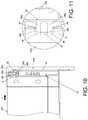
- the second wall 20b of the furniture piece 20can be guided and corrected by the guiding portion 50 (as shown in FIG. 14 ), which can facilitate the at least one mounting portion 30 to be mounted to the engaging portion (such as the first engaging portion 46a and the second engaging portion 46b) of the engaging arm 36 (as shown in FIG. 11 ).
- the second wall 20b of the furniture piece 20being moved toward the first wall 20a along the mounting direction Y, if the second wall 20b of the furniture piece 20 has the mounting error B with respect to the first wall 20a (as shown in FIG. 12 ), with the mounting end 48 of the mounting portion 30 contacting the guiding portion 50 (as shown in FIG. 13 ), the second wall 20b of the furniture piece 20 can be guided and corrected (as shown in FIG. 14 ). As such, the mounting end 48 of the at least one mounting portion 30 can be successfully engaged to the first engaging portion 46a and the second engaging portion 46b (as shown in FIG. 11 ).
- an end 202 of the another second wall 200 used in the furniture piece 20is capable of abutting against the surface 45 of the base portion 34 of the connecting device 32, at least one fastening feature 38a is provided to be inserted by the at least one fastening member 52 and the fastening member 52 is fastened to at least one corresponding fastening feature 204 of the another second wall 200, such that the another second wall 200 is fixed to the auxiliary portion 38, and the another second wall 200 can be connected to the first wall 20a thereby.
- the connecting device 32is capable of connecting two types of second walls (for example, the aforesaid second wall 20b and the another second wall 200) with different structures to the first wall 20a without using other accessories, which can satisfy different market demands.
- the connecting device 32includes features as follows.
- the second wall 20b of the furniture piece 20can be connected to the first wall 20a in a tool-free manner, which facilitates and eases the assembling and detachment.
- the at least one engaging arm 36is substantially transversely arranged with respect to the first wall 20a which is longitudinally arranged, and the mounting direction Y of the second wall 20b is substantially parallel to the engaging arm 36 which is substantially transversely arranged. As such, it facilitates a user to connect the second wall 20b to the first wall 20a.
- the connecting device 32is capable of connecting two types of second walls (20b and 200, shown in FIG. 3 and FIG .15 ) with different structures to the first wall 20a without using other accessories, which can satisfy different market demands.
Landscapes
- Engineering & Computer Science (AREA)
- General Engineering & Computer Science (AREA)
- Mechanical Engineering (AREA)
- Connection Of Plates (AREA)
- Assembled Shelves (AREA)
- Furniture Connections (AREA)
Abstract
Description
- The present invention relates to a connecting device, and more particularly, to a connecting device which connects two walls of a furniture piece.
- As shown in the
US patent with Pat. No. 8,998,356 B2 , a fastening device for connecting two wall parts of a furniture piece is disclosed, and more particularly, the fastening device is for connecting a rear wall to a side wall of a drawer. In the aforesaid US patent, a wall part of the fastening device has at least one locking projection which is resiliently movable about a virtual spring axis, and the locking projection can be locked, preferably detachably locked, into a locking receiver fastened to or formed on the other wall part. The virtual spring axis of the locking projection is provided transversely, preferably substantially perpendicularly, relative to a wall of the wall part. The locking receiver is formed on the other wall part as an opening. A virtual normal of the opening is substantially parallel to the virtual spring axis of the resilient locking projection. - However, with different market demands, how to develop related products to provide more choices in the market has become an issue that cannot be ignored. Furthermore, the fastening device of the aforesaid US patent is configured to barely protrude from a plane (shown in
FIG. 3a of theUS patent with Pat. No. 8,998,356 B2 - This in mind, the present invention aims at providing a connecting device.
- This is achieved by a connecting device according to claim 1. The dependent claims pertain to corresponding further developments and improvements.
- As will be seen more clearly from the detailed description following below, the claimed connecting device is adapted to connect a first wall and a second wall of a furniture piece. The connecting device includes a base portion and at least one engaging arm. The base portion is connected to the first wall of the furniture piece. The at least one engaging arm is arranged at the base portion. The at least one engaging arm is resiliently movable around a hypothetical axis. The at least one engaging arm is arranged with an engaging portion. The hypothetical axis is substantially parallel to the first wall. The second wall of the furniture piece is mountable to the engaging portion along a mounting direction. The mounting direction is substantially perpendicular to the hypothetical axis.
- In the following, the invention is further illustrated by way of example, taking reference to the accompanying drawings thereof:
FIG. 1 is a three-dimensional diagram showing a furniture piece being mounted to a cabinet via a slide rail assembly according to an embodiment of the present invention;FIG. 2 is a three-dimensional diagram showing a slide rail of the slide rail assembly capable of carrying the furniture piece according to the embodiment of the present invention;FIG. 3 is an exploded diagram showing a connecting device connecting a first wall to a second wall of the furniture piece mounted on the slide rail assembly according to the embodiment of the present invention;FIG. 4 is a diagram showing the connecting device connecting to the first wall of the furniture piece mounted on the slide rail assembly according to the embodiment of the present invention;FIG. 5 is a diagram showing the second wall of the furniture piece mounting to the first wall of the furniture piece along a direction according to the embodiment of the present invention;FIG. 6 is a diagram showing the second wall of the furniture piece continued to be moved toward the first wall of the furniture piece along the direction according to the embodiment of the present invention;FIG. 7 is an enlarged view of a portion A ofFIG. 6 ;FIG. 8 is a diagram showing the second wall of the furniture piece further moved toward the first wall of the furniture piece along the direction according to the embodiment of the present invention;FIG. 9 is an enlarged view of a portion A ofFIG. 8 ;FIG. 10 is a diagram showing the second wall of the furniture piece being connected to the first wall via the connecting device according to the embodiment of the present invention;FIG. 11 is an enlarged view of a portion A ofFIG. 10 ;FIG. 12 is a diagram showing a mounting error between the first wall and the second wall of the furniture piece according to the embodiment of the present invention;FIG. 13 is an enlarged view of a portion A ofFIG. 12 ;FIG. 14 is a diagram showing the mounting error between the first wall and the second wall of the furniture piece capable of being guided and corrected by a guiding portion of the connecting device according to the embodiment of the present invention;FIG. 15 is a diagram showing another second wall of the furniture piece capable of being mounted to the first wall via the connecting device according to another embodiment of the present invention;FIG. 16 is a diagram showing the another second wall of the furniture piece which has been mounted to the first wall at a view angle according to the another embodiment of the present invention; andFIG. 17 is a diagram showing the another second wall of the furniture piece which has been mounted to the first wall at another view angle according to the another embodiment of the present invention.- In the following detailed description of the embodiments, the phrase "substantially perpendicular" or "substantially perpendicularly" refers that a member/feature is configured to be perpendicular relative to the other member/feature. However, due to manufacturing tolerance or other factors, the member/feature is not perfectly perpendicular relative to the other member/feature. For example, an included angle between the member/feature and the other member/feature ranging from 85 degrees to 95 degrees and an included angle between the member/feature and the other member/feature ranging from 88 degrees to 92 degrees are within the scope of the present invention. The phrase "substantially parallel" refers that a member/feature is configured to be parallel relative to the other member/feature. However, due to manufacturing tolerance or other factors, the member/feature is not perfectly parallel relative to the other member/feature. For example, an included angle between the member/feature and the other member/feature less than 5 degrees and an included angle between the member/feature and the other member/feature less than 2 degrees are within the scope of the present invention. The phrase "substantially a plane" refers that a member/feature is configured to be a plane. However, due to manufacturing tolerance or other factors, the member/feature is not a perfect plane. The meaning of the phrase "substantially transversely" is similar to that of the phrase "substantially perpendicularly", and thus does not repeated herein.
- As shown in
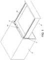
FIG. 1 , afurniture piece 20 can be mounted to acabinet 23 via a pair ofslide rail assemblies 22. For example, thefurniture piece 20 can be a drawer, but the present invention is not limited thereto. - As shown in
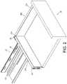
FIG. 2 , each of theslide rail assemblies 22 includes afixed rail 24 and amovable rail 26 longitudinally movable relative to thefixed rail 24. Thefurniture piece 20 includes a plurality of walls, such as afirst wall 20a and asecond wall 20b. Thefirst wall 20a is carried by themovable rail 26, such that thefurniture piece 20 can be moved along themovable rail 26 relative to thefixed rail 24 via thefirst wall 20a. In the embodiment, thefirst wall 20a is a side wall and is longitudinally arranged, thesecond wall 20b is a rear wall and is transversely arranged with respect to thefirst wall 20a, but the present invention is not limited thereto. Thefirst wall 20a of thefurniture piece 20 includes afirst portion 27a and asecond portion 27b opposite to thefirst portion 27a. Thefirst portion 27a is a front portion, and thesecond portion 27b is a rear portion. Furthermore, thesecond wall 20b has twoend portions 28 opposite to each other. The phrase "longitudinally movable"/"longitudinally arranged" refers a member/feature is movable/arranged along a length direction of the fixedrail 24. - As shown in
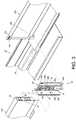
FIG. 3 , thesecond wall 20b is arranged with at least one mountingportion 30. Preferably, the at least one mountingportion 30 is arranged and adjacent to theend portion 28 of thesecond wall 20b. Preferably, the at least one mountingportion 30 protrudes from theend portion 28 of thesecond wall 20b. For example, the at least one mountingportion 30 is a protruding structure with curved contour. Anaccommodating space 31 is formed between an inner side of the protruding structure and theend portion 28 of thesecond wall 20b. At least one hole or slot communicating with theaccommodating space 31 is formed at a middle portion of the protruding structure. The least one hole or slot has a width W. In the embodiment, a plurality of holes communicating with theaccommodating space 31 are formed at the middle portion of the protruding structure, which is only for exemplary and the present invention is not limited thereto. - Furthermore, the present invention provides a connecting
device 32 adapted to connect thefirst wall 20a and thesecond wall 20b of thefurniture piece 20. Preferably, at least one portion of the connectingdevice 32 is made of a plastic material. In the embodiment, the connectingdevice 32 is made of a plastic material, but the present invention is not limited thereto. - As shown in
FIG. 3 andFIG. 4 , the connectingdevice 32 includes abase portion 34 and at least one engagingarm 36. Preferably, the connectingdevice 32 further includes anauxiliary portion 38. - The
base portion 34 is connected to thefirst wall 20a of thefurniture piece 20. Preferably, thebase portion 34 is connected and adjacent to thesecond portion 27b of thefirst wall 20a of thefurniture piece 20. Specifically, thebase portion 34 includes at least one connecting feature. In the embodiment, a first side (such as a rear side) of thebase portion 34 is connected to (fixedly connected to or detachably connected to) thesecond portion 27b of thefirst wall 20a of thefurniture piece 20. For example, in the embodiment, thebase portion 34 is connected to a plate 42 (shown inFIG. 3 ) via at least one fixing member 41 (such as screw or rivet), such that theplate 42 is attached to the first side of thebase portion 34. Theplate 42 includes at least one connecting feature, such as a first connectingfeature 40a and a second connectingfeature 40b, to be fixed to at least one corresponding feature of thefirst wall 20a of thefurniture piece 20, such as a firstcorresponding feature 44a and a secondcorresponding feature 44a (shown inFIG. 3 ), via engaging, inserting or fastening. In other embodiment, thebase portion 34 can be fixed to thefirst wall 20a of thefurniture piece 20 via at least one screw or rivet. Therefore, the connection between thebase portion 34 and thefirst wall 20a of thefurniture piece 20 is not limited. Furthermore, the connectingfeatures corresponding feature - The at least one engaging
arm 36 is arranged at thebase portion 34, and the at least one engagingarm 36 is substantially transversely arranged with respect to thefirst wall 20a. In the embodiment, the at least one engagingarm 36 is arranged at a second side (such as a front side) opposite to the first side of thebase portion 34, which is only exemplary. The at least one engagingarm 36 is resiliently movable around a hypothetical axis X. The hypothetical axis X is substantially parallel to thefirst wall 20a which is longitudinally arranged. - Preferably, the at least one engaging
arm 36 can be three pairs of engaging arms, which is only exemplary and the number of theengaging arm 36 is not limited thereto. Each pair of the engagingarms 36 includes a firstengaging arm 36a and a secondengaging arm 36b. The structures of the firstengaging arm 36a and the secondengaging arm 36b are substantially identical. The firstengaging arm 36a and the secondengaging arm 36b are separated from each other by a distance G. The distance G is less than the width W. Furthermore, each of the firstengaging arm 36a and the secondengaging arm 36b is arranged with an engaging portion. For example, the firstengaging arm 36a is arranged with a firstengaging portion 46a, and the secondengaging arm 36b is arranged with a secondengaging portion 46b. Preferably, the structures of the first engagingportion 46a and the secondengaging portion 46b are configured to be symmetrical. Each of the first engagingportion 46a and the secondengaging portion 46b includes a guidingsegment 49. The guidingsegment 49 can be arranged as an inclined surface or a curved surface. Furthermore, the first engagingportion 46a can be a hook facing upwardly, and the secondengaging portion 46b can be a hook facing downwardly (shown inFIG. 5 ). However, the directions of the first engagingportion 46a and the secondengaging portion 46b are not limited thereto. - Preferably, the
base portion 34 includes asurface 45 and aspace 47 adjacent to thesurface 45. Thesurface 45 is substantially a plane. Thespace 47 is formed at thebase 34, and an opening of thespace 47 is located at thesurface 45. The at least one engagingarm 36 is arranged inside thespace 47, and a length of the at least one engagingarm 36 does not exceed thesurface 45. Furthermore, theauxiliary portion 38 is substantially perpendicularly connected to thebase portion 34, and theauxiliary portion 38 exceeds thesurface 45 of thebase portion 34 by a predetermined distance. Theauxiliary portion 38 includes at least onefastening feature 38a to be inserted by a fastening member. - As shown in
FIG. 5 , thesecond wall 20b of thefurniture piece 20 is mountable to the at least one engagingarm 36 along a mounting direction Y via the at least one mountingportion 30. The mounting direction Y is substantially perpendicular to the hypothetical axis X, and the mounting direction Y is substantially parallel to the at least one engagingarm 36 which is transversely arranged. - As shown in
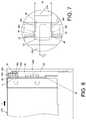
FIG. 6 and FIG. 7 , when thesecond wall 20b of thefurniture piece 20 is moved along the mounting direction Y to a predetermined distance and is close to thefirst wall 20a, the mountingend 48 of the at least one mountingportion 30 contacts the guidingsegments 49 of the first engagingportion 46a and the secondengaging portion 46b of the at least one engagingarm 36, wherein a distance between the two mounting ends 48 defines the width W. - As shown in
FIG. 8 and FIG. 9 , when thesecond wall 20b of thefurniture piece 20 is continued to be moved along the mounting direction Y, the mountingend 48 of the at least one mountingportion 30 pushes against the guidingsegments 49 of the first engagingportion 46a and the secondengaging portion 46b of the at least one engagingarm 36 to drive the firstengaging arm 36a and the secondengaging arm 36b to move resiliently around the hypothetical axis X, such that the firstengaging arm 36a and the secondengaging arm 36b are approached toward each other. Meanwhile, the firstengaging arm 36a and the secondengaging arm 36b are in a state of accumulating a resilient force, and the end portions of the firstengaging arm 36a and the secondengaging arm 36b move slightly into theaccommodating space 31. - As shown in
FIG. 10 and FIG.11 , when thesecond wall 20b of thefurniture piece 20 is further moved along the mounting direction Y, the mountingend 48 of the at least one mountingportion 30 further passes the first engagingportion 46a and the secondengaging portion 46b of the at least one theengaging arm 36, such that the first engagingportion 46a and the secondengaging portion 46b of the at least one engagingarm 36 are accommodated in theaccommodating space 31. Once the mountingend 48 of the at least one mountingportion 30 passes the first engagingportion 46a and the secondengaging portion 46b, the firstengaging arm 36a and the secondengaging arm 36b release the resilient force, such that the firstengaging arm 36a and the secondengaging arm 36b return to the state that the firstengaging arm 36a and the secondengaging arm 36b are spaced by the distance G. As such, the first engagingportion 46a and the secondengaging portion 46b engage with the mountingend 48 of the at least one mountingportion 30 and abut against a wall surface of the mountingend 48 of the at least one mountingportion 30. Therefore, thesecond wall 20b can be fixedly connected to thefirst wall 20a via the connectingdevice 32 in a tool-free manner. - Moreover, the at least one mounting
portion 30 of the connectingdevice 32 can be detachably disengaged from the first engagingportion 46a and the secondengaging portion 46b. For example, when a user applies a force to deform the firstengaging arm 36a and the secondengaging arm 36b (as the state shown inFIG. 9 ), the first engagingportion 46a and the secondengaging portion 46b are no longer engaged with the mountingend 48 of the at least one mountingportion 30, such that thesecond wall 20b can be detached from thefirst wall 20a along a detaching direction opposite to the mounting direction Y. - As shown in
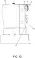
FIG. 12 andFIG.13 , the connectingdevice 32 can further include a guidingportion 50, and the guidingportion 50 can be a curved surface or an inclined surface. When thesecond wall 20b of thefurniture piece 20 has a mounting error B with respect to thefirst wall 20a, thesecond wall 20b of thefurniture piece 20 can be guided and corrected by the guiding portion 50 (as shown inFIG. 14 ), which can facilitate the at least one mountingportion 30 to be mounted to the engaging portion (such as the first engagingportion 46a and the secondengaging portion 46b) of the engaging arm 36 (as shown inFIG. 11 ). - For example, during the
second wall 20b of thefurniture piece 20 being moved toward thefirst wall 20a along the mounting direction Y, if thesecond wall 20b of thefurniture piece 20 has the mounting error B with respect to thefirst wall 20a (as shown inFIG. 12 ), with the mountingend 48 of the mountingportion 30 contacting the guiding portion 50 (as shown inFIG. 13 ), thesecond wall 20b of thefurniture piece 20 can be guided and corrected (as shown inFIG. 14 ). As such, the mountingend 48 of the at least one mountingportion 30 can be successfully engaged to the first engagingportion 46a and the secondengaging portion 46b (as shown inFIG. 11 ). - As shown in
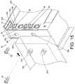
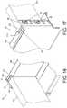
FIG. 15 ,FIG. 16 and FIG.17 , when thesecond wall 20b of thefurniture piece 20 is detached from the first engagingportion 46a and the secondengaging portion 46b via the mountingportion 30, another type of plate (such as a wood plate or other solid plate) can be used to replace thesecond wall 20b. For example, anend 202 of the anothersecond wall 200 used in thefurniture piece 20 is capable of abutting against thesurface 45 of thebase portion 34 of the connectingdevice 32, at least onefastening feature 38a is provided to be inserted by the at least onefastening member 52 and thefastening member 52 is fastened to at least onecorresponding fastening feature 204 of the anothersecond wall 200, such that the anothersecond wall 200 is fixed to theauxiliary portion 38, and the anothersecond wall 200 can be connected to thefirst wall 20a thereby. - Therefore, the connecting
device 32 is capable of connecting two types of second walls (for example, the aforesaidsecond wall 20b and the another second wall 200) with different structures to thefirst wall 20a without using other accessories, which can satisfy different market demands. - To sum up, the connecting
device 32 according to the embodiment of the present invention includes features as follows. - First, the
second wall 20b of thefurniture piece 20 can be connected to thefirst wall 20a in a tool-free manner, which facilitates and eases the assembling and detachment. - Second, the at least one engaging
arm 36 is substantially transversely arranged with respect to thefirst wall 20a which is longitudinally arranged, and the mounting direction Y of thesecond wall 20b is substantially parallel to theengaging arm 36 which is substantially transversely arranged. As such, it facilitates a user to connect thesecond wall 20b to thefirst wall 20a. - Third, the connecting
device 32 is capable of connecting two types of second walls (20b and 200, shown inFIG. 3 andFIG .15 ) with different structures to thefirst wall 20a without using other accessories, which can satisfy different market demands.
Claims (15)
- A connecting device (32) adapted to connect a first wall (20a) and a second wall (20b, 200) of a furniture piece (20), the connecting device (32)characterized by:a base portion (34) connected to the first wall (20a) of the furniture piece (20); andat least one engaging arm (36, 36a, 36b) arranged at the base portion (34), the at least one engaging arm (36, 36a, 36b) being resiliently movable around a hypothetical axis (X), and the at least one engaging arm (36, 36a, 36b) being arranged with an engaging portion (46a, 46b);wherein the hypothetical axis (X) is substantially parallel to the first wall (20a);wherein the second wall (20b, 200) of the furniture piece (20) is mountable to the engaging portion (46a, 46b) along a mounting direction (Y);wherein the mounting direction (Y) is substantially perpendicular to the hypothetical axis (X).
- The connecting device (32) of claim 1,characterized in that the base portion (34) comprises a surface (45) and a space (47) adjacent to the surface (45), the at least one engaging arm (36, 36a, 36b) is arranged inside the space (47), and a length of the at least one engaging arm (36, 36a, 36b) does not exceed the surface (45).
- The connecting device (32) of claim 1 or 2,characterized in that the second wall (20b) of the furniture piece (20) is mountable to the engaging portion (46a, 46b) along the mounting direction (Y) via a mounting portion (30).
- The connecting device (32) of claim 3,characterized in that the mounting portion (30) is arranged and adjacent to an end portion (28) of the second wall (20b).
- The connecting device (32) of claim 4,characterized in that the mounting portion (30) is detachably mounted to the engaging portion (46a, 46b).
- The connecting device (32) of claim 4 or 5,characterized in that the mounting portion (30) protrudes from the end portion (28) of the second wall (20b), and an accommodating space (31) is formed between the mounting portion (30) and the end portion (28) of the second wall (20b) to accommodate the engaging portion (46a, 46b).
- The connecting device (32) of any of claims 3-6,characterized in that the mounting portion (30) is a hole, when the mounting portion (30) is mounted to the engaging portion (46a, 46b), the engaging portion (46a, 46b) passes through the hole and is engaged at a mounting end (48) of the hole.
- The connecting device (32) of any of claims 3-7, furthercharacterized by a guiding portion (50), the guiding portion (50) being a curved surface or an inclined surface, wherein when the second wall (20b) of the furniture piece (20) has a mounting error (B) with respect to the first wall (20a) of the furniture piece (20), the second wall (20b) of the furniture piece (20) is guided and corrected by the guiding portion (50), so as to facilitate the mounting portion (30) to be mounted to the engaging portion (46a, 46b).
- The connecting device (32) of claim 2, furthercharacterized by an auxiliary portion (38) substantially perpendicularly connected to the base portion (34), wherein the auxiliary portion (38) comprises at least one fastening feature (38a) provided to be inserted by a fastening member (52).
- The connecting device (32) of claim 9,characterized in that the auxiliary portion (38) exceeding the surface (45) of the base portion (34) by a predetermined distance.
- The connecting device (32) of claim 9 or 10,characterized in that an end (202) of the second wall (200) of the furniture piece (20) is capable of abutting against the surface (45) of the base portion (34), and the second wall (200) of the furniture piece (20) is fixed to the auxiliary portion (38) via the at least one fastening feature (38a) and the fastening member (52).
- The connecting device (32) of any of claims 2-11,characterized in that the surface (45) is substantially a plane.
- The connecting device (32) of any of claims 1-12,characterized in that at least one portion of the connecting device (32) is made of a plastic material.
- The connecting device (32) of any of claims 1-13,characterized in that the first wall (20a) of the furniture piece (20) comprises a first portion (27a) and a second portion (27b) opposite to the first portion (27a), and the base portion (34) is connected and adjacent to the second portion (27b).
- The connecting device (32) of any of claims 1-14,characterized in that the base portion (34) is fixed to the first wall (20a) of the furniture piece (20) via at least one connecting feature (40a, 40b).
Applications Claiming Priority (1)
| Application Number | Priority Date | Filing Date | Title |
|---|---|---|---|
| TW108109209ATWI697304B (en) | 2019-03-15 | 2019-03-15 | Connecting device |
Publications (2)
| Publication Number | Publication Date |
|---|---|
| EP3708031A1true EP3708031A1 (en) | 2020-09-16 |
| EP3708031B1 EP3708031B1 (en) | 2021-04-28 |
Family
ID=67253700
Family Applications (1)
| Application Number | Title | Priority Date | Filing Date |
|---|---|---|---|
| EP19185621.0AActiveEP3708031B1 (en) | 2019-03-15 | 2019-07-11 | Connecting device |
Country Status (4)
| Country | Link |
|---|---|
| US (1) | US10772422B1 (en) |
| EP (1) | EP3708031B1 (en) |
| JP (1) | JP6841875B2 (en) |
| TW (1) | TWI697304B (en) |
Families Citing this family (3)
| Publication number | Priority date | Publication date | Assignee | Title |
|---|---|---|---|---|
| AT520822B1 (en)* | 2018-02-01 | 2019-08-15 | Blum Gmbh Julius | Drawer side wall |
| AT522842B1 (en)* | 2019-07-18 | 2023-11-15 | Blum Gmbh Julius | Drawer back panel |
| US11898584B2 (en) | 2020-02-07 | 2024-02-13 | Hni Technologies Inc. | Tool-less fastening system |
Citations (5)
| Publication number | Priority date | Publication date | Assignee | Title |
|---|---|---|---|---|
| GB1431046A (en)* | 1972-04-24 | 1976-04-07 | Formica Int | Structural panel assemblies |
| DE202009004982U1 (en)* | 2009-07-02 | 2010-11-25 | Paul Hettich Gmbh & Co. Kg | drawer |
| US20140167586A1 (en)* | 2011-08-30 | 2014-06-19 | Julius Blum Gmbh | Drawer |
| US8998356B2 (en) | 2010-11-23 | 2015-04-07 | Julius Blum Gmbh | Fastening device for wall parts |
| DE202017107475U1 (en)* | 2016-12-23 | 2018-01-08 | Julius Blum Gmbh | drawer |
Family Cites Families (9)
| Publication number | Priority date | Publication date | Assignee | Title |
|---|---|---|---|---|
| GB1507498A (en)* | 1975-05-30 | 1978-04-12 | Swish Prod | Structural elements |
| GB1603980A (en)* | 1978-05-13 | 1981-12-02 | Lb Plastics Ltd | Structural components |
| AT510724B1 (en)* | 2011-02-03 | 2012-06-15 | Blum Gmbh Julius | ECKVERBINDUNGSBESCHLAG |
| AT511091B1 (en)* | 2011-04-19 | 2012-09-15 | Blum Gmbh Julius | DRAWER WHEEL WITH TILT ADJUSTMENT |
| TWI507611B (en)* | 2014-01-22 | 2015-11-11 | Lite On Electronics Guangzhou | Buckling mechanism and article having the same |
| DE102015110560A1 (en)* | 2015-07-01 | 2017-01-05 | Form Orange Produktentwicklung | Drawer with a base plate, two side walls, a rear wall and a panel |
| TWI539915B (en)* | 2015-11-12 | 2016-07-01 | 川湖科技股份有限公司 | Drawer parts and mounting fitting thereof |
| DE102017102643B4 (en)* | 2017-02-10 | 2025-04-10 | Paul Hettich Gmbh & Co. Kg | Drawer and method for mounting a back panel on a side frame of a drawer |
| AT520822B1 (en)* | 2018-02-01 | 2019-08-15 | Blum Gmbh Julius | Drawer side wall |
- 2019
- 2019-03-15TWTW108109209Apatent/TWI697304B/enactive
- 2019-07-04USUS16/503,595patent/US10772422B1/enactiveActive
- 2019-07-11EPEP19185621.0Apatent/EP3708031B1/enactiveActive
- 2019-08-09JPJP2019147257Apatent/JP6841875B2/enactiveActive
Patent Citations (5)
| Publication number | Priority date | Publication date | Assignee | Title |
|---|---|---|---|---|
| GB1431046A (en)* | 1972-04-24 | 1976-04-07 | Formica Int | Structural panel assemblies |
| DE202009004982U1 (en)* | 2009-07-02 | 2010-11-25 | Paul Hettich Gmbh & Co. Kg | drawer |
| US8998356B2 (en) | 2010-11-23 | 2015-04-07 | Julius Blum Gmbh | Fastening device for wall parts |
| US20140167586A1 (en)* | 2011-08-30 | 2014-06-19 | Julius Blum Gmbh | Drawer |
| DE202017107475U1 (en)* | 2016-12-23 | 2018-01-08 | Julius Blum Gmbh | drawer |
Also Published As
| Publication number | Publication date |
|---|---|
| JP2020148340A (en) | 2020-09-17 |
| JP6841875B2 (en) | 2021-03-10 |
| US10772422B1 (en) | 2020-09-15 |
| TWI697304B (en) | 2020-07-01 |
| EP3708031B1 (en) | 2021-04-28 |
| US20200291976A1 (en) | 2020-09-17 |
| TW202034821A (en) | 2020-10-01 |
Similar Documents
| Publication | Publication Date | Title |
|---|---|---|
| CN102084139B (en) | Two-part assembly structure | |
| EP3708031B1 (en) | Connecting device | |
| CN112817383B (en) | Expansion card mounting structure and circuit assembly | |
| JP5113850B2 (en) | Termination cassette release latch | |
| US9608374B2 (en) | Holding frame for plug connector modules | |
| US8622492B2 (en) | Positioning mechanism for quick release device of slide assembly | |
| US20210265767A1 (en) | Holding frame for a plug connector and methods of populating same | |
| JPH02227974A (en) | Double lock structure of connector housing | |
| US6623049B2 (en) | Battery latch | |
| US20080158845A1 (en) | Slide assembly with fixing device | |
| CN114623291A (en) | Holder for manifold | |
| JP2011521419A (en) | Electrical connection component formed by a casing having two arms at an angle of 90 ° | |
| CN115076192A (en) | Fastening structure | |
| EP2517604B1 (en) | Positioning mechanism for quick release device of slide assembly | |
| US6891728B1 (en) | Modular computer system and mounting assembly therefor | |
| KR20230046386A (en) | Partition assembly | |
| US20100018847A1 (en) | Trigger switch | |
| CN107084177B (en) | Fastener and component mounting structure | |
| US10135188B2 (en) | Enclosure assembly for an electrical connector and same | |
| US12371937B2 (en) | Hinge and door | |
| EP4427635B1 (en) | Furniture system and furniture assembly thereof | |
| KR20220088042A (en) | Rearholder and connector having the same | |
| CN112449522A (en) | Fixing frame | |
| JP2012084404A (en) | Connector | |
| JP2021180100A (en) | Connector having stationary housing and movable housing |
Legal Events
| Date | Code | Title | Description |
|---|---|---|---|
| PUAI | Public reference made under article 153(3) epc to a published international application that has entered the european phase | Free format text:ORIGINAL CODE: 0009012 | |
| STAA | Information on the status of an ep patent application or granted ep patent | Free format text:STATUS: REQUEST FOR EXAMINATION WAS MADE | |
| 17P | Request for examination filed | Effective date:20200622 | |
| AK | Designated contracting states | Kind code of ref document:A1 Designated state(s):AL AT BE BG CH CY CZ DE DK EE ES FI FR GB GR HR HU IE IS IT LI LT LU LV MC MK MT NL NO PL PT RO RS SE SI SK SM TR | |
| AX | Request for extension of the european patent | Extension state:BA ME | |
| GRAP | Despatch of communication of intention to grant a patent | Free format text:ORIGINAL CODE: EPIDOSNIGR1 | |
| STAA | Information on the status of an ep patent application or granted ep patent | Free format text:STATUS: GRANT OF PATENT IS INTENDED | |
| RIC1 | Information provided on ipc code assigned before grant | Ipc:F16B 12/38 20060101ALN20201120BHEP Ipc:A47B 88/90 20170101AFI20201120BHEP Ipc:F16B 12/26 20060101ALN20201120BHEP Ipc:F16B 12/50 20060101ALN20201120BHEP Ipc:F16B 12/46 20060101ALN20201120BHEP | |
| INTG | Intention to grant announced | Effective date:20201209 | |
| GRAS | Grant fee paid | Free format text:ORIGINAL CODE: EPIDOSNIGR3 | |
| GRAA | (expected) grant | Free format text:ORIGINAL CODE: 0009210 | |
| STAA | Information on the status of an ep patent application or granted ep patent | Free format text:STATUS: THE PATENT HAS BEEN GRANTED | |
| AK | Designated contracting states | Kind code of ref document:B1 Designated state(s):AL AT BE BG CH CY CZ DE DK EE ES FI FR GB GR HR HU IE IS IT LI LT LU LV MC MK MT NL NO PL PT RO RS SE SI SK SM TR | |
| REG | Reference to a national code | Ref country code:GB Ref legal event code:FG4D | |
| REG | Reference to a national code | Ref country code:CH Ref legal event code:EP | |
| REG | Reference to a national code | Ref country code:AT Ref legal event code:REF Ref document number:1386126 Country of ref document:AT Kind code of ref document:T Effective date:20210515 | |
| REG | Reference to a national code | Ref country code:DE Ref legal event code:R096 Ref document number:602019004199 Country of ref document:DE | |
| REG | Reference to a national code | Ref country code:IE Ref legal event code:FG4D | |
| REG | Reference to a national code | Ref country code:LT Ref legal event code:MG9D | |
| REG | Reference to a national code | Ref country code:AT Ref legal event code:MK05 Ref document number:1386126 Country of ref document:AT Kind code of ref document:T Effective date:20210428 | |
| PG25 | Lapsed in a contracting state [announced via postgrant information from national office to epo] | Ref country code:HR Free format text:LAPSE BECAUSE OF FAILURE TO SUBMIT A TRANSLATION OF THE DESCRIPTION OR TO PAY THE FEE WITHIN THE PRESCRIBED TIME-LIMIT Effective date:20210428 Ref country code:LT Free format text:LAPSE BECAUSE OF FAILURE TO SUBMIT A TRANSLATION OF THE DESCRIPTION OR TO PAY THE FEE WITHIN THE PRESCRIBED TIME-LIMIT Effective date:20210428 Ref country code:FI Free format text:LAPSE BECAUSE OF FAILURE TO SUBMIT A TRANSLATION OF THE DESCRIPTION OR TO PAY THE FEE WITHIN THE PRESCRIBED TIME-LIMIT Effective date:20210428 Ref country code:NL Free format text:LAPSE BECAUSE OF FAILURE TO SUBMIT A TRANSLATION OF THE DESCRIPTION OR TO PAY THE FEE WITHIN THE PRESCRIBED TIME-LIMIT Effective date:20210428 Ref country code:AT Free format text:LAPSE BECAUSE OF FAILURE TO SUBMIT A TRANSLATION OF THE DESCRIPTION OR TO PAY THE FEE WITHIN THE PRESCRIBED TIME-LIMIT Effective date:20210428 Ref country code:BG Free format text:LAPSE BECAUSE OF FAILURE TO SUBMIT A TRANSLATION OF THE DESCRIPTION OR TO PAY THE FEE WITHIN THE PRESCRIBED TIME-LIMIT Effective date:20210728 | |
| PG25 | Lapsed in a contracting state [announced via postgrant information from national office to epo] | Ref country code:IS Free format text:LAPSE BECAUSE OF FAILURE TO SUBMIT A TRANSLATION OF THE DESCRIPTION OR TO PAY THE FEE WITHIN THE PRESCRIBED TIME-LIMIT Effective date:20210828 Ref country code:GR Free format text:LAPSE BECAUSE OF FAILURE TO SUBMIT A TRANSLATION OF THE DESCRIPTION OR TO PAY THE FEE WITHIN THE PRESCRIBED TIME-LIMIT Effective date:20210729 Ref country code:SE Free format text:LAPSE BECAUSE OF FAILURE TO SUBMIT A TRANSLATION OF THE DESCRIPTION OR TO PAY THE FEE WITHIN THE PRESCRIBED TIME-LIMIT Effective date:20210428 Ref country code:PT Free format text:LAPSE BECAUSE OF FAILURE TO SUBMIT A TRANSLATION OF THE DESCRIPTION OR TO PAY THE FEE WITHIN THE PRESCRIBED TIME-LIMIT Effective date:20210830 Ref country code:RS Free format text:LAPSE BECAUSE OF FAILURE TO SUBMIT A TRANSLATION OF THE DESCRIPTION OR TO PAY THE FEE WITHIN THE PRESCRIBED TIME-LIMIT Effective date:20210428 Ref country code:PL Free format text:LAPSE BECAUSE OF FAILURE TO SUBMIT A TRANSLATION OF THE DESCRIPTION OR TO PAY THE FEE WITHIN THE PRESCRIBED TIME-LIMIT Effective date:20210428 Ref country code:NO Free format text:LAPSE BECAUSE OF FAILURE TO SUBMIT A TRANSLATION OF THE DESCRIPTION OR TO PAY THE FEE WITHIN THE PRESCRIBED TIME-LIMIT Effective date:20210728 Ref country code:LV Free format text:LAPSE BECAUSE OF FAILURE TO SUBMIT A TRANSLATION OF THE DESCRIPTION OR TO PAY THE FEE WITHIN THE PRESCRIBED TIME-LIMIT Effective date:20210428 | |
| REG | Reference to a national code | Ref country code:NL Ref legal event code:MP Effective date:20210428 | |
| PG25 | Lapsed in a contracting state [announced via postgrant information from national office to epo] | Ref country code:SK Free format text:LAPSE BECAUSE OF FAILURE TO SUBMIT A TRANSLATION OF THE DESCRIPTION OR TO PAY THE FEE WITHIN THE PRESCRIBED TIME-LIMIT Effective date:20210428 Ref country code:EE Free format text:LAPSE BECAUSE OF FAILURE TO SUBMIT A TRANSLATION OF THE DESCRIPTION OR TO PAY THE FEE WITHIN THE PRESCRIBED TIME-LIMIT Effective date:20210428 Ref country code:ES Free format text:LAPSE BECAUSE OF FAILURE TO SUBMIT A TRANSLATION OF THE DESCRIPTION OR TO PAY THE FEE WITHIN THE PRESCRIBED TIME-LIMIT Effective date:20210428 Ref country code:SM Free format text:LAPSE BECAUSE OF FAILURE TO SUBMIT A TRANSLATION OF THE DESCRIPTION OR TO PAY THE FEE WITHIN THE PRESCRIBED TIME-LIMIT Effective date:20210428 Ref country code:RO Free format text:LAPSE BECAUSE OF FAILURE TO SUBMIT A TRANSLATION OF THE DESCRIPTION OR TO PAY THE FEE WITHIN THE PRESCRIBED TIME-LIMIT Effective date:20210428 Ref country code:DK Free format text:LAPSE BECAUSE OF FAILURE TO SUBMIT A TRANSLATION OF THE DESCRIPTION OR TO PAY THE FEE WITHIN THE PRESCRIBED TIME-LIMIT Effective date:20210428 Ref country code:CZ Free format text:LAPSE BECAUSE OF FAILURE TO SUBMIT A TRANSLATION OF THE DESCRIPTION OR TO PAY THE FEE WITHIN THE PRESCRIBED TIME-LIMIT Effective date:20210428 | |
| REG | Reference to a national code | Ref country code:DE Ref legal event code:R097 Ref document number:602019004199 Country of ref document:DE | |
| PLBE | No opposition filed within time limit | Free format text:ORIGINAL CODE: 0009261 | |
| STAA | Information on the status of an ep patent application or granted ep patent | Free format text:STATUS: NO OPPOSITION FILED WITHIN TIME LIMIT | |
| PG25 | Lapsed in a contracting state [announced via postgrant information from national office to epo] | Ref country code:MC Free format text:LAPSE BECAUSE OF FAILURE TO SUBMIT A TRANSLATION OF THE DESCRIPTION OR TO PAY THE FEE WITHIN THE PRESCRIBED TIME-LIMIT Effective date:20210428 | |
| REG | Reference to a national code | Ref country code:BE Ref legal event code:MM Effective date:20210731 | |
| 26N | No opposition filed | Effective date:20220131 | |
| PG25 | Lapsed in a contracting state [announced via postgrant information from national office to epo] | Ref country code:IS Free format text:LAPSE BECAUSE OF FAILURE TO SUBMIT A TRANSLATION OF THE DESCRIPTION OR TO PAY THE FEE WITHIN THE PRESCRIBED TIME-LIMIT Effective date:20210828 Ref country code:LU Free format text:LAPSE BECAUSE OF NON-PAYMENT OF DUE FEES Effective date:20210711 Ref country code:FR Free format text:LAPSE BECAUSE OF NON-PAYMENT OF DUE FEES Effective date:20210731 Ref country code:AL Free format text:LAPSE BECAUSE OF FAILURE TO SUBMIT A TRANSLATION OF THE DESCRIPTION OR TO PAY THE FEE WITHIN THE PRESCRIBED TIME-LIMIT Effective date:20210428 | |
| PG25 | Lapsed in a contracting state [announced via postgrant information from national office to epo] | Ref country code:IT Free format text:LAPSE BECAUSE OF FAILURE TO SUBMIT A TRANSLATION OF THE DESCRIPTION OR TO PAY THE FEE WITHIN THE PRESCRIBED TIME-LIMIT Effective date:20210428 Ref country code:BE Free format text:LAPSE BECAUSE OF NON-PAYMENT OF DUE FEES Effective date:20210731 | |
| REG | Reference to a national code | Ref country code:CH Ref legal event code:PL | |
| PG25 | Lapsed in a contracting state [announced via postgrant information from national office to epo] | Ref country code:LI Free format text:LAPSE BECAUSE OF NON-PAYMENT OF DUE FEES Effective date:20220731 Ref country code:CH Free format text:LAPSE BECAUSE OF NON-PAYMENT OF DUE FEES Effective date:20220731 | |
| PG25 | Lapsed in a contracting state [announced via postgrant information from national office to epo] | Ref country code:CY Free format text:LAPSE BECAUSE OF FAILURE TO SUBMIT A TRANSLATION OF THE DESCRIPTION OR TO PAY THE FEE WITHIN THE PRESCRIBED TIME-LIMIT Effective date:20210428 | |
| PG25 | Lapsed in a contracting state [announced via postgrant information from national office to epo] | Ref country code:HU Free format text:LAPSE BECAUSE OF FAILURE TO SUBMIT A TRANSLATION OF THE DESCRIPTION OR TO PAY THE FEE WITHIN THE PRESCRIBED TIME-LIMIT; INVALID AB INITIO Effective date:20190711 | |
| PG25 | Lapsed in a contracting state [announced via postgrant information from national office to epo] | Ref country code:MK Free format text:LAPSE BECAUSE OF FAILURE TO SUBMIT A TRANSLATION OF THE DESCRIPTION OR TO PAY THE FEE WITHIN THE PRESCRIBED TIME-LIMIT Effective date:20210428 | |
| REG | Reference to a national code | Ref country code:DE Ref legal event code:R082 Ref document number:602019004199 Country of ref document:DE Representative=s name:STRAUS, ALEXANDER, DIPL.-CHEM.UNIV. DR.PHIL., DE | |
| PG25 | Lapsed in a contracting state [announced via postgrant information from national office to epo] | Ref country code:MT Free format text:LAPSE BECAUSE OF FAILURE TO SUBMIT A TRANSLATION OF THE DESCRIPTION OR TO PAY THE FEE WITHIN THE PRESCRIBED TIME-LIMIT Effective date:20210428 | |
| PGFP | Annual fee paid to national office [announced via postgrant information from national office to epo] | Ref country code:DE Payment date:20240611 Year of fee payment:6 | |
| PGFP | Annual fee paid to national office [announced via postgrant information from national office to epo] | Ref country code:GB Payment date:20250508 Year of fee payment:7 | |
| PGFP | Annual fee paid to national office [announced via postgrant information from national office to epo] | Ref country code:IE Payment date:20250507 Year of fee payment:7 |