EP3707555B1 - Privacy glazing system with discrete electrical driver - Google Patents
Privacy glazing system with discrete electrical driverDownload PDFInfo
- Publication number
- EP3707555B1 EP3707555B1EP18808174.9AEP18808174AEP3707555B1EP 3707555 B1EP3707555 B1EP 3707555B1EP 18808174 AEP18808174 AEP 18808174AEP 3707555 B1EP3707555 B1EP 3707555B1
- Authority
- EP
- European Patent Office
- Prior art keywords
- pane
- driver
- transparent material
- spacer
- privacy
- Prior art date
- Legal status (The legal status is an assumption and is not a legal conclusion. Google has not performed a legal analysis and makes no representation as to the accuracy of the status listed.)
- Active
Links
Images


Classifications
- G—PHYSICS
- G02—OPTICS
- G02F—OPTICAL DEVICES OR ARRANGEMENTS FOR THE CONTROL OF LIGHT BY MODIFICATION OF THE OPTICAL PROPERTIES OF THE MEDIA OF THE ELEMENTS INVOLVED THEREIN; NON-LINEAR OPTICS; FREQUENCY-CHANGING OF LIGHT; OPTICAL LOGIC ELEMENTS; OPTICAL ANALOGUE/DIGITAL CONVERTERS
- G02F1/00—Devices or arrangements for the control of the intensity, colour, phase, polarisation or direction of light arriving from an independent light source, e.g. switching, gating or modulating; Non-linear optics
- G02F1/01—Devices or arrangements for the control of the intensity, colour, phase, polarisation or direction of light arriving from an independent light source, e.g. switching, gating or modulating; Non-linear optics for the control of the intensity, phase, polarisation or colour
- G02F1/13—Devices or arrangements for the control of the intensity, colour, phase, polarisation or direction of light arriving from an independent light source, e.g. switching, gating or modulating; Non-linear optics for the control of the intensity, phase, polarisation or colour based on liquid crystals, e.g. single liquid crystal display cells
- G02F1/137—Devices or arrangements for the control of the intensity, colour, phase, polarisation or direction of light arriving from an independent light source, e.g. switching, gating or modulating; Non-linear optics for the control of the intensity, phase, polarisation or colour based on liquid crystals, e.g. single liquid crystal display cells characterised by the electro-optical or magneto-optical effect, e.g. field-induced phase transition, orientation effect, guest-host interaction or dynamic scattering
- B—PERFORMING OPERATIONS; TRANSPORTING
- B32—LAYERED PRODUCTS
- B32B—LAYERED PRODUCTS, i.e. PRODUCTS BUILT-UP OF STRATA OF FLAT OR NON-FLAT, e.g. CELLULAR OR HONEYCOMB, FORM
- B32B17/00—Layered products essentially comprising sheet glass, or glass, slag, or like fibres
- E—FIXED CONSTRUCTIONS
- E06—DOORS, WINDOWS, SHUTTERS, OR ROLLER BLINDS IN GENERAL; LADDERS
- E06B—FIXED OR MOVABLE CLOSURES FOR OPENINGS IN BUILDINGS, VEHICLES, FENCES OR LIKE ENCLOSURES IN GENERAL, e.g. DOORS, WINDOWS, BLINDS, GATES
- E06B3/00—Window sashes, door leaves, or like elements for closing wall or like openings; Layout of fixed or moving closures, e.g. windows in wall or like openings; Features of rigidly-mounted outer frames relating to the mounting of wing frames
- E06B3/66—Units comprising two or more parallel glass or like panes permanently secured together
- E06B3/67—Units comprising two or more parallel glass or like panes permanently secured together characterised by additional arrangements or devices for heat or sound insulation or for controlled passage of light
- E06B3/6715—Units comprising two or more parallel glass or like panes permanently secured together characterised by additional arrangements or devices for heat or sound insulation or for controlled passage of light specially adapted for increased thermal insulation or for controlled passage of light
- E06B3/6722—Units comprising two or more parallel glass or like panes permanently secured together characterised by additional arrangements or devices for heat or sound insulation or for controlled passage of light specially adapted for increased thermal insulation or for controlled passage of light with adjustable passage of light
- E—FIXED CONSTRUCTIONS
- E06—DOORS, WINDOWS, SHUTTERS, OR ROLLER BLINDS IN GENERAL; LADDERS
- E06B—FIXED OR MOVABLE CLOSURES FOR OPENINGS IN BUILDINGS, VEHICLES, FENCES OR LIKE ENCLOSURES IN GENERAL, e.g. DOORS, WINDOWS, BLINDS, GATES
- E06B9/00—Screening or protective devices for wall or similar openings, with or without operating or securing mechanisms; Closures of similar construction
- E06B9/24—Screens or other constructions affording protection against light, especially against sunshine; Similar screens for privacy or appearance; Slat blinds
- G—PHYSICS
- G02—OPTICS
- G02F—OPTICAL DEVICES OR ARRANGEMENTS FOR THE CONTROL OF LIGHT BY MODIFICATION OF THE OPTICAL PROPERTIES OF THE MEDIA OF THE ELEMENTS INVOLVED THEREIN; NON-LINEAR OPTICS; FREQUENCY-CHANGING OF LIGHT; OPTICAL LOGIC ELEMENTS; OPTICAL ANALOGUE/DIGITAL CONVERTERS
- G02F1/00—Devices or arrangements for the control of the intensity, colour, phase, polarisation or direction of light arriving from an independent light source, e.g. switching, gating or modulating; Non-linear optics
- G02F1/01—Devices or arrangements for the control of the intensity, colour, phase, polarisation or direction of light arriving from an independent light source, e.g. switching, gating or modulating; Non-linear optics for the control of the intensity, phase, polarisation or colour
- G02F1/13—Devices or arrangements for the control of the intensity, colour, phase, polarisation or direction of light arriving from an independent light source, e.g. switching, gating or modulating; Non-linear optics for the control of the intensity, phase, polarisation or colour based on liquid crystals, e.g. single liquid crystal display cells
- G02F1/133—Constructional arrangements; Operation of liquid crystal cells; Circuit arrangements
- G02F1/13306—Circuit arrangements or driving methods for the control of single liquid crystal cells
- G—PHYSICS
- G02—OPTICS
- G02F—OPTICAL DEVICES OR ARRANGEMENTS FOR THE CONTROL OF LIGHT BY MODIFICATION OF THE OPTICAL PROPERTIES OF THE MEDIA OF THE ELEMENTS INVOLVED THEREIN; NON-LINEAR OPTICS; FREQUENCY-CHANGING OF LIGHT; OPTICAL LOGIC ELEMENTS; OPTICAL ANALOGUE/DIGITAL CONVERTERS
- G02F1/00—Devices or arrangements for the control of the intensity, colour, phase, polarisation or direction of light arriving from an independent light source, e.g. switching, gating or modulating; Non-linear optics
- G02F1/01—Devices or arrangements for the control of the intensity, colour, phase, polarisation or direction of light arriving from an independent light source, e.g. switching, gating or modulating; Non-linear optics for the control of the intensity, phase, polarisation or colour
- G02F1/13—Devices or arrangements for the control of the intensity, colour, phase, polarisation or direction of light arriving from an independent light source, e.g. switching, gating or modulating; Non-linear optics for the control of the intensity, phase, polarisation or colour based on liquid crystals, e.g. single liquid crystal display cells
- G02F1/133—Constructional arrangements; Operation of liquid crystal cells; Circuit arrangements
- G02F1/1333—Constructional arrangements; Manufacturing methods
- G02F1/1339—Gaskets; Spacers; Sealing of cells
- G02F1/13394—Gaskets; Spacers; Sealing of cells spacers regularly patterned on the cell subtrate, e.g. walls, pillars
- G—PHYSICS
- G02—OPTICS
- G02F—OPTICAL DEVICES OR ARRANGEMENTS FOR THE CONTROL OF LIGHT BY MODIFICATION OF THE OPTICAL PROPERTIES OF THE MEDIA OF THE ELEMENTS INVOLVED THEREIN; NON-LINEAR OPTICS; FREQUENCY-CHANGING OF LIGHT; OPTICAL LOGIC ELEMENTS; OPTICAL ANALOGUE/DIGITAL CONVERTERS
- G02F1/00—Devices or arrangements for the control of the intensity, colour, phase, polarisation or direction of light arriving from an independent light source, e.g. switching, gating or modulating; Non-linear optics
- G02F1/01—Devices or arrangements for the control of the intensity, colour, phase, polarisation or direction of light arriving from an independent light source, e.g. switching, gating or modulating; Non-linear optics for the control of the intensity, phase, polarisation or colour
- G02F1/13—Devices or arrangements for the control of the intensity, colour, phase, polarisation or direction of light arriving from an independent light source, e.g. switching, gating or modulating; Non-linear optics for the control of the intensity, phase, polarisation or colour based on liquid crystals, e.g. single liquid crystal display cells
- G02F1/133—Constructional arrangements; Operation of liquid crystal cells; Circuit arrangements
- G02F1/1333—Constructional arrangements; Manufacturing methods
- G02F1/1343—Electrodes
- G02F1/13439—Electrodes characterised by their electrical, optical, physical properties; materials therefor; method of making
- G—PHYSICS
- G02—OPTICS
- G02F—OPTICAL DEVICES OR ARRANGEMENTS FOR THE CONTROL OF LIGHT BY MODIFICATION OF THE OPTICAL PROPERTIES OF THE MEDIA OF THE ELEMENTS INVOLVED THEREIN; NON-LINEAR OPTICS; FREQUENCY-CHANGING OF LIGHT; OPTICAL LOGIC ELEMENTS; OPTICAL ANALOGUE/DIGITAL CONVERTERS
- G02F1/00—Devices or arrangements for the control of the intensity, colour, phase, polarisation or direction of light arriving from an independent light source, e.g. switching, gating or modulating; Non-linear optics
- G02F1/01—Devices or arrangements for the control of the intensity, colour, phase, polarisation or direction of light arriving from an independent light source, e.g. switching, gating or modulating; Non-linear optics for the control of the intensity, phase, polarisation or colour
- G02F1/15—Devices or arrangements for the control of the intensity, colour, phase, polarisation or direction of light arriving from an independent light source, e.g. switching, gating or modulating; Non-linear optics for the control of the intensity, phase, polarisation or colour based on an electrochromic effect
- G02F1/153—Constructional details
- G—PHYSICS
- G02—OPTICS
- G02F—OPTICAL DEVICES OR ARRANGEMENTS FOR THE CONTROL OF LIGHT BY MODIFICATION OF THE OPTICAL PROPERTIES OF THE MEDIA OF THE ELEMENTS INVOLVED THEREIN; NON-LINEAR OPTICS; FREQUENCY-CHANGING OF LIGHT; OPTICAL LOGIC ELEMENTS; OPTICAL ANALOGUE/DIGITAL CONVERTERS
- G02F1/00—Devices or arrangements for the control of the intensity, colour, phase, polarisation or direction of light arriving from an independent light source, e.g. switching, gating or modulating; Non-linear optics
- G02F1/01—Devices or arrangements for the control of the intensity, colour, phase, polarisation or direction of light arriving from an independent light source, e.g. switching, gating or modulating; Non-linear optics for the control of the intensity, phase, polarisation or colour
- G02F1/15—Devices or arrangements for the control of the intensity, colour, phase, polarisation or direction of light arriving from an independent light source, e.g. switching, gating or modulating; Non-linear optics for the control of the intensity, phase, polarisation or colour based on an electrochromic effect
- G02F1/163—Operation of electrochromic cells, e.g. electrodeposition cells; Circuit arrangements therefor
- B—PERFORMING OPERATIONS; TRANSPORTING
- B32—LAYERED PRODUCTS
- B32B—LAYERED PRODUCTS, i.e. PRODUCTS BUILT-UP OF STRATA OF FLAT OR NON-FLAT, e.g. CELLULAR OR HONEYCOMB, FORM
- B32B2255/00—Coating on the layer surface
- B32B2255/20—Inorganic coating
- B—PERFORMING OPERATIONS; TRANSPORTING
- B32—LAYERED PRODUCTS
- B32B—LAYERED PRODUCTS, i.e. PRODUCTS BUILT-UP OF STRATA OF FLAT OR NON-FLAT, e.g. CELLULAR OR HONEYCOMB, FORM
- B32B2419/00—Buildings or parts thereof
- C—CHEMISTRY; METALLURGY
- C03—GLASS; MINERAL OR SLAG WOOL
- C03C—CHEMICAL COMPOSITION OF GLASSES, GLAZES OR VITREOUS ENAMELS; SURFACE TREATMENT OF GLASS; SURFACE TREATMENT OF FIBRES OR FILAMENTS MADE FROM GLASS, MINERALS OR SLAGS; JOINING GLASS TO GLASS OR OTHER MATERIALS
- C03C17/00—Surface treatment of glass, not in the form of fibres or filaments, by coating
- C03C17/22—Surface treatment of glass, not in the form of fibres or filaments, by coating with other inorganic material
- C03C17/23—Oxides
- C—CHEMISTRY; METALLURGY
- C03—GLASS; MINERAL OR SLAG WOOL
- C03C—CHEMICAL COMPOSITION OF GLASSES, GLAZES OR VITREOUS ENAMELS; SURFACE TREATMENT OF GLASS; SURFACE TREATMENT OF FIBRES OR FILAMENTS MADE FROM GLASS, MINERALS OR SLAGS; JOINING GLASS TO GLASS OR OTHER MATERIALS
- C03C2217/00—Coatings on glass
- C03C2217/20—Materials for coating a single layer on glass
- C03C2217/21—Oxides
- C03C2217/215—In2O3
- C—CHEMISTRY; METALLURGY
- C03—GLASS; MINERAL OR SLAG WOOL
- C03C—CHEMICAL COMPOSITION OF GLASSES, GLAZES OR VITREOUS ENAMELS; SURFACE TREATMENT OF GLASS; SURFACE TREATMENT OF FIBRES OR FILAMENTS MADE FROM GLASS, MINERALS OR SLAGS; JOINING GLASS TO GLASS OR OTHER MATERIALS
- C03C2217/00—Coatings on glass
- C03C2217/20—Materials for coating a single layer on glass
- C03C2217/21—Oxides
- C03C2217/216—ZnO
- C—CHEMISTRY; METALLURGY
- C03—GLASS; MINERAL OR SLAG WOOL
- C03C—CHEMICAL COMPOSITION OF GLASSES, GLAZES OR VITREOUS ENAMELS; SURFACE TREATMENT OF GLASS; SURFACE TREATMENT OF FIBRES OR FILAMENTS MADE FROM GLASS, MINERALS OR SLAGS; JOINING GLASS TO GLASS OR OTHER MATERIALS
- C03C2217/00—Coatings on glass
- C03C2217/20—Materials for coating a single layer on glass
- C03C2217/21—Oxides
- C03C2217/24—Doped oxides
- C—CHEMISTRY; METALLURGY
- C03—GLASS; MINERAL OR SLAG WOOL
- C03C—CHEMICAL COMPOSITION OF GLASSES, GLAZES OR VITREOUS ENAMELS; SURFACE TREATMENT OF GLASS; SURFACE TREATMENT OF FIBRES OR FILAMENTS MADE FROM GLASS, MINERALS OR SLAGS; JOINING GLASS TO GLASS OR OTHER MATERIALS
- C03C2217/00—Coatings on glass
- C03C2217/90—Other aspects of coatings
- C03C2217/94—Transparent conductive oxide layers [TCO] being part of a multilayer coating
- E—FIXED CONSTRUCTIONS
- E06—DOORS, WINDOWS, SHUTTERS, OR ROLLER BLINDS IN GENERAL; LADDERS
- E06B—FIXED OR MOVABLE CLOSURES FOR OPENINGS IN BUILDINGS, VEHICLES, FENCES OR LIKE ENCLOSURES IN GENERAL, e.g. DOORS, WINDOWS, BLINDS, GATES
- E06B9/00—Screening or protective devices for wall or similar openings, with or without operating or securing mechanisms; Closures of similar construction
- E06B9/24—Screens or other constructions affording protection against light, especially against sunshine; Similar screens for privacy or appearance; Slat blinds
- E06B2009/2417—Light path control; means to control reflection
- E—FIXED CONSTRUCTIONS
- E06—DOORS, WINDOWS, SHUTTERS, OR ROLLER BLINDS IN GENERAL; LADDERS
- E06B—FIXED OR MOVABLE CLOSURES FOR OPENINGS IN BUILDINGS, VEHICLES, FENCES OR LIKE ENCLOSURES IN GENERAL, e.g. DOORS, WINDOWS, BLINDS, GATES
- E06B9/00—Screening or protective devices for wall or similar openings, with or without operating or securing mechanisms; Closures of similar construction
- E06B9/24—Screens or other constructions affording protection against light, especially against sunshine; Similar screens for privacy or appearance; Slat blinds
- E06B2009/2464—Screens or other constructions affording protection against light, especially against sunshine; Similar screens for privacy or appearance; Slat blinds featuring transparency control by applying voltage, e.g. LCD, electrochromic panels
- E—FIXED CONSTRUCTIONS
- E06—DOORS, WINDOWS, SHUTTERS, OR ROLLER BLINDS IN GENERAL; LADDERS
- E06B—FIXED OR MOVABLE CLOSURES FOR OPENINGS IN BUILDINGS, VEHICLES, FENCES OR LIKE ENCLOSURES IN GENERAL, e.g. DOORS, WINDOWS, BLINDS, GATES
- E06B9/00—Screening or protective devices for wall or similar openings, with or without operating or securing mechanisms; Closures of similar construction
- E06B9/24—Screens or other constructions affording protection against light, especially against sunshine; Similar screens for privacy or appearance; Slat blinds
- E06B2009/247—Electrically powered illumination
- G—PHYSICS
- G02—OPTICS
- G02F—OPTICAL DEVICES OR ARRANGEMENTS FOR THE CONTROL OF LIGHT BY MODIFICATION OF THE OPTICAL PROPERTIES OF THE MEDIA OF THE ELEMENTS INVOLVED THEREIN; NON-LINEAR OPTICS; FREQUENCY-CHANGING OF LIGHT; OPTICAL LOGIC ELEMENTS; OPTICAL ANALOGUE/DIGITAL CONVERTERS
- G02F1/00—Devices or arrangements for the control of the intensity, colour, phase, polarisation or direction of light arriving from an independent light source, e.g. switching, gating or modulating; Non-linear optics
- G02F1/01—Devices or arrangements for the control of the intensity, colour, phase, polarisation or direction of light arriving from an independent light source, e.g. switching, gating or modulating; Non-linear optics for the control of the intensity, phase, polarisation or colour
- G02F1/13—Devices or arrangements for the control of the intensity, colour, phase, polarisation or direction of light arriving from an independent light source, e.g. switching, gating or modulating; Non-linear optics for the control of the intensity, phase, polarisation or colour based on liquid crystals, e.g. single liquid crystal display cells
- G02F1/133—Constructional arrangements; Operation of liquid crystal cells; Circuit arrangements
- G02F1/1333—Constructional arrangements; Manufacturing methods
- G02F1/133302—Rigid substrates, e.g. inorganic substrates
- G—PHYSICS
- G02—OPTICS
- G02F—OPTICAL DEVICES OR ARRANGEMENTS FOR THE CONTROL OF LIGHT BY MODIFICATION OF THE OPTICAL PROPERTIES OF THE MEDIA OF THE ELEMENTS INVOLVED THEREIN; NON-LINEAR OPTICS; FREQUENCY-CHANGING OF LIGHT; OPTICAL LOGIC ELEMENTS; OPTICAL ANALOGUE/DIGITAL CONVERTERS
- G02F1/00—Devices or arrangements for the control of the intensity, colour, phase, polarisation or direction of light arriving from an independent light source, e.g. switching, gating or modulating; Non-linear optics
- G02F1/01—Devices or arrangements for the control of the intensity, colour, phase, polarisation or direction of light arriving from an independent light source, e.g. switching, gating or modulating; Non-linear optics for the control of the intensity, phase, polarisation or colour
- G02F1/13—Devices or arrangements for the control of the intensity, colour, phase, polarisation or direction of light arriving from an independent light source, e.g. switching, gating or modulating; Non-linear optics for the control of the intensity, phase, polarisation or colour based on liquid crystals, e.g. single liquid crystal display cells
- G02F1/133—Constructional arrangements; Operation of liquid crystal cells; Circuit arrangements
- G02F1/1333—Constructional arrangements; Manufacturing methods
- G02F1/133308—Support structures for LCD panels, e.g. frames or bezels
- G02F1/133317—Intermediate frames, e.g. between backlight housing and front frame
- G—PHYSICS
- G02—OPTICS
- G02F—OPTICAL DEVICES OR ARRANGEMENTS FOR THE CONTROL OF LIGHT BY MODIFICATION OF THE OPTICAL PROPERTIES OF THE MEDIA OF THE ELEMENTS INVOLVED THEREIN; NON-LINEAR OPTICS; FREQUENCY-CHANGING OF LIGHT; OPTICAL LOGIC ELEMENTS; OPTICAL ANALOGUE/DIGITAL CONVERTERS
- G02F1/00—Devices or arrangements for the control of the intensity, colour, phase, polarisation or direction of light arriving from an independent light source, e.g. switching, gating or modulating; Non-linear optics
- G02F1/01—Devices or arrangements for the control of the intensity, colour, phase, polarisation or direction of light arriving from an independent light source, e.g. switching, gating or modulating; Non-linear optics for the control of the intensity, phase, polarisation or colour
- G02F1/13—Devices or arrangements for the control of the intensity, colour, phase, polarisation or direction of light arriving from an independent light source, e.g. switching, gating or modulating; Non-linear optics for the control of the intensity, phase, polarisation or colour based on liquid crystals, e.g. single liquid crystal display cells
- G02F1/133—Constructional arrangements; Operation of liquid crystal cells; Circuit arrangements
- G02F1/1333—Constructional arrangements; Manufacturing methods
- G02F1/133308—Support structures for LCD panels, e.g. frames or bezels
- G02F1/133328—Segmented frames
- G—PHYSICS
- G02—OPTICS
- G02F—OPTICAL DEVICES OR ARRANGEMENTS FOR THE CONTROL OF LIGHT BY MODIFICATION OF THE OPTICAL PROPERTIES OF THE MEDIA OF THE ELEMENTS INVOLVED THEREIN; NON-LINEAR OPTICS; FREQUENCY-CHANGING OF LIGHT; OPTICAL LOGIC ELEMENTS; OPTICAL ANALOGUE/DIGITAL CONVERTERS
- G02F1/00—Devices or arrangements for the control of the intensity, colour, phase, polarisation or direction of light arriving from an independent light source, e.g. switching, gating or modulating; Non-linear optics
- G02F1/01—Devices or arrangements for the control of the intensity, colour, phase, polarisation or direction of light arriving from an independent light source, e.g. switching, gating or modulating; Non-linear optics for the control of the intensity, phase, polarisation or colour
- G02F1/13—Devices or arrangements for the control of the intensity, colour, phase, polarisation or direction of light arriving from an independent light source, e.g. switching, gating or modulating; Non-linear optics for the control of the intensity, phase, polarisation or colour based on liquid crystals, e.g. single liquid crystal display cells
- G02F1/133—Constructional arrangements; Operation of liquid crystal cells; Circuit arrangements
- G02F1/1333—Constructional arrangements; Manufacturing methods
- G02F1/1339—Gaskets; Spacers; Sealing of cells
- G02F1/13398—Spacer materials; Spacer properties
Definitions
- This disclosurerelates to glazing structures that include electrically controllable optically active material and, more particularly, to electrical driver arrangements for glazing structure systems.
- Windows, doors, partitions, and other structures having controllable light modulationhave been gaining popularity in the marketplace. These structures are commonly referred to as “smart” structures or “privacy” structures for their ability to transform from a transparent state in which a user can see through the structure to a private state in which viewing is inhibited through the structure. For example, smart windows are being used in high-end automobiles and homes and smart partitions are being used as walls in office spaces to provide controlled privacy and visual darkening.
- a variety of different technologiescan be used to provide controlled optical transmission for a smart structure.
- electrochromic technologies, photochromic technologies, thermochromic technologies, suspended particle technologies, and liquid crystal technologiesare all being used in different smart structure applications to provide controllable privacy.
- the technologiesgenerally use an energy source, such as electricity, to transform from a transparent state to a privacy state or vice versa.
- an electrical driveris typically provided to control the electrical signal delivered to the privacy structure.
- the drivermay condition the electrical signal delivered to the privacy structure to provide a controlled transition from one state to another state and/or to maintain the privacy structure in a stable optical state.
- WO2017/027407 A1 and US 2012/147449 A1disclose privacy glazing structures having a spacer located between adjacent panes.
- an optical structuremay include an electrically controllable optically active material that provides controlled transition between a privacy or scattering state and a visible or transmittance state.
- the electrical drivermay receive power from a power source, such as a rechargeable and/or replaceable battery and/or wall or mains power source.
- the electrical drivercan condition the electricity received from the power source, e.g., by changing the frequency, amplitude, waveform, and/or other characteristic of the electricity received from the power source.
- the electrical drivercan deliver the conditioned electrical signal to electrodes that are electrically coupled to the optically active material.
- the electrical drivermay change the conditioned electrical signal delivered to the electrodes and/or cease delivering electricity to the electrodes. Accordingly, the electrical driver can control the electrical signal delivered to the optically active material, thereby controlling the material to maintain a specific optical state or to transition from one state (e.g., a transparent state or scattering state) to another state.
- the term privacy structureincludes privacy cells, privacy glazing structures, smart cells, smart glazing structure, and related devices that provide controllable optical activity and, hence, visibility through the structure.
- Such structurescan provide switchable optical activity that provides controllable darkening, controllable light scattering, or both controllable darkening and controllable light scattering.
- Controllable darkeningrefers to the ability of the optically active material to transition between a high visible light transmission state (a bright state), a low visible light transmission dark state, and optionally intermediate states therebetween, and vice versa, by controlling an external energy source applied to the optically active material.
- Controllable light scatteringrefers to the ability of the optically active material to transition between a low visible haze state, a high visible haze state, and optionally intermediate states therebetween, and vice versa, by controlling an external energy source.
- reference to the terms “privacy” and “privacy state” in the present disclosuredoes not necessarily require complete visible obscuring through the structure (unless otherwise noted). Rather, different degrees of privacy or obscuring through the structure may be achieved depending, e.g., on the type of optically active material used and the conditions of the external energy source applied to the optically active material.
- FIGS. 3-10describe example electrical driver arrangements that may be used with a privacy structure.
- fig.1describes an example privacy structure
- fig.2describes an embodiment of the invention that utilizes an electrical driver arrangement as described herein.
- FIG. 1is a side view of an example privacy glazing structure 12 that includes a first pane of transparent material 14 and a second pane of transparent material 16 with a layer of optically active material 18 bounded between the two panes of transparent material.
- the privacy glazing structure 12also includes a first electrode layer 20 and a second electrode layer 22.
- the first electrode layer 20is carried by the first pane of transparent material 14 while the second electrode layer 22 is carried by the second pane of transparent material.
- electricity supplied through the first and second electrode layers 20, 22controls the optically active material 18 to control visibility through the privacy glazing structure.
- a driveris electrically connected to the first electrode layer 20 and second electrode layer 22, e.g., via wiring or other electrically conductive member extending between the driver and respective electrode layer.
- the driverconditions power received from a power source for controlling the layer of optically active material 18, e.g., to maintain a specific optical state or to transition from one optical state to another optical state.
- the drivercan have a variety of different arrangements and configurations relative to a privacy structure as described in greater detail herein.
- Privacy glazing structure 12can utilize any suitable privacy materials for the layer of optically active material 18.
- optically active material 18is generally illustrated and described as being a single layer of material, it should be appreciated that a structure in accordance with the disclosure can have one or more layers of optically active material with the same or varying thicknesses.
- optically active material 18is configured to provide controllable and reversible optical obscuring and lightening.
- Optically active material 18can be an electronically controllable optically active material that changes direct visible transmittance in response to changes in electrical energy applied to the material.
- optically active material 18is formed of an electrochromic material that changes opacity or color tinting and, hence, light transmission properties, in response to voltage changes applied to the material.
- electrochromic materialsare WO 3 and MoO 3 , which are usually colorless when applied to a substrate in thin layers.
- An electrochromic layermay change its optical properties by oxidation or reduction processes. For example, in the case of tungsten oxide, protons can move in the electrochromic layer in response to changing voltage, reducing the tungsten oxide to blue tungsten bronze. The intensity of coloration is varied by the magnitude of charge applied to the layer.
- optically active material 18is formed of a liquid crystal material.
- liquid crystal materialsthat can be used as optically active material 18 include polymer dispersed liquid crystal (PDLC) materials and polymer stabilized cholesteric texture (PSCT) materials.
- PDLCpolymer dispersed liquid crystal
- PSCTpolymer stabilized cholesteric texture
- Polymer dispersed liquid crystalsusually involve phase separation of nematic liquid crystal from a homogeneous liquid crystal containing an amount of polymer, sandwiched between electrode layers 20 and 22. When the electric field is off, the liquid crystals may be randomly oriented. This scatters light entering the liquid crystal and diffuses the transmitted light through the material. When a certain voltage is applied between the two electrode layers, the liquid crystals may homeotropically align and the liquid crystals increase in optical transparency, allowing light to transmit through the layer of liquid crystal material.
- PDLCpolymer dispersed liquid crystal
- PSCTpolymer stabilized cholesteric texture
- the materialcan either be a normal mode polymer stabilized cholesteric texture material or a reverse mode polymer stabilized cholesteric texture material.
- a normal polymer stabilized cholesteric texture materiallight is scattered when there is no electrical field applied to the material. If an electric field is applied to the liquid crystal, it turns to the homeotropic state, causing the liquid crystals to reorient themselves parallel in the direction of the electric field. This causes the liquid crystals to increase in optical transparency and allows light to transmit through the liquid crystal layer.
- the liquid crystalsare transparent in the absence of an electric field (e.g., zero electric field) but light scattering upon application of an electric field.
- the optically active materialincludes liquid crystals and a dichroic dye to provide a guest-host liquid crystal mode of operation.
- the dichroic dyecan function as a guest compound within the liquid crystal host.
- the dichroic dyecan be selected so the orientation of the dye molecules follows the orientation of the liquid crystal molecules.
- the dichroic dye moleculesabsorb in the long axis.
- the dichroic dye moleculescan absorb light when the optically active material is transitioned to a scattering state.
- the optically active materialmay absorb light impinging upon the material to prevent an observer on one side of privacy glazing structure 12 from clearly observing activity occurring on the opposite side of the structure.
- the optically active material 18may include liquid crystal molecules within a polymer matrix.
- the polymer matrixmay or may not be cured, resulting in a solid or liquid medium of polymer surrounding liquid crystal molecules.
- the optically active material 18may contain spacer beads (e.g., micro-spheres), for example having an average diameter ranging from 3 micrometers to 40 micrometers, to maintain separation between the first pane of transparent material 14 and the second pane of transparent material 16.
- the layer of optically active material 18turns hazy when transitioned to the privacy state.
- a materialmay scatter light impinging upon the material to prevent an observer on one side of privacy glazing structure 12 from clearly observing activity occurring on the opposite side of the structure.
- Such a materialmay significantly reduce regular visible transmittance through the material (which may also be referred to as direct visible transmittance) while only minimally reducing total visible transmittance when in the privacy state, as compared to when in the light transmitting state.
- regular visible transmittancethrough the material
- the amount of scattered visible light transmitting through the materialmay increase in the privacy state as compared to the light transmitting state, compensating for the reduced regular visible transmittance through the material.
- Regular or direct visible transmittancemay be considered the transmitted visible light that is not scattered or redirected through optically active material 18.
- optically active material 18Another type of material that can be used as the layer of optically active material 18 is a suspended particle material. Suspended particle materials are typically dark or opaque in a non-activated state but become transparent when a voltage is applied. Other types of electrically controllable optically active materials can be utilized as optically active material 18, and the disclosure is not limited in this respect.
- the materialcan change from a light transmissive state in which privacy glazing structure 12 is intended to be transparent to a privacy state in which visibility through the insulating glazing unit is intended to be reduced.
- Optically active material 18may exhibit progressively decreasing direct visible transmittance when transitioning from a maximum light transmissive state to a maximum privacy state.
- optically active material 18may exhibit progressively increasing direct visible transmittance when transitioning from a maximum privacy state to a maximum transmissive state.
- optically active material 18transitions from a generally transparent transmission state to a generally opaque privacy state may be dictated by a variety factors, including the specific type of material selected for optically active material 18, the temperature of the material, the electrical voltage applied to the material, and the like.
- controllable darkeningrefers to the ability of the optically active material to transition between a high visible light transmission state (a bright state), a low visible light transmission dark state, and optionally intermediate states therebetween, and vice versa, by controlling an external energy source applied to the optically active material.
- controllable darkeningrefers to the ability of the optically active material to transition between a high visible light transmission state (a bright state), a low visible light transmission dark state, and optionally intermediate states therebetween, and vice versa, by controlling an external energy source applied to the optically active material.
- the visible transmittance through the cell formed by flexible material 24, optically active material 22, and second pane of transparent material 16may be greater than 40% when optically active material 22 is transitioned to the high visible transmission state light state, such as greater than 60%.
- the visible transmittance through the cellmay be less than 5 percent when optically active material 22 is transitioned to the low visible light transmission dark state, such as less than 1%. Visible transmittance can be measured according to ASTM D1003-13
- optically active material 22may exhibit controllable light scattering.
- controllable light scatteringrefers to the ability of the optically active material to transition between a low visible haze state, a high visible haze state, and optionally intermediate states therebetween, and vice versa, by controlling an external energy source.
- the transmission haze through the cell formed by flexible material 24, optically active material 22, and second pane of transparent material 16may be less than 10% when optically active material 22 is transitioned to the low visible haze state, such as less than 2%.
- the transmission haze through the cellmay be greater than 85% when optically active material 22 is transitioned to the high visible haze state and have a clarity value below 50%, such as a transmission haze greater than 95% and a clarity value below 30%.
- Transmission hazecan be measured according to ASTM D1003-13. Clarity can be measured using a BYK Gardener Haze-Gard meter, commercially available from BYK-GARDNER GMBH.
- privacy glazing structure 12 in the example of FIG. 1includes first electrode layer 20 and second electrode layer 22.
- Each electrode layermay be in the form of an electrically conductive coating deposited on or over the surface of each respective pane facing the optically active material 18.
- first pane of transparent material 14may define an inner surface 24A and an outer surface 24B on an opposite side of the pane.
- second pane of transparent material 16may define an inner surface 26A and an outer surface 26B on an opposite side of the pane.
- First electrode layer 20can be deposited over the inner surface 24A of the first pane
- second electrode layer 22can be deposited over the inner surface 26A of the second pane.
- the first and second electrode layers 20, 22can be deposited directed on the inner surface of a respective pane or one or more intermediate layers, such as a blocker layer, and be deposited between the inner surface of the pane and the electrode layer.
- Each electrode layer 20, 22may be an electrically conductive coating that is a transparent conductive oxide (“TCO”) coating, such as aluminum-doped zinc oxide and/or tin-doped indium oxide.
- TCOtransparent conductive oxide
- the transparent conductive oxide coatingscan be electrically connected to a driver as described in greater detail below.
- the transparent conductive coatings forming electrode layers 20, 22define wall surfaces of a cavity between first pane of transparent material 14 and second pane of transparent material 16 which optically active material 18 contacts.
- one or more other coatingsmay overlay the first and/or second electrode layers 20, 22, such as a dielectric overcoat (e.g., silicon oxynitride).
- first pane of transparent material 14 and second pane of transparent material 16as well as any coatings on inner faces 24A, 26A of the panes can form a cavity or chamber containing optically active material 18.
- Each pane of transparent materialmay be formed from the same material, or at least one of the panes of transparent material may be formed of a material different than at least one other of the panes of transparent material.
- at least one (and optionally all) the panes of privacy glazing structure 12are formed of glass.
- at least one (and optionally all) the privacy glazing structure 12are formed of plastic such as, e.g., a fluorocarbon plastic, polypropylene, polyethylene, or polyester.
- the glassmay be aluminum borosilicate glass, sodium-lime (e.g., sodium-lime-silicate) glass, or another type of glass.
- the glassmay be clear or the glass may be colored, depending on the application.
- the glasscan be manufactured using different techniques, in some examples the glass is manufactured on a float bath line in which molten glass is deposited on a bath of molten tin to shape and solidify the glass. Such an example glass may be referred to as float glass.
- first pane 14 and/or second pane of transparent material 16may be formed from multiple different types of materials.
- the substratesmay be formed of a laminated glass, which may include two panes of glass bonded together with a polymer such as polyvinyl butyral. Additional details on privacy glazing substrate arrangements that can be used in the present disclosure can be found in US Patent Publication No. 2018/0307111, titled "HIGH PERFORMANCE PRIVACY GLAZING STRUCTURES" and published on October 25, 2018 .
- Privacy glazing structure 12can be used in any desired application, including in a door, a window, a wall (e.g., wall partition), a skylight in a residential or commercial building, or in other applications.
- the structuremay include a frame 30 surrounding the exterior perimeter of the structure (which also may be referred to as a sash).
- frame 30may be fabricated from wood, metal, or a plastic material such as vinyl.
- Frame 30may define a channel 32 that receives and holds the external perimeter edge of structure 12.
- the sightline through privacy glazing structure 12is generally established as the location where frame 30 ends and visibility through privacy glazing structure 12 begins.
- privacy glazing structure 12is illustrated as a privacy cell formed of two panes of transparent material bounding optically active material 18.
- privacy glazing structure 12may be incorporated into a multi-pane glazing structure that include a privacy cell having one or more additional panes separated by one or more between-pane spaces.
- FIG. 2is a side view of an configuration as according to the invention in which privacy glazing structure 12 from FIG. 1 is incorporated into a multi-pane insulating glazing unit having a between-pane space.
- a multi-pane privacy glazing structure 50includes privacy glazing structure 12 separated from an additional (e.g., third) pane of transparent material 52 by a between-pane space 54 by a spacer 56.
- Spacer 56may extend around the entire perimeter of multi-pane privacy glazing structure 50 to hermetically seal the between-pane space 54 from gas exchange with a surrounding environment.
- between-pane space 54can be filled with an insulative gas or even evacuated of gas.
- between-pane space 54may be filled with an insulative gas such as argon, krypton, or xenon.
- the insulative gasmay be mixed with dry air to provide a desired ratio of air to insulative gas, such as 10 percent air and 90 percent insulative gas.
- between-pane space 54may be evacuated so that the between-pane space is at vacuum pressure relative to the pressure of an environment surrounding multi-pane privacy glazing structure 50.
- Spacer 56can be any structure that holds opposed substrates in a spaced apart relationship over the service life of multi-pane privacy glazing structure 50 and seals between-pane space 54 between the opposed panes of material, e.g., so as to inhibit or eliminate gas exchange between the between-pane space and an environment surrounding the unit.
- a spacer that is used as spacer 56is a tubular spacer positioned between first pane of transparent material 14 and third pane of transparent material 52.
- the tubular spacermay define a hollow lumen or tube which, in some examples, is filled with desiccant.
- the tubular spacermay have a first side surface adhered (by a first bead of sealant) to the outer surface 24B of first pane of transparent material 14 and a second side surface adhered (by a second bead of sealant) to third pane of transparent material 52.
- a top surface of the tubular spacercan be exposed to between-pane space 54 and, in some examples, includes openings that allow gas within the between-pane space to communicate with desiccating material inside of the spacer.
- Such a spacercan be fabricated from aluminum, stainless steel, a thermoplastic, or any other suitable material.
- Advantageous glazing spacersare available commercially from Allmetal, Inc. of Itasca, IL, U.S.A.
- spacer 56Another example of a spacer that can be used as spacer 56 is a spacer formed from a corrugated metal reinforcing sheet surrounded by a sealant composition.
- the corrugated metal reinforcing sheetmay be a rigid structural component that holds first pane of transparent material 14 apart from third pane of transparent material 52.
- spacer 56may be formed from a foam material surrounded on all sides except a side facing a between-pane space with a metal foil.
- Such a spaceris commercially available from Edgetech under the trade name Super Spacer ® .
- spacer 56may be a thermoplastic spacer (TPS) spacer formed by positioning a primary sealant (e.g., adhesive) between first pane of transparent material 14 and third pane of transparent material 52 followed, optionally, by a secondary sealant applied around the perimeter defined between the substrates and the primary sealant.
- TPSthermoplastic spacer
- Spacer 56can have other configurations, as will be appreciated by those of ordinary skill in the art.
- first pane of transparent material 14, second pane of transparent material 16, and/or third pane of transparent material 52may be coated with one or more functional coatings to modify the performance of privacy structure.
- Example functional coatingsinclude, but are not limited to, low-emissivity coatings, solar control coatings, and photocatalytic coatings.
- a low-emissivity coatingis a coating that is designed to allow near infrared and visible light to pass through a pane while substantially preventing medium infrared and far infrared radiation from passing through the panes.
- a low-emissivity coatingmay include one or more layers of infrared-reflection film interposed between two or more layers of transparent dielectric film.
- the infrared-reflection filmmay include a conductive metal like silver, gold, or copper.
- Advantageous low-emissivity coatingsinclude the LoE-180 TM , LoE-272 TM , and LoE-366 TM coatings available commercially from Cardinal CG Company of Spring Green, Wisconsin, U.S.A.
- a photocatalytic coatingmay be a coating that includes a photocatalyst, such as titanium dioxide. In use, the photocatalyst may exhibit photoactivity that can help self-clean, or provide less maintenance for the panes.
- Advantageous photocatalytic coatingsinclude the NEAT ® coatings available from Cardinal CG Company.
- the panes of transparent material forming privacy glazing structure 12can carry a first electrode layer 20 and second electrode layer 22 for controlling optically active material 18.
- the first electrode layer 20 and second electrode layer 22can be electrically coupled to a driver that conditions power received from a power source to control optical active material 18.
- FIG. 3is a block diagram of an example driver configuration that can be used to condition electricity supplied to privacy glazing structure 12.
- a driver 80can be electrically coupled to privacy glazing structure 12 via an electrical linkage 82.
- Driver 80includes a controller 84, a communication module 86, an output circuit 88, and a power source 90. Some or all of the components of driver 80 may be contained in a housing 92.
- Controller 84can communicate with the other components of driver 80 to manage the overall operation of the driver. In some examples, controller 84 receives input from a user interface and/or sensor to control conditioning of the electrical signal received from power source 90.
- Controller 84may include a processor and memory. The processor can run software stored in memory to perform functions attributed to controller 84. The memory can provide non-transitory storage of software used by and data used or generated by controller 84.
- Communication module 86can be implemented using a wired and/or wireless interface to communicate between controller 84 and the external environment. Communication module 86 may be used to send status information from driver 80 to an external computing device and/or to receive information concerning how driver 80 should be controlled. For example, driver 80 may be communicatively coupled via communication module 86 with a smart home computing system and/or a wireless module that would enable smart device control remotely.
- Example communication protocols that communication module 86 may communicate overinclude, but are not limited to, Ethernet (e.g., TCP/IP), RS232, RS485, and common bus protocols (e.g., CAN).
- Output circuit 88which may also be referred to as a driver circuit, can take control signals from controller 84 and power signals from power source 90 and generate a conditioned electrical signal supplied to privacy glazing structure 12.
- the control signals received from controller 84may dictate the frequency, amplitude, waveform, and/or other signal properties of the conditioned electrical signal to be supplied to privacy glazing structure 12 to control optically active material 18.
- Output circuit 88can condition the power signal received from power source 90 using the control signal information received from controller 84. In some examples, output circuit 88 may generate feedback signals returned to controller 84 providing information for maintenance and/or status monitoring.
- Power source 90may be implemented using any source or combination of sources of electrical power to control privacy glazing structure 12.
- Power source 90may be a battery source having a finite capacity and/or be a continuous source having an infinite capacity (e.g., wall or mains power, a direct current power source such as power over Ethernet (POE)). When configured with one or more batteries, the batteries may be rechargeable and/or replaceable. Examples of power source 90 include, but are not limited to, 115Vac or 240Vac, 12Vdc, 24 Vdc, and combinations thereof. Power source 90 may or may not be located inside of driver housing 92, as illustrated in FIG. 3 , depending on the manner in which the power source is implemented in the system.
- the privacy systemmay include a user interface 94.
- User interface 94may be wired or wirelessly connected to controller 84.
- User interface 94may include a switch, buttons, touch screen display, and/or other features with which a user can interact to control privacy glazing structure 12.
- a usermay interact with user interface 94 to change the degree of privacy provided by privacy glazing structure 12.
- the usermay interact with user interface 94 to change privacy glazing structure 12 from a scattering or privacy state to a transparent or visible state, or vice versa, and/or the user may change to degree of privacy provided along a continuously variable spectrum.
- Information received from user interface 94can be used by controller 84, e.g., with reference to information stored in memory, to control the electrical signal supplied to privacy glazing structure 12 by driver 80.
- FIG. 4is a schematic illustration of a driver assembly that is used with privacy glazing 12 to discretely locate the driver relative to the glazing.
- FIG. 4illustrates driver 80 contained within a spacer key 100 joining opposed ends of spacer 56 together.
- spacer 56may surround the perimeter of glazing assembly 50 to define a hermetically sealed between-pane space.
- Spacer 56is formed of a unitary spacer member having two opposed ends 102 and 104 that join together at opposite ends of the single spacer member by spacer key 100.
- spacer 56may include multiple spacer segments each joined together with spacer keys.
- spacer key 100may be formed of a section of material of the same or different composition than spacer 56.
- Spacer key 100is inserted into opposed ends 102 and 104 of the spacer to join the spacer together and form a closed structure extending around the perimeter of the glazing assembly.
- spacer key 100can have a cross-sectional size and/or substantially equivalent to spacer 56, e.g., with a first end 106 size and shape indexed to fit inside first end 102 of the spacer and a second end 108 size and shape indexed to fit inside second end 104 of the spacer.
- Spacer 56may define a hollow lumen or tube which, in some examples, is filled with desiccant (not illustrated).
- the top surface of the tubular spacerincludes openings that allow gas within between-pane space 54 ( FIG. 2 ) to communicate into the lumen.
- gas communication between the between-pane space and desiccant in the lumencan help remove moisture from within the between-pane space, helping to prevent condensation between the panes.
- spacer 56may be a rigid tubular structure that holds one pane of transparent material (e.g., 14) a fixed distance from another pane of material (e.g., 52) over the service life of unit.
- spacer 56is fabricated from aluminum, stainless steel, a thermoplastic, or any other suitable material.
- spacer 56defines a W-shaped cross-section (e.g., in the X-Z plane), but can define any polygonal (e.g., square, hexagonal) or arcuate (e.g., circular, elliptical) shape, or even combinations of polygonal and arcuate shapes.
- spacer key 100can be a component that bridges the gap between the opposed ends 102, 104 of spacer 56, which may be ends of a single, unitary spacer body or ends of different individual spacer members.
- the ends 106, 108 of spacer key 100may include projections, detents, or other mechanical engagement features to help keep the spacer key retained in spacer 56 once inserted.
- spacer key 100is formed of a polymeric material while spacer 56 is formed of metal, although other materials can be used.
- spacer key 100contains driver 80.
- Spacer key 100may form the driver housing 92 in which various components defining the driver are inserted and housed.
- driver 80may include a separate driver housing 92 that is insertable into a space or cavity inside of spacer key 100.
- spacer key 100includes a close top surface 110 that faces between-pane space 54, when the spacer key and spacer are assembled to define the between-pane space.
- Spacer key 100may include an opening in bottom surface 112 that provides access to an internal cavity of the spacer key. When so configured, driver 80 can be inserted into spacer key 100 through the opening in bottom surface of the key, e.g., before or after inserting the spacer key into opposed ends 102, 104 of spacer.
- FIGS. 5A and 5Bare side view illustrations showing example configurations of spacer key 100.
- driver 80is contained within an interior cavity of spacer key 100.
- the bottom surface 112 of spacer key 100is offset relative to the bottom surface of spacer 56, providing a spacer key gap region in which driver 80 can be inserted and attached to the spacer key.
- a sealant layer 120may be positioned across the entire bottom surface of spacer key 100 and driver 80 contained therein, e.g., extending over the joints where the spacer key joins spacer 56 ( FIG. 5A ).
- sealant layer 120may be positioned over the joints where the spacer key joins spacer 56 without extending across the entire bottom surface ( FIG. 5B ).
- the sealant layer 120may be one or more polymeric and/or metal layers the inhibit gas diffusion.
- sealant layer 120may be a metal foil tape with adhesive backing to hold the metal foil to the surfaces of spacer 56 and spacer key 100.
- one or more polymeric sealant layersare positioned around spacer 56 and may or may not be positioned around spacer key 100 as well.
- a two-part sealant systemmay be used that includes a primary sealant positioned in contact with spacer 56 and a secondary sealant overlaying the primary sealant.
- Example materials that may be used as the primary sealantinclude, but are not limited to, extrudable thermoplastic materials, butyl rubber sealants (e.g., polyisobutylene-based thermoplastics), polysulfide sealants, and polyurethane sealants.
- the primary sealantis formed from a butyl rubber sealant that includes silicone functional groups or a polyurethane sealant that includes silicone functional groups.
- Example materials that may be used as the secondary sealantinclude acrylate polymers, silicone-based polymers, extrudable thermoplastic materials, butyl rubber sealants (e.g., polyisobutylene-based thermoplastics), polysulfide sealants, polyurethane sealants, and silicone-based sealants.
- the secondary sealantmay be a silicone-based sealant.
- electrical conductors 124, 126extend from driver 80 (for example through a wall surface of spacer key 100) to electrically connect the driver to first electrode layer 20 and second electrode layer 22, respectively. If connected to a wall power source, an electrical conductor may extend from the power source to driver 80, e.g., through a wall surface of spacer key 100.
- spacer key 100By configuring spacer key 100 with driver functionality, the driver may be positioned in close proximity to the electrodes of privacy glazing structure 12 to which the driver delivers a conditioned electrical signal. In addition, the driver may be discretely located in a visually unobtrusive space for the typical user. Moreover, by utilizing spacer key 100 as real estate for the driver, the driver may be readily installed by the manufacturer of privacy glazing structure, e.g., before shipping to a downstream fabricator that incorporates the structure in frame 30 or other desired end user package.
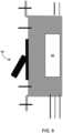
- FIG. 6is an illustration of another example driver assembly that can be used with privacy glazing 12 to discretely locate the driver relative to the glazing.
- FIG. 6illustrates a front face view of privacy glazing 12 showing the glazing with an example muntin bar or grill structure 150.
- some privacy glazing structuressuch as windows or doors may include muntin bars.
- the muntin barswhich may also be called glazing bars or sash bars, divide a single window into a grid system of small panes of glass, called lites.
- Typical muntin bar patternsinclude grids of rectangles, squares, or diamonds.
- Muntin barscreate the visual appearance that the window is formed of multiple, small pieces of glass joined together by the muntin bars instead of large, unitary panes of glass. This replicates the appearance of early windows and doors, which were formed of small panes of glass joined together instead of large unitary panes of glass, which were more expensive and difficult to manufacture.
- the muntin barscan be located inside of a between-pane space 54 (in configurations where the assembly includes a between-pane space) or on a surface of privacy glazing structure accessible from an external environment (which may be an exterior environment exposed to natural elements or an interior environment of a building).
- muntin barsmay be formed of a metal (e.g., aluminum, stainless steel), a polymer (e.g., vinyl), wood, or other material.
- Muntin barscan be of any size and can have any cross-sectional shape.
- muntin barscan have any polygonal cross-sectional shape (e.g., square, rectangle), arcuate cross-sectional shape (e.g., circular, elliptical), or combinations of polygonal and arcuate shape.
- muntin bars 150have a contoured profile with a rectangular center that tapers toward the top and bottom of the stock along the height of the muntin bar.
- different muntin bar segmentsmay be joined together, e.g., using notched joints such as half-lap joins, with or without the addition of joining keys.
- driver 80is contained within the muntin bar structure.
- One or more individual muntin bar segments forming a grid structuremay define the driver housing 92 in which various components defining the driver are inserted and housed.
- driver 80may include a separate driver housing 92 that is insertable into a space or cavity inside of one or more muntin bar segments.
- one or more of the muntin barsmay include an opening defining a cavity in which driver 80 or components thereof can be placed in the muntin bar(s).
- the openingmay be closed with a cover or seal, which may or may not be formed of the same material from which the muntin bars are fabricated, and may include any of the seal / seal layer materials discussed above.
- the openingis on a face positioned in contact with the pane of transparent material against which muntin bars 150 are positioned. This may cause the opening, or any cover thereof, to be obscured when the muntin bars are positioned against the face of the pane of transparent material to visually divide the pane into a plurality of individual lites.
- electrical conductors 124, 126extend from driver 80 to electrically connect the driver to first electrode layer 20 and second electrode layer 22, respectively.
- the electrical conductors 124, 126may extend through a hollow lumen formed through muntin bars 150 to an edge of privacy glazing structure 12 where electrical connections are made between the driver and electrode layers. If connected to a wall power source, an electrical conductor may extend from the power source to driver 80, e.g., through a lumen extending through muntin bars 150.
- FIG. 7is an illustration of another example driver assembly that can be used with privacy glazing 12 to discretely locate the driver relative to the glazing.
- driver 80is installed within a wall-mounted gang box 180 configured to be located outside of and physically spaced from privacy glazing structure 12.
- Wall-mounted gang box 180may be a box enclosed on five sides and open on a sixth, front side.
- Wall-mounted gang box 180can be fabricated from metal or plastic and may or may not have integrated mechanical fasteners 182, such as securing apertures with pre-installed nails or screws, for securing the gang box to a wall stud of a building.
- FIGS. 8A and 8Bare illustrations of example single and double gang box structures, respectively, that may be used for mounting a driver to control privacy glazing structure 12 according to the disclosure. While dimensions of the gang box may vary, in some examples, gang box 180 has a height ranging from 3 inches to 4.5 inches (approximately 7 cm to 11 cm) (e.g., 3.75 inches (approximately 10 cm)), a width ranging from 1.75 inches to 2.75 inches (approximately 4 cm to 7 cm) (e.g., 2.25 inches (approximately 6 cm)), and a depth ranging from 2 inches to 4 inches (approximately 5 cm to 10 cm), such as from 2.75 inches to 3.45 inches (approximately 7 cm to 9 cm).
- gang box 180has a height ranging from 3 inches to 4.5 inches (approximately 7 cm to 11 cm) (e.g., 3.75 inches (approximately 10 cm)), a width ranging from 1.75 inches to
- Gang box 180may have power entering the gang box from a power source, which is illustrated as being implemented using three electrical conductors 184, 186, 188 (e.g., positive, negative, ground).
- the electrical conductors communicating with the power sourcecan be electrically connected to driver 80 within gang box 180.
- electrical conductors 124, 126may extend from driver 80 and gang box 180 to electrically connect the driver to first electrode layer 20 and second electrode layer 22, respectively.
- the electrical conductors 124, 126may extend from gang box 180, through a lumen passing through one or more studs forming a wall in which privacy glazing structure 12 is mounted, and/or through a frame or sash surrounding the privacy glazing structure to electrically connect with electrode layers 20, 22.
- driver 80is mounted within gang box 180 and user interface 96 is also mounted in the gang box, e.g., over the driver.
- the user interface 96can be connected to driver 80 in the gang box 180 and used to control conditioned electrical signals supplied by the driver to the privacy glazing structure.
- driver 80may have user interface contacts 190 on a front surface of the driver that are configured to connect to user interface 96, when the user interface is installed in the gang box.
- user interface 96which is illustrated as being a light or toggle-style switch, can be physically separate from and connectable to driver or can be integrated with the driver to form an integrated driver-gang-box assembly. For example, FIG.
- driver 80need not be mounted in separate gang box but may be sized consistent with the size of a gang box for direct mounting to a stud.
- user interface 96is illustrated as a toggle or rocker switch, other types of user interfaces such as a capacitive touch switch, depressible buttons, slider, or the like may be used.
- driver 80In some examples in which driver 80 is configured to be mounted in or as a gang box, the driver may have a height ranging from 50 mm to 100 mm (e.g., 60 mm), a width ranging from 15 mm to 55 mm (e.g., 35 mm), and a depth ranging from 15 mm to 60 mm (e.g., 25 mm).
- gang box 180 and the driver 80 contained thereinmay be mounted directly adjacent to privacy glazing 12 or may be mounted a distance away from the privacy glazing.
- gang box 180 and the driver 80may be mounted at least 1 foot (approximately 0.3 m) away from a nearest perimeter edge of privacy glazing 12, such as at least 5 feet (approximately 1.5 m), or at least 10 feet (approximately 3 m).
- gang box 180 and driver 80may be mounted within 1 foot (approximately 0.3 m) from the nearest perimeter edge of the privacy glazing.
- electrical conductors 124, 126may extend from driver 80 and gang box 180 to electrically connect the driver to first electrode layer 20 and second electrode layer 22, respectively.
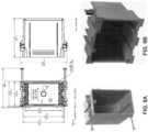
- FIG. 10is an exploded perspective view of an example privacy door 200 showing an example driver assembly arrangement.
- Privacy door 200can be constructed using the arrangement and configuration of components discussed above with respect to privacy glazing structure 12 ( FIGS. 1 and 2 ).
- privacy door 200may include a first pane of transparent material 14, a second pane of transparent material 16, and an electrically controllable optically active material 18 positioned between the first and second panes of transparent material.
- the first pane of transparent material 14can carry a first electrode layer
- the second pane of transparent material 16can carry a second electrode layer, as discussed with respect to privacy glazing structure 12.
- Privacy door 200may be visually transparent, or see through, when electrically controllable optically active material 18 is in a transparent state but optically obscured when the optically active material is in a darkened or privacy state.
- privacy door 200can include an optically opaque panel covering an access opening to an interior space formed within the door.
- privacy door 200 in the example of FIG. 10is illustrated as include a kick plate 202 positioned across the lower quadrant of the door.
- Privacy door 200is also shown as having a hinge plate 204 which, in the illustrated example, is depicted as a top hinge plate 204A and bottom hinge plate 204B.
- the hinge platescan define mating surfaces where privacy door 200 is joined via hinge(s) to a door frame.
- a cavitymay be formed in first pane of transparent material 14 and/or privacy door 200 that is covered by and/or accessible through a corresponding optically opaque panel.
- Driver 80can be within the cavity and electrically connected to the electrode layers carried by the transparent panels, e.g., using electrical conductors extending from the driver to each respective electrode layer.
- the cavity formed within privacy door 200may form the driver housing 92 in which various components defining the driver are inserted and housed.
- driver 80may include a separate driver housing 92 that is insertable into cavity.
- the optically opaque panelcan be covered over the opening to discretely hide the driver within the opening. While FIG. 10 illustrates privacy door 200 with a driver positioned behind kick plate 202 and hinge plate 204A, in practice, such a door may utilize only a single driver.
- the optically opaque platemay be fabricated from a material that is not visually transparent, regardless of the state of electrically controllable optically active material 18.
- the optically opaque platemay be fabricated from non-transparent glass (e.g., frosted glass), metal, non-transparent plastic, or other suitable material.
- processormay refer to any one or more of the foregoing structures or any other structure suitable for implementation of the techniques described herein.
- various components illustrated hereinmay be realized by any suitable combination of hardware, software, firmware.
- various componentsare depicted as separate units or modules. However, all or several of the various components described with reference to these figures may be integrated into combined units or modules within common hardware, firmware, and/or software. Accordingly, the representation of features as components, units or modules is intended to highlight particular functional features for ease of illustration, and does not necessarily require realization of such features by separate hardware, firmware, or software components.
- various unitsmay be implemented as programmable processes performed by one or more processors or controllers.
- any features described herein as modules, devices, or componentsmay be implemented together in an integrated logic device or separately as discrete but interoperable logic devices.
- such componentsmay be formed at least in part as one or more integrated circuit devices, which may be referred to collectively as an integrated circuit device, such as an integrated circuit chip or chipset.
- integrated circuit devicesuch as an integrated circuit chip or chipset.
- Such circuitrymay be provided in a single integrated circuit chip device or in multiple, interoperable integrated circuit chip devices.
- the techniquesmay be realized at least in part by a computer-readable data storage medium (e.g., a non-transitory computer-readable storage medium) comprising code with instructions that, when executed by one or more processors or controllers, performs one or more of the methods and functions described in this disclosure.
- the computer-readable storage mediummay form part of a computer program product, which may include packaging materials.
- the computer-readable mediummay comprise random access memory (RAM) such as synchronous dynamic random access memory (SDRAM), read-only memory (ROM), non-volatile random access memory (NVRAM), electrically erasable programmable read-only memory (EEPROM), embedded dynamic random access memory (eDRAM), static random access memory (SRAM), flash memory, magnetic or optical data storage media.
- RAMrandom access memory
- SDRAMsynchronous dynamic random access memory
- ROMread-only memory
- NVRAMnon-volatile random access memory
- EEPROMelectrically erasable programmable read-only memory
- eDRAMembedded dynamic random access memory
Landscapes
- Physics & Mathematics (AREA)
- Nonlinear Science (AREA)
- Optics & Photonics (AREA)
- General Physics & Mathematics (AREA)
- Chemical & Material Sciences (AREA)
- Crystallography & Structural Chemistry (AREA)
- Engineering & Computer Science (AREA)
- Structural Engineering (AREA)
- Mathematical Physics (AREA)
- Civil Engineering (AREA)
- Architecture (AREA)
- Liquid Crystal (AREA)
- Electrochromic Elements, Electrophoresis, Or Variable Reflection Or Absorption Elements (AREA)
- Joining Of Glass To Other Materials (AREA)
- Securing Of Glass Panes Or The Like (AREA)
Description
- This application claims priority to
U.S. Provisional Patent Application No. 62/582,113, filed November 06, 2017 - This disclosure relates to glazing structures that include electrically controllable optically active material and, more particularly, to electrical driver arrangements for glazing structure systems.
- Windows, doors, partitions, and other structures having controllable light modulation have been gaining popularity in the marketplace. These structures are commonly referred to as "smart" structures or "privacy" structures for their ability to transform from a transparent state in which a user can see through the structure to a private state in which viewing is inhibited through the structure. For example, smart windows are being used in high-end automobiles and homes and smart partitions are being used as walls in office spaces to provide controlled privacy and visual darkening.
- A variety of different technologies can be used to provide controlled optical transmission for a smart structure. For example, electrochromic technologies, photochromic technologies, thermochromic technologies, suspended particle technologies, and liquid crystal technologies are all being used in different smart structure applications to provide controllable privacy. The technologies generally use an energy source, such as electricity, to transform from a transparent state to a privacy state or vice versa.
- For systems that use electricity to control the transition between transparent and privacy states, an electrical driver is typically provided to control the electrical signal delivered to the privacy structure. The driver may condition the electrical signal delivered to the privacy structure to provide a controlled transition from one state to another state and/or to maintain the privacy structure in a stable optical state.
WO2017/027407 A1 andUS 2012/147449 A1 disclose privacy glazing structures having a spacer located between adjacent panes. - The invention is set out in
claim 1, to which reference should now be made. Additional, optional features are given in the dependent claims. - The details of one or more examples are set forth in the accompanying drawings and the description below. Other features, objects, and advantages will be apparent from the description and drawings, and from the claims.
FIG. 1 is a side view illustration of an example privacy glazing structure configuration.FIG. 2 is a side view illustration of a privacy glazing structure as according to invention.FIG. 3 is a block diagram of an example driver configuration that can be used to condition electricity supplied to an example privacy glazing structure according toFIGS. 1 and2 .FIG. 4 is a schematic illustration of an example driver assembly that can be used with an example privacy glazing structure according toFIGS. 1 and2 to discretely locate the driver relative to the glazing.FIGS. 5A and 5B are side view illustrations showing example configurations of a spacer key containing a driver.FIG. 6 is an illustration of another example driver assembly that can be used with an example privacy glazing structure according toFIGS. 1 and2 to discretely locate the driver relative to the glazing.FIG. 7 is an illustration of another example driver assembly that can be used with an example privacy glazing structure according toFIGS. 1 and2 to discretely locate the driver relative to the glazing.FIGS. 8A and 8B are illustrations of example single and double gang box structures, respectively, that may be used for mounting a driver to control a privacy glazing structure.FIG. 9 is a side view illustration of an example integrated driver-gang-box assembly.FIG. 10 is a perspective view of an example privacy door structure showing example driver mounting configurations.- In general, the present disclosure is directed to electric driver arrangements for optical structures having electrically controllable light modulation. For example, an optical structure may include an electrically controllable optically active material that provides controlled transition between a privacy or scattering state and a visible or transmittance state. The electrical driver may receive power from a power source, such as a rechargeable and/or replaceable battery and/or wall or mains power source. The electrical driver can condition the electricity received from the power source, e.g., by changing the frequency, amplitude, waveform, and/or other characteristic of the electricity received from the power source. The electrical driver can deliver the conditioned electrical signal to electrodes that are electrically coupled to the optically active material. In addition, in response to a user input or other control information, the electrical driver may change the conditioned electrical signal delivered to the electrodes and/or cease delivering electricity to the electrodes. Accordingly, the electrical driver can control the electrical signal delivered to the optically active material, thereby controlling the material to maintain a specific optical state or to transition from one state (e.g., a transparent state or scattering state) to another state.
- In the present disclosure, the term privacy structure includes privacy cells, privacy glazing structures, smart cells, smart glazing structure, and related devices that provide controllable optical activity and, hence, visibility through the structure. Such structures can provide switchable optical activity that provides controllable darkening, controllable light scattering, or both controllable darkening and controllable light scattering. Controllable darkening refers to the ability of the optically active material to transition between a high visible light transmission state (a bright state), a low visible light transmission dark state, and optionally intermediate states therebetween, and vice versa, by controlling an external energy source applied to the optically active material. Controllable light scattering refers to the ability of the optically active material to transition between a low visible haze state, a high visible haze state, and optionally intermediate states therebetween, and vice versa, by controlling an external energy source. Thus, reference to the terms "privacy" and "privacy state" in the present disclosure does not necessarily require complete visible obscuring through the structure (unless otherwise noted). Rather, different degrees of privacy or obscuring through the structure may be achieved depending, e.g., on the type of optically active material used and the conditions of the external energy source applied to the optically active material.
FIGS. 3-10 describe example electrical driver arrangements that may be used with a privacy structure. However,fig.1 describes an example privacy structure andfig.2 describes an embodiment of the invention that utilizes an electrical driver arrangement as described herein.FIG. 1 is a side view of an exampleprivacy glazing structure 12 that includes a first pane oftransparent material 14 and a second pane oftransparent material 16 with a layer of opticallyactive material 18 bounded between the two panes of transparent material. Theprivacy glazing structure 12 also includes afirst electrode layer 20 and asecond electrode layer 22. Thefirst electrode layer 20 is carried by the first pane oftransparent material 14 while thesecond electrode layer 22 is carried by the second pane of transparent material. In operation, electricity supplied through the first andsecond electrode layers active material 18 to control visibility through the privacy glazing structure.- As described in greater detail below, a driver is electrically connected to the
first electrode layer 20 andsecond electrode layer 22, e.g., via wiring or other electrically conductive member extending between the driver and respective electrode layer. In operation, the driver conditions power received from a power source for controlling the layer of opticallyactive material 18, e.g., to maintain a specific optical state or to transition from one optical state to another optical state. The driver can have a variety of different arrangements and configurations relative to a privacy structure as described in greater detail herein. Privacy glazing structure 12 can utilize any suitable privacy materials for the layer of opticallyactive material 18. Further, although opticallyactive material 18 is generally illustrated and described as being a single layer of material, it should be appreciated that a structure in accordance with the disclosure can have one or more layers of optically active material with the same or varying thicknesses. In general, opticallyactive material 18 is configured to provide controllable and reversible optical obscuring and lightening. Opticallyactive material 18 can be an electronically controllable optically active material that changes direct visible transmittance in response to changes in electrical energy applied to the material.- In one example, optically
active material 18 is formed of an electrochromic material that changes opacity or color tinting and, hence, light transmission properties, in response to voltage changes applied to the material. Typical examples of electrochromic materials are WO3 and MoO3, which are usually colorless when applied to a substrate in thin layers. An electrochromic layer may change its optical properties by oxidation or reduction processes. For example, in the case of tungsten oxide, protons can move in the electrochromic layer in response to changing voltage, reducing the tungsten oxide to blue tungsten bronze. The intensity of coloration is varied by the magnitude of charge applied to the layer. - In another example, optically
active material 18 is formed of a liquid crystal material. Different types of liquid crystal materials that can be used as opticallyactive material 18 include polymer dispersed liquid crystal (PDLC) materials and polymer stabilized cholesteric texture (PSCT) materials. Polymer dispersed liquid crystals usually involve phase separation of nematic liquid crystal from a homogeneous liquid crystal containing an amount of polymer, sandwiched between electrode layers 20 and 22. When the electric field is off, the liquid crystals may be randomly oriented. This scatters light entering the liquid crystal and diffuses the transmitted light through the material. When a certain voltage is applied between the two electrode layers, the liquid crystals may homeotropically align and the liquid crystals increase in optical transparency, allowing light to transmit through the layer of liquid crystal material. - In the case of polymer stabilized cholesteric texture (PSCT) materials, the material can either be a normal mode polymer stabilized cholesteric texture material or a reverse mode polymer stabilized cholesteric texture material. In a normal polymer stabilized cholesteric texture material, light is scattered when there is no electrical field applied to the material. If an electric field is applied to the liquid crystal, it turns to the homeotropic state, causing the liquid crystals to reorient themselves parallel in the direction of the electric field. This causes the liquid crystals to increase in optical transparency and allows light to transmit through the liquid crystal layer. In a reverse mode polymer stabilized cholesteric texture material, the liquid crystals are transparent in the absence of an electric field (e.g., zero electric field) but light scattering upon application of an electric field.
- In one example in which the layer of optically
active material 18 is implemented using liquid crystals, the optically active material includes liquid crystals and a dichroic dye to provide a guest-host liquid crystal mode of operation. When so configured, the dichroic dye can function as a guest compound within the liquid crystal host. The dichroic dye can be selected so the orientation of the dye molecules follows the orientation of the liquid crystal molecules. In some examples, when an electric field is applied to the opticallyactive material 18, there is little to no absorption in the short axis of the dye molecule, and when the electric field is removed from the optically active material, the dye molecules absorb in the long axis. As a result, the dichroic dye molecules can absorb light when the optically active material is transitioned to a scattering state. When so configured, the optically active material may absorb light impinging upon the material to prevent an observer on one side ofprivacy glazing structure 12 from clearly observing activity occurring on the opposite side of the structure. - When optically
active material 18 is implemented using liquid crystals, the optically active material may include liquid crystal molecules within a polymer matrix. The polymer matrix may or may not be cured, resulting in a solid or liquid medium of polymer surrounding liquid crystal molecules. In addition, in some examples, the opticallyactive material 18 may contain spacer beads (e.g., micro-spheres), for example having an average diameter ranging from 3 micrometers to 40 micrometers, to maintain separation between the first pane oftransparent material 14 and the second pane oftransparent material 16. - In another example in which the layer of optically
active material 18 is implemented using a liquid crystal material, the liquid crystal material turns hazy when transitioned to the privacy state. Such a material may scatter light impinging upon the material to prevent an observer on one side ofprivacy glazing structure 12 from clearly observing activity occurring on the opposite side of the structure. Such a material may significantly reduce regular visible transmittance through the material (which may also be referred to as direct visible transmittance) while only minimally reducing total visible transmittance when in the privacy state, as compared to when in the light transmitting state. When using these materials, the amount of scattered visible light transmitting through the material may increase in the privacy state as compared to the light transmitting state, compensating for the reduced regular visible transmittance through the material. Regular or direct visible transmittance may be considered the transmitted visible light that is not scattered or redirected through opticallyactive material 18. - Another type of material that can be used as the layer of optically
active material 18 is a suspended particle material. Suspended particle materials are typically dark or opaque in a non-activated state but become transparent when a voltage is applied. Other types of electrically controllable optically active materials can be utilized as opticallyactive material 18, and the disclosure is not limited in this respect. - Independent of the specific type of material(s) used for the layer of optically
active material 18, the material can change from a light transmissive state in whichprivacy glazing structure 12 is intended to be transparent to a privacy state in which visibility through the insulating glazing unit is intended to be reduced. Opticallyactive material 18 may exhibit progressively decreasing direct visible transmittance when transitioning from a maximum light transmissive state to a maximum privacy state. Similarly, opticallyactive material 18 may exhibit progressively increasing direct visible transmittance when transitioning from a maximum privacy state to a maximum transmissive state. The speed at which opticallyactive material 18 transitions from a generally transparent transmission state to a generally opaque privacy state may be dictated by a variety factors, including the specific type of material selected for opticallyactive material 18, the temperature of the material, the electrical voltage applied to the material, and the like. - Depending on the type of material used for optically
active material 22, the material may exhibit controllable darkening. As noted above, controllable darkening refers to the ability of the optically active material to transition between a high visible light transmission state (a bright state), a low visible light transmission dark state, and optionally intermediate states therebetween, and vice versa, by controlling an external energy source applied to the optically active material. When opticallyactive material 22 is so configured, the visible transmittance through the cell formed by flexible material 24, opticallyactive material 22, and second pane oftransparent material 16 may be greater than 40% when opticallyactive material 22 is transitioned to the high visible transmission state light state, such as greater than 60%. By contrast, the visible transmittance through the cell may be less than 5 percent when opticallyactive material 22 is transitioned to the low visible light transmission dark state, such as less than 1%. Visible transmittance can be measured according to ASTM D1003-13. - Additionally or alternatively, optically
active material 22 may exhibit controllable light scattering. As noted above, controllable light scattering refers to the ability of the optically active material to transition between a low visible haze state, a high visible haze state, and optionally intermediate states therebetween, and vice versa, by controlling an external energy source. When opticallyactive material 22 is so configured, the transmission haze through the cell formed by flexible material 24, opticallyactive material 22, and second pane oftransparent material 16 may be less than 10% when opticallyactive material 22 is transitioned to the low visible haze state, such as less than 2%. By contrast, the transmission haze through the cell may be greater than 85% when opticallyactive material 22 is transitioned to the high visible haze state and have a clarity value below 50%, such as a transmission haze greater than 95% and a clarity value below 30%. Transmission haze can be measured according to ASTM D1003-13. Clarity can be measured using a BYK Gardener Haze-Gard meter, commercially available from BYK-GARDNER GMBH. - To electrically control optically
active material 18,privacy glazing structure 12 in the example ofFIG. 1 includesfirst electrode layer 20 andsecond electrode layer 22. Each electrode layer may be in the form of an electrically conductive coating deposited on or over the surface of each respective pane facing the opticallyactive material 18. For example, first pane oftransparent material 14 may define aninner surface 24A and anouter surface 24B on an opposite side of the pane. Similarly, second pane oftransparent material 16 may define aninner surface 26A and anouter surface 26B on an opposite side of the pane.First electrode layer 20 can be deposited over theinner surface 24A of the first pane, whilesecond electrode layer 22 can be deposited over theinner surface 26A of the second pane. The first and second electrode layers 20, 22 can be deposited directed on the inner surface of a respective pane or one or more intermediate layers, such as a blocker layer, and be deposited between the inner surface of the pane and the electrode layer. - Each
electrode layer transparent material 14 and second pane oftransparent material 16 which opticallyactive material 18 contacts. In other examples, one or more other coatings may overlay the first and/or second electrode layers 20, 22, such as a dielectric overcoat (e.g., silicon oxynitride). In either case, first pane oftransparent material 14 and second pane oftransparent material 16, as well as any coatings oninner faces active material 18. - The panes of transparent material forming
privacy glazing structure 12, includingfirst pane 14 and second pane oftransparent material 16, and be formed of any suitable material. Each pane of transparent material may be formed from the same material, or at least one of the panes of transparent material may be formed of a material different than at least one other of the panes of transparent material. In some examples, at least one (and optionally all) the panes ofprivacy glazing structure 12 are formed of glass. In other examples, at least one (and optionally all) theprivacy glazing structure 12 are formed of plastic such as, e.g., a fluorocarbon plastic, polypropylene, polyethylene, or polyester. When glass is used, the glass may be aluminum borosilicate glass, sodium-lime (e.g., sodium-lime-silicate) glass, or another type of glass. In addition, the glass may be clear or the glass may be colored, depending on the application. Although the glass can be manufactured using different techniques, in some examples the glass is manufactured on a float bath line in which molten glass is deposited on a bath of molten tin to shape and solidify the glass. Such an example glass may be referred to as float glass. - In some examples,
first pane 14 and/or second pane oftransparent material 16 may be formed from multiple different types of materials. For example, the substrates may be formed of a laminated glass, which may include two panes of glass bonded together with a polymer such as polyvinyl butyral. Additional details on privacy glazing substrate arrangements that can be used in the present disclosure can be found inUS Patent Publication No. 2018/0307111, titled "HIGH PERFORMANCE PRIVACY GLAZING STRUCTURES" and published on October 25, 2018 . Privacy glazing structure 12 can be used in any desired application, including in a door, a window, a wall (e.g., wall partition), a skylight in a residential or commercial building, or in other applications. To help facilitate installation ofprivacy glazing structure 12, the structure may include aframe 30 surrounding the exterior perimeter of the structure (which also may be referred to as a sash). In different examples,frame 30 may be fabricated from wood, metal, or a plastic material such as vinyl.Frame 30 may define achannel 32 that receives and holds the external perimeter edge ofstructure 12. The sightline throughprivacy glazing structure 12 is generally established as the location whereframe 30 ends and visibility throughprivacy glazing structure 12 begins.- In the example of
FIG. 1 ,privacy glazing structure 12 is illustrated as a privacy cell formed of two panes of transparent material bounding opticallyactive material 18. In other configurations,privacy glazing structure 12 may be incorporated into a multi-pane glazing structure that include a privacy cell having one or more additional panes separated by one or more between-pane spaces.FIG. 2 is a side view of an configuration as according to the invention in whichprivacy glazing structure 12 fromFIG. 1 is incorporated into a multi-pane insulating glazing unit having a between-pane space. - As shown in
FIG. 2 , a multi-paneprivacy glazing structure 50 includesprivacy glazing structure 12 separated from an additional (e.g., third) pane oftransparent material 52 by a between-pane space 54 by aspacer 56.Spacer 56 may extend around the entire perimeter of multi-paneprivacy glazing structure 50 to hermetically seal the between-pane space 54 from gas exchange with a surrounding environment. To minimize thermal exchange across multi-paneprivacy glazing structure 50, between-pane space 54 can be filled with an insulative gas or even evacuated of gas. For example, between-pane space 54 may be filled with an insulative gas such as argon, krypton, or xenon. In such applications, the insulative gas may be mixed with dry air to provide a desired ratio of air to insulative gas, such as 10 percent air and 90 percent insulative gas. In other examples, between-pane space 54 may be evacuated so that the between-pane space is at vacuum pressure relative to the pressure of an environment surrounding multi-paneprivacy glazing structure 50. Spacer 56 can be any structure that holds opposed substrates in a spaced apart relationship over the service life of multi-paneprivacy glazing structure 50 and seals between-pane space 54 between the opposed panes of material, e.g., so as to inhibit or eliminate gas exchange between the between-pane space and an environment surrounding the unit. A spacer that is used asspacer 56 is a tubular spacer positioned between first pane oftransparent material 14 and third pane oftransparent material 52. The tubular spacer may define a hollow lumen or tube which, in some examples, is filled with desiccant. The tubular spacer may have a first side surface adhered (by a first bead of sealant) to theouter surface 24B of first pane oftransparent material 14 and a second side surface adhered (by a second bead of sealant) to third pane oftransparent material 52. A top surface of the tubular spacer can be exposed to between-pane space 54 and, in some examples, includes openings that allow gas within the between-pane space to communicate with desiccating material inside of the spacer. Such a spacer can be fabricated from aluminum, stainless steel, a thermoplastic, or any other suitable material. Advantageous glazing spacers are available commercially from Allmetal, Inc. of Itasca, IL, U.S.A.- Another example of a spacer that can be used as
spacer 56 is a spacer formed from a corrugated metal reinforcing sheet surrounded by a sealant composition. The corrugated metal reinforcing sheet may be a rigid structural component that holds first pane oftransparent material 14 apart from third pane oftransparent material 52. Such a spacer is often referred to in commercial settings as swiggle spacer. In yet another example,spacer 56 may be formed from a foam material surrounded on all sides except a side facing a between-pane space with a metal foil. Such a spacer is commercially available from Edgetech under the trade name Super Spacer®. As another example,spacer 56 may be a thermoplastic spacer (TPS) spacer formed by positioning a primary sealant (e.g., adhesive) between first pane oftransparent material 14 and third pane oftransparent material 52 followed, optionally, by a secondary sealant applied around the perimeter defined between the substrates and the primary sealant.Spacer 56 can have other configurations, as will be appreciated by those of ordinary skill in the art. - Depending on application, first pane of
transparent material 14, second pane oftransparent material 16, and/or third pane of transparent material 52 (when included) may be coated with one or more functional coatings to modify the performance of privacy structure. Example functional coatings include, but are not limited to, low-emissivity coatings, solar control coatings, and photocatalytic coatings. In general, a low-emissivity coating is a coating that is designed to allow near infrared and visible light to pass through a pane while substantially preventing medium infrared and far infrared radiation from passing through the panes. A low-emissivity coating may include one or more layers of infrared-reflection film interposed between two or more layers of transparent dielectric film. The infrared-reflection film may include a conductive metal like silver, gold, or copper. Advantageous low-emissivity coatings include the LoE-180™, LoE-272™, and LoE-366™ coatings available commercially from Cardinal CG Company of Spring Green, Wisconsin, U.S.A. A photocatalytic coating, by contrast, may be a coating that includes a photocatalyst, such as titanium dioxide. In use, the photocatalyst may exhibit photoactivity that can help self-clean, or provide less maintenance for the panes. Advantageous photocatalytic coatings include the NEAT® coatings available from Cardinal CG Company. - As briefly mentioned above, the panes of transparent material forming
privacy glazing structure 12, whether implemented alone or in the form of multiple-pane structure with a between-pane space, can carry afirst electrode layer 20 andsecond electrode layer 22 for controlling opticallyactive material 18. Thefirst electrode layer 20 andsecond electrode layer 22 can be electrically coupled to a driver that conditions power received from a power source to control opticalactive material 18.FIG. 3 is a block diagram of an example driver configuration that can be used to condition electricity supplied toprivacy glazing structure 12. - As shown in the example of
FIG. 3 , adriver 80 can be electrically coupled toprivacy glazing structure 12 via an electrical linkage 82.Driver 80 includes acontroller 84, a communication module 86, anoutput circuit 88, and a power source 90. Some or all of the components ofdriver 80 may be contained in ahousing 92.Controller 84 can communicate with the other components ofdriver 80 to manage the overall operation of the driver. In some examples,controller 84 receives input from a user interface and/or sensor to control conditioning of the electrical signal received from power source 90.Controller 84 may include a processor and memory. The processor can run software stored in memory to perform functions attributed tocontroller 84. The memory can provide non-transitory storage of software used by and data used or generated bycontroller 84. - Communication module 86 can be implemented using a wired and/or wireless interface to communicate between
controller 84 and the external environment. Communication module 86 may be used to send status information fromdriver 80 to an external computing device and/or to receive information concerning howdriver 80 should be controlled. For example,driver 80 may be communicatively coupled via communication module 86 with a smart home computing system and/or a wireless module that would enable smart device control remotely. Example communication protocols that communication module 86 may communicate over include, but are not limited to, Ethernet (e.g., TCP/IP), RS232, RS485, and common bus protocols (e.g., CAN). Output circuit 88, which may also be referred to as a driver circuit, can take control signals fromcontroller 84 and power signals from power source 90 and generate a conditioned electrical signal supplied toprivacy glazing structure 12. For example, the control signals received fromcontroller 84 may dictate the frequency, amplitude, waveform, and/or other signal properties of the conditioned electrical signal to be supplied toprivacy glazing structure 12 to control opticallyactive material 18.Output circuit 88 can condition the power signal received from power source 90 using the control signal information received fromcontroller 84. In some examples,output circuit 88 may generate feedback signals returned tocontroller 84 providing information for maintenance and/or status monitoring.- Power source 90 may be implemented using any source or combination of sources of electrical power to control
privacy glazing structure 12. Power source 90 may be a battery source having a finite capacity and/or be a continuous source having an infinite capacity (e.g., wall or mains power, a direct current power source such as power over Ethernet (POE)). When configured with one or more batteries, the batteries may be rechargeable and/or replaceable. Examples of power source 90 include, but are not limited to, 115Vac or 240Vac, 12Vdc, 24 Vdc, and combinations thereof. Power source 90 may or may not be located inside ofdriver housing 92, as illustrated inFIG. 3 , depending on the manner in which the power source is implemented in the system. - To control
driver 80, the privacy system may include auser interface 94.User interface 94 may be wired or wirelessly connected tocontroller 84.User interface 94 may include a switch, buttons, touch screen display, and/or other features with which a user can interact to controlprivacy glazing structure 12. In operation, a user may interact withuser interface 94 to change the degree of privacy provided byprivacy glazing structure 12. For example, the user may interact withuser interface 94 to changeprivacy glazing structure 12 from a scattering or privacy state to a transparent or visible state, or vice versa, and/or the user may change to degree of privacy provided along a continuously variable spectrum. Information received fromuser interface 94 can be used bycontroller 84, e.g., with reference to information stored in memory, to control the electrical signal supplied toprivacy glazing structure 12 bydriver 80. FIG. 4 is a schematic illustration of a driver assembly that is used withprivacy glazing 12 to discretely locate the driver relative to the glazing. In particular,FIG. 4 illustratesdriver 80 contained within aspacer key 100 joining opposed ends ofspacer 56 together. As mentioned above in connection withFIG. 2 ,spacer 56 may surround the perimeter ofglazing assembly 50 to define a hermetically sealed between-pane space.Spacer 56 is formed of a unitary spacer member having two opposed ends 102 and 104 that join together at opposite ends of the single spacer member byspacer key 100. Alternatively,spacer 56 may include multiple spacer segments each joined together with spacer keys. In either case,spacer key 100 may be formed of a section of material of the same or different composition thanspacer 56.Spacer key 100 is inserted into opposed ends 102 and 104 of the spacer to join the spacer together and form a closed structure extending around the perimeter of the glazing assembly. For example,spacer key 100 can have a cross-sectional size and/or substantially equivalent tospacer 56, e.g., with afirst end 106 size and shape indexed to fit insidefirst end 102 of the spacer and asecond end 108 size and shape indexed to fit insidesecond end 104 of the spacer.Spacer 56 may define a hollow lumen or tube which, in some examples, is filled with desiccant (not illustrated). In some examples, the top surface of the tubular spacer includes openings that allow gas within between-pane space 54 (FIG. 2 ) to communicate into the lumen. When the tubular spacer is filled with desiccating material, gas communication between the between-pane space and desiccant in the lumen can help remove moisture from within the between-pane space, helping to prevent condensation between the panes.- For example,
spacer 56 may be a rigid tubular structure that holds one pane of transparent material (e.g., 14) a fixed distance from another pane of material (e.g., 52) over the service life of unit. In different examples,spacer 56 is fabricated from aluminum, stainless steel, a thermoplastic, or any other suitable material. In some examples,spacer 56 defines a W-shaped cross-section (e.g., in the X-Z plane), but can define any polygonal (e.g., square, hexagonal) or arcuate (e.g., circular, elliptical) shape, or even combinations of polygonal and arcuate shapes. - Independent of the specific configuration of
spacer 56,spacer key 100 can be a component that bridges the gap between the opposed ends 102, 104 ofspacer 56, which may be ends of a single, unitary spacer body or ends of different individual spacer members. The ends 106, 108 ofspacer key 100 may include projections, detents, or other mechanical engagement features to help keep the spacer key retained inspacer 56 once inserted. In some examples,spacer key 100 is formed of a polymeric material whilespacer 56 is formed of metal, although other materials can be used. - In the configuration of
FIG. 4 ,spacer key 100 containsdriver 80. Spacer key 100 may form thedriver housing 92 in which various components defining the driver are inserted and housed. Alternatively,driver 80 may include aseparate driver housing 92 that is insertable into a space or cavity inside ofspacer key 100. In some examples,spacer key 100 includes a closetop surface 110 that faces between-pane space 54, when the spacer key and spacer are assembled to define the between-pane space. Spacer key 100 may include an opening inbottom surface 112 that provides access to an internal cavity of the spacer key. When so configured,driver 80 can be inserted intospacer key 100 through the opening in bottom surface of the key, e.g., before or after inserting the spacer key into opposed ends 102, 104 of spacer. FIGS. 5A and 5B are side view illustrations showing example configurations ofspacer key 100. In the example ofFIG. 5A ,driver 80 is contained within an interior cavity ofspacer key 100. In the example ofFIG. 5B , thebottom surface 112 ofspacer key 100 is offset relative to the bottom surface ofspacer 56, providing a spacer key gap region in whichdriver 80 can be inserted and attached to the spacer key. In either configuration, asealant layer 120 may be positioned across the entire bottom surface ofspacer key 100 anddriver 80 contained therein, e.g., extending over the joints where the spacer key joins spacer 56 (FIG. 5A ). Alternatively,sealant layer 120 may be positioned over the joints where the spacer key joinsspacer 56 without extending across the entire bottom surface (FIG. 5B ). Thesealant layer 120 may be one or more polymeric and/or metal layers the inhibit gas diffusion. For example,sealant layer 120 may be a metal foil tape with adhesive backing to hold the metal foil to the surfaces ofspacer 56 andspacer key 100.- In some examples, one or more polymeric sealant layers are positioned around
spacer 56 and may or may not be positioned aroundspacer key 100 as well. For example, a two-part sealant system may be used that includes a primary sealant positioned in contact withspacer 56 and a secondary sealant overlaying the primary sealant. Example materials that may be used as the primary sealant include, but are not limited to, extrudable thermoplastic materials, butyl rubber sealants (e.g., polyisobutylene-based thermoplastics), polysulfide sealants, and polyurethane sealants. In some examples, the primary sealant is formed from a butyl rubber sealant that includes silicone functional groups or a polyurethane sealant that includes silicone functional groups. Example materials that may be used as the secondary sealant include acrylate polymers, silicone-based polymers, extrudable thermoplastic materials, butyl rubber sealants (e.g., polyisobutylene-based thermoplastics), polysulfide sealants, polyurethane sealants, and silicone-based sealants. For example, the secondary sealant may be a silicone-based sealant. - In some examples,
electrical conductors first electrode layer 20 andsecond electrode layer 22, respectively. If connected to a wall power source, an electrical conductor may extend from the power source todriver 80, e.g., through a wall surface ofspacer key 100. - By configuring
spacer key 100 with driver functionality, the driver may be positioned in close proximity to the electrodes ofprivacy glazing structure 12 to which the driver delivers a conditioned electrical signal. In addition, the driver may be discretely located in a visually unobtrusive space for the typical user. Moreover, by utilizingspacer key 100 as real estate for the driver, the driver may be readily installed by the manufacturer of privacy glazing structure, e.g., before shipping to a downstream fabricator that incorporates the structure inframe 30 or other desired end user package. FIG. 6 is an illustration of another example driver assembly that can be used withprivacy glazing 12 to discretely locate the driver relative to the glazing. In particular,FIG. 6 illustrates a front face view ofprivacy glazing 12 showing the glazing with an example muntin bar orgrill structure 150.- For aesthetic reasons, some privacy glazing structures such as windows or doors may include muntin bars. The muntin bars, which may also be called glazing bars or sash bars, divide a single window into a grid system of small panes of glass, called lites. Typical muntin bar patterns include grids of rectangles, squares, or diamonds. Muntin bars create the visual appearance that the window is formed of multiple, small pieces of glass joined together by the muntin bars instead of large, unitary panes of glass. This replicates the appearance of early windows and doors, which were formed of small panes of glass joined together instead of large unitary panes of glass, which were more expensive and difficult to manufacture. In different examples, the muntin bars can be located inside of a between-pane space 54 (in configurations where the assembly includes a between-pane space) or on a surface of privacy glazing structure accessible from an external environment (which may be an exterior environment exposed to natural elements or an interior environment of a building).
- In different examples, muntin bars may be formed of a metal (e.g., aluminum, stainless steel), a polymer (e.g., vinyl), wood, or other material. Muntin bars can be of any size and can have any cross-sectional shape. For example, muntin bars can have any polygonal cross-sectional shape (e.g., square, rectangle), arcuate cross-sectional shape (e.g., circular, elliptical), or combinations of polygonal and arcuate shape. In some examples, muntin bars 150 have a contoured profile with a rectangular center that tapers toward the top and bottom of the stock along the height of the muntin bar. Depending on the style of muntin bar grid being fabricated, different muntin bar segments may be joined together, e.g., using notched joints such as half-lap joins, with or without the addition of joining keys.
- Independent of the location of muntin bars 150, in the example of
FIG. 6 ,driver 80 is contained within the muntin bar structure. One or more individual muntin bar segments forming a grid structure may define thedriver housing 92 in which various components defining the driver are inserted and housed. Alternatively,driver 80 may include aseparate driver housing 92 that is insertable into a space or cavity inside of one or more muntin bar segments. In either case, one or more of the muntin bars may include an opening defining a cavity in whichdriver 80 or components thereof can be placed in the muntin bar(s). The opening may be closed with a cover or seal, which may or may not be formed of the same material from which the muntin bars are fabricated, and may include any of the seal / seal layer materials discussed above. In some examples, the opening is on a face positioned in contact with the pane of transparent material against which muntin bars 150 are positioned. This may cause the opening, or any cover thereof, to be obscured when the muntin bars are positioned against the face of the pane of transparent material to visually divide the pane into a plurality of individual lites. - In some examples,
electrical conductors driver 80 to electrically connect the driver tofirst electrode layer 20 andsecond electrode layer 22, respectively. For example, theelectrical conductors muntin bars 150 to an edge ofprivacy glazing structure 12 where electrical connections are made between the driver and electrode layers. If connected to a wall power source, an electrical conductor may extend from the power source todriver 80, e.g., through a lumen extending through muntin bars 150. FIG. 7 is an illustration of another example driver assembly that can be used withprivacy glazing 12 to discretely locate the driver relative to the glazing. In the example ofFIG. 7 ,driver 80 is installed within a wall-mountedgang box 180 configured to be located outside of and physically spaced fromprivacy glazing structure 12. Wall-mountedgang box 180 may be a box enclosed on five sides and open on a sixth, front side. Wall-mountedgang box 180 can be fabricated from metal or plastic and may or may not have integratedmechanical fasteners 182, such as securing apertures with pre-installed nails or screws, for securing the gang box to a wall stud of a building.FIGS. 8A and 8B are illustrations of example single and double gang box structures, respectively, that may be used for mounting a driver to controlprivacy glazing structure 12 according to the disclosure. While dimensions of the gang box may vary, in some examples,gang box 180 has a height ranging from 3 inches to 4.5 inches (approximately 7 cm to 11 cm) (e.g., 3.75 inches (approximately 10 cm)), a width ranging from 1.75 inches to 2.75 inches (approximately 4 cm to 7 cm) (e.g., 2.25 inches (approximately 6 cm)), and a depth ranging from 2 inches to 4 inches (approximately 5 cm to 10 cm), such as from 2.75 inches to 3.45 inches (approximately 7 cm to 9 cm).Gang box 180 may have power entering the gang box from a power source, which is illustrated as being implemented using threeelectrical conductors driver 80 withingang box 180. In addition,electrical conductors driver 80 andgang box 180 to electrically connect the driver tofirst electrode layer 20 andsecond electrode layer 22, respectively. For example, theelectrical conductors gang box 180, through a lumen passing through one or more studs forming a wall in whichprivacy glazing structure 12 is mounted, and/or through a frame or sash surrounding the privacy glazing structure to electrically connect withelectrode layers - In some examples,
driver 80 is mounted withingang box 180 anduser interface 96 is also mounted in the gang box, e.g., over the driver. Theuser interface 96 can be connected todriver 80 in thegang box 180 and used to control conditioned electrical signals supplied by the driver to the privacy glazing structure. For example,driver 80 may haveuser interface contacts 190 on a front surface of the driver that are configured to connect touser interface 96, when the user interface is installed in the gang box. In different examples,user interface 96, which is illustrated as being a light or toggle-style switch, can be physically separate from and connectable to driver or can be integrated with the driver to form an integrated driver-gang-box assembly. For example,FIG. 9 is a side view illustration of an example integrated driver-gang-box assembly whereuser interface 94 is not separate fromdriver 80. Accordinglydriver 80 need not be mounted in separate gang box but may be sized consistent with the size of a gang box for direct mounting to a stud. In addition, althoughuser interface 96 is illustrated as a toggle or rocker switch, other types of user interfaces such as a capacitive touch switch, depressible buttons, slider, or the like may be used. - In some examples in which
driver 80 is configured to be mounted in or as a gang box, the driver may have a height ranging from 50 mm to 100 mm (e.g., 60 mm), a width ranging from 15 mm to 55 mm (e.g., 35 mm), and a depth ranging from 15 mm to 60 mm (e.g., 25 mm). In practice,gang box 180 and thedriver 80 contained therein may be mounted directly adjacent toprivacy glazing 12 or may be mounted a distance away from the privacy glazing. For example,gang box 180 and thedriver 80 may be mounted at least 1 foot (approximately 0.3 m) away from a nearest perimeter edge ofprivacy glazing 12, such as at least 5 feet (approximately 1.5 m), or at least 10 feet (approximately 3 m). Alternatively,gang box 180 anddriver 80 may be mounted within 1 foot (approximately 0.3 m) from the nearest perimeter edge of the privacy glazing. In either case,electrical conductors driver 80 andgang box 180 to electrically connect the driver tofirst electrode layer 20 andsecond electrode layer 22, respectively. FIG. 10 is an exploded perspective view of anexample privacy door 200 showing an example driver assembly arrangement.Privacy door 200 can be constructed using the arrangement and configuration of components discussed above with respect to privacy glazing structure 12 (FIGS. 1 and2 ). For example,privacy door 200 may include a first pane oftransparent material 14, a second pane oftransparent material 16, and an electrically controllable opticallyactive material 18 positioned between the first and second panes of transparent material. The first pane oftransparent material 14 can carry a first electrode layer, and the second pane oftransparent material 16 can carry a second electrode layer, as discussed with respect toprivacy glazing structure 12.Privacy door 200 may be visually transparent, or see through, when electrically controllable opticallyactive material 18 is in a transparent state but optically obscured when the optically active material is in a darkened or privacy state.- To provide a location to discretely position
driver 80 that is electrically coupled to the electrode layers carried by the panes of transparent material,privacy door 200 can include an optically opaque panel covering an access opening to an interior space formed within the door. For example,privacy door 200 in the example ofFIG. 10 is illustrated as include akick plate 202 positioned across the lower quadrant of the door.Privacy door 200 is also shown as having a hinge plate 204 which, in the illustrated example, is depicted as atop hinge plate 204A andbottom hinge plate 204B. The hinge plates can define mating surfaces whereprivacy door 200 is joined via hinge(s) to a door frame. - A cavity may be formed in first pane of
transparent material 14 and/orprivacy door 200 that is covered by and/or accessible through a corresponding optically opaque panel.Driver 80 can be within the cavity and electrically connected to the electrode layers carried by the transparent panels, e.g., using electrical conductors extending from the driver to each respective electrode layer. The cavity formed withinprivacy door 200 may form thedriver housing 92 in which various components defining the driver are inserted and housed. Alternatively,driver 80 may include aseparate driver housing 92 that is insertable into cavity. In either case, the optically opaque panel can be covered over the opening to discretely hide the driver within the opening. WhileFIG. 10 illustratesprivacy door 200 with a driver positioned behindkick plate 202 and hingeplate 204A, in practice, such a door may utilize only a single driver. - The optically opaque plate may be fabricated from a material that is not visually transparent, regardless of the state of electrically controllable optically
active material 18. For example, the optically opaque plate may be fabricated from non-transparent glass (e.g., frosted glass), metal, non-transparent plastic, or other suitable material. - The techniques described in this disclosure, including functions performed by a controller, control unit, or control system, may be implemented within one or more of a general purpose microprocessor, digital signal processor (DSP), application specific integrated circuit (ASIC), field programmable gate array (FPGA), programmable logic devices (PLDs), or other equivalent logic devices. Accordingly, the terms "processor" or "controller," as used herein, may refer to any one or more of the foregoing structures or any other structure suitable for implementation of the techniques described herein.
- The various components illustrated herein may be realized by any suitable combination of hardware, software, firmware. In the figures, various components are depicted as separate units or modules. However, all or several of the various components described with reference to these figures may be integrated into combined units or modules within common hardware, firmware, and/or software. Accordingly, the representation of features as components, units or modules is intended to highlight particular functional features for ease of illustration, and does not necessarily require realization of such features by separate hardware, firmware, or software components. In some cases, various units may be implemented as programmable processes performed by one or more processors or controllers.
- Any features described herein as modules, devices, or components may be implemented together in an integrated logic device or separately as discrete but interoperable logic devices. In various aspects, such components may be formed at least in part as one or more integrated circuit devices, which may be referred to collectively as an integrated circuit device, such as an integrated circuit chip or chipset. Such circuitry may be provided in a single integrated circuit chip device or in multiple, interoperable integrated circuit chip devices.
- If implemented in part by software, the techniques may be realized at least in part by a computer-readable data storage medium (e.g., a non-transitory computer-readable storage medium) comprising code with instructions that, when executed by one or more processors or controllers, performs one or more of the methods and functions described in this disclosure. The computer-readable storage medium may form part of a computer program product, which may include packaging materials. The computer-readable medium may comprise random access memory (RAM) such as synchronous dynamic random access memory (SDRAM), read-only memory (ROM), non-volatile random access memory (NVRAM), electrically erasable programmable read-only memory (EEPROM), embedded dynamic random access memory (eDRAM), static random access memory (SRAM), flash memory, magnetic or optical data storage media. Any software that is utilized may be executed by one or more processors, such as one or more DSP's, general purpose microprocessors, ASIC's, FPGA's, or other equivalent integrated or discrete logic circuitry.
- Various examples have been described. These and other examples are within the scope of the following claims.
Claims (11)
- A privacy glazing structure (12) comprising:a first pane (52) of transparent material;a second pane (14) of transparent material;a spacer (56) positioned between the first pane of transparent material and the second pane of transparent material to define a between-pane space, the spacer sealing the between-pane space from gas exchange with a surrounding environment and holding the first pane of transparent material a separation distance from the second pane of transparent material;a third pane (16) of transparent material; andan electrically controllable optically active material (18) positioned between the second pane of transparent material and the third pane of transparent material, the electrically controllable optically active material being positioned between a first electrode layer (20) anda second electrode layer (22),wherein the spacer comprises a tubular body having opposed ends joined together by a key (100) having first and second ends that are inserted into the opposed ends of the tubular body, and key includes a driver (80) electrically connected to the first electrode layer and the second electrode layer, wherein the driver is configured to be electrically connected to a power source and condition power received from the power source to provide a drive signal to the first electrode layer and the second electrode layer for controlling the electrically controllable optically active material, andwherein the key has a closed surface facing the between-pane space and defines an opening facing the surrounding environment, the opening providing access to a hollow interior space of the key for inserting and removing the driver from the key.
- The structure (12) of claim 1, further comprising a seal (120) placed over at least one of the opening and an interface between the key and the tubular body.
- The structure (12) of claim 2, wherein the seal (120) is selected from the group consisting of a polymeric sealant, a film, a metal foil, and combinations thereof.
- The structure (12) of any one of the foregoing claims, wherein the driver (80) is configured to condition power received from the power source by altering at least one of a frequency, an amplitude, and a waveform of an electrical signal received from the power source.
- The structure (12) of any one of the foregoing claims, wherein the power source is selected from the group consisting of:wall power delivering alternating current; anda battery delivering direct current.
- The structure (12) of any one of the foregoing claims, wherein the second pane (14) of transparent material and the third pane (16) of transparent material are each laminate panes comprising a pair of glass substrates laminated together.
- The structure (12) of any one of the foregoing claims, wherein the driver (80) comprises a controller that is configured to receive input from a user control located outside of the privacy glazing structure.
- The structure (12) of any one of the foregoing claims, wherein:the first pane (52) of transparent material and the second pane (14) of transparent material are each fabricated from float glass,the first electrode layer (20) comprises a transparent conductive oxide coating deposited over the second pane of transparent material, andthe second electrode layer (22) comprises a transparent conductive oxide coating deposited over the third pane of transparent material.
- The structure (12) of any one of the foregoing claims, further comprising at least one of a wiring and an electrical joint extending out from the key (100) and electrically coupling the driver (80) to the first (20) and second (22) electrode layers.
- The structure (12) of any one of the foregoing claims, wherein the tubular body of the spacer (56) is fabricated from metal and contains desiccant inside of the tubular body.
- The structure (12) of any one of the foregoing claims, wherein the electrically controllable optically active material (18) is a liquid crystal material.
Priority Applications (1)
| Application Number | Priority Date | Filing Date | Title |
|---|---|---|---|
| EP25171716.1AEP4566812A3 (en) | 2017-11-06 | 2018-11-06 | Privacy glazing system with discrete electrical driver |
Applications Claiming Priority (2)
| Application Number | Priority Date | Filing Date | Title |
|---|---|---|---|
| US201762582113P | 2017-11-06 | 2017-11-06 | |
| PCT/US2018/059472WO2019090341A1 (en) | 2017-11-06 | 2018-11-06 | Privacy glazing system with discrete electrical driver |
Related Child Applications (1)
| Application Number | Title | Priority Date | Filing Date |
|---|---|---|---|
| EP25171716.1ADivisionEP4566812A3 (en) | 2017-11-06 | 2018-11-06 | Privacy glazing system with discrete electrical driver |
Publications (2)
| Publication Number | Publication Date |
|---|---|
| EP3707555A1 EP3707555A1 (en) | 2020-09-16 |
| EP3707555B1true EP3707555B1 (en) | 2025-05-07 |
Family
ID=64457106
Family Applications (2)
| Application Number | Title | Priority Date | Filing Date |
|---|---|---|---|
| EP18808174.9AActiveEP3707555B1 (en) | 2017-11-06 | 2018-11-06 | Privacy glazing system with discrete electrical driver |
| EP25171716.1APendingEP4566812A3 (en) | 2017-11-06 | 2018-11-06 | Privacy glazing system with discrete electrical driver |
Family Applications After (1)
| Application Number | Title | Priority Date | Filing Date |
|---|---|---|---|
| EP25171716.1APendingEP4566812A3 (en) | 2017-11-06 | 2018-11-06 | Privacy glazing system with discrete electrical driver |
Country Status (5)
| Country | Link |
|---|---|
| US (4) | US20190137796A1 (en) |
| EP (2) | EP3707555B1 (en) |
| CA (1) | CA3081612A1 (en) |
| MX (1) | MX2020004703A (en) |
| WO (1) | WO2019090341A1 (en) |
Families Citing this family (21)
| Publication number | Priority date | Publication date | Assignee | Title |
|---|---|---|---|---|
| US10303035B2 (en) | 2009-12-22 | 2019-05-28 | View, Inc. | Self-contained EC IGU |
| US9442339B2 (en) | 2010-12-08 | 2016-09-13 | View, Inc. | Spacers and connectors for insulated glass units |
| WO2012078634A2 (en) | 2010-12-08 | 2012-06-14 | Soladigm, Inc. | Improved spacers for insulated glass units |
| WO2018195458A1 (en) | 2017-04-20 | 2018-10-25 | Cardinal Ig Company | High performance privacy glazing structures |
| WO2019014613A1 (en) | 2017-07-13 | 2019-01-17 | Cardinal Ig Company | Electrical connection configurations for privacy glazing structures |
| EP3707555B1 (en) | 2017-11-06 | 2025-05-07 | Cardinal Ig Company | Privacy glazing system with discrete electrical driver |
| MX2020011871A (en) | 2018-05-09 | 2021-01-20 | Cardinal Ig Co | Electrically controllable privacy glazing with energy recapturing driver. |
| CN112654919B (en) | 2018-08-17 | 2024-05-28 | 卡迪纳尔Ig公司 | Privacy glazing structure with asymmetric pane offset for electrical connection configuration |
| US11474385B1 (en) | 2018-12-02 | 2022-10-18 | Cardinal Ig Company | Electrically controllable privacy glazing with ultralow power consumption comprising a liquid crystal material having a light transmittance that varies in response to application of an electric field |
| WO2020163836A1 (en) | 2019-02-08 | 2020-08-13 | Cardinal Ig Company | Low power driver for privacy glazing |
| MX2021013259A (en) | 2019-04-29 | 2022-01-06 | Cardinal Ig Co | SYSTEMS AND METHODS FOR OPERATING ONE OR MORE GLAZING STRUCTURES WITH ELECTRICALLY CONTROLLABLE PRIVACY. |
| US11175523B2 (en) | 2019-04-29 | 2021-11-16 | Cardinal Ig Company | Staggered driving electrical control of a plurality of electrically controllable privacy glazing structures |
| KR102809744B1 (en) | 2019-04-29 | 2025-05-16 | 카디날 아이지 컴퍼니 | Leakage current detection and control for one or more electrically controllable privacy glass structures |
| JP7615527B2 (en)* | 2019-11-01 | 2025-01-17 | Toppanホールディングス株式会社 | Light control device and light control sheet |
| JP7615526B2 (en)* | 2019-11-01 | 2025-01-17 | Toppanホールディングス株式会社 | Light control device |
| EP4189199A1 (en) | 2020-07-30 | 2023-06-07 | Cardinal Ig Company | Power transfer hinge for privacy glazing structure |
| US20220142379A1 (en)* | 2020-11-12 | 2022-05-12 | Hussmann Corporation | Transparent door |
| MX2023015424A (en) | 2021-06-23 | 2024-06-11 | Cardinal Ig Co | Power transfer systems for movable privacy glazing structures. |
| US12140848B2 (en)* | 2021-07-01 | 2024-11-12 | Glass Dyenamics, Inc. | Window and entryway systems with variable light transmission panels |
| US12197097B2 (en) | 2021-07-01 | 2025-01-14 | Glass Dynamics, Inc. | Entryway systems with variable light transmission panels |
| CN115949203A (en)* | 2023-02-03 | 2023-04-11 | 苏州美瑞德建筑装饰有限公司 | A large-scale transparent floor assembly design structure with privacy protection function |
Citations (2)
| Publication number | Priority date | Publication date | Assignee | Title |
|---|---|---|---|---|
| US20120147449A1 (en)* | 2010-12-08 | 2012-06-14 | Soladigm, Inc. | Spacers for insulated glass units |
| WO2017027407A1 (en)* | 2015-08-07 | 2017-02-16 | Kinestral Technologies, Inc. | Electrochromic device assemblies |
Family Cites Families (240)
| Publication number | Priority date | Publication date | Assignee | Title |
|---|---|---|---|---|
| GB1406441A (en) | 1972-03-13 | 1975-09-17 | Triplex Safety Glass Co | Laminated transparent assemblies |
| US3951846A (en) | 1974-06-28 | 1976-04-20 | Rca Corporation | Novel liquid crystal electro-optic devices |
| NO145771C (en) | 1974-09-16 | 1982-05-26 | Bfg Glassgroup | LIGHT THROUGH PANEL |
| CH604198A5 (en) | 1975-09-02 | 1978-08-31 | Siemens Ag | |
| US4284677A (en) | 1979-04-24 | 1981-08-18 | Libbey-Owens-Ford Company | Glazing unit |
| US4277294A (en) | 1979-06-06 | 1981-07-07 | Ppg Industries, Inc. | Method of fabricating window panels, particularly curved panels |
| JPS57133439A (en) | 1981-02-13 | 1982-08-18 | Citizen Watch Co Ltd | Electrochromism display cell |
| FR2529609A1 (en) | 1982-07-05 | 1984-01-06 | Saint Gobain Vitrage | MULTIPLE GLAZING WITH THERMAL AND ACOUSTIC INSULATION PROPERTIES |
| FR2538025A1 (en) | 1982-12-20 | 1984-06-22 | Conforglace Sa | IMPROVEMENT IN THE FLAME PROTECTION PANELS |
| JPS60216333A (en) | 1984-04-12 | 1985-10-29 | Asahi Glass Co Ltd | Electrochromic display element |
| JPS6271930A (en) | 1985-09-26 | 1987-04-02 | Canon Inc | display device |
| US4749261A (en) | 1986-01-17 | 1988-06-07 | Taliq Corporation | Shatter-proof liquid crystal panel with infrared filtering properties |
| US5111629A (en) | 1987-06-25 | 1992-05-12 | Allied-Signal Inc. | Dual-pane thermal window with liquid crystal shade |
| US4932608A (en) | 1987-12-28 | 1990-06-12 | Ppg Industries, Inc. | Aircraft windshield design and method of use |
| JPH01115725U (en) | 1988-01-29 | 1989-08-03 | ||
| JPH01202713A (en) | 1988-02-09 | 1989-08-15 | Seiko Epson Corp | Liquid crystal optical device |
| US5355245A (en) | 1988-02-12 | 1994-10-11 | Donnelly Corporation | Ultraviolet protected electrochemichromic rearview mirror |
| US5239406A (en) | 1988-02-12 | 1993-08-24 | Donnelly Corporation | Near-infrared reflecting, ultraviolet protected, safety protected, electrochromic vehicular glazing |
| GB8828634D0 (en) | 1988-12-08 | 1989-01-11 | Glaverbel | Composite glazing panel |
| US5164853A (en) | 1989-04-06 | 1992-11-17 | Ricoh Company, Ltd. | Liquid crystal display panel with plural substrates |
| US5103336A (en) | 1989-09-25 | 1992-04-07 | General Electric Company | Multilayered security window structure |
| US5076673A (en) | 1990-08-10 | 1991-12-31 | Donnelly Corporation | Prolonged coloration electrochromic assembly |
| FR2666805B1 (en) | 1990-09-14 | 1992-10-30 | Saint Gobain Vitrage Int | PROCESS FOR OBTAINING ELECTROCHROMIC WINDOWS. ELECTROCHROMIC WINDOWS. |
| US5151824A (en) | 1990-11-26 | 1992-09-29 | Donnelly Corporation | Vehicular outside mirror assembly |
| US5111329A (en) | 1990-11-28 | 1992-05-05 | Ford Motor Company | Solar load reduction panel with controllable light transparency |
| US5168387A (en) | 1990-12-11 | 1992-12-01 | Central Glass Company, Limited | Variable light transmittance device |
| US5142644A (en) | 1991-03-08 | 1992-08-25 | General Motors Corporation | Electrical contacts for polymer dispersed liquid crystal films |
| FR2680364B1 (en) | 1991-08-14 | 1994-02-25 | Saint Gobain Vitrage Internal | GLASS SAFETY SHEET FOR AIRPLANE. |
| US5239405A (en) | 1991-09-06 | 1993-08-24 | Donnelly Corporation | Electrochemichromic solutions, processes for preparing and using the same, and devices manufactured with the same |
| US6671008B1 (en) | 1991-11-27 | 2003-12-30 | Reveo, Inc. | Electro-optical glazing structures having scattering and transparent modes of operation and methods and apparatus for making the same |
| US6559903B2 (en)* | 1991-11-27 | 2003-05-06 | Reveo, Inc. | Non-absorptive electro-optical glazing structure employing composite infrared reflective polarizing filter |
| US5202787A (en) | 1992-01-10 | 1993-04-13 | Gentex Corporation | Electro-optic device |
| FR2691550B1 (en) | 1992-05-21 | 1995-04-21 | Saint Gobain Vitrage Int | Architectural electrochromic glazing. |
| US5197242A (en) | 1992-07-17 | 1993-03-30 | Allied-Signal Inc. | Dual-pane thermal window with liquid crystal shade |
| US5408353A (en) | 1993-07-13 | 1995-04-18 | Ford Motor Company | Controllable transparency panel with solar load reduction |
| ATE212415T1 (en) | 1993-09-27 | 2002-02-15 | Saint Gobain | INSULATING GLAZING AND VACUUM GENERATION PROCESS THEREOF |
| US5668663A (en) | 1994-05-05 | 1997-09-16 | Donnelly Corporation | Electrochromic mirrors and devices |
| US5589958A (en) | 1995-02-09 | 1996-12-31 | Lieb; Joseph A. | Kitchen ensemble having windows with controllable opacity |
| US7009665B2 (en) | 1995-10-30 | 2006-03-07 | Le Li | Electro-optical glazing structures having scattering and transparent modes of operation and methods and apparatus for making the same |
| FR2752012B3 (en) | 1996-07-31 | 1998-08-21 | Saint Gobain Vitrage | PROCESS FOR MAKING A VACUUM BETWEEN TWO GLASS SHEETS AND INSULATING GLAZING |
| FR2752570B1 (en) | 1996-08-22 | 1998-10-02 | Saint Gobain Vitrage | GLAZING WITH VARIABLE OPTICAL AND / OR ENERGY PROPERTIES |
| ATE238167T1 (en) | 1996-10-17 | 2003-05-15 | Saint Gobain | GLAZING WITH AN ACTIVE THERMAL, ELECTRICAL AND/OR ELECTROCHEMICAL UNIT |
| US5796452A (en) | 1997-03-21 | 1998-08-18 | International Business Machines Corporation | Simplified wiring escape technique for tiled display |
| AUPO816097A0 (en) | 1997-07-22 | 1997-08-14 | Sustainable Technologies Australia Limited | Combined electrochromic and photovoltaic smart window devices and methods |
| US6064509A (en) | 1997-08-22 | 2000-05-16 | Gentex Corporation | Clip for use with transparent conductive electrodes in electrochromic devices |
| US8294975B2 (en) | 1997-08-25 | 2012-10-23 | Donnelly Corporation | Automotive rearview mirror assembly |
| DE19737978C2 (en) | 1997-08-30 | 1999-09-16 | Bayer Ag | Electrochromic mirror |
| DE19802339A1 (en) | 1998-01-23 | 1999-07-29 | Bayer Ag | Electrochromic cell with two transparent, spaced panes |
| US5887391A (en)* | 1998-02-02 | 1999-03-30 | Columbia Manufacturing Co. | Storm door and method of fabrication thereof |
| JPH11305243A (en) | 1998-04-16 | 1999-11-05 | Internatl Business Mach Corp <Ibm> | Liquid crystal display device |
| FR2779839B1 (en) | 1998-06-10 | 2003-06-06 | Saint Gobain Vitrage | ELECTRICALLY CONTROLLED SYSTEM WITH VARIABLE OPTICAL PROPERTIES |
| US6317248B1 (en) | 1998-07-02 | 2001-11-13 | Donnelly Corporation | Busbars for electrically powered cells |
| DE19829480C2 (en) | 1998-07-02 | 2002-03-14 | Heinz Kunert | Insulating glass element for building glazing |
| JP3718355B2 (en) | 1998-11-26 | 2005-11-24 | 株式会社 日立ディスプレイズ | Liquid crystal display device |
| JP2001053524A (en)* | 1999-08-09 | 2001-02-23 | Central Glass Co Ltd | Glass antenna for vehicle |
| WO2001084230A1 (en) | 2000-05-04 | 2001-11-08 | Schott Donnelly Llc | Chromogenic glazing |
| US6373618B1 (en) | 2000-05-04 | 2002-04-16 | Schott-Donnelly, Llc | Chromogenic glazing for automobiles and display filters |
| JP3425693B2 (en) | 2000-05-22 | 2003-07-14 | 株式会社村上開明堂 | EC mirror electrode structure |
| US6643050B2 (en) | 2000-06-13 | 2003-11-04 | Ppg Industries Ohio, Inc. | Colored electrochromic transparent window assemblies |
| FR2811778B1 (en) | 2000-07-13 | 2003-06-20 | Saint Gobain | ELECTROCHEMICAL DEVICE OF THE ELECTROCHROMIC TYPE OR PHOTOVOLTAIC DEVICE AND ITS ELECTRICAL CONNECTION MEANS |
| US6407847B1 (en)* | 2000-07-25 | 2002-06-18 | Gentex Corporation | Electrochromic medium having a color stability |
| US6567708B1 (en) | 2000-07-25 | 2003-05-20 | Gentex Corporation | System to interconnect, link, and control variable transmission windows and variable transmission window constructions |
| FR2815374B1 (en) | 2000-10-18 | 2003-06-06 | Saint Gobain | SHEET GLAZING AND ITS MEANS FOR PERIPHERAL SEALING |
| US6589613B1 (en) | 2000-11-20 | 2003-07-08 | Heinz Kunert | Insulating glass element for glazing a building |
| US7522257B2 (en)* | 2001-01-23 | 2009-04-21 | Kenneth Jacobs | System and method for a 3-D phenomenoscope |
| US6639708B2 (en) | 2001-04-24 | 2003-10-28 | Schott North America, Inc | Electrochromic safety glazing |
| FR2827396B1 (en) | 2001-07-12 | 2003-11-14 | Saint Gobain | ELECTRICALLY CONTROLLABLE DEVICE WITH VARIABLE OPTICAL AND / OR ENERGY PROPERTIES |
| FR2829723B1 (en) | 2001-09-14 | 2004-02-20 | Saint Gobain | FUNCTIONALIZED SAFETY GLASS |
| JPWO2003032069A1 (en) | 2001-10-05 | 2005-01-27 | 株式会社村上開明堂 | Liquid electrochromic device |
| JP2003195359A (en)* | 2001-12-25 | 2003-07-09 | Canon Inc | Manufacturing method of liquid crystal element |
| JP2003228054A (en) | 2002-02-05 | 2003-08-15 | Mitsubishi Electric Corp | Liquid crystal shutter panel, optical printer head, and method of manufacturing liquid crystal shutter panel |
| US6963435B2 (en) | 2002-03-27 | 2005-11-08 | Avery Dennison Corporation | Switchable electro-optical laminates |
| US20040185195A1 (en) | 2002-08-06 | 2004-09-23 | Anderson Christopher C. | Laminated glass and structural glass with integrated lighting, sensors and electronics |
| US7310177B2 (en) | 2002-09-20 | 2007-12-18 | Donnelly Corporation | Electro-optic reflective element assembly |
| JP4225770B2 (en) | 2002-11-22 | 2009-02-18 | ティーピーオー ホンコン ホールディング リミテッド | Transflective liquid crystal display device |
| JP2004182484A (en) | 2002-11-29 | 2004-07-02 | Nippon Sheet Glass Co Ltd | Light controlling body and laminated glass equipped with the same |
| JP2004272224A (en) | 2003-02-18 | 2004-09-30 | Sony Corp | Liquid crystal display device and its manufacturing method |
| US7300166B2 (en) | 2003-03-05 | 2007-11-27 | Electrochromix, Inc. | Electrochromic mirrors and other electrooptic devices |
| CA2477781A1 (en) | 2003-12-17 | 2004-11-28 | Denis John Hennessy | Method of treating a glazing panel |
| US8101061B2 (en) | 2004-03-05 | 2012-01-24 | Board Of Regents, The University Of Texas System | Material and device properties modification by electrochemical charge injection in the absence of contacting electrolyte for either local spatial or final states |
| US7502156B2 (en) | 2004-07-12 | 2009-03-10 | Gentex Corporation | Variable reflectance mirrors and windows |
| US20080089073A1 (en) | 2004-11-25 | 2008-04-17 | Koninklijke Philips Electronics, N.V. | Dynamic Liquid Crystal Gel Holograms |
| EP1846936A4 (en)* | 2005-01-24 | 2011-08-10 | Philips Solid State Lighting | Methods and apparatus for providing workspace lighting and facilitating workspace customization |
| US7525604B2 (en) | 2005-03-15 | 2009-04-28 | Naxellent, Llc | Windows with electrically controllable transmission and reflection |
| JP2007004085A (en) | 2005-06-27 | 2007-01-11 | Asahi Glass Co Ltd | Light control device and manufacturing method thereof |
| US7173750B2 (en) | 2005-07-01 | 2007-02-06 | Ppg Industries Ohio, Inc. | Electrochromic vision panel having a plurality of connectors |
| US7342716B2 (en) | 2005-10-11 | 2008-03-11 | Cardinal Cg Company | Multiple cavity low-emissivity coatings |
| US7876400B2 (en) | 2005-10-31 | 2011-01-25 | Hewlett-Packard Development Company, L.P. | Optical modulation system |
| US20080158448A1 (en)* | 2005-12-09 | 2008-07-03 | Primal Fernando | Adjustably Opaque Window |
| GB0600215D0 (en) | 2006-01-06 | 2006-02-15 | Pilkington Automotive D Gmbh | Vehicle glazing |
| GB0602933D0 (en) | 2006-02-14 | 2006-03-22 | Pilkington Automotive Ltd | Vehicle glazing |
| US7746534B2 (en) | 2006-12-07 | 2010-06-29 | Gentex Corporation | Thin-film coatings, electro-optic elements and assemblies incorporating these elements |
| GB0607746D0 (en) | 2006-04-20 | 2006-05-31 | Pilkington Plc | Glazing |
| US7990603B2 (en) | 2006-06-09 | 2011-08-02 | Gentex Corporation | Variable transmission window system |
| DE602007012890D1 (en) | 2006-07-28 | 2011-04-14 | Chromogenics Sweden Ab | CONTACTING ELECTROCHROMICAL ARRANGEMENTS |
| JP2008089626A (en) | 2006-09-29 | 2008-04-17 | Seiko Epson Corp | Liquid crystal device and electronic device |
| US8058977B2 (en)* | 2006-10-24 | 2011-11-15 | Donnelly Corporation | Exterior mirror having a display that can be viewed by a host driver or drivers of other vehicles |
| JP2010509133A (en) | 2006-11-15 | 2010-03-25 | ピルキントン オートモーティヴ ドイチェラント ゲーエムベーハー | Window glass |
| GB0701077D0 (en) | 2007-01-22 | 2007-02-28 | Tse Ho K | Smart glass |
| EP1992478A1 (en) | 2007-05-18 | 2008-11-19 | LYTTRON Technology GmbH | Composite glass element, preferably composite safety glass element, with integrated electroluminescence (EL) illumination structure |
| JP4998857B2 (en) | 2007-06-01 | 2012-08-15 | 日本電気硝子株式会社 | Laminated glass, window material, and wall structure with window |
| US20080317977A1 (en) | 2007-06-22 | 2008-12-25 | Chiefway Engineering Co., Ltd. | Light-regulation membrane |
| GB0712826D0 (en) | 2007-07-03 | 2007-08-08 | Pilkington Group Ltd | RF interference reduction for functional glazings |
| US8169587B2 (en) | 2007-08-16 | 2012-05-01 | Apple Inc. | Methods and systems for strengthening LCD modules |
| EP2036714A1 (en) | 2007-09-06 | 2009-03-18 | Schott AG | Element with protective glass against ionising radiation |
| US8199264B2 (en) | 2007-11-26 | 2012-06-12 | Guardian Industries Corp. | Ruggedized switchable glazing comprising a liquid crystal inclusive layer and a multi-layer low-E ultraviolet blocking coating |
| US9333728B2 (en) | 2007-11-06 | 2016-05-10 | Guardian Industries Corp. | Ruggedized switchable glazing, and/or method of making the same |
| CN101533162B (en) | 2008-03-14 | 2011-09-07 | 苏州汉朗光电有限公司 | Electrical control light modulating medium |
| WO2009151716A2 (en) | 2008-03-24 | 2009-12-17 | Kent State University | Bistable switchable liquid crystal window |
| CA2641452A1 (en) | 2008-03-28 | 2009-09-28 | Haijiang Wu | Fire resistant glazing assembly with additional functions |
| BE1018074A3 (en) | 2008-03-31 | 2010-04-06 | Mactac Europ Sa | ADHESIVE STRUCTURE WITH LIQUID CRYSTALS. |
| CN201226062Y (en) | 2008-06-13 | 2009-04-22 | 浙江西溪玻璃有限公司 | LOW-E light modulation glass |
| GB0811058D0 (en) | 2008-06-17 | 2008-07-23 | Pilkington Group Ltd | Sealed switchable glazing |
| US8514476B2 (en) | 2008-06-25 | 2013-08-20 | View, Inc. | Multi-pane dynamic window and method for making same |
| DE102008034996B4 (en)* | 2008-07-25 | 2010-11-18 | Benteler Automobiltechnik Gmbh | Apparatus for thermoforming, press hardening and cutting of a semifinished product of hardenable steel |
| US7719751B2 (en) | 2008-09-17 | 2010-05-18 | Soladigm, Inc. | Electrical contact technique for electrochromic windows |
| FR2937006B1 (en)* | 2008-10-09 | 2012-05-18 | Airbus | AIRCRAFT CABIN DOOR |
| US7710671B1 (en) | 2008-12-12 | 2010-05-04 | Applied Materials, Inc. | Laminated electrically tintable windows |
| WO2010100807A1 (en) | 2009-03-02 | 2010-09-10 | 九州ナノテック光学株式会社 | Liquid-crystal blind device and method of using same |
| FR2944611B1 (en) | 2009-04-16 | 2011-05-06 | Saint Gobain | ELECTROCHROME DEVICE HAVING CONTROLLED TRANSPARENCY |
| US20100279125A1 (en) | 2009-04-29 | 2010-11-04 | Kent State University | Film comprising substrate-free polymer dispersed liquid crystal; fiber, fabric, and device thereof; and methods thereof |
| JP5259501B2 (en) | 2009-06-11 | 2013-08-07 | 富士フイルム株式会社 | Infrared light reflection plate, infrared light reflective laminated glass, and laminate and laminated glass having a cholesteric liquid crystal layer |
| JP5020289B2 (en) | 2009-06-11 | 2012-09-05 | 富士フイルム株式会社 | Infrared light reflector and infrared light reflective laminated glass |
| EP2440967B1 (en) | 2009-06-11 | 2018-03-21 | Switch Materials, Inc. | Variable transmittance optical filter and uses thereof |
| JP5267666B2 (en) | 2009-06-19 | 2013-08-21 | 日本電気株式会社 | LCD shutters and LCD shutter glasses |
| GB0916379D0 (en) | 2009-09-18 | 2009-10-28 | Pilkington Group Ltd | Laminated glazing |
| US20110133940A1 (en)* | 2009-12-08 | 2011-06-09 | Margalit Yonatan Z | Multi-Sheet Glazing Unit With Internal Sensor |
| WO2011069248A1 (en) | 2009-12-10 | 2011-06-16 | Lensvector Inc. | Apparatus and method for dynamically controlling light transmission |
| DE102009054991A1 (en)* | 2009-12-18 | 2011-06-22 | Endress + Hauser GmbH + Co. KG, 79689 | Display i.e. LCD, for use in measuring device for displaying temporally varying e.g. presentation in measurement results, has controller causing display of quickly varying regions of presentation by controlling mono-stable layers |
| US10303035B2 (en)* | 2009-12-22 | 2019-05-28 | View, Inc. | Self-contained EC IGU |
| US8213074B1 (en) | 2011-03-16 | 2012-07-03 | Soladigm, Inc. | Onboard controller for multistate windows |
| EP3995885A1 (en) | 2009-12-22 | 2022-05-11 | View, Inc. | Wireless powered electrochromic windows |
| JP2011154215A (en) | 2010-01-27 | 2011-08-11 | Fujifilm Corp | Infrared light-reflecting plate, laminated interlayer film sheet for laminated glass and its production method, and the laminated glass |
| CN101775953A (en) | 2010-01-27 | 2010-07-14 | 友达光电(厦门)有限公司 | Liquid crystal window |
| WO2011109306A2 (en) | 2010-03-01 | 2011-09-09 | Cpfilms Inc. | Low emissivity and emi shielding window films |
| KR20130010899A (en) | 2010-03-05 | 2013-01-29 | 세이지 일렉트로크로믹스, 인크. | Lamination of electrochromic device to glass substrates |
| FR2962682B1 (en)* | 2010-07-16 | 2015-02-27 | Saint Gobain | ELECTROCHEMICAL WINDOW WITH ELECTRONICALLY CONTROLLED OPTICAL AND / OR ENERGY PROPERTIES |
| US8270059B2 (en) | 2010-08-05 | 2012-09-18 | Soladigm, Inc. | Multi-pane electrochromic windows |
| US20120080080A1 (en)* | 2010-10-01 | 2012-04-05 | Hanoch Shalit | Methods and systems for controlling image characteristics of a window |
| FR2965641B1 (en) | 2010-10-04 | 2013-10-11 | Saint Gobain | VARIABLE DIFFUSION MULTIPLE GLAZING BY LIQUID CRYSTALS, ITS MANUFACTURING PROCESS |
| US8164818B2 (en) | 2010-11-08 | 2012-04-24 | Soladigm, Inc. | Electrochromic window fabrication methods |
| US9958750B2 (en) | 2010-11-08 | 2018-05-01 | View, Inc. | Electrochromic window fabrication methods |
| US8643933B2 (en) | 2011-12-14 | 2014-02-04 | View, Inc. | Connectors for smart windows |
| US9442339B2 (en)* | 2010-12-08 | 2016-09-13 | View, Inc. | Spacers and connectors for insulated glass units |
| EP2652547B1 (en) | 2010-12-15 | 2019-10-23 | Switch Materials, Inc. | Variable transmittance optical filter with substantially co- planar electrode system |
| EP2652546A4 (en)* | 2010-12-15 | 2014-09-10 | Switch Materials Inc | Variable transmittance optical devices |
| WO2012088233A1 (en) | 2010-12-22 | 2012-06-28 | Odl, Incorporated | Insulated glass blind assembly |
| WO2012099127A1 (en) | 2011-01-17 | 2012-07-26 | 株式会社オルタステクノロジー | Liquid crystal lens, liquid crystal lens drive method, lens unit, camera module, and capsule-type medical apparatus |
| WO2012109494A2 (en) | 2011-02-09 | 2012-08-16 | Kinestral Technologies, Inc. | Electrochromic multi-layer devices with spatially coordinated switching |
| JP5671365B2 (en) | 2011-02-18 | 2015-02-18 | 富士フイルム株式会社 | Infrared light reflection plate, laminated interlayer sheet for laminated glass, laminated glass and method for producing them |
| AU2012232886B2 (en) | 2011-03-24 | 2015-11-19 | Saint-Gobain Glass France | Transparent substrate equipped with a thin-film multilayer |
| CA2835111C (en) | 2011-05-06 | 2016-03-15 | Pittsburgh Glass Works, Llc | Switchable automotive glazing |
| US8683745B2 (en)* | 2011-05-10 | 2014-04-01 | Anthony, Inc. | Refrigerated display case door with transparent LCD panel |
| CN202383391U (en) | 2011-09-07 | 2012-08-15 | 3M创新有限公司 | Dimming insulation film |
| KR101888139B1 (en) | 2011-10-06 | 2018-08-14 | 엘지디스플레이 주식회사 | Smart window display |
| FR2985327B1 (en) | 2011-12-29 | 2013-12-20 | Saint Gobain | VARIABLE DIFFUSION MULTIPLE GLAZING BY LIQUID CRYSTALS, ITS MANUFACTURING PROCESS |
| US9281672B2 (en) | 2012-01-20 | 2016-03-08 | Sage Electrochromics, Inc. | Electrical connectivity within architectural glazing frame systems |
| FR2986625B1 (en) | 2012-02-06 | 2014-11-21 | Saint Gobain | ELECTROCOMMANDABLE DEVICE |
| US8869493B2 (en) | 2012-03-14 | 2014-10-28 | Thermoseal Industries, L.L.C. | Door for a refrigerated cabinet |
| JP2013200515A (en) | 2012-03-26 | 2013-10-03 | Fujifilm Corp | Light-reflecting layer, light-reflecting plate, interlayer sheet for laminated glass, laminated glass and processes for production of the same |
| FR2988865B1 (en) | 2012-03-30 | 2014-04-25 | Saint Gobain | SUPPLYING A LIQUID CRYSTAL ELECTROCOMMANDABLE GLAZING, METHOD FOR SUPPLYING SUCH A GLAZING |
| US20150103389A1 (en) | 2012-05-25 | 2015-04-16 | View, Inc. | Portable power supplies and portable controllers for smart windows |
| FR2992434B1 (en) | 2012-06-22 | 2014-06-13 | Saint Gobain | METHOD FOR MANUFACTURING A VARIABLE DIFFUSION MULTIPLE VITRATION BY PDLC LAYER, SUCH A MULTIPLE GLAZING WITH A PDLC LAYER |
| US9091868B2 (en) | 2012-08-08 | 2015-07-28 | Kinestral Technologies, Inc. | Electrochromic multi-layer devices with composite current modulating structure |
| EP2883108B1 (en) | 2012-08-08 | 2022-06-22 | Kinestral Technologies, Inc. | Electrochromic multi-layer devices with composite electrically conductive layers |
| US9507233B2 (en) | 2012-08-08 | 2016-11-29 | Kinestral Technologies, Inc. | Electrochromic multi-layer devices with current modulating structure |
| EP2888427B1 (en)* | 2012-08-23 | 2021-02-17 | View, Inc. | Photonic-powered electrochromic (ec) devices |
| US9618820B2 (en) | 2012-11-14 | 2017-04-11 | Solarwindow Technologies, Inc. | Integrated photovoltaic and electrochromic windows |
| JP2016506534A (en) | 2012-11-21 | 2016-03-03 | ネクセオン エナジー ソリューションズ エルエルシー | Energy efficient thin film |
| WO2014082092A1 (en)* | 2012-11-26 | 2014-05-30 | View, Inc. | Multi-pane windows including electrochromic devices and electromechanical systems devices |
| US8941788B2 (en) | 2012-12-24 | 2015-01-27 | Guardian Industries Corp. | Switchable window having low emissivity (low-E) coating as conductive layer and/or method of making the same |
| US8970810B2 (en) | 2013-01-30 | 2015-03-03 | Kent Displays Incorporated | Electronic display with internal ledges |
| ES2760698T3 (en) | 2013-02-06 | 2020-05-14 | Isoclima Spa | Window construction |
| EP4050410A3 (en) | 2013-03-07 | 2022-10-26 | Solutia Canada Inc. | Seal and seal system for a layered device |
| EP2976676B1 (en) | 2013-03-22 | 2018-07-04 | Vlyte Innovations Limited | An electrophoretic device having a transparent light state |
| EP2984517B1 (en) | 2013-04-10 | 2018-05-30 | Saint-Gobain Glass France | Multilayer film with electrically switchable optical properties |
| EP3004505B1 (en) | 2013-05-31 | 2018-06-27 | Vlyte Innovations Limited | An electrophoretic insulated glass unit |
| ES2687597T3 (en) | 2013-07-29 | 2018-10-26 | Chromogenics Ab | Electrochromic contact devices |
| EP3031786B1 (en) | 2013-08-05 | 2019-11-20 | AGC Inc. | Double glazing |
| US9575359B2 (en) | 2013-09-24 | 2017-02-21 | Gentex Corporation | Emissive display system |
| KR102074422B1 (en) | 2013-10-10 | 2020-02-07 | 삼성디스플레이 주식회사 | Liquid crystal display and manufacturing method thereof |
| US9669764B2 (en)* | 2013-10-16 | 2017-06-06 | Magna Mirrors Of America, Inc. | Vehicular mirror reflective element with electrochromic film |
| EP3060960B1 (en) | 2013-10-22 | 2018-12-05 | Vlyte Innovations Limited | A wide operating temperature range electrophoretic device |
| TW201522118A (en) | 2013-12-02 | 2015-06-16 | Hon Hai Prec Ind Co Ltd | Glass transparency control system and method |
| CN105814271B (en)* | 2013-12-24 | 2019-03-22 | 唯景公司 | Masking bus bars in electrochromic glass structures |
| US10221612B2 (en) | 2014-02-04 | 2019-03-05 | View, Inc. | Infill electrochromic windows |
| WO2015117736A1 (en) | 2014-02-06 | 2015-08-13 | Merck Patent Gmbh | Device for the regulation of light transmission |
| CN203858432U (en) | 2014-02-21 | 2014-10-01 | 深圳市慧能新型材料科技有限公司 | Electronic intelligent glass |
| EP3122983B1 (en) | 2014-03-28 | 2022-01-26 | Cardinal CG Company | Light masked smart glazing |
| US9939702B2 (en) | 2014-06-17 | 2018-04-10 | Sage Electrochromics, Inc. | Controlled switching for electrochromic devices |
| US9989798B2 (en) | 2014-06-27 | 2018-06-05 | Lg Display Co., Ltd. | Light controlling apparatus, method of fabricating the light controlling apparatus and transparent display device including the light controlling apparatus with transparent mode and light shielding mode |
| CN105334658A (en) | 2014-07-14 | 2016-02-17 | 法国圣戈班玻璃公司 | Switchable glass structure and car window |
| WO2016013154A1 (en) | 2014-07-23 | 2016-01-28 | パナソニックIpマネジメント株式会社 | Light control element and building material provided with same |
| JP6303068B2 (en) | 2014-07-31 | 2018-03-28 | セイジ・エレクトロクロミクス,インコーポレイテッド | Controlled heating for electrochromic devices |
| WO2016026055A1 (en) | 2014-08-22 | 2016-02-25 | UNIVERSITé LAVAL | Lc modulator devices based on non-uniform electrode structures |
| US9550457B2 (en) | 2014-09-11 | 2017-01-24 | Gentex Corporation | Electro-optic device with ultrasonic solder bus |
| JP2017200856A (en) | 2014-09-17 | 2017-11-09 | 旭硝子株式会社 | Light control window |
| EP3198335B1 (en) | 2014-09-24 | 2022-12-28 | Gentex Corporation | Electro-optic element with ablation-formed indicia and methods for making the same |
| CN113655669B (en) | 2014-12-19 | 2025-03-04 | 唯景公司 | Reducing defects under bus bars in electrochromic devices |
| CN107873090B (en) | 2015-01-12 | 2020-07-31 | 基内斯托技术公司 | Electrochromic multilayer devices using charge trapping and related methods |
| US11220076B2 (en) | 2015-02-19 | 2022-01-11 | Scienstry, Inc. | Laminated switchable panel and methods for making and using |
| EP3268565B1 (en) | 2015-03-09 | 2022-01-26 | Gentex Corporation | Window system with indicia |
| US10969645B2 (en) | 2015-03-20 | 2021-04-06 | View, Inc. | Faster switching low-defect electrochromic windows |
| JP2016204222A (en) | 2015-04-24 | 2016-12-08 | 旭硝子株式会社 | Laminated glass |
| CN204786253U (en)* | 2015-05-17 | 2015-11-18 | 王愉婷 | Daily house door of using |
| US9857657B2 (en) | 2015-06-12 | 2018-01-02 | Gentex Corporation | Electrochromic whiteboard privacy window or divider |
| CN104948080B (en) | 2015-06-17 | 2016-06-15 | 安徽嘉伟新材料科技有限责任公司 | A kind of intelligent display glass door and window |
| CN113759630B (en) | 2015-06-29 | 2024-04-26 | 伊英克公司 | Method for mechanically and electrically connecting to display electrodes |
| CN105044965B (en) | 2015-07-09 | 2018-09-18 | 深圳市三利谱光电科技股份有限公司 | Intelligent window and its manufacturing method |
| WO2017011268A1 (en) | 2015-07-10 | 2017-01-19 | View, Inc. | Bird friendly electrochromic devices |
| JP7073249B2 (en) | 2015-07-16 | 2022-05-23 | メルク パテント ゲゼルシャフト ミット ベシュレンクテル ハフツング | A device for controlling the transmission of light |
| US20170028686A1 (en) | 2015-07-29 | 2017-02-02 | Pleotint, L.L.C. | Durable and lightweight glazing units |
| CN107924084A (en) | 2015-08-14 | 2018-04-17 | 金泰克斯公司 | Head-Up Display System |
| JP2017068196A (en) | 2015-10-02 | 2017-04-06 | 大日本印刷株式会社 | Light control film and method of manufacturing light control film |
| US10303031B2 (en) | 2015-11-18 | 2019-05-28 | Gentex Corporation | Electro-optic gas barrier |
| CN205176432U (en) | 2015-11-24 | 2016-04-20 | 南方科技大学 | Liquid crystal window |
| CN105334656B (en) | 2015-11-24 | 2018-08-31 | 南方科技大学 | Liquid crystal window and control method thereof |
| TWM517348U (en)* | 2015-11-27 | 2016-02-11 | Nano Bit Tech Co Ltd | Multi-layer displaying smart window of polymer dispersed liquid crystal |
| CN205297172U (en) | 2015-12-25 | 2016-06-08 | 福建艺根玻璃有限公司 | Intelligent door |
| GB2546987A (en) | 2016-02-02 | 2017-08-09 | Grigsby Tim | Viewing apparatus comprising a switchable pane |
| CN107288492A (en) | 2016-03-31 | 2017-10-24 | 天津创世经纬科技有限公司 | A kind of double glazing smart window |
| EP3447566B1 (en) | 2016-04-21 | 2020-05-27 | Dai Nippon Printing Co., Ltd. | Light control film, laminated glass and method for producing light control film |
| CN205558664U (en) | 2016-04-26 | 2016-09-07 | 广西冠铝幕墙装饰工程有限公司 | Novel intelligent window |
| CN206352460U (en) | 2016-06-30 | 2017-07-25 | 湖北雄华科技有限公司 | A kind of three layers of double glazing with an automatic light meter |
| CN206035269U (en) | 2016-08-11 | 2017-03-22 | 广州市万明实业有限公司 | Plug -type light control glass door and window |
| GB201614208D0 (en)* | 2016-08-19 | 2016-10-05 | Pilkington Group Ltd | Switchable glazing unit |
| WO2018089562A1 (en)* | 2016-11-09 | 2018-05-17 | Corning Incorporated | Dimmable window pane with reduced bow and insulated glazing unit comprising the same |
| SG11201802760PA (en) | 2016-11-11 | 2018-06-28 | Zhuhai Singyes New Materials Technology Co Ltd | Smart glass fixed door of multimedia system of platform screen door |
| WO2018148446A1 (en)* | 2017-02-08 | 2018-08-16 | Cardinal Ig Company | Film-to-glass switchable glazing |
| WO2018195458A1 (en) | 2017-04-20 | 2018-10-25 | Cardinal Ig Company | High performance privacy glazing structures |
| CN206801372U (en) | 2017-05-24 | 2017-12-26 | 安徽嘉伟新材料科技有限责任公司 | A kind of transparent multimedia windowpane |
| CN206737720U (en) | 2017-05-26 | 2017-12-12 | 山东昊润新材料有限公司 | Smart electronicses double glazing |
| CN107327250A (en) | 2017-05-27 | 2017-11-07 | 扬州晶彩智能玻璃科技有限公司 | A kind of liquid crystal light modulation glass sliding door |
| CN206848627U (en) | 2017-06-13 | 2018-01-05 | 深圳市志凌伟业技术股份有限公司 | A kind of smart window patch |
| WO2019014613A1 (en)* | 2017-07-13 | 2019-01-17 | Cardinal Ig Company | Electrical connection configurations for privacy glazing structures |
| CN207004397U (en) | 2017-08-02 | 2018-02-13 | 吴江市林森净化设备有限公司 | A kind of functional form forms |
| EP3707555B1 (en) | 2017-11-06 | 2025-05-07 | Cardinal Ig Company | Privacy glazing system with discrete electrical driver |
| MX2020011871A (en)* | 2018-05-09 | 2021-01-20 | Cardinal Ig Co | Electrically controllable privacy glazing with energy recapturing driver. |
| CN112654919B (en)* | 2018-08-17 | 2024-05-28 | 卡迪纳尔Ig公司 | Privacy glazing structure with asymmetric pane offset for electrical connection configuration |
| WO2020163836A1 (en)* | 2019-02-08 | 2020-08-13 | Cardinal Ig Company | Low power driver for privacy glazing |
- 2018
- 2018-11-06EPEP18808174.9Apatent/EP3707555B1/enactiveActive
- 2018-11-06USUS16/182,430patent/US20190137796A1/ennot_activeAbandoned
- 2018-11-06CACA3081612Apatent/CA3081612A1/enactivePending
- 2018-11-06MXMX2020004703Apatent/MX2020004703A/enunknown
- 2018-11-06EPEP25171716.1Apatent/EP4566812A3/enactivePending
- 2018-11-06WOPCT/US2018/059472patent/WO2019090341A1/ennot_activeCeased
- 2018-11-06USUS16/182,433patent/US11360364B2/enactiveActive
- 2022
- 2022-05-17USUS17/746,017patent/US11698562B2/enactiveActive
- 2023
- 2023-05-24USUS18/323,076patent/US20230296952A1/enactivePending
Patent Citations (2)
| Publication number | Priority date | Publication date | Assignee | Title |
|---|---|---|---|---|
| US20120147449A1 (en)* | 2010-12-08 | 2012-06-14 | Soladigm, Inc. | Spacers for insulated glass units |
| WO2017027407A1 (en)* | 2015-08-07 | 2017-02-16 | Kinestral Technologies, Inc. | Electrochromic device assemblies |
Also Published As
| Publication number | Publication date |
|---|---|
| US20190137797A1 (en) | 2019-05-09 |
| US20190137796A1 (en) | 2019-05-09 |
| MX2020004703A (en) | 2021-03-02 |
| US11698562B2 (en) | 2023-07-11 |
| WO2019090341A1 (en) | 2019-05-09 |
| EP3707555A1 (en) | 2020-09-16 |
| EP4566812A3 (en) | 2025-08-27 |
| US20230296952A1 (en) | 2023-09-21 |
| EP4566812A2 (en) | 2025-06-11 |
| US11360364B2 (en) | 2022-06-14 |
| CA3081612A1 (en) | 2019-05-09 |
| US20220276515A1 (en) | 2022-09-01 |
Similar Documents
| Publication | Publication Date | Title |
|---|---|---|
| US11698562B2 (en) | Privacy glazing system with discrete electrical driver | |
| US12000203B2 (en) | Privacy glazing structure with asymetrical pane offsets for electrical connection configurations | |
| US11934055B2 (en) | Electrical connection configurations for privacy glazing structures | |
| EP3580186A1 (en) | Film-to-glass switchable glazing | |
| US11822166B2 (en) | Power transfer hinge for privacy glazing structure | |
| US11111720B2 (en) | Low power driver for privacy glazing | |
| KR20130003732U (en) | Plane structure of polymeric dispersed liquid crystal film | |
| US12164186B2 (en) | Electrically dynamic window structure with ultralow power consumption comprising a liquid crystal material that can switch between first and second optical transition states | |
| US12255428B2 (en) | Power transfer systems for movable privacy glazing structures |
Legal Events
| Date | Code | Title | Description |
|---|---|---|---|
| STAA | Information on the status of an ep patent application or granted ep patent | Free format text:STATUS: UNKNOWN | |
| STAA | Information on the status of an ep patent application or granted ep patent | Free format text:STATUS: THE INTERNATIONAL PUBLICATION HAS BEEN MADE | |
| PUAI | Public reference made under article 153(3) epc to a published international application that has entered the european phase | Free format text:ORIGINAL CODE: 0009012 | |
| STAA | Information on the status of an ep patent application or granted ep patent | Free format text:STATUS: REQUEST FOR EXAMINATION WAS MADE | |
| 17P | Request for examination filed | Effective date:20200505 | |
| AK | Designated contracting states | Kind code of ref document:A1 Designated state(s):AL AT BE BG CH CY CZ DE DK EE ES FI FR GB GR HR HU IE IS IT LI LT LU LV MC MK MT NL NO PL PT RO RS SE SI SK SM TR | |
| AX | Request for extension of the european patent | Extension state:BA ME | |
| DAV | Request for validation of the european patent (deleted) | ||
| DAX | Request for extension of the european patent (deleted) | ||
| STAA | Information on the status of an ep patent application or granted ep patent | Free format text:STATUS: EXAMINATION IS IN PROGRESS | |
| 17Q | First examination report despatched | Effective date:20220131 | |
| GRAP | Despatch of communication of intention to grant a patent | Free format text:ORIGINAL CODE: EPIDOSNIGR1 | |
| STAA | Information on the status of an ep patent application or granted ep patent | Free format text:STATUS: GRANT OF PATENT IS INTENDED | |
| RIC1 | Information provided on ipc code assigned before grant | Ipc:G02F 1/1333 20060101ALN20241106BHEP Ipc:B32B 17/00 20060101ALI20241106BHEP Ipc:E06B 9/24 20060101ALI20241106BHEP Ipc:G02F 1/163 20060101ALI20241106BHEP Ipc:G02F 1/153 20060101AFI20241106BHEP | |
| RIC1 | Information provided on ipc code assigned before grant | Ipc:G02F 1/1333 20060101ALN20241125BHEP Ipc:B32B 17/00 20060101ALI20241125BHEP Ipc:E06B 9/24 20060101ALI20241125BHEP Ipc:G02F 1/163 20060101ALI20241125BHEP Ipc:G02F 1/153 20060101AFI20241125BHEP | |
| INTG | Intention to grant announced | Effective date:20241205 | |
| GRAS | Grant fee paid | Free format text:ORIGINAL CODE: EPIDOSNIGR3 | |
| GRAA | (expected) grant | Free format text:ORIGINAL CODE: 0009210 | |
| STAA | Information on the status of an ep patent application or granted ep patent | Free format text:STATUS: THE PATENT HAS BEEN GRANTED | |
| AK | Designated contracting states | Kind code of ref document:B1 Designated state(s):AL AT BE BG CH CY CZ DE DK EE ES FI FR GB GR HR HU IE IS IT LI LT LU LV MC MK MT NL NO PL PT RO RS SE SI SK SM TR | |
| REG | Reference to a national code | Ref country code:GB Ref legal event code:FG4D | |
| REG | Reference to a national code | Ref country code:CH Ref legal event code:EP | |
| REG | Reference to a national code | Ref country code:DE Ref legal event code:R096 Ref document number:602018081772 Country of ref document:DE | |
| REG | Reference to a national code | Ref country code:IE Ref legal event code:FG4D | |
| REG | Reference to a national code | Ref country code:NL Ref legal event code:MP Effective date:20250507 | |
| PG25 | Lapsed in a contracting state [announced via postgrant information from national office to epo] | Ref country code:ES Free format text:LAPSE BECAUSE OF FAILURE TO SUBMIT A TRANSLATION OF THE DESCRIPTION OR TO PAY THE FEE WITHIN THE PRESCRIBED TIME-LIMIT Effective date:20250507 Ref country code:FI Free format text:LAPSE BECAUSE OF FAILURE TO SUBMIT A TRANSLATION OF THE DESCRIPTION OR TO PAY THE FEE WITHIN THE PRESCRIBED TIME-LIMIT Effective date:20250507 Ref country code:PT Free format text:LAPSE BECAUSE OF FAILURE TO SUBMIT A TRANSLATION OF THE DESCRIPTION OR TO PAY THE FEE WITHIN THE PRESCRIBED TIME-LIMIT Effective date:20250908 | |
| REG | Reference to a national code | Ref country code:LT Ref legal event code:MG9D |