EP3705266B1 - Method for additive manufacture of a three dimensional product - Google Patents
Method for additive manufacture of a three dimensional productDownload PDFInfo
- Publication number
- EP3705266B1 EP3705266B1EP19161717.4AEP19161717AEP3705266B1EP 3705266 B1EP3705266 B1EP 3705266B1EP 19161717 AEP19161717 AEP 19161717AEP 3705266 B1EP3705266 B1EP 3705266B1
- Authority
- EP
- European Patent Office
- Prior art keywords
- photopolymerizable material
- component
- blower
- product
- existing component
- Prior art date
- Legal status (The legal status is an assumption and is not a legal conclusion. Google has not performed a legal analysis and makes no representation as to the accuracy of the status listed.)
- Active
Links
Images


Classifications
- B—PERFORMING OPERATIONS; TRANSPORTING
- B29—WORKING OF PLASTICS; WORKING OF SUBSTANCES IN A PLASTIC STATE IN GENERAL
- B29C—SHAPING OR JOINING OF PLASTICS; SHAPING OF MATERIAL IN A PLASTIC STATE, NOT OTHERWISE PROVIDED FOR; AFTER-TREATMENT OF THE SHAPED PRODUCTS, e.g. REPAIRING
- B29C64/00—Additive manufacturing, i.e. manufacturing of three-dimensional [3D] objects by additive deposition, additive agglomeration or additive layering, e.g. by 3D printing, stereolithography or selective laser sintering
- B29C64/10—Processes of additive manufacturing
- B29C64/106—Processes of additive manufacturing using only liquids or viscous materials, e.g. depositing a continuous bead of viscous material
- B29C64/124—Processes of additive manufacturing using only liquids or viscous materials, e.g. depositing a continuous bead of viscous material using layers of liquid which are selectively solidified
- B29C64/129—Processes of additive manufacturing using only liquids or viscous materials, e.g. depositing a continuous bead of viscous material using layers of liquid which are selectively solidified characterised by the energy source therefor, e.g. by global irradiation combined with a mask
- B29C64/135—Processes of additive manufacturing using only liquids or viscous materials, e.g. depositing a continuous bead of viscous material using layers of liquid which are selectively solidified characterised by the energy source therefor, e.g. by global irradiation combined with a mask the energy source being concentrated, e.g. scanning lasers or focused light sources
- B—PERFORMING OPERATIONS; TRANSPORTING
- B29—WORKING OF PLASTICS; WORKING OF SUBSTANCES IN A PLASTIC STATE IN GENERAL
- B29C—SHAPING OR JOINING OF PLASTICS; SHAPING OF MATERIAL IN A PLASTIC STATE, NOT OTHERWISE PROVIDED FOR; AFTER-TREATMENT OF THE SHAPED PRODUCTS, e.g. REPAIRING
- B29C64/00—Additive manufacturing, i.e. manufacturing of three-dimensional [3D] objects by additive deposition, additive agglomeration or additive layering, e.g. by 3D printing, stereolithography or selective laser sintering
- B29C64/20—Apparatus for additive manufacturing; Details thereof or accessories therefor
- B29C64/205—Means for applying layers
- B29C64/209—Heads; Nozzles
- B—PERFORMING OPERATIONS; TRANSPORTING
- B29—WORKING OF PLASTICS; WORKING OF SUBSTANCES IN A PLASTIC STATE IN GENERAL
- B29C—SHAPING OR JOINING OF PLASTICS; SHAPING OF MATERIAL IN A PLASTIC STATE, NOT OTHERWISE PROVIDED FOR; AFTER-TREATMENT OF THE SHAPED PRODUCTS, e.g. REPAIRING
- B29C64/00—Additive manufacturing, i.e. manufacturing of three-dimensional [3D] objects by additive deposition, additive agglomeration or additive layering, e.g. by 3D printing, stereolithography or selective laser sintering
- B29C64/20—Apparatus for additive manufacturing; Details thereof or accessories therefor
- B29C64/205—Means for applying layers
- B29C64/214—Doctor blades
- B—PERFORMING OPERATIONS; TRANSPORTING
- B29—WORKING OF PLASTICS; WORKING OF SUBSTANCES IN A PLASTIC STATE IN GENERAL
- B29C—SHAPING OR JOINING OF PLASTICS; SHAPING OF MATERIAL IN A PLASTIC STATE, NOT OTHERWISE PROVIDED FOR; AFTER-TREATMENT OF THE SHAPED PRODUCTS, e.g. REPAIRING
- B29C64/00—Additive manufacturing, i.e. manufacturing of three-dimensional [3D] objects by additive deposition, additive agglomeration or additive layering, e.g. by 3D printing, stereolithography or selective laser sintering
- B29C64/20—Apparatus for additive manufacturing; Details thereof or accessories therefor
- B29C64/245—Platforms or substrates
- B—PERFORMING OPERATIONS; TRANSPORTING
- B29—WORKING OF PLASTICS; WORKING OF SUBSTANCES IN A PLASTIC STATE IN GENERAL
- B29C—SHAPING OR JOINING OF PLASTICS; SHAPING OF MATERIAL IN A PLASTIC STATE, NOT OTHERWISE PROVIDED FOR; AFTER-TREATMENT OF THE SHAPED PRODUCTS, e.g. REPAIRING
- B29C64/00—Additive manufacturing, i.e. manufacturing of three-dimensional [3D] objects by additive deposition, additive agglomeration or additive layering, e.g. by 3D printing, stereolithography or selective laser sintering
- B29C64/20—Apparatus for additive manufacturing; Details thereof or accessories therefor
- B29C64/255—Enclosures for the building material, e.g. powder containers
- B—PERFORMING OPERATIONS; TRANSPORTING
- B29—WORKING OF PLASTICS; WORKING OF SUBSTANCES IN A PLASTIC STATE IN GENERAL
- B29C—SHAPING OR JOINING OF PLASTICS; SHAPING OF MATERIAL IN A PLASTIC STATE, NOT OTHERWISE PROVIDED FOR; AFTER-TREATMENT OF THE SHAPED PRODUCTS, e.g. REPAIRING
- B29C64/00—Additive manufacturing, i.e. manufacturing of three-dimensional [3D] objects by additive deposition, additive agglomeration or additive layering, e.g. by 3D printing, stereolithography or selective laser sintering
- B29C64/30—Auxiliary operations or equipment
- B29C64/386—Data acquisition or data processing for additive manufacturing
- B29C64/393—Data acquisition or data processing for additive manufacturing for controlling or regulating additive manufacturing processes
- B—PERFORMING OPERATIONS; TRANSPORTING
- B33—ADDITIVE MANUFACTURING TECHNOLOGY
- B33Y—ADDITIVE MANUFACTURING, i.e. MANUFACTURING OF THREE-DIMENSIONAL [3-D] OBJECTS BY ADDITIVE DEPOSITION, ADDITIVE AGGLOMERATION OR ADDITIVE LAYERING, e.g. BY 3-D PRINTING, STEREOLITHOGRAPHY OR SELECTIVE LASER SINTERING
- B33Y10/00—Processes of additive manufacturing
- B—PERFORMING OPERATIONS; TRANSPORTING
- B33—ADDITIVE MANUFACTURING TECHNOLOGY
- B33Y—ADDITIVE MANUFACTURING, i.e. MANUFACTURING OF THREE-DIMENSIONAL [3-D] OBJECTS BY ADDITIVE DEPOSITION, ADDITIVE AGGLOMERATION OR ADDITIVE LAYERING, e.g. BY 3-D PRINTING, STEREOLITHOGRAPHY OR SELECTIVE LASER SINTERING
- B33Y50/00—Data acquisition or data processing for additive manufacturing
- B33Y50/02—Data acquisition or data processing for additive manufacturing for controlling or regulating additive manufacturing processes
- B—PERFORMING OPERATIONS; TRANSPORTING
- B29—WORKING OF PLASTICS; WORKING OF SUBSTANCES IN A PLASTIC STATE IN GENERAL
- B29L—INDEXING SCHEME ASSOCIATED WITH SUBCLASS B29C, RELATING TO PARTICULAR ARTICLES
- B29L2031/00—Other particular articles
- B29L2031/753—Medical equipment; Accessories therefor
- B29L2031/7532—Artificial members, protheses
- B29L2031/7536—Artificial teeth
- B—PERFORMING OPERATIONS; TRANSPORTING
- B33—ADDITIVE MANUFACTURING TECHNOLOGY
- B33Y—ADDITIVE MANUFACTURING, i.e. MANUFACTURING OF THREE-DIMENSIONAL [3-D] OBJECTS BY ADDITIVE DEPOSITION, ADDITIVE AGGLOMERATION OR ADDITIVE LAYERING, e.g. BY 3-D PRINTING, STEREOLITHOGRAPHY OR SELECTIVE LASER SINTERING
- B33Y30/00—Apparatus for additive manufacturing; Details thereof or accessories therefor
- B—PERFORMING OPERATIONS; TRANSPORTING
- B33—ADDITIVE MANUFACTURING TECHNOLOGY
- B33Y—ADDITIVE MANUFACTURING, i.e. MANUFACTURING OF THREE-DIMENSIONAL [3-D] OBJECTS BY ADDITIVE DEPOSITION, ADDITIVE AGGLOMERATION OR ADDITIVE LAYERING, e.g. BY 3-D PRINTING, STEREOLITHOGRAPHY OR SELECTIVE LASER SINTERING
- B33Y80/00—Products made by additive manufacturing
Definitions
- the present inventionrelates to a method for the additive construction of a three-dimensional product using top-down stereolithography, flowable, photopolymerizable material being cured in a vat in a location-selective manner by exposure from above.
- the inventiongenerally relates to the additive construction (additive manufacturing) of three-dimensional products by stereolithographic curing of free-flowing, photopolymerizable material, which is cured in a site-selective manner in successive layers, the layer-by-layer, site-selectively predetermined exposure areas being defined by the data of a 3D model of the product to be built up.
- the inventionis particularly aimed at the manufacture of dental and orthodontic products, in particular the manufacture of total and partial dental prostheses composed of a base simulating the gingiva and prefabricated teeth, the base and teeth being made of different materials in order to reproduce the natural characteristics to simulate optimally.
- prefabricated teethare held in the correct position in a template, which at the same time represents the pressing mold, and a base material, e.g. PMMA, is injection-molded/overmoulded.
- a base materiale.g. PMMA
- artificial teeth and basesare separated from each other, for example by machining or additives Construction method, manufactured and after their separate completion usually glued together so as to anchor the artificial teeth in the base.
- Prefabricated teeth or individually manufactured artificial teethcan be used.
- WO 2016/083296 A1describes a method for producing a dental prosthesis by pressing the prosthesis base onto the prosthesis teeth.
- the prosthetic teethare fixed in an occlusion plate so that the basal ends of the prosthetic teeth are exposed.
- the basal sides of all prosthetic teethare shortened by grinding in such a way that all basal surfaces lie in one plane.
- the occlusion plate with the prosthetic teethinserted into a holder of a stereolithographic 3D printer.
- a bottom-up stereolithography methodis shown, in which the occlusion plate is suspended from a vertically movable construction platform in such a way that the prosthetic teeth hang from it with their basal ends pointing downwards.
- the basal end regions of the prosthetic teethare then immersed in a trough filled with photopolymerizable liquid by lowering the construction platform until the prosthetic teeth rest with their basal sides lying underneath on the bottom plate of the trough.
- the base plateis transparent in the construction area, and the lighting unit for site-selective lighting is located below the base plate.
- a first layercan be hardened, which encloses the basal end areas of the prosthetic teeth. All further subsequently hardened layers are produced by successively raising the construction platform and the prosthetic teeth with the layer already formed on them upwards and by additional site-selective hardening of layers of the prosthesis base.
- the basal end areas of the prosthetic teethcan be embedded to a maximum depth that corresponds to the maximum depth of hardening of the prosthetic base material, which is typically in the millimeter range.
- the boundary line between the attached denture base and the denture teethis a straight line, namely the line of the liquid level of the photopolymerizable material, which is established after lowering the basal ends of the denture teeth into the photopolymerizable material over the lower surface of the construction platform.
- prosthetic teethcould be lowered into photopolymerizable material on the construction platform and the photopolymerizable material could be exposed from above.
- This variantwhich is not described further, then corresponds to a top-down stereolithography method in which the material layer to be hardened is leveled by a squeegee that sweeps across the material surface.
- the layer thickness of the next layer to be curedcan be precisely defined by lowering the construction platform into the photopolymerizable material for the first layer to be cured until its underside is at the distance corresponding to the desired layer thickness above the bottom of the tub, i.e.
- the precisely desired layer thickness between the underside of the construction platform and the tub flooris set by material displacement.
- the distance between the underside of the layer cured last and the bottom of the troughis adjusted in the manner described.
- top-down stereolithographyIn the case of top-down stereolithography methods, such a layer definition with the desired thickness for the next layer to be cured using a reference plane (which is at the same time a construction plane) is not possible.
- a layer of photopolymerizable material with a defined layer thicknessmust be defined on top of the build platform (for the first layer to be cured) or on top of the layer cured last. To do this, the construction platform is lowered further into the tub than the desired layer thickness of the next layer (also known as "deep dipping"), so that the photopolymerizable material can flow over the construction platform or the last polymerized layer.
- the construction platformis then raised again to the desired level of the layer thickness of the next layer, ie the difference between the stretches of lowering and raising again is the desired layer thickness.
- thisdoes not usually form a layer with a smooth surface and uniform thickness, but rather a meniscus over the construction platform or the most recently cured layer, with the layer thickness or height of the meniscus usually being greater, for example 0.5mm-1.5mm , is as the desired layer thickness to be built, typically 0.05mm - 0.15mm.
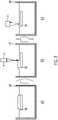
- FIG. 1The formation of such a meniscus is illustrated in 1 shown, where in 1 a) a construction platform 20 has already been lowered a little way into photopolymerizable material in a trough 50; in this case, the construction platform 20 must be lowered deeper into the trough 50 beyond the desired layer thickness, as in Fig. 1 b) shown so that the photopolymerizable material flows over the surface of the construction platform 20.
- the construction platformis then raised again as far as in Fig. 1 c) shown until it is only at a depth of the desired layer thickness in relation to the liquid level in the areas of the tub laterally surrounding the construction platform 20; however, material above the construction platform 20 is also lifted in the process, so that the mentioned meniscus remains above the construction platform 20 .
- Such inaccuracieswhich can easily amount to a deviation of more than 1 mm in the layer thickness, are unacceptable.
- a squeegee devicecomprises a horizontally movable suspended squeegee whose lower edge can be adjusted to a defined height. The movable squeegee is moved over the construction area at such a height that photopolymerizable material is displaced by the moving squeegee and a smoothed layer of photopolymerizable material with the desired layer thickness remains.
- a method for the additive construction of a three-dimensional product using top-down stereolithographyin which flowable, photopolymerizable material is locally cured in a trough by exposure from above, the procedure is as follows to cover the surface of the material layer to be cured next smooth and level. If the previously hardened layer has also been leveled before exposure, ie has been brought to a uniform level with the liquid level in the tub in the vicinity of the construction platform, a defined and uniform layer thickness is also produced in this way.
- a compressed gas jet extended transversely to the direction of travel of the compressed gas nozzleis directed onto the surface of the photopolymerizable material this worked to smooth the surface.
- the effect of the compressed gas jet extending transversely to the direction of traveldisplaces photopolymerizable material from areas with a raised surface, and thus the surface onto a uniform level with the liquid level in the tub surrounding the construction platform on the side.
- this distanceis defined as the perpendicular distance to the liquid level of the flowable material in the trough surrounding the construction platform.
- the vertical distance to the material surface in the area above the construction platformcan deviate from this distance before the smoothing and leveling by the compressed gas flow moving over it, since the material surface can be changed there by a meniscus that may have formed.
- a gas stream extending transversely to the direction of travel of the nozzleis directed through a compressed gas nozzle onto the surface of the photopolymerizable material and is moved over it in order to level the surface.
- the compressed gas nozzleacts like an air squeegee (in the case of compressed air as compressed gas), whereby the air squeegee (nozzle) is located at a distance above the surface of the photopolymerizable material, unlike conventional mechanical squeegees, but still due to the compressed air stream acts directly on the material surface.
- a bloweris generally considered to be a compressed gas source with a compressed gas nozzle, which emits the compressed gas inflow from the compressed gas source as a shaped compressed gas jet and directed volume flow.
- a mechanical pump (fan) or a compressed gas tankcan serve as the compressed gas source.
- the compressed gas sourcecan be connected directly to the compressed gas nozzle and thus form a unitary assembly.
- compressed airis used as the compressed gas, so that the blower has a compressed air source and a compressed air nozzle connected thereto, which emits a jet of compressed air.
- another gascan be supplied under pressure, e.g an inert gas such as nitrogen to reduce or prevent inhibition at the material surface.
- the method according to the inventionis a method for building a multi-component product, in which a further component of the product to be built is added to an already existing component of the product to be built by an additive construction method using top-down stereolithography.
- the existing componentwhich is carried by a construction platform located below this existing component, is lowered into the trough with the flowable, photopolymerizable material by lowering the construction platform and then raised again by a smaller distance, with the difference between the lowering distance and the raising distance being the same of the desired layer thickness so as to form the next layer to be exposed.
- free-flowing, photopolymerizable materialcan also flow over areas of the existing components if these get below the level of the photopolymerizable material in the trough due to the lowering.
- the compressed gas nozzleis suspended horizontally at such a height that, after the initial lowering and raising to form a new layer of photopolymerizable material, it is higher than the highest point of the existing component.
- the compressed gas nozzlecan be adjustable with regard to the height at which it can be moved over the trough, so that it can be adapted to the height of the component that is already present.
- the compressed air nozzlecan be moved over the construction area in order to smooth and level areas of the photopolymerizable material to be cured by means of the stream of compressed gas without colliding with any protruding parts of the existing component.
- the photopolymerizable materialis exposed in a location-selective manner for the layer currently to be cured in order to cure the layer in the desired shape.
- the steps of lowering and raising to form a new layer of photopolymerizable material, the movement of the compressed gas nozzle with its compressed gas jet over the surface of the next layer to be cured to smooth it and the subsequent site-selective exposure for curingare repeated until the further component of the layer to be removed product is attached to the existing component.
- different zones of a prosthetic toothcan be built on successively using different materials.
- the distance to the surface of the photopolymerizable materialis measured with a distance sensor that is firmly connected to the compressed gas nozzle.
- the distance to the surface of the photopolymerizable materialcan be determined in a location-dependent manner, thereby detecting elevations such as in the case of menisci and, after exposure to the air jet, the removal of elevations by displacement of material.
- the distance from the surface of the photopolymerizable material measured by the distance sensoris used to regulate the operating parameters of the blower moving over the surface of the photopolymerizable material.
- the gas flowis adjusted in such a way that it displaces or smoothes the photopolymerizable material in the area of a meniscus or another raised point in such a way that after the use of the compressed gas nozzle (e.g. air knife), the surface is level overall (i.e. with the liquid level surrounding the construction platform) and a defined layer thickness of the photopolymerizable material is formed for selective curing is, ie a uniform liquid level is formed.
- the compressed gas nozzlee.g. air knife
- the intensity of the gas flowcan be controlled by various control variables such as the distance to the surface of the photopolymerizable material, the volumetric flow, the flow rate, the lateral expansion of the gas flow while the nozzle is moved over the building area so that there is a uniform distance to the surface over the building area and thus a uniform liquid level is realized, which means that the surface of the photopolymerizable material is smoothed and leveled in a controlled manner and thus menisci are eliminated.
- the compressed gas nozzle with an elongated nozzle gap, which is transverse to the direction of travel Nozzleis expanded, designed as an air knife (air blade), wherein the angle of inclination of the discharged compressed air flow is adjustable in the range of +-45° to the orthogonal on the surface of the photopolymerizable material, preferably aligned orthogonally to the surface, over the areas intended for curing the surface of the photopolymerizable material.
- the existing componentis at least partially surrounded by cured photopolymer as a further component, so that it is bordered by the cured photopolymer in the enclosed area.
- the pre-existing componentis a prosthetic or artificial dental arch or part thereof.
- the artificial arch or part thereofis supported by the build platform with the basal side facing up.
- a prosthesis base or a part thereofis built around the basal areas of the artificial dental arch or the part thereof, as a result of which the artificial dental arch or the part thereof with the basal areas is embedded in the attached prosthesis base in a form-fitting manner.
- different photopolymerizable materialsare installed one after the other to build up the product in several steps for the attachment of several further components.
- desired material zones, material layers and gradientscan be created in the product.
- the existing component to which a further component is attached using the methods described aboveis itself a component which has been assembled using the method according to the invention.
- a first partial area of the product with a recess for inserting an existing componentis first constructed using a method of the type described above.
- the existing componentis then inserted into the at least one recess and then another partial area of the product is built up using the methods described above, so that the inserted existing component is at least partially surrounded and surrounded by the two built up partial areas.
- This preferred procedureis suitable, for example, for the construction of orthodontic products, such as dental braces, which have an orthodontic plate with metal parts (wires, clip elements) partially integrated therein.
- a first structural section of the orthodontic platecan be hardened in layers by polymerization, with this first structural section containing recesses for the inserts.
- Insertse.g. wires or clamp elements
- the construction platform for the insertion of the componentsis moved up out of the material in the tub for better handling and, if necessary, blown off with the compressed gas nozzle for cleaning in order to make the recesses more accessible for the insertion process.
- Insertse.g. wires or clamp elements
- the construction of the second construction section of the orthodontic platetakes place, whereby the recesses are filled and the inserts are thus converted and the latter into the orthodontic plate at least partially to get integrated.
- the existing component insertedis a metal part, a plastic part, a composite part or a ceramic part, which in this way is at least partially integrated into the dental or orthodontic product.
- the construction platformis raised above the liquid level and the parts already assembled are blown off the blower with a compressed gas jet for cleaning in order to remove the excess of adhering unpolymerized material, and the construction platform is optionally then placed in a bath immersed in cleaning liquid, lifted out again and the parts already assembled are blown off with a jet of compressed gas from the blower to dry them.
- compressed airis used as the pressurized gas, with which an extended stream of compressed air is then generated through a compressed air nozzle in order to act on the surface of photopolymerizable material, i.e. it becomes continuous the terms compressed air are used instead of generally compressed gas and compressed air nozzle instead of generally compressed gas nozzle.
- the compressed aircan be provided by a fan or by a compressed air reservoir and fed to a compressed air nozzle, with the fan or the compressed air reservoir being able to form a single assembly with the compressed air nozzle.
- a raised surface areacan be formed in the area above the construction platform in a top-down stereolithography method.
- the construction platform 20is only shown schematically and simplified, without the lifting mechanism carrying it.
- the procedure for forming a first layer of photopolymerizable material that is to be cured on the construction platformis as follows.
- FIG. 1 ashows the construction platform 20 when lowered into the photopolymerizable material in a trough 50, wherein in the stage of 1 a) the sinking depth is still so small that the free-flowing photopolymerizable material that has a certain viscosity has not yet flowed over the surface of the construction platform 20 . For this reason, the construction platform 20 is lowered to a greater depth than is actually required for the desired layer thickness, at which depth the photopolymerizable material can flow over the construction platform. This is in Fig. 1 b) shown in which the photopolymerizable material has already flowed over the surface of the construction platform 20.
- the construction platform 20is raised again until it is at a depth corresponding to a desired layer thickness below the liquid level of the photopolymerizable material in the trough 50 in the vicinity of the construction platform 20 lies, i.e. below the liquid level to the side of the construction platform 20.
- the construction platformis raised to this depth of the layer thickness below the liquid level, not all of the excess photopolymerizable material flows out of the area above the construction platform 20, but there is a raised area above it as a meniscus , as in 1c ) shown.
- Such a meniscuscan have a considerable height of more than one millimeter and in this respect considerably interfere with a precise definition of a layer of photopolymerizable material with a precisely defined layer thickness.
- a squeegeecould be used, which is moved with a lower edge parallel over the liquid level, in order to move the photopolymerizable material out of the area of the meniscus and thereby create a smooth surface and define a layer with a defined layer thickness on the construction platform .
- a physical squeegeeis to be dispensed with in connection with the invention when adding another component to an existing component of the product, so that construction situations can also be handled in which components protrude above the liquid level in the tub, which makes the use of a physical Doctor makes impossible because they would collide with such a component.
- To smooth and level the surface of the photopolymerizable materialhere is a distance above the Surface traveling fan 2 used with a compressed air nozzle that directs an extended jet of compressed air at the surface to smooth and level it.
- photopolymerizable materialis displaced from the area of the meniscus, as in Fig. 2 b) is illustrated.
- the displacement of photopolymerizable material from the meniscusleads to a minimal increase in the liquid level next to the construction platform and thus also above the construction platform when the liquid level as a whole is level.
- This processcan be taken into account in advance when defining the layer thickness by lowering the construction platform 20 to a height below the liquid level in Fig. 2 a) is raised, so that after the displacement of the photopolymerizable material from the meniscus, the desired layer thickness remains over the construction platform.
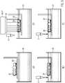
- Figures 3 a) and b)show two top views of a blower 2.
- the blower 2consists of a fan in the fan housing 4, the housing part 6 for passing on the compressed air from the fan and the compressed air nozzle 8, which has an elongated nozzle gap at its lower end, the one can emit an elongated jet of compressed air.
- figure 3 a) Fig. 12is a side plan view in which the longitudinal direction of the die gap is perpendicular to the plane of the figure
- Fig. 14is a plan view from a direction rotated by 90° in which the longitudinal direction of the nozzle gap lies in the plane of the drawing.
- the compressed air nozzle 8is connected directly to the central housing or line part 6 with its upper end.
- the compressed air nozzle 8is in the two views of Figure 1a ) and b) frustoconical in the opposite sense, so that in the view of figure 1 a) conically tapering to a narrow die gap at its lower end, while in the 90° rotated view of Figure 1 b) widens in a truncated cone shape to form a die gap that extends in the longitudinal direction.
- the longitudinal extent of the die gapspans typically the expansion of the construction area in the X or Y direction.
- the width of the die gap transverse to its longitudinal extentcan be, for example, in the range from 0.1 to 10 mm and preferably from 0.5 to 2 mm.
- the compressed air nozzle in the sense of the present inventionis not limited to compressed air nozzles with an elongated nozzle gap.
- Nozzle opening profilesare also possible in which the longitudinal and transverse dimensions of the nozzle opening have the same or similar size, so that a large-area nozzle jet is produced. It is also possible for a plurality of separate nozzle openings, which are arranged in relation to one another as a matrix, to produce a compressed air jet which extends over a surface area.
- FIG. 4 a) to c)Alternative embodiments for fan 2 with compressed air nozzles are in the Fig. 4 a) to c) shown as schematic perspective views. In these views, only the housing or duct part 6 with the connected compressed air nozzle 8 is shown, while the fan housing 4 connected thereto is omitted to simplify the illustration.
- the compressed air nozzle 8is designed as an elongated slot nozzle which has an elongated nozzle slot as the only nozzle opening.
- a plurality of nozzle orificesare formed in an elongate linear array of nozzle orifices on the compressed air nozzle 8, the elongate, extended row of nozzle orifices effectively again generating an air flow extended in the longitudinal direction of the array of nozzle orifices.
- a compressed air nozzle 8is shown with a matrix-like arrangement of closely spaced nozzle openings; This compressed air nozzle 8 with a matrix-shaped, planar arrangement of nozzle openings generates a compressed air stream that extends over a planar area and can act on a surface over a large area.
- a further housing 10is attached to the side, in which driver electronics for operating the blower are accommodated in the housing part 4 .
- a cable 12is connected to the housing 10 and contains lines for the electrical supply of the fan and lines for transmitting control signals to the driver electronics. Furthermore, lines for deriving sensor signals can also be routed in the cable 12 .
- a distance sensorcan be present, which is firmly connected to the compressed air nozzle and can measure the distance from the surface of photopolymerizable material that is located under the compressed air nozzle.
- the distance sensorcan be used to measure the level of the material (liquid level) in the trough, and on the other hand, elevations or depressions on the surface of the photopolymerizable material can be detected when the compressed air nozzle is moved over the surface together with the distance sensor.
- a sensor 14is shown schematically in Fig. 2 c) implied.
- a control unitcan be set up to intensify the operation of the fan in this range in terms of power when an increase in the surface area is detected compared to the liquid level, until the increase in the surface area is eliminated by displacement of photopolymerizable material and the surface is completely leveled.
- such a regulation of the set power of the bloweris not absolutely necessary. It can be determined in advance for a photopolymerizable material, depending on its viscosity, at what power of the blower the compressed air jet acts on the photopolymerizable material sufficiently to be able to displace it.
- the fan 2is suspended above a trough 50 of a top-down stereolithography device, so that the fan 2 the Jet of compressed air can direct onto the surface of the photopolymerizable material located in the trough 50 of the device.
- the compressed air nozzle 2can be moved at a vertical height above the trough 50 in the horizontal direction above the trough in order to be able to act on surface areas of photopolymerizable material in the trough in the construction area.
- verticalis the direction of an orthogonal line on the surface level of a liquid (i.e. "perpendicular") and "horizontal" (i.e.
- balancedis a direction of a straight line in a surface level parallel plane is. Provision can also be made here for the height of the compressed air nozzle to be adjustable above the trough, so that it can be adapted to the properties of the product to be built before a method according to the invention is carried out. This means that the compressed air nozzle should be at a height above the highest point of an existing component to which further components of the product are to be attached using a method according to the invention, as will be explained further below. This ensures that the compressed air nozzle cannot collide with the existing component.
- the blower 2can be moved in a straight line in a horizontal direction, in which case the nozzle gap with its longitudinal extent then runs at an angle to the direction of travel in the exemplary embodiment shown, so that the nozzle jet is extended transversely to the direction of travel.
- the angle of the longitudinal direction of the nozzle gap to the direction of travelcan be, in particular, 90°, which results in the maximum expansion of the compressed air jet transverse to the direction of travel.
- Other ways of moving the compressed air nozzle over the surface of the photopolymerizable materialare also possible.
- the blowercan also be suspended so that it can be rotated about a vertical axis, so that the jet of compressed air is moved over the surface of the material by rotating the blower 2 .
- the axis of rotationcan also be offset from the vertical longitudinal axis of the cylindrical housing parts 4 and 6 of the fan, so that the fan performs a pivoting movement over the material surface. Such a pivoting movement of the fan then causes the air flow to sweep over the surface in a similar way to a windshield wiper.
- the stereolithography deviceincludes a trough 50 filled with flowable photopolymerizable material.
- a construction platform 20 that can be moved in the vertical directioncan dip into the trough 50 .
- an exposure unit located above tray 50is shown schematically showing light source 40 and spatial intensity modulator 42 integrated into one unit, the output of which is imaged by projection optics 44 into the image plane.
- the spatial light modulatorcomprises a matrix of exposure elements, eg a micromirror array, which selectively project light from the light source via projection optics 44 onto respective associated image elements in an image plane at the surface of the photopolymerizable material.
- the projection optics 44can be designed to carry out a classic projection. In order to improve the construction result, however, the projection optics 44 are preferably designed as telecentric optics on the object side, in order to ensure the most orthogonal possible angle of entry of the selective radiation onto the material surface in the entire construction field area.
- a laser source with a deflection mirror/gyroscopewhich scans the image plane successively pixel by pixel, can also be used to implement location-selective exposure.
- the methodis used in the manner according to the invention in order to add another component of the product in layers to an already existing component of a product, or to convert the existing component.
- the product to be built upis a complete dental prosthesis consisting of a prosthesis base and prosthesis teeth.
- the prosthetic teethwhich are arranged as a dental arch, are regarded as already existing components.
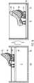
- the prosthetic teeth 30are in figure 5 a) shown as a dental arch, which is carried by the construction platform 20, the prosthetic teeth 30 being carried by pin-like connections, so-called support structures, which are connected on the one hand to the occlusal or incisal areas of the prosthetic teeth 30 and on the other hand to the construction platform 20, so that the prosthetic teeth 30 are oriented with their basal side up.
- the construction platform 20, controlled by a control unitis lowered to a predetermined depth into the photopolymerizable material in the trough 50, as in FIG Figure 5 b) shown.
- a control unitcontrolled by a control unit
- the depthdetermines where the areas of the other component (denture base) that are highest in the basal to occlusal/incisal direction (reaching furthest in the occlusal/incisal direction) are to be attached to the already existing component (denture teeth 30).
- the control unittakes this predetermined depth from the two 3D data sets of the prosthetic teeth 30 and the prosthetic base, which are arranged in the same coordinate system with respect to one another.
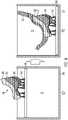
- the compressed air jet from the compressed air nozzle of the blower 2is moved over the surface of the photopolymerizable material in order to smooth it.
- the compressed air nozzlecan also be moved over areas in which the basal ends of the prosthetic teeth 30 protrude beyond the surface of the photopolymerizable material, which prohibits the use of a conventional squeegee, since such a squeegee would collide with the protruding basal ends of the prosthetic teeth 30.
- photopolymerizable materialBy moving a compressed air jet from the compressed air nozzle of the blower 2, which is extended transversely to the direction of travel, photopolymerizable material is displaced from raised areas (menisci) that are higher than the remaining surface level of the photopolymerizable material in the trough, in order to level the surface overall and a general adjust liquid level.
- raised areasmenisci
- FIG. 5 cSchematically shown location-selective exposure, which is controlled by a control unit according to a digital 3D model of the prosthesis base to be attached by controlling the intensity modulator 42.
- first regions 32 of the prosthesis base to be attachedare attached to the prosthetic teeth by curing the photopolymerizable material; in the case presented here, these are areas of the prosthesis base, which correspond to the papillae in the transition area of adjacent teeth in real gums.
- the construction platformis then lowered further down by one layer thickness into the photopolymerizable material in the trough 50; this state is in Fig. 5d) shown.
- the blower 2is then again moved with its transversely expanded jet of compressed air over the surface of the photopolymerizable material and the basal end regions of the prosthetic teeth 30 projecting thereover in order to smooth and level the surface of the photopolymerizable material.
- Remodeling the basal end areas of the prosthetic teeth by adding the prosthetic baseleads to a firm bond between the prosthetic teeth and the prosthetic base without any further joining processes or the use of adhesive.
- the basal end areas of the prosthetic teethare surrounded by the material of the prosthetic base and embedded therein, so that the basal end areas of the prosthetic teeth 30 engage with the attached prosthetic base 32 in a form-fitting manner.
- the Prosthetic teeth 30are positioned as an existing component at the beginning of the construction process on the construction platform.
- Such an embodiment of a construction process for prosthetic teethis in the Fig. 6 a) to f) illustrated.
- the structure of a single prosthetic toothis shown, but such a method can also be used to build up several prosthetic teeth in parallel next to one another or entire dental arches.
- Fig. 6 afirst shows how the construction platform 20 is lowered and a first layer for support structures 34 in the form of conical retaining pins is attached to the construction platform 20 by exposure and curing on the construction platform, after each exposure step the construction platform 20 as explained above by lowering and then Raising it again by a smaller distance effectively lowers the result by one layer thickness and then the surface of the photopolymerizable material A is smoothed and leveled by the extended jet of compressed air from the compressed air nozzle of the blower 2.
- the support structures 34are generally constructed from the same first material A as is also used for the first construction section 36 of the component, in this case the occlusal or incisal part of the prosthetic teeth to be constructed. (the built-up support structures 34 are shown schematically in Fig. 6 b) shown).
- the construction platform made of material Ais moved upwards, blown off by means of blower 2 and excess material A is removed, optionally in a further trough 52 (see Fig 7 ) cleaned with cleaning liquid and then blown off again using the blower 2 to dry.
- the construction platform together with the first construction section 36 and support structures 34is lowered into a further trough 50 with a second photopolymerizable material B, which in Fig. 6 c) is shown.
- Fig. 6 c)it can be seen that at the beginning of the construction of the second construction section 37 the first construction section 36 protrudes over the surface of the photopolymerizable material B.
- the distance between the blower 2 and the material levelmust be at least large enough so that the compressed air nozzle does not collide with parts of the first construction section 36 when driving over the material level.
- the smoothing and leveling of the surface of the material to be photopolymerizedis realized by moving the blower 2 laterally at a distance from the surface of the photopolymerizable material.
- Successive layers of the second building material Bare cured by exposure to light and attached to the occlusal part 36 of the prosthetic tooth, until finally another part 37 of the prosthetic tooth is attached to the preceding part 36, which is shown in Fig. 6d) is shown.
- a prosthesis base 32is built in layers.
- This construction processis represented schematically by the transition from state to Fig. 6g) to the state in Fig. 6 h) summarized illustrated.
- the construction platform 20 with the component completely additively generated from different materialscan be blown off by the blower 2 , cleaned in a cleaning bath and then blown dry by the blower 2 .
- FIG. 7shows a cross-section of a construction in the molar area on the left and in the front tooth area on the right with occlusal/incisal part 36 (cutting edge), another part 37 (dentin) and basal part 38 (root) and attached prosthesis base 32, which is associated with a as above with the Figure 3a ) to h) described methods can be built.
- the prosthetic teethcan of course also be made up of fewer or more than three parts 36, 37, 38.
- Figure 8a ) to f)shows a construction process for an orthodontic plate with metallic inserts, which can be constructed using a method according to the invention, with the metallic components embedded in the polymer, such as wires and clamp elements, partially protruding from the polymer plate.
- a top-down stereolithography method according to the inventionin a first construction phase support structures 34, which are shown here schematically conical, and a lower part of the orthodontic plate 60 with recesses 62 on the construction platform 20 constructed from the same material D by layered material application and site-selective exposure, which is shown in Fig. 8 a) is shown.
- This first constructed lower part of the orthodontic plate 60 with the recesses 62is then moved out of the trough 50 and the photopolymerizable material D by lifting the construction platform 20 so that the lower part of the orthodontic plate with its recesses 62 is freely accessible, as in Fig. 8 b) shown.
- Prefabricated metal elements 64such as specially bent wires and clamp elements, are then inserted into the recesses 62 provided for this purpose.
- the lower part of the orthodontic plate 60 with its recesses and the metal elements 64 inserted therein, as in FIG Fig. 8 c) showncan also be regarded as an already existing component of the dental product to be produced (complete orthodontic plate), to which further components of the complete product are now added with a preferred method according to the invention.
- the recesses 62 with the inserts 64 positioned thereinare successively closed by layer-by-layer lowering, smoothing using an air knife (blower 2) and location-selective exposure, as in Figure 8d ) shown.
- the inserts 64are thus embedded in the orthodontic plate in a form-fitting manner, as in FIG Figure 8e ) shown.
- the lower part of the orthodontic plate 60 with the positioned inserts 64is only lowered into the material trough so far that part of the component also extends over the surface to the right and left of the photopolymerizable material, see Figure 5d ).
- the surface of the photopolymerizable materialmust be smoothed without contact after lowering the construction platform by one layer thickness by moving the blower 2 with the compressed air stream directed onto the surface of the layer now to be cured.
- a conventional squeegeewould collide with the parts of the already built components that protrude above the surface.
- the completed orthodontic plate 60 together with the embedded inserts 64is obtained, as shown in Fig. 8 f) shown.
- a recording 29was first printed on the construction platform 20 by means of the top-down stereolithography method, with the occlusal/incisal areas of the Artificial teeth is provided with complementary recesses, so that the artificial teeth 30 can be used with an exact fit and positioned therein.
- the basal sides of the artificial teeth 30can then be surrounded by a prosthesis base using a top-down stereolithography method according to the invention, so that the artificial teeth 30 are finally embedded in a form-fitting manner in the built-up prosthesis base (not shown).
- FIG. 10 to 12is once again an inventive construction process summarized in which first prosthetic teeth 30 have been built on a construction platform by an inventive top-down stereolithography method, with several different building materials can be used, such as in connection with the Fig. 6 a) to h) has been explained, a cleaning process being carried out after each change of material to build up another part of the prosthetic teeth.
- a possible cleaning process between each change of materialis to be described in detail again here:
- the construction platform 20is lifted out of the tub and the built-up parts are blown off by means of a blower 2 in order to remove any excess, non-polymerized material that is still adhering; this is done over the same trough as in the previous build (see 11 left) so that the blown material gets back into the correct tub.
- the cleaning processcan be continued by cleaning in a cleaning liquid in a cleaning tub 52, for which purpose the construction platform 20 can be lowered into a tub with cleaning liquid, as in 11 is shown on the right.
- the construction platform with the parts built on itcan then be lifted out of the cleaning liquid again and blown off over the cleaning tub by the blower 2 for drying. Thereupon another construction phase can take place with another building material.
- 10 1shows the final step in the construction of prosthetic teeth 30, in which step a layer of photopolymerizable material M1 is cured as the last piece of a prosthetic tooth.
- the prosthetic teeth 30are then cleaned again as described above.
- the troughs 50can then be moved in such a way that the trough 50 with the material M2 is in the area of the construction platform 20 so that it can be lowered into the trough 50 with the photopolymerizable material M2 in order to attach the prosthetic teeth 30 as a component that is now already present the total prosthesis to grow a prosthesis base with the method according to the invention, the beginning of this construction phase in 12 is shown.
Landscapes
- Chemical & Material Sciences (AREA)
- Engineering & Computer Science (AREA)
- Materials Engineering (AREA)
- Manufacturing & Machinery (AREA)
- Physics & Mathematics (AREA)
- Optics & Photonics (AREA)
- Mechanical Engineering (AREA)
Description
Translated fromGermanDie vorliegende Erfindung betrifft ein Verfahren zum additiven Aufbau eines dreidimensionalen Produkts mit Top-Down-Stereolithographie, wobei fließfähiges, photopolymerisierbares Material in einer Wanne durch Belichtung von oben ortsselektiv ausgehärtet wird.The present invention relates to a method for the additive construction of a three-dimensional product using top-down stereolithography, flowable, photopolymerizable material being cured in a vat in a location-selective manner by exposure from above.
Die Erfindung betrifft allgemein den additiven Aufbau (additive manufacturing) von dreidimensionalen Produkten durch stereolithographisches Aushärten von fließfähigem, photopolymerisierbaren Material, das in aufeinanderfolgenden Schichten ortsselektiv ausgehärtet wird, wobei die schichtweise ortsselektiv vorgegebenen Belichtungsgebiete durch die Daten eines 3D-Modells des aufzubauenden Produkts festgelegt werden.The invention generally relates to the additive construction (additive manufacturing) of three-dimensional products by stereolithographic curing of free-flowing, photopolymerizable material, which is cured in a site-selective manner in successive layers, the layer-by-layer, site-selectively predetermined exposure areas being defined by the data of a 3D model of the product to be built up.
Die Erfindung zielt insbesondere auf die Fertigung von Dentalprodukten und orthodontischen Produkten ab, insbesondere auf die Fertigung von dentalen Totalprothesen und Teilprothesen, die sich aus einer die Gingiva simulierenden Basis und vorgefertigten Zähnen zusammensetzen, wobei Basis und Zähne aus unterschiedlichen Materialien bestehen, um die natürlichen Eigenschaften optimal simulieren zu können.The invention is particularly aimed at the manufacture of dental and orthodontic products, in particular the manufacture of total and partial dental prostheses composed of a base simulating the gingiva and prefabricated teeth, the base and teeth being made of different materials in order to reproduce the natural characteristics to simulate optimally.
Bei einem derzeit verbreiteten Verfahren zur Herstellung von Totalprothesen und Teilprothesen werden Konfektionszähne in einer Schablone, die gleichzeitig die Pressform darstellt, in der richtigen Position gehalten und von einem Basismaterial, z.B. PMMA, umspritzt/umpresst.In a currently widespread method for the production of full dentures and partial dentures, prefabricated teeth are held in the correct position in a template, which at the same time represents the pressing mold, and a base material, e.g. PMMA, is injection-molded/overmoulded.
Bei digitalen Prozessketten werden Kunstzähne und Basis getrennt voneinander, beispielsweise durch zerspanende oder additive Bauverfahren, hergestellt und nach ihrer separaten Fertigstellung in der Regel miteinander verklebt, um so die Kunstzähne in der Basis zu verankern. Dabei können vorgefertigte Konfektionszähne oder individuell hergestellte Kunstzähne verwendet werden.In digital process chains, artificial teeth and bases are separated from each other, for example by machining or additives Construction method, manufactured and after their separate completion usually glued together so as to anchor the artificial teeth in the base. Prefabricated teeth or individually manufactured artificial teeth can be used.
Die Fertigung dentaler und orthodontischer Produkte, wie etwa verschiedener Arten von Teilprothesen und Zahnspangen, aus mehreren Komponenten ist immer noch mit viel Handarbeit verbunden. Modellguss, Biegeroboter für Drähte und Metallklammern, sowie additive Fertigungsschritte für weitere Teile des Produkts können den Fertigungsprozess dabei unterstützen, ein vollständig durchgängig digitaler Bauprozess ist allerdings heute noch nicht realisierbar. In diesem Zusammenhang ist insbesondere problematisch, dass Metallteile, wie Drähte und Klammerkomponenten, in weitere Komponenten, die z.B. aus Kunststoff hergestellt werden, eingebettet werden müssen. Das ist bisher möglich, indem die Metallkomponenten in eine Pressform eingebracht und mit Kunststoffmaterial umspritzt werden. Alternativ kann eine orthodontische Platte aus Kunststoff gefertigt werden, in der Ausnehmungen für die zu integrierenden Metallkomponenten vorgesehen sind. Nach Einlegen der Metallkomponenten in die Ausnehmungen können dann die Ausnehmungen manuell vergossen und die Oberflächen verschliffen und poliert werden. In jedem Fall sind hier viele Einzelschritte und manuelle Zwischenschritte notwendig, was einer weitgehend digitalisierten Prozesskette im Wege steht.Manufacturing dental and orthodontic products, such as various types of partial dentures and braces, from multiple components still involves a lot of manual work. Model casting, bending robots for wires and metal clips, as well as additive manufacturing steps for other parts of the product can support the manufacturing process, but a completely digital construction process is not yet feasible today. In this context, it is particularly problematic that metal parts, such as wires and clip components, have to be embedded in other components that are made of plastic, for example. So far, this has been possible by placing the metal components in a press mold and overmoulding them with plastic material. Alternatively, an orthodontic plate can be made of plastic, in which recesses are provided for the metal components to be integrated. After the metal components have been placed in the recesses, the recesses can then be cast manually and the surfaces can be ground and polished. In any case, many individual steps and manual intermediate steps are necessary here, which stands in the way of a largely digitized process chain.
In
Neben dem ausdrücklich beschriebenen Verfahren, das gerade erläutert worden ist, ist auch angedeutet, dass die Prothesenzähne an der Bauplattform in photopolymerisierbares Material abgesenkt werden könnten, und das photopolymerisierbare Material von oben belichtet werden könnte. Diese nicht weiter beschriebene Variante entspricht dann einem Top-Down-Stereolithographieverfahren, bei dem die auszuhärtende Materialschicht durch eine Rakel, die über die Materialoberfläche streicht, eingeebnet wird.In addition to the explicitly described method that has just been explained, it is also indicated that the prosthetic teeth could be lowered into photopolymerizable material on the construction platform and the photopolymerizable material could be exposed from above. This variant, which is not described further, then corresponds to a top-down stereolithography method in which the material layer to be hardened is leveled by a squeegee that sweeps across the material surface.
Bei Bottom-Up-Stereolithographieverfahren ist die Schichtdicke der nächsten auszuhärtenden Schicht präzise definierbar, indem, bei der ersten auszuhärtenden Schicht, die Bauplattform soweit in das photopolymerisierbare Material abgesenkt wird, bis ihre Unterseite in dem der gewünschten Schichtdicke entsprechenden Abstand über dem Wannenboden liegt, d.h. durch Materialverdrängung wird die genau gewünschte Schichtdicke zwischen der Unterseite der Bauplattform und dem Wannenboden eingestellt. Bei den nachfolgend auszuhärtenden Schichten wird entsprechend der Abstand zwischen der Unterseite der zuletzt ausgehärteten Schicht und dem Wannenboden in der beschriebenen Weise eingestellt.In bottom-up stereolithography methods, the layer thickness of the next layer to be cured can be precisely defined by lowering the construction platform into the photopolymerizable material for the first layer to be cured until its underside is at the distance corresponding to the desired layer thickness above the bottom of the tub, i.e. The precisely desired layer thickness between the underside of the construction platform and the tub floor is set by material displacement. In the case of the layers to be cured subsequently, the distance between the underside of the layer cured last and the bottom of the trough is adjusted in the manner described.
Bei Top-Down-Stereolithographieverfahren ist eine solche Schichtdefinition mit der gewünschten Dicke für die nächste auszuhärtende Schicht mittels einer Referenzebene (die gleichzeitig Bauebene ist) nicht möglich. Bei Top-Down-Stereolithographie muss eine Schicht photopolymerisierbaren Materials mit definierter Schichtdicke auf der Oberseite der Bauplattform (für die erste auszuhärtende Schicht) oder auf der Oberseite der zuletzt ausgehärteten Schicht definiert werden. Dazu wird die Bauplattform weiter als die gewünschte Schichtdicke der nächsten Schicht tiefer in die Wanne abgesenkt (auch bekannt als "deep dipping"), damit das photopolymerisierbare Material über die Bauplattform, respektive die zuletzt auspolymerisierte Schicht nachfließen kann. Danach wird die Bauplattform wieder auf das gewünschte Maß der Schichtdicke der nächsten Schicht angehoben, d.h. die Differenz der Strecken des Absenkens und der wieder Anhebens beträgt die gewünschte Schichtdicke. Allerdings bildet sich dabei in der Regel keine Schicht mit glatter Oberfläche und gleichmäßiger Dicke, sondern ein Meniskus über der Bauplattform bzw. der zuletzt ausgehärteten Schicht, wobei die Schichtdicke bzw. Höhe des Meniskus in der Regel größer, z.B. 0,5mm - 1,5mm, ist als die gewünschte, zu bauende Schichtdicke, typischer Weise 0,05mm - 0,15mm. Je höher die Viskosität und/oder die Oberflächenspannung des Materials ist, desto höher ist der sich aufbauende Meniskus. Durch den schichtweisen Aufbau käme es somit mangels präziser Definition der auszuhärtenden Schicht zu erheblichen Ungenauigkeiten des Bauteils. Die Entstehung eines solchen Meniskus ist anschaulich in
Herkömmlich werden zur Glättung der Oberfläche und Nivellierung der Schichtdicke des photopolymerisierbaren Materials massive Rakelvorrichtungen eingesetzt, die über die Oberfläche der zuletzt gebildeten Schicht verfahrbar sind. Eine Rakelvorrichtung umfasst eine horizontal verfahrbare aufgehängte Rakel, deren untere Kante auf eine definierte Höhe einstellbar ist. Die verfahrbare Rakel wird in einer solchen Höhe über das Baugebiet verfahren, dass photopolymerisierbares Material durch die sich bewegende Rakel verschoben wird und eine glattgestrichene Schicht von photopolymerisierbarem Material mit der gewünschten Schichtdicke zurückbleibt.Conventionally, for smoothing the surface and leveling the layer thickness of the photopolymerizable material massive squeegee devices used, which can be moved over the surface of the last layer formed. A squeegee device comprises a horizontally movable suspended squeegee whose lower edge can be adjusted to a defined height. The movable squeegee is moved over the construction area at such a height that photopolymerizable material is displaced by the moving squeegee and a smoothed layer of photopolymerizable material with the desired layer thickness remains.
Es können sich aber Situationen und Konstellationen beim Bauvorgang von Produkten ergeben, bei denen eine über die Oberfläche des Baugebiets verfahrbare Rakel nicht ohne weiteres einsetzbar ist, wenn z.B. ein zuvor gefertigtes Bauteil mit einem anderen Material umbaut werden soll und dabei bei der ersten zu polymerisierbaren Schicht über die Oberfläche des anderen Materials hinausragt. In solchen Situationen sind Rakelvorrichtungen nicht einsetzbar, da eine über die Oberfläche fahrende Rakel mit herausragenden Teilen kollidieren würde.However, situations and constellations can arise during the construction process of products in which a squeegee that can be moved over the surface of the construction area cannot be used without further ado, e.g. if a previously manufactured component is to be rebuilt with a different material and the first layer to be polymerized protrudes above the surface of the other material. In such situations, squeegee devices cannot be used since a squeegee moving across the surface would collide with protruding parts.
Ähnliche Komplikationen ergeben sich, wenn ein Produkt in einer anderen Struktur aufgebaut werden soll, die seitlich des aufzubauenden Produkts höher aufragende Vorsprünge hat.Similar complications arise when a product is to be assembled in a different structure that has higher protrusions on the side of the product to be assembled.
In solchen Konstellationen sind Bottom-Up-Stereolithographieverfahren per se nicht durchführbar und auch Top-Down-Stereolithographieverfahren mit massiver Rakel nicht anwendbar, deren Einsatzgebiet insofern beschränkt ist.In such constellations, bottom-up stereolithography methods per se cannot be carried out, and top-down stereolithography methods with a solid squeegee cannot be used either, the field of use of which is limited in this respect.
Aus "A trade-off analysis of recoating methods for vat polymerization of ceramics", T.M. Haferkamp et al., 1. Januar 2017, XP0556200800, sind neben Rakelverfahren weitere Verfahrensweisen zur Definition einer neu aufgetragenen Schicht bekannt, darunter auch die Verwendung einer Druckluftdüse, deren Druckluftstrahl auf die Oberfläche der neue aufgebrachten Schicht gerichtet und darüber verfahren wird, um diese zu glätten und ihre Dicke einzustellen. Auf diesem Stand der Technik beruht der Oberbegriff von Patentanspruch 1.From "A trade-off analysis of recoating methods for vat polymerization of ceramics", TM Haferkamp et al., January 1, 2017, XP0556200800, in addition to squeegee methods, other methods for defining a newly applied layer are known, including the use of a compressed air nozzle, whose jet of compressed air is aimed at the surface of the newly applied layer and moved over it to smooth it and adjust their thickness. The preamble of patent claim 1 is based on this prior art.
Es ist Aufgabe der vorliegenden Erfindung, ein verbessertes Top-Down-Stereolithographieverfahren anzugeben, das auch in Fallkonstellationen wie oben beschrieben anwendbar ist, wenn beim Aufbau eines mehrteiligen Produkts eine weitere Komponente an eine schon vorhandene Komponente angebaut werden soll.It is the object of the present invention to specify an improved top-down stereolithography method which can also be used in the case constellations described above when a further component is to be added to an already existing component when constructing a multi-part product.
Zur Lösung dieser Aufgabe dient das Verfahren zum additiven Aufbau eines dreidimensionalen Produkts mit den Merkmalen des Patentanspruchs 1. Vorteilhafte Ausführungsformen der Erfindung sind in den Unteransprüchen aufgeführt.The method for the additive construction of a three-dimensional product with the features of patent claim 1 serves to solve this problem. Advantageous embodiments of the invention are listed in the dependent claims.
Bei einem Verfahren zum additiven Aufbau eines dreidimensionalen Produkts unter Anwendung von Top-Down- Stereolithographie, bei dem fließfähiges, photopolymerisierbares Material in einer Wanne durch Belichtung von oben ortsselektiv ausgehärtet wird, wird in folgender Weise vorgegangen, um die Oberfläche der als nächstes auszuhärtenden Materialschicht zu glätten und zu nivellieren. Soweit die vorhergehend ausgehärtete Schicht vor der Belichtung ebenso nivelliert worden ist, d.h. auf einheitliches Niveau mit dem Flüssigkeitsspiegel in der Wanne in der Umgebung der Bauplattform gebracht worden ist, wird so auch eine definierte und gleichmäßige Schichtdicke erzeugt. Es wird aus einer Druckgasdüse eines Gebläses, das im Abstand oberhalb eines Flüssigkeitsspiegels in der Wanne verfahrbar ist, ein quer zur Verfahrrichtung der Druckgasdüse ausgedehnter Druckgasstrahl auf die Oberfläche des photopolymerisierbaren Materials gerichtet, der durch Verfahren des Gebläses mit der Druckgasdüse über auszuhärtende Bereiche der Oberfläche auf diese eingewirkt, um die Oberfläche zu glätten. Durch die Einwirkung des quer zur Fahrrichtung ausgedehnten Druckgasstrahls wird photopolymerisierbares Material aus Bereichen mit erhöhter Oberfläche verdrängt, und dadurch die Oberfläche auf ein einheitliches Niveau mit dem, die Bauplattform seitlich umgebenden, Flüssigkeitsspiegel in der Wanne nivelliert. Soweit auf einen Abstand der Druckgasdüse zur Materialoberfläche Bezug genommen wird, ist dieser Abstand als der senkrechte Abstand zum die Bauplattform umgebenden Flüssigkeitsspiegel des fließfähigen Materials in der Wanne definiert. Von diesem Abstand kann, vor der Glättung und Nivellierung durch den darüber verfahrenen Druckgasstrom, der senkrechte Abstand zur Materialoberfläche im Bereich oberhalb der Bauplattform abweichen, da dort die Materialoberfläche durch einen etwa gebildeten Meniskus verändert sein kann.In a method for the additive construction of a three-dimensional product using top-down stereolithography, in which flowable, photopolymerizable material is locally cured in a trough by exposure from above, the procedure is as follows to cover the surface of the material layer to be cured next smooth and level. If the previously hardened layer has also been leveled before exposure, ie has been brought to a uniform level with the liquid level in the tub in the vicinity of the construction platform, a defined and uniform layer thickness is also produced in this way. From a compressed gas nozzle of a blower, which can be moved at a distance above a liquid level in the tub, a compressed gas jet extended transversely to the direction of travel of the compressed gas nozzle is directed onto the surface of the photopolymerizable material this worked to smooth the surface. The effect of the compressed gas jet extending transversely to the direction of travel displaces photopolymerizable material from areas with a raised surface, and thus the surface onto a uniform level with the liquid level in the tub surrounding the construction platform on the side. Insofar as reference is made to a distance between the compressed gas nozzle and the material surface, this distance is defined as the perpendicular distance to the liquid level of the flowable material in the trough surrounding the construction platform. The vertical distance to the material surface in the area above the construction platform can deviate from this distance before the smoothing and leveling by the compressed gas flow moving over it, since the material surface can be changed there by a meniscus that may have formed.
Bei einem Top-Down- Stereolithographieverfahren wird also durch eine Druckgasdüse ein quer zur Verfahrrichtung der Düse ausgedehnter Gasstrom auf die Oberfläche des photopolymerisierbaren Materials gerichtet und darüber verfahren, um die Oberfläche zu nivellieren. Die Druckgasdüse wirkt hier mit ihrem quer zur Fahrrichtung ausgedehnten Druckgasstrahl wie eine (im Fall von Druckluft als Druckgas) Luftrakel, wobei die Luftrakel (Düse) anders als herkömmliche mechanische Rakel sich auf Abstand oberhalb der Oberfläche des photopolymerisierbaren Materials befindet, aber durch den Druckluftstrom dennoch direkt auf die Materialoberfläche einwirkt.In a top-down stereolithography process, a gas stream extending transversely to the direction of travel of the nozzle is directed through a compressed gas nozzle onto the surface of the photopolymerizable material and is moved over it in order to level the surface. With its compressed gas jet extending transversely to the direction of travel, the compressed gas nozzle acts like an air squeegee (in the case of compressed air as compressed gas), whereby the air squeegee (nozzle) is located at a distance above the surface of the photopolymerizable material, unlike conventional mechanical squeegees, but still due to the compressed air stream acts directly on the material surface.
Als Gebläse wird hier allgemein eine Druckgasquelle mit einer Druckgasdüse angesehen, die den Druckgaszustrom aus der Druckgasquelle als geformten Druckgasstrahl und gerichteten Volumenstrom abgibt. Als Druckgasquelle kann eine maschinelle Pumpe (Ventilator) oder ein Druckgastank dienen. Die Druckgasquelle kann direkt mit der Druckgasdüse verbunden sein und damit eine einheitliche Baugruppe bilden. In vielen Fällen wird als Druckgas Druckluft eingesetzt, so dass das Gebläse eine Druckluftquelle und eine damit verbundene Druckluftdüse aufweist, die einen Druckluftstrahl abgibt. Alternativ zu Druckluft kann ein anderes Gas unter Druck zugeführt werden, etwa ein Schutzgas wie z.B. Stickstoff, um Inhibierung an der Materialoberfläche zu reduzieren bzw. zu unterbinden.A blower is generally considered to be a compressed gas source with a compressed gas nozzle, which emits the compressed gas inflow from the compressed gas source as a shaped compressed gas jet and directed volume flow. A mechanical pump (fan) or a compressed gas tank can serve as the compressed gas source. The compressed gas source can be connected directly to the compressed gas nozzle and thus form a unitary assembly. In many cases, compressed air is used as the compressed gas, so that the blower has a compressed air source and a compressed air nozzle connected thereto, which emits a jet of compressed air. As an alternative to compressed air, another gas can be supplied under pressure, e.g an inert gas such as nitrogen to reduce or prevent inhibition at the material surface.
Das erfindungsgemäße Verfahren ist ein Verfahren zum Aufbau eines mehrkomponentigen Produkts, bei dem an eine schon vorhandene Komponente des aufzubauenden Produkts durch ein additives Bauverfahren unter Anwendung von Top-Down-Stereolithographie eine weitere Komponente des aufzubauenden Produkts angebaut wird. Dazu wird die vorhandene Komponente, die von einer sich unterhalb dieser vorhandenen Komponente befindlichen Bauplattform getragen wird, durch Absenken der Bauplattform in die Wanne mit dem fließfähigem, photopolymerisierbaren Material abgesenkt und dann um eine geringere Strecke wieder angehoben, wobei die Differenz aus Absenkungsstrecke und Anhebungsstrecke gleich der gewünschten Schichtdicke ist, um so die nächste zu belichtenden Schicht zu bilden. Dabei kann fließfähiges, photopolymerisierbares Material auch über Bereiche der vorhandenen Komponente nachfließen, falls diese durch die Absenkung unter den Spiegel des photopolymerisierbaren Materials in der Wanne gelangen. Die Druckgasdüse ist in einer solchen Höhe horizontal verfahrbar aufgehängt, dass sie nach dem erstmaligen Absenken und Anheben zur Bildung einer neuen Schicht aus photopolymerisierbaren Material höher als der höchste Punkt der vorhandenen Komponente liegt. Dazu kann die Druckgasdüse bezüglich der Höhe, in der sie über die Wanne verfahrbar ist, einstellbar sein, damit sie an die Höhe der schon vorhandenen Komponente angepasst werden kann. Auf diese Weise wird erreicht, dass die Druckluftdüse über das Baugebiet verfahren werden kann, um auszuhärtende Bereiche des photopolymerisierbaren Materials mittels des Stroms des Druckgases zu glätten und zu nivellieren, ohne dabei mit eventuell herausragenden Teilen der vorhandenen Komponente zu kollidieren. Nach der Glättung der Oberfläche wird das photopolymerisierbare Material ortsselektiv für die aktuell auszuhärtende Schicht belichtet, um die Schicht in der gewünschten Form auszuhärten. Die Schritte des Absenkens und Anhebens zur Bildung einer neuen Schicht aus photopolymerisierbarem Material, des Verfahrens der Druckgasdüse mit ihrem Druckgasstrahl über die Oberfläche der nächsten auszuhärtenden Schicht zu deren Glättung und der anschließenden ortsselektiven Belichtung zur Aushärtung werden so oft wiederholt, bis die weitere Komponente des auszubauenden Produkts an die schon vorhandene Komponente angebaut ist.The method according to the invention is a method for building a multi-component product, in which a further component of the product to be built is added to an already existing component of the product to be built by an additive construction method using top-down stereolithography. For this purpose, the existing component, which is carried by a construction platform located below this existing component, is lowered into the trough with the flowable, photopolymerizable material by lowering the construction platform and then raised again by a smaller distance, with the difference between the lowering distance and the raising distance being the same of the desired layer thickness so as to form the next layer to be exposed. In this case, free-flowing, photopolymerizable material can also flow over areas of the existing components if these get below the level of the photopolymerizable material in the trough due to the lowering. The compressed gas nozzle is suspended horizontally at such a height that, after the initial lowering and raising to form a new layer of photopolymerizable material, it is higher than the highest point of the existing component. For this purpose, the compressed gas nozzle can be adjustable with regard to the height at which it can be moved over the trough, so that it can be adapted to the height of the component that is already present. In this way it is achieved that the compressed air nozzle can be moved over the construction area in order to smooth and level areas of the photopolymerizable material to be cured by means of the stream of compressed gas without colliding with any protruding parts of the existing component. After the surface has been smoothed, the photopolymerizable material is exposed in a location-selective manner for the layer currently to be cured in order to cure the layer in the desired shape. The steps of lowering and raising to form a new layer of photopolymerizable material, the movement of the compressed gas nozzle with its compressed gas jet over the surface of the next layer to be cured to smooth it and the subsequent site-selective exposure for curing are repeated until the further component of the layer to be removed product is attached to the existing component.
Grundsätzlich ist mit dieser Verfahrensweise jedwede Form von Anbau von weiteren Bereichen an eine bereits vorhandene Komponente in laterale und vertikale Richtungen möglich.In principle, any form of attachment of further areas to an already existing component in lateral and vertical directions is possible with this procedure.
So können zum Beispiel auch verschiedene Zonen eines Prothesenzahns mit verschiedenen Materialien sukzessive angebaut werden.For example, different zones of a prosthetic tooth can be built on successively using different materials.
In einer bevorzugten Ausführungsform wird mit einem fest mit der Druckgasdüse verbundenen Abstandssensor der Abstand zur Oberfläche des photopolymerisierbaren Materials gemessen. Damit kann ortsabhängig der Abstand zur Oberfläche des photopolymerisierbaren Materials erfasst und dadurch Erhöhungen wie im Fall von Menisken sowie, nach Einwirken des Luftstrahls die Beseitigung von Erhöhungen durch Verdrängung von Material erfasst werden. In diesem Fall ist es insbesondere bevorzugt, dass der von dem Abstandssensor gemessene Abstand zur Oberfläche des photopolymerisierbaren Materials dazu verwendet wird, um Betriebsparameter des über die Oberfläche des photopolymerisierbaren Materials fahrenden Gebläses zu regeln. Dadurch wird der Gasstrom so eingestellt, dass er das photopolymerisierbare Material im Bereich eines Meniskus oder einer anderweitig erhöhten Stelle so verdrängt bzw. glättet, dass nach Einsatz der Druckgasdüse (z.B. Luftrakel) eine insgesamt (d.h. mit dem die Bauplattform umgebenden Flüssigkeitsspiegel) nivellierte Oberfläche und eine definierte Schichtdicke des photopolymerisierbaren Materials zur selektiven Aushärtung ausgebildet ist, d.h. es ist ein einheitlicher Flüssigkeitsspiegel gebildet. Die Intensität des Gasstroms kann durch verschiedene Regelgrößen wie dem Abstand zur Oberfläche des photopolymerisierbaren Materials, dem Volumenstrom, der Strömungsgeschwindigkeit, der seitlichen Ausdehnung des Gasstroms gesteuert werden, während die Düse über das Baugebiet verfahren wird, so dass ein gleichmäßiger Abstand zur Oberfläche über das Baugebiet und somit eine einheitliches Flüssigkeitsniveau realisiert wird, was bedeutet, dass die Oberfläche des photopolymerisierbaren Materials kontrolliert geglättet und nivelliert ist und somit Menisken eliminiert sind.In a preferred embodiment, the distance to the surface of the photopolymerizable material is measured with a distance sensor that is firmly connected to the compressed gas nozzle. In this way, the distance to the surface of the photopolymerizable material can be determined in a location-dependent manner, thereby detecting elevations such as in the case of menisci and, after exposure to the air jet, the removal of elevations by displacement of material. In this case, it is particularly preferred that the distance from the surface of the photopolymerizable material measured by the distance sensor is used to regulate the operating parameters of the blower moving over the surface of the photopolymerizable material. In this way, the gas flow is adjusted in such a way that it displaces or smoothes the photopolymerizable material in the area of a meniscus or another raised point in such a way that after the use of the compressed gas nozzle (e.g. air knife), the surface is level overall (i.e. with the liquid level surrounding the construction platform) and a defined layer thickness of the photopolymerizable material is formed for selective curing is, ie a uniform liquid level is formed. The intensity of the gas flow can be controlled by various control variables such as the distance to the surface of the photopolymerizable material, the volumetric flow, the flow rate, the lateral expansion of the gas flow while the nozzle is moved over the building area so that there is a uniform distance to the surface over the building area and thus a uniform liquid level is realized, which means that the surface of the photopolymerizable material is smoothed and leveled in a controlled manner and thus menisci are eliminated.
In einer bevorzugten Ausführungsform wird zur Regelung von Betriebsparametern des Gebläses zur Glättung und Nivellierung der Oberfläche des photopolymerisierbaren Materials der Druck des Gases, die Strahlbreite, der Volumenstrom, die Verfahrgeschwindigkeit der Druckgasdüse über die Oberfläche und/oder die Neigung des von der Druckgasdüse abgegebenen Druckgasstrahls zur Orthogonalen auf der Oberfläche des photopolymerisierbaren Materials geregelt, um den gleichmäßigen Abstand zur Oberfläche über das auszuhärtende Gebiet zu realisieren und somit einen einheitlichen Flüssigkeitsspiegel zu erhalten.In a preferred embodiment, the pressure of the gas, the jet width, the volume flow, the traversing speed of the compressed gas nozzle over the surface and/or the inclination of the compressed gas jet emitted by the compressed gas nozzle to the Orthogonal regulated on the surface of the photopolymerizable material in order to realize the uniform distance to the surface over the area to be cured and thus to obtain a uniform liquid level.
Eine solche Regelung ist aber nicht unbedingt erforderlich, denn es können vorab für jeweilige Materialeigenschaften von photopolymerisierbaren Materialien geeignete Betriebsparameter für die Druckgasdüse ermittelt und dann für einen konkreten Bauvorgang mit einem bestimmten photopolymerisierbaren Material die entsprechenden Betriebsparameter ausgewählt werden, die zum Verdrängen und Nivellieren dieses photopolymerisierbaren Materials geeignet sind.However, such a regulation is not absolutely necessary, because suitable operating parameters for the compressed gas nozzle can be determined in advance for the respective material properties of photopolymerizable materials and then the corresponding operating parameters can be selected for a specific construction process with a specific photopolymerizable material, which are used to displace and level this photopolymerizable material are suitable.
In einer bevorzugten Ausführungsform ist die Druckgasdüse mit einem länglichen Düsenspalt, der quer zur Verfahrrichtung der Düse ausgedehnt ist, als eine Luftrakel (Air Blade) ausgebildet, wobei der Neigungswinkel des abgegebenen Druckluftstroms im Bereich von +-45° zur Orthogonalen auf der Oberfläche des photopolymerisierbaren Materials einstellbar ist, vorzugsweise orthogonal zur Oberfläche ausgerichtet ist, über die zur Aushärtung vorgesehenen Bereiche der Oberfläche des photopolymerisierbaren Materials verfahren wird.In a preferred embodiment, the compressed gas nozzle with an elongated nozzle gap, which is transverse to the direction of travel Nozzle is expanded, designed as an air knife (air blade), wherein the angle of inclination of the discharged compressed air flow is adjustable in the range of +-45° to the orthogonal on the surface of the photopolymerizable material, preferably aligned orthogonally to the surface, over the areas intended for curing the surface of the photopolymerizable material.
In einer bevorzugten Ausführungsform wird die vorhandene Komponente wenigstens teilweise mit ausgehärtetem Photopolymer als weitere Komponente umbaut, so dass sie in dem umbauten Bereich von dem ausgehärteten Photopolymer eingefasst ist.In a preferred embodiment, the existing component is at least partially surrounded by cured photopolymer as a further component, so that it is bordered by the cured photopolymer in the enclosed area.
In einer bevorzugten Ausführungsform ist die schon vorhandene Komponente ein Prothesen- oder Kunstzahnbogen oder ein Teil davon. Der Kunstzahnbogen oder der Teil davon wird von der Bauplattform mit der basalen Seite nach oben weisend getragen. Als weitere Komponente wird eine Prothesenbasis oder ein Teil davon um die basalen Bereiche des Kunstzahnbogens oder des Teils davon herum angebaut, wodurch der Kunstzahnbogen oder der Teil davon mit den basalen Bereichen formschlüssig in die angebaute Prothesenbasis eingebettet wird.In a preferred embodiment, the pre-existing component is a prosthetic or artificial dental arch or part thereof. The artificial arch or part thereof is supported by the build platform with the basal side facing up. As a further component, a prosthesis base or a part thereof is built around the basal areas of the artificial dental arch or the part thereof, as a result of which the artificial dental arch or the part thereof with the basal areas is embedded in the attached prosthesis base in a form-fitting manner.
Vorzugsweise werden in mehreren Schritten zum Anbau von mehreren weiteren Komponenten verschiedene photopolymerisierbare Materialien nacheinander zum Aufbau des Produkts verbaut. Dadurch können gewünschte Materialzonen, Materialschichtungen und Verläufe in dem Produkt erzeugt werden.Preferably, different photopolymerizable materials are installed one after the other to build up the product in several steps for the attachment of several further components. As a result, desired material zones, material layers and gradients can be created in the product.
In einer bevorzugten Ausführungsform ist die vorhandene Komponente, an die mit den oben beschriebenen Verfahrensweisen eine weitere Komponente angebaut wird, selbst eine Komponente die mit dem erfindungsgemäßen Verfahren aufgebaut worden ist.In a preferred embodiment, the existing component to which a further component is attached using the methods described above is itself a component which has been assembled using the method according to the invention.
In einer bevorzugten Ausführungsform wird zunächst ein erster Teilbereich des Produktes mit einer Aussparung zum Einlegen einer vorhandenen Komponente mit einem Verfahren der oben beschriebenen Art aufgebaut. Dann wird die vorhandene Komponente in die mindestens eine Aussparung eingelegt und anschließend darüber ein weiterer Teilbereich des Produktes mit den oben beschriebenen Verfahrensweisen aufgebaut, so dass die eingelegte vorhandene Komponente von den beiden aufgebauten Teilbereichen wenigstens teilweise eingefasst und umbaut ist. Diese bevorzugte Verfahrensweise eignet sich beispielsweise zum Aufbau von orthodontischen Produkten, wie etwa Zahnspangen, die eine orthodontische Platte mit darin teilweise integrierten Metallteilen (Drähte, Klammerelemente) aufweisen. In diesem Fall kann ein erster Bauabschnitt der orthodontischen Platte durch Polymerisieren schichtweise ausgehärtet werden, wobei dieser erste Bauabschnitt Aussparungen für die Einlegeteile enthält. Nach Fertigstellung des ersten Bauabschnitts verbleibt dieser zum Einlegen der Bauteile auf der Bauplattform, wird aber zur besseren Handhabung aus dem Material in der Wanne nach oben herausgefahren und gegebenenfalls zur Reinigung mit der Druckgasdüse abgeblasen, um die Aussparungen für den Einlegeprozess besser zugänglich zu machen. In diese Aussparungen werden dann in einer Bauprozessunterbrechung nach dem vorgesehenen Design Einlegeteile (beispielsweise Drähte oder Klammerelemente) eingelegt, woraufhin der Aufbau des zweiten Bauabschnitts der orthodontischen Platte erfolgt, wodurch die Aussparungen gefüllt und somit die Einlegeteile umbaut werden und letztere in die orthodontische Platte wenigstens teilweise integriert werden.In a preferred embodiment, a first partial area of the product with a recess for inserting an existing component is first constructed using a method of the type described above. The existing component is then inserted into the at least one recess and then another partial area of the product is built up using the methods described above, so that the inserted existing component is at least partially surrounded and surrounded by the two built up partial areas. This preferred procedure is suitable, for example, for the construction of orthodontic products, such as dental braces, which have an orthodontic plate with metal parts (wires, clip elements) partially integrated therein. In this case, a first structural section of the orthodontic plate can be hardened in layers by polymerization, with this first structural section containing recesses for the inserts. After completion of the first construction phase, this remains on the construction platform for the insertion of the components, but is moved up out of the material in the tub for better handling and, if necessary, blown off with the compressed gas nozzle for cleaning in order to make the recesses more accessible for the insertion process. Inserts (e.g. wires or clamp elements) are then inserted into these recesses in a construction process interruption according to the intended design, whereupon the construction of the second construction section of the orthodontic plate takes place, whereby the recesses are filled and the inserts are thus converted and the latter into the orthodontic plate at least partially to get integrated.
In einer bevorzugten Ausführungsform dieser Verfahrensweise ist die eingelegte vorhandene Komponente ein Metallteil, ein Kunststoffteil, ein Kompositteil oder ein Keramikteil, das auf diese Weise wenigstens teilweise in das dentale oder orthodontische Produkt integriert wird.In a preferred embodiment of this procedure, the existing component inserted is a metal part, a plastic part, a composite part or a ceramic part, which in this way is at least partially integrated into the dental or orthodontic product.
Mit einem derartigen erfindungsgemäßen Verfahren ist es auch möglich, eine dentale Teilprothese anzufertigen, bei der die Zähne und der Gingiva-Anteil nach dem erfindungsgemäßen Verfahren additiv gefertigt und Halteelemente aus Metallguss als Einlegeteile durch den Gingiva-Anteil (Prothesenbasis) umbaut werden und am Ende formschlüssig eingebettet sind.With such a method according to the invention, it is also possible to produce a dental partial prosthesis in which the teeth and the gingival portion are additively manufactured according to the method according to the invention and holding elements made of cast metal are rebuilt as inserts through the gingival portion (prosthesis base) and finally form-fitting are embedded.
In einer bevorzugten Ausführungsform wird nach einem Belichtungsschritt die Bauplattform über den Flüssigkeitsspiegel angehoben wird und werden die schon aufgebauten Teile zur Reinigung mit einem Druckgasstrahl aus dem Gebläse abgeblasen, um den Überschuss von anhaftendem unpolymerisierten Material zu entfernen, und wird optional anschließend die Bauplattform in ein Bad mit Reinigungsflüssigkeit eingetaucht, wieder daraus angehoben und werden die schon aufgebauten Teile mit einem Druckgasstrahl aus dem Gebläse zum Trocknen abgeblasen.In a preferred embodiment, after an exposure step, the construction platform is raised above the liquid level and the parts already assembled are blown off the blower with a compressed gas jet for cleaning in order to remove the excess of adhering unpolymerized material, and the construction platform is optionally then placed in a bath immersed in cleaning liquid, lifted out again and the parts already assembled are blown off with a jet of compressed gas from the blower to dry them.
Die Erfindung wird im Folgenden anhand von Ausführungsbeispielen im Zusammenhang mit den Zeichnungen beschrieben, in denen:
Figuren 1 a) bis c) aufeinanderfolgende Schritte beim Absenken einer Bauplattform in eine Wanne mit photopolymerisierbaren Material zeigen,Figuren 2 a) bis c) weitere aufeinanderfolgende Schritte zur Nivellierung der Oberfläche des photopolymerisierbaren Materials wie in einem erfindungsgemäßen Verfahren zeigen,Figuren 3 a) undb) zwei Draufsichten aus unterschiedlichen Richtungen auf eine Druckgasdüse zeigen, die in einem erfindungsgemäßen Verfahren zum Aufbau eines Produkts einsetzbar ist,Figuren 4 a) bis c) schematische perspektivische Ansichten von verschiedenen Ausführungsformen Gebläsen mit Druckgasdüsen zeigen, mit denen aus unter Druck stehenden zugeführten Gas ausgedehnte Gasströme zur Einwirkung auf photopolymerisierbares Material in einem erfindungsgemäßen Verfahren erzeugt werden können,Figuren 5 a) bis f ) aufeinanderfolgende Schritte in einem erfindungsgemäßen Bauverfahren zeigt, bei dem eine Prothesenbasis an die basalen Seiten der Prothesenzähne angebaut und um die basalen Enden der Prothesenzähne herum gebaut wird,Figuren 6 a) bis f) aufeinanderfolgende Schritte eines erfindungsgemäßen Bauverfahrens zeigen, bei dem ein Kunstzahn aus verschiedenen Materialien aufgebaut wird,Figuren 6 g) bis h) aufeinanderfolgende Schritte eines erfindungsgemäßen Bauverfahrens zeigen, bei dem ein Kunstzahn mit Prothesenbasismaterial umbaut wird,Figur 7 mit einem Verfahren nachden Figuren 6 aufgebaute Kunstzähne mit einer angebauten, die basalen Seiten der Kunstzähne einfassenden Prothesenbasis im Querschnitt zeigt,Figuren 8 a) bis f) aufeinanderfolgende Schritte eines erfindungsgemäßen Verfahrens zeigt, bei dem eine orthodontische Platte mit integrierten Metallteilen aufgebaut wird, undFig. 9 einen schematischen Querschnitt einer Bauplattform mit einer darauf aufgebrachten Aufnahme zur Halterung eines anderweitig vorgefertigten Kunstzahns zeigt, der mit einem Verfahren wie in denFig. 5 a) bis f) an seiner oben freiliegenden, basalen Seite mit einem erfindungsgemäßen Verfahren mit einer Prothesenbasis umbaut werden soll,Figuren 10bis 12
Figures 1 a) to c) show successive steps when lowering a construction platform into a vat with photopolymerizable material,Figures 2 a) to c) show further successive steps for leveling the surface of the photopolymerizable material as in a method according to the invention,Figures 3 a) andb) show two top views from different directions of a compressed gas nozzle that can be used in a method according to the invention for constructing a product,Figures 4 a) to c) show schematic perspective views of various embodiments of blowers with compressed gas nozzles, with which expanded gas streams can be generated from gas supplied under pressure for acting on photopolymerizable material in a method according to the invention,Figures 5 a) to f ) shows successive steps in a construction method according to the invention, in which a prosthetic base is attached to the basal sides of the prosthetic teeth and built around the basal ends of the prosthetic teeth,Figures 6 a) to f) show successive steps of a construction method according to the invention, in which an artificial tooth is constructed from different materials,Figures 6 g) to h) show successive steps of a construction method according to the invention, in which an artificial tooth is rebuilt with prosthesis base material,figure 7 with a method according tofigures 6 shows built-up artificial teeth with an attached prosthesis base enclosing the basal sides of the artificial teeth in cross section,Figures 8 a) to f) shows successive steps of a method according to the invention, in which an orthodontic plate is built up with integrated metal parts, and9 shows a schematic cross section of a construction platform with a receptacle applied thereto for holding an otherwise prefabricated artificial tooth, which is produced using a method as in FIGSFig. 5 a) to f) is to be remodeled on its upper exposed, basal side with a prosthesis base using a method according to the invention,Figures 10 to 12 show successive steps in a method according to the invention for the construction of artificial teeth and for the subsequent cultivation of a prosthesis base.
Bei den im Folgenden im Zusammenhang mit den Figuren beschriebenen Ausführungsbeispielen wird davon ausgegangen, dass als unter Druck stehendes Gas Druckluft verwendet wird, mit der dann durch eine Druckluftdüse ein ausgedehnter Druckluftstrom erzeugt wird, um auf die Oberfläche von photopolymerisierbaren Material einzuwirken, d.h. es werden durchgängig die Begriffe Druckluft statt allgemein Druckgas und Druckluftdüse statt allgemein Druckgasdüse verwendet. Die Druckluft kann durch einen Ventilator oder durch einen Druckluftspeicher bereitgestellt und einer Druckluftdüse zugeführt werden, wobei der Ventilator oder der Druckluftspeicher mit der Druckluftdüse eine einheitliche Baugruppe bilden können.In the exemplary embodiments described below in connection with the figures, it is assumed that compressed air is used as the pressurized gas, with which an extended stream of compressed air is then generated through a compressed air nozzle in order to act on the surface of photopolymerizable material, i.e. it becomes continuous the terms compressed air are used instead of generally compressed gas and compressed air nozzle instead of generally compressed gas nozzle. The compressed air can be provided by a fan or by a compressed air reservoir and fed to a compressed air nozzle, with the fan or the compressed air reservoir being able to form a single assembly with the compressed air nozzle.
Mit Bezug auf die
Um nun eine Schicht von photopolymerisierbaren Material auf der Bauplattform 20 mit der gewünschten geringeren Schichtdicke zu bilden, wird die Bauplattform 20 wieder angehoben bis sie in einer Tiefe entsprechend einer gewünschten Schichtdicke unterhalb des Flüssigkeitsspiegels des photopolymerisierbaren Materials in der Wanne 50 in der Umgebung der Bauplattform 20 liegt, d.h. unter dem Flüssigkeitsspiegel seitlich von der Bauplattform 20. Beim Anheben der Bauplattform auf diese Tiefe der Schichtdicke unter den Flüssigkeitsspiegel fließt nicht das gesamte überschüssige photopolymerisierbare Material aus dem Bereich oberhalb der Bauplattform 20 ab, sondern es hält sich darüber ein erhöhter Bereich als Meniskus, wie in
Wie einleitend erläutert soll im Zusammenhang mit der Erfindung beim Anbau einer weiteren Komponente an eine schon vorhandene Komponente des Produkts auf eine physische Rakel verzichtet werden, damit auch Bausituationen handhabbar sind, in denen Komponenten über den Flüssigkeitsspiegel in der Wanne hinausstehen, was den Einsatz einer physischen Rakel unmöglich macht, da sie mit einer solchen Komponente kollidieren würde. Zur Glättung und Nivellierung der Oberfläche des photopolymerisierbaren Materials wird hier ein auf Abstand oberhalb der Oberfläche verfahrbares Gebläse 2 mit einer Druckluftdüse eingesetzt, die einen ausgedehnten Druckluftstrahl auf die Oberfläche richtet, um diese zu glätten und nivellieren. Insbesondere wird dabei photopolymerisierbares Material aus dem Bereich des Meniskus verdrängt, wie in
Es sei hier aber angemerkt, dass die Druckluftdüse im Sinne der vorliegenden Erfindung nicht auf Druckluftdüsen mit einem länglich ausgedehnten Düsenspalt beschränkt ist. Es sind auch Düsenöffnungsprofile möglich, bei denen Längs- und Querausdehnung der Düsenöffnung gleiche oder ähnliche Größe haben, so dass ein großflächiger Düsenstrahl erzeugt wird. Es können auch mehrere separate Düsenöffnungen, die als Matrix zueinander angeordnet sind, zusammenwirkend einen flächig ausgedehnten Druckluftstrahl erzeugen.However, it should be noted here that the compressed air nozzle in the sense of the present invention is not limited to compressed air nozzles with an elongated nozzle gap. Nozzle opening profiles are also possible in which the longitudinal and transverse dimensions of the nozzle opening have the same or similar size, so that a large-area nozzle jet is produced. It is also possible for a plurality of separate nozzle openings, which are arranged in relation to one another as a matrix, to produce a compressed air jet which extends over a surface area.
Alternative Ausführungsformen für Gebläse 2 mit Druckluftdüsen sind in den
An dem Gebläse 2 ist in der Ausführungsform nach
Wie in
Das Gebläse 2 kann geradlinig in einer horizontalen Richtung verfahrbar sein, wobei im dargestellten Ausführungsbeispiel der Düsenspalt mit seiner Längsausdehnung dann unter einem Winkel zur Verfahrrichtung verläuft, so dass der Düsenstrahl quer zur Verfahrrichtung ausgedehnt ist. Der Winkel der Längsrichtung des Düsenspaltes zur Verfahrrichtung kann insbesondere 90° betragen, was die maximale Ausdehnung des Druckluftstrahls quer zur Verfahrrichtung ergibt. Daneben sind auch andere Bewegungsweisen zum Verfahren der Druckluftdüse über die Oberfläche des photopolymerisierbaren Materials möglich. So kann das Gebläse auch um eine vertikale Achse drehbar aufgehängt sein, so dass der Druckluftstrahl durch Drehung des Gebläses 2 drehend über die Materialoberfläche bewegt wird. Die Drehachse kann auch gegenüber der vertikalen Längsachse der zylindrischen Gehäuseteile 4 und 6 des Gebläses versetzt sein, so dass das Gebläse eine schwenkende Bewegung über die Materialoberfläche ausführt. Eine solche schwenkende Bewegung des Gebläses lässt dann den Luftstrom die Oberfläche ähnlich wie ein Scheibenwischer überstreichen.The
Mit Bezug auf die
Der Vollständigkeit halber sei erwähnt, dass zur Realisierung einer ortsselektiven Belichtung auch eine Laserquelle mit einem Umlenkspiegel/Gyroscope verwendbar ist, der die Bildebene sukzessiv Bildelement für Bildelement abtastet.For the sake of completeness, it should be mentioned that a laser source with a deflection mirror/gyroscope, which scans the image plane successively pixel by pixel, can also be used to implement location-selective exposure.
In dem vorliegenden Ausführungsbeispiel in
Zunächst wird die Bauplattform 20, gesteuert durch eine Steuereinheit, in das photopolymerisierbare Material in der Wanne 50 auf eine vorbestimmte Tiefe abgesenkt, wie in
Nach dem Absenken der Bauplattform 20 auf die vorbestimmte Tiefe, wie in
Anschließend erfolgt die in
Anschließend wird die Bauplattform um eine Schichtdicke weiter nach unten in das photopolymerisierbare Material in der Wanne 50 abgesenkt; dieser Zustand ist in
Daran schließt sich der nächste Belichtungsschritt an, der schematisch in
Diese Schritte von schrittweisem Absenken (
Das Umbauen der basalen Endbereiche der Prothesenzähne durch Anbau der Prothesenbasis führt zu einem festen Verbund von Prothesenzähnen und Prothesenbasis ohne weitere Fügevorgänge oder die Verwendung von Klebstoff. Die basalen Endbereiche der Prothesenzähne sind von dem Material der Prothesenbasis umbaut und darin eingebettet, so dass die basalen Endbereiche der Prothesenzähne 30 formschlüssig mit der angebauten Prothesenbasis 32 eingreifen.Remodeling the basal end areas of the prosthetic teeth by adding the prosthetic base leads to a firm bond between the prosthetic teeth and the prosthetic base without any further joining processes or the use of adhesive. The basal end areas of the prosthetic teeth are surrounded by the material of the prosthetic base and embedded therein, so that the basal end areas of the
In dem oben beschriebenen Ausführungsbeispiel im Zusammenhang mit den
In
Nach Abschluss des ersten Bauabschnitts 36 (okklusale Schichformation des Prothesenzahns) auf den Stützstrukturen 34 wird die Bauplattform aus dem Material A nach oben gefahren, mittels Gebläse 2 abgeblasen und von überschüssigem Material A befreit, optional in einer weiteren Wanne 52 (siehe
Für den folgenden Bauabschnitt 37 mit einem zweiten photopolymerisierbaren Material B wird die Bauplattform samt erstem Bauabschnitt 36 und Stützstrukturen 34 in einer weiteren Wanne 50 mit einem zweiten photopolymerisierbaren Material B abgesenkt, was in
Sukzessive werden Schichten des zweiten Baumaterials B durch Belichten ausgehärtet und an den okklusalen Teil 36 des Prothesenzahns angebaut, bis schließlich ein weiterer Teil 37 des Prothesenzahns an den vorhergehenden Teil 36 angebaut ist, was in
Der gleiche Ablauf, wie in
Daraufhin kann, ähnlich wie in dem im Zusammenhang mit den
Zum Abschluss des letzten Bauabschnitts kann die Bauplattform 20 mit dem vollständig additiv aus verschiedenen Materialien generierten Bauteil durch das Gebläse 2 abgeblasen, in einem Reinigungsbad gereinigt und anschließend durch das Gebläse 2 trockengeblasen werden.At the end of the last construction phase, the
In
Dabei werden mit einem erfindungsgemäßen Top-Down-Stereolithographieverfahren in einem ersten Bauabschnitt Stützstrukturen 34, die hier schematisch kegelförmig dargestellt sind, und ein unterer Teil der orthodontische Platte 60 mit Aussparungen 62 auf der Bauplattform 20 aus demselben Material D durch schichtweisen Materialauftrag und ortsselektives Belichten aufgebaut, was in
Dieser zuerst aufgebaute untere Teil der orthodontischen Platte 60 mit den Aussparungen 62 wird dann durch Anheben der Bauplattform 20 aus der Wanne 50 und dem photopolymerisierbaren Material D gefahren, so dass der untere Teil der orthodontischen Platte mit Ihren Aussparungen 62 frei zugänglich ist, wie in
Daraufhin werden vorgefertigte Metallelemente 64, wie speziell gebogene Drähte und Klammerelemente, in die dafür vorgesehenen Aussparungen 62 eingelegt. In diesem Fall kann der untere Teil der orthodontischen Platte 60 mit ihren Aussparungen und den darin eingelegten Metallelementen 64, wie in
Durch einen nun folgenden zweiten Bauabschnitt werden die Aussparungen 62 mit den darin positionierten Einlegeteilen 64 durch schichtweises Absenken, Glätten mittels Luftrakel (Gebläse 2) und ortsselektives Belichten sukzessive zugebaut, wie in
Um an der Position der tiefsten Aussparung (mittig) mit dem schichtweisen Verschließen zu beginnen, wird der untere Teil der orthodontischen Platte 60 mit den positionierten Einlegeteilen 64 nur soweit in die Materialwanne abgesenkt, dass auch hier ein Teil des Bauteils rechts und links über die Oberfläche des photopolymerisierbaren Materials hinausragt, siehe
Nach Abschluss des zweiten Bauabschnitts, dem Verschliessen der Aussparungen 62, und nach der erforderlichen Nachbearbeitung (Reinigung, Nachvergütung, Entfernung der Stützstrukturen und Polieren) erhält man so die komplettierte orthodontische Platte 60 samt eingebetteter Einlegeteile 64, wie in
In
In den
Ein möglicher Reinigungsvorgang zwischen jedem Materialwechsel soll hier noch einmal im Detail beschrieben werden: Nach Abschluss einer Bauphase wird die Bauplattform 20 aus der Wanne angehoben und die aufgebauten Teile mittels Gebläse 2 abgeblasen, um noch anhaftendes, überschüssiges, nicht polymerisiertes Material zu entfernen; das erfolgt über derselben Wanne wie beim vorhergehenden Bauvorgang (siehe
In
Daraufhin erfolgt noch einmal eine Reinigung der Prothesenzähne 30 wie oben beschrieben. Anschließend können die Wannen 50 so verfahren werden, dass die Wanne 50 mit dem Material M2 im Bereich der Bauplattform 20 liegt, so dass diese in die Wanne 50 mit dem photopolymerisierbaren Material M2 abgesenkt werden kann, um an die Prothesenzähne 30 als nun schon vorhandene Komponente der Totalprothese eine Prothesenbasis mit dem erfindungsgemäßen Verfahren anzubauen, wobei der Beginn dieser Bauphase in
Claims (15)
- Method for additive manufacturing of a three-dimensional product using top-down stereolithography, in which method flowable, photopolymerizable material in a vat (50) is solidified in a locally selective manner by exposure from above, wherein, from a pressurized gas nozzle of a blower (2) which is moveable above the liquid level in the vat, a pressurized gas jet extensive in a direction transverse to the moving direction of the blower (2) is directed to the surface of the photopolymerizable material and is acting on areas of the material surface to be solidified in order to smooth and level the surface by moving the pressurized gas jet from the blower across the surface,characterized in that for building a multi-component product the additive building method by top-down stereolithography is used in order attach to an already existing component of the product to be built a further component of the product to be built, wherein the already existing component is carried by a building platform (20) located below the already existing component,in that the building platform (20) is lowered in the vat (50) into the flowable, photopolymerizable material for defining a new layer and is raised again to be effectively located one layer thickness deeper in the photopolymerizable material, wherein the pressurized gas nozzle of the blower (2) is movable in such a height above the vat that after the first lowering of the building platform (20) the pressurized gas nozzle is located higher than the highest point of the already existing component, that the pressurized gas nozzle (2) is moved across areas of the photopolymerizable material to be solidified, in order to smooth and level its surface, that the surface of the photopolymerizable material is exposed in a locally selective manner, and that the last three steps are repeated until the further component has successfully be manufactured and attached to the already existing component.
- Method according to claim 1,characterized in that the distance to the surface of the photopolymerizable material is measured with a distance sensor fixedly connected to the blower (2).
- Method according to claim 2,characterized in that the distance to the surface of the photopolymerizable material measured by the distance sensor is utilized to control operating parameters of the blower (2) being moved across the surface of the photopolymerizable material to the effect that the generated pressurized gas stream causes a position dependent displacement of photopolymerizable material in the area covered in order to specifically smooth and level the surface of the photopolymerizable material.
- Method according to claim 2 or 3,characterized in that the distance to the surface of the photopolymerizable material measured by the distance sensor is utilized to adjust the image plane of the exposure unit to the surface of the photopolymerizable material and thus to the building plane, wherein for this purpose the exposure unit and/or the material vat are moved.
- Method according to claim 3 or 4,characterized in that for controlling the operation of the blower (2) for smoothing and leveling the surface of the photopolymerizable material the pressure, a width of the jet, a volumetric flow rate, a moving speed of the pressurized gas nozzle of the blower (2) relative to the surface and/or an angle of inclination of the pressurized gas jet ejected from the pressurized gas nozzle of the blower (2) with respect to an orthogonal axis on the surface of the photopolymerizable material is/are controlled in order to realize a defined distance to the surface uniformly across the area to be solidified and to obtain in this manner a defined, uniform material layer on top of the last cured region.
- Method according to any of the preceding claims,characterized in that the pressurized gas nozzle (2) is formed with an elongated nozzle gap as an air blade which is moved across the surface of the photopolymerizable material with an adjustable angle of inclination in the range of +- 45° to an orthogonal axis on the surface of the photopolymerizable material, preferably orthogonally to the surface.
- Method according to any of the preceding claims,characterized in that the already existing component is at least partially embedded by selectively attached solidified photopolymer so that the embedded portion is surrounded by solidified photopolymer.
- Method according to any of the preceding claims,characterized in that in a plurality of steps for attaching a plurality of further components (36, 37, 38) several different photopolymerizable materials are used subsequently as building material for building the product.
- Method according to any of the preceding claims,characterized in that the existing component of the product has been previously built using a method according to any of the preceding claims.
- Method according to any of the claims 1 to 8,characterized in that in a first building phase a first component of the product which includes at least one recess (62) for inserting an existing component is built using a method according to any of the claims 1 to 7,in that the existing component (64) is inserted into the at least one recess (62), and subsequently on top of that a further component of the product (60) is built using a method according to any of the claims 1 to 7, such that the inserted existing component (64) is embedded by the built components and is at least partially enclosed.
- Method according to claim 10,characterized in that the first part of the product is a component, built by a method according to any of the claims 1 to 7, of a dental or orthodontic product, wherein as existing component a metallic or ceramic component (64) or a component (64) made of plastic or composite is inserted in the recess (62) of the first component, and that this existing component is then embedded by a further component of the product (60) built to enclose the existing component by using a method according to any of the claims 1 to 7.
- Method according to any of the claims 1 to 9,characterized in that the already existing component is an artificial dental arc or a part thereof, wherein the artificial dental arc or the part thereof is supported on the building platform (20) with the basal side facing upwards, andin that as further component a prosthetic basis (32) or a part thereof is attached around the basal regions of the artificial dental arc or the part thereof, whereby the artificial dental arc or the part thereof is embedded in the attached prosthetic basis (32) in a positively fitting manner.
- Method according to any of the preceding claims,characterized in that a dental or orthodontic product, such as a total prosthesis, a partial prosthesis or an orthodontic brace, is generated by building around an already existing component further parts of the product using a method according of any of the claims 1 to 11, such that the dental or orthodontic product is formed as a positive-locking composite of the already existing component and the attached further parts, without joining or adhesively connecting them.
- Method according to any of the preceding claims,characterized in that as pressurized gas for the blower (2) pressurized air is used, which pressurized air is supplied to the pressurized gas nozzle, formed as a pressurized air nozzle, by a fan, a compressor or by a pressurized air reservoir.
- Method according to any of the preceding claims,characterized in that after an exposure step the building platform is raised above the liquid level and the already built part are blown off with the pressurized air stream from the blower (2) for cleaning, in order to remove adhering, unpolymerized excess material, and that optionally thereafter the building platform is immersed in a bath of cleaning liquid and is lifted up out of the cleaning liquid again and thereafter the already built parts are blown off using a pressurized air stream from the blower (2) for drying.
Priority Applications (4)
| Application Number | Priority Date | Filing Date | Title |
|---|---|---|---|
| EP19161717.4AEP3705266B1 (en) | 2019-03-08 | 2019-03-08 | Method for additive manufacture of a three dimensional product |
| JP2020014708AJP7532041B2 (en) | 2019-03-08 | 2020-01-31 | Methods for additive manufacturing of 3D products |
| CN202010155124.2ACN111660557B (en) | 2019-03-08 | 2020-03-06 | Method for additive manufacturing of three-dimensional products |
| US16/810,984US11358327B2 (en) | 2019-03-08 | 2020-03-06 | Method for additive manufacturing of a three-dimensional product |
Applications Claiming Priority (1)
| Application Number | Priority Date | Filing Date | Title |
|---|---|---|---|
| EP19161717.4AEP3705266B1 (en) | 2019-03-08 | 2019-03-08 | Method for additive manufacture of a three dimensional product |
Publications (2)
| Publication Number | Publication Date |
|---|---|
| EP3705266A1 EP3705266A1 (en) | 2020-09-09 |
| EP3705266B1true EP3705266B1 (en) | 2022-08-17 |
Family
ID=65763275
Family Applications (1)
| Application Number | Title | Priority Date | Filing Date |
|---|---|---|---|
| EP19161717.4AActiveEP3705266B1 (en) | 2019-03-08 | 2019-03-08 | Method for additive manufacture of a three dimensional product |
Country Status (4)
| Country | Link |
|---|---|
| US (1) | US11358327B2 (en) |
| EP (1) | EP3705266B1 (en) |
| JP (1) | JP7532041B2 (en) |
| CN (1) | CN111660557B (en) |
Families Citing this family (11)
| Publication number | Priority date | Publication date | Assignee | Title |
|---|---|---|---|---|
| US11919229B2 (en) | 2015-04-16 | 2024-03-05 | Lawrence Livermore National Security, Llc | Large area projection micro stereolithography |
| US10967561B2 (en)* | 2018-06-17 | 2021-04-06 | National Taipei University Of Technology | System and method for close-packed gas sphere three-dimensional fabrication |
| CN112590201B (en)* | 2020-10-22 | 2022-04-19 | 南京航空航天大学 | Surface exposure based composite multi-material energy field restraint additive manufacturing device and method |
| CN112810140B (en)* | 2020-12-28 | 2023-03-10 | 上海联泰科技股份有限公司 | Data processing method, system, storage medium, 3D printing device and control method |
| EP4330018A4 (en) | 2021-04-26 | 2025-03-19 | Lawrence Livermore National Security, LLC | METHOD FOR CALIBRATION OF A STEREOLITHOGRAPHIC SYSTEM |
| WO2022232057A1 (en)* | 2021-04-26 | 2022-11-03 | 3D Systems, Inc. | Systems and methods for layer leveling in large-area microstereolithography |
| EP4371737A4 (en) | 2021-07-15 | 2025-05-21 | Bmf Nano Material Technology Co., Ltd. | Apparatus for maintaining constant 3d printing liquid level height, and method |
| WO2023018676A2 (en) | 2021-08-09 | 2023-02-16 | Quadratic 3D, Inc. | Methods and systems for forming an object in a volume of a photohardenable composition |
| CN113676705B (en)* | 2021-08-23 | 2022-02-18 | 李畅杰 | Imaging monitoring platform for hot spring irrigation tank body |
| CN115782168B (en)* | 2023-02-08 | 2023-07-07 | 西安博恩生物科技有限公司 | 3D printing equipment for dental implant and forming process thereof |
| CN117162476A (en)* | 2023-03-01 | 2023-12-05 | 徐州工程学院 | Method and device for improving surface roughness of fused deposition modeling |
Family Cites Families (18)
| Publication number | Priority date | Publication date | Assignee | Title |
|---|---|---|---|---|
| JPH03244528A (en)* | 1989-09-28 | 1991-10-31 | Three D Syst Inc | Device and method forming substantially flat and solid face for processing planograph |
| JP2000107671A (en)* | 1998-10-06 | 2000-04-18 | Sony Corp | Method for making chemical coating film thickness uniform, device for enbodying this method and chemical coating applicator including this device |
| JP2005059477A (en) | 2003-08-18 | 2005-03-10 | Shiyoufuu:Kk | 3D structure manufacturing equipment |
| US7556490B2 (en)* | 2004-07-30 | 2009-07-07 | Board Of Regents, The University Of Texas System | Multi-material stereolithography |
| ATE553910T1 (en)* | 2007-07-04 | 2012-05-15 | Envisiontec Gmbh | METHOD AND DEVICE FOR PRODUCING A THREE-DIMENSIONAL OBJECT |
| US7972898B2 (en)* | 2007-09-26 | 2011-07-05 | Eastman Kodak Company | Process for making doped zinc oxide |
| JP5743853B2 (en)* | 2010-12-28 | 2015-07-01 | 東京エレクトロン株式会社 | Liquid processing apparatus and liquid processing method |
| DE202011003443U1 (en) | 2011-03-02 | 2011-12-23 | Bego Medical Gmbh | Device for the generative production of three-dimensional components |
| ITVI20110099A1 (en)* | 2011-04-20 | 2012-10-21 | Dws Srl | METHOD FOR THE PRODUCTION OF A THREE-DIMENSIONAL OBJECT AND A STEREOLITHOGRAPHIC MACHINE USING THIS METHOD |
| AU2012300179B2 (en)* | 2011-08-20 | 2017-08-03 | Zydex Pty Ltd | Apparatus and method for making an object |
| CN102671948B (en)* | 2012-05-04 | 2014-12-17 | 中冶南方工程技术有限公司 | Process for leveling liquid films |
| CN105122135B (en) | 2013-02-12 | 2020-03-20 | 卡本有限公司 | Continuous liquid mesophase printing |
| WO2015126461A1 (en) | 2014-02-20 | 2015-08-27 | Global Filtration Systems, A Dba Of Gulf Filtration Systems Inc. | Apparatus and method for forming three-dimensional objects using a tilting solidification substrate |
| US9486878B2 (en)* | 2014-06-20 | 2016-11-08 | Velo3D, Inc. | Apparatuses, systems and methods for three-dimensional printing |
| DE102014117222A1 (en) | 2014-11-25 | 2016-05-25 | Heraeus Kulzer Gmbh | Production of a dental prosthesis by imprinting the denture base on the denture teeth |
| EP3513262B1 (en)* | 2016-09-15 | 2020-11-04 | IO Tech Group Ltd. | Method and system for additive-ablative fabrication |
| US20180178461A1 (en)* | 2016-12-22 | 2018-06-28 | Anycasting Co., Ltd. | 3d printing apparatus using selective electrochemical deposition |
| CN206633419U (en)* | 2017-04-13 | 2017-11-14 | 广州三的模型设计有限公司 | It is a kind of that elevating mechanism is struck off based on SLA principle 3D printers |
- 2019
- 2019-03-08EPEP19161717.4Apatent/EP3705266B1/enactiveActive
- 2020
- 2020-01-31JPJP2020014708Apatent/JP7532041B2/enactiveActive
- 2020-03-06USUS16/810,984patent/US11358327B2/enactiveActive
- 2020-03-06CNCN202010155124.2Apatent/CN111660557B/enactiveActive
Also Published As
| Publication number | Publication date |
|---|---|
| JP7532041B2 (en) | 2024-08-13 |
| EP3705266A1 (en) | 2020-09-09 |
| JP2020142059A (en) | 2020-09-10 |
| CN111660557B (en) | 2023-09-05 |
| CN111660557A (en) | 2020-09-15 |
| US20200282640A1 (en) | 2020-09-10 |
| US11358327B2 (en) | 2022-06-14 |
Similar Documents
| Publication | Publication Date | Title |
|---|---|---|
| EP3705266B1 (en) | Method for additive manufacture of a three dimensional product | |
| EP2505341B1 (en) | Method for layered construction of a moulded part from highly viscous photopolymerisable material | |
| EP3456513B1 (en) | Device for the generative production of three-dimensional components | |
| EP0565664B1 (en) | Stereographic equipment and method | |
| EP3833536B1 (en) | Method for producing a component by way of stereolithography | |
| EP2337667B1 (en) | Device and method for processing light-polymerizable material for the layered assembly of molds | |
| DE60002750T2 (en) | FAST PROTOTYPING PROCESS AND DEVICE | |
| DE60115136T2 (en) | Production of three-dimensional objects by controlled photocuring | |
| EP0738584B1 (en) | Apparatus and method to produce a three-dimensional object | |
| EP2864108B1 (en) | Device and method for layer-by-layer production of a three-dimensional object | |
| EP2083992B1 (en) | Continuous, generative method and apparatus for the production of a three-dimensional object | |
| EP2251185A1 (en) | Method and device for generative production of a mould with non-planar layers | |
| DE102011117005B4 (en) | Process for producing a ceramic shaped body | |
| DE19905067A1 (en) | Layer-wise molding build-up apparatus, especially for laser prototyping of metallic articles, has a grinding tool for removing irregularities from a previously laser melted and solidified layer region | |
| EP2337668A1 (en) | Device and method for processing light-polymerizable material for building up an object in layers | |
| WO2014033027A1 (en) | Method for constructing a shaped body | |
| AT515138A1 (en) | Apparatus for processing photopolymerizable material for the layered construction of a shaped body | |
| DE202006016477U1 (en) | Rapid prototyping apparatus for producing three-dimensional object, comprises carrier whose height is fixed and retaining wall whose height is adjusted by program-controlled adjuster | |
| DE69704623T2 (en) | METHOD AND DEVICE FOR PRODUCING A THREE-DIMENSIONAL OBJECT FROM A CURABLE LIQUID | |
| WO1996014203A1 (en) | Process and device for producing a three-dimensional object | |
| DE19733310A1 (en) | Conveniently-operated dental moulding unit producing plastic-based false teeth using lost wax process | |
| DE4414775A1 (en) | Appts. for shaping three dimensional object by layers in a bath | |
| EP3157460B1 (en) | Prosthesis base and method for integrally bonding at least one artificial tooth to a prosthesis base | |
| EP3446654A1 (en) | Method for producing a single dental prosthesis structure with a 3-d printer, 3d printer for producing a single dental prosthesis structure and single dental prosthesis structure | |
| DE4110903C2 (en) |
Legal Events
| Date | Code | Title | Description |
|---|---|---|---|
| PUAI | Public reference made under article 153(3) epc to a published international application that has entered the european phase | Free format text:ORIGINAL CODE: 0009012 | |
| STAA | Information on the status of an ep patent application or granted ep patent | Free format text:STATUS: THE APPLICATION HAS BEEN PUBLISHED | |
| AK | Designated contracting states | Kind code of ref document:A1 Designated state(s):AL AT BE BG CH CY CZ DE DK EE ES FI FR GB GR HR HU IE IS IT LI LT LU LV MC MK MT NL NO PL PT RO RS SE SI SK SM TR | |
| AX | Request for extension of the european patent | Extension state:BA ME | |
| STAA | Information on the status of an ep patent application or granted ep patent | Free format text:STATUS: REQUEST FOR EXAMINATION WAS MADE | |
| 17P | Request for examination filed | Effective date:20201020 | |
| RBV | Designated contracting states (corrected) | Designated state(s):AL AT BE BG CH CY CZ DE DK EE ES FI FR GB GR HR HU IE IS IT LI LT LU LV MC MK MT NL NO PL PT RO RS SE SI SK SM TR | |
| GRAP | Despatch of communication of intention to grant a patent | Free format text:ORIGINAL CODE: EPIDOSNIGR1 | |
| STAA | Information on the status of an ep patent application or granted ep patent | Free format text:STATUS: GRANT OF PATENT IS INTENDED | |
| INTG | Intention to grant announced | Effective date:20220511 | |
| GRAS | Grant fee paid | Free format text:ORIGINAL CODE: EPIDOSNIGR3 | |
| GRAA | (expected) grant | Free format text:ORIGINAL CODE: 0009210 | |
| STAA | Information on the status of an ep patent application or granted ep patent | Free format text:STATUS: THE PATENT HAS BEEN GRANTED | |
| AK | Designated contracting states | Kind code of ref document:B1 Designated state(s):AL AT BE BG CH CY CZ DE DK EE ES FI FR GB GR HR HU IE IS IT LI LT LU LV MC MK MT NL NO PL PT RO RS SE SI SK SM TR | |
| REG | Reference to a national code | Ref country code:CH Ref legal event code:EP | |
| REG | Reference to a national code | Ref country code:DE Ref legal event code:R096 Ref document number:502019005300 Country of ref document:DE | |
| REG | Reference to a national code | Ref country code:IE Ref legal event code:FG4D Free format text:LANGUAGE OF EP DOCUMENT: GERMAN | |
| REG | Reference to a national code | Ref country code:AT Ref legal event code:REF Ref document number:1511908 Country of ref document:AT Kind code of ref document:T Effective date:20220915 | |
| REG | Reference to a national code | Ref country code:NL Ref legal event code:MP Effective date:20220817 | |
| REG | Reference to a national code | Ref country code:LT Ref legal event code:MG9D | |
| PG25 | Lapsed in a contracting state [announced via postgrant information from national office to epo] | Ref country code:SE Free format text:LAPSE BECAUSE OF FAILURE TO SUBMIT A TRANSLATION OF THE DESCRIPTION OR TO PAY THE FEE WITHIN THE PRESCRIBED TIME-LIMIT Effective date:20220817 Ref country code:RS Free format text:LAPSE BECAUSE OF FAILURE TO SUBMIT A TRANSLATION OF THE DESCRIPTION OR TO PAY THE FEE WITHIN THE PRESCRIBED TIME-LIMIT Effective date:20220817 Ref country code:PT Free format text:LAPSE BECAUSE OF FAILURE TO SUBMIT A TRANSLATION OF THE DESCRIPTION OR TO PAY THE FEE WITHIN THE PRESCRIBED TIME-LIMIT Effective date:20221219 Ref country code:NO Free format text:LAPSE BECAUSE OF FAILURE TO SUBMIT A TRANSLATION OF THE DESCRIPTION OR TO PAY THE FEE WITHIN THE PRESCRIBED TIME-LIMIT Effective date:20221117 Ref country code:NL Free format text:LAPSE BECAUSE OF FAILURE TO SUBMIT A TRANSLATION OF THE DESCRIPTION OR TO PAY THE FEE WITHIN THE PRESCRIBED TIME-LIMIT Effective date:20220817 Ref country code:LV Free format text:LAPSE BECAUSE OF FAILURE TO SUBMIT A TRANSLATION OF THE DESCRIPTION OR TO PAY THE FEE WITHIN THE PRESCRIBED TIME-LIMIT Effective date:20220817 Ref country code:LT Free format text:LAPSE BECAUSE OF FAILURE TO SUBMIT A TRANSLATION OF THE DESCRIPTION OR TO PAY THE FEE WITHIN THE PRESCRIBED TIME-LIMIT Effective date:20220817 Ref country code:FI Free format text:LAPSE BECAUSE OF FAILURE TO SUBMIT A TRANSLATION OF THE DESCRIPTION OR TO PAY THE FEE WITHIN THE PRESCRIBED TIME-LIMIT Effective date:20220817 | |
| PG25 | Lapsed in a contracting state [announced via postgrant information from national office to epo] | Ref country code:PL Free format text:LAPSE BECAUSE OF FAILURE TO SUBMIT A TRANSLATION OF THE DESCRIPTION OR TO PAY THE FEE WITHIN THE PRESCRIBED TIME-LIMIT Effective date:20220817 Ref country code:IS Free format text:LAPSE BECAUSE OF FAILURE TO SUBMIT A TRANSLATION OF THE DESCRIPTION OR TO PAY THE FEE WITHIN THE PRESCRIBED TIME-LIMIT Effective date:20221217 Ref country code:HR Free format text:LAPSE BECAUSE OF FAILURE TO SUBMIT A TRANSLATION OF THE DESCRIPTION OR TO PAY THE FEE WITHIN THE PRESCRIBED TIME-LIMIT Effective date:20220817 Ref country code:GR Free format text:LAPSE BECAUSE OF FAILURE TO SUBMIT A TRANSLATION OF THE DESCRIPTION OR TO PAY THE FEE WITHIN THE PRESCRIBED TIME-LIMIT Effective date:20221118 | |
| PG25 | Lapsed in a contracting state [announced via postgrant information from national office to epo] | Ref country code:SM Free format text:LAPSE BECAUSE OF FAILURE TO SUBMIT A TRANSLATION OF THE DESCRIPTION OR TO PAY THE FEE WITHIN THE PRESCRIBED TIME-LIMIT Effective date:20220817 Ref country code:RO Free format text:LAPSE BECAUSE OF FAILURE TO SUBMIT A TRANSLATION OF THE DESCRIPTION OR TO PAY THE FEE WITHIN THE PRESCRIBED TIME-LIMIT Effective date:20220817 Ref country code:ES Free format text:LAPSE BECAUSE OF FAILURE TO SUBMIT A TRANSLATION OF THE DESCRIPTION OR TO PAY THE FEE WITHIN THE PRESCRIBED TIME-LIMIT Effective date:20220817 Ref country code:DK Free format text:LAPSE BECAUSE OF FAILURE TO SUBMIT A TRANSLATION OF THE DESCRIPTION OR TO PAY THE FEE WITHIN THE PRESCRIBED TIME-LIMIT Effective date:20220817 Ref country code:CZ Free format text:LAPSE BECAUSE OF FAILURE TO SUBMIT A TRANSLATION OF THE DESCRIPTION OR TO PAY THE FEE WITHIN THE PRESCRIBED TIME-LIMIT Effective date:20220817 | |
| REG | Reference to a national code | Ref country code:DE Ref legal event code:R097 Ref document number:502019005300 Country of ref document:DE | |
| PG25 | Lapsed in a contracting state [announced via postgrant information from national office to epo] | Ref country code:SK Free format text:LAPSE BECAUSE OF FAILURE TO SUBMIT A TRANSLATION OF THE DESCRIPTION OR TO PAY THE FEE WITHIN THE PRESCRIBED TIME-LIMIT Effective date:20220817 Ref country code:EE Free format text:LAPSE BECAUSE OF FAILURE TO SUBMIT A TRANSLATION OF THE DESCRIPTION OR TO PAY THE FEE WITHIN THE PRESCRIBED TIME-LIMIT Effective date:20220817 | |
| PLBE | No opposition filed within time limit | Free format text:ORIGINAL CODE: 0009261 | |
| STAA | Information on the status of an ep patent application or granted ep patent | Free format text:STATUS: NO OPPOSITION FILED WITHIN TIME LIMIT | |
| PG25 | Lapsed in a contracting state [announced via postgrant information from national office to epo] | Ref country code:AL Free format text:LAPSE BECAUSE OF FAILURE TO SUBMIT A TRANSLATION OF THE DESCRIPTION OR TO PAY THE FEE WITHIN THE PRESCRIBED TIME-LIMIT Effective date:20220817 | |
| P01 | Opt-out of the competence of the unified patent court (upc) registered | Effective date:20230607 | |
| 26N | No opposition filed | Effective date:20230519 | |
| PG25 | Lapsed in a contracting state [announced via postgrant information from national office to epo] | Ref country code:SI Free format text:LAPSE BECAUSE OF FAILURE TO SUBMIT A TRANSLATION OF THE DESCRIPTION OR TO PAY THE FEE WITHIN THE PRESCRIBED TIME-LIMIT Effective date:20220817 | |
| PG25 | Lapsed in a contracting state [announced via postgrant information from national office to epo] | Ref country code:MC Free format text:LAPSE BECAUSE OF FAILURE TO SUBMIT A TRANSLATION OF THE DESCRIPTION OR TO PAY THE FEE WITHIN THE PRESCRIBED TIME-LIMIT Effective date:20220817 | |
| REG | Reference to a national code | Ref country code:BE Ref legal event code:MM Effective date:20230331 | |
| PG25 | Lapsed in a contracting state [announced via postgrant information from national office to epo] | Ref country code:LU Free format text:LAPSE BECAUSE OF NON-PAYMENT OF DUE FEES Effective date:20230308 | |
| REG | Reference to a national code | Ref country code:IE Ref legal event code:MM4A | |
| PG25 | Lapsed in a contracting state [announced via postgrant information from national office to epo] | Ref country code:IE Free format text:LAPSE BECAUSE OF NON-PAYMENT OF DUE FEES Effective date:20230308 | |
| PG25 | Lapsed in a contracting state [announced via postgrant information from national office to epo] | Ref country code:BE Free format text:LAPSE BECAUSE OF NON-PAYMENT OF DUE FEES Effective date:20230331 | |
| PG25 | Lapsed in a contracting state [announced via postgrant information from national office to epo] | Ref country code:BG Free format text:LAPSE BECAUSE OF FAILURE TO SUBMIT A TRANSLATION OF THE DESCRIPTION OR TO PAY THE FEE WITHIN THE PRESCRIBED TIME-LIMIT Effective date:20220817 | |
| PG25 | Lapsed in a contracting state [announced via postgrant information from national office to epo] | Ref country code:BG Free format text:LAPSE BECAUSE OF FAILURE TO SUBMIT A TRANSLATION OF THE DESCRIPTION OR TO PAY THE FEE WITHIN THE PRESCRIBED TIME-LIMIT Effective date:20220817 | |
| PGFP | Annual fee paid to national office [announced via postgrant information from national office to epo] | Ref country code:DE Payment date:20250320 Year of fee payment:7 | |
| PGFP | Annual fee paid to national office [announced via postgrant information from national office to epo] | Ref country code:AT Payment date:20250321 Year of fee payment:7 | |
| PGFP | Annual fee paid to national office [announced via postgrant information from national office to epo] | Ref country code:FR Payment date:20250325 Year of fee payment:7 | |
| PGFP | Annual fee paid to national office [announced via postgrant information from national office to epo] | Ref country code:GB Payment date:20250324 Year of fee payment:7 Ref country code:IT Payment date:20250306 Year of fee payment:7 | |
| PGFP | Annual fee paid to national office [announced via postgrant information from national office to epo] | Ref country code:CH Payment date:20250429 Year of fee payment:7 | |
| PG25 | Lapsed in a contracting state [announced via postgrant information from national office to epo] | Ref country code:CY Free format text:LAPSE BECAUSE OF FAILURE TO SUBMIT A TRANSLATION OF THE DESCRIPTION OR TO PAY THE FEE WITHIN THE PRESCRIBED TIME-LIMIT; INVALID AB INITIO Effective date:20190308 | |
| PG25 | Lapsed in a contracting state [announced via postgrant information from national office to epo] | Ref country code:HU Free format text:LAPSE BECAUSE OF FAILURE TO SUBMIT A TRANSLATION OF THE DESCRIPTION OR TO PAY THE FEE WITHIN THE PRESCRIBED TIME-LIMIT; INVALID AB INITIO Effective date:20190308 |