EP3705066A1 - Actuated clot retrieval catheter - Google Patents
Actuated clot retrieval catheterDownload PDFInfo
- Publication number
- EP3705066A1 EP3705066A1EP20160592.0AEP20160592AEP3705066A1EP 3705066 A1EP3705066 A1EP 3705066A1EP 20160592 AEP20160592 AEP 20160592AEP 3705066 A1EP3705066 A1EP 3705066A1
- Authority
- EP
- European Patent Office
- Prior art keywords
- frame
- catheter
- shape memory
- memory material
- conductive wire
- Prior art date
- Legal status (The legal status is an assumption and is not a legal conclusion. Google has not performed a legal analysis and makes no representation as to the accuracy of the status listed.)
- Granted
Links
Images


Classifications
- A—HUMAN NECESSITIES
- A61—MEDICAL OR VETERINARY SCIENCE; HYGIENE
- A61B—DIAGNOSIS; SURGERY; IDENTIFICATION
- A61B17/00—Surgical instruments, devices or methods
- A61B17/22—Implements for squeezing-off ulcers or the like on inner organs of the body; Implements for scraping-out cavities of body organs, e.g. bones; for invasive removal or destruction of calculus using mechanical vibrations; for removing obstructions in blood vessels, not otherwise provided for
- A61B17/221—Gripping devices in the form of loops or baskets for gripping calculi or similar types of obstructions
- A—HUMAN NECESSITIES
- A61—MEDICAL OR VETERINARY SCIENCE; HYGIENE
- A61B—DIAGNOSIS; SURGERY; IDENTIFICATION
- A61B17/00—Surgical instruments, devices or methods
- A61B17/22—Implements for squeezing-off ulcers or the like on inner organs of the body; Implements for scraping-out cavities of body organs, e.g. bones; for invasive removal or destruction of calculus using mechanical vibrations; for removing obstructions in blood vessels, not otherwise provided for
- A—HUMAN NECESSITIES
- A61—MEDICAL OR VETERINARY SCIENCE; HYGIENE
- A61M—DEVICES FOR INTRODUCING MEDIA INTO, OR ONTO, THE BODY; DEVICES FOR TRANSDUCING BODY MEDIA OR FOR TAKING MEDIA FROM THE BODY; DEVICES FOR PRODUCING OR ENDING SLEEP OR STUPOR
- A61M25/00—Catheters; Hollow probes
- A61M25/0021—Catheters; Hollow probes characterised by the form of the tubing
- A61M25/0023—Catheters; Hollow probes characterised by the form of the tubing by the form of the lumen, e.g. cross-section, variable diameter
- A—HUMAN NECESSITIES
- A61—MEDICAL OR VETERINARY SCIENCE; HYGIENE
- A61M—DEVICES FOR INTRODUCING MEDIA INTO, OR ONTO, THE BODY; DEVICES FOR TRANSDUCING BODY MEDIA OR FOR TAKING MEDIA FROM THE BODY; DEVICES FOR PRODUCING OR ENDING SLEEP OR STUPOR
- A61M25/00—Catheters; Hollow probes
- A61M25/0067—Catheters; Hollow probes characterised by the distal end, e.g. tips
- A61M25/0074—Dynamic characteristics of the catheter tip, e.g. openable, closable, expandable or deformable
- A—HUMAN NECESSITIES
- A61—MEDICAL OR VETERINARY SCIENCE; HYGIENE
- A61M—DEVICES FOR INTRODUCING MEDIA INTO, OR ONTO, THE BODY; DEVICES FOR TRANSDUCING BODY MEDIA OR FOR TAKING MEDIA FROM THE BODY; DEVICES FOR PRODUCING OR ENDING SLEEP OR STUPOR
- A61M25/00—Catheters; Hollow probes
- A61M25/01—Introducing, guiding, advancing, emplacing or holding catheters
- A61M25/0105—Steering means as part of the catheter or advancing means; Markers for positioning
- A61M25/0133—Tip steering devices
- A61M25/0158—Tip steering devices with magnetic or electrical means, e.g. by using piezo materials, electroactive polymers, magnetic materials or by heating of shape memory materials
- A—HUMAN NECESSITIES
- A61—MEDICAL OR VETERINARY SCIENCE; HYGIENE
- A61B—DIAGNOSIS; SURGERY; IDENTIFICATION
- A61B17/00—Surgical instruments, devices or methods
- A61B2017/00017—Electrical control of surgical instruments
- A61B2017/00022—Sensing or detecting at the treatment site
- A61B2017/00084—Temperature
- A—HUMAN NECESSITIES
- A61—MEDICAL OR VETERINARY SCIENCE; HYGIENE
- A61B—DIAGNOSIS; SURGERY; IDENTIFICATION
- A61B17/00—Surgical instruments, devices or methods
- A61B2017/00526—Methods of manufacturing
- A—HUMAN NECESSITIES
- A61—MEDICAL OR VETERINARY SCIENCE; HYGIENE
- A61B—DIAGNOSIS; SURGERY; IDENTIFICATION
- A61B17/00—Surgical instruments, devices or methods
- A61B2017/00831—Material properties
- A61B2017/00867—Material properties shape memory effect
- A—HUMAN NECESSITIES
- A61—MEDICAL OR VETERINARY SCIENCE; HYGIENE
- A61B—DIAGNOSIS; SURGERY; IDENTIFICATION
- A61B17/00—Surgical instruments, devices or methods
- A61B17/22—Implements for squeezing-off ulcers or the like on inner organs of the body; Implements for scraping-out cavities of body organs, e.g. bones; for invasive removal or destruction of calculus using mechanical vibrations; for removing obstructions in blood vessels, not otherwise provided for
- A61B2017/22079—Implements for squeezing-off ulcers or the like on inner organs of the body; Implements for scraping-out cavities of body organs, e.g. bones; for invasive removal or destruction of calculus using mechanical vibrations; for removing obstructions in blood vessels, not otherwise provided for with suction of debris
- A—HUMAN NECESSITIES
- A61—MEDICAL OR VETERINARY SCIENCE; HYGIENE
- A61B—DIAGNOSIS; SURGERY; IDENTIFICATION
- A61B17/00—Surgical instruments, devices or methods
- A61B17/22—Implements for squeezing-off ulcers or the like on inner organs of the body; Implements for scraping-out cavities of body organs, e.g. bones; for invasive removal or destruction of calculus using mechanical vibrations; for removing obstructions in blood vessels, not otherwise provided for
- A61B17/221—Gripping devices in the form of loops or baskets for gripping calculi or similar types of obstructions
- A61B2017/2212—Gripping devices in the form of loops or baskets for gripping calculi or similar types of obstructions having a closed distal end, e.g. a loop
- A—HUMAN NECESSITIES
- A61—MEDICAL OR VETERINARY SCIENCE; HYGIENE
- A61B—DIAGNOSIS; SURGERY; IDENTIFICATION
- A61B17/00—Surgical instruments, devices or methods
- A61B17/22—Implements for squeezing-off ulcers or the like on inner organs of the body; Implements for scraping-out cavities of body organs, e.g. bones; for invasive removal or destruction of calculus using mechanical vibrations; for removing obstructions in blood vessels, not otherwise provided for
- A61B17/221—Gripping devices in the form of loops or baskets for gripping calculi or similar types of obstructions
- A61B2017/2215—Gripping devices in the form of loops or baskets for gripping calculi or similar types of obstructions having an open distal end
- A—HUMAN NECESSITIES
- A61—MEDICAL OR VETERINARY SCIENCE; HYGIENE
- A61B—DIAGNOSIS; SURGERY; IDENTIFICATION
- A61B17/00—Surgical instruments, devices or methods
- A61B17/22—Implements for squeezing-off ulcers or the like on inner organs of the body; Implements for scraping-out cavities of body organs, e.g. bones; for invasive removal or destruction of calculus using mechanical vibrations; for removing obstructions in blood vessels, not otherwise provided for
- A61B17/221—Gripping devices in the form of loops or baskets for gripping calculi or similar types of obstructions
- A61B2017/2217—Gripping devices in the form of loops or baskets for gripping calculi or similar types of obstructions single wire changing shape to a gripping configuration
- A—HUMAN NECESSITIES
- A61—MEDICAL OR VETERINARY SCIENCE; HYGIENE
- A61B—DIAGNOSIS; SURGERY; IDENTIFICATION
- A61B2217/00—General characteristics of surgical instruments
- A61B2217/002—Auxiliary appliance
- A61B2217/005—Auxiliary appliance with suction drainage system
- A—HUMAN NECESSITIES
- A61—MEDICAL OR VETERINARY SCIENCE; HYGIENE
- A61M—DEVICES FOR INTRODUCING MEDIA INTO, OR ONTO, THE BODY; DEVICES FOR TRANSDUCING BODY MEDIA OR FOR TAKING MEDIA FROM THE BODY; DEVICES FOR PRODUCING OR ENDING SLEEP OR STUPOR
- A61M25/00—Catheters; Hollow probes
- A61M25/0021—Catheters; Hollow probes characterised by the form of the tubing
- A61M25/0023—Catheters; Hollow probes characterised by the form of the tubing by the form of the lumen, e.g. cross-section, variable diameter
- A61M2025/0024—Expandable catheters or sheaths
- A—HUMAN NECESSITIES
- A61—MEDICAL OR VETERINARY SCIENCE; HYGIENE
- A61M—DEVICES FOR INTRODUCING MEDIA INTO, OR ONTO, THE BODY; DEVICES FOR TRANSDUCING BODY MEDIA OR FOR TAKING MEDIA FROM THE BODY; DEVICES FOR PRODUCING OR ENDING SLEEP OR STUPOR
- A61M25/00—Catheters; Hollow probes
- A61M25/0043—Catheters; Hollow probes characterised by structural features
- A61M2025/0063—Catheters; Hollow probes characterised by structural features having means, e.g. stylets, mandrils, rods or wires to reinforce or adjust temporarily the stiffness, column strength or pushability of catheters which are already inserted into the human body
- A—HUMAN NECESSITIES
- A61—MEDICAL OR VETERINARY SCIENCE; HYGIENE
- A61M—DEVICES FOR INTRODUCING MEDIA INTO, OR ONTO, THE BODY; DEVICES FOR TRANSDUCING BODY MEDIA OR FOR TAKING MEDIA FROM THE BODY; DEVICES FOR PRODUCING OR ENDING SLEEP OR STUPOR
- A61M2205/00—General characteristics of the apparatus
- A61M2205/02—General characteristics of the apparatus characterised by a particular materials
- A61M2205/0266—Shape memory materials
Definitions
- the present disclosuregenerally relates to devices and methods for removing acute blockages from blood vessels during intravascular medical treatments. More specifically, the present disclosure relates to an actuated clot retrieval catheter.
- Clot retrieval catheters and devicesare used in mechanical thrombectomy for endovascular intervention, often in cases where patients are suffering from conditions such as acute ischemic stroke (AIS), myocardial infarction (MI), and pulmonary embolism (PE). Accessing remote areas such as the neurovascular bed is challenging with conventional technology, as the target vessels are small in diameter, distant relative to the site of insertion, and are highly tortuous.
- AISacute ischemic stroke
- MImyocardial infarction
- PEpulmonary embolism
- the clot itselfcan complicate procedures by taking on a number of complex morphologies and consistencies, ranging from simple tube-shaped structures which assume the shape of the vessel to long, strand-like arrangements that can span multiple vessels at one time.
- the age of a clotcan also affect its compliance, with older clots tending to be less compressible than fresh clots.
- Fibrin rich clotsalso present a challenge in having a sticky nature that can cause a clot to roll along the outer surface of a mechanical thrombectomy device rather than being gripped effectively.
- Combinations of soft and firm clot regionscan also separate during aspiration, with fragmentation leading to distal embolization which can occur in vessels that cannot be reached with currently available devices. Additionally, breaking the bonds adhering the clot to the vessel wall without damaging fragile vessels is a significant challenge.
- Small diameters and fixed tip sizescan also be less efficient at directing the aspiration necessary to remove blood and thrombus material during the procedure.
- the aspiration suctionmust be strong enough such that any fragmentation occurring through the use of a mechanical thrombectomy device or other methods can, at the very least, be held stationary so that fragments cannot migrate and occlude distal vessels.
- a significant portion of the aspiration flowends up coming from vessel fluid proximal to the tip of the catheter where there is no clot. This significantly reduces aspiration efficiency, lowering the success rate of clot removal.
- the disclosed designis aimed at providing an improved aspirating retrieval catheter which addresses the above-stated deficiencies.
- An example system for retrieving an obstruction in a blood vesselcan include a catheter, a first conductive wire, and an electronic circuit.
- the electronic circuitcan provide a first current to the first conductive wire.
- a framecan be located near the distal end of the catheter and can be in electrical communication with the first conductive wire.
- the framecan include a shape memory material that enables the frame, or a portion thereof, to transition from a martensite phase to an austenite phase when heated to above the material's austenite finish temperature. At least a first portion of the frame can be expandable from a collapsed configuration to an expanded configuration upon being heated by the first current.
- the shape memory materialcan have a transition temperature above approximately 37°C. In some examples, the shape memory material can have a transition temperature of from approximately 45°C to 55°C.
- the systemcan include a thermoelectric cooling circuit in electrical communication with the frame.
- the at least a first portion of the framecan be collapsible from the expanded configuration to the collapsed configuration upon removal of heat by the thermoelectric cooling circuit.
- At least a second portion of the framecan be collapsible from an open configuration to a collapsed configuration upon being heated.
- the systemcan include a second conductive wire in electrical communication with the second portion of the frame.
- the second conductive wirecan receive a second current from the electronic circuit.
- the systemcan include a membrane cover disposed around the frame.
- the framecan be located within an inner lumen of the catheter. In other examples, the frame extends from the distal end, for example like a funnel, to capture the occlusion.
- the systemcan include a thermocouple in electrical communication with the frame.
- the thermocouplecan help to remove heat from at least a portion of the frame.
- the shape memory materialcan be in a martensite phase when the at least a first portion of the frame is in the collapsed configuration.
- the shape memory materialcan be in an austenite phase when the at least a first portion of the frame is in the expanded configuration.
- An example method of retrieving an occlusive thrombus from a blood vessel of a patientcan include delivering a catheter comprising a frame to a target site.
- the framecan include a shape memory material.
- the methodcan include delivering a first current to the frame.
- the current running through the framecan heat the frame to cause at least a first portion of the frame to change from a collapsed configuration to an expanded configuration.
- the methodcan include aspirating the occlusive thrombus into the frame.
- the cathetercan be withdrawn with the occlusive thrombus from the patient.
- the shape memory material of the framecan have a transition temperature of from approximately 45°C to 55°C.
- the methodcan include deactivating the first current. By deactivating the first current, the at least a first portion of the frame can cool to cause the at least a first portion of the frame to collapse upon the occlusive thrombus.
- the methodcan include cooling the at least a first portion of the frame with a thermoelectric cooling circuit to cause the at least a first portion of the frame to collapse upon the occlusive thrombus.
- the thermoelectric cooling circuitcan include a Peltier chip, a thermoelectric wire, and the like.
- the methodcan include delivering a second current to at least a second portion of the frame.
- the second currentcan create heat, through the resistance of the shape memory material, that causes the at least a second portion of the frame to change from an expanded configuration to a collapsed configuration and upon the occlusive thrombus.
- the methodcan include monitoring a temperature of the frame with a thermocouple in communication with the frame.
- the methodcan include deactivating the first current when the temperature is above a first temperature. This can ensure the vessel is not damaged by excessive heat.
- the framecan be located within an inner lumen of the catheter. In these examples, causing the at least a first portion of the frame to expand from a collapsed configuration to an expanded configuration can cause an inner diameter of the of the catheter to increase.
- An example method of manufacturing an actuated clot retrieval systemcan include heat setting a first shape memory material into a first frame having an expanded configuration.
- the methodcan include allowing the first shape memory material to cool and the first frame to collapse into a collapsed configuration.
- the methodcan include connecting the first frame to a first end of a first conductive wire disposed within a catheter wall of a catheter.
- the methodcan include connecting a second end of the first conductive wire to an electronic circuit.
- the methodcan include applying a membrane to the first frame and to a distal end of the catheter.
- the methodcan include heat setting a second shape memory material into a second frame having a collapsed configuration.
- the methodcan include connecting the second frame to a first end of a second conductive wire disposed within the catheter wall.
- the methodcan include connecting a second end of the second conductive wire to the electronic circuit.
- the methodcan include applying the membrane to the second frame.
- the first shape memory material and the second shape memory materialcan different alloys, and the first frame and the second frame can be coaxial and connected to the distal end of the catheter.
- the second framecan be circumferentially positioned upon the second frame such that the second frame can close upon the first frame.
- the first shape memory material and the second shape memory materialcan include the same alloy, and the first shape memory material and the second shape memory material can have different austenite finish temperatures.
- the methodcan include providing a first catheter layer and disposing the first conductive wire on the first catheter layer.
- the methodcan include applying a second catheter layer over the first conductive wire and a first anchor strut of the first frame. Connecting the first frame to the first end of the first conductive wire can include connecting the first anchor strut to the first conductive wire prior to applying the second catheter layer.
- the methodcan include encasing the first frame with a ring to hold the first frame in the collapsed configuration. Applying the membrane to the first frame can include dipping the first frame and the ring into a membrane material and allowing the membrane material to cool.
- the herein disclosed solutionis directed to a clot retrieval catheter capable of providing local flow restriction/arrest via a modular distal frame.
- Flow restriction and large tipped designsoffer substantially greater aspiration efficiency.
- Such advantagescan also be especially beneficial in the case of stroke intervention procedures, where vessels in the neurovascular bed are particularly small and circuitous, and as a result a tailored axial and bending stiffness profile can inhibit kinking and binding.
- the cathetercan also be compatible with relatively low-profile access sheaths and outer catheters, so that a puncture wound in the patient's groin (in the case of femoral access) can be easily and reliably closed.
- the cathetercan also feature internal and/or external low-friction liners, and an outer polymer jacket or membrane disposed around the support structure.
- the membranecan be an elastomeric material that encapsulates the frame or is fitted over the frame so that the frame can move independently of the membrane.
- the membranecan be tight or loose fitting. A loose-fitting elastomeric membrane will be easier to open that a tight fitting membrane.
- the membranecan be baggy and made of a non-elastomeric material such that the force to open the membrane is low compared to that of a tight-fitting elastomeric membrane.
- the membranecan be inverted to extend distally from a proximal location radially inwardly of the frame before reverting back to extend proximally radially outwardly of the frame and wherein the inner and outer layers of the membrane are bonded or reflowed together at a proximal location or for the full length of the membrane.
- the membranecan comprise an inner and an outer tube, the proximal and distal ends of the inner and outer tube being bonded together or reflowed such that the two tubes form a sock around the frame, the frame being free to move/expand within the sock.
- Accessing the various vessels within the vascular systeminvolves well-known procedural steps and the use of a number of conventional, commercially-available accessory products. These products, such as angiographic materials, rotating hemostasis valves, and guidewires are widely used in laboratory and medical procedures. When these products are employed in conjunction with the system and methods in the description below, their function and exact constitution are not known in the related art.
- Shape memory materialsare those materials, such as alloys, that can be deformed when cold and then expand to a predetermined shape when heated. Once the heat is removed from the material, the material can return to it's collapsed, pliable shape. This can be achieved by heating the shape memory material beyond an austenite finish (AF) temperature. Below the AF temperature, the shape material exits its martensite phase, which is characterized by high elasticity, pliability, and flexibility. Above the AF temperature, the shape material exists in its austenite phase, which is characterized by a more rigid state.
- the shape memory materialcan be heat set to a predetermined shape above its AF temperature such that, when the material is reheated to the AF temperature, the material returns to that predetermined shape.
- Various embodiments described hereincan include frames that can resemble a funnel sheath that, once expanded, can exert a radial force on the vasculature. Fluid can be aspirated into the expanded funnel and then into a catheter to capture a thrombus within the funnel.
- the framecan include a membrane covering that directs the aspirate into the catheter.
- the framecan be disposed within an inner lumen of the catheter. As the frame expands and collapses, the inner diameter of the catheter can be increased and decreased to adjust the flow rate into the catheter.
- the present disclosureprovides a mechanism for heating the frame to its AF temperature to cause the frame to transition into its austenite phase.
- One or more conductive lead wirescan provide a current to the frame.
- the natural electrical resistance of the shape memory materialcan then cause the frame to heat above the AF temperature.
- a thermocouplecan also be provided to monitor the temperature of the frame such that the frame does not overheat and cause trauma to the surrounding vasculature.
- a thermoelectric cooling circuitsuch as a Peltier chip, can be provided to transition the frame back into its martensite phase.
- the present disclosureprovides various example designs for frames.
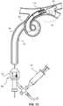
- FIGs. 1A and 1Bprovide an illustration of an example clot retrieval system 100.
- the system 100can include a catheter 102 having a proximal end 104 proximal to a circuit housing 106 and a distal end 108.
- the catheter 102can have a sufficiently small outer diameter to advance the catheter 102 through an outer catheter, such as an access sheath.
- the system 100can include a frame 110 proximate the distal end 108 of the catheter 102.
- the frame 110can extend beyond the distal end 108 of the catheter, as shown in FIGs. 1A and 1B .
- the frame 110can be disposed within an inner lumen of the catheter 102, as will be described in greater detail below. In another example, the frame 110 can be located along the length of the catheter 102 such the frame 110 can act as a closed "balloon," as will be described below with reference to FIG. 6 .
- the frame 110can be encapsulated within an inverted membrane, dual layer sealed membrane or an overmoulded or dipped membrane. Where the frame 110 is housed within an inner and outer membrane layer, the frame can have unhindered movement. Where an overmoulded membrane is supplied, there may be more resistance as the frame 110 may be required to stretch more discrete areas of membrane material. It is appreciated that, as an electrical current will be passed through the frame 110, it can be insulated in order to contain the electrical current. The membrane material can serve to insulate the frame 110. The frame 110, acting as a resistor, can thereby generate heat under a current load.
- the frame 110can have an expanded configuration and a collapsed configuration.
- FIG. 1Ashows a frame 110 in the shape of a funnel in an expanded configuration
- FIG. 1Bshows the same frame 110 in a collapsed configuration.
- the frame 110can include a shape memory material that enables the frame 110 to transition from a collapsed configuration to an expanded configuration, or vice versa, upon being heated and return to its previous configuration upon cooling.
- the shape memory material of the frame 110can include alloys that have shape memory effect such that the material can transition from a martensite phase to an austenite phase.
- These materialscan include, but are not limited to, a Ni-Ti (Nitinol) alloy, a Ni-Al alloy, an In-Ti alloy, an Ag-Cd alloy, an Au-Cd alloy, a Cu-Al-Ni alloy, a Cu-Sn alloy, a Cu-Zn alloy, a Mn-Cu alloy, and similar alloys.
- Shape memory materialsenable devices to be manufactured such that, once heated above an AF temperature, the device can be pre-set into a predetermined shape.
- the frame 110can be provided in a collapsed configuration ( FIG. 1B ).
- the frame 110can then be heated to above the AF temperature of the shape memory material and then shaped into its final configuration ( FIG. 1A ).
- the frame 110is in its austenite phase.
- the frame 110can return to its un-set shape.
- the frame 110is in its martensite phase Due to the low heat capacity of the frame 110, cooling can be achieved easily through conduction with the wires and/or thermocouple wires, and subsequentially through the catheter 102 jacket materials and/or membrane material.
- FIGs. 1C and 1Dprovide an example method of using the transition characteristics of shape memory materials to actuate a clot retrieval system 100.
- the actuated clot retrieval system 100 including the catheter 102 and frame 110can be advanced to a target site 20 in a vessel 30 containing a clot 40. This can be completed by advancing the system 100 through an outer catheter 10, as shown in the figure. However, as will be described below, the catheter 102 and frame 110 can be advanced to the target site 10 without the need for an outer catheter 10. Once the catheter 102 and frame 110 reach the target site 20, the frame 110 can be in its martensite phase, characterized by high elasticity, pliability, and flexibility of the material. This can enable the frame 110 to advance through the winding vessel 30 with ease.
- the frame 110can be heated, which is described in greater detail below, to enable the frame 110 to transition from martensite phase to austenite phase.
- the frame 110was heat set into a funnel sheath in its austenite phase such that, when heated, the frame 110 expands to a funnel to exert a force on the vessel 30.
- the clot 40can then be aspirated into the frame 110 and removed from the target site 20.
- the frame 110can be actively cooled such that the frame 110 collapses into its martensite phase to capture the clot 40.
- the frame 110can automatically cool due to the low heat capacity of the frame 110.
- various shape memory materialsincluding the alloys described above, have different AF temperatures, enabling the system 100 to be customized for the particular procedure. Further, materials processed with a certain AF temperature can be reprocessed through subsequent processes involving heat treatment in order to reset the AF temperature to the desired range.
- the shape memory materialcan be selected or processed such that the AF temperature is above human blood (e.g., above 37°C) so that the frame 110 is not inadvertently activated prior to reaching the intended activation location in a vessel.
- the AF temperaturecan be between 35°C and 200°C (e.g., between 37°C and 65°C, between 40°C and 60°C, etc.). Ideally the AF temperature can be in the range of 45 to 55 °C. This can help ensure martensite properties for a highly flexible delivery configuration while minimizing the energy required to heat the frame 110 for expansion and rigid properties.
- the terms “about” or “approximately” for any numerical values or rangesindicate a suitable dimensional tolerance that allows the part or collection of components to function for its intended purpose. More specifically, “about” or “approximately” may refer to the range of values ⁇ 10% of the recited value, e.g. "about 50°C” may refer to the range of values from 45.001°C to 54.999°C.
- the frame 110can be heated by providing a current to the frame 110.
- the high electrical resistance of the shape memory materialfor example Nitinol, can cause the frame 110 to heat in response to the electrical current and the heat in turn cause the transition from the martensite to austenite phase.
- the system 100can include an electronic circuit 112 to provide the required current to the frame 110.
- the electronic circuit 112can be disposed within a circuit housing 106.
- the electronic circuit 112can be activated with a switch 114.
- the electronic circuit 112can feed from approximately 300 mA to approximately 1500 mA (e.g., approximately 500 mA to approximately 1000 mA) to the frame 110 using a power supply ranging, for example, from approximately 3 to 12V, more preferably from approximately 5 to 9V.
- the currentcan be pulsed from 1 to 1000msec, more preferable from 100 to 500msec with a break in current of between 1 and 1000msec, more preferably from 1 to 100msec. Pulsing allows the temperature of the frame to be maintained between a set temperature range, the on segment of the pulses heating and the off segment of the pulse allowing the frame to cool such that the temperature is kept between a range.
- the temperaturecan be monitored by a thermocouple such that the pulses can be altered if the temperature goes out of range; for example, a continuous feed of current can be used to ramp up the temperature quickly and the pulses can be lowered keep the temperature of the frame under the upper range.
- One or more conductive wires 116can extend between the electronic circuit 112 and the frame 110 to provide the electrical current to heat the frame 110. Cutout A of FIG. 1A shows the positive lead 118 and negative lead 120 attaching to the frame 110.
- the conductive wire 116can be embedded within layers of the catheter 102 so that the wire is not exposed on the outer or inner surface of the catheter 102. This can enable the system 100 to be advanced into an outer catheter without the wire restricting the movement of the catheter 102 through the outer catheter.
- the conductive wires 116can comprise copper or any other material suitable to provide a current to the frame 110.
- the system 100can include a thermocouple 122 connected to the frame 110 to monitor the temperature of the frame 110. If the frame 110 is heated above a certain temperature, the frame 110 can burn the surrounding vasculature. To this end, the thermocouple 122 can monitor the temperature of the frame 110 as it is heated by the current. If the frame 110 exceeds a certain temperature, for example 50°C, the thermocouple 122 can communicate this information to the electronic circuit 112 to deactivate the current being supplied to the frame 110.
- a thermocouple 122connected to the frame 110 to monitor the temperature of the frame 110. If the frame 110 is heated above a certain temperature, the frame 110 can burn the surrounding vasculature. To this end, the thermocouple 122 can monitor the temperature of the frame 110 as it is heated by the current. If the frame 110 exceeds a certain temperature, for example 50°C, the thermocouple 122 can communicate this information to the electronic circuit 112 to deactivate the current being supplied to the frame 110.
- the thermocouple 122can comprise a platinum or stainless steel wire that can be welded between the frame 110 (e.g., at an anchor strut 206) and a conductive wire 116, where the electronic circuit 112 measures the difference in resistivity between the shape memory material and the thermocouple wire to determine the temperature of the frame 110. This can be calibrated and can have a linear temperature relationship.
- the system 100can include a thermoelectric cooling circuit 123 in electrical communication with the frame 110.
- the thermoelectric cooling circuit 123can include, for example, a Peltier chip, disposed proximate the frame 110. As described above, when the frame 110 is cooled below the AF temperature, the shape memory material of the frame can transition back into the pliable, flexible martensite phase. This can be completed to capture the clot 40 in the frame 110. Instead of allowing the shape memory material to cool naturally, the thermoelectric cooling circuit 123 can pump heat from the frame 110 to cool the frame 110 more rapidly.
- the frame 110can be characterized by a plurality of struts 124 that can form closed cells 126, loops, or undulating patterns.
- a plurality of distal hoops or crown struts(which will be described below) can form the circumferential perimeter of the frame opening 128.
- the frame 110can have a variety of shapes, including a low profile rounded tip, an open mouth funnel as shown, or other shapes that will be described herein.
- the plurality of struts 124can be enclosed within a membrane 130.
- the membrane 130can provide a means to direct fluid aspirate into the frame 110 and into the catheter 102.
- the membrane 130can also maintain the position of the struts 124 when the frame 110 is in a collapsed configuration.
- Suitable membrane 130 materialscan include elastic polyurethanes such as Chronoprene, Chronosil, Chronoflex, and other silicon and urethane polymers and the like that have high elasticity and insulative properties with good tear resistance.
- the membrane 130can have a low hardness to enable the membrane 130 to stretch when the frame 110 is expanded.
- the membrane 130can have a Shore hardness typical of 00 ranges and Shore A0.1 to Shore A100 (e.g., Shore A40 to Shore A80). Because the membrane 130 is encapsulating the frame 110, which may be intended to expand, the membrane 130 can also have a degree of expandability, for example from 200 - 2200% (e.g., 400 - 800%).
- the struts 124can be coated with a film of material with high dielectric strength such as Parylene to insulate the struts from blood, which is a conductor, for example if the frame 110 is not fully encapsulated or sealed by the membrane 130.
- a film of material with high dielectric strengthsuch as Parylene to insulate the struts from blood, which is a conductor, for example if the frame 110 is not fully encapsulated or sealed by the membrane 130.
- the system 100can be used in combination with an aspiration source 50.
- the expanded frame 110can seal with the walls of the vessel 30 to direct aspiration to the distal end 108 of the catheter 102.
- the expanded frame 110can also arrest flow and prevent the unwanted aspiration of blood proximal to the frame 110.
- FIGs. 1C and 1Ddepict a system 100 wherein the catheter 102 for the frame 110 is inserted through an outer catheter 10.
- the outer catheter 10is not required.
- the catheter 102 for the frame 110can be the only catheter required to be advanced from a guide catheter (guide catheter not shown in FIGs. 1C or ID).
- the catheter 102 and frame 110can travel farther away from a guide catheter because the system is highly flexible and self-actuating (i.e., the frame 110 does not need to be unsheathed from a catheter to change from a closed configuration to an open configuration). Therefore, the guide catheter can reside in the internal carotid artery, for example, and catheter 102 and frame 110 can extend entirely to an M1 or M2 vessel.
- FIG. 2is a cross-section illustration of an example funnel-shaped frame 110 in an expanded configuration.
- the length of the frame 110can be longer or shorter than the one shown. The length can be increased, for example, to provide more surface-area contact with the vessel wall 35 or increase the reception space for a clot within the frame 110.
- the frame 110can include a plurality of annular crowns 202 around the circumference of the frame 110.
- the annular crowns 202can form the distal tip 412 of the frame 110 and/or provide radial support at any other location along the length of the frame 110.
- the frame 110can include one or more longitudinal struts 204 that can connect peaks of the annular crowns 202.
- the annular crowns 202 and longitudinal struts 204can form cells 126, or openings. The cells 126 can be spaced to promote even expansion of the frame 110 and membrane 130.
- the frame 110does not include longitudinal struts 204, but instead the multiple annular crowns 202 can connected at each peak such that the cells 126 form a diamond-shaped lattice structure. Uniform spacing of the diamond-shaped cells 126 can also promote even expansion of the frame 110 and membrane 130.
- the frame 110does not include longitudinal struts 204, and the multiple annular crowns 202 are not connected at peaks. In these examples, the annular crowns 202 can instead be held into place by the membrane 130.
- the shapes and configurations of the frame 110 described hereincan be created by laser cutting the design into a tube. After laser cutting the design, the frame 110 can be positioned into its desired configuration and heat set such that the frame 110 can return to that desired configuration when heated during a procedure.
- the frame 110can include one or more anchor struts 206 extending proximally.
- the conductive wire 116can be connected to the one or more anchor struts 206 to provide the current to the frame 110.
- the membrane 130can encapsulate at least a portion of the distal end 108 of the catheter 102.
- the frame 110can be kept short with minimal travel path (length of strut 124 and cross section, long length and large cross section will have greatest resistance) for current such that resistance is kept to a minimum so that the basket of the frame 110 can heat up and expand rapidly.
- FIGs. 3A-3Cdepict an example design for providing current to a frame 110.
- one or more of the struts 124 defining the structure of the frame 110can be anchor struts 206 that connect to a positive lead 118 or a negative lead 120 to receive current to heat the frame 110.
- the positive lead 118 and/or negative lead 120can extend through the construction layers of the catheter 102 and connect with the anchor struts 206 within the construction layers. Embedding this electrical connection within the catheter 102 can prevent separation of the wires from the frame 110 and insulate from a conductive medium such as blood.
- the positive lead 118, negative lead 120, and/or anchor struts 206can be wound around the outer surface of the catheter 102 or within an inner lumen 302 of the catheter 102.
- the positive lead 118 and/or negative lead 120can extend longitudinally along the length of the catheter 102 or in a spiral, weave, braid, or other pattern that may be used to improve stiffness or flexibility of the catheter 102 as desired.
- the profile of the wirecan be varied longitudinally to fine tune stiffness/flexibility.
- the anchor struts 206can be pushed through openings formed in the catheter 102 wall.
- Certain junctions between struts 124can be connected with an insulating junction 304 such the current does not pass from one side of the insulating junction 304 to the other. This enables heat to be applied to the frame in a controlled pattern. Controlling the heat applied to different areas of the frame 110 enables certain portions of the frame to transition into an austenite phase while other portions do not transition. In some examples, as described above, insulating certain portions of the frame 110 also enables the frame 110 to have a distinct activation sequence. A first portion of the frame 110 can be configured to expand upon receiving current and a second portion of the frame can be configured to collapse upon receiving current. This can enable the user to collapse the frame 110 by applying a current to one portion of the frame 110 instead of waiting for the shape memory material to cool.
- Currentcan flow through a negative lead 120 into one side of a frame 110 and flow in an even electrical resistance path to the other side of the frame 110 where it returns through a positive lead 118.
- the anchor strut 206can be approximately twice the cross-sectional area of each of the struts 124 that form the v-shaped expansion strut. This will allow for even flow of resistance between struts. Segments of the expansion frame can be divided by insulators and different segments can each have independent sets of positive and negative lead wires.
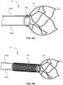
- FIGs. 4A-4Fdepict example designs for a frame 110.
- FIG. 4Aillustrates a frame 110 having four anchor struts (i.e., anchor struts 206A,206B,206C,206D).
- anchor struts 206A,206B,206C,206Dcan be embedded within the construction layers of the catheter 102 (catheter not shown in FIG. 4A ).
- the individual anchor struts 206A,206B,206C,206Dcan have electrical connections 401 to different components of the system 100.
- the electrical connections 401 that are connected to the anchor struts 206A,206B,206C,206Dcan be connections to a positive lead 118, a negative lead 120, a thermocouple 122, a thermoelectrical cooling circuit 123, or any combination thereof.
- two of the anchor struts 206A,206B,206C,206Dcan be connected to a positive lead 118 and a negative lead 120 to provide current for heating the frame 110; and/or one of the anchor struts 206A,206B,206C,206D can be connected to the thermocouple 122; and/or one of the anchor struts 206A,206B,206C,206D can be connected to the thermoelectric cooling circuit 123; and/or two anchor struts could be connected to a positive lead 118 and two anchor struts 206 to a negative lead 120; and/or any combination thereof.
- two anchor strutscan be connected to a positive lead 118 for more balanced flow of current through the frame 110 with two negative return leads.
- two of the anchor strutscan connect to a positive lead 118 and a negative lead 120 for a first portion of the frame 110 (e.g., first portion 111A); and two of the anchor struts (e.g., anchor struts 206B and 206D) can connect to a positive lead 118 and a negative lead 120 for a second portion of the frame 110 (e.g., second portion 111B).
- Thiscan enable the first portion 111A of the frame 110 to have a different activation characteristic than the second portion 111B of the frame 110.
- the first portion 111A of the frame 110can be heat-set into an expanded configuration.
- the first portion 111Acan expand during the procedure.
- the second portion 111B of the frame 110can be heat-set into a collapsed configuration.
- the second portion 111Bcan collapse during the procedure. This enables a user of the system to advance the system 100 to the target site 20, direct a first current to the first portion 111A to expand frame 110, and aspirate the clot 40 into the frame 110. The user can then direct a second current to the second portion 111B to collapse the frame 110 and capture the clot 40.
- the individual anchor struts 206A,206B,206C,206Dcan have electrical connections 401 to different components of the system 100.
- two of the electrical connections 401can include a second positive lead wire and a second negative lead wire, respectively, to heat one of the frame portions independently of the other, each circuit being insulated from the other.
- the first portion 111A and second portion 111B of the frame 110can comprise the same shape memory material and each material can have the same AF temperature. In other examples, the two portions can comprise the same material but have different AF temperatures.
- the first portion 111A and second portion 111Bcan comprise different shape memory materials, which can also enable the portions to have different AF temperatures, if needed.
- one portioncan have an AF temperature below that of human blood (e.g., below 37°C) such that it expands once delivered to the target site 20 and contacts blood; the other portion can have an AF temperature above 37°C such that it only collapses upon being heated by a current.
- one portioncan have an AF temperature below that of human blood such that it collapses as it is heated by blood.
- the first portion 111A and second portion 111Bcan be interconnected to form the cells 126 of the frame.
- heat from one portioncan be shielded from the other portion by using an insulating junction 304 like the one shown in FIG. 3C .
- the first portion 111A and the second portion 111Bcan include two separate, coaxial frames that are not interconnected with one another.
- the example frame 110 shown in FIG. 2can have a second frame disposed over the frame shown in the figure that can circumferentially wrap around the inner frame.
- the outer framei.e., the outer portion
- the inner framei.e., the inner portion
- the inner framecan be expanded to receive the clot 40, and the outer frame can be activated to close, compress the inner frame, and capture the clot 40.
- the inner and outer framewould be working against each other.
- certain annular crowns 202can have a different activation characteristic than other annular crowns 202, some expanding when heated while others collapsing when heated.
- FIG. 4Billustrates a frame 110 having split collar 402.
- a first side 404 of the split collar 402can be in electrical communication with a positive lead 118 while a second side 406 of the split collar 402 can be in electrical communication with a negative lead 120.
- the split collar 402can provide a surface for the catheter 102 (catheter not shown in FIG. 4B ) to lock with the frame 110.
- the split collar 402can be disposed within the construction layers of the catheter 102.
- the split collar 402can rest on the outer surface of the catheter 102, and the positive lead 118 and/or negative lead 120 can extend through a hole in the catheter 102 wall to connect to the split collar 402.
- the split collar 402can also be disposed within the inner lumen 302 of the catheter 102.
- the frame 110can include a solid collar 408, as shown in FIG. 4C , which can be similar to the split collar 402.
- the positive lead 118 and/or negative lead 120can be directly connected to the struts 124 so that the current is not overly resisted by the solid collar 408 leading to slow heating of the expansion frame.
- FIG. 4Dillustrates a frame 110 with a coiled collar 410.
- the coiled collar 410can be similar to the split collar 402 and/or solid collar 408 above in that it can be disposed within intermediate layers of the catheter 102, on the outer surface of the catheter 102, or within an inner lumen 302 of the catheter 102.
- the coiled collar 410can provide pushability and flexibility while reducing complexity of construction to minimize wall thickness required at the distal end 108 of the catheter 102.
- the coiled collar 410can be formed by the lead wires 116 or can be integral with the frame 110. Insulated lead wires of a highly conductive material (such as copper) can be braided to provide good pushability for the catheter construction. Stainless steel can also be used for the lead wires. While having less conductivity than copper, steel can offer better stiffness characteristics, and a larger diameter wire can be used to both counteract the lower conductivity while offering higher stiffness at the same time.
- FIG. 4Eillustrates an example strut 124 configuration for a frame 110.
- the axial force provided by the funnel-shaped frame 110can be customized by changing the angles 414 between struts 124 (e.g., crown peaks 416).
- Acute anglesoffer less radial force and require less percentage elongation at break for the membrane 130, while obtuse angles offer more radial force and require more percentage elongation at break for the membrane 130.
- Acute anglescan be achieved by lengthening struts 124 and/or increasing the number of crown peaks 416 per annular crown 202.
- crown peaks 416can be enlarged (i.e., rounded) to improve resistance to microcracks and fractures as the frame 110 expands.
- crown peaks 416can form a large round curve extending substantially in a semi-circle from the proximal end of adjacent struts 124. Such large round semi-circular profiles will be atraumatic to a blood vessel
- a distal tip 412 of the frame 110can taper or curve radially inwardly to decrease trauma to the vessel wall 35.
- the distal tip 412can be flared radially outward to improve apposition to the vessel wall 35.
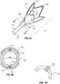
- the frame 110can include wings 418 that extend proximal on the frame 110, as shown in FIG. 4F . By extending proximally, the wings 418 are less likely to puncture the vessel wall 35 if the frame 110 is advanced distally towards the target site 20. The wings 418 can extend outwardly beyond the other struts 124 of the frame 110 and further increase the radial force on the vessel wall 35.
- This configurationalso enables the distal tip 412 to be flared inwardly to decrease the likelihood of trauma to the vessel wall 35 while also enabling the wings 418 to expand to contact the vessel wall 35 and create a fluid-tight seal in the vessel 30.
- the crowns of the wings 418can be connected to a proximal strut, as described below with reference to FIGs. 5A and 5B .
- FIGs. 5A and 5Bdepict an example frame 110 having a distal portion 502 and a proximal portion 504.
- the distal portion 502 of the frame 110can be similar to any of the frames 110 described herein.
- the proximal portion 504can oppose the distal portion 502 and be directed toward a catheter hub (catheter hub not shown in FIGs. 5A or 5B ).
- the proximal portion 504can have an expanded configuration and an open configuration, similar to the configurations described for any of the frame 110 embodiments described above. In a collapsed configuration, the proximal portion 504 can rest upon or adjacent to the distal end 108 of the catheter 102.
- the proximal portion 504can create a proximal-facing funnel to counteract blood pressure/blood flow and prevent the unwanted aspiration of blood proximal to the frame 110.
- the proximal portion 504 and/or distal portion 502can include a membrane 130.
- the proximal portion 504 and distal portion 502can be connected with a solid collar 408 or any of the other collars described herein.
- the proximal portion 504 and distal portion 502can be connected to different conductive wires such that one portion can be opened or closed with a first current and one portion can be opened or closed with a second current, as described above.
- struts 124can extend proximally from the proximal crowns of the proximal portion to a second collar positioned proximally of the solid collar 408. Either or both collars can be segmented. Connecting the proximal peaks of the proximal portion to a proximal collar can aid in reducing the likelihood of the frame snagging on an outer guide sheath or vessel side branch as it is retracted proximally.
- FIG. 6illustrates a design for a system 100 that enables the frame 110 to act as a closed balloon.
- the frame 110can be positioned along the length of the catheter 102 proximate the distal end 108 of the catheter 102. Unlike many of the designs described herein, the frame 110 does not extend beyond the distal end 108 of the catheter 102 in this example.
- the frame 110can include a fixed collar 602 at one end and a floating collar 604 at the other end.
- the fixed collar 602can be connected to the outer surface or can be embedded within the construction layers of the catheter 102 such that it does not slide along the length of the catheter 102; the floating collar 604 can, conversely, slide along the length of the catheter 102.
- the plurality of struts 124can be connected to both collars 602,604 and extend between the two.
- the struts 124can be integral struts (as shown in FIG. 6 ), while in other examples the struts can be overlapping (e.g., a weave pattern).
- the frame 110can float inside the balloon material or the frame 110 can be encapsulated in the balloon material.
- the membrane 130can include a first seal 606 and a second seal 608 at the ends of the membrane 130.
- the first seal 606 and/or second seal 608can create a fluid-tight junction between the membrane 130 and the catheter 102.
- the first seal 606 and/or second seal 608can be permanently fixed to the catheter 102, and the membrane 130 can stretch as the struts 124 expand.
- one of the first seal 606 and/or second seal 608can contract along with the floating collar 604.
- the first seal 606 and/or second seal 608can be a gasket, like an O-ring, that can slide along the outer surface of the catheter 102.
- FIG. 7illustrates a design for a system 100 that enables an anchor strut 206 to expand or contract as a spring, thereby moving the position of the frame 110 along the catheter 102.
- the end of the catheter 102 proximal the frame 110can include a narrow section 702.
- An anchor strut 206 extending from the frame 110can coil around the narrow section 702.
- the anchor strut 206can be connected at one end to a floating collar 604 that can move along the length of the narrow section 702.
- the opposite end of the anchor strut 206can be connected to a conductive wire 116 (e.g., a positive lead 118 or a negative lead 120).
- the anchor strut 206can be heat-set in a collapsed configuration such that, as the anchor strut 206 is heated, it contracts to pull the frame 110 proximal along the catheter 102.
- the distal end 108 of the catheter 102can include a catheter tip 704 having an outer diameter larger than an inner diameter of the floating collar 604.
- the catheter tip 704can prevent the frame 110 from sliding off of the catheter 102 distally. This mechanism enables the distal tip 412 of the frame 110 to be aligned with the distal end 108 of the catheter 102 when the anchor strut 206 is fully contracted.
- the anchor strut 206can be contracted and the frame 110 expanded while fluid is aspirated into the catheter 102.
- the anchor strut 206can be returned to an extended configuration, and, simultaneously, the frame 110 can collapse around the clot for removal from the vessel.
- the anchor strut 206 and the frame 110can be heated by the same current (i.e., by the same positive lead 118 and negative lead 120), or the anchor strut 206 and the frame 110 can include separate electrical connections such that they can be heated independently.
- the distal end 412can be advanced in the collapsed configuration through activation of the anchor strut 206, which acts as a linear movement actuator, so that the tip 412 is closer to the clot, and the tip 412 can be actuated to seal the vessel prior to aspiration.
- the distal end 108 of the catheter 102itself can instead be actuated by a springing mechanism.
- the catheter 102can include a flexible portion that includes a shape memory material disposed therein. As the shape memory material in the catheter 102 expands with heat, the distal end 108 of the catheter 102 can extend through the funnel formed by the frame 110 and towards the clot.
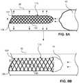
- FIGs. 8A-8Billustrate a design for a system 100 that enables the frame 110 to adjust the bore size of the catheter 102.
- the frame 110can extend from the distal end 108 of the catheter 102 (catheter not shown in the figure) to form the distal-most portion of the catheter 102.
- the frame 110can expand to increase the bore size of the catheter 102 and thus increase the flow into the catheter 102. This can be especially beneficial for larger or stiffer clots. For example, as the catheter 102 aspirates the clot, if the clot is resisting being pulled into the catheter, the operator can supply the current to the frame 110 to increase the flow into the catheter 102.
- the frame 110can be a laser cut lattice design, a shape set wire design, a wire braid design, and/or the like.
- the frame 110can be covered with a membrane 130, as described above.
- the frame 110can also be designed to expand for the full length of the catheter 102.
- the frame 110can be positioned within an inner lumen 302 of the catheter 102. In a similar manner, as the frame 110 expands inside the inner lumen 302, the bore size of the catheter 102 can increase to adjust the flow.
- FIGs. 9A-9Fdepict example designs for attaching the conductive wire 116 to the anchor strut 206 of the frame 110.
- the conductive wire 116can be connected to the anchor strut 206 by a variety of mechanical means.
- FIG. 9Adepicts a mechanical connector 802 that includes a "T" connection at one end and a hook at the other end, the hook grabbing and holding the "T" connection.
- FIG. 9Bdepicts a coiled connector 804.
- a third materialcan be coiled over the conductive wire 116 and the anchor strut 206 to create the electrical connection.
- FIG. 9Cdepicts a mechanical crimp 806.
- the crimp 806can include a third material that crimps the conductive wire 116 at one end and the anchor strut 206 at the other end.
- FIG. 9Ddepicts a forked crimp 808.
- One end of either the conductive wire 116 or the anchor strut 206can include a fork that can be crimped upon the other end of the connection.
- FIG. 9Eis an alternative forked crimp 810 including teeth 812 that can assist in gripping the material between the forks.
- FIG. 9Fdepicts a heat shrink method of bonding the conductive wire 116 and the anchor strut 206.
- Adhesives for adhering conductive wires 116 to shape memory materialscan include cyanoacrylate and epoxy.
- Welding methods for bonding the conductive wires 116 to shape memory materialsinclude, for example laser, welding, plasma welding, tungsten inert gas (TIG) welding, and the like.
- FIG. 10depicts an example system 100 with a frame 110 that opens like a glove. As can be seen, it is not required that the frame comprise a plurality of cells 126.
- the frame 110can instead include a simple loop of the struts 124 that can open like a glove when heated.
- FIG. 10also shows that, in some examples, the leads 118,120 and/or anchor struts 206 can spiral within construction layers of the catheter 102, as shown in cutaway B. Spiraling the anchor struts 206 can increase the length of, and thus the electrical resistance of, the shape memory material, which can increase the heat supplied to the frame 110.
- the anchor struts 206can be kept short and the leads can be configured straight to reduce the effect of inductance from a coil.
- the frame 110can be supplied as a number of simple loops each heated independently from a single lead pair or from a set of lead pairs.
- FIG. 11depicts a frame 110 having a distal tip 412 turned slightly inward in an expanded configuration. Turning the distal tip 412 radially inwardly can create an atraumatic profile should the user inadvertently push the device distally during use. The feature can also aid in grasping a fibrin rich clot 40 for safe extraction from a vessel 30.
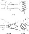
- FIG. 12depicts a frame 110 having a distal spring 1202.
- the distal spring 1202can contract upon heating.
- the contracting distal springcan deform a distal collar membrane 1204, which expands outwardly through inversion to create a funnel shape.
- the distal collar membrane 1204can comprise a stiffer material than other membranes 130 described above such that the distal collar membrane 1204 can expand radially when it is contracted with the distal spring 1202.
- the distal collar 1204can be a composite of a braid and a membrane or a braid and a fine weave mesh, the braid acting as a reinforcement to promote inversion.
- FIGs. 13A and 13Bdepict a frame 110 having struts 124 with a constant cross sectional area 1302.
- the constant cross section area 1302can enable even transfer of current across the entirety of the frame 110.
- the example designalso enables the frame 110 to decrease slightly in length as the frame 110 transitions from a closed configuration to an open configuration. In a closed configuration, the frame 110 can have a first length 1304, and as current is provided, and heat is created through resistance, the frame 110 can open like a funnel with a shorter, second length 1306.
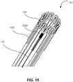
- FIGs. 14A and 14Bdepict a frame 110 having struts 124 that split into a v-shape for even flow of heat/electrical resistance.
- a frame 110can also include dissipation struts 1402 positioned at crown peaks 416 that can remove heat from the struts 124 (e.g., to allow the struts 124 to cool) and also provide support for a membrane 130 cover.
- the designcan also enable the frame 110 to decrease slightly in length as the frame 110 transitions from a closed configuration to an open configuration, as described above with reference to FIGs. 13A and 13B .
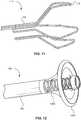
- FIG. 15is a perspective view of an example frame 110 having a thermocouple 122 that is a wire connected to a dissipation strut 1402.
- the thermocouple 122 wirecan include a material such as platinum or stainless steel can be attached to the frame 110 at an attachment 1502.
- the attachment 1502can include a weld or adhesive.
- the thermocouple 122 wirecan be in electrical communication with the electronic circuit 112, and the electronic circuit 112 can measure the difference in resistivity between the frame 110 material and the thermocouple 122 to determine the temperature of the frame 110. This can be calibrated and can have a linear temperature relationship.
- FIGs. 16-18Bdepict example designs for a frame 110.
- FIG. 16depicts an example frame 110 having no collar (e.g., neither a split collar 402 nor a solid collar 408).
- a first anchor strut 206A and a second anchor strut 206Bcan extend from a frame 110 having a single annular crown 202.
- the single annular crown 202can be held in place by a membrane 130 (not shown in FIG. 16 ).
- FIGs. 17A and 17Bdepict an example frame 110 having a split collar 402.
- the distal tip 412 of the frame 110can open to four distinct points (e.g., points 1702, 1704, 1706, 1708), as shown in the end view of FIG. 17B .
- the frame 110can include a membrane 130 to encapsulate the distal tip 412 of the frame 110 and connect the points 1702, 1704, 1706, 1708 into a rounded funnel shape.
- FIGs. 18A and 18Bdepict an example frame 110 having a plurality of distal points 1802.
- the frame 110can include a membrane 130 to encapsulate the distal tip 412 of the frame 110 and connect the plurality of distal points 1802 into a rounded funnel shape, as shown in the end view of FIG. 18B .
- FIG. 19is a flow diagram illustrating a method of retrieving an occlusive thrombus from a blood vessel of a patient.
- the method steps in FIG. 19can be implemented by any of the example means described herein or by similar means, as will be appreciated.
- a cathetercan be delivered to a target site.
- the cathetercan be advanced, for example, through an outer catheter or access sheath.
- the cathetercan comprise a frame manufactured from a shape memory material.
- the framecan have a funnel shape, can be disposed within an inner lumen of the catheter, can be disposed along the length of the catheter, or can have any of the other shapes described herein.
- method 1900can include delivering a first current to the frame.
- the first currentcan be delivered through a conductive wire connecting the frame to an electronic circuit.
- the usercan activate the electronic circuit outside of the patient.
- method 1900can include heating the frame to cause at least a first portion of the frame to change from a collapsed configuration to an expanded configuration.
- the heating of the frameis caused by the electrical resistance of the shape memory material as the current runs through the frame.
- At least a first portion of the framemeans the entire frame can expand, though it is not necessary that the entire frame expands.
- the framecan have multiple portions with different transformation characteristics. For example, a first portion of the frame can be heated to expand while a second portion is not heated. The second portion, for example, can be heated in a later step to capture the thrombus.
- a shape memory funnel framecan be restricted from expanding by an electrically actuated member, removing the electric current allows the restraining member to release and the shape memory material expands from the heat of blood.
- method 1900can include aspirating the occlusive thrombus into the frame.
- the aspirationcan be directed into the catheter by the frame, which can include a membrane covering that directs fluid.
- method 1900can include withdrawing the catheter with the occlusive thrombus from the patient. With the thrombus captured within the frame, the thrombus can be pulled from the vessel of the patient without worry of the thrombus dislodging from the catheter due to poor capture.
- Method 1900can end after step 1925. In other embodiments, additional steps according to the examples described above can be performed.
- method 1900can include deactivating the first current to cool the at least a first portion of the frame. Cooling the shape memory material can cause the at least a first portion to collapse upon the occlusive thrombus to improve the capture the thrombus for removal.
- method 1900can include delivering a second current to at least a second portion of the frame.
- the second portioncan have a different transformation characteristic than the first portion.
- the second portioncan be pre-set into a collapsed configuration in its austenite phase, which means that, once heated, it can collapse upon the thrombus.
- method 1900can include heating, via the second current, the second portion of the frame to cause the second portion of the frame to change from an expanded configuration to a collapsed configuration and upon the occlusive thrombus.
- Method 1900can also include cooling the at least a first portion of the frame with a thermoelectric cooling circuit to cause the at least a first portion of the frame to collapse upon the occlusive thrombus.
- a thermoelectric cooling circuitsuch as a Peltier chip, can pump heat from a system. Using this effect, the thermoelectric cooling circuit can cause the at least a first portion of the frame to cool and collapse more rapidly around the occlusive thrombus.
- Method 1900can include delivering the current in a series of pulses so as to maintain a steady frame temperature, and the electronic circuit can monitor the temperature and adjust the pulse duration and/or length accordingly.
- Method 1900can also include monitoring a temperature of the frame with a thermocouple.
- the thermocouplecan monitor to determine if the frame exceeds a certain temperature, for example 50°C, and deactivate the first current if the frame exceeds the temperature.
- FIG. 20is a flow diagram illustrating a method of manufacturing an exemplary actuated clot retrieval system.
- the method steps in FIG. 20can be implemented by any of the example means described herein or by similar means, as will be appreciated.
- a first shape memory materialcan be heat set into a first frame having an expanded configuration.
- heat setting the shape memory materialcan include heating the frame to above its AF temperature, forming the frame into a desired shape, and then allowing the frame to cool.
- method 2000can include allowing the first shape memory material to cool and the frame to collapse into a collapsed configuration. Once cooled, the frame is more flexible and pliable, as it is in its martensite phase. The collapsed frame can return to its predetermined shape by reheating the frame to above the AF temperature.
- method 2000can include connecting the first frame to a first end of a first conductive wire disposed within a wall of a catheter (e.g. catheter wall 306 of FIG. 3 ).
- the framecan have an electrical connection, for example, to a positive and a negative lead to provide current to heat the frame.
- This electrical connectioncan be made within the construction layers of the catheter itself, thereby protecting the connection from inadvertent separation.
- the electrical connectioncan be made within the construction layers by providing a first catheter layer (e.g., first layer 308 in FIG. 3 ) and then disposing the first conductive wire on the first catheter layer.
- the framecan be attached to the conductive wire, for example by attaching the conductive wire to an anchor strut of the frame.
- a second catheter layere.g., second layer 310 in FIG. 3
- method 2000can include connecting a second end of the first conductive wire to an electronic circuit.
- the electronic circuitcan be positioned distal to the frame.
- the electronic circuitcan be disposed within a housing that includes a switch to activate the current.
- method 2000can include applying a membrane to the first frame and to a distal end of the catheter.
- the membranecan be applied by a variety of methods. One method is to apply a thin base layer of material to a dipping mandrel with the catheter in place, followed by injection molding an intermediate layer with collapsed frame held in place by an outer mold, and a final top layer can be applied using a second outer mold or through a final dip coating process.
- a preformed ring of a material that will not form a bond with the encapsulation membranecan be used to hold the frame in a collapsed position.
- the preformed ringcan be removed before a final dipping or molding process to fill in the void left by the ring.
- a preformed ring of the same materialcan be used to avoid the necessity to remove the ring.
- Method 2000can end after step 2025. In other embodiments, additional steps according to the examples described above can be performed.
- method 2000can include heat setting a second shape memory material into a second frame having a collapsed configuration.
- the second framecan be heat set in a similar manner as described above for the first frame.
- the second framecan be heat set into a collapsed configuration such that, once heated, the second frame can return to the collapsed configuration (e.g., to capture a clot).
- Method 2000can include allowing the second shape memory material to cool and then connecting the second frame to a first end of a second conductive wire disposed within the catheter wall.
- Method 2000can include connecting a second end of the second conductive wire to the electronic circuit so that the second frame can receive a current.
- the membranecan be applied to the second frame in a similar manner to the method described for the first frame.
- the first shape memory material and the second shape memory materialcan be the same alloys or can be different alloys. Providing different alloys can enable the two frames to have different transformation characteristics (e.g., they can transform from martensite to austenite phases at different temperatures).
- the first frame and the second framecan be coaxial and connected to the distal end of the catheter. In this manner, the first frame can expand when heated, and the second frame can collapse upon the first frame to capture the clot when heated.
Landscapes
- Health & Medical Sciences (AREA)
- Life Sciences & Earth Sciences (AREA)
- Surgery (AREA)
- General Health & Medical Sciences (AREA)
- Engineering & Computer Science (AREA)
- Veterinary Medicine (AREA)
- Biomedical Technology (AREA)
- Heart & Thoracic Surgery (AREA)
- Public Health (AREA)
- Animal Behavior & Ethology (AREA)
- Nuclear Medicine, Radiotherapy & Molecular Imaging (AREA)
- Orthopedic Medicine & Surgery (AREA)
- Vascular Medicine (AREA)
- Medical Informatics (AREA)
- Molecular Biology (AREA)
- Hematology (AREA)
- Anesthesiology (AREA)
- Pulmonology (AREA)
- Biophysics (AREA)
- Surgical Instruments (AREA)
- Media Introduction/Drainage Providing Device (AREA)
Abstract

Description
- This application claims priority, and benefit under 35 U.S.C. § 119(e), to
U.S. Provisional Patent Application No. 62/813,723, filed 4 March 2019 - The present disclosure generally relates to devices and methods for removing acute blockages from blood vessels during intravascular medical treatments. More specifically, the present disclosure relates to an actuated clot retrieval catheter.
- Clot retrieval catheters and devices are used in mechanical thrombectomy for endovascular intervention, often in cases where patients are suffering from conditions such as acute ischemic stroke (AIS), myocardial infarction (MI), and pulmonary embolism (PE). Accessing remote areas such as the neurovascular bed is challenging with conventional technology, as the target vessels are small in diameter, distant relative to the site of insertion, and are highly tortuous.
- The clot itself can complicate procedures by taking on a number of complex morphologies and consistencies, ranging from simple tube-shaped structures which assume the shape of the vessel to long, strand-like arrangements that can span multiple vessels at one time. The age of a clot can also affect its compliance, with older clots tending to be less compressible than fresh clots. Fibrin rich clots also present a challenge in having a sticky nature that can cause a clot to roll along the outer surface of a mechanical thrombectomy device rather than being gripped effectively. Combinations of soft and firm clot regions can also separate during aspiration, with fragmentation leading to distal embolization which can occur in vessels that cannot be reached with currently available devices. Additionally, breaking the bonds adhering the clot to the vessel wall without damaging fragile vessels is a significant challenge.
- Conventional clot retrieval catheters, especially those for operating in the neurovascular blood vessels, can suffer from a number of drawbacks. First, the diameters of the catheters themselves must be small enough to be advanced into the vasculature, which is very small in the context of the neurovascular system. The catheter must also be sufficiently flexible to navigate the vasculature and endure high strains, while also having the axial stiffness to offer smooth advancement along the route. Once at the target site, typical objects to be retrieved from the body can be substantially larger in size than the catheter tip, making it more difficult to retrieve objects into the tip. For example, fibrin-rich clots can often be difficult to extract as they can become lodged in the tip of traditional fixed-mouth catheters. This lodging can cause softer portions of the clot to shear away from the firmer regions, leading to distal embolization.
- Small diameters and fixed tip sizes can also be less efficient at directing the aspiration necessary to remove blood and thrombus material during the procedure. The aspiration suction must be strong enough such that any fragmentation occurring through the use of a mechanical thrombectomy device or other methods can, at the very least, be held stationary so that fragments cannot migrate and occlude distal vessels. When aspirating with a traditional fixed-mouth catheter, however, a significant portion of the aspiration flow ends up coming from vessel fluid proximal to the tip of the catheter where there is no clot. This significantly reduces aspiration efficiency, lowering the success rate of clot removal.
- The disclosed design is aimed at providing an improved aspirating retrieval catheter which addresses the above-stated deficiencies.
- Examples presented herein include devices and methods for removing acute blockages from blood vessels during intravascular medical treatments. More specifically, the present disclosure relates to an actuated clot retrieval catheter system. An example system for retrieving an obstruction in a blood vessel can include a catheter, a first conductive wire, and an electronic circuit. The electronic circuit can provide a first current to the first conductive wire. A frame can be located near the distal end of the catheter and can be in electrical communication with the first conductive wire. The frame can include a shape memory material that enables the frame, or a portion thereof, to transition from a martensite phase to an austenite phase when heated to above the material's austenite finish temperature. At least a first portion of the frame can be expandable from a collapsed configuration to an expanded configuration upon being heated by the first current.
- The shape memory material can have a transition temperature above approximately 37°C. In some examples, the shape memory material can have a transition temperature of from approximately 45°C to 55°C.
- The system can include a thermoelectric cooling circuit in electrical communication with the frame. The at least a first portion of the frame can be collapsible from the expanded configuration to the collapsed configuration upon removal of heat by the thermoelectric cooling circuit.
- At least a second portion of the frame can be collapsible from an open configuration to a collapsed configuration upon being heated.
- The system can include a second conductive wire in electrical communication with the second portion of the frame. The second conductive wire can receive a second current from the electronic circuit.
- The system can include a membrane cover disposed around the frame.
- The frame can be located within an inner lumen of the catheter. In other examples, the frame extends from the distal end, for example like a funnel, to capture the occlusion.
- The system can include a thermocouple in electrical communication with the frame. The thermocouple can help to remove heat from at least a portion of the frame.
- The shape memory material can be in a martensite phase when the at least a first portion of the frame is in the collapsed configuration. The shape memory material can be in an austenite phase when the at least a first portion of the frame is in the expanded configuration.
- An example method of retrieving an occlusive thrombus from a blood vessel of a patient can include delivering a catheter comprising a frame to a target site. The frame can include a shape memory material. The method can include delivering a first current to the frame. The current running through the frame can heat the frame to cause at least a first portion of the frame to change from a collapsed configuration to an expanded configuration. The method can include aspirating the occlusive thrombus into the frame. The catheter can be withdrawn with the occlusive thrombus from the patient.
- The shape memory material of the frame can have a transition temperature of from approximately 45°C to 55°C.
- The method can include deactivating the first current. By deactivating the first current, the at least a first portion of the frame can cool to cause the at least a first portion of the frame to collapse upon the occlusive thrombus.
- The method can include cooling the at least a first portion of the frame with a thermoelectric cooling circuit to cause the at least a first portion of the frame to collapse upon the occlusive thrombus. The thermoelectric cooling circuit can include a Peltier chip, a thermoelectric wire, and the like.
- The method can include delivering a second current to at least a second portion of the frame. The second current can create heat, through the resistance of the shape memory material, that causes the at least a second portion of the frame to change from an expanded configuration to a collapsed configuration and upon the occlusive thrombus.
- The method can include monitoring a temperature of the frame with a thermocouple in communication with the frame. The method can include deactivating the first current when the temperature is above a first temperature. This can ensure the vessel is not damaged by excessive heat.
- The frame can be located within an inner lumen of the catheter. In these examples, causing the at least a first portion of the frame to expand from a collapsed configuration to an expanded configuration can cause an inner diameter of the of the catheter to increase.
- An example method of manufacturing an actuated clot retrieval system can include heat setting a first shape memory material into a first frame having an expanded configuration. The method can include allowing the first shape memory material to cool and the first frame to collapse into a collapsed configuration. The method can include connecting the first frame to a first end of a first conductive wire disposed within a catheter wall of a catheter. The method can include connecting a second end of the first conductive wire to an electronic circuit. The method can include applying a membrane to the first frame and to a distal end of the catheter.
- The method can include heat setting a second shape memory material into a second frame having a collapsed configuration. The method can include connecting the second frame to a first end of a second conductive wire disposed within the catheter wall. The method can include connecting a second end of the second conductive wire to the electronic circuit. The method can include applying the membrane to the second frame.
- The first shape memory material and the second shape memory material can different alloys, and the first frame and the second frame can be coaxial and connected to the distal end of the catheter. In other words, the second frame can be circumferentially positioned upon the second frame such that the second frame can close upon the first frame.
- The first shape memory material and the second shape memory material can include the same alloy, and the first shape memory material and the second shape memory material can have different austenite finish temperatures.
- The method can include providing a first catheter layer and disposing the first conductive wire on the first catheter layer. The method can include applying a second catheter layer over the first conductive wire and a first anchor strut of the first frame. Connecting the first frame to the first end of the first conductive wire can include connecting the first anchor strut to the first conductive wire prior to applying the second catheter layer.
- The method can include encasing the first frame with a ring to hold the first frame in the collapsed configuration. Applying the membrane to the first frame can include dipping the first frame and the ring into a membrane material and allowing the membrane material to cool.
- The above and further aspects of this disclosure are further discussed with the following description of the accompanying drawings, in which like numerals indicate like structural elements and features in various figures. The drawings are not necessarily to scale, emphasis instead being placed upon illustrating principles of the disclosure. The figures depict one or more implementations of the inventive devices, by way of example only, not by way of limitation. It is expected that those of skill in the art can conceive of and combining elements from multiple figures to better suit the needs of the user.
FIGs. 1A and 1B are side-view illustrations of an exemplary actuated clot retrieval system, according to aspects of the present disclosure;FIGs. 1C and1D illustrate a method of delivering an exemplary actuated clot retrieval system to a target site within a vessel, according to aspects of the present disclosure;FIG. 2 is a cross-sectional view of an exemplary frame within a vessel, according to aspects of the present disclosure;FIGs. 3A-3C are illustrations of exemplary designs for providing current to a frame, according to aspects of the present disclosure;FIGs. 4A-4F are side-view illustrations of exemplary frame designs, according to aspects of the present disclosure;FIGs. 5A and 5B are illustrations of an exemplary frame having opposing funnels, according to aspects of the present disclosure;FIG. 6 is a cross-sectional illustration of an exemplary balloon-shaped frame, according to aspects of the present disclosure;FIG. 7 is a side-view illustration of an exemplary actuated clot retrieval system having a retractable frame, according to aspects of the present disclosure;FIGs. 8A and 8B are cross-sectional illustrations of exemplary designs to expand the bore size of a catheter, according to aspects of the present disclosure;FIGs. 9A-9F are illustrations of exemplary attachments to connect an anchor strut to a shape memory material, according to aspects of the present disclosure;FIG. 10 is an illustration of an exemplary actuated clot retrieval system having a glove-shaped frame, according to aspects of the present disclosure;FIG. 11 is a side-view illustration of an exemplary frame design, according to aspects of the present disclosure;FIG. 12 is an illustration of an exemplary frame having a retractable distal spring, according to aspects of the present disclosure;FIGs. 13A and 13B depict a frame having struts with a constant cross sectional area, according to aspects of the present disclosure;FIGs. 14A and 14B depict a frame having struts that split into a v-shape for even flow of heat/electrical resistance, according to aspects of the present disclosure;FIG. 15 is a perspective view of an example frame having a thermocouple wire connected to a dissipation strut, according to aspects of the present disclosure;FIGs. 16-18B depict example designs for a frame, according to aspects of the present disclosure;FIG. 19 is a flow diagram illustrating a method of retrieving an occlusive thrombus from a blood vessel of a patient, according to aspects of the present disclosure; andFIG. 20 is a flow diagram illustrating a method of manufacturing an exemplary actuated clot retrieval system, according to aspects of the present disclosure.- The herein disclosed solution is directed to a clot retrieval catheter capable of providing local flow restriction/arrest via a modular distal frame. Flow restriction and large tipped designs offer substantially greater aspiration efficiency. Such advantages can also be especially beneficial in the case of stroke intervention procedures, where vessels in the neurovascular bed are particularly small and circuitous, and as a result a tailored axial and bending stiffness profile can inhibit kinking and binding. The catheter can also be compatible with relatively low-profile access sheaths and outer catheters, so that a puncture wound in the patient's groin (in the case of femoral access) can be easily and reliably closed. The catheter can also feature internal and/or external low-friction liners, and an outer polymer jacket or membrane disposed around the support structure. The membrane can be an elastomeric material that encapsulates the frame or is fitted over the frame so that the frame can move independently of the membrane. The membrane can be tight or loose fitting. A loose-fitting elastomeric membrane will be easier to open that a tight fitting membrane. The membrane can be baggy and made of a non-elastomeric material such that the force to open the membrane is low compared to that of a tight-fitting elastomeric membrane. The membrane can be inverted to extend distally from a proximal location radially inwardly of the frame before reverting back to extend proximally radially outwardly of the frame and wherein the inner and outer layers of the membrane are bonded or reflowed together at a proximal location or for the full length of the membrane. The membrane can comprise an inner and an outer tube, the proximal and distal ends of the inner and outer tube being bonded together or reflowed such that the two tubes form a sock around the frame, the frame being free to move/expand within the sock.
- These improvements can lead to safe and more rapid access of a catheter and other devices to complex areas in order to remove occlusions and shorten procedure times. While the description is in many cases in the context of mechanical thrombectomy treatments, the systems and methods can be adapted for other procedures and in other body passageways as well.
- Accessing the various vessels within the vascular system, whether they are coronary, pulmonary, or cerebral, involves well-known procedural steps and the use of a number of conventional, commercially-available accessory products. These products, such as angiographic materials, rotating hemostasis valves, and guidewires are widely used in laboratory and medical procedures. When these products are employed in conjunction with the system and methods in the description below, their function and exact constitution are not known in the related art.
- The present systems and methods employ the characteristics of shape memory materials to customize the distal dimensions of a clot-retrieval device. Shape memory materials are those materials, such as alloys, that can be deformed when cold and then expand to a predetermined shape when heated. Once the heat is removed from the material, the material can return to it's collapsed, pliable shape. This can be achieved by heating the shape memory material beyond an austenite finish (AF) temperature. Below the AF temperature, the shape material exits its martensite phase, which is characterized by high elasticity, pliability, and flexibility. Above the AF temperature, the shape material exists in its austenite phase, which is characterized by a more rigid state. The shape memory material can be heat set to a predetermined shape above its AF temperature such that, when the material is reheated to the AF temperature, the material returns to that predetermined shape.
- Various embodiments described herein can include frames that can resemble a funnel sheath that, once expanded, can exert a radial force on the vasculature. Fluid can be aspirated into the expanded funnel and then into a catheter to capture a thrombus within the funnel. The frame can include a membrane covering that directs the aspirate into the catheter. In other examples, the frame can be disposed within an inner lumen of the catheter. As the frame expands and collapses, the inner diameter of the catheter can be increased and decreased to adjust the flow rate into the catheter.
- The present disclosure provides a mechanism for heating the frame to its AF temperature to cause the frame to transition into its austenite phase. One or more conductive lead wires can provide a current to the frame. The natural electrical resistance of the shape memory material can then cause the frame to heat above the AF temperature. A thermocouple can also be provided to monitor the temperature of the frame such that the frame does not overheat and cause trauma to the surrounding vasculature. In some examples, a thermoelectric cooling circuit, such as a Peltier chip, can be provided to transition the frame back into its martensite phase. The present disclosure provides various example designs for frames.
- Various devices and methods are disclosed for providing an actuated clot retrieval catheter, and examples of the devices and methods will now be described with reference to the accompanying figures.
FIGs. 1A and 1B provide an illustration of an exampleclot retrieval system 100. Thesystem 100 can include acatheter 102 having aproximal end 104 proximal to acircuit housing 106 and adistal end 108. Thecatheter 102 can have a sufficiently small outer diameter to advance thecatheter 102 through an outer catheter, such as an access sheath. Thesystem 100 can include aframe 110 proximate thedistal end 108 of thecatheter 102. Theframe 110 can extend beyond thedistal end 108 of the catheter, as shown inFIGs. 1A and 1B . In some examples, theframe 110 can be disposed within an inner lumen of thecatheter 102, as will be described in greater detail below. In another example, theframe 110 can be located along the length of thecatheter 102 such theframe 110 can act as a closed "balloon," as will be described below with reference toFIG. 6 . - The
frame 110 can be encapsulated within an inverted membrane, dual layer sealed membrane or an overmoulded or dipped membrane. Where theframe 110 is housed within an inner and outer membrane layer, the frame can have unhindered movement. Where an overmoulded membrane is supplied, there may be more resistance as theframe 110 may be required to stretch more discrete areas of membrane material. It is appreciated that, as an electrical current will be passed through theframe 110, it can be insulated in order to contain the electrical current. The membrane material can serve to insulate theframe 110. Theframe 110, acting as a resistor, can thereby generate heat under a current load. - The
frame 110 can have an expanded configuration and a collapsed configuration.FIG. 1A shows aframe 110 in the shape of a funnel in an expanded configuration, whileFIG. 1B shows thesame frame 110 in a collapsed configuration. Theframe 110 can include a shape memory material that enables theframe 110 to transition from a collapsed configuration to an expanded configuration, or vice versa, upon being heated and return to its previous configuration upon cooling. The shape memory material of theframe 110 can include alloys that have shape memory effect such that the material can transition from a martensite phase to an austenite phase. These materials can include, but are not limited to, a Ni-Ti (Nitinol) alloy, a Ni-Al alloy, an In-Ti alloy, an Ag-Cd alloy, an Au-Cd alloy, a Cu-Al-Ni alloy, a Cu-Sn alloy, a Cu-Zn alloy, a Mn-Cu alloy, and similar alloys. - Shape memory materials enable devices to be manufactured such that, once heated above an AF temperature, the device can be pre-set into a predetermined shape. Considering the example funnel-shaped
frame 110 ofFIGs. 1A and 1B , theframe 110 can be provided in a collapsed configuration (FIG. 1B ). Theframe 110 can then be heated to above the AF temperature of the shape memory material and then shaped into its final configuration (FIG. 1A ). At this stage, theframe 110 is in its austenite phase. Once theframe 110 is re-cooled to below the AF temperature of the material, theframe 110 can return to its un-set shape. At this stage, theframe 110 is in its martensite phase Due to the low heat capacity of theframe 110, cooling can be achieved easily through conduction with the wires and/or thermocouple wires, and subsequentially through thecatheter 102 jacket materials and/or membrane material. FIGs. 1C and1D provide an example method of using the transition characteristics of shape memory materials to actuate aclot retrieval system 100. The actuatedclot retrieval system 100 including thecatheter 102 andframe 110 can be advanced to atarget site 20 in avessel 30 containing aclot 40. This can be completed by advancing thesystem 100 through anouter catheter 10, as shown in the figure. However, as will be described below, thecatheter 102 andframe 110 can be advanced to thetarget site 10 without the need for anouter catheter 10. Once thecatheter 102 andframe 110 reach thetarget site 20, theframe 110 can be in its martensite phase, characterized by high elasticity, pliability, and flexibility of the material. This can enable theframe 110 to advance through the windingvessel 30 with ease. Once theframe 110 is at thetarget site 20, theframe 110 can be heated, which is described in greater detail below, to enable theframe 110 to transition from martensite phase to austenite phase. In the examples shown in FIG. ID, theframe 110 was heat set into a funnel sheath in its austenite phase such that, when heated, theframe 110 expands to a funnel to exert a force on thevessel 30. Theclot 40 can then be aspirated into theframe 110 and removed from thetarget site 20. In some examples, theframe 110 can be actively cooled such that theframe 110 collapses into its martensite phase to capture theclot 40. Alternatively, theframe 110 can automatically cool due to the low heat capacity of theframe 110.- Referring again to
FIGs. 1A and 1B , various shape memory materials, including the alloys described above, have different AF temperatures, enabling thesystem 100 to be customized for the particular procedure. Further, materials processed with a certain AF temperature can be reprocessed through subsequent processes involving heat treatment in order to reset the AF temperature to the desired range. The shape memory material can be selected or processed such that the AF temperature is above human blood (e.g., above 37°C) so that theframe 110 is not inadvertently activated prior to reaching the intended activation location in a vessel. The AF temperature can be between 35°C and 200°C (e.g., between 37°C and 65°C, between 40°C and 60°C, etc.). Ideally the AF temperature can be in the range of 45 to 55 °C. This can help ensure martensite properties for a highly flexible delivery configuration while minimizing the energy required to heat theframe 110 for expansion and rigid properties. - As used herein, the terms "about" or "approximately" for any numerical values or ranges indicate a suitable dimensional tolerance that allows the part or collection of components to function for its intended purpose. More specifically, "about" or "approximately" may refer to the range of values ±10% of the recited value, e.g. "about 50°C" may refer to the range of values from 45.001°C to 54.999°C.
- The
frame 110 can be heated by providing a current to theframe 110. The high electrical resistance of the shape memory material, for example Nitinol, can cause theframe 110 to heat in response to the electrical current and the heat in turn cause the transition from the martensite to austenite phase. Thesystem 100 can include anelectronic circuit 112 to provide the required current to theframe 110. Theelectronic circuit 112 can be disposed within acircuit housing 106. Theelectronic circuit 112 can be activated with aswitch 114. Theelectronic circuit 112 can feed from approximately 300 mA to approximately 1500 mA (e.g., approximately 500 mA to approximately 1000 mA) to theframe 110 using a power supply ranging, for example, from approximately 3 to 12V, more preferably from approximately 5 to 9V. The current can be pulsed from 1 to 1000msec, more preferable from 100 to 500msec with a break in current of between 1 and 1000msec, more preferably from 1 to 100msec. Pulsing allows the temperature of the frame to be maintained between a set temperature range, the on segment of the pulses heating and the off segment of the pulse allowing the frame to cool such that the temperature is kept between a range. The temperature can be monitored by a thermocouple such that the pulses can be altered if the temperature goes out of range; for example, a continuous feed of current can be used to ramp up the temperature quickly and the pulses can be lowered keep the temperature of the frame under the upper range. - One or more conductive wires 116 (e.g., a
positive lead 118 and a negative lead 120) can extend between theelectronic circuit 112 and theframe 110 to provide the electrical current to heat theframe 110. Cutout A ofFIG. 1A shows thepositive lead 118 andnegative lead 120 attaching to theframe 110. Theconductive wire 116 can be embedded within layers of thecatheter 102 so that the wire is not exposed on the outer or inner surface of thecatheter 102. This can enable thesystem 100 to be advanced into an outer catheter without the wire restricting the movement of thecatheter 102 through the outer catheter. Theconductive wires 116 can comprise copper or any other material suitable to provide a current to theframe 110. - The
system 100 can include athermocouple 122 connected to theframe 110 to monitor the temperature of theframe 110. If theframe 110 is heated above a certain temperature, theframe 110 can burn the surrounding vasculature. To this end, thethermocouple 122 can monitor the temperature of theframe 110 as it is heated by the current. If theframe 110 exceeds a certain temperature, for example 50°C, thethermocouple 122 can communicate this information to theelectronic circuit 112 to deactivate the current being supplied to theframe 110. Thethermocouple 122 can comprise a platinum or stainless steel wire that can be welded between the frame 110 (e.g., at an anchor strut 206) and aconductive wire 116, where theelectronic circuit 112 measures the difference in resistivity between the shape memory material and the thermocouple wire to determine the temperature of theframe 110. This can be calibrated and can have a linear temperature relationship. - The
system 100 can include athermoelectric cooling circuit 123 in electrical communication with theframe 110. Thethermoelectric cooling circuit 123 can include, for example, a Peltier chip, disposed proximate theframe 110. As described above, when theframe 110 is cooled below the AF temperature, the shape memory material of the frame can transition back into the pliable, flexible martensite phase. This can be completed to capture theclot 40 in theframe 110. Instead of allowing the shape memory material to cool naturally, thethermoelectric cooling circuit 123 can pump heat from theframe 110 to cool theframe 110 more rapidly. - The
frame 110 can be characterized by a plurality ofstruts 124 that can formclosed cells 126, loops, or undulating patterns. A plurality of distal hoops or crown struts (which will be described below) can form the circumferential perimeter of theframe opening 128. Theframe 110 can have a variety of shapes, including a low profile rounded tip, an open mouth funnel as shown, or other shapes that will be described herein. The plurality ofstruts 124 can be enclosed within amembrane 130. Themembrane 130 can provide a means to direct fluid aspirate into theframe 110 and into thecatheter 102. Themembrane 130 can also maintain the position of thestruts 124 when theframe 110 is in a collapsed configuration.Suitable membrane 130 materials can include elastic polyurethanes such as Chronoprene, Chronosil, Chronoflex, and other silicon and urethane polymers and the like that have high elasticity and insulative properties with good tear resistance. Themembrane 130 can have a low hardness to enable themembrane 130 to stretch when theframe 110 is expanded. For example, themembrane 130 can have a Shore hardness typical of 00 ranges and Shore A0.1 to Shore A100 (e.g., Shore A40 to Shore A80). Because themembrane 130 is encapsulating theframe 110, which may be intended to expand, themembrane 130 can also have a degree of expandability, for example from 200 - 2200% (e.g., 400 - 800%). - The
struts 124 can be coated with a film of material with high dielectric strength such as Parylene to insulate the struts from blood, which is a conductor, for example if theframe 110 is not fully encapsulated or sealed by themembrane 130. - Referring again to
FIGs. 1C and ID, thesystem 100 can be used in combination with anaspiration source 50. In many cases the expandedframe 110 can seal with the walls of thevessel 30 to direct aspiration to thedistal end 108 of thecatheter 102. In other words, the expandedframe 110 can also arrest flow and prevent the unwanted aspiration of blood proximal to theframe 110. FIGs. 1C and1D depict asystem 100 wherein thecatheter 102 for theframe 110 is inserted through anouter catheter 10. In some examples, however, theouter catheter 10 is not required. Instead thecatheter 102 for theframe 110 can be the only catheter required to be advanced from a guide catheter (guide catheter not shown inFIGs. 1C or ID). Thecatheter 102 andframe 110, for example, can travel farther away from a guide catheter because the system is highly flexible and self-actuating (i.e., theframe 110 does not need to be unsheathed from a catheter to change from a closed configuration to an open configuration). Therefore, the guide catheter can reside in the internal carotid artery, for example, andcatheter 102 andframe 110 can extend entirely to an M1 or M2 vessel.FIG. 2 is a cross-section illustration of an example funnel-shapedframe 110 in an expanded configuration. The length of theframe 110 can be longer or shorter than the one shown. The length can be increased, for example, to provide more surface-area contact with thevessel wall 35 or increase the reception space for a clot within theframe 110. Theframe 110 can include a plurality ofannular crowns 202 around the circumference of theframe 110. Theannular crowns 202 can form thedistal tip 412 of theframe 110 and/or provide radial support at any other location along the length of theframe 110. Theframe 110 can include one or morelongitudinal struts 204 that can connect peaks of the annular crowns 202. Theannular crowns 202 andlongitudinal struts 204 can formcells 126, or openings. Thecells 126 can be spaced to promote even expansion of theframe 110 andmembrane 130.- In some examples, the
frame 110 does not includelongitudinal struts 204, but instead the multipleannular crowns 202 can connected at each peak such that thecells 126 form a diamond-shaped lattice structure. Uniform spacing of the diamond-shapedcells 126 can also promote even expansion of theframe 110 andmembrane 130. In yet other examples, theframe 110 does not includelongitudinal struts 204, and the multipleannular crowns 202 are not connected at peaks. In these examples, theannular crowns 202 can instead be held into place by themembrane 130. - The shapes and configurations of the
frame 110 described herein can be created by laser cutting the design into a tube. After laser cutting the design, theframe 110 can be positioned into its desired configuration and heat set such that theframe 110 can return to that desired configuration when heated during a procedure. - The
frame 110 can include one or more anchor struts 206 extending proximally. Theconductive wire 116 can be connected to the one or more anchor struts 206 to provide the current to theframe 110. As shown inFIG. 2 , themembrane 130 can encapsulate at least a portion of thedistal end 108 of thecatheter 102. - The
frame 110 can be kept short with minimal travel path (length ofstrut 124 and cross section, long length and large cross section will have greatest resistance) for current such that resistance is kept to a minimum so that the basket of theframe 110 can heat up and expand rapidly. FIGs. 3A-3C depict an example design for providing current to aframe 110. As described above, one or more of thestruts 124 defining the structure of theframe 110 can be anchor struts 206 that connect to apositive lead 118 or anegative lead 120 to receive current to heat theframe 110. Thepositive lead 118 and/ornegative lead 120 can extend through the construction layers of thecatheter 102 and connect with the anchor struts 206 within the construction layers. Embedding this electrical connection within thecatheter 102 can prevent separation of the wires from theframe 110 and insulate from a conductive medium such as blood. In other examples, thepositive lead 118,negative lead 120, and/or anchor struts 206 can be wound around the outer surface of thecatheter 102 or within aninner lumen 302 of thecatheter 102. Thepositive lead 118 and/ornegative lead 120 can extend longitudinally along the length of thecatheter 102 or in a spiral, weave, braid, or other pattern that may be used to improve stiffness or flexibility of thecatheter 102 as desired. The profile of the wire can be varied longitudinally to fine tune stiffness/flexibility. In some examples, the anchor struts 206 can be pushed through openings formed in thecatheter 102 wall.- Certain junctions between
struts 124 can be connected with an insulatingjunction 304 such the current does not pass from one side of the insulatingjunction 304 to the other. This enables heat to be applied to the frame in a controlled pattern. Controlling the heat applied to different areas of theframe 110 enables certain portions of the frame to transition into an austenite phase while other portions do not transition. In some examples, as described above, insulating certain portions of theframe 110 also enables theframe 110 to have a distinct activation sequence. A first portion of theframe 110 can be configured to expand upon receiving current and a second portion of the frame can be configured to collapse upon receiving current. This can enable the user to collapse theframe 110 by applying a current to one portion of theframe 110 instead of waiting for the shape memory material to cool. Current can flow through anegative lead 120 into one side of aframe 110 and flow in an even electrical resistance path to the other side of theframe 110 where it returns through apositive lead 118. For example, if ananchor strut 206 of theframe 110 is connected to a v-shaped expansion strut of theframe 110, theanchor strut 206 can be approximately twice the cross-sectional area of each of thestruts 124 that form the v-shaped expansion strut. This will allow for even flow of resistance between struts. Segments of the expansion frame can be divided by insulators and different segments can each have independent sets of positive and negative lead wires. FIGs. 4A-4F depict example designs for aframe 110.FIG. 4A illustrates aframe 110 having four anchor struts (i.e., anchor struts 206A,206B,206C,206D). As described above, the anchor struts 206A,206B,206C,206D can be embedded within the construction layers of the catheter 102 (catheter not shown inFIG. 4A ). The individual anchor struts 206A,206B,206C,206D can haveelectrical connections 401 to different components of thesystem 100. In other words, theelectrical connections 401 that are connected to the anchor struts 206A,206B,206C,206D can be connections to apositive lead 118, anegative lead 120, athermocouple 122, athermoelectrical cooling circuit 123, or any combination thereof. For example, two of the anchor struts 206A,206B,206C,206D can be connected to apositive lead 118 and anegative lead 120 to provide current for heating theframe 110; and/or one of the anchor struts 206A,206B,206C,206D can be connected to thethermocouple 122; and/or one of the anchor struts 206A,206B,206C,206D can be connected to thethermoelectric cooling circuit 123; and/or two anchor struts could be connected to apositive lead 118 and two anchor struts 206 to anegative lead 120; and/or any combination thereof. In some examples, two anchor struts can be connected to apositive lead 118 for more balanced flow of current through theframe 110 with two negative return leads.- In some examples, two of the anchor struts (e.g., anchor struts 206A and 206C) can connect to a
positive lead 118 and anegative lead 120 for a first portion of the frame 110 (e.g.,first portion 111A); and two of the anchor struts (e.g., anchor struts 206B and 206D) can connect to apositive lead 118 and anegative lead 120 for a second portion of the frame 110 (e.g.,second portion 111B). This can enable thefirst portion 111A of theframe 110 to have a different activation characteristic than thesecond portion 111B of theframe 110. Thefirst portion 111A of theframe 110 can be heat-set into an expanded configuration. By providing a current, and thus creating heat through resistance, thefirst portion 111A can expand during the procedure. Thesecond portion 111B of theframe 110 can be heat-set into a collapsed configuration. By providing a current, and thus creating heat through resistance, thesecond portion 111B can collapse during the procedure. This enables a user of the system to advance thesystem 100 to thetarget site 20, direct a first current to thefirst portion 111A to expandframe 110, and aspirate theclot 40 into theframe 110. The user can then direct a second current to thesecond portion 111B to collapse theframe 110 and capture theclot 40. As is described above, the individual anchor struts 206A,206B,206C,206D can haveelectrical connections 401 to different components of thesystem 100. For examples with afirst portion 111A and asecond portion 111B, this means that two of theelectrical connections 401 can include a second positive lead wire and a second negative lead wire, respectively, to heat one of the frame portions independently of the other, each circuit being insulated from the other. - The
first portion 111A andsecond portion 111B of theframe 110 can comprise the same shape memory material and each material can have the same AF temperature. In other examples, the two portions can comprise the same material but have different AF temperatures. Thefirst portion 111A andsecond portion 111B can comprise different shape memory materials, which can also enable the portions to have different AF temperatures, if needed. In examples having two portions with different AF temperatures, one portion can have an AF temperature below that of human blood (e.g., below 37°C) such that it expands once delivered to thetarget site 20 and contacts blood; the other portion can have an AF temperature above 37°C such that it only collapses upon being heated by a current. Conversely, one portion can have an AF temperature below that of human blood such that it collapses as it is heated by blood. - The
first portion 111A andsecond portion 111B can be interconnected to form thecells 126 of the frame. When thefirst portion 111A and thesecond portion 111B of theframe 110 are intended to have different activation characteristics, heat from one portion can be shielded from the other portion by using an insulatingjunction 304 like the one shown inFIG. 3C . Instead of thefirst portion 111A and thesecond portion 111B being location at different sites of theframe 110, thefirst portion 111A and thesecond portion 111B can include two separate, coaxial frames that are not interconnected with one another. For example, theexample frame 110 shown inFIG. 2 can have a second frame disposed over the frame shown in the figure that can circumferentially wrap around the inner frame. The outer frame (i.e., the outer portion) can be heat-set into a collapsed configuration and the inner frame (i.e., the inner portion) can be heat set to an expanded configuration. The inner frame can be expanded to receive theclot 40, and the outer frame can be activated to close, compress the inner frame, and capture theclot 40. In these examples, the inner and outer frame would be working against each other. In some examples, certainannular crowns 202 can have a different activation characteristic than otherannular crowns 202, some expanding when heated while others collapsing when heated. FIG. 4B illustrates aframe 110 having splitcollar 402. Afirst side 404 of thesplit collar 402 can be in electrical communication with apositive lead 118 while asecond side 406 of thesplit collar 402 can be in electrical communication with anegative lead 120. Thesplit collar 402 can provide a surface for the catheter 102 (catheter not shown inFIG. 4B ) to lock with theframe 110. For example, thesplit collar 402 can be disposed within the construction layers of thecatheter 102. In other examples, thesplit collar 402 can rest on the outer surface of thecatheter 102, and thepositive lead 118 and/ornegative lead 120 can extend through a hole in thecatheter 102 wall to connect to thesplit collar 402. Thesplit collar 402 can also be disposed within theinner lumen 302 of thecatheter 102. In other examples, theframe 110 can include asolid collar 408, as shown inFIG. 4C , which can be similar to thesplit collar 402. In the case of asolid collar 408, thepositive lead 118 and/ornegative lead 120 can be directly connected to thestruts 124 so that the current is not overly resisted by thesolid collar 408 leading to slow heating of the expansion frame.FIG. 4D illustrates aframe 110 with acoiled collar 410. Thecoiled collar 410 can be similar to thesplit collar 402 and/orsolid collar 408 above in that it can be disposed within intermediate layers of thecatheter 102, on the outer surface of thecatheter 102, or within aninner lumen 302 of thecatheter 102. Thecoiled collar 410 can provide pushability and flexibility while reducing complexity of construction to minimize wall thickness required at thedistal end 108 of thecatheter 102. Thecoiled collar 410 can be formed by thelead wires 116 or can be integral with theframe 110. Insulated lead wires of a highly conductive material (such as copper) can be braided to provide good pushability for the catheter construction. Stainless steel can also be used for the lead wires. While having less conductivity than copper, steel can offer better stiffness characteristics, and a larger diameter wire can be used to both counteract the lower conductivity while offering higher stiffness at the same time.FIG. 4E illustrates anexample strut 124 configuration for aframe 110. The axial force provided by the funnel-shapedframe 110 can be customized by changing theangles 414 between struts 124 (e.g., crown peaks 416). Acute angles offer less radial force and require less percentage elongation at break for themembrane 130, while obtuse angles offer more radial force and require more percentage elongation at break for themembrane 130. Acute angles can be achieved by lengtheningstruts 124 and/or increasing the number ofcrown peaks 416 perannular crown 202. Additionally, crown peaks 416 can be enlarged (i.e., rounded) to improve resistance to microcracks and fractures as theframe 110 expands. In another example, crown peaks 416 can form a large round curve extending substantially in a semi-circle from the proximal end ofadjacent struts 124. Such large round semi-circular profiles will be atraumatic to a blood vessel- As shown in
FIGs. 4A-4D , adistal tip 412 of theframe 110 can taper or curve radially inwardly to decrease trauma to thevessel wall 35. In other examples, thedistal tip 412 can be flared radially outward to improve apposition to thevessel wall 35. In some examples, theframe 110 can includewings 418 that extend proximal on theframe 110, as shown inFIG. 4F . By extending proximally, thewings 418 are less likely to puncture thevessel wall 35 if theframe 110 is advanced distally towards thetarget site 20. Thewings 418 can extend outwardly beyond theother struts 124 of theframe 110 and further increase the radial force on thevessel wall 35. This configuration also enables thedistal tip 412 to be flared inwardly to decrease the likelihood of trauma to thevessel wall 35 while also enabling thewings 418 to expand to contact thevessel wall 35 and create a fluid-tight seal in thevessel 30. In another example, the crowns of thewings 418 can be connected to a proximal strut, as described below with reference toFIGs. 5A and 5B . FIGs. 5A and 5B depict anexample frame 110 having adistal portion 502 and aproximal portion 504. Thedistal portion 502 of theframe 110 can be similar to any of theframes 110 described herein. Theproximal portion 504 can oppose thedistal portion 502 and be directed toward a catheter hub (catheter hub not shown inFIGs. 5A or 5B ). Theproximal portion 504 can have an expanded configuration and an open configuration, similar to the configurations described for any of theframe 110 embodiments described above. In a collapsed configuration, theproximal portion 504 can rest upon or adjacent to thedistal end 108 of thecatheter 102. Once opened into its expanded configuration, theproximal portion 504 can create a proximal-facing funnel to counteract blood pressure/blood flow and prevent the unwanted aspiration of blood proximal to theframe 110. Theproximal portion 504 and/ordistal portion 502 can include amembrane 130. Theproximal portion 504 anddistal portion 502 can be connected with asolid collar 408 or any of the other collars described herein. In some examples, theproximal portion 504 anddistal portion 502 can be connected to different conductive wires such that one portion can be opened or closed with a first current and one portion can be opened or closed with a second current, as described above. In another example, struts 124 can extend proximally from the proximal crowns of the proximal portion to a second collar positioned proximally of thesolid collar 408. Either or both collars can be segmented. Connecting the proximal peaks of the proximal portion to a proximal collar can aid in reducing the likelihood of the frame snagging on an outer guide sheath or vessel side branch as it is retracted proximally.FIG. 6 illustrates a design for asystem 100 that enables theframe 110 to act as a closed balloon. Theframe 110 can be positioned along the length of thecatheter 102 proximate thedistal end 108 of thecatheter 102. Unlike many of the designs described herein, theframe 110 does not extend beyond thedistal end 108 of thecatheter 102 in this example. Theframe 110 can include afixed collar 602 at one end and a floatingcollar 604 at the other end. The fixedcollar 602 can be connected to the outer surface or can be embedded within the construction layers of thecatheter 102 such that it does not slide along the length of thecatheter 102; the floatingcollar 604 can, conversely, slide along the length of thecatheter 102. The plurality ofstruts 124 can be connected to both collars 602,604 and extend between the two. In some examples, thestruts 124 can be integral struts (as shown inFIG. 6 ), while in other examples the struts can be overlapping (e.g., a weave pattern). When a current is applied to theframe 110, theframe 110 can expand, and the floatingcollar 604 can contract towards the fixedcollar 602. As the floatingcollar 604 contracts, thestruts 124 expand and force themembrane 130 balloon to expand outwardly to create a seal against thevessel wall 35. When the shape memory material cools, theframe 110 can then collapse under the compression force exerted by the expanded elastomeric balloon. Theframe 110 can float inside the balloon material or theframe 110 can be encapsulated in the balloon material. In some examples, themembrane 130 can include afirst seal 606 and asecond seal 608 at the ends of themembrane 130. Thefirst seal 606 and/orsecond seal 608 can create a fluid-tight junction between themembrane 130 and thecatheter 102. Thefirst seal 606 and/orsecond seal 608 can be permanently fixed to thecatheter 102, and themembrane 130 can stretch as thestruts 124 expand. In other examples, one of thefirst seal 606 and/orsecond seal 608 can contract along with the floatingcollar 604. In these cases, thefirst seal 606 and/orsecond seal 608 can be a gasket, like an O-ring, that can slide along the outer surface of thecatheter 102.FIG. 7 illustrates a design for asystem 100 that enables ananchor strut 206 to expand or contract as a spring, thereby moving the position of theframe 110 along thecatheter 102. The end of thecatheter 102 proximal theframe 110 can include anarrow section 702. Ananchor strut 206 extending from theframe 110 can coil around thenarrow section 702. Theanchor strut 206 can be connected at one end to a floatingcollar 604 that can move along the length of thenarrow section 702. The opposite end of theanchor strut 206 can be connected to a conductive wire 116 (e.g., apositive lead 118 or a negative lead 120). Theanchor strut 206 can be heat-set in a collapsed configuration such that, as theanchor strut 206 is heated, it contracts to pull theframe 110 proximal along thecatheter 102. Thedistal end 108 of thecatheter 102 can include acatheter tip 704 having an outer diameter larger than an inner diameter of the floatingcollar 604. Thecatheter tip 704 can prevent theframe 110 from sliding off of thecatheter 102 distally. This mechanism enables thedistal tip 412 of theframe 110 to be aligned with thedistal end 108 of thecatheter 102 when theanchor strut 206 is fully contracted. In some examples, theanchor strut 206 can be contracted and theframe 110 expanded while fluid is aspirated into thecatheter 102. Once the clot is pulled proximal to thedistal end 108 of thecatheter 102, theanchor strut 206 can be returned to an extended configuration, and, simultaneously, theframe 110 can collapse around the clot for removal from the vessel. Theanchor strut 206 and theframe 110 can be heated by the same current (i.e., by the samepositive lead 118 and negative lead 120), or theanchor strut 206 and theframe 110 can include separate electrical connections such that they can be heated independently. Thedistal end 412 can be advanced in the collapsed configuration through activation of theanchor strut 206, which acts as a linear movement actuator, so that thetip 412 is closer to the clot, and thetip 412 can be actuated to seal the vessel prior to aspiration.- In an alternative embodiment, the
distal end 108 of thecatheter 102 itself can instead be actuated by a springing mechanism. For example, thecatheter 102 can include a flexible portion that includes a shape memory material disposed therein. As the shape memory material in thecatheter 102 expands with heat, thedistal end 108 of thecatheter 102 can extend through the funnel formed by theframe 110 and towards the clot. FIGs. 8A-8B illustrate a design for asystem 100 that enables theframe 110 to adjust the bore size of thecatheter 102. Theframe 110 can extend from thedistal end 108 of the catheter 102 (catheter not shown in the figure) to form the distal-most portion of thecatheter 102. When thecatheter 102 reaches theclot 40, theframe 110 can expand to increase the bore size of thecatheter 102 and thus increase the flow into thecatheter 102. This can be especially beneficial for larger or stiffer clots. For example, as thecatheter 102 aspirates the clot, if the clot is resisting being pulled into the catheter, the operator can supply the current to theframe 110 to increase the flow into thecatheter 102. Theframe 110 can be a laser cut lattice design, a shape set wire design, a wire braid design, and/or the like. Theframe 110 can be covered with amembrane 130, as described above. Theframe 110 can also be designed to expand for the full length of thecatheter 102.- In some examples, instead of extending from the
catheter 102, theframe 110 can be positioned within aninner lumen 302 of thecatheter 102. In a similar manner, as theframe 110 expands inside theinner lumen 302, the bore size of thecatheter 102 can increase to adjust the flow. FIGs. 9A-9F depict example designs for attaching theconductive wire 116 to theanchor strut 206 of theframe 110. Theconductive wire 116 can be connected to theanchor strut 206 by a variety of mechanical means.FIG. 9A depicts amechanical connector 802 that includes a "T" connection at one end and a hook at the other end, the hook grabbing and holding the "T" connection.FIG. 9B depicts acoiled connector 804. A third material can be coiled over theconductive wire 116 and theanchor strut 206 to create the electrical connection.FIG. 9C depicts amechanical crimp 806. Thecrimp 806 can include a third material that crimps theconductive wire 116 at one end and theanchor strut 206 at the other end.FIG. 9D depicts a forkedcrimp 808. One end of either theconductive wire 116 or theanchor strut 206 can include a fork that can be crimped upon the other end of the connection.FIG. 9E is an alternative forkedcrimp 810 includingteeth 812 that can assist in gripping the material between the forks.FIG. 9F depicts a heat shrink method of bonding theconductive wire 116 and theanchor strut 206. Other examples for connecting theconductive wire 116 to theanchor strut 206 include, but are not limited to, overmoulding, soldering, adhering, or welding the two components. Adhesives for adheringconductive wires 116 to shape memory materials can include cyanoacrylate and epoxy. Welding methods for bonding theconductive wires 116 to shape memory materials include, for example laser, welding, plasma welding, tungsten inert gas (TIG) welding, and the like.FIG. 10 depicts anexample system 100 with aframe 110 that opens like a glove. As can be seen, it is not required that the frame comprise a plurality ofcells 126. Theframe 110 can instead include a simple loop of thestruts 124 that can open like a glove when heated.FIG. 10 also shows that, in some examples, the leads 118,120 and/or anchor struts 206 can spiral within construction layers of thecatheter 102, as shown in cutaway B. Spiraling the anchor struts 206 can increase the length of, and thus the electrical resistance of, the shape memory material, which can increase the heat supplied to theframe 110. In another example, to conserve energy, the anchor struts 206 can be kept short and the leads can be configured straight to reduce the effect of inductance from a coil. In another embodiment, theframe 110 can be supplied as a number of simple loops each heated independently from a single lead pair or from a set of lead pairs.FIG. 11 depicts aframe 110 having adistal tip 412 turned slightly inward in an expanded configuration. Turning thedistal tip 412 radially inwardly can create an atraumatic profile should the user inadvertently push the device distally during use. The feature can also aid in grasping a fibrinrich clot 40 for safe extraction from avessel 30.FIG. 12 depicts aframe 110 having adistal spring 1202. Thedistal spring 1202 can contract upon heating. The contracting distal spring can deform adistal collar membrane 1204, which expands outwardly through inversion to create a funnel shape. Thedistal collar membrane 1204 can comprise a stiffer material thanother membranes 130 described above such that thedistal collar membrane 1204 can expand radially when it is contracted with thedistal spring 1202. Thedistal collar 1204 can be a composite of a braid and a membrane or a braid and a fine weave mesh, the braid acting as a reinforcement to promote inversion.FIGs. 13A and 13B depict aframe 110 havingstruts 124 with a constant crosssectional area 1302. The constantcross section area 1302 can enable even transfer of current across the entirety of theframe 110. As shown inFIG. 13B , the example design also enables theframe 110 to decrease slightly in length as theframe 110 transitions from a closed configuration to an open configuration. In a closed configuration, theframe 110 can have afirst length 1304, and as current is provided, and heat is created through resistance, theframe 110 can open like a funnel with a shorter,second length 1306.FIGs. 14A and 14B depict aframe 110 havingstruts 124 that split into a v-shape for even flow of heat/electrical resistance. Aframe 110 can also includedissipation struts 1402 positioned atcrown peaks 416 that can remove heat from the struts 124 (e.g., to allow thestruts 124 to cool) and also provide support for amembrane 130 cover. The design can also enable theframe 110 to decrease slightly in length as theframe 110 transitions from a closed configuration to an open configuration, as described above with reference toFIGs. 13A and 13B .FIG. 15 is a perspective view of anexample frame 110 having athermocouple 122 that is a wire connected to adissipation strut 1402. Thethermocouple 122 wire can include a material such as platinum or stainless steel can be attached to theframe 110 at anattachment 1502. Theattachment 1502 can include a weld or adhesive. Thethermocouple 122 wire can be in electrical communication with theelectronic circuit 112, and theelectronic circuit 112 can measure the difference in resistivity between theframe 110 material and thethermocouple 122 to determine the temperature of theframe 110. This can be calibrated and can have a linear temperature relationship.FIGs. 16-18B depict example designs for aframe 110.FIG. 16 depicts anexample frame 110 having no collar (e.g., neither asplit collar 402 nor a solid collar 408). Afirst anchor strut 206A and asecond anchor strut 206B can extend from aframe 110 having a singleannular crown 202. The singleannular crown 202 can be held in place by a membrane 130 (not shown inFIG. 16 ).FIGs. 17A and 17B depict anexample frame 110 having asplit collar 402. Thedistal tip 412 of theframe 110 can open to four distinct points (e.g., points 1702, 1704, 1706, 1708), as shown in the end view ofFIG. 17B . Theframe 110 can include amembrane 130 to encapsulate thedistal tip 412 of theframe 110 and connect thepoints FIGs. 18A and 18B depict anexample frame 110 having a plurality ofdistal points 1802. Theframe 110 can include amembrane 130 to encapsulate thedistal tip 412 of theframe 110 and connect the plurality ofdistal points 1802 into a rounded funnel shape, as shown in the end view ofFIG. 18B .FIG. 19 is a flow diagram illustrating a method of retrieving an occlusive thrombus from a blood vessel of a patient. The method steps inFIG. 19 can be implemented by any of the example means described herein or by similar means, as will be appreciated. Referring tomethod 1900 as outlined inFIG. 19 , instep 1905, a catheter can be delivered to a target site. The catheter can be advanced, for example, through an outer catheter or access sheath. The catheter can comprise a frame manufactured from a shape memory material. The frame can have a funnel shape, can be disposed within an inner lumen of the catheter, can be disposed along the length of the catheter, or can have any of the other shapes described herein.- In
step 1910,method 1900 can include delivering a first current to the frame. The first current can be delivered through a conductive wire connecting the frame to an electronic circuit. The user can activate the electronic circuit outside of the patient. - In
step 1915,method 1900 can include heating the frame to cause at least a first portion of the frame to change from a collapsed configuration to an expanded configuration. The heating of the frame is caused by the electrical resistance of the shape memory material as the current runs through the frame. At least a first portion of the frame means the entire frame can expand, though it is not necessary that the entire frame expands. As described above, the frame can have multiple portions with different transformation characteristics. For example, a first portion of the frame can be heated to expand while a second portion is not heated. The second portion, for example, can be heated in a later step to capture the thrombus. A shape memory funnel frame can be restricted from expanding by an electrically actuated member, removing the electric current allows the restraining member to release and the shape memory material expands from the heat of blood. - At
step 1920,method 1900 can include aspirating the occlusive thrombus into the frame. The aspiration can be directed into the catheter by the frame, which can include a membrane covering that directs fluid. - At
step 1920,method 1900 can include withdrawing the catheter with the occlusive thrombus from the patient. With the thrombus captured within the frame, the thrombus can be pulled from the vessel of the patient without worry of the thrombus dislodging from the catheter due to poor capture. Method 1900 can end afterstep 1925. In other embodiments, additional steps according to the examples described above can be performed. For example,method 1900 can include deactivating the first current to cool the at least a first portion of the frame. Cooling the shape memory material can cause the at least a first portion to collapse upon the occlusive thrombus to improve the capture the thrombus for removal.- In some examples,
method 1900 can include delivering a second current to at least a second portion of the frame. The second portion can have a different transformation characteristic than the first portion. For example, the second portion can be pre-set into a collapsed configuration in its austenite phase, which means that, once heated, it can collapse upon the thrombus. Accordingly,method 1900 can include heating, via the second current, the second portion of the frame to cause the second portion of the frame to change from an expanded configuration to a collapsed configuration and upon the occlusive thrombus. Method 1900 can also include cooling the at least a first portion of the frame with a thermoelectric cooling circuit to cause the at least a first portion of the frame to collapse upon the occlusive thrombus. A thermoelectric cooling circuit, such as a Peltier chip, can pump heat from a system. Using this effect, the thermoelectric cooling circuit can cause the at least a first portion of the frame to cool and collapse more rapidly around the occlusive thrombus.Method 1900 can include delivering the current in a series of pulses so as to maintain a steady frame temperature, and the electronic circuit can monitor the temperature and adjust the pulse duration and/or length accordingly.Method 1900 can also include monitoring a temperature of the frame with a thermocouple. In some examples, the thermocouple can monitor to determine if the frame exceeds a certain temperature, for example 50°C, and deactivate the first current if the frame exceeds the temperature.FIG. 20 is a flow diagram illustrating a method of manufacturing an exemplary actuated clot retrieval system. The method steps inFIG. 20 can be implemented by any of the example means described herein or by similar means, as will be appreciated. Referring tomethod 2000 as outlined inFIG. 20 , instep 2005, a first shape memory material can be heat set into a first frame having an expanded configuration. As described throughout this disclosure, heat setting the shape memory material can include heating the frame to above its AF temperature, forming the frame into a desired shape, and then allowing the frame to cool.- In step 2010,
method 2000 can include allowing the first shape memory material to cool and the frame to collapse into a collapsed configuration. Once cooled, the frame is more flexible and pliable, as it is in its martensite phase. The collapsed frame can return to its predetermined shape by reheating the frame to above the AF temperature. - In
step 2015,method 2000 can include connecting the first frame to a first end of a first conductive wire disposed within a wall of a catheter (e.g. catheter wall 306 ofFIG. 3 ). The frame can have an electrical connection, for example, to a positive and a negative lead to provide current to heat the frame. This electrical connection can be made within the construction layers of the catheter itself, thereby protecting the connection from inadvertent separation. The electrical connection can be made within the construction layers by providing a first catheter layer (e.g.,first layer 308 inFIG. 3 ) and then disposing the first conductive wire on the first catheter layer. At this point, the frame can be attached to the conductive wire, for example by attaching the conductive wire to an anchor strut of the frame. A second catheter layer (e.g.,second layer 310 inFIG. 3 ) can be applied over the first conductive wire and the first anchor strut to encapsulate the connection in the construction layers of the catheter. - In
step 2020,method 2000 can include connecting a second end of the first conductive wire to an electronic circuit. The electronic circuit can be positioned distal to the frame. The electronic circuit can be disposed within a housing that includes a switch to activate the current. - In
step 2025,method 2000 can include applying a membrane to the first frame and to a distal end of the catheter. The membrane can be applied by a variety of methods. One method is to apply a thin base layer of material to a dipping mandrel with the catheter in place, followed by injection molding an intermediate layer with collapsed frame held in place by an outer mold, and a final top layer can be applied using a second outer mold or through a final dip coating process. In some examples, a preformed ring of a material that will not form a bond with the encapsulation membrane can be used to hold the frame in a collapsed position. After sufficient material has encapsulated the frame through a dipping or molding process, the preformed ring can be removed before a final dipping or molding process to fill in the void left by the ring. Alternatively, a preformed ring of the same material can be used to avoid the necessity to remove the ring. Method 2000 can end afterstep 2025. In other embodiments, additional steps according to the examples described above can be performed. For example,method 2000 can include heat setting a second shape memory material into a second frame having a collapsed configuration. The second frame can be heat set in a similar manner as described above for the first frame. The second frame can be heat set into a collapsed configuration such that, once heated, the second frame can return to the collapsed configuration (e.g., to capture a clot).Method 2000 can include allowing the second shape memory material to cool and then connecting the second frame to a first end of a second conductive wire disposed within the catheter wall.Method 2000 can include connecting a second end of the second conductive wire to the electronic circuit so that the second frame can receive a current. The membrane can be applied to the second frame in a similar manner to the method described for the first frame. The first shape memory material and the second shape memory material can be the same alloys or can be different alloys. Providing different alloys can enable the two frames to have different transformation characteristics (e.g., they can transform from martensite to austenite phases at different temperatures). The first frame and the second frame can be coaxial and connected to the distal end of the catheter. In this manner, the first frame can expand when heated, and the second frame can collapse upon the first frame to capture the clot when heated.- The descriptions contained herein are examples of embodiments of the disclosure and are not intended in any way to limit the scope of the disclosure. As described herein, the disclosure contemplates many variations and modifications of the aspiration device including using alternative geometries of structural elements, combining shapes and structural elements from various example embodiments, using alternative materials, etc. These modifications would be apparent to those having ordinary skill in the art to which this disclosure relates and are intended to be within the scope of the claims which follow.
- 1. A method of retrieving an occlusive thrombus from a blood vessel (30) of a patient, the method comprising:
- delivering a catheter (102) comprising a frame (110) to a target site (20), the frame (110) comprising a shape memory material; (1905)
- delivering a first current to the frame (110); (1910)
- heating, via the first current, the frame (110) to cause at least a first portion of the frame (110) to change from a collapsed configuration to an expanded configuration; (1915)
- aspirating the occlusive thrombus into the frame (110); and (1920)
- withdraw the catheter (102) with the occlusive thrombus from the patient. (1925)
- 2. The method of aspect 1, wherein the shape memory material has a transition temperature of from approximately 45°C to 55°C.
- 3. The method of aspect 1, further comprising:
- deactivating the first current; and
- cooling, via the deactivation of the first current, the at least a first portion of the frame (110) to cause the at least a first portion of the frame (110) to collapse upon the occlusive thrombus.
- 4. The method of aspect 1, further comprising cooling the at least a first portion of the frame (110) with a thermoelectric cooling circuit (123) to cause the at least a first portion of the frame (110) to collapse upon the occlusive thrombus.
- 5. The method of aspect 1, further comprising:
- delivering a second current to at least a second portion of the frame (110); and
- heating, via the second current, the at least a second portion of the frame (110) to cause the at least a second portion of the frame (110) to change from an expanded configuration to a collapsed configuration and upon the occlusive thrombus.
- 6. The method of aspect 1, further comprising:
- monitoring a temperature of the frame (110) with a thermocouple (122, 1502) in communication with the frame (110); and
- deactivating the first current when the temperature is above a first temperature.
- 7. The method of aspect 1, wherein:
- the frame (110) is disposed within an inner lumen (302) of the catheter (102); and
- causing the at least a first portion of the frame (110) to expand from a collapsed configuration to an expanded configuration causes an inner diameter of the of the catheter (102) to increase.
Claims (15)
- A system (100) for retrieving an obstruction in a blood vessel (30), the system (100) comprising:a catheter (102);a first conductive wire (116, 401);an electronic circuit (112) providing a first current to the first conductive wire (116, 401); anda frame (110) in electrical communication with the first conductive wire (116, 401) and comprising a shape memory material, at least a first portion of the frame (110) being expandable from a collapsed configuration to an expanded configuration upon being heated by the first current.
- The system of claim 1, wherein the shape memory material has a transition temperature above approximately 37°C.
- The system of claim 1, wherein the shape memory material has a transition temperature of from approximately 45°C to 55°C.
- The system of claim 1, further comprising a thermoelectric cooling circuit (123) in electrical communication with the frame (110), wherein the at least a first portion of the frame (110) is collapsible from the expanded configuration to the collapsed configuration upon removal of heat by the thermoelectric cooling circuit (123).
- The system of claim 1, wherein at least a second portion of the frame (110) is collapsible from an open configuration to a collapsed configuration upon being heated.
- The system of claim 5, further comprising a second conductive wire (116, 401) in electrical communication with the second portion of the frame (110), the second conductive wire (116, 401) receiving a second current from the electronic circuit (112).
- The system of claim 1, further comprising a membrane cover disposed around the frame (110).
- The system of claim 1, wherein the frame (110) is disposed within an inner lumen (302) of the catheter (102).
- The system of claim 1, further comprising a thermocouple (122, 1502) in electrical communication with the frame (110).
- The system of claim 1, wherein:the shape memory material is in a martensite phase when the at least a first portion of the frame (110) is in the collapsed configuration; andthe shape memory material is in an austenite phase when the at least a first portion of the frame (110) is in the expanded configuration.
- A method of manufacturing an actuated clot retrieval system (100), the method comprising:heat setting a first shape memory material into a first frame (110, 111A) having an expanded configuration; (2005)allowing the first shape memory material to cool and the first frame (110, 111A) to collapse into a collapsed configuration; (2010)connecting the first frame (110, 111A) to a first end of a first conductive wire (116, 401) disposed within a catheter wall (306) of a catheter (102); (2015)connecting a second end of the first conductive wire (116, 401) to an electronic circuit (112); and (2020)applying a membrane to the first frame (110, 111A) and to a distal end of the catheter. (2025)
- The method of claim 11, further comprising:heat setting a second shape memory material into a second frame (110, 111B) having a collapsed configuration;allowing the second shape memory material to cool;connecting the second frame (110, 111B) to a first end of a second conductive wire (116, 401) disposed within the catheter wall (306);connecting a second end of the second conductive wire (116, 401) to the electronic circuit (112); andapplying the membrane to the second frame (110, 111B).
- The method of claim 12, wherein:a) the first shape memory material and the second shape memory material are different alloys; and
the first frame (110, 111A) and the second frame (110, 111B) are coaxial and connected to the distal end of the catheter, orb) the first shape memory material and the second shape memory material comprise the same alloy; and
the first shape memory material and the second shape memory material have different austenite finish temperatures. - The method of claim 11, further comprising:providing a first catheter layer (308);disposing the first conductive wire (116, 401) on the first catheter layer (308); andapplying a second catheter layer (310) over the first conductive wire (116, 401) and a first anchor strut of the first frame (110, 111A),wherein connecting the first frame (110, 111A) to the first end of the first conductive wire (116, 401) comprises connecting the first anchor strut to the first conductive wire (116, 401) prior to applying the second catheter layer (310).
- The method of claim 11, further comprising encasing the first frame (110, 111A) with a ring to hold the first frame (110, 111A) in the collapsed configuration;
wherein applying the membrane to the first frame (110, 111A) comprises:dipping the first frame (110, 111A) and the ring into a membrane material; andallowing the membrane material to cool.
Priority Applications (1)
| Application Number | Priority Date | Filing Date | Title |
|---|---|---|---|
| EP21217262.1AEP4000540B1 (en) | 2019-03-04 | 2020-03-03 | Actuated clot retrieval catheter |
Applications Claiming Priority (1)
| Application Number | Priority Date | Filing Date | Title |
|---|---|---|---|
| US201962813723P | 2019-03-04 | 2019-03-04 |
Related Child Applications (1)
| Application Number | Title | Priority Date | Filing Date |
|---|---|---|---|
| EP21217262.1ADivisionEP4000540B1 (en) | 2019-03-04 | 2020-03-03 | Actuated clot retrieval catheter |
Publications (2)
| Publication Number | Publication Date |
|---|---|
| EP3705066A1true EP3705066A1 (en) | 2020-09-09 |
| EP3705066B1 EP3705066B1 (en) | 2021-12-29 |
Family
ID=69770429
Family Applications (2)
| Application Number | Title | Priority Date | Filing Date |
|---|---|---|---|
| EP21217262.1AActiveEP4000540B1 (en) | 2019-03-04 | 2020-03-03 | Actuated clot retrieval catheter |
| EP20160592.0AActiveEP3705066B1 (en) | 2019-03-04 | 2020-03-03 | Actuated clot retrieval catheter |
Family Applications Before (1)
| Application Number | Title | Priority Date | Filing Date |
|---|---|---|---|
| EP21217262.1AActiveEP4000540B1 (en) | 2019-03-04 | 2020-03-03 | Actuated clot retrieval catheter |
Country Status (6)
| Country | Link |
|---|---|
| US (3) | US11311304B2 (en) |
| EP (2) | EP4000540B1 (en) |
| JP (1) | JP7483409B2 (en) |
| KR (1) | KR102839578B1 (en) |
| CN (1) | CN111643155B (en) |
| ES (2) | ES2910600T3 (en) |
Cited By (2)
| Publication number | Priority date | Publication date | Assignee | Title |
|---|---|---|---|---|
| EP4124305A3 (en)* | 2021-07-29 | 2023-03-22 | Neuravi Limited | Collapsible super-bore catheter |
| CN116492013A (en)* | 2023-04-26 | 2023-07-28 | 山东大学 | Cardiovascular and cerebrovascular intervention microdevice and processing method |
Families Citing this family (43)
| Publication number | Priority date | Publication date | Assignee | Title |
|---|---|---|---|---|
| ES2874777T3 (en) | 2012-10-30 | 2021-11-05 | Univ Southern California | Non-slip snap-in archwire orthodontic appliance |
| US10265086B2 (en) | 2014-06-30 | 2019-04-23 | Neuravi Limited | System for removing a clot from a blood vessel |
| ES2966191T3 (en) | 2017-01-31 | 2024-04-18 | Swift Health Systems Inc | Hybrid Orthodontic Arch Wires |
| EP4282376A3 (en) | 2017-04-21 | 2024-01-24 | Swift Health Systems Inc. | Indirect bonding tray having several handles |
| US12285182B2 (en) | 2018-10-10 | 2025-04-29 | Innova Vascular, Inc. | Devices and methods for removing an embolus |
| EP3930622A4 (en) | 2019-03-01 | 2022-11-16 | Swift Health Systems Inc. | INDIRECT BOND TRAYS WITH BISSTURBO AND ORTHODONTIC AID INTEGRATION |
| ES2910600T3 (en) | 2019-03-04 | 2022-05-12 | Neuravi Ltd | Powered Clot Recovery Catheter |
| JP7648607B2 (en) | 2019-09-09 | 2025-03-18 | シファメド・ホールディングス・エルエルシー | ADJUSTABLE SHUNTS AND ASSOCIATED SYSTEMS AND METHODS - Patent application |
| EP3791815B1 (en) | 2019-09-11 | 2024-06-26 | Neuravi Limited | Expandable mouth catheter |
| WO2021087158A1 (en) | 2019-10-31 | 2021-05-06 | Swift Health Systems Inc. | Indirect orthodontic bonding systems and methods |
| US11779364B2 (en) | 2019-11-27 | 2023-10-10 | Neuravi Limited | Actuated expandable mouth thrombectomy catheter |
| US11839725B2 (en) | 2019-11-27 | 2023-12-12 | Neuravi Limited | Clot retrieval device with outer sheath and inner catheter |
| US11944327B2 (en) | 2020-03-05 | 2024-04-02 | Neuravi Limited | Expandable mouth aspirating clot retrieval catheter |
| US11883043B2 (en) | 2020-03-31 | 2024-01-30 | DePuy Synthes Products, Inc. | Catheter funnel extension |
| US11759217B2 (en) | 2020-04-07 | 2023-09-19 | Neuravi Limited | Catheter tubular support |
| US12090025B2 (en) | 2020-06-11 | 2024-09-17 | Swift Health Systems Inc. | Orthodontic appliance with non-sliding archform |
| JP2023540220A (en) | 2020-08-25 | 2023-09-22 | シファメド・ホールディングス・エルエルシー | Adjustable interatrial flow diverter and related systems and methods |
| US11896250B2 (en) | 2020-08-31 | 2024-02-13 | Covidien Lp | Aspiration systems and methods, and expanding-mouth catheters |
| US11883610B2 (en)* | 2020-08-31 | 2024-01-30 | Covidien Lp | Aspiration systems and methods, and expanding-mouth catheters |
| US20220080158A1 (en)* | 2020-09-15 | 2022-03-17 | Becton, Dickinson And Company | Method of Thrombus Removal and Related Devices and Systems |
| EP4243915A4 (en) | 2020-11-12 | 2024-08-07 | Shifamed Holdings, LLC | ADJUSTABLE IMPLANTABLE DEVICES AND RELATED METHODS |
| US11872359B2 (en)* | 2020-11-12 | 2024-01-16 | Covidien Lp | Expandable-tip aspiration guide catheter |
| CN114652496A (en)* | 2020-12-22 | 2022-06-24 | 微创神通医疗科技(上海)有限公司 | Blood vessel stent, blood vessel stent system, method for transporting blood vessel stent, and method for recovering or adjusting position of blood vessel stent |
| US11872354B2 (en) | 2021-02-24 | 2024-01-16 | Neuravi Limited | Flexible catheter shaft frame with seam |
| AU2022231082A1 (en) | 2021-03-01 | 2023-09-21 | Endovascular Engineering, Inc. | Aspiration devices for treatment of thrombosis including expandable distal ends and systems and methods thereof |
| US11197684B1 (en) | 2021-03-04 | 2021-12-14 | Nventric Corporation | Thrombectomy device and method |
| US12090290B2 (en)* | 2021-03-09 | 2024-09-17 | Shifamed Holdings, Llc | Shape memory actuators for adjustable shunting systems, and associated systems and methods |
| EP4304519A4 (en) | 2021-03-12 | 2025-01-15 | Swift Health Systems Inc. | INDIRECT ORTHODONTIC BONDING SYSTEMS AND METHODS |
| KR102538386B1 (en) | 2021-03-23 | 2023-06-01 | 주식회사 시브이바이오 | Catheter for blood clot removal |
| US11679195B2 (en) | 2021-04-27 | 2023-06-20 | Contego Medical, Inc. | Thrombus aspiration system and methods for controlling blood loss |
| JP2022190691A (en)* | 2021-06-14 | 2022-12-26 | ニューラヴィ・リミテッド | Expandable polymeric flare tip catheter and method for fabricating same |
| JP7645375B2 (en)* | 2021-06-23 | 2025-03-13 | オリンパス株式会社 | Ultrasonic Treatment Device |
| WO2023033869A1 (en)* | 2021-09-03 | 2023-03-09 | Swift Health Systems Inc. | Orthodontic appliance with non-sliding archform |
| EP4395688A4 (en) | 2021-09-03 | 2025-07-02 | Swift Health Systems Inc | Method for administering adhesive for bonding orthodontic brackets |
| IL311621A (en)* | 2021-09-22 | 2024-05-01 | Qapel Medical Inc | Methods and apparatus for catheters, adaptable tips for catheters, including for aspiration catheters, and aspiration catheters with adjustable tips |
| US11937839B2 (en) | 2021-09-28 | 2024-03-26 | Neuravi Limited | Catheter with electrically actuated expandable mouth |
| US12011186B2 (en) | 2021-10-28 | 2024-06-18 | Neuravi Limited | Bevel tip expandable mouth catheter with reinforcing ring |
| USD1043994S1 (en) | 2022-01-06 | 2024-09-24 | Swift Health Systems Inc. | Archwire |
| CN115399836B (en)* | 2022-08-04 | 2024-12-17 | 中国人民解放军总医院第一医学中心 | Coagulation block taking-out device through gastrointestinal endoscope instrument channel |
| US12053192B2 (en) | 2022-09-01 | 2024-08-06 | Endovascular Engineering, Inc. | Systems, devices, and methods for aspiration, including expandable structures and rotatable shafts |
| WO2024126131A1 (en)* | 2022-12-12 | 2024-06-20 | Koninklijke Philips N.V. | State manipulated memory wire assemblies |
| US12114880B1 (en) | 2023-08-03 | 2024-10-15 | Nventric Corporation | Thrombectomy device having open frame cell ring |
| CN118453038B (en)* | 2024-07-10 | 2024-11-12 | 江苏金泰医疗器械有限公司 | Thrombectomy device |
Citations (8)
| Publication number | Priority date | Publication date | Assignee | Title |
|---|---|---|---|---|
| US20030236533A1 (en)* | 2002-06-20 | 2003-12-25 | The Regents Of The University Of California | Shape memory polymer actuator and catheter |
| US20060009785A1 (en)* | 2003-11-13 | 2006-01-12 | The Regents Of The University Of California | Shape memory polymer medical device |
| US20060030933A1 (en)* | 2004-08-04 | 2006-02-09 | Delegge Rebecca | Thermal transition methods and devices |
| US20060155322A1 (en)* | 2005-01-07 | 2006-07-13 | Medtronic Vascular, Inc. | Distal protection device for filtering and occlusion |
| US20110264132A1 (en)* | 2008-04-04 | 2011-10-27 | Reverse Medical Corporation | Multi-utilitarian microcatheter system and method of use |
| US20170172554A1 (en)* | 2012-03-06 | 2017-06-22 | Highlife Sas | Treatment catheter member with encircling function |
| US20180235743A1 (en)* | 2017-02-23 | 2018-08-23 | Boston Scientific Scimed, Inc. | Medical drain device |
| WO2018193603A1 (en)* | 2017-04-20 | 2018-10-25 | 朝日インテック株式会社 | Catheter |
Family Cites Families (715)
| Publication number | Priority date | Publication date | Assignee | Title |
|---|---|---|---|---|
| US4324262A (en) | 1979-01-02 | 1982-04-13 | University Of Virginia Alumni Patents Foundation | Aspirating culture catheter and method of use |
| US4243040A (en) | 1979-09-17 | 1981-01-06 | Beecher William H | Extracting device for removing objects from human body passages |
| SE433445B (en) | 1981-04-16 | 1984-05-28 | Erik Gustav Percy Nordqvist | urinary catheter |
| US4351342A (en) | 1981-06-10 | 1982-09-28 | Wiita Bruce E | Balloon catheter |
| US4592356A (en) | 1984-09-28 | 1986-06-03 | Pedro Gutierrez | Localizing device |
| US4738666A (en) | 1985-06-11 | 1988-04-19 | Genus Catheter Technologies, Inc. | Variable diameter catheter |
| US4767404A (en) | 1986-07-14 | 1988-08-30 | R & S Associates Co. | Surgical suction device having a perforated sleeve |
| US4719924A (en) | 1986-09-09 | 1988-01-19 | C. R. Bard, Inc. | Small diameter steerable guidewire with adjustable tip |
| US4793348A (en) | 1986-11-15 | 1988-12-27 | Palmaz Julio C | Balloon expandable vena cava filter to prevent migration of lower extremity venous clots into the pulmonary circulation |
| US4873978A (en) | 1987-12-04 | 1989-10-17 | Robert Ginsburg | Device and method for emboli retrieval |
| US5011488A (en) | 1988-12-07 | 1991-04-30 | Robert Ginsburg | Thrombus extraction system |
| DE8910603U1 (en) | 1989-09-06 | 1989-12-07 | Günther, Rolf W., Prof. Dr. | Device for removing blood clots from arteries and veins |
| US5092839A (en) | 1989-09-29 | 1992-03-03 | Kipperman Robert M | Coronary thrombectomy |
| US5256144A (en) | 1989-11-02 | 1993-10-26 | Danforth Biomedical, Inc. | Low profile, high performance interventional catheters |
| US5122136A (en) | 1990-03-13 | 1992-06-16 | The Regents Of The University Of California | Endovascular electrolytically detachable guidewire tip for the electroformation of thrombus in arteries, veins, aneurysms, vascular malformations and arteriovenous fistulas |
| US5171233A (en) | 1990-04-25 | 1992-12-15 | Microvena Corporation | Snare-type probe |
| AU646666B2 (en) | 1990-05-14 | 1994-03-03 | Colin Nates | Surgical apparatus |
| US5449372A (en) | 1990-10-09 | 1995-09-12 | Scimed Lifesystems, Inc. | Temporary stent and methods for use and manufacture |
| WO1992007606A1 (en) | 1990-10-29 | 1992-05-14 | Scimed Life Systems, Inc. | Guide catheter system for angioplasty balloon catheter |
| JPH05208014A (en)* | 1991-04-10 | 1993-08-20 | Olympus Optical Co Ltd | Treating tool |
| US6309379B1 (en) | 1991-05-23 | 2001-10-30 | Lloyd K. Willard | Sheath for selective delivery of multiple intravascular devices and methods of use thereof |
| DE69226539T2 (en) | 1991-09-05 | 1999-04-29 | Mayo Foundation For Medical Education And Research, Rochester, Minn. | BENDING TUBULAR DEVICE FOR MEDICAL APPLICATIONS |
| US5234437A (en) | 1991-12-12 | 1993-08-10 | Target Therapeutics, Inc. | Detachable pusher-vasoocclusion coil assembly with threaded coupling |
| US5261916A (en) | 1991-12-12 | 1993-11-16 | Target Therapeutics | Detachable pusher-vasoocclusive coil assembly with interlocking ball and keyway coupling |
| EP0661949A4 (en) | 1992-09-23 | 1995-09-20 | Target Therapeutics Inc | Medical retrieval device. |
| US5396902A (en) | 1993-02-03 | 1995-03-14 | Medtronic, Inc. | Steerable stylet and manipulative handle assembly |
| US5538512A (en) | 1993-02-25 | 1996-07-23 | Zenzon; Wendy J. | Lubricious flow directed catheter |
| US5897567A (en) | 1993-04-29 | 1999-04-27 | Scimed Life Systems, Inc. | Expandable intravascular occlusion material removal devices and methods of use |
| GB9308893D0 (en) | 1993-04-29 | 1993-06-16 | Special Trustees For The Unite | Apparatus for collecting data |
| CA2172129A1 (en) | 1993-09-20 | 1995-04-06 | Bruce H. Diamond | Multiple biopsy sampling device |
| US5855598A (en) | 1993-10-21 | 1999-01-05 | Corvita Corporation | Expandable supportive branched endoluminal grafts |
| US5387226A (en) | 1994-01-14 | 1995-02-07 | Baxter International Inc. | Rapid exchange catheter |
| US5609627A (en) | 1994-02-09 | 1997-03-11 | Boston Scientific Technology, Inc. | Method for delivering a bifurcated endoluminal prosthesis |
| ES2340142T3 (en) | 1994-07-08 | 2010-05-31 | Ev3 Inc. | SYSTEM TO CARRY OUT AN INTRAVASCULAR PROCEDURE. |
| US5520651A (en) | 1994-10-03 | 1996-05-28 | Conmed Corporation | Self releasing suction and irrigation apparatus and method of attachment |
| US5558652A (en) | 1994-10-06 | 1996-09-24 | B. Braun Medical, Inc. | Introducer with radiopaque marked tip and method of manufacture therefor |
| US5658296A (en) | 1994-11-21 | 1997-08-19 | Boston Scientific Corporation | Method for making surgical retrieval baskets |
| US5709704A (en) | 1994-11-30 | 1998-01-20 | Boston Scientific Corporation | Blood clot filtering |
| US5549626A (en) | 1994-12-23 | 1996-08-27 | New York Society For The Ruptured And Crippled Maintaining The Hospital For Special Surgery | Vena caval filter |
| US6348056B1 (en) | 1999-08-06 | 2002-02-19 | Scimed Life Systems, Inc. | Medical retrieval device with releasable retrieval basket |
| CA2212084C (en) | 1995-02-02 | 2008-11-18 | Boston Scientific Corporation | Surgical wire basket extractor |
| US5645558A (en) | 1995-04-20 | 1997-07-08 | Medical University Of South Carolina | Anatomically shaped vasoocclusive device and method of making the same |
| US5639277A (en) | 1995-04-28 | 1997-06-17 | Target Therapeutics, Inc. | Embolic coils with offset helical and twisted helical shapes |
| US5938645A (en) | 1995-05-24 | 1999-08-17 | Boston Scientific Corporation Northwest Technology Center Inc. | Percutaneous aspiration catheter system |
| US6312407B1 (en)* | 1995-06-05 | 2001-11-06 | Medtronic Percusurge, Inc. | Occlusion of a vessel |
| US5624461A (en) | 1995-06-06 | 1997-04-29 | Target Therapeutics, Inc. | Three dimensional in-filling vaso-occlusive coils |
| US5713853A (en) | 1995-06-07 | 1998-02-03 | Interventional Innovations Corporation | Methods for treating thrombosis |
| RU2157146C2 (en) | 1995-06-13 | 2000-10-10 | ВИЛЬЯМ КУК Европа, A/S | Device for performing implantation in blood vessels and hollow organs |
| JPH0919438A (en) | 1995-07-04 | 1997-01-21 | Asahi Optical Co Ltd | Basket-type grasping tool for endoscope |
| US5601600A (en) | 1995-09-08 | 1997-02-11 | Conceptus, Inc. | Endoluminal coil delivery system having a mechanical release mechanism |
| US6168604B1 (en) | 1995-10-06 | 2001-01-02 | Metamorphic Surgical Devices, Llc | Guide wire device for removing solid objects from body canals |
| US6264663B1 (en) | 1995-10-06 | 2001-07-24 | Metamorphic Surgical Devices, Llc | Device for removing solid objects from body canals, cavities and organs including an invertable basket |
| US5779716A (en) | 1995-10-06 | 1998-07-14 | Metamorphic Surgical Devices, Inc. | Device for removing solid objects from body canals, cavities and organs |
| US5827304A (en) | 1995-11-16 | 1998-10-27 | Applied Medical Resources Corporation | Intraluminal extraction catheter |
| US5769871A (en) | 1995-11-17 | 1998-06-23 | Louisville Laboratories, Inc. | Embolectomy catheter |
| US5695519A (en) | 1995-11-30 | 1997-12-09 | American Biomed, Inc. | Percutaneous filter for carotid angioplasty |
| US6168622B1 (en) | 1996-01-24 | 2001-01-02 | Microvena Corporation | Method and apparatus for occluding aneurysms |
| CN1216929A (en) | 1996-02-02 | 1999-05-19 | 血管转换公司 | Method and apparatus for blocking flow through blood vessels |
| US5895398A (en) | 1996-02-02 | 1999-04-20 | The Regents Of The University Of California | Method of using a clot capture coil |
| NL1002423C2 (en) | 1996-02-22 | 1997-08-25 | Cordis Europ | Temporary filter catheter. |
| US5728078A (en) | 1996-03-19 | 1998-03-17 | Powers Dental & Medical Technologies Inc. | Medical suctioning bacteria valve and related method |
| US5971938A (en) | 1996-04-02 | 1999-10-26 | Hart; Charles C. | Access device with expandable containment member |
| US5846251A (en) | 1996-07-22 | 1998-12-08 | Hart; Charles C. | Access device with expandable containment member |
| US6254571B1 (en) | 1996-04-18 | 2001-07-03 | Applied Medical Resources Corporation | Remote clot management |
| US6096053A (en) | 1996-05-03 | 2000-08-01 | Scimed Life Systems, Inc. | Medical retrieval basket |
| US5935139A (en) | 1996-05-03 | 1999-08-10 | Boston Scientific Corporation | System for immobilizing or manipulating an object in a tract |
| US6022336A (en) | 1996-05-20 | 2000-02-08 | Percusurge, Inc. | Catheter system for emboli containment |
| US5662671A (en) | 1996-07-17 | 1997-09-02 | Embol-X, Inc. | Atherectomy device having trapping and excising means for removal of plaque from the aorta and other arteries |
| US6066158A (en) | 1996-07-25 | 2000-05-23 | Target Therapeutics, Inc. | Mechanical clot encasing and removal wire |
| US6325819B1 (en) | 1996-08-19 | 2001-12-04 | Cook Incorporated | Endovascular prosthetic device, an endovascular graft prothesis with such a device, and a method for repairing an abdominal aortic aneurysm |
| US6072154A (en)* | 1996-09-05 | 2000-06-06 | Medtronic, Inc. | Selectively activated shape memory device |
| US6520951B1 (en) | 1996-09-13 | 2003-02-18 | Scimed Life Systems, Inc. | Rapid exchange catheter with detachable hood |
| US5827321A (en) | 1997-02-07 | 1998-10-27 | Cornerstone Devices, Inc. | Non-Foreshortening intraluminal prosthesis |
| US5893869A (en) | 1997-02-19 | 1999-04-13 | University Of Iowa Research Foundation | Retrievable inferior vena cava filter system and method for use thereof |
| WO1998038929A1 (en) | 1997-03-06 | 1998-09-11 | Percusurge, Inc. | Intravascular aspiration system |
| EP0934092A4 (en) | 1997-03-06 | 2008-03-26 | Boston Scient Scimed Inc | DEVICE AND METHOD FOR DISTAL PROTECTION |
| US5814064A (en) | 1997-03-06 | 1998-09-29 | Scimed Life Systems, Inc. | Distal protection device |
| US5947995A (en) | 1997-06-06 | 1999-09-07 | Samuels; Shaun Lawrence Wilkie | Method and apparatus for removing blood clots and other objects |
| US5904698A (en) | 1997-06-10 | 1999-05-18 | Applied Medical Resources Corporation | Surgical shaving device for use within body conduits |
| US5968057A (en) | 1997-06-18 | 1999-10-19 | Taheri; Syde A. | Apparatus for removing a blood clot from a vessel |
| US5911725A (en) | 1997-08-22 | 1999-06-15 | Boury; Harb N. | Intraluminal retrieval catheter |
| US6179832B1 (en)* | 1997-09-11 | 2001-01-30 | Vnus Medical Technologies, Inc. | Expandable catheter having two sets of electrodes |
| US6361545B1 (en) | 1997-09-26 | 2002-03-26 | Cardeon Corporation | Perfusion filter catheter |
| US6395014B1 (en) | 1997-09-26 | 2002-05-28 | John A. Macoviak | Cerebral embolic protection assembly and associated methods |
| US6066149A (en) | 1997-09-30 | 2000-05-23 | Target Therapeutics, Inc. | Mechanical clot treatment device with distal filter |
| US6099534A (en) | 1997-10-01 | 2000-08-08 | Scimed Life Systems, Inc. | Releasable basket |
| US6174318B1 (en) | 1998-04-23 | 2001-01-16 | Scimed Life Systems, Inc. | Basket with one or more moveable legs |
| US5908435A (en) | 1997-10-23 | 1999-06-01 | Samuels; Shaun L. W. | Expandable lumen device and method of use |
| US6120534A (en)* | 1997-10-29 | 2000-09-19 | Ruiz; Carlos E. | Endoluminal prosthesis having adjustable constriction |
| US7491216B2 (en) | 1997-11-07 | 2009-02-17 | Salviac Limited | Filter element with retractable guidewire tip |
| EP1028670B1 (en) | 1997-11-07 | 2008-01-02 | Salviac Limited | An embolic protection device |
| US20100030256A1 (en) | 1997-11-12 | 2010-02-04 | Genesis Technologies Llc | Medical Devices and Methods |
| US20040199202A1 (en) | 1997-11-12 | 2004-10-07 | Genesis Technologies Llc | Biological passageway occlusion removal |
| DE69839888D1 (en) | 1997-11-12 | 2008-09-25 | Genesis Technologies Llc | DEVICE FOR REMOVING OCCLUSIONS IN BIOLOGICAL PASSES |
| US20040260333A1 (en) | 1997-11-12 | 2004-12-23 | Dubrul William R. | Medical device and method |
| US9498604B2 (en) | 1997-11-12 | 2016-11-22 | Genesis Technologies Llc | Medical device and method |
| JP3075355B2 (en) | 1998-02-05 | 2000-08-14 | オリンパス光学工業株式会社 | Basket type grasping forceps |
| US6602265B2 (en) | 1998-02-10 | 2003-08-05 | Artemis Medical, Inc. | Tissue separation medical device and method |
| WO1999039648A1 (en) | 1998-02-10 | 1999-08-12 | Dubrul William R | Entrapping apparatus and method for use |
| US6423032B2 (en) | 1998-03-13 | 2002-07-23 | Arteria Medical Science, Inc. | Apparatus and methods for reducing embolization during treatment of carotid artery disease |
| US6960222B2 (en) | 1998-03-13 | 2005-11-01 | Gore Enterprise Holdins, Inc. | Catheter having a funnel-shaped occlusion balloon of uniform thickness and methods of manufacture |
| AU746955B2 (en) | 1998-03-27 | 2002-05-09 | Cook Urological Inc. | Minimally-invasive medical retrieval device |
| JP2002503140A (en) | 1998-04-23 | 2002-01-29 | サイムド ライフ システムズ,インコーポレイテッド | Non-traumatic medical recovery device |
| US6511492B1 (en) | 1998-05-01 | 2003-01-28 | Microvention, Inc. | Embolectomy catheters and methods for treating stroke and other small vessel thromboembolic disorders |
| IL124958A0 (en) | 1998-06-16 | 1999-01-26 | Yodfat Ofer | Implantable blood filtering device |
| US6165194A (en) | 1998-07-24 | 2000-12-26 | Micrus Corporation | Intravascular flow modifier and reinforcement device |
| US6656218B1 (en) | 1998-07-24 | 2003-12-02 | Micrus Corporation | Intravascular flow modifier and reinforcement device |
| US6306163B1 (en) | 1998-08-04 | 2001-10-23 | Advanced Cardiovascular Systems, Inc. | Assembly for collecting emboli and method of use |
| US6093199A (en) | 1998-08-05 | 2000-07-25 | Endovascular Technologies, Inc. | Intra-luminal device for treatment of body cavities and lumens and method of use |
| US6022343A (en) | 1998-09-03 | 2000-02-08 | Intratherapeutics, Inc. | Bridged coil catheter support structure |
| US6409683B1 (en) | 1998-09-30 | 2002-06-25 | Cordis Corporation | Medical guidewire with improved coil attachment |
| AUPP633898A0 (en)* | 1998-10-02 | 1998-10-29 | Baxter International Inc. | Guidewire capture device |
| US6371963B1 (en) | 1998-11-17 | 2002-04-16 | Scimed Life Systems, Inc. | Device for controlled endoscopic penetration of injection needle |
| US5997939A (en) | 1998-11-24 | 1999-12-07 | Archer-Daniels-Midland Company | Weather-resistant protein supplement feeds, and methods of making same |
| US6102932A (en) | 1998-12-15 | 2000-08-15 | Micrus Corporation | Intravascular device push wire delivery system |
| US6165199A (en) | 1999-01-12 | 2000-12-26 | Coaxia, Inc. | Medical device for removing thromboembolic material from cerebral arteries and methods of use |
| US6161547A (en) | 1999-01-15 | 2000-12-19 | Coaxia, Inc. | Medical device for flow augmentation in patients with occlusive cerebrovascular disease and methods of use |
| US7018401B1 (en) | 1999-02-01 | 2006-03-28 | Board Of Regents, The University Of Texas System | Woven intravascular devices and methods for making the same and apparatus for delivery of the same |
| US20020138094A1 (en) | 1999-02-12 | 2002-09-26 | Thomas Borillo | Vascular filter system |
| US6146396A (en) | 1999-03-05 | 2000-11-14 | Board Of Regents, The University Of Texas System | Declotting method and apparatus |
| US20020169474A1 (en) | 1999-03-08 | 2002-11-14 | Microvena Corporation | Minimally invasive medical device deployment and retrieval system |
| US6673089B1 (en) | 1999-03-11 | 2004-01-06 | Mindguard Ltd. | Implantable stroke treating device |
| US6632236B2 (en) | 1999-03-12 | 2003-10-14 | Arteria Medical Science, Inc. | Catheter having radially expandable main body |
| US6893450B2 (en) | 1999-03-26 | 2005-05-17 | Cook Urological Incorporated | Minimally-invasive medical retrieval device |
| US7014647B2 (en) | 1999-05-07 | 2006-03-21 | Salviac Limited | Support frame for an embolic protection device |
| GB2365356A (en) | 1999-05-07 | 2002-02-20 | Salviac Ltd | An embolic protection device |
| US6964672B2 (en) | 1999-05-07 | 2005-11-15 | Salviac Limited | Support frame for an embolic protection device |
| WO2000067666A1 (en) | 1999-05-07 | 2000-11-16 | Salviac Limited | Improved filter element for embolic protection device |
| US6585756B1 (en) | 1999-05-14 | 2003-07-01 | Ernst P. Strecker | Implantable lumen prosthesis |
| US6350271B1 (en) | 1999-05-17 | 2002-02-26 | Micrus Corporation | Clot retrieval device |
| US6375668B1 (en) | 1999-06-02 | 2002-04-23 | Hanson S. Gifford | Devices and methods for treating vascular malformations |
| US6458139B1 (en) | 1999-06-21 | 2002-10-01 | Endovascular Technologies, Inc. | Filter/emboli extractor for use in variable sized blood vessels |
| US6530939B1 (en) | 1999-07-30 | 2003-03-11 | Incept, Llc | Vascular device having articulation region and methods of use |
| US6179861B1 (en) | 1999-07-30 | 2001-01-30 | Incept Llc | Vascular device having one or more articulation regions and methods of use |
| US6203561B1 (en) | 1999-07-30 | 2001-03-20 | Incept Llc | Integrated vascular device having thrombectomy element and vascular filter and methods of use |
| US7306618B2 (en) | 1999-07-30 | 2007-12-11 | Incept Llc | Vascular device for emboli and thrombi removal and methods of use |
| US6544279B1 (en) | 2000-08-09 | 2003-04-08 | Incept, Llc | Vascular device for emboli, thrombus and foreign body removal and methods of use |
| US20020026211A1 (en) | 1999-12-23 | 2002-02-28 | Farhad Khosravi | Vascular device having emboli and thrombus removal element and methods of use |
| US6616679B1 (en) | 1999-07-30 | 2003-09-09 | Incept, Llc | Rapid exchange vascular device for emboli and thrombus removal and methods of use |
| US6214026B1 (en) | 1999-07-30 | 2001-04-10 | Incept Llc | Delivery system for a vascular device with articulation region |
| US6346116B1 (en) | 1999-08-03 | 2002-02-12 | Medtronic Ave, Inc. | Distal protection device |
| US6245087B1 (en) | 1999-08-03 | 2001-06-12 | Embol-X, Inc. | Variable expansion frame system for deploying medical devices and methods of use |
| US6251122B1 (en) | 1999-09-02 | 2001-06-26 | Scimed Life Systems, Inc. | Intravascular filter retrieval device and method |
| US6146404A (en) | 1999-09-03 | 2000-11-14 | Scimed Life Systems, Inc. | Removable thrombus filter |
| US6315778B1 (en) | 1999-09-10 | 2001-11-13 | C. R. Bard, Inc. | Apparatus for creating a continuous annular lesion |
| US6454775B1 (en)* | 1999-12-06 | 2002-09-24 | Bacchus Vascular Inc. | Systems and methods for clot disruption and retrieval |
| US6660013B2 (en) | 1999-10-05 | 2003-12-09 | Omnisonics Medical Technologies, Inc. | Apparatus for removing plaque from blood vessels using ultrasonic energy |
| US6652555B1 (en) | 1999-10-27 | 2003-11-25 | Atritech, Inc. | Barrier device for covering the ostium of left atrial appendage |
| US6425909B1 (en) | 1999-11-04 | 2002-07-30 | Concentric Medical, Inc. | Methods and devices for filtering fluid flow through a body structure |
| US6402771B1 (en) | 1999-12-23 | 2002-06-11 | Guidant Endovascular Solutions | Snare |
| US6660021B1 (en) | 1999-12-23 | 2003-12-09 | Advanced Cardiovascular Systems, Inc. | Intravascular device and system |
| US6575997B1 (en) | 1999-12-23 | 2003-06-10 | Endovascular Technologies, Inc. | Embolic basket |
| US9113936B2 (en) | 1999-12-23 | 2015-08-25 | Abbott Laboratories | Snare |
| US6520934B1 (en) | 1999-12-29 | 2003-02-18 | Advanced Cardiovascular Systems, Inc. | Catheter assemblies with flexible radiopaque marker |
| US6383206B1 (en) | 1999-12-30 | 2002-05-07 | Advanced Cardiovascular Systems, Inc. | Embolic protection system and method including filtering elements |
| US6663613B1 (en) | 2000-01-25 | 2003-12-16 | Bacchus Vascular, Inc. | System and methods for clot dissolution |
| US6540768B1 (en) | 2000-02-09 | 2003-04-01 | Cordis Corporation | Vascular filter system |
| US6391037B1 (en) | 2000-03-02 | 2002-05-21 | Prodesco, Inc. | Bag for use in the intravascular treatment of saccular aneurysms |
| US6485502B2 (en) | 2000-03-10 | 2002-11-26 | T. Anthony Don Michael | Vascular embolism prevention device employing filters |
| US6695865B2 (en) | 2000-03-20 | 2004-02-24 | Advanced Bio Prosthetic Surfaces, Ltd. | Embolic protection device |
| US6514273B1 (en) | 2000-03-22 | 2003-02-04 | Endovascular Technologies, Inc. | Device for removal of thrombus through physiological adhesion |
| US6632241B1 (en) | 2000-03-22 | 2003-10-14 | Endovascular Technologies, Inc. | Self-expanding, pseudo-braided intravascular device |
| GB2369575A (en) | 2000-04-20 | 2002-06-05 | Salviac Ltd | An embolic protection system |
| US6592616B1 (en) | 2000-04-28 | 2003-07-15 | Advanced Cardiovascular Systems, Inc. | System and device for minimizing embolic risk during an interventional procedure |
| US6334864B1 (en) | 2000-05-17 | 2002-01-01 | Aga Medical Corp. | Alignment member for delivering a non-symmetric device with a predefined orientation |
| US6602271B2 (en) | 2000-05-24 | 2003-08-05 | Medtronic Ave, Inc. | Collapsible blood filter with optimal braid geometry |
| AUPQ831500A0 (en) | 2000-06-22 | 2000-07-13 | White, Geoffrey H. | Method and apparatus for performing percutaneous thromboembolectomies |
| US6565591B2 (en) | 2000-06-23 | 2003-05-20 | Salviac Limited | Medical device |
| DE10191982T1 (en) | 2000-06-23 | 2003-11-06 | Salviac Ltd | Filter element for embolic protection device |
| US6824545B2 (en)* | 2000-06-29 | 2004-11-30 | Concentric Medical, Inc. | Systems, methods and devices for removing obstructions from a blood vessel |
| US20050288686A1 (en) | 2000-06-29 | 2005-12-29 | Concentric Medical, Inc., A Delaware Corporation | Systems, methods and devices for removing obstructions from a blood vessel |
| US6663650B2 (en) | 2000-06-29 | 2003-12-16 | Concentric Medical, Inc. | Systems, methods and devices for removing obstructions from a blood vessel |
| US7285126B2 (en) | 2000-06-29 | 2007-10-23 | Concentric Medical, Inc. | Systems, methods and devices for removing obstructions from a blood vessel |
| US7766921B2 (en) | 2000-06-29 | 2010-08-03 | Concentric Medical, Inc. | Systems, methods and devices for removing obstructions from a blood vessel |
| US20040073243A1 (en) | 2000-06-29 | 2004-04-15 | Concentric Medical, Inc., A Delaware Corporation | Systems, methods and devices for removing obstructions from a blood vessel |
| US20070208371A1 (en) | 2000-06-29 | 2007-09-06 | Concentric Medical, Inc. | Devices and methods for removing obstructions from a patient and methods for making obstruction removing devices |
| US7727243B2 (en) | 2000-06-29 | 2010-06-01 | Concentric Medical., Inc. | Systems, methods and devices for removing obstructions from a blood vessel |
| US8298257B2 (en) | 2000-06-29 | 2012-10-30 | Concentric Medical, Inc. | Systems, methods and devices for removing obstructions from a blood vessel |
| US7727242B2 (en) | 2000-06-29 | 2010-06-01 | Concentric Medical, Inc. | Systems, methods and devices for removing obstructions from a blood vessel |
| CA2411699A1 (en) | 2000-06-29 | 2002-01-10 | Ivan Sepetka | Systems, methods and devices for removing obstructions from a blood vessel |
| US6730104B1 (en) | 2000-06-29 | 2004-05-04 | Concentric Medical, Inc. | Methods and devices for removing an obstruction from a blood vessel |
| AU2001273088A1 (en) | 2000-06-30 | 2002-01-30 | Viacor Incorporated | Intravascular filter with debris entrapment mechanism |
| US6485501B1 (en) | 2000-08-11 | 2002-11-26 | Cordis Corporation | Vascular filter system with guidewire and capture mechanism |
| US7381198B2 (en) | 2000-08-23 | 2008-06-03 | Revascular Therapeutics, Inc. | Steerable distal support system |
| SE517247C2 (en) | 2000-09-13 | 2002-05-14 | Dan Lundgren | Strainer for suction tubes for surgical or dental use |
| US6589265B1 (en) | 2000-10-31 | 2003-07-08 | Endovascular Technologies, Inc. | Intrasaccular embolic device |
| US6602272B2 (en) | 2000-11-02 | 2003-08-05 | Advanced Cardiovascular Systems, Inc. | Devices configured from heat shaped, strain hardened nickel-titanium |
| US6740094B2 (en) | 2000-11-06 | 2004-05-25 | The Regents Of The University Of California | Shape memory polymer actuator and catheter |
| US7229472B2 (en) | 2000-11-16 | 2007-06-12 | Cordis Corporation | Thoracic aneurysm repair prosthesis and system |
| US6517551B1 (en) | 2000-11-22 | 2003-02-11 | George Mark Driskill | Intravascular foreign object retrieval catheter |
| US6726703B2 (en) | 2000-11-27 | 2004-04-27 | Scimed Life Systems, Inc. | Distal protection device and method |
| US6579308B1 (en) | 2000-11-28 | 2003-06-17 | Scimed Life Systems, Inc. | Stent devices with detachable distal or proximal wires |
| US7927784B2 (en) | 2000-12-20 | 2011-04-19 | Ev3 | Vascular lumen debulking catheters and methods |
| US6582448B1 (en) | 2000-12-21 | 2003-06-24 | Advanced Cardiovascular Systems, Inc. | Vessel occlusion device for embolic protection system |
| US6951569B2 (en) | 2000-12-27 | 2005-10-04 | Ethicon, Inc. | Surgical balloon having varying wall thickness |
| US6936059B2 (en) | 2001-01-16 | 2005-08-30 | Scimed Life Systems, Inc. | Endovascular guidewire filter and methods of use |
| WO2002094111A2 (en) | 2001-01-16 | 2002-11-28 | Incept Llc | Vascular device for emboli and thrombi removal |
| US6610077B1 (en) | 2001-01-23 | 2003-08-26 | Endovascular Technologies, Inc. | Expandable emboli filter and thrombectomy device |
| US7226464B2 (en) | 2001-03-01 | 2007-06-05 | Scimed Life Systems, Inc. | Intravascular filter retrieval device having an actuatable dilator tip |
| US6562066B1 (en) | 2001-03-02 | 2003-05-13 | Eric C. Martin | Stent for arterialization of the coronary sinus and retrograde perfusion of the myocardium |
| US6579302B2 (en) | 2001-03-06 | 2003-06-17 | Cordis Corporation | Total occlusion guidewire device |
| US7214237B2 (en) | 2001-03-12 | 2007-05-08 | Don Michael T Anthony | Vascular filter with improved strength and flexibility |
| US20020177800A1 (en) | 2001-04-16 | 2002-11-28 | Bagaoisan Celso J. | Aspiration catheters and method of use |
| US6814739B2 (en) | 2001-05-18 | 2004-11-09 | U.S. Endoscopy Group, Inc. | Retrieval device |
| US6635070B2 (en) | 2001-05-21 | 2003-10-21 | Bacchus Vascular, Inc. | Apparatus and methods for capturing particulate material within blood vessels |
| US6551341B2 (en) | 2001-06-14 | 2003-04-22 | Advanced Cardiovascular Systems, Inc. | Devices configured from strain hardened Ni Ti tubing |
| US6702782B2 (en) | 2001-06-26 | 2004-03-09 | Concentric Medical, Inc. | Large lumen balloon catheter |
| US6638245B2 (en) | 2001-06-26 | 2003-10-28 | Concentric Medical, Inc. | Balloon catheter |
| ATE372729T1 (en) | 2001-06-28 | 2007-09-15 | Lithotech Medical Ltd | DEVICE FOR CATCHING FOREIGN BODY |
| US7338510B2 (en) | 2001-06-29 | 2008-03-04 | Advanced Cardiovascular Systems, Inc. | Variable thickness embolic filtering devices and method of manufacturing the same |
| JP4567918B2 (en) | 2001-07-02 | 2010-10-27 | テルモ株式会社 | Intravascular foreign matter removal wire and medical device |
| US6997939B2 (en) | 2001-07-02 | 2006-02-14 | Rubicon Medical, Inc. | Methods, systems, and devices for deploying an embolic protection filter |
| US8715312B2 (en) | 2001-07-20 | 2014-05-06 | Microvention, Inc. | Aneurysm treatment device and method of use |
| US8252040B2 (en) | 2001-07-20 | 2012-08-28 | Microvention, Inc. | Aneurysm treatment device and method of use |
| US6533800B1 (en) | 2001-07-25 | 2003-03-18 | Coaxia, Inc. | Devices and methods for preventing distal embolization using flow reversal in arteries having collateral blood flow |
| JP4313197B2 (en) | 2001-08-22 | 2009-08-12 | ゴア エンタープライズ ホールディングス,インコーポレイティド | Apparatus and method for treating a stroke and controlling blood flow characteristics of the brain |
| US6730107B2 (en) | 2001-08-23 | 2004-05-04 | Scimed Life Systems, Inc. | Single lumen rapid-exchange catheter |
| US6551342B1 (en) | 2001-08-24 | 2003-04-22 | Endovascular Technologies, Inc. | Embolic filter |
| US7175655B1 (en) | 2001-09-17 | 2007-02-13 | Endovascular Technologies, Inc. | Avoiding stress-induced martensitic transformation in nickel titanium alloys used in medical devices |
| US7749243B2 (en) | 2001-10-19 | 2010-07-06 | Boston Scientific Scimed, Inc. | Embolus extractor |
| US20040138692A1 (en) | 2003-01-13 | 2004-07-15 | Scimed Life Systems, Inc. | Embolus extractor |
| US7594926B2 (en) | 2001-11-09 | 2009-09-29 | Boston Scientific Scimed, Inc. | Methods, systems and devices for delivering stents |
| EP1441666B1 (en) | 2001-11-09 | 2008-01-23 | Rubicon Medical, Inc. | Stent delivery device with embolic protection |
| US6740050B2 (en) | 2001-11-27 | 2004-05-25 | Advanced Cardiovascular Systems, Inc. | Intracorporeal member with improved transition section |
| US6890340B2 (en) | 2001-11-29 | 2005-05-10 | Medtronic Vascular, Inc. | Apparatus for temporary intraluminal protection |
| US6837898B2 (en) | 2001-11-30 | 2005-01-04 | Advanced Cardiovascular Systems, Inc. | Intraluminal delivery system for an attachable treatment device |
| US7153320B2 (en) | 2001-12-13 | 2006-12-26 | Scimed Life Systems, Inc. | Hydraulic controlled retractable tip filter retrieval catheter |
| US6790196B2 (en) | 2001-12-18 | 2004-09-14 | Scimed Life Systems, Inc. | Aspirating devices for removal of thrombus/lipid from a body lumen |
| EP1455686A2 (en) | 2001-12-21 | 2004-09-15 | Salviac Limited | A support frame for an embolic protection device |
| US8647359B2 (en) | 2002-01-10 | 2014-02-11 | Boston Scientific Scimed, Inc. | Distal protection filter |
| US7118539B2 (en) | 2002-02-26 | 2006-10-10 | Scimed Life Systems, Inc. | Articulating guide wire for embolic protection and methods of use |
| US7063707B2 (en) | 2002-03-06 | 2006-06-20 | Scimed Life Systems, Inc. | Medical retrieval device |
| US20030176884A1 (en) | 2002-03-12 | 2003-09-18 | Marwane Berrada | Everted filter device |
| US20030187495A1 (en) | 2002-04-01 | 2003-10-02 | Cully Edward H. | Endoluminal devices, embolic filters, methods of manufacture and use |
| US20030191493A1 (en) | 2002-04-05 | 2003-10-09 | Epstein Gordon H. | Device for clot retrieval and distal protection |
| US20030199917A1 (en) | 2002-04-22 | 2003-10-23 | Knudson Mark B. | Thrombus treatment with emboli management |
| US6685628B2 (en) | 2002-05-15 | 2004-02-03 | Dinh Q. Vu | Endoscopic balloon for spill-proof laparoscopic ovarian cystectomy |
| US7232452B2 (en) | 2002-07-12 | 2007-06-19 | Ev3 Inc. | Device to create proximal stasis |
| US7166120B2 (en) | 2002-07-12 | 2007-01-23 | Ev3 Inc. | Catheter with occluding cuff |
| US8425549B2 (en)* | 2002-07-23 | 2013-04-23 | Reverse Medical Corporation | Systems and methods for removing obstructive matter from body lumens and treating vascular defects |
| JP4142369B2 (en) | 2002-08-07 | 2008-09-03 | オリンパス株式会社 | Endoscopic treatment system |
| US7058456B2 (en) | 2002-08-09 | 2006-06-06 | Concentric Medical, Inc. | Methods and devices for changing the shape of a medical device |
| DE10242444A1 (en) | 2002-09-11 | 2004-04-01 | pfm Produkte für die Medizin AG | extractor |
| FR2844492B1 (en) | 2002-09-12 | 2005-06-10 | Valeo Systemes Dessuyage | ARRANGEMENT FOR FASTENING A WIPER BLADE ON AN ARM |
| US20060100695A1 (en) | 2002-09-27 | 2006-05-11 | Peacock James C Iii | Implantable stent with modified ends |
| CA2501147A1 (en) | 2002-10-10 | 2004-04-22 | Micro Therapeutics, Inc. | Wire braid-reinforced microcatheter |
| US6989021B2 (en) | 2002-10-31 | 2006-01-24 | Cordis Corporation | Retrievable medical filter |
| US8282678B2 (en) | 2002-11-13 | 2012-10-09 | Allium Medical Solutions Ltd. | Endoluminal lining |
| US7766973B2 (en) | 2005-01-19 | 2010-08-03 | Gi Dynamics, Inc. | Eversion resistant sleeves |
| WO2004056275A1 (en) | 2002-12-23 | 2004-07-08 | Lithotech Medical Ltd. | Surgical device for extracting a foreign object and method for manufacturing thereof |
| US7323001B2 (en) | 2003-01-30 | 2008-01-29 | Ev3 Inc. | Embolic filters with controlled pore size |
| US7220271B2 (en) | 2003-01-30 | 2007-05-22 | Ev3 Inc. | Embolic filters having multiple layers and controlled pore size |
| DE602004003266D1 (en) | 2003-02-07 | 2007-01-04 | Pierpont Family Ltd Partnershi | Catheter system for angioplasty |
| US20040199201A1 (en) | 2003-04-02 | 2004-10-07 | Scimed Life Systems, Inc. | Embolectomy devices |
| US7604649B2 (en) | 2003-04-29 | 2009-10-20 | Rex Medical, L.P. | Distal protection device |
| US7331976B2 (en) | 2003-04-29 | 2008-02-19 | Rex Medical, L.P. | Distal protection device |
| WO2004100772A2 (en) | 2003-05-12 | 2004-11-25 | University Of Florida | Devices and methods for disruption and removal of luninal occlusions |
| US7122043B2 (en) | 2003-05-19 | 2006-10-17 | Stout Medical Group, L.P. | Tissue distention device and related methods for therapeutic intervention |
| WO2005000130A1 (en) | 2003-06-11 | 2005-01-06 | Concentric Medical, Inc. | Systems, methods and devices for removing obstructions from a blood vessel |
| US7722634B2 (en) | 2003-07-03 | 2010-05-25 | Regents Of The University Of Minnesota | Medical device and method of intravenous filtration |
| US7220252B2 (en) | 2003-07-18 | 2007-05-22 | Polyzen, Inc. | Inflatable dual balloon catheter |
| US7316692B2 (en) | 2003-08-12 | 2008-01-08 | Boston Scientific Scimed, Inc. | Laser-cut clot puller |
| US20050049669A1 (en) | 2003-08-29 | 2005-03-03 | Jones Donald K. | Self-expanding stent and stent delivery system with distal protection |
| US20050049670A1 (en) | 2003-08-29 | 2005-03-03 | Jones Donald K. | Self-expanding stent and stent delivery system for treatment of vascular disease |
| JP2007503918A (en) | 2003-09-04 | 2007-03-01 | セカント メディカル エルエルシー | Intravascular snare for capturing and removing arterial emboli |
| US8535344B2 (en) | 2003-09-12 | 2013-09-17 | Rubicon Medical, Inc. | Methods, systems, and devices for providing embolic protection and removing embolic material |
| US20050059993A1 (en) | 2003-09-17 | 2005-03-17 | Kamal Ramzipoor | Embolectomy device |
| US8388630B2 (en) | 2003-09-18 | 2013-03-05 | Boston Scientific Scimed, Inc. | Medical retrieval devices and methods |
| US7371228B2 (en) | 2003-09-19 | 2008-05-13 | Medtronic Vascular, Inc. | Delivery of therapeutics to treat aneurysms |
| JP3660931B2 (en) | 2003-09-22 | 2005-06-15 | 新 石丸 | Thrombus embolus capture device |
| US7344550B2 (en) | 2003-10-21 | 2008-03-18 | Boston Scientific Scimed, Inc. | Clot removal device |
| US6994718B2 (en) | 2003-10-29 | 2006-02-07 | Medtronic Vascular, Inc. | Distal protection device for filtering and occlusion |
| US7220269B1 (en) | 2003-11-06 | 2007-05-22 | Possis Medical, Inc. | Thrombectomy catheter system with occluder and method of using same |
| JP2005160648A (en) | 2003-12-01 | 2005-06-23 | Terumo Corp | Wire and medical instrument for removing foreign body in blood vessel |
| US7651514B2 (en) | 2003-12-11 | 2010-01-26 | Boston Scientific Scimed, Inc. | Nose rider improvement for filter exchange and methods of use |
| JP4301935B2 (en) | 2003-12-26 | 2009-07-22 | テルモ株式会社 | Device for retaining embolus member |
| US20070179513A1 (en) | 2004-01-09 | 2007-08-02 | Deutsch Harvey L | Method and device for removing an occlusion |
| US8002822B2 (en) | 2004-01-22 | 2011-08-23 | Isoflux, Inc. | Radiopaque coating for biomedical devices |
| CA2556935A1 (en) | 2004-02-19 | 2005-09-01 | Applied Medical Resources Corporation | Embolectomy capture sheath |
| US20050209673A1 (en) | 2004-03-04 | 2005-09-22 | Y Med Inc. | Bifurcation stent delivery devices |
| US20070118165A1 (en) | 2004-03-08 | 2007-05-24 | Demello Jonathan R | System and method for removal of material from a blood vessel using a small diameter catheter |
| US20080228209A1 (en) | 2004-03-08 | 2008-09-18 | Demello Richard M | System and method for removal of material from a blood vessel using a small diameter catheter |
| US20050228417A1 (en) | 2004-03-26 | 2005-10-13 | Teitelbaum George P | Devices and methods for removing a matter from a body cavity of a patient |
| US20080045881A1 (en) | 2004-03-26 | 2008-02-21 | University Of Southern California | Devices and methods for removing a matter from a body cavity of a patient |
| US7232462B2 (en) | 2004-03-31 | 2007-06-19 | Cook Incorporated | Self centering delivery catheter |
| US7654997B2 (en) | 2004-04-21 | 2010-02-02 | Acclarent, Inc. | Devices, systems and methods for diagnosing and treating sinusitus and other disorders of the ears, nose and/or throat |
| US9308382B2 (en) | 2004-06-10 | 2016-04-12 | Medtronic Urinary Solutions, Inc. | Implantable pulse generator systems and methods for providing functional and/or therapeutic stimulation of muscles and/or nerves and/or central nervous system tissue |
| US20060184175A1 (en) | 2004-07-29 | 2006-08-17 | X-Sten, Inc. | Spinal ligament modification devices |
| DE102004040868A1 (en) | 2004-08-23 | 2006-03-09 | Miloslavski, Elina | Device for removing thrombi |
| US20060058837A1 (en) | 2004-09-10 | 2006-03-16 | Arani Bose | System and method for treating ischemic stroke |
| US7931659B2 (en) | 2004-09-10 | 2011-04-26 | Penumbra, Inc. | System and method for treating ischemic stroke |
| US9655633B2 (en) | 2004-09-10 | 2017-05-23 | Penumbra, Inc. | System and method for treating ischemic stroke |
| EP2468348B1 (en) | 2004-09-17 | 2016-10-26 | Codman & Shurtleff, Inc. | Thin film metallic devices for plugging aneurysms or vessels |
| WO2006052322A2 (en) | 2004-09-22 | 2006-05-18 | Guterman Lee R | Cranial aneurysm treatment arrangement |
| US20060089637A1 (en) | 2004-10-14 | 2006-04-27 | Werneth Randell L | Ablation catheter |
| US8562672B2 (en) | 2004-11-19 | 2013-10-22 | Medtronic, Inc. | Apparatus for treatment of cardiac valves and method of its manufacture |
| US20060149313A1 (en) | 2004-12-30 | 2006-07-06 | Edward Arguello | Distal protection apparatus with improved wall apposition |
| US8057543B2 (en) | 2005-01-28 | 2011-11-15 | Greatbatch Ltd. | Stent coating for eluting medication |
| US8109941B2 (en) | 2005-02-28 | 2012-02-07 | Boston Scientific Scimed, Inc. | Distal release retrieval assembly and related methods of use |
| EP1863402B1 (en) | 2005-03-24 | 2010-01-13 | Cook Incorporated | Exchangeable delivery system with distal protection |
| US20060229638A1 (en) | 2005-03-29 | 2006-10-12 | Abrams Robert M | Articulating retrieval device |
| US7955345B2 (en) | 2005-04-01 | 2011-06-07 | Nexgen Medical Systems, Inc. | Thrombus removal system and process |
| US7955344B2 (en) | 2005-04-01 | 2011-06-07 | Nexgen Medical Systems, Inc. | Thrombus removal system and process |
| US8603122B2 (en) | 2005-04-01 | 2013-12-10 | Nexgen Medical Systems, Incorporated | Thrombus removal system and process |
| US20060282111A1 (en) | 2005-06-09 | 2006-12-14 | Baylor College Of Medicine | Segmented Embolectomy Catheter |
| US9636115B2 (en) | 2005-06-14 | 2017-05-02 | Stryker Corporation | Vaso-occlusive delivery device with kink resistant, flexible distal end |
| US7850708B2 (en) | 2005-06-20 | 2010-12-14 | Cook Incorporated | Embolic protection device having a reticulated body with staggered struts |
| EP2759276A1 (en) | 2005-06-20 | 2014-07-30 | Medtronic Ablation Frontiers LLC | Ablation catheter |
| US8109962B2 (en) | 2005-06-20 | 2012-02-07 | Cook Medical Technologies Llc | Retrievable device having a reticulation portion with staggered struts |
| US7771452B2 (en) | 2005-07-12 | 2010-08-10 | Cook Incorporated | Embolic protection device with a filter bag that disengages from a basket |
| US7766934B2 (en) | 2005-07-12 | 2010-08-03 | Cook Incorporated | Embolic protection device with an integral basket and bag |
| US8187298B2 (en) | 2005-08-04 | 2012-05-29 | Cook Medical Technologies Llc | Embolic protection device having inflatable frame |
| US8123769B2 (en) | 2005-08-12 | 2012-02-28 | Cook Medical Technologies Llc | Thrombus removal device |
| US8702777B2 (en) | 2005-08-22 | 2014-04-22 | Incept, Llc | Steep-taper flared stents and apparatus and methods for delivering them |
| US20080188928A1 (en) | 2005-09-16 | 2008-08-07 | Amr Salahieh | Medical device delivery sheath |
| US8632562B2 (en) | 2005-10-03 | 2014-01-21 | Cook Medical Technologies Llc | Embolic protection device |
| US8182508B2 (en) | 2005-10-04 | 2012-05-22 | Cook Medical Technologies Llc | Embolic protection device |
| US8252017B2 (en) | 2005-10-18 | 2012-08-28 | Cook Medical Technologies Llc | Invertible filter for embolic protection |
| US20090221967A1 (en) | 2005-10-28 | 2009-09-03 | Carag Ag | Intravascular Device |
| JP2009514630A (en) | 2005-11-09 | 2009-04-09 | フェノックス ゲーエムベーハー | Thrombus removal device |
| US8066036B2 (en) | 2005-11-17 | 2011-11-29 | Microvention, Inc. | Three-dimensional complex coil |
| DE102005059670A1 (en) | 2005-12-12 | 2007-06-14 | Phenox Gmbh | Device for removing thrombi from blood vessels |
| US7837702B2 (en) | 2005-12-21 | 2010-11-23 | Nexeon Medsystems, Inc. | Interventional catheter for retrograde use having embolic protection capability and methods of use |
| WO2007076480A2 (en) | 2005-12-23 | 2007-07-05 | Levy Elad I | Bifurcated aneurysm treatment arrangement |
| JP5301080B2 (en) | 2005-12-26 | 2013-09-25 | 株式会社ジャパンディスプレイ | Liquid crystal display |
| US20070149996A1 (en) | 2005-12-28 | 2007-06-28 | Medtronic Vascular, Inc. | Low profile filter |
| US7691124B2 (en) | 2006-01-31 | 2010-04-06 | Codman & Shurtleff, Inc. | Delivery of therapeutic devices |
| BRPI0707681A2 (en) | 2006-02-01 | 2011-05-10 | Cleveland Clinic Foudation | Method and apparatus for increasing blood flow through a blocked artery |
| EP1986568B1 (en) | 2006-02-03 | 2017-04-05 | Covidien LP | Methods and devices for restoring blood flow within blocked vasculature |
| US9757260B2 (en) | 2006-03-30 | 2017-09-12 | Medtronic Vascular, Inc. | Prosthesis with guide lumen |
| US20070239182A1 (en) | 2006-04-03 | 2007-10-11 | Boston Scientific Scimed, Inc. | Thrombus removal device |
| US7846175B2 (en) | 2006-04-03 | 2010-12-07 | Medrad, Inc. | Guidewire and collapsable filter system |
| US20120150147A1 (en) | 2010-12-08 | 2012-06-14 | Penumbra, Inc. | System and method for treating ischemic stroke |
| US20070239254A1 (en) | 2006-04-07 | 2007-10-11 | Chris Chia | System for percutaneous delivery and removal of a prosthetic valve |
| US9615832B2 (en) | 2006-04-07 | 2017-04-11 | Penumbra, Inc. | Aneurysm occlusion system and method |
| US8034046B2 (en)* | 2006-04-13 | 2011-10-11 | Boston Scientific Scimed, Inc. | Medical devices including shape memory materials |
| GB0700560D0 (en) | 2007-01-11 | 2007-02-21 | Emcision Ltd | Device and method for the treatment of diseased tissue such as tumours |
| US20100016957A1 (en)* | 2006-05-26 | 2010-01-21 | Edwin Jager | Device and method for controlled delivery of chemical substances |
| US20070288038A1 (en) | 2006-06-13 | 2007-12-13 | Frank Bimbo | Medical Retrieval Devices and Methods |
| CA2655026C (en) | 2006-06-15 | 2016-08-02 | Microvention, Inc. | Embolization device constructed from expansible polymer |
| JP5065710B2 (en) | 2006-06-20 | 2012-11-07 | テルモ株式会社 | Catheter assembly |
| US20080082107A1 (en) | 2006-07-21 | 2008-04-03 | John Miller | Devices and methods for removing obstructions from a cerebral vessel |
| US20100004607A1 (en) | 2006-07-21 | 2010-01-07 | Scott Wilson | Devices and methods for accessing a cerebral vessel |
| US7708704B2 (en) | 2006-07-31 | 2010-05-04 | Codman & Shurtleff, Pc | Interventional medical device component having an interrupted spiral section and method of making the same |
| CA2660851A1 (en) | 2006-08-17 | 2008-02-21 | Nfocus Neuromedical, Inc. | Isolation devices for the treatment of aneurysms |
| US8834554B2 (en) | 2006-08-22 | 2014-09-16 | Abbott Cardiovascular Systems Inc. | Intravascular stent |
| DE102006044831A1 (en) | 2006-09-20 | 2008-04-03 | Phenox Gmbh | Device for removing thrombi from blood vessels |
| US9149609B2 (en) | 2006-10-16 | 2015-10-06 | Embolitech, Llc | Catheter for removal of an organized embolic thrombus |
| US20080269774A1 (en) | 2006-10-26 | 2008-10-30 | Chestnut Medical Technologies, Inc. | Intracorporeal Grasping Device |
| WO2008057554A1 (en) | 2006-11-08 | 2008-05-15 | Cook Incorporated | Thrombus removal device |
| EP2263605A1 (en) | 2006-11-20 | 2010-12-22 | SeptRx, Inc. | Device and method for preventing the undesired passage of emboli from a venous blood pool to an arterial blood pool |
| US20080281350A1 (en) | 2006-12-13 | 2008-11-13 | Biomerix Corporation | Aneurysm Occlusion Devices |
| US7914549B2 (en) | 2007-01-05 | 2011-03-29 | Hesham Morsi | Mechanical embolectomy and suction catheter |
| EP3689274A1 (en) | 2007-02-05 | 2020-08-05 | Boston Scientific Limited | Thrombectomy system |
| US8333783B2 (en) | 2007-02-16 | 2012-12-18 | Reverse Medical Corporation | Occlusion device and method of use |
| CA2673213A1 (en) | 2007-03-20 | 2008-09-25 | Minvasys | Apparatus and methods for stent delivery with embolic protection |
| US20080243170A1 (en) | 2007-03-30 | 2008-10-02 | Boston Scientific Scimed, Inc. | Embolic capturing devices and methods |
| US10064635B2 (en) | 2007-04-17 | 2018-09-04 | Covidien Lp | Articulating retrieval devices |
| US8535334B2 (en) | 2007-04-17 | 2013-09-17 | Lazarus Effect, Inc. | Complex wire formed devices |
| US20080275488A1 (en) | 2007-05-01 | 2008-11-06 | Fleming James A | Extended duration removable medical filter |
| US20080275493A1 (en) | 2007-05-01 | 2008-11-06 | Victor Farmiga | Extended duration medical filter system with caged filter |
| US20110022149A1 (en) | 2007-06-04 | 2011-01-27 | Cox Brian J | Methods and devices for treatment of vascular defects |
| WO2008157256A1 (en) | 2007-06-13 | 2008-12-24 | Catharos Medical Systems, Inc. | Methods and devices for removal of a medical agent from a physiological efferent fluid collection site |
| US20090024157A1 (en) | 2007-07-18 | 2009-01-22 | Abbott Laboratories | Embolic protection device with open cell design |
| EP2180839A4 (en) | 2007-08-06 | 2013-08-28 | Michael R Henson | Thrombectomy system and method |
| WO2009019664A2 (en) | 2007-08-07 | 2009-02-12 | Itgi Medical Ltd. | Method and devices useful for the treatment of aneurysms |
| JP2010268818A (en) | 2007-09-06 | 2010-12-02 | Will Fine:Kk | Intravascular clot recovering device |
| US8419748B2 (en) | 2007-09-14 | 2013-04-16 | Cook Medical Technologies Llc | Helical thrombus removal device |
| US8252018B2 (en) | 2007-09-14 | 2012-08-28 | Cook Medical Technologies Llc | Helical embolic protection device |
| US9138307B2 (en) | 2007-09-14 | 2015-09-22 | Cook Medical Technologies Llc | Expandable device for treatment of a stricture in a body vessel |
| US8088140B2 (en) | 2008-05-19 | 2012-01-03 | Mindframe, Inc. | Blood flow restorative and embolus removal methods |
| US8066757B2 (en) | 2007-10-17 | 2011-11-29 | Mindframe, Inc. | Blood flow restoration and thrombus management methods |
| US8585713B2 (en) | 2007-10-17 | 2013-11-19 | Covidien Lp | Expandable tip assembly for thrombus management |
| US10123803B2 (en) | 2007-10-17 | 2018-11-13 | Covidien Lp | Methods of managing neurovascular obstructions |
| US9220522B2 (en) | 2007-10-17 | 2015-12-29 | Covidien Lp | Embolus removal systems with baskets |
| US9198687B2 (en) | 2007-10-17 | 2015-12-01 | Covidien Lp | Acute stroke revascularization/recanalization systems processes and products thereby |
| US9827084B2 (en) | 2007-10-26 | 2017-11-28 | Embolitech, Llc | Intravascular guidewire filter system for pulmonary embolism protection and embolism removal or maceration |
| US8221358B2 (en) | 2007-11-20 | 2012-07-17 | Warsaw Orthopedic, Inc. | Devices and methods for delivering drug depots to a site beneath the skin |
| DE102007056946A1 (en) | 2007-11-27 | 2009-05-28 | Gunnar Pah | Device for filtering blood |
| WO2009073619A2 (en) | 2007-11-30 | 2009-06-11 | New England Association Of Gynecologic Laparoscopists, Llp | Transcervical excision and removal of tissue |
| WO2009076482A1 (en) | 2007-12-10 | 2009-06-18 | Incept, Llc | Retrieval apparatus and methods for use |
| US20110213290A1 (en) | 2007-12-20 | 2011-09-01 | Vortex Medical | Systems and Methods for Removing Undesirable Material Within a Circulatory System |
| US8075510B2 (en) | 2007-12-20 | 2011-12-13 | Vortex Medical, Inc. | Systems and methods for removing undesirable material within a circulatory system |
| US8734374B2 (en) | 2007-12-20 | 2014-05-27 | Angiodynamics, Inc. | Systems and methods for removing undesirable material within a circulatory system during a surgical procedure |
| US10517617B2 (en) | 2007-12-20 | 2019-12-31 | Angiodynamics, Inc. | Systems and methods for removing undesirable material within a circulatory system utilizing a balloon catheter |
| US8506512B2 (en) | 2007-12-20 | 2013-08-13 | Angio Dynamics | Systems and methods for removing undesirable material within a circulatory system utilizing a balloon catheter |
| WO2009086208A2 (en) | 2007-12-21 | 2009-07-09 | Microvention, Inc. | Hydrogel filaments for biomedical uses |
| US8545526B2 (en) | 2007-12-26 | 2013-10-01 | Lazarus Effect, Inc. | Retrieval systems and methods for use thereof |
| US8246672B2 (en) | 2007-12-27 | 2012-08-21 | Cook Medical Technologies Llc | Endovascular graft with separately positionable and removable frame units |
| US20090177206A1 (en) | 2008-01-08 | 2009-07-09 | Zimmer Spine, Inc. | Instruments, implants, and methods for fixation of vertebral compression fractures |
| US8021379B2 (en) | 2008-01-11 | 2011-09-20 | Medtronic Vascular, Inc. | Obstruction removal system |
| US8021380B2 (en) | 2008-01-11 | 2011-09-20 | Dustin Thompson | Obstruction removal system |
| CA2781407A1 (en) | 2008-01-14 | 2009-07-23 | Michael P. Brenzel | Apparatus and methods for fracture repair |
| US20110046716A1 (en) | 2008-02-20 | 2011-02-24 | Murray Vascular Pty Limited | Stent |
| JP5457373B2 (en) | 2008-02-22 | 2014-04-02 | コヴィディエン リミテッド パートナーシップ | Device for blood flow recovery |
| US8974518B2 (en) | 2008-03-25 | 2015-03-10 | Medtronic Vascular, Inc. | Eversible branch stent-graft and deployment method |
| US20090270815A1 (en) | 2008-04-29 | 2009-10-29 | Infraredx, Inc. | Catheter Priming System |
| EP2192947A1 (en) | 2008-04-30 | 2010-06-09 | Medtronic, Inc. | Techniques for placing medical leads for electrical stimulation of nerve tissue |
| US8992591B2 (en) | 2008-05-07 | 2015-03-31 | Cook Medical Technologies Llc | Delivery system with low longitudinal compressibility |
| US9440054B2 (en) | 2008-05-14 | 2016-09-13 | Onset Medical Corporation | Expandable transapical sheath and method of use |
| US20090292307A1 (en) | 2008-05-22 | 2009-11-26 | Nasser Razack | Mechanical embolectomy device and method |
| US20090299374A1 (en) | 2008-06-02 | 2009-12-03 | Loma Vista Medical, Inc. | Inflatable medical devices |
| US8939991B2 (en) | 2008-06-08 | 2015-01-27 | Hotspur Technologies, Inc. | Apparatus and methods for removing obstructive material from body lumens |
| US8070694B2 (en) | 2008-07-14 | 2011-12-06 | Medtronic Vascular, Inc. | Fiber based medical devices and aspiration catheters |
| US8333796B2 (en) | 2008-07-15 | 2012-12-18 | Penumbra, Inc. | Embolic coil implant system and implantation method |
| US9402707B2 (en) | 2008-07-22 | 2016-08-02 | Neuravi Limited | Clot capture systems and associated methods |
| EP2341845B1 (en) | 2008-07-22 | 2016-01-06 | Neuravi Limited | Clot capture systems |
| US9232992B2 (en) | 2008-07-24 | 2016-01-12 | Aga Medical Corporation | Multi-layered medical device for treating a target site and associated method |
| US8465456B2 (en) | 2008-07-31 | 2013-06-18 | Boston Scientific Scimed, Inc. | Extendable aspiration catheter |
| WO2010017537A2 (en) | 2008-08-08 | 2010-02-11 | Incept, Llc | Apparatus and methods for accessing and removing material from body lumens |
| DE102008038195A1 (en) | 2008-08-19 | 2010-02-25 | Phenox Gmbh | Device for opening occluded blood vessels |
| US9005237B2 (en) | 2008-08-29 | 2015-04-14 | Rapid Medical Ltd. | Device and method for clot capture |
| US9034008B2 (en) | 2008-08-29 | 2015-05-19 | Rapid Medical Ltd. | Device and method involving stabilization during clot removal |
| US8864792B2 (en) | 2008-08-29 | 2014-10-21 | Rapid Medical, Ltd. | Device and method for clot engagement |
| ATE534336T1 (en) | 2008-08-29 | 2011-12-15 | Rapid Medical Ltd | EMBOLECTOMY DEVICE |
| US8758364B2 (en) | 2008-08-29 | 2014-06-24 | Rapid Medical Ltd. | Device and method for clot engagement and capture |
| US8721714B2 (en) | 2008-09-17 | 2014-05-13 | Medtronic Corevalve Llc | Delivery system for deployment of medical devices |
| DE202009001951U1 (en) | 2008-10-02 | 2010-03-04 | M T W - Endoskopie Inhaber Wolfgang Haag E.K. | Medical instrument |
| US7951111B2 (en) | 2008-10-10 | 2011-05-31 | Intervalve, Inc. | Valvuloplasty catheter and methods |
| WO2010046897A1 (en) | 2008-10-24 | 2010-04-29 | Rapid Medical Ltd. | Embolectomy device containing a distal and proximal effecter |
| US20100125326A1 (en) | 2008-11-20 | 2010-05-20 | Medtronic Vascular, Inc. | Braided Stent With a Shortenable Tether |
| WO2010065556A1 (en) | 2008-12-01 | 2010-06-10 | Percutaneous Systems, Inc. | Methods and systems for capturing and removing urinary stones from body cavities |
| US20110152920A1 (en) | 2008-12-02 | 2011-06-23 | Rapid Medical Ltd. | Embolectomy device |
| US20100191272A1 (en) | 2009-01-23 | 2010-07-29 | Salviac Limited | Distal access embolic protection system and methods of using the same |
| US8361095B2 (en) | 2009-02-17 | 2013-01-29 | Cook Medical Technologies Llc | Loop thrombectomy device |
| US20100211094A1 (en) | 2009-02-18 | 2010-08-19 | Cook Incorporated | Umbrella distal embolic protection device |
| US9011511B2 (en) | 2009-02-20 | 2015-04-21 | Boston Scientific Scimed, Inc. | Balloon catheter |
| EP2403583B1 (en) | 2009-03-06 | 2016-10-19 | Lazarus Effect, Inc. | Retrieval systems |
| US20100249815A1 (en) | 2009-03-25 | 2010-09-30 | Cook Incorporated | Everted sheath thrombectomy device |
| US9717500B2 (en) | 2009-04-15 | 2017-08-01 | Microvention, Inc. | Implant delivery system |
| GB2470716B (en) | 2009-05-18 | 2013-10-23 | Cook Medical Technologies Llc | Thrombus retrieval device |
| DE202009012796U1 (en) | 2009-05-29 | 2009-11-26 | Aesculap Ag | Surgical instrument |
| TR201907891T4 (en) | 2009-06-15 | 2019-06-21 | Perflow Medical Ltd | Apparatus for maintaining blood flow through a blocked vein. |
| US8758423B2 (en) | 2009-06-18 | 2014-06-24 | Graftcraft I Goteborg Ab | Device and method for treating ruptured aneurysms |
| US8795345B2 (en) | 2009-07-08 | 2014-08-05 | Concentric Medical, Inc. | Vascular and bodily duct treatment devices and methods |
| US8529596B2 (en) | 2009-07-08 | 2013-09-10 | Concentric Medical, Inc. | Vascular and bodily duct treatment devices and methods |
| US8795317B2 (en) | 2009-07-08 | 2014-08-05 | Concentric Medical, Inc. | Embolic obstruction retrieval devices and methods |
| US8357179B2 (en) | 2009-07-08 | 2013-01-22 | Concentric Medical, Inc. | Vascular and bodily duct treatment devices and methods |
| US8357178B2 (en) | 2009-07-08 | 2013-01-22 | Concentric Medical, Inc. | Vascular and bodily duct treatment devices and methods |
| US8057497B1 (en) | 2009-07-28 | 2011-11-15 | Seshadri Raju | Thrombectomy removal device kit |
| JP5537081B2 (en) | 2009-07-28 | 2014-07-02 | 浜松ホトニクス株式会社 | Processing object cutting method |
| US9452040B2 (en) | 2009-08-27 | 2016-09-27 | Boston Scientific Scimed Inc. | Embolic protection devices with an improved filter membrane |
| US20110054504A1 (en) | 2009-08-31 | 2011-03-03 | Boston Scientific Scimed, Inc. | Recanalization device with expandable cage |
| US8911487B2 (en) | 2009-09-22 | 2014-12-16 | Penumbra, Inc. | Manual actuation system for deployment of implant |
| US8357893B2 (en) | 2009-09-23 | 2013-01-22 | Ut-Battelle, Llc | Ion mobility sensor system |
| US20110071432A1 (en) | 2009-09-24 | 2011-03-24 | Carrillo Jr Oscar R | Fine Needle Aspiration Device with Distal Anchor |
| US20110077620A1 (en) | 2009-09-30 | 2011-03-31 | Debeer Nicholas C | Guide Catheters |
| US8372133B2 (en) | 2009-10-05 | 2013-02-12 | 480 Biomedical, Inc. | Polymeric implant delivery system |
| US8636724B2 (en) | 2009-10-26 | 2014-01-28 | Poiesis Medical, Llc | Balloon encapsulated catheter tip |
| DE102009056448B4 (en) | 2009-12-01 | 2011-11-10 | Acandis Gmbh & Co. Kg | Delivery system for a medical functional element |
| DE102009056450A1 (en) | 2009-12-01 | 2011-06-09 | Acandis Gmbh & Co. Kg | Medical device for introduction into a hollow organ and method for producing such a device |
| US20110130756A1 (en)* | 2009-12-01 | 2011-06-02 | Everson Jr David C | Vasculature device |
| US9539081B2 (en) | 2009-12-02 | 2017-01-10 | Surefire Medical, Inc. | Method of operating a microvalve protection device |
| CN102821704A (en) | 2010-02-05 | 2012-12-12 | 斯瑞克运营有限公司 | Multimode occlusion and stenosis treatment apparatus and method of use |
| DE102010025661A1 (en) | 2010-02-05 | 2011-08-11 | Acandis GmbH & Co. KG, 76327 | Medical device for the release of concrements, method for producing such a device, treatment system with such a device and method for producing a treatment system |
| CA2804254C (en) | 2010-02-23 | 2016-11-01 | Medina Medical, Inc. | Devices and methods for vascular recanalization |
| DE102010010848A1 (en) | 2010-03-10 | 2011-09-15 | Acandis Gmbh & Co. Kg | Medical device for removing concretions from hollow organs of the body |
| DE102010010849B4 (en) | 2010-03-10 | 2024-10-02 | Acandis Gmbh | Medical device for removing concretions from hollow body organs and method for producing such a device |
| GB2478592B (en) | 2010-03-12 | 2012-02-29 | Cook Medical Technologies Llc | Obstruction removal assembly and method |
| DE102010014778A1 (en) | 2010-04-13 | 2011-10-13 | Acandis Gmbh & Co. Kg | Medical device for e.g. removing thrombus from curved blood vessel, has suction opening turnable towards calculus such that calculus is connected with suction element over low pressure laterally transferable from line and suction element |
| EP2558005B1 (en) | 2010-04-13 | 2022-03-30 | MIVI Neuroscience, Inc | Embolectomy devices for treatment of acute ischemic stroke condition |
| AU2011240927B2 (en) | 2010-04-14 | 2015-07-16 | Microvention, Inc. | Implant delivery device |
| US8764811B2 (en) | 2010-04-20 | 2014-07-01 | Medtronic Vascular, Inc. | Controlled tip release stent graft delivery system and method |
| US10220134B2 (en) | 2010-04-23 | 2019-03-05 | Mark D. Wieczorek | Transseptal access device and method of use |
| US20130184739A1 (en) | 2010-04-28 | 2013-07-18 | Eamon Brady | Clot engagement and removal systems |
| DE102010024085B4 (en) | 2010-06-17 | 2012-10-18 | Acandis Gmbh & Co. Kg | Delivery system for a medical functional element |
| US8876878B2 (en) | 2010-07-23 | 2014-11-04 | Medtronic, Inc. | Attachment mechanism for stent release |
| US8858497B2 (en) | 2010-09-07 | 2014-10-14 | Angio Dynamics, Inc. | Device and method for removing material from a hollow anatomical structure |
| US8616040B2 (en) | 2010-09-17 | 2013-12-31 | Medtronic Vascular, Inc. | Method of forming a drug-eluting medical device |
| US9039749B2 (en) | 2010-10-01 | 2015-05-26 | Covidien Lp | Methods and apparatuses for flow restoration and implanting members in the human body |
| ES2683943T3 (en) | 2010-10-22 | 2018-09-28 | Neuravi Limited | Clot capture and removal system |
| WO2012064726A1 (en) | 2010-11-12 | 2012-05-18 | Stryker Corporation | Axially variable radial pressure cages for clot capture |
| EP2646102A4 (en) | 2010-12-03 | 2017-12-06 | AngioDynamics, Inc. | Devices and methods for removing clots |
| US8915950B2 (en) | 2010-12-06 | 2014-12-23 | Covidien Lp | Vascular remodeling device |
| WO2012081020A1 (en) | 2010-12-12 | 2012-06-21 | Perflow Medical Ltd. | Method and apparatus for occlusion retrieval |
| WO2012088162A1 (en) | 2010-12-20 | 2012-06-28 | Microvention, Inc. | Polymer stents and methods of manufacture |
| WO2012106657A2 (en) | 2011-02-04 | 2012-08-09 | Concentric Medical, Inc. | Vascular and bodily duct treatment devices and methods |
| DE102011011510B4 (en) | 2011-02-17 | 2022-12-29 | Acandis Gmbh | Medical device for removing calculus and system with such a medical device |
| ES2807348T3 (en) | 2011-03-07 | 2021-02-22 | Stryker Corp | Balloon catheter and support shaft for it |
| EP4566553A3 (en) | 2011-03-09 | 2025-08-06 | Neuravi Limited | A clot retrieval device for removing occlusive clot from a blood vessel |
| US11259824B2 (en) | 2011-03-09 | 2022-03-01 | Neuravi Limited | Clot retrieval device for removing occlusive clot from a blood vessel |
| DE102011014586B3 (en) | 2011-03-21 | 2012-09-13 | Acandis Gmbh & Co. Kg | Medical device for treatment of hollow organs of the body, system with such a device and method for producing such a device |
| US20120283768A1 (en) | 2011-05-05 | 2012-11-08 | Sequent Medical Inc. | Method and apparatus for the treatment of large and giant vascular defects |
| US9486604B2 (en) | 2011-05-12 | 2016-11-08 | Medtronic, Inc. | Packaging and preparation tray for a delivery system |
| WO2012156924A1 (en) | 2011-05-17 | 2012-11-22 | Cardioflow Ltd. | Vascular occlusion and aspiration device |
| WO2012158668A1 (en) | 2011-05-17 | 2012-11-22 | Stryker Corporation | Method of fabricating an implantable medical device that includes one or more thin film polymer support layers |
| US20120296362A1 (en) | 2011-05-19 | 2012-11-22 | Tyco Healthcare Group Lp | Vascular remodeling device |
| ES2683178T3 (en) | 2011-05-23 | 2018-09-25 | Covidien Lp | Extraction systems |
| WO2012166467A1 (en) | 2011-05-27 | 2012-12-06 | Stryker Corporation | Assembly for percutaneously inserting an implantable medical device, steering the device to a target location and deploying the device |
| US11026708B2 (en) | 2011-07-26 | 2021-06-08 | Thrombx Medical, Inc. | Intravascular thromboembolectomy device and method using the same |
| US8916996B2 (en) | 2011-07-29 | 2014-12-23 | General Electric Company | Electrical distribution system |
| US10779855B2 (en) | 2011-08-05 | 2020-09-22 | Route 92 Medical, Inc. | Methods and systems for treatment of acute ischemic stroke |
| US8617200B2 (en) | 2011-08-17 | 2013-12-31 | Cook Medical Technologies Llc | Multi-layer filtration device |
| US20130046334A1 (en) | 2011-08-19 | 2013-02-21 | Donald K. Jones | Intralumenal retrieval system |
| US20130046333A1 (en) | 2011-08-19 | 2013-02-21 | Donald K. Jones | Intralumenal retrieval system |
| WO2013037805A1 (en)* | 2011-09-12 | 2013-03-21 | Highlife Sas | Treatment catheter system |
| JP5998147B2 (en) | 2011-09-27 | 2016-09-28 | 寛治 井上 | Vascular free substance capture device |
| US9750565B2 (en) | 2011-09-30 | 2017-09-05 | Medtronic Advanced Energy Llc | Electrosurgical balloons |
| US20130085439A1 (en) | 2011-09-30 | 2013-04-04 | Tyco Healthcare Group Lp | Device to encourage blood circulation between dialysis |
| US12096951B2 (en) | 2011-10-05 | 2024-09-24 | Penumbra, Inc. | System and method for treating ischemic stroke |
| AU2015271876B2 (en) | 2011-10-17 | 2017-03-09 | W. L. Gore & Associates, Inc. | Endoluminal device retrieval devices and related systems and methods |
| CN104159525A (en) | 2011-10-24 | 2014-11-19 | 急速医疗有限公司 | Clot removal devices and methods |
| US8771341B2 (en) | 2011-11-04 | 2014-07-08 | Reverse Medical Corporation | Protuberant aneurysm bridging device and method of use |
| US20140309673A1 (en) | 2011-11-11 | 2014-10-16 | Nathan John Dacuycuy | Devices for removing vessel occlusions |
| US20130144328A1 (en) | 2011-12-06 | 2013-06-06 | Boston Scientific Scimed, Inc. | Expanding distal sheath with combined embolic protection |
| US9439750B2 (en) | 2011-12-16 | 2016-09-13 | Stryker Corporation | Embolectomy cage |
| GB2498349B (en) | 2012-01-10 | 2013-12-11 | Cook Medical Technologies Llc | Object capture device |
| ES2671045T3 (en) | 2012-01-15 | 2018-06-04 | Triticum Ltd. | Device to remove occlusions of a biological vessel |
| CN104159535A (en) | 2012-01-17 | 2014-11-19 | 波士顿科学西美德公司 | Renal nerve modulation devices and methods for making and using the same |
| CN104168845B (en) | 2012-01-17 | 2017-10-20 | 珀弗娄医疗有限公司 | Method and apparatus for removing blockages |
| DE102012101284A1 (en) | 2012-02-17 | 2013-09-05 | Acandis Gmbh & Co. Kg | Medical device with a grid structure and treatment system with such a medical device |
| US9522258B2 (en) | 2012-02-24 | 2016-12-20 | Cook Medical Technologies Llc | Clot removal system and method |
| CA2867181C (en) | 2012-03-16 | 2020-08-11 | Microvention, Inc. | Stent and stent delivery device |
| US9717421B2 (en) | 2012-03-26 | 2017-08-01 | Medtronic, Inc. | Implantable medical device delivery catheter with tether |
| US9833625B2 (en) | 2012-03-26 | 2017-12-05 | Medtronic, Inc. | Implantable medical device delivery with inner and outer sheaths |
| US9242290B2 (en) | 2012-04-03 | 2016-01-26 | Medtronic Vascular, Inc. | Method and apparatus for creating formed elements used to make wound stents |
| US9549832B2 (en) | 2012-04-26 | 2017-01-24 | Medtronic Vascular, Inc. | Apparatus and methods for filling a drug eluting medical device via capillary action |
| US9622892B2 (en) | 2012-04-26 | 2017-04-18 | Cook Medical Technologies Llc | Longitudinally reinforced sheath |
| US9700399B2 (en) | 2012-04-26 | 2017-07-11 | Medtronic Vascular, Inc. | Stopper to prevent graft material slippage in a closed web stent-graft |
| JP2012196463A (en) | 2012-05-10 | 2012-10-18 | Saint Louis Univ | Intramedullary nail device and method for mending long bone |
| WO2013179217A1 (en) | 2012-05-29 | 2013-12-05 | Alvimedica Tibbi̇ Ürünler San. Ve Diş Ti̇c. A.Ş. | A balloon dilatation catheter for treatment of paranasal sinus diseases |
| JP5238088B1 (en) | 2012-06-29 | 2013-07-17 | ハリマ化成株式会社 | Solder alloy, solder paste and electronic circuit board |
| US9445828B2 (en) | 2012-07-05 | 2016-09-20 | Cognition Medical Corp. | Methods, devices, and systems for postconditioning with clot removal |
| US20140012281A1 (en) | 2012-07-09 | 2014-01-09 | Boston Scientific Scimed, Inc. | Expandable guide extension catheter |
| US9149190B2 (en) | 2012-07-17 | 2015-10-06 | Stryker Corporation | Notification system of deviation from predefined conditions |
| EP2882350B1 (en) | 2012-08-13 | 2019-09-25 | MicroVention, Inc. | Shaped removal device |
| US9204887B2 (en) | 2012-08-14 | 2015-12-08 | W. L. Gore & Associates, Inc. | Devices and systems for thrombus treatment |
| CN104812420B (en) | 2012-08-17 | 2017-09-22 | 波士顿科学西美德公司 | Guiding extension conduit |
| EP2895227B1 (en) | 2012-09-17 | 2018-06-20 | Boston Scientific Scimed, Inc. | Collarless guide extension catheter |
| US9504476B2 (en) | 2012-10-01 | 2016-11-29 | Microvention, Inc. | Catheter markers |
| US11419620B2 (en) | 2012-10-03 | 2022-08-23 | The University Of Toledo | Minimally invasive thrombectomy |
| EP2906254B1 (en) | 2012-10-15 | 2020-01-08 | Microvention, Inc. | Polymeric treatment compositions |
| US9456834B2 (en) | 2012-10-31 | 2016-10-04 | Covidien Lp | Thrombectomy device with distal protection |
| US9314248B2 (en) | 2012-11-06 | 2016-04-19 | Covidien Lp | Multi-pivot thrombectomy device |
| US10327781B2 (en) | 2012-11-13 | 2019-06-25 | Covidien Lp | Occlusive devices |
| US8784434B2 (en) | 2012-11-20 | 2014-07-22 | Inceptus Medical, Inc. | Methods and apparatus for treating embolism |
| US9539022B2 (en) | 2012-11-28 | 2017-01-10 | Microvention, Inc. | Matter conveyance system |
| WO2014089392A1 (en) | 2012-12-07 | 2014-06-12 | Medtronic, Inc. | Minimally invasive implantable neurostimulation system |
| US20140180377A1 (en) | 2012-12-20 | 2014-06-26 | Penumbra, Inc. | Aneurysm occlusion system and method |
| US9358021B2 (en) | 2013-01-09 | 2016-06-07 | Covidien Lp | Connection of an endovascular intervention device to a manipulation member |
| US10342546B2 (en) | 2013-01-14 | 2019-07-09 | Microvention, Inc. | Occlusive device |
| WO2014113257A2 (en) | 2013-01-15 | 2014-07-24 | A.V. Medical Technologies, Ltd. | Infusion catheter with guidewire valving |
| US20140257362A1 (en) | 2013-03-07 | 2014-09-11 | St. Jude Medical, Cardiology Division, Inc. | Filtering and removing particulates from bloodstream |
| US10688230B2 (en) | 2013-03-07 | 2020-06-23 | Circulite, Inc. | Malleable cannula |
| WO2014164847A1 (en)* | 2013-03-12 | 2014-10-09 | Boston Scientific Scimed, Inc. | Retrieval device and related methods of use |
| US9539382B2 (en) | 2013-03-12 | 2017-01-10 | Medtronic, Inc. | Stepped catheters with flow restrictors and infusion systems using the same |
| US9642635B2 (en) | 2013-03-13 | 2017-05-09 | Neuravi Limited | Clot removal device |
| US20140277003A1 (en) | 2013-03-13 | 2014-09-18 | The Spectranetics Corporation | Material Capturing Guidewire |
| WO2014140092A2 (en) | 2013-03-14 | 2014-09-18 | Neuravi Limited | Devices and methods for removal of acute blockages from blood vessels |
| JP6182660B2 (en) | 2013-03-14 | 2017-08-16 | ボストン サイエンティフィック サイムド,インコーポレイテッドBoston Scientific Scimed,Inc. | Subintimal reentry catheter with shape-controlled balloon |
| WO2014150824A1 (en) | 2013-03-14 | 2014-09-25 | Stryker Corporation | Vaso-occlusive device delivery system |
| EP2967573B1 (en) | 2013-03-14 | 2021-04-21 | Stryker Corporation | Vaso-occlusive device delivery system |
| US9433429B2 (en) | 2013-03-14 | 2016-09-06 | Neuravi Limited | Clot retrieval devices |
| ES2708786T3 (en) | 2013-03-14 | 2019-04-11 | Neuravi Ltd | Clot recovery device to remove occlusive clots from a blood vessel |
| CN105228534B (en) | 2013-03-14 | 2018-03-30 | 斯瑞克公司 | Vaso-Occlusive Device Delivery System |
| US9724112B2 (en) | 2013-03-15 | 2017-08-08 | Cook Medical Technologies Llc | Shape memory metal emboli trap |
| WO2014151123A1 (en) | 2013-03-15 | 2014-09-25 | Microvention, Inc. | Multi-component obstruction removal system and method |
| US9398966B2 (en) | 2013-03-15 | 2016-07-26 | Medtronic Vascular, Inc. | Welded stent and stent delivery system |
| US9545301B2 (en) | 2013-03-15 | 2017-01-17 | Covidien Lp | Coated medical devices and methods of making and using same |
| BR112015023602A2 (en) | 2013-03-15 | 2017-07-18 | Microvention Inc | embolic protection device |
| US9393035B2 (en) | 2013-04-12 | 2016-07-19 | Yongyi Alan Yu | Systems and methods for restoring blood flow to a vessel |
| US8974472B2 (en) | 2013-04-16 | 2015-03-10 | Calcula Technologies, Inc. | Method for removing kidney stones |
| US9662425B2 (en) | 2013-04-22 | 2017-05-30 | Stryker European Holdings I, Llc | Method for drug loading hydroxyapatite coated implant surfaces |
| US10111676B2 (en) | 2013-05-01 | 2018-10-30 | Cook Medical Technologies Llc | Looped clot retriever wire |
| WO2014178198A1 (en) | 2013-05-02 | 2014-11-06 | テルモ株式会社 | Blood clot removal device |
| ITMI20130816A1 (en) | 2013-05-20 | 2014-11-21 | Fabio Melchiorre | DEVICE TO INTRODUCE WITH EXPANDABLE ENDS |
| US9445928B2 (en) | 2013-05-30 | 2016-09-20 | Medtronic Vascular, Inc. | Delivery system having a single handed deployment handle for a retractable outer sheath |
| US20140364896A1 (en) | 2013-06-07 | 2014-12-11 | Abott Cardiovascular Systems, Inc. | Device, system, and method for thrombus retrieval |
| US9737306B2 (en) | 2013-06-14 | 2017-08-22 | Artventive Medical Group, Inc. | Implantable luminal devices |
| US9259237B2 (en) | 2013-07-12 | 2016-02-16 | Inceptus Medical, Llc | Methods and apparatus for treating pulmonary embolism |
| US10076399B2 (en) | 2013-09-13 | 2018-09-18 | Covidien Lp | Endovascular device engagement |
| US9675782B2 (en) | 2013-10-10 | 2017-06-13 | Medtronic Vascular, Inc. | Catheter pull wire actuation mechanism |
| US10383644B2 (en) | 2013-10-17 | 2019-08-20 | Covidien Lp | Mechanical thrombectomy with proximal occlusion |
| US10238406B2 (en) | 2013-10-21 | 2019-03-26 | Inari Medical, Inc. | Methods and apparatus for treating embolism |
| US9955978B2 (en) | 2013-10-25 | 2018-05-01 | Medtronic Vascular, Inc. | Tissue compression device with multi-chamber bladder |
| WO2015073704A1 (en) | 2013-11-13 | 2015-05-21 | Covidien Lp | Galvanically assisted attachment of medical devices to thrombus |
| GB2520482B (en) | 2013-11-15 | 2015-12-23 | Cook Medical Technologies Llc | Aneurysm closure device |
| EP3082939B1 (en) | 2013-12-20 | 2020-12-02 | MicroVention, Inc. | Delivery adapter |
| KR102211335B1 (en) | 2013-12-20 | 2021-02-03 | 마이크로벤션, 인코포레이티드 | Device delivery system |
| US9265512B2 (en) | 2013-12-23 | 2016-02-23 | Silk Road Medical, Inc. | Transcarotid neurovascular catheter |
| EP3086721B1 (en) | 2013-12-24 | 2020-09-16 | Boston Scientific Scimed, Inc. | Medical retrieval devices |
| WO2015179324A2 (en) | 2014-05-18 | 2015-11-26 | Legacy Ventures LLC | Clot retrieval system |
| US9155552B2 (en) | 2014-01-03 | 2015-10-13 | Legacy Ventures LLC | Clot retrieval system |
| US8900265B1 (en) | 2014-01-03 | 2014-12-02 | Legacy Ventures LLC | Clot retrieval system |
| US9962177B2 (en) | 2014-01-03 | 2018-05-08 | Legacy Ventures LLC | Clot retrieval system |
| US20150290437A1 (en) | 2014-02-13 | 2015-10-15 | Artventive Medical Group, Inc. | Luminal device delivery system |
| US20160066921A1 (en) | 2014-02-21 | 2016-03-10 | Neuravi Limited | DEVICE AND METHOD FOR ENDOVASCULAR TREATMENT OF ANEURYSMS USING EMBOLIC ePTFE |
| US10271863B2 (en) | 2014-03-04 | 2019-04-30 | Thrombx Medical, Inc. | Intravascular thromboembolectomy device comprising a plurality of clot engaging elements and method using the same |
| US20150374391A1 (en) | 2014-03-07 | 2015-12-31 | Inceptus Medical, Llc | Methods and apparatus for treating small vessel thromboembolisms |
| JP6959003B2 (en) | 2014-03-10 | 2021-11-02 | トリバスキュラー インコーポレイテッド | Inflatable occlusion wire balloon for aortic applications |
| US10285720B2 (en) | 2014-03-11 | 2019-05-14 | Neuravi Limited | Clot retrieval system for removing occlusive clot from a blood vessel |
| US9968740B2 (en) | 2014-03-25 | 2018-05-15 | Surefire Medical, Inc. | Closed tip dynamic microvalve protection device |
| WO2015157181A1 (en) | 2014-04-08 | 2015-10-15 | Stryker Corporation | Implant delivery system |
| WO2015167997A1 (en) | 2014-04-30 | 2015-11-05 | Stryker Corporation | Implant delivery system and method of use |
| WO2015179377A1 (en) | 2014-05-20 | 2015-11-26 | Muffin Incorporated | Aneurysm stop pressure system |
| US9060777B1 (en) | 2014-05-28 | 2015-06-23 | Tw Medical Technologies, Llc | Vaso-occlusive devices and methods of use |
| EP3151904A4 (en) | 2014-06-04 | 2018-02-14 | Nfinium Vascular Technologies, LLC | Low radial force vascular device and method of occlusion |
| CN106470728A (en) | 2014-06-09 | 2017-03-01 | 因赛普特斯医学有限责任公司 | Retraction and suction device and related systems and methods for treating embolism |
| US10792056B2 (en) | 2014-06-13 | 2020-10-06 | Neuravi Limited | Devices and methods for removal of acute blockages from blood vessels |
| JP6595513B2 (en) | 2014-06-13 | 2019-10-23 | ニューラヴィ・リミテッド | Device for removal of acute occlusions from blood vessels |
| US10265086B2 (en) | 2014-06-30 | 2019-04-23 | Neuravi Limited | System for removing a clot from a blood vessel |
| WO2016010995A1 (en) | 2014-07-15 | 2016-01-21 | Boston Scientific Scimed, Inc. | Medical retrieval devices |
| US9668898B2 (en) | 2014-07-24 | 2017-06-06 | Medtronic Vascular, Inc. | Stent delivery system having dynamic deployment and methods of manufacturing same |
| US9801657B2 (en) | 2014-09-12 | 2017-10-31 | Freudenberg Medical, Llc | Expandable introducer sheath |
| US9770577B2 (en) | 2014-09-15 | 2017-09-26 | Medtronic Xomed, Inc. | Pressure relief for a catheter balloon device |
| US9579484B2 (en) | 2014-09-19 | 2017-02-28 | Medtronic Vascular, Inc. | Sterile molded dispenser |
| CN106455910B (en) | 2014-10-01 | 2018-07-24 | 奥林巴斯株式会社 | Endoscope-use swan-neck and endoscope with the endoscope-use swan-neck |
| EP4008389B1 (en) | 2014-11-04 | 2025-07-02 | OrbusNeich Medical Pte. Ltd. | Progressive flexibility catheter support frame |
| US20160135829A1 (en)* | 2014-11-13 | 2016-05-19 | Angiodynamics, Inc. | Systems and methods for en bloc removal of undesirable material from passageways |
| EP3682821B1 (en) | 2014-11-26 | 2022-05-11 | Neuravi Limited | A clot retrieval device for removing an occlusive clot from a blood vessel |
| US10617435B2 (en) | 2014-11-26 | 2020-04-14 | Neuravi Limited | Clot retrieval device for removing clot from a blood vessel |
| CN205729569U (en) | 2014-12-31 | 2016-11-30 | 科迪斯公司 | Ink vessel transfusing implant |
| US11771446B2 (en) | 2020-10-19 | 2023-10-03 | Anaconda Biomed, S.L. | Thrombectomy system and method of use |
| US9692557B2 (en) | 2015-02-04 | 2017-06-27 | Stryker European Holdings I, Llc | Apparatus and methods for administering treatment within a bodily duct of a patient |
| US10314699B2 (en) | 2015-03-13 | 2019-06-11 | St. Jude Medical, Cardiology Division, Inc. | Recapturable valve-graft combination and related methods |
| US10327896B2 (en) | 2015-04-10 | 2019-06-25 | Edwards Lifesciences Corporation | Expandable sheath with elastomeric cross sectional portions |
| US10603195B1 (en) | 2015-05-20 | 2020-03-31 | Paul Sherburne | Radial expansion and contraction features of medical devices |
| WO2016189394A1 (en) | 2015-05-27 | 2016-12-01 | Angioworks Medical, B.V. | Devices and methods for minimally invasive tissue removal |
| CA2988595A1 (en) | 2015-06-30 | 2017-01-05 | Boston Scientific Scimed, Inc. | Retrieval devices and related methods of use |
| CN104905873B (en) | 2015-07-09 | 2018-05-04 | 宁波胜杰康生物科技有限公司 | A kind of new intracavitary neoplasm cryoablation conduit and its operating method |
| US9999493B2 (en) | 2015-08-06 | 2018-06-19 | Kp Medcure, Inc. | Axial lengthening thrombus capture system |
| US10307168B2 (en) | 2015-08-07 | 2019-06-04 | Terumo Corporation | Complex coil and manufacturing techniques |
| US10154905B2 (en) | 2015-08-07 | 2018-12-18 | Medtronic Vascular, Inc. | System and method for deflecting a delivery catheter |
| US10492938B2 (en) | 2015-08-11 | 2019-12-03 | Terumo Corporation | System and method for implant delivery |
| JP6816126B2 (en) | 2015-09-18 | 2021-01-20 | マイクロベンション インコーポレイテッドMicrovention, Inc. | Releasable delivery system |
| CN113952095B (en) | 2015-09-18 | 2025-06-06 | 微仙美国有限公司 | Implant retention, detachment and delivery systems |
| EP3349669B1 (en) | 2015-09-18 | 2020-10-21 | Terumo Corporation | Vessel prosthesis |
| JP6854282B2 (en) | 2015-09-18 | 2021-04-07 | テルモ株式会社 | Pressable implant delivery system |
| CN108024821B (en) | 2015-09-21 | 2020-10-30 | 斯瑞克公司 | Embolectomy device |
| JP6591664B2 (en) | 2015-09-21 | 2019-10-16 | ストライカー コーポレイションStryker Corporation | Embolization removal device |
| US10172632B2 (en) | 2015-09-22 | 2019-01-08 | Medtronic Vascular, Inc. | Occlusion bypassing apparatus with a re-entry needle and a stabilization tube |
| CN108348319B (en) | 2015-09-28 | 2020-03-10 | 斯瑞克公司 | Mechanical embolectomy device and method |
| US10327791B2 (en) | 2015-10-07 | 2019-06-25 | Medtronic Vascular, Inc. | Occlusion bypassing apparatus with a re-entry needle and a distal stabilization balloon |
| WO2017062383A1 (en) | 2015-10-07 | 2017-04-13 | Stryker Corporation | Multiple barrel clot removal devices |
| US20170100142A1 (en) | 2015-10-09 | 2017-04-13 | Incuvate, Llc | Systems and methods for management of thrombosis |
| US10786302B2 (en) | 2015-10-09 | 2020-09-29 | Medtronic, Inc. | Method for closure and ablation of atrial appendage |
| US10271873B2 (en) | 2015-10-26 | 2019-04-30 | Medtronic Vascular, Inc. | Sheathless guide catheter assembly |
| JP6878422B2 (en) | 2015-10-31 | 2021-05-26 | ニューロヴァスク・テクノロジーズ・インコーポレイテッド | Embolectomy devices and methods with blood flow restriction |
| WO2017087816A1 (en) | 2015-11-19 | 2017-05-26 | Penumbra, Inc. | Systems and methods for treatment of stroke |
| US10716915B2 (en) | 2015-11-23 | 2020-07-21 | Mivi Neuroscience, Inc. | Catheter systems for applying effective suction in remote vessels and thrombectomy procedures facilitated by catheter systems |
| US10631946B2 (en) | 2015-11-30 | 2020-04-28 | Penumbra, Inc. | System for endoscopic intracranial procedures |
| EP3386580B1 (en) | 2015-12-09 | 2023-11-01 | Medtronic Vascular Inc. | Catheter with a lumen shaped as an identification symbol |
| WO2017097616A1 (en) | 2015-12-11 | 2017-06-15 | Neuravi Limited | Devices and methods for removal of acute blockages from blood vessels |
| US10159568B2 (en) | 2015-12-14 | 2018-12-25 | Medtronic, Inc. | Delivery system having retractable wires as a coupling mechanism and a deployment mechanism for a self-expanding prosthesis |
| US10500046B2 (en) | 2015-12-14 | 2019-12-10 | Medtronic, Inc. | Delivery system having retractable wires as a coupling mechanism and a deployment mechanism for a self-expanding prosthesis |
| WO2017117284A1 (en) | 2015-12-30 | 2017-07-06 | Stryker Corporation | Embolic devices and methods of manufacturing same |
| US20170189033A1 (en) | 2016-01-06 | 2017-07-06 | Microvention, Inc. | Occlusive Embolic Coil |
| US10070950B2 (en) | 2016-02-09 | 2018-09-11 | Medtronic Vascular, Inc. | Endoluminal prosthetic assemblies, and associated systems and methods for percutaneous repair of a vascular tissue defect |
| AU2017218115B2 (en) | 2016-02-10 | 2020-03-05 | Microvention, Inc. | Devices for vascular occlusion |
| KR102837372B1 (en) | 2016-02-10 | 2025-07-24 | 마이크로벤션, 인코포레이티드 | Intravascular treatment site access |
| US10188500B2 (en) | 2016-02-12 | 2019-01-29 | Medtronic Vascular, Inc. | Stent graft with external scaffolding and method |
| WO2017147493A1 (en) | 2016-02-24 | 2017-08-31 | Incept, Llc | Enhanced flexibility neurovascular catheter |
| WO2017151988A1 (en) | 2016-03-03 | 2017-09-08 | Boston Scientific Scimed, Inc. | Guide extension catheter with expandable balloon |
| CN114432008A (en) | 2016-03-31 | 2022-05-06 | 美敦力瓦斯科尔勒公司 | Expandable introducer sheath with steering mechanism |
| US20170281331A1 (en) | 2016-03-31 | 2017-10-05 | Medtronic Vascular, Inc. | Endoluminal prosthetic devices having fluid-absorbable compositions for repair of a vascular tissue defect |
| US10695542B2 (en) | 2016-04-04 | 2020-06-30 | Medtronic Vascular, Inc. | Drug coated balloon |
| US10252024B2 (en) | 2016-04-05 | 2019-04-09 | Stryker Corporation | Medical devices and methods of manufacturing same |
| US10441407B2 (en) | 2016-04-12 | 2019-10-15 | Medtronic Vascular, Inc. | Gutter filling stent-graft and method |
| US9987122B2 (en) | 2016-04-13 | 2018-06-05 | Medtronic Vascular, Inc. | Iliac branch device and method |
| US10010403B2 (en) | 2016-04-18 | 2018-07-03 | Medtronic Vascular, Inc. | Stent-graft prosthesis and method of manufacture |
| US20170304097A1 (en) | 2016-04-21 | 2017-10-26 | Medtronic Vascular, Inc. | Stent-graft delivery system having an inner shaft component with a loading pad or covering on a distal segment thereof for stent retention |
| WO2017189591A1 (en) | 2016-04-25 | 2017-11-02 | Stryker Corporation | Inverting mechanical thrombectomy apparatuses and methods of use in the vasculature |
| EP3448276B1 (en) | 2016-04-25 | 2020-03-04 | Stryker Corporation | Clot-engulfing mechanical thrombectomy apparatuses |
| EP3590446B1 (en) | 2016-04-25 | 2021-01-06 | Stryker Corporation | Anti-jamming and macerating thrombectomy apparatuses |
| US10517711B2 (en) | 2016-04-25 | 2019-12-31 | Medtronic Vascular, Inc. | Dissection prosthesis system and method |
| US10940294B2 (en) | 2016-04-25 | 2021-03-09 | Medtronic Vascular, Inc. | Balloon catheter including a drug delivery sheath |
| US11147952B2 (en) | 2016-04-28 | 2021-10-19 | Medtronic Vascular, Inc. | Drug coated inflatable balloon having a thermal dependent release layer |
| US10191615B2 (en) | 2016-04-28 | 2019-01-29 | Medtronic Navigation, Inc. | Method and apparatus for image-based navigation |
| US10406011B2 (en) | 2016-04-28 | 2019-09-10 | Medtronic Vascular, Inc. | Implantable medical device delivery system |
| US10292844B2 (en) | 2016-05-17 | 2019-05-21 | Medtronic Vascular, Inc. | Method for compressing a stented prosthesis |
| US10786659B2 (en) | 2016-06-01 | 2020-09-29 | Microvention, Inc. | Reinforced balloon catheter |
| CN109561903B (en) | 2016-06-03 | 2021-07-27 | 斯瑞克公司 | Flip thrombectomy device |
| WO2018006041A1 (en) | 2016-06-30 | 2018-01-04 | Avinger, Inc. | Atherectomy catheter with shapeable distal tip |
| US10856981B2 (en) | 2016-07-08 | 2020-12-08 | Edwards Lifesciences Corporation | Expandable sheath and methods of using the same |
| US20180042623A1 (en) | 2016-08-11 | 2018-02-15 | Stanley Batiste | Blood Clot Aspiration Catheter |
| JP2019187458A (en) | 2016-08-29 | 2019-10-31 | テルモ株式会社 | Suction catheter, suction system, and treatment method |
| US10610668B2 (en) | 2016-10-05 | 2020-04-07 | Becton, Dickinson And Company | Catheter with an asymmetric tip |
| FI3528717T3 (en) | 2016-10-24 | 2024-08-09 | Inari Medical Inc | Devices for treating vascular occlusion |
| US20180132896A1 (en)* | 2016-11-14 | 2018-05-17 | Covidien Lp | Apparatus, systems, and methods of facilitating manipulation of tissue |
| AU2017254847A1 (en) | 2016-11-28 | 2018-06-14 | Neuravi Limited | Devices and methods for removal of acute blockages from blood vessels |
| US20180193050A1 (en) | 2017-01-10 | 2018-07-12 | Empire Technology Development Llc | Diverticulum inverting device |
| US10806893B2 (en) | 2017-01-10 | 2020-10-20 | Surefire Medical, Inc. | Guiding catheter having shape-retentive distal end |
| US10864350B2 (en) | 2017-01-20 | 2020-12-15 | Route 92 Medical, Inc. | Single operator intracranial medical device delivery systems and methods of use |
| EP3600079A1 (en) | 2017-03-27 | 2020-02-05 | Append Medical Ltd. | Left atrial appendage closure |
| US10499895B2 (en) | 2017-04-24 | 2019-12-10 | Medtronic Vascular, Inc. | Elastic introducer sheath |
| AU2018204059A1 (en) | 2017-06-28 | 2019-01-17 | Neuravi Limited | Clot retrieval system for removing occlusive clot from a blood vessel |
| EP4085853B1 (en) | 2017-07-31 | 2024-07-24 | Boston Scientific Scimed, Inc. | Introducer system with expandable capabilities |
| CN111511296A (en) | 2017-09-30 | 2020-08-07 | 赛瑞特锐弗有限公司 | Extraction system |
| US10258357B1 (en) | 2017-10-16 | 2019-04-16 | Michael Bruce Horowitz | Catheter based retrieval device with proximal body having axial freedom of movement |
| US20200297364A1 (en) | 2017-10-16 | 2020-09-24 | Shanghai Wallaby Medical Technologies Co., Inc. | Devices and methods for treating blocked blood vessels |
| CN117599322A (en) | 2018-02-15 | 2024-02-27 | 阿比奥梅德公司 | Expandable introducer sheath for medical devices |
| US11305095B2 (en) | 2018-02-22 | 2022-04-19 | Scientia Vascular, Llc | Microfabricated catheter having an intermediate preferred bending section |
| US11191556B2 (en) | 2018-03-01 | 2021-12-07 | Covidien Lp | Catheter including an expandable member |
| SG11202008410YA (en) | 2018-03-07 | 2020-09-29 | Innovative Cardiovascular Solutions Llc | Embolic protection device |
| CN111867495A (en) | 2018-03-12 | 2020-10-30 | 纽瓦斯克医疗科技有限公司 | Blood flow protection device for ischemic stroke treatment |
| EP3764922A4 (en) | 2018-03-12 | 2022-01-12 | Xtract Medical, Inc. | Devices and methods for removing material from a patient |
| WO2019236737A1 (en) | 2018-06-05 | 2019-12-12 | Medtronic Vascular, Inc. | Catheter including slidable push grip |
| US11253279B2 (en) | 2018-11-15 | 2022-02-22 | Progressive NEURO, Inc. | Apparatus, system, and method for vasculature obstruction removal |
| WO2020139979A1 (en) | 2018-12-27 | 2020-07-02 | C. R. Bard, Inc. | Extraction basket |
| ES2910600T3 (en) | 2019-03-04 | 2022-05-12 | Neuravi Ltd | Powered Clot Recovery Catheter |
| CN110141303B (en) | 2019-06-06 | 2022-09-02 | 赛诺神畅医疗科技有限公司 | Apparatus for breaking thrombus and sucking thrombus |
| EP3982882A4 (en)* | 2019-06-17 | 2023-07-05 | The Foundry, LLC | Hybrid expandable device |
| JP2022540692A (en) | 2019-07-19 | 2022-09-16 | エリクシアー メディカル コーポレイション | Devices and methods for thrombus aspiration |
| JP7648607B2 (en)* | 2019-09-09 | 2025-03-18 | シファメド・ホールディングス・エルエルシー | ADJUSTABLE SHUNTS AND ASSOCIATED SYSTEMS AND METHODS - Patent application |
| US11839725B2 (en) | 2019-11-27 | 2023-12-12 | Neuravi Limited | Clot retrieval device with outer sheath and inner catheter |
| US20210153883A1 (en) | 2019-11-27 | 2021-05-27 | Neuravi Limited | Aspiration catheter, systems, and methods thereof |
| US11779364B2 (en) | 2019-11-27 | 2023-10-10 | Neuravi Limited | Actuated expandable mouth thrombectomy catheter |
| US20210196292A1 (en) | 2019-12-26 | 2021-07-01 | Neuravi Limited | Intravascular Catheter |
| EP4090222A1 (en) | 2020-01-16 | 2022-11-23 | Entellect Medical Holdings | A steerable shaft for interventional devices |
| CN115697220A (en) | 2020-02-11 | 2023-02-03 | 史赛克公司 | Anti-locking thrombectomy device and method |
| AU2020429461A1 (en) | 2020-02-18 | 2022-09-22 | Vantis Vascular, Inc. | Intravascular delivery system and method for percutaneous coronary intervention |
| KR20230009271A (en) | 2020-05-13 | 2023-01-17 | 에드워즈 라이프사이언시스 코포레이션 | Kink-resistant inflatable sheath |
| CN116348047A (en) | 2020-07-20 | 2023-06-27 | 万能医药公司 | Device and method for aspiration of thrombus |
| DE202020107013U1 (en) | 2020-12-04 | 2021-01-07 | Biotronik Ag | Expandable insertion element, especially for catheter-supported aortic valve implantation |
| US11872354B2 (en) | 2021-02-24 | 2024-01-16 | Neuravi Limited | Flexible catheter shaft frame with seam |
- 2020
- 2020-03-03ESES20160592Tpatent/ES2910600T3/enactiveActive
- 2020-03-03EPEP21217262.1Apatent/EP4000540B1/enactiveActive
- 2020-03-03JPJP2020035529Apatent/JP7483409B2/enactiveActive
- 2020-03-03ESES21217262Tpatent/ES2974673T3/enactiveActive
- 2020-03-03EPEP20160592.0Apatent/EP3705066B1/enactiveActive
- 2020-03-04CNCN202010143059.1Apatent/CN111643155B/enactiveActive
- 2020-03-04KRKR1020200027206Apatent/KR102839578B1/enactiveActive
- 2020-03-04USUS16/809,085patent/US11311304B2/enactiveActive
- 2022
- 2022-04-14USUS17/720,627patent/US11969180B2/enactiveActive
- 2024
- 2024-02-27USUS18/588,153patent/US20240197349A1/enactivePending
Patent Citations (8)
| Publication number | Priority date | Publication date | Assignee | Title |
|---|---|---|---|---|
| US20030236533A1 (en)* | 2002-06-20 | 2003-12-25 | The Regents Of The University Of California | Shape memory polymer actuator and catheter |
| US20060009785A1 (en)* | 2003-11-13 | 2006-01-12 | The Regents Of The University Of California | Shape memory polymer medical device |
| US20060030933A1 (en)* | 2004-08-04 | 2006-02-09 | Delegge Rebecca | Thermal transition methods and devices |
| US20060155322A1 (en)* | 2005-01-07 | 2006-07-13 | Medtronic Vascular, Inc. | Distal protection device for filtering and occlusion |
| US20110264132A1 (en)* | 2008-04-04 | 2011-10-27 | Reverse Medical Corporation | Multi-utilitarian microcatheter system and method of use |
| US20170172554A1 (en)* | 2012-03-06 | 2017-06-22 | Highlife Sas | Treatment catheter member with encircling function |
| US20180235743A1 (en)* | 2017-02-23 | 2018-08-23 | Boston Scientific Scimed, Inc. | Medical drain device |
| WO2018193603A1 (en)* | 2017-04-20 | 2018-10-25 | 朝日インテック株式会社 | Catheter |
Cited By (3)
| Publication number | Priority date | Publication date | Assignee | Title |
|---|---|---|---|---|
| EP4124305A3 (en)* | 2021-07-29 | 2023-03-22 | Neuravi Limited | Collapsible super-bore catheter |
| EP4537773A3 (en)* | 2021-07-29 | 2025-09-03 | Neuravi Limited | Collapsible super-bore catheter |
| CN116492013A (en)* | 2023-04-26 | 2023-07-28 | 山东大学 | Cardiovascular and cerebrovascular intervention microdevice and processing method |
Also Published As
| Publication number | Publication date |
|---|---|
| EP4000540A1 (en) | 2022-05-25 |
| EP4000540B1 (en) | 2024-02-14 |
| EP4000540C0 (en) | 2024-02-14 |
| US11311304B2 (en) | 2022-04-26 |
| ES2910600T3 (en) | 2022-05-12 |
| CN111643155A (en) | 2020-09-11 |
| US20200281611A1 (en) | 2020-09-10 |
| US20240197349A1 (en) | 2024-06-20 |
| KR20200106851A (en) | 2020-09-15 |
| ES2974673T3 (en) | 2024-07-01 |
| US20220240957A1 (en) | 2022-08-04 |
| CN111643155B (en) | 2025-03-04 |
| US11969180B2 (en) | 2024-04-30 |
| EP3705066B1 (en) | 2021-12-29 |
| JP7483409B2 (en) | 2024-05-15 |
| KR102839578B1 (en) | 2025-07-30 |
| JP2020142074A (en) | 2020-09-10 |
Similar Documents
| Publication | Publication Date | Title |
|---|---|---|
| EP3705066B1 (en) | Actuated clot retrieval catheter | |
| US12349930B2 (en) | Retrieval systems and methods for use thereof | |
| US10064635B2 (en) | Articulating retrieval devices | |
| US20160228134A1 (en) | Retrieval systems and methods for use thereof | |
| JP2009142677A (en) | Apparatus and method for treating stroke and controlling cerebral blood flow characteristic | |
| JP2014522268A (en) | Recovery system and method of use | |
| EP4154828B1 (en) | Catheter with electrically actuated expandable mouth | |
| US12076035B2 (en) | Articulating retrieval devices | |
| US20230165617A1 (en) | Blood clot retrieval systems and methods | |
| JP2013017833A (en) | Apparatus and method for treating stroke and controlling cerebral flow characteristics |
Legal Events
| Date | Code | Title | Description |
|---|---|---|---|
| PUAI | Public reference made under article 153(3) epc to a published international application that has entered the european phase | Free format text:ORIGINAL CODE: 0009012 | |
| STAA | Information on the status of an ep patent application or granted ep patent | Free format text:STATUS: THE APPLICATION HAS BEEN PUBLISHED | |
| AK | Designated contracting states | Kind code of ref document:A1 Designated state(s):AL AT BE BG CH CY CZ DE DK EE ES FI FR GB GR HR HU IE IS IT LI LT LU LV MC MK MT NL NO PL PT RO RS SE SI SK SM TR | |
| AX | Request for extension of the european patent | Extension state:BA ME | |
| STAA | Information on the status of an ep patent application or granted ep patent | Free format text:STATUS: REQUEST FOR EXAMINATION WAS MADE | |
| 17P | Request for examination filed | Effective date:20210302 | |
| RBV | Designated contracting states (corrected) | Designated state(s):AL AT BE BG CH CY CZ DE DK EE ES FI FR GB GR HR HU IE IS IT LI LT LU LV MC MK MT NL NO PL PT RO RS SE SI SK SM TR | |
| GRAP | Despatch of communication of intention to grant a patent | Free format text:ORIGINAL CODE: EPIDOSNIGR1 | |
| STAA | Information on the status of an ep patent application or granted ep patent | Free format text:STATUS: GRANT OF PATENT IS INTENDED | |
| INTG | Intention to grant announced | Effective date:20210909 | |
| GRAS | Grant fee paid | Free format text:ORIGINAL CODE: EPIDOSNIGR3 | |
| GRAA | (expected) grant | Free format text:ORIGINAL CODE: 0009210 | |
| STAA | Information on the status of an ep patent application or granted ep patent | Free format text:STATUS: THE PATENT HAS BEEN GRANTED | |
| AK | Designated contracting states | Kind code of ref document:B1 Designated state(s):AL AT BE BG CH CY CZ DE DK EE ES FI FR GB GR HR HU IE IS IT LI LT LU LV MC MK MT NL NO PL PT RO RS SE SI SK SM TR | |
| REG | Reference to a national code | Ref country code:GB Ref legal event code:FG4D | |
| REG | Reference to a national code | Ref country code:CH Ref legal event code:EP | |
| REG | Reference to a national code | Ref country code:AT Ref legal event code:REF Ref document number:1458105 Country of ref document:AT Kind code of ref document:T Effective date:20220115 | |
| REG | Reference to a national code | Ref country code:IE Ref legal event code:FG4D | |
| REG | Reference to a national code | Ref country code:DE Ref legal event code:R096 Ref document number:602020001414 Country of ref document:DE | |
| REG | Reference to a national code | Ref country code:LT Ref legal event code:MG9D | |
| PG25 | Lapsed in a contracting state [announced via postgrant information from national office to epo] | Ref country code:RS Free format text:LAPSE BECAUSE OF FAILURE TO SUBMIT A TRANSLATION OF THE DESCRIPTION OR TO PAY THE FEE WITHIN THE PRESCRIBED TIME-LIMIT Effective date:20211229 Ref country code:LT Free format text:LAPSE BECAUSE OF FAILURE TO SUBMIT A TRANSLATION OF THE DESCRIPTION OR TO PAY THE FEE WITHIN THE PRESCRIBED TIME-LIMIT Effective date:20211229 Ref country code:FI Free format text:LAPSE BECAUSE OF FAILURE TO SUBMIT A TRANSLATION OF THE DESCRIPTION OR TO PAY THE FEE WITHIN THE PRESCRIBED TIME-LIMIT Effective date:20211229 Ref country code:BG Free format text:LAPSE BECAUSE OF FAILURE TO SUBMIT A TRANSLATION OF THE DESCRIPTION OR TO PAY THE FEE WITHIN THE PRESCRIBED TIME-LIMIT Effective date:20220329 | |
| REG | Reference to a national code | Ref country code:NL Ref legal event code:MP Effective date:20211229 | |
| REG | Reference to a national code | Ref country code:ES Ref legal event code:FG2A Ref document number:2910600 Country of ref document:ES Kind code of ref document:T3 Effective date:20220512 | |
| REG | Reference to a national code | Ref country code:AT Ref legal event code:MK05 Ref document number:1458105 Country of ref document:AT Kind code of ref document:T Effective date:20211229 | |
| PG25 | Lapsed in a contracting state [announced via postgrant information from national office to epo] | Ref country code:SE Free format text:LAPSE BECAUSE OF FAILURE TO SUBMIT A TRANSLATION OF THE DESCRIPTION OR TO PAY THE FEE WITHIN THE PRESCRIBED TIME-LIMIT Effective date:20211229 Ref country code:NO Free format text:LAPSE BECAUSE OF FAILURE TO SUBMIT A TRANSLATION OF THE DESCRIPTION OR TO PAY THE FEE WITHIN THE PRESCRIBED TIME-LIMIT Effective date:20220329 Ref country code:LV Free format text:LAPSE BECAUSE OF FAILURE TO SUBMIT A TRANSLATION OF THE DESCRIPTION OR TO PAY THE FEE WITHIN THE PRESCRIBED TIME-LIMIT Effective date:20211229 Ref country code:HR Free format text:LAPSE BECAUSE OF FAILURE TO SUBMIT A TRANSLATION OF THE DESCRIPTION OR TO PAY THE FEE WITHIN THE PRESCRIBED TIME-LIMIT Effective date:20211229 Ref country code:GR Free format text:LAPSE BECAUSE OF FAILURE TO SUBMIT A TRANSLATION OF THE DESCRIPTION OR TO PAY THE FEE WITHIN THE PRESCRIBED TIME-LIMIT Effective date:20220330 | |
| PG25 | Lapsed in a contracting state [announced via postgrant information from national office to epo] | Ref country code:NL Free format text:LAPSE BECAUSE OF FAILURE TO SUBMIT A TRANSLATION OF THE DESCRIPTION OR TO PAY THE FEE WITHIN THE PRESCRIBED TIME-LIMIT Effective date:20211229 | |
| PG25 | Lapsed in a contracting state [announced via postgrant information from national office to epo] | Ref country code:SM Free format text:LAPSE BECAUSE OF FAILURE TO SUBMIT A TRANSLATION OF THE DESCRIPTION OR TO PAY THE FEE WITHIN THE PRESCRIBED TIME-LIMIT Effective date:20211229 Ref country code:SK Free format text:LAPSE BECAUSE OF FAILURE TO SUBMIT A TRANSLATION OF THE DESCRIPTION OR TO PAY THE FEE WITHIN THE PRESCRIBED TIME-LIMIT Effective date:20211229 Ref country code:RO Free format text:LAPSE BECAUSE OF FAILURE TO SUBMIT A TRANSLATION OF THE DESCRIPTION OR TO PAY THE FEE WITHIN THE PRESCRIBED TIME-LIMIT Effective date:20211229 Ref country code:PT Free format text:LAPSE BECAUSE OF FAILURE TO SUBMIT A TRANSLATION OF THE DESCRIPTION OR TO PAY THE FEE WITHIN THE PRESCRIBED TIME-LIMIT Effective date:20220429 Ref country code:EE Free format text:LAPSE BECAUSE OF FAILURE TO SUBMIT A TRANSLATION OF THE DESCRIPTION OR TO PAY THE FEE WITHIN THE PRESCRIBED TIME-LIMIT Effective date:20211229 Ref country code:CZ Free format text:LAPSE BECAUSE OF FAILURE TO SUBMIT A TRANSLATION OF THE DESCRIPTION OR TO PAY THE FEE WITHIN THE PRESCRIBED TIME-LIMIT Effective date:20211229 | |
| PG25 | Lapsed in a contracting state [announced via postgrant information from national office to epo] | Ref country code:PL Free format text:LAPSE BECAUSE OF FAILURE TO SUBMIT A TRANSLATION OF THE DESCRIPTION OR TO PAY THE FEE WITHIN THE PRESCRIBED TIME-LIMIT Effective date:20211229 Ref country code:AT Free format text:LAPSE BECAUSE OF FAILURE TO SUBMIT A TRANSLATION OF THE DESCRIPTION OR TO PAY THE FEE WITHIN THE PRESCRIBED TIME-LIMIT Effective date:20211229 | |
| PG25 | Lapsed in a contracting state [announced via postgrant information from national office to epo] | Ref country code:IS Free format text:LAPSE BECAUSE OF FAILURE TO SUBMIT A TRANSLATION OF THE DESCRIPTION OR TO PAY THE FEE WITHIN THE PRESCRIBED TIME-LIMIT Effective date:20220429 | |
| REG | Reference to a national code | Ref country code:DE Ref legal event code:R097 Ref document number:602020001414 Country of ref document:DE | |
| PG25 | Lapsed in a contracting state [announced via postgrant information from national office to epo] | Ref country code:MC Free format text:LAPSE BECAUSE OF FAILURE TO SUBMIT A TRANSLATION OF THE DESCRIPTION OR TO PAY THE FEE WITHIN THE PRESCRIBED TIME-LIMIT Effective date:20211229 Ref country code:DK Free format text:LAPSE BECAUSE OF FAILURE TO SUBMIT A TRANSLATION OF THE DESCRIPTION OR TO PAY THE FEE WITHIN THE PRESCRIBED TIME-LIMIT Effective date:20211229 Ref country code:AL Free format text:LAPSE BECAUSE OF FAILURE TO SUBMIT A TRANSLATION OF THE DESCRIPTION OR TO PAY THE FEE WITHIN THE PRESCRIBED TIME-LIMIT Effective date:20211229 | |
| PLBE | No opposition filed within time limit | Free format text:ORIGINAL CODE: 0009261 | |
| STAA | Information on the status of an ep patent application or granted ep patent | Free format text:STATUS: NO OPPOSITION FILED WITHIN TIME LIMIT | |
| 26N | No opposition filed | Effective date:20220930 | |
| REG | Reference to a national code | Ref country code:BE Ref legal event code:MM Effective date:20220331 | |
| PG25 | Lapsed in a contracting state [announced via postgrant information from national office to epo] | Ref country code:LU Free format text:LAPSE BECAUSE OF NON-PAYMENT OF DUE FEES Effective date:20220303 | |
| PG25 | Lapsed in a contracting state [announced via postgrant information from national office to epo] | Ref country code:SI Free format text:LAPSE BECAUSE OF FAILURE TO SUBMIT A TRANSLATION OF THE DESCRIPTION OR TO PAY THE FEE WITHIN THE PRESCRIBED TIME-LIMIT Effective date:20211229 Ref country code:BE Free format text:LAPSE BECAUSE OF NON-PAYMENT OF DUE FEES Effective date:20220331 | |
| REG | Reference to a national code | Ref country code:CH Ref legal event code:PL | |
| PG25 | Lapsed in a contracting state [announced via postgrant information from national office to epo] | Ref country code:LI Free format text:LAPSE BECAUSE OF NON-PAYMENT OF DUE FEES Effective date:20230331 Ref country code:CH Free format text:LAPSE BECAUSE OF NON-PAYMENT OF DUE FEES Effective date:20230331 | |
| PG25 | Lapsed in a contracting state [announced via postgrant information from national office to epo] | Ref country code:MK Free format text:LAPSE BECAUSE OF FAILURE TO SUBMIT A TRANSLATION OF THE DESCRIPTION OR TO PAY THE FEE WITHIN THE PRESCRIBED TIME-LIMIT Effective date:20211229 Ref country code:CY Free format text:LAPSE BECAUSE OF FAILURE TO SUBMIT A TRANSLATION OF THE DESCRIPTION OR TO PAY THE FEE WITHIN THE PRESCRIBED TIME-LIMIT Effective date:20211229 | |
| PG25 | Lapsed in a contracting state [announced via postgrant information from national office to epo] | Ref country code:HU Free format text:LAPSE BECAUSE OF FAILURE TO SUBMIT A TRANSLATION OF THE DESCRIPTION OR TO PAY THE FEE WITHIN THE PRESCRIBED TIME-LIMIT; INVALID AB INITIO Effective date:20200303 | |
| PG25 | Lapsed in a contracting state [announced via postgrant information from national office to epo] | Ref country code:MT Free format text:LAPSE BECAUSE OF FAILURE TO SUBMIT A TRANSLATION OF THE DESCRIPTION OR TO PAY THE FEE WITHIN THE PRESCRIBED TIME-LIMIT Effective date:20211229 | |
| GBPC | Gb: european patent ceased through non-payment of renewal fee | Effective date:20240303 | |
| PG25 | Lapsed in a contracting state [announced via postgrant information from national office to epo] | Ref country code:GB Free format text:LAPSE BECAUSE OF NON-PAYMENT OF DUE FEES Effective date:20240303 | |
| PG25 | Lapsed in a contracting state [announced via postgrant information from national office to epo] | Ref country code:GB Free format text:LAPSE BECAUSE OF NON-PAYMENT OF DUE FEES Effective date:20240303 | |
| PGFP | Annual fee paid to national office [announced via postgrant information from national office to epo] | Ref country code:DE Payment date:20250128 Year of fee payment:6 | |
| PGFP | Annual fee paid to national office [announced via postgrant information from national office to epo] | Ref country code:IE Payment date:20250211 Year of fee payment:6 | |
| PGFP | Annual fee paid to national office [announced via postgrant information from national office to epo] | Ref country code:FR Payment date:20250210 Year of fee payment:6 | |
| PGFP | Annual fee paid to national office [announced via postgrant information from national office to epo] | Ref country code:IT Payment date:20250211 Year of fee payment:6 | |
| PGFP | Annual fee paid to national office [announced via postgrant information from national office to epo] | Ref country code:ES Payment date:20250411 Year of fee payment:6 |