EP3704710B1 - Surgical system comprising a surgical tool and a surgical hub - Google Patents
Surgical system comprising a surgical tool and a surgical hubDownload PDFInfo
- Publication number
- EP3704710B1 EP3704710B1EP18807480.1AEP18807480AEP3704710B1EP 3704710 B1EP3704710 B1EP 3704710B1EP 18807480 AEP18807480 AEP 18807480AEP 3704710 B1EP3704710 B1EP 3704710B1
- Authority
- EP
- European Patent Office
- Prior art keywords
- clip
- magazine
- jaw
- applier
- clip applier
- Prior art date
- Legal status (The legal status is an assumption and is not a legal conclusion. Google has not performed a legal analysis and makes no representation as to the accuracy of the status listed.)
- Active
Links
Images


Classifications
- A—HUMAN NECESSITIES
- A61—MEDICAL OR VETERINARY SCIENCE; HYGIENE
- A61B—DIAGNOSIS; SURGERY; IDENTIFICATION
- A61B17/00—Surgical instruments, devices or methods
- A61B17/10—Surgical instruments, devices or methods for applying or removing wound clamps, e.g. containing only one clamp or staple; Wound clamp magazines
- A61B17/105—Wound clamp magazines
- A—HUMAN NECESSITIES
- A61—MEDICAL OR VETERINARY SCIENCE; HYGIENE
- A61B—DIAGNOSIS; SURGERY; IDENTIFICATION
- A61B17/00—Surgical instruments, devices or methods
- A61B17/08—Wound clamps or clips, i.e. not or only partly penetrating the tissue ; Devices for bringing together the edges of a wound
- A61B17/083—Clips, e.g. resilient
- A—HUMAN NECESSITIES
- A61—MEDICAL OR VETERINARY SCIENCE; HYGIENE
- A61B—DIAGNOSIS; SURGERY; IDENTIFICATION
- A61B17/00—Surgical instruments, devices or methods
- A61B17/10—Surgical instruments, devices or methods for applying or removing wound clamps, e.g. containing only one clamp or staple; Wound clamp magazines
- A—HUMAN NECESSITIES
- A61—MEDICAL OR VETERINARY SCIENCE; HYGIENE
- A61B—DIAGNOSIS; SURGERY; IDENTIFICATION
- A61B17/00—Surgical instruments, devices or methods
- A61B17/12—Surgical instruments, devices or methods for ligaturing or otherwise compressing tubular parts of the body, e.g. blood vessels or umbilical cord
- A61B17/122—Clamps or clips, e.g. for the umbilical cord
- A61B17/1222—Packages or dispensers therefor
- A—HUMAN NECESSITIES
- A61—MEDICAL OR VETERINARY SCIENCE; HYGIENE
- A61B—DIAGNOSIS; SURGERY; IDENTIFICATION
- A61B17/00—Surgical instruments, devices or methods
- A61B17/12—Surgical instruments, devices or methods for ligaturing or otherwise compressing tubular parts of the body, e.g. blood vessels or umbilical cord
- A61B17/122—Clamps or clips, e.g. for the umbilical cord
- A61B17/1227—Spring clips
- A—HUMAN NECESSITIES
- A61—MEDICAL OR VETERINARY SCIENCE; HYGIENE
- A61B—DIAGNOSIS; SURGERY; IDENTIFICATION
- A61B17/00—Surgical instruments, devices or methods
- A61B17/12—Surgical instruments, devices or methods for ligaturing or otherwise compressing tubular parts of the body, e.g. blood vessels or umbilical cord
- A61B17/128—Surgical instruments, devices or methods for ligaturing or otherwise compressing tubular parts of the body, e.g. blood vessels or umbilical cord for applying or removing clamps or clips
- A61B17/1285—Surgical instruments, devices or methods for ligaturing or otherwise compressing tubular parts of the body, e.g. blood vessels or umbilical cord for applying or removing clamps or clips for minimally invasive surgery
- A—HUMAN NECESSITIES
- A61—MEDICAL OR VETERINARY SCIENCE; HYGIENE
- A61B—DIAGNOSIS; SURGERY; IDENTIFICATION
- A61B17/00—Surgical instruments, devices or methods
- A61B17/28—Surgical forceps
- A61B17/29—Forceps for use in minimally invasive surgery
- A61B17/2909—Handles
- A—HUMAN NECESSITIES
- A61—MEDICAL OR VETERINARY SCIENCE; HYGIENE
- A61B—DIAGNOSIS; SURGERY; IDENTIFICATION
- A61B17/00—Surgical instruments, devices or methods
- A61B17/34—Trocars; Puncturing needles
- A61B17/3417—Details of tips or shafts, e.g. grooves, expandable, bendable; Multiple coaxial sliding cannulas, e.g. for dilating
- A61B17/3421—Cannulas
- A—HUMAN NECESSITIES
- A61—MEDICAL OR VETERINARY SCIENCE; HYGIENE
- A61B—DIAGNOSIS; SURGERY; IDENTIFICATION
- A61B34/00—Computer-aided surgery; Manipulators or robots specially adapted for use in surgery
- A61B34/30—Surgical robots
- A—HUMAN NECESSITIES
- A61—MEDICAL OR VETERINARY SCIENCE; HYGIENE
- A61B—DIAGNOSIS; SURGERY; IDENTIFICATION
- A61B90/00—Instruments, implements or accessories specially adapted for surgery or diagnosis and not covered by any of the groups A61B1/00 - A61B50/00, e.g. for luxation treatment or for protecting wound edges
- A61B90/90—Identification means for patients or instruments, e.g. tags
- A61B90/98—Identification means for patients or instruments, e.g. tags using electromagnetic means, e.g. transponders
- G—PHYSICS
- G16—INFORMATION AND COMMUNICATION TECHNOLOGY [ICT] SPECIALLY ADAPTED FOR SPECIFIC APPLICATION FIELDS
- G16H—HEALTHCARE INFORMATICS, i.e. INFORMATION AND COMMUNICATION TECHNOLOGY [ICT] SPECIALLY ADAPTED FOR THE HANDLING OR PROCESSING OF MEDICAL OR HEALTHCARE DATA
- G16H20/00—ICT specially adapted for therapies or health-improving plans, e.g. for handling prescriptions, for steering therapy or for monitoring patient compliance
- G16H20/40—ICT specially adapted for therapies or health-improving plans, e.g. for handling prescriptions, for steering therapy or for monitoring patient compliance relating to mechanical, radiation or invasive therapies, e.g. surgery, laser therapy, dialysis or acupuncture
- G—PHYSICS
- G16—INFORMATION AND COMMUNICATION TECHNOLOGY [ICT] SPECIALLY ADAPTED FOR SPECIFIC APPLICATION FIELDS
- G16H—HEALTHCARE INFORMATICS, i.e. INFORMATION AND COMMUNICATION TECHNOLOGY [ICT] SPECIALLY ADAPTED FOR THE HANDLING OR PROCESSING OF MEDICAL OR HEALTHCARE DATA
- G16H40/00—ICT specially adapted for the management or administration of healthcare resources or facilities; ICT specially adapted for the management or operation of medical equipment or devices
- G16H40/60—ICT specially adapted for the management or administration of healthcare resources or facilities; ICT specially adapted for the management or operation of medical equipment or devices for the operation of medical equipment or devices
- G16H40/63—ICT specially adapted for the management or administration of healthcare resources or facilities; ICT specially adapted for the management or operation of medical equipment or devices for the operation of medical equipment or devices for local operation
- G—PHYSICS
- G16—INFORMATION AND COMMUNICATION TECHNOLOGY [ICT] SPECIALLY ADAPTED FOR SPECIFIC APPLICATION FIELDS
- G16H—HEALTHCARE INFORMATICS, i.e. INFORMATION AND COMMUNICATION TECHNOLOGY [ICT] SPECIALLY ADAPTED FOR THE HANDLING OR PROCESSING OF MEDICAL OR HEALTHCARE DATA
- G16H40/00—ICT specially adapted for the management or administration of healthcare resources or facilities; ICT specially adapted for the management or operation of medical equipment or devices
- G16H40/60—ICT specially adapted for the management or administration of healthcare resources or facilities; ICT specially adapted for the management or operation of medical equipment or devices for the operation of medical equipment or devices
- G16H40/67—ICT specially adapted for the management or administration of healthcare resources or facilities; ICT specially adapted for the management or operation of medical equipment or devices for the operation of medical equipment or devices for remote operation
- A—HUMAN NECESSITIES
- A61—MEDICAL OR VETERINARY SCIENCE; HYGIENE
- A61B—DIAGNOSIS; SURGERY; IDENTIFICATION
- A61B17/00—Surgical instruments, devices or methods
- A61B17/00234—Surgical instruments, devices or methods for minimally invasive surgery
- A—HUMAN NECESSITIES
- A61—MEDICAL OR VETERINARY SCIENCE; HYGIENE
- A61B—DIAGNOSIS; SURGERY; IDENTIFICATION
- A61B17/00—Surgical instruments, devices or methods
- A61B17/068—Surgical staplers, e.g. containing multiple staples or clamps
- A61B17/0682—Surgical staplers, e.g. containing multiple staples or clamps for applying U-shaped staples or clamps, e.g. without a forming anvil
- A—HUMAN NECESSITIES
- A61—MEDICAL OR VETERINARY SCIENCE; HYGIENE
- A61B—DIAGNOSIS; SURGERY; IDENTIFICATION
- A61B17/00—Surgical instruments, devices or methods
- A61B17/068—Surgical staplers, e.g. containing multiple staples or clamps
- A61B17/072—Surgical staplers, e.g. containing multiple staples or clamps for applying a row of staples in a single action, e.g. the staples being applied simultaneously
- A—HUMAN NECESSITIES
- A61—MEDICAL OR VETERINARY SCIENCE; HYGIENE
- A61B—DIAGNOSIS; SURGERY; IDENTIFICATION
- A61B17/00—Surgical instruments, devices or methods
- A61B17/28—Surgical forceps
- A61B17/29—Forceps for use in minimally invasive surgery
- A—HUMAN NECESSITIES
- A61—MEDICAL OR VETERINARY SCIENCE; HYGIENE
- A61B—DIAGNOSIS; SURGERY; IDENTIFICATION
- A61B17/00—Surgical instruments, devices or methods
- A61B2017/00017—Electrical control of surgical instruments
- A—HUMAN NECESSITIES
- A61—MEDICAL OR VETERINARY SCIENCE; HYGIENE
- A61B—DIAGNOSIS; SURGERY; IDENTIFICATION
- A61B17/00—Surgical instruments, devices or methods
- A61B2017/00017—Electrical control of surgical instruments
- A61B2017/00022—Sensing or detecting at the treatment site
- A61B2017/00026—Conductivity or impedance, e.g. of tissue
- A—HUMAN NECESSITIES
- A61—MEDICAL OR VETERINARY SCIENCE; HYGIENE
- A61B—DIAGNOSIS; SURGERY; IDENTIFICATION
- A61B17/00—Surgical instruments, devices or methods
- A61B2017/00017—Electrical control of surgical instruments
- A61B2017/00022—Sensing or detecting at the treatment site
- A61B2017/00039—Electric or electromagnetic phenomena other than conductivity, e.g. capacity, inductivity, Hall effect
- A—HUMAN NECESSITIES
- A61—MEDICAL OR VETERINARY SCIENCE; HYGIENE
- A61B—DIAGNOSIS; SURGERY; IDENTIFICATION
- A61B17/00—Surgical instruments, devices or methods
- A61B2017/00017—Electrical control of surgical instruments
- A61B2017/00115—Electrical control of surgical instruments with audible or visual output
- A61B2017/00119—Electrical control of surgical instruments with audible or visual output alarm; indicating an abnormal situation
- A61B2017/00123—Electrical control of surgical instruments with audible or visual output alarm; indicating an abnormal situation and automatic shutdown
- A—HUMAN NECESSITIES
- A61—MEDICAL OR VETERINARY SCIENCE; HYGIENE
- A61B—DIAGNOSIS; SURGERY; IDENTIFICATION
- A61B17/00—Surgical instruments, devices or methods
- A61B2017/00017—Electrical control of surgical instruments
- A61B2017/00115—Electrical control of surgical instruments with audible or visual output
- A61B2017/00128—Electrical control of surgical instruments with audible or visual output related to intensity or progress of surgical action
- A—HUMAN NECESSITIES
- A61—MEDICAL OR VETERINARY SCIENCE; HYGIENE
- A61B—DIAGNOSIS; SURGERY; IDENTIFICATION
- A61B17/00—Surgical instruments, devices or methods
- A61B2017/00017—Electrical control of surgical instruments
- A61B2017/00221—Electrical control of surgical instruments with wireless transmission of data, e.g. by infrared radiation or radiowaves
- A—HUMAN NECESSITIES
- A61—MEDICAL OR VETERINARY SCIENCE; HYGIENE
- A61B—DIAGNOSIS; SURGERY; IDENTIFICATION
- A61B17/00—Surgical instruments, devices or methods
- A61B17/00234—Surgical instruments, devices or methods for minimally invasive surgery
- A61B2017/00292—Surgical instruments, devices or methods for minimally invasive surgery mounted on or guided by flexible, e.g. catheter-like, means
- A61B2017/003—Steerable
- A61B2017/00318—Steering mechanisms
- A61B2017/00323—Cables or rods
- A61B2017/00327—Cables or rods with actuating members moving in opposite directions
- A—HUMAN NECESSITIES
- A61—MEDICAL OR VETERINARY SCIENCE; HYGIENE
- A61B—DIAGNOSIS; SURGERY; IDENTIFICATION
- A61B17/00—Surgical instruments, devices or methods
- A61B2017/00367—Details of actuation of instruments, e.g. relations between pushing buttons, or the like, and activation of the tool, working tip, or the like
- A61B2017/00389—Button or wheel for performing multiple functions, e.g. rotation of shaft and end effector
- A61B2017/00393—Button or wheel for performing multiple functions, e.g. rotation of shaft and end effector with means for switching between functions
- A—HUMAN NECESSITIES
- A61—MEDICAL OR VETERINARY SCIENCE; HYGIENE
- A61B—DIAGNOSIS; SURGERY; IDENTIFICATION
- A61B17/00—Surgical instruments, devices or methods
- A61B2017/00367—Details of actuation of instruments, e.g. relations between pushing buttons, or the like, and activation of the tool, working tip, or the like
- A61B2017/00398—Details of actuation of instruments, e.g. relations between pushing buttons, or the like, and activation of the tool, working tip, or the like using powered actuators, e.g. stepper motors, solenoids
- A—HUMAN NECESSITIES
- A61—MEDICAL OR VETERINARY SCIENCE; HYGIENE
- A61B—DIAGNOSIS; SURGERY; IDENTIFICATION
- A61B17/00—Surgical instruments, devices or methods
- A61B2017/00367—Details of actuation of instruments, e.g. relations between pushing buttons, or the like, and activation of the tool, working tip, or the like
- A61B2017/00407—Ratchet means
- A—HUMAN NECESSITIES
- A61—MEDICAL OR VETERINARY SCIENCE; HYGIENE
- A61B—DIAGNOSIS; SURGERY; IDENTIFICATION
- A61B17/00—Surgical instruments, devices or methods
- A61B2017/0042—Surgical instruments, devices or methods with special provisions for gripping
- A61B2017/00424—Surgical instruments, devices or methods with special provisions for gripping ergonomic, e.g. fitting in fist
- A—HUMAN NECESSITIES
- A61—MEDICAL OR VETERINARY SCIENCE; HYGIENE
- A61B—DIAGNOSIS; SURGERY; IDENTIFICATION
- A61B17/00—Surgical instruments, devices or methods
- A61B2017/0046—Surgical instruments, devices or methods with a releasable handle; with handle and operating part separable
- A—HUMAN NECESSITIES
- A61—MEDICAL OR VETERINARY SCIENCE; HYGIENE
- A61B—DIAGNOSIS; SURGERY; IDENTIFICATION
- A61B17/00—Surgical instruments, devices or methods
- A61B2017/0046—Surgical instruments, devices or methods with a releasable handle; with handle and operating part separable
- A61B2017/00464—Surgical instruments, devices or methods with a releasable handle; with handle and operating part separable for use with different instruments
- A—HUMAN NECESSITIES
- A61—MEDICAL OR VETERINARY SCIENCE; HYGIENE
- A61B—DIAGNOSIS; SURGERY; IDENTIFICATION
- A61B17/00—Surgical instruments, devices or methods
- A61B2017/0046—Surgical instruments, devices or methods with a releasable handle; with handle and operating part separable
- A61B2017/00473—Distal part, e.g. tip or head
- A—HUMAN NECESSITIES
- A61—MEDICAL OR VETERINARY SCIENCE; HYGIENE
- A61B—DIAGNOSIS; SURGERY; IDENTIFICATION
- A61B17/00—Surgical instruments, devices or methods
- A61B2017/00477—Coupling
- A—HUMAN NECESSITIES
- A61—MEDICAL OR VETERINARY SCIENCE; HYGIENE
- A61B—DIAGNOSIS; SURGERY; IDENTIFICATION
- A61B17/00—Surgical instruments, devices or methods
- A61B2017/00681—Aspects not otherwise provided for
- A61B2017/00734—Aspects not otherwise provided for battery operated
- A—HUMAN NECESSITIES
- A61—MEDICAL OR VETERINARY SCIENCE; HYGIENE
- A61B—DIAGNOSIS; SURGERY; IDENTIFICATION
- A61B17/00—Surgical instruments, devices or methods
- A61B17/28—Surgical forceps
- A61B17/29—Forceps for use in minimally invasive surgery
- A61B2017/2901—Details of shaft
- A61B2017/2902—Details of shaft characterized by features of the actuating rod
- A61B2017/2903—Details of shaft characterized by features of the actuating rod transferring rotary motion
- A—HUMAN NECESSITIES
- A61—MEDICAL OR VETERINARY SCIENCE; HYGIENE
- A61B—DIAGNOSIS; SURGERY; IDENTIFICATION
- A61B17/00—Surgical instruments, devices or methods
- A61B17/28—Surgical forceps
- A61B17/29—Forceps for use in minimally invasive surgery
- A61B17/2909—Handles
- A61B2017/2912—Handles transmission of forces to actuating rod or piston
- A61B2017/2913—Handles transmission of forces to actuating rod or piston cams or guiding means
- A—HUMAN NECESSITIES
- A61—MEDICAL OR VETERINARY SCIENCE; HYGIENE
- A61B—DIAGNOSIS; SURGERY; IDENTIFICATION
- A61B17/00—Surgical instruments, devices or methods
- A61B17/28—Surgical forceps
- A61B17/29—Forceps for use in minimally invasive surgery
- A61B17/2909—Handles
- A61B2017/2912—Handles transmission of forces to actuating rod or piston
- A61B2017/2923—Toothed members, e.g. rack and pinion
- A—HUMAN NECESSITIES
- A61—MEDICAL OR VETERINARY SCIENCE; HYGIENE
- A61B—DIAGNOSIS; SURGERY; IDENTIFICATION
- A61B17/00—Surgical instruments, devices or methods
- A61B17/28—Surgical forceps
- A61B17/29—Forceps for use in minimally invasive surgery
- A61B2017/2926—Details of heads or jaws
- A61B2017/2927—Details of heads or jaws the angular position of the head being adjustable with respect to the shaft
- A61B2017/2929—Details of heads or jaws the angular position of the head being adjustable with respect to the shaft with a head rotatable about the longitudinal axis of the shaft
- A—HUMAN NECESSITIES
- A61—MEDICAL OR VETERINARY SCIENCE; HYGIENE
- A61B—DIAGNOSIS; SURGERY; IDENTIFICATION
- A61B17/00—Surgical instruments, devices or methods
- A61B17/28—Surgical forceps
- A61B17/29—Forceps for use in minimally invasive surgery
- A61B2017/2926—Details of heads or jaws
- A61B2017/2931—Details of heads or jaws with releasable head
- A—HUMAN NECESSITIES
- A61—MEDICAL OR VETERINARY SCIENCE; HYGIENE
- A61B—DIAGNOSIS; SURGERY; IDENTIFICATION
- A61B17/00—Surgical instruments, devices or methods
- A61B17/28—Surgical forceps
- A61B17/29—Forceps for use in minimally invasive surgery
- A61B2017/2926—Details of heads or jaws
- A61B2017/2932—Transmission of forces to jaw members
- A61B2017/2933—Transmission of forces to jaw members camming or guiding means
- A61B2017/2936—Pins in guiding slots
- A—HUMAN NECESSITIES
- A61—MEDICAL OR VETERINARY SCIENCE; HYGIENE
- A61B—DIAGNOSIS; SURGERY; IDENTIFICATION
- A61B17/00—Surgical instruments, devices or methods
- A61B17/28—Surgical forceps
- A61B17/29—Forceps for use in minimally invasive surgery
- A61B2017/2926—Details of heads or jaws
- A61B2017/2932—Transmission of forces to jaw members
- A61B2017/2943—Toothed members, e.g. rack and pinion
- A—HUMAN NECESSITIES
- A61—MEDICAL OR VETERINARY SCIENCE; HYGIENE
- A61B—DIAGNOSIS; SURGERY; IDENTIFICATION
- A61B17/00—Surgical instruments, devices or methods
- A61B17/28—Surgical forceps
- A61B17/29—Forceps for use in minimally invasive surgery
- A61B2017/2926—Details of heads or jaws
- A61B2017/2932—Transmission of forces to jaw members
- A61B2017/2944—Translation of jaw members
- A—HUMAN NECESSITIES
- A61—MEDICAL OR VETERINARY SCIENCE; HYGIENE
- A61B—DIAGNOSIS; SURGERY; IDENTIFICATION
- A61B34/00—Computer-aided surgery; Manipulators or robots specially adapted for use in surgery
- A61B34/30—Surgical robots
- A61B2034/302—Surgical robots specifically adapted for manipulations within body cavities, e.g. within abdominal or thoracic cavities
- A—HUMAN NECESSITIES
- A61—MEDICAL OR VETERINARY SCIENCE; HYGIENE
- A61B—DIAGNOSIS; SURGERY; IDENTIFICATION
- A61B34/00—Computer-aided surgery; Manipulators or robots specially adapted for use in surgery
- A61B34/30—Surgical robots
- A61B2034/305—Details of wrist mechanisms at distal ends of robotic arms
- A—HUMAN NECESSITIES
- A61—MEDICAL OR VETERINARY SCIENCE; HYGIENE
- A61B—DIAGNOSIS; SURGERY; IDENTIFICATION
- A61B90/00—Instruments, implements or accessories specially adapted for surgery or diagnosis and not covered by any of the groups A61B1/00 - A61B50/00, e.g. for luxation treatment or for protecting wound edges
- A61B90/03—Automatic limiting or abutting means, e.g. for safety
- A61B2090/032—Automatic limiting or abutting means, e.g. for safety pressure limiting, e.g. hydrostatic
- A—HUMAN NECESSITIES
- A61—MEDICAL OR VETERINARY SCIENCE; HYGIENE
- A61B—DIAGNOSIS; SURGERY; IDENTIFICATION
- A61B90/00—Instruments, implements or accessories specially adapted for surgery or diagnosis and not covered by any of the groups A61B1/00 - A61B50/00, e.g. for luxation treatment or for protecting wound edges
- A61B90/03—Automatic limiting or abutting means, e.g. for safety
- A61B2090/033—Abutting means, stops, e.g. abutting on tissue or skin
- A61B2090/034—Abutting means, stops, e.g. abutting on tissue or skin abutting on parts of the device itself
- A61B2090/035—Abutting means, stops, e.g. abutting on tissue or skin abutting on parts of the device itself preventing further rotation
- A—HUMAN NECESSITIES
- A61—MEDICAL OR VETERINARY SCIENCE; HYGIENE
- A61B—DIAGNOSIS; SURGERY; IDENTIFICATION
- A61B90/00—Instruments, implements or accessories specially adapted for surgery or diagnosis and not covered by any of the groups A61B1/00 - A61B50/00, e.g. for luxation treatment or for protecting wound edges
- A61B90/06—Measuring instruments not otherwise provided for
- A61B2090/064—Measuring instruments not otherwise provided for for measuring force, pressure or mechanical tension
- A61B2090/065—Measuring instruments not otherwise provided for for measuring force, pressure or mechanical tension for measuring contact or contact pressure
- A—HUMAN NECESSITIES
- A61—MEDICAL OR VETERINARY SCIENCE; HYGIENE
- A61B—DIAGNOSIS; SURGERY; IDENTIFICATION
- A61B90/00—Instruments, implements or accessories specially adapted for surgery or diagnosis and not covered by any of the groups A61B1/00 - A61B50/00, e.g. for luxation treatment or for protecting wound edges
- A61B90/08—Accessories or related features not otherwise provided for
- A61B2090/0807—Indication means
- A61B2090/0808—Indication means for indicating correct assembly of components, e.g. of the surgical apparatus
- A—HUMAN NECESSITIES
- A61—MEDICAL OR VETERINARY SCIENCE; HYGIENE
- A61B—DIAGNOSIS; SURGERY; IDENTIFICATION
- A61B90/00—Instruments, implements or accessories specially adapted for surgery or diagnosis and not covered by any of the groups A61B1/00 - A61B50/00, e.g. for luxation treatment or for protecting wound edges
- A61B90/08—Accessories or related features not otherwise provided for
- A61B2090/0807—Indication means
- A61B2090/0811—Indication means for the position of a particular part of an instrument with respect to the rest of the instrument, e.g. position of the anvil of a stapling instrument
- A—HUMAN NECESSITIES
- A61—MEDICAL OR VETERINARY SCIENCE; HYGIENE
- A61B—DIAGNOSIS; SURGERY; IDENTIFICATION
- A61B90/00—Instruments, implements or accessories specially adapted for surgery or diagnosis and not covered by any of the groups A61B1/00 - A61B50/00, e.g. for luxation treatment or for protecting wound edges
- A61B90/08—Accessories or related features not otherwise provided for
- A61B2090/0814—Preventing re-use
- A—HUMAN NECESSITIES
- A61—MEDICAL OR VETERINARY SCIENCE; HYGIENE
- A61B—DIAGNOSIS; SURGERY; IDENTIFICATION
- A61B90/00—Instruments, implements or accessories specially adapted for surgery or diagnosis and not covered by any of the groups A61B1/00 - A61B50/00, e.g. for luxation treatment or for protecting wound edges
- A61B90/90—Identification means for patients or instruments, e.g. tags
Definitions
- This disclosurerelates generally to a surgical system for use in a surgical theater, and more particularly to a surgical system comprising a surgical hub and a surgical tool.
- a variety of fastenerscan be utilized to treat, clamp, fasten, secure, and/or hold tissue.
- Clipscan be positioned relative to tissue located within a surgical site in a patient and then deformed to apply a clamping force, for example, to the tissue.
- EP3078334A1discloses a calibration method for a hand-held surgical instrument.
- US2014/005693A1discloses a surgical device for clipping tissue that can include an actuator, such as a handle or a robotic arm, for example, and a replaceable end effector including a plurality of clips contained therein.
- proximal and distalare used herein with reference to a clinician manipulating the handle portion of the surgical instrument.
- proximalrefers to the portion closest to the clinician and the term “distal” refers to the portion located away from the clinician.
- distalrefers to the portion located away from the clinician.
- spatial termssuch as “vertical”, “horizontal”, “up”, and “down” may be used herein with respect to the drawings.
- surgical instrumentsare used in many orientations and positions, and these terms are not intended to be limiting and/or absolute.
- Various exemplary devices and methodsare provided for performing laparoscopic and minimally invasive surgical procedures.
- the various methods and devices disclosed hereincan be used in numerous surgical procedures and applications including, for example, in connection with open surgical procedures.
- the various instruments disclosed hereincan be inserted into a body in any way, such as through a natural orifice, through an incision or puncture hole formed in tissue, etc.
- the working portions or end effector portions of the instrumentscan be inserted directly into a patient's body or can be inserted through an access device that has a working channel through which the end effector and elongate shaft of a surgical instrument can be advanced.
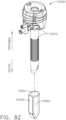
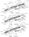
- a surgical instrumentsuch as a clip applier 100
- a surgical instrumentcan be configured to apply one or more clips to tissue located within a surgical site in the patient.
- the clip applier 100can be structured and arranged to position a clip 140 relative to the tissue in order to compress the tissue within the clip 140.
- the clip applier 100can be configured to deform the clip 140 as illustrated in FIGS. 3 and 4 , for example, and as described in greater detail further below.
- Each clip 140can comprise a base 142 and opposing legs 144 extending from the base 142.
- the base 142 and the legs 144can comprise any suitable shape and can define a substantially U-shaped configuration and/or a substantially V-shaped configuration, for example.
- the base 142can comprise angled portions 141 which are connected together by a joint 143.
- the legs 144 of the clip 140can be positioned on opposite sides of the tissue wherein the legs 144 can be pushed toward one another to compress the tissue positioned between the legs 144.
- the joint 143can be configured to permit the angled portions 141 of the base 142, and the legs 144 extending therefrom, to deform inwardly.
- the clip 140can be configured to yield, or deform plastically, when the clip 140 is sufficiently compressed, although some amount of elastic deformation, or spring-back, may occur within the deformed clip 140.
- the clip applier 100can include a shaft 110, an end effector 120, and a replaceable clip cartridge, or magazine, 130.
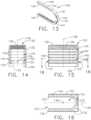
- the clip cartridge 130can comprise a housing 132 and a plurality of clips 140 positioned within the housing 132.
- the housing 132can define a storage chamber 134 in which the clips 140 can be stacked.
- the storage chamber 134can comprise sidewalls which extend around, or at least substantially around, the perimeter of the clips 140.
- each clip 140can comprise opposing faces, such as a top face 145 and a bottom face 146 on opposite sides of the clip 140 wherein, when the clips 140 are stacked in the housing 132, the top face 145 of a clip 140 can be positioned against the bottom face 146 of an adjacent clip 140 and wherein the bottom face 146 of the clip 140 can be positioned against the top face 145 of another adjacent clip 140.
- the bottom faces 146 of the clips 140can face downwardly toward one or more support shelves, or platforms, 135 defined in the housing 132 while the top faces 145 of the clips 140 can face upwardly away from the support shelves 135.
- the top faces 145 and the bottom faces 146 of the clips 140may be identical, or at least substantially identical, in some cases, while, in other cases, the top faces 145 and the bottom faces 146 may be different.
- the stack of clips 140 depicted in FIGS. 14-16comprises five clips 140, for example; however, other arrangements are envisioned in which the stack of clips 140 can include more than five clips 140 or less than five clips 140.
- the clip cartridge 130can further comprise at least one biasing member, such as biasing member 136, for example, positioned intermediate the housing 132 and the top clip 140 in the stack of clips 140.
- the biasing member 136can be configured to bias the bottom clip 140 in the stack of clips 140 or, more particularly, the bottom face 146 of the bottom clip 140, against the support shelves 135 defined in the housing 132.
- the biasing member 136can comprise a spring, and/or any suitable compressed elastic element, for example, which can be configured to apply a biasing force to the clips 140, or at least apply a biasing force to the top clip 140 which is transmitted downwardly through the stack of clips 140.
- the clip 140When a clip 140 is positioned against the support shelves 135 as described above, the clip 140 can be supported in a firing position in which the clip 140 can be advanced and ejected from the cartridge 130.
- the support shelves 135can define at least a portion of a firing chamber 149 in which the clips 140 can be sequentially positioned in the firing position.
- the firing chamber 149can be entirely defined within the cartridge 130 or, in other cases, the firing chamber 149 can be defined within and/or between the shaft 110 and the cartridge 130.
- the clip applier 100can comprise a firing drive which can advance a firing member into the cartridge 130 and push the clip 140 from its firing position positioned against the support shelves 135 to a fired position in which it is received within the end effector 120 of the clip applier 100.
- the housing 132 of the cartridge 130can comprise a proximal opening, or window, 133 which can be aligned, or at least substantially aligned, with the support shelves 135 such that the firing member can enter into the cartridge 130 through the proximal opening 133 and advance a clip 140 distally out of the cartridge 130.
- the housing 132can further comprise a distal, or discharge, opening, or window, 137 which is also aligned with the support shelves 135 such that the clip 140 can be advanced, or fired, distally along a firing axis 139 extending through the proximal opening 133, the firing chamber 149, and the distal opening 137, for example.
- the firing member of the firing drivecan be advanced into to the cartridge housing 132 and, in various circumstances, into the firing chamber 149. As disclosed in greater detail further below, the firing member can pass entirely through the cartridge 130 in order to advance the clip 140 into its fired position within the end effector 120. After the clip 140 positioned in the firing chamber 149 has been advanced distally by the firing member, as outlined above, the firing member can be retracted sufficiently such that the biasing member 136 can position another clip 140 against the support shelves 135. In various circumstances, the biasing member 136 can bias a clip 140 against the firing member while the firing member is positioned within the housing 132. Such a clip 140 can be referred to as a queued clip.
- the cartridge 130can be configured to supply the clips 140 to the firing chamber 149 along a predetermined path, such as supply axis 138, for example.
- the supply axis 138can be transverse to the firing axis 139 such that the clips 140 are fed into the firing chamber 149 in a direction which is different than the direction in which the firing member passes through the firing chamber 149.
- the supply axis 138can be perpendicular, or at least substantially perpendicular, to the firing axis 139, for example.
- the shaft 110can comprise a cartridge, or magazine, aperture 131 which can be sized and configured to receive a clip cartridge 130, for example, therein.
- the cartridge aperture 131can be sized and configured such that the housing 132 of the cartridge 130 is closely received within the cartridge aperture 131.
- the sidewalls which define the cartridge aperture 131can limit, or at least substantially limit, the lateral movement of the cartridge 130 relative to the shaft 110.
- the shaft 110 and/or the cartridge 130can further comprise one or more locks which can be configured to releasably hold the cartridge 130 in the cartridge aperture 131. As illustrated in FIG.
- the cartridge 130can be loaded into the cartridge aperture 131 along an axis which is, in at least one arrangement, parallel to or collinear with the supply axis 138.
- the shaft 110can further comprise a pad or seat 118 extending from the sidewall 111 of the shaft 110 wherein the pad 118 can be configured to be received within and/or engaged with the housing 132 of the cartridge 130.
- the pad 118can be sized and configured to be closely received within a recess 148 defined in the cartridge housing such that the pad 118 can limit, or at least substantially limit, the lateral movement of the cartridge 130 relative to the shaft 110.
- the pad 118can be sized and configured to align the cartridge 130 within the shaft 110 and/or support the cartridge housing 132.
- a firing drive 160 of the clip applier 100can be actuated to advance the clips 140 from the clip cartridge 130 as described above.
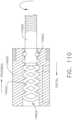
- the firing drive 160can comprise a rotary drive input such as a drive screw 161, for example, and a displaceable firing nut 163 operably engaged with the drive screw 161.
- the drive screw 161can comprise at least one drive thread 162 which can be threadably engaged with a threaded aperture extending through the firing nut 163.
- the clip applier 100can further include an electric motor, for example, operably coupled with the drive screw 161.
- the drive screw 161can be operably coupled with the motor of a surgical instrument system comprising a hand-held instrument or a robotic arm, for example.
- the movement of the firing nut 163 within the shaft 110can be constrained such that the firing nut 163 moves along a longitudinal axis 164 when the drive screw 161 is rotated about the longitudinal axis 164 by the motor.
- the drive screw 161can advance the firing nut 163 distally toward the end effector 120, as illustrated in FIG. 6 .
- the shaft 110can comprise one or more bearings which can be configured to rotatably support the drive screw 161.
- a bearing 159can be configured to rotatably support the distal end of the drive screw 161, for example, as illustrated in FIGS. 5 and 6 .
- the firing drive 160can further comprise a firing member 165 extending from the firing nut 163 which can be advanced distally and retracted proximally with the firing nut 163, as described in greater detail further below.
- a firing member 165extending from the firing nut 163 which can be advanced distally and retracted proximally with the firing nut 163, as described in greater detail further below.
- the clip cartridge 130is illustrated as comprising a plurality of clips 140 stored therein wherein one of the clips 140 is positioned in a firing position, as described above.
- the firing member 165can include a distal portion 166 which can be advanced into the staple cartridge 130 along a firing axis 167 and engage the clip 140 positioned in the firing position when the firing member 165 and the firing nut 163 are advanced distally.
- the firing member 165can comprise a linear member while, in other cases, the distal end 166 of the firing member 165 can extend upwardly from the firing member 165, for example.
- the firing member 165can advance the clip 140 distally out of the clip cartridge 130 along the firing axis 167 and into a receiving cavity 122 defined in the end effector 120.
- the firing member 165can be attached to and extend distally from the firing nut 163 while, in other cases, the firing member 165 and the firing nut 163 can be operably connected to one another by a firing actuator 168.
- the firing actuator 168can be pivotably mounted to the firing member 165 at a pivot 169 and can include a distal arm 170a and a proximal arm 170b which can be engaged with a longitudinal slot 113 defined in the housing 112 of the shaft 110.
- Each of the arms 170a, 170bcan include a projection, such as projections 171a and 171b, respectively, extending therefrom which can be configured to slide within the longitudinal slot 113.
- the firing nut 163can further include a firing pin 172 extending therefrom which can be configured to engage the distal arm 170a in order to advance the actuator 168 and the firing member 165 distally, as described above.
- the firing nut 163can be advanced distally by the drive screw 161 wherein the firing pin 172, which is positioned intermediate the distal arm 170a and the proximal arm 170b, can contact the distal arm 170a and drive the actuator 168 and the firing member 165 distally.
- the actuator 168may be prevented from rotating about the pivot pin 169 as one or both of the projections 171a and 171b sliding in the shaft slot 113 can be prevented from being moved laterally relative to the longitudinal shaft slot 113 until the actuator 168 reaches the position illustrated in FIG. 6 .
- the distal projection 171acan enter into a distal slot portion 114 of the longitudinal slot 113 which can be configured to pivot the actuator 168 downwardly, or permit the actuator 168 to be pivoted downwardly, as illustrated in FIG. 9 .
- the distal projection 171acan come into contact with the sidewall of the distal slot portion 114 which can guide the distal projection 171a downwardly and pivot the actuator 168 about the pivot 169 as the actuator 168 is advanced forward by the firing nut 163.
- the firing pin 172 extending from the firing nut 163may no longer be engaged with the distal arm 170a of the actuator 168 wherein, subsequently, the firing nut 163 may move distally independently of the actuator 168 thereby leaving behind the actuator 168 and the firing member 165.
- the distal end 114 of the longitudinal shaft slot 113may deactivate the firing member 165 wherein, at such point, the position of the firing member 165 may represent the fully-fired or distal-most position of the firing member 165.
- the clip 140has been fully advanced into the receiving cavity, or receiver, 122.
- the next clip 140 to be advanced into the receiving cavity 122may be biased against the top surface of the firing member 165, further to the above.
- the end effector 120 of the clip applier 100can further comprise a first jaw 123a and a second jaw 123b wherein the first jaw 123a and the second jaw 123b can at least partially define the receiving chamber 122.
- the first jaw 123acan comprise a first channel 124a and the second jaw 123b can comprise a second channel 124b which can each be configured to receive and support at least a portion of a clip 140 therein.
- the first jaw 123acan be pivotably coupled to a frame 111 of the shaft 110 by a pin 125a and the second jaw 123b can be pivotably coupled to the frame 111 by a pin 125b.
- the crimping drive 180can be configured to rotate the first jaw 123a toward the second jaw 123b and/or rotate the second jaw 123b toward the first jaw 123a in order to compress the clip 140 positioned therebetween.
- the crimping drive 180can comprise a cam actuator 181 which can be configured to engage a first cam surface 126a defined on the first jaw 123a and a second cam surface 126b on the second jaw 123b in order to pivot the first jaw 123a and the second jaw 123b toward one another.
- the cam actuator 181can comprise a collar which at least partially surrounds the first jaw 123a and the second jaw 123b.
- the collarcan comprise an inner cam surface 182 which can be contoured to contact the cam surfaces 126a, 126b of the jaws 123a, 123b and drive them inwardly toward one another.
- the clip 140 positioned within the receiving chamber 122 defined in the end effector 120can be positioned relative to tissue before the crimping drive 180 is actuated.
- the crimping drive 180can be at least partially actuated prior to positioning the clip 140 relative to the tissue in order to at least partially compress the clip 140.
- the clip 140 and the receiving chamber 122can be sized and configured such that the clip 140 can be biased or flexed inwardly when the end effector 120 is in its unactuated state, as illustrated in FIG. 3 .
- the crimping first jaw 123a and the second jaw 123bcan be actuated to elastically crimp and/or permanently crimp the clip 140 positioned therebetween.
- the firing nut 163can be configured to actuate the crimping drive 180. More particularly, referring now to FIG. 7 , the crimping drive 180 can comprise a crimping actuator 188 operably coupled with the cam actuator 181 wherein the crimping actuator 188 can be selectively engaged by the firing nut 163 as the firing nut 163 is advanced distally as described above.
- the firing nut 163can further comprise a second firing pin, such as firing pin 184, for example, extending therefrom which can be configured to engage the crimping actuator 188 as the firing nut 163 is advancing the firing actuator 168. Referring again to FIG.
- the crimping actuator 188is positioned in an unactuated position and, when the firing nut 163 is advanced sufficiently to engage a distal arm 190a of the crimping actuator 188, the firing nut 163 can rotate the crimping actuator 188 upwardly into an actuated position as illustrated in FIG. 8 .
- the distal arm 190a and a proximal arm 190bcan each comprise a projection, such as projections 191a and 191b, respectively, extending therefrom which can be positioned within a second longitudinal slot defined in shaft 110, such as slot 115, for example.
- the projections 191a and 191bcan move from the proximal curved end 116 of the longitudinal slot 115 into a portion of the longitudinal slot 115 which is substantially linear.
- the sidewalls of the longitudinal slot 115can be configured to confine the movement of the crimping actuator 188 along a longitudinal path and can be configured to limit or prevent the rotation of the crimping actuator 188 once the crimping actuator 188 has been rotated upwardly into an at least partially actuated position, as discussed above.
- the firing pin 172 of the firing drive 160 and the firing pin 184 of the crimping drive 180both extend from the firing nut 163.
- the firing pins 172 and 184are illustrated as extending from the same side of the firing nut 163; however, it is envisioned that the firing pin 172 can extend from a first lateral side of the firing nut 163 while the firing pin 184 can extend from the other lateral side of the firing nut 163.
- the firing actuator 168can be positioned alongside the first lateral side of the drive screw 161 and the crimping actuator 188 can be positioned alongside the opposite lateral side of the drive screw 161.
- the longitudinal slot 113can be defined in a first lateral side of the shaft housing 112 while the longitudinal slot 115 can be defined in the opposite lateral side of the shaft housing 112.
- the cam actuator 181can be operably coupled with crimping actuator 188 such that, when the crimping actuator 188 is advanced distally by the firing nut 163, the cam actuator 181 can be advanced distally, as illustrated in FIGS. 8 and 10 , until the distal projection 191a extending from the distal arm 190a reaches the distal end 117 of the longitudinal slot 115. In such a distal position, the cam actuator 181 may be in a fully advanced position and the clip 140 positioned within the receiving chamber 122 can be in a fully deformed or crimped configuration. Thereafter, the cam actuator 181 can be retracted and the end effector 120 can be reopened.
- the drive screw 161can be rotated in an opposite direction in order to move the firing nut 163 proximally and retract the cam actuator 181 wherein, in certain instances, the end effector 120 can further include a biasing member which can be configured to bias the first jaw 123 and the second jaw 123b from the closed, or fired, position illustrated in FIG. 4 into the open, or unfired, position illustrated in FIG. 3 .
- the firing pin 184 extending from the firing nut 163can engage the proximal arm 190b of the crimping actuator 188 and move the crimping actuator 188, and the cam actuator 181 extending therefrom, proximally as illustrated in FIG.
- the proximal projection 191b extending from the proximal arm 190b of the crimping actuator 188can be configured to contact the sidewall of the curved proximal end 116 wherein the sidewall can guide the crimping actuator 188 downwardly and rotate the crimping actuator 188 about the pivot 189.
- the firing pin 184may no longer be engaged with the crimping actuator 188, the cam actuator 181 may be fully retracted, and the firing nut 163 may continue to be retracted proximally relative to the crimping actuator 188.
- the firing nut 163can be configured to re-engage the firing actuator 168 as the firing nut 163 is being retracted proximally.
- the firing actuator 168is rotated downwardly when the firing actuator 168 reaches the distal end 114 of the longitudinal slot 113 and, as a result, the firing actuator 168 may still be in its downwardly rotated position when the firing nut 163 is retracted proximally to re-engage the firing actuator 168.
- FIG. 11the firing nut 163 can be configured to re-engage the firing actuator 168 as the firing nut 163 is being retracted proximally.
- the firing pin 172 extending from the firing nut 163can engage the proximal arm 170b of the firing actuator 168 and, as the firing nut 163 is further retracted, the firing nut 163 can rotate the firing actuator 168 upwardly such that the projections 171a and 171b extending from the arms 170a and 170b, respectively, can re-enter the longitudinal portion of the longitudinal slot 113. Thereafter, the firing nut 163 and can be retracted until the firing actuator 168 and the firing member 165 extending therefrom have been returned to their starting, or unfired, positions illustrated in FIG. 5 .
- the firing member 165can be withdrawn from the clip cartridge 130 as the firing member 165 is retracted proximally by the firing nut 163 such that a new clip 140 can be biased into the firing chamber of the clip cartridge 130 by the biasing member 136.
- the firing drive 160can be actuated once again in order to move the firing nut 163 and the firing member 165 distally to advance the next clip 140 into the end effector 120.
- the firing nut 163can re-actuate the crimping drive 180 as the firing nut 163 is moved distally once again in order to deform the next clip 140.
- the firing nut 163can retracted in order to re-set the crimping drive 180 and the firing drive 160 once again. This process can be repeated until a sufficient number of clips 140 have been applied to the targeted tissue and/or until the clips 140 contained within the clip cartridge 130 have been depleted. In the event that additional clips 140 are needed, the expended clip cartridge 130 can be removed from the shaft 110 and a replacement clip cartridge 130 containing additional clips 140 can be inserted into the shaft 110.
- an at least partially depleted clip cartridge 130can be replaced with an identical, or at least nearly identical, replacement clip cartridge 130 while, in other circumstances, the clip cartridge 130 can be replaced with a clip cartridge having more than or less than five clips 140 contained therein and/or a clip cartridge having clips other than clips 140 contained therein, for example.
- the firing nut 163can be configured to become disengaged from the firing actuator 168 at the same time that the firing nut 163 becomes engaged with the crimping actuator 188.
- the firing drive 160can be deactivated at the same time that the crimping drive 180 is activated.
- timingcan be achieved when the distal end 114 of the longitudinal slot 113 is aligned, or at least substantially aligned, with the proximal end 116 of the second longitudinal slot 115, for example.
- a lagcan exist between the deactivation of the firing drive 160 and the activation of the crimping drive 180.
- Such a lag between the end of the firing stroke of the firing member 165 and the beginning of the firing stroke of the cam actuator 181can be created, in some circumstances, to assure that the clip 140 has been positioned in its fully-seated position within the receiving chamber 122 before the clip 140 is deformed by the cam actuator 181. In various circumstances, such a lag can be created when the distal end 114 of the longitudinal slot 113 is positioned proximally with respect to the proximal end 116 of the second longitudinal slot 115, for example.
- the deactivation of the firing drive 160may occur after the activation of the crimping drive 180.
- Such an overlap between the end of the firing stroke of the firing member 165 and the beginning of the firing stroke of the cam actuator 181can be created, in some circumstances, to apply at least some inward pressure on the clip 140 as it is moved into its fully-seated position within the receiving chamber 122 so as to reduce or eliminate relative movement between the clip 140 and the sidewalls of the receiving chamber 122, for example.
- such an overlapcan be created when the distal end 114 of the longitudinal slot 113 is positioned distally with respect to the proximal end 116 of the second longitudinal slot 115, for example.
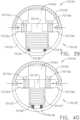
- a clip cartridgesuch as clip cartridge 230, for example, can comprise a pusher plate 248 positioned intermediate the biasing member 136 and the top-most clip 140 stacked within the clip cartridge 230.
- the pusher plate 248can be rigid, or at least substantially rigid, and can comprise a first bearing surface against which the biasing member 136 can apply a biasing force.
- the pusher plate 248can also comprise a second bearing surface which can transmit the biasing force to the top surface 145 of the top-most clip 140.
- the pusher plate 248can be comprised of a sheet of stainless steel material, for example, although the pusher plate 248 can comprise any suitable shape and can be comprised of any suitable material.
- the pusher plate 248may not be attached to the biasing member 136 while, in other instances, the pusher plate 248 can be affixed to the biasing member 136 such that the pusher plate 248 does not become dislodged from the cartridge housing 132. In various circumstances, the pusher plate 248 can be sized and configured such that it cannot pass through the proximal opening 133 and/or the distal opening 137 defined in the cartridge housing 132.
- a clip cartridgesuch as clip cartridge 330, for example, can comprise a lockout member which can be positioned within the firing chamber 149 of the clip cartridge 330 after all of the clips 140 contained within the clip cartridge 330 have been ejected from the cartridge 330.
- the lockout membercan comprise a lockout plate 348 which can be positioned intermediate the biasing member 136 and the top surface 145 of the top-most clip 140 contained within the clip cartridge 330.
- the clips 140can be sequentially positioned in the firing chamber 149 of the clip cartridge 130 and then advanced distally out of the clip housing 132 wherein, after the last clip 140 has been advanced out of the clip housing 132 and the firing member 165 has been withdrawn from the clip cartridge 130, the biasing member 136 can bias the lockout plate 348 against the shelves 135. In such a position, the lockout plate 348 can be aligned with the proximal opening 133 and the distal opening 137 such that the firing member 165 cannot enter, or at least substantially enter, the clip cartridge 130.
- the lockout plate 348can block the firing member 165 from entering into and passing through the housing 132 and, as a result, prevent the inadvertent firing of the clip applier 100 after the clip cartridge 130 has run out of clips.
- the firing member 165would contact and abut the lockout plate 348 wherein, in such circumstances, a compressive load can be created within the firing member 165.
- the clip applier 100can further include a clutch which can be configured to slip and operably disconnect the motor from the drive screw 161 when the compressive load created within the firing member 165 exceeds a certain or predetermined amount.
- the motor and/or motor controller of the clip applier 100 which operates the firing drive 160can comprise a load sensor configured to detect the load generated within the firing member 165 and, when the load created within the firing member 165 exceeds a certain or predetermined amount, the voltage and/or current supplied to the motor can be switched off and/or reduced.
- the lockout plate 348can be sized and configured such that the lockout plate 348 cannot be dislodged through the distal opening 137 and/or the proximal opening 133 when the firing member 165 contacts the lockout plate 348.
- the operator of the clip applier 100can remove the spent cartridge 330 from the shaft 110 and insert a new clip cartridge 330, for example, into the shaft 110.
- a clip 140may be positioned within the firing chamber 149 of the new clip cartridge 330 and the firing member 165 can be advanced distally into the new clip cartridge 330 to deploy the clip 140 as described above.
- a clip cartridgesuch as clip cartridge 430, for example, can comprise guides which can be configured to limit or confine the movement of a lockout member within the clip cartridge 430.
- the lockout membercan comprise a lockout plate 448, for example, which can be positioned intermediate the biasing member 136 and the top surface 145 of the top-most clip 140 contained within the housing 432 of the clip cartridge 430.
- the lockout plate 448can be progressively pushed downwardly into the firing chamber 149 as the clips 140 are sequentially ejected from the clip cartridge 430.
- the lockout plate 448can be sized and configured such that it is closely received within the cartridge housing 432 and such that relative lateral movement between the lockout plate 448 and the housing 432 can be limited in order to reduce, or prevent, the possibility of the lockout plate 448 becoming misaligned within the clip cartridge 430. In the event that the lockout plate 448 were to become misaligned within the clip cartridge 430, the lockout plate 448 may bind within the housing 432 and prevent the biasing member 136 from applying an appropriate biasing force to the stack of clips 140, for example. As illustrated in FIGS. 20 and 21 , the lockout plate 438 can further comprise guide members 447 extending therefrom which can be received within guide slots 446 defined in the cartridge housing 432.
- the guide members 447 and the guide slots 446can be sized and configured such that the guide members 447 are closely received within the guide slots 446 and such that relative lateral movement between the lockout plate 438 and the cartridge housing 432 can be limited.
- Each of the guide slots 446can be defined by opposing sidewalls 445 which can define a distance therebetween which is equal to or slightly larger than the width of the guide member 447 positioned therein such that the guide member 447 can slide between the opposing sidewalls 445 between the top 443 and the bottom 444 of the guide slot 446.
- the guide members 447 and the guide slots 446can be configured to limit lateral movement therebetween, as outlined above, the guide members 447 and the guide slots 446 can be configured to permit relative movement between the lockout plate 438 and the cartridge housing 432 along a predetermined path parallel to or collinear with the supply axis 138, for example.
- the lockout plate 438When the lockout plate 438 is pushed into the firing chamber 149 by the biasing member 136, the lockout plate 438 can inhibit the advancement of the firing member 165 and the operation of the clip applier 100, as outlined above, until the spent clip cartridge 430 is replaced with another suitable clip cartridge.
- the drive screw 161can be rotated in a first direction to advance the firing nut 163 distally and rotated in a second, or reverse, direction to retract the firing nut 163 proximally.
- the electric motor operably coupled with the drive screw 161can be operated in corresponding first and second directions.
- a clip appliercan utilize a motor which is operated in only a first direction wherein the rotation of the motor in such a single direction can be utilized to advance a firing nut distally and retract the firing nut proximally.
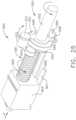
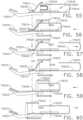
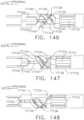
- FIGS. 22-26the output of an electric motor can be transmitted to a drive system 560 via a transmission system 550.
- the transmission system 550can comprise an input shaft 552 which is operated in a single direction wherein the transmission system 550 can be switchable or shiftable between a first state, or configuration, in which the transmission system 550 rotates a drive screw 561 of the drive system 560 in a first direction and a second state, of configuration, in which the transmission system 550 rotates the drive screw 561 in a second, or opposite, direction.
- the first state of the transmission system 550is depicted in FIGS. 22-24 and the second state of the transmission system 550 is depicted in FIGS. 25 and 26 .
- the input shaft 552can comprise an input gear 551 mounted thereto which is operably coupled, or meshingly engaged, with a shifter gear 553 such that the rotation of the input shaft 552 is transmitted to the shifter gear 553.
- gears which are operably coupled or meshingly engaged with one anothercan comprise any suitable arrangement of teeth, for example, which can transmit the rotation of one gear to the other.
- the shifter gear 553In the first state of the transmission system, the shifter gear 553 is in a first position in which the shifter gear 553 is operably coupled with an intermediate gear 554 wherein, when the shifter gear 553 is rotated in the second direction by the input gear 551, as discussed above, the intermediate gear 554 is rotated in the first direction.
- the intermediate gear 554can be rotatably supported within the shaft 110 of the clip applier 100, for example.
- the intermediate gear 554can also be operably coupled with an output gear 555 mounted to the drive screw 561 such that the rotation of the intermediate gear 554 can be transmitted to the output gear 555.
- the intermediate gear 554When the intermediate gear 554 is driven in the first direction by the shifter gear 553, as described above, the intermediate gear 554 can drive the output gear 555 and the drive screw 561 in the second direction. Similar to the above, the firing nut 563 can be operably coupled with the drive screw 561 and suitably constrained within the shaft 110 such that, when the drive screw 561 is rotated in the second direction, the firing nut 563 is advanced distally as indicated by the arrow D.
- the firing nut 563can be advanced to its distal-most position, illustrated in FIG. 24 , in order to advance a clip 140 from the clip cartridge 130 into the end effector 120 and crimp the clip 140 as described above.
- the firing nut 563can further comprise a cam bar 569 extending therefrom which can be configured to shift the transmission system 550 from its first state to its second state.
- the shifter gear 553is movable between a first position in which the transmission system 550 is in its first state and a second position in which the transmission system 550 is in its second state.
- the shifter gear 553is mounted to a shifter 556 which is rotatable about the input shaft 552 such that the shifter gear 553 can be rotated from its first position in which the shifter gear 553 is operably engaged with the input gear 551 and the intermediate gear 554 and its second position in which the shifter gear 553 is operably disengaged from the intermediate gear 554.
- the shifter gear 553is operably disengaged from the intermediate gear 554 when the shifter gear 553 is in its second position
- the shifter gear 553can be operably coupled with the input gear 551 and the output gear 555 in order to transmit rotary motion from the input shaft 552 to the drive screw 561. As illustrated in FIGS.
- the shifter 556can comprise a central aperture through which the input shaft 552 can extend; however, the shifter 556 may not be operably engaged with the input shaft 552 and, as a result, the rotation of the input shaft 552 may not rotate the shifter 556 and, likewise, the rotation of the shifter 556 may not rotate the input shaft 552.
- the shifter 556can further comprise a cam follower 558 extending therefrom which can be engaged by a cam 568 defined on the cam bar 569 as the firing nut 563 is advanced distally. When the cam 568 engages the cam follower 558, the cam 568 can rotate the shifter 556 and the shifter gear 553 between its first position and its second position as described above.
- the input shaft 552 and the drive screw 561can both be rotated in the first direction. More particularly, the input shaft 552, when rotated in the first direction, can rotate the input gear 551 in the first direction and, as the shifter gear 553 is directly engaged with the input gear 551, the shifter gear 553 will be rotated in the second direction.
- the shifter gear 553rotates in the second direction when the transmission system 550 is in its second state as compared to the first, or opposite, direction when the transmission system 550 is in its first state.
- the intermediate gear 554is no longer operably positioned intermediate the input gear 551 and the shifter gear 553 when the transmission system 550 is in its second state thereby accounting for the different directions of rotation.
- the shifter gear 553can rotate the output gear 555, and the drive screw 561 coupled to the output gear 555, in the first direction.
- the firing nut 563can be retracted proximally to permit the end effector 120 to be reopened and to retract the firing member 165.
- the firing nut 563can further comprise a second cam bar 567 extending therefrom comprising a cam 566 which can be configured to contact the cam follower 558 of the shifter 556 as the firing nut 563 is retracted proximally into its fully-retracted position.
- the cam 566can push the shifter 556 back into its first position and into operative engagement with the intermediate gear 554 such that the transmission system 550 can be reset into its first state and the clip applier 100 can be actuated once again.
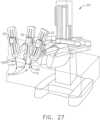
- the firing drive of the clip applier 100can be operated by a surgical instrument system comprising an electric motor.
- a robotic surgical instrument system 20is illustrated in FIG. 27 and can comprise a plurality of movable arms 30. Each arm 30 can comprise an actuator module 32 comprising an electric motor configured to supply the rotary motion to the shaft 110 of a clip applier 100, and/or any other suitable surgical instrument.
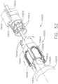
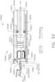
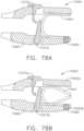
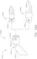
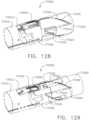
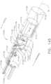
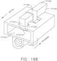
- an end effector 620may be selectively engageable with and disengageable from an actuator shaft 610 of a clip applier wherein the end effector 620 can comprise a proximal end 621 which can be coupled to a distal end 611 of the shaft 610.
- the proximal end 621 of the end effector 620can comprise an outer housing 629, a frame extending through the outer housing 629, an outer drive shaft extending through the frame, and an inner drive shaft extending through the outer drive shaft.
- the distal end 611 of the shaft 610can comprise an outer housing 619, a frame 663 extending through the outer housing 619, an outer drive shaft 662 extending through the frame 663, and an inner drive shaft 661 extending through the outer drive shaft 662.
- the frame 663, the outer drive shaft 662, and the inner drive shaft 661can each comprise a portion of a tongue connector 613 extending therefrom and a portion of a connector groove 612 defined therein, wherein the tongue connector 613 can be configured to be received within a tongue groove 623 defined in the proximal end 621 of the end effector 620, and wherein the tongue groove 612 can be configured to receive a tongue connector 622 extending from the proximal end 621 of the end effector 620.
- the tongue connector 622can extend across the frame, the outer drive shaft, and the inner drive shaft of the proximal end 621 of the end effector 620.
- the tongue groove 623can extend across the frame, the outer drive shaft, and the inner drive shaft of the proximal end 621 of the end effector 620.
- the tongue connector 622 of the end effector 620can be slid laterally into the tongue groove 612 of the shaft 610 at the same time that the tongue connector 613 of the shaft 610 is slid laterally into the tongue groove 623 of the end effector 620.
- the frame of the end effector 620can be securely coupled to the frame 663 of the shaft 610
- the outer drive shaft of the end effector 620can be operably coupled to the outer drive shaft 662 of the shaft 110
- the inner drive shaft of the end effector 620can be operable coupled to the inner drive shaft 661 of the shaft 110.
- the portions of the tongue connector 612are aligned with one another, the portions of the tongue groove 613 are aligned with one another, the portions of the tongue groove 622 are aligned with one another, and the portions of the tongue connector 623 are aligned with one another when the end effector 620 is assembled to the shaft 610.
- the outer drive shaft 662 of the shaft 110can rotate the outer drive shaft of the end effector 620, and the inner drive shaft 661 of the shaft 610 can rotate the inner drive shaft of the end effector 620.
- the portions of the tongue connector 612, the portions of the tongue groove 613, the portions of the tongue groove 622, and the portions of the tongue connector 623may no longer be aligned.
- the inner drive shaft 661 and/or the outer drive shaft 662can be rotated into one or more positions in which the tongue connectors 612 and 623 and the tongue grooves 613 and 622 are sufficiently aligned.
- the outer housing 619 of the shaft 610can further comprise a stop 614 which can be configured to limit the lateral movement of the end effector 620 as the end effector 620 is being slid transversely onto the distal end 611 of the shaft 610.
- the stop 614can provide a datum from which the inner drive shaft of the end effector 620 and the inner drive shaft 661 of the shaft 610 are aligned along longitudinal axis 615, the outer drive shaft of the end effector 620 and the other drive shaft 662 of the shaft 610 are aligned along longitudinal axis 615, and/or the frame of the end effector 620 and the frame 663 of the shaft 610 are aligned along the longitudinal axis 615.
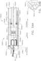
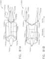
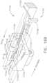
- the inner drive shaft 661can extend into an actuator module 632 which can comprise an electric motor and/or gear train 664 operably coupled with the inner drive shaft 661 configured to rotate the inner drive shaft 661.
- the actuator module 632can comprise a second electric motor and gear train operably engaged with the second drive shaft 662 configured to drive the second drive shaft 662.
- a second electric motorcan be utilized to articulate the end effector 620.
- the outer housing 619 and/or the frame 663 of the shaft 610can further comprise a gear 617 mounted thereto which is operably engaged with an electric motor and gear train 618 which can be configured to rotate the shaft 610 and the end effector 620 about the longitudinal axis 615.
- the shaft 610 and the end effector 620can be rotated about the axis 615 in a clockwise direction while, if the electric motor and gear train 618 are operated in a second direction, the shaft 610 and the end effector 620 can be rotated about the axis 615 in a counter-clockwise direction in order to position and orient the end effector 620.
- the end effector 620can be selectively attached to and detached from the shaft 610.
- the readerwill note that the principles discussed in connection with the end effector 620 and shaft 610 can be equally applied to the end effector 120 and the shaft 110 of the device disclosed in FIG. 1 , among others. That said, referring again to FIG. 27 , one of the robotic arms 30 can be selectively engaged with an end effector 120 of a clip applier or, alternatively, any other suitable end effector, such as the end effector of a surgical stapler, for example. In such circumstances, an end effector 120 can be selectively interchanged with another end effector and, as a result, a single robotic arm 30 can be utilized to perform more than one function.
- the clip applier 100can comprise a replaceable loading unit which can be replaced by, or interchanged with, another clip applier loading unit and/or any other suitable replaceable loading unit.
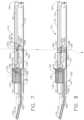
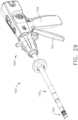
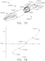
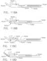
- the end effector 120 and the shaft 110 of the clip applier 100can be utilized with a surgical instrument system comprising a handle 700.
- the handle 700can comprise an actuator 701 which can be operated, or squeezed toward grip 702, in order to apply a rotary motion to the drive screw 161 as described above.
- the rotation of the actuator 701can be mechanically transmitted to the drive screw 161 while, in other cases, the actuator 701 can operate a motor operably coupled to the drive screw 161.
- the end effector 120 and the shaft 110 of the clip applier 100can be aligned along a longitudinal axis of the clip applier 100.
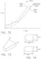
- the end effector 120 and/or the shaft 110can further comprise an articulation joint 101 which can be configured to permit the end effector 120 to be articulated relative to the longitudinal axis of the clip applier 100.
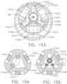
- the shaft 110can comprise an outer housing, or frame portion, 119 which can comprise a proximal end 102 and can comprise a distal portion of the articulation joint 101.
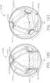
- the proximal end 102can comprise a spherical, or an at least substantially spherical, end 102, for example, which can be received within a spherical, or an at least substantially spherical, cavity 104 defined in an articulation joint member 103.
- the articulation joint member 103can also comprise a spherical, or at least substantially spherical, end 105, for example, which can be received within a spherical, or an at least substantially spherical, cavity 107 defined in a shaft frame portion 106.
- the proximal end 102 of the shaft 110can be at least partially captured within the cavity 104 such that the proximal end 102 cannot be readily removed from the cavity 104.
- the proximal end 102 and the cavity 104can be sized and configured to permit the proximal end 102 to be rotated in any suitable direction within the cavity 104.
- the clip applier 100can further comprise articulation controls 108a and 108b, for example, which can extend through the articulation joint 101 and can comprise distal ends mounted within mounting apertures 109a and 109b, respectively, defined within the proximal end 102 of the shaft housing 119.
- the articulation controls 108a and 108bcan be pushed and/or pulled in order to move the proximal end 102 within the cavity 104.
- the end 105 of the articulation joint member 103can be at least partially captured within the cavity 107 defined in the shaft frame portion 106 such that the end 105 cannot be readily removed from the cavity 107. That said, the end 105 and the cavity 107 can be sized and configured to permit the end 105 to be rotated in any suitable direction within the cavity 107 when the shaft end 102 is pushed and/or pulled by the actuators 108a and 108b as described above.
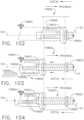
- the drive screw 161can be rotated by an input shaft, such as input shaft 152, for example.
- the input shaft 152can extend through an aperture 156 defined within the shaft frame portion 106, the articulation joint member 103, and the proximal end 102 of the shaft housing 119.
- the input shaft 152can comprise an input gear 151 mounted to the distal end thereof which can be operably coupled with an output gear 155 mounted to the proximal end of the drive screw 161.
- the input shaft 152can be rotated by the electric motor, described above, wherein the input shaft 152 can rotate the drive screw 161.
- the articulation joint 101can be configured to permit the end effector 120 and at least a portion of the shaft 110 to be articulated relative to a longitudinal axis defined by the clip applier 100. In order to accommodate such movement, at least the portion of the input shaft 152 extending through the articulation joint 101 can be sufficiently flexible.
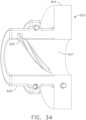
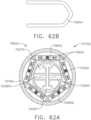
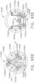
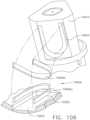
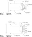
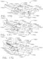
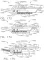
- the articulation actuators 108a and 108bcan be operated by an actuator module such as module 832, for example.
- the actuator module 832can comprise a rotatable articulation driver 833 which can be configured to push and pull the articulation actuators 108a and 108b.
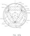
- the articulation driver 833can comprise a cylindrical, or an at least substantially cylindrical, collar 835 including an aperture 837 which can be configured to receive at least a portion of the shaft frame 106 therein in order to rotatably support the collar 835.
- the articulation driver 833can further comprise an input gear portion 834 which can be operably coupled with an electric motor and gear train 831 of the module 832 wherein, when the electric motor and gear train 831 are actuated, the articulation driver 833 can be rotated about the shaft frame 106.
- the articulation driver 833can further comprise two cam slots defined in the sidewall of the collar aperture 837, although the reader will note that only one cam slot 835a is illustrated in the provided views.
- the cam slot 835ais configured to receive a cam follower 838a extending from the articulation driver 108a wherein the cam follower 838a is configured to slide within the cam slot 835a.
- the helical contour of the cam slot 835acan be configured to push the cam follower 838a distally or pull the cam follower 838a proximally, depending on the direction in which the articulation driver 833 is rotated.
- the cam actuator 108acan be moved proximally or distally, respectively.
- the articulation driver 108bcan comprise a cam follower, similar to the cam follower 838a, which can be configured to slide within the other cam slot discussed above.
- the other cam slotcan be configured such that, when the articulation actuator 108a is driven distally by the articulation driver 833 when the articulation driver 833 is rotated in a first direction, the articulation actuator 108b can be pulled proximally.
- the other cam slotcan be configured such that, when the articulation actuator 108a is pulled proximally by the articulation driver 833 when the articulation driver 833 is rotated in a second direction, the articulation actuator 108b can be driven distally.
- the shaft frame portion 106can comprise clearance slots 839 defined therein through which the cam followers can extend.
- FIGS. 35A, 35B, and 35Cdepict a clip applier 70100.
- the clip applier 70100is similar to the clip applier 100 in many respects, most of which will not be repeated herein for the sake of brevity.
- the clip applier 70100comprises an end effector 70120, a shaft, a clip cartridge, and a firing member 70165.
- the clip cartridgecomprises a plurality of clips 70140 removably stored therein.
- the end effector 70120comprise a first jaw 70123a and a second jaw 70123b wherein the first jaw 70123a and the second jaw 70123b at least partially define a receiving chamber 70122.
- first jaw 70123a and the second jaw 70123bare pivotally coupled to the shaft by a pin 70125 such that the first jaw 70123a and the second jaw 70123b are movable relative to each other between an open position ( FIG. 35B ) and a closed position ( FIG. 35A ).
- the first jaw 70123a and the second jaw 70123bare movable between the open position and the closed position by a crimping drive 70180 (see FIGS. 36-38 ).
- Other arrangementsare envisioned where the first jaw 70123a and the second jaw 70123b are pivotally coupled to the shaft utilizing at least one pin similar to the first jaw 125a and second jaw 125b depicted in FIG. 1 .
- the first jaw 70123a and the second jaw 70123binclude pre-form features, such as protrusions 70126a and 70126b which are discussed in further detail below.
- the firing member 70165advances a clip 70140 from the clip cartridge onto the protrusions 70126a and 70126b as depicted in FIG. 35A .
- the clip 70140is in a pre-formed configuration.
- the width of the clip 70140 in the pre-formed configurationcan be 0.080" preferably.
- the protrusions 70126a and 70126bexpand the clip 70140 to an expanded configuration as depicted in FIG. 35B .
- the width of the clip 70140 in the expanded configurationcan be 0.210" preferably.
- the firing member 70165supports the backside of the clip 70140.
- the firing member 70165includes angled surfaces 70165a and 70165b which provide support for the backside of the clip 70140 as the clip 70140 expands. Further, as the clip 70140 is expanded, the firing member 70165 can be advanced to allow the angled surfaces 70165a and 70165b to continue to maintain contact against the backside of the clip 70140 as the clip 70140 expands. Once in the expanded configuration, the clip 70140 is advanced into the receiving chamber 70122 by the firing member 70165.
- the protrusions 70126a and 70126binclude angled portions which allow the clip 70140 to slide over the protrusions 70126a and 70126b when the clip 70140 is advanced by the firing member 70165.
- the firing member 70165is retracted, and the crimping drive 70180 is actuated to transition the first jaw 70123a and the second jaw 70123b to the closed position depicted in FIG. 35A to crimp the clip 70140 positioned in the receiving chamber 70122.
- another clip 70140can be advanced onto the protrusions 70126a and 70126b by the firing member 70165.
- the clip 70140 that has been crimped in the receiving chamber 70122will be released from the receiving chamber 70122 and the clip 70140 that was advanced onto the protrusions 70126a and 70126b will be expanded into to the expanded configuration by the protrusions 70126a and 70126b of the first and second jaws 70123a and 70123b.
- Interaction between the crimping drive 70180 and the first and second jaws 70123a and 70123bis discussed in further detail below.
- FIGS. 36-38depict the clip applier 70100 as described above.
- FIGS. 36-38further depict the interaction between the crimping drive 70180 and the first and second jaws 70123a and 70123b.
- the crimping drive 70180comprises a first crimping drive pin 70180a and a second crimping drive pin 70180b protruding therefrom.
- the first jaw 70123acomprises a first jaw cam 70124a extending therefrom and the second jaw 70123b comprises a second jaw cam 70124b extending therefrom.
- the crimping drive 70180is movable between a fully retracted position ( FIG. 38 ), a home position ( FIG. 37 ), and a fully-fired position ( FIG. 36 ).
- the fully-fired positioncan preferably be 0.300" distal to the home position.
- the fully retracted positioncan preferably be 0.050" proximal to the home position. Other arrangements are envisioned with different distances between the home position, the fully retracted position, and the fully-fired position.
- the crimping drive 70180cammingly engages outer surfaces of the first jaw 70123a and the second jaw 70123b to transition the fist jaw 70123a and the second jaw 70123b to a closed position when the crimping drive 70180 is moved into the fully-fired position ( FIG. 36 ) - similar to the interaction between the crimping drive 180 and the first and second jaws 123a and 123b described above. In the home position ( FIG.
- the first and second crimping drive pins 70180a and 70180bengage the first jaw cam 70124a and the second jaw cam 70124b, respectively, such that the first jaw 70123a and the second jaw 70123b are moved toward the open position to release a crimped clip 70140 from the first and second jaws 70123a and 70123b.
- the crimping drive 70180is in the home position, another clip 70140 can be advanced onto the protrusions 70126a and 70126b as discussed above. Further, as the crimping drive 70180 is moved from the home position ( FIG. 37 ) to the fully retracted position ( FIG.
- the first crimping drive pin 70180a and the second crimping drive pin 70180btransition the first jaw 70123a and the second jaw 70123b towards the open position, and thus, the clip 70140 positioned around the protrusions 70126a and 70126b is expanded into the expanded configuration, as discussed above.
- Alternative arrangementsare envisioned in which a crimped clip 70140 is released from the first and second jaws 70123a and 70123b and, at the same time, another clip 70140 positioned on the protrusions 70126a and 70126b is least partially expanded when the crimping drive is moved from the closed position to the home position.
- FIGS. 39 and 40depict a clip applier 70150.
- the clip applier 70150comprises a frame 70155, a firing member 70160, a first jaw 70170a, and a second jaw 70170b.
- the first jaw 70170a and the second jaw 70170bare pivotally coupled to the frame 70155 such that the first jaw 70170a and the second jaw 70170b are movable relative to each other.
- the clip applier 70150is configured to receive various types of clip cartridges, such as clip cartridge 70130 depicted in FIG. 39 , for example.
- the clip cartridge 70130comprises a cartridge body 70132 including a first cartridge jaw 70132a and a second cartridge jaw 70132b that oppose each other.
- the clip cartridge 70130When the clip cartridge 70130 is attached to the frame 70155 of the clip applier 70150, the first cartridge jaw 70132a biases the first jaw 70170a towards the second jaw 70170b, and the second cartridge jaw 70132b biases the second jaw 70170b towards the first jaw 70170a.
- the first and second jaws 70170a and 70170bare approximated to form a receiving chamber 70175.
- the clip cartridge 70130further comprises a plurality of clips 70136 removably stored in a clip housing 70134.
- the clip cartridge 70130further includes biasing members, such as springs 70138 for example, configured to bias the clips 70136 out of the clip housing 70134 into the receiving chamber 70175.
- a clip 70136can be advanced by the firing member 70160 into a crimping chamber in the distal end of the first and second jaws 70170a and 70170b. A clip 70136 positioned in the crimping chamber can then be crimped when the first jaw 70170a and the second jaw 70170b are moved towards each other.
- FIG. 40depicts a different clip cartridge 70130' positioned in the clip applier 70150.
- the clip cartridge 70130'is similar to clip cartridge 70130 discussed above, except for the differences discussed below.
- the clip cartridge 70130'is configured to store clips 70136' which are smaller than clips 70136.
- Other arrangementsare envisioned where the clip cartridge 70130' is configured to store clips that are larger than clips 70136.
- clip cartridge 70136'comprises, one, a clip housing 70134' which stores the clips 70136' and, two, biasing members, such as springs 70138' for example, which bias the stored clips 70136' into a receiving chamber 70175'.
- the clip cartridge 70130'comprises a cartridge body 70132', a first cartridge jaw 70132a', and a second cartridge jaw 70132b' opposing the first cartridge jaw 70132a'.
- the first cartridge jaw 70132a' and the second cartridge jaw 70132b'extend further inward toward each other as compared to the first cartridge jaw 70132a and the second cartridge jaw 70132b of the clip cartridge 70130. Stated another way, the gap between the first cartridge jaw 70132a' and the second cartridge jaw 70132b' is smaller than the gap between the first cartridge jaw 70132a and the second cartridge jaw 70132b.
- the receiving chamber 70175' defined between the first jaw 70170a and the second jaw 70170bwill be smaller than the receiving chamber 70175.
- various sizes of receiving chamberscan be created.
- the clip cartridges 70130 and 70130'can therefore be modified to approximate the first jaw 70170a and the second jaw 70170b of the clip applier 70150 to receive any suitable clip size.
- FIG. 41depicts a clip applier 70200.
- the clip appliercomprises a shaft 70210 extending from a housing, an end effector 70220 extending from the shaft 70210, a feeder member 70230 configured to move through the clip applier 70200 in response to rotary motions generated in the housing, and a clip magazine 70240.
- the end effectorcomprises a pair of jaws 70225 configured to move relative to each other between open and closed positions.
- the clip magazine 70240is not removable from the clip applier 70200; however, other arrangements are envisioned where the clip magazine 70240 is removable and/or replaceable.
- the clip magazine 70240comprises a first layer 70246 of clips 70244 and a second layer 70248 of clips 70244 stored within the clip magazine 70240.
- the first layer 70246 of clips 70244are in a feeding position from which they can be ejected from the clip magazine 70240.
- the second layer 70248 of clips 70244are stored above the first layer 70246 of clips 70244 in a storage position from which they cannot be ejected from the clip magazine 70240.
- Each of the first layer 70246 and second layer 70248comprises three clips 70244, however, other arrangements are envisioned with more or less than three clips.
- the first and second layers 70246 and 70248are separated by a divider member, such as a divider plate 70249.
- the clip magazine 70240further comprises a top plate 70243 and biasing members 70242.
- the top plate 70243rests on top of the second layer 70248 of clips 70244.
- the biasing members 70242bias the top plate 70243 toward the top of the second layer 70248 of clips 70244 and, thus, bias the second layer 70248 of clips 70244 toward the divider plate 70249.
- the divider plate 70249rests on top of the first layer 70246 of clips 70244 and a distal protrusion 70232 of the feeder member 70230.
- the distal protrusion 70232extends above the feeder member 70230. Operation of the clip applier 70200 is discussed in further detail below.
- the feeder member 70230is translated distally to push the first layer 70246 of clips 70244 toward the end effector 70220 and out of the clip magazine 70240.
- the divider plate 70249is supported by the distal protrusion 70232 of the feeder member 70230 and any of the clips 70244 which haven't been fully ejected from the clip magazine 70240.
- the divider plate 70249is biased by the biasing members 70242 into a recess 70233 in the feeder member 70230.
- the recess 70233is defined between the distal protrusion 70232 of the feeder member 70230 and a proximal protrusion 70234 of the feeder member 70230 extending upward from the proximal end of the feeder member 70230.
- the feeder member 70230 and divider plate 70249can be advanced together toward the end effector to eject the second layer 70248 of clips 70244 from the clip magazine 70240.
- the readerwill appreciate that all of the clips 70244 in the first layer 70246 and/or second layer 70248 are not ejected at the same time, rather, they are ejected one at a time to allow each clip 70244 to be sequentially crimped by the pair of jaws 70255 of the end effector 70220.
- other arrangementsare envisioned in which more than one clip 70244 can be ejected at a time.
- FIG. 42Adepicts a clip applier 70250.
- the clip applier 70250comprises an elongate shaft 70260 extending from a housing, a clip cartridge 70270 extending from the elongate shaft 70260, and an end effector 70280 extending from the clip cartridge 70270.
- the elongate shaft 70260 and the clip cartridge 70270define a shaft axis SA.
- the elongate shaft 70260comprises a first inwardly extending detent 70264a and a second inwardly extending detent 70264b opposing the first inwardly extending detent 70264a.
- the first and second inwardly extending detents 70264a and 70264bextend inwardly toward the shaft axis SA and can flex outwardly away from the shaft axis SA when a force is applied thereto.
- the elongate shaft 70260further comprises a top notch 70262a and a bottom notch 70262b opposing the top notch 70262a.
- the top notch 70262a and the bottom notch 70262bare located in the distal end of the elongate shaft 70260.
- the clip cartridge 70270is releasably attachable to the distal end of the elongate shaft 70260 as discussed in further detail below.
- the clip cartridge 70270comprises a top protrusion 70272a and a bottom protrusion 70272b opposite the top protrusion 70272a.
- the top protrusion 70272a and the bottom protrusion 70272bextend from the clip cartridge 70270 away from the shaft axis SA.
- the clip cartridge 70270further comprises a first slot and a second slot 70274b in the proximal end of the clip cartridge 70270. The first slot and the second slot 70274b oppose one another.
- the clip cartridge 70270is configured to slide into the inner diameter of the elongate shaft 70260 such that the top protrusion 70272a slides into the top notch 70262a, the bottom protrusion 70272b slides into the bottom notch 70262b, the first inwardly extending detent 70264a engages the first slot of the clip cartridge 70270, and the second inwardly extending detent 70264b engages the second slot 70274b of the clip cartridge 70270 to attach the clip cartridge 70220 to the elongate shaft 70260.
- the elongate shaft 70260 and clip cartridge 70270are fixedly coupled such that they can rotate together about the shaft axis SA.
- the clip cartridge 70270can be detached from the elongate shaft 70260 by a clinician when the clinician applies a distal force to the clip cartridge 70270 to disengage the first and second inwardly extending detents 70264a and 70264b of the elongate shaft 70260 from the first slot and the second slot 70274b of the clip cartridge 70270.
- the end effector 70280comprises a first jaw 70280a and a second jaw 70280b configured to move relative to each other between an open position ( FIG. 42A ) and a closed position ( FIG. 42B ).
- the first jaw 70280a and the second jaw 70280bcomprise openings at the proximal end thereof which are configured to receive a pin 70290.
- the pin 70290is rotatably captured within an opening 70276 in the clip cartridge 70270.
- the pin 70290defines a pin axis PA which is orthogonal to the shaft axis SA.
- the first jaw 70280a and the second jaw 70280bare rotatable relative to each other about the pin axis PA.
- a clipcan be positioned between the first jaw 70280a and the second jaw 70280b.
- the clipis crimped between the first jaw 70280a and the second jaw 70280b.
- the first jaw 70280a and the second jaw 70280bare moved from the open position to the closed position by a closure tube which cammingly engages the outer surfaces of the first jaw 70280a and the second jaw 70280b as the closure tube moves distally.
- first jaw 70280a and the second jaw 70280bare returned to the open position by a biasing member, or spring, which biases the first jaw 70280a and the second jaw 70280b into the open position.
- a biasing memberor spring
- the first jaw 70280a and the second jaw 70280bare movable from the closed position to the open position by jaw cams on the first jaw 70280a and the second jaw 70280b interacting with the closure tube, similar to jaw cams 70124a and 70124b depicted in FIGS. 36-38 , for example.
- FIG. 43Adepicts a clip applier 70300.
- the clip applier 70300comprises a shaft 70310, an end effector 70320 extending from the shaft 70310, a firing drive, and a clip magazine 70306.
- the clip magazine 70306is built into the shaft 70310 of the clip applier 70300 as depicted in FIG. 43A .
- the clip magazine 70306is releasably attachable to the clip applier 70300.
- the shaft 70310comprises openings 70308 on either side of the shaft 70310 which allow a user of the clip applier 70300 to access the clip magazine 70306.
- Other arrangementsare envisioned with only one opening in the shaft 70310 of the clip applier.
- the clip applier 70300further comprises an outer tube 70302 that is slidable along the shaft 70310 of the clip applier 70300.
- the outer tube 70302is configured to slide along the shaft 70310 to cover the openings 70308 in the shaft 70310.
- the clip magazine 70306is configured to store a plurality of clips, such as clips 70304 therein.
- the clips 70304are insertable into the clip magazine 70306 through the openings 70308 when the outer tube 70302 is not obstructing the openings 70308, as depicted in FIG. 43A . Once positioned in the clip magazine 70306, the clips 70304 can be advanced out of the clip magazine 70306 into the end effector 70320 by the firing member.
- the clips 70304can be sequentially advanced out of the clip magazine 70306 into the end effector 70320.
- the outer tube 70302When the outer tube 70302 is covering the openings 70308, access to the clip magazine 70306 is prevented, and, if clips 70304 have already been inserted into the clip magazine 70306, the outer tube 70302 prevents the clips 70304 from exiting the clip magazine 70306 through the openings 70308.
- the outer tube 70302can be retracted to allow a new set of clips to be inserted into the clip magazine 70306.
- the outer tube 70302can be operably engaged with the firing member of the clip applier 70300, such that, when the outer tube 70302 is retracted as depicted in FIG. 43A , or at least partially retracted, the firing member cannot be actuated.
- FIG. 44depicts a clip applier 70300'.
- Clip applier 70300'is similar to clip applier 70300 in many respects.
- the clip applier 70300'comprises an elongate shaft 70315 extending from a housing, an articulation joint 70314 extending from the elongate shaft 70315, a shaft assembly 70310' extending from the articulation joint 70314, an end effector 70320 extending from the shaft assembly 70310', and an outer tube 70302' positioned around the shaft assembly 70310'.
- the articulation joint 70314connects the elongate shaft 70315 to the shaft assembly 70310' so that the shaft assembly 70310' can be articulated relative to the elongate shaft 70315.
- the shaft assembly 70310'comprises a proximal shaft portion 70311 extending from the articulation joint 70314, a distal shaft portion 70312 extending from the proximal shaft portion 70311, and a hinge 70307.
- the distal shaft portion 70312further comprises a clip magazine 70306'.
- the proximal shaft portion 70311comprises the clip magazine 70306'.
- the hinge 70307allows the distal shaft portion 70312 to rotate away from the proximal shaft portion 70311.
- the outer tube 70302'is configured to slide along the shaft assembly 70310' between a locked position and an unlocked position when the proximal shaft portion 70311 and distal shaft portion 70312 are aligned.
- the distal shaft portion 70312is prevented from rotating away from the proximal shaft portion 70311 about the hinge 70307.
- the outer tube 70302'is in the unlocked position, the distal shaft portion 70312 is capable of rotating away from the proximal shaft portion 70311 about the hinge 70307.
- an opening 70308' in the clip magazine 70306'is exposed. The opening 70308' allows clips 70304' to be inserted into the clip magazine 70306' .
- a clip reloader 70350can be utilized to insert the clips 70304' into the clip applier 70300' as depicted in FIG. 44 .
- the clip reloadercomprises a housing 70352, a trigger 70354 movable relative to the housing 70352, a feeder bar operably engaged with the trigger 70354, an elongate shaft 70356 extending from the housing 70352, and a docking station 70360 extending from the elongate shaft 70356.
- a plurality of clips 70304'are removably stored in the elongate shaft 70356.
- the elongate shaft 70356may store 20 clips within a six inch span of the elongate shaft 70356.
- the clips 70304'are advanced from the elongate shaft 70356 into the docking station 70360 by the feeder bar when the trigger 70354 is moved towards the housing 70352.
- the docking station 70360comprises a cavity 70358 configured to dock with the shaft assembly 70310' of the clip applier 70300' when the distal shaft portion 70312 is rotated away from the proximal shaft portion 70311.
- the clips 70304'can be advanced form the elongate shaft 70356 into the clip magazine 70306' of the clip applier.
- FIGS. 45-47depict a different clip reloader 70400.
- the clip reloader 70400is similar to the clip reloader 70350 in many respects.
- the clip reloader 70400comprises a housing 70410, a plurality of clips 70404 stored inside the housing 70410, and a plunger 70402.
- the plunger 70402extends into and is movable relative to the housing 70410.
- the clips 70404are stacked vertically in the arrangement illustrated in FIGS. 45 and 46 ; however, other arrangements are envisioned where the clips are stacked horizontally.
- a feeder block 70406extends from the plunger 70402 and is slidably engaged with the inside of the housing 70410.
- the feeder block 70406comprises angled portions that support the backside of the top-most clip in the clip stack as depicted in FIG. 45 .
- the housing 70410comprises a boss 70408 extending from the bottom of the housing 70410, and a flexible ramp 70409 extending from the bottom of the boss 70408.
- the housing 70410further comprises a cutout region 70411. Docking the clip reloader 70400 with a clip applier is discussed in further detail below.
- the clip reloader 70400is configured to insert the clips 70404 into a clip applier, such as clip applier 70450, for example.
- the clip applier 70450comprises a shaft 70460, an end effector 70480 extending distally from the shaft 70460, and an articulation joint 70470 extending proximally from the shaft 70460.
- the boss 70408docks with an opening 70464 in the shaft 70460 of the clip applier 70450
- the cutout region 70411mates with the exterior of the shaft 70460
- the flexible ramp 70409extends into a clip slot 70462 of the clip applier 70450 as depicted in FIG. 47 .
- the opening 70464leads to the clip slot 70462 which comprises an angled portion that receives the boss 70408 and flexible ramp 70409 of the clip reloader 70400.
- the clip slot 70462further comprises a flat portion that facilitates the advancement of the clips 70404 into the end effector 70480 of the clip applier 70450. The operation of the clip reloader 70400 in conjunction with the clip applier 70450 is discussed in further detail below.
- the plunger 70402is moved towards the clip applier 70450 to advance the clips 70404 from the housing 70410 into the angled portion of the clip slot 70462.
- the ramp 70409supports and guides the clips 70404 from the angled portion of the clip slot 70462 into the flat portion of the clip slot 70462.
- the housing 70410 of the clip reloader 70400is positioned at an angle relative to the longitudinal axis of the clip applier 70450 when the clip reloader 70400 is docked with the clip applier 70450.
- the housing 70410is orthogonal, or at least substantially orthogonal, to the clip applier 70450 when docked.
- the clip applier 70450further comprises a flexible firing member 70465 positioned within a firing slot 70466 located proximal to the clip slot 70462. After the clip reloader 70400 is un-docked with the clip applier 70450, the flexible firing member 70465 can move from the firing slot 70466 into the clip slot 70462 to advance the clips 70404 into the end effector 70480.
- the flexible firing member 70465can be retracted from the clip slot 70462 into the firing slot 70466 and additional clips 70404 can be loaded into the clip slot 70462 by the clip reloader 70400.
- FIGS. 48-50depict a clip applier 70500.
- the clip applier 70500comprises an elongate shaft 70570 (see FIG. 50 ) extending from a housing, a shaft 70510 attachable to the elongate shaft 70570, an end effector 70520 extending from the shaft 70510, and a clip magazine 70530.
- the attachable shaft 70510comprises an upper pivot link 70512 and a lower pivot link 70514 extending distally therefrom.
- the end effector 70520comprises a first jaw 70521a and a second jaw 70521b movable relative to each other between an open position and a closed position about a pivot pin 70511.
- the pivot pin 70511is constrained within openings in the upper pivot link 70512 and the lower pivot link 70514 of the shaft 70510.
- the clip magazine 70530is removably positioned within the attachable shaft 70510 and comprises a plurality of clips 70532.
- the clip applier 70500further comprises a closure system 70540 and a firing system 70550. The closure system 70540 and the firing system 70550 are discussed in greater detail below.
- the closure system 70540comprises a proximal closure driver 70542 comprising a threaded portion 70543, a distal closure driver 70566 comprising a closure nut 70544, an upper closure hinge 70545a, and a lower closure hinge 70545b.
- the proximal closure drive 70542is configured to rotate in response to rotary motions generated inside the housing of the clip applier.
- the closure drive 70542transmits rotational motion to the threaded portion 70543 which is threadably received in the closure nut 70544.
- the closure drive 70542can comprise a flexible portion to facilitate the transfer of rotational motion to the closure nut 70544.
- the closure nut 70544is rotatably constrained within the shaft 70510 such that rotation of the threaded portion 70543 in a first direction will result in translation of the nut 70544 distally, and rotation of the threaded portion 70543 in a second direction - opposite the first direction - will result in translation of the nut 70544 proximally.
- the distal closure driver 70566extends from the closure nut 70544 and attaches to the upper closure hinge 70545a and the lower closure hinge 70545b via a closure pin 70547.
- the closure pin 70547allows the upper and lower closure hinges 70545a and 70545b to translate distally and proximally with the distal closure driver 70566 while still being rotatable about the closure pin 70547. Further to the above, the upper closure hinge 70545a is rotatably engaged with a proximal portion 70523a of the first jaw 70521a, and the lower closure hinge 70545b is rotatably engaged with a proximal portion 70523b of the second jaw 70521b. As illustrated in FIG. 48 , the first jaw 70521a and the second jaw 70521b cross over each other about the pivot pin 70511 in a scissor like formation.
- Such an arrangementallows the first jaw 70521a and the second jaw 70521b to move toward the open position when the upper and lower closure hinges 70545a and 70545b are translated distally by the closure system 70540, and allows the first jaw 70521a and the second jaw 70521b to move toward the closed position when the upper and lower closure hinges 70545a and 70545b are translated proximally by the closure system 70540.
- the clip applier 70500further comprises a firing system 70550 comprising a firing member 70560.
- the firing member 70560is translatable through the end effector between an unfired position and a fired position in response to the rotary motions that drive the closure system 70540.
- Other arrangementsare envisioned where the closure system 70540 and the firing system 70550 are operated by two separate motors within the housing of the clip applier, for instance.
- the firing member 70560is configured to advance a clip 70532 from the clip magazine 70530 into the first and second jaws 70521a and 70521b of the clip applier 70500.
- the clip magazine 70530is at least partially supported by the closure system 70540.
- a biasing membersuch as leaf spring 70546, for example, biases the clips 70532 toward the firing member 70560 and holds the clip magazine 70530 in position.
- the closure system 70540can align, and/or guide, and/or lock the clip magazine 70530 into place within the shaft 70510.
- the arrangement depicted in FIGS. 48 and 49illustrates the closure system 70540 arranged around the clip magazine 70530 to allow a larger space inside the shaft 70510 for the clip magazine 70530 and clips 70532; however, a closure system can have any suitable arrangement.
- the closure system 70540is discussed in further detail below.
- the threaded portion 70543 and closure nut 70544 of the closure system 70540allows for a more precise actuation of the first and second jaws 70521a and 70521b when moving between the open position and the closed position as compared to previous clip applier arrangements that utilize a translating closure tube or cam member.
- Rotary encoders and/or other sensorscan be used in combination with the closure system 70540 to provide even greater accuracy in determining the position of the first and second jaws 70521a and 70521b.
- the clip applier 70500further comprise protrusions 70513 and 70516 extending from the proximal end of the shaft 70510.
- the protrusions 70513 and 70516may be the same shape or different shapes.
- the protrusions 70513 and 70516are configured to lockingly engage slots 70572a and 70572b in the elongate shaft 70570 of the clip applier 70500 to form a bayonet connection therebetween.
- the slots 70572a and 70572bcomprise L-shaped portions that lock the protrusions 70513 and 70516 into place when the shaft 70510 is inserted into and then rotated relative to the elongate shaft 70570.
- FIG. 50further depicts a clip 70532 located within the first jaw 70521a and the second jaw 70521b. The clip 70532 and other clips for use with a clip applier, such as clip applier 70500, are discussed in further detail below.
- the clip 70532comprises a base portion 70534, a first leg 70534a extending from the base portion 70534, and a second leg 70534b extending from the base portion 70534 and opposing the first leg 70534a.
- the base portion 70534can comprise a flexible material, such as plastic and/or any other suitable flexible material, to allow the clip 70532 to flex between multiple positions without breaking or becoming plastically deformed in an unsuitable manner.
- the clip 70532can be moved between a magazine storage configuration, a pre-firing configuration, and a post-firing configuration as depicted in FIG. 51B .
- the first leg 70534acomprises a reinforced region comprising a ridge 70535a
- the second leg 70534bcomprises a reinforced region comprising a ridge 70535b.
- the ridges 70535a and 70535bextend along at least a portion of the first leg 70534a and the second leg 70534b, respectively.
- the ridges 70535a and 70535bact as a rigid backbone to prevent, or at least substantially reduce, the deformation of the first leg 70534a and the second leg 70534b during crimping. Other arrangements are envisioned where only one of the first leg 70534a and the second leg 70534b comprises a ridge.
- the ridges 70535a and/or 70535bmay be comprised of a rigid material, such as a fiberglass-filled and/or particle-filled plastic, for example, to prevent, or at least reduce, deflection of the first leg 70534a and/or the second leg 70534b when the clip 70532 is crimped.
- the clip 70532further comprises a locking portion, such as tooth 70536, for example, extending from a portion of the first leg 70534a.
- the tooth 70536lockingly engages the edges of an opening, or window, 70537 in the second leg 70534b when the clip 70532 is crimped (see the post-firing configuration in FIG. 51B ).
- the clip 70532includes grip features, such as protrusions 70538, extending from the inside surfaces of the first and second legs 70534a and 70534b.
- the protrusions 70538engage tissue clamped between the first and second legs 70534a and 70534b when the clip 70532 is crimped.
- the protrusions 70538prevent, or at least substantially reduce, the movement of the tissue relative to the clip 70532 after the clip 70532 is crimped around the tissue.
- the protrusions 70538may be any number of shapes and sizes, such as pyramidal shapes, conical shapes, frustoconical shapes, for example, and/or any other suitable shape.
- FIGS. 51C-51Fa different clip 70580 for use with a clip applier is depicted.
- the clip 70580is similar to clip 70532 in many respects. That said, the base 70534 of the clip 70580 comprises a stress relief notch 70588 on the side of the base 70534 opposite the first and second legs 70534a and 70534b.
- the stress relief notch 70588allows the first and second legs 70534a and 70534b to flex inwardly and then outwardly a number of times without being plastically deformed in an unsuitable manner.
- the clip 70580can be configured to yield, or deform plastically, when the clip 70580 is sufficiently compressed. Such designed or controlled yielding, in various instances, can help the clip 70580 fold into the desired shape.
- FIGS. 52-60depict a clip applier 70600.
- the clip applier 70600comprises a shaft 70610 extending from a housing, an end effector 70605 extending from the shaft 70610, and a rotatable clip magazine 70650.
- the end effector 70605comprises a first jaw and a second jaw that are movable relative to each other between an open position and a closed position, similar to the first jaw 70123a and the second jaw 70123b of the clip applier 70100 discussed above.
- the rotatable clip magazine 70650is rotatably and slidably supported within the clip applier 70600. More specifically, the rotatable clip magazine 70650 is rotatable about shaft axis SA and translatable along shaft axis SA.
- the shaft axis SAis defined by the shaft 70610. Further detail regarding how the clip magazine 70650 is supported within the clip applier 70600 is provided below.
- the rotatable clip magazine 70650comprises a body portion 70652 including five sides, each of which comprises a clip channel 70656 configured to removably store a clip 70654 therein.
- the body portion 70652further comprises an opening 70653 that extends through the body portion 70652.
- the body portion 70652is pentagonal in shape, for example; however, other arrangements are envisioned in which the opening 70653 comprises different shapes to allow for more than or less than five clip channels 70656 and, therefore, more than or less than five clips 70654 stored in the rotatable clip magazine 70650.
- the clips 70654comprise a clip width of 0.080", a clip thickness of 0.03", and a clip length of 0.310" (for a LIGAMAX 5 Clip) or 0.315" (for an ER320 Clip), for example; however, clips having any suitable size can be used.
- the clips stored in the clip magazine 70650will have the same, or at least substantially the same size; however, alternative arrangements are envisioned in which clips having different sizes may be stored in the same clip magazine.
- the overall diameter of the entire rotatable clip magazine 70650is 0.996", for example; however, the clip magazine 70650 can have any suitable diameter - including diameters which can permit the clip magazine 70650 to be inserted through a trocar.
- the rotatable clip magazine 70650further includes a clocking portion, such as teeth 70658, for example, extending proximally from the clip magazine 70650.
- the clip applier 70600comprises several drives and drivers which define the motion and/or operating sequence of the clip applier 70600, as described in further detail below.
- the clip applier 70600further comprises a closure tube 70620, a feeder member 70630, and a firing member 70640.
- the closure tube 70620comprises a closure drive 70625 extending proximally from the closure tube 70620.
- the closure drive 70625extends through the opening 70653 in the clip magazine 70650 and is operably engaged with an actuator inside the housing of the clip applier 70600.
- the clip magazine 70650is supported on at least a portion of the closure drive 70625.
- the closure tube 70620is at least partially supported and aligned within a recess in the shaft 70610.
- the closure tube 70620is movable between a plurality of positions, such as a fully retracted position, a home position, and a fully advanced position (see FIGS. 53 and 54A ). Similar to the crimping drive 70180 of the clip applier 70100, the closure tube 70620 is configured to move the first jaw and the second jaw of the end effector 70605 toward and away from each other. When the closure tube 70620 moves distally, the closure tube 70620 cammingly engages the first and second jaws to move the first and second jaws to the closed position and, when the closure tube 70620 moves proximally, the closure tube 70620 engages jaw cams on each of the first and second jaws to move the first and second jaws to the open position. That said, any suitable jaw opening and closing arrangement could be used.
- the feeder member 70630is aligned with one of the clip channels 70656 of the rotatable clip cartridge 70650, and is configured to advance a clip 70654 out of the clip channel 70656 that is aligned with the feeder member 70630 toward the end effector 70605.
- the feeder member 70630is translatable linearly through the clip applier 70600 by a feeder gear 70638 and a feeder drive 70635 which are operably engaged with a rack portion of the feeder member 70630.
- the feeder drive 70635comprises a pinion gear 70637 at the distal end thereof which is operably engaged with the feeder gear 70638 such that, as the feeder drive 70635 is rotated, the feeder member 70630 is translated linearly through the clip applier 70600.
- the feeder drive 70635is operably engaged with a first motor inside the housing of the clip applier 70600.
- the first motortransmits rotational motion to the feeder drive 70635.
- the firing member 70640is translatable linearly through the clip applier by a firing gear 70648 and a firing drive 70645 which are operably engaged with a rack portion of the firing member 70640.
- the firing drive 70645comprises a pinion gear 70647 on the distal end thereof which is engaged with the firing gear 70648 such that, as the firing drive 70645 is rotated, the firing member 70640 is translated linearly through the clip applier 70600.
- the firing drive 70645is operably engaged with a second motor inside the housing of the clip applier 70600.
- the second motortransmits rotational motion to the firing drive 70645.
- the feeder drive 70635 and the firing drive 70645are rotatable by the same motor utilizing a transmission.
- other arrangementsare envisioned, and are described further below, where the feeder member 70630 and the firing member 70640 translate together through the clip applier 70600. Operation of the feeder member 70630 and firing member 70640 are also described in greater detail below.
- the firing member 70640comprises a distal portion 70640a extending therefrom that is configured to advance a clip 70654 into the end effector.
- the shaft 70610further includes a ground portion 70612 mounted to the shaft 70610 and aligned with the clip magazine 70650.
- the ground portion 70612is mounted to the shaft 70610 such that the ground portion 70612 is not movable, translatable, and/or rotatable relative to the shaft 70610.
- the ground portion 70612includes a clocking portion, such as teeth 70614, for example, extending distally therefrom as illustrated in FIG. 54B .
- the teeth 70614 of the ground portion 70612are aligned, or at least substantially aligned, with the teeth 70658 of the rotatable clip magazine 70650. Further, the ground portion 70612 supports a biasing member, such as spring 70616, for example, thereon.
- the spring 70616biases the clip magazine 70650 distally toward the closure tube 70620 and the end effector 70605, as illustrated in FIG. 54A .
- the springcomprises a leaf spring and the clip applier 70600 further comprises a track and the leaf spring can be configured to both index the clip magazine 70650 and prevent the clip magazine 70650 from counter rotation. In any event, the rotation of the clip magazine 70650 about the shaft axis SA and translation of the clip magazine 70650 along shaft axis SA is described in further detail below.
- the closure tube 70620includes clocking channels 70622 located radially around the closure drive 70625.
- the closure drive 70625rotatably and slidably supports the rotatable clip magazine 70650 thereon as discussed above.
- the clocking channels 70622are engaged with protrusions within the opening 70653 of the clip magazine 70650 to rotatingly lock the clip magazine 70650 into place relative to the closure tube 70620 when the closure tube is in the home position or the fully advanced position.
- the closure tube 70620is moved to the fully retracted position, as illustrated in FIG.
- the spring 70616moves/biases the clip magazine 70650 toward the closure tube 70620 resulting in the clocking channels 70622 becoming disengaged from the protrusions within the opening 70653 of the clip magazine 70650.
- the clip magazine 70650can rotate freely about shaft axis SA.
- the teeth 70658 of the clip magazine 70650engage the teeth 70614 of the ground portion 70612 to rotate (i.e., cycle) the clip magazine 70650.
- the teeth 70658 and the teeth 70614are structured to rotate the clip magazine 70650 about the shaft axis SA a predefined amount of degrees based on the spacing and angles of the teeth 70658 relative to the teeth 70614.
- the spacing and angles of the teeth 70658 relative to the teeth 70614can be designed to generate a suitable degree of rotation for the clip magazine 70650 about shaft axis SA.
- the teeth 70658 and the teeth 70614are spaced and aligned such that, when they are engaged, the clip magazine 70650 rotates 72 degrees to align an adjacent clip 70654 with the feeder member 70630.
- the closure tube 70620can be moved distally from the fully retracted position to the home position ( FIG.
- FIGS. 55-60illustrate the functions of clip applier 70600 where the feeder member 70630 and firing member 70640 move together to feed and fire a clip 70654 from the rotatable clip magazine 70650.
- a clip 70654is advanced from the rotatable clip magazine 70650 into engagement with a biasing member, such as a leaf spring 70624, for example, of the closure tube 70620 by the feeder member 70630.
- the leaf spring 70624biases and guides the clip 70654 onto the top of the firing member 70640, as illustrated in FIG. 56 .
- Protrusions 70608can be similar to protrusions 70126a and 70126b described above (See FIG. 35A and 35B ). One protrusion 70608 is located on one jaw of the end effector 70605, and another protrusion 70608 is located on another jaw of the end effector 70605.
- the jaws of the clip applier 70600are in the open position and the protrusions 70608 expand the clip 70654 from a storage configuration into a firing configuration - similar to the expansion of clip 70140 described above in connection with FIGS. 35A and 35B .
- the rotatable clip magazine 70650is rotated (i.e., cycled) about the shaft axis SA to position another clip 70654 into alignment with the feeder member 70630.
- the firing member 70640can be moved toward the end effector 70605 to advance the clip 70654 over the protrusions 70608 and into the end effector 70605.
- the protrusions 70608can comprise angled portions that allow the clip 70654 to slide over the protrusions 70608 when advanced distally by the firing member 70640.
- the feeder member 70630advances another clip 70654 (i.e., the clip that was rotated into position when the closure tube 70620 was fully retracted) from the clip cartridge 70650 down onto the firing member 70654 with the aid of the leaf spring 70624, as discussed above, when the firing member 70640 advances a clip 70654 into the end effector 70605.
- the firing member 70640 and the feeder member 70630can be retracted to allow the new clip 70654 to be biased downward by the leaf spring 70624 and seated around the protrusions 70608.
- the new clip 70654can then be expanded to the firing configuration as clip magazine 70650 is cycled, and then the new clip 70654 can be advanced into the end effector 70605 for crimping as discussed above. The process discussed above can be repeated until the clip magazine 70650 has been spent.
- the closure tube 70620can be moved between the home position ( FIGS. 56 and 57 ) and the fully advanced position ( FIG. 60 ) to crimp and release a clip 70654 within the end effector 70605 without cycling the clip magazine 70650. This allows the jaws of the end effector 70605 to move between the open and closed positions without cycling the clip magazine 70650 and/or ejecting another clip from the clip magazine 70650.
- FIG. 61depicts a clip applier 70700.
- the clip applier 70700comprises a shaft 70710 extending from a housing, an end effector 70705 extending from the shaft 70710, and a clip cartridge 70720 that is releasably attachable to the clip applier 70700.
- the end effector 70705comprises a first jaw and a second jaw movable relative to each other, similar to the first and second jaws 70123a and 70123b discussed above.
- the clip applier 70700further comprises a firing system 70730 that comprises a rotatable drive 70732 which is operably responsive to a motor inside the housing of the clip applier 70700.
- the rotatable drive 70732comprises a threaded portion.
- the firing system 70730further includes a firing member 70736 and a firing nut 70734.
- the firing nut 70734is threadably received on the threaded portion of the rotatable drive 70732.
- the firing nut 70734is rotatably constrained within the clip applier 70700 such that the rotation of the rotatable drive 70732 translates the firing nut 70734 through the clip applier 70700.
- the firing member 70736is engaged with the firing nut 70734 and translates into the first and second jaws of the end effector 70705 in response to translation of the firing nut 70734 by the rotatable drive 70732. Attachment of the clip cartridge 70720 to the clip applier 70700 is described in greater detail below.
- the clip applier 70700further comprises a docking region, or recess 70714, in the distal end of the clip applier 70700, as illustrated in FIG. 61 .
- the clip cartridge 70720comprises a body portion 70722 that is slidably receivable in the recess 70714 of the clip applier 70700.
- a locking feature 70728extends proximally from the clip cartridge 70720.
- the locking feature 70728includes an angled surface 70728a at the proximal end thereof and a detent 70728b extending downwardly, although the locking feature 70728 can include any suitable arrangement.
- the locking feature 70728engages a protrusion 70712 of the shaft 70710 when the clip cartridge 70720 is docked within the recess 70714.
- the angled surface 70728aslides over the protrusion 70712 and the downwardly extending detent 70728b locks into place proximal to the protrusion 70712, thus locking the clip cartridge 70720 to the clip applier 70700.
- the locking feature 70728deflects as the angled surface 70728a slides over the protrusion 70712 and then resiliently returns to, or at least toward, its undeflected configuration, when the detent 70728b locks into place.
- a sufficient distal pulling motioncan cause the locking feature 70728 to deflect and release the clip cartridge 70720 from the clip applier 70700. Operation of the clip applier 70700 is described in further detail below.
- the clip cartridge 70720further comprises a ramp portion 70721, a plurality of clips 70724 positioned in a stack, and biasing members, such as springs 70726, for example.
- the clips 70724are biased toward the ramp portion 70721 by the springs 70726.
- the top clip 70724 in the stack of clipsis biased into the ramp portion 70712 by the springs 70726.
- the ramp portion 70721aligns with a feeder drive 70740 of the clip applier 70700.
- the feeder drive 70740is operably responsive to an actuator within the housing of the clip applier 70700.
- the feeder drive 70740is configured to reciprocatingly actuate into the ramp portion 70721.
- the feeder drive 70740can be flexible.
- the feeder drive 70740feeds the top clip 70724 in the stack of clips through the ramp portion 70721 and into the end effector 70720.
- the clip 70724can be advanced further distally into the first and second jaws of the end effector 70705 by translation of the firing member 70736, as discussed above.
- the clip 70724can be crimped by a crimping drive.
- the feeder drive 70740can be retracted, allowing another clip 70724 to be biased into the ramp portion 70721.
- the feeder drive 70740can advance the new clip 70724 through the ramp portion 70721 and into the first and second jaws of the end effector 70705 as discussed above. The process discussed above can be repeated until all of the clips 70724 in the clip cartridge 70720 have been depleted, and/or until a suitable number of clips have been applied to the tissue.
- FIG. 62Adepicts a clip applier system 70750.
- the clip applier system 70750comprises a shaft 70760 extending from a housing, the clip applier 70250 depicted in FIG. 42 positioned at least partially within the shaft 70760, and the rotatable clip magazine 70650 depicted in FIGS. 52-60 positioned within the shaft 70760.
- a feeder memberis configured to advance the clips 70654 from the rotatable clip magazine 70650 - one at a time - into the first and second jaws 70280a and 70280b of the clip applier 70250. Once located within the first and second jaws 70280a and 70280b, the clip 70654 can be crimped as discussed above in relation to FIGS. 42A and 42B .
- the rotatable clip magazine 70650can be cycled (i.e., rotated) to position another clip 70654 for advancement into the first and second jaws 70280a and 70280b of the clip applier 70250 by the feeder member. This process can continue until all of the clips 70654 in the rotatable clip magazine 70650 have been spent. After all of the clips 70654 have been spent, the rotatable clip magazine 70650 can be replaced with another rotatable clip magazine 70650 containing a full complement of clips 70650. Other arrangements are envisioned where the spent rotatable clip magazine 70650 can be detached from the clip applier system 70750, reloaded with clips 70650, and then re-attached to the clip applier system 70750 for further use.
- the articulation joint 70800releasably couples a clip cartridge 70820 to a shaft 70810 of a clip applier.
- the shaft 70810comprises an articulation pivot, or pivot pin 70814, extending from the inside of the shaft 70810.
- the pivot pin 70814comprises a base portion 70817, a first leg 70814a extending from the base portion 70817, and a second leg 70814b extending from the base portion 70817 and opposing the first leg 70814a.
- the first and second legs 70814a and 70814bextend away from each other.
- the first leg 70814acomprises a first detent, or shoulder, 70816a extending outwardly from the first leg 70814a
- the second leg 70814bcomprises a second detent, or shoulder, 70816b extending outwardly from the second leg 70814b
- the clip cartridge 70820comprises a first opening 70822 and, also, a second opening 70824 positioned adjacent and lateral to the first opening 70822.
- the first opening 70822is centered in the clip cartridge 70820 and rotatably receives the pivot pin 70814 when the clip cartridge 70820 is attached to the shaft 70810.
- the first leg 70814a and the second leg 70814bflex towards each other when the first opening 70822 is slid onto the pivot pin 70814 due to angled surfaces at the end of each of the first leg 70814a and second leg 70814b (See FIG. 63B ). As the first leg 70814a and second leg 70814b flex toward each other, the pivot pin 70814 can slide through the first opening 70822 until the first and second detents 70816a and 70816b clear the first opening 70822, as illustrated in FIG. 63B .
- the first and second legs 70814a and 70814bcan expand to lock the clip cartridge 70820 to the pivot pin 70814. More specifically, the bottom surfaces of the first and second detents 70816a and 70816b rest on an outer surface 70826 of the clip cartridge 70822 preventing the clip cartridge 70820 from being detached from the pivot pin 70814 unless a sufficient force is applied that exceeds a predetermined, or designed, force threshold.
- a user of the clip appliercan attach and detach the clip cartridge 70820 to the shaft 70810. Articulation of the clip cartridge about the pivot pin 70814 is described in further detail below.
- the clip applier depicted in FIGS. 63A and 63Bfurther comprises a rotatable output 70830 that is operably responsive to a motor located within the housing of the clip applier.
- the rotatable output 70830is threadably engaged with a threaded portion 70834 of an articulation bar 70832.
- Rotation of the rotatably output 70830 in a first directiontranslates the articulation bar 70832 distally, and rotation of the rotatable output 70830 in a second, or opposite, direction translates the articulation bar 70832 proximally.
- the articulation bar 70832comprises a downwardly extending protrusion 70836 that is slidably received in a slot 70812 defined in the shaft 70810.
- the protrusion 70836 and slot 70812guide the articulation bar 70832 as the articulation bar 70832 translates and limit relative lateral motion between the articulation bar 70832 and the shaft 70810.
- the articulation bar 70832further comprises an upwardly extending protrusion 70838 which is received in the second opening 70824 of the clip cartridge 70820 when the clip cartridge 70820 is attached to the shaft 70810.
- the distal translation of the articulation bar 70832will rotate the clip cartridge 70820 about the pivot pin 70814 in a first direction and the proximal translation of the articulation bar 70832 will rotate the clip cartridge 70820 about the pivot pin 70814 in a second, or opposite, direction.
- the articulation bar 70832can be flexible to allow the articulation bar 70832 to flex as needed when the clip cartridge 70820 is articulated about the pivot pin 70814.
- FIG. 64depicts a clip applier 70900.
- the clip applier 70900comprises an elongate shaft 70910, an articulation joint 70920, and a distal head 70930.
- the articulation joint 70920extends from the elongate shaft 70910 and the distal head 70930 extends from the articulation joint 70920.
- the distal head 70930comprises a distal shaft 70932 attached to the articulation joint 70920, an end effector 70936 including a first jaw 70936a and a second jaw 70936b, and a clip cartridge 70934.
- the first jaw 70936a and second jaw 70936bare movable relative to each other between open and closed positions by any suitable drive system, such as the drive systems disclosed herein, for example.
- the clip cartridge 70934stores a plurality of clips which can be advanced into the end effector 70936 and crimped by the first jaw 70936a and the second jaw 70936b.
- the clip cartridge 70934is removably attachable to the distal shaft 70932 via a keying arrangement 70938. Other arrangements are envisioned where the clip cartridge 70934 is not removably attachable to the distal shaft 70932.
- the elongate shaft 70910defines a first roll axis RA 1 and the distal head 70930 defines a second roll axis RA 2 .
- the elongate shaft 70910 and the distal head 70930are articulable relative to each other about articulation axis AA via the articulation joint 70920.
- the arrangement depicted in FIG. 64is attachable - via the elongate shaft 70910 - to a plurality of clip applier handle types, such as, a standard handle (i.e., a wand grip) and/or a pistol grip handle, for example.
- a standard handlei.e., a wand grip
- a pistol grip handlefor example.
- different actuations of, or within, the handlemay perform different actuations of the arrangement depicted in FIG. 64 about the first roll axis RA 1 , the second roll axis RA 2 , and the articulation axis AA. These actuations are described in further detail below.
- the elongate shaft 70910is attached to a standard handle (i.e., a wand handle), referring still to FIG. 64 , the elongate shaft 70910, the articulation joint 70920, and the distal head 70930 are all rotatable about the first roll axis RA 1 by the clinician rotating the wand handle. Further, a rotary knob on the wand handle is operably engaged with the elongate shaft 70910, through an electric motor and/or control system, for example, such that manually rotating the rotary knob will result in the distal head 70930 rotating about the second roll axis RA 2 .
- a standard handlei.e., a wand handle
- articulation of the distal head 70930 relative to the elongate shaft 70910 about articulation axis AAis driven by an articulation driver operably engaged with a motor housed within the wand handle, for example.
- a pistol grip handlesuch as the handle 700 discussed above, for example, the elongate shaft 70910, the articulation joint 70920, and the distal head 70930 are all rotatable about the first roll axis RA 1 by a rotary knob, for example.
- the distal head 70930is rotated about the second roll axis RA 2 by a dedicated motor within the pistol grip handle.
- articulation of the distal head 70930 relative to the elongate shaft 70910 about articulation axis AAis induced by an articulation driver operably engaged with a motor housed within the pistol grip handle.
- an articulation driveroperably engaged with a motor housed within the pistol grip handle.
- rotation of the elongate shaft 70910 about the first roll axis RA 1can be accomplished by rotating the entire handle manually, rotation of a rotary knob engaged with the elongated shaft, and/or by a dedicated motor inside the handle.
- the rotation of the distal head 70930 about the second roll axis RA 2can be accomplished by rotation of a rotary knob engaged within the elongate shaft 70910 or by a dedicated motor inside the handle.
- a clip applier jaw assembly 70950, or half of the jaw assembly 70950, and a clip leg 70954 of a clipare illustrated in FIG. 65 .
- the clip applier jaw assembly 70950comprises a first jaw 70950a which includes a base 70952, a first leg 70952a extending from the base 70952, and a second leg 70952b extending from the base 70952.
- the first leg 70952a and second leg 70952boppose one another and define a receiving area 70953 therebetween.
- the clip leg 70954is received in the receiving area 70953 but, notably, part of the clip leg 70954 cross-section is not positioned within the receiving area 70953.
- the receiving area 70953is substantially the same depth and width as the clip leg 70954 of the clip such that all, or at least substantially all, of the cross-section of the clip leg 70954 is positioned within the receiving area 70953 and supported by the first jaw 70950a.
- a clip applier jaw assembly 70960is depicted in FIG. 66A .
- the clip applier jaw assembly 70960comprises a first jaw 70960a which includes a base 70962, a first leg 70962a, a second leg 70962b, and a receiving area 70963 which receives a first clip leg 70964 of a clip.
- the first leg 70962a of the first jaw 70960aextends from the base portion 70962 beyond the first clip leg 70964 when the first clip leg 70964 is seated in the receiving area 70963.
- the second leg 70962b of the first jaw 70960aextends from the base portion 70962 and terminates prior to the end of the first clip leg 70964 such that only a portion of the first clip leg 70964 is supported by the second leg 70962b of the first jaw 70960a.
- the clip applier jaw assembly 70960further comprises a second jaw 70960b positioned opposite, or opposing, the first jaw 70960a.
- the second jaw 70960bcomprises a base 70962', a first leg 70962a', a second leg 70962b', and a receiving area 70963' which receives a second clip leg 70964' of the clip.
- the second jaw 70960bopposes the first jaw 70960a such that the first leg 70962a of the first jaw 70960a is aligned with the first leg 70962a' of the second jaw 70960b, and the second leg 70962b of the first jaw 70960a is aligned with the second leg 70962b' of the second jaw 70960b.
- the second leg 70962b' of the second jaw 70960bextends from the base portion 70962' beyond the second clip leg 70964' of the clip when the second clip leg 70964' is seated in the receiving area 70963'. Further, the first leg 70962a' of the second jaw 70960b extends from the base portion 70962' and terminates prior to the end of the second clip leg 70964' such that only a portion of the second clip leg 70964' is supported by the first leg 70962a' of the second jaw 70960b.
- the first leg 70962a of the first jaw 70960asupports the entire first clip leg 70964 of the clip and, also, a portion of the second clip leg 70964' of the clip.
- the second leg 70962b' of the second jaw 70960bsupports the entire second clip leg 70964' of the clip and, also, a portion of the first clip leg 70964 of the clip.
- first leg 70962a of the first jaw 70960a and the second leg 70962b' of the second jaw 70960bare opposite one another, the cross-sections of the first clip leg 70964 and the second clip leg 70964' are supported by both the first jaw 70960a and the second jaw 70960b - along at least a portion of the leg lengths. Such an arrangement prevents, or at least inhibits, the clip from twisting when the clip is crimped.
- the clip leg 70954is seated within the first clip jaw 70950a of the clip applier jaw assembly 70950 but is not prevented from being slid longitudinally within the clip applier jaw assembly 70950.
- the first jaw 70960a and/or the second jaw 70960bcomprise a clip ejection prevention feature, such as distal stop 70966.
- the distal stop 70966prevents the clip 70964 from sliding out of the distal end of the first jaw 70950a and/or the second jaw 70950b of the clip applier jaw assembly 70960.
- Other clip applier jaw shapes and guidance featuresconfigured to control the position of the clip, and/or prevent the unintentional dropping and/or ejection of the clip from the clip applier, are discussed in greater detail below.
- clip jawsare used to deform the clips.
- clip jawsthemselves undergo stresses and strains and, in some instances, can be plastically deformed.
- Clip jaws designed to resist plastic deformation during usemay comprise clip jaws which vary in thickness, width, and/or clip path depth along the clip jaw lengths in order to improve the stiffness in a lap clip applier, for example.
- a proximal portion of one of the clip applier jawscan comprise a protruding bar (i.e., a tongue portion) and a proximal portion of the other clip applier jaw can comprise a recess (i.e., a groove portion) such that the protruding bar is seated in the recess when the clip applier jaws are closed.
- a protruding bari.e., a tongue portion
- a proximal portion of the other clip applier jawcan comprise a recess (i.e., a groove portion) such that the protruding bar is seated in the recess when the clip applier jaws are closed.
- the clip applier jawsmay comprise a clip retention channel, or recess, to allow a clip to be advanced into the clip applier jaws via a feeder member from below.
- the feeder memberincludes a flexible drive plate that is retracted when the clip applier jaws are actuated (i.e., moved from an open position to a closed position) and is extended into the distal end of the clip applier jaws to hold the clip in a distal position until the clip applier jaws are actuated. Further, the feeding member prevents any further clips from inadvertently advancing into the clip applier jaws until the feeder member is retracted to retrieve and advance the next clip. Clip applier jaws including a distal retaining feature are discussed in greater detail below.
- the clip applier jawseach comprise a distal retaining feature, such as a ledge, for example, that extends above a guidance trough in the clip applier jaws.
- the guidance troughmay comprise retention features, such as recesses, for example, on the distal end thereof which mate with protrusions on the clip to allow the clip to remain in a distal position within the clip applier jaws without needing to be held into place by a firing member and/or feeder member.
- the clip applier jawsare manufactured using a two part method where at least the distal portions of the clip applier jaws are metal injection molded (MIM) within an injection mold.
- MIMmetal injection molded
- the injection moldcomprises two sides which are translatable toward and away from each other along a parting axis and the interface between the two mold halves is often planar, or at least substantially planar, and is often called a "parting plane".
- the parting planeis perpendicular to the axis of a clip trough of the clip applier jaws formed within the injection mold.
- Such an arrangementallows stiffening features, such as a rail, for example, to be designed onto the back side of the clip applier jaws, friction or holding features within the clip trough, and/or the distal holding features discussed above, for instance.
- Using a MIM processmay often require the clip applier jaws to be machined, ground, and/or polished, for example, after being removed from the injection mold.
- the clip applier jawsare then either pivotally pined together and/or welded pivotally to the connection features of an end effector.
- the clip applier jawscan be independently manufactured using MIM and then welded to a spring based interconnection clip. Moreover, independently manufactured clip applier jaws that are thereafter assembled together allows for the clip applier jaws to have a metallic clip guidance track to be built into the lateral inside facing portion of the clip applier jaws.
- the independently manufactured clip applier jaws using MIMmay further comprise distal clip retention features, such as ledges, for example, which prevent the unintentional ejection of a clip from the distal end of the clip applier jaws. Such distal clip retention features can extend above the primary face of the clip applier jaws owing to these MIM processes.
- certain clip appliersare configured to be inserted into a patient through a passage defined in a trocar. That said, the clip jaws of many clip appliers are wider than the trocar passage when they are in their open configuration. Described below are various systems that can be incorporated into a clip applier to facilitate the insertion of the clip applier through the trocar passage.
- a graph 71000depicts the movements of a cam member and a feeder/firing member of a clip applier, such as the clip applier 70100, for example.
- the cam memberis similar to cam member 70180 and the feeder shoe is similar to firing member 70165 illustrated in FIGS. 35A-38 , for example.
- the cam memberis moved to a fully advanced position to close the jaws of the clip applier and the feeder shoe is moved to a fully retracted position.
- the clip appliercomprises a control system including a button which, when depressed, places the clip applier in its trocar-insertion configuration.
- the control systemoperates the one or more electric motors of the clip applier to configure the drive systems as described above.
- the clip applieris ready to be inserted into the patient through the trocar.
- the buttoncan be pressed again and, in response thereto, the control system will retract the cam member to a fully retracted position and open the jaws of the clip applier.
- This buttoncan be pressed repeatedly to toggle the configuration of the clip applier as needed.
- Such an arrangementis also useful to remove the clip applier from the patient through the trocar.
- the opening and closing of the jaws via the buttonwill not affect the other functions of the clip applier such as advancing a clip, forming a clip, and/or ejecting a clip from the clip magazine.
- a firing buttoncan be pressed resulting in the feeder shoe advancing to a fully advanced position.
- a clipwill be advanced with the feeder shoe as described above in relation to clip applier 70100 ( FIGS. 35A-38 ), for instance.
- the feeder shoecan then be retracted to a fully retracted position and the cam member can be advanced to the fully advanced position to form the clip around tissue of the patient, as also described above.
- the cam membercan then be retracted to the fully retracted position to release the clip and the tissue.
- the buttoncould be actuated again to close the jaws to allow the clip applier to be removed through the trocar. Such an arrangement enables the user of the clip applier to close the jaws without releasing a loose clip into the patient.
- a clip appliercomprises a motor and a motor controller.
- the motor controllercan be configured to control the motor via a processor and a memory.
- the motor controllercan implement motor control algorithms to configure the jaws to open and close as well as advance a clip into the jaws.
- a motor control algorithmcan be implemented to allow the jaws to advance a clip into a crimping and/or forming position, as described above, after the jaws have been inserted through the trocar. By not feeding a clip into the jaws until after the clip applier has been introduced into the patient, the jaws can be moved into a very compact arrangement when being inserted through the trocar as discussed above.
- a graph 71100depicts the movements of a cam member and a feeder shoe of a clip applier comprising a rotating clip magazine (i.e., a barrel magazine), such as the clip applier 70600, for example.
- a rotating clip magazinei.e., a barrel magazine
- the operation of the clip applier depicted in FIG. 70is similar to that of clip applier 70600 in many respects.
- the cam memberis similar to closure tube 70620
- the feeder shoeis similar to feeder member 70630
- the barrel magazineis similar to rotatable clip magazine 70650 illustrated in FIGS. 52-60 , for example.
- the clip applieris placed into the patient through a trocar with the jaws closed and a clip positioned in the jaws and another clip aligned with the feeder shoe for deployment out of the barrel magazine.
- the cam memberWith the feeder shoe in the home position (i.e., zero displacement) the cam member can be advanced to a fully advanced position from the home position to crimp the clip already placed within the jaws. In at least one instance, the distance between the home position and the fully advanced position is 0.3", for example.
- the cam memberis then retracted to a partially advanced position just proximal to the fully advanced position to reduce the force applied to the clip by the jaws.
- the cam memberis advanced again to the fully advanced position to crimp the clip again.
- the partially advanced positionis dependent on the type of clip being utilized with the clip applier.
- the partially advanced positionis preferably 0.2" distal from the home position for a clip with a clip opening of 0.210" and is preferably 0.23" distal from the home position for a clip with a clip opening of 0.180", for example.
- Suitable thresholdscan be set by the user depending on the type of clips in the barrel magazine being utilized with the clip applier. Other arrangements are envisioned with different clip sizes and position arrangements for the partially retracted and fully advanced positions.
- the cam memberis then retracted proximally toward the home position as the feeder shoe distally advances a clip out of the barrel magazine toward the jaws of the clip applier into a pre-form position when the feeder shoe is 0.08" distal from the home position, for example.
- the jawscan be partially opened by retracting the cam member slightly beyond the home position, i.e., the cam member interacts with the jaws of the clip applier to open the jaws when the cam member is retracted proximal to the home position, as discussed above.
- Such an arrangementallows the clip to be expanded by the pre-form features on each of the jaws (i.e., protrusions 70608) as discussed above.
- the feeder shoethen distally advances the clip further into a crimping position - 0.3" distal to the home position, for example.
- the barrel magazinecan be cycled (i.e., rotated) to position another clip for advancement into the jaws.
- the barrel magazineis cycled by retracting the cam member to a fully retracted position - 0.05" proximal to the home position, for example.
- the cycled clipwill be biased against the feeder shoe which prevents the clip from being completely ejected from the barrel magazine.
- the cycled clipcan be displayed (i.e., the biasing member in the barrel magazine can now position the cycled clip into alignment with the feeder shoe because the feeder shoe has been retracted and is no longer blocking such movement).
- the biasing member in the barrel magazinecan now position the cycled clip into alignment with the feeder shoe because the feeder shoe has been retracted and is no longer blocking such movement.
- a clip that has been pre-formedis positioned in the jaws and another clip is aligned with the feeder shoe for deployment out of the barrel magazine into the clip applier jaws, just as when the clip applier was first inserted into the patient.
- the same operations discussed abovecan be performed until all of the clips in the barrel magazine are spent.
- a graph 71200 of a firing member of a clip applieris illustrated in FIG. 71 .
- the graph 71200shows the relationship between the force required to advance a clip within the clip applier (i.e., via the firing member) versus displacement.
- a graph 71300 of the same clip applieris illustrated showing the relationship between the voltage applied to the motor driving the firing member of the clip applier versus time.
- the motor controller of the clip appliercan monitor the current being drawn by the motor and/or the force being applied to the firing member by the motor to detect a clip feed jam, or an irregular force within the clip applier, and then prevent further advancement of the firing member by implementing changes to the voltage applied to electric motor, as seen in graph 71300.
- the motor controllercan, one, reduce the magnitude of the voltage potential being applied to the motor for a period of time and, two, further assess the force within the firing system and/or further assess the electrical current being drawn by the motor.
- the motor control systemcan stop the motor and/or reverse the direction of the motor shaft to retract the firing member through a short stroke distance to clear the jammed clip. Once the jammed clip is cleared, the clip applier can return to its normal operation and prepare the next clip to be advanced in accord with the normal operating sequence of the clip applier.
- the control system of the clip applieri.e., motor controller, processor, and memory
- the cliniciancould request the clinician initiate a jam removal actuation.
- the jam removal actuationresults in the jaws of the clip applier being opened further than normal prior to another attempt to re-advance the clip.
- the acceptable load thresholdi.e., the current threshold and/or the force threshold
- the clip appliercould return to its normal operation and prepare the next clip to be advanced in accord with the normal operating sequence of the clip applier.
- certain clip applierscan be loaded with clips having a first size and/or a second size.
- the relative size of the clipscan be measured using any suitable dimension, such as the leg-to-leg width of the clips, for example.
- First clips having a first widthcan be wider than second clips having a second width.
- the clip appliercan be loaded with only first clips, only second clips, or both first and second clips at the same time.
- clips having different sizesmay deform differently for a given closure stroke of the clip jaws.
- a first closure stroke of the clip jawsmay be more preferable for the first clips while a second closure stroke of the clip jaws may be more preferable for the second clips.
- the clip appliers disclosed hereinare capable of selectively applying more than one closure stroke to the clip jaws; however, in order to apply the correct closure stroke to a clip, the clip applier needs to be able to assess which size of clip is positioned within the clip jaws. In certain instances, such information can be manually entered into the control system of the clip applier by the clinician. Such an arrangement is convenient when the clips in the clip applier all have the same size.
- the clip cartridge attached to the clip appliercomprises a marker, such as a microchip, for example, which can be evaluated by the control system and/or a sensor circuit in communication with the control system, for example. Such an arrangement is convenient when the clips in the clip cartridge all have the same size.
- the clip appliercan be configured to assess the clip positioned between the clip jaws of the clip applier to assess the size of the clip.
- the control systemcan partially operate the jaw closure drive and observe the force within the jaw closure drive and/or the current drawn by the electric motor of the jaw closure drive.
- the control systemis configured to compare the measured data to data stored in a memory device, for example, to assess whether the clip between the clip jaws is a first clip or a second clip, or any other clip. For instance, if the measured force and/or motor current follows a first profile, then the control system will determine that the clip is a first clip and then apply the first closure stroke.
- the control systemwill apply the second closure stroke if the measured force and/or motor current follows a second profile for the second clip.
- the control systemcan use the jaw closure drive to apply a short evaluation closure stroke to assess the clip size and then complete the full closure stroke as appropriate.
- the control systemcan reset the jaw closure drive after performing the short evaluation closure stroke and then complete a full closure stroke as appropriate.
- the short evaluation closure strokedoes not plastically deform, or at least substantially plastically deform, the clip.
- a graph 71400 of the force applied to a pair of jaws of a clip applier versus timeis illustrated.
- the control system of the clip appliercan monitor the force within the crimping drive and/or the electric current drawn by the motor to determine the amount of force needed to crimp a clip positioned within the jaws of the clip applier.
- This feedback forceis initially dependent on the size and/or type of clip that is within the jaws for a first portion of the closure stroke of the jaws. Once the size/type of clip is determined, the force applied to the jaws of the clip applier can be adjusted for the remainder of the jaw closure stroke to crimp the clip with the proper amount of force.
- an adaptive control program changeis initiated by the cartridge identifying itself to the clip applier upon insertion into the clip applier. This allows the clip applier to update to the alternative control program and thresholds (i.e., the forces applied to the jaws) for the size/type of clip loaded into the clip applier.
- an alternative to the identification of the cartridgecould be the detection of the loads needed to accomplish the first job of the clip applier, which could be the advancement of a clip from the cartridge or pre-forming a clip within the jaws as discussed above.
- the first job of the clip appliermay have a significantly higher load threshold needed to complete the operation and exceeding that threshold, or not, will then determine the subsequent operations the clip applier and the threshold limits of each operation.
- the clip appliers disclosed hereincan be configured to apply both the clamp-to-crush clips and the stretch-and-release clips. Similar to the above, the clip appliers would need to be able to identify the type of clips contained therein in order to apply them properly to the patient tissue. Identification chips in the clip cartridges could be used for such purposes, for example.
- FIG. 75depicts a clip applier system 71500.
- the clip applier system 71500comprises the clip applier 70600 discussed above.
- the clip applier system 71500further comprises a magnet aligned with one of the clips 70654 of the rotatable clip magazine 70650.
- the clip applier system 71500further comprises a sensor, such as a Hall Effect sensor 71502, for example, fixedly positioned within the ground portion 70612 of the clip applier 70600.
- the magnetcan be sensed by the Hall Effect sensor 71502 and, based on the voltage potential created by the Hall Effect sensor, the control system of the clip applier 71500 can determine the radial location and orientation of the magnet and, thus, the radial location and orientation of the clip magazine 70650.
- the rotatable clip magazine 70650When the magnet is in a first position 71504, referring to FIG. 76 , the rotatable clip magazine 70650 is loaded with a full compliment of clips 70654 and one of the clips 70654 can be advanced out of the rotatable clip magazine 70650 into the end effector 70605. The rotatable clip magazine 70650 can then be cycled (e.g., rotated) as discussed above, causing the magnet to move between the first position 71504 and a second position 71506. Another clip 70654 can be advanced out of the rotatable clip magazine 70650 and the rotatable clip magazine 70650 can be cycled again, causing the magnet to move to a third position 71508.
- Another clip 70654can be advanced out of the rotatable clip magazine 70650 and the rotatable clip magazine 70650 can be cycled again, causing the magnet to move to a fourth position 71510. Further, another clip 70654 can be advanced out of the rotatable clip magazine 70650 and the rotatable clip magazine 70650 can be cycled again, causing the magnet to move to a fifth position 71512. In the fifth position 71512, the last clip 70654 in the rotatable clip magazine 70650 can be advanced out of the rotatable clip magazine 70650.
- the clip applier system 71500can determine the status of the clip magazine 70650 (i.e., the number of clips remaining) depending on the position of the magnet relative to the Hall Effect sensor 71502. Further to the above, FIG. 76 depicts the voltage potential generated by the Hall Effect sensor 71502 depending on the position of the magnet.
- the clip magazine 70650further comprises an extension member, or bar, that extends proximally from the clip magazine 70650 once all of the clips 70654 have been ejected from the clip magazine 70650.
- the extension memberis sensed by the Hall Effect sensor 71502 and/or another electrical sensor within the clip applier 70600.
- the mechanical systemsi.e., the feeder member 70630, firing member 70640, and drive tube 70620
- the mechanical systemsi.e., the feeder member 70630, firing member 70640, and drive tube 70620
- FIG. 77depicts a clip applier 71600.
- the clip applier 71600comprises a first jaw 71610a and a second jaw 71610b moveable relative to each other between open and closed positions.
- the clip applier 71600is configured to receive a clip 71604 which is crimped by the first jaw 71610a and the second jaw 71610b when the first jaw 71610a and the second jaw 71610b are moved toward the closed position.
- the clip applier 71600comprises a resistive sensing circuit configured to determine the position of the clip 71604 within the clip applier 71600.
- the resistive sensing circuitcomprises a supply voltage source 71602 which supplies current through a first lead 71620a, the first jaw 71610a, the clip 71604, the second jaw 71610b, and a Resistor 71620b and back to a return 71606 where the current can be measured.
- a supply voltage source 71602which supplies current through a first lead 71620a, the first jaw 71610a, the clip 71604, the second jaw 71610b, and a Resistor 71620b and back to a return 71606 where the current can be measured.
- the current measured at the return 71606is directly proportional to the position of the clip 71604 within the clip applier 71600.
- the control system of the clip applieris configured to use the magnitude of the current in this sensing circuit to assess the position of the clip 71604' within the jaws 71610a and 71610b. Higher current magnitudes indicate that the clip 71604' is more proximal and lower current magnitudes indicate that the clip 71604's is more distal, while intermediate current magnitudes indicate that the clip 71604' is positioned in the middle of the jaws 71610a and 71610b.
- the clip applier 71600further comprises a second resistive sensing circuit configured to determine when the first jaw 71610a and the second jaw 71610b are in the closed position. More specifically, the supply voltage supplies current which flows through a first lead 71630a connected to the first jaw 71610a.
- the first lead 71630ais insulated from the first jaw 71610a, i.e., it does not allow current to flow into the first jaw 71610a.
- the first lead 71630acontacts a second lead 71630b connected to the second jaw 71610b which allows current to flow into a resistor 71630c and into the return 71606 where the current can be measured.
- the second lead 71630bis also insulated from the second jaw 71610b.
- the control systemmay, at the same time, also sense the resistance through resistor 71620b which indicates the position of the clip 71604 within the clip applier 71600.
- resistor 71620bwhich indicates the position of the clip 71604 within the clip applier 71600.
- Other arrangementsare envisioned where only one of the resistive sensing circuits discussed above are utilized with the clip applier 71600.
- FIGS. 78A and 78Bdepict a variable resistance system for use with a clip applier 71650 configured to gather information (i.e., data) on the position of the clip jaws and the formation of the clip during a crimping stroke.
- the clip applier 71650is similar to clip applier 71600, for example, in many respects.
- the clip applier 71650comprises a first jaw 71650a and a second jaw 71650b moveable relative to each other between an open position ( FIG. 78A ), a partially closed position ( FIG. 78B ) and a closed position.
- the clip applier 71650is configured to receive a clip 71654 which is crimped by the first and second jaws 71650a, 71650b when the first and second jaws 71650a, 71650b are moved toward the closed position.
- the legs of the clip 71654 positioned within the first and second jaws 71650a, 71650bextend outwardly into engagement with the first and second jaws 71650a, 71650b to ensure the clip 71654 is properly seated therebetween (i.e., so there is no slop or play between the clip 71654 and the first and second jaws 71650a, 71650b).
- the legs of the clipare slightly deflected inwardly when the clip is fed into the first and second jaws 71650a, 71650b.
- the variable resistance system of the clip applier 71650is described in further detail below.
- the variable resistance systemcomprises three return paths through which an electrical current can flow and be sensed by the control system of the clip applier in order to determine the position of the first and second jaws 71650a, 71650b relative to each other, and to sense the formation of the clip 71654.
- the first return path 71660comprises the second jaw 71650b.
- the second return path 71670comprises a variable resistor configured to determine the position of the first jaw 71650a and the second jaw 71650b relative to each other. More specifically, as the first jaw 71650a and the second jaw 71650b are moved from the open position ( FIG. 78A ) toward the closed position the resistance in the variable resistor will change.
- the third return path 71680comprises another variable resistor at the distal end of the second jaw 71650b which is insulated from the second jaw 71650b.
- the clip 71654is in contact with the first return path 71660 and the third return path 71680.
- the clip 71654is only in contact with the first return path 71660.
- variable resistance systemcan determine jaw position and sense clip formation throughout the clip formation process by determining the resistance through each of the three paths.
- FIG. 79depicts a clip applier jaw71700.
- the clip applier jaw 71700is configured to move toward and away from another clip applier jaw and is further configured to crimp a clip as discussed above in relation to various arrangements disclosed herein.
- the clip appliercomprises a proximal strain gauge 71720 and a distal strain gauge 71730, and/or any number of suitable strain gauges.
- the proximal strain gauge 71720 and the distal strain gauge 71730are positioned on a face 71710 of the clip applier jaw 71700.
- Other arrangementsare envisioned with more than two strain gauges spaced along any suitable face of the clip applier jaw 71700 and/or built into the clip applier jaw 71710 itself.
- the proximal strain gauge 71720is part of a proximal strain gauge circuit and generates a voltage signal indicative of the strain within the clip applier jaw 71700 in a first location and the distal strain gauge 71730 is part of a distal strain gauge circuit and generates a voltage signal indicative of the strain within the clip applier jaw 71700 in a second location.
- the proximal and distal strain gauge circuitsare in communication with the control system of the clip applier and, as a clip is formed between the clip applier jaw 71700 and another clip applier jaw, different levels of strain will be detected by the control system at the first location and the second location.
- a graph 71800 of the strain (measured in Volts, but could be more conveniently illustrated in mV) within the proximal strain gauge 71720 and the distal strain gauge 71730 at various stages of clip formationis depicted.
- the clip legs of certain clipsare biased outwardly into engagement with the jaws, as discussed above.
- a larger strainmay be measured in the proximal strain gauge 71720 as compared to the distal strain gauge 71730.
- the difference in the voltages within the strain gauges 71720, 71730 at this stageis voltage A as depicted in FIG. 80 .
- the reading from the proximal strain gauge 71720will exceed a pre-formed strain threshold T PF while the reading from the distal strain gauge 71730 remains below the pre-formed strain threshold T PF .
- Thiscan indicate that the clip has only been formed at or near the proximal strain gauge 71720.
- the difference in the voltages between the readings of the strain gauges 71720, 71730, at this stage,is measured to be A'.
- the reading from the distal strain gauge 71730will eventually exceed the pre-formed strain threshold T PF and the reading from the proximal strain gauge 71720 will eventually exceed a full-formed strain threshold T FF .
- the difference in the strain gauge readingsis measured as A" as depicted in FIG. 80 .
- the reading from the distal strain gauge 71730will eventually exceed the full-formed strain threshold T FF and the reading from the proximal strain gauge 71720 will continue to increase above the full-formed strain threshold T FF .
- the difference in the strain gauge readingsis measured as A′′′ as depicted in FIG. 80 .
- the state of the clipcan be determined by measuring the differences between the readings of the proximal strain gauge 71720 and the distal strain gauge 71730 throughout the formation of a clip. More specifically, a difference in voltage measuring A indicates that the clip has yet to be deformed. A difference in voltage measuring A' indicates that only a proximal portion of the clip has been deformed. A difference in voltage measuring A" indicates that the proximal portion of the clip has been fully formed and the distal portion of the clip has begun to be deformed. And lastly, a difference in the voltage measuring A′′′ indicates that both the proximal and distal portions of the clip have been fully formed.
- a clip applieris often inserted into a patient through a trocar.
- the diameter of the passageway through the trocardictates a lot of the design considerations of the clip applier - especially of the portions of the clip applier that are inserted through and/or into the trocar passageway. That said, there is often motivation to make trocars as narrow as possible to reduce the size of the incisions in the patient, among other reasons.
- narrow trocars, and narrow trocar passagewayspresent significant design constraints and often limit the widths of the clips that can be used.
- clip appliersare disclosed herein which are configured to store the clips in a small configuration and then enlarge the clips once they are on the other side of the trocar. Such an arrangement can allow clips to be used which, in their enlarged state, exceed the diameter of the trocar that they were inserted through.
- FIGS. 81A and 81Bdepict a clip applier 71900.
- the clip applier 71900comprises a first jaw 71910a and a second jaw 7191 0b moveable relative to each other about a pivot pin 71912 between a closed position, a home position ( FIG. 81A ), and an open position ( FIG. 81B ).
- the clip applier 71900further comprises a cam member 71920 configured to move the first jaw 71910a and the second jaw 71910b between the closed position, the home position, and the open position. More specifically, the first jaw 71910a and the second jaw 71910b are moved to the open position by the cam member 71920 when the cam member 71920 is moved to a fully retracted position ( FIG.
- the cam member 71920engages a first jaw cam 71914a on the first jaw 71910a and a second jaw cam 71914b on the second jaw 71910b. Furthermore, the first jaw 71910a and the second jaw 71910b are moved to the home position by the cam member 71920 when the cam member 71920 is moved distally to a home position depicted in FIG. 81A (i.e., the cam member 71920 is no longer engaging the first jaw cam 71914a and the second jaw cam 71914b allowing the first jaw 71910a and the second jaw 71910b to assume the home position).
- first jaw 71910a and the second jaw 71910bare moved to the closed position by the cam member 71920 when the cam member 71920 is moved distally to a fully advanced position due to the cam member 71920 cammingly engaging the outer surfaces of the first jaw 71910a and the second jaw 71910b.
- the first jaw 71910a and the second jaw 71910bare configured to receive a clip 71904 therein to be expanded during a pre-form operation and crimped during a crimping operation.
- FIG. 81Adepicts the clip 71904 in a storage configuration when the first jaw 71910a and the second jaw 7191 0b are in the home position.
- the clip 71904can be a 5mm clip in the storage configuration, for example. Expansion of the clip 71904 during the pre-form operation and crimping of the clip 71904 during the crimping operation are described in further detail below.
- the first jaw 71910a and the second jaw 71910bcomprise pre-forming features, or protrusions 71930a and 71930b, similar to protrusions 70126a and 70126b discussed above.
- the protrusions 71930a and 71930bengage the inner surfaces of the clip 71904 and expand the clip 71904 from the storage configuration ( FIG. 81A ) to a firing configuration ( FIG. 81B ) when the first jaw 71910a and the second jaw 71910b are moved to the open position.
- the clip 71904is expanded from the storage configuration where the clip 71904 has an approximately 5mm width to a firing configuration where the clip 71904 has an approximately 10mm width.
- a clipcan have any suitable stored width and any suitable expanded width.
- a firing memberadvances the clip over the protrusions 71930a, 71930b into a crimping position within the first jaw 71910a and the second jaw 71910b.
- the protrusions 71930a and 71930bcomprise angled portions which allow the clip 71904 to slide over the protrusions 71930a and 71930b when advanced by the firing member.
- the cam member 71920is advanced distally to the fully advanced position during a crimping stroke to move the first jaw 71910a and the second jaw 7191 0b to the closed position, and, thus, crimp the clip 71904 within the crimping chamber.
- the clip applier 71900further comprises a sensor array 71940 that detects a magnet 71950 included in one of the first jaw 71910a and the second jaw 71910b.
- the sensor array 71940detects the location of the magnet 71950 relative to the sensor array 71940 in order to determine the position of the first jaw 71910a and the second jaw 71910b relative to each other during the operation of the clip applier 71900.
- clip appliersare loaded with clips in a variety of manners.
- clipscan be loaded into a clip applier by way of a clip cartridge.
- Such clip cartridgescan comprise clips stacked along a longitudinal axis, for example.
- Such clip cartridgescan also comprise clips stacked along an axis which is transverse to the longitudinal axis of the clip applier.
- Certain cartridgesare stored in a circumferential configuration, as described above. That being said, some clip appliers may be configured to hold only one clip at a time.
- the teachings provided hereinare adaptable to such clip appliers.
- a one-clip clip applierfor example, can be used with a docking station comprising a plurality of clips stored therein.
- the cliniciancan use the docking station to re-supply a clip to the one-clip clip applier after each use of the clip applier.
- the docking stationcan be positioned in the patient which prevents the need to remove the clip applier from the patient such that the clip applier can be reloaded.
- the docking stationcan be attached to a trocar inserted into the patient, for example. The above being said, the idea of a docking station positioned within a patient can also be used with a multi-clip clip applier. In such instances, one or more clips from the docking station can be loaded into the multi-clip clip applier without having to remove the clip applier from the patient.
- the clip applier systemcomprises a trocar 72010, a clip magazine 72050, and a clip applier 72020.
- the clip applier 72020comprises an elongate shaft 72011 extending from a housing, an articulation joint 72022 extending from the elongate shaft 72011, and an end effector 72024 extending from the articulation joint 72022.
- the end effector 72024comprises a first jaw 72024a and a second jaw 72024b moveable relative to each other between an open position and a closed position.
- the end effector 72024is articulable relative to the elongate shaft 72011 about the articulation joint 72022.
- the clip magazine 72050comprises an opening 72051 (see FIG. 82 ) through the clip magazine 72050.
- the clip magazine 72050Prior to insertion of the clip applier 72020 through the trocar 72010, the clip magazine 72050 is positioned within the patient and attached to the distal end of the trocar 72010.
- the opening 72051allows the clip magazine 72050 to be received and attached to the distal end of the trocar 72010 as depicted in FIG. 83 .
- the clip magazine 72050can be threadably attached to the distal end of the trocar 72010, for example.
- the clip applier 72020is then inserted through the trocar 72010 and the opening 72051 of the clip magazine 72050 until the end effector 72024 of the clip applier 72020 is positioned distal to the clip magazine 72050. As the clip applier 72020 is retracted toward the clip magazine 72050, the clip applier 72020 engages the clip magazine 72050 to eject a clip from the clip magazine 72050 into the end effector of the clip applier 72020, as discussed in greater detail below.
- the clip magazine 72050further comprises, a leaf spring 72052, a plurality of clips 72054 removably stored in the clip magazine 72050, a spring 72059, a sled 72058, and a loading arm 72056.
- the leaf spring 72052prevents the clips 72054 from falling out of the clip magazine 72050 inadvertently.
- the spring 72059biases the sled 72058 distally to bias the clips 72054 toward the loading arm 72056.
- the loading arm 72056grasps and holds a clip 72054 in place until acted upon by the clip applier 72020.
- the loading arm 72056engages a jaw wing 72026 of the clip applier 72020 as the clip applier 72020 is retracted towards the clip magazine 72050 (i.e., proximally).
- the jaw wing 72026moves proximally and the loading arm 72056 rotates toward the end effector 72024 to load a clip 72054 from the clip magazine 72050 into the end effector 72024 of the clip applier 72020.
- FIGS. 84A - 84Cdepict the movements of the jaw wing 72024 and the loading arm 72056 as the clip applier 72020 is retracted towards the clip magazine 72050.
- the clip applier 72024can be moved distally to a desired location within the patient to crimp the clip 72054 around patient tissue.
- the clip applier 72020can be retracted toward the clip magazine 72050 (i.e., proximally) to engage the jaw wing 72026 with the loading arm 72056 of the clip magazine 72050 to load another clip into the clip applier 72020. This process can be repeated until all of the clips 72054 have been depleted from the clip magazine 72050, and/or until a suitable number of clips have been applied.
- FIGS. 86A and 86Bthe relationship between the jaw wing 72026 and the first and second jaws 72024a and 72024b of the clip applier 72020 is depicted.
- the jaw wing 72026is operably engaged with the first and second jaws 72024a and 72024b such that, when the first and second jaws 72024a and 72024b are in the closed position ( FIG. 86B ), the jaw wing 72026 is retracted.
- the clip applier 72020can be inserted through the clip magazine 72050 without the jaw wing 72026 engaging the loading arm 72056 of the clip magazine 72050.
- clip applier 72020engages the clip magazine 72050 to load a clip 72054 into the end effector 72024 when the clip applier 72020 is moved from a proximal position behind the clip magazine 72050 to a distal position beyond the clip magazine 72050.
- a clip applier 73000is depicted in FIGS. 87A-87D .
- the clip applier 73000comprises an elongate shaft 73010 extending from a housing, an articulation joint 73020 extending from the elongate shaft 73010, a magazine housing 73030 extending from the articulation joint 73020, and an end effector 73040 extending from the magazine housing 73030.
- the end effector 73040comprises a first jaw 73040a and a second jaw 73040b moveable relative to each other between an open position and a closed position.
- the magazine housing 73030comprises a bottom housing 73030b and a top housing 73030a.
- the top housing 73030ais movable relative to the bottom housing 73030b between an open position ( FIG. 87A ) and a closed position ( FIG. 87C ) about a pivot pin 73032 attached to the articulation joint 73020.
- the magazine housing 73030can receive a clip magazine 73050 comprising a plurality of clips 73054 stored therein.
- the clips 73054are loaded into the clip magazine 73030 and are locked in place by a biasing member, or leaf spring 73056.
- the leaf spring 73056prevents the clips 73054 from being ejected form the clip magazine 73050 until the clip magazine 73050 is seated in the magazine housing 73030, as discussed in greater detail below.
- the clip magazine 73050further comprises notches 73058 on either side of the clip magazine 73050.
- the notches 73058 of the clip magazine 73050are aligned with protrusions 73034 of the magazine housing 73030 to seat and align the clip magazine 73050 in the magazine housing 73030 as depicted in FIG. 87B .
- the top housing 73030acan be moved to the closed position as depicted in FIG. 87C .
- the top housing 73030acomprises a lockout release, or protrusion 73032, that engages the leaf spring 73056 of the clip magazine 73050 when the clip magazine 73050 is installed in the magazine housing 73030 and the top housing 73030a is in the closed position as depicted in FIG. 87D .
- the leaf spring 73056is depressed by the protrusion 73032
- the clips 73054are no longer locked into position within the clip magazine 73050 and can be ejected from the clip magazine 73050 into the end effector 73040 by a firing member.
- the clip magazine 73050can be locked out when removed from the magazine housing 73030 to prevent the clip magazine 73050 from being re-installed into the magazine housing 73030 until reloaded with at least one new clip 73054.
- the clip magazine 73030comprises a sled 73052 that moves through the clip magazine 73030 as the clips 73054 are ejected.
- the sled 73052comprises spring loaded detents 73059 which align with the notches 73058 in the clip magazine 73050 when the last clip 73054 has been ejected form the clip magazine 73050.
- the spring loaded detents 73059are biased against the protrusions 73034 as depicted in FIGS. 88B and 88D .
- the spring loaded detents 73059protrude through the notches 73058 to lock the sled 73052 into place as depicted in FIG. 88A .
- the spent clip magazine 73050cannot be re-installed into the magazine housing 73030 unless at least one clip 73054 is loaded into the clip magazine 73050.
- the clip magazine 73050cannot be installed into the magazine housing 73030 because the spring loaded detents 73059 occupy the notches 73058 and will not allow the notches 73058 to properly align and seat with the protrusions 73034 of the magazine housing 73030.
- a clip applier systemcomprises a clip applier, a trocar, and a sensing system.
- the clip applier of the clip applier systemis similar to clip applier 72020 in many respects and the trocar is similar to the trocar 72010 in many respects.
- the trocarcan comprise a sensor, such as a Hall Effect sensor, for example, attached to, or near, the distal end of the trocar.
- the clip applierfurther comprises a detectable element, such as a magnet, for example, positioned in the end effector of the clip applier. The magnet in the end effector of the clip applier and the Hall Effect sensor on the distal end of the trocar are included in the sensing system.
- the sensing systemis in signal communication with the control system of the clip applier via a wireless signal transmitter in the trocar and a wireless signal receiver in the clip applier.
- the control system of the clip applieris configured to automatically control the opening and closing of the jaws of the end effector depending on the position of the magnet relative to the Hall Effect sensor. More specifically, when the magnet in the jaws is positioned a predetermined distance distal to the Hall Effect sensor of the trocar - which indicates that the jaws have passed through the trocar, the clip jaws are automatically moved to an open position by the control system of the clip applier. Moreover, the control system of the clip applier can also automatically load a clip into the open jaws. Such an arrangement reduces the time needed to load the clip applier after being inserted into a patient.
- the control systemautomatically moves the jaws to a closed position to allow the clip applier to be retracted through the trocar.
- FIG. 89depicts a clip applier 74000.
- the clip applier 74000comprises an elongate shaft 74010 extending from a housing, a clip reload 74020 comprising a plurality of clips, a distal head 74030 rotatable relative to the housing, an end effector 74040 extending from the distal head 74030, and an articulation joint 74050 rotatably connecting the distal head 74030 and the elongate shaft 74010.
- the distal head 74030is articulatable relative to the elongate shaft 74010 by an articulation bar 74052 that is operably responsive to a motor inside the housing of the clip applier 74000.
- the clip reload 74020is releasably attachable to the distal head 74030 by way of an opening 74032 in the distal head 74030 and a protrusion 74022 on the clip reload 74020.
- the protrusion 74022extends outwardly and is captured by the opening 74032 to releasably attach the clip reload 74020 to the distal head 74030.
- the clip reload 74020is interchangeable with other clip reloads, for instance, the clip reload 74020 can be interchanged with clip reloads containing clips that are smaller or larger than the clips of clip reload 74020. This arrangement allows for different size clip reloads to be attached to the same distal head, such as the distal head 74030, for example.
- FIGS. 90A and 90Bdepict a distal head 74100 releasably attached to a shaft 74120 of a clip applier.
- the distal head 74100has an eight millimeter diameter and is for use with LIGAMAX 5 clips from Ethicon Inc. and the shaft 74120 has an eight millimeter diameter shaft, for example.
- the distal head 74100is releasably attachable to the shaft 74120 by a detent 74105. Other arrangements are envisioned with different attachment mechanisms.
- the distal head 74100comprises a proximal portion 74110 which extends proximally from the distal head 74100 and comprises the detent 74105 thereon.
- the proximal portion 74110is configured to fit inside and align with the shaft 74120 of the clip applier to facilitate proper attachment of the distal head 74100 to the shaft 74120.
- FIGS. 91A and 91Bdepict a distal head 74200 releasably attached to a shaft 74220 of a clip applier.
- the distal head 74200has a nine millimeter diameter and is for use with ER320 clips from Ethicon Inc. and the shaft 74220 has an eight millimeter shaft diameter.
- the distal head 74200is releasably attachable to the shaft 74220 by a detent 74205.
- the distal head 74200comprises a proximal portion 74210 which extends proximally from the distal head 74200 and comprises the detent 74205 thereon.
- the proximal portion 74210is configured to fit inside and align with the shaft 74220 of the clip applier to facilitate proper attachment of the distal head 74200 to the shaft 74220.
- FIGS. 92A and 92Bdepict a distal head 74300 releasably attached to a shaft 74320 of a clip applier.
- the distal head 74300is an eleven millimeter distal clip applier head for use with ER420 clips and the shaft 74320 is an eight millimeter shaft, for example.
- the distal head 74300is releasably attachable to the shaft 74320 by a detent 74305.
- the distal head 74300comprises a proximal portion 74310 which extends proximally from the distal head 74300 and comprises the detent 74305 thereon.
- the proximal portion 74310is configured to fit inside and align with the shaft 74320 of the clip applier to facilitate proper attachment of the distal head 74300 to the shaft 74320.
- the distal heads 74100, 74200, and 74300are of varying sizes as described above, however, the distal heads 74100, 74200, and 74300 are releasably attachable to the same size shaft (an eight millimeter shaft, for example).
- FIG. 93Adepicts a clip applier system 74400.
- the clip applier system 74400comprises a clip applier shaft 74410 extending from a housing of the clip applier system 74400.
- the clip applier shaft 74410is configured to selectively receive various distal heads, such as distal head 74450, or in the alternative distal head 74460, for example.
- the clip applier shaft 74410comprises a proximal shaft 74412 extending from the housing of the clip applier, a distal shaft 74420 comprising an opening 74422, and an articulation joint 74415 connecting the proximal shaft 74412 and the distal shaft 74420.
- the opening 74422is configured to receiver protrusions 74452, 74462 of the distal heads 74450 and 74460, respectively, depending on which distal head is attached to the clip applier shaft 74410.
- the distal heads 74450 and 74460are different sizes (e.g., in diameter and/or length) and are configured to store different size clips, for example.
- the distal head 74450comprises an end effector 74454 extending therefrom and the distal head 74460 comprises end effector 74464 extending therefrom which have different sizes and can form clips to different sizes.
- the clip applier system 74400comprises a clip applier shaft 74410 configured to interchangeably connect different size distal heads with different size end effectors to the same size clip applier shaft 74410.
- FIG. 93Bdepicts a clip applier system 74470.
- the clip applier system 74470comprises a distal head 74472 configured to releasably attach to a shaft 74478 comprising a rotary input 74479.
- the shaft 74478extends from a housing of the clip applier system 74470 and is operably responsive to rotary motions generated by a motor within the housing.
- the distal headcomprises a carriage 74474 and a drive screw 74477 threadably engaged with the carriage 74474.
- the carriage 74474is configured to translate relative to the distal head 74472 when the distal head 74472 is attached to the shaft 74478.
- the drive screw 74477is threadably engaged with a collar 74476 of the carriage 74474 and the carriage 74474 is rotatably constrained within the distal head 74472 such that, as the drive screw 74477 is rotated, the carriage 74474 will translate through the distal head 74472.
- the rotary input 74479is configured to connect to the drive screw 74477 via a quick disconnect 74475 on the distal end of the rotary input 74479 when the distal head 74472 and the shaft 74478 are brought together.
- the rotary input 74479can rotate the drive screw 74477 when they are attached.
- the proximal end of the drive screw 74477comprises a square shape (see FIG.
- the distal end of the rotary input 74479comprises a square opening configured to receive the square shape of the drive screw 74477 to allow the transfer of rotational motions from the rotary input 74479 to the drive screw 74477.
- Other arrangementsare envisioned with different mechanical connection types between the rotary input 74479 and drive screw 74477 to allow the distal head 74472 and shaft 74478 to releasably attach and rotate together.
- the rotary input 74479can be rotated to translate the carriage 74474 between a proximal position and a distal position within the distal head 74472.
- the thread pitch of the drive screw 74477can be chosen to effectuate a translation of the carriage 74474 through a stroke of a predetermined length.
- the predetermined lengthcan be based on the distal head function that the translation of the carriage 74474 is performing, such as feeding a clip through the distal head into an end effector or crimping a clip within the end effector, for example. Further, the predetermined length can be selected based on the size (e.g., diameter or length) of the distal head and/or the size of the clips to be advanced and/or formed.
- FIG. 93Cdepicts a clip applier system 74480.
- the clip applier system 74480is similar to the clip applier system 74470 in many respects.
- the distal head 74482comprises a carriage 74484 rotatably constrained within the distal head 74482, and the carriage 74484 comprises a collar 74486 configured to capture a drive screw 74487 of the distal head 74482.
- the drive screw 74487is configured to releasably attach to the rotary input 74479 of the shaft 74478 of the clip applier system 74470, similar to the above. As illustrated in FIG.
- the distal head 74482is larger than the distal head 74472; however, the carriage 74484 of the distal head 74482 is sized such that the drive screw 74487 and rotary input 74489 are aligned when the distal head 74482 is attached to the shaft 74478.
- the quick disconnect 74475 of the clip applier system 74470is compatible with the drive screw 74487 of the clip applier system 74480. Similar to the drive screw 74477 of the clip applier system 74470, the thread pitch of the drive screw 74487 can be selected to effectuate a translation of the carriage 74484 through a stroke of a predetermined length.
- the predetermined lengthcan be based on the distal head function that the translation of the carriage 74484 is performing, such as feeding a clip through the distal head 74482 into an end effector or crimping a clip within the end effector, for example. Further, the predetermined length can be selected based on the size (e.g., diameter and/or length) of the distal head and/or the size of the clips to be advanced or formed.
- FIG. 94depicts a clip magazine 74500 of a clip applier.
- the clip magazine 74500is rotatable about a magazine axis MA.
- the clip magazine 74500is configured to removable store a plurality of clips, such as inner clips 74501, 74503, 74505 and outer clips 74502, 74504, 74506, for example.
- the clip magazine 74500comprises an outer housing 74510 with the plurality of clips removably stored therein.
- the clipsare arranged in a radial array and spaced approximately 120 degrees apart around the magazine axis MA. Further, the outer clips 74502, 74504, and 74506 are closest to the outer housing 74510 and the inner clips 74501, 74503, 74505 are closest to the magazine axis MA.
- Each outer clip 74502, 74504, and 74506is laterally offset from, and stacked on top of, a respective inner clip 74501, 74503, and 74505.
- Each outer clip 74502, 74504, 74506is centered on a clip axis CA, the clip axes CA are approximately 120 degrees apart, and each inner clip 74501, 74503, 74505 is offset from its respective clip axis CA.
- the outer clip 74502is stacked on top of the inner clip 74501, and the edges of the outer clip 74502 are offset from the edges of the inner clip 74501 (the outer clip 7502 is centered on the clip axis CA and inner clip 74501 is not).
- the outer housing 74510is smaller than a clip arrangement where the clip stacks are not offset, such as in FIG. 95A , for example.
- the radial footprint of the clipswill be larger, absent other considerations.
- Other arrangements of clip arrangements within a clip magazineare envisioned and described below.
- FIG. 95Adepicts a clip magazine 74550.
- the clip magazine 74550is configured to attach to and/or fit inside a clip applier shaft 74552 and is rotatable relative to the clip applier shaft 74552.
- the clip magazine 74550comprises a plurality of clips 74554 arranged in stacks and stored in the clip magazine 74550 at storage locations 74556 that are radially spaced approximately 120 degrees apart, for example.
- the storage locations 74556are sized to keep the edges of the clips 74554 aligned with one another.
- An opening 74558 in the clip magazine 74550allows an internal drive to pass through the clip magazine 74550.
- the internal drivecan advance a clip 74554 out of the clip magazine 74550 into an end effector of the clip applier and/or crimp a clip 74554 positioned in the end effector of the clip applier.
- the clips 74554are the same size; however, in at least one alternative arrangement, the clips 74554 positioned at each storage location 74556 are different sizes, for example. Further, in at least one alternative arrangement, the clip size can vary between storage locations 74556, for example.
- the clip applier shaft 74552comprises a loading slot 74559 configured to receive a clip 74554 when one of the storage locations 74556 is aligned with the loading slot 74559.
- biasing members 74557are configured to bias the clips 74554 from the clip magazine 74550 into the loading slot 74559.
- FIG. 95Bdepicts a clip magazine 74560.
- the clip magazine 74560is configured to attach to and/or fit inside a clip applier shaft 74562 and is rotatable relative to the clip applier shaft 74562.
- the clip magazine 74560comprises a plurality of clips 74564 arranged in stacks and stored in the clip magazine 74560 at storage locations 74566 that are radially spaced approximately 120 degrees apart.
- the storage locations 74566are angled to offset the edges of the clips 74564 and each storage location 74566 stores multiple clips 74564.
- An opening 74568 in the clip magazine 74560allows an internal drive of a clip applier to pass through the clip magazine 74560.
- the internal drivecan advance a clip 74564 out of the clip magazine 74560 into an end effector of the clip applier and/or crimp a clip 74564 positioned in the end effector.
- the clips 74564are the same size; however, in at least one alternative arrangement, the clips 74564 positioned at each storage location 74566 are different sizes. In at least one alternative arrangement, the clip size can vary between storage locations 74566, for example.
- the clip applier shaft 74562comprises a loading slot 74569 configured to receive a clip 74564 when one of the storage locations 74566 is aligned with the loading slot 74569. Biasing members 74567 are configured to bias the clips 74564 from the clip magazine 74560 into the loading slot 74569.
- FIG. 95Cdepicts a clip magazine 74570.
- the clip magazine 74570is configured to attach to and/or fit inside a clip applier shaft 74572 and is rotatable relative to the clip applier shaft 74572 about a magazine axis MA.
- the clip applier shaft 74572defines a shaft axis SA.
- the clip magazine 74570comprises a plurality of clips 74574 arranged in stacks and stored in the clip magazine 74570 at storage locations 74576 that are radially spaced approximately 120 degrees apart.
- the storage locations 74576are sized to keep the edges of the clips 74574 aligned and each storage location 74576 stores multiple clips 74574.
- the magazine axis MAis offset from the shaft axis SA; thus, the diameter of the clip magazine 74570 is reduced (as compared to the clip magazine 74550) to provide ample storage for the clips 74574. Therefore, in at least one arrangement, the storage locations 74576 are closer together than storage locations 74556 of clip magazine 74550.
- the clip magazine 74570works in conjunction with external drivers configured to advance the clips 74574 out of the clip magazine 74570 and/or crimp a clip 74574 positioned in an end effector of a clip applier. In at least one arrangement, the clips 74574 positioned at each storage location 74576 are different sizes.
- the clip sizecan vary between storage locations 74576.
- the clip applier shaft 74572comprises a loading slot 74579 configured to receive a clip 74574 when one of the storage locations 74576 is aligned with the loading slot 74579.
- Biasing members 74577are configured to bias the clips 74574 from the clip magazine 74570 into the loading slot 74579.
- FIG. 95Ddepicts a clip magazine 74580.
- the clip magazine 74580is configured to attach to and/or fit inside a clip applier shaft 74582 and is rotatable relative to the clip applier shaft 74582 about a magazine axis MA.
- the clip applier shaft 74852defines a shaft axis SA.
- the clip magazine 74580comprises a plurality of clips 74584 arranged in stacks and stored in the clip magazine 74580 at storage locations 74586 that are radially spaced approximately 120 degrees apart.
- the storage locations 74586are sized to keep the edges of the clips 74584 aligned and each storage location 74586 stores multiple clips 74584.
- the magazine axis MAis offset from the shaft axis SA; thus, the diameter of the clip magazine 74580 is reduced (as compared to the clip magazine 74550) to provide ample storage for the clips 74574. Therefore, in at least one arrangement, the storage locations 74586 are closer together than storage locations 74556 of clip magazine 74550, for example.
- the clip magazine 74580works in conjunction with an external drive configured to advance a clip 74584 out of the clip magazine 74580. Further, the clip magazine 74580 is configured to protrude through an opening 74589 in the clip applier shaft 74582 which provides additional space for the clip magazine 74580 relative to the clip applier shaft 74582. In at least one arrangement, the clips 74584 positioned at each storage location 74586 are different sizes.
- the clip sizecan vary between storage locations 74586.
- the clip applier shaft 74582comprises a loading slot 74581 configured to receive a clip 74584 when one of the storage locations 74586 is aligned with the loading slot 74581.
- Biasing members 74587are configured to bias the clips 74584 from the clip magazine 74580 into the loading slot 74581.
- FIG. 95Edepicts a clip magazine 74590.
- the clip magazine 74590is configured to attach to and/or fit inside a clip applier shaft 74592 and is rotatable relative to the clip applier shaft 74592.
- the clip magazine 74590comprises a plurality of clips 74594 arranged in stacks and stored in the clip magazine 74590 at storage locations 74596 that are radially spaced approximately 90 degrees apart.
- the storage locations 74596are sized to keep the edges of the clips 74594 aligned and can store multiple clips in each location, for example.
- the clips 74594are the same size; however, in at least one alternative arrangement, the clips 74594 positioned at each storage location 74596 are different sizes.
- the clip sizecan vary between storage locations 74596.
- the clip magazine 74590is rotated using a gear and tooth arrangement 74591. More specifically, the clip magazine 74590 further comprises a circumferential rack of teeth 74593 that extends between the storage locations 74596.
- the circumferential rack of teeth 74593is operably engaged with a rotatable drive shaft 74599 of a clip applier.
- the rotatable drive shaft 74599comprises a gear 74598 fixed thereto which is engaged with the circumferential rack of teeth 74593.
- the clip applier shaft 74592comprises a loading slot 74595 configured to receive a clip 74594 when one of the storage locations 74596 is aligned with the loading slot 74595.
- Biasing members 74597are configured to bias the clips 74594 from the clip magazine 74590 into the loading slot 74595.
- FIG. 96depicts a clip magazine 74600.
- the clip magazine 74600is configured for use with a clip applier and the clip magazine 74600 is configured to store a plurality of clips 74610.
- the clips 74610are arranged in the clip magazine 74600 in a clip stack and are held in the clip magazine 74600 by a clip channel 74620 that is angled laterally relative to the radius of the clip magazine 74600.
- the clip channel 74620partially mimics the shape of the clips 74610 in the clip stack in order to hold the clips 74610 into the clip magazine 74600.
- the clip channel 74620provides space for the clips 74610 to slide relative to the clip channel 74620 at discrete locations and at other discrete locations the clip channel 74620 releasably holds the clips 74610 in place.
- the clip channel 74620can comprises discrete holding locations 74630 and 74640 to hold the clips 74610 in place.
- the discrete holding locations 74630, 74640provide for a tighter fit between the clips 74610 and the clip channel 74620 as compared to the rest of the clip channel 74620.
- the discrete holding locations 74630, 74640, along with the angled clip channel 74620,maintain the clips 74610 in the clip magazine 74600 until the clips 74610 are ejected.
- FIGS. 97A and 97Bdepict a clip magazine 74700.
- the clip magazine 74700is configured to be attached to and/or fit inside a shaft 74720 of a clip applier, for example.
- the shaft 74720defines a shaft axis SA.
- the clip magazine 74700comprises a carriage 74710 comprising a plurality of clip holders 74712 configured to store a plurality of clips 74714.
- the clip holders 74712extend from the driven portion of the carriage 74710 such that the plurality of clips 74714 are positioned distal to the carriage 74710.
- the clip magazine 74700is configured to rotate relative to the shaft 74720 about the shaft axis SA between a plurality of clip firing positions ( FIG.
- the clip magazine 74700is rotatable via a rotary input 74726 which is operably responsive to a motor of a clip applier. As the clip magazine 74700 is rotated, the clips 74714 are configured to be biased into a clip track 74716 of the shaft 74720 when the clip magazine 74700 is in a loading position, as illustrated in FIG. 100 .
- a clip 74714 positioned in the clip track 74716is configured to be advanced into an end effector of the clip applier by a feeder shoe 74724 when the clip magazine 74700 is in a firing position, as illustrated in FIG. 97A .
- Other arrangementsare envisioned where the clip track 74716 is part of the clip magazine 74700 and is aligned with another clip track in the shaft 74720 to facilitate the stripping and advancement of clips 74714 from the clip magazine 74700, for example.
- each clip holder 74712stores two clips 74714. Other arrangements are envisioned where each clip holder 74712 stores one clip or more than two clips 74714.
- Each clip holder 74712comprises biasing members 74713 (see FIG. 101 ) configured to bias the clips 74714 away from the shaft axis SA.
- the clip track 74716is configured to receive a clip 74714 when one of the clips 74714 is biased into the clip track 74716 (e.g., when the clip magazine 74700 is in a loading position, for example). Further, when the clip magazine 74700 is initially loaded into the clip applier one of the clips 74714 can already be loaded in the clip track 74716 as illustrated in FIG. 97A .
- the clip magazine 74700further comprises a lockout, or lockout clip 74718, configured to prevent further rotation of the clip magazine 74700 after all of the clips 74714 have been spent.
- the lockout clip 74718extends proximally further than the clips 74714, as illustrated in FIG. 97B , to allow the lockout clip 74718 to interfere with the carriage 74710 when the clip magazine 74700 is empty. Operation of the clip magazine 74700 is described in greater detail below.
- the clip magazine 74700is in a firing position.
- a clip 74714is already loaded into the clip track 74716 by the biasing members 74713, as discussed above.
- the initially loaded clip 74714can be advanced into the end effector of the clip applier by a feeder shoe 74724 of the clip applier.
- the feeder shoe 74724extends on a side of the carriage 74710 to engage the clip 74714 without interfering with the clip magazine 74700. Once the feeder shoe 74724 is retracted, the next clip 74714 is rotated into place as described in greater detail below.
- the clip magazine 74700is rotated toward a loading position (see FIG. 100 ). As the clip magazine 74700 rotates toward a loading position, the leading edge of the next clip 74714 drops into a recessed portion 74719 of the clip track 74716 (see FIG. 98 ). As the clip magazine 74700 rotates further toward the loading position, the clip 74714 begins to seat in the clip track 74716 (see FIG. 99 ). Referring now to FIG.
- the clip 74714is biased completely into the clip track 74716 by the biasing members 74713 when the clip 74714 and the clip track 74716 are completely aligned.
- the clip 74714is now in the loading position. Further operation of the clip magazine 74700 is discussed in greater detail below.
- the remaining clips 74714are held in their respective clip holders 74712. More specifically, referring to FIG. 100 , another clip 74714 is sitting on top of the clip 74714 in the clip track 74716 when the clip magazine 74700 is in the loading positon. This clip 74714 will continue to rotate with the carriage 74710 when the carriage 74710 is rotated as there is no room for the clip 74714 to move toward the clip track 74716 because the clip track 74716 is already occupied by a clip 74714.
- the clip 74714 positioned in the clip track 74716is advanced into the end effector by the feeder shoe 74724, as discussed above.
- another clip 74714is stripped (i.e., biased into the clip track 74716), as discussed above. This sequence continues until all of the clips 74714 are stripped from the clip magazine 74700 and advanced into the end effector.
- the outer clips 74714i.e., clips 2, 3, and 4) are stripped from the clip magazine 74700 first based on the arrangement described above.
- the inner clips 74714i.e., clips 5, 6, and the lockout clip 74718, can be stripped from the clip magazine 74700.
- the lockout clip 74718 of the clip magazine 74700is described in greater detail below.
- the lockout clip 74718is biased into the clip track 74716 when the clip magazine 74700 is rotated into a final loading position. As discussed above, the lockout clip 74718 extends further proximally toward the carriage 74710 than the clips 74714 (see FIG. 97B ). Therefore, when the lockout clip 74718 is positioned in the clip track 74716 the lockout clip 74718 will interfere with the carriage 74710 as the clip magazine 74700 rotates from the loading position to the firing position.
- the carriage 74710 of the clip magazine 74700will engage the top of the lockout clip 74718 which prevents further rotation of the clip magazine 74700.
- the biasing members 74713push the lockout clip 74718 into the clip track 74716 and hold the lockout clip 74718 in place.
- the biasing members 74713 in the last clip holder 74712 locationcan be configured to extend into the clip track 74716 to prevent further rotation of the clip magazine 74700 after all of the clips have been spent.
- the clip magazine 74700can vary the amount of force the biasing members 74713 apply to the clips 74714 depending on the orientation of the clip magazine 74700, for example.
- the clip magazine 74700can decrease the amount of force the biasing members 74713 apply to the clips 74714 when the clip magazine 74700 is in a firing position.
- the clip magazine 74700can increase the amount of force the biasing members 74713 apply to the clips 74714 in order to encourage the clip 74714 above the clip track 74716 into the clip track 74716 when the clip magazine 74700 is in a loading position.
- the clip magazine 74700can relieve the spring bias of the biasing members 74713 just before a clip 74714 is aligned with the clip track 74716 (see FIGS. 98 and 99 ) and increase the spring bias when a clip 7471 is aligned with the clip track 74716 (see FIG. 100 ) in order to only encourage the clip 74714 to eject from the clip holder 74712 when the clip 74714 and the clip track 74716 are aligned.
- the inside diameter 74722 of the clip magazine 74700can be eccentric with respect to the travel path of the carriage 74710.
- the inside diameter 74722 of the clip magazine 74700can be shaped such that the biasing members 74713 are compressed when the clip magazine 74700 is in a loading position providing more force to the clips 74714. Further, the inside diameter 74722 can provided room for the biasing members 74713 to extend when the clip magazine 74700 is in a firing position and/or moving from a firing position to a loading position to provide less force to the clips 74714.
- the inside diameter 74722 of the clip magazine 74700can be polished to reduce the friction between the carriage 74710 and the inside diameter 74722.
- the inside diameter 74722is only polished in certain areas to reduce rotational friction when the carriage 74710 is rotated through certain radial positions, for example. In such instances, the high friction forces can hold the clip magazine 74700 in position when firing.
- FIGS. 102-106depict a clip applier 74800.
- the clip applier 74800comprises a clip magazine 74810 comprising a plurality of clips, a rotary input 74820, a shaft 74830 extending from a housing, a feeder shoe 74840, and a crimping drive 74850.
- the shaft 74830defines a shaft axis SA and the clip magazine 74810 is translatable along and rotatable about the shaft axis SA.
- the plurality of clipscomprise a first set of clips 74806 stored on a first side 74812 of the clip magazine 74810, a second set of clips 74807 stored on a second side 74814 of the clip magazine 74810, and a third set of clips 74808 stored on a third side 74816 of the clip magazine 74810.
- the first side 74812, the second side 74814, and the third side 74816are positioned approximately 120 degrees apart about the shaft axis SA.
- Each of the first, second, and third sets of clips 74806, 74807, 74808are biased radially outward relative to the clip magazine 74810 by biasing members 74809 (see FIG. 104 ).
- the first, second, and third sets of clips 74806, 74807, 74808are stored in clip slots 74804 of the clip magazine 74810.
- the rotary input 74820is configured to rotate in response to rotary motions generated by a motor positioned in the housing of the clip applier 74800.
- the rotary input 74820is threadably engaged with the clip magazine 74810. Operation of the clip applier 74800 is discussed in greater detail below.
- the clip magazine 74810is translated distally by the rotary input 74820 until the first set of clips 74806 are aligned with a loading slot 74832 in the bottom of the shaft 74830 of the clip applier 74800.
- the first set of clips 74806comprises a first clip 74806a and a second clip 74806b (see FIG. 106 ).
- the clip magazine 74810is rotatably constrained within the shaft 74830 of the clip applier 74800 by the first set of clips 74806 and the biasing members 74809 such that when the rotary input 74820 is rotated in direction D1, the clip magazine 74810 is translated between a proximal position ( FIG. 102 ) and a distal position ( FIG. 103 ).
- the clip magazine 74810can then be retracted from the distal position ( FIG. 103 ) to the proximal position ( FIG. 102 ) to strip the first clip 74806a from the clip magazine 74810 by rotating the rotary input 74820 is an opposite direction D2.
- the second clip 74806b of the first set of clips 74806is positioned on top of the first clip 74806a in the loading slot 74832 when the clip magazine 74810 is in the distal position, and therefore, the clip magazine 74810 is still rotatably constrained via the biasing members 74809.
- the clip magazine 74810will translate proximally in response to a rotation of the rotary input 74820 in direction D2 ( FIG. 102 ).
- the first clip 74806a in the loading slot 74832can be advanced into an end effector of the clip applier 74800 by the feeder shoe 74840.
- the clip magazine 74810can then be translated from the proximal position to the distal position to place the second clip 74806b into the loading slot 74832.
- the clip magazine 74810is still rotatably constrained by the biasing members 74809 which are still engaged with the second clip 74806b as it sits in the loading slot 74832.
- rotation of the rotary input 74820will translate the clip magazine 74810 proximally when the rotary input 74820 is rotated in the second direction D2.
- the biasing members 74809when the biasing members 74809 are retracted proximally beyond the loading slot 74832, the biasing members 74809 still apply a force to the shaft 74830 of the clip applier 74800 and thus continue to rotatably constrain the clip magazine 74810.
- the second clip 74860b in the loading slot 74832can be advanced into the end effector of the clip applier 74800 by the feeder shoe 74840.
- the clip magazine 74810no longer has clips remaining on the first side 74812 of the clip magazine 74810.
- the clip magazine 74810can then be translated from the proximal position ( FIG. 102 ) to the distal position ( FIG.
- the clip magazine 74810will no longer be rotatably constrained as the biasing members 74809 no longer have a clip in the loading slot 74832 to press against; and, thus, the biasing members 74809 no longer rotatably constrain the clip magazine 74810. More specifically, the biasing members 74809 only extend downward far enough to engage the shaft 74830 of the clip applier 74800 and do not extend into the loading slot 74832. Thus, if a clip is not positioned in the loading slot 74832, the clip magazine 74810 will rotate in response to the rotation of the rotary input 74820. At this point, rotation of the rotary input 74820 rotates the clip magazine 74810.
- the clip magazine 74810will rotate until the second set of clips 74807 align with, and are biased toward, the loading slot 74832.
- the first clip of the second set of clips 74807will occupy the loading slot 74832 and thus the clip magazine 74810 will again be rotatably constrained as discussed above.
- the clip magazine 74810can now be translated between the distal position ( FIG. 103 ) and the proximal position ( FIG. 102 ) to strip the first clip and the second clip of the second set of clips 74807 from the clip magazine 74810.
- the clip magazine 74810can be rotated to align the third set of clips 74808 with the loading slot 74832.
- the third set of clips 74808can follow the same ejection and advancement sequence as the first set of clips 74806 and the second set of clips 74807.
- the clip magazine 74810comprises more or less than three sides comprising clips, for example.
- the clip magazine 74810engages a distal stop 74860 which extends downward from the shaft 74830 of the clip applier 74800.
- the distal stop 74860prevents further distal translation of the clip magazine 74810 and properly aligns the clip magazine 74810 with the loading slot 74832.
- the rotary input 74820comprises a proximal stop 74862 which prevents further proximal translation of the clip magazine 74810.
- the rotary input 74820is threadably engaged with the clip magazine 74810. Other arrangements are envisioned with different rotary input to clip magazine connections, as discussed in greater detail below.
- FIG. 107depicts a rotary input 74920 and a clip magazine 74910.
- the rotary input 74920 and clip magazine 74910are similar to the rotary input 74820 and clip magazine 74810 of the clip applier 74800 in many respects (see FIGS. 102-106 ).
- the rotary input 74920is threadably engaged with the clip magazine 74910 and the rotary input 74820 is configured to advance, retract, and rotate the clip magazine 74910.
- the rotary input 74920comprises protrusions 74922 extending from a distal end of the rotary input 74920.
- the protrusions 74922are engaged with an internal thread 74912 of the clip magazine 74910.
- the clip magazine 74910When the rotary input 74920 is rotated, and the clip magazine 74910 is rotatably constrained, the clip magazine 74910 will translate. In such instances, the protrusions 74922 of the rotary input 74920 engage the internal threads 74912 of the clip magazine 74910 to linearly advance and retract the clip magazine 74910.
- the rotary input 74920is configured to rotate in a first direction to translate the clip magazine 74910 distally and, correspondingly, a second direction, opposite the first direction, to translate the clip magazine 74910 proximally.
- the rotary input 74920is rotated clock-wise and counter clock-wise to achieve the desired range of motion for the clip magazine 74910, such as translating the clip magazine 74910 back and forth between a proximal position and a distal position, for example.
- FIGS. 108 and 109depict a rotary input 74940 and a clip magazine 74930.
- the rotary input 74940 and clip magazine 74930are similar to the rotary input 74820 and clip magazine 74810 of the clip applier 74800 in many respects (see FIGS. 102-106 ).
- the rotary input 74940is threadably engaged with the clip magazine 74930 and the rotary input 74940 is configured to advance, retract, and rotate the clip magazine 74930.
- the clip magazine 74930comprises a plurality of clips 74934 and a biasing member 74936 which acts to bias the clips 74934 out of the clip magazine 74930.
- the rotary input 74940comprises external threads 74942 which are engaged with a collar 74932 in the clip magazine 74930.
- the collar 74932engages the external threads 74942 at the base of the external threads 74942 and is configured to ride along the external threads 74942 of the rotary input 74940 to translate the clip magazine 74930 when the rotary input 74940 is rotated.
- the rotary input 74940is a multi-direction rotary driver for the clip magazine 74930 that advances and retracts the clip magazine 74930 to strip clips from the clip magazine 74930.
- the rotary input 74940is configured to rotate in a first direction to advance the clip magazine 74930 distally and, correspondingly, in a second direction, opposite the first direction, to advance the clip magazine 74930 proximally.
- the rotary input 74940is rotated clock-wise and counter clock-wise to achieve the desired range of motion for the clip magazine 74930, such as translating the clip magazine 74930 back and forth between a proximal position and a distal position, for example.
- FIG. 110depicts a rotary input 74960 and a clip magazine 74950.
- the rotary input 74960 and clip magazine 74950are similar to the rotary input 74820 and clip magazine 74810 of the clip applier 74800 in many respects (see FIGS. 102-106 ).
- the rotary input 74960is threadably engaged with the clip magazine 74950 and is configured to advance, retract, and rotate the clip magazine 74950.
- the rotary input 74960comprises protrusions 74962 extending from the rotary input.
- the protrusions 74962are engaged with an internal thread 74952 of the clip magazine 74950.
- the internal thread 74952is a single-direction thread; thus, when the rotary input 74960 is rotated and the clip magazine 74950 is rotatably constrained, the clip magazine 74950 translates between a proximal position and a distal position. Once the clip magazine 74950 has reached the distal position, the protrusions 74962 move through a distal end 74954 of the internal thread 74952 which switches the direction the clip magazine 74950 is translated while the rotary input 74960 rotates in the same direction.
- the internal thread 74952comprises a left-hand thread portion and a right-hand thread portion which are connected at their distal ends such that the left-hand threaded portion and the right-hand threaded portion comprise one continuous thread groove. Therefore, the rotary input 74960 need only be rotated in one direction to achieve the desired range of motion for the clip magazine 74950, i.e., translating the clip magazine 74950 back and forth between the proximal position and the distal position.
- FIG. 111depicts a rotary input 74980 and a clip magazine 74970.
- the rotary input 74980 and clip magazine 74970are similar to the rotary input 74820 and clip magazine 74810 in many respects.
- the rotary input 74980is threadably engaged with the clip magazine 74970 and the rotary input 74880 is configured to advance, retract, and rotate the clip magazine 74970.
- the rotary input 74980comprises a thread groove 74982 defined on the outside of the rotary input 74980 which is engaged with a collar 74972 in the clip magazine 74970.
- the collar 74972engages the thread groove 74982 at the base of the thread groove 74982.
- the thread groove 74982is a single-direction thread, thus, when the rotary input 74980 is rotated and the clip magazine 74970 is rotatably constrained, the clip magazine 74970 translates back and forth between a proximal position and a distal position. Once the clip magazine 74970 has reached the distal position, the collar 74972 will move through a distal end 74984 of the thread groove 74982 which switches the direction the clip magazine 74970 is translated while the rotary input 74980 rotates in the same direction.
- the thread groove 74982comprises a left-hand thread portion and a right-hand thread portion which are connected at their distal ends such that the left-hand threaded portion and the right-hand threaded portion comprise one continuous thread groove. Therefore, the rotary input 74980 need only be rotated in one direction to achieve the desired range of motion for the clip magazine 74970, i.e., translating the clip magazine 74970 back and forth between the proximal position and the distal position.
- FIG. 112depicts a rotary input 74990 and a clip magazine 74995.
- the rotary input 74990 and the clip magazine 74995are similar to the rotary input 74820 and clip magazine 74810 of the clip applier 74800 in many respects (see FIGS. 102-106 ).
- the rotary input 74990is threadably engaged with the clip magazine 74995 and the rotary input 74980 and the clip magazine 74995 are configured to advance, retract, and rotate the clip magazine 74995.
- the clip magazine 74995comprises an upper portion 74995a and a lower portion 74995b which are assembled together using alignment pins 74999 and a coupling collar 74997.
- the clip magazine 74995further comprises a cutout region 74996 configured to receive the coupling collar 74997 when the upper portion 74995a and the lower portion 74995b are positioned together.
- the coupling collar 74997 and alignment pins 74999are configured to hold the upper portion 74995a and the lower portion 74995b together.
- the clip magazine 74995comprises an internal thread 74991 that can be molded and/or machined into the inside diameter of the clip magazine 74995.
- the upper portion 74995a and the lower portion 74995bcan be assembled around the rotary input 74990 such that protrusions 74992 extending from the rotary input 74990 are engaged with the internal thread 74991.
- the internal threads 74991can be molded and/or machined into any of the internal threads types described herein.
- the rotary input 74990can be a single direction driver and/or a multi direction driver, as described herein, depending on the internal threads utilized.
- a crimping drive 74993can be placed through an opening in the rotary input 74990 such that the crimping drive 74993 and the rotary input 74990 are co-axial.
- the crimping drive 74993is configured to actuate jaws of an end effector of the clip applier to crimp a clip positioned between the jaws.
- FIG. 113A cross-sectional view of the clip magazine 74995 located inside a shaft 74994 of a clip applier, for example, is depicted in FIG. 113 .
- the clip magazine 74995can be split so that only one clip storage location 74998 is cut in half. This allows for easy assembly and alignment of the upper portion 74995a and the lower portion 74995b.
- FIG. 114depicts a clip applier 76000.
- the clip applier 76000comprises a rotary input 76022, a magazine driver 76020 extending from the rotary input 76022, a clip magazine 76010, a firing drive 76030, and a biasing member 76040.
- the rotary input 76022comprises a flexible rotary drive to flex and/or bend around an articulation joint of the clip applier.
- the magazine driver 76020comprises a first cam surface 76024 comprising a notch 76026 at the distal end thereof.
- the clip magazine 76010comprises a second cam surface 76014 comprising a protrusion 76016 extending from the proximal end thereof.
- the clip applier 76000is shown in an exploded view in FIG. 114 , with the clip magazine 76010 separated from the magazine driver 76020 in order to show the biasing member 76040.
- the clip magazine 76010is configured to translate between a proximal position ( FIG. 115A ) and distal position ( FIG. 115B ) relative to the magazine driver 76020 as the magazine driver 76020 rotates.
- the biasing member 76040is configured to bias the clip magazine 76010 toward the proximal position and against the magazine driver 76020.
- the first cam surface 76024 and the second cam surface 76014comprise complementary shapes and, when the clip magazine 76010 is in the proximal position ( FIG. 115A ), the first cam surface 76024 and the second cam surface 76014 are aligned.
- the second cam surface 76014comprises a raised shoulder and the first cam surface 76024 is supported by a body 76003 of the clip magazine 76010 when the clip magazine 76010 and magazine driver 76020 are engaged.
- the clip magazine 76010further comprises a first clip storage location 76001, a second clip storage location 76002, and a third clip storage location configured to store clips 76004 for clipping tissue.
- there are three clip storage locationseach of the clip storage locations are configured to store two clips 76004.
- Other arrangementsare envisioned with more than or less than three clip storage locations with each clip storage location storing more or less than two clips 76004, for example.
- the rotary input 76022is configured to rotate the magazine driver 76020 to both translate and rotate the clip magazine 76010 as described in greater detail below.
- the clip magazine 76010is in its proximal position relative to the magazine driver 76020.
- the first cam surface 76024 of the magazine driver 76020engages the second cam surface 76014 of the clip magazine 76010 to translate the clip magazine 76010 to its distal position ( FIG. 115B ).
- the first clip storage location 76001is located over a loading slot of the clip applier, similar to loading slot 74832 described in relation to clip applier 74800, for example.
- a clip 76004is ejected out of the first clip storage location 76001 by the biasing members 76006 into the loading slot when the first clip storage location 76001 is aligned with the loading slot.
- the rotary input 76022is then rotated in a second direction D 2 to move the magazine driver 76020 from the distal position to the proximal position to strip the clip 76004 from the clip magazine 76010.
- the biasing member 76040pulls the clip magazine 76010 toward the magazine driver 76020 such that the second cam surface 76014 and the first cam surface 76024 are continually engaged as the magazine driver 76020 is rotated in the second direction D 2 .
- the clip magazine 76010can be advanced from the proximal position to the distal position, as discussed above, to align the second clip in the first clip storage location 76001 with the loading slot. To strip the second clip, the clip magazine 76010 is rotated to align the second clip storage location 76002 with the loading slot as discussed in greater detail below.
- the clip magazine 76010rotates 120 degrees in the first direction D 1 to align the second clip storage location 76002 with the loading slot as illustrated in FIG. 115C .
- the first clip 76004 in the second clip storage location 76002is stripped from the clip magazine 76010 by translating the clip magazine 76010 from its distal position to its proximal position via the magazine driver 76020 and biasing member 76040, as discussed above.
- the clip magazine 76010can be rotated by the magazine driver 76020 another 120 degrees in the first direction D 1 to strip the second clip in the second clip storage location 76002 and align the third clip storage location with the loading slot.
- the first clip in the third clip storage locationcan be stripped via the retraction of the clip magazine 76010 between its distal position and its proximal position, as discussed above.
- the second clip in the third clip storage locationcan also be stripped via the retraction of the clip magazine 76010 between its distal position and its proximal position, as discussed above.
- the second clip in the third clip storage locationcan also be stripped via a rotation of the clip magazine 76010 in the first direction D 1 when the clip magazine is in its distal position, as discussed above.
- the clip magazine 76010comprises a notch at the proximal end of the second cam surface 76014 and the magazine driver 76020 comprises a protrusion at the distal end of the first cam surface 76024.
- the notch and protrusioncan perform the same functions as the notch 76026 and protrusion 76016 discussed above (i.e., engaging the magazine driver 76020 with the clip magazine 76010 in its distal position to rotate the clip magazine 76010, for example).
- FIG. 116is a graphical depiction of the rotary position of the magazine driver 76020 of the clip applier 76000 versus time.
- the clip magazine 76010is in its proximal position illustrated in FIG. 115A .
- the clip magazine 76010is moved to its distal position depicted in FIG. 115B and the first clip 76004 from the first clip storage location 76001 is biased into the loading slot.
- the magazine driver 76020can then be rotated back to 0 degrees at position 76120 to strip the first clip 76004 from the first clip storage location 76001, as discussed above.
- the magazine driver 76020can then be rotated 90 degrees from zero to place the second clip from the first clip storage location 76001 into the loading slot at position 76130.
- the second clip from the first clip storage location 76001is then stripped when the magazine driver 76020 is rotated to 210 degrees from zero at position 76140.
- the second clip storage location 76002is now aligned with the loading slot, and the first clip from the second clip storage location 76002 is biased into the loading slot at position 76140.
- the first clip from the second clip storage location 76002is stripped when the magazine driver 76020 is rotated back to 90 degrees from zero at position 76150.
- the magazine driver 76020rotates to 210 degrees from zero the second clip from the second clip storage location 76002 is aligned with, and biased into, the loading slot at position 76160.
- the magazine driveris then rotated to 330 degrees from zero to strip the second clip from the second clip storage location 76002 and to align the first clip from the third clip storage location with the loading slot at position 76170.
- the first clip from the third clip storage locationcan be stripped when the magazine driver 76020 rotates back to 210 degrees from zero at position 76180.
- the second clip in the third clip storage locationis then aligned with, and biased into, the loading slot when the magazine driver 76020 is rotated to 330 degrees from zero.
- the second clip in the third clip storage locationcan be stripped from the clip magazine 70610 either by rotating magazine driver 76020 back 90 degrees to 210 degrees from zero at position 76194 to retract the clip magazine 70610 to the proximal position, or by rotating the magazine driver 76020 an additional 120 degrees to 90 degrees from zero at position 76192 to rotate the clip magazine 70610 and strip the clip.
- FIG. 117depicts a clip applier 76200.
- the clip applier 76200comprises a distal head 76220 extending from an elongate shaft, a clip magazine 76210, an end effector 76230 extending through and from the distal head 76220, a clip carriage 76260, and a clip former 76242.
- the distal head 76220is articulatable relative to the elongate shaft.
- the end effector 76230comprises a pair of opposing jaws which are movable between an open position and closed position by a jaw cam 76232, as discussed herein.
- the jaw cam 76232is operably engaged with a jaw cam driver 76250.
- the jaw cam driver 76250As the jaw cam driver 76250 is rotated, the jaw cam 76232 is translated between a proximal position and a distal position to move the jaws of the end effector 72630 between the open position and the closed position.
- the jaw cam driver 76250is rotatable in response to rotary motions generated by a motor in the housing of the clip applier 76200.
- the jaw cam driver 76250passes through an opening in the clip magazine 76210 and through an opening in a magazine driver 76202 extending proximally from the clip magazine 76210.
- the magazine driver 76202is configured to rotate the clip magazine 76210 in response to rotary motions generated by the motor in the housing of the clip applier 76200.
- the magazine driver 76202 and the jaw cam driver 76250are configured to rotate about the same axis (see FIG. 121 ).
- the clip magazine 76210comprises a plurality of clips 76204 stored in a plurality of clip storage locations. Each clip storage location comprises a pair of clips 76204 stacked on top of one another, for example.
- the clips 76204can be biased out of the clip storage locations by a biasing member, such as a leaf spring, for example, into a loading slot 76262 of the clip carriage 76260 as described in further detail below.
- a biasing membersuch as a leaf spring
- the clip magazine 76210stores one clip or more than two clips 76204 in each clip storage location.
- the clip magazine 76210is configured to rotate between a plurality of storage positions and a plurality of ejection positions. In the storage positions of the clip magazine 76210, the clips 76204 cannot be ejected from the clip magazine 76010. In the ejection positions of the clip magazine 76210, one of the clip storage locations is aligned with the loading slot 76262 of the clip carriage 76260, and one of the clips 76204 is biased from the clip magazine 76210 into the loading slot 76262. After a clip 76204 is positioned in the loading slot 76262, as illustrated in FIG. 118A , the clip 76204 can either be advanced distally to a staging position 76224 or retracted proximally to a forming positon 76228 by the clip carriage 76260 as described in greater detail below.
- the clip carriage 76260is configured to translate proximally and distally in response to the rotation of a carriage driver 76264.
- the carriage driver 76264is configured to rotate in response to rotary motions generated by the motor in the housing of the clip applier 76200.
- the carriage driver 76264is rotated in a first direction.
- the clip carriage 76260can be retracted proximally as a biasing member, or leaf spring 76226, engages the back side of the clip 76204 to keep the clip 76204 in the staging position 76224 (see FIG. 118C ).
- the clip carriage 76260is retracted via the carriage driver 76264 as the carriage driver 76264 rotates in a second direction opposite the first direction. After the clip 76204 is placed in the staging position 76224 and the clip carriage 76260 is retracted, the clip carriage 76260 can be advanced to engage a distal end 76266 of the clip carriage 72260 with the clip 76204 to advance the clip 76204 into the end effector (see FIGS. 118C and 118D ).
- the clip carriage 76260is retracted to a forming positon 76228 by rotating the carriage driver 76264 in the second direction.
- the clip former or, anvil 76242is lowered in between opposing legs 76204a and 76204b (see FIGS. 120A and 120B ) of the clip 76204 by an anvil driver 76240.
- the anvil driver 76240is configured to translate in response to rotary motions generated by the motor of the clip applier 76200, or another motor of the clip applier 76200, such that, as the anvil driver 76240 is translated, the anvil 76242 is configured to translate closer to and away from the loading slot 76262 of the clip carriage 76260 - depending on the direction of translation of the anvil driver 76240.
- the anvil driver 76240comprises a pair of laterally extending pins 76244 which engage a pair of angled slots 76246 in the anvil 76242.
- the anvil driver 76240is translated distally, the anvil moves toward the loading slot 76262.
- the anvil driver 76240is translated proximally, the anvil 76242 moves away from the loading slot 76262. Forming of the clip 76204 positioned in the loading slot 76262 is described in further detail below.
- the clip 76204comprises an angled portion 76206 connecting the legs 76204a and 76204b of the clip 76204 which is engaged by the anvil 76242 as the clip carriage 76260 is advanced such that the angled portion 76206 is deformed from a collapsed orientation (see FIG. 120A ) to an expanded orientation (see FIG. 120B ).
- the anvil 76242can be moved away from the loading slot 76262 by the anvil driver 76240 such that the clip carriage 76260 can advance the clip 76204 into the staging position 76224, as described above. Once in the staging position 76224, the clip 76204 can be advanced into the end effector 76230 as discussed above.
- the staging position 76224is configured to store a single clip 76204.
- the staging position 76224is configured to store a plurality of clips 76204 in a clip stack, for example.
- the plurality of clips in the clip stack in the staging position 76224can either be formed or unformed, as discussed above, and can be stacked in the staging position 76224 until they are sequentially advanced into the end effector by the clip carriage 76260 in the manner discussed above.
- the jaw cam driver 76250, the magazine driver 76202, the carriage driver 76264, and the anvil driver 76240are configured to rotate in response to rotary motions generated by the same motor of the clip applier 76200, or different motors of the clip applier 76200, in order to perform specific distal head functions.
- the motor of the clip applier 76200further comprises a motor controller configured to control the jaw cam driver 76250, the magazine driver 76202, the carriage driver 76264, and the anvil driver 76240.
- the jaw cam driver 76250, the magazine driver 76202, the carriage driver 76264, and the anvil driver 76240can be actuated by the motor controller to synchronize the drivers and/or interrupt one or more of the drivers in order to perform more distal head functions than there are dedicated drivers.
- FIG. 122depicts a clip applier 76300.
- the clip applier 76300comprises an outer tube 76305 extending from a housing, a clip magazine 76307 attachable to the outer tube 76305, and an end effector 76309.
- the outer tube 76305comprises a proximal tube portion 76380, an articulation tube portion 76350 extending from the proximal tube portion 76380, and a distal tube portion 76340 extending from the articulation tube portion 76350.
- the end effector 76309comprises a first jaw 76310 movable relative to a second jaw 76320 between an open positon and a closed position.
- the second jaw 76320extends from the distal tube portion 73640 and the first jaw 76310 is rotatable relative to the second jaw about a pivot pin 76315.
- the first jaw 76310is actuatable between the open position and the closed position via a jaw driver 76360 which is configured to rotate relative to the outer tube 76305 in response to rotary motions generated within the housing of the clip applier 76300.
- a jaw driver 76360which is configured to rotate relative to the outer tube 76305 in response to rotary motions generated within the housing of the clip applier 76300.
- Other arrangementsare envisioned where the first jaw 76310 and the second jaw 76320 are both rotatable relative to each other between an open and a closed position, for example.
- the clip magazine 76307comprises a plurality of clips removable stored therein.
- Each of the clipsis translatable into the end effector 76309 by a clip advancer of the clip applier 76300 which is operably responsive to a clip driver 76370.
- the clip driver 76370is configured to rotate relative to the outer tube 76305 in response to rotary motions generated by the motor within the housing of the clip applier 76300.
- the clip driver 76370is housed within an opening in the jaw driver 76360 such that the clip driver 76370 and the jaw driver 76360 are co-axial.
- the clip driver 76370 and jaw driver 76360comprise a nested rotary drive train.
- both the clip driver 76370 and the jaw driver 76360are operable independently of one another via the motor of the clip applier 76300.
- the articulation tube portion 76350, the jaw driver 76360, and the clip driver 76370are configured to bend and/or flex as the outer tube 76305 is articulated.
- the jaw driver 76360 and the clip driver 76370may be comprised of dual woven cables which provide torsional force no matter the direction the jaw driver 76360 and clip driver 76370 are rotated, for example. In various instances, the jaw driver 76360 and the clip driver 76370 may provide equal torsional force no matter the direction they are rotated, for example.
- FIG. 123depicts a clip applier 76300'.
- the clip applier 76300'is similar in many respects to the clip applier 76300.
- the clip applier 76300'comprises a jaw driver 76360' and a clip driver 76370' which perform the same end effector functions as the jaw driver 76360' and the clip driver 76370', respectively.
- the jaw driver 76360' and the clip driver 76370'may be comprised of wire tubing which provides a different torsional force depending on the direction the jaw driver 76360' and the clip driver 76370' are rotated, for example.
- the jaw drivers 76360 and 76360' and/or the clip drivers 76370 and 76370'are comprised of dual woven cables and/or wire tubing and combinations thereof.
- construction of the tubes or shaftse.g., the jaw drivers 76360, 76360' or the clip drivers 76370, 76370'
- dual woven cablesmay be more compatible with higher loads in both directions, and wire tubing (i.e., wound springs, for example) may be better suited to transmit torsional loads in one direction better than another.
- wire tubingis wound in a specific direction; thus, less force is required to rotate the wire tubing in the direction of the windings as compared to rotating the wire tubing in the direction opposite the windings.
- dual woven cablesmay comprise windings woven together in opposite directions; thus, it will require the same amount of force to rotate the dual woven cable in either direction if the windings are balanced, for example.
- FIG. 124depicts a rotary input 76400.
- the rotary input 76400may be utilized to drive distal head functions of any of the clip appliers discussed herein.
- the rotary input 76400comprises an outer hollow tube 76410 and an inner hollow tube 76420 which rotate together.
- the inner hollow tube 76420is housed inside the outer hollow tube 76410.
- the outer hollow tube 76410comprises a plurality of coiled springs 76412 wound in a first direction.
- the inner hollow tube 76420comprises a plurality of coiled springs 76422 wound in a second direction opposite the first direction.
- the plurality of coiled springs 76412are interlocked with the plurality of coiled springs 76422.
- each of the coiled springs 76422 in the inner hollow tube 76420are flanked by a pair of coiled springs 76412 of the outer hollow tube 76410 such that each of the coiled springs in the inner hollow tube 76420 are intermediate the pair of coiled springs 76412 of the outer hollow tube 76410 such that torque is transmitted therebetween.
- a clip appliermay comprise a rotary input comprising solid wall tubes that are laser cut to create an interlocking pattern.
- the interlocking patternprovides a preferred rotational direction for the rotary input.
- a rotary inputis relatively flexible to facilitate articulation of the end effector about an articulation joint as described in further detail in U.S. Patent Application No. 13/536, 232, filed on June 28, 2012 .
- FIG. 125depicts a clip applier 77000.
- the clip applier 77000comprises a shaft 77010 extending from a housing, an end effector 77050 (see FIG. 141A ) extending from the shaft 77010, a clip magazine 77020, and a clip advancer 77030.
- the clip magazine 77020 and the clip advancer 77030are housed within the shaft 77010.
- the clip magazine 77020is configured to translate and rotate relative to the shaft 77010 in response to a translating motion transmitted from the housing.
- the clip advancer 77030is configured to translate relative to the shaft 77010 when the clip magazine 77020 is translated as the clip advancer 77030 is translatably coupled to the clip magazine 77020.
- the clip magazine 77020is configured to store a plurality of clips 77004 in a plurality of clip slots 77022 positioned radially around the clip magazine 77020.
- Each clip slot 77022comprises a clip spring 77025 configured to bias a clip 77004 out of the clip magazine 77020.
- the clip advancer 77030comprises a slot 77036, a proximal feeder spring 77032, and a distal feeder spring 77034.
- the proximal feeder spring 77032 and the distal feeder spring 77034advance and hold clips in position as the clips are advanced into the end effector 77050.
- the shaft 77010comprises a stationary spring 77018 extending into a loading slot 77015 of the shaft 77010.
- the loading slot 77015is configured to temporarily store a clip 77004 before the clip is advanced into the end effector 77050 of the clip applier 77000.
- the shaft 77010comprises a groove 77012 comprising a translation portion 77014 and a rotation portion 77016.
- the clip magazine 77020comprises pins 77024 configured to ride within the groove 77012 in order to translate and rotate the clip magazine 77020, as described in greater detail below.
- the pins 77024 of the clip magazine 77020are located in a proximal portion of the translation portion 77014 of the groove 77012.
- the clip magazine 77020 and the clip advancer 77030translate together distally and the pins 77024 ride within the translation portion 77014 of the groove 77012.
- the clip magazine 77020translates to the distal position ( FIG.
- the clip slot 77022 of the clip magazine 77020will align with the loading slot 77015 of the shaft 77010 and the clip spring 77025 will bias the clip 77004 into the loading slot 77015, as illustrated in FIG. 126 .
- the pins 77024 of the clip magazine 77020are configured to ride within the rotation portion 77016 of the groove 77012 to rotate the clip magazine 77020 relative to the shaft 77010 and retract the clip magazine 77020 to the proximal position.
- the clip 77004 in the loading slot 77015is left behind in the loading slot 77015, as illustrated in FIG. 128 . At such point, the clip 77004 can be advanced into the end effector 77050.
- the proximal feeder spring 77032will engage the clip 77004 in the loading slot 77015 and translate the clip 77004 distally into a staging position 77017 within the shaft 77010 of the clip applier 77000, as illustrated in FIGS. 129-131 .
- the proximal feeder spring 77032pushes the clip 77004 distally, referring to FIG. 132 , the clip 77004 engages the stationary spring 77018 which biases the clip 77004 from the loading slot 77015 into the staging position 77017.
- the staging position 77017comprises a slot, or any suitable means of holding the clip 77004.
- the clip magazine 77020can be translated again to the distal position to advance the clip 77004 into a clip track 77052 (see FIG. 141A ). More specifically, as the clip magazine 77020 is moved toward the distal position, the distal feeder spring 77034 of the clip advancer 77030 will engage the clip 77004 and advance the clip 77004 from the staging position 77017 (see FIG. 134 ) into the clip track 77052 (see FIG. 136 ).
- the clip magazine 77020is configured to hold a plurality of clips 77004. However, only one clip 77004 is shown in FIGS. 125-136 in order to show how the clip 77004 is advanced by the clip advancer 77030 and clip magazine 77020. Referring primarily to FIG. 137 , with each retraction of the clip magazine 77020 from the distal position to the proximal position the clip magazine 77020 will rotate, as discussed above.
- the clip magazine 77020will rotate relative to the clip advancer 77030 to align a second clip 77005 with the slot 77036 of the clip advancer 77030. Thereafter, the second clip 77005 is advanced by the clip advancer 77030 into the loading slot 77015 while the clip 77004 is advanced by the proximal feeder spring 77032 into the staging position 77017, as discussed above. The clip advancer 77030 and clip magazine 77020 can then be retracted again while leaving the clip 77004 in the staging position 77017 and leaving the second clip 77005 in the loading slot 77015.
- a third clip 77006can be aligned with the slot 77036 of the clip advancer 77030.
- the third clip 77006can then be advanced by the clip advancer 77030 toward the loading slot 77015 when the clip magazine 77020 is moved toward the distal position.
- the proximal feeder spring 77032 of the clip advancer 77030will advance the second clip 77005 from the loading slot 77015 into the staging position 77017. Further, the clip 77004 positioned in the staging position 77017 will be advanced by the distal feeder spring 77034 into the clip track 77052. Referring now to FIG. 139 , when the clip magazine 77020 is then retracted to the proximal position, it will rotate and align a fourth clip 77007 with the slot 77036 of the clip advancer 77030.
- the fourth clip 77007can then be advanced into the loading slot 77015 while the third clip 77006 in the loading slot 77015 is advanced into the staging position 77017 (see FIG. 140 ). Further, while the fourth clip 77007 is advanced toward the loading slot 77015 the clips 77004, 77005 are advanced distally by the distal feeder spring 77034 (see FIG. 140 ). More specifically, the distal feeder spring 77034 engages the second clip 77005 and advances the second clip 77005 from the staging position 77017 into the clip track 77052. The second clip 77005 engages the backside of the clip 77004 such that the second clip 77005 advances the clip 77004.
- the clip magazine 77020can be retracted to rotate the clip magazine once again, which will align a fifth clip 77008 (see FIG. 141A ) with the slot 77036 of the clip advancer 77030.
- the fifth clip 77008can then be advanced into the loading slot 77015 while the fourth clip 77007 is advanced into the staging position 77017 and the third clip 77006 is advanced into the clip track 77052.
- the third clip 77006engages the backside of the second clip 77005 and thus advances the second clip 77005 and the first clip 77004 through the clip track 77052.
- the stroke of the clip advancer 77030 and clip magazine 77020is such that the clips are advanced through the clip track 77052 one clip length at a time. Other arrangements are envisioned with different clip advancer 77030 and clip magazine 77020 strokes, among other things. Further operation of the clip applier 77000 is discussed in greater detail below.
- the clip applier 77000further comprises a jaw cam 77060 configured to actuate the end effector 77050.
- the end effector 77050comprises a first jaw 77054 and a second jaw 77056 which at least partially define a receiving chamber 77055 therein and are movable relative to each other between an open position and a closed position.
- the end effector 77050further comprises a proximal portion 77058 extending proximally from the first jaw 77054 and the second jaw 77056.
- the proximal portion 77058is attached to the shaft 77010 via a laterally extending pin fixed within the distal end of the shaft 77010 such that the end effector 77050 is mounted to the shaft 77010.
- the jaw cam 77060is configured to translate along the proximal portion 77058 of the end effector 77050 between a proximal position (see FIG. 141A ) and a distal position (see FIG. 141C ).
- the jaw cam 77060is threadably engaged with a rotary input, such that rotation of the rotary input will translate the jaw cam 77060.
- the rotary inputis operably responsive to rotary motions generated within the housing of clip applier 77000.
- the jaw cam 77060is rotatably constrained by the proximal portion 77058 of the end effector 77050, such that, when the rotary input is rotated, the jaw cam 77060 is translated.
- the first jaw 77054 and the second jaw 77056remain in the open position when the jaw cam 77060 is moved between the proximal position and the distal position; however, the jaw cam 77060 can be moved beyond the distal position to cammingly engage the first jaw 77054 and the second jaw 77056 to move the first jaw 77054 and the second jaw 77056 toward the closed position as described in greater detail below.
- the jaw cam 77060is slidably coupled to a feeder shoe 77062 extending distally from the jaw cam 77060.
- the jaw cam 77060 and the feeder shoe 77062are configured to advance a clip from the clip track 77052 - if a clip is present in the clip track - into the receiving chamber 77055 of the end effector 77050.
- the jaw cam 77060comprises a pin 77065 extending into a slot 77064 of the feeder shoe 77062 (see FIG. 142 ).
- the feeder shoe 77062further comprises a biasing member, such as a spring 77061, for example, extending proximally from the distal end of the slot 77064 which is engaged with the pin 77065 of the jaw cam 77060 such that the feeder shoe 77062 is biased distally by the spring 77061.
- the spring 77061acts to keep the pin 77065 positioned in the proximal end of the slot 77064.
- the feeder shoe 77062advances a clip - if a clip is present in the clip track 77052 - into the receiving chamber 77055 of the end effector 77050. More specifically, when the jaw cam 77060 translates distally, the distal end of the feeder shoe 77062 engages the backside of a clip in the clip track 77052 to advance the clip (see FIG. 143 ). The biasing force of the spring 77061 is not overcome by translating the clip into the end effector 77050; thus, the feeder shoe 77062 moves with the jaw cam 77060 as the jaw cam 77060 translates to the distal position.
- the feeder shoe 77062is stopped from further advancement by a distal stop 77057 protruding from the clip track 77052. More specifically, the feeder shoe 77062 comprises a protrusion 77063 extending toward the clip track 77052 that engages the distal stop 77057 to prevent further distal translation of the feeder shoe 77062. The jaw cam 77060 can then be translated further, beyond the distal position, to cammingly engage the first jaw 77054 and the second jaw 77056 of the end effector 77050 to crimp the clip positioned in the receiving chamber 77055.
- the feeder shoe 77062will not translate with the jaw cam 77060 when the jaw cam 77060 translates beyond the distal position.
- the biasing force of the spring 77061is overcome and the pin 77065 of the jaw cam 77060 will translate distally through the slot 77064 of the feeder shoe 77062 as the feeder shoe 77062 is prevented from distally translating via the distal stop 77057.
- the spring 77061is compressed to allow the jaw cam 77060 to translate distally without further advancing the feeder shoe 77062.
- the spring 77061will bias the feeder shoe 77062 proximally such that the pin 77065 is once again positioned in the proximal end of the slot 77064. Also, the first jaw 77054 and the second jaw 77056 will be moved from the closed position to the open position to release the crimped clip from the end effector 77050. The pin 77065 will remain in the proximal end of the slot 77064 as the jaw cam 77060 is retracted from the distal position to the proximal positon due to the biasing force of the spring 77061 as discussed above.
- the jaw cam 77060 and feeder shoe 77062are retractable together to position the feeder shoe 77062 behind another clip in the clip track 77052.
- the distal end of the feeder shoe 77062comprises an angled portion 77067 which allows the feeder shoe 77062 to slide up and over the next clip positioned in the clip track 77052.
- the clip track 77052comprises a proximal stop 77053 at its proximal end that prevents further proximal translation of the feeder shoe 77062, i.e., via the protrusion 77063 on the feeder shoe 77062.
- the proximal stop 77053ensures that the distal end of the feeder shoe 77062 is aligned with the backside of the next clip in the clip track 77052.
- the clip advancer 77030 and the jaw cam 77060can be independently sequenced, i.e., intermittently actuated by the motor, in order to move the first jaw 77054 and the second jaw 77056 between the open and closed positions without advancing a clip into the end effector 77050. In such instances, the clip advancer 77030 can be prevented from being actuated while the jaw cam 77060 is being actuated. Thus, the jaw cam 77060 can open and/or close the first jaw 77054 and the second jaw 77056 without a clip positioned in between the first jaw 77054 and the second jaw 77056 until the clip advancer 77030 has been actuated.
- the jaw cam 77060can be utilized to open and/or close the first jaw 77054 and the second jaw 77056 a predetermined number of times before the clip advancer 77030 is actuated to feed a clip.
- the sequence between the jaw cam 77060 and the clip advancer 77030can be interrupted so as to not advance another clip into the clip track 77052.
- the jaw cam 77060 and feeder shoe 77062can advance and crimp the clip or clips remaining in the clip track 77052 until the clip track 77052 is empty.
- the jaw cam 77060can be moved between the proximal position and the distal position as needed without the feeder shoe 77062 engaging a clip.
- the clip advancer 77030can then be actuated again to advance more clips into the clip track 77052 for engagement with the feeder shoe 77062.
- the clip applier 77000is capable of intermittently advancing clips into the end effector 77050 such that the first jaw 77054 and the second jaw 77056 can be actuated with or without a clip present, even after a clip has already been advanced and crimped.
- FIGS. 144A-144Cdepict a clip applier 77000'.
- the clip applier 77000'is similar in many respects to the clip applier 77000. More specifically, the clip applier 77000' comprises a jaw cam 77060' configured to move the first jaw 77054 and the second jaw 77056 of the end effector 77050 between the open position and the closed position, as discussed above.
- the jaw cam 77060'comprises a body portion 77062' configured to threadably engage a rotary input 77070' that is operably responsive to rotary motions generated inside the housing of the clip applier 77000'. As the rotary input 77070' is rotated, the jaw cam 77060' will translate to move the first jaw 77054 and the second jaw 77056 between the open position and the closed position.
- the body portion 77062'comprises a protrusion 77066' extending laterally therefrom.
- the protrusion 77066'is configured to extend into a proximal opening 77069' of a clip advancer 77064' to releasably engage the body portion 77062' with the clip advancer 77064'.
- the clip advancer 77064' and the body portion 77062'are releasably attachable with a spring clip, or any other suitable means, for example.
- the clip advancer 77064'comprises a feeder shoe 77067' extending distally therefrom.
- the feeder shoe 77067'is configured to advance a clip (one of the clips 77004, 77005, 77006, 77007, 77008, for example) from the clip track 77052 into the receiving chamber 77055 of the end effector 77050 as the body portion 77062' moves from a proximal position ( FIG. 144A ) to a distal position ( FIG. 144B ).
- a clipone of the clips 77004, 77005, 77006, 77007, 77008, for example
- the body portion 77062'can advance beyond the distal position ( FIG. 144B ) to a closing position (see FIG. 144C ) in response to further rotation of the rotary input 77070'. As the body portion 77062' moves toward the closing position, it will cammingly engage the outer surfaces of the first jaw 77054 and the second jaw 77056 to move the first jaw 77054 and the second jaw 77056 toward the closed position.
- the distal end of the feeder shoe 77067' of the clip advancer 77064'is abutted against the clip 77004 and the clip 77004 is abutted against a distal stop 77059 preventing further distal advancement of the clip advancer 77064'.
- the distal stops 77059are positioned at the distal end of both the first jaw 77054 and the second jaw 77056 and prevent the clip 77004 from translating distally out of the end effector 77050. Therefore, as the body portion 77062' of the jaw cam 77060' is advanced beyond the distal position ( FIG. 144B ) to the closing position ( FIG.
- the protrusion 77066' of the body portion 77062'moves from the proximal opening 77069' of the clip advancer 77064' into a distal opening 77068' of the clip advancer 77064' because the clip advancer 77064' is no longer translatable distally, as discussed above.
- the retention force between the proximal opening 77069' and the protrusion 77066'is overcome by the body portion 77062' when the body portion 77062' is advanced from the distal position ( FIG. 144B ) toward the closing position ( FIG. 144C ).
- the body portion 77062' and clip advancer 77064'are translatable together to advance a clip into the end effector 77050 and then the body portion 77062' can be advanced further distally to move the first jaw 77054 and the second jaw 77056 to the closed position without further advancement of the clip advancer 77064'.
- FIGS. 145-150depict a clip applier 77100.
- the clip applier 77100comprises a shaft 77120, a clip magazine 77110, a clip advancer 77130, and a feeder shoe 77140.
- the shaft 77120extends from a housing of the clip applier 77100 and defines a shaft axis SA.
- the clip magazine 77110is configured to translate relative to the shaft 77120 between a proximal position (see FIGS. 146 and 150 ) and a distal position (see FIG. 148 ) in response to the rotational output of a motor within the housing of the clip applier 77100.
- the clip magazine 77110is further configured to store a plurality of clips 77104 in a plurality of clip storage positions 77112.
- the clip magazine 77110further comprises a boss 77114 extending from its distal end.
- the clip advancer 77130is rotatably mounted on the boss 77114 of the clip magazine 77110 such that the clip advancer 77130 is rotatable relative to the clip magazine 77110 and translatable with the clip magazine 77110.
- the clip advancer 77130is configured to translate a clip 77104 through a clip track 77106 in response to a translation of the clip magazine 77110 as described in greater detail below.
- the shaft 77120 of the clip applier 77100comprises an annular groove 77124 on the inside diameter 77122 of the shaft 77120.
- the annular groove 77124is configured to slidably receive a protrusion 77138 extending from a camming member 77132 of the clip advancer 77130.
- the annular groove 77124is defined in the inside diameter 77122 of the shaft 77120 to provide a spiral travel path for the protrusion 77138 of the camming member 77132.
- the spiral travel path of the annular groove 77124is in a first direction.
- the camming member 77132extends laterally relative to the shaft axis SA from a body portion 77131 of the clip advancer 77130.
- the camming member 77132comprises an annular slot 77134 configured to slidably receive a protrusion 77141 extending from the proximal end of the feeder shoe 77140.
- the annular slot 77134is formed into the camming member 77132 to provide a spiral travel path for the protrusion 77141 extending from the feeder shoe 77140.
- the spiral travel path of the annular groove 77124 of the shaft 77120 and the spiral travel path of the annular slot 77134 of the camming member 77132are in opposite directions.
- the clip advancerfurther comprises a recess 77136 between the camming member 77132 and the body portion 77131.
- the recess 77136provides clearance for the feeder shoe 77140 to translate relative to the clip advancer 77130. More specifically, when the protrusion 77141 of the feeder shoe 77140 is captured in the annular slot 77134 of the camming member 77132, the feeder shoe 77140 is positioned within the recess 77136.
- the feeder shoe 77140comprises a dovetail portion 77144 extending from the distal end of the feeder shoe 77140.
- the dovetail portion 77144is captured in a longitudinal groove 77126 defined in the inside diameter 77122 of the shaft 77120.
- the longitudinal groove 77123comprises a complementary shape to the dovetail portion 77144 such that the dovetail portion 77144 is retained within and slidable along the longitudinal groove 77123.
- the feeder shoe 77140further comprises a clip feeder 77146 extending downward from its proximal end.
- the clip feeder 77146is configured to feed a clip 77104 through the clip track 77106 of the clip applier 77100 when the clip magazine 77110 is translated distally as discussed in greater detail below.
- the protrusion 77138 extending from the camming member 77132is configured to travel through the annular groove 77124 of the shaft 77120 and the protrusion 77141 of the feeder shoe 77140 is configured to travel through the annular slot 77134 of the camming member 77132 when the clip magazine 77110 is translated between its proximal position and its distal position.
- the clip magazine 77110is in the proximal position and a clip 77104 is abutted against the clip feeder 77146 of the feeder shoe 77140. As the clip magazine 77110 is translated distally (see FIG.
- the clip advancer 77130will rotate due to the protrusion 77138 being constrained within the annular groove 77124 of the shaft 77120.
- the feeder shoe 77140is constrained to longitudinal movement by the longitudinal groove 77126 and dovetail portion 77144 of the feeder shoe 77140.
- the clip advancer 77130will translate the feeder shoe 77140 distally due to the sidewalls of the annular slot 77134 engaging the protrusion 77141 of the feeder shoe 77140 as the annular slot 77134 is rotated.
- the feeder shoe 77140translates distally, the feeder shoe 77140 will translate the clip 77104 distally via the clip feeder 77146.
- the clip magazinemoves from the proximal position to the distal position, it moves through a stroke length SL 1 and the feeder shoe 77140 moves through a stroke length SL 2 (see FIGS. 151A and 151B ).
- the stroke length SL 2 of the feeder shoe 77140is twice the stroke length SL 1 of the clip magazine 77110.
- the pitches of the annular groove 77124 and the annular slot 77134can be constructed to modify the stroke lengths SL 1 and SL 2 , for example.
- the clip magazine 77110can be translated proximally toward the proximal position (see FIG. 149 ) to partially retract the feeder shoe 77140. Further proximal translation of the clip magazine 77110 to the proximal position (see FIG. 150 ) will completely retract the feeder shoe 77140.
- FIGS. 152 and 153depict a clip applier 77200.
- the clip applier 77200comprises a shaft 77220 extending from a housing of the clip applier 77200, a clip magazine 77210 extending from the shaft 77220, a clip advancer 77230 extending from the clip magazine 77210, a firing drive 77250, and an end effector 77240.
- the clip magazine 77210defines a magazine axis MA.
- the clip magazine 77210is configured to rotate about the magazine axis MA.
- the firing drive 77250is also aligned with, and is rotatable about, the magazine axis MA in response to rotary motions generated by a motor within the housing of the clip applier 77200.
- the clip magazine 77210comprises clip holders 77212 circumferentially positioned approximately 120 degrees apart about the magazine axis MA.
- the clip holders 77212are configured to store a plurality of clips for clipping tissue.
- Each of the clip holders 77212is configured to align with a clip track 77232 of the clip advancer 77230 as the clip magazine 77210 rotates about the magazine axis MA between a plurality of ejection positions. For example, one of the ejection positions is illustrated in FIG. 153 , i.e., a clip holder 77212 is aligned with the clip track 77232.
- the clip magazine 77210When the clip magazine 77210 is in an ejection position, the clip magazine 77210 is configured to bias a clip from the clip magazine 77210 into the clip track 77232. Once a clip is positioned in the clip track 77232, it can be advanced into the end effector 77240 by a feeder shoe 77270.
- the feeder shoe 77270is translatable through the clip track 77232 relative to the shaft 77220 in response to rotary motions generated within the housing of the clip applier 77200.
- the end effector 77240comprises a proximal portion 77245 configured to extend through a first opening 77234 in the clip advancer 77230 and a second opening 77216 in the clip magazine 77210.
- the proximal portion 77245comprises a first arm 77246 and a second arm 77248 which extend through the first opening 77234 in the clip advancer 77230 and the second opening 77216 in the clip magazine 77210.
- the end effector 77240further comprises a proximal anchor 77249 extending through the first opening 77234 in the clip advancer 77230 and through slots 77214 of the clip magazine 77210.
- the slots 77214are radially disposed approximately 120 degrees apart within the clip magazine 77210 about the magazine axis MA.
- the slots 77214extend away from the second opening 77216 to provide clearance for the proximal anchor 77249 of the end effector 77240. Further, the first arm 77246 and the second arm 77248 are chamfered to provide clearance for the firing drive 77250.
- the end effector 77240further comprises a first jaw 77242 extending distally from the first arm 77246 of the proximal portion 77245, and a second jaw 77244 extending distally from the second arm 77248 of the proximal portion 77245.
- the first arm 77246 and the second arm 77248 of the proximal portion 77245are coupled together via a collar 77260.
- the first arm 77246 and the second arm 77248extend away from each other, at least partially, due to their connection via the proximal anchor 77249.
- the collar 77260is advanceable from a proximal position to a distal position to move the first arm 77246 and the second arm 77248 together, or toward one another.
- first jaw 77242 and the second jaw 77244are movable between an open position (as illustrated in FIG. 152 ) and a closed position in response to the distal movement of the collar 77260. Further, the first jaw 77242 and the second jaw 77244 extend down from a center plane CP (see FIG. 155 ) of the proximal portion 77245 such that the firing drive 77250, the first arm 77246 and the second arm 77248 of the proximal portion 77245, and the first jaw 77242 and the second jaw 77244 are positioned on different planes of the clip applier 77200.
- the first jaw 77242 and the second jaw 77244at least partially define a receiving chamber 77241 configured to receive a clip from the clip magazine 77210.
- the above-described arrangementallows a clip to be fed into the jaws of the end effector 77240 along a plane that is offset from the magazine axis MA.
- the jaws of the end effectorare angled toward the magazine axis MA at their distal end, as illustrated in FIG. 152 , to allow a clip positioned therein to be crimped in a plane that is closer to the magazine axis MA than the plane by which the clip was fed into the end effector 77240.
- Thisallows a different input other than the feeder shoe, such as the firing drive 77250, to extend through the clip magazine 77210 while crimping the clips on a plane that is coincident, or close to coincident, with the magazine axis MA.
- FIGS. 156 and 157depict a clip applier 77300 .
- the clip appliercomprises an elongate tube 77320 extending from a housing of the clip applier 77300, a clip magazine 77310 housed within the elongate tube 77320, and an end effector 77340.
- the clip magazine 77310comprises a central opening 77316 that defines a magazine axis MA.
- the clip magazine 77310is configured to translate along and rotate about the magazine axis MA.
- the clip magazine 77310further comprises clip slots 77312 radially disposed approximately 120 degrees apart about the magazine axis MA.
- the clip slots 77312are configured to store a plurality of clips which are biased out of the clip magazine 77310.
- the clipscan be biased out of the clip magazine 77310 by any suitable biasing member, including the biasing members discussed herein, for example.
- the elongate tube 77320further comprises an opening 77322 which provides clearance for a clip from the clip magazine 77310 to be biased from the clip magazine 77310 onto a clip track when one of the clip slots 77312 is aligned with the opening 77322.
- the clipcan be advanced through the clip track into the end effector by a feeder shoe, as described herein.
- the end effector 77340comprises a first jaw 77342, a second jaw 77344, and a proximal portion 77345 extending proximally from the first jaw 77342 and the second jaw 77344.
- the first jaw 77342 and the second jaw 77344at least partially define a receiver 77341 configured to receive a clip from the clip track when the clip is advanced by the feeder shoe, as discussed above.
- the proximal portion 77345is configured to attach the end effector 77340 to the elongate tube 77320.
- the proximal portion 77345comprises a first support 77346 extending proximally from the first jaw 77342 and the second jaw 77344.
- the first support 77346is located below the magazine axis MA, as discussed in greater detail below.
- the proximal portion 77345further comprises a second support 77348 located between the magazine axis MA and the first support 77346. Other arrangements are envisioned where the second support 77348 is located at and/or above the magazine axis MA, for example. In any event, the proximal portion 77345 comprises a U-shaped portion connecting the first support 77346 and the second support 77348 at their proximal ends.
- the elongate tube 77320further comprises a lateral bar 77324 positioned at the distal end of the elongate tube 77320 and spanning across the inside diameter 77326 of the elongate tube 77320.
- the U-shaped portion 77347is configured to receive the lateral bar 77324 to connect the proximal portion 77345 of the end effector 77340 to the elongate tube 77320.
- the clip applier 77300further comprises a collar 77360 mounted around the first support 77346 of the proximal portion 77345 of the end effector 77340.
- the collar 77360is formed around the first support 77346 after the proximal portion 77345 of the end effector 77340 is attached to the elongate tube 77320, as discussed above.
- the collar 77360comprises a first bendable side 77364 and a second bendable side 77365.
- the first bendable side 77364comprises a groove 77366 and the second bendable side 77365 comprises a protrusion 77367.
- the first and second bendable sides 77364, 77365are bent around the first support 77346 and attached together below the first support 77346. More specifically, the protrusion 77367 engages the groove 77366 to slidably secure the collar 77360 to the proximal portion 77345 of the end effector 77340.
- the assembled collar 77360is attached to the end effector 77340 prior to attaching the end effector 77340 to the elongate tube 77320. More specifically, the collar 77360, after being assembled in the above-described manner, is slid onto the proximal portion 77345 of the end effector 77340 prior to bending the second support 77348 relative to the first support 77346.
- the second support 77348can be bent relative to the first support 77346 to form the U-shaped portion 77347.
- the end effector 77340is then attached to the elongate tube 77320 in the above-described manner. Operation of the collar 77360 is discussed in greater detail below.
- the collar 77360is configured to cammingly engage the first jaw 77342 and the second jaw 77344 as the collar 77360 moves from a proximal position to a distal position.
- the first jaw 77342 and the second jaw 77344are movable relative to each other between an open position and a closed position as the collar 77360 moves from the proximal position to the distal position.
- the collar 77360comprises a protrusion 77362 extending toward the magazine axis MA.
- the protrusion 77362comprises a threaded aperture 77343 (see FIG. 158 ) that is threadably engaged with a collar driver.
- the collar driveris configured to move the collar 77360 between the proximal position and the distal position in response to rotary motions generated within the housing of the clip applier 77300.
- the protrusion 77362extends within an opening 77349 in the second support 77348.
- the opening 77349extends into the U-shaped portion 77347 to provide clearance for the collar driver to extend proximally through the central opening 77316 of the clip magazine 77310.
- This arrangementallows the clip magazine 77310 to rotate about the magazine axis MA, while the collar 77360 is translated along an axis parallel to, but offset from, the magazine axis MA. As illustrated in FIG.
- the jaws of the end effector 77340are angled toward the magazine axis MA at their distal end to allow a clip positioned therein to be crimped in a plane that is closer to the magazine axis MA than the plane by which the clip was fed into the end effector 77340.
- Thisallows a different input other than the feeder shoe, such as the collar driver, to extend through the clip magazine 77310 while still allowing the clips to be crimped on a plane that is coincident, or substantially coincident, with the magazine axis MA.
- the end effector 77340'for use with the clip applier 77300 is depicted.
- the end effector 77340'is similar to the end effector 77340 in many respects.
- the end effector 77340'comprises a first protrusion 77342a extending from the first jaw 77342, and a second protrusion 77344b extending from the second jaw 77344.
- the first protrusion 77342a and the second protrusion 77344bare angled relative to one another such that their proximal ends are closer together than their distal ends.
- the end effector 77340'is configured for use with a cam member 77370 that comprises a first slot 77372 oriented transversely relative to the first protrusion 77342a and a second slot 77374 oriented transversely relative to the second protrusion 77344b.
- the cam member 77370is movable between a proximal position and a distal position by a cam member driver in response to rotary motions generated within the housing of the clip applier 77300. More specifically, the cam member driver is threadably engaged with the cam member 77370 via a threaded aperture 77376 defined in the cam member 77370 such that, as the cam member driver rotates, the cam member 77370 translates.
- the cam member 77370will bias the first jaw 77342 and the second jaw 77344 toward a closed position as the cam member 77370 moves from the proximal position to the distal position. Further, the cam member 77370 will bias the first jaw 77342 and the second jaw 77344 toward an open position as the cam member 77370 moves from the distal position to the proximal position.
- FIGS. 161 and 162depict a clip applier 77400.
- the clip applier 77400comprises a clip applier head, or end effector 77420, for example, extending from a shaft.
- the end effector 77420comprises a top portion 77422, a bottom portion 77424, and an intermediate portion 77426 connecting the top portion 77422 and the bottom portion 77424.
- the top portion 77422 and the bottom portion 77424are in two different parallel, or at least substantially parallel planes.
- the bottom portion 77424comprises a pair of opposing jaws 77421 extending distally therefrom.
- the pair of opposing jaws 77421at least partially define a receiving chamber 77428 therein.
- the opposing jaws 77421are movable between an open position and a closed position by way of a camming member 77440 slidably attached to the bottom portion 77424 of the end effector 77420.
- the camming member 77440is rotatably constrained by the bottom portion 77424 and is threadably engage with a drive screw 77430.
- the drive screw 77430comprises a distal thread portion 77434, a proximal thread portion 77432, and an intermediate portion 77436 connecting the distal thread portion 77434 and the proximal thread portion 77432.
- the intermediate portion 77436 of the drive screw 77430is rotatably supported by, but not threadably engaged with, an opening in the intermediate portion 77426 of the end effector 77420.
- the distal thread portion 77434is threadably engaged with the camming member 77440 such that rotation of drive screw 77430 in a first direction will translate the camming member 77440 distally.
- the proximal thread portion 77432is threadably engaged with a feeder shoe 77450 such that rotation of the drive screw 77430 in the first direction will translate the feeder shoe 77450 proximally.
- the distal thread portion 77434 and the proximal thread portion 77432are threaded in opposite directions.
- the distal thread portion 77434comprises a smaller thread pitch than the proximal thread portion 77432.
- the camming member 77440will translate less than the feeder shoe 77450, for example.
- the camming member 77440will translate from a proximal position (see FIG. 161 ) to a distal position (see FIG. 162 ) and the feeder shoe 77450 will translate from a distal position (see FIG. 161 ) to a proximal position (see FIG. 162 ).
- the camming member 77440As the camming member 77440 is moved toward the distal position, it will cammingly engage the pair of opposing jaws 77421 and move the jaws 77421 to the closed position. Correspondingly, as the drive screw 77430 is rotated in a second direction, opposite the first direction, the camming member 77440 will translate from the distal position (see FIG. 162 ) to the proximal position (see FIG. 161 ) and the feeder shoe 77450 will translate from the proximal position (see FIG. 162 ) to the distal position (see FIG. 161 ). As the camming member 77440 is moved toward the proximal position, the pair of opposing jaws 77421 will move to the open position.
- the clip applier 77400further comprises a clip track 77410 configured to store a first clip 77404, a second clip 77405, and a third clip 77406.
- the first clip 77404, the second clip 77405, and the third clip 77406can be fed into the clip track 77410 by a clip magazine.
- the clips 77404, 77405, 77406are biased distally by a feeder block 77412 and a feeder spring 77413.
- the feeder shoe 77450further comprises a feeder bar 77452 extending distally therefrom.
- the feeder bar 77452comprises a first clip notch 77454 located at the distal end thereof, and a second clip notch 77456 located proximal to the first clip notch 77454. Operation of the clip applier 77400 is described in greater detail below.
- the opposing jaws 77421can already have the first clip 77404 positioned therein.
- the second clip 77405 and the third clip 77406are located in the clip track 77410 and biased distally by the feeder spring 77413.
- the second clip 77405 and the third clip 77406are held in place by the second clip notch 77456 of the feeder bar 77452.
- the biasing force in this position from the feeder spring 77413is not enough to force the second clip 77405 out of the second clip notch 77456 as the spring is in an expanded position.
- the opposing jaws 77421will move toward the closed position and the feeder shoe 77450 will move toward the proximal position, as discussed above.
- the first clip 77404will be crimped and the feeder shoe 77450 will retract the second clip 77405 and the third clip 77406 proximally while compressing the feeder spring 77413.
- the second and third clips 77405, 77406will retract proximally until the biasing force from the feeder spring 77413 overcomes the retention force between the second clip 77405 and the second clip notch 77456. At this point, the second clip 77405 will slide by the second clip notch 77456.
- first clip notch 77454will catch the second clip 77405.
- third clip 77406will follow the second clip 77405 by the second clip notch 77456 such that the feeder spring 77413 is pushing on the second clip 77405 via the third clip 77406.
- the first clip 77404After the first clip 77404 has been crimped it can be released from the receiving chamber 77428 by rotating the drive screw 77430 in the second direction. As discussed above, when the drive screw 77430 is rotated in the second direction, the opposing jaws 77421 of the end effector 77420 will move to the open position and the feeder shoe 77450 will move toward the distal position. As the feeder shoe 77450 moves toward the distal position the feeder bar 77452 will carry the second and third clips 77405, 77406 distally. The second and third clips 77405, 77406 will remain biased into the first clip notch 77454 by the feeder spring 77413 until the distal end of the feeder shoe 77450 approaches the receiving chamber 77428 of the end effector 77420.
- the distal end of the feeder shoe 77450is configured to curve, or bend, upwardly as it approaches the receiving chamber 77428 of the end effector 77420 and, as a result, the second clip 77405 is released from the first clip notch 77454.
- the feeder spring 77413biases the second clip 77405 into the receiving chamber 77428 of the end effector 77420.
- the third clip 77406is biased distally by the feeder spring 77413 but cannot enter the receiving chamber 77428 because the receiver is occupied by the second clip 77405. In such instances, the third clip 77406 is staged for the next actuation of the clip applier as described below.
- the drive screw 77430can now be rotated in the first direction to crimp the second clip 77405 positioned in the receiving chamber 77428 and retract the feeder bar 77452 via the feeder shoe 77450, as discussed above.
- the first clip notch 77454will engage the third clip 77406 and retract the third clip 77406 proximally (see FIG. 162 ).
- the feeder shoe 77450is in the proximal position once again, the cam member 77440 is in the distal position once again, the second clip 77405 has been crimped by the opposing jaws 77421, and the third clip 77406 has been retracted.
- the drive screw 77430can now be rotated in the first direction to release the second clip 77405 from the opposing jaws 77421 of the end effector 77420 and to advance the third clip 77406 into the opposing jaws 77421 by way of the feeder bar 77452, in the manner discussed above in connection with the second clip 77405.
- the third clip 77406can then be crimped by rotating the drive screw 77430 in the second direction and then the crimped third clip 77406 can be released from the opposing jaws 77421 by rotating the drive screw 77430 in the first direction.
- FIGS. 161 and 162comprises a system for automatically loading a plurality of clips into an end effector after the first clip has been crimped and released.
- the clips loaded into the end effectorare then sequentially crimped and released.
- FIGS. 163 and 164depict a clip applier 77500.
- the clip appliercomprises an end effector 77520, an actuator 77510, and a drive screw 77530 extending proximally from the actuator 77510.
- the actuator 77510comprises a drive bar 77511 and a threaded nut 77514 at the proximal end of the drive bar 77511.
- the drive bar 77511comprises internal threads 77512 configured to receive the external threads 77532 of the drive screw 77530.
- the actuator 77510is rotatably constrained within a shaft of the clip applier 77500 by the threaded nut 77514 thus, the drive screw 77530 can be rotated to translate the actuator 77510 between a proximal position ( FIG.
- the drive screw 77530is rotatable about a drive axis DA in response to rotary motions generated by a motor of the clip applier 77500.
- the drive screw 77530comprises a pair of laterally-extending pins 77516 which extend away from the drive bar 77511 of the actuator.
- the end effector 77520comprise a first jaw 77522 and a second jaw 77524 movable relative to each other between an open position ( FIG. 163 ) and a closed position ( FIG. 164 ).
- the first jaw 77522 and the second jaw 77524at least partially define a receiving chamber 77521 between an inner surface 77518 of the first jaw 77522 and an inner surface 77519 of the second jaw 77524.
- the first jaw 77522 and the second jaw 77524are discussed in greater detail below.
- the first jaw 77522comprises a first cam member 77526.
- the second jaw 77524comprises a second cam member 77528.
- the first cam member 77526comprises a first pair of parallel slots 77527 that are angled transverse to the drive axis DA.
- the second cam member 77528comprises a second pair of parallel slots 77529 that are angled transverse to the drive axis DA.
- the first pair of parallel slots 77527are transverse to the second pair of parallel slots 77529.
- the laterally-extending pins 77516 of the actuator 77510are received in the first pair of parallel slots 77527 and the second pair of parallel slots 77529.
- first cam member 77526comprises a lateral slot 77523 located at the proximal end of the first cam member 77526.
- the second cam member 77528comprises a protrusion, or pin 77525, extending into the lateral slot 77523 of the first cam member 77526. Operation of the clip applier 77500 is discussed in greater detail below.
- the rotation of the drive screw 77530translates the actuator 77510.
- the laterally-extending pins 77516will engage the sidewalls of the first pair of slots 77527 and the second pair of slots 77529 to move the end effector from its open position to its closed position.
- the first jaw 77522 and the second jaw 77524close in a parallel manner. Stated another way, the first jaw 77522 and the second jaw 77524 are translated closed, not rotated closed. This motion is controlled by the arrangement of the laterally-extending pins 77516 and the pin 77525.
- FIGS. 165 and 166depict a clip applier 77600.
- the clip appliercomprises a shaft 77640 extending from a housing of the clip applier 77600.
- the shaft 77640defines a shaft axis SA.
- the clip applier 77600further comprises an end effector 77620, an actuator 77650, and a drive screw 77660 extending proximally from the actuator 77650.
- the actuator 77650comprises a boss 77658 at its proximal end.
- the boss 77658comprises an internal thread configured to receive the drive screw 77660; thus, the drive screw 77660 is threadably engaged with the actuator 77650.
- the actuator 77650is rotatably constrained within the shaft 77640, such that, the actuator 77650 is translated between a distal position ( FIG. 165 ) and a proximal position ( FIG. 166 ) when the drive screw 77660 is rotated.
- the drive screw 77660is rotatable about the shaft axis SA in response to rotary motions generated by a motor of the clip applier 77600.
- the end effector 77620comprise a first jaw 77622 and a second jaw 77632 movable relative to each other between an open position ( FIG. 165 ) and a closed position ( FIG. 166 ).
- the first jaw 77622 and the second jaw 77632at least partially define a receiving chamber 77621 between an inner surface 77623 of the first jaw 77622 and an inner surface 77633 of the second jaw 77632.
- the first jaw 77622comprises a first cam member 77624 extending proximally from the first jaw 77622.
- the second jaw 77632comprises a second cam member 77634 extending proximally from the second jaw 77632.
- the first cam member 77624comprises a first slot 77626 that is angled transverse to the shaft axis SA. More specifically, the first slot 77626 comprises a distal portion extending in one direction and a proximal portion extending in another direction.
- the second cam member 77634comprises a second slot 77636 that is transverse to the shaft axis SA. More specifically, the second slot 77636 comprises a distal portion extending in one direction and a proximal portion extending in another direction. The first slot and the second slot overlap to form an X-shape as illustrated in FIG. 165 .
- the actuator 77650comprises a distal slot 77654, a proximal slot 77656, and a distal protrusion 77652.
- the distal slot 77654is transverse to the shaft axis SA in a first direction
- the proximal slot 77656is transverse to the shaft axis SA in a second direction, opposite the first direction.
- the distal protrusion 77652 of the actuator 77650is configured to be slidably received in the first slot 77626 and the second slot 77636.
- the first cam member 77624comprises a first cam protrusion 77628 located at the proximal end of the first cam member 77624.
- the second cam member 77634comprises a second cam protrusion 77638 located at the proximal end of the second cam member 77634.
- the first cam protrusion 77628is located proximal to the second cam protrusion 77638.
- the first cam protrusion 77628is configured to be slidably received in the proximal slot 77656 of the actuator 77650 and the second cam protrusion 77638 is configured to be slidably received in the distal slot 77654 of the actuator 77650. Operation of the clip applier 77600 is discussed in greater detail below.
- the rotation of the drive screw 77660results in translation of the actuator 77650.
- the actuator 77650translates from the distal position ( FIG. 165 ) to the proximal position ( FIG. 166 )
- the distal protrusion 77652 of the actuator 77650will move proximally a distance D1.
- the distal protrusion 77652engages the sidewalls of the first slot 77626 and the second slot 77636 which are moved toward each other.
- the distal slot 77654 and the proximal slot 77656will move proximally resulting in the second cam protrusion 77638 and the first cam protrusion 77628 moving transversely to the shaft axis SA in opposite directions. More specifically, the first cam protrusion 77628 will move distally along the shaft axis SA and transverse to the shaft axis SA in a first direction FD. Further, the second cam protrusion 77638 will move distally along the shaft axis SA and transverse to the shaft axis SA in a second direction SD.
- the first jaw 77622 and the second jaw 77632will move toward the closed position illustrated in FIG. 166 . More specifically, the distal end of the inner surface 77623 of the first jaw 77622 and the distal end of the inner surface 77633 of the second jaw 77632 will move toward each other. Thus, the inner surface 77623 of the first jaw 77622 and the inner surface 77633 of the second jaw 77632 are not parallel when the first jaw 77622 and the second jaw 77632 are in the closed position. In other words, the end effector 77620 has tip-first closure of the jaws as compared to the end effector 77520 which has parallel closure of the jaws.
- FIGS. 167A-167Ddepict a clip applier 77700.
- the clip applier 77700comprises an end effector 77720, a clip magazine 77710, a clip feeding system 77730, and a jaw cam assembly 77740.
- the end effector 77720comprises a pair of opposing jaws 77721 configured to move between an open position and a closed position, as described herein.
- the clip magazine 77710 and the jaw cam assembly 77740are actuatable via two separate rotary inputs.
- the clip magazine 77710is similar to the clip magazine 76010 of the clip applier 76000 (see FIG. 114 ).
- the clip magazine 77710comprises a plurality of clips 77714 stored in a plurality of clip holders 77718.
- the clip magazine 77710is rotatable and translatable via a magazine driver 77716 that is operably responsive to a first rotary input 77712.
- the first rotary input 77712is operably responsive to rotary motions generated within a housing of the clip applier 77700.
- the clip magazine 77710is configured to be advanced and retracted to strip the clips 77714 from the clip magazine 77710 into a loading slot, such as loading slot 77722 of end effector 77720.
- the jaw cam assembly 77740comprises a jaw cam 77742 that is threadably engaged with a second rotary input 77744.
- the second rotary input 77744is operably responsive to rotary motions generated within the housing of the clip applier 77700.
- the second rotary input 77744is configured to translate the jaw cam 77742 between a fully-advanced position ( FIG. 167D ), a retracted position ( FIG. 167B ), and a fully-retracted position ( FIG. 167C ).
- the jaw cam 77742is configured to interact with the opposing jaws 77721 of the end effector 77720 to move the opposing jaws 77721 between the open position and the closed position.
- the jaw cam 77742comprises a cam window 77743 (see FIG. 168 ) configured to be receive over a proximal portion 77723 of the opposing jaws 77721.
- the first rotary input 77712 and the second rotary input 77744are operable independently of one another by a motor control system of the clip applier 777000.
- the opposing jaws 77721 of the end effector 77720are in their closed position. More specifically, as the jaw cam 77742 moves toward the fully-advanced position the cam window 77743 of the jaw cam 77742 will cammingly engage the exterior of the opposing jaws 77721 to move the opposing jaws 77721 to the closed position.
- the jaw cam 77742is in its retracted position ( FIG. 167B ) or the fully-retracted position ( FIG. 167C )
- the opposing jaws 77721are in their open position.
- the opposing jaws 77721are biased away from each allowing the opposing jaws 77721 to move to the open position when the jaw cam 77742 is not holding the opposing jaws 77721 together.
- the opposing jaws 77721can be moved between the open and closed position without performing clip feed or clip magazine functions.
- the jaw cam 77742is also used to release the clip feeding system 77730 such that a clip is fed into the end effector 77720. As described below, the jaw cam 77742 is retracted from its retracted position to its fully-retracted position to release a feeder shoe 77732 which is pushed distally by a feeder spring 77734.
- the jaw cam 77742further comprises a shoe release latch 77746 positioned thereon.
- the shoe release latch 77746is biased toward the jaw cam 77742 by a biasing member 77748.
- the shoe release latch 77746comprises a protrusion 77747 on its distal end that extends through a top opening 77745 in the jaw cam 77742 and down into the cam window 77743 of the jaw cam 77742.
- the protrusion 77747comprises a chamfered portion 77747a on the distal end of the shoe release latch 77746.
- the shoe release latch 77746further comprises a chamfered portion 77749 on its proximal end.
- the clip feeding system 77730comprises the feeder shoe 77732, a release latch 77731, and the feeder spring 77734.
- the feeder shoe 77732In its stored position, the feeder shoe 77732 is biased away from a proximal stop 77750 of the clip applier 77700 by the feeder spring 77734, but held in place by the release latch 77731 (see FIG. 167A ).
- the opposing jaws 77721 of the end effector 77720can be in the closed position (see FIG. 167A ). In such instances, the feeder shoe 77732 is held in its stored, or ready-to-be-fired position, as described above.
- the loading slot 77722can receive one of the clips 77714 from the clip magazine 77710.
- the jaw cam 77742can then be retracted to the fully-retracted position ( FIG. 167C ) to release the feeder shoe 77732 and advance the clip 77714 into the opposing jaws 77721 of the end effector 77720. More specifically, as the jaw cam 77742 is retracted to the fully-retracted position ( FIG. 167C ), the jaw cam 77742 engages a front side 77738 of the release latch 77731 to rotate the release latch 77731 away from the feeder shoe 77732.
- the shoe release latch 77746engages the proximal stop 77750 which moves the shoe release latch 77746 in an upward direction UD (see FIG. 169 ) providing clearance for the feeder shoe 77732 to be advanced toward the end effector 77720.
- the jaw cam 77742is moved to its fully-advanced position (see FIG. 167D ) to move the opposing jaws 77721 of the end effector 77720 to their closed position to crimp the clip 77714 positioned in the end effector 77720.
- the jaw cam 77742carries the shoe release latch 77746 distally to engage the feeder shoe 77732 once again.
- the chamfered portion 77747a on the distal end of the shoe release latch 77746engages the proximal end of the feeder shoe 77732 such that the shoe release latch 77746 is biased in the upward direction UD.
- the shoe release latch 77746moves downward toward the feeder shoe 77732 by the biasing member 77748.
- the shoe release latch 77746can move up and over the feeder shoe 77732 to engage a distal side of the feeder shoe 77732.
- the jaw cam 77742can now be used to retract the feeder shoe 77732.
- the feeder shoe 77732is re-engaged with the release latch 77731 when the jaw cam 77742 reaches its retracted position ( FIG. 167B ).
- the jaw cam 77742can translate freely between the retracted position FIG. 167A and the fully-advanced position ( FIG. 167D ) to actuate the opposing jaws 77721 of the end effector 77720, as discussed herein.
- the opposing jaws 77721can be opened and closed without having to feed and/or crimp a clip. Such opening and closing is often needed to position the end effector of the clip applier within the patient. This is possible, in part, owing to the fact that the clip feeding system isn't triggered within the closing stroke of the jaw cam system.
- the clip feeding systemis actuated only when the jaw cam is fully-retracted, i.e., retracted proximally behind the position of the jaw cam associated with the fully-open position of the opposing jaws.
- the jaw cam 77742is moved to the retracted position ( FIG. 167B )
- another clip 77714can be positioned in the loading slot 77722 from the clip magazine 77710 and this clip 77714 can be advanced into the end effector 77720 by the feeder shoe 77732 and crimped by the opposing jaws 77721, as discussed above. This process can continue until all of the clips 77714 have been spent from the clip magazine 77710.
- FIGS. 170-175depict a clip applier 77800.
- the clip applier 77800comprises an end effector 77820, a clip track 77840, a cam member 77850, a clip advancer 77860, and a rotary input 77870.
- the rotary input 77870defines a rotary axis RA and is rotatable about the rotary axis RA in response to rotary motions generated by a motor within a housing of the clip applier 77800.
- the rotary input 77870comprises a proximal threaded portion 77872 and a distal threaded portion 77874 extending from the proximal threaded portion 77872.
- the proximal threaded portion 77872comprises a larger thread pitch than the distal threaded portion 77874; however, any suitable thread pitches could be used.
- the end effector 77820extends distally from the clip track 77840 and is mounted to the clip track 77840 via a mounting member 77830.
- the mounting member 77830extends above the clip track 77840 and in-between a first jaw 77822 and a second jaw 77824 of the end effector 77820.
- the first jaw 77822 and the second jaw 77824are movable relative to each other between an open position ( FIGS. 172 and 175 ) and a closed position ( FIGS. 170 and 173 ).
- the first jaw 77822 and the second jaw 77824at least partially define a receiving chamber 77826 there between.
- the mounting member 77830comprises a pair of laterally-extending pins 77832.
- Each of the first jaw 77822 and the second jaw 77824comprises holes 77829 configured to slidably receive the pair of laterally-extending pins 77832 of the mounting member 77830.
- the first jaw 77822 and the second jaw 77824are movable laterally relative to each other along the laterally-extending pins 77832.
- the first jaw 77822comprises a first pin 77827 extending upward intermediate the holes 77829 in the first jaw 77822.
- the second jaw 77824comprises a second pin 77828 extending upward intermediate the holes 77829 in the second jaw 77824.
- the first pin 77827is slidably received in a first slot 77852 of the cam member 77850
- the second pin 77828is slidably received in a second slot 77854 of the cam member 77850.
- the first slot 77852comprises a longitudinal portion 77856 and a transverse portion 77857.
- the longitudinal portion 77856is parallel to the rotary axis RA of the rotary input 77870 and the transverse portion 77857 is transverse to the rotary axis RA of the rotary input 77870.
- the second slot 77854comprises a longitudinal portion 77858 and a transverse portion 77859.
- the longitudinal portion 77858is parallel to the rotary axis RA of the rotary input 77870 and the transverse portion 77859 is transverse to the rotary axis RA of the rotary input 77870.
- the transverse portions 77857 and 77859extend toward the rotary axis RA from the longitudinal portions 77856 and 77858.
- the cam member 77850further comprises a protrusion 77851 extending upward from its proximal end.
- the protrusion 77851comprises an internal thread 77853 (see FIG. 175 ) that is threadably engaged with the distal thread portion 77874 of the rotary input 77870.
- the clip advancer 77860comprises a protrusion 77862 extending upward from its proximal end.
- the protrusion 77862comprise an internal thread 77864 that is threadably engaged with the proximal threaded portion 77872 of the rotary input 77870.
- Both the protrusion 77851 of the cam member 77850 and the protrusion 77862 of the clip advancer 77860are rotatably constrained within a slot 77882 of a top housing 77880 of the clip applier 77800.
- the slot 77882allows for the cam member 77850 and the clip advancer 77860 to translate along the rotary axis RA as the rotary input 77870 is rotated about the rotary axis RA.
- the proximal thread portion 77872 of the rotary input 77870comprises a larger thread pitch than the distal thread portion 77874 of the rotary input 77870.
- the clip advancer 77860further comprises a feeder shoe 77866 extending downward from the clip advancer 77860.
- the feeder shoe 77866is configured to translate through a loading slot 77842 of the clip track 77840 as the clip advancer 77860 is translated via the rotary input 77870.
- the loading slot 77842is configured to store a plurality of clips 77804 in a longitudinal row for sequential advancement into the receiving chamber 77826 of the end effector 77820. The operation of the clip applier 77800 is discussed in greater detail below.
- both the clip advancer 77860 and the cam member 77850are in their proximal position (see FIGS. 170 and 173 ), for example.
- the clip advancer 77860 and cam member 77850translate distally to intermediate positions to move the first jaw 77822 and the second jaw 77824 into the open position and to advance a clip 77804 through the clip track 77840 to a position just proximal to the receiving chamber 77826 of the end effector 77820.
- the cam member 77850is translated distally from its proximal position to this intermediate position ( FIGS.
- the transverse portions 77857 and 77859 of the first and second slots 77852 and 77854 of the cam member 77850engage the first and second pins 77827 and 77828 of first and second jaws 77822,77824 and move the first and second pins 77827 and 77828 away from each other until the first and second pins 77827 and 77828 move into the longitudinal portions 77856 and 77858 of the first and second slots 77852,77854 (see FIG. 171 ).
- first and second pins 77827 and 77828extend upward from the first and second jaws 77822 and 77824, and the first and second jaws 77822 and 77824 are slidable relative to each other along the pair of laterally-extending pins 77832 of the mounting member 77830.
- the cam member 77850is moved distally from its proximal position to this intermediate position, the first jaw 77822 and the second jaw 77824 are moved to their open position.
- the first clip 77804is advanced to a position just proximal to the receiving chamber 77826 by the feeder shoe 77866 of the clip advancer 77860 when the clip advancer 77860 is moved from its proximal position ( FIG.
- the rotary input 77870can be rotated in the first direction FD to move the first and second jaws 77822 and 77824 to the open position without advancing a clip 77804 into the end effector 77820.
- the rotary input 77870can be rotated further in the first direction FD to translate the clip advancer 77860 and the cam member 77850 further distally to advance the first clip 77804 into the receiving chamber 77826 of the end effector 77820. More specifically, the cam member 77850 can be moved from the intermediate position ( FIG. 171 ) to a distal position ( FIG. 172 ) and the clip advancer 77860 can be moved from the intermediate position ( FIG. 171 ) to a distal position ( FIG. 172 ).
- the first and second pins 77827 and 77828 of the first and second jaw 77822 and 77824will move through the longitudinal portions 77856 and 77858 of the first and second slots 77852 and 77854 of the cam member 77850 and the first and second jaws 77822, 77824 are not driven laterally.
- the feeder shoe 77866 of the clip advancer 77860will advance the first clip 77804 into the receiving chamber 77826 defined between the first and second jaws 77822 and 77824.
- the feeder shoe 77866is angled such that it will also advance the second clip 77804 distally to a position just proximal to the receiving chamber 77826.
- the rotary input 77870can be rotated in the second direction to retract the clip advancer 77860 and cam member 77850 to their intermediate positions.
- the clip advancer 77860 and cam member 77850are moved into their intermediate positions, the first and second jaws 77822 and 77824 will remain in the open position and the feeder shoe 77866 of the clip advancer 77860 is retracted proximally beyond the receiving chamber 77826.
- the feeder shoe 77866will not interfere with the crimping of the first clip 77804 positioned in the receiving chamber 77826.
- the rotary input 77870can be rotated further still in the second direction to retract the clip advancer 77860 and cam member 77850 from their intermediate positions to their proximal positions.
- the clip advancer 77860 and cam member 77850are moved toward their proximal positions, the first and second jaws 77822 and 77824 move to the closed position to crimp the first clip 77804 positioned therebetween.
- the clip advancer 77860moves proximally such that the feeder shoe 77866 moves proximally beyond the second clip 77804 positioned in the clip track 77840 just proximal to the receiving chamber 77826.
- the distal end of the feeder shoe 77866is angled such that the feeder shoe 77866 can move up and over the second clip 77804 into position behind the second clip 77804.
- the first and second jaws 77822 and 77824can then be moved to the open position to release the first clip 77804 from the first and second jaws 77822 and 77824 while the second clip 77804 is advanced into the receiving chamber 77826.
- the second clip 77804can then be crimped and released while a third clip 77804 is advanced into the receiving chamber 77826, and so forth.
- a graph 78000 of the displacement of a crimping drive of a clip applier system at various set points over timeis depicted.
- the crimping driveis configured to crimp a clip 78004 positioned in between the jaws of an end effector, as discussed herein.
- the crimping driveis operably responsive to a motor of the clip applier system configured to generate rotary motions. Further, the motor is controllable by a motor controller comprising a processor and a memory in signal communication with the processor.
- the motor controlleris configured to detect the current draw of the motor, compare the detected current to pre-determined ranges of current stored in the memory of the motor controller, and then adjust the speed and/or force of the crimping drive based on the detected current.
- the pre-determined ranges of current stored in the memorycan be based on the expected amount of current draw on the motor for various clip formations. This information can be programmed into the motor controller when it is manufactured and/or from a surgical hub, as described in greater detail below.
- the clip 78004 positioned in the end effectoris configured to be crimped by the crimping drive such that the distal ends of the legs of the clip touch at set point 78010.
- This type of formationis called, tip first, however other types of formation can be used.
- the clipis further formed at set point 78020.
- the clipis completely formed at set point 78030.
- Each orientation of the clip 78004 at set points 78010, 78020, and 78030can be detected by the motor controller based on the current draw of the motor and/or any other performance characteristic of the motor. With this data, the motor controller can adapt the operation of the motor to achieve a desired result. For instance, when the ends of the legs of the clip 78004 touch (e.g., at set point 78010), the motor controller will likely detect an increase in the current draw of the motor due to the force required to form the clip beyond the configuration shown at set point 78010.
- the current drawwill likely increase further as the force required to crimp the clip 78004 will increase further owing to the resistance of the tissue and the additional deformation of the clip 78004.
- the current draw of the motorwill significantly increase as the clip 78004 cannot be formed further.
- the current draw on the motor at each of these set points 78010, 78020, 78030can be compared to the pre-determined ranges of current stored in the memory of the motor controller to determine how the motor controller is to proceed, as described in greater detail below.
- the motor controllercan direct the motor to continue advancing the crimping drive from distance ⁇ A to ⁇ B or ⁇ C to further form the clip. Additionally, the motor controller can direct the motor to dwell for a set period of time at set point 78010 (e.g., from t A to t x , for example) and then either retract the crimping drive from distance ⁇ A to distance ⁇ 0 to release the clip 78004 or advance the crimping drive from distance ⁇ A to distance ⁇ B or distance ⁇ C to further crimp the clip 78004.
- the motor controllercan direct the motor to perform similar functions at each set point 78010, 78020, and 78030.
- the motor controllercan direct the motor to continue to advance the crimping drive from distance ⁇ B to distance ⁇ c to further form the clip. Additionally, at set point 78020, the motor controller can direct the motor to dwell for a set period of time (e.g., from t b to to, for example) and then either retract the crimping drive from distance ⁇ B to distance ⁇ 0 to release the clip 78004 or advance the crimping drive from distance ⁇ B to distance ⁇ C to completely crimp the clip 78004, for example.
- a set period of timee.g., from t b to to, for example
- the current draws expected at each of the set points 78010, 78020, 78030can be pre-programmed into the memory of the motor controller such that the motor controller will automatically stop the motor when the current draw on the motor is indicative of one of the set points 78010, 78020, 78030.
- the motor controllercan then require a manual input from the user of the clip applier system in order to proceed.
- a user of the clip applier systemcan selectively determine how much to deform the clip 78004 and when to release the clip 78004 such that varying ranges of clip formation are possible depending on the pre-programmed set points 78010, 78020, 78030.
- the motor controllercan be configured to slow down the motor, pause the motor, or speed up the motor at each set point based on the manual input from the user. More specifically, once a set point 78010, 78020, 78030 is reached the motor will be paused and/or stopped, the user can then select a slow motion button (e.g., some form of actuator, for example) on the clip applier to direct the motor controller to slowly advance the crimping drive from one set point to another or the user can select a fast motion button, or actuator, to direct the motor controller to more quickly advance the crimping drive.
- a slow motion buttone.g., some form of actuator, for example
- the opening and closing of the jaws of a clip applierresulted in a clip being automatically cycled, i.e., fed into the jaws and then crimped.
- a clipis crimped and then dropped into the patient when the jaws are opened.
- the clip feeding system and the jaw drive system of a clip applierare operated by separate and distinct drive systems. In such arrangements, the clip feeding system can be deactivated while the jaw drive system is cycled.
- the clip applierincludes an actuator and/or control in communication with the control system of the clip applier that deactivates the clip feeding system when actuated.
- the actuatoris re-actuated to re-activate the clip feeding system or the clip applier comprises a separate actuator to re-activate the clip applier.
- the jaws of a clip appliercan be used to grasp and/or dissect the patient's tissue.
- the jawscan be repeatedly opened and closed. Deactivating the clip feeding system, as described above, can facilitate an end effector being used in this manner.
- a clip appliercan have a grasping and/or dissecting mode. In such a mode, or modes, the controller of the clip applier can move the jaws outside of their normal closing and opening strokes. In a grasping mode, for instance, the jaws can be moved closer together than their fully-crimped, or fully-fired, position. In such a position, the jaws can be used to grasp very small objects, such as a suturing needle, for example.
- the jawsIn a dissecting mode, for instance, the jaws can be moved further apart than their open, or ready-to-fire, position. In such a position, the jaws can be used to spread open an otomy in the patient tissue.
- the clip appliercan include one or more actuators and/or controls which can be used to place the clip applier in a grasping and/or dissecting mode, or modes by the clinician.
- the loads, or forces, experienced by the jaws of the clip applier, and/or patterns of forces experienced by the jaws of the clip applierare detectably different by one or more strain gauges and/or load cells, for example.
- the jaws of the clip appliermay experience very little loading throughout the closing stroke of the jaws, or at least until the end of the closing stroke, when a clip is not positioned between the jaws and the jaws are being used for grasping.
- the controller of the clip appliercan identify such a force pattern and automatically enter into the grasping mode.
- a similar patterncan occur when the jaws of the clip applier are being used to dissect the tissue, except that the force suddenly increases as the jaws are being opened.
- the controller of the clip appliercan identify such a force pattern and automatically enter into the dissecting mode.
- the clip appliercan have an override feature which, when actuated by the clinician, can place the clip applier back into its clip firing mode.
- the control system of the clip applieris pre-programmed, or programmed prior to being used by the clinician, to move the jaws of the clip applier to pre-determined positions.
- the control systemcomprises an interface configured to permit the clinician to set, or program, positions for the jaws.
- Such an interfacecan include a control screen and/or actuators in communication with the clip applier control system, for example.
- the control systemcomprises a memory, such as a solid state memory, for example, configured to store these settings such that the jaws can be automatically moved to these positions when directed to do so by the clinician.
- the clip appliercomprises a first position control and a second position control, but could include any suitable number of position controls. For each position control, the clinician can program a specific position or configuration for the jaws when the position control is actuated. Such positions can include a less than fully-open position and a less than fully-closed position, for example.
- the initial testing of a clip applier on a manufacturing linegenerates the expected load curve needed to fire a clip in that specific clip applier.
- the load curvecan be used to form a set of thresholds that the device is expected to operate within, such as the set points discussed above, for example.
- the motor currentis measured as an indicator of load while closing the jaws while the motor voltage is an indicator of motor speed. If, during use, the load on the motor exceeds the expected threshold (indicating higher loads and/or thicker tissue, for example), the closed loop nature of the system allows the control algorithm stored in the memory of the motor controller to adjust the current supplied to the motor. These changes, however, are on-the-fly changes. They do not evaluate the loads experienced during other firings in that instrument, or in other instruments. That said, such data can be used to adapt the control program of the clip applier.
- Such adjustmentscan comprise adjusting the motor voltage to slow down the advancement rate of the crimping drive and/or change the final stroke position of the crimping drive, for example.
- Situational awarenesscan be used to adjust operations of the clip applier.
- Situational awarenessis the ability of a surgical system to determine or infer information related to a surgical procedure from data received from databases and/or instruments.
- the informationcan include the type of procedure being undertaken, the type of tissue being operated on, or the body cavity that is the subject of the procedure.
- the surgical systemcan, for example, improve the manner in which it controls an instrument and provide suggestions to the surgeon during the course of the surgical procedure. In various instances, the control of the surgical instrument can be adjusted without requiring input from the user of the surgical instrument.
- the clip appliers described hereinwhen used in conjunction with the surgical hub and situational awareness modules as described herein and/or referenced herein, can be utilized to detect diseased tissue and/or detect tissue quality.
- the clip appliers disclosed hereincan detect an atherosclerosis (e.g., hardening of the arteries) or aneurysms (e.g., weak artery walls), as well as detect the presence of another clip, staple, or artificial object captured between the jaws of the clip applier.
- a surgical hub or systemcan detect the risk of a potential atherosclerosis (hardening of the arteries) by surveying contextual cues (e.g., pre-determined patient information and/or patient information gathered by the surgical system during the procedure, for example) stored in the surgical hub that are indicative of such a condition, such as, high blood pressure, high cholesterol (especially LDL cholesterol), and co-morbidities (e.g., obesity and diabetes, for example). If such conditions are detected, the surgical hub can direct the clip applier being used to respond in a specific manner.
- contextual cuese.g., pre-determined patient information and/or patient information gathered by the surgical system during the procedure, for example
- co-morbiditiese.g., obesity and diabetes, for example
- the first action to the contextual cuescan include slowing down the jaw actuation rate, lowering the max torque and clamp load thresholds for non-firing operations (e.g., opening and closing the jaws of the clip applier without a clip present, for example) and/or decrease the max stroke of a cam member or crimping drive being used to form the clip, for example.
- Further contextual cuescan be monitored by the surgical system and a second action can be taken by the surgical system in response to the monitored contextual cues, as discussed in greater detail below.
- the surgical systemcan monitor a contextual cue such as the force required to crimp the clip.
- a contextual cuesuch as the force required to crimp the clip.
- the irregular force peaks outside of the anticipated forming events and associated slopescan be detected by the surgical system and the surgical system can direct the clip applier to perform a second action. More specifically, when irregular force peaks are detected, the motor can be stopped and the force on the jaws can be monitored to monitor the tissue creep. Further, if the tissue does not relax (e.g., the tissue creep is abnormal) then something irregular may be in between the jaws. The surgical system can then indicate a fault condition and request feedback from the user to open the jaws of the clip applier to prevent unintentionally clamping the unknown object.
- the surgical systemcan adjust the advancement rate of the crimping/closure drive with additional set stop points for further monitoring and move the jaws at a slower crimping rate. In other words, the surgical system can pause the closing of the jaws to monitor the tissue creep and then determine how to proceed based on the tissue creep detected, for example.
- tissue relaxatione.g., tissue creep
- the surgical systemcan monitor a contextual cue such as the load on the crimping drive shaft of the clip applier, for example.
- the crimping drive shaftcan be outfitted with a strain gauge in order to determine the forces within the crimping drive shaft when the clip applier crimps a clip.
- the strain gaugecan be used to determine the forces being applied to the tissue by the clip applier jaws.
- the clip appliercan be used in conjunction with a surgical system, as discussed above, including a surgical grasper, for example.
- the surgical grasperis used to hold the target tissue and can stretch or relax the tissue depending on the load detected within the crimping drive shaft.
- the grasper of the surgical systemwill automatically move in an attempt to relieve the forces on the crimping drive shaft. More specifically, the grasper can move to stretch the tissue to thin the tissue between the jaws of the clip applier so that the clip can be properly crimped around the tissue, for example. If automatic relief efforts do not relieve the load, the actuation of the jaws of the clip applier (e.g., via the crimping drive shaft, for example) can be slowed or stopped by the surgical system.
- the surgical hubcan detect an aneurysm (weak artery wall strength) by surveying contextual cues (e.g., pre-determined patient information and/or patient information gathered by the surgical system during the procedure, for example) stored in the surgical hub that are indicative of such a condition.
- a vision system of the surgical system including one or more camerascan detect a bulge or change in artery thickness in a clamping location relative to adjacent areas.
- the impedance of tissuecan be monitored to determine if a fatty deposit within the artery wall exists, which may be a sign of a weak artery wall.
- the clip applier jaw loadingcan be monitored to determine if there is a sudden compliance of the tissue indicative of a weak artery wall. In such instances, the force required to crimp a clip around the tissue is less than expected.
- a action to the contextual cuescan be taken in response to the monitored parameters, which can include slowing down the jaw actuation rate, lowering the max torque and clamp load thresholds for non-firing operations, and/or decrease the max stroke of a cam member or crimping drive that drives clip formation, for example.
- the surgical systemcan initiate an inquiry to the surgical hub databases for a list of known contributing factors for an aneurysm that the patient may exhibit prior to or during the surgical procedure. This information can be used by the surgical system to determine if the cause of the irregularity during tissue clamping requires a greater/different response.
- the known contributing factors inquired by the surgical systemmay include high blood pressure, smoking, obesity, family history of atherosclerosis, bacterial activity, and/or polyarteritis nodosa (e.g., inflammation of the small and medium arteries) - which, if present, can cause the controller of the hub to assume that an aneurysm is present.
- the surgical systemcan monitor the contextual cues to identify a potential issue such as a weakened artery wall, for example.
- the clip appliercan automatically slow the crimping rate of the clip.
- the surgical systemassumes that a hesitation by the surgeon indicates that the surgeon is being cautious due to the contextual cue presented; thus, the surgical system automatically responds by slowing down the crimping rate of the clip to prevent unintended tissue damage if there is in fact an artery wall weakness present.
- the surgical hubcan detect the presence of another clip, staple, or object within the jaws of the clip applier by surveying contextual cues stored in the surgical hub that are indicative of such a condition.
- the controllercan assume that high force stresses and/or strains are the result of a previous clip being captured in the end effector.
- the contextual cues to monitor to determine if an undesired object is between the jaws when clampingcan include the forces on the clip during clip formation. If the forces depict a spike with high magnitude and very steep slope during clip formation, at a time after tip contact, or during leg forming, this can be indicative of an irregular object within the clip applier jaws.
- visual cues from the vision system, described hereincan indicate to the use that an irregular object, such as a staple or clip already positioned in the surgical site may be in between the jaws of the clip applier.
- This informationcan be fed back to the surgical hub, and/or the clip applier directly, to direct the clip applier to perform specific actions in response to the detected information.
- the clip applier jawscan be stopped and a visual alert can be provided to the clinician, the final stroke distance to form the clip can be shortened such that the final crimped clip is not fully crimped to avoid shearing the irregular object, and/or the jaws can be closed at a very slow rate to minimize the damage to the irregular object and surrounding tissue.
- FIG. 177is a logic diagram of a control system 75000 for use with any of the various clip appliers described herein.
- the control system 75000comprises a control circuit.
- the control circuitincludes a microcontroller 75040 comprising a processor 75020 and a memory 75030.
- the control system 75000further comprises a motor driver 75050 configured to control an electric motor 75010 and a tracking system 75060 configured to determine the position of one or more longitudinally movable components in the clip applier, such as firing member 70165 ( FIG. 35A ), crimping drive 70180 ( FIG.
- the tracking system 75060is also configured to determine the position of one or more rotational components in the clip applier, such as the rotatable clip magazine 70650 ( FIG. 52 ), for example.
- the tracking system 75060provides position information to the processor 75020, which can be programmed or configured to, among other things, determine the position of the rotatable clip magazine 70650 ( FIG. 52 ), determine the position of the firing member, feeder member, closure tube and/or crimping drive, as well as determine the orientation of the jaws of the clip applier.
- the motor driver 75050may be an A3941 available from Allegro Microsystems, Inc., for example; however, other motor drivers may be readily substituted for use in the tracking system 75060.
- a detailed description of an absolute positioning systemis described in U.S. Patent Application Publication No. 2017/0296213 , entitled SYSTEMS AND METHODS FOR CONTROLLING A SURGICAL STAPLING AND CUTTING INSTRUMENT.
- the microcontroller 75040may be any single core or multicore processor such as those known under the trade name ARM Cortex by Texas Instruments, for example.
- the microcontroller 75040is a LM4F230H5QR ARM Cortex-M4F Processor Core, available from Texas Instruments, for example, comprising on-chip memory of 256 KB single-cycle flash memory, or other non-volatile memory, up to 40 MHz, a prefetch buffer to improve performance above 40 MHz, a 32 KB single-cycle serial random access memory (SRAM), internal read-only memory (ROM) loaded with StellarisWare ® software, 2 KB electrically erasable programmable read-only memory (EEPROM), one or more pulse width modulation (PWM) modules and/or frequency modulation (FM) modules, one or more quadrature encoder inputs (QEI) analog, one or more 12-bit Analog-to-Digital Converters (ADC) with 12 analog input channels, for example, details of which are available from Texas Instruments
- the microcontroller 75040comprises a safety controller comprising two controller-based families such as TMS570 and RM4x known under the trade name Hercules ARM Cortex R4, also by Texas Instruments.
- the safety controllermay be configured specifically for IEC 61508 and ISO 26262 safety critical applications, among others, to provide advanced integrated safety features while delivering scalable performance, connectivity, and memory options.
- the microcontroller 75040is programmed to perform various functions such as precisely controlling the speed and/or position of the firing member, feeder member, crimping drive or closure tube of any of the clip appliers disclosed herein, for example.
- the microcontroller 75040is also programmed to precisely control the rotational speed and position of the end effector of the clip applier and the articulation speed and position of the end effector of the clip applier.
- the microcontroller 75040computes a response in the software of the microcontroller 75040.
- the computed responseis compared to a measured response of the actual system to obtain an "observed" response, which is used for actual feedback decisions.
- the observed responseis a favorable, tuned, value that balances the smooth, continuous nature of the simulated response with the measured response, which can detect outside influences on the system.
- the motor 75010is controlled by the motor driver 75050.
- the motor 75010is a DC brushed driving motor having a maximum rotational speed of approximately 25,000 RPM, for example.
- the motor 75010includes a brushless motor, a cordless motor, a synchronous motor, a stepper motor, or any other suitable electric motor.
- the motor driver 75050may comprise an H-bridge driver comprising field-effect transistors (FETs), for example.
- FETsfield-effect transistors
- the motor driver 75050may be an A3941 available from Allegro Microsystems, Inc., for example.
- the A3941 motor driver 75050is a full-bridge controller for use with external N-channel power metal oxide semiconductor field effect transistors (MOSFETs) specifically designed for inductive loads, such as brush DC motors.
- the motor driver 75050comprises a unique charge pump regulator provides full (>10 V) gate drive for battery voltages down to 7 V and allows the A3941 motor driver 75050 to operate with a reduced gate drive, down to 5.5 V.
- a bootstrap capacitormay be employed to provide the above-battery supply voltage required for N-channel MOSFETs.
- An internal charge pump for the high-side driveallows DC (100% duty cycle) operation.
- the full bridgecan be driven in fast or slow decay modes using diode or synchronous rectification.
- current recirculationcan be through the high-side or the lowside FETs.
- the power FETsare protected from shoot-through by resistor adjustable dead time.
- Integrated diagnosticsprovide indication of undervoltage, overtemperature, and power bridge faults, and can be configured to protect the power MOSFETs under most short circuit conditions. Other motor drivers may be readily substituted.
- the tracking system 75060comprises a controlled motor drive circuit arrangement comprising one or more position sensors, such as the sensor 75080, sensor 75090, sensor 71502, and sensor array 71940, for example.
- the position sensors for an absolute positioning systemprovide a unique position signal corresponding to the location of a displacement member.
- the term displacement memberis used generically to refer to any movable member of any of the clip appliers disclosed herein.
- the displacement membermay be coupled to any position sensor suitable for measuring linear displacement or rotational displacement.
- Linear displacement sensorsmay include contact or non-contact displacement sensors.
- the displacement sensorsmay comprise linear variable differential transformers (LVDT), differential variable reluctance transducers (DVRT), a slide potentiometer, a magnetic sensing system comprising a movable magnet and a series of linearly arranged Hall Effect sensors similar to the arrangement illustrated in FIG. 75 , a magnetic sensing system comprising a fixed magnet and a series of movable linearly arranged Hall Effect sensors similar to the arrangement illustrated in FIGS. 81A and 81B , an optical sensing system comprising a movable light source and a series of linearly arranged photo diodes or photo detectors, or an optical sensing system comprising a fixed light source and a series of movable linearly arranged photo diodes or photo detectors, or any combination thereof.
- LVDTlinear variable differential transformers
- DVRTdifferential variable reluctance transducers
- a slide potentiometera magnetic sensing system comprising a movable magnet and a series of linearly arranged Hall Effect sensors similar to the arrangement illustrated
- the position sensors 75080, 75090, 71502, and 71940may comprise any number of magnetic sensing elements, such as, for example, magnetic sensors classified according to whether they measure the total magnetic field or the vector components of the magnetic field.
- the techniques used to produce both types of magnetic sensorsencompass many aspects of physics and electronics.
- the technologies used for magnetic field sensinginclude search coil, fluxgate, optically pumped, nuclear precession, SQUID, Hall-Effect, anisotropic magnetoresistance, giant magnetoresistance, magnetic tunnel junctions, giant magnetoimpedance, magnetostrictive/piezoelectric composites, magnetodiode, magnetotransistor, fiber optic, magnetooptic, and microelectromechanical systems-based magnetic sensors, among others.
- one or more of the position sensors of the tracking system 75060comprise a magnetic rotary absolute positioning system.
- Such position sensorsmay be implemented as an AS5055EQFT single-chip magnetic rotary position sensor available from Austria Microsystems, AG and can be interfaced with the controller 75040 to provide an absolute positioning system.
- a position sensorcomprises a low-voltage and low-power component and includes four Hall-Effect elements in an area of the position sensor that is located adjacent a magnet.
- a high resolution ADC and a smart power management controllerare also provided on the chip.
- a CORDIC processorfor Coordinate Rotation Digital Computer, also known as the digit-by-digit method and Volder's algorithm, is provided to implement a simple and efficient algorithm to calculate hyperbolic and trigonometric functions that require only addition, subtraction, bitshift, and table lookup operations.
- the angle position, alarm bits, and magnetic field informationare transmitted over a standard serial communication interface such as an SPI interface to the controller 75040.
- the position sensorscan provide 12 or 14 bits of resolution, for example.
- the position sensorscan be an AS5055 chip provided in a small QFN 16-pin 4x4x0.85mm package, for example.
- the tracking system 75060may comprise and/or be programmed to implement a feedback controller, such as a PID, state feedback, and adaptive controller.
- a power sourceconverts the signal from the feedback controller into a physical input to the system, in this case voltage.
- Other examplesinclude pulse width modulation (PWM) and/or frequency modulation (FM) of the voltage, current, and force.
- PWMpulse width modulation
- FMfrequency modulation
- Other sensor(s)may be provided to measure physical parameters of the physical system in addition to position.
- the other sensor(s)can include sensor arrangements such as those described in U.S. Patent No. 9,345,481 , entitled STAPLE CARTRIDGE TISSUE THICKNESS SENSOR SYSTEM; U.S. Patent Application Publication No.
- absolute positioning systemis coupled to a digital data acquisition system where the output of the absolute positioning system will have finite resolution and sampling frequency.
- the absolute positioning systemmay comprise a compare and combine circuit to combine a computed response with a measured response using algorithms such as weighted average and theoretical control loop that drives the computed response towards the measured response.
- the computed response of the physical systemtakes into account properties like mass, inertial, viscous friction, inductance resistance, etc., to predict what the states and outputs of the physical system will be by knowing the input.
- the absolute positioning systemprovides an absolute position of the displacement member upon power up of the instrument without retracting or advancing the displacement member to a reset (zero or home) position as may be required with conventional rotary encoders that merely count the number of steps forwards or backwards that the motor 75010 has taken to infer the position of a device actuator, a firing member, a feeder drive, a crimping drive, a closure tube, and the like.
- a sensor 75080comprising a strain gauge or a micro-strain gauge, for example, is configured to measure one or more parameters of the end effector of the clip applier, such as, for example, the strain experienced by the jaws during a crimping operation.
- the sensor 75080can comprise the strain gauges 71720 and 71730 ( FIG. 79 ) discussed in greater detail above, for example. The measured strain is converted to a digital signal and provided to the processor 75020.
- a sensor 75090comprising a load sensor, for example, can measure the closure force applied by the closure drive system to the jaws of the clip applier.
- a current sensor 75070can be employed to measure the current drawn by the motor 75010.
- the force required to clamp the first and second jaws to crimp a clipcan correspond to the current drawn by the motor 75010, for example.
- the measured forceis converted to a digital signal and provided to the processor 75020.
- a magnetic field sensorcan be employed to measure the thickness of the captured tissue. The measurement of the magnetic field sensor can also be converted to a digital signal and provided to the processor 75020.
- the measurements of the tissue compression, the tissue thickness, and/or the force required to close the end effector and crimp a clip around tissue as measured by the sensorscan be used by the controller 75040 to characterize the position and/or speed of the movable member being tracked.
- the memory 75030may store a technique, an equation, and/or a look-up table which can be employed by the controller 75040 in the assessment.
- the controller 75040can provide the user of the clip applier with a choice as to the manner in which the clip applier should be operated.
- a display 75044can display a variety of operating conditions of the clip applier and can include touch screen functionality for data input.
- information displayed on the display 75044may be overlaid with images acquired via the imaging modules of one or more endoscopes and/or one or more additional surgical instruments used during the surgical procedure.
- the clip appliers disclosed hereinmay comprise control systems.
- Each of the control systemscan comprise a circuit board having one or more processors and/or memory devices.
- the control systemsare configured to store sensor data, for example. They are also configured to store data which identifies the type of clip applier attached to a handle or housing, such as handle 700 ( FIG. 29 ), for example. More specifically, the type of clip applier can be identified when attached to the handle or housing by the sensors and the sensor data can be stored in the control system. Moreover, they are also configured to store data including whether or not the clip applier has been previously used and/or how many clips have been ejected from the clip magazine or clip cartridge of the clip applier during operation. This information can be obtained by the control system to assess whether or not the clip applier is suitable for use and/or has been used less than a predetermined number of times, for example.
- the surgical instrument systems described hereinare motivated by an electric motor; however, the surgical instrument systems described herein can be motivated in any suitable manner.
- the motors disclosed hereinmay comprise a portion or portions of a robotically controlled system.
- U.S. Patent Application Serial No. 13/118,241entitled SURGICAL STAPLING INSTRUMENTS WITH ROTATABLE STAPLE DEPLOYMENT ARRANGEMENTS, now U.S. Patent No. 9,072,535 , for example, discloses several examples of a robotic surgical instrument system in greater detail.
- the surgical instrument systems described hereincan be used in connection with the deployment and deformation of staples.
- Various arrangementsare envisioned which deploy fasteners other than staples, such as clamps or tacks, for example.
- various arrangementsare envisioned which utilize any suitable means for sealing tissue.
- an end effector in accordance with various arrangementscan comprise electrodes configured to heat and seal the tissue.
- an end effector in accordance with certain arrangementscan apply vibrational energy to seal the tissue.
- various arrangementsare envisioned which utilize a suitable cutting means to cut the tissue.
- the devices disclosed hereincan be designed to be disposed of after a single use, or they can be designed to be used multiple times. In either case, however, a device can be reconditioned for reuse after at least one use.
- Reconditioningcan include any combination of the steps including, but not limited to, the disassembly of the device, followed by cleaning or replacement of particular pieces of the device, and subsequent reassembly of the device.
- a reconditioning facility and/or surgical teamcan disassemble a device and, after cleaning and/or replacing particular parts of the device, the device can be reassembled for subsequent use.
- reconditioning of a devicecan utilize a variety of techniques for disassembly, cleaning/replacement, and reassembly.
- the devices disclosed hereinmay be processed before surgery.
- a new or used instrumentmay be obtained and, when necessary, cleaned.
- the instrumentmay then be sterilized.
- the instrumentis placed in a closed and sealed container, such as a plastic or TYVEK bag.
- the container and instrumentmay then be placed in a field of radiation that can penetrate the container, such as gamma radiation, x-rays, and/or high-energy electrons.
- the radiationmay kill bacteria on the instrument and in the container.
- the sterilized instrumentmay then be stored in the sterile container.
- the sealed containermay keep the instrument sterile until it is opened in a medical facility.
- a devicemay also be sterilized using any other technique known in the art, including but not limited to beta radiation, gamma radiation, ethylene oxide, plasma peroxide, and/or steam.
Landscapes
- Health & Medical Sciences (AREA)
- Surgery (AREA)
- Life Sciences & Earth Sciences (AREA)
- Engineering & Computer Science (AREA)
- Biomedical Technology (AREA)
- General Health & Medical Sciences (AREA)
- Medical Informatics (AREA)
- Public Health (AREA)
- Nuclear Medicine, Radiotherapy & Molecular Imaging (AREA)
- Heart & Thoracic Surgery (AREA)
- Molecular Biology (AREA)
- Animal Behavior & Ethology (AREA)
- Veterinary Medicine (AREA)
- Vascular Medicine (AREA)
- Reproductive Health (AREA)
- Pathology (AREA)
- Epidemiology (AREA)
- Primary Health Care (AREA)
- Business, Economics & Management (AREA)
- General Business, Economics & Management (AREA)
- Robotics (AREA)
- Physics & Mathematics (AREA)
- Electromagnetism (AREA)
- Oral & Maxillofacial Surgery (AREA)
- Ophthalmology & Optometry (AREA)
- Urology & Nephrology (AREA)
- Surgical Instruments (AREA)
Description
- This disclosure relates generally to a surgical system for use in a surgical theater, and more particularly to a surgical system comprising a surgical hub and a surgical tool.
- A variety of fasteners can be utilized to treat, clamp, fasten, secure, and/or hold tissue. Clips can be positioned relative to tissue located within a surgical site in a patient and then deformed to apply a clamping force, for example, to the tissue.
EP3078334A1 discloses a calibration method for a hand-held surgical instrument.US2014/005693A1 discloses a surgical device for clipping tissue that can include an actuator, such as a handle or a robotic arm, for example, and a replaceable end effector including a plurality of clips contained therein. - The invention is defined in
independent claim 1. Further embodiments are set out in the dependent claims. - The features and advantages of this disclosure, and the manner of attaining them, will become more apparent and the disclosure itself will be better understood by reference to the following description taken in conjunction with the accompanying drawings, wherein:
FIG. 1 is a partial perspective view of a clip applier;FIG. 2 is a cross-sectional view of an end effector of the clip applier ofFIG. 1 comprising a removable clip cartridge, a reciprocating firing drive for sequentially advancing the clips, a receiver for receiving the clips, and a crimping drive for deforming the clips;FIG. 3 is a partial cross-sectional view of the clip applier ofFIG. 1 in an open configuration;FIG. 4 is a partial cross-sectional view of the clip applier ofFIG. 1 in a closed configuration;FIG. 5 is a cross-sectional view of the end effector ofFIG. 2 in an unfired condition;FIG. 6 is a cross-sectional view of the end effector ofFIG. 2 illustrating the firing drive in a partially fired condition in which a firing member of the firing drive has advanced a clip into the receiver;FIG. 7 is a cross-sectional view of the end effector ofFIG. 2 illustrating the firing drive coming into engagement with the crimping drive;FIG. 8 is a cross-sectional view of the end effector ofFIG. 2 illustrating the crimping drive in an at least partially fired condition;FIG. 9 is a cross-sectional view of the end effector ofFIG. 2 illustrating the firing drive becoming disengaged from the firing member;FIG. 10 is a cross-sectional view of the end effector ofFIG. 2 illustrating the crimping drive in its fully fired condition;FIG. 11 is a cross-sectional view of the firing drive of the end effector ofFIG. 2 in a partially retracted position in which the firing drive is being re-engaged with the firing member;FIG. 12 is a cross-sectional view of the firing drive of the end effector ofFIG. 2 being disengaged from the crimping drive;FIG. 13 is a perspective view of a clip illustrated inFIGS. 2-12 ;FIG. 14 is a front view of a cartridge illustrated inFIGS. 1-12 comprising a plurality of clips with portions of the cartridge removed to illustrate the clips stored in the cartridge;FIG. 15 is a side view of the cartridge ofFIG. 14 illustrated with portions removed to illustrate the clips stored in the cartridge;FIG. 16 is a cross-sectional plan view of the cartridge ofFIG. 14 taken along line 16-16 inFIG. 15 ;FIG. 17 is a side view of an alternative cartridge usable in connection with the clip applier ofFIGS. 1-12 or any other suitable clip applier, wherein the cartridge is illustrated with portions removed to illustrate a biasing member and a pusher plate positioned intermediate the biasing member and the clips contained therein;FIG. 18 is a side view of a cartridge illustrated with portions removed to illustrate a biasing member and a lockout plate positioned intermediate the biasing member and the clips contained therein;FIG. 19 is a cross-sectional plan view of the cartridge ofFIG. 18 taken along line 19-19 inFIG. 18 ;FIG. 20 is a side view of a further alternative cartridge usable in connection with the clip applier ofFIGS. 1-12 or any other suitable clip applier, wherein the cartridge can comprise a housing illustrated with portions removed to illustrate a lockout plate comprising guides which are configured to co-operate with guides defined in the cartridge housing;FIG. 21 is a cross-sectional plan view of the cartridge ofFIG. 20 taken along line 21-21 inFIG. 20 ;FIG. 22 is an elevational view of a firing drive comprising a rotary input, a rotary output, a firing nut engaged with the rotary output, and a transmission in a firing configuration;FIG. 23 is a perspective view of the firing drive ofFIG. 22 illustrating the firing nut in an unfired position;FIG. 24 is a perspective view of the firing drive ofFIG. 22 illustrating the firing nut advanced along the rotary output and a cam extending from the firing nut;FIG. 25 is a perspective view of the firing drive ofFIG. 22 illustrating the cam of the firing nut engaged with the transmission of the firing drive and the transmission in a reverse configuration;FIG. 26 is a perspective view of the firing drive ofFIG. 22 illustrating firing nut in a retracted position and a second cam extending from the firing nut engaged with the transmission to shift the transmission from its reverse configuration to its firing configuration;FIG. 27 is a perspective view of a robotic surgical instrument system operably supporting a plurality of surgical tools usable with the clip applier ofFIGS. 2-12 or any other suitable clip applier;FIG. 28 is a perspective view of a surgical tool including an actuator module, a shaft extending from the actuator module, and a replaceable end effector;FIG. 29 is a perspective view of a handle actuator usable with the clip applier ofFIGS. 2-12 or any other suitable clip applier;FIG. 30 is a cross-sectional view of the articulation joint illustrated inFIG. 2 ;FIG. 31 is a rear perspective view of an alternative actuator module that may be used in place of the actuator module ofFIG. 28 with at least a portion of its housing removed;FIG. 32 is an exploded view of a portion of the actuator module ofFIG. 31 ;FIG. 33 is a partial sectional view of the actuator module ofFIG. 31 ;FIG. 34 is a cross-sectional view of an articulation actuator of the actuator module ofFIG. 31 ;FIG. 35A is a partial cross-sectional view of an end effector of a clip applier in a closed configuration;FIG. 35B is a partial cross-sectional view of the end effector ofFIG. 35A in an open configuration;FIG. 35C is a cross-sectional view of the end effector ofFIG. 35A in an open configuration;FIG. 36 is a partial cross-sectional view of the end effector ofFIG. 35A illustrating the position of a stored clip when a crimping drive of the end effector is in a fully fired position;FIG. 37 is a partial cross-sectional view of the end effector ofFIG. 35A illustrating the position of the stored clip when the crimping drive is in a home position;FIG. 38 is a partial cross-sectional view of the end effector ofFIG. 35A illustrating the position of the stored clip when the crimping drive is in a fully retracted position;FIG. 39 is a partial cross-sectional view of a clip applier comprising a clip cartridge containing clips having a first size;FIG. 40 is a partial cross-sectional view of the clip applier ofFIG. 39 comprising a different clip cartridge containing clips having a second size;FIG. 41 is a partial cross-sectional view of a multi-level clip stack arrangement;FIG. 42A is a perspective view of a clip applier comprising an attachment mechanism;FIG. 42B is a cross-sectional view of the clip applier ofFIG. 42A ;FIG. 43A is a perspective view of a clip applier comprising a clip magazine;FIG. 43B is a perspective view of clips for use with the clip applier ofFIG. 43A ;FIG. 44 is a perspective view of a clip reloader for use with a clip applier comprising a clip magazine;FIG. 45 is a perspective view of a clip reloader;FIG. 46 is a cross-sectional view of the clip reloader ofFIG. 45 ;FIG. 47 is a cross-sectional view of the clip reloader ofFIG. 45 and an end effector of a clip applier;FIG. 48 is a partial cross-sectional plan view of a clip applier;FIG. 49 is a partial cross-sectional side view of the clip applier ofFIG. 48 ;FIG. 50 is a perspective view of the clip applier ofFIG. 48 ;FIG. 51A is a perspective view of a clip including a flexible base;FIG. 51B is a side view of the clip ofFIG. 51A in various configurations;FIG. 51C is a perspective view of a clip for use with a clip applier;FIG. 51D is a side view of the clip ofFIG. 51C in a storage configuration;FIG. 51E is a side view of the clip ofFIG. 51C in a pre-firing configuration;FIG. 51F is a side view of the clip ofFIG. 51C in a post-firing configuration;FIG. 52 is a perspective view of a clip applier including a rotatable clip magazine;FIG. 53 is a partial cross-sectional view of the clip applier ofFIG. 52 illustrating a closure tube of the clip applier in a fully retracted position;FIG. 54A is a partial cross-sectional view of the clip applier ofFIG. 52 illustrating the closure tube in a home position;FIG. 54B is a perspective view of a ground portion including a clocking portion of the clip applier ofFIG. 52 ;FIG. 55 is a partial cross-sectional view of the clip applier ofFIG. 52 illustrating clips stored in the rotatable clip magazine prior to being advanced, illustrated with some components removed;FIG. 56 is a partial cross-sectional view of the clip applier ofFIG. 52 illustrating a clip being advanced from the rotatable clip magazine by a feeder member of the clip applier;FIG. 57 is a partial cross-sectional view of the clip applier ofFIG. 52 illustrating the feeder member retracted;FIG. 58 is a partial cross-sectional view of the clip applier forFIG. 52 illustrating a closure tube of the clip applier in a fully retracted position;FIG. 59 is a partial cross-sectional view of the clip applier ofFIG. 52 illustrating the closure tube in a home position and a firing member advancing a clip, illustrated with some components removed;FIG. 60 is a partial cross-sectional view of the clip applier ofFIG. 53 illustrating the firing member retracted and the closure tube in a fully advanced position, illustrated with some components removed;FIG. 61 is a partial cross-sectional view of a clip applier comprising a replaceable cartridge;FIG. 62A is a cross-sectional end view of a rotatable clip magazine;FIG. 62B is a plan view of a clip for use with the rotatable clip magazine ofFIG. 62A ;FIG. 63A is a perspective view of a releasable clip cartridge including an articulation joint;FIG. 63B is a partial cross-sectional view of the releasable clip cartridge and articulation joint ofFIG. 63A ;FIG. 64 is a perspective view of a clip applier including an articulation joint;FIG. 65 is a partial cross-sectional view of a clip applier jaw assembly;FIG. 66A is a partial cross-sectional view of clip applier jaw assembly including offset support legs;FIG. 66B is a partial cross-sectional view of the clip applier jaw assembly ofFIG. 66A ;FIG. 67 is a partial cross sectional plan view of the clip applier jaw assembly ofFIG. 65 ;FIG. 68 is a partial cross sectional plan view of the clip applier jaw assembly ofFIG. 66A ;FIG. 69 is a graphical depiction of the movements of a cam member and a feeder shoe of a clip applier throughout the operation of the clip applier;FIG. 70 is a graph depicting the displacement of a cam member and feeder shoe of the clip applier ofFIG. 52 as a function of time;FIG. 71 depicts a first graph illustrating the force to advance a clip of a clip applier as a function of displacement and a second graph illustrating the voltage of a motor of the clip applier as a function of time;FIG. 72 depicts a graph of the force applied to a pair of jaws of a clip applier versus time;FIG. 73 is directed to an alternative arrangement;FIG. 74 is directed to an alternative arrangement;FIG. 75 is a perspective view of a clip applier including a rotating clip magazine, a magnet, and a Hall Effect sensor;FIG. 76 is a graphical depiction of the clip applier ofFIG. 75 illustrating the voltage of the Hall Effect sensor as a function of the position of the magnet over time;FIG. 77 is a partial cross-sectional view of a clip applier including resistive sensing circuits;FIG. 78A is a partial cross-sectional view of a clip applier including a variable resistance meter;FIG. 78B is a partial cross-sectional view of the clip applier ofFIG. 78A in a partially crimped configuration;FIG. 79 is a perspective view of a clip applier jaw including strain gauges;FIG. 80 is a graphical depiction of the clip applier jaw ofFIG. 79 illustrating the voltage of the strain gauges as a function of time;FIG. 81A is a partial cross-sectional view of a clip applier including a sensor array and a magnet;FIG. 81B is a partial cross-sectional view of the clip applier ofFIG. 81A ;FIG. 82 is a perspective view of a clip applier system utilizing a trocar;FIG. 83 is a perspective view of the clip applier system ofFIG. 82 ;FIG. 84A is a partial side elevational view of the clip applier system ofFIG. 82 depicting a jaw wing of a clip applier of the clip applier system positioned distal to a loading arm of a clip magazine of the clip applier system;FIG. 84B is a partial side elevational view of the clip applier system ofFIG. 82 depicting the jaw wing of the clip applier positioned proximal to the loading arm of the clip magazine;FIG. 84C is a partial side elevational view of the clip applier system ofFIG. 82 depicting the jaw wing of the clip applier positioned proximal to the loading arm of the clip magazine;FIG. 85A is a partial perspective view of the clip applier system ofFIG. 82 ;FIG. 85B is a cross-sectional perspective view of the clip applier system ofFIG. 82 ;FIG. 86A is a plan view of the clip applier system ofFIG. 82 depicting a jaw wing of the clip applier in an expanded configuration;FIG. 86B is a plan view of the clip applier system ofFIG. 82 depicting the jaw wing of the clip applier in a retracted configuration;FIG. 87A is a perspective view of a clip applier and a clip magazine for use with the clip applier;FIG. 87B is a perspective view of the clip magazine seated into the clip applier ofFIG. 87A ;FIG. 87C is a perspective view of the clip applier and the clip magazine ofFIG. 87A in a loaded configuration;FIG. 87D is a cross-sectional view of the clip applier and the clip magazine ofFIG. 87A in the loaded configuration ofFIG. 87C ;FIG. 88A is a perspective view the spent clip magazine removed from the clip applier ofFIG. 87A ;FIG. 88B is a plan view of the spent clip magazine seated into the clip applier ofFIG. 87A ;FIG. 88C is a cross-sectional plan view of the clip applier and the clip magazine ofFIG. 87A ;FIG. 88D is a cross-sectional plan view of the clip applier and the clip magazine ofFIG. 87A in a nearly spent configuration; andFIG. 89 is a side elevational view of a clip applier utilizing an interchangeable clip magazine;FIG. 90A is a side elevational view of a distal head releasably attached to a shaft of a clip applier;FIG. 90B is a front elevational view of the distal head and shaft ofFIG. 90A ;FIG. 91A is a side elevational view of a distal head releasably attached to a shaft of a clip applier;FIG. 91B is a front elevational view of the distal head and shaft ofFIG. 91A FIG. 92A is a side elevational view of a distal head releasably attached to a shaft of a clip applier;FIG. 92B is a front elevational view of the distal head and shaft ofFIG. 92A ;FIG. 93A is an exploded perspective view of a clip applier system comprising interchangeable distal heads that are releasably attachable to a clip applier;FIG. 93B is a cross-sectional view of a quick disconnect configured for use between a shaft and a distal head of a clip applier;FIG. 93C is a cross-sectional view of the quick disconnect ofFIG. 93B ;FIG. 93D is a cross-sectional front view of the quick disconnect ofFIG. 93B ;FIG. 94 is a cross-sectional view of a clip magazine including clips that are stacked in an offset manner;FIG. 95A is a cross-sectional view of a clip magazine including an opening for an internal drive of a clip applier;FIG. 95B is a cross-sectional view of a clip magazine comprising slanted clip channels and an opening for an internal drive of a clip applier;FIG. 95C is a cross-sectional view of a clip magazine for use with a clip applier;FIG. 95D is a cross-sectional view of a clip magazine for use with a clip applier;FIG. 95E is a cross-sectional view of a clip magazine comprising clips stacked in a non-concentric radial array;FIG. 96 is a perspective view of a clip magazine comprising an angled clip storage channel;FIG. 97A is a cross-sectional view of a clip magazine including a plurality of clips and a lockout, illustrated with the clip magazine in a firing position;FIG. 97B is a cross-sectional side elevation view of the clip magazine ofFIG. 97A ;FIG. 98 is a cross-sectional view of the clip magazine ofFIG. 97A which has been rotated counter clock-wise approximately 30 degrees from the firing position ofFIG. 97A toward a clip loading position;FIG. 99 is a cross-sectional view of the clip magazine ofFIG. 97A which has been rotated counter clock-wise approximately 60 degrees from the firing position ofFIG. 97A toward the clip loading position;FIG. 100 is a cross-sectional view of the clip magazine ofFIG. 97A in the clip loading position, wherein a clip is positioned in a loading slot;FIG. 101 is a cross-section view of the clip magazine ofFIG. 97A in the clip loading position, wherein a lockout clip is positioned in the loading slot;FIG. 102 is a perspective view of a clip applier comprising a clip magazine and a rotary input, illustrated with the clip magazine is in a proximal position;FIG. 103 is a perspective view of the clip applier ofFIG. 102 , illustrated with the clip magazine is in a distal position;FIG. 104 is a perspective view of the clip applier ofFIG. 102 , illustrated with the clip magazine is in the distal position and has rotated approximately 120 degrees;FIG. 105 is a perspective view of the clip applier ofFIG. 102 including a feeder shoe, a crimping drive, and a shaft comprising a loading slot, wherein the loading slot has a clip from the clip magazine stored therein;FIG. 106 is a perspective exploded view of the clip applier ofFIG. 105 ;FIG. 107 is a cross-sectional view of a rotary input and a clip magazine for use with a clip applier, wherein the rotary input is a multi-directional rotary input;FIG. 108 is a cross-sectional side view of a rotary input and a clip magazine for use with a clip applier, wherein the rotary input is a multi-directional rotary input;FIG. 109 is a cross-sectional front view of the rotary input and clip magazine ofFIG. 108 ;FIG. 110 is a cross-sectional view of a rotary input and a clip magazine for use with a clip applier, wherein the rotary input is a single-direction rotary input;FIG. 111 is a cross-sectional view of a rotary input, a clip magazine, and a loading slot for use with a clip applier, wherein the rotary input is a single-direction rotary input;FIG. 112 is a perspective view of a rotary input and a clip magazine for use with a clip applier, wherein the clip magazine includes a clam-shell construction;FIG. 113 is a cross-sectional front view of the clip magazine ofFIG. 112 ;FIG. 114 is an exploded perspective view of a clip applier comprising a clip magazine and a magazine driver, wherein the clip magazine and magazine driver comprise camming surfaces;FIG. 115A is a side elevational view of the clip applier ofFIG. 114 , illustrated with the clip magazine in a proximal position;FIG. 115B is a side elevational view of the rotatable clip magazine ofFIG. 114 wherein the cam advancer has advanced the rotatable clip magazine from the proximal position to a distal position;FIG. 115C is a side elevational view of the rotatable clip magazine ofFIG. 114 in a ready to clock position relative to the cam advancer ofFIG. 114 ;FIG. 116 is a graphical depiction of the absolute rotary position of the magazine driver of the clip applier ofFIG. 114 during an operation sequence;FIG. 117 is a cross-sectional view of a clip applier comprising an end effector, a clip magazine, a clip carriage, and a clip former configured to form a clip from the clip magazine;FIG. 118A is a cross-sectional view of the clip applier ofFIG. 117 depicting the clip carriage holding a clip with portions of the clip applier removed for the purpose of illustration;FIG. 118B is a cross-sectional view of the clip applier ofFIG. 117 depicting the clip carriage advancing a clip into a staging position with portions of the clip applier removed for the purpose of illustration;FIG. 118C is a cross-sectional view of the clip applier ofFIG. 117 depicting the clip carriage retracted and a clip in the staging position with portions of the clip applier removed for the purpose of illustration;FIG. 118D is a cross-sectional view of the clip applier ofFIG. 117 depicting the clip carriage advancing a clip in the staging position into the end effector with portions of the clip applier removed for the purpose of illustration;FIG. 119A is a cross-sectional view of the clip applier ofFIG. 117 depicting the clip carriage retracted a clip to a forming position, wherein the an anvil is positioned above the clip;FIG. 119B is a cross-sectional view of the clip applier ofFIG. 117 depicting the clip carriage retracted a clip to the forming position, wherein the an anvil is positioned in between a first leg and a second leg of the clip;FIG. 120A is a plan view of the clip carriage and anvil of the clip applier ofFIG. 117 , wherein a clip has been positioned around the anvil, and wherein the clip is in an unformed state;FIG. 120B is a plan view of the clip carriage and anvil of the clip applier ofFIG. 117 , wherein a clip has been positioned around the anvil, and wherein the clip is in a formed state;FIG. 121 is a cross-sectional view of the clip applier ofFIG. 117 ;FIG. 122 is a perspective view of a clip applier comprising an end effector, a clip magazine, and co-axial rotary inputs comprised of dual-woven cables;FIG. 123 is a perspective view of a clip applier comprising an end effector, a clip magazine, and co-axial rotary inputs comprises of wire tubing;FIG. 124 is a perspective view of rotary input for use with a clip applier, wherein the rotary input comprises layers of coiled springs wound in opposite directions;FIG. 125 is a perspective view of a clip applier comprising a shaft, a clip magazine, and a clip advancer configured to advance clips from the clip magazine into a loading slot, then into a staging position, and then into a clip track of the clip applier, wherein a first clip is shown in the clip magazine;FIG. 126 is a perspective view of the clip applier ofFIG. 125 depicting the first clip being advanced into the loading slot of the clip applier as the clip magazine moves distally;FIG. 127 is a perspective view of the clip applier ofFIG. 125 depicting the first clip being stripped from the clip magazine by the loading slot of the clip applier as the clip magazine is rotated and retracted;FIG. 128 is a perspective view of the clip applier ofFIG. 125 depicting the first clip in the loading slot as the clip magazine is further rotated and retracted;FIG. 129 is a perspective view of the clip applier ofFIG. 125 depicting the first clip in the loading slot as the clip magazine is fully retracted placing the first clip in a position to be advanced through the loading slot;FIG. 130 is a perspective view of the clip applier ofFIG. 125 depicting the first clip in the loading slot as the clip magazine is advanced to engage the clip advancer with the backside of the first clip;FIG. 131 is a perspective view of the clip applier ofFIG. 125 depicting the first clip after it has been advanced through the loading slot by the clip advancer;FIG. 132 is a perspective view of the clip applier ofFIG. 125 depicting the first clip after it has been advanced out of the loading slot into the staging position by the clip advancer;FIG. 133 is a perspective view of the clip applier ofFIG. 125 depicting the first clip positioned in the staging position and the clip advancer and clip magazine retracted;FIG. 134 is a perspective view of the clip applier ofFIG. 125 depicting the clip magazine and the clip advancer advanced and abutted against the first clip in the staging position;FIG. 135 is a perspective view of the clip applier ofFIG. 125 depicting the first clip after it has been advanced from the staging position into the clip track by the clip advancer;FIG. 136 is a perspective view of the clip applier ofFIG. 125 depicting the first clip after it has been completely advanced into the clip track by the clip advancer;FIG. 137 is a perspective view of the clip applier ofFIG. 125 depicting the first clip after it has been advanced through the loading slot, with a second clip positioned in the loading slot and a third clip positioned in the clip magazine;FIG. 138 is a perspective view of the clip applier ofFIG. 125 depicting the first clip in the clip track, the second clip in the staging position, and the third clip in the loading slot;FIG. 139 is a perspective view of the clip applier ofFIG. 125 depicting the first clip in the clip track, the second clip in the staging position, the third clip in the loading slot, and a fourth clip in the clip magazine;FIG. 140 is a perspective view of the clip applier ofFIG. 125 depicting the first clip in the clip track, the second clip in the clip track, the third clip in the staging position, and a fourth clip in the loading slot;FIG. 141A is a perspective view of the clip applier ofFIG. 125 depicting an end effector extending from the shaft of the clip applier, wherein the first clip is in the clip track, the second clip is in the clip track, the third clip is in the staging position, a fourth clip is in the loading slot, and a fifth clip is in the clip magazine.FIG. 141B is a perspective view of the clip applier ofFIG. 125 , wherein the first, second, third, fourth, and fifth clips have been advanced toward the end effector.FIG. 141C is a perspective view of the clip applier ofFIG. 125 , wherein the first clip has been advanced into the end effector.FIG. 142 is a perspective view of the clip applier ofFIG. 125 depicting a jaw cam and feeder shoe mounted to the end effector.FIG. 143 is a perspective view of the clip applier ofFIG. 125 depicting the feeder shoe engaged with the backside of the first clip and the jaw cam in a proximal position.FIG. 144A is a perspective view of an alternative jaw cam for use with the end effector of the clip applier ofFIG. 125 , illustrated with the jaw cam in a proximal position;FIG. 144B is a perspective view of the jaw cam ofFIG. 144A , illustrated with the jaw cam in a distal position.FIG. 144C is a perspective view of the jaw cam ofFIG. 144B , illustrated with the jaw cam in a closing position;FIG. 145 is a perspective view of a clip applier comprising a translatable clip magazine and a translatable and rotatable clip advancer configured to advance a clip;FIG. 146 is a plan view of the clip applier ofFIG. 145 , illustrating the clip magazine and clip advancer in proximal positions;FIG. 147 is a plan view of the clip applier ofFIG. 145 , illustrating the clip magazine and clip advancer moved distally from their proximal positions to advance the clip;FIG. 148 is a plan view of the clip applier ofFIG. 145 , illustrating the clip magazine and clip advancer moved to their distal-most positions to completely advance the clip;FIG. 149 is a plan view of the clip applier ofFIG. 145 , illustrating the clip magazine and clip advancer partially retracted from their distal-most positions toward their proximal position;FIG. 150 is a plan view of the clip applier ofFIG. 145 , illustrating the clip magazine and clip advancer in their proximal positions;FIG. 151A is a side view of the clip applier ofFIG. 145 , illustrating the clip magazine and clip advancer in their proximal positions with the clip ready to be advanced;FIG. 151B is a side view of the clip applier ofFIG. 145 , illustrating the clip magazine and clip advancer in their distal-most positions after advancing the clip;FIG. 152 is a perspective view of a clip applier comprising an end effector spanning two different planes, a clip magazine, and a rotary input extending through the clip magazine;FIG. 153 is a cross-sectional view of the clip applier ofFIG. 152 depicting a portion of the end effector and the rotary input extending through the clip magazine;FIG. 154 is a cross-sectional view of the clip applier ofFIG. 152 depicting an anchor portion of the end effector extending through the clip magazine;FIG. 155 is a cross-sectional view of the clip applier ofFIG. 152 depicting a portion of the end effector and the rotary input extending through the clip magazine including clip holders;FIG. 156 is a perspective view of a clip applier comprising an end effector extending from a shaft, and a clip magazine, wherein the end effector spans two different planes;FIG. 157 is a side view of the clip applier ofFIG. 156 ;FIG. 158 is a perspective view of the clip applier ofFIG. 156 depicting a collar of the clip applier being installed onto the end effector;FIG. 159 is a perspective view of the clip applier ofFIG. 156 depicting the collar of the clip applier installed onto the end effector;FIG. 160 is a perspective view of an alternative end effector.FIG. 161 is a side view of a clip applier comprising a drive screw with two different thread pitches configured to move a camming member and a feeder shoe in opposite directions to advance and crimp a clip, illustrating the camming member in a proximal position and the feeder shoe in a distal position;FIG. 162 is a side view of the clip applier ofFIG. 161 , illustrating the camming member in a distal position and the feeder shoe in a proximal position;FIG. 163 is a plan view of a clip applier comprising an end effector including jaws configured to close parallel to one another in response to a rotation of a drive screw, illustrating the jaws in an open position;FIG. 164 is a plan view of the clip applier ofFIG. 163 , illustrating the jaws in a closed position;FIG. 165 is a plan view of a clip applier comprising an end effector including jaws configured to provide tip first closure in response to a rotation of a drive screw, illustrating the jaws in an open position;FIG. 166 is a plan view of the clip applier ofFIG. 165 , illustrating the jaws in a closed position;FIG. 167A is a side elevational view of a clip applier comprising a jaw cam and a clip advancer, wherein the clip applier is configured to advance a clip and approximate a pair of jaws in response to the same rotary input, illustrating the jaw cam in a distal position and the jaws in a closed configuration;FIG. 167B is a side elevational view of the clip applier ofFIG. 167A , illustrating the pair of jaws in an open configuration and the jaw cam retracted to a proximal position;FIG. 167C is a side elevational view of the clip applier ofFIG. 167A , illustrating the pair of jaws in the open configuration and the jaw cam retracted to a fully-retracted position to release the clip advancer and to advance a clip into the pair of jaws;FIG. 167D is a side elevational view of the clip applier ofFIG. 167A , wherein a shoe retrieval latch of the jaw cam is operably engaged with the clip advancer when the jaw cam is advanced again to the distal position;FIG. 168 is a perspective view of the jaw cam and the shoe retrieval latch of the clip applier ofFIG. 167A ;FIG. 169 is a perspective view of the jaw cam and the shoe retrieval latch of the clip applier ofFIG. 167A engaging a feeder shoe of the clip advancer;FIG. 170 is a perspective view of a clip applier comprising a cam member and a clip advancer threadably engaged with a rotary input and configured to advance a clip and approximate a pair of opposing jaws, wherein the cam member and clip advancer are in a proximal position and the pair of jaws are closed;FIG. 171 is a perspective view of the clip applier ofFIG. 170 , wherein the cam member and clip advancer are in an intermediate position and the pair of jaws are open;FIG. 172 is a perspective view of the clip applier ofFIG. 170 , wherein the cam member and clip advancer are in a distal position, the pair of jaws are open, and a clip has been advanced into the pair of jaws;FIG. 173 is a cross-sectional side view of the clip applier ofFIG. 170 , wherein the cam member and clip advancer are in the proximal position and the pair of jaws are closed;FIG. 174 is a cross-sectional side view of the clip applier ofFIG. 170 , wherein the cam member and clip advancer are in the intermediate position and the pair of jaws are open;FIG. 175 is a cross-sectional side view of the clip applier ofFIG. 170 , wherein the cam member and clip advancer are in the distal position, the pair of jaws are open, and the clip has been advanced into the pair of jaws;FIG. 176 is a graphical depiction of a clip applier illustrating position of a crimping drive of the clip applier over time and including set points indicative of clip formation; andFIG. 177 is a schematic of a control system for use with any of the surgical instruments disclosed herein.- Corresponding reference characters indicate corresponding parts throughout the several views.
- Numerous specific details are set forth to provide a thorough understanding of the overall structure, function, manufacture, and use of the devices as described in the specification and illustrated in the accompanying drawings. Well-known operations, components, and elements have not been described in detail so as not to obscure the devices described in the specification. The reader will understand that the devices described and illustrated herein are non-limiting examples, and thus it can be appreciated that the specific structural and functional details disclosed herein may be representative and illustrative.
- The terms "comprise" (and any form of comprise, such as "comprises" and "comprising"), "have" (and any form of have, such as "has" and "having"), "include" (and any form of include, such as "includes" and "including"), and "contain" (and any form of contain, such as "contains" and "containing") are open-ended linking verbs. As a result, a surgical system, device, or apparatus that "comprises," "has," "includes", or "contains" one or more elements possesses those one or more elements, but is not limited to possessing only those one or more elements. Likewise, an element of a system, device, or apparatus that "comprises," "has," "includes", or "contains" one or more features possesses those one or more features, but is not limited to possessing only those one or more features.
- The terms "proximal" and "distal" are used herein with reference to a clinician manipulating the handle portion of the surgical instrument. The term "proximal" refers to the portion closest to the clinician and the term "distal" refers to the portion located away from the clinician. It will be further appreciated that, for convenience and clarity, spatial terms such as "vertical", "horizontal", "up", and "down" may be used herein with respect to the drawings. However, surgical instruments are used in many orientations and positions, and these terms are not intended to be limiting and/or absolute.
- Various exemplary devices and methods are provided for performing laparoscopic and minimally invasive surgical procedures. However, the reader will readily appreciate that the various methods and devices disclosed herein can be used in numerous surgical procedures and applications including, for example, in connection with open surgical procedures. As the present Detailed Description proceeds, the reader will further appreciate that the various instruments disclosed herein can be inserted into a body in any way, such as through a natural orifice, through an incision or puncture hole formed in tissue, etc. The working portions or end effector portions of the instruments can be inserted directly into a patient's body or can be inserted through an access device that has a working channel through which the end effector and elongate shaft of a surgical instrument can be advanced.
- During various surgical procedures, a surgeon, or other clinician, may apply a clip to a patient's tissue in order to achieve various effects and/or therapeutic results. Referring to
FIG. 1 , a surgical instrument, such as aclip applier 100, for example, can be configured to apply one or more clips to tissue located within a surgical site in the patient. Generally, referring now toFIG. 13 , theclip applier 100 can be structured and arranged to position aclip 140 relative to the tissue in order to compress the tissue within theclip 140. Theclip applier 100 can be configured to deform theclip 140 as illustrated inFIGS. 3 and 4 , for example, and as described in greater detail further below. Eachclip 140 can comprise abase 142 and opposinglegs 144 extending from thebase 142. Thebase 142 and thelegs 144 can comprise any suitable shape and can define a substantially U-shaped configuration and/or a substantially V-shaped configuration, for example. The base 142 can compriseangled portions 141 which are connected together by a joint 143. In use, thelegs 144 of theclip 140 can be positioned on opposite sides of the tissue wherein thelegs 144 can be pushed toward one another to compress the tissue positioned between thelegs 144. The joint 143 can be configured to permit theangled portions 141 of thebase 142, and thelegs 144 extending therefrom, to deform inwardly. In various circumstances, theclip 140 can be configured to yield, or deform plastically, when theclip 140 is sufficiently compressed, although some amount of elastic deformation, or spring-back, may occur within thedeformed clip 140. - Referring now to
FIGS. 1 and 2 , theclip applier 100 can include ashaft 110, anend effector 120, and a replaceable clip cartridge, or magazine, 130. Referring toFIGS. 14-16 , theclip cartridge 130 can comprise ahousing 132 and a plurality ofclips 140 positioned within thehousing 132. Thehousing 132 can define astorage chamber 134 in which theclips 140 can be stacked. Thestorage chamber 134 can comprise sidewalls which extend around, or at least substantially around, the perimeter of theclips 140. Referring again toFIG. 13 , eachclip 140 can comprise opposing faces, such as atop face 145 and abottom face 146 on opposite sides of theclip 140 wherein, when theclips 140 are stacked in thehousing 132, thetop face 145 of aclip 140 can be positioned against thebottom face 146 of anadjacent clip 140 and wherein thebottom face 146 of theclip 140 can be positioned against thetop face 145 of anotheradjacent clip 140. In various circumstances, the bottom faces 146 of theclips 140 can face downwardly toward one or more support shelves, or platforms, 135 defined in thehousing 132 while the top faces 145 of theclips 140 can face upwardly away from thesupport shelves 135. The top faces 145 and the bottom faces 146 of theclips 140 may be identical, or at least substantially identical, in some cases, while, in other cases, the top faces 145 and the bottom faces 146 may be different. The stack ofclips 140 depicted inFIGS. 14-16 comprises fiveclips 140, for example; however, other arrangements are envisioned in which the stack ofclips 140 can include more than fiveclips 140 or less than fiveclips 140. In any event, theclip cartridge 130 can further comprise at least one biasing member, such as biasingmember 136, for example, positioned intermediate thehousing 132 and thetop clip 140 in the stack ofclips 140. As described in greater detail below, the biasingmember 136 can be configured to bias thebottom clip 140 in the stack ofclips 140 or, more particularly, thebottom face 146 of thebottom clip 140, against thesupport shelves 135 defined in thehousing 132. The biasingmember 136 can comprise a spring, and/or any suitable compressed elastic element, for example, which can be configured to apply a biasing force to theclips 140, or at least apply a biasing force to thetop clip 140 which is transmitted downwardly through the stack ofclips 140. - When a
clip 140 is positioned against thesupport shelves 135 as described above, theclip 140 can be supported in a firing position in which theclip 140 can be advanced and ejected from thecartridge 130. In various circumstances, thesupport shelves 135 can define at least a portion of afiring chamber 149 in which theclips 140 can be sequentially positioned in the firing position. In some cases, thefiring chamber 149 can be entirely defined within thecartridge 130 or, in other cases, thefiring chamber 149 can be defined within and/or between theshaft 110 and thecartridge 130. In any event, as described in greater detail further below, theclip applier 100 can comprise a firing drive which can advance a firing member into thecartridge 130 and push theclip 140 from its firing position positioned against thesupport shelves 135 to a fired position in which it is received within theend effector 120 of theclip applier 100. Referring primarily toFIGS. 14-16 , thehousing 132 of thecartridge 130 can comprise a proximal opening, or window, 133 which can be aligned, or at least substantially aligned, with thesupport shelves 135 such that the firing member can enter into thecartridge 130 through theproximal opening 133 and advance aclip 140 distally out of thecartridge 130. In at least one such arrangement, thehousing 132 can further comprise a distal, or discharge, opening, or window, 137 which is also aligned with thesupport shelves 135 such that theclip 140 can be advanced, or fired, distally along a firingaxis 139 extending through theproximal opening 133, thefiring chamber 149, and thedistal opening 137, for example. - In order to advance a
clip 140 out of thecartridge 130, further to the above, the firing member of the firing drive can be advanced into to thecartridge housing 132 and, in various circumstances, into thefiring chamber 149. As disclosed in greater detail further below, the firing member can pass entirely through thecartridge 130 in order to advance theclip 140 into its fired position within theend effector 120. After theclip 140 positioned in thefiring chamber 149 has been advanced distally by the firing member, as outlined above, the firing member can be retracted sufficiently such that the biasingmember 136 can position anotherclip 140 against thesupport shelves 135. In various circumstances, the biasingmember 136 can bias aclip 140 against the firing member while the firing member is positioned within thehousing 132. Such aclip 140 can be referred to as a queued clip. After the firing member has been sufficiently retracted and slid out from underneath the queuedclip 140, the biasingmember 136 can then bias theclip 140 against thesupport shelves 135 where it is staged for the next stroke of the reciprocating firing member. Referring primarily toFIGS. 2 and14-16 , thecartridge 130 can be configured to supply theclips 140 to thefiring chamber 149 along a predetermined path, such assupply axis 138, for example. Thesupply axis 138 can be transverse to the firingaxis 139 such that theclips 140 are fed into thefiring chamber 149 in a direction which is different than the direction in which the firing member passes through thefiring chamber 149. In at least one such arrangement, thesupply axis 138 can be perpendicular, or at least substantially perpendicular, to the firingaxis 139, for example. - Referring again to
FIG. 2 , theshaft 110 can comprise a cartridge, or magazine,aperture 131 which can be sized and configured to receive aclip cartridge 130, for example, therein. Thecartridge aperture 131 can be sized and configured such that thehousing 132 of thecartridge 130 is closely received within thecartridge aperture 131. The sidewalls which define thecartridge aperture 131 can limit, or at least substantially limit, the lateral movement of thecartridge 130 relative to theshaft 110. Theshaft 110 and/or thecartridge 130 can further comprise one or more locks which can be configured to releasably hold thecartridge 130 in thecartridge aperture 131. As illustrated inFIG. 2 , thecartridge 130 can be loaded into thecartridge aperture 131 along an axis which is, in at least one arrangement, parallel to or collinear with thesupply axis 138. As also illustrated inFIG. 2 , theshaft 110 can further comprise a pad orseat 118 extending from the sidewall 111 of theshaft 110 wherein thepad 118 can be configured to be received within and/or engaged with thehousing 132 of thecartridge 130. Thepad 118 can be sized and configured to be closely received within arecess 148 defined in the cartridge housing such that thepad 118 can limit, or at least substantially limit, the lateral movement of thecartridge 130 relative to theshaft 110. Thepad 118 can be sized and configured to align thecartridge 130 within theshaft 110 and/or support thecartridge housing 132. - Once the
clip cartridge 130 has been positioned and seated within theshaft aperture 131, referring now toFIGS. 5 and 6 , afiring drive 160 of theclip applier 100 can be actuated to advance theclips 140 from theclip cartridge 130 as described above. The firingdrive 160 can comprise a rotary drive input such as adrive screw 161, for example, and adisplaceable firing nut 163 operably engaged with thedrive screw 161. Thedrive screw 161 can comprise at least onedrive thread 162 which can be threadably engaged with a threaded aperture extending through the firingnut 163. Theclip applier 100 can further include an electric motor, for example, operably coupled with thedrive screw 161. In various instances, thedrive screw 161 can be operably coupled with the motor of a surgical instrument system comprising a hand-held instrument or a robotic arm, for example. In any event, the movement of the firingnut 163 within theshaft 110 can be constrained such that the firingnut 163 moves along alongitudinal axis 164 when thedrive screw 161 is rotated about thelongitudinal axis 164 by the motor. For instance, when thedrive screw 161 is rotated in a first direction by the motor, thedrive screw 161 can advance the firingnut 163 distally toward theend effector 120, as illustrated inFIG. 6 . When thedrive screw 161 is rotated in a direction opposite the first direction by the motor, thedrive screw 161 can retract thefiring nut 163 proximally away from theend effector 120. Theshaft 110 can comprise one or more bearings which can be configured to rotatably support thedrive screw 161. For instance, abearing 159 can be configured to rotatably support the distal end of thedrive screw 161, for example, as illustrated inFIGS. 5 and 6 . - The firing
drive 160 can further comprise a firingmember 165 extending from the firingnut 163 which can be advanced distally and retracted proximally with the firingnut 163, as described in greater detail further below. Upon comparingFIGS. 5 and 6 , the reader will note that the firingnut 163 and the firingmember 165 have been advanced from a proximal, unfired position, illustrated inFIG. 5 , to a distal, fired position, illustrated inFIG. 6 , in which the firingmember 165 has advanced aclip 140 from theclip cartridge 130 into theend effector 120. Referring primarily toFIG. 5 , theclip cartridge 130 is illustrated as comprising a plurality ofclips 140 stored therein wherein one of theclips 140 is positioned in a firing position, as described above. As illustrated inFIGS. 5 and 6 , the firingmember 165 can include adistal portion 166 which can be advanced into thestaple cartridge 130 along a firingaxis 167 and engage theclip 140 positioned in the firing position when the firingmember 165 and the firingnut 163 are advanced distally. In some cases, the firingmember 165 can comprise a linear member while, in other cases, thedistal end 166 of the firingmember 165 can extend upwardly from the firingmember 165, for example. Further to the above, the firingmember 165 can advance theclip 140 distally out of theclip cartridge 130 along the firingaxis 167 and into a receivingcavity 122 defined in theend effector 120. - In various cases, the firing
member 165 can be attached to and extend distally from the firingnut 163 while, in other cases, the firingmember 165 and the firingnut 163 can be operably connected to one another by a firingactuator 168. The firingactuator 168 can be pivotably mounted to the firingmember 165 at apivot 169 and can include adistal arm 170a and aproximal arm 170b which can be engaged with alongitudinal slot 113 defined in thehousing 112 of theshaft 110. Each of thearms projections longitudinal slot 113. Further to the above, the firingnut 163 can further include afiring pin 172 extending therefrom which can be configured to engage thedistal arm 170a in order to advance theactuator 168 and the firingmember 165 distally, as described above. In use, referring again to the progression illustrated inFIGS. 5 and 6 , the firingnut 163 can be advanced distally by thedrive screw 161 wherein thefiring pin 172, which is positioned intermediate thedistal arm 170a and theproximal arm 170b, can contact thedistal arm 170a and drive theactuator 168 and the firingmember 165 distally. As theactuator 168 is advanced distally, theactuator 168 may be prevented from rotating about thepivot pin 169 as one or both of theprojections shaft slot 113 can be prevented from being moved laterally relative to thelongitudinal shaft slot 113 until theactuator 168 reaches the position illustrated inFIG. 6 . - When the
actuator 168 has reached the position illustrated inFIG. 6 , thedistal projection 171a can enter into adistal slot portion 114 of thelongitudinal slot 113 which can be configured to pivot theactuator 168 downwardly, or permit theactuator 168 to be pivoted downwardly, as illustrated inFIG. 9 . Thedistal projection 171a can come into contact with the sidewall of thedistal slot portion 114 which can guide thedistal projection 171a downwardly and pivot theactuator 168 about thepivot 169 as theactuator 168 is advanced forward by the firingnut 163. In such a pivoted position, thefiring pin 172 extending from the firingnut 163 may no longer be engaged with thedistal arm 170a of theactuator 168 wherein, subsequently, the firingnut 163 may move distally independently of theactuator 168 thereby leaving behind theactuator 168 and the firingmember 165. Stated another way, thedistal end 114 of thelongitudinal shaft slot 113 may deactivate the firingmember 165 wherein, at such point, the position of the firingmember 165 may represent the fully-fired or distal-most position of the firingmember 165. In such a position, theclip 140 has been fully advanced into the receiving cavity, or receiver, 122. Furthermore, in such a position, thenext clip 140 to be advanced into the receivingcavity 122 may be biased against the top surface of the firingmember 165, further to the above. - Once a
clip 140 has been positioned within the receivingcavity 122, further to the above, theclip 140 can be deformed by a crimpingdrive 180, for example. Referring now toFIGS. 3 and 4 , theend effector 120 of theclip applier 100 can further comprise afirst jaw 123a and asecond jaw 123b wherein thefirst jaw 123a and thesecond jaw 123b can at least partially define the receivingchamber 122. As illustrated inFIGS. 3 and 4 , thefirst jaw 123a can comprise afirst channel 124a and thesecond jaw 123b can comprise asecond channel 124b which can each be configured to receive and support at least a portion of aclip 140 therein. Thefirst jaw 123a can be pivotably coupled to a frame 111 of theshaft 110 by apin 125a and thesecond jaw 123b can be pivotably coupled to the frame 111 by apin 125b. In use, the crimpingdrive 180 can be configured to rotate thefirst jaw 123a toward thesecond jaw 123b and/or rotate thesecond jaw 123b toward thefirst jaw 123a in order to compress theclip 140 positioned therebetween. The crimpingdrive 180 can comprise acam actuator 181 which can be configured to engage afirst cam surface 126a defined on thefirst jaw 123a and asecond cam surface 126b on thesecond jaw 123b in order to pivot thefirst jaw 123a and thesecond jaw 123b toward one another. Thecam actuator 181 can comprise a collar which at least partially surrounds thefirst jaw 123a and thesecond jaw 123b. The collar can comprise aninner cam surface 182 which can be contoured to contact thecam surfaces jaws clip 140 positioned within the receivingchamber 122 defined in theend effector 120 can be positioned relative to tissue before the crimpingdrive 180 is actuated. In some circumstances, the crimpingdrive 180 can be at least partially actuated prior to positioning theclip 140 relative to the tissue in order to at least partially compress theclip 140. In certain instances, theclip 140 and the receivingchamber 122 can be sized and configured such that theclip 140 can be biased or flexed inwardly when theend effector 120 is in its unactuated state, as illustrated inFIG. 3 . In various instances, the crimpingfirst jaw 123a and thesecond jaw 123b can be actuated to elastically crimp and/or permanently crimp theclip 140 positioned therebetween. - Further to the above, the firing
nut 163 can be configured to actuate the crimpingdrive 180. More particularly, referring now toFIG. 7 , the crimpingdrive 180 can comprise a crimpingactuator 188 operably coupled with thecam actuator 181 wherein the crimpingactuator 188 can be selectively engaged by the firingnut 163 as the firingnut 163 is advanced distally as described above. The firingnut 163 can further comprise a second firing pin, such asfiring pin 184, for example, extending therefrom which can be configured to engage the crimpingactuator 188 as the firingnut 163 is advancing the firingactuator 168. Referring again toFIG. 7 , the crimpingactuator 188 is positioned in an unactuated position and, when the firingnut 163 is advanced sufficiently to engage adistal arm 190a of the crimpingactuator 188, the firingnut 163 can rotate the crimpingactuator 188 upwardly into an actuated position as illustrated inFIG. 8 . As also illustrated inFIG. 8 , thedistal arm 190a and aproximal arm 190b can each comprise a projection, such asprojections shaft 110, such asslot 115, for example. As the crimpingactuator 188 is rotated upwardly from its unactuated position about apivot 189, theprojections curved end 116 of thelongitudinal slot 115 into a portion of thelongitudinal slot 115 which is substantially linear. Similar to the above, the sidewalls of thelongitudinal slot 115 can be configured to confine the movement of the crimpingactuator 188 along a longitudinal path and can be configured to limit or prevent the rotation of the crimpingactuator 188 once the crimpingactuator 188 has been rotated upwardly into an at least partially actuated position, as discussed above. As the reader will understand, thefiring pin 172 of thefiring drive 160 and thefiring pin 184 of the crimpingdrive 180 both extend from the firingnut 163. For the sake of expediency and demonstration, thefiring pins nut 163; however, it is envisioned that thefiring pin 172 can extend from a first lateral side of the firingnut 163 while thefiring pin 184 can extend from the other lateral side of the firingnut 163. In such circumstances, the firingactuator 168 can be positioned alongside the first lateral side of thedrive screw 161 and the crimpingactuator 188 can be positioned alongside the opposite lateral side of thedrive screw 161. Correspondingly, thelongitudinal slot 113 can be defined in a first lateral side of theshaft housing 112 while thelongitudinal slot 115 can be defined in the opposite lateral side of theshaft housing 112. - Further to the above, the
cam actuator 181 can be operably coupled with crimpingactuator 188 such that, when the crimpingactuator 188 is advanced distally by the firingnut 163, thecam actuator 181 can be advanced distally, as illustrated inFIGS. 8 and10 , until thedistal projection 191a extending from thedistal arm 190a reaches thedistal end 117 of thelongitudinal slot 115. In such a distal position, thecam actuator 181 may be in a fully advanced position and theclip 140 positioned within the receivingchamber 122 can be in a fully deformed or crimped configuration. Thereafter, thecam actuator 181 can be retracted and theend effector 120 can be reopened. More particularly, thedrive screw 161 can be rotated in an opposite direction in order to move thefiring nut 163 proximally and retract thecam actuator 181 wherein, in certain instances, theend effector 120 can further include a biasing member which can be configured to bias the first jaw 123 and thesecond jaw 123b from the closed, or fired, position illustrated inFIG. 4 into the open, or unfired, position illustrated inFIG. 3 . As the firingnut 163 is retracted from its position illustrated inFIG. 10 , thefiring pin 184 extending from the firingnut 163 can engage theproximal arm 190b of the crimpingactuator 188 and move the crimpingactuator 188, and thecam actuator 181 extending therefrom, proximally as illustrated inFIG. 12 . Similar to the above, theproximal projection 191b extending from theproximal arm 190b of the crimpingactuator 188 can be configured to contact the sidewall of the curvedproximal end 116 wherein the sidewall can guide the crimpingactuator 188 downwardly and rotate the crimpingactuator 188 about thepivot 189. At such point, thefiring pin 184 may no longer be engaged with the crimpingactuator 188, thecam actuator 181 may be fully retracted, and the firingnut 163 may continue to be retracted proximally relative to the crimpingactuator 188. - Further to the above, referring now to
FIG. 11 , the firingnut 163 can be configured to re-engage thefiring actuator 168 as the firingnut 163 is being retracted proximally. As discussed above, the firingactuator 168 is rotated downwardly when the firingactuator 168 reaches thedistal end 114 of thelongitudinal slot 113 and, as a result, the firingactuator 168 may still be in its downwardly rotated position when the firingnut 163 is retracted proximally to re-engage thefiring actuator 168. As illustrated inFIG. 11 , thefiring pin 172 extending from the firingnut 163 can engage theproximal arm 170b of the firingactuator 168 and, as the firingnut 163 is further retracted, the firingnut 163 can rotate thefiring actuator 168 upwardly such that theprojections arms longitudinal slot 113. Thereafter, the firingnut 163 and can be retracted until the firingactuator 168 and the firingmember 165 extending therefrom have been returned to their starting, or unfired, positions illustrated inFIG. 5 . In such circumstances, the firingmember 165 can be withdrawn from theclip cartridge 130 as the firingmember 165 is retracted proximally by the firingnut 163 such that anew clip 140 can be biased into the firing chamber of theclip cartridge 130 by the biasingmember 136. Once the firingmember 165 and the firingactuator 168 have been retracted to their starting positions and thenext clip 140 has been positioned within the firing chamber, the firingdrive 160 can be actuated once again in order to move thefiring nut 163 and the firingmember 165 distally to advance thenext clip 140 into theend effector 120. Likewise, the firingnut 163 can re-actuate the crimpingdrive 180 as the firingnut 163 is moved distally once again in order to deform thenext clip 140. Thereafter, the firingnut 163 can retracted in order to re-set the crimpingdrive 180 and thefiring drive 160 once again. This process can be repeated until a sufficient number ofclips 140 have been applied to the targeted tissue and/or until theclips 140 contained within theclip cartridge 130 have been depleted. In the event thatadditional clips 140 are needed, the expendedclip cartridge 130 can be removed from theshaft 110 and areplacement clip cartridge 130 containingadditional clips 140 can be inserted into theshaft 110. In some circumstances, an at least partially depletedclip cartridge 130 can be replaced with an identical, or at least nearly identical,replacement clip cartridge 130 while, in other circumstances, theclip cartridge 130 can be replaced with a clip cartridge having more than or less than fiveclips 140 contained therein and/or a clip cartridge having clips other thanclips 140 contained therein, for example. - Referring again to
FIGS. 6-9 , the firingnut 163 can be configured to become disengaged from the firingactuator 168 at the same time that the firingnut 163 becomes engaged with the crimpingactuator 188. Stated another way, the firingdrive 160 can be deactivated at the same time that the crimpingdrive 180 is activated. In various circumstances, such timing can be achieved when thedistal end 114 of thelongitudinal slot 113 is aligned, or at least substantially aligned, with theproximal end 116 of the secondlongitudinal slot 115, for example. A lag can exist between the deactivation of thefiring drive 160 and the activation of the crimpingdrive 180. Such a lag between the end of the firing stroke of the firingmember 165 and the beginning of the firing stroke of thecam actuator 181 can be created, in some circumstances, to assure that theclip 140 has been positioned in its fully-seated position within the receivingchamber 122 before theclip 140 is deformed by thecam actuator 181. In various circumstances, such a lag can be created when thedistal end 114 of thelongitudinal slot 113 is positioned proximally with respect to theproximal end 116 of the secondlongitudinal slot 115, for example. The deactivation of thefiring drive 160 may occur after the activation of the crimpingdrive 180. Such an overlap between the end of the firing stroke of the firingmember 165 and the beginning of the firing stroke of thecam actuator 181 can be created, in some circumstances, to apply at least some inward pressure on theclip 140 as it is moved into its fully-seated position within the receivingchamber 122 so as to reduce or eliminate relative movement between theclip 140 and the sidewalls of the receivingchamber 122, for example. In various circumstances, such an overlap can be created when thedistal end 114 of thelongitudinal slot 113 is positioned distally with respect to theproximal end 116 of the secondlongitudinal slot 115, for example. - Turning now to
FIG. 17 , a clip cartridge, such asclip cartridge 230, for example, can comprise apusher plate 248 positioned intermediate the biasingmember 136 and thetop-most clip 140 stacked within theclip cartridge 230. Thepusher plate 248 can be rigid, or at least substantially rigid, and can comprise a first bearing surface against which the biasingmember 136 can apply a biasing force. Thepusher plate 248 can also comprise a second bearing surface which can transmit the biasing force to thetop surface 145 of thetop-most clip 140. Thepusher plate 248 can be comprised of a sheet of stainless steel material, for example, although thepusher plate 248 can comprise any suitable shape and can be comprised of any suitable material. In certain instances, thepusher plate 248 may not be attached to the biasingmember 136 while, in other instances, thepusher plate 248 can be affixed to the biasingmember 136 such that thepusher plate 248 does not become dislodged from thecartridge housing 132. In various circumstances, thepusher plate 248 can be sized and configured such that it cannot pass through theproximal opening 133 and/or thedistal opening 137 defined in thecartridge housing 132. - Turning now to
FIGS. 18 and 19 , a clip cartridge, such asclip cartridge 330, for example, can comprise a lockout member which can be positioned within thefiring chamber 149 of theclip cartridge 330 after all of theclips 140 contained within theclip cartridge 330 have been ejected from thecartridge 330. The lockout member can comprise alockout plate 348 which can be positioned intermediate the biasingmember 136 and thetop surface 145 of thetop-most clip 140 contained within theclip cartridge 330. In use, further to the above, theclips 140 can be sequentially positioned in thefiring chamber 149 of theclip cartridge 130 and then advanced distally out of theclip housing 132 wherein, after thelast clip 140 has been advanced out of theclip housing 132 and the firingmember 165 has been withdrawn from theclip cartridge 130, the biasingmember 136 can bias thelockout plate 348 against theshelves 135. In such a position, thelockout plate 348 can be aligned with theproximal opening 133 and thedistal opening 137 such that the firingmember 165 cannot enter, or at least substantially enter, theclip cartridge 130. In such circumstances, thelockout plate 348 can block the firingmember 165 from entering into and passing through thehousing 132 and, as a result, prevent the inadvertent firing of theclip applier 100 after theclip cartridge 130 has run out of clips. In the event that the operator of theclip applier 100 were to actuate thefiring drive 160 and attempt to advance the firingmember 165 into the spentclip cartridge 130, the firingmember 165 would contact and abut thelockout plate 348 wherein, in such circumstances, a compressive load can be created within the firingmember 165. Theclip applier 100 can further include a clutch which can be configured to slip and operably disconnect the motor from thedrive screw 161 when the compressive load created within the firingmember 165 exceeds a certain or predetermined amount. In addition to or in lieu of a clutch, the motor and/or motor controller of theclip applier 100 which operates thefiring drive 160, for example, can comprise a load sensor configured to detect the load generated within the firingmember 165 and, when the load created within the firingmember 165 exceeds a certain or predetermined amount, the voltage and/or current supplied to the motor can be switched off and/or reduced. In any event, thelockout plate 348 can be sized and configured such that thelockout plate 348 cannot be dislodged through thedistal opening 137 and/or theproximal opening 133 when the firingmember 165 contacts thelockout plate 348. In order to use theclip applier 100 once again, the operator of theclip applier 100 can remove the spentcartridge 330 from theshaft 110 and insert anew clip cartridge 330, for example, into theshaft 110. At such point, aclip 140 may be positioned within thefiring chamber 149 of thenew clip cartridge 330 and the firingmember 165 can be advanced distally into thenew clip cartridge 330 to deploy theclip 140 as described above. - Referring now to
FIGS. 20 and 21 , a clip cartridge, such asclip cartridge 430, for example, can comprise guides which can be configured to limit or confine the movement of a lockout member within theclip cartridge 430. Similar to the above, the lockout member can comprise alockout plate 448, for example, which can be positioned intermediate the biasingmember 136 and thetop surface 145 of thetop-most clip 140 contained within thehousing 432 of theclip cartridge 430. In use, similar to the above, thelockout plate 448 can be progressively pushed downwardly into thefiring chamber 149 as theclips 140 are sequentially ejected from theclip cartridge 430. Thelockout plate 448 can be sized and configured such that it is closely received within thecartridge housing 432 and such that relative lateral movement between thelockout plate 448 and thehousing 432 can be limited in order to reduce, or prevent, the possibility of thelockout plate 448 becoming misaligned within theclip cartridge 430. In the event that thelockout plate 448 were to become misaligned within theclip cartridge 430, thelockout plate 448 may bind within thehousing 432 and prevent the biasingmember 136 from applying an appropriate biasing force to the stack ofclips 140, for example. As illustrated inFIGS. 20 and 21 , the lockout plate 438 can further compriseguide members 447 extending therefrom which can be received withinguide slots 446 defined in thecartridge housing 432. Theguide members 447 and theguide slots 446 can be sized and configured such that theguide members 447 are closely received within theguide slots 446 and such that relative lateral movement between the lockout plate 438 and thecartridge housing 432 can be limited. Each of theguide slots 446 can be defined by opposingsidewalls 445 which can define a distance therebetween which is equal to or slightly larger than the width of theguide member 447 positioned therein such that theguide member 447 can slide between the opposingsidewalls 445 between the top 443 and thebottom 444 of theguide slot 446. Thus, while theguide members 447 and theguide slots 446 can be configured to limit lateral movement therebetween, as outlined above, theguide members 447 and theguide slots 446 can be configured to permit relative movement between the lockout plate 438 and thecartridge housing 432 along a predetermined path parallel to or collinear with thesupply axis 138, for example. When the lockout plate 438 is pushed into thefiring chamber 149 by the biasingmember 136, the lockout plate 438 can inhibit the advancement of the firingmember 165 and the operation of theclip applier 100, as outlined above, until the spentclip cartridge 430 is replaced with another suitable clip cartridge. - As discussed above, the
drive screw 161 can be rotated in a first direction to advance the firingnut 163 distally and rotated in a second, or reverse, direction to retract thefiring nut 163 proximally. In order to rotate thedrive screw 161 in the first and second directions, the electric motor operably coupled with thedrive screw 161 can be operated in corresponding first and second directions. A clip applier can utilize a motor which is operated in only a first direction wherein the rotation of the motor in such a single direction can be utilized to advance a firing nut distally and retract the firing nut proximally. Turning now toFIGS. 22-26 , the output of an electric motor can be transmitted to adrive system 560 via atransmission system 550. Thetransmission system 550 can comprise aninput shaft 552 which is operated in a single direction wherein thetransmission system 550 can be switchable or shiftable between a first state, or configuration, in which thetransmission system 550 rotates adrive screw 561 of thedrive system 560 in a first direction and a second state, of configuration, in which thetransmission system 550 rotates thedrive screw 561 in a second, or opposite, direction. The first state of thetransmission system 550 is depicted inFIGS. 22-24 and the second state of thetransmission system 550 is depicted inFIGS. 25 and26 . - Referring again to
FIGS. 22-24 , theinput shaft 552 can comprise aninput gear 551 mounted thereto which is operably coupled, or meshingly engaged, with ashifter gear 553 such that the rotation of theinput shaft 552 is transmitted to theshifter gear 553. With regard to all of the gears discussed herein, gears which are operably coupled or meshingly engaged with one another can comprise any suitable arrangement of teeth, for example, which can transmit the rotation of one gear to the other. When theinput shaft 552 is rotated in the first direction, theshifter gear 553 is rotated in the second, or opposite, direction. In the first state of the transmission system, theshifter gear 553 is in a first position in which theshifter gear 553 is operably coupled with anintermediate gear 554 wherein, when theshifter gear 553 is rotated in the second direction by theinput gear 551, as discussed above, theintermediate gear 554 is rotated in the first direction. Although not illustrated, theintermediate gear 554 can be rotatably supported within theshaft 110 of theclip applier 100, for example. Theintermediate gear 554 can also be operably coupled with anoutput gear 555 mounted to thedrive screw 561 such that the rotation of theintermediate gear 554 can be transmitted to theoutput gear 555. When theintermediate gear 554 is driven in the first direction by theshifter gear 553, as described above, theintermediate gear 554 can drive theoutput gear 555 and thedrive screw 561 in the second direction. Similar to the above, the firingnut 563 can be operably coupled with thedrive screw 561 and suitably constrained within theshaft 110 such that, when thedrive screw 561 is rotated in the second direction, the firingnut 563 is advanced distally as indicated by the arrow D. - Similar to the above, the firing
nut 563 can be advanced to its distal-most position, illustrated inFIG. 24 , in order to advance aclip 140 from theclip cartridge 130 into theend effector 120 and crimp theclip 140 as described above. As illustrated inFIGS. 23 and24 , the firingnut 563 can further comprise acam bar 569 extending therefrom which can be configured to shift thetransmission system 550 from its first state to its second state. Upon comparingFIG. 24 andFIG. 25 , the reader will note that theshifter gear 553 is movable between a first position in which thetransmission system 550 is in its first state and a second position in which thetransmission system 550 is in its second state. More particularly, theshifter gear 553 is mounted to ashifter 556 which is rotatable about theinput shaft 552 such that theshifter gear 553 can be rotated from its first position in which theshifter gear 553 is operably engaged with theinput gear 551 and theintermediate gear 554 and its second position in which theshifter gear 553 is operably disengaged from theintermediate gear 554. Although theshifter gear 553 is operably disengaged from theintermediate gear 554 when theshifter gear 553 is in its second position, theshifter gear 553 can be operably coupled with theinput gear 551 and theoutput gear 555 in order to transmit rotary motion from theinput shaft 552 to thedrive screw 561. As illustrated inFIGS. 24 and25 , theshifter 556 can comprise a central aperture through which theinput shaft 552 can extend; however, theshifter 556 may not be operably engaged with theinput shaft 552 and, as a result, the rotation of theinput shaft 552 may not rotate theshifter 556 and, likewise, the rotation of theshifter 556 may not rotate theinput shaft 552. In any event, theshifter 556 can further comprise acam follower 558 extending therefrom which can be engaged by acam 568 defined on thecam bar 569 as the firingnut 563 is advanced distally. When thecam 568 engages thecam follower 558, thecam 568 can rotate theshifter 556 and theshifter gear 553 between its first position and its second position as described above. - When the
shifter gear 553 is in its second position and thetransmission system 550 is in its second state, as described above, theinput shaft 552 and thedrive screw 561 can both be rotated in the first direction. More particularly, theinput shaft 552, when rotated in the first direction, can rotate theinput gear 551 in the first direction and, as theshifter gear 553 is directly engaged with theinput gear 551, theshifter gear 553 will be rotated in the second direction. The reader will note that theshifter gear 553 rotates in the second direction when thetransmission system 550 is in its second state as compared to the first, or opposite, direction when thetransmission system 550 is in its first state. Upon comparingFIGS. 24 and25 , further to the above, the reader will appreciate that theintermediate gear 554 is no longer operably positioned intermediate theinput gear 551 and theshifter gear 553 when thetransmission system 550 is in its second state thereby accounting for the different directions of rotation. As theshifter gear 553 is operably engaged with theinput gear 551 and theoutput gear 555 when theshifter gear 553 is in its second position, theshifter gear 553 can rotate theoutput gear 555, and thedrive screw 561 coupled to theoutput gear 555, in the first direction. When thedrive screw 561 is rotated in the first direction, as illustrated inFIGS. 25 and26 , the firingnut 563 can be retracted proximally to permit theend effector 120 to be reopened and to retract the firingmember 165. Referring primarily toFIG. 26 , the firingnut 563 can further comprise asecond cam bar 567 extending therefrom comprising acam 566 which can be configured to contact thecam follower 558 of theshifter 556 as the firingnut 563 is retracted proximally into its fully-retracted position. In such circumstances, thecam 566 can push theshifter 556 back into its first position and into operative engagement with theintermediate gear 554 such that thetransmission system 550 can be reset into its first state and theclip applier 100 can be actuated once again. - As discussed above, the firing drive of the
clip applier 100 can be operated by a surgical instrument system comprising an electric motor. A roboticsurgical instrument system 20 is illustrated inFIG. 27 and can comprise a plurality ofmovable arms 30. Eacharm 30 can comprise anactuator module 32 comprising an electric motor configured to supply the rotary motion to theshaft 110 of aclip applier 100, and/or any other suitable surgical instrument. Referring now toFIG. 28 , anend effector 620 may be selectively engageable with and disengageable from anactuator shaft 610 of a clip applier wherein theend effector 620 can comprise aproximal end 621 which can be coupled to adistal end 611 of theshaft 610. Theproximal end 621 of theend effector 620 can comprise anouter housing 629, a frame extending through theouter housing 629, an outer drive shaft extending through the frame, and an inner drive shaft extending through the outer drive shaft. Similarly, thedistal end 611 of theshaft 610 can comprise anouter housing 619, aframe 663 extending through theouter housing 619, anouter drive shaft 662 extending through theframe 663, and aninner drive shaft 661 extending through theouter drive shaft 662. With regard to thedistal end 611 of theshaft 610, theframe 663, theouter drive shaft 662, and theinner drive shaft 661 can each comprise a portion of atongue connector 613 extending therefrom and a portion of aconnector groove 612 defined therein, wherein thetongue connector 613 can be configured to be received within atongue groove 623 defined in theproximal end 621 of theend effector 620, and wherein thetongue groove 612 can be configured to receive atongue connector 622 extending from theproximal end 621 of theend effector 620. Similar to thetongue connector 613 which extends across theframe 663, theouter drive shaft 662, and theinner drive shaft 661 of thedistal shaft end 611, thetongue connector 622 can extend across the frame, the outer drive shaft, and the inner drive shaft of theproximal end 621 of theend effector 620. Also, similar to thetongue groove 612 which extends across theframe 663, theouter drive shaft 662, and theinner drive shaft 661 of thedistal shaft end 611, thetongue groove 623 can extend across the frame, the outer drive shaft, and the inner drive shaft of theproximal end 621 of theend effector 620. In the configuration depicted inFIG. 28 , thetongue connector 622 of theend effector 620 can be slid laterally into thetongue groove 612 of theshaft 610 at the same time that thetongue connector 613 of theshaft 610 is slid laterally into thetongue groove 623 of theend effector 620. Owing to such assembly, the frame of theend effector 620 can be securely coupled to theframe 663 of theshaft 610, the outer drive shaft of theend effector 620 can be operably coupled to theouter drive shaft 662 of theshaft 110, and the inner drive shaft of theend effector 620 can be operable coupled to theinner drive shaft 661 of theshaft 110. The reader will note that the portions of thetongue connector 612 are aligned with one another, the portions of thetongue groove 613 are aligned with one another, the portions of thetongue groove 622 are aligned with one another, and the portions of thetongue connector 623 are aligned with one another when theend effector 620 is assembled to theshaft 610. Once assembled, theouter drive shaft 662 of theshaft 110 can rotate the outer drive shaft of theend effector 620, and theinner drive shaft 661 of theshaft 610 can rotate the inner drive shaft of theend effector 620. When theouter drive shaft 662 and/or theinner drive shaft 661 are rotated, the portions of thetongue connector 612, the portions of thetongue groove 613, the portions of thetongue groove 622, and the portions of thetongue connector 623 may no longer be aligned. In order to remove theend effector 620 from theshaft 610, theinner drive shaft 661 and/or theouter drive shaft 662 can be rotated into one or more positions in which thetongue connectors tongue grooves - Referring again to
FIG. 28 , theouter housing 619 of theshaft 610 can further comprise astop 614 which can be configured to limit the lateral movement of theend effector 620 as theend effector 620 is being slid transversely onto thedistal end 611 of theshaft 610. Thestop 614 can provide a datum from which the inner drive shaft of theend effector 620 and theinner drive shaft 661 of theshaft 610 are aligned alonglongitudinal axis 615, the outer drive shaft of theend effector 620 and theother drive shaft 662 of theshaft 610 are aligned alonglongitudinal axis 615, and/or the frame of theend effector 620 and theframe 663 of theshaft 610 are aligned along thelongitudinal axis 615. Further to the above, theinner drive shaft 661 can extend into anactuator module 632 which can comprise an electric motor and/orgear train 664 operably coupled with theinner drive shaft 661 configured to rotate theinner drive shaft 661. Furthermore, theactuator module 632 can comprise a second electric motor and gear train operably engaged with thesecond drive shaft 662 configured to drive thesecond drive shaft 662. As described in greater detail below, a second electric motor can be utilized to articulate theend effector 620. Also, further to the above, theouter housing 619 and/or theframe 663 of theshaft 610 can further comprise agear 617 mounted thereto which is operably engaged with an electric motor andgear train 618 which can be configured to rotate theshaft 610 and theend effector 620 about thelongitudinal axis 615. For instance, if the electric motor andgear train 618 are operated in a first direction, theshaft 610 and theend effector 620 can be rotated about theaxis 615 in a clockwise direction while, if the electric motor andgear train 618 are operated in a second direction, theshaft 610 and theend effector 620 can be rotated about theaxis 615 in a counter-clockwise direction in order to position and orient theend effector 620. - As discussed above, the
end effector 620 can be selectively attached to and detached from theshaft 610. The reader will note that the principles discussed in connection with theend effector 620 andshaft 610 can be equally applied to theend effector 120 and theshaft 110 of the device disclosed inFIG. 1 , among others.
That said, referring again toFIG. 27 , one of therobotic arms 30 can be selectively engaged with anend effector 120 of a clip applier or, alternatively, any other suitable end effector, such as the end effector of a surgical stapler, for example. In such circumstances, anend effector 120 can be selectively interchanged with another end effector and, as a result, a singlerobotic arm 30 can be utilized to perform more than one function. Stated another way, theclip applier 100 can comprise a replaceable loading unit which can be replaced by, or interchanged with, another clip applier loading unit and/or any other suitable replaceable loading unit. Turning now toFIG. 29 , theend effector 120 and theshaft 110 of theclip applier 100 can be utilized with a surgical instrument system comprising ahandle 700. Thehandle 700 can comprise anactuator 701 which can be operated, or squeezed towardgrip 702, in order to apply a rotary motion to thedrive screw 161 as described above. In some cases, the rotation of theactuator 701 can be mechanically transmitted to thedrive screw 161 while, in other cases, theactuator 701 can operate a motor operably coupled to thedrive screw 161. - Further to the above, the
end effector 120 and theshaft 110 of theclip applier 100 can be aligned along a longitudinal axis of theclip applier 100. Turning now toFIG. 30 , theend effector 120 and/or theshaft 110 can further comprise an articulation joint 101 which can be configured to permit theend effector 120 to be articulated relative to the longitudinal axis of theclip applier 100. Theshaft 110 can comprise an outer housing, or frame portion, 119 which can comprise aproximal end 102 and can comprise a distal portion of the articulation joint 101. Theproximal end 102 can comprise a spherical, or an at least substantially spherical,end 102, for example, which can be received within a spherical, or an at least substantially spherical,cavity 104 defined in an articulationjoint member 103. The articulationjoint member 103 can also comprise a spherical, or at least substantially spherical,end 105, for example, which can be received within a spherical, or an at least substantially spherical,cavity 107 defined in ashaft frame portion 106. Theproximal end 102 of theshaft 110 can be at least partially captured within thecavity 104 such that theproximal end 102 cannot be readily removed from thecavity 104. That said, theproximal end 102 and thecavity 104 can be sized and configured to permit theproximal end 102 to be rotated in any suitable direction within thecavity 104. As also illustrated inFIG. 30 , theclip applier 100 can further comprisearticulation controls apertures proximal end 102 of theshaft housing 119. In use, the articulation controls 108a and 108b can be pushed and/or pulled in order to move theproximal end 102 within thecavity 104. Further to the above, theend 105 of the articulationjoint member 103 can be at least partially captured within thecavity 107 defined in theshaft frame portion 106 such that theend 105 cannot be readily removed from thecavity 107. That said, theend 105 and thecavity 107 can be sized and configured to permit theend 105 to be rotated in any suitable direction within thecavity 107 when theshaft end 102 is pushed and/or pulled by theactuators - Further to the above, referring again to
FIG. 30 , thedrive screw 161 can be rotated by an input shaft, such asinput shaft 152, for example. Theinput shaft 152 can extend through anaperture 156 defined within theshaft frame portion 106, the articulationjoint member 103, and theproximal end 102 of theshaft housing 119. Theinput shaft 152 can comprise aninput gear 151 mounted to the distal end thereof which can be operably coupled with anoutput gear 155 mounted to the proximal end of thedrive screw 161. In use, theinput shaft 152 can be rotated by the electric motor, described above, wherein theinput shaft 152 can rotate thedrive screw 161. As outlined above, the articulation joint 101 can be configured to permit theend effector 120 and at least a portion of theshaft 110 to be articulated relative to a longitudinal axis defined by theclip applier 100. In order to accommodate such movement, at least the portion of theinput shaft 152 extending through the articulation joint 101 can be sufficiently flexible. - Turning now to
FIGS. 31-34 , thearticulation actuators module 832, for example. Referring primarily toFIG. 31 , theactuator module 832 can comprise arotatable articulation driver 833 which can be configured to push and pull thearticulation actuators articulation driver 833 can comprise a cylindrical, or an at least substantially cylindrical,collar 835 including anaperture 837 which can be configured to receive at least a portion of theshaft frame 106 therein in order to rotatably support thecollar 835. Thearticulation driver 833 can further comprise aninput gear portion 834 which can be operably coupled with an electric motor andgear train 831 of themodule 832 wherein, when the electric motor andgear train 831 are actuated, thearticulation driver 833 can be rotated about theshaft frame 106. Referring primarily toFIGS. 32 and34 , thearticulation driver 833 can further comprise two cam slots defined in the sidewall of thecollar aperture 837, although the reader will note that only onecam slot 835a is illustrated in the provided views. Thecam slot 835a is configured to receive acam follower 838a extending from thearticulation driver 108a wherein thecam follower 838a is configured to slide within thecam slot 835a. When thearticulation driver 833 is rotated, the helical contour of thecam slot 835a, for example, can be configured to push thecam follower 838a distally or pull thecam follower 838a proximally, depending on the direction in which thearticulation driver 833 is rotated. As a result of the proximal or distal movement of thecam follower 838a, thecam actuator 108a can be moved proximally or distally, respectively. While not illustrated, thearticulation driver 108b can comprise a cam follower, similar to thecam follower 838a, which can be configured to slide within the other cam slot discussed above. The other cam slot can be configured such that, when thearticulation actuator 108a is driven distally by thearticulation driver 833 when thearticulation driver 833 is rotated in a first direction, thearticulation actuator 108b can be pulled proximally. Similarly, the other cam slot can be configured such that, when thearticulation actuator 108a is pulled proximally by thearticulation driver 833 when thearticulation driver 833 is rotated in a second direction, thearticulation actuator 108b can be driven distally. Referring primarily toFIG. 32 , theshaft frame portion 106 can compriseclearance slots 839 defined therein through which the cam followers can extend. Although the above features have been discussed in connection with anactuator module 832, such features could be used in connection with the other actuator modules disclosed herein. FIGS. 35A, 35B, and 35C depict aclip applier 70100. Theclip applier 70100 is similar to theclip applier 100 in many respects, most of which will not be repeated herein for the sake of brevity. Similar to theclip applier 100, theclip applier 70100 comprises anend effector 70120, a shaft, a clip cartridge, and a firingmember 70165. The clip cartridge comprises a plurality ofclips 70140 removably stored therein. Theend effector 70120 comprise afirst jaw 70123a and asecond jaw 70123b wherein thefirst jaw 70123a and thesecond jaw 70123b at least partially define a receivingchamber 70122. Further, thefirst jaw 70123a and thesecond jaw 70123b are pivotally coupled to the shaft by apin 70125 such that thefirst jaw 70123a and thesecond jaw 70123b are movable relative to each other between an open position (FIG. 35B ) and a closed position (FIG. 35A ). Thefirst jaw 70123a and thesecond jaw 70123b are movable between the open position and the closed position by a crimping drive 70180 (seeFIGS. 36-38 ). Other arrangements are envisioned where thefirst jaw 70123a and thesecond jaw 70123b are pivotally coupled to the shaft utilizing at least one pin similar to thefirst jaw 125a andsecond jaw 125b depicted inFIG. 1 . Thefirst jaw 70123a and thesecond jaw 70123b include pre-form features, such asprotrusions - In use, the firing
member 70165 advances aclip 70140 from the clip cartridge onto theprotrusions FIG. 35A . In this position, theclip 70140 is in a pre-formed configuration. The width of theclip 70140 in the pre-formed configuration can be 0.080" preferably. When thefirst jaw 70123a and thesecond jaw 70123b are moved from the closed position to the open position, theprotrusions clip 70140 to an expanded configuration as depicted inFIG. 35B . The width of theclip 70140 in the expanded configuration can be 0.210" preferably. During the transition of theclip 70140 from the pre-formed configuration to the expanded configuration, the firingmember 70165 supports the backside of theclip 70140. More specifically, the firingmember 70165 includesangled surfaces clip 70140 as theclip 70140 expands. Further, as theclip 70140 is expanded, the firingmember 70165 can be advanced to allow theangled surfaces clip 70140 as theclip 70140 expands. Once in the expanded configuration, theclip 70140 is advanced into the receivingchamber 70122 by the firingmember 70165. Theprotrusions clip 70140 to slide over theprotrusions clip 70140 is advanced by the firingmember 70165. After theclip 70140 has been advanced into the receivingchamber 70122, the firingmember 70165 is retracted, and the crimpingdrive 70180 is actuated to transition thefirst jaw 70123a and thesecond jaw 70123b to the closed position depicted inFIG. 35A to crimp theclip 70140 positioned in the receivingchamber 70122. After theclip 70140 is crimped, anotherclip 70140 can be advanced onto theprotrusions member 70165. When thefirst jaw 70123a and thesecond jaw 70123b are moved from the closed position to the open position by the crimpingdrive 70180, theclip 70140 that has been crimped in the receivingchamber 70122 will be released from the receivingchamber 70122 and theclip 70140 that was advanced onto theprotrusions protrusions second jaws drive 70180 and the first andsecond jaws FIGS. 36-38 depict theclip applier 70100 as described above. In addition,FIGS. 36-38 further depict the interaction between the crimpingdrive 70180 and the first andsecond jaws drive 70180 comprises a first crimpingdrive pin 70180a and a second crimpingdrive pin 70180b protruding therefrom. Thefirst jaw 70123a comprises afirst jaw cam 70124a extending therefrom and thesecond jaw 70123b comprises asecond jaw cam 70124b extending therefrom. In use, the crimpingdrive 70180 is movable between a fully retracted position (FIG. 38 ), a home position (FIG. 37 ), and a fully-fired position (FIG. 36 ). The fully-fired position can preferably be 0.300" distal to the home position. The fully retracted position can preferably be 0.050" proximal to the home position. Other arrangements are envisioned with different distances between the home position, the fully retracted position, and the fully-fired position. The crimpingdrive 70180 cammingly engages outer surfaces of thefirst jaw 70123a and thesecond jaw 70123b to transition thefist jaw 70123a and thesecond jaw 70123b to a closed position when the crimpingdrive 70180 is moved into the fully-fired position (FIG. 36 ) - similar to the interaction between the crimpingdrive 180 and the first andsecond jaws FIG. 37 ), the first and second crimping drive pins 70180a and 70180b engage thefirst jaw cam 70124a and thesecond jaw cam 70124b, respectively, such that thefirst jaw 70123a and thesecond jaw 70123b are moved toward the open position to release a crimpedclip 70140 from the first andsecond jaws drive 70180 is in the home position, anotherclip 70140 can be advanced onto theprotrusions drive 70180 is moved from the home position (FIG. 37 ) to the fully retracted position (FIG. 38 ) the first crimpingdrive pin 70180a and the second crimpingdrive pin 70180b transition thefirst jaw 70123a and thesecond jaw 70123b towards the open position, and thus, theclip 70140 positioned around theprotrusions clip 70140 is released from the first andsecond jaws clip 70140 positioned on theprotrusions FIGS. 39 and 40 depict aclip applier 70150. Theclip applier 70150 comprises aframe 70155, a firingmember 70160, afirst jaw 70170a, and asecond jaw 70170b. Thefirst jaw 70170a and thesecond jaw 70170b are pivotally coupled to theframe 70155 such that thefirst jaw 70170a and thesecond jaw 70170b are movable relative to each other. Theclip applier 70150 is configured to receive various types of clip cartridges, such asclip cartridge 70130 depicted inFIG. 39 , for example. Theclip cartridge 70130 comprises acartridge body 70132 including afirst cartridge jaw 70132a and asecond cartridge jaw 70132b that oppose each other. When theclip cartridge 70130 is attached to theframe 70155 of theclip applier 70150, thefirst cartridge jaw 70132a biases thefirst jaw 70170a towards thesecond jaw 70170b, and thesecond cartridge jaw 70132b biases thesecond jaw 70170b towards thefirst jaw 70170a. Thus, when theclip cartridge 70130 is attached to theclip applier 70150, the first andsecond jaws chamber 70175. Theclip cartridge 70130 further comprises a plurality ofclips 70136 removably stored in aclip housing 70134. Theclip cartridge 70130 further includes biasing members, such assprings 70138 for example, configured to bias theclips 70136 out of theclip housing 70134 into the receivingchamber 70175. Once in the receivingchamber 70175, aclip 70136 can be advanced by the firingmember 70160 into a crimping chamber in the distal end of the first andsecond jaws clip 70136 positioned in the crimping chamber can then be crimped when thefirst jaw 70170a and thesecond jaw 70170b are moved towards each other.FIG. 40 depicts a different clip cartridge 70130' positioned in theclip applier 70150. The clip cartridge 70130' is similar toclip cartridge 70130 discussed above, except for the differences discussed below. The clip cartridge 70130' is configured to store clips 70136' which are smaller than clips 70136. Other arrangements are envisioned where the clip cartridge 70130' is configured to store clips that are larger than clips 70136. In any event, clip cartridge 70136' comprises, one, a clip housing 70134' which stores the clips 70136' and, two, biasing members, such as springs 70138' for example, which bias the stored clips 70136' into a receiving chamber 70175'. Further, the clip cartridge 70130' comprises a cartridge body 70132', afirst cartridge jaw 70132a', and asecond cartridge jaw 70132b' opposing thefirst cartridge jaw 70132a'. Thefirst cartridge jaw 70132a' and thesecond cartridge jaw 70132b' extend further inward toward each other as compared to thefirst cartridge jaw 70132a and thesecond cartridge jaw 70132b of theclip cartridge 70130. Stated another way, the gap between thefirst cartridge jaw 70132a' and thesecond cartridge jaw 70132b' is smaller than the gap between thefirst cartridge jaw 70132a and thesecond cartridge jaw 70132b. When the clip cartridge 70130' is attached to theclip applier 70150, the receiving chamber 70175' defined between thefirst jaw 70170a and thesecond jaw 70170b will be smaller than the receivingchamber 70175. By changing the distance between the first cartridge jaw and the second cartridge jaw of theclip cartridges 70130 and 70130', various sizes of receiving chambers can be created. Theclip cartridges 70130 and 70130' can therefore be modified to approximate thefirst jaw 70170a and thesecond jaw 70170b of theclip applier 70150 to receive any suitable clip size.FIG. 41 depicts aclip applier 70200. The clip applier comprises ashaft 70210 extending from a housing, anend effector 70220 extending from theshaft 70210, afeeder member 70230 configured to move through theclip applier 70200 in response to rotary motions generated in the housing, and aclip magazine 70240. The end effector comprises a pair ofjaws 70225 configured to move relative to each other between open and closed positions. Theclip magazine 70240 is not removable from theclip applier 70200; however, other arrangements are envisioned where theclip magazine 70240 is removable and/or replaceable. Theclip magazine 70240 comprises afirst layer 70246 ofclips 70244 and asecond layer 70248 ofclips 70244 stored within theclip magazine 70240. Thefirst layer 70246 ofclips 70244 are in a feeding position from which they can be ejected from theclip magazine 70240. Thesecond layer 70248 ofclips 70244 are stored above thefirst layer 70246 ofclips 70244 in a storage position from which they cannot be ejected from theclip magazine 70240. Each of thefirst layer 70246 andsecond layer 70248 comprises threeclips 70244, however, other arrangements are envisioned with more or less than three clips. The first andsecond layers divider plate 70249. Theclip magazine 70240 further comprises atop plate 70243 and biasingmembers 70242. Thetop plate 70243 rests on top of thesecond layer 70248 ofclips 70244. The biasingmembers 70242 bias thetop plate 70243 toward the top of thesecond layer 70248 ofclips 70244 and, thus, bias thesecond layer 70248 ofclips 70244 toward thedivider plate 70249. Thedivider plate 70249 rests on top of thefirst layer 70246 ofclips 70244 and adistal protrusion 70232 of thefeeder member 70230. Thedistal protrusion 70232 extends above thefeeder member 70230. Operation of theclip applier 70200 is discussed in further detail below.- In use, the
feeder member 70230 is translated distally to push thefirst layer 70246 ofclips 70244 toward theend effector 70220 and out of theclip magazine 70240. As thefirst layer 70246 ofclips 70244 is being advanced from theclip magazine 70240, thedivider plate 70249 is supported by thedistal protrusion 70232 of thefeeder member 70230 and any of theclips 70244 which haven't been fully ejected from theclip magazine 70240. Once thefeeder member 70230 has advance all of theclips 70244 in thefirst layer 70246 out of theclip magazine 70240, thedivider plate 70249 is biased by the biasingmembers 70242 into arecess 70233 in thefeeder member 70230. Therecess 70233 is defined between thedistal protrusion 70232 of thefeeder member 70230 and aproximal protrusion 70234 of thefeeder member 70230 extending upward from the proximal end of thefeeder member 70230. Once thedivider plate 70249 is seated in therecess 70233, thefeeder member 70230 anddivider plate 70249 can be retracted together proximally out of theclip magazine 70240. After thefeeder member 70230 anddivider plate 70249 are completely retracted out of theclip magazine 70240, thesecond layer 70248 ofclips 70244 is biased by the biasingmembers 70242 into the feeding position (i.e., where thefirst layer 70246 ofclips 70244 used to be). Thefeeder member 70230 anddivider plate 70249 can be advanced together toward the end effector to eject thesecond layer 70248 ofclips 70244 from theclip magazine 70240. The reader will appreciate that all of theclips 70244 in thefirst layer 70246 and/orsecond layer 70248 are not ejected at the same time, rather, they are ejected one at a time to allow eachclip 70244 to be sequentially crimped by the pair of jaws 70255 of theend effector 70220. The above being said, other arrangements are envisioned in which more than oneclip 70244 can be ejected at a time. FIG. 42A depicts aclip applier 70250. Theclip applier 70250 comprises anelongate shaft 70260 extending from a housing, aclip cartridge 70270 extending from theelongate shaft 70260, and anend effector 70280 extending from theclip cartridge 70270. Theelongate shaft 70260 and theclip cartridge 70270 define a shaft axis SA. Theelongate shaft 70260 comprises a first inwardly extendingdetent 70264a and a second inwardly extendingdetent 70264b opposing the first inwardly extendingdetent 70264a. The first and second inwardly extendingdetents elongate shaft 70260 further comprises atop notch 70262a and abottom notch 70262b opposing thetop notch 70262a. Thetop notch 70262a and thebottom notch 70262b are located in the distal end of theelongate shaft 70260. Theclip cartridge 70270 is releasably attachable to the distal end of theelongate shaft 70260 as discussed in further detail below.- The
clip cartridge 70270 comprises atop protrusion 70272a and abottom protrusion 70272b opposite thetop protrusion 70272a. Thetop protrusion 70272a and thebottom protrusion 70272b extend from theclip cartridge 70270 away from the shaft axis SA. Theclip cartridge 70270 further comprises a first slot and asecond slot 70274b in the proximal end of theclip cartridge 70270. The first slot and thesecond slot 70274b oppose one another. Theclip cartridge 70270 is configured to slide into the inner diameter of theelongate shaft 70260 such that thetop protrusion 70272a slides into thetop notch 70262a, thebottom protrusion 70272b slides into thebottom notch 70262b, the first inwardly extendingdetent 70264a engages the first slot of theclip cartridge 70270, and the second inwardly extendingdetent 70264b engages thesecond slot 70274b of theclip cartridge 70270 to attach theclip cartridge 70220 to theelongate shaft 70260. After theclip cartridge 70270 is attached to theelongate shaft 70260, theelongate shaft 70260 andclip cartridge 70270 are fixedly coupled such that they can rotate together about the shaft axis SA. Further, theclip cartridge 70270 can be detached from theelongate shaft 70260 by a clinician when the clinician applies a distal force to theclip cartridge 70270 to disengage the first and second inwardly extendingdetents elongate shaft 70260 from the first slot and thesecond slot 70274b of theclip cartridge 70270. - Referring primarily to
FIGS. 42A and 42B , theend effector 70280 comprises afirst jaw 70280a and asecond jaw 70280b configured to move relative to each other between an open position (FIG. 42A ) and a closed position (FIG. 42B ). To this end, thefirst jaw 70280a and thesecond jaw 70280b comprise openings at the proximal end thereof which are configured to receive apin 70290. Thepin 70290 is rotatably captured within anopening 70276 in theclip cartridge 70270. Thepin 70290 defines a pin axis PA which is orthogonal to the shaft axis SA. Thefirst jaw 70280a and thesecond jaw 70280b are rotatable relative to each other about the pin axis PA. When thefirst jaw 70280a and thesecond jaw 70280b are in the open position (FIG. 42A ) a clip can be positioned between thefirst jaw 70280a and thesecond jaw 70280b. As thefirst jaw 70280a and thesecond jaw 70280b are moved towards the closed position (FIG. 42B ) the clip is crimped between thefirst jaw 70280a and thesecond jaw 70280b. Thefirst jaw 70280a and thesecond jaw 70280b are moved from the open position to the closed position by a closure tube which cammingly engages the outer surfaces of thefirst jaw 70280a and thesecond jaw 70280b as the closure tube moves distally. When the closure tube is retracted, thefirst jaw 70280a and thesecond jaw 70280b are returned to the open position by a biasing member, or spring, which biases thefirst jaw 70280a and thesecond jaw 70280b into the open position. Other arrangements are envisioned where thefirst jaw 70280a and thesecond jaw 70280b are movable from the closed position to the open position by jaw cams on thefirst jaw 70280a and thesecond jaw 70280b interacting with the closure tube, similar tojaw cams FIGS. 36-38 , for example. FIG. 43A depicts aclip applier 70300. Theclip applier 70300 comprises ashaft 70310, anend effector 70320 extending from theshaft 70310, a firing drive, and aclip magazine 70306. Theclip magazine 70306 is built into theshaft 70310 of theclip applier 70300 as depicted inFIG. 43A . However, other arrangements are envisioned where theclip magazine 70306 is releasably attachable to theclip applier 70300. Theshaft 70310 comprisesopenings 70308 on either side of theshaft 70310 which allow a user of theclip applier 70300 to access theclip magazine 70306. Other arrangements are envisioned with only one opening in theshaft 70310 of the clip applier. Theclip applier 70300 further comprises anouter tube 70302 that is slidable along theshaft 70310 of theclip applier 70300. Theouter tube 70302 is configured to slide along theshaft 70310 to cover theopenings 70308 in theshaft 70310. Theclip magazine 70306 is configured to store a plurality of clips, such asclips 70304 therein. Theclips 70304 are insertable into theclip magazine 70306 through theopenings 70308 when theouter tube 70302 is not obstructing theopenings 70308, as depicted inFIG. 43A . Once positioned in theclip magazine 70306, theclips 70304 can be advanced out of theclip magazine 70306 into theend effector 70320 by the firing member. Theclips 70304 can be sequentially advanced out of theclip magazine 70306 into theend effector 70320. When theouter tube 70302 is covering theopenings 70308, access to theclip magazine 70306 is prevented, and, ifclips 70304 have already been inserted into theclip magazine 70306, theouter tube 70302 prevents theclips 70304 from exiting theclip magazine 70306 through theopenings 70308. Once all of theclips 70304 inside theclip magazine 70306 have been advanced into theend effector 70320, theouter tube 70302 can be retracted to allow a new set of clips to be inserted into theclip magazine 70306. Further to the above, theouter tube 70302 can be operably engaged with the firing member of theclip applier 70300, such that, when theouter tube 70302 is retracted as depicted inFIG. 43A , or at least partially retracted, the firing member cannot be actuated.FIG. 44 depicts a clip applier 70300'. Clip applier 70300' is similar toclip applier 70300 in many respects. The clip applier 70300' comprises anelongate shaft 70315 extending from a housing, an articulation joint 70314 extending from theelongate shaft 70315, a shaft assembly 70310' extending from the articulation joint 70314, anend effector 70320 extending from the shaft assembly 70310', and an outer tube 70302' positioned around the shaft assembly 70310'. The articulation joint 70314 connects theelongate shaft 70315 to the shaft assembly 70310' so that the shaft assembly 70310' can be articulated relative to theelongate shaft 70315. The shaft assembly 70310' comprises aproximal shaft portion 70311 extending from the articulation joint 70314, adistal shaft portion 70312 extending from theproximal shaft portion 70311, and ahinge 70307. Thedistal shaft portion 70312 further comprises a clip magazine 70306'. Other arrangements are envisioned where theproximal shaft portion 70311 comprises the clip magazine 70306'. Thehinge 70307 allows thedistal shaft portion 70312 to rotate away from theproximal shaft portion 70311. The outer tube 70302' is configured to slide along the shaft assembly 70310' between a locked position and an unlocked position when theproximal shaft portion 70311 anddistal shaft portion 70312 are aligned. More specifically, when theproximal shaft portion 70311 anddistal shaft portion 70312 are aligned and the outer tube 70302' is in the locked position, thedistal shaft portion 70312 is prevented from rotating away from theproximal shaft portion 70311 about thehinge 70307. When the outer tube 70302' is in the unlocked position, thedistal shaft portion 70312 is capable of rotating away from theproximal shaft portion 70311 about thehinge 70307. Further to the above, when thedistal shaft portion 70312 is rotated away from theproximal shaft portion 70311, an opening 70308' in the clip magazine 70306' is exposed. The opening 70308' allows clips 70304' to be inserted into the clip magazine 70306' .- Further to the above, a
clip reloader 70350 can be utilized to insert the clips 70304' into the clip applier 70300' as depicted inFIG. 44 . The clip reloader comprises ahousing 70352, atrigger 70354 movable relative to thehousing 70352, a feeder bar operably engaged with thetrigger 70354, anelongate shaft 70356 extending from thehousing 70352, and adocking station 70360 extending from theelongate shaft 70356. A plurality of clips 70304' are removably stored in theelongate shaft 70356. Theelongate shaft 70356 may store 20 clips within a six inch span of theelongate shaft 70356. Other arrangements are envisioned with different numbers of clips and spans, for example. The clips 70304' are advanced from theelongate shaft 70356 into thedocking station 70360 by the feeder bar when thetrigger 70354 is moved towards thehousing 70352. Thedocking station 70360 comprises acavity 70358 configured to dock with the shaft assembly 70310' of the clip applier 70300' when thedistal shaft portion 70312 is rotated away from theproximal shaft portion 70311. When thedocking station 70360 is docked with the shaft assembly 70310' of the clip applier 70300', the clips 70304' can be advanced form theelongate shaft 70356 into the clip magazine 70306' of the clip applier. FIGS. 45-47 depict adifferent clip reloader 70400. Theclip reloader 70400 is similar to theclip reloader 70350 in many respects. Theclip reloader 70400 comprises ahousing 70410, a plurality ofclips 70404 stored inside thehousing 70410, and aplunger 70402. Theplunger 70402 extends into and is movable relative to thehousing 70410. Theclips 70404 are stacked vertically in the arrangement illustrated inFIGS. 45 and 46 ; however, other arrangements are envisioned where the clips are stacked horizontally. Afeeder block 70406 extends from theplunger 70402 and is slidably engaged with the inside of thehousing 70410. Thefeeder block 70406 comprises angled portions that support the backside of the top-most clip in the clip stack as depicted inFIG. 45 . Thehousing 70410 comprises aboss 70408 extending from the bottom of thehousing 70410, and aflexible ramp 70409 extending from the bottom of theboss 70408. Thehousing 70410 further comprises acutout region 70411. Docking theclip reloader 70400 with a clip applier is discussed in further detail below.- In various circumstances, the
clip reloader 70400 is configured to insert theclips 70404 into a clip applier, such asclip applier 70450, for example. Theclip applier 70450 comprises ashaft 70460, anend effector 70480 extending distally from theshaft 70460, and an articulation joint 70470 extending proximally from theshaft 70460. To align theclip reloader 70400 with theclip applier 70450, theboss 70408 docks with anopening 70464 in theshaft 70460 of theclip applier 70450, thecutout region 70411 mates with the exterior of theshaft 70460, and theflexible ramp 70409 extends into aclip slot 70462 of theclip applier 70450 as depicted inFIG. 47 . Theopening 70464 leads to theclip slot 70462 which comprises an angled portion that receives theboss 70408 andflexible ramp 70409 of theclip reloader 70400. Theclip slot 70462 further comprises a flat portion that facilitates the advancement of theclips 70404 into theend effector 70480 of theclip applier 70450. The operation of theclip reloader 70400 in conjunction with theclip applier 70450 is discussed in further detail below. - In use, after the
clip reloader 70400 is docked with theclip applier 70450, theplunger 70402 is moved towards theclip applier 70450 to advance theclips 70404 from thehousing 70410 into the angled portion of theclip slot 70462. Theramp 70409 supports and guides theclips 70404 from the angled portion of theclip slot 70462 into the flat portion of theclip slot 70462. As illustrated inFIG. 47 , thehousing 70410 of theclip reloader 70400 is positioned at an angle relative to the longitudinal axis of theclip applier 70450 when theclip reloader 70400 is docked with theclip applier 70450. Other arrangements are envisioned where thehousing 70410 is orthogonal, or at least substantially orthogonal, to theclip applier 70450 when docked. Referring primarily toFIG. 47 , theclip applier 70450 further comprises aflexible firing member 70465 positioned within afiring slot 70466 located proximal to theclip slot 70462. After theclip reloader 70400 is un-docked with theclip applier 70450, theflexible firing member 70465 can move from thefiring slot 70466 into theclip slot 70462 to advance theclips 70404 into theend effector 70480. Once at least one, or all, of theclips 70404 have been advanced into theend effector 70480, theflexible firing member 70465 can be retracted from theclip slot 70462 into thefiring slot 70466 andadditional clips 70404 can be loaded into theclip slot 70462 by theclip reloader 70400. FIGS. 48-50 depict aclip applier 70500. Theclip applier 70500 comprises an elongate shaft 70570 (seeFIG. 50 ) extending from a housing, ashaft 70510 attachable to theelongate shaft 70570, anend effector 70520 extending from theshaft 70510, and aclip magazine 70530. Theattachable shaft 70510 comprises anupper pivot link 70512 and alower pivot link 70514 extending distally therefrom. Theend effector 70520 comprises afirst jaw 70521a and asecond jaw 70521b movable relative to each other between an open position and a closed position about apivot pin 70511. Thepivot pin 70511 is constrained within openings in theupper pivot link 70512 and thelower pivot link 70514 of theshaft 70510. Theclip magazine 70530 is removably positioned within theattachable shaft 70510 and comprises a plurality ofclips 70532. Theclip applier 70500 further comprises aclosure system 70540 and afiring system 70550. Theclosure system 70540 and thefiring system 70550 are discussed in greater detail below.- The
closure system 70540 comprises aproximal closure driver 70542 comprising a threadedportion 70543, adistal closure driver 70566 comprising aclosure nut 70544, anupper closure hinge 70545a, and alower closure hinge 70545b. Theproximal closure drive 70542 is configured to rotate in response to rotary motions generated inside the housing of the clip applier. Theclosure drive 70542 transmits rotational motion to the threadedportion 70543 which is threadably received in theclosure nut 70544. Theclosure drive 70542 can comprise a flexible portion to facilitate the transfer of rotational motion to theclosure nut 70544. Theclosure nut 70544 is rotatably constrained within theshaft 70510 such that rotation of the threadedportion 70543 in a first direction will result in translation of thenut 70544 distally, and rotation of the threadedportion 70543 in a second direction - opposite the first direction - will result in translation of thenut 70544 proximally. Thedistal closure driver 70566 extends from theclosure nut 70544 and attaches to theupper closure hinge 70545a and thelower closure hinge 70545b via aclosure pin 70547. Theclosure pin 70547 allows the upper and lower closure hinges 70545a and 70545b to translate distally and proximally with thedistal closure driver 70566 while still being rotatable about theclosure pin 70547. Further to the above, theupper closure hinge 70545a is rotatably engaged with aproximal portion 70523a of thefirst jaw 70521a, and thelower closure hinge 70545b is rotatably engaged with aproximal portion 70523b of thesecond jaw 70521b. As illustrated inFIG. 48 , thefirst jaw 70521a and thesecond jaw 70521b cross over each other about thepivot pin 70511 in a scissor like formation. Such an arrangement allows thefirst jaw 70521a and thesecond jaw 70521b to move toward the open position when the upper and lower closure hinges 70545a and 70545b are translated distally by theclosure system 70540, and allows thefirst jaw 70521a and thesecond jaw 70521b to move toward the closed position when the upper and lower closure hinges 70545a and 70545b are translated proximally by theclosure system 70540. - The
clip applier 70500 further comprises afiring system 70550 comprising a firingmember 70560. The firingmember 70560 is translatable through the end effector between an unfired position and a fired position in response to the rotary motions that drive theclosure system 70540. Other arrangements are envisioned where theclosure system 70540 and thefiring system 70550 are operated by two separate motors within the housing of the clip applier, for instance. The firingmember 70560 is configured to advance aclip 70532 from theclip magazine 70530 into the first andsecond jaws clip applier 70500. As illustrated inFIG. 49 , theclip magazine 70530 is at least partially supported by theclosure system 70540. More specifically, a biasing member, such asleaf spring 70546, for example, biases theclips 70532 toward the firingmember 70560 and holds theclip magazine 70530 in position. Other arrangements are envisioned where theclosure system 70540 can align, and/or guide, and/or lock theclip magazine 70530 into place within theshaft 70510. The arrangement depicted inFIGS. 48 and 49 illustrates theclosure system 70540 arranged around theclip magazine 70530 to allow a larger space inside theshaft 70510 for theclip magazine 70530 andclips 70532; however, a closure system can have any suitable arrangement. Theclosure system 70540 is discussed in further detail below. - The threaded
portion 70543 andclosure nut 70544 of theclosure system 70540 allows for a more precise actuation of the first andsecond jaws closure system 70540 to provide even greater accuracy in determining the position of the first andsecond jaws - Turning now to
FIG. 50 , theclip applier 70500 further compriseprotrusions shaft 70510. Theprotrusions protrusions slots elongate shaft 70570 of theclip applier 70500 to form a bayonet connection therebetween. Theslots protrusions shaft 70510 is inserted into and then rotated relative to theelongate shaft 70570.FIG. 50 further depicts aclip 70532 located within thefirst jaw 70521a and thesecond jaw 70521b. Theclip 70532 and other clips for use with a clip applier, such asclip applier 70500, are discussed in further detail below. - Turning now to
FIGS. 51A and 51B , theclip 70532 comprises abase portion 70534, afirst leg 70534a extending from thebase portion 70534, and asecond leg 70534b extending from thebase portion 70534 and opposing thefirst leg 70534a. Thebase portion 70534 can comprise a flexible material, such as plastic and/or any other suitable flexible material, to allow theclip 70532 to flex between multiple positions without breaking or becoming plastically deformed in an unsuitable manner. For example, theclip 70532 can be moved between a magazine storage configuration, a pre-firing configuration, and a post-firing configuration as depicted inFIG. 51B . Thefirst leg 70534a comprises a reinforced region comprising aridge 70535a, and thesecond leg 70534b comprises a reinforced region comprising aridge 70535b. Theridges first leg 70534a and thesecond leg 70534b, respectively. Theridges first leg 70534a and thesecond leg 70534b during crimping. Other arrangements are envisioned where only one of thefirst leg 70534a and thesecond leg 70534b comprises a ridge. Theridges 70535a and/or 70535b may be comprised of a rigid material, such as a fiberglass-filled and/or particle-filled plastic, for example, to prevent, or at least reduce, deflection of thefirst leg 70534a and/or thesecond leg 70534b when theclip 70532 is crimped. Theclip 70532 further comprises a locking portion, such astooth 70536, for example, extending from a portion of thefirst leg 70534a. Thetooth 70536 lockingly engages the edges of an opening, or window, 70537 in thesecond leg 70534b when theclip 70532 is crimped (see the post-firing configuration inFIG. 51B ). Such an arrangement allows theclip 70532 to stay in a crimped state after theclip 70532 has been released from the jaws of a clip applier. Further, theclip 70532 includes grip features, such asprotrusions 70538, extending from the inside surfaces of the first andsecond legs protrusions 70538 engage tissue clamped between the first andsecond legs clip 70532 is crimped. Theprotrusions 70538 prevent, or at least substantially reduce, the movement of the tissue relative to theclip 70532 after theclip 70532 is crimped around the tissue. Theprotrusions 70538 may be any number of shapes and sizes, such as pyramidal shapes, conical shapes, frustoconical shapes, for example, and/or any other suitable shape. - Turning now to
FIGS. 51C-51F , adifferent clip 70580 for use with a clip applier is depicted. Theclip 70580 is similar toclip 70532 in many respects. That said, thebase 70534 of theclip 70580 comprises astress relief notch 70588 on the side of thebase 70534 opposite the first andsecond legs stress relief notch 70588 allows the first andsecond legs clip 70580 can be configured to yield, or deform plastically, when theclip 70580 is sufficiently compressed. Such designed or controlled yielding, in various instances, can help theclip 70580 fold into the desired shape. FIGS. 52-60 depict aclip applier 70600. Turning now toFIG. 53 , theclip applier 70600 comprises ashaft 70610 extending from a housing, anend effector 70605 extending from theshaft 70610, and arotatable clip magazine 70650. Theend effector 70605 comprises a first jaw and a second jaw that are movable relative to each other between an open position and a closed position, similar to thefirst jaw 70123a and thesecond jaw 70123b of theclip applier 70100 discussed above. Therotatable clip magazine 70650 is rotatably and slidably supported within theclip applier 70600. More specifically, therotatable clip magazine 70650 is rotatable about shaft axis SA and translatable along shaft axis SA. The shaft axis SA is defined by theshaft 70610. Further detail regarding how theclip magazine 70650 is supported within theclip applier 70600 is provided below.- Referring to
FIG. 52 , therotatable clip magazine 70650 comprises abody portion 70652 including five sides, each of which comprises aclip channel 70656 configured to removably store aclip 70654 therein. Thebody portion 70652 further comprises anopening 70653 that extends through thebody portion 70652. In the illustrated arrangement, thebody portion 70652 is pentagonal in shape, for example; however, other arrangements are envisioned in which theopening 70653 comprises different shapes to allow for more than or less than fiveclip channels 70656 and, therefore, more than or less than fiveclips 70654 stored in therotatable clip magazine 70650. In at least one arrangement, theclips 70654 comprise a clip width of 0.080", a clip thickness of 0.03", and a clip length of 0.310" (for aLIGAMAX 5 Clip) or 0.315" (for an ER320 Clip), for example; however, clips having any suitable size can be used. Moreover, it is envisioned that the clips stored in theclip magazine 70650 will have the same, or at least substantially the same size; however, alternative arrangements are envisioned in which clips having different sizes may be stored in the same clip magazine. Further, in at least one arrangement, the overall diameter of the entirerotatable clip magazine 70650 is 0.996", for example; however, theclip magazine 70650 can have any suitable diameter - including diameters which can permit theclip magazine 70650 to be inserted through a trocar. Therotatable clip magazine 70650 further includes a clocking portion, such asteeth 70658, for example, extending proximally from theclip magazine 70650. Theclip applier 70600 comprises several drives and drivers which define the motion and/or operating sequence of theclip applier 70600, as described in further detail below. - Referring again to
FIG. 53 , theclip applier 70600 further comprises aclosure tube 70620, afeeder member 70630, and a firingmember 70640. Theclosure tube 70620 comprises aclosure drive 70625 extending proximally from theclosure tube 70620. Theclosure drive 70625 extends through theopening 70653 in theclip magazine 70650 and is operably engaged with an actuator inside the housing of theclip applier 70600. Theclip magazine 70650 is supported on at least a portion of theclosure drive 70625. Theclosure tube 70620 is at least partially supported and aligned within a recess in theshaft 70610. Theclosure tube 70620 is movable between a plurality of positions, such as a fully retracted position, a home position, and a fully advanced position (seeFIGS. 53 and54A ). Similar to the crimpingdrive 70180 of theclip applier 70100, theclosure tube 70620 is configured to move the first jaw and the second jaw of theend effector 70605 toward and away from each other. When theclosure tube 70620 moves distally, theclosure tube 70620 cammingly engages the first and second jaws to move the first and second jaws to the closed position and, when theclosure tube 70620 moves proximally, theclosure tube 70620 engages jaw cams on each of the first and second jaws to move the first and second jaws to the open position. That said, any suitable jaw opening and closing arrangement could be used. - The
feeder member 70630 is aligned with one of theclip channels 70656 of therotatable clip cartridge 70650, and is configured to advance aclip 70654 out of theclip channel 70656 that is aligned with thefeeder member 70630 toward theend effector 70605. Thefeeder member 70630 is translatable linearly through theclip applier 70600 by afeeder gear 70638 and afeeder drive 70635 which are operably engaged with a rack portion of thefeeder member 70630. Thefeeder drive 70635 comprises apinion gear 70637 at the distal end thereof which is operably engaged with thefeeder gear 70638 such that, as thefeeder drive 70635 is rotated, thefeeder member 70630 is translated linearly through theclip applier 70600. Thefeeder drive 70635 is operably engaged with a first motor inside the housing of theclip applier 70600. The first motor transmits rotational motion to thefeeder drive 70635. Similar to the operation of thefeeder member 70630, the firingmember 70640 is translatable linearly through the clip applier by afiring gear 70648 and afiring drive 70645 which are operably engaged with a rack portion of the firingmember 70640. The firingdrive 70645 comprises apinion gear 70647 on the distal end thereof which is engaged with thefiring gear 70648 such that, as thefiring drive 70645 is rotated, the firingmember 70640 is translated linearly through theclip applier 70600. Further, the firingdrive 70645 is operably engaged with a second motor inside the housing of theclip applier 70600. The second motor transmits rotational motion to thefiring drive 70645. Other arrangements are envisioned where thefeeder drive 70635 and thefiring drive 70645 are rotatable by the same motor utilizing a transmission. Further, other arrangements are envisioned, and are described further below, where thefeeder member 70630 and the firingmember 70640 translate together through theclip applier 70600. Operation of thefeeder member 70630 and firingmember 70640 are also described in greater detail below. - Referring primarily to
FIG. 53 , the firingmember 70640 comprises adistal portion 70640a extending therefrom that is configured to advance aclip 70654 into the end effector. Theshaft 70610 further includes aground portion 70612 mounted to theshaft 70610 and aligned with theclip magazine 70650. Theground portion 70612 is mounted to theshaft 70610 such that theground portion 70612 is not movable, translatable, and/or rotatable relative to theshaft 70610. Theground portion 70612 includes a clocking portion, such asteeth 70614, for example, extending distally therefrom as illustrated inFIG. 54B . Theteeth 70614 of theground portion 70612 are aligned, or at least substantially aligned, with theteeth 70658 of therotatable clip magazine 70650. Further, theground portion 70612 supports a biasing member, such asspring 70616, for example, thereon. Thespring 70616 biases theclip magazine 70650 distally toward theclosure tube 70620 and theend effector 70605, as illustrated inFIG. 54A . Other arrangements are envisioned where the spring comprises a leaf spring and theclip applier 70600 further comprises a track and the leaf spring can be configured to both index theclip magazine 70650 and prevent theclip magazine 70650 from counter rotation. In any event, the rotation of theclip magazine 70650 about the shaft axis SA and translation of theclip magazine 70650 along shaft axis SA is described in further detail below. - Referring primarily to
FIG. 52 , theclosure tube 70620 includes clockingchannels 70622 located radially around theclosure drive 70625. Theclosure drive 70625 rotatably and slidably supports therotatable clip magazine 70650 thereon as discussed above. The clockingchannels 70622 are engaged with protrusions within theopening 70653 of theclip magazine 70650 to rotatingly lock theclip magazine 70650 into place relative to theclosure tube 70620 when the closure tube is in the home position or the fully advanced position. When theclosure tube 70620 is moved to the fully retracted position, as illustrated inFIG. 53 , thespring 70616 moves/biases theclip magazine 70650 toward theclosure tube 70620 resulting in the clockingchannels 70622 becoming disengaged from the protrusions within theopening 70653 of theclip magazine 70650. As such, theclip magazine 70650 can rotate freely about shaft axis SA. Further, when theclosure tube 70620 is moved to the fully retracted position, theteeth 70658 of theclip magazine 70650 engage theteeth 70614 of theground portion 70612 to rotate (i.e., cycle) theclip magazine 70650. More specifically, theteeth 70658 and theteeth 70614 are structured to rotate theclip magazine 70650 about the shaft axis SA a predefined amount of degrees based on the spacing and angles of theteeth 70658 relative to theteeth 70614. The reader will appreciate that the spacing and angles of theteeth 70658 relative to theteeth 70614 can be designed to generate a suitable degree of rotation for theclip magazine 70650 about shaft axis SA. In the arrangement depicted inFIGS. 52-54A , theteeth 70658 and theteeth 70614 are spaced and aligned such that, when they are engaged, theclip magazine 70650 rotates 72 degrees to align anadjacent clip 70654 with thefeeder member 70630. After theclip magazine 70650 is cycled, theclosure tube 70620 can be moved distally from the fully retracted position to the home position (FIG. 54A ) resulting in the clockingchannels 70622 engaging the protrusions in theopening 70653 of theclip magazine 70650 to lock the rotation of theclip magazine 70650 as discussed above. Usage of theclip applier 70600 to advance, form, and fire aclip 70654 is describe in further detail below. - As mentioned above, the
feeder member 70630 and firingmember 70640 can be translatable together. For simplicity,FIGS. 55-60 illustrate the functions ofclip applier 70600 where thefeeder member 70630 and firingmember 70640 move together to feed and fire aclip 70654 from therotatable clip magazine 70650. Turning now toFIGS. 55 and 56 , aclip 70654 is advanced from therotatable clip magazine 70650 into engagement with a biasing member, such as aleaf spring 70624, for example, of theclosure tube 70620 by thefeeder member 70630. Theleaf spring 70624 biases and guides theclip 70654 onto the top of the firingmember 70640, as illustrated inFIG. 56 . When the firingmember 70640 andfeeder member 70630 are retracted, theclip 70654 is moved further downward by theleaf spring 70624 and seated around pre-form features, such asprotrusions 70608, for example, depicted inFIG. 57 .Protrusions 70608 can be similar toprotrusions FIG. 35A and 35B ). Oneprotrusion 70608 is located on one jaw of theend effector 70605, and anotherprotrusion 70608 is located on another jaw of theend effector 70605. - When the
closure tube 70620 is in the fully retracted position, referring toFIG. 58 , the jaws of theclip applier 70600 are in the open position and theprotrusions 70608 expand theclip 70654 from a storage configuration into a firing configuration - similar to the expansion ofclip 70140 described above in connection withFIGS. 35A and 35B . When theclosure tube 70620 is moved to the fully retracted position, as described above, therotatable clip magazine 70650 is rotated (i.e., cycled) about the shaft axis SA to position anotherclip 70654 into alignment with thefeeder member 70630. Turning toFIG. 59 , the firingmember 70640 can be moved toward theend effector 70605 to advance theclip 70654 over theprotrusions 70608 and into theend effector 70605. As discussed above in connection withprotrusions protrusions 70608 can comprise angled portions that allow theclip 70654 to slide over theprotrusions 70608 when advanced distally by the firingmember 70640. Once theclip 70654 is positioned in theend effector 70605, theclosure tube 70620 can be moved to the fully advanced position (FIG. 60 ) to move the jaws from the open position to the closed position to crimp theclip 70654 positioned between the jaws. - Because the
feeder member 70630 and the firingmember 70640 translate together, further to the above, thefeeder member 70630 advances another clip 70654 (i.e., the clip that was rotated into position when theclosure tube 70620 was fully retracted) from theclip cartridge 70650 down onto the firingmember 70654 with the aid of theleaf spring 70624, as discussed above, when the firingmember 70640 advances aclip 70654 into theend effector 70605. Again, the firingmember 70640 and thefeeder member 70630 can be retracted to allow thenew clip 70654 to be biased downward by theleaf spring 70624 and seated around theprotrusions 70608. Thenew clip 70654 can then be expanded to the firing configuration asclip magazine 70650 is cycled, and then thenew clip 70654 can be advanced into theend effector 70605 for crimping as discussed above. The process discussed above can be repeated until theclip magazine 70650 has been spent. The reader will appreciate that theclosure tube 70620 can be moved between the home position (FIGS. 56 and 57 ) and the fully advanced position (FIG. 60 ) to crimp and release aclip 70654 within theend effector 70605 without cycling theclip magazine 70650. This allows the jaws of theend effector 70605 to move between the open and closed positions without cycling theclip magazine 70650 and/or ejecting another clip from theclip magazine 70650. FIG. 61 depicts aclip applier 70700. Theclip applier 70700 comprises ashaft 70710 extending from a housing, anend effector 70705 extending from theshaft 70710, and aclip cartridge 70720 that is releasably attachable to theclip applier 70700. Theend effector 70705 comprises a first jaw and a second jaw movable relative to each other, similar to the first andsecond jaws clip applier 70700 further comprises afiring system 70730 that comprises arotatable drive 70732 which is operably responsive to a motor inside the housing of theclip applier 70700. Therotatable drive 70732 comprises a threaded portion. Thefiring system 70730 further includes a firingmember 70736 and afiring nut 70734. The firingnut 70734 is threadably received on the threaded portion of therotatable drive 70732. The firingnut 70734 is rotatably constrained within theclip applier 70700 such that the rotation of therotatable drive 70732 translates the firingnut 70734 through theclip applier 70700. The firingmember 70736 is engaged with the firingnut 70734 and translates into the first and second jaws of theend effector 70705 in response to translation of the firingnut 70734 by therotatable drive 70732. Attachment of theclip cartridge 70720 to theclip applier 70700 is described in greater detail below.- The
clip applier 70700 further comprises a docking region, orrecess 70714, in the distal end of theclip applier 70700, as illustrated inFIG. 61 . Theclip cartridge 70720 comprises abody portion 70722 that is slidably receivable in therecess 70714 of theclip applier 70700. Alocking feature 70728 extends proximally from theclip cartridge 70720. Thelocking feature 70728 includes anangled surface 70728a at the proximal end thereof and adetent 70728b extending downwardly, although thelocking feature 70728 can include any suitable arrangement. Thelocking feature 70728 engages aprotrusion 70712 of theshaft 70710 when theclip cartridge 70720 is docked within therecess 70714. More specifically, theangled surface 70728a slides over theprotrusion 70712 and the downwardly extendingdetent 70728b locks into place proximal to theprotrusion 70712, thus locking theclip cartridge 70720 to theclip applier 70700. In such instances, thelocking feature 70728 deflects as theangled surface 70728a slides over theprotrusion 70712 and then resiliently returns to, or at least toward, its undeflected configuration, when thedetent 70728b locks into place. A sufficient distal pulling motion can cause thelocking feature 70728 to deflect and release theclip cartridge 70720 from theclip applier 70700. Operation of theclip applier 70700 is described in further detail below. - The
clip cartridge 70720 further comprises aramp portion 70721, a plurality ofclips 70724 positioned in a stack, and biasing members, such assprings 70726, for example. Theclips 70724 are biased toward theramp portion 70721 by thesprings 70726. In fact, thetop clip 70724 in the stack of clips is biased into theramp portion 70712 by thesprings 70726. When theclip cartridge 70720 is docked with theclip applier 70700, as discussed above, theramp portion 70721 aligns with afeeder drive 70740 of theclip applier 70700. Thefeeder drive 70740 is operably responsive to an actuator within the housing of theclip applier 70700. Thefeeder drive 70740 is configured to reciprocatingly actuate into theramp portion 70721. To accommodate an angled portion within theramp portion 70721 thefeeder drive 70740 can be flexible. Thefeeder drive 70740 feeds thetop clip 70724 in the stack of clips through theramp portion 70721 and into theend effector 70720. Once in theend effector 70705, theclip 70724 can be advanced further distally into the first and second jaws of theend effector 70705 by translation of the firingmember 70736, as discussed above. Once located in the first and second jaws, theclip 70724 can be crimped by a crimping drive. Thefeeder drive 70740 can be retracted, allowing anotherclip 70724 to be biased into theramp portion 70721. Thefeeder drive 70740 can advance thenew clip 70724 through theramp portion 70721 and into the first and second jaws of theend effector 70705 as discussed above. The process discussed above can be repeated until all of theclips 70724 in theclip cartridge 70720 have been depleted, and/or until a suitable number of clips have been applied to the tissue. FIG. 62A depicts aclip applier system 70750. Theclip applier system 70750 comprises ashaft 70760 extending from a housing, theclip applier 70250 depicted inFIG. 42 positioned at least partially within theshaft 70760, and therotatable clip magazine 70650 depicted inFIGS. 52-60 positioned within theshaft 70760. A feeder member is configured to advance theclips 70654 from the rotatable clip magazine 70650 - one at a time - into the first andsecond jaws clip applier 70250. Once located within the first andsecond jaws clip 70654 can be crimped as discussed above in relation toFIGS. 42A and 42B . Once theclip 70654 is crimped, therotatable clip magazine 70650 can be cycled (i.e., rotated) to position anotherclip 70654 for advancement into the first andsecond jaws clip applier 70250 by the feeder member. This process can continue until all of theclips 70654 in therotatable clip magazine 70650 have been spent. After all of theclips 70654 have been spent, therotatable clip magazine 70650 can be replaced with anotherrotatable clip magazine 70650 containing a full complement ofclips 70650. Other arrangements are envisioned where the spentrotatable clip magazine 70650 can be detached from theclip applier system 70750, reloaded withclips 70650, and then re-attached to theclip applier system 70750 for further use.- Turning now to
FIGS. 63A and 63B , anarticulation joint 70800 for use with a clip applier is illustrated. The articulation joint 70800 releasably couples aclip cartridge 70820 to ashaft 70810 of a clip applier. Theshaft 70810 comprises an articulation pivot, orpivot pin 70814, extending from the inside of theshaft 70810. Thepivot pin 70814 comprises abase portion 70817, afirst leg 70814a extending from thebase portion 70817, and asecond leg 70814b extending from thebase portion 70817 and opposing thefirst leg 70814a. The first andsecond legs first leg 70814a comprises a first detent, or shoulder, 70816a extending outwardly from thefirst leg 70814a, and thesecond leg 70814b comprises a second detent, or shoulder, 70816b extending outwardly from thesecond leg 70814b. Theclip cartridge 70820 comprises afirst opening 70822 and, also, asecond opening 70824 positioned adjacent and lateral to thefirst opening 70822. Thefirst opening 70822 is centered in theclip cartridge 70820 and rotatably receives thepivot pin 70814 when theclip cartridge 70820 is attached to theshaft 70810. Thefirst leg 70814a and thesecond leg 70814b flex towards each other when thefirst opening 70822 is slid onto thepivot pin 70814 due to angled surfaces at the end of each of thefirst leg 70814a andsecond leg 70814b (SeeFIG. 63B ). As thefirst leg 70814a andsecond leg 70814b flex toward each other, thepivot pin 70814 can slide through thefirst opening 70822 until the first andsecond detents first opening 70822, as illustrated inFIG. 63B . Once the first andsecond detents first opening 70822, the first andsecond legs clip cartridge 70820 to thepivot pin 70814. More specifically, the bottom surfaces of the first andsecond detents outer surface 70826 of theclip cartridge 70822 preventing theclip cartridge 70820 from being detached from thepivot pin 70814 unless a sufficient force is applied that exceeds a predetermined, or designed, force threshold. The reader will appreciate that, with force, a user of the clip applier can attach and detach theclip cartridge 70820 to theshaft 70810. Articulation of the clip cartridge about thepivot pin 70814 is described in further detail below. - The clip applier depicted in
FIGS. 63A and 63B further comprises arotatable output 70830 that is operably responsive to a motor located within the housing of the clip applier. Therotatable output 70830 is threadably engaged with a threadedportion 70834 of anarticulation bar 70832. Rotation of therotatably output 70830 in a first direction translates thearticulation bar 70832 distally, and rotation of therotatable output 70830 in a second, or opposite, direction translates thearticulation bar 70832 proximally. Thearticulation bar 70832 comprises a downwardly extendingprotrusion 70836 that is slidably received in aslot 70812 defined in theshaft 70810. Theprotrusion 70836 andslot 70812 guide thearticulation bar 70832 as thearticulation bar 70832 translates and limit relative lateral motion between thearticulation bar 70832 and theshaft 70810. Thearticulation bar 70832 further comprises an upwardly extendingprotrusion 70838 which is received in thesecond opening 70824 of theclip cartridge 70820 when theclip cartridge 70820 is attached to theshaft 70810. In use, the distal translation of thearticulation bar 70832 will rotate theclip cartridge 70820 about thepivot pin 70814 in a first direction and the proximal translation of thearticulation bar 70832 will rotate theclip cartridge 70820 about thepivot pin 70814 in a second, or opposite, direction. Thearticulation bar 70832 can be flexible to allow thearticulation bar 70832 to flex as needed when theclip cartridge 70820 is articulated about thepivot pin 70814. FIG. 64 depicts aclip applier 70900. Theclip applier 70900 comprises anelongate shaft 70910, an articulation joint 70920, and adistal head 70930. The articulation joint 70920 extends from theelongate shaft 70910 and thedistal head 70930 extends from thearticulation joint 70920. Thedistal head 70930 comprises adistal shaft 70932 attached to the articulation joint 70920, anend effector 70936 including afirst jaw 70936a and asecond jaw 70936b, and aclip cartridge 70934. Thefirst jaw 70936a andsecond jaw 70936b are movable relative to each other between open and closed positions by any suitable drive system, such as the drive systems disclosed herein, for example. Theclip cartridge 70934 stores a plurality of clips which can be advanced into theend effector 70936 and crimped by thefirst jaw 70936a and thesecond jaw 70936b. Theclip cartridge 70934 is removably attachable to thedistal shaft 70932 via akeying arrangement 70938. Other arrangements are envisioned where theclip cartridge 70934 is not removably attachable to thedistal shaft 70932. Theelongate shaft 70910 defines a first roll axis RA1 and thedistal head 70930 defines a second roll axis RA2. Theelongate shaft 70910 and thedistal head 70930 are articulable relative to each other about articulation axis AA via thearticulation joint 70920. The arrangement depicted inFIG. 64 is attachable - via the elongate shaft 70910 - to a plurality of clip applier handle types, such as, a standard handle (i.e., a wand grip) and/or a pistol grip handle, for example. Depending on the type of handle that is attached to theelongate shaft 70910, different actuations of, or within, the handle may perform different actuations of the arrangement depicted inFIG. 64 about the first roll axis RA1, the second roll axis RA2, and the articulation axis AA. These actuations are described in further detail below.- If the
elongate shaft 70910 is attached to a standard handle (i.e., a wand handle), referring still toFIG. 64 , theelongate shaft 70910, the articulation joint 70920, and thedistal head 70930 are all rotatable about the first roll axis RA1 by the clinician rotating the wand handle. Further, a rotary knob on the wand handle is operably engaged with theelongate shaft 70910, through an electric motor and/or control system, for example, such that manually rotating the rotary knob will result in thedistal head 70930 rotating about the second roll axis RA2. Further, articulation of thedistal head 70930 relative to theelongate shaft 70910 about articulation axis AA is driven by an articulation driver operably engaged with a motor housed within the wand handle, for example. If theelongate shaft 70910 is attached to a pistol grip handle, such as thehandle 700 discussed above, for example, theelongate shaft 70910, the articulation joint 70920, and thedistal head 70930 are all rotatable about the first roll axis RA1 by a rotary knob, for example. Further, thedistal head 70930 is rotated about the second roll axis RA2 by a dedicated motor within the pistol grip handle. Further still, articulation of thedistal head 70930 relative to theelongate shaft 70910 about articulation axis AA is induced by an articulation driver operably engaged with a motor housed within the pistol grip handle. The reader should appreciate that, depending on the type of handle attached to the arrangement depicted inFIG. 64 , rotation of theelongate shaft 70910 about the first roll axis RA1 can be accomplished by rotating the entire handle manually, rotation of a rotary knob engaged with the elongated shaft, and/or by a dedicated motor inside the handle. Further, the rotation of thedistal head 70930 about the second roll axis RA2 can be accomplished by rotation of a rotary knob engaged within theelongate shaft 70910 or by a dedicated motor inside the handle. - A clip
applier jaw assembly 70950, or half of thejaw assembly 70950, and aclip leg 70954 of a clip are illustrated inFIG. 65 . As can be seen inFIG. 65 , the clipapplier jaw assembly 70950 comprises afirst jaw 70950a which includes abase 70952, a first leg 70952a extending from thebase 70952, and asecond leg 70952b extending from thebase 70952. The first leg 70952a andsecond leg 70952b oppose one another and define a receiving area 70953 therebetween. Theclip leg 70954 is received in the receiving area 70953 but, notably, part of theclip leg 70954 cross-section is not positioned within the receiving area 70953. Thus, only portions of theclip leg 70954 cross-section are supported by thefirst jaw 70950a. Other arrangements exist where the receiving area 70953 is substantially the same depth and width as theclip leg 70954 of the clip such that all, or at least substantially all, of the cross-section of theclip leg 70954 is positioned within the receiving area 70953 and supported by thefirst jaw 70950a. - A clip
applier jaw assembly 70960 is depicted inFIG. 66A . The clipapplier jaw assembly 70960 comprises afirst jaw 70960a which includes abase 70962, afirst leg 70962a, asecond leg 70962b, and a receivingarea 70963 which receives afirst clip leg 70964 of a clip. Thefirst leg 70962a of thefirst jaw 70960a extends from thebase portion 70962 beyond thefirst clip leg 70964 when thefirst clip leg 70964 is seated in the receivingarea 70963. Thesecond leg 70962b of thefirst jaw 70960a extends from thebase portion 70962 and terminates prior to the end of thefirst clip leg 70964 such that only a portion of thefirst clip leg 70964 is supported by thesecond leg 70962b of thefirst jaw 70960a. - The clip
applier jaw assembly 70960 further comprises asecond jaw 70960b positioned opposite, or opposing, thefirst jaw 70960a. Thesecond jaw 70960b comprises a base 70962', afirst leg 70962a', asecond leg 70962b', and a receiving area 70963' which receives a second clip leg 70964' of the clip. Thesecond jaw 70960b opposes thefirst jaw 70960a such that thefirst leg 70962a of thefirst jaw 70960a is aligned with thefirst leg 70962a' of thesecond jaw 70960b, and thesecond leg 70962b of thefirst jaw 70960a is aligned with thesecond leg 70962b' of thesecond jaw 70960b. Thesecond leg 70962b' of thesecond jaw 70960b extends from the base portion 70962' beyond the second clip leg 70964' of the clip when the second clip leg 70964' is seated in the receiving area 70963'. Further, thefirst leg 70962a' of thesecond jaw 70960b extends from the base portion 70962' and terminates prior to the end of the second clip leg 70964' such that only a portion of the second clip leg 70964' is supported by thefirst leg 70962a' of thesecond jaw 70960b. - When the
first jaw 70962a and thesecond jaw 70962b of the clipapplier jaw assembly 70960 are in a closed configuration, as depicted inFIG. 66B , thefirst leg 70962a of thefirst jaw 70960a supports the entirefirst clip leg 70964 of the clip and, also, a portion of the second clip leg 70964' of the clip. Further, thesecond leg 70962b' of thesecond jaw 70960b supports the entire second clip leg 70964' of the clip and, also, a portion of thefirst clip leg 70964 of the clip. Because thefirst leg 70962a of thefirst jaw 70960a and thesecond leg 70962b' of thesecond jaw 70960b are opposite one another, the cross-sections of thefirst clip leg 70964 and the second clip leg 70964' are supported by both thefirst jaw 70960a and thesecond jaw 70960b - along at least a portion of the leg lengths. Such an arrangement prevents, or at least inhibits, the clip from twisting when the clip is crimped. - Referring to
FIG. 67 , theclip leg 70954 is seated within thefirst clip jaw 70950a of the clipapplier jaw assembly 70950 but is not prevented from being slid longitudinally within the clipapplier jaw assembly 70950. In accordance with at least one arrangement, such as the clipapplier jaw assembly 70960, for example, thefirst jaw 70960a and/or thesecond jaw 70960b comprise a clip ejection prevention feature, such asdistal stop 70966. Thedistal stop 70966 prevents theclip 70964 from sliding out of the distal end of thefirst jaw 70950a and/or the second jaw 70950b of the clipapplier jaw assembly 70960. Other clip applier jaw shapes and guidance features configured to control the position of the clip, and/or prevent the unintentional dropping and/or ejection of the clip from the clip applier, are discussed in greater detail below. - As discussed above, the jaws of a clip applier, or "clip jaws", are used to deform the clips. As the reader should appreciate, the clip jaws themselves undergo stresses and strains and, in some instances, can be plastically deformed. Clip jaws designed to resist plastic deformation during use may comprise clip jaws which vary in thickness, width, and/or clip path depth along the clip jaw lengths in order to improve the stiffness in a lap clip applier, for example. Further, a proximal portion of one of the clip applier jaws can comprise a protruding bar (i.e., a tongue portion) and a proximal portion of the other clip applier jaw can comprise a recess (i.e., a groove portion) such that the protruding bar is seated in the recess when the clip applier jaws are closed. Such an arrangement provides for superior jaw resilience to vertical skewing and/or twisting of the clip applier jaws relative to each other during crimping of a clip. Improved clip retention structures are discussed in further detail below.
- In at least one arrangement, the clip applier jaws may comprise a clip retention channel, or recess, to allow a clip to be advanced into the clip applier jaws via a feeder member from below. The feeder member includes a flexible drive plate that is retracted when the clip applier jaws are actuated (i.e., moved from an open position to a closed position) and is extended into the distal end of the clip applier jaws to hold the clip in a distal position until the clip applier jaws are actuated. Further, the feeding member prevents any further clips from inadvertently advancing into the clip applier jaws until the feeder member is retracted to retrieve and advance the next clip. Clip applier jaws including a distal retaining feature are discussed in greater detail below.
- In at least one arrangement, the clip applier jaws each comprise a distal retaining feature, such as a ledge, for example, that extends above a guidance trough in the clip applier jaws. The guidance trough may comprise retention features, such as recesses, for example, on the distal end thereof which mate with protrusions on the clip to allow the clip to remain in a distal position within the clip applier jaws without needing to be held into place by a firing member and/or feeder member. The construction and manufacturing of certain clip applier jaws is discussed in greater detail below.
- In various arrangements, the clip applier jaws are manufactured using a two part method where at least the distal portions of the clip applier jaws are metal injection molded (MIM) within an injection mold. In certain instances, the injection mold comprises two sides which are translatable toward and away from each other along a parting axis and the interface between the two mold halves is often planar, or at least substantially planar, and is often called a "parting plane". In at least one such instance, the parting plane is perpendicular to the axis of a clip trough of the clip applier jaws formed within the injection mold. Such an arrangement allows stiffening features, such as a rail, for example, to be designed onto the back side of the clip applier jaws, friction or holding features within the clip trough, and/or the distal holding features discussed above, for instance. Using a MIM process may often require the clip applier jaws to be machined, ground, and/or polished, for example, after being removed from the injection mold. The clip applier jaws are then either pivotally pined together and/or welded pivotally to the connection features of an end effector. By using MIM to produce certain portions of the jaws, the cost to produce the jaws can be reduced as inexpensive manufacturing methods can be utilized for the connection features, as opposed to using MIM to produce the entire clip applier jaws. Further, the clip applier jaws can be independently manufactured using MIM and then welded to a spring based interconnection clip. Moreover, independently manufactured clip applier jaws that are thereafter assembled together allows for the clip applier jaws to have a metallic clip guidance track to be built into the lateral inside facing portion of the clip applier jaws. The independently manufactured clip applier jaws using MIM may further comprise distal clip retention features, such as ledges, for example, which prevent the unintentional ejection of a clip from the distal end of the clip applier jaws. Such distal clip retention features can extend above the primary face of the clip applier jaws owing to these MIM processes.
- As discussed above, and as described in greater detail below, certain clip appliers are configured to be inserted into a patient through a passage defined in a trocar. That said, the clip jaws of many clip appliers are wider than the trocar passage when they are in their open configuration. Described below are various systems that can be incorporated into a clip applier to facilitate the insertion of the clip applier through the trocar passage.
- Referring to
FIG. 69 , agraph 71000 depicts the movements of a cam member and a feeder/firing member of a clip applier, such as theclip applier 70100, for example. The cam member is similar tocam member 70180 and the feeder shoe is similar to firingmember 70165 illustrated inFIGS. 35A-38 , for example. In order to configure theclip applier 70100 in a trocar-insertion configuration, the cam member is moved to a fully advanced position to close the jaws of the clip applier and the feeder shoe is moved to a fully retracted position. In various instances, the clip applier comprises a control system including a button which, when depressed, places the clip applier in its trocar-insertion configuration. In at least one instance, the control system operates the one or more electric motors of the clip applier to configure the drive systems as described above. At such point, the clip applier is ready to be inserted into the patient through the trocar. Once inserted into the patient, the button can be pressed again and, in response thereto, the control system will retract the cam member to a fully retracted position and open the jaws of the clip applier. This button can be pressed repeatedly to toggle the configuration of the clip applier as needed. Such an arrangement is also useful to remove the clip applier from the patient through the trocar. The reader should appreciate that the opening and closing of the jaws via the button will not affect the other functions of the clip applier such as advancing a clip, forming a clip, and/or ejecting a clip from the clip magazine. - Once the clip applier has been inserted through the trocar and the button has been actuated a second time (i.e., the jaws are open), further to the above, a firing button can be pressed resulting in the feeder shoe advancing to a fully advanced position. A clip will be advanced with the feeder shoe as described above in relation to clip applier 70100 (
FIGS. 35A-38 ), for instance. The feeder shoe can then be retracted to a fully retracted position and the cam member can be advanced to the fully advanced position to form the clip around tissue of the patient, as also described above. The cam member can then be retracted to the fully retracted position to release the clip and the tissue. Once all of the clips have been applied, or at least a sufficient number of clips have been applied, the button could be actuated again to close the jaws to allow the clip applier to be removed through the trocar. Such an arrangement enables the user of the clip applier to close the jaws without releasing a loose clip into the patient. - Further to the above, arrangements are envisioned where a clip applier comprises a motor and a motor controller. The motor controller can be configured to control the motor via a processor and a memory. The motor controller can implement motor control algorithms to configure the jaws to open and close as well as advance a clip into the jaws. For example, a motor control algorithm can be implemented to allow the jaws to advance a clip into a crimping and/or forming position, as described above, after the jaws have been inserted through the trocar. By not feeding a clip into the jaws until after the clip applier has been introduced into the patient, the jaws can be moved into a very compact arrangement when being inserted through the trocar as discussed above.
- Turning now to
FIG. 70 , agraph 71100 depicts the movements of a cam member and a feeder shoe of a clip applier comprising a rotating clip magazine (i.e., a barrel magazine), such as theclip applier 70600, for example. The operation of the clip applier depicted inFIG. 70 is similar to that ofclip applier 70600 in many respects. For example, the cam member is similar toclosure tube 70620, the feeder shoe is similar tofeeder member 70630, and the barrel magazine is similar torotatable clip magazine 70650 illustrated inFIGS. 52-60 , for example. The clip applier is placed into the patient through a trocar with the jaws closed and a clip positioned in the jaws and another clip aligned with the feeder shoe for deployment out of the barrel magazine. With the feeder shoe in the home position (i.e., zero displacement) the cam member can be advanced to a fully advanced position from the home position to crimp the clip already placed within the jaws. In at least one instance, the distance between the home position and the fully advanced position is 0.3", for example. The cam member is then retracted to a partially advanced position just proximal to the fully advanced position to reduce the force applied to the clip by the jaws. The cam member is advanced again to the fully advanced position to crimp the clip again. By applying a force, reducing that force, and then applying the same, or another, force again, the elasticity within the clip can be reduced such that full plastic deformation can occur to properly crimp the clip onto the patient tissue. The partially advanced position is dependent on the type of clip being utilized with the clip applier. For example, the partially advanced position is preferably 0.2" distal from the home position for a clip with a clip opening of 0.210" and is preferably 0.23" distal from the home position for a clip with a clip opening of 0.180", for example. Suitable thresholds can be set by the user depending on the type of clips in the barrel magazine being utilized with the clip applier. Other arrangements are envisioned with different clip sizes and position arrangements for the partially retracted and fully advanced positions. - In any event, after the clip has been properly crimped, the cam member is then retracted proximally toward the home position as the feeder shoe distally advances a clip out of the barrel magazine toward the jaws of the clip applier into a pre-form position when the feeder shoe is 0.08" distal from the home position, for example. When the clip is in the pre-form position, the jaws can be partially opened by retracting the cam member slightly beyond the home position, i.e., the cam member interacts with the jaws of the clip applier to open the jaws when the cam member is retracted proximal to the home position, as discussed above. Such an arrangement allows the clip to be expanded by the pre-form features on each of the jaws (i.e., protrusions 70608) as discussed above. The feeder shoe then distally advances the clip further into a crimping position - 0.3" distal to the home position, for example. Once the feeder shoe is advanced beyond the barrel magazine (i.e., to the pre-form position) the barrel magazine can be cycled (i.e., rotated) to position another clip for advancement into the jaws. The barrel magazine is cycled by retracting the cam member to a fully retracted position - 0.05" proximal to the home position, for example. The cycled clip will be biased against the feeder shoe which prevents the clip from being completely ejected from the barrel magazine. Once the feeder shoe is retracted to the home position the cycled clip can be displayed (i.e., the biasing member in the barrel magazine can now position the cycled clip into alignment with the feeder shoe because the feeder shoe has been retracted and is no longer blocking such movement). At this point a clip that has been pre-formed is positioned in the jaws and another clip is aligned with the feeder shoe for deployment out of the barrel magazine into the clip applier jaws, just as when the clip applier was first inserted into the patient. The same operations discussed above can be performed until all of the clips in the barrel magazine are spent.
- A
graph 71200 of a firing member of a clip applier, such as any of the clip appliers described herein, for example, is illustrated inFIG. 71 . Thegraph 71200 shows the relationship between the force required to advance a clip within the clip applier (i.e., via the firing member) versus displacement. With further reference toFIG. 71 , agraph 71300 of the same clip applier is illustrated showing the relationship between the voltage applied to the motor driving the firing member of the clip applier versus time. The motor controller of the clip applier can monitor the current being drawn by the motor and/or the force being applied to the firing member by the motor to detect a clip feed jam, or an irregular force within the clip applier, and then prevent further advancement of the firing member by implementing changes to the voltage applied to electric motor, as seen ingraph 71300. In other words, if the monitored force exceeds a threshold value, and/or the monitored motor current exceeds a threshold value, during the clip feed step, the motor controller can, one, reduce the magnitude of the voltage potential being applied to the motor for a period of time and, two, further assess the force within the firing system and/or further assess the electrical current being drawn by the motor. If the force and/or motor current continue to increase with the continued application of voltage to the motor, the motor control system can stop the motor and/or reverse the direction of the motor shaft to retract the firing member through a short stroke distance to clear the jammed clip. Once the jammed clip is cleared, the clip applier can return to its normal operation and prepare the next clip to be advanced in accord with the normal operating sequence of the clip applier. - Other arrangements are envisioned where clearing the jammed clip is accomplished by interrupting the normal sequence of the end effector jaw operations. More specifically, once the clip jam is detected the control system of the clip applier (i.e., motor controller, processor, and memory) could request the clinician initiate a jam removal actuation. The jam removal actuation results in the jaws of the clip applier being opened further than normal prior to another attempt to re-advance the clip. During the attempt to re-advance the clip, the acceptable load threshold, i.e., the current threshold and/or the force threshold, could be elevated above the normal thresholds previously discussed to insure the clip is ejected from the jaws. Once the jammed clip has been ejected, the clip applier could return to its normal operation and prepare the next clip to be advanced in accord with the normal operating sequence of the clip applier.
- As mentioned above, certain clip appliers can be loaded with clips having a first size and/or a second size. The relative size of the clips can be measured using any suitable dimension, such as the leg-to-leg width of the clips, for example. First clips having a first width can be wider than second clips having a second width. In various instances, the clip applier can be loaded with only first clips, only second clips, or both first and second clips at the same time. In any event, clips having different sizes may deform differently for a given closure stroke of the clip jaws. Thus, for instance, a first closure stroke of the clip jaws may be more preferable for the first clips while a second closure stroke of the clip jaws may be more preferable for the second clips. Many of the clip appliers disclosed herein are capable of selectively applying more than one closure stroke to the clip jaws; however, in order to apply the correct closure stroke to a clip, the clip applier needs to be able to assess which size of clip is positioned within the clip jaws. In certain instances, such information can be manually entered into the control system of the clip applier by the clinician. Such an arrangement is convenient when the clips in the clip applier all have the same size. In various instances, the clip cartridge attached to the clip applier comprises a marker, such as a microchip, for example, which can be evaluated by the control system and/or a sensor circuit in communication with the control system, for example. Such an arrangement is convenient when the clips in the clip cartridge all have the same size.
- In various instances, further to the above, the clip applier can be configured to assess the clip positioned between the clip jaws of the clip applier to assess the size of the clip. Once a clip is loaded between the clip jaws, the control system can partially operate the jaw closure drive and observe the force within the jaw closure drive and/or the current drawn by the electric motor of the jaw closure drive. The control system is configured to compare the measured data to data stored in a memory device, for example, to assess whether the clip between the clip jaws is a first clip or a second clip, or any other clip. For instance, if the measured force and/or motor current follows a first profile, then the control system will determine that the clip is a first clip and then apply the first closure stroke. Similarly, the control system will apply the second closure stroke if the measured force and/or motor current follows a second profile for the second clip. As such, the control system can use the jaw closure drive to apply a short evaluation closure stroke to assess the clip size and then complete the full closure stroke as appropriate. In at least one instance, the control system can reset the jaw closure drive after performing the short evaluation closure stroke and then complete a full closure stroke as appropriate. In various instances, it is envisioned that the short evaluation closure stroke does not plastically deform, or at least substantially plastically deform, the clip.
- Referring to
FIG. 72 , agraph 71400 of the force applied to a pair of jaws of a clip applier versus time is illustrated. The control system of the clip applier can monitor the force within the crimping drive and/or the electric current drawn by the motor to determine the amount of force needed to crimp a clip positioned within the jaws of the clip applier. This feedback force is initially dependent on the size and/or type of clip that is within the jaws for a first portion of the closure stroke of the jaws. Once the size/type of clip is determined, the force applied to the jaws of the clip applier can be adjusted for the remainder of the jaw closure stroke to crimp the clip with the proper amount of force. Such an arrangement is convenient when more than one size of clip has been loaded into the clip applier. Other arrangements are envisioned where an adaptive control program change is initiated by the cartridge identifying itself to the clip applier upon insertion into the clip applier. This allows the clip applier to update to the alternative control program and thresholds (i.e., the forces applied to the jaws) for the size/type of clip loaded into the clip applier. Further, an alternative to the identification of the cartridge could be the detection of the loads needed to accomplish the first job of the clip applier, which could be the advancement of a clip from the cartridge or pre-forming a clip within the jaws as discussed above. The first job of the clip applier may have a significantly higher load threshold needed to complete the operation and exceeding that threshold, or not, will then determine the subsequent operations the clip applier and the threshold limits of each operation. - Many of the clip appliers discussed herein have been discussed in the context that the clip jaws of the clip appliers are squeezed to crush a clip into its proper size. Other arrangements are envisioned in which a clip is elastically or resiliently stretched and then released once the targeted tissue has been positioned within the stretched clip. Such an arrangement can be particularly useful when clamping or clipping blood vessels, for example. In such instances, a clip can be released to resiliently return to, or at least toward, its unstretched position and clamp the blood vessel in an atraumatic, or a nearly atraumatic, manner. All of the clip appliers disclosed herein can be adapted to apply such stretch-and-release clips. Moreover, further to the above, the clip appliers disclosed herein can be configured to apply both the clamp-to-crush clips and the stretch-and-release clips. Similar to the above, the clip appliers would need to be able to identify the type of clips contained therein in order to apply them properly to the patient tissue. Identification chips in the clip cartridges could be used for such purposes, for example.
FIG. 75 depicts aclip applier system 71500. Theclip applier system 71500 comprises theclip applier 70600 discussed above. Theclip applier system 71500 further comprises a magnet aligned with one of theclips 70654 of therotatable clip magazine 70650. Theclip applier system 71500 further comprises a sensor, such as aHall Effect sensor 71502, for example, fixedly positioned within theground portion 70612 of theclip applier 70600. The magnet can be sensed by theHall Effect sensor 71502 and, based on the voltage potential created by the Hall Effect sensor, the control system of theclip applier 71500 can determine the radial location and orientation of the magnet and, thus, the radial location and orientation of theclip magazine 70650. When the magnet is in afirst position 71504, referring toFIG. 76 , therotatable clip magazine 70650 is loaded with a full compliment ofclips 70654 and one of theclips 70654 can be advanced out of therotatable clip magazine 70650 into theend effector 70605. Therotatable clip magazine 70650 can then be cycled (e.g., rotated) as discussed above, causing the magnet to move between thefirst position 71504 and asecond position 71506. Anotherclip 70654 can be advanced out of therotatable clip magazine 70650 and therotatable clip magazine 70650 can be cycled again, causing the magnet to move to athird position 71508. Anotherclip 70654 can be advanced out of therotatable clip magazine 70650 and therotatable clip magazine 70650 can be cycled again, causing the magnet to move to afourth position 71510. Further, anotherclip 70654 can be advanced out of therotatable clip magazine 70650 and therotatable clip magazine 70650 can be cycled again, causing the magnet to move to afifth position 71512. In thefifth position 71512, thelast clip 70654 in therotatable clip magazine 70650 can be advanced out of therotatable clip magazine 70650. Thus, theclip applier system 71500 can determine the status of the clip magazine 70650 (i.e., the number of clips remaining) depending on the position of the magnet relative to theHall Effect sensor 71502. Further to the above,FIG. 76 depicts the voltage potential generated by theHall Effect sensor 71502 depending on the position of the magnet.- In at least one alternative arrangement of the
clip applier system 71500, theclip magazine 70650 further comprises an extension member, or bar, that extends proximally from theclip magazine 70650 once all of theclips 70654 have been ejected from theclip magazine 70650. The extension member is sensed by theHall Effect sensor 71502 and/or another electrical sensor within theclip applier 70600. When the extension member is detected by theclip applier system 71500, the mechanical systems (i.e., thefeeder member 70630, firingmember 70640, and drive tube 70620) of theclip applier 70600 can be locked out to prevent further actuation. FIG. 77 depicts aclip applier 71600. Theclip applier 71600 comprises afirst jaw 71610a and asecond jaw 71610b moveable relative to each other between open and closed positions. Theclip applier 71600 is configured to receive aclip 71604 which is crimped by thefirst jaw 71610a and thesecond jaw 71610b when thefirst jaw 71610a and thesecond jaw 71610b are moved toward the closed position. Theclip applier 71600 comprises a resistive sensing circuit configured to determine the position of theclip 71604 within theclip applier 71600. The resistive sensing circuit comprises asupply voltage source 71602 which supplies current through afirst lead 71620a, thefirst jaw 71610a, theclip 71604, thesecond jaw 71610b, and aResistor 71620b and back to areturn 71606 where the current can be measured. When theclip 71604 is moved distally though the clip applier, such as to the position shown by clip 71604', for example, the path through which the current flows is larger (i.e., larger than the path for clip 71604) and the resistance within the path is greater and, as a result, the current measured at thereturn 71606 will be smaller. Thus, the current measured at thereturn 71606 is directly proportional to the position of theclip 71604 within theclip applier 71600. The control system of the clip applier is configured to use the magnitude of the current in this sensing circuit to assess the position of the clip 71604' within thejaws clip 71604's is more distal, while intermediate current magnitudes indicate that the clip 71604' is positioned in the middle of thejaws - Referring still to
FIG. 77 , theclip applier 71600 further comprises a second resistive sensing circuit configured to determine when thefirst jaw 71610a and thesecond jaw 71610b are in the closed position. More specifically, the supply voltage supplies current which flows through afirst lead 71630a connected to thefirst jaw 71610a. Thefirst lead 71630a is insulated from thefirst jaw 71610a, i.e., it does not allow current to flow into thefirst jaw 71610a. When thefirst jaw 71610a and thesecond jaw 71610b are in the closed position, thefirst lead 71630a contacts a second lead 71630b connected to thesecond jaw 71610b which allows current to flow into aresistor 71630c and into thereturn 71606 where the current can be measured. Thesecond lead 71630b is also insulated from thesecond jaw 71610b. Thus, when thefirst jaw 71610a and thesecond jaw 71610b are in the closed position, the control system, via the return, will sense a current determined by a second resistance through theresistor 71630c which indicates that the first andsecond jaws resistor 71620b which indicates the position of theclip 71604 within theclip applier 71600. Other arrangements are envisioned where only one of the resistive sensing circuits discussed above are utilized with theclip applier 71600. FIGS. 78A and 78B depict a variable resistance system for use with aclip applier 71650 configured to gather information (i.e., data) on the position of the clip jaws and the formation of the clip during a crimping stroke. Theclip applier 71650 is similar toclip applier 71600, for example, in many respects. Theclip applier 71650 comprises afirst jaw 71650a and asecond jaw 71650b moveable relative to each other between an open position (FIG. 78A ), a partially closed position (FIG. 78B ) and a closed position. Theclip applier 71650 is configured to receive aclip 71654 which is crimped by the first andsecond jaws second jaws clip 71654 positioned within the first andsecond jaws second jaws clip 71654 is properly seated therebetween (i.e., so there is no slop or play between theclip 71654 and the first andsecond jaws second jaws clip applier 71650 is described in further detail below.- The variable resistance system comprises three return paths through which an electrical current can flow and be sensed by the control system of the clip applier in order to determine the position of the first and
second jaws clip 71654. Thefirst return path 71660 comprises thesecond jaw 71650b. Thesecond return path 71670 comprises a variable resistor configured to determine the position of thefirst jaw 71650a and thesecond jaw 71650b relative to each other. More specifically, as thefirst jaw 71650a and thesecond jaw 71650b are moved from the open position (FIG. 78A ) toward the closed position the resistance in the variable resistor will change. Thethird return path 71680 comprises another variable resistor at the distal end of thesecond jaw 71650b which is insulated from thesecond jaw 71650b. When thefirst jaw 71650a and thesecond jaw 71650b are in the open position (FIG. 78A ), theclip 71654 is in contact with thefirst return path 71660 and thethird return path 71680. When thefirst jaw 71650a and the second jaw 71650n are in the partially closed position (FIG. 78B ), theclip 71654 is only in contact with thefirst return path 71660. When thefirst jaw 71650a and thesecond jaw 71650b are in the closed position theclip 71654 has been fully crimped and is once again in contact with thefirst return path 71660 and thethird path 71680. Throughout the movement of thefirst jaw 71650a and thesecond jaw 71650b between the open position, the partially closed position, and the closed position, thesecond return path 71670 determines the position of thefirst jaw 71650a relative to thesecond jaw 71650b. Thus, the variable resistance system can determine jaw position and sense clip formation throughout the clip formation process by determining the resistance through each of the three paths. FIG. 79 depicts a clip applier jaw71700. Theclip applier jaw 71700 is configured to move toward and away from another clip applier jaw and is further configured to crimp a clip as discussed above in relation to various arrangements disclosed herein. The clip applier comprises aproximal strain gauge 71720 and adistal strain gauge 71730, and/or any number of suitable strain gauges. Theproximal strain gauge 71720 and thedistal strain gauge 71730 are positioned on aface 71710 of theclip applier jaw 71700. Other arrangements are envisioned with more than two strain gauges spaced along any suitable face of theclip applier jaw 71700 and/or built into theclip applier jaw 71710 itself. Theproximal strain gauge 71720 is part of a proximal strain gauge circuit and generates a voltage signal indicative of the strain within theclip applier jaw 71700 in a first location and thedistal strain gauge 71730 is part of a distal strain gauge circuit and generates a voltage signal indicative of the strain within theclip applier jaw 71700 in a second location. The proximal and distal strain gauge circuits are in communication with the control system of the clip applier and, as a clip is formed between theclip applier jaw 71700 and another clip applier jaw, different levels of strain will be detected by the control system at the first location and the second location.- Referring to
FIG. 80 , agraph 71800 of the strain (measured in Volts, but could be more conveniently illustrated in mV) within theproximal strain gauge 71720 and thedistal strain gauge 71730 at various stages of clip formation is depicted. Upon the initial placement of a clip between the clip applier jaws, the clip legs of certain clips are biased outwardly into engagement with the jaws, as discussed above. In such instances, a larger strain may be measured in theproximal strain gauge 71720 as compared to thedistal strain gauge 71730. The difference in the voltages within the strain gauges 71720, 71730 at this stage is voltage A as depicted inFIG. 80 . As the jaws of the clip applier begin to form the clip, the reading from theproximal strain gauge 71720 will exceed a pre-formed strain threshold TPF while the reading from thedistal strain gauge 71730 remains below the pre-formed strain threshold TPF. This can indicate that the clip has only been formed at or near theproximal strain gauge 71720. The difference in the voltages between the readings of the strain gauges 71720, 71730, at this stage, is measured to be A'. As the jaws of the clip applier form the clip further, the reading from thedistal strain gauge 71730 will eventually exceed the pre-formed strain threshold TPF and the reading from theproximal strain gauge 71720 will eventually exceed a full-formed strain threshold TFF. This can indicate that the clip has been fully formed at or near theproximal strain gauge 71720 and has begun to be deformed at or near thedistal strain gauge 71730. When the readings from theproximal strain gauge 71720 and thedistal strain gauge 71730 are both measured to be beyond the full-formed threshold TFF and the pre-formed threshold TPF, respectively, the difference in the strain gauge readings is measured as A" as depicted inFIG. 80 . Further, as the jaws of the clip applier form the clip further, the reading from thedistal strain gauge 71730 will eventually exceed the full-formed strain threshold TFF and the reading from theproximal strain gauge 71720 will continue to increase above the full-formed strain threshold TFF. When the reading from theproximal strain gauge 71720 and thedistal strain gauge 71730 are measured to both be beyond the full-formed threshold TFF, the difference in the strain gauge readings is measured as A‴ as depicted inFIG. 80 . - Further to the above, the state of the clip can be determined by measuring the differences between the readings of the
proximal strain gauge 71720 and thedistal strain gauge 71730 throughout the formation of a clip. More specifically, a difference in voltage measuring A indicates that the clip has yet to be deformed. A difference in voltage measuring A' indicates that only a proximal portion of the clip has been deformed. A difference in voltage measuring A" indicates that the proximal portion of the clip has been fully formed and the distal portion of the clip has begun to be deformed. And lastly, a difference in the voltage measuring A‴ indicates that both the proximal and distal portions of the clip have been fully formed. - As discussed above, a clip applier is often inserted into a patient through a trocar. As a result, the diameter of the passageway through the trocar dictates a lot of the design considerations of the clip applier - especially of the portions of the clip applier that are inserted through and/or into the trocar passageway. That said, there is often motivation to make trocars as narrow as possible to reduce the size of the incisions in the patient, among other reasons. As such, narrow trocars, and narrow trocar passageways, present significant design constraints and often limit the widths of the clips that can be used. With this in mind, clip appliers are disclosed herein which are configured to store the clips in a small configuration and then enlarge the clips once they are on the other side of the trocar. Such an arrangement can allow clips to be used which, in their enlarged state, exceed the diameter of the trocar that they were inserted through.
FIGS. 81A and 81B depict aclip applier 71900. Theclip applier 71900 comprises afirst jaw 71910a and a second jaw 7191 0b moveable relative to each other about apivot pin 71912 between a closed position, a home position (FIG. 81A ), and an open position (FIG. 81B ). Theclip applier 71900 further comprises acam member 71920 configured to move thefirst jaw 71910a and thesecond jaw 71910b between the closed position, the home position, and the open position. More specifically, thefirst jaw 71910a and thesecond jaw 71910b are moved to the open position by thecam member 71920 when thecam member 71920 is moved to a fully retracted position (FIG. 81B ) due to thecam member 71920 engaging afirst jaw cam 71914a on thefirst jaw 71910a and asecond jaw cam 71914b on thesecond jaw 71910b. Furthermore, thefirst jaw 71910a and thesecond jaw 71910b are moved to the home position by thecam member 71920 when thecam member 71920 is moved distally to a home position depicted inFIG. 81A (i.e., thecam member 71920 is no longer engaging thefirst jaw cam 71914a and thesecond jaw cam 71914b allowing thefirst jaw 71910a and thesecond jaw 71910b to assume the home position). Further still, thefirst jaw 71910a and thesecond jaw 71910b are moved to the closed position by thecam member 71920 when thecam member 71920 is moved distally to a fully advanced position due to thecam member 71920 cammingly engaging the outer surfaces of thefirst jaw 71910a and thesecond jaw 71910b. Thefirst jaw 71910a and thesecond jaw 71910b are configured to receive aclip 71904 therein to be expanded during a pre-form operation and crimped during a crimping operation.FIG. 81A depicts theclip 71904 in a storage configuration when thefirst jaw 71910a and the second jaw 7191 0b are in the home position. Theclip 71904 can be a 5mm clip in the storage configuration, for example. Expansion of theclip 71904 during the pre-form operation and crimping of theclip 71904 during the crimping operation are described in further detail below.- The
first jaw 71910a and thesecond jaw 71910b comprise pre-forming features, orprotrusions protrusions protrusions clip 71904 and expand theclip 71904 from the storage configuration (FIG. 81A ) to a firing configuration (FIG. 81B ) when thefirst jaw 71910a and thesecond jaw 71910b are moved to the open position. For example, theclip 71904 is expanded from the storage configuration where theclip 71904 has an approximately 5mm width to a firing configuration where theclip 71904 has an approximately 10mm width. That said, a clip can have any suitable stored width and any suitable expanded width. After theclip 71904 has been expanded to the firing configuration, a firing member advances the clip over theprotrusions first jaw 71910a and thesecond jaw 71910b. Theprotrusions clip 71904 to slide over theprotrusions cam member 71920 is advanced distally to the fully advanced position during a crimping stroke to move thefirst jaw 71910a and the second jaw 7191 0b to the closed position, and, thus, crimp theclip 71904 within the crimping chamber. - Further to the above, the
clip applier 71900 further comprises asensor array 71940 that detects amagnet 71950 included in one of thefirst jaw 71910a and thesecond jaw 71910b. Thesensor array 71940 detects the location of themagnet 71950 relative to thesensor array 71940 in order to determine the position of thefirst jaw 71910a and thesecond jaw 71910b relative to each other during the operation of theclip applier 71900. - As discussed herein, clip appliers are loaded with clips in a variety of manners. For instance, clips can be loaded into a clip applier by way of a clip cartridge. Such clip cartridges can comprise clips stacked along a longitudinal axis, for example. Such clip cartridges can also comprise clips stacked along an axis which is transverse to the longitudinal axis of the clip applier. Certain cartridges are stored in a circumferential configuration, as described above. That being said, some clip appliers may be configured to hold only one clip at a time. The teachings provided herein are adaptable to such clip appliers. In at least one instance, a one-clip clip applier, for example, can be used with a docking station comprising a plurality of clips stored therein. In such instances, the clinician can use the docking station to re-supply a clip to the one-clip clip applier after each use of the clip applier. In certain instances, the docking station can be positioned in the patient which prevents the need to remove the clip applier from the patient such that the clip applier can be reloaded. In at least one instance, as discussed below, the docking station can be attached to a trocar inserted into the patient, for example. The above being said, the idea of a docking station positioned within a patient can also be used with a multi-clip clip applier. In such instances, one or more clips from the docking station can be loaded into the multi-clip clip applier without having to remove the clip applier from the patient.
- Turning to
FIGS. 82 and83 , aclip applier system 72000 is depicted. The clip applier system comprises atrocar 72010, aclip magazine 72050, and aclip applier 72020. Theclip applier 72020 comprises anelongate shaft 72011 extending from a housing, an articulation joint 72022 extending from theelongate shaft 72011, and anend effector 72024 extending from thearticulation joint 72022. Theend effector 72024 comprises afirst jaw 72024a and asecond jaw 72024b moveable relative to each other between an open position and a closed position. Theend effector 72024 is articulable relative to theelongate shaft 72011 about thearticulation joint 72022. Theclip magazine 72050 comprises an opening 72051 (seeFIG. 82 ) through theclip magazine 72050. Prior to insertion of theclip applier 72020 through thetrocar 72010, theclip magazine 72050 is positioned within the patient and attached to the distal end of thetrocar 72010. Theopening 72051 allows theclip magazine 72050 to be received and attached to the distal end of thetrocar 72010 as depicted inFIG. 83 . Theclip magazine 72050 can be threadably attached to the distal end of thetrocar 72010, for example. Theclip applier 72020 is then inserted through thetrocar 72010 and theopening 72051 of theclip magazine 72050 until theend effector 72024 of theclip applier 72020 is positioned distal to theclip magazine 72050. As theclip applier 72020 is retracted toward theclip magazine 72050, theclip applier 72020 engages theclip magazine 72050 to eject a clip from theclip magazine 72050 into the end effector of theclip applier 72020, as discussed in greater detail below. - Turning to
FIGS. 85A and85B , theclip magazine 72050 further comprises, aleaf spring 72052, a plurality ofclips 72054 removably stored in theclip magazine 72050, aspring 72059, asled 72058, and aloading arm 72056. Theleaf spring 72052 prevents theclips 72054 from falling out of theclip magazine 72050 inadvertently. Thespring 72059 biases thesled 72058 distally to bias theclips 72054 toward theloading arm 72056. Theloading arm 72056 grasps and holds aclip 72054 in place until acted upon by theclip applier 72020. To this end, theloading arm 72056 engages ajaw wing 72026 of theclip applier 72020 as theclip applier 72020 is retracted towards the clip magazine 72050 (i.e., proximally). When thejaw wing 72026 is engaged by theloading arm 72056, thejaw wing 72026 moves proximally and theloading arm 72056 rotates toward theend effector 72024 to load aclip 72054 from theclip magazine 72050 into theend effector 72024 of theclip applier 72020.FIGS. 84A - 84C depict the movements of thejaw wing 72024 and theloading arm 72056 as theclip applier 72020 is retracted towards theclip magazine 72050. After aclip 72054 has been loaded into theend effector 72024, theclip applier 72024 can be moved distally to a desired location within the patient to crimp theclip 72054 around patient tissue. After theclip 72054 is crimped and released, theclip applier 72020 can be retracted toward the clip magazine 72050 (i.e., proximally) to engage thejaw wing 72026 with theloading arm 72056 of theclip magazine 72050 to load another clip into theclip applier 72020. This process can be repeated until all of theclips 72054 have been depleted from theclip magazine 72050, and/or until a suitable number of clips have been applied. - Turning now to
FIGS. 86A and 86B , the relationship between thejaw wing 72026 and the first andsecond jaws clip applier 72020 is depicted. Thejaw wing 72026 is operably engaged with the first andsecond jaws second jaws FIG. 86B ), thejaw wing 72026 is retracted. To this end, theclip applier 72020 can be inserted through theclip magazine 72050 without thejaw wing 72026 engaging theloading arm 72056 of theclip magazine 72050. Other arrangements are envisioned where theclip applier 72020 engages theclip magazine 72050 to load aclip 72054 into theend effector 72024 when theclip applier 72020 is moved from a proximal position behind theclip magazine 72050 to a distal position beyond theclip magazine 72050. - A
clip applier 73000 is depicted inFIGS. 87A-87D . Theclip applier 73000 comprises anelongate shaft 73010 extending from a housing, an articulation joint 73020 extending from theelongate shaft 73010, amagazine housing 73030 extending from the articulation joint 73020, and anend effector 73040 extending from themagazine housing 73030. Theend effector 73040 comprises afirst jaw 73040a and asecond jaw 73040b moveable relative to each other between an open position and a closed position. Themagazine housing 73030 comprises abottom housing 73030b and atop housing 73030a. Thetop housing 73030a is movable relative to thebottom housing 73030b between an open position (FIG. 87A ) and a closed position (FIG. 87C ) about apivot pin 73032 attached to thearticulation joint 73020. Themagazine housing 73030 can receive aclip magazine 73050 comprising a plurality ofclips 73054 stored therein. Theclips 73054 are loaded into theclip magazine 73030 and are locked in place by a biasing member, orleaf spring 73056. Theleaf spring 73056 prevents theclips 73054 from being ejected form theclip magazine 73050 until theclip magazine 73050 is seated in themagazine housing 73030, as discussed in greater detail below. - The
clip magazine 73050 further comprisesnotches 73058 on either side of theclip magazine 73050. To properly seat theclip magazine 73050 in themagazine housing 73030, thenotches 73058 of theclip magazine 73050 are aligned withprotrusions 73034 of themagazine housing 73030 to seat and align theclip magazine 73050 in themagazine housing 73030 as depicted inFIG. 87B . Once theclip magazine 73050 is installed into themagazine housing 73030, thetop housing 73030a can be moved to the closed position as depicted inFIG. 87C . Thetop housing 73030a comprises a lockout release, orprotrusion 73032, that engages theleaf spring 73056 of theclip magazine 73050 when theclip magazine 73050 is installed in themagazine housing 73030 and thetop housing 73030a is in the closed position as depicted inFIG. 87D . When theleaf spring 73056 is depressed by theprotrusion 73032, theclips 73054 are no longer locked into position within theclip magazine 73050 and can be ejected from theclip magazine 73050 into theend effector 73040 by a firing member. - Turning now to
FIGS. 88A-88D , after all of theclips 73054 have been ejected from theclip magazine 73050, theclip magazine 73050 can be locked out when removed from themagazine housing 73030 to prevent theclip magazine 73050 from being re-installed into themagazine housing 73030 until reloaded with at least onenew clip 73054. More specifically, theclip magazine 73030 comprises asled 73052 that moves through theclip magazine 73030 as theclips 73054 are ejected. Thesled 73052 comprises spring loadeddetents 73059 which align with thenotches 73058 in theclip magazine 73050 when thelast clip 73054 has been ejected form theclip magazine 73050. When theclip magazine 73050 is installed in themagazine housing 73030 and theclip magazine 73050 has been spent, the spring loadeddetents 73059 are biased against theprotrusions 73034 as depicted inFIGS. 88B and88D . After theclip magazine 73050 is removed from themagazine housing 73030, the spring loadeddetents 73059 protrude through thenotches 73058 to lock thesled 73052 into place as depicted inFIG. 88A . The spentclip magazine 73050 cannot be re-installed into themagazine housing 73030 unless at least oneclip 73054 is loaded into theclip magazine 73050. More specifically, until thesled 73052 is retracted to disengage the spring loadeddetents 73059 from the notches 73058 (i.e., at least oneclip 73054 is installed) theclip magazine 73050 cannot be installed into themagazine housing 73030 because the spring loadeddetents 73059 occupy thenotches 73058 and will not allow thenotches 73058 to properly align and seat with theprotrusions 73034 of themagazine housing 73030. - Other arrangements are envisioned where a clip applier system comprises a clip applier, a trocar, and a sensing system. The clip applier of the clip applier system is similar to
clip applier 72020 in many respects and the trocar is similar to thetrocar 72010 in many respects. The trocar can comprise a sensor, such as a Hall Effect sensor, for example, attached to, or near, the distal end of the trocar. The clip applier further comprises a detectable element, such as a magnet, for example, positioned in the end effector of the clip applier. The magnet in the end effector of the clip applier and the Hall Effect sensor on the distal end of the trocar are included in the sensing system. The sensing system is in signal communication with the control system of the clip applier via a wireless signal transmitter in the trocar and a wireless signal receiver in the clip applier. The control system of the clip applier is configured to automatically control the opening and closing of the jaws of the end effector depending on the position of the magnet relative to the Hall Effect sensor. More specifically, when the magnet in the jaws is positioned a predetermined distance distal to the Hall Effect sensor of the trocar - which indicates that the jaws have passed through the trocar, the clip jaws are automatically moved to an open position by the control system of the clip applier. Moreover, the control system of the clip applier can also automatically load a clip into the open jaws. Such an arrangement reduces the time needed to load the clip applier after being inserted into a patient. Further, when the magnet in the jaws is approaching the Hall Effect sensor of the trocar from a distal position (i.e., the clip applier is being retracted proximally toward the trocar) the control system automatically moves the jaws to a closed position to allow the clip applier to be retracted through the trocar. FIG. 89 depicts aclip applier 74000. Theclip applier 74000 comprises anelongate shaft 74010 extending from a housing, a clip reload 74020 comprising a plurality of clips, adistal head 74030 rotatable relative to the housing, anend effector 74040 extending from thedistal head 74030, and an articulation joint 74050 rotatably connecting thedistal head 74030 and theelongate shaft 74010. Thedistal head 74030 is articulatable relative to theelongate shaft 74010 by anarticulation bar 74052 that is operably responsive to a motor inside the housing of theclip applier 74000. Further, the clip reload 74020 is releasably attachable to thedistal head 74030 by way of anopening 74032 in thedistal head 74030 and aprotrusion 74022 on the clip reload 74020. Theprotrusion 74022 extends outwardly and is captured by theopening 74032 to releasably attach the clip reload 74020 to thedistal head 74030. The clip reload 74020 is interchangeable with other clip reloads, for instance, the clip reload 74020 can be interchanged with clip reloads containing clips that are smaller or larger than the clips of clip reload 74020. This arrangement allows for different size clip reloads to be attached to the same distal head, such as thedistal head 74030, for example.FIGS. 90A and 90B depict adistal head 74100 releasably attached to ashaft 74120 of a clip applier. Thedistal head 74100 has an eight millimeter diameter and is for use withLIGAMAX 5 clips from Ethicon Inc. and theshaft 74120 has an eight millimeter diameter shaft, for example. Thedistal head 74100 is releasably attachable to theshaft 74120 by adetent 74105. Other arrangements are envisioned with different attachment mechanisms. Thedistal head 74100 comprises aproximal portion 74110 which extends proximally from thedistal head 74100 and comprises thedetent 74105 thereon. Theproximal portion 74110 is configured to fit inside and align with theshaft 74120 of the clip applier to facilitate proper attachment of thedistal head 74100 to theshaft 74120.FIGS. 91A and 91B depict adistal head 74200 releasably attached to ashaft 74220 of a clip applier. Thedistal head 74200 has a nine millimeter diameter and is for use with ER320 clips from Ethicon Inc. and theshaft 74220 has an eight millimeter shaft diameter. Thedistal head 74200 is releasably attachable to theshaft 74220 by adetent 74205. Thedistal head 74200 comprises aproximal portion 74210 which extends proximally from thedistal head 74200 and comprises thedetent 74205 thereon. Theproximal portion 74210 is configured to fit inside and align with theshaft 74220 of the clip applier to facilitate proper attachment of thedistal head 74200 to theshaft 74220.FIGS. 92A and 92B depict adistal head 74300 releasably attached to ashaft 74320 of a clip applier. Thedistal head 74300 is an eleven millimeter distal clip applier head for use with ER420 clips and theshaft 74320 is an eight millimeter shaft, for example. Thedistal head 74300 is releasably attachable to theshaft 74320 by adetent 74305. Thedistal head 74300 comprises aproximal portion 74310 which extends proximally from thedistal head 74300 and comprises thedetent 74305 thereon. Theproximal portion 74310 is configured to fit inside and align with theshaft 74320 of the clip applier to facilitate proper attachment of thedistal head 74300 to theshaft 74320.- The
distal heads distal heads FIG. 93A depicts aclip applier system 74400. Theclip applier system 74400 comprises aclip applier shaft 74410 extending from a housing of theclip applier system 74400. Theclip applier shaft 74410 is configured to selectively receive various distal heads, such asdistal head 74450, or in the alternativedistal head 74460, for example. Theclip applier shaft 74410 comprises aproximal shaft 74412 extending from the housing of the clip applier, adistal shaft 74420 comprising anopening 74422, and an articulation joint 74415 connecting theproximal shaft 74412 and thedistal shaft 74420. Theopening 74422 is configured toreceiver protrusions distal heads clip applier shaft 74410. In at least one arrangement, thedistal heads distal head 74450 comprises anend effector 74454 extending therefrom and thedistal head 74460 comprisesend effector 74464 extending therefrom which have different sizes and can form clips to different sizes. As a result of the above, theclip applier system 74400 comprises aclip applier shaft 74410 configured to interchangeably connect different size distal heads with different size end effectors to the same sizeclip applier shaft 74410.FIG. 93B depicts aclip applier system 74470. Theclip applier system 74470 comprises adistal head 74472 configured to releasably attach to ashaft 74478 comprising arotary input 74479. Theshaft 74478 extends from a housing of theclip applier system 74470 and is operably responsive to rotary motions generated by a motor within the housing. The distal head comprises acarriage 74474 and adrive screw 74477 threadably engaged with thecarriage 74474. Thecarriage 74474 is configured to translate relative to thedistal head 74472 when thedistal head 74472 is attached to theshaft 74478. More specifically, thedrive screw 74477 is threadably engaged with acollar 74476 of thecarriage 74474 and thecarriage 74474 is rotatably constrained within thedistal head 74472 such that, as thedrive screw 74477 is rotated, thecarriage 74474 will translate through thedistal head 74472. Therotary input 74479 is configured to connect to thedrive screw 74477 via aquick disconnect 74475 on the distal end of therotary input 74479 when thedistal head 74472 and theshaft 74478 are brought together. Thus, therotary input 74479 can rotate thedrive screw 74477 when they are attached. In at least one arrangement, the proximal end of thedrive screw 74477 comprises a square shape (seeFIG. 93D ) and the distal end of therotary input 74479 comprises a square opening configured to receive the square shape of thedrive screw 74477 to allow the transfer of rotational motions from therotary input 74479 to thedrive screw 74477. Other arrangements are envisioned with different mechanical connection types between therotary input 74479 and drivescrew 74477 to allow thedistal head 74472 andshaft 74478 to releasably attach and rotate together.- Once the
distal head 74472 is attached to theshaft 74478, therotary input 74479 can be rotated to translate thecarriage 74474 between a proximal position and a distal position within thedistal head 74472. The thread pitch of thedrive screw 74477 can be chosen to effectuate a translation of thecarriage 74474 through a stroke of a predetermined length. The predetermined length can be based on the distal head function that the translation of thecarriage 74474 is performing, such as feeding a clip through the distal head into an end effector or crimping a clip within the end effector, for example. Further, the predetermined length can be selected based on the size (e.g., diameter or length) of the distal head and/or the size of the clips to be advanced and/or formed. FIG. 93C depicts aclip applier system 74480. Theclip applier system 74480 is similar to theclip applier system 74470 in many respects. Thedistal head 74482 comprises acarriage 74484 rotatably constrained within thedistal head 74482, and thecarriage 74484 comprises acollar 74486 configured to capture adrive screw 74487 of thedistal head 74482. Thedrive screw 74487 is configured to releasably attach to therotary input 74479 of theshaft 74478 of theclip applier system 74470, similar to the above. As illustrated inFIG. 93C , thedistal head 74482 is larger than thedistal head 74472; however, thecarriage 74484 of thedistal head 74482 is sized such that thedrive screw 74487 and rotary input 74489 are aligned when thedistal head 74482 is attached to theshaft 74478. Thus, thequick disconnect 74475 of theclip applier system 74470 is compatible with thedrive screw 74487 of theclip applier system 74480. Similar to thedrive screw 74477 of theclip applier system 74470, the thread pitch of thedrive screw 74487 can be selected to effectuate a translation of thecarriage 74484 through a stroke of a predetermined length. The predetermined length can be based on the distal head function that the translation of thecarriage 74484 is performing, such as feeding a clip through thedistal head 74482 into an end effector or crimping a clip within the end effector, for example. Further, the predetermined length can be selected based on the size (e.g., diameter and/or length) of the distal head and/or the size of the clips to be advanced or formed.FIG. 94 depicts aclip magazine 74500 of a clip applier. Theclip magazine 74500 is rotatable about a magazine axis MA. Theclip magazine 74500 is configured to removable store a plurality of clips, such asinner clips outer clips clip magazine 74500 comprises anouter housing 74510 with the plurality of clips removably stored therein. The clips are arranged in a radial array and spaced approximately 120 degrees apart around the magazine axis MA. Further, theouter clips outer housing 74510 and theinner clips outer clip inner clip outer clip inner clip outer clip 74502 is stacked on top of theinner clip 74501, and the edges of theouter clip 74502 are offset from the edges of the inner clip 74501 (the outer clip 7502 is centered on the clip axis CA andinner clip 74501 is not). When this arrangement is duplicated with the clip stacks at each 120 degree location, as illustrated inFIG. 94 , theouter housing 74510 is smaller than a clip arrangement where the clip stacks are not offset, such as inFIG. 95A , for example. In other words, if the clips are stacked on top of one another with no lateral offset then the radial footprint of the clips will be larger, absent other considerations. Other arrangements of clip arrangements within a clip magazine are envisioned and described below.FIG. 95A depicts aclip magazine 74550. Theclip magazine 74550 is configured to attach to and/or fit inside aclip applier shaft 74552 and is rotatable relative to theclip applier shaft 74552. Theclip magazine 74550 comprises a plurality ofclips 74554 arranged in stacks and stored in theclip magazine 74550 atstorage locations 74556 that are radially spaced approximately 120 degrees apart, for example. Thestorage locations 74556 are sized to keep the edges of theclips 74554 aligned with one another. Anopening 74558 in theclip magazine 74550 allows an internal drive to pass through theclip magazine 74550. The internal drive can advance aclip 74554 out of theclip magazine 74550 into an end effector of the clip applier and/or crimp aclip 74554 positioned in the end effector of the clip applier. Other arrangements are envisioned where more than one internal drive extends through theopening 74558, for example. Theclips 74554 are the same size; however, in at least one alternative arrangement, theclips 74554 positioned at eachstorage location 74556 are different sizes, for example. Further, in at least one alternative arrangement, the clip size can vary betweenstorage locations 74556, for example. Theclip applier shaft 74552 comprises aloading slot 74559 configured to receive aclip 74554 when one of thestorage locations 74556 is aligned with theloading slot 74559. In at least one arrangement, biasingmembers 74557 are configured to bias theclips 74554 from theclip magazine 74550 into theloading slot 74559.FIG. 95B depicts aclip magazine 74560. Theclip magazine 74560 is configured to attach to and/or fit inside aclip applier shaft 74562 and is rotatable relative to theclip applier shaft 74562. Theclip magazine 74560 comprises a plurality ofclips 74564 arranged in stacks and stored in theclip magazine 74560 atstorage locations 74566 that are radially spaced approximately 120 degrees apart. Thestorage locations 74566 are angled to offset the edges of theclips 74564 and eachstorage location 74566 storesmultiple clips 74564. Anopening 74568 in theclip magazine 74560 allows an internal drive of a clip applier to pass through theclip magazine 74560. The internal drive can advance aclip 74564 out of theclip magazine 74560 into an end effector of the clip applier and/or crimp aclip 74564 positioned in the end effector. Other arrangements are envisioned where more than one internal drive extends through theopening 74568. Theclips 74564 are the same size; however, in at least one alternative arrangement, theclips 74564 positioned at eachstorage location 74566 are different sizes. In at least one alternative arrangement, the clip size can vary betweenstorage locations 74566, for example. Theclip applier shaft 74562 comprises aloading slot 74569 configured to receive aclip 74564 when one of thestorage locations 74566 is aligned with theloading slot 74569. Biasingmembers 74567 are configured to bias theclips 74564 from theclip magazine 74560 into theloading slot 74569.FIG. 95C depicts aclip magazine 74570. Theclip magazine 74570 is configured to attach to and/or fit inside aclip applier shaft 74572 and is rotatable relative to theclip applier shaft 74572 about a magazine axis MA. Theclip applier shaft 74572 defines a shaft axis SA. Further, theclip magazine 74570 comprises a plurality ofclips 74574 arranged in stacks and stored in theclip magazine 74570 atstorage locations 74576 that are radially spaced approximately 120 degrees apart. Thestorage locations 74576 are sized to keep the edges of theclips 74574 aligned and eachstorage location 74576 storesmultiple clips 74574. The magazine axis MA is offset from the shaft axis SA; thus, the diameter of theclip magazine 74570 is reduced (as compared to the clip magazine 74550) to provide ample storage for theclips 74574. Therefore, in at least one arrangement, thestorage locations 74576 are closer together thanstorage locations 74556 ofclip magazine 74550. Theclip magazine 74570 works in conjunction with external drivers configured to advance theclips 74574 out of theclip magazine 74570 and/or crimp aclip 74574 positioned in an end effector of a clip applier. In at least one arrangement, theclips 74574 positioned at eachstorage location 74576 are different sizes. In at least one alternative arrangement, the clip size can vary between storage locations 74576.Theclip applier shaft 74572 comprises aloading slot 74579 configured to receive aclip 74574 when one of thestorage locations 74576 is aligned with theloading slot 74579. Biasingmembers 74577 are configured to bias theclips 74574 from theclip magazine 74570 into theloading slot 74579.FIG. 95D depicts aclip magazine 74580. Theclip magazine 74580 is configured to attach to and/or fit inside aclip applier shaft 74582 and is rotatable relative to theclip applier shaft 74582 about a magazine axis MA. The clip applier shaft 74852 defines a shaft axis SA. Theclip magazine 74580 comprises a plurality ofclips 74584 arranged in stacks and stored in theclip magazine 74580 atstorage locations 74586 that are radially spaced approximately 120 degrees apart. Thestorage locations 74586 are sized to keep the edges of theclips 74584 aligned and eachstorage location 74586 storesmultiple clips 74584. The magazine axis MA is offset from the shaft axis SA; thus, the diameter of theclip magazine 74580 is reduced (as compared to the clip magazine 74550) to provide ample storage for theclips 74574. Therefore, in at least one arrangement, thestorage locations 74586 are closer together thanstorage locations 74556 ofclip magazine 74550, for example. Theclip magazine 74580 works in conjunction with an external drive configured to advance aclip 74584 out of theclip magazine 74580. Further, theclip magazine 74580 is configured to protrude through anopening 74589 in theclip applier shaft 74582 which provides additional space for theclip magazine 74580 relative to theclip applier shaft 74582. In at least one arrangement, theclips 74584 positioned at eachstorage location 74586 are different sizes. In at least one alternative arrangement, the clip size can vary betweenstorage locations 74586. Theclip applier shaft 74582 comprises aloading slot 74581 configured to receive aclip 74584 when one of thestorage locations 74586 is aligned with theloading slot 74581. Biasingmembers 74587 are configured to bias theclips 74584 from theclip magazine 74580 into theloading slot 74581.FIG. 95E depicts aclip magazine 74590. Theclip magazine 74590 is configured to attach to and/or fit inside aclip applier shaft 74592 and is rotatable relative to theclip applier shaft 74592. Theclip magazine 74590 comprises a plurality ofclips 74594 arranged in stacks and stored in theclip magazine 74590 atstorage locations 74596 that are radially spaced approximately 90 degrees apart. Thestorage locations 74596 are sized to keep the edges of theclips 74594 aligned and can store multiple clips in each location, for example. Theclips 74594 are the same size; however, in at least one alternative arrangement, theclips 74594 positioned at eachstorage location 74596 are different sizes. In at least one alternative arrangement, the clip size can vary betweenstorage locations 74596. Theclip magazine 74590 is rotated using a gear andtooth arrangement 74591. More specifically, theclip magazine 74590 further comprises a circumferential rack ofteeth 74593 that extends between thestorage locations 74596. The circumferential rack ofteeth 74593 is operably engaged with arotatable drive shaft 74599 of a clip applier. Therotatable drive shaft 74599 comprises agear 74598 fixed thereto which is engaged with the circumferential rack ofteeth 74593. Thus, as therotatable drive shaft 74599 rotates, theclip magazine 74590 rotates relative to theclip applier shaft 74592. Theclip applier shaft 74592 comprises aloading slot 74595 configured to receive aclip 74594 when one of thestorage locations 74596 is aligned with theloading slot 74595. Biasingmembers 74597 are configured to bias theclips 74594 from theclip magazine 74590 into theloading slot 74595.FIG. 96 depicts aclip magazine 74600. Theclip magazine 74600 is configured for use with a clip applier and theclip magazine 74600 is configured to store a plurality ofclips 74610. Theclips 74610 are arranged in theclip magazine 74600 in a clip stack and are held in theclip magazine 74600 by aclip channel 74620 that is angled laterally relative to the radius of theclip magazine 74600. Theclip channel 74620 partially mimics the shape of theclips 74610 in the clip stack in order to hold theclips 74610 into theclip magazine 74600. More specifically, theclip channel 74620 provides space for theclips 74610 to slide relative to theclip channel 74620 at discrete locations and at other discrete locations theclip channel 74620 releasably holds theclips 74610 in place. For example, theclip channel 74620 can comprisesdiscrete holding locations clips 74610 in place. Thediscrete holding locations clips 74610 and theclip channel 74620 as compared to the rest of theclip channel 74620. Thediscrete holding locations angled clip channel 74620, maintain theclips 74610 in theclip magazine 74600 until theclips 74610 are ejected.FIGS. 97A and97B depict aclip magazine 74700. Theclip magazine 74700 is configured to be attached to and/or fit inside ashaft 74720 of a clip applier, for example. Theshaft 74720 defines a shaft axis SA. Theclip magazine 74700 comprises acarriage 74710 comprising a plurality ofclip holders 74712 configured to store a plurality ofclips 74714. Theclip holders 74712 extend from the driven portion of thecarriage 74710 such that the plurality ofclips 74714 are positioned distal to thecarriage 74710. Theclip magazine 74700 is configured to rotate relative to theshaft 74720 about the shaft axis SA between a plurality of clip firing positions (FIG. 97A ) and a plurality of clip loading positions (FIG. 100 ). Theclip magazine 74700 is rotatable via arotary input 74726 which is operably responsive to a motor of a clip applier. As theclip magazine 74700 is rotated, theclips 74714 are configured to be biased into aclip track 74716 of theshaft 74720 when theclip magazine 74700 is in a loading position, as illustrated inFIG. 100 . Aclip 74714 positioned in theclip track 74716 is configured to be advanced into an end effector of the clip applier by afeeder shoe 74724 when theclip magazine 74700 is in a firing position, as illustrated inFIG. 97A . Other arrangements are envisioned where theclip track 74716 is part of theclip magazine 74700 and is aligned with another clip track in theshaft 74720 to facilitate the stripping and advancement ofclips 74714 from theclip magazine 74700, for example.- Further to the above, each
clip holder 74712 stores twoclips 74714. Other arrangements are envisioned where eachclip holder 74712 stores one clip or more than twoclips 74714. Eachclip holder 74712 comprises biasing members 74713 (seeFIG. 101 ) configured to bias theclips 74714 away from the shaft axis SA. Theclip track 74716 is configured to receive aclip 74714 when one of theclips 74714 is biased into the clip track 74716 (e.g., when theclip magazine 74700 is in a loading position, for example). Further, when theclip magazine 74700 is initially loaded into the clip applier one of theclips 74714 can already be loaded in theclip track 74716 as illustrated inFIG. 97A . Theclip magazine 74700 further comprises a lockout, orlockout clip 74718, configured to prevent further rotation of theclip magazine 74700 after all of theclips 74714 have been spent. Thelockout clip 74718 extends proximally further than theclips 74714, as illustrated inFIG. 97B , to allow thelockout clip 74718 to interfere with thecarriage 74710 when theclip magazine 74700 is empty. Operation of theclip magazine 74700 is described in greater detail below. - In the orientation depicted in
FIG. 97A , theclip magazine 74700 is in a firing position. After initially loading theclip magazine 74700 into the clip applier, aclip 74714 is already loaded into theclip track 74716 by the biasingmembers 74713, as discussed above. The initially loadedclip 74714 can be advanced into the end effector of the clip applier by afeeder shoe 74724 of the clip applier. Thefeeder shoe 74724 extends on a side of thecarriage 74710 to engage theclip 74714 without interfering with theclip magazine 74700. Once thefeeder shoe 74724 is retracted, thenext clip 74714 is rotated into place as described in greater detail below. - Referring now to
FIG. 98 , after theinitial clip 74714 is advanced by thefeeder shoe 74724 and thefeeder shoe 74724 is retracted, theclip magazine 74700 is rotated toward a loading position (seeFIG. 100 ). As theclip magazine 74700 rotates toward a loading position, the leading edge of thenext clip 74714 drops into a recessedportion 74719 of the clip track 74716 (seeFIG. 98 ). As theclip magazine 74700 rotates further toward the loading position, theclip 74714 begins to seat in the clip track 74716 (seeFIG. 99 ). Referring now toFIG. 100 , theclip 74714 is biased completely into theclip track 74716 by the biasingmembers 74713 when theclip 74714 and theclip track 74716 are completely aligned. Theclip 74714 is now in the loading position. Further operation of theclip magazine 74700 is discussed in greater detail below. - As the
clip magazine 74700 rotates from the loading position depicted inFIG. 100 to another firing position, the remainingclips 74714 are held in theirrespective clip holders 74712. More specifically, referring toFIG. 100 , anotherclip 74714 is sitting on top of theclip 74714 in theclip track 74716 when theclip magazine 74700 is in the loading positon. Thisclip 74714 will continue to rotate with thecarriage 74710 when thecarriage 74710 is rotated as there is no room for theclip 74714 to move toward theclip track 74716 because theclip track 74716 is already occupied by aclip 74714. Once theclip magazine 74700 is rotated into the firing position, theclip 74714 positioned in theclip track 74716 is advanced into the end effector by thefeeder shoe 74724, as discussed above. As theclip magazine 74700 is rotated toward another loading position, anotherclip 74714 is stripped (i.e., biased into the clip track 74716), as discussed above. This sequence continues until all of theclips 74714 are stripped from theclip magazine 74700 and advanced into the end effector. The outer clips 74714 (i.e., clips 2, 3, and 4) are stripped from theclip magazine 74700 first based on the arrangement described above. Once all of theouter clips 74714 are stripped the inner clips 74714 (i.e., clips 5, 6, and the lockout clip 74718) can be stripped from theclip magazine 74700. Thelockout clip 74718 of theclip magazine 74700 is described in greater detail below. - Referring now to
FIG. 101 , after all of theclips 74714 have been stripped from theclip magazine 74700, thelockout clip 74718 is biased into theclip track 74716 when theclip magazine 74700 is rotated into a final loading position. As discussed above, thelockout clip 74718 extends further proximally toward thecarriage 74710 than the clips 74714 (seeFIG. 97B ). Therefore, when thelockout clip 74718 is positioned in theclip track 74716 thelockout clip 74718 will interfere with thecarriage 74710 as theclip magazine 74700 rotates from the loading position to the firing position. More specifically, thecarriage 74710 of theclip magazine 74700 will engage the top of thelockout clip 74718 which prevents further rotation of theclip magazine 74700. The biasingmembers 74713 push thelockout clip 74718 into theclip track 74716 and hold thelockout clip 74718 in place. Alternatively, the biasingmembers 74713 in thelast clip holder 74712 location can be configured to extend into theclip track 74716 to prevent further rotation of theclip magazine 74700 after all of the clips have been spent. - As a means to minimize rotational binding of the
clips 74714 as theclip magazine 74700 rotates, theclip magazine 74700 can vary the amount of force the biasingmembers 74713 apply to theclips 74714 depending on the orientation of theclip magazine 74700, for example. In at least one arrangement, theclip magazine 74700 can decrease the amount of force the biasingmembers 74713 apply to theclips 74714 when theclip magazine 74700 is in a firing position. Alternatively, theclip magazine 74700 can increase the amount of force the biasingmembers 74713 apply to theclips 74714 in order to encourage theclip 74714 above theclip track 74716 into theclip track 74716 when theclip magazine 74700 is in a loading position. Other arrangements are envisioned where theclip magazine 74700 can relieve the spring bias of the biasingmembers 74713 just before aclip 74714 is aligned with the clip track 74716 (seeFIGS. 98 and 99 ) and increase the spring bias when a clip 7471 is aligned with the clip track 74716 (seeFIG. 100 ) in order to only encourage theclip 74714 to eject from theclip holder 74712 when theclip 74714 and theclip track 74716 are aligned. To reduce the spring bias in the non loading positions (i.e. the firing positions), theinside diameter 74722 of theclip magazine 74700 can be eccentric with respect to the travel path of thecarriage 74710. In such instances, theinside diameter 74722 of theclip magazine 74700 can be shaped such that the biasingmembers 74713 are compressed when theclip magazine 74700 is in a loading position providing more force to theclips 74714. Further, theinside diameter 74722 can provided room for the biasingmembers 74713 to extend when theclip magazine 74700 is in a firing position and/or moving from a firing position to a loading position to provide less force to theclips 74714. - Further to the above, as another means to minimize rotational binding of the
clips 74714 as theclip magazine 74700 rotates, theinside diameter 74722 of theclip magazine 74700 can be polished to reduce the friction between thecarriage 74710 and theinside diameter 74722. Other arrangements are envisioned where theinside diameter 74722 is only polished in certain areas to reduce rotational friction when thecarriage 74710 is rotated through certain radial positions, for example. In such instances, the high friction forces can hold theclip magazine 74700 in position when firing. FIGS. 102-106 depict aclip applier 74800. Theclip applier 74800 comprises aclip magazine 74810 comprising a plurality of clips, arotary input 74820, ashaft 74830 extending from a housing, afeeder shoe 74840, and a crimpingdrive 74850. Theshaft 74830 defines a shaft axis SA and theclip magazine 74810 is translatable along and rotatable about the shaft axis SA. The plurality of clips comprise a first set ofclips 74806 stored on afirst side 74812 of theclip magazine 74810, a second set ofclips 74807 stored on asecond side 74814 of theclip magazine 74810, and a third set ofclips 74808 stored on athird side 74816 of theclip magazine 74810. Thefirst side 74812, thesecond side 74814, and thethird side 74816 are positioned approximately 120 degrees apart about the shaft axis SA. Each of the first, second, and third sets ofclips clip magazine 74810 by biasing members 74809 (seeFIG. 104 ). The first, second, and third sets ofclips clip slots 74804 of theclip magazine 74810. Therotary input 74820 is configured to rotate in response to rotary motions generated by a motor positioned in the housing of theclip applier 74800. Therotary input 74820 is threadably engaged with theclip magazine 74810. Operation of theclip applier 74800 is discussed in greater detail below.- To strip the first set of
clips 74806 from theclip magazine 74810, theclip magazine 74810 is translated distally by therotary input 74820 until the first set ofclips 74806 are aligned with aloading slot 74832 in the bottom of theshaft 74830 of theclip applier 74800. The first set ofclips 74806 comprises afirst clip 74806a and asecond clip 74806b (seeFIG. 106 ). Theclip magazine 74810 is rotatably constrained within theshaft 74830 of theclip applier 74800 by the first set ofclips 74806 and the biasingmembers 74809 such that when therotary input 74820 is rotated in direction D1, theclip magazine 74810 is translated between a proximal position (FIG. 102 ) and a distal position (FIG. 103 ). - The
clip magazine 74810 can then be retracted from the distal position (FIG. 103 ) to the proximal position (FIG. 102 ) to strip thefirst clip 74806a from theclip magazine 74810 by rotating therotary input 74820 is an opposite direction D2. Notably, thesecond clip 74806b of the first set ofclips 74806 is positioned on top of thefirst clip 74806a in theloading slot 74832 when theclip magazine 74810 is in the distal position, and therefore, theclip magazine 74810 is still rotatably constrained via the biasingmembers 74809. Thus, theclip magazine 74810 will translate proximally in response to a rotation of therotary input 74820 in direction D2 (FIG. 102 ). Once theclip magazine 74810 is retracted to the proximal positon, thefirst clip 74806a in theloading slot 74832 can be advanced into an end effector of theclip applier 74800 by thefeeder shoe 74840. Theclip magazine 74810 can then be translated from the proximal position to the distal position to place thesecond clip 74806b into theloading slot 74832. At this point, theclip magazine 74810 is still rotatably constrained by the biasingmembers 74809 which are still engaged with thesecond clip 74806b as it sits in theloading slot 74832. As such, rotation of therotary input 74820 will translate theclip magazine 74810 proximally when therotary input 74820 is rotated in the second direction D2. Further, when the biasingmembers 74809 are retracted proximally beyond theloading slot 74832, the biasingmembers 74809 still apply a force to theshaft 74830 of theclip applier 74800 and thus continue to rotatably constrain theclip magazine 74810. Once theclip magazine 74810 is in the proximal position, the second clip 74860b in theloading slot 74832 can be advanced into the end effector of theclip applier 74800 by thefeeder shoe 74840. At this point, theclip magazine 74810 no longer has clips remaining on thefirst side 74812 of theclip magazine 74810. Theclip magazine 74810 can then be translated from the proximal position (FIG. 102 ) to the distal position (FIG. 103 ) owing to the biasingmembers 74809 rotatably constraining theclip magazine 74810 against theshaft 74830, as discussed above. Once in the distal position (FIG. 103 ), theclip magazine 74810 will no longer be rotatably constrained as the biasingmembers 74809 no longer have a clip in theloading slot 74832 to press against; and, thus, the biasingmembers 74809 no longer rotatably constrain theclip magazine 74810. More specifically, the biasingmembers 74809 only extend downward far enough to engage theshaft 74830 of theclip applier 74800 and do not extend into theloading slot 74832. Thus, if a clip is not positioned in theloading slot 74832, theclip magazine 74810 will rotate in response to the rotation of therotary input 74820. At this point, rotation of therotary input 74820 rotates theclip magazine 74810. - Further to the above, when the
loading slot 74832 is empty and therotary input 74820 is rotated, theclip magazine 74810 will rotate until the second set ofclips 74807 align with, and are biased toward, theloading slot 74832. The first clip of the second set ofclips 74807 will occupy theloading slot 74832 and thus theclip magazine 74810 will again be rotatably constrained as discussed above. Theclip magazine 74810 can now be translated between the distal position (FIG. 103 ) and the proximal position (FIG. 102 ) to strip the first clip and the second clip of the second set ofclips 74807 from theclip magazine 74810. Once the first and second clip of the second set ofclips 74807 are stripped and advanced, theclip magazine 74810 can be rotated to align the third set ofclips 74808 with theloading slot 74832. The third set ofclips 74808 can follow the same ejection and advancement sequence as the first set ofclips 74806 and the second set ofclips 74807. Other arrangements are envisioned where theclip magazine 74810 comprises more or less than three sides comprising clips, for example. - As the
clip magazine 74810 translates from the proximal position (seeFIG. 102 ) to the distal position (seeFIG. 103 ), further to the above, theclip magazine 74810 engages adistal stop 74860 which extends downward from theshaft 74830 of theclip applier 74800. Thedistal stop 74860 prevents further distal translation of theclip magazine 74810 and properly aligns theclip magazine 74810 with theloading slot 74832. Further, therotary input 74820 comprises aproximal stop 74862 which prevents further proximal translation of theclip magazine 74810. As mentioned above, therotary input 74820 is threadably engaged with theclip magazine 74810. Other arrangements are envisioned with different rotary input to clip magazine connections, as discussed in greater detail below. FIG. 107 depicts arotary input 74920 and aclip magazine 74910. Therotary input 74920 andclip magazine 74910 are similar to therotary input 74820 andclip magazine 74810 of theclip applier 74800 in many respects (seeFIGS. 102-106 ). For example, therotary input 74920 is threadably engaged with theclip magazine 74910 and therotary input 74820 is configured to advance, retract, and rotate theclip magazine 74910. Therotary input 74920 comprisesprotrusions 74922 extending from a distal end of therotary input 74920. Theprotrusions 74922 are engaged with aninternal thread 74912 of theclip magazine 74910. When therotary input 74920 is rotated, and theclip magazine 74910 is rotatably constrained, theclip magazine 74910 will translate. In such instances, theprotrusions 74922 of therotary input 74920 engage theinternal threads 74912 of theclip magazine 74910 to linearly advance and retract theclip magazine 74910. Therotary input 74920 is configured to rotate in a first direction to translate theclip magazine 74910 distally and, correspondingly, a second direction, opposite the first direction, to translate theclip magazine 74910 proximally. In use, therotary input 74920 is rotated clock-wise and counter clock-wise to achieve the desired range of motion for theclip magazine 74910, such as translating theclip magazine 74910 back and forth between a proximal position and a distal position, for example.FIGS. 108 and 109 depict arotary input 74940 and aclip magazine 74930. Therotary input 74940 andclip magazine 74930 are similar to therotary input 74820 andclip magazine 74810 of theclip applier 74800 in many respects (seeFIGS. 102-106 ). For example, therotary input 74940 is threadably engaged with theclip magazine 74930 and therotary input 74940 is configured to advance, retract, and rotate theclip magazine 74930. Theclip magazine 74930 comprises a plurality ofclips 74934 and a biasingmember 74936 which acts to bias theclips 74934 out of theclip magazine 74930. Therotary input 74940 comprisesexternal threads 74942 which are engaged with acollar 74932 in theclip magazine 74930. Thecollar 74932 engages theexternal threads 74942 at the base of theexternal threads 74942 and is configured to ride along theexternal threads 74942 of therotary input 74940 to translate theclip magazine 74930 when therotary input 74940 is rotated. Therotary input 74940 is a multi-direction rotary driver for theclip magazine 74930 that advances and retracts theclip magazine 74930 to strip clips from theclip magazine 74930. Therotary input 74940 is configured to rotate in a first direction to advance theclip magazine 74930 distally and, correspondingly, in a second direction, opposite the first direction, to advance theclip magazine 74930 proximally. In use, therotary input 74940 is rotated clock-wise and counter clock-wise to achieve the desired range of motion for theclip magazine 74930, such as translating theclip magazine 74930 back and forth between a proximal position and a distal position, for example.FIG. 110 depicts arotary input 74960 and aclip magazine 74950. Therotary input 74960 andclip magazine 74950 are similar to therotary input 74820 andclip magazine 74810 of theclip applier 74800 in many respects (seeFIGS. 102-106 ). For example, therotary input 74960 is threadably engaged with theclip magazine 74950 and is configured to advance, retract, and rotate theclip magazine 74950. Therotary input 74960 comprisesprotrusions 74962 extending from the rotary input. Theprotrusions 74962 are engaged with aninternal thread 74952 of theclip magazine 74950. Theinternal thread 74952 is a single-direction thread; thus, when therotary input 74960 is rotated and theclip magazine 74950 is rotatably constrained, theclip magazine 74950 translates between a proximal position and a distal position. Once theclip magazine 74950 has reached the distal position, theprotrusions 74962 move through adistal end 74954 of theinternal thread 74952 which switches the direction theclip magazine 74950 is translated while therotary input 74960 rotates in the same direction. Theinternal thread 74952 comprises a left-hand thread portion and a right-hand thread portion which are connected at their distal ends such that the left-hand threaded portion and the right-hand threaded portion comprise one continuous thread groove. Therefore, therotary input 74960 need only be rotated in one direction to achieve the desired range of motion for theclip magazine 74950, i.e., translating theclip magazine 74950 back and forth between the proximal position and the distal position.FIG. 111 depicts arotary input 74980 and aclip magazine 74970. Therotary input 74980 andclip magazine 74970 are similar to therotary input 74820 andclip magazine 74810 in many respects. For example, therotary input 74980 is threadably engaged with theclip magazine 74970 and the rotary input 74880 is configured to advance, retract, and rotate theclip magazine 74970. Therotary input 74980 comprises athread groove 74982 defined on the outside of therotary input 74980 which is engaged with acollar 74972 in theclip magazine 74970. Thecollar 74972 engages thethread groove 74982 at the base of thethread groove 74982. Thethread groove 74982 is a single-direction thread, thus, when therotary input 74980 is rotated and theclip magazine 74970 is rotatably constrained, theclip magazine 74970 translates back and forth between a proximal position and a distal position. Once theclip magazine 74970 has reached the distal position, thecollar 74972 will move through adistal end 74984 of thethread groove 74982 which switches the direction theclip magazine 74970 is translated while therotary input 74980 rotates in the same direction. Thethread groove 74982 comprises a left-hand thread portion and a right-hand thread portion which are connected at their distal ends such that the left-hand threaded portion and the right-hand threaded portion comprise one continuous thread groove. Therefore, therotary input 74980 need only be rotated in one direction to achieve the desired range of motion for theclip magazine 74970, i.e., translating theclip magazine 74970 back and forth between the proximal position and the distal position.FIG. 112 depicts arotary input 74990 and aclip magazine 74995. Therotary input 74990 and theclip magazine 74995 are similar to therotary input 74820 andclip magazine 74810 of theclip applier 74800 in many respects (seeFIGS. 102-106 ). For example, therotary input 74990 is threadably engaged with theclip magazine 74995 and therotary input 74980 and theclip magazine 74995 are configured to advance, retract, and rotate theclip magazine 74995. Theclip magazine 74995 comprises anupper portion 74995a and alower portion 74995b which are assembled together usingalignment pins 74999 and acoupling collar 74997. Theclip magazine 74995 further comprises acutout region 74996 configured to receive thecoupling collar 74997 when theupper portion 74995a and thelower portion 74995b are positioned together. Thecoupling collar 74997 andalignment pins 74999 are configured to hold theupper portion 74995a and thelower portion 74995b together.- Further to the above, the
clip magazine 74995 comprises aninternal thread 74991 that can be molded and/or machined into the inside diameter of theclip magazine 74995. Theupper portion 74995a and thelower portion 74995b can be assembled around therotary input 74990 such thatprotrusions 74992 extending from therotary input 74990 are engaged with theinternal thread 74991. Theinternal threads 74991 can be molded and/or machined into any of the internal threads types described herein. Therotary input 74990 can be a single direction driver and/or a multi direction driver, as described herein, depending on the internal threads utilized. Further, a crimpingdrive 74993 can be placed through an opening in therotary input 74990 such that the crimpingdrive 74993 and therotary input 74990 are co-axial. The crimpingdrive 74993 is configured to actuate jaws of an end effector of the clip applier to crimp a clip positioned between the jaws. - A cross-sectional view of the
clip magazine 74995 located inside ashaft 74994 of a clip applier, for example, is depicted inFIG. 113 . In order to achieve the clam-shell construction described above (e.g., piecing together theupper portion 74995a and thelower portion 74995b of the clip magazine 74995) theclip magazine 74995 can be split so that only oneclip storage location 74998 is cut in half. This allows for easy assembly and alignment of theupper portion 74995a and thelower portion 74995b. FIG. 114 depicts aclip applier 76000. Theclip applier 76000 comprises arotary input 76022, amagazine driver 76020 extending from therotary input 76022, aclip magazine 76010, afiring drive 76030, and a biasingmember 76040. Therotary input 76022 comprises a flexible rotary drive to flex and/or bend around an articulation joint of the clip applier. Themagazine driver 76020 comprises afirst cam surface 76024 comprising anotch 76026 at the distal end thereof. Theclip magazine 76010 comprises asecond cam surface 76014 comprising aprotrusion 76016 extending from the proximal end thereof. Theclip applier 76000 is shown in an exploded view inFIG. 114 , with theclip magazine 76010 separated from themagazine driver 76020 in order to show the biasingmember 76040.- Further to the above, the
clip magazine 76010 is configured to translate between a proximal position (FIG. 115A ) and distal position (FIG. 115B ) relative to themagazine driver 76020 as themagazine driver 76020 rotates. The biasingmember 76040 is configured to bias theclip magazine 76010 toward the proximal position and against themagazine driver 76020. Thefirst cam surface 76024 and thesecond cam surface 76014 comprise complementary shapes and, when theclip magazine 76010 is in the proximal position (FIG. 115A ), thefirst cam surface 76024 and thesecond cam surface 76014 are aligned. Thesecond cam surface 76014 comprises a raised shoulder and thefirst cam surface 76024 is supported by abody 76003 of theclip magazine 76010 when theclip magazine 76010 andmagazine driver 76020 are engaged. Theclip magazine 76010 further comprises a firstclip storage location 76001, a secondclip storage location 76002, and a third clip storage location configured to storeclips 76004 for clipping tissue. In the arrangement illustrated inFIG. 114 , there are three clip storage locations, each of the clip storage locations are configured to store twoclips 76004. Other arrangements are envisioned with more than or less than three clip storage locations with each clip storage location storing more or less than twoclips 76004, for example. Therotary input 76022 is configured to rotate themagazine driver 76020 to both translate and rotate theclip magazine 76010 as described in greater detail below. - Referring now to
FIG. 115A , theclip magazine 76010 is in its proximal position relative to themagazine driver 76020. As therotary input 76022 is rotated in a first direction D1, thefirst cam surface 76024 of themagazine driver 76020 engages thesecond cam surface 76014 of theclip magazine 76010 to translate theclip magazine 76010 to its distal position (FIG. 115B ). In the distal position, the firstclip storage location 76001 is located over a loading slot of the clip applier, similar toloading slot 74832 described in relation to clipapplier 74800, for example. In at least one arrangement, aclip 76004 is ejected out of the firstclip storage location 76001 by the biasingmembers 76006 into the loading slot when the firstclip storage location 76001 is aligned with the loading slot. Therotary input 76022 is then rotated in a second direction D2 to move themagazine driver 76020 from the distal position to the proximal position to strip theclip 76004 from theclip magazine 76010. Notably, the biasingmember 76040 pulls theclip magazine 76010 toward themagazine driver 76020 such that thesecond cam surface 76014 and thefirst cam surface 76024 are continually engaged as themagazine driver 76020 is rotated in the second direction D2. After the first clip in the firstclip storage location 76001 has been stripped, theclip magazine 76010 can be advanced from the proximal position to the distal position, as discussed above, to align the second clip in the firstclip storage location 76001 with the loading slot. To strip the second clip, theclip magazine 76010 is rotated to align the secondclip storage location 76002 with the loading slot as discussed in greater detail below. - With the second clip of the first
clip storage location 76001 located in the loading slot and theclip magazine 76010 positioned in its distal position, a further rotation of themagazine driver 76020 in the first direction D1 will rotate theclip magazine 76010 to strip the second clip from the firstclip storage location 76001. In such instances, therotary input 76022 will rotate themagazine driver 76020 to engage thenotch 76026 of themagazine driver 76020 with theprotrusion 76016 of theclip magazine 76010. Once thenotch 76026 and theprotrusion 76016 are engaged, theclip magazine 76010 will rotate with themagazine driver 76020 as therotary input 76022 rotates in direction D1. Theclip magazine 76010 rotates 120 degrees in the first direction D1 to align the secondclip storage location 76002 with the loading slot as illustrated inFIG. 115C . Thefirst clip 76004 in the secondclip storage location 76002 is stripped from theclip magazine 76010 by translating theclip magazine 76010 from its distal position to its proximal position via themagazine driver 76020 and biasingmember 76040, as discussed above. After thefirst clip 76004 in the secondclip storage location 76002 has been stripped, theclip magazine 76010 can be rotated by themagazine driver 76020 another 120 degrees in the first direction D1 to strip the second clip in the secondclip storage location 76002 and align the third clip storage location with the loading slot. The first clip in the third clip storage location can be stripped via the retraction of theclip magazine 76010 between its distal position and its proximal position, as discussed above. The second clip in the third clip storage location can also be stripped via the retraction of theclip magazine 76010 between its distal position and its proximal position, as discussed above. Further, the second clip in the third clip storage location can also be stripped via a rotation of theclip magazine 76010 in the first direction D1 when the clip magazine is in its distal position, as discussed above. - Further to the above, alternative arrangements are envisioned where the
clip magazine 76010 comprises a notch at the proximal end of thesecond cam surface 76014 and themagazine driver 76020 comprises a protrusion at the distal end of thefirst cam surface 76024. The notch and protrusion can perform the same functions as thenotch 76026 andprotrusion 76016 discussed above (i.e., engaging themagazine driver 76020 with theclip magazine 76010 in its distal position to rotate theclip magazine 76010, for example). FIG. 116 is a graphical depiction of the rotary position of themagazine driver 76020 of theclip applier 76000 versus time. When themagazine driver 76020 is atposition 76110, theclip magazine 76010 is in its proximal position illustrated inFIG. 115A . When themagazine driver 76020 is rotated to 90 degrees from zero, theclip magazine 76010 is moved to its distal position depicted inFIG. 115B and thefirst clip 76004 from the firstclip storage location 76001 is biased into the loading slot. Themagazine driver 76020 can then be rotated back to 0 degrees atposition 76120 to strip thefirst clip 76004 from the firstclip storage location 76001, as discussed above. Themagazine driver 76020 can then be rotated 90 degrees from zero to place the second clip from the firstclip storage location 76001 into the loading slot atposition 76130. The second clip from the firstclip storage location 76001 is then stripped when themagazine driver 76020 is rotated to 210 degrees from zero atposition 76140. The secondclip storage location 76002 is now aligned with the loading slot, and the first clip from the secondclip storage location 76002 is biased into the loading slot atposition 76140. The first clip from the secondclip storage location 76002 is stripped when themagazine driver 76020 is rotated back to 90 degrees from zero atposition 76150. As themagazine driver 76020 rotates to 210 degrees from zero the second clip from the secondclip storage location 76002 is aligned with, and biased into, the loading slot atposition 76160. The magazine driver is then rotated to 330 degrees from zero to strip the second clip from the secondclip storage location 76002 and to align the first clip from the third clip storage location with the loading slot atposition 76170. The first clip from the third clip storage location can be stripped when themagazine driver 76020 rotates back to 210 degrees from zero atposition 76180. The second clip in the third clip storage location is then aligned with, and biased into, the loading slot when themagazine driver 76020 is rotated to 330 degrees from zero. The second clip in the third clip storage location can be stripped from theclip magazine 70610 either by rotatingmagazine driver 76020 back 90 degrees to 210 degrees from zero atposition 76194 to retract theclip magazine 70610 to the proximal position, or by rotating themagazine driver 76020 an additional 120 degrees to 90 degrees from zero atposition 76192 to rotate theclip magazine 70610 and strip the clip.FIG. 117 depicts aclip applier 76200. Theclip applier 76200 comprises adistal head 76220 extending from an elongate shaft, aclip magazine 76210, anend effector 76230 extending through and from thedistal head 76220, aclip carriage 76260, and a clip former 76242. Thedistal head 76220 is articulatable relative to the elongate shaft. Theend effector 76230 comprises a pair of opposing jaws which are movable between an open position and closed position by ajaw cam 76232, as discussed herein. Thejaw cam 76232 is operably engaged with ajaw cam driver 76250. As thejaw cam driver 76250 is rotated, thejaw cam 76232 is translated between a proximal position and a distal position to move the jaws of the end effector 72630 between the open position and the closed position. Thejaw cam driver 76250 is rotatable in response to rotary motions generated by a motor in the housing of theclip applier 76200.- Further to the above, the
jaw cam driver 76250 passes through an opening in theclip magazine 76210 and through an opening in amagazine driver 76202 extending proximally from theclip magazine 76210. Themagazine driver 76202 is configured to rotate theclip magazine 76210 in response to rotary motions generated by the motor in the housing of theclip applier 76200. Themagazine driver 76202 and thejaw cam driver 76250 are configured to rotate about the same axis (seeFIG. 121 ). Theclip magazine 76210 comprises a plurality ofclips 76204 stored in a plurality of clip storage locations. Each clip storage location comprises a pair ofclips 76204 stacked on top of one another, for example. Theclips 76204 can be biased out of the clip storage locations by a biasing member, such as a leaf spring, for example, into aloading slot 76262 of theclip carriage 76260 as described in further detail below. Other arrangements are envisioned where theclip magazine 76210 stores one clip or more than twoclips 76204 in each clip storage location. - The
clip magazine 76210 is configured to rotate between a plurality of storage positions and a plurality of ejection positions. In the storage positions of theclip magazine 76210, theclips 76204 cannot be ejected from theclip magazine 76010. In the ejection positions of theclip magazine 76210, one of the clip storage locations is aligned with theloading slot 76262 of theclip carriage 76260, and one of theclips 76204 is biased from theclip magazine 76210 into theloading slot 76262. After aclip 76204 is positioned in theloading slot 76262, as illustrated inFIG. 118A , theclip 76204 can either be advanced distally to astaging position 76224 or retracted proximally to a formingpositon 76228 by theclip carriage 76260 as described in greater detail below. - The
clip carriage 76260 is configured to translate proximally and distally in response to the rotation of acarriage driver 76264. Thecarriage driver 76264 is configured to rotate in response to rotary motions generated by the motor in the housing of theclip applier 76200. To advance aclip 76204 into thestaging position 76224, thecarriage driver 76264 is rotated in a first direction. After theclip carriage 76260 advances theclip 76204 to the staging position 76224 (seeFIG. 118B ), theclip carriage 76260 can be retracted proximally as a biasing member, orleaf spring 76226, engages the back side of theclip 76204 to keep theclip 76204 in the staging position 76224 (seeFIG. 118C ). Theclip carriage 76260 is retracted via thecarriage driver 76264 as thecarriage driver 76264 rotates in a second direction opposite the first direction. After theclip 76204 is placed in thestaging position 76224 and theclip carriage 76260 is retracted, theclip carriage 76260 can be advanced to engage a distal end 76266 of the clip carriage 72260 with theclip 76204 to advance theclip 76204 into the end effector (seeFIGS. 118C and 118D ). - Further to the above, after a
clip 76204 is positioned in theloading slot 76262 from theclip magazine 76210, as illustrated inFIG. 118A , theclip carriage 76260 is retracted to a formingpositon 76228 by rotating thecarriage driver 76264 in the second direction. Once in the forming positon 76228 (seeFIGS. 119A and 119B ), the clip former or,anvil 76242, is lowered in between opposinglegs FIGS. 120A and 120B ) of theclip 76204 by ananvil driver 76240. Theanvil driver 76240 is configured to translate in response to rotary motions generated by the motor of theclip applier 76200, or another motor of theclip applier 76200, such that, as theanvil driver 76240 is translated, theanvil 76242 is configured to translate closer to and away from theloading slot 76262 of the clip carriage 76260 - depending on the direction of translation of theanvil driver 76240. - Notably, the
anvil driver 76240 comprises a pair of laterally extendingpins 76244 which engage a pair ofangled slots 76246 in theanvil 76242. When theanvil driver 76240 is translated distally, the anvil moves toward theloading slot 76262. When theanvil driver 76240 is translated proximally, theanvil 76242 moves away from theloading slot 76262. Forming of theclip 76204 positioned in theloading slot 76262 is described in further detail below. - After the
anvil 76242 is lowered in between thelegs clip 76204, theclip carriage 76260 is advanced distally, as discussed above, such that thelegs clip 76204 are expanded away from each other by the anvil 76242 (seeFIG. 120B ). Theclip 76204 comprises anangled portion 76206 connecting thelegs clip 76204 which is engaged by theanvil 76242 as theclip carriage 76260 is advanced such that theangled portion 76206 is deformed from a collapsed orientation (seeFIG. 120A ) to an expanded orientation (seeFIG. 120B ). After theclip 76204 has been expanded, theanvil 76242 can be moved away from theloading slot 76262 by theanvil driver 76240 such that theclip carriage 76260 can advance theclip 76204 into thestaging position 76224, as described above. Once in thestaging position 76224, theclip 76204 can be advanced into theend effector 76230 as discussed above. - Further to the above, the
staging position 76224 is configured to store asingle clip 76204. However, other arrangements are envisioned where thestaging position 76224 is configured to store a plurality ofclips 76204 in a clip stack, for example. The plurality of clips in the clip stack in thestaging position 76224 can either be formed or unformed, as discussed above, and can be stacked in thestaging position 76224 until they are sequentially advanced into the end effector by theclip carriage 76260 in the manner discussed above. - As discussed above, the
jaw cam driver 76250, themagazine driver 76202, thecarriage driver 76264, and theanvil driver 76240 are configured to rotate in response to rotary motions generated by the same motor of theclip applier 76200, or different motors of theclip applier 76200, in order to perform specific distal head functions. The motor of theclip applier 76200 further comprises a motor controller configured to control thejaw cam driver 76250, themagazine driver 76202, thecarriage driver 76264, and theanvil driver 76240. Thejaw cam driver 76250, themagazine driver 76202, thecarriage driver 76264, and theanvil driver 76240 can be actuated by the motor controller to synchronize the drivers and/or interrupt one or more of the drivers in order to perform more distal head functions than there are dedicated drivers. FIG. 122 depicts aclip applier 76300. Theclip applier 76300 comprises anouter tube 76305 extending from a housing, aclip magazine 76307 attachable to theouter tube 76305, and anend effector 76309. Theouter tube 76305 comprises aproximal tube portion 76380, anarticulation tube portion 76350 extending from theproximal tube portion 76380, and adistal tube portion 76340 extending from thearticulation tube portion 76350. Theend effector 76309 comprises afirst jaw 76310 movable relative to asecond jaw 76320 between an open positon and a closed position. Thesecond jaw 76320 extends from the distal tube portion 73640 and thefirst jaw 76310 is rotatable relative to the second jaw about apivot pin 76315. Thefirst jaw 76310 is actuatable between the open position and the closed position via ajaw driver 76360 which is configured to rotate relative to theouter tube 76305 in response to rotary motions generated within the housing of theclip applier 76300. Other arrangements are envisioned where thefirst jaw 76310 and thesecond jaw 76320 are both rotatable relative to each other between an open and a closed position, for example.- Further to the above, the
clip magazine 76307 comprises a plurality of clips removable stored therein. Each of the clips is translatable into theend effector 76309 by a clip advancer of theclip applier 76300 which is operably responsive to aclip driver 76370. Theclip driver 76370 is configured to rotate relative to theouter tube 76305 in response to rotary motions generated by the motor within the housing of theclip applier 76300. Theclip driver 76370 is housed within an opening in thejaw driver 76360 such that theclip driver 76370 and thejaw driver 76360 are co-axial. In other words, theclip driver 76370 andjaw driver 76360 comprise a nested rotary drive train. Further, both theclip driver 76370 and thejaw driver 76360 are operable independently of one another via the motor of theclip applier 76300. Thearticulation tube portion 76350, thejaw driver 76360, and theclip driver 76370 are configured to bend and/or flex as theouter tube 76305 is articulated. Thejaw driver 76360 and theclip driver 76370 may be comprised of dual woven cables which provide torsional force no matter the direction thejaw driver 76360 andclip driver 76370 are rotated, for example. In various instances, thejaw driver 76360 and theclip driver 76370 may provide equal torsional force no matter the direction they are rotated, for example. FIG. 123 depicts a clip applier 76300'. The clip applier 76300' is similar in many respects to theclip applier 76300. For example, the clip applier 76300' comprises a jaw driver 76360' and aclip driver 76370' which perform the same end effector functions as the jaw driver 76360' and theclip driver 76370', respectively. However, the jaw driver 76360' and theclip driver 76370' may be comprised of wire tubing which provides a different torsional force depending on the direction the jaw driver 76360' and theclip driver 76370' are rotated, for example. Other arrangements are envisioned where thejaw drivers 76360 and 76360' and/or theclip drivers jaw drivers 76360, 76360' or theclip drivers FIG. 124 depicts arotary input 76400. Therotary input 76400 may be utilized to drive distal head functions of any of the clip appliers discussed herein. Therotary input 76400 comprises an outerhollow tube 76410 and an innerhollow tube 76420 which rotate together. The innerhollow tube 76420 is housed inside the outerhollow tube 76410. The outerhollow tube 76410 comprises a plurality ofcoiled springs 76412 wound in a first direction. The innerhollow tube 76420 comprises a plurality ofcoiled springs 76422 wound in a second direction opposite the first direction. The plurality ofcoiled springs 76412 are interlocked with the plurality of coiled springs 76422. More specifically, each of thecoiled springs 76422 in the innerhollow tube 76420 are flanked by a pair ofcoiled springs 76412 of the outerhollow tube 76410 such that each of the coiled springs in the innerhollow tube 76420 are intermediate the pair ofcoiled springs 76412 of the outerhollow tube 76410 such that torque is transmitted therebetween.- In at least one alternative arrangement, a clip applier may comprise a rotary input comprising solid wall tubes that are laser cut to create an interlocking pattern. The interlocking pattern provides a preferred rotational direction for the rotary input. Further, such a rotary input is relatively flexible to facilitate articulation of the end effector about an articulation joint as described in further detail in
U.S. Patent Application No. 13/536, 232, filed on June 28, 2012 FIG. 125 depicts aclip applier 77000. Theclip applier 77000 comprises ashaft 77010 extending from a housing, an end effector 77050 (seeFIG. 141A ) extending from theshaft 77010, aclip magazine 77020, and aclip advancer 77030. Theclip magazine 77020 and theclip advancer 77030 are housed within theshaft 77010. Theclip magazine 77020 is configured to translate and rotate relative to theshaft 77010 in response to a translating motion transmitted from the housing. Theclip advancer 77030 is configured to translate relative to theshaft 77010 when theclip magazine 77020 is translated as theclip advancer 77030 is translatably coupled to theclip magazine 77020. Theclip magazine 77020 is configured to store a plurality ofclips 77004 in a plurality ofclip slots 77022 positioned radially around theclip magazine 77020. Eachclip slot 77022 comprises aclip spring 77025 configured to bias aclip 77004 out of theclip magazine 77020.- The
clip advancer 77030 comprises aslot 77036, aproximal feeder spring 77032, and adistal feeder spring 77034. As discussed below, theproximal feeder spring 77032 and thedistal feeder spring 77034 advance and hold clips in position as the clips are advanced into theend effector 77050. Theshaft 77010 comprises astationary spring 77018 extending into aloading slot 77015 of theshaft 77010. Theloading slot 77015 is configured to temporarily store aclip 77004 before the clip is advanced into theend effector 77050 of theclip applier 77000. Theshaft 77010 comprises agroove 77012 comprising atranslation portion 77014 and arotation portion 77016. Theclip magazine 77020 comprisespins 77024 configured to ride within thegroove 77012 in order to translate and rotate theclip magazine 77020, as described in greater detail below. - When the
clip magazine 77020 is in a proximal position, referring again toFIG. 125 , thepins 77024 of theclip magazine 77020 are located in a proximal portion of thetranslation portion 77014 of thegroove 77012. As theclip magazine 77020 is translated distally to a distal position, as illustrated inFIG. 126 , theclip magazine 77020 and theclip advancer 77030 translate together distally and thepins 77024 ride within thetranslation portion 77014 of thegroove 77012. As theclip magazine 77020 translates to the distal position (FIG. 126 ), theclip slot 77022 of theclip magazine 77020 will align with theloading slot 77015 of theshaft 77010 and theclip spring 77025 will bias theclip 77004 into theloading slot 77015, as illustrated inFIG. 126 . When theclip magazine 77020 is retracted from the distal position toward the proximal position, as illustrated inFIG. 127 , thepins 77024 of theclip magazine 77020 are configured to ride within therotation portion 77016 of thegroove 77012 to rotate theclip magazine 77020 relative to theshaft 77010 and retract theclip magazine 77020 to the proximal position. As theclip magazine 77020 rotates and translates proximally, theclip 77004 in theloading slot 77015 is left behind in theloading slot 77015, as illustrated inFIG. 128 . At such point, theclip 77004 can be advanced into theend effector 77050. - As the
clip magazine 77020 and theclip advancer 77030 are translated distally from the proximal position to the distal position, theproximal feeder spring 77032 will engage theclip 77004 in theloading slot 77015 and translate theclip 77004 distally into astaging position 77017 within theshaft 77010 of theclip applier 77000, as illustrated inFIGS. 129-131 . As theproximal feeder spring 77032 pushes theclip 77004 distally, referring toFIG. 132 , theclip 77004 engages thestationary spring 77018 which biases theclip 77004 from theloading slot 77015 into thestaging position 77017. As theclip advancer 77030 and theclip magazine 77020 are retracted, theclip 77004 will remain in thestaging position 77017, as illustrated inFIG. 133 . Thestaging position 77017 comprises a slot, or any suitable means of holding theclip 77004. - Referring now to
FIGS. 134-136 , after theclip 77004 is positioned in thestaging position 77017, theclip magazine 77020 can be translated again to the distal position to advance theclip 77004 into a clip track 77052 (seeFIG. 141A ). More specifically, as theclip magazine 77020 is moved toward the distal position, thedistal feeder spring 77034 of theclip advancer 77030 will engage theclip 77004 and advance theclip 77004 from the staging position 77017 (seeFIG. 134 ) into the clip track 77052 (seeFIG. 136 ). - As discussed above, the
clip magazine 77020 is configured to hold a plurality ofclips 77004. However, only oneclip 77004 is shown inFIGS. 125-136 in order to show how theclip 77004 is advanced by theclip advancer 77030 andclip magazine 77020. Referring primarily toFIG. 137 , with each retraction of theclip magazine 77020 from the distal position to the proximal position theclip magazine 77020 will rotate, as discussed above. Thus, when theclip 77004 is advanced into theloading slot 77015 and theclip advancer 77030 andclip magazine 77020 are retracted, theclip magazine 77020 will rotate relative to theclip advancer 77030 to align asecond clip 77005 with theslot 77036 of theclip advancer 77030. Thereafter, thesecond clip 77005 is advanced by theclip advancer 77030 into theloading slot 77015 while theclip 77004 is advanced by theproximal feeder spring 77032 into thestaging position 77017, as discussed above. Theclip advancer 77030 andclip magazine 77020 can then be retracted again while leaving theclip 77004 in thestaging position 77017 and leaving thesecond clip 77005 in theloading slot 77015. When theclip magazine 77020 is retracted, once again, it will rotate once again, and thus, athird clip 77006 can be aligned with theslot 77036 of theclip advancer 77030. Thethird clip 77006 can then be advanced by theclip advancer 77030 toward theloading slot 77015 when theclip magazine 77020 is moved toward the distal position. - Referring now to
FIG. 138 , as thethird clip 77006 is advanced into theloading slot 77015, theproximal feeder spring 77032 of theclip advancer 77030 will advance thesecond clip 77005 from theloading slot 77015 into thestaging position 77017. Further, theclip 77004 positioned in thestaging position 77017 will be advanced by thedistal feeder spring 77034 into theclip track 77052. Referring now toFIG. 139 , when theclip magazine 77020 is then retracted to the proximal position, it will rotate and align afourth clip 77007 with theslot 77036 of theclip advancer 77030. Thefourth clip 77007 can then be advanced into theloading slot 77015 while thethird clip 77006 in theloading slot 77015 is advanced into the staging position 77017 (seeFIG. 140 ). Further, while thefourth clip 77007 is advanced toward theloading slot 77015 theclips FIG. 140 ). More specifically, thedistal feeder spring 77034 engages thesecond clip 77005 and advances thesecond clip 77005 from thestaging position 77017 into theclip track 77052. Thesecond clip 77005 engages the backside of theclip 77004 such that thesecond clip 77005 advances theclip 77004. - Further to the above, the
clip magazine 77020 can be retracted to rotate the clip magazine once again, which will align a fifth clip 77008 (seeFIG. 141A ) with theslot 77036 of theclip advancer 77030. Thefifth clip 77008 can then be advanced into theloading slot 77015 while thefourth clip 77007 is advanced into thestaging position 77017 and thethird clip 77006 is advanced into theclip track 77052. Thethird clip 77006 engages the backside of thesecond clip 77005 and thus advances thesecond clip 77005 and thefirst clip 77004 through theclip track 77052. The stroke of theclip advancer 77030 andclip magazine 77020 is such that the clips are advanced through theclip track 77052 one clip length at a time. Other arrangements are envisioned withdifferent clip advancer 77030 andclip magazine 77020 strokes, among other things. Further operation of theclip applier 77000 is discussed in greater detail below. - Referring primarily to
FIGS. 141A-141C , theclip applier 77000 further comprises ajaw cam 77060 configured to actuate theend effector 77050. Theend effector 77050 comprises afirst jaw 77054 and asecond jaw 77056 which at least partially define a receivingchamber 77055 therein and are movable relative to each other between an open position and a closed position. Theend effector 77050 further comprises aproximal portion 77058 extending proximally from thefirst jaw 77054 and thesecond jaw 77056. Theproximal portion 77058 is attached to theshaft 77010 via a laterally extending pin fixed within the distal end of theshaft 77010 such that theend effector 77050 is mounted to theshaft 77010. Thejaw cam 77060 is configured to translate along theproximal portion 77058 of theend effector 77050 between a proximal position (seeFIG. 141A ) and a distal position (seeFIG. 141C ). Thejaw cam 77060 is threadably engaged with a rotary input, such that rotation of the rotary input will translate thejaw cam 77060. The rotary input is operably responsive to rotary motions generated within the housing ofclip applier 77000. Thejaw cam 77060 is rotatably constrained by theproximal portion 77058 of theend effector 77050, such that, when the rotary input is rotated, thejaw cam 77060 is translated. Thefirst jaw 77054 and thesecond jaw 77056 remain in the open position when thejaw cam 77060 is moved between the proximal position and the distal position; however, thejaw cam 77060 can be moved beyond the distal position to cammingly engage thefirst jaw 77054 and thesecond jaw 77056 to move thefirst jaw 77054 and thesecond jaw 77056 toward the closed position as described in greater detail below. - The
jaw cam 77060 is slidably coupled to afeeder shoe 77062 extending distally from thejaw cam 77060. Thejaw cam 77060 and thefeeder shoe 77062 are configured to advance a clip from the clip track 77052 - if a clip is present in the clip track - into the receivingchamber 77055 of theend effector 77050. Thejaw cam 77060 comprises apin 77065 extending into aslot 77064 of the feeder shoe 77062 (seeFIG. 142 ). Thefeeder shoe 77062 further comprises a biasing member, such as aspring 77061, for example, extending proximally from the distal end of theslot 77064 which is engaged with thepin 77065 of thejaw cam 77060 such that thefeeder shoe 77062 is biased distally by thespring 77061. In other words, thespring 77061 acts to keep thepin 77065 positioned in the proximal end of theslot 77064. - Further to the above, when the
jaw cam 77060 is moved from the proximal position to the distal position thefeeder shoe 77062 advances a clip - if a clip is present in the clip track 77052 - into the receivingchamber 77055 of theend effector 77050. More specifically, when thejaw cam 77060 translates distally, the distal end of thefeeder shoe 77062 engages the backside of a clip in theclip track 77052 to advance the clip (seeFIG. 143 ). The biasing force of thespring 77061 is not overcome by translating the clip into theend effector 77050; thus, thefeeder shoe 77062 moves with thejaw cam 77060 as thejaw cam 77060 translates to the distal position. When thejaw cam 77060 is moved to the distal position, thefeeder shoe 77062 is stopped from further advancement by adistal stop 77057 protruding from theclip track 77052. More specifically, thefeeder shoe 77062 comprises aprotrusion 77063 extending toward theclip track 77052 that engages thedistal stop 77057 to prevent further distal translation of thefeeder shoe 77062. Thejaw cam 77060 can then be translated further, beyond the distal position, to cammingly engage thefirst jaw 77054 and thesecond jaw 77056 of theend effector 77050 to crimp the clip positioned in the receivingchamber 77055. In other words, thefeeder shoe 77062 will not translate with thejaw cam 77060 when thejaw cam 77060 translates beyond the distal position. As the rotary input continues to drive thejaw cam 77060 distally, the biasing force of thespring 77061 is overcome and thepin 77065 of thejaw cam 77060 will translate distally through theslot 77064 of thefeeder shoe 77062 as thefeeder shoe 77062 is prevented from distally translating via thedistal stop 77057. In such instances, thespring 77061 is compressed to allow thejaw cam 77060 to translate distally without further advancing thefeeder shoe 77062. - Further to the above, as the
jaw cam 77060 retracts from beyond the distal position to the distal position, thespring 77061 will bias thefeeder shoe 77062 proximally such that thepin 77065 is once again positioned in the proximal end of theslot 77064. Also, thefirst jaw 77054 and thesecond jaw 77056 will be moved from the closed position to the open position to release the crimped clip from theend effector 77050. Thepin 77065 will remain in the proximal end of theslot 77064 as thejaw cam 77060 is retracted from the distal position to the proximal positon due to the biasing force of thespring 77061 as discussed above. Thus, thejaw cam 77060 andfeeder shoe 77062 are retractable together to position thefeeder shoe 77062 behind another clip in theclip track 77052. More specifically, the distal end of thefeeder shoe 77062 comprises anangled portion 77067 which allows thefeeder shoe 77062 to slide up and over the next clip positioned in theclip track 77052. Further, theclip track 77052 comprises aproximal stop 77053 at its proximal end that prevents further proximal translation of thefeeder shoe 77062, i.e., via theprotrusion 77063 on thefeeder shoe 77062. Theproximal stop 77053 ensures that the distal end of thefeeder shoe 77062 is aligned with the backside of the next clip in theclip track 77052. - The
clip advancer 77030 and thejaw cam 77060 can be independently sequenced, i.e., intermittently actuated by the motor, in order to move thefirst jaw 77054 and thesecond jaw 77056 between the open and closed positions without advancing a clip into theend effector 77050. In such instances, theclip advancer 77030 can be prevented from being actuated while thejaw cam 77060 is being actuated. Thus, thejaw cam 77060 can open and/or close thefirst jaw 77054 and thesecond jaw 77056 without a clip positioned in between thefirst jaw 77054 and thesecond jaw 77056 until theclip advancer 77030 has been actuated. In at least one instance, thejaw cam 77060 can be utilized to open and/or close thefirst jaw 77054 and the second jaw 77056 a predetermined number of times before theclip advancer 77030 is actuated to feed a clip. In certain instances, after advancing a clip (or several clips) into theend effector 77050 for crimping between thefirst jaw 77054 and thesecond jaw 77056, the sequence between thejaw cam 77060 and theclip advancer 77030 can be interrupted so as to not advance another clip into theclip track 77052. Thejaw cam 77060 andfeeder shoe 77062 can advance and crimp the clip or clips remaining in theclip track 77052 until theclip track 77052 is empty. With theclip track 77052 empty, thejaw cam 77060 can be moved between the proximal position and the distal position as needed without thefeeder shoe 77062 engaging a clip. Theclip advancer 77030 can then be actuated again to advance more clips into theclip track 77052 for engagement with thefeeder shoe 77062. In other words, theclip applier 77000 is capable of intermittently advancing clips into theend effector 77050 such that thefirst jaw 77054 and thesecond jaw 77056 can be actuated with or without a clip present, even after a clip has already been advanced and crimped. FIGS. 144A-144C depict a clip applier 77000'. The clip applier 77000' is similar in many respects to theclip applier 77000. More specifically, the clip applier 77000' comprises a jaw cam 77060' configured to move thefirst jaw 77054 and thesecond jaw 77056 of theend effector 77050 between the open position and the closed position, as discussed above. The jaw cam 77060' comprises a body portion 77062' configured to threadably engage a rotary input 77070' that is operably responsive to rotary motions generated inside the housing of the clip applier 77000'. As the rotary input 77070' is rotated, the jaw cam 77060' will translate to move thefirst jaw 77054 and thesecond jaw 77056 between the open position and the closed position.- Further to the above, the body portion 77062' comprises a protrusion 77066' extending laterally therefrom. The protrusion 77066' is configured to extend into a proximal opening 77069' of a clip advancer 77064' to releasably engage the body portion 77062' with the clip advancer 77064'. Other arrangements are envisioned where the clip advancer 77064' and the body portion 77062' are releasably attachable with a spring clip, or any other suitable means, for example. In any event, the clip advancer 77064' comprises a feeder shoe 77067' extending distally therefrom. The feeder shoe 77067' is configured to advance a clip (one of the
clips clip track 77052 into the receivingchamber 77055 of theend effector 77050 as the body portion 77062' moves from a proximal position (FIG. 144A ) to a distal position (FIG. 144B ). During the translation of the body portion 77062' between the proximal position and the distal position, the first andsecond jaws - Further to the above, the body portion 77062' can advance beyond the distal position (
FIG. 144B ) to a closing position (seeFIG. 144C ) in response to further rotation of the rotary input 77070'. As the body portion 77062' moves toward the closing position, it will cammingly engage the outer surfaces of thefirst jaw 77054 and thesecond jaw 77056 to move thefirst jaw 77054 and thesecond jaw 77056 toward the closed position. Once theclip 77004 has been advanced into the receivingchamber 77055, the distal end of the feeder shoe 77067' of the clip advancer 77064' is abutted against theclip 77004 and theclip 77004 is abutted against adistal stop 77059 preventing further distal advancement of the clip advancer 77064'. The distal stops 77059 are positioned at the distal end of both thefirst jaw 77054 and thesecond jaw 77056 and prevent theclip 77004 from translating distally out of theend effector 77050. Therefore, as the body portion 77062' of the jaw cam 77060' is advanced beyond the distal position (FIG. 144B ) to the closing position (FIG. 144C ), the protrusion 77066' of the body portion 77062' moves from the proximal opening 77069' of the clip advancer 77064' into a distal opening 77068' of the clip advancer 77064' because the clip advancer 77064' is no longer translatable distally, as discussed above. In other words, the retention force between the proximal opening 77069' and the protrusion 77066' is overcome by the body portion 77062' when the body portion 77062' is advanced from the distal position (FIG. 144B ) toward the closing position (FIG. 144C ). Thus, the body portion 77062' and clip advancer 77064' are translatable together to advance a clip into theend effector 77050 and then the body portion 77062' can be advanced further distally to move thefirst jaw 77054 and thesecond jaw 77056 to the closed position without further advancement of the clip advancer 77064'. FIGS. 145-150 depict aclip applier 77100. Theclip applier 77100 comprises ashaft 77120, aclip magazine 77110, aclip advancer 77130, and afeeder shoe 77140. Theshaft 77120 extends from a housing of theclip applier 77100 and defines a shaft axis SA. Theclip magazine 77110 is configured to translate relative to theshaft 77120 between a proximal position (seeFIGS. 146 and150 ) and a distal position (seeFIG. 148 ) in response to the rotational output of a motor within the housing of theclip applier 77100. Similar to the above, theclip magazine 77110 is further configured to store a plurality ofclips 77104 in a plurality of clip storage positions 77112. Theclip magazine 77110 further comprises aboss 77114 extending from its distal end. Theclip advancer 77130 is rotatably mounted on theboss 77114 of theclip magazine 77110 such that theclip advancer 77130 is rotatable relative to theclip magazine 77110 and translatable with theclip magazine 77110. Theclip advancer 77130 is configured to translate aclip 77104 through aclip track 77106 in response to a translation of theclip magazine 77110 as described in greater detail below.- The
shaft 77120 of theclip applier 77100 comprises anannular groove 77124 on theinside diameter 77122 of theshaft 77120. Theannular groove 77124 is configured to slidably receive aprotrusion 77138 extending from acamming member 77132 of theclip advancer 77130. Theannular groove 77124 is defined in theinside diameter 77122 of theshaft 77120 to provide a spiral travel path for theprotrusion 77138 of thecamming member 77132. The spiral travel path of theannular groove 77124 is in a first direction. Thecamming member 77132 extends laterally relative to the shaft axis SA from abody portion 77131 of theclip advancer 77130. Thecamming member 77132 comprises anannular slot 77134 configured to slidably receive aprotrusion 77141 extending from the proximal end of thefeeder shoe 77140. Theannular slot 77134 is formed into thecamming member 77132 to provide a spiral travel path for theprotrusion 77141 extending from thefeeder shoe 77140. The spiral travel path of theannular groove 77124 of theshaft 77120 and the spiral travel path of theannular slot 77134 of thecamming member 77132 are in opposite directions. - The clip advancer further comprises a
recess 77136 between thecamming member 77132 and thebody portion 77131. Therecess 77136 provides clearance for thefeeder shoe 77140 to translate relative to theclip advancer 77130. More specifically, when theprotrusion 77141 of thefeeder shoe 77140 is captured in theannular slot 77134 of thecamming member 77132, thefeeder shoe 77140 is positioned within therecess 77136. - Further to the above, the
feeder shoe 77140 comprises adovetail portion 77144 extending from the distal end of thefeeder shoe 77140. Thedovetail portion 77144 is captured in alongitudinal groove 77126 defined in theinside diameter 77122 of theshaft 77120. The longitudinal groove 77123 comprises a complementary shape to thedovetail portion 77144 such that thedovetail portion 77144 is retained within and slidable along the longitudinal groove 77123. Thefeeder shoe 77140 further comprises aclip feeder 77146 extending downward from its proximal end. Theclip feeder 77146 is configured to feed aclip 77104 through theclip track 77106 of theclip applier 77100 when theclip magazine 77110 is translated distally as discussed in greater detail below. - Referring again to
FIGS. 146-150 . Theprotrusion 77138 extending from thecamming member 77132 is configured to travel through theannular groove 77124 of theshaft 77120 and theprotrusion 77141 of thefeeder shoe 77140 is configured to travel through theannular slot 77134 of thecamming member 77132 when theclip magazine 77110 is translated between its proximal position and its distal position. Referring primarily toFIG. 146 , theclip magazine 77110 is in the proximal position and aclip 77104 is abutted against theclip feeder 77146 of thefeeder shoe 77140. As theclip magazine 77110 is translated distally (seeFIG. 147 ), theclip advancer 77130 will rotate due to theprotrusion 77138 being constrained within theannular groove 77124 of theshaft 77120. As discussed above, thefeeder shoe 77140 is constrained to longitudinal movement by thelongitudinal groove 77126 anddovetail portion 77144 of thefeeder shoe 77140. Thus, as theclip advancer 77130 rotates, theclip advancer 77130 will translate thefeeder shoe 77140 distally due to the sidewalls of theannular slot 77134 engaging theprotrusion 77141 of thefeeder shoe 77140 as theannular slot 77134 is rotated. As thefeeder shoe 77140 translates distally, thefeeder shoe 77140 will translate theclip 77104 distally via theclip feeder 77146. Further, when the clip magazine moves from the proximal position to the distal position, it moves through a stroke length SL1 and thefeeder shoe 77140 moves through a stroke length SL2 (seeFIGS. 151A and 151B ). The stroke length SL2 of thefeeder shoe 77140 is twice the stroke length SL1 of theclip magazine 77110. Other arrangements are envisioned where the stroke length SL2 is more than or less than twice the stroke length SL1, for example. In various instances, the pitches of theannular groove 77124 and theannular slot 77134 can be constructed to modify the stroke lengths SL1 and SL2, for example. - Further to the above, as the
clip magazine 77110 translates into the distal position (FIG. 148 ), the above-described rotation of theclip advancer 77130 will continue until theprotrusion 77138 of theclip advancer 77130 reaches the end of the annular groove 77124 - thus preventing further rotation of theclip advancer 77130. Further, the distal translation of thefeeder shoe 77140 will continue until theprotrusion 77141 reaches the end of theannular slot 77134 of the clip advancer 77130 - thus preventing further distal translation of thefeeder shoe 77140. Correspondingly, theclip magazine 77110 can be translated proximally toward the proximal position (seeFIG. 149 ) to partially retract thefeeder shoe 77140. Further proximal translation of theclip magazine 77110 to the proximal position (seeFIG. 150 ) will completely retract thefeeder shoe 77140. FIGS. 152 and153 depict aclip applier 77200. Theclip applier 77200 comprises ashaft 77220 extending from a housing of theclip applier 77200, aclip magazine 77210 extending from theshaft 77220, aclip advancer 77230 extending from theclip magazine 77210, afiring drive 77250, and anend effector 77240. Theclip magazine 77210 defines a magazine axis MA. Theclip magazine 77210 is configured to rotate about the magazine axis MA. The firingdrive 77250 is also aligned with, and is rotatable about, the magazine axis MA in response to rotary motions generated by a motor within the housing of theclip applier 77200. Theclip magazine 77210 comprisesclip holders 77212 circumferentially positioned approximately 120 degrees apart about the magazine axis MA. Theclip holders 77212 are configured to store a plurality of clips for clipping tissue. Each of theclip holders 77212 is configured to align with aclip track 77232 of theclip advancer 77230 as theclip magazine 77210 rotates about the magazine axis MA between a plurality of ejection positions. For example, one of the ejection positions is illustrated inFIG. 153 , i.e., aclip holder 77212 is aligned with theclip track 77232. When theclip magazine 77210 is in an ejection position, theclip magazine 77210 is configured to bias a clip from theclip magazine 77210 into theclip track 77232. Once a clip is positioned in theclip track 77232, it can be advanced into theend effector 77240 by afeeder shoe 77270. Thefeeder shoe 77270 is translatable through theclip track 77232 relative to theshaft 77220 in response to rotary motions generated within the housing of theclip applier 77200.- Further to the above, the
end effector 77240 comprises aproximal portion 77245 configured to extend through afirst opening 77234 in theclip advancer 77230 and asecond opening 77216 in theclip magazine 77210. Theproximal portion 77245 comprises afirst arm 77246 and asecond arm 77248 which extend through thefirst opening 77234 in theclip advancer 77230 and thesecond opening 77216 in theclip magazine 77210. Theend effector 77240 further comprises aproximal anchor 77249 extending through thefirst opening 77234 in theclip advancer 77230 and throughslots 77214 of theclip magazine 77210. Theslots 77214 are radially disposed approximately 120 degrees apart within theclip magazine 77210 about the magazine axis MA. Theslots 77214 extend away from thesecond opening 77216 to provide clearance for theproximal anchor 77249 of theend effector 77240. Further, thefirst arm 77246 and thesecond arm 77248 are chamfered to provide clearance for thefiring drive 77250. - Further to the above, the
end effector 77240 further comprises afirst jaw 77242 extending distally from thefirst arm 77246 of theproximal portion 77245, and asecond jaw 77244 extending distally from thesecond arm 77248 of theproximal portion 77245. Thefirst arm 77246 and thesecond arm 77248 of theproximal portion 77245 are coupled together via acollar 77260. Thefirst arm 77246 and thesecond arm 77248 extend away from each other, at least partially, due to their connection via theproximal anchor 77249. Thecollar 77260 is advanceable from a proximal position to a distal position to move thefirst arm 77246 and thesecond arm 77248 together, or toward one another. In such instances, thefirst jaw 77242 and thesecond jaw 77244 are movable between an open position (as illustrated inFIG. 152 ) and a closed position in response to the distal movement of thecollar 77260. Further, thefirst jaw 77242 and thesecond jaw 77244 extend down from a center plane CP (seeFIG. 155 ) of theproximal portion 77245 such that thefiring drive 77250, thefirst arm 77246 and thesecond arm 77248 of theproximal portion 77245, and thefirst jaw 77242 and thesecond jaw 77244 are positioned on different planes of theclip applier 77200. Thefirst jaw 77242 and thesecond jaw 77244 at least partially define a receivingchamber 77241 configured to receive a clip from theclip magazine 77210. - The above-described arrangement allows a clip to be fed into the jaws of the
end effector 77240 along a plane that is offset from the magazine axis MA. The jaws of the end effector are angled toward the magazine axis MA at their distal end, as illustrated inFIG. 152 , to allow a clip positioned therein to be crimped in a plane that is closer to the magazine axis MA than the plane by which the clip was fed into theend effector 77240. This allows a different input other than the feeder shoe, such as thefiring drive 77250, to extend through theclip magazine 77210 while crimping the clips on a plane that is coincident, or close to coincident, with the magazine axis MA. FIGS. 156 and157 depict aclip applier 77300 . The clip applier comprises anelongate tube 77320 extending from a housing of theclip applier 77300, aclip magazine 77310 housed within theelongate tube 77320, and anend effector 77340. Theclip magazine 77310 comprises acentral opening 77316 that defines a magazine axis MA. Theclip magazine 77310 is configured to translate along and rotate about the magazine axis MA. Theclip magazine 77310 further comprisesclip slots 77312 radially disposed approximately 120 degrees apart about the magazine axis MA. Theclip slots 77312 are configured to store a plurality of clips which are biased out of theclip magazine 77310. The clips can be biased out of theclip magazine 77310 by any suitable biasing member, including the biasing members discussed herein, for example. Theelongate tube 77320 further comprises anopening 77322 which provides clearance for a clip from theclip magazine 77310 to be biased from theclip magazine 77310 onto a clip track when one of theclip slots 77312 is aligned with theopening 77322. The clip can be advanced through the clip track into the end effector by a feeder shoe, as described herein.- Referring primarily to
FIG. 156 , theend effector 77340 comprises afirst jaw 77342, asecond jaw 77344, and aproximal portion 77345 extending proximally from thefirst jaw 77342 and thesecond jaw 77344. Thefirst jaw 77342 and thesecond jaw 77344 at least partially define areceiver 77341 configured to receive a clip from the clip track when the clip is advanced by the feeder shoe, as discussed above. Theproximal portion 77345 is configured to attach theend effector 77340 to theelongate tube 77320. Theproximal portion 77345 comprises afirst support 77346 extending proximally from thefirst jaw 77342 and thesecond jaw 77344. Thefirst support 77346 is located below the magazine axis MA, as discussed in greater detail below. - The
proximal portion 77345 further comprises asecond support 77348 located between the magazine axis MA and thefirst support 77346. Other arrangements are envisioned where thesecond support 77348 is located at and/or above the magazine axis MA, for example. In any event, theproximal portion 77345 comprises a U-shaped portion connecting thefirst support 77346 and thesecond support 77348 at their proximal ends. Theelongate tube 77320 further comprises alateral bar 77324 positioned at the distal end of theelongate tube 77320 and spanning across theinside diameter 77326 of theelongate tube 77320. TheU-shaped portion 77347 is configured to receive thelateral bar 77324 to connect theproximal portion 77345 of theend effector 77340 to theelongate tube 77320. - Further to the above, and with regard to
FIGS. 158 and 159 , theclip applier 77300 further comprises acollar 77360 mounted around thefirst support 77346 of theproximal portion 77345 of theend effector 77340. Thecollar 77360 is formed around thefirst support 77346 after theproximal portion 77345 of theend effector 77340 is attached to theelongate tube 77320, as discussed above. More specifically, thecollar 77360 comprises a firstbendable side 77364 and a secondbendable side 77365. The firstbendable side 77364 comprises agroove 77366 and the secondbendable side 77365 comprises aprotrusion 77367. The first and secondbendable sides first support 77346 and attached together below thefirst support 77346. More specifically, theprotrusion 77367 engages thegroove 77366 to slidably secure thecollar 77360 to theproximal portion 77345 of theend effector 77340. In at least one alternative arrangement, the assembledcollar 77360 is attached to theend effector 77340 prior to attaching theend effector 77340 to theelongate tube 77320. More specifically, thecollar 77360, after being assembled in the above-described manner, is slid onto theproximal portion 77345 of theend effector 77340 prior to bending thesecond support 77348 relative to thefirst support 77346. Once thecollar 77360 is attached to theproximal portion 77345, thesecond support 77348 can be bent relative to thefirst support 77346 to form theU-shaped portion 77347. Theend effector 77340 is then attached to theelongate tube 77320 in the above-described manner. Operation of thecollar 77360 is discussed in greater detail below. - The
collar 77360 is configured to cammingly engage thefirst jaw 77342 and thesecond jaw 77344 as thecollar 77360 moves from a proximal position to a distal position. In such instances, thefirst jaw 77342 and thesecond jaw 77344 are movable relative to each other between an open position and a closed position as thecollar 77360 moves from the proximal position to the distal position. Thecollar 77360 comprises aprotrusion 77362 extending toward the magazine axis MA. Theprotrusion 77362 comprises a threaded aperture 77343 (seeFIG. 158 ) that is threadably engaged with a collar driver. The collar driver is configured to move thecollar 77360 between the proximal position and the distal position in response to rotary motions generated within the housing of theclip applier 77300. Theprotrusion 77362 extends within anopening 77349 in thesecond support 77348. In fact, theopening 77349 extends into theU-shaped portion 77347 to provide clearance for the collar driver to extend proximally through thecentral opening 77316 of theclip magazine 77310. This arrangement allows theclip magazine 77310 to rotate about the magazine axis MA, while thecollar 77360 is translated along an axis parallel to, but offset from, the magazine axis MA. As illustrated inFIG. 157 , the jaws of theend effector 77340 are angled toward the magazine axis MA at their distal end to allow a clip positioned therein to be crimped in a plane that is closer to the magazine axis MA than the plane by which the clip was fed into theend effector 77340. This allows a different input other than the feeder shoe, such as the collar driver, to extend through theclip magazine 77310 while still allowing the clips to be crimped on a plane that is coincident, or substantially coincident, with the magazine axis MA. - Referring now to
FIG. 160 , an alternative end effector 77340' for use with theclip applier 77300 is depicted. The end effector 77340' is similar to theend effector 77340 in many respects. The end effector 77340' comprises afirst protrusion 77342a extending from thefirst jaw 77342, and asecond protrusion 77344b extending from thesecond jaw 77344. Thefirst protrusion 77342a and thesecond protrusion 77344b are angled relative to one another such that their proximal ends are closer together than their distal ends. The end effector 77340' is configured for use with acam member 77370 that comprises afirst slot 77372 oriented transversely relative to thefirst protrusion 77342a and asecond slot 77374 oriented transversely relative to thesecond protrusion 77344b. Thecam member 77370 is movable between a proximal position and a distal position by a cam member driver in response to rotary motions generated within the housing of theclip applier 77300. More specifically, the cam member driver is threadably engaged with thecam member 77370 via a threadedaperture 77376 defined in thecam member 77370 such that, as the cam member driver rotates, thecam member 77370 translates. As thecam member 77370 moves from the proximal position to the distal position, the sidewalls of thefirst slot 77372 and thesecond slot 77374 will engage theprotrusions protrusions slots cam member 77370 will bias thefirst jaw 77342 and thesecond jaw 77344 toward a closed position as thecam member 77370 moves from the proximal position to the distal position. Further, thecam member 77370 will bias thefirst jaw 77342 and thesecond jaw 77344 toward an open position as thecam member 77370 moves from the distal position to the proximal position. FIGS. 161 and 162 depict aclip applier 77400. Theclip applier 77400 comprises a clip applier head, orend effector 77420, for example, extending from a shaft. Theend effector 77420 comprises atop portion 77422, abottom portion 77424, and anintermediate portion 77426 connecting thetop portion 77422 and thebottom portion 77424. Thetop portion 77422 and thebottom portion 77424 are in two different parallel, or at least substantially parallel planes. Thebottom portion 77424 comprises a pair of opposingjaws 77421 extending distally therefrom. The pair of opposingjaws 77421 at least partially define a receivingchamber 77428 therein. The opposingjaws 77421 are movable between an open position and a closed position by way of acamming member 77440 slidably attached to thebottom portion 77424 of theend effector 77420. Thecamming member 77440 is rotatably constrained by thebottom portion 77424 and is threadably engage with adrive screw 77430. Thedrive screw 77430 comprises adistal thread portion 77434, aproximal thread portion 77432, and anintermediate portion 77436 connecting thedistal thread portion 77434 and theproximal thread portion 77432.- Further to the above, the
intermediate portion 77436 of thedrive screw 77430 is rotatably supported by, but not threadably engaged with, an opening in theintermediate portion 77426 of theend effector 77420. Thedistal thread portion 77434 is threadably engaged with thecamming member 77440 such that rotation ofdrive screw 77430 in a first direction will translate thecamming member 77440 distally. In addition, theproximal thread portion 77432 is threadably engaged with afeeder shoe 77450 such that rotation of thedrive screw 77430 in the first direction will translate thefeeder shoe 77450 proximally. In other words, thedistal thread portion 77434 and theproximal thread portion 77432 are threaded in opposite directions. Moreover, thedistal thread portion 77434 comprises a smaller thread pitch than theproximal thread portion 77432. As a result, for a given rotation of thedrive screw 77430, thecamming member 77440 will translate less than thefeeder shoe 77450, for example. As thedrive screw 77430 is rotated in the first direction, thecamming member 77440 will translate from a proximal position (seeFIG. 161 ) to a distal position (seeFIG. 162 ) and thefeeder shoe 77450 will translate from a distal position (seeFIG. 161 ) to a proximal position (seeFIG. 162 ). As thecamming member 77440 is moved toward the distal position, it will cammingly engage the pair of opposingjaws 77421 and move thejaws 77421 to the closed position. Correspondingly, as thedrive screw 77430 is rotated in a second direction, opposite the first direction, thecamming member 77440 will translate from the distal position (seeFIG. 162 ) to the proximal position (seeFIG. 161 ) and thefeeder shoe 77450 will translate from the proximal position (seeFIG. 162 ) to the distal position (seeFIG. 161 ). As thecamming member 77440 is moved toward the proximal position, the pair of opposingjaws 77421 will move to the open position. - Further to the above, the
clip applier 77400 further comprises aclip track 77410 configured to store afirst clip 77404, asecond clip 77405, and athird clip 77406. In at least one arrangement, thefirst clip 77404, thesecond clip 77405, and thethird clip 77406 can be fed into theclip track 77410 by a clip magazine. Theclips feeder block 77412 and afeeder spring 77413. Thefeeder shoe 77450 further comprises afeeder bar 77452 extending distally therefrom. Thefeeder bar 77452 comprises afirst clip notch 77454 located at the distal end thereof, and asecond clip notch 77456 located proximal to thefirst clip notch 77454. Operation of theclip applier 77400 is described in greater detail below. - When the
clip applier 77400 is initially loaded into a surgical site through a trocar or cannula, for example (referring primarily toFIG. 161 ), the opposingjaws 77421 can already have thefirst clip 77404 positioned therein. In such instances, thesecond clip 77405 and thethird clip 77406 are located in theclip track 77410 and biased distally by thefeeder spring 77413. Thesecond clip 77405 and thethird clip 77406 are held in place by thesecond clip notch 77456 of thefeeder bar 77452. The biasing force in this position from thefeeder spring 77413 is not enough to force thesecond clip 77405 out of thesecond clip notch 77456 as the spring is in an expanded position. As thedrive screw 77430 is rotated in the first direction, the opposingjaws 77421 will move toward the closed position and thefeeder shoe 77450 will move toward the proximal position, as discussed above. As thefeeder shoe 77450 is moved toward the proximal position, thefirst clip 77404 will be crimped and thefeeder shoe 77450 will retract thesecond clip 77405 and thethird clip 77406 proximally while compressing thefeeder spring 77413. The second andthird clips feeder spring 77413 overcomes the retention force between thesecond clip 77405 and thesecond clip notch 77456. At this point, thesecond clip 77405 will slide by thesecond clip notch 77456. However, thefirst clip notch 77454 will catch thesecond clip 77405. Moreover, thethird clip 77406 will follow thesecond clip 77405 by thesecond clip notch 77456 such that thefeeder spring 77413 is pushing on thesecond clip 77405 via thethird clip 77406. - After the
first clip 77404 has been crimped it can be released from the receivingchamber 77428 by rotating thedrive screw 77430 in the second direction. As discussed above, when thedrive screw 77430 is rotated in the second direction, the opposingjaws 77421 of theend effector 77420 will move to the open position and thefeeder shoe 77450 will move toward the distal position. As thefeeder shoe 77450 moves toward the distal position thefeeder bar 77452 will carry the second andthird clips third clips first clip notch 77454 by thefeeder spring 77413 until the distal end of thefeeder shoe 77450 approaches the receivingchamber 77428 of theend effector 77420. The distal end of thefeeder shoe 77450 is configured to curve, or bend, upwardly as it approaches the receivingchamber 77428 of theend effector 77420 and, as a result, thesecond clip 77405 is released from thefirst clip notch 77454. Once thesecond clip 77405 is released, thefeeder spring 77413 biases thesecond clip 77405 into the receivingchamber 77428 of theend effector 77420. At the same time, thethird clip 77406 is biased distally by thefeeder spring 77413 but cannot enter the receivingchamber 77428 because the receiver is occupied by thesecond clip 77405. In such instances, thethird clip 77406 is staged for the next actuation of the clip applier as described below. - Further to the above, the
drive screw 77430 can now be rotated in the first direction to crimp thesecond clip 77405 positioned in the receivingchamber 77428 and retract thefeeder bar 77452 via thefeeder shoe 77450, as discussed above. As thefeeder bar 77452 is retracted, thefirst clip notch 77454 will engage thethird clip 77406 and retract thethird clip 77406 proximally (seeFIG. 162 ). At this stage, thefeeder shoe 77450 is in the proximal position once again, thecam member 77440 is in the distal position once again, thesecond clip 77405 has been crimped by the opposingjaws 77421, and thethird clip 77406 has been retracted. Thedrive screw 77430 can now be rotated in the first direction to release thesecond clip 77405 from the opposingjaws 77421 of theend effector 77420 and to advance thethird clip 77406 into the opposingjaws 77421 by way of thefeeder bar 77452, in the manner discussed above in connection with thesecond clip 77405. Thethird clip 77406 can then be crimped by rotating thedrive screw 77430 in the second direction and then the crimpedthird clip 77406 can be released from the opposingjaws 77421 by rotating thedrive screw 77430 in the first direction. - The above-discussed arrangement of
FIGS. 161 and 162 comprises a system for automatically loading a plurality of clips into an end effector after the first clip has been crimped and released. The clips loaded into the end effector are then sequentially crimped and released. FIGS. 163 and 164 depict aclip applier 77500. The clip applier comprises anend effector 77520, anactuator 77510, and adrive screw 77530 extending proximally from theactuator 77510. Theactuator 77510 comprises adrive bar 77511 and a threadednut 77514 at the proximal end of thedrive bar 77511. Thedrive bar 77511 comprisesinternal threads 77512 configured to receive theexternal threads 77532 of thedrive screw 77530. Theactuator 77510 is rotatably constrained within a shaft of theclip applier 77500 by the threadednut 77514 thus, thedrive screw 77530 can be rotated to translate theactuator 77510 between a proximal position (FIG. 163 ) and a distal position (FIG. 164 ). Thedrive screw 77530 is rotatable about a drive axis DA in response to rotary motions generated by a motor of theclip applier 77500. Thedrive screw 77530 comprises a pair of laterally-extendingpins 77516 which extend away from thedrive bar 77511 of the actuator. Theend effector 77520 comprise afirst jaw 77522 and asecond jaw 77524 movable relative to each other between an open position (FIG. 163 ) and a closed position (FIG. 164 ). Thefirst jaw 77522 and thesecond jaw 77524 at least partially define a receivingchamber 77521 between aninner surface 77518 of thefirst jaw 77522 and aninner surface 77519 of thesecond jaw 77524. Thefirst jaw 77522 and thesecond jaw 77524 are discussed in greater detail below.- The
first jaw 77522 comprises afirst cam member 77526. Thesecond jaw 77524 comprises asecond cam member 77528. Thefirst cam member 77526 comprises a first pair ofparallel slots 77527 that are angled transverse to the drive axis DA. Thesecond cam member 77528 comprises a second pair ofparallel slots 77529 that are angled transverse to the drive axis DA. The first pair ofparallel slots 77527 are transverse to the second pair ofparallel slots 77529. The laterally-extendingpins 77516 of theactuator 77510 are received in the first pair ofparallel slots 77527 and the second pair ofparallel slots 77529. In addition, thefirst cam member 77526 comprises alateral slot 77523 located at the proximal end of thefirst cam member 77526. Thesecond cam member 77528 comprises a protrusion, orpin 77525, extending into thelateral slot 77523 of thefirst cam member 77526. Operation of theclip applier 77500 is discussed in greater detail below. - As discussed above, the rotation of the
drive screw 77530 translates theactuator 77510. As theactuator 77510 translates from the proximal position to the distal position, the laterally-extendingpins 77516 will engage the sidewalls of the first pair ofslots 77527 and the second pair ofslots 77529 to move the end effector from its open position to its closed position. Notably, thefirst jaw 77522 and thesecond jaw 77524 close in a parallel manner. Stated another way, thefirst jaw 77522 and thesecond jaw 77524 are translated closed, not rotated closed. This motion is controlled by the arrangement of the laterally-extendingpins 77516 and thepin 77525. FIGS. 165 and 166 depict aclip applier 77600. The clip applier comprises ashaft 77640 extending from a housing of theclip applier 77600. Theshaft 77640 defines a shaft axis SA. Theclip applier 77600 further comprises anend effector 77620, anactuator 77650, and adrive screw 77660 extending proximally from theactuator 77650. Theactuator 77650 comprises aboss 77658 at its proximal end. Theboss 77658 comprises an internal thread configured to receive thedrive screw 77660; thus, thedrive screw 77660 is threadably engaged with theactuator 77650. Theactuator 77650 is rotatably constrained within theshaft 77640, such that, theactuator 77650 is translated between a distal position (FIG. 165 ) and a proximal position (FIG. 166 ) when thedrive screw 77660 is rotated. Thedrive screw 77660 is rotatable about the shaft axis SA in response to rotary motions generated by a motor of theclip applier 77600.- Further to the above, the
end effector 77620 comprise afirst jaw 77622 and asecond jaw 77632 movable relative to each other between an open position (FIG. 165 ) and a closed position (FIG. 166 ). Thefirst jaw 77622 and thesecond jaw 77632 at least partially define a receivingchamber 77621 between aninner surface 77623 of thefirst jaw 77622 and aninner surface 77633 of thesecond jaw 77632. Thefirst jaw 77622 comprises afirst cam member 77624 extending proximally from thefirst jaw 77622. Thesecond jaw 77632 comprises asecond cam member 77634 extending proximally from thesecond jaw 77632. Thefirst cam member 77624 comprises afirst slot 77626 that is angled transverse to the shaft axis SA. More specifically, thefirst slot 77626 comprises a distal portion extending in one direction and a proximal portion extending in another direction. Thesecond cam member 77634 comprises asecond slot 77636 that is transverse to the shaft axis SA. More specifically, thesecond slot 77636 comprises a distal portion extending in one direction and a proximal portion extending in another direction. The first slot and the second slot overlap to form an X-shape as illustrated inFIG. 165 . - The
actuator 77650 comprises adistal slot 77654, aproximal slot 77656, and adistal protrusion 77652. Thedistal slot 77654 is transverse to the shaft axis SA in a first direction, and theproximal slot 77656 is transverse to the shaft axis SA in a second direction, opposite the first direction. Thedistal protrusion 77652 of theactuator 77650 is configured to be slidably received in thefirst slot 77626 and thesecond slot 77636. Further, thefirst cam member 77624 comprises afirst cam protrusion 77628 located at the proximal end of thefirst cam member 77624. Thesecond cam member 77634 comprises asecond cam protrusion 77638 located at the proximal end of thesecond cam member 77634. Thefirst cam protrusion 77628 is located proximal to thesecond cam protrusion 77638. Thefirst cam protrusion 77628 is configured to be slidably received in theproximal slot 77656 of theactuator 77650 and thesecond cam protrusion 77638 is configured to be slidably received in thedistal slot 77654 of theactuator 77650. Operation of theclip applier 77600 is discussed in greater detail below. - As discussed above, the rotation of the
drive screw 77660 results in translation of theactuator 77650. As theactuator 77650 translates from the distal position (FIG. 165 ) to the proximal position (FIG. 166 ), thedistal protrusion 77652 of theactuator 77650 will move proximally a distance D1. As thedistal protrusion 77652 moves proximally, thedistal protrusion 77652 engages the sidewalls of thefirst slot 77626 and thesecond slot 77636 which are moved toward each other. Further, as theactuator 77650 moves proximally, thedistal slot 77654 and theproximal slot 77656 will move proximally resulting in thesecond cam protrusion 77638 and thefirst cam protrusion 77628 moving transversely to the shaft axis SA in opposite directions. More specifically, thefirst cam protrusion 77628 will move distally along the shaft axis SA and transverse to the shaft axis SA in a first direction FD. Further, thesecond cam protrusion 77638 will move distally along the shaft axis SA and transverse to the shaft axis SA in a second direction SD. As thefirst cam protrusion 77628 moves in the first direction FD and thesecond cam protrusion 77638 moves in the second direction SD, thefirst jaw 77622 and thesecond jaw 77632 will move toward the closed position illustrated inFIG. 166 . More specifically, the distal end of theinner surface 77623 of thefirst jaw 77622 and the distal end of theinner surface 77633 of thesecond jaw 77632 will move toward each other. Thus, theinner surface 77623 of thefirst jaw 77622 and theinner surface 77633 of thesecond jaw 77632 are not parallel when thefirst jaw 77622 and thesecond jaw 77632 are in the closed position. In other words, theend effector 77620 has tip-first closure of the jaws as compared to theend effector 77520 which has parallel closure of the jaws. FIGS. 167A-167D depict aclip applier 77700. Theclip applier 77700 comprises anend effector 77720, aclip magazine 77710, aclip feeding system 77730, and ajaw cam assembly 77740. Theend effector 77720 comprises a pair of opposingjaws 77721 configured to move between an open position and a closed position, as described herein. Theclip magazine 77710 and thejaw cam assembly 77740 are actuatable via two separate rotary inputs. Theclip magazine 77710 is similar to theclip magazine 76010 of the clip applier 76000 (seeFIG. 114 ). Theclip magazine 77710 comprises a plurality ofclips 77714 stored in a plurality ofclip holders 77718. Theclip magazine 77710 is rotatable and translatable via amagazine driver 77716 that is operably responsive to a firstrotary input 77712. The firstrotary input 77712 is operably responsive to rotary motions generated within a housing of theclip applier 77700. In any event, theclip magazine 77710 is configured to be advanced and retracted to strip theclips 77714 from theclip magazine 77710 into a loading slot, such asloading slot 77722 ofend effector 77720.- The
jaw cam assembly 77740 comprises ajaw cam 77742 that is threadably engaged with a secondrotary input 77744. The secondrotary input 77744 is operably responsive to rotary motions generated within the housing of theclip applier 77700. The secondrotary input 77744 is configured to translate thejaw cam 77742 between a fully-advanced position (FIG. 167D ), a retracted position (FIG. 167B ), and a fully-retracted position (FIG. 167C ). Thejaw cam 77742 is configured to interact with the opposingjaws 77721 of theend effector 77720 to move the opposingjaws 77721 between the open position and the closed position. More specifically, thejaw cam 77742 comprises a cam window 77743 (seeFIG. 168 ) configured to be receive over aproximal portion 77723 of the opposingjaws 77721. The firstrotary input 77712 and the secondrotary input 77744 are operable independently of one another by a motor control system of the clip applier 777000. - When the
jaw cam 77742 is in its fully-advanced position (FIG. 167D ), the opposingjaws 77721 of theend effector 77720 are in their closed position. More specifically, as thejaw cam 77742 moves toward the fully-advanced position thecam window 77743 of thejaw cam 77742 will cammingly engage the exterior of the opposingjaws 77721 to move the opposingjaws 77721 to the closed position. When thejaw cam 77742 is in its retracted position (FIG. 167B ) or the fully-retracted position (FIG. 167C ), the opposingjaws 77721 are in their open position. The opposingjaws 77721 are biased away from each allowing the opposingjaws 77721 to move to the open position when thejaw cam 77742 is not holding the opposingjaws 77721 together. The opposingjaws 77721 can be moved between the open and closed position without performing clip feed or clip magazine functions. - The above being said, the
jaw cam 77742 is also used to release theclip feeding system 77730 such that a clip is fed into theend effector 77720. As described below, thejaw cam 77742 is retracted from its retracted position to its fully-retracted position to release afeeder shoe 77732 which is pushed distally by afeeder spring 77734. - Referring now to
FIGS. 168 and169 , thejaw cam 77742 further comprises ashoe release latch 77746 positioned thereon. Theshoe release latch 77746 is biased toward thejaw cam 77742 by a biasingmember 77748. Theshoe release latch 77746 comprises aprotrusion 77747 on its distal end that extends through atop opening 77745 in thejaw cam 77742 and down into thecam window 77743 of thejaw cam 77742. Theprotrusion 77747 comprises a chamferedportion 77747a on the distal end of theshoe release latch 77746. Theshoe release latch 77746 further comprises a chamferedportion 77749 on its proximal end. - Further to the above, the
clip feeding system 77730 comprises thefeeder shoe 77732, arelease latch 77731, and thefeeder spring 77734. In its stored position, thefeeder shoe 77732 is biased away from aproximal stop 77750 of theclip applier 77700 by thefeeder spring 77734, but held in place by the release latch 77731 (seeFIG. 167A ). - When the
clip applier 77700 is in an initial position (e.g., when the clip applier 777000 is placed into a surgical site), the opposingjaws 77721 of theend effector 77720 can be in the closed position (seeFIG. 167A ). In such instances, thefeeder shoe 77732 is held in its stored, or ready-to-be-fired position, as described above. - When the
jaw cam 77742 is retracted to the retracted position (FIG. 167B ) to open the opposingjaws 77721, theloading slot 77722 can receive one of theclips 77714 from theclip magazine 77710. Thejaw cam 77742 can then be retracted to the fully-retracted position (FIG. 167C ) to release thefeeder shoe 77732 and advance theclip 77714 into the opposingjaws 77721 of theend effector 77720. More specifically, as thejaw cam 77742 is retracted to the fully-retracted position (FIG. 167C ), thejaw cam 77742 engages afront side 77738 of therelease latch 77731 to rotate therelease latch 77731 away from thefeeder shoe 77732. Further, as thejaw cam 77742 is moved to the fully-retracted position, theshoe release latch 77746 engages theproximal stop 77750 which moves theshoe release latch 77746 in an upward direction UD (seeFIG. 169 ) providing clearance for thefeeder shoe 77732 to be advanced toward theend effector 77720. - After the
clip 77714 has been advanced into theend effector 77720, thejaw cam 77742 is moved to its fully-advanced position (seeFIG. 167D ) to move the opposingjaws 77721 of theend effector 77720 to their closed position to crimp theclip 77714 positioned in theend effector 77720. Notably, thejaw cam 77742 carries theshoe release latch 77746 distally to engage thefeeder shoe 77732 once again. More specifically, as thejaw cam 77742 moves toward the fully-advanced position, the chamferedportion 77747a on the distal end of theshoe release latch 77746 engages the proximal end of thefeeder shoe 77732 such that theshoe release latch 77746 is biased in the upward direction UD. When thejaw cam 77742 is in the fully-advanced position, theshoe release latch 77746 moves downward toward thefeeder shoe 77732 by the biasingmember 77748. In other words, as thejaw cam 77742 is moved toward the fully-advanced position, theshoe release latch 77746 can move up and over thefeeder shoe 77732 to engage a distal side of thefeeder shoe 77732. - The
jaw cam 77742 can now be used to retract thefeeder shoe 77732. Thefeeder shoe 77732 is re-engaged with therelease latch 77731 when thejaw cam 77742 reaches its retracted position (FIG. 167B ). - When the
feeder shoe 77732 is engaged with therelease latch 77731, thejaw cam 77742 can translate freely between the retracted positionFIG. 167A and the fully-advanced position (FIG. 167D ) to actuate the opposingjaws 77721 of theend effector 77720, as discussed herein. The opposingjaws 77721 can be opened and closed without having to feed and/or crimp a clip. Such opening and closing is often needed to position the end effector of the clip applier within the patient. This is possible, in part, owing to the fact that the clip feeding system isn't triggered within the closing stroke of the jaw cam system. Rather, as described above, the clip feeding system is actuated only when the jaw cam is fully-retracted, i.e., retracted proximally behind the position of the jaw cam associated with the fully-open position of the opposing jaws. Once thejaw cam 77742 is moved to the retracted position (FIG. 167B ), anotherclip 77714 can be positioned in theloading slot 77722 from theclip magazine 77710 and thisclip 77714 can be advanced into theend effector 77720 by thefeeder shoe 77732 and crimped by the opposingjaws 77721, as discussed above. This process can continue until all of theclips 77714 have been spent from theclip magazine 77710. FIGS. 170-175 depict aclip applier 77800. Theclip applier 77800 comprises anend effector 77820, aclip track 77840, acam member 77850, aclip advancer 77860, and arotary input 77870. Therotary input 77870 defines a rotary axis RA and is rotatable about the rotary axis RA in response to rotary motions generated by a motor within a housing of theclip applier 77800. Therotary input 77870 comprises a proximal threadedportion 77872 and a distal threadedportion 77874 extending from the proximal threadedportion 77872. The proximal threadedportion 77872 comprises a larger thread pitch than the distal threadedportion 77874; however, any suitable thread pitches could be used.- The
end effector 77820 extends distally from theclip track 77840 and is mounted to theclip track 77840 via a mountingmember 77830. The mountingmember 77830 extends above theclip track 77840 and in-between afirst jaw 77822 and asecond jaw 77824 of theend effector 77820. Thefirst jaw 77822 and thesecond jaw 77824 are movable relative to each other between an open position (FIGS. 172 and175 ) and a closed position (FIGS. 170 and173 ). Thefirst jaw 77822 and thesecond jaw 77824 at least partially define a receivingchamber 77826 there between. Further, the mountingmember 77830 comprises a pair of laterally-extendingpins 77832. Each of thefirst jaw 77822 and thesecond jaw 77824 comprisesholes 77829 configured to slidably receive the pair of laterally-extendingpins 77832 of the mountingmember 77830. Thus, thefirst jaw 77822 and thesecond jaw 77824 are movable laterally relative to each other along the laterally-extendingpins 77832. - The
first jaw 77822 comprises afirst pin 77827 extending upward intermediate theholes 77829 in thefirst jaw 77822. Further, thesecond jaw 77824 comprises asecond pin 77828 extending upward intermediate theholes 77829 in thesecond jaw 77824. Thefirst pin 77827 is slidably received in afirst slot 77852 of thecam member 77850, and thesecond pin 77828 is slidably received in asecond slot 77854 of thecam member 77850. Thefirst slot 77852 comprises alongitudinal portion 77856 and atransverse portion 77857. Thelongitudinal portion 77856 is parallel to the rotary axis RA of therotary input 77870 and thetransverse portion 77857 is transverse to the rotary axis RA of therotary input 77870. Similarly, thesecond slot 77854 comprises alongitudinal portion 77858 and atransverse portion 77859. Thelongitudinal portion 77858 is parallel to the rotary axis RA of therotary input 77870 and thetransverse portion 77859 is transverse to the rotary axis RA of therotary input 77870. Thetransverse portions longitudinal portions - Further to the above, the
cam member 77850 further comprises aprotrusion 77851 extending upward from its proximal end. Theprotrusion 77851 comprises an internal thread 77853 (seeFIG. 175 ) that is threadably engaged with thedistal thread portion 77874 of therotary input 77870. Similarly, theclip advancer 77860 comprises aprotrusion 77862 extending upward from its proximal end. Theprotrusion 77862 comprise aninternal thread 77864 that is threadably engaged with the proximal threadedportion 77872 of therotary input 77870. Both theprotrusion 77851 of thecam member 77850 and theprotrusion 77862 of theclip advancer 77860 are rotatably constrained within aslot 77882 of atop housing 77880 of theclip applier 77800. Theslot 77882 allows for thecam member 77850 and theclip advancer 77860 to translate along the rotary axis RA as therotary input 77870 is rotated about the rotary axis RA. As discussed above, theproximal thread portion 77872 of therotary input 77870 comprises a larger thread pitch than thedistal thread portion 77874 of therotary input 77870. Thus, rotation of therotary input 77870 will translate theclip advancer 77860 through a clip advancement stroke and will translate thecam member 77850 through a jaw closure stroke that is smaller than the clip advancement stroke. In other words, rotation of therotary input 77870 will translate the clip advancer 77860 a greater distance than it will translate thecam member 77850. Theclip advancer 77860 further comprises afeeder shoe 77866 extending downward from theclip advancer 77860. Thefeeder shoe 77866 is configured to translate through aloading slot 77842 of theclip track 77840 as theclip advancer 77860 is translated via therotary input 77870. Theloading slot 77842 is configured to store a plurality ofclips 77804 in a longitudinal row for sequential advancement into the receivingchamber 77826 of theend effector 77820. The operation of theclip applier 77800 is discussed in greater detail below. - In an initial position, the
first jaw 77822 and thesecond jaw 77824 are in the closed position without aclip 77804 placed between them, such instances can occur, when theclip applier 77800 is first loaded into a surgical site. Also in such instances, both theclip advancer 77860 and thecam member 77850 are in their proximal position (seeFIGS. 170 and173 ), for example. When therotary input 77870 is rotated in a first direction FD, theclip advancer 77860 andcam member 77850 translate distally to intermediate positions to move thefirst jaw 77822 and thesecond jaw 77824 into the open position and to advance aclip 77804 through theclip track 77840 to a position just proximal to the receivingchamber 77826 of theend effector 77820. When thecam member 77850 is translated distally from its proximal position to this intermediate position (FIGS. 171 and174 ), as described above, thetransverse portions second slots cam member 77850 engage the first andsecond pins second jaws second pins second pins longitudinal portions second slots 77852,77854 (seeFIG. 171 ). - As discussed above, the first and
second pins second jaws second jaws pins 77832 of the mountingmember 77830. Thus, as thecam member 77850 is moved distally from its proximal position to this intermediate position, thefirst jaw 77822 and thesecond jaw 77824 are moved to their open position. Further, thefirst clip 77804 is advanced to a position just proximal to the receivingchamber 77826 by thefeeder shoe 77866 of theclip advancer 77860 when theclip advancer 77860 is moved from its proximal position (FIG. 173 ) to this intermediate position (FIG. 174 ). In other words, therotary input 77870 can be rotated in the first direction FD to move the first andsecond jaws clip 77804 into theend effector 77820. - When the
clip advancer 77860 andcam member 77850 are in their intermediate positions (FIGS. 171 and174 ), therotary input 77870 can be rotated further in the first direction FD to translate theclip advancer 77860 and thecam member 77850 further distally to advance thefirst clip 77804 into the receivingchamber 77826 of theend effector 77820. More specifically, thecam member 77850 can be moved from the intermediate position (FIG. 171 ) to a distal position (FIG. 172 ) and theclip advancer 77860 can be moved from the intermediate position (FIG. 171 ) to a distal position (FIG. 172 ). As thecam member 77850 is moved toward the distal position, the first andsecond pins second jaw longitudinal portions second slots cam member 77850 and the first andsecond jaws clip advancer 77860 is moved toward the distal position, thefeeder shoe 77866 of theclip advancer 77860 will advance thefirst clip 77804 into the receivingchamber 77826 defined between the first andsecond jaws feeder shoe 77866 is angled such that it will also advance thesecond clip 77804 distally to a position just proximal to the receivingchamber 77826. - Once the
first clip 77804 has been advanced into the receivingchamber 77826, therotary input 77870 can be rotated in the second direction to retract theclip advancer 77860 andcam member 77850 to their intermediate positions. When theclip advancer 77860 andcam member 77850 are moved into their intermediate positions, the first andsecond jaws feeder shoe 77866 of theclip advancer 77860 is retracted proximally beyond the receivingchamber 77826. Thus, thefeeder shoe 77866 will not interfere with the crimping of thefirst clip 77804 positioned in the receivingchamber 77826. - Further to the above, the
rotary input 77870 can be rotated further still in the second direction to retract theclip advancer 77860 andcam member 77850 from their intermediate positions to their proximal positions. When theclip advancer 77860 andcam member 77850 are moved toward their proximal positions, the first andsecond jaws first clip 77804 positioned therebetween. Further, theclip advancer 77860 moves proximally such that thefeeder shoe 77866 moves proximally beyond thesecond clip 77804 positioned in theclip track 77840 just proximal to the receivingchamber 77826. The distal end of thefeeder shoe 77866 is angled such that thefeeder shoe 77866 can move up and over thesecond clip 77804 into position behind thesecond clip 77804. The first andsecond jaws first clip 77804 from the first andsecond jaws second clip 77804 is advanced into the receivingchamber 77826. Thesecond clip 77804 can then be crimped and released while athird clip 77804 is advanced into the receivingchamber 77826, and so forth. - Referring to
FIG. 176 , a graph 78000 of the displacement of a crimping drive of a clip applier system at various set points over time is depicted. The crimping drive is configured to crimp aclip 78004 positioned in between the jaws of an end effector, as discussed herein. The crimping drive is operably responsive to a motor of the clip applier system configured to generate rotary motions. Further, the motor is controllable by a motor controller comprising a processor and a memory in signal communication with the processor. The motor controller is configured to detect the current draw of the motor, compare the detected current to pre-determined ranges of current stored in the memory of the motor controller, and then adjust the speed and/or force of the crimping drive based on the detected current. The pre-determined ranges of current stored in the memory can be based on the expected amount of current draw on the motor for various clip formations. This information can be programmed into the motor controller when it is manufactured and/or from a surgical hub, as described in greater detail below. - As the crimping drive is moved from distanceδ0 to distanceδA, referring still to
FIG. 176 , theclip 78004 positioned in the end effector is configured to be crimped by the crimping drive such that the distal ends of the legs of the clip touch atset point 78010. This type of formation is called, tip first, however other types of formation can be used. As the crimping drive is moved from distanceδA to distanceδB, the clip is further formed atset point 78020. As the crimping drive is moved from distanceδB to distanceδC, the clip is completely formed atset point 78030. Each orientation of theclip 78004 atset points clip 78004 touch (e.g., at set point 78010), the motor controller will likely detect an increase in the current draw of the motor due to the force required to form the clip beyond the configuration shown atset point 78010. As theclip 78004 is further formed to the orientation depicted atset point 78020, the current draw will likely increase further as the force required to crimp theclip 78004 will increase further owing to the resistance of the tissue and the additional deformation of theclip 78004. As theclip 78004 is fully formed (e.g., at point 78030), the current draw of the motor will significantly increase as theclip 78004 cannot be formed further. The current draw on the motor at each of theseset points - At
set point 78010, further to the above, the motor controller can direct the motor to continue advancing the crimping drive from distanceδA toδB orδC to further form the clip. Additionally, the motor controller can direct the motor to dwell for a set period of time at set point 78010 (e.g., from tA to tx, for example) and then either retract the crimping drive from distanceδA to distanceδ0 to release theclip 78004 or advance the crimping drive from distanceδA to distanceδB or distanceδC to further crimp theclip 78004. The motor controller can direct the motor to perform similar functions at eachset point set point 78020, the motor controller can direct the motor to continue to advance the crimping drive from distanceδB to distanceδc to further form the clip. Additionally, atset point 78020, the motor controller can direct the motor to dwell for a set period of time (e.g., from tb to to, for example) and then either retract the crimping drive from distanceδB to distanceδ0 to release theclip 78004 or advance the crimping drive from distanceδB to distanceδC to completely crimp theclip 78004, for example. - The current draws expected at each of the
set points set points clip 78004 and when to release theclip 78004 such that varying ranges of clip formation are possible depending on thepre-programmed set points set point - In previous devices, the opening and closing of the jaws of a clip applier resulted in a clip being automatically cycled, i.e., fed into the jaws and then crimped. In many instances, such an arrangement is suitable; however, many instances can arise where cycling a clip results in the clip being dropped into the patient, or otherwise wasted. For instance, when the jaws are closed to insert the clip applier through a trocar and then reopened inside the patient, a clip is crimped and then dropped into the patient when the jaws are opened. In many arrangements described herein, the clip feeding system and the jaw drive system of a clip applier are operated by separate and distinct drive systems. In such arrangements, the clip feeding system can be deactivated while the jaw drive system is cycled. Such an arrangement allows the jaws of the clip applier to be opened and closed, as many times as needed, to position the clip applier in a patient without cycling a clip. Once the clip applier is suitably positioned in the patient, the clip feeding system can be reactivated such that the clip feeding system and the jaw drive system can be used to cooperatively apply clips to the patient tissue. In various arrangements, the clip applier includes an actuator and/or control in communication with the control system of the clip applier that deactivates the clip feeding system when actuated. In certain arrangements, the actuator is re-actuated to re-activate the clip feeding system or the clip applier comprises a separate actuator to re-activate the clip applier.
- Further to the above, the jaws of a clip applier can be used to grasp and/or dissect the patient's tissue. In such instances, the jaws can be repeatedly opened and closed. Deactivating the clip feeding system, as described above, can facilitate an end effector being used in this manner. In addition to or in lieu of the above, a clip applier can have a grasping and/or dissecting mode. In such a mode, or modes, the controller of the clip applier can move the jaws outside of their normal closing and opening strokes. In a grasping mode, for instance, the jaws can be moved closer together than their fully-crimped, or fully-fired, position. In such a position, the jaws can be used to grasp very small objects, such as a suturing needle, for example. In a dissecting mode, for instance, the jaws can be moved further apart than their open, or ready-to-fire, position. In such a position, the jaws can be used to spread open an otomy in the patient tissue. Similar to the above, the clip applier can include one or more actuators and/or controls which can be used to place the clip applier in a grasping and/or dissecting mode, or modes by the clinician.
- Notably, further to the above, the loads, or forces, experienced by the jaws of the clip applier, and/or patterns of forces experienced by the jaws of the clip applier, are detectably different by one or more strain gauges and/or load cells, for example. For instance, the jaws of the clip applier may experience very little loading throughout the closing stroke of the jaws, or at least until the end of the closing stroke, when a clip is not positioned between the jaws and the jaws are being used for grasping. The controller of the clip applier can identify such a force pattern and automatically enter into the grasping mode. A similar pattern can occur when the jaws of the clip applier are being used to dissect the tissue, except that the force suddenly increases as the jaws are being opened. The controller of the clip applier can identify such a force pattern and automatically enter into the dissecting mode. The clip applier can have an override feature which, when actuated by the clinician, can place the clip applier back into its clip firing mode.
- As described above, the control system of the clip applier is pre-programmed, or programmed prior to being used by the clinician, to move the jaws of the clip applier to pre-determined positions. In various instances, the control system comprises an interface configured to permit the clinician to set, or program, positions for the jaws. Such an interface can include a control screen and/or actuators in communication with the clip applier control system, for example. The control system comprises a memory, such as a solid state memory, for example, configured to store these settings such that the jaws can be automatically moved to these positions when directed to do so by the clinician. In at least one instance, the clip applier comprises a first position control and a second position control, but could include any suitable number of position controls. For each position control, the clinician can program a specific position or configuration for the jaws when the position control is actuated. Such positions can include a less than fully-open position and a less than fully-closed position, for example.
- Further to the above, the initial testing of a clip applier on a manufacturing line generates the expected load curve needed to fire a clip in that specific clip applier. The load curve can be used to form a set of thresholds that the device is expected to operate within, such as the set points discussed above, for example. The motor current is measured as an indicator of load while closing the jaws while the motor voltage is an indicator of motor speed. If, during use, the load on the motor exceeds the expected threshold (indicating higher loads and/or thicker tissue, for example), the closed loop nature of the system allows the control algorithm stored in the memory of the motor controller to adjust the current supplied to the motor. These changes, however, are on-the-fly changes. They do not evaluate the loads experienced during other firings in that instrument, or in other instruments. That said, such data can be used to adapt the control program of the clip applier. Such adjustments can comprise adjusting the motor voltage to slow down the advancement rate of the crimping drive and/or change the final stroke position of the crimping drive, for example.
- Situational awareness can be used to adjust operations of the clip applier. Situational awareness is the ability of a surgical system to determine or infer information related to a surgical procedure from data received from databases and/or instruments. The information can include the type of procedure being undertaken, the type of tissue being operated on, or the body cavity that is the subject of the procedure. With the contextual information related to the surgical procedure, the surgical system can, for example, improve the manner in which it controls an instrument and provide suggestions to the surgeon during the course of the surgical procedure. In various instances, the control of the surgical instrument can be adjusted without requiring input from the user of the surgical instrument.
- The clip appliers described herein, when used in conjunction with the surgical hub and situational awareness modules as described herein and/or referenced herein, can be utilized to detect diseased tissue and/or detect tissue quality. For example, the clip appliers disclosed herein can detect an atherosclerosis (e.g., hardening of the arteries) or aneurysms (e.g., weak artery walls), as well as detect the presence of another clip, staple, or artificial object captured between the jaws of the clip applier.
- More specifically, according to an embodiment of the invention, a surgical hub or system, can detect the risk of a potential atherosclerosis (hardening of the arteries) by surveying contextual cues (e.g., pre-determined patient information and/or patient information gathered by the surgical system during the procedure, for example) stored in the surgical hub that are indicative of such a condition, such as, high blood pressure, high cholesterol (especially LDL cholesterol), and co-morbidities (e.g., obesity and diabetes, for example). If such conditions are detected, the surgical hub can direct the clip applier being used to respond in a specific manner. The first action to the contextual cues can include slowing down the jaw actuation rate, lowering the max torque and clamp load thresholds for non-firing operations (e.g., opening and closing the jaws of the clip applier without a clip present, for example) and/or decrease the max stroke of a cam member or crimping drive being used to form the clip, for example. Further contextual cues can be monitored by the surgical system and a second action can be taken by the surgical system in response to the monitored contextual cues, as discussed in greater detail below.
- Further to the above, the surgical system can monitor a contextual cue such as the force required to crimp the clip. For example, the irregular force peaks outside of the anticipated forming events and associated slopes can be detected by the surgical system and the surgical system can direct the clip applier to perform a second action. More specifically, when irregular force peaks are detected, the motor can be stopped and the force on the jaws can be monitored to monitor the tissue creep. Further, if the tissue does not relax (e.g., the tissue creep is abnormal) then something irregular may be in between the jaws. The surgical system can then indicate a fault condition and request feedback from the user to open the jaws of the clip applier to prevent unintentionally clamping the unknown object. Further still, if tissue relaxation (e.g., tissue creep) is detected but is outside of the predefined anticipated range, the surgical system can adjust the advancement rate of the crimping/closure drive with additional set stop points for further monitoring and move the jaws at a slower crimping rate. In other words, the surgical system can pause the closing of the jaws to monitor the tissue creep and then determine how to proceed based on the tissue creep detected, for example.
- Further to the above, according to an embodiment of the invention, the surgical system can monitor a contextual cue such as the load on the crimping drive shaft of the clip applier, for example. The crimping drive shaft can be outfitted with a strain gauge in order to determine the forces within the crimping drive shaft when the clip applier crimps a clip. Thus, the strain gauge can be used to determine the forces being applied to the tissue by the clip applier jaws. The clip applier can be used in conjunction with a surgical system, as discussed above, including a surgical grasper, for example. The surgical grasper is used to hold the target tissue and can stretch or relax the tissue depending on the load detected within the crimping drive shaft. For example, if the loading of the crimping drive shaft approaches a threshold value this indicates that the tissue being grasped or clipped is too thick for a clip to be crimped around the tissue, the grasper of the surgical system will automatically move in an attempt to relieve the forces on the crimping drive shaft. More specifically, the grasper can move to stretch the tissue to thin the tissue between the jaws of the clip applier so that the clip can be properly crimped around the tissue, for example. If automatic relief efforts do not relieve the load, the actuation of the jaws of the clip applier (e.g., via the crimping drive shaft, for example) can be slowed or stopped by the surgical system.
- Further to the above, according to an embodiment of the invention, the surgical hub can detect an aneurysm (weak artery wall strength) by surveying contextual cues (e.g., pre-determined patient information and/or patient information gathered by the surgical system during the procedure, for example) stored in the surgical hub that are indicative of such a condition. For example, a vision system of the surgical system including one or more cameras can detect a bulge or change in artery thickness in a clamping location relative to adjacent areas. In addition to or in lieu of the above, the impedance of tissue can be monitored to determine if a fatty deposit within the artery wall exists, which may be a sign of a weak artery wall. Also, the clip applier jaw loading can be monitored to determine if there is a sudden compliance of the tissue indicative of a weak artery wall. In such instances, the force required to crimp a clip around the tissue is less than expected. A action to the contextual cues can be taken in response to the monitored parameters, which can include slowing down the jaw actuation rate, lowering the max torque and clamp load thresholds for non-firing operations, and/or decrease the max stroke of a cam member or crimping drive that drives clip formation, for example.
- Further to the above, the surgical system can initiate an inquiry to the surgical hub databases for a list of known contributing factors for an aneurysm that the patient may exhibit prior to or during the surgical procedure. This information can be used by the surgical system to determine if the cause of the irregularity during tissue clamping requires a greater/different response. For example, the known contributing factors inquired by the surgical system may include high blood pressure, smoking, obesity, family history of atherosclerosis, bacterial activity, and/or polyarteritis nodosa (e.g., inflammation of the small and medium arteries) - which, if present, can cause the controller of the hub to assume that an aneurysm is present.
- Further to the above, the surgical system can monitor the contextual cues to identify a potential issue such as a weakened artery wall, for example. In an embodiment of the invention, if the surgeon pauses to inspect the surgical site after the detected weakness is presented to the user, the clip applier can automatically slow the crimping rate of the clip. In other words, the surgical system assumes that a hesitation by the surgeon indicates that the surgeon is being cautious due to the contextual cue presented; thus, the surgical system automatically responds by slowing down the crimping rate of the clip to prevent unintended tissue damage if there is in fact an artery wall weakness present.
- Further to the above, the surgical hub can detect the presence of another clip, staple, or object within the jaws of the clip applier by surveying contextual cues stored in the surgical hub that are indicative of such a condition.
- For instance, if a previous procedure used clips in the relevant body cavity, the controller can assume that high force stresses and/or strains are the result of a previous clip being captured in the end effector. The contextual cues to monitor to determine if an undesired object is between the jaws when clamping can include the forces on the clip during clip formation. If the forces depict a spike with high magnitude and very steep slope during clip formation, at a time after tip contact, or during leg forming, this can be indicative of an irregular object within the clip applier jaws. Further, according to an embodiment of the invention, visual cues from the vision system, described herein, can indicate to the use that an irregular object, such as a staple or clip already positioned in the surgical site may be in between the jaws of the clip applier. This information can be fed back to the surgical hub, and/or the clip applier directly, to direct the clip applier to perform specific actions in response to the detected information. For example, the clip applier jaws can be stopped and a visual alert can be provided to the clinician, the final stroke distance to form the clip can be shortened such that the final crimped clip is not fully crimped to avoid shearing the irregular object, and/or the jaws can be closed at a very slow rate to minimize the damage to the irregular object and surrounding tissue.
FIG. 177 is a logic diagram of acontrol system 75000 for use with any of the various clip appliers described herein. Thecontrol system 75000 comprises a control circuit. The control circuit includes amicrocontroller 75040 comprising aprocessor 75020 and amemory 75030. One or more sensors, such assensor 75080,sensor 75090,sensor 71502, andsensor array 71940, for example, provide real time feedback to theprocessor 75020. Thecontrol system 75000 further comprises amotor driver 75050 configured to control anelectric motor 75010 and atracking system 75060 configured to determine the position of one or more longitudinally movable components in the clip applier, such as firing member 70165 (FIG. 35A ), crimping drive 70180 (FIG. 36 ), feeder member 70630 (FIG. 53 ), firing member 70640 (FIG. 53 ), and closure tube 70620 (FIG. 53 ), for example. Thetracking system 75060 is also configured to determine the position of one or more rotational components in the clip applier, such as the rotatable clip magazine 70650 (FIG. 52 ), for example. Thetracking system 75060 provides position information to theprocessor 75020, which can be programmed or configured to, among other things, determine the position of the rotatable clip magazine 70650 (FIG. 52 ), determine the position of the firing member, feeder member, closure tube and/or crimping drive, as well as determine the orientation of the jaws of the clip applier. Themotor driver 75050 may be an A3941 available from Allegro Microsystems, Inc., for example; however, other motor drivers may be readily substituted for use in thetracking system 75060. A detailed description of an absolute positioning system is described inU.S. Patent Application Publication No. 2017/0296213 , entitled SYSTEMS AND METHODS FOR CONTROLLING A SURGICAL STAPLING AND CUTTING INSTRUMENT.- The
microcontroller 75040 may be any single core or multicore processor such as those known under the trade name ARM Cortex by Texas Instruments, for example. In at least one instance, themicrocontroller 75040 is a LM4F230H5QR ARM Cortex-M4F Processor Core, available from Texas Instruments, for example, comprising on-chip memory of 256 KB single-cycle flash memory, or other non-volatile memory, up to 40 MHz, a prefetch buffer to improve performance above 40 MHz, a 32 KB single-cycle serial random access memory (SRAM), internal read-only memory (ROM) loaded with StellarisWare® software, 2 KB electrically erasable programmable read-only memory (EEPROM), one or more pulse width modulation (PWM) modules and/or frequency modulation (FM) modules, one or more quadrature encoder inputs (QEI) analog, one or more 12-bit Analog-to-Digital Converters (ADC) with 12 analog input channels, for example, details of which are available from the product datasheet. - In various instances, the
microcontroller 75040 comprises a safety controller comprising two controller-based families such as TMS570 and RM4x known under the trade name Hercules ARM Cortex R4, also by Texas Instruments. The safety controller may be configured specifically for IEC 61508 and ISO 26262 safety critical applications, among others, to provide advanced integrated safety features while delivering scalable performance, connectivity, and memory options. - The
microcontroller 75040 is programmed to perform various functions such as precisely controlling the speed and/or position of the firing member, feeder member, crimping drive or closure tube of any of the clip appliers disclosed herein, for example. Themicrocontroller 75040 is also programmed to precisely control the rotational speed and position of the end effector of the clip applier and the articulation speed and position of the end effector of the clip applier. In various instances, themicrocontroller 75040 computes a response in the software of themicrocontroller 75040. The computed response is compared to a measured response of the actual system to obtain an "observed" response, which is used for actual feedback decisions. The observed response is a favorable, tuned, value that balances the smooth, continuous nature of the simulated response with the measured response, which can detect outside influences on the system. - The
motor 75010 is controlled by themotor driver 75050. In various forms, themotor 75010 is a DC brushed driving motor having a maximum rotational speed of approximately 25,000 RPM, for example. In other arrangements, themotor 75010 includes a brushless motor, a cordless motor, a synchronous motor, a stepper motor, or any other suitable electric motor. Themotor driver 75050 may comprise an H-bridge driver comprising field-effect transistors (FETs), for example. Themotor driver 75050 may be an A3941 available from Allegro Microsystems, Inc., for example. TheA3941 motor driver 75050 is a full-bridge controller for use with external N-channel power metal oxide semiconductor field effect transistors (MOSFETs) specifically designed for inductive loads, such as brush DC motors. In various instances, themotor driver 75050 comprises a unique charge pump regulator provides full (>10 V) gate drive for battery voltages down to 7 V and allows theA3941 motor driver 75050 to operate with a reduced gate drive, down to 5.5 V. A bootstrap capacitor may be employed to provide the above-battery supply voltage required for N-channel MOSFETs. An internal charge pump for the high-side drive allows DC (100% duty cycle) operation. The full bridge can be driven in fast or slow decay modes using diode or synchronous rectification. In the slow decay mode, current recirculation can be through the high-side or the lowside FETs. The power FETs are protected from shoot-through by resistor adjustable dead time. Integrated diagnostics provide indication of undervoltage, overtemperature, and power bridge faults, and can be configured to protect the power MOSFETs under most short circuit conditions. Other motor drivers may be readily substituted. - The
tracking system 75060 comprises a controlled motor drive circuit arrangement comprising one or more position sensors, such as thesensor 75080,sensor 75090,sensor 71502, andsensor array 71940, for example. The position sensors for an absolute positioning system provide a unique position signal corresponding to the location of a displacement member. As used herein, the term displacement member is used generically to refer to any movable member of any of the clip appliers disclosed herein. In various instances, the displacement member may be coupled to any position sensor suitable for measuring linear displacement or rotational displacement. Linear displacement sensors may include contact or non-contact displacement sensors. The displacement sensors may comprise linear variable differential transformers (LVDT), differential variable reluctance transducers (DVRT), a slide potentiometer, a magnetic sensing system comprising a movable magnet and a series of linearly arranged Hall Effect sensors similar to the arrangement illustrated inFIG. 75 , a magnetic sensing system comprising a fixed magnet and a series of movable linearly arranged Hall Effect sensors similar to the arrangement illustrated inFIGS. 81A and 81B , an optical sensing system comprising a movable light source and a series of linearly arranged photo diodes or photo detectors, or an optical sensing system comprising a fixed light source and a series of movable linearly arranged photo diodes or photo detectors, or any combination thereof. - The
position sensors - In various instances, one or more of the position sensors of the
tracking system 75060 comprise a magnetic rotary absolute positioning system. Such position sensors may be implemented as an AS5055EQFT single-chip magnetic rotary position sensor available from Austria Microsystems, AG and can be interfaced with thecontroller 75040 to provide an absolute positioning system. In certain instances, a position sensor comprises a low-voltage and low-power component and includes four Hall-Effect elements in an area of the position sensor that is located adjacent a magnet. A high resolution ADC and a smart power management controller are also provided on the chip. A CORDIC processor (for Coordinate Rotation Digital Computer), also known as the digit-by-digit method and Volder's algorithm, is provided to implement a simple and efficient algorithm to calculate hyperbolic and trigonometric functions that require only addition, subtraction, bitshift, and table lookup operations. The angle position, alarm bits, and magnetic field information are transmitted over a standard serial communication interface such as an SPI interface to thecontroller 75040. The position sensors can provide 12 or 14 bits of resolution, for example. The position sensors can be an AS5055 chip provided in a small QFN 16-pin 4x4x0.85mm package, for example. - The
tracking system 75060 may comprise and/or be programmed to implement a feedback controller, such as a PID, state feedback, and adaptive controller. A power source converts the signal from the feedback controller into a physical input to the system, in this case voltage. Other examples include pulse width modulation (PWM) and/or frequency modulation (FM) of the voltage, current, and force. Other sensor(s) may be provided to measure physical parameters of the physical system in addition to position. In various instances, the other sensor(s) can include sensor arrangements such as those described inU.S. Patent No. 9,345,481 U.S. Patent Application Publication No. 2014/0263552 , entitled STAPLE CARTRIDGE TISSUE THICKNESS SENSOR SYSTEM; andU.S. Patent Application Serial No. 15/628,175 , entitled TECHNIQUES FOR ADAPTIVE CONTROL OF MOTOR VELOCITY OF A SURGICAL STAPLING AND CUTTING INSTRUMENT. In a digital signal processing system, absolute positioning system is coupled to a digital data acquisition system where the output of the absolute positioning system will have finite resolution and sampling frequency. The absolute positioning system may comprise a compare and combine circuit to combine a computed response with a measured response using algorithms such as weighted average and theoretical control loop that drives the computed response towards the measured response. The computed response of the physical system takes into account properties like mass, inertial, viscous friction, inductance resistance, etc., to predict what the states and outputs of the physical system will be by knowing the input. - The absolute positioning system provides an absolute position of the displacement member upon power up of the instrument without retracting or advancing the displacement member to a reset (zero or home) position as may be required with conventional rotary encoders that merely count the number of steps forwards or backwards that the
motor 75010 has taken to infer the position of a device actuator, a firing member, a feeder drive, a crimping drive, a closure tube, and the like. - A
sensor 75080 comprising a strain gauge or a micro-strain gauge, for example, is configured to measure one or more parameters of the end effector of the clip applier, such as, for example, the strain experienced by the jaws during a crimping operation. In one arrangement, thesensor 75080 can comprise the strain gauges 71720 and 71730 (FIG. 79 ) discussed in greater detail above, for example. The measured strain is converted to a digital signal and provided to theprocessor 75020. In addition to or in lieu of thesensor 75080, asensor 75090 comprising a load sensor, for example, can measure the closure force applied by the closure drive system to the jaws of the clip applier. In various instances, acurrent sensor 75070 can be employed to measure the current drawn by themotor 75010. The force required to clamp the first and second jaws to crimp a clip can correspond to the current drawn by themotor 75010, for example. The measured force is converted to a digital signal and provided to theprocessor 75020. A magnetic field sensor can be employed to measure the thickness of the captured tissue. The measurement of the magnetic field sensor can also be converted to a digital signal and provided to theprocessor 75020. - The measurements of the tissue compression, the tissue thickness, and/or the force required to close the end effector and crimp a clip around tissue as measured by the sensors can be used by the
controller 75040 to characterize the position and/or speed of the movable member being tracked. In at least one instance, thememory 75030 may store a technique, an equation, and/or a look-up table which can be employed by thecontroller 75040 in the assessment. In various instances, thecontroller 75040 can provide the user of the clip applier with a choice as to the manner in which the clip applier should be operated. To this end, adisplay 75044 can display a variety of operating conditions of the clip applier and can include touch screen functionality for data input. Moreover, information displayed on thedisplay 75044 may be overlaid with images acquired via the imaging modules of one or more endoscopes and/or one or more additional surgical instruments used during the surgical procedure. - As discussed above, the clip appliers disclosed herein may comprise control systems. Each of the control systems can comprise a circuit board having one or more processors and/or memory devices. Among other things, the control systems are configured to store sensor data, for example. They are also configured to store data which identifies the type of clip applier attached to a handle or housing, such as handle 700 (
FIG. 29 ), for example. More specifically, the type of clip applier can be identified when attached to the handle or housing by the sensors and the sensor data can be stored in the control system. Moreover, they are also configured to store data including whether or not the clip applier has been previously used and/or how many clips have been ejected from the clip magazine or clip cartridge of the clip applier during operation. This information can be obtained by the control system to assess whether or not the clip applier is suitable for use and/or has been used less than a predetermined number of times, for example. - The surgical instrument systems described herein are motivated by an electric motor; however, the surgical instrument systems described herein can be motivated in any suitable manner. In certain instances, the motors disclosed herein may comprise a portion or portions of a robotically controlled system.
U.S. Patent Application Serial No. 13/118,241 , entitled SURGICAL STAPLING INSTRUMENTS WITH ROTATABLE STAPLE DEPLOYMENT ARRANGEMENTS, nowU.S. Patent No. 9,072,535 - The surgical instrument systems described herein can be used in connection with the deployment and deformation of staples. Various arrangements are envisioned which deploy fasteners other than staples, such as clamps or tacks, for example. Moreover, various arrangements are envisioned which utilize any suitable means for sealing tissue. For instance, an end effector in accordance with various arrangements can comprise electrodes configured to heat and seal the tissue. Also, for instance, an end effector in accordance with certain arrangements can apply vibrational energy to seal the tissue. In addition, various arrangements are envisioned which utilize a suitable cutting means to cut the tissue.
- Although various devices have been described herein in connection with certain embodiments, modifications and variations to those embodiments may be implemented. Particular features, structures, or characteristics may be combined in any suitable manner in one or more embodiments. Thus, the particular features, structures, or characteristics illustrated or described in connection with one embodiment may be combined in whole or in part, with the features, structures or characteristics of one ore more other embodiments without limitation. Also, where materials are disclosed for certain components, other materials may be used. Furthermore, according to various embodiments, a single component may be replaced by multiple components, and multiple components may be replaced by a single component, to perform a given function or functions.
- The devices disclosed herein can be designed to be disposed of after a single use, or they can be designed to be used multiple times. In either case, however, a device can be reconditioned for reuse after at least one use. Reconditioning can include any combination of the steps including, but not limited to, the disassembly of the device, followed by cleaning or replacement of particular pieces of the device, and subsequent reassembly of the device. In particular, a reconditioning facility and/or surgical team can disassemble a device and, after cleaning and/or replacing particular parts of the device, the device can be reassembled for subsequent use. Those skilled in the art will appreciate that reconditioning of a device can utilize a variety of techniques for disassembly, cleaning/replacement, and reassembly.
- The devices disclosed herein may be processed before surgery. First, a new or used instrument may be obtained and, when necessary, cleaned. The instrument may then be sterilized. In one sterilization technique, the instrument is placed in a closed and sealed container, such as a plastic or TYVEK bag. The container and instrument may then be placed in a field of radiation that can penetrate the container, such as gamma radiation, x-rays, and/or high-energy electrons. The radiation may kill bacteria on the instrument and in the container. The sterilized instrument may then be stored in the sterile container. The sealed container may keep the instrument sterile until it is opened in a medical facility. A device may also be sterilized using any other technique known in the art, including but not limited to beta radiation, gamma radiation, ethylene oxide, plasma peroxide, and/or steam.
- While this disclosure has been described as having exemplary designs, the present disclosure may be further modified. The scope of the invention is defined by the appended claims.
Claims (14)
- A surgical system for use in a surgical theater, comprising:a clip applier, comprising:a motor;a motor controller in signal communication with said motor;a crimping drive operably responsive to said motor; andan end effector, comprising:a first jaw; anda second jaw, wherein said first jaw and said second jaw are movable relative to each other from an open position toward a closed position in response to a translation of said crimping drive during a crimping stroke; anda surgical hub in signal communication with said motor controller, wherein said surgical hub is configured to detect a contextual cue within the surgical theater, wherein said motor controller is configured to adjust said crimping stroke of said crimping drive based on said contextual cue detected by said surgical hub.
- The surgical system of Claim 1, wherein said contextual cue comprises patient tissue properties.
- The surgical system of Claim 1 or Claim 2, wherein said contextual cue comprises pre-determined biometric data of a patient.
- The surgical system of any preceding Claim, wherein said clip applier further comprises a sensor configured to measure at least one operational parameter of said motor, wherein said sensor is in signal communication with said surgical hub.
- The surgical system of Claim 4, wherein said contextual cue comprises said at least one operational parameter measured by said sensor.
- The surgical system of Claim 4 or Claim 5, wherein said at least one operational parameter comprises the speed of said motor.
- The surgical system of Claim 4 or Claim 5, wherein said at least one operational parameter comprises the current draw of said motor.
- The surgical system of any preceding Claim, wherein said surgical system is further configured to initiate an inquiry to a database of said surgical hub, wherein said contextual cue is the result of said inquiry.
- The surgical system of Claim 8, wherein the surgical hub is configured to detect potential atherosclerosis based on the contextual cue, wherein said potential atherosclerosis is detected based on said contextual cue relating to pre-determined patient information indicative of atherosclerosis, and wherein, when said surgical hub detects said potential atherosclerosis, said motor controller is configured to:slow down a jaw actuation rate;lower a max torque and clamp load thresholds for non-crimping operations; and/ordecrease a max stroke of said crimping drive.
- The surgical system of any preceding Claim further comprising a surgical grasper configured to hold a target tissue for clipping, wherein said crimping drive comprises a strain gauge configured to determine forces within said crimping drive, wherein said surgical grasper is configured to stretch said target tissue to reduce said forces based on said forces measured by said strain gauge exceeding a threshold value during said crimping stroke of said target tissue.
- The surgical system of any preceding Claim, wherein the surgical hub is configured to detect an aneurysm based on the contextual cue and, when said surgical hub detects said aneurysm, said motor controller is configured to:slow down a jaw actuation rate;lower a max torque and clamp load thresholds for non-crimping operations; and/ordecrease a max stroke of said crimping drive.
- The surgical system of Claim 11, wherein said aneurysm is detected based on said contextual cue relating to at least one of:a detection of a bulge or change in artery thickness in a clamping location relative to adjacent locations by a vision system of the surgical system comprising one or more cameras;a detection of a fatty deposit within an artery wall via an impedance measurement of tissue;a detection of sudden compliance of tissue engaged by said first and second jaws via monitoring a loading of said first and second jaws.
- The surgical system of Claim 11 or Claim 12, wherein said surgical hub is configured to detect a hesitation by a surgeon operating said clip applier and said motor controller is configured to slow down said jaw actuation rate in response to said surgical hub detecting said hesitation.
- The surgical system of any preceding Claim further comprising a vision system configured to detect a visual cue indicative of an irregular object between said first and second jaws, wherein, based on said visual cue, said clip applier is configured to:stop said first and second jaws and provide a visual alert;shorten a final crimping stroke distance; and/orreduce the closure speed of said first and second jaws.
Applications Claiming Priority (43)
| Application Number | Priority Date | Filing Date | Title |
|---|---|---|---|
| US201762578855P | 2017-10-30 | 2017-10-30 | |
| US201762578844P | 2017-10-30 | 2017-10-30 | |
| US201762578835P | 2017-10-30 | 2017-10-30 | |
| US201762578817P | 2017-10-30 | 2017-10-30 | |
| US201762578804P | 2017-10-30 | 2017-10-30 | |
| US201762578793P | 2017-10-30 | 2017-10-30 | |
| US201762611341P | 2017-12-28 | 2017-12-28 | |
| US201762611339P | 2017-12-28 | 2017-12-28 | |
| US201762611340P | 2017-12-28 | 2017-12-28 | |
| US15/908,057US11129634B2 (en) | 2017-10-30 | 2018-02-28 | Surgical instrument with rotary drive selectively actuating multiple end effector functions |
| US15/908,143US10932804B2 (en) | 2017-10-30 | 2018-02-28 | Surgical instrument with sensor and/or control systems |
| US15/908,021US10736616B2 (en) | 2017-10-30 | 2018-02-28 | Surgical instrument with remote release |
| US15/908,040US10952708B2 (en) | 2017-10-30 | 2018-02-28 | Surgical instrument with rotary drive selectively actuating multiple end effector functions |
| US15/908,012US10842473B2 (en) | 2017-10-30 | 2018-02-28 | Surgical instrument having dual rotatable members to effect different types of end effector movement |
| US15/908,058US11116485B2 (en) | 2017-10-30 | 2018-02-28 | Surgical instrument with modular power sources |
| US201862649300P | 2018-03-28 | 2018-03-28 | |
| US201862649327P | 2018-03-28 | 2018-03-28 | |
| US201862649296P | 2018-03-28 | 2018-03-28 | |
| US201862649320P | 2018-03-28 | 2018-03-28 | |
| US201862649315P | 2018-03-28 | 2018-03-28 | |
| US201862649307P | 2018-03-28 | 2018-03-28 | |
| US201862649302P | 2018-03-28 | 2018-03-28 | |
| US201862649323P | 2018-03-28 | 2018-03-28 | |
| US201862649333P | 2018-03-28 | 2018-03-28 | |
| US201862649309P | 2018-03-28 | 2018-03-28 | |
| US201862649291P | 2018-03-28 | 2018-03-28 | |
| US201862649313P | 2018-03-28 | 2018-03-28 | |
| US201862649310P | 2018-03-28 | 2018-03-28 | |
| US201862649294P | 2018-03-28 | 2018-03-28 | |
| US201862659300P | 2018-04-18 | 2018-04-18 | |
| US201862659900P | 2018-04-19 | 2018-04-19 | |
| US201862665139P | 2018-05-01 | 2018-05-01 | |
| US201862665128P | 2018-05-01 | 2018-05-01 | |
| US201862665177P | 2018-05-01 | 2018-05-01 | |
| US201862665192P | 2018-05-01 | 2018-05-01 | |
| US201862665129P | 2018-05-01 | 2018-05-01 | |
| US201862665134P | 2018-05-01 | 2018-05-01 | |
| US16/112,237US11026713B2 (en) | 2017-10-30 | 2018-08-24 | Surgical clip applier configured to store clips in a stored state |
| US201862750539P | 2018-10-25 | 2018-10-25 | |
| US201862750555P | 2018-10-25 | 2018-10-25 | |
| US16/172,164US11229436B2 (en) | 2017-10-30 | 2018-10-26 | Surgical system comprising a surgical tool and a surgical hub |
| US16/172,128US11413042B2 (en) | 2017-10-30 | 2018-10-26 | Clip applier comprising a reciprocating clip advancing member |
| PCT/US2018/057950WO2019089431A1 (en) | 2017-10-30 | 2018-10-29 | Surgical system comprising a surgical tool and a surgical hub |
Publications (2)
| Publication Number | Publication Date |
|---|---|
| EP3704710A1 EP3704710A1 (en) | 2020-09-09 |
| EP3704710B1true EP3704710B1 (en) | 2024-08-14 |
Family
ID=75523552
Family Applications (7)
| Application Number | Title | Priority Date | Filing Date |
|---|---|---|---|
| EP18807768.9AWithdrawnEP3703575A1 (en) | 2017-10-30 | 2018-10-29 | Clip applier comprising interchangeable clip reloads |
| EP18807480.1AActiveEP3704710B1 (en) | 2017-10-30 | 2018-10-29 | Surgical system comprising a surgical tool and a surgical hub |
| EP18815052.8AWithdrawnEP3703585A2 (en) | 2017-10-30 | 2018-10-29 | Clip applier comprising a clip crimping system |
| EP18807766.3AWithdrawnEP3703591A2 (en) | 2017-10-30 | 2018-10-29 | Clip applier comprising a rotatable clip magazine |
| EP18808151.7AActiveEP3703584B1 (en) | 2017-10-30 | 2018-10-29 | Clip applier comprising a motor controller |
| EP18807767.1AWithdrawnEP3703596A1 (en) | 2017-10-30 | 2018-10-29 | Clip applier comprising clip advancing systems |
| EP18807479.3AActiveEP3703590B1 (en) | 2017-10-30 | 2018-10-29 | Clip applier comprising a reciprocating clip advancing member |
Family Applications Before (1)
| Application Number | Title | Priority Date | Filing Date |
|---|---|---|---|
| EP18807768.9AWithdrawnEP3703575A1 (en) | 2017-10-30 | 2018-10-29 | Clip applier comprising interchangeable clip reloads |
Family Applications After (5)
| Application Number | Title | Priority Date | Filing Date |
|---|---|---|---|
| EP18815052.8AWithdrawnEP3703585A2 (en) | 2017-10-30 | 2018-10-29 | Clip applier comprising a clip crimping system |
| EP18807766.3AWithdrawnEP3703591A2 (en) | 2017-10-30 | 2018-10-29 | Clip applier comprising a rotatable clip magazine |
| EP18808151.7AActiveEP3703584B1 (en) | 2017-10-30 | 2018-10-29 | Clip applier comprising a motor controller |
| EP18807767.1AWithdrawnEP3703596A1 (en) | 2017-10-30 | 2018-10-29 | Clip applier comprising clip advancing systems |
| EP18807479.3AActiveEP3703590B1 (en) | 2017-10-30 | 2018-10-29 | Clip applier comprising a reciprocating clip advancing member |
Country Status (5)
| Country | Link |
|---|---|
| US (6) | US11026687B2 (en) |
| EP (7) | EP3703575A1 (en) |
| JP (8) | JP7341995B2 (en) |
| CN (8) | CN111565650B (en) |
| WO (8) | WO2019089423A1 (en) |
Families Citing this family (505)
| Publication number | Priority date | Publication date | Assignee | Title |
|---|---|---|---|---|
| US9060770B2 (en) | 2003-05-20 | 2015-06-23 | Ethicon Endo-Surgery, Inc. | Robotically-driven surgical instrument with E-beam driver |
| US20070084897A1 (en) | 2003-05-20 | 2007-04-19 | Shelton Frederick E Iv | Articulating surgical stapling instrument incorporating a two-piece e-beam firing mechanism |
| US11890012B2 (en) | 2004-07-28 | 2024-02-06 | Cilag Gmbh International | Staple cartridge comprising cartridge body and attached support |
| US9072535B2 (en) | 2011-05-27 | 2015-07-07 | Ethicon Endo-Surgery, Inc. | Surgical stapling instruments with rotatable staple deployment arrangements |
| US11998198B2 (en) | 2004-07-28 | 2024-06-04 | Cilag Gmbh International | Surgical stapling instrument incorporating a two-piece E-beam firing mechanism |
| US8215531B2 (en) | 2004-07-28 | 2012-07-10 | Ethicon Endo-Surgery, Inc. | Surgical stapling instrument having a medical substance dispenser |
| US7934630B2 (en) | 2005-08-31 | 2011-05-03 | Ethicon Endo-Surgery, Inc. | Staple cartridges for forming staples having differing formed staple heights |
| US9237891B2 (en) | 2005-08-31 | 2016-01-19 | Ethicon Endo-Surgery, Inc. | Robotically-controlled surgical stapling devices that produce formed staples having different lengths |
| US7669746B2 (en) | 2005-08-31 | 2010-03-02 | Ethicon Endo-Surgery, Inc. | Staple cartridges for forming staples having differing formed staple heights |
| US11484312B2 (en) | 2005-08-31 | 2022-11-01 | Cilag Gmbh International | Staple cartridge comprising a staple driver arrangement |
| US10159482B2 (en) | 2005-08-31 | 2018-12-25 | Ethicon Llc | Fastener cartridge assembly comprising a fixed anvil and different staple heights |
| US11246590B2 (en) | 2005-08-31 | 2022-02-15 | Cilag Gmbh International | Staple cartridge including staple drivers having different unfired heights |
| US20070106317A1 (en) | 2005-11-09 | 2007-05-10 | Shelton Frederick E Iv | Hydraulically and electrically actuated articulation joints for surgical instruments |
| US7845537B2 (en) | 2006-01-31 | 2010-12-07 | Ethicon Endo-Surgery, Inc. | Surgical instrument having recording capabilities |
| US11278279B2 (en) | 2006-01-31 | 2022-03-22 | Cilag Gmbh International | Surgical instrument assembly |
| US11224427B2 (en) | 2006-01-31 | 2022-01-18 | Cilag Gmbh International | Surgical stapling system including a console and retraction assembly |
| US20110024477A1 (en) | 2009-02-06 | 2011-02-03 | Hall Steven G | Driven Surgical Stapler Improvements |
| US8186555B2 (en) | 2006-01-31 | 2012-05-29 | Ethicon Endo-Surgery, Inc. | Motor-driven surgical cutting and fastening instrument with mechanical closure system |
| US8820603B2 (en) | 2006-01-31 | 2014-09-02 | Ethicon Endo-Surgery, Inc. | Accessing data stored in a memory of a surgical instrument |
| US20120292367A1 (en) | 2006-01-31 | 2012-11-22 | Ethicon Endo-Surgery, Inc. | Robotically-controlled end effector |
| US11793518B2 (en) | 2006-01-31 | 2023-10-24 | Cilag Gmbh International | Powered surgical instruments with firing system lockout arrangements |
| US20110295295A1 (en) | 2006-01-31 | 2011-12-01 | Ethicon Endo-Surgery, Inc. | Robotically-controlled surgical instrument having recording capabilities |
| US8708213B2 (en) | 2006-01-31 | 2014-04-29 | Ethicon Endo-Surgery, Inc. | Surgical instrument having a feedback system |
| US7753904B2 (en) | 2006-01-31 | 2010-07-13 | Ethicon Endo-Surgery, Inc. | Endoscopic surgical instrument with a handle that can articulate with respect to the shaft |
| US8992422B2 (en) | 2006-03-23 | 2015-03-31 | Ethicon Endo-Surgery, Inc. | Robotically-controlled endoscopic accessory channel |
| US8322455B2 (en) | 2006-06-27 | 2012-12-04 | Ethicon Endo-Surgery, Inc. | Manually driven surgical cutting and fastening instrument |
| US10568652B2 (en) | 2006-09-29 | 2020-02-25 | Ethicon Llc | Surgical staples having attached drivers of different heights and stapling instruments for deploying the same |
| US11980366B2 (en) | 2006-10-03 | 2024-05-14 | Cilag Gmbh International | Surgical instrument |
| US11291441B2 (en) | 2007-01-10 | 2022-04-05 | Cilag Gmbh International | Surgical instrument with wireless communication between control unit and remote sensor |
| US8632535B2 (en) | 2007-01-10 | 2014-01-21 | Ethicon Endo-Surgery, Inc. | Interlock and surgical instrument including same |
| US8684253B2 (en) | 2007-01-10 | 2014-04-01 | Ethicon Endo-Surgery, Inc. | Surgical instrument with wireless communication between a control unit of a robotic system and remote sensor |
| US20080169333A1 (en) | 2007-01-11 | 2008-07-17 | Shelton Frederick E | Surgical stapler end effector with tapered distal end |
| US11039836B2 (en) | 2007-01-11 | 2021-06-22 | Cilag Gmbh International | Staple cartridge for use with a surgical stapling instrument |
| US7673782B2 (en) | 2007-03-15 | 2010-03-09 | Ethicon Endo-Surgery, Inc. | Surgical stapling instrument having a releasable buttress material |
| US8931682B2 (en) | 2007-06-04 | 2015-01-13 | Ethicon Endo-Surgery, Inc. | Robotically-controlled shaft based rotary drive systems for surgical instruments |
| US11564682B2 (en) | 2007-06-04 | 2023-01-31 | Cilag Gmbh International | Surgical stapler device |
| US7753245B2 (en) | 2007-06-22 | 2010-07-13 | Ethicon Endo-Surgery, Inc. | Surgical stapling instruments |
| US11849941B2 (en) | 2007-06-29 | 2023-12-26 | Cilag Gmbh International | Staple cartridge having staple cavities extending at a transverse angle relative to a longitudinal cartridge axis |
| US7819298B2 (en) | 2008-02-14 | 2010-10-26 | Ethicon Endo-Surgery, Inc. | Surgical stapling apparatus with control features operable with one hand |
| US9179912B2 (en) | 2008-02-14 | 2015-11-10 | Ethicon Endo-Surgery, Inc. | Robotically-controlled motorized surgical cutting and fastening instrument |
| US11986183B2 (en) | 2008-02-14 | 2024-05-21 | Cilag Gmbh International | Surgical cutting and fastening instrument comprising a plurality of sensors to measure an electrical parameter |
| US8573465B2 (en) | 2008-02-14 | 2013-11-05 | Ethicon Endo-Surgery, Inc. | Robotically-controlled surgical end effector system with rotary actuated closure systems |
| US7866527B2 (en) | 2008-02-14 | 2011-01-11 | Ethicon Endo-Surgery, Inc. | Surgical stapling apparatus with interlockable firing system |
| JP5410110B2 (en) | 2008-02-14 | 2014-02-05 | エシコン・エンド−サージェリィ・インコーポレイテッド | Surgical cutting / fixing instrument with RF electrode |
| US8636736B2 (en) | 2008-02-14 | 2014-01-28 | Ethicon Endo-Surgery, Inc. | Motorized surgical cutting and fastening instrument |
| US9585657B2 (en) | 2008-02-15 | 2017-03-07 | Ethicon Endo-Surgery, Llc | Actuator for releasing a layer of material from a surgical end effector |
| US11648005B2 (en) | 2008-09-23 | 2023-05-16 | Cilag Gmbh International | Robotically-controlled motorized surgical instrument with an end effector |
| US9386983B2 (en) | 2008-09-23 | 2016-07-12 | Ethicon Endo-Surgery, Llc | Robotically-controlled motorized surgical instrument |
| US9005230B2 (en) | 2008-09-23 | 2015-04-14 | Ethicon Endo-Surgery, Inc. | Motorized surgical instrument |
| US8210411B2 (en) | 2008-09-23 | 2012-07-03 | Ethicon Endo-Surgery, Inc. | Motor-driven surgical cutting instrument |
| US8608045B2 (en) | 2008-10-10 | 2013-12-17 | Ethicon Endo-Sugery, Inc. | Powered surgical cutting and stapling apparatus with manually retractable firing system |
| US8517239B2 (en) | 2009-02-05 | 2013-08-27 | Ethicon Endo-Surgery, Inc. | Surgical stapling instrument comprising a magnetic element driver |
| RU2525225C2 (en) | 2009-02-06 | 2014-08-10 | Этикон Эндо-Серджери, Инк. | Improvement of drive surgical suturing instrument |
| US8220688B2 (en) | 2009-12-24 | 2012-07-17 | Ethicon Endo-Surgery, Inc. | Motor-driven surgical cutting instrument with electric actuator directional control assembly |
| US8851354B2 (en) | 2009-12-24 | 2014-10-07 | Ethicon Endo-Surgery, Inc. | Surgical cutting instrument that analyzes tissue thickness |
| US8783543B2 (en) | 2010-07-30 | 2014-07-22 | Ethicon Endo-Surgery, Inc. | Tissue acquisition arrangements and methods for surgical stapling devices |
| US9788834B2 (en) | 2010-09-30 | 2017-10-17 | Ethicon Llc | Layer comprising deployable attachment members |
| US9386988B2 (en) | 2010-09-30 | 2016-07-12 | Ethicon End-Surgery, LLC | Retainer assembly including a tissue thickness compensator |
| US11298125B2 (en) | 2010-09-30 | 2022-04-12 | Cilag Gmbh International | Tissue stapler having a thickness compensator |
| US11812965B2 (en) | 2010-09-30 | 2023-11-14 | Cilag Gmbh International | Layer of material for a surgical end effector |
| US10945731B2 (en) | 2010-09-30 | 2021-03-16 | Ethicon Llc | Tissue thickness compensator comprising controlled release and expansion |
| US9629814B2 (en) | 2010-09-30 | 2017-04-25 | Ethicon Endo-Surgery, Llc | Tissue thickness compensator configured to redistribute compressive forces |
| US9016542B2 (en) | 2010-09-30 | 2015-04-28 | Ethicon Endo-Surgery, Inc. | Staple cartridge comprising compressible distortion resistant components |
| US11925354B2 (en) | 2010-09-30 | 2024-03-12 | Cilag Gmbh International | Staple cartridge comprising staples positioned within a compressible portion thereof |
| US12213666B2 (en) | 2010-09-30 | 2025-02-04 | Cilag Gmbh International | Tissue thickness compensator comprising layers |
| US9351730B2 (en) | 2011-04-29 | 2016-05-31 | Ethicon Endo-Surgery, Llc | Tissue thickness compensator comprising channels |
| US8695866B2 (en) | 2010-10-01 | 2014-04-15 | Ethicon Endo-Surgery, Inc. | Surgical instrument having a power control circuit |
| AU2012250197B2 (en) | 2011-04-29 | 2017-08-10 | Ethicon Endo-Surgery, Inc. | Staple cartridge comprising staples positioned within a compressible portion thereof |
| US11207064B2 (en) | 2011-05-27 | 2021-12-28 | Cilag Gmbh International | Automated end effector component reloading system for use with a robotic system |
| BR112014024098B1 (en) | 2012-03-28 | 2021-05-25 | Ethicon Endo-Surgery, Inc. | staple cartridge |
| MX358135B (en) | 2012-03-28 | 2018-08-06 | Ethicon Endo Surgery Inc | Tissue thickness compensator comprising a plurality of layers. |
| JP6224070B2 (en) | 2012-03-28 | 2017-11-01 | エシコン・エンド−サージェリィ・インコーポレイテッドEthicon Endo−Surgery,Inc. | Retainer assembly including tissue thickness compensator |
| US12226070B2 (en) | 2012-05-20 | 2025-02-18 | Cilag Gmbh International | System comprising control circuit to determine a property of a fluid at a surgical site |
| US11871901B2 (en) | 2012-05-20 | 2024-01-16 | Cilag Gmbh International | Method for situational awareness for surgical network or surgical network connected device capable of adjusting function based on a sensed situation or usage |
| US9101358B2 (en) | 2012-06-15 | 2015-08-11 | Ethicon Endo-Surgery, Inc. | Articulatable surgical instrument comprising a firing drive |
| US9289256B2 (en) | 2012-06-28 | 2016-03-22 | Ethicon Endo-Surgery, Llc | Surgical end effectors having angled tissue-contacting surfaces |
| US9408606B2 (en) | 2012-06-28 | 2016-08-09 | Ethicon Endo-Surgery, Llc | Robotically powered surgical device with manually-actuatable reversing system |
| US12383267B2 (en) | 2012-06-28 | 2025-08-12 | Cilag Gmbh International | Robotically powered surgical device with manually-actuatable reversing system |
| JP6290201B2 (en) | 2012-06-28 | 2018-03-07 | エシコン・エンド−サージェリィ・インコーポレイテッドEthicon Endo−Surgery,Inc. | Lockout for empty clip cartridge |
| US9282974B2 (en) | 2012-06-28 | 2016-03-15 | Ethicon Endo-Surgery, Llc | Empty clip cartridge lockout |
| US11278284B2 (en) | 2012-06-28 | 2022-03-22 | Cilag Gmbh International | Rotary drive arrangements for surgical instruments |
| US20140001231A1 (en) | 2012-06-28 | 2014-01-02 | Ethicon Endo-Surgery, Inc. | Firing system lockout arrangements for surgical instruments |
| BR112014032776B1 (en) | 2012-06-28 | 2021-09-08 | Ethicon Endo-Surgery, Inc | SURGICAL INSTRUMENT SYSTEM AND SURGICAL KIT FOR USE WITH A SURGICAL INSTRUMENT SYSTEM |
| BR112015021082B1 (en) | 2013-03-01 | 2022-05-10 | Ethicon Endo-Surgery, Inc | surgical instrument |
| RU2672520C2 (en) | 2013-03-01 | 2018-11-15 | Этикон Эндо-Серджери, Инк. | Hingedly turnable surgical instruments with conducting ways for signal transfer |
| US9629629B2 (en) | 2013-03-14 | 2017-04-25 | Ethicon Endo-Surgey, LLC | Control systems for surgical instruments |
| BR112015026109B1 (en) | 2013-04-16 | 2022-02-22 | Ethicon Endo-Surgery, Inc | surgical instrument |
| US9826976B2 (en) | 2013-04-16 | 2017-11-28 | Ethicon Llc | Motor driven surgical instruments with lockable dual drive shafts |
| US9775609B2 (en) | 2013-08-23 | 2017-10-03 | Ethicon Llc | Tamper proof circuit for surgical instrument battery pack |
| MX369362B (en) | 2013-08-23 | 2019-11-06 | Ethicon Endo Surgery Llc | Firing member retraction devices for powered surgical instruments. |
| BR112016021943B1 (en) | 2014-03-26 | 2022-06-14 | Ethicon Endo-Surgery, Llc | SURGICAL INSTRUMENT FOR USE BY AN OPERATOR IN A SURGICAL PROCEDURE |
| US20150272580A1 (en) | 2014-03-26 | 2015-10-01 | Ethicon Endo-Surgery, Inc. | Verification of number of battery exchanges/procedure count |
| US10013049B2 (en) | 2014-03-26 | 2018-07-03 | Ethicon Llc | Power management through sleep options of segmented circuit and wake up control |
| US12232723B2 (en) | 2014-03-26 | 2025-02-25 | Cilag Gmbh International | Systems and methods for controlling a segmented circuit |
| BR112016023825B1 (en) | 2014-04-16 | 2022-08-02 | Ethicon Endo-Surgery, Llc | STAPLE CARTRIDGE FOR USE WITH A SURGICAL STAPLER AND STAPLE CARTRIDGE FOR USE WITH A SURGICAL INSTRUMENT |
| CN106456176B (en) | 2014-04-16 | 2019-06-28 | 伊西康内外科有限责任公司 | Fastener Cartridge Including Extensions With Different Configurations |
| CN106456159B (en) | 2014-04-16 | 2019-03-08 | 伊西康内外科有限责任公司 | Fastener Cartridge Assembly and Nail Retainer Cover Arrangement |
| US10327764B2 (en) | 2014-09-26 | 2019-06-25 | Ethicon Llc | Method for creating a flexible staple line |
| US20150297225A1 (en) | 2014-04-16 | 2015-10-22 | Ethicon Endo-Surgery, Inc. | Fastener cartridges including extensions having different configurations |
| US11311294B2 (en) | 2014-09-05 | 2022-04-26 | Cilag Gmbh International | Powered medical device including measurement of closure state of jaws |
| BR112017004361B1 (en) | 2014-09-05 | 2023-04-11 | Ethicon Llc | ELECTRONIC SYSTEM FOR A SURGICAL INSTRUMENT |
| US10135242B2 (en) | 2014-09-05 | 2018-11-20 | Ethicon Llc | Smart cartridge wake up operation and data retention |
| US10105142B2 (en) | 2014-09-18 | 2018-10-23 | Ethicon Llc | Surgical stapler with plurality of cutting elements |
| US11523821B2 (en) | 2014-09-26 | 2022-12-13 | Cilag Gmbh International | Method for creating a flexible staple line |
| CN107427300B (en) | 2014-09-26 | 2020-12-04 | 伊西康有限责任公司 | Surgical suture buttresses and auxiliary materials |
| US9924944B2 (en) | 2014-10-16 | 2018-03-27 | Ethicon Llc | Staple cartridge comprising an adjunct material |
| US10517594B2 (en) | 2014-10-29 | 2019-12-31 | Ethicon Llc | Cartridge assemblies for surgical staplers |
| US11141153B2 (en) | 2014-10-29 | 2021-10-12 | Cilag Gmbh International | Staple cartridges comprising driver arrangements |
| US11504192B2 (en) | 2014-10-30 | 2022-11-22 | Cilag Gmbh International | Method of hub communication with surgical instrument systems |
| US9844376B2 (en) | 2014-11-06 | 2017-12-19 | Ethicon Llc | Staple cartridge comprising a releasable adjunct material |
| US10736636B2 (en) | 2014-12-10 | 2020-08-11 | Ethicon Llc | Articulatable surgical instrument system |
| US9844375B2 (en) | 2014-12-18 | 2017-12-19 | Ethicon Llc | Drive arrangements for articulatable surgical instruments |
| MX389118B (en) | 2014-12-18 | 2025-03-20 | Ethicon Llc | SURGICAL INSTRUMENT WITH AN ANVIL THAT CAN BE SELECTIVELY MOVED ON A DISCRETE, NON-MOBILE AXIS RELATIVE TO A STAPLE CARTRIDGE. |
| US9844374B2 (en) | 2014-12-18 | 2017-12-19 | Ethicon Llc | Surgical instrument systems comprising an articulatable end effector and means for adjusting the firing stroke of a firing member |
| US9987000B2 (en) | 2014-12-18 | 2018-06-05 | Ethicon Llc | Surgical instrument assembly comprising a flexible articulation system |
| US9943309B2 (en) | 2014-12-18 | 2018-04-17 | Ethicon Llc | Surgical instruments with articulatable end effectors and movable firing beam support arrangements |
| US10085748B2 (en) | 2014-12-18 | 2018-10-02 | Ethicon Llc | Locking arrangements for detachable shaft assemblies with articulatable surgical end effectors |
| US11154301B2 (en) | 2015-02-27 | 2021-10-26 | Cilag Gmbh International | Modular stapling assembly |
| US10245033B2 (en) | 2015-03-06 | 2019-04-02 | Ethicon Llc | Surgical instrument comprising a lockable battery housing |
| US10441279B2 (en) | 2015-03-06 | 2019-10-15 | Ethicon Llc | Multiple level thresholds to modify operation of powered surgical instruments |
| US9993248B2 (en) | 2015-03-06 | 2018-06-12 | Ethicon Endo-Surgery, Llc | Smart sensors with local signal processing |
| JP2020121162A (en) | 2015-03-06 | 2020-08-13 | エシコン エルエルシーEthicon LLC | Time dependent evaluation of sensor data to determine stability element, creep element and viscoelastic element of measurement |
| US10548504B2 (en) | 2015-03-06 | 2020-02-04 | Ethicon Llc | Overlaid multi sensor radio frequency (RF) electrode system to measure tissue compression |
| US10433844B2 (en) | 2015-03-31 | 2019-10-08 | Ethicon Llc | Surgical instrument with selectively disengageable threaded drive systems |
| US10105139B2 (en) | 2015-09-23 | 2018-10-23 | Ethicon Llc | Surgical stapler having downstream current-based motor control |
| US10238386B2 (en) | 2015-09-23 | 2019-03-26 | Ethicon Llc | Surgical stapler having motor control based on an electrical parameter related to a motor current |
| US10299878B2 (en) | 2015-09-25 | 2019-05-28 | Ethicon Llc | Implantable adjunct systems for determining adjunct skew |
| US11890015B2 (en) | 2015-09-30 | 2024-02-06 | Cilag Gmbh International | Compressible adjunct with crossing spacer fibers |
| US10433846B2 (en) | 2015-09-30 | 2019-10-08 | Ethicon Llc | Compressible adjunct with crossing spacer fibers |
| US10478188B2 (en) | 2015-09-30 | 2019-11-19 | Ethicon Llc | Implantable layer comprising a constricted configuration |
| US10980539B2 (en) | 2015-09-30 | 2021-04-20 | Ethicon Llc | Implantable adjunct comprising bonded layers |
| US10265068B2 (en) | 2015-12-30 | 2019-04-23 | Ethicon Llc | Surgical instruments with separable motors and motor control circuits |
| US10368865B2 (en) | 2015-12-30 | 2019-08-06 | Ethicon Llc | Mechanisms for compensating for drivetrain failure in powered surgical instruments |
| US10292704B2 (en) | 2015-12-30 | 2019-05-21 | Ethicon Llc | Mechanisms for compensating for battery pack failure in powered surgical instruments |
| US11213293B2 (en) | 2016-02-09 | 2022-01-04 | Cilag Gmbh International | Articulatable surgical instruments with single articulation link arrangements |
| BR112018016098B1 (en) | 2016-02-09 | 2023-02-23 | Ethicon Llc | SURGICAL INSTRUMENT |
| US10448948B2 (en) | 2016-02-12 | 2019-10-22 | Ethicon Llc | Mechanisms for compensating for drivetrain failure in powered surgical instruments |
| US11224426B2 (en) | 2016-02-12 | 2022-01-18 | Cilag Gmbh International | Mechanisms for compensating for drivetrain failure in powered surgical instruments |
| US11607239B2 (en) | 2016-04-15 | 2023-03-21 | Cilag Gmbh International | Systems and methods for controlling a surgical stapling and cutting instrument |
| US10426467B2 (en) | 2016-04-15 | 2019-10-01 | Ethicon Llc | Surgical instrument with detection sensors |
| US10492783B2 (en) | 2016-04-15 | 2019-12-03 | Ethicon, Llc | Surgical instrument with improved stop/start control during a firing motion |
| US10456137B2 (en) | 2016-04-15 | 2019-10-29 | Ethicon Llc | Staple formation detection mechanisms |
| US10335145B2 (en) | 2016-04-15 | 2019-07-02 | Ethicon Llc | Modular surgical instrument with configurable operating mode |
| US11179150B2 (en) | 2016-04-15 | 2021-11-23 | Cilag Gmbh International | Systems and methods for controlling a surgical stapling and cutting instrument |
| US10828028B2 (en) | 2016-04-15 | 2020-11-10 | Ethicon Llc | Surgical instrument with multiple program responses during a firing motion |
| US10357247B2 (en) | 2016-04-15 | 2019-07-23 | Ethicon Llc | Surgical instrument with multiple program responses during a firing motion |
| US11317917B2 (en) | 2016-04-18 | 2022-05-03 | Cilag Gmbh International | Surgical stapling system comprising a lockable firing assembly |
| US10363037B2 (en) | 2016-04-18 | 2019-07-30 | Ethicon Llc | Surgical instrument system comprising a magnetic lockout |
| US20170296173A1 (en) | 2016-04-18 | 2017-10-19 | Ethicon Endo-Surgery, Llc | Method for operating a surgical instrument |
| US10500000B2 (en) | 2016-08-16 | 2019-12-10 | Ethicon Llc | Surgical tool with manual control of end effector jaws |
| JP7010957B2 (en) | 2016-12-21 | 2022-01-26 | エシコン エルエルシー | Shaft assembly with lockout |
| US11134942B2 (en) | 2016-12-21 | 2021-10-05 | Cilag Gmbh International | Surgical stapling instruments and staple-forming anvils |
| US10813638B2 (en) | 2016-12-21 | 2020-10-27 | Ethicon Llc | Surgical end effectors with expandable tissue stop arrangements |
| US10582928B2 (en) | 2016-12-21 | 2020-03-10 | Ethicon Llc | Articulation lock arrangements for locking an end effector in an articulated position in response to actuation of a jaw closure system |
| JP6983893B2 (en) | 2016-12-21 | 2021-12-17 | エシコン エルエルシーEthicon LLC | Lockout configuration for surgical end effectors and replaceable tool assemblies |
| US10542982B2 (en) | 2016-12-21 | 2020-01-28 | Ethicon Llc | Shaft assembly comprising first and second articulation lockouts |
| US11090048B2 (en) | 2016-12-21 | 2021-08-17 | Cilag Gmbh International | Method for resetting a fuse of a surgical instrument shaft |
| US10973516B2 (en) | 2016-12-21 | 2021-04-13 | Ethicon Llc | Surgical end effectors and adaptable firing members therefor |
| US20180168615A1 (en) | 2016-12-21 | 2018-06-21 | Ethicon Endo-Surgery, Llc | Method of deforming staples from two different types of staple cartridges with the same surgical stapling instrument |
| MX2019007295A (en) | 2016-12-21 | 2019-10-15 | Ethicon Llc | Surgical instrument system comprising an end effector lockout and a firing assembly lockout. |
| US20180168625A1 (en) | 2016-12-21 | 2018-06-21 | Ethicon Endo-Surgery, Llc | Surgical stapling instruments with smart staple cartridges |
| US10980536B2 (en) | 2016-12-21 | 2021-04-20 | Ethicon Llc | No-cartridge and spent cartridge lockout arrangements for surgical staplers |
| CN110087565A (en) | 2016-12-21 | 2019-08-02 | 爱惜康有限责任公司 | Surgical stapling system |
| US11419606B2 (en) | 2016-12-21 | 2022-08-23 | Cilag Gmbh International | Shaft assembly comprising a clutch configured to adapt the output of a rotary firing member to two different systems |
| JP7010956B2 (en) | 2016-12-21 | 2022-01-26 | エシコン エルエルシー | How to staple tissue |
| JP2020501815A (en) | 2016-12-21 | 2020-01-23 | エシコン エルエルシーEthicon LLC | Surgical stapling system |
| US11071554B2 (en) | 2017-06-20 | 2021-07-27 | Cilag Gmbh International | Closed loop feedback control of motor velocity of a surgical stapling and cutting instrument based on magnitude of velocity error measurements |
| US11653914B2 (en) | 2017-06-20 | 2023-05-23 | Cilag Gmbh International | Systems and methods for controlling motor velocity of a surgical stapling and cutting instrument according to articulation angle of end effector |
| US11090046B2 (en) | 2017-06-20 | 2021-08-17 | Cilag Gmbh International | Systems and methods for controlling displacement member motion of a surgical stapling and cutting instrument |
| US10779820B2 (en) | 2017-06-20 | 2020-09-22 | Ethicon Llc | Systems and methods for controlling motor speed according to user input for a surgical instrument |
| US10881399B2 (en) | 2017-06-20 | 2021-01-05 | Ethicon Llc | Techniques for adaptive control of motor velocity of a surgical stapling and cutting instrument |
| US11517325B2 (en) | 2017-06-20 | 2022-12-06 | Cilag Gmbh International | Closed loop feedback control of motor velocity of a surgical stapling and cutting instrument based on measured displacement distance traveled over a specified time interval |
| US11382638B2 (en) | 2017-06-20 | 2022-07-12 | Cilag Gmbh International | Closed loop feedback control of motor velocity of a surgical stapling and cutting instrument based on measured time over a specified displacement distance |
| US10307170B2 (en) | 2017-06-20 | 2019-06-04 | Ethicon Llc | Method for closed loop control of motor velocity of a surgical stapling and cutting instrument |
| US11090049B2 (en) | 2017-06-27 | 2021-08-17 | Cilag Gmbh International | Staple forming pocket arrangements |
| US11266405B2 (en) | 2017-06-27 | 2022-03-08 | Cilag Gmbh International | Surgical anvil manufacturing methods |
| US10993716B2 (en) | 2017-06-27 | 2021-05-04 | Ethicon Llc | Surgical anvil arrangements |
| US11324503B2 (en) | 2017-06-27 | 2022-05-10 | Cilag Gmbh International | Surgical firing member arrangements |
| US11484310B2 (en) | 2017-06-28 | 2022-11-01 | Cilag Gmbh International | Surgical instrument comprising a shaft including a closure tube profile |
| US11564686B2 (en) | 2017-06-28 | 2023-01-31 | Cilag Gmbh International | Surgical shaft assemblies with flexible interfaces |
| US10765427B2 (en) | 2017-06-28 | 2020-09-08 | Ethicon Llc | Method for articulating a surgical instrument |
| USD906355S1 (en) | 2017-06-28 | 2020-12-29 | Ethicon Llc | Display screen or portion thereof with a graphical user interface for a surgical instrument |
| EP3420947B1 (en) | 2017-06-28 | 2022-05-25 | Cilag GmbH International | Surgical instrument comprising selectively actuatable rotatable couplers |
| US11246592B2 (en) | 2017-06-28 | 2022-02-15 | Cilag Gmbh International | Surgical instrument comprising an articulation system lockable to a frame |
| US10758232B2 (en) | 2017-06-28 | 2020-09-01 | Ethicon Llc | Surgical instrument with positive jaw opening features |
| US11259805B2 (en) | 2017-06-28 | 2022-03-01 | Cilag Gmbh International | Surgical instrument comprising firing member supports |
| US10932772B2 (en) | 2017-06-29 | 2021-03-02 | Ethicon Llc | Methods for closed loop velocity control for robotic surgical instrument |
| US11974742B2 (en) | 2017-08-03 | 2024-05-07 | Cilag Gmbh International | Surgical system comprising an articulation bailout |
| US11944300B2 (en) | 2017-08-03 | 2024-04-02 | Cilag Gmbh International | Method for operating a surgical system bailout |
| US11304695B2 (en) | 2017-08-03 | 2022-04-19 | Cilag Gmbh International | Surgical system shaft interconnection |
| US11471155B2 (en) | 2017-08-03 | 2022-10-18 | Cilag Gmbh International | Surgical system bailout |
| US10743872B2 (en) | 2017-09-29 | 2020-08-18 | Ethicon Llc | System and methods for controlling a display of a surgical instrument |
| US11399829B2 (en) | 2017-09-29 | 2022-08-02 | Cilag Gmbh International | Systems and methods of initiating a power shutdown mode for a surgical instrument |
| US11317919B2 (en) | 2017-10-30 | 2022-05-03 | Cilag Gmbh International | Clip applier comprising a clip crimping system |
| US11510741B2 (en) | 2017-10-30 | 2022-11-29 | Cilag Gmbh International | Method for producing a surgical instrument comprising a smart electrical system |
| US11564756B2 (en) | 2017-10-30 | 2023-01-31 | Cilag Gmbh International | Method of hub communication with surgical instrument systems |
| US11925373B2 (en) | 2017-10-30 | 2024-03-12 | Cilag Gmbh International | Surgical suturing instrument comprising a non-circular needle |
| US11026687B2 (en) | 2017-10-30 | 2021-06-08 | Cilag Gmbh International | Clip applier comprising clip advancing systems |
| US11090075B2 (en) | 2017-10-30 | 2021-08-17 | Cilag Gmbh International | Articulation features for surgical end effector |
| US11134944B2 (en) | 2017-10-30 | 2021-10-05 | Cilag Gmbh International | Surgical stapler knife motion controls |
| US11801098B2 (en) | 2017-10-30 | 2023-10-31 | Cilag Gmbh International | Method of hub communication with surgical instrument systems |
| US11911045B2 (en) | 2017-10-30 | 2024-02-27 | Cllag GmbH International | Method for operating a powered articulating multi-clip applier |
| US11291510B2 (en) | 2017-10-30 | 2022-04-05 | Cilag Gmbh International | Method of hub communication with surgical instrument systems |
| US11311342B2 (en) | 2017-10-30 | 2022-04-26 | Cilag Gmbh International | Method for communicating with surgical instrument systems |
| US11229436B2 (en) | 2017-10-30 | 2022-01-25 | Cilag Gmbh International | Surgical system comprising a surgical tool and a surgical hub |
| US10842490B2 (en) | 2017-10-31 | 2020-11-24 | Ethicon Llc | Cartridge body design with force reduction based on firing completion |
| US10779826B2 (en) | 2017-12-15 | 2020-09-22 | Ethicon Llc | Methods of operating surgical end effectors |
| US11197670B2 (en) | 2017-12-15 | 2021-12-14 | Cilag Gmbh International | Surgical end effectors with pivotal jaws configured to touch at their respective distal ends when fully closed |
| US11071543B2 (en) | 2017-12-15 | 2021-07-27 | Cilag Gmbh International | Surgical end effectors with clamping assemblies configured to increase jaw aperture ranges |
| US10835330B2 (en) | 2017-12-19 | 2020-11-17 | Ethicon Llc | Method for determining the position of a rotatable jaw of a surgical instrument attachment assembly |
| US11311290B2 (en) | 2017-12-21 | 2022-04-26 | Cilag Gmbh International | Surgical instrument comprising an end effector dampener |
| US11129680B2 (en) | 2017-12-21 | 2021-09-28 | Cilag Gmbh International | Surgical instrument comprising a projector |
| US12336705B2 (en) | 2017-12-21 | 2025-06-24 | Cilag Gmbh International | Continuous use self-propelled stapling instrument |
| US11179151B2 (en) | 2017-12-21 | 2021-11-23 | Cilag Gmbh International | Surgical instrument comprising a display |
| US11076853B2 (en) | 2017-12-21 | 2021-08-03 | Cilag Gmbh International | Systems and methods of displaying a knife position during transection for a surgical instrument |
| US11540855B2 (en) | 2017-12-28 | 2023-01-03 | Cilag Gmbh International | Controlling activation of an ultrasonic surgical instrument according to the presence of tissue |
| US11612444B2 (en) | 2017-12-28 | 2023-03-28 | Cilag Gmbh International | Adjustment of a surgical device function based on situational awareness |
| US11304763B2 (en) | 2017-12-28 | 2022-04-19 | Cilag Gmbh International | Image capturing of the areas outside the abdomen to improve placement and control of a surgical device in use |
| US11786245B2 (en) | 2017-12-28 | 2023-10-17 | Cilag Gmbh International | Surgical systems with prioritized data transmission capabilities |
| US20190201142A1 (en) | 2017-12-28 | 2019-07-04 | Ethicon Llc | Automatic tool adjustments for robot-assisted surgical platforms |
| US10892995B2 (en) | 2017-12-28 | 2021-01-12 | Ethicon Llc | Surgical network determination of prioritization of communication, interaction, or processing based on system or device needs |
| US11602393B2 (en) | 2017-12-28 | 2023-03-14 | Cilag Gmbh International | Surgical evacuation sensing and generator control |
| US11304745B2 (en) | 2017-12-28 | 2022-04-19 | Cilag Gmbh International | Surgical evacuation sensing and display |
| US12127729B2 (en) | 2017-12-28 | 2024-10-29 | Cilag Gmbh International | Method for smoke evacuation for surgical hub |
| US11903601B2 (en) | 2017-12-28 | 2024-02-20 | Cilag Gmbh International | Surgical instrument comprising a plurality of drive systems |
| US11832899B2 (en) | 2017-12-28 | 2023-12-05 | Cilag Gmbh International | Surgical systems with autonomously adjustable control programs |
| US11069012B2 (en) | 2017-12-28 | 2021-07-20 | Cilag Gmbh International | Interactive surgical systems with condition handling of devices and data capabilities |
| US10943454B2 (en) | 2017-12-28 | 2021-03-09 | Ethicon Llc | Detection and escalation of security responses of surgical instruments to increasing severity threats |
| US11304699B2 (en) | 2017-12-28 | 2022-04-19 | Cilag Gmbh International | Method for adaptive control schemes for surgical network control and interaction |
| US11464535B2 (en) | 2017-12-28 | 2022-10-11 | Cilag Gmbh International | Detection of end effector emersion in liquid |
| US11284936B2 (en) | 2017-12-28 | 2022-03-29 | Cilag Gmbh International | Surgical instrument having a flexible electrode |
| US11376002B2 (en) | 2017-12-28 | 2022-07-05 | Cilag Gmbh International | Surgical instrument cartridge sensor assemblies |
| US11273001B2 (en) | 2017-12-28 | 2022-03-15 | Cilag Gmbh International | Surgical hub and modular device response adjustment based on situational awareness |
| US11324557B2 (en) | 2017-12-28 | 2022-05-10 | Cilag Gmbh International | Surgical instrument with a sensing array |
| US20190206569A1 (en) | 2017-12-28 | 2019-07-04 | Ethicon Llc | Method of cloud based data analytics for use with the hub |
| US11234756B2 (en) | 2017-12-28 | 2022-02-01 | Cilag Gmbh International | Powered surgical tool with predefined adjustable control algorithm for controlling end effector parameter |
| US11464559B2 (en) | 2017-12-28 | 2022-10-11 | Cilag Gmbh International | Estimating state of ultrasonic end effector and control system therefor |
| US11308075B2 (en) | 2017-12-28 | 2022-04-19 | Cilag Gmbh International | Surgical network, instrument, and cloud responses based on validation of received dataset and authentication of its source and integrity |
| US11253315B2 (en) | 2017-12-28 | 2022-02-22 | Cilag Gmbh International | Increasing radio frequency to create pad-less monopolar loop |
| US12396806B2 (en) | 2017-12-28 | 2025-08-26 | Cilag Gmbh International | Adjustment of a surgical device function based on situational awareness |
| US11013563B2 (en) | 2017-12-28 | 2021-05-25 | Ethicon Llc | Drive arrangements for robot-assisted surgical platforms |
| US11051876B2 (en) | 2017-12-28 | 2021-07-06 | Cilag Gmbh International | Surgical evacuation flow paths |
| WO2019133144A1 (en) | 2017-12-28 | 2019-07-04 | Ethicon Llc | Detection and escalation of security responses of surgical instruments to increasing severity threats |
| US11832840B2 (en) | 2017-12-28 | 2023-12-05 | Cilag Gmbh International | Surgical instrument having a flexible circuit |
| US10849697B2 (en) | 2017-12-28 | 2020-12-01 | Ethicon Llc | Cloud interface for coupled surgical devices |
| US10944728B2 (en) | 2017-12-28 | 2021-03-09 | Ethicon Llc | Interactive surgical systems with encrypted communication capabilities |
| US11160605B2 (en) | 2017-12-28 | 2021-11-02 | Cilag Gmbh International | Surgical evacuation sensing and motor control |
| US11166772B2 (en) | 2017-12-28 | 2021-11-09 | Cilag Gmbh International | Surgical hub coordination of control and communication of operating room devices |
| US20190201039A1 (en) | 2017-12-28 | 2019-07-04 | Ethicon Llc | Situational awareness of electrosurgical systems |
| US11179175B2 (en) | 2017-12-28 | 2021-11-23 | Cilag Gmbh International | Controlling an ultrasonic surgical instrument according to tissue location |
| US11317937B2 (en) | 2018-03-08 | 2022-05-03 | Cilag Gmbh International | Determining the state of an ultrasonic end effector |
| US11026751B2 (en) | 2017-12-28 | 2021-06-08 | Cilag Gmbh International | Display of alignment of staple cartridge to prior linear staple line |
| US11786251B2 (en) | 2017-12-28 | 2023-10-17 | Cilag Gmbh International | Method for adaptive control schemes for surgical network control and interaction |
| US11666331B2 (en) | 2017-12-28 | 2023-06-06 | Cilag Gmbh International | Systems for detecting proximity of surgical end effector to cancerous tissue |
| US11857152B2 (en) | 2017-12-28 | 2024-01-02 | Cilag Gmbh International | Surgical hub spatial awareness to determine devices in operating theater |
| US11419667B2 (en) | 2017-12-28 | 2022-08-23 | Cilag Gmbh International | Ultrasonic energy device which varies pressure applied by clamp arm to provide threshold control pressure at a cut progression location |
| US12376855B2 (en) | 2017-12-28 | 2025-08-05 | Cilag Gmbh International | Safety systems for smart powered surgical stapling |
| US11559308B2 (en) | 2017-12-28 | 2023-01-24 | Cilag Gmbh International | Method for smart energy device infrastructure |
| US11202570B2 (en) | 2017-12-28 | 2021-12-21 | Cilag Gmbh International | Communication hub and storage device for storing parameters and status of a surgical device to be shared with cloud based analytics systems |
| US11389164B2 (en) | 2017-12-28 | 2022-07-19 | Cilag Gmbh International | Method of using reinforced flexible circuits with multiple sensors to optimize performance of radio frequency devices |
| US10892899B2 (en) | 2017-12-28 | 2021-01-12 | Ethicon Llc | Self describing data packets generated at an issuing instrument |
| US11896322B2 (en) | 2017-12-28 | 2024-02-13 | Cilag Gmbh International | Sensing the patient position and contact utilizing the mono-polar return pad electrode to provide situational awareness to the hub |
| US11410259B2 (en) | 2017-12-28 | 2022-08-09 | Cilag Gmbh International | Adaptive control program updates for surgical devices |
| US11132462B2 (en) | 2017-12-28 | 2021-09-28 | Cilag Gmbh International | Data stripping method to interrogate patient records and create anonymized record |
| US11179208B2 (en) | 2017-12-28 | 2021-11-23 | Cilag Gmbh International | Cloud-based medical analytics for security and authentication trends and reactive measures |
| US12062442B2 (en) | 2017-12-28 | 2024-08-13 | Cilag Gmbh International | Method for operating surgical instrument systems |
| US11056244B2 (en) | 2017-12-28 | 2021-07-06 | Cilag Gmbh International | Automated data scaling, alignment, and organizing based on predefined parameters within surgical networks |
| US11076921B2 (en) | 2017-12-28 | 2021-08-03 | Cilag Gmbh International | Adaptive control program updates for surgical hubs |
| US11864728B2 (en) | 2017-12-28 | 2024-01-09 | Cilag Gmbh International | Characterization of tissue irregularities through the use of mono-chromatic light refractivity |
| US10966791B2 (en) | 2017-12-28 | 2021-04-06 | Ethicon Llc | Cloud-based medical analytics for medical facility segmented individualization of instrument function |
| US10758310B2 (en) | 2017-12-28 | 2020-09-01 | Ethicon Llc | Wireless pairing of a surgical device with another device within a sterile surgical field based on the usage and situational awareness of devices |
| US11419630B2 (en) | 2017-12-28 | 2022-08-23 | Cilag Gmbh International | Surgical system distributed processing |
| US11969216B2 (en) | 2017-12-28 | 2024-04-30 | Cilag Gmbh International | Surgical network recommendations from real time analysis of procedure variables against a baseline highlighting differences from the optimal solution |
| US12290231B2 (en) | 2017-12-28 | 2025-05-06 | Cilag Gmbh International | Method of hub communication, processing, storage and display |
| US11311306B2 (en) | 2017-12-28 | 2022-04-26 | Cilag Gmbh International | Surgical systems for detecting end effector tissue distribution irregularities |
| US11266468B2 (en) | 2017-12-28 | 2022-03-08 | Cilag Gmbh International | Cooperative utilization of data derived from secondary sources by intelligent surgical hubs |
| US11432885B2 (en) | 2017-12-28 | 2022-09-06 | Cilag Gmbh International | Sensing arrangements for robot-assisted surgical platforms |
| US11291495B2 (en) | 2017-12-28 | 2022-04-05 | Cilag Gmbh International | Interruption of energy due to inadvertent capacitive coupling |
| US11969142B2 (en) | 2017-12-28 | 2024-04-30 | Cilag Gmbh International | Method of compressing tissue within a stapling device and simultaneously displaying the location of the tissue within the jaws |
| US11109866B2 (en) | 2017-12-28 | 2021-09-07 | Cilag Gmbh International | Method for circular stapler control algorithm adjustment based on situational awareness |
| US11304720B2 (en) | 2017-12-28 | 2022-04-19 | Cilag Gmbh International | Activation of energy devices |
| US11257589B2 (en) | 2017-12-28 | 2022-02-22 | Cilag Gmbh International | Real-time analysis of comprehensive cost of all instrumentation used in surgery utilizing data fluidity to track instruments through stocking and in-house processes |
| US11744604B2 (en) | 2017-12-28 | 2023-09-05 | Cilag Gmbh International | Surgical instrument with a hardware-only control circuit |
| US11446052B2 (en) | 2017-12-28 | 2022-09-20 | Cilag Gmbh International | Variation of radio frequency and ultrasonic power level in cooperation with varying clamp arm pressure to achieve predefined heat flux or power applied to tissue |
| US11659023B2 (en) | 2017-12-28 | 2023-05-23 | Cilag Gmbh International | Method of hub communication |
| US20190201112A1 (en) | 2017-12-28 | 2019-07-04 | Ethicon Llc | Computer implemented interactive surgical systems |
| US10898622B2 (en) | 2017-12-28 | 2021-01-26 | Ethicon Llc | Surgical evacuation system with a communication circuit for communication between a filter and a smoke evacuation device |
| US11364075B2 (en) | 2017-12-28 | 2022-06-21 | Cilag Gmbh International | Radio frequency energy device for delivering combined electrical signals |
| US12096916B2 (en) | 2017-12-28 | 2024-09-24 | Cilag Gmbh International | Method of sensing particulate from smoke evacuated from a patient, adjusting the pump speed based on the sensed information, and communicating the functional parameters of the system to the hub |
| US11424027B2 (en) | 2017-12-28 | 2022-08-23 | Cilag Gmbh International | Method for operating surgical instrument systems |
| US10987178B2 (en) | 2017-12-28 | 2021-04-27 | Ethicon Llc | Surgical hub control arrangements |
| US11937769B2 (en) | 2017-12-28 | 2024-03-26 | Cilag Gmbh International | Method of hub communication, processing, storage and display |
| US11529187B2 (en) | 2017-12-28 | 2022-12-20 | Cilag Gmbh International | Surgical evacuation sensor arrangements |
| US11278281B2 (en) | 2017-12-28 | 2022-03-22 | Cilag Gmbh International | Interactive surgical system |
| US10755813B2 (en) | 2017-12-28 | 2020-08-25 | Ethicon Llc | Communication of smoke evacuation system parameters to hub or cloud in smoke evacuation module for interactive surgical platform |
| US11678881B2 (en) | 2017-12-28 | 2023-06-20 | Cilag Gmbh International | Spatial awareness of surgical hubs in operating rooms |
| US11571234B2 (en) | 2017-12-28 | 2023-02-07 | Cilag Gmbh International | Temperature control of ultrasonic end effector and control system therefor |
| US11589888B2 (en) | 2017-12-28 | 2023-02-28 | Cilag Gmbh International | Method for controlling smart energy devices |
| US11696760B2 (en) | 2017-12-28 | 2023-07-11 | Cilag Gmbh International | Safety systems for smart powered surgical stapling |
| US11423007B2 (en) | 2017-12-28 | 2022-08-23 | Cilag Gmbh International | Adjustment of device control programs based on stratified contextual data in addition to the data |
| US11896443B2 (en) | 2017-12-28 | 2024-02-13 | Cilag Gmbh International | Control of a surgical system through a surgical barrier |
| US11100631B2 (en) | 2017-12-28 | 2021-08-24 | Cilag Gmbh International | Use of laser light and red-green-blue coloration to determine properties of back scattered light |
| US20190201090A1 (en) | 2017-12-28 | 2019-07-04 | Ethicon Llc | Capacitive coupled return path pad with separable array elements |
| US11998193B2 (en) | 2017-12-28 | 2024-06-04 | Cilag Gmbh International | Method for usage of the shroud as an aspect of sensing or controlling a powered surgical device, and a control algorithm to adjust its default operation |
| US11096693B2 (en) | 2017-12-28 | 2021-08-24 | Cilag Gmbh International | Adjustment of staple height of at least one row of staples based on the sensed tissue thickness or force in closing |
| US11818052B2 (en) | 2017-12-28 | 2023-11-14 | Cilag Gmbh International | Surgical network determination of prioritization of communication, interaction, or processing based on system or device needs |
| US11576677B2 (en) | 2017-12-28 | 2023-02-14 | Cilag Gmbh International | Method of hub communication, processing, display, and cloud analytics |
| US10932872B2 (en) | 2017-12-28 | 2021-03-02 | Ethicon Llc | Cloud-based medical analytics for linking of local usage trends with the resource acquisition behaviors of larger data set |
| US10918310B2 (en) | 2018-01-03 | 2021-02-16 | Biosense Webster (Israel) Ltd. | Fast anatomical mapping (FAM) using volume filling |
| US11633237B2 (en) | 2017-12-28 | 2023-04-25 | Cilag Gmbh International | Usage and technique analysis of surgeon / staff performance against a baseline to optimize device utilization and performance for both current and future procedures |
| US11147607B2 (en) | 2017-12-28 | 2021-10-19 | Cilag Gmbh International | Bipolar combination device that automatically adjusts pressure based on energy modality |
| US11559307B2 (en) | 2017-12-28 | 2023-01-24 | Cilag Gmbh International | Method of robotic hub communication, detection, and control |
| US10695081B2 (en) | 2017-12-28 | 2020-06-30 | Ethicon Llc | Controlling a surgical instrument according to sensed closure parameters |
| US11986233B2 (en) | 2018-03-08 | 2024-05-21 | Cilag Gmbh International | Adjustment of complex impedance to compensate for lost power in an articulating ultrasonic device |
| US11534196B2 (en) | 2018-03-08 | 2022-12-27 | Cilag Gmbh International | Using spectroscopy to determine device use state in combo instrument |
| US12303159B2 (en) | 2018-03-08 | 2025-05-20 | Cilag Gmbh International | Methods for estimating and controlling state of ultrasonic end effector |
| US11259830B2 (en) | 2018-03-08 | 2022-03-01 | Cilag Gmbh International | Methods for controlling temperature in ultrasonic device |
| US11219453B2 (en) | 2018-03-28 | 2022-01-11 | Cilag Gmbh International | Surgical stapling devices with cartridge compatible closure and firing lockout arrangements |
| US11096688B2 (en) | 2018-03-28 | 2021-08-24 | Cilag Gmbh International | Rotary driven firing members with different anvil and channel engagement features |
| US10973520B2 (en) | 2018-03-28 | 2021-04-13 | Ethicon Llc | Surgical staple cartridge with firing member driven camming assembly that has an onboard tissue cutting feature |
| US11207067B2 (en) | 2018-03-28 | 2021-12-28 | Cilag Gmbh International | Surgical stapling device with separate rotary driven closure and firing systems and firing member that engages both jaws while firing |
| US11278280B2 (en) | 2018-03-28 | 2022-03-22 | Cilag Gmbh International | Surgical instrument comprising a jaw closure lockout |
| US11471156B2 (en) | 2018-03-28 | 2022-10-18 | Cilag Gmbh International | Surgical stapling devices with improved rotary driven closure systems |
| US11589865B2 (en) | 2018-03-28 | 2023-02-28 | Cilag Gmbh International | Methods for controlling a powered surgical stapler that has separate rotary closure and firing systems |
| US11090047B2 (en) | 2018-03-28 | 2021-08-17 | Cilag Gmbh International | Surgical instrument comprising an adaptive control system |
| US11213294B2 (en) | 2018-03-28 | 2022-01-04 | Cilag Gmbh International | Surgical instrument comprising co-operating lockout features |
| US11335449B2 (en)* | 2018-05-31 | 2022-05-17 | Vimocity LLC | Movement station for interactive health therapy |
| US11083458B2 (en) | 2018-08-20 | 2021-08-10 | Cilag Gmbh International | Powered surgical instruments with clutching arrangements to convert linear drive motions to rotary drive motions |
| US11253256B2 (en) | 2018-08-20 | 2022-02-22 | Cilag Gmbh International | Articulatable motor powered surgical instruments with dedicated articulation motor arrangements |
| USD914878S1 (en) | 2018-08-20 | 2021-03-30 | Ethicon Llc | Surgical instrument anvil |
| US11207065B2 (en) | 2018-08-20 | 2021-12-28 | Cilag Gmbh International | Method for fabricating surgical stapler anvils |
| US11039834B2 (en) | 2018-08-20 | 2021-06-22 | Cilag Gmbh International | Surgical stapler anvils with staple directing protrusions and tissue stability features |
| US11324501B2 (en) | 2018-08-20 | 2022-05-10 | Cilag Gmbh International | Surgical stapling devices with improved closure members |
| US20200054321A1 (en) | 2018-08-20 | 2020-02-20 | Ethicon Llc | Surgical instruments with progressive jaw closure arrangements |
| US11045192B2 (en) | 2018-08-20 | 2021-06-29 | Cilag Gmbh International | Fabricating techniques for surgical stapler anvils |
| US11291440B2 (en) | 2018-08-20 | 2022-04-05 | Cilag Gmbh International | Method for operating a powered articulatable surgical instrument |
| US11304704B2 (en) | 2018-08-22 | 2022-04-19 | Covidien Lp | Surgical clip applier and ligation clips |
| US11141777B2 (en)* | 2018-12-31 | 2021-10-12 | Cilag Gmbh International | Multi-piece jaw assembly for surgical clip applier |
| US11369377B2 (en) | 2019-02-19 | 2022-06-28 | Cilag Gmbh International | Surgical stapling assembly with cartridge based retainer configured to unlock a firing lockout |
| US11317915B2 (en) | 2019-02-19 | 2022-05-03 | Cilag Gmbh International | Universal cartridge based key feature that unlocks multiple lockout arrangements in different surgical staplers |
| US11357503B2 (en) | 2019-02-19 | 2022-06-14 | Cilag Gmbh International | Staple cartridge retainers with frangible retention features and methods of using same |
| US11331100B2 (en) | 2019-02-19 | 2022-05-17 | Cilag Gmbh International | Staple cartridge retainer system with authentication keys |
| US11464511B2 (en) | 2019-02-19 | 2022-10-11 | Cilag Gmbh International | Surgical staple cartridges with movable authentication key arrangements |
| US11147551B2 (en) | 2019-03-25 | 2021-10-19 | Cilag Gmbh International | Firing drive arrangements for surgical systems |
| US11147553B2 (en) | 2019-03-25 | 2021-10-19 | Cilag Gmbh International | Firing drive arrangements for surgical systems |
| US11172929B2 (en) | 2019-03-25 | 2021-11-16 | Cilag Gmbh International | Articulation drive arrangements for surgical systems |
| US11696761B2 (en) | 2019-03-25 | 2023-07-11 | Cilag Gmbh International | Firing drive arrangements for surgical systems |
| US11369378B2 (en)* | 2019-04-18 | 2022-06-28 | Covidien Lp | Surgical instrument including an adapter assembly and an articulating surgical loading unit |
| US11452528B2 (en) | 2019-04-30 | 2022-09-27 | Cilag Gmbh International | Articulation actuators for a surgical instrument |
| US11426251B2 (en) | 2019-04-30 | 2022-08-30 | Cilag Gmbh International | Articulation directional lights on a surgical instrument |
| US11471157B2 (en) | 2019-04-30 | 2022-10-18 | Cilag Gmbh International | Articulation control mapping for a surgical instrument |
| US11648009B2 (en) | 2019-04-30 | 2023-05-16 | Cilag Gmbh International | Rotatable jaw tip for a surgical instrument |
| US11432816B2 (en) | 2019-04-30 | 2022-09-06 | Cilag Gmbh International | Articulation pin for a surgical instrument |
| US11253254B2 (en) | 2019-04-30 | 2022-02-22 | Cilag Gmbh International | Shaft rotation actuator on a surgical instrument |
| US11903581B2 (en) | 2019-04-30 | 2024-02-20 | Cilag Gmbh International | Methods for stapling tissue using a surgical instrument |
| CN112089470A (en)* | 2019-06-18 | 2020-12-18 | 迈斯科生化科技有限公司 | Clip nail pushing structure of clip applier |
| USD952144S1 (en) | 2019-06-25 | 2022-05-17 | Cilag Gmbh International | Surgical staple cartridge retainer with firing system authentication key |
| USD950728S1 (en) | 2019-06-25 | 2022-05-03 | Cilag Gmbh International | Surgical staple cartridge |
| USD964564S1 (en) | 2019-06-25 | 2022-09-20 | Cilag Gmbh International | Surgical staple cartridge retainer with a closure system authentication key |
| US11051807B2 (en) | 2019-06-28 | 2021-07-06 | Cilag Gmbh International | Packaging assembly including a particulate trap |
| US11627959B2 (en) | 2019-06-28 | 2023-04-18 | Cilag Gmbh International | Surgical instruments including manual and powered system lockouts |
| US11553971B2 (en) | 2019-06-28 | 2023-01-17 | Cilag Gmbh International | Surgical RFID assemblies for display and communication |
| US11246678B2 (en) | 2019-06-28 | 2022-02-15 | Cilag Gmbh International | Surgical stapling system having a frangible RFID tag |
| US11684434B2 (en) | 2019-06-28 | 2023-06-27 | Cilag Gmbh International | Surgical RFID assemblies for instrument operational setting control |
| US11497492B2 (en) | 2019-06-28 | 2022-11-15 | Cilag Gmbh International | Surgical instrument including an articulation lock |
| US11224497B2 (en) | 2019-06-28 | 2022-01-18 | Cilag Gmbh International | Surgical systems with multiple RFID tags |
| US11399837B2 (en) | 2019-06-28 | 2022-08-02 | Cilag Gmbh International | Mechanisms for motor control adjustments of a motorized surgical instrument |
| US11853835B2 (en) | 2019-06-28 | 2023-12-26 | Cilag Gmbh International | RFID identification systems for surgical instruments |
| US11241235B2 (en) | 2019-06-28 | 2022-02-08 | Cilag Gmbh International | Method of using multiple RFID chips with a surgical assembly |
| US11259803B2 (en) | 2019-06-28 | 2022-03-01 | Cilag Gmbh International | Surgical stapling system having an information encryption protocol |
| US11298132B2 (en) | 2019-06-28 | 2022-04-12 | Cilag GmbH Inlernational | Staple cartridge including a honeycomb extension |
| US11638587B2 (en)* | 2019-06-28 | 2023-05-02 | Cilag Gmbh International | RFID identification systems for surgical instruments |
| US11219455B2 (en) | 2019-06-28 | 2022-01-11 | Cilag Gmbh International | Surgical instrument including a lockout key |
| US11771419B2 (en) | 2019-06-28 | 2023-10-03 | Cilag Gmbh International | Packaging for a replaceable component of a surgical stapling system |
| US11291451B2 (en) | 2019-06-28 | 2022-04-05 | Cilag Gmbh International | Surgical instrument with battery compatibility verification functionality |
| US11298127B2 (en) | 2019-06-28 | 2022-04-12 | Cilag GmbH Interational | Surgical stapling system having a lockout mechanism for an incompatible cartridge |
| US11464601B2 (en) | 2019-06-28 | 2022-10-11 | Cilag Gmbh International | Surgical instrument comprising an RFID system for tracking a movable component |
| US11426167B2 (en) | 2019-06-28 | 2022-08-30 | Cilag Gmbh International | Mechanisms for proper anvil attachment surgical stapling head assembly |
| US11478241B2 (en) | 2019-06-28 | 2022-10-25 | Cilag Gmbh International | Staple cartridge including projections |
| US11376098B2 (en) | 2019-06-28 | 2022-07-05 | Cilag Gmbh International | Surgical instrument system comprising an RFID system |
| US11523822B2 (en) | 2019-06-28 | 2022-12-13 | Cilag Gmbh International | Battery pack including a circuit interrupter |
| US11660163B2 (en) | 2019-06-28 | 2023-05-30 | Cilag Gmbh International | Surgical system with RFID tags for updating motor assembly parameters |
| US12004740B2 (en) | 2019-06-28 | 2024-06-11 | Cilag Gmbh International | Surgical stapling system having an information decryption protocol |
| EP4034017A4 (en)* | 2019-09-24 | 2022-10-05 | Intuitive Surgical Operations, Inc. | METHOD AND SYSTEM FOR CONTROLLING THE GRIP BEHAVIOR OF AN INSTRUMENT |
| US20240122597A1 (en)* | 2019-10-23 | 2024-04-18 | Intocare Medical Technology (Suzhou) Co., Ltd. | Surgical apparatus and automatic clip-delivery method thereof |
| US20210128155A1 (en)* | 2019-11-05 | 2021-05-06 | Covidien Lp | Surgical clip applier with partial clamping |
| US11291446B2 (en) | 2019-12-18 | 2022-04-05 | Covidien Lp | Surgical instrument including an adapter assembly and an articulating surgical loading unit |
| US11446029B2 (en) | 2019-12-19 | 2022-09-20 | Cilag Gmbh International | Staple cartridge comprising projections extending from a curved deck surface |
| US11607219B2 (en) | 2019-12-19 | 2023-03-21 | Cilag Gmbh International | Staple cartridge comprising a detachable tissue cutting knife |
| US11529137B2 (en) | 2019-12-19 | 2022-12-20 | Cilag Gmbh International | Staple cartridge comprising driver retention members |
| US11234698B2 (en) | 2019-12-19 | 2022-02-01 | Cilag Gmbh International | Stapling system comprising a clamp lockout and a firing lockout |
| US12035913B2 (en) | 2019-12-19 | 2024-07-16 | Cilag Gmbh International | Staple cartridge comprising a deployable knife |
| US11304696B2 (en) | 2019-12-19 | 2022-04-19 | Cilag Gmbh International | Surgical instrument comprising a powered articulation system |
| US11291447B2 (en) | 2019-12-19 | 2022-04-05 | Cilag Gmbh International | Stapling instrument comprising independent jaw closing and staple firing systems |
| US11559304B2 (en) | 2019-12-19 | 2023-01-24 | Cilag Gmbh International | Surgical instrument comprising a rapid closure mechanism |
| US11576672B2 (en) | 2019-12-19 | 2023-02-14 | Cilag Gmbh International | Surgical instrument comprising a closure system including a closure member and an opening member driven by a drive screw |
| US11701111B2 (en) | 2019-12-19 | 2023-07-18 | Cilag Gmbh International | Method for operating a surgical stapling instrument |
| US11529139B2 (en) | 2019-12-19 | 2022-12-20 | Cilag Gmbh International | Motor driven surgical instrument |
| US11844520B2 (en) | 2019-12-19 | 2023-12-19 | Cilag Gmbh International | Staple cartridge comprising driver retention members |
| US11464512B2 (en) | 2019-12-19 | 2022-10-11 | Cilag Gmbh International | Staple cartridge comprising a curved deck surface |
| US11911032B2 (en) | 2019-12-19 | 2024-02-27 | Cilag Gmbh International | Staple cartridge comprising a seating cam |
| US11504122B2 (en) | 2019-12-19 | 2022-11-22 | Cilag Gmbh International | Surgical instrument comprising a nested firing member |
| US11931033B2 (en) | 2019-12-19 | 2024-03-19 | Cilag Gmbh International | Staple cartridge comprising a latch lockout |
| USD975851S1 (en) | 2020-06-02 | 2023-01-17 | Cilag Gmbh International | Staple cartridge |
| USD974560S1 (en) | 2020-06-02 | 2023-01-03 | Cilag Gmbh International | Staple cartridge |
| USD966512S1 (en) | 2020-06-02 | 2022-10-11 | Cilag Gmbh International | Staple cartridge |
| USD975850S1 (en) | 2020-06-02 | 2023-01-17 | Cilag Gmbh International | Staple cartridge |
| USD976401S1 (en) | 2020-06-02 | 2023-01-24 | Cilag Gmbh International | Staple cartridge |
| USD967421S1 (en) | 2020-06-02 | 2022-10-18 | Cilag Gmbh International | Staple cartridge |
| USD975278S1 (en) | 2020-06-02 | 2023-01-10 | Cilag Gmbh International | Staple cartridge |
| US10934318B1 (en) | 2020-06-05 | 2021-03-02 | The Florida International University Board Of Trustees | Synthesis of the organoarsenical antibiotic arsinothricin and derivatives thereof |
| WO2021252817A1 (en)* | 2020-06-10 | 2021-12-16 | The Regents Of The University Of California | Endoscopic stapler and staple remover |
| CN113925559B (en)* | 2020-06-29 | 2025-07-22 | 苏州英途康医疗科技有限公司 | Jaw assembly and clip applier |
| US11871925B2 (en) | 2020-07-28 | 2024-01-16 | Cilag Gmbh International | Surgical instruments with dual spherical articulation joint arrangements |
| GB2599101B (en)* | 2020-09-23 | 2025-02-12 | Cmr Surgical Ltd | Arrangement of end effector elements |
| US20220104826A1 (en)* | 2020-10-06 | 2022-04-07 | Transenterix Surgical, Inc. | Multi-fire clip applier |
| WO2022082250A1 (en)* | 2020-10-20 | 2022-04-28 | Chien, Chih-Yung | A surgical actuator with interchangeable applier |
| US11931059B2 (en) | 2020-10-22 | 2024-03-19 | Cilag Gmbh International | Surgical instrument with a carrier kart and various communication cable arrangements |
| US11998228B2 (en) | 2020-10-22 | 2024-06-04 | Cilag Gmbh International | Ultrasonic surgical instrument with a carrier kart and reusable stage |
| US12016587B2 (en)* | 2020-10-22 | 2024-06-25 | Cilag Gmbh International | Carrier kart and jaw closure of an ultrasonic surgical instrument |
| US12035935B2 (en) | 2020-10-22 | 2024-07-16 | Cilag Gmbh International | Surgical instrument and carrier kart supporting ultrasonic transducer |
| US11896217B2 (en) | 2020-10-29 | 2024-02-13 | Cilag Gmbh International | Surgical instrument comprising an articulation lock |
| US11844518B2 (en) | 2020-10-29 | 2023-12-19 | Cilag Gmbh International | Method for operating a surgical instrument |
| US11517390B2 (en) | 2020-10-29 | 2022-12-06 | Cilag Gmbh International | Surgical instrument comprising a limited travel switch |
| US12053175B2 (en) | 2020-10-29 | 2024-08-06 | Cilag Gmbh International | Surgical instrument comprising a stowed closure actuator stop |
| USD1013170S1 (en) | 2020-10-29 | 2024-01-30 | Cilag Gmbh International | Surgical instrument assembly |
| US11779330B2 (en) | 2020-10-29 | 2023-10-10 | Cilag Gmbh International | Surgical instrument comprising a jaw alignment system |
| US11931025B2 (en) | 2020-10-29 | 2024-03-19 | Cilag Gmbh International | Surgical instrument comprising a releasable closure drive lock |
| US11617577B2 (en) | 2020-10-29 | 2023-04-04 | Cilag Gmbh International | Surgical instrument comprising a sensor configured to sense whether an articulation drive of the surgical instrument is actuatable |
| US11534259B2 (en) | 2020-10-29 | 2022-12-27 | Cilag Gmbh International | Surgical instrument comprising an articulation indicator |
| US11717289B2 (en) | 2020-10-29 | 2023-08-08 | Cilag Gmbh International | Surgical instrument comprising an indicator which indicates that an articulation drive is actuatable |
| US11452526B2 (en) | 2020-10-29 | 2022-09-27 | Cilag Gmbh International | Surgical instrument comprising a staged voltage regulation start-up system |
| USD980425S1 (en) | 2020-10-29 | 2023-03-07 | Cilag Gmbh International | Surgical instrument assembly |
| US11653920B2 (en) | 2020-12-02 | 2023-05-23 | Cilag Gmbh International | Powered surgical instruments with communication interfaces through sterile barrier |
| US11744581B2 (en) | 2020-12-02 | 2023-09-05 | Cilag Gmbh International | Powered surgical instruments with multi-phase tissue treatment |
| US11627960B2 (en) | 2020-12-02 | 2023-04-18 | Cilag Gmbh International | Powered surgical instruments with smart reload with separately attachable exteriorly mounted wiring connections |
| US11849943B2 (en) | 2020-12-02 | 2023-12-26 | Cilag Gmbh International | Surgical instrument with cartridge release mechanisms |
| US11890010B2 (en) | 2020-12-02 | 2024-02-06 | Cllag GmbH International | Dual-sided reinforced reload for surgical instruments |
| US11678882B2 (en) | 2020-12-02 | 2023-06-20 | Cilag Gmbh International | Surgical instruments with interactive features to remedy incidental sled movements |
| US11944296B2 (en) | 2020-12-02 | 2024-04-02 | Cilag Gmbh International | Powered surgical instruments with external connectors |
| US11653915B2 (en) | 2020-12-02 | 2023-05-23 | Cilag Gmbh International | Surgical instruments with sled location detection and adjustment features |
| US11737751B2 (en) | 2020-12-02 | 2023-08-29 | Cilag Gmbh International | Devices and methods of managing energy dissipated within sterile barriers of surgical instrument housings |
| CN114680995B (en)* | 2020-12-31 | 2025-08-29 | 江苏风和医疗器材股份有限公司 | A clip applier |
| CN113100102A (en)* | 2021-02-23 | 2021-07-13 | 邓洋 | Livestock self-service water drinking device capable of automatically adding water and uniformly mixing additives |
| US11696757B2 (en) | 2021-02-26 | 2023-07-11 | Cilag Gmbh International | Monitoring of internal systems to detect and track cartridge motion status |
| CN113019958B (en)* | 2021-02-26 | 2022-08-12 | 贵州省建材产品质量检验检测院 | Steel bar diameter device calibration device for building engineering detection |
| US11730473B2 (en) | 2021-02-26 | 2023-08-22 | Cilag Gmbh International | Monitoring of manufacturing life-cycle |
| US11950777B2 (en) | 2021-02-26 | 2024-04-09 | Cilag Gmbh International | Staple cartridge comprising an information access control system |
| US11793514B2 (en) | 2021-02-26 | 2023-10-24 | Cilag Gmbh International | Staple cartridge comprising sensor array which may be embedded in cartridge body |
| US11925349B2 (en) | 2021-02-26 | 2024-03-12 | Cilag Gmbh International | Adjustment to transfer parameters to improve available power |
| US11812964B2 (en) | 2021-02-26 | 2023-11-14 | Cilag Gmbh International | Staple cartridge comprising a power management circuit |
| US11701113B2 (en) | 2021-02-26 | 2023-07-18 | Cilag Gmbh International | Stapling instrument comprising a separate power antenna and a data transfer antenna |
| US12108951B2 (en) | 2021-02-26 | 2024-10-08 | Cilag Gmbh International | Staple cartridge comprising a sensing array and a temperature control system |
| US12324580B2 (en) | 2021-02-26 | 2025-06-10 | Cilag Gmbh International | Method of powering and communicating with a staple cartridge |
| US11950779B2 (en) | 2021-02-26 | 2024-04-09 | Cilag Gmbh International | Method of powering and communicating with a staple cartridge |
| US11980362B2 (en) | 2021-02-26 | 2024-05-14 | Cilag Gmbh International | Surgical instrument system comprising a power transfer coil |
| US11723657B2 (en) | 2021-02-26 | 2023-08-15 | Cilag Gmbh International | Adjustable communication based on available bandwidth and power capacity |
| US11751869B2 (en) | 2021-02-26 | 2023-09-12 | Cilag Gmbh International | Monitoring of multiple sensors over time to detect moving characteristics of tissue |
| US11749877B2 (en) | 2021-02-26 | 2023-09-05 | Cilag Gmbh International | Stapling instrument comprising a signal antenna |
| US11744583B2 (en) | 2021-02-26 | 2023-09-05 | Cilag Gmbh International | Distal communication array to tune frequency of RF systems |
| US11723658B2 (en) | 2021-03-22 | 2023-08-15 | Cilag Gmbh International | Staple cartridge comprising a firing lockout |
| US11717291B2 (en) | 2021-03-22 | 2023-08-08 | Cilag Gmbh International | Staple cartridge comprising staples configured to apply different tissue compression |
| US11737749B2 (en) | 2021-03-22 | 2023-08-29 | Cilag Gmbh International | Surgical stapling instrument comprising a retraction system |
| US11826042B2 (en) | 2021-03-22 | 2023-11-28 | Cilag Gmbh International | Surgical instrument comprising a firing drive including a selectable leverage mechanism |
| US11826012B2 (en) | 2021-03-22 | 2023-11-28 | Cilag Gmbh International | Stapling instrument comprising a pulsed motor-driven firing rack |
| US11759202B2 (en) | 2021-03-22 | 2023-09-19 | Cilag Gmbh International | Staple cartridge comprising an implantable layer |
| US11806011B2 (en) | 2021-03-22 | 2023-11-07 | Cilag Gmbh International | Stapling instrument comprising tissue compression systems |
| US11744603B2 (en) | 2021-03-24 | 2023-09-05 | Cilag Gmbh International | Multi-axis pivot joints for surgical instruments and methods for manufacturing same |
| US11793516B2 (en) | 2021-03-24 | 2023-10-24 | Cilag Gmbh International | Surgical staple cartridge comprising longitudinal support beam |
| US11896219B2 (en) | 2021-03-24 | 2024-02-13 | Cilag Gmbh International | Mating features between drivers and underside of a cartridge deck |
| US11944336B2 (en) | 2021-03-24 | 2024-04-02 | Cilag Gmbh International | Joint arrangements for multi-planar alignment and support of operational drive shafts in articulatable surgical instruments |
| US11786239B2 (en) | 2021-03-24 | 2023-10-17 | Cilag Gmbh International | Surgical instrument articulation joint arrangements comprising multiple moving linkage features |
| US12102323B2 (en) | 2021-03-24 | 2024-10-01 | Cilag Gmbh International | Rotary-driven surgical stapling assembly comprising a floatable component |
| US11857183B2 (en) | 2021-03-24 | 2024-01-02 | Cilag Gmbh International | Stapling assembly components having metal substrates and plastic bodies |
| US11832816B2 (en) | 2021-03-24 | 2023-12-05 | Cilag Gmbh International | Surgical stapling assembly comprising nonplanar staples and planar staples |
| US11849945B2 (en) | 2021-03-24 | 2023-12-26 | Cilag Gmbh International | Rotary-driven surgical stapling assembly comprising eccentrically driven firing member |
| US11896218B2 (en) | 2021-03-24 | 2024-02-13 | Cilag Gmbh International | Method of using a powered stapling device |
| US11849944B2 (en) | 2021-03-24 | 2023-12-26 | Cilag Gmbh International | Drivers for fastener cartridge assemblies having rotary drive screws |
| US11786243B2 (en) | 2021-03-24 | 2023-10-17 | Cilag Gmbh International | Firing members having flexible portions for adapting to a load during a surgical firing stroke |
| US11903582B2 (en) | 2021-03-24 | 2024-02-20 | Cilag Gmbh International | Leveraging surfaces for cartridge installation |
| CN113331880B (en)* | 2021-05-25 | 2023-01-20 | 上海交通大学 | Miniature full alimentary canal multi-position clamp type biopsy sampling device |
| CN113320976B (en)* | 2021-05-27 | 2023-05-12 | 珠海格力智能装备有限公司 | Clamp, transporting device and production method using clamp |
| US11826047B2 (en) | 2021-05-28 | 2023-11-28 | Cilag Gmbh International | Stapling instrument comprising jaw mounts |
| US11957337B2 (en) | 2021-10-18 | 2024-04-16 | Cilag Gmbh International | Surgical stapling assembly with offset ramped drive surfaces |
| US12239317B2 (en) | 2021-10-18 | 2025-03-04 | Cilag Gmbh International | Anvil comprising an arrangement of forming pockets proximal to tissue stop |
| US11980363B2 (en) | 2021-10-18 | 2024-05-14 | Cilag Gmbh International | Row-to-row staple array variations |
| US11877745B2 (en) | 2021-10-18 | 2024-01-23 | Cilag Gmbh International | Surgical stapling assembly having longitudinally-repeating staple leg clusters |
| US12089841B2 (en) | 2021-10-28 | 2024-09-17 | Cilag CmbH International | Staple cartridge identification systems |
| US12432790B2 (en) | 2021-10-28 | 2025-09-30 | Cilag Gmbh International | Method and device for transmitting UART communications over a security short range wireless communication |
| US11937816B2 (en) | 2021-10-28 | 2024-03-26 | Cilag Gmbh International | Electrical lead arrangements for surgical instruments |
| EP4432933A1 (en)* | 2021-11-15 | 2024-09-25 | Boston Scientific Scimed Inc. | Devices, systems, and methods for positioning a leaflet clip |
| CN114111746B (en)* | 2021-11-23 | 2023-11-21 | 山东省地质测绘院 | Positioning robot for remote sensing mapping and method for keeping identification rod stable |
| CN114221188B (en)* | 2022-01-13 | 2024-02-20 | 北京三一智造科技有限公司 | Swivel joint and operation machinery |
| US12127773B2 (en)* | 2022-06-15 | 2024-10-29 | DePuy Synthes Products, Inc. | Orthopedic fixation system and methods of use thereof |
| CN115153687B (en)* | 2022-06-27 | 2024-08-27 | 星奇点(武汉)医疗科技有限公司 | Endoluminal surgical instrument |
| CN115337066B (en) | 2022-10-18 | 2023-01-10 | 苏州英途康医疗科技有限公司 | Clamping mechanism and clamping device thereof |
| CN115337069B (en)* | 2022-10-18 | 2023-01-10 | 苏州英途康医疗科技有限公司 | Clamping mechanism and clamping device thereof |
| US12254977B2 (en)* | 2022-12-30 | 2025-03-18 | Cilag Gmbh International | Detection of knock-off or counterfeit surgical devices |
| CN115924137B (en)* | 2023-01-09 | 2025-07-04 | 中山大学 | A high-aspect-ratio snail-like space satellite selfie device |
| CN116616904B (en)* | 2023-06-19 | 2025-09-02 | 苏州视通医疗科技有限公司 | A control mechanism for a flexible robotic arm and a medical device |
| WO2025054512A1 (en)* | 2023-09-08 | 2025-03-13 | Arizona Board Of Regents On Behalf Of Arizona State University | Magnetic surgical clip, and associated system and method for manipulation of tissue |
| WO2025054514A1 (en)* | 2023-09-08 | 2025-03-13 | Arizona Board Of Regents On Behalf Of Arizona State University | Surgical clip with tethered magnetic element, and associated system and method for manipulation of tissue |
| CN118766532B (en)* | 2024-07-17 | 2025-01-03 | 江苏风和医疗器材股份有限公司 | Clip applier |
| CN118500285B (en)* | 2024-07-22 | 2024-09-20 | 福智星(福州)智能科技有限公司 | Laser device applied to 3D depth information detection and detection method thereof |
| CN119184781B (en)* | 2024-09-20 | 2025-05-09 | 江苏风和医疗器材股份有限公司 | Clip Applier |
Family Cites Families (1981)
| Publication number | Priority date | Publication date | Assignee | Title |
|---|---|---|---|---|
| US1392408A (en) | 1919-09-22 | 1921-10-04 | Remington Typewriter Co | Typewriting-machine |
| US1853416A (en) | 1931-01-24 | 1932-04-12 | Ada P Hall | Tattoo marker |
| US2222125A (en)* | 1940-03-19 | 1940-11-19 | Rudolph J Stehlik | Nail driver |
| US2321212A (en) | 1940-07-23 | 1943-06-08 | H A Douglas Mfg Co | Electric switch means |
| US3082426A (en) | 1960-06-17 | 1963-03-26 | George Oliver Halsted | Surgical stapling device |
| US3503396A (en) | 1967-09-21 | 1970-03-31 | American Hospital Supply Corp | Atraumatic surgical clamp |
| US3584628A (en) | 1968-10-11 | 1971-06-15 | United States Surgical Corp | Wire suture wrapping instrument |
| US3633584A (en) | 1969-06-10 | 1972-01-11 | Research Corp | Method and means for marking animals for identification |
| US4041362A (en) | 1970-01-23 | 1977-08-09 | Canon Kabushiki Kaisha | Motor control system |
| US3626457A (en) | 1970-03-05 | 1971-12-07 | Koppers Co Inc | Sentinel control for cutoff apparatus |
| DE2037167A1 (en) | 1970-07-27 | 1972-02-03 | Kretschmer H | |
| US3759017A (en) | 1971-10-22 | 1973-09-18 | American Air Filter Co | Latch for a filter apparatus |
| US3863118A (en) | 1973-01-26 | 1975-01-28 | Warner Electric Brake & Clutch | Closed-loop speed control for step motors |
| US3898545A (en) | 1973-05-25 | 1975-08-05 | Mohawk Data Sciences Corp | Motor control circuit |
| US3932812A (en) | 1974-03-20 | 1976-01-13 | Peripheral Equipment Corporation | Motor speed indicator |
| US3912121A (en) | 1974-08-14 | 1975-10-14 | Dickey John Corp | Controlled population monitor |
| US3915271A (en) | 1974-09-25 | 1975-10-28 | Koppers Co Inc | Method and apparatus for electronically controlling the engagement of coacting propulsion systems |
| US4052649A (en) | 1975-06-18 | 1977-10-04 | Lear Motors Corporation | Hand held variable speed drill motor and control system therefor |
| AT340039B (en) | 1975-09-18 | 1977-11-25 | Viennatone Gmbh | MYOELECTRIC CONTROL CIRCUIT |
| US4096006A (en) | 1976-09-22 | 1978-06-20 | Spectra-Strip Corporation | Method and apparatus for making twisted pair multi-conductor ribbon cable with intermittent straight sections |
| US4412539A (en) | 1976-10-08 | 1983-11-01 | United States Surgical Corporation | Repeating hemostatic clip applying instruments and multi-clip cartridges therefor |
| US4171700A (en) | 1976-10-13 | 1979-10-23 | Erbe Elektromedizin Gmbh & Co. Kg | High-frequency surgical apparatus |
| JPS6056394B2 (en) | 1976-12-10 | 1985-12-10 | ソニー株式会社 | Motor control device |
| US4157859A (en) | 1977-05-26 | 1979-06-12 | Clifford Terry | Surgical microscope system |
| CA1124605A (en) | 1977-08-05 | 1982-06-01 | Charles H. Klieman | Surgical stapler |
| DE2944730A1 (en) | 1978-11-16 | 1980-05-29 | Corning Glass Works | SURGICAL INSTRUMENT |
| DE3016131A1 (en) | 1980-04-23 | 1981-10-29 | Siemens AG, 1000 Berlin und 8000 München | Telecommunications cable with humidity detector - comprising one bare conductor and one conductor insulated with water-soluble material |
| DE3204522A1 (en) | 1982-02-10 | 1983-08-25 | B. Braun Melsungen Ag, 3508 Melsungen | SURGICAL SKIN CLIP DEVICE |
| US4448193A (en)* | 1982-02-26 | 1984-05-15 | Ethicon, Inc. | Surgical clip applier with circular clip magazine |
| US5385544A (en) | 1992-08-12 | 1995-01-31 | Vidamed, Inc. | BPH ablation method and apparatus |
| US4614366A (en) | 1983-11-18 | 1986-09-30 | Exactident, Inc. | Nail identification wafer |
| US4633874A (en) | 1984-10-19 | 1987-01-06 | Senmed, Inc. | Surgical stapling instrument with jaw latching mechanism and disposable staple cartridge |
| US4608160A (en) | 1984-11-05 | 1986-08-26 | Nelson Industries, Inc. | System for separating liquids |
| DE3523871C3 (en) | 1985-07-04 | 1994-07-28 | Erbe Elektromedizin | High frequency surgical device |
| US4701193A (en) | 1985-09-11 | 1987-10-20 | Xanar, Inc. | Smoke evacuator system for use in laser surgery |
| GB2180972A (en) | 1985-09-27 | 1987-04-08 | Philips Electronic Associated | Generating addresses for circuit units |
| US5047043A (en) | 1986-03-11 | 1991-09-10 | Olympus Optical Co., Ltd. | Resecting device for living organism tissue utilizing ultrasonic vibrations |
| US4735603A (en) | 1986-09-10 | 1988-04-05 | James H. Goodson | Laser smoke evacuation system and method |
| USD303787S (en) | 1986-10-31 | 1989-10-03 | Messenger Ronald L | Connector strain relieving back shell |
| GB8704265D0 (en) | 1987-02-24 | 1987-04-01 | Yang T H | Manual electric tools(1) |
| US5084057A (en)* | 1989-07-18 | 1992-01-28 | United States Surgical Corporation | Apparatus and method for applying surgical clips in laparoscopic or endoscopic procedures |
| US5158585A (en) | 1988-04-13 | 1992-10-27 | Hitachi, Ltd. | Compressor unit and separator therefor |
| DE3824913A1 (en) | 1988-07-22 | 1990-02-01 | Thomas Hill | Device for monitoring high-frequency (radio-frequency) electric leakage currents |
| JPH071130Y2 (en) | 1988-10-25 | 1995-01-18 | オリンパス光学工業株式会社 | Ultrasonic treatment device |
| US4892244A (en) | 1988-11-07 | 1990-01-09 | Ethicon, Inc. | Surgical stapler cartridge lockout device |
| US4955959A (en) | 1989-05-26 | 1990-09-11 | United States Surgical Corporation | Locking mechanism for a surgical fastening apparatus |
| FR2647683B1 (en) | 1989-05-31 | 1993-02-12 | Kyocera Corp | BLOOD WATERPROOFING / COAGULATION DEVICE OUTSIDE BLOOD VESSELS |
| JPH0341943A (en) | 1989-07-10 | 1991-02-22 | Topcon Corp | Laser surgical operation device |
| US5010341A (en) | 1989-10-04 | 1991-04-23 | The United States Of America As Represented By The Secretary Of The Navy | High pulse repetition frequency radar early warning receiver |
| DE4002843C1 (en) | 1990-02-01 | 1991-04-18 | Gesellschaft Fuer Geraetebau Mbh, 4600 Dortmund, De | Protective breathing mask with filter - having gas sensors in-front and behind with difference in their signals providing signal for change of filter |
| US5035692A (en) | 1990-02-13 | 1991-07-30 | Nicholas Herbert | Hemostasis clip applicator |
| US5026387A (en) | 1990-03-12 | 1991-06-25 | Ultracision Inc. | Method and apparatus for ultrasonic surgical cutting and hemostatis |
| US5318516A (en) | 1990-05-23 | 1994-06-07 | Ioan Cosmescu | Radio frequency sensor for automatic smoke evacuator system for a surgical laser and/or electrical apparatus and method therefor |
| DE4026452C2 (en) | 1990-08-21 | 1993-12-02 | Schott Glaswerke | Device for recognizing and distinguishing medical disposable applicators that can be connected to a laser under a plug connection |
| US5204669A (en) | 1990-08-30 | 1993-04-20 | Datacard Corporation | Automatic station identification where function modules automatically initialize |
| US5156315A (en) | 1990-09-17 | 1992-10-20 | United States Surgical Corporation | Arcuate apparatus for applying two-part surgical fasteners |
| US5253793A (en) | 1990-09-17 | 1993-10-19 | United States Surgical Corporation | Apparatus for applying two-part surgical fasteners |
| US5100402A (en) | 1990-10-05 | 1992-03-31 | Megadyne Medical Products, Inc. | Electrosurgical laparoscopic cauterization electrode |
| US5129570A (en) | 1990-11-30 | 1992-07-14 | Ethicon, Inc. | Surgical stapler |
| US5366458A (en)* | 1990-12-13 | 1994-11-22 | United States Surgical Corporation | Latchless surgical clip |
| BR9107241A (en) | 1990-12-18 | 1994-02-16 | Minnesota Mining & Mfg | CLAMP CARTRIDGE SET ADAPTED FOR USE IN A SURGICAL STAPLER |
| USD399561S (en) | 1991-01-24 | 1998-10-13 | Megadyne Medical Products, Inc. | Electrical surgical forceps handle |
| US5423192A (en) | 1993-08-18 | 1995-06-13 | General Electric Company | Electronically commutated motor for driving a compressor |
| US5171247A (en) | 1991-04-04 | 1992-12-15 | Ethicon, Inc. | Endoscopic multiple ligating clip applier with rotating shaft |
| US5396900A (en) | 1991-04-04 | 1995-03-14 | Symbiosis Corporation | Endoscopic end effectors constructed from a combination of conductive and non-conductive materials and useful for selective endoscopic cautery |
| US5189277A (en) | 1991-04-08 | 1993-02-23 | Thermal Dynamics Corporation | Modular, stackable plasma cutting apparatus |
| US5413267A (en) | 1991-05-14 | 1995-05-09 | United States Surgical Corporation | Surgical stapler with spent cartridge sensing and lockout means |
| US5197962A (en) | 1991-06-05 | 1993-03-30 | Megadyne Medical Products, Inc. | Composite electrosurgical medical instrument |
| US5417210A (en) | 1992-05-27 | 1995-05-23 | International Business Machines Corporation | System and method for augmentation of endoscopic surgery |
| USD327061S (en) | 1991-07-29 | 1992-06-16 | Motorola, Inc. | Radio telephone controller or similar article |
| FR2679763B1 (en)* | 1991-07-31 | 1994-02-04 | Vitacorp | SURGICAL PLIERS FOR POSITIONING SUTURE CLIPS. |
| US5397046A (en) | 1991-10-18 | 1995-03-14 | United States Surgical Corporation | Lockout mechanism for surgical apparatus |
| US5307976A (en) | 1991-10-18 | 1994-05-03 | Ethicon, Inc. | Linear stapling mechanism with cutting means |
| US6250532B1 (en) | 1991-10-18 | 2001-06-26 | United States Surgical Corporation | Surgical stapling apparatus |
| EP0642376A4 (en) | 1991-11-01 | 1995-04-12 | Sorenson Laboratories, Inc. | Dual mode laser smoke evacuation system with sequential filter monitor and vacuum compensation. |
| US5383880A (en) | 1992-01-17 | 1995-01-24 | Ethicon, Inc. | Endoscopic surgical system with sensing means |
| US5271543A (en) | 1992-02-07 | 1993-12-21 | Ethicon, Inc. | Surgical anastomosis stapling instrument with flexible support shaft and anvil adjusting mechanism |
| US5318563A (en) | 1992-06-04 | 1994-06-07 | Valley Forge Scientific Corporation | Bipolar RF generator |
| US5906625A (en) | 1992-06-04 | 1999-05-25 | Olympus Optical Co., Ltd. | Tissue-fixing surgical instrument, tissue-fixing device, and method of fixing tissue |
| US5762458A (en) | 1996-02-20 | 1998-06-09 | Computer Motion, Inc. | Method and apparatus for performing minimally invasive cardiac procedures |
| US5772597A (en) | 1992-09-14 | 1998-06-30 | Sextant Medical Corporation | Surgical tool end effector |
| FR2696089B1 (en) | 1992-09-25 | 1994-11-25 | Gen Electric Cgr | Device for handling a radiology device. |
| US5626587A (en) | 1992-10-09 | 1997-05-06 | Ethicon Endo-Surgery, Inc. | Method for operating a surgical instrument |
| US5431323A (en)* | 1992-10-09 | 1995-07-11 | Ethicon, Inc. | Endoscopic surgical instrument with pivotable and rotatable staple cartridge |
| DE4304353A1 (en) | 1992-10-24 | 1994-04-28 | Helmut Dipl Ing Wurster | Suturing device used in endoscopic surgical operations - has helical needle with fixed non-traumatic thread held and rotated by rollers attached to instrument head extended into patients body. |
| US5610811A (en) | 1992-11-09 | 1997-03-11 | Niti-On Medical Supply Co., Ltd. | Surgical instrument file system |
| US5417699A (en) | 1992-12-10 | 1995-05-23 | Perclose Incorporated | Device and method for the percutaneous suturing of a vascular puncture site |
| US5697926A (en) | 1992-12-17 | 1997-12-16 | Megadyne Medical Products, Inc. | Cautery medical instrument |
| US5403312A (en) | 1993-07-22 | 1995-04-04 | Ethicon, Inc. | Electrosurgical hemostatic device |
| US5403327A (en) | 1992-12-31 | 1995-04-04 | Pilling Weck Incorporated | Surgical clip applier |
| US5322055B1 (en) | 1993-01-27 | 1997-10-14 | Ultracision Inc | Clamp coagulator/cutting system for ultrasonic surgical instruments |
| US5987346A (en) | 1993-02-26 | 1999-11-16 | Benaron; David A. | Device and method for classification of tissue |
| US5467911A (en) | 1993-04-27 | 1995-11-21 | Olympus Optical Co., Ltd. | Surgical device for stapling and fastening body tissues |
| JPH06304176A (en)* | 1993-04-27 | 1994-11-01 | Olympus Optical Co Ltd | Suturing and ligating device |
| ES2122282T3 (en) | 1993-04-30 | 1998-12-16 | United States Surgical Corp | SURGICAL INSTRUMENT THAT HAS AN ARTICULATED JAW STRUCTURE. |
| GB9309142D0 (en) | 1993-05-04 | 1993-06-16 | Gyrus Medical Ltd | Laparoscopic instrument |
| US5364003A (en) | 1993-05-05 | 1994-11-15 | Ethicon Endo-Surgery | Staple cartridge for a surgical stapler |
| US5439468A (en) | 1993-05-07 | 1995-08-08 | Ethicon Endo-Surgery | Surgical clip applier |
| GR940100335A (en) | 1993-07-22 | 1996-05-22 | Ethicon Inc. | Electrosurgical device for placing staples. |
| US5817093A (en) | 1993-07-22 | 1998-10-06 | Ethicon Endo-Surgery, Inc. | Impedance feedback monitor with query electrode for electrosurgical instrument |
| US5342349A (en) | 1993-08-18 | 1994-08-30 | Sorenson Laboratories, Inc. | Apparatus and system for coordinating a surgical plume evacuator and power generator |
| US5503320A (en) | 1993-08-19 | 1996-04-02 | United States Surgical Corporation | Surgical apparatus with indicator |
| ZA948393B (en) | 1993-11-01 | 1995-06-26 | Polartechnics Ltd | Method and apparatus for tissue type recognition |
| US5462545A (en) | 1994-01-31 | 1995-10-31 | New England Medical Center Hospitals, Inc. | Catheter electrodes |
| US5560372A (en) | 1994-02-02 | 1996-10-01 | Cory; Philip C. | Non-invasive, peripheral nerve mapping device and method of use |
| US5465895A (en) | 1994-02-03 | 1995-11-14 | Ethicon Endo-Surgery, Inc. | Surgical stapler instrument |
| US5415335A (en) | 1994-04-07 | 1995-05-16 | Ethicon Endo-Surgery | Surgical stapler cartridge containing lockout mechanism |
| US5529235A (en) | 1994-04-28 | 1996-06-25 | Ethicon Endo-Surgery, Inc. | Identification device for surgical instrument |
| US5474566A (en)* | 1994-05-05 | 1995-12-12 | United States Surgical Corporation | Self-contained powered surgical apparatus |
| DE69530642T2 (en) | 1994-07-29 | 2004-04-01 | Olympus Optical Co., Ltd. | Medical instrument for use in combination with endoscopes |
| US5496315A (en) | 1994-08-26 | 1996-03-05 | Megadyne Medical Products, Inc. | Medical electrode insulating system |
| US7053752B2 (en) | 1996-08-06 | 2006-05-30 | Intuitive Surgical | General purpose distributed operating room control system |
| US6646541B1 (en) | 1996-06-24 | 2003-11-11 | Computer Motion, Inc. | General purpose distributed operating room control system |
| DE4434864C2 (en) | 1994-09-29 | 1997-06-19 | United States Surgical Corp | Surgical staple applicator with interchangeable staple magazine |
| US6678552B2 (en) | 1994-10-24 | 2004-01-13 | Transscan Medical Ltd. | Tissue characterization based on impedance images and on impedance measurements |
| US5531743A (en) | 1994-11-18 | 1996-07-02 | Megadyne Medical Products, Inc. | Resposable electrode |
| US5846237A (en) | 1994-11-18 | 1998-12-08 | Megadyne Medical Products, Inc. | Insulated implement |
| JPH08164148A (en) | 1994-12-13 | 1996-06-25 | Olympus Optical Co Ltd | Surgical operation device under endoscope |
| US5836869A (en) | 1994-12-13 | 1998-11-17 | Olympus Optical Co., Ltd. | Image tracking endoscope system |
| US5632432A (en) | 1994-12-19 | 1997-05-27 | Ethicon Endo-Surgery, Inc. | Surgical instrument |
| US5613966A (en) | 1994-12-21 | 1997-03-25 | Valleylab Inc | System and method for accessory rate control |
| DE19503702B4 (en) | 1995-02-04 | 2005-10-27 | Nicolay Verwaltungs-Gmbh | Liquid and gas-tight encapsulated switch, in particular for electrosurgical instruments |
| US5654750A (en) | 1995-02-23 | 1997-08-05 | Videorec Technologies, Inc. | Automatic recording system |
| US5735445A (en) | 1995-03-07 | 1998-04-07 | United States Surgical Corporation | Surgical stapler |
| US5695505A (en) | 1995-03-09 | 1997-12-09 | Yoon; Inbae | Multifunctional spring clips and cartridges and applicators therefor |
| US5942333A (en) | 1995-03-27 | 1999-08-24 | Texas Research Institute | Non-conductive coatings for underwater connector backshells |
| US5624452A (en) | 1995-04-07 | 1997-04-29 | Ethicon Endo-Surgery, Inc. | Hemostatic surgical cutting or stapling instrument |
| US5775331A (en) | 1995-06-07 | 1998-07-07 | Uromed Corporation | Apparatus and method for locating a nerve |
| US5752644A (en) | 1995-07-11 | 1998-05-19 | United States Surgical Corporation | Disposable loading unit for surgical stapler |
| US5706998A (en) | 1995-07-17 | 1998-01-13 | United States Surgical Corporation | Surgical stapler with alignment pin locking mechanism |
| US5718359A (en) | 1995-08-14 | 1998-02-17 | United States Of America Surgical Corporation | Surgical stapler with lockout mechanism |
| US5693052A (en) | 1995-09-01 | 1997-12-02 | Megadyne Medical Products, Inc. | Coated bipolar electrocautery |
| USD379346S (en) | 1995-09-05 | 1997-05-20 | International Business Machines Corporation | Battery charger |
| GB9521772D0 (en) | 1995-10-24 | 1996-01-03 | Gyrus Medical Ltd | An electrosurgical instrument |
| US6283960B1 (en) | 1995-10-24 | 2001-09-04 | Oratec Interventions, Inc. | Apparatus for delivery of energy to a surgical site |
| DE19546707A1 (en) | 1995-12-14 | 1997-06-19 | Bayerische Motoren Werke Ag | Drive device for a motor vehicle |
| US5746209A (en) | 1996-01-26 | 1998-05-05 | The United States Of America As Represented By The Administrator Of The National Aeronautics And Space Administration | Method of and apparatus for histological human tissue characterizationusing ultrasound |
| US6010054A (en) | 1996-02-20 | 2000-01-04 | Imagyn Medical Technologies | Linear stapling instrument with improved staple cartridge |
| US5820009A (en) | 1996-02-20 | 1998-10-13 | Richard-Allan Medical Industries, Inc. | Articulated surgical instrument with improved jaw closure mechanism |
| US5725536A (en) | 1996-02-20 | 1998-03-10 | Richard-Allen Medical Industries, Inc. | Articulated surgical instrument with improved articulation control mechanism |
| US5762255A (en) | 1996-02-20 | 1998-06-09 | Richard-Allan Medical Industries, Inc. | Surgical instrument with improvement safety lockout mechanisms |
| US5797537A (en) | 1996-02-20 | 1998-08-25 | Richard-Allan Medical Industries, Inc. | Articulated surgical instrument with improved firing mechanism |
| US6099537A (en) | 1996-02-26 | 2000-08-08 | Olympus Optical Co., Ltd. | Medical treatment instrument |
| JPH09224948A (en)* | 1996-02-26 | 1997-09-02 | Olympus Optical Co Ltd | Treatment tool |
| US5673842A (en) | 1996-03-05 | 1997-10-07 | Ethicon Endo-Surgery | Surgical stapler with locking mechanism |
| IL117607A0 (en) | 1996-03-21 | 1996-07-23 | Dev Of Advanced Medical Produc | Surgical stapler and method of surgical fastening |
| WO1997038634A1 (en) | 1996-04-18 | 1997-10-23 | Applied Medical Resources Corporation | Malleable clip applier and method |
| US6911916B1 (en) | 1996-06-24 | 2005-06-28 | The Cleveland Clinic Foundation | Method and apparatus for accessing medical data over a network |
| US6017354A (en) | 1996-08-15 | 2000-01-25 | Stryker Corporation | Integrated system for powered surgical tools |
| US5997528A (en) | 1996-08-29 | 1999-12-07 | Bausch & Lomb Surgical, Inc. | Surgical system providing automatic reconfiguration |
| DE69728793T2 (en) | 1996-08-29 | 2004-09-23 | Bausch & Lomb Surgical, Inc. | FREQUENCY AND POWER CONTROL ARRANGEMENT WITH DOUBLE CIRCLE |
| US5724468A (en) | 1996-09-09 | 1998-03-03 | Lucent Technologies Inc. | Electronic backplane device for a fiber distribution shelf in an optical fiber administration system |
| US7030146B2 (en) | 1996-09-10 | 2006-04-18 | University Of South Carolina | Methods for treating diabetic neuropathy |
| US5836909A (en) | 1996-09-13 | 1998-11-17 | Cosmescu; Ioan | Automatic fluid control system for use in open and laparoscopic laser surgery and electrosurgery and method therefor |
| US6109500A (en) | 1996-10-04 | 2000-08-29 | United States Surgical Corporation | Lockout mechanism for a surgical stapler |
| US5843080A (en) | 1996-10-16 | 1998-12-01 | Megadyne Medical Products, Inc. | Bipolar instrument with multi-coated electrodes |
| US6582424B2 (en) | 1996-10-30 | 2003-06-24 | Megadyne Medical Products, Inc. | Capacitive reusable electrosurgical return electrode |
| US6053910A (en) | 1996-10-30 | 2000-04-25 | Megadyne Medical Products, Inc. | Capacitive reusable electrosurgical return electrode |
| US5766186A (en) | 1996-12-03 | 1998-06-16 | Simon Fraser University | Suturing device |
| US6331181B1 (en) | 1998-12-08 | 2001-12-18 | Intuitive Surgical, Inc. | Surgical robotic tools, data architecture, and use |
| US9050119B2 (en) | 2005-12-20 | 2015-06-09 | Intuitive Surgical Operations, Inc. | Cable tensioning in a robotic surgical system |
| US8183998B2 (en) | 1996-12-16 | 2012-05-22 | Ip Holdings, Inc. | System for seamless and secure networking of implantable medical devices, electronic patch devices and wearable devices |
| EP0864348A1 (en) | 1997-03-11 | 1998-09-16 | Philips Electronics N.V. | Gas purifier |
| US6699187B2 (en) | 1997-03-27 | 2004-03-02 | Medtronic, Inc. | System and method for providing remote expert communications and video capabilities for use during a medical procedure |
| US7041941B2 (en) | 1997-04-07 | 2006-05-09 | Patented Medical Solutions, Llc | Medical item thermal treatment systems and method of monitoring medical items for compliance with prescribed requirements |
| US5947996A (en) | 1997-06-23 | 1999-09-07 | Medicor Corporation | Yoke for surgical instrument |
| DE19731894C1 (en) | 1997-07-24 | 1999-05-12 | Storz Karl Gmbh & Co | Endoscopic instrument for performing endoscopic interventions or examinations and endoscopic instruments containing such an endoscopic instrument |
| US5878938A (en) | 1997-08-11 | 1999-03-09 | Ethicon Endo-Surgery, Inc. | Surgical stapler with improved locking mechanism |
| US6102907A (en) | 1997-08-15 | 2000-08-15 | Somnus Medical Technologies, Inc. | Apparatus and device for use therein and method for ablation of tissue |
| US5865361A (en) | 1997-09-23 | 1999-02-02 | United States Surgical Corporation | Surgical stapling apparatus |
| US6039735A (en) | 1997-10-03 | 2000-03-21 | Megadyne Medical Products, Inc. | Electric field concentrated electrosurgical electrode |
| US5873873A (en) | 1997-10-10 | 1999-02-23 | Ethicon Endo-Surgery, Inc. | Ultrasonic clamp coagulator apparatus having improved clamp mechanism |
| US5980510A (en) | 1997-10-10 | 1999-11-09 | Ethicon Endo-Surgery, Inc. | Ultrasonic clamp coagulator apparatus having improved clamp arm pivot mount |
| US6068627A (en) | 1997-12-10 | 2000-05-30 | Valleylab, Inc. | Smart recognition apparatus and method |
| US6273887B1 (en) | 1998-01-23 | 2001-08-14 | Olympus Optical Co., Ltd. | High-frequency treatment tool |
| US6457625B1 (en) | 1998-02-17 | 2002-10-01 | Bionx Implants, Oy | Device for installing a tissue fastener |
| AU2769399A (en) | 1998-02-17 | 1999-08-30 | James A. Baker Jr. | Radiofrequency medical instrument for vessel welding |
| US6126658A (en) | 1998-02-19 | 2000-10-03 | Baker; James A. | Radiofrequency medical instrument and methods for vessel welding |
| JPH11267133A (en) | 1998-03-25 | 1999-10-05 | Olympus Optical Co Ltd | Therapeutic apparatus |
| US5968032A (en) | 1998-03-30 | 1999-10-19 | Sleister; Dennis R. | Smoke evacuator for a surgical laser or cautery plume |
| US8688188B2 (en) | 1998-04-30 | 2014-04-01 | Abbott Diabetes Care Inc. | Analyte monitoring device and methods of use |
| US6059799A (en) | 1998-06-25 | 2000-05-09 | United States Surgical Corporation | Apparatus for applying surgical clips |
| US6341164B1 (en) | 1998-07-22 | 2002-01-22 | Entrust Technologies Limited | Method and apparatus for correcting improper encryption and/or for reducing memory storage |
| US6126592A (en) | 1998-09-12 | 2000-10-03 | Smith & Nephew, Inc. | Endoscope cleaning and irrigation sheath |
| US6090107A (en) | 1998-10-20 | 2000-07-18 | Megadyne Medical Products, Inc. | Resposable electrosurgical instrument |
| US20100042093A9 (en) | 1998-10-23 | 2010-02-18 | Wham Robert H | System and method for terminating treatment in impedance feedback algorithm |
| US7137980B2 (en) | 1998-10-23 | 2006-11-21 | Sherwood Services Ag | Method and system for controlling output of RF medical generator |
| US7901400B2 (en) | 1998-10-23 | 2011-03-08 | Covidien Ag | Method and system for controlling output of RF medical generator |
| WO2000024322A1 (en) | 1998-10-23 | 2000-05-04 | Applied Medical Resources Corporation | Surgical grasper with inserts and method of using same |
| JP4101951B2 (en) | 1998-11-10 | 2008-06-18 | オリンパス株式会社 | Surgical microscope |
| US6451015B1 (en) | 1998-11-18 | 2002-09-17 | Sherwood Services Ag | Method and system for menu-driven two-dimensional display lesion generator |
| US6659939B2 (en) | 1998-11-20 | 2003-12-09 | Intuitive Surgical, Inc. | Cooperative minimally invasive telesurgical system |
| US6325808B1 (en) | 1998-12-08 | 2001-12-04 | Advanced Realtime Control Systems, Inc. | Robotic system, docking station, and surgical tool for collaborative control in minimally invasive surgery |
| DE19860689C2 (en) | 1998-12-29 | 2001-07-05 | Erbe Elektromedizin | Method for controlling a device for removing smoke and device for carrying out the method |
| CA2358387C (en)* | 1998-12-31 | 2007-11-13 | Jeffrey E. Yeung | Tissue fastening devices and delivery means |
| GB2351884B (en) | 1999-04-10 | 2002-07-31 | Peter Strong | Data transmission method |
| US6308089B1 (en) | 1999-04-14 | 2001-10-23 | O.B. Scientific, Inc. | Limited use medical probe |
| US6301495B1 (en) | 1999-04-27 | 2001-10-09 | International Business Machines Corporation | System and method for intra-operative, image-based, interactive verification of a pre-operative surgical plan |
| US6461352B2 (en) | 1999-05-11 | 2002-10-08 | Stryker Corporation | Surgical handpiece with self-sealing switch assembly |
| US6454781B1 (en) | 1999-05-26 | 2002-09-24 | Ethicon Endo-Surgery, Inc. | Feedback control in an ultrasonic surgical instrument for improved tissue effects |
| US8229549B2 (en) | 2004-07-09 | 2012-07-24 | Tyco Healthcare Group Lp | Surgical imaging device |
| US6716233B1 (en) | 1999-06-02 | 2004-04-06 | Power Medical Interventions, Inc. | Electromechanical driver and remote surgical instrument attachment having computer assisted control capabilities |
| US8025199B2 (en) | 2004-02-23 | 2011-09-27 | Tyco Healthcare Group Lp | Surgical cutting and stapling device |
| US7032798B2 (en) | 1999-06-02 | 2006-04-25 | Power Medical Interventions, Inc. | Electro-mechanical surgical device |
| US8241322B2 (en) | 2005-07-27 | 2012-08-14 | Tyco Healthcare Group Lp | Surgical device |
| US6264087B1 (en) | 1999-07-12 | 2001-07-24 | Powermed, Inc. | Expanding parallel jaw device for use with an electromechanical driver device |
| US6793652B1 (en) | 1999-06-02 | 2004-09-21 | Power Medical Interventions, Inc. | Electro-mechanical surgical device |
| US6443973B1 (en) | 1999-06-02 | 2002-09-03 | Power Medical Interventions, Inc. | Electromechanical driver device for use with anastomosing, stapling, and resecting instruments |
| US6619406B1 (en) | 1999-07-14 | 2003-09-16 | Cyra Technologies, Inc. | Advanced applications for 3-D autoscanning LIDAR system |
| JP2001029353A (en) | 1999-07-21 | 2001-02-06 | Olympus Optical Co Ltd | Ultrasonic treating device |
| DE19935904C1 (en) | 1999-07-30 | 2001-07-12 | Karlsruhe Forschzent | Applicator tip of a surgical applicator for placing clips / clips for the connection of tissue |
| WO2001008578A1 (en) | 1999-07-30 | 2001-02-08 | Vivant Medical, Inc. | Device and method for safe location and marking of a cavity and sentinel lymph nodes |
| AU7880600A (en) | 1999-08-12 | 2001-03-13 | Somnus Medical Technologies, Inc. | Nerve stimulation and tissue ablation apparatus and method |
| US6269411B1 (en) | 1999-08-12 | 2001-07-31 | Hewlett-Packard Company | System for enabling stacking of autochanger modules |
| US6611793B1 (en) | 1999-09-07 | 2003-08-26 | Scimed Life Systems, Inc. | Systems and methods to identify and disable re-use single use devices based on detecting environmental changes |
| WO2001020892A2 (en) | 1999-09-13 | 2001-03-22 | Fernway Limited | A method for transmitting data between respective first and second modems in a telecommunications system, and a telecommunications system |
| US8004229B2 (en) | 2005-05-19 | 2011-08-23 | Intuitive Surgical Operations, Inc. | Software center and highly configurable robotic systems for surgery and other uses |
| US6325811B1 (en) | 1999-10-05 | 2001-12-04 | Ethicon Endo-Surgery, Inc. | Blades with functional balance asymmetries for use with ultrasonic surgical instruments |
| US20040078236A1 (en) | 1999-10-30 | 2004-04-22 | Medtamic Holdings | Storage and access of aggregate patient data for analysis |
| US6466817B1 (en) | 1999-11-24 | 2002-10-15 | Nuvasive, Inc. | Nerve proximity and status detection system and method |
| DK1246665T3 (en) | 2000-01-07 | 2006-01-09 | Biowave Corp | Electromagnetic Therapy Device |
| US6569109B2 (en) | 2000-02-04 | 2003-05-27 | Olympus Optical Co., Ltd. | Ultrasonic operation apparatus for performing follow-up control of resonance frequency drive of ultrasonic oscillator by digital PLL system using DDS (direct digital synthesizer) |
| US6911033B2 (en) | 2001-08-21 | 2005-06-28 | Microline Pentax Inc. | Medical clip applying device |
| US8016855B2 (en) | 2002-01-08 | 2011-09-13 | Tyco Healthcare Group Lp | Surgical device |
| US7770773B2 (en) | 2005-07-27 | 2010-08-10 | Power Medical Interventions, Llc | Surgical device |
| AUPQ600100A0 (en) | 2000-03-03 | 2000-03-23 | Macropace Products Pty. Ltd. | Animation technology |
| US6689131B2 (en) | 2001-03-08 | 2004-02-10 | Tissuelink Medical, Inc. | Electrosurgical device having a tissue reduction sensor |
| US6391102B1 (en) | 2000-03-21 | 2002-05-21 | Stackhouse, Inc. | Air filtration system with filter efficiency management |
| US6778846B1 (en) | 2000-03-30 | 2004-08-17 | Medtronic, Inc. | Method of guiding a medical device and system regarding same |
| JP4723156B2 (en) | 2000-03-31 | 2011-07-13 | アンジオ ダイナミクス インコーポレイテッド | Tissue biopsy and treatment equipment |
| US6905498B2 (en) | 2000-04-27 | 2005-06-14 | Atricure Inc. | Transmural ablation device with EKG sensor and pacing electrode |
| US7252664B2 (en) | 2000-05-12 | 2007-08-07 | Cardima, Inc. | System and method for multi-channel RF energy delivery with coagulum reduction |
| EP1289415A4 (en) | 2000-05-18 | 2008-12-03 | Nuvasive Inc | Tissue discrimination and applications in medical procedures |
| US6742895B2 (en) | 2000-07-06 | 2004-06-01 | Alan L. Robin | Internet-based glaucoma diagnostic system |
| JP2004520865A (en) | 2000-07-25 | 2004-07-15 | リタ メディカル システムズ インコーポレイテッド | Apparatus for tumor detection and treatment using localized impedance measurements |
| ATE369800T1 (en) | 2000-09-24 | 2007-09-15 | Medtronic Inc | MOTOR CONTROL SYSTEM FOR A SURGICAL HANDPIECE |
| WO2003079909A2 (en) | 2002-03-19 | 2003-10-02 | Tyco Healthcare Group, Lp | Surgical fastener applying apparatus |
| US7334717B2 (en) | 2001-10-05 | 2008-02-26 | Tyco Healthcare Group Lp | Surgical fastener applying apparatus |
| US7055730B2 (en) | 2000-10-13 | 2006-06-06 | Tyco Healthcare Group Lp | Surgical fastener applying apparatus |
| CA2702198C (en) | 2000-10-20 | 2013-12-17 | Ethicon Endo-Surgery, Inc. | Detection circuitry for surgical handpiece system |
| US7077853B2 (en) | 2000-10-20 | 2006-07-18 | Ethicon Endo-Surgery, Inc. | Method for calculating transducer capacitance to determine transducer temperature |
| US6633234B2 (en) | 2000-10-20 | 2003-10-14 | Ethicon Endo-Surgery, Inc. | Method for detecting blade breakage using rate and/or impedance information |
| US6945981B2 (en) | 2000-10-20 | 2005-09-20 | Ethicon-Endo Surgery, Inc. | Finger operated switch for controlling a surgical handpiece |
| US6679899B2 (en) | 2000-10-20 | 2004-01-20 | Ethicon Endo-Surgery, Inc. | Method for detecting transverse vibrations in an ultrasonic hand piece |
| US6480796B2 (en) | 2000-10-20 | 2002-11-12 | Ethicon Endo-Surgery, Inc. | Method for improving the start up of an ultrasonic system under zero load conditions |
| US20020049551A1 (en) | 2000-10-20 | 2002-04-25 | Ethicon Endo-Surgery, Inc. | Method for differentiating between burdened and cracked ultrasonically tuned blades |
| ATE326802T1 (en) | 2000-11-28 | 2006-06-15 | Flash Networks Ltd | SYSTEM AND METHOD FOR TRANSMISSION RATE CONTROL |
| US7232445B2 (en) | 2000-12-06 | 2007-06-19 | Id, Llc | Apparatus for the endoluminal treatment of gastroesophageal reflux disease (GERD) |
| US6558380B2 (en) | 2000-12-08 | 2003-05-06 | Gfd Gesellschaft Fur Diamantprodukte Mbh | Instrument for surgical purposes and method of cleaning same |
| EP1216651A1 (en) | 2000-12-21 | 2002-06-26 | BrainLAB AG | Wireless medical acquisition and treatment system |
| US20050004559A1 (en) | 2003-06-03 | 2005-01-06 | Senorx, Inc. | Universal medical device control console |
| US6618626B2 (en) | 2001-01-16 | 2003-09-09 | Hs West Investments, Llc | Apparatus and methods for protecting the axillary nerve during thermal capsullorhaphy |
| US6551243B2 (en) | 2001-01-24 | 2003-04-22 | Siemens Medical Solutions Health Services Corporation | System and user interface for use in providing medical information and health care delivery support |
| WO2002067798A1 (en) | 2001-02-26 | 2002-09-06 | Ntero Surgical, Inc. | System and method for reducing post-surgical complications |
| EP1235471A1 (en) | 2001-02-27 | 2002-08-28 | STMicroelectronics Limited | A stackable module |
| DE60232315D1 (en) | 2001-02-27 | 2009-06-25 | Smith & Nephew Inc | SURGICAL NAVIGATION SYSTEM FOR PARTIAL KNEE JOINT CONSTRUCTION |
| EP1367958B1 (en) | 2001-03-14 | 2007-11-07 | Braun GmbH | Device for cleaning teeth |
| JP2002288105A (en) | 2001-03-26 | 2002-10-04 | Hitachi Ltd | Storage area network system, operation method thereof, storage, data transfer amount monitoring device |
| US6783524B2 (en) | 2001-04-19 | 2004-08-31 | Intuitive Surgical, Inc. | Robotic surgical tool with ultrasound cauterizing and cutting instrument |
| ATE551955T1 (en) | 2001-04-20 | 2012-04-15 | Tyco Healthcare | SURGICAL DEVICE HAVING BIPOLAR OR ULTRASONIC FEATURES |
| JP4617059B2 (en) | 2001-04-20 | 2011-01-19 | パワー メディカル インターベンションズ, エルエルシー | Imaging device |
| US11229472B2 (en) | 2001-06-12 | 2022-01-25 | Cilag Gmbh International | Modular battery powered handheld surgical instrument with multiple magnetic position sensors |
| WO2002100247A2 (en) | 2001-06-13 | 2002-12-19 | Ckm Diagnostics, Inc. | Non-invasive method and apparatus for tissue detection |
| US7044911B2 (en) | 2001-06-29 | 2006-05-16 | Philometron, Inc. | Gateway platform for biological monitoring and delivery of therapeutic compounds |
| WO2003013374A1 (en) | 2001-08-06 | 2003-02-20 | Penn State Research Foundation | Multifunctional tool and method for minimally invasive surgery |
| EP2314233B1 (en) | 2001-08-08 | 2013-06-12 | Stryker Corporation | A surgical tool system with an intermediate attachment located between the handpiece and an accessory or an implant, the attachment able to transmit energy from the handpiece to the accessory or the implant and the transmission of data signals from the accessory or implant to the handpiece |
| US7344532B2 (en) | 2001-08-27 | 2008-03-18 | Gyrus Medical Limited | Electrosurgical generator and system |
| US7104949B2 (en) | 2001-08-31 | 2006-09-12 | Ams Research Corporation | Surgical articles for placing an implant about a tubular tissue structure and methods |
| US20030093503A1 (en) | 2001-09-05 | 2003-05-15 | Olympus Optical Co., Ltd. | System for controling medical instruments |
| CN1561244A (en) | 2001-09-28 | 2005-01-05 | 密根医药公司 | Method and apparatus for securing and/or identifying a link to a percutaneous probe |
| JP4450622B2 (en) | 2001-09-28 | 2010-04-14 | アンジオ ダイナミクス インコーポレイテッド | Impedance-controlled tissue peeling device and method |
| US6524307B1 (en) | 2001-10-05 | 2003-02-25 | Medtek Devices, Inc. | Smoke evacuation apparatus |
| US6635056B2 (en) | 2001-10-09 | 2003-10-21 | Cardiac Pacemakers, Inc. | RF ablation apparatus and method using amplitude control |
| DE10151269B4 (en) | 2001-10-17 | 2005-08-25 | Sartorius Ag | Method for monitoring the integrity of filtration plants |
| US7464847B2 (en) | 2005-06-03 | 2008-12-16 | Tyco Healthcare Group Lp | Surgical stapler with timer and feedback display |
| US10285694B2 (en) | 2001-10-20 | 2019-05-14 | Covidien Lp | Surgical stapler with timer and feedback display |
| US6770072B1 (en) | 2001-10-22 | 2004-08-03 | Surgrx, Inc. | Electrosurgical jaw structure for controlled energy delivery |
| WO2003038566A2 (en) | 2001-11-01 | 2003-05-08 | Scott Laboratories, Inc. | User interface for sedation and analgesia delivery systems and methods |
| US7383088B2 (en) | 2001-11-07 | 2008-06-03 | Cardiac Pacemakers, Inc. | Centralized management system for programmable medical devices |
| US7409354B2 (en) | 2001-11-29 | 2008-08-05 | Medison Online Inc. | Method and apparatus for operative event documentation and related data management |
| EP1453432B1 (en) | 2001-12-04 | 2012-08-01 | Tyco Healthcare Group LP | System and method for calibrating a surgical instrument |
| US6783525B2 (en) | 2001-12-12 | 2004-08-31 | Megadyne Medical Products, Inc. | Application and utilization of a water-soluble polymer on a surface |
| US20030114851A1 (en) | 2001-12-13 | 2003-06-19 | Csaba Truckai | Electrosurgical jaws for controlled application of clamping pressure |
| US6869435B2 (en) | 2002-01-17 | 2005-03-22 | Blake, Iii John W | Repeating multi-clip applier |
| US6585791B1 (en) | 2002-01-29 | 2003-07-01 | Jon C. Garito | Smoke plume evacuation filtration system |
| US8775196B2 (en) | 2002-01-29 | 2014-07-08 | Baxter International Inc. | System and method for notification and escalation of medical data |
| EP1334699A1 (en) | 2002-02-11 | 2003-08-13 | Led S.p.A. | Apparatus for electrosurgery |
| US20030210812A1 (en) | 2002-02-26 | 2003-11-13 | Ali Khamene | Apparatus and method for surgical navigation |
| US6685704B2 (en) | 2002-02-26 | 2004-02-03 | Megadyne Medical Products, Inc. | Utilization of an active catalyst in a surface coating of an electrosurgical instrument |
| US8010180B2 (en) | 2002-03-06 | 2011-08-30 | Mako Surgical Corp. | Haptic guidance system and method |
| US7527590B2 (en) | 2002-03-19 | 2009-05-05 | Olympus Corporation | Anastomosis system |
| US7343565B2 (en) | 2002-03-20 | 2008-03-11 | Mercurymd, Inc. | Handheld device graphical user interfaces for displaying patient medical records |
| US6641039B2 (en) | 2002-03-21 | 2003-11-04 | Alcon, Inc. | Surgical procedure identification system |
| FR2838234A1 (en) | 2002-04-03 | 2003-10-10 | Sylea | Flat electric cable, uses two layers with alternating wave layout for flattened conductors to provide electromagnetic cancellation |
| US7258688B1 (en) | 2002-04-16 | 2007-08-21 | Baylis Medical Company Inc. | Computerized electrical signal generator |
| WO2003090630A2 (en) | 2002-04-25 | 2003-11-06 | Tyco Healthcare Group, Lp | Surgical instruments including micro-electromechanical systems (mems) |
| US7457804B2 (en) | 2002-05-10 | 2008-11-25 | Medrad, Inc. | System and method for automated benchmarking for the recognition of best medical practices and products and for establishing standards for medical procedures |
| EP2292151B1 (en) | 2002-05-10 | 2014-08-27 | Covidien LP | Surgical stapling apparatus having a wound closure material applicator assembly |
| US20030223877A1 (en) | 2002-06-04 | 2003-12-04 | Ametek, Inc. | Blower assembly with closed-loop feedback |
| US7442198B2 (en) | 2002-06-12 | 2008-10-28 | Boston Scientific Scimed, Inc. | Suturing instrument with multi-load cartridge |
| CA2489727C (en) | 2002-06-14 | 2011-04-26 | Power Medical Interventions, Inc. | Surgical device |
| US6849074B2 (en) | 2002-06-17 | 2005-02-01 | Medconx, Inc. | Disposable surgical devices |
| US6951559B1 (en) | 2002-06-21 | 2005-10-04 | Megadyne Medical Products, Inc. | Utilization of a hybrid material in a surface coating of an electrosurgical instrument |
| WO2004001569A2 (en) | 2002-06-21 | 2003-12-31 | Cedara Software Corp. | Computer assisted system and method for minimal invasive hip, uni knee and total knee replacement |
| US7121460B1 (en) | 2002-07-16 | 2006-10-17 | Diebold Self-Service Systems Division Of Diebold, Incorporated | Automated banking machine component authentication system and method |
| US6852219B2 (en) | 2002-07-22 | 2005-02-08 | John M. Hammond | Fluid separation and delivery apparatus and method |
| US20060116908A1 (en) | 2002-07-30 | 2006-06-01 | Dew Douglas K | Web-based data entry system and method for generating medical records |
| US6824539B2 (en) | 2002-08-02 | 2004-11-30 | Storz Endoskop Produktions Gmbh | Touchscreen controlling medical equipment from multiple manufacturers |
| US9271753B2 (en) | 2002-08-08 | 2016-03-01 | Atropos Limited | Surgical device |
| AU2003257309A1 (en) | 2002-08-13 | 2004-02-25 | Microbotics Corporation | Microsurgical robot system |
| JP4217215B2 (en) | 2002-10-02 | 2009-01-28 | オリンパス株式会社 | Surgery system |
| ES2730694T3 (en) | 2002-10-04 | 2019-11-12 | Covidien Lp | Surgical stapler with universal joint and prior tissue support |
| EP1561299B1 (en) | 2002-10-28 | 2009-09-16 | Nokia Corporation | Device keys |
| US6913471B2 (en) | 2002-11-12 | 2005-07-05 | Gateway Inc. | Offset stackable pass-through signal connector |
| US7073765B2 (en) | 2002-11-13 | 2006-07-11 | Hill-Rom Services, Inc. | Apparatus for carrying medical equipment |
| US7009511B2 (en) | 2002-12-17 | 2006-03-07 | Cardiac Pacemakers, Inc. | Repeater device for communications with an implantable medical device |
| JP3769752B2 (en) | 2002-12-24 | 2006-04-26 | ソニー株式会社 | Information processing apparatus and information processing method, data communication system, and program |
| US7081096B2 (en) | 2003-01-24 | 2006-07-25 | Medtronic Vascular, Inc. | Temperature mapping balloon |
| US7230529B2 (en) | 2003-02-07 | 2007-06-12 | Theradoc, Inc. | System, method, and computer program for interfacing an expert system to a clinical information system |
| US7182775B2 (en) | 2003-02-27 | 2007-02-27 | Microline Pentax, Inc. | Super atraumatic grasper apparatus |
| US20080114212A1 (en) | 2006-10-10 | 2008-05-15 | General Electric Company | Detecting surgical phases and/or interventions |
| US8882657B2 (en) | 2003-03-07 | 2014-11-11 | Intuitive Surgical Operations, Inc. | Instrument having radio frequency identification systems and methods for use |
| US20040206365A1 (en) | 2003-03-31 | 2004-10-21 | Knowlton Edward Wells | Method for treatment of tissue |
| US9149322B2 (en) | 2003-03-31 | 2015-10-06 | Edward Wells Knowlton | Method for treatment of tissue |
| US20040199180A1 (en) | 2003-04-02 | 2004-10-07 | Knodel Bryan D. | Method of using surgical device for anastomosis |
| WO2004091419A2 (en) | 2003-04-08 | 2004-10-28 | Wasielewski Ray C | Use of micro-and miniature position sensing devices for use in tka and tha |
| CA2523675C (en) | 2003-05-01 | 2016-04-26 | Sherwood Services Ag | Electrosurgical instrument which reduces thermal damage to adjacent tissue |
| JP5137230B2 (en) | 2003-05-15 | 2013-02-06 | コヴィディエン・アクチェンゲゼルシャフト | Tissue sealer with non-conductive variable stop member and method for sealing tissue |
| US7140528B2 (en) | 2003-05-20 | 2006-11-28 | Ethicon Endo-Surgery, Inc. | Surgical stapling instrument having an electroactive polymer actuated single lockout mechanism for prevention of firing |
| US7143923B2 (en) | 2003-05-20 | 2006-12-05 | Ethicon Endo-Surgery, Inc. | Surgical stapling instrument having a firing lockout for an unclosed anvil |
| US20070010838A1 (en) | 2003-05-20 | 2007-01-11 | Shelton Frederick E Iv | Surgical stapling instrument having a firing lockout for an unclosed anvil |
| US6978921B2 (en) | 2003-05-20 | 2005-12-27 | Ethicon Endo-Surgery, Inc. | Surgical stapling instrument incorporating an E-beam firing mechanism |
| US7044352B2 (en) | 2003-05-20 | 2006-05-16 | Ethicon Endo-Surgery, Inc. | Surgical stapling instrument having a single lockout mechanism for prevention of firing |
| US9060770B2 (en) | 2003-05-20 | 2015-06-23 | Ethicon Endo-Surgery, Inc. | Robotically-driven surgical instrument with E-beam driver |
| US7380695B2 (en) | 2003-05-20 | 2008-06-03 | Ethicon Endo-Surgery, Inc. | Surgical stapling instrument having a single lockout mechanism for prevention of firing |
| US6988649B2 (en) | 2003-05-20 | 2006-01-24 | Ethicon Endo-Surgery, Inc. | Surgical stapling instrument having a spent cartridge lockout |
| US20070084897A1 (en) | 2003-05-20 | 2007-04-19 | Shelton Frederick E Iv | Articulating surgical stapling instrument incorporating a two-piece e-beam firing mechanism |
| US20040243435A1 (en) | 2003-05-29 | 2004-12-02 | Med-Sched, Inc. | Medical information management system |
| US9035741B2 (en) | 2003-06-27 | 2015-05-19 | Stryker Corporation | Foot-operated control console for wirelessly controlling medical devices |
| US9002518B2 (en) | 2003-06-30 | 2015-04-07 | Intuitive Surgical Operations, Inc. | Maximum torque driving of robotic surgical tools in robotic surgical systems |
| US20050020909A1 (en) | 2003-07-10 | 2005-01-27 | Moctezuma De La Barrera Jose Luis | Display device for surgery and method for using the same |
| US8200775B2 (en) | 2005-02-01 | 2012-06-12 | Newsilike Media Group, Inc | Enhanced syndication |
| JP2005058616A (en) | 2003-08-19 | 2005-03-10 | Olympus Corp | Control device for medical system and method of control for medical system |
| KR100724837B1 (en) | 2003-08-25 | 2007-06-04 | 엘지전자 주식회사 | How to manage audio level information recording and adjust audio output level in digital audio equipment |
| US20050065438A1 (en) | 2003-09-08 | 2005-03-24 | Miller Landon C.G. | System and method of capturing and managing information during a medical diagnostic imaging procedure |
| AU2004273890A1 (en) | 2003-09-15 | 2005-03-31 | Robert O. Dean | Operating room smoke evacuator with integrated vacuum motor and filter |
| EP1517117A1 (en) | 2003-09-22 | 2005-03-23 | Leica Geosystems AG | Method and system for the determination of the actual position of a positioning apparatus |
| US8147486B2 (en) | 2003-09-22 | 2012-04-03 | St. Jude Medical, Atrial Fibrillation Division, Inc. | Medical device with flexible printed circuit |
| US20050063575A1 (en) | 2003-09-22 | 2005-03-24 | Ge Medical Systems Global Technology, Llc | System and method for enabling a software developer to introduce informational attributes for selective inclusion within image headers for medical imaging apparatus applications |
| JP2005111085A (en) | 2003-10-09 | 2005-04-28 | Olympus Corp | Operation supporting system |
| US10041822B2 (en)* | 2007-10-05 | 2018-08-07 | Covidien Lp | Methods to shorten calibration times for powered devices |
| US20090090763A1 (en) | 2007-10-05 | 2009-04-09 | Tyco Healthcare Group Lp | Powered surgical stapling device |
| US8968276B2 (en) | 2007-09-21 | 2015-03-03 | Covidien Lp | Hand held surgical handle assembly, surgical adapters for use between surgical handle assembly and surgical end effectors, and methods of use |
| US10588629B2 (en) | 2009-11-20 | 2020-03-17 | Covidien Lp | Surgical console and hand-held surgical device |
| US9113880B2 (en) | 2007-10-05 | 2015-08-25 | Covidien Lp | Internal backbone structural chassis for a surgical device |
| US9055943B2 (en) | 2007-09-21 | 2015-06-16 | Covidien Lp | Hand held surgical handle assembly, surgical adapters for use between surgical handle assembly and surgical end effectors, and methods of use |
| US10105140B2 (en) | 2009-11-20 | 2018-10-23 | Covidien Lp | Surgical console and hand-held surgical device |
| CA2543613A1 (en) | 2003-10-28 | 2005-05-12 | Uab Research Foundation | Electrosurgical control system |
| US7169145B2 (en) | 2003-11-21 | 2007-01-30 | Megadyne Medical Products, Inc. | Tuned return electrode with matching inductor |
| US7118564B2 (en) | 2003-11-26 | 2006-10-10 | Ethicon Endo-Surgery, Inc. | Medical treatment system with energy delivery device for limiting reuse |
| US7317955B2 (en) | 2003-12-12 | 2008-01-08 | Conmed Corporation | Virtual operating room integration |
| US20050143759A1 (en) | 2003-12-30 | 2005-06-30 | Kelly William D. | Curved cutter stapler shaped for male pelvis |
| US7766207B2 (en) | 2003-12-30 | 2010-08-03 | Ethicon Endo-Surgery, Inc. | Articulating curved cutter stapler |
| US7207472B2 (en) | 2003-12-30 | 2007-04-24 | Ethicon Endo-Surgery, Inc. | Cartridge with locking knife for a curved cutter stapler |
| US7147139B2 (en) | 2003-12-30 | 2006-12-12 | Ethicon Endo-Surgery, Inc | Closure plate lockout for a curved cutter stapler |
| US20050149356A1 (en) | 2004-01-02 | 2005-07-07 | Cyr Keneth K. | System and method for management of clinical supply operations |
| CN100490750C (en) | 2004-01-23 | 2009-05-27 | Ams研究公司 | Tissue Binding and Cutting Tools |
| US7766905B2 (en) | 2004-02-12 | 2010-08-03 | Covidien Ag | Method and system for continuity testing of medical electrodes |
| ES2285586T3 (en) | 2004-02-17 | 2007-11-16 | Tyco Healthcare Group Lp | SURGICAL ENGRAVING DEVICE WITH LOCKING MECHANISM. |
| US20050192610A1 (en) | 2004-02-27 | 2005-09-01 | Houser Kevin L. | Ultrasonic surgical shears and tissue pad for same |
| US7625388B2 (en) | 2004-03-22 | 2009-12-01 | Alcon, Inc. | Method of controlling a surgical system based on a load on the cutting tip of a handpiece |
| JP2007531124A (en) | 2004-03-26 | 2007-11-01 | コンヴァージェンス シーティー | System and method for controlling access and use of patient medical data records |
| US20050222631A1 (en) | 2004-04-06 | 2005-10-06 | Nirav Dalal | Hierarchical data storage and analysis system for implantable medical devices |
| US7379790B2 (en) | 2004-05-04 | 2008-05-27 | Intuitive Surgical, Inc. | Tool memory-based software upgrades for robotic surgery |
| US20050251233A1 (en) | 2004-05-07 | 2005-11-10 | John Kanzius | System and method for RF-induced hyperthermia |
| US20070179482A1 (en) | 2004-05-07 | 2007-08-02 | Anderson Robert S | Apparatuses and methods to treat biological external tissue |
| US7945065B2 (en) | 2004-05-07 | 2011-05-17 | Phonak Ag | Method for deploying hearing instrument fitting software, and hearing instrument adapted therefor |
| EP1753357B1 (en) | 2004-05-11 | 2014-11-26 | Wisconsin Alumni Research Foundation | Radiofrequency ablation with independently controllable ground pad conductors |
| US20050277913A1 (en) | 2004-06-09 | 2005-12-15 | Mccary Brian D | Heads-up display for displaying surgical parameters in a surgical microscope |
| US20050283148A1 (en) | 2004-06-17 | 2005-12-22 | Janssen William M | Ablation apparatus and system to limit nerve conduction |
| KR20070039065A (en) | 2004-06-24 | 2007-04-11 | 필립 엘. 길덴버그 | Anti-robot sealing device |
| US7818041B2 (en) | 2004-07-07 | 2010-10-19 | Young Kim | System and method for efficient diagnostic analysis of ophthalmic examinations |
| CA2513202C (en) | 2004-07-23 | 2015-03-31 | Mehran Anvari | Multi-purpose robotic operating system and method |
| US7143925B2 (en) | 2004-07-28 | 2006-12-05 | Ethicon Endo-Surgery, Inc. | Surgical instrument incorporating EAP blocking lockout mechanism |
| US8905977B2 (en) | 2004-07-28 | 2014-12-09 | Ethicon Endo-Surgery, Inc. | Surgical stapling instrument having an electroactive polymer actuated medical substance dispenser |
| US7879070B2 (en) | 2004-07-28 | 2011-02-01 | Ethicon Endo-Surgery, Inc. | Electroactive polymer-based actuation mechanism for grasper |
| US9072535B2 (en) | 2011-05-27 | 2015-07-07 | Ethicon Endo-Surgery, Inc. | Surgical stapling instruments with rotatable staple deployment arrangements |
| US7407074B2 (en) | 2004-07-28 | 2008-08-05 | Ethicon Endo-Surgery, Inc. | Electroactive polymer-based actuation mechanism for multi-fire surgical fastening instrument |
| US7147138B2 (en) | 2004-07-28 | 2006-12-12 | Ethicon Endo-Surgery, Inc. | Surgical stapling instrument having an electroactive polymer actuated buttress deployment mechanism |
| US7128254B2 (en)* | 2004-09-07 | 2006-10-31 | Ethicon Endo-Surgery, Inc. | Surgical stapling instrument incorporating a multistroke firing mechanism having a rotary slip-clutch transmission |
| JP4873384B2 (en) | 2004-09-16 | 2012-02-08 | オリンパス株式会社 | Medical practice management method, management server and medical practice management system using the same |
| US8123764B2 (en) | 2004-09-20 | 2012-02-28 | Endoevolution, Llc | Apparatus and method for minimally invasive suturing |
| WO2008147555A2 (en) | 2007-05-24 | 2008-12-04 | Suturtek Incorporated | Apparatus and method for minimally invasive suturing |
| US7782789B2 (en) | 2004-09-23 | 2010-08-24 | Harris Corporation | Adaptive bandwidth utilization for telemetered data |
| US20080015664A1 (en) | 2004-10-06 | 2008-01-17 | Podhajsky Ronald J | Systems and methods for thermally profiling radiofrequency electrodes |
| US8409222B2 (en)* | 2004-10-08 | 2013-04-02 | Covidien Lp | Endoscopic surgical clip applier |
| US20060079872A1 (en) | 2004-10-08 | 2006-04-13 | Eggleston Jeffrey L | Devices for detecting heating under a patient return electrode |
| US20060079879A1 (en) | 2004-10-08 | 2006-04-13 | Faller Craig N | Actuation mechanism for use with an ultrasonic surgical instrument |
| US7865236B2 (en) | 2004-10-20 | 2011-01-04 | Nervonix, Inc. | Active electrode, bio-impedance based, tissue discrimination system and methods of use |
| US8641738B1 (en) | 2004-10-28 | 2014-02-04 | James W. Ogilvie | Method of treating scoliosis using a biological implant |
| JP2006158525A (en) | 2004-12-03 | 2006-06-22 | Olympus Medical Systems Corp | Ultrasonic surgical apparatus and driving method of ultrasonic treatment instrument |
| US7371227B2 (en) | 2004-12-17 | 2008-05-13 | Ethicon Endo-Surgery, Inc. | Trocar seal assembly |
| US20060136622A1 (en) | 2004-12-21 | 2006-06-22 | Spx Corporation | Modular controller apparatus and method |
| US7294116B1 (en) | 2005-01-03 | 2007-11-13 | Ellman Alan G | Surgical smoke plume evacuation system |
| USD521936S1 (en) | 2005-01-07 | 2006-05-30 | Apple Computer, Inc. | Connector system |
| US8027710B1 (en) | 2005-01-28 | 2011-09-27 | Patrick Dannan | Imaging system for endoscopic surgery |
| US20080040151A1 (en) | 2005-02-01 | 2008-02-14 | Moore James F | Uses of managed health care data |
| US20070168461A1 (en) | 2005-02-01 | 2007-07-19 | Moore James F | Syndicating surgical data in a healthcare environment |
| EP1848332A4 (en) | 2005-02-03 | 2011-11-02 | Christopher Sakezles | Models and methods of using same for testing medical devices |
| US20060241399A1 (en) | 2005-02-10 | 2006-10-26 | Fabian Carl E | Multiplex system for the detection of surgical implements within the wound cavity |
| US7884735B2 (en) | 2005-02-11 | 2011-02-08 | Hill-Rom Services, Inc. | Transferable patient care equipment support |
| JP4681908B2 (en) | 2005-02-14 | 2011-05-11 | オリンパス株式会社 | Surgical device controller and surgical system using the same |
| JP2006223375A (en) | 2005-02-15 | 2006-08-31 | Olympus Corp | Surgery data recorder, surgery data display device and surgery data recording and displaying method |
| WO2006093807A2 (en) | 2005-02-28 | 2006-09-08 | Michael Rothman | A system and method for improving hospital patient care by providing a continual measurement of health |
| US8206345B2 (en) | 2005-03-07 | 2012-06-26 | Medtronic Cryocath Lp | Fluid control system for a medical device |
| US7784663B2 (en) | 2005-03-17 | 2010-08-31 | Ethicon Endo-Surgery, Inc. | Surgical stapling instrument having load sensing control circuitry |
| US8945095B2 (en) | 2005-03-30 | 2015-02-03 | Intuitive Surgical Operations, Inc. | Force and torque sensing for surgical instruments |
| US7699860B2 (en) | 2005-04-14 | 2010-04-20 | Ethicon Endo-Surgery, Inc. | Surgical clip |
| US7297149B2 (en) | 2005-04-14 | 2007-11-20 | Ethicon Endo-Surgery, Inc. | Surgical clip applier methods |
| US8038686B2 (en)* | 2005-04-14 | 2011-10-18 | Ethicon Endo-Surgery, Inc. | Clip applier configured to prevent clip fallout |
| US9204830B2 (en) | 2005-04-15 | 2015-12-08 | Surgisense Corporation | Surgical instruments with sensors for detecting tissue properties, and system using such instruments |
| US7362228B2 (en) | 2005-04-28 | 2008-04-22 | Warsaw Orthepedic, Inc. | Smart instrument tray RFID reader |
| US7515961B2 (en) | 2005-04-29 | 2009-04-07 | Medtronic, Inc. | Method and apparatus for dynamically monitoring, detecting and diagnosing lead conditions |
| US9526587B2 (en) | 2008-12-31 | 2016-12-27 | Intuitive Surgical Operations, Inc. | Fiducial marker design and detection for locating surgical instrument in images |
| US7717312B2 (en) | 2005-06-03 | 2010-05-18 | Tyco Healthcare Group Lp | Surgical instruments employing sensors |
| US8398541B2 (en) | 2006-06-06 | 2013-03-19 | Intuitive Surgical Operations, Inc. | Interactive user interfaces for robotic minimally invasive surgical systems |
| US20060282097A1 (en) | 2005-06-13 | 2006-12-14 | Ortiz Mark S | Surgical suturing apparatus with a non-visible spectrum sensing member |
| US8468030B2 (en) | 2005-06-27 | 2013-06-18 | Children's Mercy Hospital | System and method for collecting, organizing, and presenting date-oriented medical information |
| US8603083B2 (en) | 2005-07-15 | 2013-12-10 | Atricure, Inc. | Matrix router for surgical ablation |
| US20160374747A9 (en) | 2005-07-15 | 2016-12-29 | Atricure, Inc. | Ablation Device with Sensor |
| US9662116B2 (en) | 2006-05-19 | 2017-05-30 | Ethicon, Llc | Electrically self-powered surgical instrument with cryptographic identification of interchangeable part |
| US8627993B2 (en) | 2007-02-12 | 2014-01-14 | Ethicon Endo-Surgery, Inc. | Active braking electrical surgical instrument and method for braking such an instrument |
| US8627995B2 (en) | 2006-05-19 | 2014-01-14 | Ethicon Endo-Sugery, Inc. | Electrically self-powered surgical instrument with cryptographic identification of interchangeable part |
| US8573462B2 (en) | 2006-05-19 | 2013-11-05 | Ethicon Endo-Surgery, Inc. | Electrical surgical instrument with optimized power supply and drive |
| CN101495046B (en) | 2005-07-27 | 2012-12-12 | Tyco医疗健康集团 | e.g. shafts for electromechanical surgical equipment |
| US7621192B2 (en) | 2005-07-29 | 2009-11-24 | Dynatek Laboratories, Inc. | Medical device durability test apparatus having an integrated particle counter and method of use |
| KR20080045165A (en) | 2005-07-29 | 2008-05-22 | 알콘, 인코퍼레이티드 | Method and system for configuring a surgical device and entering data |
| US7641092B2 (en) | 2005-08-05 | 2010-01-05 | Ethicon Endo - Surgery, Inc. | Swing gate for device lockout in a curved cutter stapler |
| US7407075B2 (en) | 2005-08-15 | 2008-08-05 | Tyco Healthcare Group Lp | Staple cartridge having multiple staple sizes for a surgical stapling instrument |
| US20070049947A1 (en) | 2005-08-25 | 2007-03-01 | Microline Pentax Inc. | Cinch control device |
| US7720306B2 (en) | 2005-08-29 | 2010-05-18 | Photomed Technologies, Inc. | Systems and methods for displaying changes in biological responses to therapy |
| US8800838B2 (en) | 2005-08-31 | 2014-08-12 | Ethicon Endo-Surgery, Inc. | Robotically-controlled cable-based surgical end effectors |
| US9237891B2 (en) | 2005-08-31 | 2016-01-19 | Ethicon Endo-Surgery, Inc. | Robotically-controlled surgical stapling devices that produce formed staples having different lengths |
| US20070078678A1 (en) | 2005-09-30 | 2007-04-05 | Disilvestro Mark R | System and method for performing a computer assisted orthopaedic surgical procedure |
| US8096459B2 (en) | 2005-10-11 | 2012-01-17 | Ethicon Endo-Surgery, Inc. | Surgical stapler with an end effector support |
| CA2625359A1 (en) | 2005-10-11 | 2007-04-19 | Blake Podaima | Smart medical compliance method and system |
| US20070191713A1 (en) | 2005-10-14 | 2007-08-16 | Eichmann Stephen E | Ultrasonic device for cutting and coagulating |
| US7966269B2 (en) | 2005-10-20 | 2011-06-21 | Bauer James D | Intelligent human-machine interface |
| DE202005021068U1 (en) | 2005-10-25 | 2007-02-15 | Olympus Winter & Ibe Gmbh | Surgical gripping or cutting tool, comprises gripping or cutting elements and joint area separately made of different material |
| JP4676864B2 (en) | 2005-10-26 | 2011-04-27 | 株式会社フジクラ | Circuit structure using flexible wiring board |
| US7328828B2 (en) | 2005-11-04 | 2008-02-12 | Ethicon Endo-Surgery, Inc, | Lockout mechanisms and surgical instruments including same |
| CN1964187B (en) | 2005-11-11 | 2011-09-28 | 鸿富锦精密工业(深圳)有限公司 | A system, device and method to manage sound volume |
| US8411034B2 (en) | 2009-03-12 | 2013-04-02 | Marc Boillot | Sterile networked interface for medical systems |
| US7761164B2 (en) | 2005-11-30 | 2010-07-20 | Medtronic, Inc. | Communication system for medical devices |
| US7246734B2 (en) | 2005-12-05 | 2007-07-24 | Ethicon Endo-Surgery, Inc. | Rotary hydraulic pump actuated multi-stroke surgical instrument |
| JP2009519104A (en) | 2005-12-12 | 2009-05-14 | クック クリティカル ケア インコーポレーテッド | High intensity echo stimulation block needle |
| CA2867838C (en) | 2005-12-14 | 2016-08-02 | Stryker Corporation | Medical surgical waste collection and disposal system including a rover and a docker, the docker having features facilitating the alignment of the docker with the rover |
| US8054752B2 (en) | 2005-12-22 | 2011-11-08 | Intuitive Surgical Operations, Inc. | Synchronous data communication |
| US7757028B2 (en) | 2005-12-22 | 2010-07-13 | Intuitive Surgical Operations, Inc. | Multi-priority messaging |
| JP2007175231A (en) | 2005-12-27 | 2007-07-12 | Olympus Medical Systems Corp | Medical system |
| WO2007075091A2 (en) | 2005-12-29 | 2007-07-05 | Rikshospitalet - Radiumhospitalet Hf | Method and apparatus for determining local tissue impedance for positioning of a needle |
| US8628518B2 (en) | 2005-12-30 | 2014-01-14 | Intuitive Surgical Operations, Inc. | Wireless force sensor on a distal portion of a surgical instrument and method |
| US20070167702A1 (en) | 2005-12-30 | 2007-07-19 | Intuitive Surgical Inc. | Medical robotic system providing three-dimensional telestration |
| US7907166B2 (en) | 2005-12-30 | 2011-03-15 | Intuitive Surgical Operations, Inc. | Stereo telestration for robotic surgery |
| US7670334B2 (en) | 2006-01-10 | 2010-03-02 | Ethicon Endo-Surgery, Inc. | Surgical instrument having an articulating end effector |
| CA2574935A1 (en) | 2006-01-24 | 2007-07-24 | Sherwood Services Ag | A method and system for controlling an output of a radio-frequency medical generator having an impedance based control algorithm |
| CA2854625C (en) | 2006-01-27 | 2017-01-24 | Suturtek Incorporated | Apparatus and method for tissue closure |
| US7644848B2 (en) | 2006-01-31 | 2010-01-12 | Ethicon Endo-Surgery, Inc. | Electronic lockouts and surgical instrument including same |
| US7568603B2 (en) | 2006-01-31 | 2009-08-04 | Ethicon Endo-Surgery, Inc. | Motor-driven surgical cutting and fastening instrument with articulatable end effector |
| US20120292367A1 (en) | 2006-01-31 | 2012-11-22 | Ethicon Endo-Surgery, Inc. | Robotically-controlled end effector |
| US20070175955A1 (en) | 2006-01-31 | 2007-08-02 | Shelton Frederick E Iv | Surgical cutting and fastening instrument with closure trigger locking mechanism |
| US8763879B2 (en) | 2006-01-31 | 2014-07-01 | Ethicon Endo-Surgery, Inc. | Accessing data stored in a memory of surgical instrument |
| US7575144B2 (en) | 2006-01-31 | 2009-08-18 | Ethicon Endo-Surgery, Inc. | Surgical fastener and cutter with single cable actuator |
| US7422139B2 (en) | 2006-01-31 | 2008-09-09 | Ethicon Endo-Surgery, Inc. | Motor-driven surgical cutting fastening instrument with tactile position feedback |
| US7845537B2 (en) | 2006-01-31 | 2010-12-07 | Ethicon Endo-Surgery, Inc. | Surgical instrument having recording capabilities |
| US7464849B2 (en) | 2006-01-31 | 2008-12-16 | Ethicon Endo-Surgery, Inc. | Electro-mechanical surgical instrument with closure system and anvil alignment components |
| US8161977B2 (en) | 2006-01-31 | 2012-04-24 | Ethicon Endo-Surgery, Inc. | Accessing data stored in a memory of a surgical instrument |
| US8820603B2 (en) | 2006-01-31 | 2014-09-02 | Ethicon Endo-Surgery, Inc. | Accessing data stored in a memory of a surgical instrument |
| US10357184B2 (en) | 2012-06-21 | 2019-07-23 | Globus Medical, Inc. | Surgical tool systems and method |
| US20070203744A1 (en) | 2006-02-28 | 2007-08-30 | Stefan Scholl | Clinical workflow simulation tool and method |
| CA2644983C (en) | 2006-03-16 | 2015-09-29 | Boston Scientific Limited | System and method for treating tissue wall prolapse |
| US20070225556A1 (en) | 2006-03-23 | 2007-09-27 | Ethicon Endo-Surgery, Inc. | Disposable endoscope devices |
| US8992422B2 (en) | 2006-03-23 | 2015-03-31 | Ethicon Endo-Surgery, Inc. | Robotically-controlled endoscopic accessory channel |
| US9636188B2 (en) | 2006-03-24 | 2017-05-02 | Stryker Corporation | System and method for 3-D tracking of surgical instrument in relation to patient body |
| US20070270660A1 (en) | 2006-03-29 | 2007-11-22 | Caylor Edward J Iii | System and method for determining a location of an orthopaedic medical device |
| US9675375B2 (en) | 2006-03-29 | 2017-06-13 | Ethicon Llc | Ultrasonic surgical system and method |
| US20080015912A1 (en) | 2006-03-30 | 2008-01-17 | Meryl Rosenthal | Systems and methods for workforce management |
| US7667839B2 (en) | 2006-03-30 | 2010-02-23 | Particle Measuring Systems, Inc. | Aerosol particle sensor with axial fan |
| FR2899932A1 (en) | 2006-04-14 | 2007-10-19 | Renault Sas | METHOD AND DEVICE FOR CONTROLLING THE REGENERATION OF A DEPOLLUTION SYSTEM |
| US20070244478A1 (en) | 2006-04-18 | 2007-10-18 | Sherwood Services Ag | System and method for reducing patient return electrode current concentrations |
| US20070249990A1 (en) | 2006-04-20 | 2007-10-25 | Ioan Cosmescu | Automatic smoke evacuator and insufflation system for surgical procedures |
| CN101060315B (en) | 2006-04-21 | 2010-09-29 | 鸿富锦精密工业(深圳)有限公司 | Volume management system and method |
| US7278563B1 (en) | 2006-04-25 | 2007-10-09 | Green David T | Surgical instrument for progressively stapling and incising tissue |
| US8007494B1 (en) | 2006-04-27 | 2011-08-30 | Encision, Inc. | Device and method to prevent surgical burns |
| US8574229B2 (en) | 2006-05-02 | 2013-11-05 | Aesculap Ag | Surgical tool |
| US7841980B2 (en) | 2006-05-11 | 2010-11-30 | Olympus Medical Systems Corp. | Treatment system, trocar, treatment method and calibration method |
| US7920162B2 (en) | 2006-05-16 | 2011-04-05 | Stryker Leibinger Gmbh & Co. Kg | Display method and system for surgical procedures |
| WO2007136769A2 (en) | 2006-05-19 | 2007-11-29 | Mako Surgical Corp. | Method and apparatus for controlling a haptic device |
| EP2486862B1 (en) | 2006-05-19 | 2019-03-27 | Ethicon Endo-Surgery, Inc. | Electrical surgical instrument |
| US20070293218A1 (en) | 2006-05-22 | 2007-12-20 | Qualcomm Incorporated | Collision avoidance for traffic in a wireless network |
| US8366727B2 (en) | 2006-06-01 | 2013-02-05 | Ethicon Endo-Surgery, Inc. | Tissue pad ultrasonic surgical instrument |
| JP4504332B2 (en) | 2006-06-12 | 2010-07-14 | オリンパスメディカルシステムズ株式会社 | Surgical system and system operation information notification method |
| US9561045B2 (en) | 2006-06-13 | 2017-02-07 | Intuitive Surgical Operations, Inc. | Tool with rotation lock |
| US8560047B2 (en) | 2006-06-16 | 2013-10-15 | Board Of Regents Of The University Of Nebraska | Method and apparatus for computer aided surgery |
| WO2007149559A2 (en) | 2006-06-22 | 2007-12-27 | Board Of Regents Of The University Of Nebraska | Magnetically coupleable robotic devices and related methods |
| CN103222894B (en) | 2006-06-28 | 2015-07-01 | 美敦力Af卢森堡公司 | Methods and systems for thermally-induced renal neuromodulation |
| US10258425B2 (en) | 2008-06-27 | 2019-04-16 | Intuitive Surgical Operations, Inc. | Medical robotic system providing an auxiliary view of articulatable instruments extending out of a distal end of an entry guide |
| US20080059658A1 (en) | 2006-06-29 | 2008-03-06 | Nokia Corporation | Controlling the feeding of data from a feed buffer |
| US7391173B2 (en) | 2006-06-30 | 2008-06-24 | Intuitive Surgical, Inc | Mechanically decoupled capstan drive |
| JP2009543299A (en) | 2006-06-30 | 2009-12-03 | モレックス インコーポレイテド | Compliant pin control module and manufacturing method thereof |
| CA2692368C (en) | 2006-07-03 | 2016-09-20 | Beth Israel Deaconess Medical Center | Multi-channel medical imaging systems |
| US7776037B2 (en) | 2006-07-07 | 2010-08-17 | Covidien Ag | System and method for controlling electrode gap during tissue sealing |
| US20080013460A1 (en) | 2006-07-17 | 2008-01-17 | Geoffrey Benjamin Allen | Coordinated upload of content from multimedia capture devices based on a transmission rule |
| JP2008026051A (en) | 2006-07-19 | 2008-02-07 | Furuno Electric Co Ltd | Biochemical autoanalyzer |
| US7740159B2 (en) | 2006-08-02 | 2010-06-22 | Ethicon Endo-Surgery, Inc. | Pneumatically powered surgical cutting and fastening instrument with a variable control of the actuating rate of firing with mechanical power assist |
| US20080033404A1 (en) | 2006-08-03 | 2008-02-07 | Romoda Laszlo O | Surgical machine with removable display |
| US9757142B2 (en) | 2006-08-09 | 2017-09-12 | Olympus Corporation | Relay device and ultrasonic-surgical and electrosurgical system |
| US7771429B2 (en) | 2006-08-25 | 2010-08-10 | Warsaw Orthopedic, Inc. | Surgical tool for holding and inserting fasteners |
| US8652086B2 (en) | 2006-09-08 | 2014-02-18 | Abbott Medical Optics Inc. | Systems and methods for power and flow rate control |
| US7637907B2 (en) | 2006-09-19 | 2009-12-29 | Covidien Ag | System and method for return electrode monitoring |
| USD584688S1 (en) | 2006-09-26 | 2009-01-13 | Hosiden Corporation | Photoelectric-transfer connector for optical fiber |
| US7506791B2 (en) | 2006-09-29 | 2009-03-24 | Ethicon Endo-Surgery, Inc. | Surgical stapling instrument with mechanical mechanism for limiting maximum tissue compression |
| US10130359B2 (en) | 2006-09-29 | 2018-11-20 | Ethicon Llc | Method for forming a staple |
| US8733614B2 (en) | 2006-10-06 | 2014-05-27 | Covidien Lp | End effector identification by mechanical features |
| US8584921B2 (en) | 2006-10-06 | 2013-11-19 | Covidien Lp | Surgical instrument with articulating tool assembly |
| CA2605135C (en) | 2006-10-17 | 2014-12-30 | Tyco Healthcare Group Lp | Apparatus for applying surgical clips |
| EP2455036B1 (en) | 2006-10-18 | 2015-07-15 | Vessix Vascular, Inc. | Tuned RF energy and electrical tissue characterization for selective treatment of target tissues |
| US8229767B2 (en) | 2006-10-18 | 2012-07-24 | Hartford Fire Insurance Company | System and method for salvage calculation, fraud prevention and insurance adjustment |
| US8126728B2 (en) | 2006-10-24 | 2012-02-28 | Medapps, Inc. | Systems and methods for processing and transmittal of medical data through an intermediary device |
| JP5085996B2 (en) | 2006-10-25 | 2012-11-28 | テルモ株式会社 | Manipulator system |
| US8214007B2 (en) | 2006-11-01 | 2012-07-03 | Welch Allyn, Inc. | Body worn physiological sensor device having a disposable electrode module |
| IL179051A0 (en) | 2006-11-05 | 2007-03-08 | Gyrus Group Plc | Modular surgical workstation |
| WO2008056618A2 (en) | 2006-11-06 | 2008-05-15 | Johnson & Johnson Kabushiki Kaisha | Stapling instrument |
| WO2008069816A1 (en) | 2006-12-06 | 2008-06-12 | Ryan Timothy J | Apparatus and methods for delivering sutures |
| US8062306B2 (en) | 2006-12-14 | 2011-11-22 | Ethicon Endo-Surgery, Inc. | Manually articulating devices |
| US8571598B2 (en) | 2006-12-18 | 2013-10-29 | Intel Corporation | Method and apparatus for location-based wireless connection and pairing |
| WO2008097407A2 (en) | 2006-12-18 | 2008-08-14 | Trillium Precision Surgical, Inc. | Intraoperative tissue mapping and dissection systems, devices, methods, and kits |
| US7617137B2 (en) | 2006-12-19 | 2009-11-10 | At&T Intellectual Property I, L.P. | Surgical suite radio frequency identification methods and systems |
| US7721936B2 (en) | 2007-01-10 | 2010-05-25 | Ethicon Endo-Surgery, Inc. | Interlock and surgical instrument including same |
| US8684253B2 (en) | 2007-01-10 | 2014-04-01 | Ethicon Endo-Surgery, Inc. | Surgical instrument with wireless communication between a control unit of a robotic system and remote sensor |
| US11291441B2 (en) | 2007-01-10 | 2022-04-05 | Cilag Gmbh International | Surgical instrument with wireless communication between control unit and remote sensor |
| US7954682B2 (en) | 2007-01-10 | 2011-06-07 | Ethicon Endo-Surgery, Inc. | Surgical instrument with elements to communicate between control unit and end effector |
| JP5165696B2 (en) | 2007-01-16 | 2013-03-21 | エシコン・エンド−サージェリィ・インコーポレイテッド | Ultrasonic device for cutting and coagulation |
| US20080177258A1 (en) | 2007-01-18 | 2008-07-24 | Assaf Govari | Catheter with microphone |
| US20080177362A1 (en) | 2007-01-18 | 2008-07-24 | Medtronic, Inc. | Screening device and lead delivery system |
| US20090017910A1 (en) | 2007-06-22 | 2009-01-15 | Broadcom Corporation | Position and motion tracking of an object |
| US7836085B2 (en) | 2007-02-05 | 2010-11-16 | Google Inc. | Searching structured geographical data |
| US20110125149A1 (en) | 2007-02-06 | 2011-05-26 | Rizk El-Galley | Universal surgical function control system |
| US20080306759A1 (en) | 2007-02-09 | 2008-12-11 | Hakan Mehmel Ilkin | Patient workflow process messaging notification apparatus, system, and method |
| US8930203B2 (en) | 2007-02-18 | 2015-01-06 | Abbott Diabetes Care Inc. | Multi-function analyte test device and methods therefor |
| US8986197B2 (en)* | 2007-02-20 | 2015-03-24 | Olympus Medical Systems Corp. | Medical system and endoscope system |
| DK2117621T3 (en) | 2007-03-01 | 2013-12-09 | Buffalo Filter Llc | Weights and relief valve for laparoscopic disposable smoke evacuation system |
| EP3087929B1 (en) | 2007-03-06 | 2020-04-29 | Covidien LP | Surgical stapling apparatus |
| US8690864B2 (en) | 2007-03-09 | 2014-04-08 | Covidien Lp | System and method for controlling tissue treatment |
| US7673782B2 (en) | 2007-03-15 | 2010-03-09 | Ethicon Endo-Surgery, Inc. | Surgical stapling instrument having a releasable buttress material |
| US7422136B1 (en) | 2007-03-15 | 2008-09-09 | Tyco Healthcare Group Lp | Powered surgical stapling device |
| US8057498B2 (en) | 2007-11-30 | 2011-11-15 | Ethicon Endo-Surgery, Inc. | Ultrasonic surgical instrument blades |
| US8142461B2 (en) | 2007-03-22 | 2012-03-27 | Ethicon Endo-Surgery, Inc. | Surgical instruments |
| US7862560B2 (en) | 2007-03-23 | 2011-01-04 | Arthrocare Corporation | Ablation apparatus having reduced nerve stimulation and related methods |
| EP2156718B1 (en) | 2007-04-03 | 2015-06-03 | Optis Wireless Technology, LLC | Backplane to mate boards with different widths |
| WO2008124079A1 (en) | 2007-04-03 | 2008-10-16 | Nuvasive, Inc. | Neurophysiologic monitoring system |
| CN102327136B (en) | 2007-04-11 | 2014-04-23 | 柯惠Lp公司 | Surgical clip applier |
| US7950560B2 (en) | 2007-04-13 | 2011-05-31 | Tyco Healthcare Group Lp | Powered surgical instrument |
| US20080255413A1 (en) | 2007-04-13 | 2008-10-16 | Michael Zemlok | Powered surgical instrument |
| US7995045B2 (en) | 2007-04-13 | 2011-08-09 | Ethicon Endo-Surgery, Inc. | Combined SBI and conventional image processor |
| US8170396B2 (en) | 2007-04-16 | 2012-05-01 | Adobe Systems Incorporated | Changing video playback rate |
| WO2009040677A2 (en) | 2007-04-16 | 2009-04-02 | The Governors Of The University Of Calgary | Methods, devices, and systems useful in registration |
| US20080281301A1 (en) | 2007-04-20 | 2008-11-13 | Deboer Charles | Personal Surgical Center |
| US7823760B2 (en) | 2007-05-01 | 2010-11-02 | Tyco Healthcare Group Lp | Powered surgical stapling device platform |
| DE102007021185B4 (en) | 2007-05-05 | 2012-09-20 | Ziehm Imaging Gmbh | X-ray diagnostic device with a plurality of coded marks and a method for determining the position of device parts of the X-ray diagnostic device |
| US8083685B2 (en) | 2007-05-08 | 2011-12-27 | Propep, Llc | System and method for laparoscopic nerve detection |
| US20080281678A1 (en) | 2007-05-09 | 2008-11-13 | Mclagan Partners, Inc. | Practice management analysis tool for financial advisors |
| US9042978B2 (en) | 2007-05-11 | 2015-05-26 | Neurometrix, Inc. | Method and apparatus for quantitative nerve localization |
| US8768251B2 (en) | 2007-05-17 | 2014-07-01 | Abbott Medical Optics Inc. | Exclusive pairing technique for Bluetooth compliant medical devices |
| US7518502B2 (en) | 2007-05-24 | 2009-04-14 | Smith & Nephew, Inc. | System and method for tracking surgical assets |
| WO2008147567A1 (en) | 2007-05-25 | 2008-12-04 | The Charles Stark Draper Laboratory, Inc. | Integration and control of medical devices in a clinical environment |
| US20080296346A1 (en) | 2007-05-31 | 2008-12-04 | Shelton Iv Frederick E | Pneumatically powered surgical cutting and fastening instrument with electrical control and recording mechanisms |
| US8157145B2 (en) | 2007-05-31 | 2012-04-17 | Ethicon Endo-Surgery, Inc. | Pneumatically powered surgical cutting and fastening instrument with electrical feedback |
| US8931682B2 (en) | 2007-06-04 | 2015-01-13 | Ethicon Endo-Surgery, Inc. | Robotically-controlled shaft based rotary drive systems for surgical instruments |
| US8620473B2 (en) | 2007-06-13 | 2013-12-31 | Intuitive Surgical Operations, Inc. | Medical robotic system with coupled control modes |
| US9138129B2 (en) | 2007-06-13 | 2015-09-22 | Intuitive Surgical Operations, Inc. | Method and system for moving a plurality of articulated instruments in tandem back towards an entry guide |
| US8160690B2 (en) | 2007-06-14 | 2012-04-17 | Hansen Medical, Inc. | System and method for determining electrode-tissue contact based on amplitude modulation of sensed signal |
| US20080312953A1 (en) | 2007-06-14 | 2008-12-18 | Advanced Medical Optics, Inc. | Database design for collection of medical instrument parameters |
| US8408439B2 (en) | 2007-06-22 | 2013-04-02 | Ethicon Endo-Surgery, Inc. | Surgical stapling instrument with an articulatable end effector |
| US7753245B2 (en) | 2007-06-22 | 2010-07-13 | Ethicon Endo-Surgery, Inc. | Surgical stapling instruments |
| US8062330B2 (en) | 2007-06-27 | 2011-11-22 | Tyco Healthcare Group Lp | Buttress and surgical stapling apparatus |
| GB0715211D0 (en) | 2007-08-06 | 2007-09-12 | Smith & Nephew | Apparatus |
| US9861354B2 (en) | 2011-05-06 | 2018-01-09 | Ceterix Orthopaedics, Inc. | Meniscus repair |
| US20160184054A1 (en) | 2007-07-05 | 2016-06-30 | Orthoaccel Technologies, Inc. | Pulsatile orthodontic device and methods |
| US7982776B2 (en) | 2007-07-13 | 2011-07-19 | Ethicon Endo-Surgery, Inc. | SBI motion artifact removal apparatus and method |
| US8808319B2 (en) | 2007-07-27 | 2014-08-19 | Ethicon Endo-Surgery, Inc. | Surgical instruments |
| US8035685B2 (en) | 2007-07-30 | 2011-10-11 | General Electric Company | Systems and methods for communicating video data between a mobile imaging system and a fixed monitor system |
| US8512365B2 (en) | 2007-07-31 | 2013-08-20 | Ethicon Endo-Surgery, Inc. | Surgical instruments |
| US8604709B2 (en) | 2007-07-31 | 2013-12-10 | Lsi Industries, Inc. | Methods and systems for controlling electrical power to DC loads |
| US9044261B2 (en) | 2007-07-31 | 2015-06-02 | Ethicon Endo-Surgery, Inc. | Temperature controlled ultrasonic surgical instruments |
| US8801703B2 (en) | 2007-08-01 | 2014-08-12 | Covidien Lp | System and method for return electrode monitoring |
| WO2009023634A2 (en) | 2007-08-10 | 2009-02-19 | Smiths Medical Md, Inc. | System for controlling medical devices |
| US9020240B2 (en) | 2007-08-10 | 2015-04-28 | Leica Geosystems Ag | Method and surveying system for noncontact coordinate measurement on an object surface |
| US20090046146A1 (en) | 2007-08-13 | 2009-02-19 | Jonathan Hoyt | Surgical communication and control system |
| US20090048589A1 (en) | 2007-08-14 | 2009-02-19 | Tomoyuki Takashino | Treatment device and treatment method for living tissue |
| FR2920086A1 (en) | 2007-08-24 | 2009-02-27 | Univ Grenoble 1 | ANALYSIS SYSTEM AND METHOD FOR ENDOSCOPY SURGICAL OPERATION |
| US9848058B2 (en) | 2007-08-31 | 2017-12-19 | Cardiac Pacemakers, Inc. | Medical data transport over wireless life critical network employing dynamic communication link mapping |
| GB0718291D0 (en) | 2007-09-19 | 2007-10-31 | King S College London | Imaging apparatus and method |
| CN102793571B (en) | 2007-09-21 | 2014-12-17 | 柯惠Lp公司 | Surgical device |
| AU2008302043B2 (en) | 2007-09-21 | 2013-06-27 | Covidien Lp | Surgical device |
| US9050120B2 (en) | 2007-09-30 | 2015-06-09 | Intuitive Surgical Operations, Inc. | Apparatus and method of user interface with alternate tool mode for robotic surgical tools |
| US20090112618A1 (en) | 2007-10-01 | 2009-04-30 | Johnson Christopher D | Systems and methods for viewing biometrical information and dynamically adapting schedule and process interdependencies with clinical process decisioning |
| US8960520B2 (en) | 2007-10-05 | 2015-02-24 | Covidien Lp | Method and apparatus for determining parameters of linear motion in a surgical instrument |
| US10271844B2 (en) | 2009-04-27 | 2019-04-30 | Covidien Lp | Surgical stapling apparatus employing a predictive stapling algorithm |
| US10779818B2 (en) | 2007-10-05 | 2020-09-22 | Covidien Lp | Powered surgical stapling device |
| US20130214025A1 (en) | 2007-10-05 | 2013-08-22 | Covidien Lp | Powered surgical stapling device |
| US8967443B2 (en) | 2007-10-05 | 2015-03-03 | Covidien Lp | Method and apparatus for determining parameters of linear motion in a surgical instrument |
| US20110022032A1 (en) | 2007-10-05 | 2011-01-27 | Tyco Healthcare Group Lp | Battery ejection design for a surgical device |
| EP2217157A2 (en) | 2007-10-05 | 2010-08-18 | Ethicon Endo-Surgery, Inc. | Ergonomic surgical instruments |
| US8012170B2 (en) | 2009-04-27 | 2011-09-06 | Tyco Healthcare Group Lp | Device and method for controlling compression of tissue |
| US10498269B2 (en) | 2007-10-05 | 2019-12-03 | Covidien Lp | Powered surgical stapling device |
| US8343065B2 (en) | 2007-10-18 | 2013-01-01 | Innovative Surgical Solutions, Llc | Neural event detection |
| US8321581B2 (en) | 2007-10-19 | 2012-11-27 | Voxer Ip Llc | Telecommunication and multimedia management method and apparatus |
| DE102007050232B4 (en) | 2007-10-20 | 2024-05-02 | Deutsches Zentrum für Luft- und Raumfahrt e.V. | Handling robot and method for controlling a handling robot |
| EP2053353A1 (en) | 2007-10-26 | 2009-04-29 | Leica Geosystems AG | Distance measuring method and corresponding device |
| US7954685B2 (en)* | 2007-11-06 | 2011-06-07 | Tyco Healthcare Group Lp | Articulation and firing force mechanisms |
| EP2060986B1 (en) | 2007-11-13 | 2019-01-02 | Karl Storz SE & Co. KG | System and method for management of processes in a hospital and/or in an operating room |
| DE102007057033A1 (en) | 2007-11-27 | 2009-05-28 | Robert Bosch Gmbh | Electrically drivable hand tool machine |
| JP5278854B2 (en) | 2007-12-10 | 2013-09-04 | 富士フイルム株式会社 | Image processing system and program |
| DE102008061418A1 (en) | 2007-12-12 | 2009-06-18 | Erbe Elektromedizin Gmbh | Apparatus for contactless communication and use of a memory device |
| FR2924917B1 (en) | 2007-12-13 | 2011-02-11 | Microval | APPARATUS FOR INSTALLING SUTURE SPIERS RESULTING FROM A SHAPE MEMORY METAL WIRE. |
| EP2075096A1 (en) | 2007-12-27 | 2009-07-01 | Leica Geosystems AG | Method and system for extremely precise positioning of at least one object in the end position of a space |
| US20110264000A1 (en) | 2007-12-28 | 2011-10-27 | Saurav Paul | System and method for determining tissue type and mapping tissue morphology |
| US20090182577A1 (en) | 2008-01-15 | 2009-07-16 | Carestream Health, Inc. | Automated information management process |
| US8740840B2 (en) | 2008-01-16 | 2014-06-03 | Catheter Robotics Inc. | Remotely controlled catheter insertion system |
| JP5154961B2 (en) | 2008-01-29 | 2013-02-27 | テルモ株式会社 | Surgery system |
| US9336385B1 (en) | 2008-02-11 | 2016-05-10 | Adaptive Cyber Security Instruments, Inc. | System for real-time threat detection and management |
| US8561870B2 (en) | 2008-02-13 | 2013-10-22 | Ethicon Endo-Surgery, Inc. | Surgical stapling instrument |
| US7810692B2 (en) | 2008-02-14 | 2010-10-12 | Ethicon Endo-Surgery, Inc. | Disposable loading unit with firing indicator |
| US8758391B2 (en)* | 2008-02-14 | 2014-06-24 | Ethicon Endo-Surgery, Inc. | Interchangeable tools for surgical instruments |
| US9179912B2 (en) | 2008-02-14 | 2015-11-10 | Ethicon Endo-Surgery, Inc. | Robotically-controlled motorized surgical cutting and fastening instrument |
| US8752749B2 (en) | 2008-02-14 | 2014-06-17 | Ethicon Endo-Surgery, Inc. | Robotically-controlled disposable motor-driven loading unit |
| US8573465B2 (en) | 2008-02-14 | 2013-11-05 | Ethicon Endo-Surgery, Inc. | Robotically-controlled surgical end effector system with rotary actuated closure systems |
| US7857185B2 (en) | 2008-02-14 | 2010-12-28 | Ethicon Endo-Surgery, Inc. | Disposable loading unit for surgical stapling apparatus |
| US8636736B2 (en) | 2008-02-14 | 2014-01-28 | Ethicon Endo-Surgery, Inc. | Motorized surgical cutting and fastening instrument |
| US7819298B2 (en) | 2008-02-14 | 2010-10-26 | Ethicon Endo-Surgery, Inc. | Surgical stapling apparatus with control features operable with one hand |
| US7913891B2 (en) | 2008-02-14 | 2011-03-29 | Ethicon Endo-Surgery, Inc. | Disposable loading unit with user feedback features and surgical instrument for use therewith |
| US8608044B2 (en) | 2008-02-15 | 2013-12-17 | Ethicon Endo-Surgery, Inc. | Feedback and lockout mechanism for surgical instrument |
| US20090206131A1 (en) | 2008-02-15 | 2009-08-20 | Ethicon Endo-Surgery, Inc. | End effector coupling arrangements for a surgical cutting and stapling instrument |
| US9585657B2 (en) | 2008-02-15 | 2017-03-07 | Ethicon Endo-Surgery, Llc | Actuator for releasing a layer of material from a surgical end effector |
| US7980443B2 (en) | 2008-02-15 | 2011-07-19 | Ethicon Endo-Surgery, Inc. | End effectors for a surgical cutting and stapling instrument |
| US20090217932A1 (en) | 2008-03-03 | 2009-09-03 | Ethicon Endo-Surgery, Inc. | Intraluminal tissue markers |
| US8118206B2 (en) | 2008-03-15 | 2012-02-21 | Surgisense Corporation | Sensing adjunct for surgical staplers |
| US20090234352A1 (en) | 2008-03-17 | 2009-09-17 | Tyco Healthcare Group Lp | Variable Capacitive Electrode Pad |
| US9987072B2 (en) | 2008-03-17 | 2018-06-05 | Covidien Lp | System and method for detecting a fault in a capacitive return electrode for use in electrosurgery |
| US8343096B2 (en) | 2008-03-27 | 2013-01-01 | St. Jude Medical, Atrial Fibrillation Division, Inc. | Robotic catheter system |
| US8155479B2 (en) | 2008-03-28 | 2012-04-10 | Intuitive Surgical Operations Inc. | Automated panning and digital zooming for robotic surgical systems |
| ES2442241T3 (en) | 2008-03-31 | 2014-02-10 | Applied Medical Resources Corporation | Electrosurgical system with a switching mechanism |
| USD583328S1 (en) | 2008-04-01 | 2008-12-23 | Cheng Uei Precision Industry Co., Ltd. | Receptacle connector |
| WO2009126553A2 (en) | 2008-04-08 | 2009-10-15 | The Quantum Group, Inc. | Dynamic integration of disparate health-related processes and data |
| US20090259149A1 (en) | 2008-04-15 | 2009-10-15 | Naoko Tahara | Power supply apparatus for operation |
| US20090259221A1 (en) | 2008-04-15 | 2009-10-15 | Naoko Tahara | Power supply apparatus for operation |
| US9526407B2 (en) | 2008-04-25 | 2016-12-27 | Karl Storz Imaging, Inc. | Wirelessly powered medical devices and instruments |
| WO2009140092A1 (en) | 2008-05-13 | 2009-11-19 | The Medicines Company | Maintenance of platelet inhibition during antiplatelet therapy |
| EP2793154B1 (en) | 2008-05-27 | 2021-03-31 | Stryker Corporation | Wireless medical room control arrangement for control of a plurality of medical devices |
| DE602009001103D1 (en) | 2008-06-04 | 2011-06-01 | Fujifilm Corp | Lighting device for use in endoscopes |
| EP2304555A2 (en) | 2008-06-05 | 2011-04-06 | Alcon Research, Ltd. | Wireless network and methods of wireless communication for ophthalmic surgical consoles |
| US7789283B2 (en) | 2008-06-06 | 2010-09-07 | Tyco Healthcare Group Lp | Knife/firing rod connection for surgical instrument |
| US7942303B2 (en) | 2008-06-06 | 2011-05-17 | Tyco Healthcare Group Lp | Knife lockout mechanisms for surgical instrument |
| US7932826B2 (en) | 2008-06-12 | 2011-04-26 | Abbott Laboratories Inc. | System for tracking the location of components, assemblies, and subassemblies in an automated diagnostic analyzer |
| US8007513B2 (en) | 2008-06-12 | 2011-08-30 | Ethicon Endo-Surgery, Inc. | Partially reusable surgical stapler |
| US8628545B2 (en) | 2008-06-13 | 2014-01-14 | Covidien Lp | Endoscopic stitching devices |
| JP5216429B2 (en) | 2008-06-13 | 2013-06-19 | 富士フイルム株式会社 | Light source device and endoscope device |
| US20090326321A1 (en) | 2008-06-18 | 2009-12-31 | Jacobsen Stephen C | Miniaturized Imaging Device Including Multiple GRIN Lenses Optically Coupled to Multiple SSIDs |
| US9168104B2 (en) | 2008-06-23 | 2015-10-27 | John Richard Dein | Intra-operative system for identifying and tracking surgical sharp objects, instruments, and sponges |
| US20090326336A1 (en) | 2008-06-25 | 2009-12-31 | Heinz Ulrich Lemke | Process for comprehensive surgical assist system by means of a therapy imaging and model management system (TIMMS) |
| CN101617950A (en) | 2008-07-01 | 2010-01-06 | 王爱娣 | Repeating titanium clamp pincers |
| US8771270B2 (en) | 2008-07-16 | 2014-07-08 | Intuitive Surgical Operations, Inc. | Bipolar cautery instrument |
| US8054184B2 (en) | 2008-07-31 | 2011-11-08 | Intuitive Surgical Operations, Inc. | Identification of surgical instrument attached to surgical robot |
| US8058771B2 (en) | 2008-08-06 | 2011-11-15 | Ethicon Endo-Surgery, Inc. | Ultrasonic device for cutting and coagulating with stepped output |
| US9089360B2 (en) | 2008-08-06 | 2015-07-28 | Ethicon Endo-Surgery, Inc. | Devices and techniques for cutting and coagulating tissue |
| US8406859B2 (en) | 2008-08-10 | 2013-03-26 | Board Of Regents, The University Of Texas System | Digital light processing hyperspectral imaging apparatus |
| US8172836B2 (en) | 2008-08-11 | 2012-05-08 | Tyco Healthcare Group Lp | Electrosurgical system having a sensor for monitoring smoke or aerosols |
| US20100217991A1 (en) | 2008-08-14 | 2010-08-26 | Seung Wook Choi | Surgery robot system of server and client type |
| US8257387B2 (en) | 2008-08-15 | 2012-09-04 | Tyco Healthcare Group Lp | Method of transferring pressure in an articulating surgical instrument |
| US8500728B2 (en) | 2008-08-18 | 2013-08-06 | Encision, Inc. | Enhanced control systems including flexible shielding and support systems for electrosurgical applications |
| US8409223B2 (en) | 2008-08-29 | 2013-04-02 | Covidien Lp | Endoscopic surgical clip applier with clip retention |
| JP5231902B2 (en) | 2008-09-02 | 2013-07-10 | 株式会社ニデック | Vitreous surgery device |
| US8208707B2 (en) | 2008-09-02 | 2012-06-26 | General Electric Company | Tissue classification in medical images |
| WO2010030850A2 (en) | 2008-09-12 | 2010-03-18 | Ethicon Endo-Surgery, Inc. | Ultrasonic device for fingertip control |
| US9107688B2 (en) | 2008-09-12 | 2015-08-18 | Ethicon Endo-Surgery, Inc. | Activation feature for surgical instrument with pencil grip |
| US20100070417A1 (en) | 2008-09-12 | 2010-03-18 | At&T Mobility Ii Llc | Network registration for content transactions |
| CN101672648A (en) | 2008-09-12 | 2010-03-17 | 富士通天株式会社 | Information processing device and image processing device |
| US20100069939A1 (en) | 2008-09-15 | 2010-03-18 | Olympus Medical Systems Corp. | Operation system |
| EP2163209A1 (en) | 2008-09-15 | 2010-03-17 | Zhiqiang Weng | Lockout mechanism for a surgical stapler |
| US20100069942A1 (en) | 2008-09-18 | 2010-03-18 | Ethicon Endo-Surgery, Inc. | Surgical instrument with apparatus for measuring elapsed time between actions |
| US7954686B2 (en) | 2008-09-19 | 2011-06-07 | Ethicon Endo-Surgery, Inc. | Surgical stapler with apparatus for adjusting staple height |
| US8005947B2 (en) | 2008-09-22 | 2011-08-23 | Abbott Medical Optics Inc. | Systems and methods for providing remote diagnostics and support for surgical systems |
| US9386983B2 (en) | 2008-09-23 | 2016-07-12 | Ethicon Endo-Surgery, Llc | Robotically-controlled motorized surgical instrument |
| US8210411B2 (en) | 2008-09-23 | 2012-07-03 | Ethicon Endo-Surgery, Inc. | Motor-driven surgical cutting instrument |
| US9050083B2 (en) | 2008-09-23 | 2015-06-09 | Ethicon Endo-Surgery, Inc. | Motorized surgical instrument |
| US7988028B2 (en) | 2008-09-23 | 2011-08-02 | Tyco Healthcare Group Lp | Surgical instrument having an asymmetric dynamic clamping member |
| CN102216430B (en) | 2008-10-01 | 2014-07-09 | 雪佛龙美国公司 | A process to manufacture a base stock and a base oil manufacturing plant |
| US8608045B2 (en) | 2008-10-10 | 2013-12-17 | Ethicon Endo-Sugery, Inc. | Powered surgical cutting and stapling apparatus with manually retractable firing system |
| US7918377B2 (en) | 2008-10-16 | 2011-04-05 | Ethicon Endo-Surgery, Inc. | Surgical stapling instrument with apparatus for providing anvil position feedback |
| US8239066B2 (en) | 2008-10-27 | 2012-08-07 | Lennox Industries Inc. | System and method of use for a user interface dashboard of a heating, ventilation and air conditioning network |
| US8021890B2 (en) | 2008-11-03 | 2011-09-20 | Petty Jon A | Colorimetric test for brake system corrosion |
| US8231042B2 (en) | 2008-11-06 | 2012-07-31 | Tyco Healthcare Group Lp | Surgical stapler |
| US8295902B2 (en) | 2008-11-11 | 2012-10-23 | Shifamed Holdings, Llc | Low profile electrode assembly |
| US20100137845A1 (en) | 2008-12-03 | 2010-06-03 | Immersion Corporation | Tool Having Multiple Feedback Devices |
| US8515520B2 (en) | 2008-12-08 | 2013-08-20 | Medtronic Xomed, Inc. | Nerve electrode |
| US10080578B2 (en) | 2008-12-16 | 2018-09-25 | Nico Corporation | Tissue removal device with adjustable delivery sleeve for neurosurgical and spinal surgery applications |
| US8627483B2 (en) | 2008-12-18 | 2014-01-07 | Accenture Global Services Limited | Data anonymization based on guessing anonymity |
| US8335590B2 (en) | 2008-12-23 | 2012-12-18 | Intuitive Surgical Operations, Inc. | System and method for adjusting an image capturing device attribute using an unused degree-of-freedom of a master control device |
| US8160098B1 (en) | 2009-01-14 | 2012-04-17 | Cisco Technology, Inc. | Dynamically allocating channel bandwidth between interfaces |
| US11075754B2 (en) | 2009-01-15 | 2021-07-27 | International Business Machines Corporation | Universal personal medical database access control |
| US20100191100A1 (en) | 2009-01-23 | 2010-07-29 | Warsaw Orthopedic, Inc. | Methods and systems for diagnosing, treating, or tracking spinal disorders |
| US20110278343A1 (en) | 2009-01-29 | 2011-11-17 | Cardica, Inc. | Clamping of Hybrid Surgical Instrument |
| BRPI1007522A2 (en) | 2009-01-30 | 2016-02-16 | Univ Columbia | controllable magnetic source for intracorporeal device fixation |
| US20100198200A1 (en) | 2009-01-30 | 2010-08-05 | Christopher Horvath | Smart Illumination for Surgical Devices |
| CN102300516B (en) | 2009-01-30 | 2014-07-23 | 皇家飞利浦电子股份有限公司 | Check device |
| US8799009B2 (en) | 2009-02-02 | 2014-08-05 | Mckesson Financial Holdings | Systems, methods and apparatuses for predicting capacity of resources in an institution |
| US20100198248A1 (en) | 2009-02-02 | 2010-08-05 | Ethicon Endo-Surgery, Inc. | Surgical dissector |
| EP2215980B1 (en) | 2009-02-04 | 2012-12-19 | Stryker Leibinger GmbH & Co. KG | Surgical electric tool and actuation components for same |
| US8517239B2 (en) | 2009-02-05 | 2013-08-27 | Ethicon Endo-Surgery, Inc. | Surgical stapling instrument comprising a magnetic element driver |
| US8641621B2 (en) | 2009-02-17 | 2014-02-04 | Inneroptic Technology, Inc. | Systems, methods, apparatuses, and computer-readable media for image management in image-guided medical procedures |
| US8858547B2 (en) | 2009-03-05 | 2014-10-14 | Intuitive Surgical Operations, Inc. | Cut and seal instrument |
| US9848904B2 (en) | 2009-03-06 | 2017-12-26 | Procept Biorobotics Corporation | Tissue resection and treatment with shedding pulses |
| TW201129129A (en) | 2009-03-06 | 2011-08-16 | Interdigital Patent Holdings | Platform validation and management of wireless devices |
| US8892191B2 (en) | 2009-03-08 | 2014-11-18 | Oprobe, Llc | Methods of determining motion and distance during medical and veterinary procedures |
| US8423182B2 (en) | 2009-03-09 | 2013-04-16 | Intuitive Surgical Operations, Inc. | Adaptable integrated energy control system for electrosurgical tools in robotic surgical systems |
| US8418073B2 (en) | 2009-03-09 | 2013-04-09 | Intuitive Surgical Operations, Inc. | User interfaces for electrosurgical tools in robotic surgical systems |
| US8918207B2 (en) | 2009-03-09 | 2014-12-23 | Intuitive Surgical Operations, Inc. | Operator input device for a robotic surgical system |
| US8120301B2 (en) | 2009-03-09 | 2012-02-21 | Intuitive Surgical Operations, Inc. | Ergonomic surgeon control console in robotic surgical systems |
| US9226689B2 (en) | 2009-03-10 | 2016-01-05 | Medtronic Xomed, Inc. | Flexible circuit sheet |
| US20100235689A1 (en) | 2009-03-16 | 2010-09-16 | Qualcomm Incorporated | Apparatus and method for employing codes for telecommunications |
| US20100250276A1 (en) | 2009-03-26 | 2010-09-30 | Jay Pierce | System and method for an orthopedic dynamic data repository and registry for clinical |
| US8945163B2 (en) | 2009-04-01 | 2015-02-03 | Ethicon Endo-Surgery, Inc. | Methods and devices for cutting and fastening tissue |
| US9277969B2 (en) | 2009-04-01 | 2016-03-08 | Covidien Lp | Microwave ablation system with user-controlled ablation size and method of use |
| DE102009018818A1 (en)* | 2009-04-24 | 2010-10-28 | Aesculap Ag | Surgical instrument for applying ligature clips |
| US8277446B2 (en) | 2009-04-24 | 2012-10-02 | Tyco Healthcare Group Lp | Electrosurgical tissue sealer and cutter |
| US8365975B1 (en) | 2009-05-05 | 2013-02-05 | Cardica, Inc. | Cam-controlled knife for surgical instrument |
| AU2010245667B2 (en) | 2009-05-08 | 2015-03-12 | Johnson & Johnson Surgical Vision, Inc. | Self-learning engine for the refinement and optimization of surgical settings |
| GB2470189B (en) | 2009-05-11 | 2013-10-16 | Gyrus Medical Ltd | Electrosurgical generator |
| US9656092B2 (en) | 2009-05-12 | 2017-05-23 | Chronicmobile, Inc. | Methods and systems for managing, controlling and monitoring medical devices via one or more software applications functioning in a secure environment |
| GB0908368D0 (en) | 2009-05-15 | 2009-06-24 | Univ Leuven Kath | Adjustable remote center of motion positioner |
| US20100292684A1 (en) | 2009-05-15 | 2010-11-18 | Cybulski James S | Tissue modification devices and methods of the same |
| US20100292535A1 (en) | 2009-05-18 | 2010-11-18 | Larry Paskar | Endoscope with multiple fields of view |
| WO2010141922A1 (en) | 2009-06-04 | 2010-12-09 | Abbott Diabetes Care Inc. | Method and system for updating a medical device |
| US9277961B2 (en) | 2009-06-12 | 2016-03-08 | Advanced Cardiac Therapeutics, Inc. | Systems and methods of radiometrically determining a hot-spot temperature of tissue being treated |
| US9226791B2 (en) | 2012-03-12 | 2016-01-05 | Advanced Cardiac Therapeutics, Inc. | Systems for temperature-controlled ablation using radiometric feedback |
| US20110077512A1 (en) | 2009-06-16 | 2011-03-31 | Dept. Of Veterans Affairs | Biopsy marker composition and method of use |
| US9532827B2 (en) | 2009-06-17 | 2017-01-03 | Nuortho Surgical Inc. | Connection of a bipolar electrosurgical hand piece to a monopolar output of an electrosurgical generator |
| US9872609B2 (en) | 2009-06-18 | 2018-01-23 | Endochoice Innovation Center Ltd. | Multi-camera endoscope |
| WO2010146587A1 (en) | 2009-06-18 | 2010-12-23 | Peer Medical Ltd. | Multi-camera endoscope |
| US8827134B2 (en) | 2009-06-19 | 2014-09-09 | Covidien Lp | Flexible surgical stapler with motor in the head |
| US9017326B2 (en) | 2009-07-15 | 2015-04-28 | Ethicon Endo-Surgery, Inc. | Impedance monitoring apparatus, system, and method for ultrasonic surgical instruments |
| US8461744B2 (en) | 2009-07-15 | 2013-06-11 | Ethicon Endo-Surgery, Inc. | Rotating transducer mount for ultrasonic surgical instruments |
| WO2011007271A1 (en) | 2009-07-15 | 2011-01-20 | Koninklijke Philips Electronics N.V. | Method for automatic setting time varying parameter alert and alarm limits |
| US8663220B2 (en) | 2009-07-15 | 2014-03-04 | Ethicon Endo-Surgery, Inc. | Ultrasonic surgical instruments |
| US9439736B2 (en) | 2009-07-22 | 2016-09-13 | St. Jude Medical, Atrial Fibrillation Division, Inc. | System and method for controlling a remote medical device guidance system in three-dimensions using gestures |
| FR2948594B1 (en) | 2009-07-31 | 2012-07-20 | Dexterite Surgical | ERGONOMIC AND SEMI-AUTOMATIC MANIPULATOR AND INSTRUMENT APPLICATIONS FOR MINI-INVASIVE SURGERY |
| US8968358B2 (en) | 2009-08-05 | 2015-03-03 | Covidien Lp | Blunt tissue dissection surgical instrument jaw designs |
| GB0913930D0 (en) | 2009-08-07 | 2009-09-16 | Ucl Business Plc | Apparatus and method for registering two medical images |
| US8360299B2 (en) | 2009-08-11 | 2013-01-29 | Covidien Lp | Surgical stapling apparatus |
| US8955732B2 (en) | 2009-08-11 | 2015-02-17 | Covidien Lp | Surgical stapling apparatus |
| US7956620B2 (en) | 2009-08-12 | 2011-06-07 | Tyco Healthcare Group Lp | System and method for augmented impedance sensing |
| US20140148729A1 (en) | 2012-11-29 | 2014-05-29 | Gregory P. Schmitz | Micro-mechanical devices and methods for brain tumor removal |
| US8886790B2 (en) | 2009-08-19 | 2014-11-11 | Opanga Networks, Inc. | Systems and methods for optimizing channel resources by coordinating data transfers based on data type and traffic |
| US9636239B2 (en) | 2009-08-20 | 2017-05-02 | Case Western Reserve University | System and method for mapping activity in peripheral nerves |
| US20110166883A1 (en) | 2009-09-01 | 2011-07-07 | Palmer Robert D | Systems and Methods for Modeling Healthcare Costs, Predicting Same, and Targeting Improved Healthcare Quality and Profitability |
| SE0901166A1 (en) | 2009-09-10 | 2011-03-11 | Cathprint Ab | Flexible catheter lead carrier provided with such lead carrier |
| US9265429B2 (en) | 2009-09-18 | 2016-02-23 | Welch Allyn, Inc. | Physiological parameter measuring platform device supporting multiple workflows |
| US10386990B2 (en) | 2009-09-22 | 2019-08-20 | Mederi Rf, Llc | Systems and methods for treating tissue with radiofrequency energy |
| US9474565B2 (en) | 2009-09-22 | 2016-10-25 | Mederi Therapeutics, Inc. | Systems and methods for treating tissue with radiofrequency energy |
| US9750563B2 (en) | 2009-09-22 | 2017-09-05 | Mederi Therapeutics, Inc. | Systems and methods for treating tissue with radiofrequency energy |
| WO2011035816A1 (en) | 2009-09-28 | 2011-03-31 | Johnson & Johnson Medical S.P.A. | Method and system for monitoring the flow and usage of medical devices |
| WO2011035817A1 (en) | 2009-09-28 | 2011-03-31 | Johnson & Johnson Medical S.P.A. | Method and system for monitoring the flow and usage of medical devices |
| EP2329786A2 (en) | 2009-10-01 | 2011-06-08 | Navotek Medical Ltd. | Guided surgery |
| US20110125519A1 (en) | 2009-10-02 | 2011-05-26 | Rabin Chandra Kemp Dhoble | Apparatuses, methods and systems for a mobile healthcare manager-based patient feedback driven prescription optimizer |
| US9050093B2 (en) | 2009-10-09 | 2015-06-09 | Ethicon Endo-Surgery, Inc. | Surgical generator for ultrasonic and electrosurgical devices |
| US9168054B2 (en) | 2009-10-09 | 2015-10-27 | Ethicon Endo-Surgery, Inc. | Surgical generator for ultrasonic and electrosurgical devices |
| US8267945B2 (en)* | 2009-10-09 | 2012-09-18 | Ethicon Endo-Surgery, Inc. | Clip advancer with lockout mechanism |
| US10441345B2 (en) | 2009-10-09 | 2019-10-15 | Ethicon Llc | Surgical generator for ultrasonic and electrosurgical devices |
| US20140074076A1 (en) | 2009-10-12 | 2014-03-13 | Kona Medical, Inc. | Non-invasive autonomic nervous system modulation |
| US8157151B2 (en) | 2009-10-15 | 2012-04-17 | Tyco Healthcare Group Lp | Staple line reinforcement for anvil and cartridge |
| AU2010306622A1 (en) | 2009-10-16 | 2012-05-24 | Nanomedapps Llc | Item and user tracking |
| US8038693B2 (en) | 2009-10-21 | 2011-10-18 | Tyco Healthcare Group Ip | Methods for ultrasonic tissue sensing and feedback |
| WO2011052390A1 (en) | 2009-10-28 | 2011-05-05 | オリンパスメディカルシステムズ株式会社 | Medical device |
| US8322590B2 (en) | 2009-10-28 | 2012-12-04 | Covidien Lp | Surgical stapling instrument |
| US8398633B2 (en) | 2009-10-30 | 2013-03-19 | Covidien Lp | Jaw roll joint |
| US8225979B2 (en) | 2009-10-30 | 2012-07-24 | Tyco Healthcare Group Lp | Locking shipping wedge |
| DK2320621T3 (en) | 2009-11-06 | 2016-12-19 | Hoffmann La Roche | A method of establishing a cryptographic communication between a remote device and a medical device and system for carrying out this method |
| US20110118708A1 (en) | 2009-11-13 | 2011-05-19 | Intuitive Surgical Operations, Inc. | Double universal joint |
| US8521331B2 (en) | 2009-11-13 | 2013-08-27 | Intuitive Surgical Operations, Inc. | Patient-side surgeon interface for a minimally invasive, teleoperated surgical instrument |
| KR102152042B1 (en) | 2009-11-13 | 2020-09-04 | 인튜어티브 서지컬 오퍼레이션즈 인코포레이티드 | Surgical tool with a compact wrist |
| US8682489B2 (en) | 2009-11-13 | 2014-03-25 | Intuitive Sugical Operations, Inc. | Method and system for hand control of a teleoperated minimally invasive slave surgical instrument |
| EP2467065B1 (en) | 2009-11-13 | 2020-01-08 | Intuitive Surgical Operations, Inc. | End effector with redundant closing mechanisms |
| US9241730B2 (en) | 2009-11-25 | 2016-01-26 | Eliaz Babaev | Ultrasound surgical saw |
| US8540709B2 (en) | 2009-12-07 | 2013-09-24 | Covidien Lp | Removable ink for surgical instrument |
| US8136712B2 (en) | 2009-12-10 | 2012-03-20 | Ethicon Endo-Surgery, Inc. | Surgical stapler with discrete staple height adjustment and tactile feedback |
| US20110152712A1 (en) | 2009-12-21 | 2011-06-23 | Hong Cao | Impedance Measurement Tissue Identification in Blood Vessels |
| US8851354B2 (en) | 2009-12-24 | 2014-10-07 | Ethicon Endo-Surgery, Inc. | Surgical cutting instrument that analyzes tissue thickness |
| US8220688B2 (en) | 2009-12-24 | 2012-07-17 | Ethicon Endo-Surgery, Inc. | Motor-driven surgical cutting instrument with electric actuator directional control assembly |
| US20110162048A1 (en) | 2009-12-31 | 2011-06-30 | Apple Inc. | Local device awareness |
| USD657368S1 (en) | 2009-12-31 | 2012-04-10 | Welch Allyn, Inc. | Patient monitoring device with graphical user interface |
| US8608046B2 (en) | 2010-01-07 | 2013-12-17 | Ethicon Endo-Surgery, Inc. | Test device for a surgical tool |
| WO2011089606A1 (en) | 2010-01-20 | 2011-07-28 | Creative Team Instruments Ltd. | Orientation dector for use with a hand-held surgical or dental tool |
| US8439910B2 (en) | 2010-01-22 | 2013-05-14 | Megadyne Medical Products Inc. | Electrosurgical electrode with electric field concentrating flash edge |
| US11881307B2 (en) | 2012-05-24 | 2024-01-23 | Deka Products Limited Partnership | System, method, and apparatus for electronic patient care |
| US8476227B2 (en) | 2010-01-22 | 2013-07-02 | Ethicon Endo-Surgery, Inc. | Methods of activating a melanocortin-4 receptor pathway in obese subjects |
| US8556929B2 (en) | 2010-01-29 | 2013-10-15 | Covidien Lp | Surgical forceps capable of adjusting seal plate width based on vessel size |
| GB2477515B (en) | 2010-02-03 | 2012-09-26 | Orbital Multi Media Holdings Corp | Data flow control method and apparatus |
| ES2436516T3 (en) | 2010-02-04 | 2014-01-02 | Aesculap Ag | Laparoscopic radiofrequency surgical device |
| US8486096B2 (en) | 2010-02-11 | 2013-07-16 | Ethicon Endo-Surgery, Inc. | Dual purpose surgical instrument for cutting and coagulating tissue |
| US8951272B2 (en) | 2010-02-11 | 2015-02-10 | Ethicon Endo-Surgery, Inc. | Seal arrangements for ultrasonically powered surgical instruments |
| US8403945B2 (en) | 2010-02-25 | 2013-03-26 | Covidien Lp | Articulating endoscopic surgical clip applier |
| US8512325B2 (en) | 2010-02-26 | 2013-08-20 | Covidien Lp | Frequency shifting multi mode ultrasonic dissector |
| US9610412B2 (en) | 2010-03-02 | 2017-04-04 | Covidien Lp | Internally pressurized medical devices |
| US9107684B2 (en) | 2010-03-05 | 2015-08-18 | Covidien Lp | System and method for transferring power to intrabody instruments |
| USD673117S1 (en) | 2010-03-09 | 2012-12-25 | Wago Verwaltungsgesellschaft Mbh | Electrical connectors |
| WO2011112931A1 (en) | 2010-03-12 | 2011-09-15 | The Board Of Trustees Of The University Of Illinois | Waterproof stretchable optoelectronics |
| US9888864B2 (en) | 2010-03-12 | 2018-02-13 | Inspire Medical Systems, Inc. | Method and system for identifying a location for nerve stimulation |
| US9023032B2 (en) | 2010-03-25 | 2015-05-05 | Covidien Lp | Shaped circuit boards suitable for use in electrosurgical devices and rotatable assemblies including same |
| WO2011119840A1 (en) | 2010-03-25 | 2011-09-29 | The Research Foundation Of State University Of New York | Method and system for guided, efficient treatment |
| JP5405373B2 (en) | 2010-03-26 | 2014-02-05 | 富士フイルム株式会社 | Electronic endoscope system |
| JP5606120B2 (en) | 2010-03-29 | 2014-10-15 | 富士フイルム株式会社 | Endoscope device |
| USD678304S1 (en) | 2010-03-31 | 2013-03-19 | Spintso International Ab | Display screen or portion thereof with graphical user interface |
| US8834518B2 (en) | 2010-04-12 | 2014-09-16 | Ethicon Endo-Surgery, Inc. | Electrosurgical cutting and sealing instruments with cam-actuated jaws |
| WO2011128766A2 (en) | 2010-04-13 | 2011-10-20 | Picard Frederic | Methods and systems for object tracking |
| WO2011128796A1 (en) | 2010-04-13 | 2011-10-20 | Koninklijke Philips Electronics N.V. | Medical body area network (mban) with key-based control of spectrum usage |
| US10631912B2 (en) | 2010-04-30 | 2020-04-28 | Medtronic Xomed, Inc. | Interface module for use with nerve monitoring and electrosurgery |
| USD631252S1 (en) | 2010-05-26 | 2011-01-25 | Leslie Henry E | Glove holder for engaging a garment |
| US9052809B2 (en) | 2010-05-26 | 2015-06-09 | General Electric Company | Systems and methods for situational application development and deployment with patient event monitoring |
| US9091588B2 (en) | 2010-05-28 | 2015-07-28 | Prognost Systems Gmbh | System and method of mechanical fault detection based on signature detection |
| AU2015201140B2 (en) | 2010-06-11 | 2017-02-09 | Ethicon, Llc | Suture delivery tools for endoscopic and robot-assisted surgery and methods |
| US20120130217A1 (en) | 2010-11-23 | 2012-05-24 | Kauphusman James V | Medical devices having electrodes mounted thereon and methods of manufacturing therefor |
| US8596515B2 (en) | 2010-06-18 | 2013-12-03 | Covidien Lp | Staple position sensor system |
| RU2579737C2 (en) | 2010-06-24 | 2016-04-10 | Конинклейке Филипс Электроникс Н.В. | Real-time hifu therapy monitoring and control in set of measurements |
| US8429153B2 (en) | 2010-06-25 | 2013-04-23 | The United States Of America As Represented By The Secretary Of The Army | Method and apparatus for classifying known specimens and media using spectral properties and identifying unknown specimens and media |
| US20120022519A1 (en) | 2010-07-22 | 2012-01-26 | Ethicon Endo-Surgery, Inc. | Surgical cutting and sealing instrument with controlled energy delivery |
| US8403946B2 (en) | 2010-07-28 | 2013-03-26 | Covidien Lp | Articulating clip applier cartridge |
| US8968337B2 (en)* | 2010-07-28 | 2015-03-03 | Covidien Lp | Articulating clip applier |
| US10137245B2 (en) | 2010-08-17 | 2018-11-27 | University Of Florida Research Foundation, Inc. | Central site photoplethysmography, medication administration, and safety |
| US8814864B2 (en) | 2010-08-23 | 2014-08-26 | Covidien Lp | Method of manufacturing tissue sealing electrodes |
| US20120059684A1 (en) | 2010-09-02 | 2012-03-08 | International Business Machines Corporation | Spatial-Temporal Optimization of Physical Asset Maintenance |
| US8360296B2 (en) | 2010-09-09 | 2013-01-29 | Ethicon Endo-Surgery, Inc. | Surgical stapling head assembly with firing lockout for a surgical stapler |
| US9289212B2 (en) | 2010-09-17 | 2016-03-22 | Ethicon Endo-Surgery, Inc. | Surgical instruments and batteries for surgical instruments |
| US8632525B2 (en) | 2010-09-17 | 2014-01-21 | Ethicon Endo-Surgery, Inc. | Power control arrangements for surgical instruments and batteries |
| WO2012044410A2 (en) | 2010-09-20 | 2012-04-05 | Surgiquest, Inc. | Multi-flow filtration system |
| US9220559B2 (en) | 2010-09-24 | 2015-12-29 | Ethicon Endo-Surgery, Inc. | Articulation joint features for articulating surgical device |
| US8733613B2 (en) | 2010-09-29 | 2014-05-27 | Ethicon Endo-Surgery, Inc. | Staple cartridge |
| US9301753B2 (en) | 2010-09-30 | 2016-04-05 | Ethicon Endo-Surgery, Llc | Expandable tissue thickness compensator |
| EP3120781B1 (en) | 2010-09-30 | 2018-03-21 | Ethicon LLC | Surgical stapling instrument with interchangeable staple cartridge arrangements |
| US9351730B2 (en) | 2011-04-29 | 2016-05-31 | Ethicon Endo-Surgery, Llc | Tissue thickness compensator comprising channels |
| US9788834B2 (en) | 2010-09-30 | 2017-10-17 | Ethicon Llc | Layer comprising deployable attachment members |
| US8893949B2 (en) | 2010-09-30 | 2014-11-25 | Ethicon Endo-Surgery, Inc. | Surgical stapler with floating anvil |
| RU2013119928A (en) | 2010-09-30 | 2014-11-10 | Этикон Эндо-Серджери, Инк. | A STAPLING SYSTEM CONTAINING A RETAINING MATRIX AND A LEVELING MATRIX |
| US9113862B2 (en) | 2010-09-30 | 2015-08-25 | Ethicon Endo-Surgery, Inc. | Surgical stapling instrument with a variable staple forming system |
| US9016542B2 (en) | 2010-09-30 | 2015-04-28 | Ethicon Endo-Surgery, Inc. | Staple cartridge comprising compressible distortion resistant components |
| US9386988B2 (en) | 2010-09-30 | 2016-07-12 | Ethicon End-Surgery, LLC | Retainer assembly including a tissue thickness compensator |
| US9314246B2 (en) | 2010-09-30 | 2016-04-19 | Ethicon Endo-Surgery, Llc | Tissue stapler having a thickness compensator incorporating an anti-inflammatory agent |
| US8979890B2 (en) | 2010-10-01 | 2015-03-17 | Ethicon Endo-Surgery, Inc. | Surgical instrument with jaw member |
| AU2011308509B8 (en) | 2010-10-01 | 2015-04-02 | Applied Medical Resources Corporation | Electrosurgical instrument |
| US9655672B2 (en) | 2010-10-04 | 2017-05-23 | Covidien Lp | Vessel sealing instrument |
| BR112013008763B1 (en) | 2010-10-11 | 2021-02-17 | Cook Medical Technologies LLC. | medical device for engaging a tissue |
| US9155503B2 (en) | 2010-10-27 | 2015-10-13 | Cadwell Labs | Apparatus, system, and method for mapping the location of a nerve |
| US9381058B2 (en) | 2010-11-05 | 2016-07-05 | Ethicon Endo-Surgery, Llc | Recharge system for medical devices |
| US20120116265A1 (en) | 2010-11-05 | 2012-05-10 | Houser Kevin L | Surgical instrument with charging devices |
| US9782214B2 (en) | 2010-11-05 | 2017-10-10 | Ethicon Llc | Surgical instrument with sensor and powered control |
| US10959769B2 (en) | 2010-11-05 | 2021-03-30 | Ethicon Llc | Surgical instrument with slip ring assembly to power ultrasonic transducer |
| US9072523B2 (en) | 2010-11-05 | 2015-07-07 | Ethicon Endo-Surgery, Inc. | Medical device with feature for sterile acceptance of non-sterile reusable component |
| US9011471B2 (en) | 2010-11-05 | 2015-04-21 | Ethicon Endo-Surgery, Inc. | Surgical instrument with pivoting coupling to modular shaft and end effector |
| US20120116381A1 (en) | 2010-11-05 | 2012-05-10 | Houser Kevin L | Surgical instrument with charging station and wireless communication |
| US9161803B2 (en) | 2010-11-05 | 2015-10-20 | Ethicon Endo-Surgery, Inc. | Motor driven electrosurgical device with mechanical and electrical feedback |
| CA140107S (en) | 2010-11-11 | 2011-11-30 | Hosiden Corp | Electrical connector |
| EP2640301B1 (en) | 2010-11-15 | 2016-03-30 | Intuitive Surgical Operations, Inc. | Decoupling instrument shaft roll and end effector actuation in a surgical instrument |
| EP2458328B1 (en) | 2010-11-24 | 2016-01-27 | Leica Geosystems AG | Construction measuring device with an automatic plumbing point finding function |
| US8814996B2 (en) | 2010-12-01 | 2014-08-26 | University Of South Carolina | Methods and sensors for the detection of active carbon filters degradation with EMIS-ECIS PWAS |
| US8523043B2 (en) | 2010-12-07 | 2013-09-03 | Immersion Corporation | Surgical stapler having haptic feedback |
| US8714352B2 (en) | 2010-12-10 | 2014-05-06 | Covidien Lp | Cartridge shipping aid |
| US9044244B2 (en) | 2010-12-10 | 2015-06-02 | Biosense Webster (Israel), Ltd. | System and method for detection of metal disturbance based on mutual inductance measurement |
| US9364171B2 (en) | 2010-12-22 | 2016-06-14 | Veebot Systems, Inc. | Systems and methods for autonomous intravenous needle insertion |
| DE112011104539T5 (en) | 2010-12-22 | 2013-09-26 | Cooper Technologies Company | Pre-filtering and maintenance detection for explosion-proof enclosures |
| US9119655B2 (en) | 2012-08-03 | 2015-09-01 | Stryker Corporation | Surgical manipulator capable of controlling a surgical instrument in multiple modes |
| US8936614B2 (en) | 2010-12-30 | 2015-01-20 | Covidien Lp | Combined unilateral/bilateral jaws on a surgical instrument |
| USD678196S1 (en) | 2011-01-07 | 2013-03-19 | Seiko Epson Corporation | Input signal selector for projector |
| EP3113692B1 (en) | 2011-01-11 | 2025-09-10 | Amsel Medical Corporation | Apparatus for occluding a blood vessel and/or other tubular structures |
| US8818556B2 (en) | 2011-01-13 | 2014-08-26 | Microsoft Corporation | Multi-state model for robot and user interaction |
| US8798527B2 (en) | 2011-01-14 | 2014-08-05 | Covidien Lp | Wireless relay module for remote monitoring systems |
| US20120191162A1 (en) | 2011-01-20 | 2012-07-26 | Cristiano Villa | System of Remote Controlling a Medical Laser Generator Unit with a Portable Computing Device |
| US20120191091A1 (en) | 2011-01-24 | 2012-07-26 | Tyco Healthcare Group Lp | Reusable Medical Device with Advanced Counting Capability |
| US9875339B2 (en) | 2011-01-27 | 2018-01-23 | Simbionix Ltd. | System and method for generating a patient-specific digital image-based model of an anatomical structure |
| US9990856B2 (en) | 2011-02-08 | 2018-06-05 | The Trustees Of The University Of Pennsylvania | Systems and methods for providing vibration feedback in robotic systems |
| CA2827044A1 (en) | 2011-02-10 | 2012-08-16 | Actuated Medical, Inc. | Medical tool with electromechanical control and feedback |
| KR102359695B1 (en) | 2011-02-15 | 2022-02-09 | 인튜어티브 서지컬 오퍼레이션즈 인코포레이티드 | Systems for detecting clamping or firing failure |
| US9216062B2 (en) | 2011-02-15 | 2015-12-22 | Intuitive Surgical Operations, Inc. | Seals and sealing methods for a surgical instrument having an articulated end effector actuated by a drive shaft |
| US9393017B2 (en) | 2011-02-15 | 2016-07-19 | Intuitive Surgical Operations, Inc. | Methods and systems for detecting staple cartridge misfire or failure |
| WO2012112251A1 (en) | 2011-02-15 | 2012-08-23 | Intuitive Surgical Operations, Inc. | Systems for indicating a clamping prediction |
| US20120211542A1 (en) | 2011-02-23 | 2012-08-23 | Tyco Healthcare Group I.P | Controlled tissue compression systems and methods |
| USD687146S1 (en) | 2011-03-02 | 2013-07-30 | Baylis Medical Company Inc. | Electrosurgical generator |
| AU2012225668A1 (en) | 2011-03-07 | 2013-10-10 | Passer Stitch, Llc | Suture passing devices and methods |
| US8397972B2 (en) | 2011-03-18 | 2013-03-19 | Covidien Lp | Shipping wedge with lockout |
| US20120245958A1 (en) | 2011-03-25 | 2012-09-27 | Surgichart, Llc | Case-Centric Medical Records System with Social Networking |
| US10729458B2 (en) | 2011-03-30 | 2020-08-04 | Covidien Lp | Ultrasonic surgical instruments |
| EP2509276B1 (en) | 2011-04-05 | 2013-11-20 | F. Hoffmann-La Roche AG | Method for secure transmission of electronic data over a data communication connection between one device and another |
| BR112013026603A8 (en) | 2011-04-15 | 2018-03-06 | Infobionic Inc | multi-layer analysis remote data collection and monitoring system |
| US20150051452A1 (en) | 2011-04-26 | 2015-02-19 | The Trustees Of Columbia University In The City Of New York | Apparatus, method and computer-accessible medium for transform analysis of biomedical data |
| US9649113B2 (en) | 2011-04-27 | 2017-05-16 | Covidien Lp | Device for monitoring physiological parameters in vivo |
| AU2012250197B2 (en) | 2011-04-29 | 2017-08-10 | Ethicon Endo-Surgery, Inc. | Staple cartridge comprising staples positioned within a compressible portion thereof |
| US9561316B2 (en) | 2011-04-29 | 2017-02-07 | Medtronic, Inc. | Intersession monitoring for blood fluid removal therapy |
| JP5816457B2 (en) | 2011-05-12 | 2015-11-18 | オリンパス株式会社 | Surgical device |
| US9820741B2 (en) | 2011-05-12 | 2017-11-21 | Covidien Lp | Replaceable staple cartridge |
| JP5865606B2 (en) | 2011-05-27 | 2016-02-17 | オリンパス株式会社 | Endoscope apparatus and method for operating endoscope apparatus |
| US9202078B2 (en) | 2011-05-27 | 2015-12-01 | International Business Machines Corporation | Data perturbation and anonymization using one way hash |
| US10542978B2 (en) | 2011-05-27 | 2020-01-28 | Covidien Lp | Method of internally potting or sealing a handheld medical device |
| KR102109615B1 (en) | 2011-05-31 | 2020-05-12 | 인튜어티브 서지컬 오퍼레이션즈 인코포레이티드 | Positive control of robotic surgical instrument end effector |
| WO2012174539A1 (en) | 2011-06-17 | 2012-12-20 | Parallax Enterprises | Consolidated healthcare and resource management system |
| US9498231B2 (en) | 2011-06-27 | 2016-11-22 | Board Of Regents Of The University Of Nebraska | On-board tool tracking system and methods of computer assisted surgery |
| US20130008677A1 (en) | 2011-07-08 | 2013-01-10 | Chen Huifu | Multi-head power tool |
| US9652655B2 (en) | 2011-07-09 | 2017-05-16 | Gauss Surgical, Inc. | System and method for estimating extracorporeal blood volume in a physical sample |
| JP5936914B2 (en) | 2011-08-04 | 2016-06-22 | オリンパス株式会社 | Operation input device and manipulator system including the same |
| JP6021353B2 (en) | 2011-08-04 | 2016-11-09 | オリンパス株式会社 | Surgery support device |
| US9539007B2 (en) | 2011-08-08 | 2017-01-10 | Covidien Lp | Surgical fastener applying aparatus |
| US9724095B2 (en) | 2011-08-08 | 2017-08-08 | Covidien Lp | Surgical fastener applying apparatus |
| US20130112618A1 (en) | 2011-08-08 | 2013-05-09 | Mamadou S. Diallo | Filtration membranes, related nano and/or micro fibers, composites methods and systems |
| US9312618B2 (en) | 2011-08-08 | 2016-04-12 | Molex, Llc | Connector with tuned channel |
| US9123155B2 (en) | 2011-08-09 | 2015-09-01 | Covidien Lp | Apparatus and method for using augmented reality vision system in surgical procedures |
| US9125644B2 (en) | 2011-08-14 | 2015-09-08 | SafePath Medical, Inc. | Apparatus and method for suturing tissue |
| US20130046182A1 (en) | 2011-08-16 | 2013-02-21 | Elwha LLC, a limited liability company of the State of Delaware | Devices and Methods for Recording Information on a Subject's Body |
| US20130046279A1 (en) | 2011-08-16 | 2013-02-21 | Paul J. Niklewski | User interface feature for drug delivery system |
| US8685056B2 (en) | 2011-08-18 | 2014-04-01 | Covidien Lp | Surgical forceps |
| WO2013036496A1 (en) | 2011-09-09 | 2013-03-14 | Depuy Spine, Inc. | Systems and methods for surgical support and management |
| US9099863B2 (en) | 2011-09-09 | 2015-08-04 | Covidien Lp | Surgical generator and related method for mitigating overcurrent conditions |
| US9101359B2 (en) | 2011-09-13 | 2015-08-11 | Ethicon Endo-Surgery, Inc. | Surgical staple cartridge with self-dispensing staple buttress |
| US9414940B2 (en) | 2011-09-23 | 2016-08-16 | Orthosensor Inc. | Sensored head for a measurement tool for the muscular-skeletal system |
| WO2013049386A1 (en) | 2011-09-27 | 2013-04-04 | Allied Minds Devices Llc | Instruct-or |
| US11154559B2 (en) | 2011-09-29 | 2021-10-26 | Ethicon Endo-Surgery, Inc. | Methods and compositions of bile acids |
| US9579503B2 (en) | 2011-10-05 | 2017-02-28 | Medtronic Xomed, Inc. | Interface module allowing delivery of tissue stimulation and electrosurgery through a common surgical instrument |
| US9463646B2 (en) | 2011-10-07 | 2016-10-11 | Transact Technologies Incorporated | Tilting touch screen for printer and printer with tilting touch screen |
| US8856936B2 (en) | 2011-10-14 | 2014-10-07 | Albeado Inc. | Pervasive, domain and situational-aware, adaptive, automated, and coordinated analysis and control of enterprise-wide computers, networks, and applications for mitigation of business and operational risks and enhancement of cyber security |
| US8931679B2 (en) | 2011-10-17 | 2015-01-13 | Covidien Lp | Surgical stapling apparatus |
| US8585631B2 (en) | 2011-10-18 | 2013-11-19 | Alcon Research, Ltd. | Active bimodal valve system for real-time IOP control |
| EP2768418B1 (en) | 2011-10-19 | 2017-07-19 | Ethicon Endo-Surgery, Inc. | Clip applier adapted for use with a surgical robot |
| US9492146B2 (en) | 2011-10-25 | 2016-11-15 | Covidien Lp | Apparatus for endoscopic procedures |
| US9016539B2 (en) | 2011-10-25 | 2015-04-28 | Covidien Lp | Multi-use loading unit |
| US8657177B2 (en) | 2011-10-25 | 2014-02-25 | Covidien Lp | Surgical apparatus and method for endoscopic surgery |
| US9480492B2 (en) | 2011-10-25 | 2016-11-01 | Covidien Lp | Apparatus for endoscopic procedures |
| US8912746B2 (en) | 2011-10-26 | 2014-12-16 | Intuitive Surgical Operations, Inc. | Surgical instrument motor pack latch |
| KR102019754B1 (en) | 2011-10-26 | 2019-09-10 | 인튜어티브 서지컬 오퍼레이션즈 인코포레이티드 | Surgical instrument with integral knife blade |
| EP2770937B1 (en) | 2011-10-26 | 2016-10-05 | Intuitive Surgical Operations, Inc. | Cartridge status and presence detection |
| US9364231B2 (en) | 2011-10-27 | 2016-06-14 | Covidien Lp | System and method of using simulation reload to optimize staple formation |
| US10404801B2 (en) | 2011-11-08 | 2019-09-03 | DISH Technologies L.L.C. | Reconfiguring remote controls for different devices in a network |
| US9277956B2 (en) | 2011-11-09 | 2016-03-08 | Siemens Medical Solutions Usa, Inc. | System for automatic medical ablation control |
| US8968309B2 (en) | 2011-11-10 | 2015-03-03 | Covidien Lp | Surgical forceps |
| CN111281457B (en) | 2011-11-15 | 2023-10-20 | 直观外科手术操作公司 | Surgical instrument with retracting blade |
| EP2781195B1 (en) | 2011-11-16 | 2016-10-26 | Olympus Corporation | Medical instrument |
| US8968312B2 (en) | 2011-11-16 | 2015-03-03 | Covidien Lp | Surgical device with powered articulation wrist rotation |
| WO2013076714A1 (en) | 2011-11-24 | 2013-05-30 | Synerom Medical Ltd | A safe skin treatment apparatus for personal use and method for its use |
| WO2013086036A1 (en) | 2011-12-05 | 2013-06-13 | Qualcomm Incorporated | Telehealth wireless communication hub device and service platform system |
| US9259268B2 (en) | 2011-12-06 | 2016-02-16 | Covidien Lp | Vessel sealing using microwave energy |
| US8968336B2 (en) | 2011-12-07 | 2015-03-03 | Edwards Lifesciences Corporation | Self-cinching surgical clips and delivery system |
| US20130165776A1 (en) | 2011-12-22 | 2013-06-27 | Andreas Blomqvist | Contraction status assessment |
| US9220502B2 (en) | 2011-12-28 | 2015-12-29 | Covidien Lp | Staple formation recognition for a surgical device |
| JP5859849B2 (en) | 2011-12-28 | 2016-02-16 | タイコエレクトロニクスジャパン合同会社 | Electrical connector |
| US20130178853A1 (en) | 2012-01-05 | 2013-07-11 | International Business Machines Corporation | Surgical tool management |
| US9867914B2 (en) | 2012-01-10 | 2018-01-16 | Buffalo Filter Llc | Fluid filtration device and system |
| US8962062B2 (en) | 2012-01-10 | 2015-02-24 | Covidien Lp | Methods of manufacturing end effectors for energy-based surgical instruments |
| CN103841910B (en) | 2012-01-19 | 2017-02-15 | 奥林巴斯株式会社 | Medical system |
| US20130191154A1 (en) | 2012-01-22 | 2013-07-25 | Dobkin William R. | Medical data system generating automated surgical reports |
| JP5815426B2 (en) | 2012-01-25 | 2015-11-17 | 富士フイルム株式会社 | Endoscope system, processor device for endoscope system, and image processing method |
| WO2013111244A1 (en) | 2012-01-25 | 2013-08-01 | パナソニック株式会社 | Consumer electronic appliance information management device, consumer electronic appliance information sharing method and consumer electronic appliance information sharing system |
| US9649064B2 (en) | 2012-01-26 | 2017-05-16 | Autonomix Medical, Inc. | Controlled sympathectomy and micro-ablation systems and methods |
| US9183723B2 (en) | 2012-01-31 | 2015-11-10 | Cleanalert, Llc | Filter clog detection and notification system |
| US9710644B2 (en) | 2012-02-01 | 2017-07-18 | Servicenow, Inc. | Techniques for sharing network security event information |
| US9038882B2 (en) | 2012-02-03 | 2015-05-26 | Covidien Lp | Circular stapling instrument |
| US20140066700A1 (en) | 2012-02-06 | 2014-03-06 | Vantage Surgical Systems Inc. | Stereoscopic System for Minimally Invasive Surgery Visualization |
| US20130206813A1 (en) | 2012-02-14 | 2013-08-15 | Ethicon Endo-Surgery, Inc. | Linear stapler |
| US8682049B2 (en) | 2012-02-14 | 2014-03-25 | Terarecon, Inc. | Cloud-based medical image processing system with access control |
| US9192375B2 (en) | 2012-02-29 | 2015-11-24 | Marker Medical, Llc | Surgical apparatus and method |
| US9486271B2 (en) | 2012-03-05 | 2016-11-08 | Covidien Lp | Method and apparatus for identification using capacitive elements |
| US20150066000A1 (en) | 2012-03-06 | 2015-03-05 | Briteseed Llc | Surgical Tool With Integrated Sensor |
| US11399898B2 (en) | 2012-03-06 | 2022-08-02 | Briteseed, Llc | User interface for a system used to determine tissue or artifact characteristics |
| US9864839B2 (en) | 2012-03-14 | 2018-01-09 | El Wha Llc. | Systems, devices, and method for determining treatment compliance including tracking, registering, etc. of medical staff, patients, instrumentation, events, etc. according to a treatment staging plan |
| US9119617B2 (en) | 2012-03-16 | 2015-09-01 | Ethicon, Inc. | Clamping devices for dispensing surgical fasteners into soft media |
| US9364249B2 (en) | 2012-03-22 | 2016-06-14 | Ethicon Endo-Surgery, Llc | Method and apparatus for programming modular surgical instrument |
| US9198711B2 (en) | 2012-03-22 | 2015-12-01 | Covidien Lp | Electrosurgical system for communicating information embedded in an audio tone |
| US20130253480A1 (en) | 2012-03-22 | 2013-09-26 | Cory G. Kimball | Surgical instrument usage data management |
| US9381003B2 (en) | 2012-03-23 | 2016-07-05 | Integrated Medical Systems International, Inc. | Digital controller for surgical handpiece |
| US9375282B2 (en) | 2012-03-26 | 2016-06-28 | Covidien Lp | Light energy sealing, cutting and sensing surgical device |
| WO2013143573A1 (en) | 2012-03-26 | 2013-10-03 | Brainlab Ag | Pairing medical devices within a working environment |
| US9078653B2 (en) | 2012-03-26 | 2015-07-14 | Ethicon Endo-Surgery, Inc. | Surgical stapling device with lockout system for preventing actuation in the absence of an installed staple cartridge |
| US20130256373A1 (en) | 2012-03-28 | 2013-10-03 | Ethicon Endo-Surgery, Inc. | Devices and methods for attaching tissue thickness compensating materials to surgical stapling instruments |
| MX358135B (en) | 2012-03-28 | 2018-08-06 | Ethicon Endo Surgery Inc | Tissue thickness compensator comprising a plurality of layers. |
| JP2013202313A (en) | 2012-03-29 | 2013-10-07 | Panasonic Corp | Surgery support device and surgery support program |
| US9050063B2 (en) | 2012-03-30 | 2015-06-09 | Sandance Technology Llc | Systems and methods for determining suitability of a mechanical implant for a medical procedure |
| KR101365357B1 (en) | 2012-04-02 | 2014-02-20 | 주식회사 모바수 | Instrument for Minimally Invasive Surgery Having Articulation Fixing Structure |
| US20130268283A1 (en) | 2012-04-05 | 2013-10-10 | Welch Allyn, Inc. | Process to Streamline Workflow for Continuous Monitoring of a Patient |
| US9055870B2 (en) | 2012-04-05 | 2015-06-16 | Welch Allyn, Inc. | Physiological parameter measuring platform device supporting multiple workflows |
| USD772252S1 (en) | 2012-04-05 | 2016-11-22 | Welch Allyn, Inc. | Patient monitoring device with a graphical user interface |
| US9439668B2 (en) | 2012-04-09 | 2016-09-13 | Ethicon Endo-Surgery, Llc | Switch arrangements for ultrasonic surgical instruments |
| US9241731B2 (en) | 2012-04-09 | 2016-01-26 | Ethicon Endo-Surgery, Inc. | Rotatable electrical connection for ultrasonic surgical instruments |
| US9237921B2 (en) | 2012-04-09 | 2016-01-19 | Ethicon Endo-Surgery, Inc. | Devices and techniques for cutting and coagulating tissue |
| US9724118B2 (en) | 2012-04-09 | 2017-08-08 | Ethicon Endo-Surgery, Llc | Techniques for cutting and coagulating tissue for ultrasonic surgical instruments |
| US9226766B2 (en) | 2012-04-09 | 2016-01-05 | Ethicon Endo-Surgery, Inc. | Serial communication protocol for medical device |
| US20130267874A1 (en) | 2012-04-09 | 2013-10-10 | Amy L. Marcotte | Surgical instrument with nerve detection feature |
| US9814457B2 (en) | 2012-04-10 | 2017-11-14 | Ethicon Llc | Control interface for laparoscopic suturing instrument |
| US9186141B2 (en) | 2012-04-12 | 2015-11-17 | Covidien Lp | Circular anastomosis stapling apparatus utilizing a two stroke firing sequence |
| JP5940864B2 (en) | 2012-04-12 | 2016-06-29 | カール シュトルツ ゲゼルシャフト ミット ベシュレンクテル ハフツング ウント コンパニー コマンディートゲゼルシャフト | Medical manipulator |
| US10357304B2 (en) | 2012-04-18 | 2019-07-23 | CardioSonic Ltd. | Tissue treatment |
| US9788851B2 (en) | 2012-04-18 | 2017-10-17 | Ethicon Llc | Surgical instrument with tissue density sensing |
| JP5997365B2 (en) | 2012-04-18 | 2016-09-28 | カーディカ インコーポレイテッド | Safety lockout for surgical staplers |
| US20150133945A1 (en) | 2012-05-02 | 2015-05-14 | Stryker Global Technology Center | Handheld tracking system and devices for aligning implant systems during surgery |
| US11871901B2 (en) | 2012-05-20 | 2024-01-16 | Cilag Gmbh International | Method for situational awareness for surgical network or surgical network connected device capable of adjusting function based on a sensed situation or usage |
| US9439622B2 (en) | 2012-05-22 | 2016-09-13 | Covidien Lp | Surgical navigation system |
| US9498182B2 (en) | 2012-05-22 | 2016-11-22 | Covidien Lp | Systems and methods for planning and navigation |
| US9493807B2 (en) | 2012-05-25 | 2016-11-15 | Medtronic Minimed, Inc. | Foldover sensors and methods for making and using them |
| US9572592B2 (en) | 2012-05-31 | 2017-02-21 | Ethicon Endo-Surgery, Llc | Surgical instrument with orientation sensing |
| US9084606B2 (en) | 2012-06-01 | 2015-07-21 | Megadyne Medical Products, Inc. | Electrosurgical scissors |
| KR20130136184A (en) | 2012-06-04 | 2013-12-12 | 삼성전자주식회사 | Method for contents backup and an electronic device thereof |
| US10453573B2 (en) | 2012-06-05 | 2019-10-22 | Dexcom, Inc. | Dynamic report building |
| US20130331875A1 (en) | 2012-06-11 | 2013-12-12 | Covidien Lp | Temperature estimation and tissue detection of an ultrasonic dissector from frequency response monitoring |
| US11076880B2 (en) | 2012-06-11 | 2021-08-03 | Covidien Lp | Temperature estimation and tissue detection of an ultrasonic dissector from frequency response monitoring |
| US10677764B2 (en) | 2012-06-11 | 2020-06-09 | Covidien Lp | Temperature estimation and tissue detection of an ultrasonic dissector from frequency response monitoring |
| US9101358B2 (en) | 2012-06-15 | 2015-08-11 | Ethicon Endo-Surgery, Inc. | Articulatable surgical instrument comprising a firing drive |
| US10136954B2 (en) | 2012-06-21 | 2018-11-27 | Globus Medical, Inc. | Surgical tool systems and method |
| US20190000569A1 (en) | 2012-06-21 | 2019-01-03 | Globus Medical, Inc. | Controlling a surgical robot to avoid robotic arm collision |
| US10799298B2 (en) | 2012-06-21 | 2020-10-13 | Globus Medical Inc. | Robotic fluoroscopic navigation |
| US20140107697A1 (en) | 2012-06-25 | 2014-04-17 | Castle Surgical, Inc. | Clamping Forceps and Associated Methods |
| US8968296B2 (en) | 2012-06-26 | 2015-03-03 | Covidien Lp | Energy-harvesting system, apparatus and methods |
| US9642606B2 (en) | 2012-06-27 | 2017-05-09 | Camplex, Inc. | Surgical visualization system |
| US9615728B2 (en) | 2012-06-27 | 2017-04-11 | Camplex, Inc. | Surgical visualization system with camera tracking |
| US20140005718A1 (en) | 2012-06-28 | 2014-01-02 | Ethicon Endo-Surgery, Inc. | Multi-functional powered surgical device with external dissection features |
| US9561038B2 (en)* | 2012-06-28 | 2017-02-07 | Ethicon Endo-Surgery, Llc | Interchangeable clip applier |
| US9408606B2 (en) | 2012-06-28 | 2016-08-09 | Ethicon Endo-Surgery, Llc | Robotically powered surgical device with manually-actuatable reversing system |
| US20140001231A1 (en) | 2012-06-28 | 2014-01-02 | Ethicon Endo-Surgery, Inc. | Firing system lockout arrangements for surgical instruments |
| RU2637625C2 (en)* | 2012-06-28 | 2017-12-05 | Этикон Эндо-Серджери, Инк. | Replacement cartridge with clips for clip applier |
| US9282974B2 (en) | 2012-06-28 | 2016-03-15 | Ethicon Endo-Surgery, Llc | Empty clip cartridge lockout |
| BR112014032776B1 (en) | 2012-06-28 | 2021-09-08 | Ethicon Endo-Surgery, Inc | SURGICAL INSTRUMENT SYSTEM AND SURGICAL KIT FOR USE WITH A SURGICAL INSTRUMENT SYSTEM |
| US9119657B2 (en) | 2012-06-28 | 2015-09-01 | Ethicon Endo-Surgery, Inc. | Rotary actuatable closure arrangement for surgical end effector |
| US20140006132A1 (en) | 2012-06-28 | 2014-01-02 | Jason W. Barker | Systems and methods for managing promotional offers |
| JP6290201B2 (en)* | 2012-06-28 | 2018-03-07 | エシコン・エンド−サージェリィ・インコーポレイテッドEthicon Endo−Surgery,Inc. | Lockout for empty clip cartridge |
| US8747238B2 (en) | 2012-06-28 | 2014-06-10 | Ethicon Endo-Surgery, Inc. | Rotary drive shaft assemblies for surgical instruments with articulatable end effectors |
| US10930400B2 (en) | 2012-06-28 | 2021-02-23 | LiveData, Inc. | Operating room checklist system |
| US9028494B2 (en) | 2012-06-28 | 2015-05-12 | Ethicon Endo-Surgery, Inc. | Interchangeable end effector coupling arrangement |
| US9072536B2 (en) | 2012-06-28 | 2015-07-07 | Ethicon Endo-Surgery, Inc. | Differential locking arrangements for rotary powered surgical instruments |
| US20140005640A1 (en) | 2012-06-28 | 2014-01-02 | Ethicon Endo-Surgery, Inc. | Surgical end effector jaw and electrode configurations |
| US9226767B2 (en) | 2012-06-29 | 2016-01-05 | Ethicon Endo-Surgery, Inc. | Closed feedback control for electrosurgical device |
| US9283045B2 (en) | 2012-06-29 | 2016-03-15 | Ethicon Endo-Surgery, Llc | Surgical instruments with fluid management system |
| US9393037B2 (en) | 2012-06-29 | 2016-07-19 | Ethicon Endo-Surgery, Llc | Surgical instruments with articulating shafts |
| TWM444669U (en) | 2012-07-03 | 2013-01-01 | Sercomm Corp | Multi-module combination communication device |
| US9955965B2 (en)* | 2012-07-09 | 2018-05-01 | Covidien Lp | Switch block control assembly of a medical device |
| US20140013565A1 (en) | 2012-07-10 | 2014-01-16 | Eileen B. MacDonald | Customized process for facilitating successful total knee arthroplasty with outcomes analysis |
| US10194907B2 (en) | 2012-07-18 | 2019-02-05 | Covidien Lp | Multi-fire stapler with electronic counter, lockout, and visual indicator |
| MX346174B (en) | 2012-07-26 | 2017-03-10 | Depuy Synthes Products Inc | YCBCR PULSED LIGHTING SCHEME IN A DEFICIENT LIGHT ENVIRONMENT. |
| US20140029411A1 (en) | 2012-07-27 | 2014-01-30 | Samsung Electronics Co., Ltd. | Method and system to provide seamless data transmission |
| US8917513B1 (en) | 2012-07-30 | 2014-12-23 | Methode Electronics, Inc. | Data center equipment cabinet information center and updateable asset tracking system |
| CA2880277A1 (en) | 2012-08-03 | 2014-02-06 | Applied Medical Resources Corporation | Simulated stapling and energy based ligation for surgical training |
| US20140033926A1 (en) | 2012-08-03 | 2014-02-06 | Robert Scott Fassel | Filtration System |
| US8761717B1 (en) | 2012-08-07 | 2014-06-24 | Brian K. Buchheit | Safety feature to disable an electronic device when a wireless implantable medical device (IMD) is proximate |
| JP6257930B2 (en) | 2012-08-07 | 2018-01-10 | 東芝メディカルシステムズ株式会社 | Ultrasonic diagnostic apparatus and ultrasonic probe |
| US9101374B1 (en) | 2012-08-07 | 2015-08-11 | David Harris Hoch | Method for guiding an ablation catheter based on real time intracardiac electrical signals and apparatus for performing the method |
| EP2883510B1 (en) | 2012-08-07 | 2017-09-27 | Olympus Corporation | Medical control system |
| EP4218647A1 (en) | 2012-08-08 | 2023-08-02 | Ortoma AB | System for computer assisted surgery |
| US8795001B1 (en) | 2012-08-10 | 2014-08-05 | Cisco Technology, Inc. | Connector for providing pass-through power |
| EP2698602A1 (en) | 2012-08-16 | 2014-02-19 | Leica Geosystems AG | Hand-held distance measuring device with angle calculation unit |
| WO2014031800A1 (en) | 2012-08-22 | 2014-02-27 | Energize Medical Llc | Therapeutic energy systems |
| AU2012388657B2 (en) | 2012-08-28 | 2017-09-07 | Covidien Lp | Adjustable electrosurgical pencil |
| USD729267S1 (en) | 2012-08-28 | 2015-05-12 | Samsung Electronics Co., Ltd. | Oven display screen with a graphical user interface |
| US20140073893A1 (en) | 2012-09-12 | 2014-03-13 | Boston Scientific Scimed Inc. | Open irrigated-mapping linear ablation catheter |
| US10496788B2 (en) | 2012-09-13 | 2019-12-03 | Parkland Center For Clinical Innovation | Holistic hospital patient care and management system and method for automated patient monitoring |
| CN202875416U (en) | 2012-09-14 | 2013-04-17 | 苏州天臣国际医疗科技有限公司 | Staple chamber of linear stitching and cutting device |
| US20140081659A1 (en) | 2012-09-17 | 2014-03-20 | Depuy Orthopaedics, Inc. | Systems and methods for surgical and interventional planning, support, post-operative follow-up, and functional recovery tracking |
| US9250172B2 (en) | 2012-09-21 | 2016-02-02 | Ethicon Endo-Surgery, Inc. | Systems and methods for predicting metabolic and bariatric surgery outcomes |
| US20140087999A1 (en) | 2012-09-21 | 2014-03-27 | The General Hospital Corporation D/B/A Massachusetts General Hospital | Clinical predictors of weight loss |
| US20140084949A1 (en) | 2012-09-24 | 2014-03-27 | Access Business Group International Llc | Surface impedance systems and methods |
| JP5719819B2 (en) | 2012-09-28 | 2015-05-20 | 日本光電工業株式会社 | Surgery support system |
| US9106270B2 (en) | 2012-10-02 | 2015-08-11 | Covidien Lp | Transmitting data across a patient isolation barrier using an electric-field capacitive coupler module |
| DE102012109459A1 (en) | 2012-10-04 | 2014-04-10 | Aesculap Ag | Adjustable blade for transapical aortic valve resection |
| US20140108035A1 (en) | 2012-10-11 | 2014-04-17 | Kunter Seref Akbay | System and method to automatically assign resources in a network of healthcare enterprises |
| US9107573B2 (en) | 2012-10-17 | 2015-08-18 | Karl Storz Endovision, Inc. | Detachable shaft flexible endoscope |
| US9421014B2 (en) | 2012-10-18 | 2016-08-23 | Covidien Lp | Loading unit velocity and position feedback |
| US10201365B2 (en) | 2012-10-22 | 2019-02-12 | Ethicon Llc | Surgeon feedback sensing and display methods |
| US9095367B2 (en) | 2012-10-22 | 2015-08-04 | Ethicon Endo-Surgery, Inc. | Flexible harmonic waveguides/blades for surgical instruments |
| US9265585B2 (en) | 2012-10-23 | 2016-02-23 | Covidien Lp | Surgical instrument with rapid post event detection |
| EP4257159A3 (en) | 2012-10-24 | 2023-10-25 | Stryker Corporation | Mobile cart of a waste collection system |
| US9572529B2 (en) | 2012-10-31 | 2017-02-21 | Covidien Lp | Surgical devices and methods utilizing optical coherence tomography (OCT) to monitor and control tissue sealing |
| US9918788B2 (en) | 2012-10-31 | 2018-03-20 | St. Jude Medical, Atrial Fibrillation Division, Inc. | Electrogram-based ablation control |
| US10631939B2 (en) | 2012-11-02 | 2020-04-28 | Intuitive Surgical Operations, Inc. | Systems and methods for mapping flux supply paths |
| KR102359702B1 (en) | 2012-11-02 | 2022-02-09 | 인튜어티브 서지컬 오퍼레이션즈 인코포레이티드 | Flux transmission connectors and systems, flux disambiguation, and systems and methods for mapping flux supply paths |
| US9686306B2 (en) | 2012-11-02 | 2017-06-20 | University Of Washington Through Its Center For Commercialization | Using supplemental encrypted signals to mitigate man-in-the-middle attacks on teleoperated systems |
| CN104902836B (en) | 2012-11-05 | 2017-08-08 | 毕达哥拉斯医疗有限公司 | controlled tissue ablation |
| CA2795323C (en) | 2012-11-09 | 2019-09-24 | Covidien Lp | Multi-use loading unit |
| ES2736004T3 (en) | 2012-11-14 | 2019-12-23 | Covidien Lp | Multipurpose Charging Unit |
| US9546662B2 (en) | 2012-11-20 | 2017-01-17 | Smith & Nephew, Inc. | Medical pump |
| WO2014081783A1 (en) | 2012-11-20 | 2014-05-30 | Surgiquest, Inc. | Systems and methods for conducting smoke evacuation during laparoscopic surgical procedures |
| US9724100B2 (en) | 2012-12-04 | 2017-08-08 | Ethicon Llc | Circular anvil introduction system with alignment feature |
| US9743016B2 (en) | 2012-12-10 | 2017-08-22 | Intel Corporation | Techniques for improved focusing of camera arrays |
| US9320534B2 (en) | 2012-12-13 | 2016-04-26 | Alcon Research, Ltd. | Fine membrane forceps with integral scraping feature |
| US9398905B2 (en) | 2012-12-13 | 2016-07-26 | Ethicon Endo-Surgery, Llc | Circular needle applier with offset needle and carrier tracks |
| FR2999757A1 (en) | 2012-12-13 | 2014-06-20 | Patrick Coudert | METHOD FOR SECURE ACCESS TO CONFIDENTIAL MEDICAL DATA, AND STORAGE MEDIUM FOR SAID METHOD |
| US10722222B2 (en) | 2012-12-14 | 2020-07-28 | Covidien Lp | Surgical system including a plurality of handle assemblies |
| CN202953237U (en) | 2012-12-14 | 2013-05-29 | 纬创资通股份有限公司 | carton structure |
| US9597081B2 (en) | 2012-12-17 | 2017-03-21 | Ethicon Endo-Surgery, Llc | Motor driven rotary input circular stapler with modular end effector |
| US9463022B2 (en) | 2012-12-17 | 2016-10-11 | Ethicon Endo-Surgery, Llc | Motor driven rotary input circular stapler with lockable flexible shaft |
| DE102012025102A1 (en) | 2012-12-20 | 2014-06-26 | avateramedical GmBH | Endoscope with a multi-camera system for minimally invasive surgery |
| MX365363B (en) | 2012-12-21 | 2019-05-30 | Deka Products Lp | System, method, and apparatus for communicating data. |
| JP6297060B2 (en) | 2012-12-31 | 2018-03-20 | インテュイティブ サージカル オペレーションズ, インコーポレイテッド | Surgical staple cartridge with enhanced knife clearance |
| US20140187856A1 (en) | 2012-12-31 | 2014-07-03 | Lee D. Holoien | Control System For Modular Imaging Device |
| US10588597B2 (en) | 2012-12-31 | 2020-03-17 | Intuitive Surgical Operations, Inc. | Systems and methods for interventional procedure planning |
| US10028788B2 (en) | 2012-12-31 | 2018-07-24 | Mako Surgical Corp. | System for image-based robotic surgery |
| US9717141B1 (en) | 2013-01-03 | 2017-07-25 | St. Jude Medical, Atrial Fibrillation Division, Inc. | Flexible printed circuit with removable testing portion |
| GB2509523A (en) | 2013-01-07 | 2014-07-09 | Anish Kumar Mampetta | Surgical instrument with flexible members and a motor |
| US9522003B2 (en) | 2013-01-14 | 2016-12-20 | Intuitive Surgical Operations, Inc. | Clamping instrument |
| US9675354B2 (en) | 2013-01-14 | 2017-06-13 | Intuitive Surgical Operations, Inc. | Torque compensation |
| US10265090B2 (en) | 2013-01-16 | 2019-04-23 | Covidien Lp | Hand held electromechanical surgical system including battery compartment diagnostic display |
| US9750500B2 (en) | 2013-01-18 | 2017-09-05 | Covidien Lp | Surgical clip applier |
| USD716333S1 (en) | 2013-01-24 | 2014-10-28 | Broadbandtv, Corp. | Display screen or portion thereof with a graphical user interface |
| US9610114B2 (en) | 2013-01-29 | 2017-04-04 | Ethicon Endo-Surgery, Llc | Bipolar electrosurgical hand shears |
| US9370248B2 (en) | 2013-01-31 | 2016-06-21 | Enrique Ramirez Magaña | Theater seating system with reclining seats and comfort divider |
| US9386984B2 (en) | 2013-02-08 | 2016-07-12 | Ethicon Endo-Surgery, Llc | Staple cartridge comprising a releasable cover |
| CN105358070B (en) | 2013-02-08 | 2018-03-23 | 阿库图森医疗有限公司 | Expandable catheter assembly with flexible printed circuit board |
| US20140226572A1 (en) | 2013-02-13 | 2014-08-14 | Qualcomm Incorporated | Smart WiFi Access Point That Selects The Best Channel For WiFi Clients Having Multi-Radio Co-Existence Problems |
| KR101451970B1 (en) | 2013-02-19 | 2014-10-23 | 주식회사 루트로닉 | An ophthalmic surgical apparatus and an method for controlling that |
| US20140243809A1 (en) | 2013-02-22 | 2014-08-28 | Mark Gelfand | Endovascular catheters for trans-superficial temporal artery transmural carotid body modulation |
| WO2014134196A1 (en) | 2013-02-26 | 2014-09-04 | Eastern Virginia Medical School | Augmented shared situational awareness system |
| US10098527B2 (en) | 2013-02-27 | 2018-10-16 | Ethidcon Endo-Surgery, Inc. | System for performing a minimally invasive surgical procedure |
| US20140243799A1 (en) | 2013-02-27 | 2014-08-28 | Ethicon Endo-Surgery, Inc. | Percutaneous Instrument with Tapered Shaft |
| US9808248B2 (en) | 2013-02-28 | 2017-11-07 | Ethicon Llc | Installation features for surgical instrument end effector cartridge |
| US9717497B2 (en) | 2013-02-28 | 2017-08-01 | Ethicon Llc | Lockout feature for movable cutting member of surgical instrument |
| US9468438B2 (en) | 2013-03-01 | 2016-10-18 | Eticon Endo-Surgery, LLC | Sensor straightened end effector during removal through trocar |
| RU2672520C2 (en) | 2013-03-01 | 2018-11-15 | Этикон Эндо-Серджери, Инк. | Hingedly turnable surgical instruments with conducting ways for signal transfer |
| BR112015021082B1 (en)* | 2013-03-01 | 2022-05-10 | Ethicon Endo-Surgery, Inc | surgical instrument |
| US20140252064A1 (en) | 2013-03-05 | 2014-09-11 | Covidien Lp | Surgical stapling device including adjustable fastener crimping |
| US9414776B2 (en) | 2013-03-06 | 2016-08-16 | Navigated Technologies, LLC | Patient permission-based mobile health-linked information collection and exchange systems and methods |
| KR102117270B1 (en) | 2013-03-06 | 2020-06-01 | 삼성전자주식회사 | Surgical robot system and method for controlling the same |
| US9706993B2 (en) | 2013-03-08 | 2017-07-18 | Covidien Lp | Staple cartridge with shipping wedge |
| US9204995B2 (en) | 2013-03-12 | 2015-12-08 | Katalyst Surgical, Llc | Membrane removing forceps |
| US9717498B2 (en) | 2013-03-13 | 2017-08-01 | Covidien Lp | Surgical stapling apparatus |
| US9629628B2 (en) | 2013-03-13 | 2017-04-25 | Covidien Lp | Surgical stapling apparatus |
| US9345481B2 (en) | 2013-03-13 | 2016-05-24 | Ethicon Endo-Surgery, Llc | Staple cartridge tissue thickness sensor system |
| EP3135225B1 (en) | 2013-03-13 | 2019-08-14 | Covidien LP | Surgical stapling apparatus |
| US9668729B2 (en) | 2013-03-13 | 2017-06-06 | Covidien Lp | Surgical stapling apparatus |
| US9814463B2 (en) | 2013-03-13 | 2017-11-14 | Covidien Lp | Surgical stapling apparatus |
| US9314308B2 (en) | 2013-03-13 | 2016-04-19 | Ethicon Endo-Surgery, Llc | Robotic ultrasonic surgical device with articulating end effector |
| US9114494B1 (en) | 2013-03-14 | 2015-08-25 | Kenneth Jack Mah | Electronic drill guide |
| US9629629B2 (en) | 2013-03-14 | 2017-04-25 | Ethicon Endo-Surgey, LLC | Control systems for surgical instruments |
| WO2014142926A1 (en) | 2013-03-14 | 2014-09-18 | Empire Technology Development Llc | Identification of surgical smoke |
| EP2967564B1 (en) | 2013-03-14 | 2018-09-12 | Applied Medical Resources Corporation | Surgical stapler with partial pockets |
| US9808244B2 (en) | 2013-03-14 | 2017-11-07 | Ethicon Llc | Sensor arrangements for absolute positioning system for surgical instruments |
| WO2014142925A1 (en) | 2013-03-14 | 2014-09-18 | Empire Technology Development Llc | Identification of surgical smoke |
| US9241728B2 (en) | 2013-03-15 | 2016-01-26 | Ethicon Endo-Surgery, Inc. | Surgical instrument with multiple clamping mechanisms |
| WO2014144947A1 (en) | 2013-03-15 | 2014-09-18 | Olive Medical Corporation | Super resolution and color motion artifact correction in a pulsed color imaging system |
| JP6396987B2 (en) | 2013-03-15 | 2018-09-26 | エスアールアイ インターナショナルSRI International | Super elaborate surgical system |
| WO2014145249A1 (en) | 2013-03-15 | 2014-09-18 | Olive Medical Corporation | Controlling the integral light energy of a laser pulse |
| US9283028B2 (en) | 2013-03-15 | 2016-03-15 | Covidien Lp | Crest-factor control of phase-shifted inverter |
| MY177299A (en) | 2013-03-15 | 2020-09-11 | Synaptive Medical Inc | Surgical imaging systems |
| US9485475B2 (en) | 2013-03-15 | 2016-11-01 | Arthrex, Inc. | Surgical imaging system and method for processing surgical images |
| US11278353B2 (en) | 2016-03-16 | 2022-03-22 | Synaptive Medical Inc. | Trajectory alignment system and methods |
| WO2014145695A1 (en) | 2013-03-15 | 2014-09-18 | Peerbridge Health, Inc. | System and method for monitoring and diagnosing patient condition based on wireless sensor monitoring data |
| WO2014145661A1 (en) | 2013-03-15 | 2014-09-18 | Pentair Water Pool And Spa, Inc. | Dissolved oxygen control system for aquaculture |
| US20160038253A1 (en) | 2013-03-15 | 2016-02-11 | Cameron Anthony Piron | Method, system and apparatus for controlling a surgical navigation system |
| US9116597B1 (en) | 2013-03-15 | 2015-08-25 | Ca, Inc. | Information management software |
| CN105050527B (en) | 2013-03-15 | 2018-03-27 | 圣纳普医疗(巴巴多斯)公司 | Intelligent positioning system and method therefor |
| WO2014144946A2 (en) | 2013-03-15 | 2014-09-18 | John Alberti | Force responsive power tool |
| US9788906B2 (en) | 2013-03-15 | 2017-10-17 | Synaptive Medical (Barbados) Inc. | Context aware surgical systems for intraoperatively configuring imaging devices |
| KR102526549B1 (en) | 2013-03-15 | 2023-04-27 | 어플라이드 메디컬 리소시스 코포레이션 | Surgical stapler having actuation mechanism with rotatable shaft |
| US9668765B2 (en) | 2013-03-15 | 2017-06-06 | The Spectranetics Corporation | Retractable blade for lead removal device |
| US9600138B2 (en) | 2013-03-15 | 2017-03-21 | Synaptive Medical (Barbados) Inc. | Planning, navigation and simulation systems and methods for minimally invasive therapy |
| EP2967347B1 (en) | 2013-03-15 | 2023-09-06 | Synaptive Medical Inc. | Intramodal synchronization of surgical data |
| US9420967B2 (en) | 2013-03-19 | 2016-08-23 | Surgisense Corporation | Apparatus, systems and methods for determining tissue oxygenation |
| US9433422B2 (en)* | 2013-03-26 | 2016-09-06 | Design Standards Corporation | Surgical clip applicator |
| US20140364691A1 (en) | 2013-03-28 | 2014-12-11 | Endochoice, Inc. | Circuit Board Assembly of A Multiple Viewing Elements Endoscope |
| US20140303660A1 (en) | 2013-04-04 | 2014-10-09 | Elwha Llc | Active tremor control in surgical instruments |
| US20140303990A1 (en) | 2013-04-05 | 2014-10-09 | Biomet Manufacturing Corp. | Integrated orthopedic planning and management process |
| US10349824B2 (en) | 2013-04-08 | 2019-07-16 | Apama Medical, Inc. | Tissue mapping and visualization systems |
| US9826976B2 (en)* | 2013-04-16 | 2017-11-28 | Ethicon Llc | Motor driven surgical instruments with lockable dual drive shafts |
| US9561982B2 (en) | 2013-04-30 | 2017-02-07 | Corning Incorporated | Method of cleaning glass substrates |
| US9629648B2 (en)* | 2013-05-10 | 2017-04-25 | Ethicon Endo-Surgery, Llc | Surgical instrument with translating compliant jaw closure feature |
| US9592095B2 (en) | 2013-05-16 | 2017-03-14 | Intuitive Surgical Operations, Inc. | Systems and methods for robotic medical system integration with external imaging |
| US9111548B2 (en) | 2013-05-23 | 2015-08-18 | Knowles Electronics, Llc | Synchronization of buffered data in multiple microphones |
| US10722292B2 (en) | 2013-05-31 | 2020-07-28 | Covidien Lp | Surgical device with an end-effector assembly and system for monitoring of tissue during a surgical procedure |
| JP6599317B2 (en) | 2013-06-05 | 2019-10-30 | ザ アリゾナ ボード オブ リージェンツ オン ビハーフ オブ ザ ユニバーシティー オブ アリゾナ | Imaging probe |
| AU2014288938B2 (en) | 2013-06-17 | 2019-03-14 | Nyxoah SA | Dynamic modification of modulation throughout a therapy period |
| US9820699B2 (en) | 2013-06-18 | 2017-11-21 | Koninklijke Philips N.V. | Processing status information of a medical device |
| EP2639580B1 (en) | 2013-06-20 | 2017-08-16 | Siemens Schweiz AG | Monitoring the function of an electrolytic gas sensor with three electrodes and a hazard warning device and gas measuring device |
| US9797486B2 (en) | 2013-06-20 | 2017-10-24 | Covidien Lp | Adapter direct drive with manual retraction, lockout and connection mechanisms |
| WO2014205254A2 (en) | 2013-06-21 | 2014-12-24 | Virtual Radiologic Corporation | Radiology data processing and standardization techniques |
| US11195598B2 (en) | 2013-06-28 | 2021-12-07 | Carefusion 303, Inc. | System for providing aggregated patient data |
| EP2827099A1 (en) | 2013-07-16 | 2015-01-21 | Leica Geosystems AG | Laser tracker with target searching functionality |
| US10097578B2 (en) | 2013-07-23 | 2018-10-09 | Oasis Technology, Inc. | Anti-cyber hacking defense system |
| CN105431093B (en) | 2013-08-06 | 2019-03-29 | 奥林巴斯株式会社 | Pneumoperitoneum device |
| WO2015021333A1 (en) | 2013-08-07 | 2015-02-12 | Cornell Universty | Semiconductor tweezers and instrumentation for tissue detection and characterization |
| US9439717B2 (en) | 2013-08-13 | 2016-09-13 | Covidien Lp | Surgical forceps including thermal spread control |
| US9750522B2 (en) | 2013-08-15 | 2017-09-05 | Ethicon Llc | Surgical instrument with clips having transecting blades |
| US9636112B2 (en) | 2013-08-16 | 2017-05-02 | Covidien Lp | Chip assembly for reusable surgical instruments |
| KR102299245B1 (en) | 2013-08-16 | 2021-09-08 | 인튜어티브 서지컬 오퍼레이션즈 인코포레이티드 | System and method for coordinated motion among heterogeneous devices |
| GB201314774D0 (en) | 2013-08-19 | 2013-10-02 | Fish Engineering Ltd | Distributor apparatus |
| US9675419B2 (en) | 2013-08-21 | 2017-06-13 | Brachium, Inc. | System and method for automating medical procedures |
| US9775609B2 (en) | 2013-08-23 | 2017-10-03 | Ethicon Llc | Tamper proof circuit for surgical instrument battery pack |
| US9539006B2 (en) | 2013-08-27 | 2017-01-10 | Covidien Lp | Hand held electromechanical surgical handle assembly for use with surgical end effectors, and methods of use |
| US9295514B2 (en) | 2013-08-30 | 2016-03-29 | Ethicon Endo-Surgery, Llc | Surgical devices with close quarter articulation features |
| EP3041427B1 (en) | 2013-09-06 | 2024-11-06 | Brigham and Women's Hospital, Inc. | System for a tissue resection margin measurement device |
| US9916942B2 (en) | 2013-09-10 | 2018-03-13 | Apple Inc. | Sealed button for an electronic device |
| US9861428B2 (en) | 2013-09-16 | 2018-01-09 | Ethicon Llc | Integrated systems for electrosurgical steam or smoke control |
| US9962157B2 (en) | 2013-09-18 | 2018-05-08 | Covidien Lp | Apparatus and method for differentiating between tissue and mechanical obstruction in a surgical instrument |
| US9830424B2 (en) | 2013-09-18 | 2017-11-28 | Hill-Rom Services, Inc. | Bed/room/patient association systems and methods |
| US9622684B2 (en) | 2013-09-20 | 2017-04-18 | Innovative Surgical Solutions, Llc | Neural locating system |
| US10478189B2 (en) | 2015-06-26 | 2019-11-19 | Ethicon Llc | Method of applying an annular array of staples to tissue |
| US9717548B2 (en) | 2013-09-24 | 2017-08-01 | Covidien Lp | Electrode for use in a bipolar electrosurgical instrument |
| US9513861B2 (en) | 2013-09-24 | 2016-12-06 | Intel Corporation | Systems and methods for discovering wireless display devices using inaudible audio signals |
| US9867651B2 (en) | 2013-09-26 | 2018-01-16 | Covidien Lp | Systems and methods for estimating tissue parameters using surgical devices |
| US9936942B2 (en) | 2013-09-26 | 2018-04-10 | Surgimatix, Inc. | Laparoscopic suture device with release mechanism |
| DE102013016063A1 (en) | 2013-09-27 | 2015-04-02 | W. O. M. World of Medicine GmbH | Pressure-retaining smoke evacuation in an insufflator |
| US20140035762A1 (en) | 2013-10-01 | 2014-02-06 | Ethicon Endo-Surgery, Inc. | Providing Near Real Time Feedback To A User Of A Surgical Instrument |
| US20160235303A1 (en) | 2013-10-11 | 2016-08-18 | The Trustees Of Columbia University In The City Of New York | System, method and computer-accessible medium for characterization of tissue |
| US10037715B2 (en) | 2013-10-16 | 2018-07-31 | Simulab Corporation | Detecting insertion of needle into simulated vessel using a conductive fluid |
| US10463365B2 (en) | 2013-10-17 | 2019-11-05 | Covidien Lp | Chip assembly for surgical instruments |
| US20150108198A1 (en) | 2013-10-17 | 2015-04-23 | Covidien Lp | Surgical instrument, loading unit and fasteners for use therewith |
| US10022090B2 (en) | 2013-10-18 | 2018-07-17 | Atlantic Health System, Inc. | Nerve protecting dissection device |
| EP3060157B1 (en) | 2013-10-24 | 2019-12-11 | Auris Health, Inc. | System for robotic-assisted endolumenal surgery |
| EP3065824A4 (en) | 2013-11-04 | 2017-07-05 | Guided Interventions, Inc. | Method and apparatus for performance of thermal bronchiplasty with unfocused ultrasound |
| US9922304B2 (en) | 2013-11-05 | 2018-03-20 | Deroyal Industries, Inc. | System for sensing and recording consumption of medical items during medical procedure |
| US9544744B2 (en) | 2013-11-15 | 2017-01-10 | Richard Postrel | Method and system for pre and post processing of beacon ID signals |
| USD783675S1 (en) | 2013-11-18 | 2017-04-11 | Mitsubishi Electric Corporation | Information display for an automotive vehicle with a computer generated icon |
| US9949785B2 (en) | 2013-11-21 | 2018-04-24 | Ethicon Llc | Ultrasonic surgical instrument with electrosurgical feature |
| EP2876885A1 (en) | 2013-11-21 | 2015-05-27 | Axis AB | Method and apparatus in a motion video capturing system |
| US10368892B2 (en) | 2013-11-22 | 2019-08-06 | Ethicon Llc | Features for coupling surgical instrument shaft assembly with instrument body |
| US10552574B2 (en) | 2013-11-22 | 2020-02-04 | Spinal Generations, Llc | System and method for identifying a medical device |
| US9105174B2 (en) | 2013-11-25 | 2015-08-11 | Mark Matthew Harris | System and methods for nonverbally communicating patient comfort data |
| WO2015081038A1 (en) | 2013-11-26 | 2015-06-04 | Ethicon Endo-Surgery, Inc. | Features to apply fluid to an ultrasonic blade of a surgical instrument |
| US9943325B2 (en) | 2013-11-26 | 2018-04-17 | Ethicon Llc | Handpiece and blade configurations for ultrasonic surgical instrument |
| WO2015081086A1 (en) | 2013-11-27 | 2015-06-04 | The Johns Hopkins University | System and method for medical data analysis and sharing |
| US9713503B2 (en) | 2013-12-04 | 2017-07-25 | Novartis Ag | Surgical utility connector |
| FR3014636A1 (en) | 2013-12-05 | 2015-06-12 | Sagemcom Broadband Sas | ELECTRIC MODULE |
| US10159044B2 (en) | 2013-12-09 | 2018-12-18 | GM Global Technology Operations LLC | Method and apparatus for controlling operating states of bluetooth interfaces of a bluetooth module |
| KR101527176B1 (en) | 2013-12-09 | 2015-06-09 | (주)미래컴퍼니 | Surgical Robot Apparatus and Method for Controlling Surgical Robot Apparatus |
| CN105813582B (en) | 2013-12-11 | 2019-05-28 | 柯惠Lp公司 | Wrist and jaw assemblies for robotic surgical systems |
| CN110448377A (en) | 2013-12-12 | 2019-11-15 | 柯惠Lp公司 | Gear train for robotic surgical system |
| US9808245B2 (en) | 2013-12-13 | 2017-11-07 | Covidien Lp | Coupling assembly for interconnecting an adapter assembly and a surgical device, and surgical systems thereof |
| GB2521228A (en) | 2013-12-16 | 2015-06-17 | Ethicon Endo Surgery Inc | Medical device |
| US9743946B2 (en) | 2013-12-17 | 2017-08-29 | Ethicon Llc | Rotation features for ultrasonic surgical instrument |
| US9681870B2 (en) | 2013-12-23 | 2017-06-20 | Ethicon Llc | Articulatable surgical instruments with separate and distinct closing and firing systems |
| US20150297311A1 (en) | 2013-12-23 | 2015-10-22 | Camplex, Inc. | Surgical visualization systems |
| US10039546B2 (en) | 2013-12-23 | 2018-08-07 | Covidien Lp | Loading unit including shipping member |
| US20150173756A1 (en) | 2013-12-23 | 2015-06-25 | Ethicon Endo-Surgery, Inc. | Surgical cutting and stapling methods |
| US9642620B2 (en) | 2013-12-23 | 2017-05-09 | Ethicon Endo-Surgery, Llc | Surgical cutting and stapling instruments with articulatable end effectors |
| US9839428B2 (en) | 2013-12-23 | 2017-12-12 | Ethicon Llc | Surgical cutting and stapling instruments with independent jaw control features |
| US9539020B2 (en) | 2013-12-27 | 2017-01-10 | Ethicon Endo-Surgery, Llc | Coupling features for ultrasonic surgical instrument |
| TWI548388B (en) | 2013-12-30 | 2016-09-11 | 國立臺灣大學 | A handheld robot for orthopedic surgery and a control method thereof |
| US9795436B2 (en) | 2014-01-07 | 2017-10-24 | Ethicon Llc | Harvesting energy from a surgical generator |
| KR20150085251A (en) | 2014-01-15 | 2015-07-23 | 엘지전자 주식회사 | Display device and method for controlling the same |
| US9839424B2 (en) | 2014-01-17 | 2017-12-12 | Covidien Lp | Electromechanical surgical assembly |
| US9655616B2 (en) | 2014-01-22 | 2017-05-23 | Covidien Lp | Apparatus for endoscopic procedures |
| US20150208934A1 (en) | 2014-01-24 | 2015-07-30 | Genevieve Sztrubel | Method And Apparatus For The Detection Of Neural Tissue |
| US9907550B2 (en) | 2014-01-27 | 2018-03-06 | Covidien Lp | Stitching device with long needle delivery |
| WO2015116687A1 (en) | 2014-01-28 | 2015-08-06 | St. Jude Medical, Cardiology Division, Inc. | Elongate medical devices incorporating a flexible substrate, a sensor, and electrically-conductive traces |
| US9700312B2 (en) | 2014-01-28 | 2017-07-11 | Covidien Lp | Surgical apparatus |
| US9468454B2 (en) | 2014-01-28 | 2016-10-18 | Ethicon Endo-Surgery, Inc. | Motor control and feedback in powered surgical devices |
| US9802033B2 (en) | 2014-01-28 | 2017-10-31 | Ethicon Llc | Surgical devices having controlled tissue cutting and sealing |
| US9801679B2 (en) | 2014-01-28 | 2017-10-31 | Ethicon Llc | Methods and devices for controlling motorized surgical devices |
| US9358685B2 (en) | 2014-02-03 | 2016-06-07 | Brain Corporation | Apparatus and methods for control of robot actions based on corrective user inputs |
| US9706674B2 (en) | 2014-02-04 | 2017-07-11 | Covidien Lp | Authentication system for reusable surgical instruments |
| US10213266B2 (en) | 2014-02-07 | 2019-02-26 | Covidien Lp | Robotic surgical assemblies and adapter assemblies thereof |
| US11090109B2 (en) | 2014-02-11 | 2021-08-17 | Covidien Lp | Temperature-sensing electrically-conductive tissue-contacting plate configured for use in an electrosurgical jaw member, electrosurgical system including same, and methods of controlling vessel sealing using same |
| JP5942045B2 (en) | 2014-02-17 | 2016-06-29 | オリンパス株式会社 | Ultrasonic treatment device |
| US9301691B2 (en) | 2014-02-21 | 2016-04-05 | Covidien Lp | Instrument for optically detecting tissue attributes |
| US20140166724A1 (en) | 2014-02-24 | 2014-06-19 | Ethicon Endo-Surgery, Inc. | Staple cartridge including a barbed staple |
| JP6462004B2 (en) | 2014-02-24 | 2019-01-30 | エシコン エルエルシー | Fastening system with launcher lockout |
| US10973682B2 (en) | 2014-02-24 | 2021-04-13 | Alcon Inc. | Surgical instrument with adhesion optimized edge condition |
| US10499994B2 (en) | 2014-02-27 | 2019-12-10 | University Surgical Associates, Inc. | Interactive display for surgery with mother and daughter video feeds |
| JP2015163172A (en) | 2014-02-28 | 2015-09-10 | オリンパス株式会社 | Exclusion device and robot system |
| US9603277B2 (en) | 2014-03-06 | 2017-03-21 | Adtran, Inc. | Field-reconfigurable backplane system |
| WO2015134749A2 (en) | 2014-03-06 | 2015-09-11 | Stryker Corporation | Medical/surgical waste collection unit with a light assembly separate from the primary display, the light assembly presenting informatin about the operation of the system by selectively outputting light |
| GB2523831B (en) | 2014-03-07 | 2020-09-30 | Cmr Surgical Ltd | Surgical arm |
| US10342623B2 (en) | 2014-03-12 | 2019-07-09 | Proximed, Llc | Surgical guidance systems, devices, and methods |
| KR20170035831A (en) | 2014-03-14 | 2017-03-31 | 시냅티브 메디컬 (바베이도스) 아이엔씨. | Intelligent positioning system and methods therefore |
| US10166061B2 (en) | 2014-03-17 | 2019-01-01 | Intuitive Surgical Operations, Inc. | Teleoperated surgical system equipment with user interface |
| KR102536576B1 (en) | 2014-03-17 | 2023-05-26 | 인튜어티브 서지컬 오퍼레이션즈 인코포레이티드 | Surgical cannulas and related systems and methods of identifying surgical cannulas |
| KR102360482B1 (en) | 2014-03-17 | 2022-02-10 | 인튜어티브 서지컬 오퍼레이션즈 인코포레이티드 | Methods and devices for tele-surgical table registration |
| KR102395425B1 (en) | 2014-03-17 | 2022-05-09 | 인튜어티브 서지컬 오퍼레이션즈 인코포레이티드 | Alignment and engagement for teleoperated actuated surgical instruments |
| KR102553082B1 (en) | 2014-03-17 | 2023-07-10 | 인튜어티브 서지컬 오퍼레이션즈 인코포레이티드 | Surgical cannula mounts and related systems and methods |
| WO2015142953A1 (en) | 2014-03-17 | 2015-09-24 | Intuitive Surgical Operations, Inc. | System and method for recentering imaging devices and input controls |
| US9554854B2 (en) | 2014-03-18 | 2017-01-31 | Ethicon Endo-Surgery, Llc | Detecting short circuits in electrosurgical medical devices |
| US9913642B2 (en) | 2014-03-26 | 2018-03-13 | Ethicon Llc | Surgical instrument comprising a sensor system |
| US10004497B2 (en) | 2014-03-26 | 2018-06-26 | Ethicon Llc | Interface systems for use with surgical instruments |
| US10013049B2 (en) | 2014-03-26 | 2018-07-03 | Ethicon Llc | Power management through sleep options of segmented circuit and wake up control |
| US20150272580A1 (en) | 2014-03-26 | 2015-10-01 | Ethicon Endo-Surgery, Inc. | Verification of number of battery exchanges/procedure count |
| US10159140B2 (en) | 2014-03-27 | 2018-12-18 | Fagerhults Belysning Ab | Lighting system for providing light in a room |
| US10197803B2 (en) | 2014-03-28 | 2019-02-05 | Alma Mater Studiorum—Universita' di Bologna | Augmented reality glasses for medical applications and corresponding augmented reality system |
| US9737355B2 (en) | 2014-03-31 | 2017-08-22 | Ethicon Llc | Controlling impedance rise in electrosurgical medical devices |
| CN106163445B (en) | 2014-03-31 | 2019-11-29 | 直观外科手术操作公司 | Surgical instruments with switchable drives |
| US9757126B2 (en) | 2014-03-31 | 2017-09-12 | Covidien Lp | Surgical stapling apparatus with firing lockout mechanism |
| CN106163444B (en) | 2014-04-01 | 2019-06-28 | 直观外科手术操作公司 | Control Input Accuracy of Teleoperated Surgical Instruments |
| US9974595B2 (en) | 2014-04-04 | 2018-05-22 | Covidien Lp | Systems and methods for optimizing emissions from simultaneous activation of electrosurgery generators |
| US9987068B2 (en) | 2014-04-04 | 2018-06-05 | Covidien Lp | Systems and methods for optimizing emissions from simultaneous activation of electrosurgery generators |
| US9980769B2 (en) | 2014-04-08 | 2018-05-29 | Ethicon Llc | Methods and devices for controlling motorized surgical devices |
| US9918730B2 (en) | 2014-04-08 | 2018-03-20 | Ethicon Llc | Methods and devices for controlling motorized surgical devices |
| US20170027603A1 (en) | 2014-04-08 | 2017-02-02 | Ams Research Corporation | Flexible devices for blunt dissection and related methods |
| EP3128941B1 (en) | 2014-04-09 | 2020-11-18 | Gyrus ACMI, Inc. (D.B.A. Olympus Surgical Technologies America) | Enforcement device for limited usage product |
| US10765376B2 (en) | 2014-04-09 | 2020-09-08 | University Of Rochester | Method and apparatus to diagnose the metastatic or progressive potential of cancer, fibrosis and other diseases |
| US20150297225A1 (en) | 2014-04-16 | 2015-10-22 | Ethicon Endo-Surgery, Inc. | Fastener cartridges including extensions having different configurations |
| US10327764B2 (en) | 2014-09-26 | 2019-06-25 | Ethicon Llc | Method for creating a flexible staple line |
| BR112016023825B1 (en) | 2014-04-16 | 2022-08-02 | Ethicon Endo-Surgery, Llc | STAPLE CARTRIDGE FOR USE WITH A SURGICAL STAPLER AND STAPLE CARTRIDGE FOR USE WITH A SURGICAL INSTRUMENT |
| US10470768B2 (en) | 2014-04-16 | 2019-11-12 | Ethicon Llc | Fastener cartridge including a layer attached thereto |
| US20150297200A1 (en) | 2014-04-17 | 2015-10-22 | Covidien Lp | End of life transmission system for surgical instruments |
| US20150302157A1 (en) | 2014-04-17 | 2015-10-22 | Ryan Mitchell Collar | Apparatus, Method, and System for Counting Packaged, Consumable, Medical Items Such as Surgical Suture Cartridges |
| US10164466B2 (en) | 2014-04-17 | 2018-12-25 | Covidien Lp | Non-contact surgical adapter electrical interface |
| US10258363B2 (en) | 2014-04-22 | 2019-04-16 | Ethicon Llc | Method of operating an articulating ultrasonic surgical instrument |
| AU2015249277B2 (en) | 2014-04-25 | 2020-01-30 | Sharp Fluidics Inc. | Systems and methods for increased operating room efficiency |
| EP3134038A4 (en) | 2014-04-25 | 2017-11-29 | The Trustees of Columbia University in the City of New York | Spinal treatment devices, methods, and systems |
| US10133248B2 (en) | 2014-04-28 | 2018-11-20 | Covidien Lp | Systems and methods for determining an end of life state for surgical devices |
| US20150317899A1 (en) | 2014-05-01 | 2015-11-05 | Covidien Lp | System and method for using rfid tags to determine sterilization of devices |
| US10175127B2 (en) | 2014-05-05 | 2019-01-08 | Covidien Lp | End-effector force measurement drive circuit |
| US10342606B2 (en) | 2014-05-06 | 2019-07-09 | Cosman Instruments, Llc | Electrosurgical generator |
| US9861366B2 (en)* | 2014-05-06 | 2018-01-09 | Covidien Lp | Ejecting assembly for a surgical stapler |
| US20150324114A1 (en) | 2014-05-06 | 2015-11-12 | Conceptualiz Inc. | System and method for interactive 3d surgical planning and modelling of surgical implants |
| WO2015175570A1 (en) | 2014-05-12 | 2015-11-19 | Virginia Tech Intellectual Properties, Inc. | Selective modulation of intracellular effects of cells using pulsed electric fields |
| CN106456257B (en) | 2014-05-13 | 2019-11-05 | 柯惠Lp公司 | Robot arm for operation support system and application method |
| US9770541B2 (en) | 2014-05-15 | 2017-09-26 | Thermedx, Llc | Fluid management system with pass-through fluid volume measurement |
| EP3142569B1 (en) | 2014-05-15 | 2023-12-27 | Covidien LP | Surgical fastener applying apparatus |
| US11977998B2 (en) | 2014-05-15 | 2024-05-07 | Storz Endoskop Produktions Gmbh | Surgical workflow support system |
| US9753568B2 (en) | 2014-05-15 | 2017-09-05 | Bebop Sensors, Inc. | Flexible sensors and applications |
| US9901341B2 (en)* | 2014-05-16 | 2018-02-27 | Covidien Lp | Surgical instrument |
| US9943918B2 (en) | 2014-05-16 | 2018-04-17 | Powdermet, Inc. | Heterogeneous composite bodies with isolated cermet regions formed by high temperature, rapid consolidation |
| US20150332003A1 (en) | 2014-05-19 | 2015-11-19 | Unitedhealth Group Incorporated | Computer readable storage media for utilizing derived medical records and methods and systems for same |
| SG10201912585TA (en) | 2014-05-30 | 2020-02-27 | Semiconductor Energy Lab | Semiconductor device and method for manufacturing the same |
| WO2015184146A1 (en) | 2014-05-30 | 2015-12-03 | Sameh Mesallum | Systems for automated biomechanical computerized surgery |
| US9549781B2 (en) | 2014-05-30 | 2017-01-24 | The Johns Hopkins University | Multi-force sensing surgical instrument and method of use for robotic surgical systems |
| JP6735272B2 (en) | 2014-05-30 | 2020-08-05 | アプライド メディカル リソーシーズ コーポレイション | Electrosurgical sealing and incision system |
| US9325732B1 (en) | 2014-06-02 | 2016-04-26 | Amazon Technologies, Inc. | Computer security threat sharing |
| US10251725B2 (en) | 2014-06-09 | 2019-04-09 | Covidien Lp | Authentication and information system for reusable surgical instruments |
| WO2015191562A1 (en) | 2014-06-09 | 2015-12-17 | Revon Systems, Llc | Systems and methods for health tracking and management |
| US9331422B2 (en) | 2014-06-09 | 2016-05-03 | Apple Inc. | Electronic device with hidden connector |
| ES2861258T3 (en) | 2014-06-11 | 2021-10-06 | Applied Med Resources | Circumferential Shot Surgical Stapler |
| US10045781B2 (en) | 2014-06-13 | 2018-08-14 | Ethicon Llc | Closure lockout systems for surgical instruments |
| KR101587721B1 (en) | 2014-06-17 | 2016-01-22 | 에스엔유 프리시젼 주식회사 | Apparatus and method for controlling surgical burr cutter |
| US10314577B2 (en) | 2014-06-25 | 2019-06-11 | Ethicon Llc | Lockout engagement features for surgical stapler |
| US10335147B2 (en) | 2014-06-25 | 2019-07-02 | Ethicon Llc | Method of using lockout features for surgical stapler cartridge |
| US9636825B2 (en) | 2014-06-26 | 2017-05-02 | Robotex Inc. | Robotic logistics system |
| CN112862775A (en) | 2014-07-25 | 2021-05-28 | 柯惠Lp公司 | Augmenting surgical reality environment |
| US20160034648A1 (en) | 2014-07-30 | 2016-02-04 | Verras Healthcare International, LLC | System and method for reducing clinical variation |
| US10748115B2 (en) | 2014-08-01 | 2020-08-18 | Smith & Nephew, Inc. | Providing implants for surgical procedures |
| US10422727B2 (en) | 2014-08-10 | 2019-09-24 | Harry Leon Pliskin | Contaminant monitoring and air filtration system |
| EP3179952B1 (en) | 2014-08-13 | 2019-03-20 | Covidien LP | Robotically controlled mechanical advantage gripper |
| US10194972B2 (en) | 2014-08-26 | 2019-02-05 | Ethicon Llc | Managing tissue treatment |
| CN105449719B (en) | 2014-08-26 | 2019-01-04 | 珠海格力电器股份有限公司 | distributed energy power supply control method, device and system |
| KR20170045286A (en) | 2014-08-26 | 2017-04-26 | 아벤트, 인크. | Method and system for identification of source of chronic pain and treatment |
| US9636103B2 (en)* | 2014-08-28 | 2017-05-02 | Covidien Lp | Surgical suturing instrument |
| US9700320B2 (en) | 2014-09-02 | 2017-07-11 | Ethicon Llc | Devices and methods for removably coupling a cartridge to an end effector of a surgical device |
| US9943312B2 (en) | 2014-09-02 | 2018-04-17 | Ethicon Llc | Methods and devices for locking a surgical device based on loading of a fastener cartridge in the surgical device |
| US9848877B2 (en) | 2014-09-02 | 2017-12-26 | Ethicon Llc | Methods and devices for adjusting a tissue gap of an end effector of a surgical device |
| US10004500B2 (en) | 2014-09-02 | 2018-06-26 | Ethicon Llc | Devices and methods for manually retracting a drive shaft, drive beam, and associated components of a surgical fastening device |
| US9788835B2 (en) | 2014-09-02 | 2017-10-17 | Ethicon Llc | Devices and methods for facilitating ejection of surgical fasteners from cartridges |
| US9280884B1 (en) | 2014-09-03 | 2016-03-08 | Oberon, Inc. | Environmental sensor device with alarms |
| US10135242B2 (en) | 2014-09-05 | 2018-11-20 | Ethicon Llc | Smart cartridge wake up operation and data retention |
| EP3193767B1 (en) | 2014-09-15 | 2022-04-20 | Covidien LP | Robotically controlling surgical assemblies |
| CA2957091C (en) | 2014-09-15 | 2021-08-10 | Synaptive Medical (Barbados) Inc. | System and method for collection, storage and management of medical data |
| KR102773368B1 (en) | 2014-09-15 | 2025-02-27 | 어플라이드 메디컬 리소시스 코포레이션 | Surgical stapler with self-adjusting staple height |
| US10105142B2 (en) | 2014-09-18 | 2018-10-23 | Ethicon Llc | Surgical stapler with plurality of cutting elements |
| WO2016044920A1 (en) | 2014-09-23 | 2016-03-31 | Surgical Safety Technologies Inc. | Operating room black-box device, system, method and computer readable medium |
| WO2016149794A1 (en) | 2015-03-26 | 2016-09-29 | Surgical Safety Technologies Inc. | Operating room black-box device, system, method and computer readable medium |
| EP3626279A1 (en) | 2014-09-25 | 2020-03-25 | NxStage Medical Inc. | Medicament preparation and treatment devices, methods, and systems |
| US9936961B2 (en) | 2014-09-26 | 2018-04-10 | DePuy Synthes Products, Inc. | Surgical tool with feedback |
| CN106714722A (en) | 2014-09-29 | 2017-05-24 | 柯惠Lp公司 | Dynamic Input Scaling for Controlling Robotic Surgical Systems |
| US10039564B2 (en) | 2014-09-30 | 2018-08-07 | Ethicon Llc | Surgical devices having power-assisted jaw closure and methods for compressing and sensing tissue |
| US9630318B2 (en) | 2014-10-02 | 2017-04-25 | Brain Corporation | Feature detection apparatus and methods for training of robotic navigation |
| US9901406B2 (en) | 2014-10-02 | 2018-02-27 | Inneroptic Technology, Inc. | Affected region display associated with a medical device |
| US9833254B1 (en) | 2014-10-03 | 2017-12-05 | Verily Life Sciences Llc | Controlled dissection of biological tissue |
| US10603128B2 (en) | 2014-10-07 | 2020-03-31 | Covidien Lp | Handheld electromechanical surgical system |
| GB201417963D0 (en) | 2014-10-10 | 2014-11-26 | Univ Oslo Hf | Measurement of impedance of body tissue |
| US10010309B2 (en)* | 2014-10-10 | 2018-07-03 | Ethicon Llc | Surgical device with overload mechanism |
| US10292758B2 (en) | 2014-10-10 | 2019-05-21 | Ethicon Llc | Methods and devices for articulating laparoscopic energy device |
| US10102926B1 (en) | 2014-10-14 | 2018-10-16 | Sentry Data Systems, Inc. | Detecting, analyzing and impacting improvement opportunities related to total cost of care, clinical quality and revenue integrity |
| US9924944B2 (en) | 2014-10-16 | 2018-03-27 | Ethicon Llc | Staple cartridge comprising an adjunct material |
| CN110236853B (en) | 2014-10-27 | 2021-06-04 | 直观外科手术操作公司 | System and method for registration to an operating table |
| US11504192B2 (en) | 2014-10-30 | 2022-11-22 | Cilag Gmbh International | Method of hub communication with surgical instrument systems |
| DE112014006992T5 (en) | 2014-10-31 | 2017-06-14 | Olympus Corporation | Medical treatment device |
| CN104436911A (en) | 2014-11-03 | 2015-03-25 | 佛山市顺德区阿波罗环保器材有限公司 | Air purifier capable of preventing faking based on filter element recognition |
| US9844376B2 (en) | 2014-11-06 | 2017-12-19 | Ethicon Llc | Staple cartridge comprising a releasable adjunct material |
| US10792422B2 (en) | 2014-11-10 | 2020-10-06 | White Bear Medical LLC | Dynamically controlled treatment protocols for autonomous treatment systems |
| JP6614456B2 (en) | 2014-11-19 | 2019-12-04 | 国立大学法人九州大学 | High frequency forceps |
| US10092355B1 (en) | 2014-11-21 | 2018-10-09 | Verily Life Sciences Llc | Biophotonic surgical probe |
| US9782212B2 (en) | 2014-12-02 | 2017-10-10 | Covidien Lp | High level algorithms |
| CA2969129A1 (en) | 2014-12-03 | 2016-06-09 | Metavention, Inc. | Systems and methods for modulating nerves or other tissue |
| US10736636B2 (en) | 2014-12-10 | 2020-08-11 | Ethicon Llc | Articulatable surgical instrument system |
| US9247996B1 (en) | 2014-12-10 | 2016-02-02 | F21, Llc | System, method, and apparatus for refurbishment of robotic surgical arms |
| US10095942B2 (en) | 2014-12-15 | 2018-10-09 | Reflex Robotics, Inc | Vision based real-time object tracking system for robotic gimbal control |
| WO2016100214A1 (en) | 2014-12-16 | 2016-06-23 | Intuitive Surgical Operations, Inc. | Ureter detection using waveband-selective imaging |
| CN104490448B (en) | 2014-12-17 | 2017-03-15 | 徐保利 | Surgical ligation clip applier |
| US9160853B1 (en) | 2014-12-17 | 2015-10-13 | Noble Systems Corporation | Dynamic display of real time speech analytics agent alert indications in a contact center |
| WO2016100719A1 (en) | 2014-12-17 | 2016-06-23 | Maquet Cardiovascular Llc | Surgical device |
| US10085748B2 (en) | 2014-12-18 | 2018-10-02 | Ethicon Llc | Locking arrangements for detachable shaft assemblies with articulatable surgical end effectors |
| US9987000B2 (en) | 2014-12-18 | 2018-06-05 | Ethicon Llc | Surgical instrument assembly comprising a flexible articulation system |
| US10117649B2 (en) | 2014-12-18 | 2018-11-06 | Ethicon Llc | Surgical instrument assembly comprising a lockable articulation system |
| US9844374B2 (en) | 2014-12-18 | 2017-12-19 | Ethicon Llc | Surgical instrument systems comprising an articulatable end effector and means for adjusting the firing stroke of a firing member |
| US9844375B2 (en) | 2014-12-18 | 2017-12-19 | Ethicon Llc | Drive arrangements for articulatable surgical instruments |
| US9943309B2 (en) | 2014-12-18 | 2018-04-17 | Ethicon Llc | Surgical instruments with articulatable end effectors and movable firing beam support arrangements |
| US10188385B2 (en) | 2014-12-18 | 2019-01-29 | Ethicon Llc | Surgical instrument system comprising lockable systems |
| US20160180045A1 (en) | 2014-12-19 | 2016-06-23 | Ebay Inc. | Wireless beacon devices used to track medical information at a hospital |
| US20160224760A1 (en) | 2014-12-24 | 2016-08-04 | Oncompass Gmbh | System and method for adaptive medical decision support |
| ES2971142T3 (en) | 2014-12-30 | 2024-06-03 | Touchstone International Medical Science Co Ltd | Stapling head and suturing and cutting apparatus set for endoscopic surgery |
| EP3241166A4 (en) | 2014-12-31 | 2018-10-03 | Vector Medical, LLC | Process and apparatus for managing medical device selection and implantation |
| US9775611B2 (en) | 2015-01-06 | 2017-10-03 | Covidien Lp | Clam shell surgical stapling loading unit |
| US9931124B2 (en)* | 2015-01-07 | 2018-04-03 | Covidien Lp | Reposable clip applier |
| US10362179B2 (en) | 2015-01-09 | 2019-07-23 | Tracfone Wireless, Inc. | Peel and stick activation code for activating service for a wireless device |
| US9931040B2 (en) | 2015-01-14 | 2018-04-03 | Verily Life Sciences Llc | Applications of hyperspectral laser speckle imaging |
| WO2016115409A1 (en) | 2015-01-14 | 2016-07-21 | Datto, Inc. | Remotely configurable routers with failover features, and methods and apparatus for reliable web-based administration of same |
| GB2535627B (en) | 2015-01-14 | 2017-06-28 | Gyrus Medical Ltd | Electrosurgical system |
| CN107205747B (en) | 2015-01-15 | 2020-09-08 | 柯惠有限合伙公司 | Reusable endoscopic surgical clip applier |
| US10656720B1 (en) | 2015-01-16 | 2020-05-19 | Ultrahaptics IP Two Limited | Mode switching for integrated gestural interaction and multi-user collaboration in immersive virtual reality environments |
| AU2016200084B2 (en) | 2015-01-16 | 2020-01-16 | Covidien Lp | Powered surgical stapling device |
| EP3247298A4 (en) | 2015-01-21 | 2018-12-26 | Serene Medical, Inc. | Systems and devices to identify and limit nerve conduction |
| GB2534558B (en) | 2015-01-21 | 2020-12-30 | Cmr Surgical Ltd | Robot tool retraction |
| US9387295B1 (en) | 2015-01-30 | 2016-07-12 | SurgiQues, Inc. | Filter cartridge with internal gaseous seal for multimodal surgical gas delivery system having a smoke evacuation mode |
| US10159809B2 (en) | 2015-01-30 | 2018-12-25 | Surgiquest, Inc. | Multipath filter assembly with integrated gaseous seal for multimodal surgical gas delivery system |
| CN107209805A (en) | 2015-02-02 | 2017-09-26 | 思想外科有限公司 | Method and system for managed care data |
| EP3254640A4 (en) | 2015-02-05 | 2018-08-08 | Olympus Corporation | Manipulator |
| US9713424B2 (en) | 2015-02-06 | 2017-07-25 | Richard F. Spaide | Volume analysis and display of information in optical coherence tomography angiography |
| JP6389774B2 (en) | 2015-02-10 | 2018-09-12 | 東芝テック株式会社 | Product sales data processing device |
| US10111658B2 (en) | 2015-02-12 | 2018-10-30 | Covidien Lp | Display screens for medical devices |
| EP3872525A1 (en) | 2015-02-13 | 2021-09-01 | Zoller & Fröhlich GmbH | Scanning assembly and method for scanning an object |
| US9805472B2 (en) | 2015-02-18 | 2017-10-31 | Sony Corporation | System and method for smoke detection during anatomical surgery |
| US9905000B2 (en) | 2015-02-19 | 2018-02-27 | Sony Corporation | Method and system for surgical tool localization during anatomical surgery |
| US10111665B2 (en) | 2015-02-19 | 2018-10-30 | Covidien Lp | Electromechanical surgical systems |
| US20160242836A1 (en) | 2015-02-23 | 2016-08-25 | Hemostatix Medical Technologies, LLC | Apparatus, System and Method for Excision of Soft Tissue |
| US10085749B2 (en) | 2015-02-26 | 2018-10-02 | Covidien Lp | Surgical apparatus with conductor strain relief |
| US10285698B2 (en) | 2015-02-26 | 2019-05-14 | Covidien Lp | Surgical apparatus |
| US9993258B2 (en) | 2015-02-27 | 2018-06-12 | Ethicon Llc | Adaptable surgical instrument handle |
| US10180463B2 (en) | 2015-02-27 | 2019-01-15 | Ethicon Llc | Surgical apparatus configured to assess whether a performance parameter of the surgical apparatus is within an acceptable performance band |
| US10159483B2 (en) | 2015-02-27 | 2018-12-25 | Ethicon Llc | Surgical apparatus configured to track an end-of-life parameter |
| US10733267B2 (en) | 2015-02-27 | 2020-08-04 | Surgical Black Box Llc | Surgical data control system |
| JP6440816B2 (en) | 2015-02-27 | 2018-12-19 | オリンパス株式会社 | MEDICAL TREATMENT DEVICE AND METHOD OF OPERATING MEDICAL TREATMENT DEVICE |
| US9924961B2 (en) | 2015-03-06 | 2018-03-27 | Ethicon Endo-Surgery, Llc | Interactive feedback system for powered surgical instruments |
| US10045776B2 (en) | 2015-03-06 | 2018-08-14 | Ethicon Llc | Control techniques and sub-processor contained within modular shaft with select control processing from handle |
| US10548504B2 (en) | 2015-03-06 | 2020-02-04 | Ethicon Llc | Overlaid multi sensor radio frequency (RF) electrode system to measure tissue compression |
| US10245033B2 (en) | 2015-03-06 | 2019-04-02 | Ethicon Llc | Surgical instrument comprising a lockable battery housing |
| US10441279B2 (en) | 2015-03-06 | 2019-10-15 | Ethicon Llc | Multiple level thresholds to modify operation of powered surgical instruments |
| US9901342B2 (en) | 2015-03-06 | 2018-02-27 | Ethicon Endo-Surgery, Llc | Signal and power communication system positioned on a rotatable shaft |
| US9808246B2 (en) | 2015-03-06 | 2017-11-07 | Ethicon Endo-Surgery, Llc | Method of operating a powered surgical instrument |
| US10617412B2 (en) | 2015-03-06 | 2020-04-14 | Ethicon Llc | System for detecting the mis-insertion of a staple cartridge into a surgical stapler |
| US10687806B2 (en)* | 2015-03-06 | 2020-06-23 | Ethicon Llc | Adaptive tissue compression techniques to adjust closure rates for multiple tissue types |
| US9993248B2 (en) | 2015-03-06 | 2018-06-12 | Ethicon Endo-Surgery, Llc | Smart sensors with local signal processing |
| US9895148B2 (en) | 2015-03-06 | 2018-02-20 | Ethicon Endo-Surgery, Llc | Monitoring speed control and precision incrementing of motor for powered surgical instruments |
| JP6360803B2 (en) | 2015-03-10 | 2018-07-18 | 富士フイルム株式会社 | Medical data management apparatus, its operating method and operating program |
| ES2779523T3 (en) | 2015-03-10 | 2020-08-18 | Covidien Lp | Robotic Surgical Systems, Instrument Drive Units, and Drive Assemblies |
| WO2016144937A1 (en) | 2015-03-10 | 2016-09-15 | Covidien Lp | Measuring health of a connector member of a robotic surgical system |
| US10190888B2 (en) | 2015-03-11 | 2019-01-29 | Covidien Lp | Surgical stapling instruments with linear position assembly |
| US10653476B2 (en) | 2015-03-12 | 2020-05-19 | Covidien Lp | Mapping vessels for resecting body tissue |
| US9717525B2 (en) | 2015-03-17 | 2017-08-01 | Prabhat Kumar Ahluwalia | Uterine manipulator |
| US10342602B2 (en) | 2015-03-17 | 2019-07-09 | Ethicon Llc | Managing tissue treatment |
| US10390718B2 (en) | 2015-03-20 | 2019-08-27 | East Carolina University | Multi-spectral physiologic visualization (MSPV) using laser imaging methods and systems for blood flow and perfusion imaging and quantification in an endoscopic design |
| US10136891B2 (en) | 2015-03-25 | 2018-11-27 | Ethicon Llc | Naturally derived bioabsorbable polymer gel adhesive for releasably attaching a staple buttress to a surgical stapler |
| US10172618B2 (en) | 2015-03-25 | 2019-01-08 | Ethicon Llc | Low glass transition temperature bioabsorbable polymer adhesive for releasably attaching a staple buttress to a surgical stapler |
| US9636164B2 (en) | 2015-03-25 | 2017-05-02 | Advanced Cardiac Therapeutics, Inc. | Contact sensing systems and methods |
| US10349939B2 (en) | 2015-03-25 | 2019-07-16 | Ethicon Llc | Method of applying a buttress to a surgical stapler |
| US10863984B2 (en) | 2015-03-25 | 2020-12-15 | Ethicon Llc | Low inherent viscosity bioabsorbable polymer adhesive for releasably attaching a staple buttress to a surgical stapler |
| US10568621B2 (en) | 2015-03-25 | 2020-02-25 | Ethicon Llc | Surgical staple buttress with integral adhesive for releasably attaching to a surgical stapler |
| US10813684B2 (en) | 2015-03-30 | 2020-10-27 | Ethicon Llc | Control of cutting and sealing based on tissue mapped by segmented electrode |
| EP3278256A4 (en) | 2015-03-30 | 2018-11-21 | Zoll Medical Corporation | Clinical data handoff in device management and data sharing |
| US10383518B2 (en) | 2015-03-31 | 2019-08-20 | Midmark Corporation | Electronic ecosystem for medical examination room |
| EP3777745B1 (en) | 2015-03-31 | 2024-06-05 | St. Jude Medical, Cardiology Division, Inc. | Device for delivering pulsed rf energy during catheter ablation |
| US10433844B2 (en) | 2015-03-31 | 2019-10-08 | Ethicon Llc | Surgical instrument with selectively disengageable threaded drive systems |
| EP3280315B1 (en) | 2015-04-06 | 2020-11-18 | Thomas Jefferson University | Implantable vital sign sensor |
| EP3280345B1 (en) | 2015-04-10 | 2024-08-07 | MAKO Surgical Corp. | System of controlling a surgical tool during autonomous movement of the surgical tool |
| US10117702B2 (en) | 2015-04-10 | 2018-11-06 | Ethicon Llc | Surgical generator systems and related methods |
| US20160299213A1 (en) | 2015-04-10 | 2016-10-13 | Enovate Medical, Llc | Asset tags |
| US20160296246A1 (en) | 2015-04-13 | 2016-10-13 | Novartis Ag | Forceps with metal and polymeric arms |
| JP2018512967A (en) | 2015-04-20 | 2018-05-24 | メドロボティクス コーポレイション | Articulated robotic probe, system and method for incorporating a probe, and method for performing a surgical procedure |
| US10806506B2 (en) | 2015-04-21 | 2020-10-20 | Smith & Nephew, Inc. | Vessel sealing algorithm and modes |
| EP3741309A1 (en) | 2015-04-22 | 2020-11-25 | Covidien LP | Handheld electromechanical surgical system |
| CN107708595B (en) | 2015-04-23 | 2020-08-04 | Sri国际公司 | Ultra-dexterous surgical system user interface device |
| US20160342753A1 (en) | 2015-04-24 | 2016-11-24 | Starslide | Method and apparatus for healthcare predictive decision technology platform |
| US20160314717A1 (en) | 2015-04-27 | 2016-10-27 | KindHeart, Inc. | Telerobotic surgery system for remote surgeon training using robotic surgery station coupled to remote surgeon trainee and instructor stations and associated methods |
| US20160314712A1 (en) | 2015-04-27 | 2016-10-27 | KindHeart, Inc. | Telerobotic surgery system for remote surgeon training using robotic surgery station and remote surgeon station and associated methods |
| US20160323283A1 (en) | 2015-04-30 | 2016-11-03 | Samsung Electronics Co., Ltd. | Semiconductor device for controlling access right to resource based on pairing technique and method thereof |
| JP6501915B2 (en) | 2015-05-07 | 2019-04-17 | ノバダック テクノロジーズ ユーエルシー | Method and system for laser speckle imaging of tissue using color image sensor |
| US10235737B2 (en) | 2015-05-11 | 2019-03-19 | Elwha Llc | Interactive surgical drape, system, and related methods |
| CN107735044B (en) | 2015-05-11 | 2021-02-05 | 柯惠Lp公司 | Coupling instrument drive unit and robotic surgical instrument |
| JP6930062B2 (en) | 2015-05-12 | 2021-09-01 | レビー、エイブラハム | Dynamic field endoscope |
| GB2538497B (en) | 2015-05-14 | 2020-10-28 | Cmr Surgical Ltd | Torque sensing in a surgical robotic wrist |
| US9566708B2 (en) | 2015-05-14 | 2017-02-14 | Daniel Kurnianto | Control mechanism for end-effector maneuver |
| EP4434690A3 (en) | 2015-05-15 | 2024-12-18 | Mako Surgical Corp. | Systems for providing guidance for a robotic medical procedure |
| US10555675B2 (en) | 2015-05-15 | 2020-02-11 | Gauss Surgical, Inc. | Method for projecting blood loss of a patient during a surgery |
| US20160342916A1 (en) | 2015-05-20 | 2016-11-24 | Schlumberger Technology Corporation | Downhole tool management system |
| CA3029355A1 (en) | 2015-05-22 | 2016-11-22 | Covidien Lp | Surgical instruments and methods for performing tonsillectomy, adenoidectomy, and other surgical procedures |
| US9999721B2 (en)* | 2015-05-26 | 2018-06-19 | Medtronic Minimed, Inc. | Error handling in infusion devices with distributed motor control and related operating methods |
| US10022120B2 (en) | 2015-05-26 | 2018-07-17 | Ethicon Llc | Surgical needle with recessed features |
| US9519753B1 (en) | 2015-05-26 | 2016-12-13 | Virtual Radiologic Corporation | Radiology workflow coordination techniques |
| US9918326B2 (en) | 2015-05-27 | 2018-03-13 | Comcast Cable Communications, Llc | Optimizing resources in data transmission |
| US10349941B2 (en) | 2015-05-27 | 2019-07-16 | Covidien Lp | Multi-fire lead screw stapling device |
| US10959788B2 (en) | 2015-06-03 | 2021-03-30 | Covidien Lp | Offset instrument drive unit |
| EP4179997A3 (en) | 2015-06-08 | 2023-08-30 | Covidien LP | Mounting device for surgical systems and method of use |
| US10118119B2 (en) | 2015-06-08 | 2018-11-06 | Cts Corporation | Radio frequency process sensing, control, and diagnostics network and system |
| CN114376733B (en) | 2015-06-09 | 2025-01-10 | 直观外科手术操作公司 | Configuring surgical systems using surgical procedure atlases |
| US20160361070A1 (en) | 2015-06-10 | 2016-12-15 | OrthoDrill Medical Ltd. | Sensor technologies with alignment to body movements |
| EP3307197B1 (en) | 2015-06-10 | 2024-06-26 | Intuitive Surgical Operations, Inc. | System for patient-side instrument control |
| US10004491B2 (en) | 2015-06-15 | 2018-06-26 | Ethicon Llc | Suturing instrument with needle motion indicator |
| CN107921618B (en) | 2015-06-15 | 2022-10-28 | 米沃奇电动工具公司 | Electric tool communication system |
| CA2987637C (en) | 2015-06-16 | 2023-10-03 | Covidien Lp | Robotic surgical system torque transduction sensing |
| US9782164B2 (en) | 2015-06-16 | 2017-10-10 | Ethicon Endo-Surgery, Llc | Suturing instrument with multi-mode cartridges |
| US9888914B2 (en) | 2015-06-16 | 2018-02-13 | Ethicon Endo-Surgery, Llc | Suturing instrument with motorized needle drive |
| US9839419B2 (en) | 2015-06-16 | 2017-12-12 | Ethicon Endo-Surgery, Llc | Suturing instrument with jaw having integral cartridge component |
| US9861422B2 (en) | 2015-06-17 | 2018-01-09 | Medtronic, Inc. | Catheter breach loop feedback fault detection with active and inactive driver system |
| US10154841B2 (en) | 2015-06-18 | 2018-12-18 | Ethicon Llc | Surgical stapling instruments with lockout arrangements for preventing firing system actuation when a cartridge is spent or missing |
| US10512499B2 (en) | 2015-06-19 | 2019-12-24 | Covidien Lp | Systems and methods for detecting opening of the jaws of a vessel sealer mid-seal |
| JP6771494B2 (en) | 2015-06-19 | 2020-10-21 | コヴィディエン リミテッド パートナーシップ | Control method for robotic surgical instruments with bidirectional connections |
| JP6697487B2 (en) | 2015-06-19 | 2020-05-20 | コヴィディエン リミテッド パートナーシップ | Robotic surgery assembly |
| US10792118B2 (en) | 2015-06-23 | 2020-10-06 | Matrix It Medical Tracking Systems, Inc. | Sterile implant tracking device, system and method of use |
| EP3313315B1 (en) | 2015-06-23 | 2024-04-10 | Covidien LP | Robotic surgical assemblies |
| US10528840B2 (en) | 2015-06-24 | 2020-01-07 | Stryker Corporation | Method and system for surgical instrumentation setup and user preferences |
| WO2016206015A1 (en) | 2015-06-24 | 2016-12-29 | Covidien Lp | Surgical clip applier with multiple clip feeding mechanism |
| US10905415B2 (en) | 2015-06-26 | 2021-02-02 | Ethicon Llc | Surgical stapler with electromechanical lockout |
| US11141213B2 (en) | 2015-06-30 | 2021-10-12 | Cilag Gmbh International | Surgical instrument with user adaptable techniques |
| US9839470B2 (en) | 2015-06-30 | 2017-12-12 | Covidien Lp | Electrosurgical generator for minimizing neuromuscular stimulation |
| US10898256B2 (en) | 2015-06-30 | 2021-01-26 | Ethicon Llc | Surgical system with user adaptable techniques based on tissue impedance |
| US11129669B2 (en) | 2015-06-30 | 2021-09-28 | Cilag Gmbh International | Surgical system with user adaptable techniques based on tissue type |
| US11051873B2 (en) | 2015-06-30 | 2021-07-06 | Cilag Gmbh International | Surgical system with user adaptable techniques employing multiple energy modalities based on tissue parameters |
| US10034704B2 (en) | 2015-06-30 | 2018-07-31 | Ethicon Llc | Surgical instrument with user adaptable algorithms |
| KR101726054B1 (en) | 2015-07-08 | 2017-04-12 | 성균관대학교산학협력단 | Apparatus and method for discriminating biological tissue, surgical apparatus using the apparatus |
| WO2017011382A1 (en) | 2015-07-13 | 2017-01-19 | Surgimatix, Inc. | Laparoscopic suture device with release mechanism |
| WO2017011576A2 (en) | 2015-07-13 | 2017-01-19 | Mako Surgical Corp. | Lower extremities leg length calculation method |
| WO2017011646A1 (en) | 2015-07-14 | 2017-01-19 | Smith & Nephew, Inc. | Instrumentation identification and re-ordering system |
| GB2541369B (en) | 2015-07-22 | 2021-03-31 | Cmr Surgical Ltd | Drive mechanisms for robot arms |
| GB2540756B (en) | 2015-07-22 | 2021-03-31 | Cmr Surgical Ltd | Gear packaging for robot arms |
| US10194913B2 (en) | 2015-07-30 | 2019-02-05 | Ethicon Llc | Surgical instrument comprising systems for assuring the proper sequential operation of the surgical instrument |
| US10045782B2 (en) | 2015-07-30 | 2018-08-14 | Covidien Lp | Surgical stapling loading unit with stroke counter and lockout |
| US10679758B2 (en) | 2015-08-07 | 2020-06-09 | Abbott Cardiovascular Systems Inc. | System and method for supporting decisions during a catheterization procedure |
| US9532845B1 (en) | 2015-08-11 | 2017-01-03 | ITKR Software LLC | Methods for facilitating individualized kinematically aligned total knee replacements and devices thereof |
| EP3334510B1 (en) | 2015-08-14 | 2020-02-12 | 3M Innovative Properties Company | Identification of filter media within a filtration system |
| US10136949B2 (en) | 2015-08-17 | 2018-11-27 | Ethicon Llc | Gathering and analyzing data for robotic surgical systems |
| US11351001B2 (en) | 2015-08-17 | 2022-06-07 | Intuitive Surgical Operations, Inc. | Ungrounded master control devices and methods of use |
| US10205708B1 (en) | 2015-08-21 | 2019-02-12 | Teletracking Technologies, Inc. | Systems and methods for digital content protection and security in multi-computer networks |
| US10639039B2 (en) | 2015-08-24 | 2020-05-05 | Ethicon Llc | Surgical stapler buttress applicator with multi-zone platform for pressure focused release |
| US10980538B2 (en) | 2015-08-26 | 2021-04-20 | Ethicon Llc | Surgical stapling configurations for curved and circular stapling instruments |
| WO2017037705A1 (en) | 2015-08-30 | 2017-03-09 | M.S.T. Medical Surgery Technologies Ltd | An intelligent surgical tool control system for laparoscopic surgeries |
| JP6894431B2 (en) | 2015-08-31 | 2021-06-30 | ケービー メディカル エスアー | Robotic surgical system and method |
| US20170068792A1 (en) | 2015-09-03 | 2017-03-09 | Bruce Reiner | System and method for medical device security, data tracking and outcomes analysis |
| EP3141181B1 (en) | 2015-09-11 | 2018-06-20 | Bernard Boon Chye Lim | Ablation catheter apparatus with a basket comprising electrodes, an optical emitting element and an optical receiving element |
| EP3346940B1 (en) | 2015-09-11 | 2021-08-18 | Covidien LP | Robotic surgical system control scheme for manipulating robotic end effctors |
| DE102015115559A1 (en) | 2015-09-15 | 2017-03-16 | Karl Storz Gmbh & Co. Kg | Manipulation system and handling device for surgical instruments |
| US10076326B2 (en) | 2015-09-23 | 2018-09-18 | Ethicon Llc | Surgical stapler having current mirror-based motor control |
| CN108024834A (en) | 2015-09-25 | 2018-05-11 | 柯惠Lp公司 | Elastic Surgical Interfaces for Robotic Surgical Systems |
| CN108289713B (en) | 2015-09-25 | 2021-07-27 | 柯惠Lp公司 | Robotic surgical components and their electromechanical instruments |
| US10639111B2 (en) | 2015-09-25 | 2020-05-05 | Covidien Lp | Surgical robotic assemblies and instrument adapters thereof |
| US11076909B2 (en) | 2015-09-25 | 2021-08-03 | Gyrus Acmi, Inc. | Multifunctional medical device |
| AU2016326371B2 (en) | 2015-09-25 | 2020-07-23 | Covidien Lp | Robotic surgical assemblies and instrument drive connectors thereof |
| JP7123791B2 (en) | 2015-09-30 | 2022-08-23 | エシコン エルエルシー | Circuit topology for compound generator |
| EP3355816B1 (en) | 2015-09-30 | 2022-06-15 | Ethicon LLC | Generator for digitally generating combined electrical signal waveforms for ultrasonic surgical instruments |
| US10433846B2 (en) | 2015-09-30 | 2019-10-08 | Ethicon Llc | Compressible adjunct with crossing spacer fibers |
| US10194973B2 (en) | 2015-09-30 | 2019-02-05 | Ethicon Llc | Generator for digitally generating electrical signal waveforms for electrosurgical and ultrasonic surgical instruments |
| US9900787B2 (en) | 2015-09-30 | 2018-02-20 | George Ou | Multicomputer data transferring system with a base station |
| CN107613897B (en) | 2015-10-14 | 2021-12-17 | 外科手术室公司 | Augmented reality surgical navigation |
| US10595930B2 (en) | 2015-10-16 | 2020-03-24 | Ethicon Llc | Electrode wiping surgical device |
| US11020200B2 (en) | 2015-10-19 | 2021-06-01 | Ethicon Llc | Surgical instrument with dual mode end effector and compound lever with detents |
| US10058393B2 (en) | 2015-10-21 | 2018-08-28 | P Tech, Llc | Systems and methods for navigation and visualization |
| EP3364904A4 (en) | 2015-10-22 | 2019-06-19 | Covidien LP | VARIABLE SCAN FOR INPUT DEVICES |
| US20170116873A1 (en) | 2015-10-26 | 2017-04-27 | C-SATS, Inc. | Crowd-sourced assessment of performance of an activity |
| US10639027B2 (en) | 2015-10-27 | 2020-05-05 | Ethicon Llc | Suturing instrument cartridge with torque limiting features |
| WO2017075541A1 (en) | 2015-10-29 | 2017-05-04 | Sharp Fluidics Llc | Systems and methods for data capture in an operating room |
| EP3367948B1 (en) | 2015-10-30 | 2024-04-24 | Covidien LP | Haptic fedback controls for a robotic surgical system interface |
| CN108348303B (en) | 2015-10-30 | 2021-03-05 | 柯惠Lp公司 | Input handle for robotic surgical system with visual feedback |
| US10818383B2 (en) | 2015-10-30 | 2020-10-27 | Koninklijke Philips N.V. | Hospital matching of de-identified healthcare databases without obvious quasi-identifiers |
| WO2017075176A1 (en) | 2015-10-30 | 2017-05-04 | Cedars-Sinai Medical Center | Methods and systems for performing tissue classification using multi-channel tr-lifs and multivariate analysis |
| US20170132785A1 (en) | 2015-11-09 | 2017-05-11 | Xerox Corporation | Method and system for evaluating the quality of a surgical procedure from in-vivo video |
| US10084833B2 (en) | 2015-11-09 | 2018-09-25 | Cisco Technology, Inc. | Initiating a collaboration session between devices using an audible message |
| US10390831B2 (en) | 2015-11-10 | 2019-08-27 | Covidien Lp | Endoscopic reposable surgical clip applier |
| EP3373811A4 (en) | 2015-11-10 | 2019-09-04 | Novanta Inc. | Cordless and wireless surgical display system |
| US20170132374A1 (en) | 2015-11-11 | 2017-05-11 | Zyno Medical, Llc | System for Collecting Medical Data Using Proxy Inputs |
| EP3373834A4 (en) | 2015-11-12 | 2019-07-31 | Intuitive Surgical Operations Inc. | Surgical system with training or assist functions |
| US10973517B2 (en) | 2015-11-13 | 2021-04-13 | Intuitive Surgical Operations, Inc. | Stapler with composite cardan and screw drive |
| US10772630B2 (en) | 2015-11-13 | 2020-09-15 | Intuitive Surgical Operations, Inc. | Staple pusher with lost motion between ramps |
| EP3373831B1 (en) | 2015-11-13 | 2024-01-03 | Intuitive Surgical Operations, Inc. | Push-pull stapler with two degree of freedom wrist |
| WO2017091704A1 (en) | 2015-11-25 | 2017-06-01 | Camplex, Inc. | Surgical visualization systems and displays |
| US20170143284A1 (en) | 2015-11-25 | 2017-05-25 | Carestream Health, Inc. | Method to detect a retained surgical object |
| KR102374677B1 (en) | 2015-11-27 | 2022-03-15 | 삼성전자 주식회사 | Method and apparatus for managing terminal using wireless communication |
| US10143526B2 (en) | 2015-11-30 | 2018-12-04 | Auris Health, Inc. | Robot-assisted driving systems and methods |
| US9888975B2 (en) | 2015-12-04 | 2018-02-13 | Ethicon Endo-Surgery, Llc | Methods, systems, and devices for control of surgical tools in a robotic surgical system |
| US10311036B1 (en) | 2015-12-09 | 2019-06-04 | Universal Research Solutions, Llc | Database management for a logical registry |
| KR102535081B1 (en) | 2015-12-09 | 2023-05-22 | 삼성전자주식회사 | Watch-type wearable device |
| GB201521804D0 (en) | 2015-12-10 | 2016-01-27 | Cambridge Medical Robotics Ltd | Pulley arrangement for articulating a surgical instrument |
| US20170164997A1 (en) | 2015-12-10 | 2017-06-15 | Ethicon Endo-Surgery, Llc | Method of treating tissue using end effector with ultrasonic and electrosurgical features |
| GB201521805D0 (en) | 2015-12-10 | 2016-01-27 | Cambridge Medical Robotics Ltd | Guiding engagement of a robot arm and surgical instrument |
| AU2016367922B2 (en) | 2015-12-11 | 2019-08-08 | Servicenow, Inc. | Computer network threat assessment |
| US10265130B2 (en) | 2015-12-11 | 2019-04-23 | Ethicon Llc | Systems, devices, and methods for coupling end effectors to surgical devices and loading devices |
| US11045223B2 (en) | 2015-12-11 | 2021-06-29 | Reach Surgical, Inc. | Modular signal interface system and powered trocar |
| CA3005094C (en) | 2015-12-14 | 2021-05-25 | Buffalo Filter Llc | Method and apparatus for attachment and evacuation |
| US10238413B2 (en) | 2015-12-16 | 2019-03-26 | Ethicon Llc | Surgical instrument with multi-function button |
| US20170172614A1 (en) | 2015-12-17 | 2017-06-22 | Ethicon Endo-Surgery, Llc | Surgical instrument with multi-functioning trigger |
| US10624616B2 (en) | 2015-12-18 | 2020-04-21 | Covidien Lp | Surgical instruments including sensors |
| US20170177806A1 (en) | 2015-12-21 | 2017-06-22 | Gavin Fabian | System and method for optimizing surgical team composition and surgical team procedure resource management |
| US10368894B2 (en) | 2015-12-21 | 2019-08-06 | Ethicon Llc | Surgical instrument with variable clamping force |
| WO2017111890A1 (en) | 2015-12-21 | 2017-06-29 | GYRUS ACMI, INC. (d/b/a OLYMPUS SURGICAL TECHNOLOGIES AMERICA) | High surface energy portion on a medical instrument |
| JP6657933B2 (en) | 2015-12-25 | 2020-03-04 | ソニー株式会社 | Medical imaging device and surgical navigation system |
| US10779900B2 (en) | 2015-12-29 | 2020-09-22 | Covidien Lp | Robotic surgical systems and instrument drive assemblies |
| US10470791B2 (en) | 2015-12-30 | 2019-11-12 | Ethicon Llc | Surgical instrument with staged application of electrosurgical and ultrasonic energy |
| US10368865B2 (en) | 2015-12-30 | 2019-08-06 | Ethicon Llc | Mechanisms for compensating for drivetrain failure in powered surgical instruments |
| US10265068B2 (en) | 2015-12-30 | 2019-04-23 | Ethicon Llc | Surgical instruments with separable motors and motor control circuits |
| US10292704B2 (en) | 2015-12-30 | 2019-05-21 | Ethicon Llc | Mechanisms for compensating for battery pack failure in powered surgical instruments |
| US10716615B2 (en) | 2016-01-15 | 2020-07-21 | Ethicon Llc | Modular battery powered handheld surgical instrument with curved end effectors having asymmetric engagement between jaw and blade |
| US11129670B2 (en) | 2016-01-15 | 2021-09-28 | Cilag Gmbh International | Modular battery powered handheld surgical instrument with selective application of energy based on button displacement, intensity, or local tissue characterization |
| US11051840B2 (en) | 2016-01-15 | 2021-07-06 | Ethicon Llc | Modular battery powered handheld surgical instrument with reusable asymmetric handle housing |
| US11229471B2 (en) | 2016-01-15 | 2022-01-25 | Cilag Gmbh International | Modular battery powered handheld surgical instrument with selective application of energy based on tissue characterization |
| US20170202595A1 (en) | 2016-01-15 | 2017-07-20 | Ethicon Endo-Surgery, Llc | Modular battery powered handheld surgical instrument with a plurality of control programs |
| US11022421B2 (en) | 2016-01-20 | 2021-06-01 | Lucent Medical Systems, Inc. | Low-frequency electromagnetic tracking |
| US11273006B2 (en) | 2016-01-29 | 2022-03-15 | Millennium Healthcare Technologies, Inc. | Laser-assisted periodontics |
| KR102760033B1 (en) | 2016-01-29 | 2025-02-03 | 인튜어티브 서지컬 오퍼레이션즈 인코포레이티드 | Systems and methods for variable speed surgical devices |
| CN108601623B (en) | 2016-01-29 | 2021-11-02 | 波士顿科学医学有限公司 | Medical User Interface |
| JP6864011B2 (en) | 2016-02-02 | 2021-04-21 | インテュイティブ サージカル オペレーションズ, インコーポレイテッド | Instrument force sensor using strain gauge on Faraday cage |
| USD784270S1 (en) | 2016-02-08 | 2017-04-18 | Vivint, Inc. | Control panel |
| US10413291B2 (en) | 2016-02-09 | 2019-09-17 | Ethicon Llc | Surgical instrument articulation mechanism with slotted secondary constraint |
| US11213293B2 (en) | 2016-02-09 | 2022-01-04 | Cilag Gmbh International | Articulatable surgical instruments with single articulation link arrangements |
| US10420559B2 (en) | 2016-02-11 | 2019-09-24 | Covidien Lp | Surgical stapler with small diameter endoscopic portion |
| US9980140B1 (en) | 2016-02-11 | 2018-05-22 | Bigfoot Biomedical, Inc. | Secure communication architecture for medical devices |
| US10258331B2 (en) | 2016-02-12 | 2019-04-16 | Ethicon Llc | Mechanisms for compensating for drivetrain failure in powered surgical instruments |
| US20170231628A1 (en) | 2016-02-12 | 2017-08-17 | Ethicon Endo-Surgery, Llc | Mechanisms for compensating for drivetrain failure in powered surgical instruments |
| US11224426B2 (en) | 2016-02-12 | 2022-01-18 | Cilag Gmbh International | Mechanisms for compensating for drivetrain failure in powered surgical instruments |
| US10448948B2 (en) | 2016-02-12 | 2019-10-22 | Ethicon Llc | Mechanisms for compensating for drivetrain failure in powered surgical instruments |
| US20170231827A1 (en) | 2016-02-14 | 2017-08-17 | Christina Goree | Hand or Foot Compression Wound Bandage System |
| US10555769B2 (en) | 2016-02-22 | 2020-02-11 | Ethicon Llc | Flexible circuits for electrosurgical instrument |
| CA2958160A1 (en) | 2016-02-24 | 2017-08-24 | Covidien Lp | Endoscopic reposable surgical clip applier |
| CN108697468B (en) | 2016-02-26 | 2021-06-08 | 柯惠Lp公司 | Robotic surgical system and its robotic arm |
| US10717194B2 (en) | 2016-02-26 | 2020-07-21 | Intuitive Surgical Operations, Inc. | System and method for collision avoidance using virtual boundaries |
| AU2017224228B2 (en) | 2016-02-26 | 2022-03-24 | Think Surgical, Inc. | Method and system for guiding user positioning of a robot |
| US10786298B2 (en) | 2016-03-01 | 2020-09-29 | Covidien Lp | Surgical instruments and systems incorporating machine learning based tissue identification and methods thereof |
| US10561753B2 (en) | 2016-03-02 | 2020-02-18 | Asp Global Manufacturing Gmbh | Method of sterilizing medical devices, analyzing biological indicators, and linking medical device sterilization equipment |
| AU2017225996B2 (en) | 2016-03-04 | 2021-05-20 | Covidien Lp | Electromechanical surgical systems and robotic surgical instruments thereof |
| EP3422990A4 (en) | 2016-03-04 | 2019-11-13 | Covidien LP | REVERSE KINEMATIC CONTROL SYSTEMS FOR SURGICAL ROBOTIC SYSTEM |
| EP3422983B1 (en) | 2016-03-04 | 2021-09-22 | Covidien LP | Ultrasonic instruments for robotic surgical systems |
| WO2017155999A1 (en) | 2016-03-07 | 2017-09-14 | Hansa Medical Products, Inc. | Apparatus and method for forming an opening in patient's tissue |
| JP6488249B2 (en) | 2016-03-08 | 2019-03-20 | 富士フイルム株式会社 | Blood vessel information acquisition apparatus, endoscope system, and blood vessel information acquisition method |
| CA2960535C (en) | 2016-03-11 | 2019-08-20 | The Toronto-Dominion Bank | Application platform security enforcement in cross device and ownership structures |
| WO2017160808A1 (en) | 2016-03-15 | 2017-09-21 | Advanced Cardiac Therapeutics, Inc. | Improved devices, systems and methods for irrigated ablation |
| US10631858B2 (en) | 2016-03-17 | 2020-04-28 | Intuitive Surgical Operations, Inc. | Stapler with cable-driven advanceable clamping element and distal pulley |
| US10350016B2 (en) | 2016-03-17 | 2019-07-16 | Intuitive Surgical Operations, Inc. | Stapler with cable-driven advanceable clamping element and dual distal pulleys |
| CN108601670B (en) | 2016-03-30 | 2021-03-23 | 索尼公司 | Image processing device and method, surgical system, and surgical member |
| US10420552B2 (en) | 2016-04-01 | 2019-09-24 | Ethicon Llc | Surgical stapling system configured to provide selective cutting of tissue |
| US11284890B2 (en) | 2016-04-01 | 2022-03-29 | Cilag Gmbh International | Circular stapling system comprising an incisable tissue support |
| US10413297B2 (en) | 2016-04-01 | 2019-09-17 | Ethicon Llc | Surgical stapling system configured to apply annular rows of staples having different heights |
| US10531874B2 (en) | 2016-04-01 | 2020-01-14 | Ethicon Llc | Surgical cutting and stapling end effector with anvil concentric drive member |
| US10175096B2 (en) | 2016-04-01 | 2019-01-08 | Ethicon Llc | System and method to enable re-use of surgical instrument |
| US10722233B2 (en) | 2016-04-07 | 2020-07-28 | Intuitive Surgical Operations, Inc. | Stapling cartridge |
| KR102388183B1 (en) | 2016-04-12 | 2022-04-19 | 어플라이드 메디컬 리소시스 코포레이션 | Reload Shaft Assembly for Surgical Stapler |
| US10492783B2 (en) | 2016-04-15 | 2019-12-03 | Ethicon, Llc | Surgical instrument with improved stop/start control during a firing motion |
| US11607239B2 (en) | 2016-04-15 | 2023-03-21 | Cilag Gmbh International | Systems and methods for controlling a surgical stapling and cutting instrument |
| US11179150B2 (en) | 2016-04-15 | 2021-11-23 | Cilag Gmbh International | Systems and methods for controlling a surgical stapling and cutting instrument |
| US10456137B2 (en) | 2016-04-15 | 2019-10-29 | Ethicon Llc | Staple formation detection mechanisms |
| US10357247B2 (en) | 2016-04-15 | 2019-07-23 | Ethicon Llc | Surgical instrument with multiple program responses during a firing motion |
| US10828028B2 (en) | 2016-04-15 | 2020-11-10 | Ethicon Llc | Surgical instrument with multiple program responses during a firing motion |
| US10426467B2 (en) | 2016-04-15 | 2019-10-01 | Ethicon Llc | Surgical instrument with detection sensors |
| US20170296173A1 (en) | 2016-04-18 | 2017-10-19 | Ethicon Endo-Surgery, Llc | Method for operating a surgical instrument |
| US10363037B2 (en) | 2016-04-18 | 2019-07-30 | Ethicon Llc | Surgical instrument system comprising a magnetic lockout |
| EP3445978B1 (en) | 2016-04-19 | 2021-03-10 | Clearmotion, Inc. | Active hydraulec ripple cancellation methods and systems |
| US10285700B2 (en) | 2016-04-20 | 2019-05-14 | Ethicon Llc | Surgical staple cartridge with hydraulic staple deployment |
| US20170304020A1 (en) | 2016-04-20 | 2017-10-26 | Samson Ng | Navigation arm system and methods |
| US10363032B2 (en) | 2016-04-20 | 2019-07-30 | Ethicon Llc | Surgical stapler with hydraulic deck control |
| WO2017189317A1 (en) | 2016-04-26 | 2017-11-02 | KindHeart, Inc. | Telerobotic surgery system for remote surgeon training using robotic surgery station and remote surgeon station and an animating device |
| US20170312456A1 (en) | 2016-04-27 | 2017-11-02 | David Bruce PHILLIPS | Skin Desensitizing Device |
| US10772673B2 (en) | 2016-05-02 | 2020-09-15 | Covidien Lp | Surgical energy system with universal connection features |
| US10456193B2 (en) | 2016-05-03 | 2019-10-29 | Ethicon Llc | Medical device with a bilateral jaw configuration for nerve stimulation |
| DE102016207666B4 (en) | 2016-05-03 | 2023-03-02 | Olympus Winter & Ibe Gmbh | Medical smoke evacuation apparatus and method of operating the same |
| CN105785611A (en) | 2016-05-04 | 2016-07-20 | 深圳市华星光电技术有限公司 | Backboard and mould used for manufacturing backboard brackets |
| US20170325878A1 (en) | 2016-05-11 | 2017-11-16 | Ethicon Llc | Suction and irrigation sealing grasper |
| CA3024623A1 (en) | 2016-05-18 | 2017-11-23 | Virtual Incision Corporation | Robotic surgical devices, systems and related methods |
| US10624667B2 (en) | 2016-05-20 | 2020-04-21 | Ethicon Llc | System and method to track usage of surgical instrument |
| US10555748B2 (en) | 2016-05-25 | 2020-02-11 | Ethicon Llc | Features and methods to control delivery of cooling fluid to end effector of ultrasonic surgical instrument |
| WO2017205481A1 (en) | 2016-05-26 | 2017-11-30 | Covidien Lp | Robotic surgical assemblies and instrument drive units thereof |
| EP3463159B1 (en) | 2016-05-26 | 2024-01-03 | Covidien LP | Instrument drive units |
| EP3463158B1 (en) | 2016-05-26 | 2023-08-30 | Covidien LP | Cannula assemblies for use with robotic surgical systems |
| EP3463143A4 (en) | 2016-05-26 | 2020-01-22 | Covidien LP | ROBOTIC SURGICAL ARRANGEMENTS |
| GB201609467D0 (en) | 2016-05-30 | 2016-07-13 | Givaudan Sa | Improvements in or relating to organic compounds |
| DE102016209576B4 (en) | 2016-06-01 | 2024-06-13 | Siemens Healthineers Ag | Motion control for a mobile medical device |
| US11090125B2 (en) | 2016-06-03 | 2021-08-17 | Covidien Lp | Passive axis system for robotic surgical systems |
| CN107735040B (en) | 2016-06-03 | 2021-06-18 | 柯惠Lp公司 | Control Arms for Robotic Surgical Systems |
| CA3023266A1 (en) | 2016-06-03 | 2017-12-07 | Covidien Lp | Systems, methods, and computer-readable storage media for controlling aspects of a robotic surgical device and viewer adaptive stereoscopic display |
| US11272992B2 (en) | 2016-06-03 | 2022-03-15 | Covidien Lp | Robotic surgical assemblies and instrument drive units thereof |
| CN107708594B (en) | 2016-06-03 | 2021-03-05 | 柯惠Lp公司 | Control arm assembly for robotic surgical system |
| US11617611B2 (en) | 2016-06-17 | 2023-04-04 | Megadayne Medical Products, Inc. | Hand-held instrument with dual zone fluid removal |
| US11515030B2 (en) | 2016-06-23 | 2022-11-29 | Siemens Healthcare Gmbh | System and method for artificial agent based cognitive operating rooms |
| US11125553B2 (en) | 2016-06-24 | 2021-09-21 | Syracuse University | Motion sensor assisted room shape reconstruction and self-localization using first-order acoustic echoes |
| USD847989S1 (en) | 2016-06-24 | 2019-05-07 | Ethicon Llc | Surgical fastener cartridge |
| US10893863B2 (en) | 2016-06-24 | 2021-01-19 | Ethicon Llc | Staple cartridge comprising offset longitudinal staple rows |
| USD850617S1 (en) | 2016-06-24 | 2019-06-04 | Ethicon Llc | Surgical fastener cartridge |
| USD822206S1 (en) | 2016-06-24 | 2018-07-03 | Ethicon Llc | Surgical fastener |
| USD826405S1 (en) | 2016-06-24 | 2018-08-21 | Ethicon Llc | Surgical fastener |
| CN113425344A (en) | 2016-06-30 | 2021-09-24 | 直观外科手术操作公司 | System and method for fault reaction mechanism for medical robotic system |
| US10313137B2 (en) | 2016-07-05 | 2019-06-04 | General Electric Company | Method for authenticating devices in a medical network |
| CN206097107U (en) | 2016-07-08 | 2017-04-12 | 山东威瑞外科医用制品有限公司 | Ultrasonic knife frequency tracking device |
| US10258362B2 (en) | 2016-07-12 | 2019-04-16 | Ethicon Llc | Ultrasonic surgical instrument with AD HOC formed blade |
| US10842522B2 (en) | 2016-07-15 | 2020-11-24 | Ethicon Llc | Ultrasonic surgical instruments having offset blades |
| WO2018020553A1 (en) | 2016-07-25 | 2018-02-01 | オリンパス株式会社 | Energy control device and treatment system |
| JP6665299B2 (en) | 2016-07-26 | 2020-03-13 | オリンパス株式会社 | Energy control device, treatment system, and method of operating energy control device |
| US10378893B2 (en) | 2016-07-29 | 2019-08-13 | Ca, Inc. | Location detection sensors for physical devices |
| US9844321B1 (en) | 2016-08-04 | 2017-12-19 | Novartis Ag | Enhanced ophthalmic surgical experience using a virtual reality head-mounted display |
| US10376305B2 (en) | 2016-08-05 | 2019-08-13 | Ethicon Llc | Methods and systems for advanced harmonic energy |
| US11006997B2 (en) | 2016-08-09 | 2021-05-18 | Covidien Lp | Ultrasonic and radiofrequency energy production and control from a single power converter |
| US10037641B2 (en) | 2016-08-10 | 2018-07-31 | Elwha Llc | Systems and methods for individual identification and authorization utilizing conformable electronics |
| EP3497544B1 (en) | 2016-08-12 | 2021-09-22 | Boston Scientific Scimed, Inc. | Distributed interactive medical visualization system with primary/secondary interaction features |
| US9943377B2 (en) | 2016-08-16 | 2018-04-17 | Ethicon Endo-Surgery, Llc | Methods, systems, and devices for causing end effector motion with a robotic surgical system |
| US10398517B2 (en) | 2016-08-16 | 2019-09-03 | Ethicon Llc | Surgical tool positioning based on sensed parameters |
| US10531929B2 (en) | 2016-08-16 | 2020-01-14 | Ethicon Llc | Control of robotic arm motion based on sensed load on cutting tool |
| US10390895B2 (en) | 2016-08-16 | 2019-08-27 | Ethicon Llc | Control of advancement rate and application force based on measured forces |
| US10813703B2 (en) | 2016-08-16 | 2020-10-27 | Ethicon Llc | Robotic surgical system with energy application controls |
| US10500000B2 (en) | 2016-08-16 | 2019-12-10 | Ethicon Llc | Surgical tool with manual control of end effector jaws |
| US10231775B2 (en) | 2016-08-16 | 2019-03-19 | Ethicon Llc | Robotic surgical system with tool lift control |
| US11285314B2 (en) | 2016-08-19 | 2022-03-29 | Cochlear Limited | Advanced electrode array insertion |
| US10555750B2 (en) | 2016-08-25 | 2020-02-11 | Ethicon Llc | Ultrasonic surgical instrument with replaceable blade having identification feature |
| US10736649B2 (en) | 2016-08-25 | 2020-08-11 | Ethicon Llc | Electrical and thermal connections for ultrasonic transducer |
| US10695134B2 (en) | 2016-08-25 | 2020-06-30 | Verily Life Sciences Llc | Motion execution of a robotic system |
| KR102299132B1 (en) | 2016-08-30 | 2021-09-08 | 마코 서지컬 코포레이션 | Intraoperative pelvic registration systems and methods |
| US11370113B2 (en) | 2016-09-06 | 2022-06-28 | Verily Life Sciences Llc | Systems and methods for prevention of surgical mistakes |
| US10568703B2 (en) | 2016-09-21 | 2020-02-25 | Verb Surgical Inc. | User arm support for use in a robotic surgical system |
| US10069633B2 (en) | 2016-09-30 | 2018-09-04 | Data I/O Corporation | Unified programming environment for programmable devices |
| KR102265060B1 (en) | 2016-10-03 | 2021-06-16 | 버브 서지컬 인크. | Immersive 3D display for robotic surgery |
| US20180098816A1 (en) | 2016-10-06 | 2018-04-12 | Biosense Webster (Israel) Ltd. | Pre-Operative Registration of Anatomical Images with a Position-Tracking System Using Ultrasound |
| US10278778B2 (en) | 2016-10-27 | 2019-05-07 | Inneroptic Technology, Inc. | Medical device navigation using a virtual 3D space |
| EP3534817A4 (en) | 2016-11-04 | 2020-07-29 | Intuitive Surgical Operations Inc. | RECONFIGURABLE DISPLAY IN COMPUTER-BASED REMOTE-CONTROLLED SURGERY |
| US10492784B2 (en) | 2016-11-08 | 2019-12-03 | Covidien Lp | Surgical tool assembly with compact firing assembly |
| WO2018089812A1 (en) | 2016-11-11 | 2018-05-17 | Intuitive Surgical Operations, Inc. | Teleoperated surgical system with patient health records based instrument control |
| WO2018089986A2 (en) | 2016-11-14 | 2018-05-17 | Conmed Corporation | Multimodal surgical gas delivery system having continuous pressure monitoring of a continuous flow of gas to a body cavity |
| US11147935B2 (en) | 2016-11-14 | 2021-10-19 | Conmed Corporation | Smoke evacuation system for continuously removing gas from a body cavity |
| US11003988B2 (en) | 2016-11-23 | 2021-05-11 | General Electric Company | Hardware system design improvement using deep learning algorithms |
| US10463371B2 (en) | 2016-11-29 | 2019-11-05 | Covidien Lp | Reload assembly with spent reload indicator |
| DE112017006128T5 (en) | 2016-12-01 | 2019-08-14 | Kinze Manufacturing, Inc. | A system, method and / or apparatus for providing a display unit and an interface for use with an agricultural implement |
| WO2018106809A2 (en) | 2016-12-06 | 2018-06-14 | Fellowes, Inc. | Air purifier with intelligent sensors and airflow |
| US10881446B2 (en) | 2016-12-19 | 2021-01-05 | Ethicon Llc | Visual displays of electrical pathways |
| US10318763B2 (en) | 2016-12-20 | 2019-06-11 | Privacy Analytics Inc. | Smart de-identification using date jittering |
| BR112019010623B1 (en) | 2016-12-20 | 2023-01-24 | Verb Surgical Inc | SYSTEM FOR USE IN A ROBOTIC SURGICAL SYSTEM AND METHOD OF OPERATING A ROBOTIC SURGICAL SYSTEM |
| US10993715B2 (en) | 2016-12-21 | 2021-05-04 | Ethicon Llc | Staple cartridge comprising staples with different clamping breadths |
| US10582928B2 (en) | 2016-12-21 | 2020-03-10 | Ethicon Llc | Articulation lock arrangements for locking an end effector in an articulated position in response to actuation of a jaw closure system |
| US10485543B2 (en) | 2016-12-21 | 2019-11-26 | Ethicon Llc | Anvil having a knife slot width |
| US10426471B2 (en) | 2016-12-21 | 2019-10-01 | Ethicon Llc | Surgical instrument with multiple failure response modes |
| US20180168648A1 (en) | 2016-12-21 | 2018-06-21 | Ethicon Endo-Surgery, Llc | Durability features for end effectors and firing assemblies of surgical stapling instruments |
| US10568625B2 (en) | 2016-12-21 | 2020-02-25 | Ethicon Llc | Staple cartridges and arrangements of staples and staple cavities therein |
| US10758229B2 (en) | 2016-12-21 | 2020-09-01 | Ethicon Llc | Surgical instrument comprising improved jaw control |
| US10687810B2 (en) | 2016-12-21 | 2020-06-23 | Ethicon Llc | Stepped staple cartridge with tissue retention and gap setting features |
| US10973516B2 (en) | 2016-12-21 | 2021-04-13 | Ethicon Llc | Surgical end effectors and adaptable firing members therefor |
| US10813638B2 (en) | 2016-12-21 | 2020-10-27 | Ethicon Llc | Surgical end effectors with expandable tissue stop arrangements |
| US11090048B2 (en) | 2016-12-21 | 2021-08-17 | Cilag Gmbh International | Method for resetting a fuse of a surgical instrument shaft |
| US10980536B2 (en) | 2016-12-21 | 2021-04-20 | Ethicon Llc | No-cartridge and spent cartridge lockout arrangements for surgical staplers |
| US20180168625A1 (en) | 2016-12-21 | 2018-06-21 | Ethicon Endo-Surgery, Llc | Surgical stapling instruments with smart staple cartridges |
| US11419606B2 (en) | 2016-12-21 | 2022-08-23 | Cilag Gmbh International | Shaft assembly comprising a clutch configured to adapt the output of a rotary firing member to two different systems |
| US10542982B2 (en) | 2016-12-21 | 2020-01-28 | Ethicon Llc | Shaft assembly comprising first and second articulation lockouts |
| US10898186B2 (en) | 2016-12-21 | 2021-01-26 | Ethicon Llc | Staple forming pocket arrangements comprising primary sidewalls and pocket sidewalls |
| US10695055B2 (en) | 2016-12-21 | 2020-06-30 | Ethicon Llc | Firing assembly comprising a lockout |
| US10945727B2 (en) | 2016-12-21 | 2021-03-16 | Ethicon Llc | Staple cartridge with deformable driver retention features |
| US11134942B2 (en) | 2016-12-21 | 2021-10-05 | Cilag Gmbh International | Surgical stapling instruments and staple-forming anvils |
| US20180168615A1 (en) | 2016-12-21 | 2018-06-21 | Ethicon Endo-Surgery, Llc | Method of deforming staples from two different types of staple cartridges with the same surgical stapling instrument |
| US11523857B2 (en) | 2016-12-22 | 2022-12-13 | Medtronic, Inc. | Multiplexing algorithm with power allocation |
| US10244926B2 (en) | 2016-12-28 | 2019-04-02 | Auris Health, Inc. | Detecting endolumenal buckling of flexible instruments |
| US10610654B2 (en) | 2017-01-10 | 2020-04-07 | General Electric Company | Lung protective ventilation control |
| US10842897B2 (en) | 2017-01-20 | 2020-11-24 | Éclair Medical Systems, Inc. | Disinfecting articles with ozone |
| CN110139619A (en) | 2017-02-15 | 2019-08-16 | 柯惠Lp公司 | Anti-Crush Systems and Devices for Medical Robotics Applications |
| US11158415B2 (en) | 2017-02-16 | 2021-10-26 | Mako Surgical Corporation | Surgical procedure planning system with multiple feedback loops |
| KR102471422B1 (en) | 2017-02-17 | 2022-11-30 | 엔제트 테크놀러지스 인크. | Method and system for non-contact control in surgical environment |
| US20180242967A1 (en) | 2017-02-26 | 2018-08-30 | Endoevolution, Llc | Apparatus and method for minimally invasive suturing |
| US9922172B1 (en) | 2017-02-28 | 2018-03-20 | Digital Surgery Limited | Surgical guidance system based on a pre-coded surgical procedural map |
| US10675100B2 (en) | 2017-03-06 | 2020-06-09 | Covidien Lp | Systems and methods for improving medical instruments and devices |
| US10497472B1 (en) | 2017-03-08 | 2019-12-03 | Deborah T. Bullington | Directional signal fencing for medical appointment progress tracking |
| WO2018167878A1 (en) | 2017-03-15 | 2018-09-20 | オリンパス株式会社 | Energy source device |
| CN110402111A (en) | 2017-03-17 | 2019-11-01 | 柯惠有限合伙公司 | Cutting boards for surgical stapling instruments |
| US11017906B2 (en) | 2017-03-20 | 2021-05-25 | Amino, Inc. | Machine learning models in location based episode prediction |
| US10028402B1 (en) | 2017-03-22 | 2018-07-17 | Seagate Technology Llc | Planar expansion card assembly |
| CN108652695B (en) | 2017-03-31 | 2020-02-14 | 江苏风和医疗器材股份有限公司 | Surgical instrument |
| WO2018176414A1 (en) | 2017-03-31 | 2018-10-04 | Fengh Medical Co., Ltd. | Staple cartridge assembly and surgical instrument with the same |
| EP3609424A1 (en) | 2017-04-14 | 2020-02-19 | Stryker Corporation | Surgical systems and methods for facilitating ad-hoc intraoperative planning of surgical procedures |
| JP2018176387A (en) | 2017-04-19 | 2018-11-15 | 富士ゼロックス株式会社 | Robot device and program |
| EP3612122B1 (en) | 2017-04-21 | 2023-12-20 | Medicrea International | A system for developing one or more patient-specific spinal implants |
| US20180315492A1 (en) | 2017-04-26 | 2018-11-01 | Darroch Medical Solutions, Inc. | Communication devices and systems and methods of analyzing, authenticating, and transmitting medical information |
| CN117373636A (en) | 2017-05-08 | 2024-01-09 | 梅西莫股份有限公司 | System for pairing a medical system with a network controller using an adapter |
| USD834541S1 (en) | 2017-05-19 | 2018-11-27 | Universal Remote Control, Inc. | Remote control |
| CN110650675B (en) | 2017-05-22 | 2022-12-06 | 贝克顿·迪金森公司 | System, apparatus and method for secure wireless pairing between two devices using embedded out-of-band key generation |
| US10806532B2 (en) | 2017-05-24 | 2020-10-20 | KindHeart, Inc. | Surgical simulation system using force sensing and optical tracking and robotic surgery system |
| US10478185B2 (en) | 2017-06-02 | 2019-11-19 | Covidien Lp | Tool assembly with minimal dead space |
| US10992698B2 (en) | 2017-06-05 | 2021-04-27 | Meditechsafe, Inc. | Device vulnerability management |
| US10932784B2 (en) | 2017-06-09 | 2021-03-02 | Covidien Lp | Handheld electromechanical surgical system |
| US20180360456A1 (en) | 2017-06-20 | 2018-12-20 | Ethicon Llc | Surgical instrument having controllable articulation velocity |
| US10881399B2 (en) | 2017-06-20 | 2021-01-05 | Ethicon Llc | Techniques for adaptive control of motor velocity of a surgical stapling and cutting instrument |
| US10980537B2 (en) | 2017-06-20 | 2021-04-20 | Ethicon Llc | Closed loop feedback control of motor velocity of a surgical stapling and cutting instrument based on measured time over a specified number of shaft rotations |
| US10888321B2 (en) | 2017-06-20 | 2021-01-12 | Ethicon Llc | Systems and methods for controlling velocity of a displacement member of a surgical stapling and cutting instrument |
| US10307170B2 (en) | 2017-06-20 | 2019-06-04 | Ethicon Llc | Method for closed loop control of motor velocity of a surgical stapling and cutting instrument |
| US11229496B2 (en) | 2017-06-22 | 2022-01-25 | Navlab Holdings Ii, Llc | Systems and methods of providing assistance to a surgeon for minimizing errors during a surgical procedure |
| US10903685B2 (en) | 2017-06-28 | 2021-01-26 | Ethicon Llc | Surgical shaft assemblies with slip ring assemblies forming capacitive channels |
| US10299870B2 (en) | 2017-06-28 | 2019-05-28 | Auris Health, Inc. | Instrument insertion compensation |
| US10765427B2 (en) | 2017-06-28 | 2020-09-08 | Ethicon Llc | Method for articulating a surgical instrument |
| USD893717S1 (en) | 2017-06-28 | 2020-08-18 | Ethicon Llc | Staple cartridge for surgical instrument |
| US11298128B2 (en) | 2017-06-28 | 2022-04-12 | Cilag Gmbh International | Surgical system couplable with staple cartridge and radio frequency cartridge, and method of using same |
| US10758232B2 (en) | 2017-06-28 | 2020-09-01 | Ethicon Llc | Surgical instrument with positive jaw opening features |
| US10898183B2 (en) | 2017-06-29 | 2021-01-26 | Ethicon Llc | Robotic surgical instrument with closed loop feedback techniques for advancement of closure member during firing |
| US10932772B2 (en) | 2017-06-29 | 2021-03-02 | Ethicon Llc | Methods for closed loop velocity control for robotic surgical instrument |
| US10258418B2 (en) | 2017-06-29 | 2019-04-16 | Ethicon Llc | System for controlling articulation forces |
| US11007022B2 (en) | 2017-06-29 | 2021-05-18 | Ethicon Llc | Closed loop velocity control techniques based on sensed tissue parameters for robotic surgical instrument |
| US10398434B2 (en) | 2017-06-29 | 2019-09-03 | Ethicon Llc | Closed loop velocity control of closure member for robotic surgical instrument |
| US11153076B2 (en) | 2017-07-17 | 2021-10-19 | Thirdwayv, Inc. | Secure communication for medical devices |
| JP6901342B2 (en) | 2017-07-21 | 2021-07-14 | 東芝テック株式会社 | Information processing device |
| US10959732B2 (en)* | 2017-08-10 | 2021-03-30 | Ethicon Llc | Jaw for clip applier |
| US10751052B2 (en)* | 2017-08-10 | 2020-08-25 | Ethicon Llc | Surgical device with overload mechanism |
| EP3662810A4 (en) | 2017-08-31 | 2020-07-08 | Sony Corporation | DEVICE FOR PROCESSING MEDICAL IMAGES, SYSTEM FOR PROCESSING MEDICAL IMAGES AND CONTROL METHOD OF A DEVICE FOR PROCESSING MEDICAL IMAGES |
| US11027432B2 (en) | 2017-09-06 | 2021-06-08 | Stryker Corporation | Techniques for controlling position of an end effector of a robotic device relative to a virtual constraint |
| USD831209S1 (en) | 2017-09-14 | 2018-10-16 | Ethicon Llc | Surgical stapler cartridge |
| US10624707B2 (en) | 2017-09-18 | 2020-04-21 | Verb Surgical Inc. | Robotic surgical system and method for communicating synchronous and asynchronous information to and from nodes of a robotic arm |
| US20190087544A1 (en) | 2017-09-21 | 2019-03-21 | General Electric Company | Surgery Digital Twin |
| US10743872B2 (en) | 2017-09-29 | 2020-08-18 | Ethicon Llc | System and methods for controlling a display of a surgical instrument |
| WO2019074722A2 (en) | 2017-10-10 | 2019-04-18 | Miki Roberto Augusto | Universal orthopedic clamp |
| WO2019079179A1 (en) | 2017-10-16 | 2019-04-25 | Cryterion Medical, Inc. | Fluid detection assembly for a medical device |
| EP3697356B1 (en) | 2017-10-17 | 2023-02-15 | Alcon Inc. | Customized ophthalmic surgical profiles |
| WO2019079126A1 (en) | 2017-10-17 | 2019-04-25 | Verily Life Sciences Llc | Display of preoperative and intraoperative images |
| US10398348B2 (en) | 2017-10-19 | 2019-09-03 | Biosense Webster (Israel) Ltd. | Baseline impedance maps for tissue proximity indications |
| US10736616B2 (en) | 2017-10-30 | 2020-08-11 | Ethicon Llc | Surgical instrument with remote release |
| US11229436B2 (en) | 2017-10-30 | 2022-01-25 | Cilag Gmbh International | Surgical system comprising a surgical tool and a surgical hub |
| US11925373B2 (en) | 2017-10-30 | 2024-03-12 | Cilag Gmbh International | Surgical suturing instrument comprising a non-circular needle |
| US10932804B2 (en) | 2017-10-30 | 2021-03-02 | Ethicon Llc | Surgical instrument with sensor and/or control systems |
| US11510741B2 (en) | 2017-10-30 | 2022-11-29 | Cilag Gmbh International | Method for producing a surgical instrument comprising a smart electrical system |
| US11026687B2 (en) | 2017-10-30 | 2021-06-08 | Cilag Gmbh International | Clip applier comprising clip advancing systems |
| US11317919B2 (en) | 2017-10-30 | 2022-05-03 | Cilag Gmbh International | Clip applier comprising a clip crimping system |
| US11801098B2 (en) | 2017-10-30 | 2023-10-31 | Cilag Gmbh International | Method of hub communication with surgical instrument systems |
| US11911045B2 (en) | 2017-10-30 | 2024-02-27 | Cllag GmbH International | Method for operating a powered articulating multi-clip applier |
| US11291510B2 (en) | 2017-10-30 | 2022-04-05 | Cilag Gmbh International | Method of hub communication with surgical instrument systems |
| US11090075B2 (en) | 2017-10-30 | 2021-08-17 | Cilag Gmbh International | Articulation features for surgical end effector |
| US11311342B2 (en) | 2017-10-30 | 2022-04-26 | Cilag Gmbh International | Method for communicating with surgical instrument systems |
| US11129634B2 (en) | 2017-10-30 | 2021-09-28 | Cilag Gmbh International | Surgical instrument with rotary drive selectively actuating multiple end effector functions |
| US11564756B2 (en) | 2017-10-30 | 2023-01-31 | Cilag Gmbh International | Method of hub communication with surgical instrument systems |
| US10842490B2 (en) | 2017-10-31 | 2020-11-24 | Ethicon Llc | Cartridge body design with force reduction based on firing completion |
| US10783634B2 (en) | 2017-11-22 | 2020-09-22 | General Electric Company | Systems and methods to deliver point of care alerts for radiological findings |
| US10631916B2 (en) | 2017-11-29 | 2020-04-28 | Megadyne Medical Products, Inc. | Filter connection for a smoke evacuation device |
| US10786317B2 (en) | 2017-12-11 | 2020-09-29 | Verb Surgical Inc. | Active backdriving for a robotic arm |
| US10729509B2 (en) | 2017-12-19 | 2020-08-04 | Ethicon Llc | Surgical instrument comprising closure and firing locking mechanism |
| US11179151B2 (en) | 2017-12-21 | 2021-11-23 | Cilag Gmbh International | Surgical instrument comprising a display |
| US11026751B2 (en) | 2017-12-28 | 2021-06-08 | Cilag Gmbh International | Display of alignment of staple cartridge to prior linear staple line |
| US11109866B2 (en) | 2017-12-28 | 2021-09-07 | Cilag Gmbh International | Method for circular stapler control algorithm adjustment based on situational awareness |
| US10758310B2 (en) | 2017-12-28 | 2020-09-01 | Ethicon Llc | Wireless pairing of a surgical device with another device within a sterile surgical field based on the usage and situational awareness of devices |
| US11132462B2 (en) | 2017-12-28 | 2021-09-28 | Cilag Gmbh International | Data stripping method to interrogate patient records and create anonymized record |
| US20190201090A1 (en) | 2017-12-28 | 2019-07-04 | Ethicon Llc | Capacitive coupled return path pad with separable array elements |
| US11571234B2 (en) | 2017-12-28 | 2023-02-07 | Cilag Gmbh International | Temperature control of ultrasonic end effector and control system therefor |
| US20190206569A1 (en) | 2017-12-28 | 2019-07-04 | Ethicon Llc | Method of cloud based data analytics for use with the hub |
| US11464559B2 (en) | 2017-12-28 | 2022-10-11 | Cilag Gmbh International | Estimating state of ultrasonic end effector and control system therefor |
| US11896322B2 (en) | 2017-12-28 | 2024-02-13 | Cilag Gmbh International | Sensing the patient position and contact utilizing the mono-polar return pad electrode to provide situational awareness to the hub |
| US20190201130A1 (en) | 2017-12-28 | 2019-07-04 | Ethicon Llc | Communication of data where a surgical network is using context of the data and requirements of a receiving system / user to influence inclusion or linkage of data and metadata to establish continuity |
| US20190201034A1 (en) | 2017-12-28 | 2019-07-04 | Ethicon Llc | Powered stapling device configured to adjust force, advancement speed, and overall stroke of cutting member based on sensed parameter of firing or clamping |
| US11678881B2 (en) | 2017-12-28 | 2023-06-20 | Cilag Gmbh International | Spatial awareness of surgical hubs in operating rooms |
| US11903601B2 (en) | 2017-12-28 | 2024-02-20 | Cilag Gmbh International | Surgical instrument comprising a plurality of drive systems |
| US11147607B2 (en) | 2017-12-28 | 2021-10-19 | Cilag Gmbh International | Bipolar combination device that automatically adjusts pressure based on energy modality |
| US11304699B2 (en) | 2017-12-28 | 2022-04-19 | Cilag Gmbh International | Method for adaptive control schemes for surgical network control and interaction |
| US11179208B2 (en) | 2017-12-28 | 2021-11-23 | Cilag Gmbh International | Cloud-based medical analytics for security and authentication trends and reactive measures |
| US20190200906A1 (en) | 2017-12-28 | 2019-07-04 | Ethicon Llc | Dual cmos array imaging |
| US11696760B2 (en) | 2017-12-28 | 2023-07-11 | Cilag Gmbh International | Safety systems for smart powered surgical stapling |
| US11419630B2 (en) | 2017-12-28 | 2022-08-23 | Cilag Gmbh International | Surgical system distributed processing |
| US10695081B2 (en) | 2017-12-28 | 2020-06-30 | Ethicon Llc | Controlling a surgical instrument according to sensed closure parameters |
| US11324557B2 (en) | 2017-12-28 | 2022-05-10 | Cilag Gmbh International | Surgical instrument with a sensing array |
| US11419667B2 (en) | 2017-12-28 | 2022-08-23 | Cilag Gmbh International | Ultrasonic energy device which varies pressure applied by clamp arm to provide threshold control pressure at a cut progression location |
| US20190200980A1 (en) | 2017-12-28 | 2019-07-04 | Ethicon Llc | Surgical system for presenting information interpreted from external data |
| US20190206555A1 (en) | 2017-12-28 | 2019-07-04 | Ethicon Llc | Cloud-based medical analytics for customization and recommendations to a user |
| US11364075B2 (en) | 2017-12-28 | 2022-06-21 | Cilag Gmbh International | Radio frequency energy device for delivering combined electrical signals |
| US11051876B2 (en) | 2017-12-28 | 2021-07-06 | Cilag Gmbh International | Surgical evacuation flow paths |
| US20190200987A1 (en) | 2017-12-28 | 2019-07-04 | Ethicon Llc | Variable output cartridge sensor assembly |
| US11633237B2 (en) | 2017-12-28 | 2023-04-25 | Cilag Gmbh International | Usage and technique analysis of surgeon / staff performance against a baseline to optimize device utilization and performance for both current and future procedures |
| US11056244B2 (en) | 2017-12-28 | 2021-07-06 | Cilag Gmbh International | Automated data scaling, alignment, and organizing based on predefined parameters within surgical networks |
| US11278281B2 (en) | 2017-12-28 | 2022-03-22 | Cilag Gmbh International | Interactive surgical system |
| US11559307B2 (en) | 2017-12-28 | 2023-01-24 | Cilag Gmbh International | Method of robotic hub communication, detection, and control |
| US11266468B2 (en) | 2017-12-28 | 2022-03-08 | Cilag Gmbh International | Cooperative utilization of data derived from secondary sources by intelligent surgical hubs |
| US11612444B2 (en) | 2017-12-28 | 2023-03-28 | Cilag Gmbh International | Adjustment of a surgical device function based on situational awareness |
| US11202570B2 (en) | 2017-12-28 | 2021-12-21 | Cilag Gmbh International | Communication hub and storage device for storing parameters and status of a surgical device to be shared with cloud based analytics systems |
| US11311306B2 (en) | 2017-12-28 | 2022-04-26 | Cilag Gmbh International | Surgical systems for detecting end effector tissue distribution irregularities |
| US20190201112A1 (en) | 2017-12-28 | 2019-07-04 | Ethicon Llc | Computer implemented interactive surgical systems |
| US20190200997A1 (en) | 2017-12-28 | 2019-07-04 | Ethicon Llc | Stapling device with both compulsory and discretionary lockouts based on sensed parameters |
| US11076921B2 (en) | 2017-12-28 | 2021-08-03 | Cilag Gmbh International | Adaptive control program updates for surgical hubs |
| US11666331B2 (en) | 2017-12-28 | 2023-06-06 | Cilag Gmbh International | Systems for detecting proximity of surgical end effector to cancerous tissue |
| US11529187B2 (en) | 2017-12-28 | 2022-12-20 | Cilag Gmbh International | Surgical evacuation sensor arrangements |
| US11589888B2 (en) | 2017-12-28 | 2023-02-28 | Cilag Gmbh International | Method for controlling smart energy devices |
| WO2019133144A1 (en) | 2017-12-28 | 2019-07-04 | Ethicon Llc | Detection and escalation of security responses of surgical instruments to increasing severity threats |
| US11304763B2 (en) | 2017-12-28 | 2022-04-19 | Cilag Gmbh International | Image capturing of the areas outside the abdomen to improve placement and control of a surgical device in use |
| US11786245B2 (en) | 2017-12-28 | 2023-10-17 | Cilag Gmbh International | Surgical systems with prioritized data transmission capabilities |
| US12127729B2 (en) | 2017-12-28 | 2024-10-29 | Cilag Gmbh International | Method for smoke evacuation for surgical hub |
| US20190201142A1 (en) | 2017-12-28 | 2019-07-04 | Ethicon Llc | Automatic tool adjustments for robot-assisted surgical platforms |
| US11423007B2 (en) | 2017-12-28 | 2022-08-23 | Cilag Gmbh International | Adjustment of device control programs based on stratified contextual data in addition to the data |
| US10966791B2 (en) | 2017-12-28 | 2021-04-06 | Ethicon Llc | Cloud-based medical analytics for medical facility segmented individualization of instrument function |
| US11432885B2 (en) | 2017-12-28 | 2022-09-06 | Cilag Gmbh International | Sensing arrangements for robot-assisted surgical platforms |
| US12096916B2 (en) | 2017-12-28 | 2024-09-24 | Cilag Gmbh International | Method of sensing particulate from smoke evacuated from a patient, adjusting the pump speed based on the sensed information, and communicating the functional parameters of the system to the hub |
| US11896443B2 (en) | 2017-12-28 | 2024-02-13 | Cilag Gmbh International | Control of a surgical system through a surgical barrier |
| US11998193B2 (en) | 2017-12-28 | 2024-06-04 | Cilag Gmbh International | Method for usage of the shroud as an aspect of sensing or controlling a powered surgical device, and a control algorithm to adjust its default operation |
| US11969216B2 (en) | 2017-12-28 | 2024-04-30 | Cilag Gmbh International | Surgical network recommendations from real time analysis of procedure variables against a baseline highlighting differences from the optimal solution |
| US11864728B2 (en) | 2017-12-28 | 2024-01-09 | Cilag Gmbh International | Characterization of tissue irregularities through the use of mono-chromatic light refractivity |
| US10943454B2 (en) | 2017-12-28 | 2021-03-09 | Ethicon Llc | Detection and escalation of security responses of surgical instruments to increasing severity threats |
| US11424027B2 (en) | 2017-12-28 | 2022-08-23 | Cilag Gmbh International | Method for operating surgical instrument systems |
| US11069012B2 (en) | 2017-12-28 | 2021-07-20 | Cilag Gmbh International | Interactive surgical systems with condition handling of devices and data capabilities |
| US10987178B2 (en) | 2017-12-28 | 2021-04-27 | Ethicon Llc | Surgical hub control arrangements |
| US11602393B2 (en) | 2017-12-28 | 2023-03-14 | Cilag Gmbh International | Surgical evacuation sensing and generator control |
| US10849697B2 (en) | 2017-12-28 | 2020-12-01 | Ethicon Llc | Cloud interface for coupled surgical devices |
| US11832840B2 (en) | 2017-12-28 | 2023-12-05 | Cilag Gmbh International | Surgical instrument having a flexible circuit |
| US11464535B2 (en) | 2017-12-28 | 2022-10-11 | Cilag Gmbh International | Detection of end effector emersion in liquid |
| US11100631B2 (en) | 2017-12-28 | 2021-08-24 | Cilag Gmbh International | Use of laser light and red-green-blue coloration to determine properties of back scattered light |
| US11744604B2 (en) | 2017-12-28 | 2023-09-05 | Cilag Gmbh International | Surgical instrument with a hardware-only control circuit |
| US11969142B2 (en) | 2017-12-28 | 2024-04-30 | Cilag Gmbh International | Method of compressing tissue within a stapling device and simultaneously displaying the location of the tissue within the jaws |
| US11937769B2 (en) | 2017-12-28 | 2024-03-26 | Cilag Gmbh International | Method of hub communication, processing, storage and display |
| US11389164B2 (en) | 2017-12-28 | 2022-07-19 | Cilag Gmbh International | Method of using reinforced flexible circuits with multiple sensors to optimize performance of radio frequency devices |
| US11284936B2 (en) | 2017-12-28 | 2022-03-29 | Cilag Gmbh International | Surgical instrument having a flexible electrode |
| US11559308B2 (en) | 2017-12-28 | 2023-01-24 | Cilag Gmbh International | Method for smart energy device infrastructure |
| US11410259B2 (en) | 2017-12-28 | 2022-08-09 | Cilag Gmbh International | Adaptive control program updates for surgical devices |
| US10898622B2 (en) | 2017-12-28 | 2021-01-26 | Ethicon Llc | Surgical evacuation system with a communication circuit for communication between a filter and a smoke evacuation device |
| US20190201115A1 (en) | 2017-12-28 | 2019-07-04 | Ethicon Llc | Aggregation and reporting of surgical hub data |
| US11291495B2 (en) | 2017-12-28 | 2022-04-05 | Cilag Gmbh International | Interruption of energy due to inadvertent capacitive coupling |
| US10755813B2 (en) | 2017-12-28 | 2020-08-25 | Ethicon Llc | Communication of smoke evacuation system parameters to hub or cloud in smoke evacuation module for interactive surgical platform |
| US11832899B2 (en) | 2017-12-28 | 2023-12-05 | Cilag Gmbh International | Surgical systems with autonomously adjustable control programs |
| US10892899B2 (en) | 2017-12-28 | 2021-01-12 | Ethicon Llc | Self describing data packets generated at an issuing instrument |
| US20190205567A1 (en) | 2017-12-28 | 2019-07-04 | Ethicon Llc | Data pairing to interconnect a device measured parameter with an outcome |
| US11013563B2 (en) | 2017-12-28 | 2021-05-25 | Ethicon Llc | Drive arrangements for robot-assisted surgical platforms |
| US11857152B2 (en) | 2017-12-28 | 2024-01-02 | Cilag Gmbh International | Surgical hub spatial awareness to determine devices in operating theater |
| US20190206564A1 (en) | 2017-12-28 | 2019-07-04 | Ethicon Llc | Method for facility data collection and interpretation |
| US10944728B2 (en) | 2017-12-28 | 2021-03-09 | Ethicon Llc | Interactive surgical systems with encrypted communication capabilities |
| US11308075B2 (en) | 2017-12-28 | 2022-04-19 | Cilag Gmbh International | Surgical network, instrument, and cloud responses based on validation of received dataset and authentication of its source and integrity |
| US11096693B2 (en) | 2017-12-28 | 2021-08-24 | Cilag Gmbh International | Adjustment of staple height of at least one row of staples based on the sensed tissue thickness or force in closing |
| US11376002B2 (en) | 2017-12-28 | 2022-07-05 | Cilag Gmbh International | Surgical instrument cartridge sensor assemblies |
| US11576677B2 (en) | 2017-12-28 | 2023-02-14 | Cilag Gmbh International | Method of hub communication, processing, display, and cloud analytics |
| US20190201140A1 (en) | 2017-12-28 | 2019-07-04 | Ethicon Llc | Surgical hub situational awareness |
| US11160605B2 (en) | 2017-12-28 | 2021-11-02 | Cilag Gmbh International | Surgical evacuation sensing and motor control |
| US11304720B2 (en) | 2017-12-28 | 2022-04-19 | Cilag Gmbh International | Activation of energy devices |
| US10932872B2 (en) | 2017-12-28 | 2021-03-02 | Ethicon Llc | Cloud-based medical analytics for linking of local usage trends with the resource acquisition behaviors of larger data set |
| US11273001B2 (en) | 2017-12-28 | 2022-03-15 | Cilag Gmbh International | Surgical hub and modular device response adjustment based on situational awareness |
| US11253315B2 (en) | 2017-12-28 | 2022-02-22 | Cilag Gmbh International | Increasing radio frequency to create pad-less monopolar loop |
| US11166772B2 (en) | 2017-12-28 | 2021-11-09 | Cilag Gmbh International | Surgical hub coordination of control and communication of operating room devices |
| US11257589B2 (en) | 2017-12-28 | 2022-02-22 | Cilag Gmbh International | Real-time analysis of comprehensive cost of all instrumentation used in surgery utilizing data fluidity to track instruments through stocking and in-house processes |
| US10892995B2 (en) | 2017-12-28 | 2021-01-12 | Ethicon Llc | Surgical network determination of prioritization of communication, interaction, or processing based on system or device needs |
| US11659023B2 (en) | 2017-12-28 | 2023-05-23 | Cilag Gmbh International | Method of hub communication |
| US11304745B2 (en) | 2017-12-28 | 2022-04-19 | Cilag Gmbh International | Surgical evacuation sensing and display |
| US20190201039A1 (en) | 2017-12-28 | 2019-07-04 | Ethicon Llc | Situational awareness of electrosurgical systems |
| US11234756B2 (en) | 2017-12-28 | 2022-02-01 | Cilag Gmbh International | Powered surgical tool with predefined adjustable control algorithm for controlling end effector parameter |
| US20190201027A1 (en) | 2017-12-28 | 2019-07-04 | Ethicon Llc | Surgical instrument with acoustic-based motor control |
| US11540855B2 (en) | 2017-12-28 | 2023-01-03 | Cilag Gmbh International | Controlling activation of an ultrasonic surgical instrument according to the presence of tissue |
| US11179175B2 (en) | 2017-12-28 | 2021-11-23 | Cilag Gmbh International | Controlling an ultrasonic surgical instrument according to tissue location |
| US11446052B2 (en) | 2017-12-28 | 2022-09-20 | Cilag Gmbh International | Variation of radio frequency and ultrasonic power level in cooperation with varying clamp arm pressure to achieve predefined heat flux or power applied to tissue |
| US11317937B2 (en) | 2018-03-08 | 2022-05-03 | Cilag Gmbh International | Determining the state of an ultrasonic end effector |
| US20190206561A1 (en) | 2017-12-28 | 2019-07-04 | Ethicon Llc | Data handling and prioritization in a cloud analytics network |
| WO2019143856A2 (en) | 2018-01-17 | 2019-07-25 | Zoll Medical Corporation | Systems and methods for assisting patient airway management |
| US10856768B2 (en) | 2018-01-25 | 2020-12-08 | Biosense Webster (Israel) Ltd. | Intra-cardiac scar tissue identification using impedance sensing and contact measurement |
| WO2019152898A1 (en) | 2018-02-03 | 2019-08-08 | Caze Technologies | Surgical systems with sensing and machine learning capabilities and methods thereof |
| US10682139B2 (en) | 2018-02-11 | 2020-06-16 | Chul Hi Park | Device and method for assisting selection of surgical staple height |
| KR20250038836A (en) | 2018-02-27 | 2025-03-19 | 어플라이드 메디컬 리소시스 코포레이션 | Surgical stapler having a powered handle |
| US11967422B2 (en) | 2018-03-05 | 2024-04-23 | Medtech S.A. | Robotically-assisted surgical procedure feedback techniques |
| US11986233B2 (en) | 2018-03-08 | 2024-05-21 | Cilag Gmbh International | Adjustment of complex impedance to compensate for lost power in an articulating ultrasonic device |
| US11534196B2 (en) | 2018-03-08 | 2022-12-27 | Cilag Gmbh International | Using spectroscopy to determine device use state in combo instrument |
| US11259830B2 (en) | 2018-03-08 | 2022-03-01 | Cilag Gmbh International | Methods for controlling temperature in ultrasonic device |
| US11219453B2 (en) | 2018-03-28 | 2022-01-11 | Cilag Gmbh International | Surgical stapling devices with cartridge compatible closure and firing lockout arrangements |
| US11471156B2 (en) | 2018-03-28 | 2022-10-18 | Cilag Gmbh International | Surgical stapling devices with improved rotary driven closure systems |
| US11589865B2 (en) | 2018-03-28 | 2023-02-28 | Cilag Gmbh International | Methods for controlling a powered surgical stapler that has separate rotary closure and firing systems |
| US11090047B2 (en) | 2018-03-28 | 2021-08-17 | Cilag Gmbh International | Surgical instrument comprising an adaptive control system |
| US10973520B2 (en) | 2018-03-28 | 2021-04-13 | Ethicon Llc | Surgical staple cartridge with firing member driven camming assembly that has an onboard tissue cutting feature |
| US11096688B2 (en) | 2018-03-28 | 2021-08-24 | Cilag Gmbh International | Rotary driven firing members with different anvil and channel engagement features |
| US11213294B2 (en) | 2018-03-28 | 2022-01-04 | Cilag Gmbh International | Surgical instrument comprising co-operating lockout features |
| US20190298353A1 (en) | 2018-03-28 | 2019-10-03 | Ethicon Llc | Surgical stapling devices with asymmetric closure features |
| US11278280B2 (en) | 2018-03-28 | 2022-03-22 | Cilag Gmbh International | Surgical instrument comprising a jaw closure lockout |
| US11207067B2 (en) | 2018-03-28 | 2021-12-28 | Cilag Gmbh International | Surgical stapling device with separate rotary driven closure and firing systems and firing member that engages both jaws while firing |
| US11141232B2 (en) | 2018-03-29 | 2021-10-12 | Intuitive Surgical Operations, Inc. | Teleoperated surgical instruments |
| USD876466S1 (en) | 2018-03-29 | 2020-02-25 | Mitsubishi Electric Corporation | Display screen with graphical user interface |
| JP7108449B2 (en) | 2018-04-10 | 2022-07-28 | Dgshape株式会社 | Surgical instrument management system |
| US11278274B2 (en) | 2018-05-04 | 2022-03-22 | Arch Day Design, Llc | Suture passing device |
| WO2019236847A1 (en) | 2018-06-08 | 2019-12-12 | East Carolina University | Determining peripheral oxygen saturation (spo2) and hemoglobin concentration using multi-spectral laser imaging (msli) methods and systems |
| USD904612S1 (en) | 2018-08-13 | 2020-12-08 | Ethicon Llc | Cartridge for linear surgical stapler |
| US11278285B2 (en) | 2018-08-13 | 2022-03-22 | Cilag GbmH International | Clamping assembly for linear surgical stapler |
| US11253256B2 (en) | 2018-08-20 | 2022-02-22 | Cilag Gmbh International | Articulatable motor powered surgical instruments with dedicated articulation motor arrangements |
| US11039834B2 (en) | 2018-08-20 | 2021-06-22 | Cilag Gmbh International | Surgical stapler anvils with staple directing protrusions and tissue stability features |
| US11045192B2 (en) | 2018-08-20 | 2021-06-29 | Cilag Gmbh International | Fabricating techniques for surgical stapler anvils |
| US10856870B2 (en) | 2018-08-20 | 2020-12-08 | Ethicon Llc | Switching arrangements for motor powered articulatable surgical instruments |
| US11291440B2 (en) | 2018-08-20 | 2022-04-05 | Cilag Gmbh International | Method for operating a powered articulatable surgical instrument |
| US10779821B2 (en) | 2018-08-20 | 2020-09-22 | Ethicon Llc | Surgical stapler anvils with tissue stop features configured to avoid tissue pinch |
| US20200054321A1 (en) | 2018-08-20 | 2020-02-20 | Ethicon Llc | Surgical instruments with progressive jaw closure arrangements |
| USD914878S1 (en) | 2018-08-20 | 2021-03-30 | Ethicon Llc | Surgical instrument anvil |
| US11083458B2 (en) | 2018-08-20 | 2021-08-10 | Cilag Gmbh International | Powered surgical instruments with clutching arrangements to convert linear drive motions to rotary drive motions |
| US10912559B2 (en) | 2018-08-20 | 2021-02-09 | Ethicon Llc | Reinforced deformable anvil tip for surgical stapler anvil |
| US11207065B2 (en) | 2018-08-20 | 2021-12-28 | Cilag Gmbh International | Method for fabricating surgical stapler anvils |
| US10842492B2 (en) | 2018-08-20 | 2020-11-24 | Ethicon Llc | Powered articulatable surgical instruments with clutching and locking arrangements for linking an articulation drive system to a firing drive system |
| US11804679B2 (en) | 2018-09-07 | 2023-10-31 | Cilag Gmbh International | Flexible hand-switch circuit |
| US11510720B2 (en) | 2018-09-07 | 2022-11-29 | Cilag Gmbh International | Managing simultaneous monopolar outputs using duty cycle and synchronization |
| US12144136B2 (en) | 2018-09-07 | 2024-11-12 | Cilag Gmbh International | Modular surgical energy system with module positional awareness with digital logic |
| US11923084B2 (en) | 2018-09-07 | 2024-03-05 | Cilag Gmbh International | First and second communication protocol arrangement for driving primary and secondary devices through a single port |
| US20200078113A1 (en) | 2018-09-07 | 2020-03-12 | Ethicon Llc | Port presence detection system for modular energy system |
| US11357503B2 (en) | 2019-02-19 | 2022-06-14 | Cilag Gmbh International | Staple cartridge retainers with frangible retention features and methods of using same |
| US11317915B2 (en) | 2019-02-19 | 2022-05-03 | Cilag Gmbh International | Universal cartridge based key feature that unlocks multiple lockout arrangements in different surgical staplers |
| US11464511B2 (en) | 2019-02-19 | 2022-10-11 | Cilag Gmbh International | Surgical staple cartridges with movable authentication key arrangements |
| US11331100B2 (en) | 2019-02-19 | 2022-05-17 | Cilag Gmbh International | Staple cartridge retainer system with authentication keys |
| US11369377B2 (en) | 2019-02-19 | 2022-06-28 | Cilag Gmbh International | Surgical stapling assembly with cartridge based retainer configured to unlock a firing lockout |
| US11218822B2 (en) | 2019-03-29 | 2022-01-04 | Cilag Gmbh International | Audio tone construction for an energy module of a modular energy system |
| US20200305924A1 (en) | 2019-03-29 | 2020-10-01 | Ethicon Llc | Automatic ultrasonic energy activation circuit design for modular surgical systems |
| US11547468B2 (en) | 2019-06-27 | 2023-01-10 | Cilag Gmbh International | Robotic surgical system with safety and cooperative sensing control |
| US11253255B2 (en) | 2019-07-26 | 2022-02-22 | Covidien Lp | Knife lockout wedge |
| US20210128149A1 (en) | 2019-11-01 | 2021-05-06 | Covidien Lp | Surgical staple cartridge |
| US10902944B1 (en) | 2020-01-06 | 2021-01-26 | Carlsmed, Inc. | Patient-specific medical procedures and devices, and associated systems and methods |
- 2018
- 2018-10-26USUS16/172,087patent/US11026687B2/ennot_activeExpired - Fee Related
- 2018-10-26USUS16/172,128patent/US11413042B2/enactiveActive
- 2018-10-26USUS16/172,130patent/US11406390B2/enactiveActive
- 2018-10-26USUS16/172,168patent/US11141160B2/enactiveActive
- 2018-10-26USUS16/172,066patent/US11045197B2/ennot_activeExpired - Fee Related
- 2018-10-26USUS16/172,078patent/US11123070B2/enactiveActive
- 2018-10-29EPEP18807768.9Apatent/EP3703575A1/ennot_activeWithdrawn
- 2018-10-29EPEP18807480.1Apatent/EP3704710B1/enactiveActive
- 2018-10-29CNCN201880084891.XApatent/CN111565650B/enactiveActive
- 2018-10-29WOPCT/US2018/057939patent/WO2019089423A1/ennot_activeCeased
- 2018-10-29EPEP18815052.8Apatent/EP3703585A2/ennot_activeWithdrawn
- 2018-10-29JPJP2020524243Apatent/JP7341995B2/enactiveActive
- 2018-10-29EPEP18807766.3Apatent/EP3703591A2/ennot_activeWithdrawn
- 2018-10-29WOPCT/US2018/057943patent/WO2019089426A2/ennot_activeCeased
- 2018-10-29EPEP18808151.7Apatent/EP3703584B1/enactiveActive
- 2018-10-29JPJP2020524078Apatent/JP7317820B2/enactiveActive
- 2018-10-29CNCN201880084822.9Apatent/CN111566752B/enactiveActive
- 2018-10-29JPJP2020524077Apatent/JP2021500990A/enactivePending
- 2018-10-29CNCN201880084810.6Apatent/CN111542277B/enactiveActive
- 2018-10-29JPJP2020524017Apatent/JP7275126B2/enactiveActive
- 2018-10-29JPJP2020524076Apatent/JP7293216B2/enactiveActive
- 2018-10-29EPEP18807767.1Apatent/EP3703596A1/ennot_activeWithdrawn
- 2018-10-29CNCN201880084809.3Apatent/CN111587091B/enactiveActive
- 2018-10-29JPJP2020524003Apatent/JP7309704B2/enactiveActive
- 2018-10-29WOPCT/US2018/057954patent/WO2019089433A2/ennot_activeCeased
- 2018-10-29CNCN201880084044.3Apatent/CN111526809B/enactiveActive
- 2018-10-29WOPCT/US2018/057945patent/WO2019089427A1/ennot_activeCeased
- 2018-10-29JPJP2020524119Apatent/JP7301828B2/enactiveActive
- 2018-10-29JPJP2020524124Apatent/JP7297744B2/enactiveActive
- 2018-10-29CNCN201880083651.8Apatent/CN111601559B/enactiveActive
- 2018-10-29CNCN201880084777.7Apatent/CN111526805B/enactiveActive
- 2018-10-29EPEP18807479.3Apatent/EP3703590B1/enactiveActive
- 2018-10-29WOPCT/US2018/057941patent/WO2019089424A2/ennot_activeCeased
- 2018-10-29WOPCT/US2018/057947patent/WO2019089428A1/ennot_activeCeased
- 2018-10-29WOPCT/US2018/057950patent/WO2019089431A1/ennot_activeCeased
- 2018-10-29CNCN201880084823.3Apatent/CN111542272B/enactiveActive
- 2018-10-29WOPCT/US2018/057942patent/WO2019089425A1/ennot_activeCeased
Also Published As
Similar Documents
| Publication | Publication Date | Title |
|---|---|---|
| EP3704710B1 (en) | Surgical system comprising a surgical tool and a surgical hub | |
| US11317919B2 (en) | Clip applier comprising a clip crimping system | |
| US11229436B2 (en) | Surgical system comprising a surgical tool and a surgical hub | |
| US20220054158A1 (en) | Surgical clip applier comprising an automatic clip feeding system | |
| EP3476315B1 (en) | Surgical clip applier comprising adaptive control in response to a strain gauge circuit | |
| EP3981344B1 (en) | Surgical clip applier comprising adaptive control in response to a strain gauge circuit | |
| EP3703589B1 (en) | Clip applier comprising a movable clip magazine |
Legal Events
| Date | Code | Title | Description |
|---|---|---|---|
| STAA | Information on the status of an ep patent application or granted ep patent | Free format text:STATUS: UNKNOWN | |
| STAA | Information on the status of an ep patent application or granted ep patent | Free format text:STATUS: THE INTERNATIONAL PUBLICATION HAS BEEN MADE | |
| PUAI | Public reference made under article 153(3) epc to a published international application that has entered the european phase | Free format text:ORIGINAL CODE: 0009012 | |
| STAA | Information on the status of an ep patent application or granted ep patent | Free format text:STATUS: REQUEST FOR EXAMINATION WAS MADE | |
| 17P | Request for examination filed | Effective date:20200528 | |
| AK | Designated contracting states | Kind code of ref document:A1 Designated state(s):AL AT BE BG CH CY CZ DE DK EE ES FI FR GB GR HR HU IE IS IT LI LT LU LV MC MK MT NL NO PL PT RO RS SE SI SK SM TR | |
| AX | Request for extension of the european patent | Extension state:BA ME | |
| DAV | Request for validation of the european patent (deleted) | ||
| DAX | Request for extension of the european patent (deleted) | ||
| RAP3 | Party data changed (applicant data changed or rights of an application transferred) | Owner name:ETHICON LLC | |
| STAA | Information on the status of an ep patent application or granted ep patent | Free format text:STATUS: EXAMINATION IS IN PROGRESS | |
| 17Q | First examination report despatched | Effective date:20230803 | |
| GRAP | Despatch of communication of intention to grant a patent | Free format text:ORIGINAL CODE: EPIDOSNIGR1 | |
| STAA | Information on the status of an ep patent application or granted ep patent | Free format text:STATUS: GRANT OF PATENT IS INTENDED | |
| INTG | Intention to grant announced | Effective date:20240304 | |
| RIN1 | Information on inventor provided before grant (corrected) | Inventor name:BAKOS, GREGORY J. Inventor name:HARRIS, JASON L. Inventor name:SHELTON IV, FREDERICK E. | |
| GRAS | Grant fee paid | Free format text:ORIGINAL CODE: EPIDOSNIGR3 | |
| GRAA | (expected) grant | Free format text:ORIGINAL CODE: 0009210 | |
| STAA | Information on the status of an ep patent application or granted ep patent | Free format text:STATUS: THE PATENT HAS BEEN GRANTED | |
| AK | Designated contracting states | Kind code of ref document:B1 Designated state(s):AL AT BE BG CH CY CZ DE DK EE ES FI FR GB GR HR HU IE IS IT LI LT LU LV MC MK MT NL NO PL PT RO RS SE SI SK SM TR | |
| REG | Reference to a national code | Ref country code:GB Ref legal event code:FG4D | |
| REG | Reference to a national code | Ref country code:CH Ref legal event code:EP | |
| REG | Reference to a national code | Ref country code:DE Ref legal event code:R096 Ref document number:602018073137 Country of ref document:DE | |
| REG | Reference to a national code | Ref country code:IE Ref legal event code:FG4D | |
| PGFP | Annual fee paid to national office [announced via postgrant information from national office to epo] | Ref country code:GB Payment date:20240906 Year of fee payment:7 | |
| PGFP | Annual fee paid to national office [announced via postgrant information from national office to epo] | Ref country code:FR Payment date:20240909 Year of fee payment:7 | |
| REG | Reference to a national code | Ref country code:DE Ref legal event code:R082 Ref document number:602018073137 Country of ref document:DE | |
| REG | Reference to a national code | Ref country code:LT Ref legal event code:MG9D | |
| REG | Reference to a national code | Ref country code:NL Ref legal event code:MP Effective date:20240814 | |
| PGFP | Annual fee paid to national office [announced via postgrant information from national office to epo] | Ref country code:DE Payment date:20240904 Year of fee payment:7 | |
| PG25 | Lapsed in a contracting state [announced via postgrant information from national office to epo] | Ref country code:NO Free format text:LAPSE BECAUSE OF FAILURE TO SUBMIT A TRANSLATION OF THE DESCRIPTION OR TO PAY THE FEE WITHIN THE PRESCRIBED TIME-LIMIT Effective date:20241114 | |
| REG | Reference to a national code | Ref country code:AT Ref legal event code:MK05 Ref document number:1714079 Country of ref document:AT Kind code of ref document:T Effective date:20240814 | |
| PG25 | Lapsed in a contracting state [announced via postgrant information from national office to epo] | Ref country code:PT Free format text:LAPSE BECAUSE OF FAILURE TO SUBMIT A TRANSLATION OF THE DESCRIPTION OR TO PAY THE FEE WITHIN THE PRESCRIBED TIME-LIMIT Effective date:20241216 Ref country code:NL Free format text:LAPSE BECAUSE OF FAILURE TO SUBMIT A TRANSLATION OF THE DESCRIPTION OR TO PAY THE FEE WITHIN THE PRESCRIBED TIME-LIMIT Effective date:20240814 Ref country code:FI Free format text:LAPSE BECAUSE OF FAILURE TO SUBMIT A TRANSLATION OF THE DESCRIPTION OR TO PAY THE FEE WITHIN THE PRESCRIBED TIME-LIMIT Effective date:20240814 Ref country code:GR Free format text:LAPSE BECAUSE OF FAILURE TO SUBMIT A TRANSLATION OF THE DESCRIPTION OR TO PAY THE FEE WITHIN THE PRESCRIBED TIME-LIMIT Effective date:20241115 Ref country code:PL Free format text:LAPSE BECAUSE OF FAILURE TO SUBMIT A TRANSLATION OF THE DESCRIPTION OR TO PAY THE FEE WITHIN THE PRESCRIBED TIME-LIMIT Effective date:20240814 | |
| PG25 | Lapsed in a contracting state [announced via postgrant information from national office to epo] | Ref country code:BG Free format text:LAPSE BECAUSE OF FAILURE TO SUBMIT A TRANSLATION OF THE DESCRIPTION OR TO PAY THE FEE WITHIN THE PRESCRIBED TIME-LIMIT Effective date:20240814 | |
| PG25 | Lapsed in a contracting state [announced via postgrant information from national office to epo] | Ref country code:LV Free format text:LAPSE BECAUSE OF FAILURE TO SUBMIT A TRANSLATION OF THE DESCRIPTION OR TO PAY THE FEE WITHIN THE PRESCRIBED TIME-LIMIT Effective date:20240814 | |
| PG25 | Lapsed in a contracting state [announced via postgrant information from national office to epo] | Ref country code:AT Free format text:LAPSE BECAUSE OF FAILURE TO SUBMIT A TRANSLATION OF THE DESCRIPTION OR TO PAY THE FEE WITHIN THE PRESCRIBED TIME-LIMIT Effective date:20240814 Ref country code:IS Free format text:LAPSE BECAUSE OF FAILURE TO SUBMIT A TRANSLATION OF THE DESCRIPTION OR TO PAY THE FEE WITHIN THE PRESCRIBED TIME-LIMIT Effective date:20241214 | |
| PG25 | Lapsed in a contracting state [announced via postgrant information from national office to epo] | Ref country code:HR Free format text:LAPSE BECAUSE OF FAILURE TO SUBMIT A TRANSLATION OF THE DESCRIPTION OR TO PAY THE FEE WITHIN THE PRESCRIBED TIME-LIMIT Effective date:20240814 | |
| PG25 | Lapsed in a contracting state [announced via postgrant information from national office to epo] | Ref country code:RS Free format text:LAPSE BECAUSE OF FAILURE TO SUBMIT A TRANSLATION OF THE DESCRIPTION OR TO PAY THE FEE WITHIN THE PRESCRIBED TIME-LIMIT Effective date:20241114 Ref country code:ES Free format text:LAPSE BECAUSE OF FAILURE TO SUBMIT A TRANSLATION OF THE DESCRIPTION OR TO PAY THE FEE WITHIN THE PRESCRIBED TIME-LIMIT Effective date:20240814 | |
| PG25 | Lapsed in a contracting state [announced via postgrant information from national office to epo] | Ref country code:RS Free format text:LAPSE BECAUSE OF FAILURE TO SUBMIT A TRANSLATION OF THE DESCRIPTION OR TO PAY THE FEE WITHIN THE PRESCRIBED TIME-LIMIT Effective date:20241114 Ref country code:PT Free format text:LAPSE BECAUSE OF FAILURE TO SUBMIT A TRANSLATION OF THE DESCRIPTION OR TO PAY THE FEE WITHIN THE PRESCRIBED TIME-LIMIT Effective date:20241216 Ref country code:PL Free format text:LAPSE BECAUSE OF FAILURE TO SUBMIT A TRANSLATION OF THE DESCRIPTION OR TO PAY THE FEE WITHIN THE PRESCRIBED TIME-LIMIT Effective date:20240814 Ref country code:NO Free format text:LAPSE BECAUSE OF FAILURE TO SUBMIT A TRANSLATION OF THE DESCRIPTION OR TO PAY THE FEE WITHIN THE PRESCRIBED TIME-LIMIT Effective date:20241114 Ref country code:NL Free format text:LAPSE BECAUSE OF FAILURE TO SUBMIT A TRANSLATION OF THE DESCRIPTION OR TO PAY THE FEE WITHIN THE PRESCRIBED TIME-LIMIT Effective date:20240814 Ref country code:LV Free format text:LAPSE BECAUSE OF FAILURE TO SUBMIT A TRANSLATION OF THE DESCRIPTION OR TO PAY THE FEE WITHIN THE PRESCRIBED TIME-LIMIT Effective date:20240814 Ref country code:IS Free format text:LAPSE BECAUSE OF FAILURE TO SUBMIT A TRANSLATION OF THE DESCRIPTION OR TO PAY THE FEE WITHIN THE PRESCRIBED TIME-LIMIT Effective date:20241214 Ref country code:HR Free format text:LAPSE BECAUSE OF FAILURE TO SUBMIT A TRANSLATION OF THE DESCRIPTION OR TO PAY THE FEE WITHIN THE PRESCRIBED TIME-LIMIT Effective date:20240814 Ref country code:GR Free format text:LAPSE BECAUSE OF FAILURE TO SUBMIT A TRANSLATION OF THE DESCRIPTION OR TO PAY THE FEE WITHIN THE PRESCRIBED TIME-LIMIT Effective date:20241115 Ref country code:FI Free format text:LAPSE BECAUSE OF FAILURE TO SUBMIT A TRANSLATION OF THE DESCRIPTION OR TO PAY THE FEE WITHIN THE PRESCRIBED TIME-LIMIT Effective date:20240814 Ref country code:ES Free format text:LAPSE BECAUSE OF FAILURE TO SUBMIT A TRANSLATION OF THE DESCRIPTION OR TO PAY THE FEE WITHIN THE PRESCRIBED TIME-LIMIT Effective date:20240814 Ref country code:BG Free format text:LAPSE BECAUSE OF FAILURE TO SUBMIT A TRANSLATION OF THE DESCRIPTION OR TO PAY THE FEE WITHIN THE PRESCRIBED TIME-LIMIT Effective date:20240814 Ref country code:AT Free format text:LAPSE BECAUSE OF FAILURE TO SUBMIT A TRANSLATION OF THE DESCRIPTION OR TO PAY THE FEE WITHIN THE PRESCRIBED TIME-LIMIT Effective date:20240814 | |
| PG25 | Lapsed in a contracting state [announced via postgrant information from national office to epo] | Ref country code:SM Free format text:LAPSE BECAUSE OF FAILURE TO SUBMIT A TRANSLATION OF THE DESCRIPTION OR TO PAY THE FEE WITHIN THE PRESCRIBED TIME-LIMIT Effective date:20240814 Ref country code:RO Free format text:LAPSE BECAUSE OF FAILURE TO SUBMIT A TRANSLATION OF THE DESCRIPTION OR TO PAY THE FEE WITHIN THE PRESCRIBED TIME-LIMIT Effective date:20240814 Ref country code:DK Free format text:LAPSE BECAUSE OF FAILURE TO SUBMIT A TRANSLATION OF THE DESCRIPTION OR TO PAY THE FEE WITHIN THE PRESCRIBED TIME-LIMIT Effective date:20240814 | |
| PG25 | Lapsed in a contracting state [announced via postgrant information from national office to epo] | Ref country code:EE Free format text:LAPSE BECAUSE OF FAILURE TO SUBMIT A TRANSLATION OF THE DESCRIPTION OR TO PAY THE FEE WITHIN THE PRESCRIBED TIME-LIMIT Effective date:20240814 | |
| PG25 | Lapsed in a contracting state [announced via postgrant information from national office to epo] | Ref country code:CZ Free format text:LAPSE BECAUSE OF FAILURE TO SUBMIT A TRANSLATION OF THE DESCRIPTION OR TO PAY THE FEE WITHIN THE PRESCRIBED TIME-LIMIT Effective date:20240814 | |
| PG25 | Lapsed in a contracting state [announced via postgrant information from national office to epo] | Ref country code:SK Free format text:LAPSE BECAUSE OF FAILURE TO SUBMIT A TRANSLATION OF THE DESCRIPTION OR TO PAY THE FEE WITHIN THE PRESCRIBED TIME-LIMIT Effective date:20240814 Ref country code:IT Free format text:LAPSE BECAUSE OF FAILURE TO SUBMIT A TRANSLATION OF THE DESCRIPTION OR TO PAY THE FEE WITHIN THE PRESCRIBED TIME-LIMIT Effective date:20240814 | |
| REG | Reference to a national code | Ref country code:DE Ref legal event code:R097 Ref document number:602018073137 Country of ref document:DE | |
| REG | Reference to a national code | Ref country code:CH Ref legal event code:PL | |
| PLBE | No opposition filed within time limit | Free format text:ORIGINAL CODE: 0009261 | |
| STAA | Information on the status of an ep patent application or granted ep patent | Free format text:STATUS: NO OPPOSITION FILED WITHIN TIME LIMIT | |
| PG25 | Lapsed in a contracting state [announced via postgrant information from national office to epo] | Ref country code:MC Free format text:LAPSE BECAUSE OF FAILURE TO SUBMIT A TRANSLATION OF THE DESCRIPTION OR TO PAY THE FEE WITHIN THE PRESCRIBED TIME-LIMIT Effective date:20240814 | |
| PG25 | Lapsed in a contracting state [announced via postgrant information from national office to epo] | Ref country code:LU Free format text:LAPSE BECAUSE OF NON-PAYMENT OF DUE FEES Effective date:20241029 Ref country code:BE Free format text:LAPSE BECAUSE OF NON-PAYMENT OF DUE FEES Effective date:20241031 | |
| 26N | No opposition filed | Effective date:20250515 | |
| PG25 | Lapsed in a contracting state [announced via postgrant information from national office to epo] | Ref country code:CH Free format text:LAPSE BECAUSE OF NON-PAYMENT OF DUE FEES Effective date:20241031 | |
| REG | Reference to a national code | Ref country code:BE Ref legal event code:MM Effective date:20241031 | |
| PG25 | Lapsed in a contracting state [announced via postgrant information from national office to epo] | Ref country code:SE Free format text:LAPSE BECAUSE OF FAILURE TO SUBMIT A TRANSLATION OF THE DESCRIPTION OR TO PAY THE FEE WITHIN THE PRESCRIBED TIME-LIMIT Effective date:20240814 |