EP3702132B1 - Method for lithography-based generative production of a three-dimensional component - Google Patents
Method for lithography-based generative production of a three-dimensional componentDownload PDFInfo
- Publication number
- EP3702132B1 EP3702132B1EP19450004.7AEP19450004AEP3702132B1EP 3702132 B1EP3702132 B1EP 3702132B1EP 19450004 AEP19450004 AEP 19450004AEP 3702132 B1EP3702132 B1EP 3702132B1
- Authority
- EP
- European Patent Office
- Prior art keywords
- substructures
- component
- built
- volume
- irradiation device
- Prior art date
- Legal status (The legal status is an assumption and is not a legal conclusion. Google has not performed a legal analysis and makes no representation as to the accuracy of the status listed.)
- Active
Links
Images


Classifications
- B—PERFORMING OPERATIONS; TRANSPORTING
- B29—WORKING OF PLASTICS; WORKING OF SUBSTANCES IN A PLASTIC STATE IN GENERAL
- B29C—SHAPING OR JOINING OF PLASTICS; SHAPING OF MATERIAL IN A PLASTIC STATE, NOT OTHERWISE PROVIDED FOR; AFTER-TREATMENT OF THE SHAPED PRODUCTS, e.g. REPAIRING
- B29C64/00—Additive manufacturing, i.e. manufacturing of three-dimensional [3D] objects by additive deposition, additive agglomeration or additive layering, e.g. by 3D printing, stereolithography or selective laser sintering
- B29C64/10—Processes of additive manufacturing
- B29C64/106—Processes of additive manufacturing using only liquids or viscous materials, e.g. depositing a continuous bead of viscous material
- B29C64/124—Processes of additive manufacturing using only liquids or viscous materials, e.g. depositing a continuous bead of viscous material using layers of liquid which are selectively solidified
- B29C64/129—Processes of additive manufacturing using only liquids or viscous materials, e.g. depositing a continuous bead of viscous material using layers of liquid which are selectively solidified characterised by the energy source therefor, e.g. by global irradiation combined with a mask
- B29C64/135—Processes of additive manufacturing using only liquids or viscous materials, e.g. depositing a continuous bead of viscous material using layers of liquid which are selectively solidified characterised by the energy source therefor, e.g. by global irradiation combined with a mask the energy source being concentrated, e.g. scanning lasers or focused light sources
- B—PERFORMING OPERATIONS; TRANSPORTING
- B29—WORKING OF PLASTICS; WORKING OF SUBSTANCES IN A PLASTIC STATE IN GENERAL
- B29C—SHAPING OR JOINING OF PLASTICS; SHAPING OF MATERIAL IN A PLASTIC STATE, NOT OTHERWISE PROVIDED FOR; AFTER-TREATMENT OF THE SHAPED PRODUCTS, e.g. REPAIRING
- B29C64/00—Additive manufacturing, i.e. manufacturing of three-dimensional [3D] objects by additive deposition, additive agglomeration or additive layering, e.g. by 3D printing, stereolithography or selective laser sintering
- B29C64/10—Processes of additive manufacturing
- B29C64/106—Processes of additive manufacturing using only liquids or viscous materials, e.g. depositing a continuous bead of viscous material
- B29C64/124—Processes of additive manufacturing using only liquids or viscous materials, e.g. depositing a continuous bead of viscous material using layers of liquid which are selectively solidified
- B—PERFORMING OPERATIONS; TRANSPORTING
- B29—WORKING OF PLASTICS; WORKING OF SUBSTANCES IN A PLASTIC STATE IN GENERAL
- B29C—SHAPING OR JOINING OF PLASTICS; SHAPING OF MATERIAL IN A PLASTIC STATE, NOT OTHERWISE PROVIDED FOR; AFTER-TREATMENT OF THE SHAPED PRODUCTS, e.g. REPAIRING
- B29C64/00—Additive manufacturing, i.e. manufacturing of three-dimensional [3D] objects by additive deposition, additive agglomeration or additive layering, e.g. by 3D printing, stereolithography or selective laser sintering
- B29C64/20—Apparatus for additive manufacturing; Details thereof or accessories therefor
- B29C64/227—Driving means
- B29C64/236—Driving means for motion in a direction within the plane of a layer
- B—PERFORMING OPERATIONS; TRANSPORTING
- B29—WORKING OF PLASTICS; WORKING OF SUBSTANCES IN A PLASTIC STATE IN GENERAL
- B29C—SHAPING OR JOINING OF PLASTICS; SHAPING OF MATERIAL IN A PLASTIC STATE, NOT OTHERWISE PROVIDED FOR; AFTER-TREATMENT OF THE SHAPED PRODUCTS, e.g. REPAIRING
- B29C64/00—Additive manufacturing, i.e. manufacturing of three-dimensional [3D] objects by additive deposition, additive agglomeration or additive layering, e.g. by 3D printing, stereolithography or selective laser sintering
- B29C64/20—Apparatus for additive manufacturing; Details thereof or accessories therefor
- B29C64/245—Platforms or substrates
- B—PERFORMING OPERATIONS; TRANSPORTING
- B29—WORKING OF PLASTICS; WORKING OF SUBSTANCES IN A PLASTIC STATE IN GENERAL
- B29C—SHAPING OR JOINING OF PLASTICS; SHAPING OF MATERIAL IN A PLASTIC STATE, NOT OTHERWISE PROVIDED FOR; AFTER-TREATMENT OF THE SHAPED PRODUCTS, e.g. REPAIRING
- B29C64/00—Additive manufacturing, i.e. manufacturing of three-dimensional [3D] objects by additive deposition, additive agglomeration or additive layering, e.g. by 3D printing, stereolithography or selective laser sintering
- B29C64/20—Apparatus for additive manufacturing; Details thereof or accessories therefor
- B29C64/255—Enclosures for the building material, e.g. powder containers
- B—PERFORMING OPERATIONS; TRANSPORTING
- B29—WORKING OF PLASTICS; WORKING OF SUBSTANCES IN A PLASTIC STATE IN GENERAL
- B29C—SHAPING OR JOINING OF PLASTICS; SHAPING OF MATERIAL IN A PLASTIC STATE, NOT OTHERWISE PROVIDED FOR; AFTER-TREATMENT OF THE SHAPED PRODUCTS, e.g. REPAIRING
- B29C64/00—Additive manufacturing, i.e. manufacturing of three-dimensional [3D] objects by additive deposition, additive agglomeration or additive layering, e.g. by 3D printing, stereolithography or selective laser sintering
- B29C64/20—Apparatus for additive manufacturing; Details thereof or accessories therefor
- B29C64/264—Arrangements for irradiation
- B29C64/268—Arrangements for irradiation using laser beams; using electron beams [EB]
- B—PERFORMING OPERATIONS; TRANSPORTING
- B29—WORKING OF PLASTICS; WORKING OF SUBSTANCES IN A PLASTIC STATE IN GENERAL
- B29C—SHAPING OR JOINING OF PLASTICS; SHAPING OF MATERIAL IN A PLASTIC STATE, NOT OTHERWISE PROVIDED FOR; AFTER-TREATMENT OF THE SHAPED PRODUCTS, e.g. REPAIRING
- B29C64/00—Additive manufacturing, i.e. manufacturing of three-dimensional [3D] objects by additive deposition, additive agglomeration or additive layering, e.g. by 3D printing, stereolithography or selective laser sintering
- B29C64/20—Apparatus for additive manufacturing; Details thereof or accessories therefor
- B29C64/264—Arrangements for irradiation
- B29C64/286—Optical filters, e.g. masks
- B—PERFORMING OPERATIONS; TRANSPORTING
- B33—ADDITIVE MANUFACTURING TECHNOLOGY
- B33Y—ADDITIVE MANUFACTURING, i.e. MANUFACTURING OF THREE-DIMENSIONAL [3-D] OBJECTS BY ADDITIVE DEPOSITION, ADDITIVE AGGLOMERATION OR ADDITIVE LAYERING, e.g. BY 3-D PRINTING, STEREOLITHOGRAPHY OR SELECTIVE LASER SINTERING
- B33Y10/00—Processes of additive manufacturing
- B—PERFORMING OPERATIONS; TRANSPORTING
- B33—ADDITIVE MANUFACTURING TECHNOLOGY
- B33Y—ADDITIVE MANUFACTURING, i.e. MANUFACTURING OF THREE-DIMENSIONAL [3-D] OBJECTS BY ADDITIVE DEPOSITION, ADDITIVE AGGLOMERATION OR ADDITIVE LAYERING, e.g. BY 3-D PRINTING, STEREOLITHOGRAPHY OR SELECTIVE LASER SINTERING
- B33Y30/00—Apparatus for additive manufacturing; Details thereof or accessories therefor
- G—PHYSICS
- G03—PHOTOGRAPHY; CINEMATOGRAPHY; ANALOGOUS TECHNIQUES USING WAVES OTHER THAN OPTICAL WAVES; ELECTROGRAPHY; HOLOGRAPHY
- G03F—PHOTOMECHANICAL PRODUCTION OF TEXTURED OR PATTERNED SURFACES, e.g. FOR PRINTING, FOR PROCESSING OF SEMICONDUCTOR DEVICES; MATERIALS THEREFOR; ORIGINALS THEREFOR; APPARATUS SPECIALLY ADAPTED THEREFOR
- G03F7/00—Photomechanical, e.g. photolithographic, production of textured or patterned surfaces, e.g. printing surfaces; Materials therefor, e.g. comprising photoresists; Apparatus specially adapted therefor
- G03F7/0002—Lithographic processes using patterning methods other than those involving the exposure to radiation, e.g. by stamping
- B—PERFORMING OPERATIONS; TRANSPORTING
- B29—WORKING OF PLASTICS; WORKING OF SUBSTANCES IN A PLASTIC STATE IN GENERAL
- B29K—INDEXING SCHEME ASSOCIATED WITH SUBCLASSES B29B, B29C OR B29D, RELATING TO MOULDING MATERIALS OR TO MATERIALS FOR MOULDS, REINFORCEMENTS, FILLERS OR PREFORMED PARTS, e.g. INSERTS
- B29K2995/00—Properties of moulding materials, reinforcements, fillers, preformed parts or moulds
- B29K2995/0037—Other properties
- B29K2995/0094—Geometrical properties
- B29K2995/0097—Thickness
Definitions
- the inventionrelates to a method for the lithography-based additive manufacturing of a three-dimensional component, in which electromagnetic radiation emitted by an irradiation device is successively focused on focal points within a material, as a result of which a volume element of the material located at the focal point is solidified by means of multiphoton absorption, wherein in a write area of the irradiation device a partial structure is constructed from the volume elements in each case and a plurality of partial structures is arranged next to one another.
- a method for forming a shaped body in which the solidification of a liquid photosensitive material is carried out by means of multiphoton absorptionis, for example, from DE10111422A1 known.
- a focused laser beamis radiated into the bath of the photosensitive material, with the irradiation conditions for a multi-photon absorption process triggering the solidification being met only in the immediate vicinity of the focus, so that the focus of the beam is directed within the bath volume in accordance with the geometric data of the shaped body to be produced leads to the areas to be strengthened.
- Irradiation devices for multiphoton absorption methodsinclude an optical system for focusing a laser beam and a deflection device for deflecting the laser beam. Due to their design, such irradiation devices have a limited write area within which the deflection device moves the laser beam. The specified writing area is usually smaller than the volume required for the component to be manufactured.
- the devicemust therefore be divided into a plurality of substructures, each of which corresponds to a write area and are built up one after the other. After the construction of a partial structure, the irradiation device is shifted relative to the material for the construction of the next partial structure and the next partial area is written directly to the previous partial area. This so-called “stitching" can cause a discontinuity in the joint area between two adjoining partial structures, which forms a mechanical weak point of the component.
- EP 3093123 A1describes a method that avoids shading by tilting the enveloping interfaces between adjacent substructures to the main direction of the structure entry.
- the enveloping boundary surfaces of the partial structurerun obliquely to the main direction of the structure entry in such a way that a covering or shading of the structure entry along the main direction by existing partial structures is avoided. It is therefore possible to select a comparatively large depth along the main direction for the partial structure. Therefore, to produce the overall structure, it is necessary to break it down into a comparatively small number of substructure blocks.
- the aim of the present inventionis to specify an improved method with which not only the shading problem is taken into account, but also the mechanical susceptibility to fracture of the component caused by the stitching method is improved.
- the inventionprovides a method according to claim 1.
- the methodprovides that partial structures are arranged one above the other, so that upper partial structures bridge the interface(s) between lower partial structures arranged next to one another. Due to the fact that the component is not only broken down into partial structures lying next to one another, but also into partial structures lying one on top of the other, the thickness of the partial structures can be selected to be smaller. In particular, the thickness of the partial structures can be selected to be so small that no shading occurs.
- the componentcomprises a plurality of superimposed layers, each of which is formed from a plurality of partial structures arranged next to one another, the component being built up in layers, with the partial structures of an upper layer forming the interface(s) between adjacent partial structures of the immediately below bridge lying position.
- the componentIn order to form a lower layer, several substructures are first built up next to one another before the substructures of the next, upper layer are built up directly above them.
- shadingis significantly reduced or completely avoided if the layers are made thin enough, because the shadow is only generated by the height of a layer.
- the inventionthus takes a different approach than that EP 3093123 A1 , where the component is only built up from substructures arranged next to one another, ie from a single layer.
- the method according to the inventionis thus different from the solution according to the EP 3093123 A1
- no comparatively large depth along the main directionis selected in terms of absolute value, but the depth of the partial structures is limited to the thickness of a layer, which in turn is not selected to be greater than the shadow-free penetration depth.
- boundary surfaceswhich run obliquely to the insertion direction between two adjacent partial structures, as a result of which the outlay on control for the structuring device is reduced. Rather, the boundary surfaces preferably run parallel to the direction of entry.
- Boundary surfaces that run obliquely to the direction of insertioncan be formed between two adjacent substructures.
- the layered construction of the componentalso makes it possible to improve the mechanical stability in that the substructures of one layer bridge the interface(s) between adjacent substructures of the layer immediately below. This creates an offset between the substructures of the individual layer, similar to the offset of bricks in a masonry bond. Due to the offset, the weak points occurring due to the joints or boundary surfaces between two adjacent substructures of a layer are compensated and, in particular, the propagation of cracks along the boundary surfaces in the component is prevented.
- a partial structureis understood to be an area of the body to be produced which corresponds to the writing area of the irradiation device and whose thickness measured in the direction of insertion corresponds to the thickness of one layer in the case of a layered structure.
- the writing area of the irradiation deviceis shifted transversely to the entry direction of the irradiation device by changing the relative position of the irradiation device relative to the material in order to build up a next partial structure after the construction of a partial structure.
- the irradiation devicecan be relatively be shifted to the stationary material or the material or the container accommodating the material can be shifted relative to the stationary irradiation device.
- Partial structures lying next to one anotherare thus partial structures which directly adjoin one another transversely to the direction of entry of the irradiation device.
- the boundary surface between the layers lying one on top of the otheris flat throughout.
- the adjacent partial structures forming a layerthus have the same thickness, resulting in a layer of uniform thickness.
- the layershere extend transversely to the direction of entry.
- the boundary surface between partial structures lying one above the othercan also be formed in a stepped manner.
- an upper substructurehas a surface on its underside that has a step at the interface between two lower substructures.
- a lower partial structurehas a surface on its upper side which has a step at the interface between two upper partial structures. Due to such a step configuration, the thickness of a neighboring substructure appears lower by the height of the step, so that the Shading effect can be further reduced or the thickness of the partial structures can be increased by the height of the step without worsening the shading conditions.
- an advantageous embodimentprovides that the height of the step is chosen to be 10-50%, in particular 20-40%, of the thickness (measured in the height direction) of the partial structure.
- the offset of the substructures lying one above the otheris preferably designed in such a way that there is sufficient covering or overlapping of the substructures.
- a preferred embodimentprovides that two lower substructures bordering one another at an interface are each overlapped by at least 10%, preferably at least 30%, particularly preferably at least 40%, in particular 50%, by the upper substructure bridging this interface.
- the thickness of the partial structures and/or the layersis less than 100 ⁇ m, preferably less than 50 ⁇ m, preferably less than 30 ⁇ m, in particular less than 10 is ⁇ m.
- the thickness of the partial structures and/or the layersis at most 10 ⁇ m given a numerical aperture of the irradiation system of 1.4, and given a numerical aperture of the irradiation system of 0.8 is at most 30 ⁇ m and at a numerical aperture of the irradiation system of 0.4 at most 50 ⁇ m.
- the individual substructurescan be built up in layers, i.e. made of several layers.
- a particularly preferred procedureresults when the material is present on a material carrier, such as e.g. in a trough, and the material is irradiated from below through the material carrier, which is at least partially transparent to the radiation.
- a construction platformcan be positioned at a distance from the material carrier and the component can be built up on the construction platform by solidifying material located between the construction platform and the material carrier.
- the structuring of a suitable material by means of multiphoton absorptionoffers the advantage of an extremely high structure resolution, whereby volume elements with minimal structure sizes of up to 50nm x 50nm x 50nm can be achieved. Due to the small focus point volume, however, the throughput of such a method is very low since, for example, a total of more than 10 9 points have to be exposed for a volume of 1 mm 3 . This leads to very long construction times, which is the main reason for the low industrial use of multiphoton absorption processes.
- a preferred development of the inventionprovides that the Volume of the focus point is varied at least once during the construction of the component, so that the component is built up from solidified volume elements of different volumes.
- variable volume of the focus pointDue to the variable volume of the focus point, high resolutions are possible (with a small focus point volume). At the same time (with a large focus point volume) a high writing speed (measured in mm 3 /h) can be achieved.
- the variation of the focal point volumecan be used, for example, in such a way that a large focal point volume is used inside the component to be built in order to increase throughput, and a smaller focal point volume is used on the surface of the component in order to form the component surface with high resolution .
- Increasing the focus point volumeenables a higher patterning throughput, since the volume of material solidified in an exposure process is increased.
- small focus point volumescan be used for finer structures and surfaces, and larger focus point volumes for coarse structures and/or interior space filling.
- the focal volumeis varied in such a way that the volume ratio between the largest focal point volume during the manufacture of a component and the smallest focal point volume is at least 2, preferably at least 5.
- Multiphoton absorption processesalso include, for example, 2-photon absorption processes.
- the materialchanges into at least one other state, typically resulting in photopolymerization.
- the principle of multiphoton absorptionis based on the photochemical process mentioned only taking place in those areas of the beam path in which the photon density is sufficient for multiphoton absorption. The highest photon density occurs at the focal point of the optical imaging system, so multiphoton absorption is likely to occur only at the focal point with sufficient probability.
- the photon densityis lower, so the probability of multiphoton absorption out of focus is too small to cause an irreversible change in the material by a photochemical reaction.
- the electromagnetic radiationcan pass through the material largely unhindered in the wavelength used, and there is an interaction between the photosensitive material and the electromagnetic radiation only at the focal point.
- the principle of multiphoton absorptionis, for example, in Zipfel et al, "Nonlinear magic: multiphoton microscopy in the biosciences", NATURE BIOTECHNOLOGY VOLUME 21 NUMBER 11 NOVEMBER 2003 , described.
- the source for the electromagnetic radiationcan preferably be a collimated laser beam.
- the lasercan be one or more, fixed or emit variable wavelengths. In particular, it is a continuous or pulsed laser with pulse lengths in the nanosecond, picosecond or femtosecond range.
- a pulsed femtosecond laseroffers the advantage that a lower average power is required for multiphoton absorption.
- Photosensitive materialis understood to mean any material that is flowable under construction conditions and that transitions into a second state through multiphoton absorption in the focus point volume—for example, through polymerisation.
- the material changemust be limited to the focal point volume and its immediate surroundings.
- the change in substance propertiescan be permanent, such as a change from a liquid to a solid state, but it can also be temporary.
- a permanent changecan also be reversible or non-reversible.
- the change in the material propertiesdoes not necessarily have to go completely from one state to the other, but can also occur as a mixed form of both states.
- the power of the electromagnetic radiation and the exposure timeinfluence the quality of the component produced.
- the volume of the focus pointcan be varied within a narrow range by adjusting the radiant power and/or the exposure time. If the radiation power is too high, additional processes occur that can lead to damage to the component. If the radiation power is too low, no permanent material property change can occur. Therefore, for each photosensitive material there are typical ones Construction process parameters that are associated with good component properties.
- the variation of the focus point volume described aboveis not based on a change in the intensity of the electromagnetic radiation used. Rather, the (optimal) radiation intensity selected for the construction process is used, which is left unchanged during the construction of the component.
- the methodis therefore preferably carried out in such a way that the focus point volume is changed while the radiation intensity remains the same, with the average power of the electromagnetic radiation used being adjusted accordingly.
- the focus point volumeis therefore the volume of an exposed point after the preparation step with the typical construction process parameters.
- the change in the focus point volume described abovemeans a change in the spatial intensity distribution in the focus point.
- the spatial intensity distribution of the focus pointcan be changed in one or more directions. For example, by reducing the effective numerical aperture of the optical imaging system, the intensity distribution can be increased in all three spatial directions.
- the focuscan be changed to a line or area, or the number of focus points can be increased.
- the electromagnetic radiationcan be deflected by means of a deflection unit in order to adjust the focal point in a plane running essentially perpendicularly to the direction of entry within the writing area.
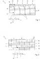
- In 1 1schematically shows an optical unit 1 of an irradiation device in cross section, which has an entry direction 2 .
- the direction of entry 2indicates the direction in which the electromagnetic radiation is emitted from the irradiation device onto the component 3 to be formed in the basic setting.
- the irradiation devicehas a writing area an extension 4, which corresponds to the width within which the emitted radiation can be focused on focus points 5 within the material that is to be solidified by the radiation.
- the irradiation deviceincludes a unit that is not shown in detail, such as a deflection unit. If the unit mentioned is designed to change the direction of irradiation, the term "direction of entry" is to be understood as meaning the main direction of entry of the irradiation device in the basic position.
- the componentis constructed from a plurality of partial structures 6 arranged next to one another.
- the procedurecan be such that the partial structure 6 is built up from a plurality of layers 9 in the vertical direction.
- a first partial structure 6is formed, which lies within the writing range of the irradiation device.
- the writing areais laterally shifted by shifting the irradiation device relative to the component 3 or by shifting the component 3 relative to the irradiation device in order to construct a second partial structure 6 next to the first partial structure 6 . This is repeated until the finished component 3 has been assembled from all substructures.
- a component constructed in this wayhas mechanical weak points at the boundary surfaces 7 between partial structures 6 arranged next to one another.
- shadingoccurs when a certain height, measured in the insertion direction, of a partial structure 6 is exceeded.
- a partial structure 6 that has already been constructedcan shade the beam coming from the optical unit 1 and directed to a focal point within the partial structure adjoining it on the left, as is shown schematically using line 8 .
- line 8In the area delimited by the line 8, there are therefore structuring errors which should be avoided.
- the component 3 according to the method according to the inventionis built up again from a plurality of substructures 6, the substructures 6 now being arranged not only next to one another but also one above the other.
- the partial structures 6are arranged in layers 10 arranged one on top of the other, so that the interface 11 between layers 10 lying one on top of the other is flat throughout. Due to the fact that the component 3 is composed of a plurality of partial structures 6 not only in the lateral direction but also in the vertical direction, each individual partial structure 6 can be formed with a reduced height in order to avoid shading.
- thisopens up the possibility of offsetting the partial structures 6 of the individual layers 10 laterally relative to one another, so that upper partial structures 6 bridge the boundary surfaces 7 between partial structures 6 arranged next to one another and lying directly underneath.
- the lateral offsetis half the width of the individual substructures 6, so that two lower substructures 6 adjoining one another at an interface 7 each of the upper part structure 6 bridging this boundary surface 7 by 50%.
- the offsetis only 10%.
- FIG 4Whilst the boundary surfaces 7 between partial structures 6 arranged next to one another run parallel to the insertion direction 2, FIG 4 various alternative possibilities, namely curved and stepped boundary surfaces 7 running obliquely to the direction of entry 2. This can additionally prevent shading.
- FIG 5a further modified embodiment is shown, in which the partial structures 6 lying one above the other are not arranged in layers, but according to a stepped arrangement.
- the partial structures 6each have a surface on their underside and on their upper side, which has a step at the point at which an interface 7 is provided between the partial structures below or between them. Because of such a step configuration, the protruding portion b of the height a of a partial structure 6 that is relevant with regard to shading is less than in an embodiment according to FIG 2 , so that shading can be avoided even more effectively or the height of the substructures can be increased without increasing the risk of shading.
- the substructures 6here have a hexagonal cross section, resulting in a honeycomb arrangement of substructures arranged next to one another and one on top of the other.
- the partial structures 6are designed in the form of crosses.
- substructures 6 as in FIGS Figures 1 to 8 shownare represented only by border lines that indicate that spatial area in which the solidification of the volume elements takes place within the respective partial structure, without a specific structuring being represented. It goes without saying that in the course of producing a component with the respectively desired geometry, not all volume elements within a partial structure have to be solidified, but rather that volume areas can remain free within the partial structures.
Landscapes
- Engineering & Computer Science (AREA)
- Chemical & Material Sciences (AREA)
- Materials Engineering (AREA)
- Physics & Mathematics (AREA)
- Optics & Photonics (AREA)
- Manufacturing & Machinery (AREA)
- Mechanical Engineering (AREA)
- Toxicology (AREA)
- Health & Medical Sciences (AREA)
- Plasma & Fusion (AREA)
- General Physics & Mathematics (AREA)
- Materials For Photolithography (AREA)
- Polymerisation Methods In General (AREA)
Description
Translated fromGermanDie Erfindung betrifft ein Verfahren zur lithographiebasierten generativen Fertigung eines dreidimensionalen Bauteils, bei dem von einer Bestrahlungseinrichtung ausgesendete elektromagnetische Strahlung nacheinander auf Fokuspunkte innerhalb eines Materials fokussiert wird, wodurch jeweils ein am Fokuspunkt befindliches Volumenelement des Materials mittels Multiphotonenabsorption verfestigt wird, wobei in einem Schreibbereich der Bestrahlungseinrichtung aus den Volumenelementen jeweils eine Teilstruktur aufgebaut wird und eine Mehrzahl von Teilstrukturen nebeneinander angeordnet wird.The invention relates to a method for the lithography-based additive manufacturing of a three-dimensional component, in which electromagnetic radiation emitted by an irradiation device is successively focused on focal points within a material, as a result of which a volume element of the material located at the focal point is solidified by means of multiphoton absorption, wherein in a write area of the irradiation device a partial structure is constructed from the volume elements in each case and a plurality of partial structures is arranged next to one another.
Ein Verfahren zur Ausbildung eines Formkörpers, bei dem die Verfestigung eines flüssigen photosensitiven Materials mittels Multiphotonenabsorption vorgenommen wird, ist beispielsweise aus der
Bei der Anwendung von Multiphotonen-Absorptionsverfahren besteht ein weiteres Problem darin, dass bereits gebildete verfestigte Strukturen nachfolgend zu strukturierende Bereiche verschatten. Dies bedeutet, dass die für die Verfestigung ins Material eingebrachte Strahlung in bestimmten Fällen bereits verfestigte Strukturbereiche durchdringen müsste, um zu dem zu verfestigenden Volumenelement zu gelangen. Derartige Verschattungen können zu Strukturierungsfehlern führen.When using multiphoton absorption methods, there is a further problem in that solidified structures that have already formed shade regions that are to be structured subsequently. This means that the radiation introduced into the material for the hardening would have to penetrate already hardened structural areas in certain cases in order to reach the volume element to be hardened. Such shading can lead to structuring errors.
In der
Ein weiteres Verfahren zum Erzeugen einer 3D-Struktur mittels Laserlithographie ist in der
Die vorliegende Erfindung zielt darauf ab, ein verbessertes Verfahren anzugeben, mit welchem nicht nur der Verschattungsproblematik Rechnung getragen wird, sondern auch die durch das Stitching-Verfahren verursachte mechanische Bruchanfälligkeit des Bauteils verbessert wird.The aim of the present invention is to specify an improved method with which not only the shading problem is taken into account, but also the mechanical susceptibility to fracture of the component caused by the stitching method is improved.
Zur Lösung dieser Aufgabe sieht die Erfindung ein Verfahren gemäß Anspruch 1 vor. Das Verfahren sieht vor, dass Teilstrukturen übereinander angeordnet werden, sodass obere Teilstrukturen die Grenzfläche(n) zwischen nebeneinander angeordneten, unteren Teilstrukturen überbrücken. Dadurch, dass das Bauteil nicht nur in nebeneinander liegende, sondern auch in übereinander liegende Teilstrukturen zerlegt wird, kann die Dicke der Teilstrukturen geringer gewählt werden. Insbesondere kann die Dicke der Teilstrukturen so gering gewählt werden, dass sich keine Verschattungen ergeben.To solve this problem, the invention provides a method according to
-Erfindungsgemäß ist hierbei vorgesehen, dass das Bauteil mehrere übereinanderliegende Lagen umfasst, die jeweils aus einer Mehrzahl von nebeneinander angeordneten Teilstrukturen gebildet werden, wobei das Bauteil lagenweise aufgebaut wird, wobei die Teilstrukturen einer oberen Lage die Grenzfläche(n) zwischen aneinandergrenzenden Teilstrukturen der unmittelbar darunter liegenden Lage überbrücken. Dabei werden zur Ausbildung einer unteren Lage zuerst mehrere Teilstrukturen nebeneinander aufgebaut, bevor unmittelbar darüber die Teilstrukturen der nächsten, oberen Lage aufgebaut werden. Dadurch werden Verschattungen wesentlich reduziert bzw. bei entsprechend dünner Ausbildung der Lagen gänzlich vermieden, weil der Schatten lediglich durch die Höhe einer Lage erzeugt wird. Die Erfindung beschreitet somit einen anderen Lösungsweg als die
Beim erfindungsgemäßen Verfahren wird somit anders als bei der Lösung gemäß der
Im Rahmen der vorliegenden Erfindung kann daher auf die Ausbildung von schräg zur Eintragsrichtung verlaufenden Grenzflächen zwischen zwei aneinandergrenzenden Teilstrukturen verzichtet werden, wodurch der Steuerungsaufwand für die Strukturierungseinrichtung reduziert wird. Vielmehr verlaufen die Grenzflächen bevorzugt parallel zur Eintragsrichtung.Within the scope of the present invention, it is therefore possible to dispense with the formation of boundary surfaces which run obliquely to the insertion direction between two adjacent partial structures, as a result of which the outlay on control for the structuring device is reduced. Rather, the boundary surfaces preferably run parallel to the direction of entry.
Es ist aber auch denkbar, dass im Rahmen der Erfindung so wie bei der Lösung gemäß der
Der lagenweise Aufbau des Bauteils ermöglicht es weiters die mechanische Stabilität dadurch zu verbessern, dass die Teilstrukturen einer Lage die Grenzfläche(n) zwischen aneinandergrenzenden Teilstrukturen der unmittelbar darunter liegenden Lage überbrücken. Dadurch entsteht ein Versatz zwischen den Teilstrukturen der einzelnen Lage, ähnlich wie der Versatz von Mauersteinen in einem Mauerwerksverband. Auf Grund des Versatzes werden die durch die Stoßstellen bzw. Grenzflächen zwischen zwei aneinander angrenzenden Teilstrukturen einer Lage auftretenden Schwachstellen kompensiert und insbesondere das Ausbreiten von Rissen entlang der Grenzflächen im Bauteil verhindert.The layered construction of the component also makes it possible to improve the mechanical stability in that the substructures of one layer bridge the interface(s) between adjacent substructures of the layer immediately below. This creates an offset between the substructures of the individual layer, similar to the offset of bricks in a masonry bond. Due to the offset, the weak points occurring due to the joints or boundary surfaces between two adjacent substructures of a layer are compensated and, in particular, the propagation of cracks along the boundary surfaces in the component is prevented.
Unter einer Teilstruktur wird im Rahmen der Erfindung ein Bereich des herzustellenden Körpers verstanden, der dem Schreibbereich der Bestrahlungseinrichtung entspricht und dessen in Richtung der Eintragsrichtung gemessene Dicke im Fall des lagenweisen Aufbaus der Dicke einer Lage entspricht. Um eine Mehrzahl von Teilstrukturen auszubilden, ist bevorzugt vorgesehen, dass der Schreibbereich der Bestrahlungseinrichtung durch Veränderung der Relativposition der Bestrahlungseinrichtung relativ zum Material quer zur Eintragsrichtung der Bestrahlungseinrichtung verschoben wird, um nach dem Aufbau einer Teilstruktur eine nächste Teilstruktur aufzubauen. Hierbei kann entweder die Bestrahlungseinrichtung relativ zum ortsfesten Material verschoben werden oder es kann das Material bzw. das das Material aufnehmende Behältnis relativ zur ortsfesten Bestrahlungseinrichtung verschoben werden.In the context of the invention, a partial structure is understood to be an area of the body to be produced which corresponds to the writing area of the irradiation device and whose thickness measured in the direction of insertion corresponds to the thickness of one layer in the case of a layered structure. In order to form a plurality of partial structures, it is preferably provided that the writing area of the irradiation device is shifted transversely to the entry direction of the irradiation device by changing the relative position of the irradiation device relative to the material in order to build up a next partial structure after the construction of a partial structure. In this case, either the irradiation device can be relatively be shifted to the stationary material or the material or the container accommodating the material can be shifted relative to the stationary irradiation device.
Wenn im Rahmen der Erfindung Teilstrukturen angesprochen werden, die nebeneinander liegen, so bedeutet dies, dass der Schreibbereich der Bestrahlungseinrichtung wie oben beschrieben quer zur Eintragsrichtung verschoben wird, um zuerst die eine und dann die andere der nebeneinander liegenden Teilstrukturen herzustellen. Nebeneinander liegende Teilstrukturen sind somit Teilstrukturen, die quer zur Eintragsrichtung der Bestrahlungseinrichtung unmittelbar aneinander anschließen.If, within the framework of the invention, partial structures are addressed that lie next to one another, this means that the writing area of the irradiation device is shifted transversely to the entry direction, as described above, in order first to produce one and then the other of the partial structures lying next to one another. Partial structures lying next to one another are thus partial structures which directly adjoin one another transversely to the direction of entry of the irradiation device.
Bevorzugt ist vorgesehen, dass die Grenzfläche zwischen übereinander liegenden Lagen durchgehend eben ausgebildet ist. Die eine Lage ausbildenden, aneinander grenzenden Teilstrukturen weisen somit die gleiche Dicke auf, sodass sich eine Lage einheitlicher Dicke ergibt. Die Lagen erstrecken sich hierbei quer zur Eintragsrichtung.It is preferably provided that the boundary surface between the layers lying one on top of the other is flat throughout. The adjacent partial structures forming a layer thus have the same thickness, resulting in a layer of uniform thickness. The layers here extend transversely to the direction of entry.
Alternativ kann die Grenzfläche zwischen übereinander liegenden Teilstrukturen aber auch gestuft ausgebildet sein. Insbesondere ist es vorteilhaft, wenn eine obere Teilstruktur an ihrer Unterseite eine Oberfläche aufweist, die an der Grenzfläche zwischen zwei unteren Teilstrukturen eine Stufe aufweist. Weiters ist es vorteilhaft, wenn eine untere Teilstruktur an ihrer Oberseite eine Oberfläche aufweist, die an der Grenzfläche zwischen zwei oberen Teilstrukturen eine Stufe aufweist. Auf Grund einer solchen Stufenkonfiguration erscheint die Dicke einer benachbarten Teilstruktur um die Höhe der Stufe tiefer, sodass der Verschattungseffekt weiter verringert werden oder die Dicke der Teilstrukturen ohne Verschlechterung der Verschattungsbedingungen um die Höhe der Stufe erhöht werden kann.Alternatively, however, the boundary surface between partial structures lying one above the other can also be formed in a stepped manner. In particular, it is advantageous if an upper substructure has a surface on its underside that has a step at the interface between two lower substructures. Furthermore, it is advantageous if a lower partial structure has a surface on its upper side which has a step at the interface between two upper partial structures. Due to such a step configuration, the thickness of a neighboring substructure appears lower by the height of the step, so that the Shading effect can be further reduced or the thickness of the partial structures can be increased by the height of the step without worsening the shading conditions.
Eine vorteilhafte Ausbildung sieht in diesem Zusammenhang vor, dass die Höhe der Stufe 10-50%, insbesondere 20-40%, der Dicke (in Höhenrichtung gemessen) der Teilstruktur gewählt wird.In this context, an advantageous embodiment provides that the height of the step is chosen to be 10-50%, in particular 20-40%, of the thickness (measured in the height direction) of the partial structure.
Für eine zufriedenstellende mechanische Stabilität des Bauteils ist der Versatz der übereinander liegenden Teilstrukturen bevorzugt so gestaltet, dass sich eine ausreichende Überdeckung bzw. Überlappung der Teilstrukturen ergibt. Eine bevorzugte Ausbildung sieht hierbei vor, dass zwei an einer Grenzfläche aneinander grenzende untere Teilstrukturen jeweils von der diese Grenzfläche überbrückenden oberen Teilstruktur zu wenigstens 10%, bevorzugt wenigstens 30%, besonders bevorzugt wenigstens 40%, insbesondere zu 50%, überlappt werden.For a satisfactory mechanical stability of the component, the offset of the substructures lying one above the other is preferably designed in such a way that there is sufficient covering or overlapping of the substructures. A preferred embodiment provides that two lower substructures bordering one another at an interface are each overlapped by at least 10%, preferably at least 30%, particularly preferably at least 40%, in particular 50%, by the upper substructure bridging this interface.
Um zu vermeiden, dass eine bereits aufgebaute Teilstruktur benachbarte Bereiche einer angrenzenden Teilstruktur derselben Lage verschattet, ist bevorzugt vorgesehen, dass die Dicke der Teilstrukturen und/oder der Lagen weniger als 100µm, vorzugsweise weniger als 50µm, vorzugsweise weniger als 30µm, insbesondere weniger als 10 µm beträgt. Insbesondere beträgt die Dicke der Teilstrukturen und/oder der Lagen bei einer numerischen Apertur des Bestrahlungssystems von 1,4 höchstens 10 µm, bei einer numerischen Apertur des Bestrahlungssystems von 0,8 höchstens 30 µm beträgt und bei einer numerischen Apertur des Bestrahlungssystems von 0,4 höchstens 50 µm.In order to prevent a partial structure that has already been built up from shading neighboring areas of an adjacent partial structure of the same layer, it is preferably provided that the thickness of the partial structures and/or the layers is less than 100 μm, preferably less than 50 μm, preferably less than 30 μm, in particular less than 10 is µm. In particular, the thickness of the partial structures and/or the layers is at most 10 μm given a numerical aperture of the irradiation system of 1.4, and given a numerical aperture of the irradiation system of 0.8 is at most 30 µm and at a numerical aperture of the irradiation system of 0.4 at most 50 µm.
Die einzelnen Teilstrukturen können schichtweise aufgebaut werden, d.h. aus mehreren Schichten gefertigt werden.The individual substructures can be built up in layers, i.e. made of several layers.
Eine besonders bevorzugte Verfahrensweise ergibt sich, wenn das Material auf einem Materialträger, wie z.B. in einer Wanne, vorliegt, und die Bestrahlung des Materials von unten durch den für die Strahlung zumindest bereichsweise durchlässigen Materialträger erfolgt. Hierbei kann eine Bauplattform in Abstand vom Materialträger positioniert und das Bauteil durch Verfestigen von zwischen der Bauplattform und dem Materialträger befindlichem Material auf der Bauplattform aufgebaut werden. Alternativ ist es aber auch möglich, die Bestrahlung des Materials von oben vorzunehmen.A particularly preferred procedure results when the material is present on a material carrier, such as e.g. in a trough, and the material is irradiated from below through the material carrier, which is at least partially transparent to the radiation. In this case, a construction platform can be positioned at a distance from the material carrier and the component can be built up on the construction platform by solidifying material located between the construction platform and the material carrier. Alternatively, however, it is also possible to irradiate the material from above.
Die Strukturierung eines geeigneten Materials mittels Multiphotonenabsorption bietet den Vorteil einer überaus hohen Strukturauflösung, wobei Volumenelemente mit minimalen Strukturgrößen von bis zu 50nm x 50nm x 50nm erzielbar sind. Bedingt durch das kleine Fokuspunktvolumen ist der Durchsatz eines solchen Verfahrens allerdings sehr gering, da z.B. für ein Volumen von lmm3 insgesamt mehr als 109 Punkte belichtet werden müssen. Dies führt zu sehr langen Bauzeiten, was der Hauptgrund für den geringen industriellen Einsatz von MultiphotonenabsorptionsVerfahren ist.The structuring of a suitable material by means of multiphoton absorption offers the advantage of an extremely high structure resolution, whereby volume elements with minimal structure sizes of up to 50nm x 50nm x 50nm can be achieved. Due to the small focus point volume, however, the throughput of such a method is very low since, for example, a total of more than 109 points have to be exposed for a volume of 1 mm3 . This leads to very long construction times, which is the main reason for the low industrial use of multiphoton absorption processes.
Um den Bauteiledurchsatz zu erhöhen ohne die Möglichkeit einer hohen Strukturauflösung zu verlieren, sieht eine bevorzugte Weiterbildung der Erfindung vor, dass das Volumen des Fokuspunkts während des Aufbaus des Bauteils zumindest einmal variiert wird, sodass das Bauteil aus verfestigten Volumenelementen unterschiedlichen Volumens aufgebaut wird.In order to increase the component throughput without losing the possibility of a high structural resolution, a preferred development of the invention provides that the Volume of the focus point is varied at least once during the construction of the component, so that the component is built up from solidified volume elements of different volumes.
Durch das variable Volumen des Fokuspunktes sind (bei kleinem Fokuspunktvolumen) hohe Auflösungen möglich. Gleichzeitig ist (bei großem Fokuspunktvolumen) eine hohe Schreibgeschwindigkeit (gemessen in mm3/h) erzielbar. Durch das Variieren des Fokuspunktvolumens kann also eine hohe Auflösung mit großem Durchsatz kombiniert werden. Die Variation des Fokuspunktvolumens kann dabei zum Beispiel so genutzt werden, dass im Inneren des aufzubauenden Bauteils ein großes Fokuspunktvolumen verwendet wird, um den Durchsatz zu erhöhen, und an der Oberfläche des Bauteils ein kleineres Fokuspunktvolumen zur Anwendung kommt, um die Bauteiloberfläche mit hoher Auflösung auszubilden. Eine Vergrößerung des Fokuspunktvolumens ermöglicht einen höheren Strukturierungsdurchsatz, da das in einem Belichtungsvorgang verfestigte Materialvolumen vergrößert wird. Um bei hohem Durchsatz eine hohe Auflösung beizubehalten, können kleine Fokuspunktvolumina für feinere Strukturen und Oberflächen, und größere Fokuspunktvolumina für grobe Strukturen und/oder zum Füllen von Innenräumen verwendet werden.Due to the variable volume of the focus point, high resolutions are possible (with a small focus point volume). At the same time (with a large focus point volume) a high writing speed (measured in mm3 /h) can be achieved. By varying the focus point volume, high resolution can be combined with high throughput. The variation of the focal point volume can be used, for example, in such a way that a large focal point volume is used inside the component to be built in order to increase throughput, and a smaller focal point volume is used on the surface of the component in order to form the component surface with high resolution . Increasing the focus point volume enables a higher patterning throughput, since the volume of material solidified in an exposure process is increased. To maintain high resolution at high throughput, small focus point volumes can be used for finer structures and surfaces, and larger focus point volumes for coarse structures and/or interior space filling.
Bei einer bevorzugten Verfahrensweise erfolgt die Variation des Fokusvolumens derart, dass das Volumenverhältnis zwischen dem größten Fokuspunktvolumen während der Fertigung eines Bauteils und dem kleinsten Fokuspunktvolumen mindestens 2, bevorzugt mindestens 5 beträgt.In a preferred procedure, the focal volume is varied in such a way that the volume ratio between the largest focal point volume during the manufacture of a component and the smallest focal point volume is at least 2, preferably at least 5.
Das Prinzip der Multiphotonenabsorption wird im Rahmen der Erfindung genutzt, um im photosensitiven Materialbad einen photochemischen Vorgang zu initiieren. Multiphotonenabsorptionsverfahren umfassen beispielsweise auch Verfahren der 2-Photonenabsorption. Als Folge der photochemischen Reaktion kommt es zur Veränderung des Materials in mindestens einen anderen Zustand, wobei es typischerweise zu einer Photopolymerisation kommt. Das Prinzip der Multiphotonenabsorption beruht darauf, dass der genannte photochemische Vorgang nur in jenen Bereichen des Strahlengangs stattfindet, in denen eine für die Multiphotonenabsorption ausreichende Photonendichte vorliegt. Die höchste Photonendichte tritt im Brennpunkt des optischen Abbildungssystems auf, sodass die Multiphotonenabsorption mit ausreichender Wahrscheinlichkeit nur im Fokuspunkt auftritt. Außerhalb des Brennpunktes ist die Photonendichte geringer, sodass die Wahrscheinlichkeit der Multiphotonenabsorption außerhalb des Brennpunktes zu gering ist, um eine unumkehrbare Veränderung des Materials durch eine photochemische Reaktion zu bewirken. Die elektromagnetische Strahlung kann in der verwendeten Wellenlänge weitestgehend ungehindert das Material passieren und nur im Fokuspunkt kommt es zu einer Interaktion zwischen photosensitivem Material und elektromagnetischer Strahlung. Das Prinzip der Multiphotonenabsorption ist beispielsweise in
Als Quelle für die elektromagnetische Strahlung kann es sich vorzugsweise um einen kollimierten Laserstrahl handeln. Der Laser kann sowohl eine oder mehrere, feste oder variable Wellenlängen emittieren. Insbesondere handelt es sich um einen kontinuierlichen oder gepulsten Laser mit Pulslängen im Nanosekunden-, Pikosekunden- oder Femtosekunden-Bereich. Ein gepulster Femtosekundenlaser bietet dabei den Vorteil, dass eine geringere mittlere Leistung für die Multiphotonenabsorption benötigt wird.The source for the electromagnetic radiation can preferably be a collimated laser beam. The laser can be one or more, fixed or emit variable wavelengths. In particular, it is a continuous or pulsed laser with pulse lengths in the nanosecond, picosecond or femtosecond range. A pulsed femtosecond laser offers the advantage that a lower average power is required for multiphoton absorption.
Unter photosensitivem Material wird jedes unter Baubedingungen fließfähige Material verstanden, das durch Multiphotonenabsorption im Fokuspunktvolumen in einen zweiten Zustand übergeht - beispielsweise durch Polymerisation. Die Materialveränderung muss sich dabei auf das Fokuspunktvolumen und dessen direkte Umgebung begrenzen. Die Veränderung der Substanzeigenschaften kann dauerhaft sein und beispielsweise in einer Veränderung von einem flüssigen in einen festen Zustand bestehen, kann jedoch auch nur vorübergehend sein. Auch eine dauerhafte Veränderung kann im Übrigen reversibel oder nicht reversibel sein. Die Änderung der Materialeigenschaften muss nicht zwingend vollständig von einem in den anderen Zustand übergehen, sondern kann auch als Mischform beider Zustände vorliegen.Photosensitive material is understood to mean any material that is flowable under construction conditions and that transitions into a second state through multiphoton absorption in the focus point volume—for example, through polymerisation. The material change must be limited to the focal point volume and its immediate surroundings. The change in substance properties can be permanent, such as a change from a liquid to a solid state, but it can also be temporary. A permanent change can also be reversible or non-reversible. The change in the material properties does not necessarily have to go completely from one state to the other, but can also occur as a mixed form of both states.
Die Leistung der elektromagnetischen Strahlung und die Belichtungsdauer beeinflussen die Qualität des erzeugten Bauteils. Durch Anpassung der Strahlungsleistung und/oder der Belichtungsdauer kann das Volumen des Fokuspunktes in einem engen Bereich variiert werden. Bei zu hohen Strahlungsleistungen treten zusätzliche Prozesse auf, die zur Beschädigung des Bauteils führen können. Ist die Strahlungsleistung zu gering, kann sich keine dauerhafte Materialeigenschaftsänderung einstellen. Für jedes photosensitive Material gibt es daher typische Bauprozessparameter die mit guten Bauteileigenschaften verbunden sind.The power of the electromagnetic radiation and the exposure time influence the quality of the component produced. The volume of the focus point can be varied within a narrow range by adjusting the radiant power and/or the exposure time. If the radiation power is too high, additional processes occur that can lead to damage to the component. If the radiation power is too low, no permanent material property change can occur. Therefore, for each photosensitive material there are typical ones Construction process parameters that are associated with good component properties.
Die oben beschriebene Variation des Fokuspunktvolumens beruht hierbei jedoch nicht auf einer Änderung der Intensität der verwendeten elektromagnetischen Strahlung. Vielmehr wird mit der für den Bauprozess gewählten (optimalen) Strahlungsintensität gearbeitet, die während des Bauteilaufbaus unverändert gelassen wird. Das Verfahren wird daher bevorzugt so durchgeführt, dass die Änderung des Fokuspunktvolumens bei gleichbleibender Strahlungsintensität vorgenommen wird, wobei die verwendete durchschnittliche Leistung der elektromagnetischen Strahlung dementsprechend angepasst wird.However, the variation of the focus point volume described above is not based on a change in the intensity of the electromagnetic radiation used. Rather, the (optimal) radiation intensity selected for the construction process is used, which is left unchanged during the construction of the component. The method is therefore preferably carried out in such a way that the focus point volume is changed while the radiation intensity remains the same, with the average power of the electromagnetic radiation used being adjusted accordingly.
Als Fokuspunktvolumen wird daher jenes Volumen eines belichteten Punktes nach dem Aufbereitungsschritt bei den typischen Bauprozessparametern verstanden. Unter der oben beschriebenen Änderung des Fokuspunktvolumens wird eine Veränderung der räumlichen Intensitätsverteilung im Fokuspunkt verstanden. Hierbei kann die räumliche Intensitätsverteilung des Fokuspunktes sowohl in eine oder mehrere Richtungen verändert werden. So kann zum Beispiel durch Reduktion der effektiven numerischen Apertur des optischen Abbildungssystems die Intensitätsverteilung in alle drei Raumrichtungen vergrößert werden. Bei der Verwendung eines diffraktiven optischen Elementes kann der Fokus in eine Linie oder Fläche verändert, oder die Anzahl der Fokuspunkte erhöht werden.The focus point volume is therefore the volume of an exposed point after the preparation step with the typical construction process parameters. The change in the focus point volume described above means a change in the spatial intensity distribution in the focus point. Here, the spatial intensity distribution of the focus point can be changed in one or more directions. For example, by reducing the effective numerical aperture of the optical imaging system, the intensity distribution can be increased in all three spatial directions. When using a diffractive optical element, the focus can be changed to a line or area, or the number of focus points can be increased.
Eine Reihe von apparativen Möglichkeiten zur Veränderung des Fokuspunktvolumens ist in der
Bevorzugt ist vorgesehen, dass die Änderung des Fokuspunktvolumens in wenigstens einer, bevorzugt zwei, insbesondere in drei, senkrecht zueinander stehenden Raumrichtungen erfolgt.Provision is preferably made for the change in the focal point volume to take place in at least one, preferably two, in particular three, spatial directions which are perpendicular to one another.
Insbesondere kann die elektromagnetische Strahlung mittels einer Ablenkeinheit abgelenkt werden, um den Fokuspunkt in einer im Wesentlichen senkrecht zur Eintragsrichtung verlaufenden Ebene innerhalb des Schreibbereichs zu verstellen.In particular, the electromagnetic radiation can be deflected by means of a deflection unit in order to adjust the focal point in a plane running essentially perpendicularly to the direction of entry within the writing area.
Die Erfindung wird nachfolgend anhand von in der Zeichnung schematisch dargestellten Ausführungsbeispielen näher erläutert. In dieser zeigen
In
Da die Ausdehnung 4 des Schreibbereichs nicht ausreicht, um das gesamte Bauteil zu erzeugen, wird das Bauteil aus einer Mehrzahl von nebeneinander angeordneten Teilstrukturen 6 aufgebaut. Dabei kann so vorgegangen werden, dass die Teilstruktur 6 in Höhenrichtung aus einer Mehrzahl von Schichten 9 aufgebaut wird. Zuerst wird eine erste Teilstruktur 6 ausgebildet, die innerhalb des Schreibbereichs der Bestrahlungseinrichtung liegt. Danach wird der Schreibbereich durch Verlagerung der Bestrahlungseinrichtung relativ zum Bauteil 3 oder durch Verlagerung des Bauteils 3 relativ zur Bestrahlungseinrichtung seitlich verschoben, um neben der ersten Teilstruktur 6 eine zweite Teilstruktur 6 aufzubauen. Dies wird solange wiederholt, bis aus allen Teilstrukturen das fertige Bauteil 3 zusammengesetzt wurde. Ein solcherart aufgebautes Bauteil besitzt an den Grenzflächen 7 zwischen nebeneinander angeordneten Teilstrukturen 6 mechanische Schwachstellen.Since the
Weiters tritt bei Überschreitung einer bestimmten, in der Eintragsrichtung gemessenen Höhe einer Teilstruktur 6 eine Verschattung auf. Dies bedeutet, dass eine bereits aufgebaute Teilstruktur 6 den aus der optischen Einheit 1 kommenden, auf einen Fokuspunkt innerhalb der links daran anschließenden Teilstruktur gerichteten Strahl abschatten kann, wie dies anhand der Linie 8 schematisch dargestellt ist. In dem durch die Linie 8 begrenzten Bereich kommt es daher zu Strukturierungsfehlern, die es zu vermeiden gilt.Furthermore, shading occurs when a certain height, measured in the insertion direction, of a
In
Bei der abgewandelten Ausbildung gemäß
Während die Grenzflächen 7 zwischen nebeneinander angeordneten Teilstrukturen 6 parallel zur Eintragsrichtung 2 verlaufen, zeigt
In
In
Bei der Ausbildung gemäß
Anzumerken ist, dass die Teilstrukturen 6 wie in den
Claims (11)
- Method for the lithography-based generative production of a three-dimensional component (3), in which electromagnetic radiation emitted by an irradiation device is successively focused on focal points (5) within a material, wherein in each case a volume element of the material located at the focal point is solidified by means of multiphoton absorption, wherein a substructure (6) is each built up from the volume elements in a writing area of the irradiation device, and a plurality of substructures are arranged next to one another, wherein the component comprises several superimposed layers (10), which are each formed from a plurality of substructures arranged next to one another,characterized in that the component is built up in layers, by first building up a plurality of substructures next to one another to form a lower layer, after which immediately above the substructures of an upper layer are built up, which bridge the interface(s) (7) between adjacent substructures of the layer arranged immediately below.
- Method according to claim 1,characterized in that the interface (11) between layers lying one on top of the other layer is flat throughout.
- Method according to claim 1,characterized in that the interface between substructures lying one above the other is stepped.
- Method according to any one of claims 1 to 3,characterized in that the writing area of the irradiation device is displaced by changing the relative position of the irradiation device relative to the material transversely to the entry direction of the irradiation device in order to build up, after a substructure has been built up, a next adjacent substructure.
- Method according to any one of claims 1 to 4,characterized in that two lower substructures (6) adjoining one another at an interface are each overlapped by at least 10%, preferably at least 30%, particularly preferably at least 40%, in particular 50%, by the upper substructure that bridges this interface.
- Method according to any one of claims 1 to 5,characterized in that the thickness of the substructures and/or of the layers is less than 100 µm, preferably less than 50 µm, preferably less than 30 µm, in particular less than 10 µm.
- Method according to any one of claims 1 to 6,characterized in that the material is present on a material carrier, such as in a vat, and the material is irradiated from below through the material carrier which is at least partially transparent to the radiation.
- Method according to claim 7,characterized in that a building platform is positioned at a distance from the material carrier and the component is built up on the building platform by solidifying material located between the building platform and the material carrier.
- Method according to any one of claims 1 to 8,characterized in that the volume of the focal point is varied at least once during the construction of the component, so that the component is built up from solidified volume elements of different volumes.
- Method according to claim 9,characterized in that the change in the focal point volume takes place in at least one, preferably two, in particular in three spatial directions perpendicular to one another.
- Method according to any one of claims 1 to 10,characterized in that the electromagnetic radiation is deflected by means of a deflection unit in order to adjust the focal point within the writing area in a plane that is essentially perpendicular to the entry direction.
Priority Applications (10)
| Application Number | Priority Date | Filing Date | Title |
|---|---|---|---|
| ES19450004TES2938985T3 (en) | 2019-02-26 | 2019-02-26 | Procedure for Lithography-Based Generative Manufacturing of a Three-Dimensional Component |
| LTEP19450004.7TLT3702132T (en) | 2019-02-26 | 2019-02-26 | Method for lithography-based generative production of a three-dimensional component |
| EP19450004.7AEP3702132B1 (en) | 2019-02-26 | 2019-02-26 | Method for lithography-based generative production of a three-dimensional component |
| PCT/IB2020/051626WO2020174411A1 (en) | 2019-02-26 | 2020-02-26 | Method for lithography-based generative production of a three-dimensional component |
| US17/431,677US11787106B2 (en) | 2019-02-26 | 2020-02-26 | Method for the lithography-based additive manufacturing of a three-dimensional component |
| KR1020217030508AKR102723421B1 (en) | 2019-02-26 | 2020-02-26 | Method for lithography-based generative manufacturing of three-dimensional components |
| CA3131320ACA3131320C (en) | 2019-02-26 | 2020-02-26 | Method for the lithography-based additive manufacturing of a three-dimensional component |
| JP2021549914AJP7362756B2 (en) | 2019-02-26 | 2020-02-26 | Additive manufacturing method for three-dimensional parts using lithography |
| CN202080017000.6ACN113453874A (en) | 2019-02-26 | 2020-02-26 | Method for generative manufacturing of three-dimensional components based on lithography |
| IL285753AIL285753B2 (en) | 2019-02-26 | 2020-02-26 | A method for lithography-based additive manufacturing of a three-dimensional component |
Applications Claiming Priority (1)
| Application Number | Priority Date | Filing Date | Title |
|---|---|---|---|
| EP19450004.7AEP3702132B1 (en) | 2019-02-26 | 2019-02-26 | Method for lithography-based generative production of a three-dimensional component |
Publications (2)
| Publication Number | Publication Date |
|---|---|
| EP3702132A1 EP3702132A1 (en) | 2020-09-02 |
| EP3702132B1true EP3702132B1 (en) | 2023-01-11 |
Family
ID=65717948
Family Applications (1)
| Application Number | Title | Priority Date | Filing Date |
|---|---|---|---|
| EP19450004.7AActiveEP3702132B1 (en) | 2019-02-26 | 2019-02-26 | Method for lithography-based generative production of a three-dimensional component |
Country Status (10)
| Country | Link |
|---|---|
| US (1) | US11787106B2 (en) |
| EP (1) | EP3702132B1 (en) |
| JP (1) | JP7362756B2 (en) |
| KR (1) | KR102723421B1 (en) |
| CN (1) | CN113453874A (en) |
| CA (1) | CA3131320C (en) |
| ES (1) | ES2938985T3 (en) |
| IL (1) | IL285753B2 (en) |
| LT (1) | LT3702132T (en) |
| WO (1) | WO2020174411A1 (en) |
Citations (9)
| Publication number | Priority date | Publication date | Assignee | Title |
|---|---|---|---|---|
| US5198159A (en) | 1990-10-09 | 1993-03-30 | Matsushita Electric Works, Ltd. | Process of fabricating three-dimensional objects from a light curable resin liquid |
| EP0747203A2 (en) | 1988-04-18 | 1996-12-11 | 3D Systems, Inc. | Stereolithographic curl reduction |
| WO1999054784A1 (en) | 1998-04-21 | 1999-10-28 | University Of Connecticut | Free-form nanofabrication using multi-photon excitation |
| WO2014154363A1 (en) | 2013-03-28 | 2014-10-02 | Karlsruher Institut für Technologie | Production of 3d free-form waveguide structures |
| EP3012688A1 (en) | 2014-10-22 | 2016-04-27 | Nanoscribe GmbH | Method for producing a three-dimensional structure |
| EP3093123A1 (en) | 2015-05-13 | 2016-11-16 | Nanoscribe GmbH | Method for producing a three-dimensional structure |
| WO2017112682A1 (en) | 2015-12-22 | 2017-06-29 | Carbon, Inc. | Fabrication of compound products from multiple intermediates by additive manufacturing with dual cure resins |
| EP3266594A1 (en) | 2016-07-07 | 2018-01-10 | Technische Universität Wien | Method and apparatus for lithography-based generative production of three-dimensional articles |
| WO2018206161A1 (en) | 2017-05-11 | 2018-11-15 | Nanoscribe Gmbh | Method for producing a 3d structure by means of laser lithography with a modified exposure dose at edge portions, and corresponding computer program product |
Family Cites Families (11)
| Publication number | Priority date | Publication date | Assignee | Title |
|---|---|---|---|---|
| US5965079A (en)* | 1995-04-25 | 1999-10-12 | 3D Systems, Inc. | Method and apparatus for making a three-dimensional object by stereolithography |
| US5597520A (en)* | 1990-10-30 | 1997-01-28 | Smalley; Dennis R. | Simultaneous multiple layer curing in stereolithography |
| DE10111422A1 (en) | 2001-03-09 | 2002-09-26 | Hannover Laser Zentrum | Photosensitive molding production by irradiating a liquid material in a bath, to solidify the material, using a multi-photon absorption process |
| WO2005025838A1 (en)* | 2003-09-11 | 2005-03-24 | Nabtesco Corporation | Optical 3-dimensional object formation and device |
| JP6022493B2 (en)* | 2014-02-13 | 2016-11-09 | シーメット株式会社 | Stereolithography method, stereolithography apparatus, and generation program |
| US9981312B2 (en)* | 2015-05-11 | 2018-05-29 | Wisconsin Alumni Research Foundation | Three-dimension printer with mechanically scanned cathode-comb |
| JP6724303B2 (en)* | 2015-07-22 | 2020-07-15 | 株式会社リコー | Method for manufacturing three-dimensional object |
| EP3135459A1 (en)* | 2015-08-31 | 2017-03-01 | Nederlandse Organisatie voor toegepast- natuurwetenschappelijk onderzoek TNO | Method and apparatus for layerwise production of a tangible object |
| US11278988B2 (en)* | 2015-12-17 | 2022-03-22 | Eos Of North America, Inc. | Additive manufacturing method using large and small beam sizes |
| DE102017205051A1 (en)* | 2017-03-24 | 2018-09-27 | Eos Gmbh Electro Optical Systems | Überlappoptimierung |
| CN108927993B (en)* | 2017-05-26 | 2020-12-15 | 三纬国际立体列印科技股份有限公司 | Light curing 3D printing method of multi-light source module |
- 2019
- 2019-02-26ESES19450004Tpatent/ES2938985T3/enactiveActive
- 2019-02-26LTLTEP19450004.7Tpatent/LT3702132T/enunknown
- 2019-02-26EPEP19450004.7Apatent/EP3702132B1/enactiveActive
- 2020
- 2020-02-26KRKR1020217030508Apatent/KR102723421B1/enactiveActive
- 2020-02-26JPJP2021549914Apatent/JP7362756B2/enactiveActive
- 2020-02-26ILIL285753Apatent/IL285753B2/enunknown
- 2020-02-26USUS17/431,677patent/US11787106B2/enactiveActive
- 2020-02-26CNCN202080017000.6Apatent/CN113453874A/enactivePending
- 2020-02-26CACA3131320Apatent/CA3131320C/enactiveActive
- 2020-02-26WOPCT/IB2020/051626patent/WO2020174411A1/ennot_activeCeased
Patent Citations (9)
| Publication number | Priority date | Publication date | Assignee | Title |
|---|---|---|---|---|
| EP0747203A2 (en) | 1988-04-18 | 1996-12-11 | 3D Systems, Inc. | Stereolithographic curl reduction |
| US5198159A (en) | 1990-10-09 | 1993-03-30 | Matsushita Electric Works, Ltd. | Process of fabricating three-dimensional objects from a light curable resin liquid |
| WO1999054784A1 (en) | 1998-04-21 | 1999-10-28 | University Of Connecticut | Free-form nanofabrication using multi-photon excitation |
| WO2014154363A1 (en) | 2013-03-28 | 2014-10-02 | Karlsruher Institut für Technologie | Production of 3d free-form waveguide structures |
| EP3012688A1 (en) | 2014-10-22 | 2016-04-27 | Nanoscribe GmbH | Method for producing a three-dimensional structure |
| EP3093123A1 (en) | 2015-05-13 | 2016-11-16 | Nanoscribe GmbH | Method for producing a three-dimensional structure |
| WO2017112682A1 (en) | 2015-12-22 | 2017-06-29 | Carbon, Inc. | Fabrication of compound products from multiple intermediates by additive manufacturing with dual cure resins |
| EP3266594A1 (en) | 2016-07-07 | 2018-01-10 | Technische Universität Wien | Method and apparatus for lithography-based generative production of three-dimensional articles |
| WO2018206161A1 (en) | 2017-05-11 | 2018-11-15 | Nanoscribe Gmbh | Method for producing a 3d structure by means of laser lithography with a modified exposure dose at edge portions, and corresponding computer program product |
Non-Patent Citations (5)
| Title |
|---|
| DEHAECK S., SCHEID B., LAMBERT P.: "Adaptive stitching for meso-scale printing with two-photon lithography", ADDITIVE MANUFACTURING, ELSEVIER, NL, vol. 21, 1 May 2018 (2018-05-01), NL , pages 589 - 597, XP093137190, ISSN: 2214-8604, DOI: 10.1016/j.addma.2018.03.026 |
| GRAEBER GUSTAV, MARTIN KIELIGER OSKAR B., SCHUTZIUS THOMAS M., POULIKAKOS DIMOS: "3D-Printed Surface Architecture Enhancing Superhydrophobicity and Viscous Droplet Repellency", APPLIED MATERIALS & INTERFACES, AMERICAN CHEMICAL SOCIETY, US, vol. 10, no. 49, 12 December 2018 (2018-12-12), US , pages 43275 - 43281, XP093137173, ISSN: 1944-8244, DOI: 10.1021/acsami.8b16893 |
| JAMES S. OAKDALE; RAYMOND F. SMITH; JEAN‐BAPTISTE FORIEN; WILLIAM L. SMITH; SUZANNE J. ALI; LEONARDUS B. BAYU AJI; TREVOR M. WILLE: "Direct Laser Writing of Low‐Density Interdigitated Foams for Plasma Drive Shaping", ADVANCED FUNCTIONAL MATERIALS, WILEY - V C H VERLAG GMBH & CO. KGAA, DE, vol. 27, no. 43, 27 September 2017 (2017-09-27), DE , pages n/a - n/a, XP072411582, ISSN: 1616-301X, DOI: 10.1002/adfm.201702425 |
| MONTINARO E., GRISI M., LETIZIA M. C., PETHÖ L., GIJS M. A. M., GUIDETTI R., MICHLER J., BRUGGER J., BOERO G.: "3D printed microchannels for sub-nL NMR spectroscopy", PLOS ONE, PUBLIC LIBRARY OF SCIENCE, US, vol. 13, no. 5, 9 May 2018 (2018-05-09), US , pages e0192780, XP093137196, ISSN: 1932-6203, DOI: 10.1371/journal.pone.0192780 |
| OAKDALE JAMES S., SMITH RAYMOND F., FORIEN JEAN‐BAPTISTE, SMITH WILLIAM L., ALI SUZANNE J., BAYU AJI LEONARDUS B., WILLEY TREVOR M: "Supporting Information: Direct Laser Writing of Low‐Density Interdigitated Foams for Plasma Drive Shaping", ADVANCED FUNCTIONAL MATERIALS, WILEY - V C H VERLAG GMBH & CO. KGAA, DE, vol. 27, no. 43, 17 November 2017 (2017-11-17), DE , pages 1 - 9, XP093137207, ISSN: 1616-301X, DOI: 10.1002/adfm.201702425 |
Also Published As
| Publication number | Publication date |
|---|---|
| JP2022521626A (en) | 2022-04-11 |
| JP7362756B2 (en) | 2023-10-17 |
| IL285753B1 (en) | 2024-11-01 |
| US20220118691A1 (en) | 2022-04-21 |
| LT3702132T (en) | 2023-02-27 |
| CA3131320C (en) | 2023-10-31 |
| WO2020174411A1 (en) | 2020-09-03 |
| IL285753B2 (en) | 2025-03-01 |
| KR20210131390A (en) | 2021-11-02 |
| US11787106B2 (en) | 2023-10-17 |
| IL285753A (en) | 2021-10-31 |
| KR102723421B1 (en) | 2024-10-28 |
| CN113453874A (en) | 2021-09-28 |
| CA3131320A1 (en) | 2020-09-03 |
| ES2938985T3 (en) | 2023-04-18 |
| EP3702132A1 (en) | 2020-09-02 |
Similar Documents
| Publication | Publication Date | Title |
|---|---|---|
| EP3710182B1 (en) | Layer-selective exposure in the overhang region in additive manufacturing | |
| DE4233812C1 (en) | METHOD AND DEVICE FOR PRODUCING THREE-DIMENSIONAL OBJECTS | |
| EP3242762A1 (en) | Device and generative layer-building process for producing a three-dimensional object by multiple beams | |
| DE4436695C1 (en) | Stereolithography, the making of a three dimensional object by irradiation of powder or liquid layers | |
| EP3266594B1 (en) | Method and apparatus for lithography-based generative production of three-dimensional articles | |
| EP1419836A1 (en) | Process for preparing a workpiece, particularly through powder stereolithography or sintering | |
| EP3538293B1 (en) | Additive manufacturing method of layered products and corresponding computer program | |
| EP3970900B1 (en) | Method for producing a 3d structure by means of laser lithography with altered exposure dose at edge sections, and corresponding computer program product | |
| DE102017202843B3 (en) | Method and device for controlling an irradiation system for workpiece production | |
| WO2008116518A1 (en) | Method and device for the production of a three-dimensional object | |
| EP3866999A1 (en) | Method and device for producing a three-dimensional workpiece | |
| EP4163083B1 (en) | Method and device for lithography-based generative production of a three-dimensional component | |
| EP3568258B1 (en) | Method for reducing or completely closing an opening of an inner contour of a workpiece by means of a material melted by a laser deposition welding device | |
| EP3743261A1 (en) | Method and device for improving the component quality of objects manufactured using an additive manufacturing method | |
| EP3702132B1 (en) | Method for lithography-based generative production of a three-dimensional component | |
| EP3888887B1 (en) | Method and apparatus for lithography-based generative production of a three-dimensional component | |
| DE4416901A1 (en) | Prodn of three=dimensional objects | |
| EP4043186A1 (en) | Method and device for controlling a lithography-based additive manufacturing device | |
| EP4316782A1 (en) | Method and device for lithography-based additive manufacturing of a three-dimensional component | |
| DE102024105278A1 (en) | Method and device for the additive production of a component layer from at least one powder layer and use | |
| WO2023156132A1 (en) | Additive manufacturing of a thin, angled component structure | |
| EP4200097A1 (en) | Planning device, manufacturing device, method and computer program product for the additive manufacturing of components from a powder material | |
| DE102022109802A1 (en) | Method and device for generating control data for a device for the additive manufacturing of a component | |
| WO2025157553A1 (en) | Method and device for additively manufacturing workpieces with reduced hot cracking | |
| DE102011085949A1 (en) | Filter i.e. dead mirror blocking filter, for filtering certain proportions of work light of light beam assembly, has fields arranged next to each other, and lattice arrangement defining and surrounding fields and formed in irregular manner |
Legal Events
| Date | Code | Title | Description |
|---|---|---|---|
| PUAI | Public reference made under article 153(3) epc to a published international application that has entered the european phase | Free format text:ORIGINAL CODE: 0009012 | |
| STAA | Information on the status of an ep patent application or granted ep patent | Free format text:STATUS: THE APPLICATION HAS BEEN PUBLISHED | |
| AK | Designated contracting states | Kind code of ref document:A1 Designated state(s):AL AT BE BG CH CY CZ DE DK EE ES FI FR GB GR HR HU IE IS IT LI LT LU LV MC MK MT NL NO PL PT RO RS SE SI SK SM TR | |
| AX | Request for extension of the european patent | Extension state:BA ME | |
| STAA | Information on the status of an ep patent application or granted ep patent | Free format text:STATUS: REQUEST FOR EXAMINATION WAS MADE | |
| 17P | Request for examination filed | Effective date:20210302 | |
| RBV | Designated contracting states (corrected) | Designated state(s):AL AT BE BG CH CY CZ DE DK EE ES FI FR GB GR HR HU IE IS IT LI LT LU LV MC MK MT NL NO PL PT RO RS SE SI SK SM TR | |
| STAA | Information on the status of an ep patent application or granted ep patent | Free format text:STATUS: EXAMINATION IS IN PROGRESS | |
| 17Q | First examination report despatched | Effective date:20211108 | |
| RIN1 | Information on inventor provided before grant (corrected) | Inventor name:GRUBER, PETER | |
| GRAP | Despatch of communication of intention to grant a patent | Free format text:ORIGINAL CODE: EPIDOSNIGR1 | |
| STAA | Information on the status of an ep patent application or granted ep patent | Free format text:STATUS: GRANT OF PATENT IS INTENDED | |
| GRAS | Grant fee paid | Free format text:ORIGINAL CODE: EPIDOSNIGR3 | |
| INTG | Intention to grant announced | Effective date:20221110 | |
| GRAA | (expected) grant | Free format text:ORIGINAL CODE: 0009210 | |
| STAA | Information on the status of an ep patent application or granted ep patent | Free format text:STATUS: THE PATENT HAS BEEN GRANTED | |
| AK | Designated contracting states | Kind code of ref document:B1 Designated state(s):AL AT BE BG CH CY CZ DE DK EE ES FI FR GB GR HR HU IE IS IT LI LT LU LV MC MK MT NL NO PL PT RO RS SE SI SK SM TR | |
| REG | Reference to a national code | Ref country code:GB Ref legal event code:FG4D Free format text:NOT ENGLISH | |
| REG | Reference to a national code | Ref country code:CH Ref legal event code:EP | |
| REG | Reference to a national code | Ref country code:DE Ref legal event code:R096 Ref document number:502019006763 Country of ref document:DE | |
| REG | Reference to a national code | Ref country code:IE Ref legal event code:FG4D Free format text:LANGUAGE OF EP DOCUMENT: GERMAN | |
| REG | Reference to a national code | Ref country code:AT Ref legal event code:REF Ref document number:1543166 Country of ref document:AT Kind code of ref document:T Effective date:20230215 | |
| REG | Reference to a national code | Ref country code:NL Ref legal event code:FP | |
| REG | Reference to a national code | Ref country code:ES Ref legal event code:FG2A Ref document number:2938985 Country of ref document:ES Kind code of ref document:T3 Effective date:20230418 | |
| P01 | Opt-out of the competence of the unified patent court (upc) registered | Effective date:20230515 | |
| PG25 | Lapsed in a contracting state [announced via postgrant information from national office to epo] | Ref country code:RS Free format text:LAPSE BECAUSE OF FAILURE TO SUBMIT A TRANSLATION OF THE DESCRIPTION OR TO PAY THE FEE WITHIN THE PRESCRIBED TIME-LIMIT Effective date:20230111 Ref country code:PT Free format text:LAPSE BECAUSE OF FAILURE TO SUBMIT A TRANSLATION OF THE DESCRIPTION OR TO PAY THE FEE WITHIN THE PRESCRIBED TIME-LIMIT Effective date:20230511 Ref country code:NO Free format text:LAPSE BECAUSE OF FAILURE TO SUBMIT A TRANSLATION OF THE DESCRIPTION OR TO PAY THE FEE WITHIN THE PRESCRIBED TIME-LIMIT Effective date:20230411 Ref country code:LV Free format text:LAPSE BECAUSE OF FAILURE TO SUBMIT A TRANSLATION OF THE DESCRIPTION OR TO PAY THE FEE WITHIN THE PRESCRIBED TIME-LIMIT Effective date:20230111 Ref country code:HR Free format text:LAPSE BECAUSE OF FAILURE TO SUBMIT A TRANSLATION OF THE DESCRIPTION OR TO PAY THE FEE WITHIN THE PRESCRIBED TIME-LIMIT Effective date:20230111 | |
| PG25 | Lapsed in a contracting state [announced via postgrant information from national office to epo] | Ref country code:SE Free format text:LAPSE BECAUSE OF FAILURE TO SUBMIT A TRANSLATION OF THE DESCRIPTION OR TO PAY THE FEE WITHIN THE PRESCRIBED TIME-LIMIT Effective date:20230111 Ref country code:PL Free format text:LAPSE BECAUSE OF FAILURE TO SUBMIT A TRANSLATION OF THE DESCRIPTION OR TO PAY THE FEE WITHIN THE PRESCRIBED TIME-LIMIT Effective date:20230111 Ref country code:IS Free format text:LAPSE BECAUSE OF FAILURE TO SUBMIT A TRANSLATION OF THE DESCRIPTION OR TO PAY THE FEE WITHIN THE PRESCRIBED TIME-LIMIT Effective date:20230511 Ref country code:GR Free format text:LAPSE BECAUSE OF FAILURE TO SUBMIT A TRANSLATION OF THE DESCRIPTION OR TO PAY THE FEE WITHIN THE PRESCRIBED TIME-LIMIT Effective date:20230412 Ref country code:FI Free format text:LAPSE BECAUSE OF FAILURE TO SUBMIT A TRANSLATION OF THE DESCRIPTION OR TO PAY THE FEE WITHIN THE PRESCRIBED TIME-LIMIT Effective date:20230111 | |
| REG | Reference to a national code | Ref country code:DE Ref legal event code:R026 Ref document number:502019006763 Country of ref document:DE | |
| PLBI | Opposition filed | Free format text:ORIGINAL CODE: 0009260 | |
| PLAX | Notice of opposition and request to file observation + time limit sent | Free format text:ORIGINAL CODE: EPIDOSNOBS2 | |
| PG25 | Lapsed in a contracting state [announced via postgrant information from national office to epo] | Ref country code:SM Free format text:LAPSE BECAUSE OF FAILURE TO SUBMIT A TRANSLATION OF THE DESCRIPTION OR TO PAY THE FEE WITHIN THE PRESCRIBED TIME-LIMIT Effective date:20230111 Ref country code:RO Free format text:LAPSE BECAUSE OF FAILURE TO SUBMIT A TRANSLATION OF THE DESCRIPTION OR TO PAY THE FEE WITHIN THE PRESCRIBED TIME-LIMIT Effective date:20230111 Ref country code:MC Free format text:LAPSE BECAUSE OF FAILURE TO SUBMIT A TRANSLATION OF THE DESCRIPTION OR TO PAY THE FEE WITHIN THE PRESCRIBED TIME-LIMIT Effective date:20230111 Ref country code:LU Free format text:LAPSE BECAUSE OF NON-PAYMENT OF DUE FEES Effective date:20230226 Ref country code:EE Free format text:LAPSE BECAUSE OF FAILURE TO SUBMIT A TRANSLATION OF THE DESCRIPTION OR TO PAY THE FEE WITHIN THE PRESCRIBED TIME-LIMIT Effective date:20230111 Ref country code:DK Free format text:LAPSE BECAUSE OF FAILURE TO SUBMIT A TRANSLATION OF THE DESCRIPTION OR TO PAY THE FEE WITHIN THE PRESCRIBED TIME-LIMIT Effective date:20230111 Ref country code:CZ Free format text:LAPSE BECAUSE OF FAILURE TO SUBMIT A TRANSLATION OF THE DESCRIPTION OR TO PAY THE FEE WITHIN THE PRESCRIBED TIME-LIMIT Effective date:20230111 | |
| 26 | Opposition filed | Opponent name:NANOSCRIBE HOLDING GMBH Effective date:20231009 | |
| PG25 | Lapsed in a contracting state [announced via postgrant information from national office to epo] | Ref country code:SK Free format text:LAPSE BECAUSE OF FAILURE TO SUBMIT A TRANSLATION OF THE DESCRIPTION OR TO PAY THE FEE WITHIN THE PRESCRIBED TIME-LIMIT Effective date:20230111 | |
| REG | Reference to a national code | Ref country code:IE Ref legal event code:MM4A | |
| PG25 | Lapsed in a contracting state [announced via postgrant information from national office to epo] | Ref country code:SI Free format text:LAPSE BECAUSE OF FAILURE TO SUBMIT A TRANSLATION OF THE DESCRIPTION OR TO PAY THE FEE WITHIN THE PRESCRIBED TIME-LIMIT Effective date:20230111 Ref country code:IE Free format text:LAPSE BECAUSE OF NON-PAYMENT OF DUE FEES Effective date:20230226 | |
| PLBB | Reply of patent proprietor to notice(s) of opposition received | Free format text:ORIGINAL CODE: EPIDOSNOBS3 | |
| PG25 | Lapsed in a contracting state [announced via postgrant information from national office to epo] | Ref country code:BG Free format text:LAPSE BECAUSE OF FAILURE TO SUBMIT A TRANSLATION OF THE DESCRIPTION OR TO PAY THE FEE WITHIN THE PRESCRIBED TIME-LIMIT Effective date:20230111 | |
| PG25 | Lapsed in a contracting state [announced via postgrant information from national office to epo] | Ref country code:BG Free format text:LAPSE BECAUSE OF FAILURE TO SUBMIT A TRANSLATION OF THE DESCRIPTION OR TO PAY THE FEE WITHIN THE PRESCRIBED TIME-LIMIT Effective date:20230111 | |
| PGFP | Annual fee paid to national office [announced via postgrant information from national office to epo] | Ref country code:NL Payment date:20250220 Year of fee payment:7 | |
| PGFP | Annual fee paid to national office [announced via postgrant information from national office to epo] | Ref country code:DE Payment date:20250218 Year of fee payment:7 | |
| PGFP | Annual fee paid to national office [announced via postgrant information from national office to epo] | Ref country code:LT Payment date:20250213 Year of fee payment:7 | |
| PGFP | Annual fee paid to national office [announced via postgrant information from national office to epo] | Ref country code:ES Payment date:20250318 Year of fee payment:7 | |
| PGFP | Annual fee paid to national office [announced via postgrant information from national office to epo] | Ref country code:AT Payment date:20250207 Year of fee payment:7 Ref country code:BE Payment date:20250218 Year of fee payment:7 Ref country code:CH Payment date:20250301 Year of fee payment:7 | |
| PGFP | Annual fee paid to national office [announced via postgrant information from national office to epo] | Ref country code:FR Payment date:20250220 Year of fee payment:7 | |
| PGFP | Annual fee paid to national office [announced via postgrant information from national office to epo] | Ref country code:IT Payment date:20250228 Year of fee payment:7 Ref country code:GB Payment date:20250220 Year of fee payment:7 | |
| PG25 | Lapsed in a contracting state [announced via postgrant information from national office to epo] | Ref country code:CY Free format text:LAPSE BECAUSE OF FAILURE TO SUBMIT A TRANSLATION OF THE DESCRIPTION OR TO PAY THE FEE WITHIN THE PRESCRIBED TIME-LIMIT; INVALID AB INITIO Effective date:20190226 | |
| PG25 | Lapsed in a contracting state [announced via postgrant information from national office to epo] | Ref country code:HU Free format text:LAPSE BECAUSE OF FAILURE TO SUBMIT A TRANSLATION OF THE DESCRIPTION OR TO PAY THE FEE WITHIN THE PRESCRIBED TIME-LIMIT; INVALID AB INITIO Effective date:20190226 |