EP3700444B1 - Devices for performing minimally invasive surgery having bellows support housing - Google Patents
Devices for performing minimally invasive surgery having bellows support housingDownload PDFInfo
- Publication number
- EP3700444B1 EP3700444B1EP18870102.3AEP18870102AEP3700444B1EP 3700444 B1EP3700444 B1EP 3700444B1EP 18870102 AEP18870102 AEP 18870102AEP 3700444 B1EP3700444 B1EP 3700444B1
- Authority
- EP
- European Patent Office
- Prior art keywords
- access
- rigid
- bellow
- support
- flexible support
- Prior art date
- Legal status (The legal status is an assumption and is not a legal conclusion. Google has not performed a legal analysis and makes no representation as to the accuracy of the status listed.)
- Active
Links
Images


Classifications
- A—HUMAN NECESSITIES
- A61—MEDICAL OR VETERINARY SCIENCE; HYGIENE
- A61B—DIAGNOSIS; SURGERY; IDENTIFICATION
- A61B17/00—Surgical instruments, devices or methods
- A61B17/34—Trocars; Puncturing needles
- A61B17/3417—Details of tips or shafts, e.g. grooves, expandable, bendable; Multiple coaxial sliding cannulas, e.g. for dilating
- A61B17/3421—Cannulas
- A61B17/3423—Access ports, e.g. toroid shape introducers for instruments or hands
- A—HUMAN NECESSITIES
- A61—MEDICAL OR VETERINARY SCIENCE; HYGIENE
- A61B—DIAGNOSIS; SURGERY; IDENTIFICATION
- A61B17/00—Surgical instruments, devices or methods
- A61B17/34—Trocars; Puncturing needles
- A61B17/3462—Trocars; Puncturing needles with means for changing the diameter or the orientation of the entrance port of the cannula, e.g. for use with different-sized instruments, reduction ports, adapter seals
- A—HUMAN NECESSITIES
- A61—MEDICAL OR VETERINARY SCIENCE; HYGIENE
- A61B—DIAGNOSIS; SURGERY; IDENTIFICATION
- A61B17/00—Surgical instruments, devices or methods
- A61B17/34—Trocars; Puncturing needles
- A61B17/3417—Details of tips or shafts, e.g. grooves, expandable, bendable; Multiple coaxial sliding cannulas, e.g. for dilating
- A61B17/3421—Cannulas
- A61B17/3431—Cannulas being collapsible, e.g. made of thin flexible material
- A—HUMAN NECESSITIES
- A61—MEDICAL OR VETERINARY SCIENCE; HYGIENE
- A61M—DEVICES FOR INTRODUCING MEDIA INTO, OR ONTO, THE BODY; DEVICES FOR TRANSDUCING BODY MEDIA OR FOR TAKING MEDIA FROM THE BODY; DEVICES FOR PRODUCING OR ENDING SLEEP OR STUPOR
- A61M39/00—Tubes, tube connectors, tube couplings, valves, access sites or the like, specially adapted for medical use
- A61M39/02—Access sites
- A61M39/06—Haemostasis valves, i.e. gaskets sealing around a needle, catheter or the like, closing on removal thereof
- A—HUMAN NECESSITIES
- A61—MEDICAL OR VETERINARY SCIENCE; HYGIENE
- A61B—DIAGNOSIS; SURGERY; IDENTIFICATION
- A61B17/00—Surgical instruments, devices or methods
- A61B2017/00477—Coupling
- A—HUMAN NECESSITIES
- A61—MEDICAL OR VETERINARY SCIENCE; HYGIENE
- A61B—DIAGNOSIS; SURGERY; IDENTIFICATION
- A61B17/00—Surgical instruments, devices or methods
- A61B2017/00831—Material properties
- A61B2017/00862—Material properties elastic or resilient
- A—HUMAN NECESSITIES
- A61—MEDICAL OR VETERINARY SCIENCE; HYGIENE
- A61B—DIAGNOSIS; SURGERY; IDENTIFICATION
- A61B17/00—Surgical instruments, devices or methods
- A61B17/34—Trocars; Puncturing needles
- A61B17/3417—Details of tips or shafts, e.g. grooves, expandable, bendable; Multiple coaxial sliding cannulas, e.g. for dilating
- A61B2017/3419—Sealing means between cannula and body
- A—HUMAN NECESSITIES
- A61—MEDICAL OR VETERINARY SCIENCE; HYGIENE
- A61B—DIAGNOSIS; SURGERY; IDENTIFICATION
- A61B17/00—Surgical instruments, devices or methods
- A61B17/34—Trocars; Puncturing needles
- A61B17/3417—Details of tips or shafts, e.g. grooves, expandable, bendable; Multiple coaxial sliding cannulas, e.g. for dilating
- A61B17/3421—Cannulas
- A61B2017/3445—Cannulas used as instrument channel for multiple instruments
- A61B2017/3449—Cannulas used as instrument channel for multiple instruments whereby the instrument channels merge into one single channel
- A—HUMAN NECESSITIES
- A61—MEDICAL OR VETERINARY SCIENCE; HYGIENE
- A61B—DIAGNOSIS; SURGERY; IDENTIFICATION
- A61B17/00—Surgical instruments, devices or methods
- A61B17/34—Trocars; Puncturing needles
- A61B17/3462—Trocars; Puncturing needles with means for changing the diameter or the orientation of the entrance port of the cannula, e.g. for use with different-sized instruments, reduction ports, adapter seals
- A61B2017/3464—Trocars; Puncturing needles with means for changing the diameter or the orientation of the entrance port of the cannula, e.g. for use with different-sized instruments, reduction ports, adapter seals with means acting on inner surface of valve or seal for expanding or protecting, e.g. inner pivoting fingers
- A—HUMAN NECESSITIES
- A61—MEDICAL OR VETERINARY SCIENCE; HYGIENE
- A61B—DIAGNOSIS; SURGERY; IDENTIFICATION
- A61B17/00—Surgical instruments, devices or methods
- A61B17/34—Trocars; Puncturing needles
- A61B17/3462—Trocars; Puncturing needles with means for changing the diameter or the orientation of the entrance port of the cannula, e.g. for use with different-sized instruments, reduction ports, adapter seals
- A61B2017/3466—Trocars; Puncturing needles with means for changing the diameter or the orientation of the entrance port of the cannula, e.g. for use with different-sized instruments, reduction ports, adapter seals for simultaneous sealing of multiple instruments
- A—HUMAN NECESSITIES
- A61—MEDICAL OR VETERINARY SCIENCE; HYGIENE
- A61B—DIAGNOSIS; SURGERY; IDENTIFICATION
- A61B90/00—Instruments, implements or accessories specially adapted for surgery or diagnosis and not covered by any of the groups A61B1/00 - A61B50/00, e.g. for luxation treatment or for protecting wound edges
- A61B90/03—Automatic limiting or abutting means, e.g. for safety
- A61B2090/033—Abutting means, stops, e.g. abutting on tissue or skin
- A61B2090/034—Abutting means, stops, e.g. abutting on tissue or skin abutting on parts of the device itself
- A61B2090/035—Abutting means, stops, e.g. abutting on tissue or skin abutting on parts of the device itself preventing further rotation
Definitions
- the subject inventionis directed to surgical access devices, and more particularly, to multi-port access devices for minimally invasive surgical procedures.
- Laparoscopic or "minimally invasive" surgical techniquesare becoming commonplace in the performance of procedures such as cholecystectomies, appendectomies, hernia repair and nephrectomies. Benefits of such procedures include reduced trauma to the patient, reduced opportunity for infection, and decreased recovery time. Such procedures commonly involve filling or "insufflating" the abdominal (peritoneal) cavity with a pressurized fluid, such as carbon dioxide, to create what is referred to as a pneumoperitoneum.
- a pressurized fluidsuch as carbon dioxide
- the insufflationcan be carried out by a surgical access device equipped to deliver insufflation fluid, or by a separate insufflation device, such as an insufflation (veress) needle.
- a surgical access deviceequipped to deliver insufflation fluid
- a separate insufflation devicesuch as an insufflation (veress) needle.
- CONMED Corporation of Utica, New York, USAhas developed unique surgical access devices that permit ready access to an insufflated surgical cavity without the need for conventional mechanical seals, and it has developed related gas delivery systems for providing sufficient pressure and flow rates to such access devices, as described in whole or in part in U.S. Patent No. 7,854,724 and U.S. Patent No. 8,795,223 .
- a surgeonmakes three to four small incisions, usually no larger than about twelve millimeters each.
- the surgical access deviceis inserted into an incision using a separate inserter or obturator placed therein. Following insertion, the inserter is removed, and the trocar allows access for instruments to be inserted into the abdominal cavity.
- Trans-anal minimally invasive surgeryis a specialized minimally invasive approach to removing benign polyps and some cancerous tumors within the rectum and lower sigmoid colon.
- the benefit of TAMISis that it is considered an organ-sparing procedure, and is performed entirely through the body's natural opening, requiring no skin incisions to gain access to a polyp or tumor. This scar-free recovery provides a quick return to normal bowel function.
- Traditional surgeryoften requires a large incision and a hospital stay ranging from a few days to more than a week.
- a TAMIS proceduremay only require an overnight stay in the hospital or can be performed as an outpatient procedure, often permitting patients an immediate return to an active lifestyle.
- TATMeTrans-anal Total Mesorectal Excision
- US 2010/228092 A1discloses a surgical access device, comprising a housing having a central axis and a working channel extending therethrough; a seal member disposed in the housing and configured to seal the working channel; and a plurality of sealing elements disposed in the seal member, each sealing element being configured to receive and form a seal around an instrument inserted therethrough and into the working channel, the plurality of sealing elements including at least one movable sealing element that is movable independent of the other sealing elements within a predetermined path.
- US 2010/081880 A1discloses a surgical access device, comprising a retractor having an opening extending therethrough for forming a pathway through tissue into a body cavity; a housing coupled to the retractor and defining a longitudinal axis extending therethrough, the housing having a plurality of rigid sealing ports in communication with the opening in the retractor, each sealing port having a sealing element therein and having a central axis that forms an angle with the longitudinal axis of the housing that is greater than zero.
- WO 2010/082722 A1discloses a a multi-channel trocar having an attachable/ detachable sealing member, in which one trocar can be equipped with various types of surgical instruments to perform laparoscopic surgery with a minimized abdominal incision and relieve the cost burden on the patient, and in which the sealing member for preventing the inflow/outflow of air to/from the trocar is attachable/detachable to/from the trocar such that the sealing member is removed from the trocar and used in a conventional trocar in the event the condition of the patient worsens, requiring a plurality of incisions to be made at the abdomen of the patient and a plurality of conventional trocars (which enables only one surgical instrument to be inserted into one trocar) to be used.
- the multi-channel trocar having the attachable/detachable sealing membercomprises: a main body having an upper part with a plurality of mounting portions and an open lower part; a cannula which is coupled to the lower part of the main body to close the opening of the lower part, and inserted into the abdomen of the patient; and a plurality of sealing members which are removably fitted to the mounting portions of the main body, and seal the outer circumference of the laparoscopic surgical instrument inserted into the trocar to prevent the inflow/outflow of air to/from the trocar.
- US 6 551 270 B1discloses a port assembly adapted for insertion into the tissue of a patient during laparoscopic or endoscopic surgery wherein the port assembly includes an access port having a plurality of openings therein to allow for the insertion of multiple surgical instruments therethrough while maintaining a barrier to the flow of gas from the body cavity of the patient to the atmosphere.
- the access portis positioned in the housing of the port assembly and preferably includes two or more circular or semi-circularly shaped openings therein and a sealing member associated therewith to allow for the independent movement of the instruments therethrough.
- US 2010/268035 A1discloses a seal that is used for closing-off a proximal-side access port of an access instrument into a body. It has a cap having a wall covering the access port and a circumferential collar, which can be put over an edge of the access port. At least two approximately circular-segment-shaped openings are present in the wall, wherein a flexible dome sits on each opening and, on the proximal side, has, compared to the circular-segment-shaped openings, a smaller entry port.
- An access device for surgical proceduresincludes a multiport end cap having a rigid body with a flexible support sealingly mounted to the rigid body with a plurality of separate access ports for accommodating introduction of individual surgical instruments into a body of a patient. At least one of the access ports is sealingly attached to the flexible support and extends in a proximal direction therefrom.
- the flexible supportis of a material more flexible than those of the rigid body and access ports to provide for relative angular movement of at least one of the access ports to provide flexibility for positioning surgical instruments introduced through the access ports.
- the flexible supportincludes at least one flexible bellow.
- the at least one flexible bellowcan include at least one of a rubber material, a rubber-like material, and/or a VersaFlex material.
- the rigid bodyincludes a rigid top body and a rigid bellow support, wherein the rigid top body and the rigid bellow support compress an outer peripheral edge of the flexible support therebetween to form a sealing engagement between the rigid body and the flexible support.
- the rigid bellow supportincludes at least one support rib extending proximally from the rigid bellow support into the bellow to inhibit inversion of the bellow during instrument insertion into the access port.
- the at least one access portcan include a compression ring engaged to a distal end of the access port with an inner edge of the flexible support compressed between the access port and the compression ring to form a sealing engagement between the at least one access port and the flexible support.
- the at least one access port and compression ringcan include an axially opposed pair of gripping rims with a portion of the flexible support gripped between the gripping rims.
- the flexible supportcan have a respective receptacle groove defined therein for engaging each of the gripping rims.
- Each of the access portscan include a respective seal configured to seal against gas flow when no surgical instrument is introduced therethrough, and to seal around surgical instruments introduced therethrough.
- the rigid supportcan include a respective support rib extending proximally from the rigid support into each one of the two bellows, respectively, to inhibit inversion of the two bellows during instrument insertion into the access port.
- a second flexible supportcan be included with a single bellow for connecting a third one of the three access ports to the rigid body.
- the three access portscan connect to the rigid body through the flexible support, wherein the flexible support has three bellows, one for each of the three access ports.
- the rigid supportcan include a respective support rib extending proximally from the rigid support into each one of the two bellows, respectively, to inhibit inversion of the two bellows during instrument insertion into the access port.
- the flexible supportcan include a bellow with a single sigmoidal cross-section that positions a distal end of the at least one access port within the multiport end cap.
- the flexible supportcan include a bellow with an accordion cross-section that spaces a distal end of the at least one access port proximally from the multiport end cap.
- the flexible supportcan include a bellow with a perimeter shape about the at least one access port that includes at least one of round and diamond shaped.
- a bottom bodycan be included having a distally extending tubular body with an access channel defined therethrough for accommodating surgical instruments from the access ports into the body of a patient.
- the bottom bodycan include a gas inlet in fluid communication with the access channel.
- the access portscan be configured to form a mechanical seal for insufflation gas for when instruments are inserted through the access ports and when no instruments are inserted through the access ports.
- the tubular bodycan be configured for introduction through a body lumen or through a single incision formed in the wall of the abdominal cavity of a patient.
- the tubular bodycan be configured for trans-anal introduction.
- the end capcan be configured for complete 360° axial rotation relative to the bottom body.
- the tubular bodycan be mounted to a main ring portion of the bottom body, wherein the tubular body is of a less rigid material than that of the main ring portion.
- the rigid bodycan include at least one flexible tab configured to engage and disengage the bottom body to selectively permit or prevent relative axial rotation of the multiport end cap and bottom body.
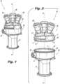
- FIG. 1a partial view of an exemplary embodiment of an access device in accordance with the disclosure is shown in Fig. 1 and is designated generally by reference character 10.
- FIG. 2-34Other embodiments of access devices in accordance with the disclosure, or aspects thereof, are provided in Figs. 2-34 , as will be described.
- the systems and methods described hereincan be used for single incision/natural orifice surgical access, such as for trans-anal minimally invasive surgical procedures, with multiple ports.
- the access device 10 for surgical proceduresincludes a multiport end cap 20 and a bottom body 30.
- the end capincludes a plurality of separate access ports 40 for accommodating introduction of individual surgical instruments into a body of a patient.
- the access ports 40extend in a proximal direction, i.e., upwards as oriented in Fig. 1 .
- the bottom body 30has a distally extending, i.e. downward extending as oriented in Fig. 1 , tubular body 8 with an access channel 9, shown in Figs. 6-7 , defined therethrough for accommodating surgical instruments from the access ports 40 into the body of a patient.
- the tubular body 8is mounted to a main ring portion 6 of the bottom body 30.
- the tubular body 8is of a less rigid material than that of the main ring portion 6.
- the tubular body 8is configured for introduction into a patient's body , e.g., for trans-anal introduction, or through a single incision formed in the wall of the abdominal cavity of a patient.
- the bottom body 30includes suture tie downs 22, which are identified in Fig. 4 . After the tubular body 8 of bottom body 30 is inserted into a body cavity or incision, the end cap 20 can be attached to the bottom body 30 to provide gas seal functionality.
- the bottom body 30includes an insufflation gas inlet 14 in fluid communication with the access channel 9 through tubular body 8.
- the insufflation gas inlet 14 shown in Fig. 5is configured to receive a tube set with one or more lumens, e.g., a double lumen tube set, however those skilled in the art will readily appreciate that any other suitable type of inlet can be used without departing from the scope of this disclosure.
- the access ports 40are configured to form mechanical seals for insufflation gas for when instruments are inserted through the access ports 40, and when there are no instruments inserted through the access ports 40.
- the end cap 20includes a distally extending seal ring 2.
- the seal ring 2 of the end cap 20is received inside and seals against a proximal rim 3 of the bottom body 30.
- the end cap 20includes a radially protruding stopper rim 5 that abuts a proximal most surface 19 of bottom body 30.
- An elastomeric seal ring 12forms a seal between the seal ring 2 of the end cap 20 and the proximal rim 3 of the bottom body 30 to provide sealing even during relative rotation of the end cap 20 and bottom body 30 about the longitudinal axis A.
- the elastomeric seal 12is seated in a circumferential channel 13 defined in the seal ring 2.
- the bottom body 30includes a plurality of circumferentially spaced apart teeth 18 on the outside of the proximal rim 3.
- the end cap 20includes an opposed pair of flexible tabs 16, shown in Figs. 3-4 , with distal teeth 32 thereon that extend radially inward, as shown in Figs. 10 and 11 , configured to engage and disengage the radially outwardly extending teeth 18 of the bottom body 30 to selectively permit or prevent relative axial rotation of the multiport end cap 20 around the longitudinal axis A.
- each of the flexible tabs 16includes a proximally extending manipulation member 17 and a compliant hinge member 24 between the manipulation member and the distal teeth 32 of the flexible tab16.
- hinge member 24is shown as a compliant hinge member, however it can also be a pivoting hinge member 24 as shown in Fig. 8A .
- the flexible tabs 16are integral with the end cap 20, and are connected to the end cap 20 by the complaint hinge members 24.
- the bottom body 30includes a latching surface 23, labeled in Fig. 8A , proximal to the teeth 18 thereof.
- the flexible tabs 16latch with the latching surface 23 to prevent axial movement of the end cap away from the bottom body when the teeth 18 and 32 are engaged, and can even stay latched when the teeth 18 and 32 are disengaged during relative axial rotation of the end cap 20 and the bottom body 30 to prevent axial displacement of the end cap 20 relative to the bottom body 30 during rotation.
- Optional feedback member 11cams against the cam 7 to increase force feedback as a user squeezes manipulation members 17 to prevent over squeezing to keep latching surface 23 engaged to the teeth 32 when rotating end cap 20 without axially removing it from bottom body 30.
- the proximal rim 3is sandwiched between the seal ring 2 and teeth 32 of end cap 20, as shown in the cross-section of Fig. 7 .
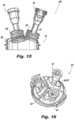
- each access port 40includes a rigid cannula body 42 and a cannula cap 44 housing a seal assembly 50, shown in Fig. 6 , for sealing against surgical instruments passing through the respective access port 40.
- Each cannula body 42is permanently attached in an air tight manner to a bellow 4, e.g.
- bellow 4allows for relative movement of the rigid cannula bodies 42 with respect to one another to provide flexibility and movement for surgical devices inserted through access ports 40.
- Each access port 40extends from a respective planar facet 25 of the end cap 40. Each access port 40 extends normal from the respective facet 25 of the end cap 20.
- the respective facets 25meet at facet junctures 27, wherein the facet junctures meet each other at an apex 29 of the end cap 20.
- each facet 25is angled at an angle ⁇ from a circumferential plane of the end cap 20, e.g., relative to a plane parallel to rim 5.
- the angle ⁇is larger than 0° and less than or equal to 60°.
- bellow 52forms a flexible support with a single sigmoidal cross-section that positions a distal end 51 of the at least one access port 40 within the multiport end cap, represented in Fig. 13 by the dashed line, and as shown in the cross sections of Figs. 6 and 7 .
- the flexible supports, e.g., including bellows 52, described hereincan include at least one of a rubber material, a rubber-like material, and/or a VersaFlex material available from VersaFlex Incorporated of Kansas City, Kansas.
- an access device 100 for surgical proceduresincludes a multiport end cap 120 having a rigid body 102 with flexible supports 154 sealingly mounted to the rigid body 102 with a plurality of separate access ports 40 for accommodating introduction of individual surgical instruments into a body of a patient, much as described above with respect to access device 10.
- Each of the access ports 40is sealingly attached to a respective one of the flexible supports 154 and extends in a proximal direction therefrom, i.e., in an upwards direction as oriented in Fig. 14 .
- the flexible supports 154are of a material more flexible than those of the rigid body 102 and access ports 40 to provide for relative angular movement of the access ports 40 to provide flexibility for positioning surgical instruments introduced through the access ports 40.
- Each of the flexible supports 154includes a flexible bellow with an accordion cross-section, as shown in Fig. 15 , which spaces a distal end 55 of the respective access port 40 proximally from the multiport end cap 20.
- Fig. 16another exemplary embodiment of an end cap 60 is shown.
- the bellows 52 and 154 in Figs. 12-15have a perimeter shape about the respective access ports that is round
- the bellows 66have diamond shaped perimeters around the respective access ports 40.
- the rigid body of end cap 60includes a rigid top body 62 and a two rigid bellow supports 72 and 74.
- the rigid top body 62 and the rigid bellow supports 72 and 74compress an outer peripheral edge 67 of the flexible supports 64 and 65 therebetween axially, e.g., by ultrasound welding, adhesive, or any other suitable joining technique, to form a sealing engagement between the rigid body of the end cap 60 and the flexible supports 64 and 65.
- the rigid bellow supports 72 and 74each include a respective support rib 76 and 78 extending proximally from the rigid bellow support 72 and 74 into the respective bellow 66 to inhibit inversion of the bellow 66 during instrument insertion into the access port 40.
- Each access port 40can include a compression ring 68 engaged to the distal end 51 of the access port 40.
- Each paired access port 40 and compression ring 68include an axially opposed pair of respective gripping rims 71 and 73 with a portion of the respective flexible support 64 and 65 gripped between the gripping rims 71 and 73.
- Each flexible supporthas a respective receptacle groove 75 defined therein for engaging each of the gripping rims 71 and 73.
- Each of the access ports 40includes a respective seal, much like seal assembly 50 described above, configured to seal against gas flow when no surgical instrument is introduced therethrough, and to seal around surgical instruments introduced therethrough.
- end cap 60includes three access ports 40 extending proximally from the end cap 60.
- One of the access ports 40connects to the rigid body of end cap 60 through the flexible support 65, wherein the flexible support 65 has a single bellow 66.
- the remaining two access ports 40connect to the rigid body of end cap 60 through the flexible support 64, wherein the flexible support 64 has two bellows 66, i.e., a double bellow, as shown in Fig. 18 , one for each of the two access ports 40.
- the rigid bellow support 72 of the rigid supportincludes two respective support ribs 76 extending proximally from the rigid support 72 into each one of the two bellows 66, respectively, to inhibit inversion of the two bellows 66 during instrument insertion into the access port 40.
- the rigid bellow support 74includes a single support rib 76 extending proximally from the rigid support 74 into the respective bellow 66 for the same purpose.
- FIG. 19another exemplary embodiment of an end cap 80 much like end caps 20 and 60 described above is shown with diamond shaped bellows 66.
- the three access ports 40connect to the rigid body of end cap 80 through the flexible support 84, wherein the flexible support 84 has three bellows 66, i.e., a triple bellow as shown in Fig. 21 , one for each of the three access ports 40.
- the rigid body of end cap 80includes a rigid top body 82 and a single rigid bellow support 86.
- the rigid top body 82 and the rigid bellow support 86compress an outer peripheral edge 87 of the flexible support 84 therebetween to form a sealing engagement between the rigid body of the end cap 80 and the flexible support 84.
- Three respective support ribs 88extending proximally from the rigid support 86 into each one of the three bellows 66, respectively, to inhibit inversion of the bellows 66 during instrument insertion into the access ports 40.
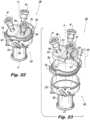
- Access device 200includes a multiport end cap 220 having a rigid body 204 with a flexible support 206 sealingly mounted to the rigid body 204 with a plurality of separate access ports 40 as described above for accommodating introduction of individual surgical instruments into a body of a patient.
- a bottom body 230is included in the access device 200, having a distally extending tubular body 202 with an access channel defined therethrough for accommodating surgical instruments from the access ports 40 into the body of a patient as in embodiments described above.
- the bottom body 230includes a connection port 203 for connecting a tube set with one or more lumens in fluid communication with the access channel much as described above with respect to access device 10.
- the access ports 40are configured to form mechanical seals for insufflation gas for when instruments are inserted through the access ports 40, and when there are no instruments inserted though the access ports 40.
- the tubular body 202is mounted to a main ring portion 207 of the bottom body 230, and wherein the tubular body 202 is of a less rigid material than that of the main ring portion 207.
- the tubular body 202is configured for introduction through a natural orifice of a body lumen or through a single incision formed in the wall of the abdominal cavity of a patient, for trans-anal introduction, or any other suitable
- the end cap 220is configured for complete 360° axial rotation relative to the bottom body 230 about longitudinal axis A.
- the rigid bodyincludes at least one flexible tab 216 configured to engage and disengage the bottom body 230 to selectively permit or prevent relative axial rotation of the multiport end cap 220 and bottom body 230 as described above with respect to access device 10.
- Each of the access ports 40includes a respective seal assembly as described with respect to embodiments above.
- the access ports 40are sealingly attached to the flexible support 206 and extend in a proximal direction therefrom, i.e. upwards as oriented in Fig 22 .
- the flexible support 206is of a material more flexible and/or stretchable than those of the rigid body 204 and access ports 40 to provide for relative angular movement of the access ports 40 to provide flexibility for positioning surgical instruments introduced through the access ports.
- the flexible support 206includes a flexible, closed-cell foam material for providing sealing to prevent gas flow therethrough; however it is also contemplated that an open-cell foam material can be used with an air tight coating. It is also contemplated that the foam material can include at least one of a rubber material, a rubber-like material, a VersaFlex material available from VersaFlex Incorporated of Kansas City, Kansas, and/or a foam material made from a gel or gel-like material.
- the access ports 40are mounted to a distal surface of the flexible support 206, i.e. the bottom surface of flexible support 206 as oriented in Fig.
- the rigid body 204defines a complete circumferential ring wherein the flexible support 206 is mounted within and spans the circumferential ring forming a complete circumferential seal between the rigid body 204 and the flexible support 206.
- the flexible support 206is adhered, ultrasonic welded, clamped or joined by any other suitable joining technique to an inward facing surface 211 of the circumferential ring to form a gas tight seal between the flexible support 206 and the rigid body 204.
- each access port 40extends from a respective planar facet 225 of the flexible support 206.
- Each access port 40extends normal from the respective facet 225 of the flexible support.
- the respective facets 225meet at facet junctures 227, wherein the facet junctures 227 meet each other at an apex 229 of the flexible support 206.
- Each facet 225is angled at an angle ⁇ from a circumferential plane of the end cap 220.
- the angle ⁇is not labeled in Fig. 23 , but see angle ⁇ labeled in Fig. 9 as described above.
- the angle ⁇is larger than 0° and less than or equal to 60°. It is also contemplated that the flexible support 206 can be flat, e.g. where angle ⁇ is equal to 0°.
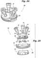
- FIG. 24another exemplary embodiment of an access device 300 is shown, including a flexible support 306 as described above with respect to access device 200.
- the circumferential ring of rigid body 304includes a proximal ring portion 313 and a distal ring portion 314.
- the flexible support 306is squeezed between the proximal and distal ring portions 313 and 314.
- the flexible support 306defines a respective ring groove 315 (labeled in Figs. 25 and 28 ) in its proximal and distal surfaces for receiving circumferential rims of the proximal and distal ring portions 313 and 314.
- the proximal and distal portions 313 and 314can be sealingly joined to the flexible support 306 by ultrasonic welding, adhesive, or any other suitable joining technique.
- Each access port 40includes an axially opposed pair of gripping rims 321, including a proximally extending gripping rim 321 defined on a compression ring 323 joined to the distal end of each access port 40.
- a portion of the flexible support 306is gripped between the respective gripping rims 321 of each access port 40.
- the flexible support 306has a respective receptacle groove 325 defined therein for receiving each of the gripping rims 321.
- At least one of the access ports 40can include a surgical port assembly that provides mechanical sealing for surgical instruments to reduce loss of pressure during surgical procedures.
- the assemblyincludes a tubular surgical port body 402 extending from an upper surface of the end cap, e.g., any of the end caps described above, and defining an access channel 401 therethrough.
- a cap 404is mounted to a proximal end of the surgical port body 402 and opens into the access channel 401 of the surgical port body 402, as shown in Figs. 30 and 31 .
- a main seal 406has a base 407 that is fixed between the cap 404 and the surgical port body 402 to suspend the main seal 406 across the access channel 401 as shown in Fig.
- a duck bill seal 408is included distal from the main seal 406 within the access channel 401.
- the duck bill seal 408includes a base 409 that is fixed between the cap 404 and the surgical port body 402 and provides mechanical sealing against surgical instruments extending through the access channel 401 in addition to the sealing provided by main seal 406.
- a seal guard 412is seated in an unfixed manner between the cap 404 and the main seal 406 within the access channel 401.
- the seal guard 412is of a material that is more rigid that those of the main seal 406 and the duck bill seal 408 to provide protection for the main seal 406 and the duck bill seal 408 when instruments are inserted through access channel 401, and to prevent inversion of the main seal 406 and/or the duck bill seal 408, e.g., when surgical instruments are withdrawn from access channel 401.
- the seal guard 412extends across the access channel 401 and is configured to move relative to the cap 404 and the surgical port body 402 to accommodate movement of surgical instruments extending through the access channel 401.
- the seal guard 412can move relative to the bases 407 and 407 of the main seal 406 and duck bill seal 408. This movement is accommodated by the seating of the base 413 of the seal guard 412 about the inward rim 403 of cap 404 within access channel 401.
- the seal guard 412can accommodate movement of instruments relative to surgical port body 402 and therefore improve sealing against the instruments by the main seal 406 and duckbill seal 408 relative to the sealing that would be accomplished if the seal guard 412 was rigidly mounted relative to the cap 404 and the surgical port body 402.
- the seal guard 412defines eight evenly spaced access slits 414 therethrough in a distal, frustoconical section of the seal guard 412.
- the access slitsare spaced circumferentially about the central aperture 215 of the seal guard 412 for passage of surgical instruments through the seal guard 412, accommodated by the deflectable panels separated by the access slits 414.
- the access slits 414facilitate alignment of surgical instruments with openings through the main seal 406 and the duck bill seal 408 to reduce leakage of pressurized gas through the main seal 406 and duck bill seal 408 during surgery.
Landscapes
- Health & Medical Sciences (AREA)
- Life Sciences & Earth Sciences (AREA)
- Surgery (AREA)
- Heart & Thoracic Surgery (AREA)
- Public Health (AREA)
- Animal Behavior & Ethology (AREA)
- Biomedical Technology (AREA)
- Veterinary Medicine (AREA)
- Engineering & Computer Science (AREA)
- General Health & Medical Sciences (AREA)
- Medical Informatics (AREA)
- Molecular Biology (AREA)
- Pathology (AREA)
- Nuclear Medicine, Radiotherapy & Molecular Imaging (AREA)
- Pulmonology (AREA)
- Anesthesiology (AREA)
- Hematology (AREA)
- Surgical Instruments (AREA)
Description
- This application claims the benefit of priority to U.S Patent Application Serial No.
15/790,658 filed October 23, 2017 - The subject invention is directed to surgical access devices, and more particularly, to multi-port access devices for minimally invasive surgical procedures.
- Laparoscopic or "minimally invasive" surgical techniques are becoming commonplace in the performance of procedures such as cholecystectomies, appendectomies, hernia repair and nephrectomies. Benefits of such procedures include reduced trauma to the patient, reduced opportunity for infection, and decreased recovery time. Such procedures commonly involve filling or "insufflating" the abdominal (peritoneal) cavity with a pressurized fluid, such as carbon dioxide, to create what is referred to as a pneumoperitoneum.
- The insufflation can be carried out by a surgical access device equipped to deliver insufflation fluid, or by a separate insufflation device, such as an insufflation (veress) needle. CONMED Corporation of Utica, New York, USA has developed unique surgical access devices that permit ready access to an insufflated surgical cavity without the need for conventional mechanical seals, and it has developed related gas delivery systems for providing sufficient pressure and flow rates to such access devices, as described in whole or in part in
U.S. Patent No. 7,854,724 andU.S. Patent No. 8,795,223 . - During typical laparoscopic procedures, a surgeon makes three to four small incisions, usually no larger than about twelve millimeters each. Typically the surgical access device is inserted into an incision using a separate inserter or obturator placed therein. Following insertion, the inserter is removed, and the trocar allows access for instruments to be inserted into the abdominal cavity.
- A variety of larger access devices are also known in the art for accessing a surgical site through a single relatively large incision to perform minimally invasive procedures, rather than through multiple small incisions. Examples of such devices are disclosed in
U.S. Patent Application Publication No. 2013/0012782 . - Trans-anal minimally invasive surgery (TAMIS) is a specialized minimally invasive approach to removing benign polyps and some cancerous tumors within the rectum and lower sigmoid colon. The benefit of TAMIS is that it is considered an organ-sparing procedure, and is performed entirely through the body's natural opening, requiring no skin incisions to gain access to a polyp or tumor. This scar-free recovery provides a quick return to normal bowel function. Unlike traditional surgery where a major portion of the large intestine is removed, with TAMIS the surgeon will precisely remove the diseased tissue, leaving the rest of the natural bowel lumen intact to function normally. Traditional surgery often requires a large incision and a hospital stay ranging from a few days to more than a week. A TAMIS procedure may only require an overnight stay in the hospital or can be performed as an outpatient procedure, often permitting patients an immediate return to an active lifestyle. TATMe (Trans-anal Total Mesorectal Excision) is a more significant trans-anal procedure.
US 2010/228092 A1 discloses a surgical access device, comprising a housing having a central axis and a working channel extending therethrough; a seal member disposed in the housing and configured to seal the working channel; and a plurality of sealing elements disposed in the seal member, each sealing element being configured to receive and form a seal around an instrument inserted therethrough and into the working channel, the plurality of sealing elements including at least one movable sealing element that is movable independent of the other sealing elements within a predetermined path.US 2010/081880 A1 discloses a surgical access device, comprising a retractor having an opening extending therethrough for forming a pathway through tissue into a body cavity; a housing coupled to the retractor and defining a longitudinal axis extending therethrough, the housing having a plurality of rigid sealing ports in communication with the opening in the retractor, each sealing port having a sealing element therein and having a central axis that forms an angle with the longitudinal axis of the housing that is greater than zero.WO 2010/082722 A1 discloses a a multi-channel trocar having an attachable/ detachable sealing member, in which one trocar can be equipped with various types of surgical instruments to perform laparoscopic surgery with a minimized abdominal incision and relieve the cost burden on the patient, and in which the sealing member for preventing the inflow/outflow of air to/from the trocar is attachable/detachable to/from the trocar such that the sealing member is removed from the trocar and used in a conventional trocar in the event the condition of the patient worsens, requiring a plurality of incisions to be made at the abdomen of the patient and a plurality of conventional trocars (which enables only one surgical instrument to be inserted into one trocar) to be used. The multi-channel trocar having the attachable/detachable sealing member comprises: a main body having an upper part with a plurality of mounting portions and an open lower part; a cannula which is coupled to the lower part of the main body to close the opening of the lower part, and inserted into the abdomen of the patient; and a plurality of sealing members which are removably fitted to the mounting portions of the main body, and seal the outer circumference of the laparoscopic surgical instrument inserted into the trocar to prevent the inflow/outflow of air to/from the trocar.US 6 551 270 B1 discloses a port assembly adapted for insertion into the tissue of a patient during laparoscopic or endoscopic surgery wherein the port assembly includes an access port having a plurality of openings therein to allow for the insertion of multiple surgical instruments therethrough while maintaining a barrier to the flow of gas from the body cavity of the patient to the atmosphere. The access port is positioned in the housing of the port assembly and preferably includes two or more circular or semi-circularly shaped openings therein and a sealing member associated therewith to allow for the independent movement of the instruments therethrough.US 2010/268035 A1 discloses a seal that is used for closing-off a proximal-side access port of an access instrument into a body. It has a cap having a wall covering the access port and a circumferential collar, which can be put over an edge of the access port. At least two approximately circular-segment-shaped openings are present in the wall, wherein a flexible dome sits on each opening and, on the proximal side, has, compared to the circular-segment-shaped openings, a smaller entry port.- It would be beneficial to provide a single incision access device having multiple ports with a variety of different port sizes to give a surgeon more options for instrument introduction during a laparoscopic surgical procedure. It would also be beneficial to provide an access device having multiple ports with a variety of different port sizes that enables ready access to natural orifices for performing trans-anal minimally invasive surgical procedures or the like.
- The invention is defined by the subject matter of the independent claim 1. Further embodiments of the invention are defined in the dependent claims. Embodiments which are not covered by the claims are only used for illustrative purposes and do not form part of the invention. No surgical methods form part of the invention. An access device for surgical procedures includes a multiport end cap having a rigid body with a flexible support sealingly mounted to the rigid body with a plurality of separate access ports for accommodating introduction of individual surgical instruments into a body of a patient. At least one of the access ports is sealingly attached to the flexible support and extends in a proximal direction therefrom. The flexible support is of a material more flexible than those of the rigid body and access ports to provide for relative angular movement of at least one of the access ports to provide flexibility for positioning surgical instruments introduced through the access ports.
- The flexible support includes at least one flexible bellow. The at least one flexible bellow can include at least one of a rubber material, a rubber-like material, and/or a VersaFlex material. The rigid body includes a rigid top body and a rigid bellow support, wherein the rigid top body and the rigid bellow support compress an outer peripheral edge of the flexible support therebetween to form a sealing engagement between the rigid body and the flexible support. The rigid bellow support includes at least one support rib extending proximally from the rigid bellow support into the bellow to inhibit inversion of the bellow during instrument insertion into the access port.
- The at least one access port can include a compression ring engaged to a distal end of the access port with an inner edge of the flexible support compressed between the access port and the compression ring to form a sealing engagement between the at least one access port and the flexible support. The at least one access port and compression ring can include an axially opposed pair of gripping rims with a portion of the flexible support gripped between the gripping rims. The flexible support can have a respective receptacle groove defined therein for engaging each of the gripping rims. Each of the access ports can include a respective seal configured to seal against gas flow when no surgical instrument is introduced therethrough, and to seal around surgical instruments introduced therethrough.
- There can be three access ports extending proximally from the end cap. At least one of the access ports can connect to the rigid body through the flexible support, wherein the flexible support has a single bellow. Two of the access ports can connect to the rigid body through the flexible support, wherein the flexible support has two bellows, one for each of the two access ports. The rigid support can include a respective support rib extending proximally from the rigid support into each one of the two bellows, respectively, to inhibit inversion of the two bellows during instrument insertion into the access port. A second flexible support can be included with a single bellow for connecting a third one of the three access ports to the rigid body. It is also contemplated that the three access ports can connect to the rigid body through the flexible support, wherein the flexible support has three bellows, one for each of the three access ports. The rigid support can include a respective support rib extending proximally from the rigid support into each one of the two bellows, respectively, to inhibit inversion of the two bellows during instrument insertion into the access port.
- The flexible support can include a bellow with a single sigmoidal cross-section that positions a distal end of the at least one access port within the multiport end cap. The flexible support can include a bellow with an accordion cross-section that spaces a distal end of the at least one access port proximally from the multiport end cap. The flexible support can include a bellow with a perimeter shape about the at least one access port that includes at least one of round and diamond shaped.
- A bottom body can be included having a distally extending tubular body with an access channel defined therethrough for accommodating surgical instruments from the access ports into the body of a patient. The bottom body can include a gas inlet in fluid communication with the access channel. The access ports can be configured to form a mechanical seal for insufflation gas for when instruments are inserted through the access ports and when no instruments are inserted through the access ports. The tubular body can be configured for introduction through a body lumen or through a single incision formed in the wall of the abdominal cavity of a patient. The tubular body can be configured for trans-anal introduction. The end cap can be configured for complete 360° axial rotation relative to the bottom body. The tubular body can be mounted to a main ring portion of the bottom body, wherein the tubular body is of a less rigid material than that of the main ring portion. The rigid body can include at least one flexible tab configured to engage and disengage the bottom body to selectively permit or prevent relative axial rotation of the multiport end cap and bottom body.
- These and other features of the systems and methods of the subject disclosure will become more readily apparent to those skilled in the art from the following detailed description of the preferred embodiments taken in conjunction with the drawings.
- So that those skilled in the art to which the subject disclosure appertains will readily understand how to make and use the devices and methods of the subject disclosure without undue experimentation, preferred embodiments thereof will be described in detail herein below with reference to certain figures, wherein:
Fig. 1 is a perspective view of an exemplary embodiment of an access device constructed in accordance with the present disclosure, showing the flexible tab and teeth configured to selectively permit or prevent relative axial rotation of the multiport end cap;Fig. 2 is an exploded perspective view of the access device ofFig. 1 , showing the multiport end cap removed from the bottom body;Fig. 3 is a plan view of the access device ofFig. 1 , showing the two opposed flexible tabs viewed looking distally;Fig. 4 is a plan view of the access device ofFig. 1 , showing the two opposed flexible tabs viewed looking proximally;Fig. 5 is a side elevation view of the access device ofFig. 1 , showing a connection port for a tube set;Fig. 6 is a cross-sectional side elevation view of the access device ofFig. 1 , showing the sealing ring of the end cap sealing against the proximal rim of the bottom body;Fig. 7 is a cross-sectional side elevation view of the access device ofFig. 1 , showing the flexible tabs engaging the teeth of the bottom body;Fig. 8A is a cross-sectional side elevation view of a portion of the access device ofFig. 1 , showing a pivoting hinge instead of compliant hinge for the flexible tabs;Fig. 8B is a perspective view of a portion of the access device ofFig. 1 , showing the end cap;Fig. 9 is a side elevation view of the end cap ofFig 8 , showing the angle of the facet junctures of the end cap;Fig. 10 is a plan view of the end cap ofFig. 8 , showing the teeth of the flexible tabs;Fig. 11 is a plan view of a portion of the end cap ofFig. 8 , showing the teeth of one of the flexible tabs;Fig. 12 is a side elevation view of one of the access ports of the end cap ofFig. 8 , showing the bellow;Fig. 13 is a cross-sectional side elevation view of the access port ofFig. 12 , showing the cross-section of the bellow;Fig. 14 is a side elevation view of another embodiment of an end cap constructed in accordance with the present disclosure, showing bellows with accordion cross-sections;Fig. 15 is a cross-sectional side elevation view of the end cap ofFig. 14 , showing the cross-section of one of the bellows;Fig. 16 is a perspective view of another exemplary embodiment of an end cap constructed in accordance with the present disclosure, showing two flexible supports, one including a single bellow and one including a double bellow;Fig. 17 is an exploded perspective view of the end cap ofFig. 16 , showing rigid bellow supports with support ribs to inhibit inversion of the bellows;Fig. 18 is a perspective view of the double bellow ofFig. 16 ;Fig. 19 is a perspective view of another exemplary embodiment of an end cap constructed in accordance with the present disclosure, showing a single flexible support with three bellows;Fig. 20 is an exploded perspective view of the end cap ofFig. 19 , showing a rigid bellow support with support ribs to inhibit inversion of the bellows;Fig. 21 is a perspective view of the triple bellow ofFig. 19 ;Fig. 22 is a perspective view of another exemplary embodiment of an end cap constructed in accordance with the present invention, showing a flexible body that includes a flexible foam material;Fig. 23 is an exploded perspective view of the end cap ofFig. 22 , showing the rigid body separated from the flexible foam support;Fig. 24 is a perspective view of another exemplary embodiment of an end cap constructed in accordance with the present invention;Fig. 25 is an exploded perspective view of the end cap ofFig. 24 , showing the access ports separated from the flexible foam support;Fig. 26 is a plan view of the end cap ofFig. 24 , showing the flexible tabs;Fig. 27 is a cross-sectional side elevation view of the end cap ofFig. 24 , showing the attachment of one of the access ports to the flexible foam support;Fig. 28 is a cross-sectional side elevation view of a portion of the end cap ofFig. 24 , showing the gripping rims of one of the access ports gripping the flexible support;Fig. 29 is an exploded perspective view of one of the access ports constructed in accordance with an exemplary embodiment, showing the seal guard;Fig. 30 is a side elevation view of the access port ofFig. 29 , showing the cap mounted on the proximal end of the surgical port body;Fig. 31 is a cross-sectional side elevation view of a portion of the access port ofFig. 29 , showing the bases of the main and duck bill seals fixed between the cap and the surgical port body with the base of the seal guard floating unfixed relative to the cap and surgical port body;Fig. 32 is a side elevation view of the seal guard ofFig. 29 , showing the access slits;Fig. 33 is distal end view of the seal guard ofFig. 32 , showing the circumferential spacing of the access slits; andFig. 34 is a schematic view of the access device ofFig. 1 , showingaccess ports 40 that vary in size relative to one another.- Reference will now be made to the drawings wherein like reference numerals identify similar structural features or aspects of the subject disclosure. For purposes of explanation and illustration, and not limitation, a partial view of an exemplary embodiment of an access device in accordance with the disclosure is shown in
Fig. 1 and is designated generally byreference character 10. Other embodiments of access devices in accordance with the disclosure, or aspects thereof, are provided inFigs. 2-34 , as will be described. The systems and methods described herein can be used for single incision/natural orifice surgical access, such as for trans-anal minimally invasive surgical procedures, with multiple ports. - The
access device 10 for surgical procedures includes amultiport end cap 20 and abottom body 30. The end cap includes a plurality ofseparate access ports 40 for accommodating introduction of individual surgical instruments into a body of a patient. Theaccess ports 40 extend in a proximal direction, i.e., upwards as oriented inFig. 1 . Thebottom body 30 has a distally extending, i.e. downward extending as oriented inFig. 1 , tubular body 8 with an access channel 9, shown inFigs. 6-7 , defined therethrough for accommodating surgical instruments from theaccess ports 40 into the body of a patient. The tubular body 8 is mounted to amain ring portion 6 of thebottom body 30. The tubular body 8 is of a less rigid material than that of themain ring portion 6. The tubular body 8 is configured for introduction into a patient's body , e.g., for trans-anal introduction, or through a single incision formed in the wall of the abdominal cavity of a patient. Thebottom body 30 includes suture tie downs 22, which are identified inFig. 4 . After the tubular body 8 ofbottom body 30 is inserted into a body cavity or incision, theend cap 20 can be attached to thebottom body 30 to provide gas seal functionality. - The
bottom body 30 includes an insufflation gas inlet 14 in fluid communication with the access channel 9 through tubular body 8. The insufflation gas inlet 14 shown inFig. 5 is configured to receive a tube set with one or more lumens, e.g., a double lumen tube set, however those skilled in the art will readily appreciate that any other suitable type of inlet can be used without departing from the scope of this disclosure. Theaccess ports 40 are configured to form mechanical seals for insufflation gas for when instruments are inserted through theaccess ports 40, and when there are no instruments inserted through theaccess ports 40. - With reference now to
Fig. 2 , theend cap 20 includes a distally extendingseal ring 2. Theseal ring 2 of theend cap 20 is received inside and seals against aproximal rim 3 of thebottom body 30. Theend cap 20 includes a radially protruding stopper rim 5 that abuts a proximal most surface 19 ofbottom body 30. Anelastomeric seal ring 12 forms a seal between theseal ring 2 of theend cap 20 and theproximal rim 3 of thebottom body 30 to provide sealing even during relative rotation of theend cap 20 andbottom body 30 about the longitudinal axis A. Theelastomeric seal 12 is seated in acircumferential channel 13 defined in theseal ring 2. - The
bottom body 30 includes a plurality of circumferentially spaced apartteeth 18 on the outside of theproximal rim 3. Theend cap 20 includes an opposed pair offlexible tabs 16, shown inFigs. 3-4 , withdistal teeth 32 thereon that extend radially inward, as shown inFigs. 10 and 11 , configured to engage and disengage the radially outwardly extendingteeth 18 of thebottom body 30 to selectively permit or prevent relative axial rotation of themultiport end cap 20 around the longitudinal axis A. - With reference now to
Figs. 7 and8A , each of theflexible tabs 16 includes a proximally extendingmanipulation member 17 and acompliant hinge member 24 between the manipulation member and thedistal teeth 32 of the flexible tab16. InFig. 7 ,hinge member 24 is shown as a compliant hinge member, however it can also be a pivotinghinge member 24 as shown inFig. 8A . Theflexible tabs 16 are integral with theend cap 20, and are connected to theend cap 20 by thecomplaint hinge members 24. Since there are there are two circumferentially opposedflexible tabs 16, squeezing themanipulation members 17 together, i.e., radially inward towards one another, releases theteeth 32 of theflexible tabs 16 from theteeth 18 of thebottom body 30 to allow rotation of theend cap 20 relative to thebottom body 30 around the longitudinal axis A. Theend cap 20 is configured for complete 360° axial rotation relative to thebottom body 30. Releasing theflexible tabs 16 re-engages theteeth bottom body 30 includes a latchingsurface 23, labeled inFig. 8A , proximal to theteeth 18 thereof. Theflexible tabs 16 latch with the latchingsurface 23 to prevent axial movement of the end cap away from the bottom body when theteeth teeth end cap 20 and thebottom body 30 to prevent axial displacement of theend cap 20 relative to thebottom body 30 during rotation.Optional feedback member 11 cams against the cam 7 to increase force feedback as a user squeezesmanipulation members 17 to prevent over squeezing to keep latchingsurface 23 engaged to theteeth 32 when rotatingend cap 20 without axially removing it frombottom body 30. Theproximal rim 3 is sandwiched between theseal ring 2 andteeth 32 ofend cap 20, as shown in the cross-section ofFig. 7 . - With reference now to
Fig. 8B , there are threeaccess ports 40 extending proximally from theend cap 20. As shown inFigs. 3 and10 , theaccess ports 40 are evenly spaced circumferentially about theend cap 20, and all threeaccess ports 40 can be of a uniform size with one another, or can vary in size. Eachaccess port 40 includes a rigid cannula body 42 and a cannula cap 44 housing aseal assembly 50, shown inFig. 6 , for sealing against surgical instruments passing through therespective access port 40. Each cannula body 42 is permanently attached in an air tight manner to a bellow 4, e.g. of an elastomeric material, which is in turn permanently attached in an air tight manner to therespective facet 25 ofend cap 20, e.g., by adhesive, ultrasound welding, over molding, or any other suitable joining process). The flexibility of bellow 4 allows for relative movement of the rigid cannula bodies 42 with respect to one another to provide flexibility and movement for surgical devices inserted throughaccess ports 40. - Each
access port 40 extends from a respectiveplanar facet 25 of theend cap 40. Eachaccess port 40 extends normal from therespective facet 25 of theend cap 20. Therespective facets 25 meet at facet junctures 27, wherein the facet junctures meet each other at an apex 29 of theend cap 20. As shown inFig. 9 , eachfacet 25 is angled at an angle α from a circumferential plane of theend cap 20, e.g., relative to a plane parallel to rim 5. The angle α is larger than 0° and less than or equal to 60°. - With reference now to
Fig. 12 , an access port with another embodiment of abellow 52 is shown, wherein thebase 53 of thebellow 52 is circular. As shown inFig. 13 , bellow 52 forms a flexible support with a single sigmoidal cross-section that positions adistal end 51 of the at least oneaccess port 40 within the multiport end cap, represented inFig. 13 by the dashed line, and as shown in the cross sections ofFigs. 6 and7 . The flexible supports, e.g., including bellows 52, described herein can include at least one of a rubber material, a rubber-like material, and/or a VersaFlex material available from VersaFlex Incorporated of Kansas City, Kansas. - Referring now to
Fig. 14 , another exemplary embodiment of anaccess device 100 for surgical procedures includes a multiport end cap 120 having arigid body 102 withflexible supports 154 sealingly mounted to therigid body 102 with a plurality ofseparate access ports 40 for accommodating introduction of individual surgical instruments into a body of a patient, much as described above with respect to accessdevice 10. Each of theaccess ports 40 is sealingly attached to a respective one of theflexible supports 154 and extends in a proximal direction therefrom, i.e., in an upwards direction as oriented inFig. 14 . Theflexible supports 154 are of a material more flexible than those of therigid body 102 andaccess ports 40 to provide for relative angular movement of theaccess ports 40 to provide flexibility for positioning surgical instruments introduced through theaccess ports 40. Each of theflexible supports 154 includes a flexible bellow with an accordion cross-section, as shown inFig. 15 , which spaces adistal end 55 of therespective access port 40 proximally from themultiport end cap 20. - With reference now to
Fig. 16 , another exemplary embodiment of anend cap 60 is shown. Whereas thebellows Figs. 12-15 have a perimeter shape about the respective access ports that is round, inend cap 60, thebellows 66 have diamond shaped perimeters around therespective access ports 40. As shown inFig. 17 , the rigid body ofend cap 60 includes a rigidtop body 62 and a two rigid bellow supports 72 and 74. The rigidtop body 62 and the rigid bellow supports 72 and 74 compress an outerperipheral edge 67 of theflexible supports 64 and 65 therebetween axially, e.g., by ultrasound welding, adhesive, or any other suitable joining technique, to form a sealing engagement between the rigid body of theend cap 60 and theflexible supports 64 and 65. The rigid bellow supports 72 and 74 each include a respective support rib 76 and 78 extending proximally from therigid bellow support 72 and 74 into therespective bellow 66 to inhibit inversion of thebellow 66 during instrument insertion into theaccess port 40. - Each
access port 40 can include a compression ring 68 engaged to thedistal end 51 of theaccess port 40. An inner edge 69 of theflexible supports 64 and 65 compressed between therespective access port 40 and the compression ring 68 to form a sealing engagement between theaccess ports 40 and theflexible supports 64 and 65. Each pairedaccess port 40 and compression ring 68 include an axially opposed pair of respectivegripping rims flexible support 64 and 65 gripped between thegripping rims respective receptacle groove 75 defined therein for engaging each of thegripping rims access ports 40 includes a respective seal, much likeseal assembly 50 described above, configured to seal against gas flow when no surgical instrument is introduced therethrough, and to seal around surgical instruments introduced therethrough. - As with
end cap 20 described above,end cap 60 includes threeaccess ports 40 extending proximally from theend cap 60. One of theaccess ports 40 connects to the rigid body ofend cap 60 through the flexible support 65, wherein the flexible support 65 has asingle bellow 66. The remaining twoaccess ports 40 connect to the rigid body ofend cap 60 through theflexible support 64, wherein theflexible support 64 has twobellows 66, i.e., a double bellow, as shown inFig. 18 , one for each of the twoaccess ports 40. - With reference again to
Fig. 17 , therigid bellow support 72 of the rigid support includes two respective support ribs 76 extending proximally from therigid support 72 into each one of the two bellows 66, respectively, to inhibit inversion of the two bellows 66 during instrument insertion into theaccess port 40. The rigid bellow support 74 includes a single support rib 76 extending proximally from the rigid support 74 into therespective bellow 66 for the same purpose. - Referring now to
Fig. 19 , another exemplary embodiment of anend cap 80 much like end caps 20 and 60 described above is shown with diamond shaped bellows 66. The threeaccess ports 40 connect to the rigid body ofend cap 80 through theflexible support 84, wherein theflexible support 84 has threebellows 66, i.e., a triple bellow as shown inFig. 21 , one for each of the threeaccess ports 40. As shown inFig. 20 , the rigid body ofend cap 80 includes a rigidtop body 82 and a single rigid bellow support 86. The rigidtop body 82 and the rigid bellow support 86 compress an outerperipheral edge 87 of theflexible support 84 therebetween to form a sealing engagement between the rigid body of theend cap 80 and theflexible support 84. Threerespective support ribs 88 extending proximally from the rigid support 86 into each one of the three bellows 66, respectively, to inhibit inversion of thebellows 66 during instrument insertion into theaccess ports 40. - With reference now to
Fig. 22 , another exemplary embodiment of anaccess device 200 is shown for surgical procedures.Access device 200 includes amultiport end cap 220 having arigid body 204 with a flexible support 206 sealingly mounted to therigid body 204 with a plurality ofseparate access ports 40 as described above for accommodating introduction of individual surgical instruments into a body of a patient. - A
bottom body 230 is included in theaccess device 200, having a distally extendingtubular body 202 with an access channel defined therethrough for accommodating surgical instruments from theaccess ports 40 into the body of a patient as in embodiments described above. Thebottom body 230 includes aconnection port 203 for connecting a tube set with one or more lumens in fluid communication with the access channel much as described above with respect to accessdevice 10. Theaccess ports 40 are configured to form mechanical seals for insufflation gas for when instruments are inserted through theaccess ports 40, and when there are no instruments inserted though theaccess ports 40. Thetubular body 202 is mounted to amain ring portion 207 of thebottom body 230, and wherein thetubular body 202 is of a less rigid material than that of themain ring portion 207. Thetubular body 202 is configured for introduction through a natural orifice of a body lumen or through a single incision formed in the wall of the abdominal cavity of a patient, for trans-anal introduction, or any other suitable mode of introduction. - As in embodiments described above, the
end cap 220 is configured for complete 360° axial rotation relative to thebottom body 230 about longitudinal axis A. The rigid body includes at least oneflexible tab 216 configured to engage and disengage thebottom body 230 to selectively permit or prevent relative axial rotation of themultiport end cap 220 andbottom body 230 as described above with respect to accessdevice 10. Each of theaccess ports 40 includes a respective seal assembly as described with respect to embodiments above. - The
access ports 40 are sealingly attached to the flexible support 206 and extend in a proximal direction therefrom, i.e. upwards as oriented inFig 22 . The flexible support 206 is of a material more flexible and/or stretchable than those of therigid body 204 andaccess ports 40 to provide for relative angular movement of theaccess ports 40 to provide flexibility for positioning surgical instruments introduced through the access ports. - With reference now to
Fig. 23 , the flexible support 206 includes a flexible, closed-cell foam material for providing sealing to prevent gas flow therethrough; however it is also contemplated that an open-cell foam material can be used with an air tight coating. It is also contemplated that the foam material can include at least one of a rubber material, a rubber-like material, a VersaFlex material available from VersaFlex Incorporated of Kansas City, Kansas, and/or a foam material made from a gel or gel-like material. Theaccess ports 40 are mounted to a distal surface of the flexible support 206, i.e. the bottom surface of flexible support 206 as oriented inFig. 23 , and extend proximally throughrespective bores 209 in the flexible support 206 to extend proximally from the flexible support 206. Therigid body 204 defines a complete circumferential ring wherein the flexible support 206 is mounted within and spans the circumferential ring forming a complete circumferential seal between therigid body 204 and the flexible support 206. The flexible support 206 is adhered, ultrasonic welded, clamped or joined by any other suitable joining technique to an inward facingsurface 211 of the circumferential ring to form a gas tight seal between the flexible support 206 and therigid body 204. - As with embodiments described above, there are three
access ports 40 extending proximally from theend cap 220, evenly spaced circumferentially about theend cap 220, and uniform in size with one another, however it is also contemplated that in an end cap can have ports of sizes that differ from one another as shown schematically inFig. 34 . Eachaccess port 40 extends from a respectiveplanar facet 225 of the flexible support 206. Eachaccess port 40 extends normal from therespective facet 225 of the flexible support. Therespective facets 225 meet atfacet junctures 227, wherein thefacet junctures 227 meet each other at an apex 229 of the flexible support 206. Eachfacet 225 is angled at an angle α from a circumferential plane of theend cap 220. The angle α is not labeled inFig. 23 , but see angle α labeled inFig. 9 as described above. The angle α is larger than 0° and less than or equal to 60°. It is also contemplated that the flexible support 206 can be flat, e.g. where angle α is equal to 0°. - With reference now to
Fig. 24 , another exemplary embodiment of anaccess device 300 is shown, including aflexible support 306 as described above with respect to accessdevice 200. As shown inFig. 25 , the circumferential ring ofrigid body 304 includes aproximal ring portion 313 and adistal ring portion 314. As shown inFigs. 26-27 , theflexible support 306 is squeezed between the proximal anddistal ring portions flexible support 306 defines a respective ring groove 315 (labeled inFigs. 25 and28 ) in its proximal and distal surfaces for receiving circumferential rims of the proximal anddistal ring portions distal portions flexible support 306 by ultrasonic welding, adhesive, or any other suitable joining technique. - Each
access port 40 includes an axially opposed pair ofgripping rims 321, including a proximally extendinggripping rim 321 defined on acompression ring 323 joined to the distal end of eachaccess port 40. A portion of theflexible support 306 is gripped between the respectivegripping rims 321 of eachaccess port 40. Theflexible support 306 has arespective receptacle groove 325 defined therein for receiving each of thegripping rims 321. - With reference now to
Fig. 29 , at least one of theaccess ports 40 can include a surgical port assembly that provides mechanical sealing for surgical instruments to reduce loss of pressure during surgical procedures. The assembly includes a tubularsurgical port body 402 extending from an upper surface of the end cap, e.g., any of the end caps described above, and defining anaccess channel 401 therethrough. Acap 404 is mounted to a proximal end of thesurgical port body 402 and opens into theaccess channel 401 of thesurgical port body 402, as shown inFigs. 30 and 31 . Amain seal 406 has a base 407 that is fixed between thecap 404 and thesurgical port body 402 to suspend themain seal 406 across theaccess channel 401 as shown inFig. 31 to provide mechanical sealing against surgical instruments extending through theaccess channel 401. Aduck bill seal 408 is included distal from themain seal 406 within theaccess channel 401. Theduck bill seal 408 includes a base 409 that is fixed between thecap 404 and thesurgical port body 402 and provides mechanical sealing against surgical instruments extending through theaccess channel 401 in addition to the sealing provided bymain seal 406. - A
seal guard 412 is seated in an unfixed manner between thecap 404 and themain seal 406 within theaccess channel 401. Theseal guard 412 is of a material that is more rigid that those of themain seal 406 and theduck bill seal 408 to provide protection for themain seal 406 and theduck bill seal 408 when instruments are inserted throughaccess channel 401, and to prevent inversion of themain seal 406 and/or theduck bill seal 408, e.g., when surgical instruments are withdrawn fromaccess channel 401. - With continued reference to
Fig. 31 , theseal guard 412 extends across theaccess channel 401 and is configured to move relative to thecap 404 and thesurgical port body 402 to accommodate movement of surgical instruments extending through theaccess channel 401. Theseal guard 412 can move relative to thebases main seal 406 andduck bill seal 408. This movement is accommodated by the seating of thebase 413 of theseal guard 412 about theinward rim 403 ofcap 404 withinaccess channel 401. Since it is free to move relative to thecap 404 and thesurgical port body 402, theseal guard 412 can accommodate movement of instruments relative tosurgical port body 402 and therefore improve sealing against the instruments by themain seal 406 andduckbill seal 408 relative to the sealing that would be accomplished if theseal guard 412 was rigidly mounted relative to thecap 404 and thesurgical port body 402. - As shown in
Figs. 32 and 33 , theseal guard 412 defines eight evenly spacedaccess slits 414 therethrough in a distal, frustoconical section of theseal guard 412. The access slits are spaced circumferentially about thecentral aperture 215 of theseal guard 412 for passage of surgical instruments through theseal guard 412, accommodated by the deflectable panels separated by the access slits 414. The access slits 414 facilitate alignment of surgical instruments with openings through themain seal 406 and theduck bill seal 408 to reduce leakage of pressurized gas through themain seal 406 andduck bill seal 408 during surgery. - The methods and systems of the present disclosure, as described above and shown in the drawings, provide for single incision/natural orifice surgical access with superior properties including minimally invasive, multiple port access with flexibility for relative movement of the access ports.
Claims (14)
- An access device (100) for surgical procedures comprising:a multiport end cap (60; 80) including a rigid body (102) with a flexible support (64, 65; 84) sealingly mounted to the rigid body (102) with a plurality of separate access ports (40) for accommodating introduction of individual surgical instruments into a body of a patient, at least one of the access ports (40) sealingly attached to the flexible support (64, 65; 84) and extending in a proximal direction therefrom, wherein the flexible support (64, 65; 84) is of a material more flexible than those of the rigid body (102) and access ports (40) to provide for relative angular movement of at least one of the access ports (40) to provide flexibility for positioning surgical instruments introduced through the at least one access port (40),characterized in that the flexible support (64, 65; 84) includes at least one flexible bellow (66), wherein the rigid body includes a rigid top body (62; 82) and a rigid bellow support (72, 74), wherein the rigid top body (62; 82) and the rigid bellow support (72, 74; 86) compress an outer peripheral edge (67) of the flexible support (64, 65; 84) therebetween to form a sealing engagement between the rigid body (102) and the flexible support (64, 65; 84),wherein the rigid bellow support (72, 74; 86) includes at least one support rib (76, 78; 88) extending proximally from the rigid bellow support (72, 74; 86) into the bellow (66) to inhibit inversion of the bellow (66) during instrument insertion into the access port (40).
- The access device (100) as recited in claim 1, wherein the at least one flexible bellow (66) includes at least one of a rubber material and a rubber-like material.
- The access device (100) as recited in claim 1, wherein the at least one access port (40) includes a compression ring (68) engaged to a distal end (51) of the access port (40) with an inner edge (69) of the flexible support (64, 65) compressed between the access port (40) and the compression ring (68) to form a sealing engagement between the at least one access port (40) and the flexible support (64, 65), in particular wherein:the at least one access port (40) and compression ring (68) include an axially opposed pair of gripping rims (71, 73) with a portion of the flexible support (64, 65) gripped between the gripping rims (71, 73),in particular wherein the flexible support (64, 65) has a respective receptacle groove (75) defined therein for engaging each of the gripping rims (71, 73).
- The access device (100) as recited in claim 1, wherein there are three access ports (40) extending proximally from the end cap (60; 80).
- The access device (100) as recited in claim 4, wherein at least one of the access ports (40) connects to the rigid body through the flexible support (65), wherein the flexible support (65) has a single bellow (66).
- The access device (100) as recited in claim 4, wherein two of the access ports (40) connect to the rigid body through the flexible support (64), wherein the flexible support (64) has two bellows (66), one for each of the two access ports (40).
- The access device (100) as recited in claim 6, wherein the rigid bellow support (72) includes a respective support rib (76) extending proximally from the rigid bellow support (72) into each one of the two bellows (66), respectively, to inhibit inversion of the two bellows (66) during instrument insertion into the access port (40),
and/or
wherein the access device (100) further comprises a second flexible support (65) with a single bellow (66) for connecting a third one of the three access ports (40) to the rigid body. - The access device (100) as recited in claim 4, wherein the three access ports (40) connect to the rigid body through the flexible support (84), wherein the flexible support (84) has three bellows (66), one for each of the three access ports (40),
in particular wherein the rigid bellow support (86) includes a respective support rib (88) extending proximally from the rigid bellow support (86) into each one of the three bellows (66), respectively, to inhibit inversion of the three bellows (66) during instrument insertion into the access port (40). - The access device (100) as recited in claim 1, wherein the flexible support includes a bellow (66) with a single sigmoidal cross-section that positions a distal end (51) of the at least one access port (40) within the multiport end cap (60; 80),
and/orwherein the flexible support (64, 65; 84) includes a bellow with an accordion cross-section that spaces a distal end (51) of the at least one access port (40) proximally from the multiport end cap (60; 80),
and/orwherein the flexible support (64, 65; 84) includes a bellow (66) with a perimeter shape about the at least one access port (40) that includes at least one of round and diamond shaped. - The access device (100) as recited in claim 1, further comprising:
a bottom body (30) having a distally extending tubular body (8) with an access channel (9) defined therethrough for accommodating surgical instruments from the access ports (40) into the body of a patient. - The access device (100) as recited in claim 10, wherein the bottom body (30) includesa gas inlet (14) in fluid communication with the access channel (9),in particular wherein the access ports (40) are configured to form a mechanical seal for insufflation gas for when instruments are inserted through the access ports (40) and when no instruments are inserted through the access ports (40).
- The access device (100) as recited in claim 10, wherein the tubular body (8) is configured for introduction through a body lumen or through a single incision formed in the wall of the abdominal cavity of a patient,
and/orwherein the tubular body (8) is configured for trans-anal introduction,
and/orwherein the end cap (60; 80) is configured for complete 360° axial rotation relative to the bottom body (30). - The access device (100) as recited in claim 10, wherein the tubular body (8) ismounted to a main ring portion (6) of the bottom body (30), and wherein the tubular body (8) is of a less rigid material than that of the main ring portion (6),
and/orwherein the rigid body includes at least one flexible tab (16) configured to engage and disengage the bottom body (30) to selectively permit or prevent relative axial rotation of the multiport end cap and bottom body (30). - The access device (100) as recited in claim 1, wherein each of the access ports (40) includes a respective seal (50) configured to seal against gas flow when no surgical instrument is introduced therethrough and to seal around surgical instruments introduced therethrough.
Applications Claiming Priority (2)
| Application Number | Priority Date | Filing Date | Title |
|---|---|---|---|
| US15/790,658US10463396B2 (en) | 2017-10-23 | 2017-10-23 | Devices for performing minimally invasive surgery having bellows support housing |
| PCT/US2018/052527WO2019083664A1 (en) | 2017-10-23 | 2018-09-25 | Devices for performing minimally invasive surgery having bellows supprot housing |
Publications (3)
| Publication Number | Publication Date |
|---|---|
| EP3700444A1 EP3700444A1 (en) | 2020-09-02 |
| EP3700444A4 EP3700444A4 (en) | 2021-07-21 |
| EP3700444B1true EP3700444B1 (en) | 2023-09-13 |
Family
ID=66170328
Family Applications (1)
| Application Number | Title | Priority Date | Filing Date |
|---|---|---|---|
| EP18870102.3AActiveEP3700444B1 (en) | 2017-10-23 | 2018-09-25 | Devices for performing minimally invasive surgery having bellows support housing |
Country Status (9)
| Country | Link |
|---|---|
| US (1) | US10463396B2 (en) |
| EP (1) | EP3700444B1 (en) |
| JP (1) | JP6949214B2 (en) |
| KR (1) | KR102493686B1 (en) |
| CN (1) | CN111246814B (en) |
| AU (1) | AU2018354578B2 (en) |
| CA (1) | CA3078494C (en) |
| ES (1) | ES2965982T3 (en) |
| WO (1) | WO2019083664A1 (en) |
Families Citing this family (4)
| Publication number | Priority date | Publication date | Assignee | Title |
|---|---|---|---|---|
| US8961406B2 (en) | 2009-03-06 | 2015-02-24 | Ethicon Endo-Surgery, Inc. | Surgical access devices and methods providing seal movement in predefined movement regions |
| US10413324B2 (en) | 2017-10-23 | 2019-09-17 | Conmed Corporation | Devices for performing minimally invasive surgery having foam support housing |
| CN113729799B (en)* | 2021-08-31 | 2023-05-05 | 重庆西山科技股份有限公司 | Surgical device, composite operation channel and multi-degree-of-freedom positioning structure |
| WO2024073069A1 (en)* | 2022-09-30 | 2024-04-04 | Vicarious Surgical Inc. | Trocars with sealing assemblies for minimally invasive surgical applications |
Family Cites Families (48)
| Publication number | Priority date | Publication date | Assignee | Title |
|---|---|---|---|---|
| US4844484A (en) | 1988-06-28 | 1989-07-04 | Dana Corporation | Floating lip seal with reinforced flexible portion |
| US4998740A (en) | 1989-09-29 | 1991-03-12 | Rockwell International Corporation | Face seal assembly |
| US5865728A (en)* | 1991-05-29 | 1999-02-02 | Origin Medsystems, Inc. | Method of using an endoscopic inflatable lifting apparatus to create an anatomic working space |
| US5366446A (en)* | 1993-11-17 | 1994-11-22 | Unisurge, Inc. | Introducer assembly |
| US7930782B2 (en) | 1994-04-19 | 2011-04-26 | Applied Elastomerics, Inc. | Gels, gel composites, and gel articles |
| US6440063B1 (en)* | 1997-04-30 | 2002-08-27 | University Of Massachusetts | Surgical access port and laparoscopic surgical method |
| EP2111884A1 (en) | 1997-05-28 | 2009-10-28 | United States Surgical Corporation | Trocar seal system |
| US7559893B2 (en)* | 1998-12-01 | 2009-07-14 | Atropos Limited | Wound retractor device |
| US6595946B1 (en)* | 2000-02-25 | 2003-07-22 | United States Surgical Corporation | Valve assembly |
| US6551270B1 (en) | 2000-08-30 | 2003-04-22 | Snowden Pencer, Inc. | Dual lumen access port |
| US7854724B2 (en) | 2003-04-08 | 2010-12-21 | Surgiquest, Inc. | Trocar assembly with pneumatic sealing |
| AU2004273890A1 (en) | 2003-09-15 | 2005-03-31 | Robert O. Dean | Operating room smoke evacuator with integrated vacuum motor and filter |
| US7163510B2 (en) | 2003-09-17 | 2007-01-16 | Applied Medical Resources Corporation | Surgical instrument access device |
| US7753901B2 (en) | 2004-07-21 | 2010-07-13 | Tyco Healthcare Group Lp | Laparoscopic instrument and cannula assembly and related surgical method |
| US8262622B2 (en) | 2003-10-28 | 2012-09-11 | Applied Medical Resources Corporation | Surgical gel seal |
| US20060247678A1 (en)* | 2005-04-08 | 2006-11-02 | Weisenburgh William B Ii | Surgical instrument system |
| AU2006304141B2 (en) | 2005-10-14 | 2012-07-05 | Applied Medical Resources Corporation | Gel cap for wound retractor |
| US8251900B2 (en)* | 2009-03-06 | 2012-08-28 | Ethicon Endo-Surgery, Inc. | Surgical access devices and methods providing seal movement in predefined paths |
| US8485970B2 (en)* | 2008-09-30 | 2013-07-16 | Ethicon Endo-Surgery, Inc. | Surgical access device |
| US8357085B2 (en)* | 2009-03-31 | 2013-01-22 | Ethicon Endo-Surgery, Inc. | Devices and methods for providing access into a body cavity |
| WO2008141291A1 (en) | 2007-05-11 | 2008-11-20 | Applied Medical Resources Corporation | Surgical retractor with gel pad |
| WO2008149332A1 (en) | 2007-06-05 | 2008-12-11 | Atropos Limited | An instrument access device |
| US8657740B2 (en) | 2007-06-05 | 2014-02-25 | Atropos Limited | Instrument access device |
| WO2009035663A2 (en) | 2007-09-12 | 2009-03-19 | Synecor, Llc | Multi-instrument access devices and systems |
| US20090093752A1 (en) | 2007-10-05 | 2009-04-09 | Tyco Healthcare Group Lp | Seal anchor for use in surgical procedures |
| US8795326B2 (en) | 2007-10-05 | 2014-08-05 | Covidien Lp | Expanding seal anchor for single incision surgery |
| US8273017B1 (en) | 2007-10-30 | 2012-09-25 | Ethicon Endo-Surgery, Inc. | Surgical access port with ring actuated latching mechanism |
| US8763892B2 (en) | 2007-12-31 | 2014-07-01 | Oridon Medical 1987 Ltd. | Tube verifier |
| US8328761B2 (en)* | 2008-09-30 | 2012-12-11 | Ethicon Endo-Surgery, Inc. | Variable surgical access device |
| KR101829726B1 (en) | 2008-10-10 | 2018-02-19 | 서지퀘스트, 인코포레이티드 | Low-profile surgical access devices with anchoring |
| KR100909672B1 (en)* | 2009-01-16 | 2009-07-29 | (주)다림써지넷 | Multichannel trocar with detachable sealing member |
| DE102009018639A1 (en) | 2009-04-17 | 2010-10-21 | Karl Storz Gmbh & Co. Kg | Seal for closing an access instrument into a body |
| US8574153B2 (en) | 2009-03-20 | 2013-11-05 | Covidien Lp | Flexible port seal |
| US20100249520A1 (en) | 2009-03-31 | 2010-09-30 | Shelton Iv Frederick E | Method Of Surgical Access |
| US8795163B2 (en) | 2009-06-05 | 2014-08-05 | Ethicon Endo-Surgery, Inc. | Interlocking seal components |
| US8475490B2 (en) | 2009-06-05 | 2013-07-02 | Ethicon Endo-Surgery, Inc. | Methods and devices for providing access through tissue to a surgical site |
| US9173677B2 (en) | 2009-07-08 | 2015-11-03 | Covidien Lp | Apparatus and method for transvaginal surgery |
| US8376938B2 (en) | 2009-11-20 | 2013-02-19 | Ethicon Endo-Surgery, Inc. | Discrete flexion head for single port device |
| US8764647B2 (en) | 2009-11-24 | 2014-07-01 | Covidien Lp | Foam port device having closed-end lumens |
| US8480683B2 (en) | 2009-11-24 | 2013-07-09 | Covidien Lp | Foam introduction system including modified port geometry |
| US8500633B2 (en)* | 2009-12-11 | 2013-08-06 | Ethicon Endo-Surgery, Inc. | Methods and devices for providing surgical access through tissue to a surgical site |
| KR101022754B1 (en) | 2010-08-24 | 2011-03-17 | 류성엽 | Multichannel trocar with ound retractor |
| JP6396657B2 (en) | 2010-10-01 | 2018-09-26 | アプライド メディカル リソーシーズ コーポレイション | Natural orifice surgery system |
| US8602983B2 (en) | 2010-12-20 | 2013-12-10 | Covidien Lp | Access assembly having undercut structure |
| WO2012122263A2 (en) | 2011-03-08 | 2012-09-13 | Surgiquest, Inc. | Trocar assembly with pneumatic sealing |
| GB201500328D0 (en)* | 2015-01-09 | 2015-02-25 | Cannula sealing | |
| US10159809B2 (en) | 2015-01-30 | 2018-12-25 | Surgiquest, Inc. | Multipath filter assembly with integrated gaseous seal for multimodal surgical gas delivery system |
| US10076358B2 (en) | 2015-09-01 | 2018-09-18 | Surgiquest, Inc. | Multi-port access device for minimally invasive surgical procedures |
- 2017
- 2017-10-23USUS15/790,658patent/US10463396B2/enactiveActive
- 2018
- 2018-09-25ESES18870102Tpatent/ES2965982T3/enactiveActive
- 2018-09-25CACA3078494Apatent/CA3078494C/enactiveActive
- 2018-09-25CNCN201880068546.7Apatent/CN111246814B/enactiveActive
- 2018-09-25KRKR1020207014612Apatent/KR102493686B1/enactiveActive
- 2018-09-25WOPCT/US2018/052527patent/WO2019083664A1/ennot_activeCeased
- 2018-09-25AUAU2018354578Apatent/AU2018354578B2/enactiveActive
- 2018-09-25JPJP2020522676Apatent/JP6949214B2/enactiveActive
- 2018-09-25EPEP18870102.3Apatent/EP3700444B1/enactiveActive
Also Published As
| Publication number | Publication date |
|---|---|
| CN111246814A (en) | 2020-06-05 |
| ES2965982T3 (en) | 2024-04-17 |
| EP3700444A4 (en) | 2021-07-21 |
| AU2018354578A1 (en) | 2020-05-21 |
| JP6949214B2 (en) | 2021-10-13 |
| US20190117257A1 (en) | 2019-04-25 |
| JP2021500144A (en) | 2021-01-07 |
| AU2018354578B2 (en) | 2021-02-11 |
| US10463396B2 (en) | 2019-11-05 |
| KR102493686B1 (en) | 2023-02-06 |
| CA3078494C (en) | 2022-07-26 |
| CA3078494A1 (en) | 2019-05-02 |
| WO2019083664A1 (en) | 2019-05-02 |
| KR20200065083A (en) | 2020-06-08 |
| CN111246814B (en) | 2023-07-18 |
| WO2019083664A8 (en) | 2020-02-06 |
| EP3700444A1 (en) | 2020-09-02 |
Similar Documents
| Publication | Publication Date | Title |
|---|---|---|
| CA3078477C (en) | Devices for performing minimally invasive surgery having rotating multiport access | |
| EP3700445B1 (en) | Devices for performing minimally invasive surgery having foam support housing | |
| EP3700444B1 (en) | Devices for performing minimally invasive surgery having bellows support housing | |
| JP2020072830A (en) | Multi-lumen tube set for gas circulation system with single lumen gas sealed access port and single lumen valve sealed access port | |
| JP2010207577A (en) | Methods and devices for providing access into body cavity |
Legal Events
| Date | Code | Title | Description |
|---|---|---|---|
| STAA | Information on the status of an ep patent application or granted ep patent | Free format text:STATUS: THE INTERNATIONAL PUBLICATION HAS BEEN MADE | |
| PUAI | Public reference made under article 153(3) epc to a published international application that has entered the european phase | Free format text:ORIGINAL CODE: 0009012 | |
| STAA | Information on the status of an ep patent application or granted ep patent | Free format text:STATUS: REQUEST FOR EXAMINATION WAS MADE | |
| 17P | Request for examination filed | Effective date:20200331 | |
| AK | Designated contracting states | Kind code of ref document:A1 Designated state(s):AL AT BE BG CH CY CZ DE DK EE ES FI FR GB GR HR HU IE IS IT LI LT LU LV MC MK MT NL NO PL PT RO RS SE SI SK SM TR | |
| AX | Request for extension of the european patent | Extension state:BA ME | |
| DAV | Request for validation of the european patent (deleted) | ||
| DAX | Request for extension of the european patent (deleted) | ||
| A4 | Supplementary search report drawn up and despatched | Effective date:20210623 | |
| RIC1 | Information provided on ipc code assigned before grant | Ipc:A61B 17/34 20060101AFI20210617BHEP Ipc:A61M 39/06 20060101ALI20210617BHEP | |
| STAA | Information on the status of an ep patent application or granted ep patent | Free format text:STATUS: EXAMINATION IS IN PROGRESS | |
| 17Q | First examination report despatched | Effective date:20220620 | |
| GRAP | Despatch of communication of intention to grant a patent | Free format text:ORIGINAL CODE: EPIDOSNIGR1 | |
| STAA | Information on the status of an ep patent application or granted ep patent | Free format text:STATUS: GRANT OF PATENT IS INTENDED | |
| INTG | Intention to grant announced | Effective date:20230331 | |
| P01 | Opt-out of the competence of the unified patent court (upc) registered | Effective date:20230524 | |
| GRAS | Grant fee paid | Free format text:ORIGINAL CODE: EPIDOSNIGR3 | |
| GRAA | (expected) grant | Free format text:ORIGINAL CODE: 0009210 | |
| STAA | Information on the status of an ep patent application or granted ep patent | Free format text:STATUS: THE PATENT HAS BEEN GRANTED | |
| AK | Designated contracting states | Kind code of ref document:B1 Designated state(s):AL AT BE BG CH CY CZ DE DK EE ES FI FR GB GR HR HU IE IS IT LI LT LU LV MC MK MT NL NO PL PT RO RS SE SI SK SM TR | |
| REG | Reference to a national code | Ref country code:CH Ref legal event code:EP | |
| REG | Reference to a national code | Ref country code:DE Ref legal event code:R096 Ref document number:602018057688 Country of ref document:DE | |
| REG | Reference to a national code | Ref country code:IE Ref legal event code:FG4D | |
| REG | Reference to a national code | Ref country code:LT Ref legal event code:MG9D | |
| REG | Reference to a national code | Ref country code:NL Ref legal event code:MP Effective date:20230913 | |
| PG25 | Lapsed in a contracting state [announced via postgrant information from national office to epo] | Ref country code:GR Free format text:LAPSE BECAUSE OF FAILURE TO SUBMIT A TRANSLATION OF THE DESCRIPTION OR TO PAY THE FEE WITHIN THE PRESCRIBED TIME-LIMIT Effective date:20231214 | |
| PG25 | Lapsed in a contracting state [announced via postgrant information from national office to epo] | Ref country code:SE Free format text:LAPSE BECAUSE OF FAILURE TO SUBMIT A TRANSLATION OF THE DESCRIPTION OR TO PAY THE FEE WITHIN THE PRESCRIBED TIME-LIMIT Effective date:20230913 Ref country code:RS Free format text:LAPSE BECAUSE OF FAILURE TO SUBMIT A TRANSLATION OF THE DESCRIPTION OR TO PAY THE FEE WITHIN THE PRESCRIBED TIME-LIMIT Effective date:20230913 Ref country code:NO Free format text:LAPSE BECAUSE OF FAILURE TO SUBMIT A TRANSLATION OF THE DESCRIPTION OR TO PAY THE FEE WITHIN THE PRESCRIBED TIME-LIMIT Effective date:20231213 Ref country code:LV Free format text:LAPSE BECAUSE OF FAILURE TO SUBMIT A TRANSLATION OF THE DESCRIPTION OR TO PAY THE FEE WITHIN THE PRESCRIBED TIME-LIMIT Effective date:20230913 Ref country code:LT Free format text:LAPSE BECAUSE OF FAILURE TO SUBMIT A TRANSLATION OF THE DESCRIPTION OR TO PAY THE FEE WITHIN THE PRESCRIBED TIME-LIMIT Effective date:20230913 Ref country code:HR Free format text:LAPSE BECAUSE OF FAILURE TO SUBMIT A TRANSLATION OF THE DESCRIPTION OR TO PAY THE FEE WITHIN THE PRESCRIBED TIME-LIMIT Effective date:20230913 Ref country code:GR Free format text:LAPSE BECAUSE OF FAILURE TO SUBMIT A TRANSLATION OF THE DESCRIPTION OR TO PAY THE FEE WITHIN THE PRESCRIBED TIME-LIMIT Effective date:20231214 Ref country code:FI Free format text:LAPSE BECAUSE OF FAILURE TO SUBMIT A TRANSLATION OF THE DESCRIPTION OR TO PAY THE FEE WITHIN THE PRESCRIBED TIME-LIMIT Effective date:20230913 | |
| REG | Reference to a national code | Ref country code:AT Ref legal event code:MK05 Ref document number:1610480 Country of ref document:AT Kind code of ref document:T Effective date:20230913 | |
| PG25 | Lapsed in a contracting state [announced via postgrant information from national office to epo] | Ref country code:NL Free format text:LAPSE BECAUSE OF FAILURE TO SUBMIT A TRANSLATION OF THE DESCRIPTION OR TO PAY THE FEE WITHIN THE PRESCRIBED TIME-LIMIT Effective date:20230913 | |
| PG25 | Lapsed in a contracting state [announced via postgrant information from national office to epo] | Ref country code:IS Free format text:LAPSE BECAUSE OF FAILURE TO SUBMIT A TRANSLATION OF THE DESCRIPTION OR TO PAY THE FEE WITHIN THE PRESCRIBED TIME-LIMIT Effective date:20240113 | |
| REG | Reference to a national code | Ref country code:ES Ref legal event code:FG2A Ref document number:2965982 Country of ref document:ES Kind code of ref document:T3 Effective date:20240417 | |
| PG25 | Lapsed in a contracting state [announced via postgrant information from national office to epo] | Ref country code:AT Free format text:LAPSE BECAUSE OF FAILURE TO SUBMIT A TRANSLATION OF THE DESCRIPTION OR TO PAY THE FEE WITHIN THE PRESCRIBED TIME-LIMIT Effective date:20230913 | |
| PG25 | Lapsed in a contracting state [announced via postgrant information from national office to epo] | Ref country code:SM Free format text:LAPSE BECAUSE OF FAILURE TO SUBMIT A TRANSLATION OF THE DESCRIPTION OR TO PAY THE FEE WITHIN THE PRESCRIBED TIME-LIMIT Effective date:20230913 Ref country code:RO Free format text:LAPSE BECAUSE OF FAILURE TO SUBMIT A TRANSLATION OF THE DESCRIPTION OR TO PAY THE FEE WITHIN THE PRESCRIBED TIME-LIMIT Effective date:20230913 Ref country code:IS Free format text:LAPSE BECAUSE OF FAILURE TO SUBMIT A TRANSLATION OF THE DESCRIPTION OR TO PAY THE FEE WITHIN THE PRESCRIBED TIME-LIMIT Effective date:20240113 Ref country code:EE Free format text:LAPSE BECAUSE OF FAILURE TO SUBMIT A TRANSLATION OF THE DESCRIPTION OR TO PAY THE FEE WITHIN THE PRESCRIBED TIME-LIMIT Effective date:20230913 Ref country code:CZ Free format text:LAPSE BECAUSE OF FAILURE TO SUBMIT A TRANSLATION OF THE DESCRIPTION OR TO PAY THE FEE WITHIN THE PRESCRIBED TIME-LIMIT Effective date:20230913 Ref country code:AT Free format text:LAPSE BECAUSE OF FAILURE TO SUBMIT A TRANSLATION OF THE DESCRIPTION OR TO PAY THE FEE WITHIN THE PRESCRIBED TIME-LIMIT Effective date:20230913 Ref country code:SK Free format text:LAPSE BECAUSE OF FAILURE TO SUBMIT A TRANSLATION OF THE DESCRIPTION OR TO PAY THE FEE WITHIN THE PRESCRIBED TIME-LIMIT Effective date:20230913 Ref country code:PT Free format text:LAPSE BECAUSE OF FAILURE TO SUBMIT A TRANSLATION OF THE DESCRIPTION OR TO PAY THE FEE WITHIN THE PRESCRIBED TIME-LIMIT Effective date:20240115 | |
| REG | Reference to a national code | Ref country code:CH Ref legal event code:PL | |
| PG25 | Lapsed in a contracting state [announced via postgrant information from national office to epo] | Ref country code:LU Free format text:LAPSE BECAUSE OF NON-PAYMENT OF DUE FEES Effective date:20230925 | |
| REG | Reference to a national code | Ref country code:BE Ref legal event code:MM Effective date:20230930 | |
| PG25 | Lapsed in a contracting state [announced via postgrant information from national office to epo] | Ref country code:PL Free format text:LAPSE BECAUSE OF FAILURE TO SUBMIT A TRANSLATION OF THE DESCRIPTION OR TO PAY THE FEE WITHIN THE PRESCRIBED TIME-LIMIT Effective date:20230913 Ref country code:LU Free format text:LAPSE BECAUSE OF NON-PAYMENT OF DUE FEES Effective date:20230925 | |
| REG | Reference to a national code | Ref country code:DE Ref legal event code:R097 Ref document number:602018057688 Country of ref document:DE | |
| PG25 | Lapsed in a contracting state [announced via postgrant information from national office to epo] | Ref country code:MC Free format text:LAPSE BECAUSE OF FAILURE TO SUBMIT A TRANSLATION OF THE DESCRIPTION OR TO PAY THE FEE WITHIN THE PRESCRIBED TIME-LIMIT Effective date:20230913 | |
| REG | Reference to a national code | Ref country code:IE Ref legal event code:MM4A | |
| PG25 | Lapsed in a contracting state [announced via postgrant information from national office to epo] | Ref country code:IE Free format text:LAPSE BECAUSE OF NON-PAYMENT OF DUE FEES Effective date:20230925 | |
| PG25 | Lapsed in a contracting state [announced via postgrant information from national office to epo] | Ref country code:DK Free format text:LAPSE BECAUSE OF FAILURE TO SUBMIT A TRANSLATION OF THE DESCRIPTION OR TO PAY THE FEE WITHIN THE PRESCRIBED TIME-LIMIT Effective date:20230913 | |
| PG25 | Lapsed in a contracting state [announced via postgrant information from national office to epo] | Ref country code:CH Free format text:LAPSE BECAUSE OF NON-PAYMENT OF DUE FEES Effective date:20230930 | |
| PLBE | No opposition filed within time limit | Free format text:ORIGINAL CODE: 0009261 | |
| STAA | Information on the status of an ep patent application or granted ep patent | Free format text:STATUS: NO OPPOSITION FILED WITHIN TIME LIMIT | |
| PG25 | Lapsed in a contracting state [announced via postgrant information from national office to epo] | Ref country code:MC Free format text:LAPSE BECAUSE OF FAILURE TO SUBMIT A TRANSLATION OF THE DESCRIPTION OR TO PAY THE FEE WITHIN THE PRESCRIBED TIME-LIMIT Effective date:20230913 Ref country code:IE Free format text:LAPSE BECAUSE OF NON-PAYMENT OF DUE FEES Effective date:20230925 Ref country code:DK Free format text:LAPSE BECAUSE OF FAILURE TO SUBMIT A TRANSLATION OF THE DESCRIPTION OR TO PAY THE FEE WITHIN THE PRESCRIBED TIME-LIMIT Effective date:20230913 Ref country code:CH Free format text:LAPSE BECAUSE OF NON-PAYMENT OF DUE FEES Effective date:20230930 | |
| 26N | No opposition filed | Effective date:20240614 | |
| PG25 | Lapsed in a contracting state [announced via postgrant information from national office to epo] | Ref country code:BE Free format text:LAPSE BECAUSE OF NON-PAYMENT OF DUE FEES Effective date:20230930 | |
| PGFP | Annual fee paid to national office [announced via postgrant information from national office to epo] | Ref country code:DE Payment date:20240730 Year of fee payment:7 | |
| PGFP | Annual fee paid to national office [announced via postgrant information from national office to epo] | Ref country code:GB Payment date:20240801 Year of fee payment:7 | |
| PGFP | Annual fee paid to national office [announced via postgrant information from national office to epo] | Ref country code:FR Payment date:20240808 Year of fee payment:7 | |
| PG25 | Lapsed in a contracting state [announced via postgrant information from national office to epo] | Ref country code:SI Free format text:LAPSE BECAUSE OF FAILURE TO SUBMIT A TRANSLATION OF THE DESCRIPTION OR TO PAY THE FEE WITHIN THE PRESCRIBED TIME-LIMIT Effective date:20230913 | |
| PG25 | Lapsed in a contracting state [announced via postgrant information from national office to epo] | Ref country code:SI Free format text:LAPSE BECAUSE OF FAILURE TO SUBMIT A TRANSLATION OF THE DESCRIPTION OR TO PAY THE FEE WITHIN THE PRESCRIBED TIME-LIMIT Effective date:20230913 | |
| PGFP | Annual fee paid to national office [announced via postgrant information from national office to epo] | Ref country code:IT Payment date:20240812 Year of fee payment:7 | |
| PG25 | Lapsed in a contracting state [announced via postgrant information from national office to epo] | Ref country code:BG Free format text:LAPSE BECAUSE OF FAILURE TO SUBMIT A TRANSLATION OF THE DESCRIPTION OR TO PAY THE FEE WITHIN THE PRESCRIBED TIME-LIMIT Effective date:20230913 | |
| PG25 | Lapsed in a contracting state [announced via postgrant information from national office to epo] | Ref country code:BG Free format text:LAPSE BECAUSE OF FAILURE TO SUBMIT A TRANSLATION OF THE DESCRIPTION OR TO PAY THE FEE WITHIN THE PRESCRIBED TIME-LIMIT Effective date:20230913 | |
| PGFP | Annual fee paid to national office [announced via postgrant information from national office to epo] | Ref country code:ES Payment date:20241004 Year of fee payment:7 | |
| PG25 | Lapsed in a contracting state [announced via postgrant information from national office to epo] | Ref country code:CY Free format text:LAPSE BECAUSE OF FAILURE TO SUBMIT A TRANSLATION OF THE DESCRIPTION OR TO PAY THE FEE WITHIN THE PRESCRIBED TIME-LIMIT; INVALID AB INITIO Effective date:20180925 | |
| PG25 | Lapsed in a contracting state [announced via postgrant information from national office to epo] | Ref country code:HU Free format text:LAPSE BECAUSE OF FAILURE TO SUBMIT A TRANSLATION OF THE DESCRIPTION OR TO PAY THE FEE WITHIN THE PRESCRIBED TIME-LIMIT; INVALID AB INITIO Effective date:20180925 |