EP3700437B1 - Device for cutting into a cancellous bone - Google Patents
Device for cutting into a cancellous boneDownload PDFInfo
- Publication number
- EP3700437B1 EP3700437B1EP18871664.1AEP18871664AEP3700437B1EP 3700437 B1EP3700437 B1EP 3700437B1EP 18871664 AEP18871664 AEP 18871664AEP 3700437 B1EP3700437 B1EP 3700437B1
- Authority
- EP
- European Patent Office
- Prior art keywords
- restrainer
- wire
- cutting wire
- closed end
- tunnel
- Prior art date
- Legal status (The legal status is an assumption and is not a legal conclusion. Google has not performed a legal analysis and makes no representation as to the accuracy of the status listed.)
- Active
Links
Images


Classifications
- A—HUMAN NECESSITIES
- A61—MEDICAL OR VETERINARY SCIENCE; HYGIENE
- A61B—DIAGNOSIS; SURGERY; IDENTIFICATION
- A61B17/00—Surgical instruments, devices or methods
- A61B17/16—Instruments for performing osteoclasis; Drills or chisels for bones; Trepans
- A61B17/1613—Component parts
- A61B17/1615—Drill bits, i.e. rotating tools extending from a handpiece to contact the worked material
- A61B17/1617—Drill bits, i.e. rotating tools extending from a handpiece to contact the worked material with mobile or detachable parts
- A—HUMAN NECESSITIES
- A61—MEDICAL OR VETERINARY SCIENCE; HYGIENE
- A61B—DIAGNOSIS; SURGERY; IDENTIFICATION
- A61B17/00—Surgical instruments, devices or methods
- A61B17/16—Instruments for performing osteoclasis; Drills or chisels for bones; Trepans
- A61B17/1697—Instruments for performing osteoclasis; Drills or chisels for bones; Trepans specially adapted for wire insertion
- A—HUMAN NECESSITIES
- A61—MEDICAL OR VETERINARY SCIENCE; HYGIENE
- A61B—DIAGNOSIS; SURGERY; IDENTIFICATION
- A61B17/00—Surgical instruments, devices or methods
- A61B17/16—Instruments for performing osteoclasis; Drills or chisels for bones; Trepans
- A61B17/1613—Component parts
- A61B17/1615—Drill bits, i.e. rotating tools extending from a handpiece to contact the worked material
- A—HUMAN NECESSITIES
- A61—MEDICAL OR VETERINARY SCIENCE; HYGIENE
- A61B—DIAGNOSIS; SURGERY; IDENTIFICATION
- A61B17/00—Surgical instruments, devices or methods
- A61B17/16—Instruments for performing osteoclasis; Drills or chisels for bones; Trepans
- A61B17/1613—Component parts
- A61B17/1631—Special drive shafts, e.g. flexible shafts
- A—HUMAN NECESSITIES
- A61—MEDICAL OR VETERINARY SCIENCE; HYGIENE
- A61B—DIAGNOSIS; SURGERY; IDENTIFICATION
- A61B17/00—Surgical instruments, devices or methods
- A61B17/16—Instruments for performing osteoclasis; Drills or chisels for bones; Trepans
- A61B17/1662—Instruments for performing osteoclasis; Drills or chisels for bones; Trepans for particular parts of the body
- A61B17/1671—Instruments for performing osteoclasis; Drills or chisels for bones; Trepans for particular parts of the body for the spine
Definitions
- the present inventionis related to a tool for cutting into a cancellous bone, whereby soft tissues therein are broken into pieces to facilitate the migration/penetration of an orthopaedic paste. Without being broken, these soft tissues may hinder the migration/penetration of the orthopaedic paste in the bone being treated.
- the orthopaedic pastewill set to act as a medical implant.
- the present inventionis directed to a wire cutter for creating a cavity in a bone, as defined in claim 1.
- bioresorbable orthopedic implantsare always the better choice than permanent foreign-body implants, as long as their bioresorption rates, biomechanical properties and variations in biomechanical properties with respect to the resorption processes are appropriately controlled.
- calcium-based implantscalcium phosphate, calcium sulfate, etc.
- Some popular conventional methods of forming a hardened (set) bone cement in bone cavityinvolve creating a bone cavity in advance.
- Prior-art cavity creation devices having an inflatable and expandable fluid-filled balloon structureoften have insufficient "lift”- ability to push back compression-fractured bone (e.g., to restore vertebral body height) under certain circumstances due to the "softness” and the relatively large surface of the balloon. These devices do not have the function of cutting into the cancellous portion of a bone.
- Prior-art cavity creation devices having an inflatable and expandable balloon-type structurerely on a high pressure fluid to expand a cavity in bone, which increases various high pressure-related risks in clinical procedures. These devices do not have the function of cutting into the cancellous portion of a bone.
- Prior-art cavity creation devices having a foldable and extendable (expandable) rigid structurehave risks of generating stress-concentrated spots and fresh cracks in the readily fractured bone. These devices do not have the function of cutting into the cancellous portion of a bone.
- WO 2006/138398 A2disclose a non-inflated tool for expanding a bone cavity in which an orthopaedic paste is to be implanted comprising a flexible linear filler and a rod with one end thereof connected to one end of the flexible linear filler, so that the flexible linear filler can be pushed by the rod through a tube into a hole of a bone to expand a bone cavity in the bone.
- the fillermay be a wire, band, or chain.
- the chaincomprises a series of beads linked one after another or by a string.
- the inventors of the present application in WO 2009/035549 Adisclose a method of using beads to create a cavity in a bone comprising the following steps: a) introducing said beads into a bone by applying a pressure on said beads, wherein said beads are metallic beads able to be attracted by a magnet; and b) withdrawing said beads from said bone by magnetic force.
- a toolis disclosed to facilitate the introduction said beads into a bone. These devices do not have the function of cutting into the cancellous portion of a bone.
- a primary object of the present inventionis to provide a device for cutting into the cancellous portion of a bone, (for example, a fractured vertebral body and a bone suffering osteoporosis), in which a sufficient amount of an orthopaedic paste is to be implanted in the bone by injection.
- a wire cutterhaving the features defined in claim 1. Further preferred embodiments are defined in the dependent claims.
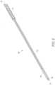
- a wire cutter 100 for creating a cavity in a bone constructed according to a first preferred embodiment of the present inventionis shown in Fig. 1 to Fig. 4 .
- the wire cutter 100has a restrainer 10, an elastic wire 20, and a driver 30.
- the restrainer 10has a closed end 11, an opening 12, a tunnel 13 inside the restrainer and from the opening 12 till the closed end 11, and a slot 14 parallel to the tunnel 13 which forms a passage from the tunnel 13 to an outside of the restrainer 10.
- the restrainer 10is further provided with threads 15 on an inner wall of the tunnel 13 and near the opening 12, and with a round recess 16 at the closed end 11.
- the driver 30has a handle 31, and a threaded stud 32 having a central mounting hole 33 axially along the threaded stud 32, and threads 34 formed on an outside wall of the threaded stud 32.
- the elastic wire 20has a holding segment 21 which is rotatably received in the central mounting hole 33 of the threaded stud 32, and an enlarged spherical end 22 corresponding to the round recess 16 at the closed end 11 of the restrainer 10 (shown in Fig. 2 ), so that the enlarged spherical end 22 of the elastic wire 10 is able to be slightly clamped in the round recess 16 at the closed end 11 of the restrainer 10.
- the aforesaid wire cutter 100can be used to create a cavity in a bone having a pre-drilled hole (not shown in the drawings).
- the elastic wire 20is inserted into the tunnel 13 by holding the handle 31 of the driver 30.
- the driver 30is rotated clockwisely when the threaded stud 32 contacts the opening 12 of the restrainer 10, so that the driver 30 is threadedly connected to the restrainer 10, and thus the wire cutter 100 is assembled.
- the assembled wire cutter 100is inserted into the bone via said pre-drilled hole, so that the slot 14 is inside the bone.
- the restrainer 10is first inserted into the bone via said pre-drilled hole, so that the slot 14 is inside the bone.
- the elastic wire 20is inserted into the tunnel 13 and the driver 30 is rotated clockwisely to assemble the wire cutter 100.
- the holding segment 21 of the elastic wire 20is advanced into the tunnel 13 of the restrainer 10, while the enlarged spherical end 22 of the elastic wire 20 is being stopped by the closed end 11 of the restrainer 10
- the clockwise rotation of the driver 30is continued further until a portion of the elastic wire 20 protrudes from the slot 14 to the outside of the restrainer 10, as shown in Fig. 6 .
- the protruded portion of the elastic wire 10is inside the bone now. Cancellous portion of the bone will be cut by the protruded portion of the elastic wire 20, when the restrainer 10 and the driver 30 are rotated together.
- the holding segment 21 of the elastic wire 20is advanced closer to the closed end 11 of the restrainer 10, so that a greater portion of the elastic wire 20 protrudes from the slot 14 to the outside of the restrainer 10. Greater cancellous portion of the bone will be cut by the greater protruded portion of the elastic wire 10 by rotating the restrainer 10 and the driver 30 together.
- the protruded (rotation-cut) portiongradually increases while the wire continues to gradually advance until a desired volume of cavity is created. After that, the protruded portion of the elastic wire 20 can be retrieved from the cavity by rotating the driver 30 counterclockwisely.
- the elastic wire 20is preferably a biocompatible, high strength metallic wire (e.g., a 316L stainless steel wire or a titanium/ titanium alloy wire) having a diameter of about 0.20 mm to 3.0 mm; preferably 0.3 mm to 2.0 mm; and more preferably 0.4 mm to 1.5 mm.
- the elastic wire 20has a sufficient strength so that it will not be broken into two pieces, and it will bend and a portion thereof will protrude from the slot 14 when the driver 30 is rotated clockwisely as described above.
- a certain degree of elasticity of the elastic wire 20is preferred, so that the bent elastic wire can resume a straight line as the driver 30 is rotated counterclockwisely, making retrieval of the wire cutter 100 from the bone easier.
- the elastic wire 20is not necessarily a fully elastic wire. A certain degree of plastic deformation may be allowed, as long as it can be retrieved through the restrainer 10.
- the portion of the cutting wire protruding from the slothas a shape of an arch similar to a rainbow.
- the cutting wire protruding from the slotmay have an inverted U-shape shape, when at least a portion of the cutting wire protruding from the slot is thicker than the rest portion of the cutting wire protruding from the slot.
- the rotation-cutting method using the cutting wire of the present inventioncan create a cavity by breaking the soft tissue network of a cancellous portion of a bone, which readily forms overtime for a chronic case. Without breaking loose the soft tissue network, cement is often very hard to be injected into the bone.
- the diameter of the elastic wire 20should be as close to a diameter of the tunnel 13 of the restrainer 20 as possible, so that the advancement of the elastic wire 20 in the tunnel 13 may be easier (without being bent in the tunnel 13 of the restrainer 10 during the advancement).
- the slot 14should have a width as close to the diameter of the elastic wire 20 as possible, so that the cutting ability is maximized by the slot inner wall support (without being bent inside the slot during cutting (rotation)).
- the slot 14should also has a depth as large as possible to increase the support of the slot wall during cutting (rotation).
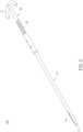
- a wire cutter 200 constructed in accordance with a second preferred embodiment of the present inventionis shown in Fig. 9 and Fig. 10 , which is similar to the wire cutter 100 constructed according to the first preferred embodiment of the present invention, wherein like elements in the two embodiments are represented by like numerals.
- the wire cutter 200has a restrainer 10, an elastic wire 20, and a driver 30.
- the driver 30has a disc 31', a cover 35, and a pair of bolts 38 for fastening the cover 35 to the disc 31'.
- the disc 31'has a threaded stud 32 located concentrically on one side of the disc 31'.
- a central mounting hole 33'which is a through hole is formed axially along the threaded stud 32 and the disc 31'.
- the threaded stud 32is provided with threads 34 on an outside wall thereof.
- the cover 35has a central through hole 36 corresponding to the central mounting hole 33' of the disc 31', wherein an enlarged dome-shaped opening 37 is provided at one end of the central through hole 36.
- the elastic wire 20has a distal end 22', a holding segment 21 close to another end, and a spherical flange 23 on the holding segment 21, wherein the elastic wire 20 has a diameter slighter smaller than that of the central mounting hole 33' of the disc 31'/the central through hole 36 of the cover 35, and the spherical flange 23 has a diameter larger than that of the central mounting hole 33' of the disc 31 '/the central through hole 36 of the cover 35.
- the spherical flange 23is smaller than the dome-shaped opening 37.
- the distal end 22' of the elastic wire 20is able to be inserted into the central mounting hole 33' of the disc 31', until the spherical flange 23 is stopped by the disc 31'.
- the cover 35is then put on the elastic wire 20 with the holding segment 21 being received in the central through hole 36 of the cover 35 and the spherical flange 23 being accommodated in the dome-shaped opening 37.
- the pair of bolts 38are then threaded into two threading bores 39, so that the cover 35 is fastened to the disc 31', and the elastic wire 20 is rotatably connected to the driver 30.
- the restrainer 10is formed by two parts, a closed end part 17 and a major part 18, wherein the closed end part 17 is threadedly connected to the major part 18.
- the tunnel 13' of the restrainer 10has a major straight segment 131 in the major part 18 followed by a bent segment 132 in the closed end part 17 of the restrainer 10, wherein an angle between an imaginary extension of the straight segment 131 and the bent segment 132 of the tunnel 13' is about 45°.
- the restrainer 10is further provided with an opening 12 opposite to the closed end part 17, and threads 15 on an inner wall of the tunnel 13' and near the opening 12.
- the elastic wire 20 with its holding segment 21 rotatably received in the driver 30is inserted into the tunnel 13' of the restrainer 10 by holding the driver 30.
- a distal end 22' of the elastic wire 20will enter the bent segment 132 of the tunnel 13' as the threaded stud 32 contacts the opening 12 of the restrainer 10 and is threaded into the tunnel 13'.
- the driver 30is driven closer to the opening 12 of the restrainer 10, a greater portion of the elastic wire 20 will protrude from the slot 14 to the outside of the restrainer 10.
- the bent segment 132 of the tunnel 13is helpful for forming the protruded portion of the elastic wire 20, when the threaded stud 32 is threaded into the tunnel 13'; and is also helpful for rotating the protruded portion of the elastic wire 20, when the restrainer 10 is rotated.
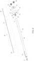
- a wire cutter 300 constructed in accordance with a third preferred embodiment of the present inventionis shown in Fig. 13 , 14A and 14B , wherein a much shorter cutting wire is adopted in comparison with the cutting wires used in the aforesaid first and second embodiments.
- the wire cutter 300has a restrainer 10, an elastic wire 20, and an advancing mechanism.
- the restrainer 10is formed by two parts, a closed end part 17 and a major part 18, wherein the closed end part 17 is threadedly connected to or tightly plugged into the major part 18.
- the restrainer 10has an opening 12, and a tunnel 13 inside the restrainer and from the opening 12 till the closed end part 17, and a slot 14 parallel to the tunnel 13 which forms a passage from the tunnel 13 to an outside of the restrainer 10.
- the advancing mechanism shown in Fig. 13 , 14A and 14Bincludes a first wire holder 50 holding the distal end of the cutting wire 20 by soldering; a second wire holder 55 holding the holding segment of the cutting wire 20 by soldering; a central rod 60; a compression spring 65; threads 15 formed in the opening of the tunnel 13 of the restrainer 10; and a threaded stud 32 having an axial mounting hole 33 at one end thereof, and a handle 31 at another end thereof, wherein the central rod 60 is received in the tunnel 13 of the restrainer with one end thereof being stopped by the closed end part 17 of the restrainer and another end thereof protruding from the opening 12 of the restrainer 10, the first wire holder 55 is slidably received on the central rod 60 with one end of being stopped by the closed end part 17 of the restrainer, the compression spring 65 is slidably received on the central rod 60 with one end of being stopped by another end of the first wire holder 50, the second wire holder 55 is slidably received on
- the central rod 60is provided with a pair of opposite grooves on its outer surface, and the first wire holder 50 and the second wire holder 55 are both provided with a pair of opposite ridges corresponding to the grooves on the inner walls of the through holes of the first wire holder 50 and the second wire holder 55.
- the closed end part 17is provided with a recess to grasp the distal end of the central rod 60 by friction/elasticity.
- a wire cutter 400 constructed in accordance with a fourth preferred embodiment of the present inventionis shown in Fig. 15 and Fig. 16 , wherein a different advancing mechanism similar to that used in the conventional automatic ball pens is adopted.
- the wire cutter 400has a restrainer 10, an elastic wire 20, and an advancing mechanism.
- the restrainer 10is formed by two parts, a closed end part 17 and a major part 18, wherein the closed end part 17 is threadedly connected to or tightly plugged into the major part 18.
- the restrainer 10has an opening 12, and a tunnel 13 inside the restrainer and from the opening 12 till the closed end part 17, and a slot 14 parallel to the tunnel 13 which forms a passage from the tunnel 13 to an outside of the restrainer 10.
- the advancing mechanism shown in Figs. 15 and 16includes a first wire holder 50 holding the distal end of the cutting wire 20; a second wire holder 55 holding the holding segment of the cutting wire 20; a central rod 60; a compression spring 65; threads 15 formed in the opening of the tunnel 13 of the restrainer 10; and a clutch rod 70 having an axial mounting hole 71 at one end thereof, and a pushing end 72 at another end thereof; and a control tubular element 80, wherein the central rod 60 is received in the tunnel 13 of the restrainer with one end thereof being stopped by the closed end part 17 of the restrainer, the first wire holder 50 is slidably received on the central rod 60 with one end of being stopped by the closed end part 17 of the restrainer, the compression spring 65 is slidably received on the central rod 60 with one end of being stopped by another end of the first wire holder 50, the second wire holder 55 is slidably received on the central rod 60 with one end thereof being stopped by another end of the compression spring 65, the clutch
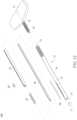
- a wire cutter constructed according to a fifth preferred embodiment of the present inventionis further provided with a slot adjustment mechanism, including a slot front adjuster 90 and a slot rear adjuster 95.
- the slot front adjuster 90is a long narrow thin plate suitable to be inserted into the tunnel 13 of the restrainer 10 from the opening 12 to the closed end 11 thereof, wherein a distal end of the slot front adjuster 90 is provided with an adjusting slot 91 corresponding to the slot 14 of the restrainer 10.
- the slot front adjuster 90can be used to adjust the span of an arch of the elastic wire 20 protruding from the slot 14 of the restrainer 10, when the slot front adjuster 90 is inserted into the tunnel 13 of the restrainer 10 before the elastic wire 20.
- the elastic wire 20after being inserted into the tunnel 13 of the restrainer 10, as described before, will form a protruding arch from the adjusting slot 91 of the slot front adjuster 90 and the slot 14 of the restrainer 10 as shown in Fig. 17 and Fig. 18 . It is apparent that the span of the protruding arch will become narrower, if a proximal end of the slot front adjuster 90 is pulled to withdraw the adjusting slot 91 of the slot front adjuster 90 from the closed end 11 of the restrainer 10 while holding the elastic wire 20 still. That is a front end of the protruding arch of the elastic wire 20 from the slot 14 of the restrainer 10 is retreated by using the slot front adjuster 90.
- the slot rear adjuster 95can be used to narrow the span of the protruding arch of the elastic wire 20 from the slot 14 of the restrainer 10 by pushing the rear end of the protruding arch of the elastic wire 20 forward.
- the slot rear adjuster 95is a long narrow thin plate suitable to be inserted into the tunnel 13 of the restrainer 10 from the opening 12 to the closed end 11 thereof, wherein a distal end of the slot rear adjuster 95 is adapted to cover the slot 14 of the restrainer 10.
- the slot rear adjuster 95can be used to adjust the span of an arch of the elastic wire 20 protruding from the slot 14 of the restrainer 10, when the slot rear adjuster 95 is inserted into the tunnel 13 of the restrainer 10 before or after the elastic wire 20.
- the elastic wire 20after being inserted into the tunnel 13 of the restrainer 10, as described before, will form a protruding arch from the slot 14 of the restrainer 10 as shown in Fig. 17 and Fig. 18 . It is apparent that the span of the protruding arch will become narrower, if a proximal end of the slot rear adjuster 95 is pushed to cover a part of the slot 14 of the restrainer 10 by the distal end of the slot rear adjuster 95 while holding the elastic wire 20 still. That is a rear end of the protruding arch of the elastic wire 20 from the slot 14 of the restrainer 10 is pushed forward by using the slot rear adjuster 95.
- the position of the protruding arch of the elastic wire 20 from the slot 14 of the restrainer 10can be adjusted by using the slot front adjuster 90 and the slot rear adjuster 95 together as shown in Fig. 17 and Fig. 18 , wherein the front end of the protruding arch of the elastic wire 20 from the slot 14 of the restrainer 10 can be retreated by pulling the slot front adjuster 90, and the rear end of the protruding arch of the elastic wire 20 from the slot 14 of the restrainer 10 can be moved forward by pushing the slot front adjuster 90, while holding the elastic wire 20 still.
- height of the protruding arch of the elastic wire 20 from the slot 14 of the restrainer 10can be increased, if the proximal end of the elastic wire 20 is pushed toward the closed end 11 of the restrainer while holding the slot front adjuster 90 and the slot rear adjuster 95 still.
Landscapes
- Health & Medical Sciences (AREA)
- Surgery (AREA)
- Life Sciences & Earth Sciences (AREA)
- Biomedical Technology (AREA)
- Medical Informatics (AREA)
- Orthopedic Medicine & Surgery (AREA)
- Oral & Maxillofacial Surgery (AREA)
- Engineering & Computer Science (AREA)
- Dentistry (AREA)
- Heart & Thoracic Surgery (AREA)
- Nuclear Medicine, Radiotherapy & Molecular Imaging (AREA)
- Molecular Biology (AREA)
- Animal Behavior & Ethology (AREA)
- General Health & Medical Sciences (AREA)
- Public Health (AREA)
- Veterinary Medicine (AREA)
- Surgical Instruments (AREA)
Description
- The present invention is related to a tool for cutting into a cancellous bone, whereby soft tissues therein are broken into pieces to facilitate the migration/penetration of an orthopaedic paste. Without being broken, these soft tissues may hinder the migration/penetration of the orthopaedic paste in the bone being treated. The orthopaedic paste will set to act as a medical implant. In particular the present invention is directed to a wire cutter for creating a cavity in a bone, as defined in claim 1.
- It is well accepted that bioresorbable orthopedic implants are always the better choice than permanent foreign-body implants, as long as their bioresorption rates, biomechanical properties and variations in biomechanical properties with respect to the resorption processes are appropriately controlled. Among all bioresorbable orthopedic implants, calcium-based implants (calcium phosphate, calcium sulfate, etc.), are among the top choices so far. Some popular conventional methods of forming a hardened (set) bone cement in bone cavity involve creating a bone cavity in advance.
- Prior-art cavity creation devices having an inflatable and expandable fluid-filled balloon structure often have insufficient "lift"- ability to push back compression-fractured bone (e.g., to restore vertebral body height) under certain circumstances due to the "softness" and the relatively large surface of the balloon. These devices do not have the function of cutting into the cancellous portion of a bone.
- Prior-art cavity creation devices having an inflatable and expandable balloon-type structure rely on a high pressure fluid to expand a cavity in bone, which increases various high pressure-related risks in clinical procedures. These devices do not have the function of cutting into the cancellous portion of a bone.
- Prior-art cavity creation devices having a foldable and extendable (expandable) rigid structure have risks of generating stress-concentrated spots and fresh cracks in the readily fractured bone. These devices do not have the function of cutting into the cancellous portion of a bone.
- Most prior-art rigid-structure cavity creation devices have a hollow structure under expanded/unfolded condition. Once bone chips/fragments are trapped in such devices during unfolding (expanding) and/or folding (collapsing) procedures, such devices have risks of being unable to be retrieved from the treated site, especially through a minimally invasive percutaneous path. Likewise, in case any pieces/components of the rigid-structure devices break off the structure during procedure, these broken-off pieces/components would be very hard to be retrieved, especially through a minimally invasive percutaneous path. These devices do not have the function of cutting into the cancellous portion of a bone.
- The inventors of the present application in
WO 2006/138398 A2 disclose a non-inflated tool for expanding a bone cavity in which an orthopaedic paste is to be implanted comprising a flexible linear filler and a rod with one end thereof connected to one end of the flexible linear filler, so that the flexible linear filler can be pushed by the rod through a tube into a hole of a bone to expand a bone cavity in the bone. The filler may be a wire, band, or chain. Preferably, the chain comprises a series of beads linked one after another or by a string. Despite the ability of this non-inflated tool to effectively create/expand bone cavity, once the linear filler breaks, it would be very hard to retrieve the broken-loose bodies, especially through a minimally invasive percutaneous path. Another risk for the prior-art non-inflated tool is entanglement of the linear filler, which might happen during feeding (expansion) and/or retrieving procedure. When entanglement happens, it would be very hard for the linear filler to be retrieved, especially through a minimally invasive percutaneous path. These devices do not have the function of cutting into the cancellous portion of a bone. - The inventors of the present application in
WO 2009/035549 A disclose a method of using beads to create a cavity in a bone comprising the following steps: a) introducing said beads into a bone by applying a pressure on said beads, wherein said beads are metallic beads able to be attracted by a magnet; and b) withdrawing said beads from said bone by magnetic force. In this prior art a tool is disclosed to facilitate the introduction said beads into a bone. These devices do not have the function of cutting into the cancellous portion of a bone. - For most prior-art rigid-structure cavity creation devices, an easy, accurate, reliable and safe bone-cavity creation procedure for a fractured bone or a bone suffering osteoporosis is always a great challenge. There is a need in developing an easy, accurate, reliable and safe technique for cutting into the cancellous portion of a bone, whereby soft tissues therein may be broken into pieces to facilitate the migration/penetration of an orthopaedic paste. Without being broken, these soft tissues may hinder the migration/penetration of the orthopaedic paste in the bone being treated. The orthopaedic paste will set to act as a medical implant.
Further relevant prior art is described inUS 2008/114364 A1 andWO 2010/121172 A1 . - A primary object of the present invention is to provide a device for cutting into the cancellous portion of a bone, (for example, a fractured vertebral body and a bone suffering osteoporosis), in which a sufficient amount of an orthopaedic paste is to be implanted in the bone by injection. In particular, the present invention provides a wire cutter having the features defined in claim 1. Further preferred embodiments are defined in the dependent claims.
Fig. 1 is a schematic perspective view showing a wire cutter embodied according to a first preferred embodiment of the present invention.Fig. 2 is a cross-sectional view showing a restrainer of the wire cutter shown inFig. 1 .Fig. 3 is a schematic perspective view showing a driver of the wire cutter shown inFig. 1 .Fig. 4 is a schematic perspective view showing an elastic wire of the wire cutter shown inFig. 1 .Fig. 5 is a schematic perspective view showing an initially engaged stage of the wire cutter shown inFig. 1 .Fig. 6 is a schematic perspective view showing an intermediately engaged stage of the wire cutter shown inFig. 1 .Fig. 7 is a schematic perspective view showing a fully engaged stage of the wire cutter shown inFig. 1 .Fig. 8 is a schematic cross-sectional view showing the wire cutter shown inFig. 7 .Fig. 9 is a schematic perspective view showing a wire cutter embodied according to a second preferred embodiment of the present invention.Fig. 10 is a cross-sectional view showing the wire cutter shown inFig. 9 .Fig. 11 is an enlarged partial cross-sectional view showing the closed end of the wire cutter shown inFig. 10 .Fig. 12 is an enlarged partial cross-sectional view showing the proximal end of the wire cutter shown inFig. 10 .Fig. 13 is a schematic perspective view showing a wire cutter embodied according to a third preferred embodiment of the present invention.Fig. 14A is an enlarged cross-sectional view showing the closed end of the wire cutter shown inFig. 13 .Fig. 14B is an enlarged cross-sectional view showing the proximal end of the wire cutter shown inFig. 13 .Fig. 15 is a schematic perspective view showing a wire cutter embodied according to a fourth preferred embodiment of the present invention, wherein the restrainer is not shown.Fig. 16 is a cross-sectional view showing the wire cutter shown inFig. 15 .Fig. 17 is a schematic perspective view showing a wire cutter embodied according to a fifth preferred embodiment of the present invention. For the illustration purpose, the restrainer is assumed being transparent.Fig. 18 is a cross-sectional view showing the wire cutter shown inFig. 17 .- In the following a wire cutter is described and a technique for creating a cavity in a bone and in particular, a cancellous bone, so that the quantity of an orthopaedic paste to be implanted in the bone by injection can be increased remarkably in comparison with the bone without creating a cavity. As long as the method is described, this is helpful for understanding the present invention. The scope of protection is defined by the claims.
- A
wire cutter 100 for creating a cavity in a bone constructed according to a first preferred embodiment of the present invention is shown inFig. 1 to Fig. 4 . Thewire cutter 100 has a restrainer 10, anelastic wire 20, and adriver 30. - As shown in
Fig. 2 , the restrainer 10 has aclosed end 11, anopening 12, atunnel 13 inside the restrainer and from theopening 12 till theclosed end 11, and aslot 14 parallel to thetunnel 13 which forms a passage from thetunnel 13 to an outside of the restrainer 10. The restrainer 10 is further provided withthreads 15 on an inner wall of thetunnel 13 and near theopening 12, and with around recess 16 at theclosed end 11. - As shown in
Fig. 3 and Fig. 4 , thedriver 30 has ahandle 31, and a threadedstud 32 having a central mountinghole 33 axially along the threadedstud 32, andthreads 34 formed on an outside wall of the threadedstud 32. Theelastic wire 20 has a holdingsegment 21 which is rotatably received in the central mountinghole 33 of the threadedstud 32, and an enlargedspherical end 22 corresponding to theround recess 16 at theclosed end 11 of the restrainer 10 (shown inFig. 2 ), so that the enlargedspherical end 22 of theelastic wire 10 is able to be slightly clamped in theround recess 16 at theclosed end 11 of the restrainer 10. - The
aforesaid wire cutter 100 can be used to create a cavity in a bone having a pre-drilled hole (not shown in the drawings). As shown inFig. 5 to Fig. 8 , theelastic wire 20 is inserted into thetunnel 13 by holding thehandle 31 of thedriver 30. Thedriver 30 is rotated clockwisely when the threadedstud 32 contacts theopening 12 of the restrainer 10, so that thedriver 30 is threadedly connected to the restrainer 10, and thus thewire cutter 100 is assembled. Then, the assembledwire cutter 100 is inserted into the bone via said pre-drilled hole, so that theslot 14 is inside the bone. Alternatively, the restrainer 10 is first inserted into the bone via said pre-drilled hole, so that theslot 14 is inside the bone. Then, theelastic wire 20 is inserted into thetunnel 13 and thedriver 30 is rotated clockwisely to assemble thewire cutter 100. As the clockwise rotation of thedriver 30 continues, the holdingsegment 21 of theelastic wire 20 is advanced into thetunnel 13 of the restrainer 10, while the enlargedspherical end 22 of theelastic wire 20 is being stopped by theclosed end 11 of the restrainer 10 - The clockwise rotation of the
driver 30 is continued further until a portion of theelastic wire 20 protrudes from theslot 14 to the outside of the restrainer 10, as shown inFig. 6 . The protruded portion of theelastic wire 10 is inside the bone now. Cancellous portion of the bone will be cut by the protruded portion of theelastic wire 20, when the restrainer 10 and thedriver 30 are rotated together. - As shown in
Figs. 7 and8 , the holdingsegment 21 of theelastic wire 20 is advanced closer to theclosed end 11 of the restrainer 10, so that a greater portion of theelastic wire 20 protrudes from theslot 14 to the outside of the restrainer 10. Greater cancellous portion of the bone will be cut by the greater protruded portion of theelastic wire 10 by rotating the restrainer 10 and thedriver 30 together. The protruded (rotation-cut) portion gradually increases while the wire continues to gradually advance until a desired volume of cavity is created. After that, the protruded portion of theelastic wire 20 can be retrieved from the cavity by rotating thedriver 30 counterclockwisely. - The
elastic wire 20 is preferably a biocompatible, high strength metallic wire (e.g., a 316L stainless steel wire or a titanium/ titanium alloy wire) having a diameter of about 0.20 mm to 3.0 mm; preferably 0.3 mm to 2.0 mm; and more preferably 0.4 mm to 1.5 mm. Theelastic wire 20 has a sufficient strength so that it will not be broken into two pieces, and it will bend and a portion thereof will protrude from theslot 14 when thedriver 30 is rotated clockwisely as described above. A certain degree of elasticity of theelastic wire 20 is preferred, so that the bent elastic wire can resume a straight line as thedriver 30 is rotated counterclockwisely, making retrieval of thewire cutter 100 from the bone easier. Theelastic wire 20 is not necessarily a fully elastic wire. A certain degree of plastic deformation may be allowed, as long as it can be retrieved through the restrainer 10. The portion of the cutting wire protruding from the slot has a shape of an arch similar to a rainbow. The cutting wire protruding from the slot may have an inverted U-shape shape, when at least a portion of the cutting wire protruding from the slot is thicker than the rest portion of the cutting wire protruding from the slot. - The rotation-cutting method using the cutting wire of the present invention can create a cavity by breaking the soft tissue network of a cancellous portion of a bone, which readily forms overtime for a chronic case. Without breaking loose the soft tissue network, cement is often very hard to be injected into the bone.
- The diameter of the
elastic wire 20 should be as close to a diameter of thetunnel 13 of the restrainer 20 as possible, so that the advancement of theelastic wire 20 in thetunnel 13 may be easier (without being bent in thetunnel 13 of the restrainer 10 during the advancement). - The
slot 14 should have a width as close to the diameter of theelastic wire 20 as possible, so that the cutting ability is maximized by the slot inner wall support (without being bent inside the slot during cutting (rotation)). Theslot 14 should also has a depth as large as possible to increase the support of the slot wall during cutting (rotation). - A reasonable prototype device would be:
- 316L stainless steel wire with diameter about 1 mm;
- 316L stainless steel tube with inner diameter slightly larger than 1 mm and outer diameter about 3 mm; and
- the slot depth about 1 mm.
- A wire cutter 200 constructed in accordance with a second preferred embodiment of the present invention is shown in
Fig. 9 andFig. 10 , which is similar to thewire cutter 100 constructed according to the first preferred embodiment of the present invention, wherein like elements in the two embodiments are represented by like numerals. - As shown in
Fig. 9 to Fig. 12 , the wire cutter 200 has a restrainer 10, anelastic wire 20, and adriver 30. Thedriver 30 has a disc 31', acover 35, and a pair ofbolts 38 for fastening thecover 35 to the disc 31'. The disc 31' has a threadedstud 32 located concentrically on one side of the disc 31'. A central mounting hole 33' which is a through hole is formed axially along the threadedstud 32 and the disc 31'. The threadedstud 32 is provided withthreads 34 on an outside wall thereof. Thecover 35 has a central throughhole 36 corresponding to the central mounting hole 33' of the disc 31', wherein an enlarged dome-shapedopening 37 is provided at one end of the central throughhole 36. Theelastic wire 20 has a distal end 22', a holdingsegment 21 close to another end, and aspherical flange 23 on the holdingsegment 21, wherein theelastic wire 20 has a diameter slighter smaller than that of the central mounting hole 33' of the disc 31'/the central throughhole 36 of thecover 35, and thespherical flange 23 has a diameter larger than that of the central mounting hole 33' of the disc 31 '/the central throughhole 36 of thecover 35. At the same time, thespherical flange 23 is smaller than the dome-shapedopening 37. Accordingly, the distal end 22' of theelastic wire 20 is able to be inserted into the central mounting hole 33' of the disc 31', until thespherical flange 23 is stopped by the disc 31'. Thecover 35 is then put on theelastic wire 20 with the holdingsegment 21 being received in the central throughhole 36 of thecover 35 and thespherical flange 23 being accommodated in the dome-shapedopening 37. The pair ofbolts 38 are then threaded into two threading bores 39, so that thecover 35 is fastened to the disc 31', and theelastic wire 20 is rotatably connected to thedriver 30. - The restrainer 10 is formed by two parts, a
closed end part 17 and amajor part 18, wherein theclosed end part 17 is threadedly connected to themajor part 18. The tunnel 13' of the restrainer 10 has a majorstraight segment 131 in themajor part 18 followed by abent segment 132 in theclosed end part 17 of the restrainer 10, wherein an angle between an imaginary extension of thestraight segment 131 and thebent segment 132 of the tunnel 13' is about 45°. The restrainer 10 is further provided with anopening 12 opposite to theclosed end part 17, andthreads 15 on an inner wall of the tunnel 13' and near theopening 12. - The
elastic wire 20 with its holdingsegment 21 rotatably received in thedriver 30 is inserted into the tunnel 13' of the restrainer 10 by holding thedriver 30. A distal end 22' of theelastic wire 20 will enter thebent segment 132 of the tunnel 13' as the threadedstud 32 contacts theopening 12 of the restrainer 10 and is threaded into the tunnel 13'. As thedriver 30 is driven closer to theopening 12 of the restrainer 10, a greater portion of theelastic wire 20 will protrude from theslot 14 to the outside of the restrainer 10. Thebent segment 132 of thetunnel 13 is helpful for forming the protruded portion of theelastic wire 20, when the threadedstud 32 is threaded into the tunnel 13'; and is also helpful for rotating the protruded portion of theelastic wire 20, when the restrainer 10 is rotated. - A
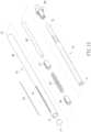
wire cutter 300 constructed in accordance with a third preferred embodiment of the present invention is shown inFig. 13 ,14A and14B , wherein a much shorter cutting wire is adopted in comparison with the cutting wires used in the aforesaid first and second embodiments. Thewire cutter 300 has a restrainer 10, anelastic wire 20, and an advancing mechanism. - The restrainer 10 is formed by two parts, a
closed end part 17 and amajor part 18, wherein theclosed end part 17 is threadedly connected to or tightly plugged into themajor part 18. The restrainer 10 has anopening 12, and atunnel 13 inside the restrainer and from theopening 12 till theclosed end part 17, and aslot 14 parallel to thetunnel 13 which forms a passage from thetunnel 13 to an outside of the restrainer 10. - The advancing mechanism shown in
Fig. 13 ,14A and14B includes a first wire holder 50 holding the distal end of the cutting wire 20 by soldering; a second wire holder 55 holding the holding segment of the cutting wire 20 by soldering; a central rod 60; a compression spring 65; threads 15 formed in the opening of the tunnel 13 of the restrainer 10; and a threaded stud 32 having an axial mounting hole 33 at one end thereof, and a handle 31 at another end thereof, wherein the central rod 60 is received in the tunnel 13 of the restrainer with one end thereof being stopped by the closed end part 17 of the restrainer and another end thereof protruding from the opening 12 of the restrainer 10, the first wire holder 55 is slidably received on the central rod 60 with one end of being stopped by the closed end part 17 of the restrainer, the compression spring 65 is slidably received on the central rod 60 with one end of being stopped by another end of the first wire holder 50, the second wire holder 55 is slidably received on the central rod 60 with one end thereof being stopped by another end of the compression spring 65, and the threaded stud 32 is threadedly received in the opening 12 of the restrainer with the protruding end of the central rod 60 being received in the mounting hole 33 of the threaded stud by rotating the handle 31 of the threaded stud in relative to the restrainer 10, wherein the second wire holder 55 will be pressed by the threaded stud 32 and moved toward the closed end part 17 of the restrainer as the rotation of the handle 31 of the threaded stud is continued, so that the compression spring 65 is compressed by the second wire holder 55 and the first wire holder 50, and thus the cutting wire 20 is pressed by the second wire holder 55 and protrudes from the slot 14 to the outside of the restrainer 10. In order to prevent the relative rotation between thecentral rod 60 and thefirst wire holder 50 and thesecond wire holder 55, thecentral rod 60 is provided with a pair of opposite grooves on its outer surface, and thefirst wire holder 50 and thesecond wire holder 55 are both provided with a pair of opposite ridges corresponding to the grooves on the inner walls of the through holes of thefirst wire holder 50 and thesecond wire holder 55. Further, theclosed end part 17 is provided with a recess to grasp the distal end of thecentral rod 60 by friction/elasticity. - A wire cutter 400 constructed in accordance with a fourth preferred embodiment of the present invention is shown in
Fig. 15 andFig. 16 , wherein a different advancing mechanism similar to that used in the conventional automatic ball pens is adopted. The wire cutter 400 has a restrainer 10, anelastic wire 20, and an advancing mechanism. - The restrainer 10 is formed by two parts, a
closed end part 17 and amajor part 18, wherein theclosed end part 17 is threadedly connected to or tightly plugged into themajor part 18. The restrainer 10 has anopening 12, and atunnel 13 inside the restrainer and from theopening 12 till theclosed end part 17, and aslot 14 parallel to thetunnel 13 which forms a passage from thetunnel 13 to an outside of the restrainer 10. - The advancing mechanism shown in
Figs. 15 and16 includes a first wire holder 50 holding the distal end of the cutting wire 20; a second wire holder 55 holding the holding segment of the cutting wire 20; a central rod 60; a compression spring 65; threads 15 formed in the opening of the tunnel 13 of the restrainer 10; and a clutch rod 70 having an axial mounting hole 71 at one end thereof, and a pushing end 72 at another end thereof; and a control tubular element 80, wherein the central rod 60 is received in the tunnel 13 of the restrainer with one end thereof being stopped by the closed end part 17 of the restrainer, the first wire holder 50 is slidably received on the central rod 60 with one end of being stopped by the closed end part 17 of the restrainer, the compression spring 65 is slidably received on the central rod 60 with one end of being stopped by another end of the first wire holder 50, the second wire holder 55 is slidably received on the central rod 60 with one end thereof being stopped by another end of the compression spring 65, the clutch rod 70 is inserted into the tunnel 13 of the restrainer via the opening 12 of the restrainer with the mounting hole 71 of the clutch rod accommodating another end of the central rod 60 and the pushing end 72 protruding from the opening 12 of the restrainer, and the control tubular element 80 is fixedly connected to the opening 12 of the restrainer with the pushing end 72 of the clutch rod protruding from the control tubular element 80, wherein a clutch mechanism is provided on an outer surface of the clutch rod and on the control tubular element, so that the clutch rod 70 is able to be stopped by the control tubular element 80 at various positions in relative to the closed end part 17 of the restrainer when the clutch rod 70 is pushed back by the compression spring 65 which has be deformed by pushing the pushing end 72 of the clutch rod toward the closed end part 17 of the restrainer, wherein the various positions comprise an advanced position where the compression spring 65 is compressed at a relatively greater extent, so that the cutting wire 20 is pressed by the second wire holder 55 and protrudes from the slot 14 to the outside of the restrainer; and a release position where the compression spring 65 is compressed at a relatively less extent, so that the cutting wire 20 is released from the press by the second wire holder 65 and dives from the slot 14 into the tunnel 13 of the restrainer. - As shown in
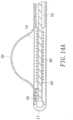
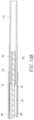
Figs. 17-18 , a wire cutter constructed according to a fifth preferred embodiment of the present invention is further provided with a slot adjustment mechanism, including aslot front adjuster 90 and a slotrear adjuster 95. - The
slot front adjuster 90 is a long narrow thin plate suitable to be inserted into thetunnel 13 of the restrainer 10 from theopening 12 to theclosed end 11 thereof, wherein a distal end of theslot front adjuster 90 is provided with an adjustingslot 91 corresponding to theslot 14 of the restrainer 10. Theslot front adjuster 90 can be used to adjust the span of an arch of theelastic wire 20 protruding from theslot 14 of the restrainer 10, when theslot front adjuster 90 is inserted into thetunnel 13 of the restrainer 10 before theelastic wire 20. Theelastic wire 20 after being inserted into thetunnel 13 of the restrainer 10, as described before, will form a protruding arch from the adjustingslot 91 of theslot front adjuster 90 and theslot 14 of the restrainer 10 as shown inFig. 17 andFig. 18 . It is apparent that the span of the protruding arch will become narrower, if a proximal end of theslot front adjuster 90 is pulled to withdraw the adjustingslot 91 of theslot front adjuster 90 from theclosed end 11 of the restrainer 10 while holding theelastic wire 20 still. That is a front end of the protruding arch of theelastic wire 20 from theslot 14 of the restrainer 10 is retreated by using theslot front adjuster 90. - On the contrary, the slot
rear adjuster 95 can be used to narrow the span of the protruding arch of theelastic wire 20 from theslot 14 of the restrainer 10 by pushing the rear end of the protruding arch of theelastic wire 20 forward. The slotrear adjuster 95 is a long narrow thin plate suitable to be inserted into thetunnel 13 of the restrainer 10 from theopening 12 to theclosed end 11 thereof, wherein a distal end of the slotrear adjuster 95 is adapted to cover theslot 14 of the restrainer 10. The slotrear adjuster 95 can be used to adjust the span of an arch of theelastic wire 20 protruding from theslot 14 of the restrainer 10, when the slotrear adjuster 95 is inserted into thetunnel 13 of the restrainer 10 before or after theelastic wire 20. Theelastic wire 20 after being inserted into thetunnel 13 of the restrainer 10, as described before, will form a protruding arch from theslot 14 of the restrainer 10 as shown inFig. 17 andFig. 18 . It is apparent that the span of the protruding arch will become narrower, if a proximal end of the slotrear adjuster 95 is pushed to cover a part of theslot 14 of the restrainer 10 by the distal end of the slotrear adjuster 95 while holding theelastic wire 20 still. That is a rear end of the protruding arch of theelastic wire 20 from theslot 14 of the restrainer 10 is pushed forward by using the slotrear adjuster 95. - One can imagines that the position of the protruding arch of the
elastic wire 20 from theslot 14 of the restrainer 10 can be adjusted by using theslot front adjuster 90 and the slotrear adjuster 95 together as shown inFig. 17 andFig. 18 , wherein the front end of the protruding arch of theelastic wire 20 from theslot 14 of the restrainer 10 can be retreated by pulling theslot front adjuster 90, and the rear end of the protruding arch of theelastic wire 20 from theslot 14 of the restrainer 10 can be moved forward by pushing theslot front adjuster 90, while holding theelastic wire 20 still. Thereafter, height of the protruding arch of theelastic wire 20 from theslot 14 of the restrainer 10 can be increased, if the proximal end of theelastic wire 20 is pushed toward theclosed end 11 of the restrainer while holding theslot front adjuster 90 and the slotrear adjuster 95 still.
Claims (9)
- A wire cutter (100) for creating a cavity in a bone, said wire cutter (100) comprising a restrainer (10) and a cutting wire (20), wherein the restrainer (10) comprises an opening (12) at a proximal end thereof, a closed end (11) opposite to the proximal end, a tunnel (13) inside the restrainer (10) and from the opening (12) till the closed end (11), and a slot (14) parallel to the tunnel (13) and forming a passage from the tunnel (13) to an outside of the restrainer (10); and said cutting wire (20) adapted to be received in the tunnel (13), wherein said cutting wire (20) has a distal end (22) and a holding segment (21) away from the distal end (22), wherein the holding segment (21) is able to be driven to move in the tunnel (13) toward the closed end (11) of the restrainer (10) while the distal end (22) of the cutting wire (20) being stopped directly or indirectly by the closed end (11) of the restrainer (10), so that a portion of the cutting wire (20) will protrude from the slot (14) to the outside of the restrainer (10), when the holding segment (21) of the cutting wire (20) is driven to move toward the closed end (11) of the restrainer (10), wherein the wire cutter further comprises an advancing means for driving the holding segment (21) of the cutting wire (20) to move toward the closed end (11) of the restrainer (10) and to move away from the closed end (11) after being driven to move toward the closed (11) end of the restrainer (10), so that a greater portion of the cutting wire (20) will protrude from the slot (14) to the outside of the restrainer (10) as the holding segment (21) of the cutting wire (20) is driven to move closer to the closed end (11) of the restrainer (10), wherein the distal end (22) of the cutting wire (20) is stopped directly by the closed end of the restrainer (10),
characterised in that
the advancing means comprises threads (15) formed on an inner wall of the tunnel (13) of the restrainer (10) and near the opening of the restrainer (10), and a threaded stud (32)adapted to be in engagement with the threads (15), wherein the threaded stud (32) is provided with an axial mounting hole adapted to accommodate the holding segment (21) of the cutting wire (20). - The wire cutter (100) of claim 1, wherein the cutting wire (20) is straight, and the holding segment (21) is clamped fixedly in the mounting hole of the threaded stud (32).
- The wire cutter (100) of claim 1, wherein the cutting wire (20) is straight, the holding segment (21) of the cutting wire (20) is protruding from the opening (14) of the restrainer (21), and the holding segment is rotatably received in the mounting hole of the threaded stud (32).
- The wire cutter (100) of claim 1, wherein the cutting wire (20) is straight, and the tunnel (13) of the restrainer (10) has a major straight segment followed by a bent segment near the closed end of the restrainer (10), wherein an angle between an imaginary extension of the straight segment and the bent segment of the tunnel is ranging from 5° to 60°.
- The wire cutter (100) of claim 4, wherein the restrainer is formed at least by two parts, a closed end part and a major part, wherein the closed end part contains the closed end of the restrainer and the bent segment of the tunnel, and is threadedly connected to the major part.
- The wire cutter (100) of claim 1 wherein the cutting wire (20) is a steel wire, a titanium or titanium alloy wire having a diameter or a width of 0.20 mm to 3.0 mm; preferably 0.3 mm to 2.0 mm; and more preferably 0.4 mm to 1.5 mm.
- The wire cutter (100) of claim 1 wherein the cutting wire (20) has a cross section of a shape selected from circular, oval, square, rectangular, triangular, and hexagonal.
- The wire cutter (100) of claim 1 wherein the cutting wire (20) has a cross section of a shape selected from circular, oval, square, rectangular, triangular, and hexagonal, wherein the portion of the cutting wire (20) which will protrude from the slot (14) has a cross-sectional area smaller than a cross-sectional area of the remaining portion of the cutting wire (20).
- The wire cutter (100) of claim 1, wherein the portion of the cutting wire(20) protruding from the slot (14) has a shape of an arch or an inverted U-shape.
Applications Claiming Priority (2)
| Application Number | Priority Date | Filing Date | Title |
|---|---|---|---|
| US201762577219P | 2017-10-26 | 2017-10-26 | |
| PCT/US2018/056188WO2019083784A1 (en) | 2017-10-26 | 2018-10-17 | Device and method for cutting into a cancellous bone |
Publications (3)
| Publication Number | Publication Date |
|---|---|
| EP3700437A1 EP3700437A1 (en) | 2020-09-02 |
| EP3700437A4 EP3700437A4 (en) | 2021-03-31 |
| EP3700437B1true EP3700437B1 (en) | 2023-06-28 |
Family
ID=66247425
Family Applications (1)
| Application Number | Title | Priority Date | Filing Date |
|---|---|---|---|
| EP18871664.1AActiveEP3700437B1 (en) | 2017-10-26 | 2018-10-17 | Device for cutting into a cancellous bone |
Country Status (5)
| Country | Link |
|---|---|
| US (1) | US11571223B2 (en) |
| EP (1) | EP3700437B1 (en) |
| CN (1) | CN111200980B (en) |
| TW (1) | TWI681750B (en) |
| WO (1) | WO2019083784A1 (en) |
Family Cites Families (22)
| Publication number | Priority date | Publication date | Assignee | Title |
|---|---|---|---|---|
| US1685380A (en)* | 1926-09-09 | 1928-09-25 | Pilley Packing & Flue Brush Mf | Scraping tool |
| US5275610A (en)* | 1991-05-13 | 1994-01-04 | Cook Incorporated | Surgical retractors and method of use |
| US5678572A (en)* | 1995-01-12 | 1997-10-21 | Shaw; Dein | Cavity expanding device for laparoscopic surgery |
| US5833628A (en)* | 1996-04-24 | 1998-11-10 | Yuan; Hansen | Graduated bone graft harvester |
| US20030208219A1 (en) | 2001-05-18 | 2003-11-06 | Aznoian Harold M. | Steerable biliary catheter |
| US20130267959A1 (en)* | 2001-06-14 | 2013-10-10 | Alexandria Research Technologies, Inc. | Modular apparatus and method for sculpting the surface of a joint |
| US6482209B1 (en)* | 2001-06-14 | 2002-11-19 | Gerard A. Engh | Apparatus and method for sculpting the surface of a joint |
| US7641664B2 (en)* | 2004-02-12 | 2010-01-05 | Warsaw Orthopedic, Inc. | Surgical instrumentation and method for treatment of a spinal structure |
| US7682378B2 (en)* | 2004-11-10 | 2010-03-23 | Dfine, Inc. | Bone treatment systems and methods for introducing an abrading structure to abrade bone |
| US20080114364A1 (en)* | 2006-11-15 | 2008-05-15 | Aoi Medical, Inc. | Tissue cavitation device and method |
| IL181211A0 (en) | 2007-02-07 | 2007-07-04 | Nmb Medical Applic Ltd | Device and methods for strengthening long bones |
| FR2912304B1 (en)* | 2007-02-14 | 2009-05-15 | Scient X Sa | INSTRUMENT FOR REDUCING FRACTURE OF BONE BODY. |
| US8114084B2 (en)* | 2007-03-07 | 2012-02-14 | Vertech, Inc. | Expandable blade device for stabilizing compression fractures |
| US20090131952A1 (en)* | 2007-05-21 | 2009-05-21 | Brian Schumacher | Delivery system and method for inflatable devices |
| CN102573667B (en)* | 2009-04-02 | 2015-04-29 | 马丁·M·马劳尔 | Bone rifling system and method of treating bone using the system |
| US8801739B2 (en) | 2009-04-17 | 2014-08-12 | Spine View, Inc. | Devices and methods for arched roof cutters |
| US20220071770A1 (en)* | 2010-01-04 | 2022-03-10 | Surgalign Spine Technologies, Inc. | Sacroiliac fusion system |
| CA2833543A1 (en)* | 2011-05-05 | 2012-11-08 | Zyga Technology, Inc. | Sacroiliac fusion system |
| US20130018385A1 (en) | 2011-07-11 | 2013-01-17 | Boston Scientific Scimed, Inc. | Polypectomy Snare Device |
| US20130165935A1 (en)* | 2011-12-27 | 2013-06-27 | Jerry R. Griffiths | Expandable retrograde drill |
| CN104546085B (en)* | 2013-10-22 | 2018-02-16 | 思必瑞特脊椎股份有限公司 | Bone anchoring device |
| CN205083573U (en)* | 2015-11-09 | 2016-03-16 | 崔岩 | Dedicated section bone cutterbar of orthopedics |
- 2018
- 2018-10-12TWTW107135955Apatent/TWI681750B/enactive
- 2018-10-17WOPCT/US2018/056188patent/WO2019083784A1/ennot_activeCeased
- 2018-10-17CNCN201880063683.1Apatent/CN111200980B/enactiveActive
- 2018-10-17EPEP18871664.1Apatent/EP3700437B1/enactiveActive
- 2018-10-17USUS16/649,418patent/US11571223B2/enactiveActive
Also Published As
| Publication number | Publication date |
|---|---|
| EP3700437A1 (en) | 2020-09-02 |
| CN111200980A (en) | 2020-05-26 |
| US11571223B2 (en) | 2023-02-07 |
| TW201916861A (en) | 2019-05-01 |
| EP3700437A4 (en) | 2021-03-31 |
| US20200297359A1 (en) | 2020-09-24 |
| WO2019083784A1 (en) | 2019-05-02 |
| TWI681750B (en) | 2020-01-11 |
| CN111200980B (en) | 2023-07-25 |
Similar Documents
| Publication | Publication Date | Title |
|---|---|---|
| EP3071133B1 (en) | Apparatus for an intramedullary implant | |
| US9883897B2 (en) | Method and apparatus for a compressing plate | |
| JP5653908B2 (en) | Posterior spinal fixation | |
| US9675344B2 (en) | Surgical instrument | |
| US9439770B2 (en) | Implant for stabilizing vertebrae or bones | |
| US8114084B2 (en) | Expandable blade device for stabilizing compression fractures | |
| US8480675B2 (en) | Betts osteotome | |
| EP2724680B1 (en) | Device for bone fixation | |
| JP5202323B2 (en) | Intramedullary longitudinal implant | |
| JP2012005881A (en) | System and device for directional expansion of expandable structure within bone and system for treatment of bone | |
| US20090005816A1 (en) | Spinal rod, insertion device, and method of using | |
| JP2009511198A (en) | Vertebral augmentation device and method | |
| EP3700437B1 (en) | Device for cutting into a cancellous bone | |
| US9636155B2 (en) | Method and apparatus for an intramudullary implant and method of implantation thereof |
Legal Events
| Date | Code | Title | Description |
|---|---|---|---|
| STAA | Information on the status of an ep patent application or granted ep patent | Free format text:STATUS: THE INTERNATIONAL PUBLICATION HAS BEEN MADE | |
| PUAI | Public reference made under article 153(3) epc to a published international application that has entered the european phase | Free format text:ORIGINAL CODE: 0009012 | |
| STAA | Information on the status of an ep patent application or granted ep patent | Free format text:STATUS: REQUEST FOR EXAMINATION WAS MADE | |
| 17P | Request for examination filed | Effective date:20200507 | |
| AK | Designated contracting states | Kind code of ref document:A1 Designated state(s):AL AT BE BG CH CY CZ DE DK EE ES FI FR GB GR HR HU IE IS IT LI LT LU LV MC MK MT NL NO PL PT RO RS SE SI SK SM TR | |
| AX | Request for extension of the european patent | Extension state:BA ME | |
| RIC1 | Information provided on ipc code assigned before grant | Ipc:A61B 17/15 20060101ALI20201123BHEP Ipc:A61B 17/14 20060101AFI20201123BHEP Ipc:A61B 17/16 20060101ALI20201123BHEP Ipc:A61B 17/34 20060101ALI20201123BHEP | |
| DAV | Request for validation of the european patent (deleted) | ||
| DAX | Request for extension of the european patent (deleted) | ||
| A4 | Supplementary search report drawn up and despatched | Effective date:20210302 | |
| RIC1 | Information provided on ipc code assigned before grant | Ipc:A61B 17/16 20060101ALI20210224BHEP Ipc:A61B 17/15 20060101ALI20210224BHEP Ipc:A61B 17/14 20060101AFI20210224BHEP Ipc:A61B 17/34 20060101ALI20210224BHEP | |
| GRAP | Despatch of communication of intention to grant a patent | Free format text:ORIGINAL CODE: EPIDOSNIGR1 | |
| STAA | Information on the status of an ep patent application or granted ep patent | Free format text:STATUS: GRANT OF PATENT IS INTENDED | |
| INTG | Intention to grant announced | Effective date:20230210 | |
| RIN1 | Information on inventor provided before grant (corrected) | Inventor name:CHEN, GUAN-TING Inventor name:YANG, BING-CHEN Inventor name:CHEN, YEN-CHUN Inventor name:LIN, JLIN-HUEY CHERN Inventor name:JU, CHIEN-PING | |
| GRAS | Grant fee paid | Free format text:ORIGINAL CODE: EPIDOSNIGR3 | |
| GRAA | (expected) grant | Free format text:ORIGINAL CODE: 0009210 | |
| STAA | Information on the status of an ep patent application or granted ep patent | Free format text:STATUS: THE PATENT HAS BEEN GRANTED | |
| P01 | Opt-out of the competence of the unified patent court (upc) registered | Effective date:20230505 | |
| AK | Designated contracting states | Kind code of ref document:B1 Designated state(s):AL AT BE BG CH CY CZ DE DK EE ES FI FR GB GR HR HU IE IS IT LI LT LU LV MC MK MT NL NO PL PT RO RS SE SI SK SM TR | |
| REG | Reference to a national code | Ref country code:CH Ref legal event code:EP | |
| REG | Reference to a national code | Ref country code:AT Ref legal event code:REF Ref document number:1582010 Country of ref document:AT Kind code of ref document:T Effective date:20230715 | |
| REG | Reference to a national code | Ref country code:IE Ref legal event code:FG4D | |
| REG | Reference to a national code | Ref country code:DE Ref legal event code:R096 Ref document number:602018052625 Country of ref document:DE | |
| REG | Reference to a national code | Ref country code:LT Ref legal event code:MG9D | |
| PG25 | Lapsed in a contracting state [announced via postgrant information from national office to epo] | Ref country code:SE Free format text:LAPSE BECAUSE OF FAILURE TO SUBMIT A TRANSLATION OF THE DESCRIPTION OR TO PAY THE FEE WITHIN THE PRESCRIBED TIME-LIMIT Effective date:20230628 Ref country code:NO Free format text:LAPSE BECAUSE OF FAILURE TO SUBMIT A TRANSLATION OF THE DESCRIPTION OR TO PAY THE FEE WITHIN THE PRESCRIBED TIME-LIMIT Effective date:20230928 | |
| REG | Reference to a national code | Ref country code:NL Ref legal event code:MP Effective date:20230628 | |
| REG | Reference to a national code | Ref country code:AT Ref legal event code:MK05 Ref document number:1582010 Country of ref document:AT Kind code of ref document:T Effective date:20230628 | |
| PG25 | Lapsed in a contracting state [announced via postgrant information from national office to epo] | Ref country code:RS Free format text:LAPSE BECAUSE OF FAILURE TO SUBMIT A TRANSLATION OF THE DESCRIPTION OR TO PAY THE FEE WITHIN THE PRESCRIBED TIME-LIMIT Effective date:20230628 Ref country code:NL Free format text:LAPSE BECAUSE OF FAILURE TO SUBMIT A TRANSLATION OF THE DESCRIPTION OR TO PAY THE FEE WITHIN THE PRESCRIBED TIME-LIMIT Effective date:20230628 Ref country code:LV Free format text:LAPSE BECAUSE OF FAILURE TO SUBMIT A TRANSLATION OF THE DESCRIPTION OR TO PAY THE FEE WITHIN THE PRESCRIBED TIME-LIMIT Effective date:20230628 Ref country code:LT Free format text:LAPSE BECAUSE OF FAILURE TO SUBMIT A TRANSLATION OF THE DESCRIPTION OR TO PAY THE FEE WITHIN THE PRESCRIBED TIME-LIMIT Effective date:20230628 Ref country code:HR Free format text:LAPSE BECAUSE OF FAILURE TO SUBMIT A TRANSLATION OF THE DESCRIPTION OR TO PAY THE FEE WITHIN THE PRESCRIBED TIME-LIMIT Effective date:20230628 Ref country code:GR Free format text:LAPSE BECAUSE OF FAILURE TO SUBMIT A TRANSLATION OF THE DESCRIPTION OR TO PAY THE FEE WITHIN THE PRESCRIBED TIME-LIMIT Effective date:20230929 | |
| PG25 | Lapsed in a contracting state [announced via postgrant information from national office to epo] | Ref country code:FI Free format text:LAPSE BECAUSE OF FAILURE TO SUBMIT A TRANSLATION OF THE DESCRIPTION OR TO PAY THE FEE WITHIN THE PRESCRIBED TIME-LIMIT Effective date:20230628 | |
| PG25 | Lapsed in a contracting state [announced via postgrant information from national office to epo] | Ref country code:SK Free format text:LAPSE BECAUSE OF FAILURE TO SUBMIT A TRANSLATION OF THE DESCRIPTION OR TO PAY THE FEE WITHIN THE PRESCRIBED TIME-LIMIT Effective date:20230628 | |
| PG25 | Lapsed in a contracting state [announced via postgrant information from national office to epo] | Ref country code:ES Free format text:LAPSE BECAUSE OF FAILURE TO SUBMIT A TRANSLATION OF THE DESCRIPTION OR TO PAY THE FEE WITHIN THE PRESCRIBED TIME-LIMIT Effective date:20230628 | |
| PG25 | Lapsed in a contracting state [announced via postgrant information from national office to epo] | Ref country code:IS Free format text:LAPSE BECAUSE OF FAILURE TO SUBMIT A TRANSLATION OF THE DESCRIPTION OR TO PAY THE FEE WITHIN THE PRESCRIBED TIME-LIMIT Effective date:20231028 | |
| PG25 | Lapsed in a contracting state [announced via postgrant information from national office to epo] | Ref country code:SM Free format text:LAPSE BECAUSE OF FAILURE TO SUBMIT A TRANSLATION OF THE DESCRIPTION OR TO PAY THE FEE WITHIN THE PRESCRIBED TIME-LIMIT Effective date:20230628 Ref country code:SK Free format text:LAPSE BECAUSE OF FAILURE TO SUBMIT A TRANSLATION OF THE DESCRIPTION OR TO PAY THE FEE WITHIN THE PRESCRIBED TIME-LIMIT Effective date:20230628 Ref country code:RO Free format text:LAPSE BECAUSE OF FAILURE TO SUBMIT A TRANSLATION OF THE DESCRIPTION OR TO PAY THE FEE WITHIN THE PRESCRIBED TIME-LIMIT Effective date:20230628 Ref country code:PT Free format text:LAPSE BECAUSE OF FAILURE TO SUBMIT A TRANSLATION OF THE DESCRIPTION OR TO PAY THE FEE WITHIN THE PRESCRIBED TIME-LIMIT Effective date:20231030 Ref country code:IS Free format text:LAPSE BECAUSE OF FAILURE TO SUBMIT A TRANSLATION OF THE DESCRIPTION OR TO PAY THE FEE WITHIN THE PRESCRIBED TIME-LIMIT Effective date:20231028 Ref country code:ES Free format text:LAPSE BECAUSE OF FAILURE TO SUBMIT A TRANSLATION OF THE DESCRIPTION OR TO PAY THE FEE WITHIN THE PRESCRIBED TIME-LIMIT Effective date:20230628 Ref country code:EE Free format text:LAPSE BECAUSE OF FAILURE TO SUBMIT A TRANSLATION OF THE DESCRIPTION OR TO PAY THE FEE WITHIN THE PRESCRIBED TIME-LIMIT Effective date:20230628 Ref country code:CZ Free format text:LAPSE BECAUSE OF FAILURE TO SUBMIT A TRANSLATION OF THE DESCRIPTION OR TO PAY THE FEE WITHIN THE PRESCRIBED TIME-LIMIT Effective date:20230628 Ref country code:AT Free format text:LAPSE BECAUSE OF FAILURE TO SUBMIT A TRANSLATION OF THE DESCRIPTION OR TO PAY THE FEE WITHIN THE PRESCRIBED TIME-LIMIT Effective date:20230628 | |
| PG25 | Lapsed in a contracting state [announced via postgrant information from national office to epo] | Ref country code:PL Free format text:LAPSE BECAUSE OF FAILURE TO SUBMIT A TRANSLATION OF THE DESCRIPTION OR TO PAY THE FEE WITHIN THE PRESCRIBED TIME-LIMIT Effective date:20230628 | |
| REG | Reference to a national code | Ref country code:DE Ref legal event code:R097 Ref document number:602018052625 Country of ref document:DE | |
| PG25 | Lapsed in a contracting state [announced via postgrant information from national office to epo] | Ref country code:DK Free format text:LAPSE BECAUSE OF FAILURE TO SUBMIT A TRANSLATION OF THE DESCRIPTION OR TO PAY THE FEE WITHIN THE PRESCRIBED TIME-LIMIT Effective date:20230628 | |
| PLBE | No opposition filed within time limit | Free format text:ORIGINAL CODE: 0009261 | |
| STAA | Information on the status of an ep patent application or granted ep patent | Free format text:STATUS: NO OPPOSITION FILED WITHIN TIME LIMIT | |
| PG25 | Lapsed in a contracting state [announced via postgrant information from national office to epo] | Ref country code:IT Free format text:LAPSE BECAUSE OF FAILURE TO SUBMIT A TRANSLATION OF THE DESCRIPTION OR TO PAY THE FEE WITHIN THE PRESCRIBED TIME-LIMIT Effective date:20230628 Ref country code:MC Free format text:LAPSE BECAUSE OF FAILURE TO SUBMIT A TRANSLATION OF THE DESCRIPTION OR TO PAY THE FEE WITHIN THE PRESCRIBED TIME-LIMIT Effective date:20230628 | |
| REG | Reference to a national code | Ref country code:CH Ref legal event code:PL | |
| 26N | No opposition filed | Effective date:20240402 | |
| REG | Reference to a national code | Ref country code:BE Ref legal event code:MM Effective date:20231031 | |
| PG25 | Lapsed in a contracting state [announced via postgrant information from national office to epo] | Ref country code:LU Free format text:LAPSE BECAUSE OF NON-PAYMENT OF DUE FEES Effective date:20231017 | |
| PG25 | Lapsed in a contracting state [announced via postgrant information from national office to epo] | Ref country code:LU Free format text:LAPSE BECAUSE OF NON-PAYMENT OF DUE FEES Effective date:20231017 | |
| PG25 | Lapsed in a contracting state [announced via postgrant information from national office to epo] | Ref country code:CH Free format text:LAPSE BECAUSE OF NON-PAYMENT OF DUE FEES Effective date:20231031 | |
| PG25 | Lapsed in a contracting state [announced via postgrant information from national office to epo] | Ref country code:CH Free format text:LAPSE BECAUSE OF NON-PAYMENT OF DUE FEES Effective date:20231031 Ref country code:SI Free format text:LAPSE BECAUSE OF FAILURE TO SUBMIT A TRANSLATION OF THE DESCRIPTION OR TO PAY THE FEE WITHIN THE PRESCRIBED TIME-LIMIT Effective date:20230628 | |
| PG25 | Lapsed in a contracting state [announced via postgrant information from national office to epo] | Ref country code:BE Free format text:LAPSE BECAUSE OF NON-PAYMENT OF DUE FEES Effective date:20231031 | |
| PG25 | Lapsed in a contracting state [announced via postgrant information from national office to epo] | Ref country code:IE Free format text:LAPSE BECAUSE OF NON-PAYMENT OF DUE FEES Effective date:20231017 | |
| PG25 | Lapsed in a contracting state [announced via postgrant information from national office to epo] | Ref country code:IE Free format text:LAPSE BECAUSE OF NON-PAYMENT OF DUE FEES Effective date:20231017 | |
| PG25 | Lapsed in a contracting state [announced via postgrant information from national office to epo] | Ref country code:BG Free format text:LAPSE BECAUSE OF FAILURE TO SUBMIT A TRANSLATION OF THE DESCRIPTION OR TO PAY THE FEE WITHIN THE PRESCRIBED TIME-LIMIT Effective date:20230628 | |
| PG25 | Lapsed in a contracting state [announced via postgrant information from national office to epo] | Ref country code:BG Free format text:LAPSE BECAUSE OF FAILURE TO SUBMIT A TRANSLATION OF THE DESCRIPTION OR TO PAY THE FEE WITHIN THE PRESCRIBED TIME-LIMIT Effective date:20230628 | |
| PGFP | Annual fee paid to national office [announced via postgrant information from national office to epo] | Ref country code:DE Payment date:20241028 Year of fee payment:7 | |
| PGFP | Annual fee paid to national office [announced via postgrant information from national office to epo] | Ref country code:GB Payment date:20241023 Year of fee payment:7 | |
| PGFP | Annual fee paid to national office [announced via postgrant information from national office to epo] | Ref country code:FR Payment date:20241023 Year of fee payment:7 | |
| PG25 | Lapsed in a contracting state [announced via postgrant information from national office to epo] | Ref country code:CY Free format text:LAPSE BECAUSE OF FAILURE TO SUBMIT A TRANSLATION OF THE DESCRIPTION OR TO PAY THE FEE WITHIN THE PRESCRIBED TIME-LIMIT; INVALID AB INITIO Effective date:20181017 | |
| PG25 | Lapsed in a contracting state [announced via postgrant information from national office to epo] | Ref country code:HU Free format text:LAPSE BECAUSE OF FAILURE TO SUBMIT A TRANSLATION OF THE DESCRIPTION OR TO PAY THE FEE WITHIN THE PRESCRIBED TIME-LIMIT; INVALID AB INITIO Effective date:20181017 |