EP3697252B1 - Smart luggage system with camera installed in pull rod - Google Patents
Smart luggage system with camera installed in pull rodDownload PDFInfo
- Publication number
- EP3697252B1 EP3697252B1EP19779349.0AEP19779349AEP3697252B1EP 3697252 B1EP3697252 B1EP 3697252B1EP 19779349 AEP19779349 AEP 19779349AEP 3697252 B1EP3697252 B1EP 3697252B1
- Authority
- EP
- European Patent Office
- Prior art keywords
- video
- luggage
- photograph
- smart
- camera
- Prior art date
- Legal status (The legal status is an assumption and is not a legal conclusion. Google has not performed a legal analysis and makes no representation as to the accuracy of the status listed.)
- Active
Links
- 238000000034methodMethods0.000claimsdescription30
- 238000012545processingMethods0.000claimsdescription16
- 238000009432framingMethods0.000claimsdescription12
- 230000003213activating effectEffects0.000claimsdescription5
- 238000006243chemical reactionMethods0.000claimsdescription2
- 239000003086colorantSubstances0.000claimsdescription2
- 238000012937correctionMethods0.000claimsdescription2
- 238000013507mappingMethods0.000claimsdescription2
- 230000000712assemblyEffects0.000description16
- 238000000429assemblyMethods0.000description16
- 230000006870functionEffects0.000description15
- 238000004891communicationMethods0.000description10
- 230000001413cellular effectEffects0.000description7
- 238000010586diagramMethods0.000description4
- 230000001133accelerationEffects0.000description2
- 238000005259measurementMethods0.000description1
- 230000005055memory storageEffects0.000description1
- 230000003287optical effectEffects0.000description1
- 230000002265preventionEffects0.000description1
- 230000000007visual effectEffects0.000description1
Images


Classifications
- G—PHYSICS
- G05—CONTROLLING; REGULATING
- G05D—SYSTEMS FOR CONTROLLING OR REGULATING NON-ELECTRIC VARIABLES
- G05D1/00—Control of position, course, altitude or attitude of land, water, air or space vehicles, e.g. using automatic pilots
- G05D1/0094—Control of position, course, altitude or attitude of land, water, air or space vehicles, e.g. using automatic pilots involving pointing a payload, e.g. camera, weapon, sensor, towards a fixed or moving target
- A—HUMAN NECESSITIES
- A45—HAND OR TRAVELLING ARTICLES
- A45C—PURSES; LUGGAGE; HAND CARRIED BAGS
- A45C5/00—Rigid or semi-rigid luggage
- A45C5/04—Trunks; Travelling baskets
- A—HUMAN NECESSITIES
- A45—HAND OR TRAVELLING ARTICLES
- A45C—PURSES; LUGGAGE; HAND CARRIED BAGS
- A45C13/00—Details; Accessories
- A45C13/26—Special adaptations of handles
- A45C13/262—Special adaptations of handles for wheeled luggage
- A—HUMAN NECESSITIES
- A45—HAND OR TRAVELLING ARTICLES
- A45C—PURSES; LUGGAGE; HAND CARRIED BAGS
- A45C13/00—Details; Accessories
- A45C13/26—Special adaptations of handles
- A45C13/28—Combinations of handles with other devices
- A—HUMAN NECESSITIES
- A45—HAND OR TRAVELLING ARTICLES
- A45C—PURSES; LUGGAGE; HAND CARRIED BAGS
- A45C15/00—Purses, bags, luggage or other receptacles covered by groups A45C1/00 - A45C11/00, combined with other objects or articles
- A—HUMAN NECESSITIES
- A45—HAND OR TRAVELLING ARTICLES
- A45C—PURSES; LUGGAGE; HAND CARRIED BAGS
- A45C5/00—Rigid or semi-rigid luggage
- A45C5/03—Suitcases
- A—HUMAN NECESSITIES
- A45—HAND OR TRAVELLING ARTICLES
- A45C—PURSES; LUGGAGE; HAND CARRIED BAGS
- A45C5/00—Rigid or semi-rigid luggage
- A45C5/14—Rigid or semi-rigid luggage with built-in rolling means
- G—PHYSICS
- G05—CONTROLLING; REGULATING
- G05D—SYSTEMS FOR CONTROLLING OR REGULATING NON-ELECTRIC VARIABLES
- G05D1/00—Control of position, course, altitude or attitude of land, water, air or space vehicles, e.g. using automatic pilots
- G05D1/02—Control of position or course in two dimensions
- G05D1/021—Control of position or course in two dimensions specially adapted to land vehicles
- G05D1/0231—Control of position or course in two dimensions specially adapted to land vehicles using optical position detecting means
- G05D1/0246—Control of position or course in two dimensions specially adapted to land vehicles using optical position detecting means using a video camera in combination with image processing means
- H—ELECTRICITY
- H04—ELECTRIC COMMUNICATION TECHNIQUE
- H04N—PICTORIAL COMMUNICATION, e.g. TELEVISION
- H04N23/00—Cameras or camera modules comprising electronic image sensors; Control thereof
- H04N23/57—Mechanical or electrical details of cameras or camera modules specially adapted for being embedded in other devices
- H—ELECTRICITY
- H04—ELECTRIC COMMUNICATION TECHNIQUE
- H04N—PICTORIAL COMMUNICATION, e.g. TELEVISION
- H04N7/00—Television systems
- H04N7/18—Closed-circuit television [CCTV] systems, i.e. systems in which the video signal is not broadcast
- H04N7/183—Closed-circuit television [CCTV] systems, i.e. systems in which the video signal is not broadcast for receiving images from a single remote source
- H04N7/185—Closed-circuit television [CCTV] systems, i.e. systems in which the video signal is not broadcast for receiving images from a single remote source from a mobile camera, e.g. for remote control
- A—HUMAN NECESSITIES
- A45—HAND OR TRAVELLING ARTICLES
- A45C—PURSES; LUGGAGE; HAND CARRIED BAGS
- A45C5/00—Rigid or semi-rigid luggage
- A45C5/14—Rigid or semi-rigid luggage with built-in rolling means
- A45C2005/148—Other arrangements of the rolling means
Definitions
- Embodiments disclosed hereinrelate to a smart luggage system having a camera installed in a top portion of the pull rod.
- a smart luggage system according to claim 1is disclosed.
- a method of taking a photograph and/or video according to claim 9is disclosed.
- the inventionincludes a smart luggage system that is self-driving and has one or more motorized wheel assemblies.
- the smart luggage systemis configured to autonomously follow any type of object, such as a user, moving in a given direction.
- objectsuch as a user
- the embodiments of the smart luggage systemare described and illustrated herein with respect to a suitcase, the embodiments may be used with other types of portable equipment, such as a shopping cart.
- the smart luggage systemhas one or more cameras installed in the pull rod of the handle.
- the camerasare configured to take photographs and/or videos, and send the photographs and/or videos to a personal user device, including but not limited to a cellular phone, a tablet, a wristband, and a computer.
- the camerasare also configured to help guide the smart luggage system when following an object, such as a user, in a rear follow position or a side follow position.
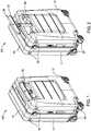
- FIGS 1 and 2are perspective views of a smart luggage system 100 according to one embodiment.
- the smart luggage system 100includes a body in the form of a piece of luggage 10, such as a suitcase, that can be used to store items for transport.
- the luggage 10is supported by four wheel assemblies 20.
- Each wheel assembly 20is configured to rotate in a given direction and roll in the given direction.
- Each wheel assembly 20is motorized to move the luggage 10 in a given direction.
- the luggage 10is supported by two, three, or more wheel assemblies 20.
- two, three, or more of the wheel assemblies 20are motorized to move the luggage in a given direction.
- the wheel assemblies 20are caster-type wheels.
- the system 100includes one or more proximity sensors 50 coupled to the luggage 10. Two proximity sensors 50 are shown coupled to a front side 11 of the luggage 10 near the top end of the luggage 10. Any number of proximity sensors 50 can be used and located at different positions and/or on any side of the luggage 10.
- the proximity sensors 50are configured to detect the proximity of one or more objects relative to the luggage 10, and may include but are not limited to ultrasonic sensors, sonar sensors, infrared sensors, radar sensors, and/or LiDAR sensors.
- a handle 30is coupled to the luggage 10, and is configured to allow a user to push, pull, and/or lift the luggage 10.
- a usercan move the handle 30 between a collapsed position as shown in Figure 1 and an extended position as shown in Figure 2 .
- the handle 30is located on a right side 12 of the luggage 10, but alternatively can be located on the opposite side.
- the handle 30includes a pull rod 31 coupled to a connecting rod 32, which is coupled to the luggage 10.
- the pull rod 31forms a "T" shape.
- One or more camerasare installed in the pull rod 31 as further described below.
- Figures 3, 4, 5, and 6are different perspective views of the handle 30 of the smart luggage system according 100 to one embodiment.
- One or more upper cameras 40, 41, 46, 47are coupled to the top portion of the pull rod 31.
- One or more lower cameras 42, 43, 44, 45are coupled to the bottom portion of the pull rod 31.
- the top portion of the pull rod 31is an elongated portion that is oriented horizontally and perpendicular to the bottom portion of the pull rod 31, which bottom portion is oriented vertically relative to the top portion.
- the upper cameras 40, 41, 46, 47are configured to detect and record, such as take photographs and/or videos, of nearby objects.
- the lower cameras 42, 43, 44, 45are configured to detect the proximity of objects relative to the luggage 10.
- the lower cameras 42, 43, 44, 45include an optical filter configured to identify invisible light/laser to help calculate the proximity of nearby objects.
- the upper cameras 40, 41, 46, 47are configured to take photographs and/or videos (for user recognition as one example) of nearby objects, and the lower cameras 42, 43, 44, 45 are configured to detect the proximity of nearby objects (for proximity sensing as one example).
- Embodiments of the smart luggage systeminclude any combination, number, and/or location of upper and/or lower cameras 40-47 coupled to the pull rod 31 as described herein.
- the upper camera 40is disposed in the top portion of the pull rod 31, and specifically is located at a front end 33 of the pull rod 31 facing a front view.
- the upper camera 41is disposed in the top portion of the pull rod 31, and specifically is located at a rear end 34 of the pull rod 31 facing a rear view.
- the upper camera 46is disposed in the top portion of the pull rod 31, and specifically is located at the center and on one side (e.g. the right side) of the pull rod 31 facing a side view.
- the upper camera 47is disposed in the top portion of the pull rod 31, and specifically is located on an opposite side (e.g. the left side) of the pull rod 31 at a location closer to the front end 33.
- the upper camera 46can be located closer to the front end 33 and/or the rear end 34 of the pull rod 31. Additionally or alternatively, the upper camera 47 can be located closer to the rear end 34 and/or centrally located on the side of the pull rod 31. Additionally or alternatively, the upper cameras 46 and/or 47 may instead be a control button configured to power on/off the smart luggage system 100.
- the lower camera 42is disposed in the bottom portion of the pull rod 31, and specifically is located facing the front view similar to the upper camera 40.
- the upper camera 44is disposed in the bottom portion of the pull rod 31, and specifically is located facing the rear view similar to the upper camera 41.
- the lower camera 43is disposed in the bottom portion of the pull rod 31, and specifically is located facing the side view similar to the upper camera 46.
- the lower camera 45is disposed in the bottom portion of the pull rod 31, and specifically is located facing the side view similar to the upper camera 47.
- FIG. 7is a perspective view of the handle 30 with a cover of the top portion removed and showing the interior of the top portion of the pull rod 31.
- the upper cameras 40, 41are disposed in the top portion of the pull rod 31 and located at the front and rear ends 33, 34 facing toward the front and toward the rear, respectively.
- the upper camera 47(additionally or alternatively the control button) is shown disposed in the top portion of the pull rod 31 facing toward the side.
- the lower cameras 42, 43are disposed in the bottom portion of the pull rod 31 facing the front and side, respectively.
- the top portion of the pull rod 31supports any number of components, such as a central processing unit (“CPU”) 49, configured to help with the operation of the smart luggage system 100 as further described below.
- CPUcentral processing unit
- Advantages of installing the cameras 40-47 in the pull rod 31 of the handle 30include but are not limited to: (1) better protection for the cameras when the luggage 10 is being transported, (2) the height of the cameras can be adjusted based on a user's height or preference, (3) the cameras are less likely to be vision blocked, and (4) better accuracy of people following using two sets of cameras, upper cameras for user recognition and lower cameras for proximity sensing.
- Figure 8is a plan view of the smart luggage system 100 following a user 300 in a side follow position according to one embodiment.
- the upper camera 46 and/or the lower camera 43can be used to detect and/or record the movement of the user 300 when within a viewing range 200 of the cameras 46, 43.
- the cameras 46, 43are configured to help maintain the smart luggage system 100 in the side follow position (e.g. next to or on the side of the user 300) as the user 300 moves in a given direction as indicted by reference arrow "A".
- the combination of the wheel assemblies 20 and the cameras 43, 46are configured to keep the front side 11 of the smart luggage system 100 facing forward in the given direction while moving in the side follow position.
- the upper camera 46can be used to maintain the smart luggage system 100 in the side follow position as discussed above.
- Figure 9is a plan view of the smart luggage system 100 following the user 300 in the rear follow position according to one embodiment.
- the upper camera 40 and/or the lower camera 42can be used to detect and/or record the movement of the user 300 when within the viewing range 200 of the cameras 40, 42.
- the cameras 40, 42are configured to help maintain the smart luggage system 100 in the rear follow position (e.g. behind the user 300) as the user 300 moves in the given direction as indicted by reference arrow "A".
- the combination of the wheel assemblies 20 and the cameras 40, 42are configured to keep the front side 11 of the smart luggage system 100 facing forward in the given direction while moving in the rear follow position.
- Figure 10is a plan view of the smart luggage system 100 following the user 300 in another rear follow position according to one embodiment.
- the upper camera 41 and/or the lower camera 44can be used to detect and/or record the movement of the user 300 when within the viewing range 200 of the cameras 41, 44.
- the cameras 41, 44are configured to help maintain the smart luggage system 100 in the rear follow position (e.g. behind the user 300) as the user 300 moves in the given direction as indicted by reference arrow "A".
- the combination of the wheel assemblies 20 and the cameras 41, 44are configured to keep the rear side 13 of the smart luggage system 100 facing forward in the given direction while moving in the rear follow position.
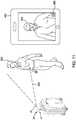
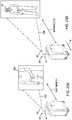
- FIG 11is a schematic view of the smart luggage system 100 taking a photograph and/or video using any one or all of the upper cameras 40, 41.
- the smart luggage system 100is configured to take and communicate the photograph and/or video to a personal user device 400, such as a cellular phone and/or tablet, where the user can view the photograph and/or video.
- a personal user device 400such as a cellular phone and/or tablet
- the height of the upper cameras 40, 41can be adjusted by adjusting the height of the handle 30 relative to the smart luggage system 100.
- the user 300can control the movement of the smart luggage system 100 using a control feature 450 on the screen of the personal user device 400 while the image within the viewing range of the upper cameras 40, 41 is displayed on the personal user device 400 to find the best position to take the photograph and/or video.
- the user 300can also use the control feature 450 to operate the upper cameras 40, 41 to take the photograph and/or video.
- the upper cameras 40, 41are also configured to turn 90 degrees to better fit the image of the user 300 when taking a selfie photograph and/or video. In this manner, the smart luggage system 100 can be used to take a selfie photograph and/or video, while being able to adjust the position, without the assistance of another person.
- Figure 12is a plan view of the smart luggage system 100 using an auto-framing mode to move in a given direction as indicated by reference arrow "B" (e.g. a 360 degree path) about the user 300 while maintaining the front side 11 of the smart luggage system 100 facing the user 300 at all times.
- the upper camera 40 and/or the lower camera 42can be used to detect and/or record the user 300 as the user 300 remains stationary.
- Activating the auto-framing mode of the upper camera 40 and/or the lower camera 42enables the smart luggage system 100 to autonomously find the user 300 and put the user 300 in the middle of the photograph and/or video by itself.
- the combination of the wheel assemblies 20 and the cameras 40, 42are configured to keep the front side 11 of the smart luggage system 100 facing the user 300 while moving in the given direction about the user 300.
- Figure 13is a plan view of the smart luggage system 100 using an auto-framing mode to move in a given direction as indicated by reference arrow "C" (e.g. in a sideways direction) while maintaining the front side 11 of the smart luggage system 100 facing the user 300 at all times.
- the upper camera 40 and/or the lower camera 42can be used to detect and/or record the user 300 as the user 300 moves sideways.
- Activating the auto-framing mode of the upper camera 40 and/or the lower camera 42enables the smart luggage system 100 to autonomously find the user 300 and put the user 300 in the middle of the photograph and/or video by itself.
- the combination of the wheel assemblies 20 and the cameras 40, 42are configured to keep the front side 11 of the smart luggage system 100 facing the user 300 while moving sideways with the user 300.
- a method of taking a photograph and/or video using the smart luggage system 100comprises moving the handle 30 from a collapsed position to an extended position (as shown in Figures 1 and 2 , respectively).
- the methodfurther comprises viewing an object (e.g. the user 300) that is within a viewing range of the upper cameras 40 and/or 41 on the personal user device 400.
- the methodfurther comprises taking the photograph and/or video of the object using the upper cameras 40 and/or 41.
- the methodfurther comprises moving the smart luggage system 100 using the control feature 450 on the personal user device 400.
- the methodfurther comprises operating the upper cameras 40 and/or 41 to take the photograph and/or video using the control feature 450.
- the methodfurther comprises activating an auto-framing mode using the control feature 450 such that the smart luggage system 100 autonomously moves and puts the object in the middle of the photograph and/or video.
- the methodfurther comprises adjusting the upper cameras 40 and/or 41 by adjusting a height of the handle 30.
- Figure 14is a schematic view of the smart luggage system 100 while in the rear follow position relative to the user 300.
- the upper and/or lower cameras 40, 42are configured to detect and/or record images within a front viewing range 210, such as the user 300.
- the upper and/or lower cameras 41, 44are configured to detect and/or record images within a rear viewing range 220, such as another person 350.
- the smart luggage system 100is configured to take real time photographs and/or videos using the cameras 40, 41, 42, 44, and communicate the real time photographs and/or videos to the personal user device 400, such as a cellular phone and/or tablet.
- the user 300can simultaneously view real time images within the front viewing range 210 and the rear viewing range 220 on the personal user device 400.
- Figures 15 and 16are schematic views of different locations where a control button 48 can be located on the pull rod 31 of the handle 30 of the smart luggage system 100.
- the control button 48is configured to power on/off the smart luggage system 100, and/or to switch the smart luggage system 100 between autonomous control and manual control.
- one or more control buttons 48can be positioned at any one of three different locations as identified by reference circles "D", "E", and "F” where the user 300 grips the pull rod 31.
- one or more control buttons 48can be positioned at the location as identified by reference circles "G” where the user 300 grips the pull rod 31.
- the control buttons 48can be located on the top or sides of the top portion of the pull rod 31, and/or on the underside of the top portion of the pull rod 31.
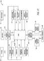
- FIG 17is a block diagram of the smart luggage system 100 according to one embodiment.
- the smart luggage system 100includes a battery 70 in communication with a power distribution module 71.
- the power distribution module 71is configured to distribute power supplied by the battery 70 to the other components of the smart luggage system 100.
- the smart luggage system 100includes a central processing unit (“CPU") 72 in communication with a phone communication module 61 and a wristband communication module 75.
- the CPU 72may be the same or a different CPU than the CPU 49 located in the top portion of the pull rod 31 as shown in Figure 7 .
- a cellular phone 60 and a wristband 76are used to communicate with the phone communication module 61 and the wristband communication module 75, respectively, via ultra-wideband, radio frequency identification (active and/or passive), Bluetooth (low energy), WiFi, and/or any other form of communication known in the art.
- the cellular phone 60 and the wristband 76are two examples of personal user devices that can be used with the smart luggage system 100.
- the cellular phone 60 and/or the wristband 76are configured to allow a user to send instructions to the CPU 72 to control operation of the smart luggage system 100, and to receive information from the CPU 72 regarding the operation of the smart luggage system 100.
- a positioning module 74is configured to communicate information regarding the position of the luggage 10 to the CPU 72 and the user (via the cellular phone 60 and/or the wristband 76 for example).
- the positioning module 74may include GPS (outdoor), WiFi access points (indoor), and/or Bluetooth beacons (indoor) so that the user can find the location of the smart luggage system 100 at any time, such as in the event that the smart luggage system 100 is lost.
- An accelerometer 51is configured to communicate information regarding the overall acceleration and/or speed of the smart luggage system 100 to the CPU 72.
- a wheel orientation sensor 55is configured to communicate information regarding the orientation of the motorized wheel assemblies 20 to the CPU 72.
- the CPU 72is also in communication with the upper and lower cameras 40, 41, 42, 43, 44, 45, 46, 47, the proximity sensors 50, an inertial measurement unit ("IMU") 77, and a wheel control module 65.
- the cameras 40-47are configured to communicate information regarding the visual images and presence of nearby objects that the cameras 40-47 records and/or detects to the CPU 72.
- the proximity sensors 50are configured to communicate information regarding the presence of objects near the smart luggage system 100 to the CPU 72.
- the IMU 77is configured to communicate information regarding the dynamic movements of the smart luggage system 100, such as the pitch, roll, yaw, acceleration, and/or angular rate of the smart luggage system 100 to the CPU 72. For example, once the IMU 77 detects that the smart luggage system 100 is tilting or falling over, then the CPU 72 will instruct a wheel control module 65 to stop one or more wheel rotating motors 52 from rotating one or more of the wheel assemblies 20.
- the wheel control module 65is in communication with a rotary speed sensor 53 and the wheel rotating motor 52.
- the wheel control module 65is configured to communicate information regarding the motorized wheel assemblies 20, such as the rotary speed measured by the rotary speed sensor 53, to the CPU 72.
- each wheel assembly 20can include a separate wheel control module 65 in communication with the CPU 72.
- the wheel control module 65can be integrated into the CPU 72 as a single processing unit.
- the CPU 72includes a single wheel control module 65 to control all four wheel assemblies 20.
- the CPU 72includes four wheel control modules 65, one for each wheel assembly 20.
- the CPU 72is configured to analyze the information received from the various components (e.g. cameras 40-47, proximity sensors 50, modules 61, 65, 74, 75, etc.) of the smart luggage system 100 and perform the computational functions programmed into the CPU 72 based on the information to operate the smart luggage system 100 as described herein. For example, the CPU 72 is configured to determine a given direction and speed based on the information. The CPU 72 is configured to control the direction and speed of the smart luggage system 100 relative to a user and/or the surrounding environment. For example, the CPU 72 is configured to control the direction and the speed of the smart luggage system 100 through the wheel control module 65 by instructing the wheel control module 65 to increase, decrease, or stop power, e.g. input current, supplied to each respective motorized wheel assembly 20.
- the various componentse.g. cameras 40-47, proximity sensors 50, modules 61, 65, 74, 75, etc.
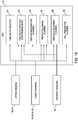
- FIG 18is another block diagram of the smart luggage system 100 according to one embodiment.
- the CPU 72may be pre-programmed with several functions directed to the operation of the smart luggage system 100.
- a take selfie function 81is configured to help a user take a selfie photograph and/or video using any one of the upper cameras 40, 41.
- a take selfie function (with auto-framing mode) 82is configured to help a user take a selfie photograph and/or video with auto-framing assistance using any one of the upper cameras 40, 41, the lower cameras 42, 43, 44, 45, and/or the proximity sensors 50.
- a gesture recognition function 83is configured to help detect a user based on a gesture provided by the user using any one of the upper cameras 40, 41.
- a people following function 84is configured to maintain the smart luggage system 100 in a rear follow or side follow position relative to a user using any one of the upper cameras 40, 41, the lower cameras 42, 43, 44, 45, and/or the proximity sensors 50.
- An obstacle avoidance function 85is configured to help the smart luggage system 100 avoid obstacle when moving in a given direction using any one of the lower cameras 42, 43, 44, 45, and/or the proximity sensors 50.
- a fall prevention function 86is configured to help prevent the smart luggage system 100 from falling over using any one of the lower cameras 42, 43, 44, 45.
- FIG 19is a perspective view of a smart luggage system 500 according to one embodiment.
- the smart luggage system 500includes a body in the form of a piece of luggage 510, such as a suitcase, that can be used to store items for transport.
- the luggage 510is supported by four wheel assemblies 520 that are configured to rotate in a given direction and roll in the given direction.
- the wheel assembliesmay be motorized or non-motorized.
- the smart luggage system 500is similar to the smart luggage system 100 discussed above but may include one or more cameras 550 coupled to the luggage 510 and/or one or more cameras 552 coupled to a handle 530 of the luggage 510.
- One camera 550is shown coupled to a front side 511 of the luggage 510 near the top end of the luggage 510.
- Three cameras 552are shown coupled to front and right sides of the handle 530, and specifically coupled to a pull rod 531 of the handle 530, but can additionally or alternatively be coupled to a connecting rod 532 of the handle 530. Any number of cameras 550, 552 can be used and located at different positions and/or on any side of the luggage 510 and/or the handle 530.
- a control button 551is shown coupled to the front side 511 of the luggage 510, and a control button 553 is shown coupled to the pull rod 531 of the handle 530.
- the control button 553may be the control button 48 as described above with respect to Figures 15 and 16 .
- the control buttons 551, 553are configured to activate the cameras 550, 552 so that a user can take photographs and/or videos using the cameras 550, 552. Any number of control buttons 551, 553 can be used and located at different positions and/or on any side of the luggage 510 and/or the handle 530.
- Figure 21is a flow chart of a method 700 of taking a photograph and/or video using the smart luggage systems 100 and/or 500 according to one embodiment.
- a userpresses a control button (such as control buttons 48, 551, 553) on the luggage and/or the handle (such as luggage 10, 510 and/or handle 30, 530) to stop the people following function and activate any one of the cameras on the luggage and/or the handle to take a photograph and/or video.
- a processing unitsuch as CPUs 49, 72
- the luggageis operating a people recognizing process to identify an object to follow, such as the user, and move the luggage in a side following position or a rear following position relative to the user.
- the control buttonis used to instruct a processing unit to activate the selfie function to prepare the cameras to take the photograph and/or video.
- the luggage, and specifically the processing unitstops the people recognizing process and starts the photograph/video taking process of capturing real-time images.
- the photograph/video taking processmay include adjusting the real-time image so that the user can see the photograph and/or video with vivid colors via the processing unit and/or the personal user device.
- the photograph/video taking processmay also include adjusting the real-time image using tone mapping, gamma correction, color space conversion, white balance, edge enhancement, and/or contrast enhancement, etc., via the processing unit and/or the personal user device.
- the luggagewirelessly connects to the personal user device (such as personal user device 400).
- the processing unit of the luggagecommunicates the real-time image of an object within a viewing range of any one or more of the cameras of the systems 100, 500 to the personal user device such that the real-time image is viewable on the screen of the device. If needed, the user can adjust the position of the object and/or the luggage to obtain a better viewing angle with the camera on the luggage.
- the personal user deviceWhen the shutter button is pressed, the personal user device instructs the processing unit to take the photograph and/or video of the object using one of the cameras.
- the luggagetakes the photograph and/or video and sends it to the personal user device via the processing unit.
- the photograph and/or videois stored on the personal user device and/or on a cloud storage space (e.g. an internet based memory storage system).
- the userpresses the control button on the luggage and/or the handle to stop the selfie function and switch back to the people following function.
- the control buttonis used to instruct the processing unit to stop the selfie function and switch back to the people following function.
- the luggage, and specifically the processing unitstops the photograph/video taking process and switches back to the people recognizing process to identify an object to follow, such as the user, and continue moving the luggage in a side following positon or a rear following position relative to the user.
- Figure 22is a schematic view of the smart luggage system 100 taking a self-photograph and/or video using any one or all of the upper cameras 40, 41, and displaying the self-photograph and/or video on the personal user device 400.
- the user 300can select an auto-framing mode or a manual mode on the personal user device 400 to control how to take the self-photograph and/or video using the smart luggage system 100. If the user 300 selects the manual mode, then the user 300 can move the smart luggage system 100 to the desired location via the control feature 450 while viewing the image on the screen of the personal user device 400 to capture the desired image. The user 300 can then press the control feature 450 to take the photograph and/or video.
- the user 300can then select the style of photograph and/or video, specifically a full body photograph/video which captures the full body of the user 300, or a half body photograph/video which captures only half of the body of the user 300.
- the smart luggage system 100is configured to move itself and find a location such that the user 300 will appear in the middle of the photograph and/or video.
- the smart luggage system 100is also configured to match the selected style (e.g. full body or half body).
- the smart luggage systemis configured to use the light on the luggage 10 or on the pull rod 30 to count down and indicate when it will take the photograph and/or video. In other words, the smart luggage system 100 will find a location, wait for a few seconds with a light indication, and then take the photograph and/or video.
- Figure 23Ais a schematic view of the smart luggage system 100 taking a photograph and/or video of the user 300 when located at a first distance D1 relative to the user 300. As shown, the user 300 is located within the viewing range 200 of the camera 40 but is too close to the camera 40 such that only a portion of the user 300 is viewed. The user 300 can manually control the location of the smart luggage system 100 using the control feature 450 to adjust the distance for a better photograph and/or video.
- the smart luggage system 100is configured to automatically move in a direction indicated by reference arrow "H" to a location that is at a second distance D2 relative to the user 300 to capture the selected style of photograph and/or video (e.g. full body or half body).
- Activating the auto-framing mode of the upper camera 40 (and/or any of the other cameras, e.g. upper camera 41)enables the smart luggage system 100 to autonomously find the user 300 and put the user 300 in the middle of the photograph and/or video by itself.
- the smart luggage system 100will wait for a few seconds with a light indication and then take the photograph and/or video.
Landscapes
- Engineering & Computer Science (AREA)
- Physics & Mathematics (AREA)
- General Physics & Mathematics (AREA)
- Aviation & Aerospace Engineering (AREA)
- Radar, Positioning & Navigation (AREA)
- Remote Sensing (AREA)
- Multimedia (AREA)
- Automation & Control Theory (AREA)
- Computer Vision & Pattern Recognition (AREA)
- Electromagnetism (AREA)
- Signal Processing (AREA)
- Purses, Travelling Bags, Baskets, Or Suitcases (AREA)
- Studio Devices (AREA)
- Control Of Position, Course, Altitude, Or Attitude Of Moving Bodies (AREA)
Description
- Embodiments disclosed herein relate to a smart luggage system having a camera installed in a top portion of the pull rod.
- Current self-driving luggage designs have cameras located on the body of the luggage that are used for proximity sensing to avoid obstacles, especially when being used in crowded places like airports, hotels, or a busy sidewalk. The cameras on these self-driving luggage designs often have a narrow viewing range, are easily obstructed, and are limited in their capability. Therefore there is a continuous need for new and improved smart luggage systems.
- Document
US2018360177 discloses a robotic suitcase that can autonomously follow a traveler while providing him or her with additional smart functionalities. - A smart luggage system according to claim 1 is disclosed.
- In one embodiment, a method of taking a photograph and/or video according to claim 9 is disclosed.
Figures 1 and 2 are perspective views of a smart luggage system according to one embodiment.Figures 3, 4, 5, and 6 are different perspective views of a handle of the smart luggage system according to one embodiment.Figure 7 is a perspective view of the interior of the handle according to one embodiment.Figure 8 is a plan view of the smart luggage system following a user in a side follow position according to one embodiment.Figure 9 is a plan view of the smart luggage system following a user in a rear follow position according to one embodiment.Figure 10 is a plan view of the smart luggage system following a user in another rear follow position according to one embodiment.Figure 11 is a schematic view of the smart luggage system taking a photograph and/or video and displaying the photograph and/or video on a personal user device.Figure 12 is a plan view of the smart luggage system moving along a 360 degree path about a user according to one embodiment.Figure 13 is a plan view of the smart luggage system moving along a path that is parallel to a path of a user according to one embodiment.Figure 14 is a schematic view of the smart luggage system recording front and rear views and displaying the front and rear views on a personal user device.Figures 15 and16 are schematic views of different locations of a control button of the handle of the smart luggage system.Figure 17 is a block diagram of the smart luggage system according to one embodiment.Figure 18 is another block diagram of the smart luggage system according to one embodiment.Figure 19 is a perspective view of a smart luggage system according to one embodiment.Figure 20 is a flow chart of a method of taking a photograph and/or video using the smart luggage system according to one embodiment.Figure 21 is a flow chart of a method of taking a photograph and/or video using the smart luggage system according to one embodiment.Figure 22 is a schematic view of the smart luggage system taking a photograph and/or video and displaying the photograph and/or video on a personal user device.Figure 23A is a schematic view of the smart luggage system taking a photograph and/or video at a first distance relative to a user.Figure 23B is a schematic view of the smart luggage system taking a photograph and/or video at a second distance relative to the user.- To facilitate understanding, identical reference numerals have been used, where possible, to designate identical elements that are common to the figures. It is contemplated that elements disclosed in one embodiment may be beneficially utilized with other embodiments without specific recitation.
- The invention includes a smart luggage system that is self-driving and has one or more motorized wheel assemblies. The smart luggage system is configured to autonomously follow any type of object, such as a user, moving in a given direction. Although the embodiments of the smart luggage system are described and illustrated herein with respect to a suitcase, the embodiments may be used with other types of portable equipment, such as a shopping cart.
- In one embodiment, the smart luggage system has one or more cameras installed in the pull rod of the handle. The cameras are configured to take photographs and/or videos, and send the photographs and/or videos to a personal user device, including but not limited to a cellular phone, a tablet, a wristband, and a computer. The cameras are also configured to help guide the smart luggage system when following an object, such as a user, in a rear follow position or a side follow position.
Figures 1 and 2 are perspective views of asmart luggage system 100 according to one embodiment. Thesmart luggage system 100 includes a body in the form of a piece ofluggage 10, such as a suitcase, that can be used to store items for transport. Theluggage 10 is supported by fourwheel assemblies 20. Eachwheel assembly 20 is configured to rotate in a given direction and roll in the given direction. Eachwheel assembly 20 is motorized to move theluggage 10 in a given direction.- In one embodiment, the
luggage 10 is supported by two, three, ormore wheel assemblies 20. In one embodiment, two, three, or more of thewheel assemblies 20 are motorized to move the luggage in a given direction. In one embodiment, thewheel assemblies 20 are caster-type wheels. - The
system 100 includes one ormore proximity sensors 50 coupled to theluggage 10. Twoproximity sensors 50 are shown coupled to afront side 11 of theluggage 10 near the top end of theluggage 10. Any number ofproximity sensors 50 can be used and located at different positions and/or on any side of theluggage 10. Theproximity sensors 50 are configured to detect the proximity of one or more objects relative to theluggage 10, and may include but are not limited to ultrasonic sensors, sonar sensors, infrared sensors, radar sensors, and/or LiDAR sensors. - A
handle 30 is coupled to theluggage 10, and is configured to allow a user to push, pull, and/or lift theluggage 10. A user can move thehandle 30 between a collapsed position as shown inFigure 1 and an extended position as shown inFigure 2 . Thehandle 30 is located on aright side 12 of theluggage 10, but alternatively can be located on the opposite side. Thehandle 30 includes apull rod 31 coupled to a connectingrod 32, which is coupled to theluggage 10. Thepull rod 31 forms a "T" shape. One or more cameras are installed in thepull rod 31 as further described below. Figures 3, 4, 5, and 6 are different perspective views of thehandle 30 of the smart luggage system according 100 to one embodiment. One or moreupper cameras pull rod 31. One or morelower cameras pull rod 31. The top portion of thepull rod 31 is an elongated portion that is oriented horizontally and perpendicular to the bottom portion of thepull rod 31, which bottom portion is oriented vertically relative to the top portion.- In one embodiment, the
upper cameras lower cameras luggage 10. For example, thelower cameras upper cameras lower cameras pull rod 31 as described herein. - The
upper camera 40 is disposed in the top portion of thepull rod 31, and specifically is located at afront end 33 of thepull rod 31 facing a front view. Theupper camera 41 is disposed in the top portion of thepull rod 31, and specifically is located at arear end 34 of thepull rod 31 facing a rear view. Theupper camera 46 is disposed in the top portion of thepull rod 31, and specifically is located at the center and on one side (e.g. the right side) of thepull rod 31 facing a side view. Theupper camera 47 is disposed in the top portion of thepull rod 31, and specifically is located on an opposite side (e.g. the left side) of thepull rod 31 at a location closer to thefront end 33. - Additionally or alternatively, the
upper camera 46 can be located closer to thefront end 33 and/or therear end 34 of thepull rod 31. Additionally or alternatively, theupper camera 47 can be located closer to therear end 34 and/or centrally located on the side of thepull rod 31. Additionally or alternatively, theupper cameras 46 and/or 47 may instead be a control button configured to power on/off thesmart luggage system 100. - The
lower camera 42 is disposed in the bottom portion of thepull rod 31, and specifically is located facing the front view similar to theupper camera 40. Theupper camera 44 is disposed in the bottom portion of thepull rod 31, and specifically is located facing the rear view similar to theupper camera 41. Thelower camera 43 is disposed in the bottom portion of thepull rod 31, and specifically is located facing the side view similar to theupper camera 46. Thelower camera 45 is disposed in the bottom portion of thepull rod 31, and specifically is located facing the side view similar to theupper camera 47. Figure 7 is a perspective view of thehandle 30 with a cover of the top portion removed and showing the interior of the top portion of thepull rod 31. As shown, theupper cameras pull rod 31 and located at the front andrear ends pull rod 31 facing toward the side. Thelower cameras pull rod 31 facing the front and side, respectively. The top portion of thepull rod 31 supports any number of components, such as a central processing unit ("CPU") 49, configured to help with the operation of thesmart luggage system 100 as further described below.- Advantages of installing the cameras 40-47 in the
pull rod 31 of thehandle 30 include but are not limited to: (1) better protection for the cameras when theluggage 10 is being transported, (2) the height of the cameras can be adjusted based on a user's height or preference, (3) the cameras are less likely to be vision blocked, and (4) better accuracy of people following using two sets of cameras, upper cameras for user recognition and lower cameras for proximity sensing. Figure 8 is a plan view of thesmart luggage system 100 following auser 300 in a side follow position according to one embodiment. When thehandle 30 is in the extended position (as shown inFigure 2 ), theupper camera 46 and/or thelower camera 43 can be used to detect and/or record the movement of theuser 300 when within aviewing range 200 of thecameras cameras smart luggage system 100 in the side follow position (e.g. next to or on the side of the user 300) as theuser 300 moves in a given direction as indicted by reference arrow "A". As shown, the combination of thewheel assemblies 20 and thecameras front side 11 of thesmart luggage system 100 facing forward in the given direction while moving in the side follow position. When thehandle 30 is in the collapsed position (as shown inFigure 1 ) theupper camera 46 can be used to maintain thesmart luggage system 100 in the side follow position as discussed above.Figure 9 is a plan view of thesmart luggage system 100 following theuser 300 in the rear follow position according to one embodiment. When thehandle 30 is in the extended position (as shown inFigure 2 ), theupper camera 40 and/or thelower camera 42 can be used to detect and/or record the movement of theuser 300 when within theviewing range 200 of thecameras cameras smart luggage system 100 in the rear follow position (e.g. behind the user 300) as theuser 300 moves in the given direction as indicted by reference arrow "A". As shown, the combination of thewheel assemblies 20 and thecameras front side 11 of thesmart luggage system 100 facing forward in the given direction while moving in the rear follow position.Figure 10 is a plan view of thesmart luggage system 100 following theuser 300 in another rear follow position according to one embodiment. When thehandle 30 is in the extended position (as shown inFigure 2 ), theupper camera 41 and/or thelower camera 44 can be used to detect and/or record the movement of theuser 300 when within theviewing range 200 of thecameras cameras smart luggage system 100 in the rear follow position (e.g. behind the user 300) as theuser 300 moves in the given direction as indicted by reference arrow "A". As shown, the combination of thewheel assemblies 20 and thecameras rear side 13 of thesmart luggage system 100 facing forward in the given direction while moving in the rear follow position.Figure 11 is a schematic view of thesmart luggage system 100 taking a photograph and/or video using any one or all of theupper cameras smart luggage system 100 is configured to take and communicate the photograph and/or video to apersonal user device 400, such as a cellular phone and/or tablet, where the user can view the photograph and/or video. To help take the photograph and/or video, the height of theupper cameras handle 30 relative to thesmart luggage system 100. Theuser 300 can control the movement of thesmart luggage system 100 using acontrol feature 450 on the screen of thepersonal user device 400 while the image within the viewing range of theupper cameras personal user device 400 to find the best position to take the photograph and/or video. Theuser 300 can also use thecontrol feature 450 to operate theupper cameras upper cameras user 300 when taking a selfie photograph and/or video. In this manner, thesmart luggage system 100 can be used to take a selfie photograph and/or video, while being able to adjust the position, without the assistance of another person.Figure 12 is a plan view of thesmart luggage system 100 using an auto-framing mode to move in a given direction as indicated by reference arrow "B" (e.g. a 360 degree path) about theuser 300 while maintaining thefront side 11 of thesmart luggage system 100 facing theuser 300 at all times. When thehandle 30 is in the extended position (as shown inFigure 2 ), theupper camera 40 and/or thelower camera 42 can be used to detect and/or record theuser 300 as theuser 300 remains stationary. Activating the auto-framing mode of theupper camera 40 and/or thelower camera 42 enables thesmart luggage system 100 to autonomously find theuser 300 and put theuser 300 in the middle of the photograph and/or video by itself. The combination of thewheel assemblies 20 and thecameras front side 11 of thesmart luggage system 100 facing theuser 300 while moving in the given direction about theuser 300.Figure 13 is a plan view of thesmart luggage system 100 using an auto-framing mode to move in a given direction as indicated by reference arrow "C" (e.g. in a sideways direction) while maintaining thefront side 11 of thesmart luggage system 100 facing theuser 300 at all times. When thehandle 30 is in the extended position (as shown inFigure 2 ), theupper camera 40 and/or thelower camera 42 can be used to detect and/or record theuser 300 as theuser 300 moves sideways. Activating the auto-framing mode of theupper camera 40 and/or thelower camera 42 enables thesmart luggage system 100 to autonomously find theuser 300 and put theuser 300 in the middle of the photograph and/or video by itself. The combination of thewheel assemblies 20 and thecameras front side 11 of thesmart luggage system 100 facing theuser 300 while moving sideways with theuser 300.- In one embodiment, a method of taking a photograph and/or video using the
smart luggage system 100 comprises moving thehandle 30 from a collapsed position to an extended position (as shown inFigures 1 and 2 , respectively). The method further comprises viewing an object (e.g. the user 300) that is within a viewing range of theupper cameras 40 and/or 41 on thepersonal user device 400. The method further comprises taking the photograph and/or video of the object using theupper cameras 40 and/or 41. The method further comprises moving thesmart luggage system 100 using thecontrol feature 450 on thepersonal user device 400. The method further comprises operating theupper cameras 40 and/or 41 to take the photograph and/or video using thecontrol feature 450. The method further comprises activating an auto-framing mode using thecontrol feature 450 such that thesmart luggage system 100 autonomously moves and puts the object in the middle of the photograph and/or video. The method further comprises adjusting theupper cameras 40 and/or 41 by adjusting a height of thehandle 30. Figure 14 is a schematic view of thesmart luggage system 100 while in the rear follow position relative to theuser 300. The upper and/orlower cameras front viewing range 210, such as theuser 300. At the same time, the upper and/orlower cameras rear viewing range 220, such as anotherperson 350. Thesmart luggage system 100 is configured to take real time photographs and/or videos using thecameras personal user device 400, such as a cellular phone and/or tablet. Theuser 300 can simultaneously view real time images within thefront viewing range 210 and therear viewing range 220 on thepersonal user device 400.Figures 15 and16 are schematic views of different locations where acontrol button 48 can be located on thepull rod 31 of thehandle 30 of thesmart luggage system 100. Thecontrol button 48 is configured to power on/off thesmart luggage system 100, and/or to switch thesmart luggage system 100 between autonomous control and manual control. As shown inFigure 15 , one ormore control buttons 48 can be positioned at any one of three different locations as identified by reference circles "D", "E", and "F" where theuser 300 grips thepull rod 31. As shown inFigure 16 , one ormore control buttons 48 can be positioned at the location as identified by reference circles "G" where theuser 300 grips thepull rod 31. Thecontrol buttons 48 can be located on the top or sides of the top portion of thepull rod 31, and/or on the underside of the top portion of thepull rod 31.Figure 17 is a block diagram of thesmart luggage system 100 according to one embodiment. Thesmart luggage system 100 includes abattery 70 in communication with apower distribution module 71. Thepower distribution module 71 is configured to distribute power supplied by thebattery 70 to the other components of thesmart luggage system 100.- The
smart luggage system 100 includes a central processing unit ("CPU") 72 in communication with aphone communication module 61 and awristband communication module 75. TheCPU 72 may be the same or a different CPU than theCPU 49 located in the top portion of thepull rod 31 as shown inFigure 7 . Acellular phone 60 and awristband 76 are used to communicate with thephone communication module 61 and thewristband communication module 75, respectively, via ultra-wideband, radio frequency identification (active and/or passive), Bluetooth (low energy), WiFi, and/or any other form of communication known in the art. Thecellular phone 60 and thewristband 76 are two examples of personal user devices that can be used with thesmart luggage system 100. Thecellular phone 60 and/or thewristband 76 are configured to allow a user to send instructions to theCPU 72 to control operation of thesmart luggage system 100, and to receive information from theCPU 72 regarding the operation of thesmart luggage system 100. - A
positioning module 74 is configured to communicate information regarding the position of theluggage 10 to theCPU 72 and the user (via thecellular phone 60 and/or thewristband 76 for example). Thepositioning module 74 may include GPS (outdoor), WiFi access points (indoor), and/or Bluetooth beacons (indoor) so that the user can find the location of thesmart luggage system 100 at any time, such as in the event that thesmart luggage system 100 is lost. Anaccelerometer 51 is configured to communicate information regarding the overall acceleration and/or speed of thesmart luggage system 100 to theCPU 72. Awheel orientation sensor 55 is configured to communicate information regarding the orientation of themotorized wheel assemblies 20 to theCPU 72. - The
CPU 72 is also in communication with the upper andlower cameras proximity sensors 50, an inertial measurement unit ("IMU") 77, and awheel control module 65. The cameras 40-47 are configured to communicate information regarding the visual images and presence of nearby objects that the cameras 40-47 records and/or detects to theCPU 72. Theproximity sensors 50 are configured to communicate information regarding the presence of objects near thesmart luggage system 100 to theCPU 72. TheIMU 77 is configured to communicate information regarding the dynamic movements of thesmart luggage system 100, such as the pitch, roll, yaw, acceleration, and/or angular rate of thesmart luggage system 100 to theCPU 72. For example, once theIMU 77 detects that thesmart luggage system 100 is tilting or falling over, then theCPU 72 will instruct awheel control module 65 to stop one or morewheel rotating motors 52 from rotating one or more of thewheel assemblies 20. - The
wheel control module 65 is in communication with arotary speed sensor 53 and thewheel rotating motor 52. Thewheel control module 65 is configured to communicate information regarding themotorized wheel assemblies 20, such as the rotary speed measured by therotary speed sensor 53, to theCPU 72. Although only onewheel control module 65 is shown, eachwheel assembly 20 can include a separatewheel control module 65 in communication with theCPU 72. In one embodiment, thewheel control module 65 can be integrated into theCPU 72 as a single processing unit. According to one example, theCPU 72 includes a singlewheel control module 65 to control all fourwheel assemblies 20. According to one example, theCPU 72 includes fourwheel control modules 65, one for eachwheel assembly 20. - The
CPU 72 is configured to analyze the information received from the various components (e.g. cameras 40-47,proximity sensors 50,modules smart luggage system 100 and perform the computational functions programmed into theCPU 72 based on the information to operate thesmart luggage system 100 as described herein. For example, theCPU 72 is configured to determine a given direction and speed based on the information. TheCPU 72 is configured to control the direction and speed of thesmart luggage system 100 relative to a user and/or the surrounding environment. For example, theCPU 72 is configured to control the direction and the speed of thesmart luggage system 100 through thewheel control module 65 by instructing thewheel control module 65 to increase, decrease, or stop power, e.g. input current, supplied to each respectivemotorized wheel assembly 20. Figure 18 is another block diagram of thesmart luggage system 100 according to one embodiment. TheCPU 72 may be pre-programmed with several functions directed to the operation of thesmart luggage system 100. Atake selfie function 81 is configured to help a user take a selfie photograph and/or video using any one of theupper cameras upper cameras lower cameras proximity sensors 50.- A
gesture recognition function 83 is configured to help detect a user based on a gesture provided by the user using any one of theupper cameras people following function 84 is configured to maintain thesmart luggage system 100 in a rear follow or side follow position relative to a user using any one of theupper cameras lower cameras proximity sensors 50. Anobstacle avoidance function 85 is configured to help thesmart luggage system 100 avoid obstacle when moving in a given direction using any one of thelower cameras proximity sensors 50. Afall prevention function 86 is configured to help prevent thesmart luggage system 100 from falling over using any one of thelower cameras Figure 19 is a perspective view of asmart luggage system 500 according to one embodiment. Thesmart luggage system 500 includes a body in the form of a piece ofluggage 510, such as a suitcase, that can be used to store items for transport. Theluggage 510 is supported by fourwheel assemblies 520 that are configured to rotate in a given direction and roll in the given direction. The wheel assemblies may be motorized or non-motorized.- The
smart luggage system 500 is similar to thesmart luggage system 100 discussed above but may include one ormore cameras 550 coupled to theluggage 510 and/or one ormore cameras 552 coupled to ahandle 530 of theluggage 510. Onecamera 550 is shown coupled to afront side 511 of theluggage 510 near the top end of theluggage 510. Threecameras 552 are shown coupled to front and right sides of thehandle 530, and specifically coupled to apull rod 531 of thehandle 530, but can additionally or alternatively be coupled to a connectingrod 532 of thehandle 530. Any number ofcameras luggage 510 and/or thehandle 530. - A
control button 551 is shown coupled to thefront side 511 of theluggage 510, and acontrol button 553 is shown coupled to thepull rod 531 of thehandle 530. Thecontrol button 553 may be thecontrol button 48 as described above with respect toFigures 15 and16 . Thecontrol buttons cameras cameras control buttons luggage 510 and/or thehandle 530. Figure 21 is a flow chart of amethod 700 of taking a photograph and/or video using thesmart luggage systems 100 and/or 500 according to one embodiment. Atstep 705, a user presses a control button (such ascontrol buttons luggage CPUs 49, 72) in the luggage is operating a people recognizing process to identify an object to follow, such as the user, and move the luggage in a side following position or a rear following position relative to the user.- The control button is used to instruct a processing unit to activate the selfie function to prepare the cameras to take the photograph and/or video. At
step 707, the luggage, and specifically the processing unit, stops the people recognizing process and starts the photograph/video taking process of capturing real-time images. The photograph/video taking process may include adjusting the real-time image so that the user can see the photograph and/or video with vivid colors via the processing unit and/or the personal user device. The photograph/video taking process may also include adjusting the real-time image using tone mapping, gamma correction, color space conversion, white balance, edge enhancement, and/or contrast enhancement, etc., via the processing unit and/or the personal user device. - At
step 710, the luggage, and specifically the processing unit, wirelessly connects to the personal user device (such as personal user device 400). Atstep 715, the processing unit of the luggage communicates the real-time image of an object within a viewing range of any one or more of the cameras of thesystems step 720, the user presses a shutter button (such as control feature 450) on the personal user device to take a photograph and/or video of the object using the cameras on the luggage and/or the handle. - When the shutter button is pressed, the personal user device instructs the processing unit to take the photograph and/or video of the object using one of the cameras. At
step 725, the luggage takes the photograph and/or video and sends it to the personal user device via the processing unit. Atstep 730, the photograph and/or video is stored on the personal user device and/or on a cloud storage space (e.g. an internet based memory storage system). - At
step 735, the user presses the control button on the luggage and/or the handle to stop the selfie function and switch back to the people following function. The control button is used to instruct the processing unit to stop the selfie function and switch back to the people following function. At step 740, the luggage, and specifically the processing unit, stops the photograph/video taking process and switches back to the people recognizing process to identify an object to follow, such as the user, and continue moving the luggage in a side following positon or a rear following position relative to the user. Figure 22 is a schematic view of thesmart luggage system 100 taking a self-photograph and/or video using any one or all of theupper cameras personal user device 400. Theuser 300 can select an auto-framing mode or a manual mode on thepersonal user device 400 to control how to take the self-photograph and/or video using thesmart luggage system 100. If theuser 300 selects the manual mode, then theuser 300 can move thesmart luggage system 100 to the desired location via thecontrol feature 450 while viewing the image on the screen of thepersonal user device 400 to capture the desired image. Theuser 300 can then press thecontrol feature 450 to take the photograph and/or video.- If the
user 300 selects the auto-framing mode, theuser 300 can then select the style of photograph and/or video, specifically a full body photograph/video which captures the full body of theuser 300, or a half body photograph/video which captures only half of the body of theuser 300. After theuser 300 selects the style, then thesmart luggage system 100 is configured to move itself and find a location such that theuser 300 will appear in the middle of the photograph and/or video. Thesmart luggage system 100 is also configured to match the selected style (e.g. full body or half body). After finding the location at which to take the photograph and/or video, the smart luggage system is configured to use the light on theluggage 10 or on thepull rod 30 to count down and indicate when it will take the photograph and/or video. In other words, thesmart luggage system 100 will find a location, wait for a few seconds with a light indication, and then take the photograph and/or video. Figure 23A is a schematic view of thesmart luggage system 100 taking a photograph and/or video of theuser 300 when located at a first distance D1 relative to theuser 300. As shown, theuser 300 is located within theviewing range 200 of thecamera 40 but is too close to thecamera 40 such that only a portion of theuser 300 is viewed. Theuser 300 can manually control the location of thesmart luggage system 100 using thecontrol feature 450 to adjust the distance for a better photograph and/or video.- As shown in
Figure 23B , if theuser 300 selects the auto-framing mode, thesmart luggage system 100 is configured to automatically move in a direction indicated by reference arrow "H" to a location that is at a second distance D2 relative to theuser 300 to capture the selected style of photograph and/or video (e.g. full body or half body). Activating the auto-framing mode of the upper camera 40 (and/or any of the other cameras, e.g. upper camera 41) enables thesmart luggage system 100 to autonomously find theuser 300 and put theuser 300 in the middle of the photograph and/or video by itself. When the appropriate location is found, thesmart luggage system 100 will wait for a few seconds with a light indication and then take the photograph and/or video. - While the foregoing is directed to embodiments of the disclosure, other and further embodiments of the disclosure thus may be devised without departing from the basic scope thereof, and the scope thereof is determined by the claims that follow.
Claims (15)
- A smart luggage system (100), comprising:a piece of luggage (10) configured to store items for transport:a handle (30) coupled to the luggage, wherein the handle includes a pull rod (31) coupled to a connecting rod (32);an upper camera disposed in a top portion of the pull rod (31);a processing unit (49);at least one motorized wheel assembly (20); anda control button coupled to the luggage or the handle and configured to stop a people following function of the smart luggage system and start a photo/video taking process of the smart luggage system, wherein the people following function is fulfilled by using the processing unit and the at least one motorized wheel assembly.
- The system of claim 1, wherein the upper camera is configured to take a photograph and/or a video and communicate the photograph and/or video to a personal user device.
- The system of claim 2, wherein the personal user device is configured to control the movement of the luggage while an image within a viewing range of the upper camera is displayed on the personal user device.
- The system of claim 2, wherein a height of the upper camera is adjusted by adjusting a height of the handle relative to the luggage.
- The system of claim 2, wherein the upper camera includes an auto-framing mode configured to autonomously put an object in the middle of the photograph and/or video.
- The system of claim 1, wherein the upper camera is configured to detect and record an object moving in a given direction while the luggage is in a rear follow position behind the object.
- The system of claim 6, further comprising a lower camera disposed in a bottom portion of the pull rod, wherein the lower camera is configured to detect the proximity of the object relative to the luggage.
- The system of claim 1, the at least one motorized wheel assembly is coupled to the luggage and configured to move the luggage in a given direction.
- A method of taking a photograph and/or video using the smart luggage system according to any preceding claim, comprising:pressing a control button on the smart luggage system to stop a people following function and start a photo/video taking process;activating a camera on the smart luggage system to take a photograph and/or video;communicating a real-time image of an object that is within a viewing range of the camera to a personal user device;taking a photograph and/or video of the object using the camera; andcommunicating the photograph and/or video of the object to the personal user device.
- The method of claim 9, further comprising pressing a control button on the smart luggage system to activate the camera.
- The method of claim 10, further comprising viewing the real-time image of the object on the personal user device.
- The method of claim 11, further comprising pressing a shutter button on the personal user device to take the photograph and/or video of the object using the camera.
- The method of claim 9, wherein the photo/video taking process comprises adjusting the real-time image so that the user can see the photograph and/or video with vivid colors.
- The method of claim 9, wherein the photo/video taking process comprises adjusting the real-time image using tone mapping, gamma correction, color space conversion, white balance, edge enhancement, and/or contrast enhancement.
- The method of claim 9, further comprising pressing the control button on the smart luggage system to stop the photo/video taking process and switch back to the people following function.
Applications Claiming Priority (1)
| Application Number | Priority Date | Filing Date | Title |
|---|---|---|---|
| PCT/CN2019/070389WO2020140255A1 (en) | 2019-01-04 | 2019-01-04 | Smart luggage system with camera installed in pull rod |
Publications (3)
| Publication Number | Publication Date |
|---|---|
| EP3697252A4 EP3697252A4 (en) | 2020-08-26 |
| EP3697252A1 EP3697252A1 (en) | 2020-08-26 |
| EP3697252B1true EP3697252B1 (en) | 2021-07-07 |
Family
ID=68536045
Family Applications (1)
| Application Number | Title | Priority Date | Filing Date |
|---|---|---|---|
| EP19779349.0AActiveEP3697252B1 (en) | 2019-01-04 | 2019-01-04 | Smart luggage system with camera installed in pull rod |
Country Status (5)
| Country | Link |
|---|---|
| US (3) | US10477933B1 (en) |
| EP (1) | EP3697252B1 (en) |
| JP (1) | JP6893709B2 (en) |
| CN (1) | CN110494061B (en) |
| WO (1) | WO2020140255A1 (en) |
Families Citing this family (7)
| Publication number | Priority date | Publication date | Assignee | Title |
|---|---|---|---|---|
| WO2019080559A1 (en) | 2017-10-27 | 2019-05-02 | Lingdong Technology (Beijing) Co. Ltd | Smart self-driving systems with motorized wheels |
| US11099568B2 (en) | 2018-09-06 | 2021-08-24 | Lingdong Technology (Beijing) Co. Ltd | Self-driving vehicle system with retractable sensor head |
| JP6893709B2 (en) | 2019-01-04 | 2021-06-23 | 霊動科技(北京)有限公司Lingdong Technology (Beijing) Co. Ltd | Smart luggage system with camera attached to pull rod |
| US11492030B2 (en)* | 2019-02-04 | 2022-11-08 | Honda Motor Co., Ltd. | Mobility apparatus |
| CN111202330A (en)* | 2020-01-07 | 2020-05-29 | 灵动科技(北京)有限公司 | Self-driven system and method |
| US20210267330A1 (en)* | 2020-02-29 | 2021-09-02 | Oladayo Luke | Child carrier seat arrangement and method for navigation thereof |
| FR3135104B1 (en)* | 2022-04-27 | 2024-03-22 | Pa Cotte Sa | Cash register integrating a computer unit configured to operate the cash register opening according to predefined control rules |
Family Cites Families (71)
| Publication number | Priority date | Publication date | Assignee | Title |
|---|---|---|---|---|
| US5219264A (en) | 1986-09-19 | 1993-06-15 | Texas Instruments Incorporated | Mobile robot on-board vision system |
| US5316096A (en) | 1992-07-22 | 1994-05-31 | Good Marketing, Inc. | Portable motorized suitcase |
| US5645146A (en)* | 1994-11-08 | 1997-07-08 | Airway Industries, Inc. | Suitcase with retractable pull handle |
| JPH08166822A (en)* | 1994-12-13 | 1996-06-25 | Nippon Telegr & Teleph Corp <Ntt> | User tracking type mobile robot device and sensing method |
| US6491127B1 (en) | 1998-08-14 | 2002-12-10 | 3Com Corporation | Powered caster wheel module for use on omnidirectional drive systems |
| US6298964B1 (en)* | 1998-08-27 | 2001-10-09 | Outrigger, Inc. | Rolling case |
| DE19949351A1 (en) | 1999-10-13 | 2001-07-12 | Hanebeck Uwe D | Wheel module with at least one wheel; has drive motor with drive shaft and steering motor to steer wheel about steering angle, where one shaft is hollow and other shaft rotates in it |
| JP3738694B2 (en)* | 2001-02-28 | 2006-01-25 | 株式会社日本自動車部品総合研究所 | Movable case |
| IL149815A0 (en) | 2002-05-23 | 2002-11-10 | Tzora Active Systems Ltd | Hub motor |
| US20060086569A1 (en)* | 2004-10-26 | 2006-04-27 | Jimmydeer Llc | Mobile hunting stand |
| JP4316477B2 (en)* | 2004-11-18 | 2009-08-19 | パナソニック株式会社 | Tracking method of mobile robot |
| US7210545B1 (en) | 2005-01-07 | 2007-05-01 | Jerry Paul Waid | Motorized beach cart |
| US7441783B2 (en)* | 2005-03-21 | 2008-10-28 | Ez Does It Cart, Inc. | Utility cart |
| DE202005011625U1 (en) | 2005-07-20 | 2006-11-30 | Wanzl Metallwarenfabrik Gmbh | Dolly, especially shopping carts |
| EP2050544B1 (en) | 2005-09-30 | 2011-08-31 | iRobot Corporation | Robot system with wireless communication by TCP/IP transmissions |
| US7789175B2 (en) | 2005-10-11 | 2010-09-07 | Cycogs, Llc | Modular dual wheel drive assembly, wheeled devices that include modular dual wheel drive assemblies and methods for moving and/or maneuvering wheeled devices using modular dual wheel drive assemblies |
| US7826919B2 (en) | 2006-06-09 | 2010-11-02 | Kiva Systems, Inc. | Method and system for transporting inventory items |
| US20080041644A1 (en)* | 2006-08-16 | 2008-02-21 | Tudek Arthur L | Electric shopping cart/burden carrier |
| US7762363B1 (en)* | 2006-12-14 | 2010-07-27 | Hirschfeld Steven L | Motorized beach wagon |
| US8453771B1 (en) | 2006-12-14 | 2013-06-04 | Steven L. Hirschfeld | Beach wagon |
| JP4371153B2 (en)* | 2007-06-15 | 2009-11-25 | トヨタ自動車株式会社 | Autonomous mobile device |
| US8989972B2 (en) | 2008-09-11 | 2015-03-24 | Deere & Company | Leader-follower fully-autonomous vehicle with operator on side |
| CN101856554A (en) | 2009-04-07 | 2010-10-13 | 谢春雷 | Golf bag vehicle |
| JP2011006314A (en) | 2009-06-29 | 2011-01-13 | Showa Denko Kk | Single crystal pulling device |
| KR20120060064A (en) | 2010-12-01 | 2012-06-11 | 한국기술교육대학교 산학협력단 | Intelligent cart and Intelligent cart Control Method |
| CN103376803A (en) | 2012-04-16 | 2013-10-30 | 鸿富锦精密工业(深圳)有限公司 | Baggage moving system and method thereof |
| US9443366B2 (en) | 2012-06-27 | 2016-09-13 | Treefrog Developments, Inc. | Tracking and control of personal effects |
| US20140107868A1 (en)* | 2012-10-15 | 2014-04-17 | Mirko DiGiacomcantonio | Self-propelled luggage |
| CN103932473A (en)* | 2013-01-21 | 2014-07-23 | 张汉湘 | U-shaped handle with camera placing device |
| US20140277841A1 (en)* | 2013-03-15 | 2014-09-18 | Elizabeth Klicpera | Motorized Luggage or Luggage Platform with Wired or Wireless Guidance and Distance Control |
| US8901442B1 (en)* | 2013-04-03 | 2014-12-02 | Guillermo Dilone | Luggage incorporating a weight determination mechanism and location determination system |
| US9557740B2 (en) | 2013-07-02 | 2017-01-31 | David Crawley | Autonomous mobile platform for service applications |
| US20150047939A1 (en)* | 2013-08-13 | 2015-02-19 | Han-Hsiang Chang | Suitcase with telescopic handle device capable of locating camera |
| CN105022396B (en) | 2014-04-29 | 2018-03-06 | 世洋科技股份有限公司 | The lateral following device of forward direction and left and right and its follow-up control method |
| CN104085313B (en) | 2014-07-18 | 2016-06-29 | 安徽中家智锐科技有限公司 | The 8 degree-of-freedom manipulator systems on AGV chassis |
| US9215561B1 (en) | 2014-08-20 | 2015-12-15 | Kambiz Arman | Luggage tracking assembly |
| CN104433113A (en)* | 2014-12-06 | 2015-03-25 | 深圳市卓派电子科技有限公司 | Electric power-assisted travelling suitcase |
| TWI680908B (en) | 2014-12-17 | 2020-01-01 | 英商威廉斯精進工程有限公司 | An electric drive wheel hub system for a vehicle and a vehicle incorporating the same |
| CN204378181U (en) | 2015-01-08 | 2015-06-10 | 上海海琛国际贸易有限公司 | The luggage case of automatic walking |
| JP6438155B2 (en) | 2015-03-02 | 2018-12-12 | ケビン オドネル | Electric luggage |
| JP6402429B2 (en)* | 2015-03-26 | 2018-10-10 | 株式会社エクォス・リサーチ | Moving body |
| US9964398B2 (en) | 2015-05-06 | 2018-05-08 | Faro Technologies, Inc. | Three-dimensional measuring device removably coupled to robotic arm on motorized mobile platform |
| EP3298458B1 (en) | 2015-05-27 | 2019-12-18 | GoPro, Inc. | Camera system using stabilizing gimbal |
| US20170049202A1 (en) | 2015-08-21 | 2017-02-23 | Edinaldo Nascimento | Automatic Following Luggage System |
| US9795199B2 (en) | 2015-09-26 | 2017-10-24 | Amber Caputo | Motorized luggage assembly |
| US9643638B1 (en)* | 2015-12-16 | 2017-05-09 | Bosch Automotive Service Solutions Inc. | Motorized service cart |
| US20170174096A1 (en) | 2015-12-17 | 2017-06-22 | Zack Z. Wang | Feedback for control of a wheel hub motor |
| HK1211410A2 (en)* | 2016-01-11 | 2016-05-20 | 黄丽钦 | A travelling case |
| US20170220040A1 (en)* | 2016-02-02 | 2017-08-03 | Justin London | Smart luggage systems |
| CN205390655U (en) | 2016-03-11 | 2016-07-27 | 谢帅涛 | Intelligent suitcase |
| CN105717927A (en) | 2016-04-13 | 2016-06-29 | 京东方科技集团股份有限公司 | Bearing device and control method used for bearing device |
| CN107440292A (en)* | 2016-06-01 | 2017-12-08 | 周剑兴 | A kind of multi-functional case and bag |
| CN206150730U (en)* | 2016-07-29 | 2017-05-10 | 安徽酷哇机器人有限公司 | Be applied to handle of intelligent suitcase |
| CN206249095U (en) | 2016-12-01 | 2017-06-13 | 广州视源电子科技股份有限公司 | Universal wheel structure and automatic moving luggage case |
| CN206576442U (en)* | 2017-02-22 | 2017-10-24 | 韩喆珩 | A kind of luggage case of energy auto-tracking shooting |
| US20180278190A1 (en) | 2017-03-21 | 2018-09-27 | Inboard Technology, Inc. | Controlling a motorized wheel |
| CN108991698A (en)* | 2017-06-07 | 2018-12-14 | 程天晟 | It is a kind of can self-timer luggage |
| CN109008119A (en)* | 2017-06-12 | 2018-12-18 | 灵动科技(北京)有限公司 | Luggage case, smart machine and the system of automatically walk |
| CN207370256U (en) | 2017-06-12 | 2018-05-18 | 灵动科技(北京)有限公司 | Luggage case, smart machine and the system of automatically walk |
| US20180360177A1 (en)* | 2017-06-15 | 2018-12-20 | Travelmate Robotics Inc. | Robotic suitcase |
| DE102017117872B4 (en)* | 2017-08-07 | 2019-11-07 | Motherson Innovations Company Limited | Self-propelled baggage and method of operating a self-propelled piece of luggage |
| CN107440283A (en)* | 2017-08-09 | 2017-12-08 | 苏州奇控机器人科技有限公司 | A kind of intelligence follows draw-bar box |
| CN107361490A (en)* | 2017-09-03 | 2017-11-21 | 佛山神航科技有限公司 | A kind of multifunction combined luggage case |
| CN207374107U (en) | 2017-10-27 | 2018-05-18 | 灵动科技(北京)有限公司 | Intelligent mobile chassis based on universal wheel and the intelligent mobile device including the chassis |
| WO2019080559A1 (en) | 2017-10-27 | 2019-05-02 | Lingdong Technology (Beijing) Co. Ltd | Smart self-driving systems with motorized wheels |
| CN107640016A (en) | 2017-10-27 | 2018-01-30 | 灵动科技(北京)有限公司 | Intelligent mobile chassis, intelligent mobile device based on universal wheel and traveling method is controlled accordingly |
| CN207676376U (en) | 2017-11-04 | 2018-07-31 | 孙智博 | A kind of cargo seeks a device |
| CN107951147A (en)* | 2017-12-15 | 2018-04-24 | 芜湖酷哇机器人产业技术研究院有限公司 | Automatic trailing type suitcase |
| EP3824364B1 (en) | 2018-07-20 | 2023-10-11 | Lingdong Technology (Beijing) Co. Ltd | Smart self-driving systems with side follow and obstacle avoidance |
| JP6893709B2 (en) | 2019-01-04 | 2021-06-23 | 霊動科技(北京)有限公司Lingdong Technology (Beijing) Co. Ltd | Smart luggage system with camera attached to pull rod |
| WO2020248109A1 (en) | 2019-06-11 | 2020-12-17 | Lingdong Technology (Beijing) Co., Ltd | Self-driving systems |
- 2019
- 2019-01-04JPJP2019558702Apatent/JP6893709B2/enactiveActive
- 2019-01-04WOPCT/CN2019/070389patent/WO2020140255A1/ennot_activeCeased
- 2019-01-04EPEP19779349.0Apatent/EP3697252B1/enactiveActive
- 2019-01-04CNCN201980001719.8Apatent/CN110494061B/enactiveActive
- 2019-01-17USUS16/250,740patent/US10477933B1/enactiveActive
- 2019-09-12USUS16/569,366patent/US10646015B1/enactiveActive
- 2020
- 2020-04-02USUS16/838,721patent/US11089855B2/ennot_activeExpired - Fee Related
Non-Patent Citations (1)
| Title |
|---|
| None* |
Also Published As
| Publication number | Publication date |
|---|---|
| EP3697252A4 (en) | 2020-08-26 |
| CN110494061A (en) | 2019-11-22 |
| EP3697252A1 (en) | 2020-08-26 |
| US10477933B1 (en) | 2019-11-19 |
| US11089855B2 (en) | 2021-08-17 |
| JP6893709B2 (en) | 2021-06-23 |
| US10646015B1 (en) | 2020-05-12 |
| WO2020140255A1 (en) | 2020-07-09 |
| US20200229569A1 (en) | 2020-07-23 |
| CN110494061B (en) | 2021-11-12 |
| JP2021507728A (en) | 2021-02-25 |
Similar Documents
| Publication | Publication Date | Title |
|---|---|---|
| EP3697252B1 (en) | Smart luggage system with camera installed in pull rod | |
| JP7341652B2 (en) | Information processing device, information processing method, program, and system | |
| EP3824364B1 (en) | Smart self-driving systems with side follow and obstacle avoidance | |
| KR102242713B1 (en) | Moving robot and contorlling method and a terminal | |
| US20200000193A1 (en) | Smart luggage system | |
| EP3585571B1 (en) | Moving robot and control method thereof | |
| KR102224157B1 (en) | Moving robot system comprising moving robot and charging station | |
| US10024678B2 (en) | Wearable clip for providing social and environmental awareness | |
| US20180043542A1 (en) | Customer service robot and related systems and methods | |
| JP5775632B2 (en) | Aircraft flight control system | |
| KR102559745B1 (en) | Airport robot, and airport robot system including same | |
| KR20180067724A (en) | Interfacing with a mobile telepresence robot | |
| JP2008227877A (en) | Video information processing device | |
| CN108720731A (en) | Method for running the vehicle independently advanced | |
| US11358274B2 (en) | Autonomous mobile robot with adjustable display screen | |
| KR102190743B1 (en) | AUGMENTED REALITY SERVICE PROVIDING APPARATUS INTERACTING WITH ROBOT and METHOD OF THEREOF | |
| CN112930503B (en) | Manual steering control device for self-propelled vehicles | |
| JP6624800B2 (en) | Image processing apparatus, image processing method, and image processing system | |
| CN114905503A (en) | Robot control system, robot control method, and storage medium | |
| KR101358064B1 (en) | Method for remote controlling using user image and system of the same | |
| KR20240100020A (en) | Robot and tracking method thereof | |
| JP2025098506A (en) | Mobile Tracking System |
Legal Events
| Date | Code | Title | Description |
|---|---|---|---|
| STAA | Information on the status of an ep patent application or granted ep patent | Free format text:STATUS: UNKNOWN | |
| STAA | Information on the status of an ep patent application or granted ep patent | Free format text:STATUS: THE INTERNATIONAL PUBLICATION HAS BEEN MADE | |
| PUAI | Public reference made under article 153(3) epc to a published international application that has entered the european phase | Free format text:ORIGINAL CODE: 0009012 | |
| STAA | Information on the status of an ep patent application or granted ep patent | Free format text:STATUS: REQUEST FOR EXAMINATION WAS MADE | |
| 17P | Request for examination filed | Effective date:20191009 | |
| A4 | Supplementary search report drawn up and despatched | Effective date:20191202 | |
| AK | Designated contracting states | Kind code of ref document:A1 Designated state(s):AL AT BE BG CH CY CZ DE DK EE ES FI FR GB GR HR HU IE IS IT LI LT LU LV MC MK MT NL NO PL PT RO RS SE SI SK SM TR | |
| AX | Request for extension of the european patent | Extension state:BA ME | |
| GRAP | Despatch of communication of intention to grant a patent | Free format text:ORIGINAL CODE: EPIDOSNIGR1 | |
| STAA | Information on the status of an ep patent application or granted ep patent | Free format text:STATUS: GRANT OF PATENT IS INTENDED | |
| DAV | Request for validation of the european patent (deleted) | ||
| DAX | Request for extension of the european patent (deleted) | ||
| INTG | Intention to grant announced | Effective date:20210125 | |
| GRAS | Grant fee paid | Free format text:ORIGINAL CODE: EPIDOSNIGR3 | |
| GRAA | (expected) grant | Free format text:ORIGINAL CODE: 0009210 | |
| STAA | Information on the status of an ep patent application or granted ep patent | Free format text:STATUS: THE PATENT HAS BEEN GRANTED | |
| AK | Designated contracting states | Kind code of ref document:B1 Designated state(s):AL AT BE BG CH CY CZ DE DK EE ES FI FR GB GR HR HU IE IS IT LI LT LU LV MC MK MT NL NO PL PT RO RS SE SI SK SM TR | |
| REG | Reference to a national code | Ref country code:GB Ref legal event code:FG4D | |
| REG | Reference to a national code | Ref country code:AT Ref legal event code:REF Ref document number:1407701 Country of ref document:AT Kind code of ref document:T Effective date:20210715 | |
| REG | Reference to a national code | Ref country code:DE Ref legal event code:R096 Ref document number:602019005978 Country of ref document:DE | |
| REG | Reference to a national code | Ref country code:IE Ref legal event code:FG4D | |
| REG | Reference to a national code | Ref country code:LT Ref legal event code:MG9D | |
| REG | Reference to a national code | Ref country code:NL Ref legal event code:MP Effective date:20210707 | |
| REG | Reference to a national code | Ref country code:AT Ref legal event code:MK05 Ref document number:1407701 Country of ref document:AT Kind code of ref document:T Effective date:20210707 | |
| PG25 | Lapsed in a contracting state [announced via postgrant information from national office to epo] | Ref country code:FI Free format text:LAPSE BECAUSE OF FAILURE TO SUBMIT A TRANSLATION OF THE DESCRIPTION OR TO PAY THE FEE WITHIN THE PRESCRIBED TIME-LIMIT Effective date:20210707 Ref country code:HR Free format text:LAPSE BECAUSE OF FAILURE TO SUBMIT A TRANSLATION OF THE DESCRIPTION OR TO PAY THE FEE WITHIN THE PRESCRIBED TIME-LIMIT Effective date:20210707 Ref country code:NO Free format text:LAPSE BECAUSE OF FAILURE TO SUBMIT A TRANSLATION OF THE DESCRIPTION OR TO PAY THE FEE WITHIN THE PRESCRIBED TIME-LIMIT Effective date:20211007 Ref country code:NL Free format text:LAPSE BECAUSE OF FAILURE TO SUBMIT A TRANSLATION OF THE DESCRIPTION OR TO PAY THE FEE WITHIN THE PRESCRIBED TIME-LIMIT Effective date:20210707 Ref country code:PT Free format text:LAPSE BECAUSE OF FAILURE TO SUBMIT A TRANSLATION OF THE DESCRIPTION OR TO PAY THE FEE WITHIN THE PRESCRIBED TIME-LIMIT Effective date:20211108 Ref country code:AT Free format text:LAPSE BECAUSE OF FAILURE TO SUBMIT A TRANSLATION OF THE DESCRIPTION OR TO PAY THE FEE WITHIN THE PRESCRIBED TIME-LIMIT Effective date:20210707 Ref country code:BG Free format text:LAPSE BECAUSE OF FAILURE TO SUBMIT A TRANSLATION OF THE DESCRIPTION OR TO PAY THE FEE WITHIN THE PRESCRIBED TIME-LIMIT Effective date:20211007 Ref country code:LT Free format text:LAPSE BECAUSE OF FAILURE TO SUBMIT A TRANSLATION OF THE DESCRIPTION OR TO PAY THE FEE WITHIN THE PRESCRIBED TIME-LIMIT Effective date:20210707 Ref country code:SE Free format text:LAPSE BECAUSE OF FAILURE TO SUBMIT A TRANSLATION OF THE DESCRIPTION OR TO PAY THE FEE WITHIN THE PRESCRIBED TIME-LIMIT Effective date:20210707 Ref country code:RS Free format text:LAPSE BECAUSE OF FAILURE TO SUBMIT A TRANSLATION OF THE DESCRIPTION OR TO PAY THE FEE WITHIN THE PRESCRIBED TIME-LIMIT Effective date:20210707 Ref country code:ES Free format text:LAPSE BECAUSE OF FAILURE TO SUBMIT A TRANSLATION OF THE DESCRIPTION OR TO PAY THE FEE WITHIN THE PRESCRIBED TIME-LIMIT Effective date:20210707 | |
| PG25 | Lapsed in a contracting state [announced via postgrant information from national office to epo] | Ref country code:PL Free format text:LAPSE BECAUSE OF FAILURE TO SUBMIT A TRANSLATION OF THE DESCRIPTION OR TO PAY THE FEE WITHIN THE PRESCRIBED TIME-LIMIT Effective date:20210707 Ref country code:LV Free format text:LAPSE BECAUSE OF FAILURE TO SUBMIT A TRANSLATION OF THE DESCRIPTION OR TO PAY THE FEE WITHIN THE PRESCRIBED TIME-LIMIT Effective date:20210707 Ref country code:GR Free format text:LAPSE BECAUSE OF FAILURE TO SUBMIT A TRANSLATION OF THE DESCRIPTION OR TO PAY THE FEE WITHIN THE PRESCRIBED TIME-LIMIT Effective date:20211008 | |
| REG | Reference to a national code | Ref country code:DE Ref legal event code:R097 Ref document number:602019005978 Country of ref document:DE | |
| PG25 | Lapsed in a contracting state [announced via postgrant information from national office to epo] | Ref country code:DK Free format text:LAPSE BECAUSE OF FAILURE TO SUBMIT A TRANSLATION OF THE DESCRIPTION OR TO PAY THE FEE WITHIN THE PRESCRIBED TIME-LIMIT Effective date:20210707 | |
| PLBE | No opposition filed within time limit | Free format text:ORIGINAL CODE: 0009261 | |
| STAA | Information on the status of an ep patent application or granted ep patent | Free format text:STATUS: NO OPPOSITION FILED WITHIN TIME LIMIT | |
| PG25 | Lapsed in a contracting state [announced via postgrant information from national office to epo] | Ref country code:SM Free format text:LAPSE BECAUSE OF FAILURE TO SUBMIT A TRANSLATION OF THE DESCRIPTION OR TO PAY THE FEE WITHIN THE PRESCRIBED TIME-LIMIT Effective date:20210707 Ref country code:SK Free format text:LAPSE BECAUSE OF FAILURE TO SUBMIT A TRANSLATION OF THE DESCRIPTION OR TO PAY THE FEE WITHIN THE PRESCRIBED TIME-LIMIT Effective date:20210707 Ref country code:RO Free format text:LAPSE BECAUSE OF FAILURE TO SUBMIT A TRANSLATION OF THE DESCRIPTION OR TO PAY THE FEE WITHIN THE PRESCRIBED TIME-LIMIT Effective date:20210707 Ref country code:EE Free format text:LAPSE BECAUSE OF FAILURE TO SUBMIT A TRANSLATION OF THE DESCRIPTION OR TO PAY THE FEE WITHIN THE PRESCRIBED TIME-LIMIT Effective date:20210707 Ref country code:CZ Free format text:LAPSE BECAUSE OF FAILURE TO SUBMIT A TRANSLATION OF THE DESCRIPTION OR TO PAY THE FEE WITHIN THE PRESCRIBED TIME-LIMIT Effective date:20210707 Ref country code:AL Free format text:LAPSE BECAUSE OF FAILURE TO SUBMIT A TRANSLATION OF THE DESCRIPTION OR TO PAY THE FEE WITHIN THE PRESCRIBED TIME-LIMIT Effective date:20210707 | |
| 26N | No opposition filed | Effective date:20220408 | |
| PG25 | Lapsed in a contracting state [announced via postgrant information from national office to epo] | Ref country code:IT Free format text:LAPSE BECAUSE OF FAILURE TO SUBMIT A TRANSLATION OF THE DESCRIPTION OR TO PAY THE FEE WITHIN THE PRESCRIBED TIME-LIMIT Effective date:20210707 | |
| PGFP | Annual fee paid to national office [announced via postgrant information from national office to epo] | Ref country code:MC Payment date:20230119 Year of fee payment:5 Ref country code:LU Payment date:20230123 Year of fee payment:5 Ref country code:IE Payment date:20230119 Year of fee payment:5 Ref country code:FR Payment date:20230123 Year of fee payment:5 Ref country code:CH Payment date:20230130 Year of fee payment:5 | |
| PGFP | Annual fee paid to national office [announced via postgrant information from national office to epo] | Ref country code:GB Payment date:20230124 Year of fee payment:5 Ref country code:DE Payment date:20230119 Year of fee payment:5 Ref country code:BE Payment date:20230123 Year of fee payment:5 | |
| PGFP | Annual fee paid to national office [announced via postgrant information from national office to epo] | Ref country code:MT Payment date:20230120 Year of fee payment:5 | |
| PG25 | Lapsed in a contracting state [announced via postgrant information from national office to epo] | Ref country code:MK Free format text:LAPSE BECAUSE OF FAILURE TO SUBMIT A TRANSLATION OF THE DESCRIPTION OR TO PAY THE FEE WITHIN THE PRESCRIBED TIME-LIMIT Effective date:20210707 Ref country code:CY Free format text:LAPSE BECAUSE OF FAILURE TO SUBMIT A TRANSLATION OF THE DESCRIPTION OR TO PAY THE FEE WITHIN THE PRESCRIBED TIME-LIMIT Effective date:20210707 | |
| PG25 | Lapsed in a contracting state [announced via postgrant information from national office to epo] | Ref country code:HU Free format text:LAPSE BECAUSE OF FAILURE TO SUBMIT A TRANSLATION OF THE DESCRIPTION OR TO PAY THE FEE WITHIN THE PRESCRIBED TIME-LIMIT; INVALID AB INITIO Effective date:20190104 | |
| REG | Reference to a national code | Ref country code:DE Ref legal event code:R119 Ref document number:602019005978 Country of ref document:DE | |
| PG25 | Lapsed in a contracting state [announced via postgrant information from national office to epo] | Ref country code:MC Free format text:LAPSE BECAUSE OF NON-PAYMENT OF DUE FEES Effective date:20240131 | |
| PG25 | Lapsed in a contracting state [announced via postgrant information from national office to epo] | Ref country code:MC Free format text:LAPSE BECAUSE OF NON-PAYMENT OF DUE FEES Effective date:20240131 | |
| REG | Reference to a national code | Ref country code:CH Ref legal event code:PL | |
| PG25 | Lapsed in a contracting state [announced via postgrant information from national office to epo] | Ref country code:LU Free format text:LAPSE BECAUSE OF NON-PAYMENT OF DUE FEES Effective date:20240104 | |
| GBPC | Gb: european patent ceased through non-payment of renewal fee | Effective date:20240104 | |
| PG25 | Lapsed in a contracting state [announced via postgrant information from national office to epo] | Ref country code:LU Free format text:LAPSE BECAUSE OF NON-PAYMENT OF DUE FEES Effective date:20240104 | |
| PG25 | Lapsed in a contracting state [announced via postgrant information from national office to epo] | Ref country code:DE Free format text:LAPSE BECAUSE OF NON-PAYMENT OF DUE FEES Effective date:20240801 | |
| PG25 | Lapsed in a contracting state [announced via postgrant information from national office to epo] | Ref country code:GB Free format text:LAPSE BECAUSE OF NON-PAYMENT OF DUE FEES Effective date:20240104 | |
| PG25 | Lapsed in a contracting state [announced via postgrant information from national office to epo] | Ref country code:BE Free format text:LAPSE BECAUSE OF NON-PAYMENT OF DUE FEES Effective date:20240131 | |
| PG25 | Lapsed in a contracting state [announced via postgrant information from national office to epo] | Ref country code:FR Free format text:LAPSE BECAUSE OF NON-PAYMENT OF DUE FEES Effective date:20240131 | |
| PG25 | Lapsed in a contracting state [announced via postgrant information from national office to epo] | Ref country code:CH Free format text:LAPSE BECAUSE OF NON-PAYMENT OF DUE FEES Effective date:20240131 | |
| PG25 | Lapsed in a contracting state [announced via postgrant information from national office to epo] | Ref country code:GB Free format text:LAPSE BECAUSE OF NON-PAYMENT OF DUE FEES Effective date:20240104 Ref country code:FR Free format text:LAPSE BECAUSE OF NON-PAYMENT OF DUE FEES Effective date:20240131 Ref country code:DE Free format text:LAPSE BECAUSE OF NON-PAYMENT OF DUE FEES Effective date:20240801 Ref country code:CH Free format text:LAPSE BECAUSE OF NON-PAYMENT OF DUE FEES Effective date:20240131 Ref country code:BE Free format text:LAPSE BECAUSE OF NON-PAYMENT OF DUE FEES Effective date:20240131 | |
| REG | Reference to a national code | Ref country code:BE Ref legal event code:MM Effective date:20240131 | |
| PG25 | Lapsed in a contracting state [announced via postgrant information from national office to epo] | Ref country code:IE Free format text:LAPSE BECAUSE OF NON-PAYMENT OF DUE FEES Effective date:20240104 | |
| PG25 | Lapsed in a contracting state [announced via postgrant information from national office to epo] | Ref country code:IE Free format text:LAPSE BECAUSE OF NON-PAYMENT OF DUE FEES Effective date:20240104 |