EP3692314B1 - Environmental control unit - Google Patents
Environmental control unitDownload PDFInfo
- Publication number
- EP3692314B1 EP3692314B1EP18795870.7AEP18795870AEP3692314B1EP 3692314 B1EP3692314 B1EP 3692314B1EP 18795870 AEP18795870 AEP 18795870AEP 3692314 B1EP3692314 B1EP 3692314B1
- Authority
- EP
- European Patent Office
- Prior art keywords
- control unit
- environmental control
- transport container
- computing device
- thermoelectric device
- Prior art date
- Legal status (The legal status is an assumption and is not a legal conclusion. Google has not performed a legal analysis and makes no representation as to the accuracy of the status listed.)
- Active
Links
Images


Classifications
- F—MECHANICAL ENGINEERING; LIGHTING; HEATING; WEAPONS; BLASTING
- F25—REFRIGERATION OR COOLING; COMBINED HEATING AND REFRIGERATION SYSTEMS; HEAT PUMP SYSTEMS; MANUFACTURE OR STORAGE OF ICE; LIQUEFACTION SOLIDIFICATION OF GASES
- F25B—REFRIGERATION MACHINES, PLANTS OR SYSTEMS; COMBINED HEATING AND REFRIGERATION SYSTEMS; HEAT PUMP SYSTEMS
- F25B21/00—Machines, plants or systems, using electric or magnetic effects
- F25B21/02—Machines, plants or systems, using electric or magnetic effects using Peltier effect; using Nernst-Ettinghausen effect
- F—MECHANICAL ENGINEERING; LIGHTING; HEATING; WEAPONS; BLASTING
- F25—REFRIGERATION OR COOLING; COMBINED HEATING AND REFRIGERATION SYSTEMS; HEAT PUMP SYSTEMS; MANUFACTURE OR STORAGE OF ICE; LIQUEFACTION SOLIDIFICATION OF GASES
- F25D—REFRIGERATORS; COLD ROOMS; ICE-BOXES; COOLING OR FREEZING APPARATUS NOT OTHERWISE PROVIDED FOR
- F25D11/00—Self-contained movable devices, e.g. domestic refrigerators
- F25D11/003—Transport containers
- F—MECHANICAL ENGINEERING; LIGHTING; HEATING; WEAPONS; BLASTING
- F25—REFRIGERATION OR COOLING; COMBINED HEATING AND REFRIGERATION SYSTEMS; HEAT PUMP SYSTEMS; MANUFACTURE OR STORAGE OF ICE; LIQUEFACTION SOLIDIFICATION OF GASES
- F25D—REFRIGERATORS; COLD ROOMS; ICE-BOXES; COOLING OR FREEZING APPARATUS NOT OTHERWISE PROVIDED FOR
- F25D19/00—Arrangement or mounting of refrigeration units with respect to devices or objects to be refrigerated, e.g. infrared detectors
- F25D19/02—Arrangement or mounting of refrigeration units with respect to devices or objects to be refrigerated, e.g. infrared detectors plug-in type
- F—MECHANICAL ENGINEERING; LIGHTING; HEATING; WEAPONS; BLASTING
- F25—REFRIGERATION OR COOLING; COMBINED HEATING AND REFRIGERATION SYSTEMS; HEAT PUMP SYSTEMS; MANUFACTURE OR STORAGE OF ICE; LIQUEFACTION SOLIDIFICATION OF GASES
- F25D—REFRIGERATORS; COLD ROOMS; ICE-BOXES; COOLING OR FREEZING APPARATUS NOT OTHERWISE PROVIDED FOR
- F25D23/00—General constructional features
- F—MECHANICAL ENGINEERING; LIGHTING; HEATING; WEAPONS; BLASTING
- F25—REFRIGERATION OR COOLING; COMBINED HEATING AND REFRIGERATION SYSTEMS; HEAT PUMP SYSTEMS; MANUFACTURE OR STORAGE OF ICE; LIQUEFACTION SOLIDIFICATION OF GASES
- F25D—REFRIGERATORS; COLD ROOMS; ICE-BOXES; COOLING OR FREEZING APPARATUS NOT OTHERWISE PROVIDED FOR
- F25D29/00—Arrangement or mounting of control or safety devices
- F25D29/003—Arrangement or mounting of control or safety devices for movable devices
- F—MECHANICAL ENGINEERING; LIGHTING; HEATING; WEAPONS; BLASTING
- F25—REFRIGERATION OR COOLING; COMBINED HEATING AND REFRIGERATION SYSTEMS; HEAT PUMP SYSTEMS; MANUFACTURE OR STORAGE OF ICE; LIQUEFACTION SOLIDIFICATION OF GASES
- F25B—REFRIGERATION MACHINES, PLANTS OR SYSTEMS; COMBINED HEATING AND REFRIGERATION SYSTEMS; HEAT PUMP SYSTEMS
- F25B2321/00—Details of machines, plants or systems, using electric or magnetic effects
- F25B2321/02—Details of machines, plants or systems, using electric or magnetic effects using Peltier effects; using Nernst-Ettinghausen effects
- F25B2321/023—Mounting details thereof
- F—MECHANICAL ENGINEERING; LIGHTING; HEATING; WEAPONS; BLASTING
- F25—REFRIGERATION OR COOLING; COMBINED HEATING AND REFRIGERATION SYSTEMS; HEAT PUMP SYSTEMS; MANUFACTURE OR STORAGE OF ICE; LIQUEFACTION SOLIDIFICATION OF GASES
- F25D—REFRIGERATORS; COLD ROOMS; ICE-BOXES; COOLING OR FREEZING APPARATUS NOT OTHERWISE PROVIDED FOR
- F25D2700/00—Means for sensing or measuring; Sensors therefor
- F25D2700/12—Sensors measuring the inside temperature
- F25D2700/121—Sensors measuring the inside temperature of particular compartments
Definitions
- the subject matter disclosed hereingenerally relates to the field of transport containers, and more particularly to an apparatus and method for cooling transport containers.
- Refrigerated trucks and trailersare commonly used to transport perishable cargo, such as, for example, produce, meat, poultry, fish, dairy products, cut flowers, and other fresh or frozen perishable products.
- a transport refrigeration systemis mounted to the truck or to the trailer in operative association with a cargo space defined within the truck or trailer for maintaining a controlled temperature environment within the cargo space.
- transport refrigeration systems used in connection with refrigerated trucks and refrigerated trailersinclude a transport environmental control unit having a refrigerant compressor, a condenser with one or more associated condenser fans, an expansion device, and an evaporator with one or more associated evaporator fans, which are connected via appropriate refrigerant lines in a closed refrigerant flow circuit.
- Air or an air/ gas mixtureis drawn from the interior volume of the cargo space by means of the evaporator fan(s) associated with the evaporator, passed through the airside of the evaporator in heat exchange relationship with refrigerant whereby the refrigerant absorbs heat from the air, thereby cooling the air.
- the cooled airis then supplied back to the cargo space.
- the perishable cargo within the truck's transport refrigeration systemis contained within simple cardboard boxes, wooden crates, or plastic containers and is cooled or heated by the truck's environmental control system.
- the perishable cargoUpon arriving at a destination the perishable cargo is unloaded onto a dock or other uncontrolled area where it may sit for hours until it could be moved to an environmentally controlled location.
- the perishable cargomay also need to be transported for the "last mile" to the consumer via a non-refrigerated means, such as a motorcycle or truck. This time spent on dock or in "last mile” transit, out of a controlled environment, leads to the degradation of the product life and ultimately leads to a lower quality product being served to the end consumer.
- WO 2016/181223 A2discloses a portable refrigeration system for use in the transport of valuable, temperature sensitive materials.
- WO 2017/096171 A1discloses an environmental control unit for use with a transport container.
- the environmental control unitfor use with a transport container, the environmental control unit being configured to be removably connected to the transport container.
- the environmental control unitincludes a thermoelectric device, a fan configured to blow air across the thermoelectric device, a cooling module configured to receive the air blown across the thermoelectric device and convey the air to a compartment of a transport container when the transport container is removably connected to the environmental control unit, a controller in electronic communication with the thermoelectric device and the fan, and a communication module in electronic communication with the controller.
- the communication moduleis configured to transmit parameters of the environmental control unit to a computing device through wireless communication.
- the controlleris configured to determine a present location of the transport container, determine a destination of the transport container, evaluate an internal temperature of the transport container, and control an on or off condition of the thermoelectric device based on the present location, the destination, and the internal temperature of the transport container.
- a refrigerated transport systemthat includes a transport container, and an environmental control unit removably connected to the transport container.
- the environmental control unitincludes a thermoelectric device, a fan configured to blow air across the thermoelectric device, a cooling module configured to receive the air blown across the thermoelectric device and convey the air to a compartment of the transport container, a controller in electronic communication with the thermoelectric device and the fan, and a communication module in electronic communication with the controller and wireless communication with a computing device.
- the communication moduleis configured to transmit parameters of the environmental control unit to the computing device through wireless communication.
- the controlleris configured to determine a present location of the transport container, determine a destination of the transport container, evaluate an internal temperature of the transport container, and control an on or off condition of the thermoelectric device based on the present location, the destination, and the internal temperature of the transport container.
- the methodincludes determining, via a processor in the computing device, a present location of the refrigerated transport system, and determining, via the processor, a destination of the refrigerated transport system.
- the methodfurther includes evaluating, via the processor, an internal temperature of the refrigerated transport system, and controlling, via the processor, an on or off condition of a thermoelectric device based on the present location, the destination, and the internal temperature of the refrigerated transport system.
- Various embodiments of the present disclosureare related to environmental control of perishable cargo during the "last mile" of delivery.
- the perishable cargo in a truck's transport environmental control systemis contained within simple cardboard boxes, wooden crates, or plastic containers.
- the perishable cargomay need to be transported on smaller-vehicles without environmental control systems over the "last-mile” to make it to market.
- the term "last mile”is figurative to illustrate the final stretch of a supply chain that perishable goods may take to arrive at a market. Often large trucks with environmental control systems cannot carry the perishable goods through this "last mile" due to multiple reasons, such as, for example, the size of city streets.
- the embodiments disclosed hereinhelp preserve perishable goods through the "last mile" of the supply chain by automatic control of the cooling function based on external factors to the cooling system including location, destination, starting position, relative humidity, and the product being cooled.
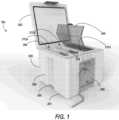
- FIG. 1depicts an isometric view of a refrigerated transport system 100 in an example embodiment.
- the refrigerated transport system 100includes a transport container 200 and an environmental control unit 290 removably connected to the transport container 200.
- the environmental control unit 290is removable from the transport container 200 and may be connected to a variety of different transport containers other than what is depicted in the illustrated embodiment of FIG. 1 .
- the environmental control unit 290provides cooling to the transport container through one or more cooling modules 362 (depicted in FIG. 2 ) and will be discussed further below.
- one or more orifices 230are formed in the base 201 of the transport container 200 and then cooling modules 362 inserted into each orifice 230.
- the cooling modules 362may include seals (not shown) configured to seal the connection between each formed orifices 230 and each cooling modules 362.
- the transport container 200may be composed of a base 201 and a lid 202.
- base 201may be an open ended container wherein perishable cargo, such as, for example, produce, meat, poultry, fish, dairy products, cut flowers, pharmaceuticals, organs, and other fresh/frozen perishable products, is stowed for transport.
- perishable cargosuch as, for example, produce, meat, poultry, fish, dairy products, cut flowers, pharmaceuticals, organs, and other fresh/frozen perishable products.
- the lid 202is configured to fit on the base 201, thus enclosing the perishable cargo within the transport container 200.
- the lid 202is configured to securely fasten to the base 201 such that an airtight seal is created between the lid 202 and the base 201.
- the base 201 and the lid 202may be composed of a plastic, metal vacuum, extruded polystyrene foam, polyurethane foam, polyethylene foam, or other lightweight insulating material.
- the base 201is collapsible and may be folded when not in use for easy storage and transportation.
- the base 201further includes an interior 204 and an exterior 206.
- the interior 204houses the perishable goods and may be subdivided into one or more separate compartments 212a-212c by one or more dividers 218.
- a secondary lid 240may provide additional insulation to each of the compartments 212a-212c and/or the interior 204 in general.
- the secondary lid 240also keeps additional cold air from escaping, thus increasing efficiency.
- the secondary lid 240may be transparent, which advantageously provides the opportunity to still see goods in each compartment 212a-212c.
- One or more anchors 280may be configured on the exterior 206 of the base 201 so that the refrigerated transport system 100 may be secured to a vehicle, such as, for example a motorcycle.
- FIG. 2illustrates an isometric view of the environmental control unit 290.
- the environmental control unit 290includes a power convertor 310, a battery 320, a controller 330, a fan 340, a thermoelectric device 360, a communication module 370, and a control panel 380.
- the thermoelectric device 360provides cooling to the transport container 200.
- the thermoelectric device 360in operation generates heating/cooling by creating a temperature difference across two sides of the thermoelectric device 360 when a voltage is applied to the thermoelectric device 360.
- thermoelectric device 360there is a thermoelectric device 360 for each compartment 212. There may be a single fan 340 or a fan 340 for each thermoelectric device 360. The fan 340 pulls in air 344 external to environmental control unit 290 through a vent 342. The air 344 that passes across the thermoelectric device 360 is cooled and is then sent through the cooling modules 362 into the transport container 200.
- airwhen used herein with reference to the atmosphere draw into the environmental control unit 290 by the fan 340 may include a mixture of oxygen with other gases, such as for example, but not limited to, nitrogen or carbon dioxide.
- the fan 340may be rotated by a fan motor (not shown) powered by the power source 306 and/or the battery 320.
- the environmental control unit 290also includes a controller 330 configured for controlling the operation of the environmental control unit 290 including, but not limited to, the operation of thermoelectric device 360 and fan 340 to provide and maintain a desired thermal environment within the transport container 200.
- the controller 330is an electronic controller including a processor and an associated memory comprising computer-executable instructions that, when executed by the processor, cause the processor to perform various operations.
- the processormay be but is not limited to a single-processor or multiprocessor system of any of a wide array of possible architectures, including field programmable gate array (FPGA), central processing unit (CPU), application specific integrated circuits (ASIC), digital signal processor (DSP) or graphics processing unit (GPU) hardware arranged homogenously or heterogeneously.
- FPGAfield programmable gate array
- CPUcentral processing unit
- ASICapplication specific integrated circuits
- DSPdigital signal processor
- GPUgraphics processing unit
- the memorymay be a storage device such as, for example, a random access memory (RAM), read only memory (ROM), or other electronic, optical, magnetic or any other computer readable medium.
- the operation of the environmental control unit 290may also be controlled through the control panel 380 located on the exterior of the environmental control unit 290. Using the control panel 380, users may set a selected temperature 382 for each compartment 212 of the refrigerated transport system 100. Also using the control panel 380, users may set a maximum temperature 386 and a minimum temperature 384 for the selected temperature 382.
- the controller 330is in electronic communication with the communication module 370.
- the communication module 370is in wireless communication with a computing device 400, such as, for example a smart phone, PDA, smart watch, tablet, laptop computer, desktop computer etc.
- the computing device 400may include a touch screen (not shown), mouse, keyboard, scroll wheel, physical button, or any input mechanism known to one of skill in the art.
- the computing device 400may include a processor 450, memory 452 and communication module 454 as shown in FIG. 2 .
- the processor 450can be any type or combination of computer processors, such as a microprocessor, microcontroller, digital signal processor, application specific integrated circuit, programmable logic device, and/or field programmable gate array.
- the memory 452is an example of a non-transitory computer readable storage medium tangibly embodied in the computing device 400 including executable instructions stored therein, for instance, as firmware.
- the communication module 454may implement one or more communication protocols as described in further detail herein.
- Embodiments hereingenerate a graphical user interface on the computing device 400 through an application 455.
- One exemplary graphic user interface 460is shown with respect to FIG. 3 .
- the computing device 400may view and/or adjust parameters 410 of the environmental control system through the application 455.
- the wireless communication between the communication module 370 of the environmental control units 290 and the communication module 454 of the computing device 400may be satellite, WiFi, cellular, Bluetooth, radio communication or any other wireless communication method known to one of skill in the art.
- the computing device 400may be configured to wirelessly control the operation of the environmental control unit 290 and/or display the parameters 410 of the environmental control unit 290.
- the parameters 410may include but are not limited to location of the environmental control unit 290, temperature of the cooling output of the environmental control unit 290, and humidity of the cooling output of the environmental control unit 290.
- the location and temperature outputmay be detected but one or more sensors 390.
- a sensor 390may include a temperature sensor or humidity sensor.
- the temperature sensor or humidity sensormay be located proximate the one or more cooling modules 362.
- a sensor 390may include a GPS sensor configured to determine the location of the environmental control unit 290.
- a destinationmay be included as one of the parameters 410, where the destination is the physical destination intended for one or more of the items being cooled by the transport container 200.
- the parametersinclude a number of times the lid 202 and/or 240 have been opened.
- the parametersmay include a relative position of the items being cooled within the transport container 200.
- one or more piezoelectric or other configured sensormay determine a position of an item relative to one or more positions of other items within the transport container 200.
- the relative position of the itemsmay be included in a determination of the operation of the environmental control unit 290.
- the environmental control unit 290may be powered by a power source 306 and/or a battery 320.
- the power source 306may charge the battery 320 such that the battery 320 may provide power to the environmental control unit 290 when the environmental control unit 290 is receiving reduced and/or no power from the power source 306.
- the power source 306may comprise an AC generator configured to generate alternating current (AC) power including at least one AC voltage at one or more frequencies.
- the power source 306may, for example, be a permanent magnet AC generator or a synchronous AC generator.
- the power source 306may comprise a single onboard, DC generator configured to generate direct current (DC) power at least one voltage.
- the power source 306is a fly wheel generator operably connected to a rotating component of a vehicle.
- the power source 306may be an onboard battery of a vehicle, such as, for example a 12 Volt battery. Some power sources may have internal voltage regulators while other power sources do not.
- various power converters 310such as AC to DC rectifiers, DC to AC inverters, AC to AC voltage/frequency converters, and DC to DC voltage converters, may be employed in connection with the power source 306 as appropriate.
- the power converter 310may include a voltage sensor to sense the voltage of the power source 306.
- the power source 306may also include a battery, a solar panel, or any similar power source known to one of skill in the art.
- FIG. 3depicts the exemplary user interface 460 in accordance with an embodiment.
- the graphic user interface 460can include the one or more parameters 420 such as, for example, a temperature 462, a graphical representation of the temperature 464, a humidity of the current environment, etc.
- one or more fieldsare user-selectable 389 to show other additional parameters.
- each of the parameters 420may be user-selectable to toggle on/off, which may control whether that particular parameter is included in the automated control of the environmental control unit 290.
- the graphic user interface 460can also include a map interface 475 that indicates a current position along a route 472, a starting position 468, and an intended destination 470.
- the route 472is user selectable based on a particular mode of transportation used with the device (e.g., motorcycle vs. automobile).
- the graphic user interface 460includes a product temperature matrix 474, which shows an allowable temperature range 478 for products stored (or that may be stored) in the transport container 200.
- FIG. 4depicts an exemplary screen graphic showing one or more user-selectable product fields 480.
- the processormay receive one or more user selections indicative of one or more products stored in the transport container 200.
- the processor 450may determine a starting position 468 and an intended destination 470 for one or more of the stored products indicated as being transported in the product temperature matrix 474.
- the processor 450may also determine an intended or suggested route 472.
- the processor 450may determine, based on one or more of the parameters 420 whether the suggested storage temperature for each of the stored products stored in the transport container 200 will exceed its ideal storage temperature range.
- Exceeding an ideal storage temperature rangemay include, for example, obtaining an amount of heat that raises the internal temperature in the transport container 200 outside of (higher than) the ideal or safe storage temperature range 478 for a particular product indicated as being stored in the transport container 200.
- the processor 450responsive to determining that the internal temperature is or is predicted to exceed the storage temperature range 478, the processor 450 can alter the route 472 and indicate the new route in the map 475.
- the processor 450may determine a power level remaining in the power source 306, determine an internal temperature of the transport container 200, and control an on or off condition of the cooling modules 362. For example, as shown in FIG. 5 , the processor 450 may determine, based on one or more of the destination, the current position, the ambient air temperature, the internal air temperature, whether there is sufficient condition inside of the transport container 200 to maintain the ideal temperature(s) for the items transported with the cooling modules 362 switched off some or all of the time on the remaining portion of the intended route. For example, referring to FIG.
- the processor 450may determine, based on the parameters 420, that the cooling modules 362 should be switched from a currently "off' position to an on position until the internal temperature reaches 33 degrees F (0.56 degrees Celsius). The processor 450 may switch the cooling modules 362 off for a ten minute interval at an internal temperature reading of 34 degrees F (1.11 degrees Celsius). After fifteen minutes, at an internal reading of 35 degrees F (1.67 degrees Celsius), the processor 450 may turn the cooling elements on for a twenty minute interval, to bring the temperature to 34 degrees F (1.11 degrees Celsius), etc. In some aspects, the processor 450 determines the on and off conditions of the cooling modules based on a combination of the current location, the intended destination, the ambient (outside) temperature, and the internal temperature of the transport container 200. The operation of the environmental control unit is also selectably adjustable by the processor 450 based on other parameters, including traffic conditions, waypoints during a delivery schedule, anticipated lid opening(s), and other factors.
- FIG. 6shows a flow diagram illustrating a method 600 of managing environmental conditions within a refrigerated transport system 100 through a computing device, such as the computing device 400.
- a first actionincludes removably connecting an environmental control unit 290 to a transport container 200 if not already connected.
- One or more orifices 230may be formed in the base 201 of the transport container 200 to removably connect the environmental control unit 290 to the transport container 200.
- a cooling module 362may be configured to slide into each of the formed orifices 230. As mentioned above, there may be one cooling module 362 for each compartment 212, thus there may be one orifice 230 for each compartment 212.
- the cooling modules 362can include seals (not shown) configured to seal the connection between each formed orifice 230 and each cooling module 362.
- the processor 450instantiates an application in the graphic user interface 460 of the computing device 400.
- the computing device 400uses the instantiated application of block 604, scans for environmental control units 290 located within a user-selectable radius of the computing device 400.
- a selected radiusmay be, for example, one meter.
- a user-selectable radiusmay be one kilometer. It should be appreciated that any theoretical radial distance is contemplated.
- the computing device 400displays, through the graphic user interface 460, the one or more environmental control units 290 located within a selected radius of the computing device 400.
- a usermay selected a environmental control unit 290 through the graphic user interface 460 in order to connect with the environmental control unit 290.
- At block 610will confirm when the computing device 400 is connected to the particular environmental control unit 290. If the computing device 400 does not connect to the environmental control unit 290 then an alert message may display on the computing device 400 through the graphic user interface 460 at block 612. The alert message may be visual and/or audible. If the computing device 400 does connect to the environmental control unit 290 then parameters 410 of the environmental control unit 290 will display on the computing device 400 through the graphic user interface 460 and block 614.
- the usermay make a selection through the graphic user interface 460 whether to adjust the operations of the environmental control unit 290 or display the parameters 410 of the environmental control unit 290 on a map. If at block 616, the user selects to adjust the operations, then at block 618 the user may adjust the operations of the environmental control system 460 including but not limited to, temperature and humidity within the transport container 200.
- the controller 330is configured to adjust operation of the fan 340 and the thermoelectric device 360 in response to a control command from a computing device 400 to adjust temperature and humidity. If at block 616, the user selects to view a map of the parameters 410, then at block 620 the graphic user interface 460 with display a map of the parameters 410 of the environmental control unit 290 on the computing device 400.
- embodimentscan be in the form of processor-implemented processes and devices for practicing those processes, such as a processor.
- Embodimentscan also be in the form of computer program code containing instructions embodied in tangible media, such as network cloud storage, SD cards, flash drives, floppy diskettes, CD ROMs, hard drives, or any other computer-readable storage medium, wherein, when the computer program code is loaded into and executed by a computer, the computer becomes a device for practicing the embodiments.
- Embodimentscan also be in the form of computer program code, for example, whether stored in a storage medium, loaded into and/or executed by a computer, or transmitted over some transmission medium, loaded into and/or executed by a computer, or transmitted over some transmission medium, such as over electrical wiring or cabling, through fiber optics, or via electromagnetic radiation, wherein, when the computer program code is loaded into an executed by a computer, the computer becomes a device for practicing the embodiments.
- the computer program code segmentsconfigure the microprocessor to create specific logic circuits.
Landscapes
- Engineering & Computer Science (AREA)
- Physics & Mathematics (AREA)
- Mechanical Engineering (AREA)
- Thermal Sciences (AREA)
- General Engineering & Computer Science (AREA)
- Chemical & Material Sciences (AREA)
- Combustion & Propulsion (AREA)
- Devices That Are Associated With Refrigeration Equipment (AREA)
Description
- The subject matter disclosed herein generally relates to the field of transport containers, and more particularly to an apparatus and method for cooling transport containers.
- Refrigerated trucks and trailers are commonly used to transport perishable cargo, such as, for example, produce, meat, poultry, fish, dairy products, cut flowers, and other fresh or frozen perishable products. A transport refrigeration system is mounted to the truck or to the trailer in operative association with a cargo space defined within the truck or trailer for maintaining a controlled temperature environment within the cargo space.
- Conventionally, transport refrigeration systems used in connection with refrigerated trucks and refrigerated trailers include a transport environmental control unit having a refrigerant compressor, a condenser with one or more associated condenser fans, an expansion device, and an evaporator with one or more associated evaporator fans, which are connected via appropriate refrigerant lines in a closed refrigerant flow circuit. Air or an air/ gas mixture is drawn from the interior volume of the cargo space by means of the evaporator fan(s) associated with the evaporator, passed through the airside of the evaporator in heat exchange relationship with refrigerant whereby the refrigerant absorbs heat from the air, thereby cooling the air. The cooled air is then supplied back to the cargo space.
- Currently last mile cooling is served by either dry ice or just insulated containers, there are few use cases where a smaller compressor driven system can be used due to size, weight, etc. Typically, the perishable cargo within the truck's transport refrigeration system is contained within simple cardboard boxes, wooden crates, or plastic containers and is cooled or heated by the truck's environmental control system. Upon arriving at a destination the perishable cargo is unloaded onto a dock or other uncontrolled area where it may sit for hours until it could be moved to an environmentally controlled location. The perishable cargo may also need to be transported for the "last mile" to the consumer via a non-refrigerated means, such as a motorcycle or truck. This time spent on dock or in "last mile" transit, out of a controlled environment, leads to the degradation of the product life and ultimately leads to a lower quality product being served to the end consumer.
WO 2016/181223 A2 discloses a portable refrigeration system for use in the transport of valuable, temperature sensitive materials.WO 2017/096171 A1 discloses an environmental control unit for use with a transport container.- Disclosed is an environmental control unit for use with a transport container, the environmental control unit being configured to be removably connected to the transport container. The environmental control unit includes a thermoelectric device, a fan configured to blow air across the thermoelectric device, a cooling module configured to receive the air blown across the thermoelectric device and convey the air to a compartment of a transport container when the transport container is removably connected to the environmental control unit, a controller in electronic communication with the thermoelectric device and the fan, and a communication module in electronic communication with the controller. The communication module is configured to transmit parameters of the environmental control unit to a computing device through wireless communication. The controller is configured to determine a present location of the transport container, determine a destination of the transport container, evaluate an internal temperature of the transport container, and control an on or off condition of the thermoelectric device based on the present location, the destination, and the internal temperature of the transport container.
- Also disclosed is a refrigerated transport system that includes a transport container, and an environmental control unit removably connected to the transport container. The environmental control unit includes a thermoelectric device, a fan configured to blow air across the thermoelectric device, a cooling module configured to receive the air blown across the thermoelectric device and convey the air to a compartment of the transport container, a controller in electronic communication with the thermoelectric device and the fan, and a communication module in electronic communication with the controller and wireless communication with a computing device. The communication module is configured to transmit parameters of the environmental control unit to the computing device through wireless communication. The controller is configured to determine a present location of the transport container, determine a destination of the transport container, evaluate an internal temperature of the transport container, and control an on or off condition of the thermoelectric device based on the present location, the destination, and the internal temperature of the transport container.
- Also disclosed is a method of managing environmental conditions within the refrigerated transport system through a computing device. The method includes determining, via a processor in the computing device, a present location of the refrigerated transport system, and determining, via the processor, a destination of the refrigerated transport system. The method further includes evaluating, via the processor, an internal temperature of the refrigerated transport system, and controlling, via the processor, an on or off condition of a thermoelectric device based on the present location, the destination, and the internal temperature of the refrigerated transport system.
- The following descriptions should not be considered limiting in any way. With reference to the accompanying drawings, like elements are numbered alike:
FIG. 1 illustrates a isometric view of a refrigerated transport system;FIG. 2 illustrates an isometric view of an environmental control unit;FIG. 3 illustrates a view of an exemplary graphic user interface;FIG. 4 illustrates another exemplary graphic user interface;FIG. 5 illustrates an exemplary implementation of the refrigerated transport system ofFIG. 1 ; andFIG. 6 is a flow diagram illustrating management of environmental conditions within a refrigerated transport system.- A detailed description of one or more embodiments of the disclosed apparatus and method are presented herein by way of exemplification and not limitation with reference to the Figures.
- Various embodiments of the present disclosure are related to environmental control of perishable cargo during the "last mile" of delivery. Typically, the perishable cargo in a truck's transport environmental control system is contained within simple cardboard boxes, wooden crates, or plastic containers. The perishable cargo may need to be transported on smaller-vehicles without environmental control systems over the "last-mile" to make it to market. The term "last mile" is figurative to illustrate the final stretch of a supply chain that perishable goods may take to arrive at a market. Often large trucks with environmental control systems cannot carry the perishable goods through this "last mile" due to multiple reasons, such as, for example, the size of city streets. For these reasons, smaller vehicles must carry the perishable goods over the "last mile", such as for example, motorcycles, mopeds, bicycles, and rickshaws. This time spent on smaller vehicles, out of a controlled environment leads to degradation of the product life and ultimately leads to a lower quality product being available to the end consumer. For instance, the life of a fragile ripe at harvest fruit such as, for example, raspberries and blueberries, decreases with the amount of time they spend in ambient air. Advantageously, the embodiments disclosed herein help preserve perishable goods through the "last mile" of the supply chain by automatic control of the cooling function based on external factors to the cooling system including location, destination, starting position, relative humidity, and the product being cooled.
- Referring to
FIG. 1 , which depicts an isometric view of a refrigeratedtransport system 100 in an example embodiment. The refrigeratedtransport system 100 includes atransport container 200 and anenvironmental control unit 290 removably connected to thetransport container 200. Theenvironmental control unit 290 is removable from thetransport container 200 and may be connected to a variety of different transport containers other than what is depicted in the illustrated embodiment ofFIG. 1 . Theenvironmental control unit 290 provides cooling to the transport container through one or more cooling modules 362 (depicted inFIG. 2 ) and will be discussed further below. In order to removably connect theenvironmental control unit 290 to thetransport container 200, one or more orifices 230 are formed in thebase 201 of thetransport container 200 and thencooling modules 362 inserted into each orifice 230. There may be onecooling module 362 for each compartment 212 of thetransport container 200, thus there may be one orifice 230 for each compartment 212. Thecooling modules 362 may include seals (not shown) configured to seal the connection between each formed orifices 230 and eachcooling modules 362. - The
transport container 200 may be composed of abase 201 and alid 202. As shown inFIG. 1 ,base 201 may be an open ended container wherein perishable cargo, such as, for example, produce, meat, poultry, fish, dairy products, cut flowers, pharmaceuticals, organs, and other fresh/frozen perishable products, is stowed for transport. Thelid 202 is configured to fit on thebase 201, thus enclosing the perishable cargo within thetransport container 200. Thelid 202 is configured to securely fasten to thebase 201 such that an airtight seal is created between thelid 202 and thebase 201. In various embodiments, thebase 201 and thelid 202 may be composed of a plastic, metal vacuum, extruded polystyrene foam, polyurethane foam, polyethylene foam, or other lightweight insulating material. In one embodiment, thebase 201 is collapsible and may be folded when not in use for easy storage and transportation. - The
base 201 further includes aninterior 204 and anexterior 206. Theinterior 204 houses the perishable goods and may be subdivided into one or moreseparate compartments 212a-212c by one ormore dividers 218. Asecondary lid 240 may provide additional insulation to each of thecompartments 212a-212c and/or theinterior 204 in general. Thesecondary lid 240 also keeps additional cold air from escaping, thus increasing efficiency. In an embodiment, thesecondary lid 240 may be transparent, which advantageously provides the opportunity to still see goods in eachcompartment 212a-212c. One ormore anchors 280 may be configured on theexterior 206 of thebase 201 so that the refrigeratedtransport system 100 may be secured to a vehicle, such as, for example a motorcycle. - Referring now to
FIG. 2 with continued reference toFIG. 1 .FIG. 2 illustrates an isometric view of theenvironmental control unit 290. Theenvironmental control unit 290 includes apower convertor 310, a battery 320, acontroller 330, afan 340, athermoelectric device 360, acommunication module 370, and acontrol panel 380. Thethermoelectric device 360 provides cooling to thetransport container 200. Thethermoelectric device 360 in operation generates heating/cooling by creating a temperature difference across two sides of thethermoelectric device 360 when a voltage is applied to thethermoelectric device 360. The amount of heating and cooling changes in response to polarity of the voltage that is applied to thethermoelectric device 360 as the material properties cause the atoms to diffuse to a first side or a second side of thethermoelectric device 360. This is also known as Peltier effect. In an embodiment, there is athermoelectric device 360 for each compartment 212. There may be asingle fan 340 or afan 340 for eachthermoelectric device 360. Thefan 340 pulls inair 344 external toenvironmental control unit 290 through avent 342. Theair 344 that passes across thethermoelectric device 360 is cooled and is then sent through the coolingmodules 362 into thetransport container 200. It is to be understood that the term "air" when used herein with reference to the atmosphere draw into theenvironmental control unit 290 by thefan 340 may include a mixture of oxygen with other gases, such as for example, but not limited to, nitrogen or carbon dioxide. Thefan 340 may be rotated by a fan motor (not shown) powered by thepower source 306 and/or the battery 320. - The
environmental control unit 290 also includes acontroller 330 configured for controlling the operation of theenvironmental control unit 290 including, but not limited to, the operation ofthermoelectric device 360 andfan 340 to provide and maintain a desired thermal environment within thetransport container 200. Thecontroller 330 is an electronic controller including a processor and an associated memory comprising computer-executable instructions that, when executed by the processor, cause the processor to perform various operations. The processor may be but is not limited to a single-processor or multiprocessor system of any of a wide array of possible architectures, including field programmable gate array (FPGA), central processing unit (CPU), application specific integrated circuits (ASIC), digital signal processor (DSP) or graphics processing unit (GPU) hardware arranged homogenously or heterogeneously. The memory may be a storage device such as, for example, a random access memory (RAM), read only memory (ROM), or other electronic, optical, magnetic or any other computer readable medium. The operation of theenvironmental control unit 290 may also be controlled through thecontrol panel 380 located on the exterior of theenvironmental control unit 290. Using thecontrol panel 380, users may set a selectedtemperature 382 for each compartment 212 of therefrigerated transport system 100. Also using thecontrol panel 380, users may set amaximum temperature 386 and aminimum temperature 384 for the selectedtemperature 382. - The
controller 330 is in electronic communication with thecommunication module 370. Thecommunication module 370 is in wireless communication with acomputing device 400, such as, for example a smart phone, PDA, smart watch, tablet, laptop computer, desktop computer etc. Thecomputing device 400 may include a touch screen (not shown), mouse, keyboard, scroll wheel, physical button, or any input mechanism known to one of skill in the art. Thecomputing device 400 may include aprocessor 450,memory 452 andcommunication module 454 as shown inFIG. 2 . Theprocessor 450 can be any type or combination of computer processors, such as a microprocessor, microcontroller, digital signal processor, application specific integrated circuit, programmable logic device, and/or field programmable gate array. Thememory 452 is an example of a non-transitory computer readable storage medium tangibly embodied in thecomputing device 400 including executable instructions stored therein, for instance, as firmware. Thecommunication module 454 may implement one or more communication protocols as described in further detail herein. Embodiments herein generate a graphical user interface on thecomputing device 400 through anapplication 455. One exemplarygraphic user interface 460 is shown with respect toFIG. 3 . Thecomputing device 400 may view and/or adjustparameters 410 of the environmental control system through theapplication 455. - The wireless communication between the
communication module 370 of theenvironmental control units 290 and thecommunication module 454 of thecomputing device 400 may be satellite, WiFi, cellular, Bluetooth, radio communication or any other wireless communication method known to one of skill in the art. Thecomputing device 400 may be configured to wirelessly control the operation of theenvironmental control unit 290 and/or display theparameters 410 of theenvironmental control unit 290. Theparameters 410 may include but are not limited to location of theenvironmental control unit 290, temperature of the cooling output of theenvironmental control unit 290, and humidity of the cooling output of theenvironmental control unit 290. The location and temperature output may be detected but one ormore sensors 390. In an embodiment, asensor 390 may include a temperature sensor or humidity sensor. The temperature sensor or humidity sensor may be located proximate the one ormore cooling modules 362. In an embodiment, asensor 390 may include a GPS sensor configured to determine the location of theenvironmental control unit 290. In another embodiment, a destination may be included as one of theparameters 410, where the destination is the physical destination intended for one or more of the items being cooled by thetransport container 200. In another aspect, the parameters include a number of times thelid 202 and/or 240 have been opened. - In another aspect, the parameters may include a relative position of the items being cooled within the
transport container 200. For example, one or more piezoelectric or other configured sensor may determine a position of an item relative to one or more positions of other items within thetransport container 200. In one embodiment, the relative position of the items may be included in a determination of the operation of theenvironmental control unit 290. - The
environmental control unit 290 may be powered by apower source 306 and/or a battery 320. Thepower source 306 may charge the battery 320 such that the battery 320 may provide power to theenvironmental control unit 290 when theenvironmental control unit 290 is receiving reduced and/or no power from thepower source 306. Thepower source 306 may comprise an AC generator configured to generate alternating current (AC) power including at least one AC voltage at one or more frequencies. In an embodiment, thepower source 306 may, for example, be a permanent magnet AC generator or a synchronous AC generator. In another embodiment, thepower source 306 may comprise a single onboard, DC generator configured to generate direct current (DC) power at least one voltage. In an embodiment, thepower source 306 is a fly wheel generator operably connected to a rotating component of a vehicle. In an embodiment, thepower source 306 may be an onboard battery of a vehicle, such as, for example a 12 Volt battery. Some power sources may have internal voltage regulators while other power sources do not. It is to be understood thatvarious power converters 310, such as AC to DC rectifiers, DC to AC inverters, AC to AC voltage/frequency converters, and DC to DC voltage converters, may be employed in connection with thepower source 306 as appropriate. Thepower converter 310 may include a voltage sensor to sense the voltage of thepower source 306. Thepower source 306 may also include a battery, a solar panel, or any similar power source known to one of skill in the art. FIG. 3 depicts theexemplary user interface 460 in accordance with an embodiment. In some aspects, thegraphic user interface 460 can include the one or more parameters 420 such as, for example, atemperature 462, a graphical representation of thetemperature 464, a humidity of the current environment, etc. In some aspects one or more fields are user-selectable 389 to show other additional parameters. In one aspect, each of the parameters 420 may be user-selectable to toggle on/off, which may control whether that particular parameter is included in the automated control of theenvironmental control unit 290. Thegraphic user interface 460 can also include amap interface 475 that indicates a current position along aroute 472, a startingposition 468, and an intendeddestination 470. Theroute 472 is user selectable based on a particular mode of transportation used with the device (e.g., motorcycle vs. automobile).- In one aspect, the
graphic user interface 460 includes aproduct temperature matrix 474, which shows anallowable temperature range 478 for products stored (or that may be stored) in thetransport container 200.FIG. 4 depicts an exemplary screen graphic showing one or more user-selectable product fields 480. In one aspect, the processor may receive one or more user selections indicative of one or more products stored in thetransport container 200. - According to one embodiment, the
processor 450 may determine astarting position 468 and an intendeddestination 470 for one or more of the stored products indicated as being transported in theproduct temperature matrix 474. Theprocessor 450 may also determine an intended or suggestedroute 472. In one embodiment, theprocessor 450 may determine, based on one or more of the parameters 420 whether the suggested storage temperature for each of the stored products stored in thetransport container 200 will exceed its ideal storage temperature range. Exceeding an ideal storage temperature range may include, for example, obtaining an amount of heat that raises the internal temperature in thetransport container 200 outside of (higher than) the ideal or safestorage temperature range 478 for a particular product indicated as being stored in thetransport container 200. In one aspect, responsive to determining that the internal temperature is or is predicted to exceed thestorage temperature range 478, theprocessor 450 can alter theroute 472 and indicate the new route in themap 475. - According to another embodiment, the
processor 450 may determine a power level remaining in thepower source 306, determine an internal temperature of thetransport container 200, and control an on or off condition of the coolingmodules 362. For example, as shown inFIG. 5 , theprocessor 450 may determine, based on one or more of the destination, the current position, the ambient air temperature, the internal air temperature, whether there is sufficient condition inside of thetransport container 200 to maintain the ideal temperature(s) for the items transported with the coolingmodules 362 switched off some or all of the time on the remaining portion of the intended route. For example, referring toFIG. 5 , theprocessor 450 may determine, based on the parameters 420, that the coolingmodules 362 should be switched from a currently "off' position to an on position until the internal temperature reaches 33 degrees F (0.56 degrees Celsius). Theprocessor 450 may switch thecooling modules 362 off for a ten minute interval at an internal temperature reading of 34 degrees F (1.11 degrees Celsius). After fifteen minutes, at an internal reading of 35 degrees F (1.67 degrees Celsius), theprocessor 450 may turn the cooling elements on for a twenty minute interval, to bring the temperature to 34 degrees F (1.11 degrees Celsius), etc. In some aspects, theprocessor 450 determines the on and off conditions of the cooling modules based on a combination of the current location, the intended destination, the ambient (outside) temperature, and the internal temperature of thetransport container 200. The operation of the environmental control unit is also selectably adjustable by theprocessor 450 based on other parameters, including traffic conditions, waypoints during a delivery schedule, anticipated lid opening(s), and other factors. - Referring now to
FIG. 6 , while referencing components ofFIG 1 .FIG. 6 shows a flow diagram illustrating amethod 600 of managing environmental conditions within arefrigerated transport system 100 through a computing device, such as thecomputing device 400. As a preliminary step, a first action includes removably connecting anenvironmental control unit 290 to atransport container 200 if not already connected. One or more orifices 230 may be formed in thebase 201 of thetransport container 200 to removably connect theenvironmental control unit 290 to thetransport container 200. Acooling module 362 may be configured to slide into each of the formed orifices 230. As mentioned above, there may be onecooling module 362 for each compartment 212, thus there may be one orifice 230 for each compartment 212. The coolingmodules 362 can include seals (not shown) configured to seal the connection between each formed orifice 230 and eachcooling module 362. Atblock 604, theprocessor 450 instantiates an application in thegraphic user interface 460 of thecomputing device 400. - At
block 606, thecomputing device 400, using the instantiated application ofblock 604, scans forenvironmental control units 290 located within a user-selectable radius of thecomputing device 400. A selected radius may be, for example, one meter. In another aspect, a user-selectable radius may be one kilometer. It should be appreciated that any theoretical radial distance is contemplated. Responsive to detecting one or moreenvironmental control units 290 within the selected radius, atblock 608, thecomputing device 400 displays, through thegraphic user interface 460, the one or moreenvironmental control units 290 located within a selected radius of thecomputing device 400. A user may selected aenvironmental control unit 290 through thegraphic user interface 460 in order to connect with theenvironmental control unit 290. - At
block 610, will confirm when thecomputing device 400 is connected to the particularenvironmental control unit 290. If thecomputing device 400 does not connect to theenvironmental control unit 290 then an alert message may display on thecomputing device 400 through thegraphic user interface 460 atblock 612. The alert message may be visual and/or audible. If thecomputing device 400 does connect to theenvironmental control unit 290 thenparameters 410 of theenvironmental control unit 290 will display on thecomputing device 400 through thegraphic user interface 460 and block 614. - At
block 616, the user may make a selection through thegraphic user interface 460 whether to adjust the operations of theenvironmental control unit 290 or display theparameters 410 of theenvironmental control unit 290 on a map. If atblock 616, the user selects to adjust the operations, then atblock 618 the user may adjust the operations of theenvironmental control system 460 including but not limited to, temperature and humidity within thetransport container 200. Thecontroller 330 is configured to adjust operation of thefan 340 and thethermoelectric device 360 in response to a control command from acomputing device 400 to adjust temperature and humidity. If atblock 616, the user selects to view a map of theparameters 410, then atblock 620 thegraphic user interface 460 with display a map of theparameters 410 of theenvironmental control unit 290 on thecomputing device 400. - While the above description has described the flow process of
FIG. 6 in a particular order, it should be appreciated that unless otherwise specifically required in the attached claims that the ordering of the steps may be varied. - As described above, embodiments can be in the form of processor-implemented processes and devices for practicing those processes, such as a processor. Embodiments can also be in the form of computer program code containing instructions embodied in tangible media, such as network cloud storage, SD cards, flash drives, floppy diskettes, CD ROMs, hard drives, or any other computer-readable storage medium, wherein, when the computer program code is loaded into and executed by a computer, the computer becomes a device for practicing the embodiments. Embodiments can also be in the form of computer program code, for example, whether stored in a storage medium, loaded into and/or executed by a computer, or transmitted over some transmission medium, loaded into and/or executed by a computer, or transmitted over some transmission medium, such as over electrical wiring or cabling, through fiber optics, or via electromagnetic radiation, wherein, when the computer program code is loaded into an executed by a computer, the computer becomes a device for practicing the embodiments. When implemented on a general-purpose microprocessor, the computer program code segments configure the microprocessor to create specific logic circuits.
- The term "about" is intended to include the degree of error associated with measurement of the particular quantity based upon the equipment available at the time of filing the application. For example, "about" can include a range of ± 8% or 5%, or 2% of a given value.
- The terminology used herein is for the purpose of describing particular embodiments only and is not intended to be limiting of the present disclosure. As used herein, the singular forms "a", "an" and "the" are intended to include the plural forms as well, unless the context clearly indicates otherwise. It will be further understood that the terms "comprises" and/or "comprising," when used in this specification, specify the presence of stated features, integers, steps, operations, elements, and/or components, but do not preclude the presence or addition of one or more other features, integers, steps, operations, element components, and/or groups thereof.
Claims (13)
- An environmental control unit (290) for use with a transport container (200), the environmental control unit being configured to be removably connected to the transport container (200), and comprising:a thermoelectric device (360);a fan (340) configured to blow air across the thermoelectric device (360);a cooling module (362) configured to receive the air blown across the thermoelectric device (360) and convey the air to a compartment of the transport container (200) when the transport container is removably connected to the environmental control unit (290);a controller (330) in electronic communication with the thermoelectric device (360) and the fan (340); anda communication module (370) in electronic communication with the controller (330), wherein the communication module is configured to transmit parameters of the environmental control unit (290) to a computing device (400) through wireless communication; wherein the controller is configured to:determine a present location of the transport container (200);determine a destination of the transport container (200); andevaluate an internal temperature of the transport container (200);characterized in that the controller (330) is further configured to:
control an on or off condition of the thermoelectric device (360) based on the present location, the destination, and the internal temperature of the transport container (200). - The environmental control unit (290) of claim 1, further comprising:
a battery (320) configured to power the environmental control unit (290). - The environmental control unit (290) of claim 1, further comprising:
a power source (306) configured to power the environmental control unit (290), wherein the power source is a flywheel generator. - The environmental control unit (290) of claim 1, further comprising:
a power source (306) configured to power the environmental control unit, wherein the power source is a vehicle battery. - The environmental control unit (290) of claim 1, wherein:the communication module (370) is configured to receive control commands from the computing device (400); andthe controller (330) is configured to adjust operation of the fan (340) and the thermoelectric device (360) in response to the control command.
- The environmental control unit (290) of claim 1, further comprising:
one or more sensors (390), configured to detect at least one of a temperature of air flowing through the cooling module (362), humidity of air flowing through the cooling module, and a location of the environmental control unit (290). - The environmental control unit (290) of claim 1, wherein:the transport container (200) includes more than one compartment (212); andthe environmental control unit (290) includes at least one thermoelectric device (360) for each compartment (212).
- The environmental control unit (290) of claim 1, further comprising:
a control panel (380) located on an exterior of the environmental control unit (290), wherein the control panel is configured to receive input of at least one of a selected temperature for the environmental control unit, a maximum temperature for the environmental control unit, and a minimum temperature for the environmental control unit. - A refrigerated transport system (100) comprising:a transport container (200); andthe environmental control unit (290) of any preceding claim removably connected to the transport container (200), wherein the communication module (370) is in wireless communication with the computing device (400).
- The refrigerated transport system (100) of claim 9, wherein:
the computing device (400) is configured to display parameters (410) on a map (475) though a graphical user interface (460). - A method of managing environmental conditions within a refrigerated transport system (100) according to claim 9 or 10 through a computing device (400), the method comprising:determining, via a processor (450) in the computing device (400), a present location of the refrigerated transport system (100);determining, via the processor (450), a destination of the refrigerated transport system (100);evaluating, via the processor (450), an internal temperature of the refrigerated transport system (100);characterized in that the method further comprises:
controlling, via the processor (450), an on or off condition of a thermoelectric device (360) based on the present location, the destination, and the internal temperature of the refrigerated transport system (100). - The method of claim 11, further comprising:
adjusting operation of an environmental control system (290) using the computing device (400). - The method of claim 11, further comprising:updating a route (472) based on the adjusted operation of the environmental control system (290);generating map (475) through a graphic user interphase (460) on the computing device (400); anddisplaying an updated route (472) on the map (475).
Applications Claiming Priority (2)
| Application Number | Priority Date | Filing Date | Title |
|---|---|---|---|
| US201762569287P | 2017-10-06 | 2017-10-06 | |
| PCT/US2018/054585WO2019071112A1 (en) | 2017-10-06 | 2018-10-05 | Responsive cooling based on external factors |
Publications (2)
| Publication Number | Publication Date |
|---|---|
| EP3692314A1 EP3692314A1 (en) | 2020-08-12 |
| EP3692314B1true EP3692314B1 (en) | 2024-06-12 |
Family
ID=64049714
Family Applications (1)
| Application Number | Title | Priority Date | Filing Date |
|---|---|---|---|
| EP18795870.7AActiveEP3692314B1 (en) | 2017-10-06 | 2018-10-05 | Environmental control unit |
Country Status (4)
| Country | Link |
|---|---|
| US (1) | US11530849B2 (en) |
| EP (1) | EP3692314B1 (en) |
| CN (1) | CN111148951B (en) |
| WO (1) | WO2019071112A1 (en) |
Families Citing this family (5)
| Publication number | Priority date | Publication date | Assignee | Title |
|---|---|---|---|---|
| US11027907B2 (en)* | 2016-06-29 | 2021-06-08 | Eufouric Brands, Llc | Container with closures |
| JP2023508480A (en)* | 2019-12-26 | 2023-03-02 | フォノニック インコーポレイテッド | Storage and transport coolers for thermoelectric refrigeration/refrigeration products |
| US12359857B2 (en)* | 2020-08-14 | 2025-07-15 | Hussmann Corporation | Temperature-controlled container |
| US11897689B2 (en) | 2020-10-26 | 2024-02-13 | Intelligrated Headquarters, Llc | Universal robotic-enabled storage and retrieval system |
| KR20230071837A (en)* | 2021-11-15 | 2023-05-24 | 현대자동차주식회사 | HVAC System for Cargo |
Family Cites Families (46)
| Publication number | Priority date | Publication date | Assignee | Title |
|---|---|---|---|---|
| US5256907A (en)* | 1988-06-13 | 1993-10-26 | Mitsubishi Denki Kabushiki Kaisha | Electric power supply apparatus |
| US5301508A (en) | 1992-08-14 | 1994-04-12 | Rubbermaid Incorporated | Thermoelectric portable container |
| US5457963A (en) | 1994-06-15 | 1995-10-17 | Carrier Corporation | Controlled atmosphere system for a refrigerated container |
| US8280682B2 (en) | 2000-12-15 | 2012-10-02 | Tvipr, Llc | Device for monitoring movement of shipped goods |
| US5572873A (en) | 1995-03-02 | 1996-11-12 | Emertech Incorporated | Carrier method and apparatus for maintaining pharmaceutical integrity |
| US6712276B1 (en) | 1999-01-29 | 2004-03-30 | International Business Machines Corporation | Method and apparatus for automated measurement of properties of perishable consumer products |
| GB9923125D0 (en) | 1999-10-01 | 1999-12-01 | Carley Nigel | Container |
| US6378319B1 (en) | 2000-10-27 | 2002-04-30 | The Mani Brothers | Multi-compartment multi-climate delivery vehicle |
| US6354104B1 (en)* | 2001-01-26 | 2002-03-12 | Darrell L. Feagin | Lockable specimen transporter |
| US6668240B2 (en) | 2001-05-03 | 2003-12-23 | Emerson Retail Services Inc. | Food quality and safety model for refrigerated food |
| US7392150B2 (en) | 2001-12-14 | 2008-06-24 | 3M Innovative Properties Company | Environmental parameter indicator for perishable goods |
| US6944574B2 (en) | 2003-03-21 | 2005-09-13 | Xerox Corporation | Integrated data acquisition system for product in transit |
| US7046148B2 (en) | 2003-12-24 | 2006-05-16 | Fujitsu Limited | Distribution management system |
| US7149658B2 (en) | 2004-02-02 | 2006-12-12 | United Parcel Service Of America, Inc. | Systems and methods for transporting a product using an environmental sensor |
| ITPD20040050A1 (en) | 2004-02-20 | 2004-05-20 | Carlo Martini | THERMAL CONTAINER FOR PUTS TO TAKE AWAY CONNECTABLE TO THE ELECTRICAL SOCKET OF THE CAR AND / OR BATTERY |
| US7339469B2 (en) | 2004-11-22 | 2008-03-04 | Maersk Logistics Usa, Inc. | Shipping container monitoring and tracking system |
| US7455225B1 (en) | 2005-02-22 | 2008-11-25 | Sabioso, Inc. | Method and system for monitoring and controlling goods while in transit |
| JP5371747B2 (en)* | 2006-05-31 | 2013-12-18 | イー・アイ・デュポン・ドウ・ヌムール・アンド・カンパニー | Vapor compression using ionic liquid as compressor lubricant |
| JP5294646B2 (en)* | 2008-02-14 | 2013-09-18 | ホシザキ電機株式会社 | Refrigerator |
| US20170206497A1 (en)* | 2009-02-05 | 2017-07-20 | KLATU Networks, LLC | Method for determining the remaining life of a thermal mass in a shipping package while in transit |
| US20100264048A1 (en)* | 2009-04-16 | 2010-10-21 | Gabriel Sharkey Gunsberg | Temperature-controlled musical instrument carrying case |
| US8154421B2 (en) | 2009-05-12 | 2012-04-10 | Fisher Clinical Services Inc. | Real time temperature and location tracker |
| FI20096113A7 (en) | 2009-10-28 | 2011-04-29 | Ccs Cold Cargo Solutions Oy | Method and system for temperature-controlled transportation |
| EP2508044A4 (en) | 2009-12-02 | 2015-03-25 | Oxx Products Llc | Portable appliance for heating and cooling food |
| US20110193710A1 (en) | 2010-02-05 | 2011-08-11 | Par Technology Corporation | Refrigerated container monitoring system |
| US9447995B2 (en) | 2010-02-08 | 2016-09-20 | Tokitac LLC | Temperature-stabilized storage systems with integral regulated cooling |
| US8286437B2 (en) | 2010-06-30 | 2012-10-16 | Thermo King Corporation | Transport refrigeration system with predictive refrigeration |
| AT12310U1 (en)* | 2010-09-16 | 2012-03-15 | Red Bull Gmbh | COOLING DEVICE WITH INTEGRATED BOTTLE HOSE |
| US9087333B2 (en) | 2010-10-06 | 2015-07-21 | Korea Food Research Institute | Method and system for monitoring quality of food |
| EP2734048B1 (en) | 2011-07-18 | 2017-04-05 | Carrier Corporation | Control of atmosphere within a closed environment |
| KR20130037837A (en) | 2011-10-07 | 2013-04-17 | 한국전자통신연구원 | Total history management system and method using rfid tag and bar code |
| US8893032B2 (en) | 2012-03-29 | 2014-11-18 | Google Inc. | User interfaces for HVAC schedule display and modification on smartphone or other space-limited touchscreen device |
| US20140180953A1 (en) | 2012-12-20 | 2014-06-26 | Purfresh, Inc. | Methods and systems for controlled distribution of perishable goods |
| CA2813285A1 (en) | 2013-04-18 | 2014-10-18 | Bluenica Corporation | Sensing device and method to monitor perishable goods |
| CN104141514A (en)* | 2013-05-06 | 2014-11-12 | 董鹏 | Combined technology for large-area energy conservation and emission reduction by using liquid nitrogen |
| US11266274B2 (en) | 2014-06-26 | 2022-03-08 | Fishsix Rc | Catering box with active climate control for transporting delicate food items |
| CN104135403B (en) | 2014-07-25 | 2017-10-27 | 成都蓝宇科维科技有限公司 | A kind of distributed environment Monitoring Data transfer check method |
| FI20145807A7 (en) | 2014-09-16 | 2016-03-17 | Bitzer Kuehlmaschinenbau Gmbh | Control unit for transport refrigeration device |
| US10386117B2 (en)* | 2015-01-15 | 2019-08-20 | Pepsico, Inc. | Quick-chill beverage cooler with post-chill storage chamber |
| US10445684B2 (en) | 2015-03-30 | 2019-10-15 | Zest Labs, Inc. | Actively managed food delivery |
| US11639815B2 (en)* | 2015-05-13 | 2023-05-02 | Stone Cold Systems, Inc. | Portable refrigerator and method of using |
| US20160379179A1 (en) | 2015-06-23 | 2016-12-29 | Roger Roisen | Method and apparatus for distributed asset location monitoring |
| EP3329434A1 (en) | 2015-07-30 | 2018-06-06 | Nokia Technologies Oy | Method and apparatus for generating a dynamic environmental profile for transport of cargo |
| US9958187B2 (en)* | 2015-10-20 | 2018-05-01 | Jerry Monroy | Active cooling system for transport of body fluids and organs |
| CN108369049A (en) | 2015-12-04 | 2018-08-03 | 开利公司 | Shipping container environmental Kuznets Curves lid |
| CN205784117U (en)* | 2016-05-18 | 2016-12-07 | 北京优鲜达科技有限责任公司 | A kind of constant temperature mobile refrigerating case |
- 2018
- 2018-10-05EPEP18795870.7Apatent/EP3692314B1/enactiveActive
- 2018-10-05CNCN201880064990.1Apatent/CN111148951B/enactiveActive
- 2018-10-05USUS16/753,659patent/US11530849B2/enactiveActive
- 2018-10-05WOPCT/US2018/054585patent/WO2019071112A1/ennot_activeCeased
Also Published As
| Publication number | Publication date |
|---|---|
| WO2019071112A1 (en) | 2019-04-11 |
| US11530849B2 (en) | 2022-12-20 |
| CN111148951B (en) | 2022-06-14 |
| CN111148951A (en) | 2020-05-12 |
| US20200256593A1 (en) | 2020-08-13 |
| EP3692314A1 (en) | 2020-08-12 |
Similar Documents
| Publication | Publication Date | Title |
|---|---|---|
| US11473827B2 (en) | Actively cooled device for small scale delivery | |
| EP3692314B1 (en) | Environmental control unit | |
| EP3531354A1 (en) | Delivery cooler management system | |
| US11085782B2 (en) | Interactive trip-planning application for transportation refrigeration unit with an energy storage device | |
| JP6693494B2 (en) | Containment unit, temperature control system and program | |
| EP3472542B1 (en) | Transport refrigeration system with a battery system and corresponding method | |
| EP3521762A1 (en) | Cold chain transportation route modeling system | |
| US20170259648A1 (en) | Apparatuses and methods for providing transportation container temperature control | |
| US20180274843A1 (en) | Transport container environmental control lid | |
| US10654412B2 (en) | Notification system and information processing device | |
| US12138985B2 (en) | Trailer compartment transportation refrigeration unit operation visualization | |
| JP6004584B2 (en) | Refrigeration / freezer delivery management system using wireless LAN and delivery management method thereof | |
| US20230288265A1 (en) | Method for monitoring temperature of product deliveries from origin to destination | |
| US11181312B2 (en) | Vehicle, thawing system and server | |
| CN114945783A (en) | Cooling material, information management device, cooling material management system, and freezer control system | |
| JP2014174819A (en) | Vehicle drive management system | |
| JP6231715B1 (en) | Logistics management system | |
| WO2019105288A1 (en) | Fresh-keeping device, cold-chain transportation apparatus, cold-chain system, and product pricing method | |
| KR20250109726A (en) | Temperature-based dynamic order sequencing in order fulfillment |
Legal Events
| Date | Code | Title | Description |
|---|---|---|---|
| STAA | Information on the status of an ep patent application or granted ep patent | Free format text:STATUS: UNKNOWN | |
| STAA | Information on the status of an ep patent application or granted ep patent | Free format text:STATUS: THE INTERNATIONAL PUBLICATION HAS BEEN MADE | |
| PUAI | Public reference made under article 153(3) epc to a published international application that has entered the european phase | Free format text:ORIGINAL CODE: 0009012 | |
| STAA | Information on the status of an ep patent application or granted ep patent | Free format text:STATUS: REQUEST FOR EXAMINATION WAS MADE | |
| 17P | Request for examination filed | Effective date:20200324 | |
| AK | Designated contracting states | Kind code of ref document:A1 Designated state(s):AL AT BE BG CH CY CZ DE DK EE ES FI FR GB GR HR HU IE IS IT LI LT LU LV MC MK MT NL NO PL PT RO RS SE SI SK SM TR | |
| AX | Request for extension of the european patent | Extension state:BA ME | |
| DAV | Request for validation of the european patent (deleted) | ||
| DAX | Request for extension of the european patent (deleted) | ||
| STAA | Information on the status of an ep patent application or granted ep patent | Free format text:STATUS: EXAMINATION IS IN PROGRESS | |
| 17Q | First examination report despatched | Effective date:20220224 | |
| GRAP | Despatch of communication of intention to grant a patent | Free format text:ORIGINAL CODE: EPIDOSNIGR1 | |
| STAA | Information on the status of an ep patent application or granted ep patent | Free format text:STATUS: GRANT OF PATENT IS INTENDED | |
| INTG | Intention to grant announced | Effective date:20240108 | |
| GRAS | Grant fee paid | Free format text:ORIGINAL CODE: EPIDOSNIGR3 | |
| GRAA | (expected) grant | Free format text:ORIGINAL CODE: 0009210 | |
| STAA | Information on the status of an ep patent application or granted ep patent | Free format text:STATUS: THE PATENT HAS BEEN GRANTED | |
| RAP3 | Party data changed (applicant data changed or rights of an application transferred) | Owner name:CARRIER CORPORATION | |
| AK | Designated contracting states | Kind code of ref document:B1 Designated state(s):AL AT BE BG CH CY CZ DE DK EE ES FI FR GB GR HR HU IE IS IT LI LT LU LV MC MK MT NL NO PL PT RO RS SE SI SK SM TR | |
| REG | Reference to a national code | Ref country code:GB Ref legal event code:FG4D | |
| REG | Reference to a national code | Ref country code:CH Ref legal event code:EP | |
| REG | Reference to a national code | Ref country code:DE Ref legal event code:R096 Ref document number:602018070562 Country of ref document:DE | |
| REG | Reference to a national code | Ref country code:IE Ref legal event code:FG4D | |
| PG25 | Lapsed in a contracting state [announced via postgrant information from national office to epo] | Ref country code:BG Free format text:LAPSE BECAUSE OF FAILURE TO SUBMIT A TRANSLATION OF THE DESCRIPTION OR TO PAY THE FEE WITHIN THE PRESCRIBED TIME-LIMIT Effective date:20240612 | |
| PG25 | Lapsed in a contracting state [announced via postgrant information from national office to epo] | Ref country code:HR Free format text:LAPSE BECAUSE OF FAILURE TO SUBMIT A TRANSLATION OF THE DESCRIPTION OR TO PAY THE FEE WITHIN THE PRESCRIBED TIME-LIMIT Effective date:20240612 Ref country code:FI Free format text:LAPSE BECAUSE OF FAILURE TO SUBMIT A TRANSLATION OF THE DESCRIPTION OR TO PAY THE FEE WITHIN THE PRESCRIBED TIME-LIMIT Effective date:20240612 | |
| REG | Reference to a national code | Ref country code:LT Ref legal event code:MG9D | |
| PG25 | Lapsed in a contracting state [announced via postgrant information from national office to epo] | Ref country code:GR Free format text:LAPSE BECAUSE OF FAILURE TO SUBMIT A TRANSLATION OF THE DESCRIPTION OR TO PAY THE FEE WITHIN THE PRESCRIBED TIME-LIMIT Effective date:20240913 | |
| PGFP | Annual fee paid to national office [announced via postgrant information from national office to epo] | Ref country code:GB Payment date:20240919 Year of fee payment:7 | |
| PGFP | Annual fee paid to national office [announced via postgrant information from national office to epo] | Ref country code:FR Payment date:20240919 Year of fee payment:7 | |
| REG | Reference to a national code | Ref country code:NL Ref legal event code:MP Effective date:20240612 | |
| PG25 | Lapsed in a contracting state [announced via postgrant information from national office to epo] | Ref country code:ES Free format text:LAPSE BECAUSE OF FAILURE TO SUBMIT A TRANSLATION OF THE DESCRIPTION OR TO PAY THE FEE WITHIN THE PRESCRIBED TIME-LIMIT Effective date:20240612 | |
| PG25 | Lapsed in a contracting state [announced via postgrant information from national office to epo] | Ref country code:LV Free format text:LAPSE BECAUSE OF FAILURE TO SUBMIT A TRANSLATION OF THE DESCRIPTION OR TO PAY THE FEE WITHIN THE PRESCRIBED TIME-LIMIT Effective date:20240612 | |
| PG25 | Lapsed in a contracting state [announced via postgrant information from national office to epo] | Ref country code:NO Free format text:LAPSE BECAUSE OF FAILURE TO SUBMIT A TRANSLATION OF THE DESCRIPTION OR TO PAY THE FEE WITHIN THE PRESCRIBED TIME-LIMIT Effective date:20240912 Ref country code:LV Free format text:LAPSE BECAUSE OF FAILURE TO SUBMIT A TRANSLATION OF THE DESCRIPTION OR TO PAY THE FEE WITHIN THE PRESCRIBED TIME-LIMIT Effective date:20240612 Ref country code:HR Free format text:LAPSE BECAUSE OF FAILURE TO SUBMIT A TRANSLATION OF THE DESCRIPTION OR TO PAY THE FEE WITHIN THE PRESCRIBED TIME-LIMIT Effective date:20240612 Ref country code:GR Free format text:LAPSE BECAUSE OF FAILURE TO SUBMIT A TRANSLATION OF THE DESCRIPTION OR TO PAY THE FEE WITHIN THE PRESCRIBED TIME-LIMIT Effective date:20240913 Ref country code:FI Free format text:LAPSE BECAUSE OF FAILURE TO SUBMIT A TRANSLATION OF THE DESCRIPTION OR TO PAY THE FEE WITHIN THE PRESCRIBED TIME-LIMIT Effective date:20240612 Ref country code:ES Free format text:LAPSE BECAUSE OF FAILURE TO SUBMIT A TRANSLATION OF THE DESCRIPTION OR TO PAY THE FEE WITHIN THE PRESCRIBED TIME-LIMIT Effective date:20240612 Ref country code:BG Free format text:LAPSE BECAUSE OF FAILURE TO SUBMIT A TRANSLATION OF THE DESCRIPTION OR TO PAY THE FEE WITHIN THE PRESCRIBED TIME-LIMIT Effective date:20240612 Ref country code:RS Free format text:LAPSE BECAUSE OF FAILURE TO SUBMIT A TRANSLATION OF THE DESCRIPTION OR TO PAY THE FEE WITHIN THE PRESCRIBED TIME-LIMIT Effective date:20240912 | |
| PG25 | Lapsed in a contracting state [announced via postgrant information from national office to epo] | Ref country code:NL Free format text:LAPSE BECAUSE OF FAILURE TO SUBMIT A TRANSLATION OF THE DESCRIPTION OR TO PAY THE FEE WITHIN THE PRESCRIBED TIME-LIMIT Effective date:20240612 | |
| REG | Reference to a national code | Ref country code:AT Ref legal event code:MK05 Ref document number:1694590 Country of ref document:AT Kind code of ref document:T Effective date:20240612 | |
| PG25 | Lapsed in a contracting state [announced via postgrant information from national office to epo] | Ref country code:NL Free format text:LAPSE BECAUSE OF FAILURE TO SUBMIT A TRANSLATION OF THE DESCRIPTION OR TO PAY THE FEE WITHIN THE PRESCRIBED TIME-LIMIT Effective date:20240612 | |
| PG25 | Lapsed in a contracting state [announced via postgrant information from national office to epo] | Ref country code:PT Free format text:LAPSE BECAUSE OF FAILURE TO SUBMIT A TRANSLATION OF THE DESCRIPTION OR TO PAY THE FEE WITHIN THE PRESCRIBED TIME-LIMIT Effective date:20241014 | |
| PG25 | Lapsed in a contracting state [announced via postgrant information from national office to epo] | Ref country code:PT Free format text:LAPSE BECAUSE OF FAILURE TO SUBMIT A TRANSLATION OF THE DESCRIPTION OR TO PAY THE FEE WITHIN THE PRESCRIBED TIME-LIMIT Effective date:20241014 | |
| PGFP | Annual fee paid to national office [announced via postgrant information from national office to epo] | Ref country code:DE Payment date:20240919 Year of fee payment:7 | |
| PG25 | Lapsed in a contracting state [announced via postgrant information from national office to epo] | Ref country code:PL Free format text:LAPSE BECAUSE OF FAILURE TO SUBMIT A TRANSLATION OF THE DESCRIPTION OR TO PAY THE FEE WITHIN THE PRESCRIBED TIME-LIMIT Effective date:20240612 | |
| PG25 | Lapsed in a contracting state [announced via postgrant information from national office to epo] | Ref country code:EE Free format text:LAPSE BECAUSE OF FAILURE TO SUBMIT A TRANSLATION OF THE DESCRIPTION OR TO PAY THE FEE WITHIN THE PRESCRIBED TIME-LIMIT Effective date:20240612 | |
| PG25 | Lapsed in a contracting state [announced via postgrant information from national office to epo] | Ref country code:AT Free format text:LAPSE BECAUSE OF FAILURE TO SUBMIT A TRANSLATION OF THE DESCRIPTION OR TO PAY THE FEE WITHIN THE PRESCRIBED TIME-LIMIT Effective date:20240612 Ref country code:IS Free format text:LAPSE BECAUSE OF FAILURE TO SUBMIT A TRANSLATION OF THE DESCRIPTION OR TO PAY THE FEE WITHIN THE PRESCRIBED TIME-LIMIT Effective date:20241012 | |
| PG25 | Lapsed in a contracting state [announced via postgrant information from national office to epo] | Ref country code:CZ Free format text:LAPSE BECAUSE OF FAILURE TO SUBMIT A TRANSLATION OF THE DESCRIPTION OR TO PAY THE FEE WITHIN THE PRESCRIBED TIME-LIMIT Effective date:20240612 | |
| PG25 | Lapsed in a contracting state [announced via postgrant information from national office to epo] | Ref country code:SK Free format text:LAPSE BECAUSE OF FAILURE TO SUBMIT A TRANSLATION OF THE DESCRIPTION OR TO PAY THE FEE WITHIN THE PRESCRIBED TIME-LIMIT Effective date:20240612 Ref country code:RO Free format text:LAPSE BECAUSE OF FAILURE TO SUBMIT A TRANSLATION OF THE DESCRIPTION OR TO PAY THE FEE WITHIN THE PRESCRIBED TIME-LIMIT Effective date:20240612 | |
| PG25 | Lapsed in a contracting state [announced via postgrant information from national office to epo] | Ref country code:SM Free format text:LAPSE BECAUSE OF FAILURE TO SUBMIT A TRANSLATION OF THE DESCRIPTION OR TO PAY THE FEE WITHIN THE PRESCRIBED TIME-LIMIT Effective date:20240612 | |
| PG25 | Lapsed in a contracting state [announced via postgrant information from national office to epo] | Ref country code:SM Free format text:LAPSE BECAUSE OF FAILURE TO SUBMIT A TRANSLATION OF THE DESCRIPTION OR TO PAY THE FEE WITHIN THE PRESCRIBED TIME-LIMIT Effective date:20240612 Ref country code:SK Free format text:LAPSE BECAUSE OF FAILURE TO SUBMIT A TRANSLATION OF THE DESCRIPTION OR TO PAY THE FEE WITHIN THE PRESCRIBED TIME-LIMIT Effective date:20240612 Ref country code:RO Free format text:LAPSE BECAUSE OF FAILURE TO SUBMIT A TRANSLATION OF THE DESCRIPTION OR TO PAY THE FEE WITHIN THE PRESCRIBED TIME-LIMIT Effective date:20240612 Ref country code:PL Free format text:LAPSE BECAUSE OF FAILURE TO SUBMIT A TRANSLATION OF THE DESCRIPTION OR TO PAY THE FEE WITHIN THE PRESCRIBED TIME-LIMIT Effective date:20240612 Ref country code:IS Free format text:LAPSE BECAUSE OF FAILURE TO SUBMIT A TRANSLATION OF THE DESCRIPTION OR TO PAY THE FEE WITHIN THE PRESCRIBED TIME-LIMIT Effective date:20241012 Ref country code:EE Free format text:LAPSE BECAUSE OF FAILURE TO SUBMIT A TRANSLATION OF THE DESCRIPTION OR TO PAY THE FEE WITHIN THE PRESCRIBED TIME-LIMIT Effective date:20240612 Ref country code:CZ Free format text:LAPSE BECAUSE OF FAILURE TO SUBMIT A TRANSLATION OF THE DESCRIPTION OR TO PAY THE FEE WITHIN THE PRESCRIBED TIME-LIMIT Effective date:20240612 Ref country code:AT Free format text:LAPSE BECAUSE OF FAILURE TO SUBMIT A TRANSLATION OF THE DESCRIPTION OR TO PAY THE FEE WITHIN THE PRESCRIBED TIME-LIMIT Effective date:20240612 | |
| PG25 | Lapsed in a contracting state [announced via postgrant information from national office to epo] | Ref country code:IT Free format text:LAPSE BECAUSE OF FAILURE TO SUBMIT A TRANSLATION OF THE DESCRIPTION OR TO PAY THE FEE WITHIN THE PRESCRIBED TIME-LIMIT Effective date:20240612 | |
| REG | Reference to a national code | Ref country code:DE Ref legal event code:R097 Ref document number:602018070562 Country of ref document:DE | |
| PG25 | Lapsed in a contracting state [announced via postgrant information from national office to epo] | Ref country code:DK Free format text:LAPSE BECAUSE OF FAILURE TO SUBMIT A TRANSLATION OF THE DESCRIPTION OR TO PAY THE FEE WITHIN THE PRESCRIBED TIME-LIMIT Effective date:20240612 | |
| PLBE | No opposition filed within time limit | Free format text:ORIGINAL CODE: 0009261 | |
| STAA | Information on the status of an ep patent application or granted ep patent | Free format text:STATUS: NO OPPOSITION FILED WITHIN TIME LIMIT | |
| 26N | No opposition filed | Effective date:20250313 | |
| REG | Reference to a national code | Ref country code:CH Ref legal event code:PL | |
| PG25 | Lapsed in a contracting state [announced via postgrant information from national office to epo] | Ref country code:MC Free format text:LAPSE BECAUSE OF FAILURE TO SUBMIT A TRANSLATION OF THE DESCRIPTION OR TO PAY THE FEE WITHIN THE PRESCRIBED TIME-LIMIT Effective date:20240612 | |
| PG25 | Lapsed in a contracting state [announced via postgrant information from national office to epo] | Ref country code:LU Free format text:LAPSE BECAUSE OF NON-PAYMENT OF DUE FEES Effective date:20241005 Ref country code:BE Free format text:LAPSE BECAUSE OF NON-PAYMENT OF DUE FEES Effective date:20241031 | |
| PG25 | Lapsed in a contracting state [announced via postgrant information from national office to epo] | Ref country code:CH Free format text:LAPSE BECAUSE OF NON-PAYMENT OF DUE FEES Effective date:20241031 | |
| REG | Reference to a national code | Ref country code:BE Ref legal event code:MM Effective date:20241031 | |
| PG25 | Lapsed in a contracting state [announced via postgrant information from national office to epo] | Ref country code:SE Free format text:LAPSE BECAUSE OF FAILURE TO SUBMIT A TRANSLATION OF THE DESCRIPTION OR TO PAY THE FEE WITHIN THE PRESCRIBED TIME-LIMIT Effective date:20240612 |