EP3691899B1 - Printer unit for a 3d-printing apparatus and method - Google Patents
Printer unit for a 3d-printing apparatus and methodDownload PDFInfo
- Publication number
- EP3691899B1 EP3691899B1EP18778509.2AEP18778509AEP3691899B1EP 3691899 B1EP3691899 B1EP 3691899B1EP 18778509 AEP18778509 AEP 18778509AEP 3691899 B1EP3691899 B1EP 3691899B1
- Authority
- EP
- European Patent Office
- Prior art keywords
- printing material
- printer
- unit
- printer head
- pressure
- Prior art date
- Legal status (The legal status is an assumption and is not a legal conclusion. Google has not performed a legal analysis and makes no representation as to the accuracy of the status listed.)
- Active
Links
- 238000007639printingMethods0.000titleclaimsdescription110
- 238000000034methodMethods0.000titleclaimsdescription28
- 239000000463materialSubstances0.000claimsdescription107
- 238000012546transferMethods0.000claimsdescription39
- 2380000101463D printingMethods0.000claimsdescription21
- 230000008021depositionEffects0.000claimsdescription13
- 238000012886linear functionMethods0.000claimsdescription5
- 238000012935AveragingMethods0.000claimsdescription4
- 238000000151depositionMethods0.000description12
- 230000007547defectEffects0.000description4
- 230000007812deficiencyEffects0.000description4
- 238000005259measurementMethods0.000description4
- 230000008859changeEffects0.000description3
- 230000009286beneficial effectEffects0.000description2
- 238000005314correlation functionMethods0.000description2
- 238000010586diagramMethods0.000description2
- 238000004519manufacturing processMethods0.000description2
- 238000013507mappingMethods0.000description2
- 239000012768molten materialSubstances0.000description2
- 230000008569processEffects0.000description2
- 239000000654additiveSubstances0.000description1
- 230000000996additive effectEffects0.000description1
- 238000005094computer simulationMethods0.000description1
- 238000012937correctionMethods0.000description1
- 230000008878couplingEffects0.000description1
- 238000010168coupling processMethods0.000description1
- 238000005859coupling reactionMethods0.000description1
- 230000001419dependent effectEffects0.000description1
- 230000000694effectsEffects0.000description1
- 238000001125extrusionMethods0.000description1
- 238000010438heat treatmentMethods0.000description1
- 230000007774longtermEffects0.000description1
- 238000012986modificationMethods0.000description1
- 230000004048modificationEffects0.000description1
- 238000000465mouldingMethods0.000description1
- 235000019592roughnessNutrition0.000description1
- 238000004088simulationMethods0.000description1
- 230000003746surface roughnessEffects0.000description1
- 229920001169thermoplasticPolymers0.000description1
- 239000004416thermosoftening plasticSubstances0.000description1
Images


Classifications
- B—PERFORMING OPERATIONS; TRANSPORTING
- B29—WORKING OF PLASTICS; WORKING OF SUBSTANCES IN A PLASTIC STATE IN GENERAL
- B29C—SHAPING OR JOINING OF PLASTICS; SHAPING OF MATERIAL IN A PLASTIC STATE, NOT OTHERWISE PROVIDED FOR; AFTER-TREATMENT OF THE SHAPED PRODUCTS, e.g. REPAIRING
- B29C64/00—Additive manufacturing, i.e. manufacturing of three-dimensional [3D] objects by additive deposition, additive agglomeration or additive layering, e.g. by 3D printing, stereolithography or selective laser sintering
- B29C64/10—Processes of additive manufacturing
- B29C64/106—Processes of additive manufacturing using only liquids or viscous materials, e.g. depositing a continuous bead of viscous material
- B29C64/118—Processes of additive manufacturing using only liquids or viscous materials, e.g. depositing a continuous bead of viscous material using filamentary material being melted, e.g. fused deposition modelling [FDM]
- B—PERFORMING OPERATIONS; TRANSPORTING
- B29—WORKING OF PLASTICS; WORKING OF SUBSTANCES IN A PLASTIC STATE IN GENERAL
- B29C—SHAPING OR JOINING OF PLASTICS; SHAPING OF MATERIAL IN A PLASTIC STATE, NOT OTHERWISE PROVIDED FOR; AFTER-TREATMENT OF THE SHAPED PRODUCTS, e.g. REPAIRING
- B29C64/00—Additive manufacturing, i.e. manufacturing of three-dimensional [3D] objects by additive deposition, additive agglomeration or additive layering, e.g. by 3D printing, stereolithography or selective laser sintering
- B29C64/20—Apparatus for additive manufacturing; Details thereof or accessories therefor
- B29C64/205—Means for applying layers
- B29C64/209—Heads; Nozzles
- B—PERFORMING OPERATIONS; TRANSPORTING
- B29—WORKING OF PLASTICS; WORKING OF SUBSTANCES IN A PLASTIC STATE IN GENERAL
- B29C—SHAPING OR JOINING OF PLASTICS; SHAPING OF MATERIAL IN A PLASTIC STATE, NOT OTHERWISE PROVIDED FOR; AFTER-TREATMENT OF THE SHAPED PRODUCTS, e.g. REPAIRING
- B29C64/00—Additive manufacturing, i.e. manufacturing of three-dimensional [3D] objects by additive deposition, additive agglomeration or additive layering, e.g. by 3D printing, stereolithography or selective laser sintering
- B29C64/30—Auxiliary operations or equipment
- B29C64/386—Data acquisition or data processing for additive manufacturing
- B29C64/393—Data acquisition or data processing for additive manufacturing for controlling or regulating additive manufacturing processes
- B—PERFORMING OPERATIONS; TRANSPORTING
- B33—ADDITIVE MANUFACTURING TECHNOLOGY
- B33Y—ADDITIVE MANUFACTURING, i.e. MANUFACTURING OF THREE-DIMENSIONAL [3-D] OBJECTS BY ADDITIVE DEPOSITION, ADDITIVE AGGLOMERATION OR ADDITIVE LAYERING, e.g. BY 3-D PRINTING, STEREOLITHOGRAPHY OR SELECTIVE LASER SINTERING
- B33Y10/00—Processes of additive manufacturing
- B—PERFORMING OPERATIONS; TRANSPORTING
- B33—ADDITIVE MANUFACTURING TECHNOLOGY
- B33Y—ADDITIVE MANUFACTURING, i.e. MANUFACTURING OF THREE-DIMENSIONAL [3-D] OBJECTS BY ADDITIVE DEPOSITION, ADDITIVE AGGLOMERATION OR ADDITIVE LAYERING, e.g. BY 3-D PRINTING, STEREOLITHOGRAPHY OR SELECTIVE LASER SINTERING
- B33Y50/00—Data acquisition or data processing for additive manufacturing
- B33Y50/02—Data acquisition or data processing for additive manufacturing for controlling or regulating additive manufacturing processes
- B—PERFORMING OPERATIONS; TRANSPORTING
- B29—WORKING OF PLASTICS; WORKING OF SUBSTANCES IN A PLASTIC STATE IN GENERAL
- B29K—INDEXING SCHEME ASSOCIATED WITH SUBCLASSES B29B, B29C OR B29D, RELATING TO MOULDING MATERIALS OR TO MATERIALS FOR MOULDS, REINFORCEMENTS, FILLERS OR PREFORMED PARTS, e.g. INSERTS
- B29K2101/00—Use of unspecified macromolecular compounds as moulding material
- B29K2101/12—Thermoplastic materials
- B—PERFORMING OPERATIONS; TRANSPORTING
- B33—ADDITIVE MANUFACTURING TECHNOLOGY
- B33Y—ADDITIVE MANUFACTURING, i.e. MANUFACTURING OF THREE-DIMENSIONAL [3-D] OBJECTS BY ADDITIVE DEPOSITION, ADDITIVE AGGLOMERATION OR ADDITIVE LAYERING, e.g. BY 3-D PRINTING, STEREOLITHOGRAPHY OR SELECTIVE LASER SINTERING
- B33Y30/00—Apparatus for additive manufacturing; Details thereof or accessories therefor
- B—PERFORMING OPERATIONS; TRANSPORTING
- B33—ADDITIVE MANUFACTURING TECHNOLOGY
- B33Y—ADDITIVE MANUFACTURING, i.e. MANUFACTURING OF THREE-DIMENSIONAL [3-D] OBJECTS BY ADDITIVE DEPOSITION, ADDITIVE AGGLOMERATION OR ADDITIVE LAYERING, e.g. BY 3-D PRINTING, STEREOLITHOGRAPHY OR SELECTIVE LASER SINTERING
- B33Y70/00—Materials specially adapted for additive manufacturing
Definitions
- the present inventiongenerally relates to the field of 3D printing. More specifically, the present invention relates to a printer unit for a 3D printing apparatus, and a printing method.
- Additive manufacturingsometimes also referred to as 3D printing, refers to processes used to synthesize a three-dimensional object. 3D printing is rapidly gaining popularity because of its ability to perform rapid prototyping without the need for assembly or molding techniques to form the desired article.
- an article or objectmay be built in three dimensions in a number of printing steps that often are controlled by a computer model.
- a sliced 3D model of the objectmay be provided in which each slice is recreated by the 3D printing apparatus in a discrete printing step.
- FFF printersoften use a thermoplastic filament which in its molten state is ejected from a nozzle of the printer. The material is then placed layer by layer, to create a three-dimensional object. FFF printers are relatively fast and can be used for printing objects of various kinds, even those having relatively complex structures.
- the deposited layer of printing materialmay be provided as a relatively smooth, homogeneous surface.
- Document US2017252820discloses a control loop which measures a force required to extrude the build material, and uses this sensed parameter to estimate a temperature of the build material.
- the temperature, or a difference between the estimated temperature and a target temperature,can be used to speed or slow extrusion of the build material to control heat transfer from a heating system along the feed path.
- a printer unit for a 3D-printing apparatuscomprising a printer head comprising a nozzle arranged to deposit printing material from the printer unit.
- the printer unitfurther comprises a pressure sensor configured to sense a pressure exerted on the printer head from the printing material.
- the printer unitcomprises a control unit coupled to the pressure sensor, wherein the control unit is configured to control the speed of the printer head based on a transfer function from the pressure sensed by the pressure sensor to a desired speed of the printer head, in order to maintain a constant deposition of the amount of printing material per length unit of deposited printing material.
- the transfer functionis an increasing function so that when a pressure increase is detected, the printing speed will be increased according to a predefined correlation, and vice versa.
- a method for 3D-printing an object by a printer unitcomprising a printer head comprising a nozzle arranged to deposit printing material from the printer unit.
- the methodcomprises the step of sensing a pressure exerted on the printer head from the printing material.
- the methodfurther comprises the step of controlling the speed of the printer head based on a transfer function from the pressure sensed by the pressure sensor to a desired speed of the printer head, in order to maintain a constant deposition of the amount of printing material per length unit of deposited printing material.
- the transfer functionis an increasing function so that when a pressure increase is detected, the printing speed will be increased according to a predefined correlation, and vice versa.
- the present inventionis based on the idea of providing a printer unit for a 3D-printing apparatus which is configured to deposit a printing material to generate a 3D-printed object having a relatively homogeneous surface that is smooth over a relatively large area.
- Thismay be achieved by controlling the speed of the printer head during operation of the printer unit with the purpose of depositing a (relatively) constant amount of printing material per length unit of deposited printing material.
- the speed of the printer headis controlled based on an increasing transfer or correlation function between a pressure (measured or estimated) of the printer head (e.g. the printer nozzle of the printer head) and a desired speed of the printer head.
- a function yf ( x ) is increasing if f ( x 1 ) ⁇ f ( x 2 ) when x 1 ⁇ x 2 , for any combination of x 1 and x 2 .
- the present inventionis advantageous in that the concept of ensuring a (relatively) constant material deposition by controlling the printing speed of the printer unit as a function of the pressure exerted on the printer head from the printing material is significantly more efficient compared to arrangements in the prior art.
- the present inventionmay avoid a control of the feeding rate of the printing material as a function of the pressure which the printing material exerts on the nozzle. Consequently, relatively complex feedback control systems may hereby be avoided, and a much more efficient feed-forward system may be sufficient to provide desired surface properties of a 3D-printed product.
- the printing material provided to the printer headis usually formed as a cylinder-shaped filament. It should be noted, however, that the diameter of the filament may vary along the length of the filament, especially in case printing material of lower quality is used. Hence, the volume of the printing material supplied to the printer head may vary quite significantly, considering that the volume of the printing material per unit length in the form of a filament is a function of the radius squared. Consequently, this may lead to relatively large variations in pressure exerted on the printer head from the printing material.
- the present inventionis advantageous in that it may compensate for pressure variations of this kind by controlling the speed of the printer head accordingly.
- the printer unit of the present inventioncomprises a printer head comprising a nozzle arranged to deposit printing material from the printer unit.
- the printer unitfurther comprises a pressure sensor configured to sense a pressure exerted on the printer head from the printing material.
- pressure sensorit is here meant substantially any sensor, measuring device, or the like, for measuring the pressure or force.
- the printer unitcomprises a control unit coupled to the pressure sensor.
- control unitit is here meant substantially any unit, device, or the like, for control purposes.
- the control unitis configured to control the speed of the printer head.
- speed of the printer headit is hereby meant the linear speed of the printer head during operation of the printer unit, i.e. during deposition of printing material by means of the printer unit.
- the control unitis configured to control the speed of the printer head based on a transfer function from the pressure sensed by the pressure sensor to a desired speed of the printer head.
- transfer functionit is here meant a mapping or correlation function.
- the speed of the printer headis hereby controlled in order to maintain a (relatively) constant deposition of the amount of printing material per length unit of deposited printing material.
- the transfer functionis an increasing function so that when a pressure increase is detected, the printing speed will be increased according to a predefined correlation, and vice versa.
- the printer unitfurther comprises a feeding unit configured to feed printing material.
- the pressure sensoris coupled to the feeding unit and configured to sense a pressure exerted on the feeding unit from the printing material.
- the present embodimentis advantageous in that a (direct) measurement of the pressure from the printing material in or near the nozzle may be avoided. This may be beneficial in some cases, as such a measurement may be circumstantial, complex and/or inconvenient, especially when considering that the nozzle may be relatively hot. However, in some cases, it may be preferable to (directly) sense a pressure exerted on the nozzle from the printing material by providing a coupling of the pressure sensor to the nozzle.
- the transfer functioncomprises at least one filter function between the pressure sensed by the pressure sensor and the desired speed of the printer head.
- the present embodimentis advantageous in that the filter function may even further improve the transfer function, which consequently may generate an even more improved speed of the printer head during operation in order to maintain a constant deposition of the amount of printing material per length unit of deposited printing material.
- At least one filter functionis selected from a list comprising a delay function, an averaging function, a scaling function, and a non-linear function.
- delay functionit is here meant a delay, pause, interval, or the like in the correlation between the pressure sensed by the pressure sensor to a desired speed of the printer head.
- averaging functionit is here meant that data of the pressure sensed by the pressure sensor may be averaged before providing the correlation to the desired speed of the printer head.
- scaling functionit is here meant that a change of the pressure sensed by the pressure sensor by a factor changes the desired speed of the printer head by the same factor.
- non-linear functione.g. an offset, exponential term, logarithmic function, etc.
- filter function(s)may contribute to an even further improved transfer function, with the purpose of generating an even more improved speed of the printer head during operation.
- the transfer functionis determined based on at least one parameter selected from a list comprising a speed of the printer head, a temperature of the nozzle, a feeding rate of printing material, and an amount of printing material deposited per length unit of deposited printing material.
- a speed of the printer heada temperature of the nozzle
- a feeding rate of printing materiala feeding rate of printing material
- an amount of printing material deposited per length unit of deposited printing materialmay have an impact on the deposition of printing material by the printer head during operation of the printer unit.
- an even more customized speed of the printer headmay be achieved in order to maintain a constant deposition of the amount of printing material per length unit of deposited printing material.
- the printer unitfurther comprises a measuring device configured to measure at least one parameter selected from a list comprising a speed of the printer head, a temperature of the nozzle, a feeding rate of printing material, and an amount of printing material deposited per length unit of deposited printing material.
- the transfer functionis predefined.
- the transfer functionis determined (set) in advance. It will be appreciated that the transfer function may be determined based on simulations, empirical data and/or theory.
- the present embodimentis advantageous in that a provision of a predetermined or predefined transfer function may avoid additional measurements, thereby conveniently providing a transfer function from the pressure sensed by the pressure sensor to a desired speed of the printer head.
- the control unitis configured to interrupt an operation of the printer unit in case the speed of the printer head is outside a predetermined interval.
- the present embodimentis advantageous in that the limited speed may counteract defects and/or aesthetic deficiencies in the 3D-printed objects, in case of a too low or too high speed of the printer head.
- the present embodimentis advantageous in that potential damages of the printer unit may be avoided, e.g. in case of a too high printer head speed.
- the printer unitfurther comprises a feeding unit configured to feed printing material
- the method according to the second aspect of the present inventionmay further comprise the step of sensing a pressure exerted on the feeding unit from the printing material.
- the methodfurther comprises the step of sensing a pressure exerted on the nozzle from the printing material.
- the methodfurther comprises interrupting an operation of the printer unit in case the speed of the printer head is outside a predetermined interval.
- Fig. 0shows a schematic view of a 3D-printed object 10 which has been printed by a 3D-printing apparatus according to the prior art.
- the surface of the object 10discloses significant roughnesses, undulations and irregularities, and these defects or deficiencies are due to variations of the pressure of the molten material inside the printing nozzle of the 3D-printing apparatus.
- a method to measure the nozzle pressure and trying to control the feeding rate of the printing material to try to keep a relatively constant pressure which the printing material exerts on the nozzleare of interest, which are able to provide an even higher printing quality of a 3D-printed object.
- Fig. 1shows a schematic view of a printer unit 100 for a 3D-printing apparatus. It will be appreciated that the printer unit 100 may comprise additional elements, features, etc. However, these are omitted in Fig. 1 for an increased understanding.
- the printer unit 100comprises a printer head 105 which in turn comprises a nozzle 110 and a feeding unit 107.
- the nozzle 110is arranged to deposit printing material supplied to the nozzle 110 by the feeding unit 107.
- the printer head 105moves with a speed S (indicated to the right in Fig. 1 ) during deposition of printing material.
- the nozzle 110is arranged to deposit printing material in the form of a filament 115 in a vertical direction and on an underlying material 135.
- the underlying material 135is exemplified as a slightly undulated build-plate, but may alternatively constitute at least one layer of (previously deposited) printing material.
- the printing materialis extruded from the bottom portion of the tapered nozzle 110.
- the first layer of printing materialis normally printed with a relatively small layer thickness of 0.1-0.2 mm.
- the printer unit 100comprises a pressure sensor 120, which is schematically indicated in Fig. 1 .
- the pressure sensor 120 of the printer unit 100is configured to sense a pressure exerted on the printer head 105 from the printing material, e.g. as described in the following.
- the pressure sensor 120may be configured to sense a pressure resulting from a force F exerted on the feeding unit 107 of the printer head 105 from the printing material, which may be explained by the following: during an operation of a 3D-printing apparatus comprising a printer unit 100 according to the depicted example of the invention, printing material deposited upon the underlying material 135 from the printer unit nozzle 110 may push printing material backwards (i.e.
- the printing materialimparts an (upwards) force F in the z-direction on the feeding unit 107 which pushes the feeding unit 107 away from the nozzle 110.
- the pressure exerted on the feeding unit 107 from the printing material, resulting from the force F,may hereby be measured by the pressure sensor 120.
- the pressure sensor 120may be coupled to the nozzle 110 and configured to sense a pressure exerted on the nozzle 110 from the printing material.
- the printer unit 100further comprises a control unit 130 which is schematically indicated in Fig. 1 .
- the printer unit 100is coupled to the pressure sensor 120, wherein the control unit 130 is configured to control the speed S of the printer head 105.
- the speed Sis based on a transfer function f from a pressure P s sensed by the pressure sensor 120 to a desired speed S d of the printer head 105, with the purpose of maintaining a constant deposition of the amount of printing material per length unit of deposited printing material.
- Fig. 2is a schematic illustration of a transfer function f according to an embodiment of the present invention.
- Figs. 3a-bare schematic illustrations of increasing transfer functions according to exemplifying embodiments of the present invention. It should be noted that the figures are not drawn to scale, and are merely shown as examples.
- the transfer function fmay correspond to a linear function which sets or determines the desired speed S d of the printer head linearly to the sensed pressure P s .
- a change in the pressure P s from P s1 to P s2 as indicated in Fig. 3amay results in a change of the desired speed S d from S d1 to S d2 .
- the scaling factor kmay be selected to be 0.5 ⁇ k ⁇ 1.
- the transfer functionmay comprise at least one filter function between the pressure P s sensed by the pressure sensor and the desired speed S d of the printer head.
- the filter function fcomprises a delay function such that S d remains unchanged even though the pressure P s changes from P s1 to P s2 .
- the transfer function fmay comprise other functions which are not exemplified in the figures.
- the filter functionmay further comprise an averaging function, whereby data of the pressure P s is filtered and/or averaged over several measurements. This may be beneficial for a removal of short and/or long-term pressure effects.
- the filter functionmay further comprise one or more non-linear functions (e.g. comprising one or more offsets, exponential terms, logarithmic functions, etc.)
- the transfer functionmay be determined based on other parameters. For example, the speed of the printer head, the temperature of the nozzle, the feeding rate of printing material, the amount of printing material deposited per length unit, etc. may influence the transfer function. For example, the transfer function may generate a higher desired speed S d in case the feeding rate of printing material increases and/or the temperature of the nozzle increases.
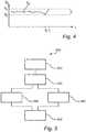
- Fig. 4is a schematic diagram of a desired speed S d of the printer head as a function of time t during an operation of the printer unit.
- the control unit of the printer unitmay be configured to set or provide a predetermined interval I of the desired speed S d , wherein the interval I is defined between a lower boundary S 0 and an upper boundary Si, i.e. S 0 ⁇ S d ⁇ S 1 .
- the desired speed S dis found within the predetermined interval I.
- the printer unitmay be configured to maintain its printing operation.
- the printer unitmay be configured to interrupt its operation in case the desired speed S d is outside the predetermined interval I.
- Thisis exemplified in Fig. 4 at time t 1 , wherein the desired speed S d is outside the predetermined interval I (i.e. S d >S 1 ).
- Fig. 4is not drawn to scale, and that S d is shown only as an example.
- the predetermined interval Iis also provided as an example, and may be defined differently. For example, the predetermined interval I may be wider or more narrow than that indicated.
- Fig. 5is a method 500 for 3D-printing an object by a printer unit comprising a printer head arranged to deposit printing material from the printer unit.
- the method 500comprises the step of sensing 510 a pressure exerted on the printer head from the printing material. Furthermore, the method 500 comprises the step of controlling 520 the speed of the printer head based on a transfer function from the pressure sensed by the pressure sensor to a desired speed of the printer head, in order to maintain a constant deposition of the amount of printing material per length unit of deposited printing material.
- the method 500may optionally comprise the further step of sensing 530 a pressure exerted on the feeding unit from the printing material.
- the method 500may comprise the step of sensing 540 a pressure exerted on the nozzle from the printing material.
- the method 500may optionally comprise the further step of interrupting 550 an operation of the printer unit in case the speed of the printer head is outside a predetermined interval.
- any elements/components of the printer unit 100such as the printer head 105, the nozzle 110, the feeding unit 107, etc., may have different dimensions, shapes and/or sizes than those depicted and/or described.
- the printer head 105, the nozzle 110 and/or the feeding unit 107may be larger or smaller than what is exemplified in the figures.
Landscapes
- Chemical & Material Sciences (AREA)
- Engineering & Computer Science (AREA)
- Materials Engineering (AREA)
- Manufacturing & Machinery (AREA)
- Physics & Mathematics (AREA)
- Mechanical Engineering (AREA)
- Optics & Photonics (AREA)
- Application Of Or Painting With Fluid Materials (AREA)
- Powder Metallurgy (AREA)
Description
- The present invention generally relates to the field of 3D printing. More specifically, the present invention relates to a printer unit for a 3D printing apparatus, and a printing method.
- Additive manufacturing, sometimes also referred to as 3D printing, refers to processes used to synthesize a three-dimensional object. 3D printing is rapidly gaining popularity because of its ability to perform rapid prototyping without the need for assembly or molding techniques to form the desired article.
- By using a 3D-printing apparatus, an article or object may be built in three dimensions in a number of printing steps that often are controlled by a computer model. For example, a sliced 3D model of the object may be provided in which each slice is recreated by the 3D printing apparatus in a discrete printing step.
- One of the most widely used 3D-printing processes is Fused Filament Fabrication (FFF). FFF printers often use a thermoplastic filament which in its molten state is ejected from a nozzle of the printer. The material is then placed layer by layer, to create a three-dimensional object. FFF printers are relatively fast and can be used for printing objects of various kinds, even those having relatively complex structures.
- During 3D-printing, it is desirable to provide an adequate adherence of the printing material to the underlying material, and that the deposited layer of printing material has a predictable layer thickness and layer width. As a consequence, the deposited layer may be provided as a relatively smooth, homogeneous surface.
- It will be appreciated that variations of the pressure of the molten material inside the printing nozzle may lead to defects and/or aesthetic deficiencies in the FDM 3D-printed products. Examples of these defects or deficiencies may be material surface roughnesses, undulations, irregularities, or the like. In the prior art, there is suggested a method to measure the nozzle pressure and trying to control the feeding rate of the printing material to try to keep a relatively constant pressure which the printing material exerts on the nozzle. However, it should be noted that an arrangement of this kind requires a relatively circumstantial control arrangement, since corrections of the feeding rate immediately influences the mentioned pressure.
- Document
US2017252820 discloses a control loop which measures a force required to extrude the build material, and uses this sensed parameter to estimate a temperature of the build material. The temperature, or a difference between the estimated temperature and a target temperature, can be used to speed or slow extrusion of the build material to control heat transfer from a heating system along the feed path. - Hence, alternative solutions are of interest, which are able to deposit one or more layers of printing material, resulting in a relatively smooth, homogeneous layer surface.
- It is an object of the present invention to mitigate the above problems and to provide a printer unit and a method which are able to deposit one or more layers of printing material with a desired layer thickness and layer width, resulting in a relatively smooth, homogeneous layer surface.
- This and other objects are achieved by providing a printer unit and a method having the features in the independent claims. Preferred embodiments are defined in the dependent claims.
- Hence, according to a first aspect of the present invention, there is provided a printer unit for a 3D-printing apparatus. The printer unit comprises a printer head comprising a nozzle arranged to deposit printing material from the printer unit. The printer unit further comprises a pressure sensor configured to sense a pressure exerted on the printer head from the printing material. Moreover, the printer unit comprises a control unit coupled to the pressure sensor, wherein the control unit is configured to control the speed of the printer head based on a transfer function from the pressure sensed by the pressure sensor to a desired speed of the printer head, in order to maintain a constant deposition of the amount of printing material per length unit of deposited printing material. The transfer function is an increasing function so that when a pressure increase is detected, the printing speed will be increased according to a predefined correlation, andvice versa.
- According to a second aspect of the present invention, there is provided a method for 3D-printing an object by a printer unit comprising a printer head comprising a nozzle arranged to deposit printing material from the printer unit. The method comprises the step of sensing a pressure exerted on the printer head from the printing material. The method further comprises the step of controlling the speed of the printer head based on a transfer function from the pressure sensed by the pressure sensor to a desired speed of the printer head, in order to maintain a constant deposition of the amount of printing material per length unit of deposited printing material. The transfer function is an increasing function so that when a pressure increase is detected, the printing speed will be increased according to a predefined correlation, andvice versa.
- Thus, the present invention is based on the idea of providing a printer unit for a 3D-printing apparatus which is configured to deposit a printing material to generate a 3D-printed object having a relatively homogeneous surface that is smooth over a relatively large area. This may be achieved by controlling the speed of the printer head during operation of the printer unit with the purpose of depositing a (relatively) constant amount of printing material per length unit of deposited printing material. The speed of the printer head is controlled based on an increasing transfer or correlation function between a pressure (measured or estimated) of the printer head (e.g. the printer nozzle of the printer head) and a desired speed of the printer head. A functiony = f(x) is increasing iff(x1) ≤f(x2) whenx1 < x2, for any combination ofx1 andx2. The present invention is advantageous in that the concept of ensuring a (relatively) constant material deposition by controlling the printing speed of the printer unit as a function of the pressure exerted on the printer head from the printing material is significantly more efficient compared to arrangements in the prior art. Notably, the present invention may avoid a control of the feeding rate of the printing material as a function of the pressure which the printing material exerts on the nozzle. Consequently, relatively complex feedback control systems may hereby be avoided, and a much more efficient feed-forward system may be sufficient to provide desired surface properties of a 3D-printed product.
- The printing material provided to the printer head is usually formed as a cylinder-shaped filament. It should be noted, however, that the diameter of the filament may vary along the length of the filament, especially in case printing material of lower quality is used. Hence, the volume of the printing material supplied to the printer head may vary quite significantly, considering that the volume of the printing material per unit length in the form of a filament is a function of the radius squared. Consequently, this may lead to relatively large variations in pressure exerted on the printer head from the printing material. The present invention is advantageous in that it may compensate for pressure variations of this kind by controlling the speed of the printer head accordingly.
- It will be appreciated that the mentioned advantages of the printer unit of the first aspect of the present invention also hold for the method according to the second aspect of the present invention.
- The printer unit of the present invention comprises a printer head comprising a nozzle arranged to deposit printing material from the printer unit. The printer unit further comprises a pressure sensor configured to sense a pressure exerted on the printer head from the printing material. By the term "pressure sensor", it is here meant substantially any sensor, measuring device, or the like, for measuring the pressure or force. Moreover, the printer unit comprises a control unit coupled to the pressure sensor. By "control unit", it is here meant substantially any unit, device, or the like, for control purposes. The control unit is configured to control the speed of the printer head. By the term "speed of the printer head", it is hereby meant the linear speed of the printer head during operation of the printer unit, i.e. during deposition of printing material by means of the printer unit. The control unit is configured to control the speed of the printer head based on a transfer function from the pressure sensed by the pressure sensor to a desired speed of the printer head. By the term "transfer function", it is here meant a mapping or correlation function. The speed of the printer head is hereby controlled in order to maintain a (relatively) constant deposition of the amount of printing material per length unit of deposited printing material. The transfer function is an increasing function so that when a pressure increase is detected, the printing speed will be increased according to a predefined correlation, andvice versa.
- According to an embodiment of the present invention, the printer unit further comprises a feeding unit configured to feed printing material. The pressure sensor is coupled to the feeding unit and configured to sense a pressure exerted on the feeding unit from the printing material. The present embodiment is advantageous in that a (direct) measurement of the pressure from the printing material in or near the nozzle may be avoided. This may be beneficial in some cases, as such a measurement may be circumstantial, complex and/or inconvenient, especially when considering that the nozzle may be relatively hot. However, in some cases, it may be preferable to (directly) sense a pressure exerted on the nozzle from the printing material by providing a coupling of the pressure sensor to the nozzle.
- According to an embodiment of the present invention, the transfer function comprises at least one filter function between the pressure sensed by the pressure sensor and the desired speed of the printer head. The present embodiment is advantageous in that the filter function may even further improve the transfer function, which consequently may generate an even more improved speed of the printer head during operation in order to maintain a constant deposition of the amount of printing material per length unit of deposited printing material.
- According to an embodiment of the present invention, at least one filter function is selected from a list comprising a delay function, an averaging function, a scaling function, and a non-linear function. By the term "delay function", it is here meant a delay, pause, interval, or the like in the correlation between the pressure sensed by the pressure sensor to a desired speed of the printer head. By the term "averaging function", it is here meant that data of the pressure sensed by the pressure sensor may be averaged before providing the correlation to the desired speed of the printer head. By the term "scaling function", it is here meant that a change of the pressure sensed by the pressure sensor by a factor changes the desired speed of the printer head by the same factor. By the term "non-linear function", it is here meant e.g. an offset, exponential term, logarithmic function, etc. The present embodiment is advantageous in that the mentioned filter function(s) may contribute to an even further improved transfer function, with the purpose of generating an even more improved speed of the printer head during operation.
- According to an embodiment of the present invention, the transfer function is determined based on at least one parameter selected from a list comprising a speed of the printer head, a temperature of the nozzle, a feeding rate of printing material, and an amount of printing material deposited per length unit of deposited printing material. It will be appreciated that one or more of the mentioned features may have an impact on the deposition of printing material by the printer head during operation of the printer unit. Hence, by providing a transfer function from the pressure sensed by the pressure sensor to a desired speed of the printer head based on one or more of the mentioned parameters, an even more customized speed of the printer head may be achieved in order to maintain a constant deposition of the amount of printing material per length unit of deposited printing material.
- According to an embodiment of the present invention, the printer unit further comprises a measuring device configured to measure at least one parameter selected from a list comprising a speed of the printer head, a temperature of the nozzle, a feeding rate of printing material, and an amount of printing material deposited per length unit of deposited printing material.
- According to an embodiment of the present invention, the transfer function is predefined. In other words, the transfer function is determined (set) in advance. It will be appreciated that the transfer function may be determined based on simulations, empirical data and/or theory. The present embodiment is advantageous in that a provision of a predetermined or predefined transfer function may avoid additional measurements, thereby conveniently providing a transfer function from the pressure sensed by the pressure sensor to a desired speed of the printer head.
- According to an embodiment of the present invention, the control unit is configured to interrupt an operation of the printer unit in case the speed of the printer head is outside a predetermined interval. The present embodiment is advantageous in that the limited speed may counteract defects and/or aesthetic deficiencies in the 3D-printed objects, in case of a too low or too high speed of the printer head. The present embodiment is advantageous in that potential damages of the printer unit may be avoided, e.g. in case of a too high printer head speed.
- According to an embodiment of the present invention, the printer unit further comprises a feeding unit configured to feed printing material, and the method according to the second aspect of the present invention may further comprise the step of sensing a pressure exerted on the feeding unit from the printing material.
- According to an embodiment of the present invention, the method further comprises the step of sensing a pressure exerted on the nozzle from the printing material.
- According to an embodiment of the present invention, the method further comprises interrupting an operation of the printer unit in case the speed of the printer head is outside a predetermined interval.
- Further objectives of, features of, and advantages with, the present invention will become apparent when studying the following detailed disclosure, the drawings and the appended claims. Those skilled in the art will realize that different features of the present invention can be combined to create embodiments other than those described in the following.
- This and other aspects of the present invention will now be described in more detail, with reference to the appended drawings showing embodiment(s) of the invention.
Fig. 0 shows a schematic view of a 3D-printed object which has been printed by a 3D-printing apparatus according to the prior art,Fig. 1 is a schematic view of a printer unit for a 3D-printing apparatus according to an exemplifying embodiment of the present invention,Fig. 2 is a schematic view of a transfer function according to an exemplifying embodiment of the present invention,Figs. 3a-b are schematic illustrations of transfer functions according to exemplifying embodiments of the present invention,Fig. 4 is a schematic view of a 3D-printing arrangement according to an embodiment of the present invention, andFig. 5 is a schematic view of a method according to an exemplifying embodiment of the present invention.Fig. 0 shows a schematic view of a 3D-printedobject 10 which has been printed by a 3D-printing apparatus according to the prior art. It will be appreciated that the surface of theobject 10 discloses significant roughnesses, undulations and irregularities, and these defects or deficiencies are due to variations of the pressure of the molten material inside the printing nozzle of the 3D-printing apparatus. According to the prior art, there is suggested a method to measure the nozzle pressure and trying to control the feeding rate of the printing material to try to keep a relatively constant pressure which the printing material exerts on the nozzle. However, alternative solutions are of interest, which are able to provide an even higher printing quality of a 3D-printed object.Fig. 1 shows a schematic view of aprinter unit 100 for a 3D-printing apparatus. It will be appreciated that theprinter unit 100 may comprise additional elements, features, etc. However, these are omitted inFig. 1 for an increased understanding. Theprinter unit 100 comprises aprinter head 105 which in turn comprises anozzle 110 and afeeding unit 107. Thenozzle 110 is arranged to deposit printing material supplied to thenozzle 110 by thefeeding unit 107. During operation of theprinter unit 100, theprinter head 105 moves with a speed S (indicated to the right inFig. 1 ) during deposition of printing material.- In this example, the
nozzle 110 is arranged to deposit printing material in the form of afilament 115 in a vertical direction and on anunderlying material 135. Theunderlying material 135 is exemplified as a slightly undulated build-plate, but may alternatively constitute at least one layer of (previously deposited) printing material. The printing material is extruded from the bottom portion of the taperednozzle 110. To be able to create a relatively smooth surface of layer(s) of printing material, the first layer of printing material is normally printed with a relatively small layer thickness of 0.1-0.2 mm. - The
printer unit 100 comprises apressure sensor 120, which is schematically indicated inFig. 1 . Thepressure sensor 120 of theprinter unit 100 is configured to sense a pressure exerted on theprinter head 105 from the printing material, e.g. as described in the following. Thepressure sensor 120 may be configured to sense a pressure resulting from a force F exerted on thefeeding unit 107 of theprinter head 105 from the printing material, which may be explained by the following: during an operation of a 3D-printing apparatus comprising aprinter unit 100 according to the depicted example of the invention, printing material deposited upon theunderlying material 135 from theprinter unit nozzle 110 may push printing material backwards (i.e. in the z-direction) within theprinter unit 100 against the printing material feed direction (i.e. the negative z-direction). Consequently, the printing material imparts an (upwards) force F in the z-direction on thefeeding unit 107 which pushes thefeeding unit 107 away from thenozzle 110. The pressure exerted on thefeeding unit 107 from the printing material, resulting from the force F, may hereby be measured by thepressure sensor 120. Alternatively, thepressure sensor 120 may be coupled to thenozzle 110 and configured to sense a pressure exerted on thenozzle 110 from the printing material. - The
printer unit 100 further comprises acontrol unit 130 which is schematically indicated inFig. 1 . Theprinter unit 100 is coupled to thepressure sensor 120, wherein thecontrol unit 130 is configured to control the speed S of theprinter head 105. The speed S is based on a transfer function f from a pressure Ps sensed by thepressure sensor 120 to a desired speed Sd of theprinter head 105, with the purpose of maintaining a constant deposition of the amount of printing material per length unit of deposited printing material. Fig. 2 is a schematic illustration of a transfer function f according to an embodiment of the present invention. The transfer function f may be interpreted as a transfer or mapping function f from the pressure Ps sensed by thepressure sensor 120 to the desired speed Sd of theprinter head 105, i.e. f(Ps)=Sd.Figs. 3a-b are schematic illustrations of increasing transfer functions according to exemplifying embodiments of the present invention. It should be noted that the figures are not drawn to scale, and are merely shown as examples. InFig. 3a , the transfer function f may correspond to a linear function which sets or determines the desired speed Sd of the printer head linearly to the sensed pressure Ps. For example, in case of a linear transfer function f, a change in the pressure Ps from Ps1 to Ps2 as indicated inFig. 3a may results in a change of the desired speed Sd from Sd1 to Sd2. For example, the function f may be expressed as Sd = f(Ps) = k*Ps+m, wherein k is a scaling factor. For example, the scaling factor k may be selected to be 0.5 < k < 1. Alternatively, the transfer function may comprise at least one filter function between the pressure Ps sensed by the pressure sensor and the desired speed Sd of the printer head. InFig, 3b , the filter function f comprises a delay function such that Sd remains unchanged even though the pressure Ps changes from Ps1 to Ps2. Then, if there is an increase of the pressure Ps from Ps2 to Ps3, the desired speed Sd changes from Sd1 to Sd2. It will be appreciated that the transfer function f may comprise other functions which are not exemplified in the figures. For example, the filter function may further comprise an averaging function, whereby data of the pressure Ps is filtered and/or averaged over several measurements. This may be beneficial for a removal of short and/or long-term pressure effects. As yet another alternative, the filter function may further comprise one or more non-linear functions (e.g. comprising one or more offsets, exponential terms, logarithmic functions, etc.)- Moreover, the transfer function may be determined based on other parameters. For example, the speed of the printer head, the temperature of the nozzle, the feeding rate of printing material, the amount of printing material deposited per length unit, etc. may influence the transfer function. For example, the transfer function may generate a higher desired speed Sd in case the feeding rate of printing material increases and/or the temperature of the nozzle increases.
Fig. 4 is a schematic diagram of a desired speed Sd of the printer head as a function of time t during an operation of the printer unit. The control unit of the printer unit may be configured to set or provide a predetermined interval I of the desired speed Sd, wherein the interval I is defined between a lower boundary S0 and an upper boundary Si, i.e. S0 ≤ Sd ≤ S1. During a first period of the operation of the printer unit, at a left hand side of the diagram inFig. 4 , the desired speed Sd is found within the predetermined interval I. During this condition of the operation of the printer unit, the printer unit may be configured to maintain its printing operation. However, the printer unit may be configured to interrupt its operation in case the desired speed Sd is outside the predetermined interval I. This is exemplified inFig. 4 at time t1, wherein the desired speed Sd is outside the predetermined interval I (i.e. Sd>S1). It should be noted thatFig. 4 is not drawn to scale, and that Sd is shown only as an example. Furthermore, the predetermined interval I is also provided as an example, and may be defined differently. For example, the predetermined interval I may be wider or more narrow than that indicated.Fig. 5 is amethod 500 for 3D-printing an object by a printer unit comprising a printer head arranged to deposit printing material from the printer unit. Themethod 500 comprises the step of sensing 510 a pressure exerted on the printer head from the printing material. Furthermore, themethod 500 comprises the step of controlling 520 the speed of the printer head based on a transfer function from the pressure sensed by the pressure sensor to a desired speed of the printer head, in order to maintain a constant deposition of the amount of printing material per length unit of deposited printing material.- In case the printer unit further comprises a feeding unit configured to feed printing material, according to a previously described embodiment, the
method 500 may optionally comprise the further step of sensing 530 a pressure exerted on the feeding unit from the printing material. Alternatively, themethod 500 may comprise the step of sensing 540 a pressure exerted on the nozzle from the printing material. - The
method 500 may optionally comprise the further step of interrupting 550 an operation of the printer unit in case the speed of the printer head is outside a predetermined interval. - The person skilled in the art realizes that the present invention by no means is limited to the preferred embodiments described above. On the contrary, many modifications and variations are possible within the scope of the appended claims. For example, it will be appreciated that the figures are merely schematic views of printer units according to embodiments of the present invention. Hence, any elements/components of the
printer unit 100 such as theprinter head 105, thenozzle 110, thefeeding unit 107, etc., may have different dimensions, shapes and/or sizes than those depicted and/or described. For example, theprinter head 105, thenozzle 110 and/or thefeeding unit 107 may be larger or smaller than what is exemplified in the figures.
Claims (13)
- A printer unit (100) for a 3D-printing apparatus, comprising
a printer head (105) comprising a nozzle (110) arranged to deposit printing material from the printer unit,
a pressure sensor (120) configured to sense a pressure Ps exerted on the printer head from the printing material, and
a control unit (130) coupled to the pressure sensor, wherein the control unit is configured to control the speed of the printer head based on an increasing transfer function f from the pressure sensed by the pressure sensor to a desired speed Sd of the printer head, in order to maintain a constant deposition of the amount of printing material per length unit of deposited printing material. - The printer unit according to claim 1, further comprising a feeding unit (107) configured to feed printing material, wherein the pressure sensor is coupled to the feeding unit and configured to sense a pressure exerted on the feeding unit from the printing material.
- The printer unit according to claim 1 or 2, wherein the pressure sensor is coupled to the nozzle and configured to sense a pressure exerted on the nozzle from the printing material.
- The printer unit according to any one of the preceding claims, wherein the transfer function comprises at least one filter function between the pressure sensed by the pressure sensor and the desired speed of the printer head.
- The printer unit according to claim 4, wherein the at least one filter function is selected from a list comprising a delay function, an averaging function, a scaling function, and a non-linear function.
- The printer unit according to any one of the preceding claims, wherein the transfer function is determined based on at least one parameter selected from a list comprising a speed of the printer head, a temperature of the nozzle, a feeding rate of the printing material, and an amount of printing material deposited per length unit of deposited printing material.
- The printer unit according to claim 6, further comprising a measuring device configured to measure at least one parameter selected from a list comprising a speed of the printer head, a temperature of the nozzle, a feeding rate of the printing material, and an amount of printing material deposited per length unit of deposited printing material.
- The printer unit according to any one of the preceding claims, wherein the transfer function is predefined.
- The printer unit according to any one of the preceding claims, wherein the control unit is configured to interrupt an operation of the printer unit in case the speed of the printer head is outside a predetermined interval.
- A method (500) for 3D-printing an object by a printer unit comprising a printer head comprising a nozzle arranged to deposit printing material from the printer unit, comprising the steps of:sensing (510) a pressure exerted on the printer head from the printing material, andcontrolling (520) the speed of the printer head based on an increasing transfer function from the pressure sensed by the pressure sensor to a desired speed of the printer head, in order to maintain a constant deposition of the amount of printing material per length unit of deposited printing material.
- The method according to claim 10, wherein the printer unit further comprises a feeding unit configured to feed printing material, and wherein the method further comprises the step of
sensing (530) a pressure exerted on the feeding unit from the printing material. - The method according to claim 10 or 11, further comprising the step of
sensing (540) a pressure exerted on the nozzle from the printing material. - The method according to any one of claims 10-12, further comprising
interrupting (550) an operation of the printer unit in case the speed of the printer head is outside a predetermined interval.
Applications Claiming Priority (2)
| Application Number | Priority Date | Filing Date | Title |
|---|---|---|---|
| EP17194899 | 2017-10-05 | ||
| PCT/EP2018/076733WO2019068681A1 (en) | 2017-10-05 | 2018-10-02 | Printer unit for a 3d-printing apparatus and method |
Publications (2)
| Publication Number | Publication Date |
|---|---|
| EP3691899A1 EP3691899A1 (en) | 2020-08-12 |
| EP3691899B1true EP3691899B1 (en) | 2021-02-17 |
Family
ID=60021972
Family Applications (1)
| Application Number | Title | Priority Date | Filing Date |
|---|---|---|---|
| EP18778509.2AActiveEP3691899B1 (en) | 2017-10-05 | 2018-10-02 | Printer unit for a 3d-printing apparatus and method |
Country Status (5)
| Country | Link |
|---|---|
| US (1) | US11590690B2 (en) |
| EP (1) | EP3691899B1 (en) |
| JP (1) | JP6877641B2 (en) |
| CN (1) | CN111194265B (en) |
| WO (1) | WO2019068681A1 (en) |
Families Citing this family (5)
| Publication number | Priority date | Publication date | Assignee | Title |
|---|---|---|---|---|
| NL2018720B1 (en)* | 2017-04-14 | 2018-10-24 | Bond High Performance 3D Tech B V | Three-dimensional modeling method and system |
| JP7625937B2 (en)* | 2021-03-30 | 2025-02-04 | トヨタ自動車株式会社 | Injection molding machine, additive manufacturing device, and pressure control method |
| CN113246473B (en)* | 2021-05-10 | 2022-04-22 | 深圳拓竹科技有限公司 | Compensation method and compensation device for 3D printer, 3D printer and storage medium |
| DE102021133946A1 (en) | 2021-12-20 | 2023-06-22 | Arburg Gmbh + Co Kg | Method of leveling a surface |
| CN114770951B (en)* | 2022-03-31 | 2024-08-20 | 深圳市纵维立方科技有限公司 | Printing control method and device and 3D printer |
Family Cites Families (18)
| Publication number | Priority date | Publication date | Assignee | Title |
|---|---|---|---|---|
| US5121329A (en) | 1989-10-30 | 1992-06-09 | Stratasys, Inc. | Apparatus and method for creating three-dimensional objects |
| US5764521A (en)* | 1995-11-13 | 1998-06-09 | Stratasys Inc. | Method and apparatus for solid prototyping |
| US6085957A (en)* | 1996-04-08 | 2000-07-11 | Stratasys, Inc. | Volumetric feed control for flexible filament |
| CN107187022B (en) | 2013-03-22 | 2020-08-11 | 格雷戈里·托马斯·马克 | Three-dimensional printing |
| US10201931B2 (en) | 2013-10-04 | 2019-02-12 | Stratasys, Inc. | Additive manufacturing system and process with material flow feedback control |
| US10005126B2 (en) | 2014-03-19 | 2018-06-26 | Autodesk, Inc. | Systems and methods for improved 3D printing |
| US20170120528A1 (en)* | 2014-06-06 | 2017-05-04 | Das-Nano, S.L. | 3d printing material encoding |
| US9808991B2 (en)* | 2014-07-29 | 2017-11-07 | Cc3D Llc. | Method and apparatus for additive mechanical growth of tubular structures |
| EP3593978A1 (en) | 2014-11-24 | 2020-01-15 | Ladanyi, Robert | 3d printer |
| US20170050382A1 (en) | 2015-08-21 | 2017-02-23 | Voxel8, Inc. | Closed-Loop 3D Printing Incorporating Sensor Feedback |
| US10471702B2 (en) | 2015-12-11 | 2019-11-12 | Stratasys, Inc. | Additive manufacturing systems and method of filling voids in 3D parts |
| CN108290348A (en) | 2015-12-21 | 2018-07-17 | 瓦克化学股份公司 | The method and apparatus for being used to produce object by using 3D printing equipment |
| US20170252817A1 (en)* | 2016-03-03 | 2017-09-07 | Desktop Metal, Inc. | Nozzle cleaning for semi-solid deposition nozzles |
| US20180015655A1 (en)* | 2016-07-12 | 2018-01-18 | Microsoft Technology Licensing, Llc | Dimensional accuracy in generating 3d objects |
| CN210477829U (en)* | 2016-08-23 | 2020-05-08 | 斯特塔思有限公司 | Predictive flow control response in an additive manufacturing system |
| US10377124B2 (en)* | 2016-08-31 | 2019-08-13 | Thermwood Corporation | Methods and apparatus for processing and dispensing material during additive manufacturing |
| US20180297272A1 (en)* | 2017-04-14 | 2018-10-18 | Desktop Metal, Inc. | High density 3d printing |
| US10201503B1 (en)* | 2018-01-09 | 2019-02-12 | Triastek, Inc. | Precision pharmaceutical 3D printing device |
- 2018
- 2018-10-02EPEP18778509.2Apatent/EP3691899B1/enactiveActive
- 2018-10-02WOPCT/EP2018/076733patent/WO2019068681A1/ennot_activeCeased
- 2018-10-02JPJP2020519734Apatent/JP6877641B2/enactiveActive
- 2018-10-02USUS16/652,618patent/US11590690B2/enactiveActive
- 2018-10-02CNCN201880065060.8Apatent/CN111194265B/enactiveActive
Non-Patent Citations (1)
| Title |
|---|
| None* |
Also Published As
| Publication number | Publication date |
|---|---|
| US11590690B2 (en) | 2023-02-28 |
| JP6877641B2 (en) | 2021-05-26 |
| CN111194265A (en) | 2020-05-22 |
| WO2019068681A1 (en) | 2019-04-11 |
| CN111194265B (en) | 2022-06-10 |
| JP2020535997A (en) | 2020-12-10 |
| EP3691899A1 (en) | 2020-08-12 |
| US20200238680A1 (en) | 2020-07-30 |
Similar Documents
| Publication | Publication Date | Title |
|---|---|---|
| EP3691899B1 (en) | Printer unit for a 3d-printing apparatus and method | |
| KR102366616B1 (en) | High-speed extrusion 3-D printing system | |
| US10421268B2 (en) | Filament feeding device having a capacitive filament displacement sensor for use in additive manufacturing system | |
| EP3668702B1 (en) | Additive manufacturing temperature | |
| US5764521A (en) | Method and apparatus for solid prototyping | |
| US20190022922A1 (en) | Print head nozzle for use with additive manufacturing system | |
| AU2015202215B2 (en) | 3-D printer having motion sensors | |
| US11046012B2 (en) | Three-dimensional modeling method and system | |
| JP5555769B2 (en) | Method and apparatus for making a three-dimensional object | |
| CN210477829U (en) | Predictive flow control response in an additive manufacturing system | |
| US20180015655A1 (en) | Dimensional accuracy in generating 3d objects | |
| EP3052299B1 (en) | Liquefier assembly for additive manufacturing systems, and methods of use thereof | |
| EP3505329B1 (en) | Three-dimensional printer of fused deposition modeling method | |
| JP2020521653A5 (en) | ||
| WO2016192748A1 (en) | 3d printingsystem and method | |
| WO2019068685A1 (en) | Printer unit for a 3d-printing apparatus and method | |
| JP2020192705A (en) | Molding system, control device, molding method, and program | |
| CN112088083B (en) | Fused three-dimensional (3D) parts | |
| US20210370596A1 (en) | Controlling an energy source of an additive manufacturing system | |
| CN119156275A (en) | Extrusion compensation method of extrusion wheel, 3D printer and electronic equipment | |
| JP2020082432A (en) | Modeling equipment |
Legal Events
| Date | Code | Title | Description |
|---|---|---|---|
| STAA | Information on the status of an ep patent application or granted ep patent | Free format text:STATUS: UNKNOWN | |
| STAA | Information on the status of an ep patent application or granted ep patent | Free format text:STATUS: THE INTERNATIONAL PUBLICATION HAS BEEN MADE | |
| PUAI | Public reference made under article 153(3) epc to a published international application that has entered the european phase | Free format text:ORIGINAL CODE: 0009012 | |
| STAA | Information on the status of an ep patent application or granted ep patent | Free format text:STATUS: REQUEST FOR EXAMINATION WAS MADE | |
| 17P | Request for examination filed | Effective date:20200506 | |
| AK | Designated contracting states | Kind code of ref document:A1 Designated state(s):AL AT BE BG CH CY CZ DE DK EE ES FI FR GB GR HR HU IE IS IT LI LT LU LV MC MK MT NL NO PL PT RO RS SE SI SK SM TR | |
| AX | Request for extension of the european patent | Extension state:BA ME | |
| GRAP | Despatch of communication of intention to grant a patent | Free format text:ORIGINAL CODE: EPIDOSNIGR1 | |
| STAA | Information on the status of an ep patent application or granted ep patent | Free format text:STATUS: GRANT OF PATENT IS INTENDED | |
| DAV | Request for validation of the european patent (deleted) | ||
| DAX | Request for extension of the european patent (deleted) | ||
| INTG | Intention to grant announced | Effective date:20200915 | |
| GRAS | Grant fee paid | Free format text:ORIGINAL CODE: EPIDOSNIGR3 | |
| GRAA | (expected) grant | Free format text:ORIGINAL CODE: 0009210 | |
| STAA | Information on the status of an ep patent application or granted ep patent | Free format text:STATUS: THE PATENT HAS BEEN GRANTED | |
| AK | Designated contracting states | Kind code of ref document:B1 Designated state(s):AL AT BE BG CH CY CZ DE DK EE ES FI FR GB GR HR HU IE IS IT LI LT LU LV MC MK MT NL NO PL PT RO RS SE SI SK SM TR | |
| REG | Reference to a national code | Ref country code:GB Ref legal event code:FG4D | |
| REG | Reference to a national code | Ref country code:CH Ref legal event code:EP | |
| REG | Reference to a national code | Ref country code:DE Ref legal event code:R096 Ref document number:602018012780 Country of ref document:DE | |
| REG | Reference to a national code | Ref country code:AT Ref legal event code:REF Ref document number:1360969 Country of ref document:AT Kind code of ref document:T Effective date:20210315 | |
| REG | Reference to a national code | Ref country code:IE Ref legal event code:FG4D | |
| REG | Reference to a national code | Ref country code:LT Ref legal event code:MG9D | |
| REG | Reference to a national code | Ref country code:NL Ref legal event code:MP Effective date:20210217 | |
| PG25 | Lapsed in a contracting state [announced via postgrant information from national office to epo] | Ref country code:PT Free format text:LAPSE BECAUSE OF FAILURE TO SUBMIT A TRANSLATION OF THE DESCRIPTION OR TO PAY THE FEE WITHIN THE PRESCRIBED TIME-LIMIT Effective date:20210617 Ref country code:NO Free format text:LAPSE BECAUSE OF FAILURE TO SUBMIT A TRANSLATION OF THE DESCRIPTION OR TO PAY THE FEE WITHIN THE PRESCRIBED TIME-LIMIT Effective date:20210517 Ref country code:LT Free format text:LAPSE BECAUSE OF FAILURE TO SUBMIT A TRANSLATION OF THE DESCRIPTION OR TO PAY THE FEE WITHIN THE PRESCRIBED TIME-LIMIT Effective date:20210217 Ref country code:HR Free format text:LAPSE BECAUSE OF FAILURE TO SUBMIT A TRANSLATION OF THE DESCRIPTION OR TO PAY THE FEE WITHIN THE PRESCRIBED TIME-LIMIT Effective date:20210217 Ref country code:FI Free format text:LAPSE BECAUSE OF FAILURE TO SUBMIT A TRANSLATION OF THE DESCRIPTION OR TO PAY THE FEE WITHIN THE PRESCRIBED TIME-LIMIT Effective date:20210217 Ref country code:GR Free format text:LAPSE BECAUSE OF FAILURE TO SUBMIT A TRANSLATION OF THE DESCRIPTION OR TO PAY THE FEE WITHIN THE PRESCRIBED TIME-LIMIT Effective date:20210518 Ref country code:BG Free format text:LAPSE BECAUSE OF FAILURE TO SUBMIT A TRANSLATION OF THE DESCRIPTION OR TO PAY THE FEE WITHIN THE PRESCRIBED TIME-LIMIT Effective date:20210517 | |
| REG | Reference to a national code | Ref country code:AT Ref legal event code:MK05 Ref document number:1360969 Country of ref document:AT Kind code of ref document:T Effective date:20210217 | |
| PG25 | Lapsed in a contracting state [announced via postgrant information from national office to epo] | Ref country code:SE Free format text:LAPSE BECAUSE OF FAILURE TO SUBMIT A TRANSLATION OF THE DESCRIPTION OR TO PAY THE FEE WITHIN THE PRESCRIBED TIME-LIMIT Effective date:20210217 Ref country code:RS Free format text:LAPSE BECAUSE OF FAILURE TO SUBMIT A TRANSLATION OF THE DESCRIPTION OR TO PAY THE FEE WITHIN THE PRESCRIBED TIME-LIMIT Effective date:20210217 Ref country code:PL Free format text:LAPSE BECAUSE OF FAILURE TO SUBMIT A TRANSLATION OF THE DESCRIPTION OR TO PAY THE FEE WITHIN THE PRESCRIBED TIME-LIMIT Effective date:20210217 Ref country code:NL Free format text:LAPSE BECAUSE OF FAILURE TO SUBMIT A TRANSLATION OF THE DESCRIPTION OR TO PAY THE FEE WITHIN THE PRESCRIBED TIME-LIMIT Effective date:20210217 Ref country code:LV Free format text:LAPSE BECAUSE OF FAILURE TO SUBMIT A TRANSLATION OF THE DESCRIPTION OR TO PAY THE FEE WITHIN THE PRESCRIBED TIME-LIMIT Effective date:20210217 | |
| PG25 | Lapsed in a contracting state [announced via postgrant information from national office to epo] | Ref country code:IS Free format text:LAPSE BECAUSE OF FAILURE TO SUBMIT A TRANSLATION OF THE DESCRIPTION OR TO PAY THE FEE WITHIN THE PRESCRIBED TIME-LIMIT Effective date:20210617 | |
| PG25 | Lapsed in a contracting state [announced via postgrant information from national office to epo] | Ref country code:EE Free format text:LAPSE BECAUSE OF FAILURE TO SUBMIT A TRANSLATION OF THE DESCRIPTION OR TO PAY THE FEE WITHIN THE PRESCRIBED TIME-LIMIT Effective date:20210217 Ref country code:CZ Free format text:LAPSE BECAUSE OF FAILURE TO SUBMIT A TRANSLATION OF THE DESCRIPTION OR TO PAY THE FEE WITHIN THE PRESCRIBED TIME-LIMIT Effective date:20210217 Ref country code:AT Free format text:LAPSE BECAUSE OF FAILURE TO SUBMIT A TRANSLATION OF THE DESCRIPTION OR TO PAY THE FEE WITHIN THE PRESCRIBED TIME-LIMIT Effective date:20210217 Ref country code:SM Free format text:LAPSE BECAUSE OF FAILURE TO SUBMIT A TRANSLATION OF THE DESCRIPTION OR TO PAY THE FEE WITHIN THE PRESCRIBED TIME-LIMIT Effective date:20210217 | |
| REG | Reference to a national code | Ref country code:DE Ref legal event code:R097 Ref document number:602018012780 Country of ref document:DE | |
| PG25 | Lapsed in a contracting state [announced via postgrant information from national office to epo] | Ref country code:SK Free format text:LAPSE BECAUSE OF FAILURE TO SUBMIT A TRANSLATION OF THE DESCRIPTION OR TO PAY THE FEE WITHIN THE PRESCRIBED TIME-LIMIT Effective date:20210217 Ref country code:RO Free format text:LAPSE BECAUSE OF FAILURE TO SUBMIT A TRANSLATION OF THE DESCRIPTION OR TO PAY THE FEE WITHIN THE PRESCRIBED TIME-LIMIT Effective date:20210217 Ref country code:DK Free format text:LAPSE BECAUSE OF FAILURE TO SUBMIT A TRANSLATION OF THE DESCRIPTION OR TO PAY THE FEE WITHIN THE PRESCRIBED TIME-LIMIT Effective date:20210217 | |
| PLBE | No opposition filed within time limit | Free format text:ORIGINAL CODE: 0009261 | |
| STAA | Information on the status of an ep patent application or granted ep patent | Free format text:STATUS: NO OPPOSITION FILED WITHIN TIME LIMIT | |
| 26N | No opposition filed | Effective date:20211118 | |
| PG25 | Lapsed in a contracting state [announced via postgrant information from national office to epo] | Ref country code:ES Free format text:LAPSE BECAUSE OF FAILURE TO SUBMIT A TRANSLATION OF THE DESCRIPTION OR TO PAY THE FEE WITHIN THE PRESCRIBED TIME-LIMIT Effective date:20210217 Ref country code:AL Free format text:LAPSE BECAUSE OF FAILURE TO SUBMIT A TRANSLATION OF THE DESCRIPTION OR TO PAY THE FEE WITHIN THE PRESCRIBED TIME-LIMIT Effective date:20210217 | |
| PG25 | Lapsed in a contracting state [announced via postgrant information from national office to epo] | Ref country code:IT Free format text:LAPSE BECAUSE OF FAILURE TO SUBMIT A TRANSLATION OF THE DESCRIPTION OR TO PAY THE FEE WITHIN THE PRESCRIBED TIME-LIMIT Effective date:20210217 | |
| REG | Reference to a national code | Ref country code:CH Ref legal event code:PL | |
| PG25 | Lapsed in a contracting state [announced via postgrant information from national office to epo] | Ref country code:IS Free format text:LAPSE BECAUSE OF FAILURE TO SUBMIT A TRANSLATION OF THE DESCRIPTION OR TO PAY THE FEE WITHIN THE PRESCRIBED TIME-LIMIT Effective date:20210617 | |
| REG | Reference to a national code | Ref country code:BE Ref legal event code:MM Effective date:20211031 | |
| PG25 | Lapsed in a contracting state [announced via postgrant information from national office to epo] | Ref country code:MC Free format text:LAPSE BECAUSE OF FAILURE TO SUBMIT A TRANSLATION OF THE DESCRIPTION OR TO PAY THE FEE WITHIN THE PRESCRIBED TIME-LIMIT Effective date:20210217 | |
| PG25 | Lapsed in a contracting state [announced via postgrant information from national office to epo] | Ref country code:LU Free format text:LAPSE BECAUSE OF NON-PAYMENT OF DUE FEES Effective date:20211002 Ref country code:BE Free format text:LAPSE BECAUSE OF NON-PAYMENT OF DUE FEES Effective date:20211031 | |
| PG25 | Lapsed in a contracting state [announced via postgrant information from national office to epo] | Ref country code:LI Free format text:LAPSE BECAUSE OF NON-PAYMENT OF DUE FEES Effective date:20211031 Ref country code:CH Free format text:LAPSE BECAUSE OF NON-PAYMENT OF DUE FEES Effective date:20211031 | |
| PG25 | Lapsed in a contracting state [announced via postgrant information from national office to epo] | Ref country code:IE Free format text:LAPSE BECAUSE OF NON-PAYMENT OF DUE FEES Effective date:20211002 | |
| P01 | Opt-out of the competence of the unified patent court (upc) registered | Effective date:20230425 | |
| PG25 | Lapsed in a contracting state [announced via postgrant information from national office to epo] | Ref country code:CY Free format text:LAPSE BECAUSE OF FAILURE TO SUBMIT A TRANSLATION OF THE DESCRIPTION OR TO PAY THE FEE WITHIN THE PRESCRIBED TIME-LIMIT Effective date:20210217 | |
| PG25 | Lapsed in a contracting state [announced via postgrant information from national office to epo] | Ref country code:HU Free format text:LAPSE BECAUSE OF FAILURE TO SUBMIT A TRANSLATION OF THE DESCRIPTION OR TO PAY THE FEE WITHIN THE PRESCRIBED TIME-LIMIT; INVALID AB INITIO Effective date:20181002 | |
| PG25 | Lapsed in a contracting state [announced via postgrant information from national office to epo] | Ref country code:SI Free format text:LAPSE BECAUSE OF FAILURE TO SUBMIT A TRANSLATION OF THE DESCRIPTION OR TO PAY THE FEE WITHIN THE PRESCRIBED TIME-LIMIT Effective date:20210217 | |
| PG25 | Lapsed in a contracting state [announced via postgrant information from national office to epo] | Ref country code:MK Free format text:LAPSE BECAUSE OF FAILURE TO SUBMIT A TRANSLATION OF THE DESCRIPTION OR TO PAY THE FEE WITHIN THE PRESCRIBED TIME-LIMIT Effective date:20210217 | |
| PG25 | Lapsed in a contracting state [announced via postgrant information from national office to epo] | Ref country code:MT Free format text:LAPSE BECAUSE OF FAILURE TO SUBMIT A TRANSLATION OF THE DESCRIPTION OR TO PAY THE FEE WITHIN THE PRESCRIBED TIME-LIMIT Effective date:20210217 | |
| PGFP | Annual fee paid to national office [announced via postgrant information from national office to epo] | Ref country code:GB Payment date:20241022 Year of fee payment:7 | |
| PGFP | Annual fee paid to national office [announced via postgrant information from national office to epo] | Ref country code:FR Payment date:20241025 Year of fee payment:7 | |
| PGFP | Annual fee paid to national office [announced via postgrant information from national office to epo] | Ref country code:DE Payment date:20241227 Year of fee payment:7 |