EP3689683B1 - Light emitting module for an automotive vehicle - Google Patents
Light emitting module for an automotive vehicleDownload PDFInfo
- Publication number
- EP3689683B1 EP3689683B1EP19155389.0AEP19155389AEP3689683B1EP 3689683 B1EP3689683 B1EP 3689683B1EP 19155389 AEP19155389 AEP 19155389AEP 3689683 B1EP3689683 B1EP 3689683B1
- Authority
- EP
- European Patent Office
- Prior art keywords
- light
- light emitting
- emitting module
- portions
- module according
- Prior art date
- Legal status (The legal status is an assumption and is not a legal conclusion. Google has not performed a legal analysis and makes no representation as to the accuracy of the status listed.)
- Active
Links
Images


Classifications
- F—MECHANICAL ENGINEERING; LIGHTING; HEATING; WEAPONS; BLASTING
- F21—LIGHTING
- F21S—NON-PORTABLE LIGHTING DEVICES; SYSTEMS THEREOF; VEHICLE LIGHTING DEVICES SPECIALLY ADAPTED FOR VEHICLE EXTERIORS
- F21S43/00—Signalling devices specially adapted for vehicle exteriors, e.g. brake lamps, direction indicator lights or reversing lights
- F21S43/20—Signalling devices specially adapted for vehicle exteriors, e.g. brake lamps, direction indicator lights or reversing lights characterised by refractors, transparent cover plates, light guides or filters
- F21S43/26—Refractors, transparent cover plates, light guides or filters not provided in groups F21S43/235 - F21S43/255
- F—MECHANICAL ENGINEERING; LIGHTING; HEATING; WEAPONS; BLASTING
- F21—LIGHTING
- F21S—NON-PORTABLE LIGHTING DEVICES; SYSTEMS THEREOF; VEHICLE LIGHTING DEVICES SPECIALLY ADAPTED FOR VEHICLE EXTERIORS
- F21S43/00—Signalling devices specially adapted for vehicle exteriors, e.g. brake lamps, direction indicator lights or reversing lights
- F21S43/10—Signalling devices specially adapted for vehicle exteriors, e.g. brake lamps, direction indicator lights or reversing lights characterised by the light source
- F21S43/13—Signalling devices specially adapted for vehicle exteriors, e.g. brake lamps, direction indicator lights or reversing lights characterised by the light source characterised by the type of light source
- F21S43/14—Light emitting diodes [LED]
- B—PERFORMING OPERATIONS; TRANSPORTING
- B60—VEHICLES IN GENERAL
- B60Q—ARRANGEMENT OF SIGNALLING OR LIGHTING DEVICES, THE MOUNTING OR SUPPORTING THEREOF OR CIRCUITS THEREFOR, FOR VEHICLES IN GENERAL
- B60Q1/00—Arrangement of optical signalling or lighting devices, the mounting or supporting thereof or circuits therefor
- B60Q1/26—Arrangement of optical signalling or lighting devices, the mounting or supporting thereof or circuits therefor the devices being primarily intended to indicate the vehicle, or parts thereof, or to give signals, to other traffic
- B60Q1/2607—Arrangement of optical signalling or lighting devices, the mounting or supporting thereof or circuits therefor the devices being primarily intended to indicate the vehicle, or parts thereof, or to give signals, to other traffic comprising at least two indicating lamps
- F—MECHANICAL ENGINEERING; LIGHTING; HEATING; WEAPONS; BLASTING
- F21—LIGHTING
- F21S—NON-PORTABLE LIGHTING DEVICES; SYSTEMS THEREOF; VEHICLE LIGHTING DEVICES SPECIALLY ADAPTED FOR VEHICLE EXTERIORS
- F21S43/00—Signalling devices specially adapted for vehicle exteriors, e.g. brake lamps, direction indicator lights or reversing lights
- F21S43/30—Signalling devices specially adapted for vehicle exteriors, e.g. brake lamps, direction indicator lights or reversing lights characterised by reflectors
- F21S43/31—Optical layout thereof
- F21S43/315—Optical layout thereof using total internal reflection
- F—MECHANICAL ENGINEERING; LIGHTING; HEATING; WEAPONS; BLASTING
- F21—LIGHTING
- F21S—NON-PORTABLE LIGHTING DEVICES; SYSTEMS THEREOF; VEHICLE LIGHTING DEVICES SPECIALLY ADAPTED FOR VEHICLE EXTERIORS
- F21S43/00—Signalling devices specially adapted for vehicle exteriors, e.g. brake lamps, direction indicator lights or reversing lights
- F21S43/40—Signalling devices specially adapted for vehicle exteriors, e.g. brake lamps, direction indicator lights or reversing lights characterised by the combination of reflectors and refractors
- G—PHYSICS
- G02—OPTICS
- G02B—OPTICAL ELEMENTS, SYSTEMS OR APPARATUS
- G02B19/00—Condensers, e.g. light collectors or similar non-imaging optics
- G02B19/0004—Condensers, e.g. light collectors or similar non-imaging optics characterised by the optical means employed
- G02B19/0028—Condensers, e.g. light collectors or similar non-imaging optics characterised by the optical means employed refractive and reflective surfaces, e.g. non-imaging catadioptric systems
- G—PHYSICS
- G02—OPTICS
- G02B—OPTICAL ELEMENTS, SYSTEMS OR APPARATUS
- G02B19/00—Condensers, e.g. light collectors or similar non-imaging optics
- G02B19/0033—Condensers, e.g. light collectors or similar non-imaging optics characterised by the use
- G02B19/0047—Condensers, e.g. light collectors or similar non-imaging optics characterised by the use for use with a light source
- G02B19/0061—Condensers, e.g. light collectors or similar non-imaging optics characterised by the use for use with a light source the light source comprising a LED
- G02B19/0066—Condensers, e.g. light collectors or similar non-imaging optics characterised by the use for use with a light source the light source comprising a LED in the form of an LED array
- G—PHYSICS
- G02—OPTICS
- G02B—OPTICAL ELEMENTS, SYSTEMS OR APPARATUS
- G02B19/00—Condensers, e.g. light collectors or similar non-imaging optics
- G02B19/0033—Condensers, e.g. light collectors or similar non-imaging optics characterised by the use
- G02B19/0047—Condensers, e.g. light collectors or similar non-imaging optics characterised by the use for use with a light source
- G02B19/0071—Condensers, e.g. light collectors or similar non-imaging optics characterised by the use for use with a light source adapted to illuminate a complete hemisphere or a plane extending 360 degrees around the source
- B—PERFORMING OPERATIONS; TRANSPORTING
- B60—VEHICLES IN GENERAL
- B60Q—ARRANGEMENT OF SIGNALLING OR LIGHTING DEVICES, THE MOUNTING OR SUPPORTING THEREOF OR CIRCUITS THEREFOR, FOR VEHICLES IN GENERAL
- B60Q2400/00—Special features or arrangements of exterior signal lamps for vehicles
- B60Q2400/20—Multi-color single source or LED matrix, e.g. yellow blinker and red brake lamp generated by single lamp
- B—PERFORMING OPERATIONS; TRANSPORTING
- B60—VEHICLES IN GENERAL
- B60Q—ARRANGEMENT OF SIGNALLING OR LIGHTING DEVICES, THE MOUNTING OR SUPPORTING THEREOF OR CIRCUITS THEREFOR, FOR VEHICLES IN GENERAL
- B60Q3/00—Arrangement of lighting devices for vehicle interiors; Lighting devices specially adapted for vehicle interiors
- B60Q3/60—Arrangement of lighting devices for vehicle interiors; Lighting devices specially adapted for vehicle interiors characterised by optical aspects
- B60Q3/62—Arrangement of lighting devices for vehicle interiors; Lighting devices specially adapted for vehicle interiors characterised by optical aspects using light guides
- B60Q3/64—Arrangement of lighting devices for vehicle interiors; Lighting devices specially adapted for vehicle interiors characterised by optical aspects using light guides for a single lighting device
- B—PERFORMING OPERATIONS; TRANSPORTING
- B60—VEHICLES IN GENERAL
- B60Q—ARRANGEMENT OF SIGNALLING OR LIGHTING DEVICES, THE MOUNTING OR SUPPORTING THEREOF OR CIRCUITS THEREFOR, FOR VEHICLES IN GENERAL
- B60Q3/00—Arrangement of lighting devices for vehicle interiors; Lighting devices specially adapted for vehicle interiors
- B60Q3/70—Arrangement of lighting devices for vehicle interiors; Lighting devices specially adapted for vehicle interiors characterised by the purpose
- B60Q3/74—Arrangement of lighting devices for vehicle interiors; Lighting devices specially adapted for vehicle interiors characterised by the purpose for overall compartment lighting; for overall compartment lighting in combination with specific lighting, e.g. room lamps with reading lamps
- B60Q3/745—Arrangement of lighting devices for vehicle interiors; Lighting devices specially adapted for vehicle interiors characterised by the purpose for overall compartment lighting; for overall compartment lighting in combination with specific lighting, e.g. room lamps with reading lamps using lighting panels or mats, e.g. electro-luminescent panels, LED mats
Definitions
- the present inventionrelates to a light emitting device for an automotive vehicle.
- Light emitting devices for an automotive vehicleare placed on the exterior of automotive vehicles, especially for security purposes, to indicate to other road users the presence of the vehicle, as well as the intensions of the driver of the vehicle, such as breaking, changing the driving direction or reversing.
- Other devicesare placed inside the vehicle to illuminate the passengers, to welcome them when they enter the vehicle, or to create a special ambience light in the cabin.
- the known light emitting deviceswhich have good homogeneity, are generally bulky. Conversely, those that are not bulky have a poor homogeneity. In addition, they are also poorly adapted to ensure a good homogeneity when they emit several light functions.
- An object of the present inventionis to solve the disadvantages described above of known light emitting devices of an automotive vehicle.
- the object of the present inventionis to provide a light emitting device, which is not bulky and can ensure a good homogeneity when it performs several lighting and/or signaling functions, for example, tail lighting function and turn indicator function.
- the inventionproposes a light emitting module comprising an optical part according to claim 1.
- an optical part for an automotive vehiclecomprising:
- the second light input faceis situated at one extremity of the second portion that is protruded from the first portion.
- the second light input faceis flat.
- the second light input faceis curved and/or comports a collimator.
- the first light input faceis flat.
- the first light input faceis curved.
- the first light input facecomprises optical pattern, especially pillows and/or flutes and/or cones and/or a graining.
- the first light input facecomports hollow cones.
- the coneshave an apical angle comprised between 30° and 60°, and preferably an apical angle of of 45° with respect to a respective axis of rotation of the cones.
- the coneshave a depth comprised between 0.15 and 0.3mm, especially 0.2mm.
- the output faceis curved.
- the optical partcomprises a plurality of first portions comprising each a first light input face and a plurality of second portions comprising each a second light input face.
- the first input faces of the first portionsform a connected surface.
- the second portionsare disjointed.
- the second portionsare arranged in matrix.
- each second portionshas a form of a cylinder or a cone.
- each second portionsis rotationally symmetrical.
- the output facecomprises a plurality of curved portions.
- the output facecomprises a plurality of hollow portions.
- the hollow portionsare each rotationally symmetrical, especially have a conical form with an apex.
- the generating curve of the conical formis curved.
- the hollow portionsare disjointed.
- each hollow portionsis opposite an associated second portion.
- the apex of the conical formis centered on a central axis of its associated second portion.
- the curved portionsare arranged in a matrix, and alternating with the hollow portions.
- the light emitting modulecomprises:
- each first light input faceis associated to a first light source.
- each second input faceis associated to a second light source.
- the plurality of first light sources and the plurality of second light sourcesare semi-conductor light sources, especially light emitting diodes.
- the plurality of first light sourcesis adapted to emit a light flux different from the light flux emitted by the plurality of second light sources.
- the plurality of first light sources and the plurality of second light sourcesare configured for emitting a light color chosen from red, amber, yellow or white .
- the plurality of first light sourcesis adapted to emit a light color different from the light color emitted by the plurality of second light sources.
- the plurality of first light sourcesare disposed on a common support.
- the plurality of second light sourcesare disposed on a common support.
- the plurality of first light sources and the plurality of second light sourcesare disposed on a common support.
- the light emitting devicefurther comprises an outer lens closing the front opening of the housing, the at least one light emitting module being placed in the volume formed by the housing and the outer lens.
- the light emitting deviceis a rear lamp, a headlamp, or an internal lighting device, of an automotive vehicle.
- the light emitting deviceis an internal lighting device of an automotive vehicle, the optical part closing the front opening of the housing.
- the present inventionis to provide a light emitting device, which is not bulky and can ensure a good homogeneity when it emits several light functions
- the present inventionprovides a light emitting device, which ensures a good homogeneity when it emits several lighting and/or signaling functions, for example, tail function and turn indicator function, tail function and stop function, position or parking function and DRL (for "Daytime Running Lamp”) function, position or parking function and turn indicator function.
- lighting and/or signaling functionsfor example, tail function and turn indicator function, tail function and stop function, position or parking function and DRL (for "Daytime Running Lamp") function, position or parking function and turn indicator function.
- Figure 1ashows a perspective view of an optical part of a light emitting device, according to an embodiment of the present invention.
- Figure 1bshows a bottom view of the optical part of the Figure 1a , according to an embodiment of the present invention.
- Figure 1cshows enlarged view of the bottom portion of the optical part shown in the Figure 1b , according to an embodiment of the present invention.
- Figure 1dshows a top view of the optical part of the Figure 1a , according to an embodiment of the present invention.
- the optical part 100 of an automotive vehiclecomprises at least a first portion 105 comprising a first light input face 110 for receiving first light rays from a first light source 205 (shown in the Figure 2 ) and transmitting first light rays directly toward a light output face 115, so that the first light rays exit the optical part 100.
- the optical part 100further comprises at least a second portion 120 comprising a second light input face 125 for receiving second light rays from a second light source 210 (shown in the Figure 2 ) and transmitting the second light rays toward the light output face 115 so that the second light rays are reflected at least one time by total internal reflection on a first zone 215 (shown in the Figure 2 ) of the light output face 115 before exiting the optical part 100 through a second zone 220 (shown in the Figure 2 ) of the light output face 115.
- the light output face 115is curve shaped.
- the at least second portion 120 of the optical part 100protrudes from the at least first portion 105 of the optical part 100.
- the at least a second portion 120has a form of a cone or a cylinder.
- the second light input face 125is situated at one extremity of the second portion 120 that is protruded from the first portion 105.
- the second light input face 125may be flat shaped as shown in the Figure 1a .
- the second light input facemay be curve shaped and/or comprise a collimator (not shown in the Figures) to collimate the light emitted from the second light source 210.
- the first light input face 110may be flat shaped as shown in the Figure 1a .
- the first light input face 110may be curve shaped and/or comprise a collimator (not shown in the Figures) to collimate the light emitted from the second light source 210.
- the first light input face 110may comprise optical patterns 145, which are clearly visible in the Figure 1b .
- the optical patterns 145may be pillows and/or flutes and/or cones and/or a graining.
- the first light input face 110may comprise hollow cones 140 as shown in the Figure 1c .
- Each cone 140has an apical angle or half-opening angle.
- the half-opening angleis between 30° and 60°, and preferably 45° with respect to an axis of rotation of the cone.
- Each cone 140has a depth between 0.15 mm and 0.3mm, especially 0.2mm.
- the optical part 100comprises a plurality of first portions 105 and a plurality of second portions 120.
- Each first portion 105comprises a first light input face 110 for receiving the first light rays from the first light source 205.
- each second portion 120comprises a second light input face 125 for receiving the second light rays from the second light source 210.
- the first input faces 110 of the first portions 105form a connected surface and the second portions 120 are disjointed.
- the second portions 120may be arranged in matrix, which is a grid organized in rows and columns.
- Each second portion 120has a shape of a cylinder or a cone, and each second portion 120 is rotationally symmetrical. In one embodiment all the second portions have the same shape.
- each first portion 105can be associated to several second portions 120, i.e., the light coming from several second portions120 can be directed to one given first portion output face 115.
- the light output face 115comprises a plurality of curved portions 130 and a plurality of hollow portions 135.
- Each hollow portion 135is rotationally symmetrical, and especially have a conical form with an apex. Further, the hollow portions 135 of the output face 115 are disjointed as shown in the Figure 1a .
- Each hollow portion 135is opposite to an associated second portion 120 and an apex of the conical form of the hollow portion 135 is centered on a central axis 'C' of its associated second portion 120.
- the curved portions 130 of the light output face 115may be arranged in a matrix, and alternating with the hollow portions 135, as shown in the Figure 1a .
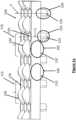
- Figure 2is a sectional representation of an optical part 100 shown in the Figure 1a , according to an embodiment of the present invention.
- the sectionis obtained by a plane perpendicular to a global elongation plane of the optical part 100 and through the center of two second portions 120.
- the optical part 100 of the present inventionensure a good homogeneity when it emits several lighting and/or signaling functions, for example, tail lighting function and turn indicator function, tail function and stop function, position or parking function and DRL (for "Daytime Running Lamp") function, position or parking function and turn indicator function.
- the plurality of first light sources 205 and the plurality of the second light sources 210are configured for emitting a light color chosen from red, amber, yellow or white in order to perform several lighting and/or signaling functions.
- the purpose of emitting different colors for performing different lighting and/or signaling functionis known to a person skilled in the art, and therefore not discussed in detail in this description.
- first light rays 230 emitted from the first light source 205is indicated by dotted arrows A. It is to be noted that only half of the first light rays is shown in the Figure 2 and Figure 3b for the purpose of the clarity. However, the rays symmetric about a not represented vertical axis centered on the light source also exist.
- First light rays emitted from the first light source 205enter into the optical part 100 through the first light input face 110 and are directly transmitted to the light output face 115, i.e., first light rays exit the optical part 100 from the curved portion 130 of the light output face 115.
- Second light rays 240 emitted from the second light source 210enter into the optical part 100 through the second light input face 125 and are transmitted towards first zones 215 of the light output face 115 through the second portion 120. From the second portion 120, transmitted second light rays meet the hollow portion 135 of the light output face 115 where they are reflected at least one time and exit the optical part 100 through the second zones 220 of the light output face 115.
- Dotted arrows B in the Figure 2show the path of second light rays emitted from the second light source 210.
- the path of the light rays emitted from the first light source 205 to perform the first lighting/signaling function and path of the light rays emitted from the second light source 210 to perform the second lighting/signaling functionis separately shown in the Figure 3a and the Figure 3b . Therefore, in accordance with present invention, single optical part can be used to perform several lighting and/or signaling functions, rather than using several parts for performing several functions.
- a light emitting modulecomprises an optical part 100 having at least one first portion 105 and at least one second portion 120, as mentioned in previously discussed embodiment.
- the light emitting modulefurther comprises at least a first light source 205 placed opposite the first light input face 110 of the at least first portion 105.
- the light emitting modulecomprises a second light source 210 placed opposite the second light input face 125 of the at least second portion 120.
- a light emitting modulehaving a plurality of first portions 105 and a plurality of second portions 120 is disclosed.
- the light emitting modulecomprises a plurality of first light sources 205 each opposite an associated first light input face 110 of the first portion 105, and a plurality of second light sources 210 each opposite an associated second light input face 125 of the second portion 120.
- Each first portion 105is associated to a first light source 205 and each second portion 120 is associated to a second light source 210.
- the plurality of first light sources 205 and the plurality of the second light sources 210are semi-conductor light sources, for example, light emitting diodes. Further, the plurality of first light sources 205 is adapted to emit a light flux different from the light flux emitted by the plurality of the second light sources 210. In addition, the plurality of first light sources 205 is adapted to emit a light color different from the light color emitted by the plurality of second light sources 210. In an aspect, the plurality of first light sources 205 are disposed on a common support, and the plurality of the second light sources 210 are disposed on another common support. In another aspect, both the plurality of first light sources 205 and the plurality of second light sources 210 are disposed on a single common support.
- the present inventiondiscloses a light emitting device comprising a housing comprising an opening, and at least one light emitting module described in the above embodiments.
- the at least one light emitting moduleis placed in the housing.
- the light emitting devicefurther comprises an outer lens closing the front opening of the housing, the at least one light emitting module being placed in the volume formed by the housing and the outer lens.
- the light emitting devicemay be either a rear lamp or a headlamp of the automotive vehicle.
- the light emitting deviceis an internal lighting device of the automotive vehicle, where the optical part closes the front opening of the housing.
- the light emitting device of the present inventioncan perform several lighting and/or signaling functions using a single optical part, and therefore occupies less space compared to conventional light emitting devices.
Landscapes
- Engineering & Computer Science (AREA)
- Physics & Mathematics (AREA)
- General Engineering & Computer Science (AREA)
- Optics & Photonics (AREA)
- General Physics & Mathematics (AREA)
- Mechanical Engineering (AREA)
- Microelectronics & Electronic Packaging (AREA)
- Non-Portable Lighting Devices Or Systems Thereof (AREA)
- Planar Illumination Modules (AREA)
Description
- The present invention relates to a light emitting device for an automotive vehicle.
- Light emitting devices for an automotive vehicle are placed on the exterior of automotive vehicles, especially for security purposes, to indicate to other road users the presence of the vehicle, as well as the intensions of the driver of the vehicle, such as breaking, changing the driving direction or reversing. Other devices are placed inside the vehicle to illuminate the passengers, to welcome them when they enter the vehicle, or to create a special ambiance light in the cabin.
- More and more constraints apply to these devices. Car manufacturers have indeed increasing requirements in terms of homogeneity of their lit appearance. Moreover, the volumes available to install them in vehicles are more and more reduced, whether in thickness or width. In addition, such devices must be able to generate, on the same light emission surface, functions having a large light flux amplitude, and even several functions simultaneously emitting very different light fluxes.
- However, the known light emitting devices, which have good homogeneity, are generally bulky. Conversely, those that are not bulky have a poor homogeneity. In addition, they are also poorly adapted to ensure a good homogeneity when they emit several light functions.
- Known lighting devices are disclosed in
US 2016/215950 A1 and inEP 3 179 157 A1 . - An object of the present invention is to solve the disadvantages described above of known light emitting devices of an automotive vehicle. In particular, the object of the present invention is to provide a light emitting device, which is not bulky and can ensure a good homogeneity when it performs several lighting and/or signaling functions, for example, tail lighting function and turn indicator function.
- The invention proposes a light emitting module comprising an optical part according to claim 1.
- More specifically the invention proposes an optical part for an automotive vehicle, comprising:
- at least a first portion comprising a first light input face for receiving first light rays from a first light source and transmitting the first light rays directly toward a light output face so that the first light rays exits the optical part ; and
- at least a second portion comprising a second light input face for receiving second light rays from a second light source and transmitting the second light rays toward said light output face so that they are reflected at least one time by total internal reflection on a first zone of said light output face before exiting the optical part through a second zone of said light output face
- According to one non-limiting embodiment of the present invention, the second light input face is situated at one extremity of the second portion that is protruded from the first portion.
- According to one non-limiting embodiment of the present invention, the second light input face is flat.
- According to one non-limiting embodiment of the present invention, the second light input face is curved and/or comports a collimator.
- According to one non-limiting embodiment of the present invention, the first light input face is flat.
- According to one non-limiting embodiment of the present invention, the first light input face is curved.
- According to one non-limiting embodiment of the present invention, the first light input face comprises optical pattern, especially pillows and/or flutes and/or cones and/or a graining.
- According to one non-limiting embodiment of the present invention, the first light input face comports hollow cones.
- According to one non-limiting embodiment of the present invention, the cones have an apical angle comprised between 30° and 60°, and preferably an apical angle of of 45° with respect to a respective axis of rotation of the cones.
- According to one non-limiting embodiment of the present invention, the cones have a depth comprised between 0.15 and 0.3mm, especially 0.2mm.
- According to one non-limiting embodiment of the present invention, the output face is curved.
- According to one non-limiting embodiment of the present invention, the optical part comprises a plurality of first portions comprising each a first light input face and a plurality of second portions comprising each a second light input face.
- According to one non-limiting embodiment of the present invention, the first input faces of the first portions form a connected surface.
- According to one non-limiting embodiment of the present invention, the second portions are disjointed.
- According to another embodiment of the present invention, the second portions are arranged in matrix.
- According to another embodiment of the present invention, each second portions has a form of a cylinder or a cone.
- According to another embodiment of the present invention, each second portions is rotationally symmetrical.
- According to one non-limiting embodiment of the present invention, the output face comprises a plurality of curved portions.
- According to one non-limiting embodiment of the present invention, the output face comprises a plurality of hollow portions.
- According to one non-limiting embodiment of the present invention, the hollow portions are each rotationally symmetrical, especially have a conical form with an apex.
- According to one non-limiting embodiment of the present invention, the generating curve of the conical form is curved.
- According to one non-limiting embodiment of the present invention, the hollow portions are disjointed.
- According to one non-limiting embodiment of the present invention, each hollow portions is opposite an associated second portion.
- According to one non-limiting embodiment of the present invention, the apex of the conical form is centered on a central axis of its associated second portion.
- According to one non-limiting embodiment of the present invention, the curved portions are arranged in a matrix, and alternating with the hollow portions.
- According to the present invention, the light emitting module comprises:
- an optical part comprising a plurality of first portions and a plurality of second portions;
- a plurality of first light sources each opposite an associated first light input face of a first portion;
- a plurality of second light sources each opposite an associated second light input face of a second portion.
- According to the present invention, each first light input face is associated to a first light source.
- According to the present invention, each second input face is associated to a second light source.
- According to one non-limiting embodiment of the present invention, the plurality of first light sources and the plurality of second light sources are semi-conductor light sources, especially light emitting diodes.
- According to one non-limiting embodiment of the present invention, the plurality of first light sources is adapted to emit a light flux different from the light flux emitted by the plurality of second light sources.
- According to one non-limiting embodiment of the present invention, the plurality of first light sources and the plurality of second light sources are configured for emitting a light color chosen from red, amber, yellow or white .
- According to one non-limiting embodiment of the present invention, the plurality of first light sources is adapted to emit a light color different from the light color emitted by the plurality of second light sources.
- According to one non-limiting embodiment of the present invention, the plurality of first light sources are disposed on a common support.
- According to one non-limiting embodiment of the present invention, the plurality of second light sources are disposed on a common support.
- According to one non-limiting embodiment of the present invention, the plurality of first light sources and the plurality of second light sources are disposed on a common support.
- A non-limiting embodiment of the present invention also proposes a light emitting device comprising:
- a housing comporting a front opening;
- at least one light emitting module according to the invention placed in the housing.
- According to one non-limiting embodiment of the present invention, the light emitting device further comprises an outer lens closing the front opening of the housing, the at least one light emitting module being placed in the volume formed by the housing and the outer lens.
- According to one non-limiting embodiment of the present invention, the light emitting device is a rear lamp, a headlamp, or an internal lighting device, of an automotive vehicle.
- According to one non-limiting embodiment of the present invention, the light emitting device is an internal lighting device of an automotive vehicle, the optical part closing the front opening of the housing.
- Thus, the present invention is to provide a light emitting device, which is not bulky and can ensure a good homogeneity when it emits several light functions
- To complete the description and to provide a better understanding of the invention, a set of drawings is provided. Said drawings form an integral part of the description and illustrate an embodiment of the invention, which should not be construed as restricting the scope of the invention, but only as an example of how the invention can be carried out. The drawings comprise the following characteristics.
Figure 1a shows a perspective view of an optical part, according to an embodiment of the present invention.Figure 1b shows a bottom view of the optical part of theFigure 1a , according to an embodiment of the present invention.Figure 1c shows enlarged view of the bottom portion of the optical part shown in theFigure 1b , according to an embodiment of the present invention.Figure 1d shows a top view of the optical part of theFigure 1a , according to an embodiment of the present invention.Figure 2 is a sectional representation of an optical part shown in theFigure 1a , according to an embodiment of the present invention.Figure 3a is a representation of a first lighting/signaling function performed by the optical part of theFigure 1a , in accordance with an embodiment of the present invention.Figure 3b is a representation of a second lighting/signaling function performed by the optical part of theFigure 1a , in accordance with an embodiment of the present invention.- Hereinafter, embodiments of the present invention will be described with reference to the accompanying drawings.
- The present invention provides a light emitting device, which ensures a good homogeneity when it emits several lighting and/or signaling functions, for example, tail function and turn indicator function, tail function and stop function, position or parking function and DRL (for "Daytime Running Lamp") function, position or parking function and turn indicator function.
Figure 1a shows a perspective view of an optical part of a light emitting device, according to an embodiment of the present invention.Figure 1b shows a bottom view of the optical part of theFigure 1a , according to an embodiment of the present invention.Figure 1c shows enlarged view of the bottom portion of the optical part shown in theFigure 1b , according to an embodiment of the present invention.Figure 1d shows a top view of the optical part of theFigure 1a , according to an embodiment of the present invention.- In accordance with an embodiment of the present invention, the
optical part 100 of an automotive vehicle comprises at least afirst portion 105 comprising a firstlight input face 110 for receiving first light rays from a first light source 205 (shown in theFigure 2 ) and transmitting first light rays directly toward alight output face 115, so that the first light rays exit theoptical part 100. Theoptical part 100 further comprises at least asecond portion 120 comprising a secondlight input face 125 for receiving second light rays from a second light source 210 (shown in theFigure 2 ) and transmitting the second light rays toward thelight output face 115 so that the second light rays are reflected at least one time by total internal reflection on a first zone 215 (shown in theFigure 2 ) of thelight output face 115 before exiting theoptical part 100 through a second zone 220 (shown in theFigure 2 ) of thelight output face 115. In one embodiment thelight output face 115 is curve shaped. - As can be seen from the
Figure 1a , the at leastsecond portion 120 of theoptical part 100 protrudes from the at leastfirst portion 105 of theoptical part 100. Further, the at least asecond portion 120 has a form of a cone or a cylinder. The secondlight input face 125 is situated at one extremity of thesecond portion 120 that is protruded from thefirst portion 105. - In an embodiment, the second
light input face 125 may be flat shaped as shown in theFigure 1a . In another embodiment, the second light input face may be curve shaped and/or comprise a collimator (not shown in the Figures) to collimate the light emitted from the secondlight source 210. - In an embodiment, the first
light input face 110 may be flat shaped as shown in theFigure 1a . In another embodiment, the firstlight input face 110 may be curve shaped and/or comprise a collimator (not shown in the Figures) to collimate the light emitted from the secondlight source 210. Further, the firstlight input face 110 may compriseoptical patterns 145, which are clearly visible in theFigure 1b . Theoptical patterns 145 may be pillows and/or flutes and/or cones and/or a graining. - Further, in an embodiment, the first
light input face 110 may comprisehollow cones 140 as shown in theFigure 1c . Eachcone 140 has an apical angle or half-opening angle. The half-opening angle is between 30° and 60°, and preferably 45° with respect to an axis of rotation of the cone. Eachcone 140 has a depth between 0.15 mm and 0.3mm, especially 0.2mm. - In accordance with another embodiment of the present invention, the
optical part 100 comprises a plurality offirst portions 105 and a plurality ofsecond portions 120. Eachfirst portion 105 comprises a firstlight input face 110 for receiving the first light rays from the firstlight source 205. Further, eachsecond portion 120 comprises a secondlight input face 125 for receiving the second light rays from the secondlight source 210. - The first input faces 110 of the
first portions 105 form a connected surface and thesecond portions 120 are disjointed. Thesecond portions 120 may be arranged in matrix, which is a grid organized in rows and columns. Eachsecond portion 120 has a shape of a cylinder or a cone, and eachsecond portion 120 is rotationally symmetrical. In one embodiment all the second portions have the same shape. - In an embodiment, each
first portion 105 can be associated to severalsecond portions 120, i.e., the light coming from several second portions120 can be directed to one given firstportion output face 115. - The
light output face 115 comprises a plurality ofcurved portions 130 and a plurality ofhollow portions 135. Eachhollow portion 135 is rotationally symmetrical, and especially have a conical form with an apex. Further, thehollow portions 135 of theoutput face 115 are disjointed as shown in theFigure 1a . Eachhollow portion 135 is opposite to an associatedsecond portion 120 and an apex of the conical form of thehollow portion 135 is centered on a central axis 'C' of its associatedsecond portion 120. Further, in an aspect, thecurved portions 130 of thelight output face 115 may be arranged in a matrix, and alternating with thehollow portions 135, as shown in theFigure 1a . - The path of the light from the
optical part 100 is explained with respect to theFigure 2. Figure 2 is a sectional representation of anoptical part 100 shown in theFigure 1a , according to an embodiment of the present invention. The section is obtained by a plane perpendicular to a global elongation plane of theoptical part 100 and through the center of twosecond portions 120. As mentioned previously, theoptical part 100 of the present invention ensure a good homogeneity when it emits several lighting and/or signaling functions, for example, tail lighting function and turn indicator function, tail function and stop function, position or parking function and DRL (for "Daytime Running Lamp") function, position or parking function and turn indicator function. - The plurality of first
light sources 205 and the plurality of the secondlight sources 210 are configured for emitting a light color chosen from red, amber, yellow or white in order to perform several lighting and/or signaling functions. The purpose of emitting different colors for performing different lighting and/or signaling function is known to a person skilled in the art, and therefore not discussed in detail in this description. - The path of first light rays 230 emitted from the first
light source 205 is indicated by dotted arrows A. It is to be noted that only half of the first light rays is shown in theFigure 2 andFigure 3b for the purpose of the clarity. However, the rays symmetric about a not represented vertical axis centered on the light source also exist. First light rays emitted from the firstlight source 205 enter into theoptical part 100 through the firstlight input face 110 and are directly transmitted to thelight output face 115, i.e., first light rays exit theoptical part 100 from thecurved portion 130 of thelight output face 115. Second light rays 240 emitted from the secondlight source 210 enter into theoptical part 100 through the secondlight input face 125 and are transmitted towardsfirst zones 215 of thelight output face 115 through thesecond portion 120. From thesecond portion 120, transmitted second light rays meet thehollow portion 135 of thelight output face 115 where they are reflected at least one time and exit theoptical part 100 through thesecond zones 220 of thelight output face 115.. Dotted arrows B in theFigure 2 show the path of second light rays emitted from the secondlight source 210. Thus, the proposed structure of theoptical part 100 ensures that light from each light sources to flow homogenously. - The path of the light rays emitted from the first
light source 205 to perform the first lighting/signaling function and path of the light rays emitted from the secondlight source 210 to perform the second lighting/signaling function is separately shown in theFigure 3a and theFigure 3b . Therefore, in accordance with present invention, single optical part can be used to perform several lighting and/or signaling functions, rather than using several parts for performing several functions. - In accordance with another embodiment of the present invention, a light emitting module is disclosed. The light emitting module comprises an
optical part 100 having at least onefirst portion 105 and at least onesecond portion 120, as mentioned in previously discussed embodiment. The light emitting module further comprises at least a firstlight source 205 placed opposite the firstlight input face 110 of the at leastfirst portion 105. In addition, the light emitting module comprises a secondlight source 210 placed opposite the secondlight input face 125 of the at leastsecond portion 120. - In accordance with another embodiment of the present invention, a light emitting module having a plurality of
first portions 105 and a plurality ofsecond portions 120 is disclosed. The light emitting module comprises a plurality of firstlight sources 205 each opposite an associated firstlight input face 110 of thefirst portion 105, and a plurality of secondlight sources 210 each opposite an associated secondlight input face 125 of thesecond portion 120. Eachfirst portion 105 is associated to a firstlight source 205 and eachsecond portion 120 is associated to a secondlight source 210. - The plurality of first
light sources 205 and the plurality of the secondlight sources 210 are semi-conductor light sources, for example, light emitting diodes. Further, the plurality of firstlight sources 205 is adapted to emit a light flux different from the light flux emitted by the plurality of the secondlight sources 210. In addition, the plurality of firstlight sources 205 is adapted to emit a light color different from the light color emitted by the plurality of secondlight sources 210. In an aspect, the plurality of firstlight sources 205 are disposed on a common support, and the plurality of the secondlight sources 210 are disposed on another common support. In another aspect, both the plurality of firstlight sources 205 and the plurality of secondlight sources 210 are disposed on a single common support. - In accordance with an embodiment, the present invention discloses a light emitting device comprising a housing comprising an opening, and at least one light emitting module described in the above embodiments. The at least one light emitting module is placed in the housing. The light emitting device further comprises an outer lens closing the front opening of the housing, the at least one light emitting module being placed in the volume formed by the housing and the outer lens. The light emitting device may be either a rear lamp or a headlamp of the automotive vehicle. In an aspect, the light emitting device is an internal lighting device of the automotive vehicle, where the optical part closes the front opening of the housing.
- The light emitting device of the present invention can perform several lighting and/or signaling functions using a single optical part, and therefore occupies less space compared to conventional light emitting devices.
Claims (12)
- Light emitting module for an automotive vehicle, comprising:- an optical part (100), comprising:- at least a first portion (105) comprising a first light input face (110) for receiving first light rays (A) from a first light source (205) and transmitting the first light rays (A) directly toward a light output face (115) so that the light exits the optical part (100); and- at least a second portion (120) comprising a second light input face (125) for receiving second light rays (B) from a second light source (210) and transmitting the second light rays (B) toward said light output face (115) so that they are reflected at least one time by total internal reflection on a first zone (215) of said light output face (115) before exiting the optical part (100) through a second zone (220) of said light output face (115),characterized in that the at least one second portion protrudes from the at least one first portion, the optical part (100) comprising a plurality of first portions (105) comprising each a first light input face (110) and a plurality of second portions (120) comprising each a second light input face (125);- a plurality of first light sources (205) each opposite an associated first light input face (110) of a first portion (105);- a plurality of second light sources (210) each opposite an associated second light input face (125) of a second portion (120); and- wherein each first light input face (110) is associated to a first light source (205) and each second light input face (125) is associated to a second light source (210).
- Light emitting module according to the preceding claim,characterized in that the first light input face comprises optical pattern, especially pillows and/or flutes and/or cones and/or a graining.
- Light emitting module according to any one of the preceding claims,characterized in that the output face (115) is curved.
- Light emitting module according to the preceding claim,characterized in that the first input faces (110) of the first portions (105) form a connected surface.
- Light emitting module according to any one of the preceding claims,characterized in that the second portions (120) are disjointed.
- Light emitting module according to the preceding claim,characterized in that the second portions (120) are arranged in matrix.
- Light emitting module according to any one of the preceding claims,characterized in that the light output face (115) comprises a plurality of curved portions (130).
- Light emitting module according to any one of the preceding claims,characterized in that the light output face (115) comprises a plurality of hollow portions (135).
- Light emitting module according to the preceding claim,characterized in that the hollow portions (135) are each rotationally symmetrical, especially have a conical form with an apex, wherein each hollow portions (135) is opposite an associated second portion (120) and the apex of the conical form is centered on a central axis of its associated second portion (120).
- Light emitting module according to claim 7 combined with claim 9,characterized in that the curved portions (130) are arranged in a matrix, and alternating with the hollow portions (135).
- Light emitting module according to any one of the preceding claims,characterized in that the plurality of first light sources (205) is adapted to emit a light flux different from the light flux emitted by the plurality of second light sources (210).
- Light emitting device comprising:- a housing comporting a front opening;- at least one light emitting module according to any one of the preceding claims, placed in the housing.
Priority Applications (5)
| Application Number | Priority Date | Filing Date | Title |
|---|---|---|---|
| EP19155389.0AEP3689683B1 (en) | 2019-02-04 | 2019-02-04 | Light emitting module for an automotive vehicle |
| CN202080012354.1ACN113365875B (en) | 2019-02-04 | 2020-01-29 | Light emitting device for a motor vehicle |
| US17/426,222US11480312B2 (en) | 2019-02-04 | 2020-01-29 | Light emitting device for an automotive vehicle |
| JP2021545450AJP7271688B2 (en) | 2019-02-04 | 2020-01-29 | light emitting device for automobiles |
| PCT/EP2020/052186WO2020160982A1 (en) | 2019-02-04 | 2020-01-29 | Light emitting device for an automotive vehicle |
Applications Claiming Priority (1)
| Application Number | Priority Date | Filing Date | Title |
|---|---|---|---|
| EP19155389.0AEP3689683B1 (en) | 2019-02-04 | 2019-02-04 | Light emitting module for an automotive vehicle |
Publications (2)
| Publication Number | Publication Date |
|---|---|
| EP3689683A1 EP3689683A1 (en) | 2020-08-05 |
| EP3689683B1true EP3689683B1 (en) | 2024-05-01 |
Family
ID=65411740
Family Applications (1)
| Application Number | Title | Priority Date | Filing Date |
|---|---|---|---|
| EP19155389.0AActiveEP3689683B1 (en) | 2019-02-04 | 2019-02-04 | Light emitting module for an automotive vehicle |
Country Status (5)
| Country | Link |
|---|---|
| US (1) | US11480312B2 (en) |
| EP (1) | EP3689683B1 (en) |
| JP (1) | JP7271688B2 (en) |
| CN (1) | CN113365875B (en) |
| WO (1) | WO2020160982A1 (en) |
Families Citing this family (2)
| Publication number | Priority date | Publication date | Assignee | Title |
|---|---|---|---|---|
| DE102022129412A1 (en)* | 2021-12-03 | 2023-06-07 | Autosystems, A Division Of Magna Exteriors Inc. | MINI OR MICRO LED BASED LIGHTING MODULE DESIGNED TO PERFORM MULTIPLE LIGHTING FUNCTIONS SEAMLESSLY WITH DIFFERENT LIGHT GUIDES IN A UNIFORM ARRANGEMENT |
| DE102023203829A1 (en)* | 2023-04-25 | 2024-10-31 | Faurecia Innenraum Systeme Gmbh | Lighting system for one or more cladding elements and lighting surface module |
Citations (2)
| Publication number | Priority date | Publication date | Assignee | Title |
|---|---|---|---|---|
| US20140160778A1 (en)* | 2012-12-07 | 2014-06-12 | Koito Manufacturing Co., Ltd. | Vehicular lamp |
| US20180306399A1 (en)* | 2017-04-21 | 2018-10-25 | Dr. Ing. H.C. F. Porsche Aktiengesellschaft | Luminaire for a motor vehicle bodywork |
Family Cites Families (25)
| Publication number | Priority date | Publication date | Assignee | Title |
|---|---|---|---|---|
| US4733335A (en)* | 1984-12-28 | 1988-03-22 | Koito Manufacturing Co., Ltd. | Vehicular lamp |
| US4996632A (en)* | 1988-10-07 | 1991-02-26 | Gulton Industries, Inc. | Multi-color illuminating system |
| DE19547861A1 (en)* | 1995-12-21 | 1997-06-26 | Reitter & Schefenacker Gmbh | Rear light for vehicles, preferably motor vehicles |
| JPH1021710A (en)* | 1996-07-05 | 1998-01-23 | Stanley Electric Co Ltd | Signal lights |
| EP1015811B1 (en)* | 1997-09-19 | 2001-06-20 | Decoma International Inc. | Optics for separation of high and low intensity light |
| DE10055561A1 (en)* | 2000-11-09 | 2002-05-23 | Hella Kg Hueck & Co | Lighting device for illuminating the interior of a vehicles equipment, has offset disturbance points in longitudinal strip-shaped region, at least two separated in peripheral direction without overlaps by regions without disturbance points |
| DE10319274A1 (en)* | 2003-04-29 | 2004-12-02 | Osram Opto Semiconductors Gmbh | light source |
| JP4335719B2 (en)* | 2004-03-19 | 2009-09-30 | スタンレー電気株式会社 | Vehicle lighting |
| JP2010212214A (en)* | 2009-03-12 | 2010-09-24 | Koito Mfg Co Ltd | Lamp unit for vehicle |
| JP5846813B2 (en)* | 2011-09-07 | 2016-01-20 | 株式会社小糸製作所 | Vehicle lighting |
| JP2013062074A (en)* | 2011-09-12 | 2013-04-04 | Stanley Electric Co Ltd | Combination lamp of vehicular lamp fitting |
| DE102012008976B4 (en)* | 2012-05-03 | 2017-06-14 | Audi Ag | Light element with targeted influence on the edge optics |
| FR2998352B1 (en)* | 2012-11-16 | 2018-08-10 | Valeo Vision | LIGHTING AND / OR SIGNALING DEVICES FOR A MOTOR VEHICLE |
| CN104903148B (en)* | 2012-12-28 | 2018-08-03 | 3M创新有限公司 | Hybrid Tail Light Products |
| JP6121721B2 (en)* | 2013-01-08 | 2017-04-26 | スタンレー電気株式会社 | Vehicle lighting |
| FR3007823B1 (en)* | 2013-06-28 | 2018-06-01 | Valeo Systemes Thermiques | LIGHT DEVICE |
| JP6245959B2 (en)* | 2013-11-22 | 2017-12-13 | スタンレー電気株式会社 | Lamp |
| EP3127747A1 (en)* | 2015-08-07 | 2017-02-08 | Valeo Vision | Lighting and/or signalling device for a motor vehicle |
| FR3044778B1 (en)* | 2015-12-07 | 2019-08-16 | Valeo Vision | TRANSPARENT OPTICAL ELEMENT WITH REFERENCE FACETS FOR IMAGE DUPLICATION |
| US10250723B2 (en) | 2017-04-13 | 2019-04-02 | BlueTalon, Inc. | Protocol-level identity mapping |
| DE102017108498A1 (en)* | 2017-04-21 | 2018-10-25 | HELLA GmbH & Co. KGaA | Lighting device for vehicles |
| JP7011443B2 (en)* | 2017-10-23 | 2022-02-10 | スタンレー電気株式会社 | Vehicle lighting |
| CZ309102B6 (en)* | 2018-02-23 | 2022-02-02 | Varroc Lighting Systems, s.r.o. | Multiple function lighting equipment |
| TWI653416B (en)* | 2018-03-12 | 2019-03-11 | 聯嘉光電股份有限公司 | Vehicle dual function lighting module and vehicle dual function lighting group |
| US11131438B2 (en)* | 2018-12-19 | 2021-09-28 | Valeo North America, Inc. | IR illuminator with secondary function |
- 2019
- 2019-02-04EPEP19155389.0Apatent/EP3689683B1/enactiveActive
- 2020
- 2020-01-29USUS17/426,222patent/US11480312B2/enactiveActive
- 2020-01-29JPJP2021545450Apatent/JP7271688B2/enactiveActive
- 2020-01-29WOPCT/EP2020/052186patent/WO2020160982A1/ennot_activeCeased
- 2020-01-29CNCN202080012354.1Apatent/CN113365875B/enactiveActive
Patent Citations (2)
| Publication number | Priority date | Publication date | Assignee | Title |
|---|---|---|---|---|
| US20140160778A1 (en)* | 2012-12-07 | 2014-06-12 | Koito Manufacturing Co., Ltd. | Vehicular lamp |
| US20180306399A1 (en)* | 2017-04-21 | 2018-10-25 | Dr. Ing. H.C. F. Porsche Aktiengesellschaft | Luminaire for a motor vehicle bodywork |
Also Published As
| Publication number | Publication date |
|---|---|
| CN113365875A (en) | 2021-09-07 |
| JP2022520749A (en) | 2022-04-01 |
| US20220090754A1 (en) | 2022-03-24 |
| JP7271688B2 (en) | 2023-05-11 |
| EP3689683A1 (en) | 2020-08-05 |
| WO2020160982A1 (en) | 2020-08-13 |
| CN113365875B (en) | 2025-01-03 |
| US11480312B2 (en) | 2022-10-25 |
Similar Documents
| Publication | Publication Date | Title |
|---|---|---|
| JP4587048B2 (en) | Vehicle lighting | |
| US6499870B1 (en) | Tail light for a motor vehicle | |
| EP2157363B1 (en) | Optical element for vehicle lamp | |
| CN104097568B (en) | Vehicle blinker | |
| US10569706B2 (en) | Overhead console and vehicle-body upper structure | |
| JP2012028155A (en) | Lamp unit for vehicle | |
| KR101672031B1 (en) | Lamp module for vehicle | |
| JP2022515179A (en) | Irradiation device for automobile floodlights and automobile floodlights | |
| US11187396B1 (en) | Exterior light assembly for vehicle and method of using the same | |
| US11480312B2 (en) | Light emitting device for an automotive vehicle | |
| JP2019096409A (en) | Vehicle fog lamp | |
| EP4191128B1 (en) | Automotive headlamp system and automotive lamp | |
| JP4191651B2 (en) | Vehicle lighting | |
| EP4325115B1 (en) | Automotive light comprising a light guide | |
| CN107435882A (en) | Lighting device | |
| KR20170112268A (en) | Lamp for vehicle | |
| US11835194B2 (en) | Lighting device for a motor vehicle | |
| JP2007227143A (en) | LED lights for vehicles | |
| JP2021153002A (en) | Vehicle lamp | |
| EP4296564A1 (en) | Automotive light | |
| US11072287B1 (en) | Vehicle rear mirror device | |
| CN210511470U (en) | Light projection device and lens structure with annular light-emitting effect | |
| JP2013101815A (en) | Vehicular lamp fixture | |
| JP4417579B2 (en) | Automotive signal lights | |
| JP7694236B2 (en) | Vehicle lighting fixtures |
Legal Events
| Date | Code | Title | Description |
|---|---|---|---|
| PUAI | Public reference made under article 153(3) epc to a published international application that has entered the european phase | Free format text:ORIGINAL CODE: 0009012 | |
| STAA | Information on the status of an ep patent application or granted ep patent | Free format text:STATUS: REQUEST FOR EXAMINATION WAS MADE | |
| 17P | Request for examination filed | Effective date:20190204 | |
| AK | Designated contracting states | Kind code of ref document:A1 Designated state(s):AL AT BE BG CH CY CZ DE DK EE ES FI FR GB GR HR HU IE IS IT LI LT LU LV MC MK MT NL NO PL PT RO RS SE SI SK SM TR | |
| AX | Request for extension of the european patent | Extension state:BA ME | |
| STAA | Information on the status of an ep patent application or granted ep patent | Free format text:STATUS: EXAMINATION IS IN PROGRESS | |
| 17Q | First examination report despatched | Effective date:20220328 | |
| P01 | Opt-out of the competence of the unified patent court (upc) registered | Effective date:20230528 | |
| GRAP | Despatch of communication of intention to grant a patent | Free format text:ORIGINAL CODE: EPIDOSNIGR1 | |
| STAA | Information on the status of an ep patent application or granted ep patent | Free format text:STATUS: GRANT OF PATENT IS INTENDED | |
| RIC1 | Information provided on ipc code assigned before grant | Ipc:G02B 5/02 20060101ALI20231026BHEP Ipc:G02B 19/00 20060101ALI20231026BHEP Ipc:B60Q 1/26 20060101ALI20231026BHEP Ipc:F21S 43/40 20180101ALI20231026BHEP Ipc:F21S 43/31 20180101ALI20231026BHEP Ipc:F21S 43/20 20180101ALI20231026BHEP Ipc:F21S 43/14 20180101ALI20231026BHEP Ipc:B60Q 3/74 20170101ALI20231026BHEP Ipc:B60Q 3/64 20170101AFI20231026BHEP | |
| INTG | Intention to grant announced | Effective date:20231128 | |
| GRAS | Grant fee paid | Free format text:ORIGINAL CODE: EPIDOSNIGR3 | |
| GRAA | (expected) grant | Free format text:ORIGINAL CODE: 0009210 | |
| STAA | Information on the status of an ep patent application or granted ep patent | Free format text:STATUS: THE PATENT HAS BEEN GRANTED | |
| AK | Designated contracting states | Kind code of ref document:B1 Designated state(s):AL AT BE BG CH CY CZ DE DK EE ES FI FR GB GR HR HU IE IS IT LI LT LU LV MC MK MT NL NO PL PT RO RS SE SI SK SM TR | |
| REG | Reference to a national code | Ref country code:GB Ref legal event code:FG4D | |
| REG | Reference to a national code | Ref country code:CH Ref legal event code:EP | |
| REG | Reference to a national code | Ref country code:IE Ref legal event code:FG4D | |
| REG | Reference to a national code | Ref country code:DE Ref legal event code:R096 Ref document number:602019051188 Country of ref document:DE | |
| REG | Reference to a national code | Ref country code:LT Ref legal event code:MG9D | |
| REG | Reference to a national code | Ref country code:NL Ref legal event code:MP Effective date:20240501 | |
| PG25 | Lapsed in a contracting state [announced via postgrant information from national office to epo] | Ref country code:IS Free format text:LAPSE BECAUSE OF FAILURE TO SUBMIT A TRANSLATION OF THE DESCRIPTION OR TO PAY THE FEE WITHIN THE PRESCRIBED TIME-LIMIT Effective date:20240901 | |
| PG25 | Lapsed in a contracting state [announced via postgrant information from national office to epo] | Ref country code:BG Free format text:LAPSE BECAUSE OF FAILURE TO SUBMIT A TRANSLATION OF THE DESCRIPTION OR TO PAY THE FEE WITHIN THE PRESCRIBED TIME-LIMIT Effective date:20240501 | |
| PG25 | Lapsed in a contracting state [announced via postgrant information from national office to epo] | Ref country code:HR Free format text:LAPSE BECAUSE OF FAILURE TO SUBMIT A TRANSLATION OF THE DESCRIPTION OR TO PAY THE FEE WITHIN THE PRESCRIBED TIME-LIMIT Effective date:20240501 Ref country code:FI Free format text:LAPSE BECAUSE OF FAILURE TO SUBMIT A TRANSLATION OF THE DESCRIPTION OR TO PAY THE FEE WITHIN THE PRESCRIBED TIME-LIMIT Effective date:20240501 | |
| PG25 | Lapsed in a contracting state [announced via postgrant information from national office to epo] | Ref country code:GR Free format text:LAPSE BECAUSE OF FAILURE TO SUBMIT A TRANSLATION OF THE DESCRIPTION OR TO PAY THE FEE WITHIN THE PRESCRIBED TIME-LIMIT Effective date:20240802 | |
| PG25 | Lapsed in a contracting state [announced via postgrant information from national office to epo] | Ref country code:PT Free format text:LAPSE BECAUSE OF FAILURE TO SUBMIT A TRANSLATION OF THE DESCRIPTION OR TO PAY THE FEE WITHIN THE PRESCRIBED TIME-LIMIT Effective date:20240902 | |
| REG | Reference to a national code | Ref country code:AT Ref legal event code:MK05 Ref document number:1681943 Country of ref document:AT Kind code of ref document:T Effective date:20240501 | |
| PG25 | Lapsed in a contracting state [announced via postgrant information from national office to epo] | Ref country code:NL Free format text:LAPSE BECAUSE OF FAILURE TO SUBMIT A TRANSLATION OF THE DESCRIPTION OR TO PAY THE FEE WITHIN THE PRESCRIBED TIME-LIMIT Effective date:20240501 | |
| PG25 | Lapsed in a contracting state [announced via postgrant information from national office to epo] | Ref country code:ES Free format text:LAPSE BECAUSE OF FAILURE TO SUBMIT A TRANSLATION OF THE DESCRIPTION OR TO PAY THE FEE WITHIN THE PRESCRIBED TIME-LIMIT Effective date:20240501 | |
| PG25 | Lapsed in a contracting state [announced via postgrant information from national office to epo] | Ref country code:AT Free format text:LAPSE BECAUSE OF FAILURE TO SUBMIT A TRANSLATION OF THE DESCRIPTION OR TO PAY THE FEE WITHIN THE PRESCRIBED TIME-LIMIT Effective date:20240501 | |
| PG25 | Lapsed in a contracting state [announced via postgrant information from national office to epo] | Ref country code:PL Free format text:LAPSE BECAUSE OF FAILURE TO SUBMIT A TRANSLATION OF THE DESCRIPTION OR TO PAY THE FEE WITHIN THE PRESCRIBED TIME-LIMIT Effective date:20240501 | |
| PG25 | Lapsed in a contracting state [announced via postgrant information from national office to epo] | Ref country code:LV Free format text:LAPSE BECAUSE OF FAILURE TO SUBMIT A TRANSLATION OF THE DESCRIPTION OR TO PAY THE FEE WITHIN THE PRESCRIBED TIME-LIMIT Effective date:20240501 | |
| PG25 | Lapsed in a contracting state [announced via postgrant information from national office to epo] | Ref country code:PT Free format text:LAPSE BECAUSE OF FAILURE TO SUBMIT A TRANSLATION OF THE DESCRIPTION OR TO PAY THE FEE WITHIN THE PRESCRIBED TIME-LIMIT Effective date:20240902 Ref country code:PL Free format text:LAPSE BECAUSE OF FAILURE TO SUBMIT A TRANSLATION OF THE DESCRIPTION OR TO PAY THE FEE WITHIN THE PRESCRIBED TIME-LIMIT Effective date:20240501 Ref country code:NO Free format text:LAPSE BECAUSE OF FAILURE TO SUBMIT A TRANSLATION OF THE DESCRIPTION OR TO PAY THE FEE WITHIN THE PRESCRIBED TIME-LIMIT Effective date:20240801 Ref country code:NL Free format text:LAPSE BECAUSE OF FAILURE TO SUBMIT A TRANSLATION OF THE DESCRIPTION OR TO PAY THE FEE WITHIN THE PRESCRIBED TIME-LIMIT Effective date:20240501 Ref country code:LV Free format text:LAPSE BECAUSE OF FAILURE TO SUBMIT A TRANSLATION OF THE DESCRIPTION OR TO PAY THE FEE WITHIN THE PRESCRIBED TIME-LIMIT Effective date:20240501 Ref country code:IS Free format text:LAPSE BECAUSE OF FAILURE TO SUBMIT A TRANSLATION OF THE DESCRIPTION OR TO PAY THE FEE WITHIN THE PRESCRIBED TIME-LIMIT Effective date:20240901 Ref country code:HR Free format text:LAPSE BECAUSE OF FAILURE TO SUBMIT A TRANSLATION OF THE DESCRIPTION OR TO PAY THE FEE WITHIN THE PRESCRIBED TIME-LIMIT Effective date:20240501 Ref country code:GR Free format text:LAPSE BECAUSE OF FAILURE TO SUBMIT A TRANSLATION OF THE DESCRIPTION OR TO PAY THE FEE WITHIN THE PRESCRIBED TIME-LIMIT Effective date:20240802 Ref country code:FI Free format text:LAPSE BECAUSE OF FAILURE TO SUBMIT A TRANSLATION OF THE DESCRIPTION OR TO PAY THE FEE WITHIN THE PRESCRIBED TIME-LIMIT Effective date:20240501 Ref country code:ES Free format text:LAPSE BECAUSE OF FAILURE TO SUBMIT A TRANSLATION OF THE DESCRIPTION OR TO PAY THE FEE WITHIN THE PRESCRIBED TIME-LIMIT Effective date:20240501 Ref country code:BG Free format text:LAPSE BECAUSE OF FAILURE TO SUBMIT A TRANSLATION OF THE DESCRIPTION OR TO PAY THE FEE WITHIN THE PRESCRIBED TIME-LIMIT Effective date:20240501 Ref country code:AT Free format text:LAPSE BECAUSE OF FAILURE TO SUBMIT A TRANSLATION OF THE DESCRIPTION OR TO PAY THE FEE WITHIN THE PRESCRIBED TIME-LIMIT Effective date:20240501 Ref country code:RS Free format text:LAPSE BECAUSE OF FAILURE TO SUBMIT A TRANSLATION OF THE DESCRIPTION OR TO PAY THE FEE WITHIN THE PRESCRIBED TIME-LIMIT Effective date:20240801 | |
| PG25 | Lapsed in a contracting state [announced via postgrant information from national office to epo] | Ref country code:DK Free format text:LAPSE BECAUSE OF FAILURE TO SUBMIT A TRANSLATION OF THE DESCRIPTION OR TO PAY THE FEE WITHIN THE PRESCRIBED TIME-LIMIT Effective date:20240501 | |
| PG25 | Lapsed in a contracting state [announced via postgrant information from national office to epo] | Ref country code:EE Free format text:LAPSE BECAUSE OF FAILURE TO SUBMIT A TRANSLATION OF THE DESCRIPTION OR TO PAY THE FEE WITHIN THE PRESCRIBED TIME-LIMIT Effective date:20240501 | |
| PG25 | Lapsed in a contracting state [announced via postgrant information from national office to epo] | Ref country code:CZ Free format text:LAPSE BECAUSE OF FAILURE TO SUBMIT A TRANSLATION OF THE DESCRIPTION OR TO PAY THE FEE WITHIN THE PRESCRIBED TIME-LIMIT Effective date:20240501 | |
| PG25 | Lapsed in a contracting state [announced via postgrant information from national office to epo] | Ref country code:RO Free format text:LAPSE BECAUSE OF FAILURE TO SUBMIT A TRANSLATION OF THE DESCRIPTION OR TO PAY THE FEE WITHIN THE PRESCRIBED TIME-LIMIT Effective date:20240501 Ref country code:SK Free format text:LAPSE BECAUSE OF FAILURE TO SUBMIT A TRANSLATION OF THE DESCRIPTION OR TO PAY THE FEE WITHIN THE PRESCRIBED TIME-LIMIT Effective date:20240501 | |
| PG25 | Lapsed in a contracting state [announced via postgrant information from national office to epo] | Ref country code:SM Free format text:LAPSE BECAUSE OF FAILURE TO SUBMIT A TRANSLATION OF THE DESCRIPTION OR TO PAY THE FEE WITHIN THE PRESCRIBED TIME-LIMIT Effective date:20240501 | |
| PG25 | Lapsed in a contracting state [announced via postgrant information from national office to epo] | Ref country code:SM Free format text:LAPSE BECAUSE OF FAILURE TO SUBMIT A TRANSLATION OF THE DESCRIPTION OR TO PAY THE FEE WITHIN THE PRESCRIBED TIME-LIMIT Effective date:20240501 Ref country code:SK Free format text:LAPSE BECAUSE OF FAILURE TO SUBMIT A TRANSLATION OF THE DESCRIPTION OR TO PAY THE FEE WITHIN THE PRESCRIBED TIME-LIMIT Effective date:20240501 Ref country code:RO Free format text:LAPSE BECAUSE OF FAILURE TO SUBMIT A TRANSLATION OF THE DESCRIPTION OR TO PAY THE FEE WITHIN THE PRESCRIBED TIME-LIMIT Effective date:20240501 Ref country code:EE Free format text:LAPSE BECAUSE OF FAILURE TO SUBMIT A TRANSLATION OF THE DESCRIPTION OR TO PAY THE FEE WITHIN THE PRESCRIBED TIME-LIMIT Effective date:20240501 Ref country code:DK Free format text:LAPSE BECAUSE OF FAILURE TO SUBMIT A TRANSLATION OF THE DESCRIPTION OR TO PAY THE FEE WITHIN THE PRESCRIBED TIME-LIMIT Effective date:20240501 Ref country code:CZ Free format text:LAPSE BECAUSE OF FAILURE TO SUBMIT A TRANSLATION OF THE DESCRIPTION OR TO PAY THE FEE WITHIN THE PRESCRIBED TIME-LIMIT Effective date:20240501 | |
| REG | Reference to a national code | Ref country code:DE Ref legal event code:R097 Ref document number:602019051188 Country of ref document:DE | |
| PG25 | Lapsed in a contracting state [announced via postgrant information from national office to epo] | Ref country code:IT Free format text:LAPSE BECAUSE OF FAILURE TO SUBMIT A TRANSLATION OF THE DESCRIPTION OR TO PAY THE FEE WITHIN THE PRESCRIBED TIME-LIMIT Effective date:20240501 | |
| PLBE | No opposition filed within time limit | Free format text:ORIGINAL CODE: 0009261 | |
| STAA | Information on the status of an ep patent application or granted ep patent | Free format text:STATUS: NO OPPOSITION FILED WITHIN TIME LIMIT | |
| 26N | No opposition filed | Effective date:20250204 | |
| PGFP | Annual fee paid to national office [announced via postgrant information from national office to epo] | Ref country code:DE Payment date:20250212 Year of fee payment:7 | |
| PG25 | Lapsed in a contracting state [announced via postgrant information from national office to epo] | Ref country code:SI Free format text:LAPSE BECAUSE OF FAILURE TO SUBMIT A TRANSLATION OF THE DESCRIPTION OR TO PAY THE FEE WITHIN THE PRESCRIBED TIME-LIMIT Effective date:20240501 | |
| PGFP | Annual fee paid to national office [announced via postgrant information from national office to epo] | Ref country code:FR Payment date:20250225 Year of fee payment:7 | |
| PG25 | Lapsed in a contracting state [announced via postgrant information from national office to epo] | Ref country code:SE Free format text:LAPSE BECAUSE OF FAILURE TO SUBMIT A TRANSLATION OF THE DESCRIPTION OR TO PAY THE FEE WITHIN THE PRESCRIBED TIME-LIMIT Effective date:20240501 | |
| PG25 | Lapsed in a contracting state [announced via postgrant information from national office to epo] | Ref country code:MC Free format text:LAPSE BECAUSE OF FAILURE TO SUBMIT A TRANSLATION OF THE DESCRIPTION OR TO PAY THE FEE WITHIN THE PRESCRIBED TIME-LIMIT Effective date:20240501 | |
| REG | Reference to a national code | Ref country code:CH Ref legal event code:PL |