EP3687600B1 - Needle mechanism module for drug delivery device - Google Patents
Needle mechanism module for drug delivery deviceDownload PDFInfo
- Publication number
- EP3687600B1 EP3687600B1EP18786539.9AEP18786539AEP3687600B1EP 3687600 B1EP3687600 B1EP 3687600B1EP 18786539 AEP18786539 AEP 18786539AEP 3687600 B1EP3687600 B1EP 3687600B1
- Authority
- EP
- European Patent Office
- Prior art keywords
- component
- slide
- needle
- insert
- mechanism module
- Prior art date
- Legal status (The legal status is an assumption and is not a legal conclusion. Google has not performed a legal analysis and makes no representation as to the accuracy of the status listed.)
- Active
Links
- 230000007246mechanismEffects0.000titleclaimsdescription119
- 238000012377drug deliveryMethods0.000titleclaimsdescription24
- 239000003814drugSubstances0.000claimsdescription14
- 229940079593drugDrugs0.000claimsdescription13
- 239000007788liquidSubstances0.000claimsdescription11
- 230000006835compressionEffects0.000claimsdescription5
- 238000007906compressionMethods0.000claimsdescription5
- 238000003780insertionMethods0.000description20
- 230000037431insertionEffects0.000description20
- 239000012530fluidSubstances0.000description11
- 230000008878couplingEffects0.000description7
- 238000010168coupling processMethods0.000description7
- 238000005859coupling reactionMethods0.000description7
- 230000004913activationEffects0.000description6
- 238000000034methodMethods0.000description6
- 230000004044responseEffects0.000description6
- 239000000470constituentSubstances0.000description4
- 241000587161GomphocarpusSpecies0.000description3
- 230000009471actionEffects0.000description3
- 238000007792additionMethods0.000description1
- 230000001419dependent effectEffects0.000description1
- 238000001802infusionMethods0.000description1
- 230000000977initiatory effectEffects0.000description1
- 238000012986modificationMethods0.000description1
- 230000004048modificationEffects0.000description1
- 230000037361pathwayEffects0.000description1
- 238000000926separation methodMethods0.000description1
- 229940124597therapeutic agentDrugs0.000description1
Images


Classifications
- A—HUMAN NECESSITIES
- A61—MEDICAL OR VETERINARY SCIENCE; HYGIENE
- A61M—DEVICES FOR INTRODUCING MEDIA INTO, OR ONTO, THE BODY; DEVICES FOR TRANSDUCING BODY MEDIA OR FOR TAKING MEDIA FROM THE BODY; DEVICES FOR PRODUCING OR ENDING SLEEP OR STUPOR
- A61M5/00—Devices for bringing media into the body in a subcutaneous, intra-vascular or intramuscular way; Accessories therefor, e.g. filling or cleaning devices, arm-rests
- A61M5/178—Syringes
- A61M5/31—Details
- A61M5/32—Needles; Details of needles pertaining to their connection with syringe or hub; Accessories for bringing the needle into, or holding the needle on, the body; Devices for protection of needles
- A61M5/3287—Accessories for bringing the needle into the body; Automatic needle insertion
- A—HUMAN NECESSITIES
- A61—MEDICAL OR VETERINARY SCIENCE; HYGIENE
- A61M—DEVICES FOR INTRODUCING MEDIA INTO, OR ONTO, THE BODY; DEVICES FOR TRANSDUCING BODY MEDIA OR FOR TAKING MEDIA FROM THE BODY; DEVICES FOR PRODUCING OR ENDING SLEEP OR STUPOR
- A61M5/00—Devices for bringing media into the body in a subcutaneous, intra-vascular or intramuscular way; Accessories therefor, e.g. filling or cleaning devices, arm-rests
- A61M5/14—Infusion devices, e.g. infusing by gravity; Blood infusion; Accessories therefor
- A61M5/142—Pressure infusion, e.g. using pumps
- A61M5/14244—Pressure infusion, e.g. using pumps adapted to be carried by the patient, e.g. portable on the body
- A61M5/14248—Pressure infusion, e.g. using pumps adapted to be carried by the patient, e.g. portable on the body of the skin patch type
- A—HUMAN NECESSITIES
- A61—MEDICAL OR VETERINARY SCIENCE; HYGIENE
- A61M—DEVICES FOR INTRODUCING MEDIA INTO, OR ONTO, THE BODY; DEVICES FOR TRANSDUCING BODY MEDIA OR FOR TAKING MEDIA FROM THE BODY; DEVICES FOR PRODUCING OR ENDING SLEEP OR STUPOR
- A61M5/00—Devices for bringing media into the body in a subcutaneous, intra-vascular or intramuscular way; Accessories therefor, e.g. filling or cleaning devices, arm-rests
- A61M5/14—Infusion devices, e.g. infusing by gravity; Blood infusion; Accessories therefor
- A61M5/142—Pressure infusion, e.g. using pumps
- A61M5/14244—Pressure infusion, e.g. using pumps adapted to be carried by the patient, e.g. portable on the body
- A—HUMAN NECESSITIES
- A61—MEDICAL OR VETERINARY SCIENCE; HYGIENE
- A61M—DEVICES FOR INTRODUCING MEDIA INTO, OR ONTO, THE BODY; DEVICES FOR TRANSDUCING BODY MEDIA OR FOR TAKING MEDIA FROM THE BODY; DEVICES FOR PRODUCING OR ENDING SLEEP OR STUPOR
- A61M5/00—Devices for bringing media into the body in a subcutaneous, intra-vascular or intramuscular way; Accessories therefor, e.g. filling or cleaning devices, arm-rests
- A61M5/14—Infusion devices, e.g. infusing by gravity; Blood infusion; Accessories therefor
- A61M5/158—Needles for infusions; Accessories therefor, e.g. for inserting infusion needles, or for holding them on the body
- A—HUMAN NECESSITIES
- A61—MEDICAL OR VETERINARY SCIENCE; HYGIENE
- A61M—DEVICES FOR INTRODUCING MEDIA INTO, OR ONTO, THE BODY; DEVICES FOR TRANSDUCING BODY MEDIA OR FOR TAKING MEDIA FROM THE BODY; DEVICES FOR PRODUCING OR ENDING SLEEP OR STUPOR
- A61M5/00—Devices for bringing media into the body in a subcutaneous, intra-vascular or intramuscular way; Accessories therefor, e.g. filling or cleaning devices, arm-rests
- A61M5/14—Infusion devices, e.g. infusing by gravity; Blood infusion; Accessories therefor
- A61M5/142—Pressure infusion, e.g. using pumps
- A61M5/14244—Pressure infusion, e.g. using pumps adapted to be carried by the patient, e.g. portable on the body
- A61M5/14248—Pressure infusion, e.g. using pumps adapted to be carried by the patient, e.g. portable on the body of the skin patch type
- A61M2005/14252—Pressure infusion, e.g. using pumps adapted to be carried by the patient, e.g. portable on the body of the skin patch type with needle insertion means
- A—HUMAN NECESSITIES
- A61—MEDICAL OR VETERINARY SCIENCE; HYGIENE
- A61M—DEVICES FOR INTRODUCING MEDIA INTO, OR ONTO, THE BODY; DEVICES FOR TRANSDUCING BODY MEDIA OR FOR TAKING MEDIA FROM THE BODY; DEVICES FOR PRODUCING OR ENDING SLEEP OR STUPOR
- A61M5/00—Devices for bringing media into the body in a subcutaneous, intra-vascular or intramuscular way; Accessories therefor, e.g. filling or cleaning devices, arm-rests
- A61M5/14—Infusion devices, e.g. infusing by gravity; Blood infusion; Accessories therefor
- A61M5/158—Needles for infusions; Accessories therefor, e.g. for inserting infusion needles, or for holding them on the body
- A61M2005/1583—Needle extractors
- A—HUMAN NECESSITIES
- A61—MEDICAL OR VETERINARY SCIENCE; HYGIENE
- A61M—DEVICES FOR INTRODUCING MEDIA INTO, OR ONTO, THE BODY; DEVICES FOR TRANSDUCING BODY MEDIA OR FOR TAKING MEDIA FROM THE BODY; DEVICES FOR PRODUCING OR ENDING SLEEP OR STUPOR
- A61M5/00—Devices for bringing media into the body in a subcutaneous, intra-vascular or intramuscular way; Accessories therefor, e.g. filling or cleaning devices, arm-rests
- A61M5/14—Infusion devices, e.g. infusing by gravity; Blood infusion; Accessories therefor
- A61M5/158—Needles for infusions; Accessories therefor, e.g. for inserting infusion needles, or for holding them on the body
- A61M2005/1585—Needle inserters
- A—HUMAN NECESSITIES
- A61—MEDICAL OR VETERINARY SCIENCE; HYGIENE
- A61M—DEVICES FOR INTRODUCING MEDIA INTO, OR ONTO, THE BODY; DEVICES FOR TRANSDUCING BODY MEDIA OR FOR TAKING MEDIA FROM THE BODY; DEVICES FOR PRODUCING OR ENDING SLEEP OR STUPOR
- A61M5/00—Devices for bringing media into the body in a subcutaneous, intra-vascular or intramuscular way; Accessories therefor, e.g. filling or cleaning devices, arm-rests
- A61M5/14—Infusion devices, e.g. infusing by gravity; Blood infusion; Accessories therefor
- A61M5/168—Means for controlling media flow to the body or for metering media to the body, e.g. drip meters, counters ; Monitoring media flow to the body
Definitions
- Embodimentsgenerally relate to medication delivery. More particularly, embodiments relate to automatic insertion of a fluid path component into a patient for drug delivery.
- Conventional on-body or wearable drug delivery devicese.g., infusion devices or pumps
- manual insertion of a needle into the userto provide a fluid path from a liquid drug stored in the drug delivery device to the user.
- the present disclosurerelates to a needle mechanism module as defined in claim 1.
- the dependent claimsdefine preferred embodiments of the needle mechanism module.
- This disclosurepresents various systems, components, and methods related to a drug delivery device and, in particular, a needle mechanism module for automatically inserting and retracting a needle.
- a needle mechanism modulefor automatically inserting and retracting a needle.
- Various embodimentsinclude a needle mechanism module for automatically inserting a needle and a cannula into a patient or user and retracting the needle, thereby leaving the cannula in the patient for the delivery of a drug from a wearable or on-body drug delivery device of which the needle mechanism module can be a component.
- the needle mechanism modulecan insert a fluid path component or portion thereof into a patient automatically for drug delivery.
- automatic insertion of the fluid path component into the patientcan reduce fear and/or pain that may be experienced by the user and may also minimize user error.
- the needle mechanism modulecan further improve patient comfort by retracting the introducer needle and leaving only a soft cannula in the patient.
- the needleis never seen by the patient, as it is initially inside the drug delivery device and automatically retracts back into the device upon insertion.
- the quick action of a spring-loaded insertion mechanismcan minimize the amount of time the needle is in the patient and may decrease pain as compared with a manual insertion of a needle. Further, retraction of the needle back into the device provides sharps protection when the drug delivery device is removed from the user.
- the needle mechanism modulecan be provided as a standalone component, and so is highly transferable for use in different device designs. Other embodiments are disclosed and described.
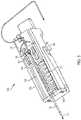
- FIG. 1illustrates a needle mechanism or needle mechanism module 100.
- the needle mechanism module 100can be a component or part of a drug delivery device such as, for example, an on-body or wearable drug delivery device.
- the needle mechanism module 100can automatically insert a fluid path component into a patient to facilitate drug delivery.
- the needle mechanism module 100can insert and retract an introducer needle and can leave a soft cannula in the patient.
- the soft cannula and retracted introducer needlecan form a portion of the fluid path component coupling a liquid drug stored within the drug delivery device to the patient.
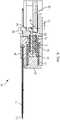
- FIG. 1shows a side cross-sectional view of the needle mechanism module 100.
- the needle mechanism module 100can include a rail housing component 102, a slide insert component 104, a slide retract component 106, a hard stop component 108, an insert spring 110, a retract spring 112, a tension lock component 114, a needle 116, a cannula 118, a lock component 120, and a rail beam component 126.
- FIG. 1illustrates the needle mechanism module 100 prior to activation. That is, FIG. 1 illustrates the needle mechanism module 100 in an initial operational state prior to insertion and retraction of the needle 116.
- the slide insert 104 and the slide retract 106are coupled together and spaced apart from the hard stop 108.
- the hard stop 108can be positioned at a first end of the rail 102.
- the slide insert 104 and the slide retract 106can be positioned at a second, opposite end of the rail 102.
- the position of the hard stop 108can be fixed.
- the slide insert 104 and the slide retract 106can move along and within the rail 102 when not locked to the position shown in FIG. 1 as described further herein.
- the insert spring 110can be an extension spring.
- the insert spring 110can be coupled to the hard stop 108 and to the slide insert 104.
- the insert spring 110can be configured to be biased so as to draw or bring the slide insert 104 and the slide retract 106 toward the hard stop 108.
- the lock 120can be configured to prevent the insert spring 110 from moving the slide insert 104 and the slide retract 106 toward the hard stop 108.
- the lock 120can be coupled to or positioned adjacent to a portion of the slide insert 104.
- the arrangement of the lock 120 and the slide insert 104 as shown in FIG. 1can prevent or block the slide insert 104 (and the coupled slide retract 106) from moving toward the hard stop 108.
- the rail beam 126as further described herein, can be coupled to the rail 102 and can restrict downward movement of the tension lock 114 as described herein.
- the needle 116e.g., an introducer needle
- the cannula 118e.g., a soft cannula
- the needle 116can be positioned inside of the cannula 118 such that the cannula 118 fits over and around a portion of the needle 116.
- the slide insert 104can include a pocket 122.
- An end portion or nail head 124 of the cannula 118can be positioned within the pocket 122.
- the end portion or nail head 124 of the cannula 118 and the pocket 122can be configured to hold or retain the cannula 118.
- the needle 116can extend beyond the slide retract 106 as shown.
- a portion of the needle 116 that extends beyond the slide retract 106can be a service loop of the needle 116.
- the service loop of the needle 116can allow the needle 116 to move forward for insertion (e.g., the service loop of the needle 116 can provide slack for when the needle 116 moves forward in a direction toward the hard stop 108 during insertion).
- the needle 116can be coupled to a liquid drug or other therapeutic agent stored by a wearable drug delivery device (e.g., stored in a reservoir).
- the needle 116 and the cannula 118can form the fluid path component (or a portion thereof) coupling the liquid drug to the patient.
- the stored liquid drugcan be provided to a patient by way of the needle 116 and the cannula 118 as described further herein.
- FIG. 2illustrates an exploded view of a portion of the needle mechanism module 100 depicted in FIG. 1 .
- the needle 116 and the cannula 118are not shown in FIG. 2 for simplicity and clarity.
- FIG. 2shows the arrangement of the constituent components of the needle mechanism module 100 described in relation to FIG. 1 .
- the hard stop 108can be attached to a first end of the rail 102.
- the rail 102can have an open center area to accommodate the other components of the needle mechanism module 100.
- the slide insert 104 and the slide retract 106can move along the open area of the rail 102 toward the hard stop 108.
- the spring 110can be coupled to the hard stop 108 and the slide insert 104.
- the tension lock component 114can be positioned to couple the slide insert 104 to the slide retract 106. Specifically, a first end of the tension lock component 114 can attached or coupled to a center portion of the slide insert 104 and a second, opposite end of the tension lock component 114 can extend beyond the slide retract 106.
- the second end of the tension lock component 114can be larger than the portion of the tension lock component 114 that connects the first and second ends of the tension lock component 114.
- the increased size of the second end of the tension lock component 114, in conjunction with the connection of the first end to the slide insert 104,can keep the slide inset 104 and slide retract 106 coupled closely together as shown.
- a portion of the spring 110can be positioned around the center portion of the slide insert 104.
- a portion of the center portion of the slide insert 104can be open along with a portion of a center portion of the slide retract 106.
- the spring 112can be positioned within these open areas of the slide insert 104 and the slide retract 106 as shown.
- the spring 112can be a compression spring.
- the tension lock component 114 and the rail beam 126can be positioned within these open areas as well.
- the spring 112can be positioned around the tension lock component 114 and the rail beam 126 as shown.
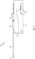
- FIG. 3illustrates an overhead side view of the needle mechanism module 100 as depicted in FIG. 1 .
- FIG. 3furthers shows the arrangement of the constituent components of the needle mechanism module 100 described in relation to FIG. 1 .
- the needle 116can be routed through the slide retract 106 and can extend beyond the slide retract 106.
- the needle 116can be shaped as desired to be routed through the drug delivery device to be coupled to the stored liquid drug (e.g., to an outlet of a reservoir storing the liquid drug). Further, the needle 116 can be wrapped around a notch or other feature in the slide retract 106 to allow it to move with the slide retract 106.
- the cannula 118is positioned around a portion of the needle 116.
- the nail head 124 of the cannula 118is directly attached to the slide insert 104.
- the needle 116is routed through this portion of the cannula 118 and through the slide insert 104. Accordingly, in various embodiments, the needle 116 is not directly attached to the slide insert 104.
- the needle 116can be directly attached to the slide retract 106 (e.g., attached to a notch or other coupling between the slide retract 106 and the needle 116).
- This arrangement of components and routing of the needle 116 relative to the cannula 118allows the needle 116 and the cannula 118 to both move together toward the hard stop 108 as the slide insert 104 and the slide retract 106 both move toward the hard stop 108 as further described herein. Further, this arrangement of components and routing of the needle 116 relative to the cannula 118 allows the cannula 118 to be held in a fixed, stationary position when the slide insert 104 is held in a fixed position as the slide retract 106 is moved back away from the hard stop 108, which causes the needle 116 to also move with the slide retract 106 and therefore away from the hard stop 108.
- thisenables the needle 116 and the cannula 118 to both be driven in a first direction to pierce a skin of a user and then to have the needle 116 be retracted out of the user in a second direction, leaving only the cannula 118 coupled to the user.
- FIG. 3also shows the open center area of the rail 102.
- FIG. 3shows a portion of the hard stop 108 extending into the open center of the rail 102 and the spring 110 coupled to the hard stop 108.
- the slide insert 104 and slide retract 106can include top portions that rest and can slide along rails 302.
- the rail component 102can be considered to be a housing that is generally rectangularly-shaped with an open center area.
- the perimeter of the sides of the open center areacan include rails 302 (positioned on either side of the open center area) that the slide insert 104 and the slide retract 106 can rest on and slide along.
- the rails 302can be lowered portions of the side walls of the rail component 102 as shown that provides a pathway of movement while allowing the side walls of the rail component 102 to stabilize the slide insert 104 and the slide retract 106.
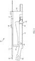
- FIG. 4illustrates a first side view of the needle mechanism module 100.
- FIG. 4illustrates a needle mechanism module lock 402 relative to the lock 120 (the lock 120 can be considered to be a needle mechanism module insert lock).
- a first end 404 of the needle mechanism module lock 402can be coupled to or positioned against or adjacent to the lock 120.
- the needle mechanism module lock 402can prevent the lock 120 from moving. Consequently, the needle mechanism module lock 402 and the lock 120 can prevent the release of the slide insert 104 such that the slide insert 104 and the coupled slide retract 106 are prevented from moving toward the hard stop 108.
- a second end 406 of the needle mechanism module lock 402can be engaged to move the needle mechanism module lock 402.
- the needle mechanism module lock 402can rotate or pivot about a pivot point 408 when the second end 406 is pushed in a downward direction (e.g., relative to the needle mechanism module 100 depicted in FIG. 4 ).
- the second end 406 of the needle mechanism module lock 402can be pushed in a downward direction by a purely mechanical mechanism or an electromechanical mechanism.
- a user of the drug delivery devicecan press a button to activate the drug delivery device with the second end 406 being pushed down in response thereto (e.g., the second end 406 can be coupled to the button).
- the first end 404can move upward in response by pivoting about the point 408 as described further herein.
- a user of the drug delivery device and/or the needle mechanism module 100can engage a user interface component to initiate activation of the needle mechanism module 100.
- the user interface componentcan be any type of component or mechanism for initiating an action based on user input including a button, a slide, a touchscreen, a dial, a knob, or a switch.
- FIG. 5illustrates the side view of the of the needle mechanism module 100 as depicted in FIG. 4 without the needle mechanism module lock 402 to further show the arrangement of the constituent components of the needle mechanism module 100.
- FIG. 5shows the arrangement of the lock 102 relative to the rail 102 and the slide insert 104.
- FIGs. 1-5depict the needle mechanism module 100 in an initial or pre-activation state. As can be seen, the needle 116 extends beyond the cannula 118 at an end of the needle mechanism module 100 near the hard stop 108. Further, the slide insert 104 and the slide retract 106 are positioned at the opposite end of the rail component 102.
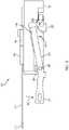
- FIG. 6illustrates release of the lock 120.
- FIG. 6illustrates engagement of the of the needle mechanism module lock 402 relative to the side view of the needle mechanism module 100 as depicted in FIG. 4 .
- indicator 602represents a downward movement of the second end 406 of the needle mechanism module lock 402.
- the second end 406 of the needle mechanism module lock 402can be moved downward, for example, in response to the user pressing a button to activate the drug delivery device and/or the needle mechanism module 100.
- the first end 404 of the needle mechanism module lock 402rotates upward about pivot 408.
- Indicator 604illustrates a movement of the first end 404 of the needle mechanism module lock 402 in response to the downward movement 602 of the first end 404.
- Movement of the needle mechanism module lock 402 as shown in FIG. 6decouples the needle mechanism module lock 402 from the lock 120.
- the first end 404 of the needle mechanism module lock 402is no longer adjacent to or positioned against the lock 120.
- the first end 404 of the needle mechanism module lock 402no longer restricts movement of the lock 120.
- the lock 120can be allowed to move.
- the lock 120can rotate (e.g., rotate counter-clockwise) as shown by indicator 606. This movement - as represented by indicator 606 - can represent releasing the lock 120.
- FIG. 6can represent the needle mechanism module 100 during initial activation - e.g., when a user first engages a button to fire or activate the needle mechanism module 100 and the slide insert 104 and the slide retract 106 first move toward the hard stop 108.
- the slide insert 104 and the slide retract 106have advanced toward the hard stop 108 from the opposite end of the rail 102.
- FIG. 7illustrates the side view of the of the needle mechanism module 100 as depicted in FIG. 6 without the needle mechanism module lock 402 to further show the arrangement of the constituent components of the needle mechanism module 100.
- FIG. 7shows the lock 120 as moved or rotated (e.g., in an unlocked or released position or state) after restriction of the movement of the lock 120 has been removed and relative to the initial position or state of the lock as depicted in, for example, FIG. 5 .
- FIGs. 6 and 7illustrate the needle mechanism module 100 during activation - e.g., when the lock 120 is released to enable movement of the slide insert 104 and the slide retract 106 toward the hard stop 108.
- FIG. 8illustrates further activation of the needle mechanism module 100.
- FIG. 8shows the needle mechanism module 100 as the slide insert 104 and the slide retract 106 as a coupled unit initial moves toward the hard stop 108 by action of the insertion spring 110.
- Indicator 802shows a direction of movement of the slide insert 104 and the slide retract 106 relative to their initial positions. Indicator 802 also shows the direction of movement of the needle 116 and the cannula 118.
- the slide insert 104 and the slide retract 106are positioned closer to the hard stop 108 relative to the positioning of the slide insert 104 and the slide react 106 as shown in FIG. 1 .
- the coils of the insert spring 110are shown to be closer together as the insert spring 108 exerts a force to draw the slide insert 104 to the hard stop 108.
- the needle 116 and the cannula 118move with the slide insert 104. As a result, the needle 116 can be moved toward the user and can be inserted into the patient.
- FIG. 8can represent a partial insertion of the needle 116 and can also represent partial insertion of the cannula 118.
- the slide insert 104 and the slide retract 106can continue moving in the direction 802 until the slide insert 104 meets the hard stop 108.
- the slide insert 104can continue moving in the direction 802 until the end of the tension lock component 114 is positioned adjacent to the hard stop 108.
- a portion of the needle 116can be further inserted into the patient (along with a portion of the cannula 118).
- FIG. 8shows a cross-sectional side view of the needle mechanism module 100.
- FIG. 9illustrates the needle mechanism module 100 with the needle 116 fully inserted into the patient (e.g., inserted to a maximum depth or by a maximum amount).
- a front portion or first end 902 of the tension lock 114is positioned against the hard stop 108.
- the hard stop 108prevents any further movement of the slide insert 104 when the first end 902 is so positioned.
- the movement of the slide insert 104 from its initial position (e.g., as shown in FIG. 1 ) to the position where the tension lock 114 is positioned against the hard stop 108can determine the fully inserted position of the needle 116.
- FIG. 9also illustrates a cross-sectional side view of the needle mechanism module 100.
- a second end or back portion 904 of the tension lock 114can extend beyond the rail beam 126.
- the tension lock 114is able to deflect downwards as shown by indicator 906.
- the slide retract 106can include an angled portion 908 in proximity to the interface of the slide retract 106 and the tension lock 114. The angled portion 908 at this interface can cause or help the tension lock 114 to be pushed or deflected downward based on a force provide by the retract spring 112.
- the retract spring 112can be biased to push the side insert 104 and the slide retract 106 apart but can be prevented from doing so while the tension lock component 114 is positioned over and/or adjacent to the rail beam 126.
- the tension lock component 114may no longer function to keep the slide insert 104 and the slide retract 106 coupled together as described herein.
- FIG. 9can represent the needle mechanism module 100 when the needle 116 is fully inserted into the patient and just prior to retraction of the needle 116.
- FIG. 10illustrates the needle mechanism module 100 during an initial stage of retraction of the needle 116.
- the tension lock 114is deflected downward (e.g., relative to the position of the tension lock 114 as shown in FIG. 9 ).
- the tension lock 114retains the slide retract 106 against the slide insert 104.
- the slide retract 106is capable of being removed from or decoupled from the slide insert 104 by a movement or force of the retract spring 112.
- the spring 112can begin to expand to force the tension lock portion 904 downward as the spring 112 begins to push the slide retract away from the hard stop 108 and the slide insert 104.
- FIG. 10illustrates the needle mechanism module 100 just prior to the slide retract 106 moving away from the slide insert 104 (e.g., in a direction away from the hard stop 108). Further, FIG. 10 can represent an operation state of the needle mechanism module 100 with the cannula 118 inserted into the patient or user.
- FIG. 11illustrates the needle mechanism module 100 during retraction. Specifically, FIG. 11 illustrates the needle mechanism module 100 during a partially retracted state of the needle 116 relative to the position of the needle 116 as shown in FIG. 9 .
- the slide retract 106is moving away from the needle insert 104 in a direction 1102.
- the expansion of the retract spring 112can cause the slide retract 106 to move in the direction 1102 relative to the stationary slide insert 104 which remains positioned against the hard stop 108.
- the needle 116is retracted inside of the cannula 118 (e.g., as it moves in the direction 1102 with the slide retract 106) while the cannula 118 remains stationary (and coupled to the slide insert 104).
- the needle 116can be removed from the patient and the cannula 118 can remain inside of the patient, maintaining the fluid path component from the stored liquid drug to the patient.
- the slide retract 106can continue moving in the direction 1102 until the retract spring 112 is expanded further.
- FIG. 12illustrates the needle mechanism module 100 when the needle 116 is fully retracted.
- the retraction spring 110is more fully expanded.
- the slide retract 106is positioned at its furthest distance away from the slide insert 104.
- the slide retract 106can be positioned at a far end of the rail 102 opposite the end of the rail 102 coupled to the hard stop 108.
- the needle 116has retracted further inside of the cannula 118 relative to the position of the needle 116 as depicted in FIG. 11 . Meanwhile, the cannula 118 remains stationary and can be left inserted into the patient.
- FIG. 12can represent the needle mechanism module 100 after completion of the retraction of the needle 116.
- the stored liquid drugcan be provided to the patient by the fluid path component that can include the needle 116 and the cannula 118. A portion of the end of the cannula 118 that extends beyond the end of the needle 116 can be positioned within the patient.
- FIG. 13illustrates an overhead side view of the needle mechanism module 100 as depicted in FIG. 12 .
- FIG. 13illustrates the arrangement and positioning of the needle insert 104 and the needle retract 106 after retraction of the needle 116 is completed.
- a complete fluid pathis provided to the patient through coupling of the needle 116 to a stored liquid drug, the coupling of the needle 116 to the cannula 118, and the coupling the cannula 118 to the patient.
- the slide insert 104is positioned against the hard stop 108 at a first end of the rail 102.
- the slide retract 106is positioned at an opposite end of the rail 102.
- the retract spring 112can maintain the separation of the slide insert 104 and the slide retract 106 as shown in FIG. 13 .
- FIG. 14illustrates a close-up view of the hard stop 108.
- the hard stop 108can include a first portion 1402 and a second portion 1404.
- the first portion 1402can extend from the second portion 1404.
- the second portion 1404can be a base portion.
- the first portn 1402can be a cylindrically-shaped portion that extends from the second portion 1404.
- the first portion 1402can include one or more components 1406 positioned along the first portion 1402.
- the components 1406can extend radially from the first portion 1402.
- the components 1406can be used to hold or retain an end of the insert spring 110.
- the base portion 1404can be coupled to an end of the rail 102.
- the first portion 1402can extend into the open area of the rail 102.
- FIG. 15illustrates a close-up view of the slide insert 104.
- the slide insert 104can include a first portion 1502 and a second portion 1504.
- the first portion 1502can extend from the second portion 1504.
- the second portion 1504can be a base portion.
- the first portion 1502can be a cylindrically-shaped portion that extends from the second portion 1504.
- the first portion 1502can include one or more components 1506 positioned along the first portion 1502.
- the components 1506can extend radially from the first portion 1502.
- the components 1506can be used to hold or retain an end of the insert spring 110 (e.g., an end opposite the end of the insert spring 110 that is held in place by the components 1406 depicted in FIG. 14 ).
- the slide insert 104can further include a top portion 1508.
- the pocket or opening 122can be positioned on a top side of the top portion 1508. An underside of the top portion 1508 can rest and move along the rails 302 of the rail base component 102.
- the pocket 122can include a channel or opening allowing the needle 116 and cannula 118 to be positioned within it for stability.
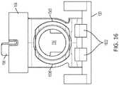
- FIGs. 16-18shows various views of the arrangement of the slide insert 104 and the slide retract 106 relative to the lock 120.
- FIG. 16shows a front view of the slide insert 104, slide retract 106, and the lock 120.
- FIG. 17shows a side view of the slide insert 104, slide retract 106, and the lock 120.
- FIG. 18shows a view of the of the slide insert 104, slide retract 106, and the lock 120 at an angle - e.g., an angle between the views shown in FIGs. 16 and 17 .
- FIGs. 16-18show the lock 120 in an initial locked position.
- the lock 120can include interior raised components 1602.
- the components 1602can restrict movement of the slide insert 104. Prior to the lock 102 being rotated as described above, the components 1602 can be positioned against a portion of the slide insert 104 and can restrict the movement of the slide insert 104. Once the lock 120 is rotated, the components 1602 can be moved away from and out of contact with the slide insert 104. As a result, the slide insert 104 is no longer restricted from moving, enabling the needle 116 of the needle mechanism module 100 to be inserted as described above.
- FIG. 19illustrates an exemplary method of operation 1900 for inserting a needle into a patient and then retracting the needle from the patient while maintaining a cannula coupled to the patient.
- the method of operation 1900can be implemented by the needle mechanism module 100.
- a lock 120 of the needle mechanism module 100can be released.
- the lock 120can be released in any number of manners.
- the lock 120can be released by engaging a needle mechanism module lock 402.
- the needle mechanism module lock 402can be engaged directly by a user or indirectly by a user.
- the mechanism module lock 402can respond to mechanical or electrical engagement by a user pressing a button. Releasing the lock 120 can no longer restrict movement of a slide insert 104 and a slide retract 106.
- the slide insert 104 and the slide retract 106can be driven toward the patient.
- a spring 110 coupled to a hard stop 108 and coupled to the slide insert 104can be biased to bring the slide insert 104 toward the hard stop 108 once the lock 102 is released.
- the slide retract 106can be coupled to the slide insert 104 so as to move toward the hard stop 108 when the lock 102 is released.
- the hard stop 108can be attached to a far end of a rail housing component 102, opposite an end from which the slide insert 104 and the slide retract 106 are initially positioned.
- a needle 116 and a cannula 118can be coupled to the slide insert 104 and can both be advanced toward the patient as the slide insert 104 is advanced toward the hard stop 108.
- the movement of the needle 116 and the cannula 118 toward the patientcan eventually cause the needle 116 to pierce the patient, allowing the needle 116 and/or the cannula 118 to enter the patient.
- the slide insert 104can reach the hard stop 108.
- the needle 116 and the cannula 118are prevented from further entering the patient. Accordingly, a maximum insertion depth of the needle 116 and/or the cannula 118 can be reached.
- a tension lock component 114can extend beyond a rail beam 126.
- the tension lock component 114can maintain a coupling or attachment between the slide insert 104 and the slide retract 106 as long as the rail beam 126 is positioned adjacent to the tension lock component 114.
- the rail beam 126can be stationary while the tension lock component 114 can be coupled to the slide insert 104 and the slide retract 106.
- the tension lock component 114moves along the rail beam 126.
- the tension lock component 114can move beyond the rail beam 126, such that the tension lock component 114 and the rail beam component 126 are no longer overlapping or adjacent to one another.
- the tension lock component 114can be bent downward in response to expansion of a spring 112.
- the spring 112can be coupled between the slide insert 104 and the slide retract 106.
- the spring 112can be prevented from expanding when the tension lock component 114 is not able to be bent or deflected downwards, thereby ensuring the slide insert 104 and the slide retract 106 are maintained in close proximity or coupled closely together.
- the spring 112can expand.
- the spring 112can force the slide retract 106 to move away from the slide insert 104.
- the slide insert 104can remain stationary and pressed against the hard stop 108 as the slide retract moves back toward the opposite end of the rail housing component 102.
- the movement of the slide retract 106 away from the hard stop 108can retract the needle 116.
- the needle 116can be retracted out of the patient.
- the cannula 118can remain coupled inside of the patient as it is coupled to the slide insert 104. Accordingly, at 1908, the needle 116 can be retracted from the patient without disturbing the positioning of the cannula 118 which is inserted into the patient at 1906.
- the slide retract 106can reach the far end of the rail housing component 102.
- the needle 116can be fully retracted from the user while the slide insert 104 and the cannula 118 remain stationary, with the cannula 118 remining inserted into the user.
Landscapes
- Health & Medical Sciences (AREA)
- Heart & Thoracic Surgery (AREA)
- Vascular Medicine (AREA)
- Engineering & Computer Science (AREA)
- Anesthesiology (AREA)
- Biomedical Technology (AREA)
- Hematology (AREA)
- Life Sciences & Earth Sciences (AREA)
- Animal Behavior & Ethology (AREA)
- General Health & Medical Sciences (AREA)
- Public Health (AREA)
- Veterinary Medicine (AREA)
- Dermatology (AREA)
- Infusion, Injection, And Reservoir Apparatuses (AREA)
Description
- Embodiments generally relate to medication delivery. More particularly, embodiments relate to automatic insertion of a fluid path component into a patient for drug delivery.
- Conventional on-body or wearable drug delivery devices (e.g., infusion devices or pumps) often require manual insertion of a needle into the user to provide a fluid path from a liquid drug stored in the drug delivery device to the user. Many users dislike the manual needle insertion required by these conventional drug delivery devices. Further, many users may not insert the needle properly, thereby leading to inefficient or improper use of the conventional drug delivery device.
- Document
US 2013/060233 A1 discloses a needle mechanism module comprising an insert extension spring and a retract compression spring used to extend or retract the needle. - Accordingly, there is a need for a drug delivery device that provides for automatic insertion of a fluid path component into the user that reduces the discomfort of the user while preventing any user error.
- The present disclosure relates to a needle mechanism module as defined in claim 1. The dependent claims define preferred embodiments of the needle mechanism module.
- Additional details and features are described in reference to the drawings and the detailed description as follows.
FIG. 1 illustrates a first cross-sectional side view of an exemplary needle mechanism module.FIG. 2 illustrates an exploded view of a portion of the needle mechanism module depicted inFIG. 1 .FIG. 3 illustrates an overhead side view of the needle mechanism module depicted inFIG. 1 .FIG. 4 illustrates a first side view of the needle mechanism module depicted inFIG. 1 .FIG. 5 illustrates a second side view of the needle mechanism module depicted inFIG. 1 .FIG. 6 illustrates a third side view of the needle mechanism module depicted inFIG. 1 .FIG. 7 illustrates a fourth side view of the needle mechanism module depicted inFIG. 1 .FIG. 8 illustrates a second cross-sectional side view of the needle mechanism module during insertion of a needle and a cannula.FIG. 9 illustrates a third cross-sectional side view of the needle mechanism module during insertion of the needle and the cannula.FIG. 10 illustrates a fourth cross-sectional side view of the needle mechanism module during retraction of the needle.FIG. 11 illustrates a fifth cross-sectional side view of the needle mechanism module during retraction of the needle.FIG. 12 illustrates a sixth cross-sectional side view of the needle mechanism module after retraction of the needle.FIG. 13 illustrates an overhead side view of the needle mechanism module depicted inFIG. 12 .FIG. 14 illustrates a first component of the needle mechanism module.FIG. 15 illustrates a second component of the needle mechanism module.FIG. 16 illustrates a front view of various components of the needle insertion mechanism.FIG. 17 illustrates a side view of the various components of the needle insertion mechanism depicted inFIG. 16 .FIG. 18 illustrates an angled view of the various components of the needle insertion mechanism depicted inFIG. 16 .FIG. 19 illustrates a method of operation for the needle mechanism module depicted inFIG. 1 .- This disclosure presents various systems, components, and methods related to a drug delivery device and, in particular, a needle mechanism module for automatically inserting and retracting a needle. Each of the systems, components, and methods disclosed herein provides one or more advantages over conventional systems, components, and methods.
- Various embodiments include a needle mechanism module for automatically inserting a needle and a cannula into a patient or user and retracting the needle, thereby leaving the cannula in the patient for the delivery of a drug from a wearable or on-body drug delivery device of which the needle mechanism module can be a component.
- In various embodiments, the needle mechanism module can insert a fluid path component or portion thereof into a patient automatically for drug delivery. In an on-body delivery system (e.g., a wearable drug delivery system), automatic insertion of the fluid path component into the patient can reduce fear and/or pain that may be experienced by the user and may also minimize user error. The needle mechanism module can further improve patient comfort by retracting the introducer needle and leaving only a soft cannula in the patient. In various embodiments, the needle is never seen by the patient, as it is initially inside the drug delivery device and automatically retracts back into the device upon insertion. The quick action of a spring-loaded insertion mechanism can minimize the amount of time the needle is in the patient and may decrease pain as compared with a manual insertion of a needle. Further, retraction of the needle back into the device provides sharps protection when the drug delivery device is removed from the user. The needle mechanism module can be provided as a standalone component, and so is highly transferable for use in different device designs. Other embodiments are disclosed and described.
FIG. 1 illustrates a needle mechanism orneedle mechanism module 100. Theneedle mechanism module 100 can be a component or part of a drug delivery device such as, for example, an on-body or wearable drug delivery device. Theneedle mechanism module 100 can automatically insert a fluid path component into a patient to facilitate drug delivery. In various embodiments, theneedle mechanism module 100 can insert and retract an introducer needle and can leave a soft cannula in the patient. The soft cannula and retracted introducer needle can form a portion of the fluid path component coupling a liquid drug stored within the drug delivery device to the patient.FIG. 1 shows a side cross-sectional view of theneedle mechanism module 100. As shown inFIG. 1 , theneedle mechanism module 100 can include arail housing component 102, aslide insert component 104, aslide retract component 106, ahard stop component 108, aninsert spring 110, aretract spring 112, atension lock component 114, aneedle 116, acannula 118, alock component 120, and arail beam component 126.FIG. 1 illustrates theneedle mechanism module 100 prior to activation. That is,FIG. 1 illustrates theneedle mechanism module 100 in an initial operational state prior to insertion and retraction of theneedle 116.- As shown in
FIG. 1 , theslide insert 104 and theslide retract 106 are coupled together and spaced apart from thehard stop 108. Thehard stop 108 can be positioned at a first end of therail 102. Theslide insert 104 and theslide retract 106 can be positioned at a second, opposite end of therail 102. The position of thehard stop 108 can be fixed. The slide insert 104 and theslide retract 106 can move along and within therail 102 when not locked to the position shown inFIG. 1 as described further herein. Theinsert spring 110 can be an extension spring. Theinsert spring 110 can be coupled to thehard stop 108 and to theslide insert 104. Theinsert spring 110 can be configured to be biased so as to draw or bring theslide insert 104 and theslide retract 106 toward thehard stop 108. Thelock 120 can be configured to prevent theinsert spring 110 from moving theslide insert 104 and theslide retract 106 toward thehard stop 108. As shown inFIG. 1 , thelock 120 can be coupled to or positioned adjacent to a portion of theslide insert 104. The arrangement of thelock 120 and theslide insert 104 as shown inFIG. 1 can prevent or block the slide insert 104 (and the coupled slide retract 106) from moving toward thehard stop 108. Therail beam 126, as further described herein, can be coupled to therail 102 and can restrict downward movement of thetension lock 114 as described herein. - As shown in
FIG. 1 , the needle 116 (e.g., an introducer needle) and the cannula 118 (e.g., a soft cannula) can be coupled to theslide insert 104. Theneedle 116 can be positioned inside of thecannula 118 such that thecannula 118 fits over and around a portion of theneedle 116. Theslide insert 104 can include apocket 122. An end portion ornail head 124 of thecannula 118 can be positioned within thepocket 122. The end portion ornail head 124 of thecannula 118 and thepocket 122 can be configured to hold or retain thecannula 118. Theneedle 116 can extend beyond the slide retract 106 as shown. A portion of theneedle 116 that extends beyond the slide retract 106 can be a service loop of theneedle 116. The service loop of theneedle 116 can allow theneedle 116 to move forward for insertion (e.g., the service loop of theneedle 116 can provide slack for when theneedle 116 moves forward in a direction toward thehard stop 108 during insertion). Theneedle 116 can be coupled to a liquid drug or other therapeutic agent stored by a wearable drug delivery device (e.g., stored in a reservoir). Theneedle 116 and thecannula 118 can form the fluid path component (or a portion thereof) coupling the liquid drug to the patient. The stored liquid drug can be provided to a patient by way of theneedle 116 and thecannula 118 as described further herein. FIG. 2 illustrates an exploded view of a portion of theneedle mechanism module 100 depicted inFIG. 1 . Theneedle 116 and thecannula 118 are not shown inFIG. 2 for simplicity and clarity.FIG. 2 shows the arrangement of the constituent components of theneedle mechanism module 100 described in relation toFIG. 1 .- Referring to
FIGs. 1 and2 , thehard stop 108 can be attached to a first end of therail 102. Therail 102 can have an open center area to accommodate the other components of theneedle mechanism module 100. When not locked into the position shown inFIG. 1 , theslide insert 104 and the slide retract 106 can move along the open area of therail 102 toward thehard stop 108. Thespring 110 can be coupled to thehard stop 108 and theslide insert 104. Thetension lock component 114 can be positioned to couple theslide insert 104 to the slide retract 106. Specifically, a first end of thetension lock component 114 can attached or coupled to a center portion of theslide insert 104 and a second, opposite end of thetension lock component 114 can extend beyond the slide retract 106. The second end of thetension lock component 114 can be larger than the portion of thetension lock component 114 that connects the first and second ends of thetension lock component 114. The increased size of the second end of thetension lock component 114, in conjunction with the connection of the first end to theslide insert 104, can keep theslide inset 104 and slide retract 106 coupled closely together as shown. - A portion of the
spring 110 can be positioned around the center portion of theslide insert 104. A portion of the center portion of theslide insert 104 can be open along with a portion of a center portion of the slide retract 106. Thespring 112 can be positioned within these open areas of theslide insert 104 and the slide retract 106 as shown. Thespring 112 can be a compression spring. Thetension lock component 114 and therail beam 126 can be positioned within these open areas as well. Thespring 112 can be positioned around thetension lock component 114 and therail beam 126 as shown. FIG. 3 illustrates an overhead side view of theneedle mechanism module 100 as depicted inFIG. 1 .FIG. 3 furthers shows the arrangement of the constituent components of theneedle mechanism module 100 described in relation toFIG. 1 . As shown inFIG. 3 , theneedle 116 can be routed through the slide retract 106 and can extend beyond the slide retract 106. Theneedle 116 can be shaped as desired to be routed through the drug delivery device to be coupled to the stored liquid drug (e.g., to an outlet of a reservoir storing the liquid drug). Further, theneedle 116 can be wrapped around a notch or other feature in the slide retract 106 to allow it to move with the slide retract 106.- Referring to
FIGs. 1 and3 , thecannula 118 is positioned around a portion of theneedle 116. Thenail head 124 of thecannula 118 is directly attached to theslide insert 104. Theneedle 116 is routed through this portion of thecannula 118 and through theslide insert 104. Accordingly, in various embodiments, theneedle 116 is not directly attached to theslide insert 104. Theneedle 116 can be directly attached to the slide retract 106 (e.g., attached to a notch or other coupling between the slide retract 106 and the needle 116). This arrangement of components and routing of theneedle 116 relative to thecannula 118 allows theneedle 116 and thecannula 118 to both move together toward thehard stop 108 as theslide insert 104 and the slide retract 106 both move toward thehard stop 108 as further described herein. Further, this arrangement of components and routing of theneedle 116 relative to thecannula 118 allows thecannula 118 to be held in a fixed, stationary position when theslide insert 104 is held in a fixed position as the slide retract 106 is moved back away from thehard stop 108, which causes theneedle 116 to also move with the slide retract 106 and therefore away from thehard stop 108. As described further herein, this enables theneedle 116 and thecannula 118 to both be driven in a first direction to pierce a skin of a user and then to have theneedle 116 be retracted out of the user in a second direction, leaving only thecannula 118 coupled to the user. FIG. 3 also shows the open center area of therail 102. In particular,FIG. 3 shows a portion of thehard stop 108 extending into the open center of therail 102 and thespring 110 coupled to thehard stop 108. Theslide insert 104 and slide retract 106 can include top portions that rest and can slide along rails 302. In various embodiments, therail component 102 can be considered to be a housing that is generally rectangularly-shaped with an open center area. The perimeter of the sides of the open center area can include rails 302 (positioned on either side of the open center area) that theslide insert 104 and the slide retract 106 can rest on and slide along. Therails 302 can be lowered portions of the side walls of therail component 102 as shown that provides a pathway of movement while allowing the side walls of therail component 102 to stabilize theslide insert 104 and the slide retract 106.FIG. 4 illustrates a first side view of theneedle mechanism module 100.FIG. 4 illustrates a needlemechanism module lock 402 relative to the lock 120 (thelock 120 can be considered to be a needle mechanism module insert lock). Afirst end 404 of the needlemechanism module lock 402 can be coupled to or positioned against or adjacent to thelock 120. The needlemechanism module lock 402 can prevent thelock 120 from moving. Consequently, the needlemechanism module lock 402 and thelock 120 can prevent the release of theslide insert 104 such that theslide insert 104 and the coupled slide retract 106 are prevented from moving toward thehard stop 108.- A
second end 406 of the needlemechanism module lock 402 can be engaged to move the needlemechanism module lock 402. In various embodiments, the needlemechanism module lock 402 can rotate or pivot about apivot point 408 when thesecond end 406 is pushed in a downward direction (e.g., relative to theneedle mechanism module 100 depicted inFIG. 4 ). Thesecond end 406 of the needlemechanism module lock 402 can be pushed in a downward direction by a purely mechanical mechanism or an electromechanical mechanism. In various embodiments, a user of the drug delivery device can press a button to activate the drug delivery device with thesecond end 406 being pushed down in response thereto (e.g., thesecond end 406 can be coupled to the button). In turn, thefirst end 404 can move upward in response by pivoting about thepoint 408 as described further herein. - In various embodiments, a user of the drug delivery device and/or the
needle mechanism module 100 can engage a user interface component to initiate activation of theneedle mechanism module 100. The user interface component can be any type of component or mechanism for initiating an action based on user input including a button, a slide, a touchscreen, a dial, a knob, or a switch. FIG. 5 illustrates the side view of the of theneedle mechanism module 100 as depicted inFIG. 4 without the needlemechanism module lock 402 to further show the arrangement of the constituent components of theneedle mechanism module 100.FIG. 5 shows the arrangement of thelock 102 relative to therail 102 and theslide insert 104.FIGs. 1-5 depict theneedle mechanism module 100 in an initial or pre-activation state. As can be seen, theneedle 116 extends beyond thecannula 118 at an end of theneedle mechanism module 100 near thehard stop 108. Further, theslide insert 104 and the slide retract 106 are positioned at the opposite end of therail component 102.FIG. 6 illustrates release of thelock 120.FIG. 6 illustrates engagement of the of the needlemechanism module lock 402 relative to the side view of theneedle mechanism module 100 as depicted inFIG. 4 . As shown inFIG. 6 ,indicator 602 represents a downward movement of thesecond end 406 of the needlemechanism module lock 402. Thesecond end 406 of the needlemechanism module lock 402 can be moved downward, for example, in response to the user pressing a button to activate the drug delivery device and/or theneedle mechanism module 100. In response to thedownward movement 602 of thesecond end 406 of the needlemechanism module lock 402, thefirst end 404 of the needlemechanism module lock 402 rotates upward aboutpivot 408.Indicator 604 illustrates a movement of thefirst end 404 of the needlemechanism module lock 402 in response to thedownward movement 602 of thefirst end 404.- Movement of the needle
mechanism module lock 402 as shown inFIG. 6 decouples the needlemechanism module lock 402 from thelock 120. In particular, thefirst end 404 of the needlemechanism module lock 402 is no longer adjacent to or positioned against thelock 120. As a result, thefirst end 404 of the needlemechanism module lock 402 no longer restricts movement of thelock 120. Accordingly, thelock 120 can be allowed to move. In various embodiments, thelock 120 can rotate (e.g., rotate counter-clockwise) as shown byindicator 606. This movement - as represented by indicator 606 - can represent releasing thelock 120. - After movement of the
lock 120, the slide insert 104 (and the coupled slide retract 106) can be free to move - for example, toward thehard stop 108 as described further herein and as shown inFIG. 6. FIG. 6 can represent theneedle mechanism module 100 during initial activation - e.g., when a user first engages a button to fire or activate theneedle mechanism module 100 and theslide insert 104 and the slide retract 106 first move toward thehard stop 108. For example, as shown inFIG. 6 , theslide insert 104 and the slide retract 106 have advanced toward thehard stop 108 from the opposite end of therail 102. FIG. 7 illustrates the side view of the of theneedle mechanism module 100 as depicted inFIG. 6 without the needlemechanism module lock 402 to further show the arrangement of the constituent components of theneedle mechanism module 100.FIG. 7 shows thelock 120 as moved or rotated (e.g., in an unlocked or released position or state) after restriction of the movement of thelock 120 has been removed and relative to the initial position or state of the lock as depicted in, for example,FIG. 5 .FIGs. 6 and7 illustrate theneedle mechanism module 100 during activation - e.g., when thelock 120 is released to enable movement of theslide insert 104 and the slide retract 106 toward thehard stop 108.FIG. 8 illustrates further activation of theneedle mechanism module 100. In particular,FIG. 8 shows theneedle mechanism module 100 as theslide insert 104 and the slide retract 106 as a coupled unit initial moves toward thehard stop 108 by action of theinsertion spring 110.Indicator 802 shows a direction of movement of theslide insert 104 and the slide retract 106 relative to their initial positions.Indicator 802 also shows the direction of movement of theneedle 116 and thecannula 118.- As shown in
FIG. 8 , theslide insert 104 and the slide retract 106 are positioned closer to thehard stop 108 relative to the positioning of theslide insert 104 and the slide react 106 as shown inFIG. 1 . The coils of theinsert spring 110 are shown to be closer together as theinsert spring 108 exerts a force to draw theslide insert 104 to thehard stop 108. Theneedle 116 and thecannula 118 move with theslide insert 104. As a result, theneedle 116 can be moved toward the user and can be inserted into the patient.FIG. 8 can represent a partial insertion of theneedle 116 and can also represent partial insertion of thecannula 118. - The
slide insert 104 and the slide retract 106 can continue moving in thedirection 802 until theslide insert 104 meets thehard stop 108. In particular, theslide insert 104 can continue moving in thedirection 802 until the end of thetension lock component 114 is positioned adjacent to thehard stop 108. During the movement of theslide insert 104 toward thehard stop 108, a portion of theneedle 116 can be further inserted into the patient (along with a portion of the cannula 118).FIG. 8 shows a cross-sectional side view of theneedle mechanism module 100. FIG. 9 illustrates theneedle mechanism module 100 with theneedle 116 fully inserted into the patient (e.g., inserted to a maximum depth or by a maximum amount). As shown inFIG. 9 , a front portion orfirst end 902 of thetension lock 114 is positioned against thehard stop 108. Accordingly, thehard stop 108 prevents any further movement of theslide insert 104 when thefirst end 902 is so positioned. The movement of theslide insert 104 from its initial position (e.g., as shown inFIG. 1 ) to the position where thetension lock 114 is positioned against the hard stop 108 (e.g., as shown inFIG. 9 ) can determine the fully inserted position of theneedle 116.FIG. 9 also illustrates a cross-sectional side view of theneedle mechanism module 100.- When the
tension lock 114 is positioned against thehard stop 108 as shown inFIG. 9 , a second end orback portion 904 of thetension lock 114 can extend beyond therail beam 126. When theback portion 904 of thetension lock 114 extends beyond thebeam 126, thetension lock 114 is able to deflect downwards as shown byindicator 906. Further, the slide retract 106 can include anangled portion 908 in proximity to the interface of the slide retract 106 and thetension lock 114. Theangled portion 908 at this interface can cause or help thetension lock 114 to be pushed or deflected downward based on a force provide by the retractspring 112. - In particular, the retract
spring 112 can be biased to push theside insert 104 and the slide retract 106 apart but can be prevented from doing so while thetension lock component 114 is positioned over and/or adjacent to therail beam 126. When thetension lock component 114 moves far enough toward thehard stop 108 to no longer be positioned over therail beam 126, thetension lock component 114 may no longer function to keep theslide insert 104 and the slide retract 106 coupled together as described herein.FIG. 9 can represent theneedle mechanism module 100 when theneedle 116 is fully inserted into the patient and just prior to retraction of theneedle 116. FIG. 10 illustrates theneedle mechanism module 100 during an initial stage of retraction of theneedle 116. As shown inFIG. 10 , thetension lock 114 is deflected downward (e.g., relative to the position of thetension lock 114 as shown inFIG. 9 ). Prior to being deflected downward, thetension lock 114 retains the slide retract 106 against theslide insert 104. When theback portion 904 of thetension lock 114 is no longer over top of therail beam 126, therail beam 126 no longer restricts the downward movement of thetension lock 114. When thetension lock 114 moves downward, the slide retract 106 is capable of being removed from or decoupled from theslide insert 104 by a movement or force of the retractspring 112. In various embodiments, thespring 112 can begin to expand to force thetension lock portion 904 downward as thespring 112 begins to push the slide retract away from thehard stop 108 and theslide insert 104.FIG. 10 illustrates theneedle mechanism module 100 just prior to the slide retract 106 moving away from the slide insert 104 (e.g., in a direction away from the hard stop 108). Further,FIG. 10 can represent an operation state of theneedle mechanism module 100 with thecannula 118 inserted into the patient or user.FIG. 11 illustrates theneedle mechanism module 100 during retraction. Specifically,FIG. 11 illustrates theneedle mechanism module 100 during a partially retracted state of theneedle 116 relative to the position of theneedle 116 as shown inFIG. 9 . As shown inFIG. 11 , the slide retract 106 is moving away from theneedle insert 104 in adirection 1102. The expansion of the retractspring 112 can cause the slide retract 106 to move in thedirection 1102 relative to thestationary slide insert 104 which remains positioned against thehard stop 108. As shown inFIG. 11 , theneedle 116 is retracted inside of the cannula 118 (e.g., as it moves in thedirection 1102 with the slide retract 106) while thecannula 118 remains stationary (and coupled to the slide insert 104). As a result of the movement of the slide retract 106 and theneedle 116 coupled thereto, theneedle 116 can be removed from the patient and thecannula 118 can remain inside of the patient, maintaining the fluid path component from the stored liquid drug to the patient. The slide retract 106 can continue moving in thedirection 1102 until the retractspring 112 is expanded further.FIG. 12 illustrates theneedle mechanism module 100 when theneedle 116 is fully retracted. As shown inFIG. 12 , theretraction spring 110 is more fully expanded. The slide retract 106 is positioned at its furthest distance away from theslide insert 104. For example, the slide retract 106 can be positioned at a far end of therail 102 opposite the end of therail 102 coupled to thehard stop 108. Theneedle 116 has retracted further inside of thecannula 118 relative to the position of theneedle 116 as depicted inFIG. 11 . Meanwhile, thecannula 118 remains stationary and can be left inserted into the patient.FIG. 12 can represent theneedle mechanism module 100 after completion of the retraction of theneedle 116. The stored liquid drug can be provided to the patient by the fluid path component that can include theneedle 116 and thecannula 118. A portion of the end of thecannula 118 that extends beyond the end of theneedle 116 can be positioned within the patient.FIG. 13 illustrates an overhead side view of theneedle mechanism module 100 as depicted inFIG. 12 .FIG. 13 illustrates the arrangement and positioning of theneedle insert 104 and the needle retract 106 after retraction of theneedle 116 is completed. As shown inFIG. 13 , a complete fluid path is provided to the patient through coupling of theneedle 116 to a stored liquid drug, the coupling of theneedle 116 to thecannula 118, and the coupling thecannula 118 to the patient. Theslide insert 104 is positioned against thehard stop 108 at a first end of therail 102. The slide retract 106 is positioned at an opposite end of therail 102. The retractspring 112 can maintain the separation of theslide insert 104 and the slide retract 106 as shown inFIG. 13 .FIG. 14 illustrates a close-up view of thehard stop 108. As shown inFIG. 14 , thehard stop 108 can include afirst portion 1402 and asecond portion 1404. Thefirst portion 1402 can extend from thesecond portion 1404. Thesecond portion 1404 can be a base portion. Thefirst portn 1402 can be a cylindrically-shaped portion that extends from thesecond portion 1404. As further shown inFIG. 14 , thefirst portion 1402 can include one ormore components 1406 positioned along thefirst portion 1402. Thecomponents 1406 can extend radially from thefirst portion 1402. Thecomponents 1406 can be used to hold or retain an end of theinsert spring 110. Thebase portion 1404 can be coupled to an end of therail 102. Thefirst portion 1402 can extend into the open area of therail 102.FIG. 15 illustrates a close-up view of theslide insert 104. As shown inFIG. 15 , theslide insert 104 can include afirst portion 1502 and asecond portion 1504. Thefirst portion 1502 can extend from thesecond portion 1504. Thesecond portion 1504 can be a base portion. Thefirst portion 1502 can be a cylindrically-shaped portion that extends from thesecond portion 1504. As further shown inFIG. 15 , thefirst portion 1502 can include one ormore components 1506 positioned along thefirst portion 1502. Thecomponents 1506 can extend radially from thefirst portion 1502. Thecomponents 1506 can be used to hold or retain an end of the insert spring 110 (e.g., an end opposite the end of theinsert spring 110 that is held in place by thecomponents 1406 depicted inFIG. 14 ).- The
slide insert 104 can further include atop portion 1508. The pocket or opening 122 can be positioned on a top side of thetop portion 1508. An underside of thetop portion 1508 can rest and move along therails 302 of therail base component 102. Thepocket 122 can include a channel or opening allowing theneedle 116 andcannula 118 to be positioned within it for stability. FIGs. 16-18 shows various views of the arrangement of theslide insert 104 and the slide retract 106 relative to thelock 120.FIG. 16 shows a front view of theslide insert 104, slide retract 106, and thelock 120.FIG. 17 shows a side view of theslide insert 104, slide retract 106, and thelock 120.FIG. 18 shows a view of the of theslide insert 104, slide retract 106, and thelock 120 at an angle - e.g., an angle between the views shown inFIGs. 16 and17 .FIGs. 16-18 show thelock 120 in an initial locked position.- As shown in
FIGs. 16-18 , thelock 120 can include interior raisedcomponents 1602. Thecomponents 1602 can restrict movement of theslide insert 104. Prior to thelock 102 being rotated as described above, thecomponents 1602 can be positioned against a portion of theslide insert 104 and can restrict the movement of theslide insert 104. Once thelock 120 is rotated, thecomponents 1602 can be moved away from and out of contact with theslide insert 104. As a result, theslide insert 104 is no longer restricted from moving, enabling theneedle 116 of theneedle mechanism module 100 to be inserted as described above. FIG. 19 illustrates an exemplary method ofoperation 1900 for inserting a needle into a patient and then retracting the needle from the patient while maintaining a cannula coupled to the patient. The method ofoperation 1900 can be implemented by theneedle mechanism module 100.- At 1902, a
lock 120 of theneedle mechanism module 100 can be released. Thelock 120 can be released in any number of manners. In various embodiments, thelock 120 can be released by engaging a needlemechanism module lock 402. The needlemechanism module lock 402 can be engaged directly by a user or indirectly by a user. For example, themechanism module lock 402 can respond to mechanical or electrical engagement by a user pressing a button. Releasing thelock 120 can no longer restrict movement of aslide insert 104 and a slide retract 106. - At 1904, the
slide insert 104 and the slide retract 106 can be driven toward the patient. Aspring 110 coupled to ahard stop 108 and coupled to theslide insert 104 can be biased to bring theslide insert 104 toward thehard stop 108 once thelock 102 is released. The slide retract 106 can be coupled to theslide insert 104 so as to move toward thehard stop 108 when thelock 102 is released. Thehard stop 108 can be attached to a far end of arail housing component 102, opposite an end from which theslide insert 104 and the slide retract 106 are initially positioned. - A
needle 116 and acannula 118 can be coupled to theslide insert 104 and can both be advanced toward the patient as theslide insert 104 is advanced toward thehard stop 108. The movement of theneedle 116 and thecannula 118 toward the patient can eventually cause theneedle 116 to pierce the patient, allowing theneedle 116 and/or thecannula 118 to enter the patient. - At 1906, the
slide insert 104 can reach thehard stop 108. When theslide insert 104 reaches thehard stop 108, theneedle 116 and thecannula 118 are prevented from further entering the patient. Accordingly, a maximum insertion depth of theneedle 116 and/or thecannula 118 can be reached. Further, when theslide insert 104 reaches thehard stop 108, atension lock component 114 can extend beyond arail beam 126. Thetension lock component 114 can maintain a coupling or attachment between theslide insert 104 and the slide retract 106 as long as therail beam 126 is positioned adjacent to thetension lock component 114. Therail beam 126 can be stationary while thetension lock component 114 can be coupled to theslide insert 104 and the slide retract 106. Accordingly, as theslide insert 104 and the slide retract 106 move toward thehard stop 108, thetension lock component 114 moves along therail beam 126. Eventually, when theslide inset 104 reaches thehard stop 108, thetension lock component 114 can move beyond therail beam 126, such that thetension lock component 114 and therail beam component 126 are no longer overlapping or adjacent to one another. - At 1908, since the
tension lock component 114 no longer overlaps thestationary rail beam 126, thetension lock component 114 can be bent downward in response to expansion of aspring 112. Thespring 112 can be coupled between theslide insert 104 and the slide retract 106. Thespring 112 can be prevented from expanding when thetension lock component 114 is not able to be bent or deflected downwards, thereby ensuring theslide insert 104 and the slide retract 106 are maintained in close proximity or coupled closely together. Once thetension lock component 114 clears therail beam 126 and is free to be deflected downwards, thespring 112 can expand. As thespring 112 expands, thespring 112 can force the slide retract 106 to move away from theslide insert 104. In particular, theslide insert 104 can remain stationary and pressed against thehard stop 108 as the slide retract moves back toward the opposite end of therail housing component 102. - The movement of the slide retract 106 away from the
hard stop 108 can retract theneedle 116. Theneedle 116 can be retracted out of the patient. Thecannula 118 can remain coupled inside of the patient as it is coupled to theslide insert 104. Accordingly, at 1908, theneedle 116 can be retracted from the patient without disturbing the positioning of thecannula 118 which is inserted into the patient at 1906. - At 1910, the slide retract 106 can reach the far end of the
rail housing component 102. Theneedle 116 can be fully retracted from the user while theslide insert 104 and thecannula 118 remain stationary, with thecannula 118 remining inserted into the user. - Certain embodiments of the present invention were described above. It is, however, expressly noted that the present invention is not limited to those embodiments, but rather the intention is that additions and modifications to what was expressly described herein are also included within the scope of the invention. Moreover, it is to be understood that the features of the various embodiments described herein were not mutually exclusive and can exist in various combinations and permutations, even if such combinations or permutations were not made express herein. A s such, the invention is defined in the appended claims.
Claims (11)
- A needle mechanism module (100), comprising:a rail housing component (102);a slide insert component (104) coupled to the rail housing component (102) and configured to slide along the rail housing component (102);a slide retract component (106) coupled to the rail housing component (102) and configured to slide along the rail housing component (102);a hard stop component (108) coupled to a first end of the rail housing component (102), the slide insert component (104) and the slide retract component (106) positioned toward a second, opposite end of the rail housing component (102), the slide insert component (104) positioned closer to the hard stop component (108);an insert extension spring (110) coupled to the hard stop component (108) and to the slide insert component (104);a retract compression spring (112) positioned between the slide insert component (104) and the slide retract component (106);a tension lock component (114) positioned through the slide insert component (104) and the slide retract component (106) and configured to couple the slide insert component (104) to the slide retract component (106);an insert lock (120) positioned against the slide insert component (104) and configured to restrict movement of the slide insert component (104) and the slide retract component (106) toward the hard stop (108) by the insert spring (110);a needle (116) coupled to the slide insert component (104) and the slide retract component (106), the needle (116) further coupled to a liquid drug stored in a reservoir of a wearable drug delivery device; anda cannula (118) surrounding a portion of the needle (116) extending from the slide insert component (104), an end of the cannula (118) coupled to the slide insert component (104).
- The needle mechanism module (100) of claim 1, further comprising a needle mechanism module lock (402) coupled to the insert lock (120), the needle mechanism module lock (402) configured to restrict movement of the insert lock (120).
- The needle mechanism module (100) of claim 2, wherein the needle mechanism module lock (402) is coupled to a push button.
- The needle mechanism module (100) of claim 3, wherein the needle mechanism module (100) is configured to remain in an idle state until a user engages the push button.
- The needle mechanism module (100) of claim 4, wherein the needle mechanism module lock (402) is configured to allow movement of the insert lock (120) responsive to the user engaging the push button.
- The needle mechanism module (100) of claim 5, wherein the insert lock (120) is configured to rotate when allowed to move and to allow movement of the slide insert component (104) and the slide retract component (106).
- The needle mechanism module (100) of claim 6, wherein the slide insert component (104) and the slide retract component (106) are configured to move along the rail housing component (102) toward the hard stop component (108) when allowed to move based on a force provided by the insert extension spring (110).
- The needle mechanism module (100) of claim 7, wherein the needle (116) and the cannula (118) are configured to move with the slide insert component (104) and the slide retract component (106) and are configured to be inserted into the user as the slide insert component (104) and the slide retract component (106) move toward the hard stop component (108).
- The needle mechanism module (100) of claim 8, wherein when the tension lock component (114) meets the hard stop component (108), an end of the tension lock component (114) positioned furthest from the hard stop component (108) is configured to deflect downward to enable the retract compression spring (112) to expand, wherein prior to the tension lock component (114) meeting the hard stop component (108), a rail beam (126) of the rail housing component (102) is configured to prevent the end of the tension lock component (114) from deflecting downward.
- The needle mechanism module (100) of claim 9, wherein the needle (116) is inserted into the user by a maximum amount when the tension lock component (114) meets the hard stop component (108).
- The needle mechanism module (100) of claim 10, wherein the slide insert component (104) and the cannula (118) remain stationary and the slide retract component (106) and the needle (116) retract away from the hard stop component (108) toward the second end of the rail housing component (102) as the retract compression spring (112) expands, thereby removing the needle (116) from the user and leaving the cannula (118) in the user.
Applications Claiming Priority (2)
| Application Number | Priority Date | Filing Date | Title |
|---|---|---|---|
| US201762563327P | 2017-09-26 | 2017-09-26 | |
| PCT/US2018/052464WO2019067367A1 (en) | 2017-09-26 | 2018-09-24 | Needle mechanism module for drug delivery device |
Publications (2)
| Publication Number | Publication Date |
|---|---|
| EP3687600A1 EP3687600A1 (en) | 2020-08-05 |
| EP3687600B1true EP3687600B1 (en) | 2022-04-27 |
Family
ID=63858115
Family Applications (1)
| Application Number | Title | Priority Date | Filing Date |
|---|---|---|---|
| EP18786539.9AActiveEP3687600B1 (en) | 2017-09-26 | 2018-09-24 | Needle mechanism module for drug delivery device |
Country Status (3)
| Country | Link |
|---|---|
| US (2) | US10898656B2 (en) |
| EP (1) | EP3687600B1 (en) |
| WO (1) | WO2019067367A1 (en) |
Families Citing this family (10)
| Publication number | Priority date | Publication date | Assignee | Title |
|---|---|---|---|---|
| EP1762259B2 (en) | 2005-09-12 | 2025-01-01 | Unomedical A/S | Inserter for an infusion set with a first and second spring units |
| WO2012123274A1 (en) | 2011-03-14 | 2012-09-20 | Unomedical A/S | Inserter system with transport protection |
| IL295010B1 (en) | 2015-03-10 | 2025-06-01 | Regeneron Pharma | Pollution-free piercing system and method |
| CN119950880A (en) | 2017-05-05 | 2025-05-09 | 里珍纳龙药品有限公司 | Auto-injectors and related methods of use |
| EP3687600B1 (en)* | 2017-09-26 | 2022-04-27 | Insulet Corporation | Needle mechanism module for drug delivery device |
| US11458292B2 (en) | 2019-05-20 | 2022-10-04 | Unomedical A/S | Rotatable infusion device and methods thereof |
| EP4179241A4 (en) | 2020-07-07 | 2024-04-03 | Cam Med Inc. | ELECTROCHEMICAL ACTUATORS AND ACTUATOR NETWORKS |
| US11419976B1 (en) | 2021-04-30 | 2022-08-23 | Fresenius Kabi Deutschland Gmbh | Wearable drug delivery device with pressurized fluid dispensing |
| USD1007676S1 (en) | 2021-11-16 | 2023-12-12 | Regeneron Pharmaceuticals, Inc. | Wearable autoinjector |
| CN115300069B (en)* | 2022-06-06 | 2025-07-11 | 乐普(北京)医疗器械股份有限公司 | A driving mechanism of a cannula needle return device and a cannula needle return device |
Family Cites Families (317)
| Publication number | Priority date | Publication date | Assignee | Title |
|---|---|---|---|---|
| US410817A (en) | 1889-09-10 | Carrying apparatus | ||
| US315727A (en) | 1885-04-14 | Odometer for vehicles | ||
| US405524A (en) | 1889-06-18 | Whip-socket | ||
| US303013A (en) | 1884-08-05 | Pen-holder | ||
| US306691A (en) | 1884-10-14 | Cord-holder for assisting in tying plants | ||
| US5338157B1 (en) | 1992-09-09 | 1999-11-02 | Sims Deltec Inc | Systems and methods for communicating with ambulat |
| US5935099A (en) | 1992-09-09 | 1999-08-10 | Sims Deltec, Inc. | Drug pump systems and methods |
| DE420595C (en) | 1924-08-07 | 1925-10-27 | Berlin Karlsruher Ind Werke A | Measuring device with tapered mandrel for tapered bores |
| US2667986A (en) | 1951-12-22 | 1954-02-02 | Harold N Perelson | Self-sealing dispensing device |
| GB875034A (en) | 1957-07-01 | 1961-08-16 | Renault | Improvements in or relating to valves for fluids under pressure |
| US3631847A (en) | 1966-03-04 | 1972-01-04 | James C Hobbs | Method and apparatus for injecting fluid into the vascular system |
| US3792703A (en) | 1972-07-10 | 1974-02-19 | Deseret Pharma | Catheter placement unit |
| US3841328A (en) | 1972-08-04 | 1974-10-15 | J Jensen | Airplane hijacking injector |
| US3812843A (en) | 1973-03-12 | 1974-05-28 | Lear Siegler Inc | Method and apparatus for injecting contrast media into the vascular system |
| US3885662A (en) | 1973-12-26 | 1975-05-27 | Ibm | Steerable follower selection mechanism |
| US4067000A (en) | 1976-05-28 | 1978-01-03 | Rca Corporation | Remote control transmitter with an audible battery life indicator |
| US4273122A (en) | 1976-11-12 | 1981-06-16 | Whitney Douglass G | Self contained powered injection system |
| US4152098A (en) | 1977-01-03 | 1979-05-01 | Clark Ivan P | Micropump |
| DE2738155A1 (en) | 1977-08-24 | 1979-03-08 | Stierlen Maquet Ag | REMOTE CONTROL ARRANGEMENT FOR A MEDICAL DEVICE |
| DE2738406A1 (en) | 1977-08-25 | 1979-03-08 | Stierlen Maquet Ag | PROCEDURE AND REMOTE CONTROL ARRANGEMENT FOR REMOTE CONTROL OF A MEDICAL DEVICE |
| US4151845A (en) | 1977-11-25 | 1979-05-01 | Miles Laboratories, Inc. | Blood glucose control apparatus |
| US4193397A (en) | 1977-12-01 | 1980-03-18 | Metal Bellows Corporation | Infusion apparatus and method |
| US4559037A (en) | 1977-12-28 | 1985-12-17 | Siemens Aktiengesellschaft | Device for the pre-programmable infusion of liquids |
| US4261388A (en) | 1978-05-19 | 1981-04-14 | Frenshore Ltd. | Drop rate controller |
| US4276170A (en) | 1978-08-16 | 1981-06-30 | Critikon, Inc. | Vented flexible filtration device for use in administering parenteral liquids |
| US4373527B1 (en) | 1979-04-27 | 1995-06-27 | Univ Johns Hopkins | Implantable programmable medication infusion system |
| WO1981001658A1 (en) | 1979-12-13 | 1981-06-25 | M Loeb | Wearable insulin infusion system having a tubular reservoir and a positive displacement metering means |
| US4268150A (en) | 1980-01-28 | 1981-05-19 | Laurence Chen | Disposable camera with simplified film advance and indicator |
| CA1169323A (en) | 1980-06-03 | 1984-06-19 | Anthony M. Albisser | Insulin infusion device |
| AU546785B2 (en) | 1980-07-23 | 1985-09-19 | Commonwealth Of Australia, The | Open-loop controlled infusion of diabetics |
| US4346385A (en) | 1980-09-18 | 1982-08-24 | Bell Telephone Laboratories, Incorporated | Microwave antenna height prediction |
| US4559033A (en) | 1980-10-27 | 1985-12-17 | University Of Utah Research Foundation | Apparatus and methods for minimizing peritoneal injection catheter obstruction |
| US4424720A (en) | 1980-12-15 | 1984-01-10 | Ivac Corporation | Mechanism for screw drive and syringe plunger engagement/disengagement |
| US4364385A (en) | 1981-03-13 | 1982-12-21 | Lossef Steven V | Insulin delivery device |
| JPS57163309A (en) | 1981-04-01 | 1982-10-07 | Olympus Optical Co Ltd | Capsule apparatus for medical use |
| JPS57211361A (en) | 1981-06-23 | 1982-12-25 | Terumo Corp | Liquid injecting apparatus |
| US4529401A (en) | 1982-01-11 | 1985-07-16 | Cardiac Pacemakers, Inc. | Ambulatory infusion pump having programmable parameters |
| US4435173A (en) | 1982-03-05 | 1984-03-06 | Delta Medical Industries | Variable rate syringe pump for insulin delivery |
| US4498843A (en) | 1982-08-02 | 1985-02-12 | Schneider Philip H | Insulin infusion pump |
| US4551134A (en) | 1982-08-06 | 1985-11-05 | Nuvatec, Inc. | Intravenous set |
| US4514732A (en) | 1982-08-23 | 1985-04-30 | General Electric Company | Technique for increasing battery life in remote control transmitters |
| US4624661A (en) | 1982-11-16 | 1986-11-25 | Surgidev Corp. | Drug dispensing system |
| DE3314664C2 (en) | 1983-04-22 | 1985-02-21 | B. Braun Melsungen Ag, 3508 Melsungen | Procedure for triggering a pre-alarm in a pressure infusion apparatus |
| US4781693A (en) | 1983-09-02 | 1988-11-01 | Minntech Corporation | Insulin dispenser for peritoneal cavity |
| DE3468173D1 (en) | 1983-09-07 | 1988-02-04 | Disetronic Ag | Portable infusion apparatus |
| US4743243A (en) | 1984-01-03 | 1988-05-10 | Vaillancourt Vincent L | Needle with vent filter assembly |
| US4685903A (en) | 1984-01-06 | 1987-08-11 | Pacesetter Infusion, Ltd. | External infusion pump apparatus |
| US4678408A (en) | 1984-01-06 | 1987-07-07 | Pacesetter Infusion, Ltd. | Solenoid drive apparatus for an external infusion pump |
| US4562751A (en) | 1984-01-06 | 1986-01-07 | Nason Clyde K | Solenoid drive apparatus for an external infusion pump |
| US4684368A (en) | 1984-06-01 | 1987-08-04 | Parker Hannifin Corporation | Inverted pump |
| US4855746A (en) | 1984-07-30 | 1989-08-08 | Zenith Electronics Corporation | Multiple device remote control transmitter |
| US4634427A (en) | 1984-09-04 | 1987-01-06 | American Hospital Supply Company | Implantable demand medication delivery assembly |
| CA1254091A (en) | 1984-09-28 | 1989-05-16 | Vladimir Feingold | Implantable medication infusion system |
| DK160633C (en) | 1985-05-15 | 1991-09-02 | Henning Munk Ejlersen | HOSE PUMP, ISSUE FOR EVENING AS INSULIN PUMP |
| US4755173A (en) | 1986-02-25 | 1988-07-05 | Pacesetter Infusion, Ltd. | Soft cannula subcutaneous injection set |
| US4778451A (en) | 1986-03-04 | 1988-10-18 | Kamen Dean L | Flow control system using boyle's law |
| US5349852A (en) | 1986-03-04 | 1994-09-27 | Deka Products Limited Partnership | Pump controller using acoustic spectral analysis |
| AT384737B (en) | 1986-04-04 | 1987-12-28 | Thoma Dipl Ing Dr Techn Herwig | DEVICE FOR CONTINUOUSLY DELIVERING LIQUID MEDICINAL PRODUCTS |
| CA1283827C (en) | 1986-12-18 | 1991-05-07 | Giorgio Cirelli | Appliance for injection of liquid formulations |
| GB8701731D0 (en) | 1987-01-27 | 1987-03-04 | Patcentre Benelux Nv Sa | Pumps |
| US4734092A (en) | 1987-02-18 | 1988-03-29 | Ivac Corporation | Ambulatory drug delivery device |
| EP0315656B1 (en) | 1987-05-18 | 1993-07-07 | Disetronic Ag | Infusion apparatus |
| US4898579A (en) | 1987-06-26 | 1990-02-06 | Pump Controller Corporation | Infusion pump |
| US4858619A (en) | 1987-06-29 | 1989-08-22 | Toth Marie A | Intracranial pressure monitoring system |
| US5189609A (en) | 1987-10-09 | 1993-02-23 | Hewlett-Packard Company | Medical monitoring system with softkey control |
| US4836752A (en) | 1987-11-02 | 1989-06-06 | Fisher Scientific Company | Partial restriction detector |
| US4898578A (en) | 1988-01-26 | 1990-02-06 | Baxter International Inc. | Drug infusion system with calculator |
| US4801957A (en) | 1988-02-18 | 1989-01-31 | Eastman Kodak Company | Disposable single-use camera and accessory re-usable electronic flash unit |
| US4994047A (en) | 1988-05-06 | 1991-02-19 | Menlo Care, Inc. | Multi-layer cannula structure |
| US4898585A (en) | 1988-05-18 | 1990-02-06 | Baxter Healthcare Corporation | Implantable patient-activated fluid delivery device with bolus injection port |
| US5062841A (en) | 1988-08-12 | 1991-11-05 | The Regents Of The University Of California | Implantable, self-regulating mechanochemical insulin pump |
| US4985016A (en) | 1989-02-15 | 1991-01-15 | Alza Corporation | Intravenous system for delivering a beneficial agent |
| IE62767B1 (en) | 1989-03-17 | 1995-02-22 | Baxter Int | Pre-slit injection site and tapered cannula |
| US4882600A (en) | 1989-04-07 | 1989-11-21 | Eastman Kodak Company | Underwater disposable single-use camera |
| US5205819A (en) | 1989-05-11 | 1993-04-27 | Bespak Plc | Pump apparatus for biomedical use |
| US5129891A (en) | 1989-05-19 | 1992-07-14 | Strato Medical Corporation | Catheter attachment device |
| US5411480A (en) | 1989-06-16 | 1995-05-02 | Science Incorporated | Fluid delivery apparatus |
| US5716343A (en) | 1989-06-16 | 1998-02-10 | Science Incorporated | Fluid delivery apparatus |
| US5045871A (en) | 1989-06-30 | 1991-09-03 | Reinholdson Mark R | Disposable camera |
| US4973998A (en) | 1990-01-16 | 1990-11-27 | Eastman Kodak Company | Disposable single-use camera and accessory re-usable electronic flash unit |
| US5109850A (en) | 1990-02-09 | 1992-05-05 | Massachusetts Institute Of Technology | Automatic blood monitoring for medication delivery method and apparatus |
| US5318540A (en) | 1990-04-02 | 1994-06-07 | Pharmetrix Corporation | Controlled release infusion device |
| US5492534A (en) | 1990-04-02 | 1996-02-20 | Pharmetrix Corporation | Controlled release portable pump |
| US5007458A (en) | 1990-04-23 | 1991-04-16 | Parker Hannifin Corporation | Poppet diaphragm valve |
| US5125415A (en) | 1990-06-19 | 1992-06-30 | Smiths Industries Medical Systems, Inc. | Syringe tip cap with self-sealing filter |
| JPH0451966A (en) | 1990-06-19 | 1992-02-20 | Toichi Ishikawa | Medical fluid continuous injector |
| US5176662A (en) | 1990-08-23 | 1993-01-05 | Minimed Technologies, Ltd. | Subcutaneous injection set with improved cannula mounting arrangement |
| TW279133B (en) | 1990-12-13 | 1996-06-21 | Elan Med Tech | |
| US5061424A (en) | 1991-01-22 | 1991-10-29 | Becton, Dickinson And Company | Method for applying a lubricious coating to an article |
| US5245447A (en) | 1991-05-20 | 1993-09-14 | Xerox Corporation | Indexing mechanism for compact scanner |
| US5213483A (en) | 1991-06-19 | 1993-05-25 | Strato Medical Corporation | Peristaltic infusion pump with removable cassette and mechanically keyed tube set |
| US5207645A (en) | 1991-06-25 | 1993-05-04 | Medication Delivery Devices | Infusion pump, treatment fluid bag therefor, and method for the use thereof |
| US5239326A (en) | 1991-08-07 | 1993-08-24 | Kabushiki Kaisha Senshukai | Film-loaded disposable camera |
| DE4129271C1 (en) | 1991-09-03 | 1992-09-17 | Fresenius Ag, 6380 Bad Homburg, De | |
| US5244463A (en) | 1991-12-06 | 1993-09-14 | Block Medical, Inc. | Programmable infusion pump |
| US5911716A (en) | 1992-01-24 | 1999-06-15 | I-Flow Corporation | Platen pump |
| US5267956A (en) | 1992-02-05 | 1993-12-07 | Alcon Surgical, Inc. | Surgical cassette |
| US5261884A (en) | 1992-04-29 | 1993-11-16 | Becton, Dickinson And Company | Syringe pump control system |
| US5346476A (en) | 1992-04-29 | 1994-09-13 | Edward E. Elson | Fluid delivery system |
| IE930532A1 (en) | 1993-07-19 | 1995-01-25 | Elan Med Tech | Liquid material dispenser and valve |
| US5254096A (en) | 1992-09-23 | 1993-10-19 | Becton, Dickinson And Company | Syringe pump with graphical display or error conditions |
| US5232439A (en) | 1992-11-02 | 1993-08-03 | Infusion Technologies Corporation | Method for pumping fluid from a flexible, variable geometry reservoir |
| US5342313A (en) | 1992-11-02 | 1994-08-30 | Infusion Technologies Corporation | Fluid pump for a flexible, variable geometry reservoir |
| GB9223084D0 (en) | 1992-11-04 | 1992-12-16 | Imp Cancer Res Tech | Compounds to target cells |
| US5433710A (en) | 1993-03-16 | 1995-07-18 | Minimed, Inc. | Medication infusion pump with fluoropolymer valve seat |
| DE4310808C2 (en) | 1993-04-02 | 1995-06-22 | Boehringer Mannheim Gmbh | Liquid dosing system |
| US5257980A (en) | 1993-04-05 | 1993-11-02 | Minimed Technologies, Ltd. | Subcutaneous injection set with crimp-free soft cannula |
| US5613956A (en) | 1993-05-07 | 1997-03-25 | C. R. Bard, Inc. | Catheter introducer |
| CA2132277C (en) | 1993-10-22 | 2005-05-10 | Giorgio Cirelli | Injection device |
| US5997501A (en) | 1993-11-18 | 1999-12-07 | Elan Corporation, Plc | Intradermal drug delivery device |
| JP3259267B2 (en) | 1993-12-28 | 2002-02-25 | ニプロ株式会社 | Chemical injection device |
| FR2716286A1 (en) | 1994-02-16 | 1995-08-18 | Debiotech Sa | Installation of remote monitoring of controllable equipment. |
| US5630710A (en) | 1994-03-09 | 1997-05-20 | Baxter International Inc. | Ambulatory infusion pump |
| US5643213A (en) | 1994-03-09 | 1997-07-01 | I-Flow Corporation | Elastomeric syringe actuation device |
| DE4415896A1 (en) | 1994-05-05 | 1995-11-09 | Boehringer Mannheim Gmbh | Analysis system for monitoring the concentration of an analyte in the blood of a patient |
| US5576781A (en) | 1994-05-16 | 1996-11-19 | Deleeuw; Paul | Disposable camera |
| US5685859A (en) | 1994-06-02 | 1997-11-11 | Nikomed Aps | Device for fixating a drainage tube and a drainage tube assembly |
| US5452033A (en) | 1994-06-06 | 1995-09-19 | Eastman Kodak Company | Single use photographic film package and camera |
| US5582593A (en) | 1994-07-21 | 1996-12-10 | Hultman; Barry W. | Ambulatory medication delivery system |
| JPH0858897A (en) | 1994-08-12 | 1996-03-05 | Japan Storage Battery Co Ltd | Fluid supply device |
| US5505709A (en) | 1994-09-15 | 1996-04-09 | Minimed, Inc., A Delaware Corporation | Mated infusion pump and syringe |
| CA2159052C (en) | 1994-10-28 | 2007-03-06 | Rainer Alex | Injection device |
| US5545152A (en) | 1994-10-28 | 1996-08-13 | Minimed Inc. | Quick-connect coupling for a medication infusion system |
| IE72524B1 (en) | 1994-11-04 | 1997-04-23 | Elan Med Tech | Analyte-controlled liquid delivery device and analyte monitor |
| US5637095A (en) | 1995-01-13 | 1997-06-10 | Minimed Inc. | Medication infusion pump with flexible drive plunger |
| US5665070A (en) | 1995-01-19 | 1997-09-09 | I-Flow Corporation | Infusion pump with magnetic bag compression |
| US5741228A (en) | 1995-02-17 | 1998-04-21 | Strato/Infusaid | Implantable access device |
| US5647853A (en) | 1995-03-03 | 1997-07-15 | Minimed Inc. | Rapid response occlusion detector for a medication infusion pump |
| US5503628A (en) | 1995-03-15 | 1996-04-02 | Jettek, Inc. | Patient-fillable hypodermic jet injector |
| US5575770A (en) | 1995-04-05 | 1996-11-19 | Therex Corporation | Implantable drug infusion system with safe bolus capability |
| PT821566E (en) | 1995-04-20 | 2004-03-31 | Acist Medical Sys Inc | ANGIOGRAPHIC INJECTOR |
| US5665065A (en) | 1995-05-26 | 1997-09-09 | Minimed Inc. | Medication infusion device with blood glucose data input |
| US5695490A (en) | 1995-06-07 | 1997-12-09 | Strato/Infusaid, Inc. | Implantable treatment material device |
| US5702363A (en) | 1995-06-07 | 1997-12-30 | Flaherty; J. Christopher | Septumless implantable treatment material device |
| US5584813A (en) | 1995-06-07 | 1996-12-17 | Minimed Inc. | Subcutaneous injection set |
| US5573342A (en) | 1995-06-20 | 1996-11-12 | Patalano; Christine S. | Body lotion applicator system |
| US5810015A (en) | 1995-09-01 | 1998-09-22 | Strato/Infusaid, Inc. | Power supply for implantable device |
| IE77523B1 (en) | 1995-09-11 | 1997-12-17 | Elan Med Tech | Medicament delivery device |
| EP0763369B1 (en) | 1995-09-18 | 2002-01-09 | Becton, Dickinson and Company | Needle shield with collapsible cover |
| US5726751A (en) | 1995-09-27 | 1998-03-10 | University Of Washington | Silicon microchannel optical flow cytometer |
| US5693018A (en) | 1995-10-11 | 1997-12-02 | Science Incorporated | Subdermal delivery device |
| US5779676A (en) | 1995-10-11 | 1998-07-14 | Science Incorporated | Fluid delivery device with bolus injection site |
| US5776103A (en) | 1995-10-11 | 1998-07-07 | Science Incorporated | Fluid delivery device with bolus injection site |
| US5800405A (en) | 1995-12-01 | 1998-09-01 | I-Flow Corporation | Syringe actuation device |
| WO1997033637A1 (en) | 1996-03-14 | 1997-09-18 | O'neil, Christine | Patient controllable drug delivery system flow regulating means |
| US5865806A (en) | 1996-04-04 | 1999-02-02 | Becton Dickinson And Company | One step catheter advancement automatic needle retraction system |
| US5976109A (en) | 1996-04-30 | 1999-11-02 | Medtronic, Inc. | Apparatus for drug infusion implanted within a living body |
| US5785688A (en) | 1996-05-07 | 1998-07-28 | Ceramatec, Inc. | Fluid delivery apparatus and method |
| US5726404A (en) | 1996-05-31 | 1998-03-10 | University Of Washington | Valveless liquid microswitch |
| IL118689A (en) | 1996-06-20 | 2000-10-31 | Gadot Amir | Intravenous infusion apparatus |
| DK0921840T3 (en) | 1996-07-03 | 2003-09-22 | Altea Therapeutics Corp | Multiple mechanical microperforation of skin or mucosa |
| EP0923335B1 (en) | 1996-07-08 | 2006-08-23 | Animas Corporation | Implantable sensor and system for in vivo measurement and control of fluid constituent levels |
| US5755682A (en) | 1996-08-13 | 1998-05-26 | Heartstent Corporation | Method and apparatus for performing coronary artery bypass surgery |
| JP3621204B2 (en) | 1996-08-20 | 2005-02-16 | 三菱製紙株式会社 | Curtain coating apparatus and coating method |
| US5748827A (en) | 1996-10-23 | 1998-05-05 | University Of Washington | Two-stage kinematic mount |
| US6883778B1 (en) | 1996-11-18 | 2005-04-26 | Nypro Inc. | Apparatus for reducing fluid drawback through a medical valve |
| US5886647A (en) | 1996-12-20 | 1999-03-23 | Badger; Berkley C. | Apparatus and method for wireless, remote control of multiple devices |
| US5851197A (en) | 1997-02-05 | 1998-12-22 | Minimed Inc. | Injector for a subcutaneous infusion set |
| US5858239A (en) | 1997-02-14 | 1999-01-12 | Aksys, Ltd. | Methods and apparatus for adjustment of blood drip chamber of dialysis machines using touchscreen interface |
| US5785681A (en) | 1997-02-25 | 1998-07-28 | Minimed Inc. | Flow rate controller for a medication infusion pump |
| US5875393A (en) | 1997-02-28 | 1999-02-23 | Randice-Lisa Altschul | Disposable wireless telephone and method |
| US5845218A (en) | 1997-02-28 | 1998-12-01 | Altschul; Randice-Lisa | Disposable wireless telephone and method |
| CH692240A5 (en) | 1997-03-26 | 2002-04-15 | Disetronic Licensing Ag | Catheter system for transdermal passage devices. |
| US5871470A (en) | 1997-04-18 | 1999-02-16 | Becton Dickinson And Company | Combined spinal epidural needle set |
| US6050978A (en) | 1997-05-09 | 2000-04-18 | Becton Dickinson And Company | Needleless valve connector |
| DE19723648C1 (en) | 1997-06-05 | 1998-08-27 | Disetronic Licensing Ag | Controlled infusion equipment with leak and reverse flow prevention used e.g. in insulin therapy |
| US5878539A (en) | 1997-06-09 | 1999-03-09 | Grubb; Dennis | Method and apparatus for a tubular skylight system |
| US7267665B2 (en) | 1999-06-03 | 2007-09-11 | Medtronic Minimed, Inc. | Closed loop system for controlling insulin infusion |
| US5954643A (en) | 1997-06-09 | 1999-09-21 | Minimid Inc. | Insertion set for a transcutaneous sensor |
| US5957890A (en) | 1997-06-09 | 1999-09-28 | Minimed Inc. | Constant flow medication infusion pump |
| US6500150B1 (en) | 1997-06-16 | 2002-12-31 | Elan Pharma International Limited | Pre-filled drug-delivery device and method of manufacture and assembly of same |
| US6071292A (en) | 1997-06-28 | 2000-06-06 | Transvascular, Inc. | Transluminal methods and devices for closing, forming attachments to, and/or forming anastomotic junctions in, luminal anatomical structures |
| US5965848A (en) | 1997-07-22 | 1999-10-12 | Randice-Lisa Altschul | Disposable portable electronic devices and method of making |
| US5957859A (en) | 1997-07-28 | 1999-09-28 | J. Peter Rosenfeld Ph.D. | Method and system for detection of deception using scaled P300 scalp amplitude distribution |
| US6527744B1 (en) | 1997-08-27 | 2003-03-04 | Science Incorporated | Fluid delivery device with light activated energy source |
| US5858005A (en) | 1997-08-27 | 1999-01-12 | Science Incorporated | Subcutaneous infusion set with dynamic needle |
| US5961492A (en) | 1997-08-27 | 1999-10-05 | Science Incorporated | Fluid delivery device with temperature controlled energy source |
| US6019747A (en) | 1997-10-21 | 2000-02-01 | I-Flow Corporation | Spring-actuated infusion syringe |
| US5983094A (en) | 1997-10-27 | 1999-11-09 | Randice-Lisa Altschul | Wireless telephone with credited airtime and method |
| US5989237A (en) | 1997-12-04 | 1999-11-23 | Baxter International Inc. | Sliding reconstitution device with seal |
| WO2000029047A1 (en) | 1998-11-18 | 2000-05-25 | Phiscience Gmbh, Entwicklung Von Sensoren | Portable device and method for the mobile supply of medicaments with wireless transmission of data for control or programming purposes |
| DE19920896A1 (en) | 1999-05-06 | 2000-11-09 | Phiscience Gmbh Entwicklung Vo | Portable unit for the supply of medicaments to a patient comprises a delivery unit connected to the patient by e.g. a catheter, and an operating unit which has wireless communication with the delivery unit |
| US5897530A (en) | 1997-12-24 | 1999-04-27 | Baxter International Inc. | Enclosed ambulatory pump |
| US6244776B1 (en) | 1998-01-05 | 2001-06-12 | Lien J. Wiley | Applicators for health and beauty products |
| ES2255155T3 (en) | 1998-02-05 | 2006-06-16 | Biosense Webster, Inc. | DEVICE FOR THE INTRACARDIAC ADMINISTRATION OF PHARMACOS. |
| US5957895A (en) | 1998-02-20 | 1999-09-28 | Becton Dickinson And Company | Low-profile automatic injection device with self-emptying reservoir |
| US5919167A (en) | 1998-04-08 | 1999-07-06 | Ferring Pharmaceuticals | Disposable micropump |
| US6126637A (en) | 1998-04-15 | 2000-10-03 | Science Incorporated | Fluid delivery device with collapsible needle cover |
| US6283944B1 (en) | 1998-04-30 | 2001-09-04 | Medtronic, Inc. | Infusion systems with patient-controlled dosage features |
| US5921419A (en) | 1998-05-04 | 1999-07-13 | Bracco Research Usa | Universal stopper |
| EP1082151A1 (en) | 1998-06-04 | 2001-03-14 | ELAN CORPORATION, Plc | Gas driven drug delivery device |
| US5906597A (en) | 1998-06-09 | 1999-05-25 | I-Flow Corporation | Patient-controlled drug administration device |
| US5954694A (en) | 1998-08-07 | 1999-09-21 | Embol-X, Inc. | Nested tubing sections and methods for making same |
| US6558320B1 (en) | 2000-01-20 | 2003-05-06 | Medtronic Minimed, Inc. | Handheld personal data assistant (PDA) with a medical device and method of using the same |
| US5993423A (en) | 1998-08-18 | 1999-11-30 | Choi; Soo Bong | Portable automatic syringe device and injection needle unit thereof |
| CA2345043C (en) | 1998-10-08 | 2009-08-11 | Minimed, Inc. | Telemetered characteristic monitor system |
| US6375639B1 (en) | 1998-10-09 | 2002-04-23 | Renee F. Duplessie | Intravenous stabilizing device |
| WO2000029049A1 (en) | 1998-11-13 | 2000-05-25 | Elan Pharma International Limited | Drug delivery systems and methods |
| WO2000030705A1 (en) | 1998-11-20 | 2000-06-02 | Novo Nordisk A/S | Injection needle |
| US6200338B1 (en) | 1998-12-31 | 2001-03-13 | Ethicon, Inc. | Enhanced radiopacity of peripheral and central catheter tubing |
| US6244778B1 (en) | 1999-01-21 | 2001-06-12 | Richard M. Chesbrough | Universal suction-based connection device |
| US6349740B1 (en) | 1999-04-08 | 2002-02-26 | Abbott Laboratories | Monolithic high performance miniature flow control unit |
| US6152898A (en) | 1999-04-30 | 2000-11-28 | Medtronic, Inc. | Overfill protection systems for implantable drug delivery devices |
| WO2000074751A1 (en) | 1999-06-08 | 2000-12-14 | Medical Research Group, Inc. | Method and apparatus for infusing liquids using a chemical reaction in an implanted infusion device |
| US6752787B1 (en) | 1999-06-08 | 2004-06-22 | Medtronic Minimed, Inc., | Cost-sensitive application infusion device |
| EP1191875A1 (en) | 1999-06-17 | 2002-04-03 | Medtronic MiniMed, Inc. | Characteristic monitor system for use with analyte sensor |
| WO2001056633A2 (en) | 2000-02-03 | 2001-08-09 | Medtronic, Inc. | Single-use therapeutic substance delivery device with infusion rate control |
| US7003336B2 (en) | 2000-02-10 | 2006-02-21 | Medtronic Minimed, Inc. | Analyte sensor method of making the same |
| US6572542B1 (en) | 2000-03-03 | 2003-06-03 | Medtronic, Inc. | System and method for monitoring and controlling the glycemic state of a patient |
| CA2401388C (en) | 2000-03-28 | 2009-09-08 | Elan Pharma International Limited | Device for measuring a volume of drug |
| US6485461B1 (en) | 2000-04-04 | 2002-11-26 | Insulet, Inc. | Disposable infusion device |
| US6699221B2 (en) | 2000-06-15 | 2004-03-02 | Vincent L. Vaillancourt | Bloodless catheter |
| US6475196B1 (en) | 2000-08-18 | 2002-11-05 | Minimed Inc. | Subcutaneous infusion cannula |
| CA2421133C (en) | 2000-09-08 | 2012-06-26 | Insulet Corporation | Devices, systems and methods for patient infusion |
| US6363609B1 (en) | 2000-10-20 | 2002-04-02 | Short Block Technologies, Inc. | Method and apparatus for aligning crankshaft sections |
| US6644944B2 (en) | 2000-11-06 | 2003-11-11 | Nanostream, Inc. | Uni-directional flow microfluidic components |
| ES2281457T3 (en) | 2000-11-09 | 2007-10-01 | Insulet Corporation | TRANSCUTANEOUS SUPPLY MEDIA. |
| US6666852B2 (en) | 2000-12-04 | 2003-12-23 | Bracco Diagnostics, Inc. | Axially activated vial access adapter |
| US20050187524A1 (en) | 2000-12-19 | 2005-08-25 | Willis Allan F. | Sealing valve assembly for medical products |
| JP4996015B2 (en) | 2001-03-12 | 2012-08-08 | メディキット株式会社 | Indwelling catheter |
| KR100407467B1 (en) | 2001-07-12 | 2003-11-28 | 최수봉 | Insulin pump operated by remote-controller |
| US6689100B2 (en) | 2001-10-05 | 2004-02-10 | Becton, Dickinson And Company | Microdevice and method of delivering or withdrawing a substance through the skin of an animal |
| US20040078028A1 (en) | 2001-11-09 | 2004-04-22 | Flaherty J. Christopher | Plunger assembly for patient infusion device |
| US6878136B2 (en) | 2002-02-28 | 2005-04-12 | Medical Product Specialists | Huber needle with anti-rebound safety mechanism |
| US6960192B1 (en) | 2002-04-23 | 2005-11-01 | Insulet Corporation | Transcutaneous fluid delivery system |
| US20050238507A1 (en) | 2002-04-23 | 2005-10-27 | Insulet Corporation | Fluid delivery device |
| US7160272B1 (en) | 2002-05-31 | 2007-01-09 | Elcam Plastic | Y-site medical valve |
| US20040010207A1 (en) | 2002-07-15 | 2004-01-15 | Flaherty J. Christopher | Self-contained, automatic transcutaneous physiologic sensing system |
| US7018360B2 (en) | 2002-07-16 | 2006-03-28 | Insulet Corporation | Flow restriction system and method for patient infusion device |
| CN1723053A (en) | 2002-09-12 | 2006-01-18 | 儿童医院医疗中心 | Method and device for painless drug injection |
| US7128727B2 (en) | 2002-09-30 | 2006-10-31 | Flaherty J Christopher | Components and methods for patient infusion device |
| US7144384B2 (en) | 2002-09-30 | 2006-12-05 | Insulet Corporation | Dispenser components and methods for patient infusion device |
| US7025744B2 (en) | 2002-10-04 | 2006-04-11 | Dsu Medical Corporation | Injection site for male luer or other tubular connector |
| ES2328806T3 (en) | 2002-10-11 | 2009-11-18 | Becton, Dickinson And Company | INSULIN RELEASE SYSTEM WITH SENSOR. |
| US20040088224A1 (en) | 2002-10-31 | 2004-05-06 | International Business Machines Corporation | Method and system for delivering commodities |
| US7142814B2 (en) | 2002-12-11 | 2006-11-28 | Shary Nassimi | Automatic Bluetooth inquiry mode headset |
| US7347839B2 (en) | 2003-02-12 | 2008-03-25 | Nipro Corporation | Indwelling catheter |
| US7354429B2 (en) | 2003-05-27 | 2008-04-08 | Integrated Sensing Systems, Inc. | Device and method for detecting and treating chemical and biological agents |
| WO2004093648A2 (en) | 2003-04-18 | 2004-11-04 | Insulet Corporation | User interface for infusion pump remote controller and method of using the same |
| MXPA05013437A (en) | 2003-06-09 | 2007-08-24 | Nipro Diabetes Systems Inc | Coupling system for an infusion pump. |
| WO2006053007A2 (en) | 2004-11-09 | 2006-05-18 | Angiotech Biocoatings Corp. | Antimicrobial needle coating for extended infusion |
| SI1729848T1 (en) | 2004-03-08 | 2015-08-31 | Ichor Medical Systems Inc. | Improved apparatus for electrically mediated delivery of therapeutic agents |
| US7416173B2 (en) | 2004-05-24 | 2008-08-26 | Tokai Rubber Industries, Ltd. | Pneumatically switchable type fluid-filled engine mount |
| US7600530B2 (en) | 2004-08-09 | 2009-10-13 | Medegen, Inc. | Connector with check valve and method of use |
| US7837646B2 (en) | 2004-09-30 | 2010-11-23 | Northeastern University | Hydrocephalus shunt system quick connector assembly |
| EP1831730A1 (en) | 2004-12-21 | 2007-09-12 | E.I. Dupont De Nemours And Company | Process for forming a patterned fluoropolymer film on a substrate |
| US7470237B2 (en) | 2005-01-10 | 2008-12-30 | Ethicon Endo-Surgery, Inc. | Biopsy instrument with improved needle penetration |
| US8167841B2 (en) | 2005-01-24 | 2012-05-01 | Novo Nordisk A/S | Transcutaneous device assembly |
| US20060178633A1 (en) | 2005-02-03 | 2006-08-10 | Insulet Corporation | Chassis for fluid delivery device |
| US20060204535A1 (en) | 2005-02-25 | 2006-09-14 | Johnson Johnnie M | Cell-friendly cannula and needle |
| US20060253085A1 (en) | 2005-05-06 | 2006-11-09 | Medtronic Minimed, Inc. | Dual insertion set |
| US7691086B2 (en) | 2005-06-14 | 2010-04-06 | Tengiz Tkebuchava | Catheter for introduction of medications to the tissues of a heart or other organ |
| WO2007014281A1 (en) | 2005-07-26 | 2007-02-01 | Colder Products Company | Coupling assembly with overmold sealing structures and method of forming the same |
| US20070112332A1 (en) | 2005-11-17 | 2007-05-17 | Becton, Dickinson And Company | Medical access device |
| US20070129690A1 (en) | 2005-12-02 | 2007-06-07 | Joel Rosenblatt | Catheter with polymeric coating |
| FR2894150B1 (en) | 2005-12-05 | 2008-01-04 | Ace Dev Solution Soc A Respons | CONNECTOR FOR MEDICAL USE |
| US20070173974A1 (en) | 2006-01-25 | 2007-07-26 | Chyi-Yeu Lin | Device and method for interacting with autonomous robot |
| AU2007218014A1 (en) | 2006-02-17 | 2007-08-30 | Alan L. Buchman | Catheter cleaning devices |
| US20070197163A1 (en) | 2006-02-23 | 2007-08-23 | Research In Motion Limited | Combination modes for network connection management |
| US20070282269A1 (en) | 2006-05-31 | 2007-12-06 | Seattle Medical Technologies | Cannula delivery apparatus and method for a disposable infusion device |
| US9119582B2 (en) | 2006-06-30 | 2015-09-01 | Abbott Diabetes Care, Inc. | Integrated analyte sensor and infusion device and methods therefor |
| US7562755B2 (en) | 2006-07-07 | 2009-07-21 | Dt Swiss, Inc. | Rear wheel hub, in particular for bicycles |
| US7682338B2 (en) | 2006-08-23 | 2010-03-23 | Medtronic Minimed, Inc. | Infusion medium delivery system, device and method with needle inserter and needle inserter device and method |
| US8561614B2 (en) | 2006-09-28 | 2013-10-22 | Covidien Lp | Multi-layer cuffs for medical devices |
| GB2443260C (en) | 2006-10-26 | 2017-11-29 | Cellnovo Ltd | Micro-valve |
| GB2456681B (en) | 2006-10-26 | 2009-11-11 | Starbridge Systems Ltd | Pump |
| US8377040B2 (en) | 2006-11-06 | 2013-02-19 | Becton, Dickinson And Company | Extravascular system venting |
| US20100152674A1 (en) | 2007-04-30 | 2010-06-17 | Medtronic Minimed, Inc | Needle inserting and fluid flow connection for infusion medium delivery system |
| JP5102350B2 (en) | 2007-04-30 | 2012-12-19 | メドトロニック ミニメド インコーポレイテッド | Reservoir filling / bubble management / infusion medium delivery system and method using the system |
| US8078787B2 (en) | 2007-06-22 | 2011-12-13 | Apple Inc. | Communication between a host device and an accessory via an intermediate device |
| US9968742B2 (en) | 2007-08-29 | 2018-05-15 | Medtronic Minimed, Inc. | Combined sensor and infusion set using separated sites |
| US7935076B2 (en) | 2007-09-07 | 2011-05-03 | Asante Solutions, Inc. | Activity sensing techniques for an infusion pump system |
| EP2200677A1 (en)* | 2007-09-17 | 2010-06-30 | ICU Medical, Inc. | Insertion devices for infusion devices |
| DE102007049446A1 (en) | 2007-10-16 | 2009-04-23 | Cequr Aps | Catheter introducer |
| US7918825B2 (en) | 2007-11-29 | 2011-04-05 | Insulet Corporation | Interfacing a prefilled syringe with an infusion pump to fill the infusion pump |
| WO2009098648A2 (en) | 2008-02-04 | 2009-08-13 | Nilimedix Ltd. | Drug delivery system with wireless monitor |
| WO2010030691A1 (en) | 2008-09-09 | 2010-03-18 | Pulmonx Corporation | Systems and methods for inhibiting secretion flow into a functional assessment catheter |
| US8303535B2 (en) | 2008-09-10 | 2012-11-06 | Hoffman-La Roche Inc. | Delivery device for use with a therapeutic drug |
| GB2464114B (en) | 2008-10-02 | 2012-06-13 | Cellnovo Ltd | Linear capacitive displacement sensor |
| US9370621B2 (en) | 2008-12-16 | 2016-06-21 | Medtronic Minimed, Inc. | Needle insertion systems and methods |
| US9375529B2 (en) | 2009-09-02 | 2016-06-28 | Becton, Dickinson And Company | Extended use medical device |
| WO2010111131A2 (en) | 2009-03-25 | 2010-09-30 | Borgwarner Inc. | Reduction of turbocharger core unbalance with centering device |
| EP2724739B1 (en) | 2009-07-30 | 2015-07-01 | Tandem Diabetes Care, Inc. | Portable infusion pump system |
| US8900190B2 (en) | 2009-09-02 | 2014-12-02 | Medtronic Minimed, Inc. | Insertion device systems and methods |
| US10911515B2 (en) | 2012-05-24 | 2021-02-02 | Deka Products Limited Partnership | System, method, and apparatus for electronic patient care |
| CA2788648A1 (en) | 2010-02-05 | 2011-08-11 | Sanofi-Aventis Deutschland Gmbh | Medicated module with time lock |
| US9662438B2 (en) | 2010-02-05 | 2017-05-30 | Deka Products Limited Partnership | Devices, methods and systems for wireless control of medical devices |
| IL211800A (en) | 2010-03-21 | 2014-03-31 | Isaac Zukier | Device for injecting fluids or gels |
| SG194370A1 (en) | 2010-06-07 | 2013-11-29 | Amgen Inc | Drug delivery device |
| DK2397181T3 (en) | 2010-06-18 | 2014-03-31 | Hoffmann La Roche | Insertion device with a permanently lockable and rotatable needle cover means |
| JP5592194B2 (en) | 2010-08-20 | 2014-09-17 | 三洋電機株式会社 | Battery pack |
| EP2436412A1 (en) | 2010-10-04 | 2012-04-04 | Unomedical A/S | A sprinkler cannula |
| WO2012061556A1 (en) | 2010-11-03 | 2012-05-10 | Flugen, Inc. | Wearable drug delivery device having spring drive and sliding actuation mechanism |
| JP6049640B2 (en) | 2011-02-09 | 2016-12-27 | ベクトン・ディキンソン・アンド・カンパニーBecton, Dickinson And Company | Insulin infusion set |
| ES2765024T3 (en) | 2011-02-09 | 2020-06-05 | Becton Dickinson Co | Foldable insert for drug delivery infusion set |
| CA2828873C (en) | 2011-02-09 | 2020-07-14 | Becton, Dickinson And Company | Infusion device with automatic insertion and introducer needle retraction |
| US8998851B2 (en) | 2011-02-09 | 2015-04-07 | Becton, Dickinson And Company | Compact spring inserter for drug deliver infusion set |
| US8308680B1 (en) | 2011-04-26 | 2012-11-13 | Medtronic Minimed, Inc. | Selective alarms for an infusion device |
| CA2845379C (en) | 2011-09-02 | 2019-08-06 | Unitract Syringe Pty Ltd | Insertion mechanism for a drug delivery pump |
| CN104023785B (en) | 2011-11-22 | 2017-03-01 | 贝克顿·迪金森公司 | Drug delivery system with delay mechanism |
| ES2666386T3 (en) | 2011-12-07 | 2018-05-04 | Becton, Dickinson And Company | Needle protection sets and infusion devices for use with them |
| US20130178791A1 (en) | 2012-01-09 | 2013-07-11 | Jonathan C. Javitt | Method and system for detecting and treating biological and chemical warfare agents |
| MY177292A (en) | 2012-03-07 | 2020-09-10 | Deka Products Lp | Infusion pump assembly |
| EP4406568A3 (en) | 2012-03-30 | 2024-10-16 | Insulet Corporation | Fluid delivery device with transcutaneous access tool, insertion mechanism and blood glucose monitoring for use therewith |
| EP2858699A1 (en)* | 2012-06-09 | 2015-04-15 | Roche Diagnostics GmbH | Disposable inserter for use with a medical device |
| CN108452399A (en) | 2012-06-18 | 2018-08-28 | 费森尤斯卡比德国有限公司 | Port intubation system for puncturing port catheter and external member |
| CA3126430C (en) | 2012-11-12 | 2023-03-07 | Empi, Inc. | Systems and methods for wireless pairing and communication for electro-stimulation |
| TWM452390U (en) | 2012-12-11 | 2013-05-01 | Dongguan Masstop Liquid Crystal Display Co Ltd | Active capacitive stylus |
| CN104870049B (en) | 2012-12-21 | 2018-06-08 | 3M创新有限公司 | Adhesive assembly and the micropin injection device including the adhesive assembly |
| BR112015022042B1 (en) | 2013-03-15 | 2023-01-10 | Amgen Inc | INJECTOR FOR INJECTING A THERAPEUTIC PRODUCT |
| AU2014274061C1 (en) | 2013-05-31 | 2019-06-13 | Mannkind Corporation | A fluid delivery device having an insertable prefilled cartridge |
| US10517892B2 (en) | 2013-10-22 | 2019-12-31 | Medtronic Minimed, Inc. | Methods and systems for inhibiting foreign-body responses in diabetic patients |
| CN204446979U (en) | 2013-12-01 | 2015-07-08 | 贝克顿·迪金森公司 | Device for establishing a sterile connection and medical device |
| WO2015097792A1 (en) | 2013-12-25 | 2015-07-02 | 富士通株式会社 | Pairing apparatus, pairing method, and pairing program |
| US10569014B2 (en) | 2015-03-02 | 2020-02-25 | Amgen Inc. | Device and method for making aseptic connections |
| US10363374B2 (en) | 2016-05-26 | 2019-07-30 | Insulet Corporation | Multi-dose drug delivery device |
| EP3687600B1 (en)* | 2017-09-26 | 2022-04-27 | Insulet Corporation | Needle mechanism module for drug delivery device |
- 2018
- 2018-09-24EPEP18786539.9Apatent/EP3687600B1/enactiveActive
- 2018-09-24WOPCT/US2018/052464patent/WO2019067367A1/ennot_activeCeased
- 2018-09-24USUS16/140,178patent/US10898656B2/enactiveActive
- 2020
- 2020-12-17USUS17/125,150patent/US11819675B2/enactiveActive
Also Published As
| Publication number | Publication date |
|---|---|
| US20190091417A1 (en) | 2019-03-28 |
| WO2019067367A1 (en) | 2019-04-04 |
| US11819675B2 (en) | 2023-11-21 |
| US20210100959A1 (en) | 2021-04-08 |
| EP3687600A1 (en) | 2020-08-05 |
| US10898656B2 (en) | 2021-01-26 |
Similar Documents
| Publication | Publication Date | Title |
|---|---|---|
| EP3687600B1 (en) | Needle mechanism module for drug delivery device | |
| US20230347072A1 (en) | Needle Protection Assembly | |
| ES2941650T3 (en) | Midline and long-term catheters and related assembly methods | |
| US7879010B2 (en) | Infusion set | |
| DK1383560T3 (en) | INFUSION | |
| EP2265308B1 (en) | Needle protection assembly with radially movable locking element | |
| CN101111279B (en) | Implant back-injecting device | |
| EP3220982B1 (en) | Medicament injection device | |
| US8460241B2 (en) | Needle protection assembly with locking element | |
| WO2006070358A3 (en) | Catheter placement device | |
| EP3341055A1 (en) | Medicament delivery device and assembly of electronic device and the medicament delivery device | |
| JP5149817B2 (en) | Injection needle including a medical device variably fixed to a needle holder | |
| CN109922848A (en) | Medicament delivery device suitable for long-term storage | |
| TW201840345A (en) | Injection device | |
| WO2016208725A1 (en) | Intraocular lens insertion instrument, intraocular lens extraction assistance tool, and method for manufacturing intraocular lens insertion instrument | |
| CN100509078C (en) | Injection device with extraction mechanism | |
| GB2515032A (en) | Guide for an injection device | |
| CN113365679A (en) | Cannula inserter | |
| JPWO2009035084A1 (en) | Lancet assembly | |
| CN109310857A (en) | Intubation device | |
| US20230109255A1 (en) | Needle assembly with extending safety shield | |
| EP3939636A1 (en) | Assistance instrument for syringe | |
| CN110650760A (en) | Injection device |
Legal Events
| Date | Code | Title | Description |
|---|---|---|---|
| STAA | Information on the status of an ep patent application or granted ep patent | Free format text:STATUS: UNKNOWN | |
| STAA | Information on the status of an ep patent application or granted ep patent | Free format text:STATUS: THE INTERNATIONAL PUBLICATION HAS BEEN MADE | |
| PUAI | Public reference made under article 153(3) epc to a published international application that has entered the european phase | Free format text:ORIGINAL CODE: 0009012 | |
| STAA | Information on the status of an ep patent application or granted ep patent | Free format text:STATUS: REQUEST FOR EXAMINATION WAS MADE | |
| 17P | Request for examination filed | Effective date:20200423 | |
| AK | Designated contracting states | Kind code of ref document:A1 Designated state(s):AL AT BE BG CH CY CZ DE DK EE ES FI FR GB GR HR HU IE IS IT LI LT LU LV MC MK MT NL NO PL PT RO RS SE SI SK SM TR | |
| AX | Request for extension of the european patent | Extension state:BA ME | |
| DAV | Request for validation of the european patent (deleted) | ||
| DAX | Request for extension of the european patent (deleted) | ||
| GRAP | Despatch of communication of intention to grant a patent | Free format text:ORIGINAL CODE: EPIDOSNIGR1 | |
| STAA | Information on the status of an ep patent application or granted ep patent | Free format text:STATUS: GRANT OF PATENT IS INTENDED | |
| INTG | Intention to grant announced | Effective date:20211203 | |
| GRAS | Grant fee paid | Free format text:ORIGINAL CODE: EPIDOSNIGR3 | |
| GRAA | (expected) grant | Free format text:ORIGINAL CODE: 0009210 | |
| STAA | Information on the status of an ep patent application or granted ep patent | Free format text:STATUS: THE PATENT HAS BEEN GRANTED | |
| AK | Designated contracting states | Kind code of ref document:B1 Designated state(s):AL AT BE BG CH CY CZ DE DK EE ES FI FR GB GR HR HU IE IS IT LI LT LU LV MC MK MT NL NO PL PT RO RS SE SI SK SM TR | |
| REG | Reference to a national code | Ref country code:GB Ref legal event code:FG4D | |
| REG | Reference to a national code | Ref country code:CH Ref legal event code:EP | |
| REG | Reference to a national code | Ref country code:DE Ref legal event code:R096 Ref document number:602018034588 Country of ref document:DE | |
| REG | Reference to a national code | Ref country code:AT Ref legal event code:REF Ref document number:1486425 Country of ref document:AT Kind code of ref document:T Effective date:20220515 | |
| REG | Reference to a national code | Ref country code:IE Ref legal event code:FG4D | |
| REG | Reference to a national code | Ref country code:LT Ref legal event code:MG9D | |
| REG | Reference to a national code | Ref country code:NL Ref legal event code:MP Effective date:20220427 | |
| REG | Reference to a national code | Ref country code:AT Ref legal event code:MK05 Ref document number:1486425 Country of ref document:AT Kind code of ref document:T Effective date:20220427 | |
| PG25 | Lapsed in a contracting state [announced via postgrant information from national office to epo] | Ref country code:NL Free format text:LAPSE BECAUSE OF FAILURE TO SUBMIT A TRANSLATION OF THE DESCRIPTION OR TO PAY THE FEE WITHIN THE PRESCRIBED TIME-LIMIT Effective date:20220427 | |
| PG25 | Lapsed in a contracting state [announced via postgrant information from national office to epo] | Ref country code:SE Free format text:LAPSE BECAUSE OF FAILURE TO SUBMIT A TRANSLATION OF THE DESCRIPTION OR TO PAY THE FEE WITHIN THE PRESCRIBED TIME-LIMIT Effective date:20220427 Ref country code:PT Free format text:LAPSE BECAUSE OF FAILURE TO SUBMIT A TRANSLATION OF THE DESCRIPTION OR TO PAY THE FEE WITHIN THE PRESCRIBED TIME-LIMIT Effective date:20220829 Ref country code:NO Free format text:LAPSE BECAUSE OF FAILURE TO SUBMIT A TRANSLATION OF THE DESCRIPTION OR TO PAY THE FEE WITHIN THE PRESCRIBED TIME-LIMIT Effective date:20220727 Ref country code:LT Free format text:LAPSE BECAUSE OF FAILURE TO SUBMIT A TRANSLATION OF THE DESCRIPTION OR TO PAY THE FEE WITHIN THE PRESCRIBED TIME-LIMIT Effective date:20220427 Ref country code:HR Free format text:LAPSE BECAUSE OF FAILURE TO SUBMIT A TRANSLATION OF THE DESCRIPTION OR TO PAY THE FEE WITHIN THE PRESCRIBED TIME-LIMIT Effective date:20220427 Ref country code:GR Free format text:LAPSE BECAUSE OF FAILURE TO SUBMIT A TRANSLATION OF THE DESCRIPTION OR TO PAY THE FEE WITHIN THE PRESCRIBED TIME-LIMIT Effective date:20220728 Ref country code:FI Free format text:LAPSE BECAUSE OF FAILURE TO SUBMIT A TRANSLATION OF THE DESCRIPTION OR TO PAY THE FEE WITHIN THE PRESCRIBED TIME-LIMIT Effective date:20220427 Ref country code:ES Free format text:LAPSE BECAUSE OF FAILURE TO SUBMIT A TRANSLATION OF THE DESCRIPTION OR TO PAY THE FEE WITHIN THE PRESCRIBED TIME-LIMIT Effective date:20220427 Ref country code:BG Free format text:LAPSE BECAUSE OF FAILURE TO SUBMIT A TRANSLATION OF THE DESCRIPTION OR TO PAY THE FEE WITHIN THE PRESCRIBED TIME-LIMIT Effective date:20220727 Ref country code:AT Free format text:LAPSE BECAUSE OF FAILURE TO SUBMIT A TRANSLATION OF THE DESCRIPTION OR TO PAY THE FEE WITHIN THE PRESCRIBED TIME-LIMIT Effective date:20220427 | |
| PG25 | Lapsed in a contracting state [announced via postgrant information from national office to epo] | Ref country code:RS Free format text:LAPSE BECAUSE OF FAILURE TO SUBMIT A TRANSLATION OF THE DESCRIPTION OR TO PAY THE FEE WITHIN THE PRESCRIBED TIME-LIMIT Effective date:20220427 Ref country code:PL Free format text:LAPSE BECAUSE OF FAILURE TO SUBMIT A TRANSLATION OF THE DESCRIPTION OR TO PAY THE FEE WITHIN THE PRESCRIBED TIME-LIMIT Effective date:20220427 Ref country code:LV Free format text:LAPSE BECAUSE OF FAILURE TO SUBMIT A TRANSLATION OF THE DESCRIPTION OR TO PAY THE FEE WITHIN THE PRESCRIBED TIME-LIMIT Effective date:20220427 Ref country code:IS Free format text:LAPSE BECAUSE OF FAILURE TO SUBMIT A TRANSLATION OF THE DESCRIPTION OR TO PAY THE FEE WITHIN THE PRESCRIBED TIME-LIMIT Effective date:20220827 | |
| REG | Reference to a national code | Ref country code:DE Ref legal event code:R097 Ref document number:602018034588 Country of ref document:DE | |
| PG25 | Lapsed in a contracting state [announced via postgrant information from national office to epo] | Ref country code:SM Free format text:LAPSE BECAUSE OF FAILURE TO SUBMIT A TRANSLATION OF THE DESCRIPTION OR TO PAY THE FEE WITHIN THE PRESCRIBED TIME-LIMIT Effective date:20220427 Ref country code:SK Free format text:LAPSE BECAUSE OF FAILURE TO SUBMIT A TRANSLATION OF THE DESCRIPTION OR TO PAY THE FEE WITHIN THE PRESCRIBED TIME-LIMIT Effective date:20220427 Ref country code:RO Free format text:LAPSE BECAUSE OF FAILURE TO SUBMIT A TRANSLATION OF THE DESCRIPTION OR TO PAY THE FEE WITHIN THE PRESCRIBED TIME-LIMIT Effective date:20220427 Ref country code:EE Free format text:LAPSE BECAUSE OF FAILURE TO SUBMIT A TRANSLATION OF THE DESCRIPTION OR TO PAY THE FEE WITHIN THE PRESCRIBED TIME-LIMIT Effective date:20220427 Ref country code:DK Free format text:LAPSE BECAUSE OF FAILURE TO SUBMIT A TRANSLATION OF THE DESCRIPTION OR TO PAY THE FEE WITHIN THE PRESCRIBED TIME-LIMIT Effective date:20220427 Ref country code:CZ Free format text:LAPSE BECAUSE OF FAILURE TO SUBMIT A TRANSLATION OF THE DESCRIPTION OR TO PAY THE FEE WITHIN THE PRESCRIBED TIME-LIMIT Effective date:20220427 | |
| PLBE | No opposition filed within time limit | Free format text:ORIGINAL CODE: 0009261 | |
| STAA | Information on the status of an ep patent application or granted ep patent | Free format text:STATUS: NO OPPOSITION FILED WITHIN TIME LIMIT | |
| PG25 | Lapsed in a contracting state [announced via postgrant information from national office to epo] | Ref country code:AL Free format text:LAPSE BECAUSE OF FAILURE TO SUBMIT A TRANSLATION OF THE DESCRIPTION OR TO PAY THE FEE WITHIN THE PRESCRIBED TIME-LIMIT Effective date:20220427 | |
| 26N | No opposition filed | Effective date:20230130 | |
| PG25 | Lapsed in a contracting state [announced via postgrant information from national office to epo] | Ref country code:MC Free format text:LAPSE BECAUSE OF FAILURE TO SUBMIT A TRANSLATION OF THE DESCRIPTION OR TO PAY THE FEE WITHIN THE PRESCRIBED TIME-LIMIT Effective date:20220427 | |
| REG | Reference to a national code | Ref country code:CH Ref legal event code:PL | |
| REG | Reference to a national code | Ref country code:BE Ref legal event code:MM Effective date:20220930 | |
| PG25 | Lapsed in a contracting state [announced via postgrant information from national office to epo] | Ref country code:SI Free format text:LAPSE BECAUSE OF FAILURE TO SUBMIT A TRANSLATION OF THE DESCRIPTION OR TO PAY THE FEE WITHIN THE PRESCRIBED TIME-LIMIT Effective date:20220427 | |
| PG25 | Lapsed in a contracting state [announced via postgrant information from national office to epo] | Ref country code:LU Free format text:LAPSE BECAUSE OF NON-PAYMENT OF DUE FEES Effective date:20220924 | |
| PG25 | Lapsed in a contracting state [announced via postgrant information from national office to epo] | Ref country code:LI Free format text:LAPSE BECAUSE OF NON-PAYMENT OF DUE FEES Effective date:20220930 Ref country code:IE Free format text:LAPSE BECAUSE OF NON-PAYMENT OF DUE FEES Effective date:20220924 Ref country code:CH Free format text:LAPSE BECAUSE OF NON-PAYMENT OF DUE FEES Effective date:20220930 | |
| PG25 | Lapsed in a contracting state [announced via postgrant information from national office to epo] | Ref country code:BE Free format text:LAPSE BECAUSE OF NON-PAYMENT OF DUE FEES Effective date:20220930 | |
| PG25 | Lapsed in a contracting state [announced via postgrant information from national office to epo] | Ref country code:IT Free format text:LAPSE BECAUSE OF FAILURE TO SUBMIT A TRANSLATION OF THE DESCRIPTION OR TO PAY THE FEE WITHIN THE PRESCRIBED TIME-LIMIT Effective date:20220427 | |
| PG25 | Lapsed in a contracting state [announced via postgrant information from national office to epo] | Ref country code:CY Free format text:LAPSE BECAUSE OF FAILURE TO SUBMIT A TRANSLATION OF THE DESCRIPTION OR TO PAY THE FEE WITHIN THE PRESCRIBED TIME-LIMIT Effective date:20220427 | |
| PG25 | Lapsed in a contracting state [announced via postgrant information from national office to epo] | Ref country code:MK Free format text:LAPSE BECAUSE OF FAILURE TO SUBMIT A TRANSLATION OF THE DESCRIPTION OR TO PAY THE FEE WITHIN THE PRESCRIBED TIME-LIMIT Effective date:20220427 Ref country code:HU Free format text:LAPSE BECAUSE OF FAILURE TO SUBMIT A TRANSLATION OF THE DESCRIPTION OR TO PAY THE FEE WITHIN THE PRESCRIBED TIME-LIMIT; INVALID AB INITIO Effective date:20180924 | |
| PG25 | Lapsed in a contracting state [announced via postgrant information from national office to epo] | Ref country code:MT Free format text:LAPSE BECAUSE OF FAILURE TO SUBMIT A TRANSLATION OF THE DESCRIPTION OR TO PAY THE FEE WITHIN THE PRESCRIBED TIME-LIMIT Effective date:20220427 | |
| PGFP | Annual fee paid to national office [announced via postgrant information from national office to epo] | Ref country code:DE Payment date:20240918 Year of fee payment:7 | |
| PGFP | Annual fee paid to national office [announced via postgrant information from national office to epo] | Ref country code:GB Payment date:20240920 Year of fee payment:7 | |
| PGFP | Annual fee paid to national office [announced via postgrant information from national office to epo] | Ref country code:FR Payment date:20240925 Year of fee payment:7 | |
| PG25 | Lapsed in a contracting state [announced via postgrant information from national office to epo] | Ref country code:BG Free format text:LAPSE BECAUSE OF FAILURE TO SUBMIT A TRANSLATION OF THE DESCRIPTION OR TO PAY THE FEE WITHIN THE PRESCRIBED TIME-LIMIT Effective date:20220427 | |
| PG25 | Lapsed in a contracting state [announced via postgrant information from national office to epo] | Ref country code:BG Free format text:LAPSE BECAUSE OF FAILURE TO SUBMIT A TRANSLATION OF THE DESCRIPTION OR TO PAY THE FEE WITHIN THE PRESCRIBED TIME-LIMIT Effective date:20220427 |