EP3685523B1 - Wireless communication system for aircrafts - Google Patents
Wireless communication system for aircraftsDownload PDFInfo
- Publication number
- EP3685523B1 EP3685523B1EP18773735.8AEP18773735AEP3685523B1EP 3685523 B1EP3685523 B1EP 3685523B1EP 18773735 AEP18773735 AEP 18773735AEP 3685523 B1EP3685523 B1EP 3685523B1
- Authority
- EP
- European Patent Office
- Prior art keywords
- antenna
- aircraft
- antenna beam
- group
- communication system
- Prior art date
- Legal status (The legal status is an assumption and is not a legal conclusion. Google has not performed a legal analysis and makes no representation as to the accuracy of the status listed.)
- Active
Links
Images


Classifications
- H—ELECTRICITY
- H01—ELECTRIC ELEMENTS
- H01Q—ANTENNAS, i.e. RADIO AERIALS
- H01Q3/00—Arrangements for changing or varying the orientation or the shape of the directional pattern of the waves radiated from an antenna or antenna system
- H01Q3/26—Arrangements for changing or varying the orientation or the shape of the directional pattern of the waves radiated from an antenna or antenna system varying the relative phase or relative amplitude of energisation between two or more active radiating elements; varying the distribution of energy across a radiating aperture
- H01Q3/2605—Array of radiating elements provided with a feedback control over the element weights, e.g. adaptive arrays
- H—ELECTRICITY
- H01—ELECTRIC ELEMENTS
- H01Q—ANTENNAS, i.e. RADIO AERIALS
- H01Q1/00—Details of, or arrangements associated with, antennas
- H01Q1/27—Adaptation for use in or on movable bodies
- H01Q1/28—Adaptation for use in or on aircraft, missiles, satellites, or balloons
- H01Q1/286—Adaptation for use in or on aircraft, missiles, satellites, or balloons substantially flush mounted with the skin of the craft
- H—ELECTRICITY
- H04—ELECTRIC COMMUNICATION TECHNIQUE
- H04B—TRANSMISSION
- H04B7/00—Radio transmission systems, i.e. using radiation field
- H04B7/14—Relay systems
- H04B7/15—Active relay systems
- H04B7/185—Space-based or airborne stations; Stations for satellite systems
- H04B7/18502—Airborne stations
- H04B7/18506—Communications with or from aircraft, i.e. aeronautical mobile service
- H—ELECTRICITY
- H04—ELECTRIC COMMUNICATION TECHNIQUE
- H04B—TRANSMISSION
- H04B7/00—Radio transmission systems, i.e. using radiation field
- H04B7/14—Relay systems
- H04B7/15—Active relay systems
- H04B7/204—Multiple access
- H04B7/2041—Spot beam multiple access
Definitions
- the present inventionrelates to the field of wireless communication technology, and more specifically to a wireless communication system and method particularly suitable for aircrafts, such as helicopters and airplanes.
- Wireless communication capability onboard aircraftsis not a new concept, even the earliest commercial aircrafts had rather primitive voice communication capability with ground personnel over shortwave radio, which improved flight safety and enabled accelerated commercialization of air transport. Since then, airborne communication systems have been further improved with advent of radar, computers and data links, which serve to improve in-flight safety as well as the overall traveling experience for passengers.
- terrestrial cellular networkshave potential for cost effective operation.
- the terrestrial cellular networksare however designed for use by terrestrial equipment (e.g. handheld cell phones) and not for aircrafts. Therefore, successful use of terrestrial networks from aircrafts depends on the ability to handle and work around the assumptions built in to such networks, most predominantly, the assumption that the client device is terrestrial.
- One of the more prominent consequences of the assumption that the client device is terrestrialis the geographical cell size employed in these networks. The assumptions are accordingly that the client devices will have very limited range, enforced by the fact that the radio propagation path between client devices and base stations is limited by obstructions (buildings, mountains, trees, etc.) and the Earth's horizon.
- WO 99/23769US 2016/013858 and WO 2016/073863 discloses use of aerial vehicles as an airborne switching node, wherein the aerial vehicle receives data from a cell within a service area/coverage area, and conveys this information to another cell within the same service/coverage area.
- the aerial vehiclehereby forms an airborne gateway, to provide connectivity to areas where there is inadequate terrestrial communication infrastructure.
- the aerial vehicletravels around a circular (or similarly shaped) orbit above the service/coverage area.
- US 2007/281705is similarly directed to an aircraft functioning as an airborne base station, for use when ground based base stations have become temporarily inoperable, e.g. after hurricanes and the like.
- Fig. 1illustrates a schematic perspective view illustration of an aircraft 10, here in the form of an airplane, having a wireless communication system 1 in accordance with an embodiment of the present invention.
- the system 1has a router 3 connected to a plurality of (external) antennas 2a - 2c.
- the router 3is configured to transmit and receive wireless data communication to and from a stationary communication server (not shown) outside the aircraft 10 through at least one ground base station 6a - 6c via the antennas 2a - 2c.
- the antennas 2a - 2care directional antennas, which may for example be passive beam forming arrays having various polarizations.
- each antenna 2a - 2cmay be realized as an antenna orthogonal pair by e.g. using a dual polarized antenna setup with a 90-degree angle between two linear polarizations or using circular left- and right handed polarizations.
- spatial diversitymay be utilized to achieve orthogonal antenna diversity.
- the antennas 2a - 2cmay be mounted to an external surface of the aircraft 10, such as e.g. to the aircraft's 10 fuselage. However, the antennas 2a - 2c may also be integrated in the external surface of the aircraft 10. A combination of these two is also feasible.
- the system 1further has a control unit 4, e.g. a microprocessor, which is configured to determine an attitude change of the aircraft 10 by determining a change in at least one of a roll angle, pitch angle and/or yaw angle of said aircraft.
- the control unit 4is preferably realized as a software controlled processor. However, the control unit 4 may alternatively be realized wholly or partly in hardware.
- the system 1may further comprise at least one of a gyroscope and an accelerometer (not shown) so that the attitude change can be determined by means of the gyroscope(s) and/or accelerometer(s).
- a change is roll angleis to be understood as the aircraft 10 making a rotation about its longitudinal axis 101, also commonly referred to as a roll axis.
- a change in pitch angleis to be understood as the aircraft 10 making a rotation about its lateral/transverse axis 102, also commonly referred to as a pitch axis
- a change in yaw angleis to be understood as the aircraft making a rotation about its vertical axis 103, also commonly referred to as a yaw axis.
- the system 1further comprises an antenna steering unit 5 connected to the control unit 4.
- the antenna steering unit 5is configured to steer the antenna beams 20 of each directional antenna based on the determined attitude change of the aircraft 10.
- the antenna steering unitmay for example be in the form of an electronic antenna steering unit which steers the antenna beam(s) 20 by e.g. by switching the antenna elements or changing the relative phases of the RF signals driving the antenna elements.
- the antennasmay as mentioned be in the form of passive beam forming arrays comprising a plurality of antenna elements (not shown).
- the antenna steering unit 4may comprise a mechanical steering element in order to mechanically/physically steer the antennas 2a - 2c, such as e.g. an actuator mounted to the antennas (not shown).
- the router 3further has a plurality of modems 9, where each antenna 2a - 2c, or each antenna orthogonal pair, preferably is assigned and connected to a separate modem 9.
- each modem 9is preferably provided with 2 antenna ports for connection to each orthogonal antenna pair.
- each modemmay also be provided four or more ports for compliance with MIMO (Multiple Input Multiple Output) systems.
- the router 3preferably comprises a subscriber identity module pool (SIM pool) 13 which includes a plurality of SIMs 14, and the control unit 8 is accordingly configured to periodically assign SIMs 14 within the SIM pool 13 to any one of the plurality of modems 9 provided within the router 3.
- SIMs 14form a common SIM pool 13, accessible for all the modems 9.
- the SIMs 14are preferably SIM cards, and the SIM pool 13 is realized as a SIM card holder, comprising a plurality of slots for receiving a plurality of SIM cards 14.
- the assignment of SIMs to modems at every specific timeis preferably determined based on a set of rules in the controller.
- the set of rulesmay e.g. be used to assign SIMs to the modems based on information such as in, the current altitude of the aircraft 10, which country the aircraft is currently travelling, the amount of data that has been conveyed by use of the different SIMs, the current price related to conveying data through the different SIMs, the type of data being conveyed, etc.
- the router 3is preferably configured for receiving and transmitting data between an internal local area network (LAN) and a plurality of external wide ware networks (WANs).
- the LANis preferably a wireless network, using one or several internal antennas to communicate with clients within the aircraft 10.
- a distributed antennasuch as a leaky feeder extending through the vehicle, but other types of antennas may also be used.
- the wireless networkmay be realized as a wireless local area network (WLAN), and may e.g. operate based on the IEEE 802.11 standard, (“Wi-Fi”), and wherein one or more access point(s) is provided in the aircraft.
- Wi-FiIEEE 802.11 standard
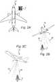
- Fig. 2Ais a schematic top view illustration of an aircraft 10 having a wireless communication system in accordance with an embodiment of the invention.
- the aircraftis provided with one directional antenna 2 with an antenna beam or radiation pattern schematically indicated by the "dotdashed” lines 30.
- the dotdashed lines 30represent the antenna's "bore-sight" direction, i.e. its nominal pointing direction.
- the antenna beam 30 in Fig. 2Atargets a predetermined sector on the ground surface below the aircraft, the sector comprising a ground base station 6, whereby a router within the aircraft 10 which is connected to the antenna 2 can transmit and receive wireless data communication to and from an external stationary communication server.
- Fig. 2Bis a schematic perspective view illustration of an aircraft from Fig. 2A during a roll maneuver.
- the aircraft 10has changed its roll angle as compared to the horizontal stable orientation illustrated in Fig. 2A .
- the control unit of the routerdetermined the attitude change of the aircraft, e.g. by means of a gyroscope, whereby the antenna steering unit steered the antenna beam 20 of the antenna 2 in order to compensate for the determined attitude change.
- the dotdashed lines 30serve to emphasize that the antenna beam 20 has deviated from its bore-sight direction 30.
- the steering unitsteered the antenna beam 20 of the antenna 2 such that the antenna beam 20 maintains a direction towards the predetermined sector of a ground surface below the aircraft by compensating for the determined roll angle (attitude change).
- Fig. 2Ca schematic perspective view illustration of an aircraft from Fig. 2A during a pitch maneuver, or stated differently, the aircraft 10 has changed its pitch angle as compared to the horizontal stable orientation illustrated in Fig. 2A .
- the control unit of the router(not shown in this figure) determined the attitude change of the aircraft, e.g. by means of a gyroscope, whereby the antenna steering unit steered the antenna beam 20 of the antenna 2 in order to compensate for the determined attitude change.
- the dotdashed lines 30serve to emphasize that the antenna beam 20 has deviated from its bore-sight direction 30.
- the steering unitsteered the antenna beam 20 of the antenna 2 such that the antenna beam 20 maintains a direction towards the predetermined sector of a ground surface below the aircraft by compensating for the determined pitch angle (attitude change).
- Fig. 3Ais a schematic top view illustration of an aircraft 10 having a wireless communication system in accordance with another embodiment of the present invention.
- the systemhas a router (not shown) connected to a plurality of directional antennas 2 which define four groups of directional antennas.
- the four groupsare spatially separate along the aircraft's 10 fuselage to primarily target four separate quadrants of the ground surface below the aircraft.
- Each grouphas a directional antenna 2 and each group is configured to radiate and/or receive radio waves towards/from a selected sector 21-24 of a ground surface below the aircraft 10.
- the sectors 21-24are preferably non-overlapping, but may be at least mostly non-overlapping as some overlap may be acceptable.
- the series of Figures 3A - 3Eserve to show how the antenna steering unit may be utilized to steer the antenna beams so to select new sectors to be targeted during the duration of the flight in order to minimize the otherwise "continuous sweeping" of the ground surface by the antenna beam which may require a large number of handovers per unit of time and therefore reduced network performance.
- a control unit of the routermay be configured to evaluate a data link quality between each group and at least one ground base station in the selected sector 21-24, and based on this data, the antenna steering unit may be configured to steer the antenna beam(s) towards a new sector 31-34 when the data link quality falls below some threshold value (e.g. due to a too long of a distance between the antenna and the base station(s)).
- the steering of the antenna beam(s) of each individual groupmay be performed sequentially one at a time, i.e. one antenna beam is steered towards a new sector while the remaining ones maintain their selected "old" sector, or other configurations are feasible e.g. 2 at a time, 3 at a time and so on depending on the number of groups and other specifications.
- Fig. 3Billustrates how the steering unit control the antenna beam of the first group (top left in reference to the illustrated aircraft 10) to select a new sector 31 which is located in front of the aircraft along a planned traveling route.
- the selectionmay be based on predefined data provided by a GNSS (e.g. a GPS) and/or by steering the antenna beam along a predefined search pattern (e.g. a spiral path).
- the antenna beams of the remaining antenna groupsare instead steered so to maintain a direction towards their previously selected sectors 22-24.
- Figs. 3C - 3Eshow a series of how the antenna steering unit sequentially controls the antenna beam of each group so to search for a new sector while the remaining groups' antenna beams are steered so to maintain their direction towards a current sector.
- the antenna steering unitmay be configured to steer the antenna beams of the four groups in pairs.
- the antenna steering unitmay be configured to steer diagonal pairs separately, meaning that the top left and bottom right antenna groups are steered towards a new sector while the remaining two are steered so to maintain the antenna beam(s) aimed at their current sectors, and subsequently the top right and bottom left antenna groups are steered towards a new sector while the remaining two are steered so to maintain the antenna beam(s) aimed at their current sectors, c.f. a horse trotting.
- the antenna steering unitmay be configured to steer front two groups towards a new sector together while the back two are steered so to maintain the antenna beam(s) aimed at their current sectors (front and back being in reference to the nose and tail of the aircraft 10).
- the four groupsmay be paired with respect to which side of the aircraft they are arranged, meaning that the top left and bottom left antenna groups are steered towards a new sector while the remaining two are steered so to maintain the antenna beam(s) aimed at their current sectors and subsequently the top right and bottom right antenna groups are steered towards a new sector while the remaining two are steered so to maintain the antenna beam(s) aimed at their current sectors.
- Left and rightare in reference to the illustrated aircraft 10 in Figs. 3A - 3E .
- Fig. 4is a schematic flowchart representation of a method for wireless data communication between a wireless communication system in an aircraft and a stationary communication server outside the aircraft in accordance with an embodiment of the present invention.
- the methodincludes a step of providing S401 a router within the aircraft.
- the routeris connected to at least one directional antenna and configured to transmit and receive wireless data communication to and from the stationary communication server outside the aircraft through at least one ground base station via the one or more directional antennas.
- an attitude change of the aircraftis determined S402 by determining a change in at least one of a roll angle, pitch angle and/or yaw angle of the aircraft.
- an antenna beam (or radiation pattern) of the at least one directional antennais steered S403, based on the determined S402 attitude change of the aircraft.
- the steering S403 of the antenna beammay include maintaining a direction (of the antenna beam) towards a predefined sector of the ground surface below the aircraft by compensating for the determined S402 attitude change. Thereby, the antenna may be kept in communication with any ground base stations in that sector in spite of any attitude changes.
- the steering S403 of the antenna beam(s)may be based on an evaluation S404 of a data link quality between each antenna and the one or more base stations which are present in the sector of the ground surface which each antenna is arranged to target. Accordingly, the steering S403 of the antenna beams may be done such that the "evaluated" antennas radiate and/or receive radio waves towards/from a new sector of the ground surface when the data link quality is below a predefined quality threshold value.
- control unitmay be considered to include the antenna steering unit, the number of modems may vary, and so on.
- more advanced mathematical algorithms for compensating for yaw changesmay be employed in order to take into account the angular moment of the aircraft and the yaw rate-of-change, in order to account for a situation where the yaw changes so rapidly that the beam steering reaches its maximum possible angle, as already exemplified.
- Such and other obvious modificationsmust be considered to be within the scope of the present invention, as it is defined by the appended claims.
Landscapes
- Engineering & Computer Science (AREA)
- Computer Networks & Wireless Communication (AREA)
- Signal Processing (AREA)
- Physics & Mathematics (AREA)
- Astronomy & Astrophysics (AREA)
- Aviation & Aerospace Engineering (AREA)
- General Physics & Mathematics (AREA)
- Remote Sensing (AREA)
- Mobile Radio Communication Systems (AREA)
- Variable-Direction Aerials And Aerial Arrays (AREA)
- Radio Transmission System (AREA)
- Radio Relay Systems (AREA)
Description
- The present invention relates to the field of wireless communication technology, and more specifically to a wireless communication system and method particularly suitable for aircrafts, such as helicopters and airplanes.
- It is not an understatement that the last few decades have introduced vast improvements and advancements in the field of communication technology. In fact, the advent of the internet, cellular phones and more recently smart phones and tablets has greatly changed the way we communicate and quite possibly accelerated the technological field surrounding these devices. As an inevitable consequence, there is an ever increasing demand for bandwidth in order to satisfy the market need for online connectivity which results in an increased focus on constantly developing and improving the underlying technology and systems in order to accommodate this demand.
- Further, there is a rapidly increasing demand from consumers to be able to communicate through mobile phones and other handheld terminals at all times, even while traveling on trains, busses, ships and even aircrafts. This is partially embodied in the increasing availability of in-flight entertainment systems and wireless communication (Wi-Fi, GSM, 3G, LTE, 5G) capability onboard aircrafts.
- Wireless communication capability onboard aircrafts is not a new concept, even the earliest commercial aircrafts had rather primitive voice communication capability with ground personnel over shortwave radio, which improved flight safety and enabled accelerated commercialization of air transport. Since then, airborne communication systems have been further improved with advent of radar, computers and data links, which serve to improve in-flight safety as well as the overall traveling experience for passengers.
- Still further, in the effort of providing connectivity to high bandwidth communication networks, such as the Internet, for aircrafts, it is known that existing terrestrial cellular networks have potential for cost effective operation. The terrestrial cellular networks are however designed for use by terrestrial equipment (e.g. handheld cell phones) and not for aircrafts. Therefore, successful use of terrestrial networks from aircrafts depends on the ability to handle and work around the assumptions built in to such networks, most predominantly, the assumption that the client device is terrestrial. One of the more prominent consequences of the assumption that the client device is terrestrial is the geographical cell size employed in these networks. The assumptions are accordingly that the client devices will have very limited range, enforced by the fact that the radio propagation path between client devices and base stations is limited by obstructions (buildings, mountains, trees, etc.) and the Earth's horizon. These assumptions are simply no longer valid from an airborne vantage point where the distance to the horizon is much larger, which causes performance degradation in terms of interference between neighboring cells. Therefore, regardless of recent developments of communication platforms for aircrafts, it has proven to be difficult to provide robust, broadband data communication for aircrafts such as airplanes, helicopters and the like. < New p. 2A >
- Thus, in view of the above, there is a need for an improved wireless aircraft communication system which provides better capacity, improved reliability while still being cost effective.
- The invention is as defined in the independent claims.
- Further aspects are disclosed in the dependent claims.
WO 99/23769 US 2016/013858 andWO 2016/073863 discloses use of aerial vehicles as an airborne switching node, wherein the aerial vehicle receives data from a cell within a service area/coverage area, and conveys this information to another cell within the same service/coverage area. Thus, the aerial vehicle hereby forms an airborne gateway, to provide connectivity to areas where there is inadequate terrestrial communication infrastructure. To this end, the aerial vehicle travels around a circular (or similarly shaped) orbit above the service/coverage area.US 2007/281705 is similarly directed to an aircraft functioning as an airborne base station, for use when ground based base stations have become temporarily inoperable, e.g. after hurricanes and the like.- For exemplifying purposes, the invention will be described in closer detail in the following with reference to embodiments thereof illustrated in the attached drawings, wherein:
Fig. 1 is a partly exploded perspective view illustration of an aircraft having a wireless communication system in accordance with an embodiment of the present invention;Fig. 2A is a top view illustration of an aircraft having a wireless communication system in accordance with an embodiment of the present invention;Fig. 2B is a perspective view illustration of the aircraft inFig. 2A making a roll maneuver;Fig. 2C is a perspective view illustration of the aircraft inFig. 2A making a pitch maneuver;Figs. 3A - 3E are top view illustrations of an aircraft having a wireless communication system in accordance with another embodiment of the present invention.Fig. 4 is a schematic flowchart representation of a method in accordance with an embodiment of the present invention.- In the following detailed description, preferred embodiments of the present invention will be described. However, it is to be understood that features of the different embodiments are exchangeable between the embodiments and may be combined in different ways, unless anything else is specifically indicated. Even though in the following description, numerous specific details are set forth to provide a more thorough understanding of the present invention, it will be apparent to one skilled in the art that the present invention may be practiced without these specific details. In other instances, well known constructions or functions are not described in detail, so as not to obscure the present invention. In the detailed embodiments described in the following are related to airplanes. However, it is to be acknowledged by the skilled reader that the method and system are correspondingly useable on other aircrafts, such as helicopters and the like.
Fig. 1 illustrates a schematic perspective view illustration of anaircraft 10, here in the form of an airplane, having awireless communication system 1 in accordance with an embodiment of the present invention. Thesystem 1 has arouter 3 connected to a plurality of (external) antennas 2a - 2c. Therouter 3 is configured to transmit and receive wireless data communication to and from a stationary communication server (not shown) outside theaircraft 10 through at least oneground base station 6a - 6c via the antennas 2a - 2c. The antennas 2a - 2c are directional antennas, which may for example be passive beam forming arrays having various polarizations. Moreover, each antenna 2a - 2c may be realized as an antenna orthogonal pair by e.g. using a dual polarized antenna setup with a 90-degree angle between two linear polarizations or using circular left- and right handed polarizations. However, in alternative embodiments spatial diversity may be utilized to achieve orthogonal antenna diversity.- The antennas 2a - 2c may be mounted to an external surface of the
aircraft 10, such as e.g. to the aircraft's 10 fuselage. However, the antennas 2a - 2c may also be integrated in the external surface of theaircraft 10. A combination of these two is also feasible. - The
system 1 further has acontrol unit 4, e.g. a microprocessor, which is configured to determine an attitude change of theaircraft 10 by determining a change in at least one of a roll angle, pitch angle and/or yaw angle of said aircraft. Thecontrol unit 4 is preferably realized as a software controlled processor. However, thecontrol unit 4 may alternatively be realized wholly or partly in hardware. Moreover, thesystem 1 may further comprise at least one of a gyroscope and an accelerometer (not shown) so that the attitude change can be determined by means of the gyroscope(s) and/or accelerometer(s). A change is roll angle is to be understood as theaircraft 10 making a rotation about its longitudinal axis 101, also commonly referred to as a roll axis. Similarly, a change in pitch angle is to be understood as theaircraft 10 making a rotation about its lateral/transverse axis 102, also commonly referred to as a pitch axis, and a change in yaw angle is to be understood as the aircraft making a rotation about itsvertical axis 103, also commonly referred to as a yaw axis. - The
system 1 further comprises anantenna steering unit 5 connected to thecontrol unit 4. Theantenna steering unit 5 is configured to steer theantenna beams 20 of each directional antenna based on the determined attitude change of theaircraft 10. Even though thecontrol unit 4 andantenna steering unit 5 are here illustrated as two separate entities, the skilled person readily realizes that these may be integrated into one single unit. The antenna steering unit may for example be in the form of an electronic antenna steering unit which steers the antenna beam(s) 20 by e.g. by switching the antenna elements or changing the relative phases of the RF signals driving the antenna elements. The antennas may as mentioned be in the form of passive beam forming arrays comprising a plurality of antenna elements (not shown). However, additionally or alternatively theantenna steering unit 4 may comprise a mechanical steering element in order to mechanically/physically steer the antennas 2a - 2c, such as e.g. an actuator mounted to the antennas (not shown). - The
router 3 further has a plurality ofmodems 9, where each antenna 2a - 2c, or each antenna orthogonal pair, preferably is assigned and connected to aseparate modem 9. In case of the latter eachmodem 9 is preferably provided with 2 antenna ports for connection to each orthogonal antenna pair. However, each modem may also be provided four or more ports for compliance with MIMO (Multiple Input Multiple Output) systems. Moreover, therouter 3 preferably comprises a subscriber identity module pool (SIM pool) 13 which includes a plurality ofSIMs 14, and the control unit 8 is accordingly configured to periodically assignSIMs 14 within theSIM pool 13 to any one of the plurality ofmodems 9 provided within therouter 3. In other words, theSIMs 14 form acommon SIM pool 13, accessible for all themodems 9. TheSIMs 14 are preferably SIM cards, and theSIM pool 13 is realized as a SIM card holder, comprising a plurality of slots for receiving a plurality ofSIM cards 14. - The assignment of SIMs to modems at every specific time is preferably determined based on a set of rules in the controller. The set of rules may e.g. be used to assign SIMs to the modems based on information such as in, the current altitude of the
aircraft 10, which country the aircraft is currently travelling, the amount of data that has been conveyed by use of the different SIMs, the current price related to conveying data through the different SIMs, the type of data being conveyed, etc. - Furthermore, the
router 3 is preferably configured for receiving and transmitting data between an internal local area network (LAN) and a plurality of external wide ware networks (WANs). The LAN is preferably a wireless network, using one or several internal antennas to communicate with clients within theaircraft 10. To this end, it is e.g. feasible to use a distributed antenna, such as a leaky feeder extending through the vehicle, but other types of antennas may also be used. The wireless network may be realized as a wireless local area network (WLAN), and may e.g. operate based on the IEEE 802.11 standard, ("Wi-Fi"), and wherein one or more access point(s) is provided in the aircraft. However, it is also possible to use a wired network within the vehicle. Fig. 2A is a schematic top view illustration of anaircraft 10 having a wireless communication system in accordance with an embodiment of the invention. Here, the aircraft is provided with onedirectional antenna 2 with an antenna beam or radiation pattern schematically indicated by the "dotdashed" lines 30. More specifically, thedotdashed lines 30 represent the antenna's "bore-sight" direction, i.e. its nominal pointing direction. Theantenna beam 30 inFig. 2A targets a predetermined sector on the ground surface below the aircraft, the sector comprising a ground base station 6, whereby a router within theaircraft 10 which is connected to theantenna 2 can transmit and receive wireless data communication to and from an external stationary communication server.Fig. 2B is a schematic perspective view illustration of an aircraft fromFig. 2A during a roll maneuver. In other words, theaircraft 10 has changed its roll angle as compared to the horizontal stable orientation illustrated inFig. 2A . Accordingly, the control unit of the router (not shown in this figure) determined the attitude change of the aircraft, e.g. by means of a gyroscope, whereby the antenna steering unit steered theantenna beam 20 of theantenna 2 in order to compensate for the determined attitude change. Thedotdashed lines 30 serve to emphasize that theantenna beam 20 has deviated from its bore-sight direction 30. The steering unit steered theantenna beam 20 of theantenna 2 such that theantenna beam 20 maintains a direction towards the predetermined sector of a ground surface below the aircraft by compensating for the determined roll angle (attitude change).- Similarly,
Fig. 2C a schematic perspective view illustration of an aircraft fromFig. 2A during a pitch maneuver, or stated differently, theaircraft 10 has changed its pitch angle as compared to the horizontal stable orientation illustrated inFig. 2A . Analogously, the control unit of the router (not shown in this figure) determined the attitude change of the aircraft, e.g. by means of a gyroscope, whereby the antenna steering unit steered theantenna beam 20 of theantenna 2 in order to compensate for the determined attitude change. Thedotdashed lines 30 serve to emphasize that theantenna beam 20 has deviated from its bore-sight direction 30. The steering unit steered theantenna beam 20 of theantenna 2 such that theantenna beam 20 maintains a direction towards the predetermined sector of a ground surface below the aircraft by compensating for the determined pitch angle (attitude change). - Further,
Fig. 3A is a schematic top view illustration of anaircraft 10 having a wireless communication system in accordance with another embodiment of the present invention. The system has a router (not shown) connected to a plurality ofdirectional antennas 2 which define four groups of directional antennas. Here the four groups are spatially separate along the aircraft's 10 fuselage to primarily target four separate quadrants of the ground surface below the aircraft. Each group has adirectional antenna 2 and each group is configured to radiate and/or receive radio waves towards/from a selected sector 21-24 of a ground surface below theaircraft 10. The sectors 21-24 are preferably non-overlapping, but may be at least mostly non-overlapping as some overlap may be acceptable. - The series of
Figures 3A - 3E serve to show how the antenna steering unit may be utilized to steer the antenna beams so to select new sectors to be targeted during the duration of the flight in order to minimize the otherwise "continuous sweeping" of the ground surface by the antenna beam which may require a large number of handovers per unit of time and therefore reduced network performance. Instead, a control unit of the router may be configured to evaluate a data link quality between each group and at least one ground base station in the selected sector 21-24, and based on this data, the antenna steering unit may be configured to steer the antenna beam(s) towards a new sector 31-34 when the data link quality falls below some threshold value (e.g. due to a too long of a distance between the antenna and the base station(s)). Furthermore, the steering of the antenna beam(s) of each individual group may be performed sequentially one at a time, i.e. one antenna beam is steered towards a new sector while the remaining ones maintain their selected "old" sector, or other configurations are feasible e.g. 2 at a time, 3 at a time and so on depending on the number of groups and other specifications. Fig. 3B illustrates how the steering unit control the antenna beam of the first group (top left in reference to the illustrated aircraft 10) to select anew sector 31 which is located in front of the aircraft along a planned traveling route. The selection may be based on predefined data provided by a GNSS (e.g. a GPS) and/or by steering the antenna beam along a predefined search pattern (e.g. a spiral path). The antenna beams of the remaining antenna groups are instead steered so to maintain a direction towards their previously selected sectors 22-24. Analogously,Figs. 3C - 3E show a series of how the antenna steering unit sequentially controls the antenna beam of each group so to search for a new sector while the remaining groups' antenna beams are steered so to maintain their direction towards a current sector.- As mentioned other beam steering configurations are feasible and within the scope of the present invention. For example, in reference to the system configuration illustrated in in
Figs. 3A - 3E , where the wireless communication system comprises four groups of antennas, the antenna steering unit may be configured to steer the antenna beams of the four groups in pairs. In more detail, the antenna steering unit may be configured to steer diagonal pairs separately, meaning that the top left and bottom right antenna groups are steered towards a new sector while the remaining two are steered so to maintain the antenna beam(s) aimed at their current sectors, and subsequently the top right and bottom left antenna groups are steered towards a new sector while the remaining two are steered so to maintain the antenna beam(s) aimed at their current sectors, c.f. a horse trotting. Left and right are in reference to the illustratedaircraft 10 inFigs. 3A - 3E . However, in an analogous manner the antenna steering unit may be configured to steer front two groups towards a new sector together while the back two are steered so to maintain the antenna beam(s) aimed at their current sectors (front and back being in reference to the nose and tail of the aircraft 10). - As yet another alternative, the four groups may be paired with respect to which side of the aircraft they are arranged, meaning that the top left and bottom left antenna groups are steered towards a new sector while the remaining two are steered so to maintain the antenna beam(s) aimed at their current sectors and subsequently the top right and bottom right antenna groups are steered towards a new sector while the remaining two are steered so to maintain the antenna beam(s) aimed at their current sectors. Left and right are in reference to the illustrated
aircraft 10 inFigs. 3A - 3E . Fig. 4 is a schematic flowchart representation of a method for wireless data communication between a wireless communication system in an aircraft and a stationary communication server outside the aircraft in accordance with an embodiment of the present invention. The method includes a step of providing S401 a router within the aircraft. The router is connected to at least one directional antenna and configured to transmit and receive wireless data communication to and from the stationary communication server outside the aircraft through at least one ground base station via the one or more directional antennas.- Further, an attitude change of the aircraft is determined S402 by determining a change in at least one of a roll angle, pitch angle and/or yaw angle of the aircraft. After which, an antenna beam (or radiation pattern) of the at least one directional antenna is steered S403, based on the determined S402 attitude change of the aircraft. More specifically, the steering S403 of the antenna beam may include maintaining a direction (of the antenna beam) towards a predefined sector of the ground surface below the aircraft by compensating for the determined S402 attitude change. Thereby, the antenna may be kept in communication with any ground base stations in that sector in spite of any attitude changes.
- Also, the steering S403 of the antenna beam(s) may be based on an evaluation S404 of a data link quality between each antenna and the one or more base stations which are present in the sector of the ground surface which each antenna is arranged to target. Accordingly, the steering S403 of the antenna beams may be done such that the "evaluated" antennas radiate and/or receive radio waves towards/from a new sector of the ground surface when the data link quality is below a predefined quality threshold value.
- The invention has now been described with reference to specific embodiments. However, several variations of the communication system are feasible. For example, the control unit may be considered to include the antenna steering unit, the number of modems may vary, and so on. Moreover, more advanced mathematical algorithms for compensating for yaw changes may be employed in order to take into account the angular moment of the aircraft and the yaw rate-of-change, in order to account for a situation where the yaw changes so rapidly that the beam steering reaches its maximum possible angle, as already exemplified. Such and other obvious modifications must be considered to be within the scope of the present invention, as it is defined by the appended claims. It should be noted that the above-mentioned embodiments illustrate rather than limit the invention, and that those skilled in the art will be able to design many alternative embodiments without departing from the scope of the appended claims. In the claims, any reference signs placed between parentheses shall not be construed as limiting to the claim. The word "comprising" does not exclude the presence of other elements or steps than those listed in the claim. The word "a" or "an" preceding an element does not exclude the presence of a plurality of such elements.
Claims (11)
- A wireless communication system (1) for 2. use aboard an aircraft (10), said
wireless communication system comprising:a router (3) connected to an antenna (2, 2a-c), wherein the router (3) is configured to transmit and receive wireless data communication to and from a stationary communication server outside said aircraft through at least one ground base station (6, 6a-c) via said antenna;wherein said antenna (2, 2a-c) is a directional antenna;a control unit (4) configured to determine an attitude change of said aircraft (10) by determining a change in at least one of a roll angle, pitch angle and/or yaw angle of said aircraft;an antenna steering unit (5) connected to said control unit (4) and being configured to steer an antenna beam of said directional antenna (2, 2a-c) based on the determined attitude change of said said aircraft in order to compensate for said determined attitude change, such that said antenna beam (20) maintains a direction towards a predetermined sector (21-24, 31-34) of a ground surface below the aircraft ,wherein said router (3) is connected to a plurality of directional antennas (2, 2a-c) defining at least two groups of directional antennas, wherein each group comprises at least one directional antenna and each group is configured to radiate and/or receive radio waves towards/from a selected sector (21-24, 31-34) of a ground surface below the aircraft, the selected sectors being at least mostly non-overlapping, and preferably non-overlapping; whereinsaid control unit (4) is configured to evaluate a data link quality between each group and said at least one ground base station in said selected sector, and wherein said antenna steering unit (5) is configured to steer said antenna beam(s) to radiate and/or receive radio waves towards/from a new sector (21-24, 31-34) of the ground surface, when said data link quality is below a predefined quality threshold value; andwherein said steering unit (5) is configured to steer the antenna beam(s) (20) of each group sequentially such that the direction of the antenna beam(s) of at least one group is maintained towards the selected sector(s) while steering the antenna beam(s) of at least one different group to radiate and/or receive radio waves towards/from the new sector. - The wireless communication system according to claim 1, wherein said directional antenna (2, 2a-c) is a phased array antenna and wherein said antenna steering unit (5) is configured to electronically steer said antenna beam (20).
- The wireless communication system according to any one of the preceding claims, wherein said antenna steering unit (5) comprises a mechanical steering element and wherein said antenna steering unit (5) is configured to mechanically steer said antenna beam (20).
- The wireless communication system according to any one of the preceding claims, wherein said control unit (4) is configured to determine a pitch angle and/or a roll angle of the aircraft, and wherein said antenna steering unit (5) is configured to steer said antenna beam (20) such that it deviates from a nominal bore-sight direction (30) by a deviation angle based on the determined pitch angle and/or roll angle.
- The wireless communication system according to any one of preceding claims, wherein said control unit (4) is configured to determine a change in yaw angle of the aircraft, and wherein said antenna steering unit (5) is configured to steer said antenna beam (20) such that it deviates from a nominal bore-sight direction (30) by a deviation angle based on the determined change in in yaw angle of the aircraft.
- The wireless communication system according to any one of the preceding claims, wherein said antenna steering unit (5) is configured to steer the antenna beam(s) (20) of each group based on the determined attitude change of said aircraft in order to compensate for said determined attitude change.
- The wireless communication system according to any one of the preceding claims, wherein said antenna steering unit (5) is configured to steer the antenna beam(s) of each group, when said aircraft makes a change in attitude, such that said antenna beam(s) (20) in each group maintain(s) the direction towards the selected sector of a ground surface below the aircraft (10) by compensating for said determined attitude change.
- The wireless communication system according to any one of the preceding claims, wherein said new sector is located in a direction in front of the aircraft (10) along a planned traveling route.
- The wireless communication system according to any one of the preceding claims, wherein said antenna steering unit (5) is configured to select said new sector by steering said antenna beam(s) (20) along a search pattern until the data link quality is above a predefined establishment threshold value.
- The wireless communication system according to any one of the preceding claims, further comprising at least one of a gyroscope and an accelerometer and wherein said attitude change is determined by means of said at least one of a gyroscope and an accelerometer.
- A method for wireless data communication between a wireless communication system (1) in an aircraft (10) and a stationary communication server outside the aircraft, said method comprising:providing a router (3) within the aircraft, the router being connected to a directional antenna (2, 2a-c) and configured to transmit and receive wireless data communication to and from the stationary communication server outside the aircraft through at least one ground base station (6, 6a-c) via said directional antenna (2, 2a-c);determining an attitude change of said aircraft (10) by determining a change in at least one of a roll angle, pitch angle and/or yaw angle of said aircraft;steering an antenna beam (20) of said directional antenna based on the determined attitude change of said aircraft (10), wherein said step of steering the antenna beam (20) comprises maintaining a direction towards a predetermined sector (21-24, 31-34) of a ground surface below the aircraft by compensating for said determined attitude change, wherein said router (3) is connected to a plurality of directional antennas (2, 2a-c) defining at least two groups of directional antennas, wherein each group comprises at least one directional antenna and each group is configured to radiate and/or receive radio waves towards/from a selected sector (21-24, 31-34) of a ground surface below the aircraft (10), the individual sectors being at least mostly non-overlapping, and preferably non-overlapping, the method further comprising:evaluating a data link quality between each group and said at least one ground base station in said selected sector; andsteering said antenna beam(s) (20) such that said at least one antenna in the evaluated group radiates and/or receives radio waves towards/from a new sector of the ground surface when said data link quality is below a predefined quality threshold value;wherein the antenna beam(s) of each group are steered sequentially such that the direction of the antenna beam(s) (20) of at least one group is maintained towards the selected sector(s) while steering the antenna beam(s) of at least one different group to radiate and/or receive radio waves towards/from the new sector (21-24, 31-34).
Applications Claiming Priority (2)
| Application Number | Priority Date | Filing Date | Title |
|---|---|---|---|
| SE1751148ASE1751148A1 (en) | 2017-09-18 | 2017-09-18 | Wireless communication system for aircrafts |
| PCT/EP2018/074988WO2019053240A1 (en) | 2017-09-18 | 2018-09-17 | Wireless communication system for aircrafts |
Publications (2)
| Publication Number | Publication Date |
|---|---|
| EP3685523A1 EP3685523A1 (en) | 2020-07-29 |
| EP3685523B1true EP3685523B1 (en) | 2021-12-29 |
Family
ID=63678612
Family Applications (1)
| Application Number | Title | Priority Date | Filing Date |
|---|---|---|---|
| EP18773735.8AActiveEP3685523B1 (en) | 2017-09-18 | 2018-09-17 | Wireless communication system for aircrafts |
Country Status (4)
| Country | Link |
|---|---|
| US (1) | US20210021028A1 (en) |
| EP (1) | EP3685523B1 (en) |
| SE (1) | SE1751148A1 (en) |
| WO (1) | WO2019053240A1 (en) |
Cited By (1)
| Publication number | Priority date | Publication date | Assignee | Title |
|---|---|---|---|---|
| EP4601215A1 (en) | 2024-02-09 | 2025-08-13 | Airbus S.A.S. | Method, control unit and communication system for providing a data connection, and vehicle comprising same |
Families Citing this family (7)
| Publication number | Priority date | Publication date | Assignee | Title |
|---|---|---|---|---|
| US11374752B2 (en) | 2019-06-07 | 2022-06-28 | Panasonic Avionics Corporation | Secure transactions for in-flight entertainment systems |
| CN110445531B (en)* | 2019-08-12 | 2022-06-07 | 北京多尼卡空联技术有限公司 | Airborne communication device and system |
| JP6923026B1 (en)* | 2020-02-27 | 2021-08-18 | 沖電気工業株式会社 | Aircraft and programs |
| US20210320712A1 (en)* | 2020-04-08 | 2021-10-14 | Peter E. Goettle | Communication System Apparatus and Methods |
| FR3116127B1 (en)* | 2020-11-12 | 2022-11-11 | Thales Sa | MIMO type multiple input and output imaging radar system. |
| CN114649667B (en)* | 2021-12-29 | 2025-06-27 | 常熟市泓博通讯技术股份有限公司 | Antenna directional communication method and communication device with adaptive posture change |
| WO2024175199A1 (en)* | 2023-02-23 | 2024-08-29 | Telefonaktiebolaget Lm Ericsson (Publ) | Enhanced communication with terrestrial networks for aerial vehicles |
Family Cites Families (6)
| Publication number | Priority date | Publication date | Assignee | Title |
|---|---|---|---|---|
| US6061562A (en)* | 1997-10-30 | 2000-05-09 | Raytheon Company | Wireless communication using an airborne switching node |
| US8249586B2 (en)* | 2006-06-02 | 2012-08-21 | The Boeing Company | Airborne emergency cell phone router |
| US10470095B2 (en)* | 2013-01-13 | 2019-11-05 | Qualcomm Incorporated | Method for air-to-ground data link antenna self calibration |
| LT2943011T (en) | 2014-05-08 | 2019-07-25 | Icomera Ab | WIRELESS VEHICLE SYSTEM |
| US9614608B2 (en)* | 2014-07-14 | 2017-04-04 | Ubiqomm Llc | Antenna beam management and gateway design for broadband access using unmanned aerial vehicle (UAV) platforms |
| US9712228B2 (en)* | 2014-11-06 | 2017-07-18 | Ubiqomm Llc | Beam forming and pointing in a network of unmanned aerial vehicles (UAVs) for broadband access |
- 2017
- 2017-09-18SESE1751148Apatent/SE1751148A1/ennot_activeApplication Discontinuation
- 2018
- 2018-09-17USUS16/647,343patent/US20210021028A1/ennot_activeAbandoned
- 2018-09-17EPEP18773735.8Apatent/EP3685523B1/enactiveActive
- 2018-09-17WOPCT/EP2018/074988patent/WO2019053240A1/ennot_activeCeased
Cited By (1)
| Publication number | Priority date | Publication date | Assignee | Title |
|---|---|---|---|---|
| EP4601215A1 (en) | 2024-02-09 | 2025-08-13 | Airbus S.A.S. | Method, control unit and communication system for providing a data connection, and vehicle comprising same |
Also Published As
| Publication number | Publication date |
|---|---|
| US20210021028A1 (en) | 2021-01-21 |
| EP3685523A1 (en) | 2020-07-29 |
| WO2019053240A1 (en) | 2019-03-21 |
| SE1751148A1 (en) | 2019-03-19 |
Similar Documents
| Publication | Publication Date | Title |
|---|---|---|
| EP3685523B1 (en) | Wireless communication system for aircrafts | |
| US10244402B2 (en) | Architecture for simultaneous spectrum usage by air-to-ground and terrestrial networks | |
| JP7012804B2 (en) | A system for using mobile phone networks to operate, control, and communicate with unmanned aerial vehicles and remote controls. | |
| US20090186611A1 (en) | Aircraft broadband wireless system and methods | |
| AU2018269657B2 (en) | Communication system for aircrafts | |
| KR20190002672A (en) | Low earth orbit satellite cluster system for telecommunications that reuse geostationary satellite spectrum | |
| CN106233642A (en) | Broadband access to mobile platforms using drones/UAVs | |
| EP3625901B1 (en) | Communication system for aircrafts with altitude based frequency band selection | |
| US9621850B1 (en) | Instant on video conferencing system and related method | |
| WO2021114828A1 (en) | Airway communication method and system, computer-readable storage medium, and electronic device | |
| US9136611B2 (en) | Blade antenna array | |
| CN111869121A (en) | Unmanned aerial vehicle comprising an antenna element panel | |
| US10700768B1 (en) | Reconfigurable wireless radio system for providing massive bandwidth to the sky using a limited number of frequencies and limited hardware | |
| AU2018268004B2 (en) | Communication system for aircrafts with altitude based antenna type selection | |
| US12136991B2 (en) | Aerial vehicle for establishing a cellular network | |
| JP2002246972A (en) | Radio communication system using annular cell |
Legal Events
| Date | Code | Title | Description |
|---|---|---|---|
| STAA | Information on the status of an ep patent application or granted ep patent | Free format text:STATUS: UNKNOWN | |
| STAA | Information on the status of an ep patent application or granted ep patent | Free format text:STATUS: THE INTERNATIONAL PUBLICATION HAS BEEN MADE | |
| PUAI | Public reference made under article 153(3) epc to a published international application that has entered the european phase | Free format text:ORIGINAL CODE: 0009012 | |
| STAA | Information on the status of an ep patent application or granted ep patent | Free format text:STATUS: REQUEST FOR EXAMINATION WAS MADE | |
| 17P | Request for examination filed | Effective date:20200320 | |
| AK | Designated contracting states | Kind code of ref document:A1 Designated state(s):AL AT BE BG CH CY CZ DE DK EE ES FI FR GB GR HR HU IE IS IT LI LT LU LV MC MK MT NL NO PL PT RO RS SE SI SK SM TR | |
| AX | Request for extension of the european patent | Extension state:BA ME | |
| RIN1 | Information on inventor provided before grant (corrected) | Inventor name:KARLSSON, MATS Inventor name:EKLUND, PETER Inventor name:BJURSTROEM, JOEL | |
| DAV | Request for validation of the european patent (deleted) | ||
| DAX | Request for extension of the european patent (deleted) | ||
| GRAP | Despatch of communication of intention to grant a patent | Free format text:ORIGINAL CODE: EPIDOSNIGR1 | |
| STAA | Information on the status of an ep patent application or granted ep patent | Free format text:STATUS: GRANT OF PATENT IS INTENDED | |
| INTG | Intention to grant announced | Effective date:20210720 | |
| GRAS | Grant fee paid | Free format text:ORIGINAL CODE: EPIDOSNIGR3 | |
| GRAA | (expected) grant | Free format text:ORIGINAL CODE: 0009210 | |
| STAA | Information on the status of an ep patent application or granted ep patent | Free format text:STATUS: THE PATENT HAS BEEN GRANTED | |
| AK | Designated contracting states | Kind code of ref document:B1 Designated state(s):AL AT BE BG CH CY CZ DE DK EE ES FI FR GB GR HR HU IE IS IT LI LT LU LV MC MK MT NL NO PL PT RO RS SE SI SK SM TR | |
| REG | Reference to a national code | Ref country code:GB Ref legal event code:FG4D | |
| REG | Reference to a national code | Ref country code:CH Ref legal event code:EP | |
| REG | Reference to a national code | Ref country code:DE Ref legal event code:R096 Ref document number:602018028861 Country of ref document:DE | |
| REG | Reference to a national code | Ref country code:AT Ref legal event code:REF Ref document number:1459457 Country of ref document:AT Kind code of ref document:T Effective date:20220115 | |
| REG | Reference to a national code | Ref country code:IE Ref legal event code:FG4D | |
| REG | Reference to a national code | Ref country code:SE Ref legal event code:TRGR | |
| REG | Reference to a national code | Ref country code:NL Ref legal event code:FP | |
| REG | Reference to a national code | Ref country code:LT Ref legal event code:MG9D | |
| PG25 | Lapsed in a contracting state [announced via postgrant information from national office to epo] | Ref country code:RS Free format text:LAPSE BECAUSE OF FAILURE TO SUBMIT A TRANSLATION OF THE DESCRIPTION OR TO PAY THE FEE WITHIN THE PRESCRIBED TIME-LIMIT Effective date:20211229 Ref country code:LT Free format text:LAPSE BECAUSE OF FAILURE TO SUBMIT A TRANSLATION OF THE DESCRIPTION OR TO PAY THE FEE WITHIN THE PRESCRIBED TIME-LIMIT Effective date:20211229 Ref country code:FI Free format text:LAPSE BECAUSE OF FAILURE TO SUBMIT A TRANSLATION OF THE DESCRIPTION OR TO PAY THE FEE WITHIN THE PRESCRIBED TIME-LIMIT Effective date:20211229 Ref country code:BG Free format text:LAPSE BECAUSE OF FAILURE TO SUBMIT A TRANSLATION OF THE DESCRIPTION OR TO PAY THE FEE WITHIN THE PRESCRIBED TIME-LIMIT Effective date:20220329 | |
| REG | Reference to a national code | Ref country code:AT Ref legal event code:MK05 Ref document number:1459457 Country of ref document:AT Kind code of ref document:T Effective date:20211229 | |
| PG25 | Lapsed in a contracting state [announced via postgrant information from national office to epo] | Ref country code:NO Free format text:LAPSE BECAUSE OF FAILURE TO SUBMIT A TRANSLATION OF THE DESCRIPTION OR TO PAY THE FEE WITHIN THE PRESCRIBED TIME-LIMIT Effective date:20220329 Ref country code:LV Free format text:LAPSE BECAUSE OF FAILURE TO SUBMIT A TRANSLATION OF THE DESCRIPTION OR TO PAY THE FEE WITHIN THE PRESCRIBED TIME-LIMIT Effective date:20211229 Ref country code:HR Free format text:LAPSE BECAUSE OF FAILURE TO SUBMIT A TRANSLATION OF THE DESCRIPTION OR TO PAY THE FEE WITHIN THE PRESCRIBED TIME-LIMIT Effective date:20211229 Ref country code:GR Free format text:LAPSE BECAUSE OF FAILURE TO SUBMIT A TRANSLATION OF THE DESCRIPTION OR TO PAY THE FEE WITHIN THE PRESCRIBED TIME-LIMIT Effective date:20220330 | |
| PG25 | Lapsed in a contracting state [announced via postgrant information from national office to epo] | Ref country code:SM Free format text:LAPSE BECAUSE OF FAILURE TO SUBMIT A TRANSLATION OF THE DESCRIPTION OR TO PAY THE FEE WITHIN THE PRESCRIBED TIME-LIMIT Effective date:20211229 Ref country code:SK Free format text:LAPSE BECAUSE OF FAILURE TO SUBMIT A TRANSLATION OF THE DESCRIPTION OR TO PAY THE FEE WITHIN THE PRESCRIBED TIME-LIMIT Effective date:20211229 Ref country code:RO Free format text:LAPSE BECAUSE OF FAILURE TO SUBMIT A TRANSLATION OF THE DESCRIPTION OR TO PAY THE FEE WITHIN THE PRESCRIBED TIME-LIMIT Effective date:20211229 Ref country code:PT Free format text:LAPSE BECAUSE OF FAILURE TO SUBMIT A TRANSLATION OF THE DESCRIPTION OR TO PAY THE FEE WITHIN THE PRESCRIBED TIME-LIMIT Effective date:20220429 Ref country code:ES Free format text:LAPSE BECAUSE OF FAILURE TO SUBMIT A TRANSLATION OF THE DESCRIPTION OR TO PAY THE FEE WITHIN THE PRESCRIBED TIME-LIMIT Effective date:20211229 Ref country code:EE Free format text:LAPSE BECAUSE OF FAILURE TO SUBMIT A TRANSLATION OF THE DESCRIPTION OR TO PAY THE FEE WITHIN THE PRESCRIBED TIME-LIMIT Effective date:20211229 Ref country code:CZ Free format text:LAPSE BECAUSE OF FAILURE TO SUBMIT A TRANSLATION OF THE DESCRIPTION OR TO PAY THE FEE WITHIN THE PRESCRIBED TIME-LIMIT Effective date:20211229 | |
| PG25 | Lapsed in a contracting state [announced via postgrant information from national office to epo] | Ref country code:PL Free format text:LAPSE BECAUSE OF FAILURE TO SUBMIT A TRANSLATION OF THE DESCRIPTION OR TO PAY THE FEE WITHIN THE PRESCRIBED TIME-LIMIT Effective date:20211229 Ref country code:AT Free format text:LAPSE BECAUSE OF FAILURE TO SUBMIT A TRANSLATION OF THE DESCRIPTION OR TO PAY THE FEE WITHIN THE PRESCRIBED TIME-LIMIT Effective date:20211229 | |
| PG25 | Lapsed in a contracting state [announced via postgrant information from national office to epo] | Ref country code:IS Free format text:LAPSE BECAUSE OF FAILURE TO SUBMIT A TRANSLATION OF THE DESCRIPTION OR TO PAY THE FEE WITHIN THE PRESCRIBED TIME-LIMIT Effective date:20220429 | |
| REG | Reference to a national code | Ref country code:DE Ref legal event code:R097 Ref document number:602018028861 Country of ref document:DE | |
| PG25 | Lapsed in a contracting state [announced via postgrant information from national office to epo] | Ref country code:DK Free format text:LAPSE BECAUSE OF FAILURE TO SUBMIT A TRANSLATION OF THE DESCRIPTION OR TO PAY THE FEE WITHIN THE PRESCRIBED TIME-LIMIT Effective date:20211229 Ref country code:AL Free format text:LAPSE BECAUSE OF FAILURE TO SUBMIT A TRANSLATION OF THE DESCRIPTION OR TO PAY THE FEE WITHIN THE PRESCRIBED TIME-LIMIT Effective date:20211229 | |
| PLBE | No opposition filed within time limit | Free format text:ORIGINAL CODE: 0009261 | |
| STAA | Information on the status of an ep patent application or granted ep patent | Free format text:STATUS: NO OPPOSITION FILED WITHIN TIME LIMIT | |
| 26N | No opposition filed | Effective date:20220930 | |
| PG25 | Lapsed in a contracting state [announced via postgrant information from national office to epo] | Ref country code:SI Free format text:LAPSE BECAUSE OF FAILURE TO SUBMIT A TRANSLATION OF THE DESCRIPTION OR TO PAY THE FEE WITHIN THE PRESCRIBED TIME-LIMIT Effective date:20211229 | |
| PG25 | Lapsed in a contracting state [announced via postgrant information from national office to epo] | Ref country code:MC Free format text:LAPSE BECAUSE OF FAILURE TO SUBMIT A TRANSLATION OF THE DESCRIPTION OR TO PAY THE FEE WITHIN THE PRESCRIBED TIME-LIMIT Effective date:20211229 | |
| REG | Reference to a national code | Ref country code:CH Ref legal event code:PL | |
| PG25 | Lapsed in a contracting state [announced via postgrant information from national office to epo] | Ref country code:LU Free format text:LAPSE BECAUSE OF NON-PAYMENT OF DUE FEES Effective date:20220917 | |
| PG25 | Lapsed in a contracting state [announced via postgrant information from national office to epo] | Ref country code:LI Free format text:LAPSE BECAUSE OF NON-PAYMENT OF DUE FEES Effective date:20220930 Ref country code:CH Free format text:LAPSE BECAUSE OF NON-PAYMENT OF DUE FEES Effective date:20220930 | |
| P01 | Opt-out of the competence of the unified patent court (upc) registered | Effective date:20230929 | |
| PG25 | Lapsed in a contracting state [announced via postgrant information from national office to epo] | Ref country code:CY Free format text:LAPSE BECAUSE OF FAILURE TO SUBMIT A TRANSLATION OF THE DESCRIPTION OR TO PAY THE FEE WITHIN THE PRESCRIBED TIME-LIMIT Effective date:20211229 | |
| PG25 | Lapsed in a contracting state [announced via postgrant information from national office to epo] | Ref country code:MK Free format text:LAPSE BECAUSE OF FAILURE TO SUBMIT A TRANSLATION OF THE DESCRIPTION OR TO PAY THE FEE WITHIN THE PRESCRIBED TIME-LIMIT Effective date:20211229 Ref country code:HU Free format text:LAPSE BECAUSE OF FAILURE TO SUBMIT A TRANSLATION OF THE DESCRIPTION OR TO PAY THE FEE WITHIN THE PRESCRIBED TIME-LIMIT; INVALID AB INITIO Effective date:20180917 | |
| PG25 | Lapsed in a contracting state [announced via postgrant information from national office to epo] | Ref country code:TR Free format text:LAPSE BECAUSE OF FAILURE TO SUBMIT A TRANSLATION OF THE DESCRIPTION OR TO PAY THE FEE WITHIN THE PRESCRIBED TIME-LIMIT Effective date:20211229 | |
| PG25 | Lapsed in a contracting state [announced via postgrant information from national office to epo] | Ref country code:MT Free format text:LAPSE BECAUSE OF FAILURE TO SUBMIT A TRANSLATION OF THE DESCRIPTION OR TO PAY THE FEE WITHIN THE PRESCRIBED TIME-LIMIT Effective date:20211229 | |
| PGFP | Annual fee paid to national office [announced via postgrant information from national office to epo] | Ref country code:IE Payment date:20240808 Year of fee payment:7 Ref country code:DE Payment date:20240812 Year of fee payment:7 | |
| PGFP | Annual fee paid to national office [announced via postgrant information from national office to epo] | Ref country code:GB Payment date:20240806 Year of fee payment:7 | |
| PGFP | Annual fee paid to national office [announced via postgrant information from national office to epo] | Ref country code:BE Payment date:20240807 Year of fee payment:7 | |
| PGFP | Annual fee paid to national office [announced via postgrant information from national office to epo] | Ref country code:FR Payment date:20240806 Year of fee payment:7 | |
| PGFP | Annual fee paid to national office [announced via postgrant information from national office to epo] | Ref country code:IT Payment date:20240718 Year of fee payment:7 Ref country code:SE Payment date:20240807 Year of fee payment:7 | |
| PGFP | Annual fee paid to national office [announced via postgrant information from national office to epo] | Ref country code:NL Payment date:20250805 Year of fee payment:8 |