EP3685092B1 - Display support structure - Google Patents
Display support structureDownload PDFInfo
- Publication number
- EP3685092B1 EP3685092B1EP18830403.4AEP18830403AEP3685092B1EP 3685092 B1EP3685092 B1EP 3685092B1EP 18830403 AEP18830403 AEP 18830403AEP 3685092 B1EP3685092 B1EP 3685092B1
- Authority
- EP
- European Patent Office
- Prior art keywords
- post
- support structure
- arm
- grip assembly
- assembly
- Prior art date
- Legal status (The legal status is an assumption and is not a legal conclusion. Google has not performed a legal analysis and makes no representation as to the accuracy of the status listed.)
- Active
Links
Images


Classifications
- F—MECHANICAL ENGINEERING; LIGHTING; HEATING; WEAPONS; BLASTING
- F16—ENGINEERING ELEMENTS AND UNITS; GENERAL MEASURES FOR PRODUCING AND MAINTAINING EFFECTIVE FUNCTIONING OF MACHINES OR INSTALLATIONS; THERMAL INSULATION IN GENERAL
- F16M—FRAMES, CASINGS OR BEDS OF ENGINES, MACHINES OR APPARATUS, NOT SPECIFIC TO ENGINES, MACHINES OR APPARATUS PROVIDED FOR ELSEWHERE; STANDS; SUPPORTS
- F16M11/00—Stands or trestles as supports for apparatus or articles placed thereon ; Stands for scientific apparatus such as gravitational force meters
- F16M11/20—Undercarriages with or without wheels
- F16M11/2007—Undercarriages with or without wheels comprising means allowing pivoting adjustment
- F16M11/2035—Undercarriages with or without wheels comprising means allowing pivoting adjustment in more than one direction
- F16M11/2064—Undercarriages with or without wheels comprising means allowing pivoting adjustment in more than one direction for tilting and panning
- F—MECHANICAL ENGINEERING; LIGHTING; HEATING; WEAPONS; BLASTING
- F16—ENGINEERING ELEMENTS AND UNITS; GENERAL MEASURES FOR PRODUCING AND MAINTAINING EFFECTIVE FUNCTIONING OF MACHINES OR INSTALLATIONS; THERMAL INSULATION IN GENERAL
- F16M—FRAMES, CASINGS OR BEDS OF ENGINES, MACHINES OR APPARATUS, NOT SPECIFIC TO ENGINES, MACHINES OR APPARATUS PROVIDED FOR ELSEWHERE; STANDS; SUPPORTS
- F16M11/00—Stands or trestles as supports for apparatus or articles placed thereon ; Stands for scientific apparatus such as gravitational force meters
- F16M11/02—Heads
- F16M11/04—Means for attachment of apparatus; Means allowing adjustment of the apparatus relatively to the stand
- F16M11/06—Means for attachment of apparatus; Means allowing adjustment of the apparatus relatively to the stand allowing pivoting
- F16M11/10—Means for attachment of apparatus; Means allowing adjustment of the apparatus relatively to the stand allowing pivoting around a horizontal axis
- F—MECHANICAL ENGINEERING; LIGHTING; HEATING; WEAPONS; BLASTING
- F16—ENGINEERING ELEMENTS AND UNITS; GENERAL MEASURES FOR PRODUCING AND MAINTAINING EFFECTIVE FUNCTIONING OF MACHINES OR INSTALLATIONS; THERMAL INSULATION IN GENERAL
- F16M—FRAMES, CASINGS OR BEDS OF ENGINES, MACHINES OR APPARATUS, NOT SPECIFIC TO ENGINES, MACHINES OR APPARATUS PROVIDED FOR ELSEWHERE; STANDS; SUPPORTS
- F16M11/00—Stands or trestles as supports for apparatus or articles placed thereon ; Stands for scientific apparatus such as gravitational force meters
- F16M11/20—Undercarriages with or without wheels
- F16M11/2007—Undercarriages with or without wheels comprising means allowing pivoting adjustment
- F16M11/2014—Undercarriages with or without wheels comprising means allowing pivoting adjustment around a vertical axis
- F—MECHANICAL ENGINEERING; LIGHTING; HEATING; WEAPONS; BLASTING
- F16—ENGINEERING ELEMENTS AND UNITS; GENERAL MEASURES FOR PRODUCING AND MAINTAINING EFFECTIVE FUNCTIONING OF MACHINES OR INSTALLATIONS; THERMAL INSULATION IN GENERAL
- F16M—FRAMES, CASINGS OR BEDS OF ENGINES, MACHINES OR APPARATUS, NOT SPECIFIC TO ENGINES, MACHINES OR APPARATUS PROVIDED FOR ELSEWHERE; STANDS; SUPPORTS
- F16M11/00—Stands or trestles as supports for apparatus or articles placed thereon ; Stands for scientific apparatus such as gravitational force meters
- F16M11/20—Undercarriages with or without wheels
- F16M11/24—Undercarriages with or without wheels changeable in height or length of legs, also for transport only, e.g. by means of tubes screwed into each other
- F—MECHANICAL ENGINEERING; LIGHTING; HEATING; WEAPONS; BLASTING
- F16—ENGINEERING ELEMENTS AND UNITS; GENERAL MEASURES FOR PRODUCING AND MAINTAINING EFFECTIVE FUNCTIONING OF MACHINES OR INSTALLATIONS; THERMAL INSULATION IN GENERAL
- F16M—FRAMES, CASINGS OR BEDS OF ENGINES, MACHINES OR APPARATUS, NOT SPECIFIC TO ENGINES, MACHINES OR APPARATUS PROVIDED FOR ELSEWHERE; STANDS; SUPPORTS
- F16M2200/00—Details of stands or supports
- F16M2200/02—Locking means
- F16M2200/025—Locking means for translational movement
- F16M2200/027—Locking means for translational movement by friction
- F—MECHANICAL ENGINEERING; LIGHTING; HEATING; WEAPONS; BLASTING
- F16—ENGINEERING ELEMENTS AND UNITS; GENERAL MEASURES FOR PRODUCING AND MAINTAINING EFFECTIVE FUNCTIONING OF MACHINES OR INSTALLATIONS; THERMAL INSULATION IN GENERAL
- F16M—FRAMES, CASINGS OR BEDS OF ENGINES, MACHINES OR APPARATUS, NOT SPECIFIC TO ENGINES, MACHINES OR APPARATUS PROVIDED FOR ELSEWHERE; STANDS; SUPPORTS
- F16M2200/00—Details of stands or supports
- F16M2200/06—Arms
- F16M2200/068—Arms being part of the undercarriage
Definitions
- the present inventionrelates to a support structure and more particularly to a support structure for a screen.
- Displayssuch as computer monitors, TVs, etc.
- displaysare often used in working environments.
- displaysare supported by support structures. It is often desired by users to be able to adjust the height of the displays in order to gain a better view of the display.
- support structures for displaysare difficult to adjust and require great effort by the user to adjust the height.
- many displaysare supplied with incorporated support structures that are either difficult to adjust or do not allow a range of movement required for a full ergonomic solution.
- DE4318669A1entitled “Seat arrangement for camera trucks,” discloses a seat arrangement for a camera truck, having a seat fastened at the free end of a supporting arm, the supporting arm being retained by an approximately vertically extending retaining bar such that, on the one hand, it can be pivoted about said bar and, on the other hand, it can be adjusted in height along said bar.
- the retaining baris either mounted directly on the camera truck or on the frame thereof or is fastened on an extension arm which is mounted on the camera truck.
- the supporting armcomprises a clamping device which, in the clamping position, acts in a positively locking manner on the retaining bar.
- the inventionis defined by support structures according to claims 1 and 13. and second portions define a cavity therebetween.
- the grip assemblyalso includes a retention member movably positioned within the cavity of the inner housing.
- the retention memberincludes a wedge component, a contact surface, and a channel that is defined between the wedge component and the contact surface.
- the grip assemblyfurther includes a first button positioned in the channel of the retention member, a second button positioned opposite the first button in the channel of the retention member, and a resilient member that biases the retention member to a first position in which the contact surface engages the post. Movement of the first and second buttons towards each other moves the retention member against the bias of the resilient member to a second position in which the contact surface is disengaged from the post.
- a support structure 10is configured to support a computer monitor, screen, or other display.
- the support structure 10may be coupled to a base.
- basesare horizontal bases such as desktops and table tops, vertical bases such as walls and posts, or other bases such as a slanting ceiling having an angle between horizontal and vertical.
- the support structure 10is able to be articulated to a number of positions so that a display can be positioned in a preferred way for a user. As such, the support structure 10 is movable into a variety of positions.
- the support structure 10includes a post assembly 14 and an arm assembly 18 that is movably coupled to the post assembly 14.
- the post assembly 14includes a clamp 22 that may be secured to an edge of a table or desk and a post 26 extending vertically from the clamp 22.
- the clamp 22includes a c-shaped bracket 30 that defines a channel 34 for receiving a table or desk.
- the clamp 22further includes a fastener 38 extending into the channel 34 that secures the support structure 10 in place.
- the fastener 38includes a flange 42 with a flat surface that engages a support, a shaft 46, and a knob 50. When the support structure 10 is positioned for use, a user can use the knob 50 to tighten the clamp 22 and secure the support structure 10 in place.
- the support structure 10may include other means of coupling to a support.
- the post 26includes a first end 54 adjacent the clamp 22, a second end 58 opposite the first end 54, and an axis 62 that extends centrally through the post 26 between the first and second ends 54, 58.
- the post 26has a length defined along the axis 62 that is between approximately one foot and approximately four feet. In other embodiments, the post may be longer than four feet or less than a foot.
- the post 26further includes a plurality of tracks 66 that extend from the first end 54 to the second end 58. In the illustrated embodiment, there are three tracks 66. In other embodiments, there may be more or less than three tracks 66.
- the tracks 66include edges 70 that engage the arm assembly 18 for translation along the axis 62 between the first and second ends 54, 58 of the post 26.
- the post 26includes an end cap 74 that further defines part of the tracks 66.
- the arm assembly 18includes a first arm 78, a second arm 82, a mounting head 86, and a grip assembly 90.
- the first arm 78includes a first end 94 and a second end 98 opposite the first end 94.
- the first end 94 of the first arm 78is coupled to the grip assembly 90 and rotatable about an axis Y1.
- a fastener 102is used to secure the first arm 78 to the grip assembly 90.
- a cap 106 on the first end 94 of the first arm 78is placed over the fastener 102 to conceal it.
- the second arm 82includes a first end 110 and a second end 114 opposite the first end 110.
- the first end 110 of the second arm 82is rotatably coupled to the second end 98 of the first arm 78 about an axis Y2.
- the second end 114 of the second arm 82includes a connecting portion 122 in which the mounting head 86 is positioned.
- the mounting head 86is coupled to the connecting portion 122 and is rotatable about an axis Y3.
- the mounting head 86includes a tilt head 130 configured to couple a display to the arm assembly 18, for example through a connection to a mounting plate.
- a displaymay be coupled to the mounting head 86 with fasteners or other supports.
- the first, second, and third axes of rotation Y1, Y2, Y3allow the first arm 78, second arm 82, and mounting head 86 to position a display or other screen into a number of positions.
- the arm assembly 18is articulated.
- the first arm 78, the second arm 82, and the mounting head 86may be made from injection molded plastics.
- the grip assembly 90movably couples the arm assembly 18 to the post assembly 14.
- the grip assembly 90includes a cover 138, an inner housing 142, a retention component, for example the holder 146, and a bearing 150.
- the cover 138conceals the inner housing 142. In other embodiments, the cover 138 may be removed without affecting the functionality of the grip assembly 90.
- the cover 138includes a first side aperture 154, a second side aperture 158 opposite the first side aperture 154, and a top aperture 162.
- the inner housing 142is positioned within the cover 138.
- the inner housing 142includes a first housing portion 166 and a second housing portion 170.
- Both the first housing portion 166 and the second housing portion 170include an aperture 174 that when positioned inside the cover 138 align with the first and second side apertures 154, 158 of the cover 138.
- the apertures 174 of the first and second housing portions 166, 170both include an upper and lower tab slot 178.
- the first and second housing portions 166, 170further include extensions 182 that when placed adjacent each other within the cover 138 extend from the top aperture 162 to define a bearing seat 186 ( FIG. 2 ).
- a bearing 190is positioned on the bearing seat 186 and allows the first arm 78 of the arm assembly 18 to rotate relative to the grip assembly 90.
- the first housing portion 166further includes a spring seat slot 194 and a forward extending lip 198.
- the second housing portion 170includes a spring seat 202 that corresponds to the spring seat slot 194 and a forward extending lip 198.
- the spring seat 202is positioned in the spring seat slot 194.
- the first and second housing portions 166, 170define a cavity 206 therebetween.
- the cavity 206defines a back wall 210 that includes an inclined surface 214 and a front wall 215, with inclined surfaces 216.
- the holder 146is positioned within the cavity 206.
- the holder 146includes a wedge component 218 with a rear inclined surface 222 that is engaged with the inclined surface 214 of the back wall 210.
- the wedge componentfurther includes front inclined surfaces 224 that are engaged with the inclined surfaces 216 of the front wall 215.
- the holder 146further includes a gripping pad 226 opposite the front inclined surfaces 224.
- the gripping pad 226can include a sticky substance that provides a high coefficient of friction and thus a high friction force when in contact with another surface.
- the sticky substancemay be a thermoplastic elastomer or thermoplastic polyurethane.
- the gripping pad 226is over molded onto the holder 146.
- a channel 230is positioned within the wedge component 218.
- the channel 230is generally rectangular and defined by four sides 234A-D ( FIG. 4 ).
- a bottom side 234D of the channel 230is defined by two inclined surfaces 238 that come together at an apex 242 ( FIG. 4 ).
- a projection 246extends away from the channel 230.
- the grip assemblyfurther includes an actuator assembly 248 with a first button 250 that is positioned in the aperture 174 of the first housing portion 166 of the inner housing 142 and a second button 254 that is positioned within the aperture 174 of the second housing portion 170 of the inner housing 142.
- a single button or other actuatormay be used.
- Both the first and second buttons 250, 254include an upper and lower tab 258 that are positioned within the upper and lower tab slots 178, respectively, of the respective housing portions 166, 170 to secure the first and second buttons 250, 254 to the grip assembly 90.
- the first and second buttons 250, 254also include a bifurcated projection 262 with an inclined surface 266.
- the inclined surface 266 of the bifurcated projections 262are positioned on the inclined surfaces 238 within the channel 230.
- the inclined surface 266 on the first button 250is positioned on the inclined surface 238 of the channel 230 that is positioned nearer the first housing portion 166 and the inclined surface 266 on the second button 254 is positioned on the inclined surface 238 of the channel 230 that is positioned nearer the second housing portion 170.
- the bifurcated projection 262 of the first button 250is interlocked with the bifurcated projection 262 of the second button 254 when positioned inside the channel 230.
- the bearing 150 of the grip assembly 90is positioned between the forward extending lips 198 of the first and second housing portions 166, 170 of the inner housing 142.
- the bearing 150includes a top side 274 with a bearing surface 278, two lateral sides 282 that have forward extending edges 286 that correspond to the forward extending lips 198 of the first and second housing portions 166, 170, a bottom side 290, and an opening 294 defined between the sides 274, 282, 290.
- the gripping pad 226 of the holder 146protrudes from the opening 294 towards the post 26.
- the grip assembly 90also includes a resilient member 298 positioned on the spring seat 202 of the second housing portion 170 and on the projection 246 of the holder 146.
- the projection 246defines an axis Y4 that the spring is positioned around.
- the axis Y4is slightly angled relative to the axes Y1, Y2, Y3 and parallel to the back and front walls 210, 215.
- the resilient member 298biases the wedge component 218 of the holder 146 towards the post 26 in a direction along the axes Y4 so that the front and rear inclined surfaces 222, 224 of the holder 146 are pressed against the inclined surfaces 214, 216 of the inner housing 142.
- fastenersmay be used to secure and hold the grip assembly 90 together.
- the forward extending lips 198 of the first and second housing portions 166, 170are aligned with the edges 70 of the tracks 66.
- the arm assembly 18can then be slid axially onto a track 66.
- the grip assembly 90engages the post 26.
- the resilient member 298pushes the holder 146 against the post 26 forcing the inclined surfaces 222, 224 against the inclined surfaces 214, 216.
- the inclined surfaces 214, 216 on the back and front walls 210, 215 of the cavity 206push the holder 146 back towards the post 26, along the axis Y4, creating a clamping force.
- the clamping forcecreates a horizontal component that acts in a direction perpendicular to the axes Y1, Y2, Y3 and a vertical component that acts in a direction parallel to the axes Y1, Y2, Y3.
- the horizontal component of the clamping forcecauses the gripping pad 226 to engage the post 26 securing the arm assembly 18 in its position on the post 26.
- the bias of the holder 146also forces the inclined surfaces 238 of the bottom side 234D of the channel 230 to bias the first and second buttons 250, 254 to extend out of the first and second side apertures 154, 158 of the cover 138.
- the clamping forceincreases.
- the increase to the vertical component of the clamping forcemoves the inclined surfaces 214, 216 of the front and back walls 210, 215 down the inclined surfaces 222, 224 of the wedge component 218, thus decreasing the clearance 300.
- the increase to the horizontal component of the clamping forcefurther presses the gripping pad 226 against the post 26. In other words, additional loads further support the arm assembly 18 on the post 26.
- the gripping pad 226in order to move the arm assembly 18, the gripping pad 226 must be disengaged from the post 26.
- the inclined surfaces 222, 224 of the wedge component 218slide along the inclined surfaces 214, 216 of the front and back walls 210, 215 of the cavity 206 drawing the holder 146 and the gripping pad 226 away from the post 26.
- a usermay slide the arm assembly 18 axially along the post 26 to a desired height.
- the bearing surface 278 of the bearing 150provides a smooth surface for the arm assembly 18 to slide along the post 26.
- a usercan release the actuator assembly 248 (i.e., first and second buttons 250, 254), allowing the gripping pad 226 to reengage the post 26 to secure it in place.
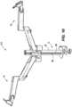
- FIG. 10illustrates a support structure 310 according to another embodiment of the invention.
- the support structure 310is similar to the support structure 10 but includes two arm assemblies 18 to support two displays.
- the two arm assemblies 18 of the support structureoperate the same way as the arm assembly 18 discussed above.
- the two arm assemblies 18are coupled to the post assembly 14 in tracks 66 adjacent one another. Both the arm assemblies 18 can be operated without influencing the other.
- the support structuremay include three or more arm assemblies 18 to support a third display.
- the terms “front,” “rear,” “upper,” “lower,” “upwardly,” “downwardly,” and other orientational descriptorsare intended to facilitate the description of the exemplary embodiments of the present disclosure, and are not intended to limit the structure of the exemplary embodiments of the present disclosure to any particular position or orientation.
- Terms of degree, such as “substantially” or “approximately”are understood by those of ordinary skill to refer to reasonable ranges outside of the given value, for example, general tolerances associated with manufacturing, assembly, and use of the described embodiments.
Landscapes
- Engineering & Computer Science (AREA)
- General Engineering & Computer Science (AREA)
- Mechanical Engineering (AREA)
- Devices For Indicating Variable Information By Combining Individual Elements (AREA)
- Casings For Electric Apparatus (AREA)
- Mutual Connection Of Rods And Tubes (AREA)
- Road Signs Or Road Markings (AREA)
Description
- The present invention relates to a support structure and more particularly to a support structure for a screen.
- Displays, such as computer monitors, TVs, etc., are often used in working environments. Typically, displays are supported by support structures. It is often desired by users to be able to adjust the height of the displays in order to gain a better view of the display. However, many support structures for displays are difficult to adjust and require great effort by the user to adjust the height. In addition, many displays are supplied with incorporated support structures that are either difficult to adjust or do not allow a range of movement required for a full ergonomic solution.
DE4318669A1 , entitled "Seat arrangement for camera trucks," discloses a seat arrangement for a camera truck, having a seat fastened at the free end of a supporting arm, the supporting arm being retained by an approximately vertically extending retaining bar such that, on the one hand, it can be pivoted about said bar and, on the other hand, it can be adjusted in height along said bar. The retaining bar is either mounted directly on the camera truck or on the frame thereof or is fastened on an extension arm which is mounted on the camera truck. The supporting arm comprises a clamping device which, in the clamping position, acts in a positively locking manner on the retaining bar. - The invention is defined by support structures according to claims 1 and 13. and second portions define a cavity therebetween. The grip assembly also includes a retention member movably positioned within the cavity of the inner housing. The retention member includes a wedge component, a contact surface, and a channel that is defined between the wedge component and the contact surface. The grip assembly further includes a first button positioned in the channel of the retention member, a second button positioned opposite the first button in the channel of the retention member, and a resilient member that biases the retention member to a first position in which the contact surface engages the post. Movement of the first and second buttons towards each other moves the retention member against the bias of the resilient member to a second position in which the contact surface is disengaged from the post.
- Other aspects of the invention will become apparent by consideration of the detailed description and accompanying drawings.
FIG. 1 is a perspective view of a support structure.FIG. 2 is an exploded view of an arm assembly of the support structure ofFIG. 1 .FIG. 3 is an exploded view of a grip assembly of the support structure ofFIG. 1 .FIG. 4 is a cross-sectional view of the grip assembly engaged to a post taken along lines 4-4 ofFIG. 1 .FIG. 5 is a cross-sectional view of the grip assembly engaged to a post taken along lines 5-5 ofFIG. 1 .FIG. 6 is a cross-sectional view of the grip assembly engaged to a post taken along lines 6-6 ofFIG. 1 .FIG. 7 is a cross-sectional view of the grip assembly disengaged from a post taken along lines 4-4 ofFIG. 1 .FIG. 8 is a cross-sectional view of the grip assembly disengaged from a post taken along lines 5-5 ofFIG. 1 .FIG. 9 is a cross-sectional view of the grip assembly disengaged from a post taken along lines 6-6 ofFIG. 1 .FIG. 10 is a perspective view of another embodiment according to the invention.- Before any embodiments of the invention are explained in detail, it is to be understood that the invention is not limited in its application to the details of construction and the arrangement of components set forth in the following description or illustrated in the following drawings. The invention is capable of other embodiments and of being practiced or of being carried out in various ways. Also, it is to be understood that the phraseology and terminology used herein is for the purpose of description and should not be regarded as limiting.
- With reference to
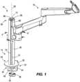
FIG. 1 , asupport structure 10 is configured to support a computer monitor, screen, or other display. Thesupport structure 10 may be coupled to a base. Examples of bases are horizontal bases such as desktops and table tops, vertical bases such as walls and posts, or other bases such as a slanting ceiling having an angle between horizontal and vertical. In some embodiments, thesupport structure 10 is able to be articulated to a number of positions so that a display can be positioned in a preferred way for a user. As such, thesupport structure 10 is movable into a variety of positions. Thesupport structure 10 includes apost assembly 14 and anarm assembly 18 that is movably coupled to thepost assembly 14. Thepost assembly 14 includes aclamp 22 that may be secured to an edge of a table or desk and apost 26 extending vertically from theclamp 22. Theclamp 22 includes a c-shaped bracket 30 that defines achannel 34 for receiving a table or desk. Theclamp 22 further includes afastener 38 extending into thechannel 34 that secures thesupport structure 10 in place. Thefastener 38 includes aflange 42 with a flat surface that engages a support, ashaft 46, and aknob 50. When thesupport structure 10 is positioned for use, a user can use theknob 50 to tighten theclamp 22 and secure thesupport structure 10 in place. In other embodiments, thesupport structure 10 may include other means of coupling to a support. - With continued reference to
FIG. 1 , thepost 26 includes afirst end 54 adjacent theclamp 22, asecond end 58 opposite thefirst end 54, and anaxis 62 that extends centrally through thepost 26 between the first andsecond ends post 26 has a length defined along theaxis 62 that is between approximately one foot and approximately four feet. In other embodiments, the post may be longer than four feet or less than a foot. Thepost 26 further includes a plurality oftracks 66 that extend from thefirst end 54 to thesecond end 58. In the illustrated embodiment, there are threetracks 66. In other embodiments, there may be more or less than threetracks 66. Thetracks 66 includeedges 70 that engage thearm assembly 18 for translation along theaxis 62 between the first andsecond ends post 26. In the illustrated embodiment, thepost 26 includes anend cap 74 that further defines part of thetracks 66. - With reference to
FIG. 2 , thearm assembly 18 includes afirst arm 78, asecond arm 82, amounting head 86, and agrip assembly 90. Thefirst arm 78 includes afirst end 94 and asecond end 98 opposite thefirst end 94. Thefirst end 94 of thefirst arm 78 is coupled to thegrip assembly 90 and rotatable about an axis Y1. Afastener 102 is used to secure thefirst arm 78 to thegrip assembly 90. Acap 106 on thefirst end 94 of thefirst arm 78 is placed over thefastener 102 to conceal it. Thesecond arm 82 includes afirst end 110 and asecond end 114 opposite thefirst end 110. Thefirst end 110 of thesecond arm 82 is rotatably coupled to thesecond end 98 of thefirst arm 78 about an axis Y2. Thesecond end 114 of thesecond arm 82 includes a connectingportion 122 in which themounting head 86 is positioned. Themounting head 86 is coupled to the connectingportion 122 and is rotatable about an axis Y3. Themounting head 86 includes atilt head 130 configured to couple a display to thearm assembly 18, for example through a connection to a mounting plate. In other embodiments, a display may be coupled to the mountinghead 86 with fasteners or other supports. The first, second, and third axes of rotation Y1, Y2, Y3 allow thefirst arm 78,second arm 82, and mountinghead 86 to position a display or other screen into a number of positions. As such, thearm assembly 18 is articulated. In some embodiments, thefirst arm 78, thesecond arm 82, and the mountinghead 86 may be made from injection molded plastics. - With reference to
FIG. 3 , thegrip assembly 90 movably couples thearm assembly 18 to thepost assembly 14. Thegrip assembly 90 includes acover 138, aninner housing 142, a retention component, for example theholder 146, and abearing 150. In the illustrated embodiment, thecover 138 conceals theinner housing 142. In other embodiments, thecover 138 may be removed without affecting the functionality of thegrip assembly 90. Thecover 138 includes afirst side aperture 154, asecond side aperture 158 opposite thefirst side aperture 154, and atop aperture 162. Theinner housing 142 is positioned within thecover 138. Theinner housing 142 includes afirst housing portion 166 and asecond housing portion 170. Both thefirst housing portion 166 and thesecond housing portion 170 include anaperture 174 that when positioned inside thecover 138 align with the first andsecond side apertures cover 138. Theapertures 174 of the first andsecond housing portions lower tab slot 178. The first andsecond housing portions extensions 182 that when placed adjacent each other within thecover 138 extend from thetop aperture 162 to define a bearing seat 186 (FIG. 2 ). Abearing 190 is positioned on thebearing seat 186 and allows thefirst arm 78 of thearm assembly 18 to rotate relative to thegrip assembly 90. Thefirst housing portion 166 further includes aspring seat slot 194 and a forward extendinglip 198. Thesecond housing portion 170 includes aspring seat 202 that corresponds to thespring seat slot 194 and a forward extendinglip 198. When theinner housing 142 is positioned within thecover 138, thespring seat 202 is positioned in thespring seat slot 194. Additionally, when theinner housing 142 is positioned within thecover 138, the first andsecond housing portions cavity 206 therebetween. Although only shown for thefirst housing portion 166, thecavity 206 defines aback wall 210 that includes aninclined surface 214 and afront wall 215, withinclined surfaces 216. - With continued reference to
FIG. 3 , theholder 146 is positioned within thecavity 206. Theholder 146 includes awedge component 218 with a rearinclined surface 222 that is engaged with theinclined surface 214 of theback wall 210. The wedge component further includes frontinclined surfaces 224 that are engaged with theinclined surfaces 216 of thefront wall 215. Theholder 146 further includes agripping pad 226 opposite the front inclined surfaces 224. Thegripping pad 226 can include a sticky substance that provides a high coefficient of friction and thus a high friction force when in contact with another surface. In some embodiments, the sticky substance may be a thermoplastic elastomer or thermoplastic polyurethane. In further embodiments, thegripping pad 226 is over molded onto theholder 146. Achannel 230 is positioned within thewedge component 218. Thechannel 230 is generally rectangular and defined by foursides 234A-D (FIG. 4 ). Abottom side 234D of thechannel 230 is defined by twoinclined surfaces 238 that come together at an apex 242 (FIG. 4 ). On the opposite side of the apex 242, aprojection 246 extends away from thechannel 230. - The grip assembly further includes an
actuator assembly 248 with afirst button 250 that is positioned in theaperture 174 of thefirst housing portion 166 of theinner housing 142 and asecond button 254 that is positioned within theaperture 174 of thesecond housing portion 170 of theinner housing 142. In some embodiments, a single button or other actuator may be used. Both the first andsecond buttons lower tab 258 that are positioned within the upper andlower tab slots 178, respectively, of therespective housing portions second buttons grip assembly 90. The first andsecond buttons bifurcated projection 262 with aninclined surface 266. Theinclined surface 266 of thebifurcated projections 262 are positioned on theinclined surfaces 238 within thechannel 230. As such, theinclined surface 266 on thefirst button 250 is positioned on theinclined surface 238 of thechannel 230 that is positioned nearer thefirst housing portion 166 and theinclined surface 266 on thesecond button 254 is positioned on theinclined surface 238 of thechannel 230 that is positioned nearer thesecond housing portion 170. Thebifurcated projection 262 of thefirst button 250 is interlocked with thebifurcated projection 262 of thesecond button 254 when positioned inside thechannel 230. - The bearing 150 of the
grip assembly 90 is positioned between the forward extendinglips 198 of the first andsecond housing portions inner housing 142. Thebearing 150 includes atop side 274 with abearing surface 278, twolateral sides 282 that have forward extendingedges 286 that correspond to theforward extending lips 198 of the first andsecond housing portions bottom side 290, and anopening 294 defined between thesides gripping pad 226 of theholder 146 protrudes from theopening 294 towards thepost 26. Thegrip assembly 90 also includes aresilient member 298 positioned on thespring seat 202 of thesecond housing portion 170 and on theprojection 246 of theholder 146. Theprojection 246 defines an axis Y4 that the spring is positioned around. The axis Y4 is slightly angled relative to the axes Y1, Y2, Y3 and parallel to the back andfront walls resilient member 298 biases thewedge component 218 of theholder 146 towards thepost 26 in a direction along the axes Y4 so that the front and rearinclined surfaces holder 146 are pressed against theinclined surfaces inner housing 142. Additionally, fasteners may be used to secure and hold thegrip assembly 90 together. - During installation, the forward extending
lips 198 of the first andsecond housing portions edges 70 of thetracks 66. Thearm assembly 18 can then be slid axially onto atrack 66. - As shown in
FIGS. 4-6 , as thearm assembly 18 is positioned on thepost assembly 14, thegrip assembly 90 engages thepost 26. When thegrip assembly 90 is engaged with thepost 26, theresilient member 298 pushes theholder 146 against thepost 26 forcing theinclined surfaces inclined surfaces inclined surfaces front walls cavity 206, push theholder 146 back towards thepost 26, along the axis Y4, creating a clamping force. Due to the inclined surfaces, the clamping force creates a horizontal component that acts in a direction perpendicular to the axes Y1, Y2, Y3 and a vertical component that acts in a direction parallel to the axes Y1, Y2, Y3. The horizontal component of the clamping force causes thegripping pad 226 to engage thepost 26 securing thearm assembly 18 in its position on thepost 26. The bias of theholder 146 also forces theinclined surfaces 238 of thebottom side 234D of thechannel 230 to bias the first andsecond buttons second side apertures cover 138. - With reference to
FIG. 4 , although theholder 146 is engaged with thepost 26, there is aclearance 300 between the top of thewedge component 218 and the top of thecavity 206. As additional loads are added to the arm assembly 18 (e.g., a display), the clamping force increases. The increase to the vertical component of the clamping force moves theinclined surfaces back walls inclined surfaces wedge component 218, thus decreasing theclearance 300. Additionally, the increase to the horizontal component of the clamping force further presses thegripping pad 226 against thepost 26. In other words, additional loads further support thearm assembly 18 on thepost 26. - As shown in
FIGS. 7-9 , in order to move thearm assembly 18, thegripping pad 226 must be disengaged from thepost 26. To disengage thegripping pad 226 from thepost 26, a user presses the actuator assembly 248 (i.e., the first andsecond buttons inclined surfaces 266 on the first andsecond buttons inclined surfaces 238 of thebottom side 234D of thechannel 230 forcing theholder 146 against the bias of theresilient member 298 and moving theholder 146 along the axis Y4 and away from thepost 26. As theholder 146 slides, theinclined surfaces wedge component 218 slide along theinclined surfaces back walls cavity 206 drawing theholder 146 and thegripping pad 226 away from thepost 26. Once thegripping pad 226 is disengaged from thepost 26, a user may slide thearm assembly 18 axially along thepost 26 to a desired height. The bearingsurface 278 of thebearing 150 provides a smooth surface for thearm assembly 18 to slide along thepost 26. Once at a desired height, a user can release the actuator assembly 248 (i.e., first andsecond buttons 250, 254), allowing thegripping pad 226 to reengage thepost 26 to secure it in place. FIG. 10 illustrates asupport structure 310 according to another embodiment of the invention. Thesupport structure 310 is similar to thesupport structure 10 but includes twoarm assemblies 18 to support two displays. The twoarm assemblies 18 of the support structure operate the same way as thearm assembly 18 discussed above. The twoarm assemblies 18 are coupled to thepost assembly 14 intracks 66 adjacent one another. Both thearm assemblies 18 can be operated without influencing the other. In other embodiments, the support structure may include three ormore arm assemblies 18 to support a third display.- Providing a support structure with a post assembly and an arm assembly that articulates and includes a gripping assembly that allows for the articulation and versatility to position a display a number of ways. Additionally, providing an actuator assembly including first and second buttons allows for the easy height adjustment of an arm assembly to a position more desirable to a user to view a display.
- The foregoing detailed description of the certain exemplary embodiments has been provided for the purpose of explaining the general principles and practical application, thereby enabling others skilled in the art to understand the disclosure for various embodiments and with various modifications as are suited to the particular use contemplated. This description is not necessarily intended to be exhaustive or to limit the disclosure to the exemplary embodiments disclosed. Any of the embodiments and/or elements disclosed herein may be combined with one another to form various additional embodiments not specifically disclosed. Accordingly, additional embodiments are possible and are intended to be encompassed within this specification and the scope of the appended claims. The specification describes specific examples to accomplish a more general goal that may be accomplished in another way.
- As used in this application, the terms "front," "rear," "upper," "lower," "upwardly," "downwardly," and other orientational descriptors are intended to facilitate the description of the exemplary embodiments of the present disclosure, and are not intended to limit the structure of the exemplary embodiments of the present disclosure to any particular position or orientation. Terms of degree, such as "substantially" or "approximately" are understood by those of ordinary skill to refer to reasonable ranges outside of the given value, for example, general tolerances associated with manufacturing, assembly, and use of the described embodiments.
Claims (17)
- A support structure (10) for supporting a display comprising:a post (26) extending between a first end (54) and a second end (58);an arm (18) movably coupled to the post (26);a grip assembly (90) for moveably coupling the arm to the post (26), the grip assembly (90) including,a housing (142),an actuator assembly (248),characterized by a retention component slidably positioned in the housing (142), anda resilient member that biases the retention component to a first position, in which, the grip assembly (90) is engaged to the post (26).
- The support structure (10) of claim 1, wherein the actuator assembly (248) includes a first actuator (250) and a second actuator (254).
- The support structure (10) of claim 1 or claim 2, wherein movement of the actuator assembly (248) is configured to move the retention component to a second position, in which the grip assembly (90) is disengaged from the post (26).
- The support structure (10) of any preceding claim, wherein the arm (18) includes a first arm (78) rotatably coupled to the grip assembly (90), a second arm (82) rotatably coupled to the first arm (78), and a mounting head (86) rotatably coupled to the second arm (82).
- The support structure (10) of claim 3 or 4, wherein the grip assembly (90) is movable in an axial direction of the post (26),
preferably the grip assembly (90) further includes a bearing surface (278) that assists a user in moving the arm relative to the post (26). - The support structure (10) of any preceding claim, wherein the post (26) includes a set of tracks (66) and the grip assembly (90) is movable within the tracks (66).
- The support structure (10) of claim 5 or claim 6, wherein the grip assembly (90) includes a forward extending lip (198) that engages the tracks (66).
- The support structure (10) of any preceding claim, further comprising a second arm (18) coupled to the post (26).
- The support structure (10) of any preceding claim, wherein the grip assembly (90) includes a gripping pad (226) having a higher coefficient of friction than the post (26).
- The support structure (10) of any preceding claim, wherein the post (26) is configured to be coupled to a horizontal base.
- The support structure (10) of any of claims 1 to 4, wherein:the post (26) includes a track (66);the housing (142) has a forward extending lip (198) positioned on the track (66) of the post (26),preferably the forward extending lip (198) is movable on the track (66) when the retention component is in the second position.
- The support structure (10) of claim 11, wherein the arm (18) includes a mounting head (86) configured to mount a display to the arm (18).
- A grip assembly (90) for coupling a support structure (10) to a post (26) comprising:an inner housing (142) including a first portion (166) and a second portion (170), the first and second portions (166, 170) defining a cavity (206) therebetween;a retention member movably positioned within the cavity (206) of the inner housing (142), the retention member including a wedge component (218), a contact surface, and a channel (230) defined between the wedge component (218) and the contact surface;characterized by a first button (250) positioned in the channel (230) of the retention membera second button (254) positioned opposite the first button (250) in the channel (230) of the retention member; anda resilient member (298) that biases the retention member to a first position in which the contact surface engages the post (26).wherein movement of the first and second buttons (250, 254) towards each other moves the retention member against the bias of the resilient member (298) to a second position in which the contact surface is disengaged from the post (26).
- The grip assembly (90) of claim 13, wherein the wedge component (218) of the retention member includes a first inclined surface (222, 224) that engages a second inclined surface (214, 216) of the inner housing (142),
preferably movement of the retention member from the first position to the second position is along the second inclined surface (214, 216) of the inner housing (142). - The grip assembly (90) of any one of claims 13 to 14, wherein the first and second buttons (250, 254) include bifurcated projections (262) that are interlocked.
- The grip assembly (90) of claim 15, wherein the bifurcated projections (262) of the first and second buttons (250, 254) include inclined surfaces (266) that engage a bottom side (234D) of the channel (230).
- The grip assembly (90) of any one of claim 13 to 16, further comprising a cover (138) that the inner housing (142) is positioned within.
Priority Applications (1)
| Application Number | Priority Date | Filing Date | Title |
|---|---|---|---|
| PL18830403.4TPL3685092T3 (en) | 2018-12-10 | 2018-12-10 | Display support structure |
Applications Claiming Priority (1)
| Application Number | Priority Date | Filing Date | Title |
|---|---|---|---|
| PCT/EP2018/084236WO2020119886A1 (en) | 2018-12-10 | 2018-12-10 | Display support structure |
Publications (3)
| Publication Number | Publication Date |
|---|---|
| EP3685092A1 EP3685092A1 (en) | 2020-07-29 |
| EP3685092B1true EP3685092B1 (en) | 2024-02-14 |
| EP3685092C0 EP3685092C0 (en) | 2024-02-14 |
Family
ID=65003332
Family Applications (1)
| Application Number | Title | Priority Date | Filing Date |
|---|---|---|---|
| EP18830403.4AActiveEP3685092B1 (en) | 2018-12-10 | 2018-12-10 | Display support structure |
Country Status (7)
| Country | Link |
|---|---|
| US (1) | US11598479B2 (en) |
| EP (1) | EP3685092B1 (en) |
| JP (1) | JP7304293B2 (en) |
| CN (1) | CN111566401B (en) |
| AU (1) | AU2018418039B2 (en) |
| PL (1) | PL3685092T3 (en) |
| WO (1) | WO2020119886A1 (en) |
Families Citing this family (7)
| Publication number | Priority date | Publication date | Assignee | Title |
|---|---|---|---|---|
| GB2580417B (en)* | 2019-01-11 | 2025-01-29 | Arrow Group Global Ltd | Display device support arm |
| CN112856180A (en)* | 2020-12-31 | 2021-05-28 | 海太欧林集团有限公司 | Be suitable for multi-functional table of fast-assembling of wisdom official working screen to press from both sides |
| USD991233S1 (en)* | 2021-05-21 | 2023-07-04 | CKnapp Sales, Inc. | Monitor mount |
| CN120488071A (en) | 2021-07-21 | 2025-08-15 | Lg电子株式会社 | Display devices |
| CN117882367A (en)* | 2021-08-26 | 2024-04-12 | Lg电子株式会社 | Display apparatus |
| USD1023020S1 (en)* | 2022-02-25 | 2024-04-16 | Ningbo Tuotuo River Design Compnay | Multifunctional display stand |
| GB2622845B (en) | 2022-09-29 | 2025-01-01 | Arrow Group Global Ltd | Display device support arm having improved stability, adjustment mobility and modularity |
Family Cites Families (48)
| Publication number | Priority date | Publication date | Assignee | Title |
|---|---|---|---|---|
| USD331181S (en) | 1989-02-03 | 1992-11-24 | Skandinavisk Data Tilbehor ApS | Table mount for a swivel arm for data processing equipment |
| USD337173S (en) | 1990-10-18 | 1993-07-06 | Yamada Iryo Shomei Kabushiki Kaisha | Balancing arm for a medical lamp |
| DE4318669C2 (en) | 1993-06-04 | 1996-10-31 | Movie Tech Filmgeraete Gmbh | Seating arrangement for camera dolly |
| USD380144S (en) | 1996-04-01 | 1997-06-24 | Lew Wing G | Pipe hanger device |
| USD391148S (en) | 1997-05-08 | 1998-02-24 | Advanced Multimedia Products Corporation | Monitor support arm |
| EP1160384A1 (en)* | 2000-05-31 | 2001-12-05 | Johs. Tandrup Metalvarefabrik APS | A shower holding device for fixating a showerhead in a specific position on a wall slide bar |
| US6209829B1 (en)* | 2000-08-02 | 2001-04-03 | Ming-Ti Yu | Guitar stand |
| DE20118841U1 (en) | 2001-11-19 | 2003-04-03 | Novus Sträter GmbH, 58540 Meinerzhagen | System for forming a stand wall for flat screen devices |
| US6997422B2 (en)* | 2002-08-21 | 2006-02-14 | Ergotron, Inc. | Stand |
| USD491574S1 (en) | 2003-06-03 | 2004-06-15 | Ray Hung | Support arm for a liquid crystal display |
| US7063296B2 (en)* | 2003-06-13 | 2006-06-20 | Innovative Office Products, Inc. | Rail mounting apparatus for electronic device |
| USD507477S1 (en) | 2004-01-02 | 2005-07-19 | Decade Industries, Inc. | Display mount |
| US20060157627A1 (en)* | 2005-01-19 | 2006-07-20 | Ray Hung | Portable support arm |
| US20070102607A1 (en)* | 2005-11-07 | 2007-05-10 | Tuang-Hock Koh | Monitor support device |
| US7766291B2 (en)* | 2006-04-19 | 2010-08-03 | Kohler Co. | Handshower slide bar |
| USD577731S1 (en) | 2006-09-15 | 2008-09-30 | Innovative Office Products, Inc. | Boom extension arm |
| USD594010S1 (en) | 2006-09-15 | 2009-06-09 | Innovative Office Products, Inc. | Boom extension arm |
| US8191487B2 (en)* | 2009-02-25 | 2012-06-05 | Humanscale Corporation | Wall-mounted accessory holder |
| US9072364B2 (en)* | 2009-02-27 | 2015-07-07 | Wagic, Inc. | Item holder |
| US20100263968A1 (en)* | 2009-04-15 | 2010-10-21 | Robert Petner | Pole mounted brake |
| CA134808S (en) | 2009-10-19 | 2011-01-11 | Ekornes Asa | Support arm for table |
| US8448270B2 (en)* | 2010-01-26 | 2013-05-28 | Globe Union Industrial Corp. | Movable support seat for a shower head |
| US9316346B2 (en) | 2010-06-09 | 2016-04-19 | Colebrook Bosson Saunders (Products) Limited | Support system |
| JP5918232B2 (en) | 2010-07-08 | 2016-05-18 | サウスコ,インコーポレイティド | Display support device |
| USD660845S1 (en) | 2011-04-13 | 2012-05-29 | GCX Corporation | Wall mounted extension arm |
| USD655297S1 (en) | 2011-06-10 | 2012-03-06 | Teknion Limited | Support arm |
| US9364655B2 (en) | 2012-05-24 | 2016-06-14 | Deka Products Limited Partnership | Flexible tubing occlusion assembly |
| US20140367137A1 (en)* | 2013-06-18 | 2014-12-18 | Master Group Asia Ltd. | Arm assembly for holding an electronic device |
| US8979050B2 (en)* | 2013-06-19 | 2015-03-17 | Tsung-Yao Yu | Positioning device for rod |
| US20150048224A1 (en)* | 2013-08-15 | 2015-02-19 | Emory Patterson | Spring tension device for supporting a television |
| CN103953831A (en) | 2014-04-24 | 2014-07-30 | 宁波乐歌视讯科技股份有限公司 | Flat-panel display support |
| USD742206S1 (en) | 2014-05-20 | 2015-11-03 | Innovative Office Products, Llc | Adjustable support arm |
| TWM487580U (en)* | 2014-05-28 | 2014-10-01 | Modernsolid Ind Co Ltd | Dual arms screen supporting device |
| JP3193302U (en) | 2014-07-15 | 2014-09-25 | 株式会社ドウシシャ | clothes hanger |
| JP6712148B2 (en) | 2016-02-22 | 2020-06-17 | タキゲン製造株式会社 | Flexible lock unit |
| USD842306S1 (en) | 2016-03-04 | 2019-03-05 | Southco, Inc. | Articulating arm |
| US10845000B2 (en) | 2016-10-21 | 2020-11-24 | Colebrook Bosson Saunders (Products) Limited | Display support system |
| GB2555421B (en) | 2016-10-26 | 2021-08-04 | Kohler Mira Ltd | Slide rail mechanism |
| CN206112442U (en) | 2016-10-26 | 2017-04-19 | 王陆彤菲 | Easy height -adjusting's display |
| USD875105S1 (en) | 2017-03-24 | 2020-02-11 | Loctek Inc. | Mounting arm for display stand |
| JP1623843S (en) | 2018-04-18 | 2019-02-04 | ||
| USD880377S1 (en) | 2018-06-05 | 2020-04-07 | Cruiser Accessories, Llc | Hitch clamp with support arms |
| USD879793S1 (en) | 2018-10-29 | 2020-03-31 | Humanscale Corporation | Monitor support |
| USD879792S1 (en) | 2018-10-29 | 2020-03-31 | Humanscale Corporation | Monitor support |
| DE212018000427U1 (en)* | 2018-11-01 | 2021-05-03 | Fujian Xihe Sanitary Ware Technology Co., Ltd. | Suspension connection sliding base and associated suspension connection frame |
| USD918218S1 (en) | 2020-04-05 | 2021-05-04 | Yaqi Lyu | Dual arm monitor stand |
| USD921645S1 (en) | 2020-05-17 | 2021-06-08 | Hua Shu | Articulating arm monitor stand |
| USD919631S1 (en) | 2020-05-17 | 2021-05-18 | Hua Shu | Dual arm monitor stand |
- 2018
- 2018-12-10CNCN201880038555.1Apatent/CN111566401B/enactiveActive
- 2018-12-10USUS16/645,164patent/US11598479B2/enactiveActive
- 2018-12-10JPJP2019569288Apatent/JP7304293B2/enactiveActive
- 2018-12-10WOPCT/EP2018/084236patent/WO2020119886A1/ennot_activeCeased
- 2018-12-10AUAU2018418039Apatent/AU2018418039B2/enactiveActive
- 2018-12-10PLPL18830403.4Tpatent/PL3685092T3/enunknown
- 2018-12-10EPEP18830403.4Apatent/EP3685092B1/enactiveActive
Also Published As
| Publication number | Publication date |
|---|---|
| AU2018418039A1 (en) | 2020-06-25 |
| US20210293375A1 (en) | 2021-09-23 |
| JP2022520908A (en) | 2022-04-04 |
| CN111566401B (en) | 2024-01-30 |
| EP3685092C0 (en) | 2024-02-14 |
| EP3685092A1 (en) | 2020-07-29 |
| US11598479B2 (en) | 2023-03-07 |
| PL3685092T3 (en) | 2024-07-01 |
| CN111566401A (en) | 2020-08-21 |
| WO2020119886A1 (en) | 2020-06-18 |
| AU2018418039B2 (en) | 2025-08-14 |
| JP7304293B2 (en) | 2023-07-06 |
Similar Documents
| Publication | Publication Date | Title |
|---|---|---|
| EP3685092B1 (en) | Display support structure | |
| EP1748244B1 (en) | Stand for flat-panel display | |
| US6402111B1 (en) | CPU mounting unit | |
| US7667957B2 (en) | Thin-type display | |
| US5895095A (en) | Adjustable armrest assemblies for chairs | |
| US6116560A (en) | Monitor stand with smooth tilting and rotating movements | |
| US20070008686A1 (en) | Display apparatus | |
| US20120047711A1 (en) | Portable visual display panel mounting device, system and method | |
| JP2927917B2 (en) | Latch device for slide assembly and slide assembly | |
| KR20050042450A (en) | Display stand | |
| JP7037564B2 (en) | Tilt mechanism | |
| JPS5814887A (en) | Tiltable/rotatable support base | |
| KR100467066B1 (en) | adjustable keyboard stand | |
| US11918104B2 (en) | Desktop riser | |
| CA2413828A1 (en) | Adjustable arm support | |
| AU2021101549A4 (en) | Securely mountable/dismountable electronic equipment support stand | |
| WO2008081380A1 (en) | An adjustment arrangement | |
| CN211654171U (en) | Lock mechanism and display screen with same | |
| JP2003019050A (en) | Stopper for movable furniture | |
| JPS60120419A (en) | Switching mechanism of set angle of case body | |
| JPH07292879A (en) | Frame plate mounting structure | |
| JPH02144485A (en) | Filing cabinet |
Legal Events
| Date | Code | Title | Description |
|---|---|---|---|
| STAA | Information on the status of an ep patent application or granted ep patent | Free format text:STATUS: UNKNOWN | |
| STAA | Information on the status of an ep patent application or granted ep patent | Free format text:STATUS: THE INTERNATIONAL PUBLICATION HAS BEEN MADE | |
| PUAI | Public reference made under article 153(3) epc to a published international application that has entered the european phase | Free format text:ORIGINAL CODE: 0009012 | |
| STAA | Information on the status of an ep patent application or granted ep patent | Free format text:STATUS: REQUEST FOR EXAMINATION WAS MADE | |
| 17P | Request for examination filed | Effective date:20191023 | |
| AK | Designated contracting states | Kind code of ref document:A1 Designated state(s):AL AT BE BG CH CY CZ DE DK EE ES FI FR GB GR HR HU IE IS IT LI LT LU LV MC MK MT NL NO PL PT RO RS SE SI SK SM TR | |
| AX | Request for extension of the european patent | Extension state:BA ME | |
| STAA | Information on the status of an ep patent application or granted ep patent | Free format text:STATUS: EXAMINATION IS IN PROGRESS | |
| 17Q | First examination report despatched | Effective date:20210909 | |
| DAV | Request for validation of the european patent (deleted) | ||
| DAX | Request for extension of the european patent (deleted) | ||
| GRAP | Despatch of communication of intention to grant a patent | Free format text:ORIGINAL CODE: EPIDOSNIGR1 | |
| STAA | Information on the status of an ep patent application or granted ep patent | Free format text:STATUS: GRANT OF PATENT IS INTENDED | |
| INTG | Intention to grant announced | Effective date:20230905 | |
| GRAS | Grant fee paid | Free format text:ORIGINAL CODE: EPIDOSNIGR3 | |
| GRAA | (expected) grant | Free format text:ORIGINAL CODE: 0009210 | |
| STAA | Information on the status of an ep patent application or granted ep patent | Free format text:STATUS: THE PATENT HAS BEEN GRANTED | |
| AK | Designated contracting states | Kind code of ref document:B1 Designated state(s):AL AT BE BG CH CY CZ DE DK EE ES FI FR GB GR HR HU IE IS IT LI LT LU LV MC MK MT NL NO PL PT RO RS SE SI SK SM TR | |
| REG | Reference to a national code | Ref country code:GB Ref legal event code:FG4D | |
| REG | Reference to a national code | Ref country code:CH Ref legal event code:EP | |
| REG | Reference to a national code | Ref country code:DE Ref legal event code:R096 Ref document number:602018065295 Country of ref document:DE | |
| REG | Reference to a national code | Ref country code:IE Ref legal event code:FG4D | |
| U01 | Request for unitary effect filed | Effective date:20240219 | |
| U07 | Unitary effect registered | Designated state(s):AT BE BG DE DK EE FI FR IT LT LU LV MT NL PT SE SI Effective date:20240229 | |
| REG | Reference to a national code | Ref country code:LT Ref legal event code:MG9D | |
| PG25 | Lapsed in a contracting state [announced via postgrant information from national office to epo] | Ref country code:IS Free format text:LAPSE BECAUSE OF FAILURE TO SUBMIT A TRANSLATION OF THE DESCRIPTION OR TO PAY THE FEE WITHIN THE PRESCRIBED TIME-LIMIT Effective date:20240614 | |
| PG25 | Lapsed in a contracting state [announced via postgrant information from national office to epo] | Ref country code:GR Free format text:LAPSE BECAUSE OF FAILURE TO SUBMIT A TRANSLATION OF THE DESCRIPTION OR TO PAY THE FEE WITHIN THE PRESCRIBED TIME-LIMIT Effective date:20240515 | |
| PG25 | Lapsed in a contracting state [announced via postgrant information from national office to epo] | Ref country code:RS Free format text:LAPSE BECAUSE OF FAILURE TO SUBMIT A TRANSLATION OF THE DESCRIPTION OR TO PAY THE FEE WITHIN THE PRESCRIBED TIME-LIMIT Effective date:20240514 Ref country code:HR Free format text:LAPSE BECAUSE OF FAILURE TO SUBMIT A TRANSLATION OF THE DESCRIPTION OR TO PAY THE FEE WITHIN THE PRESCRIBED TIME-LIMIT Effective date:20240214 | |
| PG25 | Lapsed in a contracting state [announced via postgrant information from national office to epo] | Ref country code:ES Free format text:LAPSE BECAUSE OF FAILURE TO SUBMIT A TRANSLATION OF THE DESCRIPTION OR TO PAY THE FEE WITHIN THE PRESCRIBED TIME-LIMIT Effective date:20240214 | |
| PG25 | Lapsed in a contracting state [announced via postgrant information from national office to epo] | Ref country code:RS Free format text:LAPSE BECAUSE OF FAILURE TO SUBMIT A TRANSLATION OF THE DESCRIPTION OR TO PAY THE FEE WITHIN THE PRESCRIBED TIME-LIMIT Effective date:20240514 Ref country code:NO Free format text:LAPSE BECAUSE OF FAILURE TO SUBMIT A TRANSLATION OF THE DESCRIPTION OR TO PAY THE FEE WITHIN THE PRESCRIBED TIME-LIMIT Effective date:20240514 Ref country code:IS Free format text:LAPSE BECAUSE OF FAILURE TO SUBMIT A TRANSLATION OF THE DESCRIPTION OR TO PAY THE FEE WITHIN THE PRESCRIBED TIME-LIMIT Effective date:20240614 Ref country code:HR Free format text:LAPSE BECAUSE OF FAILURE TO SUBMIT A TRANSLATION OF THE DESCRIPTION OR TO PAY THE FEE WITHIN THE PRESCRIBED TIME-LIMIT Effective date:20240214 Ref country code:GR Free format text:LAPSE BECAUSE OF FAILURE TO SUBMIT A TRANSLATION OF THE DESCRIPTION OR TO PAY THE FEE WITHIN THE PRESCRIBED TIME-LIMIT Effective date:20240515 Ref country code:ES Free format text:LAPSE BECAUSE OF FAILURE TO SUBMIT A TRANSLATION OF THE DESCRIPTION OR TO PAY THE FEE WITHIN THE PRESCRIBED TIME-LIMIT Effective date:20240214 | |
| PG25 | Lapsed in a contracting state [announced via postgrant information from national office to epo] | Ref country code:SM Free format text:LAPSE BECAUSE OF FAILURE TO SUBMIT A TRANSLATION OF THE DESCRIPTION OR TO PAY THE FEE WITHIN THE PRESCRIBED TIME-LIMIT Effective date:20240214 | |
| PG25 | Lapsed in a contracting state [announced via postgrant information from national office to epo] | Ref country code:CZ Free format text:LAPSE BECAUSE OF FAILURE TO SUBMIT A TRANSLATION OF THE DESCRIPTION OR TO PAY THE FEE WITHIN THE PRESCRIBED TIME-LIMIT Effective date:20240214 | |
| PG25 | Lapsed in a contracting state [announced via postgrant information from national office to epo] | Ref country code:SK Free format text:LAPSE BECAUSE OF FAILURE TO SUBMIT A TRANSLATION OF THE DESCRIPTION OR TO PAY THE FEE WITHIN THE PRESCRIBED TIME-LIMIT Effective date:20240214 | |
| PG25 | Lapsed in a contracting state [announced via postgrant information from national office to epo] | Ref country code:SM Free format text:LAPSE BECAUSE OF FAILURE TO SUBMIT A TRANSLATION OF THE DESCRIPTION OR TO PAY THE FEE WITHIN THE PRESCRIBED TIME-LIMIT Effective date:20240214 Ref country code:SK Free format text:LAPSE BECAUSE OF FAILURE TO SUBMIT A TRANSLATION OF THE DESCRIPTION OR TO PAY THE FEE WITHIN THE PRESCRIBED TIME-LIMIT Effective date:20240214 Ref country code:RO Free format text:LAPSE BECAUSE OF FAILURE TO SUBMIT A TRANSLATION OF THE DESCRIPTION OR TO PAY THE FEE WITHIN THE PRESCRIBED TIME-LIMIT Effective date:20240214 Ref country code:CZ Free format text:LAPSE BECAUSE OF FAILURE TO SUBMIT A TRANSLATION OF THE DESCRIPTION OR TO PAY THE FEE WITHIN THE PRESCRIBED TIME-LIMIT Effective date:20240214 | |
| REG | Reference to a national code | Ref country code:DE Ref legal event code:R097 Ref document number:602018065295 Country of ref document:DE | |
| PLBE | No opposition filed within time limit | Free format text:ORIGINAL CODE: 0009261 | |
| STAA | Information on the status of an ep patent application or granted ep patent | Free format text:STATUS: NO OPPOSITION FILED WITHIN TIME LIMIT | |
| PGFP | Annual fee paid to national office [announced via postgrant information from national office to epo] | Ref country code:PL Payment date:20241129 Year of fee payment:7 | |
| PGFP | Annual fee paid to national office [announced via postgrant information from national office to epo] | Ref country code:GB Payment date:20241226 Year of fee payment:7 | |
| 26N | No opposition filed | Effective date:20241115 | |
| U20 | Renewal fee for the european patent with unitary effect paid | Year of fee payment:7 Effective date:20241227 | |
| PG25 | Lapsed in a contracting state [announced via postgrant information from national office to epo] | Ref country code:MC Free format text:LAPSE BECAUSE OF FAILURE TO SUBMIT A TRANSLATION OF THE DESCRIPTION OR TO PAY THE FEE WITHIN THE PRESCRIBED TIME-LIMIT Effective date:20240214 | |
| REG | Reference to a national code | Ref country code:CH Ref legal event code:PL |