EP3682923B1 - Medication inhaler for aerosol pulmonary delivery with visual feedback system - Google Patents
Medication inhaler for aerosol pulmonary delivery with visual feedback systemDownload PDFInfo
- Publication number
- EP3682923B1 EP3682923B1EP19151965.1AEP19151965AEP3682923B1EP 3682923 B1EP3682923 B1EP 3682923B1EP 19151965 AEP19151965 AEP 19151965AEP 3682923 B1EP3682923 B1EP 3682923B1
- Authority
- EP
- European Patent Office
- Prior art keywords
- housing
- top cover
- medication inhaler
- outlet
- venting
- Prior art date
- Legal status (The legal status is an assumption and is not a legal conclusion. Google has not performed a legal analysis and makes no representation as to the accuracy of the status listed.)
- Active
Links
- 229940079593drugDrugs0.000titleclaimsdescription75
- 239000003814drugSubstances0.000titleclaimsdescription75
- 239000000443aerosolSubstances0.000titleclaimsdescription16
- 230000000007visual effectEffects0.000titleclaimsdescription8
- 230000002685pulmonary effectEffects0.000titledescription2
- 238000013022ventingMethods0.000claimsdescription72
- 239000012530fluidSubstances0.000claimsdescription16
- 238000002560therapeutic procedureMethods0.000claimsdescription14
- 230000002093peripheral effectEffects0.000claimsdescription13
- 239000004952PolyamideSubstances0.000claimsdescription7
- 238000012377drug deliveryMethods0.000claimsdescription7
- 229920002647polyamidePolymers0.000claimsdescription7
- 239000002861polymer materialSubstances0.000claimsdescription4
- 230000029058respiratory gaseous exchangeEffects0.000claimsdescription4
- 230000000717retained effectEffects0.000claimsdescription3
- 230000000063preceeding effectEffects0.000claims11
- 239000007789gasSubstances0.000description39
- 230000000241respiratory effectEffects0.000description16
- 210000003323beakAnatomy0.000description14
- 241000272525Anas platyrhynchosSpecies0.000description11
- 229940071648metered dose inhalerDrugs0.000description8
- 229920001971elastomerPolymers0.000description4
- 239000004033plasticSubstances0.000description4
- 239000012159carrier gasSubstances0.000description3
- 238000002664inhalation therapyMethods0.000description3
- 210000004072lungAnatomy0.000description3
- 239000000463materialSubstances0.000description3
- 239000004677NylonSubstances0.000description2
- 150000001875compoundsChemical class0.000description2
- 239000000806elastomerSubstances0.000description2
- 239000011859microparticleSubstances0.000description2
- 229920001296polysiloxanePolymers0.000description2
- 230000000712assemblyEffects0.000description1
- 238000000429assemblyMethods0.000description1
- 238000012790confirmationMethods0.000description1
- -1dropeletsSubstances0.000description1
- 229940126534drug productDrugs0.000description1
- 230000003434inspiratory effectEffects0.000description1
- 229940126601medicinal productDrugs0.000description1
- 239000000203mixtureSubstances0.000description1
- 239000000825pharmaceutical preparationSubstances0.000description1
- 239000000843powderSubstances0.000description1
- 239000012858resilient materialSubstances0.000description1
- 210000002345respiratory systemAnatomy0.000description1
- 125000006850spacer groupChemical group0.000description1
Images


Classifications
- A—HUMAN NECESSITIES
- A61—MEDICAL OR VETERINARY SCIENCE; HYGIENE
- A61M—DEVICES FOR INTRODUCING MEDIA INTO, OR ONTO, THE BODY; DEVICES FOR TRANSDUCING BODY MEDIA OR FOR TAKING MEDIA FROM THE BODY; DEVICES FOR PRODUCING OR ENDING SLEEP OR STUPOR
- A61M15/00—Inhalators
- A61M15/0086—Inhalation chambers
- A—HUMAN NECESSITIES
- A61—MEDICAL OR VETERINARY SCIENCE; HYGIENE
- A61M—DEVICES FOR INTRODUCING MEDIA INTO, OR ONTO, THE BODY; DEVICES FOR TRANSDUCING BODY MEDIA OR FOR TAKING MEDIA FROM THE BODY; DEVICES FOR PRODUCING OR ENDING SLEEP OR STUPOR
- A61M15/00—Inhalators
- A61M15/0001—Details of inhalators; Constructional features thereof
- A61M15/0013—Details of inhalators; Constructional features thereof with inhalation check valves
- A61M15/0016—Details of inhalators; Constructional features thereof with inhalation check valves located downstream of the dispenser, i.e. traversed by the product
- A—HUMAN NECESSITIES
- A61—MEDICAL OR VETERINARY SCIENCE; HYGIENE
- A61M—DEVICES FOR INTRODUCING MEDIA INTO, OR ONTO, THE BODY; DEVICES FOR TRANSDUCING BODY MEDIA OR FOR TAKING MEDIA FROM THE BODY; DEVICES FOR PRODUCING OR ENDING SLEEP OR STUPOR
- A61M15/00—Inhalators
- A61M15/0001—Details of inhalators; Constructional features thereof
- A61M15/0018—Details of inhalators; Constructional features thereof with exhalation check valves
- A—HUMAN NECESSITIES
- A61—MEDICAL OR VETERINARY SCIENCE; HYGIENE
- A61M—DEVICES FOR INTRODUCING MEDIA INTO, OR ONTO, THE BODY; DEVICES FOR TRANSDUCING BODY MEDIA OR FOR TAKING MEDIA FROM THE BODY; DEVICES FOR PRODUCING OR ENDING SLEEP OR STUPOR
- A61M15/00—Inhalators
- A61M15/009—Inhalators using medicine packages with incorporated spraying means, e.g. aerosol cans
- A—HUMAN NECESSITIES
- A61—MEDICAL OR VETERINARY SCIENCE; HYGIENE
- A61M—DEVICES FOR INTRODUCING MEDIA INTO, OR ONTO, THE BODY; DEVICES FOR TRANSDUCING BODY MEDIA OR FOR TAKING MEDIA FROM THE BODY; DEVICES FOR PRODUCING OR ENDING SLEEP OR STUPOR
- A61M2205/00—General characteristics of the apparatus
- A61M2205/58—Means for facilitating use, e.g. by people with impaired vision
- A61M2205/583—Means for facilitating use, e.g. by people with impaired vision by visual feedback
Definitions
- the present inventionrelates to a medication inhaler useable with a metered dose inhaler (MDI) for delivering a respiratory gaseous therapy, especially metered or pre-metered aerosolized doses of a medicinal product mixed with and transported by a carrier gas, such as air, to the human respiratory system of a patient in need thereof, especially of pediatric patients or the like, said medication inhaler comprising a visual feedback system allowing to immediately see whether a pediatric patient breathes through the medication inhaler.
- MDImetered dose inhaler
- Aerosol drug delivery (ADD) devicesare used for delivering various respiratory gaseous therapies, such as inhalable aerosols containing micro-particles or droplets of medication (i.e. a drug) to the lungs of a patient.
- ADDAerosol drug delivery
- An aerosol drug delivery (ADD) deviceusually comprises a medication inhaler fluidly coupled to a metered dose inhaler (MDI), typically a canister containing a medication and a pressurized gas for dispersing the medication.
- MDImetered dose inhaler
- the medication inhalergenerally comprises an elongated hollow holding chamber comprising an inlet opening into which the MDI is plugged, and an oulet opening in fluid communication with a respiratory interface, such as a respiratory mask or mouthpiece.
- the medication/gas mixtureis delivered by the MDI into the hollow holding chamber of the medication inhaler, where it is mixed with a carrier gas, typically air, thereby generating a gaseous therapy containing micro-particles or droplets of medication, that is subsequently inhaled by a patient in need thereof.
- a carrier gastypically air
- a diaphragm valvesuch as a one-way valve, is generally arranged in the medication inhaler, typically adjacent to the respiratory interface, and designed/configured to open only when the patient inhales, for allowing a passage of medication from the hollow holding chamber of the medication inhaler to the lungs of the patient.
- ADD devices or assemblies comprising medication inhalers coupled to MDIsare disclosed by document EP-A-2014325 and WO-A-03/097142 .
- medication inhalersare efficient only if the patient accepts and follows his/her inhalation therapy.
- aerosol medication delivery devicesare given by US7201164 , WO99/53982 , WO2017/163211 , US6039042 , WO2012/061866 , US2012/318261 and WO90/09203 .
- a problemis hence to provide an improved medication inhaler allowing a physician, a nurse or any other person (e.g. parents), to immediately know whether a patient, especially a paediatric patient, is correctly inhaling a gaseous therapy while it is delivered by a medication inhaler.
- a solution according to the present inventionis a medication inhaler for delivering a gaseous therapy to a patient, especially a paediatric patient, comprising a housing, a top cover fixed to the housing, and an inner compartment arranged between said housing and said top cover, and wherein:
- said mobile element moving "back and forth" into the venting channel, when the paediatric patient breathes gasprovides a visual feedback system allowing to immediately know from the outside, whether said paediatric patient is breathing gas. This provides a very useful information to the caregiver (e.g. nurse, physician, parents).
- the "gaseous therapy”can comprise at least a therapeutically-effective compound, such as a medication or drug product (e.g. dropelets, powder, gaseous compound, aerosol%) mixed with and/or transported by a carrier gas, such as air.
- a therapeutically-effective compoundsuch as a medication or drug product (e.g. dropelets, powder, gaseous compound, aerosol).
- a carrier gassuch as air.
- the medication inhaler for aerosol therapyi.e. the aerosol inhalation device, according to the present invention can comprise one or several of the following additional features :
- the present inventionalso concerns an aerosoltherapy assembly comprising a medication inhaler as described, and an aerosol drug delivery (ADD) device plugged into the bottom inlet of the bottom cover of said medication inhaler.
- ADDaerosol drug delivery
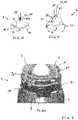
- Figure 1represents a side view of an embodiment of a medication inhaler 1 according to the present invention, also called a "spacer", that is suitable for providing a gaseous therapy to a patient, i.e. an aerosol drug pulmonary delivery.
- a spacerthat is suitable for providing a gaseous therapy to a patient, i.e. an aerosol drug pulmonary delivery.
- the medication inhaler 1comprises a housing 2 having an ellongated tubular shape having a longitudinal axis A-A, preferably a tronconical or cylindrical shape.
- the housing 2comprises an inner hollow chamber 3 (cf. Fig. 8 ) for containing the gaseous therapy (i.e. gaseous drug or the like) to be provided to the patient.
- the housing 2further comprises an exit orifice 4 (cf. Fig. 8 ) fluidly communicating with the hollow chamber 3 for allowing the gaseous therapy to leave the hollow chamber 3 and circulates in the direction of the patient's airways, while passing through the one-way valve 8 and the outlet 7 of the top cover 5, as below explained.
- the housing 2comprises two opposite ends, namely a top end 2a and a bottom end 2b.
- a bottom cover 15is detachably fixed to the bottom end 2b, whereas a top cover 5 is detachable fixed to the top end 2a.
- the bottom cover 15 and/or the top cover 5are attached to the housing 2 by a snap-fit connection system, a screw connection system or any other suitable locking mechanism or the like.
- the housing 2, the bottom cover 16 and the top cover 15are made from polymer material, such as plastic, or the like.
- the bottom cover 15 secured to housing 2comprises a bottom intlet 16 for plugging an aerosol drug delivery (ADD) device thereto, i.e. the bottom intlet 16 constitutes a central opening fluidly communicating with inner hollow chamber 3 of housing 2.
- intlet 16is configured and sized, i.e. structured and/or designed, for receiving and holding an ADD device that is plugged therein.
- top cover 5comprises an outlet 7 in fluid communication with the hollow chamber 3 of the housing 2, via the exit orifice 4 of said housing 2.
- Outlet 7is further in fluid communication with a respiratory interface (not shown), such as a respiratory mask or mouthpiece, that is detachably secured to the top cover 5, and used to administering the gaseous therapy to the patient.
- a respiratory interfacesuch as a respiratory mask or mouthpiece
- the outlet 7is arranged in the roof portion 5b, also called roof 21, of top cover 5, preferably outlet 7 is carried by a hollow neck 22 or the like, that can be located at the center of the roof portion 5b of top cover 5.
- the outlet 7 of top cover 5, the bottom intlet 16 of bottom cover 15 and the the exit orifice 4 of housing 2are co-axially arranged, i.e. on axis A-A of the housing 2 as shown in Figure 1 .
- top cover 5has a generally cup-like form. It comprises a sleeve portion 20 (i.e. tubullar) having a generally-cylindrical or tronconical shape and terminated/closed, at its top end, by roof 21 comprising the hollow neck 22 terminated by outlet 7.
- sleeve portion 20i.e. tubullar
- roof 21comprising the hollow neck 22 terminated by outlet 7.
- Top cover 5namely sleeve portion 20 and roof 21, defines with the top end 2a of housing 2, an inner compartment 6.
- inner compartment 6 delimited by the inner walls of top cover 5 and outer upper end wall 2c of housing 2is in fluid communication with:
- the outer upper end wall 2c of housing 2constitues at least a part of the bottom wall 6a of the inner compartment 6.
- a one-way valve 8preferably a duck beak valve as shown in Figures 4 and 5 , is arranged between top cap 5 and housing 2, as shown in Figures 3 and 8 .
- One-way valve 8faces the exit orifice 4 of housing 2.
- one-way valve 8is designed and arranged for allowing gas to circulate :
- one-way valve 8embodieously a duck beak valve as shown in Figures 4, 5 and 14 , opens to allow a gaseous flow, e.g. an aerosolized medication generated into hollow chamber 3 of housing 2, to reach the patient's airways, during the inhalation phases of the patient, whereas it closes for prohibiting CO 2 -enriched gases expired by the patient to flow back into hollow chamber 3 of housing 2, during the exhalation (i.e. expiration) phases of the patient.
- a gaseous flowe.g. an aerosolized medication generated into hollow chamber 3 of housing 2
- FIG. 4An embodiment of a duck beak valve useable as one-way valve 8 is shown in Figures 4, 5 and 14 . It comprises a hollow body 81 comprising a cylindrical portion 81a and a duck beak shape portion 81b defining a beak outlet 83 comprising a central slot 82 for controlling the gas flow.
- the slot 82is located at the apex or crest 86 of two angled surfaces 85 projecting upwardly and that meet at said crest 86.
- Slot 82allows the aerosolized flow exiting the ellongated hollow chamber 3 of housing 2, to pass therethrough, in the direction of the outlet 7 of the top cover 5 so as to reach the user's airways and to treat him/her.
- the duck beak valve useable as one-way valve 8can comprise several slots 82, such as 2 slots forming together a "+", an "x" or any other suitable shape.
- a peripheral annular border 84 forming a flexible peripheral skirtis attached to and surrounding the cylindrical portion 81a of the hollow body 81 of the valve 8.
- the peripheral annular border 84 or flexible peripheral skirtis squeezed between walls or structures of top cap 5 and housing 2, such as the annular rim or border 40 located around exit orifice 4 (cf. Fig. 9 ), thereby forming a gas seal that forces the gas to pass through slot 82, during the inspiratory phases of the patient, and, in contrast, to prohibit CO 2 -enriched gas to leak between top cover and housing, and go back into the inner chamber 3 of the housing 2, during the expiratory phases of the patient.
- holes 87are arranged in the peripheral annular border 84 of the one-way valve 8, that cooperate with several pins 11, picots or the like arranged in the housing 2, for instance arranged in the outer upper end wall 2c of housing 2 that constitues also the bottom wall 6a of inner compartment 6.
- Pins 11are lodged into holes 87 of flexible skirt 84 of the one-way valve 8, when the one-way valve 8 is positioned and secured on the housing 2, i.e. when sandwiched between the housing 2 and the top cover 5, for thereby maintaining the one-way valve 8 in a defined and fixed position on the housing 2, as shown in Figures 3 and 6 .
- the duck beak valve constituting one-way valve 8is made from a flexible/resilient material, such as silicone, elastomer, rubber or the like, preferably molded in one-piece.
- the duck beak valveworks as follows :
- venting channel 9is arranged in the housing 2 of the medication inhaler 1 as shown in Figures 6 and 8 . It comprises an entry port 9a and a venting port 9b.
- venting channel 9can be directly or indirectly arranged in the body of housing 2.
- the venting channel 9can be arranged in an independant element that is subsequently secured to the body of housing 2, such as the removable cassette 20 detailed hereafter in connection with Fig. 7 .
- the entry port 9a of venting channel 9is in fluid communication with the inner compartment 6 of the top cover 5, for example entry port 9a can be arranged directly in the outer upper end wall 2c of housing 2 that constitues also the bottom wall 6a of inner compartment 6 as shown in Figure 9 .
- venting port 9bis in fluid communication with the atmosphere for allowing CO 2 -enriched gas to be vented to the atmosphere.
- Venting channel 9has preferably an elongated arcuated shape as shown in Figure 6 .
- the venting channel 9is indirectly arranged in housing 2 as it is at least partially formed into an elongated arcuated hollow element forming a removable cassette 20 that is fixed to the housing 2, for example plugged into it, as shown in Figures 3 , 6 , and 12-14 .
- the removable cassette 20 shown in Figure 7comprises an inner passage terminated by orifices, i.e. an inlet 20a located at one end and an outlet 20b at the other end, and forming at least a part of the venting channel 9.
- Said removable cassette 20is secured into housing 2 so that its inlet 20a is positioned so as to face the entry port 9a arranged in the bottom 6a of inner compartment 6.
- inlet 20a of removable cassette 20 and entry port 9aare in fluid communication so that gas passing through entry port 9a (in the direction of venting port 9b) can enter into the lumen of said removable cassette 20 that constitutes, in this embodiment, at least a part of the venting channel 9.
- venting port 9bcan be either the outlet 20b itself of the removable cassette 20, or another orifice, preferably facing the outlet 20b of removable cassette 20 or fluidly communicating with it, depending on the embodiment.
- top cover 5also comprises a window 15 forming a large opening that is positionned in front of, i.e. facing, the venting port 9b, when the top cover 5 is secured onto housing 2, for instance by a screw, snap-fit or any other connection system.
- window 15can have various shapes, such as a notch.
- the sleeve portion 5a of top cover 5can be shorter and not recover the venting port 9b. In this case, a window 15, notch or the like is not required.
- a visual feedback systemhas been incorpoated into the medication inhaler 1 that provides an immediate information on the accomplishment of the respiratory acts.
- the visual feedback systemcomprises, i.e. a visual indicator, namely a mobile element 10 arranged into the venting channel 9, that can have a sphere, cylinder, ovoid or any other suitable shape.
- the mobile element 10is a little ball having a diameter that is sligthly less than the inner cross-dimension, namely the inner diameter or the like, of the lumen of the venting channel 9, for intance the inner cross-dimension of the inner passage traversing the removable cassette 20 of Figure 7 .
- the mobile element 10is a light little ball having a diameter of between 3 and 10 mm, preferably of between 4 and 7 mm, and/or a weight of less than 0.5 g, preferably less than 0.2 g, for instance of about 0.1 g, e.g. 0.08 g.
- the mobile element 10is preferably made from a light material, such as plastic or the like, such as polyamide (PA), for instance Nylon TM .
- a light materialsuch as plastic or the like, such as polyamide (PA), for instance Nylon TM .
- the mobile element 10can freely move, i.e. is mobile, into the venting channel 9 in the direction of the venting port 9b, when the patient exhales a CO 2 -enriched gas through the outlet 7 of the top cover 5 that successively flexes the flexible skirt of one-way valve 8, i.e. a duck beak valve, escapes the inner compartment 6 via entry port 9a of venting channel 9, circulates into venting channel 9 toward venting port 9b and is subsequantly evacuated to the atmosphere.
- a CO 2 -enriched gasthrough the outlet 7 of the top cover 5 that successively flexes the flexible skirt of one-way valve 8, i.e. a duck beak valve
- venting port 9be.g. its diameter or the like
- the size of venting port 9bis chosen to be less than the size of the mobile element 10, e.g. its diameter in the case of a ball, so that said mobile element 10 is kept into venting channel 9 and not allowed to escape.
- the light mobile element 10abuts against the inner walls of the venting channel 9 in the area of the venting port 9b but is retained in it, while being visible from the outside through said venting port 9b, as shown in Figure 10 .
- the medical staffcan also count the number of performed breaths, especially expiration phases of the patient, as they correspond to the number of times that the mobile element 10 travelling into the venting channel 9, has appeared in the area of the venting port 9b, over a given period of time, while the medication is delivered, thanks to the inhalation inhaler 1. This allows confirmation that the paediatric patient is breathing in the inhalation inhaler 1.
Landscapes
- Health & Medical Sciences (AREA)
- Engineering & Computer Science (AREA)
- Bioinformatics & Cheminformatics (AREA)
- Pulmonology (AREA)
- Anesthesiology (AREA)
- Biomedical Technology (AREA)
- Heart & Thoracic Surgery (AREA)
- Hematology (AREA)
- Life Sciences & Earth Sciences (AREA)
- Animal Behavior & Ethology (AREA)
- General Health & Medical Sciences (AREA)
- Public Health (AREA)
- Veterinary Medicine (AREA)
- Medicinal Preparation (AREA)
Description
- The present invention relates to a medication inhaler useable with a metered dose inhaler (MDI) for delivering a respiratory gaseous therapy, especially metered or pre-metered aerosolized doses of a medicinal product mixed with and transported by a carrier gas, such as air, to the human respiratory system of a patient in need thereof, especially of pediatric patients or the like, said medication inhaler comprising a visual feedback system allowing to immediately see whether a pediatric patient breathes through the medication inhaler.
- Aerosol drug delivery (ADD) devices are used for delivering various respiratory gaseous therapies, such as inhalable aerosols containing micro-particles or droplets of medication (i.e. a drug) to the lungs of a patient.
- An aerosol drug delivery (ADD) device usually comprises a medication inhaler fluidly coupled to a metered dose inhaler (MDI), typically a canister containing a medication and a pressurized gas for dispersing the medication.
- The medication inhaler generally comprises an elongated hollow holding chamber comprising an inlet opening into which the MDI is plugged, and an oulet opening in fluid communication with a respiratory interface, such as a respiratory mask or mouthpiece. The medication/gas mixture is delivered by the MDI into the hollow holding chamber of the medication inhaler, where it is mixed with a carrier gas, typically air, thereby generating a gaseous therapy containing micro-particles or droplets of medication, that is subsequently inhaled by a patient in need thereof.
- A diaphragm valve, such as a one-way valve, is generally arranged in the medication inhaler, typically adjacent to the respiratory interface, and designed/configured to open only when the patient inhales, for allowing a passage of medication from the hollow holding chamber of the medication inhaler to the lungs of the patient.
- ADD devices or assemblies comprising medication inhalers coupled to MDIs are disclosed by document
EP-A-2014325 andWO-A-03/097142 - Generally, several breaths of the patient are required for a full administration of the prescribed or desired drug dosage, i.e. so that the respiratory gaseous therapy is efficient.
- In other words, medication inhalers are efficient only if the patient accepts and follows his/her inhalation therapy.
- However, it has been noted in practice that it is not or rarely the case for a given population of patients, namely "pediatric patients", such as children, toddlers, babies or the like, as they are often either scared by medication inhalers and/or unable to stay calm while a medication inhaler is applied on their face. Some of them even totally refuse to inhale the aerosol.
- As a consequence, it is often difficult to know whether a paediatric patient, i.e. infant, baby, toddler or the like, has inhaled at least a part of the aerosolized medication delivered by a medication inhaler and thus has been at least partially treated.
- This is obviously an issue as it may lead to a lack of efficiency of the inhalation therapy if no or only a very low amount of medication has been inhaled by the pediatric patient.
- Examples of aerosol medication delivery devices are given by
US7201164 ,WO99/53982 WO2017/163211 ,US6039042 ,WO2012/061866 ,US2012/318261 andWO90/09203 - A problem is hence to provide an improved medication inhaler allowing a physician, a nurse or any other person (e.g. parents), to immediately know whether a patient, especially a paediatric patient, is correctly inhaling a gaseous therapy while it is delivered by a medication inhaler.
- A solution according to the present invention is a medication inhaler for delivering a gaseous therapy to a patient, especially a paediatric patient, comprising a housing, a top cover fixed to the housing, and an inner compartment arranged between said housing and said top cover, and wherein:
- the housing comprises a hollow chamber with an exit orifice, and the top cover comprises an outlet, said exit orifice of the hollow chamber and said outlet of the top cover being in fluid communication with the inner compartment,
- a venting channel comprising an entry port and a venting port, is in fluid communication with the inner compartment via the entry port and further with the atmosphere via the venting port, and
- a one-way valve is arranged in the inner compartment and configured for allowing gas to circulate :
- i) from the hollow chamber of the housing to the outlet of the top cover, when the patient inhales gas, and
- ii) from the outlet of the top cover to the venting channel, when the patient exhales gas,
characterized in that:- the mobile element has a spherical or cylindrical shape,
- at least a portion of the venting channel and the mobile element are arranged into a removable cassette having an elongated arcuated shape, and
- the removable cassette further comprises an inner passage with an inlet and an outlet, said inner passage forming at least a part of the venting channel.
- According to the invention, said mobile element moving "back and forth" into the venting channel, when the paediatric patient breathes gas, provides a visual feedback system allowing to immediately know from the outside, whether said paediatric patient is breathing gas. This provides a very useful information to the caregiver (e.g. nurse, physician, parents...).
- In accordance with the present invention, the "gaseous therapy" can comprise at least a therapeutically-effective compound, such as a medication or drug product (e.g. dropelets, powder, gaseous compound, aerosol...) mixed with and/or transported by a carrier gas, such as air.
- The medication inhaler for aerosol therapy, i.e. the aerosol inhalation device, according to the present invention can comprise one or several of the following additional features :
- the one-way valve comprises a flexible peripheral skirt that flexes toward housing, when the patient exhales gas through the outlet of the top cover, thereby allowing expired gas to enter into venting channel via entry port.
- the one-way valve is at least partially flexible.
- the mobile element is a ball or the like, preferably a light little ball or the like.
- the top cover comprises :
- a sleeve portion forming a sleeve around a top end of the housing, when the top cover is attached to the housing, and
- a roof portion secured to the sleeve portion, and comprising the outlet of the top cover.
- the inner chamber is delimited by the inner walls of the sleeve portion and of the roof portion of the top cover, and an outer end wall of the housing.
- the outer end wall of the housing forms the bottom wall of the inner chamber.
- the sleeve portion of the top cover comprises a window facing and in fluid communication with the venting port of the venting channel, when the top cover is attached to the housing.
- the one-way valve faces the exit orifice of the housing.
- the one-way valve comprises a peripheral annular border is sandwiched and squeezed between the top cap and the housing, thereby forming a gas seal.
- the mobile element has a diameter of less than 10 mm, preferably of about 5 mm.
- the mobile element has a weight of less than 1 g, preferably less than 0.5 g, more preferably less than 0.1 g, for instance of about 0.08 g.
- the mobile element is made from polymer material, preferably plastic, avantageously polyamide (PA).
- the mobile element is a ball (i.e. sphere) made of polyamide (PA), such as Nylon™ or the like.
- the mobile element can be colored for being better visible from the outside, for instance it can be red, orange, white, yellow etc...
- the top cover is detachably fixed to the upper end (i.e. top end) of the housing.
- the housing further comprises a bottom cover.
- the bottom cover is fixed to the bottom end of the housing.
- the bottom cover is detachably fixed to the bottom end of the housing, i.e. removable.
- the bottom cover comprises a bottom inlet for plugging an aerosol drug delivery (ADD) device thereto, such as a MDI (metered dose inhaler).
- the top cover has a generally cup-like shape.
- the bottom cover and/or the top cover are detachably fixed to the housing by a snap-fit connection system, a screw connection system or any other kind of locking mechanism.
- the housing, the bottom cover and the top cover are made of polymer material, such as plastic or the like.
- the one-way valve is a duck-beak valve.
- the one-way valve is sandwiched between the housing and the top cover.
- the one-way valve is a duck-beak valve made of a flexible material.
- the one-way valve is made of a polymeric material, such as silicone, elastomer, rubber or the like.
- the one-way valve is molded in one-piece.
- the one-way valve comprises a flexible peripheral collar or skirt.
- the peripheral collar or skirt of the one-way valve is traversed by several holes, preferably at least 3 holes, cooperating with several pins, preferably at least 3 pins, carried by the housing for well-positioning and securing the one-way valve.
- the pins of the housing are lodged into correspoding holes of the collar or skirt of the one-way valve, when the one-way valve is positioned/arranged on the housing, typically sandwiched between the housing and the top cover, for thereby maintaining the one-way valve in a defined and fixed position on the housing, i.e. between top cover and housing.
- the one-way valve comprises at least one slot for allowing the aerosolized flow passing therethrough, when the patients inhales the gaseous therapy from the hollow inner chamber of the housing.
- the housing has a general tubular shape, such as a tronconical or cylindrical shape.
- the housing is elongated.
- a respiratory interface, such as a respiratory mask or mouthpiece, is fixed to the top cover, preferably detachably fixed thereto.
- the outlet of the top cover is in fluid communication with the respiratory interface, such as a respiratory mask or mouthpiece.
- the bottom intlet of the bottom cover constitutes a central opening for plugging an ADD device thereto.
- the bottom intlet of the bottom cover is configured and sized for receiving and holding an ADD device.
- The present invention also concerns an aerosoltherapy assembly comprising a medication inhaler as described, and an aerosol drug delivery (ADD) device plugged into the bottom inlet of the bottom cover of said medication inhaler.
- The present invention will be explained in more details in the following illustrative description of an embodiment of a medication inhaler for aerosoltherapy, which is made in references to the accompanying drawings among them:
Figure 1 represents a side view of an embodiment of a medication inhaler according to the present invention comprising a top cap secured to a housing,Figure 2 represent a side view of the upper part of the medication inhaler ofFigure 1 ,Figure 3 shows the one-way valve arranged on the housing of the medication inhaler ofFigures 1 and 2 ,Figures 4 and 5 show how the one-way valve ofFigure 3 works during inspiration and expiration phases of the patient,Figure 6 represents an enlarged (partial) view of the upper part of the medication inhaler ofFigure 1 showing the venting channel and the mobile element arranged in it,Figure 7 represents an embodiment of a removable cassette comprising the venting channel and the mobile element ofFigure 6 ,Figure 8 represents a cross-sectional view of the upper part of the housing of the medication inhaler ofFigure 3 ,Figure 9 represents an enlarged (partial) view of the upper part of the medication inhaler ofFigure 1 shown without the one-way valve,Figure 10 shows the mobile element when located into the venting channel in the area of the venting port,Figure 11 represents a cross-sectional view of the upper part of the of the medication inhaler ofFigure 1 ,Figures 12 and 13 are side vews of the upper part of the of the medication inhaler ofFigure 1 comprising a cassette as shown inFigure 7 , andFigure 14 is a side view of the upper part of the medication inhaler ofFigure 1 comprising a cassette as shown inFigure 7 and a duck-beak valve.Figure 1 represents a side view of an embodiment of amedication inhaler 1 according to the present invention, also called a "spacer", that is suitable for providing a gaseous therapy to a patient, i.e. an aerosol drug pulmonary delivery.- The
medication inhaler 1 comprises ahousing 2 having an ellongated tubular shape having a longitudinal axis A-A, preferably a tronconical or cylindrical shape. Thehousing 2 comprises an inner hollow chamber 3 (cf.Fig. 8 ) for containing the gaseous therapy (i.e. gaseous drug or the like) to be provided to the patient. Thehousing 2 further comprises an exit orifice 4 (cf.Fig. 8 ) fluidly communicating with thehollow chamber 3 for allowing the gaseous therapy to leave thehollow chamber 3 and circulates in the direction of the patient's airways, while passing through the one-way valve 8 and theoutlet 7 of thetop cover 5, as below explained. - The
housing 2 comprises two opposite ends, namely a top end 2a and a bottom end 2b. Abottom cover 15 is detachably fixed to the bottom end 2b, whereas atop cover 5 is detachable fixed to the top end 2a. Thebottom cover 15 and/or thetop cover 5 are attached to thehousing 2 by a snap-fit connection system, a screw connection system or any other suitable locking mechanism or the like. - Preferably, the
housing 2, thebottom cover 16 and thetop cover 15 are made from polymer material, such as plastic, or the like. - The
bottom cover 15 secured tohousing 2 comprises abottom intlet 16 for plugging an aerosol drug delivery (ADD) device thereto, i.e. thebottom intlet 16 constitutes a central opening fluidly communicating with innerhollow chamber 3 ofhousing 2. Preferably, intlet 16 is configured and sized, i.e. structured and/or designed, for receiving and holding an ADD device that is plugged therein. - Further,
top cover 5 comprises anoutlet 7 in fluid communication with thehollow chamber 3 of thehousing 2, via theexit orifice 4 of saidhousing 2.Outlet 7 is further in fluid communication with a respiratory interface (not shown), such as a respiratory mask or mouthpiece, that is detachably secured to thetop cover 5, and used to administering the gaseous therapy to the patient. - The
outlet 7 is arranged in theroof portion 5b, also calledroof 21, oftop cover 5, preferablyoutlet 7 is carried by ahollow neck 22 or the like, that can be located at the center of theroof portion 5b oftop cover 5. - Preferably, the
outlet 7 oftop cover 5, thebottom intlet 16 ofbottom cover 15 and the theexit orifice 4 ofhousing 2 are co-axially arranged, i.e. on axis A-A of thehousing 2 as shown inFigure 1 . - In the embodiment of
Figures 1 and 2 ,top cover 5 has a generally cup-like form. It comprises a sleeve portion 20 (i.e. tubullar) having a generally-cylindrical or tronconical shape and terminated/closed, at its top end, byroof 21 comprising thehollow neck 22 terminated byoutlet 7. Top cover 5, namelysleeve portion 20 androof 21, defines with the top end 2a ofhousing 2, aninner compartment 6.- When
top cover 5 is secured tohousing 2, as represented inFigures 1 and 2 ,inner compartment 6 delimited by the inner walls oftop cover 5 and outer upper end wall 2c ofhousing 2, is in fluid communication with: - on the one hand, with a respiratory interface (i.e. mask or the like) via the lumen of the
hollow neck 22 andoutlet 7, and - on the other hand, with the
hollow chamber 3 ofhousing 2, viaexit orifice 4. - In other words, the outer upper end wall 2c of
housing 2 constitues at least a part of the bottom wall 6a of theinner compartment 6. - For controlling the gas flows in
inner chamber 6, a one-way valve 8, preferably a duck beak valve as shown inFigures 4 and 5 , is arranged betweentop cap 5 andhousing 2, as shown inFigures 3 and8 . One-way valve 8 faces theexit orifice 4 ofhousing 2. - More precisely, one-
way valve 8 is designed and arranged for allowing gas to circulate : - i) from
hollow chamber 3 ofhousing 2 towardoutlet 7 oftop cover 5, i.e. throughinner compartment 6, when the patient inhales gas (i.e. a gaseous medication) via theneck 22 carrying theoutlet 7 and the respiratory interface secured toneck 22, as shown inFigure 4 , and - ii) from
outlet 7 oftop cover 5 back toinner compartment 6, when the patient exhales gas, i.e. CO2-enriched gases coming from the lungs of the patient, into the respiratory interface fluidly connected tooutlet 7, especially to theneck 22 oftop cover 5, as shown inFigure 5 . - In other words, one-
way valve 8, avantageously a duck beak valve as shown inFigures 4, 5 and14 , opens to allow a gaseous flow, e.g. an aerosolized medication generated intohollow chamber 3 ofhousing 2, to reach the patient's airways, during the inhalation phases of the patient, whereas it closes for prohibiting CO2-enriched gases expired by the patient to flow back intohollow chamber 3 ofhousing 2, during the exhalation (i.e. expiration) phases of the patient. - An embodiment of a duck beak valve useable as one-
way valve 8 is shown inFigures 4, 5 and14 . It comprises ahollow body 81 comprising a cylindrical portion 81a and a duck beak shape portion 81b defining abeak outlet 83 comprising acentral slot 82 for controlling the gas flow. Theslot 82 is located at the apex or crest 86 of twoangled surfaces 85 projecting upwardly and that meet at said crest 86. Slot 82 allows the aerosolized flow exiting the ellongatedhollow chamber 3 ofhousing 2, to pass therethrough, in the direction of theoutlet 7 of thetop cover 5 so as to reach the user's airways and to treat him/her. In other embodiments, the duck beak valve useable as one-way valve 8 can compriseseveral slots 82, such as 2 slots forming together a "+", an "x" or any other suitable shape.- A peripheral
annular border 84 forming a flexible peripheral skirt is attached to and surrounding the cylindrical portion 81a of thehollow body 81 of thevalve 8. When sandwiched between thetop cap 5 and thehousing 2, the peripheralannular border 84 or flexible peripheral skirt is squeezed between walls or structures oftop cap 5 andhousing 2, such as the annular rim orborder 40 located around exit orifice 4 (cf.Fig. 9 ), thereby forming a gas seal that forces the gas to pass throughslot 82, during the inspiratory phases of the patient, and, in contrast, to prohibit CO2-enriched gas to leak between top cover and housing, and go back into theinner chamber 3 of thehousing 2, during the expiratory phases of the patient. - For well-positioning and securing the one-
way valve 8 betweentop cap 5 andhousing 2,several holes 87, preferably at least 3 holes, are arranged in the peripheralannular border 84 of the one-way valve 8, that cooperate withseveral pins 11, picots or the like arranged in thehousing 2, for instance arranged in the outer upper end wall 2c ofhousing 2 that constitues also the bottom wall 6a ofinner compartment 6.Pins 11 are lodged intoholes 87 offlexible skirt 84 of the one-way valve 8, when the one-way valve 8 is positioned and secured on thehousing 2, i.e. when sandwiched between thehousing 2 and thetop cover 5, for thereby maintaining the one-way valve 8 in a defined and fixed position on thehousing 2, as shown inFigures 3 and6 . - The duck beak valve constituting one-
way valve 8 is made from a flexible/resilient material, such as silicone, elastomer, rubber or the like, preferably molded in one-piece. - The duck beak valve works as follows :
- during the inhalation phases of the patient (
Fig. 4 ), the drug-containing gas passes through the duck beak valve constituting a one-way valve 8, namely it flows through the lumen of thehollow body 81 and exits through theslot 82 of thebeak outlet 83 as saidslot 82 is open by the gas pressure/flowrate, and - during the expiration phases of the patient (
Fig. 5 ), the gases expired by the patient, namely CO2-enriched gases, cannot pass through the duck beak valve due to its particular shape, as theslot 82 of thebeak outlet 83 is closed by the action of the pressure/flowrate of the gases expired by the patient that acts on the angled surfaces 85. At the same time, expired gases create on overpressure intoinner compartment 6 oftop cover 5 that bends and deforms one or several portions of the peripheralannular border 84 forming the flexible peripheral skirt of the duck beak valve, thereby creating gas passages (i.e. leak passages) for the expired gases, allowing them to escape theinner compartment 6 and be vented to the atmosphere, through a ventingchannel 9 arranged in the body of thehousing 2. In other words, CO2-enriched gases expired by the patient are recovered byinner compartment 6 and immediatey evacuated by ventingchannel 9 that is fluidly communicating, on the one hand, withinner compartment 6 and, on the other hand, with the atmosphere. - More precisely, venting
channel 9 is arranged in thehousing 2 of themedication inhaler 1 as shown inFigures 6 and8 . It comprises anentry port 9a and a venting port 9b. - Depending on the embodiment, venting
channel 9 can be directly or indirectly arranged in the body ofhousing 2. In particular, the ventingchannel 9 can be arranged in an independant element that is subsequently secured to the body ofhousing 2, such as theremovable cassette 20 detailed hereafter in connexion withFig. 7 . - The
entry port 9a of ventingchannel 9 is in fluid communication with theinner compartment 6 of thetop cover 5, forexample entry port 9a can be arranged directly in the outer upper end wall 2c ofhousing 2 that constitues also the bottom wall 6a ofinner compartment 6 as shown inFigure 9 . - Further, venting port 9b is in fluid communication with the atmosphere for allowing CO2-enriched gas to be vented to the atmosphere.
- Venting
channel 9 has preferably an elongated arcuated shape as shown inFigure 6 . - According to one embodiment shown in
Figure 7 , the ventingchannel 9 is indirectly arranged inhousing 2 as it is at least partially formed into an elongated arcuated hollow element forming aremovable cassette 20 that is fixed to thehousing 2, for example plugged into it, as shown inFigures 3 ,6 , and12-14 . - The
removable cassette 20 shown inFigure 7 comprises an inner passage terminated by orifices, i.e. an inlet 20a located at one end and anoutlet 20b at the other end, and forming at least a part of the ventingchannel 9. - Said
removable cassette 20 is secured intohousing 2 so that its inlet 20a is positioned so as to face theentry port 9a arranged in the bottom 6a ofinner compartment 6. In other words, inlet 20a ofremovable cassette 20 andentry port 9a are in fluid communication so that gas passing throughentry port 9a (in the direction of venting port 9b) can enter into the lumen of saidremovable cassette 20 that constitutes, in this embodiment, at least a part of the ventingchannel 9. - At the other end, venting port 9b can be either the
outlet 20b itself of theremovable cassette 20, or another orifice, preferably facing theoutlet 20b ofremovable cassette 20 or fluidly communicating with it, depending on the embodiment. - Furthermore, in the embodiment shown in
Figures 1 and 2 ,top cover 5 also comprises awindow 15 forming a large opening that is positionned in front of, i.e. facing, the venting port 9b, when thetop cover 5 is secured ontohousing 2, for instance by a screw, snap-fit or any other connection system. However,window 15 can have various shapes, such as a notch. - Further, in other embodiments, the
sleeve portion 5a oftop cover 5 can be shorter and not recover the venting port 9b. In this case, awindow 15, notch or the like is not required. - As above explained, a lot of pediatric patients, such as babies, toddlers or young infants, are either scared by medication inhalers and/or unable to stay calm while a medication inhaler is applied on their face. As a consequence, they either totally refuse to inhale the aerosol or, at best, inhale only a part of the medication. This may result in a lack of efficiency of the inhalation therapy, depending on the amount of aerosolized medication inhaled by the paediatric patient.
- In other words, it is often difficult to know whether a paediatric patient, i.e. infant, baby, toddler or the like, has inhaled at least a part of the aerosolized medication delivered by a medication inhaler and thus has been at least partially treated.
- According to the present invention, for assisting the medical staff or the like in its assessment of the amount of medication inhaled by a paediatric patient, a visual feedback system has been incorpoated into the
medication inhaler 1 that provides an immediate information on the accomplishment of the respiratory acts. - More precisely, the visual feedback system according to the present invention comprises, i.e. a visual indicator, namely a
mobile element 10 arranged into the ventingchannel 9, that can have a sphere, cylinder, ovoid or any other suitable shape. - According to a preferred embodiment, the
mobile element 10 is a little ball having a diameter that is sligthly less than the inner cross-dimension, namely the inner diameter or the like, of the lumen of the ventingchannel 9, for intance the inner cross-dimension of the inner passage traversing theremovable cassette 20 ofFigure 7 . For instance, themobile element 10 is a light little ball having a diameter of between 3 and 10 mm, preferably of between 4 and 7 mm, and/or a weight of less than 0.5 g, preferably less than 0.2 g, for instance of about 0.1 g, e.g. 0.08 g. - The
mobile element 10 is preferably made from a light material, such as plastic or the like, such as polyamide (PA), for instance Nylon™. - The
mobile element 10 can freely move, i.e. is mobile, into the ventingchannel 9 in the direction of the venting port 9b, when the patient exhales a CO2-enriched gas through theoutlet 7 of thetop cover 5 that successively flexes the flexible skirt of one-way valve 8, i.e. a duck beak valve, escapes theinner compartment 6 viaentry port 9a of ventingchannel 9, circulates into ventingchannel 9 toward venting port 9b and is subsequantly evacuated to the atmosphere. - Thus, when the patient exhales gases, said gases push against the
mobile element 10, i.e. little ball or the like, thereby forcing it to move toward the venting port 9b. Preferably, the size of venting port 9b, e.g. its diameter or the like, is chosen to be less than the size of themobile element 10, e.g. its diameter in the case of a ball, so that saidmobile element 10 is kept into ventingchannel 9 and not allowed to escape. - In other words, the light
mobile element 10 abuts against the inner walls of the ventingchannel 9 in the area of the venting port 9b but is retained in it, while being visible from the outside through said venting port 9b, as shown inFigure 10 . - This allows the medical staff or members of patient's family, to immediately see said
mobile element 10, from the outside, and ascertain whether or not the patient breathes in theinhalation inhaler 1, especially whether or not the patient has expired CO2-enriched gases through the ventingchannel 9. Indeed, if it is the case, themobile element 10 will be pushed by the gas flow toward the venting port 9b and will show up in the area of the ventingchannel 9 located immediately behind the venting port 9b and be visible from the outside. - Thanks to the invention, the medical staff can also count the number of performed breaths, especially expiration phases of the patient, as they correspond to the number of times that the
mobile element 10 travelling into the ventingchannel 9, has appeared in the area of the venting port 9b, over a given period of time, while the medication is delivered, thanks to theinhalation inhaler 1. This allows confirmation that the paediatric patient is breathing in theinhalation inhaler 1.
Claims (15)
- Medication inhaler (1) for delivering a gaseous therapy to a patient comprising a housing (2), a top cover (5) fixed to the housing (2) and an inner compartment (6) arranged between said housing (2) and said top cover (5), and wherein:- the housing (2) comprises a hollow chamber (3) with an exit orifice (4), and the top cover (5) comprises an outlet (7), said exit orifice (4) of the hollow chamber (3) and said outlet (7) of the top cover (5) being in fluid communication with the inner compartment (6),- a venting channel (9) comprising an entry port (9a) and a venting port (9b), is in fluid communication with the inner compartment (6) via the entry port (9a) and further with the atmosphere via the venting port (9b), and- a one-way valve (8) is arranged in the inner compartment (6) and configured for allowing gas to circulate :i) from the hollow chamber (3) of the housing (2) to the outlet (7) of the top cover (5), when the patient inhales gas, andii) from the outlet (7) of the top cover (5) to the venting channel (9), when the patient exhales gas,wherein the venting channel (9) comprises a mobile element (10) that moves into said venting channel (9) in the direction of the venting port (9b), said mobile element (10) being retained in the area of the venting port (9b) and visible from the outside through said venting port (9b), when the patient exhales gas through the outlet (7) of the top cover (5), thereby providing a visual feedback system allowing to immediately know from the outside, whether said patient is breathing gas,
characterized in that:- the mobile element (10) has a spherical or cylindrical shape,- at least a portion of the venting channel (9) and the mobile element (10) are arranged into a removable cassette (20) having an elongated arcuated shape, and- the removable cassette (20) further comprises an inner passage with an inlet (20a) and an outlet (20b), said inner passage forming at least a part of the venting channel (9). - Medication inhaler (1) according to the preceding claim,characterized in that the one-way valve (8) is a duck-beak valve, preferably at least partially flexible.
- Medication inhaler (1) according to any one of the preceeding claims,characterized in that the one-way valve (8) comprises a flexible peripheral skirt (84) that flexes toward housing (2), when the patient exhales gas through the outlet (7) of the top cover (5), thereby allowing expired gas to enter into venting channel (9) via entry port (9a).
- Medication inhaler (1) according to any one of the preceeding claims,characterized in that the mobile element (10) is a ball.
- Medication inhaler (1) according to Claim 1,characterized in that:- the inlet (20a) of the removable cassette (20) and the entry port (9a) of the venting channel (9) are in fluid communication, and- the outlet (20b) of the removable cassette (20) either constitutes the venting port (9b), or faces and is in fluid communication with the venting port (9b).
- Medication inhaler (1) according to any one of the preceeding claims,characterized in that the top cover (5) comprises :- a sleeve portion (5a) forming a sleeve around a top end (2b) of the housing (2), when the top cover (5) is attached to the housing (2),- a roof portion (5b) secured to the sleeve portion (5a), and comprising the outlet (7) of the top cover (5).
- Medication inhaler (1) according to any one of the preceeding claims,characterized in that the inner chamber (6) is delimited by the inner walls of the sleeve portion (5a) and of the roof portion (5b) of the top cover (5), and an outer end wall (2c) of the housing (2), preferably the outer end wall (2c) of the housing (2) forms the bottom wall (6a) of the inner chamber (6).
- Medication inhaler (1) according to claim 6,characterized in that the sleeve portion (5a) of the top cover (5) comprises a window (55) facing and in fluid communication with the venting port (9b; 20b) of the venting channel (9), when the top cover (5) is attached to the housing (2).
- Medication inhaler (1) according to any one of the preceeding claims,characterized in that the one-way valve (10) faces the exit orifice (4) of the housing (2) and/or comprises a peripheral annular border (84) is sandwiched and squeezed between the top cap (5) and the housing (2), thereby forming a gas seal.
- Medication inhaler (1) according to any one of the preceeding claims,characterized in that the venting channel (9) has an elongated arcuated shape.
- Medication inhaler (1) according to any one of the preceeding claims,characterized in that the mobile element (10) has a diameter of less than 10 mm, preferably of about 5 mm.
- Medication inhaler (1) according to any one of the preceeding claims,characterized in that the mobile element (10) is made from polymer material, preferably polyamide.
- Medication inhaler (1) according to any one of the preceeding claims,characterized in that the housing (2) further comprises a bottom cover (15) comprising a bottom inlet (16) configured for plugging an aerosol drug delivery (ADD) device thereto.
- Medication inhaler (1) according to any one of the preceeding claims,characterized in that the mobile element (10) has a weight of less 1 g, preferably less than 0,5 g.
- Aerosoltherapy assembly comprising a medication inhaler (1) according to any one of the preceeding claims and an aerosol drug delivery (ADD) device plugged into the bottom inlet (16) of the bottom cover (15) of said medication inhaler (1).
Priority Applications (1)
| Application Number | Priority Date | Filing Date | Title |
|---|---|---|---|
| EP19151965.1AEP3682923B1 (en) | 2019-01-15 | 2019-01-15 | Medication inhaler for aerosol pulmonary delivery with visual feedback system |
Applications Claiming Priority (1)
| Application Number | Priority Date | Filing Date | Title |
|---|---|---|---|
| EP19151965.1AEP3682923B1 (en) | 2019-01-15 | 2019-01-15 | Medication inhaler for aerosol pulmonary delivery with visual feedback system |
Publications (2)
| Publication Number | Publication Date |
|---|---|
| EP3682923A1 EP3682923A1 (en) | 2020-07-22 |
| EP3682923B1true EP3682923B1 (en) | 2021-12-15 |
Family
ID=65033441
Family Applications (1)
| Application Number | Title | Priority Date | Filing Date |
|---|---|---|---|
| EP19151965.1AActiveEP3682923B1 (en) | 2019-01-15 | 2019-01-15 | Medication inhaler for aerosol pulmonary delivery with visual feedback system |
Country Status (1)
| Country | Link |
|---|---|
| EP (1) | EP3682923B1 (en) |
Families Citing this family (1)
| Publication number | Priority date | Publication date | Assignee | Title |
|---|---|---|---|---|
| CN112546321B (en)* | 2020-12-03 | 2022-06-21 | 成都市赛恒尔医疗科技有限公司 | Membrane oxygenator |
Citations (2)
| Publication number | Priority date | Publication date | Assignee | Title |
|---|---|---|---|---|
| WO1999053982A1 (en)* | 1998-04-20 | 1999-10-28 | Infamed Ltd. | Improved drug delivery device and methods therefor |
| WO2017163211A1 (en)* | 2016-03-24 | 2017-09-28 | Trudell Medical International | Respiratory care system with electronic indicator |
Family Cites Families (9)
| Publication number | Priority date | Publication date | Assignee | Title |
|---|---|---|---|---|
| EP0311770B1 (en)* | 1987-08-14 | 1993-05-19 | Udo Dr. Raupach | Device for respiration therapy |
| US5522380A (en)* | 1995-01-18 | 1996-06-04 | Dwork; Paul | Metered dose medication adaptor with improved incentive spirometer |
| IT1276916B1 (en)* | 1995-10-12 | 1997-11-03 | Istoria Farmaceutici S P A | DEVICE FOR THE TREATMENT OF ASTHMATIC PATIENTS, ABLE TO MEASURE PEAK EXPIRATORY FLOW AND DELIVERY DRUGS FOR THE |
| US6039042A (en)* | 1998-02-23 | 2000-03-21 | Thayer Medical Corporation | Portable chamber for metered dose inhaler dispensers |
| WO2003092777A1 (en)* | 2002-05-03 | 2003-11-13 | Trudell Medical International | Aerosol medication delivery apparatus with narrow orifice |
| US6904908B2 (en) | 2002-05-21 | 2005-06-14 | Trudell Medical International | Visual indicator for an aerosol medication delivery apparatus and system |
| DE602007005938D1 (en) | 2007-06-06 | 2010-05-27 | Air Liquide Medical Systems S | Disposable membrane valve for an aerosol inhalation system for delivering the aerosol to the lungs |
| AU333977S (en)* | 2010-11-10 | 2010-12-03 | Medical Developments International Ltd | Valve for a spacer |
| US20120318261A1 (en)* | 2011-06-17 | 2012-12-20 | Nostrum Technology Llc | Valved Holding Chamber With Whistle for the Administration of Inhalable Drugs |
- 2019
- 2019-01-15EPEP19151965.1Apatent/EP3682923B1/enactiveActive
Patent Citations (2)
| Publication number | Priority date | Publication date | Assignee | Title |
|---|---|---|---|---|
| WO1999053982A1 (en)* | 1998-04-20 | 1999-10-28 | Infamed Ltd. | Improved drug delivery device and methods therefor |
| WO2017163211A1 (en)* | 2016-03-24 | 2017-09-28 | Trudell Medical International | Respiratory care system with electronic indicator |
Also Published As
| Publication number | Publication date |
|---|---|
| EP3682923A1 (en) | 2020-07-22 |
Similar Documents
| Publication | Publication Date | Title |
|---|---|---|
| US11266795B2 (en) | Breath actuated nebulizer | |
| US5816240A (en) | Spacer | |
| US7080643B2 (en) | Nebulizer apparatus and method | |
| CA2329126C (en) | Improved drug delivery device and methods therefor | |
| JP4485351B2 (en) | Flow display device and supply device provided with flow display device | |
| US11577033B2 (en) | Valved spacer for inhalation device | |
| KR20230053584A (en) | artificial nipple | |
| EP3682923B1 (en) | Medication inhaler for aerosol pulmonary delivery with visual feedback system | |
| EP3536367B1 (en) | Medication inhaler for aerosol pulmonary delivery with specific pattern recognizable by an electronic device | |
| US20080190420A1 (en) | Aerosol Medication Delivery Apparatus | |
| AU2004203608A1 (en) | Improved Drug Delivery Device and Methods Therefor | |
| ZA200005791B (en) | Improved drug delivery device and methods therefor. |
Legal Events
| Date | Code | Title | Description |
|---|---|---|---|
| PUAI | Public reference made under article 153(3) epc to a published international application that has entered the european phase | Free format text:ORIGINAL CODE: 0009012 | |
| STAA | Information on the status of an ep patent application or granted ep patent | Free format text:STATUS: THE APPLICATION HAS BEEN PUBLISHED | |
| AK | Designated contracting states | Kind code of ref document:A1 Designated state(s):AL AT BE BG CH CY CZ DE DK EE ES FI FR GB GR HR HU IE IS IT LI LT LU LV MC MK MT NL NO PL PT RO RS SE SI SK SM TR | |
| AX | Request for extension of the european patent | Extension state:BA ME | |
| STAA | Information on the status of an ep patent application or granted ep patent | Free format text:STATUS: REQUEST FOR EXAMINATION WAS MADE | |
| 17P | Request for examination filed | Effective date:20210122 | |
| RBV | Designated contracting states (corrected) | Designated state(s):AL AT BE BG CH CY CZ DE DK EE ES FI FR GB GR HR HU IE IS IT LI LT LU LV MC MK MT NL NO PL PT RO RS SE SI SK SM TR | |
| STAA | Information on the status of an ep patent application or granted ep patent | Free format text:STATUS: EXAMINATION IS IN PROGRESS | |
| 17Q | First examination report despatched | Effective date:20210617 | |
| GRAP | Despatch of communication of intention to grant a patent | Free format text:ORIGINAL CODE: EPIDOSNIGR1 | |
| STAA | Information on the status of an ep patent application or granted ep patent | Free format text:STATUS: GRANT OF PATENT IS INTENDED | |
| INTG | Intention to grant announced | Effective date:20210920 | |
| GRAS | Grant fee paid | Free format text:ORIGINAL CODE: EPIDOSNIGR3 | |
| GRAA | (expected) grant | Free format text:ORIGINAL CODE: 0009210 | |
| STAA | Information on the status of an ep patent application or granted ep patent | Free format text:STATUS: THE PATENT HAS BEEN GRANTED | |
| AK | Designated contracting states | Kind code of ref document:B1 Designated state(s):AL AT BE BG CH CY CZ DE DK EE ES FI FR GB GR HR HU IE IS IT LI LT LU LV MC MK MT NL NO PL PT RO RS SE SI SK SM TR | |
| REG | Reference to a national code | Ref country code:GB Ref legal event code:FG4D Ref country code:CH Ref legal event code:EP | |
| REG | Reference to a national code | Ref country code:IE Ref legal event code:FG4D Ref country code:DE Ref legal event code:R096 Ref document number:602019009976 Country of ref document:DE | |
| REG | Reference to a national code | Ref country code:AT Ref legal event code:REF Ref document number:1454994 Country of ref document:AT Kind code of ref document:T Effective date:20220115 | |
| REG | Reference to a national code | Ref country code:LT Ref legal event code:MG9D | |
| REG | Reference to a national code | Ref country code:NL Ref legal event code:MP Effective date:20211215 | |
| PG25 | Lapsed in a contracting state [announced via postgrant information from national office to epo] | Ref country code:RS Free format text:LAPSE BECAUSE OF FAILURE TO SUBMIT A TRANSLATION OF THE DESCRIPTION OR TO PAY THE FEE WITHIN THE PRESCRIBED TIME-LIMIT Effective date:20211215 Ref country code:LT Free format text:LAPSE BECAUSE OF FAILURE TO SUBMIT A TRANSLATION OF THE DESCRIPTION OR TO PAY THE FEE WITHIN THE PRESCRIBED TIME-LIMIT Effective date:20211215 Ref country code:FI Free format text:LAPSE BECAUSE OF FAILURE TO SUBMIT A TRANSLATION OF THE DESCRIPTION OR TO PAY THE FEE WITHIN THE PRESCRIBED TIME-LIMIT Effective date:20211215 Ref country code:BG Free format text:LAPSE BECAUSE OF FAILURE TO SUBMIT A TRANSLATION OF THE DESCRIPTION OR TO PAY THE FEE WITHIN THE PRESCRIBED TIME-LIMIT Effective date:20220315 | |
| REG | Reference to a national code | Ref country code:AT Ref legal event code:MK05 Ref document number:1454994 Country of ref document:AT Kind code of ref document:T Effective date:20211215 | |
| PG25 | Lapsed in a contracting state [announced via postgrant information from national office to epo] | Ref country code:SE Free format text:LAPSE BECAUSE OF FAILURE TO SUBMIT A TRANSLATION OF THE DESCRIPTION OR TO PAY THE FEE WITHIN THE PRESCRIBED TIME-LIMIT Effective date:20211215 Ref country code:NO Free format text:LAPSE BECAUSE OF FAILURE TO SUBMIT A TRANSLATION OF THE DESCRIPTION OR TO PAY THE FEE WITHIN THE PRESCRIBED TIME-LIMIT Effective date:20220315 Ref country code:LV Free format text:LAPSE BECAUSE OF FAILURE TO SUBMIT A TRANSLATION OF THE DESCRIPTION OR TO PAY THE FEE WITHIN THE PRESCRIBED TIME-LIMIT Effective date:20211215 Ref country code:HR Free format text:LAPSE BECAUSE OF FAILURE TO SUBMIT A TRANSLATION OF THE DESCRIPTION OR TO PAY THE FEE WITHIN THE PRESCRIBED TIME-LIMIT Effective date:20211215 Ref country code:GR Free format text:LAPSE BECAUSE OF FAILURE TO SUBMIT A TRANSLATION OF THE DESCRIPTION OR TO PAY THE FEE WITHIN THE PRESCRIBED TIME-LIMIT Effective date:20220316 | |
| PG25 | Lapsed in a contracting state [announced via postgrant information from national office to epo] | Ref country code:NL Free format text:LAPSE BECAUSE OF FAILURE TO SUBMIT A TRANSLATION OF THE DESCRIPTION OR TO PAY THE FEE WITHIN THE PRESCRIBED TIME-LIMIT Effective date:20211215 | |
| PG25 | Lapsed in a contracting state [announced via postgrant information from national office to epo] | Ref country code:SM Free format text:LAPSE BECAUSE OF FAILURE TO SUBMIT A TRANSLATION OF THE DESCRIPTION OR TO PAY THE FEE WITHIN THE PRESCRIBED TIME-LIMIT Effective date:20211215 Ref country code:SK Free format text:LAPSE BECAUSE OF FAILURE TO SUBMIT A TRANSLATION OF THE DESCRIPTION OR TO PAY THE FEE WITHIN THE PRESCRIBED TIME-LIMIT Effective date:20211215 Ref country code:RO Free format text:LAPSE BECAUSE OF FAILURE TO SUBMIT A TRANSLATION OF THE DESCRIPTION OR TO PAY THE FEE WITHIN THE PRESCRIBED TIME-LIMIT Effective date:20211215 Ref country code:PT Free format text:LAPSE BECAUSE OF FAILURE TO SUBMIT A TRANSLATION OF THE DESCRIPTION OR TO PAY THE FEE WITHIN THE PRESCRIBED TIME-LIMIT Effective date:20220418 Ref country code:ES Free format text:LAPSE BECAUSE OF FAILURE TO SUBMIT A TRANSLATION OF THE DESCRIPTION OR TO PAY THE FEE WITHIN THE PRESCRIBED TIME-LIMIT Effective date:20211215 Ref country code:EE Free format text:LAPSE BECAUSE OF FAILURE TO SUBMIT A TRANSLATION OF THE DESCRIPTION OR TO PAY THE FEE WITHIN THE PRESCRIBED TIME-LIMIT Effective date:20211215 Ref country code:CZ Free format text:LAPSE BECAUSE OF FAILURE TO SUBMIT A TRANSLATION OF THE DESCRIPTION OR TO PAY THE FEE WITHIN THE PRESCRIBED TIME-LIMIT Effective date:20211215 | |
| REG | Reference to a national code | Ref country code:DE Ref legal event code:R119 Ref document number:602019009976 Country of ref document:DE | |
| PG25 | Lapsed in a contracting state [announced via postgrant information from national office to epo] | Ref country code:PL Free format text:LAPSE BECAUSE OF FAILURE TO SUBMIT A TRANSLATION OF THE DESCRIPTION OR TO PAY THE FEE WITHIN THE PRESCRIBED TIME-LIMIT Effective date:20211215 Ref country code:AT Free format text:LAPSE BECAUSE OF FAILURE TO SUBMIT A TRANSLATION OF THE DESCRIPTION OR TO PAY THE FEE WITHIN THE PRESCRIBED TIME-LIMIT Effective date:20211215 | |
| REG | Reference to a national code | Ref country code:CH Ref legal event code:PL | |
| PG25 | Lapsed in a contracting state [announced via postgrant information from national office to epo] | Ref country code:MC Free format text:LAPSE BECAUSE OF FAILURE TO SUBMIT A TRANSLATION OF THE DESCRIPTION OR TO PAY THE FEE WITHIN THE PRESCRIBED TIME-LIMIT Effective date:20211215 Ref country code:IS Free format text:LAPSE BECAUSE OF FAILURE TO SUBMIT A TRANSLATION OF THE DESCRIPTION OR TO PAY THE FEE WITHIN THE PRESCRIBED TIME-LIMIT Effective date:20220415 | |
| REG | Reference to a national code | Ref country code:BE Ref legal event code:MM Effective date:20220131 | |
| PLBE | No opposition filed within time limit | Free format text:ORIGINAL CODE: 0009261 | |
| STAA | Information on the status of an ep patent application or granted ep patent | Free format text:STATUS: NO OPPOSITION FILED WITHIN TIME LIMIT | |
| PG25 | Lapsed in a contracting state [announced via postgrant information from national office to epo] | Ref country code:LU Free format text:LAPSE BECAUSE OF NON-PAYMENT OF DUE FEES Effective date:20220115 Ref country code:DK Free format text:LAPSE BECAUSE OF FAILURE TO SUBMIT A TRANSLATION OF THE DESCRIPTION OR TO PAY THE FEE WITHIN THE PRESCRIBED TIME-LIMIT Effective date:20211215 Ref country code:DE Free format text:LAPSE BECAUSE OF NON-PAYMENT OF DUE FEES Effective date:20220802 Ref country code:AL Free format text:LAPSE BECAUSE OF FAILURE TO SUBMIT A TRANSLATION OF THE DESCRIPTION OR TO PAY THE FEE WITHIN THE PRESCRIBED TIME-LIMIT Effective date:20211215 | |
| 26N | No opposition filed | Effective date:20220916 | |
| PG25 | Lapsed in a contracting state [announced via postgrant information from national office to epo] | Ref country code:SI Free format text:LAPSE BECAUSE OF FAILURE TO SUBMIT A TRANSLATION OF THE DESCRIPTION OR TO PAY THE FEE WITHIN THE PRESCRIBED TIME-LIMIT Effective date:20211215 Ref country code:BE Free format text:LAPSE BECAUSE OF NON-PAYMENT OF DUE FEES Effective date:20220131 | |
| PG25 | Lapsed in a contracting state [announced via postgrant information from national office to epo] | Ref country code:LI Free format text:LAPSE BECAUSE OF NON-PAYMENT OF DUE FEES Effective date:20220131 Ref country code:CH Free format text:LAPSE BECAUSE OF NON-PAYMENT OF DUE FEES Effective date:20220131 | |
| PG25 | Lapsed in a contracting state [announced via postgrant information from national office to epo] | Ref country code:IE Free format text:LAPSE BECAUSE OF NON-PAYMENT OF DUE FEES Effective date:20220115 | |
| GBPC | Gb: european patent ceased through non-payment of renewal fee | Effective date:20230115 | |
| PG25 | Lapsed in a contracting state [announced via postgrant information from national office to epo] | Ref country code:GB Free format text:LAPSE BECAUSE OF NON-PAYMENT OF DUE FEES Effective date:20230115 | |
| PG25 | Lapsed in a contracting state [announced via postgrant information from national office to epo] | Ref country code:MK Free format text:LAPSE BECAUSE OF FAILURE TO SUBMIT A TRANSLATION OF THE DESCRIPTION OR TO PAY THE FEE WITHIN THE PRESCRIBED TIME-LIMIT Effective date:20211215 Ref country code:CY Free format text:LAPSE BECAUSE OF FAILURE TO SUBMIT A TRANSLATION OF THE DESCRIPTION OR TO PAY THE FEE WITHIN THE PRESCRIBED TIME-LIMIT Effective date:20211215 | |
| PG25 | Lapsed in a contracting state [announced via postgrant information from national office to epo] | Ref country code:HU Free format text:LAPSE BECAUSE OF FAILURE TO SUBMIT A TRANSLATION OF THE DESCRIPTION OR TO PAY THE FEE WITHIN THE PRESCRIBED TIME-LIMIT; INVALID AB INITIO Effective date:20190115 | |
| PG25 | Lapsed in a contracting state [announced via postgrant information from national office to epo] | Ref country code:MT Free format text:LAPSE BECAUSE OF FAILURE TO SUBMIT A TRANSLATION OF THE DESCRIPTION OR TO PAY THE FEE WITHIN THE PRESCRIBED TIME-LIMIT Effective date:20211215 | |
| PGFP | Annual fee paid to national office [announced via postgrant information from national office to epo] | Ref country code:FR Payment date:20250127 Year of fee payment:7 | |
| PGFP | Annual fee paid to national office [announced via postgrant information from national office to epo] | Ref country code:IT Payment date:20250122 Year of fee payment:7 |