EP3678598B1 - Integral flushing solution for blood stasis prevention in artificial heart valves - Google Patents
Integral flushing solution for blood stasis prevention in artificial heart valvesDownload PDFInfo
- Publication number
- EP3678598B1 EP3678598B1EP18853863.1AEP18853863AEP3678598B1EP 3678598 B1EP3678598 B1EP 3678598B1EP 18853863 AEP18853863 AEP 18853863AEP 3678598 B1EP3678598 B1EP 3678598B1
- Authority
- EP
- European Patent Office
- Prior art keywords
- valve
- leaflet
- frame
- prosthetic valve
- leaflet structure
- Prior art date
- Legal status (The legal status is an assumption and is not a legal conclusion. Google has not performed a legal analysis and makes no representation as to the accuracy of the status listed.)
- Active
Links
Images


Classifications
- A—HUMAN NECESSITIES
- A61—MEDICAL OR VETERINARY SCIENCE; HYGIENE
- A61F—FILTERS IMPLANTABLE INTO BLOOD VESSELS; PROSTHESES; DEVICES PROVIDING PATENCY TO, OR PREVENTING COLLAPSING OF, TUBULAR STRUCTURES OF THE BODY, e.g. STENTS; ORTHOPAEDIC, NURSING OR CONTRACEPTIVE DEVICES; FOMENTATION; TREATMENT OR PROTECTION OF EYES OR EARS; BANDAGES, DRESSINGS OR ABSORBENT PADS; FIRST-AID KITS
- A61F2/00—Filters implantable into blood vessels; Prostheses, i.e. artificial substitutes or replacements for parts of the body; Appliances for connecting them with the body; Devices providing patency to, or preventing collapsing of, tubular structures of the body, e.g. stents
- A61F2/02—Prostheses implantable into the body
- A61F2/24—Heart valves ; Vascular valves, e.g. venous valves; Heart implants, e.g. passive devices for improving the function of the native valve or the heart muscle; Transmyocardial revascularisation [TMR] devices; Valves implantable in the body
- A61F2/2412—Heart valves ; Vascular valves, e.g. venous valves; Heart implants, e.g. passive devices for improving the function of the native valve or the heart muscle; Transmyocardial revascularisation [TMR] devices; Valves implantable in the body with soft flexible valve members, e.g. tissue valves shaped like natural valves
- A61F2/2418—Scaffolds therefor, e.g. support stents
- A—HUMAN NECESSITIES
- A61—MEDICAL OR VETERINARY SCIENCE; HYGIENE
- A61F—FILTERS IMPLANTABLE INTO BLOOD VESSELS; PROSTHESES; DEVICES PROVIDING PATENCY TO, OR PREVENTING COLLAPSING OF, TUBULAR STRUCTURES OF THE BODY, e.g. STENTS; ORTHOPAEDIC, NURSING OR CONTRACEPTIVE DEVICES; FOMENTATION; TREATMENT OR PROTECTION OF EYES OR EARS; BANDAGES, DRESSINGS OR ABSORBENT PADS; FIRST-AID KITS
- A61F2/00—Filters implantable into blood vessels; Prostheses, i.e. artificial substitutes or replacements for parts of the body; Appliances for connecting them with the body; Devices providing patency to, or preventing collapsing of, tubular structures of the body, e.g. stents
- A61F2/02—Prostheses implantable into the body
- A61F2/24—Heart valves ; Vascular valves, e.g. venous valves; Heart implants, e.g. passive devices for improving the function of the native valve or the heart muscle; Transmyocardial revascularisation [TMR] devices; Valves implantable in the body
- A61F2/2412—Heart valves ; Vascular valves, e.g. venous valves; Heart implants, e.g. passive devices for improving the function of the native valve or the heart muscle; Transmyocardial revascularisation [TMR] devices; Valves implantable in the body with soft flexible valve members, e.g. tissue valves shaped like natural valves
- A—HUMAN NECESSITIES
- A61—MEDICAL OR VETERINARY SCIENCE; HYGIENE
- A61F—FILTERS IMPLANTABLE INTO BLOOD VESSELS; PROSTHESES; DEVICES PROVIDING PATENCY TO, OR PREVENTING COLLAPSING OF, TUBULAR STRUCTURES OF THE BODY, e.g. STENTS; ORTHOPAEDIC, NURSING OR CONTRACEPTIVE DEVICES; FOMENTATION; TREATMENT OR PROTECTION OF EYES OR EARS; BANDAGES, DRESSINGS OR ABSORBENT PADS; FIRST-AID KITS
- A61F2/00—Filters implantable into blood vessels; Prostheses, i.e. artificial substitutes or replacements for parts of the body; Appliances for connecting them with the body; Devices providing patency to, or preventing collapsing of, tubular structures of the body, e.g. stents
- A61F2/02—Prostheses implantable into the body
- A61F2/24—Heart valves ; Vascular valves, e.g. venous valves; Heart implants, e.g. passive devices for improving the function of the native valve or the heart muscle; Transmyocardial revascularisation [TMR] devices; Valves implantable in the body
- A61F2/2427—Devices for manipulating or deploying heart valves during implantation
- A61F2/2436—Deployment by retracting a sheath
- A—HUMAN NECESSITIES
- A61—MEDICAL OR VETERINARY SCIENCE; HYGIENE
- A61F—FILTERS IMPLANTABLE INTO BLOOD VESSELS; PROSTHESES; DEVICES PROVIDING PATENCY TO, OR PREVENTING COLLAPSING OF, TUBULAR STRUCTURES OF THE BODY, e.g. STENTS; ORTHOPAEDIC, NURSING OR CONTRACEPTIVE DEVICES; FOMENTATION; TREATMENT OR PROTECTION OF EYES OR EARS; BANDAGES, DRESSINGS OR ABSORBENT PADS; FIRST-AID KITS
- A61F2210/00—Particular material properties of prostheses classified in groups A61F2/00 - A61F2/26 or A61F2/82 or A61F9/00 or A61F11/00 or subgroups thereof
- A61F2210/0076—Particular material properties of prostheses classified in groups A61F2/00 - A61F2/26 or A61F2/82 or A61F9/00 or A61F11/00 or subgroups thereof multilayered, e.g. laminated structures
- A—HUMAN NECESSITIES
- A61—MEDICAL OR VETERINARY SCIENCE; HYGIENE
- A61F—FILTERS IMPLANTABLE INTO BLOOD VESSELS; PROSTHESES; DEVICES PROVIDING PATENCY TO, OR PREVENTING COLLAPSING OF, TUBULAR STRUCTURES OF THE BODY, e.g. STENTS; ORTHOPAEDIC, NURSING OR CONTRACEPTIVE DEVICES; FOMENTATION; TREATMENT OR PROTECTION OF EYES OR EARS; BANDAGES, DRESSINGS OR ABSORBENT PADS; FIRST-AID KITS
- A61F2220/00—Fixations or connections for prostheses classified in groups A61F2/00 - A61F2/26 or A61F2/82 or A61F9/00 or A61F11/00 or subgroups thereof
- A61F2220/0025—Connections or couplings between prosthetic parts, e.g. between modular parts; Connecting elements
- A61F2220/0075—Connections or couplings between prosthetic parts, e.g. between modular parts; Connecting elements sutured, ligatured or stitched, retained or tied with a rope, string, thread, wire or cable
- A—HUMAN NECESSITIES
- A61—MEDICAL OR VETERINARY SCIENCE; HYGIENE
- A61F—FILTERS IMPLANTABLE INTO BLOOD VESSELS; PROSTHESES; DEVICES PROVIDING PATENCY TO, OR PREVENTING COLLAPSING OF, TUBULAR STRUCTURES OF THE BODY, e.g. STENTS; ORTHOPAEDIC, NURSING OR CONTRACEPTIVE DEVICES; FOMENTATION; TREATMENT OR PROTECTION OF EYES OR EARS; BANDAGES, DRESSINGS OR ABSORBENT PADS; FIRST-AID KITS
- A61F2230/00—Geometry of prostheses classified in groups A61F2/00 - A61F2/26 or A61F2/82 or A61F9/00 or A61F11/00 or subgroups thereof
- A61F2230/0002—Two-dimensional shapes, e.g. cross-sections
- A61F2230/0028—Shapes in the form of latin or greek characters
- A61F2230/0054—V-shaped
- A—HUMAN NECESSITIES
- A61—MEDICAL OR VETERINARY SCIENCE; HYGIENE
- A61F—FILTERS IMPLANTABLE INTO BLOOD VESSELS; PROSTHESES; DEVICES PROVIDING PATENCY TO, OR PREVENTING COLLAPSING OF, TUBULAR STRUCTURES OF THE BODY, e.g. STENTS; ORTHOPAEDIC, NURSING OR CONTRACEPTIVE DEVICES; FOMENTATION; TREATMENT OR PROTECTION OF EYES OR EARS; BANDAGES, DRESSINGS OR ABSORBENT PADS; FIRST-AID KITS
- A61F2250/00—Special features of prostheses classified in groups A61F2/00 - A61F2/26 or A61F2/82 or A61F9/00 or A61F11/00 or subgroups thereof
- A61F2250/0014—Special features of prostheses classified in groups A61F2/00 - A61F2/26 or A61F2/82 or A61F9/00 or A61F11/00 or subgroups thereof having different values of a given property or geometrical feature, e.g. mechanical property or material property, at different locations within the same prosthesis
- A61F2250/0039—Special features of prostheses classified in groups A61F2/00 - A61F2/26 or A61F2/82 or A61F9/00 or A61F11/00 or subgroups thereof having different values of a given property or geometrical feature, e.g. mechanical property or material property, at different locations within the same prosthesis differing in diameter
Definitions
- the present inventionrelates to prosthetic valves, more specifically to a prosthetic valve, such as a surgically implanted valve or a transcatheter heart valve (THV), including a secondary valve and/or flushing valve.
- a prosthetic valvesuch as a surgically implanted valve or a transcatheter heart valve (THV), including a secondary valve and/or flushing valve.
- TSVtranscatheter heart valve
- Implantable prosthetic valvescan be used to treat various valvular disorders.
- native heart valvesthe aortic, pulmonary, tricuspid and mitral valves
- These heart valvescan be rendered less effective by congenital, inflammatory, infectious conditions, etc. Such conditions can eventually lead to serious cardiovascular compromise or death.
- Doctorshave attempted to treat such disorders with surgical repair or replacement of the valve using open heart surgery or percutaneous and minimally invasive surgical approaches.
- Transcatheter heart valvescan be percutaneously introduced in a compressed state on a catheter and expanded to the desired position by balloon inflation, mechanical expansion, or by utilization of a self-expanding frame or stent.
- transcatheter heart valvessuch as surgically implanted valves or THVs might be subjected to blood stasis behind the artificial heart valve leaflets.
- US 2017/014229 A1discloses a prosthetic valve comprising a frame and a leaflet structure.
- prosthetic valvessuch as surgically implantable prosthetic valves, and trans-catheter implantable valves.
- the prosthetic valvescan be constructed in a variety of ways.
- a prosthetic valvehas a frame, a primary valve and at least one secondary valve.
- the primary valveis formed by a leaflet structure.
- the primary valveis mounted inside the frame.
- the at least one secondary valveis connected to at least one leaflet of the primary valve.
- the at least one secondary valvehas a stationary portion and a detached portion. At least one aperture is provided in the at least one leaflet and proximate to the secondary valve.
- the stationary portionis connected to at least one leaflet.
- the stationary portionis connected to an inner portion of the at least one leaflet and a detached portion contacts a perimeter portion of the at least one leaflet.
- the prosthetic valvewhen the leaflet structure closes, the secondary valve closes and covers the aperture. When the leaflet structure opens, the secondary valve opens creating one or more secondary flow paths through the aperture(s).
- the prosthetic valvefurther includes a skirt positioned between the leaflet structure and the frame.
- the prosthetic valvefurther includes a reinforcing strip, wherein the leaflet structure is between the reinforcing strip and the skirt.
- the skirtcontacts a lower portion of the internal side of the frame. In certain exemplary embodiments, the skirt contacts at least a partial portion of the internal side of the frame. In certain exemplary embodiments, the skirt contacts 3 to 5 mm of the internal side of the frame. In certain exemplary embodiments, the skirt contacts the external wall of the frame.
- a prosthetic valveincludes a frame and a primary valve that includes a disconnected portion.
- a leaflet structureforms the primary valve and is preferably mounted inside the frame at an attachment line.
- the disconnected portion of at least one leaflet of the leaflet structureis preferably located at the attachment line near an outer perimeter.
- the leaflet structurecloses to impede fluid flow through the primary valve, the disconnected portion of the leaflet(s) closes also.
- the leaflet structureopens to allow fluid flow through the primary valve, the disconnected portion of the leaflet(s) opens also.
- the prosthetic valvefurther includes a skirt positioned between the leaflet structure and the frame. In certain exemplary embodiments, the disconnected portion is not attached to the frame.
- Exemplary embodiments of the present disclosureare directed to prosthetic valves, such as surgically implanted valves and transcatheter heart valves (THVs), that include a secondary valve or flushing valve.
- prosthetic valvessuch as surgically implanted valves and transcatheter heart valves (THVs)
- TSVstranscatheter heart valves
- THVs and framesare disclosed herein, and any combination of these options may be made unless specifically excluded.
- any of the secondary valves or flushing valves disclosedcan be used with any type of implantable device, valve, and/or delivery system, even if a specific combination is not explicitly described.
- individual components of the disclosed systemscan be combined with other systems and/or components unless mutually exclusive or otherwise physically impossible.
- Transcatheter heart valves or surgically implanted valvesmight be subjected to blood stasis behind the artificial heart valve leaflets.
- anti-coagulantsare generally used.
- the present disclosuredescribes secondary or flushing valves used in a prosthetic valve, including without limitation a transcatheter heart valve.
- a secondary valve or a flushing valvecan be used to prevent blood stasis behind the artificial heart valve leaflets.
- prescription anti-coagulantscan be avoided or reduced.
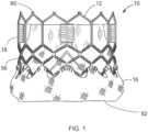
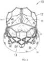
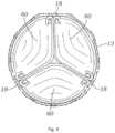
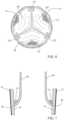
- FIGS. 1-3illustrate a prosthetic valve 10 that can include a secondary or flushing valve.
- a wide variety of different valvescan include a secondary or flushing valve.
- U.S. Pat. Nos. 9,393,110 ; 7,993,394 ; 5,411,522 ; and 6,730,118disclose non-limitations examples of collapsible transcatheter heart valves that can include a secondary or flushing valve.
- FIGS. 1-3are taken from U.S. Patent No. 9,393,110 .
- the primary valvecan include the leaflet structure 14 and the frame.
- valve 10 in the illustrated embodimentgenerally comprises a frame or stent 12, a primary valve defined by a leaflet structure 14 that is supported by the frame, and an optional skirt 16 secured to the frame or stent 12.
- Valve 10typically is implanted in the annulus of the native aortic valve but also can be adapted to be implanted in other native valves of the heart or in various other ducts or orifices of the body.
- Valve 10has a "lower" end 80 and an "upper" end 82.
- Valve 10 and frame 12are optionally configured to be radially collapsible to a collapsed or crimped state for introduction into the body on a delivery catheter and radially expandable to an expanded state for implanting the valve at a desired location in the body (e.g., the native aortic valve).
- Frame 12can be made of an expandable material that permits crimping of the valve to a smaller profile for delivery and expansion of the valve using an expansion device such as the balloon of a balloon catheter. Exemplary expandable materials that can be used to form the frame are described below.
- valve 10 and/or frame 12can be mechanically expandable, having a small profile for delivery that can be expanded mechanically using a wide variety of mechanisms.
- valve 10can be a self-expanding valve wherein the frame is made of a self-expanding material such as Nitinol.
- a self-expanding valvecan be crimped to a smaller profile and held in the crimped state with a restraining device such as a sheath covering the valve. When the valve is positioned at or near the target site, the restraining device is removed to allow the valve to self-expand to its expanded, functional size.
- Suitable expandable materials that can be used to form the frameinclude, without limitation, stainless steel, a nickel based alloy (e.g., a nickel-cobalt-chromium alloy), polymers, or combinations thereof.
- frame 20is made of a nickel-cobalt-chromium-molybdenum alloy, such as MP35N TM (tradename of SPS Technologies), which is equivalent to UNS R30035 (covered by ASTM F562-02).
- MP35N TM /UNS R30035comprises 35% nickel, 35% cobalt, 20% chromium, and 10% molybdenum, by weight.
- the optional skirt 16can be formed, for example, of polyethylene terephthalate (PET).
- PETpolyethylene terephthalate
- the skirt 16can be secured to the frame 12 via sutures 56, as shown in FIG. 1 .
- Leaflet structure 14can be attached to the skirt via a thin PET reinforcing strip (or sleeve), which enables a secure suturing and protects the pericardial tissue of the leaflet structure from tears.
- Leaflet structure 14can be formed of bovine pericardial tissue, biocompatible synthetic materials, or various other suitable natural or synthetic materials as known in the art and described in U.S. Pat. No. 6,730,118 .
- Leaflet structure 14can comprise three leaflets 60, which can be arranged to collapse in a tricuspid arrangement, as best shown in FIGS. 2 and 4 .
- the prosthetic valve 10can take a wide variety of different forms.
- FIG. 4is taken from US Patent No. 7,993,394 and shows another version of a THV.
- FIG. 4shows a top view of the valve assembly attached to frame 12.
- Leaflets 60are shown in a generally closed position. As shown, the commissures of the leaflets are aligned with and secured to vertical struts 18 of the frame.
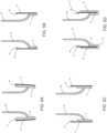
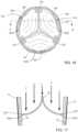
- FIGS. 5A to 5Dare cross sectional views that illustrate examples of skirts for the valve 10, in addition to the skirt example illustrated by FIGS. 1-3 .
- Each skirt 16prevents passage of blood through spaces of the frame and/or between the frame and the native tissue where the valve is implanted.
- the skirt 16can be connected to the frame 12 in a wide variety of ways. In an exemplary embodiment illustrated by FIG. 5A , the skirt 16 contacts the entire internal side 50 of the frame 12. In another exemplary embodiment illustrated by FIG. 5B , the skirt 16 only contacts the lower part of the frame 12. In the exemplary embodiment illustrated by FIG. 5C , the skirt 16 partially contacts the internal side of the frame 12. In certain exemplary embodiments, the skirt 16 can also be used to fasten the valve 10 inside the frame. As illustrated in FIG. 5D , the skirt 16 is extended at its lower end 16' into an external cover 16" which contacts the external wall of the frame 12.
- blood stasiscan occur behind an exemplary prosthetic valve having leaflets 60.
- blood 70can pool and/or remain stagnant behind the leaflets 60.
- Incorporating a secondary valve and/or flushing valve, into the leaflet at or near the bottom of the leaflet edgeallows blood flow during systole phase to flush the bottom end of the "flow pocket" behind the leaflet.
- the secondary flushing valves shown hereinhave a flap structure. During the diastole phase, back pressure on the valve closes the secondary valves by pressing the flaps against the leaflets. During the systole phase, forward flow through the valve opens both the primary and secondary valves, creating flow paths near the perimeter of the valve to flush out potentially stagnant pools of blood that may collect behind the leaflets.
- a secondary valve element 90 and an aperture 92are provided on at least one of the leaflets 60 to allow a small amount of fluid flow therethrough. (See FIGS. 8 and 9 .) As illustrated in FIGS. 8 and 9 , during the diastole phase, when the leaflets 60 close to impede the flow of fluid in direction F through the valve, the secondary valve element 90 also closes against the leaflet 60 and prevents fluid flow through the aperture 92.
- FIG. 9is a sectional view taken along the plane indicated by line A-A of FIG. 8 .
- a stationary portion 94 of the secondary valve element 90is attached to the skirt 16.
- the stationary portion 94 of the secondary valve element 90is attached to the outer perimeter 98 of the leaflet 60.
- a detached portion 96 of the secondary valve 90rests freely against the leaflet 60 forming a seal over the aperture 92, preventing fluid flow through the aperture 92.
- FIGS. 10 and 11illustrate the valve of Figures 8 and 9 during the systole phase.
- FIG. 11is a sectional view taken along the plane indicated by line B-B of the exemplary prosthetic valve of FIG. 10 .
- forward flow of fluidopens both the leaflets 60 of the primary valve and the secondary valve element 90.
- Primary flow paths Hopen the leaflets 60 of the primary valve.
- Opening the secondary valve element 90creates secondary flow paths G through the apertures 92.
- the detached portion 96 of the secondary valve element 90separates from the leaflet 60 forming a gap over the aperture 92, allowing fluid flow through the aperture 92.
- the detached portion 96 of the secondary valve element 90retracts in the direction of the skirt 16 and/or frame 12 and away from the leaflet 60.
- the secondary flow paths Gflush out potentially stagnant pools of fluid that may have collected behind the leaflet.
- blood pooling and/or stagnationcan be avoided or greatly reduced.
- the secondary valve element 90is connected to an inner portion of the leaflet 60.
- FIGS. 12 and 13illustrate an embodiment having the secondary valve element 90 connected to an inner portion of the leaflet 60.
- FIG. 13illustrates a sectional view taken along the plane indicated by line C-C of the exemplary prosthetic valve of FIG. 12 .
- the secondary valve element 90also closes against the leaflet and prevents fluid flow.
- the secondary valve elementcovers the aperture 92 during the diastole phase, preventing fluid flow through the aperture 92.
- FIGS. 12 and 13illustrate an embodiment having the secondary valve element 90 connected to an inner portion of the leaflet 60.
- FIG. 13illustrates a sectional view taken along the plane indicated by line C-C of the exemplary prosthetic valve of FIG. 12 .
- the stationary portion 94 of the secondary valve 90is attached to an inner portion of the leaflet 60 and a detached portion 96 of the secondary valve 90 rests freely on the leaflet 60.
- the detached portioncontacts or is close to an outer perimeter of the leaflet.
- the detached portionis not attached to the frame or the skirt.
- FIGS. 14 and 15illustrate the valve of FIGS 12 and 13 in the systole phase.
- FIG. 15is a sectional view taken along the plane indicated by line D-D of the exemplary prosthetic valve of FIG. 14 .
- the primary valvecan include leaflets 60.
- the primary valvecan also include the frame.
- Primary flow paths Hopen the leaflets 60 of the primary valve. Opening the secondary valve elements 90 creates secondary flow paths G through the apertures 92. The fluid flow moves the secondary valve elements 90 in the direction of the leaflet 60 and away from the skirt 16 and/or frame 12 to an open position.
- the detached portion 96 of the secondary valve 90separates from the leaflet 60 forming a gap over the aperture 92, allowing fluid flow through the aperture 92.
- the secondary flow paths Gflush out potentially stagnant pools of fluid that may have collected behind the leaflet.
- blood pooling and/or stagnationcan be avoided or greatly reduced.
- a flushing valve 102comprises an opening or slit 100 that traces a portion of the perimeter of at least one leaflet 60.
- the slit 100is provided in the leaflet 60 at the outer perimeter by not attaching a portion of the outer perimeter of the leaflet to the skirt 16 or the frame 12.
- FIG. 17illustrates a sectional view taken along the plane indicated by line E-E of the exemplary prosthetic valve of FIG. 16 .
- FIGS. 18 and 19illustrate the valve of FIGS. 16 and 17 in the systole phase.
- FIG. 19is a sectional view taken along the plane indicated by line F-F of the exemplary prosthetic valve of FIG. 18 .
- forward flow of fluidopens both the leaflets 60 of the primary valve and the disconnected portion 1600 that forms the slit 100 of the leaflet 60.
- Primary flow paths Hopen the leaflets 60 at the primary valve.
- a secondary flow path Gis created by flow through the flushing valve 102 formed by the slit 100 of the leaflet 60.
- the disconnected portion that forms the slit 100 of the leaflet 60retracts in the direction toward the center of the valve 60.
- the secondary flow paths Gflush out potentially stagnant pools of fluid that may have collected behind the leaflet. Thus, blood pooling and/or stagnation can be avoided or greatly reduced.
- the secondary flow path Gcan be in various positions on the leaflet 60. In certain exemplary embodiments, the secondary flow path G is near the perimeter of the leaflet 60.
- the slit 100 and the flushing valve 102 formed therefromcan be in various positions on the leaflet 60. In certain exemplary embodiments, the slit 100 and the flushing valve 102 formed therefrom are near the perimeter of the leaflet 60.
Landscapes
- Health & Medical Sciences (AREA)
- Engineering & Computer Science (AREA)
- Biomedical Technology (AREA)
- Cardiology (AREA)
- Oral & Maxillofacial Surgery (AREA)
- Transplantation (AREA)
- Heart & Thoracic Surgery (AREA)
- Vascular Medicine (AREA)
- Life Sciences & Earth Sciences (AREA)
- Animal Behavior & Ethology (AREA)
- General Health & Medical Sciences (AREA)
- Public Health (AREA)
- Veterinary Medicine (AREA)
- Prostheses (AREA)
Description
- This application claims priority to and the benefit of
U.S. Provisional Application No. 62/555,548, filed on September 7, 2017 - The present invention relates to prosthetic valves, more specifically to a prosthetic valve, such as a surgically implanted valve or a transcatheter heart valve (THV), including a secondary valve and/or flushing valve.
- Implantable prosthetic valves can be used to treat various valvular disorders. For example, native heart valves (the aortic, pulmonary, tricuspid and mitral valves) function to prevent backward flow or regurgitation, while allowing forward flow. These heart valves can be rendered less effective by congenital, inflammatory, infectious conditions, etc. Such conditions can eventually lead to serious cardiovascular compromise or death. Doctors have attempted to treat such disorders with surgical repair or replacement of the valve using open heart surgery or percutaneous and minimally invasive surgical approaches.
- Transcatheter heart valves can be percutaneously introduced in a compressed state on a catheter and expanded to the desired position by balloon inflation, mechanical expansion, or by utilization of a self-expanding frame or stent. In some cases, transcatheter heart valves, such as surgically implanted valves or THVs might be subjected to blood stasis behind the artificial heart valve leaflets.
US 2017/014229 A1 discloses a prosthetic valve comprising a frame and a leaflet structure. - This summary is meant to provide examples and is not intended to limit the scope of the invention in any way. For example, any feature included in an example of this summary is not required by the claims, unless the claims explicitly recite the feature. The description discloses exemplary embodiments of prosthetic valves, such as surgically implantable prosthetic valves, and trans-catheter implantable valves. The prosthetic valves can be constructed in a variety of ways.
- As defined in
independent claim 1, a prosthetic valve has a frame, a primary valve and at least one secondary valve. The primary valve is formed by a leaflet structure. The primary valve is mounted inside the frame. The at least one secondary valve is connected to at least one leaflet of the primary valve. The at least one secondary valve has a stationary portion and a detached portion. At least one aperture is provided in the at least one leaflet and proximate to the secondary valve. In certain exemplary embodiments, the stationary portion is connected to at least one leaflet. In certain exemplary embodiments, the stationary portion is connected to an inner portion of the at least one leaflet and a detached portion contacts a perimeter portion of the at least one leaflet. - Further according to the prosthetic valve as defined in
claim 1, when the leaflet structure closes, the secondary valve closes and covers the aperture. When the leaflet structure opens, the secondary valve opens creating one or more secondary flow paths through the aperture(s). In certain exemplary embodiments, the prosthetic valve further includes a skirt positioned between the leaflet structure and the frame. In certain exemplary embodiments, the prosthetic valve further includes a reinforcing strip, wherein the leaflet structure is between the reinforcing strip and the skirt. - In certain exemplary embodiments, the skirt contacts a lower portion of the internal side of the frame. In certain exemplary embodiments, the skirt contacts at least a partial portion of the internal side of the frame. In certain exemplary embodiments, the skirt contacts 3 to 5 mm of the internal side of the frame. In certain exemplary embodiments, the skirt contacts the external wall of the frame.
- As defined in independent claim 6, a prosthetic valve includes a frame and a primary valve that includes a disconnected portion. A leaflet structure forms the primary valve and is preferably mounted inside the frame at an attachment line. The disconnected portion of at least one leaflet of the leaflet structure is preferably located at the attachment line near an outer perimeter. As defined in claim 6, when the leaflet structure closes to impede fluid flow through the primary valve, the disconnected portion of the leaflet(s) closes also. As also defined in claim 6, when the leaflet structure opens to allow fluid flow through the primary valve, the disconnected portion of the leaflet(s) opens also.
- In certain exemplary embodiments, the prosthetic valve further includes a skirt positioned between the leaflet structure and the frame. In certain exemplary embodiments, the disconnected portion is not attached to the frame.
- Various features as described elsewhere in this disclosure can be included in the examples summarized here and various methods and steps for using the examples and features can be used, including as described elsewhere herein.
- Further understanding of the nature and advantages of the disclosed inventions can be obtained from the following description and claims, particularly when considered in conjunction with the accompanying drawings in which like parts bear like reference numerals.
- Further understanding of the nature and advantages of the disclosed inventions can be obtained from the following description and claims, particularly when considered in conjunction with the accompanying drawings in which like parts bear like reference numerals.
- To further clarify various aspects of embodiments of the present disclosure, a more particular description of the certain embodiments will be made by reference to various aspects of the appended drawings. It is appreciated that these drawings depict only typical embodiments of the present disclosure and are therefore not to be considered limiting of the scope of the disclosure. Moreover, while the figures may be drawn to scale for some embodiments, the figures are not necessarily drawn to scale for all embodiments. Embodiments of the present disclosure will be described and explained with additional specificity and detail through the use of the accompanying drawings.
FIG. 1 is a side view of an exemplary embodiment of a prosthetic heart valve;FIG. 2 is a perspective view of the prosthetic valve ofFIG. 1 in a closed condition;FIG. 3 is a perspective view of the prosthetic valve ofFIG. 1 in an open condition;FIG. 4 is a top plan view of another example of a prosthetic valve in a closed condition;FIGS. 5A to 5D are sectional views of a prosthetic valve;FIG. 6 is a top plan view of a prosthetic valve;FIG. 7 is a sectional view of a prosthetic valve;FIG. 8 is a top plan view of an exemplary prosthetic valve in a diastole phase;FIG. 9 is a sectional view taken along the plane indicated by line A-A of the exemplary prosthetic valve ofFIG. 8 ;FIG. 10 is a top plan view of an exemplary prosthetic valve in a systole phase;FIG. 11 is a sectional view taken along the plane indicated by line B-B of the exemplary prosthetic valve ofFIG. 10 ;FIG. 12 is a top plan view of an exemplary prosthetic valve in a diastole phase;FIG. 13 is a sectional view taken along the plane indicated by line C-C of the exemplary prosthetic valve ofFIG. 12 ;FIG. 14 is a top plan view of an exemplary prosthetic valve in a systole phase;FIG. 15 is a sectional view taken along the plane indicated by line D-D of the exemplary prosthetic valve ofFIG. 14 ;FIG. 16 is a top plan view of an exemplary prosthetic valve in a diastole phase;FIG. 17 is a sectional view taken along the plane indicated by line E-E of the exemplary prosthetic valve ofFIG. 16 ;FIG. 18 is a top plan view of an exemplary prosthetic valve in a systole phase; andFIG. 19 is a sectional view taken along the plane indicated by line F-F of the exemplary prosthetic valve ofFIG. 18 .- The following description refers to the accompanying drawings, which illustrate specific embodiments of the invention. Other embodiments having different structures and operation do not depart from the scope of the present invention. Exemplary embodiments of the present disclosure are directed to prosthetic valves, such as surgically implanted valves and transcatheter heart valves (THVs), that include a secondary valve or flushing valve.
- Various examples of THVs and frames are disclosed herein, and any combination of these options may be made unless specifically excluded. For example, any of the secondary valves or flushing valves disclosed, can be used with any type of implantable device, valve, and/or delivery system, even if a specific combination is not explicitly described. In short, individual components of the disclosed systems can be combined with other systems and/or components unless mutually exclusive or otherwise physically impossible.
- Transcatheter heart valves or surgically implanted valves might be subjected to blood stasis behind the artificial heart valve leaflets. To prevent blood from pooling and/or remaining stagnant, anti-coagulants are generally used. The present disclosure describes secondary or flushing valves used in a prosthetic valve, including without limitation a transcatheter heart valve. As disclosed herein, a secondary valve or a flushing valve can be used to prevent blood stasis behind the artificial heart valve leaflets. Thus, the use of prescription anti-coagulants can be avoided or reduced.
FIGS. 1-3 illustrate aprosthetic valve 10 that can include a secondary or flushing valve. However, a wide variety of different valves can include a secondary or flushing valve. For example,U.S. Pat. Nos. 9,393,110 7,993,394 ;5,411,522 ; and6,730,118 disclose non-limitations examples of collapsible transcatheter heart valves that can include a secondary or flushing valve.FIGS. 1-3 are taken fromU.S. Patent No. 9,393,110 leaflet structure 14 and the frame. In the example illustrated byFIGS 1-3 ,valve 10 in the illustrated embodiment generally comprises a frame orstent 12, a primary valve defined by aleaflet structure 14 that is supported by the frame, and anoptional skirt 16 secured to the frame orstent 12.Valve 10 typically is implanted in the annulus of the native aortic valve but also can be adapted to be implanted in other native valves of the heart or in various other ducts or orifices of the body.Valve 10 has a "lower"end 80 and an "upper"end 82.Valve 10 andframe 12 are optionally configured to be radially collapsible to a collapsed or crimped state for introduction into the body on a delivery catheter and radially expandable to an expanded state for implanting the valve at a desired location in the body (e.g., the native aortic valve).Frame 12 can be made of an expandable material that permits crimping of the valve to a smaller profile for delivery and expansion of the valve using an expansion device such as the balloon of a balloon catheter. Exemplary expandable materials that can be used to form the frame are described below. In certain exemplary embodiments,valve 10 and/orframe 12 can be mechanically expandable, having a small profile for delivery that can be expanded mechanically using a wide variety of mechanisms. Alternatively,valve 10 can be a self-expanding valve wherein the frame is made of a self-expanding material such as Nitinol. A self-expanding valve can be crimped to a smaller profile and held in the crimped state with a restraining device such as a sheath covering the valve. When the valve is positioned at or near the target site, the restraining device is removed to allow the valve to self-expand to its expanded, functional size.- Suitable expandable materials that can be used to form the frame include, without limitation, stainless steel, a nickel based alloy (e.g., a nickel-cobalt-chromium alloy), polymers, or combinations thereof. In particular embodiments, frame 20 is made of a nickel-cobalt-chromium-molybdenum alloy, such as MP35N™ (tradename of SPS Technologies), which is equivalent to UNS R30035 (covered by ASTM F562-02). MP35N™/UNS R30035 comprises 35% nickel, 35% cobalt, 20% chromium, and 10% molybdenum, by weight.
- Referring again to
FIG. 1 , theoptional skirt 16 can be formed, for example, of polyethylene terephthalate (PET). Theskirt 16 can be secured to theframe 12 viasutures 56, as shown inFIG. 1 .Leaflet structure 14 can be attached to the skirt via a thin PET reinforcing strip (or sleeve), which enables a secure suturing and protects the pericardial tissue of the leaflet structure from tears.Leaflet structure 14 can be formed of bovine pericardial tissue, biocompatible synthetic materials, or various other suitable natural or synthetic materials as known in the art and described inU.S. Pat. No. 6,730,118 . Leaflet structure 14 can comprise threeleaflets 60, which can be arranged to collapse in a tricuspid arrangement, as best shown inFIGS. 2 and4 . Theprosthetic valve 10 can take a wide variety of different forms. For example,FIG. 4 is taken fromUS Patent No. 7,993,394 and shows another version of a THV.FIG. 4 shows a top view of the valve assembly attached to frame 12.Leaflets 60 are shown in a generally closed position. As shown, the commissures of the leaflets are aligned with and secured tovertical struts 18 of the frame.FIGS. 5A to 5D are cross sectional views that illustrate examples of skirts for thevalve 10, in addition to the skirt example illustrated byFIGS. 1-3 . Eachskirt 16 prevents passage of blood through spaces of the frame and/or between the frame and the native tissue where the valve is implanted. Theskirt 16 can be connected to theframe 12 in a wide variety of ways. In an exemplary embodiment illustrated byFIG. 5A , theskirt 16 contacts the entireinternal side 50 of theframe 12. In another exemplary embodiment illustrated byFIG. 5B , theskirt 16 only contacts the lower part of theframe 12. In the exemplary embodiment illustrated byFIG. 5C , theskirt 16 partially contacts the internal side of theframe 12. In certain exemplary embodiments, theskirt 16 can also be used to fasten thevalve 10 inside the frame. As illustrated inFIG. 5D , theskirt 16 is extended at its lower end 16' into anexternal cover 16" which contacts the external wall of theframe 12.- As illustrated in
FIGS. 6 and 7 , blood stasis can occur behind an exemplary prostheticvalve having leaflets 60. When this occurs,blood 70 can pool and/or remain stagnant behind theleaflets 60. Incorporating a secondary valve and/or flushing valve, into the leaflet at or near the bottom of the leaflet edge allows blood flow during systole phase to flush the bottom end of the "flow pocket" behind the leaflet. In certain exemplary embodiments, the secondary flushing valves shown herein have a flap structure. During the diastole phase, back pressure on the valve closes the secondary valves by pressing the flaps against the leaflets. During the systole phase, forward flow through the valve opens both the primary and secondary valves, creating flow paths near the perimeter of the valve to flush out potentially stagnant pools of blood that may collect behind the leaflets. - In an embodiment of the present invention, a
secondary valve element 90 and anaperture 92 are provided on at least one of theleaflets 60 to allow a small amount of fluid flow therethrough. (SeeFIGS. 8 and 9 .) As illustrated inFIGS. 8 and 9 , during the diastole phase, when theleaflets 60 close to impede the flow of fluid in direction F through the valve, thesecondary valve element 90 also closes against theleaflet 60 and prevents fluid flow through theaperture 92.FIG. 9 is a sectional view taken along the plane indicated by line A-A ofFIG. 8 . In certain exemplary embodiments, astationary portion 94 of thesecondary valve element 90 is attached to theskirt 16. In another exemplary embodiment, thestationary portion 94 of thesecondary valve element 90 is attached to theouter perimeter 98 of theleaflet 60. During the diastole phase, adetached portion 96 of thesecondary valve 90 rests freely against theleaflet 60 forming a seal over theaperture 92, preventing fluid flow through theaperture 92. FIGS. 10 and 11 illustrate the valve ofFigures 8 and 9 during the systole phase.FIG. 11 is a sectional view taken along the plane indicated by line B-B of the exemplary prosthetic valve ofFIG. 10 . During the systole phase, forward flow of fluid opens both theleaflets 60 of the primary valve and thesecondary valve element 90. Primary flow paths H open theleaflets 60 of the primary valve. Opening thesecondary valve element 90 creates secondary flow paths G through theapertures 92. Thedetached portion 96 of thesecondary valve element 90 separates from theleaflet 60 forming a gap over theaperture 92, allowing fluid flow through theaperture 92. Thedetached portion 96 of thesecondary valve element 90 retracts in the direction of theskirt 16 and/orframe 12 and away from theleaflet 60. Thus, the secondary flow paths G flush out potentially stagnant pools of fluid that may have collected behind the leaflet. Thus, blood pooling and/or stagnation can be avoided or greatly reduced.- In another exemplary embodiment of the present invention, the
secondary valve element 90 is connected to an inner portion of theleaflet 60.FIGS. 12 and 13 illustrate an embodiment having thesecondary valve element 90 connected to an inner portion of theleaflet 60. Specifically,FIG. 13 illustrates a sectional view taken along the plane indicated by line C-C of the exemplary prosthetic valve ofFIG. 12 . During the diastole phase, when theleaflets 60 close to impede the flow of fluid in direction F through the valve, thesecondary valve element 90 also closes against the leaflet and prevents fluid flow. The secondary valve element covers theaperture 92 during the diastole phase, preventing fluid flow through theaperture 92. In the exemplary embodiment illustrated inFIGS. 12-15 , thestationary portion 94 of thesecondary valve 90 is attached to an inner portion of theleaflet 60 and adetached portion 96 of thesecondary valve 90 rests freely on theleaflet 60. In certain exemplary embodiments, the detached portion contacts or is close to an outer perimeter of the leaflet. The detached portion is not attached to the frame or the skirt. During the diastole phase, adetached portion 96 of thesecondary valve element 90 is pressed against theleaflet 60 by the blood, forming a seal over theaperture 92 and preventing fluid flow through theaperture 92. FIGS. 14 and 15 illustrate the valve ofFIGS 12 and 13 in the systole phase.FIG. 15 is a sectional view taken along the plane indicated by line D-D of the exemplary prosthetic valve ofFIG. 14 . During the systole phase, forward flow of fluid opens both theleaflets 60 of the primary valve and thesecondary valve element 90. InFIGS. 14 and 15 , the primary valve can includeleaflets 60. The primary valve can also include the frame. Primary flow paths H open theleaflets 60 of the primary valve. Opening thesecondary valve elements 90 creates secondary flow paths G through theapertures 92. The fluid flow moves thesecondary valve elements 90 in the direction of theleaflet 60 and away from theskirt 16 and/orframe 12 to an open position. Thedetached portion 96 of thesecondary valve 90 separates from theleaflet 60 forming a gap over theaperture 92, allowing fluid flow through theaperture 92. Thus, the secondary flow paths G flush out potentially stagnant pools of fluid that may have collected behind the leaflet. Thus, blood pooling and/or stagnation can be avoided or greatly reduced.- Referring to
FIGS. 16 and 17 , in another embodiment, a flushingvalve 102 comprises an opening or slit 100 that traces a portion of the perimeter of at least oneleaflet 60. In the exemplary embodiment, theslit 100 is provided in theleaflet 60 at the outer perimeter by not attaching a portion of the outer perimeter of the leaflet to theskirt 16 or theframe 12.FIG. 17 illustrates a sectional view taken along the plane indicated by line E-E of the exemplary prosthetic valve ofFIG. 16 . During the diastole phase, when theleaflets 60 close to impede the flow of fluid in direction F through the valve, the disconnectedportion 1600 that forms theslit 100 of theleaflet 60 contacts theskirt 16 and thus prevents fluid flow. FIGS. 18 and 19 illustrate the valve ofFIGS. 16 and 17 in the systole phase.FIG. 19 is a sectional view taken along the plane indicated by line F-F of the exemplary prosthetic valve ofFIG. 18 . During the systole phase, forward flow of fluid opens both theleaflets 60 of the primary valve and the disconnectedportion 1600 that forms theslit 100 of theleaflet 60. Primary flow paths H open theleaflets 60 at the primary valve. A secondary flow path G is created by flow through the flushingvalve 102 formed by theslit 100 of theleaflet 60. The disconnected portion that forms theslit 100 of theleaflet 60, retracts in the direction toward the center of thevalve 60. The secondary flow paths G flush out potentially stagnant pools of fluid that may have collected behind the leaflet. Thus, blood pooling and/or stagnation can be avoided or greatly reduced.- The secondary flow path G can be in various positions on the
leaflet 60. In certain exemplary embodiments, the secondary flow path G is near the perimeter of theleaflet 60. Theslit 100 and theflushing valve 102 formed therefrom can be in various positions on theleaflet 60. In certain exemplary embodiments, theslit 100 and theflushing valve 102 formed therefrom are near the perimeter of theleaflet 60. - In view of the many possible embodiments to which the principles of the disclosed invention may be applied, it should be recognized that the illustrated embodiments are only preferred examples of the invention and should not be taken as limiting the scope of the invention. The scope of the invention is defined by the following claims. We therefore claim as our invention all that comes within the scope of these claims.
Claims (14)
- A prosthetic valve (10) comprising:a frame (12);a leaflet structure (14) having at least one leaflet (60) forming a primary valve mounted inside the frame (12);at least one secondary valve element (90) connected to at least one leaflet (60) of the leaflet structure (14), wherein the at least one secondary valve element (90) has a stationary portion (94) and a detached portion (96); andat least one aperture (92) in the at least one leaflet (60) and proximate to the secondary valve element (90);wherein when the leaflet structure (14) closes, the secondary valve element (90) closes and covers the aperture (92);wherein when the leaflet structure (14) opens, the secondary valve element (90) moves to create a secondary flow path (G) through the aperture (92).
- The prosthetic valve of claim 1, wherein the stationary portion (94) is connected to a perimeter (98) of the leaflet structure (14).
- The prosthetic valve of claim 1, wherein the stationary portion (94) is connected to an inner portion of the at least one leaflet (60).
- The prosthetic valve of any of claims 1 to 3, further comprising a skirt (16) positioned between the leaflet structure (14) and the frame (12).
- The prosthetic valve of claim 4, wherein the skirt (16) contacts at least a portion of an internal side (50) of the frame (12).
- A prosthetic valve (10) comprising:a frame (12);a leaflet structure (14) having leaflets (60) forming a primary valve mounted inside the frame (12);wherein a disconnected portion (1600) of at least one leaflet (60) of the leaflet structure (14) is not attached to the frame (12);wherein when the leaflet structure (14) closes to impede fluid flow through the primary valve, the disconnected portion (1600) of the leaflet (60) closes;wherein when the leaflet structure (14) opens to allow fluid flow through the primary valve, the disconnected portion (1600) of the leaflet (60) opens.
- The prosthetic valve of claim 6, wherein the disconnected portion (1600) is located near an outer perimeter (98) of the leaflet structure (14).
- The prosthetic valve of any of claims 6 to 7, further comprising a skirt (16) positioned between the leaflet structure (14) and the frame (12).
- The prosthetic valve of claim 8, wherein the disconnected portion (1600) forms a slit (100) that traces a portion of an outer perimeter (96) of the at least one leaflet (60).
- The prosthetic valve of claim 9, when dependent on claim 8, wherein when the leaflets (60) close to impede fluid flow through the primary valve, the disconnected portion (1600) contacts the skirt (16) and thus prevents fluid flow.
- The prosthetic valve of any of claims 6 to 10, wherein the leaflet structure (14) is mounted inside the frame (12) at an attachment line.
- The prosthetic valve of claim 11, wherein the disconnected portion (1600) of the at least one leaflet (60) of the leaflet structure (14) is located at the attachment line near an outer perimeter (96).
- The prosthetic valve of any of claims 6 to 12, wherein the valve and the frame (12) are configured to be radially collapsible to a collapsed or crimped state for introduction into the body on a delivery catheter and radially expandable to an expanded state for implanting the valve at a desired location in the body.
- The prosthetic valve of any of claims 6 to 13, wherein the leaflet structure (14) is formed of bovine pericardial tissue or biocompatible synthetic materials.
Priority Applications (1)
| Application Number | Priority Date | Filing Date | Title |
|---|---|---|---|
| EP23185985.1AEP4279031A3 (en) | 2017-09-07 | 2018-09-05 | Integral flushing solution for blood stasis prevention in artificial heart valves |
Applications Claiming Priority (3)
| Application Number | Priority Date | Filing Date | Title |
|---|---|---|---|
| US201762555548P | 2017-09-07 | 2017-09-07 | |
| US16/119,317US20190069996A1 (en) | 2017-09-07 | 2018-08-31 | Integral flushing solution for blood stasis prevention in artificial heart valves |
| PCT/US2018/049479WO2019050900A1 (en) | 2017-09-07 | 2018-09-05 | Integral flushing solution for blood stasis prevention in artificial heart valves |
Related Child Applications (1)
| Application Number | Title | Priority Date | Filing Date |
|---|---|---|---|
| EP23185985.1ADivisionEP4279031A3 (en) | 2017-09-07 | 2018-09-05 | Integral flushing solution for blood stasis prevention in artificial heart valves |
Publications (3)
| Publication Number | Publication Date |
|---|---|
| EP3678598A1 EP3678598A1 (en) | 2020-07-15 |
| EP3678598A4 EP3678598A4 (en) | 2020-09-16 |
| EP3678598B1true EP3678598B1 (en) | 2023-07-19 |
Family
ID=65517611
Family Applications (2)
| Application Number | Title | Priority Date | Filing Date |
|---|---|---|---|
| EP18853863.1AActiveEP3678598B1 (en) | 2017-09-07 | 2018-09-05 | Integral flushing solution for blood stasis prevention in artificial heart valves |
| EP23185985.1APendingEP4279031A3 (en) | 2017-09-07 | 2018-09-05 | Integral flushing solution for blood stasis prevention in artificial heart valves |
Family Applications After (1)
| Application Number | Title | Priority Date | Filing Date |
|---|---|---|---|
| EP23185985.1APendingEP4279031A3 (en) | 2017-09-07 | 2018-09-05 | Integral flushing solution for blood stasis prevention in artificial heart valves |
Country Status (4)
| Country | Link |
|---|---|
| US (2) | US20190069996A1 (en) |
| EP (2) | EP3678598B1 (en) |
| CN (1) | CN111050699B (en) |
| WO (1) | WO2019050900A1 (en) |
Families Citing this family (4)
| Publication number | Priority date | Publication date | Assignee | Title |
|---|---|---|---|---|
| US20190069996A1 (en)* | 2017-09-07 | 2019-03-07 | Edwards Lifesciences Corporation | Integral flushing solution for blood stasis prevention in artificial heart valves |
| EP4125727A1 (en)* | 2020-04-01 | 2023-02-08 | Nininger Medical, Inc. | Three-dimensional thin-film leaflet valve device |
| CN112773564B (en)* | 2021-01-26 | 2025-01-14 | 康迪泰科(北京)医疗科技有限公司 | A heart valve |
| CN115245405B (en)* | 2021-04-26 | 2025-03-18 | 康迪泰科(北京)医疗科技有限公司 | An artificial heart valve |
Family Cites Families (33)
| Publication number | Priority date | Publication date | Assignee | Title |
|---|---|---|---|---|
| US4892540A (en)* | 1988-04-21 | 1990-01-09 | Sorin Biomedica S.P.A. | Two-leaflet prosthetic heart valve |
| US4872875A (en)* | 1989-01-28 | 1989-10-10 | Carbon Implants, Inc. | Prosthetic heart valve |
| US5411522A (en) | 1993-08-25 | 1995-05-02 | Linvatec Corporation | Unitary anchor for soft tissue fixation |
| US6200340B1 (en)* | 1999-04-01 | 2001-03-13 | Sulzer Carbomedics Inc. | Tilting disk heart valve having cavitation reducing contact geometry |
| US7226467B2 (en)* | 1999-04-09 | 2007-06-05 | Evalve, Inc. | Fixation device delivery catheter, systems and methods of use |
| US6893460B2 (en) | 2001-10-11 | 2005-05-17 | Percutaneous Valve Technologies Inc. | Implantable prosthetic valve |
| DE602004024766D1 (en)* | 2003-03-12 | 2010-02-04 | Cook Inc | |
| US20050075659A1 (en)* | 2003-03-30 | 2005-04-07 | Fidel Realyvasquez | Apparatus and methods for minimally invasive valve surgery |
| WO2005069850A2 (en)* | 2004-01-15 | 2005-08-04 | Macoviak John A | Trestle heart valve replacement |
| EP1773251A1 (en)* | 2004-06-29 | 2007-04-18 | The Cleveland Clinic Foundation | Prosthetic cardiac valve and method for making same |
| CA2579434A1 (en)* | 2004-09-10 | 2006-03-23 | Cook Incorporated | Prosthetic valve with pores |
| US20100298929A1 (en)* | 2005-02-07 | 2010-11-25 | Thornton Troy L | Methods, systems and devices for cardiac valve repair |
| WO2011034628A1 (en)* | 2005-02-07 | 2011-03-24 | Evalve, Inc. | Methods, systems and devices for cardiac valve repair |
| CA2597066C (en)* | 2005-02-07 | 2014-04-15 | Evalve, Inc. | Methods, systems and devices for cardiac valve repair |
| SE531468C2 (en)* | 2005-04-21 | 2009-04-14 | Edwards Lifesciences Ag | An apparatus for controlling blood flow |
| US7648527B2 (en)* | 2006-03-01 | 2010-01-19 | Cook Incorporated | Methods of reducing retrograde flow |
| US7811316B2 (en)* | 2006-05-25 | 2010-10-12 | Deep Vein Medical, Inc. | Device for regulating blood flow |
| US8236045B2 (en)* | 2006-12-22 | 2012-08-07 | Edwards Lifesciences Corporation | Implantable prosthetic valve assembly and method of making the same |
| US7678144B2 (en)* | 2007-01-29 | 2010-03-16 | Cook Incorporated | Prosthetic valve with slanted leaflet design |
| PL4223257T3 (en) | 2008-06-06 | 2024-09-23 | Edwards Lifesciences Corporation | LOW-PROFILE TRANSCATHETIC HEART VALVE |
| EP2477555B1 (en)* | 2009-09-15 | 2013-12-25 | Evalve, Inc. | Device for cardiac valve repair |
| AU2011306028B2 (en)* | 2010-09-20 | 2014-07-17 | St. Jude Medical, Cardiology Division, Inc. | Valve leaflet attachment in collapsible prosthetic valves |
| DK4233795T3 (en) | 2010-10-05 | 2024-08-26 | Edwards Lifesciences Corp | Prosthetic heart valve |
| US8568475B2 (en)* | 2010-10-05 | 2013-10-29 | Edwards Lifesciences Corporation | Spiraled commissure attachment for prosthetic valve |
| US9308087B2 (en)* | 2011-04-28 | 2016-04-12 | Neovasc Tiara Inc. | Sequentially deployed transcatheter mitral valve prosthesis |
| US9445893B2 (en)* | 2011-11-21 | 2016-09-20 | Mor Research Applications Ltd. | Device for placement in the tricuspid annulus |
| US9427315B2 (en)* | 2012-04-19 | 2016-08-30 | Caisson Interventional, LLC | Valve replacement systems and methods |
| US20140128964A1 (en)* | 2012-11-08 | 2014-05-08 | Symetis Sa | Stent Seals and Methods for Sealing an Expandable Stent |
| US10166098B2 (en)* | 2013-10-25 | 2019-01-01 | Middle Peak Medical, Inc. | Systems and methods for transcatheter treatment of valve regurgitation |
| US9974650B2 (en)* | 2015-07-14 | 2018-05-22 | Edwards Lifesciences Corporation | Prosthetic heart valve |
| US12029647B2 (en)* | 2017-03-07 | 2024-07-09 | 4C Medical Technologies, Inc. | Systems, methods and devices for prosthetic heart valve with single valve leaflet |
| US10952842B2 (en)* | 2017-06-07 | 2021-03-23 | W. L. Gore & Associates, Inc. | Prosthetic valve with improved washout |
| US20190069996A1 (en)* | 2017-09-07 | 2019-03-07 | Edwards Lifesciences Corporation | Integral flushing solution for blood stasis prevention in artificial heart valves |
- 2018
- 2018-08-31USUS16/119,317patent/US20190069996A1/ennot_activeAbandoned
- 2018-09-05EPEP18853863.1Apatent/EP3678598B1/enactiveActive
- 2018-09-05WOPCT/US2018/049479patent/WO2019050900A1/ennot_activeCeased
- 2018-09-05CNCN201880056724.4Apatent/CN111050699B/enactiveActive
- 2018-09-05EPEP23185985.1Apatent/EP4279031A3/enactivePending
- 2022
- 2022-03-16USUS17/696,029patent/US20220202569A1/enactivePending
Also Published As
| Publication number | Publication date |
|---|---|
| CN111050699B (en) | 2022-11-18 |
| US20220202569A1 (en) | 2022-06-30 |
| US20190069996A1 (en) | 2019-03-07 |
| EP3678598A1 (en) | 2020-07-15 |
| EP3678598A4 (en) | 2020-09-16 |
| EP4279031A3 (en) | 2024-01-17 |
| CN111050699A (en) | 2020-04-21 |
| EP4279031A2 (en) | 2023-11-22 |
| WO2019050900A1 (en) | 2019-03-14 |
Similar Documents
| Publication | Publication Date | Title |
|---|---|---|
| AU2022271480B2 (en) | Heart chamber prosthetic valve implant with elevated valve section and single chamber anchoring for preservation, supplementation and/or replacement of native valve function | |
| US20220202569A1 (en) | Prosthetic valve with integral flushing for blood stasis prevention | |
| US20220015901A1 (en) | Assembly for replacing the tricuspid atrioventricular valve | |
| EP3145449B1 (en) | Self-expanding heart valves for coronary perfusion and sealing | |
| EP3116445B1 (en) | Cardiac stent-valve | |
| EP3119352B1 (en) | Leaflet abrasion mitigation | |
| AU2009240565B2 (en) | Stented heart valve devices | |
| US9795476B2 (en) | Collapsible heart valve with angled frame | |
| US9532887B2 (en) | Multi-layer stent | |
| EP3760165A1 (en) | Stented heart valve devices | |
| EP3005985A1 (en) | Bi-leaflet mitral valve design | |
| WO2016073741A1 (en) | Transcatheter cardiac valve prosthetic | |
| JP7699064B2 (en) | Artificial Heart Valves |
Legal Events
| Date | Code | Title | Description |
|---|---|---|---|
| STAA | Information on the status of an ep patent application or granted ep patent | Free format text:STATUS: THE INTERNATIONAL PUBLICATION HAS BEEN MADE | |
| PUAI | Public reference made under article 153(3) epc to a published international application that has entered the european phase | Free format text:ORIGINAL CODE: 0009012 | |
| STAA | Information on the status of an ep patent application or granted ep patent | Free format text:STATUS: REQUEST FOR EXAMINATION WAS MADE | |
| 17P | Request for examination filed | Effective date:20200407 | |
| AK | Designated contracting states | Kind code of ref document:A1 Designated state(s):AL AT BE BG CH CY CZ DE DK EE ES FI FR GB GR HR HU IE IS IT LI LT LU LV MC MK MT NL NO PL PT RO RS SE SI SK SM TR | |
| AX | Request for extension of the european patent | Extension state:BA ME | |
| A4 | Supplementary search report drawn up and despatched | Effective date:20200817 | |
| RIC1 | Information provided on ipc code assigned before grant | Ipc:A61F 2/24 20060101AFI20200811BHEP | |
| DAV | Request for validation of the european patent (deleted) | ||
| DAX | Request for extension of the european patent (deleted) | ||
| GRAP | Despatch of communication of intention to grant a patent | Free format text:ORIGINAL CODE: EPIDOSNIGR1 | |
| STAA | Information on the status of an ep patent application or granted ep patent | Free format text:STATUS: GRANT OF PATENT IS INTENDED | |
| INTG | Intention to grant announced | Effective date:20230131 | |
| GRAS | Grant fee paid | Free format text:ORIGINAL CODE: EPIDOSNIGR3 | |
| GRAA | (expected) grant | Free format text:ORIGINAL CODE: 0009210 | |
| STAA | Information on the status of an ep patent application or granted ep patent | Free format text:STATUS: THE PATENT HAS BEEN GRANTED | |
| AK | Designated contracting states | Kind code of ref document:B1 Designated state(s):AL AT BE BG CH CY CZ DE DK EE ES FI FR GB GR HR HU IE IS IT LI LT LU LV MC MK MT NL NO PL PT RO RS SE SI SK SM TR | |
| REG | Reference to a national code | Ref country code:GB Ref legal event code:FG4D | |
| REG | Reference to a national code | Ref country code:CH Ref legal event code:EP | |
| REG | Reference to a national code | Ref country code:DE Ref legal event code:R096 Ref document number:602018053779 Country of ref document:DE | |
| REG | Reference to a national code | Ref country code:IE Ref legal event code:FG4D | |
| P01 | Opt-out of the competence of the unified patent court (upc) registered | Effective date:20230718 | |
| REG | Reference to a national code | Ref country code:LT Ref legal event code:MG9D | |
| REG | Reference to a national code | Ref country code:NL Ref legal event code:MP Effective date:20230719 | |
| REG | Reference to a national code | Ref country code:AT Ref legal event code:MK05 Ref document number:1588737 Country of ref document:AT Kind code of ref document:T Effective date:20230719 | |
| PG25 | Lapsed in a contracting state [announced via postgrant information from national office to epo] | Ref country code:NL Free format text:LAPSE BECAUSE OF FAILURE TO SUBMIT A TRANSLATION OF THE DESCRIPTION OR TO PAY THE FEE WITHIN THE PRESCRIBED TIME-LIMIT Effective date:20230719 | |
| PG25 | Lapsed in a contracting state [announced via postgrant information from national office to epo] | Ref country code:GR Free format text:LAPSE BECAUSE OF FAILURE TO SUBMIT A TRANSLATION OF THE DESCRIPTION OR TO PAY THE FEE WITHIN THE PRESCRIBED TIME-LIMIT Effective date:20231020 | |
| PG25 | Lapsed in a contracting state [announced via postgrant information from national office to epo] | Ref country code:IS Free format text:LAPSE BECAUSE OF FAILURE TO SUBMIT A TRANSLATION OF THE DESCRIPTION OR TO PAY THE FEE WITHIN THE PRESCRIBED TIME-LIMIT Effective date:20231119 | |
| PG25 | Lapsed in a contracting state [announced via postgrant information from national office to epo] | Ref country code:SE Free format text:LAPSE BECAUSE OF FAILURE TO SUBMIT A TRANSLATION OF THE DESCRIPTION OR TO PAY THE FEE WITHIN THE PRESCRIBED TIME-LIMIT Effective date:20230719 Ref country code:RS Free format text:LAPSE BECAUSE OF FAILURE TO SUBMIT A TRANSLATION OF THE DESCRIPTION OR TO PAY THE FEE WITHIN THE PRESCRIBED TIME-LIMIT Effective date:20230719 Ref country code:PT Free format text:LAPSE BECAUSE OF FAILURE TO SUBMIT A TRANSLATION OF THE DESCRIPTION OR TO PAY THE FEE WITHIN THE PRESCRIBED TIME-LIMIT Effective date:20231120 Ref country code:NO Free format text:LAPSE BECAUSE OF FAILURE TO SUBMIT A TRANSLATION OF THE DESCRIPTION OR TO PAY THE FEE WITHIN THE PRESCRIBED TIME-LIMIT Effective date:20231019 Ref country code:LV Free format text:LAPSE BECAUSE OF FAILURE TO SUBMIT A TRANSLATION OF THE DESCRIPTION OR TO PAY THE FEE WITHIN THE PRESCRIBED TIME-LIMIT Effective date:20230719 Ref country code:LT Free format text:LAPSE BECAUSE OF FAILURE TO SUBMIT A TRANSLATION OF THE DESCRIPTION OR TO PAY THE FEE WITHIN THE PRESCRIBED TIME-LIMIT Effective date:20230719 Ref country code:IS Free format text:LAPSE BECAUSE OF FAILURE TO SUBMIT A TRANSLATION OF THE DESCRIPTION OR TO PAY THE FEE WITHIN THE PRESCRIBED TIME-LIMIT Effective date:20231119 Ref country code:HR Free format text:LAPSE BECAUSE OF FAILURE TO SUBMIT A TRANSLATION OF THE DESCRIPTION OR TO PAY THE FEE WITHIN THE PRESCRIBED TIME-LIMIT Effective date:20230719 Ref country code:GR Free format text:LAPSE BECAUSE OF FAILURE TO SUBMIT A TRANSLATION OF THE DESCRIPTION OR TO PAY THE FEE WITHIN THE PRESCRIBED TIME-LIMIT Effective date:20231020 Ref country code:FI Free format text:LAPSE BECAUSE OF FAILURE TO SUBMIT A TRANSLATION OF THE DESCRIPTION OR TO PAY THE FEE WITHIN THE PRESCRIBED TIME-LIMIT Effective date:20230719 Ref country code:AT Free format text:LAPSE BECAUSE OF FAILURE TO SUBMIT A TRANSLATION OF THE DESCRIPTION OR TO PAY THE FEE WITHIN THE PRESCRIBED TIME-LIMIT Effective date:20230719 | |
| PG25 | Lapsed in a contracting state [announced via postgrant information from national office to epo] | Ref country code:PL Free format text:LAPSE BECAUSE OF FAILURE TO SUBMIT A TRANSLATION OF THE DESCRIPTION OR TO PAY THE FEE WITHIN THE PRESCRIBED TIME-LIMIT Effective date:20230719 | |
| REG | Reference to a national code | Ref country code:DE Ref legal event code:R097 Ref document number:602018053779 Country of ref document:DE | |
| PG25 | Lapsed in a contracting state [announced via postgrant information from national office to epo] | Ref country code:ES Free format text:LAPSE BECAUSE OF FAILURE TO SUBMIT A TRANSLATION OF THE DESCRIPTION OR TO PAY THE FEE WITHIN THE PRESCRIBED TIME-LIMIT Effective date:20230719 | |
| PG25 | Lapsed in a contracting state [announced via postgrant information from national office to epo] | Ref country code:SM Free format text:LAPSE BECAUSE OF FAILURE TO SUBMIT A TRANSLATION OF THE DESCRIPTION OR TO PAY THE FEE WITHIN THE PRESCRIBED TIME-LIMIT Effective date:20230719 Ref country code:RO Free format text:LAPSE BECAUSE OF FAILURE TO SUBMIT A TRANSLATION OF THE DESCRIPTION OR TO PAY THE FEE WITHIN THE PRESCRIBED TIME-LIMIT Effective date:20230719 Ref country code:ES Free format text:LAPSE BECAUSE OF FAILURE TO SUBMIT A TRANSLATION OF THE DESCRIPTION OR TO PAY THE FEE WITHIN THE PRESCRIBED TIME-LIMIT Effective date:20230719 Ref country code:EE Free format text:LAPSE BECAUSE OF FAILURE TO SUBMIT A TRANSLATION OF THE DESCRIPTION OR TO PAY THE FEE WITHIN THE PRESCRIBED TIME-LIMIT Effective date:20230719 Ref country code:DK Free format text:LAPSE BECAUSE OF FAILURE TO SUBMIT A TRANSLATION OF THE DESCRIPTION OR TO PAY THE FEE WITHIN THE PRESCRIBED TIME-LIMIT Effective date:20230719 Ref country code:CZ Free format text:LAPSE BECAUSE OF FAILURE TO SUBMIT A TRANSLATION OF THE DESCRIPTION OR TO PAY THE FEE WITHIN THE PRESCRIBED TIME-LIMIT Effective date:20230719 Ref country code:SK Free format text:LAPSE BECAUSE OF FAILURE TO SUBMIT A TRANSLATION OF THE DESCRIPTION OR TO PAY THE FEE WITHIN THE PRESCRIBED TIME-LIMIT Effective date:20230719 | |
| REG | Reference to a national code | Ref country code:CH Ref legal event code:PL | |
| PG25 | Lapsed in a contracting state [announced via postgrant information from national office to epo] | Ref country code:LU Free format text:LAPSE BECAUSE OF NON-PAYMENT OF DUE FEES Effective date:20230905 | |
| PLBE | No opposition filed within time limit | Free format text:ORIGINAL CODE: 0009261 | |
| STAA | Information on the status of an ep patent application or granted ep patent | Free format text:STATUS: NO OPPOSITION FILED WITHIN TIME LIMIT | |
| REG | Reference to a national code | Ref country code:BE Ref legal event code:MM Effective date:20230930 | |
| PG25 | Lapsed in a contracting state [announced via postgrant information from national office to epo] | Ref country code:MC Free format text:LAPSE BECAUSE OF FAILURE TO SUBMIT A TRANSLATION OF THE DESCRIPTION OR TO PAY THE FEE WITHIN THE PRESCRIBED TIME-LIMIT Effective date:20230719 Ref country code:LU Free format text:LAPSE BECAUSE OF NON-PAYMENT OF DUE FEES Effective date:20230905 Ref country code:IT Free format text:LAPSE BECAUSE OF FAILURE TO SUBMIT A TRANSLATION OF THE DESCRIPTION OR TO PAY THE FEE WITHIN THE PRESCRIBED TIME-LIMIT Effective date:20230719 | |
| 26N | No opposition filed | Effective date:20240422 | |
| REG | Reference to a national code | Ref country code:IE Ref legal event code:MM4A | |
| PG25 | Lapsed in a contracting state [announced via postgrant information from national office to epo] | Ref country code:IE Free format text:LAPSE BECAUSE OF NON-PAYMENT OF DUE FEES Effective date:20230905 | |
| PG25 | Lapsed in a contracting state [announced via postgrant information from national office to epo] | Ref country code:CH Free format text:LAPSE BECAUSE OF NON-PAYMENT OF DUE FEES Effective date:20230930 | |
| PG25 | Lapsed in a contracting state [announced via postgrant information from national office to epo] | Ref country code:IE Free format text:LAPSE BECAUSE OF NON-PAYMENT OF DUE FEES Effective date:20230905 Ref country code:FR Free format text:LAPSE BECAUSE OF NON-PAYMENT OF DUE FEES Effective date:20230919 Ref country code:CH Free format text:LAPSE BECAUSE OF NON-PAYMENT OF DUE FEES Effective date:20230930 Ref country code:SI Free format text:LAPSE BECAUSE OF FAILURE TO SUBMIT A TRANSLATION OF THE DESCRIPTION OR TO PAY THE FEE WITHIN THE PRESCRIBED TIME-LIMIT Effective date:20230719 | |
| PG25 | Lapsed in a contracting state [announced via postgrant information from national office to epo] | Ref country code:BE Free format text:LAPSE BECAUSE OF NON-PAYMENT OF DUE FEES Effective date:20230930 | |
| PGFP | Annual fee paid to national office [announced via postgrant information from national office to epo] | Ref country code:DE Payment date:20240702 Year of fee payment:7 | |
| PGFP | Annual fee paid to national office [announced via postgrant information from national office to epo] | Ref country code:GB Payment date:20240701 Year of fee payment:7 | |
| PG25 | Lapsed in a contracting state [announced via postgrant information from national office to epo] | Ref country code:BG Free format text:LAPSE BECAUSE OF FAILURE TO SUBMIT A TRANSLATION OF THE DESCRIPTION OR TO PAY THE FEE WITHIN THE PRESCRIBED TIME-LIMIT Effective date:20230719 | |
| PG25 | Lapsed in a contracting state [announced via postgrant information from national office to epo] | Ref country code:BG Free format text:LAPSE BECAUSE OF FAILURE TO SUBMIT A TRANSLATION OF THE DESCRIPTION OR TO PAY THE FEE WITHIN THE PRESCRIBED TIME-LIMIT Effective date:20230719 | |
| PG25 | Lapsed in a contracting state [announced via postgrant information from national office to epo] | Ref country code:CY Free format text:LAPSE BECAUSE OF FAILURE TO SUBMIT A TRANSLATION OF THE DESCRIPTION OR TO PAY THE FEE WITHIN THE PRESCRIBED TIME-LIMIT; INVALID AB INITIO Effective date:20180905 | |
| PG25 | Lapsed in a contracting state [announced via postgrant information from national office to epo] | Ref country code:HU Free format text:LAPSE BECAUSE OF FAILURE TO SUBMIT A TRANSLATION OF THE DESCRIPTION OR TO PAY THE FEE WITHIN THE PRESCRIBED TIME-LIMIT; INVALID AB INITIO Effective date:20180905 |