EP3675931B1 - Injector pressure calibration system and method - Google Patents
Injector pressure calibration system and methodDownload PDFInfo
- Publication number
- EP3675931B1 EP3675931B1EP18766499.0AEP18766499AEP3675931B1EP 3675931 B1EP3675931 B1EP 3675931B1EP 18766499 AEP18766499 AEP 18766499AEP 3675931 B1EP3675931 B1EP 3675931B1
- Authority
- EP
- European Patent Office
- Prior art keywords
- fluid
- drive member
- sensor
- calibration system
- calibration
- Prior art date
- Legal status (The legal status is an assumption and is not a legal conclusion. Google has not performed a legal analysis and makes no representation as to the accuracy of the status listed.)
- Active
Links
- 238000000034methodMethods0.000titledescription35
- 239000012530fluidSubstances0.000claimsdescription265
- 230000006835compressionEffects0.000claimsdescription35
- 238000007906compressionMethods0.000claimsdescription35
- 238000011088calibration curveMethods0.000claimsdescription22
- 238000004891communicationMethods0.000claimsdescription20
- 229920001971elastomerPolymers0.000claimsdescription6
- 239000000806elastomerSubstances0.000claimsdescription6
- 239000006260foamSubstances0.000claimsdescription6
- 238000006073displacement reactionMethods0.000claimsdescription5
- FAPWRFPIFSIZLT-UHFFFAOYSA-MSodium chlorideChemical compound[Na+].[Cl-]FAPWRFPIFSIZLT-UHFFFAOYSA-M0.000description21
- 239000011780sodium chlorideSubstances0.000description19
- 238000005259measurementMethods0.000description18
- 230000007246mechanismEffects0.000description18
- 238000002347injectionMethods0.000description16
- 239000007924injectionSubstances0.000description16
- 239000002872contrast mediaSubstances0.000description13
- 230000000875corresponding effectEffects0.000description11
- 229940039231contrast mediaDrugs0.000description10
- 238000005096rolling processMethods0.000description10
- 239000000463materialSubstances0.000description9
- 238000003384imaging methodMethods0.000description5
- 239000003795chemical substances by applicationSubstances0.000description4
- 230000007547defectEffects0.000description4
- 238000011010flushing procedureMethods0.000description4
- 230000006870functionEffects0.000description4
- 230000008569processEffects0.000description4
- 230000005483Hooke's lawEffects0.000description3
- 238000013459approachMethods0.000description3
- 238000012512characterization methodMethods0.000description3
- 230000009977dual effectEffects0.000description3
- 239000000203mixtureSubstances0.000description3
- 230000003442weekly effectEffects0.000description3
- 230000005540biological transmissionEffects0.000description2
- 230000015556catabolic processEffects0.000description2
- 238000006243chemical reactionMethods0.000description2
- 238000002591computed tomographyMethods0.000description2
- 230000002596correlated effectEffects0.000description2
- 238000006731degradation reactionMethods0.000description2
- 238000001514detection methodMethods0.000description2
- 238000005516engineering processMethods0.000description2
- 230000001788irregularEffects0.000description2
- 238000002955isolationMethods0.000description2
- 239000002184metalSubstances0.000description2
- 238000012544monitoring processMethods0.000description2
- 230000003287optical effectEffects0.000description2
- 229940071643prefilled syringeDrugs0.000description2
- 230000001105regulatory effectEffects0.000description2
- 239000000243solutionSubstances0.000description2
- 239000000126substanceSubstances0.000description2
- 230000008961swellingEffects0.000description2
- 238000012360testing methodMethods0.000description2
- 230000002792vascularEffects0.000description2
- XLYOFNOQVPJJNP-UHFFFAOYSA-NwaterChemical compoundOXLYOFNOQVPJJNP-UHFFFAOYSA-N0.000description2
- 230000009471actionEffects0.000description1
- 238000004458analytical methodMethods0.000description1
- 238000002583angiographyMethods0.000description1
- 230000008859changeEffects0.000description1
- 238000010276constructionMethods0.000description1
- 238000011109contaminationMethods0.000description1
- 238000012937correctionMethods0.000description1
- 230000002950deficientEffects0.000description1
- 238000011161developmentMethods0.000description1
- 238000002405diagnostic procedureMethods0.000description1
- 238000013399early diagnosisMethods0.000description1
- 239000013536elastomeric materialSubstances0.000description1
- 238000004401flow injection analysisMethods0.000description1
- 239000011521glassSubstances0.000description1
- 238000010438heat treatmentMethods0.000description1
- 230000000977initiatory effectEffects0.000description1
- 238000003780insertionMethods0.000description1
- 230000037431insertionEffects0.000description1
- 238000002595magnetic resonance imagingMethods0.000description1
- 238000004519manufacturing processMethods0.000description1
- KJLLKLRVCJAFRY-UHFFFAOYSA-NmebutizideChemical compoundClC1=C(S(N)(=O)=O)C=C2S(=O)(=O)NC(C(C)C(C)CC)NC2=C1KJLLKLRVCJAFRY-UHFFFAOYSA-N0.000description1
- 238000012986modificationMethods0.000description1
- 230000004048modificationEffects0.000description1
- 230000037361pathwayEffects0.000description1
- 238000002600positron emission tomographyMethods0.000description1
- 238000005381potential energyMethods0.000description1
- 238000005067remediationMethods0.000description1
- 230000008439repair processEffects0.000description1
- 230000000452restraining effectEffects0.000description1
- 238000002560therapeutic procedureMethods0.000description1
- 238000013519translationMethods0.000description1
- -1tubing diameterSubstances0.000description1
- 238000002604ultrasonographyMethods0.000description1
- 230000003313weakening effectEffects0.000description1
Images


Classifications
- A—HUMAN NECESSITIES
- A61—MEDICAL OR VETERINARY SCIENCE; HYGIENE
- A61M—DEVICES FOR INTRODUCING MEDIA INTO, OR ONTO, THE BODY; DEVICES FOR TRANSDUCING BODY MEDIA OR FOR TAKING MEDIA FROM THE BODY; DEVICES FOR PRODUCING OR ENDING SLEEP OR STUPOR
- A61M5/00—Devices for bringing media into the body in a subcutaneous, intra-vascular or intramuscular way; Accessories therefor, e.g. filling or cleaning devices, arm-rests
- A61M5/14—Infusion devices, e.g. infusing by gravity; Blood infusion; Accessories therefor
- A61M5/142—Pressure infusion, e.g. using pumps
- G—PHYSICS
- G01—MEASURING; TESTING
- G01F—MEASURING VOLUME, VOLUME FLOW, MASS FLOW OR LIQUID LEVEL; METERING BY VOLUME
- G01F25/00—Testing or calibration of apparatus for measuring volume, volume flow or liquid level or for metering by volume
- G01F25/10—Testing or calibration of apparatus for measuring volume, volume flow or liquid level or for metering by volume of flowmeters
- G01F25/17—Testing or calibration of apparatus for measuring volume, volume flow or liquid level or for metering by volume of flowmeters using calibrated reservoirs
- A—HUMAN NECESSITIES
- A61—MEDICAL OR VETERINARY SCIENCE; HYGIENE
- A61M—DEVICES FOR INTRODUCING MEDIA INTO, OR ONTO, THE BODY; DEVICES FOR TRANSDUCING BODY MEDIA OR FOR TAKING MEDIA FROM THE BODY; DEVICES FOR PRODUCING OR ENDING SLEEP OR STUPOR
- A61M5/00—Devices for bringing media into the body in a subcutaneous, intra-vascular or intramuscular way; Accessories therefor, e.g. filling or cleaning devices, arm-rests
- A61M5/14—Infusion devices, e.g. infusing by gravity; Blood infusion; Accessories therefor
- A61M5/142—Pressure infusion, e.g. using pumps
- A61M5/145—Pressure infusion, e.g. using pumps using pressurised reservoirs, e.g. pressurised by means of pistons
- A61M5/1452—Pressure infusion, e.g. using pumps using pressurised reservoirs, e.g. pressurised by means of pistons pressurised by means of pistons
- A61M5/14546—Front-loading type injectors
- A—HUMAN NECESSITIES
- A61—MEDICAL OR VETERINARY SCIENCE; HYGIENE
- A61M—DEVICES FOR INTRODUCING MEDIA INTO, OR ONTO, THE BODY; DEVICES FOR TRANSDUCING BODY MEDIA OR FOR TAKING MEDIA FROM THE BODY; DEVICES FOR PRODUCING OR ENDING SLEEP OR STUPOR
- A61M5/00—Devices for bringing media into the body in a subcutaneous, intra-vascular or intramuscular way; Accessories therefor, e.g. filling or cleaning devices, arm-rests
- A61M5/178—Syringes
- A61M5/20—Automatic syringes, e.g. with automatically actuated piston rod, with automatic needle injection, filling automatically
- F—MECHANICAL ENGINEERING; LIGHTING; HEATING; WEAPONS; BLASTING
- F16—ENGINEERING ELEMENTS AND UNITS; GENERAL MEASURES FOR PRODUCING AND MAINTAINING EFFECTIVE FUNCTIONING OF MACHINES OR INSTALLATIONS; THERMAL INSULATION IN GENERAL
- F16K—VALVES; TAPS; COCKS; ACTUATING-FLOATS; DEVICES FOR VENTING OR AERATING
- F16K37/00—Special means in or on valves or other cut-off apparatus for indicating or recording operation thereof, or for enabling an alarm to be given
- F16K37/0075—For recording or indicating the functioning of a valve in combination with test equipment
- F16K37/0083—For recording or indicating the functioning of a valve in combination with test equipment by measuring valve parameters
- G—PHYSICS
- G05—CONTROLLING; REGULATING
- G05D—SYSTEMS FOR CONTROLLING OR REGULATING NON-ELECTRIC VARIABLES
- G05D15/00—Control of mechanical force or stress; Control of mechanical pressure
- G05D15/01—Control of mechanical force or stress; Control of mechanical pressure characterised by the use of electric means
- A—HUMAN NECESSITIES
- A61—MEDICAL OR VETERINARY SCIENCE; HYGIENE
- A61M—DEVICES FOR INTRODUCING MEDIA INTO, OR ONTO, THE BODY; DEVICES FOR TRANSDUCING BODY MEDIA OR FOR TAKING MEDIA FROM THE BODY; DEVICES FOR PRODUCING OR ENDING SLEEP OR STUPOR
- A61M5/00—Devices for bringing media into the body in a subcutaneous, intra-vascular or intramuscular way; Accessories therefor, e.g. filling or cleaning devices, arm-rests
- A61M5/14—Infusion devices, e.g. infusing by gravity; Blood infusion; Accessories therefor
- A61M5/142—Pressure infusion, e.g. using pumps
- A61M2005/14288—Infusion or injection simulation
- A—HUMAN NECESSITIES
- A61—MEDICAL OR VETERINARY SCIENCE; HYGIENE
- A61M—DEVICES FOR INTRODUCING MEDIA INTO, OR ONTO, THE BODY; DEVICES FOR TRANSDUCING BODY MEDIA OR FOR TAKING MEDIA FROM THE BODY; DEVICES FOR PRODUCING OR ENDING SLEEP OR STUPOR
- A61M2205/00—General characteristics of the apparatus
- A61M2205/33—Controlling, regulating or measuring
- A61M2205/332—Force measuring means
- A—HUMAN NECESSITIES
- A61—MEDICAL OR VETERINARY SCIENCE; HYGIENE
- A61M—DEVICES FOR INTRODUCING MEDIA INTO, OR ONTO, THE BODY; DEVICES FOR TRANSDUCING BODY MEDIA OR FOR TAKING MEDIA FROM THE BODY; DEVICES FOR PRODUCING OR ENDING SLEEP OR STUPOR
- A61M2205/00—General characteristics of the apparatus
- A61M2205/50—General characteristics of the apparatus with microprocessors or computers
- A—HUMAN NECESSITIES
- A61—MEDICAL OR VETERINARY SCIENCE; HYGIENE
- A61M—DEVICES FOR INTRODUCING MEDIA INTO, OR ONTO, THE BODY; DEVICES FOR TRANSDUCING BODY MEDIA OR FOR TAKING MEDIA FROM THE BODY; DEVICES FOR PRODUCING OR ENDING SLEEP OR STUPOR
- A61M2205/00—General characteristics of the apparatus
- A61M2205/70—General characteristics of the apparatus with testing or calibration facilities
Definitions
- the present disclosurerelates generally to systems and methods for calibrating a fluid injector, such as a medical fluid injector, and, further, to a system and method for pressure calibration of the fluid injector.
- a medical practitionersuch as a physician injects a patient with one or more medical fluids.
- a number of fluid delivery systemshaving injector-actuated syringes and fluid injectors for pressurized injection of fluids, such as a contrast solution (often referred to simply as "contrast"), a flushing agent, such as saline, and other medical fluids have been developed for use in procedures such as angiography (CV), computed tomography (CT), ultrasound, magnetic resonance imaging (MRI), positron emission tomography (PET), and other imaging procedures.
- these fluid delivery systemsare designed to deliver preset amounts of a contrast fluid, a saline flushing agent, and mixtures thereof at desired flow rates over a predetermined time.
- An actual flow rate (or delivered volume) of fluid that is delivered to the patientis targeted to be as close as possible to the desired flow rate (or desired volume).
- the actual performance of the fluid delivery systemis a function of many factors due to overall impedance and capacitance of the fluid delivery system.
- impedance and capacitance of the fluid delivery systemmay cause a fluid flow over-rate or under-rate (or volume over- or under-delivery) from a desired flow rate (or desired volume).
- a calibration systemfor calibrating a pressure output of a drive member of a fluid injector according to claim 1 is provided.
- the calibration systemmay be a fluidless calibration system, which may be readily utilized between several different fluid injection systems on site and/or by an imaging technician without the presence of a trained service technician.
- the calibration systemmay store data on drive members of a fluid injector over a period of time and determine if, how, and when the drive member falls out of specification.
- the calibration systemmay be utilized for each drive member of a fluid injector, such as a fluid injector with one, two, three, or even more drive members.
- the calibration systemmay be suited to calibrate the motor force of a fluid injector having one or more pistons as drive members, such as a syringe based fluid injector system, for example a fluid injector having one, two, three, or more pistons for operatively engaging corresponding plungers or piston engagement members of one, two, three, or more syringes.
- a fluid injectorhaving one or more pistons as drive members
- a syringe based fluid injector systemfor example a fluid injector having one, two, three, or more pistons for operatively engaging corresponding plungers or piston engagement members of one, two, three, or more syringes.
- the calibration systemcomprises a housing configured for connecting to the fluid injector; a drive member engagement portion configured for contacting a drive member of the fluid injector; a compressible member connected at its proximal end to the drive member engagement portion; and a sensor connected to the compressible member.
- the compressible memberis compressed with movement of the drive member of the fluid injector between a first, uncompressed position and a second, at least partially compressed position of the fluid injector in a distal direction.
- the sensoris configured for measuring a force imparted by the drive member when the compressible member is in the second, at least partially compressed position compared to when the drive member is in the first, uncompressed position.
- the sensormay be a strain gauge, a force sensor, a load cell, a pressure sensor, a force transducer, and combination of any thereof.
- the sensoris a strain gauge and in other embodiments the sensor is a force sensor.
- the compressible membermay be a spring, a plurality of springs, a pneumatic compression cell, a hydraulic compression cell, a compressible foam, an elastomer, and combinations of any thereof.
- the compressible memberis a spring.
- the sensormay be in wired or wireless communication with a processor of the fluid injector and an output of the sensor may be transmitted to the processor.
- the output of the sensormay be used to calibrate an input to one or more of a motor, the drive member, a ball screw in mechanical communication with the motor and the drive member, a frictional component from a disposable fluid delivery reservoir, and other compressible mechanical components.
- the output of the sensormay be used to generate a calibration curve for calibrating a pressure output of the drive member of the fluid injector.
- the calibration curveis utilized to determine a fault condition, such as, for example, a warning that the drive member or motor may need servicing.
- the present disclosuredescribes a calibration system for calibrating a pressure output of a drive member of fluid injector
- the calibration systemcomprises: a housing configured for connecting to the fluid injector; a drive member engagement portion configured for contacting a drive member of the fluid injector; a compressible member having a known modulus of compression connected at its proximal end to the drive member engagement portion; and a sensor connected to the compressible member.
- the compressible membermay be compressed with movement of the drive member of the fluid injector between a first, uncompressed position and a second, at least partially compressed position of the fluid injector in a distal direction.
- the sensormay be configured for measuring a displacement of the drive member when the compressible member is in the second, at least partially compressed position compared to when the drive member is in the first, uncompressed position.
- the compressible membermay be selected from a spring, a plurality of springs, a pneumatic compression cell, a hydraulic compression cell, a compressible foam, an elastomer, or combinations of any thereof.
- the compressible memberis a spring.
- the sensormay be in wired or wireless communication with a processor of the fluid injector and an output of the sensor may be transmitted to the processor.
- the processormay determine the pressure output of the drive member of the fluid injector from the output of the sensor and the modulus of compression of the compressible member.
- the output of the sensormay be used to generate a calibration curve for calibrating the pressure output of a drive member of the fluid injector.
- the calibration curveis utilized to determine a fault condition, such as, for example, a warning that the drive member or motor may need servicing.
- the calibration systemcan be regularly used to track changes in load for the drive member over time.
- the calibration systemmay be utilized daily, weekly, monthly, or at other regular or irregular intervals to track changes in the calibration of the injector.
- the calibrationsmay be done by the imaging technician without need for service calls from the injector manufacturer representatives or third party servicing technicians.
- the calibrationsmay be recorded over a period of time and may be used by a servicing technician to determine whether specific services may be required. Changes in calibration of the injector that fall outside of expected values and tolerances may signify potential unexpected wear or defects with the injector system and allow early detection and servicing.
- a method of calibrating a pressure output of a drive member of a fluid injectormay comprise: connecting a calibration system to the fluid injector; contacting a drive member of the fluid injector with the drive member engagement portion of the calibration system; driving a motor of the fluid injector to move the drive member and compress the compressible member from a first, uncompressed positon to a second, at least partially compressed position; and generating a measurement signal by a sensor based on the a force imparted on the compressible member by the drive member or the displacement of the drive member when the compressible member is in the second, at least partially compressed position.
- the methodsmay be used by any of the various embodiments of the calibration systems described herein.
- the methodmay further include sending the measurement signal to a processor of the fluid injector to calibrate a pressure output of the drive member based on the measurement signal.
- the methodsmay include generating a calibration curve for the pressure output of the drive member. The method may further include comparing a calibration measurement signal with one or more previous measurement signals and/or with a predetermined calibration value to determine if the injector calibration falls outside of tolerances.
- the various embodiments of the calibration systemprovide useful data related to force applied by a drive member in a single stroke across an entire expected load regime.
- Conventional fluid calibrationhas a fixed orifice which reaches a set pressure when the drive member is moved at a standard speed. This requires collection of multiple different pressure points to generate a calibration profile for several drive speeds.
- the sensordetermines all loads at a given speed in a single stroke of the drive member. As the compressible member is compressed, the system travels through the entire expected load regime in a single stroke.
- proximalrefers to a portion of a syringe and/or a plunger nearest a fluid injector when a syringe and/or a plunger is oriented for connecting to a fluid injector.
- distalrefers to a portion of a syringe and/or a plunger farthest away from a fluid injector when a syringe and/or a plunger is oriented for connecting to a fluid injector.
- radialrefers to a direction in a cross-sectional plane normal to a longitudinal axis of a syringe, a plunger, and/or a piston extending between proximal and distal ends.
- circumferentialrefers to a direction around an inner or outer surface of a sidewall of a syringe, a plunger, and/or a piston.
- axialrefers to a direction along a longitudinal axis of a syringe, a piston, and/or a piston extending between the proximal and distal ends.
- openwhen used to refer to a fluid delivery component means that the system is in fluid connection with an outlet, for example through a nozzle or the open end of a tubing component or catheter.
- fluid flowmay be constrained, for example by forcing a fluid through a small diameter fluid path where flow may be determined by physical parameters of the system and the fluid, such as tubing diameter, fluid path constrictions, applied pressure, viscosity, etc.
- closedwhen used to refer to a fluid delivery component means that the system is not in fluid connection with an outlet, for example where fluid flow is stopped by a valve, such as a stopcock, high crack pressure valve, pinch valve, and the like.
- Characterizing an impedance of a fluid delivery system to minimize a difference between desired and actual fluid delivery system performancerequires consideration of how energy from an energy source, such as a pressurizing mechanism, for example a drive member such as a piston attached to a motor, is used in or moves through the system.
- the energy output or loss from the fluid delivery systemmay be in the form of heat losses through frictional forces or of work done on the fluid delivery system. For example, some of the energy carried by the pressurized fluid as it is delivered under pressure through a catheter is lost through resistive, frictional, or dissipative heating of the fluid.
- pressurized delivery of fluidcan also increase the potential energy of the system in terms of an increase in overall volume of system components and/or compressive forces on system components, as discussed herein.
- system componentsmay expand or may compress under the stress or load imparted by the pressurized fluid in a closed or open system.
- the kinetic energy of pressurized fluid moving through the fluid delivery systemcan affect the overall performance of the fluid delivery system.
- inertial forces of moving contrast media, saline, compression of system mechanical components, and expansion of the reservoirs, syringes, and/or tubing associated with the systemmay cause a phase lag between movement of the syringe plunger within the injector syringe and movement of contrast material out of the catheter and into the patient.
- Total system capacitance(also referred to as compliance or elasticity) represents the volume of fluid (i.e., change in volume, such as excess volume) that is captured in the swelling of components of the fluid delivery system and compression of mechanical components.
- capacitanceis directly correlative to injection pressure and directly correlative to volume of contrast medium and saline in the syringes. In other words, capacitance increases with an increase in injection pressure and an increase in volume of fluid in the syringes.
- Total system capacitanceis inherent to each fluid delivery system and depends on a plurality of factors beyond pressure and volume of fluid remaining in the system, including, without limitation, fluid properties (such as viscosity, temperature, etc.), injector construction, mechanical properties of materials used to construct the syringe or reservoir, plunger, pressure jacket surrounding the syringe, fluid lines delivering the fluid to the patient, size of the syringe, plunger, pressure jacket, diameter of tubing or other orifices through which the fluid must pass under pressure, and fluid properties, such as temperature, viscosity, and density. System capacitance may result in discrepancies between programed fluid volume delivery and actual volume delivery.
- fluid propertiessuch as viscosity, temperature, etc.
- initial pressurizationmay result in swelling of system components under fluid pressure and/or compression of mechanical components under force, rather than delivery of a corresponding fluid volume to a patient.
- the pressurizing forceis reduced or released during a portion of the injection, for example when the desired fluid volume is delivered, the release of the stored capacitance-based volume may result in over delivery of fluid.
- fluid delivery systemssuch as fluid delivery systems having a single syringe, two syringes (for example a contrast media syringe and a saline flush syringe), three syringes (for example two contrast syringes, which may contain the same or different contrast media or different concentrations, and a saline flush syringe) or a plurality of syringes, each independently driven by pistons or drive members of the fluid injector, the accuracy of fluid delivery is based, at least in part, on the ability of the fluid injector to accurately characterize the pressure in the syringe(s) and fluid path(s).
- the accuracy of fluid deliveryis based, at least in part, on the ability of the fluid injector to accurately characterize the pressure in the syringe(s) and fluid path(s).
- This characterizationmay be based, at least in part, on calibrating the piston/drive member using a calibration station configured for accurately measuring the pressure imparted on a fluid by the piston/drive member.
- Pressure calibration of fluid injectorsmay be performed by pushing fluid at varying rates through a frictionless fixture with a fixed orifice. Pressure of the fluid may then be measured using a pressure gauge, where a real pressure signal is either recorded or fed back into the fluid injector to correlate the load signal of the piston, such as voltage or current measurement, to a real pressure value.
- Conventional calibration stationswhich involve pressurization of fluid filled syringes and measurement of resulting fluid pressures can be cumbersome, difficult to set up and operate, and have compounded errors, leading to inaccurate pressure characterization of the piston or drive member.
- errors which may affect calibration measurementsmay include friction in the fixture, air in the fluid path, lack of data points on a correlative timescale, fluid leakage inaccuracies, and gauge reading inaccuracies.
- conventional calibrationdoes not readily provide for real-time adjustment based on factors, such as component wear, differences in syringe tolerance, fluid characteristics, and volumes of syringes used since it is typically performed infrequently, such as when the injector is serviced. Changes in tolerances and system wear in injector components can add up over time to increase volume inaccuracies, creating error in previous calibrations of the volume accuracies of fluid delivery.
- a calibration systemwhich can quickly and accurately measure and calibrate pressurization forces in a fluid injector system, such as for drive members or pistons.
- the calibration systemmay be readily used by a imaging technician, for example on a daily, weekly, and/or monthly basis to measure and monitor the calibration of a fluid injector system over time and further, may allow for calibration corrections for more accurate fluid delivery.
- the calibration systemmay work with a processor to track system characteristics over time, providing information about component status over time to determine whether system components are operating within specification or are in need of servicing or replacement.
- the calibration systemmay comprise a housing configured for connecting to and/or engaging with the fluid injector; a drive member engagement portion configured for contacting an a drive member of the fluid injector; a compressible member connected at its proximal end to the drive member engagement portion; and a sensor connected to the compressible member.
- the compressible membermay be compressed with movement of the drive member of the fluid injector between a first, uncompressed position and a second, at least partially compressed position of the fluid injector in a distal direction.
- the sensormay be configured for measuring a force imparted by the drive member when the compressible member is in the second, at least partially compressed position compared to when the drive member is in the first, uncompressed position.
- the sensormay be a strain gauge, a force sensor, a load cell, a pressure sensor, a force transducer, and combination of any thereof.
- the force appliedmay be calculated utilizing an algorithm, such as Hooke's Law.
- the sensoris a strain gauge and in other embodiments the sensor is a force sensor.
- the compressible membermay be a spring, a plurality of springs, a pneumatic compression cell, a hydraulic compression cell, a compressible foam, an elastomer, an opposing ferro- or electromagnetic repulsive force (which may be varied) to provide resistance to drive member movement, a deflectable metal member, and combinations of any thereof.
- the compressible memberis a spring.
- the sensormay be in wired or wireless (e.g., by WiFi network, Bluetooth, Ethernet, or other conventional wireless communication technology) communication with one or more of a processor of the fluid injector, an external processor, and a hospital information network, and an output of the sensor may be transmitted to the one or more of a processor of the fluid injector, an external processor, and a hospital information network.
- the output of the sensormay be used to calibrate an input to one or more of a motor, the drive member, a ball screw in mechanical communication with the motor and the drive member, a frictional component from a disposable fluid delivery reservoir, and other compressible mechanical components.
- the output of the sensormay be used to generate a calibration curve for calibrating a pressure output of the drive member of the fluid injector.
- the calibration curveis utilized to determine a fault condition, such as, for example, a warning that the drive member or motor may need servicing.
- a processormay notice gradual or sudden deviations in the pressure calibration which may be the result of degradation of or out-of-specification readings for one or more system components
- the present disclosuredescribes a calibration system for calibrating a pressure output of a drive member of fluid injector
- the calibration systemcomprises: a housing configured for connecting to the fluid injector; a drive member engagement portion configured for contacting a drive member of the fluid injector; a compressible member having a known modulus of compression connected at its proximal end to the drive member engagement portion; and a sensor connected to the compressible member.
- the compressible membermay be compressed with movement of the drive member of the fluid injector between a first, uncompressed position and a second, at least partially compressed position of the fluid injector in a distal direction.
- the sensormay be configured for measuring a displacement of the drive member when the compressible member is in the second, at least partially compressed position compared to when the drive member is in the first, uncompressed position.
- the compressible membermay be selected from a spring, a plurality of springs, a pneumatic compression cell, a hydraulic compression cell, a compressible foam, an elastomer, or combinations of any thereof.
- the compressible memberis a spring.
- the sensormay be in wired or wireless communication with a processor of the fluid injector and an output of the sensor may be transmitted to the processor.
- the processormay determine the pressure output of the drive member of the fluid injector from the output of the sensor and the modulus of compression of the compressible member.
- the force that must be applied to the compressible member to compress from the first state to the second statemay be calculated.
- the compressible memberis a spring having a known spring constant
- the modulus of compressionmay be initially determined by applying a known force of compression and measuring the distance of compression and developing an equation that shown the functional relationship between the force of compression and distance compressed. This equation may then be utilized by a processor to calculate the force of compression applied to the calibration system according to various embodiments.
- the output of the sensormay be used to generate a calibration curve for calibrating the pressure output of a drive member of the fluid injector.
- the calibration curveis utilized to determine a fault condition, such as, for example, a warning that the drive member or motor may need servicing.
- the calibration systemcan be regularly used to track changes in load for the drive member over time.
- the calibration systemmay be utilized daily, weekly, monthly, or at other regular or irregular intervals to track changes in the calibration of the injector.
- the calibrationsmay be done by the imaging technician without need for service calls from the injector manufacturer representatives or third party servicing technicians.
- the calibrationsmay be recorded over a period of time and may be used by a servicing technician to determine whether specific services may be required. Changes in calibration of the injector that fall outside of expected values, specifications, and tolerances may signify potential unexpected defects or general wear with one or more components of the injector system and allow early detection and servicing.
- Injector componentsthat may show defects or wear include but are not limited to motors, drive trains, ball drives, gearing, drive member components, syringe and/or plunger engagement or locking mechanisms, restraining members and components that restrain or engage one or more disposable or reusable components, electromechanical components, etc.
- a method of calibrating a pressure output of a drive member of a fluid injectormay comprise: connecting a calibration system to the fluid injector; contacting a drive member of the fluid injector with the drive member engagement portion of the calibration system; driving a motor of the fluid injector to move the drive member and compress the compressible member from a first, uncompressed positon to a second, at least partially compressed position; and generating a measurement signal by a sensor based on the a force imparted on the compressible member by the drive member or the displacement of the drive member when the compressible member is in the second, at least partially compressed position.
- the methodsmay be used by any of the various embodiments of the calibration systems described herein.
- the methodmay further include sending the measurement signal to one or more of a processor of the fluid injector, an external processor, a hospital information system, and to a manufacturer or service provider to calibrate a pressure output of the drive member based on the measurement signal.
- the methodsmay include generating a calibration curve for the pressure output of the drive member. The method may further include comparing a calibration measurement signal with one or more previous measurement signals and/or with a predetermined calibration value to determine if the injector calibration falls outside of specifications or tolerances.
- a calibration curvemay be created as a factory setting and/or may be generated and updated continuously by the processor, so that sudden deviations from the calibration curve may indicate degradation of operation outside of specifications or tolerances, imminent failure, or failure of one or more injector components.
- a fluid injector 10such as an automated or powered fluid injector, is adapted to interface with and actuate one or more syringes 12 (hereinafter referred to as “syringe 12 "), which may be filed with a fluid F , such as contrast media, saline solution, or any desired medical fluid.
- the injector 10may be used during a medical procedure to inject the medical fluid into the body of a patient by driving a plunger 14 of each syringe 12 with a drive member, such as piston 19 (shown in FIG. 2 ), such as linear actuator or a piston element.
- the injector 10may be a multi-syringe injector having two, three or more syringes, wherein the several syringes 12 may be oriented in a side-by-side or other relationship and may be separately actuated by respective drive members/pistons 16 associated with the injector 10 .
- the injector 10may be configured to deliver fluid from one or both of the syringes 12 , sequentially or concurrently.
- the fluid injector 10may be a dual head injector having two syringes 12a and 12b , a first syringe 12a for delivering a contrast media or other medical fluid and a second syringe 12b for delivering saline or other medically approved flushing agent to flush the contrast media to the patient.
- the fluid injector 10may have three syringes 12 , a first and second syringe for delivering one or two different contrast media or other medical fluid and a third syringe for delivering saline or other medically approved flushing agent to flush the contrast media to the patient.
- the fluid injector 10may be configured to deliver the contrast and saline separately (e.g., delivering a specific volume saline over a specific time followed by delivering a specific volume of contrast over a specific time, followed by a second volume of saline over a specified time to flush the contrast media from the tubing into the patient).
- the fluid injector 10may be configured to deliver the contrast and saline separately or as a mixture (e.g., delivering a specific volume saline over a specific time followed by delivering a specific volume of contrast, delivering a specific volume contrast over a specific time followed by delivering a specific volume of saline, or a volume of contrast followed by a specified ratio of contrast and saline (i.e., in a "dual flow" process) over a specific time, followed by a second volume of saline over a specified time to flush the contrast media from the tubing into the patient).
- a mixturee.g., delivering a specific volume saline over a specific time followed by delivering a specific volume of contrast, delivering a specific volume contrast over a specific time followed by delivering a specific volume of saline, or a volume of contrast followed by a specified ratio of contrast and saline (i.e., in a "dual flow" process) over a specific time
- a technicianmay program a specific injection protocol into the injector (or use a pre-written protocol) to deliver the desired volumes of saline, contrast, specific ratios of contrast and saline mixtures, etc., at a desired flow rate, time, and volume for each solution.
- the fluid injector 10may have at least one bulk fluid source (not shown) for filling the syringes 12a,b with fluid and in certain embodiments, the fluid injector 10 may have a plurality of bulk fluid source, one for each of the plurality of syringes, for filling each of the plurality of syringes with the desired fluid.
- a fluid path set 17may be in fluid communication with each syringe 12 to place each syringe in fluid communication with a catheter for delivering the fluid F from each syringes 12 to a catheter (not shown) inserted into a patient at a vascular access site.
- fluid flow from the one or more syringes 12may be regulated by a fluid control module (not shown) that operates various valves, stopcocks, and flow regulating structures to regulate the delivery of the saline solution and contrast to the patient based on user selected injection parameters, such as injection flow rate, duration, total injection volume, and ratio of fluids from the syringes 12 , including specific ratios of each fluid in a dual flow injection protocol.
- the drive member 19such as a reciprocally driven piston moved by a motor 31 , may be configured to extend into and from the respective syringe port 13 through an opening in the front end of the injector housing.
- a separate drive member/piston 19may be provided for each syringe 12 .
- Each drive member/piston 19is configured to impart a motive force to at least a portion of the syringe 12 , such as the plunger 14 or a distal end of a rolling diaphragm syringe (for example, as described in PCT/US2017/056747 ; WO 2016/172467 ; and WO 2015/164783 ).
- the drive member or piston 19may be reciprocally operable via electro-mechanical drive components such as a ball screw shaft driven by the motor 31 , a voice coil actuator, a rack-and-pinion gear drive, a linear motor, a linear actuator, and the like.
- the motor 31may be an electric motor.
- Suitable front-loading fluid injectors 10are disclosed in U.S. Patent Nos. 5,383,858 ; 7,553,294 ; 7,666,169 ; 9,173,995 ; 9,199,033 ; and 9,474,857 ; and in PCT Application Publication No. WO 2016/191485 and WO 2016/112163 .
- the syringe 12generally has a cylindrical syringe barrel 18 formed from glass, metal, or a suitable medical-grade plastic.
- the barrel 18has a proximal end 20 and a distal end 24 , with a sidewall 119 extending therebetween along a length of a longitudinal axis 15 extending through a center of the barrel 18 .
- the distal end 24may have a conical shape that narrows in a distal direction from the cylindrical barrel 18 .
- a nozzle 22extends from the distal end 24 .
- the barrel 18has an outer surface 21 and an inner surface 23 with an interior volume 25 configured for receiving the fluid therein.
- the proximal end 20 of the barrel 18may be sealed with the plunger 14 that is reciprocally movable through the barrel 18 by reciprocal movement of the corresponding piston 19 or drive member.
- the plunger 14forms a liquid-tight seal against the inner surface 23 of the barrel 18 as the plunger 14 is advanced moved through the barrel 18 .
- the proximal end 20 of the syringe 12is sized and adapted for being removably inserted in a syringe port 13 of an injector 10 (shown in FIG. 1 ).
- the proximal end 20 of the syringe 12defines an insertion section 30 that is configured to be removably inserted into the syringe port 13 of the injector 10 while the remaining portion of the syringe 12 remains outside of the syringe port 13 .
- the syringe 12may be made of any suitable medical-grade plastic or polymeric material, desirably a clear or substantially translucent plastic material.
- the material of the syringe 12is desirably selected to meet the required tensile and planar stress requirements, water vapor transmission, and chemical/biological compatibility. Exemplary syringes suitable for use with the injector 10 depicted in FIG. 1 are described in United States Patent Nos. 5,383,858 ; 6,322,535 ; 6,652,489 ; 9,173,995 ; and 9,199,033 .
- the injector 10may be configured for receiving and retaining a pressure jacket 32 within each syringe port 13 of the injector 10 .
- FIGS. 1 and 3illustrate fluid injectors 10 with two syringe ports 13 , which for the injector 10 shown in FIG. 3 each having a corresponding pressure jacket 32
- other examples of the fluid injector 10may include a single syringe port 13 and optionally, a corresponding pressure jacket 32 or more than two syringe ports 13 with an optional corresponding number of pressure jackets 32 .
- each pressure jacket 32may be configured to receive a syringe, such as a syringe for an angiographic (CV) procedure, or a rolling diaphragm syringe 34 (suitable examples of which are described in described in PCT/US2017/056747 ; WO 2016/172467 ; and WO 2015/164783 ).
- a fluid path setsimilar to the fluid path set 17 shown in FIG. 1 , may be fluidly connected with a discharge end of each rolling diaphragm syringe 34 for delivering fluid from the syringes 34 through tubing connected to a catheter, needle, or other fluid delivery connection (not shown) inserted into a patient at a vascular access site.
- the syringe 12 or 34may be a pre-filled syringe, i.e., the syringe may be prefilled with a medical fluid, such as a contrast agent or saline, when provided by the syringe manufacturer.
- the pre-filled syringemay be required to be spiked or otherwise punctured at the discharge end prior to an injection procedure to allow fluid to be expelled from the syringe into a fluid line to the patient, as described herein.
- the rolling diaphragm syringe 34generally includes a hollow body 36 defining an interior volume 38 .
- the body 36has a forward or distal end 40 , a rearward or proximal end 42 , and a flexible sidewall 44 extending therebetween.
- the proximal end 42may be configured to act as piston to pressurize the syringe interior to draw in or expel fluid therefrom, as described herein.
- the sidewall 44 of the rolling diaphragm syringe 34defines a soft, pliable or flexible, yet self-supporting body that is configured to roll upon itself, as a "rolling diaphragm", under the action of the a drive member or piston of the fluid injector 10 .
- the drive member/piston 19may be configured to releasably engage a drive member engagement portion 52 at the proximal end 42 of the rolling diaphragm syringe 34 (examples of which are described in PCT/US2017/056747 ).
- the sidewall 44is configured to roll such that its outer surface is folded and inverted in a radially inward direction as the drive member/piston 19 moves the proximal end 42 in a distal direction and unrolled and unfolded in the opposite manner in a radially outward direction as the drive member/piston 19 retract the proximal end 42 in a proximal direction.
- the rearward or proximal portion of the sidewall 44connects to a closed end wall 46 , and a forward or distal portion of the sidewall 44 defines a discharge neck 48 opposite the closed end wall 46 .
- the closed end wall 46may have a concave shape to facilitate the initiation of the inversion or rolling of the sidewall 44 , enhance mechanical strength of the closed end wall 46 , and/or to provide a receiving pocket to receive a distal end of drive member/piston 19 .
- the closed end wall 46may define a receiving end pocket for interfacing directly with a similarly-shaped distal end of the drive member/piston 19 .
- At least a portion of the drive member/piston 19may be shaped to substantially match the shape of the closed end wall 46 or, alternatively, pressure from the drive member/piston 19 as it is moved distally may conform the end wall 46 to substantially match the shape of at least a portion of the drive member/piston 19 .
- the end wall 46may have a central portion 50 having a substantially dome-shaped structure and a drive member engagement portion 52 extending proximally from the central portion 50 .
- the drive member engagement portion 52is configured for releasably interacting with a corresponding engagement mechanism on the drive member/piston 19 of the fluid injector 10 , for example as the drive member/piston is retracted.
- the rolling diaphragm syringe 34may be made of any suitable medical-grade plastic or polymeric material, desirably a clear or substantially translucent plastic material. The material of the rolling diaphragm syringe 34 is desirably selected to meet the required tensile and planar stress requirements, water vapor transmission, and chemical/biological compatibility.
- a fluid injector 10is illustrated in accordance with another example of the present disclosure.
- the injector 10has a housing 54 that encloses various mechanical drive components and electrical and power components necessary to drive various mechanical drive components, control components, such as electronic memory and electronic control devices used to control operation of reciprocally movable drive members (not shown).
- the fluid injector 10further has a multi-use disposable system (MUDS) 56 suitable for use over multiple injection protocols that is removably connectable with the fluid injector 10 .
- MUDSmulti-use disposable system
- the MUDS 56may be connected with the fluid injector 10 by a retaining mechanism 57 that engages a distal portion of the three syringes 58 of the MUDS 56 , to releasably secure the MUDS 56 within the injector 10 .
- Injector 10 and the corresponding MUDS 56 as illustrated in FIG. 5are described in detail in WO 2016/112163 .
- the MUDS 56may comprise one or more syringes or pumps 58 .
- the number of syringes 58corresponds to the number of drive members/pistons on the fluid injector 10 .
- the MUDS 56has three syringes 58 arranged in a side-by-side arrangement.
- Each syringe 58has a bulk fluid connector 60 for connecting to a respective bulk fluid source (not shown) via a MUDS fluid path 62 .
- the MUDS fluid path 62may be formed as a flexible tube that connects to the bulk fluid connector 60 having a spike element at its terminal end.
- the MUDS 56has a frame 64 for supporting the one or more syringes 58a-58c .
- the syringes 58a-58cmay be removably or non-removably connected to the frame 64 .
- Each syringe 58a-58chas an elongated, substantially cylindrical syringe body.
- Each syringe 58a-58chas a filling port 66 in fluid communication with the MUDS fluid path 62 for filling the syringe 58a-58c with fluid from a bulk fluid source.
- Each syringe 58a-58cfurther has a discharge outlet or conduit 68 at the terminal portion of its distal end.
- each syringe 58a-58cis in fluid communication with a manifold 70 .
- a valve 72is associated with each discharge outlet 68 and is operable between a filling position, where the filling port 66 is in fluid communication with the syringe interior while the discharge outlet 68 is in fluid isolation from the syringe interior, and a delivery position, where the discharge outlet 68 is in fluid communication with the syringe interior while the filling port 66 is in fluid isolation from the syringe interior.
- the manifold 70has a fluid pathway that is in fluid communication with each syringe 58a-58c and with a fluid outlet line 74 in fluid communication with a port 76 configured for connecting to a single use fluid path element (not shown) for delivering fluid to the patient.
- the motor 31( FIG. 2 ) provides the motive force to reciprocally drive the drive member/piston 19 in a distal direction and discharges fluid within the syringes 12, 34 or MUDS 56 .
- the motor 31may have drive components, such as gears and shafts, that are operatively connected to the drive member/piston 19 to reciprocally move the drive member/piston 19 .
- Each motor 31must be calibrated to correlate its operating characteristics, such as input current or output torque, to a flow rate or pressure and tolerances associated therewith.
- calibrationmay be desirable to compensate for any variations or out of specification behavior from any of the different components of the fluid injectors 10 , such as any variations in motor performance characteristics, particularly in fluid injectors with two or more syringes driven by two or more motors.
- conversion of motor input torque for one motor 31 to an injector output pressuremay be different for another motor 31 .
- This variationmay be further compounded by variations in tolerances of the drivetrain of the fluid injector 10 .
- the accuracy of flow rate or pressure in a fluid injector 10is directly correlative to a system and method used to calibrate the motor 31 .
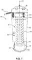
- FIG. 7illustrates one example of an embodiment of a fluidless embodiment of pressure calibration system 80 (hereinafter referred to as "calibration system 80 ") of the present disclosure.
- the calibration system 80is configured for connecting to one or more drive members 19 of a fluid injector 10 ( FIG. 8 ), such as any of the fluid injectors 10 shown in FIGS. 1 , 3 , and 5 , for performing a calibration routine to calibrate the pressure output of the individual motors and drive systems of the fluid injector 10 .
- calibration system 80is illustrated as being configured to engage with a single drive member of a fluid injector, calibration systems including multiple housing set-ups for engaging with two, three, or all drive members of a specific fluid injector are envisioned and within the bounds of the present disclosure.
- the calibration system 80 disclosed hereinavoids these limitations inherent in the prior art by eliminating the need for fluid in the calibration process while allowing for ready monitoring and calibration of a system without requiring a service technicians presence, allowing for early diagnosis of system issues, such as out of specification behavior of one or more injector components.
- the calibration system 80has a housing 82 configured for connecting with the fluid injector 10 .
- the housing 82is configured for connecting with the syringe port 13 of the fluid injector 10 (shown in FIG. 8 ) in a manner similar to the connection between the syringe 12 and the fluid injector 10 shown in FIGS. 1 , 3 , and 5 .
- the housing 82has a proximal end 84 and a distal end 86 , with a sidewall extending therebetween along a length of a longitudinal axis 90 extending through a center of the housing 82 .
- the distal end 86may have a conical shape that narrows in a distal direction, similar to the distal end of the syringe 12 .
- the distal end 86may be configured for engaging the retaining mechanism 57 (see, e.g., FIG. 8 ).
- the proximal end 84 of the housing 82may be sized and adapted for being removably inserted in or otherwise engaged with the syringe port 13 of the injector 10 (shown in FIGS. 1 , 3 , 5 , and 8 ).
- the proximal end 84 of the housing 82defines an engagement section 92 that is configured to be removably inserted into (or otherwise engaged with) the syringe port 13 of the injector 10 while the remaining portion of the housing 82 remains outside of the syringe port 13 .
- the housing 82may have one or more position markers 88 which may be used by an optical system (not shown) to determine a position of the drive member/piston 19 or piston engagement portion 96 , for example as the drive member/piston 19 or piston engagement portion 96 moves from a first, uncompressed positon to a second, at least partially compressed position.
- the drive systemmay determine the distance traveled by the drive member/piston 19 as it moves from the first, uncompressed positon to the second, at least partially compressed position, and deliver that distance information to a processor associated with the injector 10 , as described herein.
- the housing 82includes a compressible member 94 having a drive member engagement portion 96 , and a sensor 100 , such as a force gauge.
- the compressible member 94may include a one or more compressible springs 98 or other compressible components as described herein.
- the drive member engagement portion 96is configured for contacting or connecting with the drive member 19 of the fluid injector 10 (shown in FIG. 8 ). In certain embodiments, the drive member engagement portion 96 may connect with the drive member 19 in a manner similar to the connection between the plunger 16 and the drive member 19 described herein with reference to FIGS. 1-2 .
- the drive member engagement portion 96may have the same connection features as the plunger 16 to allow the compressible member 94 and sensor 100 to be connected to the drive member 19 such that the drive member engagement portion 96 and compressible member can be moved in a reciprocal manner within the housing 82 in a direction along the longitudinal axis 90 .
- the drive member 19may abut and contact a proximal surface of the drive member engagement portion 96 , such that when a distal force is applied by the drive member 19 , the drive member engagement portion 96 is moved in the distal direction with concurrent compression of the compressible member 94 .
- the compressible member 94such as the one or more compressible springe 98 may have a proximal end 102 connected with the drive member engagement portion 96 and a distal end 104 connected with a sensor 100 , such as a strain gauge, a force sensor, a load cell, a pressure sensor, a force transducer, and combination of any thereof.
- the compressible member 94translates the force from the drive member 19 and motor 31 to the sensor 100 with a minimal loss of acoustic and/or frictional energy.
- the compressible member 94is movable between a first, uncompressed position (shown in FIG.
- the compressible member 94may be resilient, wherein the compressible member 94 reverts to the uncompressed position from the compressed position after the urging force imparted by the drive member 19 is removed, such as due to retraction of the drive member 19 .
- the compressible member 94may be one or more mechanical springs.
- the compressible member 94may be a spring, a plurality of springs, a pneumatic compression cell, a hydraulic compression cell, a compressible foam, an elastomer, a compressible rod, such as a rod made from a compressible elastomeric material, a material that changes at least one measurable property, for example electrical resistivity, when compressed, and combinations of any thereof.
- an incompressible engagementmay be used between the drive member 19 and the sensor 100 such that the force translates directly from the drive member 19 to the sensor 100 and feeds back into the controller for calibration.
- the systemmay use motor current translation (PID) to determine pressure, which may vary with motor speed.
- PIDmotor current translation
- one or more of a strain gauge, a force sensormay be used to determine applied force.
- the compressible member 94may provide sufficient stroke length for different motor speeds.
- the senor 100is configured to measure the force that the drive member 19 and the motor 31 impart on the calibration system 80 .
- the sensor 100may be a force gauge or a strain gauge.
- the sensor 100may comprise a motor that pushes against the distal end 104 of the compressible member 94 based on the force imparted on the proximal end 102 of the compressible member 94 by the drive member 19 and the motor 31 .
- the senor 100may be an optical force measurement system, wherein the sensor 100 is configured to measure movement of the compressible member 94 (or a portion of the force gauge 100 ) relative to the housing 82 as the drive member 19 compresses the compressible member 94 from the first, uncompressed position to the second, at least partially compressed position.
- the output from the sensor 100may be sent to a processor, for example by a wired connection 95 or by wireless communication (e.g., WiFi, Bluetooth, or other wireless communication technology) such as a processor associated with the fluid injector 10 , an external processor, a hospital information system, or other processor, for a dynamic correlation of the measurement signal to pressure, for example using the modulus of compression for the compressible member 94 and an appropriate conversion algorithm, such as Hooke's Law for a compressible spring.
- the measurement signal of the sensor 100may be a voltage signal that is sent a processor, described herein to be converted into a force measurement.
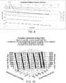
- a pressure calibration curve 106( FIG. 9 ) can be generated with real pressure values correlated to system readings for motor current.
- a three-dimensional surface profile( FIG. 10 ) can be created to generate a calibration equation to be used for the drive member 19 and motor 31 combination.
- the drive member 19may be driven distally such that the drive member 19 contacts or connects with the drive member engagement portion 96 of the calibration system 80 for the first, uncompressed position of the compressible member 96 .
- the compressible member 94is compressed from the first, uncompressed position to a second, at least partially compressed position associated with the applied force by the drive member 19 on the compressible member 94 and the force imparted may be transferred to the sensor 100 .
- the sensor 100may measure the force imparted by the drive member 19 and the motor 31 and send the measurement data to processor, such as described herein such that the input of the motor 31 can be adjusted based on a calibration curve 106 for each flow rate.
- the processcan be repeated for various rates of movement of the drive member 19 that correspond to various flow rates to generate a three-dimensional calibration equation that calibrates the motor input/pressure output for various flow rates (see FIG. 10 ).
- the calibration curvemay be utilized to adjust motor current or force such that multiple motors in a multi-fluid injector system may impart the accurate pressure to fluid within the syringe during an injection protocol.
- the calibration equation or calibration datamay be used to monitor injector calibration and highlight trends over time, such as weakening of motor strength or other injector components so that such wear or defect may be corrected before failure. An analysis of accumulated or stored data based on the distance of motor travel relative to the force sensed by the calibration unit may provide an indication of some wear, potential failure, or failure.
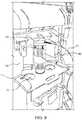
- a calibration fixture 200is shown in accordance with an example of the present disclosure.
- the calibration fixture 200can be used to test a drive mechanism 202 of an injector separately from the injector.
- the calibration fixture 200is configured for calibrating the pressure output of the drive mechanism 202 that is removable from the injector (not shown). In this manner, the calibration fixture 200 can be used to test a variety of different drive mechanisms 202 configured for use with a variety of different injectors separate from the injectors themselves.
- the drive mechanism 202may comprise a motor 31 and a drive member 19 , such as a piston.
- the calibration fixture 200has a mounting platform 204 for mounting the drive mechanism 202 .
- the mounting platform 204has an opening (not shown) for receiving at least a portion of the drive mechanism 202 , such as the piston 19 .
- the drive mechanism 202may be fixedly mounted to the mounting platform 204 while the piston 19 extends through the opening to engage a force sensor 212 .
- the calibration fixture 200may have a piston engagement portion 208 , a compressible member 210 , and a force gauge 212 .
- the piston engagement portion 208is configured for contacting or connecting with the piston 19 .
- the compressible member 210which may be any of the compressible members described herein, translates the force from the drive member 19 and motor 31 to a sensor 212 , such as a force gauge, a strain gauge, a force sensor, a load cell, a pressure sensor, a force transducer, and combination of any thereof.
- the compressible member 210is movable between a first, uncompressed position and a second, at least partially compressed position due to the urging force imparted by the drive member 19 driven by the motor 31 . Compression of the compressible member 210 between the uncompressed position and the at least partially compressed position allows the drive member 19 to move in the same manner as during delivery of fluid from a syringe 12 .
- the compressible member 210may be compressed by the drive member 19 at a varying force over time (see, FIG. 12 ) to simulate different flow rates.
- the compressible member 210may be resilient, wherein the compressible member 210 reverts to the first, uncompressed position from the compressed second, at least partially position after the urging force imparted by the drive member 19 is removed, such as due to retraction of the drive member 19 .
- the compressible member 210may be a mechanical spring.
- the compressible member 210has sufficient length to be compressed over the entire stroke of the drive member 19 .
- the senor 212may be configured to measure the force that the drive member 19 and the motor 31 impart on the calibration fixture 200 .
- a plurality of sensors 212may be used to provide redundant readings.
- the motor output, as measured by the sensor 212can be correlated to a pressure value that would be generated if the drive member 19 was driving a fluid-filled syringe in a manner similar described herein with reference to FIG. 10 .
- the drive mechanism 202can be pressure calibrated independently of the injector. In this manner, a defective drive mechanism 202 may be replaced with a new drive mechanism 202 that has been calibrated without causing any additional downtime to the injector due to further pressure calibration of a new drive mechanism.
Landscapes
- Health & Medical Sciences (AREA)
- Engineering & Computer Science (AREA)
- Heart & Thoracic Surgery (AREA)
- Animal Behavior & Ethology (AREA)
- Veterinary Medicine (AREA)
- Vascular Medicine (AREA)
- Anesthesiology (AREA)
- Biomedical Technology (AREA)
- Public Health (AREA)
- Hematology (AREA)
- Life Sciences & Earth Sciences (AREA)
- General Health & Medical Sciences (AREA)
- General Engineering & Computer Science (AREA)
- Physics & Mathematics (AREA)
- General Physics & Mathematics (AREA)
- Automation & Control Theory (AREA)
- Mechanical Engineering (AREA)
- Fluid Mechanics (AREA)
- Infusion, Injection, And Reservoir Apparatuses (AREA)
Description
- This application claims priority to
U.S. Provisional Application No. 62/552,428 - The present disclosure relates generally to systems and methods for calibrating a fluid injector, such as a medical fluid injector, and, further, to a system and method for pressure calibration of the fluid injector.
- In many medical diagnostic and therapeutic procedures, a medical practitioner, such as a physician, injects a patient with one or more medical fluids. In recent years, a number of fluid delivery systems having injector-actuated syringes and fluid injectors for pressurized injection of fluids, such as a contrast solution (often referred to simply as "contrast"), a flushing agent, such as saline, and other medical fluids have been developed for use in procedures such as angiography (CV), computed tomography (CT), ultrasound, magnetic resonance imaging (MRI), positron emission tomography (PET), and other imaging procedures. In general, these fluid delivery systems are designed to deliver preset amounts of a contrast fluid, a saline flushing agent, and mixtures thereof at desired flow rates over a predetermined time.
- An actual flow rate (or delivered volume) of fluid that is delivered to the patient is targeted to be as close as possible to the desired flow rate (or desired volume). However, the actual performance of the fluid delivery system is a function of many factors due to overall impedance and capacitance of the fluid delivery system. In certain delivery procedures, impedance and capacitance of the fluid delivery system may cause a fluid flow over-rate or under-rate (or volume over- or under-delivery) from a desired flow rate (or desired volume).
- While various approaches exist for characterizing the performance of a fluid delivery system and correlating the desired performance with actual performance in terms of fluid flow rate and volume delivered, these approaches do not address the differences between desired and actual performance due to impedance and/or capacitance of the fluid delivery system in a comprehensive manner. As a result, existing approaches fail to address the under-delivery or over-delivery of fluid resulting from system impedance and/or capacitance. As a result, less than optimal injection boluses or discrepancies in actual fluid volume delivered may result and/or operation of the fluid delivery system can result in relatively large amounts of wasted fluid.
- Accordingly, there is a need in the art for improved pressure characterization of a piston of a fluid injector. There is a further need for improved systems and methods for calibrating a fluid injector, as well as systems and methods for characterizing the performance of a fluid delivery system and correlating the desired performance with actual performance in terms of fluid flow rate and volume delivered.
- According to the invention, a calibration system for calibrating a pressure output of a drive member of a fluid injector according to claim 1 is provided. In specific embodiments, the calibration system may be a fluidless calibration system, which may be readily utilized between several different fluid injection systems on site and/or by an imaging technician without the presence of a trained service technician. The calibration system may store data on drive members of a fluid injector over a period of time and determine if, how, and when the drive member falls out of specification. The calibration system may be utilized for each drive member of a fluid injector, such as a fluid injector with one, two, three, or even more drive members. The calibration system may be suited to calibrate the motor force of a fluid injector having one or more pistons as drive members, such as a syringe based fluid injector system, for example a fluid injector having one, two, three, or more pistons for operatively engaging corresponding plungers or piston engagement members of one, two, three, or more syringes.
- According to the invention, the calibration system comprises a housing configured for connecting to the fluid injector; a drive member engagement portion configured for contacting a drive member of the fluid injector; a compressible member connected at its proximal end to the drive member engagement portion; and a sensor connected to the compressible member. The compressible member is compressed with movement of the drive member of the fluid injector between a first, uncompressed position and a second, at least partially compressed position of the fluid injector in a distal direction. The sensor is configured for measuring a force imparted by the drive member when the compressible member is in the second, at least partially compressed position compared to when the drive member is in the first, uncompressed position. The sensor may be a strain gauge, a force sensor, a load cell, a pressure sensor, a force transducer, and combination of any thereof. In specific embodiments, the sensor is a strain gauge and in other embodiments the sensor is a force sensor. According to various embodiments, the compressible member may be a spring, a plurality of springs, a pneumatic compression cell, a hydraulic compression cell, a compressible foam, an elastomer, and combinations of any thereof. In specific embodiments the compressible member is a spring. According to certain embodiments, the sensor may be in wired or wireless communication with a processor of the fluid injector and an output of the sensor may be transmitted to the processor. In certain aspects, the output of the sensor may be used to calibrate an input to one or more of a motor, the drive member, a ball screw in mechanical communication with the motor and the drive member, a frictional component from a disposable fluid delivery reservoir, and other compressible mechanical components. In various aspects, the output of the sensor may be used to generate a calibration curve for calibrating a pressure output of the drive member of the fluid injector. In specific aspects, the calibration curve is utilized to determine a fault condition, such as, for example, a warning that the drive member or motor may need servicing.
- According to various embodiments, the present disclosure describes a calibration system for calibrating a pressure output of a drive member of fluid injector where the calibration system comprises: a housing configured for connecting to the fluid injector; a drive member engagement portion configured for contacting a drive member of the fluid injector; a compressible member having a known modulus of compression connected at its proximal end to the drive member engagement portion; and a sensor connected to the compressible member. The compressible member may be compressed with movement of the drive member of the fluid injector between a first, uncompressed position and a second, at least partially compressed position of the fluid injector in a distal direction. The sensor may be configured for measuring a displacement of the drive member when the compressible member is in the second, at least partially compressed position compared to when the drive member is in the first, uncompressed position. The compressible member may be selected from a spring, a plurality of springs, a pneumatic compression cell, a hydraulic compression cell, a compressible foam, an elastomer, or combinations of any thereof. According to specific embodiments, the compressible member is a spring. According to various embodiments, the sensor may be in wired or wireless communication with a processor of the fluid injector and an output of the sensor may be transmitted to the processor. The processor may determine the pressure output of the drive member of the fluid injector from the output of the sensor and the modulus of compression of the compressible member. In various embodiments, the output of the sensor may be used to generate a calibration curve for calibrating the pressure output of a drive member of the fluid injector. In specific aspects, the calibration curve is utilized to determine a fault condition, such as, for example, a warning that the drive member or motor may need servicing.
- In certain embodiments, the calibration system can be regularly used to track changes in load for the drive member over time. The calibration system may be utilized daily, weekly, monthly, or at other regular or irregular intervals to track changes in the calibration of the injector. In certain embodiments, the calibrations may be done by the imaging technician without need for service calls from the injector manufacturer representatives or third party servicing technicians. In other embodiments, the calibrations may be recorded over a period of time and may be used by a servicing technician to determine whether specific services may be required. Changes in calibration of the injector that fall outside of expected values and tolerances may signify potential unexpected wear or defects with the injector system and allow early detection and servicing.
- In other examples of the present disclosure, a method of calibrating a pressure output of a drive member of a fluid injector. According to various embodiments, the method may comprise: connecting a calibration system to the fluid injector; contacting a drive member of the fluid injector with the drive member engagement portion of the calibration system; driving a motor of the fluid injector to move the drive member and compress the compressible member from a first, uncompressed positon to a second, at least partially compressed position; and generating a measurement signal by a sensor based on the a force imparted on the compressible member by the drive member or the displacement of the drive member when the compressible member is in the second, at least partially compressed position. The methods may be used by any of the various embodiments of the calibration systems described herein. In certain embodiments, the method may further include sending the measurement signal to a processor of the fluid injector to calibrate a pressure output of the drive member based on the measurement signal. In still further embodiments, the methods may include generating a calibration curve for the pressure output of the drive member. The method may further include comparing a calibration measurement signal with one or more previous measurement signals and/or with a predetermined calibration value to determine if the injector calibration falls outside of tolerances.
- The various embodiments of the calibration system provide useful data related to force applied by a drive member in a single stroke across an entire expected load regime. Conventional fluid calibration has a fixed orifice which reaches a set pressure when the drive member is moved at a standard speed. This requires collection of multiple different pressure points to generate a calibration profile for several drive speeds. In the various embodiments of the methods described herein, the sensor determines all loads at a given speed in a single stroke of the drive member. As the compressible member is compressed, the system travels through the entire expected load regime in a single stroke.
- These and other features and characteristics of a system for pressure calibration of the fluid injector, as well as the methods of operation and functions of the related elements of structures and the combination of parts and economies of manufacture, will become more apparent upon consideration of the following description and the appended claims with reference to the accompanying drawings, all of which form a part of this specification, wherein like reference numerals designate corresponding parts in the various figures. It is to be expressly understood, however, that the drawings are for the purpose of illustration and description only.
FIG. 1 is a perspective view of a fluid delivery system according to an example of the present disclosure;FIG. 2 is a side cross-sectional view of a syringe configured for use with the fluid delivery system ofFIG. 1 ;FIG. 3 is a perspective view of a fluid delivery system according to another example of the present disclosure;FIG. 4 is a side cross-sectional view of a syringe configured for use with the fluid delivery system ofFIG. 3 ;FIG. 5 is a perspective view of a fluid delivery system according to another example of the present disclosure;FIG. 6 is a front perspective view of a multi-use disposable system configured for use with the fluid delivery system ofFIG. 5 ;FIG. 7 is a front perspective view of a calibration fixture in accordance with an example of the present disclosure;FIG. 8 is a front perspective view of the calibration fixture ofFIG. 7 in use with the fluid delivery system shown inFIG. 5 ;FIG. 9 is a two-dimensional graph showing a correlation between real pressure values with an output of a piston of a fluid injector;FIG. 10 is a three-dimensional graph showing a correlation between real pressure values, an output of a piston of a fluid injector, and a flow rate corresponding to the movement of the piston;FIG. 11 is a front perspective view of a drive mechanism calibration fixture in accordance with an example of the present disclosure; andFIG. 12 is a graph showing a pressure calibration curve showing a force as a function of time.- As used in the specification and the claims, the singular form of "a", "an", and "the" include plural referents unless the context clearly dictates otherwise.
- For purposes of the description hereinafter, the terms "upper", "lower", "right", "left", "vertical", "horizontal", "top", "bottom", "lateral", "longitudinal", and derivatives thereof shall relate to the disclosure as it is oriented in the drawing figures.
- Spatial or directional terms, such as "left", "right", "inner", "outer", "above", "below", and the like, are not to be considered as limiting as the invention can assume various alternative orientations.
- All numbers used in the specification and claims are to be understood as being modified in all instances by the term "about". The term "about" means a range of plus or minus ten percent of the stated value.
- Unless otherwise indicated, all ranges or ratios disclosed herein are to be understood to encompass any and all subranges or subratios subsumed therein. For example, a stated range or ratio of "1 to 10" should be considered to include any and all subranges between (and inclusive of) the minimum value of 1 and the maximum value of 10; that is, all subranges or subratios beginning with a minimum value of 1 or more and ending with a maximum value of 10 or less, such as but not limited to, 1 to 6.1, 3.5 to 7.8, and 5.5 to 10.
- The term "at least" means "greater than or equal to".
- The term "includes" is synonymous with "comprises".
- When used in relation to a syringe and/or a plunger, the term "proximal" refers to a portion of a syringe and/or a plunger nearest a fluid injector when a syringe and/or a plunger is oriented for connecting to a fluid injector. The term "distal" refers to a portion of a syringe and/or a plunger farthest away from a fluid injector when a syringe and/or a plunger is oriented for connecting to a fluid injector. The term "radial" refers to a direction in a cross-sectional plane normal to a longitudinal axis of a syringe, a plunger, and/or a piston extending between proximal and distal ends. The term "circumferential" refers to a direction around an inner or outer surface of a sidewall of a syringe, a plunger, and/or a piston. The term "axial" refers to a direction along a longitudinal axis of a syringe, a piston, and/or a piston extending between the proximal and distal ends. The term "open" when used to refer to a fluid delivery component means that the system is in fluid connection with an outlet, for example through a nozzle or the open end of a tubing component or catheter. In an open system, fluid flow may be constrained, for example by forcing a fluid through a small diameter fluid path where flow may be determined by physical parameters of the system and the fluid, such as tubing diameter, fluid path constrictions, applied pressure, viscosity, etc. The term "closed" when used to refer to a fluid delivery component means that the system is not in fluid connection with an outlet, for example where fluid flow is stopped by a valve, such as a stopcock, high crack pressure valve, pinch valve, and the like.
- It is to be understood that the disclosure may assume alternative variations and step sequences, except where expressly specified to the contrary. It is also to be understood that the specific devices and processes illustrated in the attached drawings, and described in the following specification, are simply exemplary embodiments of the disclosure. Hence, specific dimensions and other physical characteristics related to the examples disclosed herein are not to be considered as limiting.
- Referring to the drawings in which like reference characters refer to like parts throughout the several views thereof, the present disclosure is generally directed to fluid injector and a system and method for a pressure calibration of the fluid injector. Associated disclosure related to capacitance development and issues associated with fluid injection system is described in PCT International Application No.
PCT/US2017/020637, filed 03 March, 2017 . - Characterizing an impedance of a fluid delivery system to minimize a difference between desired and actual fluid delivery system performance requires consideration of how energy from an energy source, such as a pressurizing mechanism, for example a drive member such as a piston attached to a motor, is used in or moves through the system. The energy output or loss from the fluid delivery system may be in the form of heat losses through frictional forces or of work done on the fluid delivery system. For example, some of the energy carried by the pressurized fluid as it is delivered under pressure through a catheter is lost through resistive, frictional, or dissipative heating of the fluid. Additionally, pressurized delivery of fluid can also increase the potential energy of the system in terms of an increase in overall volume of system components and/or compressive forces on system components, as discussed herein. For example, under the pressurized fluid force, system components may expand or may compress under the stress or load imparted by the pressurized fluid in a closed or open system. Furthermore, the kinetic energy of pressurized fluid moving through the fluid delivery system can affect the overall performance of the fluid delivery system. For example, inertial forces of moving contrast media, saline, compression of system mechanical components, and expansion of the reservoirs, syringes, and/or tubing associated with the system may cause a phase lag between movement of the syringe plunger within the injector syringe and movement of contrast material out of the catheter and into the patient.
- Due to high injection pressures, which can range from 100 psi up to on the order of 1,200 psi in some angiographic procedures, there may be an expansion, deflection, or compression of various components of the fluid delivery system, such as expansion of the fluid reservoirs, such as syringes and tubing, and compression of mechanical components, such as gearing and drive components of the fluid injector that apply the pressure, such that there may be an increased volume of fluid in the syringe and tubing in excess of the desired quantity selected to be delivered in the injection procedure. Such increase in the volume of fluid in the fluid reservoir or tubing occurs due to increased system capacitance (i.e., increased fluid volume capacity). Total system capacitance (also referred to as compliance or elasticity) represents the volume of fluid (i.e., change in volume, such as excess volume) that is captured in the swelling of components of the fluid delivery system and compression of mechanical components. In general, capacitance is directly correlative to injection pressure and directly correlative to volume of contrast medium and saline in the syringes. In other words, capacitance increases with an increase in injection pressure and an increase in volume of fluid in the syringes. Total system capacitance is inherent to each fluid delivery system and depends on a plurality of factors beyond pressure and volume of fluid remaining in the system, including, without limitation, fluid properties (such as viscosity, temperature, etc.), injector construction, mechanical properties of materials used to construct the syringe or reservoir, plunger, pressure jacket surrounding the syringe, fluid lines delivering the fluid to the patient, size of the syringe, plunger, pressure jacket, diameter of tubing or other orifices through which the fluid must pass under pressure, and fluid properties, such as temperature, viscosity, and density. System capacitance may result in discrepancies between programed fluid volume delivery and actual volume delivery. For example, when beginning a pressurized fluid delivery, initial pressurization may result in swelling of system components under fluid pressure and/or compression of mechanical components under force, rather than delivery of a corresponding fluid volume to a patient. When the pressurizing force is reduced or released during a portion of the injection, for example when the desired fluid volume is delivered, the release of the stored capacitance-based volume may result in over delivery of fluid.
- In some fluid delivery systems, such as fluid delivery systems having a single syringe, two syringes (for example a contrast media syringe and a saline flush syringe), three syringes (for example two contrast syringes, which may contain the same or different contrast media or different concentrations, and a saline flush syringe) or a plurality of syringes, each independently driven by pistons or drive members of the fluid injector, the accuracy of fluid delivery is based, at least in part, on the ability of the fluid injector to accurately characterize the pressure in the syringe(s) and fluid path(s). This characterization may be based, at least in part, on calibrating the piston/drive member using a calibration station configured for accurately measuring the pressure imparted on a fluid by the piston/drive member. Pressure calibration of fluid injectors may be performed by pushing fluid at varying rates through a frictionless fixture with a fixed orifice. Pressure of the fluid may then be measured using a pressure gauge, where a real pressure signal is either recorded or fed back into the fluid injector to correlate the load signal of the piston, such as voltage or current measurement, to a real pressure value. Conventional calibration stations which involve pressurization of fluid filled syringes and measurement of resulting fluid pressures can be cumbersome, difficult to set up and operate, and have compounded errors, leading to inaccurate pressure characterization of the piston or drive member. For example, errors which may affect calibration measurements may include friction in the fixture, air in the fluid path, lack of data points on a correlative timescale, fluid leakage inaccuracies, and gauge reading inaccuracies. Further, conventional calibration does not readily provide for real-time adjustment based on factors, such as component wear, differences in syringe tolerance, fluid characteristics, and volumes of syringes used since it is typically performed infrequently, such as when the injector is serviced. Changes in tolerances and system wear in injector components can add up over time to increase volume inaccuracies, creating error in previous calibrations of the volume accuracies of fluid delivery. According to various embodiments herein, a calibration system is described which can quickly and accurately measure and calibrate pressurization forces in a fluid injector system, such as for drive members or pistons. The calibration system may be readily used by a imaging technician, for example on a daily, weekly, and/or monthly basis to measure and monitor the calibration of a fluid injector system over time and further, may allow for calibration corrections for more accurate fluid delivery. In other embodiments, the calibration system may work with a processor to track system characteristics over time, providing information about component status over time to determine whether system components are operating within specification or are in need of servicing or replacement.
- According to an embodiment, the calibration system may comprise a housing configured for connecting to and/or engaging with the fluid injector; a drive member engagement portion configured for contacting an a drive member of the fluid injector; a compressible member connected at its proximal end to the drive member engagement portion; and a sensor connected to the compressible member. The compressible member may be compressed with movement of the drive member of the fluid injector between a first, uncompressed position and a second, at least partially compressed position of the fluid injector in a distal direction. The sensor may be configured for measuring a force imparted by the drive member when the compressible member is in the second, at least partially compressed position compared to when the drive member is in the first, uncompressed position. The sensor may be a strain gauge, a force sensor, a load cell, a pressure sensor, a force transducer, and combination of any thereof. Alternatively, if the modulus of the compressible member is known, the force applied may be calculated utilizing an algorithm, such as Hooke's Law. In specific embodiments, the sensor is a strain gauge and in other embodiments the sensor is a force sensor. According to various embodiments, the compressible member may be a spring, a plurality of springs, a pneumatic compression cell, a hydraulic compression cell, a compressible foam, an elastomer, an opposing ferro- or electromagnetic repulsive force (which may be varied) to provide resistance to drive member movement, a deflectable metal member, and combinations of any thereof. In specific embodiments the compressible member is a spring. According to certain embodiments, the sensor may be in wired or wireless (e.g., by WiFi network, Bluetooth, Ethernet, or other conventional wireless communication technology) communication with one or more of a processor of the fluid injector, an external processor, and a hospital information network, and an output of the sensor may be transmitted to the one or more of a processor of the fluid injector, an external processor, and a hospital information network. In certain aspects, the output of the sensor may be used to calibrate an input to one or more of a motor, the drive member, a ball screw in mechanical communication with the motor and the drive member, a frictional component from a disposable fluid delivery reservoir, and other compressible mechanical components. In various aspects, the output of the sensor may be used to generate a calibration curve for calibrating a pressure output of the drive member of the fluid injector. In specific aspects, the calibration curve is utilized to determine a fault condition, such as, for example, a warning that the drive member or motor may need servicing. For example, by frequent calibration using a injector calibration system as described according to the various embodiments herein, a processor may notice gradual or sudden deviations in the pressure calibration which may be the result of degradation of or out-of-specification readings for one or more system components
- According to various embodiments, the present disclosure describes a calibration system for calibrating a pressure output of a drive member of fluid injector where the calibration system comprises: a housing configured for connecting to the fluid injector; a drive member engagement portion configured for contacting a drive member of the fluid injector; a compressible member having a known modulus of compression connected at its proximal end to the drive member engagement portion; and a sensor connected to the compressible member. The compressible member may be compressed with movement of the drive member of the fluid injector between a first, uncompressed position and a second, at least partially compressed position of the fluid injector in a distal direction. The sensor may be configured for measuring a displacement of the drive member when the compressible member is in the second, at least partially compressed position compared to when the drive member is in the first, uncompressed position. The compressible member may be selected from a spring, a plurality of springs, a pneumatic compression cell, a hydraulic compression cell, a compressible foam, an elastomer, or combinations of any thereof. According to specific embodiments, the compressible member is a spring. According to various embodiments, the sensor may be in wired or wireless communication with a processor of the fluid injector and an output of the sensor may be transmitted to the processor. The processor may determine the pressure output of the drive member of the fluid injector from the output of the sensor and the modulus of compression of the compressible member. For example, when the modulus of compression of the compressible member and the distance between the first, uncompressed state and the second, at least partially compressed state are known, the force that must be applied to the compressible member to compress from the first state to the second state may be calculated. In certain embodiments, wherein the compressible member is a spring having a known spring constant, the force that must be applied to the spring to compress the spring may be calculated using Hooke's Law (Fs = -k•x, where Fs is the force applied, k is the spring constant and x is the distance compressed). According to other embodiments, where the compressible member comprises another compressible material, the modulus of compression may be initially determined by applying a known force of compression and measuring the distance of compression and developing an equation that shown the functional relationship between the force of compression and distance compressed. This equation may then be utilized by a processor to calculate the force of compression applied to the calibration system according to various embodiments. In various embodiments, the output of the sensor may be used to generate a calibration curve for calibrating the pressure output of a drive member of the fluid injector. In specific aspects, the calibration curve is utilized to determine a fault condition, such as, for example, a warning that the drive member or motor may need servicing.
- In certain embodiments, the calibration system can be regularly used to track changes in load for the drive member over time. The calibration system may be utilized daily, weekly, monthly, or at other regular or irregular intervals to track changes in the calibration of the injector. In certain embodiments, the calibrations may be done by the imaging technician without need for service calls from the injector manufacturer representatives or third party servicing technicians. In other embodiments, the calibrations may be recorded over a period of time and may be used by a servicing technician to determine whether specific services may be required. Changes in calibration of the injector that fall outside of expected values, specifications, and tolerances may signify potential unexpected defects or general wear with one or more components of the injector system and allow early detection and servicing. Injector components that may show defects or wear include but are not limited to motors, drive trains, ball drives, gearing, drive member components, syringe and/or plunger engagement or locking mechanisms, restraining members and components that restrain or engage one or more disposable or reusable components, electromechanical components, etc.
- In other examples of the present disclosure, a method of calibrating a pressure output of a drive member of a fluid injector. According to various embodiments, the method may comprise: connecting a calibration system to the fluid injector; contacting a drive member of the fluid injector with the drive member engagement portion of the calibration system; driving a motor of the fluid injector to move the drive member and compress the compressible member from a first, uncompressed positon to a second, at least partially compressed position; and generating a measurement signal by a sensor based on the a force imparted on the compressible member by the drive member or the displacement of the drive member when the compressible member is in the second, at least partially compressed position. The methods may be used by any of the various embodiments of the calibration systems described herein. In certain embodiments, the method may further include sending the measurement signal to one or more of a processor of the fluid injector, an external processor, a hospital information system, and to a manufacturer or service provider to calibrate a pressure output of the drive member based on the measurement signal. In still further embodiments, the methods may include generating a calibration curve for the pressure output of the drive member. The method may further include comparing a calibration measurement signal with one or more previous measurement signals and/or with a predetermined calibration value to determine if the injector calibration falls outside of specifications or tolerances. According to certain embodiments, a calibration curve may be created as a factory setting and/or may be generated and updated continuously by the processor, so that sudden deviations from the calibration curve may indicate degradation of operation outside of specifications or tolerances, imminent failure, or failure of one or more injector components.
- With reference to
FIG. 1 , a fluid injector10 (hereinafter referred to as "injector 10"), such as an automated or powered fluid injector, is adapted to interface with and actuate one or more syringes12 (hereinafter referred to as "syringe 12"), which may be filed with a fluidF, such as contrast media, saline solution, or any desired medical fluid. Theinjector 10 may be used during a medical procedure to inject the medical fluid into the body of a patient by driving aplunger 14 of eachsyringe 12 with a drive member, such as piston19 (shown inFIG. 2 ), such as linear actuator or a piston element. Theinjector 10 may be a multi-syringe injector having two, three or more syringes, wherein theseveral syringes 12 may be oriented in a side-by-side or other relationship and may be separately actuated by respective drive members/pistons16 associated with theinjector 10. In examples with two or more syringes, for example, arranged in a side-by-side or other relationship and filled with two different fluids, theinjector 10 may be configured to deliver fluid from one or both of thesyringes 12, sequentially or concurrently. According to one embodiment, thefluid injector 10 may be a dual head injector having twosyringes first syringe 12a for delivering a contrast media or other medical fluid and asecond syringe 12b for delivering saline or other medically approved flushing agent to flush the contrast media to the patient. In other embodiments, thefluid injector 10 may have threesyringes 12, a first and second syringe for delivering one or two different contrast media or other medical fluid and a third syringe for delivering saline or other medically approved flushing agent to flush the contrast media to the patient. According to various embodiments, thefluid injector 10 may be configured to deliver the contrast and saline separately (e.g., delivering a specific volume saline over a specific time followed by delivering a specific volume of contrast over a specific time, followed by a second volume of saline over a specified time to flush the contrast media from the tubing into the patient). According to various embodiments, thefluid injector 10 may be configured to deliver the contrast and saline separately or as a mixture (e.g., delivering a specific volume saline over a specific time followed by delivering a specific volume of contrast, delivering a specific volume contrast over a specific time followed by delivering a specific volume of saline, or a volume of contrast followed by a specified ratio of contrast and saline (i.e., in a "dual flow" process) over a specific time, followed by a second volume of saline over a specified time to flush the contrast media from the tubing into the patient). A technician may program a specific injection protocol into the injector (or use a pre-written protocol) to deliver the desired volumes of saline, contrast, specific ratios of contrast and saline mixtures, etc., at a desired flow rate, time, and volume for each solution. Thefluid injector 10 may have at least one bulk fluid source (not shown) for filling thesyringes 12a,b with fluid and in certain embodiments, thefluid injector 10 may have a plurality of bulk fluid source, one for each of the plurality of syringes, for filling each of the plurality of syringes with the desired fluid. - A fluid path set17 may be in fluid communication with each
syringe 12 to place each syringe in fluid communication with a catheter for delivering the fluidF from eachsyringes 12 to a catheter (not shown) inserted into a patient at a vascular access site. In certain embodiments, fluid flow from the one ormore syringes 12 may be regulated by a fluid control module (not shown) that operates various valves, stopcocks, and flow regulating structures to regulate the delivery of the saline solution and contrast to the patient based on user selected injection parameters, such as injection flow rate, duration, total injection volume, and ratio of fluids from thesyringes 12, including specific ratios of each fluid in a dual flow injection protocol. - With reference to
FIG. 2 , thedrive member 19, such as a reciprocally driven piston moved by amotor 31, may be configured to extend into and from therespective syringe port 13 through an opening in the front end of the injector housing. In fluid injector embodiments comprising a plurality of syringes, a separate drive member/piston 19 may be provided for eachsyringe 12. Each drive member/piston 19 is configured to impart a motive force to at least a portion of thesyringe 12, such as theplunger 14 or a distal end of a rolling diaphragm syringe (for example, as described inPCT/US2017/056747 ;WO 2016/172467 ; andWO 2015/164783 ). The drive member orpiston 19 may be reciprocally operable via electro-mechanical drive components such as a ball screw shaft driven by themotor 31, a voice coil actuator, a rack-and-pinion gear drive, a linear motor, a linear actuator, and the like. Themotor 31 may be an electric motor. - Examples of suitable front-loading
fluid injectors 10 are disclosed inU.S. Patent Nos. 5,383,858 ;7,553,294 ;7,666,169 ;9,173,995 9,199,033 9,474,857 PCT Application Publication No. WO 2016/191485 andWO 2016/112163 . - Having described the general structure and function of specific embodiments of the
fluid injector 10, an embodiment ofsyringe 12 configured for use with theinjector 10 will now be described with reference toFIG. 2 . Thesyringe 12 generally has acylindrical syringe barrel 18 formed from glass, metal, or a suitable medical-grade plastic. Thebarrel 18 has aproximal end 20 and adistal end 24, with asidewall 119 extending therebetween along a length of a longitudinal axis15 extending through a center of thebarrel 18. In some examples, thedistal end 24 may have a conical shape that narrows in a distal direction from thecylindrical barrel 18. Anozzle 22 extends from thedistal end 24. Thebarrel 18 has anouter surface 21 and aninner surface 23 with aninterior volume 25 configured for receiving the fluid therein. Theproximal end 20 of thebarrel 18 may be sealed with theplunger 14 that is reciprocally movable through thebarrel 18 by reciprocal movement of thecorresponding piston 19 or drive member. Theplunger 14 forms a liquid-tight seal against theinner surface 23 of thebarrel 18 as theplunger 14 is advanced moved through thebarrel 18. - With continued reference to
FIG. 2 , theproximal end 20 of thesyringe 12 is sized and adapted for being removably inserted in asyringe port 13 of an injector10 (shown inFIG. 1 ). In some examples, theproximal end 20 of thesyringe 12 defines aninsertion section 30 that is configured to be removably inserted into thesyringe port 13 of theinjector 10 while the remaining portion of thesyringe 12 remains outside of thesyringe port 13. - The
syringe 12 may be made of any suitable medical-grade plastic or polymeric material, desirably a clear or substantially translucent plastic material. The material of thesyringe 12 is desirably selected to meet the required tensile and planar stress requirements, water vapor transmission, and chemical/biological compatibility. Exemplary syringes suitable for use with theinjector 10 depicted inFIG. 1 are described inUnited States Patent Nos. 5,383,858 ;6,322,535 ;6,652,489 ;9,173,995 9,199,033 - In some examples, such as shown in
FIG. 3 , theinjector 10 may be configured for receiving and retaining apressure jacket 32 within eachsyringe port 13 of theinjector 10. WhileFIGS. 1 and3 illustratefluid injectors 10 with twosyringe ports 13, which for theinjector 10 shown inFIG. 3 each having acorresponding pressure jacket 32, other examples of thefluid injector 10 may include asingle syringe port 13 and optionally, acorresponding pressure jacket 32 or more than twosyringe ports 13 with an optional corresponding number ofpressure jackets 32. In embodiments comprising pressure jackets, eachpressure jacket 32 may be configured to receive a syringe, such as a syringe for an angiographic (CV) procedure, or a rolling diaphragm syringe34 (suitable examples of which are described in described inPCT/US2017/056747 ;WO 2016/172467 ; andWO 2015/164783 ). A fluid path set, similar to the fluid path set17 shown inFIG. 1 , may be fluidly connected with a discharge end of each rollingdiaphragm syringe 34 for delivering fluid from thesyringes 34 through tubing connected to a catheter, needle, or other fluid delivery connection (not shown) inserted into a patient at a vascular access site. According to various embodiments, thesyringe - With reference to
FIG. 4 , the rollingdiaphragm syringe 34 generally includes ahollow body 36 defining aninterior volume 38. Thebody 36 has a forward ordistal end 40, a rearward orproximal end 42, and aflexible sidewall 44 extending therebetween. Theproximal end 42 may be configured to act as piston to pressurize the syringe interior to draw in or expel fluid therefrom, as described herein. Thesidewall 44 of the rollingdiaphragm syringe 34 defines a soft, pliable or flexible, yet self-supporting body that is configured to roll upon itself, as a "rolling diaphragm", under the action of the a drive member or piston of thefluid injector 10. The drive member/piston 19 may be configured to releasably engage a drivemember engagement portion 52 at theproximal end 42 of the rolling diaphragm syringe34 (examples of which are described inPCT/US2017/056747 ). In operation, thesidewall 44 is configured to roll such that its outer surface is folded and inverted in a radially inward direction as the drive member/piston 19 moves theproximal end 42 in a distal direction and unrolled and unfolded in the opposite manner in a radially outward direction as the drive member/piston 19 retract theproximal end 42 in a proximal direction. - With continued reference to
FIG. 4 , the rearward or proximal portion of thesidewall 44 connects to aclosed end wall 46, and a forward or distal portion of thesidewall 44 defines adischarge neck 48 opposite theclosed end wall 46. Theclosed end wall 46 may have a concave shape to facilitate the initiation of the inversion or rolling of thesidewall 44, enhance mechanical strength of theclosed end wall 46, and/or to provide a receiving pocket to receive a distal end of drive member/piston 19. For example, theclosed end wall 46 may define a receiving end pocket for interfacing directly with a similarly-shaped distal end of the drive member/piston 19. In some examples, at least a portion of the drive member/piston 19 may be shaped to substantially match the shape of theclosed end wall 46 or, alternatively, pressure from the drive member/piston 19 as it is moved distally may conform theend wall 46 to substantially match the shape of at least a portion of the drive member/piston 19. - The
end wall 46 may have acentral portion 50 having a substantially dome-shaped structure and a drivemember engagement portion 52 extending proximally from thecentral portion 50. The drivemember engagement portion 52 is configured for releasably interacting with a corresponding engagement mechanism on the drive member/piston 19 of thefluid injector 10, for example as the drive member/piston is retracted. The rollingdiaphragm syringe 34 may be made of any suitable medical-grade plastic or polymeric material, desirably a clear or substantially translucent plastic material. The material of the rollingdiaphragm syringe 34 is desirably selected to meet the required tensile and planar stress requirements, water vapor transmission, and chemical/biological compatibility. - With reference to
FIG. 5 , afluid injector 10 is illustrated in accordance with another example of the present disclosure. Theinjector 10 has ahousing 54 that encloses various mechanical drive components and electrical and power components necessary to drive various mechanical drive components, control components, such as electronic memory and electronic control devices used to control operation of reciprocally movable drive members (not shown). Thefluid injector 10 further has a multi-use disposable system (MUDS)56 suitable for use over multiple injection protocols that is removably connectable with thefluid injector 10. TheMUDS 56 may be connected with thefluid injector 10 by aretaining mechanism 57 that engages a distal portion of the threesyringes 58 of theMUDS 56, to releasably secure theMUDS 56 within theinjector 10.Injector 10 and the correspondingMUDS 56 as illustrated inFIG. 5 are described in detail inWO 2016/112163 . - The
MUDS 56 may comprise one or more syringes or pumps58. In some aspects, the number ofsyringes 58 corresponds to the number of drive members/pistons on thefluid injector 10. In some examples, such as shown inFIGS. 5 and6 , theMUDS 56 has threesyringes 58 arranged in a side-by-side arrangement. Eachsyringe 58 has abulk fluid connector 60 for connecting to a respective bulk fluid source (not shown) via aMUDS fluid path 62. TheMUDS fluid path 62 may be formed as a flexible tube that connects to thebulk fluid connector 60 having a spike element at its terminal end. - With reference to
FIG. 6 , theMUDS 56 has aframe 64 for supporting the one ormore syringes 58a-58c. Thesyringes 58a-58c may be removably or non-removably connected to theframe 64. Eachsyringe 58a-58c has an elongated, substantially cylindrical syringe body. Eachsyringe 58a-58c has a fillingport 66 in fluid communication with theMUDS fluid path 62 for filling thesyringe 58a-58c with fluid from a bulk fluid source. Eachsyringe 58a-58c further has a discharge outlet orconduit 68 at the terminal portion of its distal end. Thedischarge outlet 68 of eachsyringe 58a-58c is in fluid communication with a manifold70. Avalve 72 is associated with eachdischarge outlet 68 and is operable between a filling position, where the fillingport 66 is in fluid communication with the syringe interior while thedischarge outlet 68 is in fluid isolation from the syringe interior, and a delivery position, where thedischarge outlet 68 is in fluid communication with the syringe interior while the fillingport 66 is in fluid isolation from the syringe interior. The manifold70 has a fluid pathway that is in fluid communication with eachsyringe 58a-58c and with afluid outlet line 74 in fluid communication with aport 76 configured for connecting to a single use fluid path element (not shown) for delivering fluid to the patient. - In various embodiments, for
fluid injector 10, for example any of the fluid injectors shown inFIGS. 1 ,3 , and5 , the motor31 (FIG. 2 ) provides the motive force to reciprocally drive the drive member/piston 19 in a distal direction and discharges fluid within thesyringes MUDS 56. Themotor 31 may have drive components, such as gears and shafts, that are operatively connected to the drive member/piston 19 to reciprocally move the drive member/piston 19. Eachmotor 31 must be calibrated to correlate its operating characteristics, such as input current or output torque, to a flow rate or pressure and tolerances associated therewith. As described herein, calibration may be desirable to compensate for any variations or out of specification behavior from any of the different components of thefluid injectors 10, such as any variations in motor performance characteristics, particularly in fluid injectors with two or more syringes driven by two or more motors. For example, conversion of motor input torque for onemotor 31 to an injector output pressure may be different for anothermotor 31. This variation may be further compounded by variations in tolerances of the drivetrain of thefluid injector 10. The accuracy of flow rate or pressure in afluid injector 10 is directly correlative to a system and method used to calibrate themotor 31. FIG. 7 illustrates one example of an embodiment of a fluidless embodiment of pressure calibration system80 (hereinafter referred to as "calibration system 80") of the present disclosure. Thecalibration system 80 is configured for connecting to one ormore drive members 19 of a fluid injector10 (FIG. 8 ), such as any of thefluid injectors 10 shown inFIGS. 1 ,3 , and5 , for performing a calibration routine to calibrate the pressure output of the individual motors and drive systems of thefluid injector 10. Whilecalibration system 80 is illustrated as being configured to engage with a single drive member of a fluid injector, calibration systems including multiple housing set-ups for engaging with two, three, or all drive members of a specific fluid injector are envisioned and within the bounds of the present disclosure. While traditional calibration systems use fluid-filled syringes having a pressure transducer at the syringe outlet, these calibration systems have inherent limitations, such as due to fluid contamination. Thecalibration system 80 disclosed herein avoids these limitations inherent in the prior art by eliminating the need for fluid in the calibration process while allowing for ready monitoring and calibration of a system without requiring a service technicians presence, allowing for early diagnosis of system issues, such as out of specification behavior of one or more injector components.- With continued reference to
FIG. 7 , thecalibration system 80 has ahousing 82 configured for connecting with thefluid injector 10. In some examples, thehousing 82 is configured for connecting with thesyringe port 13 of the fluid injector10 (shown inFIG. 8 ) in a manner similar to the connection between thesyringe 12 and thefluid injector 10 shown inFIGS. 1 ,3 , and5 . Thehousing 82 has aproximal end 84 and adistal end 86, with a sidewall extending therebetween along a length of a longitudinal axis90 extending through a center of thehousing 82. In some examples, thedistal end 86 may have a conical shape that narrows in a distal direction, similar to the distal end of thesyringe 12. When used with thefluid injector 10 shown inFIG. 5 , thedistal end 86 may be configured for engaging the retaining mechanism57 (see, e.g.,FIG. 8 ). Theproximal end 84 of thehousing 82 may be sized and adapted for being removably inserted in or otherwise engaged with thesyringe port 13 of the injector10 (shown inFIGS. 1 ,3 ,5 , and8 ). In some examples, theproximal end 84 of thehousing 82 defines anengagement section 92 that is configured to be removably inserted into (or otherwise engaged with) thesyringe port 13 of theinjector 10 while the remaining portion of thehousing 82 remains outside of thesyringe port 13. In some examples, thehousing 82 may have one ormore position markers 88 which may be used by an optical system (not shown) to determine a position of the drive member/piston 19 orpiston engagement portion 96, for example as the drive member/piston 19 orpiston engagement portion 96 moves from a first, uncompressed positon to a second, at least partially compressed position. Alternatively, the drive system may determine the distance traveled by the drive member/piston 19 as it moves from the first, uncompressed positon to the second, at least partially compressed position, and deliver that distance information to a processor associated with theinjector 10, as described herein. - With continued reference to
FIG. 7 , thehousing 82 includes acompressible member 94 having a drivemember engagement portion 96, and asensor 100, such as a force gauge. Thecompressible member 94 may include a one or morecompressible springs 98 or other compressible components as described herein. The drivemember engagement portion 96 is configured for contacting or connecting with thedrive member 19 of the fluid injector10 (shown inFIG. 8 ). In certain embodiments, the drivemember engagement portion 96 may connect with thedrive member 19 in a manner similar to the connection between the plunger16 and thedrive member 19 described herein with reference toFIGS. 1-2 . The drivemember engagement portion 96 may have the same connection features as the plunger16 to allow thecompressible member 94 andsensor 100 to be connected to thedrive member 19 such that the drivemember engagement portion 96 and compressible member can be moved in a reciprocal manner within thehousing 82 in a direction along the longitudinal axis90. In other embodiments, thedrive member 19 may abut and contact a proximal surface of the drivemember engagement portion 96, such that when a distal force is applied by thedrive member 19, the drivemember engagement portion 96 is moved in the distal direction with concurrent compression of thecompressible member 94. - With continued reference to
FIG. 7 , thecompressible member 94, such as the one or morecompressible springe 98 may have aproximal end 102 connected with the drivemember engagement portion 96 and adistal end 104 connected with asensor 100, such as a strain gauge, a force sensor, a load cell, a pressure sensor, a force transducer, and combination of any thereof. Thecompressible member 94 translates the force from thedrive member 19 andmotor 31 to thesensor 100 with a minimal loss of acoustic and/or frictional energy. Thecompressible member 94 is movable between a first, uncompressed position (shown inFIG. 7 ) and a second, at least partially compressed position (not shown), wherein theproximal end 102 ofcompressible member 94 is moved toward thedistal end 104 due to the urging force imparted by thedrive member 19 driven by themotor 31. Compression of thecompressible member 94 between the first, uncompressed position and the second, at least partially compressed position requires thedrive member 19 to move in the same manner as during delivery of fluid from a correspondingsyringe 12. Rate of compression of thecompressible member 94 due to the movement of thedrive member 19 may be varied by varying the rate at which thedrive member 19 is advanced to simulate different flow rates. Thecompressible member 94 may be resilient, wherein thecompressible member 94 reverts to the uncompressed position from the compressed position after the urging force imparted by thedrive member 19 is removed, such as due to retraction of thedrive member 19. In some examples, thecompressible member 94 may be one or more mechanical springs. In other examples, thecompressible member 94 may be a spring, a plurality of springs, a pneumatic compression cell, a hydraulic compression cell, a compressible foam, an elastomer, a compressible rod, such as a rod made from a compressible elastomeric material, a material that changes at least one measurable property, for example electrical resistivity, when compressed, and combinations of any thereof. In certain embodiments, an incompressible engagement may be used between thedrive member 19 and thesensor 100 such that the force translates directly from thedrive member 19 to thesensor 100 and feeds back into the controller for calibration. According to certain embodiments, the system may use motor current translation (PID) to determine pressure, which may vary with motor speed. In other embodiments, one or more of a strain gauge, a force sensor may be used to determine applied force. Thecompressible member 94 may provide sufficient stroke length for different motor speeds. - With further reference to
FIG. 7 , thesensor 100 is configured to measure the force that thedrive member 19 and themotor 31 impart on thecalibration system 80. In some examples, thesensor 100 may be a force gauge or a strain gauge. In other examples, thesensor 100 may comprise a motor that pushes against thedistal end 104 of thecompressible member 94 based on the force imparted on theproximal end 102 of thecompressible member 94 by thedrive member 19 and themotor 31. In other examples, thesensor 100 may be an optical force measurement system, wherein thesensor 100 is configured to measure movement of the compressible member94 (or a portion of the force gauge100) relative to thehousing 82 as thedrive member 19 compresses thecompressible member 94 from the first, uncompressed position to the second, at least partially compressed position. According to these embodiments, the output from the sensor100 (i.e., the measured distance of compression) may be sent to a processor, for example by awired connection 95 or by wireless communication (e.g., WiFi, Bluetooth, or other wireless communication technology) such as a processor associated with thefluid injector 10, an external processor, a hospital information system, or other processor, for a dynamic correlation of the measurement signal to pressure, for example using the modulus of compression for thecompressible member 94 and an appropriate conversion algorithm, such as Hooke's Law for a compressible spring. According to other embodiments, the measurement signal of thesensor 100 may be a voltage signal that is sent a processor, described herein to be converted into a force measurement. Based on an input current of themotor 31 and the voltage signal of thesensor 100, a pressure calibration curve106 (FIG. 9 ) can be generated with real pressure values correlated to system readings for motor current. With a plurality of pressure calibration curves106 plotted for varying motor speeds, a three-dimensional surface profile (FIG. 10 ) can be created to generate a calibration equation to be used for thedrive member 19 andmotor 31 combination. By monitoring the pressure readings from thecalibration system 80 and noting potential deviations from values on thecalibration curve 106 or the three-dimensional surface profiles, fault conditions may be determined or predicted and appropriate remediation may be undertaken, such as a service call and repair or replacement of one or more injector system components that may be out of specification. - Having described the
calibration system 80, a method of calibrating the pressure output of thefluid injector 10 will now be described according to an embodiment. After connecting thehousing 82 of thecalibration system 80 to thefluid injector 10, such as by connecting theproximal end 102 of thehousing 82 with thesyringe port 13 of thefluid injector 10 and/or by engaging thedistal end 104 of thehousing 82 with the retainingmechanism 57 of thefluid injector 10, thedrive member 19 may be driven distally such that thedrive member 19 contacts or connects with the drivemember engagement portion 96 of thecalibration system 80 for the first, uncompressed position of thecompressible member 96. After contact, as thedrive member 19 may be further driven distally at a set rate using themotor 31, thecompressible member 94 is compressed from the first, uncompressed position to a second, at least partially compressed position associated with the applied force by thedrive member 19 on thecompressible member 94 and the force imparted may be transferred to thesensor 100. Thesensor 100 may measure the force imparted by thedrive member 19 and themotor 31 and send the measurement data to processor, such as described herein such that the input of themotor 31 can be adjusted based on acalibration curve 106 for each flow rate. The process can be repeated for various rates of movement of thedrive member 19 that correspond to various flow rates to generate a three-dimensional calibration equation that calibrates the motor input/pressure output for various flow rates (seeFIG. 10 ). In certain embodiments, the calibration curve may be utilized to adjust motor current or force such that multiple motors in a multi-fluid injector system may impart the accurate pressure to fluid within the syringe during an injection protocol. In various embodiments, the calibration equation or calibration data may be used to monitor injector calibration and highlight trends over time, such as weakening of motor strength or other injector components so that such wear or defect may be corrected before failure. An analysis of accumulated or stored data based on the distance of motor travel relative to the force sensed by the calibration unit may provide an indication of some wear, potential failure, or failure. - With reference to
FIG. 11 , acalibration fixture 200 is shown in accordance with an example of the present disclosure. Thecalibration fixture 200 can be used to test adrive mechanism 202 of an injector separately from the injector. In some examples, thecalibration fixture 200 is configured for calibrating the pressure output of thedrive mechanism 202 that is removable from the injector (not shown). In this manner, thecalibration fixture 200 can be used to test a variety ofdifferent drive mechanisms 202 configured for use with a variety of different injectors separate from the injectors themselves. Thedrive mechanism 202 may comprise amotor 31 and adrive member 19, such as a piston. - With continued reference to
FIG. 11 , thecalibration fixture 200 has a mountingplatform 204 for mounting thedrive mechanism 202. The mountingplatform 204 has an opening (not shown) for receiving at least a portion of thedrive mechanism 202, such as thepiston 19. In this manner, thedrive mechanism 202 may be fixedly mounted to the mountingplatform 204 while thepiston 19 extends through the opening to engage aforce sensor 212. Thecalibration fixture 200 may have apiston engagement portion 208, acompressible member 210, and aforce gauge 212. Thepiston engagement portion 208 is configured for contacting or connecting with thepiston 19. - With continued reference to
FIG. 11 , thecompressible member 210, which may be any of the compressible members described herein, translates the force from thedrive member 19 andmotor 31 to asensor 212, such as a force gauge, a strain gauge, a force sensor, a load cell, a pressure sensor, a force transducer, and combination of any thereof. Thecompressible member 210 is movable between a first, uncompressed position and a second, at least partially compressed position due to the urging force imparted by thedrive member 19 driven by themotor 31. Compression of thecompressible member 210 between the uncompressed position and the at least partially compressed position allows thedrive member 19 to move in the same manner as during delivery of fluid from asyringe 12. Thecompressible member 210 may be compressed by thedrive member 19 at a varying force over time (see,FIG. 12 ) to simulate different flow rates. Thecompressible member 210 may be resilient, wherein thecompressible member 210 reverts to the first, uncompressed position from the compressed second, at least partially position after the urging force imparted by thedrive member 19 is removed, such as due to retraction of thedrive member 19. In some examples, thecompressible member 210 may be a mechanical spring. In certain embodiments, thecompressible member 210 has sufficient length to be compressed over the entire stroke of thedrive member 19. - With continued reference to
FIG. 11 , thesensor 212 may be configured to measure the force that thedrive member 19 and themotor 31 impart on thecalibration fixture 200. A plurality ofsensors 212 may be used to provide redundant readings. The motor output, as measured by thesensor 212, can be correlated to a pressure value that would be generated if thedrive member 19 was driving a fluid-filled syringe in a manner similar described herein with reference toFIG. 10 . - Using the
calibration fixture 200, thedrive mechanism 202 can be pressure calibrated independently of the injector. In this manner, adefective drive mechanism 202 may be replaced with anew drive mechanism 202 that has been calibrated without causing any additional downtime to the injector due to further pressure calibration of a new drive mechanism. - Although the disclosure has been described in detail for the purpose of illustration based on what is currently considered to be the most practical and preferred examples, it is to be understood that such detail is solely for that purpose and that the disclosure is not limited to the disclosed examples, but, on the contrary, is intended to cover modifications and equivalent arrangements. For example, it is to be understood that the present disclosure contemplates that, to the extent possible, one or more features of any example can be combined with one or more features of any other example.
Claims (14)
- A calibration system (80) for calibrating a pressure output of a drive member of a fluid injector (10), the calibration system (80) comprising:a housing (82) configured for connecting to the fluid injector (10);a drive member engagement portion (96) configured for contacting a drive member (19) of the fluid injector (10);a sensor (100) connected to the compressible member (94),characterised in thatthe calibration system (80) further comprisesa compressible member (94) connected at its proximal end to the drive member engagement portion (96), wherein the compressible member (94) is compressed with movement of the drive member (19) of the fluid injector (10) between a first, uncompressed position and a second, at least partially compressed position of the fluid injector (10) in a distal direction;wherein the sensor (100) is configured for measuring a force imparted by the drive member (19) when the compressible member (94) is in the second, at least partially compressed position.
- The calibration system (80) of claim 1, wherein the sensor (100) is selected from the group consisting of a strain gauge, a force sensor, a load cell, a pressure sensor, a force transducer, and combination of any thereof.
- The calibration system (80) of claim 2, wherein the sensor (100) comprises a strain gauge or a force sensor.
- The calibration system (80) of any of claims 1 to 3, wherein the compressible member (94) is selected from the group consisting of a spring (98), a plurality of springs, a pneumatic compression cell, a hydraulic compression cell, a compressible foam, an elastomer, and combinations of any thereof, preferably wherein the compressible member is a spring (98).
- The calibration system (80) of any of claims 1 to 4, wherein the sensor (100) is in wired (95) or wireless communication with a processor and an output of the sensor (100) is transmitted to the processor.
- The calibration system (80) of any of claims 1 to 5, wherein an output of the sensor (100) is used to calibrate an input to one or more of a motor (31), the drive member (19), a ball screw in mechanical communication with the motor (31) and the drive member (19), a frictional component from a disposable fluid delivery reservoir, and other compressible mechanical components.
- The calibration system (80) of any of claims 1 to 6, wherein an output of the sensor (100) is used to generate a calibration curve (106) for calibrating a pressure output of the drive member (19) of the fluid injector (10).
- The calibration system (80) of claim 7, wherein the calibration curve (106) is utilized to determine or predict a fault condition.
- The calibration system (80) of claim 1,
wherein the compressible member (94) has a known modulus of compression; and
wherein the sensor (100) is configured for measuring a displacement of the drive member (19) when the compressible member (94) is in the second, at least partially compressed position. - The calibration system (80) of claim 9, wherein the compressible member (94) is a spring (98).
- The calibration system (80) of any of claims 9 or 10, wherein the sensor (100) is in wired (95) or wireless communication with a processor and an output of the sensor (100) is transmitted to the processor.
- The calibration system (80) of claim 11, wherein the processor determines the pressure output of the fluid injector (10) from the output of the sensor (100) and the modulus of compression of the compressible member (94).
- The calibration system (80) of any of claims 9 to 12, wherein an output of the sensor (100) is used to generate a calibration curve (106) for calibrating the pressure output of a drive member (19) of the fluid injector (10).
- The calibration system (80) of claim 13, wherein the calibration curve (106) is utilized to determine a fault condition.
Applications Claiming Priority (2)
| Application Number | Priority Date | Filing Date | Title |
|---|---|---|---|
| US201762552428P | 2017-08-31 | 2017-08-31 | |
| PCT/US2018/048313WO2019046282A1 (en) | 2017-08-31 | 2018-08-28 | Injector pressure calibration system and method |
Publications (2)
| Publication Number | Publication Date |
|---|---|
| EP3675931A1 EP3675931A1 (en) | 2020-07-08 |
| EP3675931B1true EP3675931B1 (en) | 2021-08-11 |
Family
ID=63528965
Family Applications (1)
| Application Number | Title | Priority Date | Filing Date |
|---|---|---|---|
| EP18766499.0AActiveEP3675931B1 (en) | 2017-08-31 | 2018-08-28 | Injector pressure calibration system and method |
Country Status (6)
| Country | Link |
|---|---|
| US (1) | US11598664B2 (en) |
| EP (1) | EP3675931B1 (en) |
| JP (1) | JP7221885B2 (en) |
| AU (1) | AU2018326485B2 (en) |
| CA (1) | CA3067625C (en) |
| WO (1) | WO2019046282A1 (en) |
Families Citing this family (13)
| Publication number | Priority date | Publication date | Assignee | Title |
|---|---|---|---|---|
| AU2018317866B2 (en) | 2017-08-18 | 2024-06-13 | Bayer Healthcare Llc | System, method, and computer program product for predictive maintenance |
| AU2018326386B2 (en) | 2017-08-31 | 2024-03-28 | Bayer Healthcare Llc | Fluid injector system volume compensation system and method |
| EP3781233B1 (en) | 2018-04-19 | 2025-09-17 | Bayer Healthcare LLC | System and method for air detection in fluid injector |
| CA3111209A1 (en) | 2018-08-28 | 2020-03-05 | Bayer Healthcare Llc | Fluid injector system with improved ratio performance |
| JP7450608B2 (en) | 2018-08-28 | 2024-03-15 | バイエル・ヘルスケア・エルエルシー | Fluid injector system, method for preventing fluid backflow, and computer program product |
| CN109959434B (en)* | 2019-04-19 | 2020-07-31 | 合肥工业大学 | Sodium flowmeter online calibration method based on phase frequency characteristics |
| AU2020387553A1 (en)* | 2019-11-21 | 2022-06-02 | Bayer Healthcare Llc | System, method, and computer program product for smart fluid injector performance monitoring |
| AU2021264011A1 (en) | 2020-04-30 | 2022-11-10 | Bayer Healthcare Llc | System, device, and method for safeguarding wellbeing of patients for fluid injection |
| US12409279B1 (en) | 2024-03-08 | 2025-09-09 | Aspargo Laboratories, Inc. | Handheld oral medication dispensing device with activator mechanism |
| US12268656B1 (en)* | 2024-03-08 | 2025-04-08 | Aspargo Laboratories, Inc. | Medication dispensing system with keyed medication cartridge |
| US12106836B1 (en) | 2024-03-15 | 2024-10-01 | Aspargo Laboratories, Inc. | Biometrcially controlled handheld oral medication dispensing device |
| US12280014B1 (en) | 2024-03-11 | 2025-04-22 | Aspargo Laboratories, Inc. | Keyed medication cartridge for use in a handheld oral medication dispensing device |
| US12347541B1 (en) | 2024-03-22 | 2025-07-01 | Aspargo Laboratories, Inc. | Caregiver system and method for interfacing with and controlling a medication dispensing device |
Family Cites Families (525)
| Publication number | Priority date | Publication date | Assignee | Title |
|---|---|---|---|---|
| US508584A (en) | 1893-11-14 | Device for mixing hot and gold water for bathing | ||
| US383858A (en) | 1888-06-05 | mepartland | ||
| US945143A (en) | 1909-07-28 | 1910-01-04 | Iacques Szamek | Apparatus for mixing liquids. |
| US1020166A (en) | 1911-09-06 | 1912-03-12 | Frederick Merrill Tibbott | Rail-joint. |
| GB201800A (en) | 1922-09-18 | 1923-08-09 | Robert Sowter Hubbard | An improved toy |
| US2511291A (en) | 1947-03-12 | 1950-06-13 | Grover C Mueller | Mixer for liquids |
| US2583206A (en) | 1949-12-01 | 1952-01-22 | Separator Ab | Apparatus for homogenizing |
| US3156236A (en) | 1961-12-07 | 1964-11-10 | Cordis Corp | Medical injector |
| US3159312A (en) | 1962-09-28 | 1964-12-01 | Budd Co | Dispensing device for mixing two viscous fluids |
| US3276472A (en) | 1963-12-03 | 1966-10-04 | Medex Inc | Medical valve |
| DE1220394B (en) | 1964-09-12 | 1966-07-07 | Glanzstoff Koeln Ges Mit Besch | Device for the continuous mixing and homogenizing of liquids of different viscosities |
| CH456051A (en) | 1966-06-30 | 1968-05-15 | Contraves Ag | Medical contrast agent injection device |
| US3623474A (en) | 1966-07-25 | 1971-11-30 | Medrad Inc | Angiographic injection equipment |
| US3520295A (en) | 1968-03-06 | 1970-07-14 | Gen Electric | Cardiac r-wave detector with automatic gain control |
| BE758739A (en) | 1969-11-13 | 1971-04-16 | Fuji Photo Film Co Ltd | METHOD AND APPARATUS FOR TRANSPORTING A FLUID |
| US3635444A (en) | 1970-09-08 | 1972-01-18 | Amvit | Static mixer |
| US3701345A (en) | 1970-09-29 | 1972-10-31 | Medrad Inc | Angiographic injector equipment |
| US3671208A (en) | 1970-10-09 | 1972-06-20 | Wayne G Medsker | Fluid mixing apparatus |
| US3793600A (en) | 1971-03-16 | 1974-02-19 | Strategic Automated Systems In | Record medium with validating and cancelling feature and method |
| US3817843A (en) | 1971-04-13 | 1974-06-18 | Electricity Council | Electrodeposition of iron foil |
| US4001549A (en) | 1971-06-10 | 1977-01-04 | Corwin Edward J | Marking document and template assembly and method of making the assembly |
| US3927955A (en) | 1971-08-23 | 1975-12-23 | East West Medical Products Inc | Medical cassette pump |
| US3755655A (en) | 1971-10-26 | 1973-08-28 | Tac Ind Inc | Machine processed data card |
| US3839708A (en) | 1972-06-28 | 1974-10-01 | Searle Medidata Inc | Input-output terminal for hospital information system |
| US3868967A (en) | 1973-02-16 | 1975-03-04 | Shropshire Kenneth W | Adapter for mixing fluids |
| US3812843A (en) | 1973-03-12 | 1974-05-28 | Lear Siegler Inc | Method and apparatus for injecting contrast media into the vascular system |
| JPS5011296A (en) | 1973-05-31 | 1975-02-05 | ||
| JPS5418908B2 (en) | 1973-06-15 | 1979-07-11 | ||
| US3895220A (en) | 1973-09-07 | 1975-07-15 | Docutronix Inc | Selectively encodable envelope insert and related apparatus |
| US3898983A (en) | 1973-10-03 | 1975-08-12 | James O Elam | Device and method for detecting the degree of muscle relaxation of a medical patient |
| US3968195A (en) | 1974-06-17 | 1976-07-06 | Marilyn Bishop | Method for making sterile connections |
| US3888239A (en) | 1974-06-21 | 1975-06-10 | Morton K Rubinstein | Fluid injection system |
| US4038981A (en) | 1974-07-26 | 1977-08-02 | Burron Medical Products, Inc. | Electronically controlled intravenous infusion set |
| US3941126A (en) | 1974-08-08 | 1976-03-02 | Dietrich Joseph W | Apparatus for long term intravenous administration of diluted incompatible multiple medications |
| US4006736A (en) | 1974-11-27 | 1977-02-08 | Medrad, Inc. | Angiographic injector |
| US3995381A (en) | 1975-06-27 | 1976-12-07 | Ken Max Manfred | Low visibility answer sheet and method of testing |
| JPS5226193A (en) | 1975-08-22 | 1977-02-26 | Houseikai | Remote control barium injector |
| US4044757A (en) | 1976-01-14 | 1977-08-30 | The Kendall Company | Cholangiography device and method |
| US4273122A (en) | 1976-11-12 | 1981-06-16 | Whitney Douglass G | Self contained powered injection system |
| US4135247A (en) | 1977-08-15 | 1979-01-16 | Siemens Aktiengesellschaft | Tomography signal processing system |
| US4284073A (en) | 1977-10-11 | 1981-08-18 | Krause Horst E | Method and apparatus for pumping blood within a vessel |
| US4191183A (en) | 1977-10-31 | 1980-03-04 | Barry Mendelson | Mixing chamber for use in plural medical liquid intravenous administration set |
| US4151845A (en) | 1977-11-25 | 1979-05-01 | Miles Laboratories, Inc. | Blood glucose control apparatus |
| US4187057A (en) | 1978-01-11 | 1980-02-05 | Stewart-Naumann Laboratories, Inc. | Peristaltic infusion pump and disposable cassette for use therewith |
| US4262824A (en) | 1978-02-17 | 1981-04-21 | Baxter Travenol Laboratories, Inc. | Low-current E-frame electronic magnet with a permanent magnet armature for an I. V. valving controller |
| US4263916A (en) | 1978-03-27 | 1981-04-28 | University Of Southern California | Image averaging for angiography by registration and combination of serial images |
| US4448200A (en) | 1978-03-27 | 1984-05-15 | University Of Southern California | System and method for dynamic background subtraction |
| US4329067A (en) | 1978-04-19 | 1982-05-11 | Bruce J. Landis | Fluid mixer |
| US4207871A (en) | 1978-06-07 | 1980-06-17 | Imed Corporation | System for controlling the flow of intravenous fluids to a patient |
| US4199000A (en) | 1978-07-19 | 1980-04-22 | Edstrom William E | Cross-contamination isolator |
| US4223675A (en) | 1978-07-24 | 1980-09-23 | Baxter Travenol Laboratories, Inc. | Solution containers such as blood bags and system for preparing same |
| US4204775A (en) | 1978-08-08 | 1980-05-27 | General Dynamics Corporation Pomona Division | Mixing device for simultaneously dispensing two-part liquid compounds from packaging kit |
| US4208136A (en) | 1978-12-01 | 1980-06-17 | Komax Systems, Inc. | Static mixing apparatus |
| JPS56500240A (en) | 1979-02-28 | 1981-03-05 | ||
| US4280494A (en) | 1979-06-26 | 1981-07-28 | Cosgrove Robert J Jun | System for automatic feedback-controlled administration of drugs |
| US4315247A (en) | 1979-08-13 | 1982-02-09 | Germanton Charles E | Security systems employing an electronic lock and key apparatus |
| US4319568A (en) | 1979-10-29 | 1982-03-16 | Vickers Limited | Liquid dispensing apparatus |
| CA1171030A (en) | 1979-11-05 | 1984-07-17 | David Bellamy | Fluid transfer assembly |
| JPS5675131A (en) | 1979-11-22 | 1981-06-22 | Olympus Optical Co | Endoscope apparatus |
| US4341153A (en) | 1980-01-08 | 1982-07-27 | Truswal Systems Corp. | Splicing and truss assembly apparatus and methods |
| FR2493708A1 (en) | 1980-11-07 | 1982-05-14 | Mecaserto | Appts. for preparing solns. for physiological injection - to automate mixing and transfer from remote control |
| US4340153A (en) | 1980-11-28 | 1982-07-20 | Spivey David L | Method and apparatus for medication dispensing |
| US4396385A (en) | 1980-12-05 | 1983-08-02 | Baxter Travenol Laboratories, Inc. | Flow metering apparatus for a fluid infusion system |
| US4409966A (en) | 1981-05-29 | 1983-10-18 | Lambrecht Richard M | Method and apparatus for injecting a substance into the bloodstream of a subject |
| JPS5815842A (en) | 1981-07-20 | 1983-01-29 | 株式会社東芝 | Image contour extraction device |
| US4392849A (en) | 1981-07-27 | 1983-07-12 | The Cleveland Clinic Foundation | Infusion pump controller |
| US4447230A (en) | 1981-08-05 | 1984-05-08 | Quest Medical, Inc. | Intravenous administration set assembly |
| US4444198A (en) | 1981-12-21 | 1984-04-24 | Petre John H | Circulatory monitoring system and method |
| DE3203594A1 (en) | 1982-02-03 | 1983-08-11 | Siemens AG, 1000 Berlin und 8000 München | X-RAY DIAGNOSTIC SYSTEM FOR ANGIOGRAPHIC X-RAY IMAGES |
| JPS58152542A (en) | 1982-03-05 | 1983-09-10 | 株式会社東芝 | X-ray diagnostic equipment |
| US4504908A (en) | 1982-03-15 | 1985-03-12 | General Electric Company | Matched filter for X-ray temporal subtraction |
| US4434820A (en) | 1982-05-05 | 1984-03-06 | Glass John P | Syringe loader and method |
| US4823833A (en) | 1982-06-24 | 1989-04-25 | Baxter Healthcare Corporation | Fluid communication device |
| US4515584A (en) | 1982-07-06 | 1985-05-07 | Fujisawa Pharmaceutical Co., Ltd. | Artificial pancreas |
| US4441823A (en) | 1982-07-19 | 1984-04-10 | Power Harold H | Static line mixer |
| US4474476A (en) | 1982-08-05 | 1984-10-02 | Jack Thomsen | Chemical printing liquid method and system |
| US4512764A (en) | 1982-09-27 | 1985-04-23 | Wunsch Richard E | Manifold for controlling administration of multiple intravenous solutions and medications |
| US4542459A (en) | 1982-11-26 | 1985-09-17 | General Electric Company | Matched filter for x-ray hybrid subtraction |
| US4655197A (en) | 1982-12-01 | 1987-04-07 | Snyder Laboratories, Inc. | Lavage system with variable frequency, flow rate and pressure |
| US4479760A (en) | 1982-12-28 | 1984-10-30 | Baxter Travenol Laboratories, Inc. | Actuator apparatus for a prepackaged fluid processing module having pump and valve elements operable in response to applied pressures |
| US4479761A (en) | 1982-12-28 | 1984-10-30 | Baxter Travenol Laboratories, Inc. | Actuator apparatus for a prepackaged fluid processing module having pump and valve elements operable in response to externally applied pressures |
| US4479762A (en) | 1982-12-28 | 1984-10-30 | Baxter Travenol Laboratories, Inc. | Prepackaged fluid processing module having pump and valve elements operable in response to applied pressures |
| US4509526A (en) | 1983-02-08 | 1985-04-09 | Lawrence Medical Systems, Inc. | Method and system for non-invasive ultrasound Doppler cardiac output measurement |
| US4585009A (en) | 1983-02-28 | 1986-04-29 | E. R. Squibb & Sons, Inc. | Strontium-rubidium infusion pump with in-line dosimetry |
| JPS59160431A (en) | 1983-03-01 | 1984-09-11 | オリンパス光学工業株式会社 | Air and liquid feeding apparatus of endoscope |
| JPS59180452A (en) | 1983-03-31 | 1984-10-13 | Toshiba Corp | Pulse X-ray diagnostic equipment |
| US4625494A (en) | 1983-04-28 | 1986-12-02 | Pfrimmer & Co. Pharmazeutische Werke Erlangen | Method and apparatus for making mixtures of pharmaceutical liquids |
| JPS59214431A (en) | 1983-05-20 | 1984-12-04 | 株式会社東芝 | Radiation diagnostic apparatus |
| JPS59214432A (en) | 1983-05-20 | 1984-12-04 | 株式会社東芝 | Radiation diagnostic apparatus |
| US4610670A (en) | 1983-06-13 | 1986-09-09 | E. I. Du Pont De Nemours And Company | Sterile connection process, apparatus and system |
| JPS607292A (en) | 1983-06-27 | 1985-01-16 | Toshiba Corp | stereoscopic x-ray television equipment |
| GB8318670D0 (en) | 1983-07-11 | 1983-08-10 | Ici Plc | Fluid delivery apparatus |
| DE3329977C2 (en) | 1983-08-19 | 1985-10-17 | B. Braun Melsungen Ag, 3508 Melsungen | Device for the dosed simultaneous infusion of solutions |
| DE3433207A1 (en) | 1983-09-09 | 1985-04-18 | Nippon Gakki Seizo K.K., Hamamatsu, Shizuoka | Sounding board for musical instruments |
| US4798590A (en) | 1983-11-22 | 1989-01-17 | Medical Technology Products, Inc. | Intravenous infusion pumping system including independent pump set |
| JPS60114987A (en) | 1983-11-25 | 1985-06-21 | 株式会社東芝 | Toll collection device |
| US4559036A (en) | 1983-12-14 | 1985-12-17 | Wunsch Richard E | Apparatus for controlling administration of multiple intravenous solutions and medications |
| US4563175A (en) | 1983-12-19 | 1986-01-07 | Lafond Margaret | Multiple syringe pump |
| NL8304397A (en) | 1983-12-22 | 1985-07-16 | Philips Nv | ROENTGEN RESEARCH DEVICE WITH IMAGE SUBSTRACTION. |
| JPS60150729A (en) | 1984-01-19 | 1985-08-08 | 株式会社東芝 | Heart blood vessel function diagnostic apparatus |
| US4854324A (en) | 1984-01-31 | 1989-08-08 | Medrad, Inc. | Processor-controlled angiographic injector device |
| US5100380A (en) | 1984-02-08 | 1992-03-31 | Abbott Laboratories | Remotely programmable infusion system |
| US4610790A (en) | 1984-02-10 | 1986-09-09 | Sterimatics Company Limited Partnership | Process and system for producing sterile water and sterile aqueous solutions |
| JPS60194935A (en) | 1984-03-19 | 1985-10-03 | 株式会社日立メデイコ | X-ray vessel image fluoroscopic apparatus |
| JPS60194934A (en) | 1984-03-19 | 1985-10-03 | 株式会社日立メデイコ | X-ray vessel image fluoroscopic apparatus |
| CH663739A5 (en) | 1984-03-21 | 1988-01-15 | Urma Werkzeug Maschf | DEVICE ON A DIAMETER-ADJUSTABLE EXTRACTION TOOL WITH INSERT HOLDER. |
| FR2561949B1 (en) | 1984-03-29 | 1991-05-03 | Arc Services | PARCEL TRANSPORTATION SYSTEM |
| US4572724A (en) | 1984-04-12 | 1986-02-25 | Pall Corporation | Blood filter |
| US4551133A (en) | 1984-04-16 | 1985-11-05 | American Hospital Supply Corporation | Patient controlled medication infusion system |
| JPS60253197A (en) | 1984-05-29 | 1985-12-13 | Toshiba Corp | X-ray diagnostic equipment |
| JPH0614746B2 (en) | 1984-09-13 | 1994-02-23 | 株式会社東芝 | X-ray image processing device |
| JPS61115539A (en) | 1984-11-09 | 1986-06-03 | 株式会社 日立メデイコ | Digital x-ray photographing apparatus |
| US4634426A (en) | 1984-12-11 | 1987-01-06 | Baxter Travenol Laboratories | Medical infusion controller and user interface |
| US5088981A (en) | 1985-01-18 | 1992-02-18 | Howson David C | Safety enhanced device and method for effecting application of a therapeutic agent |
| US4676776A (en) | 1985-01-18 | 1987-06-30 | Intelligent Medicine, Inc. | Device and method for effecting application of a therapeutic agent |
| DE3575862D1 (en) | 1985-02-18 | 1990-03-15 | Medrad Inc | ANGIOGRAPHIC INJECTOR WITH A CONTROL UNIT. |
| JPS61220628A (en) | 1985-03-28 | 1986-09-30 | 株式会社 日立メデイコ | X-ray dynamic image measuring apparatus |
| DE3520044A1 (en) | 1985-06-04 | 1986-12-04 | Baxter Travenol Laboratories, Inc., Deerfield, Ill. | ARRANGEMENT FOR THE ADMINISTRATION AND / OR PRODUCTION OF MEDICINE AND / OR NUTRITIONAL SOLUTIONS, IN PARTICULAR PARENTERAL NUTRITIONAL SOLUTIONS |
| US4935005A (en) | 1985-06-05 | 1990-06-19 | Nestle, S.A. | Opthalmic fluid flow control system |
| DE3687794T2 (en) | 1985-08-06 | 1993-09-23 | Baxter Int | PATIENT CONTROLLED ADMINISTRATIVE ADMINISTRATION. |
| US4710166A (en) | 1985-11-08 | 1987-12-01 | Quest Medical, Inc. | Automated drug additive infusion system |
| JPS62216199A (en) | 1986-03-18 | 1987-09-22 | Toshiba Corp | X-ray CT device |
| JPH0672866B2 (en) | 1986-03-19 | 1994-09-14 | 本田技研工業株式会社 | Oxygen concentration detector |
| JPH072182B2 (en) | 1986-04-07 | 1995-01-18 | テルモ株式会社 | Infusion pump |
| FR2598583A1 (en) | 1986-05-06 | 1987-11-13 | Thomson Cgr | RADIOLOGY INSTALLATION WITH COMMUNICATION NETWORK |
| US4750643A (en) | 1986-08-04 | 1988-06-14 | Sugrin Surgical Instrumentation, Inc. | Sterile fluid dispensing system and method |
| JPS6340538A (en) | 1986-08-06 | 1988-02-20 | 株式会社東芝 | Ct image diagnostic method |
| US4754786A (en) | 1986-09-05 | 1988-07-05 | Roderick Roberts | Sterile fluid storage and dispensing apparatus and method for filling same |
| US4781687A (en) | 1986-10-16 | 1988-11-01 | Baxter Travenol Laboratories, Inc. | Irrigation system utilizing air bladder pressure regulator and method of use |
| US4854301A (en) | 1986-11-13 | 1989-08-08 | Olympus Optical Co., Ltd. | Endoscope apparatus having a chair with a switch |
| US4936832A (en) | 1986-11-24 | 1990-06-26 | Vaillancourt Vincent L | Ambulatory disposable infusion delivery system |
| US4793357A (en) | 1986-11-24 | 1988-12-27 | Picker International, Inc. | CT blood flow mapping with xenon gas enhancement |
| US4789014A (en) | 1986-12-05 | 1988-12-06 | Baxter International Inc. | Automated system for adding multiple fluids to a single container |
| US5056568A (en) | 1986-12-05 | 1991-10-15 | Clintec Nutrition Company | Automated system for adding multiple fluids to a single container |
| JPS63164931A (en) | 1986-12-27 | 1988-07-08 | 株式会社東芝 | Endoscope constant pressure device |
| SE457056B (en) | 1987-01-29 | 1988-11-28 | Gambro Ab | SYSTEM FOR PREPARING A SCIENTIFIC INTENDED FOR MEDICAL TREATMENT |
| JP2602823B2 (en) | 1987-03-11 | 1997-04-23 | 株式会社東芝 | Liquid feeding device for endoscope |
| US4976687A (en) | 1987-05-11 | 1990-12-11 | James Martin | Apparatus for controlling the supplying of intravenous fluids |
| JPS63290547A (en) | 1987-05-25 | 1988-11-28 | Hitachi Medical Corp | Television tomographic imaging apparatus |
| US4887554A (en) | 1987-05-27 | 1989-12-19 | Whitford Darryl R | Animal drench |
| US4838856A (en) | 1987-07-02 | 1989-06-13 | Truckee Meadows Research & Development | Fluid infusion flow control system |
| US5207642A (en) | 1987-08-07 | 1993-05-04 | Baxter International Inc. | Closed multi-fluid delivery system and method |
| US4925444A (en) | 1987-08-07 | 1990-05-15 | Baxter Travenol Laboratories, Inc. | Closed multi-fluid delivery system and method |
| DE3826550C2 (en) | 1987-08-07 | 1994-01-13 | Toshiba Kawasaki Kk | Device for displaying X-ray images |
| DE3726452A1 (en) | 1987-08-08 | 1989-02-16 | Schael Wilfried | Peristaltic pump for medical purposes |
| US4880014A (en) | 1987-08-14 | 1989-11-14 | Zarowitz Barbara J | Method for determining therapeutic drug dosage using bioelectrical resistance and reactance measurements |
| US4795429A (en) | 1987-10-28 | 1989-01-03 | Feldstein Marvin A | Method and apparatus for use in the control of intravenous medication introduction |
| US6796296B2 (en) | 2002-06-05 | 2004-09-28 | Jay S. Kim | Fluid swirling device for an internal combustion engine |
| US4835521A (en) | 1987-11-05 | 1989-05-30 | Emhart Industries, Inc. | Fluid status detector |
| DE3739230A1 (en) | 1987-11-19 | 1989-06-01 | Siemens Ag | MEDICAL EXAMINATION SYSTEM |
| DE3739229A1 (en) | 1987-11-19 | 1989-06-01 | Siemens Ag | MEDICAL EXAMINATION SYSTEM |
| US5040537A (en) | 1987-11-24 | 1991-08-20 | Hitachi, Ltd. | Method and apparatus for the measurement and medical treatment using an ultrasonic wave |
| US4863425A (en) | 1987-12-04 | 1989-09-05 | Pacesetter Infusion, Ltd. | Patient-side occlusion detection system for a medication infusion system |
| US4874359A (en) | 1987-12-14 | 1989-10-17 | White Frederick R | Power infuser |
| US4887208A (en) | 1987-12-18 | 1989-12-12 | Schneider Bruce H | Sales and inventory control system |
| US4853521A (en) | 1987-12-28 | 1989-08-01 | Claeys Ronald W | System for verifying and recording drug administration to a patient |
| US5053002A (en) | 1988-01-11 | 1991-10-01 | Olympus Corporation | Irrigation system for angioscope |
| JP2627294B2 (en) | 1988-02-13 | 1997-07-02 | 株式会社日立メディコ | CT device with contrast agent concentration control function |
| US5108363A (en) | 1988-02-19 | 1992-04-28 | Gensia Pharmaceuticals, Inc. | Diagnosis, evaluation and treatment of coronary artery disease by exercise simulation using closed loop drug delivery of an exercise simulating agent beta agonist |
| US5123121A (en) | 1988-03-07 | 1992-06-23 | Bell Helmets, Inc. | Helmet retention system with adjustable buckle |
| GB8808305D0 (en) | 1988-04-08 | 1988-05-11 | Nycomed As | Compositions |
| DE3812584A1 (en) | 1988-04-13 | 1989-10-26 | Mic Medical Instr Corp | DEVICE FOR BIOFEEDBACK CONTROL OF BODY FUNCTIONS |
| US4901731A (en) | 1988-04-27 | 1990-02-20 | Millar Instruments, Inc. | Single sensor pressure differential device |
| US4943779A (en) | 1988-05-19 | 1990-07-24 | Worcester Polytechnic Institute | Digital sweep generator |
| DE3817411A1 (en) | 1988-05-21 | 1989-11-30 | Fresenius Ag | MULTIPLE INFUSION SYSTEM |
| US4857056A (en) | 1988-07-06 | 1989-08-15 | Sherwood Medical Company | Auto-flush syringe pump |
| US4950245A (en) | 1988-07-08 | 1990-08-21 | I-Flow Corporation | Multiple fluid cartridge and pump |
| US4954129A (en) | 1988-07-25 | 1990-09-04 | Abbott Laboratories | Hydrodynamic clot flushing |
| US5021046A (en) | 1988-08-10 | 1991-06-04 | Utah Medical Products, Inc. | Medical pressure sensing and display system |
| US4946439A (en) | 1988-08-15 | 1990-08-07 | Critikon, Inc. | Dual source parenteral infusion system with secondary infusion module |
| GB8822708D0 (en) | 1988-09-28 | 1988-11-02 | Core Consulting Group | Improved microwave-powered heating device |
| US4943279A (en) | 1988-09-30 | 1990-07-24 | C. R. Bard, Inc. | Medical pump with infusion controlled by a detachable coded label |
| JPH02109546A (en) | 1988-10-18 | 1990-04-23 | Toshiba Corp | Diagnostic equipment using X-ray CT equipment |
| US5276614A (en) | 1989-11-17 | 1994-01-04 | Picker International, Inc. | Dynamic bandwidth reconstruction |
| US5166961A (en) | 1988-10-20 | 1992-11-24 | Picker International, Inc. | CT scanner having multiple detector widths |
| US5262946A (en) | 1988-10-20 | 1993-11-16 | Picker International, Inc. | Dynamic volume scanning for CT scanners |
| US4965726A (en) | 1988-10-20 | 1990-10-23 | Picker International, Inc. | CT scanner with segmented detector array |
| US5228070A (en) | 1988-10-20 | 1993-07-13 | Picker International, Inc. | Constant image quality CT scanner with variable radiation flux density |
| US4947412A (en) | 1988-10-20 | 1990-08-07 | Picker International, Inc. | X-ray detector for CT scanners |
| US5069662A (en) | 1988-10-21 | 1991-12-03 | Delcath Systems, Inc. | Cancer treatment |
| US4929818A (en) | 1988-11-15 | 1990-05-29 | Rainbarrel Corporation | Method and apparatus for vending a containerized product on multiple occasions following at least one refill of the container with the product |
| EP0378896A3 (en) | 1988-11-23 | 1991-05-22 | Picker International, Inc. | Radiation detectors |
| JP2781914B2 (en) | 1988-12-09 | 1998-07-30 | 日本アイデント・グラフ株式会社 | Continuous stereoscopic observation equipment |
| US4946256A (en) | 1989-01-11 | 1990-08-07 | Nm Laser Products, Inc. | Right angle shutter for laser beam |
| US4879880A (en) | 1989-01-17 | 1989-11-14 | Frank Harrison | Air temperature regulator |
| US5153827A (en) | 1989-01-30 | 1992-10-06 | Omni-Flow, Inc. | An infusion management and pumping system having an alarm handling system |
| JP2849396B2 (en) | 1989-02-28 | 1999-01-20 | 株式会社日立メディコ | X-ray CT imaging system |
| JPH02234747A (en) | 1989-03-09 | 1990-09-17 | Toshiba Corp | Synchronized image capture device |
| US5009654A (en) | 1989-03-10 | 1991-04-23 | Baxter International Inc. | Sterile product and method for sterilizing and assembling such product |
| US4952068A (en) | 1989-03-21 | 1990-08-28 | Flint Theodore R | Static mixing device and container |
| US5113905A (en) | 1989-03-27 | 1992-05-19 | Michael D. Hoyle | Carbon dioxide fill manifold and method |
| JPH0412994Y2 (en) | 1989-04-04 | 1992-03-27 | ||
| JPH0355040A (en) | 1989-07-21 | 1991-03-08 | Shimadzu Corp | X-ray rotary stereo digital subtraction device |
| DK0436717T3 (en) | 1989-08-02 | 2003-05-05 | Mitra Medical Technology Ab | System for use in a method of therapeutic or diagnostic treatment |
| US5010473A (en) | 1989-08-31 | 1991-04-23 | Duke University | Method and apparatus for model-based control of an open-loop process |
| US5267174A (en) | 1989-09-29 | 1993-11-30 | Healthtech Services Corp. | Interactive medication delivery system |
| US5084828A (en) | 1989-09-29 | 1992-01-28 | Healthtech Services Corp. | Interactive medication delivery system |
| US4978335A (en) | 1989-09-29 | 1990-12-18 | Medex, Inc. | Infusion pump with bar code input to computer |
| US5150292A (en) | 1989-10-27 | 1992-09-22 | Arch Development Corporation | Method and system for determination of instantaneous and average blood flow rates from digital angiograms |
| US5032112A (en) | 1989-11-22 | 1991-07-16 | Baxter International Inc. | Dual source intravenous administration set having an intravenous pump |
| US5388139A (en) | 1989-12-07 | 1995-02-07 | Electromed International | High-voltage power supply and regulator circuit for an X-ray tube with closed-loop feedback for controlling X-ray exposure |
| US5104374A (en) | 1990-01-16 | 1992-04-14 | Bishko Jay R | Electronic fluid flow rate controller for controlling the infusion of intravenous drugs into a patient |
| US4995064A (en) | 1990-01-29 | 1991-02-19 | Siemens Medical Systems, Inc. | Continuously sweeping multiple-pass image acquisition system for peripheral angiography |
| US5123056A (en) | 1990-02-02 | 1992-06-16 | Siemens Medical Systems, Inc. | Whole-leg x-ray image processing and display techniques |
| US4981467A (en) | 1990-02-27 | 1991-01-01 | Baxter International Inc. | Apparatus and method for the detection of air in fluid delivery systems |
| US5190744A (en) | 1990-03-09 | 1993-03-02 | Salutar | Methods for detecting blood perfusion variations by magnetic resonance imaging |
| US5249579A (en) | 1990-03-09 | 1993-10-05 | E-Z-Em, Inc. | Contrast media injector |
| US5249122A (en) | 1990-03-15 | 1993-09-28 | Mount Sinai School Of Medicine Of The City University Of New York | Method and apparatus for forming images using orthogonal polynomials for temporal deconvolution |
| US5287273A (en) | 1990-03-15 | 1994-02-15 | Mount Sinai School Of Medicine | Functional organ images |
| US5059173A (en) | 1990-04-04 | 1991-10-22 | Sacco John J | IV apparatus |
| US5191878A (en) | 1990-04-12 | 1993-03-09 | Olympus Optical Co., Ltd. | Endoscope device |
| US5199604A (en) | 1990-05-04 | 1993-04-06 | Sultan Chemists, Inc. | Irrigation system and method for delivering a selected one of multiple liquid solutions to a treatment site |
| US5078683A (en) | 1990-05-04 | 1992-01-07 | Block Medical, Inc. | Programmable infusion system |
| US5104387A (en) | 1990-05-25 | 1992-04-14 | St. Jude Medical, Inc. | Bi-planar fluid control valve |
| US5108365A (en) | 1990-06-20 | 1992-04-28 | Woods Jr Walter T | Transluminal infusion of magnesium during coronary angioplasty |
| US5059171A (en) | 1990-06-21 | 1991-10-22 | Boc Health Care, Inc. | Bubble detection system |
| JPH0462798A (en) | 1990-06-29 | 1992-02-27 | Toshiba Corp | X-ray diagnostic device |
| FR2664153B1 (en) | 1990-07-06 | 1992-09-11 | Gen Electric Cgr | RADIODIAGNOSTIC SYSTEM FOR ANGIOGRAPHIC EXAMINATION WITH AUTOMATIC EMBLEM TRACKING DEVICE. |
| CA2045070A1 (en) | 1990-07-31 | 1992-02-01 | Kazuaki Mizoguchi | Control system for dsa and ptca |
| US5438989A (en) | 1990-08-10 | 1995-08-08 | Hochman; Darryl | Solid tumor, cortical function, and nerve tissue imaging methods and device |
| US5215095A (en) | 1990-08-10 | 1993-06-01 | University Technologies International | Optical imaging system for neurosurgery |
| JP2871037B2 (en) | 1990-08-31 | 1999-03-17 | 株式会社島津製作所 | Digital X-ray equipment |
| MY106779A (en) | 1990-09-07 | 1995-07-31 | Mitsubishi Heavy Ind Ltd | Magnetic recording method and circuit for toll road ticket. |
| IL95743A (en) | 1990-09-19 | 1993-02-21 | Univ Ramot | Method of measuring blood flow |
| US5392849A (en) | 1990-09-28 | 1995-02-28 | Matsushita Refrigeration Company | Layer-built heat exchanger |
| US5180896A (en) | 1990-10-11 | 1993-01-19 | University Of Florida | System and method for in-line heating of medical fluid |
| US5133336A (en) | 1990-10-22 | 1992-07-28 | Endoscopy Support Services, Inc. | Disposable liquid supply system for use in an endoscope |
| JPH04160469A (en) | 1990-10-23 | 1992-06-03 | Matsushita Electric Ind Co Ltd | Automatic order sales management system using facsimile |
| US5400792A (en) | 1990-11-20 | 1995-03-28 | Siemens Aktiengesellschaft | Medical diagnostics installation controllable from a central work station |
| US5140862A (en)* | 1991-02-06 | 1992-08-25 | Pappalardo Joseph T | Injection pump calibration device |
| GB2252656B (en) | 1991-02-11 | 1994-12-14 | Keymed | Improvements in endoscopy training apparatus |
| JPH04322633A (en) | 1991-04-19 | 1992-11-12 | Olympus Optical Co Ltd | Endoscope |
| DE4121568C2 (en) | 1991-04-22 | 1997-07-03 | Schering Ag | Method and device for producing a contrast medium from a concentrate |
| US5450847A (en) | 1991-04-22 | 1995-09-19 | Schering Aktiengesellschaft | Process for making doses formulation of contrast media from concentrate |
| US5339799A (en) | 1991-04-23 | 1994-08-23 | Olympus Optical Co., Ltd. | Medical system for reproducing a state of contact of the treatment section in the operation unit |
| US5242390A (en) | 1991-05-03 | 1993-09-07 | Goldrath Milton H | Endometrium coagulating surgical method for thermal destruction of the endometrium |
| JPH0767490B2 (en) | 1991-05-14 | 1995-07-26 | 株式会社根本杏林堂 | Medical infusion equipment |
| US5196007A (en) | 1991-06-07 | 1993-03-23 | Alan Ellman | Electrosurgical handpiece with activator |
| US5300031A (en) | 1991-06-07 | 1994-04-05 | Liebel-Flarsheim Company | Apparatus for injecting fluid into animals and disposable front loadable syringe therefor |
| US5207645A (en) | 1991-06-25 | 1993-05-04 | Medication Delivery Devices | Infusion pump, treatment fluid bag therefor, and method for the use thereof |
| JPH053867A (en) | 1991-06-28 | 1993-01-14 | Toshiba Corp | 3D image diagnostic device |
| US5368570A (en) | 1991-11-12 | 1994-11-29 | Imed Corporation | Apparatus for infusing medical solutions |
| DE4218321A1 (en) | 1991-12-09 | 1993-06-17 | Siemens Ag | DIAGNOSTIC SYSTEM |
| WO1993012825A1 (en) | 1991-12-20 | 1993-07-08 | Abbott Laboratories | Automated drug infusion system with autopriming |
| WO1993012828A1 (en) | 1991-12-20 | 1993-07-08 | Abbott Laboratories | Drug channel identification and security system for infusion and pumping systems |
| US5903454A (en) | 1991-12-23 | 1999-05-11 | Hoffberg; Linda Irene | Human-factored interface corporating adaptive pattern recognition based controller apparatus |
| GB9203132D0 (en) | 1992-02-14 | 1992-04-01 | Univ Southampton | Computer assisted dynamic digital angiography |
| US5273537A (en) | 1992-03-06 | 1993-12-28 | Scimed Life Systems, Inc. | Power-assisted inflation apparatus |
| US5382232A (en) | 1992-03-13 | 1995-01-17 | Ivac Corporation | Infusion system with air-in-line clear function |
| DE4210120C1 (en) | 1992-03-27 | 1993-08-05 | Siemens Ag, 8000 Muenchen, De | X=ray appts. for peripheral angiography - calculates relative positioning of appts. and patient support using data derived from patient |
| US5311568A (en) | 1992-05-01 | 1994-05-10 | Picker International, Inc. | Optical alignment means utilizing inverse projection of a test pattern/target |
| US5230614A (en) | 1992-06-03 | 1993-07-27 | Allergan, Inc. | Reduced pulsation tapered ramp pump head |
| US5361761A (en) | 1992-06-17 | 1994-11-08 | Wisconsin Alumni Research Foundation | Method and apparatus for measuring blood iodine concentration |
| US5334141A (en) | 1992-06-26 | 1994-08-02 | Medrad, Inc. | Extravasation detection system and apparatus |
| DE9390319U1 (en) | 1992-07-27 | 1995-03-23 | Schneider (Usa) Inc., Plymouth, Minn. | Dilatation catheter with injection lumen |
| US5352979A (en) | 1992-08-07 | 1994-10-04 | Conturo Thomas E | Magnetic resonance imaging with contrast enhanced phase angle reconstruction |
| US5383858B1 (en) | 1992-08-17 | 1996-10-29 | Medrad Inc | Front-loading medical injector and syringe for use therewith |
| US5292689A (en) | 1992-09-04 | 1994-03-08 | International Business Machines Corporation | Method for planarizing semiconductor structure using subminimum features |
| US5310997A (en) | 1992-09-10 | 1994-05-10 | Tandy Corporation | Automated order and delivery system |
| US5328463A (en) | 1992-09-18 | 1994-07-12 | Namic U.S.A. Corporation | Contrast media and fluid introduction system |
| US5338662A (en) | 1992-09-21 | 1994-08-16 | Bio-Preserve Medical Corporation | Organ perfusion device |
| US5295967A (en)* | 1992-09-23 | 1994-03-22 | Becton, Dickinson And Company | Syringe pump having continuous pressure monitoring and display |
| US5376070A (en) | 1992-09-29 | 1994-12-27 | Minimed Inc. | Data transfer system for an infusion pump |
| JP3660678B2 (en) | 1992-10-15 | 2005-06-15 | ザ ゼネラル ホスピタル コーポレーション | Infusion pump with electronically loadable drug library |
| US5269756A (en) | 1992-11-13 | 1993-12-14 | Medicpro Inc. | Irrigation apparatus and method for suction catheters |
| US5349635A (en) | 1992-11-19 | 1994-09-20 | At&T Bell Laboratories | Half-duplex or full-duplex automode operation for use in data communications equipment |
| US5378231A (en) | 1992-11-25 | 1995-01-03 | Abbott Laboratories | Automated drug infusion system |
| GB9225014D0 (en) | 1992-11-30 | 1993-01-20 | Univ Hospital London Dev Corp | Pulse injector for quantitative angiographic blood-flow measurements |
| JPH06211323A (en) | 1992-11-30 | 1994-08-02 | Olympus Optical Co Ltd | Physical distribution control system |
| US5468240A (en) | 1992-12-03 | 1995-11-21 | Conmed Corporation | Manual control device for laparoscopic instrument |
| US5313992A (en) | 1992-12-11 | 1994-05-24 | Abbott Laboratories | Transfer tubing set for compounding solutions |
| US5354273A (en) | 1992-12-14 | 1994-10-11 | Mallinckrodt Medical, Inc. | Delivery apparatus with pressure controlled delivery |
| WO1994015664A1 (en) | 1993-01-07 | 1994-07-21 | Man Fai Shiu | Manifold |
| US5474683A (en) | 1993-03-03 | 1995-12-12 | Deka Products Limited Partnership | Peritoneal dialysis systems and methods employing pneumatic pressure and temperature-corrected liquid volume measurements |
| EP0619122A1 (en) | 1993-04-08 | 1994-10-12 | Getz Bros. Co.,Ltd. | Syringe control system for DSA and PTCA |
| US5472403A (en) | 1993-05-11 | 1995-12-05 | The Regents Of The University Of California | Device for automatic injection of radionuclide |
| US5385540A (en) | 1993-05-26 | 1995-01-31 | Quest Medical, Inc. | Cardioplegia delivery system |
| US5590654A (en) | 1993-06-07 | 1997-01-07 | Prince; Martin R. | Method and apparatus for magnetic resonance imaging of arteries using a magnetic resonance contrast agent |
| US5417213A (en) | 1993-06-07 | 1995-05-23 | Prince; Martin R. | Magnetic resonance arteriography with dynamic intravenous contrast agents |
| US5579767A (en) | 1993-06-07 | 1996-12-03 | Prince; Martin R. | Method for imaging abdominal aorta and aortic aneurysms |
| US5373231A (en) | 1993-06-10 | 1994-12-13 | G. G. B. Industries, Inc. | Integrated circuit probing apparatus including a capacitor bypass structure |
| US5469849A (en) | 1993-06-14 | 1995-11-28 | Kabushiki Kaisha Toshiba | Ultrasound diagnosis apparatus |
| DE4320365C2 (en) | 1993-06-19 | 2000-07-13 | Uvo Hoelscher | Multi-channel dosing system |
| US5456255A (en) | 1993-07-12 | 1995-10-10 | Kabushiki Kaisha Toshiba | Ultrasonic diagnosis apparatus |
| FR2708166A1 (en) | 1993-07-22 | 1995-01-27 | Philips Laboratoire Electroniq | A method of processing digitized images for the automatic detection of stenoses. |
| DE4426387A1 (en) | 1993-07-28 | 1995-08-24 | Manfred Linner | X=Ray contrast medium injection system using catheter |
| US5515851A (en) | 1993-07-30 | 1996-05-14 | Goldstein; James A. | Angiographic fluid control system |
| US5368562A (en) | 1993-07-30 | 1994-11-29 | Pharmacia Deltec, Inc. | Systems and methods for operating ambulatory medical devices such as drug delivery devices |
| DE1258262T1 (en) | 1993-10-28 | 2003-04-10 | Medrad, Inc. | Contrast delivery system |
| US5569181A (en) | 1993-10-28 | 1996-10-29 | Medrad, Inc. | Sterility assurance for contrast delivery system |
| DE69432582T2 (en) | 1993-10-28 | 2003-11-27 | Medrad, Inc. | System for the administration of liquids in several patients |
| US5827219A (en) | 1993-10-28 | 1998-10-27 | Medrad, Inc. | Injection system and pumping system for use therein |
| US5431627A (en) | 1993-11-12 | 1995-07-11 | Abbott Laboratories | Cassette identification system for use with a multi-program drug infusion pump |
| US5531697A (en) | 1994-04-15 | 1996-07-02 | Sims Deltec, Inc. | Systems and methods for cassette identification for drug pumps |
| US5460609A (en) | 1993-11-22 | 1995-10-24 | Advanced Cardiovascular Systems, Inc. | Electromechanical inflation/deflation system |
| US5494036A (en) | 1993-11-26 | 1996-02-27 | Medrad, Inc. | Patient infusion system for use with MRI |
| JPH07178169A (en) | 1993-12-24 | 1995-07-18 | Nemoto Kyorindo:Kk | Mri injecting device |
| US5566092A (en) | 1993-12-30 | 1996-10-15 | Caterpillar Inc. | Machine fault diagnostics system and method |
| US5464391A (en) | 1994-03-03 | 1995-11-07 | Northgate Technologies Inc. | Irrigation system for a surgical site |
| US5531679A (en) | 1994-03-14 | 1996-07-02 | Schulman; Joseph H. | Fluidic infusion system for catheter or probe |
| US5881124A (en) | 1994-03-31 | 1999-03-09 | Arch Development Corporation | Automated method and system for the detection of lesions in medical computed tomographic scans |
| DE4415337A1 (en) | 1994-05-02 | 1995-11-09 | Bayer Ag | Process for the continuous production of nitrosyl chloride |
| US5489265A (en) | 1994-06-15 | 1996-02-06 | Ivac Corporation | Restrictor fitting for an infusion pump |
| US5458128A (en) | 1994-06-17 | 1995-10-17 | Polanyi; Michael | Method and apparatus for noninvasively measuring concentration of a dye in arterial blood |
| US5513855A (en) | 1994-07-05 | 1996-05-07 | Ishikawa Gasket Co., Ltd. | Metal laminate gasket with engaging device having curved edges |
| EP0692766B1 (en) | 1994-07-12 | 2002-05-08 | Medrad, Inc. | Closed loop information path for medical fluid delivery systems |
| US5840026A (en) | 1994-09-21 | 1998-11-24 | Medrad, Inc. | Patient specific dosing contrast delivery systems and methods |
| US5522798A (en) | 1994-10-17 | 1996-06-04 | Abbott Laboratories | Control of a multi-channel drug infusion pump using a pharmacokinetic model |
| US5560317A (en) | 1994-10-19 | 1996-10-01 | N J Phillips Pty Limited | Mechanism to dispense medication to animals |
| US5533978A (en) | 1994-11-07 | 1996-07-09 | Teirstein; Paul S. | Method and apparatus for uninterrupted delivery of radiographic dye |
| US5459769A (en) | 1994-11-09 | 1995-10-17 | General Electric Company | Procedure for monitoring contrast agent application in a CT imaging system |
| IL116328A (en) | 1994-12-16 | 1999-09-22 | Bracco Research Sa | Frozen suspension of gas microbubbles in frozen aqueous carrier for use as contrast agent in ultrasonic imaging |
| US5724976A (en) | 1994-12-28 | 1998-03-10 | Kabushiki Kaisha Toshiba | Ultrasound imaging preferable to ultrasound contrast echography |
| US5544215A (en) | 1995-01-13 | 1996-08-06 | Picker International, Inc. | Digital angiography system with automatically determined frame rates |
| PT821566E (en) | 1995-04-20 | 2004-03-31 | Acist Medical Sys Inc | ANGIOGRAPHIC INJECTOR |
| EP0821600B1 (en) | 1995-04-20 | 2003-12-10 | ACIST Medical Systems, Inc. | Self-purging angiographic injector |
| US6099502A (en) | 1995-04-20 | 2000-08-08 | Acist Medical Systems, Inc. | Dual port syringe |
| US5882343A (en) | 1995-04-20 | 1999-03-16 | Invasatec, Inc. | Dual port syringe |
| US6221045B1 (en) | 1995-04-20 | 2001-04-24 | Acist Medical Systems, Inc. | Angiographic injector system with automatic high/low pressure switching |
| US5573515A (en) | 1995-04-20 | 1996-11-12 | Invasatec, Inc. | Self purging angiographic injector |
| US6656157B1 (en) | 1995-04-20 | 2003-12-02 | Acist Medical Systems, Inc. | Infinitely refillable syringe |
| US7267666B1 (en) | 1995-04-20 | 2007-09-11 | Acist Medical Systems, Inc. | Angiographic injector system with multiple processor redundancy |
| US5743266A (en) | 1995-04-25 | 1998-04-28 | Molecular Biosystems, Inc. | Method for processing real-time contrast enhanced ultrasonic images |
| US5601086A (en) | 1995-05-12 | 1997-02-11 | The United States Of America As Represented By The Administrator Of The National Aeronautics And Space Administration | Beat frequency ultrasonic microsphere contrast agent detection system |
| GB9511169D0 (en) | 1995-06-02 | 1995-07-26 | Lilly Co Eli | Containers for liquid medicaments |
| US5902525A (en) | 1995-06-19 | 1999-05-11 | Hettinga; Siebolt | Method of molding a plastic article including injecting based upon a pressure-dominated control algorithm after detecting an indicia of a decrease in the surface area of the melt front |
| US5569208A (en) | 1995-08-01 | 1996-10-29 | Merit Medical Systems, Inc. | System for managing delivery of contrast media |
| US5687208A (en) | 1995-10-06 | 1997-11-11 | Bhb General Partnership | Method of and apparatus for predicting computed tomography contrast enhancement with feedback |
| US5583902A (en) | 1995-10-06 | 1996-12-10 | Bhb General Partnership | Method of and apparatus for predicting computed tomography contrast enhancement |
| US5687708A (en) | 1995-10-30 | 1997-11-18 | Gas Research Institute | Gas-fired batch booster water heater apparatus |
| DE19702896A1 (en) | 1996-01-19 | 1997-07-24 | Schering Ag | Diagnostic systems control |
| FR2744058B1 (en) | 1996-01-31 | 1998-04-30 | Canon Research Centre France S | POWER SAVING METHOD AND DEVICE FOR IMAGE TRANSFER SYSTEM |
| US5814022A (en) | 1996-02-06 | 1998-09-29 | Plasmaseal Llc | Method and apparatus for applying tissue sealant |
| US5611344A (en) | 1996-03-05 | 1997-03-18 | Acusphere, Inc. | Microencapsulated fluorinated gases for use as imaging agents |
| US5713358A (en) | 1996-03-26 | 1998-02-03 | Wisconsin Alumni Research Foundation | Method for producing a time-resolved series of 3D magnetic resonance angiograms during the first passage of contrast agent |
| WO1997040468A1 (en) | 1996-04-24 | 1997-10-30 | Shriners Hospitals For Children | Method and apparatus for recording three-dimensional topographies |
| US5796862A (en) | 1996-08-16 | 1998-08-18 | Eastman Kodak Company | Apparatus and method for identification of tissue regions in digital mammographic images |
| US6186146B1 (en) | 1996-08-30 | 2001-02-13 | Delcath Systems Inc | Cancer treatment method |
| US5846517A (en) | 1996-09-11 | 1998-12-08 | Imarx Pharmaceutical Corp. | Methods for diagnostic imaging using a renal contrast agent and a vasodilator |
| US5865744A (en) | 1996-09-16 | 1999-02-02 | Lemelson; Jerome H. | Method and system for delivering therapeutic agents |
| DE19647701A1 (en) | 1996-11-08 | 1998-05-14 | Schering Ag | Device for obtaining constant densities of contrast media in tissues and organs |
| US5947935A (en) | 1996-11-12 | 1999-09-07 | Medrad, Inc. | Syringes, syringe plungers and injector systems |
| US5944694A (en) | 1996-11-12 | 1999-08-31 | Medrad, Inc. | Prefillable syringes and injectors for use therewith |
| US5873861A (en) | 1996-11-12 | 1999-02-23 | Medrad, Inc. | Plunger systems |
| US6397093B1 (en) | 1996-12-05 | 2002-05-28 | Essential Medical Devices, Inc. | Non-invasive carboxyhemoglobin analyzer |
| US6236706B1 (en) | 1996-12-12 | 2001-05-22 | General Electric Company | Methods and apparatus for predicting contrast agent uptake in a computed tomography system |
| JP3678382B2 (en) | 1997-01-30 | 2005-08-03 | 株式会社東芝 | X-ray CT system |
| CN1177611C (en) | 1997-03-12 | 2004-12-01 | 村松乔 | Preventive and therapeutic compsns. for drug induced nephropathy and hepatitis |
| US5808203A (en) | 1997-05-12 | 1998-09-15 | Medrad, Inc. | Fluid pressure measurement devices |
| US6537222B1 (en) | 1997-08-26 | 2003-03-25 | Koninklijke Philips Electronics N.V. | Methods for the detection of contrast agents in ultrasonic imaging |
| US6073042A (en) | 1997-09-25 | 2000-06-06 | Siemens Medical Systems, Inc. | Display of three-dimensional MRA images in which arteries can be distinguished from veins |
| US5924987A (en) | 1997-10-06 | 1999-07-20 | Meaney; James F. M. | Method and apparatus for magnetic resonance arteriography using contrast agents |
| US5988587A (en) | 1997-10-10 | 1999-11-23 | Invasatec, Inc. | Control device for providing a variable control signal to a fluid-supplying machine |
| US5916165A (en) | 1997-11-06 | 1999-06-29 | Invasatec, Inc. | Pneumatic controller and method |
| ES2252871T3 (en) | 1997-11-07 | 2006-05-16 | Acist Medical Systems, Inc. | ANGIOGRAPHIC INJECTOR SYSTEM WITH MULTIPLE FLUID PROCESSOR. |
| US5987347A (en) | 1997-12-15 | 1999-11-16 | General Electric Company | Method for removing streak artifacts in medical images |
| DE19811349C1 (en) | 1998-03-16 | 1999-10-07 | Siemens Ag | Process for contrast substance tracing using medical imaging appts. |
| US6381486B1 (en) | 1999-01-08 | 2002-04-30 | Wisconsin Alumni Research Foundation | Magnetic resonance angiography with vessel segmentation |
| US6554798B1 (en) | 1998-08-18 | 2003-04-29 | Medtronic Minimed, Inc. | External infusion device with remote programming, bolus estimator and/or vibration alarm capabilities |
| EP1105175A1 (en) | 1998-08-21 | 2001-06-13 | Medrad Inc. | Connector and tubing assembly for use with a syringe |
| US7621893B2 (en) | 1998-10-29 | 2009-11-24 | Medtronic Minimed, Inc. | Methods and apparatuses for detecting occlusions in an ambulatory infusion pump |
| US6248093B1 (en) | 1998-10-29 | 2001-06-19 | Minimed Inc. | Compact pump drive system |
| JP4406104B2 (en) | 1998-12-16 | 2010-01-27 | 東芝医用システムエンジニアリング株式会社 | X-ray CT system |
| DE19859811C2 (en) | 1998-12-23 | 2001-05-10 | Hilekes Guido | Contrast agent injection system |
| JP2000189515A (en) | 1998-12-28 | 2000-07-11 | Nemoto Kyorindo:Kk | Device and method for packing liquid chemicals |
| US20010018937A1 (en) | 1998-12-28 | 2001-09-06 | Shigeru Nemoto | Method and device for pre-filling a syringe with a contrast agent |
| AU2622800A (en) | 1999-01-21 | 2000-08-07 | Metasensors, Inc. | Non-invasive cardiac output and pulmonary function monitoring using respired gasanalysis techniques and physiological modeling |
| US6478735B1 (en) | 1999-01-28 | 2002-11-12 | The United States Of America As Represented By The Administrator Of The National Aeronautics And Space Administration | Physiological feedback method and system |
| US6556695B1 (en) | 1999-02-05 | 2003-04-29 | Mayo Foundation For Medical Education And Research | Method for producing high resolution real-time images, of structure and function during medical procedures |
| US6423719B1 (en) | 1999-02-16 | 2002-07-23 | Upsher-Smith Laboratories, Inc. | Method for treating benign prostate hyperplasia |
| US6313131B1 (en) | 1999-02-16 | 2001-11-06 | Upsher-Smith Laboratories, Inc. | Method of kidney treatment |
| US6575930B1 (en) | 1999-03-12 | 2003-06-10 | Medrad, Inc. | Agitation devices and dispensing systems incorporating such agitation devices |
| US6317623B1 (en) | 1999-03-12 | 2001-11-13 | Medrad, Inc. | Apparatus and method for controlling contrast enhanced imaging procedures |
| EP1767886B1 (en) | 1999-03-27 | 2016-04-13 | CHART HEAT EXCHANGERS Limited Partnership | Fluid mixing means |
| US6055985A (en) | 1999-04-09 | 2000-05-02 | B.H.B., L.C. | Methods for injecting a contrast medium to generate prolonged uniform vascular enhancement |
| US6635030B1 (en) | 1999-04-09 | 2003-10-21 | B.H.B. Llc | Contrast injector for injecting a contrast medium to generate prolonged uniform vascular enhancement |
| DE19919572C2 (en) | 1999-04-29 | 2002-04-18 | Fresenius Medical Care De Gmbh | Method and device for determining gas in medical liquids |
| US6574496B1 (en) | 1999-05-19 | 2003-06-03 | Amersham Health As | Magnetic resonance imaging |
| US6339718B1 (en) | 1999-07-30 | 2002-01-15 | Medrad, Inc. | Programmable injector control |
| ES2162573B1 (en) | 1999-08-04 | 2002-08-01 | Probitas Pharma Sa | ANGIOGRAPHY DEVICE FOR CO2 INJECTION. |
| US6527718B1 (en) | 1999-08-20 | 2003-03-04 | Brian G Connor | Ultrasound system for continuous imaging and delivery of an encapsulated agent |
| US6387098B1 (en) | 1999-10-21 | 2002-05-14 | Peter Alexander Cole | Intramedullary catheter nail apparatus and method |
| US6520930B2 (en) | 1999-11-24 | 2003-02-18 | Medrad, Inc. | Injectors, injector systems and injector control |
| US6673033B1 (en) | 1999-11-24 | 2004-01-06 | Medrad, Inc. | Injectors, injector systems and injector control |
| AU1816701A (en) | 1999-12-07 | 2001-06-18 | Medrad, Inc. | Syringes, syringe tubing and fluid transfer systems |
| US6652489B2 (en) | 2000-02-07 | 2003-11-25 | Medrad, Inc. | Front-loading medical injector and syringes, syringe interfaces, syringe adapters and syringe plungers for use therewith |
| US6535821B2 (en) | 2000-02-11 | 2003-03-18 | University Of Iowa Research Foundation | System and method of bolus-chasing angiography with adaptive real-time computed tomography (CT) |
| US6691047B1 (en) | 2000-03-16 | 2004-02-10 | Aksys, Ltd. | Calibration of pumps, such as blood pumps of dialysis machine |
| US6626862B1 (en) | 2000-04-04 | 2003-09-30 | Acist Medical Systems, Inc. | Fluid management and component detection system |
| US6471674B1 (en) | 2000-04-21 | 2002-10-29 | Medrad, Inc. | Fluid delivery systems, injector systems and methods of fluid delivery |
| US20030120171A1 (en) | 2000-09-08 | 2003-06-26 | Leonidas Diamantopoulos | Vasular temperature measuring device and process for measuring vascular temperature |
| US7094216B2 (en) | 2000-10-18 | 2006-08-22 | Medrad, Inc. | Injection system having a pressure isolation mechanism and/or a handheld controller |
| US6554819B2 (en) | 2001-01-09 | 2003-04-29 | Mount Sinai School Of Medicine Of New York University | Method and device for preventing contrast associated nephropathy |
| JP2005503183A (en) | 2001-01-23 | 2005-02-03 | ザ リージェンツ オブ ザ ユニバーシティ オブ カリフォルニア | Methods and apparatus for removing material from blood vessels in the heart and other parts of the body to eliminate or minimize damage or failure of the kidney or other organs |
| WO2002064195A2 (en) | 2001-02-14 | 2002-08-22 | Acist Medical Systems, Inc. | Catheter fluid control system |
| WO2002068055A1 (en) | 2001-02-26 | 2002-09-06 | Rheologics, Inc. | Method and apparatus for mitigating renal failure using mechanical vibration including ultrasound and / or heat |
| US6775764B1 (en) | 2001-04-24 | 2004-08-10 | Cisco Technology, Inc | Search function for data lookup |
| US7308300B2 (en) | 2001-05-30 | 2007-12-11 | Acist Medical Systems, Inc. | Medical injection system |
| US6597938B2 (en) | 2001-08-16 | 2003-07-22 | Koninklijke Philips Electronics, N.V. | System for assistance of parameter determination and diagnosis in MRI dynamic uptake studies |
| JP4669644B2 (en) | 2001-09-21 | 2011-04-13 | ジーイー・メディカル・システムズ・グローバル・テクノロジー・カンパニー・エルエルシー | Contrast medium amount calculation apparatus, contrast medium injection apparatus, and tomographic imaging apparatus |
| JP4216496B2 (en) | 2001-10-16 | 2009-01-28 | 株式会社東芝 | Index calculation method, apparatus and program code for blood flow dynamics of capillaries in brain tissue |
| US7563249B2 (en) | 2002-12-20 | 2009-07-21 | Medrad, Inc. | Syringe having an alignment flange, an extending lip and a radial expansion section of reduced wall thickness |
| US8540698B2 (en) | 2004-04-16 | 2013-09-24 | Medrad, Inc. | Fluid delivery system including a fluid path set and a check valve connector |
| US20070161970A1 (en) | 2004-04-16 | 2007-07-12 | Medrad, Inc. | Fluid Delivery System, Fluid Path Set, and Pressure Isolation Mechanism with Hemodynamic Pressure Dampening Correction |
| US7611503B2 (en) | 2004-04-16 | 2009-11-03 | Medrad, Inc. | Fluid delivery system, fluid path set, sterile connector and improved drip chamber and pressure isolation mechanism |
| US7291126B2 (en) | 2001-11-26 | 2007-11-06 | Nilimedix Ltd. | Drug delivery device and method |
| JP4230724B2 (en) | 2001-12-20 | 2009-02-25 | 株式会社東芝 | X-ray computed tomography system |
| JP2003210456A (en) | 2002-01-21 | 2003-07-29 | Toshiba Corp | Processing device for time-series images |
| JP4193168B2 (en) | 2002-02-01 | 2008-12-10 | 株式会社日立メディコ | Apparatus and method for analyzing blood flow dynamics |
| US6776764B2 (en) | 2002-03-01 | 2004-08-17 | University Of Pittsburgh Of The Commonwealth System Of Higher Education | Use of aortic pulse pressure and flow in bedside hemodynamic management |
| US6685733B1 (en) | 2002-04-10 | 2004-02-03 | Radiant Medical, Inc. | Methods and systems for reducing substance-induced renal damage |
| US7553294B2 (en) | 2002-05-30 | 2009-06-30 | Medrad, Inc. | Syringe plunger sensing mechanism for a medical injector |
| US7553295B2 (en) | 2002-06-17 | 2009-06-30 | Iradimed Corporation | Liquid infusion apparatus |
| US7163520B2 (en) | 2002-06-26 | 2007-01-16 | Chf Solutions, Inc. | Method and device for removal of radiocontrast media from blood |
| US20040011740A1 (en) | 2002-06-26 | 2004-01-22 | Bernard Steven J. | Method and device for removal of radiocontrast media from blood |
| DE10230877A1 (en) | 2002-07-09 | 2004-02-12 | Siemens Ag | Magnetic resonance imaging device with a device for the graphic planning of contrast medium-based angiographic measurements |
| US7267667B2 (en) | 2002-07-11 | 2007-09-11 | Boston Scientific Scimed, Inc. | Fluid management system for coronary intervention |
| US6929619B2 (en) | 2002-08-02 | 2005-08-16 | Liebel-Flarshiem Company | Injector |
| JP2004065736A (en) | 2002-08-08 | 2004-03-04 | Nemoto Kyorindo:Kk | Liquid medicine injection apparatus |
| US20040025452A1 (en) | 2002-08-12 | 2004-02-12 | Mclean Frederick Bruce | Baluster retaining member |
| JP4620929B2 (en) | 2002-09-26 | 2011-01-26 | 株式会社根本杏林堂 | Chemical injection device |
| WO2004035116A1 (en) | 2002-10-16 | 2004-04-29 | Abbott Laboratories | Medical cassette pump with single force sensor to determine the operating status |
| US6983590B2 (en) | 2002-10-22 | 2006-01-10 | General Motors Corporation | Secondary air injection diagnostic system using pressure feedback |
| US6866653B2 (en) | 2002-10-31 | 2005-03-15 | Kyongtae T. Bae | Method and apparatus for sequential delivery of multiple injectable substances stored in a prefilled syringe |
| ITMO20020321A1 (en) | 2002-11-06 | 2004-05-07 | Sidam Di Azzolini Graziano E C S A S | GROUP FOR THE MIXING OF INSERIBLE FLUIDS ALONG LINES |
| US7599730B2 (en) | 2002-11-19 | 2009-10-06 | Medtronic Navigation, Inc. | Navigation system for cardiac therapies |
| JP2004174008A (en) | 2002-11-28 | 2004-06-24 | Olympus Corp | Endoscope information system, endoscope and program |
| JP4180936B2 (en) | 2003-02-06 | 2008-11-12 | ジーイー・メディカル・システムズ・グローバル・テクノロジー・カンパニー・エルエルシー | Magnetic resonance imaging device |
| JP4731795B2 (en) | 2003-02-18 | 2011-07-27 | 株式会社根本杏林堂 | Chemical injection device |
| EP1599240A4 (en) | 2003-02-24 | 2007-06-06 | Plc Medical Systems Inc | A method and catheter system applicable to acute renal failure |
| JP4481582B2 (en) | 2003-04-01 | 2010-06-16 | 株式会社根本杏林堂 | Chemical injection system |
| WO2004091688A2 (en) | 2003-04-08 | 2004-10-28 | Medrad, Inc. | Fluid delivery systems, devices and methods for delivery of hazardous fluids |
| JP2007521233A (en) | 2003-08-05 | 2007-08-02 | フロウメディカ, インコーポレイテッド | System and method for the prevention of radiocontrast-induced nephropathy |
| GB0323918D0 (en) | 2003-10-11 | 2003-11-12 | Kvaerner Process Systems As | Fluid phase distribution adjuster |
| US7666169B2 (en) | 2003-11-25 | 2010-02-23 | Medrad, Inc. | Syringe and syringe plungers for use with medical injectors |
| DE112005000341B4 (en) | 2004-03-05 | 2024-11-07 | Waters Technologies Corp. (N.D.Ges.D. Staates Delaware) | Pressure monitoring optimization of fluid path usage |
| US7556619B2 (en) | 2004-04-16 | 2009-07-07 | Medrad, Inc. | Fluid delivery system having a fluid level sensor and a fluid control device for isolating a patient from a pump device |
| US8038682B2 (en) | 2004-08-17 | 2011-10-18 | Boston Scientific Scimed, Inc. | Apparatus and methods for delivering compounds into vertebrae for vertebroplasty |
| US20060074294A1 (en) | 2004-10-06 | 2006-04-06 | E-Z-Em, Inc. | Medical imaging system, dispensing system, method, and computer program product for assessing patient renal function prior to dispensing a contrast media as part of a medical imaging procedure |
| US20060079842A1 (en) | 2004-10-13 | 2006-04-13 | Liebel-Flarsheim Company | Powerhead control in a power injection system |
| US7507221B2 (en) | 2004-10-13 | 2009-03-24 | Mallinckrodt Inc. | Powerhead of a power injection system |
| EP1812101A4 (en) | 2004-11-16 | 2014-04-23 | Medrad Inc | Modeling of pharmaceutical propagation |
| HUE034171T2 (en) | 2004-11-24 | 2018-02-28 | Bayer Healthcare Llc | Devices, systems and methods for fluid delivery |
| US7927270B2 (en)* | 2005-02-24 | 2011-04-19 | Ethicon Endo-Surgery, Inc. | External mechanical pressure sensor for gastric band pressure measurements |
| US7766883B2 (en) | 2007-10-30 | 2010-08-03 | Medrad, Inc. | System and method for proportional mixing and continuous delivery of fluids |
| WO2006124634A1 (en) | 2005-05-16 | 2006-11-23 | Mallinckrodt Inc. | Multi-barrel syringe having integral manifold |
| JP2007090138A (en) | 2005-09-27 | 2007-04-12 | Yokogawa Electric Corp | Chemical treatment cartridge and method of use thereof |
| US8852167B2 (en) | 2005-12-01 | 2014-10-07 | Bayer Medical Care Inc. | Medical connector |
| US8579884B2 (en) | 2006-02-09 | 2013-11-12 | Deka Products Limited Partnership | Infusion pump assembly |
| EP3165247B1 (en) | 2006-02-09 | 2020-10-28 | DEKA Products Limited Partnership | Pumping fluid delivery systems and methods using force application assembley |
| JPWO2007116840A1 (en) | 2006-04-04 | 2009-08-20 | 株式会社根本杏林堂 | Chemical injection device |
| WO2007116865A1 (en) | 2006-04-04 | 2007-10-18 | Nemoto Kyorindo Co., Ltd. | Medical liquid injecting device |
| JP5227791B2 (en) | 2006-04-05 | 2013-07-03 | 株式会社根本杏林堂 | Chemical injection device |
| JP5063593B2 (en) | 2006-04-06 | 2012-10-31 | 株式会社根本杏林堂 | Chemical injection device |
| WO2007133942A2 (en) | 2006-05-11 | 2007-11-22 | Acist Medical System, Inc. | Air purge in a fluid injection system |
| US7674244B2 (en) | 2006-05-23 | 2010-03-09 | Medrad, Inc. | Devices, systems and methods for detecting increase fluid levels in tissue |
| US20080045925A1 (en) | 2006-06-19 | 2008-02-21 | Stepovich Matthew J | Drug delivery system |
| EP1875933A1 (en) | 2006-07-06 | 2008-01-09 | Debiotech S.A. | Medical device for delivery of a solution |
| US7861893B2 (en) | 2006-11-10 | 2011-01-04 | Ethicon Endo-Surgery, Inc. | Adhesive dispenser for surgery |
| JP5203971B2 (en) | 2006-12-22 | 2013-06-05 | 株式会社根本杏林堂 | Chemical injection device |
| EP2121080B1 (en) | 2007-02-26 | 2017-11-01 | CareFusion 303, Inc. | Automatic relay pump system |
| US9974894B2 (en) | 2007-04-05 | 2018-05-22 | Reliantheart, Inc. | Blood pump system |
| WO2008137375A2 (en) | 2007-05-04 | 2008-11-13 | Mallinckrodt Inc. | Methods for controlling medical fluid injections |
| US9333293B2 (en) | 2007-05-09 | 2016-05-10 | Acist Medical Systems, Inc. | Injector device, method, and computer program product for detecting a vacuum within a syringe |
| US7688057B2 (en) | 2007-07-10 | 2010-03-30 | Rosemount Inc. | Noise diagnosis of operating conditions for an electromagnetic flowmeter |
| JP4960180B2 (en) | 2007-08-31 | 2012-06-27 | 株式会社根本杏林堂 | Chemical injection device and chemical injection system |
| US8403909B2 (en) | 2007-10-19 | 2013-03-26 | Medrad, Inc. | Methods for capacitance volume correction in fluid delivery systems |
| CN101868268B (en) | 2007-11-20 | 2015-01-07 | 马林克罗特有限公司 | Power injector with ram retraction |
| WO2009086182A1 (en) | 2007-12-21 | 2009-07-09 | Carticept Medical, Inc. | Articular injection system |
| US9408971B2 (en) | 2008-03-31 | 2016-08-09 | Covidien Lp | Self-capping syringe assembly with one-way valve |
| US8834446B2 (en) | 2008-06-12 | 2014-09-16 | DePuy Synthes Products, LLC | Pulsatile flux drug delivery |
| WO2010027636A1 (en)* | 2008-08-25 | 2010-03-11 | Mallinckrodt Inc. | Medical fluid injector calibration apparatus |
| US8608699B2 (en) | 2009-03-31 | 2013-12-17 | Tandem Diabetes Care, Inc. | Systems and methods to address air, leaks and occlusions in an insulin pump system |
| US8343098B2 (en) | 2009-06-29 | 2013-01-01 | Acist Medical Systems, Inc. | Method and system for removing air from a flow path of a fluid injection device |
| US9867788B2 (en) | 2009-07-09 | 2018-01-16 | Boston Scientific Scimed, Inc. | Multi-chamber cellular mixing and delivery system and method |
| EP2456572B1 (en) | 2009-07-24 | 2014-02-26 | BAYER Medical Care Inc. | Multi-fluid medical injector system |
| US8175222B2 (en) | 2009-08-27 | 2012-05-08 | Varian Medical Systems, Inc. | Electron emitter and method of making same |
| US9480791B2 (en)* | 2009-12-21 | 2016-11-01 | Bayer Healthcare Llc | Pumping devices, systems and methods for use with medical fluids including compensation for variations in pressure or flow rate |
| JP5804543B2 (en) | 2010-04-05 | 2015-11-04 | 株式会社根本杏林堂 | Mixing device, mixing tube, chemical solution injection system, and method for mixing chemical solutions |
| CN102933241A (en) | 2010-04-06 | 2013-02-13 | 株式会社根本杏林堂 | Medical liquid injection device |
| US8366658B2 (en) | 2010-05-06 | 2013-02-05 | Becton, Dickinson And Company | Systems and methods for providing a closed venting hazardous drug IV set |
| WO2012048277A2 (en) | 2010-10-07 | 2012-04-12 | Massachusetts Institute Of Technology | Injection methods using a servo-controlled needle-free injector |
| CA2818224C (en) | 2010-11-24 | 2019-10-29 | Mallinckrodt Llc | Medical fluid injector system |
| WO2012072559A1 (en) | 2010-11-29 | 2012-06-07 | Sanofi-Aventis Deutschland Gmbh | Auto-injector device with a medicated module |
| CN104772056A (en) | 2010-12-23 | 2015-07-15 | 赢创有限公司 | Apparatus and methods for preparing an emulsion |
| US20120204997A1 (en) | 2011-02-15 | 2012-08-16 | Acist Medical Systems, Inc. | Monitoring injector operation |
| US20120245560A1 (en) | 2011-03-22 | 2012-09-27 | Hochman Mark N | Multi-vessel computer control drug delivery |
| EP2707049B1 (en) | 2011-05-12 | 2019-07-03 | Bayer Healthcare LLC | Fluid injection system having various systems for controlling an injection procedure |
| MX361930B (en)* | 2011-07-18 | 2018-12-19 | Liebel Flarsheim Co Llc | Injection system with capacitive sensing. |
| EP2551523A1 (en) | 2011-07-29 | 2013-01-30 | Debiotech S.A. | Method and device for accurate and low-consumption mems micropump actuation |
| JP2014527881A (en) | 2011-09-21 | 2014-10-23 | ベイヤー メディカル ケア インク. | Continuous multi-fluid pump device, drive and actuation system and method |
| JP5490840B2 (en) | 2012-03-21 | 2014-05-14 | 株式会社根本杏林堂 | Chemical injection device and chemical injection system |
| JP6306566B2 (en) | 2012-03-30 | 2018-04-04 | アイシーユー・メディカル・インコーポレーテッド | Air detection system and method for detecting air in an infusion system pump |
| US9259527B2 (en) | 2012-10-17 | 2016-02-16 | Bayer Healthcare Llc | Fluid delivery system with high and low pressure hand manifold |
| US9480788B2 (en) | 2012-11-30 | 2016-11-01 | Acist Medical Systems, Inc. | Medical injection systems and methods related to user activated control devices |
| CN104869903B (en) | 2012-12-19 | 2020-08-28 | 皇家飞利浦有限公司 | X-ray controlled contrast agent injection |
| US9555379B2 (en) | 2013-03-13 | 2017-01-31 | Bayer Healthcare Llc | Fluid path set with turbulent mixing chamber, backflow compensator |
| US9517305B2 (en) | 2013-03-15 | 2016-12-13 | Bayer Healthcare Llc | Medical fluid injector |
| US11058811B2 (en) | 2013-03-15 | 2021-07-13 | Bayer Healthcare Llc | Intelligent and configurable fluid delivery system and methods for its use |
| US20140276379A1 (en) | 2013-03-15 | 2014-09-18 | Medrad, Inc. | Intelligent and configurable fluid delivery system and methods for its use |
| JP6492059B2 (en) | 2013-05-01 | 2019-03-27 | バイエル・ヘルスケア・エルエルシーBayer HealthCare LLC | Fluid path set bolus control device |
| AU2014268355B2 (en) | 2013-05-24 | 2018-06-14 | Icu Medical, Inc. | Multi-sensor infusion system for detecting air or an occlusion in the infusion system |
| DE102013113387A1 (en) | 2013-12-03 | 2015-06-03 | Ulrich Gmbh & Co. Kg | Injector for injecting a fluid and method for controlling an injector |
| HRP20241397T1 (en) | 2014-01-10 | 2024-12-20 | Bayer Healthcare Llc | CONNECTOR FOR DISPOSABLE KIT |
| WO2015111401A1 (en) | 2014-01-22 | 2015-07-30 | 株式会社根本杏林堂 | Imaging system and injection device |
| WO2015150280A1 (en) | 2014-04-02 | 2015-10-08 | Grosse Wentrup David | Infusion system and method for integrity monitoring of an infusion system |
| ES2873963T3 (en) | 2014-04-25 | 2021-11-04 | Bayer Healthcare Llc | Rolling Diaphragm Syringe |
| US10391234B2 (en) | 2014-06-09 | 2019-08-27 | Bayer Healthcare Llc | Tubing assemby |
| DE102014013152A1 (en) | 2014-09-04 | 2016-03-10 | Fresenius Medical Care Deutschland Gmbh | A method for determining a system compressibility value of a medical diaphragm pump drive |
| NO2689315T3 (en) | 2014-10-28 | 2018-04-14 | ||
| US9199033B1 (en) | 2014-10-28 | 2015-12-01 | Bayer Healthcare Llc | Self-orienting syringe and syringe interface |
| US10507319B2 (en) | 2015-01-09 | 2019-12-17 | Bayer Healthcare Llc | Multiple fluid delivery system with multi-use disposable set and features thereof |
| US10933190B2 (en) | 2015-04-24 | 2021-03-02 | Bayer Healthcare Llc | Syringe with rolling diaphragm |
| AU2016268353A1 (en) | 2015-05-27 | 2017-11-09 | Bayer Health Care Llc | Fluid injection systems and features |
| US11383032B2 (en) | 2015-07-20 | 2022-07-12 | Fresenius Vial Sas | Method and system for performing a continuous infusion process |
| WO2017038575A1 (en) | 2015-08-28 | 2017-03-09 | 株式会社根本杏林堂 | Medicinal liquid injecting circuit, medicinal liquid injecting system provided with said medicinal liquid injecting circuit, and medical imaging system |
| EP4534065A3 (en) | 2015-12-04 | 2025-06-04 | ICU Medical, Inc. | Systems methods and components for transferring medical fluids |
| US10898638B2 (en) | 2016-03-03 | 2021-01-26 | Bayer Healthcare Llc | System and method for improved fluid delivery in multi-fluid injector systems |
| US20170258982A1 (en) | 2016-03-10 | 2017-09-14 | Bayer Healthcare Llc | System and methods for pre-injection pressure prediction in injection procedures |
| US10953155B2 (en)* | 2016-04-29 | 2021-03-23 | Verily Life Sciences Llc | Pressure sensor in plunger head to wake up electronics |
| US11517669B2 (en) | 2016-09-29 | 2022-12-06 | Koninklijke Philips N.V. | Piezoelectric membrane pump for the infusion of liquids |
| CA3040484A1 (en) | 2016-10-17 | 2018-04-26 | Bayer Healthcare Llc | Fluid injector with syringe engagement mechanism |
| US12263326B2 (en) | 2016-11-14 | 2025-04-01 | Bayer Healthcare Llc | Methods and systems for verifying the contents of a syringe used for medical fluid delivery |
| JP6884367B2 (en) | 2016-11-17 | 2021-06-09 | 株式会社根本杏林堂 | Injection protocol generator, injection apparatus and imaging system equipped with the generator, injection protocol generation method, and injection protocol generation program. |
| CN110382022B (en)* | 2017-03-15 | 2022-01-28 | 诺和诺德股份有限公司 | Dose capture assembly with secondary image analysis feature |
- 2018
- 2018-08-28EPEP18766499.0Apatent/EP3675931B1/enactiveActive
- 2018-08-28USUS16/621,784patent/US11598664B2/enactiveActive
- 2018-08-28WOPCT/US2018/048313patent/WO2019046282A1/ennot_activeCeased
- 2018-08-28JPJP2019572070Apatent/JP7221885B2/enactiveActive
- 2018-08-28CACA3067625Apatent/CA3067625C/enactiveActive
- 2018-08-28AUAU2018326485Apatent/AU2018326485B2/enactiveActive
Also Published As
| Publication number | Publication date |
|---|---|
| US11598664B2 (en) | 2023-03-07 |
| US20200149948A1 (en) | 2020-05-14 |
| JP7221885B2 (en) | 2023-02-14 |
| CA3067625A1 (en) | 2019-03-07 |
| WO2019046282A1 (en) | 2019-03-07 |
| CA3067625C (en) | 2024-04-30 |
| AU2018326485B2 (en) | 2024-01-04 |
| JP2020532337A (en) | 2020-11-12 |
| EP3675931A1 (en) | 2020-07-08 |
| AU2018326485A1 (en) | 2020-01-02 |
Similar Documents
| Publication | Publication Date | Title |
|---|---|---|
| EP3675931B1 (en) | Injector pressure calibration system and method | |
| AU2018326380B2 (en) | System and method for drive member position and fluid injector system mechanical calibration | |
| US11779702B2 (en) | Method for dynamic pressure control in a fluid injector system | |
| US12214155B2 (en) | Fluid injector system volume compensation system and method | |
| AU2019256461B2 (en) | System and method for air detection in fluid injector | |
| CN105307703A (en) | Pneumatically coupled direct drive fluid control system and process | |
| AU2010217760A1 (en) | Methods and devices for determination of flow reservoir volume | |
| US20230226285A1 (en) | Injector pressure calibration system and method |
Legal Events
| Date | Code | Title | Description |
|---|---|---|---|
| STAA | Information on the status of an ep patent application or granted ep patent | Free format text:STATUS: UNKNOWN | |
| STAA | Information on the status of an ep patent application or granted ep patent | Free format text:STATUS: THE INTERNATIONAL PUBLICATION HAS BEEN MADE | |
| PUAI | Public reference made under article 153(3) epc to a published international application that has entered the european phase | Free format text:ORIGINAL CODE: 0009012 | |
| STAA | Information on the status of an ep patent application or granted ep patent | Free format text:STATUS: REQUEST FOR EXAMINATION WAS MADE | |
| 17P | Request for examination filed | Effective date:20200331 | |
| AK | Designated contracting states | Kind code of ref document:A1 Designated state(s):AL AT BE BG CH CY CZ DE DK EE ES FI FR GB GR HR HU IE IS IT LI LT LU LV MC MK MT NL NO PL PT RO RS SE SI SK SM TR | |
| AX | Request for extension of the european patent | Extension state:BA ME | |
| DAV | Request for validation of the european patent (deleted) | ||
| DAX | Request for extension of the european patent (deleted) | ||
| GRAP | Despatch of communication of intention to grant a patent | Free format text:ORIGINAL CODE: EPIDOSNIGR1 | |
| STAA | Information on the status of an ep patent application or granted ep patent | Free format text:STATUS: GRANT OF PATENT IS INTENDED | |
| INTG | Intention to grant announced | Effective date:20210311 | |
| GRAS | Grant fee paid | Free format text:ORIGINAL CODE: EPIDOSNIGR3 | |
| GRAA | (expected) grant | Free format text:ORIGINAL CODE: 0009210 | |
| STAA | Information on the status of an ep patent application or granted ep patent | Free format text:STATUS: THE PATENT HAS BEEN GRANTED | |
| AK | Designated contracting states | Kind code of ref document:B1 Designated state(s):AL AT BE BG CH CY CZ DE DK EE ES FI FR GB GR HR HU IE IS IT LI LT LU LV MC MK MT NL NO PL PT RO RS SE SI SK SM TR | |
| REG | Reference to a national code | Ref country code:CH Ref legal event code:EP | |
| REG | Reference to a national code | Ref country code:DE Ref legal event code:R096 Ref document number:602018021747 Country of ref document:DE | |
| REG | Reference to a national code | Ref country code:IE Ref legal event code:FG4D Ref country code:AT Ref legal event code:REF Ref document number:1418718 Country of ref document:AT Kind code of ref document:T Effective date:20210915 | |
| REG | Reference to a national code | Ref country code:LT Ref legal event code:MG9D | |
| REG | Reference to a national code | Ref country code:NL Ref legal event code:MP Effective date:20210811 | |
| REG | Reference to a national code | Ref country code:AT Ref legal event code:MK05 Ref document number:1418718 Country of ref document:AT Kind code of ref document:T Effective date:20210811 | |
| PG25 | Lapsed in a contracting state [announced via postgrant information from national office to epo] | Ref country code:HR Free format text:LAPSE BECAUSE OF FAILURE TO SUBMIT A TRANSLATION OF THE DESCRIPTION OR TO PAY THE FEE WITHIN THE PRESCRIBED TIME-LIMIT Effective date:20210811 Ref country code:ES Free format text:LAPSE BECAUSE OF FAILURE TO SUBMIT A TRANSLATION OF THE DESCRIPTION OR TO PAY THE FEE WITHIN THE PRESCRIBED TIME-LIMIT Effective date:20210811 Ref country code:FI Free format text:LAPSE BECAUSE OF FAILURE TO SUBMIT A TRANSLATION OF THE DESCRIPTION OR TO PAY THE FEE WITHIN THE PRESCRIBED TIME-LIMIT Effective date:20210811 Ref country code:RS Free format text:LAPSE BECAUSE OF FAILURE TO SUBMIT A TRANSLATION OF THE DESCRIPTION OR TO PAY THE FEE WITHIN THE PRESCRIBED TIME-LIMIT Effective date:20210811 Ref country code:SE Free format text:LAPSE BECAUSE OF FAILURE TO SUBMIT A TRANSLATION OF THE DESCRIPTION OR TO PAY THE FEE WITHIN THE PRESCRIBED TIME-LIMIT Effective date:20210811 Ref country code:LT Free format text:LAPSE BECAUSE OF FAILURE TO SUBMIT A TRANSLATION OF THE DESCRIPTION OR TO PAY THE FEE WITHIN THE PRESCRIBED TIME-LIMIT Effective date:20210811 Ref country code:BG Free format text:LAPSE BECAUSE OF FAILURE TO SUBMIT A TRANSLATION OF THE DESCRIPTION OR TO PAY THE FEE WITHIN THE PRESCRIBED TIME-LIMIT Effective date:20211111 Ref country code:AT Free format text:LAPSE BECAUSE OF FAILURE TO SUBMIT A TRANSLATION OF THE DESCRIPTION OR TO PAY THE FEE WITHIN THE PRESCRIBED TIME-LIMIT Effective date:20210811 Ref country code:PT Free format text:LAPSE BECAUSE OF FAILURE TO SUBMIT A TRANSLATION OF THE DESCRIPTION OR TO PAY THE FEE WITHIN THE PRESCRIBED TIME-LIMIT Effective date:20211213 Ref country code:NO Free format text:LAPSE BECAUSE OF FAILURE TO SUBMIT A TRANSLATION OF THE DESCRIPTION OR TO PAY THE FEE WITHIN THE PRESCRIBED TIME-LIMIT Effective date:20211111 | |
| PG25 | Lapsed in a contracting state [announced via postgrant information from national office to epo] | Ref country code:PL Free format text:LAPSE BECAUSE OF FAILURE TO SUBMIT A TRANSLATION OF THE DESCRIPTION OR TO PAY THE FEE WITHIN THE PRESCRIBED TIME-LIMIT Effective date:20210811 Ref country code:LV Free format text:LAPSE BECAUSE OF FAILURE TO SUBMIT A TRANSLATION OF THE DESCRIPTION OR TO PAY THE FEE WITHIN THE PRESCRIBED TIME-LIMIT Effective date:20210811 Ref country code:GR Free format text:LAPSE BECAUSE OF FAILURE TO SUBMIT A TRANSLATION OF THE DESCRIPTION OR TO PAY THE FEE WITHIN THE PRESCRIBED TIME-LIMIT Effective date:20211112 | |
| REG | Reference to a national code | Ref country code:CH Ref legal event code:PL | |
| PG25 | Lapsed in a contracting state [announced via postgrant information from national office to epo] | Ref country code:NL Free format text:LAPSE BECAUSE OF FAILURE TO SUBMIT A TRANSLATION OF THE DESCRIPTION OR TO PAY THE FEE WITHIN THE PRESCRIBED TIME-LIMIT Effective date:20210811 | |
| REG | Reference to a national code | Ref country code:BE Ref legal event code:MM Effective date:20210831 | |
| PG25 | Lapsed in a contracting state [announced via postgrant information from national office to epo] | Ref country code:LI Free format text:LAPSE BECAUSE OF NON-PAYMENT OF DUE FEES Effective date:20210831 Ref country code:DK Free format text:LAPSE BECAUSE OF FAILURE TO SUBMIT A TRANSLATION OF THE DESCRIPTION OR TO PAY THE FEE WITHIN THE PRESCRIBED TIME-LIMIT Effective date:20210811 Ref country code:CH Free format text:LAPSE BECAUSE OF NON-PAYMENT OF DUE FEES Effective date:20210831 | |
| REG | Reference to a national code | Ref country code:DE Ref legal event code:R097 Ref document number:602018021747 Country of ref document:DE | |
| PG25 | Lapsed in a contracting state [announced via postgrant information from national office to epo] | Ref country code:LU Free format text:LAPSE BECAUSE OF NON-PAYMENT OF DUE FEES Effective date:20210828 Ref country code:SM Free format text:LAPSE BECAUSE OF FAILURE TO SUBMIT A TRANSLATION OF THE DESCRIPTION OR TO PAY THE FEE WITHIN THE PRESCRIBED TIME-LIMIT Effective date:20210811 Ref country code:SK Free format text:LAPSE BECAUSE OF FAILURE TO SUBMIT A TRANSLATION OF THE DESCRIPTION OR TO PAY THE FEE WITHIN THE PRESCRIBED TIME-LIMIT Effective date:20210811 Ref country code:RO Free format text:LAPSE BECAUSE OF FAILURE TO SUBMIT A TRANSLATION OF THE DESCRIPTION OR TO PAY THE FEE WITHIN THE PRESCRIBED TIME-LIMIT Effective date:20210811 Ref country code:MC Free format text:LAPSE BECAUSE OF FAILURE TO SUBMIT A TRANSLATION OF THE DESCRIPTION OR TO PAY THE FEE WITHIN THE PRESCRIBED TIME-LIMIT Effective date:20210811 Ref country code:EE Free format text:LAPSE BECAUSE OF FAILURE TO SUBMIT A TRANSLATION OF THE DESCRIPTION OR TO PAY THE FEE WITHIN THE PRESCRIBED TIME-LIMIT Effective date:20210811 Ref country code:CZ Free format text:LAPSE BECAUSE OF FAILURE TO SUBMIT A TRANSLATION OF THE DESCRIPTION OR TO PAY THE FEE WITHIN THE PRESCRIBED TIME-LIMIT Effective date:20210811 Ref country code:AL Free format text:LAPSE BECAUSE OF FAILURE TO SUBMIT A TRANSLATION OF THE DESCRIPTION OR TO PAY THE FEE WITHIN THE PRESCRIBED TIME-LIMIT Effective date:20210811 | |
| PLBE | No opposition filed within time limit | Free format text:ORIGINAL CODE: 0009261 | |
| STAA | Information on the status of an ep patent application or granted ep patent | Free format text:STATUS: NO OPPOSITION FILED WITHIN TIME LIMIT | |
| 26N | No opposition filed | Effective date:20220512 | |
| PG25 | Lapsed in a contracting state [announced via postgrant information from national office to epo] | Ref country code:IT Free format text:LAPSE BECAUSE OF FAILURE TO SUBMIT A TRANSLATION OF THE DESCRIPTION OR TO PAY THE FEE WITHIN THE PRESCRIBED TIME-LIMIT Effective date:20210811 Ref country code:IE Free format text:LAPSE BECAUSE OF NON-PAYMENT OF DUE FEES Effective date:20210828 Ref country code:BE Free format text:LAPSE BECAUSE OF NON-PAYMENT OF DUE FEES Effective date:20210831 | |
| PG25 | Lapsed in a contracting state [announced via postgrant information from national office to epo] | Ref country code:SI Free format text:LAPSE BECAUSE OF FAILURE TO SUBMIT A TRANSLATION OF THE DESCRIPTION OR TO PAY THE FEE WITHIN THE PRESCRIBED TIME-LIMIT Effective date:20210811 | |
| P01 | Opt-out of the competence of the unified patent court (upc) registered | Effective date:20230507 | |
| PG25 | Lapsed in a contracting state [announced via postgrant information from national office to epo] | Ref country code:CY Free format text:LAPSE BECAUSE OF FAILURE TO SUBMIT A TRANSLATION OF THE DESCRIPTION OR TO PAY THE FEE WITHIN THE PRESCRIBED TIME-LIMIT Effective date:20210811 | |
| PG25 | Lapsed in a contracting state [announced via postgrant information from national office to epo] | Ref country code:HU Free format text:LAPSE BECAUSE OF FAILURE TO SUBMIT A TRANSLATION OF THE DESCRIPTION OR TO PAY THE FEE WITHIN THE PRESCRIBED TIME-LIMIT; INVALID AB INITIO Effective date:20180828 | |
| PG25 | Lapsed in a contracting state [announced via postgrant information from national office to epo] | Ref country code:MK Free format text:LAPSE BECAUSE OF FAILURE TO SUBMIT A TRANSLATION OF THE DESCRIPTION OR TO PAY THE FEE WITHIN THE PRESCRIBED TIME-LIMIT Effective date:20210811 | |
| PG25 | Lapsed in a contracting state [announced via postgrant information from national office to epo] | Ref country code:MT Free format text:LAPSE BECAUSE OF FAILURE TO SUBMIT A TRANSLATION OF THE DESCRIPTION OR TO PAY THE FEE WITHIN THE PRESCRIBED TIME-LIMIT Effective date:20210811 | |
| PGFP | Annual fee paid to national office [announced via postgrant information from national office to epo] | Ref country code:DE Payment date:20240717 Year of fee payment:7 | |
| PGFP | Annual fee paid to national office [announced via postgrant information from national office to epo] | Ref country code:GB Payment date:20240718 Year of fee payment:7 | |
| PGFP | Annual fee paid to national office [announced via postgrant information from national office to epo] | Ref country code:FR Payment date:20240726 Year of fee payment:7 |