EP3675661B1 - Wick for vaporizer device - Google Patents
Wick for vaporizer deviceDownload PDFInfo
- Publication number
- EP3675661B1 EP3675661B1EP18773897.6AEP18773897AEP3675661B1EP 3675661 B1EP3675661 B1EP 3675661B1EP 18773897 AEP18773897 AEP 18773897AEP 3675661 B1EP3675661 B1EP 3675661B1
- Authority
- EP
- European Patent Office
- Prior art keywords
- wick
- glass
- cartridge
- heating element
- vaporizable material
- Prior art date
- Legal status (The legal status is an assumption and is not a legal conclusion. Google has not performed a legal analysis and makes no representation as to the accuracy of the status listed.)
- Active
Links
Images


Classifications
- A—HUMAN NECESSITIES
- A24—TOBACCO; CIGARS; CIGARETTES; SIMULATED SMOKING DEVICES; SMOKERS' REQUISITES
- A24F—SMOKERS' REQUISITES; MATCH BOXES; SIMULATED SMOKING DEVICES
- A24F40/00—Electrically operated smoking devices; Component parts thereof; Manufacture thereof; Maintenance or testing thereof; Charging means specially adapted therefor
- A24F40/40—Constructional details, e.g. connection of cartridges and battery parts
- A24F40/44—Wicks
- A—HUMAN NECESSITIES
- A24—TOBACCO; CIGARS; CIGARETTES; SIMULATED SMOKING DEVICES; SMOKERS' REQUISITES
- A24F—SMOKERS' REQUISITES; MATCH BOXES; SIMULATED SMOKING DEVICES
- A24F40/00—Electrically operated smoking devices; Component parts thereof; Manufacture thereof; Maintenance or testing thereof; Charging means specially adapted therefor
- A24F40/40—Constructional details, e.g. connection of cartridges and battery parts
- A24F40/42—Cartridges or containers for inhalable precursors
- A—HUMAN NECESSITIES
- A24—TOBACCO; CIGARS; CIGARETTES; SIMULATED SMOKING DEVICES; SMOKERS' REQUISITES
- A24F—SMOKERS' REQUISITES; MATCH BOXES; SIMULATED SMOKING DEVICES
- A24F40/00—Electrically operated smoking devices; Component parts thereof; Manufacture thereof; Maintenance or testing thereof; Charging means specially adapted therefor
- A24F40/40—Constructional details, e.g. connection of cartridges and battery parts
- A24F40/48—Fluid transfer means, e.g. pumps
- A24F40/485—Valves; Apertures
- A—HUMAN NECESSITIES
- A24—TOBACCO; CIGARS; CIGARETTES; SIMULATED SMOKING DEVICES; SMOKERS' REQUISITES
- A24F—SMOKERS' REQUISITES; MATCH BOXES; SIMULATED SMOKING DEVICES
- A24F40/00—Electrically operated smoking devices; Component parts thereof; Manufacture thereof; Maintenance or testing thereof; Charging means specially adapted therefor
- A24F40/10—Devices using liquid inhalable precursors
- A—HUMAN NECESSITIES
- A24—TOBACCO; CIGARS; CIGARETTES; SIMULATED SMOKING DEVICES; SMOKERS' REQUISITES
- A24F—SMOKERS' REQUISITES; MATCH BOXES; SIMULATED SMOKING DEVICES
- A24F40/00—Electrically operated smoking devices; Component parts thereof; Manufacture thereof; Maintenance or testing thereof; Charging means specially adapted therefor
- A24F40/40—Constructional details, e.g. connection of cartridges and battery parts
- A24F40/46—Shape or structure of electric heating means
- A—HUMAN NECESSITIES
- A61—MEDICAL OR VETERINARY SCIENCE; HYGIENE
- A61M—DEVICES FOR INTRODUCING MEDIA INTO, OR ONTO, THE BODY; DEVICES FOR TRANSDUCING BODY MEDIA OR FOR TAKING MEDIA FROM THE BODY; DEVICES FOR PRODUCING OR ENDING SLEEP OR STUPOR
- A61M11/00—Sprayers or atomisers specially adapted for therapeutic purposes
- A61M11/04—Sprayers or atomisers specially adapted for therapeutic purposes operated by the vapour pressure of the liquid to be sprayed or atomised
- A61M11/041—Sprayers or atomisers specially adapted for therapeutic purposes operated by the vapour pressure of the liquid to be sprayed or atomised using heaters
- A61M11/042—Sprayers or atomisers specially adapted for therapeutic purposes operated by the vapour pressure of the liquid to be sprayed or atomised using heaters electrical
- A—HUMAN NECESSITIES
- A61—MEDICAL OR VETERINARY SCIENCE; HYGIENE
- A61M—DEVICES FOR INTRODUCING MEDIA INTO, OR ONTO, THE BODY; DEVICES FOR TRANSDUCING BODY MEDIA OR FOR TAKING MEDIA FROM THE BODY; DEVICES FOR PRODUCING OR ENDING SLEEP OR STUPOR
- A61M2205/00—General characteristics of the apparatus
- A61M2205/02—General characteristics of the apparatus characterised by a particular materials
- A61M2205/0238—General characteristics of the apparatus characterised by a particular materials the material being a coating or protective layer
- A—HUMAN NECESSITIES
- A61—MEDICAL OR VETERINARY SCIENCE; HYGIENE
- A61M—DEVICES FOR INTRODUCING MEDIA INTO, OR ONTO, THE BODY; DEVICES FOR TRANSDUCING BODY MEDIA OR FOR TAKING MEDIA FROM THE BODY; DEVICES FOR PRODUCING OR ENDING SLEEP OR STUPOR
- A61M2205/00—General characteristics of the apparatus
- A61M2205/36—General characteristics of the apparatus related to heating or cooling
- A61M2205/3653—General characteristics of the apparatus related to heating or cooling by Joule effect, i.e. electric resistance
Definitions
- Vaporizing devicesincluding electronic vaporizers or e-vaporizer devices, allow the delivery of vapor containing one or more active ingredients by inhalation of the vapor.
- Electronic vaporizer devicesare gaining increasing popularity both for prescriptive medical use, in delivering medicaments, and for consumption of tobacco or other plant-based smokeable materials, including solid (e.g., loose-leaf) materials, solid/liquid (e.g., suspensions, liquid-coated) materials, wax extracts, and prefilled pods (e.g., cartridges, wrapped containers, and/or the like) of such materials.
- Electronic vaporizer devicesin particular may be portable, self-contained, and/or convenient for use.
- Electronic vaporizersmay use an atomizer system that includes a wicking element with a resistive heating element, such as a coil wrapped around the wicking element or positioned within a hollowed wicking element.
- a resistive heating elementsuch as a coil wrapped around the wicking element or positioned within a hollowed wicking element.
- Vaporizer devicescan utilize a wick formed of a silica or cotton material.
- Silica wick materialcan be formed by bundling together fine, continuous filaments of silica glass into threads, which are then bundled together to form a cord or rope used as the wick.
- the cordmay be specified by a nominal outer diameter, number of threads, and/or a TEX value indicating a linear density.
- TEXis, in accordance with implementations described here, a unit of weight used to measure the density of yarns, equal to 1 gram per 1000 meters.
- Atomizer systems in which liquid is drawn into the wick from a reservoirare limited in that the liquid is drawn in longitudinally at end points of the silica cord (e.g., at end points of the continuous filaments of silica).
- This designsuffers from a timing standpoint, as during use of a vaporizer device, liquid may not be replenished as quickly as desired for a user as the liquid evaporates from a heated region of the wick and more liquid needs to travel along the length of the wick for replenishment.
- WO 2014/159982 A1discloses reservoirs for storing products in electronic smoking articles, wherein the reservoir is manufactured from cellulose acetate fiber, thermoplastic fiber, non-thermoplastic fiber, or a combination thereof, wherein the reservoir is substantially tubular in shape and is adapted to accommodate internal components of the smoking article thereby increasing reservoir capacity, wherein the internal components particularly can comprise an atomizer, which may include a braided wick.
- the glass wick as defined in the claimshas one or more voids along its length for use in a vaporizer device, comprises a plurality of discontinuous glass filaments and is characterized by a TEX value of between 400 and 1000 and by having at least a 5% volume of the one or more voids to a total volume of the glass wick.
- the inventionis defined by the appended claims.
- the present inventionprovides a cartridge for a vaporization device comprising a mouthpiece, a tank configured to hold a vaporizable material, a glass wick configured to draw the vaporizable material from the tank to a vaporization region, and a heating element disposed near the vaporization region.
- the glass wickhas a length and one or more voids along the length, comprises a plurality of discontinuous glass filaments and is characterized by a TEX value of between 400 and 1000 and by having at least a 5% volume of the one or more voids to a total volume of the glass wick.
- the heating elementis configured to heat the vaporizable material drawn from the tank by the glass wick.
- the heating elementcan at least partially encircle at least a portion of the wick, the wick comprises a plurality of discontinuous glass filaments, the wick can comprise a heat-vaporizable coating, the heating element can be disposed between a pair of plates, the mouthpiece can be disposed at a first end of a body of the cartridge, and/or the heating element can be disposed at a second end of the body that is opposite the first end.
- the cartridgecan further comprise an air inlet passage.
- the air inlet passagecan be configured to direct a flow of air over the wick such that when the heating element is activated, the vaporizable material drawn by the wick into the vaporization region is evaporated into the flow of air.
- the wick and the heating elementcan be configured to cause aerosolization of the vaporizable material.
- the glass wickis characterized by a TEX value that is between 400 and 1000, between 500 and 900, between 600 and 800, between 600 and 700, between 640 and 680, and/or between 650 and 670.
- the glass wickcan be characterized by a TEX value that is 660, approximately 660, or near 660.
- the wickis characterized by at least a 5% volume of void spaces to the total volume of the wick.
- the cartridgemay not be present and the vaporization device may instead include the tank configured to hold the vaporizable material, the wick configured to draw the vaporizable material from the tank to the vaporization region, and/or the heating element disposed near the vaporization region.
- a vaporization devicecomprises a tank configured to hold a vaporizable material, a glass wick configured to draw the vaporizable material from the tank to a vaporization region, and/or a heating element disposed near the vaporization region.
- the glass wickhas a length, has one or more voids along the length, is being formed of one or more discontinuous glass fibers and is characterized by a TEX value of between 400 and 1000 and by having at least a 5% volume of the one or more voids to a total volume of the glass wick.
- the heating elementis configured to generate heat, a portion of the heat being transferred to the vaporizable material to aerosolize the vaporizable material.
- the wickcan include an inner wick material and/or an outer jacket that at least partially surrounds the inner wick material.
- the inner wick materialcan comprise a glass material and/or the outer jacket can comprise a cotton material, a hemp material, another fibrous material, and/or the like.
- the inner wick materialcan be characterized by a TEX value that is between 400 and 1000, between 500 and 900, between 600 and 800, and/or between 600 and 700, between 640 and 680, and/or between 650 and 670.
- the inner wick materialcan be characterized by a TEX value that is 660, approximately 660, or near 660.
- the inner wickcan be characterized by at least a 10% volume of void spaces to the total volume of the inner wick or at least a 5% volume of void spaces to the total volume of the inner wick.
- the heating elementcan at least partially encircle at least a portion of the wick, the inner wick material can comprise a plurality of discontinuous glass filaments, the wick can comprise a heat-vaporizable coating, and/or the heating element can be disposed between a pair of plates.
- the vaporization devicecan further comprise an air inlet passage.
- the air inlet passagecan be configured to direct a flow of air over the wick such that when the heating element is activated, the vaporizable material drawn by the wick into the vaporization region is evaporated into the flow of air.
- the wick and the heating elementcan be configured to cause aerosolization of the vaporizable material.
- the vaporization devicecomprises the tank configured to hold a vaporizable material, the wick configured to draw the vaporizable material from the tank to a vaporization region, and/or the heating element disposed near the vaporization region as further defined in the claims.
- a mouthpiececan be disposed at a first end of a body of the cartridge and/or the heating element can be disposed at a second end of the body that is opposite the first end.
- a method of providing a vapor and/or aerosol for inhalation by a usercan include drawing, through a wick, a vaporizable material from a tank of a vaporization device to a vaporization region, the wick having a plurality of voids along its length.
- the method useful for understanding the inventioncan further include heating the vaporization region with a heating element disposed near the vaporization region to cause vaporization of the vaporizable material.
- the method useful for understanding the inventioncan further include causing the vaporized vaporizable material to be entrained in a flow of air to a mouthpiece of the vaporization device.
- the vaporization devicecan include the cartridge according to the claims.
- Implementations of the current subject matterinclude devices relating to vaporizing of one or more materials for inhalation by a user.
- the term "vaporizer”is used generically in the following description and refers to a vaporizer device.
- Examples of vaporizers consistent with implementations of the current subject matterinclude electronic vaporizers, electronic cigarettes, e-cigarettes, and/or the like. In general, such vaporizers can be portable and/or hand-held devices that heat a vaporizable material to provide an inhalable dose of the material.
- Electronic vaporizerscan use an atomizer system that includes a wicking element (or wick) with a resistive heating element such as a coil wrapped around the wicking element or positioned within a hollow wicking element.
- a wicking elementor wick
- a resistive heating elementsuch as a coil wrapped around the wicking element or positioned within a hollow wicking element.
- the wickserves at least two purposes: to draw liquid from a reservoir to the atomizer where it can be vaporized by the coil; and to allow air to enter the reservoir to replace the volume of liquid removed.
- the coil heatermay be activated, and incoming may air pass over the saturated wick/coil assembly, stripping off vapor, which condenses and enters the user's lungs.
- capillary actionpulls more liquid into the wick and air returns to the reservoir through the wick.
- a vaporizerincludes a wick having a plurality of voids along its length.
- the wickmay be a glass wick formed of discontinuous glass fibers that are finite in length and/or spun together to form a yarn.
- the discontinuous glass fibers making up the wickare not packed together and have varying orientations, creating a plurality of voids, or spaces, between the various fibers and along the length of the wick. This design of voids along the length of the wick results in improved aerosol production properties relative to a traditional wick, for example one formed of silica fiberglass cord, by maintaining more liquid per unit volume in close proximity to the evaporation surface.
- this liquidneed only wick radially (or in a direction orthogonal to the evaporator surface). Between puffs, more time is available for this liquid to be replenished axially. Because of this, the mass density for a given puff can be higher than an equivalent design with a more conventional, corded wick.
- a wick consistent with implementations of the current subject matterhas increased liquid-carrying capacity, while also being thermally stable and having sufficient structural integrity for its use in vaporizer devices.
- a wick according to the present inventionhas a TEX value from between about 400 to about 1,000, preferably between about 600 to about 800. In some implementations, the wick has a TEX value of 660. Other TEX values may be used.
- a glass wick consistent with implementations of the current subject mattermay be a Decofil C-Glass Staple Fiber Yarn, such as Decofil CD 11.5 660 L01P A1 or the like, which may be from another manufacturer.
- the wickmay be formed of discontinuous C-Glass filaments, brought together to form a sliver, a yarn, and/or the like.
- Materials other than discontinuous glass fibersmay be used to form a wick with voids along its length to allow for replenishment of liquid radially (or in a direction orthogonal to the evaporator surface) and axially along the wick.
- a porous materialsuch as a ceramic material, having a plurality of voids or spaces along its length may be used as a suitable wicking material for the wick.
- other materials or fibers that are finite in length and that can be spun together to form a yarn, or other structure having voids along its lengthmay be used as a suitable wicking material.
- Such materialsmay be characterized by, for example, at least a 10% volume of void spaces to the total volume of the wick.
- a suitable wicking materialis characterized by at least a 5% volume of void spaces to the total volume of the wick.
- a wick having features consistent with implementations of the current subject matter in a vaporizer deviceproduces unexpected results. This is because the wicking performance of a glass material is worse in terms of capillary pressure as compared to more traditional, more porous wick materials (e.g., silica or cotton).
- the aerosol density produced by the atomizeris improved, intra-puff, which is a result of the atomizer layout.
- replenishmentcan easily become the rate-limiting step for aerosol production, no matter the capillary pressure.
- a wick having a plurality of voids along its lengthas described herein, there is an increased amount of liquid near the evaporator surface at the beginning of a puff, resulting in improved aerosol density.
- a glass wick having features consistent with implementations of the current subject matterwas compared with a reference silica cord wick to demonstrate the mass removal properties of the glass wick.
- the glass wick usedwas the Decofil CD 11.5 660 L01P A1 with a TEX value of 660.
- the reference silica cord wick usedhad eight strands, a diameter of 1.5mm, a TEX value of 1450, and a twist value of 120°.
- a smoking machinewas used with three replicates of each configuration of a vaporizer device with a glass wick and a vaporizer device with a reference silica cord wick (e.g., six device and cartridge combinations total).
- a standardized puff profile of 100cc puff volume, 3s puff duration, and 30s inter-puff intervalwas utilized. Puffs were taken in 10-puff bouts. An initial weight of each vaporizer device and cartridge was taken, and the weight was taken again following each bout. Results are shown in the graph 100 of FIG. 1 , which illustrates average mass lost for each configuration (data 110 for the glass wick configuration, data 120 for the reference silica cord wick configuration), for each successive bout. As can be seen in the graph 100, the glass wick is able to better replenish its liquid carrying capacity between puffs when compared to the reference silica cord wick as more mass is removed in the glass wick after each puff bout.
- a wickcan be formed of a combination of glass and another natural fibrous material, such as cotton, hemp, or the like.
- the wickcan include an inner wick material and at least one outer jacket.
- the wickcan include two or more outer jackets.
- the inner wick materialcan be formed as a continuous or discontinuous thread, yarn or another strand configuration.
- the outer jacketcan have a series of interlocking loops of material, or can be formed of a combination of solid tube-like material and/or porous tube or matrix of cross-stitched material.
- the inner wick materialcan be formed of glass, which can be continuous or discontinuous, and which inner wick material can be formed of one or more strands wound or provided together.
- inner wick materialcan include a glass wick having features consistent with implementations described herein.
- the outer jacketcan be of a different material from the inner wick material and/or include a fibrous material, such as cotton, hemp, and/or the like.
- the outer jacketcan be formed as a continuous sheath, can be formed as a matrix of cross-strands (e.g., knitted and/or the like), or any other formation.
- the wickcan include an inner wick material of a fibrous material, such as cotton, where the fibrous material can be continuous, such as a yarn or weave of one or more strands, or discontinuous, with one or more gaps along its length or along the length of one or more strands that make up the inner wick material.
- the wickcan include an outer jacket made of glass or other rigid or semi-rigid, brittle yet porous material. such as glass.
- either the inner wick material or at least one outer jacketcan include detents, apertures, holes, separations, or the like, and which can be microscopic in size.
- Each of the inner wick material or the outer jacketcan be embedded with additional materials to improve wicking and holding of a fluid to be vaporized.
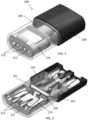
- FIGS. 2 and 3illustrate an example of a cartridge 200 that may include or be adapted to include a wick consistent with implementations of the current subject matter.
- the cartridge 200may be used with a vaporizer body (not shown) having a battery and control circuitry, together configured to generate an inhalable vapor by heating a vaporizable material before and/or as it enters a wick from which it can be vaporized.
- the cartridge 200includes a tank (or reservoir) 205 for holding a vaporizable material (such as an oil or some other fluid or liquid), a proximal mouthpiece 209, a set of pin connectors 213 at the distal end, and openings 215 into an overflow leak chamber 216 (which may include one or more absorbent pads 219 for soaking up leakage of the vaporizable material as shown in FIG. 3 ), as well as a wick 203 consistent with implementations of the current subject matter.
- the wick 203may be wrapped with a resistive heating element (coil 204), as shown in FIG. 3 , which is connected by plates 201 to pin inputs.
- a heatermay include the wick 203 extending between plates 201 and the heating element 204 in contact with both the plates 201 and the wick 203.
- Airmay be drawn in from the bottom or base of the cartridge 200, pulled over and around the heating element 204.
- An air path through the cartridge 200passes through the tank 205.
- a heating chamber, holding the wick 203 and heating element 204may be an internal chamber (e.g., surrounded by the tank) through which the airflow passes.
- the wick 203may be suspended between a pair of heater contacts positioned in the heating chamber.
- the wick 203draws vaporizable material from the tank 205, from both ends of the wick 203 and radially along the length of the wick 203 due to the plurality of voids within the wick 203.
- the heating element 204may be activated, e.g., by a pressure sensor, pushbutton, motion sensor, flow sensor, or other approach capable of detecting that a user is taking a puff or otherwise inhaling through a flow path of the vaporizer device.
- the heating element 204When the heating element 204 is activated, the coil may have a temperature increase as a result of current flowing through the coil to generate heat.
- the heatis transferred to at least a portion of the vaporizable material in the tank 205 through conductive, convective, and/or radiative heat transfer such that at least a portion of the vaporizable material vaporizes.
- the incoming air into the vaporizer deviceflows over the heated wick/coil, stripping away the vaporized vaporizable material, where it is condensed and exits as an aerosol via the mouthpiece 209 to a user.
- a wick 203 consistent with implementations of the current subject mattercan provide a capillary pathway, for vaporizable material within the tank 205, through and into the wick 203.
- the capillary pathwayis generally large enough to permit wicking to replace vaporized liquid transferred from the tank 205 by capillary action (wicking) during use of the vaporizer device, but may be small enough to prevent leakage of the vaporizable fluid material out of the cartridge 200 during normal operation, including when applying pressure to (e.g., squeezing) the cartridge 200.
- An external portion of the wick 203may include a wick housing. The wick housing and/or wick 203 may be treated to prevent leakage.
- the wick 203 and/or wick housingmay be coated after filling to prevent leakage and/or evaporation through the wick 203 until activated by connecting to a vaporizer body and/or applying current through electrical contacts (e.g., operation in a vaporizer device), or otherwise using the cartridge 200.
- Any appropriate coatingmay be used, including a heat-vaporizable coating (e.g., a wax or other material) or the like.
- a wick consistent with implementations of the current subject mattermay have an orientation other than that shown in the exemplary cartridge illustrations of FIGs. 2 and 3 .
- the wick 203 shown in FIG. 3extends horizontally between two side portions of the cartridge 200.
- the wickis not limited to this orientation and may, for example, extend internally along a length of the body of the cartridge 200 with the heating element at one end of the wick.
- Other orientations and configurationsare also possible.
- a wickconsistent with implementations of the current subject matter is not limited to such a device configuration.
- a wickmay be incorporated as part of a vaporizer device that includes a reservoir in which the wick and the heating element are included or in contact with.
- a process flow chart 400illustrates features of a method useful for understanding the invention, but not claimed, which may optionally include some or all of the following.
- a vaporizable materialis drawn, through a wick, from a tank of a vaporization device to a vaporization region.
- the vaporization regionis heated with a heating element disposed near the vaporization region. The heating causes vaporization of the vaporizable material in the vaporization region.
- the vaporized vaporizable materialis entrained in a flow of air to a mouthpiece of the vaporization device.
- references to a structure or feature that is disposed "adjacent" another featuremay have portions that overlap or underlie the adjacent feature.
- phrases such as "at least one of” or “one or more of'may occur followed by a conjunctive list of elements or features.
- the term “and/or”may also occur in a list of two or more elements or features. Unless otherwise implicitly or explicitly contradicted by the context in which it used, such a phrase is intended to mean any of the listed elements or features individually or any of the recited elements or features in combination with any of the other recited elements or features.
- the phrases “at least one of A and B;” “one or more of A and B;” and “A and/or B”are each intended to mean "A alone, B alone, or A and B together.”
- a similar interpretationis also intended for lists including three or more items.
- phrases “at least one of A, B, and C;” “one or more of A, B, and C;” and “A, B, and/or C”are each intended to mean “A alone, B alone, C alone, A and B together, A and C together, B and C together, or A and B and C together.”
- Use of the term “based on,” above and in the claimsis intended to mean, “based at least in part on,” such that an unrecited feature or element is also permissible.
- spatially relative termssuch as “under”, “below”, “lower”, “over”, “upper” and the like, may be used herein for ease of description to describe one element or feature's relationship to another element(s) or feature(s) as illustrated in the figures. It will be understood that the spatially relative terms are intended to encompass different orientations of the device in use or operation in addition to the orientation depicted in the figures. For example, if a device in the figures is inverted, elements described as “under” or “beneath” other elements or features would then be oriented “over” the other elements or features.
- the exemplary term “under”can encompass both an orientation of over and under.
- the devicemay be otherwise oriented (rotated 90 degrees or at other orientations) and the spatially relative descriptors used herein interpreted accordingly.
- the terms “upwardly”, “downwardly”, “vertical”, “horizontal” and the likeare used herein for the purpose of explanation only unless specifically indicated otherwise.
- first and secondmay be used herein to describe various features/elements (including steps), these features/elements should not be limited by these terms, unless the context indicates otherwise. These terms may be used to distinguish one feature/element from another feature/element. Thus, a first feature/element discussed below could be termed a second feature/element, and similarly, a second feature/element discussed below could be termed a first feature/element without departing from the teachings provided herein.
- a numeric valuemay have a value that is +/- 0.1% of the stated value (or range of values), +/- 1% of the stated value (or range of values), +/- 2% of the stated value (or range of values), +/- 5% of the stated value (or range of values), +/- 10% of the stated value (or range of values), etc.
- Any numerical values given hereinshould also be understood to include about or approximately that value, unless the context indicates otherwise. For example, if the value "10" is disclosed, then “about 10" is also disclosed. Any numerical range recited herein is intended to include all sub-ranges subsumed therein.
Landscapes
- Catching Or Destruction (AREA)
Description
- Vaporizing devices, including electronic vaporizers or e-vaporizer devices, allow the delivery of vapor containing one or more active ingredients by inhalation of the vapor. Electronic vaporizer devices are gaining increasing popularity both for prescriptive medical use, in delivering medicaments, and for consumption of tobacco or other plant-based smokeable materials, including solid (e.g., loose-leaf) materials, solid/liquid (e.g., suspensions, liquid-coated) materials, wax extracts, and prefilled pods (e.g., cartridges, wrapped containers, and/or the like) of such materials. Electronic vaporizer devices in particular may be portable, self-contained, and/or convenient for use.
- Electronic vaporizers may use an atomizer system that includes a wicking element with a resistive heating element, such as a coil wrapped around the wicking element or positioned within a hollowed wicking element.
- Vaporizer devices can utilize a wick formed of a silica or cotton material. Silica wick material can be formed by bundling together fine, continuous filaments of silica glass into threads, which are then bundled together to form a cord or rope used as the wick. The cord may be specified by a nominal outer diameter, number of threads, and/or a TEX value indicating a linear density. TEX is, in accordance with implementations described here, a unit of weight used to measure the density of yarns, equal to 1 gram per 1000 meters.
- Atomizer systems in which liquid is drawn into the wick from a reservoir are limited in that the liquid is drawn in longitudinally at end points of the silica cord (e.g., at end points of the continuous filaments of silica). This design suffers from a timing standpoint, as during use of a vaporizer device, liquid may not be replenished as quickly as desired for a user as the liquid evaporates from a heated region of the wick and more liquid needs to travel along the length of the wick for replenishment.
WO 2014/159982 A1 discloses reservoirs for storing products in electronic smoking articles, wherein the reservoir is manufactured from cellulose acetate fiber, thermoplastic fiber, non-thermoplastic fiber, or a combination thereof, wherein the reservoir is substantially tubular in shape and is adapted to accommodate internal components of the smoking article thereby increasing reservoir capacity, wherein the internal components particularly can comprise an atomizer, which may include a braided wick. - Aspects of the current subject matter relate to a wick, for a vaporization device, formed of glass. In particular, the glass wick as defined in the claims has one or more voids along its length for use in a vaporizer device, comprises a plurality of discontinuous glass filaments and is characterized by a TEX value of between 400 and 1000 and by having at least a 5% volume of the one or more voids to a total volume of the glass wick. The invention is defined by the appended claims.
- The present invention provides a cartridge for a vaporization device comprising a mouthpiece, a tank configured to hold a vaporizable material, a glass wick configured to draw the vaporizable material from the tank to a vaporization region, and a heating element disposed near the vaporization region. The glass wick has a length and one or more voids along the length, comprises a plurality of discontinuous glass filaments and is characterized by a TEX value of between 400 and 1000 and by having at least a 5% volume of the one or more voids to a total volume of the glass wick. The heating element is configured to heat the vaporizable material drawn from the tank by the glass wick.
- The heating element can at least partially encircle at least a portion of the wick, the wick comprises a plurality of discontinuous glass filaments, the wick can comprise a heat-vaporizable coating, the heating element can be disposed between a pair of plates, the mouthpiece can be disposed at a first end of a body of the cartridge, and/or the heating element can be disposed at a second end of the body that is opposite the first end.
- The cartridge can further comprise an air inlet passage. The air inlet passage can be configured to direct a flow of air over the wick such that when the heating element is activated, the vaporizable material drawn by the wick into the vaporization region is evaporated into the flow of air. In some aspects, the wick and the heating element can be configured to cause aerosolization of the vaporizable material.
- The glass wick is characterized by a TEX value that is between 400 and 1000, between 500 and 900, between 600 and 800, between 600 and 700, between 640 and 680, and/or between 650 and 670. The glass wick can be characterized by a TEX value that is 660, approximately 660, or near 660.
- The wick is characterized by at least a 5% volume of void spaces to the total volume of the wick.
- The cartridge may not be present and the vaporization device may instead include the tank configured to hold the vaporizable material, the wick configured to draw the vaporizable material from the tank to the vaporization region, and/or the heating element disposed near the vaporization region.
- A vaporization device according to the invention comprises a tank configured to hold a vaporizable material, a glass wick configured to draw the vaporizable material from the tank to a vaporization region, and/or a heating element disposed near the vaporization region. The glass wick has a length, has one or more voids along the length, is being formed of one or more discontinuous glass fibers and is characterized by a TEX value of between 400 and 1000 and by having at least a 5% volume of the one or more voids to a total volume of the glass wick. The heating element is configured to generate heat, a portion of the heat being transferred to the vaporizable material to aerosolize the vaporizable material.
- The wick can include an inner wick material and/or an outer jacket that at least partially surrounds the inner wick material. The inner wick material can comprise a glass material and/or the outer jacket can comprise a cotton material, a hemp material, another fibrous material, and/or the like. The inner wick material can be characterized by a TEX value that is between 400 and 1000, between 500 and 900, between 600 and 800, and/or between 600 and 700, between 640 and 680, and/or between 650 and 670. The inner wick material can be characterized by a TEX value that is 660, approximately 660, or near 660.
- The inner wick can be characterized by at least a 10% volume of void spaces to the total volume of the inner wick or at least a 5% volume of void spaces to the total volume of the inner wick.
- The heating element can at least partially encircle at least a portion of the wick, the inner wick material can comprise a plurality of discontinuous glass filaments, the wick can comprise a heat-vaporizable coating, and/or the heating element can be disposed between a pair of plates.
- The vaporization device can further comprise an air inlet passage. The air inlet passage can be configured to direct a flow of air over the wick such that when the heating element is activated, the vaporizable material drawn by the wick into the vaporization region is evaporated into the flow of air. In some aspects, the wick and the heating element can be configured to cause aerosolization of the vaporizable material.
- The vaporization device comprises the tank configured to hold a vaporizable material, the wick configured to draw the vaporizable material from the tank to a vaporization region, and/or the heating element disposed near the vaporization region as further defined in the claims. In some aspects, a mouthpiece can be disposed at a first end of a body of the cartridge and/or the heating element can be disposed at a second end of the body that is opposite the first end.
- In an example useful for understanding the invention, but not claimed, further provided is a method of providing a vapor and/or aerosol for inhalation by a user that can include drawing, through a wick, a vaporizable material from a tank of a vaporization device to a vaporization region, the wick having a plurality of voids along its length. The method useful for understanding the invention can further include heating the vaporization region with a heating element disposed near the vaporization region to cause vaporization of the vaporizable material. The method useful for understanding the invention can further include causing the vaporized vaporizable material to be entrained in a flow of air to a mouthpiece of the vaporization device. The vaporization device can include the cartridge according to the claims.
- The accompanying drawings, which are incorporated in and constitute a part of this specification, show certain aspects of the subject matter disclosed herein and, together with the description, help explain some of the principles associated with the disclosed implementations. In the drawings:
FIG. 1 illustrates, via a graph, experimental results comparing mass removal properties of a glass wick, consistent with implementations of the current subject matter, in a vaporizer device to that of a silica cord wick in a vaporizer device;FIG. 2 illustrates, via a perspective view, a cartridge in which a wick consistent with implementations of the current subject matter may be incorporated;FIG. 3 illustrates, via a cross-sectional view, the cartridge ofFIG. 2 , showing the wick and internal resistive heating components; andFIG. 4 shows a process flow chart illustrating features of an unclaimed method useful for understanding the invention of drawing a vaporizable material and causing vaporization of the vaporizable material in a vaporization device according to the claims.- Implementations of the current subject matter include devices relating to vaporizing of one or more materials for inhalation by a user. The term "vaporizer" is used generically in the following description and refers to a vaporizer device. Examples of vaporizers consistent with implementations of the current subject matter include electronic vaporizers, electronic cigarettes, e-cigarettes, and/or the like. In general, such vaporizers can be portable and/or hand-held devices that heat a vaporizable material to provide an inhalable dose of the material.
- Electronic vaporizers can use an atomizer system that includes a wicking element (or wick) with a resistive heating element such as a coil wrapped around the wicking element or positioned within a hollow wicking element. Other wick configurations are also possible, as discussed further below. The wick serves at least two purposes: to draw liquid from a reservoir to the atomizer where it can be vaporized by the coil; and to allow air to enter the reservoir to replace the volume of liquid removed. When a user inhales on the vaporizer, the coil heater may be activated, and incoming may air pass over the saturated wick/coil assembly, stripping off vapor, which condenses and enters the user's lungs. During and/or after the puff, capillary action pulls more liquid into the wick and air returns to the reservoir through the wick.
- A vaporizer includes a wick having a plurality of voids along its length. The wick may be a glass wick formed of discontinuous glass fibers that are finite in length and/or spun together to form a yarn. In some aspects, the discontinuous glass fibers making up the wick are not packed together and have varying orientations, creating a plurality of voids, or spaces, between the various fibers and along the length of the wick. This design of voids along the length of the wick results in improved aerosol production properties relative to a traditional wick, for example one formed of silica fiberglass cord, by maintaining more liquid per unit volume in close proximity to the evaporation surface. During a puff, this liquid need only wick radially (or in a direction orthogonal to the evaporator surface). Between puffs, more time is available for this liquid to be replenished axially. Because of this, the mass density for a given puff can be higher than an equivalent design with a more conventional, corded wick.
- A wick consistent with implementations of the current subject matter has increased liquid-carrying capacity, while also being thermally stable and having sufficient structural integrity for its use in vaporizer devices.
- A wick according to the present invention has a TEX value from between about 400 to about 1,000, preferably between about 600 to about 800. In some implementations, the wick has a TEX value of 660. Other TEX values may be used. A glass wick consistent with implementations of the current subject matter may be a Decofil C-Glass Staple Fiber Yarn, such as Decofil CD 11.5 660 L01P A1 or the like, which may be from another manufacturer. The wick may be formed of discontinuous C-Glass filaments, brought together to form a sliver, a yarn, and/or the like.
- Materials other than discontinuous glass fibers may be used to form a wick with voids along its length to allow for replenishment of liquid radially (or in a direction orthogonal to the evaporator surface) and axially along the wick. For example, a porous material, such as a ceramic material, having a plurality of voids or spaces along its length may be used as a suitable wicking material for the wick. Alternatively, other materials or fibers that are finite in length and that can be spun together to form a yarn, or other structure having voids along its length, may be used as a suitable wicking material. Such materials may be characterized by, for example, at least a 10% volume of void spaces to the total volume of the wick. According to the present invention, a suitable wicking material is characterized by at least a 5% volume of void spaces to the total volume of the wick.
- The use of a wick having features consistent with implementations of the current subject matter in a vaporizer device produces unexpected results. This is because the wicking performance of a glass material is worse in terms of capillary pressure as compared to more traditional, more porous wick materials (e.g., silica or cotton). However, by utilizing a wick having features consistent with implementations of the current subject matter, the aerosol density produced by the atomizer is improved, intra-puff, which is a result of the atomizer layout. As liquid has to traverse a long distance longitudinally from the reservoir, replenishment can easily become the rate-limiting step for aerosol production, no matter the capillary pressure. Thus, by incorporating a wick having a plurality of voids along its length, as described herein, there is an increased amount of liquid near the evaporator surface at the beginning of a puff, resulting in improved aerosol density.
- A glass wick having features consistent with implementations of the current subject matter was compared with a reference silica cord wick to demonstrate the mass removal properties of the glass wick. The glass wick used was the Decofil CD 11.5 660 L01P A1 with a TEX value of 660. The reference silica cord wick used had eight strands, a diameter of 1.5mm, a TEX value of 1450, and a twist value of 120°. A smoking machine was used with three replicates of each configuration of a vaporizer device with a glass wick and a vaporizer device with a reference silica cord wick (e.g., six device and cartridge combinations total). A standardized puff profile of 100cc puff volume, 3s puff duration, and 30s inter-puff interval was utilized. Puffs were taken in 10-puff bouts. An initial weight of each vaporizer device and cartridge was taken, and the weight was taken again following each bout. Results are shown in the
graph 100 ofFIG. 1 , which illustrates average mass lost for each configuration (data 110 for the glass wick configuration,data 120 for the reference silica cord wick configuration), for each successive bout. As can be seen in thegraph 100, the glass wick is able to better replenish its liquid carrying capacity between puffs when compared to the reference silica cord wick as more mass is removed in the glass wick after each puff bout. - In some implementations, a wick can be formed of a combination of glass and another natural fibrous material, such as cotton, hemp, or the like. In some implementations, the wick can include an inner wick material and at least one outer jacket. In some exemplary implementations, the wick can include two or more outer jackets.
- The inner wick material can be formed as a continuous or discontinuous thread, yarn or another strand configuration. The outer jacket can have a series of interlocking loops of material, or can be formed of a combination of solid tube-like material and/or porous tube or matrix of cross-stitched material. For instance, the inner wick material can be formed of glass, which can be continuous or discontinuous, and which inner wick material can be formed of one or more strands wound or provided together. In some implementations, inner wick material can include a glass wick having features consistent with implementations described herein. The outer jacket can be of a different material from the inner wick material and/or include a fibrous material, such as cotton, hemp, and/or the like. The outer jacket can be formed as a continuous sheath, can be formed as a matrix of cross-strands (e.g., knitted and/or the like), or any other formation.
- In other implementations, the wick can include an inner wick material of a fibrous material, such as cotton, where the fibrous material can be continuous, such as a yarn or weave of one or more strands, or discontinuous, with one or more gaps along its length or along the length of one or more strands that make up the inner wick material. The wick can include an outer jacket made of glass or other rigid or semi-rigid, brittle yet porous material. such as glass.
- In yet other implementations, in a configuration having an inner wick material and at least one outer jacket, either the inner wick material or at least one outer jacket can include detents, apertures, holes, separations, or the like, and which can be microscopic in size. Each of the inner wick material or the outer jacket can be embedded with additional materials to improve wicking and holding of a fluid to be vaporized.
FIGS. 2 and 3 illustrate an example of acartridge 200 that may include or be adapted to include a wick consistent with implementations of the current subject matter. Thecartridge 200 may be used with a vaporizer body (not shown) having a battery and control circuitry, together configured to generate an inhalable vapor by heating a vaporizable material before and/or as it enters a wick from which it can be vaporized.- In the example configuration shown in
FIGS. 2 and 3 , thecartridge 200 includes a tank (or reservoir) 205 for holding a vaporizable material (such as an oil or some other fluid or liquid), aproximal mouthpiece 209, a set ofpin connectors 213 at the distal end, andopenings 215 into an overflow leak chamber 216 (which may include one or moreabsorbent pads 219 for soaking up leakage of the vaporizable material as shown inFIG. 3 ), as well as awick 203 consistent with implementations of the current subject matter. Thewick 203 may be wrapped with a resistive heating element (coil 204), as shown inFIG. 3 , which is connected byplates 201 to pin inputs. A heater may include thewick 203 extending betweenplates 201 and theheating element 204 in contact with both theplates 201 and thewick 203. - Air may be drawn in from the bottom or base of the
cartridge 200, pulled over and around theheating element 204. An air path through thecartridge 200 passes through thetank 205. A heating chamber, holding thewick 203 andheating element 204, may be an internal chamber (e.g., surrounded by the tank) through which the airflow passes. Thewick 203 may be suspended between a pair of heater contacts positioned in the heating chamber. - The
wick 203 draws vaporizable material from thetank 205, from both ends of thewick 203 and radially along the length of thewick 203 due to the plurality of voids within thewick 203. When a user puffs on thecartridge 200, air flows into an inlet. Simultaneously, theheating element 204 may be activated, e.g., by a pressure sensor, pushbutton, motion sensor, flow sensor, or other approach capable of detecting that a user is taking a puff or otherwise inhaling through a flow path of the vaporizer device. When theheating element 204 is activated, the coil may have a temperature increase as a result of current flowing through the coil to generate heat. The heat is transferred to at least a portion of the vaporizable material in thetank 205 through conductive, convective, and/or radiative heat transfer such that at least a portion of the vaporizable material vaporizes. The incoming air into the vaporizer device flows over the heated wick/coil, stripping away the vaporized vaporizable material, where it is condensed and exits as an aerosol via themouthpiece 209 to a user. - A
wick 203 consistent with implementations of the current subject matter can provide a capillary pathway, for vaporizable material within thetank 205, through and into thewick 203. The capillary pathway is generally large enough to permit wicking to replace vaporized liquid transferred from thetank 205 by capillary action (wicking) during use of the vaporizer device, but may be small enough to prevent leakage of the vaporizable fluid material out of thecartridge 200 during normal operation, including when applying pressure to (e.g., squeezing) thecartridge 200. An external portion of thewick 203 may include a wick housing. The wick housing and/orwick 203 may be treated to prevent leakage. For example, thewick 203 and/or wick housing may be coated after filling to prevent leakage and/or evaporation through thewick 203 until activated by connecting to a vaporizer body and/or applying current through electrical contacts (e.g., operation in a vaporizer device), or otherwise using thecartridge 200. Any appropriate coating may be used, including a heat-vaporizable coating (e.g., a wax or other material) or the like. - A wick consistent with implementations of the current subject matter may have an orientation other than that shown in the exemplary cartridge illustrations of
FIGs. 2 and 3 . For example, thewick 203 shown inFIG. 3 extends horizontally between two side portions of thecartridge 200. However, the wick is not limited to this orientation and may, for example, extend internally along a length of the body of thecartridge 200 with the heating element at one end of the wick. Other orientations and configurations are also possible. - Although the example described herein with respect to
FIGs. 2 and 3 is directed to a vaporizer that utilizes a removable cartridge, a wick consistent with implementations of the current subject matter is not limited to such a device configuration. For example, a wick may be incorporated as part of a vaporizer device that includes a reservoir in which the wick and the heating element are included or in contact with. - With reference to
FIG. 4 , aprocess flow chart 400 illustrates features of a method useful for understanding the invention, but not claimed, which may optionally include some or all of the following. At 410, a vaporizable material is drawn, through a wick, from a tank of a vaporization device to a vaporization region. At 420, the vaporization region is heated with a heating element disposed near the vaporization region. The heating causes vaporization of the vaporizable material in the vaporization region. At 430, the vaporized vaporizable material is entrained in a flow of air to a mouthpiece of the vaporization device. - When a feature or element is herein referred to as being "on" another feature or element, it can be directly on the other feature or element or intervening features and/or elements may also be present. In contrast, when a feature or element is referred to as being "directly on" another feature or element, there are no intervening features or elements present. It will also be understood that, when a feature or element is referred to as being "connected", "attached" or "coupled" to another feature or element, it can be directly connected, attached or coupled to the other feature or element or intervening features or elements may be present. In contrast, when a feature or element is referred to as being "directly connected", "directly attached" or "directly coupled" to another feature or element, there are no intervening features or elements present.
- It will also be appreciated by those of skill in the art that references to a structure or feature that is disposed "adjacent" another feature may have portions that overlap or underlie the adjacent feature.
- Terminology used herein is for the purpose of describing particular examples and implementations only and is not intended to be limiting. For example, as used herein, the singular forms "a", "an" and "the" are intended to include the plural forms as well, unless the context clearly indicates otherwise. It will be further understood that the terms "comprises" and/or "comprising," when used in this specification, specify the presence of stated features, steps, operations, elements, and/or components, but do not preclude the presence or addition of one or more other features, steps, operations, elements, components, and/or groups thereof. As used herein, the term "and/or" includes any and all combinations of one or more of the associated listed items and may be abbreviated as "/".
- In the descriptions above and in the claims, phrases such as "at least one of" or "one or more of' may occur followed by a conjunctive list of elements or features. The term "and/or" may also occur in a list of two or more elements or features. Unless otherwise implicitly or explicitly contradicted by the context in which it used, such a phrase is intended to mean any of the listed elements or features individually or any of the recited elements or features in combination with any of the other recited elements or features. For example, the phrases "at least one of A and B;" "one or more of A and B;" and "A and/or B" are each intended to mean "A alone, B alone, or A and B together." A similar interpretation is also intended for lists including three or more items. For example, the phrases "at least one of A, B, and C;" "one or more of A, B, and C;" and "A, B, and/or C" are each intended to mean "A alone, B alone, C alone, A and B together, A and C together, B and C together, or A and B and C together." Use of the term "based on," above and in the claims is intended to mean, "based at least in part on," such that an unrecited feature or element is also permissible.
- Spatially relative terms, such as "under", "below", "lower", "over", "upper" and the like, may be used herein for ease of description to describe one element or feature's relationship to another element(s) or feature(s) as illustrated in the figures. It will be understood that the spatially relative terms are intended to encompass different orientations of the device in use or operation in addition to the orientation depicted in the figures. For example, if a device in the figures is inverted, elements described as "under" or "beneath" other elements or features would then be oriented "over" the other elements or features.
- Thus, the exemplary term "under" can encompass both an orientation of over and under. The device may be otherwise oriented (rotated 90 degrees or at other orientations) and the spatially relative descriptors used herein interpreted accordingly. Similarly, the terms "upwardly", "downwardly", "vertical", "horizontal" and the like are used herein for the purpose of explanation only unless specifically indicated otherwise.
- Although the terms "first" and "second" may be used herein to describe various features/elements (including steps), these features/elements should not be limited by these terms, unless the context indicates otherwise. These terms may be used to distinguish one feature/element from another feature/element. Thus, a first feature/element discussed below could be termed a second feature/element, and similarly, a second feature/element discussed below could be termed a first feature/element without departing from the teachings provided herein.
- As used herein in the specification and claims, including as used in the examples and unless otherwise expressly specified, all numbers may be read as if prefaced by the word "about" or "approximately," even if the term does not expressly appear. The phrase "about" or "approximately" may be used when describing magnitude and/or position to indicate that the value and/or position described is within a reasonable expected range of values and/or positions. For example, a numeric value may have a value that is +/- 0.1% of the stated value (or range of values), +/- 1% of the stated value (or range of values), +/- 2% of the stated value (or range of values), +/- 5% of the stated value (or range of values), +/- 10% of the stated value (or range of values), etc. Any numerical values given herein should also be understood to include about or approximately that value, unless the context indicates otherwise. For example, if the value "10" is disclosed, then "about 10" is also disclosed. Any numerical range recited herein is intended to include all sub-ranges subsumed therein. It is also understood that when a value is disclosed that "less than or equal to" the value, "greater than or equal to the value" and possible ranges between values are also disclosed, as appropriately understood by the skilled artisan. For example, if the value "X" is disclosed the "less than or equal to X" as well as "greater than or equal to X" (e.g., where X is a numerical value) is also disclosed. It is also understood that the throughout the application, data is provided in a number of different formats, and that this data, represents endpoints and starting points, and ranges for any combination of the data points. For example, if a particular data point "10" and a particular data point "15" are disclosed, it is understood that greater than, greater than or equal to, less than, less than or equal to, and equal to 10 and 15 are considered disclosed as well as between 10 and 15. It is also understood that each unit between two particular units are also disclosed. For example, if 10 and 15 are disclosed, then 11, 12, 13, and 14 are also disclosed.
Claims (12)
- A cartridge (200) for a vaporization device, the cartridge (200) comprising:a mouthpiece (209);a tank (205) configured to hold a vaporizable material;a glass wick (203) configured to draw the vaporizable material from the tank (205) to a vaporization region, the glass wick (203) having a length and having one or more voids along the length; the glass wick (203) comprising a plurality of discontinuous glass filaments; anda heating element (204) disposed near the vaporization region and configured to heat the vaporizable material drawn from the tank (205) by the glass wick (203);characterized in that the glass wick (203) has a TEX value of between 400 and 1000 and at least a 5% volume of the one or more voids to a total volume of the glass wick (203).
- The cartridge (200) of claim 1, wherein the heating element (204) at least partially encircles at least a portion of the glass wick (203).
- The cartridge (200) of claim 1, further comprising an air inlet passage.
- The cartridge (200) of claim 3, wherein the air inlet passage is configured to direct a flow of air over the glass wick (203) such that when the heating element (204) is activated, the vaporizable material drawn by the glass wick (203) into the vaporization region is evaporated into the flow of air.
- The cartridge (200) of claim 4, wherein the glass wick (203) and the heating element (204) are configured to cause aerosolization of the vaporizable material.
- The cartridge (200) of claim 1, wherein the glass wick (203) ischaracterized by the TEX value of 660.
- The cartridge (200) of claim 1, wherein the glass wick (203) comprises a heat-vaporizable coating.
- The cartridge (200) of claim 1, wherein the heating element (204) is disposed between a pair of plates (201).
- The cartridge (200) of claim 1, wherein the mouthpiece (209) is disposed at a first end of a body of the cartridge (200) and the heating element (204) is disposed at a second end of the body, opposite the first end.
- The cartridge (200) of claim 1, wherein the glass wick (203) includes an inner wick material and an outer jacket that at least partially surrounds the inner wick material.
- A vaporization device comprising:a tank (205) configured to hold a vaporizable material;a glass wick (203) configured to draw the vaporizable material from the tank (205) to a vaporization region, the glass wick (203) having a length, having one or more voids along the length, and being formed of one or more discontinuous glass fibers; anda heating element (204) disposed near the vaporization region, the heating element (204) configured to generate heat, a portion of the heat being transferred to the vaporizable material to aerosolize the vaporizable material,characterized in that the glass wick (203) has a TEX value of between 400 and 1000 and at least a 5% volume of the one or more voids to a total volume of the glass wick (203).
- The vaporization device in accordance with claim 11, wherein the glass wick (203) includes an inner wick material and an outer jacket that at least partially surrounds the inner wick material.
Applications Claiming Priority (3)
| Application Number | Priority Date | Filing Date | Title |
|---|---|---|---|
| US201762551113P | 2017-08-28 | 2017-08-28 | |
| US201862721512P | 2018-08-22 | 2018-08-22 | |
| PCT/US2018/048368WO2019046315A1 (en) | 2017-08-28 | 2018-08-28 | Wick for vaporizer device |
Publications (2)
| Publication Number | Publication Date |
|---|---|
| EP3675661A1 EP3675661A1 (en) | 2020-07-08 |
| EP3675661B1true EP3675661B1 (en) | 2023-06-07 |
Family
ID=63678675
Family Applications (1)
| Application Number | Title | Priority Date | Filing Date |
|---|---|---|---|
| EP18773897.6AActiveEP3675661B1 (en) | 2017-08-28 | 2018-08-28 | Wick for vaporizer device |
Country Status (4)
| Country | Link |
|---|---|
| US (1) | US11278058B2 (en) |
| EP (1) | EP3675661B1 (en) |
| CA (1) | CA3074463A1 (en) |
| WO (1) | WO2019046315A1 (en) |
Families Citing this family (24)
| Publication number | Priority date | Publication date | Assignee | Title |
|---|---|---|---|---|
| EP4088594B1 (en)* | 2014-09-17 | 2023-09-06 | Fontem Ventures B.V. | Device for storing and vaporizing liquid media |
| EP3813914B1 (en) | 2018-06-26 | 2023-10-25 | Juul Labs, Inc. | Vaporizer wicking elements |
| TW202011845A (en)* | 2018-07-24 | 2020-04-01 | 瑞士商傑太日煙國際股份有限公司 | Side-by-side terminal for personal vaporizing device |
| SG11202103757VA (en) | 2018-10-15 | 2021-05-28 | Juul Labs Inc | Heating element |
| WO2020142523A1 (en)* | 2018-12-31 | 2020-07-09 | Juul Labs, Inc. | Cartridges for vaporizer devices |
| EP4559330A3 (en) | 2019-06-20 | 2025-08-20 | Shaheen Innovations Holding Limited | Personal ultrasonic atomizer device |
| US11730193B2 (en) | 2019-12-15 | 2023-08-22 | Shaheen Innovations Holding Limited | Hookah device |
| US12121056B2 (en) | 2019-12-15 | 2024-10-22 | Shaheen Innovations Holding Limited | Hookah device |
| US11666713B2 (en) | 2019-12-15 | 2023-06-06 | Shaheen Innovations Holding Limited | Mist inhaler devices |
| WO2021123871A1 (en) | 2019-12-15 | 2021-06-24 | Shaheen Innovations Holding Limited | Ultrasonic mist inhaler |
| US12233207B2 (en) | 2019-12-15 | 2025-02-25 | Shaheen Innovations Holding Limited | Mist inhaler devices |
| EP4031218A4 (en) | 2019-12-15 | 2023-06-07 | Shaheen Innovations Holding Limited | Ultrasonic mist inhaler |
| EP4292632B1 (en) | 2019-12-15 | 2025-08-27 | Shaheen Innovations Holding Limited | Ultrasonic mist inhaler |
| US11589610B2 (en) | 2019-12-15 | 2023-02-28 | Shaheen Innovations Holding Limited | Nicotine delivery device having a mist generator device and a driver device |
| WO2021123867A1 (en) | 2019-12-15 | 2021-06-24 | Shaheen Innovations Holding Limited | Ultrasonic mist inhaler |
| US12201144B2 (en) | 2019-12-15 | 2025-01-21 | Shaheen Innovations Holding Limited | Hookah device |
| PL4364853T3 (en) | 2019-12-15 | 2025-05-12 | Shaheen Innovations Holding Limited | Mist inhaler devices |
| US11730191B2 (en) | 2019-12-15 | 2023-08-22 | Shaheen Innovations Holding Limited | Hookah device |
| US12213516B2 (en) | 2019-12-15 | 2025-02-04 | Shaheen Innovations Holding Limited | Ultrasonic mist inhaler |
| US11789476B2 (en) | 2021-01-18 | 2023-10-17 | Altria Client Services Llc | Heat-not-burn (HNB) aerosol-generating devices including intra-draw heater control, and methods of controlling a heater |
| USD1095794S1 (en) | 2021-01-18 | 2025-09-30 | Altria Client Services Llc | Aerosol-generating capsule |
| US11910826B2 (en) | 2021-01-18 | 2024-02-27 | Altria Client Services Llc | Heat-not-burn (HNB) aerosol-generating devices and capsules |
| US12127592B2 (en) | 2021-09-20 | 2024-10-29 | Altria Client Services Llc | Capsule validation for heat-not-burn (HNB) aerosol-generating devices |
| US20230188901A1 (en) | 2021-12-15 | 2023-06-15 | Shaheen Innovations Holding Limited | Apparatus for transmitting ultrasonic waves |
Citations (1)
| Publication number | Priority date | Publication date | Assignee | Title |
|---|---|---|---|---|
| WO2019038522A1 (en)* | 2017-08-25 | 2019-02-28 | Nicoventures Holdings Limited | Vapour provision systems |
Family Cites Families (171)
| Publication number | Priority date | Publication date | Assignee | Title |
|---|---|---|---|---|
| US4793365A (en) | 1984-09-14 | 1988-12-27 | R. J. Reynolds Tobacco Company | Smoking article |
| US4990939A (en) | 1988-09-01 | 1991-02-05 | Ricoh Company, Ltd. | Bubble jet printer head with improved operational speed |
| US5610635A (en) | 1994-08-09 | 1997-03-11 | Encad, Inc. | Printer ink cartridge with memory storage capacity |
| JP2845225B2 (en) | 1995-12-11 | 1999-01-13 | 日本電気株式会社 | Polymer compound, photosensitive resin composition and pattern forming method using the same |
| US20080038363A1 (en) | 2001-05-24 | 2008-02-14 | Zaffaroni Alejandro C | Aerosol delivery system and uses thereof |
| US7431570B2 (en) | 2002-02-19 | 2008-10-07 | Vapore, Inc. | Capillary pumps for vaporization of liquids |
| SE0300520D0 (en) | 2003-02-28 | 2003-02-28 | Pharmacia Ab | A container containing nicotine and its use and manufacture |
| JP2005034021A (en) | 2003-07-17 | 2005-02-10 | Seiko Epson Corp | Electronic Cigarette |
| JP4869927B2 (en) | 2003-08-04 | 2012-02-08 | アレックザ ファーマシューティカルズ, インコーポレイテッド | Substrates and preparation methods and uses for drug delivery devices |
| JP4411901B2 (en) | 2003-08-11 | 2010-02-10 | セイコーエプソン株式会社 | Atomizer |
| US20070215167A1 (en) | 2006-03-16 | 2007-09-20 | Evon Llewellyn Crooks | Smoking article |
| US7665460B2 (en) | 2005-10-11 | 2010-02-23 | Kimberly-Clark Worldwide, Inc. | Micro powered gas-forming device |
| US20070295347A1 (en) | 2006-02-22 | 2007-12-27 | Philip Morris Usa Inc. | Surface-modified porous substrates |
| US9220301B2 (en) | 2006-03-16 | 2015-12-29 | R.J. Reynolds Tobacco Company | Smoking article |
| DE102007026979A1 (en) | 2006-10-06 | 2008-04-10 | Friedrich Siller | inhalator |
| US7726320B2 (en) | 2006-10-18 | 2010-06-01 | R. J. Reynolds Tobacco Company | Tobacco-containing smoking article |
| ES2321468B1 (en) | 2007-08-28 | 2010-07-07 | Jorge Fernandez Pernia | PORTABLE ESSENCE VAPORIZER. |
| EP2143346A1 (en) | 2008-07-08 | 2010-01-13 | Philip Morris Products S.A. | A flow sensor system |
| US8464726B2 (en) | 2009-08-24 | 2013-06-18 | R.J. Reynolds Tobacco Company | Segmented smoking article with insulation mat |
| US8875702B2 (en) | 2009-08-28 | 2014-11-04 | The United States Of America As Represented By The Secretary Of The Department Of Health And Human Services, Centers For Disease Control And Prevention | Aerosol generator |
| US20100181387A1 (en) | 2009-12-01 | 2010-07-22 | Zaffaroni Alejandro C | Aerosol delivery system and uses thereof |
| US9999250B2 (en) | 2010-05-15 | 2018-06-19 | Rai Strategic Holdings, Inc. | Vaporizer related systems, methods, and apparatus |
| US11344683B2 (en) | 2010-05-15 | 2022-05-31 | Rai Strategic Holdings, Inc. | Vaporizer related systems, methods, and apparatus |
| US8361889B2 (en) | 2010-07-06 | 2013-01-29 | International Business Machines Corporation | Strained semiconductor-on-insulator by addition and removal of atoms in a semiconductor-on-insulator |
| US20120199146A1 (en) | 2011-02-09 | 2012-08-09 | Bill Marangos | Electronic cigarette |
| KR101324667B1 (en) | 2011-05-27 | 2013-11-04 | 퓨처사이버 주식회사 | Charging type electronic suction device in a body |
| KR101369372B1 (en) | 2011-05-27 | 2014-03-04 | 퓨처사이버 주식회사 | One-time electronic suction device |
| KR20110006928U (en) | 2011-06-10 | 2011-07-07 | 남동환 | an electronic cigarette |
| KR20120008751U (en) | 2011-06-13 | 2012-12-24 | 이영찬 | an electronic cigarette |
| HUE045286T2 (en) | 2011-09-28 | 2019-12-30 | Philip Morris Products Sa | Permeable Electric Heat Resistant Film for Evaporation of Liquids from Single Use Nozzles with Evaporator Diaphragm |
| US20130087160A1 (en) | 2011-10-06 | 2013-04-11 | Alexandru Gherghe | Electronic pipe personal vaporizer with concealed removable atomizer/ cartomizer |
| CN103141944A (en) | 2011-12-07 | 2013-06-12 | 刘志宾 | Electronic cigarette with OLED (Organic Light Emitting Diode) display |
| GB201200558D0 (en) | 2012-01-13 | 2012-02-29 | British American Tobacco Co | Smoking article |
| US9854839B2 (en) | 2012-01-31 | 2018-01-02 | Altria Client Services Llc | Electronic vaping device and method |
| US9289014B2 (en) | 2012-02-22 | 2016-03-22 | Altria Client Services Llc | Electronic smoking article and improved heater element |
| US9155336B2 (en) | 2012-06-16 | 2015-10-13 | Huizhou Kimree Technology Co., Ltd., Shenzhen Branch | Electronic cigarette and electronic cigarette device |
| GB2504076A (en) | 2012-07-16 | 2014-01-22 | Nicoventures Holdings Ltd | Electronic smoking device |
| EP2732713A4 (en) | 2012-08-31 | 2015-07-22 | Kimree Hi Tech Inc | Electronic cigarette with multiple tastes |
| US8881737B2 (en) | 2012-09-04 | 2014-11-11 | R.J. Reynolds Tobacco Company | Electronic smoking article comprising one or more microheaters |
| EP2896306A4 (en) | 2012-09-11 | 2016-06-29 | Kimree Hi Tech Inc | Electronic cigarette and electronic cigarette device thereof |
| KR101682319B1 (en) | 2012-09-28 | 2016-12-12 | 킴르 하이테크 인코퍼레이티드 | Electronic cigarette and electronic cigarette device thereof |
| CN103960781A (en) | 2013-09-29 | 2014-08-06 | 深圳市麦克韦尔科技有限公司 | Electronic cigarette |
| CN102894485B (en) | 2012-10-23 | 2015-04-01 | 深圳市合元科技有限公司 | Atomization device for electronic cigarette as well as atomizer and electronic cigarette |
| WO2014071623A1 (en) | 2012-11-12 | 2014-05-15 | Liu Qiuming | Electronic cigarette device, electronic cigarette and atomization device therefor |
| CN102920028B (en) | 2012-11-15 | 2016-01-27 | 深圳市合元科技有限公司 | Atomizers for electronic cigarettes and electronic cigarettes |
| CN203072896U (en) | 2013-01-31 | 2013-07-24 | 深圳市合元科技有限公司 | Electronic cigarette and atomizer for electronic cigarette |
| US9918495B2 (en) | 2014-02-28 | 2018-03-20 | Rai Strategic Holdings, Inc. | Atomizer for an aerosol delivery device and related input, aerosol production assembly, cartridge, and method |
| US20140261487A1 (en) | 2013-03-14 | 2014-09-18 | R. J. Reynolds Tobacco Company | Electronic smoking article with improved storage and transport of aerosol precursor compositions |
| RU2656089C2 (en) | 2013-03-14 | 2018-05-30 | Р. Дж. Рейнолдс Тобакко Компани | Atomiser for aerosol delivery device and related workpiece, aerosol production assembly, cartridge and method |
| US9277770B2 (en) | 2013-03-14 | 2016-03-08 | R. J. Reynolds Tobacco Company | Atomizer for an aerosol delivery device formed from a continuously extending wire and related input, cartridge, and method |
| US9609893B2 (en) | 2013-03-15 | 2017-04-04 | Rai Strategic Holdings, Inc. | Cartridge and control body of an aerosol delivery device including anti-rotation mechanism and related method |
| US10279934B2 (en)* | 2013-03-15 | 2019-05-07 | Juul Labs, Inc. | Fillable vaporizer cartridge and method of filling |
| US10264819B2 (en) | 2013-03-15 | 2019-04-23 | Altria Client Services Llc | Electronic smoking article |
| US9723876B2 (en) | 2013-03-15 | 2017-08-08 | Altria Client Services Llc | Electronic smoking article |
| CN203329913U (en) | 2013-05-07 | 2013-12-11 | 深圳市合元科技有限公司 | Electronic cigarette and atomizer with cotton |
| CN105473012B (en) | 2013-06-14 | 2020-06-19 | 尤尔实验室有限公司 | Multiple heating elements with separate vaporizable materials in electronic vaporization equipment |
| US20140376895A1 (en) | 2013-06-19 | 2014-12-25 | Sihui Han | Dual-tube electronic cigarette atomizer |
| WO2014205634A1 (en) | 2013-06-24 | 2014-12-31 | 吉瑞高新科技股份有限公司 | Electronic cigarette heat-generating device and electronic cigarette |
| CN203388263U (en) | 2013-06-26 | 2014-01-15 | 刘秋明 | Electronic cigarette, electronic cigarette atomizer and electronic cigarette tip |
| US20160150827A1 (en) | 2013-07-11 | 2016-06-02 | Kimree Hi-Tech Inc. | Electronic cigarette vaporizer |
| US10251422B2 (en) | 2013-07-22 | 2019-04-09 | Altria Client Services Llc | Electronic smoking article |
| CN105592734A (en) | 2013-07-24 | 2016-05-18 | 奥驰亚客户服务有限责任公司 | Electronic smoking devices with alternative airflow paths |
| CN105451582B (en) | 2013-07-30 | 2019-05-31 | 奥驰亚客户服务有限责任公司 | Electronic smoking device and flavor vapor generation device |
| CN203555161U (en) | 2013-08-07 | 2014-04-23 | 深圳市合元科技有限公司 | Atomizer and electronic cigarette provided therewith |
| US10172387B2 (en) | 2013-08-28 | 2019-01-08 | Rai Strategic Holdings, Inc. | Carbon conductive substrate for electronic smoking article |
| WO2015032093A1 (en) | 2013-09-09 | 2015-03-12 | Lin Guangrong | Ball clip-on electronic cigarette and manufacturing method, connection assembly and atomization assembly |
| CA2866283C (en) | 2013-09-30 | 2016-02-09 | Darrin B. Farrow | Vaporization device and method of preparation and use |
| US10039321B2 (en) | 2013-11-12 | 2018-08-07 | Vmr Products Llc | Vaporizer |
| WO2015077645A1 (en) | 2013-11-21 | 2015-05-28 | Corr-Tech Associates, Inc. | Improved vaporization and dosage control for electronic vaporizing inhaler |
| US9635886B2 (en) | 2013-12-20 | 2017-05-02 | POSiFA MICROSYSTEMS, INC. | Electronic cigarette with thermal flow sensor based controller |
| DE202014011260U1 (en) | 2013-12-23 | 2018-11-13 | Juul Labs Uk Holdco Limited | Systems for an evaporation device |
| US10076139B2 (en)* | 2013-12-23 | 2018-09-18 | Juul Labs, Inc. | Vaporizer apparatus |
| CN203748667U (en) | 2013-12-24 | 2014-08-06 | 深圳市合元科技有限公司 | Atomizer for electronic cigarette and electronic cigarette |
| WO2015110924A2 (en) | 2014-01-27 | 2015-07-30 | Sis Resources Ltd. | Wire communication in an e-vaping device |
| CN203733998U (en) | 2014-02-26 | 2014-07-23 | 刘秋明 | Electronic cigarette, atomization assembly and electric connecting structure thereof |
| US9888719B2 (en) | 2014-02-28 | 2018-02-13 | Altria Client Services Llc | Electronic vaping device and components thereof |
| US20150257447A1 (en) | 2014-03-11 | 2015-09-17 | Voodoo Science Llc | Electronic Cigarette Assembly |
| US20150335070A1 (en) | 2014-05-20 | 2015-11-26 | R.J. Reynolds Tobacco Company | Electrically-powered aerosol delivery system |
| GB201411483D0 (en) | 2014-06-27 | 2014-08-13 | Batmark Ltd | Vaporizer Assembly |
| KR102508566B1 (en) | 2014-07-10 | 2023-03-13 | 롬엔드하스전자재료코리아유한회사 | Organic electroluminescent compound and organic electroluminescent device comprising the same |
| US9801415B2 (en) | 2014-07-11 | 2017-10-31 | POSIFA Microsytems, Inc. | MEMS vaporizer |
| CN205667357U (en) | 2014-07-21 | 2016-11-02 | 惠州市吉瑞科技有限公司 | A kind of electronic cigarette |
| EP3864979A1 (en) | 2014-07-24 | 2021-08-18 | Altria Client Services LLC | Method of producing a vapor from an electronic vaping device |
| CN204335831U (en) | 2014-08-14 | 2015-05-20 | 惠州市吉瑞科技有限公司 | A kind of atomizer and electronic cigarette |
| US10251426B2 (en) | 2014-10-03 | 2019-04-09 | Fertin Pharma A/S | Electronic nicotine delivery system |
| WO2016054476A1 (en) | 2014-10-03 | 2016-04-07 | Altria Client Services Llc | Electronic vaping device and components thereof |
| CN107072315B (en) | 2014-10-15 | 2021-07-02 | 奥驰亚客户服务有限责任公司 | Electronic cigarette device and its components |
| PL3009019T3 (en) | 2014-10-17 | 2019-10-31 | Fontem Holdings 1 Bv | Cartridge having a liquid transporting element for uses with an electronic smoking device |
| US10612770B2 (en) | 2014-10-20 | 2020-04-07 | Numerical Design, Inc. | Microfluidic-based apparatus and method for vaporization of liquids |
| EP3209945A1 (en) | 2014-10-20 | 2017-08-30 | Numerical Design, Inc. | Microfluidic-based apparatus and method for vaporization of liquids |
| US10188148B2 (en) | 2014-11-17 | 2019-01-29 | Mcneil Ab | Electronic nicotine delivery system |
| BR112017010106A2 (en) | 2014-11-17 | 2018-01-02 | Mcneil Ab | disposable cartridge for use in an electronic nicotine release system |
| WO2016079151A1 (en) | 2014-11-17 | 2016-05-26 | Mcneil Ab | Child-resistant container for nicotine-containing cartridges |
| WO2016082103A1 (en) | 2014-11-25 | 2016-06-02 | 惠州市吉瑞科技有限公司 | Electronic cigarette |
| US9681688B1 (en) | 2014-12-16 | 2017-06-20 | Altria Client Services Llc | E-vaping device |
| US9648908B1 (en) | 2014-12-16 | 2017-05-16 | Altria Client Services Llc | E-vaping device |
| NL2014019B1 (en) | 2014-12-19 | 2016-10-12 | Sluis Cigar Machinery Bv | A wick adopted for an electronic cigarette, a method of producing such a wick and an electronic cigarette with such a wick. |
| US20160192708A1 (en) | 2014-12-31 | 2016-07-07 | Kevin DeMeritt | Enhanced Electronic Cigarette Assembly With Modular Disposable Elements Including Tanks |
| CN204393354U (en) | 2015-01-16 | 2015-06-17 | 刘翔 | A kind of electronic cigarette injecting type refuels with diaphragm seal, tobacco tar container and electronic cigarette |
| SI24908A (en) | 2015-01-27 | 2016-07-29 | Tomaž Pevec | Closed vape cartridge with a prefilled e-liquid and integrated evaporator for onetime use |
| US10010111B2 (en) | 2015-03-04 | 2018-07-03 | Altria Client Services Llc | E-vaping device |
| US20180325183A1 (en) | 2015-03-05 | 2018-11-15 | Wisenstech Ltd. | Smart Electronic Vaporizer |
| US20160255878A1 (en) | 2015-03-05 | 2016-09-08 | Wisenstech Inc. | Smart Electronic Vaporizer |
| WO2016145611A1 (en) | 2015-03-17 | 2016-09-22 | 惠州市吉瑞科技有限公司 | Atomizer and electronic cigarette |
| WO2016154897A1 (en) | 2015-03-31 | 2016-10-06 | 惠州市吉瑞科技有限公司 | Atomizing component and electronic cigarette |
| IL279264B (en) | 2015-05-06 | 2022-09-01 | Altria Client Services Llc | A non-flammable smoking device and its components |
| CN207784270U (en) | 2015-05-14 | 2018-08-31 | 惠州市吉瑞科技有限公司深圳分公司 | A kind of electronic cigarette |
| US11589427B2 (en) | 2015-06-01 | 2023-02-21 | Altria Client Services Llc | E-vapor device including a compound heater structure |
| US20160345621A1 (en) | 2015-06-01 | 2016-12-01 | San Li | Pre-vapor formulation of an electronic vaping device and/or methods of manufacturing the same |
| US10368399B2 (en) | 2015-06-10 | 2019-07-30 | Altria Client Services Llc | E-vaping device |
| US10314338B2 (en) | 2015-06-25 | 2019-06-11 | Altria Client Services Llc | Electronic vaping device |
| JP6523452B2 (en) | 2015-06-26 | 2019-05-29 | 日本たばこ産業株式会社 | Atomization unit |
| EP3311683B1 (en) | 2015-06-26 | 2021-05-26 | Japan Tobacco Inc. | Manufacturing method of atomizing unit and atomizing unit |
| EP3315035B1 (en) | 2015-06-26 | 2019-12-25 | Japan Tobacco Inc. | Atomizing unit |
| US10154689B2 (en) | 2015-06-30 | 2018-12-18 | R.J. Reynolds Tobacco Company | Heat generation segment for an aerosol-generation system of a smoking article |
| US10874139B2 (en) | 2015-07-07 | 2020-12-29 | Altria Client Services Llc | E-vapor device including capsule containing pre-vapor formulation |
| HK1250133A1 (en) | 2015-07-28 | 2018-11-30 | 日本烟草产业株式会社 | Non-combustion-type flavor inhaler |
| US10721965B2 (en) | 2015-07-29 | 2020-07-28 | Altria Client Services Llc | E-vapor device including heater structure with recessed shell layer |
| US10524505B2 (en) | 2015-08-06 | 2020-01-07 | Altria Client Services Llc. | Method for measuring a vapor precursor level in a cartomizer of an electronic vaping device and/or an electronic vaping device configured to perform the method |
| US10034494B2 (en) | 2015-09-15 | 2018-07-31 | Rai Strategic Holdings, Inc. | Reservoir for aerosol delivery devices |
| MY193793A (en) | 2015-11-24 | 2022-10-27 | Reynolds Tobacco Co R | Electrically-powered aerosol delivery system |
| US10412995B2 (en) | 2015-12-01 | 2019-09-17 | Altria Client Services Llc | E-vapor device including puncture device and sealed packet of pre-vapor formulation |
| WO2017110713A1 (en) | 2015-12-21 | 2017-06-29 | Funai Electric Co., Ltd. | Vaporization device and method of vaporizing fluid |
| EA036828B1 (en) | 2015-12-22 | 2020-12-24 | Джапан Тобакко Инк. | Power supply assembly, non-combustion-type flavor inhaler and non-combustion-type flavor inhalation system |
| MX2018007732A (en) | 2015-12-31 | 2018-08-15 | Philip Morris Products Sa | Aerosol-generating system with multiple heating elements. |
| JP6689988B2 (en) | 2015-12-31 | 2020-04-28 | 上海煙草集団有限責任公司 | Electronic cigarette smoker |
| US10194694B2 (en) | 2016-01-05 | 2019-02-05 | Rai Strategic Holdings, Inc. | Aerosol delivery device with improved fluid transport |
| CN105476072B (en) | 2016-01-14 | 2020-06-12 | 卓尔悦欧洲控股有限公司 | Atomizing head, atomizer and electron cigarette thereof |
| EP3192381B1 (en) | 2016-01-15 | 2021-07-14 | Fontem Holdings 1 B.V. | Electronic vaping device with a plurality of heating elements |
| US20170251722A1 (en) | 2016-03-03 | 2017-09-07 | Altria Client Services Llc | Flavor assembly for electronic vaping device |
| US10455863B2 (en) | 2016-03-03 | 2019-10-29 | Altria Client Services Llc | Cartridge for electronic vaping device |
| US10433580B2 (en) | 2016-03-03 | 2019-10-08 | Altria Client Services Llc | Methods to add menthol, botanic materials, and/or non-botanic materials to a cartridge, and/or an electronic vaping device including the cartridge |
| US10368580B2 (en) | 2016-03-08 | 2019-08-06 | Altria Client Services Llc | Combined cartridge for electronic vaping device |
| US10258087B2 (en) | 2016-03-10 | 2019-04-16 | Altria Client Services Llc | E-vaping cartridge and device |
| US10357060B2 (en) | 2016-03-11 | 2019-07-23 | Altria Client Services Llc | E-vaping device cartridge holder |
| US10368581B2 (en) | 2016-03-11 | 2019-08-06 | Altria Client Services Llc | Multiple dispersion generator e-vaping device |
| US10278423B2 (en) | 2016-03-11 | 2019-05-07 | Altria Client Services Llc | E-vaping device cartridge with internal conductive element |
| US20170258140A1 (en) | 2016-03-11 | 2017-09-14 | Altria Client Services Llc | Multiple dispersion generator e-vaping device |
| US10375993B2 (en) | 2016-03-21 | 2019-08-13 | Altria Client Services Llc | E-vaping device cartridge with internal infrared sensor |
| GB201605100D0 (en) | 2016-03-24 | 2016-05-11 | Nicoventures Holdings Ltd | Vapour provision system |
| GB2550540B (en) | 2016-03-24 | 2021-09-29 | Nicoventures Trading Ltd | Vapour provision device |
| GB201605103D0 (en) | 2016-03-24 | 2016-05-11 | Nicoventures Holdings Ltd | Vapour provision device |
| GB2551466A (en) | 2016-03-24 | 2017-12-27 | Nicoventures Holdings Ltd | Electronic vapour provision system |
| GB201605101D0 (en) | 2016-03-24 | 2016-05-11 | Nicoventures Holdings Ltd | Electronic vapour provision system |
| CN205492631U (en) | 2016-03-25 | 2016-08-24 | 深圳市博迪科技开发有限公司 | Electron for cigarette glass base generate heat, electron smog spinning disk atomiser and electron cigarette |
| US11717845B2 (en) | 2016-03-30 | 2023-08-08 | Altria Client Services Llc | Vaping device and method for aerosol-generation |
| US20170280769A1 (en) | 2016-04-04 | 2017-10-05 | Altria Client Services Llc | Electronic vaping device and kit |
| US10463076B2 (en) | 2016-04-11 | 2019-11-05 | Altria Client Services Llc | Electronic vaping device |
| US10334882B2 (en) | 2016-04-13 | 2019-07-02 | Md&C Creative Masion Sa | Electronic cigarette |
| WO2017185051A1 (en) | 2016-04-22 | 2017-10-26 | Pax Labs, Inc. | Aerosol devices having compartmentalized materials |
| US20190021400A1 (en)* | 2016-05-18 | 2019-01-24 | Gsw Creative Corporation | Vaporization device, method of using the device, a charging case, a kit, and a vibration assembly |
| MX2018014052A (en) | 2016-05-31 | 2019-04-04 | Philip Morris Products Sa | Aerosol-generating device having a side cavity. |
| JP7090561B2 (en) | 2016-06-16 | 2022-06-24 | ジュール・ラブズ・インコーポレイテッド | Instant portable heat convection vaporizer |
| US10881139B2 (en) | 2016-07-07 | 2021-01-05 | Altria Client Services Llc | Non-combustible vaping element with tobacco insert |
| US10729177B2 (en) | 2016-07-31 | 2020-08-04 | Altria Client Services Llc | Electronic vaping device, battery section, and charger |
| US11660403B2 (en) | 2016-09-22 | 2023-05-30 | Juul Labs, Inc. | Leak-resistant vaporizer device |
| EP3679816A3 (en) | 2016-10-27 | 2020-09-16 | McNeil AB | A vapor generating device and a method for generating vapor |
| WO2018122978A1 (en) | 2016-12-27 | 2018-07-05 | 日本たばこ産業株式会社 | Heating-type flavor inhaler |
| KR102593862B1 (en) | 2016-12-27 | 2023-10-24 | 쥴 랩스, 인크. | Thermal Wick for Electronic Vaporizers |
| US10015991B1 (en) | 2016-12-29 | 2018-07-10 | Altria Client Services Llc | Hybrid E-vaping cartridge, E-vaping device including a hybrid E-vaping cartridge, and method of making thereof |
| US9877521B1 (en) | 2017-02-28 | 2018-01-30 | Vapor Slide LLC | Vaporizer, vaporizer cartridge, vaporizer assembly, and method of use thereof |
| GB201703284D0 (en)* | 2017-03-01 | 2017-04-12 | Nicoventures Holdings Ltd | Vapour provision device with liquid capture |
| GB201704674D0 (en) | 2017-03-24 | 2017-05-10 | Nicoventures Holdings Ltd | Aerosol source for a vapour provision system |
| US12232224B2 (en) | 2017-10-11 | 2025-02-18 | Altria Client Services Llc | Folded heater for electronic vaping device |
| WO2019104441A1 (en) | 2017-12-02 | 2019-06-06 | Michael Alexander Trzecieski | Vaporizer device with removable cartridge and apparatus and method for filling removable cartridge |
| US10687557B2 (en) | 2017-12-29 | 2020-06-23 | Altria Client Services Llc | Electronic vaping device with outlet-end illumination |
| WO2019237052A1 (en) | 2018-06-07 | 2019-12-12 | Juul Labs, Inc. | Cartridges for vaporizer devices |
| EP3813914B1 (en) | 2018-06-26 | 2023-10-25 | Juul Labs, Inc. | Vaporizer wicking elements |
| EP3829361B1 (en) | 2018-07-30 | 2022-11-16 | Philip Morris Products S.A. | Electronic vaping device including transfer pads with oriented fibers |
| KR20250048483A (en) | 2018-10-08 | 2025-04-08 | 쥴 랩스, 인크. | Heating element |
| US11882884B2 (en)* | 2020-04-23 | 2024-01-30 | Altria Client Services Llc | Apparatus and method for assembling a heater assembly for a nicotine pod assembly |
- 2018
- 2018-08-28EPEP18773897.6Apatent/EP3675661B1/enactiveActive
- 2018-08-28USUS16/643,490patent/US11278058B2/enactiveActive
- 2018-08-28CACA3074463Apatent/CA3074463A1/enactivePending
- 2018-08-28WOPCT/US2018/048368patent/WO2019046315A1/ennot_activeCeased
Patent Citations (1)
| Publication number | Priority date | Publication date | Assignee | Title |
|---|---|---|---|---|
| WO2019038522A1 (en)* | 2017-08-25 | 2019-02-28 | Nicoventures Holdings Limited | Vapour provision systems |
Also Published As
| Publication number | Publication date |
|---|---|
| CA3074463A1 (en) | 2019-03-07 |
| US20200221771A1 (en) | 2020-07-16 |
| WO2019046315A1 (en) | 2019-03-07 |
| EP3675661A1 (en) | 2020-07-08 |
| US11278058B2 (en) | 2022-03-22 |
Similar Documents
| Publication | Publication Date | Title |
|---|---|---|
| EP3675661B1 (en) | Wick for vaporizer device | |
| US11272740B2 (en) | Electronic vapor provision device | |
| US20240016213A1 (en) | Cartridges for Vaporizer Devices | |
| JP7167028B2 (en) | Thermal conductive core for electronic vaporizer | |
| RU2723351C1 (en) | Aerosol source for steam supply system | |
| JP7252325B2 (en) | Liquid delivery system for use in aerosol generators | |
| KR102240569B1 (en) | An aerosol-generating system with a replacable mouthpiece cover | |
| JP7013247B2 (en) | Aerosol generation system with enhanced airflow management | |
| ES2751456T3 (en) | Smoking article | |
| JP6189321B2 (en) | Aerosol generating device with air flow nozzle | |
| KR102060042B1 (en) | An aerosol generating device having an internal heater | |
| EP3167729B1 (en) | Electronic vapour provision device | |
| CN105188430A (en) | Electronic smoking article with improved storage means | |
| JP7288502B2 (en) | Liquid delivery system for use in aerosol generators | |
| KR20190089870A (en) | Aerosol generating system with external cartridge | |
| KR102555039B1 (en) | Collapsible Fiber Substrate Reservoir for E-vaping Devices | |
| KR20240113913A (en) | Hybrid aerosol generation system with modular consumables |
Legal Events
| Date | Code | Title | Description |
|---|---|---|---|
| STAA | Information on the status of an ep patent application or granted ep patent | Free format text:STATUS: UNKNOWN | |
| STAA | Information on the status of an ep patent application or granted ep patent | Free format text:STATUS: THE INTERNATIONAL PUBLICATION HAS BEEN MADE | |
| PUAI | Public reference made under article 153(3) epc to a published international application that has entered the european phase | Free format text:ORIGINAL CODE: 0009012 | |
| STAA | Information on the status of an ep patent application or granted ep patent | Free format text:STATUS: REQUEST FOR EXAMINATION WAS MADE | |
| 17P | Request for examination filed | Effective date:20200305 | |
| AK | Designated contracting states | Kind code of ref document:A1 Designated state(s):AL AT BE BG CH CY CZ DE DK EE ES FI FR GB GR HR HU IE IS IT LI LT LU LV MC MK MT NL NO PL PT RO RS SE SI SK SM TR | |
| AX | Request for extension of the european patent | Extension state:BA ME | |
| DAV | Request for validation of the european patent (deleted) | ||
| DAX | Request for extension of the european patent (deleted) | ||
| STAA | Information on the status of an ep patent application or granted ep patent | Free format text:STATUS: EXAMINATION IS IN PROGRESS | |
| 17Q | First examination report despatched | Effective date:20220428 | |
| GRAP | Despatch of communication of intention to grant a patent | Free format text:ORIGINAL CODE: EPIDOSNIGR1 | |
| STAA | Information on the status of an ep patent application or granted ep patent | Free format text:STATUS: GRANT OF PATENT IS INTENDED | |
| INTG | Intention to grant announced | Effective date:20230104 | |
| GRAS | Grant fee paid | Free format text:ORIGINAL CODE: EPIDOSNIGR3 | |
| GRAA | (expected) grant | Free format text:ORIGINAL CODE: 0009210 | |
| STAA | Information on the status of an ep patent application or granted ep patent | Free format text:STATUS: THE PATENT HAS BEEN GRANTED | |
| AK | Designated contracting states | Kind code of ref document:B1 Designated state(s):AL AT BE BG CH CY CZ DE DK EE ES FI FR GB GR HR HU IE IS IT LI LT LU LV MC MK MT NL NO PL PT RO RS SE SI SK SM TR | |
| RAP3 | Party data changed (applicant data changed or rights of an application transferred) | Owner name:JUUL LABS, INC. | |
| REG | Reference to a national code | Ref country code:GB Ref legal event code:FG4D | |
| RIN1 | Information on inventor provided before grant (corrected) | Inventor name:LEON DUQUE, ESTEBAN Inventor name:BOWEN, ADAM Inventor name:ATKINS, ARIEL | |
| REG | Reference to a national code | Ref country code:CH Ref legal event code:EP Ref country code:AT Ref legal event code:REF Ref document number:1572036 Country of ref document:AT Kind code of ref document:T Effective date:20230615 | |
| REG | Reference to a national code | Ref country code:DE Ref legal event code:R096 Ref document number:602018051196 Country of ref document:DE | |
| REG | Reference to a national code | Ref country code:GB Ref legal event code:732E Free format text:REGISTERED BETWEEN 20230727 AND 20230802 | |
| REG | Reference to a national code | Ref country code:LT Ref legal event code:MG9D | |
| REG | Reference to a national code | Ref country code:NL Ref legal event code:MP Effective date:20230607 | |
| PG25 | Lapsed in a contracting state [announced via postgrant information from national office to epo] | Ref country code:SE Free format text:LAPSE BECAUSE OF FAILURE TO SUBMIT A TRANSLATION OF THE DESCRIPTION OR TO PAY THE FEE WITHIN THE PRESCRIBED TIME-LIMIT Effective date:20230607 Ref country code:NO Free format text:LAPSE BECAUSE OF FAILURE TO SUBMIT A TRANSLATION OF THE DESCRIPTION OR TO PAY THE FEE WITHIN THE PRESCRIBED TIME-LIMIT Effective date:20230907 Ref country code:ES Free format text:LAPSE BECAUSE OF FAILURE TO SUBMIT A TRANSLATION OF THE DESCRIPTION OR TO PAY THE FEE WITHIN THE PRESCRIBED TIME-LIMIT Effective date:20230607 | |
| REG | Reference to a national code | Ref country code:AT Ref legal event code:MK05 Ref document number:1572036 Country of ref document:AT Kind code of ref document:T Effective date:20230607 | |
| PG25 | Lapsed in a contracting state [announced via postgrant information from national office to epo] | Ref country code:RS Free format text:LAPSE BECAUSE OF FAILURE TO SUBMIT A TRANSLATION OF THE DESCRIPTION OR TO PAY THE FEE WITHIN THE PRESCRIBED TIME-LIMIT Effective date:20230607 Ref country code:NL Free format text:LAPSE BECAUSE OF FAILURE TO SUBMIT A TRANSLATION OF THE DESCRIPTION OR TO PAY THE FEE WITHIN THE PRESCRIBED TIME-LIMIT Effective date:20230607 Ref country code:LV Free format text:LAPSE BECAUSE OF FAILURE TO SUBMIT A TRANSLATION OF THE DESCRIPTION OR TO PAY THE FEE WITHIN THE PRESCRIBED TIME-LIMIT Effective date:20230607 Ref country code:LT Free format text:LAPSE BECAUSE OF FAILURE TO SUBMIT A TRANSLATION OF THE DESCRIPTION OR TO PAY THE FEE WITHIN THE PRESCRIBED TIME-LIMIT Effective date:20230607 Ref country code:HR Free format text:LAPSE BECAUSE OF FAILURE TO SUBMIT A TRANSLATION OF THE DESCRIPTION OR TO PAY THE FEE WITHIN THE PRESCRIBED TIME-LIMIT Effective date:20230607 Ref country code:GR Free format text:LAPSE BECAUSE OF FAILURE TO SUBMIT A TRANSLATION OF THE DESCRIPTION OR TO PAY THE FEE WITHIN THE PRESCRIBED TIME-LIMIT Effective date:20230908 | |
| PG25 | Lapsed in a contracting state [announced via postgrant information from national office to epo] | Ref country code:FI Free format text:LAPSE BECAUSE OF FAILURE TO SUBMIT A TRANSLATION OF THE DESCRIPTION OR TO PAY THE FEE WITHIN THE PRESCRIBED TIME-LIMIT Effective date:20230607 | |
| PG25 | Lapsed in a contracting state [announced via postgrant information from national office to epo] | Ref country code:SK Free format text:LAPSE BECAUSE OF FAILURE TO SUBMIT A TRANSLATION OF THE DESCRIPTION OR TO PAY THE FEE WITHIN THE PRESCRIBED TIME-LIMIT Effective date:20230607 | |
| PG25 | Lapsed in a contracting state [announced via postgrant information from national office to epo] | Ref country code:IS Free format text:LAPSE BECAUSE OF FAILURE TO SUBMIT A TRANSLATION OF THE DESCRIPTION OR TO PAY THE FEE WITHIN THE PRESCRIBED TIME-LIMIT Effective date:20231007 | |
| PG25 | Lapsed in a contracting state [announced via postgrant information from national office to epo] | Ref country code:SM Free format text:LAPSE BECAUSE OF FAILURE TO SUBMIT A TRANSLATION OF THE DESCRIPTION OR TO PAY THE FEE WITHIN THE PRESCRIBED TIME-LIMIT Effective date:20230607 Ref country code:SK Free format text:LAPSE BECAUSE OF FAILURE TO SUBMIT A TRANSLATION OF THE DESCRIPTION OR TO PAY THE FEE WITHIN THE PRESCRIBED TIME-LIMIT Effective date:20230607 Ref country code:RO Free format text:LAPSE BECAUSE OF FAILURE TO SUBMIT A TRANSLATION OF THE DESCRIPTION OR TO PAY THE FEE WITHIN THE PRESCRIBED TIME-LIMIT Effective date:20230607 Ref country code:PT Free format text:LAPSE BECAUSE OF FAILURE TO SUBMIT A TRANSLATION OF THE DESCRIPTION OR TO PAY THE FEE WITHIN THE PRESCRIBED TIME-LIMIT Effective date:20231009 Ref country code:IS Free format text:LAPSE BECAUSE OF FAILURE TO SUBMIT A TRANSLATION OF THE DESCRIPTION OR TO PAY THE FEE WITHIN THE PRESCRIBED TIME-LIMIT Effective date:20231007 Ref country code:EE Free format text:LAPSE BECAUSE OF FAILURE TO SUBMIT A TRANSLATION OF THE DESCRIPTION OR TO PAY THE FEE WITHIN THE PRESCRIBED TIME-LIMIT Effective date:20230607 Ref country code:CZ Free format text:LAPSE BECAUSE OF FAILURE TO SUBMIT A TRANSLATION OF THE DESCRIPTION OR TO PAY THE FEE WITHIN THE PRESCRIBED TIME-LIMIT Effective date:20230607 Ref country code:AT Free format text:LAPSE BECAUSE OF FAILURE TO SUBMIT A TRANSLATION OF THE DESCRIPTION OR TO PAY THE FEE WITHIN THE PRESCRIBED TIME-LIMIT Effective date:20230607 | |
| PG25 | Lapsed in a contracting state [announced via postgrant information from national office to epo] | Ref country code:PL Free format text:LAPSE BECAUSE OF FAILURE TO SUBMIT A TRANSLATION OF THE DESCRIPTION OR TO PAY THE FEE WITHIN THE PRESCRIBED TIME-LIMIT Effective date:20230607 | |
| REG | Reference to a national code | Ref country code:DE Ref legal event code:R097 Ref document number:602018051196 Country of ref document:DE | |
| PG25 | Lapsed in a contracting state [announced via postgrant information from national office to epo] | Ref country code:MC Free format text:LAPSE BECAUSE OF FAILURE TO SUBMIT A TRANSLATION OF THE DESCRIPTION OR TO PAY THE FEE WITHIN THE PRESCRIBED TIME-LIMIT Effective date:20230607 | |
| REG | Reference to a national code | Ref country code:GB Ref legal event code:732E Free format text:REGISTERED BETWEEN 20240222 AND 20240228 | |
| REG | Reference to a national code | Ref country code:CH Ref legal event code:PL | |
| PG25 | Lapsed in a contracting state [announced via postgrant information from national office to epo] | Ref country code:MC Free format text:LAPSE BECAUSE OF FAILURE TO SUBMIT A TRANSLATION OF THE DESCRIPTION OR TO PAY THE FEE WITHIN THE PRESCRIBED TIME-LIMIT Effective date:20230607 | |
| PLBE | No opposition filed within time limit | Free format text:ORIGINAL CODE: 0009261 | |
| STAA | Information on the status of an ep patent application or granted ep patent | Free format text:STATUS: NO OPPOSITION FILED WITHIN TIME LIMIT | |
| PG25 | Lapsed in a contracting state [announced via postgrant information from national office to epo] | Ref country code:LU Free format text:LAPSE BECAUSE OF NON-PAYMENT OF DUE FEES Effective date:20230828 | |
| PG25 | Lapsed in a contracting state [announced via postgrant information from national office to epo] | Ref country code:LU Free format text:LAPSE BECAUSE OF NON-PAYMENT OF DUE FEES Effective date:20230828 Ref country code:DK Free format text:LAPSE BECAUSE OF FAILURE TO SUBMIT A TRANSLATION OF THE DESCRIPTION OR TO PAY THE FEE WITHIN THE PRESCRIBED TIME-LIMIT Effective date:20230607 Ref country code:CH Free format text:LAPSE BECAUSE OF NON-PAYMENT OF DUE FEES Effective date:20230831 | |
| PG25 | Lapsed in a contracting state [announced via postgrant information from national office to epo] | Ref country code:SI Free format text:LAPSE BECAUSE OF FAILURE TO SUBMIT A TRANSLATION OF THE DESCRIPTION OR TO PAY THE FEE WITHIN THE PRESCRIBED TIME-LIMIT Effective date:20230607 | |
| REG | Reference to a national code | Ref country code:BE Ref legal event code:MM Effective date:20230831 | |
| 26N | No opposition filed | Effective date:20240308 | |
| REG | Reference to a national code | Ref country code:IE Ref legal event code:MM4A | |
| PG25 | Lapsed in a contracting state [announced via postgrant information from national office to epo] | Ref country code:SI Free format text:LAPSE BECAUSE OF FAILURE TO SUBMIT A TRANSLATION OF THE DESCRIPTION OR TO PAY THE FEE WITHIN THE PRESCRIBED TIME-LIMIT Effective date:20230607 Ref country code:IT Free format text:LAPSE BECAUSE OF FAILURE TO SUBMIT A TRANSLATION OF THE DESCRIPTION OR TO PAY THE FEE WITHIN THE PRESCRIBED TIME-LIMIT Effective date:20230607 | |
| PG25 | Lapsed in a contracting state [announced via postgrant information from national office to epo] | Ref country code:IE Free format text:LAPSE BECAUSE OF NON-PAYMENT OF DUE FEES Effective date:20230828 | |
| REG | Reference to a national code | Ref country code:GB Ref legal event code:732E Free format text:REGISTERED BETWEEN 20240628 AND 20240703 | |
| PG25 | Lapsed in a contracting state [announced via postgrant information from national office to epo] | Ref country code:IE Free format text:LAPSE BECAUSE OF NON-PAYMENT OF DUE FEES Effective date:20230828 | |
| PG25 | Lapsed in a contracting state [announced via postgrant information from national office to epo] | Ref country code:BE Free format text:LAPSE BECAUSE OF NON-PAYMENT OF DUE FEES Effective date:20230831 | |
| REG | Reference to a national code | Ref country code:GB Ref legal event code:732E Free format text:REGISTERED BETWEEN 20240815 AND 20240821 | |
| REG | Reference to a national code | Ref country code:GB Ref legal event code:732E Free format text:REGISTERED BETWEEN 20240905 AND 20240911 | |
| PGFP | Annual fee paid to national office [announced via postgrant information from national office to epo] | Ref country code:DE Payment date:20240702 Year of fee payment:7 | |
| PGFP | Annual fee paid to national office [announced via postgrant information from national office to epo] | Ref country code:GB Payment date:20240701 Year of fee payment:7 | |
| PGFP | Annual fee paid to national office [announced via postgrant information from national office to epo] | Ref country code:FR Payment date:20240702 Year of fee payment:7 | |
| PG25 | Lapsed in a contracting state [announced via postgrant information from national office to epo] | Ref country code:BG Free format text:LAPSE BECAUSE OF FAILURE TO SUBMIT A TRANSLATION OF THE DESCRIPTION OR TO PAY THE FEE WITHIN THE PRESCRIBED TIME-LIMIT Effective date:20230607 | |
| PG25 | Lapsed in a contracting state [announced via postgrant information from national office to epo] | Ref country code:BG Free format text:LAPSE BECAUSE OF FAILURE TO SUBMIT A TRANSLATION OF THE DESCRIPTION OR TO PAY THE FEE WITHIN THE PRESCRIBED TIME-LIMIT Effective date:20230607 | |
| PG25 | Lapsed in a contracting state [announced via postgrant information from national office to epo] | Ref country code:CY Free format text:LAPSE BECAUSE OF FAILURE TO SUBMIT A TRANSLATION OF THE DESCRIPTION OR TO PAY THE FEE WITHIN THE PRESCRIBED TIME-LIMIT; INVALID AB INITIO Effective date:20180828 | |
| PG25 | Lapsed in a contracting state [announced via postgrant information from national office to epo] | Ref country code:HU Free format text:LAPSE BECAUSE OF FAILURE TO SUBMIT A TRANSLATION OF THE DESCRIPTION OR TO PAY THE FEE WITHIN THE PRESCRIBED TIME-LIMIT; INVALID AB INITIO Effective date:20180828 |