EP3670767B1 - Sanitary insert unit - Google Patents
Sanitary insert unitDownload PDFInfo
- Publication number
- EP3670767B1 EP3670767B1EP19202671.4AEP19202671AEP3670767B1EP 3670767 B1EP3670767 B1EP 3670767B1EP 19202671 AEP19202671 AEP 19202671AEP 3670767 B1EP3670767 B1EP 3670767B1
- Authority
- EP
- European Patent Office
- Prior art keywords
- throughflow
- flow
- jet
- jet splitter
- unit according
- Prior art date
- Legal status (The legal status is an assumption and is not a legal conclusion. Google has not performed a legal analysis and makes no representation as to the accuracy of the status listed.)
- Active
Links
Images
Classifications
- E—FIXED CONSTRUCTIONS
- E03—WATER SUPPLY; SEWERAGE
- E03C—DOMESTIC PLUMBING INSTALLATIONS FOR FRESH WATER OR WASTE WATER; SINKS
- E03C1/00—Domestic plumbing installations for fresh water or waste water; Sinks
- E03C1/02—Plumbing installations for fresh water
- E03C1/08—Jet regulators or jet guides, e.g. anti-splash devices
- E03C1/084—Jet regulators with aerating means
- E—FIXED CONSTRUCTIONS
- E03—WATER SUPPLY; SEWERAGE
- E03C—DOMESTIC PLUMBING INSTALLATIONS FOR FRESH WATER OR WASTE WATER; SINKS
- E03C1/00—Domestic plumbing installations for fresh water or waste water; Sinks
- E03C1/02—Plumbing installations for fresh water
- E03C1/08—Jet regulators or jet guides, e.g. anti-splash devices
Definitions
- the inventionrelates to a sanitary insert unit, which can be mounted in the water outlet of a sanitary outlet fitting, with a flow rate regulator unit which has at least one annular throttle body made of elastic material in at least one annular flow channel, which has at least one throttle body between itself and an adjacent one which carries a control profile Channel wall delimits a control gap, the passage cross-section of which can be changed by the throttle body, which deforms under the pressure difference that forms during flow, and with a jet regulator arranged on the outflow side of the flow rate regulator unit, which has a jet splitter, which divides the water coming from the flow rate regulator unit into a A large number of individual beams are divided.
- a sanitary insert unit of the type mentioned at the beginningwhich includes an inflow-side flow rate regulator unit and a downstream-side jet regulator. While the flow rate regulator unit has to regulate the amount of water flowing through per unit of time to a set maximum value, the water in the jet regulator is formed into a homogeneous, non-splashing and pearly-soft water jet.
- the flow rate regulator unithas two annular flow channels arranged concentrically to one another, in each of which an annular throttle body made of elastic material is inserted.
- the throttle bodieseach delimit a control gap between themselves and a control profile which is provided on an adjacent channel wall of the associated flow channel, the passage cross section of which can be changed by the throttle body which deforms under the pressure difference that forms during flow.
- the downstream side arranged jet regulatorhas a jet splitter which is designed as a diffuser and has a baffle surface which deflects the incoming water radially outwards towards an annular wall.
- this ring wallthere are flow holes distributed over the circumference of the wall, through which the deflected water is divided into individual jets. These flow holes open into an annular gap that narrows in the flow direction and creates a negative pressure on the outflow side. This negative pressure allows ambient air to be sucked into the insertion housing of the previously known insertion unit, where it is mixed with the water flowing through on the outflow side of the diffuser serving as a jet splitter.
- jet regulators with a jet splitter designed as a diffusercan be used advantageously, especially in a certain area of application, especially at low water pressures.
- the jet splitter of the jet regulator used in the previously known insertion unithas a central hole-free baffle surface, which is delimited on the inflow-side end face of the jet splitter by an outer first annular wall, which has passage openings oriented in the radial direction and passing through it, on the side arranged in the baffle plane
- the through-openingseach have a flow hole connected to the through-openings through the jet splitter.
- the outer first annular wallis surrounded on the outer circumference by an annular annular space.
- the water coming from the flow rate regulatoris in the DE 10 2013 004 076 A1 known insertion unit is first deflected radially outwards on the central hole-free baffle surface in order to flow there through the passage openings provided in the inner ring wall into the associated flow hole of the jet splitter, the water flowing from the flow rate regulator unit of the previously known insertion unit cannot flow directly and flow unchecked through the flow holes in the jet splitter and the jet splitter flows out DE 10 2013 004 076 A1
- the previously known sanitary insertion unitacts more like a conventional diffuser, in which the incoming water on the inflow side of the jet splitter is also initially deflected outwards at right angles to the flow direction of the jet regulator.
- the flow rate regulator connected upstream on the inflow side DE 10 2013 004 076 A1The previously known sanitary insert unit has only one annular flow channel, the projection of which is aligned in the flow direction with the hole-free baffle surface. This combination should make the amount of water flowing through the aerator practically independent of the water pressure prevailing in front of the aerator.
- the jet splitteris designed as a perforated plate
- the projection of at least one of the flow channelsis arranged in a hole-free ring zone of the jet splitter, and that the flow channels are arranged outside the projection of the flow channels
- Flow holes of the jet splitter designed as a perforated plateare arranged on at least one circular path in the perforated plate in such a way that the water flowing from the flow rate regulator unit flows directly and unbraked through these flow holes in the jet splitter.
- the insertion unit according to the inventioncan be mounted on the water outlet of a sanitary outlet fitting.
- the insertion unithas an inflow-side flow rate regulator unit, on the outflow side of which a jet regulator is provided. While the flow rate regulator unit has to regulate the amount of water flowing through per unit of time to a fixed maximum value regardless of pressure, the jet regulator of the insertion unit according to the invention is intended to form the water emerging there into a homogeneous, non-splashing and possibly also pearly-soft water jet.
- the flow rate regulator unit of the insertion unit according to the inventionhas at least one annular flow channel in which an annular throttle body made of elastic material is provided.
- the throttle body located in the at least one flow channeldelimits a control gap between itself and an adjacent channel wall having a control profile, the passage cross section of which can be changed by the throttle body which deforms under the pressure difference that forms during flow.
- the one located on the downstream side of the flow rate regulator unitThe aerator has a jet splitter, which divides the water coming from the flow rate regulator unit into a large number of individual jets. This beam splitter is designed as a perforated plate in the insertion unit according to the invention.
- the projection of at least one of the flow channels in a hole-free ring zone of the jet splitteris arranged.
- a hole-free ring zoneis therefore provided in the jet splitter in the axial extension of at least one of the flow channels.
- the flow holes arranged outside the projection of the flow channels in the jet splitter designed as a perforated plateare arranged on at least one circular path in the perforated plate in such a way that the water flowing from the flow rate regulator unit can flow directly and unbraked through the flow holes in the jet splitter.
- the insertion unit according to the inventionis characterized by an advantageous mode of operation even over large and in particular higher pressure ranges.
- an advantageous embodiment according to the inventionprovides that at least one flow hole is provided in the central region of the jet splitter delimited by the projection of the at least one flow channel.
- At least one flow holeis also provided in the central area of the jet splitter, the formation of an outlet jet that is homogeneous in the jet cross section and non-splashing in the jet regulator of the insertion unit according to the invention favored.
- a particularly advantageous embodiment according to the inventionwhich is characterized by minimized performance deviations, provides that the flow rate regulator unit has at least two flow rate regulators, the flow channels of which are preferably arranged approximately concentrically to one another.
- the flow channels of two adjacent flow rate regulatorshave an annular wall are separated from each other, and if the control profiling of these flow channels is provided on the inside and outside of this ring wall.
- the formation of a homogeneous outlet jet in the jet regulator of the insertion unit according to the inventionis favored if the flow holes of the jet splitter arranged outside the projection of the at least one flow channel are at least a circular path and preferably on at least two circular paths.
- a preferred embodiment according to the inventionprovides that the circular paths having the flow holes are arranged concentrically to one another and/or to the projection of the at least one flow channel.
- a jet splitter designed as a perforated plateis preferred, the flow holes of which have a round clear hole cross section.
- a preferred embodiment according to the inventionwhich is characterized by particularly good functionality, provides that the flow holes of the jet splitter have an inflow hole section and an outflow hole section. While the inflow hole section can taper in a funnel shape in the flow direction, it is advantageous if the outflow section has a cylindrical clear hole cross section.
- the functional operation of the insertion unit according to the invention and its flow rate regulator unitis favored if a throttle body with a smaller cross section, in particular a smaller cord thickness, is provided in the flow channel having a smaller diameter, compared to that in the one on the outside, which has a larger diameter Throttle body located in the flow channel.
- a sanitary insert unit 1which can be mounted on the water outlet of a sanitary outlet fitting.
- the insertion unit 1has an insertion housing 2, which carries a radially projecting annular flange 3 on the circumference in its inflow-side edge region.
- the insert housing 2can be inserted into a sleeve-shaped outlet mouthpiece until the annular flange 3 rests on an annular shoulder on the inner circumference of the outlet mouthpiece, not shown here.
- the insertion unit 1has a flow rate regulator unit 4, which regulates the amount of water flowing through per unit of time to a fixed maximum value, regardless of pressure.
- a flow rate regulator unit 4which regulates the amount of water flowing through per unit of time to a fixed maximum value, regardless of pressure.
- an annular throttle body 7, 8made of elastic material is provided, which between itself and an adjacent channel wall, which has a control profile 24 made up of indentations and recesses 11 oriented in the flow direction.
- 12carries a control gap 13, the passage cross section of which is limited by the changes under the pressure difference forming during flow through the deforming throttle bodies 7, 8.
- the throttle body in the flow channels 5, 6, each forming a flow rate regulatorshapes itself more or less into the control profile 24 and the clear control gap 13 changes accordingly.
- the flow rate regulator unit 4here has two concentric flow channels 5, 6, in each of which an elastic throttle body 7, 8 is inserted.
- a throttle body 7is provided in the inner flow channel 5, which has a smaller diameter, which has a smaller material cross-section, in particular a smaller cord thickness, compared to the throttle body 8 located in the outer flow channel 6, which has a larger diameter, and is therefore lighter reacts to low water pressures and changes in water pressure.
- a jet regulator 9On the outflow side of the flow rate regulator unit 4, a jet regulator 9 is arranged, which is intended to form the incoming water into a homogeneous, non-splashing and possibly pearly-soft water jet.
- This jet regulator 9has a jet splitter 10 designed as a perforated plate with a plurality of flow holes 29, which jet splitter 10 initially divides the water coming from the flow rate regulator unit 4 in the insert housing 2 into a large number of individual jets.
- the projection of at least one of the flow channels 5, 6is arranged in a hole-free ring zone 27 of the jet splitter 10, that is in the axial extension of at least one of the flow channels 5, 6 is hole-free Ring zone 27 of the beam splitter 10 is provided.
- Ventilation openings 28are provided in the housing wall of the insert housing 2 in the ring zone located directly below the jet splitter 10, which is designed as a perforated plate.
- the individual jets coming from the jet splitter 10are mixed with the ambient air inside the housing of the insert housing 2 - in the mixing zone located inside the housing below the jet splitter 10.
- 2 insert parts 14, 15can be inserted in the insert housing 2, which have a grid or network structure made up of webs 17, 18 crossing each other at intersections within an external annular wall 16.
- concentric webs 17intersect with radial webs 18 and form a network structure on which the water is further divided and mixed.
- a flow straightener 19 with outlet openings 20adjoins the insert parts 14, 15 on the downstream side, which outlet openings 20 have a comparatively high longitudinal extent compared to the hole cross section.
- the flow straightener 19forms the outlet-side end face of the insertion unit 1.
- a housing constriction 21is provided on the outflow side of the flow straightener 19, which prevents unwanted splashing to the side of the emerging water jet.
- the flow channels 5, 6are separated from one another by an annular wall 23, with the control profiles 24 of the flow channels 5, 6 arranged concentrically to one another the inside and the outside of this ring wall 23 are provided. In this way, the hole-free ring zone 27 can be made comparatively narrow.
- the flow holes 29 of the jet splitter 10, which are arranged outside the projection of the flow channels 5, 6,are arranged on at least one circular path and - as here - preferably on at least two circular paths.
- the circular paths having the flow holes 29are arranged concentrically to one another and to the projection of the at least one flow channel 5, 6.
- the flow holes 29 in the jet splitter 10 designed as a perforated platehave an inflow hole section 25 and an outflow hole section 26. While the inflow hole section 25 tapers in a funnel shape in the flow direction, the outflow hole section 26 has a substantially cylindrical clear hole cross section.
Landscapes
- Health & Medical Sciences (AREA)
- Life Sciences & Earth Sciences (AREA)
- Engineering & Computer Science (AREA)
- Hydrology & Water Resources (AREA)
- Public Health (AREA)
- Water Supply & Treatment (AREA)
- Nozzles (AREA)
- Domestic Plumbing Installations (AREA)
- Bidet-Like Cleaning Device And Other Flush Toilet Accessories (AREA)
- Check Valves (AREA)
- External Artificial Organs (AREA)
Description
Translated fromGermanDie Erfindung betrifft eine sanitäre Einsetzeinheit, die im Wasserauslauf einer sanitären Auslaufarmatur montierbar ist, mit einer Durchflussmengenregler-Einheit, die in zumindest einem ringförmigen Durchflusskanal wenigstens einen ringförmigen Drosselkörper aus elastischem Material aufweist, welcher wenigstens eine Drosselkörper zwischen sich und einer benachbarten, eine Regelprofilierung tragenden Kanalwandung einen Steuerspalt begrenzt, dessen Durchtrittsquerschnitt durch den sich unter der beim Durchströmen bildenden Druckdifferenz verformenden Drosselkörper veränderbar ist, sowie mit einem auf der Abströmseite der Durchflussmengenregler-Einheit angeordneten Strahlregler, der einen Strahlzerleger hat, welcher das von der Durchflussmengenregler-Einheit kommende Wasser in eine Vielzahl von Einzelstrahlen aufteilt.The invention relates to a sanitary insert unit, which can be mounted in the water outlet of a sanitary outlet fitting, with a flow rate regulator unit which has at least one annular throttle body made of elastic material in at least one annular flow channel, which has at least one throttle body between itself and an adjacent one which carries a control profile Channel wall delimits a control gap, the passage cross-section of which can be changed by the throttle body, which deforms under the pressure difference that forms during flow, and with a jet regulator arranged on the outflow side of the flow rate regulator unit, which has a jet splitter, which divides the water coming from the flow rate regulator unit into a A large number of individual beams are divided.
Aus der
Strahlregler mit einem als Diffusor ausgestalteten Strahlzerleger sind jedoch vor allem in einem bestimmten Anwendungsbereich, insbesondere bei geringen Wasserdrücken, vorteilhaft einsetzbar.However, jet regulators with a jet splitter designed as a diffuser can be used advantageously, especially in a certain area of application, especially at low water pressures.
Aus der
Es besteht daher die Aufgabe, eine sanitäre Einsetzeinheit der eingangs erwähnten Art zu schaffen, die sich durch einen breiteren Einsatzbereich auszeichnet oder in anderen Anwendungsbereichen vorteilhaft eingesetzt werden kann, wobei die Geschwindigkeit des von der Durchflussmengenregler-Einheit anströmenden Wassers so kontrolliert werden soll, dass es nicht als harter Wasserstrahl austritt.There is therefore the task of creating a sanitary insertion unit of the type mentioned at the beginning, which is characterized by a wider range of uses or can be used advantageously in other areas of application, whereby the speed of the water flowing from the flow rate regulator unit should be controlled in such a way that it does not come out as a hard jet of water.
Die erfindungsgemäße Lösung dieser Aufgabe besteht bei der sanitären Einsetzeinheit der eingangs erwähnten Art insbesondere darin, dass der Strahlzerleger als Lochplatte ausgebildet ist, dass die Projektion zumindest eines der Durchflusskanäle in einer lochfreien Ringzone des Strahlzerlegers angeordnet ist, und dass die außerhalb der Projektion der Durchflusskanäle angeordneten Durchflusslöcher des als Lochplatte ausgebildeten Strahlzerlegers derart auf wenigstens einer Kreisbahn in der Lochplatte angeordnet sind, dass das von der Durchflussmengenregler-Einheit anströmende Wasser direkt und ungebremst durch diese Durchflusslöcher im Strahlzerleger fließt.The solution to this problem according to the invention in the sanitary insertion unit of the type mentioned at the outset is, in particular, that the jet splitter is designed as a perforated plate, that the projection of at least one of the flow channels is arranged in a hole-free ring zone of the jet splitter, and that the flow channels are arranged outside the projection of the flow channels Flow holes of the jet splitter designed as a perforated plate are arranged on at least one circular path in the perforated plate in such a way that the water flowing from the flow rate regulator unit flows directly and unbraked through these flow holes in the jet splitter.
Die erfindungsgemäße Einsetzeinheit ist am Wasserauslauf einer sanitären Auslaufarmatur montierbar. Die Einsetzeinheit weist eine zuströmseitige Durchflussmengenregler-Einheit auf, auf deren Abströmseite ein Strahlregler vorgesehen ist. Während die Durchflussmengenregler-Einheit die pro Zeiteinheit durchströmende Wassermenge druckunabhängig auf einen festgelegten Maximalwert einzuregeln hat, soll der Strahlregler der erfindungsgemäßen Einsetzeinheit das dort austretende Wasser zu einem homogenen, nicht-spritzenden und gegebenenfalls auch perlend-weichen Wasserstrahl formen.The insertion unit according to the invention can be mounted on the water outlet of a sanitary outlet fitting. The insertion unit has an inflow-side flow rate regulator unit, on the outflow side of which a jet regulator is provided. While the flow rate regulator unit has to regulate the amount of water flowing through per unit of time to a fixed maximum value regardless of pressure, the jet regulator of the insertion unit according to the invention is intended to form the water emerging there into a homogeneous, non-splashing and possibly also pearly-soft water jet.
Die Durchflussmengenregler-Einheit der erfindungsgemäßen Einsetzeinheit weist zumindest einen ringförmigen Durchflusskanal auf, in dem ein ringförmiger Drosselkörper aus elastischem Material vorgesehen ist. Der in dem zumindest einen Durchflusskanal befindliche Drosselkörper begrenzt zwischen sich und einer benachbarten, eine Regelprofilierung aufweisenden Kanalwandung einen Steuerspalt, dessen Durchtrittsquerschnitt durch den sich unter der beim Durchströmen bildenden Druckdifferenz verformenden Drosselkörper veränderbar ist. Der auf der Abströmseite der Durchflussmengenregler-Einheit angeordnete Strahlregler hat einen Strahlzerleger, welcher das von der Durchflussmengenregler-Einheit kommende Wasser in eine Vielzahl von Einzelstrahlen aufteilt. Dieser Strahlzerleger ist bei der erfindungsgemäßen Einsetzeinheit als Lochplatte ausgebildet. Damit das von der Durchflussmengenregler-Einheit gegebenenfalls auch mit hoher Geschwindigkeit anströmende Wasser nicht unmittelbar durch die Durchflusslöcher des Strahlzerlegers fließen kann und anschließend mit überhöhter Geschwindigkeit als harter Wasserstrahl austritt, ist erfindungsgemäß vorgesehen, dass die Projektion zumindest eines der Durchflusskanäle in einer lochfreien Ringzone des Strahlzerlegers angeordnet ist. Somit ist in axialer Verlängerung zumindest eines der Durchflusskanäle eine lochfreie Ringzone im Strahlzerleger vorgesehen. Demgegenüber sind die außerhalb der Projektion der Durchflusskanäle angeordneten Durchflusslöcher in dem als Lochplatte ausgebildeten Strahlzerleger derart auf wenigstens einer Kreisbahn in der Lochplatte angeordnet, dass das von der Durchflussmengenregler-Einheit anströmende Wasser direkt und ungebremst durch die Durchflusslöcher im Strahlzerleger fließen kann. Die erfindungsgemäße Einsetzeinheit zeichnet sich durch eine auch über große und insbesondere höhere Druckbereiche vorteilhafte Funktionsweise aus.The flow rate regulator unit of the insertion unit according to the invention has at least one annular flow channel in which an annular throttle body made of elastic material is provided. The throttle body located in the at least one flow channel delimits a control gap between itself and an adjacent channel wall having a control profile, the passage cross section of which can be changed by the throttle body which deforms under the pressure difference that forms during flow. The one located on the downstream side of the flow rate regulator unit The aerator has a jet splitter, which divides the water coming from the flow rate regulator unit into a large number of individual jets. This beam splitter is designed as a perforated plate in the insertion unit according to the invention. So that the water flowing from the flow rate regulator unit, possibly at high speed, cannot flow directly through the flow holes of the jet splitter and then emerge as a hard water jet at excessive speed, it is provided according to the invention that the projection of at least one of the flow channels in a hole-free ring zone of the jet splitter is arranged. A hole-free ring zone is therefore provided in the jet splitter in the axial extension of at least one of the flow channels. In contrast, the flow holes arranged outside the projection of the flow channels in the jet splitter designed as a perforated plate are arranged on at least one circular path in the perforated plate in such a way that the water flowing from the flow rate regulator unit can flow directly and unbraked through the flow holes in the jet splitter. The insertion unit according to the invention is characterized by an advantageous mode of operation even over large and in particular higher pressure ranges.
Zusätzlich zu den oben beschriebenen Merkmalen sieht eine vorteilhafte Ausführungsform gemäß der Erfindung vor, dass in dem von der Projektion des zumindest einen Durchflusskanals umgrenzten Zentralbereich des Strahlzerlegers zumindest ein Durchflussloch vorgesehen ist.In addition to the features described above, an advantageous embodiment according to the invention provides that at least one flow hole is provided in the central region of the jet splitter delimited by the projection of the at least one flow channel.
Da bei dieser Ausführungsform gemäß der Erfindung auch im Zentralbereich des Strahlzerlegers zumindest ein Durchflussloch vorgesehen ist, wird die Bildung eines im Strahlquerschnitt homogenen und nicht-spritzenden Auslaufstrahls im Strahlregler der erfindungsgemäßen Einsetzeinheit begünstigt.Since in this embodiment according to the invention at least one flow hole is also provided in the central area of the jet splitter, the formation of an outlet jet that is homogeneous in the jet cross section and non-splashing in the jet regulator of the insertion unit according to the invention favored.
Eine besonders vorteilhafte und sich durch minimierte Leistungsabweichungen auszeichnende Ausführung gemäß der Erfindung sieht vor, dass die Durchflussmengenregler-Einheit wenigstens zwei Durchflussmengenregler aufweist, deren Durchflusskanäle vorzugsweise etwa konzentrisch zueinander angeordnet sind.A particularly advantageous embodiment according to the invention, which is characterized by minimized performance deviations, provides that the flow rate regulator unit has at least two flow rate regulators, the flow channels of which are preferably arranged approximately concentrically to one another.
Um die in Verlängerung zumindest eines der Durchflusskanäle vorgesehene lochfreie Ringzone im Strahlzerleger möglichst schmal halten zu können, und um in dem außerhalb der Durchflusskanäle liegenden Teilbereich des Strahlzerlegers möglichst viele Durchflusslöcher platzieren zu können, ist es vorteilhaft, wenn die Durchflusskanäle zweier benachbarter Durchflussmengenregler durch eine Ringwandung voneinander getrennt sind, und wenn die Regelprofilierung dieser Durchflusskanäle auf der Innenseite und der Außenseite dieser Ringwandung vorgesehen sind.In order to be able to keep the hole-free ring zone in the jet splitter provided in the extension of at least one of the flow channels as narrow as possible, and in order to be able to place as many flow holes as possible in the partial area of the jet splitter lying outside the flow channels, it is advantageous if the flow channels of two adjacent flow rate regulators have an annular wall are separated from each other, and if the control profiling of these flow channels is provided on the inside and outside of this ring wall.
Die Bildung eines homogenen Auslaufstrahls im Strahlregler der erfindungsgemäßen Einsetzeinheit wird begünstigt, wenn die außerhalb der Projektion des zumindest einen Durchflusskanals angeordneten Durchflusslöcher des Strahlzerlegers auf wenigstens einer Kreisbahn und vorzugsweise auf mindestens zwei Kreisbahnen angeordnet sind.The formation of a homogeneous outlet jet in the jet regulator of the insertion unit according to the invention is favored if the flow holes of the jet splitter arranged outside the projection of the at least one flow channel are at least a circular path and preferably on at least two circular paths.
Dabei sieht eine bevorzugte Ausführung gemäß der Erfindung vor, dass die die Durchflusslöcher aufweisenden Kreisbahnen konzentrisch zueinander und/oder zur Projektion des zumindest einen Durchflusskanals angeordnet sind.A preferred embodiment according to the invention provides that the circular paths having the flow holes are arranged concentrically to one another and/or to the projection of the at least one flow channel.
In der erfindungsgemäßen Einsetzeinheit wird ein als Lochplatte ausgebildeter Strahlzerleger bevorzugt, dessen Durchflusslöcher einen runden lichten Lochquerschnitt haben. Dabei sieht eine bevorzugte Ausführungsform gemäß der Erfindung, die sich durch eine besonders gute Funktionsweise auszeichnet, vor, dass die Durchflusslöcher des Strahlzerlegers einen Einström-Lochabschnitt und einen Ausström-Lochabschnitt haben. Während der Einström-Lochabschnitt sich in Durchströmrichtung trichterförmig verjüngen kann, ist es vorteilhaft, wenn der Ausström-Abschnitt einen zylindrischen lichten Lochquerschnitt aufweist.In the insertion unit according to the invention, a jet splitter designed as a perforated plate is preferred, the flow holes of which have a round clear hole cross section. A preferred embodiment according to the invention, which is characterized by particularly good functionality, provides that the flow holes of the jet splitter have an inflow hole section and an outflow hole section. While the inflow hole section can taper in a funnel shape in the flow direction, it is advantageous if the outflow section has a cylindrical clear hole cross section.
Die funktionsgerechte Arbeitsweise der erfindungsgemäßen Einsetzeinheit und ihrer Durchflussmengenregler-Einheit wird begünstigt, wenn in dem einen kleineren Durchmesser aufweisenden Durchflusskanal ein Drosselkörper mit einem kleineren Querschnitt, insbesondere einer kleineren Schnurstärke, vorgesehen ist, im Vergleich zu dem in dem dazu außenliegenden, einen größeren Durchmesser aufweisenden Durchflusskanal befindlichen Drosselkörper.The functional operation of the insertion unit according to the invention and its flow rate regulator unit is favored if a throttle body with a smaller cross section, in particular a smaller cord thickness, is provided in the flow channel having a smaller diameter, compared to that in the one on the outside, which has a larger diameter Throttle body located in the flow channel.
Weiterbildungen gemäß der Erfindung ergeben sich aus der nachfolgenden Beschreibung eines bevorzugten Ausführungsbeispieles in Verbindung mit den Ansprüchen sowie der Zeichnung. Nachstehend wird die Erfindung anhand eines bevorzugten Ausführungsbeispieles noch näher beschrieben.Further developments according to the invention result from the following description of a preferred exemplary embodiment in conjunction with the claims and the drawing. The invention is described in more detail below using a preferred exemplary embodiment.
Es zeigt:
- Fig. 1
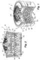
- eine sanitäre Einsetzeinheit in einer teilweise längsgeschnittenen Perspektivdarstellung, wobei die Einsetzeinheit eine Durchflussmengenregler-Einheit und einen auf der Abströmseite dieser Durchflussmengenregler-Einheit angeordneten Strahlregler hat,
- Fig. 2
- die Einsetzeinheit aus
Figur 1 - Fig. 3
- die Einsetzeinheit aus
Figur 1 und 2
- Fig. 1
- a sanitary insertion unit in a partially longitudinally sectioned perspective view, the insertion unit having a flow rate regulator unit and a jet regulator arranged on the outflow side of this flow rate regulator unit,
- Fig. 2
- the insertion unit
Figure 1 in a longitudinal section, and - Fig. 3
- the insertion unit
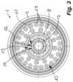
Figures 1 and 2 in a plan view of the inflow side of a jet splitter located in the jet regulator and of the flow rate regulator connected upstream on the inflow side.
In den
Die Einsetzeinheit 1 weist eine Durchflussmengenregler-Einheit 4 auf, welche die pro Zeiteinheit durchströmende Wassermenge druckunabhängig auf einen festgelegten Maximalwert einregelt. In zumindest einem, im wesentlichen ringförmigen Durchflusskanal 5, 6 der Durchflussmengenregler-Einheit 4 ist ein ringförmiger Drosselkörper 7, 8 aus elastischem Material vorgesehen, welcher zwischen sich und einer benachbarten Kanalwandung, die eine Regelprofilierung 24 aus in Durchströmrichtung orientierten Ein- und Ausformungen 11, 12 trägt, einen Steuerspalt 13 begrenzt, dessen Durchtrittsquerschnitt durch den sich unter der beim Durchströmen bildenden Druckdifferenz verformenden Drosselkörper 7, 8 verändert. Je nach Wasserdruck formt der Drosselkörper in den jeweils einen Durchflussmengenregler bildenden Durchflusskanälen 5, 6 sich mehr oder weniger stark in die Regelprofilierung 24 und der lichte Steuerspalt 13 verändert sich entsprechend.The
Die Durchflussmengenregler-Einheit 4 weist hier zwei konzentrische Durchflusskanäle 5, 6 auf, in denen jeweils ein elastischer Drosselkörper 7, 8 eingelegt ist. Dabei ist in dem, einen kleineren Durchmesser aufweisenden innenliegenden Durchflusskanal 5 ein Drosselkörper 7 vorgesehen, der im Vergleich zu dem im außenliegenden, einen größeren Durchmesser aufweisenden Durchflusskanal 6 befindlichen Drosselkörper 8 einen kleineren Materialquerschnitt, insbesondere eine kleinere Schnurstärke, hat, und deshalb leichter auch auf geringe Wasserdrücke und Wasserdruckänderungen reagiert.The flow rate regulator unit 4 here has two
Auf der Abströmseite der Durchflussmengenregler-Einheit 4 ist ein Strahlregler 9 angeordnet, der das anströmende Wasser zu einem homogenen, nicht-spritzenden und gegebenenfalls perlend-weichen Wasserstrahl formen soll. Dieser Strahlregler 9 hat einen als Lochplatte ausgebildeten Strahlzerleger 10 mit einer Mehrzahl von Durchflusslöchern 29, welcher Strahlzerleger 10 das von der Durchflussmengenregler-Einheit 4 kommende Wasser im Einsetzgehäuse 2 zunächst in eine Vielzahl von Einzelstrahlen aufteilt.On the outflow side of the flow rate regulator unit 4, a jet regulator 9 is arranged, which is intended to form the incoming water into a homogeneous, non-splashing and possibly pearly-soft water jet. This jet regulator 9 has a
Damit das von der Durchflussmengenregler-Einheit 4 noch mit einer hohen Geschwindigkeit anströmende Wasser nicht direkt und ungebremst durch die Durchflusslöcher 29 im Strahlzerleger 10 fließt, ist die Projektion zumindest eines der Durchflusskanäle 5, 6 in einer lochfreien Ringzone 27 des Strahlzerlegers 10 angeordnet, das heißt in der axialen Verlängerung zumindest eines der Durchflusskanäle 5, 6 ist eine lochfreie Ringzone 27 des Strahlzerlegers 10 vorgesehen.So that the water flowing from the flow rate regulator unit 4 at a high speed does not flow directly and unchecked through the flow holes 29 in the
In den Durchflusslöchern 29 der Lochplatte tritt das durchfließende Wasser mit einer erhöhten Geschwindigkeit aus, die auf der Abströmseite der Lochplatte einen Unterdruck bewirkt, welcher Unterdruck Umgebungsluft in das Gehäuseinnere des Einsetzgehäuses 2 saugt. Dazu sind in der Gehäusewandung des Einsetzgehäuses 2 in der direkt unterhalb des als Lochplatte ausgebildeten Strahlzerlegers 10 gelegenen Ringzone Belüftungsöffnungen 28 vorgesehen. Die vom Strahlzerleger 10 kommenden Einzelstrahlen werden im Gehäuseinneren des Einsetzgehäuses 2 - in der im Gehäuseinneren unterhalb dem Strahlzerleger 10 gelegenen Mischzone - mit der Umgebungsluft durchmischt. Um diese Durchmischung noch zusätzlich zu begünstigen und um das Wasser weiter abzubremsen, können im Einsetzgehäuse 2 Einsetzteile 14, 15 eingesetzt sein, die innerhalb einer außenliegenden Ringwand 16 eine Gitter- oder Netzstruktur aus einander an Kreuzungsknoten sich kreuzenden Stegen 17, 18 haben.In the flow holes 29 of the perforated plate, the water flowing through exits at an increased speed, which causes a negative pressure on the outflow side of the perforated plate, which negative pressure sucks ambient air into the interior of the insert housing 2. For this purpose, ventilation openings 28 are provided in the housing wall of the insert housing 2 in the ring zone located directly below the
Dabei kreuzen sich hier konzentrische Stege 17 mit radialen Stegen 18 und bilden eine Netzstruktur aus, an der das Wasser noch weiter aufgeteilt und vermischt wird. An die Einsetzteile 14, 15 schließt sich abströmseitig ein Strömungsgleichrichter 19 mit Auslauföffnungen 20 an, welche Auslauföffnungen 20 eine vergleichsweise hohe Längserstreckung im Vergleich zum Lochquerschnitt haben. In den Auslauföffnungen 20 dieses Strömungsgleichrichters 19 wird das dort austretende Wasser zu einem homogenen Auslaufstrahl geformt. Dabei bildet der Strömungsgleichrichter 19 die auslaufseitige Stirnfläche der Einsetzeinheit 1. Auf der Abströmseite des Strömungsgleichrichters 19 ist eine Gehäuseeinschnürung 21 vorgesehen, die ein unerwünschtes Spritzen seitlich des austretenden Wasserstrahls verhindert.Here,
Damit das Wasser nicht als instabiler Ringstrahl austritt und damit das austretende Wasser auch einen homogenen Strahlquerschnitt hat, ist in den von der Projektion des zumindest einen Durchflusskanals 5, 6 umgrenzten Zentralbereich 22 des Strahlzerlegers zumindest ein Durchflussloch 29 und - wie hier - vorzugsweise mehrere Durchflusslöcher 29 vorgesehen.So that the water does not emerge as an unstable ring jet and so that the emerging water also has a homogeneous jet cross section, there is at least one
Damit trotz der lochfreien Ringzone 12 noch eine ausreichende Anzahl von Durchflusslöchern 29 in der als Strahlzerleger 10 dienenden Lochplatte platziert werden können, sind die Durchflusskanäle 5, 6 durch eine Ringwandung 23 voneinander getrennt, wobei die Regelprofilierungen 24 der konzentrisch zueinander angeordneten Durchflusskanäle 5, 6 auf der Innenseite und der Außenseite dieser Ringwandung 23 vorgesehen sind. Auf diese Weise lässt sich die lochfreie Ringzone 27 vergleichsweise schmal ausgestalten.So that a sufficient number of flow holes 29 can still be placed in the perforated plate serving as a
Die außerhalb der Projektion der Durchflusskanäle 5, 6 angeordneten Durchflusslöcher 29 des Strahlzerlegers 10 sind auf wenigstens einer Kreisbahn und - wie hier - vorzugsweise auf mindestens zwei Kreisbahnen angeordnet. Dabei sind die die Durchflusslöcher 29 aufweisenden Kreisbahnen konzentrisch zueinander und zur Projektion des zumindest einen Durchflusskanals 5, 6 angeordnet.The flow holes 29 of the
Wie insbesondere aus dem Längsschnitt in
- 11
- EinsetzeinheitInsertion unit
- 22
- EinsetzgehäuseInsert housing
- 33
- RingflanschRing flange
- 44
- Durchflussmengenregler-EinheitFlow rate regulator unit
- 55
- innenliegender Durchflusskanalinternal flow channel
- 66
- außenliegender Durchflusskanalexternal flow channel
- 77
- innenliegender Drosselkörperinternal throttle body
- 88th
- außenliegender Drosselkörperexternal throttle body
- 99
- StrahlreglerAerator
- 1010
- StrahlzerlegerBeam splitter
- 1111
- Einformungenindentations
- 1212
- AusformungenFormations
- 1313
- SteuerspaltTax gap
- 1414
- EinsetzteilInsert part
- 1515
- EinsetzteilInsert part
- 1616
- RingwandRing wall
- 1717
- konzentrische Stegeconcentric webs
- 1818
- radiale Stegeradial webs
- 1919
- StrömungsgleichrichterFlow straightener
- 2020
- Auslauföffnungen des Strömungsgleichrichters 19Outlet openings of the
flow straightener 19 - 2121
- GehäuseeinschnürungHousing constriction
- 2222
- ZentralbereichCentral area
- 2323
- Ringwandungring wall
- 2424
- RegelprofilierungRule profiling
- 2525
- Einström-LochabschnittInflow hole section
- 2626
- Ausström-LochabschnittOutflow hole section
- 2727
- Ringzonering zone
- 2828
- BelüftungsöffnungenVentilation openings
- 2929
- DurchflusslöcherFlow holes
Claims (10)
- Sanitary insert unit (1) which can be fitted on the water outlet of a sanitary outlet fitting, with a throughflow-quantity regulator unit (4) which, in at least one annular throughflow channel (5, 6), has at least one annular flow-restricting body (7, 8) of elastic material, which at least one flow-restricting body (7, 8), between itself and an adjacent channel wall bearing a control profiling (24), bounds a control gap (13), the passage cross section of which can be varied by the flow-restricting body (7, 8) deforming under the differential pressure forming during the flow therethrough, and with a jet regulator (9) which is arranged on the outflow side of the throughflow-quantity regulator unit (4) and has a jet splitter (10), which jet splitter (10) divides the water coming from the throughflow-quantity regulator unit (4) into a multiplicity of individual jets,characterized in that the jet splitter (10) is designed as a perforated plate,in that the projection of at least one of the throughflow channels (5, 6) is arranged in a perforation-free annular zone (27) of the jet splitter (10) designed as a perforated plate, andin that the throughflow holes (29) of the jet splitter (10) designed as a perforated plate, which throughflow holes (29) are arranged outside the projection of the throughflow channels (5, 6), are arranged on at least one circular path in the perforated plate in such a manner that the water arriving from the throughflow-quantity regulator unit can flow directly and unbraked through said throughflow holes (29) in the jet splitter (10).
- Sanitary insert unit according to Claim 1,characterized in that at least one throughflow hole (29) is provided in the central region (22) of the jet splitter (10), which central region is bounded by the projection of the at least one throughflow channel (5, 6).
- Sanitary insert unit according to Claim 1 or 2,characterized in that the throughflow-quantity regulator unit (4) has at least two throughflow-quantity regulators, the throughflow channels (5, 6) of which are arranged approximately concentrically with respect to each other.
- Sanitary insert unit according to Claim 3,characterized in that the throughflow channels (5, 6) of two adjacent throughflow-quantity regulators are separated from each other by an annular wall (23), andin that the control profilings (24) of said throughflow channels (5, 6) are provided on the inner side and the outer side of said annular wall (23).
- Sanitary insert unit according to one of Claims 1 to 4,characterized in that the throughflow holes (29) of the jet splitter (10), which throughflow holes are arranged outside the projection of the at least one throughflow channel (5, 6), are preferably arranged on at least two circular paths.
- Sanitary insert unit according to one of Claims 1 to 5,characterized in that the circular paths having the throughflow holes (29) are arranged concentrically with respect to one another and/or with respect to the projection of the at least one throughflow channel (5, 6) .
- Sanitary insert unit according to one of Claims 1 to 6,characterized in that the throughflow holes (29) of the jet splitter (10) have an inflow hole portion (25) and an outflow hole portion (26).
- Sanitary insert unit according to Claim 7,characterized in that the inflow hole portion (25) of the throughflow holes (29) tapers in a funnel-shaped manner in the throughflow direction.
- Sanitary insert unit according to Claim 7 or 8,characterized in that the outflow hole portion (26) has a cylindrical clear hole portion.
- Sanitary insert unit according to one of Claims 1 to 9,characterized in that the throughflow channel (5) having a smaller diameter is provided with a flow-restricting body (7) with a smaller cross section, in particular with a smaller chord size, in comparison to the flow-restricting body (8) located in the throughflow channel (6) which is external to the throughflow channel (5) and has a larger diameter.
Applications Claiming Priority (3)
| Application Number | Priority Date | Filing Date | Title |
|---|---|---|---|
| DE202017101436.3UDE202017101436U1 (en) | 2017-03-13 | 2017-03-13 | Sanitary insert unit |
| PCT/EP2018/050827WO2018166666A1 (en) | 2017-03-13 | 2018-01-15 | Sanitary insert unit |
| EP18706188.2AEP3596277B1 (en) | 2017-03-13 | 2018-01-15 | Sanitary insert unit |
Related Parent Applications (2)
| Application Number | Title | Priority Date | Filing Date |
|---|---|---|---|
| EP18706188.2ADivisionEP3596277B1 (en) | 2017-03-13 | 2018-01-15 | Sanitary insert unit |
| EP18706188.2ADivision-IntoEP3596277B1 (en) | 2017-03-13 | 2018-01-15 | Sanitary insert unit |
Publications (3)
| Publication Number | Publication Date |
|---|---|
| EP3670767A1 EP3670767A1 (en) | 2020-06-24 |
| EP3670767B1true EP3670767B1 (en) | 2023-10-04 |
| EP3670767C0 EP3670767C0 (en) | 2023-10-04 |
Family
ID=61249598
Family Applications (2)
| Application Number | Title | Priority Date | Filing Date |
|---|---|---|---|
| EP19202671.4AActiveEP3670767B1 (en) | 2017-03-13 | 2018-01-15 | Sanitary insert unit |
| EP18706188.2AActiveEP3596277B1 (en) | 2017-03-13 | 2018-01-15 | Sanitary insert unit |
Family Applications After (1)
| Application Number | Title | Priority Date | Filing Date |
|---|---|---|---|
| EP18706188.2AActiveEP3596277B1 (en) | 2017-03-13 | 2018-01-15 | Sanitary insert unit |
Country Status (9)
| Country | Link |
|---|---|
| US (1) | US11441298B2 (en) |
| EP (2) | EP3670767B1 (en) |
| CN (3) | CN108571037B (en) |
| AU (1) | AU2018233432B2 (en) |
| DE (1) | DE202017101436U1 (en) |
| ES (2) | ES2964059T3 (en) |
| MX (1) | MX2019007334A (en) |
| PL (1) | PL3670767T3 (en) |
| WO (1) | WO2018166666A1 (en) |
Families Citing this family (16)
| Publication number | Priority date | Publication date | Assignee | Title |
|---|---|---|---|---|
| USD690796S1 (en)* | 2010-12-22 | 2013-10-01 | Neoperl Gmbh | Flow regulator |
| USD798999S1 (en)* | 2015-11-18 | 2017-10-03 | Neoperl Gmbh | Flow regulator |
| USD962385S1 (en)* | 2016-11-23 | 2022-08-30 | Neoperl Gmbh | Faucet stream straightener |
| USD822159S1 (en)* | 2016-11-23 | 2018-07-03 | Neoperl Gmbh | Faucet stream straightener |
| USD1037409S1 (en)* | 2017-03-03 | 2024-07-30 | Neoperl Gmbh | Jet regulator |
| DE202017101436U1 (en)* | 2017-03-13 | 2018-06-14 | Neoperl Gmbh | Sanitary insert unit |
| CN109556189A (en)* | 2018-10-25 | 2019-04-02 | 青岛海尔空调电子有限公司 | Throttling set and air conditioner |
| USD906478S1 (en)* | 2019-03-08 | 2020-12-29 | Neoperl Gmbh | Faucet stream straightener |
| US11591780B2 (en)* | 2020-04-15 | 2023-02-28 | Yeuu Deng Sanitary Facilities Industrial Co., Ltd. | Faucet aerator |
| USD1055214S1 (en)* | 2020-08-28 | 2024-12-24 | Neoperl Gmbh | Faucet stream straightener |
| USD1041615S1 (en)* | 2021-03-19 | 2024-09-10 | Tasz, Inc. | Aerator |
| USD1064193S1 (en)* | 2021-11-03 | 2025-02-25 | 3M Innovative Properties Company | Flow controller for static mixer |
| USD991402S1 (en)* | 2022-01-25 | 2023-07-04 | Xiamen Water Nymph Sanitary Technology Co., Ltd. | Aerator insert for taps |
| USD987777S1 (en)* | 2022-11-03 | 2023-05-30 | Jianfeng Sun | Filter |
| USD1029183S1 (en)* | 2023-02-07 | 2024-05-28 | Neoperl Gmbh | Faucet stream straightener |
| USD1029991S1 (en)* | 2023-02-08 | 2024-06-04 | Neoperl Gmbh | Faucet stream straightener |
Family Cites Families (18)
| Publication number | Priority date | Publication date | Assignee | Title |
|---|---|---|---|---|
| DE4413060C2 (en)* | 1994-04-15 | 1996-04-25 | Wildfang Dieter Gmbh | Aerator |
| DE10246334B4 (en) | 2002-10-04 | 2015-05-07 | Neoperl Gmbh | Sanitary installation part |
| DE102010012325A1 (en)* | 2010-03-23 | 2011-09-29 | Neoperl Gmbh | Jet regulator or the like sanitary outlet element and method and injection molding tool for its production |
| DE202010007835U1 (en) | 2010-06-11 | 2011-09-29 | Neoperl Gmbh | Flow regulator |
| CN202139650U (en)* | 2010-09-28 | 2012-02-08 | 纽珀有限公司 | hygienic inserts |
| ES2580206T3 (en)* | 2011-03-11 | 2016-08-22 | Neoperl Gmbh | Sanitary flow element with a flow regulator unit and procedure for manufacturing it |
| US8708252B2 (en)* | 2011-11-28 | 2014-04-29 | Neoperl Gmbh | Sanitary installation part |
| DE202012007719U1 (en) | 2012-08-10 | 2013-11-12 | Neoperl Gmbh | Sanitary insert unit |
| DE102013004076B4 (en)* | 2013-03-11 | 2022-06-23 | Neoperl Gmbh | Aerator with baffle and annular wall |
| DE202013002282U1 (en)* | 2013-03-11 | 2014-06-12 | Neoperl Gmbh | Jet regulator with baffle and ring wall |
| RS55899B1 (en)* | 2014-10-13 | 2017-08-31 | Ftt Doo | Shower head with a toroidal regulator and magnetic ring |
| EP3037592B2 (en)* | 2014-12-22 | 2022-11-02 | Amfag S.R.L. | Jet breaker/aerator cartridge which can be manually disassembled and faucet comprising said cartridge |
| DE102015003246B4 (en) | 2015-03-09 | 2020-02-06 | Neoperl Gmbh | Sanitary application unit |
| DE202015001885U1 (en)* | 2015-03-09 | 2016-06-10 | Neoperl Gmbh | Sanitary insert unit |
| DE202015001754U1 (en)* | 2015-03-09 | 2016-06-10 | Neoperl Gmbh | Flow regulator unit |
| DE202015003301U1 (en) | 2015-05-05 | 2016-08-09 | Neoperl Gmbh | aerator |
| CN204901054U (en)* | 2015-08-13 | 2015-12-23 | 宁波市北仑海伯精密机械制造有限公司 | Microbubble generator |
| DE202017101436U1 (en)* | 2017-03-13 | 2018-06-14 | Neoperl Gmbh | Sanitary insert unit |
- 2017
- 2017-03-13DEDE202017101436.3Upatent/DE202017101436U1/enactiveActive
- 2017-06-09CNCN201710429627.2Apatent/CN108571037B/enactiveActive
- 2017-06-09CNCN201720671549.2Upatent/CN206986982U/ennot_activeWithdrawn - After Issue
- 2018
- 2018-01-15EPEP19202671.4Apatent/EP3670767B1/enactiveActive
- 2018-01-15AUAU2018233432Apatent/AU2018233432B2/enactiveActive
- 2018-01-15WOPCT/EP2018/050827patent/WO2018166666A1/ennot_activeCeased
- 2018-01-15ESES19202671Tpatent/ES2964059T3/enactiveActive
- 2018-01-15USUS16/484,168patent/US11441298B2/enactiveActive
- 2018-01-15MXMX2019007334Apatent/MX2019007334A/enunknown
- 2018-01-15EPEP18706188.2Apatent/EP3596277B1/enactiveActive
- 2018-01-15CNCN201880013543.3Apatent/CN110573682B/enactiveActive
- 2018-01-15ESES18706188Tpatent/ES2895039T3/enactiveActive
- 2018-01-15PLPL19202671.4Tpatent/PL3670767T3/enunknown
Also Published As
| Publication number | Publication date |
|---|---|
| CN108571037B (en) | 2021-03-23 |
| CN110573682A (en) | 2019-12-13 |
| EP3670767A1 (en) | 2020-06-24 |
| WO2018166666A8 (en) | 2018-11-22 |
| WO2018166666A1 (en) | 2018-09-20 |
| ES2964059T3 (en) | 2024-04-03 |
| MX2019007334A (en) | 2019-09-09 |
| AU2018233432A1 (en) | 2019-07-25 |
| PL3670767T3 (en) | 2024-05-20 |
| DE202017101436U1 (en) | 2018-06-14 |
| CN108571037A (en) | 2018-09-25 |
| EP3596277A1 (en) | 2020-01-22 |
| EP3596277B1 (en) | 2021-07-28 |
| CN110573682B (en) | 2021-06-25 |
| EP3670767C0 (en) | 2023-10-04 |
| US11441298B2 (en) | 2022-09-13 |
| US20210285194A1 (en) | 2021-09-16 |
| ES2895039T3 (en) | 2022-02-17 |
| CN206986982U (en) | 2018-02-09 |
| AU2018233432B2 (en) | 2023-12-14 |
Similar Documents
| Publication | Publication Date | Title |
|---|---|---|
| EP3670767B1 (en) | Sanitary insert unit | |
| EP3620585B1 (en) | Sanitary built-in part | |
| EP3087226B1 (en) | Sanitary unit for water supply lines | |
| EP3679197B1 (en) | Flow regulator | |
| DE102015003246B4 (en) | Sanitary application unit | |
| EP3649300B1 (en) | Jet regulator | |
| EP3101184B1 (en) | Sanitary insert unit | |
| EP2971385B1 (en) | Flow regulator having baffle with ring-like walls | |
| EP3054060A1 (en) | Sanitary outlet element | |
| EP3009571B1 (en) | Flow regulator | |
| DE102013004076A1 (en) | Jet regulator with baffle and ring wall | |
| EP3848518A1 (en) | Sanitary outlet unit | |
| EP4077821B1 (en) | Aerator | |
| EP4101998A1 (en) | Sanitary built-in part and series for a sanitary built-in part | |
| DE102015016796A1 (en) | Sanitary outlet unit | |
| EP4111006B1 (en) | Aerator in which parts are rotationally locked | |
| DE102017105297B4 (en) | sanitary insert unit | |
| EP3239417A1 (en) | Sanitary insert unit | |
| DE102017105299A1 (en) | Sanitary installation part | |
| DE102016010842A1 (en) | Sanitary insert unit | |
| DE102020107092A1 (en) | Sanitary cartridge | |
| DE102016015807A1 (en) | Sanitary insert unit | |
| DE102019135057A1 (en) | Aerator | |
| EP3875699A1 (en) | Sanitary outlet unit | |
| DE10146788A1 (en) | Water jet control unit has a housing with a water flow divider, between the inflow and outflow openings, and a ring wall to restrict the flow cross section near the outflow |
Legal Events
| Date | Code | Title | Description |
|---|---|---|---|
| PUAI | Public reference made under article 153(3) epc to a published international application that has entered the european phase | Free format text:ORIGINAL CODE: 0009012 | |
| STAA | Information on the status of an ep patent application or granted ep patent | Free format text:STATUS: THE APPLICATION HAS BEEN PUBLISHED | |
| AC | Divisional application: reference to earlier application | Ref document number:3596277 Country of ref document:EP Kind code of ref document:P | |
| AK | Designated contracting states | Kind code of ref document:A1 Designated state(s):AL AT BE BG CH CY CZ DE DK EE ES FI FR GB GR HR HU IE IS IT LI LT LU LV MC MK MT NL NO PL PT RO RS SE SI SK SM TR | |
| AX | Request for extension of the european patent | Extension state:BA ME | |
| STAA | Information on the status of an ep patent application or granted ep patent | Free format text:STATUS: REQUEST FOR EXAMINATION WAS MADE | |
| 17P | Request for examination filed | Effective date:20201105 | |
| RBV | Designated contracting states (corrected) | Designated state(s):AL AT BE BG CH CY CZ DE DK EE ES FI FR GB GR HR HU IE IS IT LI LT LU LV MC MK MT NL NO PL PT RO RS SE SI SK SM TR | |
| RIC1 | Information provided on ipc code assigned before grant | Ipc:E03C 1/084 20060101AFI20230228BHEP | |
| GRAP | Despatch of communication of intention to grant a patent | Free format text:ORIGINAL CODE: EPIDOSNIGR1 | |
| STAA | Information on the status of an ep patent application or granted ep patent | Free format text:STATUS: GRANT OF PATENT IS INTENDED | |
| INTG | Intention to grant announced | Effective date:20230412 | |
| RIN1 | Information on inventor provided before grant (corrected) | Inventor name:TWITCHETT, SIMON Inventor name:STEIN, ALEXANDER | |
| GRAS | Grant fee paid | Free format text:ORIGINAL CODE: EPIDOSNIGR3 | |
| GRAA | (expected) grant | Free format text:ORIGINAL CODE: 0009210 | |
| STAA | Information on the status of an ep patent application or granted ep patent | Free format text:STATUS: THE PATENT HAS BEEN GRANTED | |
| AC | Divisional application: reference to earlier application | Ref document number:3596277 Country of ref document:EP Kind code of ref document:P | |
| AK | Designated contracting states | Kind code of ref document:B1 Designated state(s):AL AT BE BG CH CY CZ DE DK EE ES FI FR GB GR HR HU IE IS IT LI LT LU LV MC MK MT NL NO PL PT RO RS SE SI SK SM TR | |
| REG | Reference to a national code | Ref country code:GB Ref legal event code:FG4D Free format text:NOT ENGLISH | |
| REG | Reference to a national code | Ref country code:CH Ref legal event code:EP | |
| REG | Reference to a national code | Ref country code:IE Ref legal event code:FG4D Free format text:LANGUAGE OF EP DOCUMENT: GERMAN | |
| REG | Reference to a national code | Ref country code:DE Ref legal event code:R096 Ref document number:502018013407 Country of ref document:DE | |
| U01 | Request for unitary effect filed | Effective date:20231018 | |
| U07 | Unitary effect registered | Designated state(s):AT BE BG DE DK EE FI FR IT LT LU LV MT NL PT SE SI Effective date:20231026 | |
| U20 | Renewal fee for the european patent with unitary effect paid | Year of fee payment:7 Effective date:20240115 | |
| REG | Reference to a national code | Ref country code:ES Ref legal event code:FG2A Ref document number:2964059 Country of ref document:ES Kind code of ref document:T3 Effective date:20240403 | |
| PG25 | Lapsed in a contracting state [announced via postgrant information from national office to epo] | Ref country code:GR Free format text:LAPSE BECAUSE OF FAILURE TO SUBMIT A TRANSLATION OF THE DESCRIPTION OR TO PAY THE FEE WITHIN THE PRESCRIBED TIME-LIMIT Effective date:20240105 | |
| PG25 | Lapsed in a contracting state [announced via postgrant information from national office to epo] | Ref country code:IS Free format text:LAPSE BECAUSE OF FAILURE TO SUBMIT A TRANSLATION OF THE DESCRIPTION OR TO PAY THE FEE WITHIN THE PRESCRIBED TIME-LIMIT Effective date:20240204 | |
| PG25 | Lapsed in a contracting state [announced via postgrant information from national office to epo] | Ref country code:IS Free format text:LAPSE BECAUSE OF FAILURE TO SUBMIT A TRANSLATION OF THE DESCRIPTION OR TO PAY THE FEE WITHIN THE PRESCRIBED TIME-LIMIT Effective date:20240204 Ref country code:GR Free format text:LAPSE BECAUSE OF FAILURE TO SUBMIT A TRANSLATION OF THE DESCRIPTION OR TO PAY THE FEE WITHIN THE PRESCRIBED TIME-LIMIT Effective date:20240105 | |
| PG25 | Lapsed in a contracting state [announced via postgrant information from national office to epo] | Ref country code:RS Free format text:LAPSE BECAUSE OF FAILURE TO SUBMIT A TRANSLATION OF THE DESCRIPTION OR TO PAY THE FEE WITHIN THE PRESCRIBED TIME-LIMIT Effective date:20231004 Ref country code:NO Free format text:LAPSE BECAUSE OF FAILURE TO SUBMIT A TRANSLATION OF THE DESCRIPTION OR TO PAY THE FEE WITHIN THE PRESCRIBED TIME-LIMIT Effective date:20240104 Ref country code:HR Free format text:LAPSE BECAUSE OF FAILURE TO SUBMIT A TRANSLATION OF THE DESCRIPTION OR TO PAY THE FEE WITHIN THE PRESCRIBED TIME-LIMIT Effective date:20231004 | |
| REG | Reference to a national code | Ref country code:DE Ref legal event code:R097 Ref document number:502018013407 Country of ref document:DE | |
| PG25 | Lapsed in a contracting state [announced via postgrant information from national office to epo] | Ref country code:CZ Free format text:LAPSE BECAUSE OF FAILURE TO SUBMIT A TRANSLATION OF THE DESCRIPTION OR TO PAY THE FEE WITHIN THE PRESCRIBED TIME-LIMIT Effective date:20231004 | |
| PG25 | Lapsed in a contracting state [announced via postgrant information from national office to epo] | Ref country code:SK Free format text:LAPSE BECAUSE OF FAILURE TO SUBMIT A TRANSLATION OF THE DESCRIPTION OR TO PAY THE FEE WITHIN THE PRESCRIBED TIME-LIMIT Effective date:20231004 | |
| PG25 | Lapsed in a contracting state [announced via postgrant information from national office to epo] | Ref country code:SM Free format text:LAPSE BECAUSE OF FAILURE TO SUBMIT A TRANSLATION OF THE DESCRIPTION OR TO PAY THE FEE WITHIN THE PRESCRIBED TIME-LIMIT Effective date:20231004 Ref country code:SK Free format text:LAPSE BECAUSE OF FAILURE TO SUBMIT A TRANSLATION OF THE DESCRIPTION OR TO PAY THE FEE WITHIN THE PRESCRIBED TIME-LIMIT Effective date:20231004 Ref country code:RO Free format text:LAPSE BECAUSE OF FAILURE TO SUBMIT A TRANSLATION OF THE DESCRIPTION OR TO PAY THE FEE WITHIN THE PRESCRIBED TIME-LIMIT Effective date:20231004 Ref country code:CZ Free format text:LAPSE BECAUSE OF FAILURE TO SUBMIT A TRANSLATION OF THE DESCRIPTION OR TO PAY THE FEE WITHIN THE PRESCRIBED TIME-LIMIT Effective date:20231004 | |
| PLBE | No opposition filed within time limit | Free format text:ORIGINAL CODE: 0009261 | |
| STAA | Information on the status of an ep patent application or granted ep patent | Free format text:STATUS: NO OPPOSITION FILED WITHIN TIME LIMIT | |
| PG25 | Lapsed in a contracting state [announced via postgrant information from national office to epo] | Ref country code:MC Free format text:LAPSE BECAUSE OF FAILURE TO SUBMIT A TRANSLATION OF THE DESCRIPTION OR TO PAY THE FEE WITHIN THE PRESCRIBED TIME-LIMIT Effective date:20231004 | |
| PG25 | Lapsed in a contracting state [announced via postgrant information from national office to epo] | Ref country code:MC Free format text:LAPSE BECAUSE OF FAILURE TO SUBMIT A TRANSLATION OF THE DESCRIPTION OR TO PAY THE FEE WITHIN THE PRESCRIBED TIME-LIMIT Effective date:20231004 | |
| 26N | No opposition filed | Effective date:20240705 | |
| GBPC | Gb: european patent ceased through non-payment of renewal fee | Effective date:20240115 | |
| PG25 | Lapsed in a contracting state [announced via postgrant information from national office to epo] | Ref country code:GB Free format text:LAPSE BECAUSE OF NON-PAYMENT OF DUE FEES Effective date:20240115 | |
| PG25 | Lapsed in a contracting state [announced via postgrant information from national office to epo] | Ref country code:GB Free format text:LAPSE BECAUSE OF NON-PAYMENT OF DUE FEES Effective date:20240115 | |
| PG25 | Lapsed in a contracting state [announced via postgrant information from national office to epo] | Ref country code:IE Free format text:LAPSE BECAUSE OF NON-PAYMENT OF DUE FEES Effective date:20240115 | |
| PG25 | Lapsed in a contracting state [announced via postgrant information from national office to epo] | Ref country code:IE Free format text:LAPSE BECAUSE OF NON-PAYMENT OF DUE FEES Effective date:20240115 | |
| U20 | Renewal fee for the european patent with unitary effect paid | Year of fee payment:8 Effective date:20250115 | |
| PGFP | Annual fee paid to national office [announced via postgrant information from national office to epo] | Ref country code:ES Payment date:20250214 Year of fee payment:8 | |
| PGFP | Annual fee paid to national office [announced via postgrant information from national office to epo] | Ref country code:CH Payment date:20250201 Year of fee payment:8 | |
| PGFP | Annual fee paid to national office [announced via postgrant information from national office to epo] | Ref country code:PL Payment date:20250103 Year of fee payment:8 | |
| PGFP | Annual fee paid to national office [announced via postgrant information from national office to epo] | Ref country code:TR Payment date:20250108 Year of fee payment:8 | |
| PG25 | Lapsed in a contracting state [announced via postgrant information from national office to epo] | Ref country code:CY Free format text:LAPSE BECAUSE OF FAILURE TO SUBMIT A TRANSLATION OF THE DESCRIPTION OR TO PAY THE FEE WITHIN THE PRESCRIBED TIME-LIMIT; INVALID AB INITIO Effective date:20180115 | |
| PG25 | Lapsed in a contracting state [announced via postgrant information from national office to epo] | Ref country code:HU Free format text:LAPSE BECAUSE OF FAILURE TO SUBMIT A TRANSLATION OF THE DESCRIPTION OR TO PAY THE FEE WITHIN THE PRESCRIBED TIME-LIMIT; INVALID AB INITIO Effective date:20180115 |