EP3665394B1 - Flange mounting clamp - Google Patents
Flange mounting clampDownload PDFInfo
- Publication number
- EP3665394B1 EP3665394B1EP18843406.2AEP18843406AEP3665394B1EP 3665394 B1EP3665394 B1EP 3665394B1EP 18843406 AEP18843406 AEP 18843406AEP 3665394 B1EP3665394 B1EP 3665394B1
- Authority
- EP
- European Patent Office
- Prior art keywords
- channel
- ramp
- arm
- fastener assembly
- defines
- Prior art date
- Legal status (The legal status is an assumption and is not a legal conclusion. Google has not performed a legal analysis and makes no representation as to the accuracy of the status listed.)
- Active
Links
Images


Classifications
- F—MECHANICAL ENGINEERING; LIGHTING; HEATING; WEAPONS; BLASTING
- F16—ENGINEERING ELEMENTS AND UNITS; GENERAL MEASURES FOR PRODUCING AND MAINTAINING EFFECTIVE FUNCTIONING OF MACHINES OR INSTALLATIONS; THERMAL INSULATION IN GENERAL
- F16B—DEVICES FOR FASTENING OR SECURING CONSTRUCTIONAL ELEMENTS OR MACHINE PARTS TOGETHER, e.g. NAILS, BOLTS, CIRCLIPS, CLAMPS, CLIPS OR WEDGES; JOINTS OR JOINTING
- F16B2/00—Friction-grip releasable fastenings
- F16B2/02—Clamps, i.e. with gripping action effected by positive means other than the inherent resistance to deformation of the material of the fastening
- F16B2/14—Clamps, i.e. with gripping action effected by positive means other than the inherent resistance to deformation of the material of the fastening using wedges
- F—MECHANICAL ENGINEERING; LIGHTING; HEATING; WEAPONS; BLASTING
- F16—ENGINEERING ELEMENTS AND UNITS; GENERAL MEASURES FOR PRODUCING AND MAINTAINING EFFECTIVE FUNCTIONING OF MACHINES OR INSTALLATIONS; THERMAL INSULATION IN GENERAL
- F16B—DEVICES FOR FASTENING OR SECURING CONSTRUCTIONAL ELEMENTS OR MACHINE PARTS TOGETHER, e.g. NAILS, BOLTS, CIRCLIPS, CLAMPS, CLIPS OR WEDGES; JOINTS OR JOINTING
- F16B2/00—Friction-grip releasable fastenings
- F16B2/02—Clamps, i.e. with gripping action effected by positive means other than the inherent resistance to deformation of the material of the fastening
- F16B2/16—Clamps, i.e. with gripping action effected by positive means other than the inherent resistance to deformation of the material of the fastening using rollers or balls
- F—MECHANICAL ENGINEERING; LIGHTING; HEATING; WEAPONS; BLASTING
- F16—ENGINEERING ELEMENTS AND UNITS; GENERAL MEASURES FOR PRODUCING AND MAINTAINING EFFECTIVE FUNCTIONING OF MACHINES OR INSTALLATIONS; THERMAL INSULATION IN GENERAL
- F16B—DEVICES FOR FASTENING OR SECURING CONSTRUCTIONAL ELEMENTS OR MACHINE PARTS TOGETHER, e.g. NAILS, BOLTS, CIRCLIPS, CLAMPS, CLIPS OR WEDGES; JOINTS OR JOINTING
- F16B47/00—Suction cups for attaching purposes; Equivalent means using adhesives
- F16B47/003—Suction cups for attaching purposes; Equivalent means using adhesives using adhesives for attaching purposes
- F—MECHANICAL ENGINEERING; LIGHTING; HEATING; WEAPONS; BLASTING
- F16—ENGINEERING ELEMENTS AND UNITS; GENERAL MEASURES FOR PRODUCING AND MAINTAINING EFFECTIVE FUNCTIONING OF MACHINES OR INSTALLATIONS; THERMAL INSULATION IN GENERAL
- F16B—DEVICES FOR FASTENING OR SECURING CONSTRUCTIONAL ELEMENTS OR MACHINE PARTS TOGETHER, e.g. NAILS, BOLTS, CIRCLIPS, CLAMPS, CLIPS OR WEDGES; JOINTS OR JOINTING
- F16B2/00—Friction-grip releasable fastenings
- F16B2/02—Clamps, i.e. with gripping action effected by positive means other than the inherent resistance to deformation of the material of the fastening
- F16B2/06—Clamps, i.e. with gripping action effected by positive means other than the inherent resistance to deformation of the material of the fastening external, i.e. with contracting action
- F16B2/08—Clamps, i.e. with gripping action effected by positive means other than the inherent resistance to deformation of the material of the fastening external, i.e. with contracting action using bands
Definitions
- This applicationrelates to the attachment of elongated articles, such as cables, hoses, wires or conduits, to a structural component such as a beam. More specifically, the application relates to a fastener for attachment to a beam flange that provides multiple channels for holding multiple articles with cable ties or straps.
- Publication GB 2 024 925 Adiscloses a clamping device, suitable for supporting fabrics or other articles, that comprises a first member having a hook portion by means of which it may be suspended, and a slider slideable longitudinally on the first member.
- the sliderco-operates with inclined surfaces on the first member so that as it is slid longitudinally on the first member a jaw thereon is brought closer to a surface of the first member, and grips any article inserted therebetween.
- Figs. 1-6illustrate an example of a beam flange clamp, hereinafter referred to as the clamp 10 according to one embodiment of the invention which includes a clamp body 12 and a wedge-shaped retaining segment 14.
- the clamp body 12has an inner C-shaped portion 16 surrounded by an outer C-shaped portion 18, with inner and outer C-shaped portions 16, 18 being integral with one another by way of a right wall 20 and a left wall 22.
- Inner C-shaped portion 16has an upper clamping arm 24 and a lower ramp arm 26 connected by a stress arm 28.
- the outer C-shaped portion 18has a top surface 30 adjacent the upper clamping arm 24, a bottom surface 32 adjacent the lower ramp arm 26, and rear surface 34 adjacent stress arm 28.
- the upper clamping arm 24has a lower clamping surface 36 for contacting an upper surface of a structure such as a beam B or a flange of a beam.
- the lower clamping surface 36is provided with a gripping surface 38 which can be molded into lower clamping surface 36 or applied after construction of clamp 10.
- the retaining segment 14has an upper clamping surface 40 for contacting a lower surface of a structure such as a beam B, and a lower ramp surface 42 configured for slideable engagement with lower ramp arm 26 by way of a T-shaped rail defining a pair of wedge channels 44, 46.
- Wedge channels 44, 46preferably bear a series of serrations 48 therein.
- the lower ramp arm 26has a ramp channel 50 configured to accept wedge channels 44, 46.
- the ramp channel 50has ramp ledges 52, 54 on either side, each of which has an upper ramp surface 56, 58 terminating at a ramp flat 60, 62.
- the ramp ledges 52, 54are slideably received within wedge channels 44, 46.
- Either or both of upper ramp surfaces 56, 58bear a series of serrations 64 corresponding to wedge channels 44, 46 for firm one-way sliding engagement of retaining segment 14 within lower ramp arm 26.
- the upper clamping arm 24 and the lower ramp arm 26are further provided with apertures there through.
- the upper clamping arm 24has a first aperture 100 through right wall 20 and a second aperture 102 through left wall 22, forming a transverse channel 120 therethrough.
- the upper clamping arm 24is further provided with a third aperture 104 and a fourth aperture 106 forming a lateral channel 122.
- the lower ramp arm 26has first, second, third, and fourth apertures 108, 110, 112, 114 forming a transverse channel 124 and a lateral channel 126 therethrough.
- the stress arm 28has a pair of apertures 116, 118 forming a transverse channel 128. Aperture 106 of the upper clamping arm 24 and aperture 108 of lower ramp arm 26 each extend through stress arm 28 creating a perpendicular channel 130 therethrough.
- Apertures 100 through 118thus provide six separate channels 120 through 130 extending through the clamp 10 that are oriented in three mutually perpendicular planes along three mutually perpendicular axes, e.g., longitudinal, transverse and vertical axes.
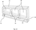
- Each of the six channels 120 - 130is configured to permit a cable tie or strap 66 to be passed therethrough. As seen in Fig. 13 , this provides the user with maximum flexibility in placing a strap or straps 66 according to the orientation of the cables to be bundled.
- the retaining segment 14may be provided in multiple sizes for use with differently sized work pieces.
- a relatively thin beam Bwould require a thicker retaining segment 14 to best hold the clamp 10 into clamping connection, while a clamp 10 would best be held into clamping connection with a relatively thick work piece by using a thinner retaining segment 14.
- a single clamp 10can be used on multiple structures by selecting an appropriately sized retaining segment 14.
- the wedge segmentsare preferably constructed with openings 68 separated by struts 70, with openings 68 designed to reduce material costs and total weight, and struts 70 designed to support clamping along the length of retaining segment 14.
- the stress arm 28 of outer C-shaped portion 18preferably has pockets 72 formed therein.
- the pockets 72are designed to reduce material costs and total weight of clamp 10, but also provide a degree of flexibility to stress arm 28 to compensate for potential over-clamping forces that could otherwise cause the clamp 10 to fail.
- Figs. 9 - 10Billustrate a preferred embodiment of lower clamping surface 36 of upper clamping arm 24, in which the lower clamping surface 36 comprises an adhesive.
- Use of molded grooves to provide frictional connection between a clamp and a surface to be clampedis known to be effective with soft surfaces or painted surfaces as these can grip the surface and prevent the clamp from loosening. Frictional rubber foam is also known for use with harder surfaces.
- lower clamping surface 36may comprise a "gecko" adhesive in which a plurality of microscopic bumps 132 have channels 134 there between, these channels 134 containing a pressure sensitive adhesive.
- the lower clamping surface 36is non-adhesive until the microscopic bumps 132 are pressed flat by engagement with a surface, thus exposing the adhesive within channels 134 to the surface.
- Fig. 10Billustrates another embodiment of a surface treatment in which micro-suction cups 136 are applied to the lower clamping surface 36.
- Micro-suction cups 136provide a strong but non-adhesive bond between lower clamping surface 36 and a beam B.
- each of apertures 100 - 118are wide relative to the clamp body 12, thus creating relatively wide channels 120 - 130. This is advantageous in that wider channels distribute the load on a strap across more surface area; narrow retaining members for straps can more easily crease and chafe the straps over time and ultimately cause them to fail.
- serrations 64extend up upper ramp surfaces 56, 58 almost to or past the center of the upper ramp surfaces 56, 58, as seen in Figs. 5 and 6 . Extending serrations 64 in this way provides additional securing forces to prevent a retaining segment 14 from backing out of place under the stress of clamping forces.
- lower ramp arm 26which, because it extends the entire width of clamp 10, maintains pressure across the length of upper ramp surfaces 56, 58 under clamping stress.
- Ramp flats 60, 62are integrated into the clamp body 12 rather than protruding from clamp 10, producing a more streamlined product.
- Ramp flat 60provides a surface within which the series of serrations 64 are formed.
- Both ramp flat 60 and ramp flat 62provide a guide and support surface for the retaining segment 14 as wedge channels 44, 46 engage with ramp channel 50.
- the lower surface of the ramp channel 50includes a protrusion 74 that is configured to provide contact, compression, and friction against the ramp ledge 52 to hold the retaining segment 14 in a preassembled position relative to the clamp 10 during shipping and handling.
- the retaining segment 14includes a snap feature 76 that provides a tactile "snap" sensation to the installer as a predetermined driving force F is exceeded.
- This featureprovides the benefit of limiting the applied driving force F to protect the integrity of the clamp structure by preventing an excessive driving force that could damage the clamp structure.
- the snap feature 76may have a frangible portion 78. As the applied driving force F is increased and exceeds the predetermined force threshold, the frangible portion 78 will break allowing the snap 80 to advance and engage the latch 82 which provides the tactile "snap" sensation to the Installer thereby warning the Installer to stop applying any further driving force F.
- wedge segmentsIn prior art flange clamps, wedge segments have been designed to fit more or less "perfectly" within the clamp body.
- the segmentshave been sized to the size of the clamp body, and may even have a ramp stop and/or wedge stop to keep a wedge segment directly within the clamp body.
- thisreduces the ability of the clamp to be adjusted to fit different beams with the same clamping force.
- clamp 10has an overall height of 43.08 mm, making it over 10% larger than prior art clamps.
- the increased clamp heightallows for an increased opening between lower clamping surface 36 of upper clamping arm 24 and ramp flats 60, 62, which in the present embodiment is 15.39 mm, over 15% larger than previously observed in prior art designs.
- the total clamp width in this embodimentis 30.75 mm, creating at least a 20% longer ramp than previously provided.
- clamp 10does not have a wedge stop that prevents a wedge segment from extending past the clamp body. This allows a wedge segment to extend past the edge of the clamp, thereby increasing the overall clamping range. Similarly, clamp 10 lacks a rear wall stop at the terminal end of wedge channels 44, 46, again allowing a wedge segment to extend past the clamp body and allowing a wider clamping range.
- 'one or more'includes a function being performed by one element, a function being performed by more than one element, e.g., in a distributed fashion, several functions being performed by one element, several functions being performed by several elements, or any combination of the above.
- first, second, etc.are, in some instances, used herein to describe various elements, these elements should not be limited by these terms. These terms are only used to distinguish one element from another.
- a first contactcould be termed a second contact, and, similarly, a second contact could be termed a first contact, without departing from the scope of the various described embodiments.
- the first contact and the second contactare both contacts, but they are not the same contact.
- the term “if”is, optionally, construed to mean “when” or “upon” or “in response to determining” or “in response to detecting,” depending on the context.
- the phrase “if it is determined” or “if [a stated condition or event] is detected”is, optionally, construed to mean “upon determining” or “in response to determining” or “upon detecting [the stated condition or event]” or “in response to detecting [the stated condition or event],” depending on the context.
Landscapes
- Engineering & Computer Science (AREA)
- General Engineering & Computer Science (AREA)
- Mechanical Engineering (AREA)
- Clamps And Clips (AREA)
- Installation Of Indoor Wiring (AREA)
- Supports For Pipes And Cables (AREA)
Description
- This application claims the benefit under Article 8 of the Patent Cooperation Treaty of
U.S. Provisional Patent Application No. 62/542,930 filed on August 9, 2017 - This application relates to the attachment of elongated articles, such as cables, hoses, wires or conduits, to a structural component such as a beam. More specifically, the application relates to a fastener for attachment to a beam flange that provides multiple channels for holding multiple articles with cable ties or straps.
- Publication
GB 2 024 925 A - The present invention will now be described, by way of example with reference to the accompanying drawings, in which:
Fig. 1 is a right hand perspective view of a clamp according to a first embodiment of the present invention;Fig. 2 is a left hand perspective view of the clamp shown inFig. 1 according to the first embodiment of the present invention;Fig. 3 is a bottom rear perspective view of the clamp shown inFig. 1 according to the first embodiment of the present invention;Fig. 4 is a side view of the clamp shown inFig. 1 according to the first embodiment of the present invention;Fig. 5 is a perspective view of the clamp shown inFig. 1 with a wedge retention segment shown removed from the body of the clamp according to the first embodiment of the present invention;Fig. 6 is a front view of the clamp shown inFig. 1 in connection with a side view of a first embodiment of a wedge segment according to the first embodiment of the present invention;Fig. 7 is a side view of a wedge segment according to a second embodiment of the present invention;Fig. 8 is a side view of a wedge segment according to a third embodiment of the present invention;Fig. 9 is a bottom left perspective view of the clamp shown inFig. 1 showing the gripping surface of the clamping arm according to the first embodiment of the present invention;Fig. 10A is a microscope view of one embodiment of the gripping surface shown inFig. 8 according to the third embodiment of the present invention;Fig. 10B is a microscope view of another embodiment of the gripping surface shown inFig. 8 according to the third embodiment of the present invention;Fig. 11 is a front view of the clamp shown inFig. 1 with the wedge segment being installed according to the first embodiment of the present invention;Fig. 12 is a front view of the clamp shown inFig. 1 with the wedge segment installed according to the first embodiment of the present invention;Fig. 13 is a right side top perspective view of the clamp being installed according to the first embodiment of the present invention;Fig. 14 is a perspective view of wedge segment according to the first embodiment of the present invention; andFig. 15 is a side view of wedge segment according to a second embodiment of the present invention.- Reference will now be made in detail to embodiments, examples of which are illustrated in the accompanying drawings. In the following detailed description, numerous specific details are set forth in order to provide a thorough understanding of the various described embodiments. However, it will be apparent to one of ordinary skill in the art that the various described embodiments may be practiced without these specific details. In other instances, well-known methods, procedures, components, circuits, and networks have not been described in detail so as not to unnecessarily obscure aspects of the embodiments.
Figs. 1-6 illustrate an example of a beam flange clamp, hereinafter referred to as theclamp 10 according to one embodiment of the invention which includes aclamp body 12 and a wedge-shaped retaining segment 14. Theclamp body 12 has an inner C-shaped portion 16 surrounded by an outer C-shaped portion 18, with inner and outer C-shaped portions right wall 20 and aleft wall 22. Inner C-shaped portion 16 has anupper clamping arm 24 and alower ramp arm 26 connected by astress arm 28. The outer C-shaped portion 18 has atop surface 30 adjacent theupper clamping arm 24, abottom surface 32 adjacent thelower ramp arm 26, andrear surface 34adjacent stress arm 28.- The
upper clamping arm 24 has alower clamping surface 36 for contacting an upper surface of a structure such as a beam B or a flange of a beam. Thelower clamping surface 36 is provided with agripping surface 38 which can be molded intolower clamping surface 36 or applied after construction ofclamp 10. - The
retaining segment 14 has anupper clamping surface 40 for contacting a lower surface of a structure such as a beam B, and alower ramp surface 42 configured for slideable engagement withlower ramp arm 26 by way of a T-shaped rail defining a pair ofwedge channels Wedge channels serrations 48 therein. - As best seen in
Fig. 5 , thelower ramp arm 26 has aramp channel 50 configured to acceptwedge channels ramp channel 50 has ramp ledges 52, 54 on either side, each of which has anupper ramp surface ramp flat wedge channels upper ramp surfaces serrations 64 corresponding towedge channels segment 14 withinlower ramp arm 26. - The
upper clamping arm 24 and thelower ramp arm 26 are further provided with apertures there through. Specifically, theupper clamping arm 24 has afirst aperture 100 throughright wall 20 and asecond aperture 102 throughleft wall 22, forming atransverse channel 120 therethrough. Theupper clamping arm 24 is further provided with athird aperture 104 and afourth aperture 106 forming alateral channel 122. - Similarly, the
lower ramp arm 26 has first, second, third, andfourth apertures transverse channel 124 and alateral channel 126 therethrough. - The
stress arm 28 has a pair ofapertures transverse channel 128.Aperture 106 of theupper clamping arm 24 andaperture 108 oflower ramp arm 26 each extend throughstress arm 28 creating aperpendicular channel 130 therethrough. Apertures 100 through 118 thus provide sixseparate channels 120 through 130 extending through theclamp 10 that are oriented in three mutually perpendicular planes along three mutually perpendicular axes, e.g., longitudinal, transverse and vertical axes. Each of the six channels 120 - 130 is configured to permit a cable tie orstrap 66 to be passed therethrough. As seen inFig. 13 , this provides the user with maximum flexibility in placing a strap orstraps 66 according to the orientation of the cables to be bundled.- As illustrated in
Figs. 6-8 , theretaining segment 14 may be provided in multiple sizes for use with differently sized work pieces. A relatively thin beam B would require a thicker retainingsegment 14 to best hold theclamp 10 into clamping connection, while aclamp 10 would best be held into clamping connection with a relatively thick work piece by using athinner retaining segment 14. In this way, asingle clamp 10 can be used on multiple structures by selecting an appropriately sizedretaining segment 14. - As can further be seen in
Figs. 6-8 , the wedge segments are preferably constructed withopenings 68 separated bystruts 70, withopenings 68 designed to reduce material costs and total weight, andstruts 70 designed to support clamping along the length ofretaining segment 14. - Referring back to
Fig. 3 , thestress arm 28 of outer C-shaped portion 18 preferably haspockets 72 formed therein. Thepockets 72 are designed to reduce material costs and total weight ofclamp 10, but also provide a degree of flexibility tostress arm 28 to compensate for potential over-clamping forces that could otherwise cause theclamp 10 to fail. Figs. 9 - 10B illustrate a preferred embodiment oflower clamping surface 36 ofupper clamping arm 24, in which thelower clamping surface 36 comprises an adhesive. Use of molded grooves to provide frictional connection between a clamp and a surface to be clamped is known to be effective with soft surfaces or painted surfaces as these can grip the surface and prevent the clamp from loosening. Frictional rubber foam is also known for use with harder surfaces. However, in the present invention, as shown inFig. 10A , it is envisioned thatlower clamping surface 36 may comprise a "gecko" adhesive in which a plurality ofmicroscopic bumps 132 havechannels 134 there between, thesechannels 134 containing a pressure sensitive adhesive. Advantageously, in this embodiment thelower clamping surface 36 is non-adhesive until themicroscopic bumps 132 are pressed flat by engagement with a surface, thus exposing the adhesive withinchannels 134 to the surface.Fig. 10B illustrates another embodiment of a surface treatment in which micro-suction cups 136 are applied to thelower clamping surface 36.Micro-suction cups 136 provide a strong but non-adhesive bond betweenlower clamping surface 36 and a beam B.- In a preferred embodiment of
clamp 10, each of apertures 100 - 118 are wide relative to theclamp body 12, thus creating relatively wide channels 120 - 130. This is advantageous in that wider channels distribute the load on a strap across more surface area; narrow retaining members for straps can more easily crease and chafe the straps over time and ultimately cause them to fail. - In another preferred embodiment of
clamp 10,serrations 64 extend up upper ramp surfaces 56, 58 almost to or past the center of the upper ramp surfaces 56, 58, as seen inFigs. 5 and 6 . Extendingserrations 64 in this way provides additional securing forces to prevent a retainingsegment 14 from backing out of place under the stress of clamping forces. - Additional support for retention of retaining
segment 14 is provided bylower ramp arm 26, which, because it extends the entire width ofclamp 10, maintains pressure across the length of upper ramp surfaces 56, 58 under clamping stress. Ramp flats clamp body 12 rather than protruding fromclamp 10, producing a more streamlined product. Ramp flat 60 provides a surface within which the series ofserrations 64 are formed. Both ramp flat 60 and ramp flat 62 provide a guide and support surface for the retainingsegment 14 aswedge channels ramp channel 50.- As illustrated in
Fig. 14 , the lower surface of theramp channel 50 includes aprotrusion 74 that is configured to provide contact, compression, and friction against theramp ledge 52 to hold the retainingsegment 14 in a preassembled position relative to theclamp 10 during shipping and handling. - As illustrated in
Fig. 15 , the retainingsegment 14 includes asnap feature 76 that provides a tactile "snap" sensation to the installer as a predetermined driving force F is exceeded. This feature provides the benefit of limiting the applied driving force F to protect the integrity of the clamp structure by preventing an excessive driving force that could damage the clamp structure. Thesnap feature 76 may have afrangible portion 78. As the applied driving force F is increased and exceeds the predetermined force threshold, thefrangible portion 78 will break allowing thesnap 80 to advance and engage thelatch 82 which provides the tactile "snap" sensation to the Installer thereby warning the Installer to stop applying any further driving force F. - In prior art flange clamps, wedge segments have been designed to fit more or less "perfectly" within the clamp body. The segments have been sized to the size of the clamp body, and may even have a ramp stop and/or wedge stop to keep a wedge segment directly within the clamp body. However, this reduces the ability of the clamp to be adjusted to fit different beams with the same clamping force.
- The present invention corrects and improves upon those deficiencies by providing a higher opening and longer ramp. For example, in a preferred embodiment, clamp 10 has an overall height of 43.08 mm, making it over 10% larger than prior art clamps. The increased clamp height allows for an increased opening between
lower clamping surface 36 ofupper clamping arm 24 andramp flats - Further, clamp 10 does not have a wedge stop that prevents a wedge segment from extending past the clamp body. This allows a wedge segment to extend past the edge of the clamp, thereby increasing the overall clamping range. Similarly, clamp 10 lacks a rear wall stop at the terminal end of
wedge channels - While this invention has been described in terms of the preferred embodiments thereof, it is not intended to be so limited, but rather only to the extent set forth in the claims that follow. For example, the above-described embodiments (and/or aspects thereof) may be used in combination with each other. In addition, many modifications may be made to configure a particular situation or material to the teachings of the invention without departing from its scope. Dimensions, types of materials, orientations of the various components, and the number and positions of the various components described herein are intended to define parameters of certain embodiments, and are by no means limiting and are merely prototypical embodiments.
- As used herein, 'one or more' includes a function being performed by one element, a function being performed by more than one element, e.g., in a distributed fashion, several functions being performed by one element, several functions being performed by several elements, or any combination of the above.
- It will also be understood that, although the terms first, second, etc. are, in some instances, used herein to describe various elements, these elements should not be limited by these terms. These terms are only used to distinguish one element from another. For example, a first contact could be termed a second contact, and, similarly, a second contact could be termed a first contact, without departing from the scope of the various described embodiments. The first contact and the second contact are both contacts, but they are not the same contact.
- The terminology used in the description of the various described embodiments herein is for the purpose of describing particular embodiments only and is not intended to be limiting. As used in the description of the various described embodiments and the appended claims, the singular forms "a", "an" and "the" are intended to include the plural forms as well, unless the context clearly indicates otherwise. It will also be understood that the term "and/or" as used herein refers to and encompasses any and all possible combinations of one or more of the associated listed items. It will be further understood that the terms "includes," "including," "comprises," and/or "comprising," when used in this specification, specify the presence of stated features, integers, steps, operations, elements, and/or components, but do not preclude the presence or addition of one or more other features, integers, steps, operations, elements, components, and/or groups thereof.
- As used herein, the term "if" is, optionally, construed to mean "when" or "upon" or "in response to determining" or "in response to detecting," depending on the context. Similarly, the phrase "if it is determined" or "if [a stated condition or event] is detected" is, optionally, construed to mean "upon determining" or "in response to determining" or "upon detecting [the stated condition or event]" or "in response to detecting [the stated condition or event]," depending on the context.
- Additionally, while terms of ordinance or orientation may be used herein these elements should not be limited by these terms. All terms of ordinance or orientation, unless stated otherwise, are used for purposes distinguishing one element from another, and do not denote any particular order, order of operations, direction or orientation unless stated otherwise.
Claims (9)
- A fastener assembly, comprising:a clamp body (12) having an upper clamping arm (24), a lower ramp arm (26) and a stress arm (28) therebetween, wherein a lower clamping surface (36) of the upper clamping arm (24) is nonparallel to an upper ramp surface (56) of the lower ramp arm (26), wherein the upper clamping arm (24) defines a first channel (120) and a second channel (122) extending therethrough, said first channel (120) is coplanar with the second channel (122), a first channel (120) axis is perpendicular with a second channel (122) axis, first and second channel (122) axes are parallel to the lower clamping surface (36), wherein the stress arm (28) defines a third channel (124) and a fourth channel (126) extending therethrough, said third channel (124) is coplanar with the fourth channel (126), a third channel (124) axis is perpendicular with a fourth channel (126) axis, and the third and fourth channel (126) axes are perpendicular to the lower clamping surface (36), and wherein the lower ramp arm (26) defines a fifth channel (128) and a sixth channel (130) extending therethrough, said fifth channel (128) is coplanar with the sixth channel (130); anda retaining segment (14) slideably connected to the lower ramp arm (26), said retaining segment (14) having an upper clamping surface (40) that is parallel to the lower clamping surface (36) and having a lower ramp surface (42) that is parallel with the upper ramp surface (56), wherein a fifth channel (128) axis is perpendicular to a sixth channel (130) axis and the fifth and sixth channel (130) axes are parallel to the upper clamping surface (40) and wherein the lower ramp arm (26) defines a pair of ramp ledges (52) that are slideably received within a pair of wedge channels (44) defined by the retaining segment (14), wherein the pair of ramp ledges (52) are parallel to the lower ramp surface (42) and the pair of wedge channels (44) are parallel to the upper ramp surface (56).
- The fastener assembly according to claim 1, wherein the pair of ramp ledges (52) and the pair of wedge channels (44) define a plurality of serrations (48) configured to provide firm one-way sliding engagement of the retaining segment (14) with the lower ramp arm (26).
- The fastener assembly according to claim 1 or 2, wherein the lower clamping surface (36) includes an adhesive.
- The fastener assembly according to any of the preceding claims, wherein the lower clamping surface (36) defines a plurality of bumps with a plurality of channels (120) formed therebetween and wherein the adhesive is disposed within the plurality of channels (120).
- The fastener assembly according to any of the preceding claims, wherein the lower clamping surface (36) defines a plurality of micro-suction cups (136).
- The fastener assembly according to any of the preceding claims, wherein a lower surface of the pair of wedge channels (44) each define a protrusion (74) configured to contact the pair of ramp ledges (52), thereby holding the retaining segment (14) in a preassembled position relative to the clamp body (12).
- The fastener assembly according to any of the preceding claims, wherein the retaining segment (14) defines a snap feature (76) configured to provide a tactile sensation as a predetermined driving force threshold is exceeded.
- The fastener assembly according to claim 7, wherein the snap feature (76) defines a frangible portion (78) configured to break when the driving force threshold is exceeded.
- The fastener assembly according to claim 7 or 8, wherein the snap feature (76) is configured to engage a latch (82) feature after the frangible portion (78) breaks when the driving force threshold is exceeded.
Applications Claiming Priority (2)
| Application Number | Priority Date | Filing Date | Title |
|---|---|---|---|
| US201762542930P | 2017-08-09 | 2017-08-09 | |
| PCT/US2018/043402WO2019032276A1 (en) | 2017-08-09 | 2018-07-24 | Flange mounting clamp |
Publications (3)
| Publication Number | Publication Date |
|---|---|
| EP3665394A1 EP3665394A1 (en) | 2020-06-17 |
| EP3665394A4 EP3665394A4 (en) | 2021-04-14 |
| EP3665394B1true EP3665394B1 (en) | 2023-12-06 |
Family
ID=65271737
Family Applications (1)
| Application Number | Title | Priority Date | Filing Date |
|---|---|---|---|
| EP18843406.2AActiveEP3665394B1 (en) | 2017-08-09 | 2018-07-24 | Flange mounting clamp |
Country Status (5)
| Country | Link |
|---|---|
| US (1) | US11209030B2 (en) |
| EP (1) | EP3665394B1 (en) |
| CA (1) | CA3071533A1 (en) |
| MX (1) | MX2020001631A (en) |
| WO (1) | WO2019032276A1 (en) |
Families Citing this family (8)
| Publication number | Priority date | Publication date | Assignee | Title |
|---|---|---|---|---|
| US10903632B2 (en) | 2016-02-05 | 2021-01-26 | Hellermanntyton Corporation | Adjustable P-clamp with multiple mounting options |
| US11644127B2 (en) | 2020-07-29 | 2023-05-09 | Panduit Corp. | Bracket for cable installations |
| US11703152B2 (en)* | 2020-10-22 | 2023-07-18 | Panduit Corp. | Wrap bracket with strap mount |
| BE1029269B1 (en)* | 2021-04-01 | 2022-11-04 | Phoenix Contact Gmbh & Co | clamping device |
| US20240376961A1 (en)* | 2021-08-18 | 2024-11-14 | Gripple Limited | Clamping device |
| US12326210B2 (en) | 2022-03-24 | 2025-06-10 | Hellermanntyton Corporation | Quick attach clamp |
| US12338848B2 (en) | 2022-06-30 | 2025-06-24 | Hellermanntyton Corporation | Anti-wobble fir tree mount |
| IT202300006678A1 (en)* | 2023-04-05 | 2024-10-05 | Mypro Res S R L | FIXING DEVICE FOR PANELS, ESPECIALLY FOR GLASS SHEETS |
Family Cites Families (19)
| Publication number | Priority date | Publication date | Assignee | Title |
|---|---|---|---|---|
| GB2024925B (en) | 1978-05-12 | 1982-04-28 | Johnson J E | Clamping devices |
| US4953820A (en) | 1985-06-20 | 1990-09-04 | Universal Consolidated Methods, Inc. | Lamp with retaining ring |
| FR2601086B1 (en) | 1986-07-07 | 1988-08-26 | Mars Actel | FIXING DEVICE ON RETAINING PROFILE |
| US5337983A (en) | 1992-09-15 | 1994-08-16 | Mcam Industries, Inc. | In-toto connector |
| FR2840048B1 (en) | 2002-05-23 | 2004-12-10 | Airbus France | DEVICE FOR FIXING ELONGATE OBJECTS ON A FLAT SUPPORT |
| US7290739B2 (en) | 2004-03-08 | 2007-11-06 | Airbus Deutschland Gmbh | Clamp support |
| KR100731290B1 (en) | 2005-11-16 | 2007-06-27 | 경신공업 주식회사 | Clamping Device for Fixing Wiring |
| DE202005019375U1 (en) | 2005-12-05 | 2006-02-16 | Takata-Petri (Ulm) Gmbh | Air bag module for motor vehicle, has ignition cable connected to gas generator, and fixing device with cable tie that fixes ignition cable at fixing device and clip that connects fixing device to holding device e.g. sheet metal component |
| DE202006001743U1 (en) | 2006-02-04 | 2006-04-13 | T.B. Dienstleistungen Gmbh | Clip for securing cable or bunched cable on e.g. motor vehicle bodywork, has molded extension provided on base of U-shaped body |
| US20070241249A1 (en)* | 2006-04-18 | 2007-10-18 | Larry Ford | Adjustable supports for mounting a planar object between opposed surfaces |
| DE202007000938U1 (en) | 2007-01-22 | 2007-04-19 | Trw Automotive Electronics & Components Gmbh & Co. Kg | Cable or cable harness fastening device, has edge clipping part for attaching device at edge of base part, and metallic part with guide extending into cable band lock, where guide engages at cable band, when cable band is inserted into lock |
| JP4298755B2 (en) | 2007-01-31 | 2009-07-22 | 住友電工ネットワークス株式会社 | Cable gripping device and electronic device |
| US8038106B2 (en)* | 2007-11-29 | 2011-10-18 | Thomas & Betts International, Inc. | Fast beam clamp |
| DE202008016000U1 (en)* | 2008-11-28 | 2009-03-05 | Haticon Ag | Shared roof hooks |
| DE102008059360B4 (en) | 2008-11-28 | 2014-10-09 | Trw Automotive Electronics & Components Gmbh | fastening device |
| EP2604867B1 (en) | 2011-12-12 | 2015-07-01 | HILTI Aktiengesellschaft | Clamp |
| GB2535605B (en)* | 2014-12-23 | 2018-04-18 | Gripple Ltd | Clamping devices for retaining elongate members on support arrangements |
| CN104595298A (en) | 2015-01-26 | 2015-05-06 | 中建钢构有限公司 | Self-locking type safety clamp capable of being rapidly mounted and detached |
| US10876658B2 (en)* | 2017-09-28 | 2020-12-29 | Georg Fischer Llc | Valve support apparatus |
- 2018
- 2018-07-24USUS16/633,378patent/US11209030B2/enactiveActive
- 2018-07-24EPEP18843406.2Apatent/EP3665394B1/enactiveActive
- 2018-07-24WOPCT/US2018/043402patent/WO2019032276A1/ennot_activeCeased
- 2018-07-24MXMX2020001631Apatent/MX2020001631A/enunknown
- 2018-07-24CACA3071533Apatent/CA3071533A1/ennot_activeAbandoned
Also Published As
| Publication number | Publication date |
|---|---|
| EP3665394A1 (en) | 2020-06-17 |
| CA3071533A1 (en) | 2019-02-14 |
| MX2020001631A (en) | 2021-07-06 |
| US20200232489A1 (en) | 2020-07-23 |
| US11209030B2 (en) | 2021-12-28 |
| WO2019032276A1 (en) | 2019-02-14 |
| EP3665394A4 (en) | 2021-04-14 |
Similar Documents
| Publication | Publication Date | Title |
|---|---|---|
| EP3665394B1 (en) | Flange mounting clamp | |
| EP3324502B1 (en) | Cradle clamp bracket assembly | |
| US4570303A (en) | Retaining clip | |
| US10348076B2 (en) | Blind hole mount | |
| US10316991B2 (en) | Wide range edge mounting clamp | |
| US7549828B2 (en) | Vehicle bed tie down device | |
| US5913480A (en) | Redetachable, self-adhesive fastening device | |
| US9797422B2 (en) | Sheet material clamp | |
| US9482370B2 (en) | Line clamp assembly and method of use | |
| CA2240367A1 (en) | Rope clamp | |
| US9970573B2 (en) | Cable tie assembly | |
| US20050167547A1 (en) | Magnetized mounting bracket | |
| US9115783B2 (en) | Device for fastening and clamping straps | |
| JP2012197830A (en) | Clamp tool | |
| EP3688357B1 (en) | Cable clips | |
| CA2622323A1 (en) | Clamping part and retention device having a clamping part of this type | |
| CA2224363A1 (en) | Rope clamp | |
| US6789295B1 (en) | Clamp apparatus | |
| KR102161327B1 (en) | Fastening method and apparatus | |
| US20150267774A1 (en) | Clamping assembly | |
| CA2969813A1 (en) | Improvements in or relating to clamping devices | |
| US9279521B2 (en) | Wire management clip for structures such as solar racking systems | |
| US5148576A (en) | Conduit clamp | |
| US20100006612A1 (en) | Fastening device for a vehicle load carrier | |
| CN108883863B (en) | Metal strip |
Legal Events
| Date | Code | Title | Description |
|---|---|---|---|
| STAA | Information on the status of an ep patent application or granted ep patent | Free format text:STATUS: THE INTERNATIONAL PUBLICATION HAS BEEN MADE | |
| PUAI | Public reference made under article 153(3) epc to a published international application that has entered the european phase | Free format text:ORIGINAL CODE: 0009012 | |
| STAA | Information on the status of an ep patent application or granted ep patent | Free format text:STATUS: REQUEST FOR EXAMINATION WAS MADE | |
| 17P | Request for examination filed | Effective date:20200213 | |
| AK | Designated contracting states | Kind code of ref document:A1 Designated state(s):AL AT BE BG CH CY CZ DE DK EE ES FI FR GB GR HR HU IE IS IT LI LT LU LV MC MK MT NL NO PL PT RO RS SE SI SK SM TR | |
| AX | Request for extension of the european patent | Extension state:BA ME | |
| DAV | Request for validation of the european patent (deleted) | ||
| DAX | Request for extension of the european patent (deleted) | ||
| A4 | Supplementary search report drawn up and despatched | Effective date:20210317 | |
| RIC1 | Information provided on ipc code assigned before grant | Ipc:F16B 2/06 20060101AFI20210311BHEP Ipc:F16B 47/00 20060101ALI20210311BHEP Ipc:F16B 2/14 20060101ALI20210311BHEP | |
| STAA | Information on the status of an ep patent application or granted ep patent | Free format text:STATUS: EXAMINATION IS IN PROGRESS | |
| 17Q | First examination report despatched | Effective date:20220317 | |
| GRAP | Despatch of communication of intention to grant a patent | Free format text:ORIGINAL CODE: EPIDOSNIGR1 | |
| STAA | Information on the status of an ep patent application or granted ep patent | Free format text:STATUS: GRANT OF PATENT IS INTENDED | |
| INTG | Intention to grant announced | Effective date:20230714 | |
| GRAS | Grant fee paid | Free format text:ORIGINAL CODE: EPIDOSNIGR3 | |
| P01 | Opt-out of the competence of the unified patent court (upc) registered | Effective date:20230927 | |
| GRAA | (expected) grant | Free format text:ORIGINAL CODE: 0009210 | |
| STAA | Information on the status of an ep patent application or granted ep patent | Free format text:STATUS: THE PATENT HAS BEEN GRANTED | |
| AK | Designated contracting states | Kind code of ref document:B1 Designated state(s):AL AT BE BG CH CY CZ DE DK EE ES FI FR GB GR HR HU IE IS IT LI LT LU LV MC MK MT NL NO PL PT RO RS SE SI SK SM TR | |
| REG | Reference to a national code | Ref country code:GB Ref legal event code:FG4D | |
| REG | Reference to a national code | Ref country code:CH Ref legal event code:EP | |
| REG | Reference to a national code | Ref country code:DE Ref legal event code:R096 Ref document number:602018062335 Country of ref document:DE | |
| REG | Reference to a national code | Ref country code:IE Ref legal event code:FG4D | |
| REG | Reference to a national code | Ref country code:LT Ref legal event code:MG9D | |
| PG25 | Lapsed in a contracting state [announced via postgrant information from national office to epo] | Ref country code:GR Free format text:LAPSE BECAUSE OF FAILURE TO SUBMIT A TRANSLATION OF THE DESCRIPTION OR TO PAY THE FEE WITHIN THE PRESCRIBED TIME-LIMIT Effective date:20240307 | |
| REG | Reference to a national code | Ref country code:NL Ref legal event code:MP Effective date:20231206 | |
| PG25 | Lapsed in a contracting state [announced via postgrant information from national office to epo] | Ref country code:LT Free format text:LAPSE BECAUSE OF FAILURE TO SUBMIT A TRANSLATION OF THE DESCRIPTION OR TO PAY THE FEE WITHIN THE PRESCRIBED TIME-LIMIT Effective date:20231206 | |
| PG25 | Lapsed in a contracting state [announced via postgrant information from national office to epo] | Ref country code:ES Free format text:LAPSE BECAUSE OF FAILURE TO SUBMIT A TRANSLATION OF THE DESCRIPTION OR TO PAY THE FEE WITHIN THE PRESCRIBED TIME-LIMIT Effective date:20231206 | |
| PG25 | Lapsed in a contracting state [announced via postgrant information from national office to epo] | Ref country code:LT Free format text:LAPSE BECAUSE OF FAILURE TO SUBMIT A TRANSLATION OF THE DESCRIPTION OR TO PAY THE FEE WITHIN THE PRESCRIBED TIME-LIMIT Effective date:20231206 Ref country code:GR Free format text:LAPSE BECAUSE OF FAILURE TO SUBMIT A TRANSLATION OF THE DESCRIPTION OR TO PAY THE FEE WITHIN THE PRESCRIBED TIME-LIMIT Effective date:20240307 Ref country code:ES Free format text:LAPSE BECAUSE OF FAILURE TO SUBMIT A TRANSLATION OF THE DESCRIPTION OR TO PAY THE FEE WITHIN THE PRESCRIBED TIME-LIMIT Effective date:20231206 Ref country code:BG Free format text:LAPSE BECAUSE OF FAILURE TO SUBMIT A TRANSLATION OF THE DESCRIPTION OR TO PAY THE FEE WITHIN THE PRESCRIBED TIME-LIMIT Effective date:20240306 | |
| REG | Reference to a national code | Ref country code:AT Ref legal event code:MK05 Ref document number:1638656 Country of ref document:AT Kind code of ref document:T Effective date:20231206 | |
| PG25 | Lapsed in a contracting state [announced via postgrant information from national office to epo] | Ref country code:NL Free format text:LAPSE BECAUSE OF FAILURE TO SUBMIT A TRANSLATION OF THE DESCRIPTION OR TO PAY THE FEE WITHIN THE PRESCRIBED TIME-LIMIT Effective date:20231206 | |
| PG25 | Lapsed in a contracting state [announced via postgrant information from national office to epo] | Ref country code:SE Free format text:LAPSE BECAUSE OF FAILURE TO SUBMIT A TRANSLATION OF THE DESCRIPTION OR TO PAY THE FEE WITHIN THE PRESCRIBED TIME-LIMIT Effective date:20231206 Ref country code:RS Free format text:LAPSE BECAUSE OF FAILURE TO SUBMIT A TRANSLATION OF THE DESCRIPTION OR TO PAY THE FEE WITHIN THE PRESCRIBED TIME-LIMIT Effective date:20231206 Ref country code:NO Free format text:LAPSE BECAUSE OF FAILURE TO SUBMIT A TRANSLATION OF THE DESCRIPTION OR TO PAY THE FEE WITHIN THE PRESCRIBED TIME-LIMIT Effective date:20240306 Ref country code:NL Free format text:LAPSE BECAUSE OF FAILURE TO SUBMIT A TRANSLATION OF THE DESCRIPTION OR TO PAY THE FEE WITHIN THE PRESCRIBED TIME-LIMIT Effective date:20231206 Ref country code:LV Free format text:LAPSE BECAUSE OF FAILURE TO SUBMIT A TRANSLATION OF THE DESCRIPTION OR TO PAY THE FEE WITHIN THE PRESCRIBED TIME-LIMIT Effective date:20231206 Ref country code:HR Free format text:LAPSE BECAUSE OF FAILURE TO SUBMIT A TRANSLATION OF THE DESCRIPTION OR TO PAY THE FEE WITHIN THE PRESCRIBED TIME-LIMIT Effective date:20231206 | |
| PG25 | Lapsed in a contracting state [announced via postgrant information from national office to epo] | Ref country code:IS Free format text:LAPSE BECAUSE OF FAILURE TO SUBMIT A TRANSLATION OF THE DESCRIPTION OR TO PAY THE FEE WITHIN THE PRESCRIBED TIME-LIMIT Effective date:20240406 | |
| PG25 | Lapsed in a contracting state [announced via postgrant information from national office to epo] | Ref country code:AT Free format text:LAPSE BECAUSE OF FAILURE TO SUBMIT A TRANSLATION OF THE DESCRIPTION OR TO PAY THE FEE WITHIN THE PRESCRIBED TIME-LIMIT Effective date:20231206 Ref country code:CZ Free format text:LAPSE BECAUSE OF FAILURE TO SUBMIT A TRANSLATION OF THE DESCRIPTION OR TO PAY THE FEE WITHIN THE PRESCRIBED TIME-LIMIT Effective date:20231206 | |
| PG25 | Lapsed in a contracting state [announced via postgrant information from national office to epo] | Ref country code:SK Free format text:LAPSE BECAUSE OF FAILURE TO SUBMIT A TRANSLATION OF THE DESCRIPTION OR TO PAY THE FEE WITHIN THE PRESCRIBED TIME-LIMIT Effective date:20231206 | |
| PG25 | Lapsed in a contracting state [announced via postgrant information from national office to epo] | Ref country code:SM Free format text:LAPSE BECAUSE OF FAILURE TO SUBMIT A TRANSLATION OF THE DESCRIPTION OR TO PAY THE FEE WITHIN THE PRESCRIBED TIME-LIMIT Effective date:20231206 Ref country code:SK Free format text:LAPSE BECAUSE OF FAILURE TO SUBMIT A TRANSLATION OF THE DESCRIPTION OR TO PAY THE FEE WITHIN THE PRESCRIBED TIME-LIMIT Effective date:20231206 Ref country code:RO Free format text:LAPSE BECAUSE OF FAILURE TO SUBMIT A TRANSLATION OF THE DESCRIPTION OR TO PAY THE FEE WITHIN THE PRESCRIBED TIME-LIMIT Effective date:20231206 Ref country code:IT Free format text:LAPSE BECAUSE OF FAILURE TO SUBMIT A TRANSLATION OF THE DESCRIPTION OR TO PAY THE FEE WITHIN THE PRESCRIBED TIME-LIMIT Effective date:20231206 Ref country code:IS Free format text:LAPSE BECAUSE OF FAILURE TO SUBMIT A TRANSLATION OF THE DESCRIPTION OR TO PAY THE FEE WITHIN THE PRESCRIBED TIME-LIMIT Effective date:20240406 Ref country code:EE Free format text:LAPSE BECAUSE OF FAILURE TO SUBMIT A TRANSLATION OF THE DESCRIPTION OR TO PAY THE FEE WITHIN THE PRESCRIBED TIME-LIMIT Effective date:20231206 Ref country code:CZ Free format text:LAPSE BECAUSE OF FAILURE TO SUBMIT A TRANSLATION OF THE DESCRIPTION OR TO PAY THE FEE WITHIN THE PRESCRIBED TIME-LIMIT Effective date:20231206 Ref country code:AT Free format text:LAPSE BECAUSE OF FAILURE TO SUBMIT A TRANSLATION OF THE DESCRIPTION OR TO PAY THE FEE WITHIN THE PRESCRIBED TIME-LIMIT Effective date:20231206 | |
| PG25 | Lapsed in a contracting state [announced via postgrant information from national office to epo] | Ref country code:PL Free format text:LAPSE BECAUSE OF FAILURE TO SUBMIT A TRANSLATION OF THE DESCRIPTION OR TO PAY THE FEE WITHIN THE PRESCRIBED TIME-LIMIT Effective date:20231206 Ref country code:PT Free format text:LAPSE BECAUSE OF FAILURE TO SUBMIT A TRANSLATION OF THE DESCRIPTION OR TO PAY THE FEE WITHIN THE PRESCRIBED TIME-LIMIT Effective date:20240408 | |
| PG25 | Lapsed in a contracting state [announced via postgrant information from national office to epo] | Ref country code:PT Free format text:LAPSE BECAUSE OF FAILURE TO SUBMIT A TRANSLATION OF THE DESCRIPTION OR TO PAY THE FEE WITHIN THE PRESCRIBED TIME-LIMIT Effective date:20240408 Ref country code:PL Free format text:LAPSE BECAUSE OF FAILURE TO SUBMIT A TRANSLATION OF THE DESCRIPTION OR TO PAY THE FEE WITHIN THE PRESCRIBED TIME-LIMIT Effective date:20231206 | |
| REG | Reference to a national code | Ref country code:DE Ref legal event code:R097 Ref document number:602018062335 Country of ref document:DE | |
| PGFP | Annual fee paid to national office [announced via postgrant information from national office to epo] | Ref country code:DE Payment date:20240723 Year of fee payment:7 | |
| PG25 | Lapsed in a contracting state [announced via postgrant information from national office to epo] | Ref country code:DK Free format text:LAPSE BECAUSE OF FAILURE TO SUBMIT A TRANSLATION OF THE DESCRIPTION OR TO PAY THE FEE WITHIN THE PRESCRIBED TIME-LIMIT Effective date:20231206 | |
| PLBE | No opposition filed within time limit | Free format text:ORIGINAL CODE: 0009261 | |
| STAA | Information on the status of an ep patent application or granted ep patent | Free format text:STATUS: NO OPPOSITION FILED WITHIN TIME LIMIT | |
| PGFP | Annual fee paid to national office [announced via postgrant information from national office to epo] | Ref country code:GB Payment date:20240722 Year of fee payment:7 | |
| PG25 | Lapsed in a contracting state [announced via postgrant information from national office to epo] | Ref country code:SI Free format text:LAPSE BECAUSE OF FAILURE TO SUBMIT A TRANSLATION OF THE DESCRIPTION OR TO PAY THE FEE WITHIN THE PRESCRIBED TIME-LIMIT Effective date:20231206 | |
| PG25 | Lapsed in a contracting state [announced via postgrant information from national office to epo] | Ref country code:SI Free format text:LAPSE BECAUSE OF FAILURE TO SUBMIT A TRANSLATION OF THE DESCRIPTION OR TO PAY THE FEE WITHIN THE PRESCRIBED TIME-LIMIT Effective date:20231206 Ref country code:DK Free format text:LAPSE BECAUSE OF FAILURE TO SUBMIT A TRANSLATION OF THE DESCRIPTION OR TO PAY THE FEE WITHIN THE PRESCRIBED TIME-LIMIT Effective date:20231206 | |
| 26N | No opposition filed | Effective date:20240909 | |
| PG25 | Lapsed in a contracting state [announced via postgrant information from national office to epo] | Ref country code:MC Free format text:LAPSE BECAUSE OF FAILURE TO SUBMIT A TRANSLATION OF THE DESCRIPTION OR TO PAY THE FEE WITHIN THE PRESCRIBED TIME-LIMIT Effective date:20231206 | |
| REG | Reference to a national code | Ref country code:CH Ref legal event code:PL | |
| PG25 | Lapsed in a contracting state [announced via postgrant information from national office to epo] | Ref country code:LU Free format text:LAPSE BECAUSE OF NON-PAYMENT OF DUE FEES Effective date:20240724 | |
| PG25 | Lapsed in a contracting state [announced via postgrant information from national office to epo] | Ref country code:LU Free format text:LAPSE BECAUSE OF NON-PAYMENT OF DUE FEES Effective date:20240724 | |
| PG25 | Lapsed in a contracting state [announced via postgrant information from national office to epo] | Ref country code:CH Free format text:LAPSE BECAUSE OF NON-PAYMENT OF DUE FEES Effective date:20240731 Ref country code:BE Free format text:LAPSE BECAUSE OF NON-PAYMENT OF DUE FEES Effective date:20240731 | |
| PG25 | Lapsed in a contracting state [announced via postgrant information from national office to epo] | Ref country code:FR Free format text:LAPSE BECAUSE OF NON-PAYMENT OF DUE FEES Effective date:20240731 | |
| REG | Reference to a national code | Ref country code:BE Ref legal event code:MM Effective date:20240731 | |
| PG25 | Lapsed in a contracting state [announced via postgrant information from national office to epo] | Ref country code:IE Free format text:LAPSE BECAUSE OF NON-PAYMENT OF DUE FEES Effective date:20240724 | |
| PG25 | Lapsed in a contracting state [announced via postgrant information from national office to epo] | Ref country code:FI Free format text:LAPSE BECAUSE OF FAILURE TO SUBMIT A TRANSLATION OF THE DESCRIPTION OR TO PAY THE FEE WITHIN THE PRESCRIBED TIME-LIMIT Effective date:20231207 |