EP3664242B1 - Predictive operation in a micronetwork with power exchange between a micronetwork and a main power network - Google Patents
Predictive operation in a micronetwork with power exchange between a micronetwork and a main power networkDownload PDFInfo
- Publication number
- EP3664242B1 EP3664242B1EP18209863.2AEP18209863AEP3664242B1EP 3664242 B1EP3664242 B1EP 3664242B1EP 18209863 AEP18209863 AEP 18209863AEP 3664242 B1EP3664242 B1EP 3664242B1
- Authority
- EP
- European Patent Office
- Prior art keywords
- power exchange
- time intervals
- power
- optimization
- microgrid
- Prior art date
- Legal status (The legal status is an assumption and is not a legal conclusion. Google has not performed a legal analysis and makes no representation as to the accuracy of the status listed.)
- Active
Links
Images


Classifications
- G—PHYSICS
- G05—CONTROLLING; REGULATING
- G05B—CONTROL OR REGULATING SYSTEMS IN GENERAL; FUNCTIONAL ELEMENTS OF SUCH SYSTEMS; MONITORING OR TESTING ARRANGEMENTS FOR SUCH SYSTEMS OR ELEMENTS
- G05B13/00—Adaptive control systems, i.e. systems automatically adjusting themselves to have a performance which is optimum according to some preassigned criterion
- G05B13/02—Adaptive control systems, i.e. systems automatically adjusting themselves to have a performance which is optimum according to some preassigned criterion electric
- G05B13/0205—Adaptive control systems, i.e. systems automatically adjusting themselves to have a performance which is optimum according to some preassigned criterion electric not using a model or a simulator of the controlled system
- G05B13/021—Adaptive control systems, i.e. systems automatically adjusting themselves to have a performance which is optimum according to some preassigned criterion electric not using a model or a simulator of the controlled system in which a variable is automatically adjusted to optimise the performance
- H—ELECTRICITY
- H02—GENERATION; CONVERSION OR DISTRIBUTION OF ELECTRIC POWER
- H02J—CIRCUIT ARRANGEMENTS OR SYSTEMS FOR SUPPLYING OR DISTRIBUTING ELECTRIC POWER; SYSTEMS FOR STORING ELECTRIC ENERGY
- H02J3/00—Circuit arrangements for AC mains or AC distribution networks
- H02J3/04—Circuit arrangements for AC mains or AC distribution networks for connecting networks of the same frequency but supplied from different sources
- H02J3/06—Controlling transfer of power between connected networks; Controlling sharing of load between connected networks
- G—PHYSICS
- G06—COMPUTING OR CALCULATING; COUNTING
- G06F—ELECTRIC DIGITAL DATA PROCESSING
- G06F1/00—Details not covered by groups G06F3/00 - G06F13/00 and G06F21/00
- G06F1/26—Power supply means, e.g. regulation thereof
- G06F1/30—Means for acting in the event of power-supply failure or interruption, e.g. power-supply fluctuations
- G—PHYSICS
- G06—COMPUTING OR CALCULATING; COUNTING
- G06Q—INFORMATION AND COMMUNICATION TECHNOLOGY [ICT] SPECIALLY ADAPTED FOR ADMINISTRATIVE, COMMERCIAL, FINANCIAL, MANAGERIAL OR SUPERVISORY PURPOSES; SYSTEMS OR METHODS SPECIALLY ADAPTED FOR ADMINISTRATIVE, COMMERCIAL, FINANCIAL, MANAGERIAL OR SUPERVISORY PURPOSES, NOT OTHERWISE PROVIDED FOR
- G06Q10/00—Administration; Management
- G06Q10/04—Forecasting or optimisation specially adapted for administrative or management purposes, e.g. linear programming or "cutting stock problem"
- G—PHYSICS
- G06—COMPUTING OR CALCULATING; COUNTING
- G06Q—INFORMATION AND COMMUNICATION TECHNOLOGY [ICT] SPECIALLY ADAPTED FOR ADMINISTRATIVE, COMMERCIAL, FINANCIAL, MANAGERIAL OR SUPERVISORY PURPOSES; SYSTEMS OR METHODS SPECIALLY ADAPTED FOR ADMINISTRATIVE, COMMERCIAL, FINANCIAL, MANAGERIAL OR SUPERVISORY PURPOSES, NOT OTHERWISE PROVIDED FOR
- G06Q50/00—Information and communication technology [ICT] specially adapted for implementation of business processes of specific business sectors, e.g. utilities or tourism
- G06Q50/06—Energy or water supply
- H—ELECTRICITY
- H02—GENERATION; CONVERSION OR DISTRIBUTION OF ELECTRIC POWER
- H02J—CIRCUIT ARRANGEMENTS OR SYSTEMS FOR SUPPLYING OR DISTRIBUTING ELECTRIC POWER; SYSTEMS FOR STORING ELECTRIC ENERGY
- H02J2203/00—Indexing scheme relating to details of circuit arrangements for AC mains or AC distribution networks
- H02J2203/20—Simulating, e g planning, reliability check, modelling or computer assisted design [CAD]
- H—ELECTRICITY
- H02—GENERATION; CONVERSION OR DISTRIBUTION OF ELECTRIC POWER
- H02J—CIRCUIT ARRANGEMENTS OR SYSTEMS FOR SUPPLYING OR DISTRIBUTING ELECTRIC POWER; SYSTEMS FOR STORING ELECTRIC ENERGY
- H02J3/00—Circuit arrangements for AC mains or AC distribution networks
- H02J3/003—Load forecast, e.g. methods or systems for forecasting future load demand
- Y—GENERAL TAGGING OF NEW TECHNOLOGICAL DEVELOPMENTS; GENERAL TAGGING OF CROSS-SECTIONAL TECHNOLOGIES SPANNING OVER SEVERAL SECTIONS OF THE IPC; TECHNICAL SUBJECTS COVERED BY FORMER USPC CROSS-REFERENCE ART COLLECTIONS [XRACs] AND DIGESTS
- Y04—INFORMATION OR COMMUNICATION TECHNOLOGIES HAVING AN IMPACT ON OTHER TECHNOLOGY AREAS
- Y04S—SYSTEMS INTEGRATING TECHNOLOGIES RELATED TO POWER NETWORK OPERATION, COMMUNICATION OR INFORMATION TECHNOLOGIES FOR IMPROVING THE ELECTRICAL POWER GENERATION, TRANSMISSION, DISTRIBUTION, MANAGEMENT OR USAGE, i.e. SMART GRIDS
- Y04S10/00—Systems supporting electrical power generation, transmission or distribution
- Y04S10/50—Systems or methods supporting the power network operation or management, involving a certain degree of interaction with the load-side end user applications
Definitions
- Various examples of the inventionrelate generally to predictive operational scheduling in a microgrid, where the microgrid has a connection to a mains power grid.
- Various examples of the inventionrelate in particular to predictive operational planning such that it provides power exchange between the micro-grid and a main power grid.
- Microgridsdescribe a localized group of power sources and power consumers.
- Microgridscan include conventional power sources and renewable power sources.
- the microgridtypically has a limited extent compared to main power grids.
- Typical consumers in a microgridare, for example: residential buildings; car batteries; industrial plants; Machinery; etc.
- Typical power sourcesare for example: Photovoltaic systems; diesel generators; wind turbines; etc.
- a micro-gridcan be deployed, for example, in a block of flats, a shared apartment, a military base, a research station, or the like.
- Microgridscan be used, for example, for the self-sufficient energy supply of industrial plants or islands.
- a microgridmay be connected to a mains power grid via a port.
- a connection of the micro-grid to the main power gridBy providing a connection of the micro-grid to the main power grid, a particularly flexible operation of the micro-grid can be made possible.
- protection against failure by resorting to the power supply from the main power gridcan be enabled.
- the operation of the main power gridcan be stabilized and supported.
- balancing power marketsserve to stabilize the main power grid.
- So-called power exchange servicesbalancing service or ancillary services or frequency-response service or reserve service
- the operator of the microgridcan make a commitment to the operator of the main power grid to make a certain amount of power available and/or to consume a certain amount of power in predetermined periods of time. As a result, peaks in consumption or generation can be cushioned in the main power grid.
- Main power grid operationcan be supported.
- the relevant state of the artis from US2018/173171A , from the DE 10 2015 2065 10 A1 , from the article " Optimal operational planning for PV-Wind-Diesel-battery microgrid", Moshi Godfrey Gladson et al., 2015 IEEE EINDHOVEN POWERTECH, IEEE, June 29, 2015 , from the US2015/039145 A1 , or from the article " Multi-agent based distributed control architecture for microgrid energy management and optimization", Basir Khan M Reyasudin et al., ENERGY CONVERSION AND MANAGEMENT, ELSEVIER SCIENCE PUBLISHERS, OXFORD, UK, vol. 112, 25 January 2016 , known.
- a method for predictive operational planning in a microgridincludes a connection to a main power grid.
- the methodincludes performing a discrete-time optimization of an objective function for a planning interval.
- the planning intervalincludes several time intervals.
- the optimizationis also carried out taking into account a boundary condition.
- the objective function and/or the boundary conditionbecomes dependent determined by several states.
- the time intervalsare there classified according to the multiple states.
- the statesare selected from the following group: (i) standby for power exchange; (ii) exchange of services requested; and ( iii ) active exchange of services.
- the methodincludes performing the operational planning based on a result of the optimization.
- the operational planningprovides for a power exchange between the microgrid and the main power grid via the connection.
- the group from which the states are selectedmay further include: ( iv ) regeneration and ( v ) off.
- An apparatusis set up for predictive operational planning in a microgrid connected to a main power grid.
- the deviceis set up to carry out the following steps: performing a time-discrete optimization of a target function for a planning interval comprising a number of time intervals and taking into account a boundary condition, the target function and/or the boundary condition depending on a number of states according to which the time intervals are classified, is determined, wherein the states are selected from the following group: ( i ) standby for power exchange, ( ii ) power exchange requested and ( iii ) active power exchange; and performing the operational planning based on a result of the optimization, the operational planning providing for power exchange between the microgrid and the main power grid via the port.
- a computer program or a computer program product or a computer-readable storage mediumincludes program code.
- the program codecan be loaded and executed by a processor.
- the program codeWhen the program code is executed by the processor, it causes the processor to execute a predictive operational planning method in a microgrid connected to a mains power grid.
- the methodincludes carrying out a time-discrete optimization of a target function for a planning interval.
- the planning intervalincludes several time intervals. Carrying out the time-discrete optimization is carried out taking into account a boundary condition.
- the objective function and/or the boundary conditionare determined depending on several states.
- the time intervalsare classified according to several states.
- the statesare selected from the following group: ( i ) standby for power exchange, ( ii ) power exchange requested, and ( iii ) active power exchange.
- the methodincludes performing the operational planning based on the result of the optimization.
- the operational planningenvisages a power exchange between the microgrid and the main power grid via the connection.
- one or more nodes of a microgridcan be controlled according to a corresponding operational plan. For example, consumption, power output, operating frequency, etc. could be controlled accordingly.
- the operating plancould also determine an architecture of the microgrid, i.e., for example, an interconnection of nodes, etc.
- the operating plancan specify one or more such parameters in a time-resolved manner for a planning interval.
- the microgridcan have a variety of power consumers and power sources.
- the microgridcould have one or more of the following nodes: photovoltaic array; battery energy storage; Diesel generator; wind turbine; electrical device such as machines, heaters, etc.
- the micro-gridcan in particular have a connection to a main power grid.
- the operator of the microgridcan be different from the operator of the main power grid. Different planning instances can be used for operating the microgrid and for operating the main power grid. Different operating plans can be used.
- the operational planningcan provide for a power exchange between the microgrid and the main power grid.
- performing operational planningmay include: sending and/or receiving control signals to and/or from one or more nodes of the microgrid, the control signals characterizing the electrical operation of the nodes. For example, a power consumption and/or a power output of the various nodes could be controlled by means of the control signals.
- Typical time intervalsthat can be taken into account as part of the optimization can, for example, have a duration in the range from a few tens of seconds to minutes.
- the optimizationis carried out prospectively for the planning interval, starting in the actual time.
- the optimizationit would be possible for the optimization to be carried out on a rolling basis.
- a sliding window approachcan be used, in which the optimization is carried out repeatedly in several iterations one after the other, with the respective planning interval starting at the respective actual time and thus being shifted forward in time from iteration to iteration becomes.
- the planning intervalcan, for example, comprise a number of the time intervals, for example 1,000 or 10,000 or more time intervals.
- the scheduling intervalmay range in length from hours to days.
- MILP optimizationmixed integer linear programming optimization
- itcould also be an integer quadratic optimization to be carried out.
- integer optimizationit can be achieved that the optimization can be carried out particularly resource-efficiently and quickly.
- binary state variablescan be defined which, for example, assume the value 1 or the value 0, depending on whether a specific criterion is met or not.
- a power exchange between the microgrid and the main power grid via a corresponding connectionis considered.
- the exchange of powercan mean that in one or more corresponding time intervals electrical energy is transferred from the main power grid to the micro-grid (power consumption) and/or in one or more further time intervals electrical power is transferred from the micro-grid to the main power grid (power output).
- the operation of the main power grid and the operation of the microgridcan be stabilized.
- consumption peaks or production peaks in the microgrid and/or in the main power gridcan be cushioned. In this way, in particular, the malfunction of individual nodes in the networks can be avoided.
- the advance warning timedesignates a period of time between the receipt of a control signal, which is indicative of a requested power exchange, and the actual activation of the power exchange with energy transmission.
- Further examplesare based on the realization that after the energy exchange has been carried out between the microgrid and the main power grid - i.e. after the end of the power exchange - there can be a recovery time, which can be used to bring the system back into a desired state (stabilized state). Before the end of the regeneration time, performing an active power exchange again can be avoided.
- the techniques described hereinallow different types of power exchanges to be configured with a consistent set of parameters related to optimization.
- the techniques described hereinare not limited to single energy storage units, such as only batteries, compare " A MILP model for optimizing multi-service portfolios of distributed energy storage, R. Moreno, R. Moreira, G. Strbac, Applied Energy 137, p. 554-566, 2015 "
- thisis done by classifying the time intervals of discrete-time optimization in one of several system modes or states is reached.
- the statescan be selected from the following group: ( i ) standby for power exchange and ( ii ) power exchange requested and ( iii ) active power exchange.
- the target function and/or the boundary condition of the optimizationcan be adapted depending on the respective classified states of the corresponding time intervals. This means, for example, that a first time interval with a first state (e.g. ( i ) standby for power exchange) has a different boundary condition and/or target function than a second interval (e.g. with state ( ii ) power exchange requested).
- the boundary conditionit is possible for the boundary condition to define the build-up of a power reserve for one or more nodes of the microgrid in time intervals with state ( i ) standby for power exchange.
- a reserve conceptcan be implemented that is tailored to the power exchange.
- a positive reservecould be provided by building up the power reserve in one or more energy sources as nodes of the microgrid, ie batteries could be charged or diesel power generators could be started up with a certain latency time.
- a negative power reservenamely in connection with one or more energy consumers of the microgrid. i.e. for example, it would be possible for the power consumption of certain loads to be reduced so that the power consumption could be increased to a maximum in the short term if necessary in connection with the power exchange.
- the boundary conditioncan also be possible, for example, to use the boundary condition to take into account a certain underfulfillment or overfulfilment of the requested exchange of services.
- thiscan be implemented by making the optimization constraint in time intervals with state ( iii ) active power exchange, a predetermined value for the power exchange is taken into account, and a positive tolerance and/or negative tolerance for the predetermined value is also taken into account.
- FIG. 1schematically illustrates a micro-grid 100 with a number of nodes 101-106.
- the nodes 101-106are connected by lines, the arrangement of the nodes in the micro-network 100 determining an architecture of the micro-network 100.
- FIG. 1the microgrid 100 also has a further node 110 which models a connection of the microgrid 100 to a main power grid 120 .
- a power exchange 121 between the microgrid 100 and the main power grid 120can be implemented via the connection 110, ie an electrical energy flow can be realized.
- the individual operation of the various nodes 101-106can be controlled.
- the architecture of the micro-network 100could also be configured.
- the device 500includes a processor 501.
- the processorcould be implemented as an FPGA or ASIC or microprocessor or CPU.
- the device 500also includes a memory 502, for example a non-volatile and/or a volatile memory.
- memory 502could be in the form of RAM memory.
- memory 502could be in the form of a magnetic hard disk or flash memory.
- program codeit may be possible for program code to be stored on memory 502 and loaded and executed by processor 501 .
- the processor 501can also exchange control signals 510 via a communication interface 503 with one or more of the nodes 101-106, 110 of the micro-network 100 exchange. Thereby the operation of the nodes 101-106, 110 can be controlled. It would also be possible, for example, for a flexible interconnection of the connections and lines between the various nodes 101-106, 110 of the micro-network 100 to be controlled via corresponding control signals 502. Processor 501 executing program code loaded from memory 502 may cause processor 501 to perform certain techniques, as described in detail below.
- These techniquesmay include, for example: performing operational planning for a microgrid; Carrying out an optimization, in particular an integer linear optimization, taking into account boundary conditions; setting the objective function and/or the boundary condition of the optimization taking into account one or more states according to which time intervals of the time-discrete optimization can be classified; Etc.
- processor 501by loading program code from memory 502 is associated with the flow chart in FIG 3 described.
- 3schematically illustrates a method according to various examples.
- 3is a flowchart.
- the procedure in 3be executed by a device that contains a processor and a memory with corresponding program code (compare device 500 from 2 ).
- the procedure according to 3is used for operational planning of a microgrid, such as microgrid 100 1 .
- a time-discrete optimization of a target function for a planning intervalis performed.
- the planning intervalcan extend into the future, starting from the actual time.
- predictive operational planningis made possible in block 1002, because certain control parameters of the various nodes of the microgrid can be controlled based on a result of the optimization from block 1001 and are thus predictive it is possible to predict how the operation of the microgrid will change over time.
- operational planningis performed.
- the result of the optimization from block 1001is taken into account.
- operational planningmay include determining an operational plan.
- optimization and operational planning in blocks 1001 and 1002is performed on a rolling basis, which is reflected in 3 is indicated by the dashed line.
- the target function and/or the boundary condition of the optimizations in block 1001can then be adjusted.
- By taking such different states into accountit can be possible in a particularly efficient and simple manner to take into account a power exchange between the microgrid 100 and the main power grid 120 .
- Such different statesare particularly related to the 4 illustrated.
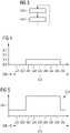
- FIG. 4illustrates aspects related to performing a discrete-time optimization for a planning interval 290 that includes multiple time intervals 291-299. The optimization is carried out at time 289, prospectively for the subsequent planning interval 290.
- the various states 200-203are associated with the power exchange 121 between the micro power grid 100 and the main power grid 120.
- the objective function and/or the boundary condition of the optimizationis adjusted. This adjustment takes place, for example, with regard to the preparation, activation and deactivation of the exchange of services.
- the state 200classifies those time intervals 291-292, 299 in which a power exchange 121 with the main power grid 120 is excluded. This means that the power exchange 121 is suppressed here, for example.
- This exclusionmay be based on a priori knowledge. For example, the exclusion could be contractually specified between a microgrid 101 operator and a mains 120 operator. This means that in the corresponding time intervals 291-292, 299 with the state 200 it need not be expected that an energy exchange will take place.
- State 201can be referred to as ( i ) standby for power exchange.
- the state 201can denote a situation in which, based on a priori knowledge, a power exchange 121 with the main power grid 120 is possible in principle, but does not necessarily have to be activated.
- State 202designates such time intervals (in 4 none of the time intervals 291-299 is classified in the state 202) in which the activation of the power exchange 121 was specifically requested, for example by a Main power grid operator node 120.
- state 202may be referred to as: ( ii ) Power exchange requested.
- state 203designates such time intervals (in the example of 4 none of the time intervals 291-299 are classified in state 203) in which the power exchange 121 is activated, ie energy is exchanged between the microgrid 100 and the main power grid 120.
- State 203can thus be denoted as: ( iii ) active power exchange.
- a reserve conceptis implemented.
- thisis achieved in that the boundary condition of the time-discrete optimization in the time intervals 293-298 with state 201 provides for the build-up or provision of a power reserve.
- Appropriate techniquesare related to figure 5 described.
- figure 5illustrates aspects related to the discrete-time optimization constraint 250 . Specifically correlated figure 5 With Fig. 4.
- Fig. 5illustrates the choice of the boundary condition 250, so that a power reserve 251 in the time intervals 293-298 with the state 201 (compare 3 ) is defined.
- figure 5illustrates in particular the size of the power reserve 251 as a function of time or as a function of the time intervals 291-299.
- the boundary condition 250 of the time-discrete optimizationis selected in such a way that the power reserve 251 during the time intervals 293-298 with the state 201 assumes a greater value than the power reserve 251 in the time intervals 291, 292, 299 with the state 200.
- the power reserve 251can be both positively defined or negatively defined. This means that as part of the operational planning of the microgrid 100, energy sources and/or energy consumers can be controlled to provide a positive power reserve or a negative power reserve.
- 6illustrates aspects related to discrete-time optimization. Especially illustrated 6 Aspects related to states 200-203. 6 is particular with figs 4 and 5 associated. 6 corresponds to performing the discrete-time optimization again in response to receiving a control signal 310, for example from a control node of the main power grid 120. The optimization is performed again at a later point in time 288.
- the control signal 310is indicative of the requested power exchange 121. This means that the power exchange 121 should be specifically activated. This requires an adjustment of the operational planning of the micro power grid 100, which is why carrying out the optimization again as a function of the control signals 310 is triggered.
- the time intervals 294, 295are in particular reclassified from the state 201 (cf 4 ) to state 202.
- State 202corresponds to ( ii ) power exchange requested, as already described above.
- the state 203corresponds to ( iii ) active power exchange, ie here an actual exchange of energy takes place between the microgrid 100 and the main power grid 120.
- the reclassified time intervals 294-297are in 6 highlighted by the hatching.
- This reclassificationcan mean that the objective function and/or the constraint of the optimization is changed in the corresponding time intervals 294-297.
- Thisis for example in connection with the 7 shown. 7 illustrates aspects related to the discrete-time optimization constraint 250 .
- a power reserve 251is maintained in the one or more nodes 101-106 of the micro-grid 100. correlated 7 With 6 .
- the boundary condition 250implements a further increase in the power reserves 251 during the time intervals 294, 295 with state 202 (a time period 240 for state 202 can be specified accordingly), so that subsequently in the time intervals 296, 297 with state 203 Power exchange 121 these power reserves 251 can reduce.
- time intervals 294-295 with state 202follow time intervals 292-293 with state 201; and the time intervals 296-297 with state 203 in turn follow the time intervals 294-295 with state 202.
- FIG. 8illustrates aspects related to discrete-time optimization. Especially illustrated 8 different states 200-204 into which the different time intervals 291-299 can be classified.
- the examplecorresponds to the 8 basically the example of 6 .
- the boundary condition 250can be selected such that the power reserve 251 is restored in the corresponding time interval 298 before the power exchange 121 is activated again (a renewed activation of the power exchange 121 is in 8 not shown).
- a corresponding period of time 241 of the time intervals 298 for restoring the power reserve 251are provided subsequent to the time intervals 296-297 with state 203 is predetermined, for example, independence from agreements between the operators of the micro power grid 100 and the main power grid 120.
- an excessive reduction in the power reserve 251can be avoided.
- Another strategy for avoiding an excessive reduction in the power reserve 251can also be achieved by taking into account a positive and/or negative tolerance 260 in connection with the power exchange 121 (cf 7 where the corresponding tolerances in the time intervals 296, 297 in connection with the reduction of the power reserve 251 are illustrated).
- These tolerances 260can relate to a specified value for the power exchange 121, for example.
- the power exchange 121 between the micro-power grid 100 and the main power grid 120can be taken into account by taking into account various states 200-204.
- the objective function and/or the boundary condition of the optimizationcan be adjusted accordingly.
- An exemplary specific implementation of such an adaptation of the boundary condition of the optimizationis described below, with the optimization being carried out as an integer linear optimization.
- a linear inequalityis first described in order to model the power exchange 121 . Then it will be shown that this inequality can be integrated into a corresponding operational planning of a microgrid 100, whereby in particular it can be taken into account that it is unknown a priori to which specific one Time a control signal 310 the power exchange 121 is specifically requested.
- inequalitiescan be used in an integer nonlinear optimization model for controlling a microgrid 100 with a connection 110 to a main power grid 120 .
- corresponding sales or operating parameters that can be achieved by using the service exchange 121can be taken into account in the objective function of the optimization.
- the target functioncan distinguish, for example, whether there is a specific activation of the power exchange 121 by a corresponding control signal 310 or time intervals 296, 297 with state 203, or the basic possibility of power exchange 121 in a standby state 201.
- the Target functionsthat relate to the power exchange 121, it would also be possible to take additional or other variables into account.
- the inequalities (1)-(7) of the boundary conditions of the optimization in the state 203can therefore model the control of the microgrid 100 when the power exchange 121 is specifically activated.
- These constraintscan be incorporated into other optimizations, for example techniques such as those described in " Optimal Operational Planning for PV Wind Diesel Battery Microgrid, GG Moshi, C Bovo, and A Berizzi, IEEE Eindhoven PowerTech, 2015 " are described.
- the planning device of the microgrid 100Only when the operator of the main power grid 120 sends the control signal 310 to request the activation of the power exchange 121 can the planning device of the microgrid 100 obtain final certainty that power for the power exchange 121 must be made available or taken up (cf 6 , where control signal 310 is received in connection with performing optimization again at time 288). In typical contracts for the control power reserve, it can then be specified how quickly the micro-power grid 100 must be ready for the activation of the power exchange 121, ie how quickly a participant must be ready to actually deliver or receive power to the main power grid 120 after receiving the control signal 310.
- a corresponding predetermined period of time 240(cf 6 ) can be taken into account as a specified time duration for the time intervals 294, 295 in the state 202 as part of the boundary condition.
- the information about the actual activation of the power exchange 121can then be made available in dependence on the receipt of the control signal 310 and a re-optimization can be triggered taking into account the requested power for the power exchange 121 at the connection 110 of the main power grid 120 (cf. 6 , optimization at time 288). This means that a new optimization can be carried out depending on the receipt of the control signal 310, in which case specific time intervals 294-297 can be reclassified from state 200 to state 202 and 203 or also to state 204 (cf 6 ) .
- a reserve conceptcan be implemented.
- the reserve conceptcan be used to ensure that the microgrid 100 builds up a power reserve 251 in time intervals 293-298 with the standby state 201 (ie basic offering of the power exchange 121) (cf. figure 5 ). A preparation for the actual activation of the power exchange 121 can thereby be achieved.
- Such a power reserve 251 for the time intervals 293-298 in the state 201can in particular be integrated into existing power reserve concepts of conventional optimizations.
- components that provide energysuch as a battery or a running diesel generator, can make a positive contribution to the power reserve 251; while power delivered to consumers, for example, may require some amount of negative power headroom 251 .
- a certain amount of energy for the power exchange 121can also be taken into account. In this way it can be ensured that the microgrid 100 can react if the power exchange is specifically activated by means of the control signal 310 .
- the boundary condition used in the optimizationcan have the following form, for example , where OR req ( K ) or OR del ( K ) is the required or made available power reserve of a node 101-106K describe. How this is designed differs depending on the type of component: ⁇ node K , the OR deliver OR del K t n ⁇ ⁇ node K , the OR to need OR req K t n ⁇ 0
- the main power gridcan be stabilized. Performance peaks can be cushioned. Cooperation between the operational planning of the main power grid and the microgrid is possible.
- the techniques described hereinare complementary to microgrid operational planning programs, which rely in particular on integer linear optimizations.
- the techniques described hereinare well suited for complex but run-time critical applications with run-time scheduling optimization.
- the integration of the exchange of servicescan be possible in a particularly simple manner and without increased complexity by taking into account the expansion of conventional boundary conditions and/or target functions.
- the techniques described hereincan be used to model different power exchange approaches with the same constraints and/or objective function. This is guaranteed by a general parameterization as described above. In particular, this is achieved by taking into account different states, depending on which the target function and/or one or more boundary conditions can be adjusted. In particular, the concept of a power reserve can be mapped in this way. In addition, by taking the states into account, there is the possibility of using certain tolerances and thus allowing deviations in the provision of the power exchange.
- Integration into an existing power reserve conceptmay be possible, i. H. it would be possible for the boundary condition to consider the power exchange as positive power reserves for a node of the microgrid that describes the connection of the microgrid to the main power grid.
- informationcan be made available to a control device in a differentiated manner depending on the respective status.
Landscapes
- Engineering & Computer Science (AREA)
- General Physics & Mathematics (AREA)
- Business, Economics & Management (AREA)
- Theoretical Computer Science (AREA)
- Physics & Mathematics (AREA)
- Strategic Management (AREA)
- Human Resources & Organizations (AREA)
- Economics (AREA)
- Power Engineering (AREA)
- Development Economics (AREA)
- Health & Medical Sciences (AREA)
- General Engineering & Computer Science (AREA)
- Software Systems (AREA)
- Medical Informatics (AREA)
- Evolutionary Computation (AREA)
- Computer Vision & Pattern Recognition (AREA)
- Game Theory and Decision Science (AREA)
- Artificial Intelligence (AREA)
- Automation & Control Theory (AREA)
- Entrepreneurship & Innovation (AREA)
- Marketing (AREA)
- Operations Research (AREA)
- Quality & Reliability (AREA)
- Tourism & Hospitality (AREA)
- General Business, Economics & Management (AREA)
- Supply And Distribution Of Alternating Current (AREA)
- Control Of Eletrric Generators (AREA)
- Feedback Control In General (AREA)
Description
Translated fromGermanVerschiedene Beispiele der Erfindung betreffen im Allgemeinen die prädiktive Betriebsplanung in einem Mikronetz, wobei das Mikronetz einen Anschluss an ein Hauptstromnetz aufweist. Verschiedene Beispiele der Erfindung betreffen insbesondere die prädiktive Betriebsplanung, so dass diese einen Leistungsaustausch zwischen dem Mikronetz und einem Hauptstromnetz vorsieht.Various examples of the invention relate generally to predictive operational scheduling in a microgrid, where the microgrid has a connection to a mains power grid. Various examples of the invention relate in particular to predictive operational planning such that it provides power exchange between the micro-grid and a main power grid.
Mikronetze beschreiben eine lokalisierte Gruppe von Stromquellen und Stromverbrauchern. Mikronetze können konventionelle Stromquellen und regenerative Stromquellen umfassen. Das Mikronetz weist im Vergleich zu Hauptstromnetzen typischerweise eine limitierte Ausdehnung auf. Typische Verbraucher in einem Mikronetz sind zum Beispiel: Wohnhäuser; Autobatterien; Industrieanlagen; Maschinen; etc. Typische Stromquellen sind zum Beispiel: Photovoltaikanlagen; Dieselgeneratoren; Windkraftanlagen; etc. Ein Mikronetz kann zum Beispiel in einem Wohnblock, einer Wohngemeinschaft, einer Militärbasis, einer Forschungsstation oder ähnlichem eingesetzt werden. Mikronetze können beispielsweise zur autarken Energieversorgung von Industrieanlagen oder Inseln eingesetzt werden.Microgrids describe a localized group of power sources and power consumers. Microgrids can include conventional power sources and renewable power sources. The microgrid typically has a limited extent compared to main power grids. Typical consumers in a microgrid are, for example: residential buildings; car batteries; industrial plants; Machinery; etc. Typical power sources are for example: Photovoltaic systems; diesel generators; wind turbines; etc. A micro-grid can be deployed, for example, in a block of flats, a shared apartment, a military base, a research station, or the like. Microgrids can be used, for example, for the self-sufficient energy supply of industrial plants or islands.
Ein Mikronetz kann über einen Anschluss mit einem Hauptstromnetz verbunden sein. Durch das Vorsehen eines Anschlusses des Mikronetzes zum Hauptstromnetz kann ein besonders flexibler Betrieb des Mikronetzes ermöglicht werden. Außerdem kann ein Schutz vor Ausfall durch Zurückgreifen auf die Stromversorgung durch das Hauptstromnetz ermöglicht werden. Der Betrieb des Hauptstromnetzes kann stabilisiert und unterstützt werden.A microgrid may be connected to a mains power grid via a port. By providing a connection of the micro-grid to the main power grid, a particularly flexible operation of the micro-grid can be made possible. In addition, protection against failure by resorting to the power supply from the main power grid can be enabled. The operation of the main power grid can be stabilized and supported.
Ferner ist es bekannt, dass durch die Teilnahme an Regelleistungsmärkten die operativen Kosten für Mikronetze durch die erwirtschaftete Vergütung gesenkt werden können. Diese Regelleistungsmärkte dienen der Stabilisierung des Hauptstromnetzes. Sogenannte Leistungsaustausch-Dienste (engl. balancing service oder ancillary services oder frequency-response service oder reserve service) können verwendet werden, um einen Leistungsaustausch zwischen dem Mikronetz und dem Hauptstromnetz durchzuführen. Dabei kann sich zum Beispiel der Betreiber des Mikronetzes gegenüber dem Betreiber des Hauptstromnetzes verpflichten, in vorher festgelegten Zeiträumen eine gewisse Leistung zur Verfügung zu stellen und/oder eine gewisse Leistung aufzunehmen. Dadurch können im Hauptstromnetz Spitzen im Verbrauch bzw. in der Erzeugung abgefedert werden.Furthermore, it is known that the operating costs for micro-grids can be reduced through the generated remuneration by participating in balancing power markets. These balancing power markets serve to stabilize the main power grid. So-called power exchange services (balancing service or ancillary services or frequency-response service or reserve service) can be used to perform a power exchange between the microgrid and the main power grid. In this case, for example, the operator of the microgrid can make a commitment to the operator of the main power grid to make a certain amount of power available and/or to consume a certain amount of power in predetermined periods of time. As a result, peaks in consumption or generation can be cushioned in the main power grid.
Der Betrieb des Hauptstromnetzes kann unterstützt werden. Relevanter Stand der Technik ist dazu aus der
Es besteht ein Bedarf, Techniken des Leistungsaustausches zwischen dem Mikronetz und dem Hauptstromnetz in eine prädiktive Betriebsplanung des Mikronetzes zu integrieren.There is a need to integrate power exchange techniques between the microgrid and the main power grid into a predictive operational planning of the microgrid.
Diese Aufgabe wird gelöst von den Merkmalen der unabhängigen Patentansprüche. Die Merkmale der abhängigen Patentansprüche definieren Ausführungsformen.This object is solved by the features of the independent patent claims. The features of the dependent claims define embodiments.
Ein Verfahren zur prädiktiven Betriebsplanung in einem Mikronetz wird beschrieben. Dabei umfasst das Mikronetz einen Anschluss an ein Hauptstromnetz. Das Verfahren umfasst das Durchführen einer zeitdiskreten Optimierung einer Zielfunktion für ein Planungsintervall. Dabei umfasst das Planungsintervall mehrere Zeitintervalle. Die Optimierung wird auch unter Berücksichtigung einer Randbedingung durchgeführt. Die Zielfunktion und/oder die Randbedingung wird in Abhängigkeit von mehreren Zuständen bestimmt. Die Zeitintervalle sind dabei gemäß der mehreren Zustände klassifiziert. Die Zustände sind aus folgender Gruppe ausgewählt: (i) Standby für Leistungsaustausch; (ii) Leistungsaustausch angefragt; sowie (iii) aktiver Leistungsaustausch. Außerdem umfasst das Verfahren das Durchführen der Betriebsplanung basierend auf einem Ergebnis der Optimierung. Dabei sieht die Betriebsplanung einen Leistungsaustausch zwischen dem Mikronetz und dem Hauptstromnetz über den Anschluss vor.A method for predictive operational planning in a microgrid is described. The microgrid includes a connection to a main power grid. The method includes performing a discrete-time optimization of an objective function for a planning interval. The planning interval includes several time intervals. The optimization is also carried out taking into account a boundary condition. The objective function and/or the boundary condition becomes dependent determined by several states. The time intervals are there classified according to the multiple states. The states are selected from the following group: (i) standby for power exchange; (ii) exchange of services requested; and (iii ) active exchange of services. In addition, the method includes performing the operational planning based on a result of the optimization. The operational planning provides for a power exchange between the microgrid and the main power grid via the connection.
Die Gruppe, aus der die Zustände ausgewählt sind, kann weiterhin umfassen: (iv) Regeneration sowie (v) ausgeschaltet.The group from which the states are selected may further include: (iv ) regeneration and (v ) off.
Ein Gerät ist zur prädiktiven Betriebsplanung in einem Mikronetz mit Anschluss an ein Hauptstromnetz eingerichtet. Das Gerät ist eingerichtet, um die folgenden Schritte auszuführen: Durchführen einer zeitdiskreten Optimierung einer Zielfunktion für ein Planungsintervall umfassend mehrere Zeitintervalle und unter Berücksichtigung einer Randbedingung, wobei die Zielfunktion und/oder die Randbedingung in Abhängigkeit von mehreren Zuständen, gemäß denen die Zeitintervalle klassifiziert sind, bestimmt ist, wobei die Zustände ausgewählt sind aus folgender Gruppe: (i) Standby für Leistungsaustausch, (ii) Leistungsaustausch angefragt und (iii) aktiver Leistungsaustausch; sowie Durchführen der Betriebsplanung basierend auf einem Ergebnis der Optimierung, wobei die Betriebsplanung einen Leistungsaustausch zwischen den Mikronetz und dem Hauptstromnetz über den Anschluss vorsieht.An apparatus is set up for predictive operational planning in a microgrid connected to a main power grid. The device is set up to carry out the following steps: performing a time-discrete optimization of a target function for a planning interval comprising a number of time intervals and taking into account a boundary condition, the target function and/or the boundary condition depending on a number of states according to which the time intervals are classified, is determined, wherein the states are selected from the following group: (i ) standby for power exchange, (ii ) power exchange requested and (iii ) active power exchange; and performing the operational planning based on a result of the optimization, the operational planning providing for power exchange between the microgrid and the main power grid via the port.
Ein Computerprogramm oder ein Computerprogramm-Produkt oder ein computerlesbares Speichermedium umfasst Programmcode. Der Programmcode kann von einem Prozessor geladen werden und ausgeführt werden. Wenn der Programmcode vom Prozessor ausgeführt wird, bewirkt dies, dass der Prozessor ein Verfahren zur prädiktiven Betriebsplanung in einem Mikronetz mit Anschluss an ein Hauptstromnetz ausführt. Dabei umfasst das Verfahren das Durchführen einer zeitdiskreten Optimierung einer Zielfunktion für ein Planungsintervall. Das Planungsintervall umfasst mehrere Zeitintervalle. Das Durchführen der zeitdiskreten Optimierung erfolgt dabei unter Berücksichtigung einer Randbedingung. Die Zielfunktion und/oder die Randbedingung werden in Abhängigkeit von mehreren Zuständen bestimmt. Dabei sind die Zeitintervalle gemäß mehreren Zuständen klassifiziert. Die Zustände sind dabei ausgewählt aus folgender Gruppe: (i) Standby für Leistungsaustausch, (ii) Leistungsaustausch angefragt, sowie (iii) aktiver Leistungsaustausch. Außerdem umfasst das Verfahren auf das Durchführen der Betriebsplanung basierend auf dem Ergebnis der Optimierung. Die Betriebsplanung sieht dabei einen Leistungsaustausch zwischen dem Mikronetz und dem Hauptstromnetz über den Anschluss vor.A computer program or a computer program product or a computer-readable storage medium includes program code. The program code can be loaded and executed by a processor. When the program code is executed by the processor, it causes the processor to execute a predictive operational planning method in a microgrid connected to a mains power grid. In this case, the method includes carrying out a time-discrete optimization of a target function for a planning interval. The planning interval includes several time intervals. Carrying out the time-discrete optimization is carried out taking into account a boundary condition. The objective function and/or the boundary condition are determined depending on several states. The time intervals are classified according to several states. The states are selected from the following group: (i ) standby for power exchange, (ii ) power exchange requested, and (iii ) active power exchange. In addition, the method includes performing the operational planning based on the result of the optimization. The operational planning envisages a power exchange between the microgrid and the main power grid via the connection.
- \Fig. 1\Fig. 1
- illustriert schematisch ein Mikrostromnetz und ein Hauptstromnetz, die gemäß verschiedenen Beispielen über einen Anschluss verbunden sind.FIG. 12 schematically illustrates a micro-power grid and a main power grid connected via a port, according to various examples.
- Fig. 22
- illustriert schematisch ein Gerät mit einem Prozessor, wobei das Gerät gemäß verschiedener Beispiele zur Betriebsplanung für das Mikrostromnetz basierend auf einem Ergebnis einer Optimierung eingerichtet ist.12 schematically illustrates a device with a processor, the device being configured according to various examples for operational planning for the micro-electrical grid based on a result of an optimization.
- Fig. 33
- ist ein Flussdiagram eines beispielhaften Verfahrens.Figure 12 is a flow chart of an example method.
- Fig. 44
- illustriert schematisch unterschiedliche Zustände von Zeitintervallen, wobei je nach Zustand eine Zielfunktion und/oder eine Randbedingung der Optimierung gemäß verschiedener Beispiele angepasst wird.schematically illustrates different states of time intervals, with a target function and/or a boundary condition of the optimization depending on the state is adjusted according to various examples.
- Fig. 5figure 5
- illustriert schematisch eine Randbedingung, die eine Leistungsreserve spezifiziert, gemäß verschiedener Beispiele.FIG. 12 schematically illustrates a constraint specifying a power margin according to various examples.
- Fig. 66
- illustriert schematisch unterschiedliche Zustände von Zeitintervallen, wobei je nach Zustand eine Zielfunktion und/oder eine Randbedingung der Optimierung gemäß verschiedener Beispiele angepasst wird.schematically illustrates different states of time intervals, with a target function and/or a boundary condition of the optimization being adapted according to various examples depending on the state.
- Fig. 77
- illustriert schematisch eine Randbedingung, die eine Leistungsreserve spezifiziert, gemäß verschiedener Beispiele.FIG. 12 schematically illustrates a constraint specifying a power margin according to various examples.
- Fig. 88
- illustriert schematisch unterschiedliche Zustände von Zeitintervallen, wobei je nach Zustand eine Zielfunktion und/oder eine Randbedingung der Optimierung gemäß verschiedener Beispiele angepasst wird.schematically illustrates different states of time intervals, with a target function and/or a boundary condition of the optimization being adapted according to various examples depending on the state.
Die oben beschriebenen Eigenschaften, Merkmale und Vorteile dieser Erfindung sowie die Art und Weise, wie diese erreicht werden, werden klarer und deutlicher verständlich im Zusammenhang mit der folgenden Beschreibung der Ausführungsbeispiele, die im Zusammenhang mit den Zeichnungen näher erläutert werden.The properties, features and advantages of this invention described above, and the manner in which they are achieved, will become clearer and more clearly understood in connection with the following description of the exemplary embodiments, which are explained in more detail in connection with the drawings.
Nachfolgend wird die vorliegende Erfindung anhand bevorzugter Ausführungsformen unter Bezugnahme auf die Zeichnungen näher erläutert. In den Figuren bezeichnen gleiche Bezugszeichen gleiche oder ähnliche Elemente. Die Figuren sind schematische Repräsentationen verschiedener Ausführungsformen der Erfindung. In den Figuren dargestellte Elemente sind nicht notwendigerweise maßstabsgetreu dargestellt. Vielmehr sind die verschiedenen in den Figuren dargestellten Elemente derart wiedergegeben, dass ihre Funktion und genereller Zweck dem Fachmann verständlich wird. In den Figuren dargestellte Verbindungen und Kopplungen zwischen funktionellen Einheiten und Elementen können auch als indirekte Verbindung oder Kopplung implementiert werden. Eine Verbindung oder Kopplung kann drahtgebunden oder drahtlos implementiert sein. Funktionale Einheiten können als Hardware, Software oder eine Kombination aus Hardware und Software implementiert werden.The present invention is explained in more detail below on the basis of preferred embodiments with reference to the drawings. In the figures, the same reference symbols designate the same or similar elements. The figures are schematic representations of various embodiments of the invention. Elements shown in the figures are not essential shown to scale. Rather, the various elements shown in the figures are presented in such a way that their function and general purpose can be understood by those skilled in the art. Connections and couplings between functional units and elements shown in the figures can also be implemented as an indirect connection or coupling. A connection or coupling can be implemented wired or wireless. Functional units can be implemented in hardware, software, or a combination of hardware and software.
Nachfolgend werden Techniken im Zusammenhang mit der prädiktiven Betriebsplanung in einem Mikronetz beschrieben. Das bedeutet, dass ein oder mehrere Knoten eines Mikronetzes gemäß einem entsprechenden Betriebsplan gesteuert werden können. Zum Beispiel könnte der Verbrauch, die abgegebene Leistung, die Betriebsfrequenz usw. entsprechend gesteuert werden. Der Betriebsplan könnte alternativ oder zusätzlich auch eine Architektur des Mikronetzes bestimmen, d.h. z.B. eine Verschaltung von Knoten etc. Der Betriebsplan kann ein oder mehrere solche Parameter zeitaufgelöst für ein Planungsintervall festlegen.Techniques related to predictive operational planning in a microgrid are described below. This means that one or more nodes of a microgrid can be controlled according to a corresponding operational plan. For example, consumption, power output, operating frequency, etc. could be controlled accordingly. Alternatively or additionally, the operating plan could also determine an architecture of the microgrid, i.e., for example, an interconnection of nodes, etc. The operating plan can specify one or more such parameters in a time-resolved manner for a planning interval.
Das Mikronetz kann eine Vielzahl von Stromverbrauchern und Stromquellen aufweisen. Beispielsweise könnte das Mikronetz ein oder mehrere der folgenden Knoten aufweisen: Photovoltaikanlage; Batterie-Energiespeichers; Dieselgenerator; Windkraftanlage; elektrisches Gerät wie Maschinen, Heizungen, etc. Das Mikronetz kann insbesondere einen Anschluss zu einem Hauptstromnetz aufweisen. Der Betreiber des Mikronetzes kann verschieden sein von dem Betreiber des Hauptstromnetzes. Für das Betreiben des Mikronetzes und das Betreiben des Hauptstromnetzes können unterschiedliche Planungsinstanzen verwendet werden. Es können unterschiedliche Betriebspläne verwendet werden.The microgrid can have a variety of power consumers and power sources. For example, the microgrid could have one or more of the following nodes: photovoltaic array; battery energy storage; Diesel generator; wind turbine; electrical device such as machines, heaters, etc. The micro-grid can in particular have a connection to a main power grid. The operator of the microgrid can be different from the operator of the main power grid. Different planning instances can be used for operating the microgrid and for operating the main power grid. Different operating plans can be used.
In verschiedenen hierin beschriebenen Techniken kann es möglich sein, eine Betriebsplanung für das Mikronetz basierend auf einem Ergebnis einer Optimierung durchzuführen. Dabei kann die Betriebsplanung einen Leistungsaustausch zwischen dem Mikronetz und dem Hauptstromnetz vorsehen.In various techniques described herein, it may be possible to plan operations for the microgrid based to perform on a result of an optimization. The operational planning can provide for a power exchange between the microgrid and the main power grid.
Zum Beispiel kann das Durchführen der Betriebsplanung umfassen: Senden und/oder Empfangen von Steuersignalen an und/oder von ein oder mehreren Knoten des Mikronetzes, wobei die Steuersignale den elektrischen Betrieb der Knoten charakterisieren. Zum Beispiel könnte mittels der Steuersignale eine Leistungsaufnahme und/oder eine Leistungsabgabe der verschiedenen Knoten gesteuert werden.For example, performing operational planning may include: sending and/or receiving control signals to and/or from one or more nodes of the microgrid, the control signals characterizing the electrical operation of the nodes. For example, a power consumption and/or a power output of the various nodes could be controlled by means of the control signals.
In verschiedenen Beispielen wäre es möglich, dass die Optimierung zeitdiskret durchgeführt wird, d. h. unter Berücksichtigung von einer Anzahl von diskreten Zeitintervallen. Typische Zeitintervalle, die im Rahmen der Optimierung berücksichtigt werden können, können beispielsweise eine Dauer im Bereich von einigen 10 Sekunden bis Minuten aufweisen.In various examples, it would be possible for the optimization to be performed in a time-discrete manner, i. H. considering a number of discrete time intervals. Typical time intervals that can be taken into account as part of the optimization can, for example, have a duration in the range from a few tens of seconds to minutes.
Es ist zum Beispiel möglich, dass die Optimierung prospektiv für das Planungsintervall, beginnend in der Ist-Zeit, durchgeführt wird. Insbesondere wäre es möglich, dass die Optimierung rollierend durchgeführt wird. Dies bedeutet, dass ein Schiebefensteransatz (engl. sliding window) verwendet werden kann, bei welchem die Optimierung in mehreren Iterationen nacheinander wiederholt durchgeführt wird, wobei das jeweilige Planungsintervall zum jeweiligen Ist-Zeitpunkt startet und somit von Iteration zu Iteration in der Zeit nach vorne verschoben wird. Das Planungsintervall kann zum Beispiel eine Anzahl der Zeitintervalle umfassen, beispielsweise 1.000 oder 10.000 oder mehr Zeitintervalle. Typischerweise kann das Planungsintervall eine Länge im Bereich von Stunden oder Tagen aufweisen.It is possible, for example, that the optimization is carried out prospectively for the planning interval, starting in the actual time. In particular, it would be possible for the optimization to be carried out on a rolling basis. This means that a sliding window approach can be used, in which the optimization is carried out repeatedly in several iterations one after the other, with the respective planning interval starting at the respective actual time and thus being shifted forward in time from iteration to iteration becomes. The planning interval can, for example, comprise a number of the time intervals, for example 1,000 or 10,000 or more time intervals. Typically, the scheduling interval may range in length from hours to days.
In manchen Beispielen könnte zum Beispiel eine ganzzahlige lineare Optimierung (engl. Mixed integer linear programming optimization, MILP optimization) durchgeführt werden. In anderen Beispielen könnte aber auch eine ganzzahlige quadratische Optimierung durchgeführt werden. Durch das Verwenden einer ganzzahligen Optimierung kann erreicht werden, dass die Optimierung besonders ressourceneffizient und zügig durchgeführt werden kann. Außerdem können zum Beispiel binäre Zustandsvariablen definiert werden, die zum Beispiel den Wert 1 oder den Wert 0 annehmen, je nachdem ob ein bestimmtes Kriterium erfüllt ist oder nicht erfüllt ist.For example, in some examples, mixed integer linear programming optimization (MILP optimization) could be performed. In other examples, however, it could also be an integer quadratic optimization to be carried out. By using an integer optimization, it can be achieved that the optimization can be carried out particularly resource-efficiently and quickly. In addition, for example, binary state variables can be defined which, for example, assume the value 1 or the value 0, depending on whether a specific criterion is met or not.
Durch das Verwenden einer linearen Optimierung kann wiederum eine besonders recheneffiziente und wenig ressourcenintensive Implementierung der Optimierung verwendet werden. Außerdem kann es möglich sein, das Auffinden eines globalen Maximums oder eines globalen Minimums einer Zielfunktion der Optimierung - unter Berücksichtigung von ein oder mehreren Randbedingungen - zu garantieren. Entsprechende Lösungsansätze für ganzzahlige lineare Optimierungen sind im Grundsatz dem Fachmann bekannt und können hier verwendet werden. Ein entsprechendes Beispiel ist zum Beispiel beschrieben in:"
In den verschiedenen Beispielen wird im Zusammenhang mit dem Durchführen der Optimierung ein Leistungsaustausch zwischen dem Mikronetz und dem Hauptstromnetz über einen entsprechenden Anschluss berücksichtigt. Der Leistungsaustausch kann bedeuten, dass in ein oder mehreren entsprechenden Zeitintervallen elektrische Energie vom Hauptstromnetz an das Mikronetz transferiert wird (Leistungsaufnahme) und/oder in ein oder mehreren weiteren Zeitintervallen elektrische Leistung vom Mikronetz an das Hauptstromnetz transferiert wird (Leistungsabgabe). Durch die Berücksichtigung eines Leistungsaustausches kann der Betrieb des Hauptstromnetzes und der Betrieb des Mikronetzes stabilisiert werden. Insbesondere können Verbrauchsspitzen oder Produktionsspitzen im Mikronetz und/oder im Hauptstromnetz abgefedert werden. Dadurch kann insbesondere die Fehlfunktion von einzelnen Knoten in den Netzen vermieden werden.In the various examples, in connection with performing the optimization, a power exchange between the microgrid and the main power grid via a corresponding connection is considered. The exchange of power can mean that in one or more corresponding time intervals electrical energy is transferred from the main power grid to the micro-grid (power consumption) and/or in one or more further time intervals electrical power is transferred from the micro-grid to the main power grid (power output). By considering a power exchange, the operation of the main power grid and the operation of the microgrid can be stabilized. In particular, consumption peaks or production peaks in the microgrid and/or in the main power grid can be cushioned. In this way, in particular, the malfunction of individual nodes in the networks can be avoided.
Verschiedene Beispiele beruhen auf der Erkenntnis, dass es im Zusammenhang mit dem Leistungsaustausch häufig eine Vorwarnzeit (engl. response time) gibt. Die Vorwarnzeit bezeichnet dabei einen Zeitraum zwischen dem Empfangen eines Steuersignals, welches indikativ für einen angefragten Leistungsaustausch ist, und dem tatsächlichen Aktivieren des Leistungsaustausches mit Energieübertragung. Weitere Beispiele beruhen auf der Erkenntnis, dass es nach dem Durchführen des Energieaustausches zwischen dem Mikronetz und dem Hauptstromnetz - das heißt nach Beendigung des Leistungsaustausches - eine Regenerationszeit (engl. recovery time) geben kann, welche genutzt werden kann, um das System wieder in einen gewünschten Zustand (stabilisierter Zustand) zu bringen. Vor dem Abschluss der Regenerationszeit kann das erneute Durchführen eines aktiven Leistungsaustausches vermieden werden.Various examples are based on the knowledge that there is often a warning time (response time) in connection with the exchange of services. The advance warning time designates a period of time between the receipt of a control signal, which is indicative of a requested power exchange, and the actual activation of the power exchange with energy transmission. Further examples are based on the realization that after the energy exchange has been carried out between the microgrid and the main power grid - i.e. after the end of the power exchange - there can be a recovery time, which can be used to bring the system back into a desired state (stabilized state). Before the end of the regeneration time, performing an active power exchange again can be avoided.
Im Zusammenhang mit den verschiedenen hierin beschriebenen Techniken kann es möglich sein, die Betriebsplanung prädiktiv derart durchzuführen, dass der Leistungsaustausch - z.B. zusätzlich neben anderen Randbedingungen des Betriebs der verschiedenen Knoten des Mikronetzes - berücksichtigt wird. Insbesondere kann es mittels der hierin beschriebenen Techniken möglich sein, den Leistungsaustausch in herkömmliche Algorithmen zur prädiktiven Betriebsplanung unter Verwendung einer Optimierung zu integrieren. Die hierin beschriebenen Techniken ermöglichen es, unterschiedliche Typen von Leistungsaustausch mit einem einheitlichen Satz von Parametern im Zusammenhang mit der Optimierung zu konfigurieren. Insbesondere sind die hierin beschriebenen Techniken nicht auf einzelne Energiespeichereinheiten beschränkt, wie zum Beispiel nur auf Batterien, vergleiche"
Gemäß verschiedener Beispiele wird dies durch die Klassifizierung der Zeitintervalle der zeitdiskreten Optimierung in jeweils einer von mehreren Systemmodi bzw. Zuständen erreicht. Insbesondere können die Zustände ausgewählt sein aus folgender Gruppe: (i) Standby für Leistungsaustausch und (ii) Leistungsaustausch angefragt und (iii) aktiver Leistungsaustausch. In verschiedenen Beispielen kann also jeweils die Zielfunktion und/oder die Randbedingung der Optimierung in Abhängigkeit von den jeweiligen klassifizierten Zuständen der entsprechenden Zeitintervalle angepasst werden. Dies bedeutet zum Beispiel, dass ein erstes Zeitintervall mit einem ersten Zustand (etwa (i) Standby für Leistungsaustausch) eine andere Randbedingung und/oder Zielfunktion aufweist, als ein zweites Intervall (beispielsweise mit Zustand (ii) Leistungsaustausch angefragt).According to various examples, this is done by classifying the time intervals of discrete-time optimization in one of several system modes or states is reached. In particular, the states can be selected from the following group: (i ) standby for power exchange and (ii ) power exchange requested and (iii ) active power exchange. In various examples, the target function and/or the boundary condition of the optimization can be adapted depending on the respective classified states of the corresponding time intervals. This means, for example, that a first time interval with a first state (e.g. (i ) standby for power exchange) has a different boundary condition and/or target function than a second interval (e.g. with state (ii ) power exchange requested).
Zum Beispiel werde es in diesem Zusammenhang möglich, dass die Randbedingung in Zeitintervallen mit Zustand (i) Standby für Leistungsaustausch den Aufbau einer Leistungsreserve für ein oder mehrere Knoten des Mikronetzes definiert. Dadurch kann ein Reservekonzept implementiert werden, welches abgestimmt ist auf den Leistungsaustausch. Zum Beispiel könnte eine positive Reserve durch Aufbau der Leistungsreserve in ein oder mehreren Energiequellen als Knoten des Mikronetzes vorgesehen werden, d.h. es könnten zum Beispiel Batterien aufgeladen werden oder Dieselstromgeneratoren mit einer gewissen Latenzzeit angefahren werden. Alternativ oder zusätzlich wäre es aber auch möglich, eine negative Leistungsreserve vorzusehen, nämlich im Zusammenhang mit einer oder mehreren Energieverbrauchern des Mikronetzes. D. h. es wäre zum Beispiel möglich, dass der Energieverbrauch von bestimmten Lasten gesenkt wird, so dass der Energieverbrauch kurzfristig auf ein Maximum erhöht werden könnte, sofern im Zusammenhang mit dem Leistungsaustausch notwendig.In this context, for example, it is possible for the boundary condition to define the build-up of a power reserve for one or more nodes of the microgrid in time intervals with state (i ) standby for power exchange. As a result, a reserve concept can be implemented that is tailored to the power exchange. For example, a positive reserve could be provided by building up the power reserve in one or more energy sources as nodes of the microgrid, ie batteries could be charged or diesel power generators could be started up with a certain latency time. Alternatively or additionally, however, it would also be possible to provide a negative power reserve, namely in connection with one or more energy consumers of the microgrid. i.e. for example, it would be possible for the power consumption of certain loads to be reduced so that the power consumption could be increased to a maximum in the short term if necessary in connection with the power exchange.
In diesem Zusammenhang kann es beispielsweise auch möglich sein, mittels der Randbedingung eine gewisse Untererfüllung oder Übererfüllung des angefragten Leistungsaustausches zu berücksichtigen. Zum Beispiel kann dies dadurch implementiert werden, dass die Randbedingung der Optimierung in Zeitintervallen mit Zustand (iii) aktiver Leistungsaustausch einen vorgegebenen Wert für den Leistungsaustausch berücksichtigt, und zusätzlich auch eine positive Toleranz und/oder negative Toleranz für den vorgegebenen Wert berücksichtigt.In this context, it can also be possible, for example, to use the boundary condition to take into account a certain underfulfillment or overfulfilment of the requested exchange of services. For example, this can be implemented by making the optimization constraint in time intervals with state (iii ) active power exchange, a predetermined value for the power exchange is taken into account, and a positive tolerance and/or negative tolerance for the predetermined value is also taken into account.
Im Rahmen des Durchführens einer Betriebsplanung des Mikronetzes 100 kann der individuelle Betrieb der verschiedenen Knoten 101-106 gesteuert werden. Alternativ oder zusätzlich könnte aber auch die Architektur des Mikronetzes 100 konfiguriert werden.As part of carrying out an operational plan for the micro-network 100, the individual operation of the various nodes 101-106 can be controlled. Alternatively or additionally, however, the architecture of the micro-network 100 could also be configured.
Zum Beispiel ist ein mögliches Verfahren, welches vom Prozessor 501 durch laden des Programmcodes aus dem Speicher 502 ausgeführt werden kann, im Zusammenhang mit dem Flussdiagram in
Zunächst wird in Block 1001 eine zeitdiskrete Optimierung einer Zielfunktion für ein Planungsintervall durchgeführt. Insbesondere kann sich das Planungsintervall ausgehend von der Ist-Zeit in die Zukunft erstrecken. Dies bedeutet, dass eine prädiktiver Betriebsplanung im Block 1002 ermöglicht wird, weil bestimmte Steuerparameter der verschiedenen Knoten des Mikronetzes auf Grundlage eines Ergebnisses der Optimierung aus Block 1001 angesteuert werden können und so prädiktive vorhergesagt werden kann, wie sich der Betrieb des Mikronetzes über der Zeit verändert.First, in
In Block 1002 wird die Betriebsplanung durchgeführt. Dabei wird das Ergebnis der Optimierung aus Block 1001 berücksichtigt. Die Betriebsplanung kann z.B. das Bestimmen eines Betriebsplans umfassen.In
In verschiedenen Beispielen kann es möglich sein, dass die Optimierung und die Betriebsplanung in den Blöcken 1001 und 1002 rollierend durchgeführt wird, was in
Beim Durchführen der Optimierung in Block 1001 kann es insbesondere möglich sein, für verschiedene Zeitintervalle im Planungsintervall unterschiedliche Zustände zu berücksichtigen. Je nach Zustand des jeweiligen Zeitintervalls kann dann die Zielfunktion und/oder die Randbedingung der Optimierungen in Block 1001 angepasst werden. Durch das Berücksichtigen von solchen unterschiedlichen Zuständen kann es besonders effizient und einfach möglich sein, einen Leistungsaustausch zwischen dem Mikronetz 100 und dem Hauptstromnetz 120 zu berücksichtigen. Solche unterschiedlichen Zustände sind insbesondere im Zusammenhang mit der
Insbesondere illustriert
In dem Beispiel der
Im Beispiel der
Der Zustand 200 klassifiziert solche Zeitintervalle 291-292, 299 in denen ein Leistungsaustausch 121 mit dem Hauptstromnetz 120 ausgeschlossen ist. Das heißt, hier wird der Leistungsaustausch 121 zum Beispiel unterdrückt. Dieser Ausschluss kann auf a-priori-Wissen basieren. Zum Beispiel könnte der Ausschluss vertraglich zwischen einem Betreiber des Mikronetzes 101 und einem Betreiber des Hauptstromnetzes 120 festgelegt sein. Dies bedeutet, dass in den entsprechenden Zeitintervallen 291-292, 299 mit dem Zustand 200 nicht damit gerechnet werden muss, dass ein Energieaustausch stattfindet.In the example of
The
Der Zustand 201 kann dagegen als (i) Standby für Leistungsaustausch bezeichnet werden. Der Zustand 201 kann eine Situation bezeichnen, in der auf Grundlage von a-priori-Wissen ein Leistungsaustausch 121 mit dem Hauptstromnetz 120 grundsätzlich möglich ist, aber nicht notwendigerweise aktiviert werden muss.
Der Zustand 202 bezeichnet wiederum solche Zeitintervalle (in
Schließlich bezeichnet der Zustand 203 solche Zeitintervalle (in dem Beispiel der
In dem Beispiel der
Dies illustriert, dass es a priori unbekannt ist, ob der Leistungsaustausch 121 konkret angefragt wird oder nicht. Zum Zeitpunkt 298, zu welchem die Optimierung durchgeführt wird (d. h. kurz vor Beginn des Planungsintervalls 290), liegt keine konkrete Anfrage für das Aktivieren des Leistungsaustausches 121 vor. Es könnte aber sein, dass zu einem Zeitpunkt innerhalb des Planungsintervalls 290 eine entsprechende Anfrage empfangen wird, so dass kurzfristig eine Umklassifizierung von einzelnen der Zeitintervalle 293-298 durchgeführt wird.This illustrates that it is unknown a priori whether the
Um auf eine solche - im Vergleich zur Zeitdauer des Planungsintervalls 290 - kurzfristige Anfrage für das Aktivieren des Leistungsaustausches 121 reagieren zu können, wird ein Reservekonzept implementiert. Insbesondere wird dies dadurch erreicht, dass die Randbedingung der zeitdiskreten Optimierung in den Zeitintervallen 293-298 mit Zustand 201 den Aufbau bzw. das Vorhalten einer Leistungsreserve vorsieht. Entsprechende Techniken sind im Zusammenhang mit
Dabei kann im Beispiel der
Das Steuersignal 310 ist indikativ für den angefragten Leistungsaustausch 121. Dies bedeutet, dass der Leistungsaustausch 121 konkret aktiviert werden soll. Dies erfordert eine Anpassung der Betriebsplanung des Mikrostromnetzes 100, weswegen ein erneutes Durchführen der Optimierung in Abhängigkeit von den Steuersignalen 310 ausgelöst wird.The
Im Zusammenhang mit dem Durchführen der Optimierung zum Zeitpunkt 288 erfolgt insbesondere ein Umklassifizieren der Zeitintervalle 294, 295 vom Zustand 201 (vergleiche
Dieses Umklassifizieren kann bedeuten, dass die Zielfunktion und/oder die Randbedingung der Optimierung in den entsprechenden Zeitintervallen 294-297 verändert wird. Dies ist zum Beispiel im Zusammenhang mit der
Durch das Berücksichtigen der Zeitdauer 240 kann erreicht werden, dass eine ausreichende Vorbereitung auf die Aktivierung des Leistungsaustausches 121 erzielt werden kann, d.h. z.B. eine genügend große Leistungsreserve aufgebaut wird.By taking the
Aus den
Wie bereits voranstehend erwähnt, wäre es möglich, dass zum Beispiel zusätzlich oder alternativ zu den Zuständen 200-203 (vergleiche
Durch das Vorsehen des Zustands 204 (iv) Regeneration kann ein übermäßiger Abbau der Leistungsreserve 251 vermieden werden. Eine weitere Strategie zur Vermeidung eines übermäßigen Abbaus der Leistungsreserve 251 kann auch durch Berücksichtigen einer positiven und/oder negativen Toleranz 260 im Zusammenhang mit dem Leistungsaustausch 121 erzielt werden (vergleiche
Voranstehend wurde also das Konzept beschrieben, wonach durch Berücksichtigung verschiedener Zustände 200-204 der Leistungsaustausch 121 zwischen dem Mikrostromnetz 100 und dem Hauptstromnetz 120 berücksichtigt werden kann. Die Zielfunktion und/oder die Randbedingung der Optimierung kann entsprechend angepasst werden. Nachfolgend wird eine beispielhafte konkrete Implementierung einer solchen Anpassung der Randbedingung der Optimierung beschrieben, wobei die Optimierung als ganzzahlige lineare Optimierung durchgeführt wird. Dabei sollte aber verstanden werden, dass es grundsätzlich möglich ist, auch andere Techniken im Zusammenhang mit der Optimierung zu verwenden, wobei dann auch eine entsprechende Anpassung der Randbedingung an die anderen Techniken der Optimierung berücksichtigt werden kann.The concept was thus described above, according to which the
Im nachfolgend beschriebenen Beispiel wird zunächst eine lineare Ungleichung beschrieben, um den Leistungsaustausch 121 zu modellieren. Dann wird gezeigt, dass diese Ungleichung in eine entsprechende Betriebsplanung eines Mikronetzes 100 integriert werden kann, wobei insbesondere berücksichtigt werden kann, dass a priori unbekannt ist, zu welchem konkreten Zeitpunkt ein Steuersignalen 310 den Leistungsaustausch 121 konkret angefragt wird. Nachfolgend wird dargelegt, welche Ungleichungen in einem ganzzahligen nichtlinearen Optimierungsmodell zur Steuerung eines Mikronetzes 100 mit einem Anschluss 110 an ein Hauptstromnetz 120 verwendet werden kann.In the example described below, a linear inequality is first described in order to model the
Dabei werden die folgenden Parameter für jedes Zeitintervall 291-299tn berücksichtigt:
- Mode(tn) : Wird aus den Inputdaten generiert und bestimmt, in welchem Zustand 200-204
sich das Mikronetz 100 bzgl.des Leistungsaustausches 121 zum Zeitintervalltn befindet, d.h.
AVAILABLE den Zustand 201, UTILIZEDden Zustand 203,RESPONSE den Zustand 202,RECOVERY den Zustand 204, sowie OFFden Zustand 200.- R(tn): Tatsächlich angeforderte Leistung im Rahmen des
Leistungsaustausches 121 zum Zeitintervalltn. Positiv, wenn Leistungsabgabe zum Hauptstromnetz angefordert wird (Bus2Grid) oder negativ bei Leistungsannahme vom Hauptstromnetz (Grid2Bus). - MaxBus2Grid (tn), MaxGrid2Bus (tn): Maximale Kapazität des
Hauptnetzanschlusses 110 - DevUp, DevDown: Grenzen für die erlaubte Abweichung von R(tn), d.h. Toleranz 260 (vgl.
FIG. 7 )
- R(tn): Tatsächlich angeforderte Leistung im Rahmen des
- Variablen für jedes Zeitintervalltn:
- pBus2Grid (tn) undpGrid2Bus (tn) (stetig) : Leistungsabgabe/ - annahme am Hauptstromnetz
- Grid2Bus(tn) (binär): Indikatorvariable (1 für Leistungsannahme, 0 für Leistungsabgabe)
- Randbedingungen für jedes Zeitintervalltn:


- Falls (R(tn) < 0)

- Sonst


- Mode(tn ): Is generated from the input data and determines the state 200-204 in which the
microgrid 100 is with regard to thepower exchange 121 at the time intervaltn , iestate 201, UTILIZED indicatesstate 203, RESPONSE indicatesstate 202, RECOVERY indicatesstate 204, and OFF indicatesstate 200.- R(tn ): Power actually requested as part of
power exchange 121 at time intervaltn. Positive when power is requested to be delivered to the main power grid (Bus2Grid) or negative when power is accepted from the main power grid (Grid2Bus). - MaxBus2Grid (tn ), MaxGrid2Bus (tn ): Maximum capacity of the
main grid connector 110 - DevUp , DevDown : Limits for the permitted deviation from R(tn ), ie tolerance 260 (cf.
FIG. 7 )
- R(tn ): Power actually requested as part of
- Variables for each time intervaltn:
- pBus2Grid (tn ) andpGrid2Bus (tn ) (continuous): power output/acceptance on the main power grid
- Grid2Bus (tn ) (binary): indicator variable (1 for power acceptance, 0 for power output)
- Boundary conditions for each time intervaltn:
- If (R (tn ) < 0)
- Otherwise
Zum Beispiel wäre es möglich, dass in der Zielfunktion der Optimierung entsprechende Umsätze oder Betriebskenngrößen, die durch das Verwenden des Leistungsaustausches 121 erzielt werden können, berücksichtigt werden. Dabei kann die Zielfunktion zum Beispiel unterscheiden, ob eine konkrete Aktivierung des Leistungsaustausches 121 durch ein entsprechendes Steuersignal 310 bzw. Zeitintervalle 296, 297 mit Zustand 203 vorliegt, oder aber die grundsätzliche Möglichkeit des Leistungsaustausches 121 in einem Standby Zustand 201. Neben solchen Termen in der Zielfunktion, die den Leistungsaustausch 121 betreffen, wäre es auch möglich, weitere oder andere Größen zu berücksichtigen.For example, it would be possible for corresponding sales or operating parameters that can be achieved by using the
Die Ungleichungen (1) - (7) der Randbedingungen der Optimierung im Zustand 203 können also die Steuerung des Mikronetzes 100 bei konkreter Aktivierung des Leistungsaustausches 121 modellieren. Diese Randbedingungen können in andere Optimierungen integriert werden, zum Beispiel in Techniken, wie sie in"
Aus obenstehenden ist wiederum ersichtlich, dass bei der operativen Steuerung des Mikronetzes 100 nicht a priori bekannt ist, wann genau der Leistungsaustausch 121 mittels des Steuersignals 310 abgerufen wird; vielmehr kann (zum Beispiel zum Zeitpunkt 289, vergleiche
Wie obenstehend beschrieben, kann ein Reservekonzept implementiert werden. Mittels des Reservekonzepts kann erreicht werden, dass das Mikronetz 100 in Zeitintervallen 293-298 mit Standby-Zustand 201 (d. h. grundsätzliches Anbieten des Leistungsaustausches 121), eine Leistungsreserve 251 aufbaut (vgl.
Um die Leistungsreserve 152 zu modellieren, kannORreq undORdel für den Hauptnetzanschluss 110 angepasst werden. Dies geschieht in Abhängigkeit des ZustandesMode(tn)∈{AVAILABLE, UTILIZED, RESPONSE}. FallsORreq(Netz,tn)> 0, ist entsprechendORdel(Netz,tn) = 0, das Hauptstromnetz 120 kann also zu diesen Zeitintervallen nicht benutzt werden, um anderweitige Schwankungen auszugleichen. Analog kann eine Ungleichung als mit der Leistungsreserve 251 assoziiert Randbedingungen der Optimierung aufgestellt werden, die sicherstellt, dass genügend Aufnahmekapazität für die Leistungsaufnahme vom Hauptnetzanschluss besteht.In order to model the power reserve 152,ORreq andORdel for the
Zusammenfassend wurden voranstehend Techniken geschrieben, um mittels einer Optimierung eine Betriebsplanung für ein Mikronetz durchzuführen. Dabei kann die Optimierung auf eine Zielfunktion und/oder ein oder mehrere Randbedingungen zurückgreifen, die in Abhängigkeit von einem Zustand, in dem ein oder mehrere jeweilige Zeitintervalle der zeitdiskreten Optimierung klassifiziert sind, angepasst werden. Ein Reservekonzept wurde beschrieben, bei welchen die Randbedingung insbesondere für Zeitintervalle, die in einen Zustand klassifiziert sind, der einen Standby vor dem konkreten Anfragen des Leistungsaustausches entspricht, aufgebaut wird. Diese Leistungsreserve kann dann in Zeitintervallen, in denen der Leistungsaustausch konkret aktiviert wurde, abgebaut werden.In summary, techniques have been written above to perform operational planning for a microgrid through optimization. The optimization can fall back on a target function and/or one or more boundary conditions that are adapted as a function of a state in which one or more respective time intervals of the time-discrete optimization are classified. A reserve concept has been described in which the boundary condition is set up in particular for time intervals which are classified in a state which corresponds to a standby before the concrete request for the power exchange. This power reserve can then be reduced in time intervals in which the power exchange was specifically activated.
Solche Techniken weisen insbesondere im Vergleich zur Referenzimplementierungen - etwa gemäß"
Einfachheit: mit dem hier beschriebenen Ansatz ist es möglich, die Abgabe/Aufnahme von Regelleistung leicht in bestehende und zukünftige Optimierungs-basierte Programme, insbesondere in Programme die eine lineare ganzzahlige Optimierung verwenden, zu integrieren. Ein mögliches Beispiel wäre zum Beispiel"
Simplicity: with the approach described here, it is possible to easily integrate the delivery/intake of control power into existing and future optimization-based programs, especially into programs using linear integer optimization. A possible example would be"
Effizienzsteigerung: die Bereitschaft Regelleistung am Hauptnetzanschluss abzugeben bzw. aufzunehmen, ermöglicht es den Betreibern von Mikronetzen die Effizienz im Betrieb des Mikronetzes zu steigern. Das Hauptstromnetz kann stabilisiert werden. Leistungsspitzen können abgefedert werden. Eine Kooperation zwischen der Betriebsplanung des Hauptstromnetzes und des Mikronetzes ist möglich.Increase in efficiency: the willingness to deliver or receive balancing power at the main grid connection enables micro-grid operators to increase the efficiency of micro-grid operation. The main power grid can be stabilized. Performance peaks can be cushioned. Cooperation between the operational planning of the main power grid and the microgrid is possible.
Flexibilität: mit den hierin beschriebenen Techniken können unterschiedliche Arten von Regelleistung mit unterschiedlichen Rahmenbedingungen umgesetzt werden. Zum Beispiel könnte es eine kurzfristige Leistungsreserve aber auch eine langfristige Leistungsreserve durch die beschriebenen Techniken implementiert werden.Flexibility: with the techniques described here, different types of balancing power can be implemented with different framework conditions. For example, a short-term power reserve but also a long-term power reserve could be implemented using the techniques described.
Die hierin beschriebenen Techniken ergänzen Programme zur Betriebsplanung von Mikronetzen, die insbesondere auf ganzzahligen linearen Optimierungen beruhen. Die hierin beschriebenen Techniken sind für komplexe, jedoch laufzeitkritische Anwendungen mit Planungsoptimierung zur Laufzeit gut geeignet.The techniques described herein are complementary to microgrid operational planning programs, which rely in particular on integer linear optimizations. The techniques described herein are well suited for complex but run-time critical applications with run-time scheduling optimization.
Dabei kann die Integration des Leistungsaustausches durch berücksichtigen der Erweiterung von herkömmlichen Randbedingungen und/oder Zielfunktionen besonders einfach und ohne erhöhte Komplexität möglich sein.In this case, the integration of the exchange of services can be possible in a particularly simple manner and without increased complexity by taking into account the expansion of conventional boundary conditions and/or target functions.
Flexibilität: mit den hierin beschriebenen Techniken kann man verschiedene Ansätze zum Leistungsaustausch mit ein und denselben Randbedingungen und/oder Zielfunktion modellieren. Dies wird gewährleistet durch eine allgemeine parametrisieren, wie obenstehend beschrieben. Insbesondere wird dies erreicht durch das berücksichtigen von unterschiedlichen Zuständen, in Abhängigkeit von denen die Zielfunktion und/oder ein oder mehrere Randbedingungen angepasst werden können. Derart kann insbesondere das Konzept einer Leistungsreserve abgebildet werden. Außerdem gibt es durch die Berücksichtigung der Zustände die Möglichkeit, bestimmte Toleranzen zu verwenden und derart Abweichungen bei der Bereitstellung des Leistungsaustausches zu erlauben.Flexibility: the techniques described herein can be used to model different power exchange approaches with the same constraints and/or objective function. This is guaranteed by a general parameterization as described above. In particular, this is achieved by taking into account different states, depending on which the target function and/or one or more boundary conditions can be adjusted. In particular, the concept of a power reserve can be mapped in this way. In addition, by taking the states into account, there is the possibility of using certain tolerances and thus allowing deviations in the provision of the power exchange.
Die Integration in ein bestehendes Leistungsreservekonzept kann möglich sein, d. h. es wäre möglich, dass die Randbedingung den Leistungsaustausch als positive Leistungsreserven für einen den Anschluss des Mikrostromnetzes an den Hauptstromnetz beschreibenden Knoten des Mikronetzes berücksichtigt. Außerdem kann eine differenzierte Bereitstellung von Informationen an ein Steuerungsgerät in Abhängigkeit von dem jeweiligen Zustand erfolgen.Integration into an existing power reserve concept may be possible, i. H. it would be possible for the boundary condition to consider the power exchange as positive power reserves for a node of the microgrid that describes the connection of the microgrid to the main power grid. In addition, information can be made available to a control device in a differentiated manner depending on the respective status.
Claims (14)
- Method for predictive operational planning in a microgrid (100) with a connection (110) to a primary grid (120), wherein the method comprises:- performing a discrete-time optimization of a target function for a planning interval comprising multiple time intervals (291-299) and by taking into consideration a constraint (250), wherein the target function and/or the constraint (250) is determined on the basis of multiple system states (200-204) of the microgrid (100) according to which the time intervals (291-299) are classified, wherein the system states (200-204) are selected from the following group: (i) standby for power exchange, (ii) power exchange requested and (iii) active power exchange, and- performing the operational planning on the basis of a result of the optimization, wherein the operational planning provides for a power exchange (121) between the microgrid (100) and the primary grid (120) via the connection (110).
- Method according to Claim 1,
wherein the constraint (250) in time intervals (291-299) with system state (i) standby for power exchange defines a buildup of a power reserve (251) for one or more nodes (101-106) of the microgrid (100). - Method according to Claim 2,
wherein the constraint (250) in time intervals (291-299) with system state (iii) active power exchange allows a reduction of the power reserve (251) for performing the power exchange (121). - Method according to one of the preceding claims,wherein time intervals with system state(ii) power exchange requested follow time intervals with system state (i) standby for power exchange,wherein time intervals with system state (iii) active power exchange follow time intervals with system state(ii) power exchange requested.
- Method according to one of the preceding claims, wherein the group from which the states are selected furthermore comprises: (iv) regeneration,wherein time intervals (291-299) with system state(iv) regeneration follow time intervals (291-299) with system state(iii) active power exchange,wherein the constraint (250) in time intervals (291-299) with system state(iv) regeneration defines a restoration of a power reserve (251) that was reduced in time intervals (291-299) with system state (iii) active power exchange.
- Method according to one of the preceding claims, wherein the method furthermore comprises:- receiving a control signal (310) indicative of a requested power exchange (121), and- triggering performance of the optimization on the basis of the control signal (310).
- Method according to Claim 6, furthermore comprising:- prior to performance of the optimization and on the basis of the control signal (310): reclassifying time intervals (294, 295) with system state (i) standby for power exchange as time intervals (291-299) with system state(ii) power exchange requested.
- Method according to one of the preceding claims,
wherein the constraint (250) in time intervals (291-299) with system state (iii) active power exchange takes into consideration a prescribed value for the power exchange (121). - Method according to Claim 8,
wherein the constraint (250) in time intervals (291-299) with system state (iii) active power exchange takes into consideration a positive tolerance and/or negative tolerance (260) for the prescribed value. - Method according to one of the preceding claims,
wherein the constraint (250) takes into consideration the power exchange (121) as a positive power reserve (251) for a node of the microgrid (100) that describes the connection (110) in time intervals (291-299) with system state (iii) active power exchange. - Method according to one of the preceding claims,
wherein the constraint (250) takes into consideration a prescribed length of time (240) for the time intervals (291-299) with system state (ii) power exchange requested. - Method according to one of the preceding claims,
wherein the optimization is performed as integer linear optimization. - Device (500) configured for predictive operational planning in a microgrid (100) with a connection (110) to a primary grid (120), wherein the device (500) is configured to carry out the following steps:- performing a discrete-time optimization of a target function for a planning interval comprising multiple time intervals (291-299) and by taking into consideration a constraint (250), wherein the target function and/or the constraint (250) is determined on the basis of multiple system states (200-204) of the microgrid (100) according to which the time intervals (291-299) are classified, wherein the system states are selected from the following group: (i) standby for power exchange, (ii) power exchange requested and (iii) active power exchange, and- performing the operational planning on the basis of a result of the optimization, wherein the operational planning provides for a power exchange (121) between the microgrid (100) and the primary grid (120) via the connection (110).
- Device (500) according to Claim 13,
wherein the device (500) is configured to perform the method according to one of Claims 2 to 12.
Priority Applications (3)
| Application Number | Priority Date | Filing Date | Title |
|---|---|---|---|
| ES18209863TES2931500T3 (en) | 2018-12-03 | 2018-12-03 | Predictive operational planning in a microgrid with power exchange between the microgrid and a main power grid |
| EP18209863.2AEP3664242B1 (en) | 2018-12-03 | 2018-12-03 | Predictive operation in a micronetwork with power exchange between a micronetwork and a main power network |
| US16/698,069US11334033B2 (en) | 2018-12-03 | 2019-11-27 | Predictive operational planning in a microgrid with power exchange between the microgrid and a primary grid |
Applications Claiming Priority (1)
| Application Number | Priority Date | Filing Date | Title |
|---|---|---|---|
| EP18209863.2AEP3664242B1 (en) | 2018-12-03 | 2018-12-03 | Predictive operation in a micronetwork with power exchange between a micronetwork and a main power network |
Publications (2)
| Publication Number | Publication Date |
|---|---|
| EP3664242A1 EP3664242A1 (en) | 2020-06-10 |
| EP3664242B1true EP3664242B1 (en) | 2022-10-26 |
Family
ID=64572231
Family Applications (1)
| Application Number | Title | Priority Date | Filing Date |
|---|---|---|---|
| EP18209863.2AActiveEP3664242B1 (en) | 2018-12-03 | 2018-12-03 | Predictive operation in a micronetwork with power exchange between a micronetwork and a main power network |
Country Status (3)
| Country | Link |
|---|---|
| US (1) | US11334033B2 (en) |
| EP (1) | EP3664242B1 (en) |
| ES (1) | ES2931500T3 (en) |
Families Citing this family (2)
| Publication number | Priority date | Publication date | Assignee | Title |
|---|---|---|---|---|
| EP3664243B1 (en)* | 2018-12-04 | 2022-04-13 | Siemens Aktiengesellschaft | Predictive planning in a micronetwork using high load time windows of a main power network |
| CN116522584B (en)* | 2023-03-07 | 2023-10-27 | 北京智中能源科技发展有限公司 | Optimization method for power supply climbing capacity maximization calculation of power distribution network |
Family Cites Families (21)
| Publication number | Priority date | Publication date | Assignee | Title |
|---|---|---|---|---|
| DE10044169A1 (en) | 2000-09-07 | 2002-03-21 | Daimler Chrysler Ag | Process for non-destructive wall thickness testing |
| DE50308048D1 (en) | 2002-07-12 | 2007-10-11 | Mycrona Ges Fuer Innovative Me | Method and device for determining the actual position of a structure of an examination object |
| US20060288756A1 (en) | 2003-02-21 | 2006-12-28 | De Meurechy Guido D K | Method and apparatus for scanning corrosion and surface defects |
| EP1559500B1 (en) | 2004-01-29 | 2011-08-17 | Siemens Aktiengesellschaft | Method and device for mechanical working of a hollow component |
| DE102005042270B4 (en) | 2005-09-06 | 2015-11-19 | MTU Aero Engines AG | Method for producing bores and manufacturing arrangement therefor |
| DE102006022104B4 (en) | 2006-05-11 | 2012-09-06 | Fraunhofer-Gesellschaft zur Förderung der angewandten Forschung e.V. | Device for the three-dimensional measurement of a solid |
| DE102007021809A1 (en) | 2007-04-20 | 2008-10-23 | Werth Messtechnik Gmbh | Method and device for dimensional measurement with coordinate measuring machines |
| DE102008016026A1 (en) | 2008-03-28 | 2009-10-01 | Mtu Aero Engines Gmbh | Method and device for measuring at least one bore in at least one first surface of a component |
| DE102008020948A1 (en) | 2008-04-25 | 2009-11-26 | Fraunhofer-Gesellschaft zur Förderung der angewandten Forschung e.V. | X-ray computer tomograph and method for examining a component by means of X-ray computer tomography |
| DE102008048963B4 (en) | 2008-09-25 | 2011-08-25 | Technische Universität Braunschweig Carolo-Wilhelmina, 38106 | 3D geometry detection method and apparatus |
| DE102011056421A1 (en) | 2011-12-14 | 2013-06-20 | V&M Deutschland Gmbh | Process for monitoring the manufacturing process of hot-finished steel tubes |
| US9563215B2 (en)* | 2012-07-14 | 2017-02-07 | Causam Energy, Inc. | Method and apparatus for actively managing electric power supply for an electric power grid |
| DE102013104490A1 (en) | 2013-01-25 | 2014-07-31 | Werth Messtechnik Gmbh | Method and device for determining the geometry of structures by means of computer tomography |
| US9733623B2 (en)* | 2013-07-31 | 2017-08-15 | Abb Research Ltd. | Microgrid energy management system and method for controlling operation of a microgrid |
| DE102014202021A1 (en) | 2014-02-05 | 2015-08-06 | Mahle International Gmbh | Method for measuring a wall thickness of hollow valves |
| DE102014205420A1 (en) | 2014-03-24 | 2015-09-24 | Siemens Aktiengesellschaft | Method and system for determining the wall thickness of a component |
| DE102015206510A1 (en)* | 2015-04-13 | 2016-10-13 | Siemens Aktiengesellschaft | Coordination of a power exchange between a consumer and a utility grid using energy demand / energy production forecasts |
| EP3308223A4 (en)* | 2015-06-12 | 2019-02-27 | United Technologies Corporation | Microgrid system and controller |
| US10444806B2 (en)* | 2015-09-24 | 2019-10-15 | Causam Energy, Inc. | Systems and methods for aggregation and integration of distributed grid elements inputs for providing an interactive electric power grid geographic visualization |
| DE102016200779A1 (en) | 2016-01-21 | 2017-07-27 | MTU Aero Engines AG | Examination method for a serviceable hollow component of a turbomachine |
| CN106532715B (en)* | 2016-12-30 | 2019-04-09 | 东南大学 | A distributed voltage control method for microgrid based on nonlinear state observer |
- 2018
- 2018-12-03EPEP18209863.2Apatent/EP3664242B1/enactiveActive
- 2018-12-03ESES18209863Tpatent/ES2931500T3/enactiveActive
- 2019
- 2019-11-27USUS16/698,069patent/US11334033B2/enactiveActive
Also Published As
| Publication number | Publication date |
|---|---|
| US11334033B2 (en) | 2022-05-17 |
| US20200174429A1 (en) | 2020-06-04 |
| ES2931500T3 (en) | 2022-12-30 |
| EP3664242A1 (en) | 2020-06-10 |
Similar Documents
| Publication | Publication Date | Title |
|---|---|---|
| EP3707798B1 (en) | Method for regulating electric power transfer and power network | |
| DE102016214332B4 (en) | AGGREGATE AND OPTIMIZED VIRTUAL POWER PLANT CONTROL | |
| DE102014206381A1 (en) | Charging system for electric vehicles | |
| EP3664242B1 (en) | Predictive operation in a micronetwork with power exchange between a micronetwork and a main power network | |
| EP3075053A1 (en) | Method for computer-assisted configuration of an electrical power grid | |
| WO2021037553A1 (en) | Method for stabilizing an electric energy grid | |
| EP3382841B1 (en) | Hybrid use of energy storage devices | |
| DE102018221156A1 (en) | Device and method for controlling energy flows between components of an energy system | |
| WO2019211034A1 (en) | Method for real-time control of a power supply and distribution system | |
| EP3906522B1 (en) | Computer-based method for managing energy and energy management system | |
| WO2013189914A1 (en) | Method for operating a supply network and supply network | |
| WO2014048463A1 (en) | Device having a stationary buffer battery for charging electrical energy accumulators and method | |
| EP3695478A1 (en) | Multiple use of energy stores | |
| EP3664243B1 (en) | Predictive planning in a micronetwork using high load time windows of a main power network | |
| EP3042433B1 (en) | Method and apparatus for optimizational management for a memory system for a photovoltaic system | |
| EP3072201B1 (en) | Method and apparatus for adaptive management for a memory system for a photovoltaic system | |
| EP4014295A1 (en) | Method for modelling one or more energy conversion installations in an energy management system | |
| DE102016000117B4 (en) | Method for securing the energy stability in a HVDC network | |
| EP3072202B1 (en) | Method and device for efficiency-controlled operational management for a storage system for a photovoltaic system | |
| EP4176504A1 (en) | Network for distributing electrical energy | |
| DE102015110029A1 (en) | METHOD FOR CONTROLLING A CONSUMER | |
| EP4006559B1 (en) | Method, system and computer program product for determining a load displacement potential of an electrical consumer | |
| DE102023131667A1 (en) | Method for load control of charging devices | |
| EP3682387A1 (en) | Controlling microgrids | |
| DE102024122974A1 (en) | Apparatus and method for V2B charge/discharge planning |
Legal Events
| Date | Code | Title | Description |
|---|---|---|---|
| PUAI | Public reference made under article 153(3) epc to a published international application that has entered the european phase | Free format text:ORIGINAL CODE: 0009012 | |
| STAA | Information on the status of an ep patent application or granted ep patent | Free format text:STATUS: THE APPLICATION HAS BEEN PUBLISHED | |
| AK | Designated contracting states | Kind code of ref document:A1 Designated state(s):AL AT BE BG CH CY CZ DE DK EE ES FI FR GB GR HR HU IE IS IT LI LT LU LV MC MK MT NL NO PL PT RO RS SE SI SK SM TR | |
| AX | Request for extension of the european patent | Extension state:BA ME | |
| STAA | Information on the status of an ep patent application or granted ep patent | Free format text:STATUS: REQUEST FOR EXAMINATION WAS MADE | |
| 17P | Request for examination filed | Effective date:20200619 | |
| RBV | Designated contracting states (corrected) | Designated state(s):AL AT BE BG CH CY CZ DE DK EE ES FI FR GB GR HR HU IE IS IT LI LT LU LV MC MK MT NL NO PL PT RO RS SE SI SK SM TR | |
| STAA | Information on the status of an ep patent application or granted ep patent | Free format text:STATUS: EXAMINATION IS IN PROGRESS | |
| 17Q | First examination report despatched | Effective date:20210618 | |
| GRAP | Despatch of communication of intention to grant a patent | Free format text:ORIGINAL CODE: EPIDOSNIGR1 | |
| STAA | Information on the status of an ep patent application or granted ep patent | Free format text:STATUS: GRANT OF PATENT IS INTENDED | |
| INTG | Intention to grant announced | Effective date:20220516 | |
| GRAS | Grant fee paid | Free format text:ORIGINAL CODE: EPIDOSNIGR3 | |
| GRAA | (expected) grant | Free format text:ORIGINAL CODE: 0009210 | |
| STAA | Information on the status of an ep patent application or granted ep patent | Free format text:STATUS: THE PATENT HAS BEEN GRANTED | |
| AK | Designated contracting states | Kind code of ref document:B1 Designated state(s):AL AT BE BG CH CY CZ DE DK EE ES FI FR GB GR HR HU IE IS IT LI LT LU LV MC MK MT NL NO PL PT RO RS SE SI SK SM TR | |
| REG | Reference to a national code | Ref country code:GB Ref legal event code:FG4D Free format text:NOT ENGLISH | |
| REG | Reference to a national code | Ref country code:CH Ref legal event code:EP | |
| REG | Reference to a national code | Ref country code:DE Ref legal event code:R096 Ref document number:502018010907 Country of ref document:DE | |
| REG | Reference to a national code | Ref country code:AT Ref legal event code:REF Ref document number:1527767 Country of ref document:AT Kind code of ref document:T Effective date:20221115 | |
| REG | Reference to a national code | Ref country code:IE Ref legal event code:FG4D Free format text:LANGUAGE OF EP DOCUMENT: GERMAN | |
| REG | Reference to a national code | Ref country code:ES Ref legal event code:FG2A Ref document number:2931500 Country of ref document:ES Kind code of ref document:T3 Effective date:20221230 | |
| REG | Reference to a national code | Ref country code:LT Ref legal event code:MG9D | |
| REG | Reference to a national code | Ref country code:NL Ref legal event code:MP Effective date:20221026 | |
| PG25 | Lapsed in a contracting state [announced via postgrant information from national office to epo] | Ref country code:NL Free format text:LAPSE BECAUSE OF FAILURE TO SUBMIT A TRANSLATION OF THE DESCRIPTION OR TO PAY THE FEE WITHIN THE PRESCRIBED TIME-LIMIT Effective date:20221026 | |
| PG25 | Lapsed in a contracting state [announced via postgrant information from national office to epo] | Ref country code:SE Free format text:LAPSE BECAUSE OF FAILURE TO SUBMIT A TRANSLATION OF THE DESCRIPTION OR TO PAY THE FEE WITHIN THE PRESCRIBED TIME-LIMIT Effective date:20221026 Ref country code:PT Free format text:LAPSE BECAUSE OF FAILURE TO SUBMIT A TRANSLATION OF THE DESCRIPTION OR TO PAY THE FEE WITHIN THE PRESCRIBED TIME-LIMIT Effective date:20230227 Ref country code:NO Free format text:LAPSE BECAUSE OF FAILURE TO SUBMIT A TRANSLATION OF THE DESCRIPTION OR TO PAY THE FEE WITHIN THE PRESCRIBED TIME-LIMIT Effective date:20230126 Ref country code:LT Free format text:LAPSE BECAUSE OF FAILURE TO SUBMIT A TRANSLATION OF THE DESCRIPTION OR TO PAY THE FEE WITHIN THE PRESCRIBED TIME-LIMIT Effective date:20221026 Ref country code:FI Free format text:LAPSE BECAUSE OF FAILURE TO SUBMIT A TRANSLATION OF THE DESCRIPTION OR TO PAY THE FEE WITHIN THE PRESCRIBED TIME-LIMIT Effective date:20221026 | |
| PGFP | Annual fee paid to national office [announced via postgrant information from national office to epo] | Ref country code:ES Payment date:20230327 Year of fee payment:5 | |
| PG25 | Lapsed in a contracting state [announced via postgrant information from national office to epo] | Ref country code:RS Free format text:LAPSE BECAUSE OF FAILURE TO SUBMIT A TRANSLATION OF THE DESCRIPTION OR TO PAY THE FEE WITHIN THE PRESCRIBED TIME-LIMIT Effective date:20221026 Ref country code:PL Free format text:LAPSE BECAUSE OF FAILURE TO SUBMIT A TRANSLATION OF THE DESCRIPTION OR TO PAY THE FEE WITHIN THE PRESCRIBED TIME-LIMIT Effective date:20221026 Ref country code:LV Free format text:LAPSE BECAUSE OF FAILURE TO SUBMIT A TRANSLATION OF THE DESCRIPTION OR TO PAY THE FEE WITHIN THE PRESCRIBED TIME-LIMIT Effective date:20221026 Ref country code:IS Free format text:LAPSE BECAUSE OF FAILURE TO SUBMIT A TRANSLATION OF THE DESCRIPTION OR TO PAY THE FEE WITHIN THE PRESCRIBED TIME-LIMIT Effective date:20230226 Ref country code:HR Free format text:LAPSE BECAUSE OF FAILURE TO SUBMIT A TRANSLATION OF THE DESCRIPTION OR TO PAY THE FEE WITHIN THE PRESCRIBED TIME-LIMIT Effective date:20221026 Ref country code:GR Free format text:LAPSE BECAUSE OF FAILURE TO SUBMIT A TRANSLATION OF THE DESCRIPTION OR TO PAY THE FEE WITHIN THE PRESCRIBED TIME-LIMIT Effective date:20230127 | |
| PGFP | Annual fee paid to national office [announced via postgrant information from national office to epo] | Ref country code:IT Payment date:20221227 Year of fee payment:5 Ref country code:GB Payment date:20230103 Year of fee payment:5 Ref country code:DE Payment date:20230217 Year of fee payment:5 | |
| REG | Reference to a national code | Ref country code:DE Ref legal event code:R097 Ref document number:502018010907 Country of ref document:DE | |
| PG25 | Lapsed in a contracting state [announced via postgrant information from national office to epo] | Ref country code:SM Free format text:LAPSE BECAUSE OF FAILURE TO SUBMIT A TRANSLATION OF THE DESCRIPTION OR TO PAY THE FEE WITHIN THE PRESCRIBED TIME-LIMIT Effective date:20221026 Ref country code:RO Free format text:LAPSE BECAUSE OF FAILURE TO SUBMIT A TRANSLATION OF THE DESCRIPTION OR TO PAY THE FEE WITHIN THE PRESCRIBED TIME-LIMIT Effective date:20221026 Ref country code:EE Free format text:LAPSE BECAUSE OF FAILURE TO SUBMIT A TRANSLATION OF THE DESCRIPTION OR TO PAY THE FEE WITHIN THE PRESCRIBED TIME-LIMIT Effective date:20221026 Ref country code:DK Free format text:LAPSE BECAUSE OF FAILURE TO SUBMIT A TRANSLATION OF THE DESCRIPTION OR TO PAY THE FEE WITHIN THE PRESCRIBED TIME-LIMIT Effective date:20221026 Ref country code:CZ Free format text:LAPSE BECAUSE OF FAILURE TO SUBMIT A TRANSLATION OF THE DESCRIPTION OR TO PAY THE FEE WITHIN THE PRESCRIBED TIME-LIMIT Effective date:20221026 | |
| REG | Reference to a national code | Ref country code:CH Ref legal event code:PL | |
| REG | Reference to a national code | Ref country code:BE Ref legal event code:MM Effective date:20221231 | |
| PG25 | Lapsed in a contracting state [announced via postgrant information from national office to epo] | Ref country code:SK Free format text:LAPSE BECAUSE OF FAILURE TO SUBMIT A TRANSLATION OF THE DESCRIPTION OR TO PAY THE FEE WITHIN THE PRESCRIBED TIME-LIMIT Effective date:20221026 Ref country code:LU Free format text:LAPSE BECAUSE OF NON-PAYMENT OF DUE FEES Effective date:20221203 Ref country code:AL Free format text:LAPSE BECAUSE OF FAILURE TO SUBMIT A TRANSLATION OF THE DESCRIPTION OR TO PAY THE FEE WITHIN THE PRESCRIBED TIME-LIMIT Effective date:20221026 | |
| PLBE | No opposition filed within time limit | Free format text:ORIGINAL CODE: 0009261 | |
| STAA | Information on the status of an ep patent application or granted ep patent | Free format text:STATUS: NO OPPOSITION FILED WITHIN TIME LIMIT | |
| 26N | No opposition filed | Effective date:20230727 | |
| PG25 | Lapsed in a contracting state [announced via postgrant information from national office to epo] | Ref country code:LI Free format text:LAPSE BECAUSE OF NON-PAYMENT OF DUE FEES Effective date:20221231 Ref country code:IE Free format text:LAPSE BECAUSE OF NON-PAYMENT OF DUE FEES Effective date:20221203 Ref country code:CH Free format text:LAPSE BECAUSE OF NON-PAYMENT OF DUE FEES Effective date:20221231 | |
| PG25 | Lapsed in a contracting state [announced via postgrant information from national office to epo] | Ref country code:SI Free format text:LAPSE BECAUSE OF FAILURE TO SUBMIT A TRANSLATION OF THE DESCRIPTION OR TO PAY THE FEE WITHIN THE PRESCRIBED TIME-LIMIT Effective date:20221026 Ref country code:FR Free format text:LAPSE BECAUSE OF NON-PAYMENT OF DUE FEES Effective date:20221226 Ref country code:BE Free format text:LAPSE BECAUSE OF NON-PAYMENT OF DUE FEES Effective date:20221231 | |
| PG25 | Lapsed in a contracting state [announced via postgrant information from national office to epo] | Ref country code:HU Free format text:LAPSE BECAUSE OF FAILURE TO SUBMIT A TRANSLATION OF THE DESCRIPTION OR TO PAY THE FEE WITHIN THE PRESCRIBED TIME-LIMIT; INVALID AB INITIO Effective date:20181203 | |
| PG25 | Lapsed in a contracting state [announced via postgrant information from national office to epo] | Ref country code:CY Free format text:LAPSE BECAUSE OF FAILURE TO SUBMIT A TRANSLATION OF THE DESCRIPTION OR TO PAY THE FEE WITHIN THE PRESCRIBED TIME-LIMIT Effective date:20221026 | |
| PG25 | Lapsed in a contracting state [announced via postgrant information from national office to epo] | Ref country code:MK Free format text:LAPSE BECAUSE OF FAILURE TO SUBMIT A TRANSLATION OF THE DESCRIPTION OR TO PAY THE FEE WITHIN THE PRESCRIBED TIME-LIMIT Effective date:20221026 | |
| PG25 | Lapsed in a contracting state [announced via postgrant information from national office to epo] | Ref country code:MC Free format text:LAPSE BECAUSE OF FAILURE TO SUBMIT A TRANSLATION OF THE DESCRIPTION OR TO PAY THE FEE WITHIN THE PRESCRIBED TIME-LIMIT Effective date:20221026 | |
| PG25 | Lapsed in a contracting state [announced via postgrant information from national office to epo] | Ref country code:MC Free format text:LAPSE BECAUSE OF FAILURE TO SUBMIT A TRANSLATION OF THE DESCRIPTION OR TO PAY THE FEE WITHIN THE PRESCRIBED TIME-LIMIT Effective date:20221026 | |
| REG | Reference to a national code | Ref country code:DE Ref legal event code:R119 Ref document number:502018010907 Country of ref document:DE | |
| PG25 | Lapsed in a contracting state [announced via postgrant information from national office to epo] | Ref country code:BG Free format text:LAPSE BECAUSE OF FAILURE TO SUBMIT A TRANSLATION OF THE DESCRIPTION OR TO PAY THE FEE WITHIN THE PRESCRIBED TIME-LIMIT Effective date:20221026 | |
| GBPC | Gb: european patent ceased through non-payment of renewal fee | Effective date:20231203 | |
| PG25 | Lapsed in a contracting state [announced via postgrant information from national office to epo] | Ref country code:MT Free format text:LAPSE BECAUSE OF FAILURE TO SUBMIT A TRANSLATION OF THE DESCRIPTION OR TO PAY THE FEE WITHIN THE PRESCRIBED TIME-LIMIT Effective date:20221026 | |
| PG25 | Lapsed in a contracting state [announced via postgrant information from national office to epo] | Ref country code:DE Free format text:LAPSE BECAUSE OF NON-PAYMENT OF DUE FEES Effective date:20240702 | |
| PG25 | Lapsed in a contracting state [announced via postgrant information from national office to epo] | Ref country code:GB Free format text:LAPSE BECAUSE OF NON-PAYMENT OF DUE FEES Effective date:20231203 | |
| PG25 | Lapsed in a contracting state [announced via postgrant information from national office to epo] | Ref country code:GB Free format text:LAPSE BECAUSE OF NON-PAYMENT OF DUE FEES Effective date:20231203 Ref country code:DE Free format text:LAPSE BECAUSE OF NON-PAYMENT OF DUE FEES Effective date:20240702 | |
| REG | Reference to a national code | Ref country code:ES Ref legal event code:FD2A Effective date:20250124 | |
| REG | Reference to a national code | Ref country code:AT Ref legal event code:MM01 Ref document number:1527767 Country of ref document:AT Kind code of ref document:T Effective date:20231203 | |
| PG25 | Lapsed in a contracting state [announced via postgrant information from national office to epo] | Ref country code:ES Free format text:LAPSE BECAUSE OF NON-PAYMENT OF DUE FEES Effective date:20231204 | |
| PG25 | Lapsed in a contracting state [announced via postgrant information from national office to epo] | Ref country code:AT Free format text:LAPSE BECAUSE OF NON-PAYMENT OF DUE FEES Effective date:20231203 | |
| PG25 | Lapsed in a contracting state [announced via postgrant information from national office to epo] | Ref country code:IT Free format text:LAPSE BECAUSE OF NON-PAYMENT OF DUE FEES Effective date:20231203 |