EP3662837B1 - Method for providing image data of a hollow organ - Google Patents
Method for providing image data of a hollow organDownload PDFInfo
- Publication number
- EP3662837B1 EP3662837B1EP19166066.1AEP19166066AEP3662837B1EP 3662837 B1EP3662837 B1EP 3662837B1EP 19166066 AEP19166066 AEP 19166066AEP 3662837 B1EP3662837 B1EP 3662837B1
- Authority
- EP
- European Patent Office
- Prior art keywords
- contrast agent
- representation
- hollow organ
- lumen
- image data
- Prior art date
- Legal status (The legal status is an assumption and is not a legal conclusion. Google has not performed a legal analysis and makes no representation as to the accuracy of the status listed.)
- Active
Links
Images


Classifications
- A—HUMAN NECESSITIES
- A61—MEDICAL OR VETERINARY SCIENCE; HYGIENE
- A61B—DIAGNOSIS; SURGERY; IDENTIFICATION
- A61B6/00—Apparatus or devices for radiation diagnosis; Apparatus or devices for radiation diagnosis combined with radiation therapy equipment
- A61B6/48—Diagnostic techniques
- A61B6/481—Diagnostic techniques involving the use of contrast agents
- A—HUMAN NECESSITIES
- A61—MEDICAL OR VETERINARY SCIENCE; HYGIENE
- A61B—DIAGNOSIS; SURGERY; IDENTIFICATION
- A61B6/00—Apparatus or devices for radiation diagnosis; Apparatus or devices for radiation diagnosis combined with radiation therapy equipment
- A61B6/02—Arrangements for diagnosis sequentially in different planes; Stereoscopic radiation diagnosis
- A61B6/03—Computed tomography [CT]
- A61B6/032—Transmission computed tomography [CT]
- A—HUMAN NECESSITIES
- A61—MEDICAL OR VETERINARY SCIENCE; HYGIENE
- A61B—DIAGNOSIS; SURGERY; IDENTIFICATION
- A61B6/00—Apparatus or devices for radiation diagnosis; Apparatus or devices for radiation diagnosis combined with radiation therapy equipment
- A61B6/42—Arrangements for detecting radiation specially adapted for radiation diagnosis
- A61B6/4208—Arrangements for detecting radiation specially adapted for radiation diagnosis characterised by using a particular type of detector
- A61B6/4241—Arrangements for detecting radiation specially adapted for radiation diagnosis characterised by using a particular type of detector using energy resolving detectors, e.g. photon counting
- A—HUMAN NECESSITIES
- A61—MEDICAL OR VETERINARY SCIENCE; HYGIENE
- A61B—DIAGNOSIS; SURGERY; IDENTIFICATION
- A61B6/00—Apparatus or devices for radiation diagnosis; Apparatus or devices for radiation diagnosis combined with radiation therapy equipment
- A61B6/46—Arrangements for interfacing with the operator or the patient
- A61B6/467—Arrangements for interfacing with the operator or the patient characterised by special input means
- A61B6/469—Arrangements for interfacing with the operator or the patient characterised by special input means for selecting a region of interest [ROI]
- A—HUMAN NECESSITIES
- A61—MEDICAL OR VETERINARY SCIENCE; HYGIENE
- A61B—DIAGNOSIS; SURGERY; IDENTIFICATION
- A61B6/00—Apparatus or devices for radiation diagnosis; Apparatus or devices for radiation diagnosis combined with radiation therapy equipment
- A61B6/48—Diagnostic techniques
- A61B6/482—Diagnostic techniques involving multiple energy imaging
- A—HUMAN NECESSITIES
- A61—MEDICAL OR VETERINARY SCIENCE; HYGIENE
- A61B—DIAGNOSIS; SURGERY; IDENTIFICATION
- A61B6/00—Apparatus or devices for radiation diagnosis; Apparatus or devices for radiation diagnosis combined with radiation therapy equipment
- A61B6/50—Apparatus or devices for radiation diagnosis; Apparatus or devices for radiation diagnosis combined with radiation therapy equipment specially adapted for specific body parts; specially adapted for specific clinical applications
- A—HUMAN NECESSITIES
- A61—MEDICAL OR VETERINARY SCIENCE; HYGIENE
- A61B—DIAGNOSIS; SURGERY; IDENTIFICATION
- A61B6/00—Apparatus or devices for radiation diagnosis; Apparatus or devices for radiation diagnosis combined with radiation therapy equipment
- A61B6/52—Devices using data or image processing specially adapted for radiation diagnosis
- A61B6/5205—Devices using data or image processing specially adapted for radiation diagnosis involving processing of raw data to produce diagnostic data
- A—HUMAN NECESSITIES
- A61—MEDICAL OR VETERINARY SCIENCE; HYGIENE
- A61M—DEVICES FOR INTRODUCING MEDIA INTO, OR ONTO, THE BODY; DEVICES FOR TRANSDUCING BODY MEDIA OR FOR TAKING MEDIA FROM THE BODY; DEVICES FOR PRODUCING OR ENDING SLEEP OR STUPOR
- A61M5/00—Devices for bringing media into the body in a subcutaneous, intra-vascular or intramuscular way; Accessories therefor, e.g. filling or cleaning devices, arm-rests
- A61M5/007—Devices for bringing media into the body in a subcutaneous, intra-vascular or intramuscular way; Accessories therefor, e.g. filling or cleaning devices, arm-rests for contrast media
Definitions
- the inventionrelates to a method for providing image data of a hollow organ.
- CTcomputed tomography
- CMcontrast media
- iodine maps showing the presence of contrast mediaare helpful, giving clear guidance and supporting the reader for making diagnosis. Also, structural changes can be accessed and taken into consideration for diagnosis, e.g. high iodine uptake in a dedicated phase of liver perfusion can be indicative for certain types of malignancies like hepatocellular carcinoma.
- CMcontrast media
- intra-venous administered agentfor example in the case of the digestive system, where in addition to intra-venous administered agent also oral contrast agent is administered and anatomical structures are very variable, reading of CT images is even more challenging and takes lots of time and effort.
- the oral agentvisualizes the lumen of small intestine and colon and stretches also the wall to reveal better the local anatomy.
- the intravenous agentvisualizes the respective walls.
- enhancementindicates vitality, abnormal behavior indicates pathologies, e.g. cancer, and absence indicates ischemia and finally necrosis.
- agentsare used for x-ray-based examinations to visualize the lumen of the digestive system. Depending on the clinical questions, they are applied orally or injected directly to the area of interest via a catheter or drainage. This includes also rectal fillings in case of colon or rectal pathologies. In CT, also water and air (for virtual colonoscopy) are applied. However, often these oral agents contain dense materials, for example iodine or barium, to visualize the lumen and also to visualize better stenosis and abnormalities in the passage of this agent when taken orally.
- contrast agents for the lumenwhich contain high attenuating materials like iodine are also supporting the detection of small perforations which are hard to visualize when applying water due to a lack of differentiation between edema/ascites and oral given water which leaks into the peritoneum as consequence of a e.g. bowel perforation.
- VRTsvolume rendering techniques
- Visualization of the wallis simply based on very high attenuation difference between soft tissue and air.
- the attenuationmay be measured in Hounsfield units (HU).
- Very dense stool and contentcan in rare cases also achieve very high HU values which can be similar to the attenuation resulting from intravenous CM application.
- CM enhanced lumencan mask the stretched wall and the enhancement under certain circumstances.
- iodine mapsis not helpful in such a case because there is no differentiation between the wall enhancement and the density of the intraluminal iodine.
- CM enhancement of parenchymal organswill overlay conventional projection approaches and result in non-diagnostic images.
- Masking of pathologies by oral and intravenous CM applicationcan be compensated by performing multiple scans to gain also dynamic information which can be used for further diagnosis. This often results in a time consuming and tiring reading process.
- WO 2017/223343 A1discloses a method of making a colloidal nanoparticle contrast agent for enhanced spectral CT image of a subject.
- the underlying technical problem of the inventionis to facilitate an improved assessment of different parts of a hollow organ. This problem is solved by the subject matter of the independent claims.
- the dependent claimsare related to further aspects of the invention.
- the inventionrelates to a method for providing image data of a hollow organ as claimed in claim 1.
- the spectrally resolved computed tomography datamay be generated, for example, by scanning the examination area using a spectral CT technique.
- the spectrally resolved computed tomography dataare acquired while the first contrast agent and the second contrast agent both are present in the examination area comprising the hollow anatomical structure.
- the first contrast agentmay be applied significantly earlier than the second contrast agent.
- the contrast agent filling of the lumenmay be a liquid contrast agent filling and/or may consist substantially of the first contrast agent.
- the spectrally resolved computed tomography datamay be, for example, photon counting computed tomography data, dual source computed tomography data or split filter computed tomography data.
- spectrally resolved computed tomography datamay be generated that allow extraction of at least two energy levels, preferable three energy levels.
- the material separation algorithmmay be, for example, a k-edge imaging algorithm.
- the material separation algorithmmay be configured to separate both contrast agents from each other and quantify each of the contrast agents.
- the material separation algorithmmay be configured to calculate a two or three material decomposition based on the spectrally resolved computed tomography data.
- a region of interest in the image datamay be determined, for example, based on a user input in a graphical user interface that displays the image data.
- the region of interest in the image datamay be classified, in particular automatically classified, in respect of the presence of the first contrast agent and the presence of the second contrast agent.
- the region of interestmay be classified, for example, as either comprising both the first contrast agent and the second contrast agent or missing at least one of the first contrast agent and the second contrast agent. Only when both agents are present in a region of interest (ROI), that ROI is close to the wall (according to the presence of the first contrast agent) and perfusion is happening (according to the presence of the second contrast agent). If first contrast agent is not in the ROI, the assessed ROI is not close to the wall of the lumen at all. This allows removal of intrinsically distracting, non-relevant structures.
- ROIregion of interest
- the representation of the border of the contrast agent filling of the lumencan be generated, for example, by applying a segmentation algorithm onto the first image data.
- a position of the wall of the hollow anatomical structurecan be determined, for example, based on the representation of the border of the contrast agent filling of the lumen. For example, pixels of the second image data that are located adjacent to and/or in very close surroundings of the border of the contrast agent filling of the lumen and show presence of the second contrast agent, in particular, exceeding a predefined threshold value for the presence of the second contrast agent, may be assigned to the representation of the wall of the hollow organ.
- the presence of the second contrast agent at the position of the wall of the hollow anatomical structureis indicative, in particular, of a perfusion of the wall, and therefore of a vitality of the wall. Missing the second contrast agent at the position of a given region of the wall may indicate potential presence of necrosis and/or ischemia in that region of the wall.
- a representation of a plurality of anatomical structures comprising the second contrast agentis generated based on the second image data.
- a region of the representation of the plurality of anatomical structuresmay be determined, the region being adjacent to the representation of the border of the contrast agent filling of the lumen.
- the representation of the wall of the hollow organmay be generated based on the region of the representation of the plurality of anatomical structures that is adjacent to the representation of the border of the contrast agent filling of the lumen. For example, at least one part of the representation of the plurality of anatomical structures can be selected that is adjacent to the representation of the border of the contrast agent filling of the lumen, thereby obtaining the representation of the wall of the hollow organ.
- a region of the representation of the plurality of anatomical structurescan be considered adjacent to the representation of the border of the contrast agent filling of the lumen, if for each pixel of that region the distance between that pixel and the representation of the border of the contrast agent filing of the lumen is below a predefined threshold value for the distance.
- the image datamay comprise at least one of the representation of the border of the contrast agent filling of the lumen, the representation of the wall of the hollow organ, and the representation of the at least one portion of the lumen that is external to the contrast agent filling of the lumen and adjacent to the wall of the hollow structure.
- the image datacan be provided, for example, by transmitting a signal that carries the image data and/or by writing the image data into a computer-readable medium and/or by displaying the image data on a display.
- Each of the representations mentioned hereinmay be visualized, for example, using two-dimensional and/or three-dimensional methods, in particular in form of a layer and/or a surface.
- a 2D and/or 3D image of the wall of the hollow organmay be generated, showing only the areas of double contrast, i. e. presence of both agents in close surrounding, being an indicator for vital tissue of the wall of the hollow organ. Holes and missing structures in such an image indicate necrosis and/or ischemia. This allows a faster and more comfortable reading of the image data.
- the hollow organmay be, for example, a bowel.
- the hollow organmay be, for example, a colon or a small intestine.
- the at least one portion of the lumenmay comprise, in particular may consist of, a solid material, for example, dense stool, and/or a gas, for example, air.
- the first contrast agentis based on a first material with a first k-edge and the second contrast agent is based on a second material with a second k-edge.
- the second contrast agenthas a different absorption spectrum than the first contrast agent, for example, if the distance between the first k-edge and the second k-edge is non-zero, in particular, at least 1 Kiloelectronvolt, for example, at least 10 Kiloelectronvolts, and/or if the absorption spectrum of the second agent has a different shape than the absorption spectrum of the first agent.
- the distance between the first k-edge and the second k-edgemay be at least 10 Kiloelectronvolts, for example at least 15 Kiloelectronvolts, in particular, at least 20 Kiloelectronvolts.
- the first contrast agentis based on tungsten, holmium or gadolinium and/or the second contrast agent is based on iodine or barium.
- the second contrast agentis based on tungsten, holmium or gadolinium and/or the first contrast agent is based on iodine or barium.
- the first contrast agentmay be gadolinium-based, and the second contrast agent may be iodine-based.
- the first contrast agentis based on iron or manganese and/or the second contrast agent is based on iodine or barium.
- the expression "based on”can in particular be understood as meaning “using, inter alia”.
- wording according to which a first feature is calculated (or generated, determined etc.) based on a second featuredoes not preclude the possibility of the first feature being calculated (or generated, determined etc.) based on a third feature.
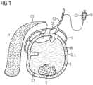
- Fig. 1shows a hollow organ O with a first contrast agent C1 and a second contrast agent C2 applied to the hollow organ O.
- the first contrast agent C1is applied to the lumen L of the hollow organ O.
- the first contrast agent C1accumulates in the lumen L of the hollow organ O and forms a contrast agent filling of the lumen L.
- the second contrast agent C2is applied to a blood vessel system V using an injector N.
- the blood vessel system Vsupplies the wall W of the hollow organ O and a parenchymal organ Y.
- the second contrast agent C2accumulates in the blood vessel system V, the wall W of the hollow organ O and the parenchymal organ Y.
- the wall W of the hollow organ Ois encompassing the lumen L of the hollow organ O.
- the parenchymal organ Yis separated from the hollow organ O, for example by an interlayer of fat.
- the hollow organ O shown in Fig. 1is a bowel.
- the lumen L of the hollow organ Ocomprises two portions A and S, each being external to the contrast agent filling of the lumen L and adjacent to the wall W of the hollow organ O.
- Portion Aconsists of air.
- Portion Sconsists of stool.
- the parenchymal organ Y shown in Fig. 1is spleen.
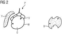
- Fig. 2shows a plurality P of anatomical structures comprising the second contrast agent C2 and a border B of a contrast agent filling of the lumen L.
- the plurality P of anatomical structurescomprises the blood vessel system V, the wall W of the hollow organ O and the parenchymal organ Y.
- Significant amounts of the second contrast agent C2are present in each of these anatomical structures.
- the plurality P of anatomical structuresis enhanced by the second contrast agent C2.
- the border B of the contrast agent filling of the lumen Lfollows the wall W of the hollow organ O with exception of those parts, where the border B of the contrast agent filling of the lumen L is separated from the wall W of the hollow organ O by portion A or portion S.
- Fig. 3shows representations of different parts of the hollow organ O, in particular the representation of the wall W of the hollow organ O, the representation of the border B of the contrast agent filling of the lumen L, a representation of the portion A and a representation of the portion S. Furthermore, a representation of the border BL of the lumen L is shown. The representation of the border BL of the lumen L can be generated based on the representation of the border B of the contrast agent filling of the lumen L and the representation of the wall W of the hollow organ O.
- a course of the border BL of the lumen Lcan be estimated for those parts, where the border B of the contrast agent filling of the lumen L is separated from the wall W of the hollow organ O by portion A or portion S.
- Fig. 4shows a diagram illustrating a method for providing image data of a hollow organ O, comprising
Landscapes
- Health & Medical Sciences (AREA)
- Life Sciences & Earth Sciences (AREA)
- Engineering & Computer Science (AREA)
- Medical Informatics (AREA)
- Public Health (AREA)
- Veterinary Medicine (AREA)
- Animal Behavior & Ethology (AREA)
- General Health & Medical Sciences (AREA)
- Biomedical Technology (AREA)
- Heart & Thoracic Surgery (AREA)
- Biophysics (AREA)
- Pathology (AREA)
- Surgery (AREA)
- Physics & Mathematics (AREA)
- Molecular Biology (AREA)
- High Energy & Nuclear Physics (AREA)
- Radiology & Medical Imaging (AREA)
- Nuclear Medicine, Radiotherapy & Molecular Imaging (AREA)
- Optics & Photonics (AREA)
- Dentistry (AREA)
- Oral & Maxillofacial Surgery (AREA)
- Hematology (AREA)
- Anesthesiology (AREA)
- Vascular Medicine (AREA)
- Computer Vision & Pattern Recognition (AREA)
- Human Computer Interaction (AREA)
- Pulmonology (AREA)
- Theoretical Computer Science (AREA)
- Apparatus For Radiation Diagnosis (AREA)
- Epidemiology (AREA)
Description
- In one aspect the invention relates to a method for providing image data of a hollow organ.
- One of the tasks when reading computed tomography (CT) images is the assessment of vitality and integrity of organs and consequently tissue. In the case of CT scans with intravenous administered contrast agent, the presence of contrast media (CM) uptake in a region of interest regarding an anatomical region can be taken as an indicator for vitality, in particular in form of a surrogate of perfusion, of that anatomical region.
- In homogeneous organs such as the liver or brain, iodine maps showing the presence of contrast media are helpful, giving clear guidance and supporting the reader for making diagnosis. Also, structural changes can be accessed and taken into consideration for diagnosis, e.g. high iodine uptake in a dedicated phase of liver perfusion can be indicative for certain types of malignancies like hepatocellular carcinoma. In case of inhomogeneous organs, reading from contrast media (CM) enhanced scans including iodine maps is more challenging because not only perfusion can be variable but also the structure of tissue is not homogenous and consequently variations of anatomy can be misinterpreted, and pathologies are easier to be missed.
- For example in the case of the digestive system, where in addition to intra-venous administered agent also oral contrast agent is administered and anatomical structures are very variable, reading of CT images is even more challenging and takes lots of time and effort. The oral agent visualizes the lumen of small intestine and colon and stretches also the wall to reveal better the local anatomy. The intravenous agent visualizes the respective walls. With regard to the intravenous agent, enhancement indicates vitality, abnormal behavior indicates pathologies, e.g. cancer, and absence indicates ischemia and finally necrosis.
- Several agents are used for x-ray-based examinations to visualize the lumen of the digestive system. Depending on the clinical questions, they are applied orally or injected directly to the area of interest via a catheter or drainage. This includes also rectal fillings in case of colon or rectal pathologies. In CT, also water and air (for virtual colonoscopy) are applied. However, often these oral agents contain dense materials, for example iodine or barium, to visualize the lumen and also to visualize better stenosis and abnormalities in the passage of this agent when taken orally.
- In CT, barium containing agents are not used anymore widely because of the severe side effects when this material contaminates the peritoneum, e.g. in case of perforated appendicitis. However, contrast agents for the lumen which contain high attenuating materials like iodine are also supporting the detection of small perforations which are hard to visualize when applying water due to a lack of differentiation between edema/ascites and oral given water which leaks into the peritoneum as consequence of a e.g. bowel perforation.
- In conventional x-ray-based exams (e.g. fluoroscopy), often a combination of dynamic imaging and so-called double contrast techniques are used to visualize textural changes. Therefore, a large tumor of the colon will often result in irregular stenosis of the lumen and irregular loss of wall structure whereas an inflammatory process will result in a more regular stenosis and a regular loss of texture. These patterns are often typical image patterns for certain diseases like Morbus Crohn or Colitis ulcerosa.
- In the case of virtual colonoscopy with CT, air is used to extend the colon and, based on volume rendering techniques (VRTs), a "fly-through" visualization of the colon is simulated to generate a similar view as achieved with conventional colonoscopy. However, visualization of pathologies is often limited because this approach requires a perfect unfolding of the colonic wall without any contamination, e.g. by stool, to be able to display also smaller pathologies like polyps.
- Visualization of the wall is simply based on very high attenuation difference between soft tissue and air. The attenuation may be measured in Hounsfield units (HU). Very dense stool and content can in rare cases also achieve very high HU values which can be similar to the attenuation resulting from intravenous CM application.
- If high attenuating materials like iodine are used as oral contrast agents, the brightness of the CM enhanced lumen can mask the stretched wall and the enhancement under certain circumstances. Also the application of iodine maps is not helpful in such a case because there is no differentiation between the wall enhancement and the density of the intraluminal iodine. Based on conventional CT images, no further visualization of the digestive system can be achieved because current algorithms cannot differentiate between the HU changes of oral and intravenous CM, which results in comparable pictures gained by fluoroscopy. In addition, CM enhancement of parenchymal organs will overlay conventional projection approaches and result in non-diagnostic images.
- Masking of pathologies by oral and intravenous CM application can be compensated by performing multiple scans to gain also dynamic information which can be used for further diagnosis. This often results in a time consuming and tiring reading process.
- SOESBE TODD C ET AL: "Separating High-Z Oral Contrast From Intravascular Iodine Contrast in an Animal Model Using Dual-Layer Spectral CT", ACADEMIC RADIOLOGY, ELSEVIER, AMSTERDAM, NL, vol. 26, no. 9, 9 October 2018 (2018-10-09), pages 1237-1244, discloses a method for separating High-Z oral contrast from intravascular iodine contrast in an animal model using dual-layer spectral CT.
WO 2017/223343 A1 discloses a method of making a colloidal nanoparticle contrast agent for enhanced spectral CT image of a subject.- The underlying technical problem of the invention is to facilitate an improved assessment of different parts of a hollow organ. This problem is solved by the subject matter of the independent claims. The dependent claims are related to further aspects of the invention.
- In one aspect the invention relates to a method for providing image data of a hollow organ as claimed in claim 1.
- The spectrally resolved computed tomography data may be generated, for example, by scanning the examination area using a spectral CT technique. In particular, the spectrally resolved computed tomography data are acquired while the first contrast agent and the second contrast agent both are present in the examination area comprising the hollow anatomical structure. For example, if the first contrast agent is applied orally and the second contrast agent is applied intravenously, the first contrast agent may be applied significantly earlier than the second contrast agent. The contrast agent filling of the lumen may be a liquid contrast agent filling and/or may consist substantially of the first contrast agent. The spectrally resolved computed tomography data may be, for example, photon counting computed tomography data, dual source computed tomography data or split filter computed tomography data. In particular, spectrally resolved computed tomography data may be generated that allow extraction of at least two energy levels, preferable three energy levels.
- The material separation algorithm may be, for example, a k-edge imaging algorithm. The material separation algorithm may be configured to separate both contrast agents from each other and quantify each of the contrast agents. For example, the material separation algorithm may be configured to calculate a two or three material decomposition based on the spectrally resolved computed tomography data.
- A region of interest in the image data may be determined, for example, based on a user input in a graphical user interface that displays the image data. The region of interest in the image data may be classified, in particular automatically classified, in respect of the presence of the first contrast agent and the presence of the second contrast agent.
- The region of interest may be classified, for example, as either comprising both the first contrast agent and the second contrast agent or missing at least one of the first contrast agent and the second contrast agent. Only when both agents are present in a region of interest (ROI), that ROI is close to the wall (according to the presence of the first contrast agent) and perfusion is happening (according to the presence of the second contrast agent). If first contrast agent is not in the ROI, the assessed ROI is not close to the wall of the lumen at all. This allows removal of intrinsically distracting, non-relevant structures.
- The representation of the border of the contrast agent filling of the lumen can be generated, for example, by applying a segmentation algorithm onto the first image data.
- A position of the wall of the hollow anatomical structure can be determined, for example, based on the representation of the border of the contrast agent filling of the lumen. For example, pixels of the second image data that are located adjacent to and/or in very close surroundings of the border of the contrast agent filling of the lumen and show presence of the second contrast agent, in particular, exceeding a predefined threshold value for the presence of the second contrast agent, may be assigned to the representation of the wall of the hollow organ.
- The presence of the second contrast agent at the position of the wall of the hollow anatomical structure is indicative, in particular, of a perfusion of the wall, and therefore of a vitality of the wall. Missing the second contrast agent at the position of a given region of the wall may indicate potential presence of necrosis and/or ischemia in that region of the wall.
- In another aspect, a representation of a plurality of anatomical structures comprising the second contrast agent is generated based on the second image data. A region of the representation of the plurality of anatomical structures may be determined, the region being adjacent to the representation of the border of the contrast agent filling of the lumen. The representation of the wall of the hollow organ may be generated based on the region of the representation of the plurality of anatomical structures that is adjacent to the representation of the border of the contrast agent filling of the lumen. For example, at least one part of the representation of the plurality of anatomical structures can be selected that is adjacent to the representation of the border of the contrast agent filling of the lumen, thereby obtaining the representation of the wall of the hollow organ.
- For example, a region of the representation of the plurality of anatomical structures can be considered adjacent to the representation of the border of the contrast agent filling of the lumen, if for each pixel of that region the distance between that pixel and the representation of the border of the contrast agent filing of the lumen is below a predefined threshold value for the distance.
- The image data may comprise at least one of the representation of the border of the contrast agent filling of the lumen, the representation of the wall of the hollow organ, and the representation of the at least one portion of the lumen that is external to the contrast agent filling of the lumen and adjacent to the wall of the hollow structure. The image data can be provided, for example, by transmitting a signal that carries the image data and/or by writing the image data into a computer-readable medium and/or by displaying the image data on a display.
- Each of the representations mentioned herein may be visualized, for example, using two-dimensional and/or three-dimensional methods, in particular in form of a layer and/or a surface. In particular, a 2D and/or 3D image of the wall of the hollow organ may be generated, showing only the areas of double contrast, i. e. presence of both agents in close surrounding, being an indicator for vital tissue of the wall of the hollow organ. Holes and missing structures in such an image indicate necrosis and/or ischemia. This allows a faster and more comfortable reading of the image data.
- The hollow organ may be, for example, a bowel. The hollow organ may be, for example, a colon or a small intestine. The at least one portion of the lumen may comprise, in particular may consist of, a solid material, for example, dense stool, and/or a gas, for example, air.
- In another aspect, the first contrast agent is based on a first material with a first k-edge and the second contrast agent is based on a second material with a second k-edge. The second contrast agent has a different absorption spectrum than the first contrast agent, for example, if the distance between the first k-edge and the second k-edge is non-zero, in particular, at least 1 Kiloelectronvolt, for example, at least 10 Kiloelectronvolts, and/or if the absorption spectrum of the second agent has a different shape than the absorption spectrum of the first agent. The distance between the first k-edge and the second k-edge may be at least 10 Kiloelectronvolts, for example at least 15 Kiloelectronvolts, in particular, at least 20 Kiloelectronvolts.
- In another aspect, the first contrast agent is based on tungsten, holmium or gadolinium and/or the second contrast agent is based on iodine or barium. In another aspect, the second contrast agent is based on tungsten, holmium or gadolinium and/or the first contrast agent is based on iodine or barium.
- For example, the first contrast agent may be gadolinium-based, and the second contrast agent may be iodine-based. In another aspect, the first contrast agent is based on iron or manganese and/or the second contrast agent is based on iodine or barium.
- Wherever not already described explicitly, individual embodiments, or their individual aspects and features, can be combined or exchanged with one another without limiting or widening the scope of the described invention, whenever such a combination or exchange is meaningful and in the sense of this invention. Advantages which are described with respect to one embodiment of the present invention are, wherever applicable, also advantageous of other embodiments of the present invention.
- In the context of the present invention, the expression "based on" can in particular be understood as meaning "using, inter alia". In particular, wording according to which a first feature is calculated (or generated, determined etc.) based on a second feature does not preclude the possibility of the first feature being calculated (or generated, determined etc.) based on a third feature.
- Reference is made to the fact that the described methods and the described units are merely preferred example embodiments of the invention and that the invention can be varied by a person skilled in the art, without departing from the scope of the invention as it is specified by the claims.
- The invention will be illustrated below with reference to the accompanying figures using example embodiments. The illustration in the figures is schematic and highly simplified and not necessarily to scale.
Fig. 1 shows a hollow organ with a first contrast agent and a second contrast agent applied to the hollow organ,Fig. 2 shows a plurality of anatomical structures and a border of a contrast agent filling of a lumen,Fig. 3 shows representations of different parts of the hollow organ, andFig. 4 shows a diagram illustrating a method for providing image data of a hollow organ.Fig. 1 shows a hollow organ O with a first contrast agent C1 and a second contrast agent C2 applied to the hollow organ O. The first contrast agent C1 is applied to the lumen L of the hollow organ O. The first contrast agent C1 accumulates in the lumen L of the hollow organ O and forms a contrast agent filling of the lumen L.- The second contrast agent C2 is applied to a blood vessel system V using an injector N. The blood vessel system V supplies the wall W of the hollow organ O and a parenchymal organ Y. The second contrast agent C2 accumulates in the blood vessel system V, the wall W of the hollow organ O and the parenchymal organ Y. The wall W of the hollow organ O is encompassing the lumen L of the hollow organ O. The parenchymal organ Y is separated from the hollow organ O, for example by an interlayer of fat.
- The hollow organ O shown in
Fig. 1 is a bowel. The lumen L of the hollow organ O comprises two portions A and S, each being external to the contrast agent filling of the lumen L and adjacent to the wall W of the hollow organ O. Portion A consists of air. Portion S consists of stool. The parenchymal organ Y shown inFig. 1 is spleen. Fig. 2 shows a plurality P of anatomical structures comprising the second contrast agent C2 and a border B of a contrast agent filling of the lumen L. The plurality P of anatomical structures comprises the blood vessel system V, the wall W of the hollow organ O and the parenchymal organ Y. Significant amounts of the second contrast agent C2 are present in each of these anatomical structures. In the second image data, the plurality P of anatomical structures is enhanced by the second contrast agent C2.- The border B of the contrast agent filling of the lumen L follows the wall W of the hollow organ O with exception of those parts, where the border B of the contrast agent filling of the lumen L is separated from the wall W of the hollow organ O by portion A or portion S.
Fig. 3 shows representations of different parts of the hollow organ O, in particular the representation of the wall W of the hollow organ O, the representation of the border B of the contrast agent filling of the lumen L, a representation of the portion A and a representation of the portion S. Furthermore, a representation of the border BL of the lumen L is shown. The representation of the border BL of the lumen L can be generated based on the representation of the border B of the contrast agent filling of the lumen L and the representation of the wall W of the hollow organ O. In particular, based on the representation of the wall W of the hollow organ O a course of the border BL of the lumen L can be estimated for those parts, where the border B of the contrast agent filling of the lumen L is separated from the wall W of the hollow organ O by portion A or portion S.Fig. 4 shows a diagram illustrating a method for providing image data of a hollow organ O, comprising- applying A1 a first contrast agent C1 to a lumen L of the hollow organ O, thereby obtaining a contrast agent filling of the lumen L,
- applying A2 a second contrast agent C2 to a blood vessel system V supplying a wall W of the hollow organ O, the second contrast agent C2 having a different absorption spectrum than the first contrast agent C1,
- generating GD spectrally resolved computed tomography data of an examination area of a patient comprising the hollow organ O,
- calculating CI first image data indicative of a presence of the first contrast agent C1 and second image data indicative of a presence of the second contrast agent C2 by applying a material separation algorithm onto the spectrally resolved computed tomography data,
- providing PI the image data of the hollow organ O comprising the first image data and the second image data.
Claims (9)
- Method for providing image data of a hollow organ (O), comprising- generating (GD) spectrally resolved computed tomography data of an examination area comprising a hollow organ (O), wherein the hollow organ (O) is an organ of the digestive system comprising a lumen filled with a first contrast agent (C1), said first contrast agent (C1) having been applied orally, wherein a second contrast agent (C2) is accumulated after the application of the first contrast agent (C1) in a blood vessel system (V), a wall (W) of the hollow organ (O) and a parenchymal organ (Y), the blood vessel system (V) supplying the wall (W) of the hollow organ (O) and the parenchymal organ (Y), the second contrast agent (C2) having a different absorption spectrum than the first contrast agent (C1),- calculating (CI) first image data indicative of a presence of the first contrast agent (C1) and second image data indicative of a presence of the second contrast agent (C2) by applying a material separation algorithm onto the spectrally resolved computed tomography data,- providing (PI) the image data of the hollow organ (O) comprising the first image data and the second image data,- generating a representation of a border (B) of the contrast agent filling of the lumen (L) based on the first image data,- generating a representation of the wall (W) of the hollow organ (O) based on the representation of the border (B) of the contrast agent filling of the lumen (L) and the second image data,- wherein the lumen (L) of the hollow organ (O) comprises at least one portion (A, S) external to the contrast agent filling of the lumen (L) and adjacent to the wall (W) of the hollow organ (O),- wherein a representation of the at least one portion (A, S) of the lumen (L) is generated based on the representation of the border (B) of the contrast agent filling of the lumen (L) and the representation of the wall (W) of the hollow organ (O).
- Method according to claim 1,- wherein the spectrally resolved computed tomography data are photon counting computed tomography data.
- Method according to claim 1 or 2,- wherein the material separation algorithm is a k-edge imaging algorithm.
- Method according to one of the claims 1 to 3,- wherein a region of interest in the image data is determined,- wherein the region of interest in the image data is classified in respect of the presence of the first contrast agent (C1) and the presence of the second contrast agent (C2).
- Method according to one of the claims 1 to 4,- wherein a representation of a plurality (P) of anatomical structures comprising the second contrast agent (C2) is generated based on the second image data,- wherein a region of the representation of the plurality (P) of anatomical structures is determined that is adjacent to the representation of the border (B) of the contrast agent filling of the lumen (L),- wherein the representation of the wall (W) of the hollow organ (O) is generated based on the region of the representation of the plurality (P) of anatomical structures that is adjacent to the representation of the border (B) of the contrast agent filling of the lumen (L).
- Method according to one of the claims 1 to 5,- wherein the at least one portion of the lumen (L) comprises a solid material and/or a gas.
- Method according to one of the claims 1 to 6,- wherein the hollow organ (O) is a colon or a small intestine.
- Method according to one of the claims 1 to 7,- wherein the first contrast agent (C1) is based on a first material with a first k-edge,- wherein the second contrast agent (C2) is based on a second material with a second k-edge, and- wherein a distance between the first k-edge and the second k-edge is at least 10 Kiloelectronvolts.
- Method according to one of the claims 1 to 8,- wherein the first contrast agent (C1) is based on tungsten, holmium or gadolinium and/or- wherein the second contrast agent (C2) is based on iodine or barium.
Priority Applications (2)
| Application Number | Priority Date | Filing Date | Title |
|---|---|---|---|
| EP19166066.1AEP3662837B1 (en) | 2019-03-29 | 2019-03-29 | Method for providing image data of a hollow organ |
| US16/819,347US11857145B2 (en) | 2019-03-29 | 2020-03-16 | Method for providing image data of a hollow organ |
Applications Claiming Priority (1)
| Application Number | Priority Date | Filing Date | Title |
|---|---|---|---|
| EP19166066.1AEP3662837B1 (en) | 2019-03-29 | 2019-03-29 | Method for providing image data of a hollow organ |
Publications (3)
| Publication Number | Publication Date |
|---|---|
| EP3662837A1 EP3662837A1 (en) | 2020-06-10 |
| EP3662837B1true EP3662837B1 (en) | 2025-04-30 |
| EP3662837C0 EP3662837C0 (en) | 2025-04-30 |
Family
ID=66001130
Family Applications (1)
| Application Number | Title | Priority Date | Filing Date |
|---|---|---|---|
| EP19166066.1AActiveEP3662837B1 (en) | 2019-03-29 | 2019-03-29 | Method for providing image data of a hollow organ |
Country Status (2)
| Country | Link |
|---|---|
| US (1) | US11857145B2 (en) |
| EP (1) | EP3662837B1 (en) |
Families Citing this family (1)
| Publication number | Priority date | Publication date | Assignee | Title |
|---|---|---|---|---|
| DE102021207957A1 (en) | 2021-07-23 | 2023-01-26 | Siemens Healthcare Gmbh | Computer-implemented method for evaluating an angiographic computed tomography data set, evaluation device, computer program and electronically readable data carrier |
Family Cites Families (34)
| Publication number | Priority date | Publication date | Assignee | Title |
|---|---|---|---|---|
| CH632199A5 (en) | 1978-09-04 | 1982-09-30 | Schweizerische Lokomotiv | RAIL VEHICLE. |
| US4662379A (en) | 1984-12-20 | 1987-05-05 | Stanford University | Coronary artery imaging system using gated tomosynthesis |
| US5611342A (en)* | 1994-02-15 | 1997-03-18 | Molecular Biosystems, Inc. | Method of computer tomography imaging the gastrointestinal tract and surrounding upper abdominal tissues and organs using an orally administered low density contrast medium |
| DE4405505A1 (en) | 1994-02-21 | 1995-08-31 | Siemens Ag | Computer tomograph for examination of hollow organs of patients |
| DE4410970C1 (en) | 1994-03-29 | 1995-07-20 | Talbot Waggonfab | Tilting support for rail vehicle on bogie |
| DE10122875C1 (en) | 2001-05-11 | 2003-02-13 | Siemens Ag | Combined 3D angio volume reconstruction procedure |
| US7054406B2 (en) | 2002-09-05 | 2006-05-30 | Kabushiki Kaisha Toshiba | X-ray CT apparatus and method of measuring CT values |
| US6950492B2 (en) | 2003-06-25 | 2005-09-27 | Besson Guy M | Dynamic multi-spectral X-ray projection imaging |
| US7582283B2 (en)* | 2004-02-13 | 2009-09-01 | Wisconsin Alumni Research Foundation | Contrast agents to improve gastrointestinal tract opacification during abdominal and pelvic CT scans |
| CA2561168A1 (en) | 2004-04-08 | 2005-10-20 | Yeda Research And Development Co., Ltd. | Three time point lung cancer detection, diagnosis and assessment of prognosis |
| US7218702B2 (en) | 2004-05-10 | 2007-05-15 | Wisconsin Alumni Research Foundation | X-ray system for use in image guided procedures |
| US7352885B2 (en) | 2004-09-30 | 2008-04-01 | General Electric Company | Method and system for multi-energy tomosynthesis |
| US7209536B2 (en)* | 2004-11-19 | 2007-04-24 | General Electric Company | CT colonography system |
| US8131336B2 (en)* | 2006-06-01 | 2012-03-06 | University Of Washington | Automated in vivo plaque composition evaluation |
| JP5091644B2 (en) | 2006-12-04 | 2012-12-05 | 株式会社東芝 | X-ray computed tomography apparatus and medical image processing apparatus |
| JP5010375B2 (en) | 2007-07-18 | 2012-08-29 | 株式会社東芝 | Medical diagnostic imaging equipment |
| JP5794752B2 (en) | 2007-07-24 | 2015-10-14 | 株式会社東芝 | X-ray computed tomography apparatus and image processing apparatus |
| JP2009028065A (en) | 2007-07-24 | 2009-02-12 | Toshiba Corp | X-ray CT system |
| DE102007037996A1 (en) | 2007-08-10 | 2009-02-19 | Siemens Ag | Organ movement e.g. heartbeat, representation method for human body, involves reconstructing three-dimensional image data from projection images i.e. tomosynthesis projection images |
| DE102007050438B4 (en)* | 2007-10-22 | 2015-12-10 | Siemens Aktiengesellschaft | Method and CT system for simultaneous visualization of blood flow in muscle tissue and vessels |
| JP5234905B2 (en) | 2007-11-20 | 2013-07-10 | 東芝メディカルシステムズ株式会社 | X-ray CT apparatus and myocardial perfusion image generation system |
| RU2376181C2 (en) | 2008-02-04 | 2009-12-20 | Открытое акционерное общество "Крюковский вагоностроительный завод" (ОАО "КВСЗ") | Passenger car bogie |
| FR2932298B1 (en) | 2008-06-06 | 2010-07-30 | Gen Electric | METHOD FOR PROCESSING A RADIOLOGICAL IMAGE OF AN ORGAN |
| US7920674B2 (en) | 2008-10-10 | 2011-04-05 | Samsung Electronics Co., Ltd. | Apparatus and method for image processing |
| DE102009014866A1 (en) | 2009-03-30 | 2010-10-28 | Bombardier Transportation Gmbh | Vehicle with roll compensation |
| WO2010113045A2 (en) | 2009-03-30 | 2010-10-07 | Bombardier Transportation Gmbh | Vehicle having pitch compensation |
| DE102009033452B4 (en)* | 2009-07-16 | 2011-06-30 | Siemens Aktiengesellschaft, 80333 | Method for providing a segmented volume dataset for a virtual colonoscopy and related items |
| DE102010041920A1 (en) | 2010-10-04 | 2012-04-05 | Siemens Aktiengesellschaft | Method for representing concentration of contrast agent in predetermined volume portion of female breast, involves subtracting two dimensional low-energy image of female breast from two dimensional high-energy image |
| JP2013128661A (en) | 2011-12-21 | 2013-07-04 | Canon Inc | Stereo x-ray imaging apparatus and stereo x-ray imaging method |
| DE102012215997B4 (en) | 2012-09-10 | 2022-10-06 | Siemens Healthcare Gmbh | Contrast-enhanced recording of objects |
| JP2014113481A (en)* | 2012-11-16 | 2014-06-26 | Toshiba Corp | Ultrasound diagnostic apparatus and image processing method |
| DE102014213464A1 (en) | 2014-07-10 | 2016-01-14 | Siemens Aktiengesellschaft | Method for combined dual-energy mammography and tomosynthesis imaging and tomosynthesis apparatus |
| DE102014214772B4 (en) | 2014-07-28 | 2025-02-20 | Siemens Healthineers Ag | Method for creating a vascular image and method for fluoroscopic imaging of vessels as well as correspondingly designed imaging system |
| WO2017223343A1 (en)* | 2016-06-22 | 2017-12-28 | Board Of Regents, The University Of Texas System | Contrast agents and methods of making the same for spectral ct that exhibit cloaking and auto-segmentation |
- 2019
- 2019-03-29EPEP19166066.1Apatent/EP3662837B1/enactiveActive
- 2020
- 2020-03-16USUS16/819,347patent/US11857145B2/enactiveActive
Also Published As
| Publication number | Publication date |
|---|---|
| EP3662837A1 (en) | 2020-06-10 |
| US20200305816A1 (en) | 2020-10-01 |
| US11857145B2 (en) | 2024-01-02 |
| EP3662837C0 (en) | 2025-04-30 |
Similar Documents
| Publication | Publication Date | Title |
|---|---|---|
| Frellesen et al. | Dual-energy CT of the pancreas: improved carcinoma-to-pancreas contrast with a noise-optimized monoenergetic reconstruction algorithm | |
| Fishman et al. | Volume rendering versus maximum intensity projection in CT angiography: what works best, when, and why | |
| Higgins et al. | Virtual bronchoscopy for three--dimensional pulmonary image assessment: state of the art and future needs. | |
| CN101529475B (en) | Presentation of 3D images in combination with 2D projection images | |
| US8548566B2 (en) | Rendering method and apparatus | |
| JP2006051365A (en) | System and method for obtaining 3d visualization of lung perfusion or lung density, and statistical analysis method therefor | |
| US10140715B2 (en) | Method and system for computing digital tomosynthesis images | |
| Godoy et al. | Basic principles and postprocessing techniques of dual-energy CT: illustrated by selected congenital abnormalities of the thorax | |
| US20070197898A1 (en) | Method for examination of vessels in a patient on the basis of image data recorded by means of a scanner within an examination area | |
| JP2008006274A (en) | Medical image processing apparatus and medical image processing method | |
| JP2007275318A (en) | Image display device, image display method and program thereof | |
| JP2004057411A (en) | Method for preparing visible image for medical use | |
| EP3662837B1 (en) | Method for providing image data of a hollow organ | |
| Cahir et al. | Multislice CT of the abdomen | |
| JP2010075549A (en) | Image processor | |
| JP6755468B2 (en) | Medical image processing device | |
| Tamm et al. | Advanced 3-D imaging for the evaluation of pancreatic cancer with multidetector CT | |
| US8908938B2 (en) | Method and device for providing a segmented volume data record for a virtual colonoscopy, and computer program product | |
| US20080150942A1 (en) | Visualization of volumetric medical imaging data | |
| Kassavin et al. | Computed Tomography Colonography: 2025 Update | |
| Shepard | Thoracic Imaging The Requisites E-Book | |
| Laghi | MDCT protocols: whole body and emergencies | |
| Jung et al. | Opacity-driven volume clipping for slice of interest (SOI) visualisation of multi-modality PET-CT volumes | |
| EP3889896A1 (en) | Model-based virtual cleansing for spectral virtual colonoscopy | |
| ROMMAN | Computer, Physics, and Clinical Applications of Spectral Computed Tomography |
Legal Events
| Date | Code | Title | Description |
|---|---|---|---|
| PUAI | Public reference made under article 153(3) epc to a published international application that has entered the european phase | Free format text:ORIGINAL CODE: 0009012 | |
| STAA | Information on the status of an ep patent application or granted ep patent | Free format text:STATUS: THE APPLICATION HAS BEEN PUBLISHED | |
| AK | Designated contracting states | Kind code of ref document:A1 Designated state(s):AL AT BE BG CH CY CZ DE DK EE ES FI FR GB GR HR HU IE IS IT LI LT LU LV MC MK MT NL NO PL PT RO RS SE SI SK SM TR | |
| AX | Request for extension of the european patent | Extension state:BA ME | |
| STAA | Information on the status of an ep patent application or granted ep patent | Free format text:STATUS: REQUEST FOR EXAMINATION WAS MADE | |
| 17P | Request for examination filed | Effective date:20201208 | |
| RBV | Designated contracting states (corrected) | Designated state(s):AL AT BE BG CH CY CZ DE DK EE ES FI FR GB GR HR HU IE IS IT LI LT LU LV MC MK MT NL NO PL PT RO RS SE SI SK SM TR | |
| STAA | Information on the status of an ep patent application or granted ep patent | Free format text:STATUS: EXAMINATION IS IN PROGRESS | |
| 17Q | First examination report despatched | Effective date:20230519 | |
| RAP1 | Party data changed (applicant data changed or rights of an application transferred) | Owner name:SIEMENS HEALTHINEERS AG | |
| GRAP | Despatch of communication of intention to grant a patent | Free format text:ORIGINAL CODE: EPIDOSNIGR1 | |
| STAA | Information on the status of an ep patent application or granted ep patent | Free format text:STATUS: GRANT OF PATENT IS INTENDED | |
| RIC1 | Information provided on ipc code assigned before grant | Ipc:A61B 6/50 20240101ALI20241112BHEP Ipc:A61B 6/00 20060101AFI20241112BHEP | |
| INTG | Intention to grant announced | Effective date:20241127 | |
| GRAS | Grant fee paid | Free format text:ORIGINAL CODE: EPIDOSNIGR3 | |
| GRAA | (expected) grant | Free format text:ORIGINAL CODE: 0009210 | |
| STAA | Information on the status of an ep patent application or granted ep patent | Free format text:STATUS: THE PATENT HAS BEEN GRANTED | |
| AK | Designated contracting states | Kind code of ref document:B1 Designated state(s):AL AT BE BG CH CY CZ DE DK EE ES FI FR GB GR HR HU IE IS IT LI LT LU LV MC MK MT NL NO PL PT RO RS SE SI SK SM TR | |
| REG | Reference to a national code | Ref country code:CH Ref legal event code:EP Ref country code:GB Ref legal event code:FG4D | |
| REG | Reference to a national code | Ref country code:IE Ref legal event code:FG4D | |
| REG | Reference to a national code | Ref country code:DE Ref legal event code:R096 Ref document number:602019069242 Country of ref document:DE | |
| U01 | Request for unitary effect filed | Effective date:20250430 | |
| U07 | Unitary effect registered | Designated state(s):AT BE BG DE DK EE FI FR IT LT LU LV MT NL PT RO SE SI Effective date:20250508 | |
| PG25 | Lapsed in a contracting state [announced via postgrant information from national office to epo] | Ref country code:ES Free format text:LAPSE BECAUSE OF FAILURE TO SUBMIT A TRANSLATION OF THE DESCRIPTION OR TO PAY THE FEE WITHIN THE PRESCRIBED TIME-LIMIT Effective date:20250430 |