EP3659535B1 - Bone plate - Google Patents
Bone plateDownload PDFInfo
- Publication number
- EP3659535B1 EP3659535B1EP20152934.4AEP20152934AEP3659535B1EP 3659535 B1EP3659535 B1EP 3659535B1EP 20152934 AEP20152934 AEP 20152934AEP 3659535 B1EP3659535 B1EP 3659535B1
- Authority
- EP
- European Patent Office
- Prior art keywords
- hole
- bone
- thread
- bone plate
- plate according
- Prior art date
- Legal status (The legal status is an assumption and is not a legal conclusion. Google has not performed a legal analysis and makes no representation as to the accuracy of the status listed.)
- Active
Links
Images


Classifications
- A—HUMAN NECESSITIES
- A61—MEDICAL OR VETERINARY SCIENCE; HYGIENE
- A61B—DIAGNOSIS; SURGERY; IDENTIFICATION
- A61B17/00—Surgical instruments, devices or methods
- A61B17/56—Surgical instruments or methods for treatment of bones or joints; Devices specially adapted therefor
- A61B17/58—Surgical instruments or methods for treatment of bones or joints; Devices specially adapted therefor for osteosynthesis, e.g. bone plates, screws or setting implements
- A61B17/68—Internal fixation devices, including fasteners and spinal fixators, even if a part thereof projects from the skin
- A61B17/80—Cortical plates, i.e. bone plates; Instruments for holding or positioning cortical plates, or for compressing bones attached to cortical plates
- A61B17/8052—Cortical plates, i.e. bone plates; Instruments for holding or positioning cortical plates, or for compressing bones attached to cortical plates immobilised relative to screws by interlocking form of the heads and plate holes, e.g. conical or threaded
- A—HUMAN NECESSITIES
- A61—MEDICAL OR VETERINARY SCIENCE; HYGIENE
- A61B—DIAGNOSIS; SURGERY; IDENTIFICATION
- A61B17/00—Surgical instruments, devices or methods
- A61B17/56—Surgical instruments or methods for treatment of bones or joints; Devices specially adapted therefor
- A61B17/58—Surgical instruments or methods for treatment of bones or joints; Devices specially adapted therefor for osteosynthesis, e.g. bone plates, screws or setting implements
- A61B17/68—Internal fixation devices, including fasteners and spinal fixators, even if a part thereof projects from the skin
- A61B17/80—Cortical plates, i.e. bone plates; Instruments for holding or positioning cortical plates, or for compressing bones attached to cortical plates
- A61B17/8052—Cortical plates, i.e. bone plates; Instruments for holding or positioning cortical plates, or for compressing bones attached to cortical plates immobilised relative to screws by interlocking form of the heads and plate holes, e.g. conical or threaded
- A61B17/8057—Cortical plates, i.e. bone plates; Instruments for holding or positioning cortical plates, or for compressing bones attached to cortical plates immobilised relative to screws by interlocking form of the heads and plate holes, e.g. conical or threaded the interlocking form comprising a thread
- A—HUMAN NECESSITIES
- A61—MEDICAL OR VETERINARY SCIENCE; HYGIENE
- A61B—DIAGNOSIS; SURGERY; IDENTIFICATION
- A61B17/00—Surgical instruments, devices or methods
- A61B17/56—Surgical instruments or methods for treatment of bones or joints; Devices specially adapted therefor
- A61B17/58—Surgical instruments or methods for treatment of bones or joints; Devices specially adapted therefor for osteosynthesis, e.g. bone plates, screws or setting implements
- A61B17/68—Internal fixation devices, including fasteners and spinal fixators, even if a part thereof projects from the skin
- A61B17/84—Fasteners therefor or fasteners being internal fixation devices
- A61B17/86—Pins or screws or threaded wires; nuts therefor
- A—HUMAN NECESSITIES
- A61—MEDICAL OR VETERINARY SCIENCE; HYGIENE
- A61L—METHODS OR APPARATUS FOR STERILISING MATERIALS OR OBJECTS IN GENERAL; DISINFECTION, STERILISATION OR DEODORISATION OF AIR; CHEMICAL ASPECTS OF BANDAGES, DRESSINGS, ABSORBENT PADS OR SURGICAL ARTICLES; MATERIALS FOR BANDAGES, DRESSINGS, ABSORBENT PADS OR SURGICAL ARTICLES
- A61L27/00—Materials for grafts or prostheses or for coating grafts or prostheses
- A61L27/02—Inorganic materials
- A61L27/04—Metals or alloys
- A—HUMAN NECESSITIES
- A61—MEDICAL OR VETERINARY SCIENCE; HYGIENE
- A61B—DIAGNOSIS; SURGERY; IDENTIFICATION
- A61B17/00—Surgical instruments, devices or methods
- A61B17/56—Surgical instruments or methods for treatment of bones or joints; Devices specially adapted therefor
- A61B17/58—Surgical instruments or methods for treatment of bones or joints; Devices specially adapted therefor for osteosynthesis, e.g. bone plates, screws or setting implements
- A61B17/68—Internal fixation devices, including fasteners and spinal fixators, even if a part thereof projects from the skin
- A61B17/70—Spinal positioners or stabilisers, e.g. stabilisers comprising fluid filler in an implant
- A61B17/7059—Cortical plates
- A—HUMAN NECESSITIES
- A61—MEDICAL OR VETERINARY SCIENCE; HYGIENE
- A61B—DIAGNOSIS; SURGERY; IDENTIFICATION
- A61B17/00—Surgical instruments, devices or methods
- A61B17/56—Surgical instruments or methods for treatment of bones or joints; Devices specially adapted therefor
- A61B17/58—Surgical instruments or methods for treatment of bones or joints; Devices specially adapted therefor for osteosynthesis, e.g. bone plates, screws or setting implements
- A61B17/68—Internal fixation devices, including fasteners and spinal fixators, even if a part thereof projects from the skin
- A61B17/80—Cortical plates, i.e. bone plates; Instruments for holding or positioning cortical plates, or for compressing bones attached to cortical plates
- A61B17/8061—Cortical plates, i.e. bone plates; Instruments for holding or positioning cortical plates, or for compressing bones attached to cortical plates specially adapted for particular bones
Definitions
- the present inventiongenerally relates to a bone plate which can be fixed to a bone by means of bone screws. More particularly, the present invention relates to a bone plate having a through hole with an internal thread to threadably receive a locking bone screw.
- Bone plates with through holescomprising a cylindrical or conical interior thread to receive a locking head bone screw are commonly used in the field of osteosynthesis. Due to the threaded connection between the head of the bone screw and the through hole in the bone plate the bone screw is firmly anchored in the through hole in the bone plate. However, one problem that can arise is that if the bone screw is not exactly coaxially inserted with respect to the through hole axis the thread of the through hole can be damaged.
- WO2009023666 A2describes a bone plate system for internal fixation of bone fractures includes a bone plate having a plurality of bone plate holes.
- the holesare constructed to receive either a non-locking, locking, or variable angle locking bone screw.
- the holeshave discrete columns of thread segments arranged around the inner surface of the hole for engaging threads on the heads of locking and variable angle locking bone screws.
- Conventional locking bone screwsengage the bone plate coaxially with the central axis of the bone plate hole.
- Variable angle locking bone screwscan engage the bone plate at a selectable angle within a range of angles relative to the bone plate.
- the head of the variable angle locking screwis at least partially spherical, and the thread thereon has a profile that follows the arc-shaped radius of curvature of the spherical portion of the screw head.
- WO2009058969 A1describes a plate for fixation to a target portion of bone to be treated, comprises a first fixation element receiving opening extending therethrough from a proximal surface to a distal surface, the first fixation element receiving opening including a plurality of columns distributed about a circumference thereof and a plurality of radially expanded sections separating adjacent ones of the columns from one another in combination with a plurality of projections formed on the columns, the projections extending from surfaces of the columns, shapes of the surfaces of the columns on which the projections are formed being selected so that, when engaged by a head of a bone fixation element, the projections engage a thread of a head of the bone fixation element to lock the bone fixation element in the first fixation element receiving opening at any user selected angle within a permitted range of angulation.
- DE102005042766 A1describes a bone plate with a bore designed as a threaded five or six-star with regularly positioned threaded segments with teeth and recesses between them.
- the recessesare arranged in a cylindrical shape.
- the upper area of the borehas a calotte shape facilitating a deep insertion of the screw head.
- the lower area of the screw headis a complementary shape to the inner surface of the bore. Both screws with a round head or with a threaded head can be used.
- the present inventionrelates to a bone plate as defined by independent claim 1.
- the present inventionis a bone plate comprising a first through hole extending through the plate along a first longitudinal axis from a proximal surface of the plate to a bone-facing distal surface thereof which, when the plate is placed on a target portion of bone in a desired orientation, faces the bone, a wall of the first through hole including at least three wall sections provided with thread or thread-like structures for receiving a screw head of a bone screw, the three wall sections being one of straight and convex.
- One of the advantages of the bone plate according to the present inventioninclude a compact entry for setting at choice bone screws under a variable angle is provided in such a way that the thread in the through hole in the bone plate is not damaged when a bone screw is not coaxially inserted with respect to the longitudinal axis of the through hole. Furthermore, due to the configuration of a through hole with three or more straight or convex sections, a bone screw inserted through the through hole may be angled relative to a longitudinal axis of the through hole with a reduction of damage to the threads of the through hole.
- the present inventionrelates to a bone plate being able to receive at least a central bone screw in such a way that the thread in the through hole in the bone plate is not damaged when a bone screw is inserted.
- the present inventionis a bone plate according to claim 1. Further embodiments of the invention are described in the dependent claims.
- the through holehas a cross-sectional area orthogonal to the longitudinal axis with a center of the cross-sectional area being centered on the longitudinal axis and wherein each of the three or more straight or convex sections is limited by two radii intersecting each other in the center and enclosing an angle ⁇ which is smaller than or equal to 360°/n (where n is the number of straight or convex sections), as will be described in greater detail below.
- the through holehas a cross-sectional area orthogonal to the longitudinal axis which is generally polygonal, preferably with rounded corners.
- the through holetapers in a direction towards a distal surface of the bone plate.
- a thread or thread-like structureextends over the whole length of the three or more straight or convex sections.
- the thread or thread-like structurehas a constant depth of thread within the straight or convex sections.
- the depth of thread of the thread or thread-like structuredecreases towards each end of each of the straight or convex sections.
- the depth of thread of the thread or thread-like structuredecreases outside each end of each of the straight or convex sections.
- the bone platecomprises two or more peripheral holes connected to and open to a through hole.
- the peripheral holesinclude a thread for receiving peripheral bone screws therein.
- the two or more peripheral holesare arranged peripherally around the through hole in such a way that they overlap with the through hole to form a composite hole structure able to receive two or more peripheral bone screws therein while a central bone screw is received in the through hole.
- each of the peripheral holescomprises a spherical recess penetrating partially into the bone plate from a proximal surface thereof.
- each of the peripheral holes and the through holeincludes a thread for locking the screw received therein at a fixed angle.
- the peripheral holesinclude threading for receiving peripheral bone screws at user selected variable angles relative to the longitudinal axes of these peripheral holes while the through hole is configured to receive a central bone screw at a fixed angle.
- the threads of the holesextend over at least half of a circumference of each of the holes.
- the present inventionis a bone plate according to claim 1, and is for the fixation of fractured or otherwise damaged bones which is adapted to receive a bone screw through a bone plate hole on one or both of a variable angle and a fixed angle.
- a bone plate according to the present inventionis provided with a central through hole configured to receive a first bone screw therethrough at any user selected angle relative to a longitudinal axis of the through hole within a permitted range of angulation.
- a plurality of second bone screwsmay also be inserted through outlying portions of the bone plate hole, each defining a separate plate hole axis.
- the outlying portions of the bone plate holeare formed as substantially circular peripheral holes configured to overlap and be open to the through hole to form a composite hole having any of a plurality of shapes depending on the placement and number of the peripheral holes relative to the through hole, as will be discussed in greater detail with respect to particular embodiments.
- the peripheral holesmay be configured with holes axes selected so that the second bone screws may only be inserted therethrough at predetermined angles relative to a surface of the bone plate. It is noted that although the peripheral holes and through holes are depicted with predetermined angles in the system of the present invention, these bone plate holes may extend through the bone plate at any angle without deviating from the spirit and scope of the present invention and may be selected to conform to the requirement of a particular procedure.
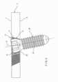
- Figs. 1 to 8illustrate a first exemplary embodiment of the invention comprising a bone plate 1 including one through hole 9 and three partially cylindrical peripheral holes 2 arranged peripherally around the through hole 9 in such a way that they overlap with the through hole 9 and are open thereto, as will be described in greater detail below.
- the bone plate 1comprises a proximal surface 7 and a bone-oriented distal surface 8.
- the through hole 9has a longitudinal axis 6 connecting the proximal and distal surfaces 7, 8, the longitudinal axis 6 extending orthogonally to the proximal surface 7.
- the through hole 9is at least partially bordered by a wall 10 including three convex sections 15 provided with projections such as a thread 5 or thread-like structures for receiving a central bone screw 30 under a variable angle.
- each of the three convex sections 15 of Fig. 1is curved with a predetermined radius of curvature.
- any number and combination of the convex sections 15may be formed with a first radius of curvature while the remainder of the convex sections 15 may be formed with a second radius of curvature.
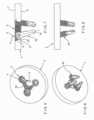
- Each of the peripheral holes 2each has a hole axis 11 extending between the proximal and distal surfaces 7, 8 and are provided with a thread 4 for receiving peripheral bone screws 20, as shown in Figs. 6-8 .
- the peripheral holes 2are arranged peripherally around the through hole 9 at equal angles relative to each other.
- the axes 11 of the peripheral holes 2when viewed in a cross-section orthogonal to the longitudinal axis 6 of the through hole 9, define an equilateral triangle.
- the three peripheral holes 2overlap the through hole 9 in such a way that the peripheral holes 2 and through hole 9 form a composite hole structure suitable to receive 3 peripheral bone screws 20, as shown in Figs. 5 to 8 and/or one central bone screw 30, as shown in Figs. 2 to 4 .
- the peripheral holes 2each also comprise a thread 4, which, in one embodiment of the present invention, may be a multiple thread.
- each of the convex sections 15When viewed in a cross-section orthogonal to the longitudinal axis 6 of the through hole 9, each of the convex sections 15 is centrally positioned along a respective corner of an equilateral triangle. Each convex section 15 is convexly curved in a direction from the proximal surface 7 to the distal surface 9 so that an apex of each of the convex sections 15 is located radially outside the through hole 9.
- a bone screw 30can be inserted into the through hole 9 under a surgeon selected angle so that a screw axis 33 of the bone screw 30 is offset by an angle ⁇ relative to the longitudinal axis 6 of the through hole 9.
- the through hole 9 of the present inventionmay be configured so that the bone screw 30 insertable therethrough is smaller, larger or the same size as the bone screws 20 insertable through the peripheral holes 2.
- the composite hole structuretherefore includes three radially symmetrically arranged convex sections 15 centrally located on the sides of an equilateral triangle and three peripheral holes 2 in the corners of the equilateral triangle.
- the axes 11 of the peripheral holes 2are arranged at a distance from the longitudinal axis 6 which is dimensioned in such a way that the peripheral holes 2 overlap the through hole 9 and extend over an angle of more than 180° between their transitions to the through hole 9.
- each convex section 15does not extend over the whole length of the wall portion limited by the transitions.
- the thread 5 or thread-like structureextends over the whole length of the three convex sections 15 with a constant depth of thread.
- the depth of thread of the thread 5 or thread-like structuredecreases between each end of the convex section 15 and each of the two transitions to one of the peripheral holes 2.
- the through hole 9tapers radially inward toward the distal surface 8 of the bone plate 1.
- a central bone screw 30 with a screw axis 33 and a screw head 31is inserted in the through hole 9.
- the screw head 31is spherically shaped and comprises an external thread 32 so that the central bone screw 30 can be inserted into the through hole at a user-selected angle ⁇ between the screw axis 33 and the longitudinal axis 6 of the through hole 9.
- a central bone screw 30comprising a spherically shaped screw head 31 with an external thread 32
- a central bone screwcomprising a conically shaped screw head with an external thread could be inserted into the through hole 9.
- the central bone screwwould be inserted into the through hole 9 at a fixed angle (e.g., with the screw axis and the longitudinal axis 6 of the through hole 9 coinciding).
- the peripheral holes 2are configured so that each of the hole axes 11 is angled at approximately 20° relative to the longitudinal axis 6 of the through hole 9.
- the peripheral holes 2may be angled at any other angle relative to the longitudinal axis 6 and may optionally also each extend along different angles, as those skilled in the art will understand.
- each of the peripheral holes 2tapers radially inward towards the distal surface 8 of the bone plate 1.
- a peripheral bone screw 20 with a screw axis 23 and a screw head 21is inserted into each of the peripheral holes 2.
- the screw head 21is conically shaped and comprises an external thread 22 so each peripheral bone screw 20 can be inserted into one of the peripheral holes 2 at a fixed angle with the screw axis 23 and the hole axis 11 of the peripheral hole 2 coinciding.
- peripheral bone screws 20comprising conically shaped screw heads 21 with an external thread
- peripheral bone screwscomprising spherically shaped screw heads with an external thread may be inserted into the peripheral holes 2.
- the peripheral bone screwsmay be inserted at a user selected variable angle between the screw axis 23 and the hole axis 11 of the peripheral hole 2.
- Each of the convex sections 15is convexly curved in a cross-section orthogonal to the longitudinal axis 6 of the through hole 9 with the apex of each convex section 15 located on a middle line orthogonal to one side of the equilateral triangle. Due to the convex sections 15, a bone screw 30 may be inserted into the through hole 9 under a surgeon selected angle relative to the axis 6.
- the through hole 9includes three radially symmetrically arranged convex sections 15 centrally located on the sides of an equilateral triangle and three concavely rounded sections in the corners of the equilateral triangle.
- each convex section 15extends over the whole length of the wall portion limited by the transitions.
- the thread 5 or thread-like structureextends over the whole periphery of the through hole 9. The depth of thread of the thread 5 or thread-like structure can decrease in the concavely rounded sections.
- the through hole 9tapers towards the distal surface 8 of the bone plate 1.
- a central bone screw 30 with a screw axis 33 and a screw head 31is inserted in the through hole 9.
- the screw head 31is spherically shaped and comprises an external thread 32 so that the central bone screw 30 can be inserted into the through hole at a user-selected variable angle ⁇ between the screw axis 33 and the longitudinal axis 6 of the through hole 9.
- Figs. 12 to 14another embodiment of the bone plate 1 is illustrated which comprises two through holes 9.
- each convex section 15extends over the whole length of the wall portion limited by the transitions.
- the through holes 9differ from the through hole 9 of the embodiment of Figs. 9 to 11 only in that the thread 5 or thread-like structure does not extend over the whole periphery of the through hole 9.
- the depth of thread of the thread 5 or thread-like structuredecreases on each end of the convex section 15 at the transition between the convex section 15 and the concavely rounded section in such a way that a portion of the concavely rounded sections is unthreaded.
- the through hole 9tapers radially inward toward the distal surface 8 of the bone plate 1.
- a central bone screw 30 with a screw axis 33 and a screw head 31can be inserted in the through hole 9.
- the central bone screw 30may be inserted into the through hole 9 at a user-selected, variable angle ⁇ of the screw axis 33 to the longitudinal axis 6 of the through hole 9.
- each convex section 15extends over the whole length of the wall portion limited by the transitions.
- the thread 5 or thread-like structuredoes not extend over the whole periphery of the through hole 9.
- the depth of thread of the thread 5 or thread-like structuredecreases on each end of the convex section 15 at the transition between the convex section 15 and the concavely rounded section in such a way that a portion of the concavely rounded sections is unthreaded.
- Each peripheral hole 2comprises a spherical recess 25 penetrating partially into the bone plate 1 from the proximal surface 7 and axially adjacent to a conically enlarging lower section 26 extending between the spherical recess 25 and the distal surface 8 of the bone plate 1. Due to the spherical recess 25, a conventional cortex screw with a spherical head may be inserted into each of the peripheral holes 2 at a user-selected angle with respect to the axis 11 of the peripheral hole 2.
Landscapes
- Health & Medical Sciences (AREA)
- Orthopedic Medicine & Surgery (AREA)
- Life Sciences & Earth Sciences (AREA)
- Surgery (AREA)
- Veterinary Medicine (AREA)
- Public Health (AREA)
- General Health & Medical Sciences (AREA)
- Animal Behavior & Ethology (AREA)
- Neurology (AREA)
- Molecular Biology (AREA)
- Medical Informatics (AREA)
- Heart & Thoracic Surgery (AREA)
- Biomedical Technology (AREA)
- Engineering & Computer Science (AREA)
- Nuclear Medicine, Radiotherapy & Molecular Imaging (AREA)
- Chemical & Material Sciences (AREA)
- Inorganic Chemistry (AREA)
- Dermatology (AREA)
- Medicinal Chemistry (AREA)
- Oral & Maxillofacial Surgery (AREA)
- Transplantation (AREA)
- Epidemiology (AREA)
- Surgical Instruments (AREA)
Description
- The present invention generally relates to a bone plate which can be fixed to a bone by means of bone screws. More particularly, the present invention relates to a bone plate having a through hole with an internal thread to threadably receive a locking bone screw.
- Bone plates with through holes comprising a cylindrical or conical interior thread to receive a locking head bone screw are commonly used in the field of osteosynthesis. Due to the threaded connection between the head of the bone screw and the through hole in the bone plate the bone screw is firmly anchored in the through hole in the bone plate. However, one problem that can arise is that if the bone screw is not exactly coaxially inserted with respect to the through hole axis the thread of the through hole can be damaged.
WO2009023666 A2 describes a bone plate system for internal fixation of bone fractures includes a bone plate having a plurality of bone plate holes. The holes are constructed to receive either a non-locking, locking, or variable angle locking bone screw. The holes have discrete columns of thread segments arranged around the inner surface of the hole for engaging threads on the heads of locking and variable angle locking bone screws. Conventional locking bone screws engage the bone plate coaxially with the central axis of the bone plate hole. Variable angle locking bone screws can engage the bone plate at a selectable angle within a range of angles relative to the bone plate. The head of the variable angle locking screw is at least partially spherical, and the thread thereon has a profile that follows the arc-shaped radius of curvature of the spherical portion of the screw head.WO2009058969 A1 describes a plate for fixation to a target portion of bone to be treated, comprises a first fixation element receiving opening extending therethrough from a proximal surface to a distal surface, the first fixation element receiving opening including a plurality of columns distributed about a circumference thereof and a plurality of radially expanded sections separating adjacent ones of the columns from one another in combination with a plurality of projections formed on the columns, the projections extending from surfaces of the columns, shapes of the surfaces of the columns on which the projections are formed being selected so that, when engaged by a head of a bone fixation element, the projections engage a thread of a head of the bone fixation element to lock the bone fixation element in the first fixation element receiving opening at any user selected angle within a permitted range of angulation.WO2005018472 A1 describes a The invention relates to a bone plate having a bottom surface on the bone side, a top surface and several plate holes with a central hole axis, connecting the bottom surface to the top surface. At least one of said plate holes has an inner lateral surface tapering in the direction of the bottom surface, wherein the inner lateral surface N = 3 has recesses extending radially from the hole axis.DE102005042766 A1 describes a bone plate with a bore designed as a threaded five or six-star with regularly positioned threaded segments with teeth and recesses between them. The recesses are arranged in a cylindrical shape. The upper area of the bore has a calotte shape facilitating a deep insertion of the screw head. The lower area of the screw head is a complementary shape to the inner surface of the bore. Both screws with a round head or with a threaded head can be used.- The present invention relates to a bone plate as defined by
independent claim 1. As such, the present invention is a bone plate comprising a first through hole extending through the plate along a first longitudinal axis from a proximal surface of the plate to a bone-facing distal surface thereof which, when the plate is placed on a target portion of bone in a desired orientation, faces the bone, a wall of the first through hole including at least three wall sections provided with thread or thread-like structures for receiving a screw head of a bone screw, the three wall sections being one of straight and convex. - One of the advantages of the bone plate according to the present invention include a compact entry for setting at choice bone screws under a variable angle is provided in such a way that the thread in the through hole in the bone plate is not damaged when a bone screw is not coaxially inserted with respect to the longitudinal axis of the through hole. Furthermore, due to the configuration of a through hole with three or more straight or convex sections, a bone screw inserted through the through hole may be angled relative to a longitudinal axis of the through hole with a reduction of damage to the threads of the through hole.
- Several exemplary embodiments of the invention will be described in the following by way of example and with reference to the accompanying drawings in which:
Fig. 1 illustrates a perspective view of an exemplary embodiment of the bone plate according to the present invention;Fig. 2 illustrates the bone plate according toFig. 1 with an inserted central bone screw;Fig. 3 illustrates a lateral view of the bone plate according toFig. 2 ;Fig. 4 illustrates a cross section through the bone plate according toFig. 2 ;Fig. 5 illustrates perspective view onto the top of the bone plate according toFig. 1 with inserted peripheral screws;Fig. 6 illustrates perspective view onto the bottom of the bone plate according toFig. 1 with inserted peripheral screws;Fig. 7 illustrates a cross section through the bone plate according toFig. 5 ;Fig. 8 illustrates a lateral view of the bone plate according toFig. 5 ;Fig. 9 illustrates a perspective view of another exemplary embodiment of the bone plate according to the present invention;Fig. 10 illustrates a cross section through the bone plate according to the embodiment ofFig. 9 ;Fig. 11 illustrates a lateral view of the bone plate according to the embodiment ofFig. 9 ;Fig. 12 illustrates a top view onto a further embodiment of the bone plate according to the invention;Fig. 13 illustrates a magnified perspective view of detail A inFig. 12 ;Fig. 14 illustrates a schematic top view of detail A inFig. 12 ;Fig. 15 illustrates a schematic top view onto a further exemplary embodiment of the through hole in the bone plate according to the present invention;Fig. 16 illustrates a schematic top view onto another exemplary embodiment of the through hole in the bone plate according to the present invention;Fig. 17 illustrates a schematic top view onto again another embodiment of the through hole in the bone plate according to the present invention; andFig. 18 illustrates a cross-section along line A-A inFig. 17 .- The present invention relates to a bone plate being able to receive at least a central bone screw in such a way that the thread in the through hole in the bone plate is not damaged when a bone screw is inserted. Specifically, the present invention is a bone plate according to
claim 1. Further embodiments of the invention are described in the dependent claims. - In an exemplary embodiment of the bone plate, the through hole has a cross-sectional area orthogonal to the longitudinal axis with a center of the cross-sectional area being centered on the longitudinal axis and wherein each of the three or more straight or convex sections is limited by two radii intersecting each other in the center and enclosing an angle Ω which is smaller than or equal to 360°/n (where n is the number of straight or convex sections), as will be described in greater detail below.
- In a further exemplary embodiment of the bone plate, the through hole has a cross-sectional area orthogonal to the longitudinal axis which is generally polygonal, preferably with rounded corners.
- In a further embodiment of the bone plate, the through hole tapers in a direction towards a distal surface of the bone plate.
- In another embodiment of the bone plate, a thread or thread-like structure extends over the whole length of the three or more straight or convex sections.
- In another embodiment of the bone plate, the thread or thread-like structure has a constant depth of thread within the straight or convex sections.
- In yet another embodiment of the bone plate the depth of thread of the thread or thread-like structure decreases towards each end of each of the straight or convex sections.
- In still another embodiment of the bone plate the depth of thread of the thread or thread-like structure decreases outside each end of each of the straight or convex sections.
- In a further embodiment of the bone plate according to the present invention, the bone plate comprises two or more peripheral holes connected to and open to a through hole. The peripheral holes include a thread for receiving peripheral bone screws therein. The two or more peripheral holes are arranged peripherally around the through hole in such a way that they overlap with the through hole to form a composite hole structure able to receive two or more peripheral bone screws therein while a central bone screw is received in the through hole.
- In a further embodiment of the bone plate each of the peripheral holes comprises a spherical recess penetrating partially into the bone plate from a proximal surface thereof. The advantage of this configuration is that a conventional cortex screw with an unthreaded spherical head may be introduced into such a peripheral hole at an angle relative to the longitudinal axis selected by the user.
- In a further embodiment of the bone plate according to the invention, each of the peripheral holes and the through hole includes a thread for locking the screw received therein at a fixed angle.
- In another embodiment of the bone plate, the peripheral holes include threading for receiving peripheral bone screws at user selected variable angles relative to the longitudinal axes of these peripheral holes while the through hole is configured to receive a central bone screw at a fixed angle.
- In a further embodiment of the bone plate, the threads of the holes extend over at least half of a circumference of each of the holes.
- The present invention is a bone plate according to
claim 1, and is for the fixation of fractured or otherwise damaged bones which is adapted to receive a bone screw through a bone plate hole on one or both of a variable angle and a fixed angle. Specifically, a bone plate according to the present invention is provided with a central through hole configured to receive a first bone screw therethrough at any user selected angle relative to a longitudinal axis of the through hole within a permitted range of angulation. A plurality of second bone screws may also be inserted through outlying portions of the bone plate hole, each defining a separate plate hole axis. The outlying portions of the bone plate hole are formed as substantially circular peripheral holes configured to overlap and be open to the through hole to form a composite hole having any of a plurality of shapes depending on the placement and number of the peripheral holes relative to the through hole, as will be discussed in greater detail with respect to particular embodiments. The peripheral holes may be configured with holes axes selected so that the second bone screws may only be inserted therethrough at predetermined angles relative to a surface of the bone plate. It is noted that although the peripheral holes and through holes are depicted with predetermined angles in the system of the present invention, these bone plate holes may extend through the bone plate at any angle without deviating from the spirit and scope of the present invention and may be selected to conform to the requirement of a particular procedure. Figs. 1 to 8 illustrate a first exemplary embodiment of the invention comprising abone plate 1 including one throughhole 9 and three partially cylindricalperipheral holes 2 arranged peripherally around the throughhole 9 in such a way that they overlap with the throughhole 9 and are open thereto, as will be described in greater detail below. It is noted that although the throughhole 9 is depicted with a triangular cross-sectional shape, any other cross-sectional shape may be employed without deviating from the spirit and scope of the present invention. Thebone plate 1 comprises aproximal surface 7 and a bone-orienteddistal surface 8. The throughhole 9 has alongitudinal axis 6 connecting the proximal anddistal surfaces longitudinal axis 6 extending orthogonally to theproximal surface 7. The throughhole 9 is at least partially bordered by awall 10 including threeconvex sections 15 provided with projections such as athread 5 or thread-like structures for receiving acentral bone screw 30 under a variable angle. As will be described in greater detail later, each of the threeconvex sections 15 ofFig. 1 is curved with a predetermined radius of curvature. In an alternate embodiment (not shown), any number and combination of theconvex sections 15 may be formed with a first radius of curvature while the remainder of theconvex sections 15 may be formed with a second radius of curvature.- Each of the
peripheral holes 2 each has ahole axis 11 extending between the proximal anddistal surfaces thread 4 for receiving peripheral bone screws 20, as shown inFigs. 6-8 . Theperipheral holes 2 are arranged peripherally around the throughhole 9 at equal angles relative to each other. In the embodiment shown where threeperipheral holes 2 are employed, theaxes 11 of theperipheral holes 2, when viewed in a cross-section orthogonal to thelongitudinal axis 6 of the throughhole 9, define an equilateral triangle. Furthermore, the threeperipheral holes 2 overlap the throughhole 9 in such a way that theperipheral holes 2 and throughhole 9 form a composite hole structure suitable to receive 3 peripheral bone screws 20, as shown inFigs. 5 to 8 and/or onecentral bone screw 30, as shown inFigs. 2 to 4 . As shown inFig. 5 , theperipheral holes 2 each also comprise athread 4, which, in one embodiment of the present invention, may be a multiple thread. - When viewed in a cross-section orthogonal to the
longitudinal axis 6 of the throughhole 9, each of theconvex sections 15 is centrally positioned along a respective corner of an equilateral triangle. Eachconvex section 15 is convexly curved in a direction from theproximal surface 7 to thedistal surface 9 so that an apex of each of theconvex sections 15 is located radially outside the throughhole 9. Abone screw 30 can be inserted into the throughhole 9 under a surgeon selected angle so that ascrew axis 33 of thebone screw 30 is offset by an angle α relative to thelongitudinal axis 6 of the throughhole 9. The throughhole 9 of the present invention may be configured so that thebone screw 30 insertable therethrough is smaller, larger or the same size as the bone screws 20 insertable through theperipheral holes 2. - The composite hole structure therefore includes three radially symmetrically arranged
convex sections 15 centrally located on the sides of an equilateral triangle and threeperipheral holes 2 in the corners of the equilateral triangle. Theaxes 11 of theperipheral holes 2 are arranged at a distance from thelongitudinal axis 6 which is dimensioned in such a way that theperipheral holes 2 overlap the throughhole 9 and extend over an angle of more than 180° between their transitions to the throughhole 9. Thewall 10 of the throughhole 9 comprises n = 3 wall portions with each wall portion being limited by a transition to the periphery of a firstperipheral hole 2 at one of its ends and by a transition to the periphery of a secondperipheral hole 2 at its other end. In the present embodiment eachconvex section 15 does not extend over the whole length of the wall portion limited by the transitions. Thethread 5 or thread-like structure extends over the whole length of the threeconvex sections 15 with a constant depth of thread. The depth of thread of thethread 5 or thread-like structure decreases between each end of theconvex section 15 and each of the two transitions to one of theperipheral holes 2. - As illustrated in
Figs. 2 to 4 the throughhole 9 tapers radially inward toward thedistal surface 8 of thebone plate 1. Acentral bone screw 30 with ascrew axis 33 and ascrew head 31 is inserted in the throughhole 9. Thescrew head 31 is spherically shaped and comprises anexternal thread 32 so that thecentral bone screw 30 can be inserted into the through hole at a user-selected angle α between thescrew axis 33 and thelongitudinal axis 6 of the throughhole 9. - Instead of a
central bone screw 30 comprising a spherically shapedscrew head 31 with an external thread 32 a central bone screw comprising a conically shaped screw head with an external thread could be inserted into the throughhole 9. In the latter case the central bone screw would be inserted into the throughhole 9 at a fixed angle (e.g., with the screw axis and thelongitudinal axis 6 of the throughhole 9 coinciding). - As shown in
Figs. 7 and 8 , theperipheral holes 2 are configured so that each of the hole axes 11 is angled at approximately 20° relative to thelongitudinal axis 6 of the throughhole 9. In another embodiment of the present invention, theperipheral holes 2 may be angled at any other angle relative to thelongitudinal axis 6 and may optionally also each extend along different angles, as those skilled in the art will understand. - As illustrated in
Fig. 7 each of theperipheral holes 2 tapers radially inward towards thedistal surface 8 of thebone plate 1. Aperipheral bone screw 20 with ascrew axis 23 and ascrew head 21 is inserted into each of theperipheral holes 2. Thescrew head 21 is conically shaped and comprises anexternal thread 22 so eachperipheral bone screw 20 can be inserted into one of theperipheral holes 2 at a fixed angle with thescrew axis 23 and thehole axis 11 of theperipheral hole 2 coinciding. - Instead of peripheral bone screws 20 comprising conically shaped screw heads 21 with an
external thread 22, peripheral bone screws comprising spherically shaped screw heads with an external thread may be inserted into theperipheral holes 2. In the latter case the peripheral bone screws may be inserted at a user selected variable angle between thescrew axis 23 and thehole axis 11 of theperipheral hole 2. - In
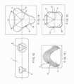
Figs. 9 to 11 another embodiment is illustrated which differs from the embodiment ofFigs. 1 to 8 only in that the generally polygonal throughhole 9 comprises rounded corners instead of the N = 3peripheral holes 2 arranged in the corners. Similarly to the embodiment ofFigs. 1 to 8 , thewall 10 of the throughhole 9 comprises n = 3convex sections 15 which in a cross-section orthogonal to thelongitudinal axis 6 are centrally located on the sides of an equilateral triangle. Each of theconvex sections 15 is convexly curved in a cross-section orthogonal to thelongitudinal axis 6 of the throughhole 9 with the apex of eachconvex section 15 located on a middle line orthogonal to one side of the equilateral triangle. Due to theconvex sections 15, abone screw 30 may be inserted into the throughhole 9 under a surgeon selected angle relative to theaxis 6. - The through
hole 9 includes three radially symmetrically arrangedconvex sections 15 centrally located on the sides of an equilateral triangle and three concavely rounded sections in the corners of the equilateral triangle. Thewall 10 of the throughhole 9 therefore comprises n = 3 wall portions whereof each wall portion extends along one side of an equilateral triangle and is limited by a transition to a first concavely rounded section at one of its ends and by a transition to a second concavely rounded section at its other end. In the present embodiment eachconvex section 15 extends over the whole length of the wall portion limited by the transitions. Thethread 5 or thread-like structure extends over the whole periphery of the throughhole 9. The depth of thread of thethread 5 or thread-like structure can decrease in the concavely rounded sections. - As illustrated in
Fig. 10 the throughhole 9 tapers towards thedistal surface 8 of thebone plate 1. Acentral bone screw 30 with ascrew axis 33 and ascrew head 31 is inserted in the throughhole 9. Thescrew head 31 is spherically shaped and comprises anexternal thread 32 so that thecentral bone screw 30 can be inserted into the through hole at a user-selected variable angle α between thescrew axis 33 and thelongitudinal axis 6 of the throughhole 9. - In
Figs. 12 to 14 another embodiment of thebone plate 1 is illustrated which comprises two throughholes 9. Similarly to the embodiment ofFigs. 9 to 11 , the throughhole 9 has cross-sectional area orthogonal to thelongitudinal axis 6 with acenter 14 located on thelongitudinal axis 6 with each of the n = 3convex sections 15 being limited by two radii intersecting each other in thecenter 14 and enclosing an angle Ω which is smaller than 120°. Thewall 10 of each of the two throughholes 9 comprises n = 3 wall portions with each wall portion extending along one side of an equilateral triangle and limited by a transition to a first concavely rounded section at one of its ends and by a transition to a second concavely rounded section at its other end. Similarly to the embodiment ofFigs. 9 to 11 , eachconvex section 15 extends over the whole length of the wall portion limited by the transitions. The throughholes 9 differ from the throughhole 9 of the embodiment ofFigs. 9 to 11 only in that thethread 5 or thread-like structure does not extend over the whole periphery of the throughhole 9. The depth of thread of thethread 5 or thread-like structure decreases on each end of theconvex section 15 at the transition between theconvex section 15 and the concavely rounded section in such a way that a portion of the concavely rounded sections is unthreaded. - As illustrated in
Fig. 13 the throughhole 9 tapers radially inward toward thedistal surface 8 of thebone plate 1. Similarly to the embodiment ofFigs. 9 to 11 , acentral bone screw 30 with ascrew axis 33 and ascrew head 31 can be inserted in the throughhole 9. By using acentral bone screw 30 thescrew head 31 of which is spherically shaped with anexternal thread 32, thecentral bone screw 30 may be inserted into the throughhole 9 at a user-selected, variable angle α of thescrew axis 33 to thelongitudinal axis 6 of the throughhole 9. Fig. 15 illustrates a further embodiment of the throughhole 9 which differs from the embodiment ofFigs. 12 to 14 only in that it comprises n = 4convex sections 15. Each of the n = 4convex sections 15 is limited by two radii intersecting each other in thecenter 14 and enclosing an angle Q which smaller than 90°. Thewall 10 of each of the two throughholes 9 comprises n = 4 wall portions with each wall portion extending along one side of a square and limited by a transition to a first concavely rounded section at one of its ends and by a transition to a second concavely rounded section at its other end. Similarly to the embodiment ofFigs. 9 to 11 , eachconvex section 15 extends over the whole length of the wall portion limited by the transitions. Thethread 5 or thread-like structure does not extend over the whole periphery of the throughhole 9. The depth of thread of thethread 5 or thread-like structure decreases on each end of theconvex section 15 at the transition between theconvex section 15 and the concavely rounded section in such a way that a portion of the concavely rounded sections is unthreaded.Fig. 16 illustrates again a further embodiment of the throughhole 9 which differs from the embodiment ofFig. 15 only in that thewall 10 of the throughhole 9 comprises n = 4straight sections 15 and that the depth of thread of thethread 5 or thread-like structure decreases from a middle line orthogonal to one side of the square towards the transition between thestraight section 15 and each of the concavely rounded sections in such a way that the concavely rounded sections are unthreaded.Figs. 17 and 18 illustrate again a further embodiment of the throughhole 9 which differs from the embodiment ofFig. 14 only in that the N = 3peripheral holes 2 are configured to receive conventional cortex screws. Eachperipheral hole 2 comprises aspherical recess 25 penetrating partially into thebone plate 1 from theproximal surface 7 and axially adjacent to a conically enlarginglower section 26 extending between thespherical recess 25 and thedistal surface 8 of thebone plate 1. Due to thespherical recess 25, a conventional cortex screw with a spherical head may be inserted into each of theperipheral holes 2 at a user-selected angle with respect to theaxis 11 of theperipheral hole 2. The n = 3 straight orconvex sections 15 of thewall 10 of the throughhole 9 are configured similarly to the embodiment ofFig. 14 .
Claims (17)
- A bone plate (1), comprising:
a first through hole (9) extending through the plate (1) along a first longitudinal axis (6) from a proximal surface (7) of the plate (1) to a bone-facing distal surface (8) thereof which, when the plate (1) is placed on a target portion of bone in a desired orientation, faces the bone, a wall (10) of the first through hole (9) including at least three wall sections (15) provided with thread or thread-like structures for receiving a screw head of a bone screw (30),characterised by the at least three wall sections (15) being straight or convex. - The bone plate according to claim 1, wherein a cross-sectional shape of the first through hole (9) extending orthogonally to the first longitudinal axis (6) is polygonal.
- The bone plate according to claim 2, wherein a cross-sectional shape of the first through hole (9) extending orthogonally to the first longitudinal axis (6) is polygonal with rounded corners.
- The bone plate according to any preceding claim, wherein the first through hole (9) tapers down in size in a direction from the proximal surface (7) towards the distal surface (8) of the bone plate (1).
- The bone plate according to any preceding claim, wherein the thread or thread-like structure extend over an entire length of each of the wall sections (15).
- The bone plate according to any preceding claim, wherein the thread or thread-like structure has a constant depth of thread in the wall sections (15).
- The bone plate according to any one of claims 1 to 5, wherein a depth of thread of the thread or thread-like structure decreases towards each end of each of the wall sections (15).
- The bone plate according to any one of claims 1 to 5 or 7, wherein a depth of thread of the one of thread and thread-like structure decreases outside each end of each of the wall sections (15).
- The bone plate according to any preceding claim, further comprising:
a plurality of first peripheral holes (2), each of the first peripheral holes (2) extending through the bone plate (1) from the proximal surface (7) to the distal surface (8) thereof along a corresponding first hole axis (11) and being configured to receive screw heads of peripheral bone screws, each of the first peripheral holes (2) overlapping a periphery of the first through hole (9) to form a composite hole structure configured to receive peripheral bone screws through the first peripheral holes (2) and a central bone screw through the first through hole (9). - The bone plate according to claim 9, wherein each of the first peripheral holes (2) comprises a spherical recess (25) partially penetrating the bone plate (1) from the proximal surface (7).
- The bone plate according to claim 9 or claim 10, wherein either; each of the first peripheral holes (2) includes a thread for locking a peripheral bone screw therein at a fixed angle relative to the corresponding first hole axis (11) and wherein the first through hole (9) includes a thread configured to lock a bone screw inserted therein at an angle relative to the first longitudinal axis (6) selected by a user; or each of the first peripheral holes (2) includes a thread configured to lock a peripheral bone screw therein at an angle relative to the corresponding first hole axis (11) selected by a user and wherein the first through hole (9) includes a thread configured to lock a bone screw therein at an angle fixed relative to the first longitudinal axis (6).
- The bone plate according to claim 11, wherein the thread extends over at least half of a circumference of each of the first peripheral holes (2).
- The bone plate according to any one of claims 9 to 12, wherein the first through hole (9) is polygonal and each of the first peripheral holes (2) is arranged at a corner of the first through hole (9).
- The bone plate according to any one of claims 9 to 13, wherein the first hole axis (11) of a first one of the first peripheral holes (2) oriented relative to the first longitudinal axis (6) at an angle between ±5° and ±20°.
- The bone plate according to any preceding claim, further comprising a second through hole (9), wherein a wall of the second through hole includes three wall sections which are one of straight and convex.
- The bone plate according to any preceding claim, wherein the first through hole (9) further comprises at least three concave sections, each of the concave sections extending between adjacent ones of the wall sections (15).
- A kit for bone fixation, comprising:a bone plate (1) according to one of the claims 1 to 16, anda central bone screw configured to be inserted through the through hole (9), the central bone screw including a threaded head sized and shaped to lockingly engage the thread or thread-like structures in the through hole; andN peripheral bone screws, each of the peripheral bone screws being sized and shaped to be inserted through a corresponding one of the peripheral holes.
Applications Claiming Priority (4)
| Application Number | Priority Date | Filing Date | Title |
|---|---|---|---|
| US35069110P | 2010-06-02 | 2010-06-02 | |
| EP14003456.2AEP2826432B1 (en) | 2010-06-02 | 2011-05-04 | Bone plate |
| EP11719740.0AEP2575655B1 (en) | 2010-06-02 | 2011-05-04 | Bone plate |
| PCT/US2011/035181WO2011152951A1 (en) | 2010-06-02 | 2011-05-04 | Bone plate |
Related Parent Applications (2)
| Application Number | Title | Priority Date | Filing Date |
|---|---|---|---|
| EP11719740.0ADivisionEP2575655B1 (en) | 2010-06-02 | 2011-05-04 | Bone plate |
| EP14003456.2ADivisionEP2826432B1 (en) | 2010-06-02 | 2011-05-04 | Bone plate |
Publications (3)
| Publication Number | Publication Date |
|---|---|
| EP3659535A1 EP3659535A1 (en) | 2020-06-03 |
| EP3659535C0 EP3659535C0 (en) | 2023-10-18 |
| EP3659535B1true EP3659535B1 (en) | 2023-10-18 |
Family
ID=44259957
Family Applications (3)
| Application Number | Title | Priority Date | Filing Date |
|---|---|---|---|
| EP14003456.2AActiveEP2826432B1 (en) | 2010-06-02 | 2011-05-04 | Bone plate |
| EP11719740.0AActiveEP2575655B1 (en) | 2010-06-02 | 2011-05-04 | Bone plate |
| EP20152934.4AActiveEP3659535B1 (en) | 2010-06-02 | 2011-05-04 | Bone plate |
Family Applications Before (2)
| Application Number | Title | Priority Date | Filing Date |
|---|---|---|---|
| EP14003456.2AActiveEP2826432B1 (en) | 2010-06-02 | 2011-05-04 | Bone plate |
| EP11719740.0AActiveEP2575655B1 (en) | 2010-06-02 | 2011-05-04 | Bone plate |
Country Status (8)
| Country | Link |
|---|---|
| US (3) | US9801669B2 (en) |
| EP (3) | EP2826432B1 (en) |
| JP (2) | JP5918223B2 (en) |
| KR (1) | KR101885507B1 (en) |
| CN (1) | CN102933165B (en) |
| BR (1) | BR112012030248A2 (en) |
| CA (1) | CA2797124A1 (en) |
| WO (1) | WO2011152951A1 (en) |
Families Citing this family (23)
| Publication number | Priority date | Publication date | Assignee | Title |
|---|---|---|---|---|
| US11259851B2 (en) | 2003-08-26 | 2022-03-01 | DePuy Synthes Products, Inc. | Bone plate |
| US11291484B2 (en) | 2004-01-26 | 2022-04-05 | DePuy Synthes Products, Inc. | Highly-versatile variable-angle bone plate system |
| US8834536B2 (en)* | 2009-07-16 | 2014-09-16 | Nexxt Spine, LLC | Cervical plate fixation system |
| WO2013173873A1 (en)* | 2012-05-22 | 2013-11-28 | Austofix Group Limited | Bone fixation device |
| US20140066998A1 (en)* | 2012-09-06 | 2014-03-06 | Jean-Jacques Martin | Assembly comprising an implantable part designed to be fastened to one or more bones or bone portions to be joined, and at least one screw for fastening the implantable part to said bone(s) |
| US9404525B2 (en) | 2013-03-14 | 2016-08-02 | Imds Llc | Polyaxial locking interface |
| US9103367B2 (en) | 2013-03-14 | 2015-08-11 | Imds Llc | Polyaxial locking interface |
| US9510880B2 (en) | 2013-08-13 | 2016-12-06 | Zimmer, Inc. | Polyaxial locking mechanism |
| US10231766B2 (en)* | 2013-12-23 | 2019-03-19 | Smith & Nephew, Inc. | Distal radius plate |
| USD779065S1 (en) | 2014-10-08 | 2017-02-14 | Nuvasive, Inc. | Anterior cervical bone plate |
| KR101722747B1 (en)* | 2015-02-25 | 2017-04-03 | 주식회사 제일메디칼코퍼레이션 | Bone plate system |
| CN104739496A (en)* | 2015-03-12 | 2015-07-01 | 创辉医疗器械江苏有限公司 | Fine-thread universal bone fracture plate |
| GB2542350A (en)* | 2015-05-15 | 2017-03-22 | N2 (Uk) Ltd | Method of creating polyaxial threads and a workpiece with a novel polyaxial thread |
| CN105342680A (en)* | 2015-10-13 | 2016-02-24 | 广州聚生生物科技有限公司 | Anterior cervical interbody steel plate cage integrated internal fixing system |
| US10820930B2 (en) | 2016-09-08 | 2020-11-03 | DePuy Synthes Products, Inc. | Variable angle bone plate |
| US10624686B2 (en) | 2016-09-08 | 2020-04-21 | DePuy Synthes Products, Inc. | Variable angel bone plate |
| US10905476B2 (en) | 2016-09-08 | 2021-02-02 | DePuy Synthes Products, Inc. | Variable angle bone plate |
| US11026727B2 (en) | 2018-03-20 | 2021-06-08 | DePuy Synthes Products, Inc. | Bone plate with form-fitting variable-angle locking hole |
| US10772665B2 (en)* | 2018-03-29 | 2020-09-15 | DePuy Synthes Products, Inc. | Locking structures for affixing bone anchors to a bone plate, and related systems and methods |
| US11013541B2 (en)* | 2018-04-30 | 2021-05-25 | DePuy Synthes Products, Inc. | Threaded locking structures for affixing bone anchors to a bone plate, and related systems and methods |
| US10925651B2 (en) | 2018-12-21 | 2021-02-23 | DePuy Synthes Products, Inc. | Implant having locking holes with collection cavity for shavings |
| US12070253B2 (en)* | 2019-06-07 | 2024-08-27 | Smith & Nephew, Inc. | Orthopedic implant with improved variable angle locking mechanism |
| GB201913436D0 (en)* | 2019-09-18 | 2019-10-30 | Depuy Ireland Ultd Co | Cutting block |
Family Cites Families (15)
| Publication number | Priority date | Publication date | Assignee | Title |
|---|---|---|---|---|
| US6139550A (en)* | 1997-02-11 | 2000-10-31 | Michelson; Gary K. | Skeletal plating system |
| ZA983955B (en)* | 1997-05-15 | 2001-08-13 | Sdgi Holdings Inc | Anterior cervical plating system. |
| FR2848413B1 (en)* | 2002-12-11 | 2005-07-29 | Fixano | OSTEOSYNTHESIS PLATE FOR OSTEOSYNTHESIS OF SMALL BONE NEIGHBORS OF OTHERS |
| US7309340B2 (en)* | 2003-06-20 | 2007-12-18 | Medicinelodge, Inc. | Method and apparatus for bone plating |
| DE20321551U1 (en)* | 2003-08-26 | 2007-12-27 | Synthes Gmbh | bone plate |
| US8574268B2 (en)* | 2004-01-26 | 2013-11-05 | DePuy Synthes Product, LLC | Highly-versatile variable-angle bone plate system |
| DE102005042766B4 (en)* | 2005-07-13 | 2009-08-20 | Königsee Implantate und Instrumente zur Osteosynthese GmbH | Plate hole of a bone plate for osteosynthesis |
| US8382807B2 (en)* | 2005-07-25 | 2013-02-26 | Smith & Nephew, Inc. | Systems and methods for using polyaxial plates |
| CA2616798C (en)* | 2005-07-25 | 2014-01-28 | Smith & Nephew, Inc. | Systems and methods for using polyaxial plates |
| DE202006019220U1 (en)* | 2006-12-19 | 2007-05-24 | Zrinski Ag | Orthopedic screw fastening system for fixing at bone of patient, has through-holes cut on one another so that intersection line and surfaces are produced in direction of plate thickness, where line and surfaces co-operate with head windings |
| AU2008318657A1 (en)* | 2007-10-30 | 2009-05-07 | Synthes Gmbh | Variable angle locked bone plate |
| US10335214B2 (en)* | 2009-04-24 | 2019-07-02 | DePuy Synthes Products, Inc. | Multiplexed screws |
| CN201469392U (en)* | 2009-08-07 | 2010-05-19 | 武汉德骼拜尔外科植入物有限公司 | Irregularly-shaped locking type bone fracture plate |
| US9404525B2 (en)* | 2013-03-14 | 2016-08-02 | Imds Llc | Polyaxial locking interface |
| US9545277B2 (en)* | 2014-03-11 | 2017-01-17 | DePuy Synthes Products, Inc. | Bone plate |
- 2011
- 2011-05-04EPEP14003456.2Apatent/EP2826432B1/enactiveActive
- 2011-05-04WOPCT/US2011/035181patent/WO2011152951A1/enactiveApplication Filing
- 2011-05-04CACA2797124Apatent/CA2797124A1/ennot_activeAbandoned
- 2011-05-04KRKR1020127031253Apatent/KR101885507B1/enactiveActive
- 2011-05-04EPEP11719740.0Apatent/EP2575655B1/enactiveActive
- 2011-05-04CNCN201180026827.4Apatent/CN102933165B/enactiveActive
- 2011-05-04USUS13/100,784patent/US9801669B2/enactiveActive
- 2011-05-04EPEP20152934.4Apatent/EP3659535B1/enactiveActive
- 2011-05-04JPJP2013513176Apatent/JP5918223B2/enactiveActive
- 2011-05-04BRBR112012030248Apatent/BR112012030248A2/ennot_activeApplication Discontinuation
- 2016
- 2016-04-07JPJP2016077099Apatent/JP6266684B2/enactiveActive
- 2017
- 2017-10-02USUS15/722,775patent/US9974583B2/enactiveActive
- 2019
- 2019-11-26USUS16/696,282patent/USRE49771E1/enactiveActive
Also Published As
| Publication number | Publication date |
|---|---|
| CN102933165A (en) | 2013-02-13 |
| BR112012030248A2 (en) | 2017-01-24 |
| CN102933165B (en) | 2015-07-29 |
| JP5918223B2 (en) | 2016-05-18 |
| JP2016154877A (en) | 2016-09-01 |
| JP2013528075A (en) | 2013-07-08 |
| US9801669B2 (en) | 2017-10-31 |
| EP3659535C0 (en) | 2023-10-18 |
| EP2575655A1 (en) | 2013-04-10 |
| US20180021072A1 (en) | 2018-01-25 |
| US9974583B2 (en) | 2018-05-22 |
| USRE49771E1 (en) | 2024-01-02 |
| US20110301608A1 (en) | 2011-12-08 |
| CA2797124A1 (en) | 2011-12-08 |
| KR20130103666A (en) | 2013-09-24 |
| JP6266684B2 (en) | 2018-01-24 |
| EP3659535A1 (en) | 2020-06-03 |
| EP2575655B1 (en) | 2014-12-10 |
| EP2826432B1 (en) | 2020-02-12 |
| EP2826432A1 (en) | 2015-01-21 |
| WO2011152951A1 (en) | 2011-12-08 |
| KR101885507B1 (en) | 2018-08-07 |
Similar Documents
| Publication | Publication Date | Title |
|---|---|---|
| EP3659535B1 (en) | Bone plate | |
| EP2477566B1 (en) | Variable angle compression plate | |
| EP2932928B1 (en) | Bone plate with enlarged angle of inclination for a bone anchor to a favored side | |
| CN109788976B (en) | Variable angle bone plate | |
| US20100312286A1 (en) | Variable Angle Locked Bone Plate | |
| EP2720630B1 (en) | Modular bone plate and member of such a modular bone plate | |
| EP2544614B1 (en) | Locking element for a polyaxial bone anchor, bone plate assembly and tool | |
| US20140303674A1 (en) | Parallel rod connector | |
| EP3768181B1 (en) | Bone plate with form-fitting variable-angle locking hole | |
| KR101520418B1 (en) | Variable angle locked bone plate | |
| US20080172094A1 (en) | Device for osteosynthesis | |
| KR20150048160A (en) | Anchor-in-anchor system | |
| US12433652B2 (en) | Tool attachment point with alignment aid for screw elements |
Legal Events
| Date | Code | Title | Description |
|---|---|---|---|
| PUAI | Public reference made under article 153(3) epc to a published international application that has entered the european phase | Free format text:ORIGINAL CODE: 0009012 | |
| STAA | Information on the status of an ep patent application or granted ep patent | Free format text:STATUS: THE APPLICATION HAS BEEN PUBLISHED | |
| AC | Divisional application: reference to earlier application | Ref document number:2575655 Country of ref document:EP Kind code of ref document:P Ref document number:2826432 Country of ref document:EP Kind code of ref document:P | |
| AK | Designated contracting states | Kind code of ref document:A1 Designated state(s):AL AT BE BG CH CY CZ DE DK EE ES FI FR GB GR HR HU IE IS IT LI LT LU LV MC MK MT NL NO PL PT RO RS SE SI SK SM TR | |
| RIN1 | Information on inventor provided before grant (corrected) | Inventor name:ROTH, BEAT Inventor name:HULLIGER, URS | |
| STAA | Information on the status of an ep patent application or granted ep patent | Free format text:STATUS: REQUEST FOR EXAMINATION WAS MADE | |
| 17P | Request for examination filed | Effective date:20201030 | |
| RBV | Designated contracting states (corrected) | Designated state(s):AL AT BE BG CH CY CZ DE DK EE ES FI FR GB GR HR HU IE IS IT LI LT LU LV MC MK MT NL NO PL PT RO RS SE SI SK SM TR | |
| GRAP | Despatch of communication of intention to grant a patent | Free format text:ORIGINAL CODE: EPIDOSNIGR1 | |
| STAA | Information on the status of an ep patent application or granted ep patent | Free format text:STATUS: GRANT OF PATENT IS INTENDED | |
| INTG | Intention to grant announced | Effective date:20230224 | |
| GRAJ | Information related to disapproval of communication of intention to grant by the applicant or resumption of examination proceedings by the epo deleted | Free format text:ORIGINAL CODE: EPIDOSDIGR1 | |
| STAA | Information on the status of an ep patent application or granted ep patent | Free format text:STATUS: REQUEST FOR EXAMINATION WAS MADE | |
| INTC | Intention to grant announced (deleted) | ||
| GRAP | Despatch of communication of intention to grant a patent | Free format text:ORIGINAL CODE: EPIDOSNIGR1 | |
| STAA | Information on the status of an ep patent application or granted ep patent | Free format text:STATUS: GRANT OF PATENT IS INTENDED | |
| INTG | Intention to grant announced | Effective date:20230707 | |
| GRAS | Grant fee paid | Free format text:ORIGINAL CODE: EPIDOSNIGR3 | |
| GRAA | (expected) grant | Free format text:ORIGINAL CODE: 0009210 | |
| STAA | Information on the status of an ep patent application or granted ep patent | Free format text:STATUS: THE PATENT HAS BEEN GRANTED | |
| AC | Divisional application: reference to earlier application | Ref document number:2575655 Country of ref document:EP Kind code of ref document:P Ref document number:2826432 Country of ref document:EP Kind code of ref document:P | |
| AK | Designated contracting states | Kind code of ref document:B1 Designated state(s):AL AT BE BG CH CY CZ DE DK EE ES FI FR GB GR HR HU IE IS IT LI LT LU LV MC MK MT NL NO PL PT RO RS SE SI SK SM TR | |
| REG | Reference to a national code | Ref country code:GB Ref legal event code:FG4D | |
| REG | Reference to a national code | Ref country code:CH Ref legal event code:EP | |
| REG | Reference to a national code | Ref country code:DE Ref legal event code:R096 Ref document number:602011074346 Country of ref document:DE | |
| REG | Reference to a national code | Ref country code:IE Ref legal event code:FG4D | |
| U01 | Request for unitary effect filed | Effective date:20231120 | |
| U07 | Unitary effect registered | Designated state(s):AT BE BG DE DK EE FI FR IT LT LU LV MT NL PT SE SI Effective date:20231124 | |
| PG25 | Lapsed in a contracting state [announced via postgrant information from national office to epo] | Ref country code:GR Free format text:LAPSE BECAUSE OF FAILURE TO SUBMIT A TRANSLATION OF THE DESCRIPTION OR TO PAY THE FEE WITHIN THE PRESCRIBED TIME-LIMIT Effective date:20240119 | |
| PG25 | Lapsed in a contracting state [announced via postgrant information from national office to epo] | Ref country code:IS Free format text:LAPSE BECAUSE OF FAILURE TO SUBMIT A TRANSLATION OF THE DESCRIPTION OR TO PAY THE FEE WITHIN THE PRESCRIBED TIME-LIMIT Effective date:20240218 | |
| PG25 | Lapsed in a contracting state [announced via postgrant information from national office to epo] | Ref country code:ES Free format text:LAPSE BECAUSE OF FAILURE TO SUBMIT A TRANSLATION OF THE DESCRIPTION OR TO PAY THE FEE WITHIN THE PRESCRIBED TIME-LIMIT Effective date:20231018 | |
| PG25 | Lapsed in a contracting state [announced via postgrant information from national office to epo] | Ref country code:IS Free format text:LAPSE BECAUSE OF FAILURE TO SUBMIT A TRANSLATION OF THE DESCRIPTION OR TO PAY THE FEE WITHIN THE PRESCRIBED TIME-LIMIT Effective date:20240218 Ref country code:GR Free format text:LAPSE BECAUSE OF FAILURE TO SUBMIT A TRANSLATION OF THE DESCRIPTION OR TO PAY THE FEE WITHIN THE PRESCRIBED TIME-LIMIT Effective date:20240119 Ref country code:ES Free format text:LAPSE BECAUSE OF FAILURE TO SUBMIT A TRANSLATION OF THE DESCRIPTION OR TO PAY THE FEE WITHIN THE PRESCRIBED TIME-LIMIT Effective date:20231018 | |
| U20 | Renewal fee for the european patent with unitary effect paid | Year of fee payment:14 Effective date:20240408 | |
| PG25 | Lapsed in a contracting state [announced via postgrant information from national office to epo] | Ref country code:RS Free format text:LAPSE BECAUSE OF FAILURE TO SUBMIT A TRANSLATION OF THE DESCRIPTION OR TO PAY THE FEE WITHIN THE PRESCRIBED TIME-LIMIT Effective date:20231018 Ref country code:PL Free format text:LAPSE BECAUSE OF FAILURE TO SUBMIT A TRANSLATION OF THE DESCRIPTION OR TO PAY THE FEE WITHIN THE PRESCRIBED TIME-LIMIT Effective date:20231018 Ref country code:NO Free format text:LAPSE BECAUSE OF FAILURE TO SUBMIT A TRANSLATION OF THE DESCRIPTION OR TO PAY THE FEE WITHIN THE PRESCRIBED TIME-LIMIT Effective date:20240118 Ref country code:HR Free format text:LAPSE BECAUSE OF FAILURE TO SUBMIT A TRANSLATION OF THE DESCRIPTION OR TO PAY THE FEE WITHIN THE PRESCRIBED TIME-LIMIT Effective date:20231018 | |
| REG | Reference to a national code | Ref country code:DE Ref legal event code:R097 Ref document number:602011074346 Country of ref document:DE | |
| PG25 | Lapsed in a contracting state [announced via postgrant information from national office to epo] | Ref country code:CZ Free format text:LAPSE BECAUSE OF FAILURE TO SUBMIT A TRANSLATION OF THE DESCRIPTION OR TO PAY THE FEE WITHIN THE PRESCRIBED TIME-LIMIT Effective date:20231018 | |
| PG25 | Lapsed in a contracting state [announced via postgrant information from national office to epo] | Ref country code:SK Free format text:LAPSE BECAUSE OF FAILURE TO SUBMIT A TRANSLATION OF THE DESCRIPTION OR TO PAY THE FEE WITHIN THE PRESCRIBED TIME-LIMIT Effective date:20231018 | |
| PG25 | Lapsed in a contracting state [announced via postgrant information from national office to epo] | Ref country code:SM Free format text:LAPSE BECAUSE OF FAILURE TO SUBMIT A TRANSLATION OF THE DESCRIPTION OR TO PAY THE FEE WITHIN THE PRESCRIBED TIME-LIMIT Effective date:20231018 Ref country code:SK Free format text:LAPSE BECAUSE OF FAILURE TO SUBMIT A TRANSLATION OF THE DESCRIPTION OR TO PAY THE FEE WITHIN THE PRESCRIBED TIME-LIMIT Effective date:20231018 Ref country code:RO Free format text:LAPSE BECAUSE OF FAILURE TO SUBMIT A TRANSLATION OF THE DESCRIPTION OR TO PAY THE FEE WITHIN THE PRESCRIBED TIME-LIMIT Effective date:20231018 Ref country code:CZ Free format text:LAPSE BECAUSE OF FAILURE TO SUBMIT A TRANSLATION OF THE DESCRIPTION OR TO PAY THE FEE WITHIN THE PRESCRIBED TIME-LIMIT Effective date:20231018 | |
| PLBE | No opposition filed within time limit | Free format text:ORIGINAL CODE: 0009261 | |
| STAA | Information on the status of an ep patent application or granted ep patent | Free format text:STATUS: NO OPPOSITION FILED WITHIN TIME LIMIT | |
| 26N | No opposition filed | Effective date:20240719 | |
| PG25 | Lapsed in a contracting state [announced via postgrant information from national office to epo] | Ref country code:MC Free format text:LAPSE BECAUSE OF FAILURE TO SUBMIT A TRANSLATION OF THE DESCRIPTION OR TO PAY THE FEE WITHIN THE PRESCRIBED TIME-LIMIT Effective date:20231018 | |
| PG25 | Lapsed in a contracting state [announced via postgrant information from national office to epo] | Ref country code:MC Free format text:LAPSE BECAUSE OF FAILURE TO SUBMIT A TRANSLATION OF THE DESCRIPTION OR TO PAY THE FEE WITHIN THE PRESCRIBED TIME-LIMIT Effective date:20231018 | |
| PG25 | Lapsed in a contracting state [announced via postgrant information from national office to epo] | Ref country code:IE Free format text:LAPSE BECAUSE OF NON-PAYMENT OF DUE FEES Effective date:20240504 | |
| U20 | Renewal fee for the european patent with unitary effect paid | Year of fee payment:15 Effective date:20250407 | |
| PGFP | Annual fee paid to national office [announced via postgrant information from national office to epo] | Ref country code:GB Payment date:20250401 Year of fee payment:15 | |
| PGFP | Annual fee paid to national office [announced via postgrant information from national office to epo] | Ref country code:CH Payment date:20250601 Year of fee payment:15 | |
| PG25 | Lapsed in a contracting state [announced via postgrant information from national office to epo] | Ref country code:CY Free format text:LAPSE BECAUSE OF FAILURE TO SUBMIT A TRANSLATION OF THE DESCRIPTION OR TO PAY THE FEE WITHIN THE PRESCRIBED TIME-LIMIT; INVALID AB INITIO Effective date:20110504 | |
| PG25 | Lapsed in a contracting state [announced via postgrant information from national office to epo] | Ref country code:HU Free format text:LAPSE BECAUSE OF FAILURE TO SUBMIT A TRANSLATION OF THE DESCRIPTION OR TO PAY THE FEE WITHIN THE PRESCRIBED TIME-LIMIT; INVALID AB INITIO Effective date:20110504 |