EP3659045B1 - Methods for managing distributed snapshot for low latency storage and devices thereof - Google Patents
Methods for managing distributed snapshot for low latency storage and devices thereofDownload PDFInfo
- Publication number
- EP3659045B1 EP3659045B1EP18728471.6AEP18728471AEP3659045B1EP 3659045 B1EP3659045 B1EP 3659045B1EP 18728471 AEP18728471 AEP 18728471AEP 3659045 B1EP3659045 B1EP 3659045B1
- Authority
- EP
- European Patent Office
- Prior art keywords
- snapshot
- storage
- computing device
- primary
- data
- Prior art date
- Legal status (The legal status is an assumption and is not a legal conclusion. Google has not performed a legal analysis and makes no representation as to the accuracy of the status listed.)
- Active
Links
Images


Classifications
- G—PHYSICS
- G06—COMPUTING OR CALCULATING; COUNTING
- G06F—ELECTRIC DIGITAL DATA PROCESSING
- G06F16/00—Information retrieval; Database structures therefor; File system structures therefor
- G06F16/10—File systems; File servers
- G06F16/11—File system administration, e.g. details of archiving or snapshots
- G06F16/119—Details of migration of file systems
- G—PHYSICS
- G06—COMPUTING OR CALCULATING; COUNTING
- G06F—ELECTRIC DIGITAL DATA PROCESSING
- G06F16/00—Information retrieval; Database structures therefor; File system structures therefor
- G06F16/10—File systems; File servers
- G06F16/11—File system administration, e.g. details of archiving or snapshots
- G06F16/128—Details of file system snapshots on the file-level, e.g. snapshot creation, administration, deletion
- G—PHYSICS
- G06—COMPUTING OR CALCULATING; COUNTING
- G06F—ELECTRIC DIGITAL DATA PROCESSING
- G06F3/00—Input arrangements for transferring data to be processed into a form capable of being handled by the computer; Output arrangements for transferring data from processing unit to output unit, e.g. interface arrangements
- G06F3/06—Digital input from, or digital output to, record carriers, e.g. RAID, emulated record carriers or networked record carriers
- G06F3/0601—Interfaces specially adapted for storage systems
- G06F3/0602—Interfaces specially adapted for storage systems specifically adapted to achieve a particular effect
- G06F3/061—Improving I/O performance
- G06F3/0611—Improving I/O performance in relation to response time
- G—PHYSICS
- G06—COMPUTING OR CALCULATING; COUNTING
- G06F—ELECTRIC DIGITAL DATA PROCESSING
- G06F3/00—Input arrangements for transferring data to be processed into a form capable of being handled by the computer; Output arrangements for transferring data from processing unit to output unit, e.g. interface arrangements
- G06F3/06—Digital input from, or digital output to, record carriers, e.g. RAID, emulated record carriers or networked record carriers
- G06F3/0601—Interfaces specially adapted for storage systems
- G06F3/0602—Interfaces specially adapted for storage systems specifically adapted to achieve a particular effect
- G06F3/0614—Improving the reliability of storage systems
- G06F3/0619—Improving the reliability of storage systems in relation to data integrity, e.g. data losses, bit errors
- G—PHYSICS
- G06—COMPUTING OR CALCULATING; COUNTING
- G06F—ELECTRIC DIGITAL DATA PROCESSING
- G06F3/00—Input arrangements for transferring data to be processed into a form capable of being handled by the computer; Output arrangements for transferring data from processing unit to output unit, e.g. interface arrangements
- G06F3/06—Digital input from, or digital output to, record carriers, e.g. RAID, emulated record carriers or networked record carriers
- G06F3/0601—Interfaces specially adapted for storage systems
- G06F3/0628—Interfaces specially adapted for storage systems making use of a particular technique
- G06F3/0646—Horizontal data movement in storage systems, i.e. moving data in between storage devices or systems
- G06F3/0647—Migration mechanisms
- G—PHYSICS
- G06—COMPUTING OR CALCULATING; COUNTING
- G06F—ELECTRIC DIGITAL DATA PROCESSING
- G06F3/00—Input arrangements for transferring data to be processed into a form capable of being handled by the computer; Output arrangements for transferring data from processing unit to output unit, e.g. interface arrangements
- G06F3/06—Digital input from, or digital output to, record carriers, e.g. RAID, emulated record carriers or networked record carriers
- G06F3/0601—Interfaces specially adapted for storage systems
- G06F3/0628—Interfaces specially adapted for storage systems making use of a particular technique
- G06F3/0646—Horizontal data movement in storage systems, i.e. moving data in between storage devices or systems
- G06F3/065—Replication mechanisms
- G—PHYSICS
- G06—COMPUTING OR CALCULATING; COUNTING
- G06F—ELECTRIC DIGITAL DATA PROCESSING
- G06F3/00—Input arrangements for transferring data to be processed into a form capable of being handled by the computer; Output arrangements for transferring data from processing unit to output unit, e.g. interface arrangements
- G06F3/06—Digital input from, or digital output to, record carriers, e.g. RAID, emulated record carriers or networked record carriers
- G06F3/0601—Interfaces specially adapted for storage systems
- G06F3/0628—Interfaces specially adapted for storage systems making use of a particular technique
- G06F3/0662—Virtualisation aspects
- G06F3/0665—Virtualisation aspects at area level, e.g. provisioning of virtual or logical volumes
- G—PHYSICS
- G06—COMPUTING OR CALCULATING; COUNTING
- G06F—ELECTRIC DIGITAL DATA PROCESSING
- G06F3/00—Input arrangements for transferring data to be processed into a form capable of being handled by the computer; Output arrangements for transferring data from processing unit to output unit, e.g. interface arrangements
- G06F3/06—Digital input from, or digital output to, record carriers, e.g. RAID, emulated record carriers or networked record carriers
- G06F3/0601—Interfaces specially adapted for storage systems
- G06F3/0668—Interfaces specially adapted for storage systems adopting a particular infrastructure
- G06F3/067—Distributed or networked storage systems, e.g. storage area networks [SAN], network attached storage [NAS]
- G—PHYSICS
- G06—COMPUTING OR CALCULATING; COUNTING
- G06F—ELECTRIC DIGITAL DATA PROCESSING
- G06F3/00—Input arrangements for transferring data to be processed into a form capable of being handled by the computer; Output arrangements for transferring data from processing unit to output unit, e.g. interface arrangements
- G06F3/06—Digital input from, or digital output to, record carriers, e.g. RAID, emulated record carriers or networked record carriers
- G06F3/0601—Interfaces specially adapted for storage systems
- G06F3/0668—Interfaces specially adapted for storage systems adopting a particular infrastructure
- G06F3/0671—In-line storage system
- G06F3/0673—Single storage device
- G06F3/0679—Non-volatile semiconductor memory device, e.g. flash memory, one time programmable memory [OTP]
- G—PHYSICS
- G06—COMPUTING OR CALCULATING; COUNTING
- G06F—ELECTRIC DIGITAL DATA PROCESSING
- G06F3/00—Input arrangements for transferring data to be processed into a form capable of being handled by the computer; Output arrangements for transferring data from processing unit to output unit, e.g. interface arrangements
- G06F3/06—Digital input from, or digital output to, record carriers, e.g. RAID, emulated record carriers or networked record carriers
- G06F3/0601—Interfaces specially adapted for storage systems
- G06F3/0668—Interfaces specially adapted for storage systems adopting a particular infrastructure
- G06F3/0671—In-line storage system
- G06F3/0683—Plurality of storage devices
- G06F3/0685—Hybrid storage combining heterogeneous device types, e.g. hierarchical storage, hybrid arrays
- G—PHYSICS
- G06—COMPUTING OR CALCULATING; COUNTING
- G06F—ELECTRIC DIGITAL DATA PROCESSING
- G06F3/00—Input arrangements for transferring data to be processed into a form capable of being handled by the computer; Output arrangements for transferring data from processing unit to output unit, e.g. interface arrangements
- G06F3/06—Digital input from, or digital output to, record carriers, e.g. RAID, emulated record carriers or networked record carriers
- G06F3/0601—Interfaces specially adapted for storage systems
- G06F3/0668—Interfaces specially adapted for storage systems adopting a particular infrastructure
- G06F3/0671—In-line storage system
- G06F3/0683—Plurality of storage devices
- G06F3/0689—Disk arrays, e.g. RAID, JBOD
Definitions
- This technologyrelates to managing distributed snapshot for low latency storage.
- the clustered network environment 100includes data storage apparatuses 102(1)-102(n) that are coupled over a cluster fabric 104 facilitating communication between the data storage apparatuses 102(1)-102(n) (and one or more modules, components, etc. therein, such as, node computing devices 106(1)-106(n)), although any number of other elements or components can also be included in the clustered network environment 100 in other examples.
- Node computing devices 106(1)-106(n)can be primary or local storage controllers or secondary or remote storage controllers that provide client devices 108(1)-108(n), with access to data stored within data storage devices 110(1)-110(n).
- the data storage apparatuses 102(1)-102(n) and/or node computing device 106(1)-106(n) of the examples described and illustrated hereinare not limited to any particular geographic areas and can be clustered locally and/or remotely.
- the data storage apparatuses 102(1)-102(n) and/or node computing device 106(1)-106(n)can be distributed over a plurality of storage systems located in a plurality of geographic locations or a clustered network can include data storage apparatuses 102(1)-102(n) and/or node computing device 106(1)-106(n) residing in a same geographic location (e.g., in a single onsite rack).
- Network connections 112(1)-112(n)include a local area network (LAN) or wide area network (WAN)that utilizes Network Attached Storage (NAS) protocols, such as a Common Internet File System (CIFS) protocol or a Network File System (NFS) protocol to exchange data packets, a Storage Area Network (SAN) protocol, such as Small Computer System Interface (SCSI) or Fiber Channel Protocol (FCP), an object protocol, such as S3, etc.
- LANlocal area network
- WANwide area network
- NASNetwork Attached Storage
- CIFSCommon Internet File System
- NFSNetwork File System
- SANStorage Area Network
- SCSISmall Computer System Interface
- FCPFiber Channel Protocol
- object protocolsuch as S3, etc.
- the client devices 108(1)-108(n)are general-purpose computers running applications, and interact with the data storage apparatuses 102(1)-102(n) using a client/server model for exchange of information. That is, the client devices 108(1)-108(n) request data from the data storage apparatuses 102(1)-102(n) (e.g., data on one of the data storage devices 110(1)-110(n) managed by a network storage control configured to process I/O commands issued by the client devices 108(1)-108(n)), and the data storage apparatuses 102(1)-102(n) return results of the request to the client devices 108(1)-108(n) via the storage network connections 112(1)-112(n).
- the client devices 108(1)-108(n)are general-purpose computers running applications, and interact with the data storage apparatuses 102(1)-102(n) using a client/server model for exchange of information. That is, the client devices 108(1)-108(n) request data from the data storage apparatuses 102(1)-102(n)
- the node computing devices 106(1)-106(n) of the data storage apparatuses 102(1)-102(n)include network or host nodes that are interconnected as a cluster to provide data storage and management services, such as to an enterprise having remote locations, cloud storage (e.g., a storage endpoint is stored within a data cloud).
- cloud storagee.g., a storage endpoint is stored within a data cloud.
- Such a node computing device 106(1)-106(n)is a device attached to the fabric 104 as a connection point, redistribution point, or communication endpoint.
- One or more of the node computing devices 106(1)-106(n)are capable of sending, receiving, and/or forwarding information over a network communications channel, and could comprise any type of device that meets any or all of these criteria.
- the node computing device 106(1)is located on a first storage site and the node computing device 106(n) is located at a second storage site.
- the node computing devices 106(1) and 106(n)are configured according to a disaster recovery configuration whereby a surviving node provides switchover access to the storage devices 110(1)-110(n) in the event a disaster occurs at a disaster storage site (e.g., the node computing device 106(1) provides client device 112(n) with switchover data access to storage devices 110(n) in the event a disaster occurs at the second storage site).
- a disaster recovery configurationwhereby a surviving node provides switchover access to the storage devices 110(1)-110(n) in the event a disaster occurs at a disaster storage site (e.g., the node computing device 106(1) provides client device 112(n) with switchover data access to storage devices 110(n) in the event a disaster occurs at the second storage site).
- any number of node computing devices or data storage apparatusescan be included.
- node computing devices 106(1)-106(n)include various functional components that coordinate to provide a distributed storage architecture.
- the node computing devices 106(1)-106(n)include network modules 114(1)-114(n) and disk modules 116(1)-116(n).
- Network modules 114(1)-114(n)are configured to allow the node computing devices 106(1)-106(n) (e.g., network storage controllers) to connect with client devices 108(1)-108(n) over the storage network connections 112(1)-112(n), allowing the client devices 108(1)-108(n) to access data stored in the clustered network environment 100.
- the network modules 114(1)-114(n)provide connections with one or more other components through the cluster fabric 104.
- the network module 114(1) of node computing device 106(1)access the data storage device 110(n) by sending a request via the cluster fabric 104 through the disk module 116(n) of node computing device 106(n).
- the cluster fabric 104include one or more local and/or wide area computing networks embodied as Infiniband, Fibre Channel (FC), or Ethernet networksalthough other types of networks supporting other protocols can also be used.
- Disk modules 116(1)-116(n)are configured to connect data storage devices 110(1)-110(2), such as SSDs to the node computing devices 106(1)-106(n). Often, disk modules 116(1)-116(n) communicate with the data storage devices 110(1)-110(n) according to the SAN protocol, such as SCSI, FCP, SAS, NVMe, NVMe-oF, although other protocols can also be used.
- the data storage devices 110(1)-110(n)can appear as locally attached. In this manner, different node computing devices 106(1)-106(n), etc. access data blocks through the operating system, rather than expressly requesting abstract files.
- While the clustered network environment 100illustrates an equal number of network modules 114(1)-114(2) and disk modules 116(1)-116(n), it can include a differing number of these modules. There may be a plurality of network and disk modules interconnected in a cluster that do not have a one-to-one correspondence between the network and disk modules. That is, different node computing devices can have a different number of network and disk modules, and the same node computing device can have a different number of network modules than disk modules.
- one or more of the client devices 108(1)-108(n) and server devices 109(1)-109(n)can be networked with the node computing devices 106(1)-106(n) in the cluster, over the storage connections 112(1)-112(n).
- Respective client devices 108(1)-108(n) that are networked to a clusterrequest services (e.g., exchanging of information in the form of data packets) of node computing devices 106(1)-106(n) in the cluster, and the node computing devices 106(1)-106(n) return results of the requested services to the client devices 108(1)-108(n).
- the client devices 108(1)-108(n)exchange information with the network modules 114(1)-114(n) residing in the node computing devices 106(1)-106(n) (e.g., network hosts) in the data storage apparatuses 102(1)-102(n).
- the network modules 114(1)-114(n)residing in the node computing devices 106(1)-106(n) (e.g., network hosts) in the data storage apparatuses 102(1)-102(n).
- the storage apparatuses 102(1)-102(n) hostaggregates corresponding to physical local and remote data storage devices, such as local flash or disk storage in the data storage devices 110(1)-110(n).
- One or more of the data storage devices 110(1)-110(n)include mass storage devices, such as disks of a disk array.
- the diskscomprise SSDs adapted to store information, including, data (D) and/or parity (P) information.
- the aggregatesinclude volumes 118(1)-118(n) in this example, although any number of volumes can be included in the aggregates.
- the volumes 118(1)-118(n)are virtual data stores that define an arrangement of storage and one or more file systems within the clustered network environment 100. Volumes 118(1)-118(n) span a portion of a disk or other storage device, a collection of disks, or portions of disks, for example, and typically define an overall logical arrangement of file storage. Volumes 118(1)-118(n) include stored data as one or more files or objects that reside in a hierarchical directory structure within the volumes 118(1)-118(n).
- Volumes 118(1)-118(n)are typically configured in formats that are associated with particular storage systems, and respective volume formats typically comprise features that provide functionality to the volumes 118(1)-118(n), such as providing an ability for volumes 118(1)-118(n) to form clusters.
- a file systeme.g., write anywhere file system
- Respective filesare implemented as a set of disk blocks configured to store information
- directoriesmay be implemented as specially formatted files in which information about other files and directories are stored.
- Dataare stored as files or objects within a physical volume and/or a virtual volume, which can be associated with respective volume identifiers, such as file system identifiers (FSIDs).
- the physical volumescorrespond to at least a portion of physical storage devices, such as the data storage device 110(1)-110(n) (e.g., a Redundant Array of Independent (or Inexpensive) Disks (RAID system)) whose address, addressable space, location, etc. does not change.
- RAID systemRedundant Array of Independent (or Inexpensive) Disks
- the location of the physical volumesdoes not change in that the (range of) address(es) used to access it generally remains constant.
- Virtual volumesare stored over an aggregate of disparate portions of different physical storage devices. Virtual volumes may be a collection of different available portions of different physical storage device locations, such as some available space from disks. It will be appreciated that since the virtual volumes are not "tied" to any one particular storage device, virtual volumes can be said to include a layer of abstraction or virtualization, which allows them to be resized and/or flexible in some regards.
- virtual volumescan include one or more logical unit numbers (LUNs), directories, Qtrees, and/or files.
- LUNslogical unit numbers
- directoriesdirectories
- Qtreeslogical unit numbers
- filesfiles
- LUNSlogical unit numbers
- these featuresallow the disparate memory locations within which data is stored to be identified, and grouped as a data storage unit.
- the LUNsare characterized as constituting a virtual disk or drive upon which data within the virtual volumes is stored within an aggregate LUNs are often referred to as virtual disks, such that they emulate a hard drive, while they actually comprise data blocks stored in various parts of a volume.
- the data storage devices 110(1)-110(n)have one or more physical ports, wherein each physical port is assigned a target address (e.g., SCSI target address). To represent respective volumes, a target address on the data storage devices 110(1)-110(n) is used to identify one or more of the LUNs. Thus, when one of the node computing devices 106(1)-106(n) connects to a volume, a connection between the one of the node computing devices 106(1)-106(n) and one or more of the LUNs underlying the volume is created.
- a target addresse.g., SCSI target address
- Respective target addressescan identify multiple of the LUNs, such that a target address can represent multiple volumes.
- the I/O interfacewhich is implemented as circuitry and/or software in a storage adapter or as executable code residing in memory and executed by a processor connect to volumes by using one or more addresses that identify the one or more of the LUNs.
- node computing device 106(1)includes processor(s) 200, a memory 202, a network adapter 204, a cluster access adapter 206, and a storage adapter 208 interconnected by a system bus 210.
- the node computing device 106also includes a storage operating system 212 installed in the memory 206 that can implement a Redundant Array of Independent (or Inexpensive) Disks (RAID) data loss protection and recovery scheme to optimize a reconstruction process of data of a failed disk or drive in an array.
- RAIDRedundant Array of Independent
- the node computing device 106(n)is substantially the same in structure and/or operation as node computing device 106(1), although the node computing device 106(n) can include a different structure and/or operation in one or more aspects than the node computing device 106(1).
- the storage operating system 212also manage communications for the node computing device 106(1) among other devices that may be in a clustered network, such as attached to a cluster fabric 104.
- the node computing device 106(1)respond to client device requests to manage data on one of the data storage devices 110(1)-110(n) (e.g., or additional clustered devices) in accordance with the client device requests.
- the storage operating system 212also establish one or more file systems including software code and data structures that implement a persistent hierarchical namespace of files and directories.
- a new data storage device(not shown) is added to a clustered network system, the storage operating system 212 is informed where, in an existing directory tree, new files associated with the new data storage device are to be stored. This is often referred to as "mounting" a file system.
- memory 202include storage locations that are addressable by the processor(s) 200 and adapters 204, 206, and 208 for storing related software application code and data structures.
- the processor(s) 200 and adapters 204, 206, and 208include processing elements and/or logic circuitry configured to execute the software code and manipulate the data structures.
- the storage operating system 212portions of which are typically resident in the memory 202 and executed by the processor(s) 200, invokes storage operations in support of a file service implemented by the node computing device 106(1).
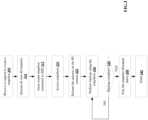
- the executable instructionsare configured to perform one or more steps of a method, described and illustrated later with reference to FIG. 3 .
- the network adapter 204includes the mechanical, electrical and signaling circuitry needed to connect the node computing device 106(1) to one or more of the client devices 108(1)-108(n) over storage network connections 112(1)-112(n), which comprise, among other things, a point-to-point connection or a shared medium, such as a local area network.
- the network adapter 204further communicates (e.g., using TCP/IP) via the fabric 104 and/or another network (e.g. a WAN) (not shown) with cloud storage devices to process storage operations associated with data stored thereon.
- the storage adapter 208cooperates with the storage operating system 212 executing on the node computing device 106(1) to access information requested by one of the client devices 108(1)-108(n) (e.g., to access data on a data storage device 110(1)-110(n) managed by a network storage controller).
- the informationare stored on SSDs adapted to store information.
- the storage adapter 208include input/output (I/O) interface circuitry that couples to the disks over an I/O interconnect arrangement, such as a storage area network (SAN) protocol (e.g., Small Computer System Interface (SCSI), iSCSI, hyperSCSI, Fiber Channel Protocol (FCP)).
- SANstorage area network
- SCSISmall Computer System Interface
- iSCSIiSCSI
- hyperSCSIHyperSCSI
- FCPFiber Channel Protocol
- the informationis retrieved by the storage adapter 208 and, if necessary, processed by the processor(s) 200 (or the storage adapter 208 itself) prior to being forwarded over the system bus 210 to the network adapter 204 (and/or the cluster access adapter 206 if sending to another node computing device in the cluster) where the information is formatted into a data packet and returned to a requesting one of the client devices 108(1)-108(2) and/or sent to another node computing device attached via the cluster fabric 104.
- a storage driver 214 in the memory 202interfaces with the storage adapter to facilitate interactions with the data storage devices 110(1)-110(n), as described and illustrated in more detail later with reference to FIG. 3 .
- step 305the node computing device 106(1) receiving a request to create a snapshot of the primary and the secondary storage, wherein the primary and the secondary storage includes primary and secondary solid state devices (SSD) respectively, although the node computing device 106(1) can receive other types or number of requests.
- the node computing device 106(1)receives the request to create the snapshot when it is determined that a point in time snapshot image is required to allow a full data or a delta update to be made from the primary storage to the secondary storage.
- step 310the node computing device 106(1) quiesces the associated logical volumes requiring the snapshot creation on both the primary storage and the secondary storage.
- Quiescesrelates to queueing all the new input/output requests and allowing all outstanding input/output requests to be completed for all associated LBA extents to all involved SSD,.
- the node computing device 106(1)issues a command to create a snapshot to all the SSDs present in both the primary and the secondary storage that is involved with the specified aggregator or volumes.
- the command to create the snapshotincludes the addressing technique to be used to access the snapshot entity on each of the SSD.
- the SSDs using the flash translation layer (FTL)creates a snapshot allocated capacity as a response to the request and maintains the old data in that region.
- the snapshot allocated capacity as illustrated in FIG. 4is a virtual region.
- the SSD flash translation layer (FTL)presents a primary LUN to the host by presenting the LBA extents that have been written, along with the LBA extents that has not been written.
- the SSD FTLutilizes the over provisioned capacity and the unused capacity in the logical division of the SSD to allow efficient management of the flash media when writes and data scrubs of the SSD are required. Additionally, the SSD FTL also presents to the host a second snap LUN that provides data to the host reflected at the time the snapshot is going to be created. Once the snapshot allocated capacity is created, each of the SSDs creates a snapshot and stores the snapshot in the created snapshot allocated capacity space.
- step 320the node computing device 106(1) acquires the access point for the new snapshot volume provided by each of the SSDs.
- step 325the node computing device 106(1) performs a quiesce release operation by releases the input/output queues that were being held in step 310. By releasing the input/output queues all the new input/output operations can resume the operations on the primary and the secondary storage.
- the node computing device 106(1)utilizes the snapshots accessed from the SSDs to perform the full backup or the delta backup from the primary storage to the secondary storage.
- Node computing device 106(1)moves data from the snapshot LUN presented by the primary storage to the original LUN on the secondary storage provided by the secondary storage volume. This data movement is done by reading some appropriate number of LBA extents from the snapshot LUN on the primary storage volume and writing these same LBA extents to the original LUN on the secondary storage volume. Additionally, writing is completed to the original LUN on the secondary storage to allow the secondary storage to continue to access the original LUNs during the update.
- the snapshotis access by the local application as required and the data that is being copied or updated is written to the original remote volume.
- the secondary storagewill typically delete the snapshot LUN and access the now updated original LUN. Additionally, all LBA reads to the original LUN are performed using normal FTL function with the original LUN's metadata from the utilized capacity region illustrated in FIG. 4 . With respect to writes to the original LUN, for the extents that have not been written, the SSD's FTL allocates data from the unused or over provisioned capacity regions and writes the new data to this allocated capacity. The original LUN's metadata is updated by the SSD's FTL to reflect this new LBA extent in the original LUN's metadata. Furthermore, the SSD's FTL updates the snap LUN's metadata reflecting the previous LBA extent. Now with respect to the LBA extents that have been written previously and are located in the utilized capacity region illustrated in FIG. 4 , are simply updated per normal FTL function for the original LUN and there is no impact to the snap LUN.
- the reads to the snap LUNis provided using the following technique: LBA Extents associated with the original LUN that has not been written since the point in time (PIT) snapshot was created is read from the utilized capacity region. LBA extents that have been written since the PIT snapshot was created, is read from the snapshot allocated capacity region. With respect to the writes to the snap LUN, extents that have not been written: the SSD's FTL allocates data from the unused or over provisioned capacity regions and writes the new data to this allocated capacity. The new data is associated with or is part of the snapshot allocation capacity region. The snapshot LUN's metadata is updated by the SSD's FTL to reflect this new LBA extent in the snap LUN's metadata.
- LBA extents that have been written previously to the original LUNindicates that the snap LUN's LBA extent already exists in the snapshot allocated capacity and are updated per normal FTL function operating on the snap LUN's metadata within the snapshot allocated capacity region illustrated in FIG. 4 .
- step 335the node computing device 106(1) determines when the data backup is complete.
- the data backupis complete when either the full data or the delta data has been completely transferred from the primary storage to the secondary storage. Accordingly, when the node computing device 106(1) determines that the data backup is not complete, a No branch is taken back to step 330. However, when the node computing device 106(1) determines that the data backup is complete, then the Yes branch is taken to step 340.
- step 340the node computing device 106(1) deletes the snapshot that was stored in the snapshot allocated capacity of the SSDs to free up the snapshot allocated capacity in the SSDs and the exemplary method ends in step 345.
- normal snapshot processingcan be accelerated by using low latency SSDs.
Landscapes
- Engineering & Computer Science (AREA)
- Theoretical Computer Science (AREA)
- Physics & Mathematics (AREA)
- General Engineering & Computer Science (AREA)
- General Physics & Mathematics (AREA)
- Human Computer Interaction (AREA)
- Data Mining & Analysis (AREA)
- Databases & Information Systems (AREA)
- Computer Security & Cryptography (AREA)
- Information Retrieval, Db Structures And Fs Structures Therefor (AREA)
Description
- This application claims priority benefit of
U.S. Utility Patent Application Serial No. 15/659,886, filed July 26, 2017 - This technology relates to managing distributed snapshot for low latency storage.
- As high performance storage class memory SSD become available, it becomes increasingly difficult to provide high level storage functions with high levels of data management (snapshot in particular) at the required latency levels due to the amount of overhead associated with managing the snapshots. Typical overheads for systems in the existing technologies deploy advanced data management features such as snapshots in the 10-100 microsecond range. However, adding these latencies to low latency SSDs significantly reduces the performance of the storage systems.
- Documents
US 2017/154093 ,WO 2017/091570 ,US 2017/031772 andUS 2017/185491 disclose backup/replication among various storage devices including the usage of a snapshot of the primary device to perform a non-disruptive replication to the secondary device. - Document
US 2014/344216 also concerns data replication among SSD storage volumes using snapshots. FIG. 1 is a block diagram of a network environment with exemplary data storage apparatuses each including a node computing device;FIG. 2 is a block diagram of an exemplary one of the node computing devices shown inFIG. 1 ;FIG. 3 is a flowchart of an exemplary method for managing distributed snapshot for low latency storage; andFIG. 4 is an exemplary block diagram of a logical view of a SSD.- A clustered network environment 100 that implement one or more aspects of the technology described and illustrated herein is shown in
FIG. 1 . The clustered network environment 100 includes data storage apparatuses 102(1)-102(n) that are coupled over acluster fabric 104 facilitating communication between the data storage apparatuses 102(1)-102(n) (and one or more modules, components, etc. therein, such as, node computing devices 106(1)-106(n)), although any number of other elements or components can also be included in the clustered network environment 100 in other examples. - Node computing devices 106(1)-106(n) can be primary or local storage controllers or secondary or remote storage controllers that provide client devices 108(1)-108(n), with access to data stored within data storage devices 110(1)-110(n). The data storage apparatuses 102(1)-102(n) and/or node computing device 106(1)-106(n) of the examples described and illustrated herein are not limited to any particular geographic areas and can be clustered locally and/or remotely. The data storage apparatuses 102(1)-102(n) and/or node computing device 106(1)-106(n) can be distributed over a plurality of storage systems located in a plurality of geographic locations or a clustered network can include data storage apparatuses 102(1)-102(n) and/or node computing device 106(1)-106(n) residing in a same geographic location (e.g., in a single onsite rack).
- One or more of the client devices 108(1)-108(n), which are personal computers (PCs), computing devices used for storage (e.g., storage servers), and other computers or peripheral devices, are coupled to the respective data storage apparatuses 102(1)-102(n) by storage network connections 112(1)-112(n). Network connections 112(1)-112(n) include a local area network (LAN) or wide area network (WAN)that utilizes Network Attached Storage (NAS) protocols, such as a Common Internet File System (CIFS) protocol or a Network File System (NFS) protocol to exchange data packets, a Storage Area Network (SAN) protocol, such as Small Computer System Interface (SCSI) or Fiber Channel Protocol (FCP), an object protocol, such as S3, etc.
- Illustratively, the client devices 108(1)-108(n) are general-purpose computers running applications, and interact with the data storage apparatuses 102(1)-102(n) using a client/server model for exchange of information. That is, the client devices 108(1)-108(n) request data from the data storage apparatuses 102(1)-102(n) (e.g., data on one of the data storage devices 110(1)-110(n) managed by a network storage control configured to process I/O commands issued by the client devices 108(1)-108(n)), and the data storage apparatuses 102(1)-102(n) return results of the request to the client devices 108(1)-108(n) via the storage network connections 112(1)-112(n).
- The node computing devices 106(1)-106(n) of the data storage apparatuses 102(1)-102(n) include network or host nodes that are interconnected as a cluster to provide data storage and management services, such as to an enterprise having remote locations, cloud storage (e.g., a storage endpoint is stored within a data cloud). Such a node computing device 106(1)-106(n) is a device attached to the
fabric 104 as a connection point, redistribution point, or communication endpoint. One or more of the node computing devices 106(1)-106(n) are capable of sending, receiving, and/or forwarding information over a network communications channel, and could comprise any type of device that meets any or all of these criteria. - The node computing device 106(1) is located on a first storage site and the node computing device 106(n) is located at a second storage site. The node computing devices 106(1) and 106(n) are configured according to a disaster recovery configuration whereby a surviving node provides switchover access to the storage devices 110(1)-110(n) in the event a disaster occurs at a disaster storage site (e.g., the node computing device 106(1) provides client device 112(n) with switchover data access to storage devices 110(n) in the event a disaster occurs at the second storage site). Additionally, while two node computing devices are illustrated in
FIG. 1 , any number of node computing devices or data storage apparatuses can be included. - As illustrated in the clustered network environment 100, node computing devices 106(1)-106(n) include various functional components that coordinate to provide a distributed storage architecture. The node computing devices 106(1)-106(n) include network modules 114(1)-114(n) and disk modules 116(1)-116(n). Network modules 114(1)-114(n) are configured to allow the node computing devices 106(1)-106(n) (e.g., network storage controllers) to connect with client devices 108(1)-108(n) over the storage network connections 112(1)-112(n), allowing the client devices 108(1)-108(n) to access data stored in the clustered network environment 100.
- Further, the network modules 114(1)-114(n) provide connections with one or more other components through the
cluster fabric 104. The network module 114(1) of node computing device 106(1) access the data storage device 110(n) by sending a request via thecluster fabric 104 through the disk module 116(n) of node computing device 106(n). Thecluster fabric 104 include one or more local and/or wide area computing networks embodied as Infiniband, Fibre Channel (FC), or Ethernet networksalthough other types of networks supporting other protocols can also be used. - Disk modules 116(1)-116(n) are configured to connect data storage devices 110(1)-110(2), such as SSDs to the node computing devices 106(1)-106(n). Often, disk modules 116(1)-116(n) communicate with the data storage devices 110(1)-110(n) according to the SAN protocol, such as SCSI, FCP, SAS, NVMe, NVMe-oF, although other protocols can also be used. Thus, as seen from an operating system on node computing devices 106(1)-106(n), the data storage devices 110(1)-110(n) can appear as locally attached. In this manner, different node computing devices 106(1)-106(n), etc. access data blocks through the operating system, rather than expressly requesting abstract files.
- While the clustered network environment 100 illustrates an equal number of network modules 114(1)-114(2) and disk modules 116(1)-116(n), it can include a differing number of these modules. There may be a plurality of network and disk modules interconnected in a cluster that do not have a one-to-one correspondence between the network and disk modules. That is, different node computing devices can have a different number of network and disk modules, and the same node computing device can have a different number of network modules than disk modules.
- Further, one or more of the client devices 108(1)-108(n) and server devices 109(1)-109(n) can be networked with the node computing devices 106(1)-106(n) in the cluster, over the storage connections 112(1)-112(n). Respective client devices 108(1)-108(n) that are networked to a cluster request services (e.g., exchanging of information in the form of data packets) of node computing devices 106(1)-106(n) in the cluster, and the node computing devices 106(1)-106(n) return results of the requested services to the client devices 108(1)-108(n). The client devices 108(1)-108(n) exchange information with the network modules 114(1)-114(n) residing in the node computing devices 106(1)-106(n) (e.g., network hosts) in the data storage apparatuses 102(1)-102(n).
- The storage apparatuses 102(1)-102(n) host aggregates corresponding to physical local and remote data storage devices, such as local flash or disk storage in the data storage devices 110(1)-110(n). One or more of the data storage devices 110(1)-110(n) include mass storage devices, such as disks of a disk array. The disks comprise SSDs adapted to store information, including, data (D) and/or parity (P) information.
- The aggregates include volumes 118(1)-118(n) in this example, although any number of volumes can be included in the aggregates. The volumes 118(1)-118(n) are virtual data stores that define an arrangement of storage and one or more file systems within the clustered network environment 100. Volumes 118(1)-118(n) span a portion of a disk or other storage device, a collection of disks, or portions of disks, for example, and typically define an overall logical arrangement of file storage. Volumes 118(1)-118(n) include stored data as one or more files or objects that reside in a hierarchical directory structure within the volumes 118(1)-118(n). Volumes 118(1)-118(n) are typically configured in formats that are associated with particular storage systems, and respective volume formats typically comprise features that provide functionality to the volumes 118(1)-118(n), such as providing an ability for volumes 118(1)-118(n) to form clusters.
- To facilitate access to data stored on the disks or other structures of the data storage device 110(1)-110(n), a file system (e.g., write anywhere file system) is implemented that logically organizes the information as a hierarchical structure of directories and files. Respective files are implemented as a set of disk blocks configured to store information, whereas directories may be implemented as specially formatted files in which information about other files and directories are stored.
- Data are stored as files or objects within a physical volume and/or a virtual volume, which can be associated with respective volume identifiers, such as file system identifiers (FSIDs). The physical volumes correspond to at least a portion of physical storage devices, such as the data storage device 110(1)-110(n) (e.g., a Redundant Array of Independent (or Inexpensive) Disks (RAID system)) whose address, addressable space, location, etc. does not change. Typically the location of the physical volumes does not change in that the (range of) address(es) used to access it generally remains constant.
- Virtual volumes, in contrast, are stored over an aggregate of disparate portions of different physical storage devices. Virtual volumes may be a collection of different available portions of different physical storage device locations, such as some available space from disks. It will be appreciated that since the virtual volumes are not "tied" to any one particular storage device, virtual volumes can be said to include a layer of abstraction or virtualization, which allows them to be resized and/or flexible in some regards.
- Further, virtual volumes can include one or more logical unit numbers (LUNs), directories, Qtrees, and/or files. Among other things, these features, but more particularly the LUNS, allow the disparate memory locations within which data is stored to be identified, and grouped as a data storage unit. As such, the LUNs are characterized as constituting a virtual disk or drive upon which data within the virtual volumes is stored within an aggregate LUNs are often referred to as virtual disks, such that they emulate a hard drive, while they actually comprise data blocks stored in various parts of a volume.
- The data storage devices 110(1)-110(n) have one or more physical ports, wherein each physical port is assigned a target address (e.g., SCSI target address). To represent respective volumes, a target address on the data storage devices 110(1)-110(n) is used to identify one or more of the LUNs. Thus, when one of the node computing devices 106(1)-106(n) connects to a volume, a connection between the one of the node computing devices 106(1)-106(n) and one or more of the LUNs underlying the volume is created.
- Respective target addresses can identify multiple of the LUNs, such that a target address can represent multiple volumes. The I/O interface, which is implemented as circuitry and/or software in a storage adapter or as executable code residing in memory and executed by a processor connect to volumes by using one or more addresses that identify the one or more of the LUNs.
- Referring to
FIG. 2 , node computing device 106(1) includes processor(s) 200, amemory 202, anetwork adapter 204, a cluster access adapter 206, and astorage adapter 208 interconnected by asystem bus 210. Thenode computing device 106 also includes astorage operating system 212 installed in the memory 206 that can implement a Redundant Array of Independent (or Inexpensive) Disks (RAID) data loss protection and recovery scheme to optimize a reconstruction process of data of a failed disk or drive in an array. The node computing device 106(n) is substantially the same in structure and/or operation as node computing device 106(1), although the node computing device 106(n) can include a different structure and/or operation in one or more aspects than the node computing device 106(1). - The
storage operating system 212 also manage communications for the node computing device 106(1) among other devices that may be in a clustered network, such as attached to acluster fabric 104. Thus, the node computing device 106(1) respond to client device requests to manage data on one of the data storage devices 110(1)-110(n) (e.g., or additional clustered devices) in accordance with the client device requests. - The
storage operating system 212 also establish one or more file systems including software code and data structures that implement a persistent hierarchical namespace of files and directories. When a new data storage device (not shown) is added to a clustered network system, thestorage operating system 212 is informed where, in an existing directory tree, new files associated with the new data storage device are to be stored. This is often referred to as "mounting" a file system. - In the node computing device 106(1),
memory 202 include storage locations that are addressable by the processor(s) 200 andadapters adapters - The
storage operating system 212, portions of which are typically resident in thememory 202 and executed by the processor(s) 200, invokes storage operations in support of a file service implemented by the node computing device 106(1). - The executable instructions are configured to perform one or more steps of a method, described and illustrated later with reference to
FIG. 3 . - The
network adapter 204 includes the mechanical, electrical and signaling circuitry needed to connect the node computing device 106(1) to one or more of the client devices 108(1)-108(n) over storage network connections 112(1)-112(n), which comprise, among other things, a point-to-point connection or a shared medium, such as a local area network. Thenetwork adapter 204 further communicates (e.g., using TCP/IP) via thefabric 104 and/or another network (e.g. a WAN) (not shown) with cloud storage devices to process storage operations associated with data stored thereon. - The
storage adapter 208 cooperates with thestorage operating system 212 executing on the node computing device 106(1) to access information requested by one of the client devices 108(1)-108(n) (e.g., to access data on a data storage device 110(1)-110(n) managed by a network storage controller). The information are stored on SSDs adapted to store information. - In the data storage devices 110(1)-110(n), information are stored in data blocks on disks. The
storage adapter 208 include input/output (I/O) interface circuitry that couples to the disks over an I/O interconnect arrangement, such as a storage area network (SAN) protocol (e.g., Small Computer System Interface (SCSI), iSCSI, hyperSCSI, Fiber Channel Protocol (FCP)). The information is retrieved by thestorage adapter 208 and, if necessary, processed by the processor(s) 200 (or thestorage adapter 208 itself) prior to being forwarded over thesystem bus 210 to the network adapter 204 (and/or the cluster access adapter 206 if sending to another node computing device in the cluster) where the information is formatted into a data packet and returned to a requesting one of the client devices 108(1)-108(2) and/or sent to another node computing device attached via thecluster fabric 104. Astorage driver 214 in thememory 202 interfaces with the storage adapter to facilitate interactions with the data storage devices 110(1)-110(n), as described and illustrated in more detail later with reference toFIG. 3 . - Referring to
FIGS. 3-4 , a method for managing distributed snapshot for low latency storage will now be described. Instep 305 the node computing device 106(1) receiving a request to create a snapshot of the primary and the secondary storage, wherein the primary and the secondary storage includes primary and secondary solid state devices (SSD) respectively, although the node computing device 106(1) can receive other types or number of requests. The node computing device 106(1) receives the request to create the snapshot when it is determined that a point in time snapshot image is required to allow a full data or a delta update to be made from the primary storage to the secondary storage. - Next in
step 310, the node computing device 106(1) quiesces the associated logical volumes requiring the snapshot creation on both the primary storage and the secondary storage. Quiesces relates to queueing all the new input/output requests and allowing all outstanding input/output requests to be completed for all associated LBA extents to all involved SSD,. - In step 315, the node computing device 106(1) issues a command to create a snapshot to all the SSDs present in both the primary and the secondary storage that is involved with the specified aggregator or volumes. The command to create the snapshot includes the addressing technique to be used to access the snapshot entity on each of the SSD. Additionally, the SSDs using the flash translation layer (FTL) creates a snapshot allocated capacity as a response to the request and maintains the old data in that region. The snapshot allocated capacity as illustrated in
FIG. 4 is a virtual region. The SSD flash translation layer (FTL) presents a primary LUN to the host by presenting the LBA extents that have been written, along with the LBA extents that has not been written. Further, the SSD FTL utilizes the over provisioned capacity and the unused capacity in the logical division of the SSD to allow efficient management of the flash media when writes and data scrubs of the SSD are required. Additionally, the SSD FTL also presents to the host a second snap LUN that provides data to the host reflected at the time the snapshot is going to be created. Once the snapshot allocated capacity is created, each of the SSDs creates a snapshot and stores the snapshot in the created snapshot allocated capacity space. - Next in
step 320, the node computing device 106(1) acquires the access point for the new snapshot volume provided by each of the SSDs. - In
step 325, the node computing device 106(1) performs a quiesce release operation by releases the input/output queues that were being held instep 310. By releasing the input/output queues all the new input/output operations can resume the operations on the primary and the secondary storage. - Next in step 330, the node computing device 106(1) utilizes the snapshots accessed from the SSDs to perform the full backup or the delta backup from the primary storage to the secondary storage. Node computing device 106(1) moves data from the snapshot LUN presented by the primary storage to the original LUN on the secondary storage provided by the secondary storage volume. This data movement is done by reading some appropriate number of LBA extents from the snapshot LUN on the primary storage volume and writing these same LBA extents to the original LUN on the secondary storage volume. Additionally, writing is completed to the original LUN on the secondary storage to allow the secondary storage to continue to access the original LUNs during the update. The snapshot is access by the local application as required and the data that is being copied or updated is written to the original remote volume. Once the original LUN has been updated by the backup operation, the secondary storage will typically delete the snapshot LUN and access the now updated original LUN. Additionally, all LBA reads to the original LUN are performed using normal FTL function with the original LUN's metadata from the utilized capacity region illustrated in
FIG. 4 . With respect to writes to the original LUN, for the extents that have not been written, the SSD's FTL allocates data from the unused or over provisioned capacity regions and writes the new data to this allocated capacity. The original LUN's metadata is updated by the SSD's FTL to reflect this new LBA extent in the original LUN's metadata. Furthermore, the SSD's FTL updates the snap LUN's metadata reflecting the previous LBA extent. Now with respect to the LBA extents that have been written previously and are located in the utilized capacity region illustrated inFIG. 4 , are simply updated per normal FTL function for the original LUN and there is no impact to the snap LUN. - With respect to the snap LUN, the reads to the snap LUN is provided using the following technique: LBA Extents associated with the original LUN that has not been written since the point in time (PIT) snapshot was created is read from the utilized capacity region. LBA extents that have been written since the PIT snapshot was created, is read from the snapshot allocated capacity region. With respect to the writes to the snap LUN, extents that have not been written: the SSD's FTL allocates data from the unused or over provisioned capacity regions and writes the new data to this allocated capacity. The new data is associated with or is part of the snapshot allocation capacity region. The snapshot LUN's metadata is updated by the SSD's FTL to reflect this new LBA extent in the snap LUN's metadata. Furthermore, LBA extents that have been written previously to the original LUN indicates that the snap LUN's LBA extent already exists in the snapshot allocated capacity and are updated per normal FTL function operating on the snap LUN's metadata within the snapshot allocated capacity region illustrated in
FIG. 4 . - In
step 335, the node computing device 106(1) determines when the data backup is complete. The data backup is complete when either the full data or the delta data has been completely transferred from the primary storage to the secondary storage. Accordingly, when the node computing device 106(1) determines that the data backup is not complete, a No branch is taken back to step 330. However, when the node computing device 106(1) determines that the data backup is complete, then the Yes branch is taken to step 340. - In
step 340, the node computing device 106(1) deletes the snapshot that was stored in the snapshot allocated capacity of the SSDs to free up the snapshot allocated capacity in the SSDs and the exemplary method ends instep 345. With this technology, normal snapshot processing can be accelerated by using low latency SSDs. - Accordingly, the technology is limited only by the following claims.
Claims (3)
- A method, comprising:receiving, by a computing device, a request to create a snapshot of a primary storage and a secondary storage, wherein the primary and the secondary storage includes primary and secondary solid state devices (SSDs), respectively;quiescing, by the computing device, prior to creating the snapshot, all logical volumes requiring the snapshot on the primary storage and the secondary storage by allowing one or more outstanding input/output requests to be completed and queueing all the new input/output requests associated with the logical volumes;
issuing, by the computing device, a command to create a snapshot to all the SSDs present in both the primary and the secondary storage, the SSDs using a flash translation layer (FTL) to create, as a response to the command, a snapshot allocated capacity space in a virtual region, create and store a snapshot in the snapshot allocated capacity space, present a first original LUN to the computing device by presenting first LBA extents that have been written, along with second LBA extents that have not been written and a second snapshot LUN that provides data to the computing device reflected at the time the snapshot is going to be created;accessing, by the computing device the snapshot created by the SSDs;
performing, by the computing device, a quiesce release operation by releasing the input/output queues that were being held such that all the new input/output operations can resume the operations on the primary and the secondary storage;initiating, by the computing device, a data transfer operation from the primary storage to the secondary storage, wherein the data transfer operation moves data from the snapshot LUN presented by the primary storage volume by reading third LBA extents from the snapshot LUN on the primary storage volume and writing these same LBA extents to the original LUN on the secondary storage volume, wherein, during the data transfer operation, the snapshot on the secondary device is accessed by local applications as required;
determining, by the computing device, when the data transfer operation is completed; anddeleting, by the computing device, the snapshot that was stored in the snapshot allocated capacity of the SSDs of both the primary and the secondary storage volumes , when the determination indicates the data transfer operation is completed. - A non-transitory machine readable medium having stored thereon instructions for managing distributed snapshots for low latency storage comprising machine executable code which when executed by at least one machine causes the machine to perform the method of claim 1.
- A computing device, comprising:a memory containing machine readable medium comprising machine executable code having stored thereon instructions for managing distributed snapshots for low latency storage; anda processor coupled to the memory, the processor configured to execute the machine executable code to cause the processor to perform the method of claim 1.
Applications Claiming Priority (2)
| Application Number | Priority Date | Filing Date | Title |
|---|---|---|---|
| US15/659,886US10620843B2 (en) | 2017-07-26 | 2017-07-26 | Methods for managing distributed snapshot for low latency storage and devices thereof |
| PCT/US2018/029743WO2019022806A1 (en) | 2017-07-26 | 2018-04-27 | Methods for managing distributed snapshot for low latency storage and devices thereof |
Publications (3)
| Publication Number | Publication Date |
|---|---|
| EP3659045A1 EP3659045A1 (en) | 2020-06-03 |
| EP3659045B1true EP3659045B1 (en) | 2024-11-27 |
| EP3659045B8 EP3659045B8 (en) | 2025-01-08 |
Family
ID=62486624
Family Applications (1)
| Application Number | Title | Priority Date | Filing Date |
|---|---|---|---|
| EP18728471.6AActiveEP3659045B8 (en) | 2017-07-26 | 2018-04-27 | Methods for managing distributed snapshot for low latency storage and devices thereof |
Country Status (4)
| Country | Link |
|---|---|
| US (1) | US10620843B2 (en) |
| EP (1) | EP3659045B8 (en) |
| CN (1) | CN111164584B (en) |
| WO (1) | WO2019022806A1 (en) |
Families Citing this family (7)
| Publication number | Priority date | Publication date | Assignee | Title |
|---|---|---|---|---|
| CN106407040B (en)* | 2016-09-05 | 2019-05-24 | 华为技术有限公司 | Method and system for remote data replication |
| US10798140B1 (en) | 2018-07-16 | 2020-10-06 | Amazon Technologies, Inc. | Stream data record reads using push-mode persistent connections |
| US10855754B1 (en) | 2018-07-16 | 2020-12-01 | Amazon Technologies, Inc. | Isolated read channel categories at streaming data service |
| US10768830B1 (en)* | 2018-07-16 | 2020-09-08 | Amazon Technologies, Inc. | Streaming data service with isolated read channels |
| US11755416B2 (en)* | 2020-01-14 | 2023-09-12 | Druva Inc. | Storage tiering for backup data |
| US11714782B2 (en)* | 2021-03-30 | 2023-08-01 | Netapp, Inc. | Coordinating snapshot operations across multiple file systems |
| CN115374057A (en)* | 2022-08-29 | 2022-11-22 | 浪潮电子信息产业股份有限公司 | Data snapshot method and related equipment |
Citations (1)
| Publication number | Priority date | Publication date | Assignee | Title |
|---|---|---|---|---|
| US20140344216A1 (en)* | 2013-05-14 | 2014-11-20 | Actifio, Inc. | Garbage collection predictions |
Family Cites Families (25)
| Publication number | Priority date | Publication date | Assignee | Title |
|---|---|---|---|---|
| US7356574B2 (en)* | 2003-02-25 | 2008-04-08 | Hewlett-Packard Development Company, L.P. | Apparatus and method for providing dynamic and automated assignment of data logical unit numbers |
| US7430568B1 (en) | 2003-02-28 | 2008-09-30 | Sun Microsystems, Inc. | Systems and methods for providing snapshot capabilities in a storage virtualization environment |
| US7383463B2 (en)* | 2004-02-04 | 2008-06-03 | Emc Corporation | Internet protocol based disaster recovery of a server |
| GB0514529D0 (en)* | 2005-07-15 | 2005-08-24 | Ibm | Virtualisation engine and method, system, and computer program product for managing the storage of data |
| US8990153B2 (en)* | 2006-02-07 | 2015-03-24 | Dot Hill Systems Corporation | Pull data replication model |
| US7979735B2 (en)* | 2008-08-15 | 2011-07-12 | International Business Machines Corporation | Data storage with snapshot-to-snapshot recovery |
| US8250035B1 (en)* | 2008-09-30 | 2012-08-21 | Emc Corporation | Methods and apparatus for creating a branch file in a file system |
| JP5234348B2 (en)* | 2008-11-21 | 2013-07-10 | 株式会社日立製作所 | Storage system and method for realizing online volume and performance / failure independent and capacity efficient snapshot |
| US8200922B2 (en)* | 2008-12-17 | 2012-06-12 | Netapp, Inc. | Storage system snapshot assisted by SSD technology |
| US9317375B1 (en)* | 2012-03-30 | 2016-04-19 | Lenovoemc Limited | Managing cache backup and restore for continuous data replication and protection |
| US9122582B2 (en)* | 2012-06-12 | 2015-09-01 | International Business Machines Corporation | File system for maintaining data versions in solid state memory |
| US9146877B2 (en)* | 2012-11-29 | 2015-09-29 | Infinidat Ltd. | Storage system capable of managing a plurality of snapshot families and method of snapshot family based read |
| US9116846B2 (en)* | 2013-06-10 | 2015-08-25 | Veeam Software Ag | Virtual machine backup from storage snapshot |
| US9519439B2 (en)* | 2013-08-28 | 2016-12-13 | Dell International L.L.C. | On-demand snapshot and prune in a data storage system |
| US9535799B2 (en)* | 2015-01-06 | 2017-01-03 | HGST Netherlands B.V. | Apparatus, systems, and methods for data recovery |
| US9912748B2 (en)* | 2015-01-12 | 2018-03-06 | Strato Scale Ltd. | Synchronization of snapshots in a distributed storage system |
| US10013177B2 (en)* | 2015-04-20 | 2018-07-03 | Hewlett Packard Enterprise Development Lp | Low write amplification in solid state drive |
| US9772794B2 (en)* | 2015-06-05 | 2017-09-26 | University Of Florida Research Foundation, Incorporated | Method and apparatus for big data cloud storage resource management |
| US10769024B2 (en) | 2015-07-31 | 2020-09-08 | Netapp Inc. | Incremental transfer with unused data block reclamation |
| CN106557274A (en)* | 2015-09-30 | 2017-04-05 | 中兴通讯股份有限公司 | Virtual snapshot processing method and processing device |
| US9954946B2 (en) | 2015-11-24 | 2018-04-24 | Netapp, Inc. | Directory level incremental replication |
| US10019502B2 (en) | 2015-11-27 | 2018-07-10 | Netapp Inc. | Non-disruptive baseline and resynchronization of a synchronous replication relationship |
| US10949309B2 (en) | 2015-12-28 | 2021-03-16 | Netapp Inc. | Snapshot creation with synchronous replication |
| US10489518B1 (en)* | 2016-03-03 | 2019-11-26 | Nutanix, Inc. | Virtual machine object version control |
| US10802927B2 (en)* | 2016-11-17 | 2020-10-13 | Vmware, Inc. | System and method for checking and characterizing snapshot metadata using snapshot metadata database |
- 2017
- 2017-07-26USUS15/659,886patent/US10620843B2/enactiveActive
- 2018
- 2018-04-27WOPCT/US2018/029743patent/WO2019022806A1/ennot_activeCeased
- 2018-04-27EPEP18728471.6Apatent/EP3659045B8/enactiveActive
- 2018-04-27CNCN201880062419.6Apatent/CN111164584B/enactiveActive
Patent Citations (1)
| Publication number | Priority date | Publication date | Assignee | Title |
|---|---|---|---|---|
| US20140344216A1 (en)* | 2013-05-14 | 2014-11-20 | Actifio, Inc. | Garbage collection predictions |
Non-Patent Citations (3)
| Title |
|---|
| ANONOYMOUS: "Snapshot (computer storage)", 24 March 2017 (2017-03-24), XP093114665, Retrieved from the Internet <URL:https://en.wikipedia.org/w/index.php?title=Snapshot_(computer_storage)&oldid=771955762> [retrieved on 20231221]* |
| ANONYMOUS: "Logical unit number - Wikipedia", 11 May 2016 (2016-05-11), pages 1 - 3, XP055796200, Retrieved from the Internet <URL:https://en.wikipedia.org/w/index.php?title=Logical_unit_number&oldid=719726067> [retrieved on 20210416]* |
| ANONYMOUS: "LVM - Snapshots", 24 March 2017 (2017-03-24), XP093114666, Retrieved from the Internet <URL:https://tldp.org/HOWTO/LVM-HOWTO/snapshotintro.html> [retrieved on 20231221]* |
Also Published As
| Publication number | Publication date |
|---|---|
| EP3659045B8 (en) | 2025-01-08 |
| CN111164584B (en) | 2022-02-18 |
| US10620843B2 (en) | 2020-04-14 |
| CN111164584A (en) | 2020-05-15 |
| WO2019022806A1 (en) | 2019-01-31 |
| US20190034092A1 (en) | 2019-01-31 |
| EP3659045A1 (en) | 2020-06-03 |
Similar Documents
| Publication | Publication Date | Title |
|---|---|---|
| US11249857B2 (en) | Methods for managing clusters of a storage system using a cloud resident orchestrator and devices thereof | |
| EP3659045B1 (en) | Methods for managing distributed snapshot for low latency storage and devices thereof | |
| EP4139802B1 (en) | Methods for managing input-ouput operations in zone translation layer architecture and devices thereof | |
| EP4139803B1 (en) | Methods for handling input-output operations in zoned storage systems and devices thereof | |
| US20220083247A1 (en) | Composite aggregate architecture | |
| US8204858B2 (en) | Snapshot reset method and apparatus | |
| US10146436B1 (en) | Efficiently storing low priority data in high priority storage devices | |
| US20220300178A1 (en) | Multi-tier write allocation | |
| US10031682B1 (en) | Methods for improved data store migrations and devices thereof | |
| US9830237B2 (en) | Resynchronization with compliance data preservation | |
| US12423015B2 (en) | Methods for handling storage devices with different zone sizes and devices thereof | |
| US11269539B2 (en) | Methods for managing deletion of data objects by utilizing cold storage and devices thereof | |
| US10872036B1 (en) | Methods for facilitating efficient storage operations using host-managed solid-state disks and devices thereof | |
| EP3616069B1 (en) | Methods for improved data replication in cloud environments and devices thereof | |
| US11481335B2 (en) | Methods for using extended physical region page lists to improve performance for solid-state drives and devices thereof | |
| US10684918B2 (en) | Granular dump backup restart |
Legal Events
| Date | Code | Title | Description |
|---|---|---|---|
| STAA | Information on the status of an ep patent application or granted ep patent | Free format text:STATUS: UNKNOWN | |
| STAA | Information on the status of an ep patent application or granted ep patent | Free format text:STATUS: THE INTERNATIONAL PUBLICATION HAS BEEN MADE | |
| PUAI | Public reference made under article 153(3) epc to a published international application that has entered the european phase | Free format text:ORIGINAL CODE: 0009012 | |
| STAA | Information on the status of an ep patent application or granted ep patent | Free format text:STATUS: REQUEST FOR EXAMINATION WAS MADE | |
| 17P | Request for examination filed | Effective date:20200226 | |
| AK | Designated contracting states | Kind code of ref document:A1 Designated state(s):AL AT BE BG CH CY CZ DE DK EE ES FI FR GB GR HR HU IE IS IT LI LT LU LV MC MK MT NL NO PL PT RO RS SE SI SK SM TR | |
| AX | Request for extension of the european patent | Extension state:BA ME | |
| DAV | Request for validation of the european patent (deleted) | ||
| DAX | Request for extension of the european patent (deleted) | ||
| STAA | Information on the status of an ep patent application or granted ep patent | Free format text:STATUS: EXAMINATION IS IN PROGRESS | |
| 17Q | First examination report despatched | Effective date:20210121 | |
| P01 | Opt-out of the competence of the unified patent court (upc) registered | Effective date:20230523 | |
| REG | Reference to a national code | Ref country code:DE Free format text:PREVIOUS MAIN CLASS: G06F0016000000 Ref country code:DE Ref legal event code:R079 Ref document number:602018076953 Country of ref document:DE Free format text:PREVIOUS MAIN CLASS: G06F0016000000 Ipc:G06F0003060000 | |
| GRAP | Despatch of communication of intention to grant a patent | Free format text:ORIGINAL CODE: EPIDOSNIGR1 | |
| STAA | Information on the status of an ep patent application or granted ep patent | Free format text:STATUS: GRANT OF PATENT IS INTENDED | |
| RIC1 | Information provided on ipc code assigned before grant | Ipc:G06F 3/06 20060101AFI20240705BHEP | |
| INTG | Intention to grant announced | Effective date:20240717 | |
| GRAS | Grant fee paid | Free format text:ORIGINAL CODE: EPIDOSNIGR3 | |
| GRAA | (expected) grant | Free format text:ORIGINAL CODE: 0009210 | |
| STAA | Information on the status of an ep patent application or granted ep patent | Free format text:STATUS: THE PATENT HAS BEEN GRANTED | |
| AK | Designated contracting states | Kind code of ref document:B1 Designated state(s):AL AT BE BG CH CY CZ DE DK EE ES FI FR GB GR HR HU IE IS IT LI LT LU LV MC MK MT NL NO PL PT RO RS SE SI SK SM TR | |
| REG | Reference to a national code | Ref country code:GB Ref legal event code:FG4D | |
| REG | Reference to a national code | Ref country code:CH Ref legal event code:EP | |
| REG | Reference to a national code | Ref country code:DE Ref legal event code:R081 Ref document number:602018076953 Country of ref document:DE Owner name:NETAPP, INC., SAN JOSE, US Free format text:FORMER OWNER: NETAPP, INC., SUNNYVALE, CA, US | |
| REG | Reference to a national code | Ref country code:CH Ref legal event code:PK Free format text:BERICHTIGUNG B8 | |
| REG | Reference to a national code | Ref country code:IE Ref legal event code:FG4D | |
| REG | Reference to a national code | Ref country code:DE Ref legal event code:R096 Ref document number:602018076953 Country of ref document:DE | |
| RAP4 | Party data changed (patent owner data changed or rights of a patent transferred) | Owner name:NETAPP, INC. | |
| REG | Reference to a national code | Ref country code:LT Ref legal event code:MG9D | |
| REG | Reference to a national code | Ref country code:NL Ref legal event code:MP Effective date:20241127 | |
| PG25 | Lapsed in a contracting state [announced via postgrant information from national office to epo] | Ref country code:HR Free format text:LAPSE BECAUSE OF FAILURE TO SUBMIT A TRANSLATION OF THE DESCRIPTION OR TO PAY THE FEE WITHIN THE PRESCRIBED TIME-LIMIT Effective date:20241127 Ref country code:IS Free format text:LAPSE BECAUSE OF FAILURE TO SUBMIT A TRANSLATION OF THE DESCRIPTION OR TO PAY THE FEE WITHIN THE PRESCRIBED TIME-LIMIT Effective date:20250327 Ref country code:PT Free format text:LAPSE BECAUSE OF FAILURE TO SUBMIT A TRANSLATION OF THE DESCRIPTION OR TO PAY THE FEE WITHIN THE PRESCRIBED TIME-LIMIT Effective date:20250327 | |
| PG25 | Lapsed in a contracting state [announced via postgrant information from national office to epo] | Ref country code:FI Free format text:LAPSE BECAUSE OF FAILURE TO SUBMIT A TRANSLATION OF THE DESCRIPTION OR TO PAY THE FEE WITHIN THE PRESCRIBED TIME-LIMIT Effective date:20241127 Ref country code:NL Free format text:LAPSE BECAUSE OF FAILURE TO SUBMIT A TRANSLATION OF THE DESCRIPTION OR TO PAY THE FEE WITHIN THE PRESCRIBED TIME-LIMIT Effective date:20241127 | |
| REG | Reference to a national code | Ref country code:AT Ref legal event code:MK05 Ref document number:1746316 Country of ref document:AT Kind code of ref document:T Effective date:20241127 | |
| PG25 | Lapsed in a contracting state [announced via postgrant information from national office to epo] | Ref country code:BG Free format text:LAPSE BECAUSE OF FAILURE TO SUBMIT A TRANSLATION OF THE DESCRIPTION OR TO PAY THE FEE WITHIN THE PRESCRIBED TIME-LIMIT Effective date:20241127 | |
| PG25 | Lapsed in a contracting state [announced via postgrant information from national office to epo] | Ref country code:ES Free format text:LAPSE BECAUSE OF FAILURE TO SUBMIT A TRANSLATION OF THE DESCRIPTION OR TO PAY THE FEE WITHIN THE PRESCRIBED TIME-LIMIT Effective date:20241127 | |
| PG25 | Lapsed in a contracting state [announced via postgrant information from national office to epo] | Ref country code:NO Free format text:LAPSE BECAUSE OF FAILURE TO SUBMIT A TRANSLATION OF THE DESCRIPTION OR TO PAY THE FEE WITHIN THE PRESCRIBED TIME-LIMIT Effective date:20250227 | |
| PG25 | Lapsed in a contracting state [announced via postgrant information from national office to epo] | Ref country code:LV Free format text:LAPSE BECAUSE OF FAILURE TO SUBMIT A TRANSLATION OF THE DESCRIPTION OR TO PAY THE FEE WITHIN THE PRESCRIBED TIME-LIMIT Effective date:20241127 Ref country code:AT Free format text:LAPSE BECAUSE OF FAILURE TO SUBMIT A TRANSLATION OF THE DESCRIPTION OR TO PAY THE FEE WITHIN THE PRESCRIBED TIME-LIMIT Effective date:20241127 Ref country code:GR Free format text:LAPSE BECAUSE OF FAILURE TO SUBMIT A TRANSLATION OF THE DESCRIPTION OR TO PAY THE FEE WITHIN THE PRESCRIBED TIME-LIMIT Effective date:20250228 | |
| PG25 | Lapsed in a contracting state [announced via postgrant information from national office to epo] | Ref country code:PL Free format text:LAPSE BECAUSE OF FAILURE TO SUBMIT A TRANSLATION OF THE DESCRIPTION OR TO PAY THE FEE WITHIN THE PRESCRIBED TIME-LIMIT Effective date:20241127 | |
| PG25 | Lapsed in a contracting state [announced via postgrant information from national office to epo] | Ref country code:RS Free format text:LAPSE BECAUSE OF FAILURE TO SUBMIT A TRANSLATION OF THE DESCRIPTION OR TO PAY THE FEE WITHIN THE PRESCRIBED TIME-LIMIT Effective date:20250227 | |
| PG25 | Lapsed in a contracting state [announced via postgrant information from national office to epo] | Ref country code:SM Free format text:LAPSE BECAUSE OF FAILURE TO SUBMIT A TRANSLATION OF THE DESCRIPTION OR TO PAY THE FEE WITHIN THE PRESCRIBED TIME-LIMIT Effective date:20241127 | |
| PGFP | Annual fee paid to national office [announced via postgrant information from national office to epo] | Ref country code:DE Payment date:20250429 Year of fee payment:8 | |
| PG25 | Lapsed in a contracting state [announced via postgrant information from national office to epo] | Ref country code:DK Free format text:LAPSE BECAUSE OF FAILURE TO SUBMIT A TRANSLATION OF THE DESCRIPTION OR TO PAY THE FEE WITHIN THE PRESCRIBED TIME-LIMIT Effective date:20241127 | |
| PGFP | Annual fee paid to national office [announced via postgrant information from national office to epo] | Ref country code:GB Payment date:20250428 Year of fee payment:8 | |
| PG25 | Lapsed in a contracting state [announced via postgrant information from national office to epo] | Ref country code:RO Free format text:LAPSE BECAUSE OF FAILURE TO SUBMIT A TRANSLATION OF THE DESCRIPTION OR TO PAY THE FEE WITHIN THE PRESCRIBED TIME-LIMIT Effective date:20241127 | |
| PG25 | Lapsed in a contracting state [announced via postgrant information from national office to epo] | Ref country code:SK Free format text:LAPSE BECAUSE OF FAILURE TO SUBMIT A TRANSLATION OF THE DESCRIPTION OR TO PAY THE FEE WITHIN THE PRESCRIBED TIME-LIMIT Effective date:20241127 | |
| PG25 | Lapsed in a contracting state [announced via postgrant information from national office to epo] | Ref country code:CZ Free format text:LAPSE BECAUSE OF FAILURE TO SUBMIT A TRANSLATION OF THE DESCRIPTION OR TO PAY THE FEE WITHIN THE PRESCRIBED TIME-LIMIT Effective date:20241127 | |
| PG25 | Lapsed in a contracting state [announced via postgrant information from national office to epo] | Ref country code:IT Free format text:LAPSE BECAUSE OF FAILURE TO SUBMIT A TRANSLATION OF THE DESCRIPTION OR TO PAY THE FEE WITHIN THE PRESCRIBED TIME-LIMIT Effective date:20241127 | |
| PG25 | Lapsed in a contracting state [announced via postgrant information from national office to epo] | Ref country code:SE Free format text:LAPSE BECAUSE OF FAILURE TO SUBMIT A TRANSLATION OF THE DESCRIPTION OR TO PAY THE FEE WITHIN THE PRESCRIBED TIME-LIMIT Effective date:20241127 | |
| PLBE | No opposition filed within time limit | Free format text:ORIGINAL CODE: 0009261 | |
| STAA | Information on the status of an ep patent application or granted ep patent | Free format text:STATUS: NO OPPOSITION FILED WITHIN TIME LIMIT |