EP3657571A1 - Battery module - Google Patents
Battery moduleDownload PDFInfo
- Publication number
- EP3657571A1 EP3657571A1EP18208347.7AEP18208347AEP3657571A1EP 3657571 A1EP3657571 A1EP 3657571A1EP 18208347 AEP18208347 AEP 18208347AEP 3657571 A1EP3657571 A1EP 3657571A1
- Authority
- EP
- European Patent Office
- Prior art keywords
- battery
- battery cell
- electrical
- module
- cell monitoring
- Prior art date
- Legal status (The legal status is an assumption and is not a legal conclusion. Google has not performed a legal analysis and makes no representation as to the accuracy of the status listed.)
- Pending
Links
Images


Classifications
- B—PERFORMING OPERATIONS; TRANSPORTING
- B60—VEHICLES IN GENERAL
- B60L—PROPULSION OF ELECTRICALLY-PROPELLED VEHICLES; SUPPLYING ELECTRIC POWER FOR AUXILIARY EQUIPMENT OF ELECTRICALLY-PROPELLED VEHICLES; ELECTRODYNAMIC BRAKE SYSTEMS FOR VEHICLES IN GENERAL; MAGNETIC SUSPENSION OR LEVITATION FOR VEHICLES; MONITORING OPERATING VARIABLES OF ELECTRICALLY-PROPELLED VEHICLES; ELECTRIC SAFETY DEVICES FOR ELECTRICALLY-PROPELLED VEHICLES
- B60L58/00—Methods or circuit arrangements for monitoring or controlling batteries or fuel cells, specially adapted for electric vehicles
- B60L58/10—Methods or circuit arrangements for monitoring or controlling batteries or fuel cells, specially adapted for electric vehicles for monitoring or controlling batteries
- B60L58/18—Methods or circuit arrangements for monitoring or controlling batteries or fuel cells, specially adapted for electric vehicles for monitoring or controlling batteries of two or more battery modules
- B60L58/22—Balancing the charge of battery modules
- H—ELECTRICITY
- H01—ELECTRIC ELEMENTS
- H01M—PROCESSES OR MEANS, e.g. BATTERIES, FOR THE DIRECT CONVERSION OF CHEMICAL ENERGY INTO ELECTRICAL ENERGY
- H01M10/00—Secondary cells; Manufacture thereof
- H01M10/42—Methods or arrangements for servicing or maintenance of secondary cells or secondary half-cells
- H01M10/425—Structural combination with electronic components, e.g. electronic circuits integrated to the outside of the casing
- B—PERFORMING OPERATIONS; TRANSPORTING
- B60—VEHICLES IN GENERAL
- B60L—PROPULSION OF ELECTRICALLY-PROPELLED VEHICLES; SUPPLYING ELECTRIC POWER FOR AUXILIARY EQUIPMENT OF ELECTRICALLY-PROPELLED VEHICLES; ELECTRODYNAMIC BRAKE SYSTEMS FOR VEHICLES IN GENERAL; MAGNETIC SUSPENSION OR LEVITATION FOR VEHICLES; MONITORING OPERATING VARIABLES OF ELECTRICALLY-PROPELLED VEHICLES; ELECTRIC SAFETY DEVICES FOR ELECTRICALLY-PROPELLED VEHICLES
- B60L58/00—Methods or circuit arrangements for monitoring or controlling batteries or fuel cells, specially adapted for electric vehicles
- B60L58/10—Methods or circuit arrangements for monitoring or controlling batteries or fuel cells, specially adapted for electric vehicles for monitoring or controlling batteries
- B60L58/18—Methods or circuit arrangements for monitoring or controlling batteries or fuel cells, specially adapted for electric vehicles for monitoring or controlling batteries of two or more battery modules
- B60L58/21—Methods or circuit arrangements for monitoring or controlling batteries or fuel cells, specially adapted for electric vehicles for monitoring or controlling batteries of two or more battery modules having the same nominal voltage
- H—ELECTRICITY
- H01—ELECTRIC ELEMENTS
- H01M—PROCESSES OR MEANS, e.g. BATTERIES, FOR THE DIRECT CONVERSION OF CHEMICAL ENERGY INTO ELECTRICAL ENERGY
- H01M10/00—Secondary cells; Manufacture thereof
- H01M10/42—Methods or arrangements for servicing or maintenance of secondary cells or secondary half-cells
- H01M10/425—Structural combination with electronic components, e.g. electronic circuits integrated to the outside of the casing
- H01M10/4257—Smart batteries, e.g. electronic circuits inside the housing of the cells or batteries
- H—ELECTRICITY
- H01—ELECTRIC ELEMENTS
- H01M—PROCESSES OR MEANS, e.g. BATTERIES, FOR THE DIRECT CONVERSION OF CHEMICAL ENERGY INTO ELECTRICAL ENERGY
- H01M10/00—Secondary cells; Manufacture thereof
- H01M10/42—Methods or arrangements for servicing or maintenance of secondary cells or secondary half-cells
- H01M10/48—Accumulators combined with arrangements for measuring, testing or indicating the condition of cells, e.g. the level or density of the electrolyte
- H01M10/482—Accumulators combined with arrangements for measuring, testing or indicating the condition of cells, e.g. the level or density of the electrolyte for several batteries or cells simultaneously or sequentially
- H—ELECTRICITY
- H01—ELECTRIC ELEMENTS
- H01M—PROCESSES OR MEANS, e.g. BATTERIES, FOR THE DIRECT CONVERSION OF CHEMICAL ENERGY INTO ELECTRICAL ENERGY
- H01M10/00—Secondary cells; Manufacture thereof
- H01M10/42—Methods or arrangements for servicing or maintenance of secondary cells or secondary half-cells
- H01M10/48—Accumulators combined with arrangements for measuring, testing or indicating the condition of cells, e.g. the level or density of the electrolyte
- H01M10/486—Accumulators combined with arrangements for measuring, testing or indicating the condition of cells, e.g. the level or density of the electrolyte for measuring temperature
- H—ELECTRICITY
- H02—GENERATION; CONVERSION OR DISTRIBUTION OF ELECTRIC POWER
- H02J—CIRCUIT ARRANGEMENTS OR SYSTEMS FOR SUPPLYING OR DISTRIBUTING ELECTRIC POWER; SYSTEMS FOR STORING ELECTRIC ENERGY
- H02J7/00—Circuit arrangements for charging or depolarising batteries or for supplying loads from batteries
- H02J7/0013—Circuit arrangements for charging or depolarising batteries or for supplying loads from batteries acting upon several batteries simultaneously or sequentially
- H02J7/0014—Circuits for equalisation of charge between batteries
- H—ELECTRICITY
- H02—GENERATION; CONVERSION OR DISTRIBUTION OF ELECTRIC POWER
- H02J—CIRCUIT ARRANGEMENTS OR SYSTEMS FOR SUPPLYING OR DISTRIBUTING ELECTRIC POWER; SYSTEMS FOR STORING ELECTRIC ENERGY
- H02J7/00—Circuit arrangements for charging or depolarising batteries or for supplying loads from batteries
- H02J7/0047—Circuit arrangements for charging or depolarising batteries or for supplying loads from batteries with monitoring or indicating devices or circuits
- H02J7/0048—Detection of remaining charge capacity or state of charge [SOC]
- H—ELECTRICITY
- H01—ELECTRIC ELEMENTS
- H01M—PROCESSES OR MEANS, e.g. BATTERIES, FOR THE DIRECT CONVERSION OF CHEMICAL ENERGY INTO ELECTRICAL ENERGY
- H01M10/00—Secondary cells; Manufacture thereof
- H01M10/42—Methods or arrangements for servicing or maintenance of secondary cells or secondary half-cells
- H01M10/425—Structural combination with electronic components, e.g. electronic circuits integrated to the outside of the casing
- H01M2010/4271—Battery management systems including electronic circuits, e.g. control of current or voltage to keep battery in healthy state, cell balancing
- H—ELECTRICITY
- H01—ELECTRIC ELEMENTS
- H01M—PROCESSES OR MEANS, e.g. BATTERIES, FOR THE DIRECT CONVERSION OF CHEMICAL ENERGY INTO ELECTRICAL ENERGY
- H01M10/00—Secondary cells; Manufacture thereof
- H01M10/42—Methods or arrangements for servicing or maintenance of secondary cells or secondary half-cells
- H01M10/425—Structural combination with electronic components, e.g. electronic circuits integrated to the outside of the casing
- H01M2010/4278—Systems for data transfer from batteries, e.g. transfer of battery parameters to a controller, data transferred between battery controller and main controller
- H—ELECTRICITY
- H01—ELECTRIC ELEMENTS
- H01M—PROCESSES OR MEANS, e.g. BATTERIES, FOR THE DIRECT CONVERSION OF CHEMICAL ENERGY INTO ELECTRICAL ENERGY
- H01M2220/00—Batteries for particular applications
- H01M2220/20—Batteries in motive systems, e.g. vehicle, ship, plane
Definitions
- the inventionrelates to a battery module for high-voltage battery packs for use in vehicles, and a method for balancing the state of charge of the individual battery cells with one another to an identical, predetermined level.
- lithium-based battery cellsare currently preferred as the basis for battery modules and those as the basis for high-voltage battery packs.
- Accumulator (AKKU) battery modulesare known which are interconnected from a plurality of individual cells connected in series or cell blocks connected in parallel. Such battery modules are also connected in series and in parallel to high-voltage battery packs.
- AKKUAccumulator
- the object of the inventionis to provide a battery module that eliminates the disadvantages mentioned above, and a battery module or also several battery modules with a battery cell management system that can balance one or more battery modules cost-effectively and energy-efficiently and that records and stores the cell history of each individual battery cell without gaps .
- a battery modulefor high-voltage battery packs, preferably for use in vehicles.
- the battery modulecomprises a plurality of battery cells.
- An electronic battery cell monitoring moduleis attached to each of the battery cells.
- the battery cell monitoring modulesare connected to one another by a balancing bus, comprising at least two electrical lines, for the transmission of data and electrical current.
- the electronic battery cell monitoring modulesare each electrically connected to a positive pole and a negative pole of a battery cell.
- the electronic battery cell monitoring moduleshave a first electrical switch and a second electrical switch.
- the electrical switchesare designed to electrically connect the battery cells to one of the two electrical lines of the balancing bus.
- the battery modulecomprises an energy storage module for storing electrical energy.
- the energy storage moduleis electrically connected to the two electrical lines of the balancing bus in order to receive or deliver electrical energy via it.
- the electronic battery cell monitoring modules and the energy storage moduleare connected to each other by the balancing bus and form a cell balancing system.
- the electronic battery cell monitoring modules and the battery cells usedare essentially of the same type.
- the electronic components used in the battery cell monitoring modulesshould be identical or technically comparable in all battery cell monitoring modules. Thereby This ensures that the control programs that control the battery cell monitoring modules run smoothly. In addition, by standardizing them in large quantities, they can be technically highly integrated and manufactured at low cost.
- the control programs used to control the battery cell monitoring modulesare also identical.
- the electronic battery cell monitoring modules, each of which is permanently connected to a battery cellcontinuously record the characteristic values of the battery cell.
- the characteristic values of the battery cellare at least the electrical voltage between the battery poles and the temperature of the battery cell.
- the battery cell monitoring modulesalso record the electrical voltage between the at least two electrical lines of the balancing bus and can thereby assess the state of charge of the electrical energy storage module.
- the electronic battery cell monitoring moduleshave the ability to communicate with each other via the balancing bus, whereby a network according to the well-known multi-master system can be used.
- the electronic battery cell monitoring modulescommunicate with one another and compare the voltage values of their own battery cells with the voltage values of the other battery cells. After all electronic battery cell monitoring modules have reached a consensus, a monitoring module connects its battery cell, which has the highest electrical voltage, together with at least one neighboring battery cell to the two electrical lines of the balancing bus and uses it to conduct electrical energy from the battery cells to the electrical energy store and then separates them again two electrical lines of the balancing bus.
- the energy storage modulecan comprise a capacitor, an electrical coil or a combination of a capacitor and an electrical coil or other storable components in order to store electrical energy.
- the balancing buscan also be connected to other buses in other modules in order to raise the balancing system to the overall battery level.
- a superordinate balancing systemcan balance charge between modules according to the same principle, in that the modules emit and absorb charges instead of the individual cells.
- the electronic battery cell monitoring modulesare advantageously designed as multimaster systems so that the battery cells in the network can carry out the active balancing without external initialization.
- Each battery cell monitoring moduletransmits its charge status cyclically. These are buffered in every battery cell monitoring module.
- the battery cell monitoring modulewhich has the highest state of charge in the network, could then be responsible for controlling the next balancing cycle.
- the cycleincludes the determination of one of the two neighboring battery cells with the higher state of charge.
- the short-term connection of the two battery cells in series to the balancing busis initiated for charge transfer to the energy storage module.
- Another control commandwill then initiate the short-term connection of the weakest battery cell for taking charge from the energy storage module.
- the battery cell monitoring module of the weakest battery cellmonitors the charging cycle (voltage, current) and disconnects from the balancing bus. After the next charge state determination, the next balancing cycle is then carried out as described above.
- each of the electronic battery cell monitoring modulescan connect the positive pole of the battery cell to one of the electrical lines of the balancing bus by means of the first electrical switch and the negative pole of the battery cell to the other electrical line of the balancing bus by means of the second electrical switch connect.
- Each of the electronic battery cell monitoring moduleshas electrical switches that can be switched individually. The design of the switches as a semiconductor component makes it possible to achieve high switching frequencies and at the same time guarantee a long service life.
- each of the electronic battery cell monitoring modulescan connect the positive pole of the battery cell to one of the electrical lines of the balancing bus by means of the first electrical switch, and an adjacent battery cell monitoring module can connect the negative pole of the battery cell to the other electrical line by means of the second electrical switch of the balancing bus, whereby, depending on the order of the cells, this can also take place in reverse order and polarity.
- the neighboring battery cellsare electrically connected to each other in series with the remaining negative pole and positive pole of the respective neighboring battery cell, so that a total voltage at the balancing bus that is two times higher is achieved.
- the independent switching option of the electrical switchesmakes it possible, for example, to connect the positive pole of a battery cell to one of the two electrical lines and the negative pole of the neighboring one Connect the battery cell to the second of the two electrical lines.
- the electrical energy storecan be charged higher in order to then have more energy or a higher charge potential available for subsequent removal from the energy store.
- Thisalso eliminates the use of electronic DC / DC voltage converters. In combination with short switching times, one charge of the electrical energy store can also charge several battery cells in succession without having to charge the electrical energy store in between.
- the battery cell monitoring modulepreferably has at least one electrical data connection, which is capacitively connected to one of the electrical lines of the balancing bus, control signals being transmitted to the data connection by modulation on this electrical line. By modulating on one or both electrical lines, additional signal lines can be omitted.
- the battery cell monitoring modulepreferably has at least one optical data connection and the balancing bus has an optical line, the data connection being optically connected to the optical line of the balancing bus, control signals being transmitted by modulating light on the corresponding optical line.
- the use of optical cableshas proven itself in particularly highly electromagnetic contaminated environments in order to avoid disruptions in data transmission.
- the battery cell monitoring modulehas at least one electrical data connection that is designed with two poles.
- the balancing buscomprises two electrical data lines that are connected to the two-pole electrical data connection. An electrical data line is connected to an electrical data connection.
- the control signalsare transmitted by modulation on the two electrical data lines.
- two electrical wirescan also be used as data lines. These wires are preferably twisted together in order to minimize interference.
- the systemcan also communicate by radio.
- Well-known technologiessuch as WLAN, Bluetooth or NFC can be used. The use of radio technology for communication would reduce the hardware scope to the two electrical lines necessary for charge transfer.
- the electronic battery cell monitoring modulesare preferably programmable and comprise at least one microprocessor module which has memory, input / output ports, temperature and voltage measuring means, the electronic battery cell monitoring modules having a basic communication functionality for communication with the other battery cell monitoring modules by means of the balancing bus.
- microprocessor componentswith the above-mentioned properties have long been used in industry and are inexpensive to purchase. Many of these microprocessor chips have an implemented communication functionality with various transmission protocols and methods used in industry. This communication functionality reduces the development effort for programming. Also have such microprocessor modules mainly have an energy-saving functionality that reduces power consumption to a minimum.
- the electronic battery cell monitoring modulespreferably each have a unique identifier, for example according to the UUID standard, with such an identifier being implemented in the battery cell monitoring modules in an indeletable manner and being able to be queried via the balancing bus.
- This unique identifiercan, for example, be stored in an EPROM on the battery cell monitoring module.
- a universally unique identifier(UUID) is a standard for identifications that is used in software development. It has been standardized by the Open Software Foundation (OSF) as part of the Distributed Computing Environment (DCE). The intention behind UUIDs is to be able to clearly identify information in distributed systems without central coordination.
- a UUIDconsists of a 16-byte number, which is noted in hexadecimal and divided into five groups.
- the electronic battery cell monitoring modulespreferably store the characteristic data of the corresponding battery cell updated over the life of the battery cell. Information about the number of charge and discharge cycles and other characteristics of the battery cell are continuously saved and can be queried via the balancing bus. For example, a service device could be connected to the balancing bus or directly to an electronic battery cell monitoring module in order to view or download this data. On the basis of this data, it is possible to make a prediction about the further usability of the battery cell and, if necessary, to exchange it.
- the electronic battery cell monitoring moduleis preferably formed in one piece with the battery cell, thereby creating an autonomous battery element.
- the electronic battery cell monitoring moduleis relatively small in relation to the battery cell and can be glued to the battery cell. Integration into the housing of the battery cell is also conceivable, which is reflected in increased protection against damage or manipulation of the electronic battery cell monitoring module.
- the battery cell of the battery modulecan be balanced during operation as a power supply, as well as in periods in which the battery module is neither connected to a power supply nor to a consumer.
- the battery moduleremains fully functional even if it is temporarily stored as a spare part.
- a deep discharge of a battery cellis largely prevented since all battery cells are kept at a similar voltage level.
- a signal device that signals deep dischargecan be provided on the power connections of the battery module, which signals that the total voltage of the battery module is becoming too low.
- the battery modulepreferably has an interface which is designed to connect the battery module to a controller of an electrically driven vehicle. Electrically powered vehicles have powerful controls to control all the necessary functions. In order to continuously supply the controller with the characteristic data of the battery cells, a Interface to the controller can be provided.
- the interfacecan be an interface specified by the manufacturer or another interface that is known and proven in the industry.
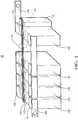
- FIG. 1shows a perspective view of a battery module 10.
- the battery module 10comprises a plurality of battery cells 100.
- An electronic battery cell monitoring module 110is attached to each of the battery cells 100.
- the battery cell monitoring modules 110are connected to one another by a balancing bus 130, comprising at least two electrical lines 140, 141, for the transmission of data and electrical current.
- the electronic battery cell monitoring modules 110are electrically connected to a positive pole 102 and a negative pole 104 of the battery cell 100.
- the electronic battery cell monitoring module 110is formed in one piece with the battery cell 100, as a result of which an autonomous battery element 150 is formed.
- Each battery cell 100 of the battery module 10is electrically connected with its own positive pole 102 to a negative pole 104 of an adjacent battery cell (100).
- each battery cell 100 of the battery module 10is electrically connected with its own negative pole 104 to a positive pole 102 of an adjacent battery cell 100. So that a series connection of battery cells 100 is created. There is an exception to the first and last battery cell 100, the free pole of which is provided with a connecting element 106, 108 in order to make the battery module 10 connectable to an electrical device.
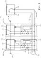
- FIG. 2shows a schematic representation of battery module 10. Only two battery cells are shown as examples.
- the electronic battery cell monitoring modules 110have a first electrical switch 112 and a second electrical switch 114.
- the electrical switches 112, 114are designed to electrically connect the battery cells 100 to one of the two electrical lines 140, 141 of the balancing bus 130.
- the battery module 10comprises an energy storage module 170 for storing electrical energy.
- the energy storage module 170comprises, for example, a combination of a capacitor and a coil.
- an alternative storage for electrical energycan also be used.
- the energy storage module 170is electrically connected to the two electrical lines 140, 141 of the balancing bus 130 in order to receive or deliver electrical energy via them.
- the energy storage module 170is connected with its connections 172, 174 to the two electrical lines 140, 141.
- the electronic battery cell monitoring modules 110 and the energy storage module 170are connected to one another by the balancing bus 130 and form a cell balancing system.
- each of the electronic battery cell monitoring modules 110can connect the positive pole 102 of the battery cell 100 to one of the electrical lines 140, 141 of the balancing bus 130 by means of the first electrical switch 112 and the negative pole 104 of the battery cell 100 by means of the second electrical switch 114 connect to the other electrical line 141 of the balancing bus 130.
- Each of the battery cell monitoring modules 110is programmable and has at least one microprocessor module 200, which includes memory, input / output ports, temperature and voltage measuring means.
- the temperature measuring meansis a temperature sensor 210 executed.
- the electronic battery cell monitoring modules 110have a basic communication functionality for communication with the other battery cell monitoring modules 110 by means of the balancing bus 130.
- FIG. 3shows details of the capacitive coupling of the data connection in a schematic representation.
- the battery cell monitoring module 110has at least one electrical data connection 116, which is capacitively connected to at least one of the electrical lines 140, 141 of the balancing bus 130, control signals being transmitted to the data connection 116 by modulation on this electrical line 140, 141.
- FIG. 4shows details of the optical coupling of the data connection in a schematic representation.
- the battery cell monitoring module 110has at least one optical data connection 117.
- the balancing bus 130has an optical line 118, the data connection 117 being optically connected to the optical line 118 of the balancing bus 130.
- the control signalsare transmitted by modulating light on optical line 118.
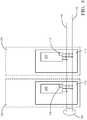
- FIG. 5shows details of the electrical coupling of the data connection in a schematic representation.
- the battery cell monitoring module 110has at least one electrical data connection 119 which or is bipolar.
- the balancing bus 130comprises one or two electrical data lines 120, which are electrically connected to the one- or two-pole electrical data connection 119, one of the electrical data lines 120 being connected to an electrical pole of the data connection 119.
- the Control signalsare transmitted by modulation on the one or two electrical data lines 120.
Landscapes
- Engineering & Computer Science (AREA)
- Electrochemistry (AREA)
- Manufacturing & Machinery (AREA)
- Chemical & Material Sciences (AREA)
- Chemical Kinetics & Catalysis (AREA)
- General Chemical & Material Sciences (AREA)
- Power Engineering (AREA)
- Microelectronics & Electronic Packaging (AREA)
- Life Sciences & Earth Sciences (AREA)
- Sustainable Development (AREA)
- Sustainable Energy (AREA)
- Transportation (AREA)
- Mechanical Engineering (AREA)
- Charge And Discharge Circuits For Batteries Or The Like (AREA)
- Secondary Cells (AREA)
Abstract
Translated fromGermanDescription
Translated fromGermanDie Erfindung betrifft Ein Batteriemodul für Hochvolt-Batterie-Packs zur Verwendung in Fahrzeugen, sowie ein Verfahren zum Balancieren des Ladezustandes der einzelnen Batteriezellen untereinander auf ein identisches, vorgegebenes Niveau.The invention relates to a battery module for high-voltage battery packs for use in vehicles, and a method for balancing the state of charge of the individual battery cells with one another to an identical, predetermined level.
Unter anderem für die Elektromobilität, insbesondere im Automobilbereich, werden aktuell bevorzugt Lithium-basierte Akkuzellen als Basis für Batteriemodule und solche als Basis für Hochvolt-Batterie-Packs verwendet. Bekannt sind Akkumulator(AKKU)-Batterie-Module, die aus mehreren in Reihe geschalteten Einzelzellen oder parallel geschalteten Zellblöcken zusammengeschaltet werden. Solche Batterie-Module werden auch zu Hochvolt-Batterie-packs in Reihe und parallelgeschaltet. Bei der Reihenschaltung von Akkus besteht die Problematik, dass mit zunehmender Anzahl von Lade- und Entladezyklen die Akkukapazitäten, bzw. Ladezustände der Zellen auseinanderdriften und sich so, orientierend an der schwächsten Zelle, die Gesamtkapazität eines Packs kontinuierlich reduziert.Among other things, for electromobility, especially in the automotive sector, lithium-based battery cells are currently preferred as the basis for battery modules and those as the basis for high-voltage battery packs. Accumulator (AKKU) battery modules are known which are interconnected from a plurality of individual cells connected in series or cell blocks connected in parallel. Such battery modules are also connected in series and in parallel to high-voltage battery packs. When batteries are connected in series, there is the problem that with increasing number of charge and discharge cycles, the battery capacities or states of charge of the cells drift apart and, based on the weakest cell, the total capacity of a pack is continuously reduced.
Zur Vermeidung eines solchen Verhalten ist es bereits Stand der Technik, die Ladung zwischen den Zellebenen auszubalancieren. Dies geschieht üblicherweise passiv beim Laden durch elektronisch kontrolliertes Zuschalten von Widerständen zu den Zellen, die bereits ein hohes Niveau an Ladung erreicht haben, um so den Strom zum Laden der anderen Zellen, an diesen "volleren Zelle" vorbeizuführen. Des Weiteren wird das so genannte Aktiv-Balancing eingesetzt, um die beim Passiv-Verfahren entstehenden elektrischen Verluste zu reduzieren. Dabei werden Ladungsportionen elektronisch von höher geladenen Zellen abgenommen und an niedriger geladene Zellen wieder abgegeben. Dies wird üblicherweise durch eine zentrale, gemeinsame Elektronikeinheit realisiert.To avoid such behavior, it is already state of the art to balance the charge between the cell levels. This is usually done passively during charging by electronically controlled switching on of the resistors to the cells, which have already reached a high level of charge, so that the current for charging the other cells passes this "fuller cell". So-called active balancing is also used to reduce the electrical losses that occur during the passive process. Charge portions are electronically removed from cells with a higher charge and at a lower level charged cells released again. This is usually implemented by a central, common electronics unit.
Zentrale Elektroniken überwachen und balancieren einen festen Zellenverbund. Dabei werden Energieportionen von Einzelzellen entnommen, über Spannungs-Wandler zwischengespeichert und danach an eine andere Einzelzelle wieder abgegeben. Hierbei ist eine aufwändige Verdrahtung und Elektronik notwendig, welche die Spannungsabgriffe und Temperatursensorsignale zentral auf der Elektronik zusammenführt. Nach einer Demontage in Einzelzellen, sofern möglich, sind alle Daten zu den einzelnen Zellen nicht mehr verfügbar. Die Zellen müssen dann einzeln aufwendig charakterisiert werden, damit sie, als Gleichwertige identifiziert, neu zusammengesetzt werden können.Central electronics monitor and balance a fixed cell network. In doing so, energy portions are taken from individual cells, temporarily stored via voltage converters and then released to another individual cell. This requires complex wiring and electronics that combine the voltage taps and temperature sensor signals centrally on the electronics. After disassembly in individual cells, if possible, all data for the individual cells are no longer available. The cells must then be individually characterized so that they can be reassembled when identified as equivalents.
Es besteht in der Technik der Bedarf nach einem Batteriemodul mit einem Batteriezellenmanagementsystem, dass kosteneffizient und energieeffizient ein Batteriemodul balancieren kann und die Zellengeschichte, jeder einzelnen Batteriezelle, lückenlosen aufzeichnet und speichert.
Des Weiteren besteht der Bedarf über die Modulgrenzen hinaus Zellen oder Module miteinander auszubalancieren.There is a technical need for a battery module with a battery cell management system that can balance a battery module in a cost-efficient and energy-efficient manner and that records and stores the cell history of each individual battery cell without gaps.
Furthermore, there is a need to balance cells or modules with one another beyond the module boundaries.
Die Aufgabe der Erfindung ist es, ein Batteriemodul bereitzustellen, dass die oben genannten Nachteile beseitigt und ein Batteriemodul oder auch darüber hinaus mehrere Batteriemodule mit einem Batteriezellenmanagementsystem, dass kosteneffizient und energieeffizient ein oder mehrere Batteriemodule balancieren kann und die Zellengeschichte jeder einzelnen Batteriezelle lückenlos aufzeichnet und speichert.The object of the invention is to provide a battery module that eliminates the disadvantages mentioned above, and a battery module or also several battery modules with a battery cell management system that can balance one or more battery modules cost-effectively and energy-efficiently and that records and stores the cell history of each individual battery cell without gaps .
Die Aufgabe wird durch den Gegenstand des Anspruchs 1 sowie durch das Verfahren nach Anspruch 15 gelöst.The object is achieved by the subject matter of
Insbesondere geschieht dies durch ein Batteriemodul für Hochvolt-Batterie-Packs vorzugsweise für den Einsatz in Fahrzeugen. Das Batteriemodul umfasst eine Mehrzahl von Batteriezellen. An jeder der Batteriezellen ist ein elektronisches Batteriezellenüberwachungsmodul angebracht. Die Batteriezellenüberwachungsmodule sind durch einen, mindestens zwei elektrische Leitungen umfassenden, Balancingbus, zur Übertragung von Daten und elektrischem Strom, miteinander verbunden. Die elektronischen Batteriezellenüberwachungsmodule sind jeweils mit einem Pluspol und einem Minuspol einer Batteriezelle elektrisch verbunden. Die elektronischen Batteriezellenüberwachungsmodule weisen einen ersten elektrischen Schalter und einen zweiten elektrischen Schalter auf. Die elektrischen Schalter sind dazu ausgebildet die Batteriezellen elektrisch mit jeweils einer der zwei elektrische Leitungen des Balancingbuses zu verbinden. Das Batteriemodul umfasst ein Energiespeichermodul zur Speicherung elektrischer Energie. Das Energiespeichermodul ist elektrisch mit den zwei elektrischen Leitungen des Balancingbuses verbunden, um elektrische Energie darüber aufzunehmen oder abzugeben. Die elektronischen Batteriezellenüberwachungsmodule und das Energiespeichermodul sind durch den Balancingbus miteinander verbunden und bilden ein Zell-Balancing-System.In particular, this is done by a battery module for high-voltage battery packs, preferably for use in vehicles. The battery module comprises a plurality of battery cells. An electronic battery cell monitoring module is attached to each of the battery cells. The battery cell monitoring modules are connected to one another by a balancing bus, comprising at least two electrical lines, for the transmission of data and electrical current. The electronic battery cell monitoring modules are each electrically connected to a positive pole and a negative pole of a battery cell. The electronic battery cell monitoring modules have a first electrical switch and a second electrical switch. The electrical switches are designed to electrically connect the battery cells to one of the two electrical lines of the balancing bus. The battery module comprises an energy storage module for storing electrical energy. The energy storage module is electrically connected to the two electrical lines of the balancing bus in order to receive or deliver electrical energy via it. The electronic battery cell monitoring modules and the energy storage module are connected to each other by the balancing bus and form a cell balancing system.
Die elektronischen Batteriezellenüberwachungsmodule und die verwendeten Batteriezellen sind im Wesentlichen von gleicher Bauart. Die in den Batteriezellenüberwachungsmodulen verwendeten elektronischen Bauteile sollten in allen Batteriezellenüberwachungsmodule identisch oder technisch vergleichbar sein. Dadurch ist ein reibungsloser Ablauf der Steuerungsprogramme gewährleistet, die die Batteriezellenüberwachungsmodule steuern. Zusätzlich lassen sie sich durch die Vereinheitlichung in großer Stückzahl technisch hoch integrieren und kostengünstig herstellen. Die Steuerungsprogramme, die für Steuerung der Batteriezellenüberwachungsmodule verwendet werden, sind ebenfalls identisch. Die elektronischen Batteriezellenüberwachungsmodule, die jeweils fest mit einer Batteriezelle verbunden sind, erfassen kontinuierlich die Kennwerte der Batteriezelle. Die Kennwerte der Batteriezelle sind zumindest die elektrische Spannung zwischen den Batteriepolen, und die Temperatur der Batteriezelle. Die Batteriezellenüberwachungsmodule erfassen des Weiteren die elektrische Spannung zwischen den mindestens zwei elektrischen Leitungen des Balancingbusses und können dadurch den Ladungszustand des elektrischen Energiespeichermoduls beurteilen. Die elektronischen Batteriezellenüberwachungsmodule verfügen über die Fähigkeit über den Balancingbus miteinander zu kommunizieren, wobei ein Netzwerk nach dem bekannten Multi-Master-System verwendet werden kann. Die elektronischen Batteriezellenüberwachungsmodule kommunizieren miteinander und vergleichen die Spannungswerte ihrer eigenen Batteriezellen mit den Spannungswerten der anderen Batteriezellen. Nach Konsensbildung aller elektronischen Batteriezellenüberwachungsmodule verbindet ein Überwachungsmodul seine Batteriezelle, die die höchste elektrische Spannung aufweist, gemeinsam mit mindestens einer benachbarten Batteriezelle mit den zwei elektrischen Leitungen des Balancingbus und leitet darüber elektrische Energie von den Batteriezellen in den elektrischen Energiespeicher und trennt sich danach wieder von den zwei elektrischen Leitungen des Balancing-Bus. Danach verbindet sich eine Batteriezelle, die eine zu niedrige elektrische Spannung aufweist mit den zwei elektrischen Leitungen, des Balancingbuses und leitet darüber elektrische Energie von dem elektrischen Energiespeicher in die Batteriezelle und trennt sich wieder von den zwei elektrischen Leitungen des Balancing-Bus. Dieser Vorgang setzt sich kontinuierlich fort. Das Energiespeichermodul kann einen Kondensator, eine elektrische Spule oder eine Kombination aus einem Kondensator und einer elektrischen Spule oder andere speicherfähige Bauteile umfassen um elektrische Energie zu speichern.The electronic battery cell monitoring modules and the battery cells used are essentially of the same type. The electronic components used in the battery cell monitoring modules should be identical or technically comparable in all battery cell monitoring modules. Thereby This ensures that the control programs that control the battery cell monitoring modules run smoothly. In addition, by standardizing them in large quantities, they can be technically highly integrated and manufactured at low cost. The control programs used to control the battery cell monitoring modules are also identical. The electronic battery cell monitoring modules, each of which is permanently connected to a battery cell, continuously record the characteristic values of the battery cell. The characteristic values of the battery cell are at least the electrical voltage between the battery poles and the temperature of the battery cell. The battery cell monitoring modules also record the electrical voltage between the at least two electrical lines of the balancing bus and can thereby assess the state of charge of the electrical energy storage module. The electronic battery cell monitoring modules have the ability to communicate with each other via the balancing bus, whereby a network according to the well-known multi-master system can be used. The electronic battery cell monitoring modules communicate with one another and compare the voltage values of their own battery cells with the voltage values of the other battery cells. After all electronic battery cell monitoring modules have reached a consensus, a monitoring module connects its battery cell, which has the highest electrical voltage, together with at least one neighboring battery cell to the two electrical lines of the balancing bus and uses it to conduct electrical energy from the battery cells to the electrical energy store and then separates them again two electrical lines of the balancing bus. Then a battery cell that has too low an electrical voltage connects to the two electrical lines, the balancing bus and conducts electrical energy from the electrical energy store into the battery cell and then disconnects from the two electrical lines of the balancing bus. This process continues. The energy storage module can comprise a capacitor, an electrical coil or a combination of a capacitor and an electrical coil or other storable components in order to store electrical energy.
Über die Modulgrenzen hinaus kann der Balancingbus auch mit weiteren Bussen in anderen Modulen verbunden werden, um das Balancingsystem auf die Gesamtbatterieebene zu heben. Alternativ kann auch ein übergeordnet Balancingsystem nach dem gleiche Prinzip Ladung zwischen Modulen balancieren, indem statt der Einzelzellen die Module Ladungen abgeben und aufnehmen.In addition to the module limits, the balancing bus can also be connected to other buses in other modules in order to raise the balancing system to the overall battery level. Alternatively, a superordinate balancing system can balance charge between modules according to the same principle, in that the modules emit and absorb charges instead of the individual cells.
Das Verfahren zum Anpassen der Ladung der einzelnen Batteriezellen eines Batteriemoduls auf ein vorgegebenes Niveau umfasst die Schritte:
- a) Bereitstellen eines Batteriemoduls für Hochvolt-Batterie-Packs vorzugsweise für den Einsatz in Fahrzeugen, umfassend jeweils eine Mehrzahl von Batteriezellen, umfassend jeweils ein an jeder der Batteriezellen angebrachtes elektronisches Batteriezellenüberwachungsmodul, wobei die Batteriezellenüberwachungsmodule durch einen, mindestens zwei elektrische Leitungen umfassenden, Balancingbus, zur Übertragung von Daten und elektrischem Strom, miteinander verbunden sind, wobei die elektronischen Batteriezellenüberwachungsmodule mit einem Pluspol und einem Minuspol der Batteriezelle elektrisch verbunden sind, wobei die elektronischen Batteriezellenüberwachungsmodule einen ersten elektrische Schalter und einen zweiten elektrischen Schalter aufweisen, wobei die elektrischen Schalter dazu ausgebildet sind, die Batteriezellen elektrisch mit jeweils einer der zwei elektrische Leitungen des Balancingbuses zu verbinden, wobei das Batteriemodul ein Energiespeichermodul zur Speicherung elektrischer Energie umfasst, wobei das Energiespeichermodul elektrisch mit den zwei elektrischen Leitungen des Balancingbuses verbunden ist, um elektrische Energie darüber aufzunehmen oder abzugeben, wobei die elektronischen Batteriezellenüberwachungsmodule und das Energiespeichermodul durch den Balancingbus miteinander verbunden, ein Zell-Balancing-System bilden.
- b) Verbinden des Pluspols der Batteriezelle mit dem Minuspol der benachbarten Batteriezelle und verbinden des Minuspols der Batteriezelle mit dem Pluspol der anderen benachbarten Batteriezelle, so das eine Reihenschaltung aller Batteriezellen entsteht, wobei ein Pluspol und ein Minuspol der Reihenschaltung nicht miteinander verbunden sind, diese bilden jeweils den +/- - Pol des Batterie-Moduls;
- c) Starten der Kommunikation aller angeschlossenen Batteriezellensteuermodul über den Balancingbuses;
- c) Identifizieren aller Batteriezellenüberwachungsmodule;
- d) Ermitteln der Anordnung der Batteriezellen im Batteriemodul;
- e) Austauschen aller Ladezustände der Batteriezellen über den Balancingbus;
- f) Kontrolle übernehmen, (zum Beispiel) durch das Batteriezellenüberwachungsmodul mit der höchsten übermittelten Ladespannung;
- g) Aufschalten zweier in Reihe geschalteter Batteriezellen auf den Balancing-Bus, jeweils durch den Pluspol der einen Zelle und den Minuspol der anderen Zelle, wobei eine der Zellen, die Zelle mit der höchsten Zellspannung ist und die zweite in Reihe liegende Zelle mit der vergleichsweise höheren Zellspannung dieser beiden in Reihe liegenden benachbarten Zellen ist;
- h) Laden des elektrischen Energiespeichers;
- i)Trennen der Batteriezellen vom Balancingbus;
- j) Aufschalten des Pluspols und des Minuspols der Batteriezellemit der niedrigsten Ladespannung auf den Balancingbus;
- k) Laden der Batteriezelle mit der Energie des elektrischen Energiespeichers;
- l) Trennen der Batteriezellen vom Balancingbus;
- m) Mit Verfahrensschritt e) fortfahren.
- a) providing a battery module for high-voltage battery packs, preferably for use in vehicles, each comprising a plurality of battery cells, each comprising an electronic battery cell monitoring module attached to each of the battery cells, the battery cell monitoring modules being provided by a balancing bus comprising at least two electrical lines, for the transmission of data and electrical current, are connected to one another, the electronic battery cell monitoring modules being electrically connected to a positive pole and a negative pole of the battery cell, the electronic battery cell monitoring modules having a first electrical switch and a second electrical switch, the electrical switches being designed for this purpose , the battery cells electrically with one of the two electrical lines to connect the balancing bus, the battery module comprising an energy storage module for storing electrical energy, the energy storage module being electrically connected to the two electrical lines of the balancing bus for receiving or delivering electrical energy thereabove, the electronic battery cell monitoring modules and the energy storage module being connected to one another by the balancing bus to form a cell balancing system.
- b) Connect the positive pole of the battery cell to the negative pole of the neighboring battery cell and connect the negative pole of the battery cell to the positive pole of the other neighboring battery cell, so that a series connection of all battery cells is formed, a positive pole and a negative pole of the series connection not being connected to one another, these form each the +/- pole of the battery module;
- c) starting the communication of all connected battery cell control modules via the balancing buses;
- c) identifying all battery cell monitoring modules;
- d) determining the arrangement of the battery cells in the battery module;
- e) replacement of all charge states of the battery cells via the balancing bus;
- f) take control (for example) by the battery cell monitoring module with the highest transmitted charging voltage;
- g) Connection of two battery cells connected in series to the balancing bus, each through the positive pole of one cell and the negative pole of the other cell, one of the cells being the cell with the highest cell voltage and the second cell in series with the comparatively higher cell voltage of these two adjacent cells in series;
- h) charging the electrical energy store;
- i) disconnecting the battery cells from the balancing bus;
- j) connecting the positive pole and the negative pole of the battery cell with the lowest charging voltage to the balancing bus;
- k) charging the battery cell with the energy of the electrical energy store;
- l) disconnecting the battery cells from the balancing bus;
- m) Continue with step e).
Vorteilhafterweise sind die elektronischen Batteriezellenüberwachungsmodule als Multimastersysteme ausgelegt, damit die im Verbund befindlichen Batteriezellen, ohne externe Initialisierung, das aktive Balancing durchführen können.The electronic battery cell monitoring modules are advantageously designed as multimaster systems so that the battery cells in the network can carry out the active balancing without external initialization.
Zyklisch übermittelt jedes Batteriezellenüberwachungsmodul seinen Ladezustand. Diese werden in jedem Batteriezellenüberwachungsmodul zwischengespeichert. Das Batteriezellenüberwachungsmodul, welches im Verbund den höchsten Ladezustand hat, könnte dann für die Steuerung des nächsten Balancingzyklus zuständig sein. Der Zyklus beinhaltet die Ermittlung einer der beiden benachbarten Batteriezellen mit dem höheren Ladezustand. Mittels Steuerkommando wird das kurzeiteige Aufschalten der beiden in Reihe befindlichen Batteriezellen auf den Balancingbus zur Ladungsabgabe an das Energiespeichermodul eingeleitet. Ein weiteres Steuerkommando wird dann das kurzzeitige Aufschalten der schwächsten Batteriezelle zur Ladungsentnahme aus dem Energiespeichermoduls einleiten. Das Batteriezellenüberwachungsmodul der schwächsten Batteriezelle übernimmt hierbei das Monitoring des Ladezyklus (Spannung, Strom) und das Trennen vom Balancingbus. Nach der nächsten Ladezustandsermittlung, wird dann der nächste Balancingzyklus wie oben beschrieben durchgeführt.Each battery cell monitoring module transmits its charge status cyclically. These are buffered in every battery cell monitoring module. The battery cell monitoring module, which has the highest state of charge in the network, could then be responsible for controlling the next balancing cycle. The cycle includes the determination of one of the two neighboring battery cells with the higher state of charge. By means of a control command, the short-term connection of the two battery cells in series to the balancing bus is initiated for charge transfer to the energy storage module. Another control command will then initiate the short-term connection of the weakest battery cell for taking charge from the energy storage module. The battery cell monitoring module of the weakest battery cell monitors the charging cycle (voltage, current) and disconnects from the balancing bus. After the next charge state determination, the next balancing cycle is then carried out as described above.
Vorteilhafte Ausbildungen der Erfindung sind den Unteransprüchen, der Beschreibung und der Zeichnung zu entnehmen.Advantageous embodiments of the invention can be found in the subclaims, the description and the drawing.
Gemäß einer Ausführungsform kann jedes der elektronischen Batteriezellenüberwachungsmodule, unabhängig von den weiteren elektronischen Batteriezellenüberwachungsmodulen, den Pluspol der Batteriezelle mittels des ersten elektrische Schalters mit einer der elektrischen Leitung des Balancingbusses verbinden und den Minuspol der Batteriezelle mittels des zweiten elektrischen Schalters mit der anderen elektrischen Leitung des Balancingbusses verbinden. Jedes der elektronischen Batteriezellenüberwachungsmodule verfügt über elektrische Schalter die einzeln schaltbar sind. Die Ausführung der Schalter als Halbleiterbauelement macht es möglich hohe Schaltfrequenzen zu realisieren und gleichzeitig eine lange Lebenszeit zu garantieren.According to one embodiment, each of the electronic battery cell monitoring modules, independently of the further electronic battery cell monitoring modules, can connect the positive pole of the battery cell to one of the electrical lines of the balancing bus by means of the first electrical switch and the negative pole of the battery cell to the other electrical line of the balancing bus by means of the second electrical switch connect. Each of the electronic battery cell monitoring modules has electrical switches that can be switched individually. The design of the switches as a semiconductor component makes it possible to achieve high switching frequencies and at the same time guarantee a long service life.
Bevorzugt kann jedes der elektronischen Batteriezellenüberwachungsmodule, unabhängig von den weiteren elektronischen Batteriezellenüberwachungsmodulen, den Pluspol der Batteriezelle mittels des ersten elektrische Schalters mit einer der elektrischen Leitung des Balancingbusses verbinden und ein benachbartes Batteriezellenüberwachungsmodul kann den Minuspol der Batteriezelle mittels des zweiten elektrischen Schalters mit der anderen elektrischen Leitung des Balancingbusses verbinden, wobei sich dies, je nach Reihenfolge der Zellen, auch in umgekehrter Reihenfolge und Polarität vollziehen kann. Die benachbarten Batteriezellen sind jeweils mit dem verbleibenden Minuspol und Pluspol der jeweiligen Nachbar Batteriezelle in Reihenschaltung elektrisch miteinander verbunden, damit wird eine um den Faktor zwei höhere Gesamtspannung am Balancingbus erreicht. Durch die unabhängige Schaltmöglichkeit der elektrischen Schalter ist es möglich zum Beispiel den Pluspol einer Batteriezelle auf eine der zwei elektrischen Leitung aufzuschalten und den Minuspol der benachbarten Batteriezelle auf die zweite der zwei elektrischen Leitungen aufzuschalten. Durch die doppelte Spannung die nun zwischen den zwei elektrischen Leitungen anliegt, kann der elektrische Energiespeicher höher geladen werden, um dann für die spätere Entnahme vom Energiespeicher mehr Energie, bzw. ein höheres Ladungspotential zur Verfügung zu haben. Dies erübrigt zu dem die Verwendung von elektronischen DC/DC-Spannungswandlern. In Kombination mit kurzen Schaltzeiten können mit einer Ladung des elektrischen Energiespeichers auch mehrere Batteriezellen nacheinander geladen werden, ohne den elektrischen Energiespeicher dazwischen laden zu müssen.Preferably, each of the electronic battery cell monitoring modules, independently of the further electronic battery cell monitoring modules, can connect the positive pole of the battery cell to one of the electrical lines of the balancing bus by means of the first electrical switch, and an adjacent battery cell monitoring module can connect the negative pole of the battery cell to the other electrical line by means of the second electrical switch of the balancing bus, whereby, depending on the order of the cells, this can also take place in reverse order and polarity. The neighboring battery cells are electrically connected to each other in series with the remaining negative pole and positive pole of the respective neighboring battery cell, so that a total voltage at the balancing bus that is two times higher is achieved. The independent switching option of the electrical switches makes it possible, for example, to connect the positive pole of a battery cell to one of the two electrical lines and the negative pole of the neighboring one Connect the battery cell to the second of the two electrical lines. As a result of the double voltage that is now present between the two electrical lines, the electrical energy store can be charged higher in order to then have more energy or a higher charge potential available for subsequent removal from the energy store. This also eliminates the use of electronic DC / DC voltage converters. In combination with short switching times, one charge of the electrical energy store can also charge several battery cells in succession without having to charge the electrical energy store in between.
Bevorzugt weist das Batteriezellenüberwachungsmodule mindestens einen elektrischen Datenanschluss auf, der kapazitiv mit einer der elektrischen Leitungen des Balancingbuses verbunden ist, wobei Steuersignale durch Modulation auf dieser elektrischen Leitung zu dem Datenanschluss übertragen werden. Durch das Aufmodulieren auf eine oder beide elektrischen Leitungen können zusätzliche Signalleitungen entfallen.The battery cell monitoring module preferably has at least one electrical data connection, which is capacitively connected to one of the electrical lines of the balancing bus, control signals being transmitted to the data connection by modulation on this electrical line. By modulating on one or both electrical lines, additional signal lines can be omitted.
Bevorzugt weist das Batteriezellenüberwachungsmodule mindestens einen optischen Datenanschluss auf und der Balancingbuses weist eine optische Leitung auf, wobei der Datenanschluss optisch mit der optischen Leitung des Balancingbuses verbunden ist, wobei Steuersignale durch Modulation von Licht auf der entsprechenden optischen Leitung übertragen werden. In der Fahrzeugtechnik hat sich die Verwendung von optischen Leitungen in besonders stark elektromagnetisch kontaminierten Umgebungen bewährt, um Störungen bei der Datenübertragung zu vermeiden.The battery cell monitoring module preferably has at least one optical data connection and the balancing bus has an optical line, the data connection being optically connected to the optical line of the balancing bus, control signals being transmitted by modulating light on the corresponding optical line. In vehicle technology, the use of optical cables has proven itself in particularly highly electromagnetic contaminated environments in order to avoid disruptions in data transmission.
Nach einer weiteren Ausführungsform weist das Batteriezellenüberwachungsmodule mindestens einen elektrischen Datenanschluss auf der zweipolig ausgeführt ist. Der Balancingbus umfasst zwei elektrische Datenleitungen, die mit dem zweipoligen elektrischen Datenanschluss verbunden sind. Jeweils eine elektrische Datenleitung ist mit einem elektrischen Datenanschluss verbunden. Die Steuersignale werden durch Modulation auf den zwei elektrischen Datenleitungen übertragen. Je nach erforderlicher Datenübertragungsrate können auch zwei elektrische Drähte als Datenleitung verwendet werden. Vorzugsweise werden diese Drähte miteinander verdrillt, um Störungen zu minimieren. Wenn erforderlich kann das System auch per Funk kommunizieren. Wobei bekannte Techniken wie WLAN, Bluetooth oder NFC zum Tragen kommen können. Der Einsatz von Funktechnik zur Kommunikation würde den Hardware-Umfang auf die, für die Ladungsverschiebung notwendigen, zwei elektrischen Leitungen reduzieren.According to a further embodiment, the battery cell monitoring module has at least one electrical data connection that is designed with two poles. The balancing bus comprises two electrical data lines that are connected to the two-pole electrical data connection. An electrical data line is connected to an electrical data connection. The control signals are transmitted by modulation on the two electrical data lines. Depending on the required data transfer rate, two electrical wires can also be used as data lines. These wires are preferably twisted together in order to minimize interference. If necessary, the system can also communicate by radio. Well-known technologies such as WLAN, Bluetooth or NFC can be used. The use of radio technology for communication would reduce the hardware scope to the two electrical lines necessary for charge transfer.
Bevorzugt sind die elektronischen Batteriezellenüberwachungsmodule programmierbar und umfassen mindestens einen Mikroprozessorbaustein, der Speicher, Ein/Ausgabe Ports, Temperatur und Spannungsmessmittel aufweist, wobei die elektronischen Batteriezellenüberwachungsmodule eine grundlegende Kommunikationsfunktionalität zur Kommunikation mit den anderen Batteriezellenüberwachungsmodulen mittels des Balancingbuses aufweisen. In der Industrie werden Mikroprozessorbausteine mit den oben genannten Eigenschaften seit langem verwendet und sind preiswert zu erwerben. Viele dieser Mikroprozessorbausteine verfügen über eine implementierte Kommunikationsfunktionalität mit verschiedenen in der Industrie verwendeten Übertragungsprotokollen und Verfahren. Diese Kommunikationsfunktionalität reduziert den Entwicklungsaufwand bei der Programmierung. Des Weiteren verfügen solche Mikroprozessorbausteine überwiegend über eine Energiesparfunktionalität die den Stromverbrauch auf ein Minimum reduziert.The electronic battery cell monitoring modules are preferably programmable and comprise at least one microprocessor module which has memory, input / output ports, temperature and voltage measuring means, the electronic battery cell monitoring modules having a basic communication functionality for communication with the other battery cell monitoring modules by means of the balancing bus. Microprocessor components with the above-mentioned properties have long been used in industry and are inexpensive to purchase. Many of these microprocessor chips have an implemented communication functionality with various transmission protocols and methods used in industry. This communication functionality reduces the development effort for programming. Also have such microprocessor modules mainly have an energy-saving functionality that reduces power consumption to a minimum.
Bevorzugt weisen die elektronischen Batteriezellenüberwachungsmodule jeweils eine einzigartige Kennung, z.B. nachdem UUID-Standard, auf, wobei jeweils eine solche Kennung unlöschbar in den Batteriezellenüberwachungsmodulen implementiert ist und über den Balancingbus abgefragt werden kann. Diese einzigartige Kennung kann zum Beispiel in einem EPROM auf dem Batteriezellenüberwachungsmodul abgelegt sein.
Ein Universally Unique Identifier (UUID) ist ein Standard für Identifikationen, der in der Softwareentwicklung verwendet wird. Er wurde von der Open Software Foundation (OSF) als Teil des Distributed Computing Environment (DCE) standardisiert. Die Absicht hinter UUIDs ist, Informationen in verteilten Systemen ohne zentrale Koordination eindeutig kennzeichnen zu können. Ein UUID besteht aus einer 16-Byte-Zahl, die hexadezimal notiert und in fünf Gruppen unterteilt wird.The electronic battery cell monitoring modules preferably each have a unique identifier, for example according to the UUID standard, with such an identifier being implemented in the battery cell monitoring modules in an indeletable manner and being able to be queried via the balancing bus. This unique identifier can, for example, be stored in an EPROM on the battery cell monitoring module.
A universally unique identifier (UUID) is a standard for identifications that is used in software development. It has been standardized by the Open Software Foundation (OSF) as part of the Distributed Computing Environment (DCE). The intention behind UUIDs is to be able to clearly identify information in distributed systems without central coordination. A UUID consists of a 16-byte number, which is noted in hexadecimal and divided into five groups.
Bevorzugt speichern die elektronischen Batteriezellenüberwachungsmodule die Kenndaten der entsprechenden Batteriezelle aktualisiert über die Lebensdauer der Batteriezelle. Informationen über die Anzahl der Lade- und Entladezyklen und weitere Kenndaten der Batteriezelle werden kontinuierlich abgespeichert und können über den Balancingbus abgefragt werden. Zum Beispiel könnte ein Service Gerät an den Balancingbus oder direkt an ein elektronisches Batteriezellenüberwachungsmodul angeschlossen werden um diese Daten anzusehen oder herunterzuladen. Anhand dieser Daten ist es möglich eine Vorhersage über die weitere Verwendungsfähigkeit der Batteriezelle zu treffen und sie gegebenenfalls auszutauschen.The electronic battery cell monitoring modules preferably store the characteristic data of the corresponding battery cell updated over the life of the battery cell. Information about the number of charge and discharge cycles and other characteristics of the battery cell are continuously saved and can be queried via the balancing bus. For example, a service device could be connected to the balancing bus or directly to an electronic battery cell monitoring module in order to view or download this data. On the basis of this data, it is possible to make a prediction about the further usability of the battery cell and, if necessary, to exchange it.
Bevorzugt ist das elektronische Batteriezellenüberwachungsmodul einteilig mit der Batteriezelle ausgebildet, wodurch ein autonomes Batterieelement entsteht. Das elektronische Batteriezellenüberwachungsmodul ist im Verhältnis zur Batteriezelle relativ klein und kann auf die Batteriezelle aufgeklebt werden. Denkbar ist auch eine Integration in das Gehäuse der Batteriezelle, was sich in einem erhöhten Schutz gegen Beschädigung oder Manipulation des elektronischen Batteriezellenüberwachungsmoduls niederschlägt.The electronic battery cell monitoring module is preferably formed in one piece with the battery cell, thereby creating an autonomous battery element. The electronic battery cell monitoring module is relatively small in relation to the battery cell and can be glued to the battery cell. Integration into the housing of the battery cell is also conceivable, which is reflected in increased protection against damage or manipulation of the electronic battery cell monitoring module.
Nach einer weiteren Ausführungsform kann die Batteriezelle des Batteriemoduls während des Betriebes als Energieversorgung, als auch in Zeiträumen in denen das Batteriemodul weder mit einer Energieversorgung noch mit einem Verbraucher verbunden ist, balanciert werden. Dadurch behält das Batteriemodul seine volle Funktionalität auch wenn es als Ersatzteil zwischengelagert ist. Eine Tiefentladung einer Batteriezelle wird weitgehend verhindert da alle Batteriezelle auf einem ähnlichen Spannung Niveau gehalten werden. Um eine Tiefentladung des gesamten Batteriemoduls zu verhindern kann eine Signalvorrichtung, die eine Tiefentladung signalisiert, an den Stromanschlüssen des Batteriemoduls vorgesehen werden, die signalisiert, dass die Gesamtspannung des Batteriemoduls zu niedrig wird.According to a further embodiment, the battery cell of the battery module can be balanced during operation as a power supply, as well as in periods in which the battery module is neither connected to a power supply nor to a consumer. As a result, the battery module remains fully functional even if it is temporarily stored as a spare part. A deep discharge of a battery cell is largely prevented since all battery cells are kept at a similar voltage level. In order to prevent deep discharge of the entire battery module, a signal device that signals deep discharge can be provided on the power connections of the battery module, which signals that the total voltage of the battery module is becoming too low.
Bevorzugt weist das Batteriemoduls eine Schnittstelle auf, die dazu ausgebildet ist das Batteriemodul mit einer Steuerung eines elektrisch angetriebenen Fahrzeugs zu verbinden. Elektrisch angetriebene Fahrzeuge weisen eine mächtige Steuerung auf, um alle nötigen Funktionen zu kontrollieren. Um die Steuerung kontinuierlich mit den Kenndaten der Batteriezellen zu versorgen, kann eine Schnittstelle zur der Steuerung vorgesehen werden. Die Schnittstelle kann eine vom Hersteller vorgegebene oder eine sonstige, in der Industrie bekannte und bewährte, Schnittstelle sein.The battery module preferably has an interface which is designed to connect the battery module to a controller of an electrically driven vehicle. Electrically powered vehicles have powerful controls to control all the necessary functions. In order to continuously supply the controller with the characteristic data of the battery cells, a Interface to the controller can be provided. The interface can be an interface specified by the manufacturer or another interface that is known and proven in the industry.
In gleicher Weise kann auch ein Balancing zwischen Modulen durchgeführt werden, die in Reihe zu einem Batteriepack zusammengeschaltet sind.
Die Module beinhalten Reihenschaltungen von Zellen, wie vorher beschrieben. Wie beim Zellenbalancing werden hier Ladungsportionen zwischen Modulen ausgetauscht.
Bevorzugt weist die Schnittstelle elektrische oder optische Kontakte auf, die dazu ausgebildet sind mit der Steuerung anderer Module, der des elektrisch angetriebenen Fahrzeugs oder der eines Lagersystems zu kommunizieren. Dadurch kann zumindest die Selbstentladung, insbesondere bei längeren Lagerzeiten, ausgeglichen werden. Durch das Anbinden des Balancingbuses an das Netzwerk des elektrisch angetriebenen Fahrzeugs wird das Batteriemodul vollständig in das elektrisch angetriebene Fahrzeug integriert, was zu einer erhöhten Ausfallsicherheit des Fahrzeugs führt, da Probleme bei der Energiespeicherung frühzeitig erkannt werden.
Nachfolgend wird die Erfindung anhand einer vorteilhaften Ausführungsform rein beispielhaft unter Bezugnahme auf den beigefügten Zeichnungen beschrieben. Es zeigen:
- Fig. 1
- zeigt eine perspektivische Darstellung des Batteriemoduls.
- Fig. 2
- zeigt eine schematische Darstellung des Batteriemoduls.
- Fig. 3
- zeigt Details zur der kapazitiven Kopplung des Datenanschlusses in schematische Darstellung
- Fig. 4
- zeigt Details zur optischen Kopplung des Datenanschlusses in schematische Darstellung
- Fig. 5
- zeigt Details zur elektrischen Kopplung des Datenanschlusses in schematische Darstellung
The modules include series connections of cells as previously described. As with cell balancing, portions of charge are exchanged between modules.
The interface preferably has electrical or optical contacts which are designed to communicate with the control of other modules, that of the electrically driven vehicle or that of a storage system. This can at least compensate for self-discharge, especially with longer storage times. By connecting the balancing bus to the network of the electrically powered vehicle, the battery module is fully integrated into the electrically powered vehicle, which leads to increased reliability of the vehicle, since problems with energy storage are recognized at an early stage.
The invention is described below using an advantageous embodiment purely by way of example with reference to the accompanying drawings. Show it:
- Fig. 1
- shows a perspective view of the battery module.
- Fig. 2
- shows a schematic representation of the battery module.
- Fig. 3
- shows details of the capacitive coupling of the data connection in a schematic representation
- Fig. 4
- shows details of the optical coupling of the data connection in a schematic representation
- Fig. 5
- shows details of the electrical coupling of the data connection in a schematic representation
oder zweipolig ausgeführt ist. Der Balancingbus 130 umfasst eine oder zwei elektrische Datenleitungen 120, die mit dem ein- oder zweipoligen elektrischen Datenanschluss 119 elektrisch verbunden sind, wobei jeweils eine der elektrischen Datenleitungen 120 mit einem elektrischen Pol des Datenanschlusses 119 verbunden ist. Die Steuersignale werden durch Modulation auf den ein oder zwei elektrischen Datenleitungen 120 übertragen.
or is bipolar. The balancing
Claims (15)
Translated fromGermanPriority Applications (3)
| Application Number | Priority Date | Filing Date | Title |
|---|---|---|---|
| EP18208347.7AEP3657571A1 (en) | 2018-11-26 | 2018-11-26 | Battery module |
| US16/686,281US11383617B2 (en) | 2018-11-26 | 2019-11-18 | Battery module |
| CN201911170849.2ACN111224182B (en) | 2018-11-26 | 2019-11-26 | Battery module |
Applications Claiming Priority (1)
| Application Number | Priority Date | Filing Date | Title |
|---|---|---|---|
| EP18208347.7AEP3657571A1 (en) | 2018-11-26 | 2018-11-26 | Battery module |
Publications (1)
| Publication Number | Publication Date |
|---|---|
| EP3657571A1true EP3657571A1 (en) | 2020-05-27 |
Family
ID=64477039
Family Applications (1)
| Application Number | Title | Priority Date | Filing Date |
|---|---|---|---|
| EP18208347.7APendingEP3657571A1 (en) | 2018-11-26 | 2018-11-26 | Battery module |
Country Status (3)
| Country | Link |
|---|---|
| US (1) | US11383617B2 (en) |
| EP (1) | EP3657571A1 (en) |
| CN (1) | CN111224182B (en) |
Families Citing this family (6)
| Publication number | Priority date | Publication date | Assignee | Title |
|---|---|---|---|---|
| CN109786599B (en)* | 2018-12-29 | 2021-08-31 | 华为数字技术(苏州)有限公司 | an energy storage system |
| US20210066953A1 (en)* | 2019-08-28 | 2021-03-04 | Delphi Automotive Systems Luxembourg Sa | Systems and methods for smooth start up of vehicle onboard battery charger |
| US11476951B2 (en)* | 2020-02-24 | 2022-10-18 | Sensata Technologies, Inc. | Optical communications in a battery pack |
| CN112687968A (en)* | 2020-12-04 | 2021-04-20 | 苏州易美新思新能源科技有限公司 | Intelligent lithium ion battery monomer and module thereof |
| CZ2020731A3 (en)* | 2020-12-30 | 2022-07-13 | Česká energeticko-auditorská společnost, s. r. o. | Connection for managing battery storage and method of managing battery storage in this connection |
| US12308674B1 (en)* | 2024-01-19 | 2025-05-20 | Moment Energy Inc. | Active energy balancing for energy storage systems |
Citations (5)
| Publication number | Priority date | Publication date | Assignee | Title |
|---|---|---|---|---|
| US20110135970A1 (en)* | 2009-12-03 | 2011-06-09 | Samsung Sdi Co., Ltd. | Circuit substrate module and battery module using the same |
| DE102010001422A1 (en)* | 2010-02-01 | 2011-08-04 | Robert Bosch GmbH, 70469 | Battery for use as electrical energy storage in power supply unit for e.g. hybrid car, has switch connected with negative pole of cell such that switch is connected with negative pole of cell based on control signal produced by controller |
| DE102014215730A1 (en)* | 2014-08-08 | 2016-02-11 | Robert Bosch Gmbh | Battery cell module with communication device for data exchange between a plurality of similar battery cell modules connected in series |
| US20170366018A1 (en)* | 2016-06-17 | 2017-12-21 | Qualcomm Incorporated | Single transformer high-power balancer |
| US20180034111A1 (en)* | 2015-02-18 | 2018-02-01 | Audi Ag | Battery cell for a battery of a motor vehicle, battery and motor vehicle |
Family Cites Families (23)
| Publication number | Priority date | Publication date | Assignee | Title |
|---|---|---|---|---|
| US20070001651A1 (en)* | 2004-07-02 | 2007-01-04 | Harvey Troy A | Distributed networks of electric double layer capacitor supervisory controllers and networks thereof |
| EP1872119A2 (en)* | 2005-04-05 | 2008-01-02 | Energycs | Multiplexer and switch-based electrochemical cell monitor and management system and method |
| JP2012505628A (en)* | 2008-10-07 | 2012-03-01 | ボストン−パワー,インコーポレイテッド | Li-ion battery array for vehicles and other high capacity applications |
| US20110276289A1 (en)* | 2010-05-07 | 2011-11-10 | Samsung Electronics Co., Ltd. | Power monitoring apparatus for household appliance |
| KR20110139424A (en)* | 2010-06-23 | 2011-12-29 | 현대자동차주식회사 | High voltage battery and its temperature control method |
| US8015452B2 (en)* | 2010-08-31 | 2011-09-06 | O2Micro International, Ltd. | Flexible bus architecture for monitoring and control of battery pack |
| US8773071B2 (en)* | 2010-11-01 | 2014-07-08 | The Boeing Company | System and method for cell voltage balancing |
| US8786261B2 (en)* | 2011-03-03 | 2014-07-22 | Davide Andrea | Cell modules for detecting temperature and voltage of cells |
| US20140042974A1 (en)* | 2011-04-22 | 2014-02-13 | Sk Innovation Co., Ltd. | Detachable battery module, and method and apparatus for the charge equalization of a battery string using same |
| DE102012000583A1 (en)* | 2012-01-13 | 2013-07-18 | Audi Ag | Battery arrangement for a motor vehicle |
| US10084331B2 (en)* | 2012-03-25 | 2018-09-25 | Gbatteries Energy Canada Inc. | Systems and methods for enhancing the performance and utilization of battery systems |
| EP2747237A3 (en)* | 2012-11-28 | 2014-12-24 | Actuant Corporation | Apparatus and method for balancing cells in a plurality of batteries |
| EP2866354B1 (en)* | 2013-10-25 | 2019-06-26 | VITO NV (Vlaamse Instelling voor Technologisch Onderzoek NV) | Method and system for providing pulsed power and data on a bus |
| CN104953194B (en)* | 2014-03-31 | 2017-08-22 | 比亚迪股份有限公司 | Battery balanced control device and electric car and battery balanced control method with it |
| US9656563B2 (en)* | 2014-07-31 | 2017-05-23 | Toyota Motor Engineering & Manufacturing North America, Inc. | Modular wireless electrical system |
| GB201511279D0 (en)* | 2015-06-26 | 2015-08-12 | Lyra Electronics Ltd | Battery |
| WO2017113340A1 (en)* | 2015-12-31 | 2017-07-06 | SZ DJI Technology Co., Ltd. | Method and system for balancing battery assembly |
| GB2564043B (en)* | 2016-02-23 | 2022-02-23 | Galvion Power Systems Inc | Dual bus battery balancing system |
| US10374440B2 (en)* | 2017-06-22 | 2019-08-06 | Rockwell Collins, Inc. | System and method for supercapacitor charging and balancing |
| CN107359669A (en)* | 2017-08-21 | 2017-11-17 | 上海空间电源研究所 | Space high tension battery group balanced type charging management system and its control method |
| JP7013745B2 (en)* | 2017-09-12 | 2022-02-15 | 株式会社デンソー | Battery pack |
| US10444295B2 (en)* | 2017-12-20 | 2019-10-15 | National Chung Shan Institute Of Science And Technology | Battery balance management circuit |
| JP7680350B2 (en)* | 2018-07-31 | 2025-05-20 | シオン・パワー・コーポレーション | Multiplexed Charge/Discharge Battery Management System |
- 2018
- 2018-11-26EPEP18208347.7Apatent/EP3657571A1/enactivePending
- 2019
- 2019-11-18USUS16/686,281patent/US11383617B2/enactiveActive
- 2019-11-26CNCN201911170849.2Apatent/CN111224182B/enactiveActive
Patent Citations (5)
| Publication number | Priority date | Publication date | Assignee | Title |
|---|---|---|---|---|
| US20110135970A1 (en)* | 2009-12-03 | 2011-06-09 | Samsung Sdi Co., Ltd. | Circuit substrate module and battery module using the same |
| DE102010001422A1 (en)* | 2010-02-01 | 2011-08-04 | Robert Bosch GmbH, 70469 | Battery for use as electrical energy storage in power supply unit for e.g. hybrid car, has switch connected with negative pole of cell such that switch is connected with negative pole of cell based on control signal produced by controller |
| DE102014215730A1 (en)* | 2014-08-08 | 2016-02-11 | Robert Bosch Gmbh | Battery cell module with communication device for data exchange between a plurality of similar battery cell modules connected in series |
| US20180034111A1 (en)* | 2015-02-18 | 2018-02-01 | Audi Ag | Battery cell for a battery of a motor vehicle, battery and motor vehicle |
| US20170366018A1 (en)* | 2016-06-17 | 2017-12-21 | Qualcomm Incorporated | Single transformer high-power balancer |
Also Published As
| Publication number | Publication date |
|---|---|
| US20200164767A1 (en) | 2020-05-28 |
| US11383617B2 (en) | 2022-07-12 |
| CN111224182B (en) | 2023-06-06 |
| CN111224182A (en) | 2020-06-02 |
Similar Documents
| Publication | Publication Date | Title |
|---|---|---|
| EP3657571A1 (en) | Battery module | |
| EP3209518B1 (en) | Method for operating an energy storage device in a motor vehicle, and motor vehicle | |
| EP3657570A1 (en) | Battery module | |
| EP2181480B1 (en) | Battery or rechargeable-battery pack | |
| EP2448082B1 (en) | Battery system and method for monitoring a charge of at least one rechargeable battery | |
| EP2817976B1 (en) | Battery sensor data transmission unit and a method for transmitting battery sensor data | |
| DE102012214091A1 (en) | Battery management system with data interface for battery module, battery module with data memory, battery system with battery management system and battery module and motor vehicle with battery system | |
| WO2010088944A2 (en) | Energy storage assembly and method for operating such an assembly | |
| EP2949021B1 (en) | Control device for an electric energy storage system | |
| DE102012105483A1 (en) | Method for transmitting information from energy storage module to receiver, involves keeping multiple parameter informations of energy storage module available in energy storage module, and transmitting parameter informations to receiver | |
| EP3103182A1 (en) | Device and method for connecting a battery management system | |
| EP2803110A1 (en) | Battery arrangement for a motor vehicle | |
| DE102012202751A1 (en) | Battery sensor data transmission unit and a method for transmitting battery sensor data | |
| WO2018185059A1 (en) | Cascadable assembly for interconnecting a plurality of stored energy sources, interconnection therefor, and method for controlling an energy supply by means of said assembly | |
| WO2015139810A1 (en) | Monitoring device for monitoring an electrical energy storage system | |
| EP2669242B1 (en) | Industrial truck with battery insertion areas | |
| WO2019121418A1 (en) | Multiple-battery adapter for establishing an electrical connection between at least two traction batteries on the one hand and a drive unit of an electric bicycle on the other hand | |
| EP2828946B1 (en) | Storage means for electrical energy and holding apparatus for at least one storage means for a vehicle which can be electrically driven | |
| DE102013100471B4 (en) | Method for determining a state of charge of an energy store with at least one energy cell | |
| DE102012006247A1 (en) | Device for operating electrochemical energy storage device e.g. lithium ion battery, of battery management system, has cell controllers that are provided with charge compensation device to perform charge balance between storage cells | |
| EP2803109A1 (en) | Battery arrangement for a motor vehicle | |
| EP3716441A1 (en) | Modular apparatus for power supply | |
| DE102021120232B3 (en) | System and method for configuring a configurable battery pack | |
| DE102022107477B3 (en) | Modular system, system, motor vehicle and method | |
| EP4046255B1 (en) | Passive additional module for a battery, battery comprising such an additional module and method for supplying power to a passive additional module |
Legal Events
| Date | Code | Title | Description |
|---|---|---|---|
| PUAI | Public reference made under article 153(3) epc to a published international application that has entered the european phase | Free format text:ORIGINAL CODE: 0009012 | |
| STAA | Information on the status of an ep patent application or granted ep patent | Free format text:STATUS: THE APPLICATION HAS BEEN PUBLISHED | |
| AK | Designated contracting states | Kind code of ref document:A1 Designated state(s):AL AT BE BG CH CY CZ DE DK EE ES FI FR GB GR HR HU IE IS IT LI LT LU LV MC MK MT NL NO PL PT RO RS SE SI SK SM TR | |
| AX | Request for extension of the european patent | Extension state:BA ME | |
| STAA | Information on the status of an ep patent application or granted ep patent | Free format text:STATUS: REQUEST FOR EXAMINATION WAS MADE | |
| 17P | Request for examination filed | Effective date:20201125 | |
| RBV | Designated contracting states (corrected) | Designated state(s):AL AT BE BG CH CY CZ DE DK EE ES FI FR GB GR HR HU IE IS IT LI LT LU LV MC MK MT NL NO PL PT RO RS SE SI SK SM TR | |
| RAP3 | Party data changed (applicant data changed or rights of an application transferred) | Owner name:APTIV TECHNOLOGIES LIMITED | |
| STAA | Information on the status of an ep patent application or granted ep patent | Free format text:STATUS: THE APPLICATION IS DEEMED TO BE WITHDRAWN |