EP3656626B1 - Floor of a railway vehicle and associated assembly method - Google Patents
Floor of a railway vehicle and associated assembly methodDownload PDFInfo
- Publication number
- EP3656626B1 EP3656626B1EP19210405.7AEP19210405AEP3656626B1EP 3656626 B1EP3656626 B1EP 3656626B1EP 19210405 AEP19210405 AEP 19210405AEP 3656626 B1EP3656626 B1EP 3656626B1
- Authority
- EP
- European Patent Office
- Prior art keywords
- removable module
- floor
- frame
- internal volume
- support
- Prior art date
- Legal status (The legal status is an assumption and is not a legal conclusion. Google has not performed a legal analysis and makes no representation as to the accuracy of the status listed.)
- Active
Links
- 238000000034methodMethods0.000titleclaimsdescription16
- 238000012360testing methodMethods0.000claimsdescription14
- 239000007769metal materialSubstances0.000claimsdescription5
- 230000008054signal transmissionEffects0.000claimsdescription5
- 239000002131composite materialSubstances0.000claimsdescription4
- 239000012530fluidSubstances0.000claimsdescription2
- 230000000903blocking effectEffects0.000claims1
- 238000005192partitionMethods0.000description8
- 238000010616electrical installationMethods0.000description7
- 230000003137locomotive effectEffects0.000description5
- 230000000295complement effectEffects0.000description1
- 239000012141concentrateSubstances0.000description1
- 238000009413insulationMethods0.000description1
- 230000010354integrationEffects0.000description1
- 238000012423maintenanceMethods0.000description1
- 238000007789sealingMethods0.000description1
Images

Classifications
- B—PERFORMING OPERATIONS; TRANSPORTING
- B61—RAILWAYS
- B61D—BODY DETAILS OR KINDS OF RAILWAY VEHICLES
- B61D17/00—Construction details of vehicle bodies
- B61D17/04—Construction details of vehicle bodies with bodies of metal; with composite, e.g. metal and wood body structures
- B61D17/10—Floors
- B—PERFORMING OPERATIONS; TRANSPORTING
- B61—RAILWAYS
- B61C—LOCOMOTIVES; MOTOR RAILCARS
- B61C17/00—Arrangement or disposition of parts; Details or accessories not otherwise provided for; Use of control gear and control systems
Definitions
- the present inventionrelates to a floor of a railway vehicle as defined in the preamble of claim 1.
- An object of the inventionis therefore to provide a solution that reduces the time required for mounting cables and pneumatic pipes in a railway vehicle.
- the subject of the inventionis a floor of a railway vehicle according to claim 1.
- the floormay include one or more of the optional features of claims 2 to 5, taken individually or in all technically possible combinations.
- the inventionalso relates to a railway vehicle comprising at least one body comprising a floor as defined above, the body comprising at least one engine for moving the railway vehicle.
- the railway vehiclemay include the optional feature that the body defines an interior space delimiting a floor downwards, the upper surface of the lid defining a part of the floor extending opposite the interior space.
- the inventionalso relates to a method of mounting a railway vehicle as defined in claim 8
- the mounting methodmay include one or more of the optional features of claims 9 and 10.
- a railway vehicle 10 according to the inventionis illustrated in the figure 1 .
- orientationsare the usual orientations of a railway vehicle.
- the terms “upper”, “lower”, “lower”, “higher”are generally understood relative to the normal direction of movement of the railway vehicle.
- the railway vehicle 10comprises at least one body 12 comprising a floor 14.
- the railway vehicle 10also comprises at least one motor for moving the railway vehicle 10 carried by the body 12, not shown. It thus forms a locomotive of the railway vehicle 10.
- the body 12contains at least one electrical installation 16, in particular the motor and a pneumatic device, not shown.
- the body 12defines an interior space 18 delimiting a floor 20 downwards, on which a user of the vehicle 10, or a maintenance agent is able to walk.
- the floor 14defines at least a part of the floor 20 upwards.
- the floor 14comprises a support 22 and a removable module 24 with respect to the support 22.
- Support 22is attached to body 12.
- the support 22forms for example a part of the ground 20 and thus presents a surface on which a user of the vehicle 10 can walk.
- the support 22defines a reception space 26 of the removable module 24.
- the reception space 26is here a longitudinal chute, defined for example substantially at the center of the floor 14 along a central longitudinal axis A of the floor 14.
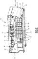
- the removable module 24is illustrated in more detail on the picture 2 .
- Itcomprises a frame 28 delimiting an interior volume 30 and a cover 32 mounted on the frame 28 and closing the interior volume 30.
- the removable module 24also comprises at least one electric cable 34 and at least one pneumatic pipe 36 for transporting a fluid, arranged in the interior volume 30.
- the removable module 24comprises a plurality of electrical cables 34 and a plurality of pneumatic lines 36, arranged in the interior volume 30.
- the removable module 24is fixed to the support 22.
- Frame 28is received in chute 26.
- Frame 28includes a bottom 42 and two outer side walls 44 extending from bottom 42 upward. It further comprises a plurality of longitudinal internal partitions 46 and a panel 48 for supporting the pneumatic pipes 36, arranged in the interior volume 30, as illustrated in the picture 2 .
- the frame 28is made of composite or metallic material. It is for example made from a profile.
- Bottom 42 of frame 28is substantially flat.
- Ithas for example a width of between 200 cm and 1000 cm. It has a thickness between 0.3 cm and 0.6 cm.
- the outer side walls 44are integral with the bottom 42.
- each outer side wall 44comprises a first vertical region 50 extending from the bottom 42 and a second vertical region 52 connected to the first vertical region 50 by an oblique region 54.
- Each outer side wall 44further includes a folded flange 56 extending horizontally toward the interior volume 30 from the second vertical region 52.
- the first vertical region 50, the oblique region 54, the second vertical region 52 and the folded edge 56 of each outer side wall 44are made in one piece.
- Each side exterior wall 44extends from the bottom 42 to a height, taken from an upper interior surface 58 of the bottom 42, of less than 80 cm.
- Internal partitions 46extend upward into interior volume 30 from upper interior surface 58 of bottom 42 of frame 28.
- Each internal partition 46extends from the upper interior surface 58 to a height, taken from the upper interior surface 58, of less than 80 cm. This height is advantageously lower than that of the outer side walls 44.
- Each internal partition 46is substantially planar.
- At least two internal partitions 46have different heights. Alternatively, all the internal partitions 46 have the same height.
- Internal partitions 46further extend longitudinally along frame 28.
- the internal partitions 46define between them, and with the outer side walls 44, internal paths 60 for receiving the electrical cables 34, and high or low voltage signal transmission cables.
- the cablesare preferably sorted according to their voltage classes, each internal reception path 60 receiving electrical cables 34 of the same voltage class.
- the support panel 48is made of metallic material.
- Jumpers 62have a U-shaped cross-section opening upwards.
- each pneumatic pipe 36is fixed to the support panel 48 by a flange 64 printed in three dimensions or made of metallic or composite material.
- the cables 34are fixed using plastic collars or by clamps printed in three dimensions.
- the flange 64has a shape matching the shape of the pneumatic pipe 36 that it fixes.
- the cover 32defines an upper surface 72 intended to form at least part of the floor 20 of the body 12 of the railway vehicle 10.
- the upper surface 72extends facing the interior space 18 of the body 12.
- the cover 32has a U-shaped cross-section opening downwards.
- the two side edges 74are substantially flat.
- the cover 32is movable relative to the frame 28 between a position of closure of the access to the interior volume 30, illustrated in the picture 2 , and a position for releasing access to the interior volume 30, not shown.
- the cover 32is made of metallic or composite material.
- the cover 32 and/or the frame 28has, for example, side orifices, not shown, forming a passage for an electric cable 34 or a pneumatic pipe 36 outside the interior volume 30
- At least one of the electrical cables 34is a high voltage signal transmission cable and at least one other of the electrical cables 34 is a low voltage signal transmission cable.
- the insulation level of the cablesis adapted to the nominal voltage of the various circuits.
- At least one of the electrical cables 34is connected to the electrical installation 16 via a connector arranged outside the interior volume 30.
- At least one of the pneumatic lines 36is connected to the pneumatic device.
- the methodincludes providing at least a first electrical cable 34 and at least a first pneumatic line 36.
- a first group of electrical cables 34 and a first group of pneumatic lines 36are provided.
- the first group of electric cables 34includes the first electric cable 34
- the first group of pneumatic lines 36includes the first pneumatic line 36.
- the methodalso includes providing a first removable module 24 identical to the removable module described above.
- the first removable module 24thus comprises a first frame 28 delimiting a first interior volume 30 and a first cover 32 initially placed in its position for releasing access to the first interior volume 30.
- the first electrical cable 34 and the first pneumatic pipe 36are arranged in the first interior volume 30 of the first removable module 24.
- the first interior volume 30is then closed by the first lid 32 which is then placed in its closed position.
- the methodthen includes a step of testing the first electric cable 34 and the first pneumatic pipe 36.
- the testis for example a continuity test or a dielectric test, and for the first pneumatic line 36, the test is for example a sealing test.
- This test stepis in particular implemented for each first electrical cable 34 and each first pneumatic line 36.
- the methodincludes providing a first rail vehicle 10.
- the first rail vehicle 10includes a first body 12 including a first floor 14, the first floor 14 comprising a first support 22, the first support 22 delimiting a first reception space 26 of the first removable module 24.
- the first body 12also includes a first electrical installation 16 and a first pneumatic device.
- the first removable module 24is inserted into the first reception space 26, then fixed to the first support 22. This step of receiving the first removable module 24 into the first reception space 26 is implemented after the test step.
- one of the first electrical cables 34is connected to the first electrical installation 16 and one of the first pneumatic lines 36 is connected to the first pneumatic device.
- the methodadvantageously comprises the assembly of a second railway vehicle 10.
- the methodincludes providing at least one second electrical cable 34 and at least one second pneumatic line 36.
- the second electrical cable 34is different from the first electrical cable 34 and/or the second pneumatic line 36 is different from the first pneumatic line 36.
- the methodalso includes providing a second removable module 24 identical to the removable module 24 described above.
- the second removable module 24comprises a second frame 28, the second frame 28 delimiting a second interior volume 30 and being identical to the first frame 28.
- the second removable module 24further comprises a second cover 32 initially disposed, in its release position access to the second interior volume 30, the second cover 32 being identical to the first cover 32.
- the second electric cable 34 and the second pneumatic pipe 36are then arranged in the second interior volume 30.
- the second interior volume 30is then closed by the second lid 32 which is then placed in its closed position.
- the methodthen includes testing each second electric cable 34 and each second pneumatic pipe 36, this test being similar to the test step described previously.
- the methodcomprises providing a second railway vehicle 10.
- the second railway vehicle 10comprises a second body 12, the second body 12 comprising a second floor 14 comprising a second support 22, the second support 22 delimiting a second reception space 26 of the second removable module 24.
- the second body 12also includes a second electrical installation and a second pneumatic device.
- the second removable module 24is inserted into the second reception space 26, then is fixed to the second support 22. Similarly, this step of receiving the second removable module 24 into the second reception space 26 is implemented after the step test of each second electrical cable 34 and each second pneumatic line 36.
- one of the second electrical cablesis connected to the second electrical installation and one of the second pneumatic lines is connected to the second pneumatic device.
- the floor 14makes it possible to concentrate the electrical cables and the pneumatic lines in the same place. This makes it possible to reduce the number of flanges screwed to the structure and to obtain time savings in the assembly and testing of the various cables and pipes.
- support 22 and the removable module 24can be common to bodies of different structures of railway vehicles. This allows standardization of assembly and a reduction in associated costs.
Landscapes
- Engineering & Computer Science (AREA)
- Mechanical Engineering (AREA)
- Life Sciences & Earth Sciences (AREA)
- Wood Science & Technology (AREA)
- Automation & Control Theory (AREA)
- Transportation (AREA)
- Electric Propulsion And Braking For Vehicles (AREA)
- Automobile Manufacture Line, Endless Track Vehicle, Trailer (AREA)
Description
Translated fromFrenchLa présente invention concerne un plancher d'un véhicule ferroviaire tel que défini dans le préambule de la revendication 1.The present invention relates to a floor of a railway vehicle as defined in the preamble of claim 1.
Dans une locomotive ou véhicule ferroviaire, il est connu de disposer un grand nombre de câbles électriques et de conduites pneumatiques à différents endroits de la locomotive, notamment au plafond, sur les faces latérales et au sol.In a locomotive or railway vehicle, it is known to have a large number of electrical cables and pneumatic lines at different locations of the locomotive, in particular on the ceiling, on the side faces and on the ground.
Les câbles électriques et les conduites pneumatiques suivent chacun un cheminement propre qui n'est pas toujours conçu en tenant compte des autres éléments présents dans l'espace.Electrical cables and pneumatic lines each follow their own path which is not always designed taking into account the other elements present in the space.
Or, une telle répartition désorganisée augmente le temps nécessaire au montage des câbles et des conduites dans la locomotive. De plus, cette répartition est souvent différente d'une locomotive à une autre, ce qui complique le montage.However, such a disorganized distribution increases the time required for mounting the cables and pipes in the locomotive. In addition, this distribution is often different from one locomotive to another, which complicates assembly.
Le document
Un but de l'invention est donc de fournir une solution réduisant le temps nécessaire au montage des câbles et des conduites pneumatiques dans un véhicule ferroviaire.An object of the invention is therefore to provide a solution that reduces the time required for mounting cables and pneumatic pipes in a railway vehicle.
A cet effet, l'invention a pour objet un plancher d'un véhicule ferroviaire selon la revendication 1.To this end, the subject of the invention is a floor of a railway vehicle according to claim 1.
Le plancher peut comprendre une ou plusieurs des caractéristiques optionnelles des revendications 2 à 5, prises isolément ou selon toutes les combinaisons techniquement possibles.The floor may include one or more of the optional features of claims 2 to 5, taken individually or in all technically possible combinations.
L'invention concerne également un véhicule ferroviaire comprenant au moins une caisse comportant un plancher tel que défini plus haut, la caisse comportant au moins un moteur de déplacement du véhicule ferroviaire.The invention also relates to a railway vehicle comprising at least one body comprising a floor as defined above, the body comprising at least one engine for moving the railway vehicle.
Le véhicule ferroviaire peut comprendre la caractéristique optionnelle selon laquelle la caisse définit un espace intérieur délimitant vers le bas un sol, la surface supérieure du couvercle définissant une partie du sol s'étendant en regard de l'espace intérieur.The railway vehicle may include the optional feature that the body defines an interior space delimiting a floor downwards, the upper surface of the lid defining a part of the floor extending opposite the interior space.
L'invention concerne aussi un procédé de montage de véhicule ferroviaire tel que défini dans la revendication 8The invention also relates to a method of mounting a railway vehicle as defined in claim 8
Le procédé de montage peut comprendre une ou plusieurs des caractéristiques optionnelles des revendications 9 et 10.The mounting method may include one or more of the optional features of
L'invention et ses avantages seront mieux compris à la lecture de la description qui va suivre, donnée uniquement à titre d'exemple, et faite en référence aux dessins annexés, sur lesquels :
- [
Fig 1 ] lafigure 1 est une vue schématique en coupe d'un détail d'un véhicule ferroviaire, et ; - [
Fig 2 ] lafigure 2 est une vue schématique en perspective et en coupe partielle d'un détail du module amovible du véhicule ferroviaire de lafigure 1 .
- [
Fig 1 ] thefigure 1 is a schematic sectional view of a detail of a railway vehicle, and; - [
Fig 2 ] thepicture 2 is a schematic view in perspective and in partial section of a detail of the removable module of the railway vehicle of thefigure 1 .
Un véhicule ferroviaire 10 selon l'invention est illustré sur la
Dans tout ce qui suit, les orientations sont les orientations habituelles d'un véhicule ferroviaire. Ainsi, les termes « supérieur », « inférieur », « bas », « haut » s'entendent généralement par rapport au sens normal de circulation du véhicule ferroviaire.In what follows, the orientations are the usual orientations of a railway vehicle. Thus, the terms “upper”, “lower”, “lower”, “higher” are generally understood relative to the normal direction of movement of the railway vehicle.
Le véhicule ferroviaire 10 comprend au moins une caisse 12 comportant un plancher 14.The
Le véhicule ferroviaire 10 comprend aussi au moins un moteur de déplacement du véhicule ferroviaire 10 porté par la caisse 12, non représenté. Elle forme ainsi une locomotive du véhicule ferroviaire 10.The
Dans un exemple, la caisse 12 contient au moins une installation électrique 16 notamment le moteur et un dispositif pneumatique non représenté.In one example, the
La caisse 12 définit un espace intérieur 18 délimitant vers le bas un sol 20, sur lequel un utilisateur du véhicule 10, ou un agent de maintenance est apte à cheminer.The
Le plancher 14 définit vers le haut au moins une partie du sol 20.The
Le plancher 14 comprend un support 22 et un module amovible 24 par rapport au support 22.The
Le support 22 est fixé à la caisse 12.
Le support 22 forme par exemple une partie du sol 20 et présente ainsi une surface sur laquelle un utilisateur du véhicule 10 peut marcher.The
Le support 22 définit un espace de réception 26 du module amovible 24.The
L'espace de réception 26 est ici une goulotte longitudinale, définie par exemple sensiblement au centre du plancher 14 le long d'un axe central longitudinal A du plancher 14.The
Le module amovible 24 est illustré plus en détail sur la
Il comporte un cadre 28 délimitant un volume intérieur 30 et un couvercle 32 monté sur le cadre 28 et fermant le volume intérieur 30.It comprises a
Le module amovible 24 comprend aussi au moins un câble électrique 34 et au moins une conduite pneumatique 36 de transport d'un fluide, agencés dans le volume intérieur 30. Dans l'exemple illustré sur la
Le module amovible 24 est fixé au support 22.The
Il s'étend longitudinalement d'un bord avant à un bord arrière le long de la caisse 12.It extends longitudinally from a front edge to a rear edge along the
Le cadre 28 est reçu dans la goulotte 26.
Le cadre 28 comprend un fond 42 et deux parois extérieures latérales 44 s'étendant à partir du fond 42 vers le haut. Il comprend en outre une pluralité de cloisons internes longitudinales 46 et un panneau 48 de support des conduites pneumatiques 36, disposés dans le volume intérieur 30, comme illustré sur la
Le cadre 28 est réalisé en matière composite ou métallique. Il est par exemple réalisé à partir d'un profilé.The
Le fond 42 du cadre 28 est sensiblement plat.
Il présente par exemple une largeur comprise entre 200 cm et 1000 cm. Il présente une épaisseur comprise entre 0,3 cm et 0,6 cm.It has for example a width of between 200 cm and 1000 cm. It has a thickness between 0.3 cm and 0.6 cm.
Les parois extérieures latérales 44 sont venues de matière avec le fond 42.The
Comme illustré sur la
Plus précisément, chaque paroi extérieure latérale 44 comprend une première région verticale 50 s'étendant à partir du fond 42 et une deuxième région verticale 52 reliée à la première région verticale 50 par une région oblique 54.More specifically, each
Chaque paroi extérieure latérale 44 comprend en outre un rebord rabattu 56 s'étendant horizontalement vers le volume intérieur 30 à partir de la deuxième région verticale 52.Each
La première région verticale 50, la région oblique 54, la deuxième région verticale 52 et le rebord rabattu 56 de chaque paroi extérieure latérale 44 sont venues de matière.The first
Chaque paroi extérieure latérale 44 s'étend à partir du fond 42 jusqu'à une hauteur, prise à partir d'une surface intérieure supérieure 58 du fond 42, inférieure à 80 cm.Each
Les cloisons internes 46 s'étendent vers le haut dans le volume intérieur 30 à partir de la surface intérieure supérieure 58 du fond 42 du cadre 28.
Chaque cloison interne 46 s'étend à partir de la surface intérieure supérieure 58 jusqu'à une hauteur, prise à partir de la surface intérieure supérieure 58, inférieure à 80 cm. Cette hauteur est avantageusement inférieure à celle des parois extérieures latérales 44.Each
Chaque cloison interne 46 est sensiblement plane.Each
Dans un exemple, au moins deux cloisons internes 46 présentent des hauteurs différentes. En variante, toutes les cloisons internes 46 présentent la même hauteur.In one example, at least two
Les cloisons internes 46 s'étendent en outre longitudinalement le long du cadre 28.
Elles s'étendent parallèlement l'une par rapport à l'autre et par rapport aux premières régions verticales 50 des parois extérieures latérales 44.They extend parallel to each other and to the first
Comme illustré sur la
Les câbles sont de préférence triés suivants leurs classes de tension, chaque chemin interne de réception 60 recevant des câbles électrique 34 d'une même classe de tension.The cables are preferably sorted according to their voltage classes, each
Le panneau support 48 est réalisé en matière métallique.The
Il est fixé sur les parois extérieures latérales 44. Plus précisément, le panneau support 48 est reçu dans des cavaliers 62, les cavaliers 62 étant fixés sur les parois extérieures latérales 44.It is fixed on the
Les cavaliers 62 présentent une section transversale en forme de U débouchant vers le haut.
Comme illustré sur la
La bride 64 présente une forme épousant la forme de la conduite pneumatique 36 qu'elle fixe.The
Le couvercle 32 définit une surface supérieure 72 destinée à former au moins une partie du sol 20 de la caisse 12 du véhicule ferroviaire 10. En particulier, la surface supérieure 72 s'étend en regard de l'espace intérieur 18 de la caisse 12.The
Le couvercle 32 présente une section transversale en forme de U débouchant vers le bas.The
Il comprend deux bords latéraux 74 appliqués contre le cadre 28, de part et d'autre du volume intérieur 30.It comprises two
Les deux bords latéraux 74 sont sensiblement plans.The two
Ils sont en particulier appliqués de manière complémentaire sur les deuxièmes régions verticales 52 des parois extérieures latérales 44.They are in particular applied in a complementary manner to the second
Le couvercle 32 est mobile par rapport au cadre 28 entre une position d'obturation de l'accès au volume intérieur 30, illustrée sur la
Le couvercle 32 est réalisé en matière métallique ou composite.The
Le couvercle 32 et/ou le cadre 28 présente(nt) par exemple des orifices latéraux non représentés formant un passage d'un câble électrique 34 ou d'une conduite pneumatique 36 hors du volume intérieur 30The
Au moins un des câbles électriques 34 est un câble de transmission d'un signal haute tension et au moins un autre des câbles électriques 34 est un câble de transmission d'un signal basse tension. Le niveau d'isolation des câbles est adapté à la tension nominale des différents circuits.At least one of the
Au moins un des câbles électriques 34 est connecté à l'installation électrique 16 via un connecteur disposé à l'extérieur du volume intérieur 30.At least one of the
Au moins une des conduites pneumatique 36 est reliée au dispositif pneumatique.At least one of the
Un procédé de montage d'un premier véhicule ferroviaire 10 selon l'invention va maintenant être décrit.A method of mounting a
Le procédé comprend la fourniture d'au moins un premier câble électrique 34 et d'au moins une première conduite pneumatique 36.The method includes providing at least a first
Plus précisément, un premier groupe de câbles électriques 34 et un premier groupe de conduites pneumatiques 36 sont fournis. Le premier groupe de câbles électriques 34 comprend le premier câble électrique 34, et le premier groupe de conduites pneumatiques 36 comprend la première conduite pneumatique 36.Specifically, a first group of
Le procédé comprend aussi la fourniture d'un premier module amovible 24 identique au module amovible décrit plus haut.The method also includes providing a first
Le premier module amovible 24 comprend ainsi un premier cadre 28 délimitant un premier volume intérieur 30 et un premier couvercle 32 disposé initialement dans sa position de libération de l'accès au premier volume intérieur 30.The first
Le premier câble électrique 34 et la première conduite pneumatique 36 sont agencés dans le premier volume intérieur 30 du premier module amovible 24.The first
Le premier volume intérieur 30 est ensuite fermé par le premier couvercle 32 qui est alors disposé dans sa position d'obturation.The first
Le procédé comporte ensuite une étape de test du premier câble électrique 34 et de la première conduite pneumatique 36.The method then includes a step of testing the first
Pour le premier câble électrique 34, le test est par exemple un test de continuité ou un test diélectrique, et pour la première conduite pneumatique 36, le test est par exemple un test d'étanchéité.For the first
Cette étape de test est en particulier mise en oeuvre pour chaque premier câble électrique 34 et chaque première conduite pneumatique 36.This test step is in particular implemented for each first
Le procédé comprend la fourniture d'un premier véhicule ferroviaire 10. Le premier véhicule ferroviaire 10 comporte une première caisse 12 comprenant un premier plancher 14, le premier plancher 14 comportant un premier support 22, le premier support 22 délimitant un premier espace de réception 26 du premier module amovible 24.The method includes providing a
La première caisse 12 comprend aussi une première installation électrique 16 et un premier dispositif pneumatique.The
Le premier module amovible 24 est inséré dans le premier espace de réception 26, puis fixé au premier support 22. Cette étape de réception du premier module amovible 24 dans le premier espace de réception 26 est mise en œuvre après l'étape de test.The first
Par la suite, un des premiers câbles électriques 34 est connecté à la première installation électrique 16 et une des premières conduites pneumatiques 36 est connectée au premier dispositif pneumatique.Subsequently, one of the first
En complément, le procédé comprend avantageusement le montage d'un deuxième véhicule ferroviaire 10.In addition, the method advantageously comprises the assembly of a
Le procédé comprend la fourniture d'au moins un deuxième câble électrique 34 et d'au moins une deuxième conduite pneumatique 36.The method includes providing at least one second
Le deuxième câble électrique 34 est différent du premier câble électrique 34 et/ou la deuxième conduite pneumatique 36 est différente de la première conduite pneumatique 36.The second
Le procédé comprend aussi la fourniture d'un deuxième module amovible 24 identique au module amovible 24 décrit plus haut.The method also includes providing a second
Le deuxième module amovible 24 comprend un deuxième cadre 28, le deuxième cadre 28 délimitant un deuxième volume intérieur 30 et étant identique au premier cadre 28. Le deuxième module amovible 24 comporte en outre un deuxième couvercle 32 disposé initialement, dans sa position de libération de l'accès au deuxième volume intérieur 30, le deuxième couvercle 32 étant identique au premier couvercle 32.The second
Le deuxième câble électrique 34 et la deuxième conduite pneumatique 36 sont alors agencés dans le deuxième volume intérieur 30.The second
Le deuxième volume intérieur 30 est ensuite fermé par le deuxième couvercle 32 qui est alors disposé dans sa position d'obturation.The second
Le procédé comporte ensuite le test de chaque deuxième câble électrique 34 et chaque deuxième conduite pneumatique 36, ce test étant similaire à l'étape de test décrite précédemment.The method then includes testing each second
Le procédé comprend la fourniture d'un deuxième véhicule ferroviaire 10. Le deuxième véhicule ferroviaire 10 comporte une deuxième caisse 12, la deuxième caisse 12 comportant un deuxième plancher 14 comprenant un deuxième support 22, le deuxième support 22 délimitant un deuxième espace de réception 26 du deuxième module amovible 24.The method comprises providing a
La deuxième caisse 12 comprend aussi une deuxième installation électrique et un deuxième dispositif pneumatique.The
Le deuxième module amovible 24 est inséré dans le deuxième espace de réception 26, puis est fixé au deuxième support 22. De même, cette étape de réception du deuxième module amovible 24 dans le deuxième espace de réception 26 est mise en œuvre après l'étape de test de chaque deuxième câble électrique 34 et chaque deuxième conduite pneumatique 36.The second
Par la suite, un des deuxièmes câbles électriques est connecté à la deuxième installation électrique et une des deuxièmes conduites pneumatiques est connectée au deuxième dispositif pneumatique.Subsequently, one of the second electrical cables is connected to the second electrical installation and one of the second pneumatic lines is connected to the second pneumatic device.
Grâce aux caractéristiques décrites ci-dessus, le plancher 14 permet de concentrer au même endroit les câbles électriques et les conduites pneumatiques. Ceci permet de réduire le nombre de brides vissées à la structure et d'obtenir un gain de temps de temps au niveau du montage et des tests des différents câbles et conduites.Thanks to the characteristics described above, the
De plus, le support 22 et le module amovible 24 peuvent être communs à des caisses de structures différentes de véhicules ferroviaires. Cela permet une standardisation du montage et une baisse des coûts associés.In addition, the
Les études d'intégration sont de plus simplifiées.Integration studies are also simplified.
Une fois le module amovible 24 disposé dans l'espace de réception 26, il ne reste qu'à connecter les différents câbles électriques 34 et conduites pneumatiques 36 aux installations électriques et aux dispositifs pneumatiques du véhicule ferroviaire 10.Once the
Claims (10)
- A floor (14) of a railway vehicle (10), comprising:- a support (22),- a removable module (24) removable from the support (22), the support (22) defining a removable module (24) receiving space (26) in which the removable module (24) is received,the removable module (24) being attached to the support (22) and comprising a frame (28) delimiting an internal volume (30), a cover (32) integral with the frame (28) and closing the internal volume (30), at least one electrical cable (34) and at least one pneumatic line (36) for transporting a fluid being arranged in the internal volume (30),the cover (32) defining an upper surface (72) for forming at least part of a platform (20) of the rail vehicle (10).
- The floor (14) according to claim 1, wherein the cover (32) is movable relative to the frame (28) between a position blocking access to the internal volume (30) and a position releasing access to the internal volume (30).
- The floor (14) according to any of the preceding claims, wherein the cover (32) comprises two lateral edges (74) applied against the frame (28), on either side of the internal volume (30).
- The floor (14) according to any one of the claims, wherein the removable module (24) comprises at least one high-voltage signal transmission cable and at least one lowvoltage signal transmission cable.
- The floor (14) according to any one of the preceding claims, wherein each cable (34) and each pneumatic line (36) is attached to the frame (28) by a flange (64) printed in three dimensions or made of composite or metallic material.
- A railway vehicle (10) comprising at least one body (12) having a floor (14) according to any of the preceding claims, the body (12) having at least one motor for moving the railway vehicle (10).
- A railway vehicle (10) according to claim 6, wherein the body (12) defines an interior space (18) downwardly bounding a platform (20), the upper surface (72) of the cover (32) defining a portion of the platform (20) extending opposite the interior space (18).
- A method of assembling a railway vehicle, comprising the following steps:- providing at least a first electrical cable and at least a first pneumatic line;- providing a first removable module comprising a first frame delimiting a first internal volume, arranging said first electrical cable and said first pneumatic line in the first internal volume, and closing the first internal volume of the first removable module by a first cover rigidly connected to the first frame;- providing a first railway vehicle having a first body comprising a first floor, the first floor comprising a first support, the first support bounding a first space for receiving the first removable module, and;- receiving the first removable module in the first receiving space, and attaching the first removable module to the first support.
- The assembly method according to claim 8, comprising a step of testing said first electrical cable and/or said first pneumatic line, prior to the step of receiving the first removable module in the first receiving space.
- The assembly method according to any of claims 8 to 10, further comprising the following steps:- providing at least one second electrical cable and at least one second pneumatic line, the second electrical cable being different from the first electrical cable and/or the second pneumatic line being different from the first pneumatic line;- providing a second removable module comprising a second frame, the second frame bounding a second internal volume and being identical to the first frame, arranging the second electrical cable and the second pneumatic line in the second internal volume, and closing the second internal volume by a second cover rigidly connected to the second frame, the second cover being identical to the first cover;- providing a second railway vehicle comprising a second body, the second body having a second floor comprising a second support, the second support bounding a second space for receiving the second removable module, and;- receiving the second removable module in the second receiving space and attaching the second removable module to the second support.
Applications Claiming Priority (1)
| Application Number | Priority Date | Filing Date | Title |
|---|---|---|---|
| FR1871706AFR3088885B1 (en) | 2018-11-22 | 2018-11-22 | Floor of a railway vehicle and associated assembly method |
Publications (2)
| Publication Number | Publication Date |
|---|---|
| EP3656626A1 EP3656626A1 (en) | 2020-05-27 |
| EP3656626B1true EP3656626B1 (en) | 2022-08-17 |
Family
ID=66218188
Family Applications (1)
| Application Number | Title | Priority Date | Filing Date |
|---|---|---|---|
| EP19210405.7AActiveEP3656626B1 (en) | 2018-11-22 | 2019-11-20 | Floor of a railway vehicle and associated assembly method |
Country Status (2)
| Country | Link |
|---|---|
| EP (1) | EP3656626B1 (en) |
| FR (1) | FR3088885B1 (en) |
Families Citing this family (1)
| Publication number | Priority date | Publication date | Assignee | Title |
|---|---|---|---|---|
| DE102023206051A1 (en)* | 2023-06-27 | 2025-01-02 | Zf Friedrichshafen Ag | Modular protection device for vehicles |
Family Cites Families (5)
| Publication number | Priority date | Publication date | Assignee | Title |
|---|---|---|---|---|
| DE102006026459A1 (en)* | 2006-05-31 | 2007-12-06 | Bombardier Transportation Gmbh | Mounting unit for a rail locomotive |
| DE102007059706A1 (en)* | 2007-12-10 | 2009-06-25 | Bombardier Transportation Gmbh | assembly unit |
| DE102009031599A1 (en)* | 2009-07-07 | 2011-01-13 | Siemens Aktiengesellschaft | track vehicle |
| EP2679485B1 (en)* | 2012-06-26 | 2016-08-10 | Airbus Operations GmbH | Floor panel with integrated cable channel |
| RU2585931C1 (en)* | 2015-03-05 | 2016-06-10 | Общество с ограниченной ответственностью "Уральские локомотивы" | Detachable section of electric power line section of electric locomotive |
- 2018
- 2018-11-22FRFR1871706Apatent/FR3088885B1/ennot_activeExpired - Fee Related
- 2019
- 2019-11-20EPEP19210405.7Apatent/EP3656626B1/enactiveActive
Also Published As
| Publication number | Publication date |
|---|---|
| FR3088885A1 (en) | 2020-05-29 |
| EP3656626A1 (en) | 2020-05-27 |
| FR3088885B1 (en) | 2020-12-11 |
Similar Documents
| Publication | Publication Date | Title |
|---|---|---|
| EP2200851B1 (en) | Motor vehicle front end module | |
| FR3090505A1 (en) | VEHICLE SIDE PART STRUCTURE | |
| EP3656626B1 (en) | Floor of a railway vehicle and associated assembly method | |
| CA2751121A1 (en) | Turbojet engine nacelle | |
| EP2055614A1 (en) | Automobile structure. | |
| FR3105167A1 (en) | Portion of aircraft fuselage comprising movable or separable underfloor props | |
| FR2979492A1 (en) | ASSEMBLY COMPRISING A GUIDE FOR CABLES AND A DEVICE FOR DERIVATION, AND ASSOCIATED DERIVATION DEVICE | |
| EP4350095A1 (en) | Construction, preferably modular, comprising a wooden ceiling frame and a wooden floor frame | |
| EP3478044B1 (en) | Assembly comprising a supporting structure with vertical structural elements, and a module having electronic equipment attached to the front face of the vertical structural elements | |
| FR3042771A1 (en) | ROOF ARRANGEMENT | |
| EP2281982A1 (en) | Single-tube pylon | |
| FR3091854A1 (en) | Assembly method of an aircraft mast | |
| EP3849884B1 (en) | Bumper shield facilitating the assembly of an air deflector on a motor vehicle | |
| FR3059625A1 (en) | FIXING FENCE OF AT LEAST ONE FUNCTIONAL ELEMENT AND VEHICLE COMPRISING SUCH A CLOSING | |
| EP2739786B1 (en) | Assembly comprising a railway track, a drainage system and a stopper | |
| WO2016020589A1 (en) | Rear panel of a motor vehicle | |
| EP3735370B1 (en) | Fairing of a motor vehicle chassis, provided with a release opening for a shackle for attaching a duct to a platform of the chassis | |
| FR2986768A1 (en) | Arrangement for arranging e.g. front feet lining, of body of car, has radiator tank comprising end elements designed to provide interior edge overlapping lower face of corresponding end of central element on overlapping zone at bottom | |
| FR3027258A1 (en) | SYSTEM FOR PROTECTING A CAP OF A FUEL TANK | |
| EP0581627B1 (en) | Method to fix a vehicle axle onto the base of the bodywork of said vehicle | |
| EP3969355B1 (en) | Sealing between a tunnel and a crossbeam constituting an underbody of a motor vehicle | |
| EP2562061B1 (en) | Rail vehicle with a removable roof cover and method for fitting out the inside of a rail vehicle | |
| EP1044867B1 (en) | Body for an industrial vehicle, manufacturing process for such a body and industrial vehicle with such a body | |
| EP3752412B1 (en) | Motor vehicle comprising a lateral aerodynamic device | |
| WO2009060036A1 (en) | Device for transporting an object into a compartment |
Legal Events
| Date | Code | Title | Description |
|---|---|---|---|
| PUAI | Public reference made under article 153(3) epc to a published international application that has entered the european phase | Free format text:ORIGINAL CODE: 0009012 | |
| STAA | Information on the status of an ep patent application or granted ep patent | Free format text:STATUS: THE APPLICATION HAS BEEN PUBLISHED | |
| STAA | Information on the status of an ep patent application or granted ep patent | Free format text:STATUS: REQUEST FOR EXAMINATION WAS MADE | |
| AK | Designated contracting states | Kind code of ref document:A1 Designated state(s):AL AT BE BG CH CY CZ DE DK EE ES FI FR GB GR HR HU IE IS IT LI LT LU LV MC MK MT NL NO PL PT RO RS SE SI SK SM TR | |
| AX | Request for extension of the european patent | Extension state:BA ME | |
| 17P | Request for examination filed | Effective date:20200518 | |
| RBV | Designated contracting states (corrected) | Designated state(s):AL AT BE BG CH CY CZ DE DK EE ES FI FR GB GR HR HU IE IS IT LI LT LU LV MC MK MT NL NO PL PT RO RS SE SI SK SM TR | |
| GRAP | Despatch of communication of intention to grant a patent | Free format text:ORIGINAL CODE: EPIDOSNIGR1 | |
| STAA | Information on the status of an ep patent application or granted ep patent | Free format text:STATUS: GRANT OF PATENT IS INTENDED | |
| RIC1 | Information provided on ipc code assigned before grant | Ipc:B61D 17/10 20060101ALI20220225BHEP Ipc:B61C 17/00 20060101AFI20220225BHEP | |
| INTG | Intention to grant announced | Effective date:20220325 | |
| GRAS | Grant fee paid | Free format text:ORIGINAL CODE: EPIDOSNIGR3 | |
| GRAA | (expected) grant | Free format text:ORIGINAL CODE: 0009210 | |
| STAA | Information on the status of an ep patent application or granted ep patent | Free format text:STATUS: THE PATENT HAS BEEN GRANTED | |
| AK | Designated contracting states | Kind code of ref document:B1 Designated state(s):AL AT BE BG CH CY CZ DE DK EE ES FI FR GB GR HR HU IE IS IT LI LT LU LV MC MK MT NL NO PL PT RO RS SE SI SK SM TR | |
| REG | Reference to a national code | Ref country code:CH Ref legal event code:EP | |
| REG | Reference to a national code | Ref country code:DE Ref legal event code:R096 Ref document number:602019018330 Country of ref document:DE | |
| REG | Reference to a national code | Ref country code:IE Ref legal event code:FG4D Free format text:LANGUAGE OF EP DOCUMENT: FRENCH | |
| REG | Reference to a national code | Ref country code:AT Ref legal event code:REF Ref document number:1511985 Country of ref document:AT Kind code of ref document:T Effective date:20220915 | |
| REG | Reference to a national code | Ref country code:NL Ref legal event code:MP Effective date:20220817 | |
| REG | Reference to a national code | Ref country code:LT Ref legal event code:MG9D | |
| PG25 | Lapsed in a contracting state [announced via postgrant information from national office to epo] | Ref country code:SE Free format text:LAPSE BECAUSE OF FAILURE TO SUBMIT A TRANSLATION OF THE DESCRIPTION OR TO PAY THE FEE WITHIN THE PRESCRIBED TIME-LIMIT Effective date:20220817 Ref country code:RS Free format text:LAPSE BECAUSE OF FAILURE TO SUBMIT A TRANSLATION OF THE DESCRIPTION OR TO PAY THE FEE WITHIN THE PRESCRIBED TIME-LIMIT Effective date:20220817 Ref country code:PT Free format text:LAPSE BECAUSE OF FAILURE TO SUBMIT A TRANSLATION OF THE DESCRIPTION OR TO PAY THE FEE WITHIN THE PRESCRIBED TIME-LIMIT Effective date:20221219 Ref country code:NO Free format text:LAPSE BECAUSE OF FAILURE TO SUBMIT A TRANSLATION OF THE DESCRIPTION OR TO PAY THE FEE WITHIN THE PRESCRIBED TIME-LIMIT Effective date:20221117 Ref country code:NL Free format text:LAPSE BECAUSE OF FAILURE TO SUBMIT A TRANSLATION OF THE DESCRIPTION OR TO PAY THE FEE WITHIN THE PRESCRIBED TIME-LIMIT Effective date:20220817 Ref country code:LV Free format text:LAPSE BECAUSE OF FAILURE TO SUBMIT A TRANSLATION OF THE DESCRIPTION OR TO PAY THE FEE WITHIN THE PRESCRIBED TIME-LIMIT Effective date:20220817 Ref country code:LT Free format text:LAPSE BECAUSE OF FAILURE TO SUBMIT A TRANSLATION OF THE DESCRIPTION OR TO PAY THE FEE WITHIN THE PRESCRIBED TIME-LIMIT Effective date:20220817 Ref country code:FI Free format text:LAPSE BECAUSE OF FAILURE TO SUBMIT A TRANSLATION OF THE DESCRIPTION OR TO PAY THE FEE WITHIN THE PRESCRIBED TIME-LIMIT Effective date:20220817 | |
| REG | Reference to a national code | Ref country code:AT Ref legal event code:MK05 Ref document number:1511985 Country of ref document:AT Kind code of ref document:T Effective date:20220817 | |
| PG25 | Lapsed in a contracting state [announced via postgrant information from national office to epo] | Ref country code:PL Free format text:LAPSE BECAUSE OF FAILURE TO SUBMIT A TRANSLATION OF THE DESCRIPTION OR TO PAY THE FEE WITHIN THE PRESCRIBED TIME-LIMIT Effective date:20220817 Ref country code:IS Free format text:LAPSE BECAUSE OF FAILURE TO SUBMIT A TRANSLATION OF THE DESCRIPTION OR TO PAY THE FEE WITHIN THE PRESCRIBED TIME-LIMIT Effective date:20221217 Ref country code:HR Free format text:LAPSE BECAUSE OF FAILURE TO SUBMIT A TRANSLATION OF THE DESCRIPTION OR TO PAY THE FEE WITHIN THE PRESCRIBED TIME-LIMIT Effective date:20220817 Ref country code:GR Free format text:LAPSE BECAUSE OF FAILURE TO SUBMIT A TRANSLATION OF THE DESCRIPTION OR TO PAY THE FEE WITHIN THE PRESCRIBED TIME-LIMIT Effective date:20221118 | |
| PG25 | Lapsed in a contracting state [announced via postgrant information from national office to epo] | Ref country code:SM Free format text:LAPSE BECAUSE OF FAILURE TO SUBMIT A TRANSLATION OF THE DESCRIPTION OR TO PAY THE FEE WITHIN THE PRESCRIBED TIME-LIMIT Effective date:20220817 Ref country code:RO Free format text:LAPSE BECAUSE OF FAILURE TO SUBMIT A TRANSLATION OF THE DESCRIPTION OR TO PAY THE FEE WITHIN THE PRESCRIBED TIME-LIMIT Effective date:20220817 Ref country code:ES Free format text:LAPSE BECAUSE OF FAILURE TO SUBMIT A TRANSLATION OF THE DESCRIPTION OR TO PAY THE FEE WITHIN THE PRESCRIBED TIME-LIMIT Effective date:20220817 Ref country code:DK Free format text:LAPSE BECAUSE OF FAILURE TO SUBMIT A TRANSLATION OF THE DESCRIPTION OR TO PAY THE FEE WITHIN THE PRESCRIBED TIME-LIMIT Effective date:20220817 Ref country code:CZ Free format text:LAPSE BECAUSE OF FAILURE TO SUBMIT A TRANSLATION OF THE DESCRIPTION OR TO PAY THE FEE WITHIN THE PRESCRIBED TIME-LIMIT Effective date:20220817 Ref country code:AT Free format text:LAPSE BECAUSE OF FAILURE TO SUBMIT A TRANSLATION OF THE DESCRIPTION OR TO PAY THE FEE WITHIN THE PRESCRIBED TIME-LIMIT Effective date:20220817 | |
| REG | Reference to a national code | Ref country code:DE Ref legal event code:R097 Ref document number:602019018330 Country of ref document:DE | |
| PG25 | Lapsed in a contracting state [announced via postgrant information from national office to epo] | Ref country code:SK Free format text:LAPSE BECAUSE OF FAILURE TO SUBMIT A TRANSLATION OF THE DESCRIPTION OR TO PAY THE FEE WITHIN THE PRESCRIBED TIME-LIMIT Effective date:20220817 Ref country code:EE Free format text:LAPSE BECAUSE OF FAILURE TO SUBMIT A TRANSLATION OF THE DESCRIPTION OR TO PAY THE FEE WITHIN THE PRESCRIBED TIME-LIMIT Effective date:20220817 | |
| PLBE | No opposition filed within time limit | Free format text:ORIGINAL CODE: 0009261 | |
| STAA | Information on the status of an ep patent application or granted ep patent | Free format text:STATUS: NO OPPOSITION FILED WITHIN TIME LIMIT | |
| PG25 | Lapsed in a contracting state [announced via postgrant information from national office to epo] | Ref country code:MC Free format text:LAPSE BECAUSE OF FAILURE TO SUBMIT A TRANSLATION OF THE DESCRIPTION OR TO PAY THE FEE WITHIN THE PRESCRIBED TIME-LIMIT Effective date:20220817 Ref country code:AL Free format text:LAPSE BECAUSE OF FAILURE TO SUBMIT A TRANSLATION OF THE DESCRIPTION OR TO PAY THE FEE WITHIN THE PRESCRIBED TIME-LIMIT Effective date:20220817 | |
| REG | Reference to a national code | Ref country code:CH Ref legal event code:PL | |
| 26N | No opposition filed | Effective date:20230519 | |
| REG | Reference to a national code | Ref country code:BE Ref legal event code:MM Effective date:20221130 | |
| PG25 | Lapsed in a contracting state [announced via postgrant information from national office to epo] | Ref country code:LI Free format text:LAPSE BECAUSE OF NON-PAYMENT OF DUE FEES Effective date:20221130 Ref country code:CH Free format text:LAPSE BECAUSE OF NON-PAYMENT OF DUE FEES Effective date:20221130 | |
| PG25 | Lapsed in a contracting state [announced via postgrant information from national office to epo] | Ref country code:SI Free format text:LAPSE BECAUSE OF FAILURE TO SUBMIT A TRANSLATION OF THE DESCRIPTION OR TO PAY THE FEE WITHIN THE PRESCRIBED TIME-LIMIT Effective date:20220817 Ref country code:LU Free format text:LAPSE BECAUSE OF NON-PAYMENT OF DUE FEES Effective date:20221120 | |
| P01 | Opt-out of the competence of the unified patent court (upc) registered | Effective date:20230823 | |
| PG25 | Lapsed in a contracting state [announced via postgrant information from national office to epo] | Ref country code:IE Free format text:LAPSE BECAUSE OF NON-PAYMENT OF DUE FEES Effective date:20221120 | |
| PG25 | Lapsed in a contracting state [announced via postgrant information from national office to epo] | Ref country code:BE Free format text:LAPSE BECAUSE OF NON-PAYMENT OF DUE FEES Effective date:20221130 | |
| PG25 | Lapsed in a contracting state [announced via postgrant information from national office to epo] | Ref country code:HU Free format text:LAPSE BECAUSE OF FAILURE TO SUBMIT A TRANSLATION OF THE DESCRIPTION OR TO PAY THE FEE WITHIN THE PRESCRIBED TIME-LIMIT; INVALID AB INITIO Effective date:20191120 | |
| PG25 | Lapsed in a contracting state [announced via postgrant information from national office to epo] | Ref country code:CY Free format text:LAPSE BECAUSE OF FAILURE TO SUBMIT A TRANSLATION OF THE DESCRIPTION OR TO PAY THE FEE WITHIN THE PRESCRIBED TIME-LIMIT Effective date:20220817 | |
| PG25 | Lapsed in a contracting state [announced via postgrant information from national office to epo] | Ref country code:MK Free format text:LAPSE BECAUSE OF FAILURE TO SUBMIT A TRANSLATION OF THE DESCRIPTION OR TO PAY THE FEE WITHIN THE PRESCRIBED TIME-LIMIT Effective date:20220817 Ref country code:IT Free format text:LAPSE BECAUSE OF FAILURE TO SUBMIT A TRANSLATION OF THE DESCRIPTION OR TO PAY THE FEE WITHIN THE PRESCRIBED TIME-LIMIT Effective date:20220817 | |
| PG25 | Lapsed in a contracting state [announced via postgrant information from national office to epo] | Ref country code:TR Free format text:LAPSE BECAUSE OF FAILURE TO SUBMIT A TRANSLATION OF THE DESCRIPTION OR TO PAY THE FEE WITHIN THE PRESCRIBED TIME-LIMIT Effective date:20220817 | |
| GBPC | Gb: european patent ceased through non-payment of renewal fee | Effective date:20231120 | |
| PG25 | Lapsed in a contracting state [announced via postgrant information from national office to epo] | Ref country code:BG Free format text:LAPSE BECAUSE OF FAILURE TO SUBMIT A TRANSLATION OF THE DESCRIPTION OR TO PAY THE FEE WITHIN THE PRESCRIBED TIME-LIMIT Effective date:20220817 | |
| PG25 | Lapsed in a contracting state [announced via postgrant information from national office to epo] | Ref country code:MT Free format text:LAPSE BECAUSE OF FAILURE TO SUBMIT A TRANSLATION OF THE DESCRIPTION OR TO PAY THE FEE WITHIN THE PRESCRIBED TIME-LIMIT Effective date:20220817 | |
| PG25 | Lapsed in a contracting state [announced via postgrant information from national office to epo] | Ref country code:GB Free format text:LAPSE BECAUSE OF NON-PAYMENT OF DUE FEES Effective date:20231120 | |
| PG25 | Lapsed in a contracting state [announced via postgrant information from national office to epo] | Ref country code:GB Free format text:LAPSE BECAUSE OF NON-PAYMENT OF DUE FEES Effective date:20231120 | |
| PGFP | Annual fee paid to national office [announced via postgrant information from national office to epo] | Ref country code:DE Payment date:20241121 Year of fee payment:6 | |
| PGFP | Annual fee paid to national office [announced via postgrant information from national office to epo] | Ref country code:FR Payment date:20241128 Year of fee payment:6 |